installation fiery®network controller for workcentre 7700 series mfp service guide
DESCRIPTION
Fiery Network Controller for WorkCentre 7700TRANSCRIPT
Fiery® Network Controller for WorkCentre 7700 Series MFP
Installation and Service GuideA guide for service technicians
for Xerox WorkCentre 7700 Series MFP
EFI Part Number: 450872027 September 2009

© 2009 Electronics for Imaging, Inc.
This documentation is protected by copyright, and all rights are reserved. No part of it may be reproduced or transmitted in any form or by any means for any purpose without express prior written consent from Electronics for Imaging, Inc. (“EFI”), except as expressly permitted herein. Information in this documentation is subject to change without notice and does not represent a commitment on the part of EFI. The documentation is further covered by “Legal Notices” distributed with this product, which can be found on the User Documentation CD. The documentation may be provided in conjunction with EFI Software (“Software”) and any other EFI product described in the documentation. The Software is furnished under license and may only be used or copied in accordance with the terms of the Software License Agreement, which can be found in the “Legal Notices” distributed with this product.
CONTENTS 3
CONTENTS
PREFACE 8
Fiery Controller customer media pack 8
About the documentation 9
Service documentation 9
Customer documentation 9
About this guide 10
About the illustrations in this guide 10
Terminology and conventions 11
Precautions 12
Tools you will need 16
INTRODUCTION 17
Features 17
How the Fiery Controller operates 18
Fiery Controller print options 19
User software and WebTools 19
INSTALLATION 20
Checking the customer site 21
Printer readiness 21
Power 21
Network 21
System contact person 21
Setting customer expectations 22
Unpacking the Fiery Controller 23
Fiery Controller connectors 25
CONTENTS
CONTENTS 4
Preparing for installation 26
Installing the Fiery Controller 27
Placing the Fiery Controller 27
Personalizing the Fiery Controller 29
Configuring the printer settings 32
Connecting and configuring the Fiery Controller 34
Configuring a Network Switch Connection (optional) 39
Connecting the Fiery Controller to the network 43
Network cable 43
Network port LEDs 44
Starting, shutting down, rebooting, and restartingthe Fiery Controller 45
SERVICE PROCEDURES 48
Overview 48
Fiery Controller components 49
LED diagnostic codes 50
Accessing the Fiery Controller 51
Checking Fiery Controller internal connections 53
Removing and replacing Fiery Controller components 56
DIMM(s) 57
Motherboard 59
CPU and CPU cooling assembly 70
Service board 77
Chassis fan 79
Power supply 82
Power button 87
HDD 89
Restoring Fiery Controller functionality after service 93
Enabling software options and new motherboard installations 95
Preparing a USB flash drive with service software 97
CONTENTS 5
SYSTEM SOFTWARE 100
System software installation reminders 101
Installing system software over the network port 102
Installing system software using a USB flash drive 109
Printing the Configuration pages 113
TROUBLESHOOTING 114
The troubleshooting process 114
Where problems occur 115
Before you go to the customer site 116
Preliminary onsite checkout 117
Checking external connections 118
Checking internal connections 119
Inspecting the system 122
Error codes and conditions 125
Clearing the CMOS and power-up settings 144
SPECIFICATIONS 145
Hardware features 145
Physical specifications 145
Networking and connectivity 145
User software 146
Safety and emissions compliance 146
PARTS LIST 147
Part numbers 147
INDEX 151
LIST OF FIGURES 6
LIST OF FIGURES
FIGURE 1: Fiery Controller printing system 17
FIGURE 2: Fiery Controller functional diagram 18
FIGURE 3: Contents of main shipping box 24
FIGURE 4: Contents of Personalization Kit 24
FIGURE 5: Fiery Controller connectors 25
FIGURE 6: Installing the rubber feet on the base of the Fiery Controller 27
FIGURE 7: Placing the Fiery Controller in the support stand 28
FIGURE 8: Service switches in boot mode 29
FIGURE 9: Service switches in normal mode 31
FIGURE 10: Printer control panel 32
FIGURE 11: Fiery Controller external connections (Direct Connection) 35
FIGURE 12: Fiery Controller external connections (Network Switch Connection) 41
FIGURE 13: Straight-through and crossover Ethernet cables 43
FIGURE 14: Network port LEDs 44
FIGURE 15: Exploded view of Fiery Controller components 49
FIGURE 16: LED display 50
FIGURE 17: Removing the chassis cover 52
FIGURE 18: Cable connections for power button 54
FIGURE 19: Fiery Controller internal cable connections 55
FIGURE 20: Releasing a DIMM 57
FIGURE 21: Motherboard battery 60
FIGURE 22: Diagram of the motherboard 62
FIGURE 23: Removing the motherboard from the chassis 65
LIST OF FIGURES
LIST OF FIGURES 7
FIGURE 24: Motherboard connections for power button cables 67
FIGURE 25: CPU cooling assembly 70
FIGURE 26: Removing/replacing the CPU mounting bracket 72
FIGURE 27: Removing/replacing the CPU fan guard 73
FIGURE 28: Removing/replacing a CPU 74
FIGURE 29: Removing/replacing the service board 77
FIGURE 30: Removing the chassis fan 79
FIGURE 31: Removing/replacing the chassis fan guard 80
FIGURE 32: Replacing the chassis fan 81
FIGURE 33: Removing the power supply guard 83
FIGURE 34: Removing the power supply 84
FIGURE 35: Wire connections to the power switch 85
FIGURE 36: Removing the power button assembly 87
FIGURE 37: Motherboard connections for power button cables 88
FIGURE 38: Removing the HDD assembly 90
FIGURE 39: Removing the HDD bracket 91
FIGURE 40: Replacing the chassis cover 93
FIGURE 41: Fiery Controller connection verification steps 94
FIGURE 42: Service switches on the Fiery Controller 95
FIGURE 43: Creating an isolated Ethernet network using a crossover cable 105
FIGURE 44: Fiery Controller service switches 105
FIGURE 45: Installer screen indicating that file transfers are complete 106
FIGURE 46: Service switches on the Fiery Controller 110
FIGURE 47: Fiery Controller printing system 115
FIGURE 48: Fiery Controller connectors 118
FIGURE 49: Cable connections for power button 120
FIGURE 50: Fiery Controller internal cable connections 121
PREFACE 8
PREFACE
The Installation and Service Guide is intended for authorized technicians servicing the Fiery Network Controller for WorkCentre 7700 MFP Series. If you are not an authorized service technician, do not attempt to install or service the Fiery Network Controller for WorkCentre 7700 MFP Series. Electronics for Imaging, Inc. does not warrant the hardware if installation or service is performed by non-authorized personnel.
NOTE: The term “Fiery Controller” is used in this guide to refer to the Fiery Network Controller for WorkCentre 7700 MFP Series. The term “printer” is used in this guide to refer to the WorkCentre 7700 Series MFP.
Fiery Controller customer media packThe Fiery Controller customer media pack contains the following:
• System Software DVD, for service use only
• User Software DVD
• USB Prep Tool CD, for service use only
• Product Activation CD, for service use only
• User Documentation CD
• Printed Fiery Installation Instructions for the WorkCentre 7700 Series MFP
• Printed Welcome
• Printed Customer Release Notes
• Grayscale strip
In addition, printed Fiery Installation Instructions for the WorkCentre 7700 Series MFP are provided in the Personalization Kit.
PREFACE 9
About the documentationThe documentation for the Fiery Controller is described in the following sections.
Service documentation
The scope of the Installation and Service Guide is limited to describing how to install Fiery Controller hardware and system software and service the Fiery Controller. The “Troubleshooting” chapter focuses on diagnosing and correcting problems with the Fiery Controller hardware, as well as with the Fiery Controller connection to the network and printer. Details about the printer, network, remote computers, and software applications are beyond the scope of this guide.
For details on the content, terminology, and conventions of this guide, see “Terminology and conventions” on page 11.
Customer documentation
Customer documentation (also known as “user documentation”) is designed primarily for users and administrators. It also has information that may be useful to service technicians; therefore, cross-references to the customer documentation are included in the Installation and Service Guide.
Service technicians can obtain user documentation on the Fiery Controller from the User Documentation CD. The documents are provided as Adobe Acrobat PDF (Portable Document Format) files, which are indexed and cross-referenced. In addition, some Fiery Controller utilities (such as Command WorkStation) offer built-in Help.
For a complete description of the Fiery Controller user documentation, see Welcome.
PREFACE 10
About this guideThe Installation and Service Guide is divided into the following sections:
• Preface
Gives general information about this guide and general information that you should know before you attempt to install or service the Fiery Controller.
• Introduction
Provides general information about the Fiery Controller.
• Installation
Provides detailed instructions for installing the Fiery Controller at the customer site.
• Service Procedures
Describes removal and replacement procedures for Fiery Controller components.
• System Software
Provides detailed instructions for installing system software on the Fiery Controller.
• Troubleshooting
Identifies the source of common problems and suggests ways of correcting them.
• Specifications
Summarizes the hardware and networking features of the Fiery Controller controller.
• Parts List
Provides part numbers for replaceable Fiery Controller components.
NOTE: The Fiery Controller Installation and Service Guide is not intended for customer use. Do not leave the Installation and Service Guide at the customer site after servicing the Fiery Controller.
About the illustrations in this guide
Illustrations in this guide reflect the Fiery Controller at the time of publication. Components shown in these illustrations are subject to change. To receive information about any components that do not match illustrations in this guide, contact your authorized service/support center.
PREFACE 11
Terminology and conventions
The following sections explain the terminology and conventions used throughout this guide.
Service technician
The term “service technician” as used or implied in this guide may refer to the service technician, the authorized analyst, the pre-sale site inspector, or the rigger.
In this guide, responsibilities attributed to the service technician include the following:
• Making sure the customer site provides an appropriate electrical outlet and sufficient physical space for the Fiery Controller
• Unpacking the Fiery Controller
• Installing and connecting the Fiery Controller
• Servicing the Fiery Controller components
Network administrator
Based on pre-sale arrangements and the evaluation of the authorized analyst, the service technician may be required to configure some TCP/IP settings for Ethernet. The term “network administrator” as used in this guide refers to a specific person at the customer site, the authorized analyst, or the service technician.
In this guide, responsibilities attributed to the network administrator include the following:
• Verifying the customer site is network-ready
• Configuring Fiery Controller Network Setup options
• Installing the user software shipped with the Fiery Controller onto the networked Microsoft Windows and Apple Mac OS computers that will print to it
• Configuring the connection between each remote computer and the Fiery Controller
Fiery Controller components
The term “printer” refers to the WorkCentre 7700 Series MFP printer.
The terms “replace” and “replacing” are typically used throughout this guide to mean the reinstallation of existing components. Install new components only when necessary.
The term “PC” refers to any computer running the Windows operating system.
The term “100BaseT” is used throughout this guide to refer to 100BaseTX.
The term “HDD” refers to the hard disk drive that is part of the Fiery Controller.
PREFACE 12
Conventions used in this guide
References to Fiery Controller user documentation, such as Configuration and Setup, are displayed in italics. User documentation is located on the User Documentation CD.
The note indicator highlights important messages and additional information.
The warning format indicates a potentially hazardous situation which, if instructions are not followed, could result in death or serious injury.
The caution format indicates a potentially hazardous situation which, if instructions are not followed, may result in minor or moderate injury or damage to equipment.
PrecautionsAlways observe the following general precautions when installing and servicing the Fiery Controller:
1. Always disconnect power before removing or opening the Fiery Controller.
2. When connecting or disconnecting the power cable:
• Only use the power cable that shipped with the Fiery Controller or an appropriate replacement power cable available from an authorized provider.
• Always disconnect the power cable from the Fiery Controller before opening the system and servicing internal components.
• Do not pull on the power cable when unplugging the Fiery Controller. Pull the plug instead.
• Do not place objects on the power cable. Place the power cable away from foot traffic.
• Do not tamper with or disable the power cable grounding plug.
• Do not use a 3-prong adapter in a 2-hole ungrounded outlet.
• Do not use an extension cord.
• Do not plug the Fiery Controller into a circuit with heating or refrigeration equipment (including water dispensers).
• Do not plug the Fiery Controller into a switchable power outlet. This can result in the Fiery Controller being turned off accidentally.
NOTE:
PREFACE 13
3. Follow standard ESD (electrostatic discharge) precautions while working on the internal components of the Fiery Controller.
Static is always a concern when servicing electronic devices. It is highly unlikely that the area around the printer and the Fiery Controller is static-free. Carpeting, leather-soled shoes, synthetic clothing fibers, silks, and plastics may generate a static charge of more than 10,000 volts. Static discharge is capable of destroying the circuits etched in silicon microchips, or dramatically shortening their life span. By observing standard precautions, you may avoid extra service calls and save the cost of a new board.
When possible, work on a ground-connected antistatic mat. Wear an antistatic grounding strap, grounded at the same place as the antistatic mat. If that is not possible, do the following:
• Attach a grounding strap to your wrist. Attach the other end to a good ground.
• When you unpack the Fiery Controller from the carton for the first time, touch a metal area of the printer to discharge the static on your body.
• Before you open the Fiery Controller and handle internal components, touch a metal part of the Fiery Controller.
• Leave new electronic components inside their antistatic bags until you are ready to install them. When you remove components from an antistatic bag, place them on a grounded antistatic surface, component-side up.
• When you remove an electronic component, place it into an antistatic bag immediately. Do not walk across a carpet or vinyl floor while carrying an unprotected board.
4. Handle printed circuit boards by their opposing edges only. Avoid touching the contacts on the edge of the board.
5. Never set any liquid on or near the Fiery Controller or printer. If liquid is spilled into the Fiery Controller or printer, disconnect the power cable immediately.
6. Do not attempt to open the Fiery Controller power supply or hard disk drive (HDD).
7. Do not install other third-party applications onto the Fiery Controller. Other third-party applications are not supported and can cause system problems.
8. Never alter an existing network without permission.
The Fiery Controller will probably be connected to an existing Local Area Network (LAN) based on Ethernet hardware. The network is the link between the customer’s computer, existing laser printers, and other prepress equipment. Never disturb the LAN by breaking or making a network connection, altering termination, installing or removing networking hardware or software, or shutting down networked devices without the knowledge and explicit permission of the system or network administrator or the shop supervisor.
PREFACE 14
9. Never assign an IP address in the Fiery Controller Network Setup options.
In a DHCP environment, the system assigns the IP address automatically. In a non-DHCP environment, enter only the IP address that has been assigned by the network administrator. Only the network administrator should assign an IP address to a network device. Assigning the Fiery Controller an incorrect IP address may cause unpredictable errors on any or all devices connected to the network.
Power Supply Cord Notice
CAUTION: The power supply cord is used as the main disconnect device. Ensure that the socket-outlet is located/installed near the equipment and is easily accessible.
ATTENTION : Le cordon d’alimentation doit être débranché pour une mise hors tension totale du produit. La prise de courant doit être située ou installée à proximité du matériel et être facilement accessible.
ATTENZIONE: Il cavo di alimentazione deve essere scollegato per interrompere completamente la corrente. Accertarsi che la presa di corrente si trovi o sia installata vicino alla macchina e sia facilmente accessibile.
ACHTUNG: Der Netzstecker dient zur sicheren Trennung des Gerätes von der Stromversorgung. Stellen Sie sicher, dass sich die Steckdose in unmittelbarer Nähe des Gerätes befindet und leicht zugänglich ist.
CUIDADO: El cable de alimentación eléctrica se utiliza como dispositivo de desconexión principal. Asegúrese de que el enchufe-toma esté situado/instalado cerca del equipo y que sea fácilmente accesible.
CUIDADO: O cabo de força é usado como dispositivo principal de desconexão. Assegure-se de que a saída de energia esteja localizada/instalada próxima ao equipamento e facilmente acessível.
VOORZICHTIG: Het netsnoer moet worden uitgetrokken om de stroomvoorziening te onderbreken. Zorg ervoor dat het stopcontact zich dicht bij het apparaat bevindt en gemakkelijk toegankelijk is.
Lithium Battery Notice
CAUTION: There is danger of explosion if the battery is replaced with an incorrect type. Replace it only with the same type recommended by the manufacturer. Dispose of used batteries according to the manufacturer’s instructions.
ATTENTION : Il y a danger d’explosion en cas de remplacement avec le mauvais type de batterie. Remplacer uniquement avec une batterie du même type recommandé par le constructeur. Les batteries usagées doivent être jetées conformément aux instructions du fabricant.
ATTENZIONE: Pericolo di esplosione se la batteria viene sostituita con un tipo non corretto. Usare esclusivamente batterie del tipo consigliato dal produttore. Lo smaltimento delle batterie deve essere effettuato in base alle istruzioni del produttore.
ACHTUNG: Es besteht Explosionsgefahr, wenn die Batterien durch einen falschen Batterientyp ersetzt werden. Ersetzen Sie sie deshalb nur durch denselben, vom Hersteller empfohlenen Typ. Entsorgen Sie leere Batterien entsprechend den Anweisungen des Herstellers.
CUIDADO: Existe peligro de explosión si la batería se sustituye por una de un tipo incorrecto. Sustituya la batería sólo por una batería del mismo tipo que recomienda el fabricante. Deseche las baterías usadas según las instrucciones del fabricante.
CUIDADO: Há perigo de explosão se a bateria for substituída por outra de tipo incorreto. Substitua apenas por outra de mesmo tipo, recomendada pelo fabricante. Descarte as baterias usadas conforme as instruções do fabricante.
VOORZICHTIG: Het vervangen van de batterij door een verkeerd type kan ontploffing veroorzaken. Vervang de batterij uitsluitend door hetzelfde, door de fabrikant aanbevolen type. Het wegwerpen van batterijen dient volgens de voorschriften van de fabrikant te gebeuren.
PREFACE 15
Short Circuit Protection
WARNING: This product relies on the building’s installation for short-circuit (overcurrent) protection. Ensure that a fuse or circuit breaker no larger than 120 VAC, 15A U.S. (240 VAC, 10A international) is used on the phase conductors (all current-carrying conductors).
ATTENTION : La protection contre les courts-circuits (surtension) du produit est assurée par l’installation électrique du local où il est installé. S’assurer qu’un fusible ou un disjoncteur inférieur ou égal à 120 V CA, 15 A aux Etats-Unis (240 V CA, 10 A dans les autres pays) est utilisé pour les conducteurs de phase (conducteurs de courant).
AVVERTENZA: La protezione contro i cortocircuiti (sovracorrente) del prodotto dipende dall’impianto elettrico dell’edificio in cui è installato. Accertarsi che sui conduttori di fase (che portano la corrente) venga utilizzato un fusibile o interruttore non superiore a 120 Vc.a., 15 A negli Stati Uniti (240 Vc.a., 10 A internazzionale).
WARNUNG: Dieses Produkt ist darauf angewiesen, dass im Gebäude ein Kurzschluss- bzw. Überstromschutz installiert ist. Stellen Sie sicher, dass eine Sicherung oder ein Unterbrecher von nicht mehr als 240 V Wechselstrom, 10 A (bzw. in den USA 120 V Wechselstrom, 15 A) an den Phasenleitern (allen stromführenden Leitern) verwendet wird.
ADVERTENCIA: Este producto depende de la instalación del edificio en lo relativo a la protección frente a cortocircuitos (sobretensión). Asegúrese de utilizar un fusible o un interruptor de circuito que no sea de más de 120 V CA, 15A en EE.UU. (240 V CA, 10A internacional) en los conductores de fase (todos los conductores que transportan corriente).
ADVERTÊNCIA: Esse produto depende da instalação de proteção contra curto-circuito (sobrecarga) do edifício. Assegure-se de que um fusível ou disjuntor de até 120 VAC, 15A U.S. (240 VAC, 10 A internacional) seja usado nos condutores de fase (todos os condutores de corrente).
WAARSCHUWING: Dit apparaat wordt tegen kortsluiting (overstroom) beveiligd via de elektrische installatie van het gebouw. Zorg ervoor dat de fasegeleiders (alle stroomvoerende geleiders) beveiligd zijn met een zekering of stroomonderbreker met een maximale capaciteit van 120 V wisselstroom, 15 A in de V.S. (240 V wisselstroom, 10 A internationaal).
PREFACE 16
Tools you will needTo service the Fiery Controller, you need the following:
• ESD wrist grounding strap
• Antistatic mat
• #0, #1, and #2 Phillips head screwdrivers
• 5.5mm nut driver
• Small, flat-blade screwdriver
• Needlenose pliers
• Tie-wraps, for securing internal cables
• Flashlight
• PC with Windows XP or 2000For additional system requirements, see page 102.
• Fiery Controller documentation, including the customer media pack and any related service bulletins
Avoid touching magnetic tools to storage media such as hard disks. Contact between magnetic tools and magnetic storage media may result in data corruption.
INTRODUCTION 17
INTRODUCTION
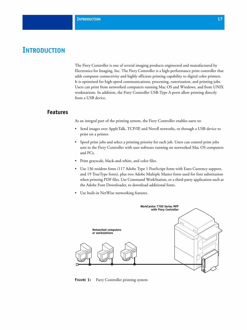
The Fiery Controller is one of several imaging products engineered and manufactured by Electronics for Imaging, Inc. The Fiery Controller is a high-performance print controller that adds computer connectivity and highly efficient printing capability to digital color printers. It is optimized for high-speed communications, processing, rasterization, and printing jobs. Users can print from networked computers running Mac OS and Windows, and from UNIX workstations. In addition, the Fiery Controller USB-Type A ports allow printing directly from a USB device.
FeaturesAs an integral part of the printing system, the Fiery Controller enables users to:
• Send images over AppleTalk, TCP/IP, and Novell networks, or through a USB device to print on a printer.
• Spool print jobs and select a printing priority for each job. Users can control print jobs sent to the Fiery Controller with user software running on networked Mac OS computers and PCs.
• Print grayscale, black-and-white, and color files.
• Use 136 resident fonts (117 Adobe Type 1 PostScript fonts with Euro Currency support, and 19 TrueType fonts), plus two Adobe Multiple Master fonts used for font substitution when printing PDF files. Use Command WorkStation, or a third-party application such as the Adobe Font Downloader, to download additional fonts.
• Use built-in NetWise networking features.
FIGURE 1: Fiery Controller printing system
Networked computers or workstations
WorkCentre 7700 Series MFPwith Fiery Controller
INTRODUCTION 18
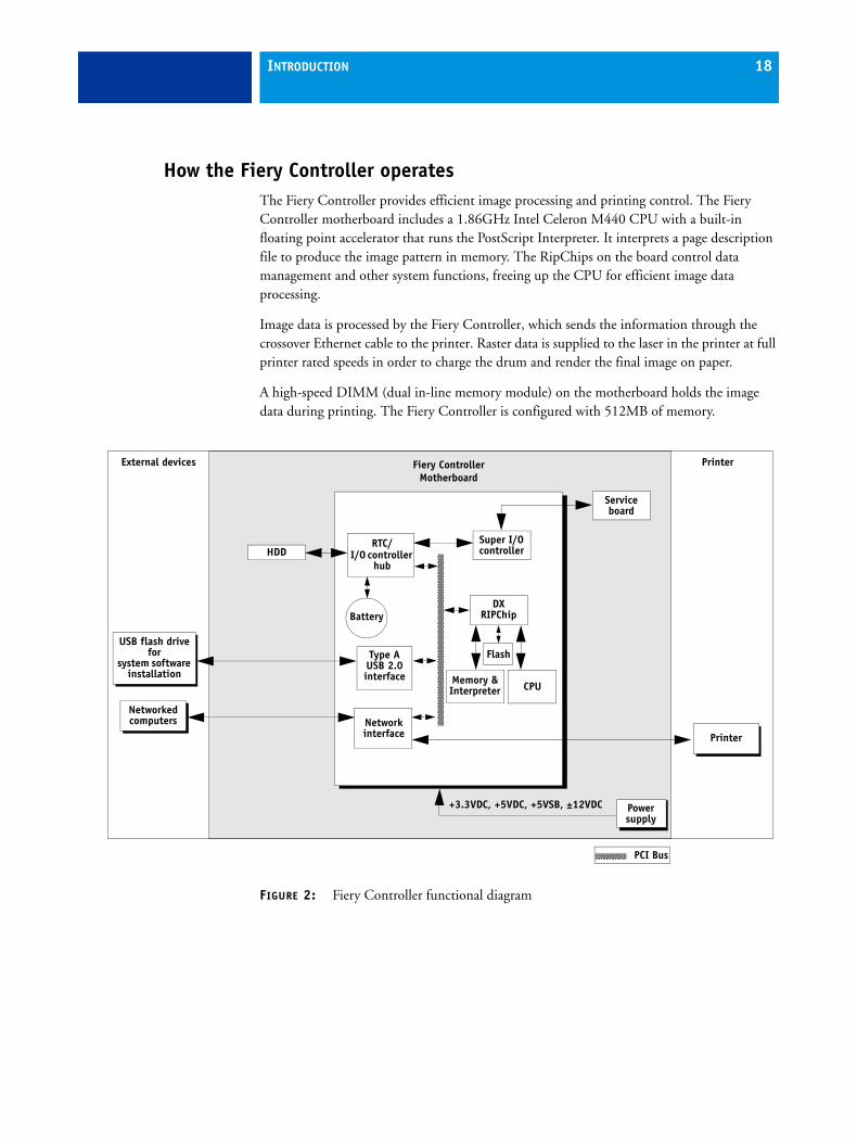
How the Fiery Controller operatesThe Fiery Controller provides efficient image processing and printing control. The Fiery Controller motherboard includes a 1.86GHz Intel Celeron M440 CPU with a built-in floating point accelerator that runs the PostScript Interpreter. It interprets a page description file to produce the image pattern in memory. The RipChips on the board control data management and other system functions, freeing up the CPU for efficient image data processing.
Image data is processed by the Fiery Controller, which sends the information through the crossover Ethernet cable to the printer. Raster data is supplied to the laser in the printer at full printer rated speeds in order to charge the drum and render the final image on paper.
A high-speed DIMM (dual in-line memory module) on the motherboard holds the image data during printing. The Fiery Controller is configured with 512MB of memory.
FIGURE 2: Fiery Controller functional diagram
Powersupply
External devices PrinterFiery ControllerMotherboard
+3.3VDC, +5VDC, +5VSB, ±12VDC
CPU
Network interface
Memory &Interpreter
Printer
DX RIPChip
Flash
Networked computers
RTC/I/O controller
hubHDD
Battery
Super I/Ocontroller
PCI Bus
Service board
Type A USB 2.0 interface
USB flash drive for
system software installation

INTRODUCTION 19
Fiery Controller print optionsThe Fiery Controller’s efficient PostScript capabilities allow customers to use a variety of applications to create printed color or black-and-white pages of text and/or images. The Fiery Controller operates both over a network and directly through a USB device connected to a USB-Type A port. Since the Fiery Controller has the ability to print an image while processing the next image (RIP-While-Print), it is capable of printing documents at full printer speeds.
Users can print documents directly from the applications in which they were created. In addition, the Fiery Controller offers an efficient way to print files that have been saved in PostScript, EPS (Encapsulated PostScript), or PDF format. These files can be downloaded directly to the Fiery Controller using WebTools or Command WorkStation, a remote utility provided with the Fiery Controller.
Through a USB-Type A port, customers can print directly from a USB device that is loaded with document files.
User software and WebToolsUser software is provided on the User Software DVD. Installers for the user software and printer files can also be downloaded using the Downloads tab within WebTools.
The WebTools also include tools for configuring the Fiery Controller and managing print jobs through the Internet or intranet.
For more information about the user software and WebTools, see Utilities on the User Documentation CD. A complete set of the user documentation (provided as PDFs) can be installed from the User Documentation CD onto any client computer.

INSTALLATION 20
INSTALLATION
This chapter describes the process for installing the Fiery Controller at the customer site. The chapter includes the following information:
• Checking the customer site
• Setting customer expectations
• Unpacking and placing the Fiery Controller
• Preparing for installation
• Installing the Fiery Controller
• Verifying the Fiery Controller installation
• Starting up, shutting down, and rebooting the Fiery Controller
INSTALLATION 21
Checking the customer siteBefore you install the Fiery Controller, check site conditions and inform the customer of any installation requirements.
Printer readiness❑ Make sure that adequate space is available next to the printer for the Fiery Controller.
Power❑ Make sure that a dedicated, grounded electrical outlet is available for the Fiery Controller
near the printer.
Locate the grounded electrical outlet that will supply power to the Fiery Controller. Do not run the Fiery Controller and the printer on the same circuit. Use a surge suppressor for the Fiery Controller if the customer has provided one.
• Do not use a 3-prong adapter in a 2-hole ungrounded outlet.
• Do not use an extension cord.
• Do not plug the Fiery Controller into a circuit with heating or refrigeration equipment (including water coolers).
• Do not plug the Fiery Controller into a switchable wall outlet. This can result in the Fiery Controller being turned off accidentally.
• Do not pull on the cable when unplugging the Fiery Controller. Pull the plug instead.
Network❑ Before you connect the Fiery Controller, verify with the network administrator or Xerox
analyst that the network is functioning.
❑ Make sure that the configuration requirements specified in Configuration and Setup (on the User Documentation CD) have been met for the remote computers and the network.
System contact person❑ Make sure that the network is available at the time set for installation.
❑ Obtain any special instructions from the Xerox analyst.
INSTALLATION 22
Setting customer expectationsInform the customer of the following:
• Some nodes on the network may be unavailable during the installation.
• The network administrator must be available during the installation for network connectivity.
Equipment downtime and impact on the network can be minimized if the network administrator installs a network connector for the Fiery Controller and confirms network functionality with the connector in place before the date scheduled for the installation.
• The network administrator should have a networked computer available during the installation. The appropriate software should already be installed. Documentation for the networked computer and network operating software should be available.
• The network administrator should install the user software shipped with the Fiery Controller onto the networked Mac OS computers and PCs that print to the Fiery Controller (user documentation is also included).
NOTE: This guide covers Fiery Controller hardware installation and service. It provides general information about connecting the Fiery Controller to the customer’s network. Network Setup and configuration information go beyond the scope of this guide. For Network Setup and configuration information, refer the network administrator to Configuration and Setup on the User Documentation CD.
INSTALLATION 23
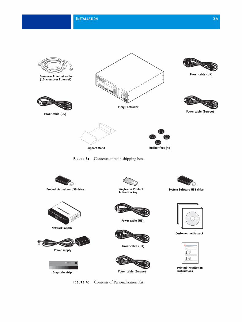
Unpacking the Fiery ControllerThe Fiery Controller is assembled and shipped from the factory in a box that includes the items shown in Figure 3 on page 24. A separate Personalization Kit accompanies the main shipping box and includes the items shown in Figure 4 on page 24.
TO UNPACK THE FIERY CONTROLLER
1. Open the main shipping box and remove any packing materials.
2. Remove the contents of the shipping box and inspect them for visible damage.
If you notice shipping damage, keep the shipping box to show the carrier, if required. Call the carrier immediately to report the damage and file a claim, and then call your authorized service/support center. The main shipping box includes the following items:
• Fiery Controller
• Support stand
• Rubber feet (4)
• Crossover Ethernet cable (10 feet)
• Power cables (3)
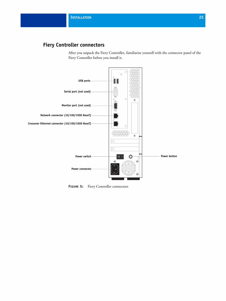
3. Open and remove the contents of the Personalization Kit.
The Personalization Kit includes the following items:
• Product Activation USB drive
• Single-use Product Activation key
• System Software USB drive
• Network switch
• Power supply for network switch
• Power cables (3)
• Customer media pack, including the Grayscale strip (see page 8 for contents)
• Printed Fiery Installation Instructions for the WorkCentre 7700 Series MFP
4. Give the media pack to the network administrator.
Let the network administrator know that to take full advantage of the Fiery Controller, the user software must be installed on computers that will print to it.
INSTALLATION 24
FIGURE 3: Contents of main shipping box
FIGURE 4: Contents of Personalization Kit
Power cable (US)
Crossover Ethernet cable(10’ crossover Ethernet)
Support stand
Power cable (UK)
Power cable (Europe)Fiery Controller
Rubber feet (4)
•
Customer media pack
Power cable (US)
Printed installation instructions
Power cable (UK)
Power cable (Europe)Grayscale strip
Network switch
Power supply
Product Activation USB drive System Software USB driveSingle-use Product Activation key
INSTALLATION 25
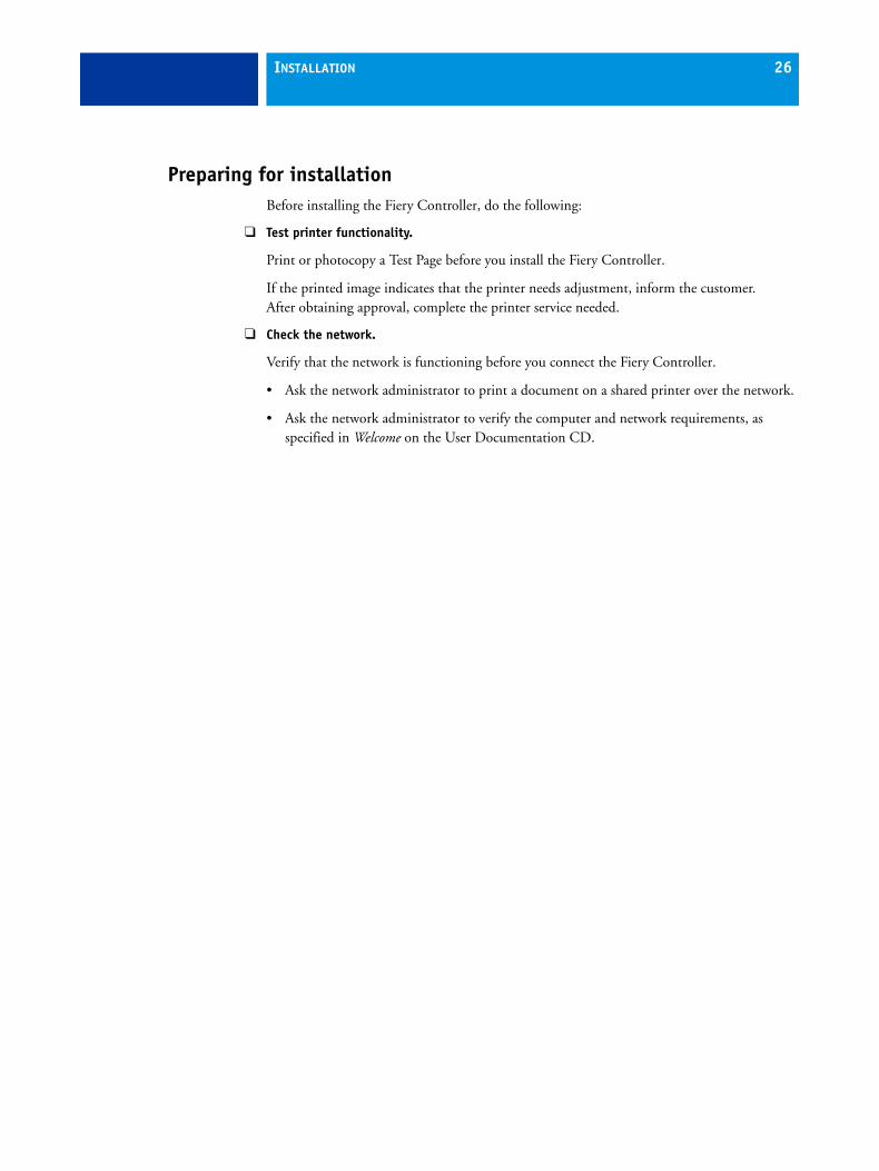
Fiery Controller connectorsAfter you unpack the Fiery Controller, familiarize yourself with the connector panel of the Fiery Controller before you install it.
FIGURE 5: Fiery Controller connectors
Power connector
Crossover Ethernet connector (10/100/1000 BaseT)
Network connector (10/100/1000 BaseT)
Monitor port (not used)
Serial port (not used)
USB ports
Power buttonPower switch
INSTALLATION 26
Preparing for installationBefore installing the Fiery Controller, do the following:
❑ Test printer functionality.
Print or photocopy a Test Page before you install the Fiery Controller.
If the printed image indicates that the printer needs adjustment, inform the customer. After obtaining approval, complete the printer service needed.
❑ Check the network.
Verify that the network is functioning before you connect the Fiery Controller.
• Ask the network administrator to print a document on a shared printer over the network.
• Ask the network administrator to verify the computer and network requirements, as specified in Welcome on the User Documentation CD.
INSTALLATION 27
Installing the Fiery ControllerUse the procedures in the following sections to install and connect the Fiery Controller.
Follow standard ESD (electrostatic discharge) precautions while handling components. For details, see “Precautions” on page 12.
Placing the Fiery Controller
Use the following procedure to place the Fiery Controller in the support stand.
TO PLACE THE FIERY CONTROLLER AND CHECK THE SWITCHES
1. Make sure that the base surface of the Fiery Controller is clean and dry.
The base surface is the narrow surface of the Fiery Controller adjacent to the power connector.
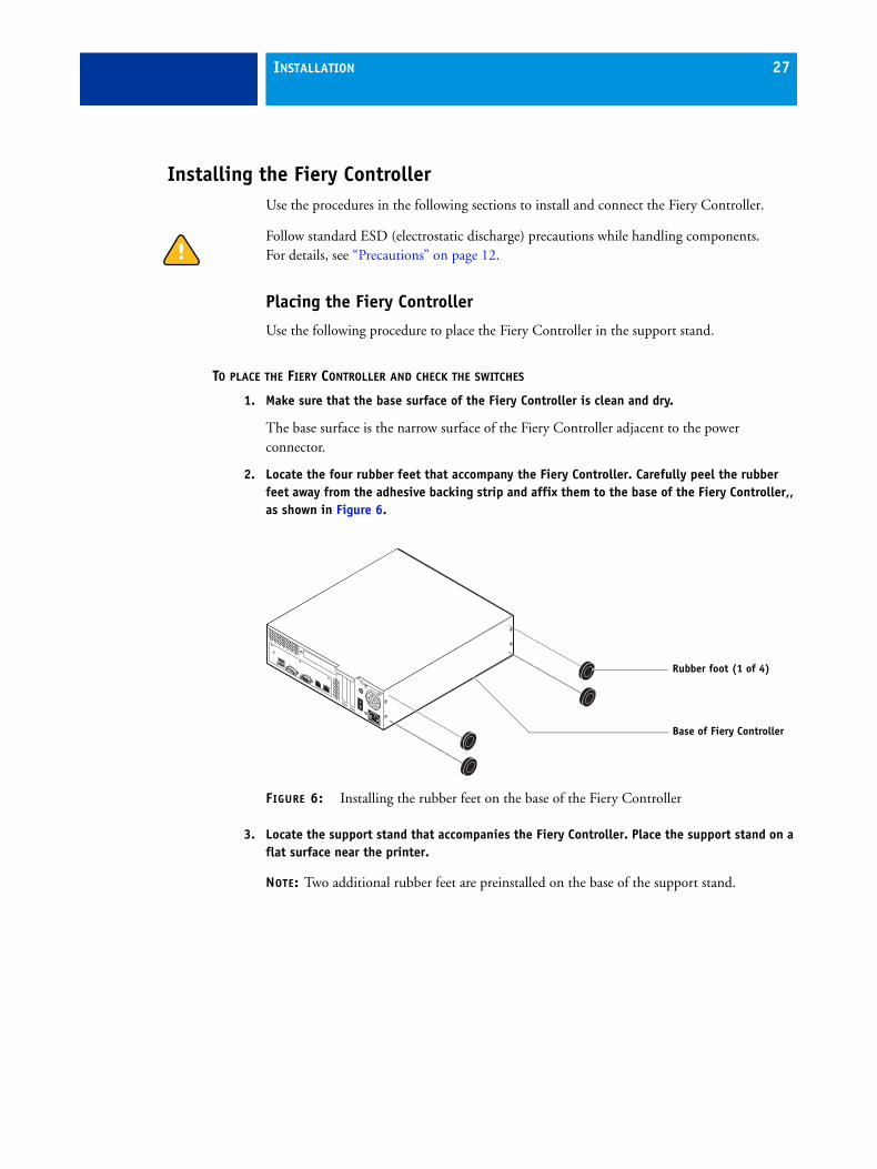
2. Locate the four rubber feet that accompany the Fiery Controller. Carefully peel the rubber feet away from the adhesive backing strip and affix them to the base of the Fiery Controller,, as shown in Figure 6.
FIGURE 6: Installing the rubber feet on the base of the Fiery Controller
3. Locate the support stand that accompanies the Fiery Controller. Place the support stand on a flat surface near the printer.
NOTE: Two additional rubber feet are preinstalled on the base of the support stand.
Base of Fiery Controller
Rubber foot (1 of 4)

INSTALLATION 28
4. Place the Fiery Controller in the support stand,, as shown in Figure 7.
When the Fiery Controller is properly placed, all four rubber feet should rest securely on the flat surface.
FIGURE 7: Placing the Fiery Controller in the support stand
5. Locate the region-specific power cable that shipped with the Fiery Controller. Connect the cable to the Fiery Controller and to a power outlet.
6. Make sure that the Fiery Controller power switch is set to the OFF (0) position.
If it is not already set, move the power switch to the OFF position.
Fiery Controller
Support stand
INSTALLATION 29
Personalizing the Fiery Controller
Before you connect the Fiery Controller to the printer, you must personalize the system by activating the product identification code and installing system software.
TO PERSONALIZE THE FIERY CONTROLLER
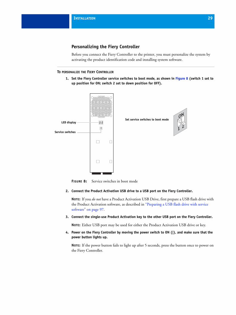
1. Set the Fiery Controller service switches to boot mode, as shown in Figure 8 (switch 1 set to up position for ON; switch 2 set to down position for OFF).
FIGURE 8: Service switches in boot mode
2. Connect the Product Activation USB drive to a USB port on the Fiery Controller.
NOTE: If you do not have a Product Activation USB Drive, first prepare a USB flash drive with the Product Activation software, as described in “Preparing a USB flash drive with service software” on page 97.
3. Connect the single-use Product Activation key to the other USB port on the Fiery Controller.
NOTE: Either USB port may be used for either the Product Activation USB drive or key.
4. Power on the Fiery Controller by moving the power switch to ON (|), and make sure that the power button lights up.
NOTE: If the power button fails to light up after 5 seconds, press the button once to power on the Fiery Controller.
Service switches
LED displaySet service switches to boot mode
INSTALLATION 30
5. Wait approximately 3 minutes for the product activation to finish. Allow the Fiery Controller to shut down automatically.
During product activation, the LED display flashes sporadically and shows 00; then it shows 01, 02, F0, and FF.
After showing FF for approximately 30 seconds, the Fiery Controller automatically shuts down.
NOTE: If an error code displays during product activation, see page 132.
6. Remove the Product Activation USB drive and single-use Product Activation key from the Fiery Controller.
• The single-use Product Activation key is now expended and cannot be reused. Dispose of the key according to your local regulations.
• The Product Activation USB drive may be required at a later time if you need to convert the Fiery Controller to a system other than the WorkCentre 7700. Store the drive in a secure location near the Fiery Controller.
7. Connect the System Software USB drive to a USB port on the Fiery Controller.
8. Power on the Fiery Controller by pressing the power button once.
9. Wait approximately 15 minutes as system software files are transferred to the Fiery Controller.
At first the LED display shows sporadic activity, eventually settling on 00. The display increases by one number approximately every 30 seconds. When all the files have been transferred to the Fiery Controller, the display switches to FF.
Do not interact with the Fiery Controller during the file transfer. Interrupting the file transfer may result in system corruption (i.e., the Fiery Controller hangs at AA for longer than 10 minutes during startup). If the system is corrupted, you must repeat the system software installation, beginning with step 7.
10. After the LED display reaches FF, wait 30 seconds, and then power off the Fiery Controller by pressing and holding down the power button for 5 seconds until the green light goes out.
NOTE: Be sure to use the power button to power off the system; do not use the power switch. Using the power switch may result in system corruption (i.e., the Fiery Controller hangs at AA for longer than 10 minutes during startup). If the system is corrupted, you must repeat the system software installation, beginning with step 7.
11. Remove the System Software USB drive from the Fiery Controller.
Store the drive in a secure location near the Fiery Controller. You may need the System Software drive at a later time to reinstall system software on the Fiery Controller for troubleshooting purposes.
INSTALLATION 31
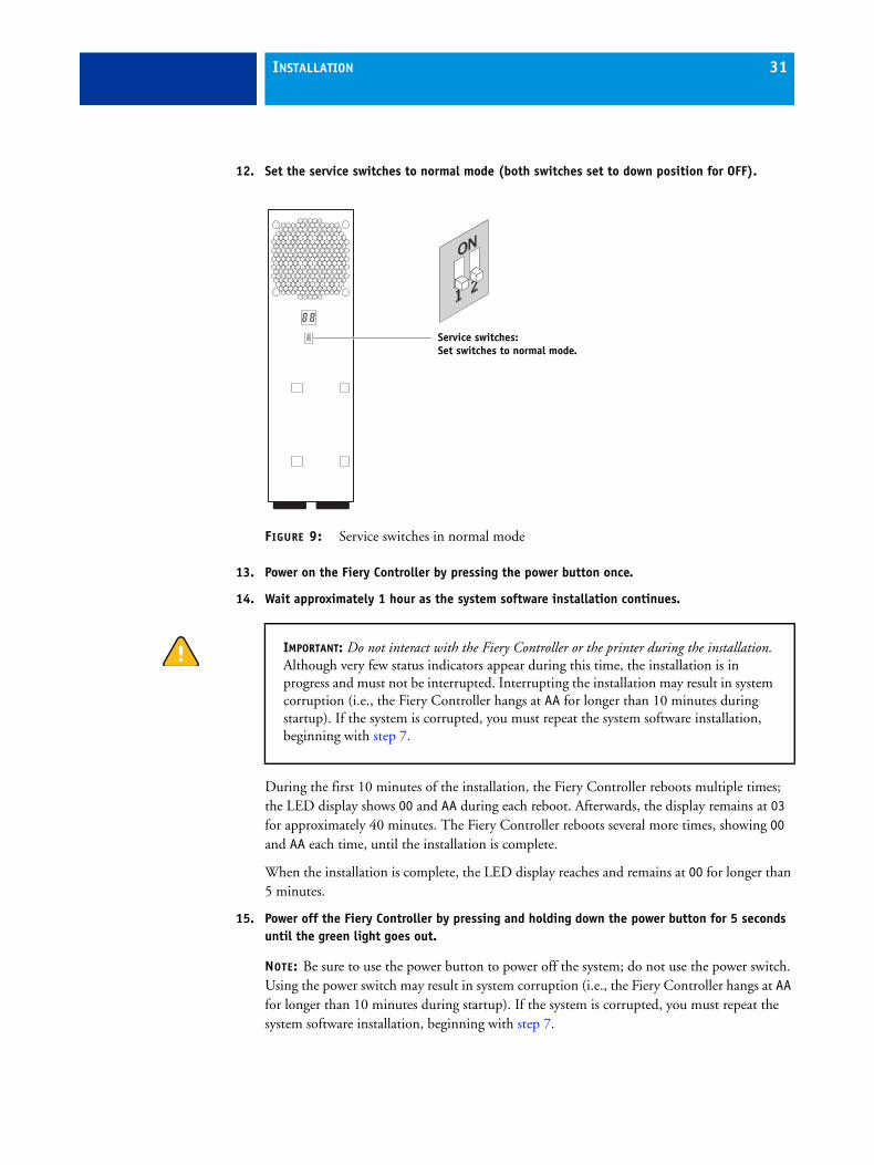
12. Set the service switches to normal mode (both switches set to down position for OFF).
FIGURE 9: Service switches in normal mode
13. Power on the Fiery Controller by pressing the power button once.
14. Wait approximately 1 hour as the system software installation continues.
During the first 10 minutes of the installation, the Fiery Controller reboots multiple times; the LED display shows 00 and AA during each reboot. Afterwards, the display remains at 03 for approximately 40 minutes. The Fiery Controller reboots several more times, showing 00 and AA each time, until the installation is complete.
When the installation is complete, the LED display reaches and remains at 00 for longer than 5 minutes.
15. Power off the Fiery Controller by pressing and holding down the power button for 5 seconds until the green light goes out.
NOTE: Be sure to use the power button to power off the system; do not use the power switch. Using the power switch may result in system corruption (i.e., the Fiery Controller hangs at AA for longer than 10 minutes during startup). If the system is corrupted, you must repeat the system software installation, beginning with step 7.
Service switches:Set switches to normal mode.
IMPORTANT: Do not interact with the Fiery Controller or the printer during the installation. Although very few status indicators appear during this time, the installation is in progress and must not be interrupted. Interrupting the installation may result in system corruption (i.e., the Fiery Controller hangs at AA for longer than 10 minutes during startup). If the system is corrupted, you must repeat the system software installation, beginning with step 7.
INSTALLATION 32
Configuring the printer settings
To ensure proper communication between the printer and the Fiery Controller, make sure that the printer IP settings are configured to DHCP.
The printer IP settings are configured by default to DHCP, but may have been changed by the network administrator.
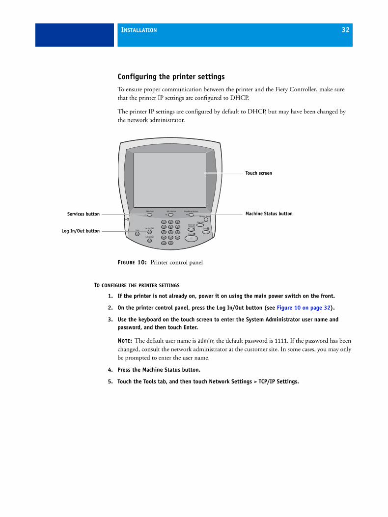
FIGURE 10: Printer control panel
TO CONFIGURE THE PRINTER SETTINGS
1. If the printer is not already on, power it on using the main power switch on the front.
2. On the printer control panel, press the Log In/Out button (see Figure 10 on page 32).
3. Use the keyboard on the touch screen to enter the System Administrator user name and password, and then touch Enter.
NOTE: The default user name is admin; the default password is 1111. If the password has been changed, consult the network administrator at the customer site. In some cases, you may only be prompted to enter the user name.
4. Press the Machine Status button.
5. Touch the Tools tab, and then touch Network Settings > TCP/IP Settings.
Job StatusServices Machine Status
Energy Saver
Language
Help
InterruptPrinting
Services button
Touch screen
Machine Status button
Log In/Out button
INSTALLATION 33
6. Verify or configure the following settings:
• TCPIP Enablement is set to IPv4 Enabled. (IPv6 may be enabled or disabled.)
• Dynamic Addressing is set to DHCP.
If a setting change is required, touch the setting name, specify the correct setting, and then touch Save.
7. Touch Close.
8. Touch the admin tab at the top of the screen, and then touch Log Out.
NOTE: If the System Administrator user name has been changed from the default, the tab shows that name instead.
9. Power off the printer using the main power switch on the front.
Wait about one minute for the printer to power off.
10. If the printer is connected to the network, disconnect it.
INSTALLATION 34
Connecting and configuring the Fiery Controller
Use the following procedure to connect the Fiery Controller cables and configure basic Fiery Controller settings.
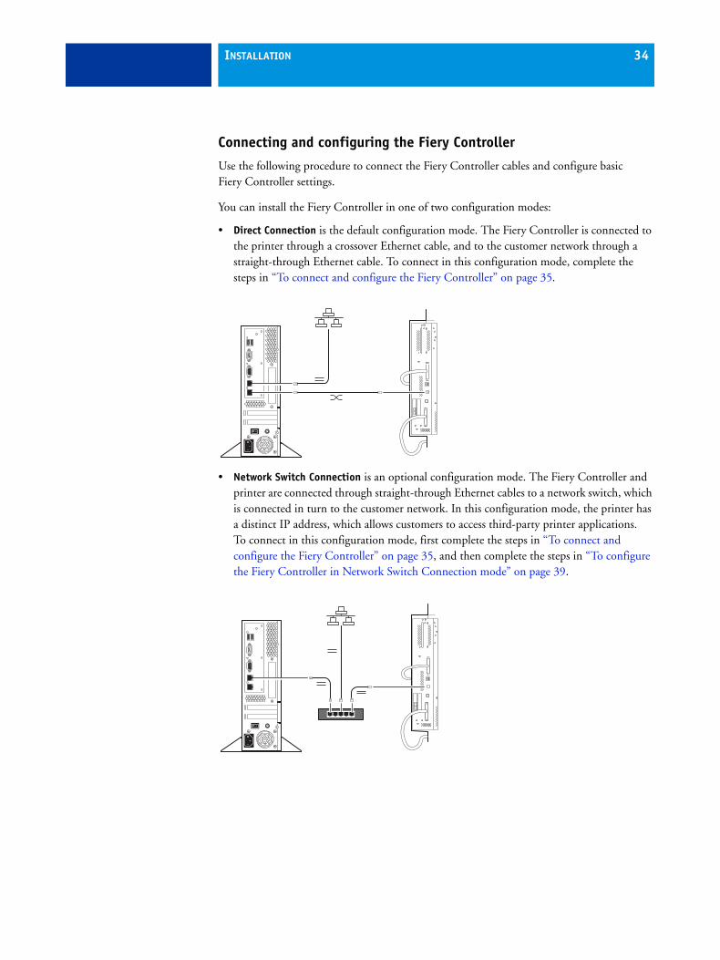
You can install the Fiery Controller in one of two configuration modes:
• Direct Connection is the default configuration mode. The Fiery Controller is connected to the printer through a crossover Ethernet cable, and to the customer network through a straight-through Ethernet cable. To connect in this configuration mode, complete the steps in “To connect and configure the Fiery Controller” on page 35.
• Network Switch Connection is an optional configuration mode. The Fiery Controller and printer are connected through straight-through Ethernet cables to a network switch, which is connected in turn to the customer network. In this configuration mode, the printer has a distinct IP address, which allows customers to access third-party printer applications. To connect in this configuration mode, first complete the steps in “To connect and configure the Fiery Controller” on page 35, and then complete the steps in “To configure the Fiery Controller in Network Switch Connection mode” on page 39.
INSTALLATION 35
TO CONNECT AND CONFIGURE THE FIERY CONTROLLER
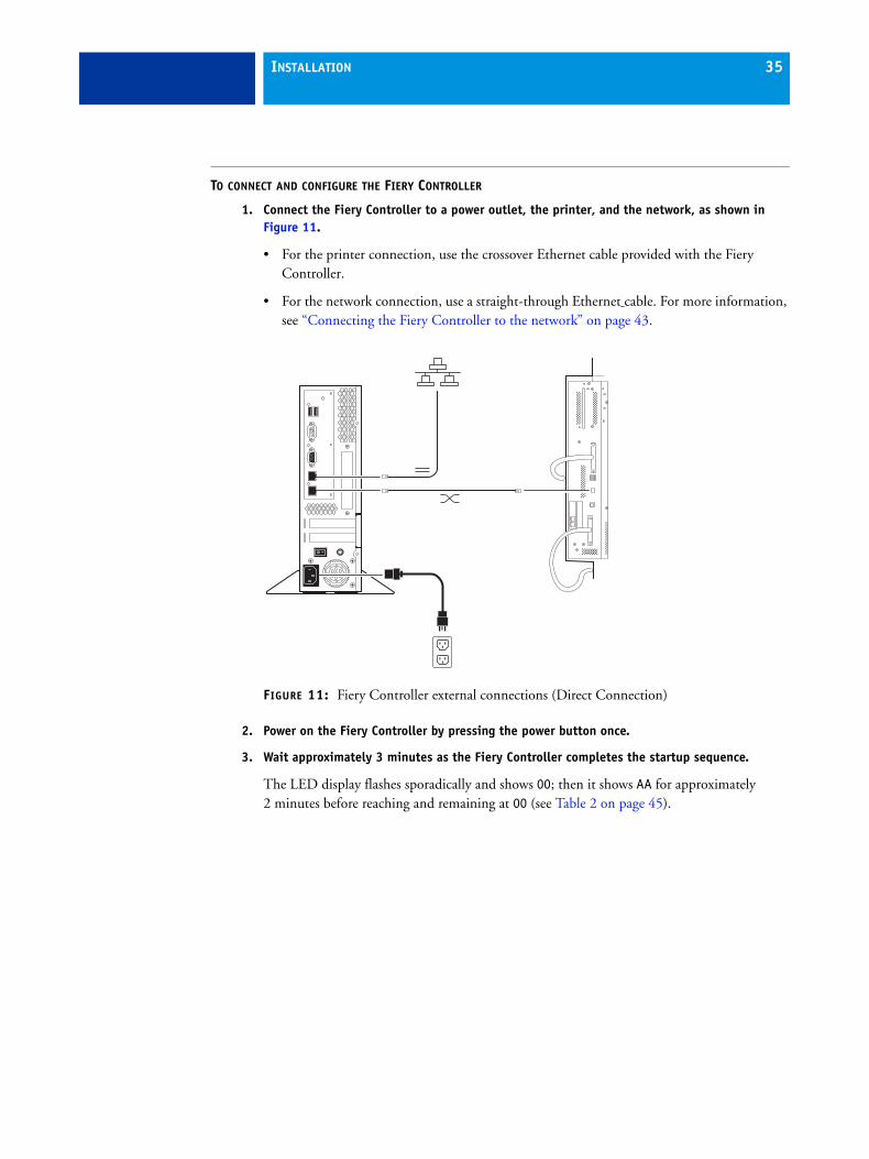
1. Connect the Fiery Controller to a power outlet, the printer, and the network, as shown in Figure 11.
• For the printer connection, use the crossover Ethernet cable provided with the Fiery Controller.
• For the network connection, use a straight-through Ethernet cable. For more information, see “Connecting the Fiery Controller to the network” on page 43.
FIGURE 11: Fiery Controller external connections (Direct Connection)
2. Power on the Fiery Controller by pressing the power button once.
3. Wait approximately 3 minutes as the Fiery Controller completes the startup sequence.
The LED display flashes sporadically and shows 00; then it shows AA for approximately 2 minutes before reaching and remaining at 00 (see Table 2 on page 45).
INSTALLATION 36
4. After the Fiery Controller LED display reaches and remains at 00, power on the printer using the main power switch on the front. Wait for the Start page to be printed.
It takes approximately 3 minutes for the printer to start up and print the Start page. If it has been enabled, the printer Configuration Report is also printed.
Verify that “WorkCentre 7700 Series (EFI)” appears on the Start page. The IP address of the Fiery Controller is listed under Protocol Setup.
NOTE: If the printer fails to print the Start page, do the following:
• Press the Job Status button and check if the Start page is being “Held for Resources.” If this is the case, make sure that Letter LEF or A4 LEF plain paper is loaded in an internal tray. The printer requires one of these paper stocks in order to print the Start page.
• If the Configuration Report was printed during startup, look under Common User Data and verify that the IP address of the printer is set to 100.100.100.101. (If the Configuration Report was not printed during startup, first press the Machine Status button on the printer control panel, touch the Machine Information tab, touch Information Pages > Configuration Report, and then touch Print.)
If the address is not correct, check and reseat the cable between the Fiery Controller and the printer. Power off and then power on the printer.
5. After the Start page prints, press the Services button on the printer control panel, and verify that the Fiery icon appears on the screen.
NOTE: If you do not see the service icons after pressing the Services button, touch Services Home. If the Fiery icon still fails to appear, refer to the troubleshooting remedies described on page 130.
IMPORTANT: Do not power on the printer until the Fiery Controller LEDs reach and remain at 00. After the printer is powered on, do not touch the printer until the Start page is printed.
INSTALLATION 37
6. If required, configure a static IP address for the Fiery Controller (the Fiery Controller is set to DHCP by default):
• Press the Services button on the printer control panel. If you do not see the service icons, touch Services Home.
• Touch the Fiery icon on the printer touch panel.
• Touch the Setup tab.
• Touch the password field. On the keyboard that appears on the touch panel, enter the Administrator password for the Fiery Controller. (The default case-sensitive password is Fiery.1.) Touch Save, and then touch Login.
• Under Network Setup, touch TCP/IP > Ethernet. Configure the following settings:
– Set IPv4 Address Type to Manual.
– Touch the IP Address field; on the keyboard that appears, enter the Fiery Controller IP address specified by your network administrator.
– Set the Subnet Mask to the value specified by your network administrator.
– Set the Gateway Type to Manual.
– Set the Gateway Address to the address specified by your network administrator.
• Touch Save Changes, and then touch Exit.
• At the main Setup screen, touch Restart Server > Reboot System. Allow the Fiery Controller to reboot.
• Wait for the Start page to print.
It takes approximately 3 minutes for the Fiery Controller to reboot and the printer to print the Start page. The Fiery Controller IP address is listed under Protocol Setup.
INSTALLATION 38
7. If required, configure 802.1x settings for the Fiery Controller:
• Press the Services button on the printer control panel. If you do not see the service icons, touch Services Home.
• Touch the Fiery icon on the printer touch panel.
• Touch the Setup tab.
• Touch the password field. On the keyboard that appears on the touch panel, enter the Administrator password for the Fiery Controller. (The default case-sensitive password is Fiery.1.) Touch Save, and then touch Login.
• Under Network Setup, touch 802.1x Setup. Configure the required settings.
For more information see Configuration and Setup on the User Documentation CD.
• Touch Save Changes, and then touch Exit.
• At the main Setup screen, touch Restart Server > Reboot System. Allow the Fiery Controller to reboot.
• Wait for the Start page to print.
It takes approximately 3 minutes for the Fiery Controller to reboot and the printer to print the Start page. The Fiery Controller IP address is listed under Protocol Setup.
NOTE: If you are installing the system in Direct Connection mode, the installation is now complete. If you are installing the system in Network Switch Connection mode, proceed to “Configuring a Network Switch Connection (optional)” on page 39.

INSTALLATION 39
Configuring a Network Switch Connection (optional)
This section provides additional steps for configuring the Fiery Controller in optional Network Switch Connection mode.
TO CONFIGURE THE FIERY CONTROLLER IN NETWORK SWITCH CONNECTION MODE
NOTE: Before starting this procedure, make sure that you have completed all the steps in“To connect and configure the Fiery Controller” on page 35.
1. Shut down the Fiery Controller by doing the following:
• On the printer control panel, press the Services button. If you do not see the service icons, touch Services Home.
• Touch the Fiery icon on the printer touch panel.
• Touch the Jobs tab, and then touch Login.
• Select the Administrator option and touch the password field. On the keyboard that appears on the touch panel, enter Fiery.1. Touch Save, and then touch Login.
• Touch Restart Server, and then touch Shut Down System.
Wait until the LED display on the Fiery Controller goes blank and the system powers off completely.
INSTALLATION 40
2. If required, configure a static IP address for the printer:
• Press the Log In/Out button on the printer control panel. Enter the System Administrator user name and password to log on to the printer. (The default user name is admin; the default password is 1111. In some cases, you may not need to enter the password.) Touch Enter.
• Press the Machine Status button.
• Touch the Tools tab, and then touch Network Settings > TCP/IP Settings.
• Touch Dynamic Addressing and select Disabled. Touch Save.
• Touch IP Address/Host Name. Set IPv4 Address to the printer IP address specified by your network administrator, and then touch Close.
• Touch Subnet and Gateway, and configure the settings as follows:
– Set IP Gateway to the gateway address specified by your network administrator.
– Set Subnet Mask to the value specified by your network administrator.
– After you configure the settings, touch Close.
• Touch the Admin tab at the top of the screen. (The tab will show a different user name if the System Administrator user name has been changed from the default.) Touch Log Out.
• Allow the printer to reboot automatically.
• If the printer Configuration Report was printed during startup, look under Common User Data and verify that the IP address of the printer is set to the static IP address that you just configured. (If the Configuration Report was not printed during startup, first press the Machine Status button on the printer control panel, touch the Machine Information tab, touch Information Pages > Configuration Report, and then touch Print.)
3. Power off the printer using the main power switch on the front.
INSTALLATION 41
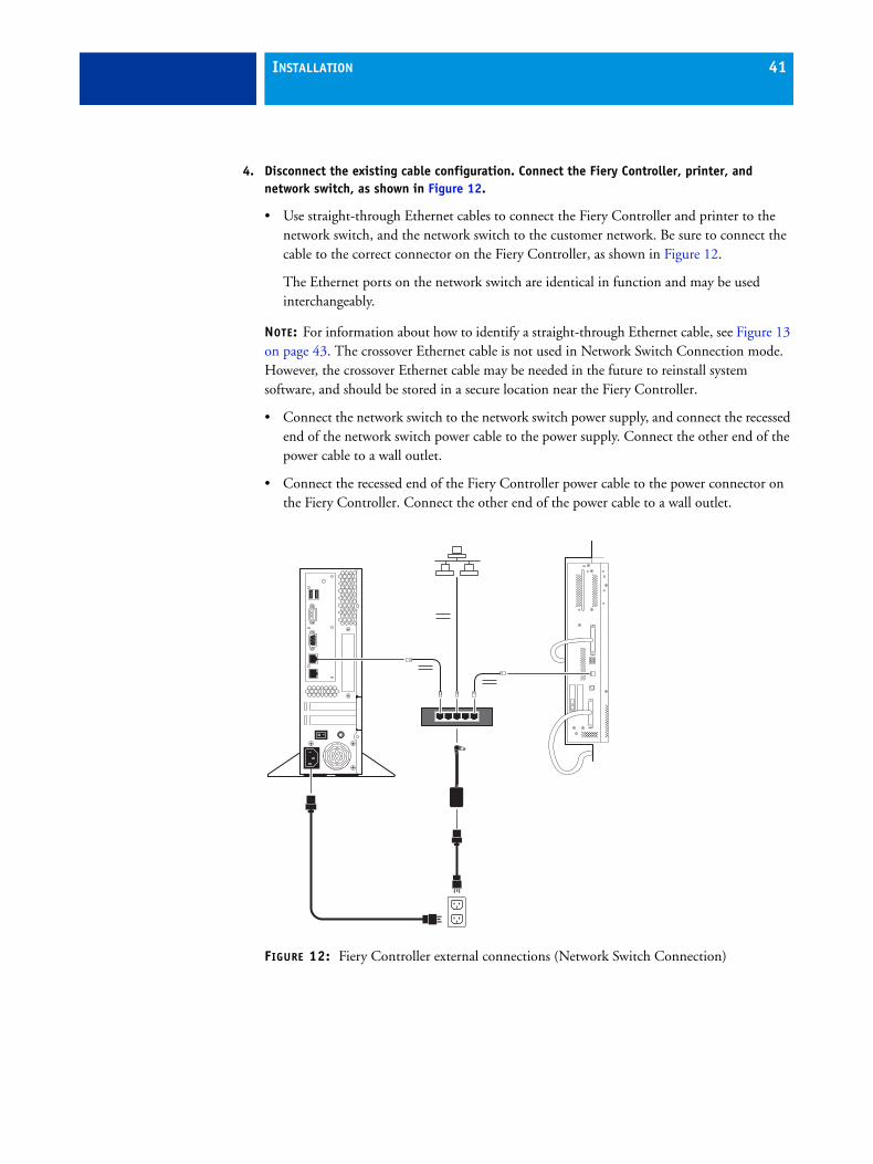
4. Disconnect the existing cable configuration. Connect the Fiery Controller, printer, and network switch, as shown in Figure 12.
• Use straight-through Ethernet cables to connect the Fiery Controller and printer to the network switch, and the network switch to the customer network. Be sure to connect the cable to the correct connector on the Fiery Controller, as shown in Figure 12.
The Ethernet ports on the network switch are identical in function and may be used interchangeably.
NOTE: For information about how to identify a straight-through Ethernet cable, see Figure 13 on page 43. The crossover Ethernet cable is not used in Network Switch Connection mode. However, the crossover Ethernet cable may be needed in the future to reinstall system software, and should be stored in a secure location near the Fiery Controller.
• Connect the network switch to the network switch power supply, and connect the recessed end of the network switch power cable to the power supply. Connect the other end of the power cable to a wall outlet.
• Connect the recessed end of the Fiery Controller power cable to the power connector on the Fiery Controller. Connect the other end of the power cable to a wall outlet.
FIGURE 12: Fiery Controller external connections (Network Switch Connection)
INSTALLATION 42
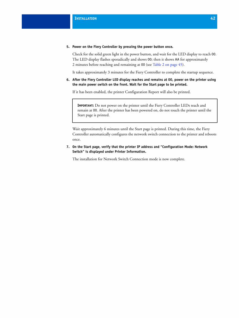
5. Power on the Fiery Controller by pressing the power button once.
Check for the solid green light in the power button, and wait for the LED display to reach 00. The LED display flashes sporadically and shows 00; then it shows AA for approximately 2 minutes before reaching and remaining at 00 (see Table 2 on page 45).
It takes approximately 3 minutes for the Fiery Controller to complete the startup sequence.
6. After the Fiery Controller LED display reaches and remains at 00, power on the printer using the main power switch on the front. Wait for the Start page to be printed.
If it has been enabled, the printer Configuration Report will also be printed.
Wait approximately 6 minutes until the Start page is printed. During this time, the Fiery Controller automatically configures the network switch connection to the printer and reboots once.
7. On the Start page, verify that the printer IP address and “Configuration Mode: Network Switch” is displayed under Printer Information.
The installation for Network Switch Connection mode is now complete.
IMPORTANT: Do not power on the printer until the Fiery Controller LEDs reach and remain at 00. After the printer has been powered on, do not touch the printer until the Start page is printed.
INSTALLATION 43
Connecting the Fiery Controller to the networkThis section provides information about the Fiery Controller network connection.
In Direct Connection mode, the Fiery Controller is connected directly to the customer network. In Network Switch Connection mode, the Fiery Controller is connected to the customer network through the network switch.
Network cable
The Fiery Controller network connection requires a straight-through Ethernet cable. Depending on your network speed, the following categories of straight-through Ethernet cables are supported:
• For 10BaseT, Category 3 or higher
• For 100BaseTX, Category 5 or higher (4-pair/8-wire, short-length)
• For 1000BaseT, Category 5e or higher (4-pair/8-wire, short-length)
NOTE: If the printer is 230V, use a shielded straight-through Ethernet cable.
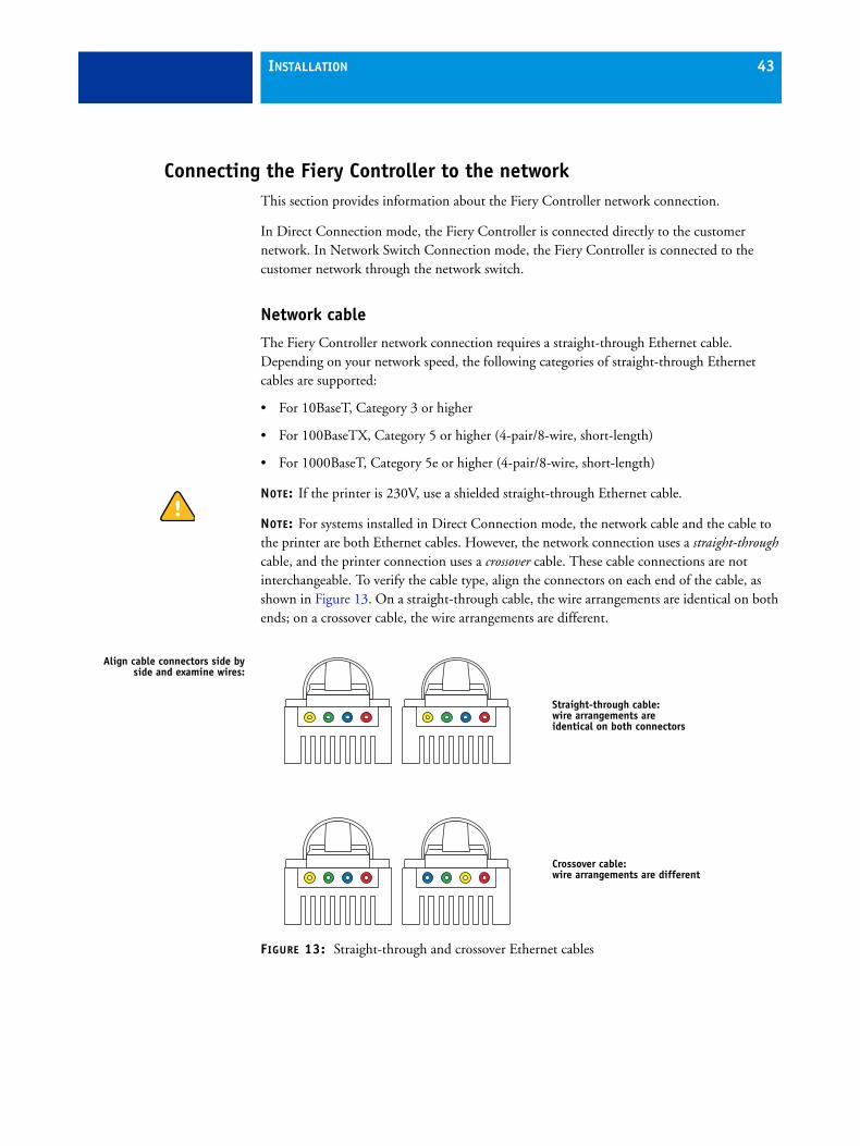
NOTE: For systems installed in Direct Connection mode, the network cable and the cable to the printer are both Ethernet cables. However, the network connection uses a straight-through cable, and the printer connection uses a crossover cable. These cable connections are not interchangeable. To verify the cable type, align the connectors on each end of the cable, as shown in Figure 13. On a straight-through cable, the wire arrangements are identical on both ends; on a crossover cable, the wire arrangements are different.
FIGURE 13: Straight-through and crossover Ethernet cables
Align cable connectors side byside and examine wires:
Straight-through cable:wire arrangements are identical on both connectors
Crossover cable:wire arrangements are different
INSTALLATION 44
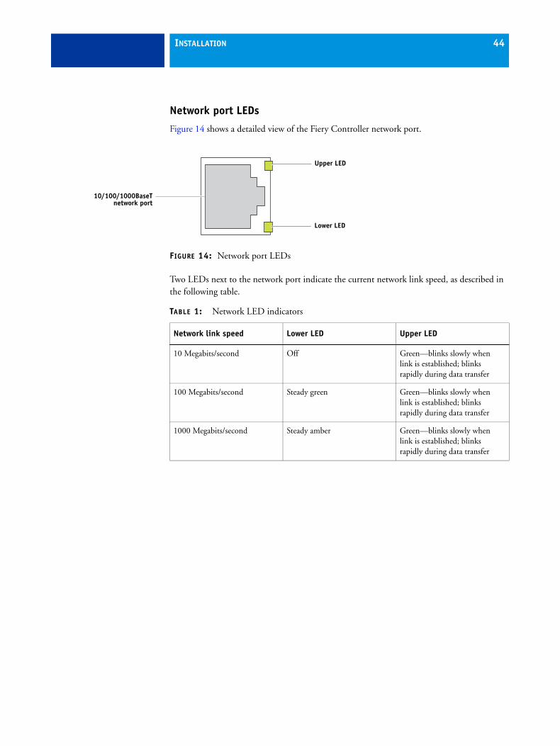
Network port LEDs
Figure 14 shows a detailed view of the Fiery Controller network port.
FIGURE 14: Network port LEDs
Two LEDs next to the network port indicate the current network link speed, as described in the following table.
TABLE 1: Network LED indicators
Lower LED
Upper LED
10/100/1000BaseTnetwork port
Network link speed Lower LED Upper LED
10 Megabits/second Off Green—blinks slowly when link is established; blinks rapidly during data transfer
100 Megabits/second Steady green Green—blinks slowly when link is established; blinks rapidly during data transfer
1000 Megabits/second Steady amber Green—blinks slowly when link is established; blinks rapidly during data transfer
INSTALLATION 45
Starting, shutting down, rebooting, and restarting the Fiery ControllerAlways use the following procedures to start, shut down, reboot, or restart the Fiery Controller.
TO START THE FIERY CONTROLLER
1. Make sure that the printer is powered off. If necessary, power it off using the main power switch on the front.
2. Do one of the following:
• If the Fiery Controller power switch is in ON (|) position (see Figure 5 on page 25), press the Fiery Controller power button once to power on the system.
• If the power switch is in OFF (O) position (see Figure 5 on page 25), move the switch to ON (|) position to power on the system. (The power button lights up when the system powers on.) If the Fiery Controller fails to power on after 5 seconds, firmly press the power button once and then release.
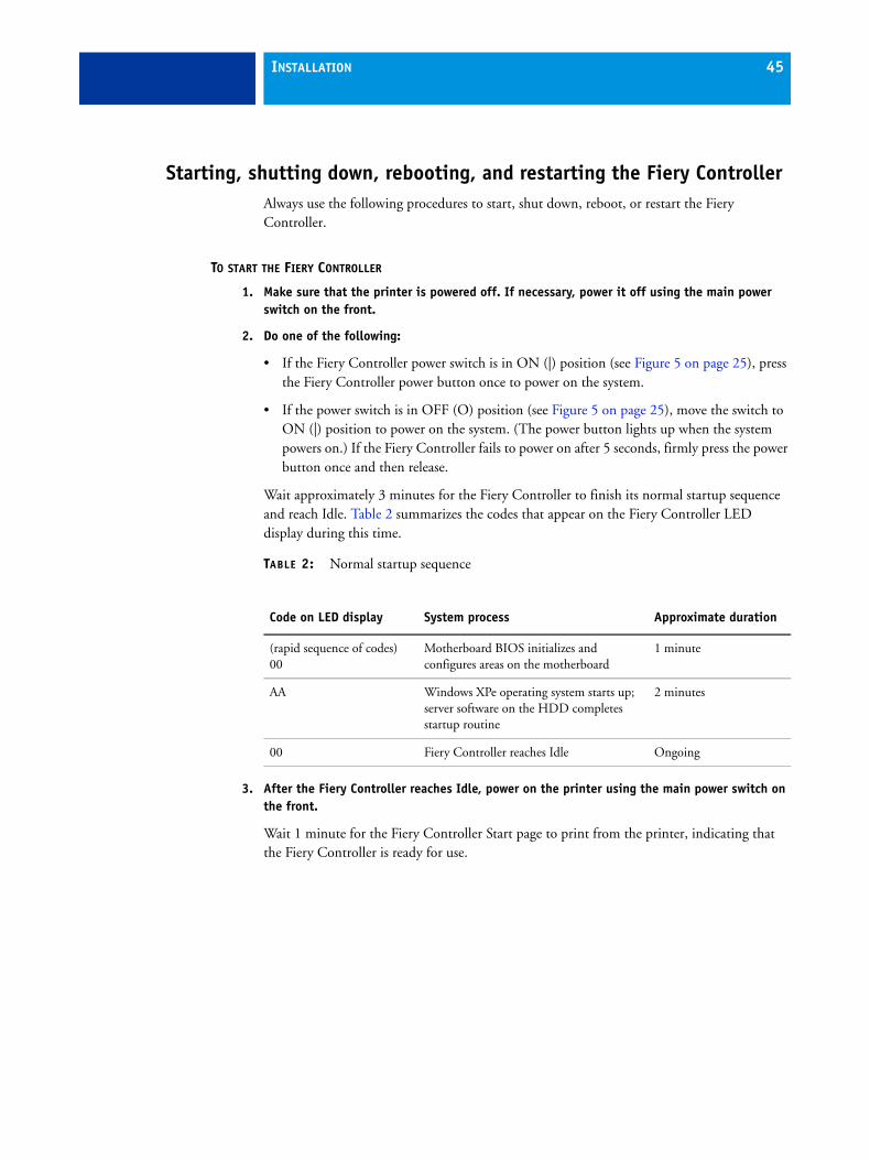
Wait approximately 3 minutes for the Fiery Controller to finish its normal startup sequence and reach Idle. Table 2 summarizes the codes that appear on the Fiery Controller LED display during this time.
TABLE 2: Normal startup sequence
3. After the Fiery Controller reaches Idle, power on the printer using the main power switch on the front.
Wait 1 minute for the Fiery Controller Start page to print from the printer, indicating that the Fiery Controller is ready for use.
Code on LED display System process Approximate duration
(rapid sequence of codes)00
Motherboard BIOS initializes and configures areas on the motherboard
1 minute
AA Windows XPe operating system starts up; server software on the HDD completes startup routine
2 minutes
00 Fiery Controller reaches Idle Ongoing
INSTALLATION 46
TO SHUT DOWN THE FIERY CONTROLLER
1. Make sure that the Fiery Controller is not receiving, processing, or printing any jobs.
2. On the printer control panel, press the Services button. If you do not see the service icons, touch Services Home.
For an illustration of the printer control panel, see Figure 10 on page 32.
3. Touch the Fiery icon on the printer touch panel.
4. Touch the Jobs tab, and then touch Login.
5. Select the Administrator option and touch the password field. On the keyboard that appears on the touch panel, enter the Administrator password for the Fiery Controller, touch Save, and then touch Login.
NOTE: The default case-sensitive password is Fiery.1.
6. Touch Restart Server, and then touch Shut Down System.
Wait until the LED display on the Fiery Controller goes blank and the system powers off completely.
NOTE: Always leave the Fiery Controller power switch in ON (|) position, unless you are servicing the system.
7. If you are servicing the Fiery Controller, make sure that the Fiery Controller has completely powered off and then move the power switch to OFF (O) position. Make sure that the printer is not in use, and then power off the printer using the main power switch on the front.
Wait about 1 minute for the printer to power off completely. All of the lights on the printer control panel turn off when the printer finishes powering off (see Figure 10 on page 32).
TO FORCE A SYSTEM SHUTDOWN
If the Fiery Controller is unresponsive and it is not possible to shut down the system from the printer control panel, use this procedure to force a system shutdown. Force a shutdown only as a last resort when the normal shutdown method is unavailable.
• Press and hold down the power button on the Fiery Controller for 5 seconds until the green light goes out and the system powers off.

INSTALLATION 47
TO REBOOT OR RESTART THE FIERY CONTROLLER
1. Make sure that the Fiery Controller is not receiving, processing, or printing any jobs.
2. On the printer control panel, press the Services button. If you do not see the service icons, touch Services Home.
3. On the printer touch screen, touch the Fiery icon.
4. Touch the Jobs tab, and then touch Login.
5. Select the Administrator option and touch the password field. On the keyboard that appears on the touch panel, enter the Administrator password for the Fiery Controller, touch Save, and then touch Login.
NOTE: The default case-sensitive Administrator password is Fiery.1.
6. Touch Restart Server.
7. Do one of the following:
• To restart the Fiery server software only, touch Restart Server.
• To reboot the Fiery Controller by restarting the operating system software and Fiery server software, touch Reboot System.
TO FORCE A SYSTEM REBOOT
If the Fiery Controller is unresponsive and it is not possible to reboot the system from the printer control panel, use this procedure to force a system reboot. You should force a reboot only as a last resort when the normal reboot method is unavailable.
1. Press and hold down the power button on the Fiery Controller for 5 seconds until the green light goes out and the system powers off.
2. Press the power button once to power on the system.

SERVICE PROCEDURES 48
SERVICE PROCEDURES
Generally, the Fiery Controller does not require regular maintenance. Use the procedures in this chapter to inspect, remove, reseat, or replace major hardware components.
OverviewThis chapter includes information about the following:
• Diagrams of Fiery Controller components (page 49)
• LED display codes (page 50)
• Accessing the Fiery Controller (page 51)
• Cable connections (page 53)
• Removing and replacing Fiery Controller components (page 56)
• Enabling software options (page 95)
• Preparing a USB flash drive with service software (page 97)
When performing the procedures described in this chapter, see “Precautions” on page 12 and “Tools you will need” on page 16.

SERVICE PROCEDURES 49
Fiery Controller components
The figures in this section provide an overview of components in the Fiery Controller.
FIGURE 15: Exploded view of Fiery Controller components
Key1. Chassis cover2. CPU fan guard3. CPU cooling assembly4. 512MB DIMM5. 1.86GHz CPU6. Battery7. Motherboard8. 80GB SATA HDD
(hard disk drive)9. CPU heatsink post
10. HDD bracket11. Chassis fan12. Chassis fan guard13. Service board14. HDD SATA data cable15. Service board cable16. Power supply17. Power supply guard18. Power switch19. Power button20. Chassis
3
1
7
9
4
10
11
13
6
15
20
17
5
14
12
16
2
8
18
19
SERVICE PROCEDURES 50
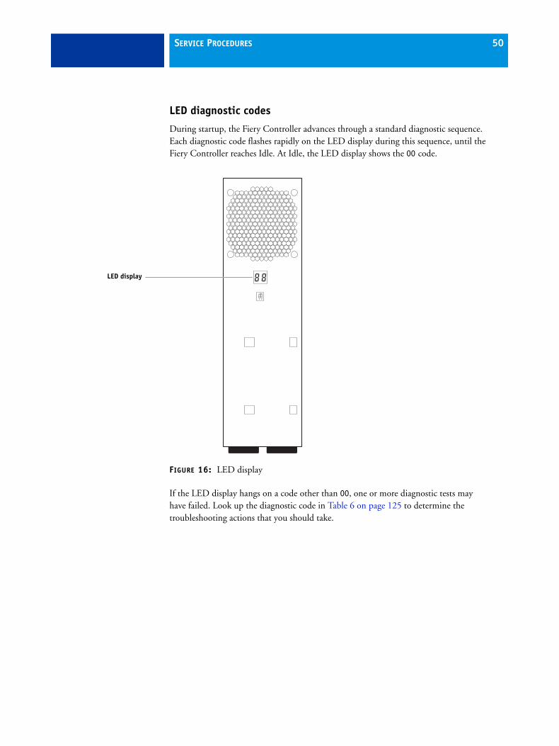
LED diagnostic codes
During startup, the Fiery Controller advances through a standard diagnostic sequence. Each diagnostic code flashes rapidly on the LED display during this sequence, until the Fiery Controller reaches Idle. At Idle, the LED display shows the 00 code.
FIGURE 16: LED display
If the LED display hangs on a code other than 00, one or more diagnostic tests may have failed. Look up the diagnostic code in Table 6 on page 125 to determine the troubleshooting actions that you should take.
LED display
SERVICE PROCEDURES 51
Accessing the Fiery ControllerAlways use the following procedure to disconnect the Fiery Controller from the printer and open the unit for inspection and service.
Make sure that you attach an ESD grounding wrist strap and follow standard ESD (electrostatic discharge) precautions before following this procedure. For details, see “Precautions” on page 12.
TO ACCESS THE FIERY CONTROLLER
1. Make sure that the Fiery Controller is not receiving, processing, or printing any jobs.
2. Shut down the Fiery Controller (see page 46).
3. Make sure that the Fiery Controller has powered off completely, and then move the power switch to OFF (O) position.
4. Make sure that the printer is not in use, and power off the printer using the main power switch on the front.
Wait for the printer to power off completely.
5. Remove all external cables from the Fiery Controller connectors.
6. Remove the Fiery Controller from its support stand and place the Fiery Controller on an antistatic surface.
SERVICE PROCEDURES 52
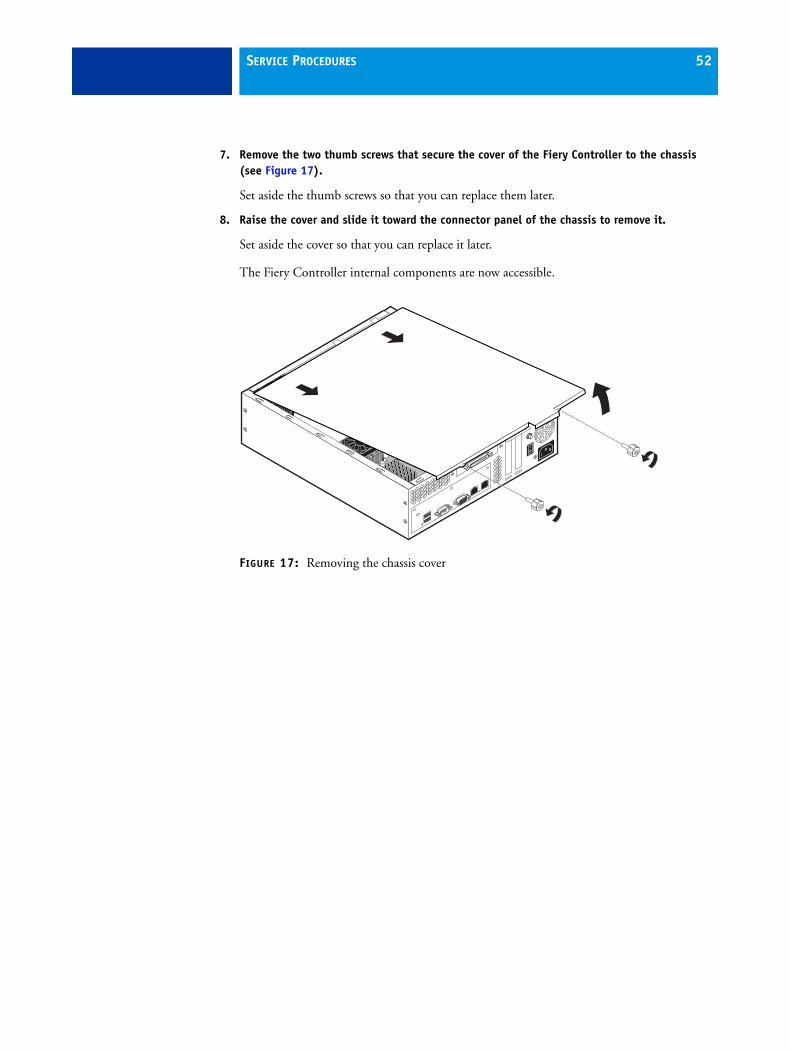
7. Remove the two thumb screws that secure the cover of the Fiery Controller to the chassis (see Figure 17).
Set aside the thumb screws so that you can replace them later.
8. Raise the cover and slide it toward the connector panel of the chassis to remove it.
Set aside the cover so that you can replace it later.
The Fiery Controller internal components are now accessible.
FIGURE 17: Removing the chassis cover
SERVICE PROCEDURES 53
Checking Fiery Controller internal connections
The most common causes of problems are faulty and loose connections. Before you conclude that any internal component has failed, remove, inspect, and reseat all appropriate connections, and then verify that the problem still occurs.
Before you touch any parts inside the Fiery Controller, attach a grounding wrist strap. Touching the chassis also discharges static electricity.
TO CHECK CABLE CONNECTIONS
1. Access and open the Fiery Controller (see page 51).
2. Place the Fiery Controller on a flat surface so that internal components are facing up.
3. Make sure that the battery is properly installed (see page 59).
4. Inspect the HDD data cable to make sure that it is intact and connected to the SATA0 connector on the motherboard (see page 62).
NOTE: The Fiery Controller will not boot up if the HDD data cable is connected to any other SATA connector on the motherboard.
Faulty data cables are easily overlooked. Check the contact point between the cable and the connector to ensure that they have not separated. If a data cable is suspect, substitute it with a tested cable.
5. Check the fan cables of the chassis fan and CPU fan.
Make sure that the cables are intact.
SERVICE PROCEDURES 54
6. Check the service board cable.
Make sure that the cable is intact and properly connected to the service board and the motherboard. For more information, see page 78.
7. Make sure that the internal power cables are intact and properly connected to the power supply, HDD, motherboard, and Fiery Controller power switch.
Make sure that the black and white wires are properly connected to the correct leads on the Fiery Controller power switch. For more information, see Figure 35 on page 85.
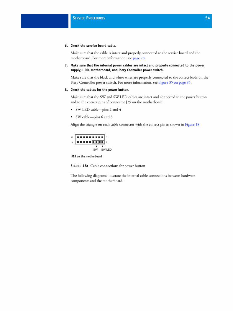
8. Check the cables for the power button.
Make sure that the SW and SW LED cables are intact and connected to the power button and to the correct pins of connector J25 on the motherboard:
• SW LED cable—pins 2 and 4
• SW cable—pins 6 and 8
Align the triangle on each cable connector with the correct pin as shown in Figure 18.
FIGURE 18: Cable connections for power button
The following diagrams illustrate the internal cable connections between hardware components and the motherboard.
18
17
2
1
SW SW LED
J25 on the motherboard

SERVICE PROCEDURES 55
FIGURE 19: Fiery Controller internal cable connections
Cable key From To
1. CPU fan cable CPU fan FAN1 connector on motherboard
2. Chassis fan cable Chassis fan FAN3 connector on motherboard
3. Service board cable Service board connector J26 connector on motherboard
4. HDD data cable HDD data connector SATA0 on motherboard
5. Power supply cables Power supply a. SATA power connector—HDD
b. 4-pin (2x2) connector— PW2 on motherboard
c. 20-pin (2x10) connector— PW1 on motherboard
6. Power button cables Power button a. SW cable—J25 (pins 6 and 8)
b. SW LED cable—J25 (pins 2 and 4)(For details, see Figure 18 on page 54.)
HDD
3
5a
6
2CPU fan
Power supply
Chassis fan
5b
5c
4
1
SERVICE PROCEDURES 56
Removing and replacing Fiery Controller componentsBefore deciding to replace costly components, be sure to verify the connections between the printer and the Fiery Controller. Also, verify the connections of each replaceable Fiery Controller component. For more information about troubleshooting, see Troubleshooting.
The following sections describe how to remove and install replaceable parts on the Fiery Controller:
• DIMM(s)
• Battery
• Motherboard
• CPU and CPU cooling assembly
• Service board
• Chassis fan
• Power supply
• Power button
• Hard disk drive (HDD)
For information about replacing other components, see the printer manufacturer’s documentation.
Be sure to use an ESD grounding wrist strap and follow standard ESD (electrostatic discharge) precautions while performing these procedures. For details, see “Precautions” on page 12.
SERVICE PROCEDURES 57
DIMM(s)
Each DIMM (dual in-line memory module) is held in place by levers at each end of the DIMM socket. The motherboard contains two DIMM sockets (DIMM1 and DIMM2).
The standard memory configuration is one 512MB DIMM installed in socket DIMM2. The memory capacity is 1GB. To upgrade the memory, install a second 512MB DIMM in socket DIMM1.
When installing DIMMs of different capacities, be sure to install the lower-capacity DIMM in socket DIMM2. Approved DIMMs are available from your authorized service/support center.
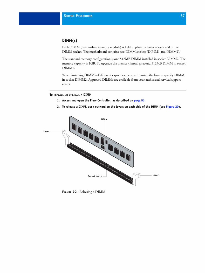
TO REPLACE OR UPGRADE A DIMM
1. Access and open the Fiery Controller, as described on page 51.
2. To release a DIMM, push outward on the levers on each side of the DIMM (see Figure 20).
FIGURE 20: Releasing a DIMM
DIMM
Lever
LeverSocket notch
SERVICE PROCEDURES 58
3. Lift the DIMM straight out of the socket.
4. To replace a DIMM, position the DIMM in the socket and press the DIMM straight down into the socket, so that the levers lock the DIMM into place (see Figure 20 on page 57).
NOTE: DIMMs fit in the socket only one way. The notch on the bottom of each DIMM should line up with the notch in the socket.
Make sure that the levers close securely around the ends of the DIMM and each DIMM is fully seated in its socket.
NOTE: For a single-DIMM configuration, you must install the DIMM in socket DIMM2. Installing the single DIMM in socket DIMM1 is incorrect and can cause problems with system performance.
5. If you installed a new or additional DIMM, clear the CMOS (see page 60).
Clear the CMOS after installing a new or additional DIMM to ensure compatibility between the new component and previous settings stored in the BIOS.
NOTE: Be sure to remove the power cable from the Fiery Controller before clearing the CMOS.
• Remove the battery (see page 60).
• Wait two minutes to allow the motherboard electrical components to fully discharge.
• Reinstall the battery (see page 60).
6. Reassemble the Fiery Controller and verify its functionality (see page 93).
7. If you installed a new DIMM and cleared the CMOS, configure the time and date in Setup.
For more information, see Configuration and Setup on the User Documentation CD.
SERVICE PROCEDURES 59
Motherboard
This section describes the battery, CMOS, and default jumper settings on the Fiery Controller motherboard, as well as procedures for removing and replacing the motherboard.
Battery
The battery is located on the motherboard. Spare batteries are not provided by your authorized service/support center. If you must replace the battery, use a 3V manganese dioxide lithium coin cell battery (Panasonic CR2032 or equivalent).
CAUTION: There is a danger of explosion if the battery is replaced with the incorrect type. Replace it only with the same type recommended by the manufacturer. Dispose of used batteries according to the manufacturer’s instructions.
ACHTUNG: Es besteht Explosionsgefahr, wenn die Batterie durch eine Batterie falschen Typs ersetzt wird. Als Ersatz dürfen nur vom Hersteller empfohlene Batterien gleichen oder ähnlichen Typs verwendet werden. Verbrauchte Batterien müssen entsprechend den Anweisungen des Herstellers entsorgt werden.
ATTENTION : Il y a risque d’explosion si la pile est remplacée par un modèle qui ne convient pas. Remplacez-la uniquement par le modèle recommandé par le constructeur. Débarrassez-vous des piles usées conformément aux instructions du constructeur.
ADVARSEL!: Lithiumbatteri - Eksplosionsfare ved fejlagtig håndtering Udskiftning må kun ske med bat-teri af samme fabrikat og type. Levér det brugte batteri tilbage til leverandøren.
VAROITUS: Paristo voi räjähtää, los se on virheellisesti asennettu. Vaihda paristo ainoastaan laitevalmistajan suosittelemaan tyyppiin. Hävitä Käytetty paristo valmistajan ohjeiden mukaisesti.
ADVARSEL: Eksplosjonsfare ved feilaktig skifte av batteri. Benytt samme batteritype eller en tilsvarende type anbefalt av apparatfabrikanten. Brukte batterier kasseres i henhold til fabrikantens instruksjoner.
VARNING: Explosionsfara vid felaktigt batteribyte. Använd samma batterityp eller en ekvivalent typ som rekommenderas av apparat-tillverkaren. Kassera använt batteri enligt fabrikantens instruktion.
SERVICE PROCEDURES 60
TO REPLACE THE BATTERY
1. Access and open the Fiery Controller as described on page 51.
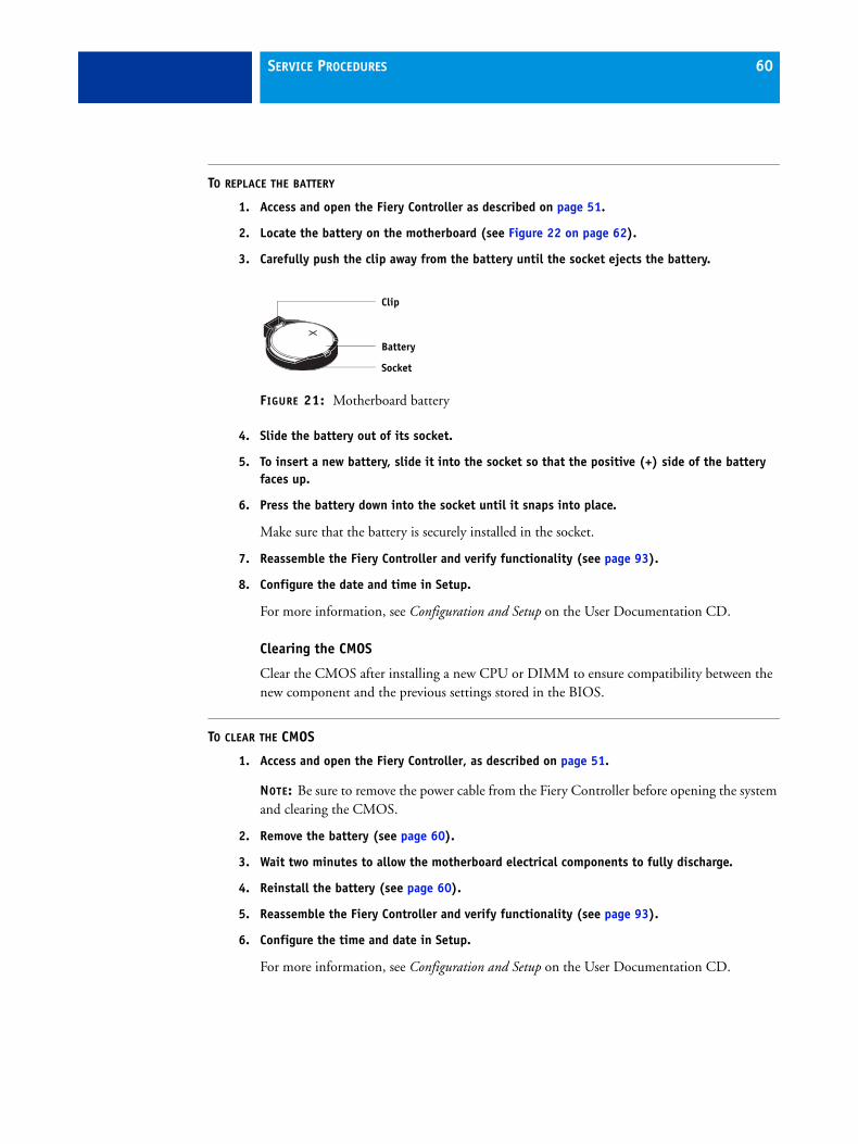
2. Locate the battery on the motherboard (see Figure 22 on page 62).
3. Carefully push the clip away from the battery until the socket ejects the battery.
FIGURE 21: Motherboard battery
4. Slide the battery out of its socket.
5. To insert a new battery, slide it into the socket so that the positive (+) side of the battery faces up.
6. Press the battery down into the socket until it snaps into place.
Make sure that the battery is securely installed in the socket.
7. Reassemble the Fiery Controller and verify functionality (see page 93).
8. Configure the date and time in Setup.
For more information, see Configuration and Setup on the User Documentation CD.
Clearing the CMOS
Clear the CMOS after installing a new CPU or DIMM to ensure compatibility between the new component and the previous settings stored in the BIOS.
TO CLEAR THE CMOS
1. Access and open the Fiery Controller, as described on page 51.
NOTE: Be sure to remove the power cable from the Fiery Controller before opening the system and clearing the CMOS.
2. Remove the battery (see page 60).
3. Wait two minutes to allow the motherboard electrical components to fully discharge.
4. Reinstall the battery (see page 60).
5. Reassemble the Fiery Controller and verify functionality (see page 93).
6. Configure the time and date in Setup.
For more information, see Configuration and Setup on the User Documentation CD.
Battery
Socket
Clip
SERVICE PROCEDURES 61
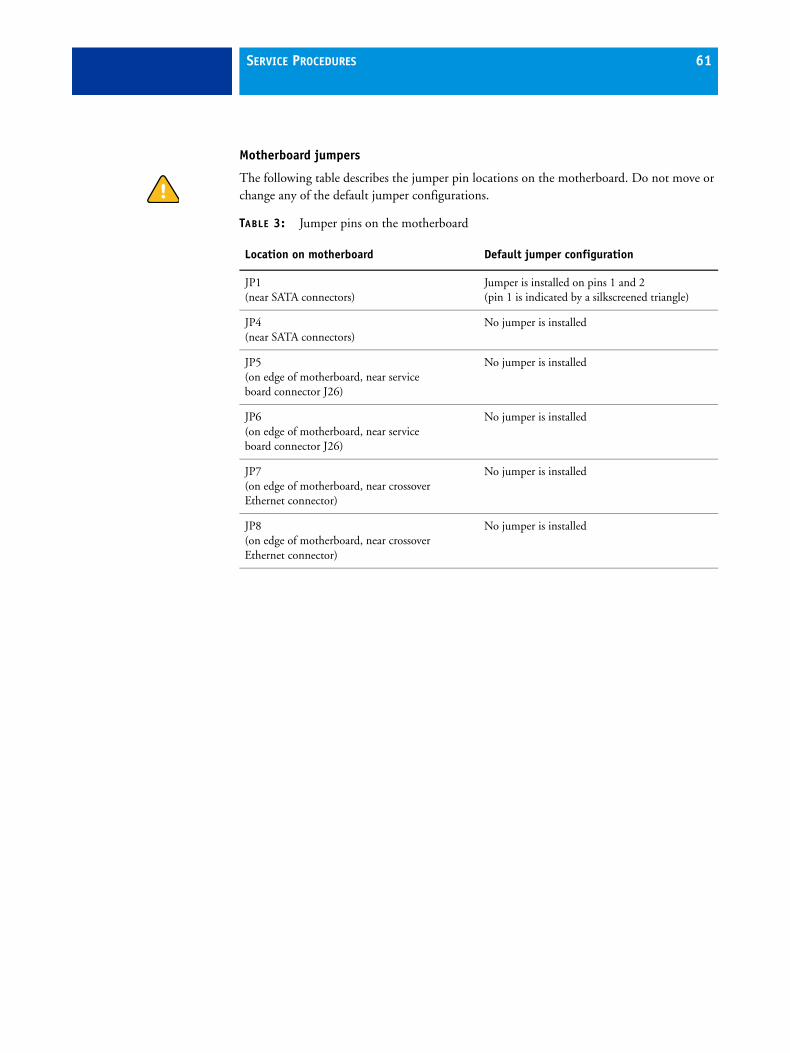
Motherboard jumpers
The following table describes the jumper pin locations on the motherboard. Do not move or change any of the default jumper configurations.
TABLE 3: Jumper pins on the motherboard
Location on motherboard Default jumper configuration
JP1 (near SATA connectors)
Jumper is installed on pins 1 and 2(pin 1 is indicated by a silkscreened triangle)
JP4 (near SATA connectors)
No jumper is installed
JP5 (on edge of motherboard, near service board connector J26)
No jumper is installed
JP6(on edge of motherboard, near service board connector J26)
No jumper is installed
JP7 (on edge of motherboard, near crossover Ethernet connector)
No jumper is installed
JP8 (on edge of motherboard, near crossover Ethernet connector)
No jumper is installed
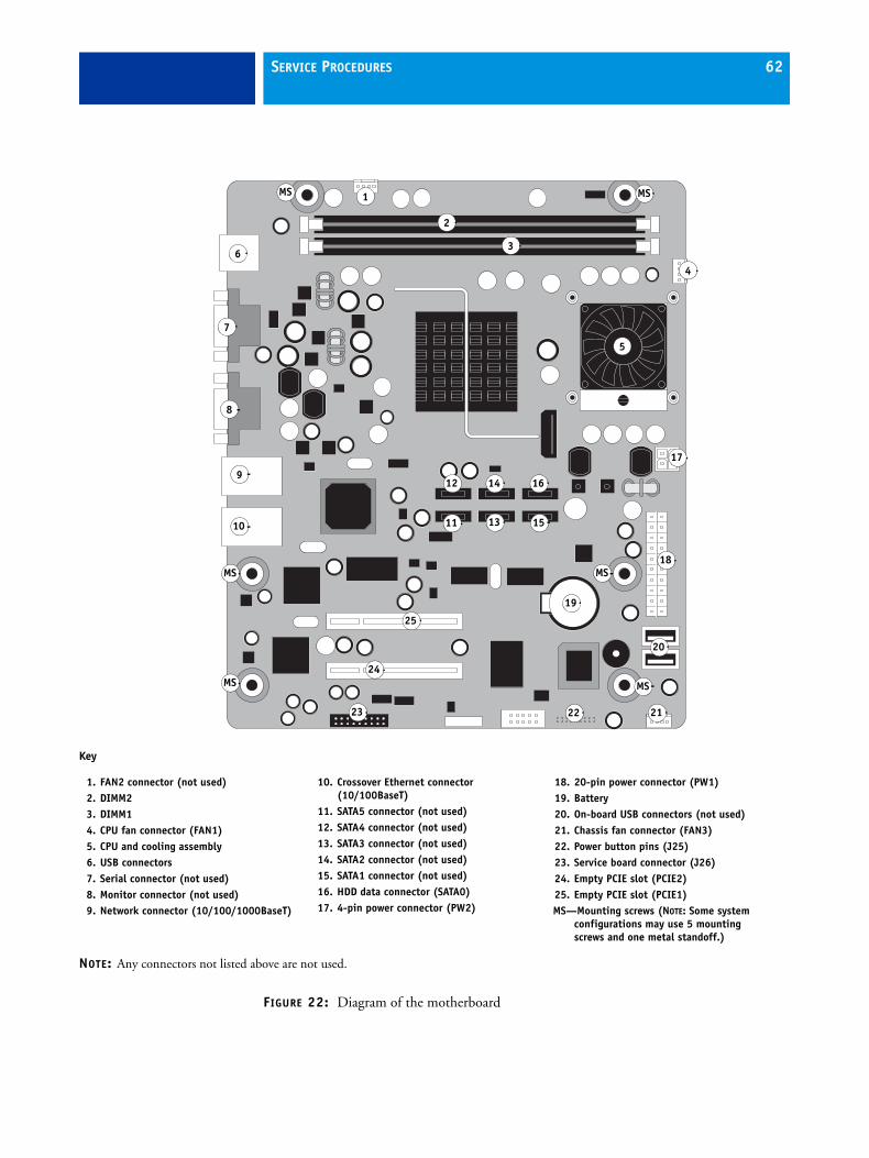
SERVICE PROCEDURES 62
FIGURE 22: Diagram of the motherboard
1
2
4
7
14
15
16
17
19
2122
18
23
25
24
MS
MS
6
MS
MS
3
11
20
10
5
MS
9
8
MS
12
13
Key
1. FAN2 connector (not used)2. DIMM23. DIMM14. CPU fan connector (FAN1)5. CPU and cooling assembly6. USB connectors7. Serial connector (not used)8. Monitor connector (not used)9. Network connector (10/100/1000BaseT)
10. Crossover Ethernet connector(10/100BaseT)
11. SATA5 connector (not used)12. SATA4 connector (not used)13. SATA3 connector (not used)14. SATA2 connector (not used)15. SATA1 connector (not used)16. HDD data connector (SATA0)17. 4-pin power connector (PW2)
18. 20-pin power connector (PW1)19. Battery20. On-board USB connectors (not used)21. Chassis fan connector (FAN3)22. Power button pins (J25)23. Service board connector (J26)24. Empty PCIE slot (PCIE2)25. Empty PCIE slot (PCIE1)MS—Mounting screws (NOTE: Some system
configurations may use 5 mounting screws and one metal standoff.)
NOTE: Any connectors not listed above are not used.
SERVICE PROCEDURES 63
Requirements for a new motherboard installation
To install a new motherboard, you need the following items:
• New motherboard
• Single-use dongle [provided with new motherboard]
• Feature Activation USB Drive [provided with new motherboard]
Cautions for a new motherboard installation
If you are installing a new motherboard:
• Follow standard ESD and other safety precautions when handling the motherboard. If you must remove the motherboard during service, place it on a grounded, anti-static surface.
• Transfer the DIMM(s) and CPU from the old motherboard. Spare motherboards ship with replacement thermal compound for use when transferring the CPU.
• Make sure that the new motherboard solves the problem you are troubleshooting before you update the system. Updating the system permanently customizes the new motherboard so that it cannot be returned to inventory and cannot be installed in another Fiery Controller. If the new motherboard does not solve the problem, do not update the system. Return the new motherboard and unused single-use dongle to inventory.
• Do not reinstall system software. Reinstalling system software is not necessary when installing a new motherboard and can result in an error if done before performing the system update.
• BIOS chips are not interchangeable. Do not transfer the BIOS chip from the old motherboard onto the new motherboard. Doing so can damage the Fiery Controller.
• Do not install a new HDD at the same time that you install a new motherboard.
It is unlikely that both the HDD and the motherboard are defective; therefore, avoid replacing both to solve one problem. If troubleshooting strategies (checking cables and connections, and so forth) do not resolve the problem and you suspect either the HDD or the motherboard is at fault, use the following order: replace the HDD; install system software; verify the problem still exists; and then move on to other procedures, such as replacing the motherboard. Otherwise, you may need to return the Fiery Controller.
• Do update the system using the single-use dongle and the Feature Activation USB drive.
SERVICE PROCEDURES 64
Removing the motherboard
Before you remove the motherboard, you must remove all cables connected from other components to the motherboard. These include both motherboard power cables, chassis fan cable, HDD data cable, power button cables, and service board cable.
If you are removing the motherboard in order to replace it with a new motherboard, observe the following guidelines:
• Replacement kits include a motherboard, as well as a service board and service board cable. When replacing the motherboard, you also have the option to replace the service board and cable; however, replacement of the service board and cable is not required.
• Be sure to return all old components to your authorized service/support center.
Follow standard ESD precautions while handling the motherboard and all components. For details, see “Precautions” on page 12.
TO REMOVE MOTHERBOARD COMPONENTS FROM THE MOTHERBOARD
1. Access and open the Fiery Controller, as described on page 51.
2. Remove the following cables attached to the motherboard:
• Chassis fan cable
• HDD data cable
• 4-pin power cable
• 20-pin power cable
• Service board cable
• SW and SW LED cables for power button
For the location of each connector on the motherboard, see Figure 19 on page 55.
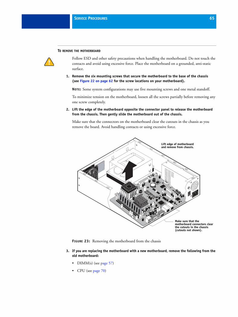
SERVICE PROCEDURES 65
TO REMOVE THE MOTHERBOARD
Follow ESD and other safety precautions when handling the motherboard. Do not touch the contacts and avoid using excessive force. Place the motherboard on a grounded, anti-static surface.
1. Remove the six mounting screws that secure the motherboard to the base of the chassis (see Figure 22 on page 62 for the screw locations on your motherboard).
NOTE: Some system configurations may use five mounting screws and one metal standoff.
To minimize tension on the motherboard, loosen all the screws partially before removing any one screw completely.
2. Lift the edge of the motherboard opposite the connector panel to release the motherboard from the chassis. Then gently slide the motherboard out of the chassis.
Make sure that the connectors on the motherboard clear the cutouts in the chassis as you remove the board. Avoid handling contacts or using excessive force.
FIGURE 23: Removing the motherboard from the chassis
3. If you are replacing the motherboard with a new motherboard, remove the following from the old motherboard:
• DIMM(s) (see page 57)
• CPU (see page 70)
Lift edge of motherboard and remove from chassis.
Make sure that the motherboard connectors clear the cutouts in the chassis (cutouts not shown).
SERVICE PROCEDURES 66
Replacing the motherboard
Use the following procedure to install the motherboard in the Fiery Controller chassis.
If you are replacing an old motherboard with a new motherboard, you will need to verify functionality and update the system after installing the new motherboard.
TO REPLACE THE MOTHERBOARD
1. If you are installing a new motherboard, install the DIMM(s) and CPU from the old motherboard onto the new motherboard. For DIMM(s), see page 57; for the CPU, see page 70.
Make sure that the motherboard is placed on an antistatic surface with some padding.
Do not transfer the BIOS chip from the old motherboard onto the new motherboard. Doing so can cause the system to shut down due to incompatibility issues.
2. Angle the motherboard so that the connectors on the motherboard fit into the cutouts in the connector panel of the chassis, and gently slide the motherboard into the chassis (see Figure 23 on page 65).
As you slide the motherboard into position, be sure to fit the Ethernet connectors under the metal grounding tabs in the cutouts.
NOTE: Failure to position the grounding tabs correctly may result in permanent damage to the motherboard and power supply.
3. Align the mounting holes on the motherboard with the screw holes located in the base of the chassis (see Figure 22 on page 62 for the mounting hole locations).
4. Insert the six mounting screws that attach the motherboard to the chassis.
NOTE: Some system configurations may use five mounting screws and one metal standoff.
Partially tighten each screw before completely tightening any one screw. Do not overtighten the screws; doing so could damage traces on the motherboard.
Now you are ready to replace motherboard components.

SERVICE PROCEDURES 67
TO REPLACE MOTHERBOARD COMPONENTS
1. Replace the following cables to the motherboard:
• Power button cables (J25)
Be sure to connect each cable to the correct pins on J25:
– SW LED cable—pins 2 and 4
– SW cable—pins 6 and 8
Align the triangle on each cable connector with the correct pin as shown in Figure 24.
FIGURE 24: Motherboard connections for power button cables
• Service board cable (J26)
• 20-pin power cable (PW1)
• 4-pin power cable (PW2)
• HDD data cable (SATA0)
• Chassis fan cable (FAN3)
For the location of each connector on the motherboard, see Figure 19 on page 55.
2. Reassemble the Fiery Controller (see page 93).
Verifying the functionality of a new motherboard installation
NOTE: Before proceeding with this section, make sure that you have all the required components, as described on page 63.
After you install a new motherboard and reassemble the system, you must verify functionality by using the single-use dongle to enter Service Mode. Verify the motherboard functionality before updating the system; do not update the system prematurely.
Entering Service Mode allows you to make sure that the new motherboard solves the problem you are troubleshooting. Service Mode is a temporary state that allows you to test the motherboard, and is indicated by code 90 on the LED display. Service Mode is exited automatically when you expend the single-use dongle to update the system.
18
17
2
1
SW SW LED
J25 on the motherboard
SERVICE PROCEDURES 68
TO ENTER SERVICE MODE AND VERIFY THE SYSTEM
NOTE: This procedure assumes you have installed a new motherboard and reassembled the Fiery Controller.
1. Verify the following:
• All external cables for the Fiery Controller have been reconnected.
• The service switches are set for normal operation (both away from “ON”).
• The Fiery Controller and printer are powered off.
2. Unpack the single-use dongle included with the new motherboard and connect it to any available USB port on the Fiery Controller (see Figure 5 on page 25).
3. Power on the Fiery Controller by moving its power switch to ON position (|). If the Fiery Controller does not start up after a few seconds, firmly press the power button once and release.
NOTE: During Service Mode, code 90 appears on the Fiery Controller LED display.
4. Power on the printer using the main power switch on the front.
5. Verify that the Fiery Controller Start page prints automatically after the Fiery Controller and printer start up.
6. Connect the Fiery Controller to the network (see page 43), and ask the site administrator to print a few test documents from a networked computer that will use the Fiery Controller (see Configuration and Setup on the User Documentation CD).
If the problem you are troubleshooting persists, or if you are unable to perform steps 5 and 6 above while in Service Mode, the new motherboard has not solved the problem you are troubleshooting. If this is the case, do not update the system, and do not attempt any other troubleshooting procedures yet (such as reinstalling system software or replacing the HDD). Reinstall the old motherboard and return the new motherboard with the unused single-use dongle to inventory. You may then perform additional service and troubleshooting procedures.
If the Fiery Controller is able to print a Test Page and a print job sent over the network, you may conclude that the new motherboard solves the problem you are troubleshooting.
7. Power off the Fiery Controller by pressing and holding down the power button for 5 seconds.
You may now proceed to update the system.
SERVICE PROCEDURES 69
Updating the system
NOTE: Before proceeding with the system update, make sure that you have all the required components, as described on page 63.
If you concluded in Service Mode that the new motherboard solves the problem you are troubleshooting, you must update the system.
If you concluded in Service Mode that the new motherboard does not solve the problem you are troubleshooting, do not update the system (described below), and do not attempt any other troubleshooting procedures (such as reinstalling system software or replacing the HDD). Reinstall the old motherboard and return the new motherboard with the unused single-use dongle to inventory. You may then perform additional service and troubleshooting procedures.
After the system is updated, the new motherboard fully replaces the old motherboard and cannot be used in another system. The Fiery Controller remains enabled for any optional features that were available on the system prior to the motherboard replacement.
TO UPDATE THE SYSTEM
• Complete the procedure “To update the system for a software option or new motherboard installation” on page 95.
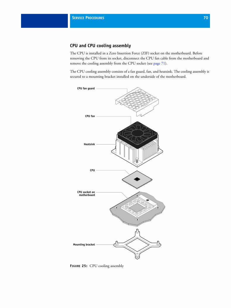
SERVICE PROCEDURES 70
CPU and CPU cooling assembly
The CPU is installed in a Zero Insertion Force (ZIF) socket on the motherboard. Before removing the CPU from its socket, disconnect the CPU fan cable from the motherboard and remove the cooling assembly from the CPU socket (see page 71).
The CPU cooling assembly consists of a fan guard, fan, and heatsink. The cooling assembly is secured to a mounting bracket installed on the underside of the motherboard.
FIGURE 25: CPU cooling assembly
CPU fan
Heatsink
Mounting bracket
CPU socket onmotherboard
CPU
CPU fan guard
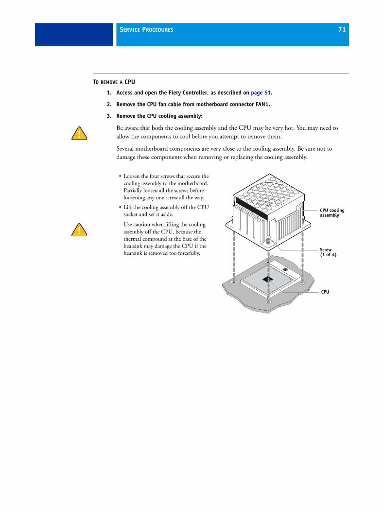
SERVICE PROCEDURES 71
TO REMOVE A CPU
1. Access and open the Fiery Controller, as described on page 51.
2. Remove the CPU fan cable from motherboard connector FAN1.
3. Remove the CPU cooling assembly:
Be aware that both the cooling assembly and the CPU may be very hot. You may need to allow the components to cool before you attempt to remove them.
Several motherboard components are very close to the cooling assembly. Be sure not to damage these components when removing or replacing the cooling assembly.
• Loosen the four screws that secure the cooling assembly to the motherboard. Partially loosen all the screws before loosening any one screw all the way.
• Lift the cooling assembly off the CPU socket and set it aside.
Use caution when lifting the cooling assembly off the CPU, because the thermal compound at the base of the heatsink may damage the CPU if the heatsink is removed too forcefully.
CPU cooling assembly
Screw(1 of 4)
CPU
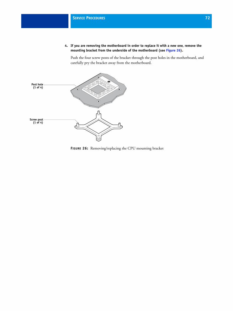
SERVICE PROCEDURES 72
4. If you are removing the motherboard in order to replace it with a new one, remove the mounting bracket from the underside of the motherboard (see Figure 26).
Push the four screw posts of the bracket through the post holes in the motherboard, and carefully pry the bracket away from the motherboard.
FIGURE 26: Removing/replacing the CPU mounting bracket
Screw post(1 of 4)
Post hole(1 of 4)
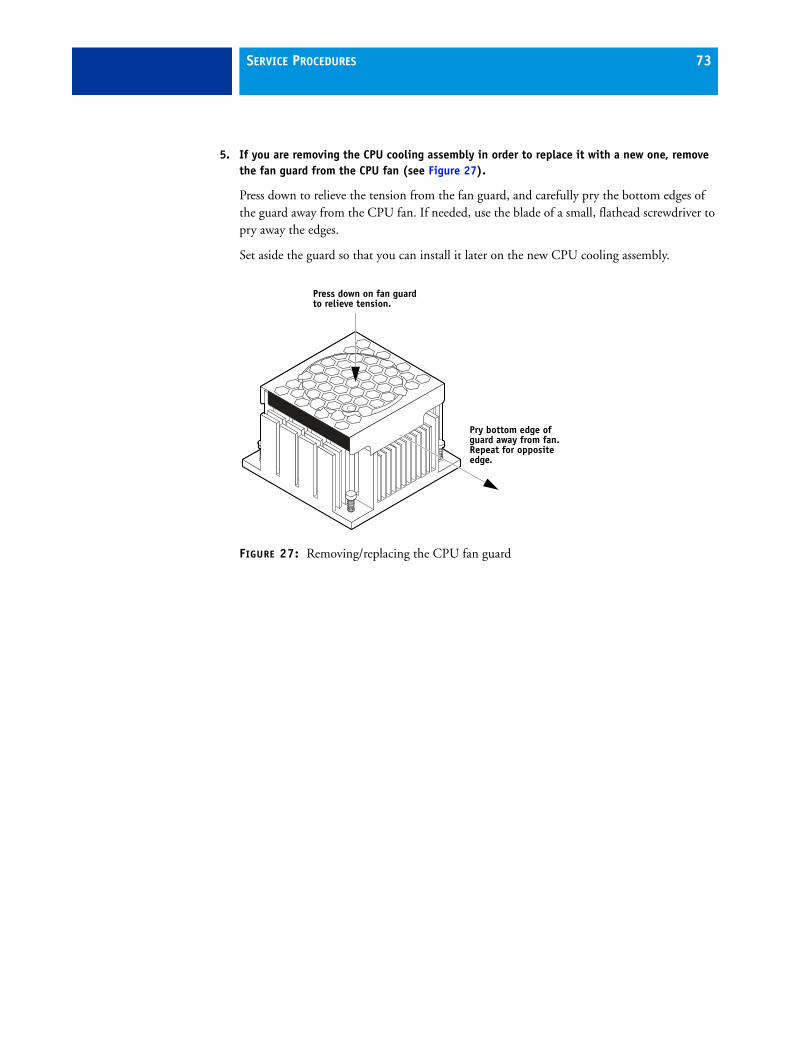
SERVICE PROCEDURES 73
5. If you are removing the CPU cooling assembly in order to replace it with a new one, remove the fan guard from the CPU fan (see Figure 27).
Press down to relieve the tension from the fan guard, and carefully pry the bottom edges of the guard away from the CPU fan. If needed, use the blade of a small, flathead screwdriver to pry away the edges.
Set aside the guard so that you can install it later on the new CPU cooling assembly.
FIGURE 27: Removing/replacing the CPU fan guard
Pry bottom edge of guard away from fan. Repeat for opposite edge.
Press down on fan guard to relieve tension.
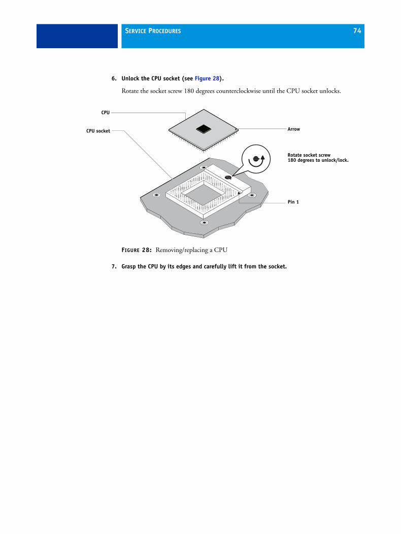
SERVICE PROCEDURES 74
6. Unlock the CPU socket (see Figure 28).
Rotate the socket screw 180 degrees counterclockwise until the CPU socket unlocks.
FIGURE 28: Removing/replacing a CPU
7. Grasp the CPU by its edges and carefully lift it from the socket.
CPU
ArrowCPU socket
Pin 1
Rotate socket screw 180 degrees to unlock/lock.

SERVICE PROCEDURES 75
TO REPLACE A CPU
1. Install the CPU in the CPU socket on the motherboard.
Make sure you align the arrow on the CPU with the arrow indicating pin 1 in the CPU socket (see Figure 28 on page 74).
2. Make sure that the CPU is correctly seated in the socket, and then lock the socket.
Rotate the socket screw 180 degrees clockwise to lock the socket.
3. Do one of the following:
• If you are installing a new CPU cooling assembly on an existing CPU, clean the contact surface of the CPU.
Be sure to remove all thermal compound residue from the surface of the CPU. It may help to scrape all the residue off the surface using the flat edge of a non-conductive tool. Then use a lint-free cloth moistened with alcohol to clean the surface.
• If you are installing the existing CPU and CPU cooling assembly on a new motherboard, clean the contact surfaces of the CPU and cooling assembly as described above. Then apply fresh thermal compound to the contact surface of the CPU using the applicator provided with the new motherboard.
4. If needed, install the CPU mounting bracket on the underside of the motherboard (see Figure 26 on page 72).
Push the four screw posts of the bracket into the four post poles in the motherboard.
5. If you are installing a new CPU cooling assembly, install the fan guard from the old cooling assembly.
Place the fan guard on top of the new CPU fan, and firmly press down until the bottom edges of the fan guard fasten around the fan.
6. If you are installing a new CPU cooling assembly, install the screws in the heatsink.
Insert each screw into a spring, and then insert the screw assembly into the heatsink. Turn the screw until the screw threads completely protrude through base of heatsink.
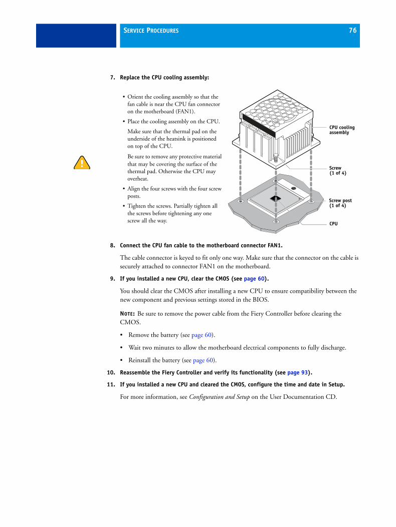
SERVICE PROCEDURES 76
7. Replace the CPU cooling assembly:
8. Connect the CPU fan cable to the motherboard connector FAN1.
The cable connector is keyed to fit only one way. Make sure that the connector on the cable is securely attached to connector FAN1 on the motherboard.
9. If you installed a new CPU, clear the CMOS (see page 60).
You should clear the CMOS after installing a new CPU to ensure compatibility between the new component and previous settings stored in the BIOS.
NOTE: Be sure to remove the power cable from the Fiery Controller before clearing the CMOS.
• Remove the battery (see page 60).
• Wait two minutes to allow the motherboard electrical components to fully discharge.
• Reinstall the battery (see page 60).
10. Reassemble the Fiery Controller and verify its functionality (see page 93).
11. If you installed a new CPU and cleared the CMOS, configure the time and date in Setup.
For more information, see Configuration and Setup on the User Documentation CD.
• Orient the cooling assembly so that the fan cable is near the CPU fan connector on the motherboard (FAN1).
• Place the cooling assembly on the CPU.
Make sure that the thermal pad on the underside of the heatsink is positioned on top of the CPU.
Be sure to remove any protective material that may be covering the surface of the thermal pad. Otherwise the CPU may overheat.
• Align the four screws with the four screw posts.
• Tighten the screws. Partially tighten all the screws before tightening any one screw all the way.
CPU cooling assembly
Screw(1 of 4)
CPU
Screw post(1 of 4)
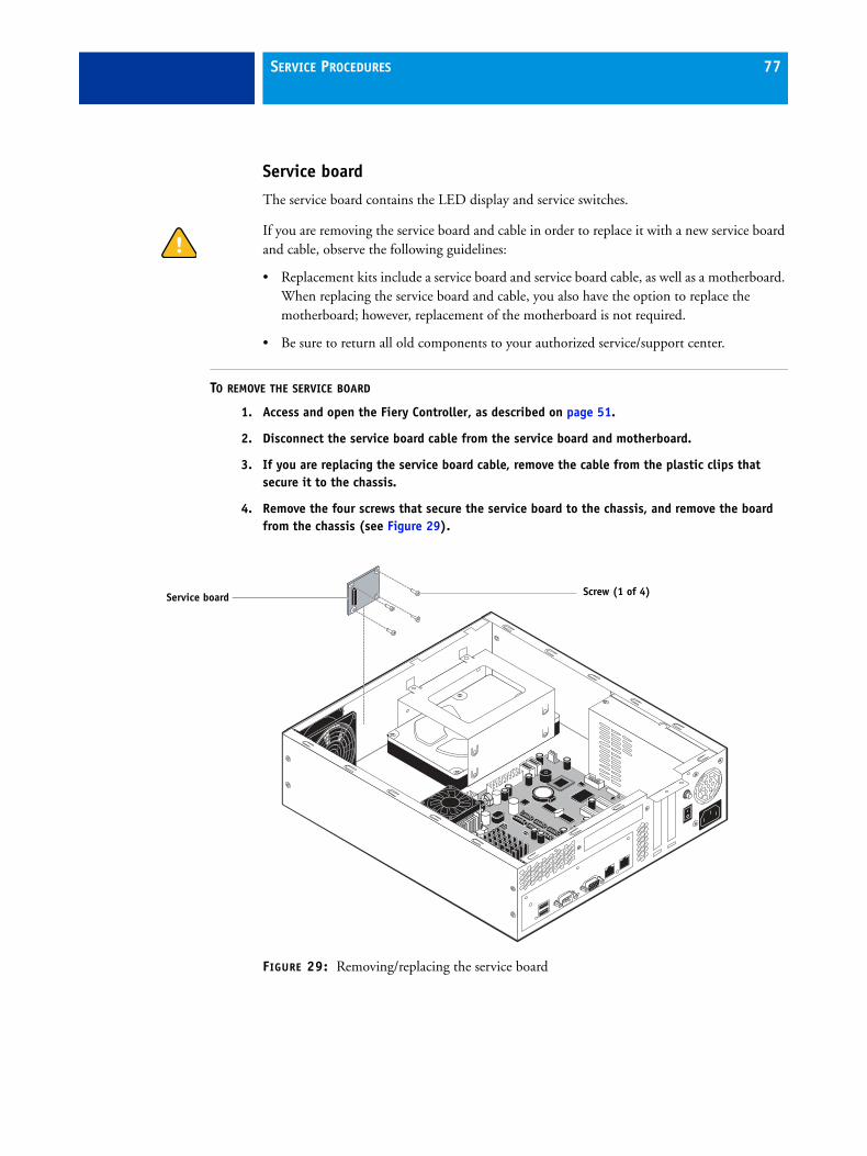
SERVICE PROCEDURES 77
Service board
The service board contains the LED display and service switches.
If you are removing the service board and cable in order to replace it with a new service board and cable, observe the following guidelines:
• Replacement kits include a service board and service board cable, as well as a motherboard. When replacing the service board and cable, you also have the option to replace the motherboard; however, replacement of the motherboard is not required.
• Be sure to return all old components to your authorized service/support center.
TO REMOVE THE SERVICE BOARD
1. Access and open the Fiery Controller, as described on page 51.
2. Disconnect the service board cable from the service board and motherboard.
3. If you are replacing the service board cable, remove the cable from the plastic clips that secure it to the chassis.
4. Remove the four screws that secure the service board to the chassis, and remove the board from the chassis (see Figure 29).
FIGURE 29: Removing/replacing the service board
Service board Screw (1 of 4)
SERVICE PROCEDURES 78
TO REPLACE THE SERVICE BOARD
1. If you are replacing the old service board with a new one, unpack the new board and cable.
2. Position the new service board inside the chassis, fitting the LED display and service switches through the cutouts in the chassis.
3. Secure the service board to the chassis using the four screws that you removed earlier (see Figure 29 on page 77).
4. Connect the service board cable to the connector on the service board.
The cable is keyed to fit in the connector only one way.
5. Route the cable through the two plastic clips on base of the chassis.
6. Connect the free end of the service board cable to connector J26 on the motherboard.
The cable is keyed to fit in the connector only one way.
7. Make sure that the service switches are set to the OFF position (both switches are away from “ON”).
8. Reassemble the Fiery Controller and verify its functionality (see page 93).
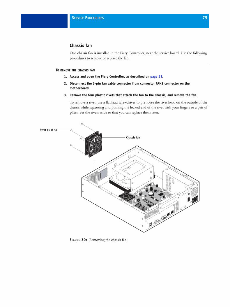
SERVICE PROCEDURES 79
Chassis fan
One chassis fan is installed in the Fiery Controller, near the service board. Use the following procedures to remove or replace the fan.
TO REMOVE THE CHASSIS FAN
1. Access and open the Fiery Controller, as described on page 51.
2. Disconnect the 3-pin fan cable connector from connector FAN3 connector on the motherboard.
3. Remove the four plastic rivets that attach the fan to the chassis, and remove the fan.
To remove a rivet, use a flathead screwdriver to pry loose the rivet head on the outside of the chassis while squeezing and pushing the locked end of the rivet with your fingers or a pair of pliers. Set the rivets aside so that you can replace them later.
FIGURE 30: Removing the chassis fan
Chassis fan
Rivet (1 of 4)
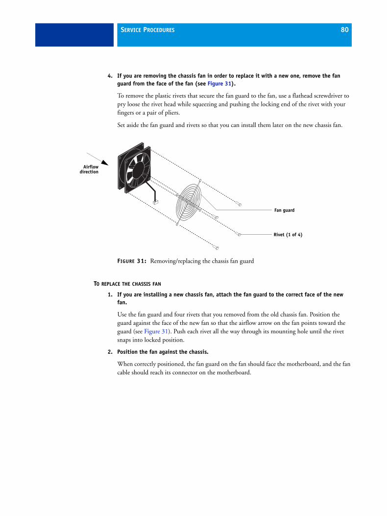
SERVICE PROCEDURES 80
4. If you are removing the chassis fan in order to replace it with a new one, remove the fan guard from the face of the fan (see Figure 31).
To remove the plastic rivets that secure the fan guard to the fan, use a flathead screwdriver to pry loose the rivet head while squeezing and pushing the locking end of the rivet with your fingers or a pair of pliers.
Set aside the fan guard and rivets so that you can install them later on the new chassis fan.
FIGURE 31: Removing/replacing the chassis fan guard
TO REPLACE THE CHASSIS FAN
1. If you are installing a new chassis fan, attach the fan guard to the correct face of the new fan.
Use the fan guard and four rivets that you removed from the old chassis fan. Position the guard against the face of the new fan so that the airflow arrow on the fan points toward the guard (see Figure 31). Push each rivet all the way through its mounting hole until the rivet snaps into locked position.
2. Position the fan against the chassis.
When correctly positioned, the fan guard on the fan should face the motherboard, and the fan cable should reach its connector on the motherboard.
Fan guard
Rivet (1 of 4)
Airflowdirection
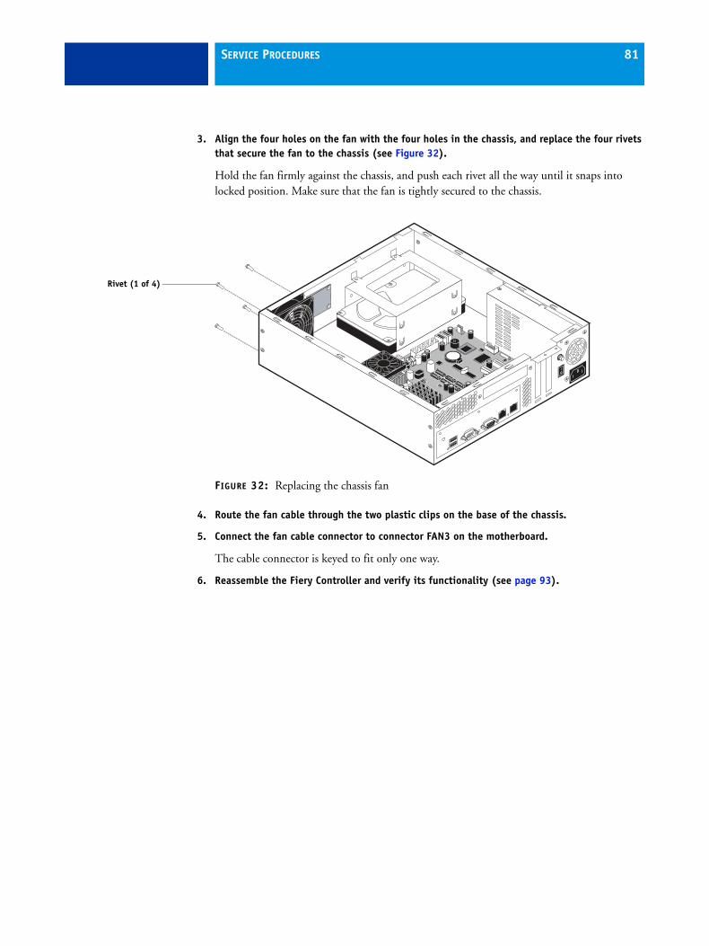
SERVICE PROCEDURES 81
3. Align the four holes on the fan with the four holes in the chassis, and replace the four rivets that secure the fan to the chassis (see Figure 32).
Hold the fan firmly against the chassis, and push each rivet all the way until it snaps into locked position. Make sure that the fan is tightly secured to the chassis.
FIGURE 32: Replacing the chassis fan
4. Route the fan cable through the two plastic clips on the base of the chassis.
5. Connect the fan cable connector to connector FAN3 on the motherboard.
The cable connector is keyed to fit only one way.
6. Reassemble the Fiery Controller and verify its functionality (see page 93).
Rivet (1 of 4)
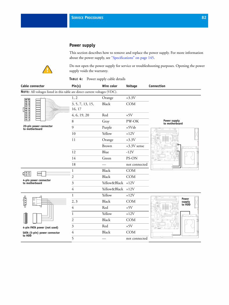
SERVICE PROCEDURES 82
Power supply
This section describes how to remove and replace the power supply. For more information about the power supply, see “Specifications” on page 145.
Do not open the power supply for service or troubleshooting purposes. Opening the power supply voids the warranty.
TABLE 4: Power supply cable details
Cable connector Pin(s) Wire color Voltage Connection
NOTE: All voltages listed in this table are direct current voltages (VDC).
1, 2 Orange +3.3V
3, 5, 7, 13, 15, 16, 17
Black COM
4, 6, 19, 20 Red +5V
8 Gray PW-OK
9 Purple +5Vsb
10 Yellow +12V
11 Orange +3.3V
Brown +3.3V sense
12 Blue -12V
14 Green PS-ON
18 — not connected
1 Black COM
2 Black COM
3 Yellow&Black +12V
4 Yellow&Black +12V
1 Yellow +12V
2, 3 Black COM
4 Red +5V
1 Yellow +12V
2 Black COM
3 Red +5V
4 Black COM
5 — not connected
10
9
8
7
6
5
4
3
2
1
20
19
18
17
16
15
14
13
12
11
P1
20-pin power connectorto motherboard
Power supply to motherboard
2
1
4
3
4-pin power connectorto motherboard
4-pin PATA power (not used)
SATA (5-pin) power connectorto HDD
Power supply to HDD
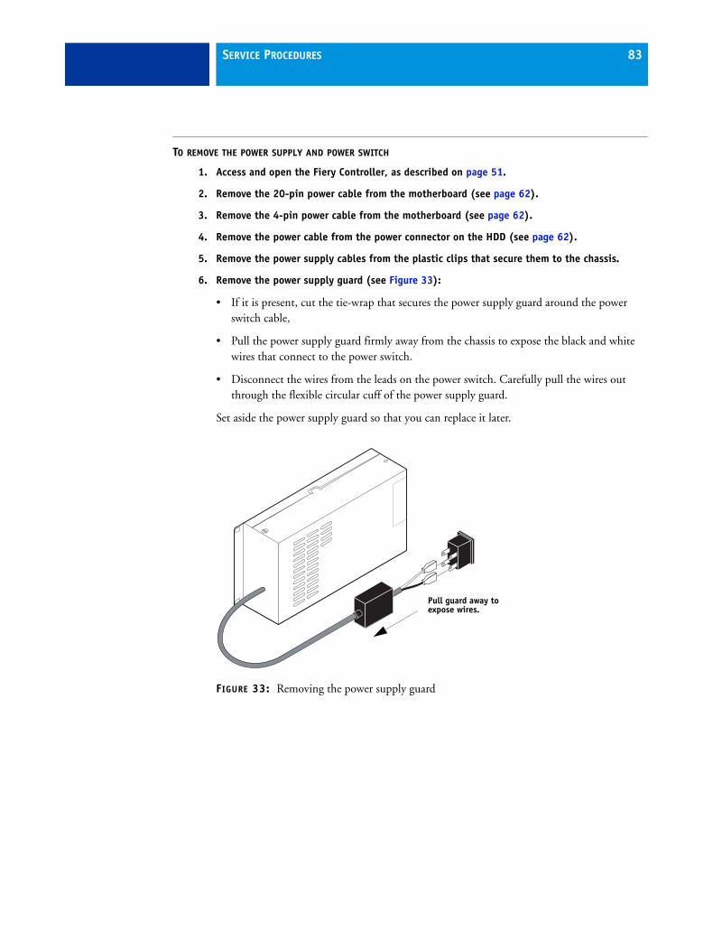
SERVICE PROCEDURES 83
TO REMOVE THE POWER SUPPLY AND POWER SWITCH
1. Access and open the Fiery Controller, as described on page 51.
2. Remove the 20-pin power cable from the motherboard (see page 62).
3. Remove the 4-pin power cable from the motherboard (see page 62).
4. Remove the power cable from the power connector on the HDD (see page 62).
5. Remove the power supply cables from the plastic clips that secure them to the chassis.
6. Remove the power supply guard (see Figure 33):
• If it is present, cut the tie-wrap that secures the power supply guard around the power switch cable,
• Pull the power supply guard firmly away from the chassis to expose the black and white wires that connect to the power switch.
• Disconnect the wires from the leads on the power switch. Carefully pull the wires out through the flexible circular cuff of the power supply guard.
Set aside the power supply guard so that you can replace it later.
FIGURE 33: Removing the power supply guard
Pull guard away to expose wires.
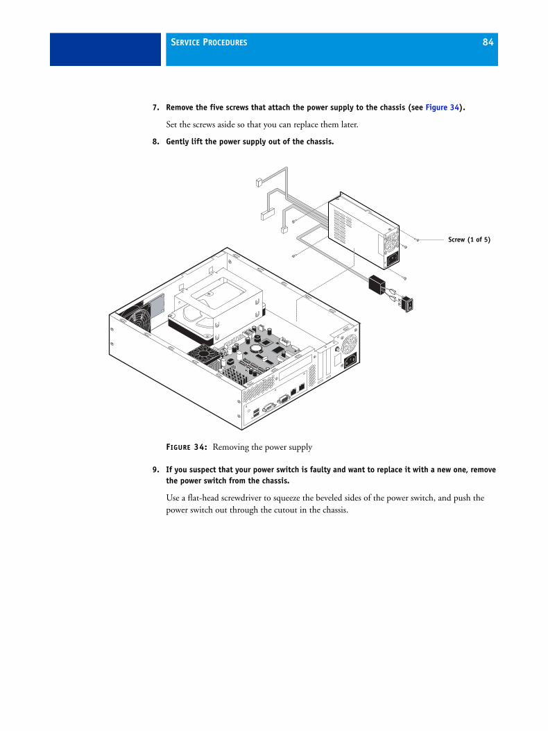
SERVICE PROCEDURES 84
7. Remove the five screws that attach the power supply to the chassis (see Figure 34).
Set the screws aside so that you can replace them later.
8. Gently lift the power supply out of the chassis.
FIGURE 34: Removing the power supply
9. If you suspect that your power switch is faulty and want to replace it with a new one, remove the power switch from the chassis.
Use a flat-head screwdriver to squeeze the beveled sides of the power switch, and push the power switch out through the cutout in the chassis.
Screw (1 of 5)
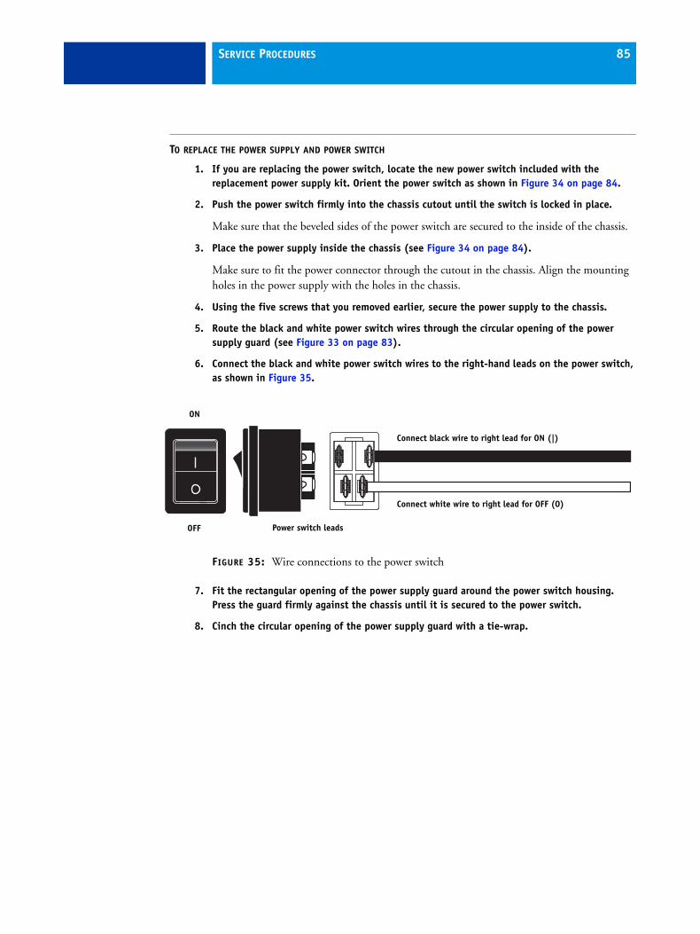
SERVICE PROCEDURES 85
TO REPLACE THE POWER SUPPLY AND POWER SWITCH
1. If you are replacing the power switch, locate the new power switch included with the replacement power supply kit. Orient the power switch as shown in Figure 34 on page 84.
2. Push the power switch firmly into the chassis cutout until the switch is locked in place.
Make sure that the beveled sides of the power switch are secured to the inside of the chassis.
3. Place the power supply inside the chassis (see Figure 34 on page 84).
Make sure to fit the power connector through the cutout in the chassis. Align the mounting holes in the power supply with the holes in the chassis.
4. Using the five screws that you removed earlier, secure the power supply to the chassis.
5. Route the black and white power switch wires through the circular opening of the power supply guard (see Figure 33 on page 83).
6. Connect the black and white power switch wires to the right-hand leads on the power switch, as shown in Figure 35.
FIGURE 35: Wire connections to the power switch
7. Fit the rectangular opening of the power supply guard around the power switch housing. Press the guard firmly against the chassis until it is secured to the power switch.
8. Cinch the circular opening of the power supply guard with a tie-wrap.
OFF
ON
Power switch leads
Connect white wire to right lead for OFF (O)
Connect black wire to right lead for ON (|)
SERVICE PROCEDURES 86
9. Connect the HDD power cable to the SATA power connector on the HDD.
Always connect power to the SATA power connector on the HDD. Do not use the PATA (4-pin) power connector, if it is present on the HDD, and do not connect power to both the SATA and PATA power connectors on the HDD. An incorrect power connection will result in system errors.
10. Connect the 4-pin (2x2) power cable to connector PW2 on the motherboard.
For the location of the motherboard connector, see page 62.
11. Connect the 20-pin power cable to connector PW1 on the motherboard.
For the location of the motherboard connector, see page 62.
12. Make sure that all power connectors are properly aligned and securely connected.
13. Secure the power cables to the chassis using the two plastic clips on the base of the chassis.
14. Replace any tie-wraps that you may have removed or cut while removing the power cables earlier.
For more information, see page 93.
15. Reassemble the Fiery Controller and verify its functionality (see page 93).
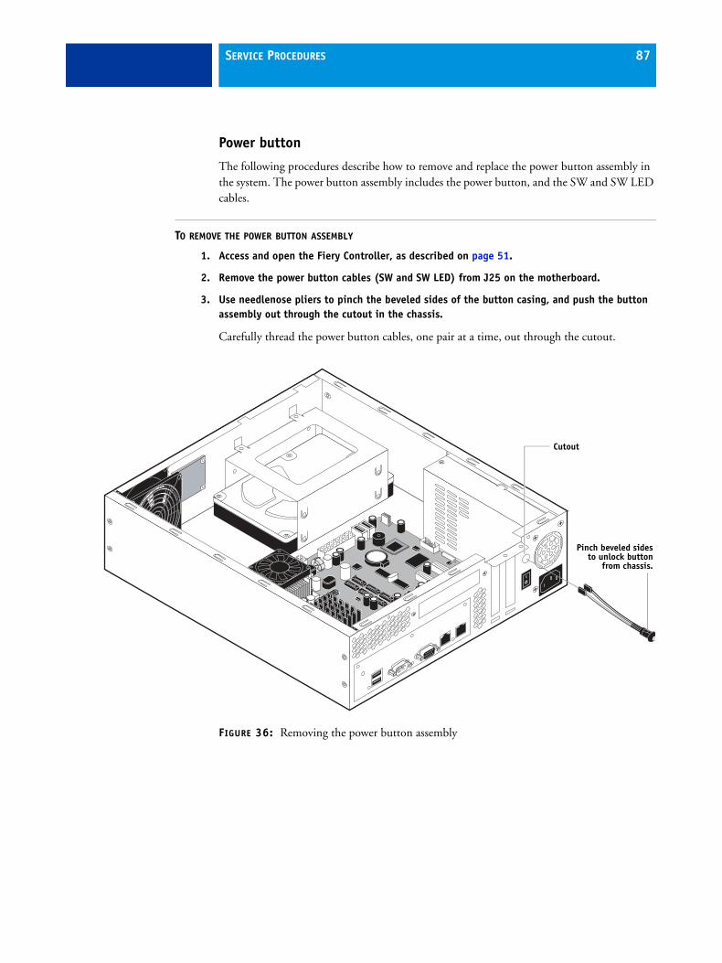
SERVICE PROCEDURES 87
Power button
The following procedures describe how to remove and replace the power button assembly in the system. The power button assembly includes the power button, and the SW and SW LED cables.
TO REMOVE THE POWER BUTTON ASSEMBLY
1. Access and open the Fiery Controller, as described on page 51.
2. Remove the power button cables (SW and SW LED) from J25 on the motherboard.
3. Use needlenose pliers to pinch the beveled sides of the button casing, and push the button assembly out through the cutout in the chassis.
Carefully thread the power button cables, one pair at a time, out through the cutout.
FIGURE 36: Removing the power button assembly
Cutout
Pinch beveled sidesto unlock button
from chassis.
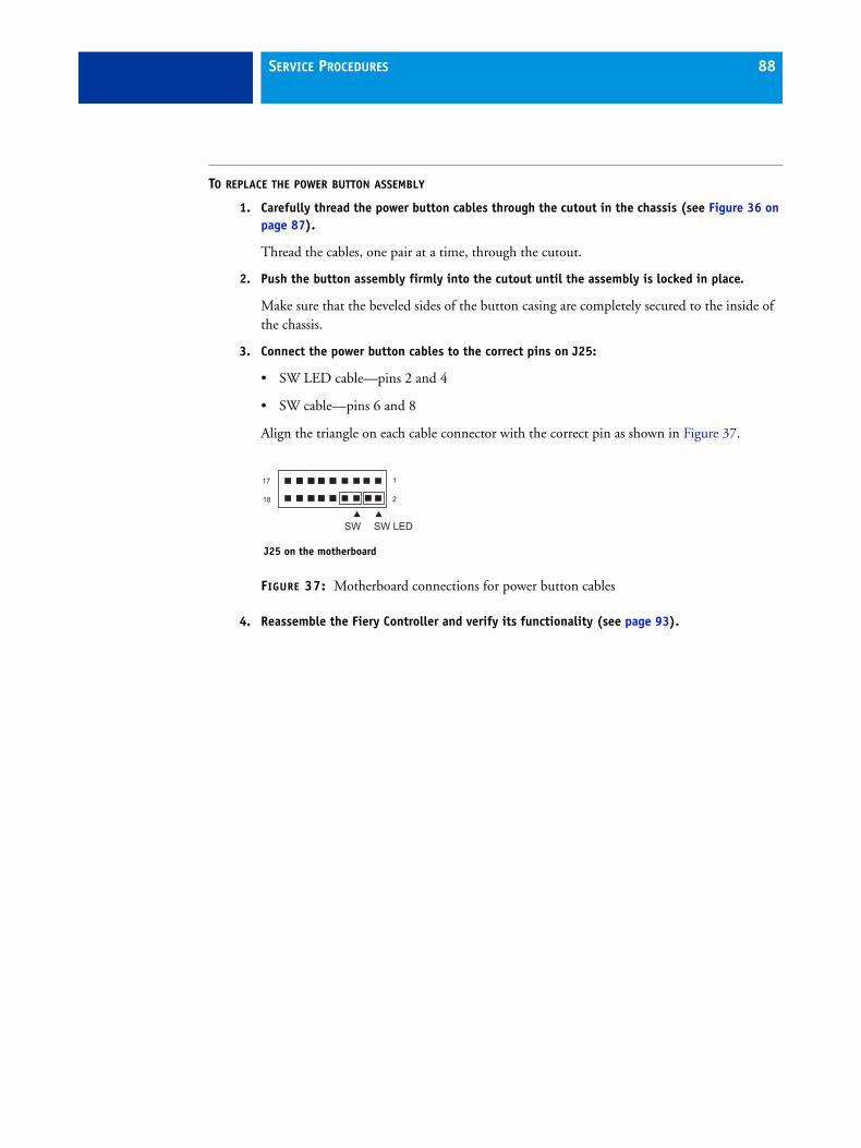
SERVICE PROCEDURES 88
TO REPLACE THE POWER BUTTON ASSEMBLY
1. Carefully thread the power button cables through the cutout in the chassis (see Figure 36 on page 87).
Thread the cables, one pair at a time, through the cutout.
2. Push the button assembly firmly into the cutout until the assembly is locked in place.
Make sure that the beveled sides of the button casing are completely secured to the inside of the chassis.
3. Connect the power button cables to the correct pins on J25:
• SW LED cable—pins 2 and 4
• SW cable—pins 6 and 8
Align the triangle on each cable connector with the correct pin as shown in Figure 37.
FIGURE 37: Motherboard connections for power button cables
4. Reassemble the Fiery Controller and verify its functionality (see page 93).
18
17
2
1
SW SW LED
J25 on the motherboard
SERVICE PROCEDURES 89
HDD
The factory-installed HDD (hard disk drive) is formatted and loaded with system software, network drivers, and printer fonts. The HDD is also used to store spooled print jobs.
If you must replace the HDD, you must install the system software on the new HDD.If you are replacing the HDD, you need:
• The appropriate system software
• The latest version of user software (for networked computers that will print to the Fiery Controller)
For information about installing system software, see page 100.
Proper handling
Improper handling can damage the HDD. Handle the HDD with extreme care:
• Use standard ESD practices when grounding yourself and the Fiery Controller.
• Keep magnets and magnetic-sensitive objects away from the HDD.
• Do not remove the screws on top of the HDD. Loosening these screws voids the warranty.
• Never drop, jar, bump, or put excessive pressure on the HDD.
• Handle the HDD by the sides and avoid touching the printed circuit boards.
• Allow the HDD to reach room temperature before installation.
HDD problems may be caused by the following:
• Loose or faulty connection
• Faulty HDD (bad sectors, read/write errors, or physical damage)
TO REMOVE THE HDD
1. If you are replacing the HDD with a new HDD, allow the network administrator the opportunity to print the Job Log and save any custom simulation and output profiles. If possible, print the following:
• Configuration pages—provide records of any installed options and the customer’s current Setup configuration.
• Font List—lists the fonts currently on the HDD. Along with the fonts provided, the customer may have installed additional fonts.
For information about how to print the Configuration page and Font List, see Configuration and Setup on the User Documentation CD.
2. Access and open the Fiery Controller, as described on page 51.
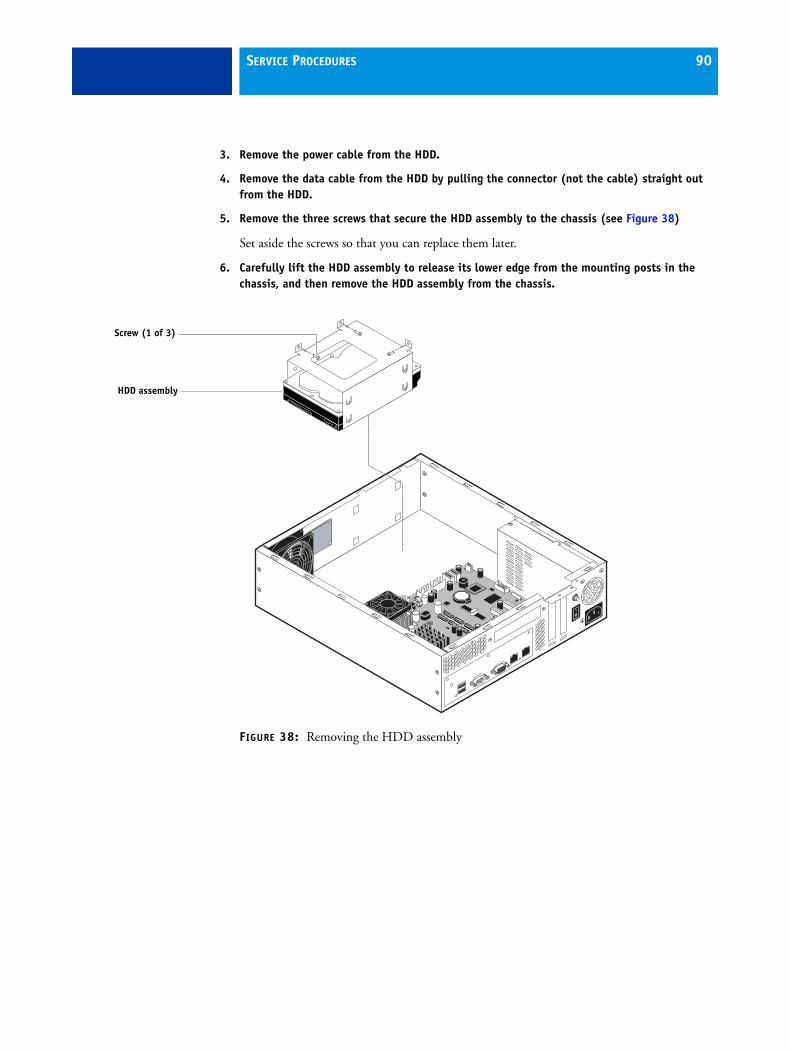
SERVICE PROCEDURES 90
3. Remove the power cable from the HDD.
4. Remove the data cable from the HDD by pulling the connector (not the cable) straight out from the HDD.
5. Remove the three screws that secure the HDD assembly to the chassis (see Figure 38)
Set aside the screws so that you can replace them later.
6. Carefully lift the HDD assembly to release its lower edge from the mounting posts in the chassis, and then remove the HDD assembly from the chassis.
FIGURE 38: Removing the HDD assembly
Screw (1 of 3)
HDD assembly
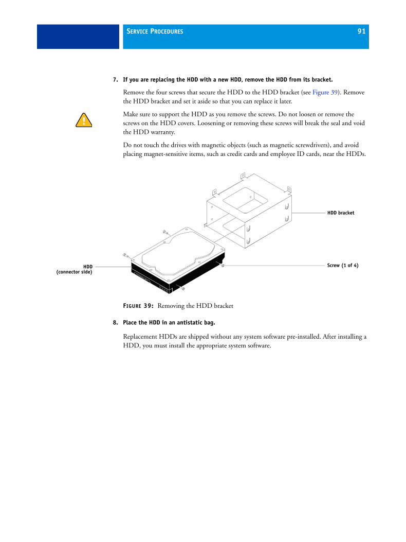
SERVICE PROCEDURES 91
7. If you are replacing the HDD with a new HDD, remove the HDD from its bracket.
Remove the four screws that secure the HDD to the HDD bracket (see Figure 39). Remove the HDD bracket and set it aside so that you can replace it later.
Make sure to support the HDD as you remove the screws. Do not loosen or remove the screws on the HDD covers. Loosening or removing these screws will break the seal and void the HDD warranty.
Do not touch the drives with magnetic objects (such as magnetic screwdrivers), and avoid placing magnet-sensitive items, such as credit cards and employee ID cards, near the HDDs.
FIGURE 39: Removing the HDD bracket
8. Place the HDD in an antistatic bag.
Replacement HDDs are shipped without any system software pre-installed. After installing a HDD, you must install the appropriate system software.
Screw (1 of 4)
HDD bracket
HDD(connector side)
SERVICE PROCEDURES 92
TO REPLACE THE HDD
1. If you are installing a new HDD, unpack the drive. If you are not installing a new HDD, skip to step 4.
Do not drop, jar, or bump the HDD. Do not touch the HDD with magnetic objects or place objects sensitive to magnets near the HDD.
2. Place the HDD inside the HDD bracket, and align the two holes on either side of the HDD with the holes in the bracket.
Position the HDD inside the HDD bracket as shown in Figure 39 on page 91.
3. Replace the four screws that attach the bracket to the HDD.
Make sure that you use the same screws that you removed earlier.
4. Position the HDD assembly inside the chassis, as shown in Figure 38 on page 90.
Position the lower edge of the HDD bracket over the mounting posts in the chassis, and press down firmly to engage the posts.
5. Using the three screws that you removed earlier, secure the HDD assembly to the chassis.
6. Connect the SATA data cable to the SATA data connector on the HDD. Make sure that the other end of the cable is connected to SATA0 on the motherboard.
7. Connect the SATA power cable connector to the SATA power connector on the HDD.
Always connect power to the SATA power connector on the HDD. Do not use the PATA (4-pin) power connector, if it is present on the HDD, and do not connect power to both the SATA and PATA power connectors on the HDD. An incorrect power connection will result in system errors.
The cable connector is keyed to fit only one way.
8. Reassemble the Fiery Controller (see page 93).
9. Connect the external cables that you removed from the Fiery Controller.
10. If you replaced the HDD with a new HDD, install system software (see page 100).
11. Verify Fiery Controller functionality (see page 94).
NOTE: If, after installing a new HDD and system software, you notice that the Fiery Controller takes longer than usual to start up, clear the CMOS (see page 60).
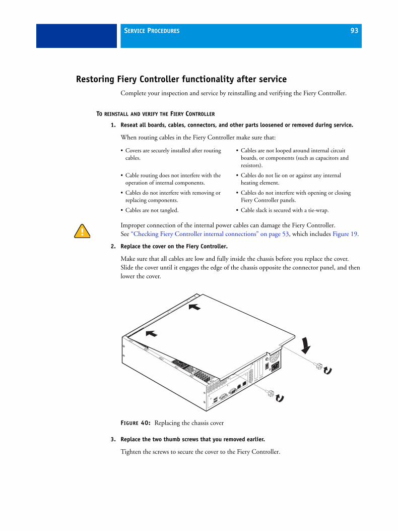
SERVICE PROCEDURES 93
Restoring Fiery Controller functionality after serviceComplete your inspection and service by reinstalling and verifying the Fiery Controller.
TO REINSTALL AND VERIFY THE FIERY CONTROLLER
1. Reseat all boards, cables, connectors, and other parts loosened or removed during service.
When routing cables in the Fiery Controller make sure that:
Improper connection of the internal power cables can damage the Fiery Controller. See “Checking Fiery Controller internal connections” on page 53, which includes Figure 19.
2. Replace the cover on the Fiery Controller.
Make sure that all cables are low and fully inside the chassis before you replace the cover. Slide the cover until it engages the edge of the chassis opposite the connector panel, and then lower the cover.
FIGURE 40: Replacing the chassis cover
3. Replace the two thumb screws that you removed earlier.
Tighten the screws to secure the cover to the Fiery Controller.
• Covers are securely installed after routing cables.
• Cables are not looped around internal circuit boards, or components (such as capacitors and resistors).
• Cable routing does not interfere with the operation of internal components.
• Cables do not lie on or against any internal heating element.
• Cables do not interfere with removing or replacing components.
• Cables do not interfere with opening or closing Fiery Controller panels.
• Cables are not tangled. • Cable slack is secured with a tie-wrap.
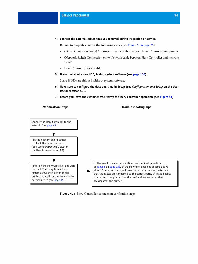
SERVICE PROCEDURES 94
4. Connect the external cables that you removed during inspection or service.
Be sure to properly connect the following cables (see Figure 5 on page 25):
• (Direct Connection only) Crossover Ethernet cable between Fiery Controller and printer
• (Network Switch Connection only) Network cable between Fiery Controller and network switch
• Fiery Controller power cable
5. If you installed a new HDD, install system software (see page 100).
Spare HDDs are shipped without system software.
6. Make sure to configure the date and time in Setup (see Configuration and Setup on the User Documentation CD).
7. Before you leave the customer site, verify the Fiery Controller operation (see Figure 41).
FIGURE 41: Fiery Controller connection verification steps
Power on the Fiery Controller and wait for the LED display to reach and remain at 00; then power on the printer and wait for the Fiery icon to become active (see page 45).
Ask the network administrator to check the Setup options.(See Configuration and Setup on the User Documentation CD).
Connect the Fiery Controller to the network. See page 43.
Verification Steps Troubleshooting Tips
In the event of an error condition, see the Startup section of Table 6 on page 128. If the Fiery icon does not become active after 10 minutes, check and reseat all external cables; make sure that the cables are connected to the correct ports. If image quality is poor, test the printer (see the service documentation that accompanies the printer).
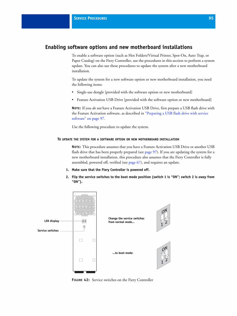
SERVICE PROCEDURES 95
Enabling software options and new motherboard installationsTo enable a software option (such as Hot Folders/Virtual Printer, Spot-On, Auto Trap, or Paper Catalog) on the Fiery Controller, use the procedures in this section to perform a system update. You can also use these procedures to update the system after a new motherboard installation.
To update the system for a new software option or new motherboard installation, you need the following items:
• Single-use dongle [provided with the software option or new motherboard]
• Feature Activation USB Drive [provided with the software option or new motherboard]
NOTE: If you do not have a Feature Activation USB Drive, first prepare a USB flash drive with the Feature Activation software, as described in “Preparing a USB flash drive with service software” on page 97.
Use the following procedure to update the system.
TO UPDATE THE SYSTEM FOR A SOFTWARE OPTION OR NEW MOTHERBOARD INSTALLATION
NOTE: This procedure assumes that you have a Feature Activation USB Drive or another USB flash drive that has been properly prepared (see page 97). If you are updating the system for a new motherboard installation, this procedure also assumes that the Fiery Controller is fully assembled, powered off, verified (see page 67), and requires an update.
1. Make sure that the Fiery Controller is powered off.
2. Flip the service switches to the boot mode position (switch 1 is “ON”; switch 2 is away from “ON”).
FIGURE 42: Service switches on the Fiery Controller
Service switches
LED displayChange the service switches from normal mode...
...to boot mode:
SERVICE PROCEDURES 96
3. Connect the single-use dongle to a USB port on the Fiery Controller (see Figure 5 on page 25). Make sure that no other dongles are attached to the Fiery Controller.
4. Connect the Feature Activation USB Drive or the prepared USB flash drive to another USB port on the Fiery Controller.
5. Make sure that the Fiery Controller power switch is set to ON (|) position, and press the power button once to power on the system.
6. Wait several minutes while the system update files are transferred from the USB drive to the Fiery Controller.
The following status codes appear on the LED display during the update process.
NOTE: If any other code appears on the LED display during the update process, refer to “System update error codes (on LED display)” on page 133.
7. After the LED display reaches FF, wait approximately 30 seconds for the Fiery Controller to shut down automatically.
8. After the Fiery Controller shuts down, wait at least 30 seconds, and then remove the USB drive and single-use dongle from the Fiery Controller.
9. Flip the service switches to normal mode (both switches are away from “ON”).
For an illustration of the service switch modes, see Figure 42 on page 95.
Be sure to flip the service switches to normal mode and remove both the USB drive and dongle from the Fiery Controller. If you do not perform these actions, the Fiery Controller may fail to start.
10. Power on the Fiery Controller by pressing the power button once. Wait several minutes for the Fiery Controller to start up and reach Idle.
11. After the Fiery Controller reaches Idle, power on the printer using the main power switch on the front.
12. Wait for the Fiery Controller Start page to print automatically.
13. If you installed a new motherboard, configure the date and time in Setup. For details, see Configuration and Setup on the User Documentation CD.
14. Print a Configuration page to verify system settings and features.
If you enabled a new software option, verify that the option name appears under BIOS Update > Installed Options.
Code on LED display System status
00 Update process is starting.
01 or 02 Update is in progress.
F0 Update is successful.
FF Update is complete.
SERVICE PROCEDURES 97
Preparing a USB flash drive with service softwareThis section describes how to load a USB flash drive with service software, such as Product Activation software, Feature Activation software, or system software. To do this, you need the following items:
• USB Prep Tool CD [provided with the Fiery Controller]
• CD or DVD containing the service software to be loaded [provided with the Fiery Controller, the option kit, or the spare kit]
• USB 2.0 flash drive [not provided]. If the drive has a write-protection feature, make sure that write-protection is switched off. The drive must have the following minimum capacity:
– For Product Activation or Feature Activation software, 32MB
– For system software, 5GB
Not all USB 2.0 flash drives have been validated for use with the Fiery Controller. If the drive that you are using does not work, try another brand.
• Any PC [not provided] with:
– Windows Vista (32 or 64-bit), or Windows XP with Service Pack 2 or later
– CD or DVD drive, built-in or attached
– Support for USB 2.0 (USB 1.1 may work, but it will be very slow.)
– 256MB of available memory
The procedures in this section are:
• “To install the USB Prep Tool application” on page 98
• “To load a USB flash drive with service software” on page 98
SERVICE PROCEDURES 98
TO INSTALL THE USB PREP TOOL APPLICATION
1. Insert the USB Prep Tool CD into the media drive of the PC.
2. Navigate to the location of the CD and double-click Setup.exe to start the installer.
3. Click Accept to accept the terms of the license agreement.
Wait while the installer verifies the installation requirements.
NOTE: If the PC does not already have .Net framework installed, click Accept to accept the terms of the license agreement that appears on the screen. Wait up to 10 minutes as the .Net framework files are installed.
4. At the security warning screen, click Install.
Wait while the application is installed on the PC.
NOTE: After the installation is complete, the application automatically starts. If you are not ready to prepare the USB flash drive yet, you may click Cancel.
5. Remove the USB Prep Tool CD.
TO LOAD A USB FLASH DRIVE WITH SERVICE SOFTWARE
NOTE: This procedure uses the USB Prep Tool application to copy the service software to the USB flash drive.
1. If necessary, start the USB Prep Tool application by clicking the Start button on the PC and choosing All Programs > Electronics for Imaging > USB Prep Tool.
2. Insert the service software CD/DVD into the media drive of the PC.
3. Attach the USB flash drive to the PC.All data on the USB flash drive is lost when the drive is reformatted during the preparation procedure. Make sure that no valuable data resides on the USB flash drive.
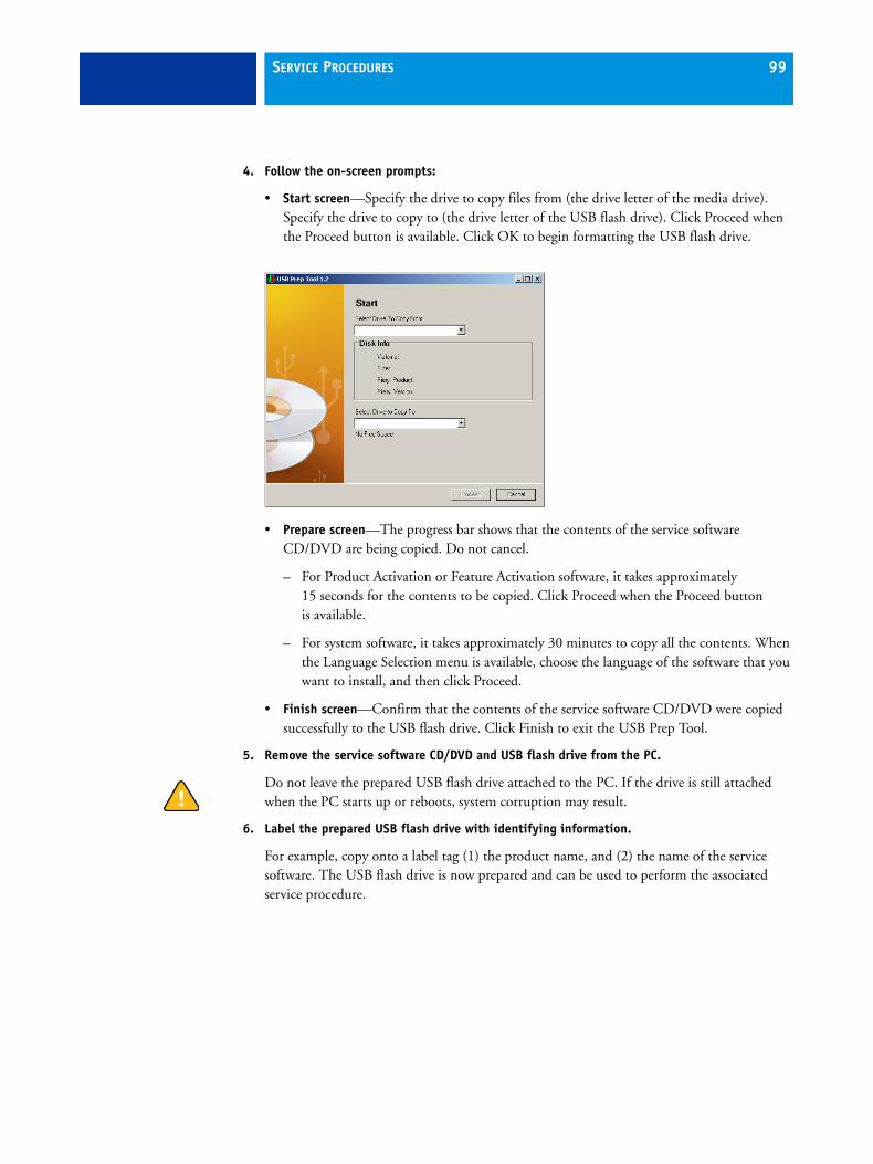
SERVICE PROCEDURES 99
4. Follow the on-screen prompts:
• Start screen—Specify the drive to copy files from (the drive letter of the media drive). Specify the drive to copy to (the drive letter of the USB flash drive). Click Proceed when the Proceed button is available. Click OK to begin formatting the USB flash drive.
• Prepare screen—The progress bar shows that the contents of the service software CD/DVD are being copied. Do not cancel.
– For Product Activation or Feature Activation software, it takes approximately 15 seconds for the contents to be copied. Click Proceed when the Proceed button is available.
– For system software, it takes approximately 30 minutes to copy all the contents. When the Language Selection menu is available, choose the language of the software that you want to install, and then click Proceed.
• Finish screen—Confirm that the contents of the service software CD/DVD were copied successfully to the USB flash drive. Click Finish to exit the USB Prep Tool.
5. Remove the service software CD/DVD and USB flash drive from the PC.
Do not leave the prepared USB flash drive attached to the PC. If the drive is still attached when the PC starts up or reboots, system corruption may result.
6. Label the prepared USB flash drive with identifying information.
For example, copy onto a label tag (1) the product name, and (2) the name of the service software. The USB flash drive is now prepared and can be used to perform the associated service procedure.
SYSTEM SOFTWARE 100
SYSTEM SOFTWARE
The Fiery Controller system software is installed on the HDD at the factory. You must install system software if a more recent version is required, if you replace the HDD, or if you discover problems with the current system.
Use one of the following methods to install system software:
• Network port method via crossover Ethernet cable (see page 102)
• USB flash drive method (see page 109)
SYSTEM SOFTWARE 101
System software installation remindersKeep in mind the following when installing system software:
• Language—Screens for installing system software are always displayed in English, even if the printer is configured for another language.
• Compatibility—The latest user software must be installed onto all computers that print to the Fiery Controller. Using incompatible versions of the system and user software may result in system problems.
• Backup/Restore Settings––All Setup configurations, as well as all custom files stored on the HDD, are deleted when you install system software. Always save the current Fiery Controller settings before you install system software. After the installation is complete, restore the settings that you saved earlier.
The saved settings file contains the following: Setup configurations (except for Server Name and Date/Time), and custom color profiles saved on the HDD.
• Configuration—When upgrading or reinstalling the system software, make sure to print the Configuration pages before installing any software (for instructions, see page 113). The Setup configurations are lost when you install system software.
• Fonts—Installing system software deletes all fonts that the customer has installed on the Fiery Controller. Only resident fonts are restored during system software installation. Use Command WorkStation to reinstall additional fonts.
To determine which additional fonts were downloaded to the Fiery Controller, ask the network administrator to print the Fonts List before you format the HDD and again after you complete the system software installation. Any fonts not listed after installation must be reinstalled.
• Jobs—All jobs in all print queues and all jobs archived locally on the Fiery Controller HDD are deleted when you install system software. To save jobs, ask the network administrator to archive them to a location on the network, so that the jobs can be imported back into the Fiery Controller queue after system software installation. For more information, see Command WorkStation Help.
• FreeForm masters—All FreeForm master jobs are deleted when you install system software. To save FreeForm master jobs, ask the network administrator to archive them to a location on the network, so that the jobs can be imported back into the Fiery Controller queue after system software installation. For more information, see Command WorkStation Help.
SYSTEM SOFTWARE 102
Installing system software over the network portThe System Software DVD contains the system software and the Fiery System Software Installer.
To install system software over the network port of the Fiery Controller, you need the following items:
• Crossover Ethernet cable (4-pair/8-wire, short-length)
NOTE: For systems installed in Direct Connection mode, the interface cable between the Fiery Controller and printer is a crossover Ethernet cable, and may be used for system software installation. For information about how to identify a crossover Ethernet cable, see Figure 13 on page 43.
• Windows XP/2000 computer with:
– A DVD media drive, built-in or attached
– Support for 100BaseTX or 1000BaseT
– 512MB minimum memory capacity
• System Software DVD
SYSTEM SOFTWARE 103
TO INSTALL SYSTEM SOFTWARE OVER THE NETWORK PORT
1. Ask the network administrator to do the following (if possible):
• Print the Job Log.
• Print the Fonts List. This page lists the fonts currently on the HDD. Along with the resident fonts provided, the customer may have installed additional, non-resident fonts. If needed, ask the network administrator to archive the non-resident fonts.
• Archive any custom color profiles and FreeForm masters that have been created on the Fiery Controller.
2. If possible, print the Configuration pages (see page 113).
The Configuration pages contain a list of any installed options and a record of the customer’s current Setup configuration.
3. If you are reinstalling the same version of system software, save the current Fiery Controller settings (if possible):
• Connect your PC to the same network as the Fiery Controller, and open a Web browser window.
• In the URL field of the browser, type the IP address or DNS name of the Fiery Controller, and press Enter.
The IP address is listed under the Network Setup section of the Configuration page.
• On the WebTools home page, click the Configure tab.
• Click Launch Configure, type the Administrator password for the Fiery Controller, and then click OK.
The default Administrator password is Fiery.1. However, the network administrator may have configured a new password for the Fiery Controller.
• Expand the Server item in the left pane, and click Backup/Restore.
• Click Backup Fiery Settings, enter a file name and a location for the settings file, and then click Save.
• Close the browser window.
NOTE: If it is not possible to save the current Fiery Controller settings or you are upgrading the system software version, ask the network administrator to archive any custom color profiles. For more information, see Color Printing on the User Documentation CD.

SYSTEM SOFTWARE 104
4. Power on the PC and do the following:
• Close all software applications.
• Stop all File Transfer Protocol (FTP) and Trivial File Transfer Protocol (TFTP) services.
• Disable all anti-virus and anti-spyware programs.
• Make sure that the PC is configured to obtain its IP address automatically (DHCP).
• Remove any network cables between the PC and the customer network.
• Disable all wireless network connections.
• Turn off the Windows firewall.
• Disable all power-save and hibernation settings.
NOTE: It is important that you complete all of the tasks in the preceding list. If you do not complete these tasks, the installation may fail.
5. Insert the System Software DVD in the media drive of the PC and wait for the Fiery System Software Installer to launch automatically.
If the Fiery System Software Installer does not launch automatically, browse to the location of System Software DVD, and double-click the DVD icon.
6. At the Welcome screen, click Next.
7. Read the Software License Agreement. Select “I Agree” to continue the installation process, and then click Next.
8. At the Connection Type screen, make sure Ethernet is selected. Click Next to advance to the Confirmation screen.
NOTE: To avoid confusion, ignore the text and graphics on the Confirmation screen. The graphics on this screen may not accurately depict Fiery Controller hardware.
9. Power off the Fiery Controller by pressing and holding down the power button for 5 seconds until the green light goes out (see Figure 43 on page 105). Leave the Fiery Controller power switch in the ON (|) position.
10. Power off the printer using the main power switch on the front.
11. Remove all external cables from the Fiery Controller, except for the power cable.
NOTE: Be sure to leave the power cable connected between the Fiery Controller and the wall outlet.

SYSTEM SOFTWARE 105
12. Connect the crossover Ethernet cable between the Fiery Controller network port and an Ethernet port on the PC.
FIGURE 43: Creating an isolated Ethernet network using a crossover cable
13. Flip the Fiery Controller service switches to the ON position (both switches set to up position for ON).
FIGURE 44: Fiery Controller service switches
After you install system software, remember to return the service switches to normal mode (both switches set to down position for OFF).
Network connector
Windows 2000/XP PC
Crossover Ethernet cable
Power button
Service switches
Flip the service switches from normal (OFF) mode...
...to ON position:
LED display

SYSTEM SOFTWARE 106
14. Power on the Fiery Controller by pressing the power button once.
Wait approximately 15 seconds for the Fiery Controller to start up and show 00 on the LED display.
15. At the PC, click Next on the Confirmation screen.
16. At the “Commence Installation?” screen, choose the language that you want to install, and then click Next to begin installation. Wait while the files are transferred from the PC to the Fiery Controller.
NOTE: If prompted, select the PC network card to use for the installation and click OK. If you receive a Windows firewall or security alert, select the option to unblock the Fiery installer so that installation can proceed.
NOTE: This segment of the installation takes approximately 15 minutes. Do not click Cancel or close the installer screen during this time.
At first the Fiery Controller LED display shows sporadic activity, eventually settling on 00. The display increases by one number approximately every 30 seconds. When all the files have been transferred to the Fiery Controller, the display switches to FF.
17. Wait until the LED display shows FF and the following screen appears on the PC, indicating that all the files have been transferred successfully.
FIGURE 45: Installer screen indicating that file transfers are complete
NOTE: To avoid confusion, ignore the text and graphics shown on the screen. This screen may not accurately depict Fiery Controller hardware.
SYSTEM SOFTWARE 107
18. Do the following at the PC:
• Click Next, and then click Finish to close the installer screen.
• Remove the System Software DVD.
• Restore the settings that you changed in step 4.
19. Power off the Fiery Controller by pressing and holding down the power button for 5 seconds until the green light goes out.
20. Move the service switches to normal position (away from ON).
For an illustration of the correct position of the service switches, see Figure 44 on page 105.
21. Disconnect the crossover cable from the Fiery Controller network port and the PC.
22. Reconnect the cables in Direct Connection mode.
Connect the network cable between the Fiery Controller and the customer network, and connect the crossover Ethernet cable between the Fiery Controller and printer (see Figure 11 on page 35).
Be sure to use the correct cable for each connection. For an illustration of the differences between the crossover Ethernet cable and network (straight-through Ethernet) cable, see Figure 13 on page 43.
23. Power on the printer using the main power switch on the front, and then power on the Fiery Controller by pressing the power button once. Wait approximately 60 minutes as the system software installation continues.
NOTE: Do not interact with the Fiery Controller or printer during the installation. Although very few status indicators appear during this time, the installation is in progress and must not be interrupted. Interrupting the installation may result in system corruption.
During the first 10 minutes of the installation, the Fiery Controller reboots multiple times; the LED display shows 00 and AA during each reboot. Afterwards, the display remains at 03 for approximately 40 minutes. The Fiery Controller reboots several more times until the installation is complete.
NOTE: If the LED display hangs on 03 for longer than 60 minutes, look up problems with system software installation in Table 6 on page 125.
You should see the following status indicators when the installation is complete:
• Fiery Controller LED display reaches and remains at 00.
• Printer Setup option becomes active on the printer control panel under Services mode.
• Fiery Controller Start page is printed.
IMPORTANT: You must reconnect the cables in Direct Connection mode in order to establish proper communication between the Fiery Controller and the printer. After the installation is complete, you can reconfigure the system in Network Switch Connection mode, if needed.
SYSTEM SOFTWARE 108
24. If needed, configure a static IP address for the Fiery Controller (see step 6 on page 37).
25. If needed, reconfigure the Fiery Controller and printer in Network Switch Connection mode, as described in “Configuring a Network Switch Connection (optional)” on page 39.
26. If you saved the Fiery Controller settings earlier, restore the settings to the system:
• Connect your PC to the same network as the Fiery Controller and open a Web browser window.
• Type the IP address or DNS name of the Fiery Controller in the URL field and press Enter.
• On the WebTools home page, click the Configure tab, click Launch Configure, type Fiery.1 for the password, and then click OK.
• Expand the Server item in the left pane, and click Backup/Restore.
• Click Restore Fiery Settings. At the reboot warning, click OK. Locate and select the configuration file that you saved earlier, and then click Open.
• Allow the Fiery Controller to reboot.
For a list of the settings that are restored, see page 101.
NOTE: If it was not possible to save the Fiery Controller settings or if you installed an upgraded version of system software, you must configure Setup using the Configuration pages you printed earlier. For information about performing Setup, see Configuration and Setup on the User Documentation CD. Bypass any settings if it is more appropriate for the network administrator to set them. After you exit Setup and allow the system to reboot, ask the network administrator to restore the custom color profiles that were archived earlier.
27. Ask the network administrator to restore the non-resident fonts and FreeForm masters that were archived earlier.
28. Install any required software patches:
• If you reinstalled the same version of system software, be sure to reinstall all software patches that were previously installed on the Fiery Controller. For a list of previously installed patches, see the Configuration pages that you printed earlier.
• If you installed an upgraded version of system software (for example, version 1.0 to version 2.0), contact your authorized service/support center for a list of valid software patches. Some or all of the patches listed on the Configuration pages that you printed earlier may no longer be valid. Before installing a patch, be sure to verify with your authorized service/support center that it is valid for your system version. Installing an invalid patch may result in system corruption.
SYSTEM SOFTWARE 109
Installing system software using a USB flash driveTo install system software using this method, you need the System Software USB drive that shipped with the Fiery Controller Personalization Kit.
NOTE: If you do not have a System Software USB drive, first prepare a USB flash drive with the Fiery Controller system software, as described in “Preparing a USB flash drive with service software” on page 97.
TO INSTALL SYSTEM SOFTWARE USING A PREPARED USB FLASH DRIVE
1. Ask the network administrator to do the following (if possible):
• Print the Job Log.
• Print the Fonts List. This page lists the fonts currently on the HDD. Along with the resident fonts provided, the customer may have installed additional, non-resident fonts. If needed, ask the network administrator to archive the non-resident fonts.
• Archive any FreeForm masters that have been created on the Fiery Controller.
2. If possible, print the Configuration pages (see page 113).
The Configuration pages contain a list of any installed options and a record of the customer’s current Setup configuration.
3. If you are reinstalling the same version of system software, save the current Fiery Controller settings (if possible):
• Connect your PC to the same network as the Fiery Controller, and open a Web browser window.
• In the URL field of the browser, type the IP address or DNS name of the Fiery Controller and press Enter.
The IP address is listed in the Network Setup section of the Configuration page.
• On the WebTools home page, click the Configure tab.
• Click Launch Configure, type the Administrator password for the Fiery Controller, and then click OK.
The default Administrator password is Fiery.1. However, the network administrator may have configured a new password for the Fiery Controller.
• Expand the Server item in the left pane and click Backup/Restore.
• Click Backup Fiery Settings, type a file name and location for the settings file, and then click Save.
• Close the browser window.
NOTE: If it is not possible to save the current Fiery Controller settings or you are upgrading the system software version, ask the network administrator to archive any custom color profiles. For more information, see Color Printing on the User Documentation CD.
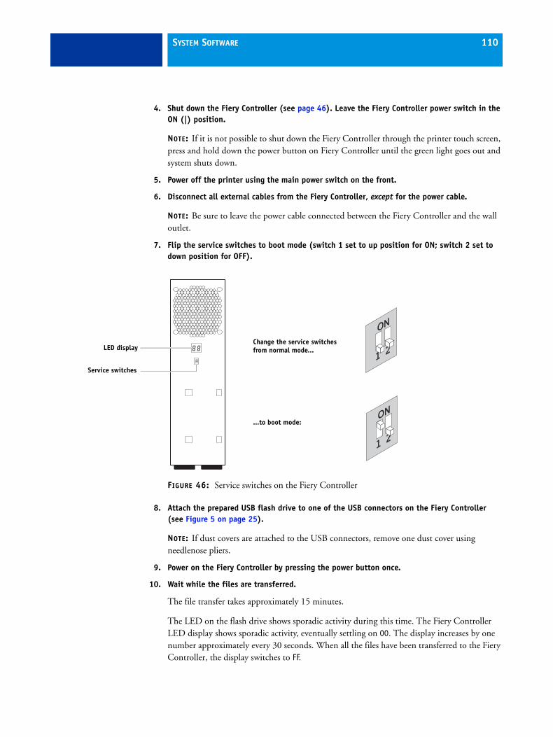
SYSTEM SOFTWARE 110
4. Shut down the Fiery Controller (see page 46). Leave the Fiery Controller power switch in the ON (|) position.
NOTE: If it is not possible to shut down the Fiery Controller through the printer touch screen, press and hold down the power button on Fiery Controller until the green light goes out and system shuts down.
5. Power off the printer using the main power switch on the front.
6. Disconnect all external cables from the Fiery Controller, except for the power cable.
NOTE: Be sure to leave the power cable connected between the Fiery Controller and the wall outlet.
7. Flip the service switches to boot mode (switch 1 set to up position for ON; switch 2 set to down position for OFF).
FIGURE 46: Service switches on the Fiery Controller
8. Attach the prepared USB flash drive to one of the USB connectors on the Fiery Controller (see Figure 5 on page 25).
NOTE: If dust covers are attached to the USB connectors, remove one dust cover using needlenose pliers.
9. Power on the Fiery Controller by pressing the power button once.
10. Wait while the files are transferred.
The file transfer takes approximately 15 minutes.
The LED on the flash drive shows sporadic activity during this time. The Fiery Controller LED display shows sporadic activity, eventually settling on 00. The display increases by one number approximately every 30 seconds. When all the files have been transferred to the Fiery Controller, the display switches to FF.
Service switches
LED displayChange the service switches from normal mode...
...to boot mode:
SYSTEM SOFTWARE 111
11. After the Fiery Controller LED display reaches FF, wait 30 seconds, and then power off the Fiery Controller by pressing and holding down the power button for 5 seconds until the green light goes out.
12. Remove the USB flash drive from the Fiery Controller.
13. Flip the service switches to normal mode (both switches set to down position for OFF).
For an illustration of the service switch modes, see Figure 46 on page 110.
Be sure to flip the service switches to normal mode and remove the USB flash drive from the Fiery Controller. If you do not perform these actions, the Fiery Controller may fail to start up.
14. Reconnect the cables in Direct Connection mode.
Connect the network cable between the Fiery Controller and the customer network, and connect the crossover Ethernet cable between the Fiery Controller and printer (see Figure 11 on page 35).
Be sure to use the correct cable for each connection. For an illustration of the differences between the crossover Ethernet cable and network (straight-through Ethernet) cable, see Figure 13 on page 43.
15. Power on the printer using the main power switch on the front, and then power on the Fiery Controller by pressing the power button once. Wait approximately 60 minutes as the system software installation continues.
NOTE: Do not interact with the Fiery Controller or the printer during the installation. Although very few status indicators appear during this time, the installation is in progress and must not be interrupted. Interrupting the installation may result in system corruption.
During the first 10 minutes of the installation, the Fiery Controller reboots multiple times; the LED display shows 00 and AA during each reboot. Afterwards, the display remains at 03 for approximately 40 minutes. The Fiery Controller reboots several more times until the installation is complete.
NOTE: If the LED display hangs on 03 for longer than 60 minutes, look up problems with system software installation in Table 6 on page 125.
You should see the following status indicators when the installation is complete:
• Fiery Controller LED display reaches and remains at 00.
• Fiery icon becomes active on the printer control panel under Services mode (if needed, touch Services Home to display the icon).
• Fiery Controller Start page is printed.
IMPORTANT: You must reconnect the cables in Direct Connection mode in order to establish proper communication between the Fiery Controller and the printer. After the installation is complete, you can reconfigure the system in Network Switch Connection mode, if needed.

SYSTEM SOFTWARE 112
16. If needed, configure a static IP address for the Fiery Controller (see step 6 on page 37).
17. If needed, reconfigure the Fiery Controller and printer in Network Switch Connection mode, as described in “Configuring a Network Switch Connection (optional)” on page 39.
18. If you saved the Fiery Controller settings earlier, restore the settings to the system:
• Connect your PC to the same network as the Fiery Controller, and open a Web browser window.
• Type the IP address or DNS name of the Fiery Controller in the URL field and press Enter.
• On the WebTools home page, click the Configure tab, click Launch Configure, type Fiery.1 for the password, and then click OK.
• Expand the Server item in the left pane and click Backup/Restore.
• Click Restore Fiery Settings. At the reboot warning, click OK. Locate and select the configuration file that you saved earlier, and then click Open.
• Allow the Fiery Controller to reboot.
For a list of the settings that are restored, see page 101.
NOTE: If it was not possible to save the Fiery Controller settings or if you installed an upgraded version of system software, you must configure Setup using the Configuration pages you printed earlier. For information about performing Setup, see Configuration and Setup on the User Documentation CD. Bypass any settings if it is more appropriate for the network administrator to set them. After you exit Setup and allow the system to reboot, ask the network administrator to restore the custom color profiles that were archived earlier.
19. Ask the network administrator to restore the non-resident fonts and FreeForm masters that were archived earlier.
20. Install any required software patches:
• If you reinstalled the same version of system software, be sure to reinstall all software patches that were previously installed on the Fiery Controller. For a list of previously installed patches, refer to the Configuration pages you printed earlier.
• If you installed an upgraded version of system software (for example, version 1.0 to version 2.0), contact your authorized service/support center for a list of valid software patches. Some or all of the patches listed on the Configuration pages that you printed earlier may no longer be valid. Before installing a patch, be sure to verify with your authorize service/support center that it is valid for your system version. Installing an invalid patch may result in system corruption.

SYSTEM SOFTWARE 113
Printing the Configuration pagesThis section describes how to print the Configuration pages. The Configuration pages list all installed options on the Fiery Controller, as well as the customer’s current Setup configuration (for more information, see page 101).
TO PRINT THE CONFIGURATION PAGES
1. Press the Services button on the printer control panel. If you do not see the service icons, touch Services Home.
2. Touch the Fiery icon on the printer touch panel.
3. Touch the Info tab.
4. Touch Login, and then touch the password field. On the keyboard that appears on the touch panel, enter the Administrator password for the Fiery Controller. (The default case-sensitive password is Fiery.1.) Touch Save, and then touch Login.
5. Touch Configuration.
Wait for the Configuration pages to print from the printer.
TROUBLESHOOTING 114
TROUBLESHOOTING
This chapter identifies the source of common problems that may occur with the Fiery Controller and suggests ways of correcting them.
The troubleshooting processThe following sections do not attempt to provide troubleshooting information for attached computers such as PCs, the printer, or extensive networks. Refer problems in these areas to the appropriate service departments and site administrators.
When performing the service procedures described in this chapter, follow the precautions listed on page 12.
The troubleshooting process is designed to eliminate the most obvious causes of failure before progressing to more complex issues. “Where problems occur” on page 115 gives an overview of the Fiery Controller components and indicates areas most likely to require troubleshooting.
• Try a phone check before you go to the customer site.
“Before you go to the customer site” on page 116 suggests areas to check before making a service call to the customer site. With a phone call, you can find out if the problem is a simple operating failure or a failure caused by a network or configuration change. Ask the customer to check for loose cables on the back of the printer and loose connections at a power strip or outlet.
• Check for obvious causes of problems.
• Check network connections.
“Preliminary onsite checkout” on page 117 takes you through the initial visual checks you should make when you arrive at the customer site.
The “Network” section of Table 6 on page 125 provides guidelines for checking the network connections between the printer and the computers to which it is connected, as well as information about several printing problems.
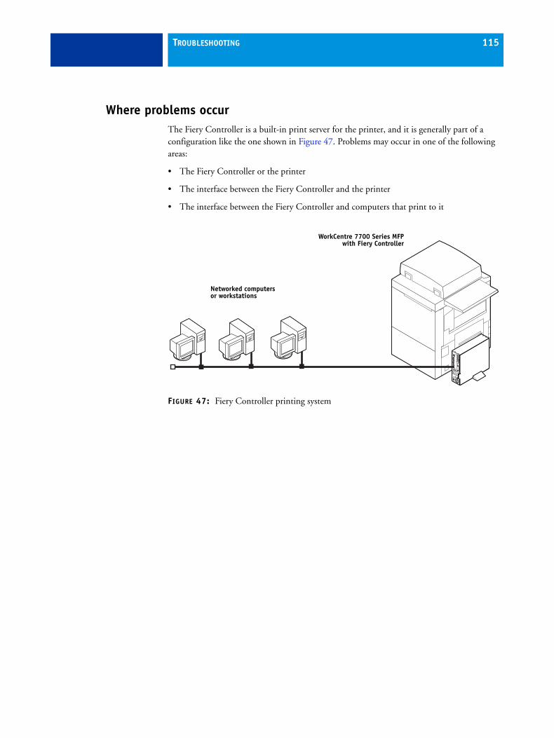
TROUBLESHOOTING 115
Where problems occurThe Fiery Controller is a built-in print server for the printer, and it is generally part of a configuration like the one shown in Figure 47. Problems may occur in one of the following areas:
• The Fiery Controller or the printer
• The interface between the Fiery Controller and the printer
• The interface between the Fiery Controller and computers that print to it
FIGURE 47: Fiery Controller printing system
Networked computers or workstations
WorkCentre 7700 Series MFPwith Fiery Controller
TROUBLESHOOTING 116
Before you go to the customer siteBefore you make a service call to a customer site, talk to the customer on the phone, and check the following items:
1. Does the printer work?
2. Is the failure caused by a simple operating problem?
Is there a printing problem?
• Does the Fiery Controller fail to respond to a print command?
• Does printing seem to take a long time?
• Is print quality poor?
• Does the Fiery Controller fail to appear in the list of printers?
If the answer to any of these questions is yes, refer the customer to the troubleshooting sections in Configuration and Setup on the User Documentation CD, or in Command WorkStation Help.
If the customer followed the suggested corrective actions and failed to solve the problem, be prepared to make a service call. Keep a log of the failures the customer has observed.
3. Has the customer made any network changes?
If network changes have occurred, request that the customer’s site administrator verify the Fiery Controller network requirements.
4. Is the user having printing problems with a particular image file?
If problems occur with files from particular applications, the user may be more successful using different print settings.
5. Does the LED display on the Fiery Controller connector panel hang on a particular code?
The code may indicate the need to replace one or more Fiery Controller components. For more information, see “Error codes and conditions” on page 125.
6. Has the customer performed a Clear Server operation?
As a preliminary troubleshooting step, instruct the customer to clear the Fiery Controller server by choosing Clear Server from the Server menu in Command WorkStation. In order to access this command, the customer must log on to Command WorkStation with Administrator privileges.
Clearing the server may fix the problem that the customer is trying to solve.
If your phone call fails to clear up the problem, proceed to the next phase, the preliminary on-site checkout.
TROUBLESHOOTING 117
Preliminary onsite checkoutYour goal in the preliminary onsite checkout is to eliminate obvious problems, such as loose or missing cables and connectors.
The most common causes of hardware problems are faulty or loose connections. Before you decide to replace any parts of the Fiery Controller, make sure to verify all cables and connections. If you have concluded that all external connections are good, check the internal connections. If all internal connections appear to be in place, inspect individual hardware components in the system.
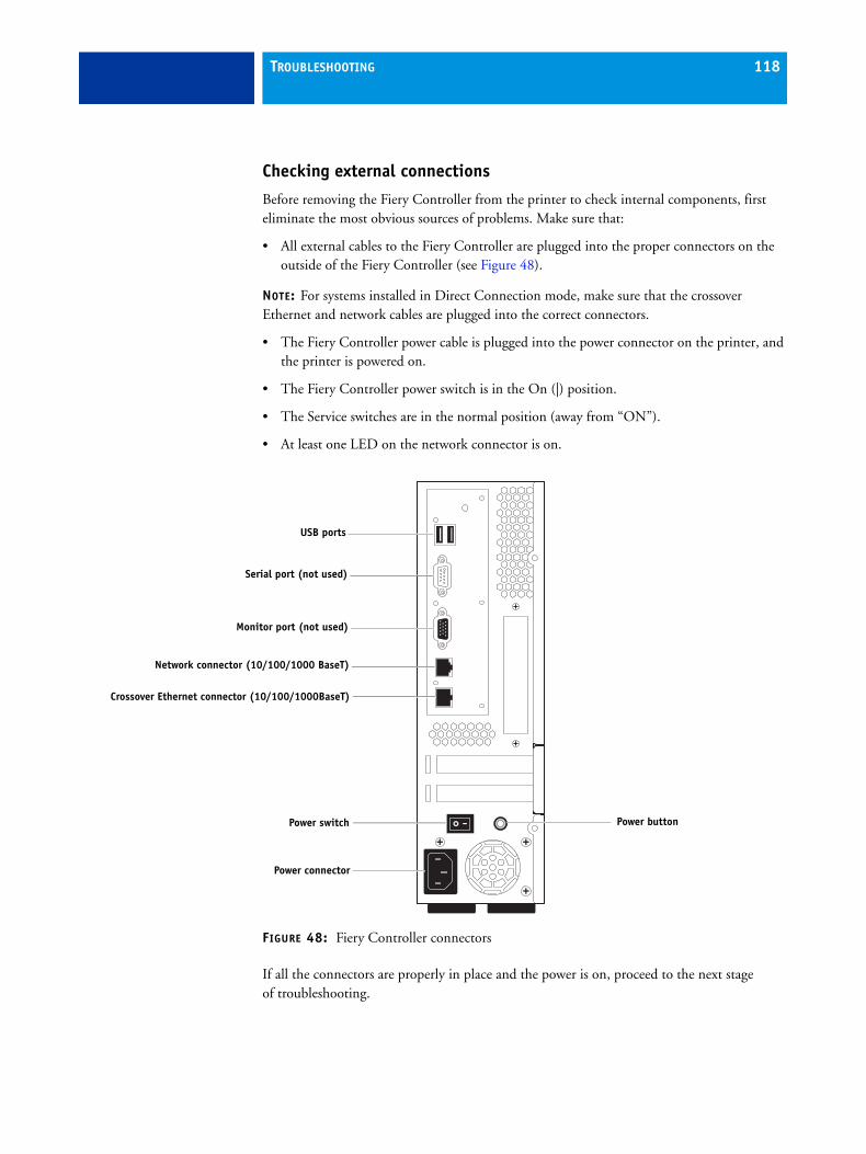
TROUBLESHOOTING 118
Checking external connections
Before removing the Fiery Controller from the printer to check internal components, first eliminate the most obvious sources of problems. Make sure that:
• All external cables to the Fiery Controller are plugged into the proper connectors on the outside of the Fiery Controller (see Figure 48).
NOTE: For systems installed in Direct Connection mode, make sure that the crossover Ethernet and network cables are plugged into the correct connectors.
• The Fiery Controller power cable is plugged into the power connector on the printer, and the printer is powered on.
• The Fiery Controller power switch is in the On (|) position.
• The Service switches are in the normal position (away from “ON”).
• At least one LED on the network connector is on.
FIGURE 48: Fiery Controller connectors
If all the connectors are properly in place and the power is on, proceed to the next stage of troubleshooting.
Power connector
Crossover Ethernet connector (10/100/1000BaseT)
Network connector (10/100/1000 BaseT)
Monitor port (not used)
Serial port (not used)
USB ports
Power buttonPower switch

TROUBLESHOOTING 119
Checking internal connections
The most common causes of problems are faulty and loose connections. Before you conclude that any internal component has failed, remove, inspect, and reseat all appropriate connections, and then verify that the problem still occurs.
Before you touch any parts inside the Fiery Controller, attach a grounding wrist strap. Touching the chassis also discharges static electricity.
TO CHECK CABLE CONNECTIONS
1. Remove and open the Fiery Controller (see page 51).
2. Place the Fiery Controller on a flat surface so that internal components are facing up.
3. Make sure that the battery is properly installed (see page 59).
4. Inspect the HDD data cable to make sure that it is intact and connected to SATA0 on the motherboard (see page 62).
NOTE: The Fiery Controller will not boot up if the HDD data cable is connected to any other SATA connector on the motherboard.
Faulty data cables are easily overlooked. Check the contact point between the cable and the connector to ensure that they have not separated. If a data cable is suspect, substitute it with a tested cable.
5. Check the fan cables of the chassis fan and the CPU fan.
Make sure that the cables are intact.
6. Check the service board cable.
Make sure that the cable is intact and properly connected to the service board and the motherboard. For more information, see page 77.
7. Make sure that the internal power cables are intact and properly connected to the power supply, HDD, motherboard, and Fiery Controller power switch.
Make sure that the black and white wires are properly connected to the correct leads on the Fiery Controller power switch. For more information, see Figure 35 on page 85.
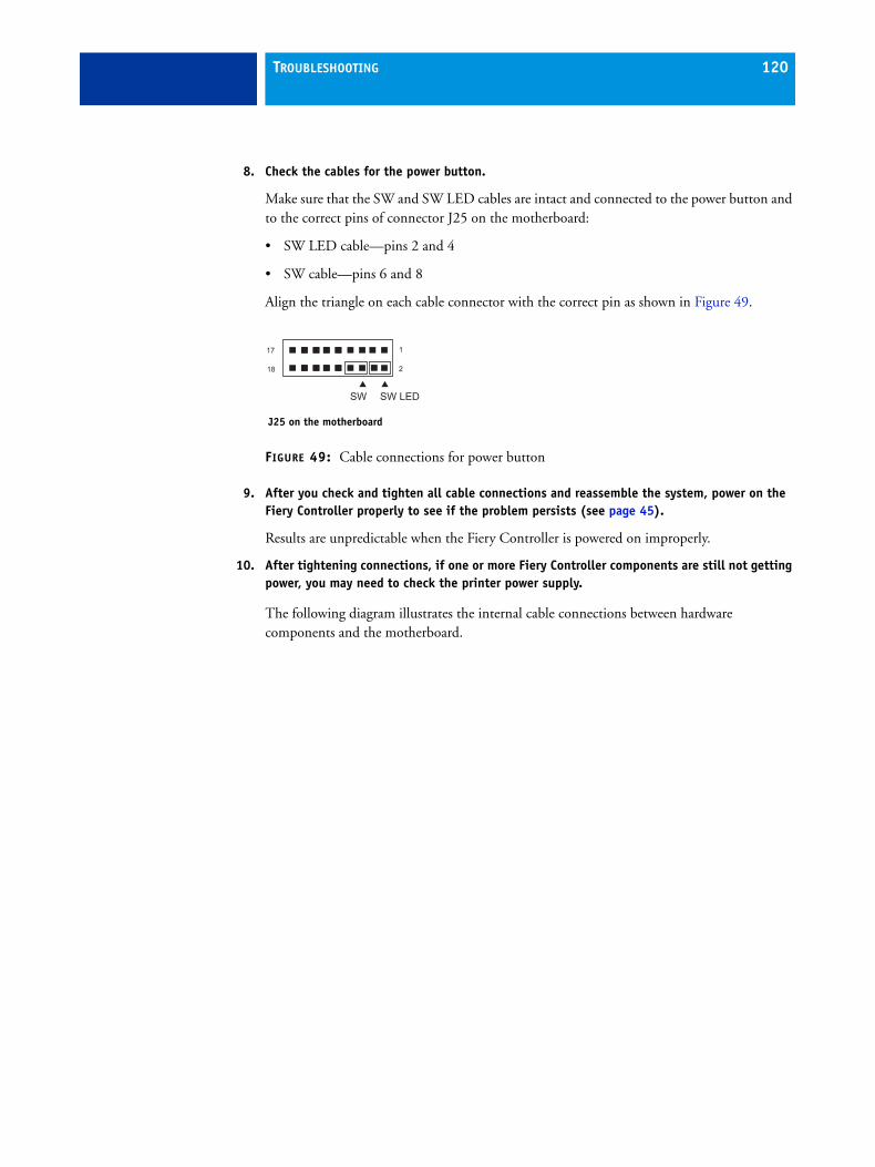
TROUBLESHOOTING 120
8. Check the cables for the power button.
Make sure that the SW and SW LED cables are intact and connected to the power button and to the correct pins of connector J25 on the motherboard:
• SW LED cable—pins 2 and 4
• SW cable—pins 6 and 8
Align the triangle on each cable connector with the correct pin as shown in Figure 49.
FIGURE 49: Cable connections for power button
9. After you check and tighten all cable connections and reassemble the system, power on the Fiery Controller properly to see if the problem persists (see page 45).
Results are unpredictable when the Fiery Controller is powered on improperly.
10. After tightening connections, if one or more Fiery Controller components are still not getting power, you may need to check the printer power supply.
The following diagram illustrates the internal cable connections between hardware components and the motherboard.
18
17
2
1
SW SW LED
J25 on the motherboard
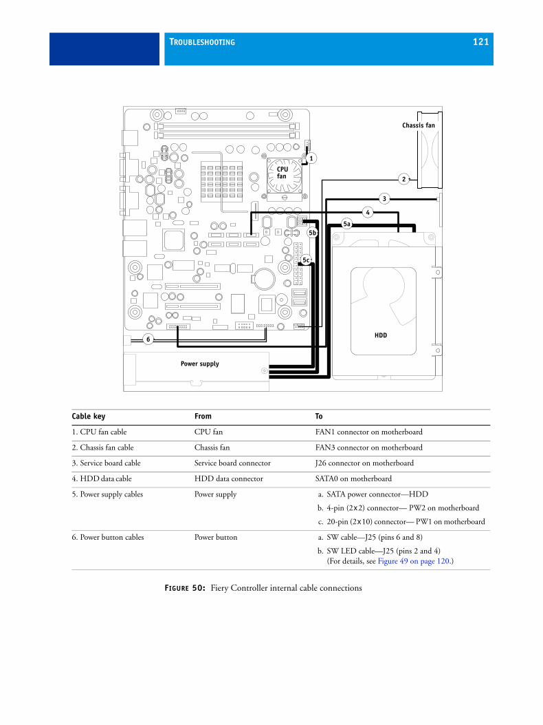
TROUBLESHOOTING 121
FIGURE 50: Fiery Controller internal cable connections
Cable key From To
1. CPU fan cable CPU fan FAN1 connector on motherboard
2. Chassis fan cable Chassis fan FAN3 connector on motherboard
3. Service board cable Service board connector J26 connector on motherboard
4. HDD data cable HDD data connector SATA0 on motherboard
5. Power supply cables Power supply a. SATA power connector—HDD
b. 4-pin (2x2) connector— PW2 on motherboard
c. 20-pin (2x10) connector— PW1 on motherboard
6. Power button cables Power button a. SW cable—J25 (pins 6 and 8)
b. SW LED cable—J25 (pins 2 and 4)(For details, see Figure 49 on page 120.)
HDD
3
5a
6
2CPU fan
Power supply
Chassis fan
5b
5c
4
1
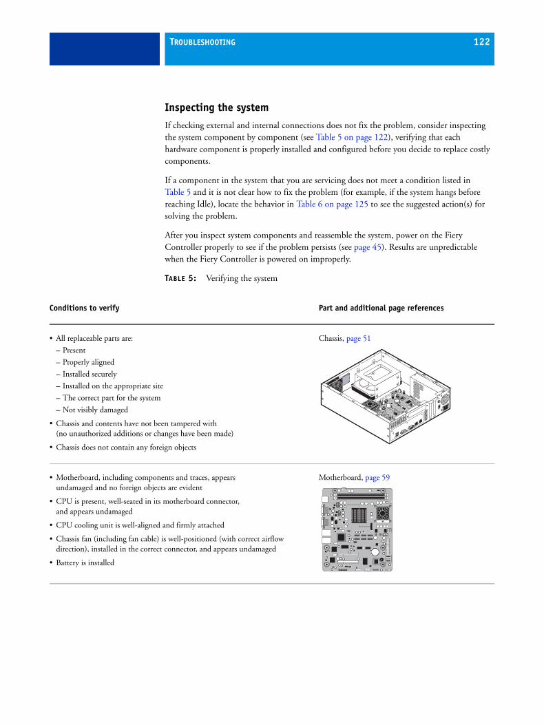
TROUBLESHOOTING 122
Inspecting the system
If checking external and internal connections does not fix the problem, consider inspecting the system component by component (see Table 5 on page 122), verifying that each hardware component is properly installed and configured before you decide to replace costly components.
If a component in the system that you are servicing does not meet a condition listed in Table 5 and it is not clear how to fix the problem (for example, if the system hangs before reaching Idle), locate the behavior in Table 6 on page 125 to see the suggested action(s) for solving the problem.
After you inspect system components and reassemble the system, power on the Fiery Controller properly to see if the problem persists (see page 45). Results are unpredictable when the Fiery Controller is powered on improperly.
TABLE 5: Verifying the system
Conditions to verify Part and additional page references
• All replaceable parts are:
– Present
– Properly aligned
– Installed securely
– Installed on the appropriate site
– The correct part for the system
– Not visibly damaged
• Chassis and contents have not been tampered with (no unauthorized additions or changes have been made)
• Chassis does not contain any foreign objects
Chassis, page 51
• Motherboard, including components and traces, appears undamaged and no foreign objects are evident
• CPU is present, well-seated in its motherboard connector, and appears undamaged
• CPU cooling unit is well-aligned and firmly attached
• Chassis fan (including fan cable) is well-positioned (with correct airflow direction), installed in the correct connector, and appears undamaged
• Battery is installed
Motherboard, page 59
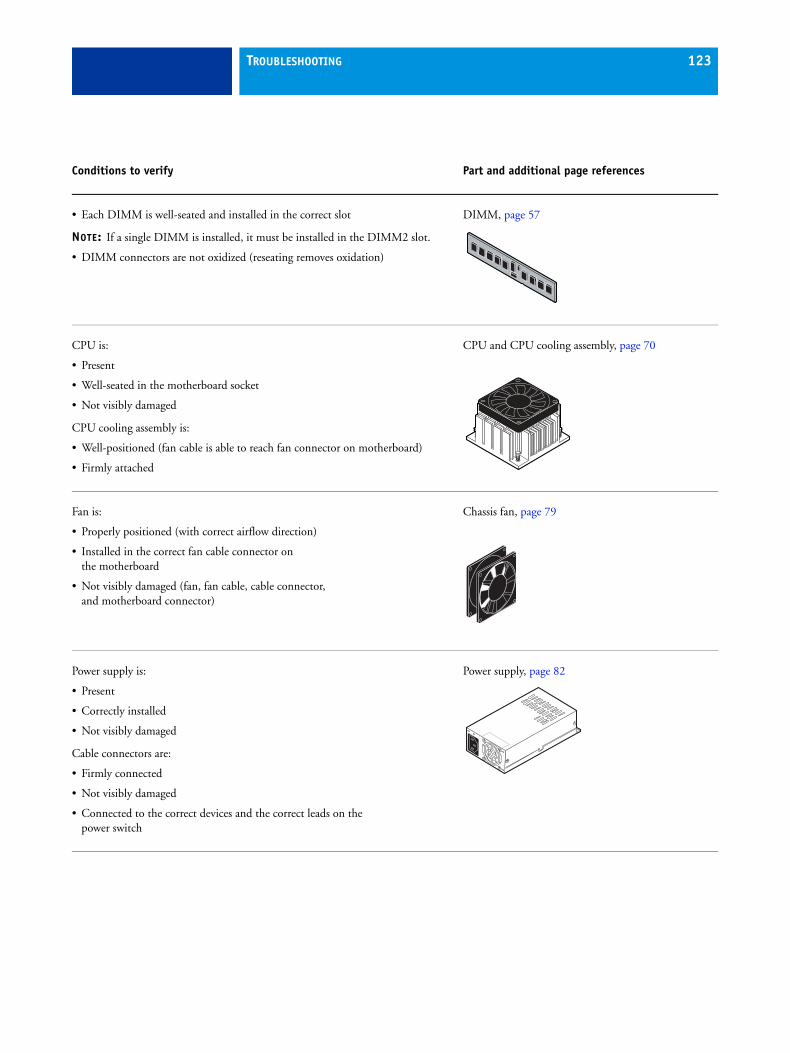
TROUBLESHOOTING 123
• Each DIMM is well-seated and installed in the correct slot
NOTE: If a single DIMM is installed, it must be installed in the DIMM2 slot.
• DIMM connectors are not oxidized (reseating removes oxidation)
DIMM, page 57
CPU is:
• Present
• Well-seated in the motherboard socket
• Not visibly damaged
CPU cooling assembly is:
• Well-positioned (fan cable is able to reach fan connector on motherboard)
• Firmly attached
CPU and CPU cooling assembly, page 70
Fan is:
• Properly positioned (with correct airflow direction)
• Installed in the correct fan cable connector on the motherboard
• Not visibly damaged (fan, fan cable, cable connector, and motherboard connector)
Chassis fan, page 79
Power supply is:
• Present
• Correctly installed
• Not visibly damaged
Cable connectors are:
• Firmly connected
• Not visibly damaged
• Connected to the correct devices and the correct leads on the power switch
Power supply, page 82
Conditions to verify Part and additional page references
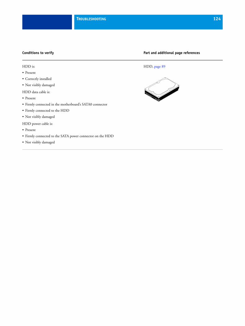
TROUBLESHOOTING 124
HDD is:
• Present
• Correctly installed
• Not visibly damaged
HDD data cable is:
• Present
• Firmly connected in the motherboard’s SATA0 connector
• Firmly connected to the HDD
• Not visibly damaged
HDD power cable is:
• Present
• Firmly connected to the SATA power connector on the HDD
• Not visibly damaged
HDD, page 89
Conditions to verify Part and additional page references
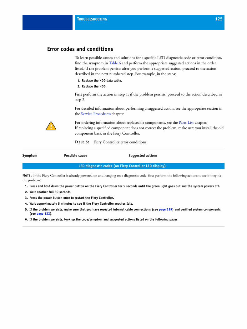
TROUBLESHOOTING 125
Error codes and conditionsTo learn possible causes and solutions for a specific LED diagnostic code or error condition, find the symptom in Table 6 and perform the appropriate suggested actions in the order listed. If the problem persists after you perform a suggested action, proceed to the action described in the next numbered step. For example, in the steps:
1. Replace the HDD data cable.
2. Replace the HDD.
First perform the action in step 1; if the problem persists, proceed to the action described in step 2.
For detailed information about performing a suggested action, see the appropriate section in the Service Procedures chapter.
For ordering information about replaceable components, see the Parts List chapter. If replacing a specified component does not correct the problem, make sure you install the old component back in the Fiery Controller.
TABLE 6: Fiery Controller error conditions
Symptom Possible cause Suggested actions
LED diagnostic codes (on Fiery Controller LED display)
NOTE: If the Fiery Controller is already powered on and hanging on a diagnostic code, first perform the following actions to see if they fix the problem:
1. Press and hold down the power button on the Fiery Controller for 5 seconds until the green light goes out and the system powers off.
2. Wait another full 30 seconds.
3. Press the power button once to restart the Fiery Controller.
4. Wait approximately 5 minutes to see if the Fiery Controller reaches Idle.
5. If the problem persists, make sure that you have reseated internal cable connections (see page 119) and verified system components (see page 122).
6. If the problem persists, look up the code/symptom and suggested actions listed on the following pages.
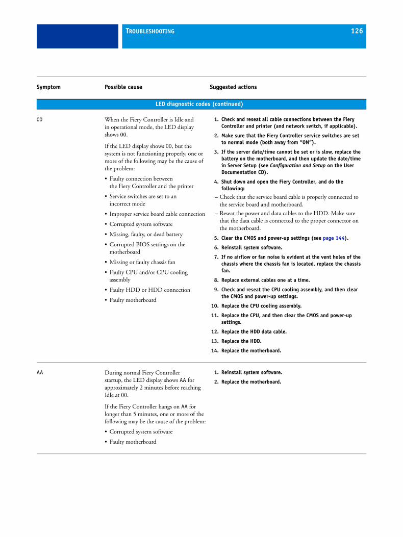
TROUBLESHOOTING 126
LED diagnostic codes (continued)
00 When the Fiery Controller is Idle and in operational mode, the LED display shows 00.
If the LED display shows 00, but the system is not functioning properly, one or more of the following may be the cause of the problem:
• Faulty connection between the Fiery Controller and the printer
• Service switches are set to an incorrect mode
• Improper service board cable connection
• Corrupted system software
• Missing, faulty, or dead battery
• Corrupted BIOS settings on the motherboard
• Missing or faulty chassis fan
• Faulty CPU and/or CPU cooling assembly
• Faulty HDD or HDD connection
• Faulty motherboard
1. Check and reseat all cable connections between the Fiery Controller and printer (and network switch, if applicable).
2. Make sure that the Fiery Controller service switches are set to normal mode (both away from “ON”).
3. If the server date/time cannot be set or is slow, replace the battery on the motherboard, and then update the date/time in Server Setup (see Configuration and Setup on the User Documentation CD).
4. Shut down and open the Fiery Controller, and do the following:
– Check that the service board cable is properly connected to the service board and motherboard.
– Reseat the power and data cables to the HDD. Make sure that the data cable is connected to the proper connector on the motherboard.
5. Clear the CMOS and power-up settings (see page 144).
6. Reinstall system software.
7. If no airflow or fan noise is evident at the vent holes of the chassis where the chassis fan is located, replace the chassis fan.
8. Replace external cables one at a time.
9. Check and reseat the CPU cooling assembly, and then clear the CMOS and power-up settings.
10. Replace the CPU cooling assembly.
11. Replace the CPU, and then clear the CMOS and power-up settings.
12. Replace the HDD data cable.
13. Replace the HDD.
14. Replace the motherboard.
AA During normal Fiery Controller startup, the LED display shows AA for approximately 2 minutes before reaching Idle at 00.
If the Fiery Controller hangs on AA for longer than 5 minutes, one or more of the following may be the cause of the problem:
• Corrupted system software
• Faulty motherboard
1. Reinstall system software.
2. Replace the motherboard.
Symptom Possible cause Suggested actions
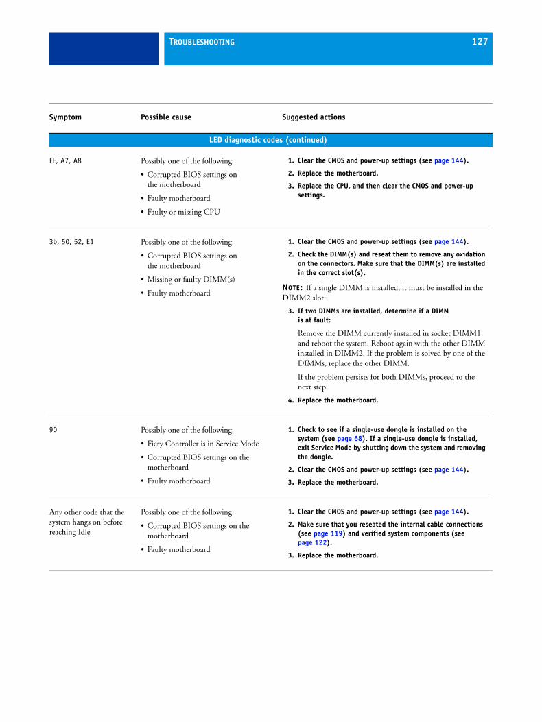
TROUBLESHOOTING 127
LED diagnostic codes (continued)
FF, A7, A8 Possibly one of the following:
• Corrupted BIOS settings on the motherboard
• Faulty motherboard
• Faulty or missing CPU
1. Clear the CMOS and power-up settings (see page 144).
2. Replace the motherboard.
3. Replace the CPU, and then clear the CMOS and power-up settings.
3b, 50, 52, E1 Possibly one of the following:
• Corrupted BIOS settings on the motherboard
• Missing or faulty DIMM(s)
• Faulty motherboard
1. Clear the CMOS and power-up settings (see page 144).
2. Check the DIMM(s) and reseat them to remove any oxidation on the connectors. Make sure that the DIMM(s) are installed in the correct slot(s).
NOTE: If a single DIMM is installed, it must be installed in the DIMM2 slot.
3. If two DIMMs are installed, determine if a DIMM is at fault:
Remove the DIMM currently installed in socket DIMM1 and reboot the system. Reboot again with the other DIMM installed in DIMM2. If the problem is solved by one of the DIMMs, replace the other DIMM.
If the problem persists for both DIMMs, proceed to the next step.
4. Replace the motherboard.
90 Possibly one of the following:
• Fiery Controller is in Service Mode
• Corrupted BIOS settings on the motherboard
• Faulty motherboard
1. Check to see if a single-use dongle is installed on the system (see page 68). If a single-use dongle is installed, exit Service Mode by shutting down the system and removing the dongle.
2. Clear the CMOS and power-up settings (see page 144).
3. Replace the motherboard.
Any other code that the system hangs on before reaching Idle
Possibly one of the following:
• Corrupted BIOS settings on the motherboard
• Faulty motherboard
1. Clear the CMOS and power-up settings (see page 144).
2. Make sure that you reseated the internal cable connections (see page 119) and verified system components (see page 122).
3. Replace the motherboard.
Symptom Possible cause Suggested actions
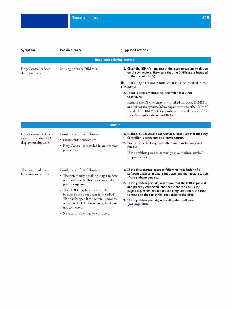
TROUBLESHOOTING 128
Beep codes during startup
Fiery Controller beeps during startup
Missing or faulty DIMM(s) 1. Check the DIMM(s) and reseat them to remove any oxidation on the connectors. Make sure that the DIMM(s) are installed in the correct slot(s).
NOTE: If a single DIMM is installed, it must be installed in the DIMM2 slot.
2. If two DIMMs are installed, determine if a DIMM is at fault:
Remove the DIMM currently installed in socket DIMM1, and reboot the system. Reboot again with the other DIMM installed in DIMM2. If the problem is solved by one of the DIMMs, replace the other DIMM.
Startup
Fiery Controller does not start up, and the LED display remains unlit
Possibly one of the following:
• Faulty cable connections
• Fiery Controller is stalled in an incorrect power state
1. Recheck all cables and connections. Make sure that the Fiery Controller is connected to a power source.
2. Firmly press the Fiery Controller power button once and release.
If the problem persists, contact your authorized service/support center.
The system takes a long time to start up.
Possibly one of the following:
• The system may be taking longer to boot up in order to finalize installation of a patch or update.
• The HDD may have fallen to the bottom of the boot order in the BIOS. This can happen if the system is powered on when the HDD is missing, faulty, or not connected.
• System software may be corrupted.
1. If the slow startup happens following installation of a software patch or update, shut down, and then restart to see if the problem persists.
2. If the problem persists, make sure that the HDD is present and properly connected, and then clear the CMOS (see page 144). When you reboot the Fiery Controller, the HDD is moved to the top of the boot order in the BIOS.
3. If the problem persists, reinstall system software(see page 100).
Symptom Possible cause Suggested actions
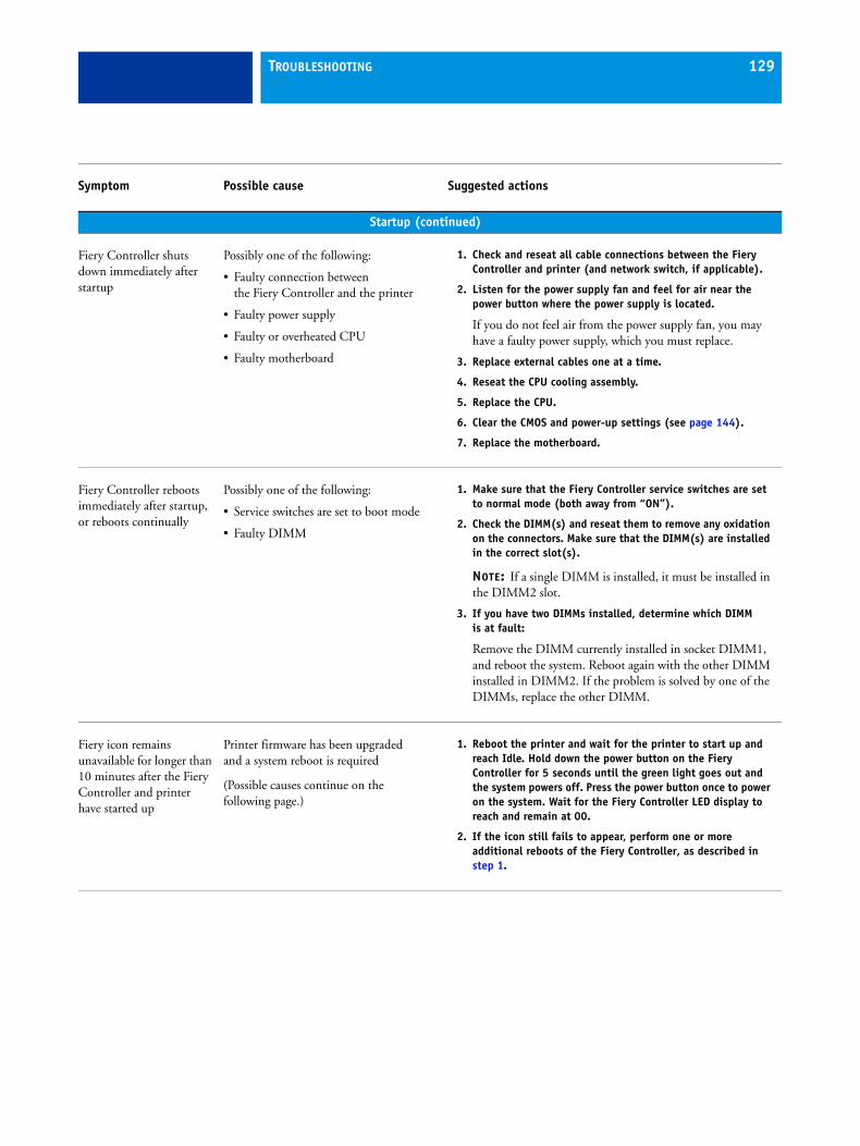
TROUBLESHOOTING 129
Startup (continued)
Fiery Controller shuts down immediately after startup
Possibly one of the following:
• Faulty connection between the Fiery Controller and the printer
• Faulty power supply
• Faulty or overheated CPU
• Faulty motherboard
1. Check and reseat all cable connections between the Fiery Controller and printer (and network switch, if applicable).
2. Listen for the power supply fan and feel for air near the power button where the power supply is located.
If you do not feel air from the power supply fan, you may have a faulty power supply, which you must replace.
3. Replace external cables one at a time.
4. Reseat the CPU cooling assembly.
5. Replace the CPU.
6. Clear the CMOS and power-up settings (see page 144).
7. Replace the motherboard.
Fiery Controller reboots immediately after startup, or reboots continually
Possibly one of the following:
• Service switches are set to boot mode
• Faulty DIMM
1. Make sure that the Fiery Controller service switches are set to normal mode (both away from “ON”).
2. Check the DIMM(s) and reseat them to remove any oxidation on the connectors. Make sure that the DIMM(s) are installed in the correct slot(s).
NOTE: If a single DIMM is installed, it must be installed in the DIMM2 slot.
3. If you have two DIMMs installed, determine which DIMM is at fault:
Remove the DIMM currently installed in socket DIMM1, and reboot the system. Reboot again with the other DIMM installed in DIMM2. If the problem is solved by one of the DIMMs, replace the other DIMM.
Fiery icon remains unavailable for longer than 10 minutes after the Fiery Controller and printer have started up
Printer firmware has been upgraded and a system reboot is required
(Possible causes continue on the following page.)
1. Reboot the printer and wait for the printer to start up and reach Idle. Hold down the power button on the Fiery Controller for 5 seconds until the green light goes out and the system powers off. Press the power button once to power on the system. Wait for the Fiery Controller LED display to reach and remain at 00.
2. If the icon still fails to appear, perform one or more additional reboots of the Fiery Controller, as described in step 1.
Symptom Possible cause Suggested actions
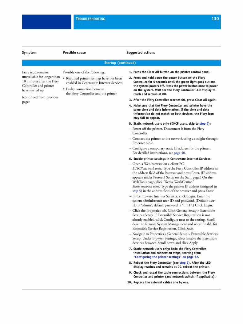
TROUBLESHOOTING 130
Startup (continued)
Fiery icon remains unavailable for longer than 10 minutes after the Fiery Controller and printer have started up
(continued from previous page)
Possibly one of the following:
• Required printer settings have not been enabled in Centreware Internet Services
• Faulty connection between the Fiery Controller and the printer
1. Press the Clear All button on the printer control panel.
2. Press and hold down the power button on the Fiery Controller for 5 seconds until the green light goes out and the system powers off. Press the power button once to power on the system. Wait for the Fiery Controller LED display to reach and remain at 00.
3. After the Fiery Controller reaches 00, press Clear All again.
4. Make sure that the Fiery Controller and printer have the same time and date information. If the time and date information do not match on both devices, the Fiery icon may fail to appear.
5. Static network users only (DHCP users, skip to step 6):
– Power off the printer. Disconnect it from the Fiery Controller.
– Connect the printer to the network using a straight-through Ethernet cable.
– Configure a temporary static IP address for the printer. For detailed instructions, see page 40.
6. Enable printer settings in Centreware Internet Services:
– Open a Web browser on a client PC.DHCP network users: Type the Fiery Controller IP address in the address field of the browser and press Enter. (IP address appears under Protocol Setup on the Start page.) On the WebTools page, click “Xerox WorkCentre.”Static network users: Type the printer IP address (assigned in step 5) in the address field of the browser and press Enter.
– In Centreware Internet Services, click Login. Enter the system administrator user ID and password. (Default user ID is “admin”; default password is “1111”.) Click Login.
– Click the Properties tab. Click General Setup > Extensible Services Setup. If Extensible Service Registration is not already enabled, click Configure next to the setting. Scroll down to Remote System Management and select Enable for Extensible Service Registration. Click Save.
– Navigate to Properties > General Setup > Extensible Services Setup. Under Browser Settings, select Enable the Extensible Services Browser. Scroll down and click Apply.
7. Static network users only: Redo the Fiery Controller installation and connection steps, starting from “Configuring the printer settings” on page 32.
8. Reboot the Fiery Controller (see step 2). After the LED display reaches and remains at 00, reboot the printer.
9. Check and reseat the cable connections between the Fiery Controller and printer (and network switch, if applicable).
10. Replace the external cables one by one.
Symptom Possible cause Suggested actions
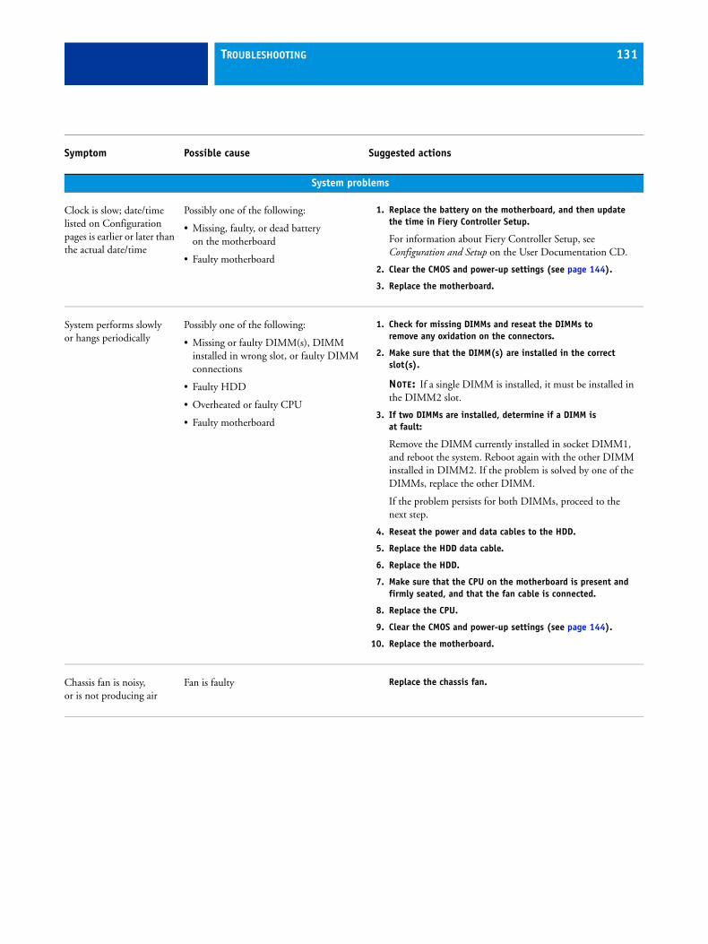
TROUBLESHOOTING 131
System problems
Clock is slow; date/time listed on Configuration pages is earlier or later than the actual date/time
Possibly one of the following:
• Missing, faulty, or dead battery on the motherboard
• Faulty motherboard
1. Replace the battery on the motherboard, and then update the time in Fiery Controller Setup.
For information about Fiery Controller Setup, see Configuration and Setup on the User Documentation CD.
2. Clear the CMOS and power-up settings (see page 144).
3. Replace the motherboard.
System performs slowly or hangs periodically
Possibly one of the following:
• Missing or faulty DIMM(s), DIMM installed in wrong slot, or faulty DIMM connections
• Faulty HDD
• Overheated or faulty CPU
• Faulty motherboard
1. Check for missing DIMMs and reseat the DIMMs to remove any oxidation on the connectors.
2. Make sure that the DIMM(s) are installed in the correct slot(s).
NOTE: If a single DIMM is installed, it must be installed in the DIMM2 slot.
3. If two DIMMs are installed, determine if a DIMM is at fault:
Remove the DIMM currently installed in socket DIMM1, and reboot the system. Reboot again with the other DIMM installed in DIMM2. If the problem is solved by one of the DIMMs, replace the other DIMM.
If the problem persists for both DIMMs, proceed to the next step.
4. Reseat the power and data cables to the HDD.
5. Replace the HDD data cable.
6. Replace the HDD.
7. Make sure that the CPU on the motherboard is present and firmly seated, and that the fan cable is connected.
8. Replace the CPU.
9. Clear the CMOS and power-up settings (see page 144).
10. Replace the motherboard.
Chassis fan is noisy, or is not producing air
Fan is faulty Replace the chassis fan.
Symptom Possible cause Suggested actions
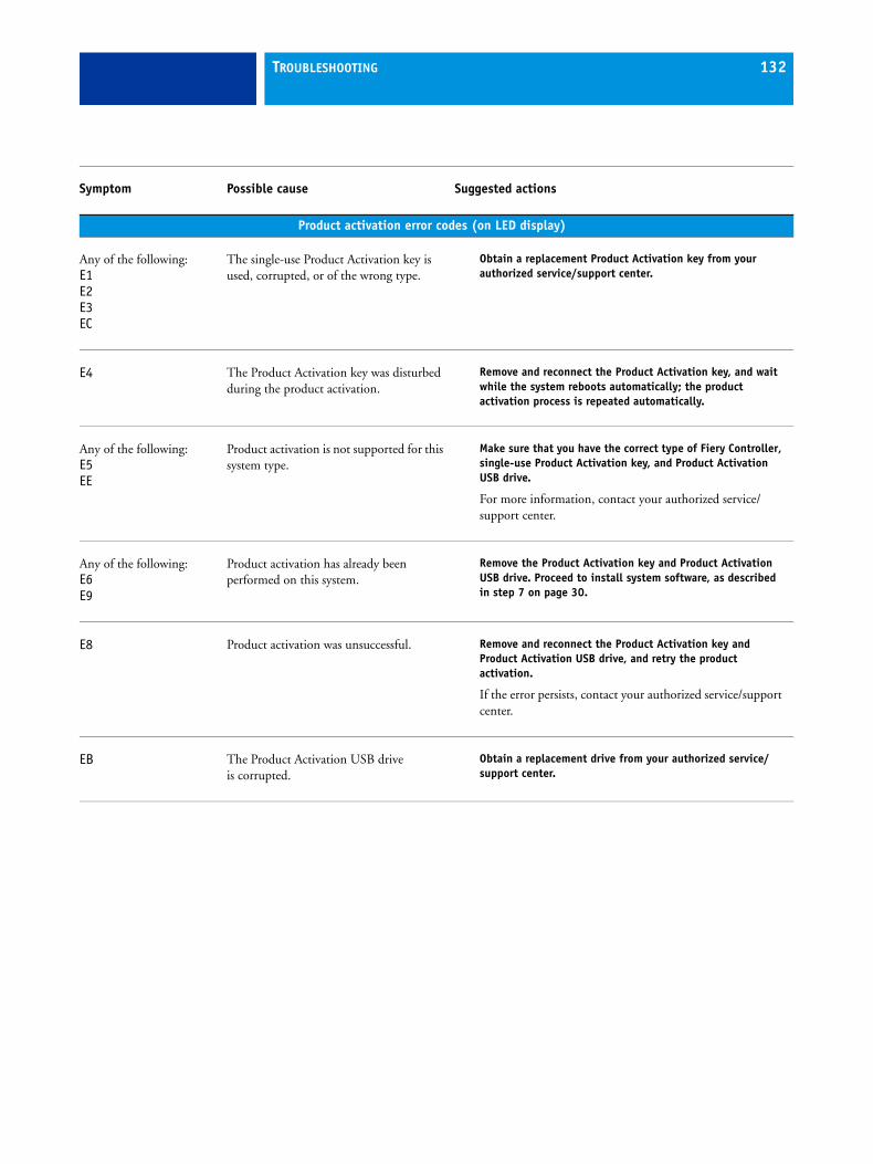
TROUBLESHOOTING 132
Product activation error codes (on LED display)
Any of the following:E1E2E3EC
The single-use Product Activation key is used, corrupted, or of the wrong type.
Obtain a replacement Product Activation key from your authorized service/support center.
E4 The Product Activation key was disturbed during the product activation.
Remove and reconnect the Product Activation key, and wait while the system reboots automatically; the product activation process is repeated automatically.
Any of the following:E5EE
Product activation is not supported for this system type.
Make sure that you have the correct type of Fiery Controller, single-use Product Activation key, and Product Activation USB drive.
For more information, contact your authorized service/support center.
Any of the following:E6E9
Product activation has already been performed on this system.
Remove the Product Activation key and Product Activation USB drive. Proceed to install system software, as described in step 7 on page 30.
E8 Product activation was unsuccessful. Remove and reconnect the Product Activation key and Product Activation USB drive, and retry the product activation.
If the error persists, contact your authorized service/support center.
EB The Product Activation USB drive is corrupted.
Obtain a replacement drive from your authorized service/support center.
Symptom Possible cause Suggested actions
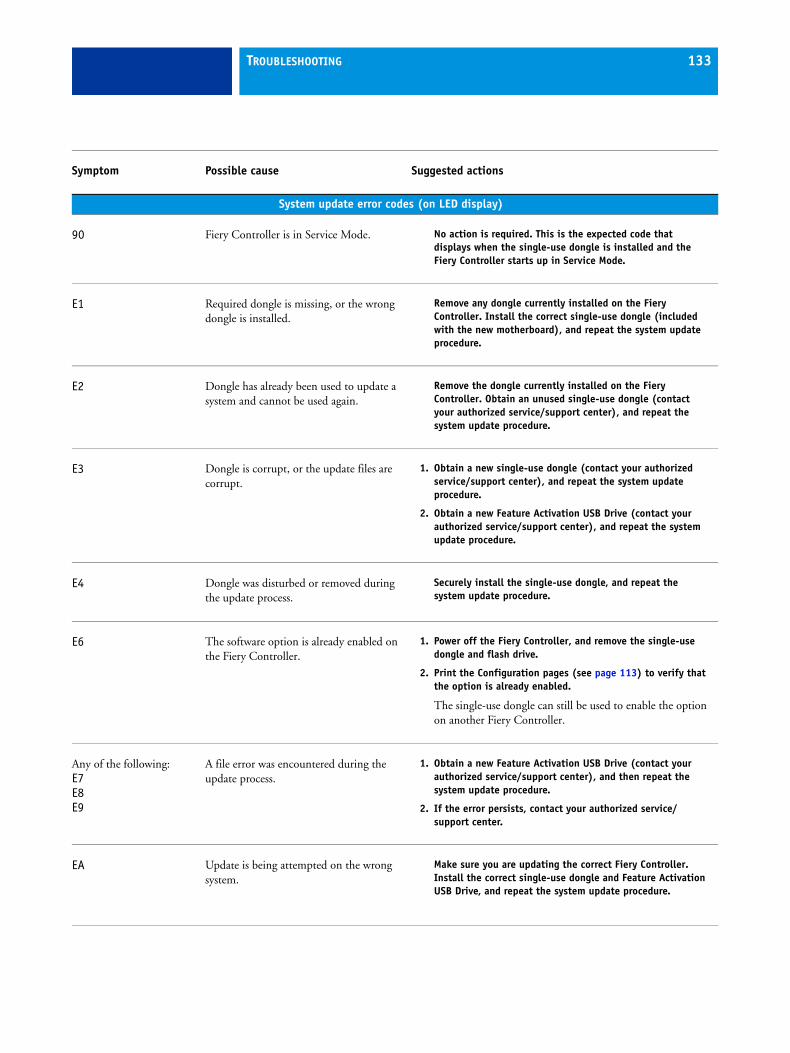
TROUBLESHOOTING 133
System update error codes (on LED display)
90 Fiery Controller is in Service Mode. No action is required. This is the expected code that displays when the single-use dongle is installed and the Fiery Controller starts up in Service Mode.
E1 Required dongle is missing, or the wrong dongle is installed.
Remove any dongle currently installed on the Fiery Controller. Install the correct single-use dongle (included with the new motherboard), and repeat the system update procedure.
E2 Dongle has already been used to update a system and cannot be used again.
Remove the dongle currently installed on the Fiery Controller. Obtain an unused single-use dongle (contact your authorized service/support center), and repeat the system update procedure.
E3 Dongle is corrupt, or the update files are corrupt.
1. Obtain a new single-use dongle (contact your authorized service/support center), and repeat the system update procedure.
2. Obtain a new Feature Activation USB Drive (contact your authorized service/support center), and repeat the system update procedure.
E4 Dongle was disturbed or removed during the update process.
Securely install the single-use dongle, and repeat the system update procedure.
E6 The software option is already enabled on the Fiery Controller.
1. Power off the Fiery Controller, and remove the single-use dongle and flash drive.
2. Print the Configuration pages (see page 113) to verify that the option is already enabled.
The single-use dongle can still be used to enable the option on another Fiery Controller.
Any of the following:E7E8E9
A file error was encountered during the update process.
1. Obtain a new Feature Activation USB Drive (contact your authorized service/support center), and then repeat the system update procedure.
2. If the error persists, contact your authorized service/support center.
EA Update is being attempted on the wrong system.
Make sure you are updating the correct Fiery Controller. Install the correct single-use dongle and Feature Activation USB Drive, and repeat the system update procedure.
Symptom Possible cause Suggested actions
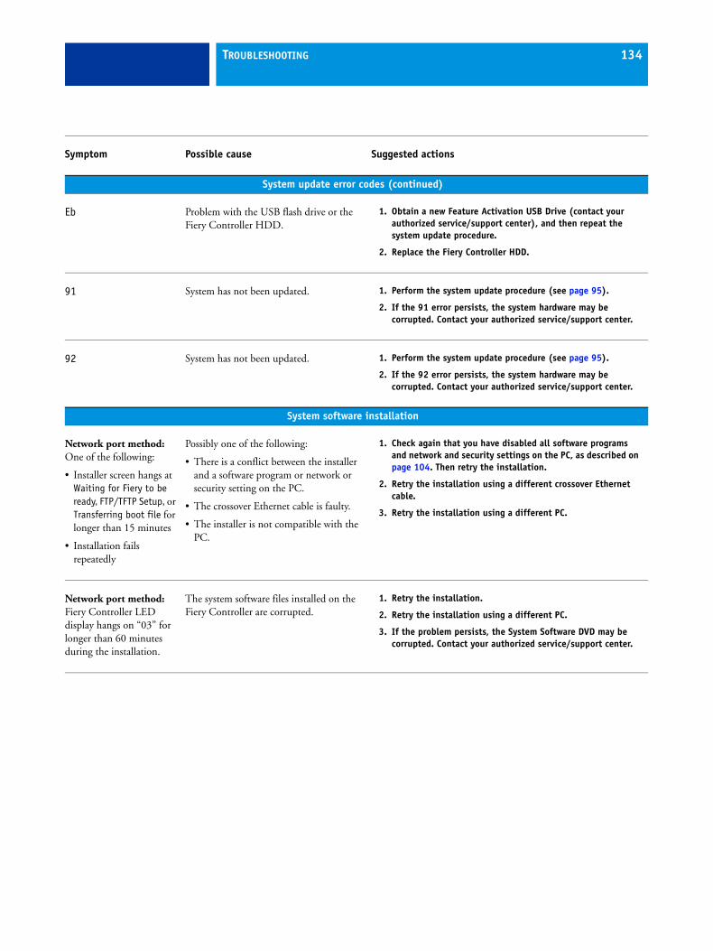
TROUBLESHOOTING 134
System update error codes (continued)
Eb Problem with the USB flash drive or the Fiery Controller HDD.
1. Obtain a new Feature Activation USB Drive (contact your authorized service/support center), and then repeat the system update procedure.
2. Replace the Fiery Controller HDD.
91 System has not been updated. 1. Perform the system update procedure (see page 95).
2. If the 91 error persists, the system hardware may be corrupted. Contact your authorized service/support center.
92 System has not been updated. 1. Perform the system update procedure (see page 95).
2. If the 92 error persists, the system hardware may be corrupted. Contact your authorized service/support center.
System software installation
Network port method:One of the following:
• Installer screen hangs at Waiting for Fiery to be ready, FTP/TFTP Setup, or Transferring boot file for longer than 15 minutes
• Installation fails repeatedly
Possibly one of the following:
• There is a conflict between the installer and a software program or network or security setting on the PC.
• The crossover Ethernet cable is faulty.
• The installer is not compatible with the PC.
1. Check again that you have disabled all software programs and network and security settings on the PC, as described on page 104. Then retry the installation.
2. Retry the installation using a different crossover Ethernet cable.
3. Retry the installation using a different PC.
Network port method:Fiery Controller LED display hangs on “03” for longer than 60 minutes during the installation.
The system software files installed on the Fiery Controller are corrupted.
1. Retry the installation.
2. Retry the installation using a different PC.
3. If the problem persists, the System Software DVD may be corrupted. Contact your authorized service/support center.
Symptom Possible cause Suggested actions
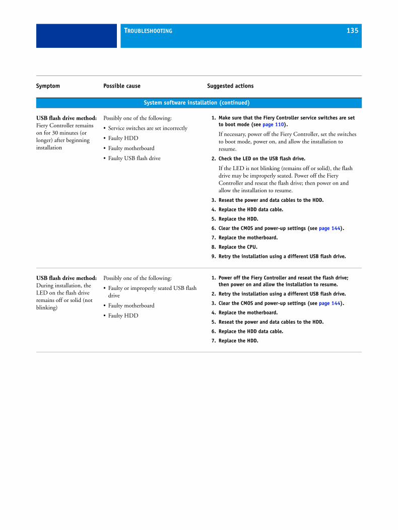
TROUBLESHOOTING 135
System software installation (continued)
USB flash drive method:Fiery Controller remains on for 30 minutes (or longer) after beginning installation
Possibly one of the following:
• Service switches are set incorrectly
• Faulty HDD
• Faulty motherboard
• Faulty USB flash drive
1. Make sure that the Fiery Controller service switches are set to boot mode (see page 110).
If necessary, power off the Fiery Controller, set the switches to boot mode, power on, and allow the installation to resume.
2. Check the LED on the USB flash drive.
If the LED is not blinking (remains off or solid), the flash drive may be improperly seated. Power off the Fiery Controller and reseat the flash drive; then power on and allow the installation to resume.
3. Reseat the power and data cables to the HDD.
4. Replace the HDD data cable.
5. Replace the HDD.
6. Clear the CMOS and power-up settings (see page 144).
7. Replace the motherboard.
8. Replace the CPU.
9. Retry the installation using a different USB flash drive.
USB flash drive method:During installation, the LED on the flash drive remains off or solid (not blinking)
Possibly one of the following:
• Faulty or improperly seated USB flash drive
• Faulty motherboard
• Faulty HDD
1. Power off the Fiery Controller and reseat the flash drive; then power on and allow the installation to resume.
2. Retry the installation using a different USB flash drive.
3. Clear the CMOS and power-up settings (see page 144).
4. Replace the motherboard.
5. Reseat the power and data cables to the HDD.
6. Replace the HDD data cable.
7. Replace the HDD.
Symptom Possible cause Suggested actions
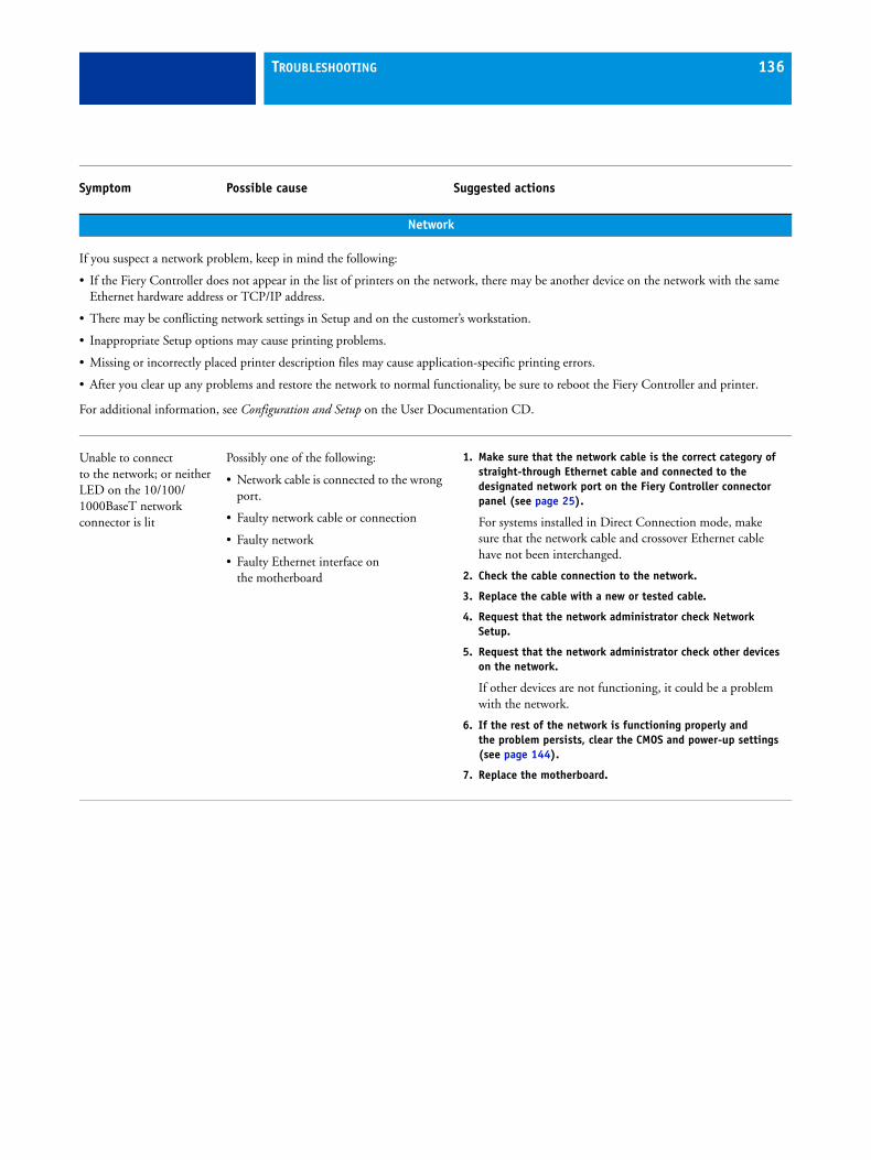
TROUBLESHOOTING 136
Network
If you suspect a network problem, keep in mind the following:
• If the Fiery Controller does not appear in the list of printers on the network, there may be another device on the network with the same Ethernet hardware address or TCP/IP address.
• There may be conflicting network settings in Setup and on the customer’s workstation.
• Inappropriate Setup options may cause printing problems.
• Missing or incorrectly placed printer description files may cause application-specific printing errors.
• After you clear up any problems and restore the network to normal functionality, be sure to reboot the Fiery Controller and printer.
For additional information, see Configuration and Setup on the User Documentation CD.
Unable to connect to the network; or neither LED on the 10/100/1000BaseT network connector is lit
Possibly one of the following:
• Network cable is connected to the wrong port.
• Faulty network cable or connection
• Faulty network
• Faulty Ethernet interface on the motherboard
1. Make sure that the network cable is the correct category of straight-through Ethernet cable and connected to the designated network port on the Fiery Controller connector panel (see page 25).
For systems installed in Direct Connection mode, make sure that the network cable and crossover Ethernet cable have not been interchanged.
2. Check the cable connection to the network.
3. Replace the cable with a new or tested cable.
4. Request that the network administrator check Network Setup.
5. Request that the network administrator check other devices on the network.
If other devices are not functioning, it could be a problem with the network.
6. If the rest of the network is functioning properly and the problem persists, clear the CMOS and power-up settings (see page 144).
7. Replace the motherboard.
Symptom Possible cause Suggested actions
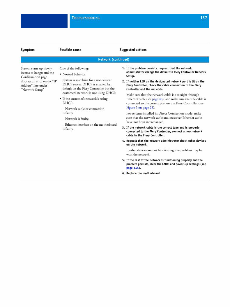
TROUBLESHOOTING 137
Network (continued)
System starts up slowly (seems to hang); and the Configuration page displays an error on the “IP Address” line under “Network Setup”
One of the following:
• Normal behavior
System is searching for a nonexistent DHCP server. DHCP is enabled by default on the Fiery Controller but the customer’s network is not using DHCP.
• If the customer’s network is using DHCP:
– Network cable or connectionis faulty.
– Network is faulty.
– Ethernet interface on the motherboard is faulty.
1. If the problem persists, request that the network administrator change the default in Fiery Controller Network Setup.
2. If neither LED on the designated network port is lit on the Fiery Controller, check the cable connection to the Fiery Controller and the network.
Make sure that the network cable is a straight-through Ethernet cable (see page 43), and make sure that the cable is connected to the correct port on the Fiery Controller (see Figure 5 on page 25).
For systems installed in Direct Connection mode, make sure that the network cable and crossover Ethernet cable have not been interchanged.
3. If the network cable is the correct type and is properly connected to the Fiery Controller, connect a new network cable to the Fiery Controller.
4. Request that the network administrator check other devices on the network.
If other devices are not functioning, the problem may be with the network.
5. If the rest of the network is functioning properly and the problem persists, clear the CMOS and power-up settings (see page 144).
6. Replace the motherboard.
Symptom Possible cause Suggested actions
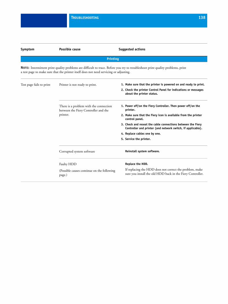
TROUBLESHOOTING 138
Printing
NOTE: Intermittent print quality problems are difficult to trace. Before you try to troubleshoot print quality problems, print a test page to make sure that the printer itself does not need servicing or adjusting.
Test page fails to print Printer is not ready to print. 1. Make sure that the printer is powered on and ready to print.
2. Check the printer Control Panel for indications or messages about the printer status.
There is a problem with the connection between the Fiery Controller and the printer.
1. Power off/on the Fiery Controller. Then power off/on the printer.
2. Make sure that the Fiery icon is available from the printer control panel.
3. Check and reseat the cable connections between the Fiery Controller and printer (and network switch, if applicable).
4. Replace cables one by one.
5. Service the printer.
Corrupted system software Reinstall system software.
Faulty HDD
(Possible causes continue on the following page.)
Replace the HDD.
If replacing the HDD does not correct the problem, make sure you install the old HDD back in the Fiery Controller.
Symptom Possible cause Suggested actions
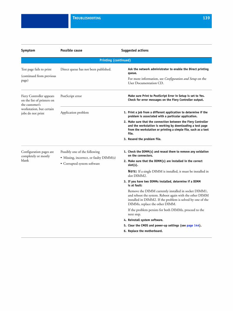
TROUBLESHOOTING 139
Printing (continued)
Test page fails to print
(continued from previous page)
Direct queue has not been published. Ask the network administrator to enable the Direct printing queue.
For more information, see Configuration and Setup on the User Documentation CD.
Fiery Controller appears on the list of printers on the customer’s workstation, but certain jobs do not print
PostScript error Make sure Print to PostScript Error in Setup is set to Yes. Check for error messages on the Fiery Controller output.
Application problem 1. Print a job from a different application to determine if the problem is associated with a particular application.
2. Make sure that the connection between the Fiery Controller and the workstation is working by downloading a test page from the workstation or printing a simple file, such as a text file.
3. Resend the problem file.
Configuration pages are completely or mostly blank
Possibly one of the following
• Missing, incorrect, or faulty DIMM(s)
• Corrupted system software
1. Check the DIMM(s) and reseat them to remove any oxidation on the connectors.
2. Make sure that the DIMM(s) are installed in the correct slot(s).
NOTE: If a single DIMM is installed, it must be installed in slot DIMM2.
3. If you have two DIMMs installed, determine if a DIMM is at fault:
Remove the DIMM currently installed in socket DIMM1, and reboot the system. Reboot again with the other DIMM installed in DIMM2. If the problem is solved by one of the DIMMs, replace the other DIMM.
If the problem persists for both DIMMs, proceed to the next step.
4. Reinstall system software.
5. Clear the CMOS and power-up settings (see page 144).
6. Replace the motherboard.
Symptom Possible cause Suggested actions
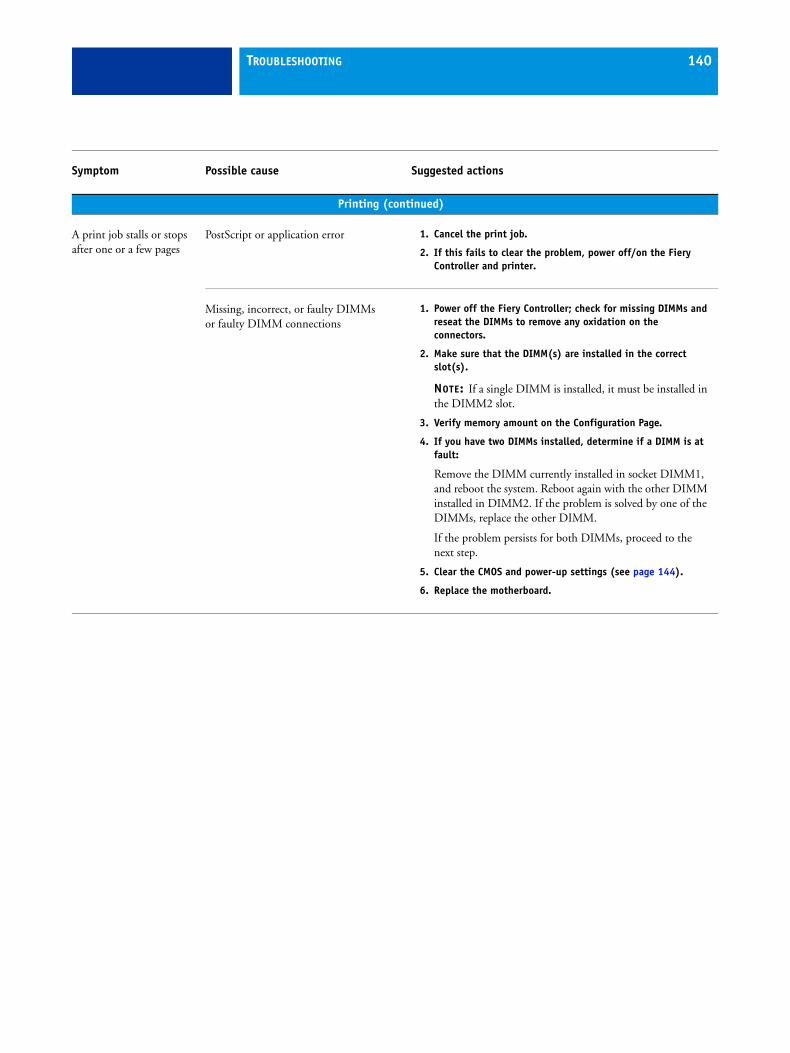
TROUBLESHOOTING 140
Printing (continued)
A print job stalls or stops after one or a few pages
PostScript or application error 1. Cancel the print job.
2. If this fails to clear the problem, power off/on the Fiery Controller and printer.
Missing, incorrect, or faulty DIMMs or faulty DIMM connections
1. Power off the Fiery Controller; check for missing DIMMs and reseat the DIMMs to remove any oxidation on the connectors.
2. Make sure that the DIMM(s) are installed in the correct slot(s).
NOTE: If a single DIMM is installed, it must be installed in the DIMM2 slot.
3. Verify memory amount on the Configuration Page.
4. If you have two DIMMs installed, determine if a DIMM is at fault:
Remove the DIMM currently installed in socket DIMM1, and reboot the system. Reboot again with the other DIMM installed in DIMM2. If the problem is solved by one of the DIMMs, replace the other DIMM.
If the problem persists for both DIMMs, proceed to the next step.
5. Clear the CMOS and power-up settings (see page 144).
6. Replace the motherboard.
Symptom Possible cause Suggested actions
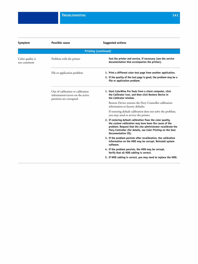
TROUBLESHOOTING 141
Printing (continued)
Color quality isnot consistent
Problem with the printer Test the printer and service, if necessary (see the service documentation that accompanies the printer).
File or application problem 1. Print a different color test page from another application.
2. If the quality of the test page is good, the problem may be a file or application problem.
Out of calibration or calibration information/curves on the active partition are corrupted.
1. Start ColorWise Pro Tools from a client computer, click the Calibrator icon, and then click Restore Device in the Calibrator window.
Restore Device restores the Fiery Controller calibration information to factory defaults.
If restoring default calibration does not solve the problem, you may need to service the printer.
2. If restoring default calibration fixes the color quality, the custom calibration may have been the cause of the problem. Request that the site administrator recalibrate the Fiery Controller (for details, see Color Printing on the User Documentation CD).
3. If the problem persists after recalibration, the calibration information on the HDD may be corrupt. Reinstall system software.
4. If the problem persists, the HDD may be corrupt. Verify that all HDD cabling is correct.
5. If HDD cabling is correct, you may need to replace the HDD.
Symptom Possible cause Suggested actions
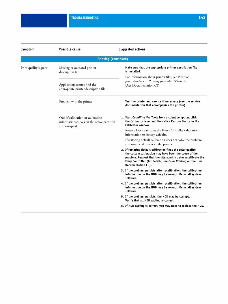
TROUBLESHOOTING 142
Printing (continued)
Print quality is poor Missing or outdated printerdescription file
Make sure that the appropriate printer description file is installed.
For information about printer files, see Printing from Windows or Printing from Mac OS on the User Documentation CD. Application cannot find the
appropriate printer description file
Problem with the printer Test the printer and service if necessary (see the service documentation that accompanies the printer).
Out of calibration or calibration information/curves on the active partition are corrupted.
1. Start ColorWise Pro Tools from a client computer, click the Calibrator icon, and then click Restore Device in the Calibrator window.
Restore Device restores the Fiery Controller calibration information to factory defaults.
If restoring default calibration does not solve the problem, you may need to service the printer.
2. If restoring default calibration fixes the color quality, the custom calibration may have been the cause of the problem. Request that the site administrator recalibrate the Fiery Controller (for details, see Color Printing on the User Documentation CD).
3. If the problem persists after recalibration, the calibration information on the HDD may be corrupt. Reinstall system software.
4. If the problem persists after recalibration, the calibration information on the HDD may be corrupt. Reinstall system software.
5. If the problem persists, the HDD may be corrupt. Verify that all HDD cabling is correct.
6. If HDD cabling is correct, you may need to replace the HDD.
Symptom Possible cause Suggested actions
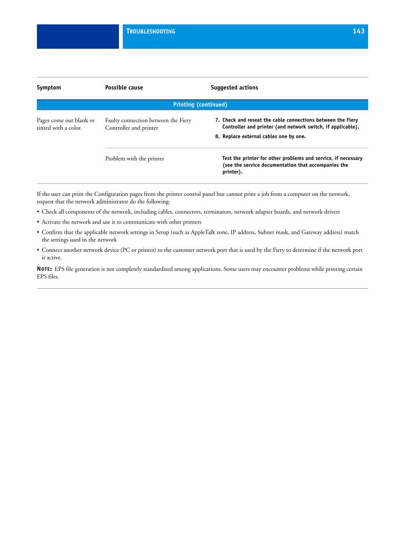
TROUBLESHOOTING 143
Printing (continued)
Pages come out blank or tinted with a color.
Faulty connection between the Fiery Controller and printer
7. Check and reseat the cable connections between the Fiery Controller and printer (and network switch, if applicable).
8. Replace external cables one by one.
Problem with the printer Test the printer for other problems and service, if necessary (see the service documentation that accompanies the printer).
If the user can print the Configuration pages from the printer control panel but cannot print a job from a computer on the network, request that the network administrator do the following:
• Check all components of the network, including cables, connectors, terminators, network adapter boards, and network drivers
• Activate the network and use it to communicate with other printers
• Confirm that the applicable network settings in Setup (such as AppleTalk zone, IP address, Subnet mask, and Gateway address) match the settings used in the network
• Connect another network device (PC or printer) to the customer network port that is used by the Fiery to determine if the network port is active.
NOTE: EPS file generation is not completely standardized among applications. Some users may encounter problems while printing certain EPS files.
Symptom Possible cause Suggested actions
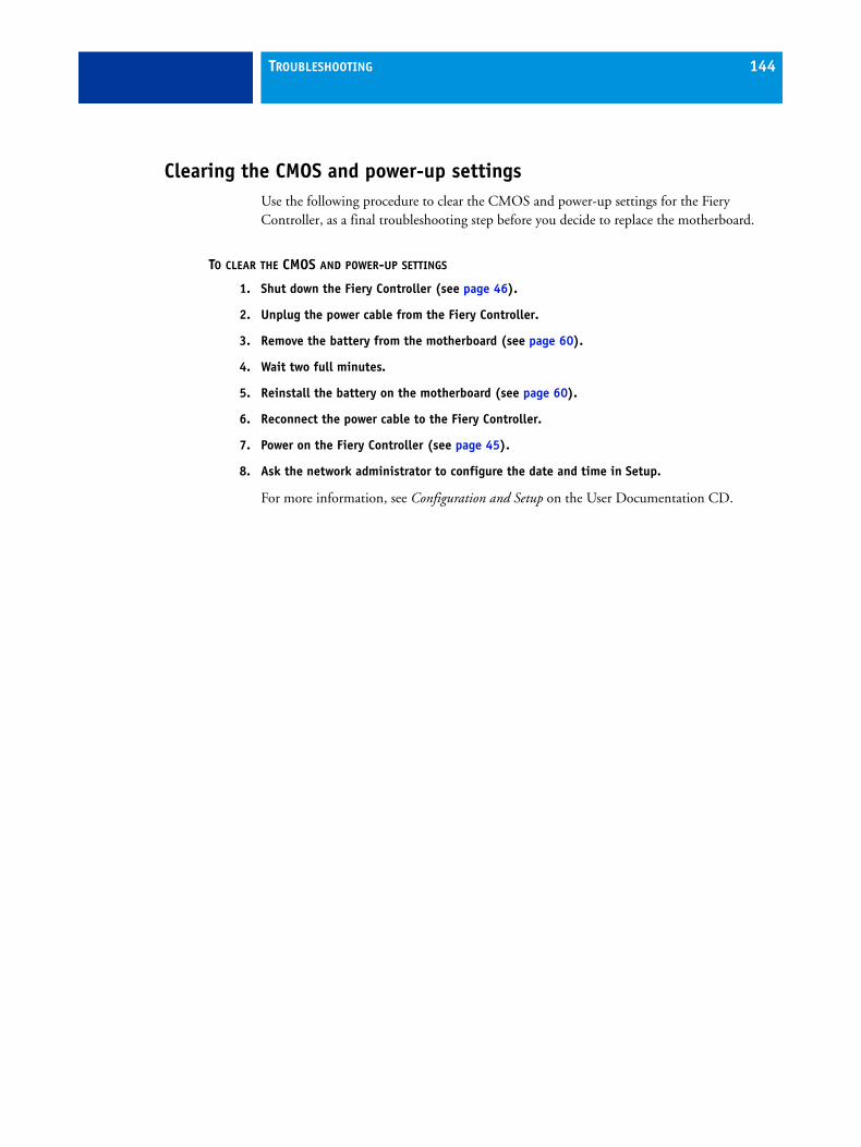
TROUBLESHOOTING 144
Clearing the CMOS and power-up settingsUse the following procedure to clear the CMOS and power-up settings for the Fiery Controller, as a final troubleshooting step before you decide to replace the motherboard.
TO CLEAR THE CMOS AND POWER-UP SETTINGS
1. Shut down the Fiery Controller (see page 46).
2. Unplug the power cable from the Fiery Controller.
3. Remove the battery from the motherboard (see page 60).
4. Wait two full minutes.
5. Reinstall the battery on the motherboard (see page 60).
6. Reconnect the power cable to the Fiery Controller.
7. Power on the Fiery Controller (see page 45).
8. Ask the network administrator to configure the date and time in Setup.
For more information, see Configuration and Setup on the User Documentation CD.
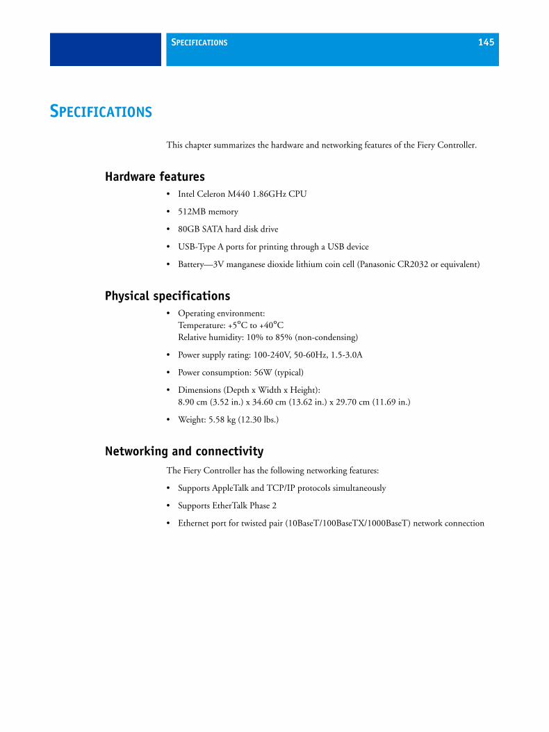
SPECIFICATIONS 145
SPECIFICATIONS
This chapter summarizes the hardware and networking features of the Fiery Controller.
Hardware features• Intel Celeron M440 1.86GHz CPU
• 512MB memory
• 80GB SATA hard disk drive
• USB-Type A ports for printing through a USB device
• Battery—3V manganese dioxide lithium coin cell (Panasonic CR2032 or equivalent)
Physical specifications• Operating environment:
Temperature: +5°C to +40°CRelative humidity: 10% to 85% (non-condensing)
• Power supply rating: 100-240V, 50-60Hz, 1.5-3.0A
• Power consumption: 56W (typical)
• Dimensions (Depth x Width x Height): 8.90 cm (3.52 in.) x 34.60 cm (13.62 in.) x 29.70 cm (11.69 in.)
• Weight: 5.58 kg (12.30 lbs.)
Networking and connectivityThe Fiery Controller has the following networking features:
• Supports AppleTalk and TCP/IP protocols simultaneously
• Supports EtherTalk Phase 2
• Ethernet port for twisted pair (10BaseT/100BaseTX/1000BaseT) network connection
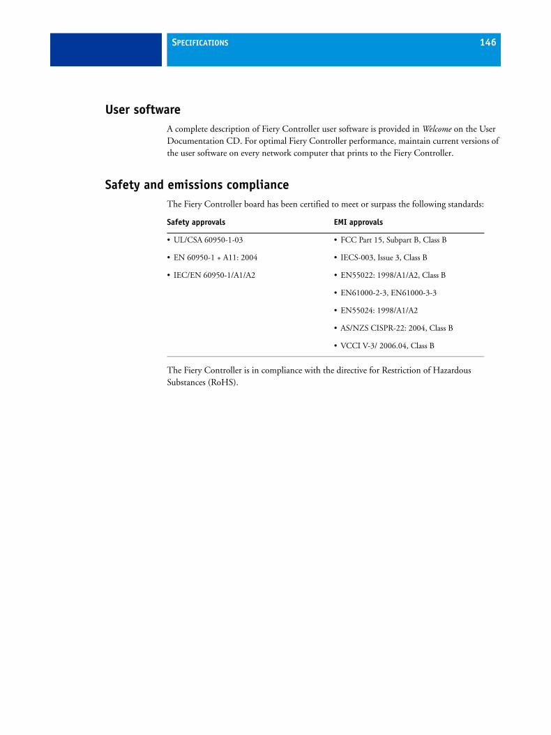
SPECIFICATIONS 146
User softwareA complete description of Fiery Controller user software is provided in Welcome on the User Documentation CD. For optimal Fiery Controller performance, maintain current versions of the user software on every network computer that prints to the Fiery Controller.
Safety and emissions complianceThe Fiery Controller board has been certified to meet or surpass the following standards:
The Fiery Controller is in compliance with the directive for Restriction of Hazardous Substances (RoHS).
Safety approvals EMI approvals
• UL/CSA 60950-1-03 • FCC Part 15, Subpart B, Class B
• EN 60950-1 + A11: 2004 • IECS-003, Issue 3, Class B
• IEC/EN 60950-1/A1/A2 • EN55022: 1998/A1/A2, Class B
• EN61000-2-3, EN61000-3-3
• EN55024: 1998/A1/A2
• AS/NZS CISPR-22: 2004, Class B
• VCCI V-3/ 2006.04, Class B
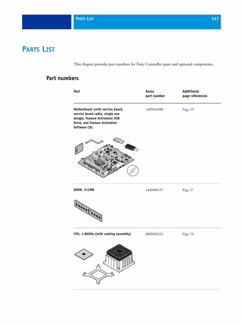
PARTS LIST 147
PARTS LIST
This chapter provides part numbers for Fiery Controller spare and optional components.
Part numbers
Part Xerox part number
Additional page references
Motherboard (with service board, service board cable, single-use dongle, Feature Activation USB Drive, and Feature Activation Software CD)
140N63390 Page 59
DIMM, 512MB 144N00157 Page 57
CPU, 1.86GHz (with cooling assembly) 600N03312 Page 70
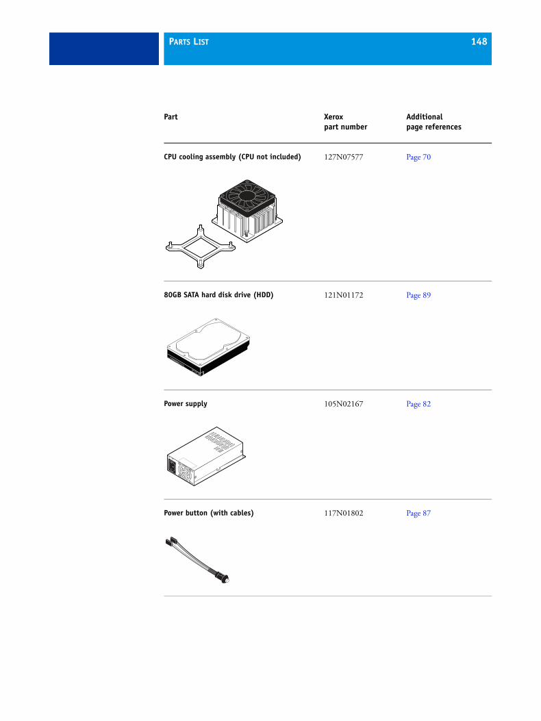
PARTS LIST 148
CPU cooling assembly (CPU not included) 127N07577 Page 70
80GB SATA hard disk drive (HDD) 121N01172 Page 89
Power supply 105N02167 Page 82
Power button (with cables)
117N01802 Page 87
Part Xerox part number
Additional page references
PARTS LIST 149
Fan 127N07576 Page 79
Crossover Ethernet cable 117N01716 Page 35
Service board cable 117N01801 Page 77
HDD SATA data cable 152N11622 Page 89
Power cable (US) 152N11664 Page 35
Part Xerox part number
Additional page references
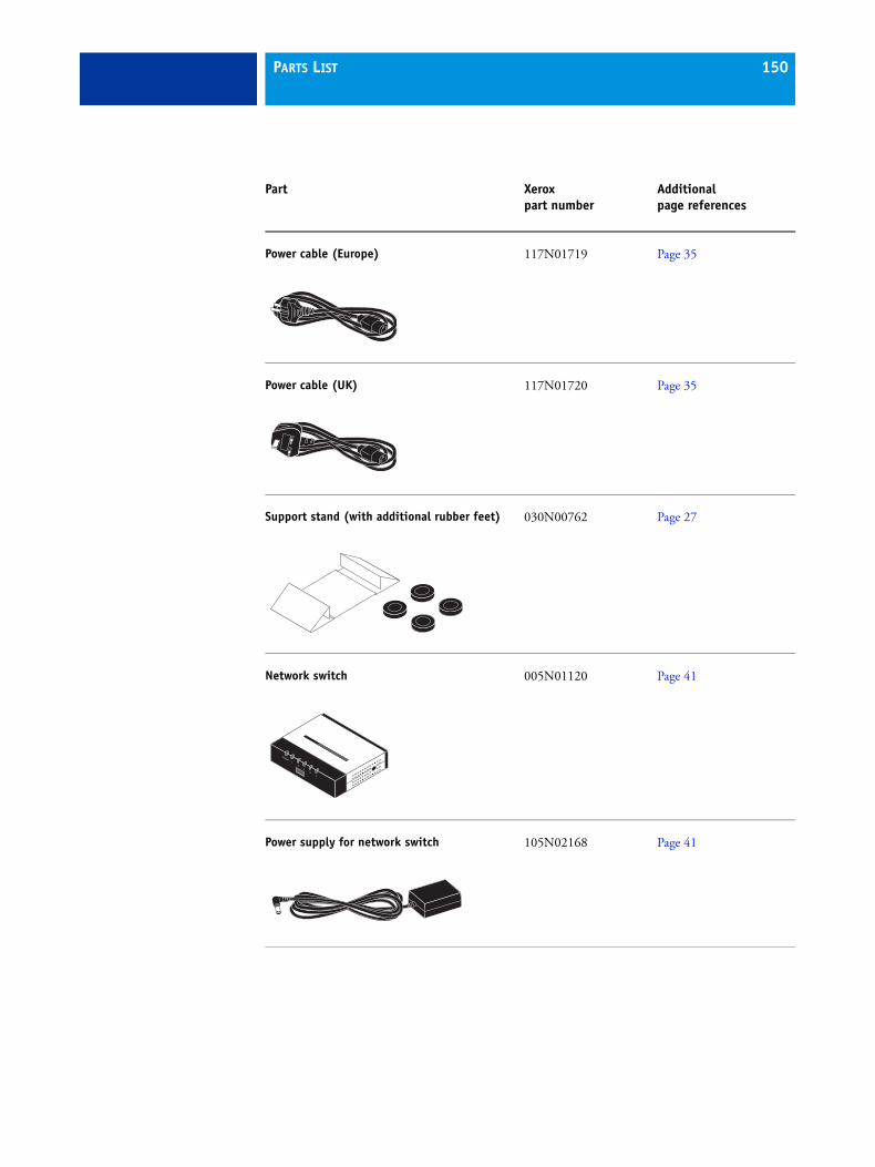
PARTS LIST 150
Power cable (Europe) 117N01719 Page 35
Power cable (UK) 117N01720 Page 35
Support stand (with additional rubber feet) 030N00762 Page 27
Network switch 005N01120 Page 41
Power supply for network switch 105N02168 Page 41
Part Xerox part number
Additional page references
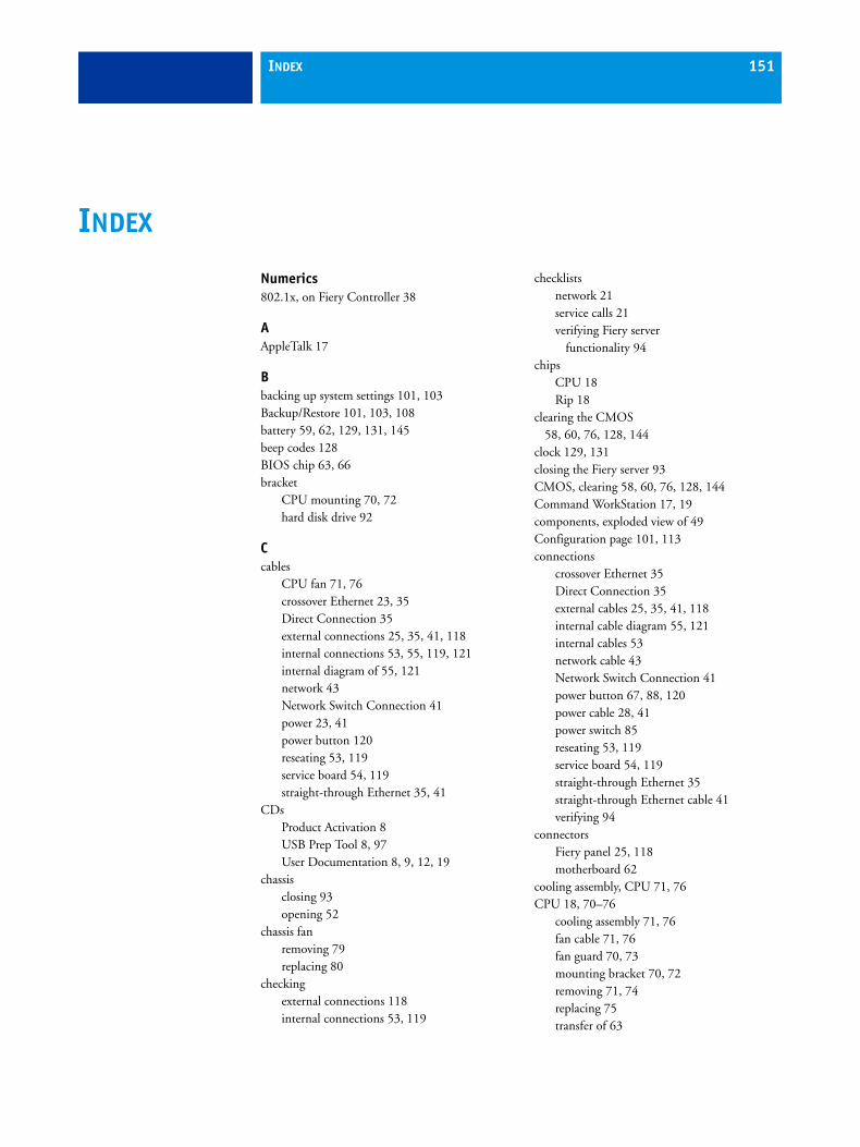
INDEX 151
Numerics802.1x, on Fiery Controller 38
AAppleTalk 17
Bbacking up system settings 101, 103Backup/Restore 101, 103, 108battery 59, 62, 129, 131, 145beep codes 128BIOS chip 63, 66bracket
CPU mounting 70, 72hard disk drive 92
Ccables
CPU fan 71, 76crossover Ethernet 23, 35Direct Connection 35external connections 25, 35, 41, 118internal connections 53, 55, 119, 121internal diagram of 55, 121network 43Network Switch Connection 41power 23, 41power button 120reseating 53, 119service board 54, 119straight-through Ethernet 35, 41
CDsProduct Activation 8USB Prep Tool 8, 97User Documentation 8, 9, 12, 19
chassisclosing 93opening 52
chassis fanremoving 79replacing 80
checkingexternal connections 118internal connections 53, 119
checklistsnetwork 21service calls 21verifying Fiery server
functionality 94chips
CPU 18Rip 18
clearing the CMOS 58, 60, 76, 128, 144
clock 129, 131closing the Fiery server 93CMOS, clearing 58, 60, 76, 128, 144Command WorkStation 17, 19components, exploded view of 49Configuration page 101, 113connections
crossover Ethernet 35Direct Connection 35external cables 25, 35, 41, 118internal cable diagram 55, 121internal cables 53network cable 43Network Switch Connection 41power button 67, 88, 120power cable 28, 41power switch 85reseating 53, 119service board 54, 119straight-through Ethernet 35straight-through Ethernet cable 41verifying 94
connectorsFiery panel 25, 118motherboard 62
cooling assembly, CPU 71, 76CPU 18, 70–76
cooling assembly 71, 76fan cable 71, 76fan guard 70, 73mounting bracket 70, 72removing 71, 74replacing 75transfer of 63
INDEX
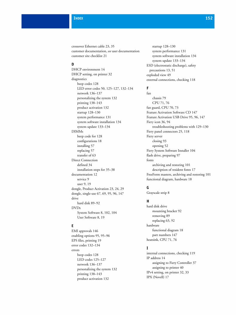
INDEX 152
crossover Ethernet cable 23, 35customer documentation, see user documentationcustomer site checklist 21
DDHCP environment 14DHCP setting, on printer 32diagnostics
beep codes 128LED error codes 50, 125–127, 132–134network 136–137personalizing the system 132printing 138–143product activation 132startup 128–130system performance 131system software installation 134system update 133–134
DIMMsbeep code for 128configurations 18installing 57replacing 57transfer of 63
Direct Connectiondefined 34installation steps for 35–38
documentation 12service 9user 9, 19
dongle, Product Activation 23, 24, 29dongle, single-use 67, 69, 95, 96, 147drive
hard disk 89–92DVDs
System Software 8, 102, 104User Software 8, 19
EEMI approvals 146enabling options 95, 95–96EPS files, printing 19error codes 132–134errors
beep codes 128LED codes 125–127network 136–137personalizing the system 132printing 138–143product activation 132
startup 128–130system performance 131system software installation 134system update 133–134
ESD (electrostatic discharge), safetyprecautions 13, 51
exploded view 49external connections, checking 118
Ffan
chassis 79CPU 71, 76
fan guard, CPU 70, 73Feature Activation Software CD 147Feature Activation USB Drive 95, 96, 147Fiery icon 36, 94
troubleshooting problems with 129–130Fiery panel connectors 25, 118Fiery server
closing 93opening 52
Fiery System Software Installer 104flash drive, preparing 97fonts
archiving and restoring 101description of resident fonts 17
FreeForm masters, archiving and restoring 101functional diagram, hardware 18
GGrayscale strip 8
Hhard disk drive
mounting bracket 92removing 89replacing 63, 92
hardwarefunctional diagram 18part numbers 147
heatsink, CPU 71, 76
Iinternal connections, checking 119IP address 14
assigning to Fiery Controller 37assigning to printer 40
IPv4 setting, on printer 32, 33IPX (Novell) 17
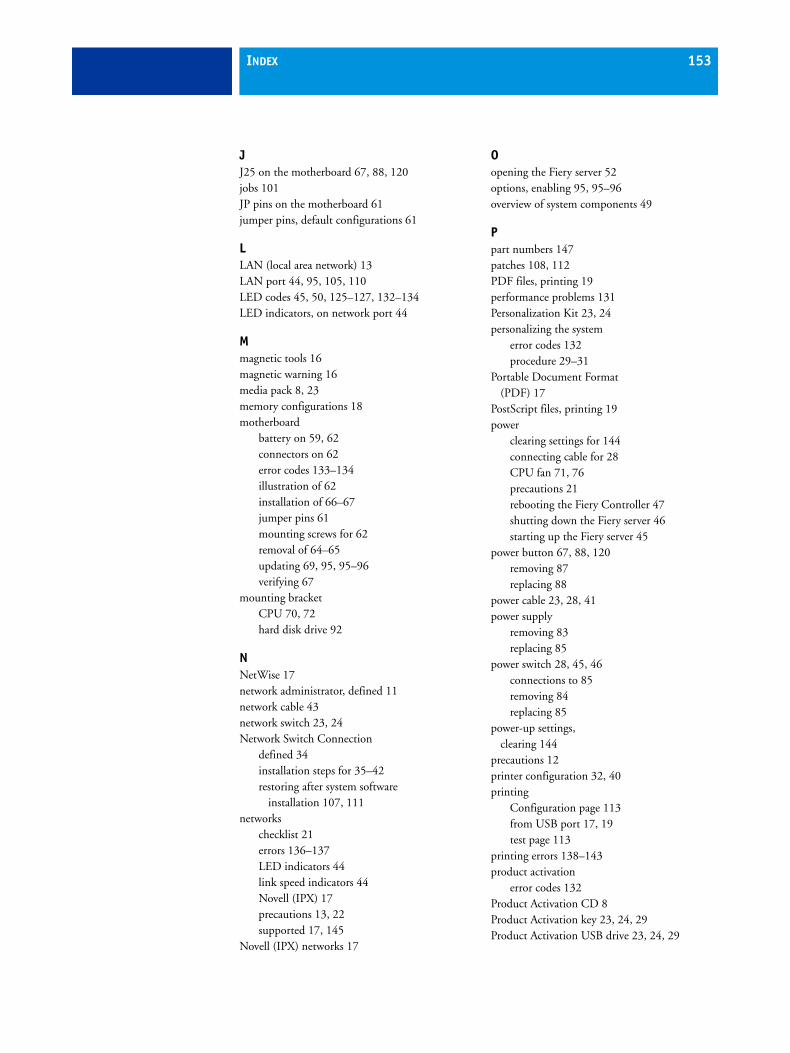
INDEX 153
JJ25 on the motherboard 67, 88, 120jobs 101JP pins on the motherboard 61jumper pins, default configurations 61
LLAN (local area network) 13LAN port 44, 95, 105, 110LED codes 45, 50, 125–127, 132–134LED indicators, on network port 44
Mmagnetic tools 16magnetic warning 16media pack 8, 23memory configurations 18motherboard
battery on 59, 62connectors on 62error codes 133–134illustration of 62installation of 66–67jumper pins 61mounting screws for 62removal of 64–65updating 69, 95, 95–96verifying 67
mounting bracketCPU 70, 72hard disk drive 92
NNetWise 17network administrator, defined 11network cable 43network switch 23, 24Network Switch Connection
defined 34installation steps for 35–42restoring after system software
installation 107, 111networks
checklist 21errors 136–137LED indicators 44link speed indicators 44Novell (IPX) 17precautions 13, 22supported 17, 145
Novell (IPX) networks 17
Oopening the Fiery server 52options, enabling 95, 95–96overview of system components 49
Ppart numbers 147patches 108, 112PDF files, printing 19performance problems 131Personalization Kit 23, 24personalizing the system
error codes 132procedure 29–31
Portable Document Format(PDF) 17
PostScript files, printing 19power
clearing settings for 144connecting cable for 28CPU fan 71, 76precautions 21rebooting the Fiery Controller 47shutting down the Fiery server 46starting up the Fiery server 45
power button 67, 88, 120removing 87replacing 88
power cable 23, 28, 41power supply
removing 83replacing 85
power switch 28, 45, 46connections to 85removing 84replacing 85
power-up settings, clearing 144
precautions 12printer configuration 32, 40printing
Configuration page 113from USB port 17, 19test page 113
printing errors 138–143product activation
error codes 132Product Activation CD 8Product Activation key 23, 24, 29Product Activation USB drive 23, 24, 29
INDEX 154
Rreboot procedure, Fiery Controller 47removing the server 51reseating connections 53, 119restart procedure, Fiery Controller 47restoring system settings 101, 108RipChips 18RIP-While-Print 19
Ssafety approvals 146safety precautions 12server
closing 93opening 52removing 51
service board 54, 77, 119removing 77replacing 78
service bulletins 16service calls
checklist 21tools required 16
Service Mode 67service switches 78, 95, 105, 110
boot mode 29, 95, 110normal (OFF) mode 31, 107, 110, 111ON position 105
service technician, defined 11shipping list 23shutdown procedure
Fiery server 46slot assignments 62software
system 63, 109user 11, 22
software patches 108, 112space requirements 21stand, for server 23, 27, 28Start page 36, 42, 45, 107, 111startup errors 128–130startup procedure, Fiery server 45startup sequence, explanation of 45static IP
on Fiery Controller 37on printer 40
straight-through Ethernet cable 35, 41support stand 23, 27, 28system overview 49system performance problems 131
system settingsbacking up 101, 103restoring 101, 108
system software 29, 63errors 134network port installation 102–108precautions 101USB installation 30, 31, 109–112
System Software DVD 8, 102, 104System Software USB drive 23, 24, 30system update errors 133–134
TTCP/IP 17terminology 11test page 113thumb drive, preparing 97tools required for service 16touch screen 32
Uupdating the system 69, 95, 95–96
error codes 133–134USB flash drive, preparing 97USB Prep Tool application 98USB Prep Tool CD 8, 97USB printing 17, 19user documentation 9, 19User Documentation CD 8, 9, 12, 19user software 11, 22User Software DVD 8, 19
Vverifying
Fiery server connections 94new motherboard installation 67
WWelcome guide 8, 146