installation - broadband internet 3bb
TRANSCRIPT
1
Installation Installation procedure:
A Install ADSL Router (Page 1-3)
B LAN Card setting (Page 4-12)
B.1 For Windows XP user
B.2 For Windows Vista user
C How to use 3BB CD-ROM and Username/Password Setting (Page 13-21)
C.1 Setting by using CD-ROM
C.2 Setting via web page
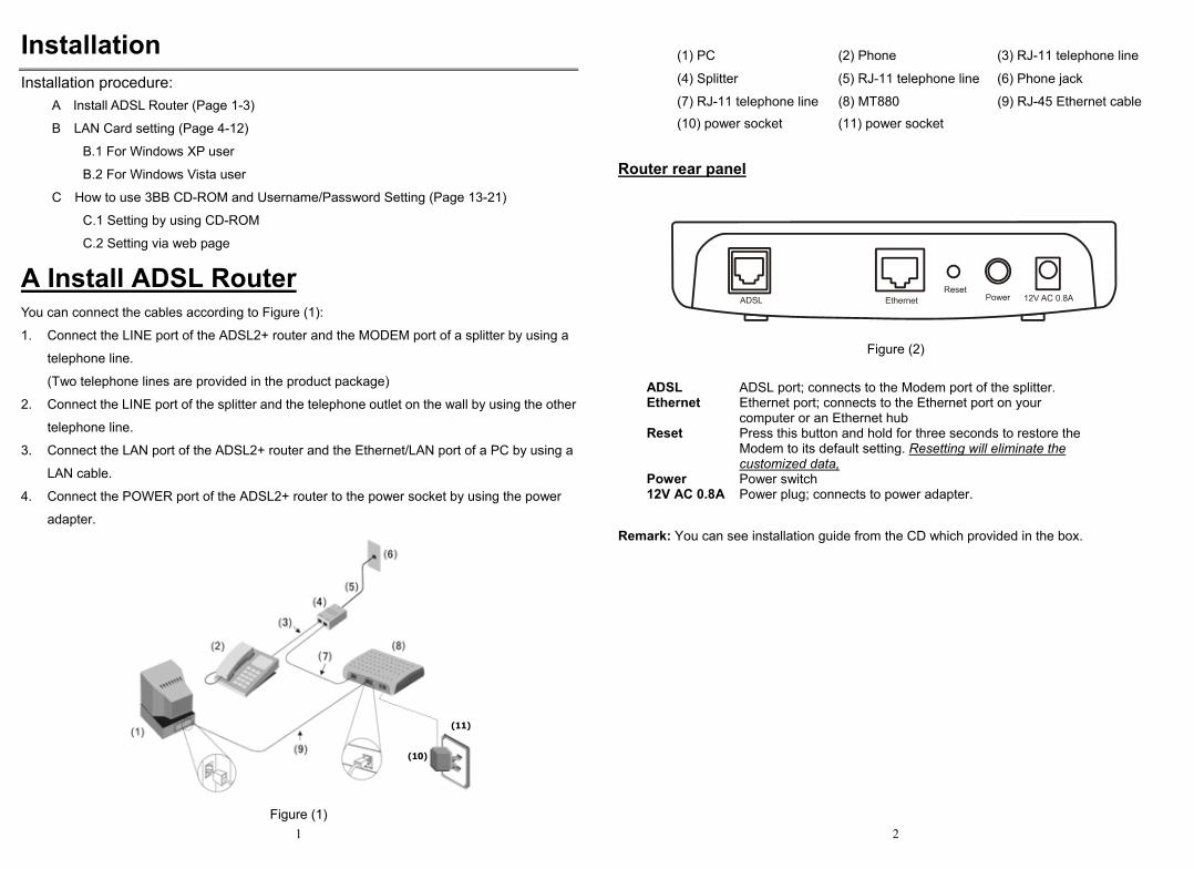
A Install ADSL Router You can connect the cables according to Figure (1):
1. Connect the LINE port of the ADSL2+ router and the MODEM port of a splitter by using a
telephone line.
(Two telephone lines are provided in the product package)
2. Connect the LINE port of the splitter and the telephone outlet on the wall by using the other
telephone line.
3. Connect the LAN port of the ADSL2+ router and the Ethernet/LAN port of a PC by using a
LAN cable.
4. Connect the POWER port of the ADSL2+ router to the power socket by using the power
adapter.
(10)
(11)
Figure (1)
2
(1) PC (2) Phone (3) RJ-11 telephone line
(4) Splitter (5) RJ-11 telephone line (6) Phone jack
(7) RJ-11 telephone line (8) MT880 (9) RJ-45 Ethernet cable (10) power socket (11) power socket
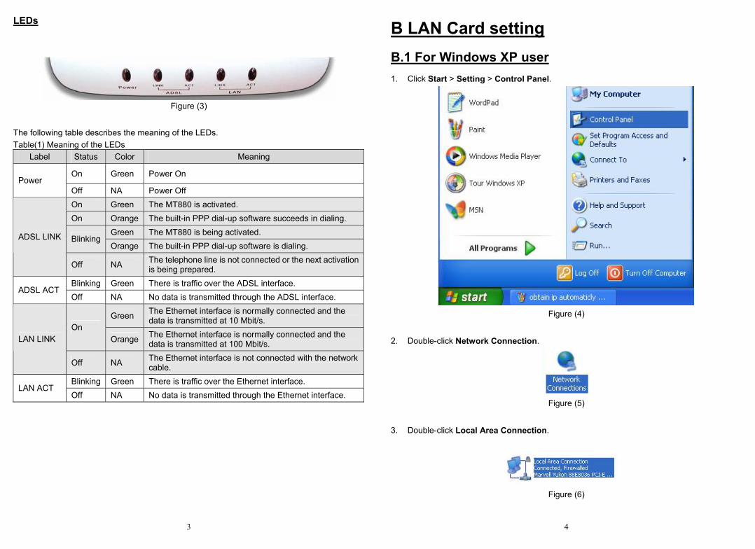
Router rear panel
Figure (2)
ADSL ADSL port; connects to the Modem port of the splitter. Ethernet Ethernet port; connects to the Ethernet port on your
computer or an Ethernet hub Reset Press this button and hold for three seconds to restore the
Modem to its default setting. Resetting will eliminate the customized data,
Power Power switch 12V AC 0.8A Power plug; connects to power adapter.
Remark: You can see installation guide from the CD which provided in the box.
3
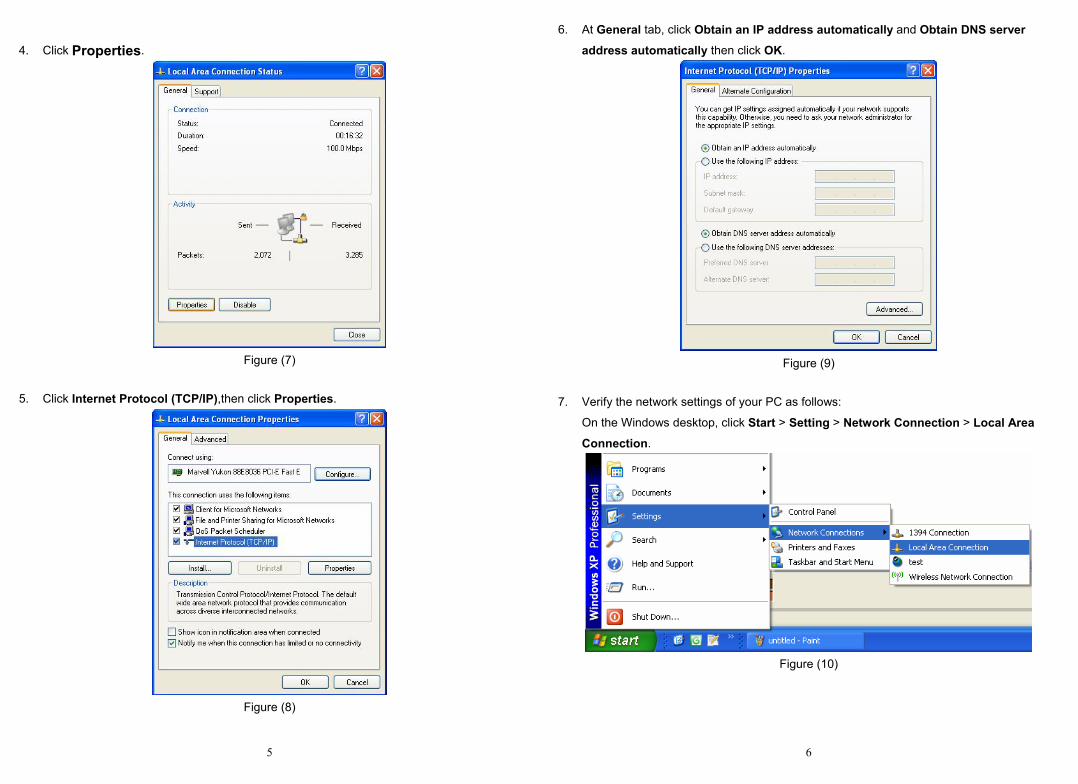
LEDs
Figure (3)
The following table describes the meaning of the LEDs. Table(1) Meaning of the LEDs
Label Status Color Meaning
On Green Power On Power
Off NA Power Off On Green The MT880 is activated. On Orange The built-in PPP dial-up software succeeds in dialing.
Green The MT880 is being activated. Blinking
Orange The built-in PPP dial-up software is dialing. ADSL LINK
Off NA The telephone line is not connected or the next activation is being prepared.
Blinking Green There is traffic over the ADSL interface. ADSL ACT
Off NA No data is transmitted through the ADSL interface.
Green The Ethernet interface is normally connected and the data is transmitted at 10 Mbit/s.
On Orange The Ethernet interface is normally connected and the
data is transmitted at 100 Mbit/s. LAN LINK
Off NA The Ethernet interface is not connected with the network cable.
Blinking Green There is traffic over the Ethernet interface. LAN ACT
Off NA No data is transmitted through the Ethernet interface.
4
B LAN Card setting B.1 For Windows XP user 1. Click Start > Setting > Control Panel.
Figure (4)
2. Double-click Network Connection.
Figure (5)
3. Double-click Local Area Connection.
Figure (6)
5
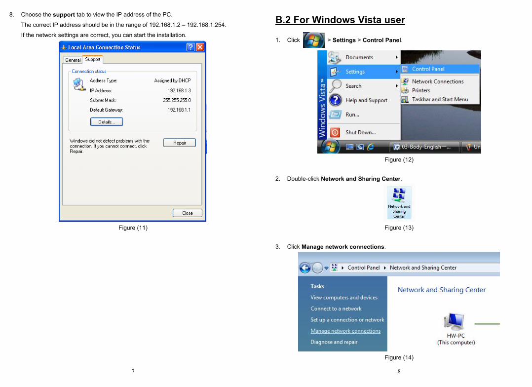
4. Click Properties.
Figure (7)
5. Click Internet Protocol (TCP/IP),then click Properties.
Figure (8)
6
6. At General tab, click Obtain an IP address automatically and Obtain DNS server
address automatically then click OK.
Figure (9)
7. Verify the network settings of your PC as follows:
On the Windows desktop, click Start > Setting > Network Connection > Local Area
Connection.
Figure (10)
7
8. Choose the support tab to view the IP address of the PC.
The correct IP address should be in the range of 192.168.1.2 – 192.168.1.254.
If the network settings are correct, you can start the installation.
Figure (11)
8
B.2 For Windows Vista user 1. Click > Settings > Control Panel.
Figure (12)
2. Double-click Network and Sharing Center.
Figure (13)
3. Click Manage network connections.
Figure (14)
9
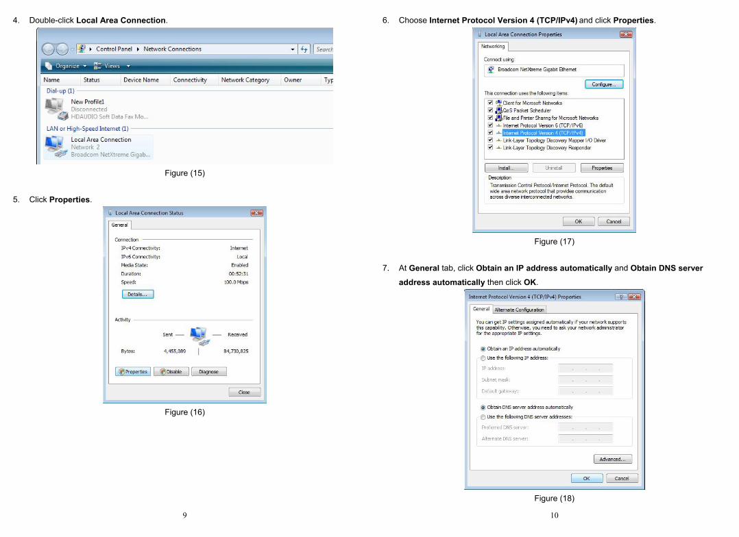
4. Double-click Local Area Connection.
Figure (15)
5. Click Properties.
Figure (16)
10
6. Choose Internet Protocol Version 4 (TCP/IPv4) and click Properties.
Figure (17)
7. At General tab, click Obtain an IP address automatically and Obtain DNS server
address automatically then click OK.
Figure (18)
11
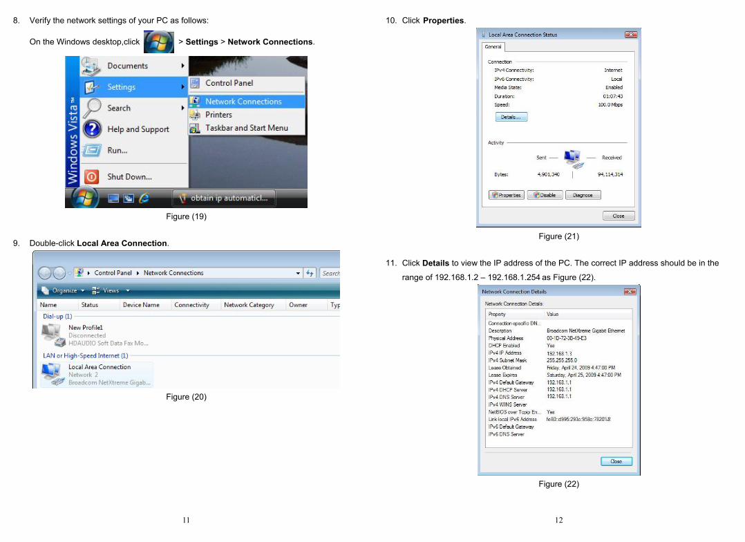
8. Verify the network settings of your PC as follows:
On the Windows desktop,click > Settings > Network Connections.
Figure (19)
9. Double-click Local Area Connection.
Figure (20)
12
10. Click Properties.
Figure (21)
11. Click Details to view the IP address of the PC. The correct IP address should be in the
range of 192.168.1.2 – 192.168.1.254 as Figure (22).
Figure (22)
13
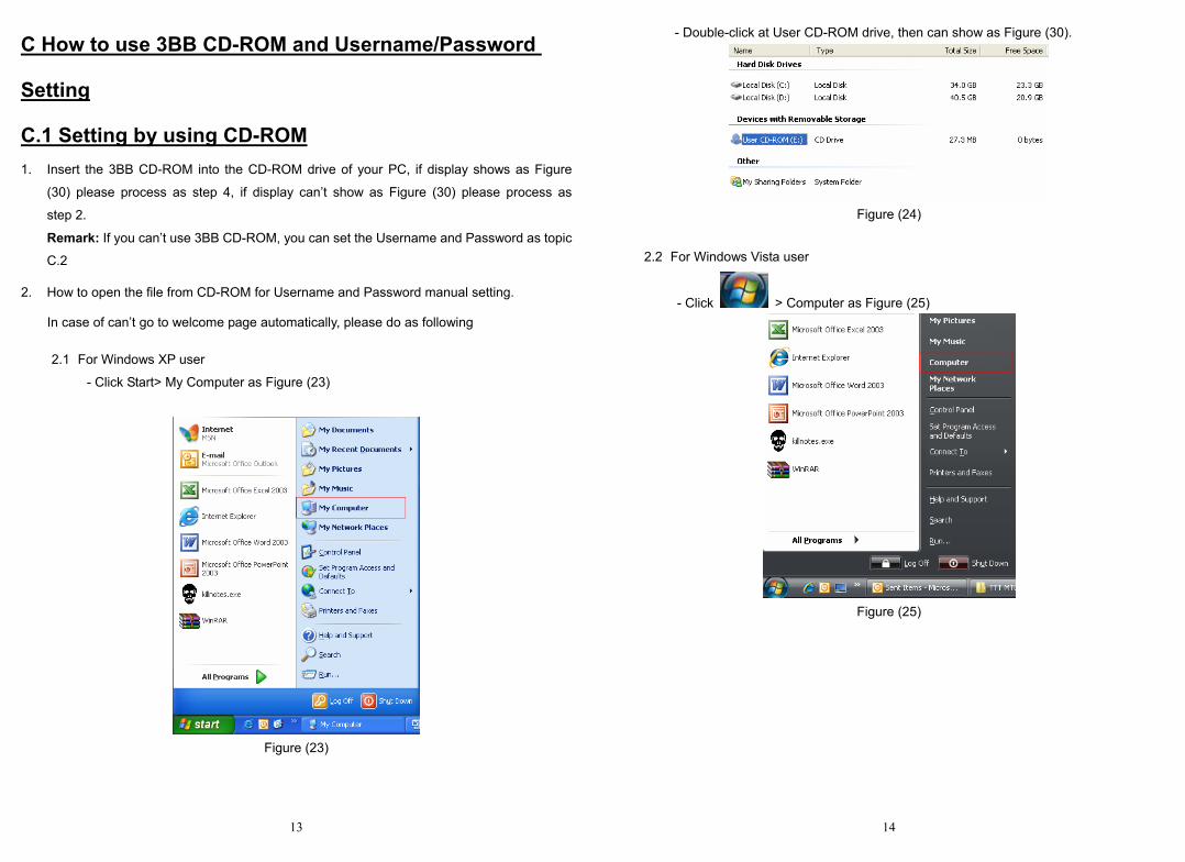
C How to use 3BB CD-ROM and Username/Password
Setting
C.1 Setting by using CD-ROM 1. Insert the 3BB CD-ROM into the CD-ROM drive of your PC, if display shows as Figure
(30) please process as step 4, if display can’t show as Figure (30) please process as
step 2.
Remark: If you can’t use 3BB CD-ROM, you can set the Username and Password as topic
C.2
2. How to open the file from CD-ROM for Username and Password manual setting.
In case of can’t go to welcome page automatically, please do as following 2.1 For Windows XP user
- Click Start> My Computer as Figure (23)
Figure (23)
14
- Double-click at User CD-ROM drive, then can show as Figure (30).
Figure (24)
2.2 For Windows Vista user
- Click > Computer as Figure (25)
Figure (25)

15
- Double-click at User CD-ROM drive.
Figure (26)
- Open the CD-ROM Drive and right-click on the icon of the MT880r-T file.
Figure (27)
- Choose Run as administrator from shortcut menu as shown in Figure (28).
Figure (28)
16
- Click Allow in the displayed User Account Control as shown in Figure (29).
Figure (29)
After that display will show as Figure (30) and please process as step 3.
3. The display will show as Figure (30)
Figure (30)
17
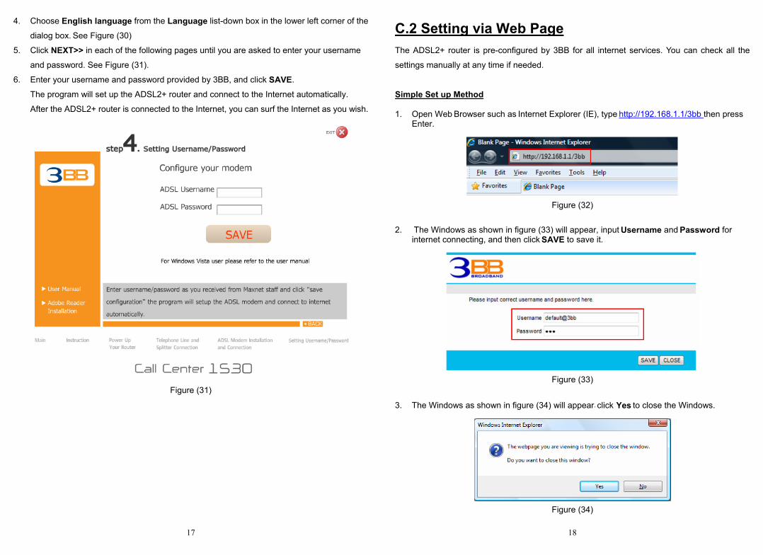
4. Choose English language from the Language list-down box in the lower left corner of the
dialog box. See Figure (30)
5. Click NEXT>> in each of the following pages until you are asked to enter your username
and password. See Figure (31).
6. Enter your username and password provided by 3BB, and click SAVE.
The program will set up the ADSL2+ router and connect to the Internet automatically.
After the ADSL2+ router is connected to the Internet, you can surf the Internet as you wish.
Figure (31)
18
C.2 Setting via Web Page The ADSL2+ router is pre-configured by 3BB for all internet services. You can check all the
settings manually at any time if needed.
Simple Set up Method
1. Open Web Browser such as Internet Explorer (IE), type http://192.168.1.1/3bb then press Enter.
Figure (32)
2. The Windows as shown in figure (33) will appear, input Username and Password for internet connecting, and then click SAVE to save it.
Figure (33)
3. The Windows as shown in figure (34) will appear, click Yes to close the Windows.
Figure (34)

19
Web Set up Method 1. After connecting the cables as Figure (1) page 1, run the ADSL2+ router for 1–2 minutes.
2. Launch the Internet Explorer and access the address 192.168.1.1.
Figure (35)
3. In the Logon page, enter your username and password.
The default values are admin (username) and 3bb (password).
Figure (36)
20
4. Then the web setup page is displayed as shown in Figure (37).
Figure (37)
5. Click Basic -> WAN Setting -> PVC-0 on web setup, enter your username and password
provided by 3BB and click Submit to save the changes. Now the ADSL2+ router will
automatically connect to the 3BB network and is ready for Internet services.
Figure (38)
Figure (39)

21
Verifying Network Settings Verify the network settings by selecting the Status tab of the web setup page. See Figure (40).
If the IP address is 0.0.0.0, it indicates that the connection is incorrect. The correct value should
be something like 202.xxx.xxx.xxx.
Figure (40)
Troubleshooting If there is any problem with the ADSL2+ router, try the following operations to fix the problem:
1. Make sure that all the cables and the power adapter are connected properly refer to Figure (1)
2. Make sure that the TCP/IP settings of your PC are correct. That is, the PC is set to obtain an IP address automatically from the DNS server. Refer to topic B.
3. Contact Call center 1530.
Issue: 05 (2009-09-14)
Part Number: 103136