installation and maintenance - xylem us€¦ · installation and maintenance micro 5g and 7g,...
TRANSCRIPT
897033/01
Installation and MaintenanceMicro Pump Station 5G and 7G, outdoor

Installation and Maintenance MICRO 5G and 7G, outdoor
3
CONTENTS1 Safety _____________________________ 32 General ___________________________ 43 Description of products and accessories _ 54 Unloading and Storage _______________ 65 Installation and assembly _____________ 66 Start up and operation ________________ 87 Maintenance _______________________ 88 Guarantee _________________________ 99 Faults, causes and remedies ___________ 9
1 SafetyThe instructions contained in this manual, concerningthe installation, operation and maintenance of the plantare to be strictly adhered to. It is therefore essential toread this manual carefully before proceeding to installa-tion or acceptance inspection. This applies both toinstallation personnel as well as to personnel responsi-ble for operation and maintenance of equipment. Thisoperation and maintenance manual must be availablefor easy access on the site at any moment.
1.1 Explanation of graphic symbolsrelated to safety
This symbol indicates safety instruc-tions which if not observed represent adanger for persons.
This symbol indicates risk of electrocu-tion.
WARNING! Non-observance of this warning maycause damage to the equipment or af-fect its functioning.
1.2 Qualification of personnelWork must be strictly entrusted to qualified personnel.
1.3 Hazards occurred in case ofnon-observance of instructions
Non-observance of safety instructions may create ahazard to the safety of persons and the installation. Itmay also result in forfeiture of all remedies under theguarantee. More specifically, the hazards occurred maybe the following:
- Failure of important functions of the installation.
- Danger to persons in case of electrical or mechanicalbreakdown of the machine.
1.4 Safety instructions for user
National regulations in force and local standards con-cerning hygiene and safety must be observed.
All risks of electrocution must be avoided (for furtherdetails, please consult the regulations established by thelocal electricity provider).
1.5 Safety advice for inspection andassembly work
User must ensure that such works are carried out byqualified and authorized personnel. Works on the pump /pump station must only be carried out when disconnect-ed from the power supply.
1.6 Modification of material and use ofunauthorized spare parts.
Use of original spare parts and accessories authorizedby the manufacturer guarantees safety. ITT FLYGTdisclaims any liability in case of use of third-party spareparts.
1.7 Assembly and disassembly
If the pump is used for pumping of hazardous liquids, itis strictly necessary to ensure that no danger is createdfor persons or the environment during the course ofdraining.
All waste and sewage such as grey cooling liquid mustbe handled in an appropriate manner. Flows of coolingliquids must be subject to careful cleansing and dis-charge of waste in the environment must be indicated.
The lifting plant must constantly be kept properly and ina good state.
All applicable regulations must be adhered to.
Installation and Maintenance MICRO 5G and 7G, outdoor
4
2 GeneralInstallation, start up and operation must be carried outexclusively by qualified personnel.
2.1 Applications
The pump station may not be used inan explosive or flammable environmentor for pumping flammable liquids.
Grey water (except for WC): Micro 5G, Micro 7G.
Waste water (including WC): Micro 5G DN 50, Micro 7G.
The Micro-stations 5G and 7G must be installed under-ground outside of the building.
In accordance with standardEN 12056-1 “Gravity drainage systemsinside buildings”, it is possible to proc-ess sanitary waste free from faecalmaterials (grey water) or sanitarywaste containing faecal materials origi-nating from private residences or rain-water.
Lifting plants complying withEN 12050-1 may be used for pumpingused water containing faecal materialsor otherwise.
Lifting plants complying withEN 12050-2 may be used for pumpingfaecal-free water.
For product compliance please refer totable 1. (page 5)
In case of non-compliance with the re-quirements concerning use of materi-als/waste (in accordance with the Mi-cro station type), conformity withEN 12050 is no longer guaranteed andthe manufacturer is released from anyliability.
You should also observe the indications specified in themanual concerning installation, start up and operation ofthe pump as well as in manual of the electrical controlbox (for the Micro 7 G version).
During the course of installation, startup and operation, all applicable stand-ards and specifications must be strictlycomplied with.
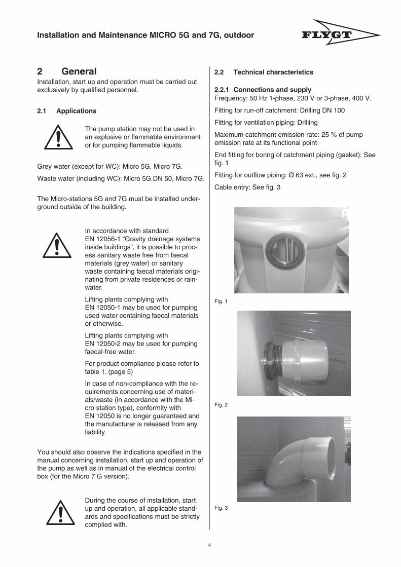
2.2 Technical characteristics
2.2.1 Connections and supplyFrequency: 50 Hz 1-phase, 230 V or 3-phase, 400 V.
Fitting for run-off catchment: Drilling DN 100
Fitting for ventilation piping: Drilling
Maximum catchment emission rate: 25 % of pumpemission rate at its functional point
End fitting for boring of catchment piping (gasket): Seefig. 1
Fitting for outflow piping: Ø 63 ext., see fig. 2
Cable entry: See fig. 3
Fig. 1
Fig. 2
Fig. 3
Installation and Maintenance MICRO 5G and 7G, outdoor
5
3872
1
105
45°
350
Ø 533
Ø 639
Ø 547
772
682
1050
360
360
200
106
120
Ø 6
50
220
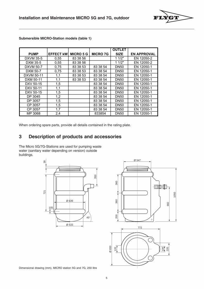
The Micro 5G/7G-Stations are used for pumping wastewater (sanitary water depending on version) outsidebuildings.
Submersible MICRO-Station models (table 1)
When ordering spare parts, provide all details contained in the rating plate.
Dimensional drawing (mm), MICRO station 5G and 7G, 250 litre
3 Description of products and accessories
PUMP EFFECT kW MICRO 5 G MICRO 7G
OUTLET
SIZE EN APPROVAL
DXVM 35-5 0,55 83 38 56 1 1/2" EN 12050-2
DXM 35-5 0,55 83 38 56 1 1/2" EN 12050-2
DXVM 50-7 0,75 83 38 53 83 38 54 DN50 EN 12050-1
DXM 50-7 0,75 83 38 53 83 38 54 DN50 EN 12050-1
DXVM 50-11 1,1 83 38 53 83 38 54 DN50 EN 12050-1
DXM 50-11 1,1 83 38 53 83 38 54 DN50 EN 12050-1
DXV 50-15 1,5 83 38 54 DN50 EN 12050-1
DXV 50-11 1,1 83 38 54 DN50 EN 12050-1
DXV 50-15 1,5 83 38 54 DN50 EN 12050-1
DP 3045 1,2 83 38 54 DN50 EN 12050-1
DP 3057 1,5 83 38 54 DN50 EN 12050-1
CP 3057 1,5 83 38 54 DN50 EN 12050-1
CP 3057 1,7 83 38 54 DN50 EN 12050-1
MP 3068 2,4 833854 DN50 EN 12050-1
Installation and Maintenance MICRO 5G and 7G, outdoor
6
4 Unloading and Storage4.1 UnloadingThe pumpstation is delivered in a box on a pallet.Unload with a suitable lifting device. It is thereforeimportant to safeguard its stability. The pumpstationmust be protected against mechanical damage.
4.2 StorageWhen recieving the packaging, check so there are nodefects on its content or on the pump station.
If the pump station is to be left in storage for a certainperiod of time prior to its installation, it should be left in avertical position in its packaging.
5 Installation and assembly
Arrange suitable barriers around the work area,eg. a safety railing.
5.1 Installation of pump
Read the Installation, Care and Maintenance manual forthe pump before installation of the MICRO pump station.
Micro 5G version: Connect pump to piping.
Micro 7G version: Slide the pump along the guide barsprovided for this purpose
Very important:
WARNING! It is essential to ensureproper functioning of level regulator inthe pumpstation.
During installation, it is necessary to separate theelectric cable from the socket , in order to pass itthrough the compression packing and to connect thecable from the outside to a standardized fuse box.
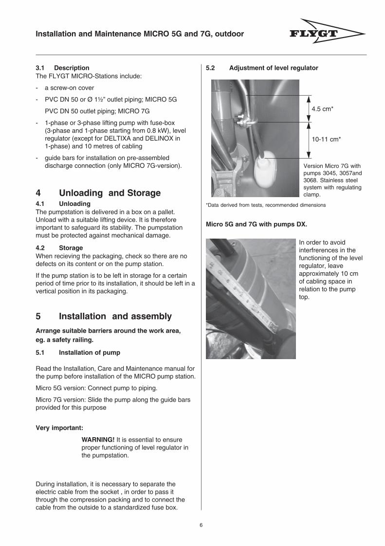
Version Micro 7G withpumps 3045, 3057and3068. Stainless steelsystem with regulatingclamp.
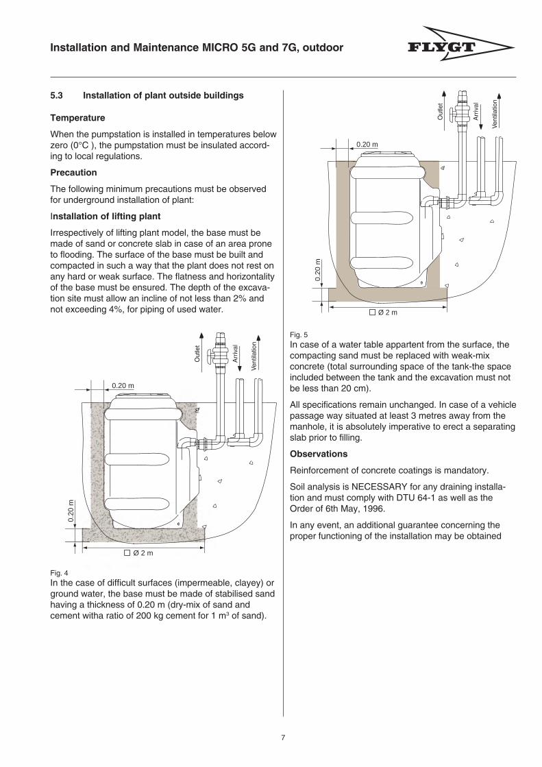
In order to avoidinterfrerences in thefunctioning of the levelregulator, leaveapproximately 10 cmof cabling space inrelation to the pumptop.
Micro 5G and 7G with pumps DX.
3.1 DescriptionThe FLYGT MICRO-Stations include:
- a screw-on cover
- PVC DN 50 or Ø 1½” outlet piping; MICRO 5G
PVC DN 50 outlet piping; MICRO 7G
- 1-phase or 3-phase lifting pump with fuse-box(3-phase and 1-phase starting from 0.8 kW), levelregulator (except for DELTIXA and DELINOX in1-phase) and 10 metres of cabling
- guide bars for installation on pre-assembleddischarge connection (only MICRO 7G-version).
*Data derived from tests, recommended dimensions
4.5 cm*
10-11 cm*
5.2 Adjustment of level regulator
Installation and Maintenance MICRO 5G and 7G, outdoor
7
5.3 Installation of plant outside buildings
Temperature
When the pumpstation is installed in temperatures belowzero (0°C ), the pumpstation must be insulated accord-ing to local regulations.
Precaution
The following minimum precautions must be observedfor underground installation of plant:
Installation of lifting plant
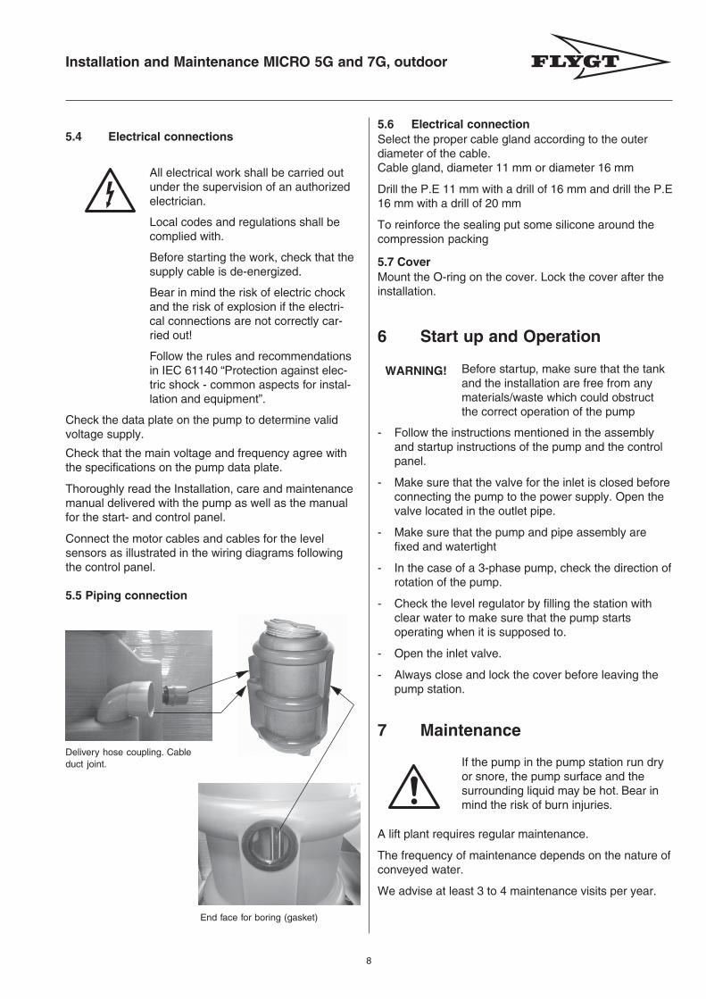
Irrespectively of lifting plant model, the base must bemade of sand or concrete slab in case of an area proneto flooding. The surface of the base must be built andcompacted in such a way that the plant does not rest onany hard or weak surface. The flatness and horizontalityof the base must be ensured. The depth of the excava-tion site must allow an incline of not less than 2% andnot exceeding 4%, for piping of used water.
Fig. 4In the case of difficult surfaces (impermeable, clayey) orground water, the base must be made of stabilised sandhaving a thickness of 0.20 m (dry-mix of sand andcement witha ratio of 200 kg cement for 1 m3 of sand).
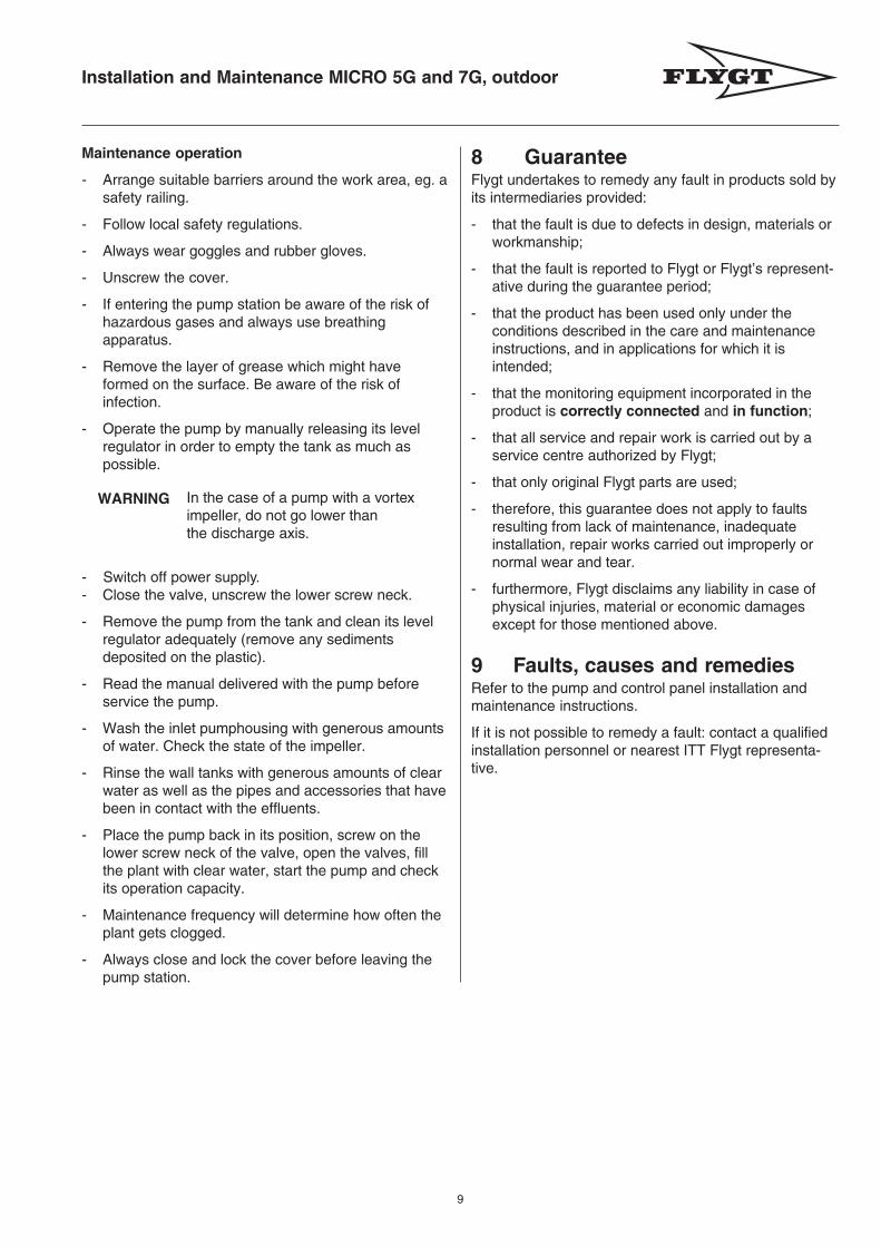
Fig. 5In case of a water table appartent from the surface, thecompacting sand must be replaced with weak-mixconcrete (total surrounding space of the tank-the spaceincluded between the tank and the excavation must notbe less than 20 cm).
All specifications remain unchanged. In case of a vehiclepassage way situated at least 3 metres away from themanhole, it is absolutely imperative to erect a separatingslab prior to filling.
Observations
Reinforcement of concrete coatings is mandatory.
Soil analysis is NECESSARY for any draining installa-tion and must comply with DTU 64-1 as well as theOrder of 6th May, 1996.
In any event, an additional guarantee concerning theproper functioning of the installation may be obtained
0.20 m
0.20
mØ 2 m
Out
let
Arr
ival
Ven
tilat
ion
Ø 2 m
0.20 m
0.20
m
Out
let
Arr
ival
Ven
tilat
ion
Installation and Maintenance MICRO 5G and 7G, outdoor
8
5.4 Electrical connections
All electrical work shall be carried outunder the supervision of an authorizedelectrician.
Local codes and regulations shall becomplied with.
Before starting the work, check that thesupply cable is de-energized.
Bear in mind the risk of electric chockand the risk of explosion if the electri-cal connections are not correctly car-ried out!
Follow the rules and recommendationsin IEC 61140 “Protection against elec-tric shock - common aspects for instal-lation and equipment”.
Check the data plate on the pump to determine validvoltage supply.
Check that the main voltage and frequency agree withthe specifications on the pump data plate.
Thoroughly read the Installation, care and maintenancemanual delivered with the pump as well as the manualfor the start- and control panel.
Connect the motor cables and cables for the levelsensors as illustrated in the wiring diagrams followingthe control panel.
5.5 Piping connection
5.6 Electrical connectionSelect the proper cable gland according to the outerdiameter of the cable.Cable gland, diameter 11 mm or diameter 16 mm
Drill the P.E 11 mm with a drill of 16 mm and drill the P.E16 mm with a drill of 20 mm
To reinforce the sealing put some silicone around thecompression packing
5.7 CoverMount the O-ring on the cover. Lock the cover after theinstallation.
6 Start up and Operation
Before startup, make sure that the tankand the installation are free from anymaterials/waste which could obstructthe correct operation of the pump
- Follow the instructions mentioned in the assemblyand startup instructions of the pump and the controlpanel.
- Make sure that the valve for the inlet is closed beforeconnecting the pump to the power supply. Open thevalve located in the outlet pipe.
- Make sure that the pump and pipe assembly arefixed and watertight
- In the case of a 3-phase pump, check the direction ofrotation of the pump.
- Check the level regulator by filling the station withclear water to make sure that the pump startsoperating when it is supposed to.
- Open the inlet valve.
- Always close and lock the cover before leaving thepump station.
WARNING!
7 Maintenance
A lift plant requires regular maintenance.
The frequency of maintenance depends on the nature ofconveyed water.
We advise at least 3 to 4 maintenance visits per year.
Delivery hose coupling. Cableduct joint.
End face for boring (gasket)
If the pump in the pump station run dryor snore, the pump surface and thesurrounding liquid may be hot. Bear inmind the risk of burn injuries.
Installation and Maintenance MICRO 5G and 7G, outdoor
9
8 GuaranteeFlygt undertakes to remedy any fault in products sold byits intermediaries provided:
- that the fault is due to defects in design, materials orworkmanship;
- that the fault is reported to Flygt or Flygt’s represent-ative during the guarantee period;
- that the product has been used only under theconditions described in the care and maintenanceinstructions, and in applications for which it isintended;
- that the monitoring equipment incorporated in theproduct is correctly connected and in function;
- that all service and repair work is carried out by aservice centre authorized by Flygt;
- that only original Flygt parts are used;
- therefore, this guarantee does not apply to faultsresulting from lack of maintenance, inadequateinstallation, repair works carried out improperly ornormal wear and tear.
- furthermore, Flygt disclaims any liability in case ofphysical injuries, material or economic damagesexcept for those mentioned above.
9 Faults, causes and remediesRefer to the pump and control panel installation andmaintenance instructions.
If it is not possible to remedy a fault: contact a qualifiedinstallation personnel or nearest ITT Flygt representa-tive.
WARNING
Maintenance operation
- Arrange suitable barriers around the work area, eg. asafety railing.
- Follow local safety regulations.
- Always wear goggles and rubber gloves.
- Unscrew the cover.
- If entering the pump station be aware of the risk ofhazardous gases and always use breathingapparatus.
- Remove the layer of grease which might haveformed on the surface. Be aware of the risk ofinfection.
- Operate the pump by manually releasing its levelregulator in order to empty the tank as much aspossible.
In the case of a pump with a vorteximpeller, do not go lower thanthe discharge axis.
- Switch off power supply.- Close the valve, unscrew the lower screw neck.
- Remove the pump from the tank and clean its levelregulator adequately (remove any sedimentsdeposited on the plastic).
- Read the manual delivered with the pump beforeservice the pump.
- Wash the inlet pumphousing with generous amountsof water. Check the state of the impeller.
- Rinse the wall tanks with generous amounts of clearwater as well as the pipes and accessories that havebeen in contact with the effluents.
- Place the pump back in its position, screw on thelower screw neck of the valve, open the valves, fillthe plant with clear water, start the pump and checkits operation capacity.
- Maintenance frequency will determine how often theplant gets clogged.
- Always close and lock the cover before leaving thepump station.
Installation and Maintenance MICRO 5G and 7G, outdoor
10
EU - Declaration of Conformity Hereby certify that Micro 5G, 7G pump station has been manufactured in accordance with the COUNCIL'S DIRECTIVE concerning convergence of the legislation of Member States with regard to Machinery 98/37/EC (89/392/EEC) + 91/368/EEC +93/44/EEC + 93/68/EEC. Marked with serial number. The product contains products that are in itself manufactured in accordance with the COUNCIL'S DIRECTIVES.
Déclaration de conformité UE Certifie par la présente que Micro 5G, 7G station de relevage est fabriquée conformément aux DIRECTIVES DU CONSEIL concernant le rapprochement des législations des Etats membres relatives aux machines 98/37/EC (89/392/EEC) + 91/368/EEC +93/44/EEC + 93/68/EEC. Portant le numéro de série. Ce produit est composé d'équipements fabriqués conformément aux DIRECTIVES DU CONSEIL.
EU-deklaration om överensstämmelse Försäkrar härmed att Micro 5G, 7G pumpstationer är tillverkade i överensstämmelse med RÅDETS DIREKTIV angående inbördes närmande av medlemsstaternas lagstiftning rörande Maskiner 98/37/EC (89/392/EEC) + 91/368/EEC + 93/44/EEC + 93/68/EEC). Märkt med serienummer. Produkten innehåller produkter som i sig är tillverkade i enlighet RÅDET´S DIREKTIV.
EU-verklaring betreffende overeensstemming Verklaren hierbij dat Micro 5G, 7G pompinstalatie vervaardigd is conform de RICHTLIJN VAN DE RAAD betreffende onderlinge afstemming van de wetgeving in de Lidstaten aangaande machines 98/37/EC (89/392/EEC) + 91/368/EEC +93/44/EEC + 93/68/EEC. Aangeduid mete en serienummer. Het product bevat producten die elk vervaardigd werden overeenkomstig de Directieven van de Commissie.
EU-deklaration om overensstemmelse Erklærer hermed at Micro 5G, 7G pumpestation er fremstillet i overensstemmelse med RÅDETS DIREKTIV vedrørende indbyrdes tilnærmelse af medlemsstaternes lovgivning angående maskiner 98/37/EC (89/392/EEC) + 91/368/EEC +93/44/EEC + 93/68/EEC. Med påtrykt serienummer. Produktet indeholder komponenter/produkter som i sig selv er produceret i overensstemmelse med RÅDETS DIREKTIVER.
EU-ilmoitus yhdenmukaisuudesta Vakuutamme täten, että Micro 5G, 7G pumpapaamot on valmistettu jäsenvaltioiden lainsäädäntöjen keskinäistä lähestymistä koskevien päivättyjen NEUVOSTON DIREKTIIVIEN mukaan koskien koneita 98/37/EC (89/392/EEC) + 91/368/EEC +93/44/EEC + 93/68/EEC. Merkitty sarjanumerolla. Tuotteessa on osia, mitkä on valmistettu paikallisesti EU direktiivinen mukaan.
EU-Konformitätserklärung Hiermit wird bestätigt, dass die Micro 5G, 7G Pumpenanlagen gemäß der Richtlinie des Rates zur Angleichung der Rechtsvorschriften der Mitgliedsstaaten in Bezug auf die Maschinenrichtlinie 98/37/EG (89/392/EWG) + 91/368/EWG +93/44/EWG + 93/68/EWG hergestellt wurden.Gekennzeichnet mit seriennummer.
Das Produkt enthält
Produkte, die wiederum gemäß der Richtlinie des Rates hergestellt wurden.
S ITT Flygt Pumpar, Solna, Sweden Tel. 0046- 8 475 65 00
F ITT Flygt sas, Nanterre Cédex, France Tel. 0033-1469533333
DK ITT Flygt a/s, Glostrup, Denmark Tel. 0045-43200900
B ITT Flygt N.V./S.A., Zaventem, Belgium Tel. 0032-27209010
DE ITT Flygt Pumpen GmbH, Hannover, Germany Tel. 0049-511-7800 0
SF ITT Flygt Pumput oy, Klaukkala, Finland Tel. 00358-98494111
Title
Technical Manager
Name
Peter Uvemo
Company name
ITT Flygt AB
Signature Date 2007-03-23
Mic
ro 5
G/7
G o
utdo
or. 0
1. 0
1. E
N_G
B.
© IT
T F
LYG
T A
B
P
rinte
d in
Sw
eden
8
9703
3
flygt.com