installation and configuration guide for exadata database ......oracle® exadata database machine...
TRANSCRIPT
Oracle® Exadata Database MachineInstallation and Configuration Guide forExadata Database Machine
19.1.0E93155-01October 2018

Oracle Exadata Database Machine Installation and Configuration Guide for Exadata Database Machine,19.1.0
E93155-01
Copyright © 2008, 2018, Oracle and/or its affiliates. All rights reserved.
Primary Author: Janet Stern
Contributing Authors: Glenn Maxey, Caroline Johnston, Lypp-Tek Khoo-Ellis
Contributors: Doug Archambault, Leo Agranonik, Andrew Babb, Bharat Baddepudi, Michael Belef, NileshChoudhury, Henry Chow, Kevin Closson, Bob Cyphers, Ravindra Dani, Boris Erlikhman, Jaime Figueroa,Gurmeet Goindi, Roger Hansen, Shrikumar Hariharasubrahmanian, Kevin Jernigan, Sarat Karkarla, LeslieKeller, Frank Kobylanski, Poojan Kumar, René Kundersma, Robert S. Lee, Sue Lee, Jennifer Leung, YangLiu, Juan Loaiza, Barb Lundhild, Catherine Luu, Varun Malhotra, Bagish Mishra, Valarie Moore, PhilipNewlan, Adrian Ng, Dan Norris, Michael Nowak, Bharat Paliwal, Umesh Panchaksharaiah, Hector Pujol,Sugam Pandey, Dmitry Potapov, Darryl Presley, Vince Pulice, Ashish Ray, Samitha Samaranayake, RichardScales, Olly Sharwood, Jia Shi, Kesavan Srinivasan, Mahesh Subramaniam, Michelle Sun, KrishnadevTelikicherla, Cliff Thomas, Alex Tsukerman, Shreyas Udgaonkar, Kothanda Umamageswaran, Doug Utzig,James Viscusi, Vern Wagman, Zheren Zhang
This software and related documentation are provided under a license agreement containing restrictions onuse and disclosure and are protected by intellectual property laws. Except as expressly permitted in yourlicense agreement or allowed by law, you may not use, copy, reproduce, translate, broadcast, modify,license, transmit, distribute, exhibit, perform, publish, or display any part, in any form, or by any means.Reverse engineering, disassembly, or decompilation of this software, unless required by law forinteroperability, is prohibited.
The information contained herein is subject to change without notice and is not warranted to be error-free. Ifyou find any errors, please report them to us in writing.
If this is software or related documentation that is delivered to the U.S. Government or anyone licensing it onbehalf of the U.S. Government, then the following notice is applicable:
U.S. GOVERNMENT END USERS: Oracle programs, including any operating system, integrated software,any programs installed on the hardware, and/or documentation, delivered to U.S. Government end users are"commercial computer software" pursuant to the applicable Federal Acquisition Regulation and agency-specific supplemental regulations. As such, use, duplication, disclosure, modification, and adaptation of theprograms, including any operating system, integrated software, any programs installed on the hardware,and/or documentation, shall be subject to license terms and license restrictions applicable to the programs.No other rights are granted to the U.S. Government.
This software or hardware is developed for general use in a variety of information management applications.It is not developed or intended for use in any inherently dangerous applications, including applications thatmay create a risk of personal injury. If you use this software or hardware in dangerous applications, then youshall be responsible to take all appropriate fail-safe, backup, redundancy, and other measures to ensure itssafe use. Oracle Corporation and its affiliates disclaim any liability for any damages caused by use of thissoftware or hardware in dangerous applications.
Oracle and Java are registered trademarks of Oracle and/or its affiliates. Other names may be trademarks oftheir respective owners.
Intel and Intel Xeon are trademarks or registered trademarks of Intel Corporation. All SPARC trademarks areused under license and are trademarks or registered trademarks of SPARC International, Inc. AMD, Opteron,the AMD logo, and the AMD Opteron logo are trademarks or registered trademarks of Advanced MicroDevices. UNIX is a registered trademark of The Open Group.
This software or hardware and documentation may provide access to or information about content, products,and services from third parties. Oracle Corporation and its affiliates are not responsible for and expresslydisclaim all warranties of any kind with respect to third-party content, products, and services unless otherwiseset forth in an applicable agreement between you and Oracle. Oracle Corporation and its affiliates will not beresponsible for any loss, costs, or damages incurred due to your access to or use of third-party content,products, or services, except as set forth in an applicable agreement between you and Oracle.
Contents
Preface
Audience x
Documentation Accessibility x
Related Documentation x
Conventions xii
1 Site Requirements for Oracle Exadata Database Machine andOracle Exadata Storage Expansion Rack
1.1 General Environmental Requirements 1-1
1.1.1 General Environmental Requirements for Oracle Exadata DatabaseMachine X6-2, X6-8, and Later 1-1
1.1.2 General Environmental Requirements for Oracle Exadata DatabaseMachine X5-2 1-1
1.1.3 General Environmental Requirements for Oracle Exadata DatabaseMachine X5-8 1-4
1.1.4 General Environmental Requirements for Oracle Exadata DatabaseMachine X4-2 1-5
1.1.5 General Environmental Requirements for Oracle Exadata DatabaseMachine X4-8 with Exadata Storage Server X5-2 Servers 1-8
1.1.6 General Environmental Requirements for Oracle Exadata DatabaseMachine X4-8 Full Rack 1-9
1.1.7 General Environmental Requirements for Oracle Exadata DatabaseMachine X3-2 1-10
1.1.8 General Environmental Requirements for Oracle Exadata DatabaseMachine X3-8 Full Rack with Exadata Storage Server X4-2L Servers 1-13
1.1.9 General Environmental Requirements for Oracle Exadata DatabaseMachine X3-8 Full Rack with Exadata Storage Server X3-2 Servers 1-14
1.1.10 General Environmental Requirements for Oracle Exadata DatabaseMachine X2-2 1-16
1.1.11 General Environmental Requirements for Oracle Exadata DatabaseMachine X2-8 Full Rack 1-17
1.1.12 General Environmental Requirements for Oracle Exadata StorageExpansion Rack X6-2 and later 1-18
1.1.13 General Environmental Requirements for Oracle Exadata StorageExpansion Rack X5-2 1-18
iii
1.1.14 General Environmental Requirements for Oracle Exadata StorageExpansion Rack X4-2 1-20
1.1.15 General Environmental Requirements for Oracle Exadata StorageExpansion Rack X3-2 1-22
1.1.16 General Environmental Requirements for Oracle Exadata StorageExpansion Rack with Exadata Storage Server with Sun Fire X4270 M2Servers 1-24
1.1.17 General Environmental Requirements for Single Servers 1-24
1.2 Space Requirements 1-26
1.2.1 Receiving and Unpacking Requirements 1-27
1.2.2 Maintenance Access Requirements 1-32
1.3 Flooring Requirements 1-32
1.4 Electrical Power Requirements 1-33
1.4.1 PDU Power Requirements 1-33
1.4.2 Facility Power Requirements 1-41
1.4.3 Circuit Breaker Requirements 1-42
1.4.4 Grounding Guidelines 1-42
1.5 Temperature and Humidity Requirements 1-42
1.6 Ventilation and Cooling Requirements 1-44
1.7 Network Connection and IP Address Requirements for Oracle ExadataDatabase Machine 1-45
1.7.1 Network Connection Requirements for Oracle Exadata DatabaseMachine 1-46
1.7.2 DNS Configuration for Oracle Exadata Database Machine 1-49
1.7.3 IP Address Requirements for Oracle Exadata Database Machine 1-50
1.7.3.1 Calculating the IP Address Requirements when Using Oracle VMs1-68
1.8 Network Connection and IP Address Requirements for Oracle ExadataStorage Expansion Rack 1-71
1.9 Ensuring Site is Ready 1-74
2 Understanding the Network Requirements for Oracle ExadataDatabase Machine
2.1 Overview of Network Requirements 2-1
2.2 Network Components and Interfaces 2-7
2.2.1 Oracle Exadata Database Machine X7-2 Database Server 2-7
2.2.2 Oracle Exadata Database Machine X5-2 and X6-2 Database Server 2-7
2.2.3 Oracle Exadata Database Machine X5-8 and X6-8 Full Rack DatabaseServer 2-8
2.2.4 Oracle Exadata Database Machine X4-2 Database Server 2-8
2.2.5 Oracle Exadata Database Machine X4-8 Full Rack Database Server 2-9
2.2.6 Oracle Exadata Database Machine X3-2 Database Server 2-9
iv
2.2.7 Oracle Exadata Database Machine X3-8 Full Rack and Oracle ExadataDatabase Machine X2-8 Full Rack Database Server 2-9
2.3 Network Channel Bonding Support 2-10
2.3.1 Bonded Network Configurations 2-10
2.3.1.1 Bonded Network Configuration for Oracle Exadata DatabaseMachine Two-Socket Systems 2-10
2.3.1.2 Bonded Network Configuration for Oracle Exadata DatabaseMachine X7-8 2-12
2.3.1.3 Bonded Network Configuration for Oracle Exadata DatabaseMachine X4-8, X5-8, and X6-8 2-13
2.3.1.4 Bonded Network Configuration for Oracle Exadata DatabaseMachine X3-8 Full Rack and Oracle Exadata Database MachineX2-8 Full Rack 2-13
2.3.2 Non-bonded Network Configuration 2-14
2.3.2.1 Non-bonded Network Configuration for Oracle Exadata DatabaseMachine Two-Socket Systems 2-15
2.3.2.2 Non-bonded Network Configuration for Oracle Exadata DatabaseMachine X5-8 and X6-8 2-16
2.3.2.3 Non-bonded Network Configuration for Oracle Exadata DatabaseMachine X4-8 Full Rack 2-17
2.3.2.4 Non-bonded Network Configuration for Oracle Exadata DatabaseMachine X3-8 Full Rack and Oracle Exadata Database MachineX2-8 Full Rack 2-17
2.3.3 Additional Networks 2-18
2.4 Configuring a Separate Network for ILOM 2-19
2.5 Using Network VLAN Tagging with Oracle Exadata Database Machine 2-20
2.6 Default IP Addresses 2-21
2.7 Port Assignments When Using a Firewall 2-34
3 Using Oracle Exadata Deployment Assistant
3.1 Overview of Oracle Exadata Deployment Assistant 3-1
3.1.1 Considerations when Using Oracle Exadata Deployment Assistant 3-2
3.1.2 Using Oracle Exadata Deployment Assistant on Systems with Non-Default root Passwords 3-3
3.2 OEDA Browser-based User Interface 3-4
3.2.1 Using the Browser-based Version of Oracle Exadata DeploymentAssistant 3-5
3.2.2 Select Hardware Page 3-6
3.2.3 Choose Operating System Page 3-12
3.2.4 Rack Networks Page 3-13
3.2.5 Users and Groups 3-18
3.2.6 Define Clusters 3-23
3.2.7 Diskgroups 3-24
3.2.8 Database Home 3-27
v
3.2.9 Database 3-28
3.2.10 Cluster Networks 3-29
3.2.11 Alerting 3-37
3.2.12 Tape Library Connectivity 3-39
3.2.13 Comments 3-40
3.3 OEDA Graphical User Interface 3-40
3.3.1 Using the GUI Interface for Oracle Exadata Deployment Assistant 3-41
3.3.2 Customer Details Configuration Page 3-44
3.3.3 Hardware Selection Configuration Page 3-45
3.3.4 Rack Details Configuration Page 3-45
3.3.5 Customer Network Configuration Page 3-45
3.3.6 Administration Network Configuration Page 3-47
3.3.6.1 Modifying the Default Administration Network Host Names 3-48
3.3.7 Client Ethernet Configuration Page 3-50
3.3.7.1 Modifying the Default Client Ethernet Network Names 3-51
3.3.8 InfiniBand Network Configuration Page 3-52
3.3.8.1 Modifying the Default InfiniBand Network Names 3-52
3.3.9 Backup Network Configuration Page 3-53
3.3.9.1 Modifying the Default Backup Network Name 3-53
3.3.10 Review and Edit Management and Private Networks 3-54
3.3.11 Identify Compute Node OS and Enable Capacity-on-DemandConfiguration Page 3-54
3.3.12 Define Clusters 3-55
3.3.13 Define Clusters Details 3-55
3.3.13.1 Configuring Automatic Cluster File System (ACFS) 3-60
3.3.14 Review and Edit SCAN, Client, VIP and Optional Backup Networks 3-61
3.3.15 Cell Alerting Configuration Page 3-61
3.3.16 Platinum Configuration Page 3-62
3.3.17 Auto Service Request Configuration Page 3-64
3.3.18 Oracle Configuration Manager Configuration Page 3-65
3.3.19 Grid Control Agent Configuration Page 3-66
3.4 OEDA Command Line Interface 3-67
3.4.1 About the OEDA Command Line Interface 3-67
3.4.2 Starting the OEDACLI Utility 3-69
3.4.2.1 Displaying Help Output for OEDACLI 3-69
3.4.2.2 Displaying Help Output for an OEDACLI Command 3-70
3.4.3 OEDACLI Command Reference 3-71
3.4.3.1 OEDACLI Commands 3-72
3.4.3.2 ACFSVOLUME 3-74
3.4.3.3 CELL 3-76
3.4.3.4 CLUSTER 3-77
vi
3.4.3.5 DISKGROUP 3-79
3.4.3.6 DATABASE 3-84
3.4.3.7 DATABASE HOME 3-90
3.4.3.8 ES 3-94
3.4.3.9 GUEST 3-95
3.4.3.10 ILOM 3-96
3.4.3.11 MACHINE 3-97
3.4.3.12 NETWORK 3-98
3.4.3.13 SCAN 3-103
3.4.3.14 SWITCH 3-105
3.4.3.15 VIP 3-106
4 Installing Oracle Exadata Database Machine or Oracle ExadataStorage Expansion Rack at the Site
4.1 Reviewing Safety Guidelines 4-1
4.2 Unpacking Oracle Exadata Rack 4-2
4.2.1 Contents of the Shipping Kit 4-3
4.2.2 Removing Oracle Exadata Rack from the Shipping Crate 4-4
4.3 Placing Oracle Exadata Rack in Its Allocated Space 4-5
4.3.1 Moving Oracle Exadata Rack 4-5
4.3.2 Stabilizing Oracle Exadata Rack 4-6
4.3.2.1 Stabilize Oracle Exadata Rack with Leveling Feet 4-7
4.3.2.2 Stabilize Oracle Exadata Rack X7 with Leveling Feet 4-8
4.3.3 Attaching a Ground Cable (Optional) 4-10
4.4 Acclimating the Oracle Exadata Database Machine 4-11
4.5 Powering on the System the First Time 4-12
4.5.1 Inspecting the Machine After it is in Place 4-12
4.5.2 Connecting Power Cords 4-12
4.5.3 Powering on Oracle Exadata Rack 4-13
5 Configuring Oracle Exadata Database Machine
5.1 Configuring Sun Datacenter InfiniBand Switch 36 Switch 5-1
5.1.1 Setting the Subnet Manager Master on Oracle Exadata DatabaseMachine Full Rack and Oracle Exadata Database Machine Half Rack 5-4
5.2 Configuring the Cisco Ethernet Switch 5-6
5.2.1 Configuring the Cisco Catalyst 4948 Ethernet Switch 5-6
5.2.2 Configuring the Cisco Nexus 93108-1G or 9348 Ethernet Switch 5-13
5.2.2.1 Performing the Initial Switch Configuration for the Cisco Nexus93108-1G or 9348 Ethernet Switch 5-14
5.2.2.2 Setting the Clock on the Cisco 93108-1G or 9348 Ethernet Switch 5-17
vii

5.3 Configuring the Power Distribution Units 5-17
5.3.1 Configuring the Threshold Settings for the Power Distribution Units 5-20
5.3.1.1 PDU Thresholds for Oracle Exadata Database Machine X5-2 andLater 5-20
5.3.1.2 PDU Thresholds for Oracle Exadata Database Machine X4-2 5-20
5.3.1.3 PDU Thresholds for Oracle Exadata Database Machine X3-2 5-26
5.3.1.4 PDU Thresholds for Oracle Exadata Database Machine X2-2(with X4170 M2 and X4270 M2 servers) 5-32
5.3.1.5 PDU Thresholds for Oracle Exadata Database Machine X2-2(with X4170 and X4275 servers) 5-38
5.3.1.6 PDU Thresholds for Oracle Exadata Database Machine X4-8 andLater 5-44
5.3.1.7 PDU Thresholds for Oracle Exadata Database Machine X3-8 FullRack 5-44
5.3.1.8 PDU Thresholds for Oracle Exadata Database Machine X2-8 FullRack 5-47
5.3.1.9 PDU Thresholds for Oracle Exadata Storage Expansion Rack withExadata Storage Server with Sun Fire X4270 M2 Servers 5-49
5.4 Checking Exadata Storage Servers 5-55
5.5 Checking Oracle Database Servers 5-57
5.6 Performing Additional Checks and Configuration 5-59
5.7 Verifying the InfiniBand Network 5-60
5.8 Imaging a New System 5-62
5.8.1 Using ISO Images to Image a New System 5-62
5.8.2 Using Elastic Configuration to Image a New System 5-65
5.8.3 Using ISO to Image a New System 5-68
5.8.4 Using PXE to Image a New System 5-74
5.8.5 Using USB to Image a New System 5-79
5.8.6 Updates to Imaging Parameters 5-83
5.9 Performing Initial Elastic Configuration of Oracle Exadata Database Machine 5-84
5.10 Adding Additional Elastic Nodes to an Existing Rack 5-90
5.11 Loading the Configuration Information and Installing the Software 5-90
5.11.1 Configuring Oracle Exadata Database Machine Using OEDA 5-91
5.11.2 Configuring Oracle Database and Oracle ASM Instances for OracleExadata Database Machine Manually 5-93
5.11.2.1 Configuring the Compatible Parameter for a Database Instance 5-95
5.11.2.2 Configuring Initialization Parameters for an Oracle ASM Instance 5-95
5.11.2.3 Using the Same DB_UNIQUE_NAME for Multiple DatabaseInstances 5-96
5.12 Installing Oracle Enterprise Manager Cloud Control 5-97
A Site Checklists
A.1 System Components Checklist A-1
viii
A.2 Data Center Room Checklist A-4
A.3 Data Center Environment Checklist A-5
A.4 Access Route Checklist A-6
A.5 Facility Power Checklist A-9
A.6 Safety Checklist A-11
A.7 Logistics Checklist A-11
A.8 Network Configuration Checklist A-15
A.9 Auto Service Request Checklist A-16
A.10 Reracking Checklists A-17
A.10.1 Recycling the Racks A-22
B Database High Availability Checklist
Index
ix
Preface
This guide describes Oracle Exadata Database Machine for online transactionprocessing (OLTP) and enterprise data warehousing. It includes information about siteplanning and configuration, as well as physical, electrical, and environmentalspecifications.
AudienceThis guide is intended for Oracle Exadata Database Machine customers and thoseresponsible for data center site planning, configuration, and maintenance of OracleExadata Database Machine.
Documentation AccessibilityFor information about Oracle's commitment to accessibility, visit the OracleAccessibility Program website at http://www.oracle.com/pls/topic/lookup?ctx=acc&id=docacc.
Access to Oracle Support
Oracle customers that have purchased support have access to electronic supportthrough My Oracle Support. For information, visit http://www.oracle.com/pls/topic/lookup?ctx=acc&id=info or visit http://www.oracle.com/pls/topic/lookup?ctx=acc&id=trsif you are hearing impaired.
Related DocumentationIn addition to the Oracle Exadata Database Machine documentation set, the followingguides contain hardware information for Oracle Exadata Database Machine:
• Oracle Exadata Database Machine System Overview
• Oracle Exadata Database Machine Security Guide
• Oracle Engineered System Safety and Compliance Guide, Compliance Model No.:ESY27
• Oracle Exadata Database Machine Extending and Multi-Rack Cabling Guide
• Oracle Exadata Database Machine Maintenance Guide
• Oracle Exadata System Software User's Guide
• Oracle Server X7-2 Service Manual at http://docs.oracle.com/cd/E72435_01/html/E72445/index.html
• Oracle Server X7-2L Service Manual at http://docs.oracle.com/cd/E72463_01/html/E72474/index.html
Preface
x
• Oracle Server X7-8 Service Manual at http://docs.oracle.com/cd/E71925_01/html/E71936/index.html
• Oracle Server X6-2 Service Manual at http://docs.oracle.com/cd/E62159_01/html/E62171/index.html
• Oracle Server X6-2L Service Manual at http://docs.oracle.com/cd/E62172_01/html/E62184/index.html
• Oracle Server X5-2 Service Manual at http://docs.oracle.com/cd/E41059_01/html/E48312/napsm.html
• Oracle Server X5-2L Service Manual at http://docs.oracle.com/cd/E41033_01/html/E48325/cnpsm.html#scrolltoc
• Sun Server X4-8 Service Manual at http://docs.oracle.com/cd/E40591_01/html/E40317/index.html
• Sun Server X4-2 Service Manual at http://docs.oracle.com/cd/E36975_01/html/E38045/gentextid-14757.html#scrolltoc
• Sun Server X4-2L Service Manual at http://docs.oracle.com/cd/E36974_01/html/E38145/gentextid-14728.html#scrolltoc
• Sun Server X3-2 (formerly Sun Fire X4170 M3) Service Manual at http://docs.oracle.com/cd/E22368_01/html/E27242/gentextid-14840.html#scrolltoc
• Sun Server X3-2L (formerly Sun Fire X4270 M3) Service Manual at http://docs.oracle.com/cd/E23393_01/html/E27229/gentextid-14804.html#scrolltoc
• Sun Server X2-8 (formerly Sun Fire X4800 M2) Service Manual at http://docs.oracle.com/cd/E20815_01/html/E20819/index.html
• Sun Fire X4800 Server Service Manual at http://docs.oracle.com/cd/E19140-01/html/821-0282/index.html
• Sun Fire X4270 M2 Server Service Manual at http://docs.oracle.com/cd/E19245-01/E21671/index.html
• Sun Fire X4170 M2 Server Service Manual at http://docs.oracle.com/cd/E19762-01/E22369-02/index.html
• Sun Fire X4170, X4270, and X4275 Servers Service Manual at http://docs.oracle.com/cd/E19477-01/820-5830-13/index.html
• Sun Datacenter InfiniBand Switch 36 Firmware Version 2.1 Documentation at http://docs.oracle.com/cd/E36265_01/index.html
• Sun Datacenter InfiniBand Switch 36 Firmware Version 2.2 Documentation at http://docs.oracle.com/cd/E76424_01/index.html
• Sun Flash Accelerator F20 PCIe Card User's Guide at http://docs.oracle.com/cd/E19682-01/E21358/index.html
• Sun Flash Accelerator F40 PCIe Card User's Guide at http://docs.oracle.com/cd/E29748_01/html/E29741/index.html
• Sun Flash Accelerator F80 PCIe Card User's Guide at http://docs.oracle.com/cd/E41278_01/html/E41251/index.html
• Oracle Flash Accelerator F160 PCIe Card User Guide at http://docs.oracle.com/cd/E54943_01/html/E54947/index.html
• Oracle Flash Accelerator F320 PCIe Card User Guide at http://docs.oracle.com/cd/E65386_01/html/E65387/index.html
Preface
xi
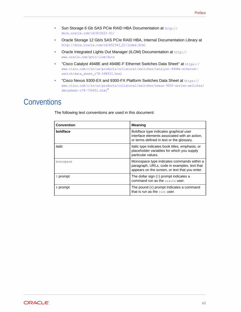
• Sun Storage 6 Gb SAS PCIe RAID HBA Documentation at http://docs.oracle.com/cd/E19221-01/
• Oracle Storage 12 Gb/s SAS PCIe RAID HBA, Internal Documentation Library at http://docs.oracle.com/cd/E52363_01/index.html
• Oracle Integrated Lights Out Manager (ILOM) Documentation at http://www.oracle.com/goto/ilom/docs
• "Cisco Catalyst 4948E and 4948E-F Ethernet Switches Data Sheet" at https://www.cisco.com/c/en/us/products/collateral/switches/catalyst-4948e-ethernet-
switch/data_sheet_c78-598933.html
• "Cisco Nexus 9300-EX and 9300-FX Platform Switches Data Sheet at https://www.cisco.com/c/en/us/products/collateral/switches/nexus-9000-series-switches/
datasheet-c78-736651.html"
ConventionsThe following text conventions are used in this document:
Convention Meaning
boldface Boldface type indicates graphical userinterface elements associated with an action,or terms defined in text or the glossary.
italic Italic type indicates book titles, emphasis, orplaceholder variables for which you supplyparticular values.
monospace Monospace type indicates commands within aparagraph, URLs, code in examples, text thatappears on the screen, or text that you enter.
$ prompt The dollar sign ($) prompt indicates acommand run as the oracle user.
# prompt The pound (#) prompt indicates a commandthat is run as the root user.
Preface
xii
1Site Requirements for Oracle ExadataDatabase Machine and Oracle ExadataStorage Expansion Rack
This chapter describes the site requirements for Oracle Exadata Database Machine,and Oracle Exadata Storage Expansion Rack.
Note:
For ease of reading, the name "Oracle Exadata Rack" is used wheninformation refers to both Oracle Exadata Database Machine and OracleExadata Storage Expansion Rack.
Related Topics
• Site Checklists
1.1 General Environmental RequirementsThe following sections describe the general environmental requirements for OracleExadata Racks.
1.1.1 General Environmental Requirements for Oracle ExadataDatabase Machine X6-2, X6-8, and Later
For Oracle Exadata Database Machine X6-2 and later environmental requirements,such as weight, acoustic level, power, cooling, and air flow, use the Oracle ExadataConfiguration Assistant, available on Oracle Technology Network:
Oracle Exadata Configuration Assistant (OECA) Downloads
1.1.2 General Environmental Requirements for Oracle ExadataDatabase Machine X5-2
The environmental requirements for Oracle Exadata Database Machine X5-2 dependon the size of the system. Table 1-1 shows the general environmental requirements forOracle Exadata Database Machine X5-2. The other sections in this chapter providedetailed information.
1-1
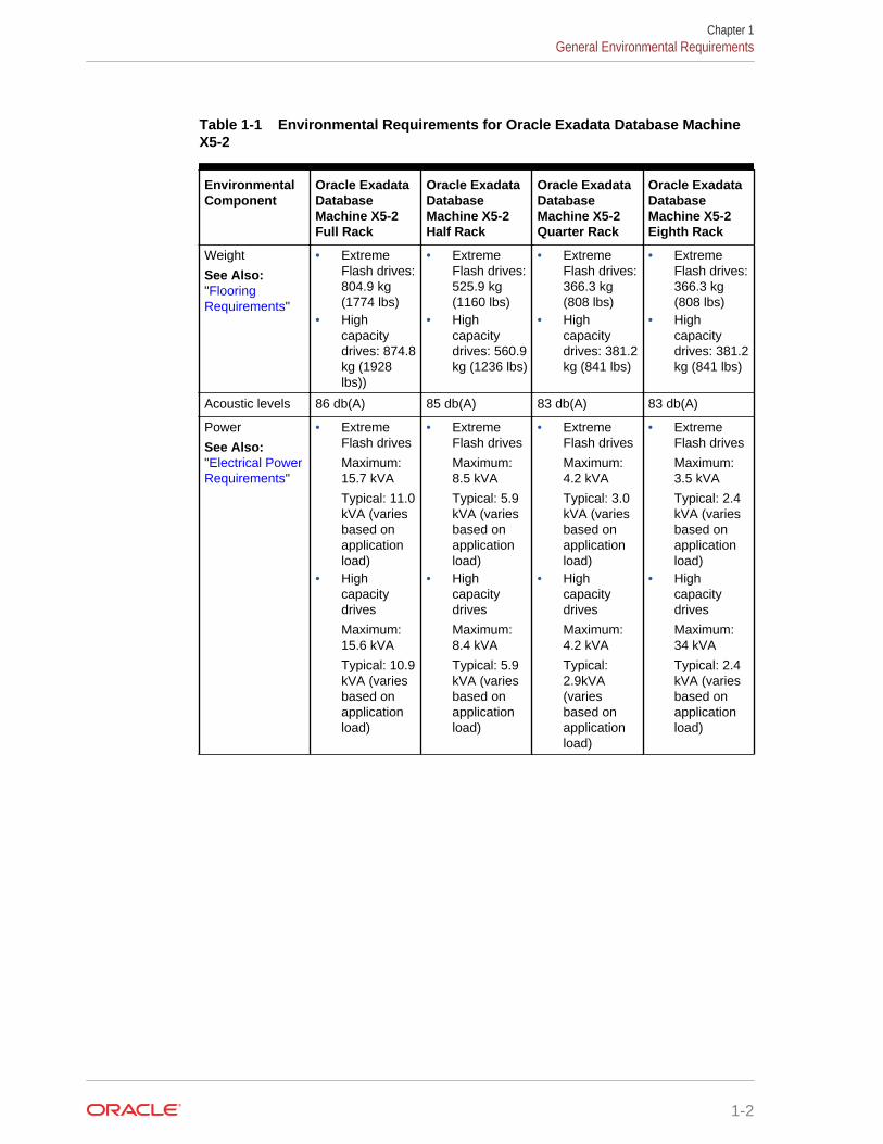
Table 1-1 Environmental Requirements for Oracle Exadata Database MachineX5-2
EnvironmentalComponent
Oracle ExadataDatabaseMachine X5-2Full Rack
Oracle ExadataDatabaseMachine X5-2Half Rack
Oracle ExadataDatabaseMachine X5-2Quarter Rack
Oracle ExadataDatabaseMachine X5-2Eighth Rack
Weight
See Also:"FlooringRequirements"
• ExtremeFlash drives:804.9 kg(1774 lbs)
• Highcapacitydrives: 874.8kg (1928lbs))
• ExtremeFlash drives:525.9 kg(1160 lbs)
• Highcapacitydrives: 560.9kg (1236 lbs)
• ExtremeFlash drives:366.3 kg(808 lbs)
• Highcapacitydrives: 381.2kg (841 lbs)
• ExtremeFlash drives:366.3 kg(808 lbs)
• Highcapacitydrives: 381.2kg (841 lbs)
Acoustic levels 86 db(A) 85 db(A) 83 db(A) 83 db(A)
Power
See Also:"Electrical PowerRequirements"
• ExtremeFlash drives
Maximum:15.7 kVA
Typical: 11.0kVA (variesbased onapplicationload)
• Highcapacitydrives
Maximum:15.6 kVA
Typical: 10.9kVA (variesbased onapplicationload)
• ExtremeFlash drives
Maximum:8.5 kVA
Typical: 5.9kVA (variesbased onapplicationload)
• Highcapacitydrives
Maximum:8.4 kVA
Typical: 5.9kVA (variesbased onapplicationload)
• ExtremeFlash drives
Maximum:4.2 kVA
Typical: 3.0kVA (variesbased onapplicationload)
• Highcapacitydrives
Maximum:4.2 kVA
Typical:2.9kVA(variesbased onapplicationload)
• ExtremeFlash drives
Maximum:3.5 kVA
Typical: 2.4kVA (variesbased onapplicationload)
• Highcapacitydrives
Maximum:34 kVA
Typical: 2.4kVA (variesbased onapplicationload)
Chapter 1General Environmental Requirements
1-2
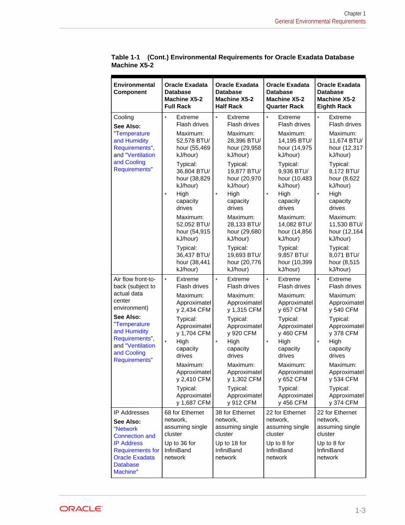
Table 1-1 (Cont.) Environmental Requirements for Oracle Exadata DatabaseMachine X5-2
EnvironmentalComponent
Oracle ExadataDatabaseMachine X5-2Full Rack
Oracle ExadataDatabaseMachine X5-2Half Rack
Oracle ExadataDatabaseMachine X5-2Quarter Rack
Oracle ExadataDatabaseMachine X5-2Eighth Rack
Cooling
See Also:"Temperatureand HumidityRequirements",and "Ventilationand CoolingRequirements"
• ExtremeFlash drives
Maximum:52,578 BTU/hour (55,469kJ/hour)
Typical:36,804 BTU/hour (38,829kJ/hour)
• Highcapacitydrives
Maximum:52,052 BTU/hour (54,915kJ/hour)
Typical:36,437 BTU/hour (38,441kJ/hour)
• ExtremeFlash drives
Maximum:28,396 BTU/hour (29,958kJ/hour)
Typical:19,877 BTU/hour (20,970kJ/hour)
• Highcapacitydrives
Maximum:28,133 BTU/hour (29,680kJ/hour)
Typical:19,693 BTU/hour (20,776kJ/hour)
• ExtremeFlash drives
Maximum:14,195 BTU/hour (14,975kJ/hour)
Typical:9,936 BTU/hour (10,483kJ/hour)
• Highcapacitydrives
Maximum:14,082 BTU/hour (14,856kJ/hour)
Typical:9,857 BTU/hour (10,399kJ/hour)
• ExtremeFlash drives
Maximum:11,674 BTU/hour (12,317kJ/hour)
Typical:8,172 BTU/hour (8,622kJ/hour)
• Highcapacitydrives
Maximum:11,530 BTU/hour (12,164kJ/hour)
Typical:8,071 BTU/hour (8,515kJ/hour)
Air flow front-to-back (subject toactual datacenterenvironment)
See Also:"Temperatureand HumidityRequirements",and "Ventilationand CoolingRequirements"
• ExtremeFlash drives
Maximum:Approximately 2,434 CFM
Typical:Approximately 1,704 CFM
• Highcapacitydrives
Maximum:Approximately 2,410 CFM
Typical:Approximately 1,687 CFM
• ExtremeFlash drives
Maximum:Approximately 1,315 CFM
Typical:Approximately 920 CFM
• Highcapacitydrives
Maximum:Approximately 1,302 CFM
Typical:Approximately 912 CFM
• ExtremeFlash drives
Maximum:Approximately 657 CFM
Typical:Approximately 460 CFM
• Highcapacitydrives
Maximum:Approximately 652 CFM
Typical:Approximately 456 CFM
• ExtremeFlash drives
Maximum:Approximately 540 CFM
Typical:Approximately 378 CFM
• Highcapacitydrives
Maximum:Approximately 534 CFM
Typical:Approximately 374 CFM
IP Addresses
See Also:"NetworkConnection andIP AddressRequirements forOracle ExadataDatabaseMachine"
68 for Ethernetnetwork,assuming singlecluster
Up to 36 forInfiniBandnetwork
38 for Ethernetnetwork,assuming singlecluster
Up to 18 forInfiniBandnetwork
22 for Ethernetnetwork,assuming singlecluster
Up to 8 forInfiniBandnetwork
22 for Ethernetnetwork,assuming singlecluster
Up to 8 forInfiniBandnetwork
Chapter 1General Environmental Requirements
1-3
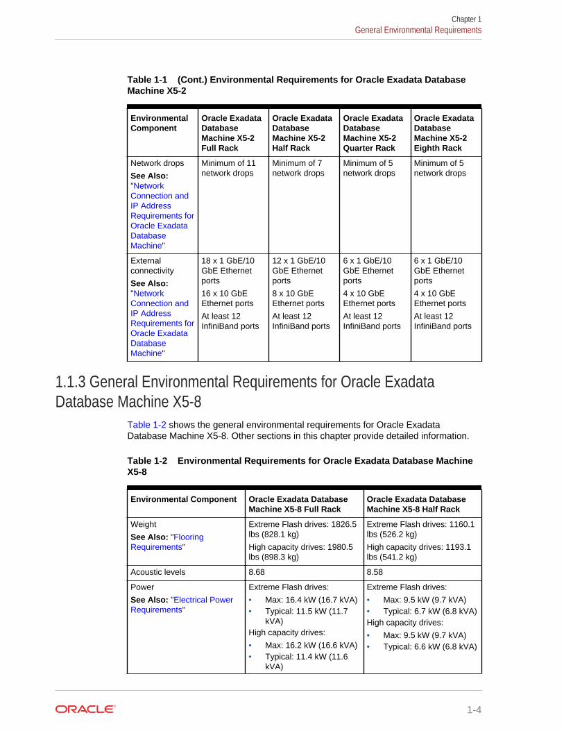
Table 1-1 (Cont.) Environmental Requirements for Oracle Exadata DatabaseMachine X5-2
EnvironmentalComponent
Oracle ExadataDatabaseMachine X5-2Full Rack
Oracle ExadataDatabaseMachine X5-2Half Rack
Oracle ExadataDatabaseMachine X5-2Quarter Rack
Oracle ExadataDatabaseMachine X5-2Eighth Rack
Network drops
See Also:"NetworkConnection andIP AddressRequirements forOracle ExadataDatabaseMachine"
Minimum of 11network drops
Minimum of 7network drops
Minimum of 5network drops
Minimum of 5network drops
Externalconnectivity
See Also:"NetworkConnection andIP AddressRequirements forOracle ExadataDatabaseMachine"
18 x 1 GbE/10GbE Ethernetports
16 x 10 GbEEthernet ports
At least 12InfiniBand ports
12 x 1 GbE/10GbE Ethernetports
8 x 10 GbEEthernet ports
At least 12InfiniBand ports
6 x 1 GbE/10GbE Ethernetports
4 x 10 GbEEthernet ports
At least 12InfiniBand ports
6 x 1 GbE/10GbE Ethernetports
4 x 10 GbEEthernet ports
At least 12InfiniBand ports
1.1.3 General Environmental Requirements for Oracle ExadataDatabase Machine X5-8
Table 1-2 shows the general environmental requirements for Oracle ExadataDatabase Machine X5-8. Other sections in this chapter provide detailed information.
Table 1-2 Environmental Requirements for Oracle Exadata Database MachineX5-8
Environmental Component Oracle Exadata DatabaseMachine X5-8 Full Rack
Oracle Exadata DatabaseMachine X5-8 Half Rack
Weight
See Also: "FlooringRequirements"
Extreme Flash drives: 1826.5lbs (828.1 kg)
High capacity drives: 1980.5lbs (898.3 kg)
Extreme Flash drives: 1160.1lbs (526.2 kg)
High capacity drives: 1193.1lbs (541.2 kg)
Acoustic levels 8.68 8.58
Power
See Also: "Electrical PowerRequirements"
Extreme Flash drives:
• Max: 16.4 kW (16.7 kVA)• Typical: 11.5 kW (11.7
kVA)High capacity drives:
• Max: 16.2 kW (16.6 kVA)• Typical: 11.4 kW (11.6
kVA)
Extreme Flash drives:
• Max: 9.5 kW (9.7 kVA)• Typical: 6.7 kW (6.8 kVA)High capacity drives:
• Max: 9.5 kW (9.7 kVA)• Typical: 6.6 kW (6.8 kVA)
Chapter 1General Environmental Requirements
1-4
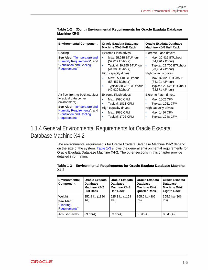
Table 1-2 (Cont.) Environmental Requirements for Oracle Exadata DatabaseMachine X5-8
Environmental Component Oracle Exadata DatabaseMachine X5-8 Full Rack
Oracle Exadata DatabaseMachine X5-8 Half Rack
Cooling
See Also: "Temperature andHumidity Requirements", and"Ventilation and CoolingRequirements"
Extreme Flash drives:
• Max: 55,935 BTU/hour(59,012 kJ/hour)
• Typical: 39,155 BTU/hour(41,308 kJ/hour)
High capacity drives:
• Max: 55,410 BTU/hour(58,457 kJ/hour)
• Typical: 38,787 BTU/hour(40,920 kJ/hour)
Extreme Flash drives:
• Max: 32,436 BTU/hour(34,220 kJ/hour)
• Typical: 22,705 BTU/hour(23,954 kJ/hour)
High capacity drives:
• Max: 32,323 BTU/hour(34,101 kJ/hour)
• Typical: 22,626 BTU/hour(23,871 kJ/hour)
Air flow front-to-back (subjectto actual data centerenvironment)
See Also: "Temperature andHumidity Requirements", and"Ventilation and CoolingRequirements"
Extreme Flash drives:
• Max: 2590 CFM• Typical: 1813 CFMHigh capacity drives:
• Max: 2565 CFM• Typical: 1796 CFM
Extreme Flash drives:
• Max: 1502 CFM• Typical: 1051 CFMHigh capacity drives:
• Max: 1496 CFM• Typical: 1048 CFM
1.1.4 General Environmental Requirements for Oracle ExadataDatabase Machine X4-2
The environmental requirements for Oracle Exadata Database Machine X4-2 dependon the size of the system. Table 1-3 shows the general environmental requirements forOracle Exadata Database Machine X4-2. The other sections in this chapter providedetailed information.
Table 1-3 Environmental Requirements for Oracle Exadata Database MachineX4-2
EnvironmentalComponent
Oracle ExadataDatabaseMachine X4-2Full Rack
Oracle ExadataDatabaseMachine X4-2Half Rack
Oracle ExadataDatabaseMachine X4-2Quarter Rack
Oracle ExadataDatabaseMachine X4-2Eighth Rack
Weight
See Also:"FlooringRequirements"
852.8 kg (1880lbs)
525.3 kg (1158lbs)
365.6 kg (806lbs)
365.6 kg (806lbs)
Acoustic levels 93 db(A) 89 db(A) 85 db(A) 85 db(A)
Chapter 1General Environmental Requirements
1-5
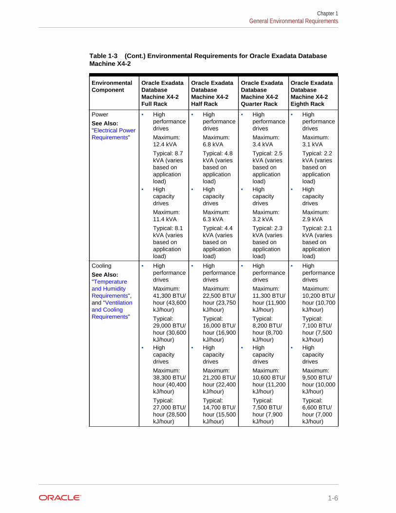
Table 1-3 (Cont.) Environmental Requirements for Oracle Exadata DatabaseMachine X4-2
EnvironmentalComponent
Oracle ExadataDatabaseMachine X4-2Full Rack
Oracle ExadataDatabaseMachine X4-2Half Rack
Oracle ExadataDatabaseMachine X4-2Quarter Rack
Oracle ExadataDatabaseMachine X4-2Eighth Rack
Power
See Also:"Electrical PowerRequirements"
• Highperformancedrives
Maximum:12.4 kVA
Typical: 8.7kVA (variesbased onapplicationload)
• Highcapacitydrives
Maximum:11.4 kVA
Typical: 8.1kVA (variesbased onapplicationload)
• Highperformancedrives
Maximum:6.8 kVA
Typical: 4.8kVA (variesbased onapplicationload)
• Highcapacitydrives
Maximum:6.3 kVA
Typical: 4.4kVA (variesbased onapplicationload)
• Highperformancedrives
Maximum:3.4 kVA
Typical: 2.5kVA (variesbased onapplicationload)
• Highcapacitydrives
Maximum:3.2 kVA
Typical: 2.3kVA (variesbased onapplicationload)
• Highperformancedrives
Maximum:3.1 kVA
Typical: 2.2kVA (variesbased onapplicationload)
• Highcapacitydrives
Maximum:2.9 kVA
Typical: 2.1kVA (variesbased onapplicationload)
Cooling
See Also:"Temperatureand HumidityRequirements",and "Ventilationand CoolingRequirements"
• Highperformancedrives
Maximum:41,300 BTU/hour (43,600kJ/hour)
Typical:29,000 BTU/hour (30,600kJ/hour)
• Highcapacitydrives
Maximum:38,300 BTU/hour (40,400kJ/hour)
Typical:27,000 BTU/hour (28,500kJ/hour)
• Highperformancedrives
Maximum:22,500 BTU/hour (23,750kJ/hour)
Typical:16,000 BTU/hour (16,900kJ/hour)
• Highcapacitydrives
Maximum:21,200 BTU/hour (22,400kJ/hour)
Typical:14,700 BTU/hour (15,500kJ/hour)
• Highperformancedrives
Maximum:11,300 BTU/hour (11,900kJ/hour)
Typical:8,200 BTU/hour (8,700kJ/hour)
• Highcapacitydrives
Maximum:10,600 BTU/hour (11,200kJ/hour)
Typical:7,500 BTU/hour (7,900kJ/hour)
• Highperformancedrives
Maximum:10,200 BTU/hour (10,700kJ/hour)
Typical:7,100 BTU/hour (7,500kJ/hour)
• Highcapacitydrives
Maximum:9,500 BTU/hour (10,000kJ/hour)
Typical:6,600 BTU/hour (7,000kJ/hour)
Chapter 1General Environmental Requirements
1-6
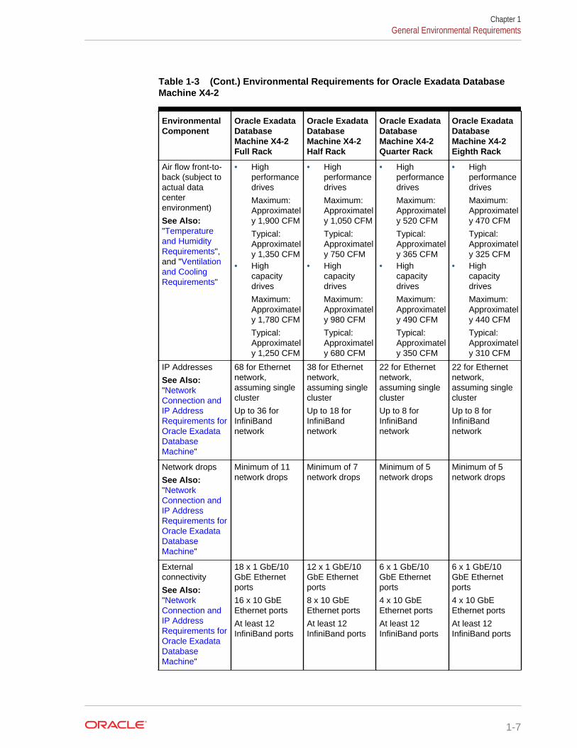
Table 1-3 (Cont.) Environmental Requirements for Oracle Exadata DatabaseMachine X4-2
EnvironmentalComponent
Oracle ExadataDatabaseMachine X4-2Full Rack
Oracle ExadataDatabaseMachine X4-2Half Rack
Oracle ExadataDatabaseMachine X4-2Quarter Rack
Oracle ExadataDatabaseMachine X4-2Eighth Rack
Air flow front-to-back (subject toactual datacenterenvironment)
See Also:"Temperatureand HumidityRequirements",and "Ventilationand CoolingRequirements"
• Highperformancedrives
Maximum:Approximately 1,900 CFM
Typical:Approximately 1,350 CFM
• Highcapacitydrives
Maximum:Approximately 1,780 CFM
Typical:Approximately 1,250 CFM
• Highperformancedrives
Maximum:Approximately 1,050 CFM
Typical:Approximately 750 CFM
• Highcapacitydrives
Maximum:Approximately 980 CFM
Typical:Approximately 680 CFM
• Highperformancedrives
Maximum:Approximately 520 CFM
Typical:Approximately 365 CFM
• Highcapacitydrives
Maximum:Approximately 490 CFM
Typical:Approximately 350 CFM
• Highperformancedrives
Maximum:Approximately 470 CFM
Typical:Approximately 325 CFM
• Highcapacitydrives
Maximum:Approximately 440 CFM
Typical:Approximately 310 CFM
IP Addresses
See Also:"NetworkConnection andIP AddressRequirements forOracle ExadataDatabaseMachine"
68 for Ethernetnetwork,assuming singlecluster
Up to 36 forInfiniBandnetwork
38 for Ethernetnetwork,assuming singlecluster
Up to 18 forInfiniBandnetwork
22 for Ethernetnetwork,assuming singlecluster
Up to 8 forInfiniBandnetwork
22 for Ethernetnetwork,assuming singlecluster
Up to 8 forInfiniBandnetwork
Network drops
See Also:"NetworkConnection andIP AddressRequirements forOracle ExadataDatabaseMachine"
Minimum of 11network drops
Minimum of 7network drops
Minimum of 5network drops
Minimum of 5network drops
Externalconnectivity
See Also:"NetworkConnection andIP AddressRequirements forOracle ExadataDatabaseMachine"
18 x 1 GbE/10GbE Ethernetports
16 x 10 GbEEthernet ports
At least 12InfiniBand ports
12 x 1 GbE/10GbE Ethernetports
8 x 10 GbEEthernet ports
At least 12InfiniBand ports
6 x 1 GbE/10GbE Ethernetports
4 x 10 GbEEthernet ports
At least 12InfiniBand ports
6 x 1 GbE/10GbE Ethernetports
4 x 10 GbEEthernet ports
At least 12InfiniBand ports
Chapter 1General Environmental Requirements
1-7
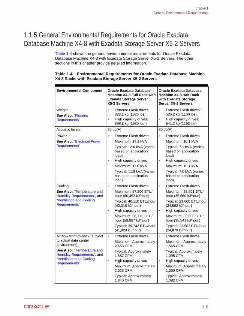
1.1.5 General Environmental Requirements for Oracle ExadataDatabase Machine X4-8 with Exadata Storage Server X5-2 Servers
Table 1-4 shows the general environmental requirements for Oracle ExadataDatabase Machine X4-8 with Exadata Storage Server X5-2 Servers. The othersections in this chapter provide detailed information.
Table 1-4 Environmental Requirements for Oracle Exadata Database MachineX4-8 Racks with Exadata Storage Server X5-2 Servers
Environmental Component Oracle Exadata DatabaseMachine X4-8 Full Rack withExadata Storage ServerX5-2 Servers
Oracle Exadata DatabaseMachine X4-8 Half Rackwith Exadata StorageServer X5-2 Servers
Weight
See Also: "FlooringRequirements"
• Extreme Flash drives:828.1 kg (1826 lbs)
• High capacity drives:898.3 kg (1980 lbs))
• Extreme Flash drives:526.2 kg (1160 lbs)
• High capacity drives:541.2 kg (1193 lbs)
Acoustic levels 86 db(A) 85 db(A)
Power
See Also: "Electrical PowerRequirements"
• Extreme Flash drives
Maximum: 17.1 kVA
Typical: 12.0 kVA (variesbased on applicationload)
• High capacity drives
Maximum: 17.0 kVA
Typical: 11.9 kVA (variesbased on applicationload)
• Extreme Flash drives
Maximum: 10.1 kVA
Typical: 7.1 kVA (variesbased on applicationload)
• High capacity drives
Maximum: 10.1 kVA
Typical: 7.0 kVA (variesbased on applicationload)
Cooling
See Also: "Temperature andHumidity Requirements", and"Ventilation and CoolingRequirements"
• Extreme Flash drives
Maximum: 57,300 BTU/hour (60,452 kJ/hour)
Typical: 40,110 BTU/hour(42,316 kJ/hour)
• High capacity drives
Maximum: 56,775 BTU/hour (59,897 kJ/hour)
Typical: 39,742 BTU/hour(41,928 kJ/hour)
• Extreme Flash drives
Maximum: 33,801 BTU/hour (35,660 kJ/hour)
Typical: 23,660 BTU/hour(24,962 kJ/hour)
• High capacity drives
Maximum: 33,688 BTU/hour (35,541 kJ/hour)
Typical: 23,582 BTU/hour(24,879 kJ/hour)
Air flow front-to-back (subjectto actual data centerenvironment)
See Also: "Temperature andHumidity Requirements", and"Ventilation and CoolingRequirements"
• Extreme Flash drives
Maximum: Approximately2,653 CFM
Typical: Approximately1,857 CFM
• High capacity drives
Maximum: Approximately2,628 CFM
Typical: Approximately1,840 CFM
• Extreme Flash drives
Maximum: Approximately1,565 CFM
Typical: Approximately1,095 CFM
• High capacity drives
Maximum: Approximately1,560 CFM
Typical: Approximately1,092 CFM
Chapter 1General Environmental Requirements
1-8
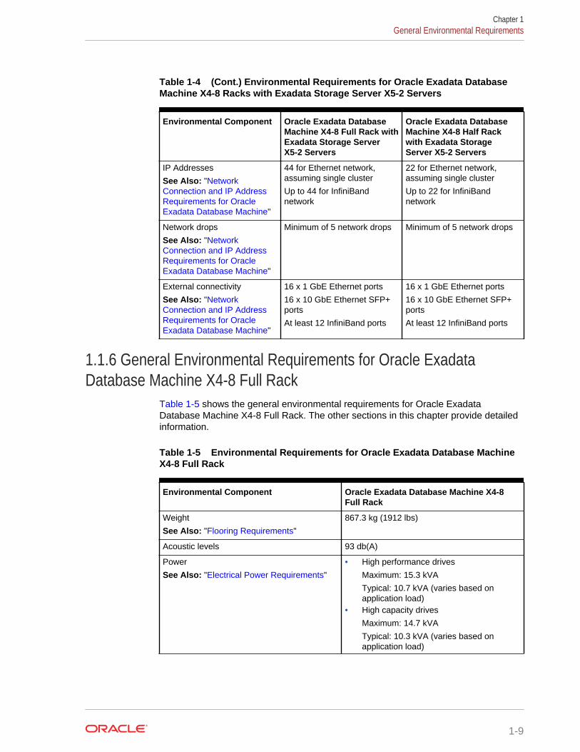
Table 1-4 (Cont.) Environmental Requirements for Oracle Exadata DatabaseMachine X4-8 Racks with Exadata Storage Server X5-2 Servers
Environmental Component Oracle Exadata DatabaseMachine X4-8 Full Rack withExadata Storage ServerX5-2 Servers
Oracle Exadata DatabaseMachine X4-8 Half Rackwith Exadata StorageServer X5-2 Servers
IP Addresses
See Also: "NetworkConnection and IP AddressRequirements for OracleExadata Database Machine"
44 for Ethernet network,assuming single cluster
Up to 44 for InfiniBandnetwork
22 for Ethernet network,assuming single cluster
Up to 22 for InfiniBandnetwork
Network drops
See Also: "NetworkConnection and IP AddressRequirements for OracleExadata Database Machine"
Minimum of 5 network drops Minimum of 5 network drops
External connectivity
See Also: "NetworkConnection and IP AddressRequirements for OracleExadata Database Machine"
16 x 1 GbE Ethernet ports
16 x 10 GbE Ethernet SFP+ports
At least 12 InfiniBand ports
16 x 1 GbE Ethernet ports
16 x 10 GbE Ethernet SFP+ports
At least 12 InfiniBand ports
1.1.6 General Environmental Requirements for Oracle ExadataDatabase Machine X4-8 Full Rack
Table 1-5 shows the general environmental requirements for Oracle ExadataDatabase Machine X4-8 Full Rack. The other sections in this chapter provide detailedinformation.
Table 1-5 Environmental Requirements for Oracle Exadata Database MachineX4-8 Full Rack
Environmental Component Oracle Exadata Database Machine X4-8Full Rack
Weight
See Also: "Flooring Requirements"
867.3 kg (1912 lbs)
Acoustic levels 93 db(A)
Power
See Also: "Electrical Power Requirements"
• High performance drives
Maximum: 15.3 kVA
Typical: 10.7 kVA (varies based onapplication load)
• High capacity drives
Maximum: 14.7 kVA
Typical: 10.3 kVA (varies based onapplication load)
Chapter 1General Environmental Requirements
1-9
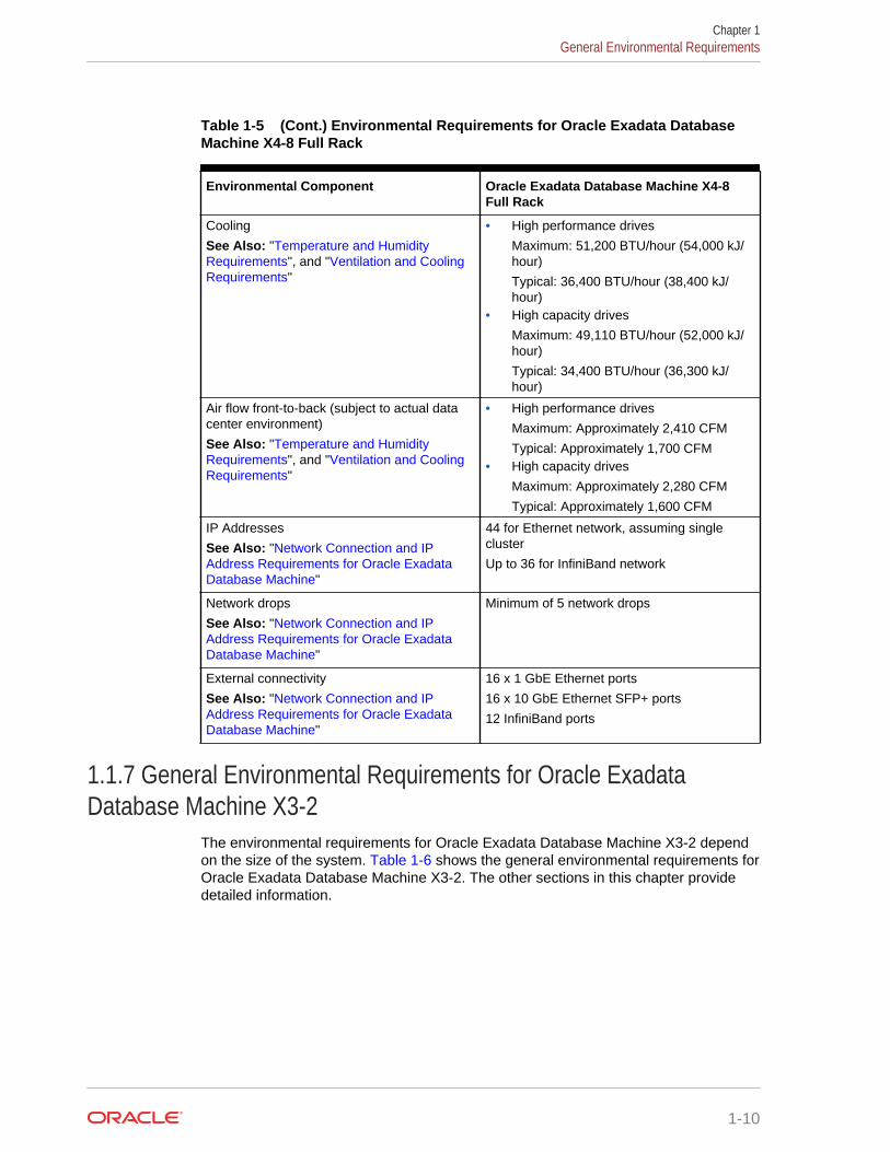
Table 1-5 (Cont.) Environmental Requirements for Oracle Exadata DatabaseMachine X4-8 Full Rack
Environmental Component Oracle Exadata Database Machine X4-8Full Rack
Cooling
See Also: "Temperature and HumidityRequirements", and "Ventilation and CoolingRequirements"
• High performance drives
Maximum: 51,200 BTU/hour (54,000 kJ/hour)
Typical: 36,400 BTU/hour (38,400 kJ/hour)
• High capacity drives
Maximum: 49,110 BTU/hour (52,000 kJ/hour)
Typical: 34,400 BTU/hour (36,300 kJ/hour)
Air flow front-to-back (subject to actual datacenter environment)
See Also: "Temperature and HumidityRequirements", and "Ventilation and CoolingRequirements"
• High performance drives
Maximum: Approximately 2,410 CFM
Typical: Approximately 1,700 CFM• High capacity drives
Maximum: Approximately 2,280 CFM
Typical: Approximately 1,600 CFM
IP Addresses
See Also: "Network Connection and IPAddress Requirements for Oracle ExadataDatabase Machine"
44 for Ethernet network, assuming singlecluster
Up to 36 for InfiniBand network
Network drops
See Also: "Network Connection and IPAddress Requirements for Oracle ExadataDatabase Machine"
Minimum of 5 network drops
External connectivity
See Also: "Network Connection and IPAddress Requirements for Oracle ExadataDatabase Machine"
16 x 1 GbE Ethernet ports
16 x 10 GbE Ethernet SFP+ ports
12 InfiniBand ports
1.1.7 General Environmental Requirements for Oracle ExadataDatabase Machine X3-2
The environmental requirements for Oracle Exadata Database Machine X3-2 dependon the size of the system. Table 1-6 shows the general environmental requirements forOracle Exadata Database Machine X3-2. The other sections in this chapter providedetailed information.
Chapter 1General Environmental Requirements
1-10
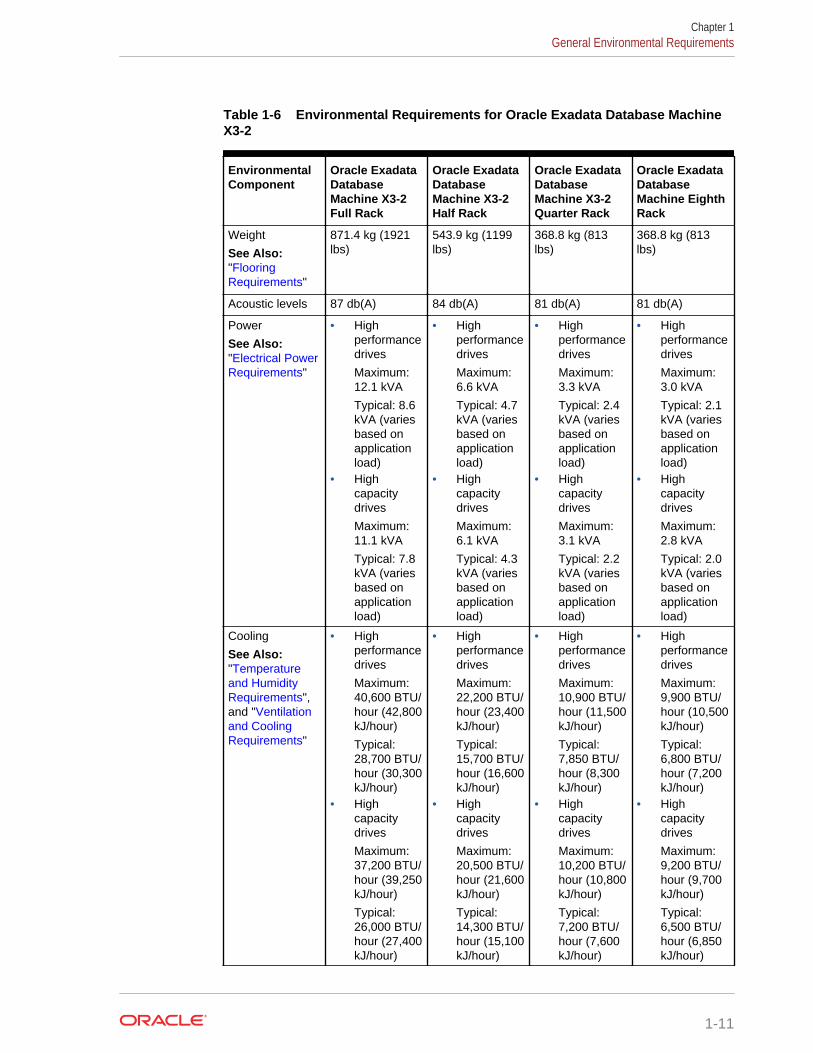
Table 1-6 Environmental Requirements for Oracle Exadata Database MachineX3-2
EnvironmentalComponent
Oracle ExadataDatabaseMachine X3-2Full Rack
Oracle ExadataDatabaseMachine X3-2Half Rack
Oracle ExadataDatabaseMachine X3-2Quarter Rack
Oracle ExadataDatabaseMachine EighthRack
Weight
See Also:"FlooringRequirements"
871.4 kg (1921lbs)
543.9 kg (1199lbs)
368.8 kg (813lbs)
368.8 kg (813lbs)
Acoustic levels 87 db(A) 84 db(A) 81 db(A) 81 db(A)
Power
See Also:"Electrical PowerRequirements"
• Highperformancedrives
Maximum:12.1 kVA
Typical: 8.6kVA (variesbased onapplicationload)
• Highcapacitydrives
Maximum:11.1 kVA
Typical: 7.8kVA (variesbased onapplicationload)
• Highperformancedrives
Maximum:6.6 kVA
Typical: 4.7kVA (variesbased onapplicationload)
• Highcapacitydrives
Maximum:6.1 kVA
Typical: 4.3kVA (variesbased onapplicationload)
• Highperformancedrives
Maximum:3.3 kVA
Typical: 2.4kVA (variesbased onapplicationload)
• Highcapacitydrives
Maximum:3.1 kVA
Typical: 2.2kVA (variesbased onapplicationload)
• Highperformancedrives
Maximum:3.0 kVA
Typical: 2.1kVA (variesbased onapplicationload)
• Highcapacitydrives
Maximum:2.8 kVA
Typical: 2.0kVA (variesbased onapplicationload)
Cooling
See Also:"Temperatureand HumidityRequirements",and "Ventilationand CoolingRequirements"
• Highperformancedrives
Maximum:40,600 BTU/hour (42,800kJ/hour)
Typical:28,700 BTU/hour (30,300kJ/hour)
• Highcapacitydrives
Maximum:37,200 BTU/hour (39,250kJ/hour)
Typical:26,000 BTU/hour (27,400kJ/hour)
• Highperformancedrives
Maximum:22,200 BTU/hour (23,400kJ/hour)
Typical:15,700 BTU/hour (16,600kJ/hour)
• Highcapacitydrives
Maximum:20,500 BTU/hour (21,600kJ/hour)
Typical:14,300 BTU/hour (15,100kJ/hour)
• Highperformancedrives
Maximum:10,900 BTU/hour (11,500kJ/hour)
Typical:7,850 BTU/hour (8,300kJ/hour)
• Highcapacitydrives
Maximum:10,200 BTU/hour (10,800kJ/hour)
Typical:7,200 BTU/hour (7,600kJ/hour)
• Highperformancedrives
Maximum:9,900 BTU/hour (10,500kJ/hour)
Typical:6,800 BTU/hour (7,200kJ/hour)
• Highcapacitydrives
Maximum:9,200 BTU/hour (9,700kJ/hour)
Typical:6,500 BTU/hour (6,850kJ/hour)
Chapter 1General Environmental Requirements
1-11
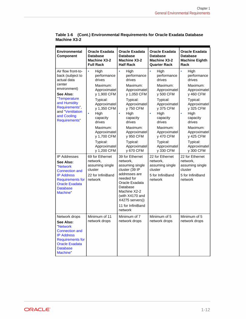
Table 1-6 (Cont.) Environmental Requirements for Oracle Exadata DatabaseMachine X3-2
EnvironmentalComponent
Oracle ExadataDatabaseMachine X3-2Full Rack
Oracle ExadataDatabaseMachine X3-2Half Rack
Oracle ExadataDatabaseMachine X3-2Quarter Rack
Oracle ExadataDatabaseMachine EighthRack
Air flow front-to-back (subject toactual datacenterenvironment)
See Also:"Temperatureand HumidityRequirements",and "Ventilationand CoolingRequirements"
• Highperformancedrives
Maximum:Approximately 1,900 CFM
Typical:Approximately 1,350 CFM
• Highcapacitydrives
Maximum:Approximately 1,700 CFM
Typical:Approximately 1,200 CFM
• Highperformancedrives
Maximum:Approximately 1,050 CFM
Typical:Approximately 750 CFM
• Highcapacitydrives
Maximum:Approximately 950 CFM
Typical:Approximately 670 CFM
• Highperformancedrives
Maximum:Approximately 500 CFM
Typical:Approximately 375 CFM
• Highcapacitydrives
Maximum:Approximately 470 CFM
Typical:Approximately 330 CFM
• Highperformancedrives
Maximum:Approximately 460 CFM
Typical:Approximately 325 CFM
• Highcapacitydrives
Maximum:Approximately 425 CFM
Typical:Approximately 300 CFM
IP Addresses
See Also:"NetworkConnection andIP AddressRequirements forOracle ExadataDatabaseMachine"
69 for Ethernetnetwork,assuming singlecluster
22 for InfiniBandnetwork
39 for Ethernetnetwork,assuming singlecluster (39 IPaddresses areneeded forOracle ExadataDatabaseMachine X2-2(with X4170 andX4275 servers))
11 for InfiniBandnetwork
22 for Ethernetnetwork,assuming singlecluster
5 for InfiniBandnetwork
22 for Ethernetnetwork,assuming singlecluster
5 for InfiniBandnetwork
Network drops
See Also:"NetworkConnection andIP AddressRequirements forOracle ExadataDatabaseMachine"
Minimum of 11network drops
Minimum of 7network drops
Minimum of 5network drops
Minimum of 5network drops
Chapter 1General Environmental Requirements
1-12
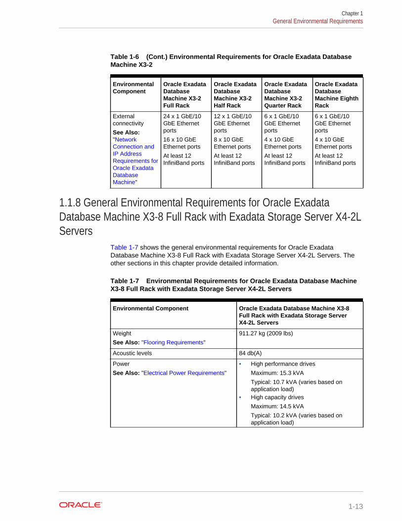
Table 1-6 (Cont.) Environmental Requirements for Oracle Exadata DatabaseMachine X3-2
EnvironmentalComponent
Oracle ExadataDatabaseMachine X3-2Full Rack
Oracle ExadataDatabaseMachine X3-2Half Rack
Oracle ExadataDatabaseMachine X3-2Quarter Rack
Oracle ExadataDatabaseMachine EighthRack
Externalconnectivity
See Also:"NetworkConnection andIP AddressRequirements forOracle ExadataDatabaseMachine"
24 x 1 GbE/10GbE Ethernetports
16 x 10 GbEEthernet ports
At least 12InfiniBand ports
12 x 1 GbE/10GbE Ethernetports
8 x 10 GbEEthernet ports
At least 12InfiniBand ports
6 x 1 GbE/10GbE Ethernetports
4 x 10 GbEEthernet ports
At least 12InfiniBand ports
6 x 1 GbE/10GbE Ethernetports
4 x 10 GbEEthernet ports
At least 12InfiniBand ports
1.1.8 General Environmental Requirements for Oracle ExadataDatabase Machine X3-8 Full Rack with Exadata Storage Server X4-2LServers
Table 1-7 shows the general environmental requirements for Oracle ExadataDatabase Machine X3-8 Full Rack with Exadata Storage Server X4-2L Servers. Theother sections in this chapter provide detailed information.
Table 1-7 Environmental Requirements for Oracle Exadata Database MachineX3-8 Full Rack with Exadata Storage Server X4-2L Servers
Environmental Component Oracle Exadata Database Machine X3-8Full Rack with Exadata Storage ServerX4-2L Servers
Weight
See Also: "Flooring Requirements"
911.27 kg (2009 lbs)
Acoustic levels 84 db(A)
Power
See Also: "Electrical Power Requirements"
• High performance drives
Maximum: 15.3 kVA
Typical: 10.7 kVA (varies based onapplication load)
• High capacity drives
Maximum: 14.5 kVA
Typical: 10.2 kVA (varies based onapplication load)
Chapter 1General Environmental Requirements
1-13
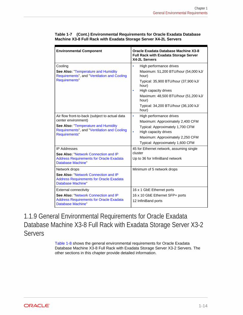
Table 1-7 (Cont.) Environmental Requirements for Oracle Exadata DatabaseMachine X3-8 Full Rack with Exadata Storage Server X4-2L Servers
Environmental Component Oracle Exadata Database Machine X3-8Full Rack with Exadata Storage ServerX4-2L Servers
Cooling
See Also: "Temperature and HumidityRequirements", and "Ventilation and CoolingRequirements"
• High performance drives
Maximum: 51,200 BTU/hour (54,000 kJ/hour)
Typical: 35,900 BTU/hour (37,900 kJ/hour)
• High capacity drives
Maximum: 48,500 BTU/hour (51,200 kJ/hour)
Typical: 34,200 BTU/hour (36,100 kJ/hour)
Air flow front-to-back (subject to actual datacenter environment)
See Also: "Temperature and HumidityRequirements", and "Ventilation and CoolingRequirements"
• High performance drives
Maximum: Approximately 2,400 CFM
Typical: Approximately 1,700 CFM• High capacity drives
Maximum: Approximately 2,250 CFM
Typical: Approximately 1,600 CFM
IP Addresses
See Also: "Network Connection and IPAddress Requirements for Oracle ExadataDatabase Machine"
45 for Ethernet network, assuming singlecluster
Up to 36 for InfiniBand network
Network drops
See Also: "Network Connection and IPAddress Requirements for Oracle ExadataDatabase Machine"
Minimum of 5 network drops
External connectivity
See Also: "Network Connection and IPAddress Requirements for Oracle ExadataDatabase Machine"
16 x 1 GbE Ethernet ports
16 x 10 GbE Ethernet SFP+ ports
12 InfiniBand ports
1.1.9 General Environmental Requirements for Oracle ExadataDatabase Machine X3-8 Full Rack with Exadata Storage Server X3-2Servers
Table 1-8 shows the general environmental requirements for Oracle ExadataDatabase Machine X3-8 Full Rack with Exadata Storage Server X3-2 Servers. Theother sections in this chapter provide detailed information.
Chapter 1General Environmental Requirements
1-14
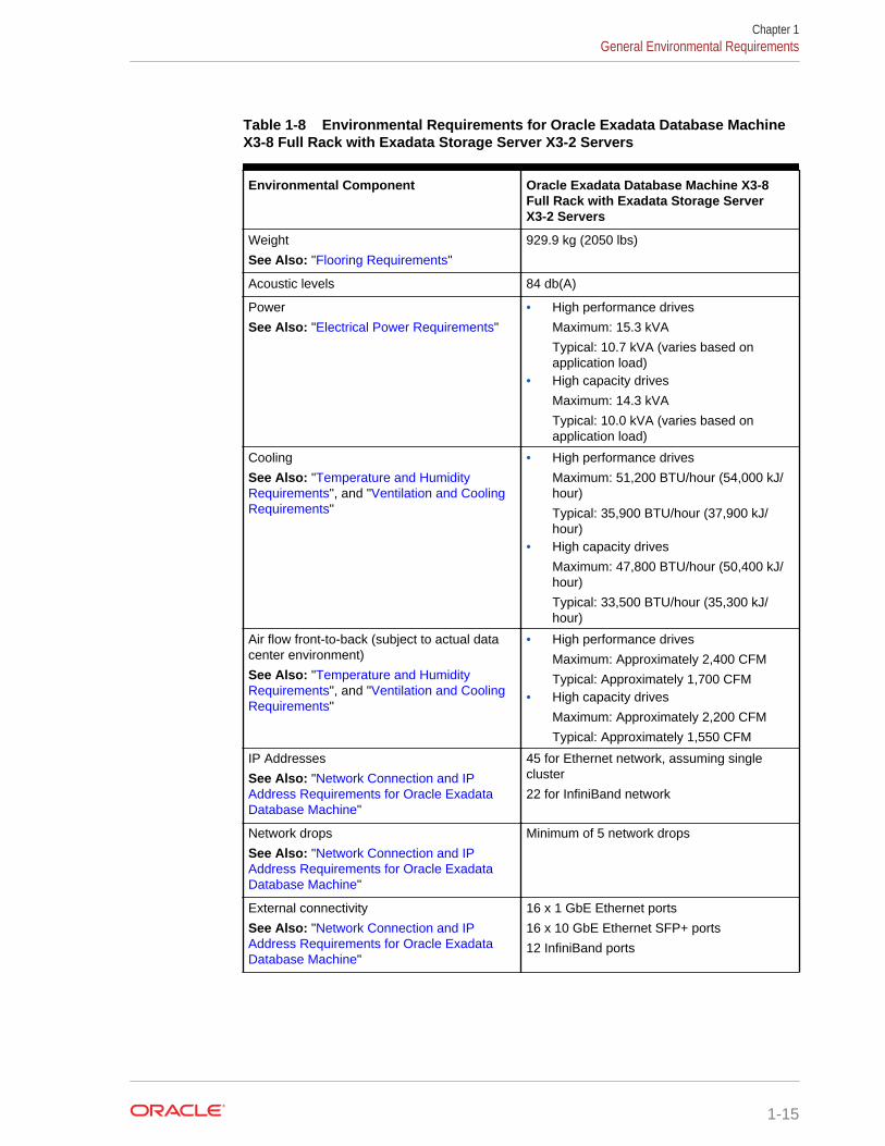
Table 1-8 Environmental Requirements for Oracle Exadata Database MachineX3-8 Full Rack with Exadata Storage Server X3-2 Servers
Environmental Component Oracle Exadata Database Machine X3-8Full Rack with Exadata Storage ServerX3-2 Servers
Weight
See Also: "Flooring Requirements"
929.9 kg (2050 lbs)
Acoustic levels 84 db(A)
Power
See Also: "Electrical Power Requirements"
• High performance drives
Maximum: 15.3 kVA
Typical: 10.7 kVA (varies based onapplication load)
• High capacity drives
Maximum: 14.3 kVA
Typical: 10.0 kVA (varies based onapplication load)
Cooling
See Also: "Temperature and HumidityRequirements", and "Ventilation and CoolingRequirements"
• High performance drives
Maximum: 51,200 BTU/hour (54,000 kJ/hour)
Typical: 35,900 BTU/hour (37,900 kJ/hour)
• High capacity drives
Maximum: 47,800 BTU/hour (50,400 kJ/hour)
Typical: 33,500 BTU/hour (35,300 kJ/hour)
Air flow front-to-back (subject to actual datacenter environment)
See Also: "Temperature and HumidityRequirements", and "Ventilation and CoolingRequirements"
• High performance drives
Maximum: Approximately 2,400 CFM
Typical: Approximately 1,700 CFM• High capacity drives
Maximum: Approximately 2,200 CFM
Typical: Approximately 1,550 CFM
IP Addresses
See Also: "Network Connection and IPAddress Requirements for Oracle ExadataDatabase Machine"
45 for Ethernet network, assuming singlecluster
22 for InfiniBand network
Network drops
See Also: "Network Connection and IPAddress Requirements for Oracle ExadataDatabase Machine"
Minimum of 5 network drops
External connectivity
See Also: "Network Connection and IPAddress Requirements for Oracle ExadataDatabase Machine"
16 x 1 GbE Ethernet ports
16 x 10 GbE Ethernet SFP+ ports
12 InfiniBand ports
Chapter 1General Environmental Requirements
1-15
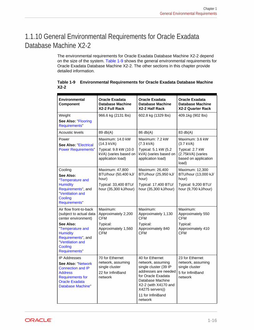
1.1.10 General Environmental Requirements for Oracle ExadataDatabase Machine X2-2
The environmental requirements for Oracle Exadata Database Machine X2-2 dependon the size of the system. Table 1-9 shows the general environmental requirements forOracle Exadata Database Machine X2-2. The other sections in this chapter providedetailed information.
Table 1-9 Environmental Requirements for Oracle Exadata Database MachineX2-2
EnvironmentalComponent
Oracle ExadataDatabase MachineX2-2 Full Rack
Oracle ExadataDatabase MachineX2-2 Half Rack
Oracle ExadataDatabase MachineX2-2 Quarter Rack
Weight
See Also: "FlooringRequirements"
966.6 kg (2131 lbs) 602.8 kg (1329 lbs) 409.1kg (902 lbs)
Acoustic levels 89 db(A) 86 db(A) 83 db(A)
Power
See Also: "ElectricalPower Requirements"
Maximum: 14.0 kW(14.3 kVA)
Typical: 9.8 kW (10.0kVA) (varies based onapplication load)
Maximum: 7.2 kW(7.3 kVA)
Typical: 5.1 kW (5.2kVA) (varies based onapplication load)
Maximum: 3.6 kW(3.7 kVA)
Typical: 2.7 kW(2.75kVA) (variesbased on applicationload)
Cooling
See Also:"Temperature andHumidityRequirements", and"Ventilation andCoolingRequirements"
Maximum: 47,800BTU/hour (50,400 kJ/hour)
Typical: 33,400 BTU/hour (35,300 kJ/hour)
Maximum: 26,400BTU/hour (25,950 kJ/hour)
Typical: 17,400 BTU/hour (35,300 kJ/hour)
Maximum: 12,300BTU/hour (13,000 kJ/hour)
Typical: 9,200 BTU/hour (9,700 kJ/hour)
Air flow front-to-back(subject to actual datacenter environment)
See Also:"Temperature andHumidityRequirements", and"Ventilation andCoolingRequirements"
Maximum:Approximately 2,200CFM
Typical:Approximately 1,560CFM
Maximum:Approximately 1,130CFM
Typical:Approximately 840CFM
Maximum:Approximately 550CFM
Typical:Approximately 410CFM
IP Addresses
See Also: "NetworkConnection and IPAddressRequirements forOracle ExadataDatabase Machine"
70 for Ethernetnetwork, assumingsingle cluster
22 for InfiniBandnetwork
40 for Ethernetnetwork, assumingsingle cluster (39 IPaddresses are neededfor Oracle ExadataDatabase MachineX2-2 (with X4170 andX4275 servers))
11 for InfiniBandnetwork
23 for Ethernetnetwork, assumingsingle cluster
5 for InfiniBandnetwork
Chapter 1General Environmental Requirements
1-16

Table 1-9 (Cont.) Environmental Requirements for Oracle Exadata DatabaseMachine X2-2
EnvironmentalComponent
Oracle ExadataDatabase MachineX2-2 Full Rack
Oracle ExadataDatabase MachineX2-2 Half Rack
Oracle ExadataDatabase MachineX2-2 Quarter Rack
Network drops
See Also: "NetworkConnection and IPAddressRequirements forOracle ExadataDatabase Machine"
Minimum of 12network drops
Minimum of 8 networkdrops
Minimum of 6 networkdrops
External connectivity
See Also: "NetworkConnection and IPAddressRequirements forOracle ExadataDatabase Machine"
24 x 1 GbE Ethernetports
16 x 10 GbE Ethernetports (valid for M2servers only)
At least 12 InfiniBandports
12 x 1 GbE Ethernetports
8 x 10 GbE Ethernetports (valid for M2servers only)
At least 12 InfiniBandports
6 x 1 GbE Ethernetports
4 x 10 GbE Ethernetports (valid for M2servers only)
At least 12 InfiniBandports
1.1.11 General Environmental Requirements for Oracle ExadataDatabase Machine X2-8 Full Rack
Table 1-10 shows the general environmental requirements for Oracle ExadataDatabase Machine X2-8 Full Rack. The other sections in this chapter provide detailedinformation.
Table 1-10 Environmental Requirements for Oracle Exadata Database MachineX2-8 Full Rack
Environmental Component Oracle Exadata DatabaseMachine X2-8 Full Rack(Sun Fire X4800 OracleDatabase Servers)
Oracle Exadata DatabaseMachine X2-8 Full Rack(Sun Server X2-8 OracleDatabase Servers)
Weight
See Also: "FlooringRequirements"
943.5 kg (2080 lbs) 980.7 kg (2162 lbs)
Acoustic levels 85 db(A) 85 db(A)
Power
See Also: "Electrical PowerRequirements"
Maximum: 17.0 kW (17.4kVA)
Typical: 11.9 kW (12.2 kVA)(varies based on applicationload)
Maximum: 17.7 kW (18.1kVA)
Typical: 12.4 kW (112.7 kVA)(varies based on applicationload)
Cooling
See Also: "Temperature andHumidity Requirements", and"Ventilation and CoolingRequirements"
Maximum: 58,050 BTU/hour(61,200 kJ/hour)
Typical: 40,630 BTU/hour(42,840 kJ/hour)
Maximum: 60,350 BTU/hour(63,630 kJ/hour)
Typical: 42,280 BTU/hour(44,580 kJ/hour)
Chapter 1General Environmental Requirements
1-17
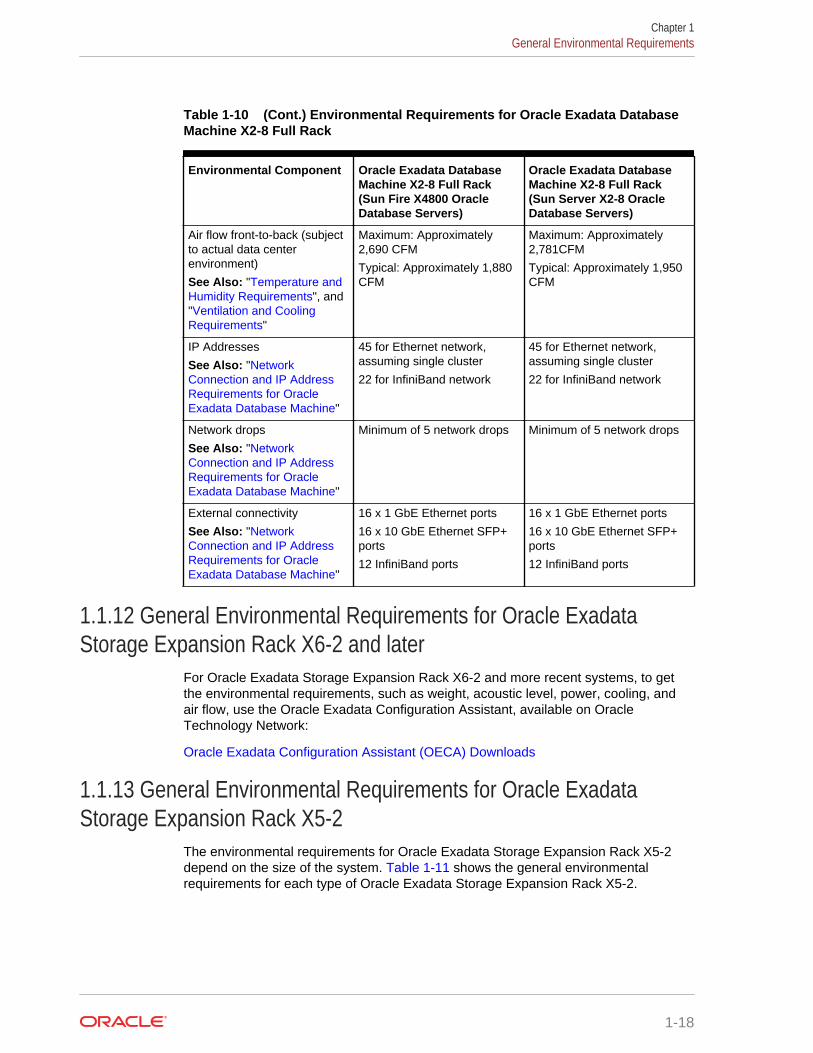
Table 1-10 (Cont.) Environmental Requirements for Oracle Exadata DatabaseMachine X2-8 Full Rack
Environmental Component Oracle Exadata DatabaseMachine X2-8 Full Rack(Sun Fire X4800 OracleDatabase Servers)
Oracle Exadata DatabaseMachine X2-8 Full Rack(Sun Server X2-8 OracleDatabase Servers)
Air flow front-to-back (subjectto actual data centerenvironment)
See Also: "Temperature andHumidity Requirements", and"Ventilation and CoolingRequirements"
Maximum: Approximately2,690 CFM
Typical: Approximately 1,880CFM
Maximum: Approximately2,781CFM
Typical: Approximately 1,950CFM
IP Addresses
See Also: "NetworkConnection and IP AddressRequirements for OracleExadata Database Machine"
45 for Ethernet network,assuming single cluster
22 for InfiniBand network
45 for Ethernet network,assuming single cluster
22 for InfiniBand network
Network drops
See Also: "NetworkConnection and IP AddressRequirements for OracleExadata Database Machine"
Minimum of 5 network drops Minimum of 5 network drops
External connectivity
See Also: "NetworkConnection and IP AddressRequirements for OracleExadata Database Machine"
16 x 1 GbE Ethernet ports
16 x 10 GbE Ethernet SFP+ports
12 InfiniBand ports
16 x 1 GbE Ethernet ports
16 x 10 GbE Ethernet SFP+ports
12 InfiniBand ports
1.1.12 General Environmental Requirements for Oracle ExadataStorage Expansion Rack X6-2 and later
For Oracle Exadata Storage Expansion Rack X6-2 and more recent systems, to getthe environmental requirements, such as weight, acoustic level, power, cooling, andair flow, use the Oracle Exadata Configuration Assistant, available on OracleTechnology Network:
Oracle Exadata Configuration Assistant (OECA) Downloads
1.1.13 General Environmental Requirements for Oracle ExadataStorage Expansion Rack X5-2
The environmental requirements for Oracle Exadata Storage Expansion Rack X5-2depend on the size of the system. Table 1-11 shows the general environmentalrequirements for each type of Oracle Exadata Storage Expansion Rack X5-2.
Chapter 1General Environmental Requirements
1-18
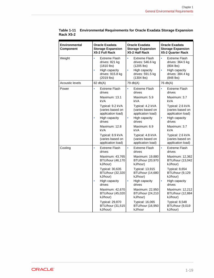
Table 1-11 Environmental Requirements for Oracle Exadata Storage ExpansionRack X5-2
EnvironmentalComponent
Oracle ExadataStorage ExpansionX5-2 Full Rack
Oracle ExadataStorage ExpansionX5-2 Half Rack
Oracle ExadataStorage ExpansionX5-2 Quarter Rack
Weight • Extreme Flashdrives: 821 kg(1810 lbs)
• High capacitydrives: 915.8 kg(2019 lbs)
• Extreme Flashdrives: 546.6 kg(1205 lbs)
• High capacitydrives: 591.5 kg(1304 lbs)
• Extreme Flashdrives: 364.5 kg(804 lbs)
• High capacitydrives: 384.4 kg(848 lbs)
Acoustic levels 82 db(A) 79 db(A) 76 db(A)
Power • Extreme Flashdrives
Maximum: 13.1kVA
Typical: 9.2 kVA(varies based onapplication load)
• High capacitydrives
Maximum: 12.8kVA
Typical: 8.9 kVA(varies based onapplication load)
• Extreme Flashdrives
Maximum: 5.9kVA
Typical: 4.2 kVA(varies based onapplication load)
• High capacitydrives
Maximum: 6.9kVA
Typical: 4.8 kVA(varies based onapplication load)
• Extreme Flashdrives
Maximum: 3.7kVA
Typical: 2.6 kVA(varies based onapplication load)
• High capacitydrives
Maximum: 3.7kVA
Typical: 2.6 kVA(varies based onapplication load)
Cooling • Extreme Flashdrives
Maximum: 43,765BTU/hour (46,170kJ/hour)
Typical: 30,635BTU/hour (32,320kJ/hour)
• High capacitydrives
Maximum: 42,670BTU/hour (45,020kJ/hour)
Typical: 29,870BTU/hour (31,515kJ/hour)
• Extreme Flashdrives
Maximum: 19,880BTU/hour (20,970kJ/hour)
Typical: 13,915BTU/hour (14,680kJ/hour)
• High capacitydrives
Maximum: 22,950BTU/hour (24,210kJ/hour)
Typical: 16,065BTU/hour (16,950kJ/hour
• Extreme Flashdrives
Maximum: 12,362BTU/hour (13,042kJ/hour)
Typical: 8,654BTU/hour (9,129kJ/hour)
• High capacitydrives
Maximum: 12,212BTU/hour (12,884kJ/hour)
Typical: 8,548BTU/hour (9,019kJ/hour)
Chapter 1General Environmental Requirements
1-19
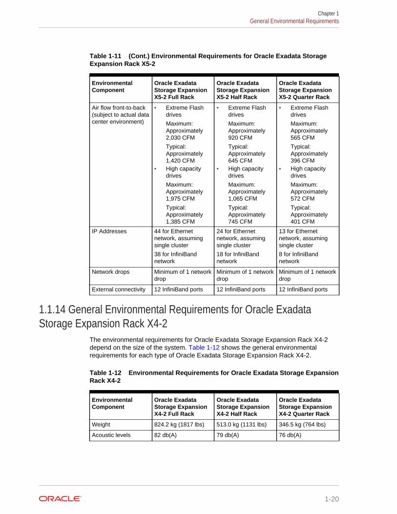
Table 1-11 (Cont.) Environmental Requirements for Oracle Exadata StorageExpansion Rack X5-2
EnvironmentalComponent
Oracle ExadataStorage ExpansionX5-2 Full Rack
Oracle ExadataStorage ExpansionX5-2 Half Rack
Oracle ExadataStorage ExpansionX5-2 Quarter Rack
Air flow front-to-back(subject to actual datacenter environment)
• Extreme Flashdrives
Maximum:Approximately2,030 CFM
Typical:Approximately1,420 CFM
• High capacitydrives
Maximum:Approximately1,975 CFM
Typical:Approximately1,385 CFM
• Extreme Flashdrives
Maximum:Approximately920 CFM
Typical:Approximately645 CFM
• High capacitydrives
Maximum:Approximately1,065 CFM
Typical:Approximately745 CFM
• Extreme Flashdrives
Maximum:Approximately565 CFM
Typical:Approximately396 CFM
• High capacitydrives
Maximum:Approximately572 CFM
Typical:Approximately401 CFM
IP Addresses 44 for Ethernetnetwork, assumingsingle cluster
38 for InfiniBandnetwork
24 for Ethernetnetwork, assumingsingle cluster
18 for InfiniBandnetwork
13 for Ethernetnetwork, assumingsingle cluster
8 for InfiniBandnetwork
Network drops Minimum of 1 networkdrop
Minimum of 1 networkdrop
Minimum of 1 networkdrop
External connectivity 12 InfiniBand ports 12 InfiniBand ports 12 InfiniBand ports
1.1.14 General Environmental Requirements for Oracle ExadataStorage Expansion Rack X4-2
The environmental requirements for Oracle Exadata Storage Expansion Rack X4-2depend on the size of the system. Table 1-12 shows the general environmentalrequirements for each type of Oracle Exadata Storage Expansion Rack X4-2.
Table 1-12 Environmental Requirements for Oracle Exadata Storage ExpansionRack X4-2
EnvironmentalComponent
Oracle ExadataStorage ExpansionX4-2 Full Rack
Oracle ExadataStorage ExpansionX4-2 Half Rack
Oracle ExadataStorage ExpansionX4-2 Quarter Rack
Weight 824.2 kg (1817 lbs) 513.0 kg (1131 lbs) 346.5 kg (764 lbs)
Acoustic levels 82 db(A) 79 db(A) 76 db(A)
Chapter 1General Environmental Requirements
1-20
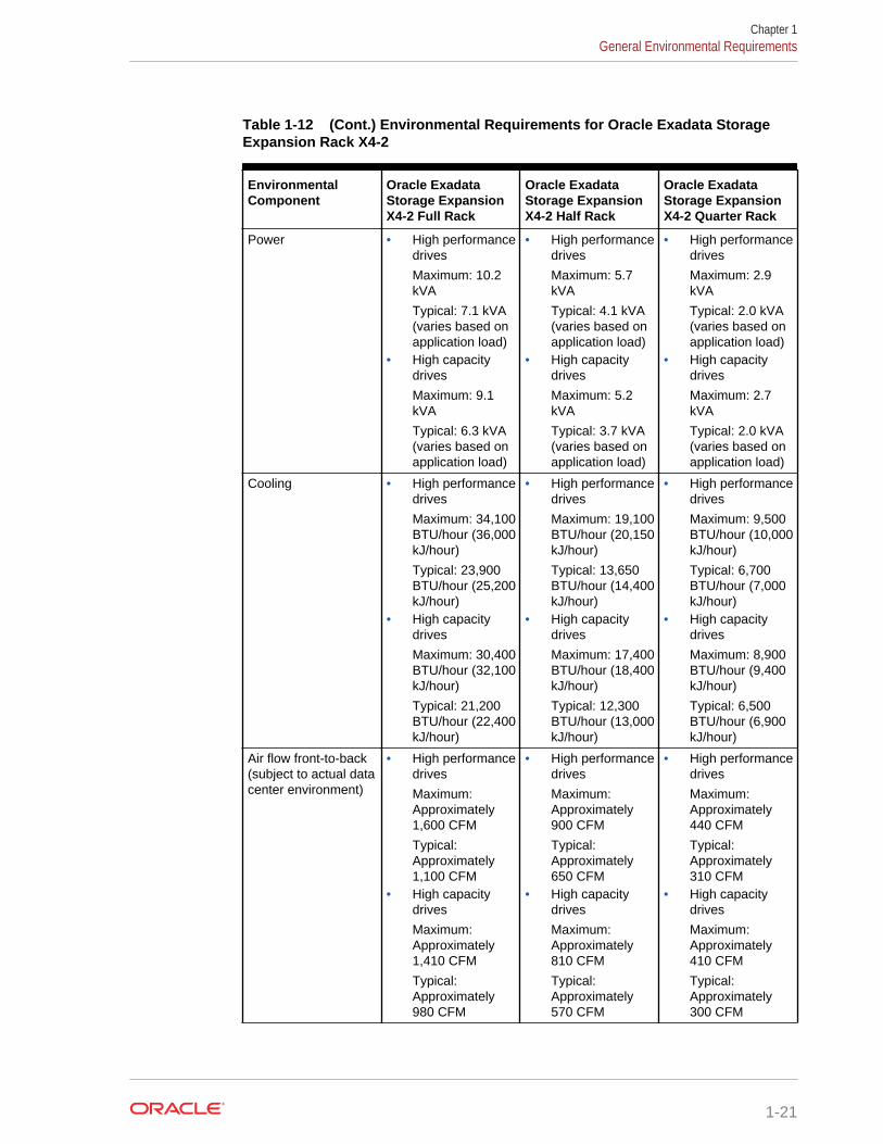
Table 1-12 (Cont.) Environmental Requirements for Oracle Exadata StorageExpansion Rack X4-2
EnvironmentalComponent
Oracle ExadataStorage ExpansionX4-2 Full Rack
Oracle ExadataStorage ExpansionX4-2 Half Rack
Oracle ExadataStorage ExpansionX4-2 Quarter Rack
Power • High performancedrives
Maximum: 10.2kVA
Typical: 7.1 kVA(varies based onapplication load)
• High capacitydrives
Maximum: 9.1kVA
Typical: 6.3 kVA(varies based onapplication load)
• High performancedrives
Maximum: 5.7kVA
Typical: 4.1 kVA(varies based onapplication load)
• High capacitydrives
Maximum: 5.2kVA
Typical: 3.7 kVA(varies based onapplication load)
• High performancedrives
Maximum: 2.9kVA
Typical: 2.0 kVA(varies based onapplication load)
• High capacitydrives
Maximum: 2.7kVA
Typical: 2.0 kVA(varies based onapplication load)
Cooling • High performancedrives
Maximum: 34,100BTU/hour (36,000kJ/hour)
Typical: 23,900BTU/hour (25,200kJ/hour)
• High capacitydrives
Maximum: 30,400BTU/hour (32,100kJ/hour)
Typical: 21,200BTU/hour (22,400kJ/hour)
• High performancedrives
Maximum: 19,100BTU/hour (20,150kJ/hour)
Typical: 13,650BTU/hour (14,400kJ/hour)
• High capacitydrives
Maximum: 17,400BTU/hour (18,400kJ/hour)
Typical: 12,300BTU/hour (13,000kJ/hour)
• High performancedrives
Maximum: 9,500BTU/hour (10,000kJ/hour)
Typical: 6,700BTU/hour (7,000kJ/hour)
• High capacitydrives
Maximum: 8,900BTU/hour (9,400kJ/hour)
Typical: 6,500BTU/hour (6,900kJ/hour)
Air flow front-to-back(subject to actual datacenter environment)
• High performancedrives
Maximum:Approximately1,600 CFM
Typical:Approximately1,100 CFM
• High capacitydrives
Maximum:Approximately1,410 CFM
Typical:Approximately980 CFM
• High performancedrives
Maximum:Approximately900 CFM
Typical:Approximately650 CFM
• High capacitydrives
Maximum:Approximately810 CFM
Typical:Approximately570 CFM
• High performancedrives
Maximum:Approximately440 CFM
Typical:Approximately310 CFM
• High capacitydrives
Maximum:Approximately410 CFM
Typical:Approximately300 CFM
Chapter 1General Environmental Requirements
1-21
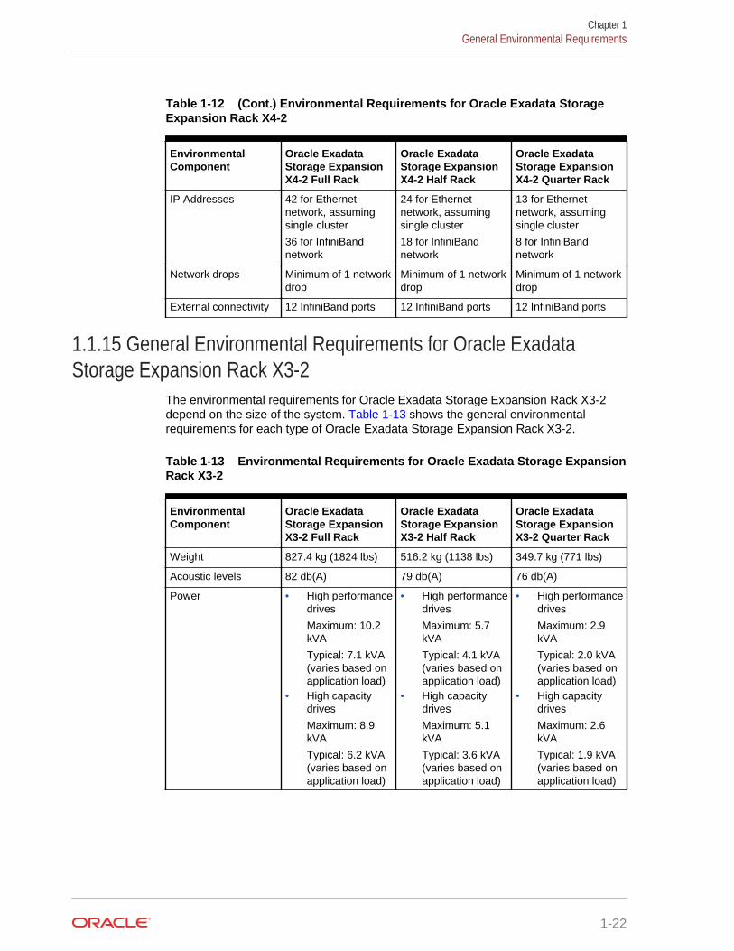
Table 1-12 (Cont.) Environmental Requirements for Oracle Exadata StorageExpansion Rack X4-2
EnvironmentalComponent
Oracle ExadataStorage ExpansionX4-2 Full Rack
Oracle ExadataStorage ExpansionX4-2 Half Rack
Oracle ExadataStorage ExpansionX4-2 Quarter Rack
IP Addresses 42 for Ethernetnetwork, assumingsingle cluster
36 for InfiniBandnetwork
24 for Ethernetnetwork, assumingsingle cluster
18 for InfiniBandnetwork
13 for Ethernetnetwork, assumingsingle cluster
8 for InfiniBandnetwork
Network drops Minimum of 1 networkdrop
Minimum of 1 networkdrop
Minimum of 1 networkdrop
External connectivity 12 InfiniBand ports 12 InfiniBand ports 12 InfiniBand ports
1.1.15 General Environmental Requirements for Oracle ExadataStorage Expansion Rack X3-2
The environmental requirements for Oracle Exadata Storage Expansion Rack X3-2depend on the size of the system. Table 1-13 shows the general environmentalrequirements for each type of Oracle Exadata Storage Expansion Rack X3-2.
Table 1-13 Environmental Requirements for Oracle Exadata Storage ExpansionRack X3-2
EnvironmentalComponent
Oracle ExadataStorage ExpansionX3-2 Full Rack
Oracle ExadataStorage ExpansionX3-2 Half Rack
Oracle ExadataStorage ExpansionX3-2 Quarter Rack
Weight 827.4 kg (1824 lbs) 516.2 kg (1138 lbs) 349.7 kg (771 lbs)
Acoustic levels 82 db(A) 79 db(A) 76 db(A)
Power • High performancedrives
Maximum: 10.2kVA
Typical: 7.1 kVA(varies based onapplication load)
• High capacitydrives
Maximum: 8.9kVA
Typical: 6.2 kVA(varies based onapplication load)
• High performancedrives
Maximum: 5.7kVA
Typical: 4.1 kVA(varies based onapplication load)
• High capacitydrives
Maximum: 5.1kVA
Typical: 3.6 kVA(varies based onapplication load)
• High performancedrives
Maximum: 2.9kVA
Typical: 2.0 kVA(varies based onapplication load)
• High capacitydrives
Maximum: 2.6kVA
Typical: 1.9 kVA(varies based onapplication load)
Chapter 1General Environmental Requirements
1-22
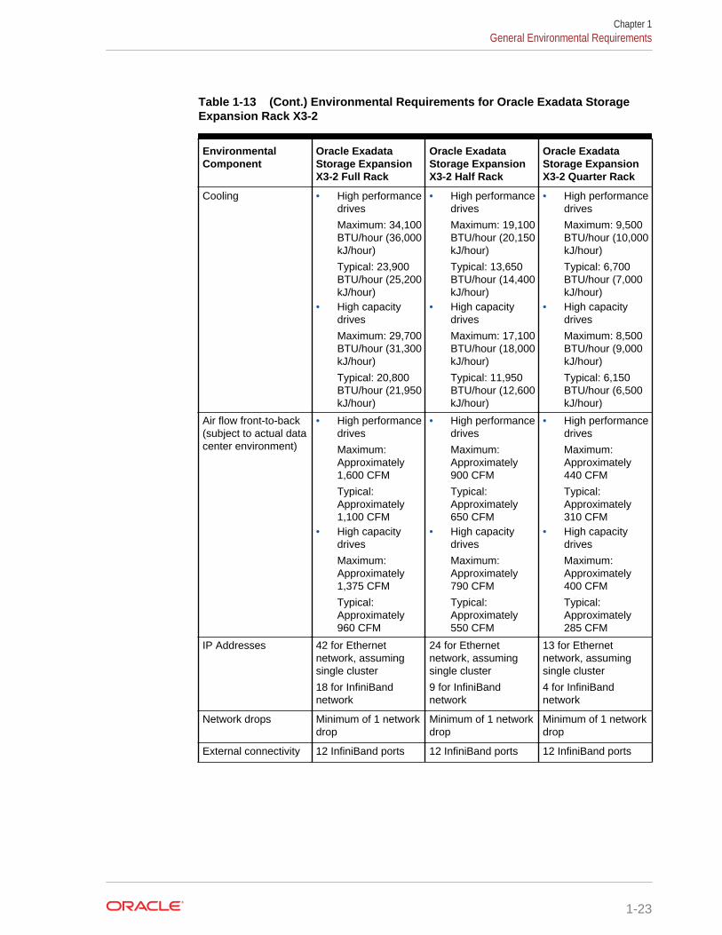
Table 1-13 (Cont.) Environmental Requirements for Oracle Exadata StorageExpansion Rack X3-2
EnvironmentalComponent
Oracle ExadataStorage ExpansionX3-2 Full Rack
Oracle ExadataStorage ExpansionX3-2 Half Rack
Oracle ExadataStorage ExpansionX3-2 Quarter Rack
Cooling • High performancedrives
Maximum: 34,100BTU/hour (36,000kJ/hour)
Typical: 23,900BTU/hour (25,200kJ/hour)
• High capacitydrives
Maximum: 29,700BTU/hour (31,300kJ/hour)
Typical: 20,800BTU/hour (21,950kJ/hour)
• High performancedrives
Maximum: 19,100BTU/hour (20,150kJ/hour)
Typical: 13,650BTU/hour (14,400kJ/hour)
• High capacitydrives
Maximum: 17,100BTU/hour (18,000kJ/hour)
Typical: 11,950BTU/hour (12,600kJ/hour)
• High performancedrives
Maximum: 9,500BTU/hour (10,000kJ/hour)
Typical: 6,700BTU/hour (7,000kJ/hour)
• High capacitydrives
Maximum: 8,500BTU/hour (9,000kJ/hour)
Typical: 6,150BTU/hour (6,500kJ/hour)
Air flow front-to-back(subject to actual datacenter environment)
• High performancedrives
Maximum:Approximately1,600 CFM
Typical:Approximately1,100 CFM
• High capacitydrives
Maximum:Approximately1,375 CFM
Typical:Approximately960 CFM
• High performancedrives
Maximum:Approximately900 CFM
Typical:Approximately650 CFM
• High capacitydrives
Maximum:Approximately790 CFM
Typical:Approximately550 CFM
• High performancedrives
Maximum:Approximately440 CFM
Typical:Approximately310 CFM
• High capacitydrives
Maximum:Approximately400 CFM
Typical:Approximately285 CFM
IP Addresses 42 for Ethernetnetwork, assumingsingle cluster
18 for InfiniBandnetwork
24 for Ethernetnetwork, assumingsingle cluster
9 for InfiniBandnetwork
13 for Ethernetnetwork, assumingsingle cluster
4 for InfiniBandnetwork
Network drops Minimum of 1 networkdrop
Minimum of 1 networkdrop
Minimum of 1 networkdrop
External connectivity 12 InfiniBand ports 12 InfiniBand ports 12 InfiniBand ports
Chapter 1General Environmental Requirements
1-23
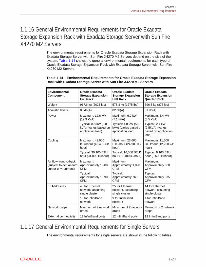
1.1.16 General Environmental Requirements for Oracle ExadataStorage Expansion Rack with Exadata Storage Server with Sun FireX4270 M2 Servers
The environmental requirements for Oracle Exadata Storage Expansion Rack withExadata Storage Server with Sun Fire X4270 M2 Servers depend on the size of thesystem. Table 1-14 shows the general environmental requirements for each type ofOracle Exadata Storage Expansion Rack with Exadata Storage Server with Sun FireX4270 M2 Servers.
Table 1-14 Environmental Requirements for Oracle Exadata Storage ExpansionRack with Exadata Storage Server with Sun Fire X4270 M2 Servers
EnvironmentalComponent
Oracle ExadataStorage ExpansionFull Rack
Oracle ExadataStorage ExpansionHalf Rack
Oracle ExadataStorage ExpansionQuarter Rack
Weight 917.6 kg (2023 lbs) 578.3 kg (1275 lbs) 396.8 kg (875 lbs)
Acoustic levels 83 db(A) 82 db(A) 81 db(A)
Power Maximum: 12.6 kW(12.9 kVA)
Typical: 8.8 kW (9.0kVA) (varies based onapplication load)
Maximum: 6.9 kW(7.1 kVA)
Typical: 4.8 kW (5.0kVA) (varies based onapplication load)
Maximum: 3.4 kW(3.5 kVA)
Typical: 2.4 kW(2.5kVA) (variesbased on applicationload)
Cooling Maximum: 43,000BTU/hour (45,400 kJ/hour)
Typical: 30,100 BTU/hour (31,800 kJ/hour)
Maximum: 23,600BTU/hour (24,900 kJ/hour)
Typical: 16,500 BTU/hour (17,400 kJ/hour)
Maximum: 11,600BTU/hour (12,250 kJ/hour)
Typical: 8,100 BTU/hour (8,600 kJ/hour)
Air flow front-to-back(subject to actual datacenter environment)
Maximum:Approximately 1,980CFM
Typical:Approximately 1,390CFM
Maximum:Approximately 1,090CFM
Typical:Approximately 760CFM
Maximum:Approximately 530CFM
Typical:Approximately 375CFM
IP Addresses 43 for Ethernetnetwork, assumingsingle cluster
18 for InfiniBandnetwork
25 for Ethernetnetwork, assumingsingle cluster
9 for InfiniBandnetwork
14 for Ethernetnetwork, assumingsingle cluster
4 for InfiniBandnetwork
Network drops Minimum of 2 networkdrops
Minimum of 2 networkdrops
Minimum of 2 networkdrops
External connectivity 12 InfiniBand ports 12 InfiniBand ports 12 InfiniBand ports
1.1.17 General Environmental Requirements for Single ServersThe environmental requirements for single servers are shown in the following tables.
Chapter 1General Environmental Requirements
1-24
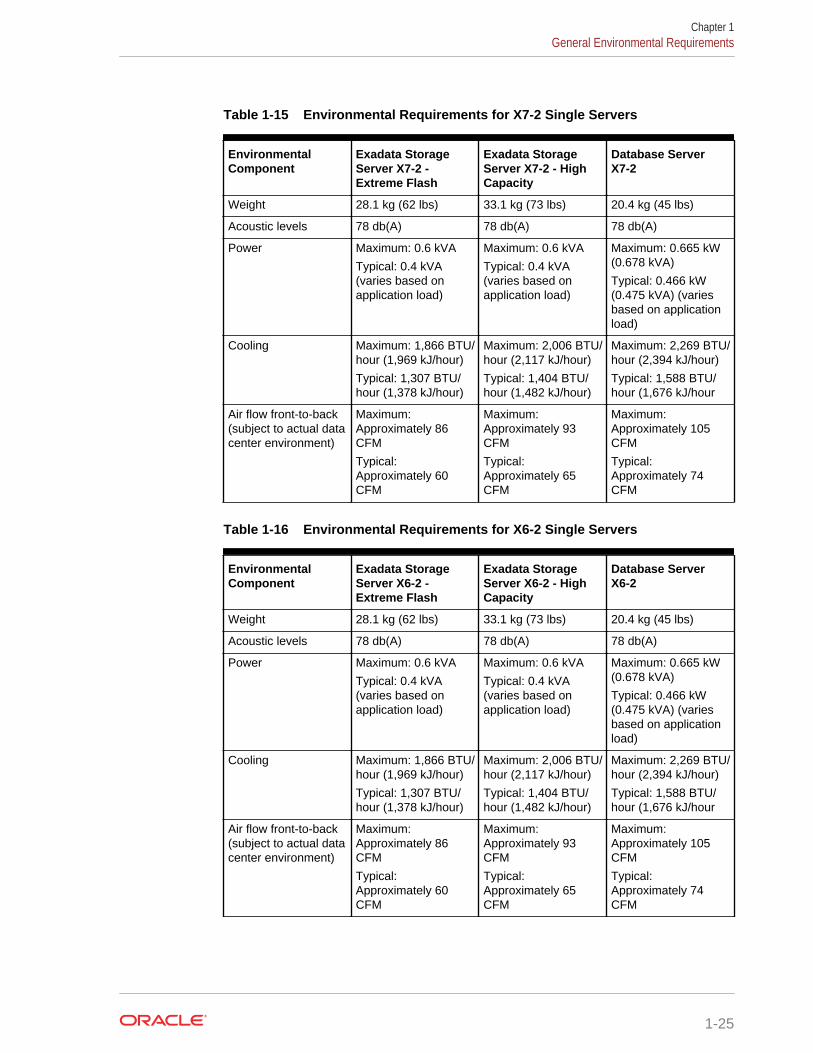
Table 1-15 Environmental Requirements for X7-2 Single Servers
EnvironmentalComponent
Exadata StorageServer X7-2 -Extreme Flash
Exadata StorageServer X7-2 - HighCapacity
Database ServerX7-2
Weight 28.1 kg (62 lbs) 33.1 kg (73 lbs) 20.4 kg (45 lbs)
Acoustic levels 78 db(A) 78 db(A) 78 db(A)
Power Maximum: 0.6 kVA
Typical: 0.4 kVA(varies based onapplication load)
Maximum: 0.6 kVA
Typical: 0.4 kVA(varies based onapplication load)
Maximum: 0.665 kW(0.678 kVA)
Typical: 0.466 kW(0.475 kVA) (variesbased on applicationload)
Cooling Maximum: 1,866 BTU/hour (1,969 kJ/hour)
Typical: 1,307 BTU/hour (1,378 kJ/hour)
Maximum: 2,006 BTU/hour (2,117 kJ/hour)
Typical: 1,404 BTU/hour (1,482 kJ/hour)
Maximum: 2,269 BTU/hour (2,394 kJ/hour)
Typical: 1,588 BTU/hour (1,676 kJ/hour
Air flow front-to-back(subject to actual datacenter environment)
Maximum:Approximately 86CFM
Typical:Approximately 60CFM
Maximum:Approximately 93CFM
Typical:Approximately 65CFM
Maximum:Approximately 105CFM
Typical:Approximately 74CFM
Table 1-16 Environmental Requirements for X6-2 Single Servers
EnvironmentalComponent
Exadata StorageServer X6-2 -Extreme Flash
Exadata StorageServer X6-2 - HighCapacity
Database ServerX6-2
Weight 28.1 kg (62 lbs) 33.1 kg (73 lbs) 20.4 kg (45 lbs)
Acoustic levels 78 db(A) 78 db(A) 78 db(A)
Power Maximum: 0.6 kVA
Typical: 0.4 kVA(varies based onapplication load)
Maximum: 0.6 kVA
Typical: 0.4 kVA(varies based onapplication load)
Maximum: 0.665 kW(0.678 kVA)
Typical: 0.466 kW(0.475 kVA) (variesbased on applicationload)
Cooling Maximum: 1,866 BTU/hour (1,969 kJ/hour)
Typical: 1,307 BTU/hour (1,378 kJ/hour)
Maximum: 2,006 BTU/hour (2,117 kJ/hour)
Typical: 1,404 BTU/hour (1,482 kJ/hour)
Maximum: 2,269 BTU/hour (2,394 kJ/hour)
Typical: 1,588 BTU/hour (1,676 kJ/hour
Air flow front-to-back(subject to actual datacenter environment)
Maximum:Approximately 86CFM
Typical:Approximately 60CFM
Maximum:Approximately 93CFM
Typical:Approximately 65CFM
Maximum:Approximately 105CFM
Typical:Approximately 74CFM
Chapter 1General Environmental Requirements
1-25
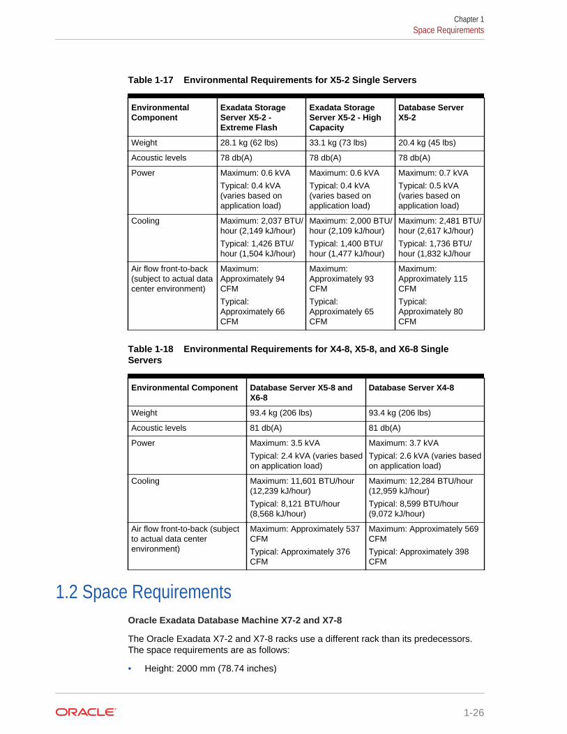
Table 1-17 Environmental Requirements for X5-2 Single Servers
EnvironmentalComponent
Exadata StorageServer X5-2 -Extreme Flash
Exadata StorageServer X5-2 - HighCapacity
Database ServerX5-2
Weight 28.1 kg (62 lbs) 33.1 kg (73 lbs) 20.4 kg (45 lbs)
Acoustic levels 78 db(A) 78 db(A) 78 db(A)
Power Maximum: 0.6 kVA
Typical: 0.4 kVA(varies based onapplication load)
Maximum: 0.6 kVA
Typical: 0.4 kVA(varies based onapplication load)
Maximum: 0.7 kVA
Typical: 0.5 kVA(varies based onapplication load)
Cooling Maximum: 2,037 BTU/hour (2,149 kJ/hour)
Typical: 1,426 BTU/hour (1,504 kJ/hour)
Maximum: 2,000 BTU/hour (2,109 kJ/hour)
Typical: 1,400 BTU/hour (1,477 kJ/hour)
Maximum: 2,481 BTU/hour (2,617 kJ/hour)
Typical: 1,736 BTU/hour (1,832 kJ/hour
Air flow front-to-back(subject to actual datacenter environment)
Maximum:Approximately 94CFM
Typical:Approximately 66CFM
Maximum:Approximately 93CFM
Typical:Approximately 65CFM
Maximum:Approximately 115CFM
Typical:Approximately 80CFM
Table 1-18 Environmental Requirements for X4-8, X5-8, and X6-8 SingleServers
Environmental Component Database Server X5-8 andX6-8
Database Server X4-8
Weight 93.4 kg (206 lbs) 93.4 kg (206 lbs)
Acoustic levels 81 db(A) 81 db(A)
Power Maximum: 3.5 kVA
Typical: 2.4 kVA (varies basedon application load)
Maximum: 3.7 kVA
Typical: 2.6 kVA (varies basedon application load)
Cooling Maximum: 11,601 BTU/hour(12,239 kJ/hour)
Typical: 8,121 BTU/hour(8,568 kJ/hour)
Maximum: 12,284 BTU/hour(12,959 kJ/hour)
Typical: 8,599 BTU/hour(9,072 kJ/hour)
Air flow front-to-back (subjectto actual data centerenvironment)
Maximum: Approximately 537CFM
Typical: Approximately 376CFM
Maximum: Approximately 569CFM
Typical: Approximately 398CFM
1.2 Space RequirementsOracle Exadata Database Machine X7-2 and X7-8
The Oracle Exadata X7-2 and X7-8 racks use a different rack than its predecessors.The space requirements are as follows:
• Height: 2000 mm (78.74 inches)
Chapter 1Space Requirements
1-26
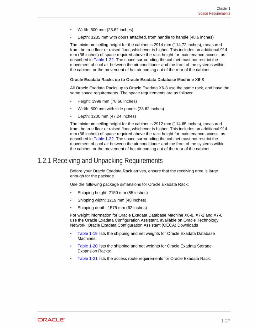
• Width: 600 mm (23.62 inches)
• Depth: 1235 mm with doors attached, from handle to handle (48.6 inches)
The minimum ceiling height for the cabinet is 2914 mm (114.72 inches), measuredfrom the true floor or raised floor, whichever is higher. This includes an additional 914mm (36 inches) of space required above the rack height for maintenance access, asdescribed in Table 1-22. The space surrounding the cabinet must not restrict themovement of cool air between the air conditioner and the front of the systems withinthe cabinet, or the movement of hot air coming out of the rear of the cabinet.
Oracle Exadata Racks up to Oracle Exadata Database Machine X6-8
All Oracle Exadata Racks up to Oracle Exadata X6-8 use the same rack, and have thesame space requirements. The space requirements are as follows:
• Height: 1998 mm (78.66 inches)
• Width: 600 mm with side panels (23.62 inches)
• Depth: 1200 mm (47.24 inches)
The minimum ceiling height for the cabinet is 2912 mm (114.65 inches), measuredfrom the true floor or raised floor, whichever is higher. This includes an additional 914mm (36 inches) of space required above the rack height for maintenance access, asdescribed in Table 1-22. The space surrounding the cabinet must not restrict themovement of cool air between the air conditioner and the front of the systems withinthe cabinet, or the movement of hot air coming out of the rear of the cabinet.
1.2.1 Receiving and Unpacking RequirementsBefore your Oracle Exadata Rack arrives, ensure that the receiving area is largeenough for the package.
Use the following package dimensions for Oracle Exadata Rack:
• Shipping height: 2159 mm (85 inches)
• Shipping width: 1219 mm (48 inches)
• Shipping depth: 1575 mm (62 inches)
For weight information for Oracle Exadata Database Machine X6-8, X7-2 and X7-8,use the Oracle Exadata Configuration Assistant, available on Oracle TechnologyNetwork: Oracle Exadata Configuration Assistant (OECA) Downloads
• Table 1-19 lists the shipping and net weights for Oracle Exadata DatabaseMachines.
• Table 1-20 lists the shipping and net weights for Oracle Exadata StorageExpansion Racks:
• Table 1-21 lists the access route requirements for Oracle Exadata Rack.
Chapter 1Space Requirements
1-27
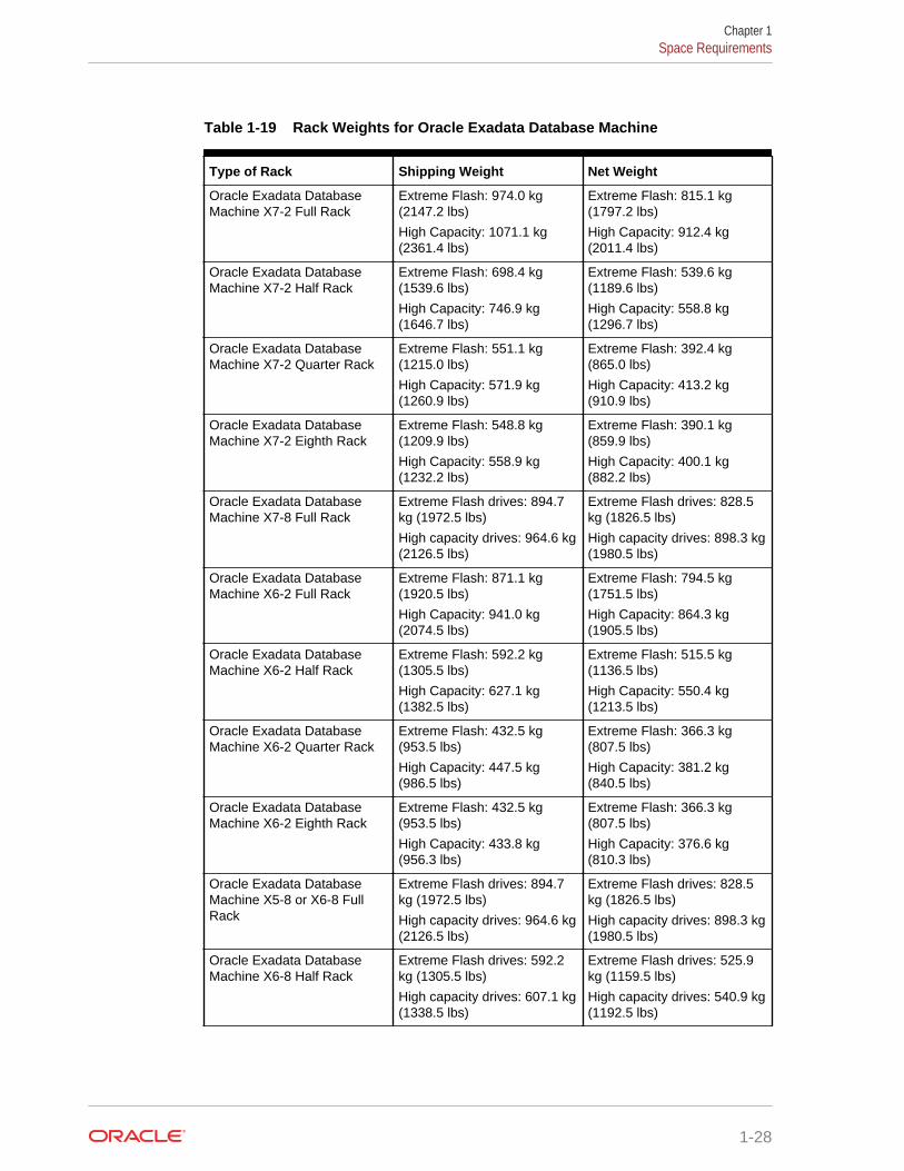
Table 1-19 Rack Weights for Oracle Exadata Database Machine
Type of Rack Shipping Weight Net Weight
Oracle Exadata DatabaseMachine X7-2 Full Rack
Extreme Flash: 974.0 kg(2147.2 lbs)
High Capacity: 1071.1 kg(2361.4 lbs)
Extreme Flash: 815.1 kg(1797.2 lbs)
High Capacity: 912.4 kg(2011.4 lbs)
Oracle Exadata DatabaseMachine X7-2 Half Rack
Extreme Flash: 698.4 kg(1539.6 lbs)
High Capacity: 746.9 kg(1646.7 lbs)
Extreme Flash: 539.6 kg(1189.6 lbs)
High Capacity: 558.8 kg(1296.7 lbs)
Oracle Exadata DatabaseMachine X7-2 Quarter Rack
Extreme Flash: 551.1 kg(1215.0 lbs)
High Capacity: 571.9 kg(1260.9 lbs)
Extreme Flash: 392.4 kg(865.0 lbs)
High Capacity: 413.2 kg(910.9 lbs)
Oracle Exadata DatabaseMachine X7-2 Eighth Rack
Extreme Flash: 548.8 kg(1209.9 lbs)
High Capacity: 558.9 kg(1232.2 lbs)
Extreme Flash: 390.1 kg(859.9 lbs)
High Capacity: 400.1 kg(882.2 lbs)
Oracle Exadata DatabaseMachine X7-8 Full Rack
Extreme Flash drives: 894.7kg (1972.5 lbs)
High capacity drives: 964.6 kg(2126.5 lbs)
Extreme Flash drives: 828.5kg (1826.5 lbs)
High capacity drives: 898.3 kg(1980.5 lbs)
Oracle Exadata DatabaseMachine X6-2 Full Rack
Extreme Flash: 871.1 kg(1920.5 lbs)
High Capacity: 941.0 kg(2074.5 lbs)
Extreme Flash: 794.5 kg(1751.5 lbs)
High Capacity: 864.3 kg(1905.5 lbs)
Oracle Exadata DatabaseMachine X6-2 Half Rack
Extreme Flash: 592.2 kg(1305.5 lbs)
High Capacity: 627.1 kg(1382.5 lbs)
Extreme Flash: 515.5 kg(1136.5 lbs)
High Capacity: 550.4 kg(1213.5 lbs)
Oracle Exadata DatabaseMachine X6-2 Quarter Rack
Extreme Flash: 432.5 kg(953.5 lbs)
High Capacity: 447.5 kg(986.5 lbs)
Extreme Flash: 366.3 kg(807.5 lbs)
High Capacity: 381.2 kg(840.5 lbs)
Oracle Exadata DatabaseMachine X6-2 Eighth Rack
Extreme Flash: 432.5 kg(953.5 lbs)
High Capacity: 433.8 kg(956.3 lbs)
Extreme Flash: 366.3 kg(807.5 lbs)
High Capacity: 376.6 kg(810.3 lbs)
Oracle Exadata DatabaseMachine X5-8 or X6-8 FullRack
Extreme Flash drives: 894.7kg (1972.5 lbs)
High capacity drives: 964.6 kg(2126.5 lbs)
Extreme Flash drives: 828.5kg (1826.5 lbs)
High capacity drives: 898.3 kg(1980.5 lbs)
Oracle Exadata DatabaseMachine X6-8 Half Rack
Extreme Flash drives: 592.2kg (1305.5 lbs)
High capacity drives: 607.1 kg(1338.5 lbs)
Extreme Flash drives: 525.9kg (1159.5 lbs)
High capacity drives: 540.9 kg(1192.5 lbs)
Chapter 1Space Requirements
1-28
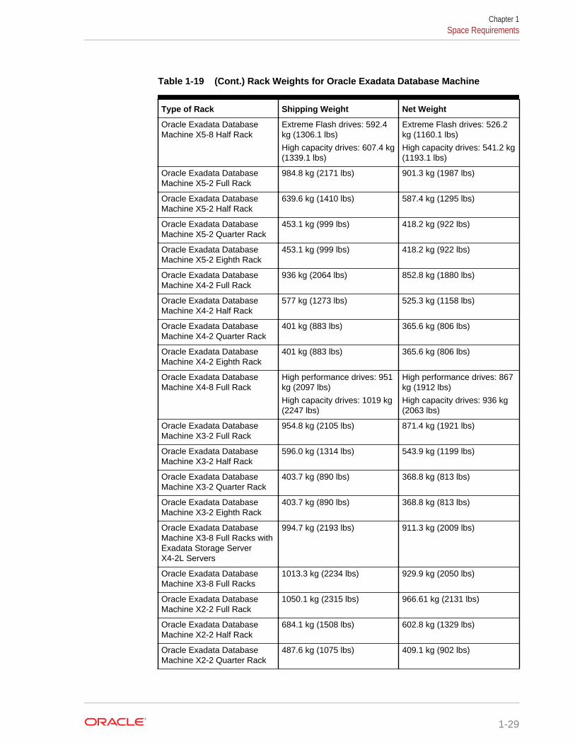
Table 1-19 (Cont.) Rack Weights for Oracle Exadata Database Machine
Type of Rack Shipping Weight Net Weight
Oracle Exadata DatabaseMachine X5-8 Half Rack
Extreme Flash drives: 592.4kg (1306.1 lbs)
High capacity drives: 607.4 kg(1339.1 lbs)
Extreme Flash drives: 526.2kg (1160.1 lbs)
High capacity drives: 541.2 kg(1193.1 lbs)
Oracle Exadata DatabaseMachine X5-2 Full Rack
984.8 kg (2171 lbs) 901.3 kg (1987 lbs)
Oracle Exadata DatabaseMachine X5-2 Half Rack
639.6 kg (1410 lbs) 587.4 kg (1295 lbs)
Oracle Exadata DatabaseMachine X5-2 Quarter Rack
453.1 kg (999 lbs) 418.2 kg (922 lbs)
Oracle Exadata DatabaseMachine X5-2 Eighth Rack
453.1 kg (999 lbs) 418.2 kg (922 lbs)
Oracle Exadata DatabaseMachine X4-2 Full Rack
936 kg (2064 lbs) 852.8 kg (1880 lbs)
Oracle Exadata DatabaseMachine X4-2 Half Rack
577 kg (1273 lbs) 525.3 kg (1158 lbs)
Oracle Exadata DatabaseMachine X4-2 Quarter Rack
401 kg (883 lbs) 365.6 kg (806 lbs)
Oracle Exadata DatabaseMachine X4-2 Eighth Rack
401 kg (883 lbs) 365.6 kg (806 lbs)
Oracle Exadata DatabaseMachine X4-8 Full Rack
High performance drives: 951kg (2097 lbs)
High capacity drives: 1019 kg(2247 lbs)
High performance drives: 867kg (1912 lbs)
High capacity drives: 936 kg(2063 lbs)
Oracle Exadata DatabaseMachine X3-2 Full Rack
954.8 kg (2105 lbs) 871.4 kg (1921 lbs)
Oracle Exadata DatabaseMachine X3-2 Half Rack
596.0 kg (1314 lbs) 543.9 kg (1199 lbs)
Oracle Exadata DatabaseMachine X3-2 Quarter Rack
403.7 kg (890 lbs) 368.8 kg (813 lbs)
Oracle Exadata DatabaseMachine X3-2 Eighth Rack
403.7 kg (890 lbs) 368.8 kg (813 lbs)
Oracle Exadata DatabaseMachine X3-8 Full Racks withExadata Storage ServerX4-2L Servers
994.7 kg (2193 lbs) 911.3 kg (2009 lbs)
Oracle Exadata DatabaseMachine X3-8 Full Racks
1013.3 kg (2234 lbs) 929.9 kg (2050 lbs)
Oracle Exadata DatabaseMachine X2-2 Full Rack
1050.1 kg (2315 lbs) 966.61 kg (2131 lbs)
Oracle Exadata DatabaseMachine X2-2 Half Rack
684.1 kg (1508 lbs) 602.8 kg (1329 lbs)
Oracle Exadata DatabaseMachine X2-2 Quarter Rack
487.6 kg (1075 lbs) 409.1 kg (902 lbs)
Chapter 1Space Requirements
1-29
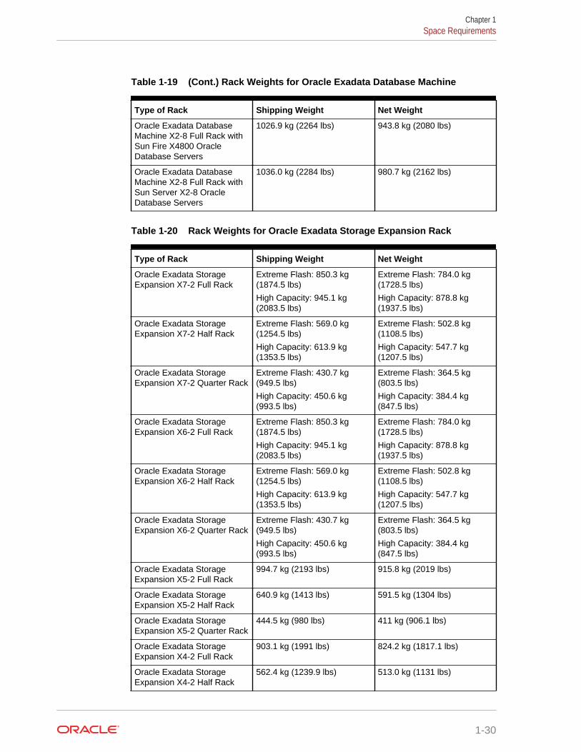
Table 1-19 (Cont.) Rack Weights for Oracle Exadata Database Machine
Type of Rack Shipping Weight Net Weight
Oracle Exadata DatabaseMachine X2-8 Full Rack withSun Fire X4800 OracleDatabase Servers
1026.9 kg (2264 lbs) 943.8 kg (2080 lbs)
Oracle Exadata DatabaseMachine X2-8 Full Rack withSun Server X2-8 OracleDatabase Servers
1036.0 kg (2284 lbs) 980.7 kg (2162 lbs)
Table 1-20 Rack Weights for Oracle Exadata Storage Expansion Rack
Type of Rack Shipping Weight Net Weight
Oracle Exadata StorageExpansion X7-2 Full Rack
Extreme Flash: 850.3 kg(1874.5 lbs)
High Capacity: 945.1 kg(2083.5 lbs)
Extreme Flash: 784.0 kg(1728.5 lbs)
High Capacity: 878.8 kg(1937.5 lbs)
Oracle Exadata StorageExpansion X7-2 Half Rack
Extreme Flash: 569.0 kg(1254.5 lbs)
High Capacity: 613.9 kg(1353.5 lbs)
Extreme Flash: 502.8 kg(1108.5 lbs)
High Capacity: 547.7 kg(1207.5 lbs)
Oracle Exadata StorageExpansion X7-2 Quarter Rack
Extreme Flash: 430.7 kg(949.5 lbs)
High Capacity: 450.6 kg(993.5 lbs)
Extreme Flash: 364.5 kg(803.5 lbs)
High Capacity: 384.4 kg(847.5 lbs)
Oracle Exadata StorageExpansion X6-2 Full Rack
Extreme Flash: 850.3 kg(1874.5 lbs)
High Capacity: 945.1 kg(2083.5 lbs)
Extreme Flash: 784.0 kg(1728.5 lbs)
High Capacity: 878.8 kg(1937.5 lbs)
Oracle Exadata StorageExpansion X6-2 Half Rack
Extreme Flash: 569.0 kg(1254.5 lbs)
High Capacity: 613.9 kg(1353.5 lbs)
Extreme Flash: 502.8 kg(1108.5 lbs)
High Capacity: 547.7 kg(1207.5 lbs)
Oracle Exadata StorageExpansion X6-2 Quarter Rack
Extreme Flash: 430.7 kg(949.5 lbs)
High Capacity: 450.6 kg(993.5 lbs)
Extreme Flash: 364.5 kg(803.5 lbs)
High Capacity: 384.4 kg(847.5 lbs)
Oracle Exadata StorageExpansion X5-2 Full Rack
994.7 kg (2193 lbs) 915.8 kg (2019 lbs)
Oracle Exadata StorageExpansion X5-2 Half Rack
640.9 kg (1413 lbs) 591.5 kg (1304 lbs)
Oracle Exadata StorageExpansion X5-2 Quarter Rack
444.5 kg (980 lbs) 411 kg (906.1 lbs)
Oracle Exadata StorageExpansion X4-2 Full Rack
903.1 kg (1991 lbs) 824.2 kg (1817.1 lbs)
Oracle Exadata StorageExpansion X4-2 Half Rack
562.4 kg (1239.9 lbs) 513.0 kg (1131 lbs)
Chapter 1Space Requirements
1-30
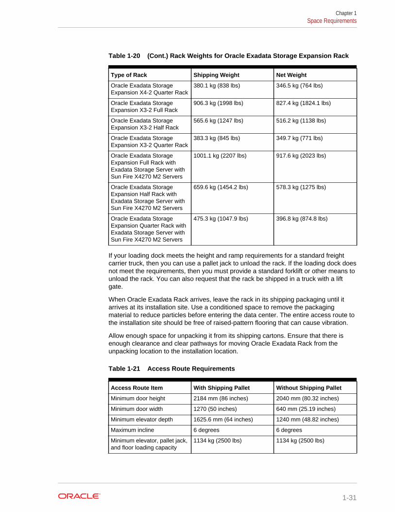
Table 1-20 (Cont.) Rack Weights for Oracle Exadata Storage Expansion Rack
Type of Rack Shipping Weight Net Weight
Oracle Exadata StorageExpansion X4-2 Quarter Rack
380.1 kg (838 lbs) 346.5 kg (764 lbs)
Oracle Exadata StorageExpansion X3-2 Full Rack
906.3 kg (1998 lbs) 827.4 kg (1824.1 lbs)
Oracle Exadata StorageExpansion X3-2 Half Rack
565.6 kg (1247 lbs) 516.2 kg (1138 lbs)
Oracle Exadata StorageExpansion X3-2 Quarter Rack
383.3 kg (845 lbs) 349.7 kg (771 lbs)
Oracle Exadata StorageExpansion Full Rack withExadata Storage Server withSun Fire X4270 M2 Servers
1001.1 kg (2207 lbs) 917.6 kg (2023 lbs)
Oracle Exadata StorageExpansion Half Rack withExadata Storage Server withSun Fire X4270 M2 Servers
659.6 kg (1454.2 lbs) 578.3 kg (1275 lbs)
Oracle Exadata StorageExpansion Quarter Rack withExadata Storage Server withSun Fire X4270 M2 Servers
475.3 kg (1047.9 lbs) 396.8 kg (874.8 lbs)
If your loading dock meets the height and ramp requirements for a standard freightcarrier truck, then you can use a pallet jack to unload the rack. If the loading dock doesnot meet the requirements, then you must provide a standard forklift or other means tounload the rack. You can also request that the rack be shipped in a truck with a liftgate.
When Oracle Exadata Rack arrives, leave the rack in its shipping packaging until itarrives at its installation site. Use a conditioned space to remove the packagingmaterial to reduce particles before entering the data center. The entire access route tothe installation site should be free of raised-pattern flooring that can cause vibration.
Allow enough space for unpacking it from its shipping cartons. Ensure that there isenough clearance and clear pathways for moving Oracle Exadata Rack from theunpacking location to the installation location.
Table 1-21 Access Route Requirements
Access Route Item With Shipping Pallet Without Shipping Pallet
Minimum door height 2184 mm (86 inches) 2040 mm (80.32 inches)
Minimum door width 1270 (50 inches) 640 mm (25.19 inches)
Minimum elevator depth 1625.6 mm (64 inches) 1240 mm (48.82 inches)
Maximum incline 6 degrees 6 degrees
Minimum elevator, pallet jack,and floor loading capacity
1134 kg (2500 lbs) 1134 kg (2500 lbs)
Chapter 1Space Requirements
1-31
1.2.2 Maintenance Access RequirementsThe maintenance area must be large enough for Oracle Exadata Rack, and have therequired access space. For example, the required space to remove the side panels is675. 64 mm (26.6 inches). Front access space requirement is typically the length ofthe longest chassis supported in the rack, plus the distance the rails need to travel outto install and remove equipment from the front. Rear access space requirement is thespace needed for a person working behind the Oracle Exadata Rack. Top accessspace requirement is for a person standing on a ladder to be able service componentsinstalled in the top of the rack.
Note:
• Open tiles are required for electrical access.
• Oracle Exadata Racks can be placed side-by-side when interconnectingthe racks.
The following table lists the maintenance access requirements.
Table 1-22 Maintenance Access Requirements for Oracle Exadata DatabaseMachine (All Models)
Location Maintenance Access Requirement
Rear maintenance 914 mm (36 inches)
Front maintenance 1232 (48.5 inches)
Top maintenance 914 mm (36 inches)
1.3 Flooring RequirementsOracle recommends that Oracle Exadata Rack be installed on raised flooring. The sitefloor and the raised flooring must be able to support the total weight of Oracle ExadataRack.
Table 1-23 lists the floor load requirements.
Table 1-23 Floor Load Requirements for Oracle Exadata Database Machine
Description Requirement
Maximum allowable weight of installed rackequipment
952.5 kg (2100 lbs)
Maximum allowable weight of installed powerdistribution units
52.16 kg (115 lbs)
Maximum dynamic load (maximum allowableweight of installed equipment including PDUs)
1004.66 kg (2215 lbs)
Chapter 1Flooring Requirements
1-32
1.4 Electrical Power RequirementsOracle Exadata Racks can operate effectively over a wide range of voltages andfrequencies. However, they must have a reliable power source. Damage may occur ifthe ranges are exceeded. Electrical disturbances such as the following may damageOracle Exadata Rack:
• Fluctuations caused by brownouts
• Wide and rapid variations in input voltage levels or in input power frequency
• Electrical storms
• Faults in the distribution system, such as defective wiring
To protect Oracle Exadata Rack from such disturbances, you should have a dedicatedpower distribution system, power-conditioning equipment, as well as lightning arrestersor power cables to protect from electrical storms.
1.4.1 PDU Power RequirementsEach rack has two pre-installed power distribution units (PDUs). The PDUs acceptdifferent power sources. You must specify the type of PDU that is correct for yourOracle Exadata Rack and data center.
The following are the PDUs that Exadata currently supports or has supported in thepast:
• Table 1-24 Low-voltage 15 kVA Single Phase PDUs for North America, SouthAmerica, Japan and Taiwan (2 PDUs per Rack)
• Table 1-25 Low-voltage 15 kVA Three Phase PDUs for North America, SouthAmerica, Japan and Taiwan (2 PDUs per Rack)
• Table 1-26 High-voltage 15 kVA Single Phase PDUs for Europe, the Middle Eastand Africa (EMEA), and Asia Pacific (APAC), except for Japan and Taiwan (2PDUs per Rack)
• Table 1-27 High-voltage 15 kVA Three Phase for Europe, the Middle East andAfrica (EMEA), and Asia Pacific (APAC), except for Japan and Taiwan (2 PDUsper Rack)
• Table 1-28 Low-voltage 22 kVA Single Phase PDUs for North America, SouthAmerica, Japan and Taiwan (2 PDUs per Rack)
• Table 1-29 High-voltage 22 kVA Single Phase PDUs for Europe, the Middle Eastand Africa (EMEA), and Asia Pacific (APAC), except for Japan and Taiwan (2PDUs per Rack)
• Table 1-30 Low-voltage 24 kVA Three Phase PDUs for North America, SouthAmerica, Japan and Taiwan (2 PDUs per Rack)
• Table 1-31 High-voltage 24 kVA Three Phase PDUs for Europe, the Middle Eastand Africa (EMEA), and Asia Pacific (APAC), except for Japan and Taiwan (2PDUs per Rack)
• Table 1-32 Low-voltage 37 kVA Three Phase PDUs for North America, SouthAmerica, Japan and Taiwan (2 PDUs per Rack)
Chapter 1Electrical Power Requirements
1-33
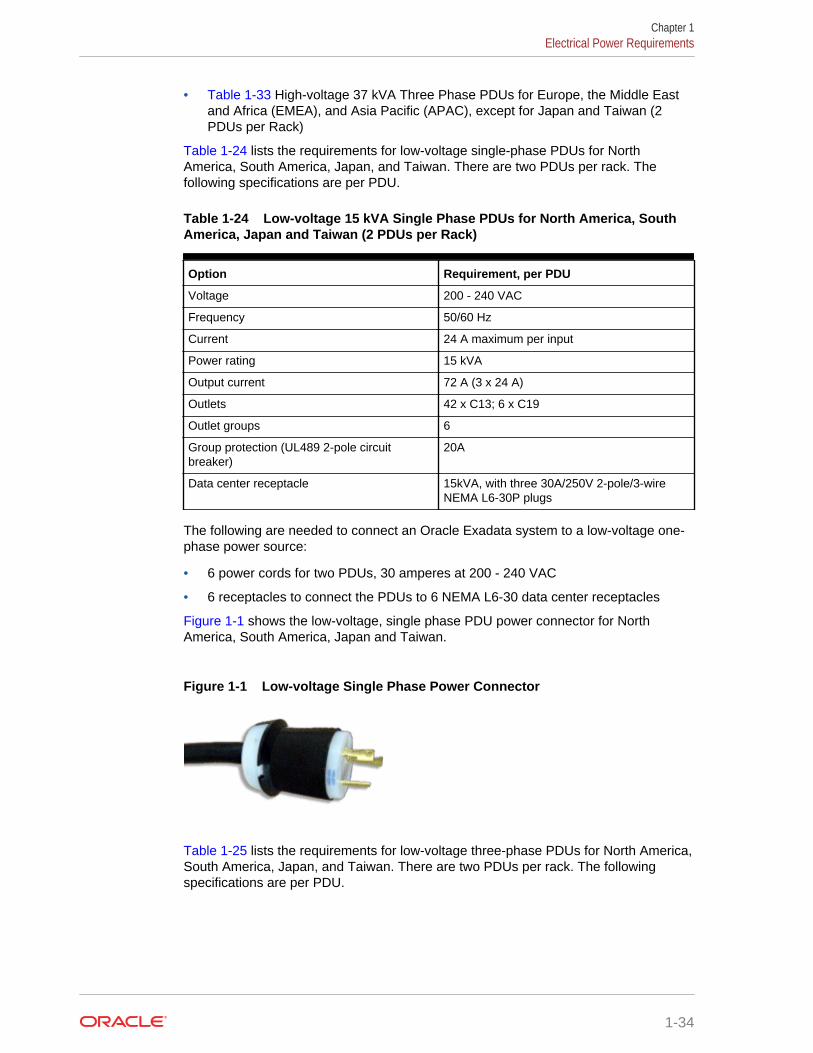
• Table 1-33 High-voltage 37 kVA Three Phase PDUs for Europe, the Middle Eastand Africa (EMEA), and Asia Pacific (APAC), except for Japan and Taiwan (2PDUs per Rack)
Table 1-24 lists the requirements for low-voltage single-phase PDUs for NorthAmerica, South America, Japan, and Taiwan. There are two PDUs per rack. Thefollowing specifications are per PDU.
Table 1-24 Low-voltage 15 kVA Single Phase PDUs for North America, SouthAmerica, Japan and Taiwan (2 PDUs per Rack)
Option Requirement, per PDU
Voltage 200 - 240 VAC
Frequency 50/60 Hz
Current 24 A maximum per input
Power rating 15 kVA
Output current 72 A (3 x 24 A)
Outlets 42 x C13; 6 x C19
Outlet groups 6
Group protection (UL489 2-pole circuitbreaker)
20A
Data center receptacle 15kVA, with three 30A/250V 2-pole/3-wireNEMA L6-30P plugs
The following are needed to connect an Oracle Exadata system to a low-voltage one-phase power source:
• 6 power cords for two PDUs, 30 amperes at 200 - 240 VAC
• 6 receptacles to connect the PDUs to 6 NEMA L6-30 data center receptacles
Figure 1-1 shows the low-voltage, single phase PDU power connector for NorthAmerica, South America, Japan and Taiwan.
Figure 1-1 Low-voltage Single Phase Power Connector
Table 1-25 lists the requirements for low-voltage three-phase PDUs for North America,South America, Japan, and Taiwan. There are two PDUs per rack. The followingspecifications are per PDU.
Chapter 1Electrical Power Requirements
1-34
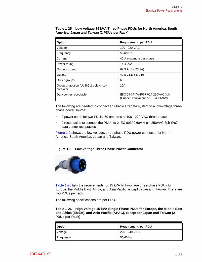
Table 1-25 Low-voltage 15 kVA Three Phase PDUs for North America, SouthAmerica, Japan and Taiwan (2 PDUs per Rack)
Option Requirement, per PDU
Voltage 190 - 220 VAC
Frequency 50/60 Hz
Current 40 A maximum per phase
Power rating 14.4 kVA
Output current 69.3 A (3 x 23.1A)
Outlets 42 x C13; 6 x C19
Outlet groups 6
Group protection (UL489 2-pole circuitbreaker)
20A
Data center receptacle IEC309-3P4W-IP67 60A 250VAC 3ph(Hubbell equivalent is HBL460R9W)
The following are needed to connect an Oracle Exadata system to a low-voltage three-phase power source:
• 2 power cords for two PDUs, 60 amperes at 190 - 220 VAC three-phase
• 2 receptacles to connect the PDUs to 2 IEC 60309 60A 4-pin 250VAC 3ph IP67data center receptacles
Figure 1-2 shows the low-voltage, three phase PDU power connector for NorthAmerica, South America, Japan and Taiwan.
Figure 1-2 Low-voltage Three Phase Power Connector
Table 1-26 lists the requirements for 15 kVA high-voltage three-phase PDUs forEurope, the Middle East, Africa, and Asia Pacific, except Japan and Taiwan. There aretwo PDUs per rack.
The following specifications are per PDU.
Table 1-26 High-voltage 15 kVA Single Phase PDUs for Europe, the Middle Eastand Africa (EMEA), and Asia Pacific (APAC), except for Japan and Taiwan (2PDUs per Rack)
Option Requirement, per PDU
Voltage 220 - 240 VAC
Frequency 50/60 Hz
Chapter 1Electrical Power Requirements
1-35
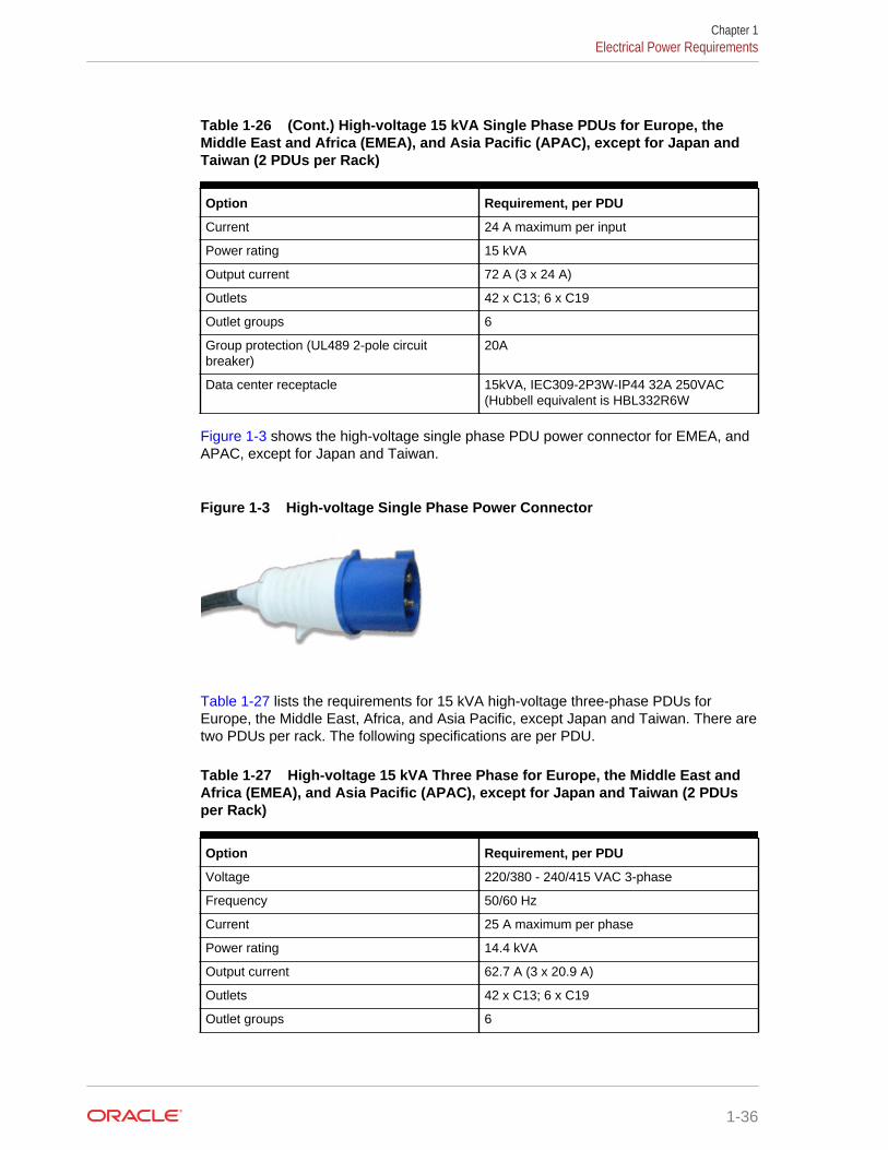
Table 1-26 (Cont.) High-voltage 15 kVA Single Phase PDUs for Europe, theMiddle East and Africa (EMEA), and Asia Pacific (APAC), except for Japan andTaiwan (2 PDUs per Rack)
Option Requirement, per PDU
Current 24 A maximum per input
Power rating 15 kVA
Output current 72 A (3 x 24 A)
Outlets 42 x C13; 6 x C19
Outlet groups 6
Group protection (UL489 2-pole circuitbreaker)
20A
Data center receptacle 15kVA, IEC309-2P3W-IP44 32A 250VAC(Hubbell equivalent is HBL332R6W
Figure 1-3 shows the high-voltage single phase PDU power connector for EMEA, andAPAC, except for Japan and Taiwan.
Figure 1-3 High-voltage Single Phase Power Connector
Table 1-27 lists the requirements for 15 kVA high-voltage three-phase PDUs forEurope, the Middle East, Africa, and Asia Pacific, except Japan and Taiwan. There aretwo PDUs per rack. The following specifications are per PDU.
Table 1-27 High-voltage 15 kVA Three Phase for Europe, the Middle East andAfrica (EMEA), and Asia Pacific (APAC), except for Japan and Taiwan (2 PDUsper Rack)
Option Requirement, per PDU
Voltage 220/380 - 240/415 VAC 3-phase
Frequency 50/60 Hz
Current 25 A maximum per phase
Power rating 14.4 kVA
Output current 62.7 A (3 x 20.9 A)
Outlets 42 x C13; 6 x C19
Outlet groups 6
Chapter 1Electrical Power Requirements
1-36
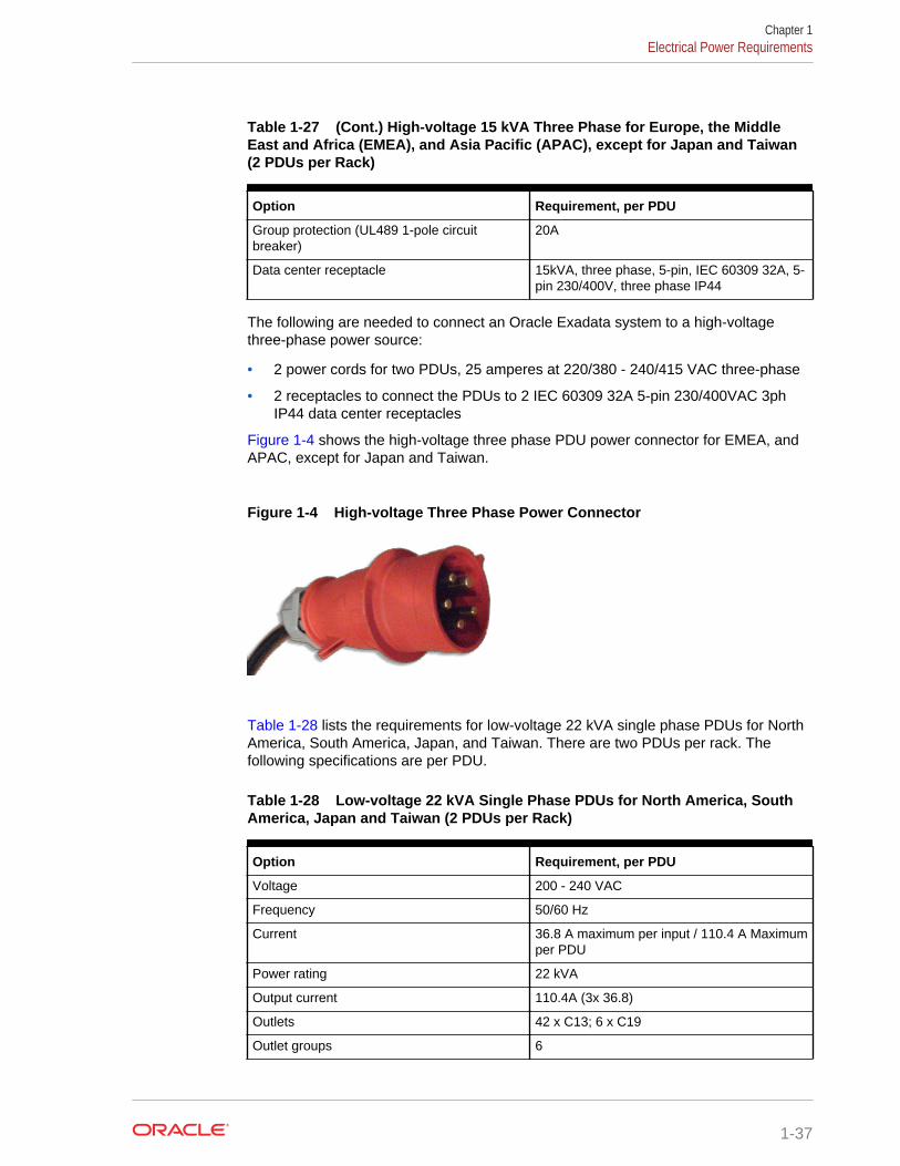
Table 1-27 (Cont.) High-voltage 15 kVA Three Phase for Europe, the MiddleEast and Africa (EMEA), and Asia Pacific (APAC), except for Japan and Taiwan(2 PDUs per Rack)
Option Requirement, per PDU
Group protection (UL489 1-pole circuitbreaker)
20A
Data center receptacle 15kVA, three phase, 5-pin, IEC 60309 32A, 5-pin 230/400V, three phase IP44
The following are needed to connect an Oracle Exadata system to a high-voltagethree-phase power source:
• 2 power cords for two PDUs, 25 amperes at 220/380 - 240/415 VAC three-phase
• 2 receptacles to connect the PDUs to 2 IEC 60309 32A 5-pin 230/400VAC 3phIP44 data center receptacles
Figure 1-4 shows the high-voltage three phase PDU power connector for EMEA, andAPAC, except for Japan and Taiwan.
Figure 1-4 High-voltage Three Phase Power Connector
Table 1-28 lists the requirements for low-voltage 22 kVA single phase PDUs for NorthAmerica, South America, Japan, and Taiwan. There are two PDUs per rack. Thefollowing specifications are per PDU.
Table 1-28 Low-voltage 22 kVA Single Phase PDUs for North America, SouthAmerica, Japan and Taiwan (2 PDUs per Rack)
Option Requirement, per PDU
Voltage 200 - 240 VAC
Frequency 50/60 Hz
Current 36.8 A maximum per input / 110.4 A Maximumper PDU
Power rating 22 kVA
Output current 110.4A (3x 36.8)
Outlets 42 x C13; 6 x C19
Outlet groups 6
Chapter 1Electrical Power Requirements
1-37
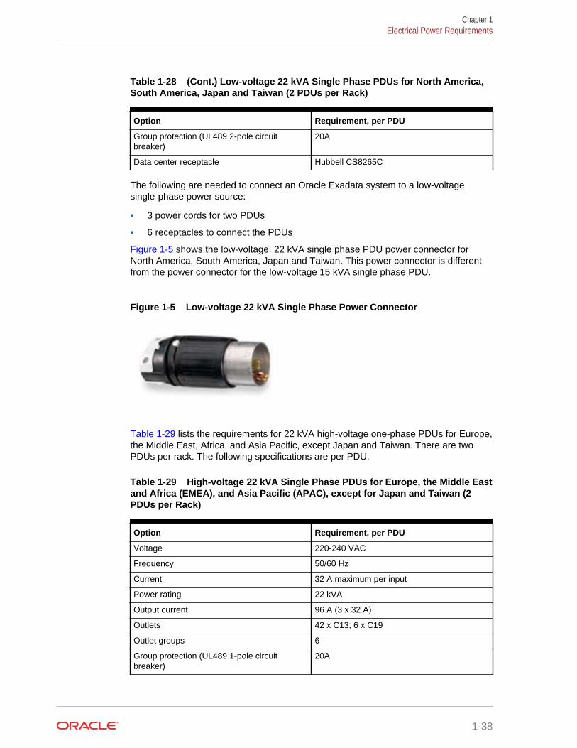
Table 1-28 (Cont.) Low-voltage 22 kVA Single Phase PDUs for North America,South America, Japan and Taiwan (2 PDUs per Rack)
Option Requirement, per PDU
Group protection (UL489 2-pole circuitbreaker)
20A
Data center receptacle Hubbell CS8265C
The following are needed to connect an Oracle Exadata system to a low-voltagesingle-phase power source:
• 3 power cords for two PDUs
• 6 receptacles to connect the PDUs
Figure 1-5 shows the low-voltage, 22 kVA single phase PDU power connector forNorth America, South America, Japan and Taiwan. This power connector is differentfrom the power connector for the low-voltage 15 kVA single phase PDU.
Figure 1-5 Low-voltage 22 kVA Single Phase Power Connector
Table 1-29 lists the requirements for 22 kVA high-voltage one-phase PDUs for Europe,the Middle East, Africa, and Asia Pacific, except Japan and Taiwan. There are twoPDUs per rack. The following specifications are per PDU.
Table 1-29 High-voltage 22 kVA Single Phase PDUs for Europe, the Middle Eastand Africa (EMEA), and Asia Pacific (APAC), except for Japan and Taiwan (2PDUs per Rack)
Option Requirement, per PDU
Voltage 220-240 VAC
Frequency 50/60 Hz
Current 32 A maximum per input
Power rating 22 kVA
Output current 96 A (3 x 32 A)
Outlets 42 x C13; 6 x C19
Outlet groups 6
Group protection (UL489 1-pole circuitbreaker)
20A
Chapter 1Electrical Power Requirements
1-38
Table 1-29 (Cont.) High-voltage 22 kVA Single Phase PDUs for Europe, theMiddle East and Africa (EMEA), and Asia Pacific (APAC), except for Japan andTaiwan (2 PDUs per Rack)
Option Requirement, per PDU
Data center receptacle IEC309-2P3W-IP44 32A 250VAC (Hubbellequivalent is HBL332R6W)
Note:
The high-voltage 15kVA single phase PDU is no longer available. The high-voltage 22kVA is a compatible replacement with the same receptacle andbreaker requirements
The following are needed to connect an Oracle Exadata system to a high-voltage one-phase power source:
• 6 power cords for two PDUs, 25 amperes at 220/380 - 240/415 VAC 1-phasevoltage
• 6 receptacles to connect the PDUs to 2 IEC 60309 32A 3-pin 250VAC IP44 datacenter receptacles, and requires 22 kVA, 1-phase
Figure 1-3 shows the high-voltage single phase PDU power connector for EMEA, andAPAC, except for Japan and Taiwan.
Table 1-30 lists the requirements for low-voltage 24 kVA three phase PDUs. There aretwo PDUs per rack. The following specifications are per PDU.
Table 1-30 Low-voltage 24 kVA Three Phase PDUs for North America, SouthAmerica, Japan and Taiwan (2 PDUs per Rack)
Option Requirement, per PDU
Voltage 200 - 208 VAC 3-phase
Frequency 50/60 Hz
Current 34.6 A maximum per phase
Power rating 25 kVA
Output current 120 A (6 x 20 A)
Outlets 42 x C13; 6 x C19
Outlet groups 6
Group protection (UL489 2-pole circuitbreaker)
20A
Data center receptacle IEC309-3P4W-IP67 60A 250VAC 3ph(Hubbell equivalent is HBL460R9W)
The following are needed to connect an Oracle Exadata system to a low-voltage three-phase power source:
Chapter 1Electrical Power Requirements
1-39
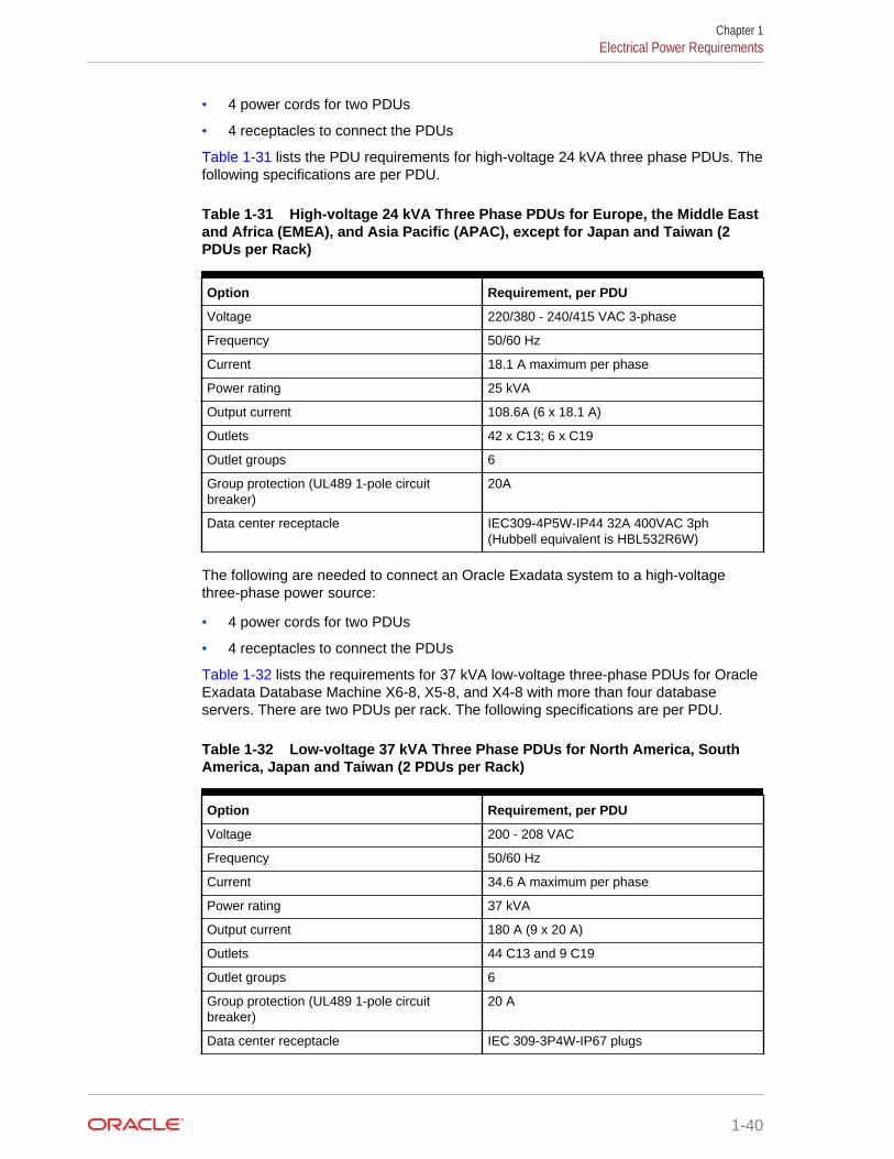
• 4 power cords for two PDUs
• 4 receptacles to connect the PDUs
Table 1-31 lists the PDU requirements for high-voltage 24 kVA three phase PDUs. Thefollowing specifications are per PDU.
Table 1-31 High-voltage 24 kVA Three Phase PDUs for Europe, the Middle Eastand Africa (EMEA), and Asia Pacific (APAC), except for Japan and Taiwan (2PDUs per Rack)
Option Requirement, per PDU
Voltage 220/380 - 240/415 VAC 3-phase
Frequency 50/60 Hz
Current 18.1 A maximum per phase
Power rating 25 kVA
Output current 108.6A (6 x 18.1 A)
Outlets 42 x C13; 6 x C19
Outlet groups 6
Group protection (UL489 1-pole circuitbreaker)
20A
Data center receptacle IEC309-4P5W-IP44 32A 400VAC 3ph(Hubbell equivalent is HBL532R6W)
The following are needed to connect an Oracle Exadata system to a high-voltagethree-phase power source:
• 4 power cords for two PDUs
• 4 receptacles to connect the PDUs
Table 1-32 lists the requirements for 37 kVA low-voltage three-phase PDUs for OracleExadata Database Machine X6-8, X5-8, and X4-8 with more than four databaseservers. There are two PDUs per rack. The following specifications are per PDU.
Table 1-32 Low-voltage 37 kVA Three Phase PDUs for North America, SouthAmerica, Japan and Taiwan (2 PDUs per Rack)
Option Requirement, per PDU
Voltage 200 - 208 VAC
Frequency 50/60 Hz
Current 34.6 A maximum per phase
Power rating 37 kVA
Output current 180 A (9 x 20 A)
Outlets 44 C13 and 9 C19
Outlet groups 6
Group protection (UL489 1-pole circuitbreaker)
20 A
Data center receptacle IEC 309-3P4W-IP67 plugs
Chapter 1Electrical Power Requirements
1-40
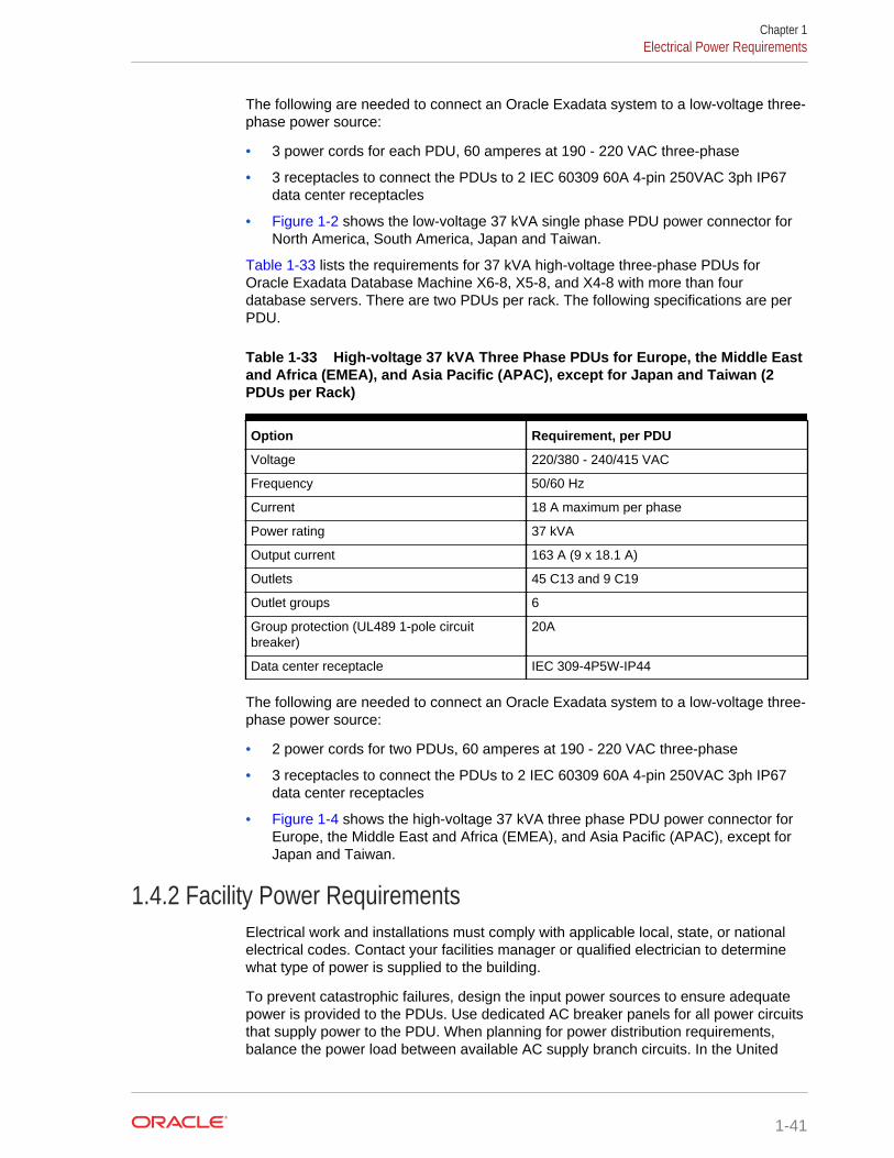
The following are needed to connect an Oracle Exadata system to a low-voltage three-phase power source:
• 3 power cords for each PDU, 60 amperes at 190 - 220 VAC three-phase
• 3 receptacles to connect the PDUs to 2 IEC 60309 60A 4-pin 250VAC 3ph IP67data center receptacles
• Figure 1-2 shows the low-voltage 37 kVA single phase PDU power connector forNorth America, South America, Japan and Taiwan.
Table 1-33 lists the requirements for 37 kVA high-voltage three-phase PDUs forOracle Exadata Database Machine X6-8, X5-8, and X4-8 with more than fourdatabase servers. There are two PDUs per rack. The following specifications are perPDU.
Table 1-33 High-voltage 37 kVA Three Phase PDUs for Europe, the Middle Eastand Africa (EMEA), and Asia Pacific (APAC), except for Japan and Taiwan (2PDUs per Rack)
Option Requirement, per PDU
Voltage 220/380 - 240/415 VAC
Frequency 50/60 Hz
Current 18 A maximum per phase
Power rating 37 kVA
Output current 163 A (9 x 18.1 A)
Outlets 45 C13 and 9 C19
Outlet groups 6
Group protection (UL489 1-pole circuitbreaker)
20A
Data center receptacle IEC 309-4P5W-IP44
The following are needed to connect an Oracle Exadata system to a low-voltage three-phase power source:
• 2 power cords for two PDUs, 60 amperes at 190 - 220 VAC three-phase
• 3 receptacles to connect the PDUs to 2 IEC 60309 60A 4-pin 250VAC 3ph IP67data center receptacles
• Figure 1-4 shows the high-voltage 37 kVA three phase PDU power connector forEurope, the Middle East and Africa (EMEA), and Asia Pacific (APAC), except forJapan and Taiwan.
1.4.2 Facility Power RequirementsElectrical work and installations must comply with applicable local, state, or nationalelectrical codes. Contact your facilities manager or qualified electrician to determinewhat type of power is supplied to the building.
To prevent catastrophic failures, design the input power sources to ensure adequatepower is provided to the PDUs. Use dedicated AC breaker panels for all power circuitsthat supply power to the PDU. When planning for power distribution requirements,balance the power load between available AC supply branch circuits. In the United
Chapter 1Electrical Power Requirements
1-41
States and Canada, ensure that the overall system AC input current load does notexceed 80 percent of the branch circuit AC current rating.
PDU power cords are 4 meters (13.12 feet) long, and 1 to 1.5 meters (3.3 to 4.9 feet)of the cord is routed within the rack cabinet. The installation site AC power receptaclemust be within 2 meters (6.6 feet) of the rack.
1.4.3 Circuit Breaker RequirementsTo prevent catastrophic failures, the design of your power system must ensure thatadequate power is provided to the servers. Use dedicated AC breaker panels for allpower circuits that supply power to the server. Electrical work and installations mustcomply with applicable local, state, or national electrical codes. Servers requireelectrical circuits be grounded to the Earth.
In addition to circuit breakers, provide a stable power source, such as anuninterruptible power supply (UPS) to reduce the possibility of component failures. Ifcomputer equipment is subjected to repeated power interruptions and fluctuations,then it is susceptible to a higher rate of component failure.
Note:
Circuit breakers are supplied by the customer. One circuit breaker is requiredfor each power cord.
1.4.4 Grounding GuidelinesThe cabinets for Oracle Exadata Rack are shipped with grounding-type power cords.Always connect the cords to grounded power outlets. Because different groundingmethods are used, depending on location, check the grounding type, and refer todocumentation, such as IEC documents, for the correct grounding method. Ensurethat the facility administrator or qualified electrical engineer verifies the groundingmethod for the building, and performs the grounding work.
1.5 Temperature and Humidity RequirementsAirflow through Oracle Exadata Rack is from front to back. Refer to GeneralEnvironmental Requirements for information on cooling and airflow.
Note:
Studies have shown that temperature increases of 10 degrees Celsius (15degrees Fahrenheit) above 20 degrees Celsius (70 degrees Fahrenheit)reduce long-term electronics reliability by 50 percent.
Excessive internal temperatures may result in full or partial shut down ofOracle Exadata Database Machine.
Chapter 1Temperature and Humidity Requirements
1-42
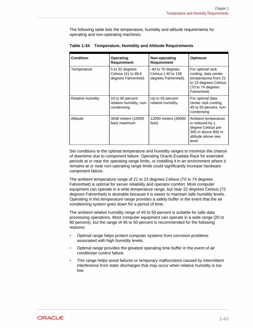
The following table lists the temperature, humidity and altitude requirements foroperating and non-operating machines.
Table 1-34 Temperature, Humidity and Altitude Requirements
Condition OperatingRequirement
Non-operatingRequirement
Optimum
Temperature 5 to 32 degreesCelsius (41 to 89.6degrees Fahrenheit)
-40 to 70 degreesCelsius (-40 to 158degrees Fahrenheit).
For optimal rackcooling, data centertemperatures from 21to 23 degrees Celsius(70 to 74 degreesFahrenheit)
Relative humidity 10 to 90 percentrelative humidity, non-condensing
Up to 93 percentrelative humidity.
For optimal datacenter rack cooling,45 to 50 percent, non-condensing
Altitude 3048 meters (10000feet) maximum
12000 meters (40000feet).
Ambient temperatureis reduced by 1degree Celsius per300 m above 900 maltitude above sealevel
Set conditions to the optimal temperature and humidity ranges to minimize the chanceof downtime due to component failure. Operating Oracle Exadata Rack for extendedperiods at or near the operating range limits, or installing it in an environment where itremains at or near non-operating range limits could significantly increase hardwarecomponent failure.
The ambient temperature range of 21 to 23 degrees Celsius (70 to 74 degreesFahrenheit) is optimal for server reliability and operator comfort. Most computerequipment can operate in a wide temperature range, but near 22 degrees Celsius (72degrees Fahrenheit) is desirable because it is easier to maintain safe humidity levels.Operating in this temperature range provides a safety buffer in the event that the airconditioning system goes down for a period of time.
The ambient relative humidity range of 45 to 50 percent is suitable for safe dataprocessing operations. Most computer equipment can operate in a wide range (20 to80 percent), but the range of 45 to 50 percent is recommended for the followingreasons:
• Optimal range helps protect computer systems from corrosion problemsassociated with high humidity levels.
• Optimal range provides the greatest operating time buffer in the event of airconditioner control failure.
• This range helps avoid failures or temporary malfunctions caused by intermittentinterference from static discharges that may occur when relative humidity is toolow.
Chapter 1Temperature and Humidity Requirements
1-43
Note:
Electrostatic discharge (ESD) is easily generated, and hard to dissipate inareas of low relative humidity, such as below 35 percent. ESD becomescritical when humidity drops below 30 percent. It is not difficult to maintainhumidity in a data center because of the high-efficiency vapor barrier and lowrate of air changes normally present.
1.6 Ventilation and Cooling RequirementsAlways provide adequate space in front and behind the rack to allow for properventilation.
Do not obstruct the front or rear of the rack with equipment or objects that mightprevent air from flowing through the rack. Rack-mountable servers and equipmenttypically draw cool air in through the front of the rack and let out warm air out the rearof the rack. There is no air flow requirement for the left and right sides due to front-to-back cooling.
If the rack is not completely filled with components, then cover the empty sections withfiller panels. Gaps between components can adversely affect air flow and coolingwithin the rack.
Relative humidity is the percentage of the total water vapor that can exist in the airwithout condensing, and is inversely proportional to air temperature. Humidity goesdown when the temperature rises, and goes up when the temperature drops. Forexample, air with a relative humidity of 45 percent at a temperature of 24 degreesCelsius (75 degrees Fahrenheit) has a relative humidity of 65 percent at a temperatureof 18 degrees Celsius (64 degrees Fahrenheit). As the temperature drops, the relativehumidity rises to more than 65 percent, and water droplets are formed.
Air conditioning facilities usually do not precisely monitor or control temperature andhumidity throughout an entire computer room. Generally, monitoring is done atindividual points corresponding to multiple exhaust vents in the main unit, and otherunits in the room. Special consideration should be paid to humidity when usingunderfloor ventilation. When underfloor ventilation is used, monitoring is done at eachpoint close to an exhaust vent. Distribution of the temperature and humidity across theentire room is uneven.
Oracle Exadata Racks have been designed to function while mounted in a naturalconvection air flow. The following requirements must be followed to meet theenvironmental specification:
• Ensure there is adequate air flow through the server.
• Ensure the server has front-to-back cooling. The air inlet is at the front of theserver, and the air is let out the rear.
• Allow a minimum clearance of 1219.2 mm (48 inches) at the front of the server,and 914 mm (36 inches) at the rear of the server for ventilation.
Use perforated tiles, approximately 400 CFM/tile, in front of the rack for cold air intake.The tiles can be arranged in any order in front of the rack, as long as cold air from thetiles can flow into the rack. Inadequate cold air flow could result in a higher inlet
Chapter 1Ventilation and Cooling Requirements
1-44
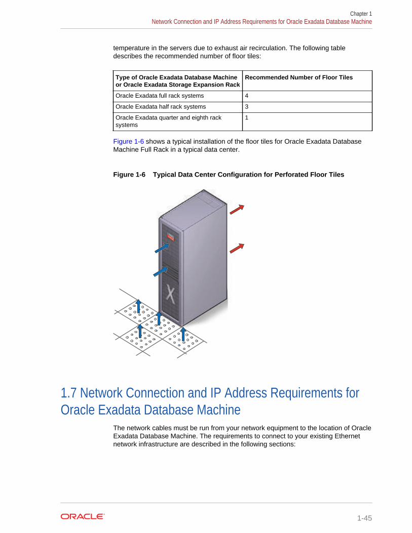
temperature in the servers due to exhaust air recirculation. The following tabledescribes the recommended number of floor tiles:
Type of Oracle Exadata Database Machineor Oracle Exadata Storage Expansion Rack
Recommended Number of Floor Tiles
Oracle Exadata full rack systems 4
Oracle Exadata half rack systems 3
Oracle Exadata quarter and eighth racksystems
1
Figure 1-6 shows a typical installation of the floor tiles for Oracle Exadata DatabaseMachine Full Rack in a typical data center.
Figure 1-6 Typical Data Center Configuration for Perforated Floor Tiles
1.7 Network Connection and IP Address Requirements forOracle Exadata Database Machine
The network cables must be run from your network equipment to the location of OracleExadata Database Machine. The requirements to connect to your existing Ethernetnetwork infrastructure are described in the following sections:
Chapter 1Network Connection and IP Address Requirements for Oracle Exadata Database Machine
1-45
1.7.1 Network Connection Requirements for Oracle Exadata DatabaseMachine
Prior to installation, network cables must be run from your existing networkinfrastructure to the installation site. The requirements to connect Oracle ExadataDatabase Machine to your existing network infrastructure are as follows:
• Management network connection requirements for all Oracle Exadata DatabaseMachine systems except for X2-n systems:
– 1 Ethernet connection for the Ethernet switch in the rack to the existingmanagement network.
• Management network connection requirements for Oracle Exadata DatabaseMachine X2-n:
– 1 Ethernet connection for the Ethernet switch in the rack to the existingmanagement network.
– 1 Ethernet connection for the KVM switch in the rack to the existingmanagement network.
• Client access network connection requirements
– One Ethernet connection per database server to the client access network.The number depends on the system type (Oracle Exadata Database MachineFull Rack, Oracle Exadata Database Machine Half Rack, or Oracle ExadataDatabase Machine Quarter Rack), and whether network channel bonding isused. Use the following formula to determine the number of connections youneed:
For bonded configurations, you need two network connections for eachdatabase node.
For non-bonded configurations, you need one network connection for eachdatabase node.
• Additional network NET2 connection requirements
One Ethernet connection per database server to connect NET2 to your existingnetwork. The number depends on the system type, as follows:
For bonded configurations, you need two network connections for each databasenode.
For non-bonded configurations, you need one network connection for eachdatabase node.
Note:
– This network is unavailable if network channel bonding is used forthe client access network.
– This network is optional. A cable is not required unless the networkis configured during deployment.
• Additional network NET3 connection requirements
Chapter 1Network Connection and IP Address Requirements for Oracle Exadata Database Machine
1-46
One Ethernet connection per database server to connect NET3 to your existingnetwork. The number depends on the system type, as follows:
– 8 connections for Oracle Exadata Database Machine 2-socket, Full Racksystems
– 4 connections for Oracle Exadata Database Machine 2-socket, Half Racksystems
– 2 connections for Oracle Exadata Database Machine 2-socket, Quarter Racksystems
– 2 connections for Oracle Exadata Database Machine 8-socket, Full Racksystems
Note:
This network is optional. A cable is not required unless the network isconfigured during deployment.
Oracle Exadata Database Machine X2-8 Full Rack has a total of 16 Ethernet ports perserver. The additional networks for Oracle Exadata Database Machine X2-8 Full Rackare NET2 through NET15.
The following table shows examples of connection requirements for different sampleenvironments. The table applies to two-socket Oracle Exadata Database Machinemodels X3-2 to X6-2.
Table 1-35 Examples of Network Configurations and Connection Requirementsfor Oracle Exadata Database Machine 2-Socket Systems X3-2 to X6-2
Scenario Network Requirements
Core Requirements • 1 for Ethernet switch• 2 for PDU monitoring
Bonded network configuration, and connectedto a dedicated backup network
• 2 per database node for client access forbonded Ethernet interface on databaseservers
• 1 per database node for backup networkaccess for database servers
Total = 3 + (3 * number of database nodes)
Non-bonded network configuration, andconnected to a dedicated backup network anda dedicated disaster recovery network
• 1 for each database node for clientaccess for the database servers
• 1 per database node for backup networkaccess for the database servers
• 1 per database node for disaster recoverynetwork access for the database servers
Total = 3 + (3 * number of database nodes)
Non-bonded network configuration, and notconnected to an additional network
• 1 per database node for database serversTotal = 3 + (1 * database node)
Chapter 1Network Connection and IP Address Requirements for Oracle Exadata Database Machine
1-47
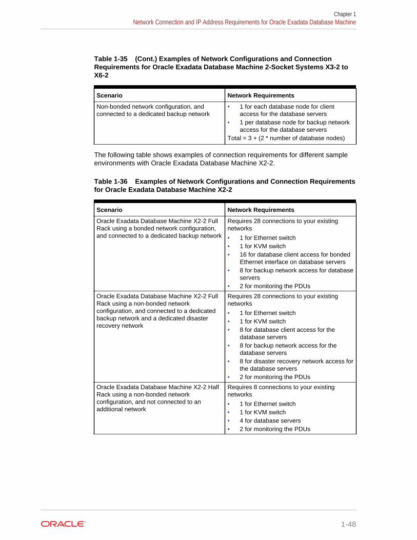
Table 1-35 (Cont.) Examples of Network Configurations and ConnectionRequirements for Oracle Exadata Database Machine 2-Socket Systems X3-2 toX6-2
Scenario Network Requirements
Non-bonded network configuration, andconnected to a dedicated backup network
• 1 for each database node for clientaccess for the database servers
• 1 per database node for backup networkaccess for the database servers
Total = 3 + (2 * number of database nodes)
The following table shows examples of connection requirements for different sampleenvironments with Oracle Exadata Database Machine X2-2.
Table 1-36 Examples of Network Configurations and Connection Requirementsfor Oracle Exadata Database Machine X2-2
Scenario Network Requirements
Oracle Exadata Database Machine X2-2 FullRack using a bonded network configuration,and connected to a dedicated backup network
Requires 28 connections to your existingnetworks
• 1 for Ethernet switch• 1 for KVM switch• 16 for database client access for bonded
Ethernet interface on database servers• 8 for backup network access for database
servers• 2 for monitoring the PDUs
Oracle Exadata Database Machine X2-2 FullRack using a non-bonded networkconfiguration, and connected to a dedicatedbackup network and a dedicated disasterrecovery network
Requires 28 connections to your existingnetworks
• 1 for Ethernet switch• 1 for KVM switch• 8 for database client access for the
database servers• 8 for backup network access for the
database servers• 8 for disaster recovery network access for
the database servers• 2 for monitoring the PDUs
Oracle Exadata Database Machine X2-2 HalfRack using a non-bonded networkconfiguration, and not connected to anadditional network
Requires 8 connections to your existingnetworks
• 1 for Ethernet switch• 1 for KVM switch• 4 for database servers• 2 for monitoring the PDUs
Chapter 1Network Connection and IP Address Requirements for Oracle Exadata Database Machine
1-48
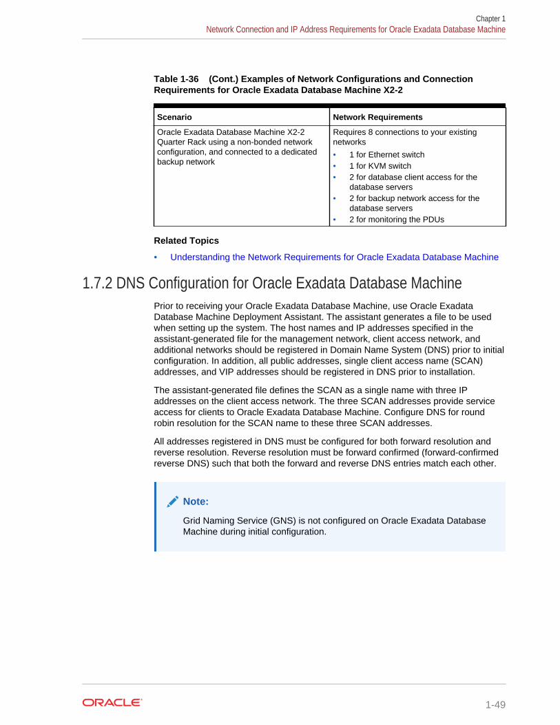
Table 1-36 (Cont.) Examples of Network Configurations and ConnectionRequirements for Oracle Exadata Database Machine X2-2
Scenario Network Requirements
Oracle Exadata Database Machine X2-2Quarter Rack using a non-bonded networkconfiguration, and connected to a dedicatedbackup network
Requires 8 connections to your existingnetworks
• 1 for Ethernet switch• 1 for KVM switch• 2 for database client access for the
database servers• 2 for backup network access for the
database servers• 2 for monitoring the PDUs
Related Topics
• Understanding the Network Requirements for Oracle Exadata Database Machine
1.7.2 DNS Configuration for Oracle Exadata Database MachinePrior to receiving your Oracle Exadata Database Machine, use Oracle ExadataDatabase Machine Deployment Assistant. The assistant generates a file to be usedwhen setting up the system. The host names and IP addresses specified in theassistant-generated file for the management network, client access network, andadditional networks should be registered in Domain Name System (DNS) prior to initialconfiguration. In addition, all public addresses, single client access name (SCAN)addresses, and VIP addresses should be registered in DNS prior to installation.
The assistant-generated file defines the SCAN as a single name with three IPaddresses on the client access network. The three SCAN addresses provide serviceaccess for clients to Oracle Exadata Database Machine. Configure DNS for roundrobin resolution for the SCAN name to these three SCAN addresses.
All addresses registered in DNS must be configured for both forward resolution andreverse resolution. Reverse resolution must be forward confirmed (forward-confirmedreverse DNS) such that both the forward and reverse DNS entries match each other.
Note:
Grid Naming Service (GNS) is not configured on Oracle Exadata DatabaseMachine during initial configuration.
Chapter 1Network Connection and IP Address Requirements for Oracle Exadata Database Machine
1-49
See Also:
• "Using Oracle Exadata Deployment Assistant"
• Oracle Grid Infrastructure Installation and Upgrade Guide for Linux foradditional information about SCAN addresses
• Your DNS vendor documentation for additional information aboutconfiguring round robin name resolution
1.7.3 IP Address Requirements for Oracle Exadata Database MachineOracle Exadata Database Machine requires a large number of host names and IPaddresses during initial configuration. The number of IP addresses required for aparticular network, such as the management network, depends on the type of system.The network configuration, such as host names and IP addresses, used duringinstallation is generated from information when completing the Oracle ExadataDatabase Machine Deployment Assistant.
Configure the new IP addresses in your existing networks only after you have runOracle Exadata Database Machine Deployment Assistant. All IP addresses in theassistant-generated file must be unassigned at the time of initial configuration. Inaddition, all IP addresses must be statically-assigned IP addresses, not dynamically-assigned (DHCP) addresses.
All InfiniBand addresses must be in the same subnet, with a minimum subnet mask of255.255.240.0 (or /20). The subnet mask chosen should be wide enough toaccommodate possible future expansion of the Oracle Exadata Database Machineand InfiniBand network.
The following table lists the IP address requirements for Oracle Exadata DatabaseMachine X5-2 and later systems:
Chapter 1Network Connection and IP Address Requirements for Oracle Exadata Database Machine
1-50

Table 1-37 IP Address Requirements for Oracle Exadata Database Machine X5-2 and LaterSystems
Type of OracleExadata DatabaseMachine
ManagementNetworkRequirements
Client AccessNetworkRequirements
AdditionalNetworks (NET2and NET3)Requirements
InfiniBand PrivateNetworkRequirements
Oracle ExadataDatabase MachineX5-2 and later FullRack
Minimum of 49 IPaddresses
• 8 IP addressesforadministration,one perdatabase server
• 14 IP addressesforadministration,one per ExadataStorage Server
• 8 IP addressesfor ILOM, oneper databaseserver
• 14 IP addressesfor ILOM, oneper ExadataStorage Server
• 3 IP addressesfor switches: 2for InfiniBand,and 1 forEthernet
• 2 IP addressesfor monitoringelectric currentof the PDUs
Minimum of 19 IPaddress
• 8 IP addressesfor publicaccess, one perdatabase server
• 8 IP addressesfor Oracle RACVIP addresses,one perdatabase server
• 3 IP addressesfor SCANaddresses forOracle RAC
Minimum of 8 IPaddresses for eachadditional network
• 8 IP addressesfor the databaseservers, one perdatabase server
If using a bondednetwork configurationfor the client accessnetwork, then NET2cannot be used as anadditional network.
44 IP addresses
• 16 IP addresses,two perdatabase server
• 28 IP addresses,two per ExadataStorage Server
Chapter 1Network Connection and IP Address Requirements for Oracle Exadata Database Machine
1-51
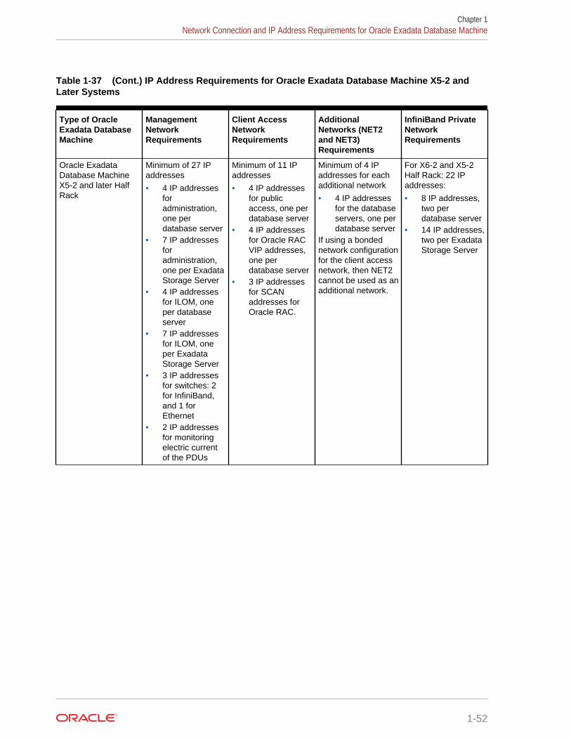
Table 1-37 (Cont.) IP Address Requirements for Oracle Exadata Database Machine X5-2 andLater Systems
Type of OracleExadata DatabaseMachine
ManagementNetworkRequirements
Client AccessNetworkRequirements
AdditionalNetworks (NET2and NET3)Requirements
InfiniBand PrivateNetworkRequirements
Oracle ExadataDatabase MachineX5-2 and later HalfRack
Minimum of 27 IPaddresses
• 4 IP addressesforadministration,one perdatabase server
• 7 IP addressesforadministration,one per ExadataStorage Server
• 4 IP addressesfor ILOM, oneper databaseserver
• 7 IP addressesfor ILOM, oneper ExadataStorage Server
• 3 IP addressesfor switches: 2for InfiniBand,and 1 forEthernet
• 2 IP addressesfor monitoringelectric currentof the PDUs
Minimum of 11 IPaddresses
• 4 IP addressesfor publicaccess, one perdatabase server
• 4 IP addressesfor Oracle RACVIP addresses,one perdatabase server
• 3 IP addressesfor SCANaddresses forOracle RAC.
Minimum of 4 IPaddresses for eachadditional network
• 4 IP addressesfor the databaseservers, one perdatabase server
If using a bondednetwork configurationfor the client accessnetwork, then NET2cannot be used as anadditional network.
For X6-2 and X5-2Half Rack: 22 IPaddresses:
• 8 IP addresses,two perdatabase server
• 14 IP addresses,two per ExadataStorage Server
Chapter 1Network Connection and IP Address Requirements for Oracle Exadata Database Machine
1-52
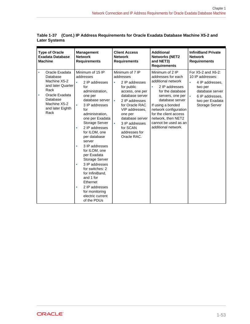
Table 1-37 (Cont.) IP Address Requirements for Oracle Exadata Database Machine X5-2 andLater Systems
Type of OracleExadata DatabaseMachine
ManagementNetworkRequirements
Client AccessNetworkRequirements
AdditionalNetworks (NET2and NET3)Requirements
InfiniBand PrivateNetworkRequirements
• Oracle ExadataDatabaseMachine X5-2and later QuarterRack
• Oracle ExadataDatabaseMachine X5-2and later EighthRack
Minimum of 15 IPaddresses
• 2 IP addressesforadministration,one perdatabase server
• 3 IP addressesforadministration,one per ExadataStorage Server
• 2 IP addressesfor ILOM, oneper databaseserver
• 3 IP addressesfor ILOM, oneper ExadataStorage Server
• 3 IP addressesfor switches: 2for InfiniBand,and 1 forEthernet
• 2 IP addressesfor monitoringelectric currentof the PDUs
Minimum of 7 IPaddresses
• 2 IP addressesfor publicaccess, one perdatabase server
• 2 IP addressesfor Oracle RACVIP addresses,one perdatabase server
• 3 IP addressesfor SCANaddresses forOracle RAC.
Minimum of 2 IPaddresses for eachadditional network
• 2 IP addressesfor the databaseservers, one perdatabase server
If using a bondednetwork configurationfor the client accessnetwork, then NET2cannot be used as anadditional network.
For X5-2 and X6-2:10 IP addresses:
• 4 IP addresses,two perdatabase server
• 6 IP addresses,two per ExadataStorage Server
Chapter 1Network Connection and IP Address Requirements for Oracle Exadata Database Machine
1-53
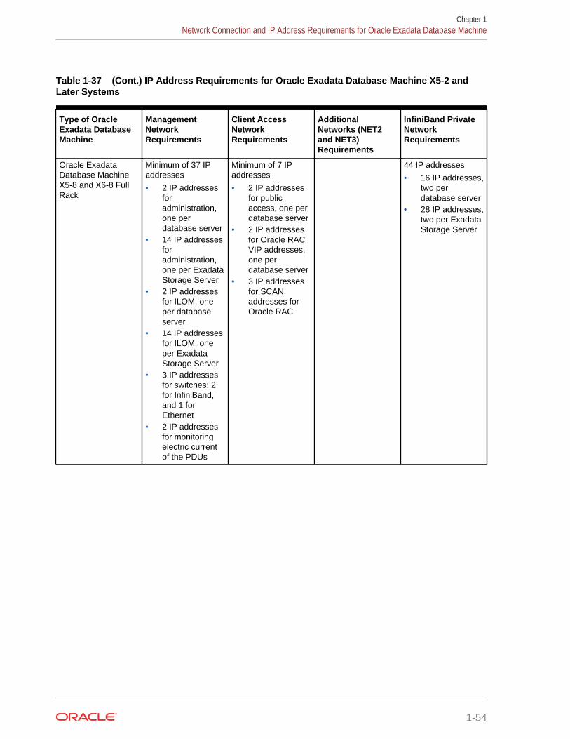
Table 1-37 (Cont.) IP Address Requirements for Oracle Exadata Database Machine X5-2 andLater Systems
Type of OracleExadata DatabaseMachine
ManagementNetworkRequirements
Client AccessNetworkRequirements
AdditionalNetworks (NET2and NET3)Requirements
InfiniBand PrivateNetworkRequirements
Oracle ExadataDatabase MachineX5-8 and X6-8 FullRack
Minimum of 37 IPaddresses
• 2 IP addressesforadministration,one perdatabase server
• 14 IP addressesforadministration,one per ExadataStorage Server
• 2 IP addressesfor ILOM, oneper databaseserver
• 14 IP addressesfor ILOM, oneper ExadataStorage Server
• 3 IP addressesfor switches: 2for InfiniBand,and 1 forEthernet
• 2 IP addressesfor monitoringelectric currentof the PDUs
Minimum of 7 IPaddresses
• 2 IP addressesfor publicaccess, one perdatabase server
• 2 IP addressesfor Oracle RACVIP addresses,one perdatabase server
• 3 IP addressesfor SCANaddresses forOracle RAC
44 IP addresses
• 16 IP addresses,two perdatabase server
• 28 IP addresses,two per ExadataStorage Server
Chapter 1Network Connection and IP Address Requirements for Oracle Exadata Database Machine
1-54
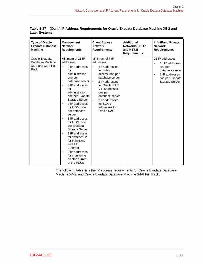
Table 1-37 (Cont.) IP Address Requirements for Oracle Exadata Database Machine X5-2 andLater Systems
Type of OracleExadata DatabaseMachine
ManagementNetworkRequirements
Client AccessNetworkRequirements
AdditionalNetworks (NET2and NET3)Requirements
InfiniBand PrivateNetworkRequirements
Oracle ExadataDatabase MachineX5-8 and X6-8 HalfRack
Minimum of 15 IPaddresses
• 2 IP addressesforadministration,one perdatabase server
• 3 IP addressesforadministration,one per ExadataStorage Server
• 2 IP addressesfor ILOM, oneper databaseserver
• 3 IP addressesfor ILOM, oneper ExadataStorage Server
• 3 IP addressesfor switches: 2for InfiniBand,and 1 forEthernet
• 2 IP addressesfor monitoringelectric currentof the PDUs
Minimum of 7 IPaddresses
• 2 IP addressesfor publicaccess, one perdatabase server
• 2 IP addressesfor Oracle RACVIP addresses,one perdatabase server
• 3 IP addressesfor SCANaddresses forOracle RAC
22 IP addresses
• 16 IP addresses,two perdatabase server
• 6 IP addresses,two per ExadataStorage Server
The following table lists the IP address requirements for Oracle Exadata DatabaseMachine X4-2, and Oracle Exadata Database Machine X4-8 Full Rack:
Chapter 1Network Connection and IP Address Requirements for Oracle Exadata Database Machine
1-55
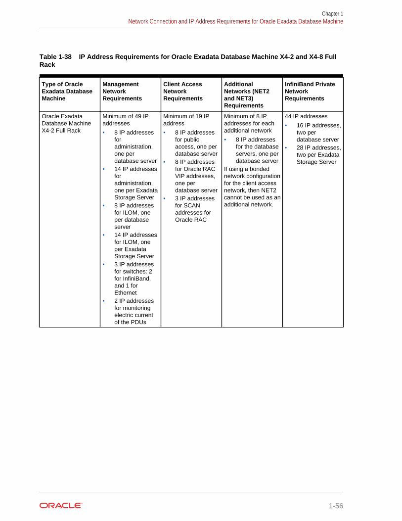
Table 1-38 IP Address Requirements for Oracle Exadata Database Machine X4-2 and X4-8 FullRack
Type of OracleExadata DatabaseMachine
ManagementNetworkRequirements
Client AccessNetworkRequirements
AdditionalNetworks (NET2and NET3)Requirements
InfiniBand PrivateNetworkRequirements
Oracle ExadataDatabase MachineX4-2 Full Rack
Minimum of 49 IPaddresses
• 8 IP addressesforadministration,one perdatabase server
• 14 IP addressesforadministration,one per ExadataStorage Server
• 8 IP addressesfor ILOM, oneper databaseserver
• 14 IP addressesfor ILOM, oneper ExadataStorage Server
• 3 IP addressesfor switches: 2for InfiniBand,and 1 forEthernet
• 2 IP addressesfor monitoringelectric currentof the PDUs
Minimum of 19 IPaddress
• 8 IP addressesfor publicaccess, one perdatabase server
• 8 IP addressesfor Oracle RACVIP addresses,one perdatabase server
• 3 IP addressesfor SCANaddresses forOracle RAC
Minimum of 8 IPaddresses for eachadditional network
• 8 IP addressesfor the databaseservers, one perdatabase server
If using a bondednetwork configurationfor the client accessnetwork, then NET2cannot be used as anadditional network.
44 IP addresses
• 16 IP addresses,two perdatabase server
• 28 IP addresses,two per ExadataStorage Server
Chapter 1Network Connection and IP Address Requirements for Oracle Exadata Database Machine
1-56
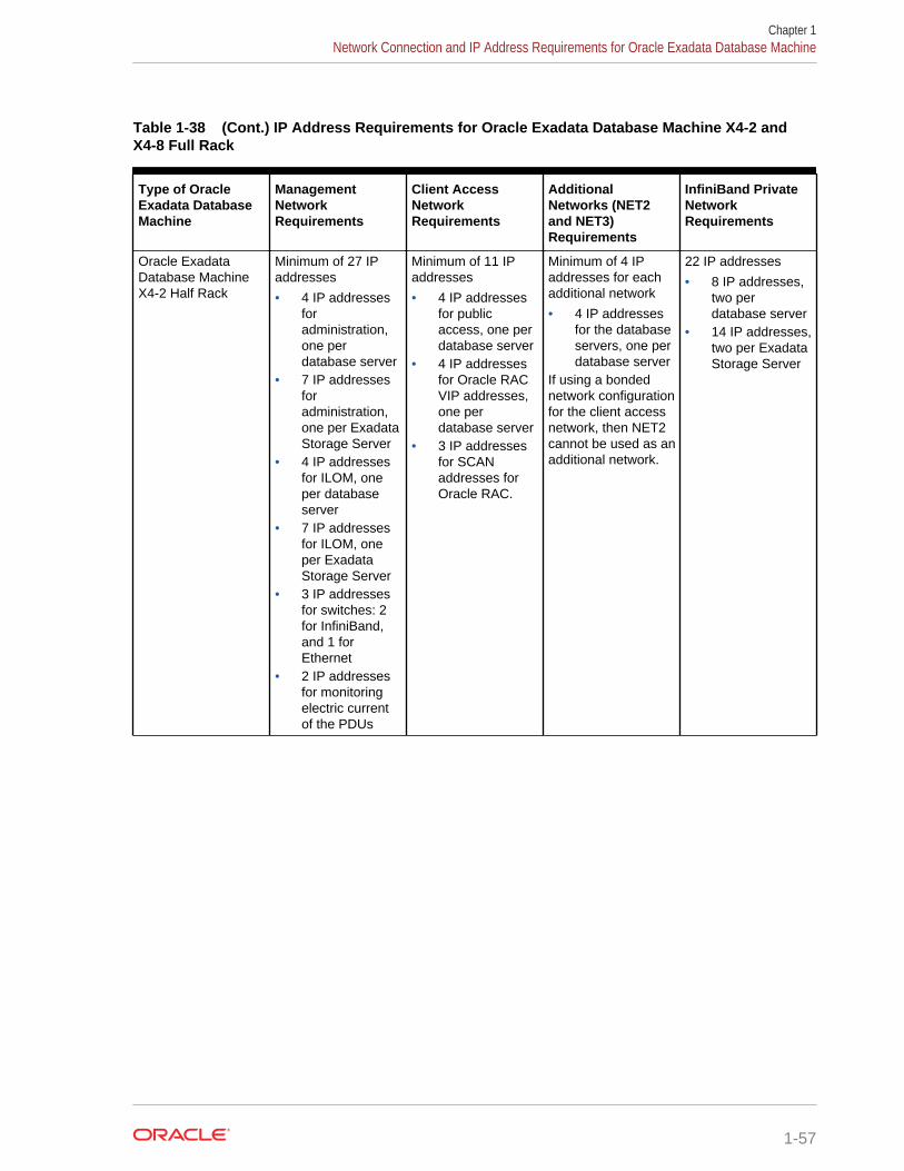
Table 1-38 (Cont.) IP Address Requirements for Oracle Exadata Database Machine X4-2 andX4-8 Full Rack
Type of OracleExadata DatabaseMachine
ManagementNetworkRequirements
Client AccessNetworkRequirements
AdditionalNetworks (NET2and NET3)Requirements
InfiniBand PrivateNetworkRequirements
Oracle ExadataDatabase MachineX4-2 Half Rack
Minimum of 27 IPaddresses
• 4 IP addressesforadministration,one perdatabase server
• 7 IP addressesforadministration,one per ExadataStorage Server
• 4 IP addressesfor ILOM, oneper databaseserver
• 7 IP addressesfor ILOM, oneper ExadataStorage Server
• 3 IP addressesfor switches: 2for InfiniBand,and 1 forEthernet
• 2 IP addressesfor monitoringelectric currentof the PDUs
Minimum of 11 IPaddresses
• 4 IP addressesfor publicaccess, one perdatabase server
• 4 IP addressesfor Oracle RACVIP addresses,one perdatabase server
• 3 IP addressesfor SCANaddresses forOracle RAC.
Minimum of 4 IPaddresses for eachadditional network
• 4 IP addressesfor the databaseservers, one perdatabase server
If using a bondednetwork configurationfor the client accessnetwork, then NET2cannot be used as anadditional network.
22 IP addresses
• 8 IP addresses,two perdatabase server
• 14 IP addresses,two per ExadataStorage Server
Chapter 1Network Connection and IP Address Requirements for Oracle Exadata Database Machine
1-57
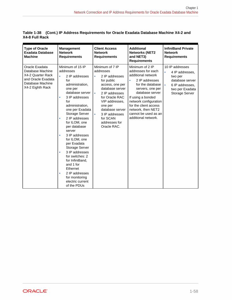
Table 1-38 (Cont.) IP Address Requirements for Oracle Exadata Database Machine X4-2 andX4-8 Full Rack
Type of OracleExadata DatabaseMachine
ManagementNetworkRequirements
Client AccessNetworkRequirements
AdditionalNetworks (NET2and NET3)Requirements
InfiniBand PrivateNetworkRequirements
Oracle ExadataDatabase MachineX4-2 Quarter Rackand Oracle ExadataDatabase MachineX4-2 Eighth Rack
Minimum of 15 IPaddresses
• 2 IP addressesforadministration,one perdatabase server
• 3 IP addressesforadministration,one per ExadataStorage Server
• 2 IP addressesfor ILOM, oneper databaseserver
• 3 IP addressesfor ILOM, oneper ExadataStorage Server
• 3 IP addressesfor switches: 2for InfiniBand,and 1 forEthernet
• 2 IP addressesfor monitoringelectric currentof the PDUs
Minimum of 7 IPaddresses
• 2 IP addressesfor publicaccess, one perdatabase server
• 2 IP addressesfor Oracle RACVIP addresses,one perdatabase server
• 3 IP addressesfor SCANaddresses forOracle RAC.
Minimum of 2 IPaddresses for eachadditional network
• 2 IP addressesfor the databaseservers, one perdatabase server
If using a bondednetwork configurationfor the client accessnetwork, then NET2cannot be used as anadditional network.
10 IP addresses
• 4 IP addresses,two perdatabase server
• 6 IP addresses,two per ExadataStorage Server
Chapter 1Network Connection and IP Address Requirements for Oracle Exadata Database Machine
1-58
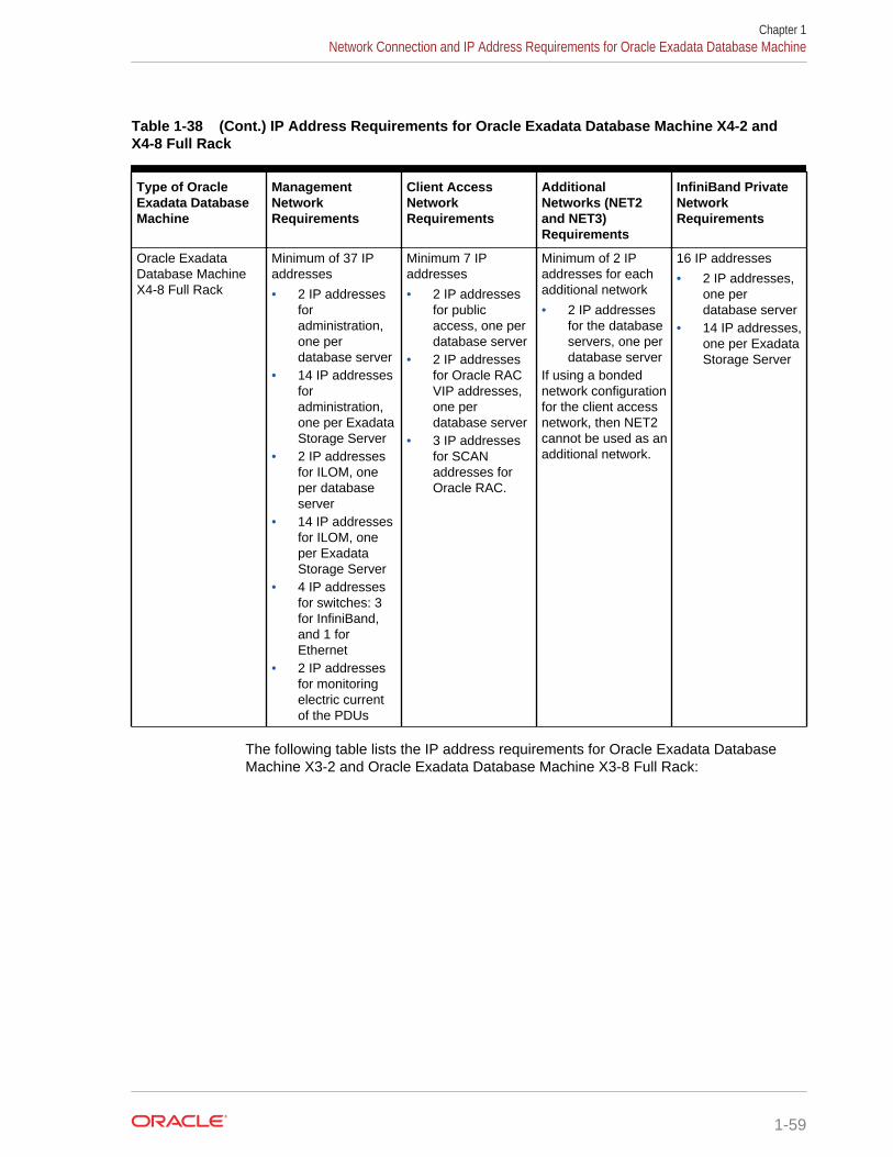
Table 1-38 (Cont.) IP Address Requirements for Oracle Exadata Database Machine X4-2 andX4-8 Full Rack
Type of OracleExadata DatabaseMachine
ManagementNetworkRequirements
Client AccessNetworkRequirements
AdditionalNetworks (NET2and NET3)Requirements
InfiniBand PrivateNetworkRequirements
Oracle ExadataDatabase MachineX4-8 Full Rack
Minimum of 37 IPaddresses
• 2 IP addressesforadministration,one perdatabase server
• 14 IP addressesforadministration,one per ExadataStorage Server
• 2 IP addressesfor ILOM, oneper databaseserver
• 14 IP addressesfor ILOM, oneper ExadataStorage Server
• 4 IP addressesfor switches: 3for InfiniBand,and 1 forEthernet
• 2 IP addressesfor monitoringelectric currentof the PDUs
Minimum 7 IPaddresses
• 2 IP addressesfor publicaccess, one perdatabase server
• 2 IP addressesfor Oracle RACVIP addresses,one perdatabase server
• 3 IP addressesfor SCANaddresses forOracle RAC.
Minimum of 2 IPaddresses for eachadditional network
• 2 IP addressesfor the databaseservers, one perdatabase server
If using a bondednetwork configurationfor the client accessnetwork, then NET2cannot be used as anadditional network.
16 IP addresses
• 2 IP addresses,one perdatabase server
• 14 IP addresses,one per ExadataStorage Server
The following table lists the IP address requirements for Oracle Exadata DatabaseMachine X3-2 and Oracle Exadata Database Machine X3-8 Full Rack:
Chapter 1Network Connection and IP Address Requirements for Oracle Exadata Database Machine
1-59
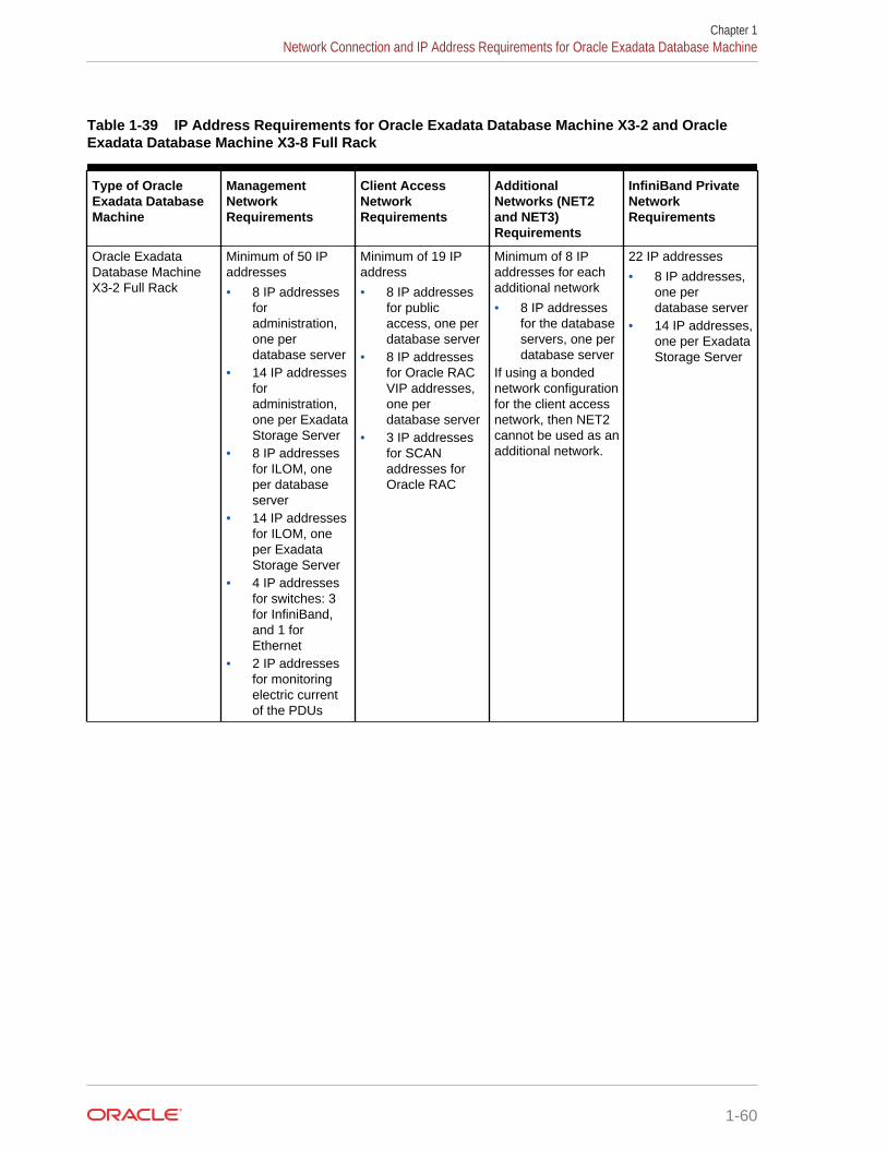
Table 1-39 IP Address Requirements for Oracle Exadata Database Machine X3-2 and OracleExadata Database Machine X3-8 Full Rack
Type of OracleExadata DatabaseMachine
ManagementNetworkRequirements
Client AccessNetworkRequirements
AdditionalNetworks (NET2and NET3)Requirements
InfiniBand PrivateNetworkRequirements
Oracle ExadataDatabase MachineX3-2 Full Rack
Minimum of 50 IPaddresses
• 8 IP addressesforadministration,one perdatabase server
• 14 IP addressesforadministration,one per ExadataStorage Server
• 8 IP addressesfor ILOM, oneper databaseserver
• 14 IP addressesfor ILOM, oneper ExadataStorage Server
• 4 IP addressesfor switches: 3for InfiniBand,and 1 forEthernet
• 2 IP addressesfor monitoringelectric currentof the PDUs
Minimum of 19 IPaddress
• 8 IP addressesfor publicaccess, one perdatabase server
• 8 IP addressesfor Oracle RACVIP addresses,one perdatabase server
• 3 IP addressesfor SCANaddresses forOracle RAC
Minimum of 8 IPaddresses for eachadditional network
• 8 IP addressesfor the databaseservers, one perdatabase server
If using a bondednetwork configurationfor the client accessnetwork, then NET2cannot be used as anadditional network.
22 IP addresses
• 8 IP addresses,one perdatabase server
• 14 IP addresses,one per ExadataStorage Server
Chapter 1Network Connection and IP Address Requirements for Oracle Exadata Database Machine
1-60
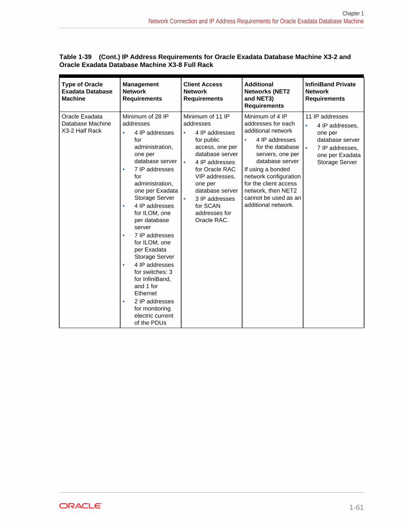
Table 1-39 (Cont.) IP Address Requirements for Oracle Exadata Database Machine X3-2 andOracle Exadata Database Machine X3-8 Full Rack
Type of OracleExadata DatabaseMachine
ManagementNetworkRequirements
Client AccessNetworkRequirements
AdditionalNetworks (NET2and NET3)Requirements
InfiniBand PrivateNetworkRequirements
Oracle ExadataDatabase MachineX3-2 Half Rack
Minimum of 28 IPaddresses
• 4 IP addressesforadministration,one perdatabase server
• 7 IP addressesforadministration,one per ExadataStorage Server
• 4 IP addressesfor ILOM, oneper databaseserver
• 7 IP addressesfor ILOM, oneper ExadataStorage Server
• 4 IP addressesfor switches: 3for InfiniBand,and 1 forEthernet
• 2 IP addressesfor monitoringelectric currentof the PDUs
Minimum of 11 IPaddresses
• 4 IP addressesfor publicaccess, one perdatabase server
• 4 IP addressesfor Oracle RACVIP addresses,one perdatabase server
• 3 IP addressesfor SCANaddresses forOracle RAC.
Minimum of 4 IPaddresses for eachadditional network
• 4 IP addressesfor the databaseservers, one perdatabase server
If using a bondednetwork configurationfor the client accessnetwork, then NET2cannot be used as anadditional network.
11 IP addresses
• 4 IP addresses,one perdatabase server
• 7 IP addresses,one per ExadataStorage Server
Chapter 1Network Connection and IP Address Requirements for Oracle Exadata Database Machine
1-61

Table 1-39 (Cont.) IP Address Requirements for Oracle Exadata Database Machine X3-2 andOracle Exadata Database Machine X3-8 Full Rack
Type of OracleExadata DatabaseMachine
ManagementNetworkRequirements
Client AccessNetworkRequirements
AdditionalNetworks (NET2and NET3)Requirements
InfiniBand PrivateNetworkRequirements
Oracle ExadataDatabase MachineX3-2 Quarter Rack
Minimum of 15 IPaddresses
• 2 IP addressesforadministration,one perdatabase server
• 3 IP addressesforadministration,one per ExadataStorage Server
• 2 IP addressesfor ILOM, oneper databaseserver
• 3 IP addressesfor ILOM, oneper ExadataStorage Server
• 3 IP addressesfor switches: 2for InfiniBand,and 1 forEthernet
• 2 IP addressesfor monitoringelectric currentof the PDUs
Minimum of 7 IPaddresses
• 2 IP addressesfor publicaccess, one perdatabase server
• 2 IP addressesfor Oracle RACVIP addresses,one perdatabase server
• 3 IP addressesfor SCANaddresses forOracle RAC.
Minimum of 2 IPaddresses for eachadditional network
• 2 IP addressesfor the databaseservers, one perdatabase server
If using a bondednetwork configurationfor the client accessnetwork, then NET2cannot be used as anadditional network.
5 IP addresses
• 2 IP addresses,one perdatabase server
• 3 IP addresses,one per ExadataStorage Server
Chapter 1Network Connection and IP Address Requirements for Oracle Exadata Database Machine
1-62
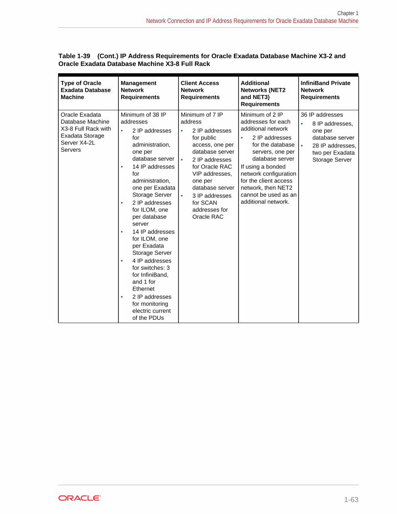
Table 1-39 (Cont.) IP Address Requirements for Oracle Exadata Database Machine X3-2 andOracle Exadata Database Machine X3-8 Full Rack
Type of OracleExadata DatabaseMachine
ManagementNetworkRequirements
Client AccessNetworkRequirements
AdditionalNetworks (NET2and NET3)Requirements
InfiniBand PrivateNetworkRequirements
Oracle ExadataDatabase MachineX3-8 Full Rack withExadata StorageServer X4-2LServers
Minimum of 38 IPaddresses
• 2 IP addressesforadministration,one perdatabase server
• 14 IP addressesforadministration,one per ExadataStorage Server
• 2 IP addressesfor ILOM, oneper databaseserver
• 14 IP addressesfor ILOM, oneper ExadataStorage Server
• 4 IP addressesfor switches: 3for InfiniBand,and 1 forEthernet
• 2 IP addressesfor monitoringelectric currentof the PDUs
Minimum of 7 IPaddress
• 2 IP addressesfor publicaccess, one perdatabase server
• 2 IP addressesfor Oracle RACVIP addresses,one perdatabase server
• 3 IP addressesfor SCANaddresses forOracle RAC
Minimum of 2 IPaddresses for eachadditional network
• 2 IP addressesfor the databaseservers, one perdatabase server
If using a bondednetwork configurationfor the client accessnetwork, then NET2cannot be used as anadditional network.
36 IP addresses
• 8 IP addresses,one perdatabase server
• 28 IP addresses,two per ExadataStorage Server
Chapter 1Network Connection and IP Address Requirements for Oracle Exadata Database Machine
1-63
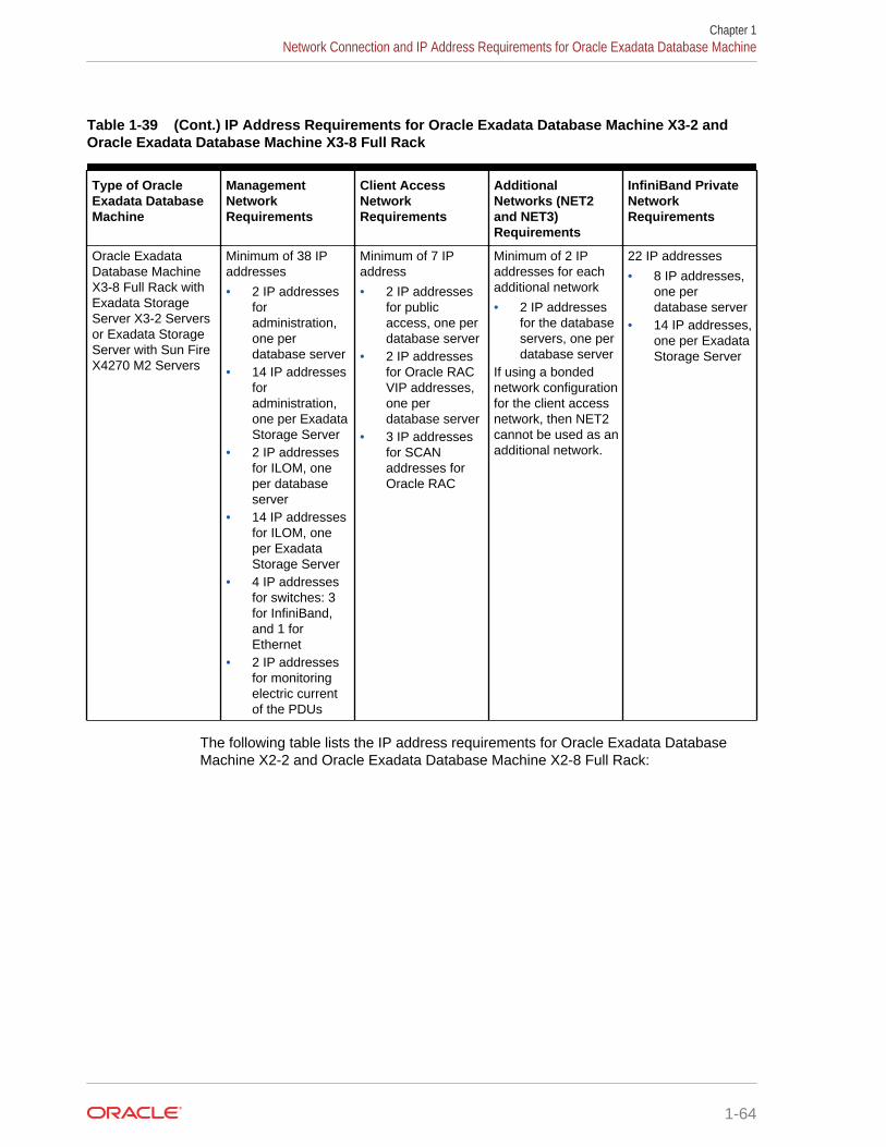
Table 1-39 (Cont.) IP Address Requirements for Oracle Exadata Database Machine X3-2 andOracle Exadata Database Machine X3-8 Full Rack
Type of OracleExadata DatabaseMachine
ManagementNetworkRequirements
Client AccessNetworkRequirements
AdditionalNetworks (NET2and NET3)Requirements
InfiniBand PrivateNetworkRequirements
Oracle ExadataDatabase MachineX3-8 Full Rack withExadata StorageServer X3-2 Serversor Exadata StorageServer with Sun FireX4270 M2 Servers
Minimum of 38 IPaddresses
• 2 IP addressesforadministration,one perdatabase server
• 14 IP addressesforadministration,one per ExadataStorage Server
• 2 IP addressesfor ILOM, oneper databaseserver
• 14 IP addressesfor ILOM, oneper ExadataStorage Server
• 4 IP addressesfor switches: 3for InfiniBand,and 1 forEthernet
• 2 IP addressesfor monitoringelectric currentof the PDUs
Minimum of 7 IPaddress
• 2 IP addressesfor publicaccess, one perdatabase server
• 2 IP addressesfor Oracle RACVIP addresses,one perdatabase server
• 3 IP addressesfor SCANaddresses forOracle RAC
Minimum of 2 IPaddresses for eachadditional network
• 2 IP addressesfor the databaseservers, one perdatabase server
If using a bondednetwork configurationfor the client accessnetwork, then NET2cannot be used as anadditional network.
22 IP addresses
• 8 IP addresses,one perdatabase server
• 14 IP addresses,one per ExadataStorage Server
The following table lists the IP address requirements for Oracle Exadata DatabaseMachine X2-2 and Oracle Exadata Database Machine X2-8 Full Rack:
Chapter 1Network Connection and IP Address Requirements for Oracle Exadata Database Machine
1-64

Table 1-40 IP Address Requirements for Oracle Exadata Database Machine X2-2 and OracleExadata Database Machine X2-8 Full Rack
Type of OracleExadata DatabaseMachine
ManagementNetworkRequirements
Client AccessNetworkRequirements
AdditionalNetworks (NET2and NET3)Requirements
InfiniBand PrivateNetworkRequirements
Oracle ExadataDatabase MachineX2-2 Full Rack
Minimum of 51 IPaddresses
• 8 IP addressesforadministration,one perdatabase server
• 14 IP addressesforadministration,one per ExadataStorage Server
• 8 IP addressesfor ILOM, oneper databaseserver
• 14 IP addressesfor ILOM, oneper ExadataStorage Server
• 5 IP addressesfor switches: 3for InfiniBand, 1for Ethernet, and1 for KVM
• 2 IP addressesfor monitoringelectric currentof the PDUs
Minimum of 19 IPaddress
• 8 IP addressesfor publicaccess, one perdatabase server
• 8 IP addressesfor Oracle RACVIP addresses,one perdatabase server
• 3 IP addressesfor SCANaddresses forOracle RAC
Minimum of 8 IPaddresses for eachadditional network
• 8 IP addressesfor the databaseservers, one perdatabase server
If using a bondednetwork configurationfor the client accessnetwork, then NET2cannot be used as anadditional network.
22 IP addresses
• 8 IP addresses,one perdatabase server
• 14 IP addresses,one per ExadataStorage Server
Chapter 1Network Connection and IP Address Requirements for Oracle Exadata Database Machine
1-65
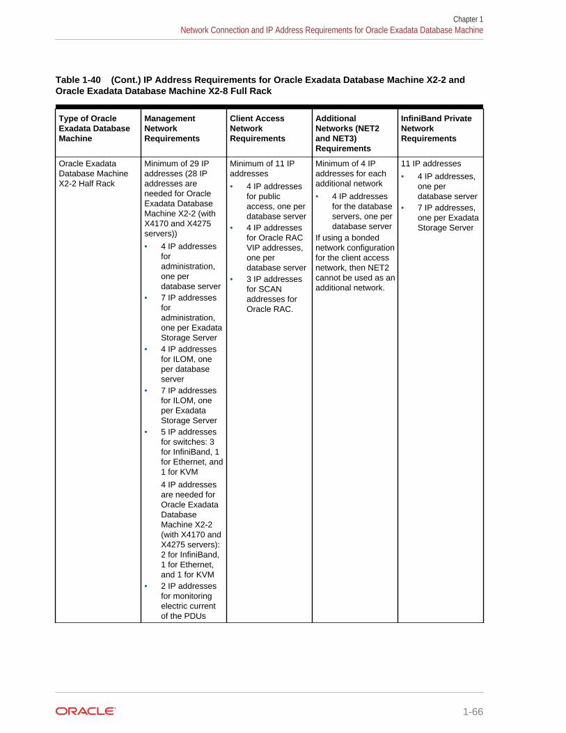
Table 1-40 (Cont.) IP Address Requirements for Oracle Exadata Database Machine X2-2 andOracle Exadata Database Machine X2-8 Full Rack
Type of OracleExadata DatabaseMachine
ManagementNetworkRequirements
Client AccessNetworkRequirements
AdditionalNetworks (NET2and NET3)Requirements
InfiniBand PrivateNetworkRequirements
Oracle ExadataDatabase MachineX2-2 Half Rack
Minimum of 29 IPaddresses (28 IPaddresses areneeded for OracleExadata DatabaseMachine X2-2 (withX4170 and X4275servers))
• 4 IP addressesforadministration,one perdatabase server
• 7 IP addressesforadministration,one per ExadataStorage Server
• 4 IP addressesfor ILOM, oneper databaseserver
• 7 IP addressesfor ILOM, oneper ExadataStorage Server
• 5 IP addressesfor switches: 3for InfiniBand, 1for Ethernet, and1 for KVM
4 IP addressesare needed forOracle ExadataDatabaseMachine X2-2(with X4170 andX4275 servers):2 for InfiniBand,1 for Ethernet,and 1 for KVM
• 2 IP addressesfor monitoringelectric currentof the PDUs
Minimum of 11 IPaddresses
• 4 IP addressesfor publicaccess, one perdatabase server
• 4 IP addressesfor Oracle RACVIP addresses,one perdatabase server
• 3 IP addressesfor SCANaddresses forOracle RAC.
Minimum of 4 IPaddresses for eachadditional network
• 4 IP addressesfor the databaseservers, one perdatabase server
If using a bondednetwork configurationfor the client accessnetwork, then NET2cannot be used as anadditional network.
11 IP addresses
• 4 IP addresses,one perdatabase server
• 7 IP addresses,one per ExadataStorage Server
Chapter 1Network Connection and IP Address Requirements for Oracle Exadata Database Machine
1-66
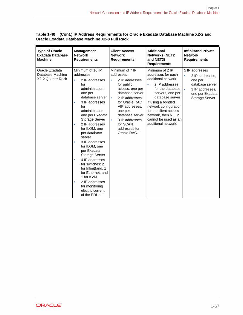
Table 1-40 (Cont.) IP Address Requirements for Oracle Exadata Database Machine X2-2 andOracle Exadata Database Machine X2-8 Full Rack
Type of OracleExadata DatabaseMachine
ManagementNetworkRequirements
Client AccessNetworkRequirements
AdditionalNetworks (NET2and NET3)Requirements
InfiniBand PrivateNetworkRequirements
Oracle ExadataDatabase MachineX2-2 Quarter Rack
Minimum of 16 IPaddresses
• 2 IP addressesforadministration,one perdatabase server
• 3 IP addressesforadministration,one per ExadataStorage Server
• 2 IP addressesfor ILOM, oneper databaseserver
• 3 IP addressesfor ILOM, oneper ExadataStorage Server
• 4 IP addressesfor switches: 2for InfiniBand, 1for Ethernet, and1 for KVM
• 2 IP addressesfor monitoringelectric currentof the PDUs
Minimum of 7 IPaddresses
• 2 IP addressesfor publicaccess, one perdatabase server
• 2 IP addressesfor Oracle RACVIP addresses,one perdatabase server
• 3 IP addressesfor SCANaddresses forOracle RAC.
Minimum of 2 IPaddresses for eachadditional network
• 2 IP addressesfor the databaseservers, one perdatabase server
If using a bondednetwork configurationfor the client accessnetwork, then NET2cannot be used as anadditional network.
5 IP addresses
• 2 IP addresses,one perdatabase server
• 3 IP addresses,one per ExadataStorage Server
Chapter 1Network Connection and IP Address Requirements for Oracle Exadata Database Machine
1-67
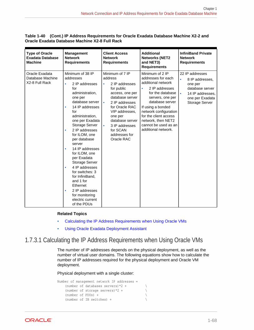
Table 1-40 (Cont.) IP Address Requirements for Oracle Exadata Database Machine X2-2 andOracle Exadata Database Machine X2-8 Full Rack
Type of OracleExadata DatabaseMachine
ManagementNetworkRequirements
Client AccessNetworkRequirements
AdditionalNetworks (NET2and NET3)Requirements
InfiniBand PrivateNetworkRequirements
Oracle ExadataDatabase MachineX2-8 Full Rack
Minimum of 38 IPaddresses
• 2 IP addressesforadministration,one perdatabase server
• 14 IP addressesforadministration,one per ExadataStorage Server
• 2 IP addressesfor ILOM, oneper databaseserver
• 14 IP addressesfor ILOM, oneper ExadataStorage Server
• 4 IP addressesfor switches: 3for InfiniBand,and 1 forEthernet
• 2 IP addressesfor monitoringelectric currentof the PDUs
Minimum of 7 IPaddress
• 2 IP addressesfor publicaccess, one perdatabase server
• 2 IP addressesfor Oracle RACVIP addresses,one perdatabase server
• 3 IP addressesfor SCANaddresses forOracle RAC
Minimum of 2 IPaddresses for eachadditional network
• 2 IP addressesfor the databaseservers, one perdatabase server
If using a bondednetwork configurationfor the client accessnetwork, then NET2cannot be used as anadditional network.
22 IP addresses
• 8 IP addresses,one perdatabase server
• 14 IP addresses,one per ExadataStorage Server
Related Topics
• Calculating the IP Address Requirements when Using Oracle VMs
• Using Oracle Exadata Deployment Assistant
1.7.3.1 Calculating the IP Address Requirements when Using Oracle VMsThe number of IP addresses depends on the physical deployment, as well as thenumber of virtual user domains. The following equations show how to calculate thenumber of IP addresses required for the physical deployment and Oracle VMdeployment.
Physical deployment with a single cluster:
Number of management network IP addresses = (number of databases servers)*2 + \ (number of storage servers)*2 + \ (number of PDUs) + \ (number of IB switches) + \
Chapter 1Network Connection and IP Address Requirements for Oracle Exadata Database Machine
1-68
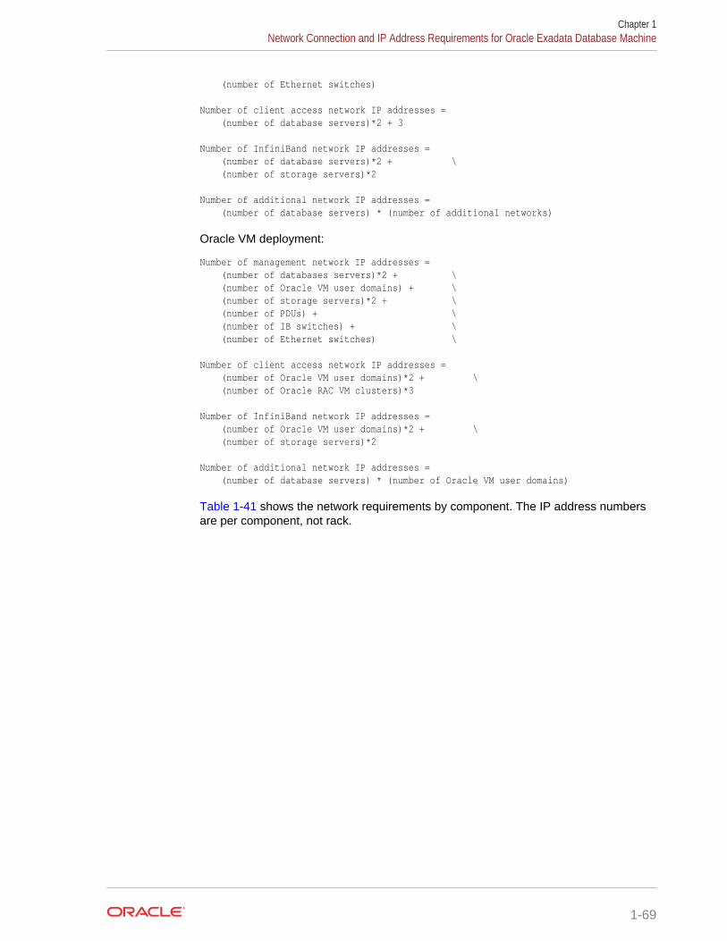
(number of Ethernet switches)
Number of client access network IP addresses = (number of database servers)*2 + 3
Number of InfiniBand network IP addresses = (number of database servers)*2 + \ (number of storage servers)*2
Number of additional network IP addresses = (number of database servers) * (number of additional networks)
Oracle VM deployment:
Number of management network IP addresses = (number of databases servers)*2 + \ (number of Oracle VM user domains) + \ (number of storage servers)*2 + \ (number of PDUs) + \ (number of IB switches) + \ (number of Ethernet switches) \
Number of client access network IP addresses = (number of Oracle VM user domains)*2 + \ (number of Oracle RAC VM clusters)*3
Number of InfiniBand network IP addresses = (number of Oracle VM user domains)*2 + \ (number of storage servers)*2
Number of additional network IP addresses = (number of database servers) * (number of Oracle VM user domains)
Table 1-41 shows the network requirements by component. The IP address numbersare per component, not rack.
Chapter 1Network Connection and IP Address Requirements for Oracle Exadata Database Machine
1-69
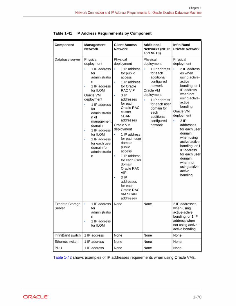
Table 1-41 IP Address Requirements by Component
Component ManagementNetwork
Client AccessNetwork
AdditionalNetworks (NET2and NET3)
InfiniBandPrivate Network
Database server Physicaldeployment
• 1 IP addressforadministration
• 1 IP addressfor ILOM
Oracle VMdeployment
• 1 IP addressforadministration ofmanagementdomain
• 1 IP addressfor ILOM
• 1 IP addressfor each userdomain foradministration
Physicaldeployment
• 1 IP addressfor publicaccess
• 1 IP addressfor OracleRAC VIP
• 3 IPaddressesfor eachOracle RACclusterSCANaddresses
Oracle VMdeployment
• 1 IP addressfor each userdomainpublicaccess
• 1 IP addressfor each userdomainOracle RACVIP
• 3 IPaddressesfor eachOracle RACVM SCANaddresses
Physicaldeployment
• 1 IP addressfor eachadditionalconfigurednetwork
Oracle VMdeployment
• 1 IP addressfor each userdomain foreachadditionalconfigurednetwork
Physicaldeployment
• 2 IP addresses whenusing active-activebonding, or 1IP addresswhen notusing active-activebonding
Oracle VMdeployment
• 2 IPaddressesfor each userdomainwhen usingactive-activebonding, or 1IP addressfor each userdomainwhen notusing active-activebonding
Exadata StorageServer
• 1 IP addressforadministration
• 1 IP addressfor ILOM
None None 2 IP addresseswhen usingactive-activebonding, or 1 IPaddress whennot using active-active bonding.
InfiniBand switch 1 IP address None None None
Ethernet switch 1 IP address None None None
PDU 1 IP address None None None
Table 1-42 shows examples of IP addresses requirements when using Oracle VMs.
Chapter 1Network Connection and IP Address Requirements for Oracle Exadata Database Machine
1-70
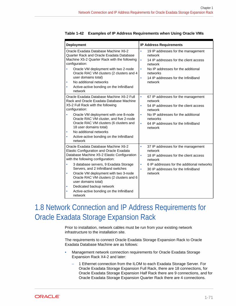
Table 1-42 Examples of IP Address Requirements when Using Oracle VMs
Deployment IP Address Requirements
Oracle Exadata Database Machine X6-2Quarter Rack and Oracle Exadata DatabaseMachine X5-2 Quarter Rack with the followingconfiguration:
• Oracle VM deployment with two 2-nodeOracle RAC VM clusters (2 clusters and 4user domains total)
• No additional networks• Active-active bonding on the InfiniBand
network
• 19 IP addresses for the managementnetwork
• 14 IP addresses for the client accessnetwork
• No IP addresses for the additionalnetworks
• 14 IP addresses for the InfiniBandnetwork
Oracle Exadata Database Machine X6-2 FullRack and Oracle Exadata Database MachineX5-2 Full Rack with the followingconfiguration:
• Oracle VM deployment with one 8-nodeOracle RAC VM cluster, and five 2-nodeOracle RAC VM clusters (6 clusters and18 user domains total)
• No additional networks• Active-active bonding on the InfiniBand
network
• 67 IP addresses for the managementnetwork
• 54 IP addresses for the client accessnetwork
• No IP addresses for the additionalnetworks
• 64 IP addresses for the InfiniBandnetwork
Oracle Exadata Database Machine X6-2Elastic Configuration and Oracle ExadataDatabase Machine X5-2 Elastic Configurationwith the following configuration:
• 3 database servers, 9 Exadata StorageServers, and 2 InfiniBand switches
• Oracle VM deployment with two 3-nodeOracle RAC VM clusters (2 clusters and 6user domains total)
• Dedicated backup network• Active-active bonding on the InfiniBand
network
• 37 IP addresses for the managementnetwork
• 18 IP addresses for the client accessnetwork
• 6 IP addresses for the additional networks• 30 IP addresses for the InfiniBand
network
1.8 Network Connection and IP Address Requirements forOracle Exadata Storage Expansion Rack
Prior to installation, network cables must be run from your existing networkinfrastructure to the installation site.
The requirements to connect Oracle Exadata Storage Expansion Rack to OracleExadata Database Machine are as follows:
• Management network connection requirements for Oracle Exadata StorageExpansion Rack X4-2 and later:
– 1 Ethernet connection from the ILOM to each Exadata Storage Server. ForOracle Exadata Storage Expansion Full Rack, there are 18 connections, forOracle Exadata Storage Expansion Half Rack there are 9 connections, and forOracle Exadata Storage Expansion Quarter Rack there are 4 connections.
Chapter 1Network Connection and IP Address Requirements for Oracle Exadata Storage Expansion Rack
1-71
– 1 Ethernet connection for each Sun Datacenter InfiniBand Switch 36.
– 1 Ethernet connection for each Exadata Storage Server. For Oracle ExadataStorage Expansion Full Rack, there are 18 connections, for Oracle ExadataStorage Expansion Half Rack there are 9 connections, and for Oracle ExadataStorage Expansion Quarter Rack there are 4 connections.
– 1 Ethernet connection for the Ethernet switch in the rack to the existingmanagement network.
– 1 Ethernet connection for each of the two PDUs. Network connectivity to thePDUs is only required if the electric current is monitored remotely.
• Management network connection requirements for Oracle Exadata StorageExpansion Rack X3-2
– 1 Ethernet connection from the ILOM to each Exadata Storage Server. ForOracle Exadata Storage Expansion Full Rack, there are 18 connections, forOracle Exadata Storage Expansion Half Rack there are 9 connections, and forOracle Exadata Storage Expansion Quarter Rack there are 4 connections.
– 1 Ethernet connection for each Sun Datacenter InfiniBand Switch 36.
– 1 Ethernet connection for each Exadata Storage Server. For Oracle ExadataStorage Expansion Full Rack, there are 18 connections, for Oracle ExadataStorage Expansion Half Rack there are 9 connections, and for Oracle ExadataStorage Expansion Quarter Rack there are 4 connections.
– 1 Ethernet connection for the Ethernet switch in the rack to the existingmanagement network.
– 1 Ethernet connection for each of the two PDUs. Network connectivity to thePDUs is only required if the electric current is monitored remotely.
• Management network connection requirements for Oracle Exadata StorageExpansion Rack with Exadata Storage Server with Sun Fire X4270 M2 Servers
– 1 Ethernet connection from the ILOM to each Exadata Storage Server. ForOracle Exadata Storage Expansion Full Rack, there are 18 connections, forOracle Exadata Storage Expansion Half Rack there are 9 connections, and forOracle Exadata Storage Expansion Quarter Rack there are 4 connections.
– 1 Ethernet connection for each Sun Datacenter InfiniBand Switch 36.
– 1 Ethernet connection for each Exadata Storage Server. For Oracle ExadataStorage Expansion Full Rack, there are 18 connections, for Oracle ExadataStorage Expansion Half Rack there are 9 connections, and for Oracle ExadataStorage Expansion Quarter Rack there are 4 connections.
– 1 Ethernet connection for the Ethernet switch in the rack to the existingmanagement network.
– 1 Ethernet connection for the KVM switch in the rack to the existingmanagement network. This connection is only for Oracle Exadata DatabaseMachine X2-2 racks.
– 1 Ethernet connection for each of the two PDUs. Network connectivity to thePDUs is only required if the electric current is monitored remotely.
The following table lists the IP address requirements for Oracle Exadata StorageExpansion Racks:
Chapter 1Network Connection and IP Address Requirements for Oracle Exadata Storage Expansion Rack
1-72
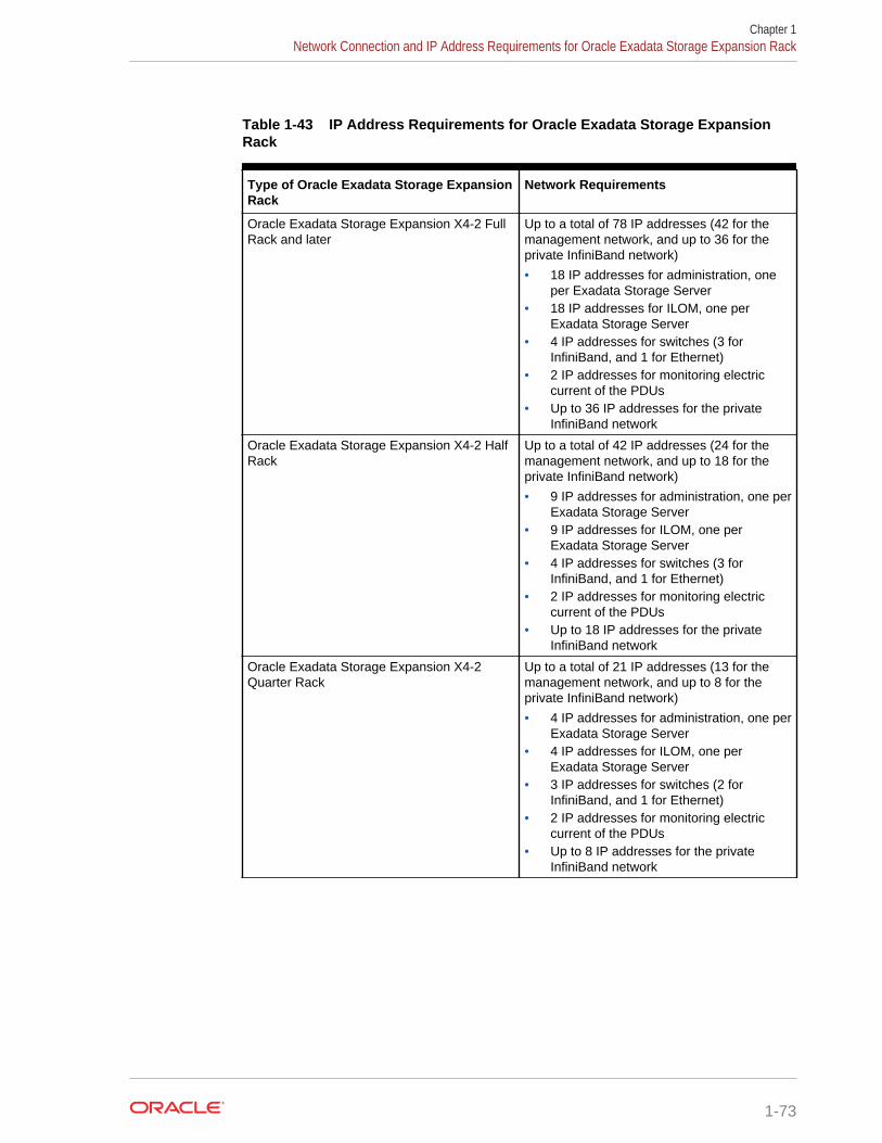
Table 1-43 IP Address Requirements for Oracle Exadata Storage ExpansionRack
Type of Oracle Exadata Storage ExpansionRack
Network Requirements
Oracle Exadata Storage Expansion X4-2 FullRack and later
Up to a total of 78 IP addresses (42 for themanagement network, and up to 36 for theprivate InfiniBand network)
• 18 IP addresses for administration, oneper Exadata Storage Server
• 18 IP addresses for ILOM, one perExadata Storage Server
• 4 IP addresses for switches (3 forInfiniBand, and 1 for Ethernet)
• 2 IP addresses for monitoring electriccurrent of the PDUs
• Up to 36 IP addresses for the privateInfiniBand network
Oracle Exadata Storage Expansion X4-2 HalfRack
Up to a total of 42 IP addresses (24 for themanagement network, and up to 18 for theprivate InfiniBand network)
• 9 IP addresses for administration, one perExadata Storage Server
• 9 IP addresses for ILOM, one perExadata Storage Server
• 4 IP addresses for switches (3 forInfiniBand, and 1 for Ethernet)
• 2 IP addresses for monitoring electriccurrent of the PDUs
• Up to 18 IP addresses for the privateInfiniBand network
Oracle Exadata Storage Expansion X4-2Quarter Rack
Up to a total of 21 IP addresses (13 for themanagement network, and up to 8 for theprivate InfiniBand network)
• 4 IP addresses for administration, one perExadata Storage Server
• 4 IP addresses for ILOM, one perExadata Storage Server
• 3 IP addresses for switches (2 forInfiniBand, and 1 for Ethernet)
• 2 IP addresses for monitoring electriccurrent of the PDUs
• Up to 8 IP addresses for the privateInfiniBand network
Chapter 1Network Connection and IP Address Requirements for Oracle Exadata Storage Expansion Rack
1-73
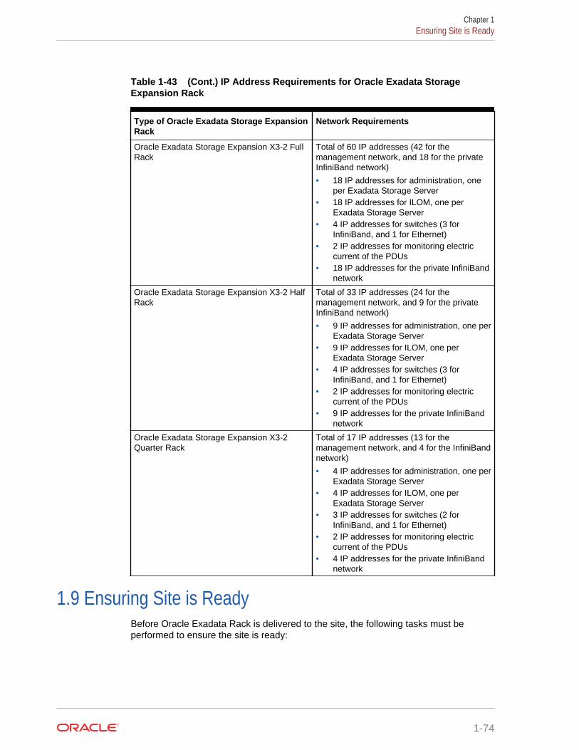
Table 1-43 (Cont.) IP Address Requirements for Oracle Exadata StorageExpansion Rack
Type of Oracle Exadata Storage ExpansionRack
Network Requirements
Oracle Exadata Storage Expansion X3-2 FullRack
Total of 60 IP addresses (42 for themanagement network, and 18 for the privateInfiniBand network)
• 18 IP addresses for administration, oneper Exadata Storage Server
• 18 IP addresses for ILOM, one perExadata Storage Server
• 4 IP addresses for switches (3 forInfiniBand, and 1 for Ethernet)
• 2 IP addresses for monitoring electriccurrent of the PDUs
• 18 IP addresses for the private InfiniBandnetwork
Oracle Exadata Storage Expansion X3-2 HalfRack
Total of 33 IP addresses (24 for themanagement network, and 9 for the privateInfiniBand network)
• 9 IP addresses for administration, one perExadata Storage Server
• 9 IP addresses for ILOM, one perExadata Storage Server
• 4 IP addresses for switches (3 forInfiniBand, and 1 for Ethernet)
• 2 IP addresses for monitoring electriccurrent of the PDUs
• 9 IP addresses for the private InfiniBandnetwork
Oracle Exadata Storage Expansion X3-2Quarter Rack
Total of 17 IP addresses (13 for themanagement network, and 4 for the InfiniBandnetwork)
• 4 IP addresses for administration, one perExadata Storage Server
• 4 IP addresses for ILOM, one perExadata Storage Server
• 3 IP addresses for switches (2 forInfiniBand, and 1 for Ethernet)
• 2 IP addresses for monitoring electriccurrent of the PDUs
• 4 IP addresses for the private InfiniBandnetwork
1.9 Ensuring Site is ReadyBefore Oracle Exadata Rack is delivered to the site, the following tasks must beperformed to ensure the site is ready:
Chapter 1Ensuring Site is Ready
1-74
Task 1 Review Site RequirementsReview the site requirements in this chapter and use the checklists in Site Checkliststo understand the requirements for Oracle Exadata Rack.
Task 2 Run the Oracle Exadata Database Machine Deployment AssistantRun the Oracle Exadata Database Machine Deployment Assistant to create thenecessary files.
Task 3 Configure the NetworkConfigure the network using the files from Oracle Exadata Database MachineDeployment Assistant. This includes registering the networks in the Domain NameSystem (DNS), assigning IP addresses, and configuring data center switches andfirewalls.
Task 4 Prepare the Site Based on RequirementsPrepare the site based on the requirements, such as, install the network cables andpower supplies, prior to the arrival of Oracle Exadata Rack:
1. Review the safety guidelines.
2. Note problems or peculiarities at the site that require special equipment. Forexample, ensure the doors are tall enough and wide enough for Oracle ExadataRack.
3. Verify that the installation site flooring has a strength rating to withstand thecombined weight of Oracle Exadata Rack and any other installed equipment.
4. Install network cables for Oracle Exadata Rack.
5. Install all necessary electrical equipment, and ensure that sufficient power isprovided for Oracle Exadata Rack.
6. Ensure that the installation site provides adequate air conditioning.
7. Operate the air conditioning system for 48 hours to bring the room temperature tothe appropriate level.
8. Clean and vacuum the area thoroughly in preparation for installation.
Related Topics
• Using Oracle Exadata Deployment Assistant
• Ventilation and Cooling RequirementsAlways provide adequate space in front and behind the rack to allow for properventilation.
• Electrical Power Requirements
• Network Connection and IP Address Requirements for Oracle Exadata DatabaseMachine
• Flooring Requirements
• Space Requirements
• Reviewing Safety GuidelinesBefore Oracle Exadata Rack arrives, the following safety precautions should bereviewed to ensure the site is safe, as well as ready for delivery.
• Network Channel Bonding Support
• Configuring Oracle Exadata Database Machine
Chapter 1Ensuring Site is Ready
1-75
2Understanding the Network Requirementsfor Oracle Exadata Database Machine
This chapter describes the network requirements for Oracle Exadata DatabaseMachine.
Note:
For ease of reading, the name "Oracle Exadata Rack" is used wheninformation refers to both Oracle Exadata Database Machine and OracleExadata Storage Expansion Rack.
2.1 Overview of Network RequirementsOracle Exadata Deployment Assistant (OEDA) includes database servers, storageservers, as well as equipment to connect the servers to your network. The networkconnections allow the servers to be administered remotely, and clients to connect tothe database servers.
The information in this section should be used in conjunction with Oracle ExadataDeployment Assistant (OEDA) to configure your environment for Oracle ExadataDatabase Machine.
Note:
The name used for the InfiniBand interface changed from BONDIB0 to IB0and IB1 on Oracle Exadata Database Machine X4-2 systems using release11.2.3.3.0 and later.
As of release 11.2.2.1.0, the names used for bonding changed. The namesare BONDIB0 for the InfiniBand bonding and BONDETH0 for Ethernetbonding. In earlier releases, the names were BOND0 and BOND1,respectively.
To deploy Oracle Exadata Database Machine ensure that you meet the minimumnetwork requirements. Oracle Exadata Database Machine requires a minimum ofthree networks, and there are interfaces available for additional networks. Eachnetwork must be on a distinct and separate subnet from the others. Oraclerecommends one common additional network for backup, which you can configurewith OEDA. The network descriptions are as follows:
• Management network: This required network connects to your existingmanagement network, and is used for administrative work for all components of
2-1
Oracle Exadata Database Machine. It connects the servers, Integrated Lights OutManager (ILOM), and switches connected to the Ethernet switch in the rack. Thereis one uplink from the Ethernet switch in the rack to your management network,one uplink from the KVM switch in the rack to your management network, and oneuplink for each power distribution unit (PDU).
Notes:
– Network connectivity to the PDUs is only required if the electriccurrent is monitored remotely.
– A properly secured configuration requires the management networkto be fully isolated from all other networks.
– Starting with Oracle Exadata System Software release 19.1.0, theExadata database and storage servers can be on a separatenetwork from the ILOM.
Each database server and storage server has two network interfaces formanagement. One provides management access to the operating system throughthe embedded NET0 Ethernet port on Oracle Exadata Database Machine Two-Socket systems, or the NEM0/NET1 Ethernet port on Oracle Exadata DatabaseMachine Eight-Socket systems. The other network interface provides access tothe ILOM through the NET MGT Ethernet port. Oracle Exadata DatabaseMachines are delivered with the NET MGT and NET0 or NEM0/NET0 portsconnected to the Ethernet switch in the rack. The NET0 or NEM0/NET0 port onthe database servers should not be used for client or application network traffic.Cabling or configuration changes to these interfaces on Oracle Exadata StorageServers is not permitted.
• Client access network: This required network connects the database servers toyour existing client network and is used for client access to the database servers.Applications access the database through this network using Single Client AccessName (SCAN) and Oracle RAC Virtual IP (VIP) addresses. Database serverssupport channel bonding to provide higher bandwidth or availability for clientconnections to the database. Oracle recommends channel bonding for the clientaccess network.
The following list describes the channel bonding configurations:
– Oracle Exadata Database Machine Two-Socket systems, use either:
* The embedded NET1 and NET2 ports
* The two 10 GbE ports or two 10/25GbE ports on Oracle ExadataDatabase Machine X7-2
– Oracle Exadata Database Machine Eight-Socket systems, X4-8 or higher
* Use two ports, with each port on a different PCIe card
– Oracle Exadata Database Machine X3-8 Full Rack and Oracle ExadataDatabase Machine X2-8 Full Rack
* Use ports from each Network Express Module (NEM)
For the Oracle Exadata Database Machine X3-8 Full Rack andOracleExadata Database Machine X2-8 Full Rack database servers, using the
Chapter 2Overview of Network Requirements
2-2
same ports on the Network Express Modules, such as NEM0/NET1 andNEM0/NET2, works but does not provide for high availability.
Note:
If your system will use more than 10 VIP addresses in the cluster andyou have VLAN configured for the Oracle Clusterware client network,then you must use 3 digit VLAN ids. Do not use 4 digit VLAN idsbecause the VLAN name can exceed the 15 character operating systeminterface name limit.
• Additional networks (optional): Database servers can connect to additionalexisting networks using the available open ports not used by the management andclient networks.
• InfiniBand private network: This network connects the database servers andstorage servers using the InfiniBand switches on the rack. Starting with the OracleExadata Storage Server X4-2L servers, the InfiniBand fabric is connected usingthe IB0 and IB1 interfaces. Oracle Exadata Storage Server X3-2L servers andearlier use the BONDIB0 interface. Oracle Database uses this network for OracleRAC cluster interconnect traffic and for accessing data on Oracle Exadata StorageServers. This non-routable network is fully contained in Oracle Exadata DatabaseMachine, and does not connect to your existing network. This network isautomatically configured during installation.
Note:
All networks must be on distinct and separate subnets from each other. Forbetter security, the management network should be isolated from all othernetworks.
Oracle Exadata Database Machine database server networking requirements areidentical with the following exceptions:
• Oracle Exadata Database Machine X7-2 embedded ports are 1/10/25 GbE.
• Oracle Exadata Database Machine X6-2, Oracle Exadata Database MachineX5-2, Oracle Exadata Database Machine X4-2, and Oracle Exadata DatabaseMachine X3-2 embedded ports are 1 GbE/10 GbE.
• Oracle Exadata Database Machine X2-2 embedded ports are 1 GbE.
• Only Oracle Exadata Database Machine X2-2 has a KVM.
At start time on an 8-socket system, each database server generates acellaffinity.ora configuration file. The cellaffinity.ora file resides in the /etc/oracle/cell/network-config directory, and must be readable by the Oracledatabase.
The file contains a mapping between the NUMA node numbers and the IP address ofthe network interface card closest to each node. Oracle Database uses the file toselect the closest network interface card when communicating with the storageservers, thereby optimizing performance. This file is only generated and used on an 8-socket system. On a 2-socket system, there is no performance to be gained in this
Chapter 2Overview of Network Requirements
2-3
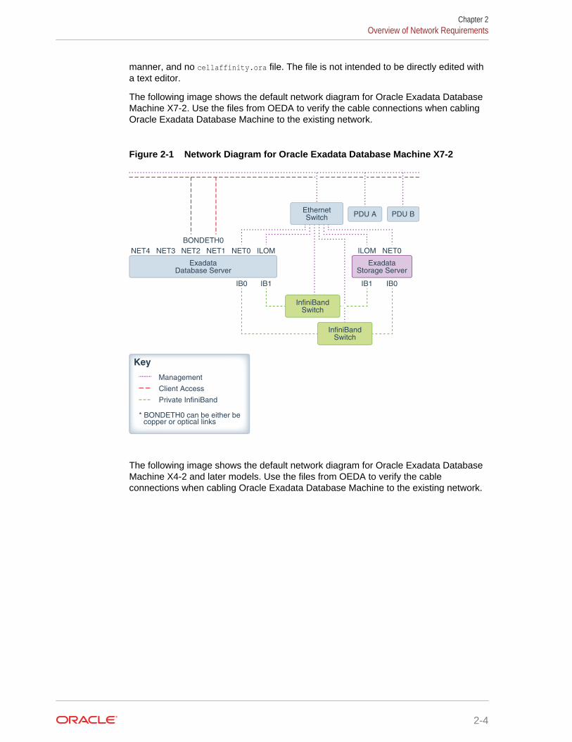
manner, and no cellaffinity.ora file. The file is not intended to be directly edited witha text editor.
The following image shows the default network diagram for Oracle Exadata DatabaseMachine X7-2. Use the files from OEDA to verify the cable connections when cablingOracle Exadata Database Machine to the existing network.
Figure 2-1 Network Diagram for Oracle Exadata Database Machine X7-2
Key
Management
Client Access
Private InfiniBand
* BONDETH0 can be either be copper or optical links
NET0ILOM
IB0 IB1 IB1 IB0
BONDETH0
NET0NET3NET4 NET1NET2 ILOM
EthernetSwitch PDU A PDU B
InfiniBandSwitch
InfiniBandSwitch
ExadataDatabase Server
ExadataStorage Server
The following image shows the default network diagram for Oracle Exadata DatabaseMachine X4-2 and later models. Use the files from OEDA to verify the cableconnections when cabling Oracle Exadata Database Machine to the existing network.
Chapter 2Overview of Network Requirements
2-4
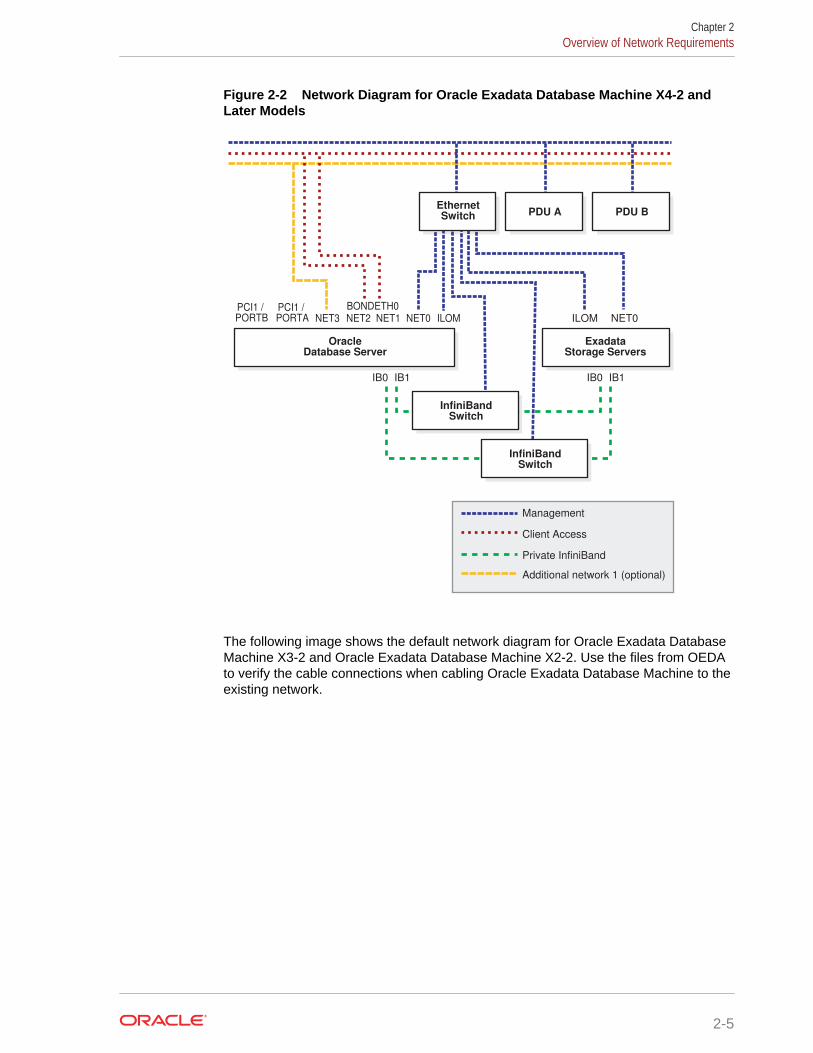
Figure 2-2 Network Diagram for Oracle Exadata Database Machine X4-2 andLater Models
IB0 IB1 IB0 IB1
OracleDatabase Server
Management
Client Access
Private InfiniBand
Additional network 1 (optional)
NET2 NET1 NET0NET0 ILOMILOMNET3PCI1 / PORTA
ExadataStorage Servers
InfiniBandSwitch
InfiniBandSwitch
EthernetSwitch
BONDETH0
PDU A PDU B
PCI1 / PORTB
The following image shows the default network diagram for Oracle Exadata DatabaseMachine X3-2 and Oracle Exadata Database Machine X2-2. Use the files from OEDAto verify the cable connections when cabling Oracle Exadata Database Machine to theexisting network.
Chapter 2Overview of Network Requirements
2-5
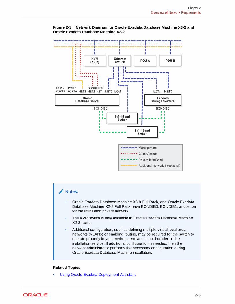
Figure 2-3 Network Diagram for Oracle Exadata Database Machine X3-2 andOracle Exadata Database Machine X2-2
BONDIB0
OracleDatabase Server
Management
Client Access
Private InfiniBand
Additional network 1 (optional)
NET2 NET1 NET0NET0 ILOMILOMNET3PCI1 / PORTA
BONDIB0
ExadataStorage Servers
InfiniBandSwitch
InfiniBandSwitch
EthernetSwitch
KVM(X2-2)
BONDETH0
PDU A PDU B
PCI1 / PORTB
Notes:
• Oracle Exadata Database Machine X3-8 Full Rack, and Oracle ExadataDatabase Machine X2-8 Full Rack have BONDIB0, BONDIB1, and so onfor the InfiniBand private network.
• The KVM switch is only available in Oracle Exadata Database MachineX2-2 racks.
• Additional configuration, such as defining multiple virtual local areanetworks (VLANs) or enabling routing, may be required for the switch tooperate properly in your environment, and is not included in theinstallation service. If additional configuration is needed, then thenetwork administrator performs the necessary configuration duringOracle Exadata Database Machine installation.
Related Topics
• Using Oracle Exadata Deployment Assistant
Chapter 2Overview of Network Requirements
2-6
• Network Components and Interfaces
• Using Network VLAN Tagging with Oracle Exadata Database Machine
2.2 Network Components and InterfacesEach Oracle Exadata Database Machine contains several network components andinterfaces.
• Oracle Exadata Database Machine X7-2 Database Server
• Oracle Exadata Database Machine X5-2 and X6-2 Database Server
• Oracle Exadata Database Machine X5-8 and X6-8 Full Rack Database Server
• Oracle Exadata Database Machine X4-2 Database Server
• Oracle Exadata Database Machine X4-8 Full Rack Database Server
• Oracle Exadata Database Machine X3-2 Database Server
• Oracle Exadata Database Machine X3-8 Full Rack and Oracle Exadata DatabaseMachine X2-8 Full Rack Database Server
2.2.1 Oracle Exadata Database Machine X7-2 Database ServerEach Oracle Exadata Database Machine X7-2 database server consists of thefollowing network components and interfaces:
• 1 embedded 1 GbE/10 GbE port (eth0 copper)
• 2 embedded 1 GbE/10 GbE ports (copper) or 2 embedded 10 GbE/25GbE ports(optical)
• 1 dual-port 4X QDR (40 Gb/s) InfiniBand Host Channel Adapter (HCA)
• 1 embedded Ethernet port for Sun Integrated Lights Out Manager (ILOM) remotemanagement
• 1 dual-port 25GbE PCIe 3.0 network card with Broadcom BCM57414 10Gb/25GbEthernet Controller
Note:
The SFP28 modules for the 25GbE PCIe 3.0 network cards are purchasedseparately.
2.2.2 Oracle Exadata Database Machine X5-2 and X6-2 DatabaseServer
Each Oracle Exadata Database Machine X5-2 and X6-2 database server consists ofthe following network components and interfaces:
• 4 embedded 1 GbE/10 GbE ports
• Oracle Exadata Database Machine X6-2 or X5-2: 1 dual-port 4X QDR (40 Gb/s)InfiniBand Host Channel Adapter (HCA)
Chapter 2Network Components and Interfaces
2-7
• 1 embedded Ethernet port for Sun Integrated Lights Out Manager (ILOM) remotemanagement
• 1 dual-port 10 GbE PCIe 2.0 network card with Intel 82599 10 GbE controller
Note:
The Small Form-Factor Pluggable (SFP) modules for the 10 GbE PCIe 2.0network cards are purchased separately.
2.2.3 Oracle Exadata Database Machine X5-8 and X6-8 Full RackDatabase Server
Each Oracle Exadata Database Machine X5-8 or X6-8 Full Rack database serverconsists of the following network components and interfaces:
• 4 dual-port 4x QDR (40 Gb/s) InfiniBand Host Channel Adapter (HCA)
• 10 x 1 GbE Base-T Ethernet Ports (2 Quad-port PCIe 2.0 network card, and 2embedded ports based on the Intel I350 1GbE Controller technology)
• 8 x 10 GbE Ethernet SFP+ Ports (4 Dual-port 10GbE PCIe 2.0 network cardbased on the Intel 82599 10GbE Controller technology)
Note:
The Small Form-Factor Pluggable (SFP) modules for the 10 GbE PCIe 2.0network cards are purchased separately.
2.2.4 Oracle Exadata Database Machine X4-2 Database ServerEach Oracle Exadata Database Machine X4-2 database server consists of thefollowing network components and interfaces:
• 4 embedded 1 GbE/10 GbE ports
• 1 dual-port 4X QDR (40 Gb/s) InfiniBand Host Channel Adapter (HCA)
• 1 embedded Ethernet port for Sun Integrated Lights Out Manager (ILOM) remotemanagement
• 1 dual-port 10 GbE PCIe 2.0 network card with Intel 82599 10 GbE controller
Note:
The Small Form-Factor Pluggable (SFP) modules for the 10 GbE PCIe 2.0network cards are purchased separately.
Chapter 2Network Components and Interfaces
2-8
2.2.5 Oracle Exadata Database Machine X4-8 Full Rack DatabaseServer
Each Oracle Exadata Database Machine X4-8 Full Rack database server consists ofthe following network components and interfaces:
• 4 dual-port 4x QDR (40 Gb/s) InfiniBand Host Channel Adapter (HCA)
• 10 x 1 GbE Base-T Ethernet Ports (2 Quad-port PCIe 2.0 network card, and 2embedded ports based on the Intel I350 1GbE Controller technology)
• 8 x 10 GbE Ethernet SFP+ Ports (4 Dual-port 10GbE PCIe 2.0 network cardbased on the Intel 82599 10GbE Controller technology)
Note:
The Small Form-Factor Pluggable (SFP) modules for the 10 GbE PCIe 2.0network cards are purchased separately.
2.2.6 Oracle Exadata Database Machine X3-2 Database ServerEach Oracle Exadata Database Machine X3-2 database server consists of thefollowing network components and interfaces:
• 4 embedded 1 GbE ports
• 1 dual-port 4X QDR (40 Gb/s) InfiniBand Host Channel Adapter (HCA)
• 1 embedded Ethernet port for Sun Integrated Lights Out Manager (ILOM) remotemanagement
• 1 dual-port 10 GbE PCIe 2.0 network card with Intel 82599 10 GbE controller
Note:
The Small Form-Factor Pluggable (SFP) modules for the 10 GbE PCIe 2.0network cards are purchased separately.
2.2.7 Oracle Exadata Database Machine X3-8 Full Rack and OracleExadata Database Machine X2-8 Full Rack Database Server
Each Oracle Exadata Database Machine X3-8 Full Rack and Oracle ExadataDatabase Machine X2-8 Full Rack database server consists of the following networkcomponents and interfaces:
• 2 Network Express Modules (NEMs) providing the total of the following:
– 8 x 10 GbE network ports
– 8 x 1 Gb Ethernet network ports
• 4 dual-port 4X QDR InfiniBand PCIe 2.0 Express Modules (EMs)
Chapter 2Network Components and Interfaces
2-9
• 1 Ethernet port for Sun Integrated Lights Out Manager (ILOM) remotemanagement
Note:
The SFP+ modules for the NEMs are purchased separately.
2.3 Network Channel Bonding SupportThe network port on a database server used for the client access network can bebonded with another network on the database server to provide higher bandwidth oravailability for client connections to the database. In a bonded network configuration,Oracle RAC SCAN and VIP addresses are defined on the BONDETH0 interface ondatabase servers.
2.3.1 Bonded Network ConfigurationsA bonded network configuration is used when there is a need to aggregate multiplenetwork interfaces together for client connections to the database.
The bonded network configuration is the default configuration.
The following sections describe the bonded network configuration for Oracle ExadataDatabase Machine:
• Bonded Network Configuration for Oracle Exadata Database Machine Two-SocketSystems
• Bonded Network Configuration for Oracle Exadata Database Machine X7-8
• Bonded Network Configuration for Oracle Exadata Database Machine X4-8, X5-8,and X6-8
• Bonded Network Configuration for Oracle Exadata Database Machine X3-8 FullRack and Oracle Exadata Database Machine X2-8 Full Rack
2.3.1.1 Bonded Network Configuration for Oracle Exadata Database MachineTwo-Socket Systems
When using a bonded network configuration for database client access on OracleExadata Database Machine Two-Socket Systems, the database servers areconfigured as follows:
• Port NET0: Provides access to the operating system using the managementnetwork through the ETH0 interface.
• Port NET1: Provides access to the database using the client access network, andis bonded with NET2 port to create the BONDETH0 interface.
• Port NET2: Provides access to the database using the client access network, andis bonded with NET1 port to create the BONDETH0 interface.
• Port NET MGT: Provides access to ILOM using the management network.
When channel bonding is configured for the client access network during initialconfiguration, the Linux bonding module is configured for active-backup mode (mode=1).
Chapter 2Network Channel Bonding Support
2-10
If a different bonding policy is preferred, then you may reconfigure the bonding moduleafter initial configuration. For configuration details, refer to the Linux Ethernet BondingDriver HOWTO in the /usr/share/doc/kernel-doc-2.6.39/Documentation/networking/bonding.txt directory on any Oracle Exadata Database Machinedatabase server.
The following table shows the port connections for Oracle Exadata Database MachineTwo-Socket Systems database servers when using channel bonding. The clientaccess network and the backup network must use different ports, in that one networkmust use the embedded GbE ports and the other network must use the PCIe ports.
Table 2-1 Channel Bonding Connections for Oracle Exadata Database MachineX7-2
Network Using 1 GbE Ports Using 10/25 GbE Ports
Management (1 GbE NET0)
The administration networkconnection uses the 1 GbEport even when using 10 GbEports for the other networks.
• Port: 1 GbE NET0• Connect to Cisco switch
• Port: 1 GbE NET0• Connect to Cisco switch
Client (BONDETH0) • Ports: 1 GbE NET1 and 1GbE NET2
• Connect to client access1 GbE switches
• Ports: 10/25 GbE PCIPorts 1 and 2
• Connect to client access10/25 GbE switches
Backup (BONDETH1) • Ports: 10/25 GbE PCIPorts 1 and 2
• Connect to backup 10/25GbE switches
• Ports: 10/25 GbE NET2and NET3
• Connect to backup 10/25GbE switches
Table 2-2 Channel Bonding Connections for Other Oracle Exadata DatabaseMachine Two-Socket Systems
Network Using 1 GbE Ports Using 10 GbE Ports
Management (1 GbE NET0)
The administration networkconnection uses the 1 GbEport even when using 10 GbEports for the other networks.
• Port: 1 GbE NET0• Connect to Cisco switch
• Port: 1 GbE NET0• Connect to Cisco switch
Client (BONDETH0) • Ports: 1 GbE NET1 and 1GbE NET2
• Connect to client access1 GbE switches
• Ports: 10 GbE PCI1/PORTA and 10 GbEPCI1/PORTB
• Connect to client access10 GbE switches
Backup (BONDETH1) • Ports: 10 GbE PCI1/PORTA and 10 GbEPCI1/PORTB
• Connect to backup 10GbE switches
• Ports: 1 GbE NET2 and 1GbE NET3
• Connect to backup 1 GbEswitches
Chapter 2Network Channel Bonding Support
2-11
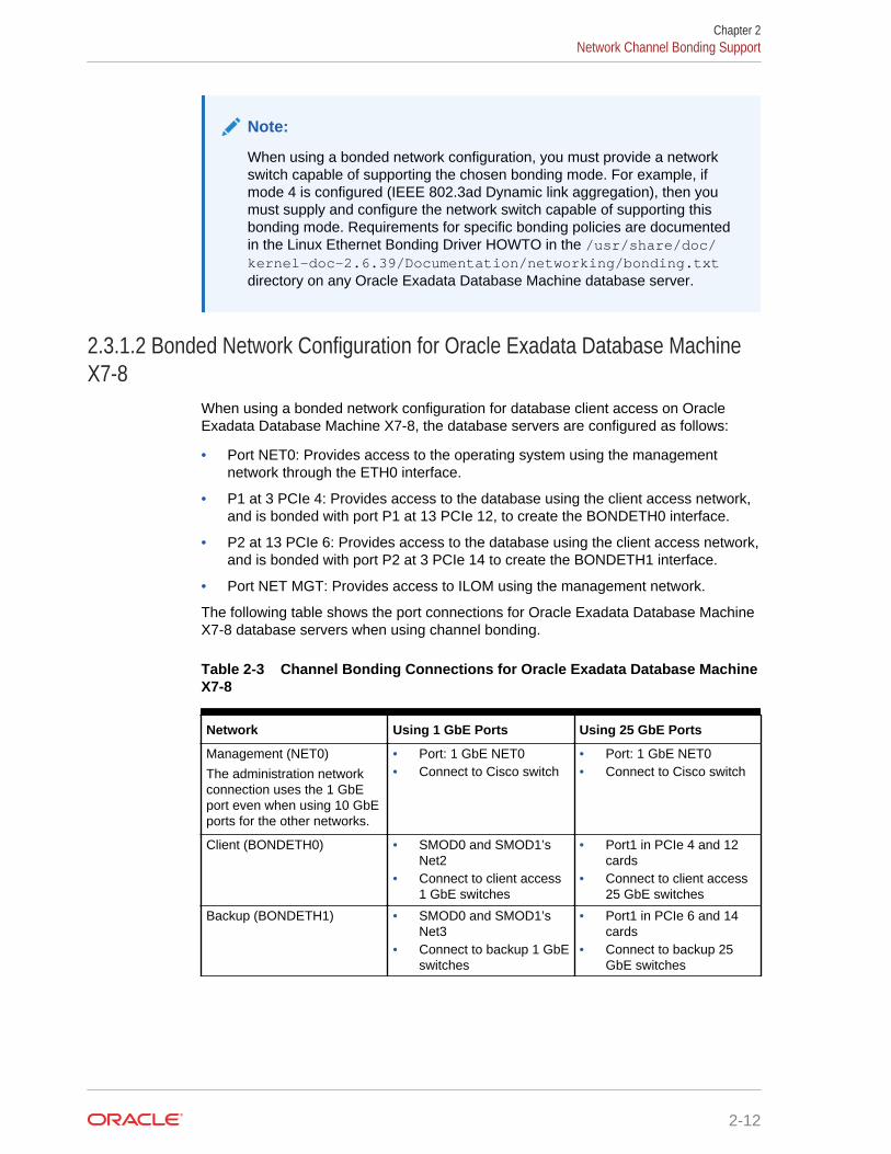
Note:
When using a bonded network configuration, you must provide a networkswitch capable of supporting the chosen bonding mode. For example, ifmode 4 is configured (IEEE 802.3ad Dynamic link aggregation), then youmust supply and configure the network switch capable of supporting thisbonding mode. Requirements for specific bonding policies are documentedin the Linux Ethernet Bonding Driver HOWTO in the /usr/share/doc/kernel-doc-2.6.39/Documentation/networking/bonding.txtdirectory on any Oracle Exadata Database Machine database server.
2.3.1.2 Bonded Network Configuration for Oracle Exadata Database MachineX7-8
When using a bonded network configuration for database client access on OracleExadata Database Machine X7-8, the database servers are configured as follows:
• Port NET0: Provides access to the operating system using the managementnetwork through the ETH0 interface.
• P1 at 3 PCIe 4: Provides access to the database using the client access network,and is bonded with port P1 at 13 PCIe 12, to create the BONDETH0 interface.
• P2 at 13 PCIe 6: Provides access to the database using the client access network,and is bonded with port P2 at 3 PCIe 14 to create the BONDETH1 interface.
• Port NET MGT: Provides access to ILOM using the management network.
The following table shows the port connections for Oracle Exadata Database MachineX7-8 database servers when using channel bonding.
Table 2-3 Channel Bonding Connections for Oracle Exadata Database MachineX7-8
Network Using 1 GbE Ports Using 25 GbE Ports
Management (NET0)
The administration networkconnection uses the 1 GbEport even when using 10 GbEports for the other networks.
• Port: 1 GbE NET0• Connect to Cisco switch
• Port: 1 GbE NET0• Connect to Cisco switch
Client (BONDETH0) • SMOD0 and SMOD1’sNet2
• Connect to client access1 GbE switches
• Port1 in PCIe 4 and 12cards
• Connect to client access25 GbE switches
Backup (BONDETH1) • SMOD0 and SMOD1’sNet3
• Connect to backup 1 GbEswitches
• Port1 in PCIe 6 and 14cards
• Connect to backup 25GbE switches
Chapter 2Network Channel Bonding Support
2-12
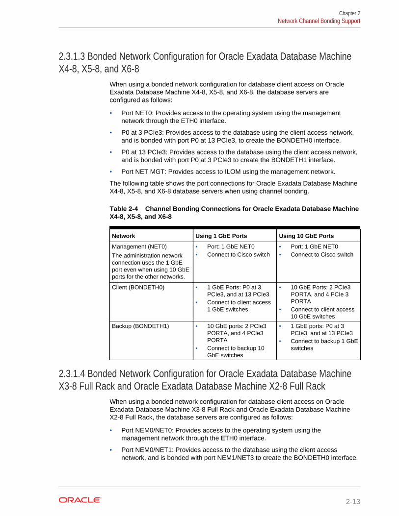
2.3.1.3 Bonded Network Configuration for Oracle Exadata Database MachineX4-8, X5-8, and X6-8
When using a bonded network configuration for database client access on OracleExadata Database Machine X4-8, X5-8, and X6-8, the database servers areconfigured as follows:
• Port NET0: Provides access to the operating system using the managementnetwork through the ETH0 interface.
• P0 at 3 PCIe3: Provides access to the database using the client access network,and is bonded with port P0 at 13 PCIe3, to create the BONDETH0 interface.
• P0 at 13 PCIe3: Provides access to the database using the client access network,and is bonded with port P0 at 3 PCIe3 to create the BONDETH1 interface.
• Port NET MGT: Provides access to ILOM using the management network.
The following table shows the port connections for Oracle Exadata Database MachineX4-8, X5-8, and X6-8 database servers when using channel bonding.
Table 2-4 Channel Bonding Connections for Oracle Exadata Database MachineX4-8, X5-8, and X6-8
Network Using 1 GbE Ports Using 10 GbE Ports
Management (NET0)
The administration networkconnection uses the 1 GbEport even when using 10 GbEports for the other networks.
• Port: 1 GbE NET0• Connect to Cisco switch
• Port: 1 GbE NET0• Connect to Cisco switch
Client (BONDETH0) • 1 GbE Ports: P0 at 3PCIe3, and at 13 PCIe3
• Connect to client access1 GbE switches
• 10 GbE Ports: 2 PCIe3PORTA, and 4 PCIe 3PORTA
• Connect to client access10 GbE switches
Backup (BONDETH1) • 10 GbE ports: 2 PCIe3PORTA, and 4 PCIe3PORTA
• Connect to backup 10GbE switches
• 1 GbE ports: P0 at 3PCIe3, and at 13 PCIe3
• Connect to backup 1 GbEswitches
2.3.1.4 Bonded Network Configuration for Oracle Exadata Database MachineX3-8 Full Rack and Oracle Exadata Database Machine X2-8 Full Rack
When using a bonded network configuration for database client access on OracleExadata Database Machine X3-8 Full Rack and Oracle Exadata Database MachineX2-8 Full Rack, the database servers are configured as follows:
• Port NEM0/NET0: Provides access to the operating system using themanagement network through the ETH0 interface.
• Port NEM0/NET1: Provides access to the database using the client accessnetwork, and is bonded with port NEM1/NET3 to create the BONDETH0 interface.
Chapter 2Network Channel Bonding Support
2-13
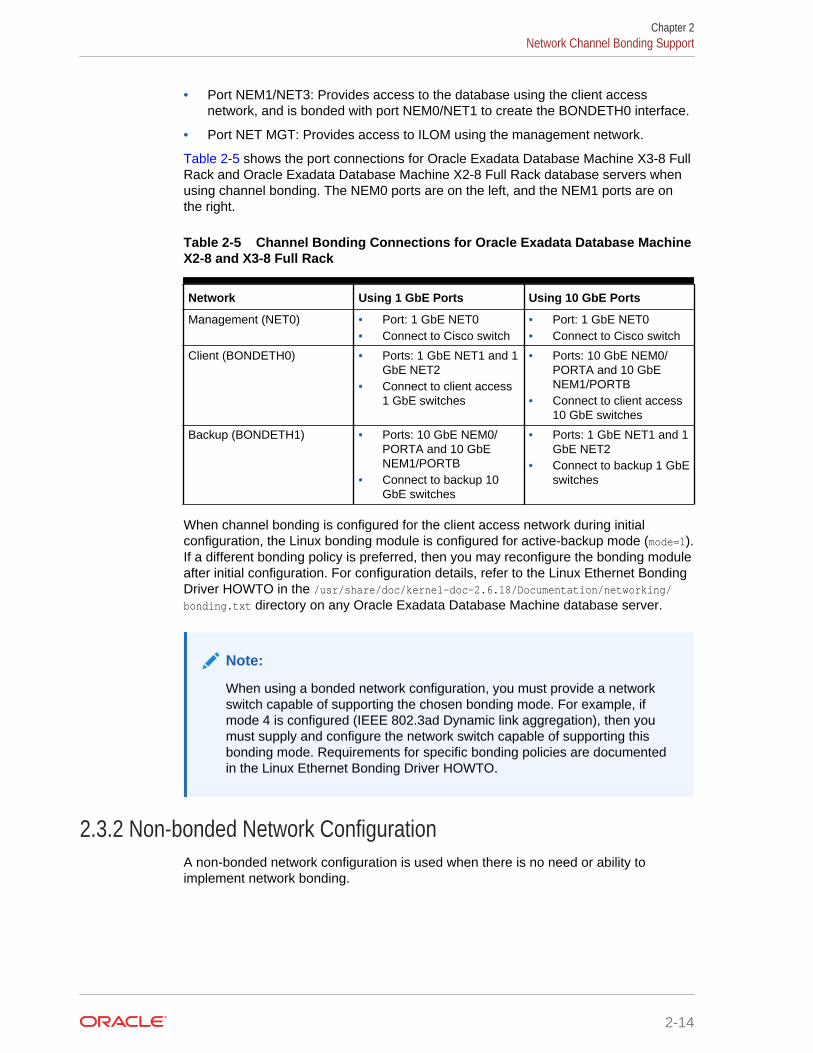
• Port NEM1/NET3: Provides access to the database using the client accessnetwork, and is bonded with port NEM0/NET1 to create the BONDETH0 interface.
• Port NET MGT: Provides access to ILOM using the management network.
Table 2-5 shows the port connections for Oracle Exadata Database Machine X3-8 FullRack and Oracle Exadata Database Machine X2-8 Full Rack database servers whenusing channel bonding. The NEM0 ports are on the left, and the NEM1 ports are onthe right.
Table 2-5 Channel Bonding Connections for Oracle Exadata Database MachineX2-8 and X3-8 Full Rack
Network Using 1 GbE Ports Using 10 GbE Ports
Management (NET0) • Port: 1 GbE NET0• Connect to Cisco switch
• Port: 1 GbE NET0• Connect to Cisco switch
Client (BONDETH0) • Ports: 1 GbE NET1 and 1GbE NET2
• Connect to client access1 GbE switches
• Ports: 10 GbE NEM0/PORTA and 10 GbENEM1/PORTB
• Connect to client access10 GbE switches
Backup (BONDETH1) • Ports: 10 GbE NEM0/PORTA and 10 GbENEM1/PORTB
• Connect to backup 10GbE switches
• Ports: 1 GbE NET1 and 1GbE NET2
• Connect to backup 1 GbEswitches
When channel bonding is configured for the client access network during initialconfiguration, the Linux bonding module is configured for active-backup mode (mode=1).If a different bonding policy is preferred, then you may reconfigure the bonding moduleafter initial configuration. For configuration details, refer to the Linux Ethernet BondingDriver HOWTO in the /usr/share/doc/kernel-doc-2.6.18/Documentation/networking/bonding.txt directory on any Oracle Exadata Database Machine database server.
Note:
When using a bonded network configuration, you must provide a networkswitch capable of supporting the chosen bonding mode. For example, ifmode 4 is configured (IEEE 802.3ad Dynamic link aggregation), then youmust supply and configure the network switch capable of supporting thisbonding mode. Requirements for specific bonding policies are documentedin the Linux Ethernet Bonding Driver HOWTO.
2.3.2 Non-bonded Network ConfigurationA non-bonded network configuration is used when there is no need or ability toimplement network bonding.
Chapter 2Network Channel Bonding Support
2-14
Note:
Non Bonded networks are not supported for Oracle Exadata DatabaseMachine X7-2 and X7-8.
The following sections describe the non-bonded network configuration for OracleExadata Database Machine:
2.3.2.1 Non-bonded Network Configuration for Oracle Exadata DatabaseMachine Two-Socket Systems
When using a non-bonded network configuration for Oracle Exadata DatabaseMachine Two-Socket Systems, the database servers are configured as follows:
• Port NET0: Provides access to the operating system using the managementnetwork through the ETH0 interface.
• Port NET1: Provides access to the database using the client access networkthrough the ETH1 interface. The Oracle Real Application Clusters (Oracle RAC)SCAN and VIP addresses are defined on this interface.
• Port NET MGT: Provides access to the Integrated Lights Out Manager (ILOM)using the management network.
The following diagram shows the network diagram for Oracle Exadata DatabaseMachine Two-Socket Systems when not using bonding.
Chapter 2Network Channel Bonding Support
2-15
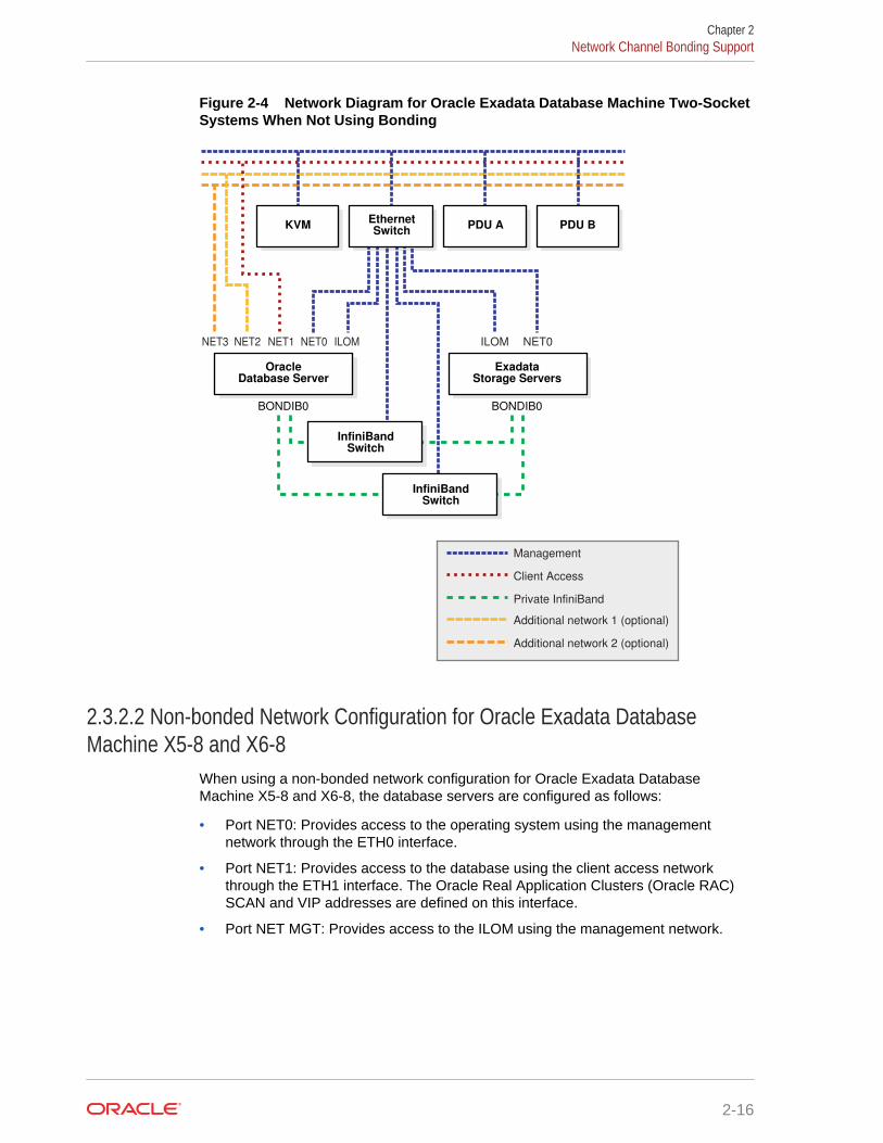
Figure 2-4 Network Diagram for Oracle Exadata Database Machine Two-SocketSystems When Not Using Bonding
BONDIB0
Oracle�Database Server
Management
Client Access
Private InfiniBand
Additional network 1 (optional)
Additional network 2 (optional)
NET2 NET1 NET0NET0 ILOMILOMNET3
BONDIB0
Exadata Storage Servers
InfiniBand�Switch
InfiniBand�Switch
Ethernet�Switch
KVM PDU A PDU B
2.3.2.2 Non-bonded Network Configuration for Oracle Exadata DatabaseMachine X5-8 and X6-8
When using a non-bonded network configuration for Oracle Exadata DatabaseMachine X5-8 and X6-8, the database servers are configured as follows:
• Port NET0: Provides access to the operating system using the managementnetwork through the ETH0 interface.
• Port NET1: Provides access to the database using the client access networkthrough the ETH1 interface. The Oracle Real Application Clusters (Oracle RAC)SCAN and VIP addresses are defined on this interface.
• Port NET MGT: Provides access to the ILOM using the management network.
Chapter 2Network Channel Bonding Support
2-16
Note:
Oracle Exadata Database Machine X5-8 and X6-8 have BONDIB0,BONDIB1, and so on for the InfiniBand private network.
2.3.2.3 Non-bonded Network Configuration for Oracle Exadata DatabaseMachine X4-8 Full Rack
When using a non-bonded network configuration for Oracle Exadata DatabaseMachine X4-8 Full Rack, the database servers are configured as follows:
• Port NET0: Provides access to the operating system using the managementnetwork through the ETH0 interface.
• Port NET1: Provides access to the database using the client access networkthrough the ETH1 interface. The Oracle RAC SCAN and VIP addresses aredefined on this interface.
• Port NET MGT: Provides access to the ILOM using the management network.
Note:
Oracle Exadata Database Machine X4-8 Full Rack has BONDIB0, BONDIB1,and so on for the InfiniBand private network.
2.3.2.4 Non-bonded Network Configuration for Oracle Exadata DatabaseMachine X3-8 Full Rack and Oracle Exadata Database Machine X2-8 Full Rack
When using a non-bonded network configuration for Oracle Exadata DatabaseMachine X4-8 Full Rack, Oracle Exadata Database Machine X3-8 Full Rack andOracle Exadata Database Machine X2-8 Full Rack, the database servers areconfigured as follows:
• Port NEM0/NET0: Provides access to the operating system using themanagement network through the ETH0 interface. This network must use the 1GbE port.
• Port NEM0/NET1: Provides access to the database using the client accessnetwork through the ETH1 interface. The Oracle RAC SCAN and VIP addressesare defined on this interface.
• Port NET MGT: Provides access to the Integrated Lights Out Manager (ILOM)using the management network.
Chapter 2Network Channel Bonding Support
2-17
Note:
Oracle Exadata Database Machine X4-8 Full Rack, Oracle ExadataDatabase Machine X3-8 Full Rack, and Oracle Exadata Database MachineX2-8 Full Rack have BONDIB0, BONDIB1, and so on for the InfiniBandprivate network.
2.3.3 Additional Networks• On Oracle Exadata Database Machine X7-2:
– Bonded network configuration— There are two open ports (10/25GbE PCIports) on each database server.
• On Oracle Exadata Database Machine two-socket systems (X2-2 to X6-2):
– Non-bonded network configuration— There are four open ports (NET2, NET3,and two additional 10 GbE ports) on each database server
– Bonded network configuration— There are three open ports (NET3 and twoadditional 10 GbE ports) on each database server
• On Oracle Exadata Database Machine X7-8:
– Bonded network configuration— There are 13 open ports (5 1/10 GbE portsand 8 open 10/25 GbE PCI ports) on each database server
• On Oracle Exadata Database Machine X5-8 and X6-8:
– Non-bonded network configuration— There are 18 open ports (10 1GbE portsand 8 10GbE ports) on each database server
– Bonded network configuration— There are 15 open ports (7 1 GbE ports and 8open 10 GbE ports) on each database server
• On Oracle Exadata Database Machine X4-8 Full Rack:
– Non-bonded network configuration— There are 16 open ports (8 1GbE portsand 8 10GbE ports) on each database server
– Bonded network configuration— There are 15 open ports (7 1 GbE ports and 8open 10 GbE ports) on each database server
• On Oracle Exadata Database Machine X3-8 Full Rack and X2-8 Full Rack:
– Non-bonded network configuration— There are 14 open ports (NEM0/NET2,NEM0/NET3, NEM1/NET0, NEM1/NET1, NEM1/NET2, NEM1/NET3, andeight additional 10 GbE ports) on each database server
– Bonded network configuration— There are 13 open ports (NEM0/NET2,NEM0/NET3, NEM1/NET0, NEM1/NET1, NEM1/NET2, and eight additional 10GbE ports) on each database server
Use of these additional network ports is optional, and the configuration variesdepending on your requirements and available network infrastructure. For example,these interfaces may be used for connectivity to a dedicated tape backup network orconnectivity to a disaster recovery network.
Chapter 2Network Channel Bonding Support
2-18
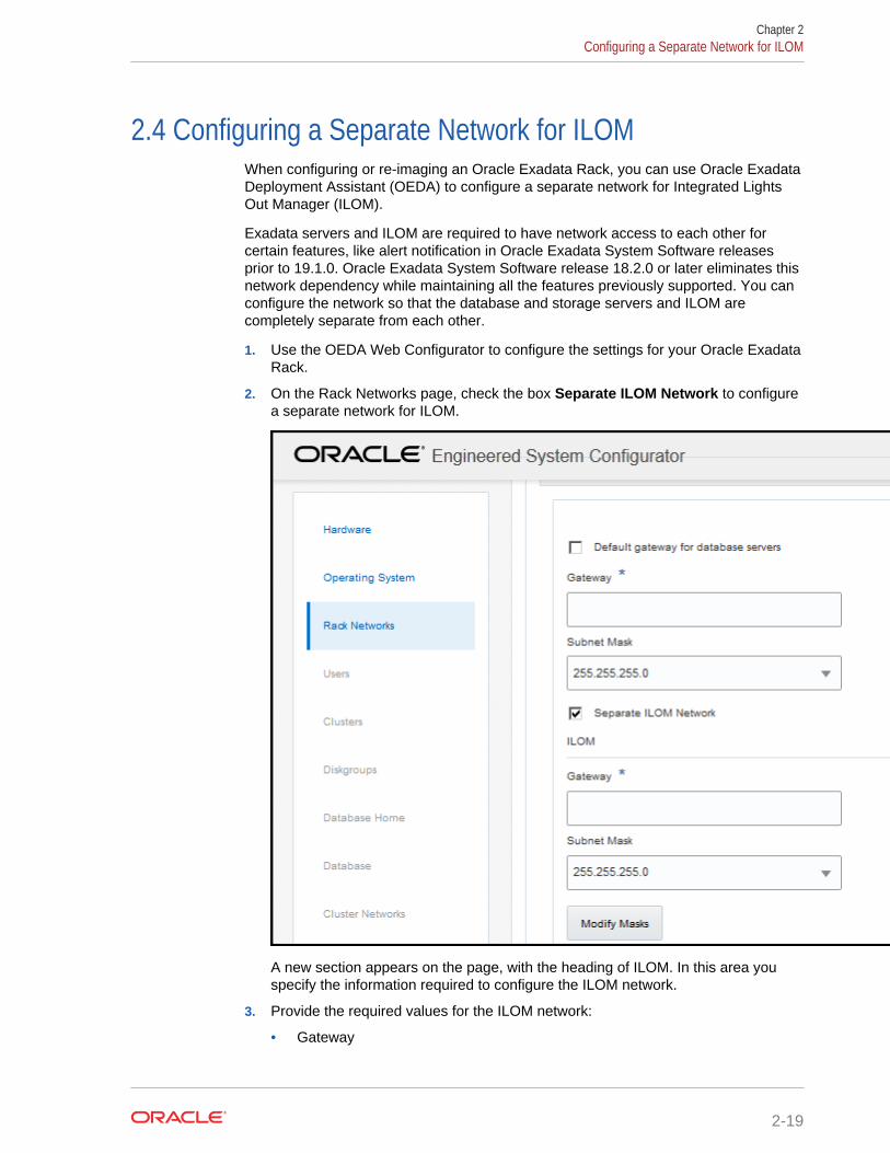
2.4 Configuring a Separate Network for ILOMWhen configuring or re-imaging an Oracle Exadata Rack, you can use Oracle ExadataDeployment Assistant (OEDA) to configure a separate network for Integrated LightsOut Manager (ILOM).
Exadata servers and ILOM are required to have network access to each other forcertain features, like alert notification in Oracle Exadata System Software releasesprior to 19.1.0. Oracle Exadata System Software release 18.2.0 or later eliminates thisnetwork dependency while maintaining all the features previously supported. You canconfigure the network so that the database and storage servers and ILOM arecompletely separate from each other.
1. Use the OEDA Web Configurator to configure the settings for your Oracle ExadataRack.
2. On the Rack Networks page, check the box Separate ILOM Network to configurea separate network for ILOM.
A new section appears on the page, with the heading of ILOM. In this area youspecify the information required to configure the ILOM network.
3. Provide the required values for the ILOM network:
• Gateway
Chapter 2Configuring a Separate Network for ILOM
2-19
• Start IP Address
• Subnet Mask
• Domain Name
4. Optional: If you do not want to use the default names and values for the ILOMnetwork, click the Modify Masks button and customize the network settings.
2.5 Using Network VLAN Tagging with Oracle ExadataDatabase Machine
Compute nodes and storage nodes can use VLANs for the management network,ILOM, client network, and the backup access network.
By default, the network switch is minimally configured, without VLAN tagging. If VLANtagging is to be used, then it must be enabled by the customer after the initialdeployment. This applies to both physical and Oracle VM deployments.
Client and backup VLAN networks must be bonded. The admin network is neverbonded.
Notes:
• VLANs do not exist in InfiniBand. For equivalent functionality, useInfiniBand partitioning as described in Oracle Exadata DatabaseMachine Maintenance Guide.
• Network VLAN tagging is supported for Oracle Real Application Clusters(Oracle RAC) on the public network.
• If the backup network is on a tagged VLAN network, the client networkmust also be on a separate tagged VLAN network.
• The backup and client networks can share the same network cables.
• Oracle Exadata Deployment Assistant (OEDA) supports VLAN taggingfor both physical and virtual deployments.
• Virtual deployments do not support IPv6 VLANs.
• If your system will use more than 10 VIP addresses in the Oracle RACcluster and you have VLAN configured for the Oracle Clusterware clientnetwork, then you must use 3 digit VLAN ids. Do not use 4 digit VLANids because the VLAN name can exceed the 15 character operatingsystem interface name limit.
The following table shows IPv4/IPv6 support on the admin, client, and backupnetworks for the different Oracle Exadata Database Machine systems and OracleDatabase versions.
Chapter 2Using Network VLAN Tagging with Oracle Exadata Database Machine
2-20
Version of Oracle Database VLAN Tagging on AdminNetwork
Client and BackupNetworks
11.2.0.4 Only supported with IPv4addresses on X3-2 and abovefor two-socket servers, andX4-8 and above for eight-socket servers.
Supported with IPv4 and IPv6on all hardware models.
12.1.0.2 Only supported with IPv4addresses on X3-2 and abovefor two-socket servers, andX4-8 and above for eight-socket servers.
Supported with IPv4 on allhardware models.
Supported with IPv6 on allhardware models with fix for22289350.
Related Topics
• Implementing InfiniBand Partitioning across Oracle VM Oracle RAC Clusters onOracle Exadata
• Enabling 802.1Q VLAN Tagging in Exadata Database Machine over clientnetworks (My Oracle Support Doc ID 1423676.1)
• Implementing Tagged VLAN Interfaces in Oracle VM Environments on Exadata(My Oracle Support Doc ID 2018550.1)
2.6 Default IP AddressesStarting with Oracle Exadata System Software release 12.1.2.1.0, the NET0 IPaddresses are assigned dynamically by the elastic configuration procedure during thefirst start of the system. The addresses are in the 172.16.2.1 to 172.16.7.254 range. Inearlier releases, Oracle Exadata Database Machine had default IP addresses set atthe factory, and the range of IP addresses was 192.168.1.1 to 192.168.1.203. Thesubnet mask is 255.255.252.0.
Note:
Prior to connecting Oracle Exadata Database Machine to the network,ensure these IP addresses do not conflict with other addresses on thenetwork. Use the checkip.sh script generated by Oracle Exadata DeploymentAssistant (OEDA) to check for conflicts. You run the checkip.sh script on thenetwork after the DNS entries for the Oracle Exadata Database Machinehave been created, but before the Oracle Exadata Database Machine isconfigured or connected to the network. Oracle recommends running thescript to avoid configuration delays, even if a check was performed as part ofplanning process before the machine was delivered.
If you ran OEDA on a Windows system, then the generated script ischeckip.bat.
The following table lists the default IP addresses for Oracle Exadata DatabaseMachine X5-2, X6-2, and X7-2. The subnet mask is 255.255.252.0.
Chapter 2Default IP Addresses
2-21
Table 2-6 Default IP Addresses for Oracle Exadata Database Machine X5-2 andHigher
Component NET0 IP Addresses ILOM IP Addresses InfiniBand ActiveBonded IPAddresses
Exadata StorageServer 14
Assigned during firststart of the system
192.168.1.122 Not applicable
Exadata StorageServer 13
Assigned during firststart of the system
192.168.1.121 Not applicable
Exadata StorageServer 12
Assigned during firststart of the system
192.168.1.120 Not applicable
Exadata StorageServer 11
Assigned during firststart of the system
192.168.1.119 Not applicable
Exadata StorageServer 10
Assigned during firststart of the system
192.168.1.118 Not applicable
Exadata StorageServer 9
Assigned during firststart of the system
192.168.1.117 Not applicable
Exadata StorageServer 8
Assigned during firststart of the system
192.168.1.116 Not applicable
Oracle Databaseserver 8
Assigned during firststart of the system
192.168.1.115 Not applicable
Oracle Databaseserver 7
Assigned during firststart of the system
192.168.1.114 Not applicable
Oracle Databaseserver 6
Assigned during firststart of the system
192.168.1.113 Not applicable
Oracle Databaseserver 5
Assigned during firststart of the system
192.168.1.112 Not applicable
Oracle Databaseserver 4
Assigned during firststart of the system
192.168.1.111 Not applicable
Oracle Databaseserver 3
Assigned during firststart of the system
192.168.1.110 Not applicable
Oracle Databaseserver 2
Assigned during firststart of the system
192.168.1.109 Not applicable
Oracle Databaseserver 1
Assigned during firststart of the system
192.168.1.108 Not applicable
Exadata StorageServer 7
Assigned during firststart of the system
192.168.1.107 Not applicable
Exadata StorageServer 6
Assigned during firststart of the system
192.168.1.106 Not applicable
Exadata StorageServer 5
Assigned during firststart of the system
192.168.1.105 Not applicable
Exadata StorageServer 4
Assigned during firststart of the system
192.168.1.104 Not applicable
Exadata StorageServer 3
Assigned during firststart of the system
192.168.1.103 Not applicable
Exadata StorageServer 2
Assigned during firststart of the system
192.168.1.102 Not applicable
Chapter 2Default IP Addresses
2-22
Table 2-6 (Cont.) Default IP Addresses for Oracle Exadata Database MachineX5-2 and Higher
Component NET0 IP Addresses ILOM IP Addresses InfiniBand ActiveBonded IPAddresses
Exadata StorageServer 1
Assigned during firststart of the system
192.168.1.101 Not applicable
Sun DatacenterInfiniBand Switch 36switch 3
192.168.1.203 Not applicable Not applicable
Sun DatacenterInfiniBand Switch 36switch 2
192.168.1.202 Not applicable Not applicable
Sun DatacenterInfiniBand Switch 36switch 1
192.168.1.201 Not applicable Not applicable
Ethernet switch 192.168.1.200 Not applicable Not applicable
The following table lists the default IP addresses for Oracle Exadata DatabaseMachine X4-2. The subnet mask is 255.255.252.0.
Table 2-7 Default IP Addresses for Oracle Exadata Database Machine X4-2
Component NET0 IP Addresses ILOM IP Addresses InfiniBand ActiveBonded IPAddresses
Exadata StorageServer 14
192.168.1.22 192.168.1.122 192.168.10.44
192.168.10.43
Exadata StorageServer 13
192.168.1.21 192.168.1.121 192.168.10.42
192.168.10.41
Exadata StorageServer 12
192.168.1.20 192.168.1.120 192.168.10.40
192.168.10.39
Exadata StorageServer 11
192.168.1.19 192.168.1.119 192.168.10.38
192.168.10.37
Exadata StorageServer 10
192.168.1.18 192.168.1.118 192.168.10.36
192.168.10.35
Exadata StorageServer 9
192.168.1.17 192.168.1.117 192.168.10.34
192.168.10.33
Exadata StorageServer 8
192.168.1.16 192.168.1.116 192.168.10.32
192.168.10.31
Oracle Databaseserver 8
192.168.1.15 192.168.1.115 192.168.10.30
192.168.10.29
Oracle Databaseserver 7
192.168.1.14 192.168.1.114 192.168.10.28
192.168.10.27
Oracle Databaseserver 6
192.168.1.13 192.168.1.113 192.168.10.26
192.168.10.25
Chapter 2Default IP Addresses
2-23
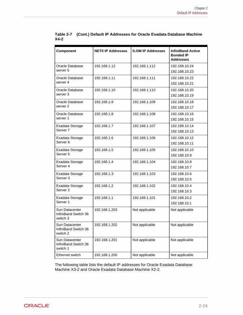
Table 2-7 (Cont.) Default IP Addresses for Oracle Exadata Database MachineX4-2
Component NET0 IP Addresses ILOM IP Addresses InfiniBand ActiveBonded IPAddresses
Oracle Databaseserver 5
192.168.1.12 192.168.1.112 192.168.10.24
192.168.10.23
Oracle Databaseserver 4
192.168.1.11 192.168.1.111 192.168.10.22
192.168.10.21
Oracle Databaseserver 3
192.168.1.10 192.168.1.110 192.168.10.20
192.168.10.19
Oracle Databaseserver 2
192.168.1.9 192.168.1.109 192.168.10.18
192.168.10.17
Oracle Databaseserver 1
192.168.1.8 192.168.1.108 192.168.10.16
192.168.10.15
Exadata StorageServer 7
192.168.1.7 192.168.1.107 192.168.10.14
192.168.10.13
Exadata StorageServer 6
192.168.1.6 192.168.1.106 192.168.10.12
192.168.10.11
Exadata StorageServer 5
192.168.1.5 192.168.1.105 192.168.10.10
192.168.10.9
Exadata StorageServer 4
192.168.1.4 192.168.1.104 192.168.10.8
192.168.10.7
Exadata StorageServer 3
192.168.1.3 192.168.1.103 192.168.10.6
192.168.10.5
Exadata StorageServer 2
192.168.1.2 192.168.1.102 192.168.10.4
192.168.10.3
Exadata StorageServer 1
192.168.1.1 192.168.1.101 192.168.10.2
192.168.10.1
Sun DatacenterInfiniBand Switch 36switch 3
192.168.1.203 Not applicable Not applicable
Sun DatacenterInfiniBand Switch 36switch 2
192.168.1.202 Not applicable Not applicable
Sun DatacenterInfiniBand Switch 36switch 1
192.168.1.201 Not applicable Not applicable
Ethernet switch 192.168.1.200 Not applicable Not applicable
The following table lists the default IP addresses for Oracle Exadata DatabaseMachine X3-2 and Oracle Exadata Database Machine X2-2.
Chapter 2Default IP Addresses
2-24
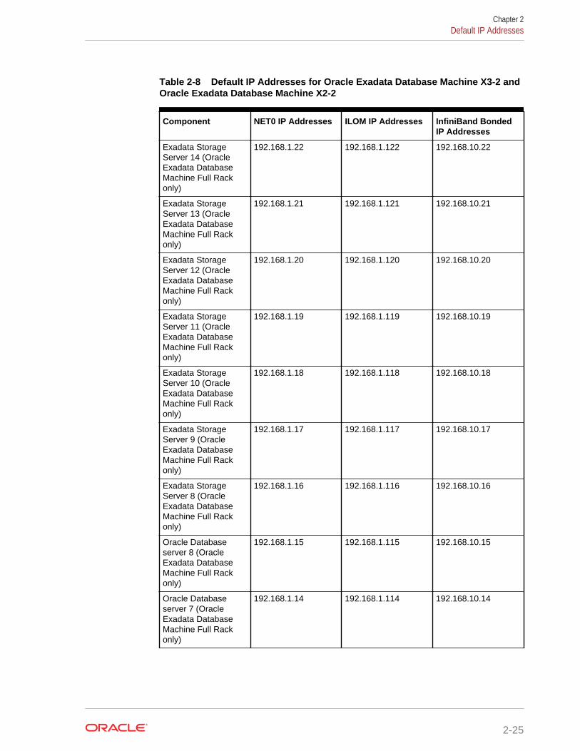
Table 2-8 Default IP Addresses for Oracle Exadata Database Machine X3-2 andOracle Exadata Database Machine X2-2
Component NET0 IP Addresses ILOM IP Addresses InfiniBand BondedIP Addresses
Exadata StorageServer 14 (OracleExadata DatabaseMachine Full Rackonly)
192.168.1.22 192.168.1.122 192.168.10.22
Exadata StorageServer 13 (OracleExadata DatabaseMachine Full Rackonly)
192.168.1.21 192.168.1.121 192.168.10.21
Exadata StorageServer 12 (OracleExadata DatabaseMachine Full Rackonly)
192.168.1.20 192.168.1.120 192.168.10.20
Exadata StorageServer 11 (OracleExadata DatabaseMachine Full Rackonly)
192.168.1.19 192.168.1.119 192.168.10.19
Exadata StorageServer 10 (OracleExadata DatabaseMachine Full Rackonly)
192.168.1.18 192.168.1.118 192.168.10.18
Exadata StorageServer 9 (OracleExadata DatabaseMachine Full Rackonly)
192.168.1.17 192.168.1.117 192.168.10.17
Exadata StorageServer 8 (OracleExadata DatabaseMachine Full Rackonly)
192.168.1.16 192.168.1.116 192.168.10.16
Oracle Databaseserver 8 (OracleExadata DatabaseMachine Full Rackonly)
192.168.1.15 192.168.1.115 192.168.10.15
Oracle Databaseserver 7 (OracleExadata DatabaseMachine Full Rackonly)
192.168.1.14 192.168.1.114 192.168.10.14
Chapter 2Default IP Addresses
2-25
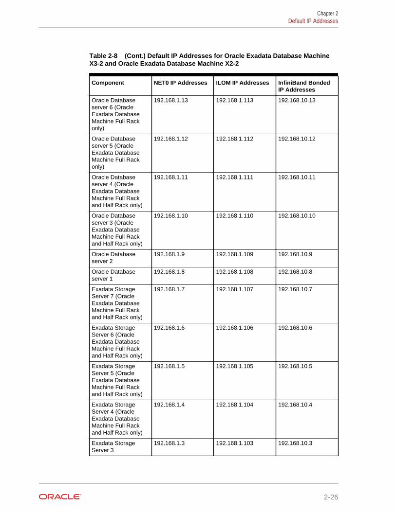
Table 2-8 (Cont.) Default IP Addresses for Oracle Exadata Database MachineX3-2 and Oracle Exadata Database Machine X2-2
Component NET0 IP Addresses ILOM IP Addresses InfiniBand BondedIP Addresses
Oracle Databaseserver 6 (OracleExadata DatabaseMachine Full Rackonly)
192.168.1.13 192.168.1.113 192.168.10.13
Oracle Databaseserver 5 (OracleExadata DatabaseMachine Full Rackonly)
192.168.1.12 192.168.1.112 192.168.10.12
Oracle Databaseserver 4 (OracleExadata DatabaseMachine Full Rackand Half Rack only)
192.168.1.11 192.168.1.111 192.168.10.11
Oracle Databaseserver 3 (OracleExadata DatabaseMachine Full Rackand Half Rack only)
192.168.1.10 192.168.1.110 192.168.10.10
Oracle Databaseserver 2
192.168.1.9 192.168.1.109 192.168.10.9
Oracle Databaseserver 1
192.168.1.8 192.168.1.108 192.168.10.8
Exadata StorageServer 7 (OracleExadata DatabaseMachine Full Rackand Half Rack only)
192.168.1.7 192.168.1.107 192.168.10.7
Exadata StorageServer 6 (OracleExadata DatabaseMachine Full Rackand Half Rack only)
192.168.1.6 192.168.1.106 192.168.10.6
Exadata StorageServer 5 (OracleExadata DatabaseMachine Full Rackand Half Rack only)
192.168.1.5 192.168.1.105 192.168.10.5
Exadata StorageServer 4 (OracleExadata DatabaseMachine Full Rackand Half Rack only)
192.168.1.4 192.168.1.104 192.168.10.4
Exadata StorageServer 3
192.168.1.3 192.168.1.103 192.168.10.3
Chapter 2Default IP Addresses
2-26
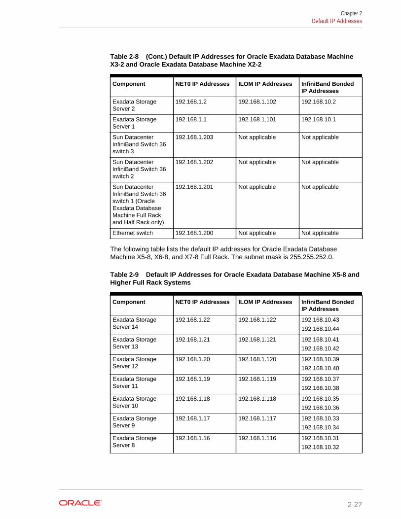
Table 2-8 (Cont.) Default IP Addresses for Oracle Exadata Database MachineX3-2 and Oracle Exadata Database Machine X2-2
Component NET0 IP Addresses ILOM IP Addresses InfiniBand BondedIP Addresses
Exadata StorageServer 2
192.168.1.2 192.168.1.102 192.168.10.2
Exadata StorageServer 1
192.168.1.1 192.168.1.101 192.168.10.1
Sun DatacenterInfiniBand Switch 36switch 3
192.168.1.203 Not applicable Not applicable
Sun DatacenterInfiniBand Switch 36switch 2
192.168.1.202 Not applicable Not applicable
Sun DatacenterInfiniBand Switch 36switch 1 (OracleExadata DatabaseMachine Full Rackand Half Rack only)
192.168.1.201 Not applicable Not applicable
Ethernet switch 192.168.1.200 Not applicable Not applicable
The following table lists the default IP addresses for Oracle Exadata DatabaseMachine X5-8, X6-8, and X7-8 Full Rack. The subnet mask is 255.255.252.0.
Table 2-9 Default IP Addresses for Oracle Exadata Database Machine X5-8 andHigher Full Rack Systems
Component NET0 IP Addresses ILOM IP Addresses InfiniBand BondedIP Addresses
Exadata StorageServer 14
192.168.1.22 192.168.1.122 192.168.10.43
192.168.10.44
Exadata StorageServer 13
192.168.1.21 192.168.1.121 192.168.10.41
192.168.10.42
Exadata StorageServer 12
192.168.1.20 192.168.1.120 192.168.10.39
192.168.10.40
Exadata StorageServer 11
192.168.1.19 192.168.1.119 192.168.10.37
192.168.10.38
Exadata StorageServer 10
192.168.1.18 192.168.1.118 192.168.10.35
192.168.10.36
Exadata StorageServer 9
192.168.1.17 192.168.1.117 192.168.10.33
192.168.10.34
Exadata StorageServer 8
192.168.1.16 192.168.1.116 192.168.10.31
192.168.10.32
Chapter 2Default IP Addresses
2-27
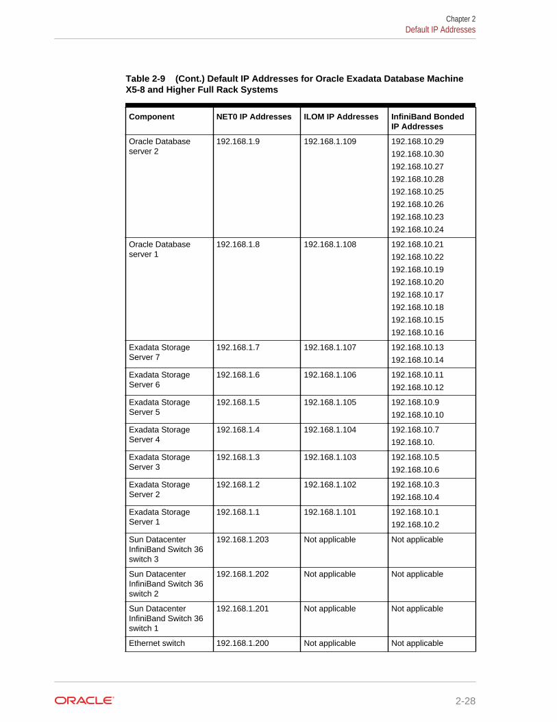
Table 2-9 (Cont.) Default IP Addresses for Oracle Exadata Database MachineX5-8 and Higher Full Rack Systems
Component NET0 IP Addresses ILOM IP Addresses InfiniBand BondedIP Addresses
Oracle Databaseserver 2
192.168.1.9 192.168.1.109 192.168.10.29
192.168.10.30
192.168.10.27
192.168.10.28
192.168.10.25
192.168.10.26
192.168.10.23
192.168.10.24
Oracle Databaseserver 1
192.168.1.8 192.168.1.108 192.168.10.21
192.168.10.22
192.168.10.19
192.168.10.20
192.168.10.17
192.168.10.18
192.168.10.15
192.168.10.16
Exadata StorageServer 7
192.168.1.7 192.168.1.107 192.168.10.13
192.168.10.14
Exadata StorageServer 6
192.168.1.6 192.168.1.106 192.168.10.11
192.168.10.12
Exadata StorageServer 5
192.168.1.5 192.168.1.105 192.168.10.9
192.168.10.10
Exadata StorageServer 4
192.168.1.4 192.168.1.104 192.168.10.7
192.168.10.
Exadata StorageServer 3
192.168.1.3 192.168.1.103 192.168.10.5
192.168.10.6
Exadata StorageServer 2
192.168.1.2 192.168.1.102 192.168.10.3
192.168.10.4
Exadata StorageServer 1
192.168.1.1 192.168.1.101 192.168.10.1
192.168.10.2
Sun DatacenterInfiniBand Switch 36switch 3
192.168.1.203 Not applicable Not applicable
Sun DatacenterInfiniBand Switch 36switch 2
192.168.1.202 Not applicable Not applicable
Sun DatacenterInfiniBand Switch 36switch 1
192.168.1.201 Not applicable Not applicable
Ethernet switch 192.168.1.200 Not applicable Not applicable
Chapter 2Default IP Addresses
2-28
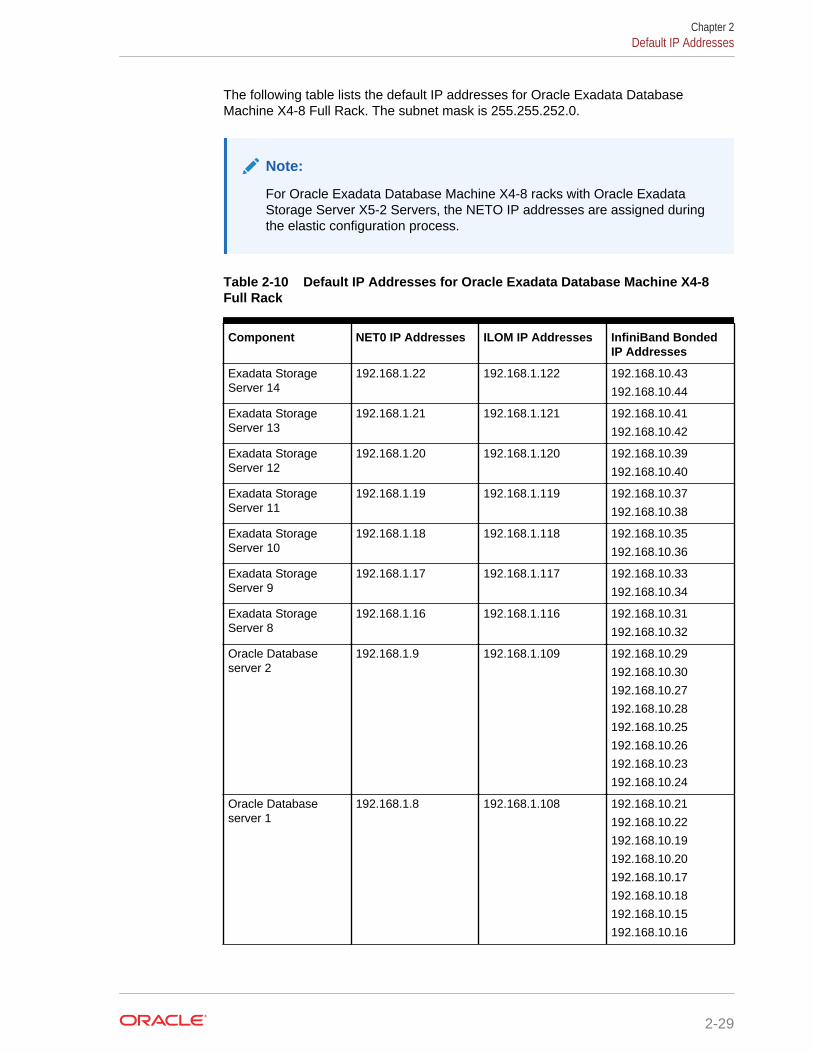
The following table lists the default IP addresses for Oracle Exadata DatabaseMachine X4-8 Full Rack. The subnet mask is 255.255.252.0.
Note:
For Oracle Exadata Database Machine X4-8 racks with Oracle ExadataStorage Server X5-2 Servers, the NETO IP addresses are assigned duringthe elastic configuration process.
Table 2-10 Default IP Addresses for Oracle Exadata Database Machine X4-8Full Rack
Component NET0 IP Addresses ILOM IP Addresses InfiniBand BondedIP Addresses
Exadata StorageServer 14
192.168.1.22 192.168.1.122 192.168.10.43
192.168.10.44
Exadata StorageServer 13
192.168.1.21 192.168.1.121 192.168.10.41
192.168.10.42
Exadata StorageServer 12
192.168.1.20 192.168.1.120 192.168.10.39
192.168.10.40
Exadata StorageServer 11
192.168.1.19 192.168.1.119 192.168.10.37
192.168.10.38
Exadata StorageServer 10
192.168.1.18 192.168.1.118 192.168.10.35
192.168.10.36
Exadata StorageServer 9
192.168.1.17 192.168.1.117 192.168.10.33
192.168.10.34
Exadata StorageServer 8
192.168.1.16 192.168.1.116 192.168.10.31
192.168.10.32
Oracle Databaseserver 2
192.168.1.9 192.168.1.109 192.168.10.29
192.168.10.30
192.168.10.27
192.168.10.28
192.168.10.25
192.168.10.26
192.168.10.23
192.168.10.24
Oracle Databaseserver 1
192.168.1.8 192.168.1.108 192.168.10.21
192.168.10.22
192.168.10.19
192.168.10.20
192.168.10.17
192.168.10.18
192.168.10.15
192.168.10.16
Chapter 2Default IP Addresses
2-29
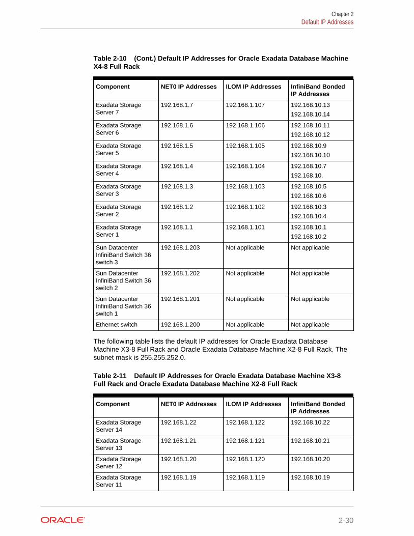
Table 2-10 (Cont.) Default IP Addresses for Oracle Exadata Database MachineX4-8 Full Rack
Component NET0 IP Addresses ILOM IP Addresses InfiniBand BondedIP Addresses
Exadata StorageServer 7
192.168.1.7 192.168.1.107 192.168.10.13
192.168.10.14
Exadata StorageServer 6
192.168.1.6 192.168.1.106 192.168.10.11
192.168.10.12
Exadata StorageServer 5
192.168.1.5 192.168.1.105 192.168.10.9
192.168.10.10
Exadata StorageServer 4
192.168.1.4 192.168.1.104 192.168.10.7
192.168.10.
Exadata StorageServer 3
192.168.1.3 192.168.1.103 192.168.10.5
192.168.10.6
Exadata StorageServer 2
192.168.1.2 192.168.1.102 192.168.10.3
192.168.10.4
Exadata StorageServer 1
192.168.1.1 192.168.1.101 192.168.10.1
192.168.10.2
Sun DatacenterInfiniBand Switch 36switch 3
192.168.1.203 Not applicable Not applicable
Sun DatacenterInfiniBand Switch 36switch 2
192.168.1.202 Not applicable Not applicable
Sun DatacenterInfiniBand Switch 36switch 1
192.168.1.201 Not applicable Not applicable
Ethernet switch 192.168.1.200 Not applicable Not applicable
The following table lists the default IP addresses for Oracle Exadata DatabaseMachine X3-8 Full Rack and Oracle Exadata Database Machine X2-8 Full Rack. Thesubnet mask is 255.255.252.0.
Table 2-11 Default IP Addresses for Oracle Exadata Database Machine X3-8Full Rack and Oracle Exadata Database Machine X2-8 Full Rack
Component NET0 IP Addresses ILOM IP Addresses InfiniBand BondedIP Addresses
Exadata StorageServer 14
192.168.1.22 192.168.1.122 192.168.10.22
Exadata StorageServer 13
192.168.1.21 192.168.1.121 192.168.10.21
Exadata StorageServer 12
192.168.1.20 192.168.1.120 192.168.10.20
Exadata StorageServer 11
192.168.1.19 192.168.1.119 192.168.10.19
Chapter 2Default IP Addresses
2-30
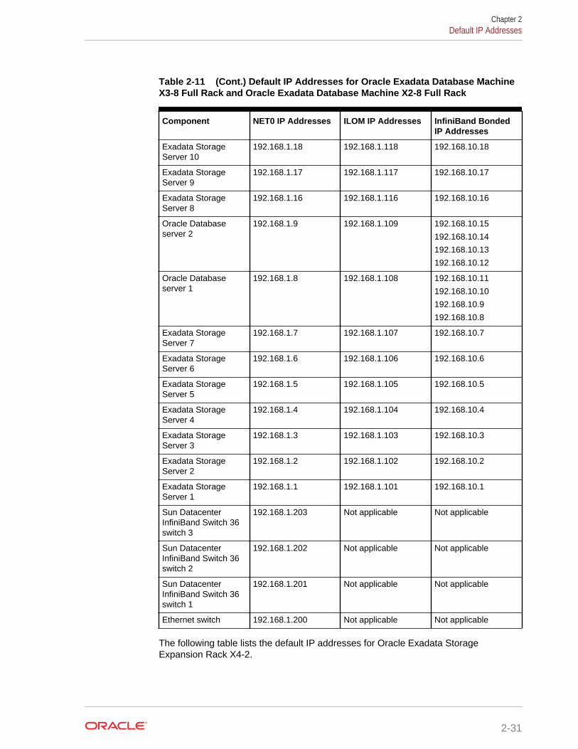
Table 2-11 (Cont.) Default IP Addresses for Oracle Exadata Database MachineX3-8 Full Rack and Oracle Exadata Database Machine X2-8 Full Rack
Component NET0 IP Addresses ILOM IP Addresses InfiniBand BondedIP Addresses
Exadata StorageServer 10
192.168.1.18 192.168.1.118 192.168.10.18
Exadata StorageServer 9
192.168.1.17 192.168.1.117 192.168.10.17
Exadata StorageServer 8
192.168.1.16 192.168.1.116 192.168.10.16
Oracle Databaseserver 2
192.168.1.9 192.168.1.109 192.168.10.15
192.168.10.14
192.168.10.13
192.168.10.12
Oracle Databaseserver 1
192.168.1.8 192.168.1.108 192.168.10.11
192.168.10.10
192.168.10.9
192.168.10.8
Exadata StorageServer 7
192.168.1.7 192.168.1.107 192.168.10.7
Exadata StorageServer 6
192.168.1.6 192.168.1.106 192.168.10.6
Exadata StorageServer 5
192.168.1.5 192.168.1.105 192.168.10.5
Exadata StorageServer 4
192.168.1.4 192.168.1.104 192.168.10.4
Exadata StorageServer 3
192.168.1.3 192.168.1.103 192.168.10.3
Exadata StorageServer 2
192.168.1.2 192.168.1.102 192.168.10.2
Exadata StorageServer 1
192.168.1.1 192.168.1.101 192.168.10.1
Sun DatacenterInfiniBand Switch 36switch 3
192.168.1.203 Not applicable Not applicable
Sun DatacenterInfiniBand Switch 36switch 2
192.168.1.202 Not applicable Not applicable
Sun DatacenterInfiniBand Switch 36switch 1
192.168.1.201 Not applicable Not applicable
Ethernet switch 192.168.1.200 Not applicable Not applicable
The following table lists the default IP addresses for Oracle Exadata StorageExpansion Rack X4-2.
Chapter 2Default IP Addresses
2-31
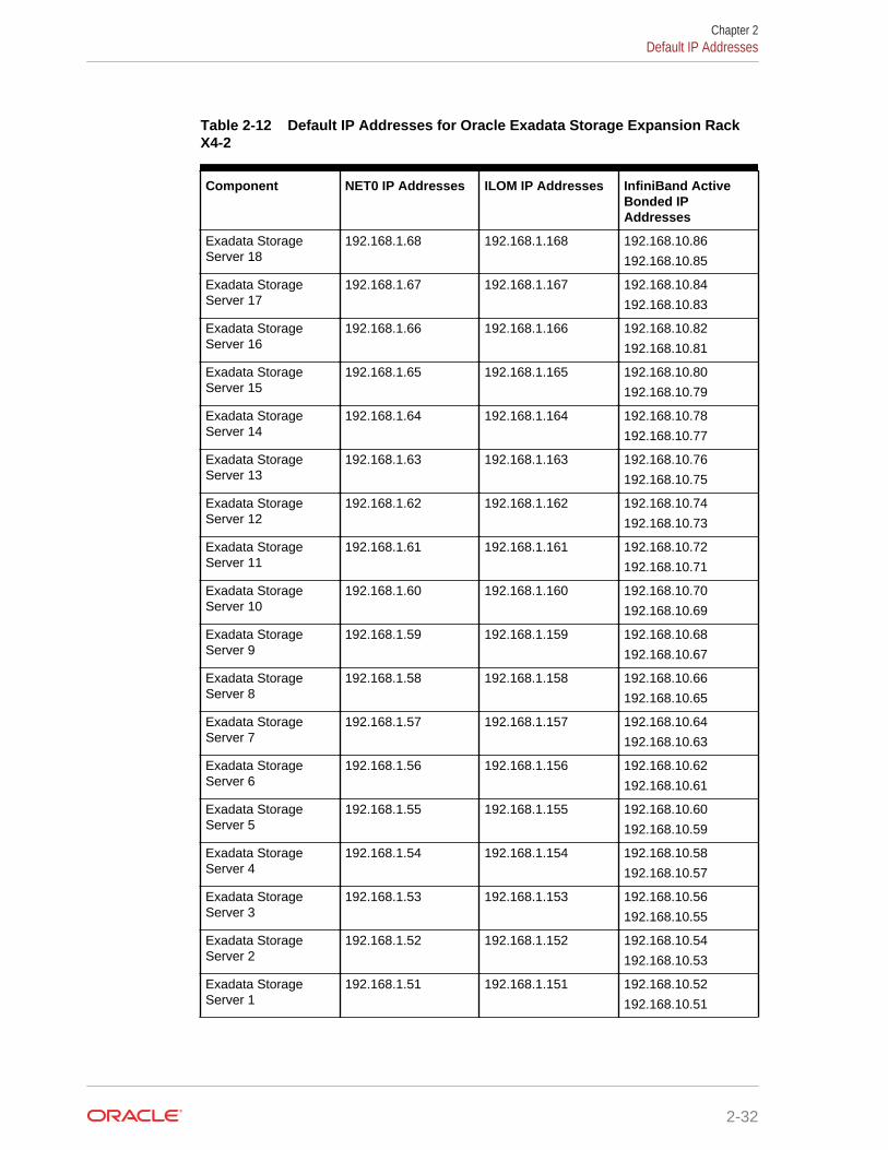
Table 2-12 Default IP Addresses for Oracle Exadata Storage Expansion RackX4-2
Component NET0 IP Addresses ILOM IP Addresses InfiniBand ActiveBonded IPAddresses
Exadata StorageServer 18
192.168.1.68 192.168.1.168 192.168.10.86
192.168.10.85
Exadata StorageServer 17
192.168.1.67 192.168.1.167 192.168.10.84
192.168.10.83
Exadata StorageServer 16
192.168.1.66 192.168.1.166 192.168.10.82
192.168.10.81
Exadata StorageServer 15
192.168.1.65 192.168.1.165 192.168.10.80
192.168.10.79
Exadata StorageServer 14
192.168.1.64 192.168.1.164 192.168.10.78
192.168.10.77
Exadata StorageServer 13
192.168.1.63 192.168.1.163 192.168.10.76
192.168.10.75
Exadata StorageServer 12
192.168.1.62 192.168.1.162 192.168.10.74
192.168.10.73
Exadata StorageServer 11
192.168.1.61 192.168.1.161 192.168.10.72
192.168.10.71
Exadata StorageServer 10
192.168.1.60 192.168.1.160 192.168.10.70
192.168.10.69
Exadata StorageServer 9
192.168.1.59 192.168.1.159 192.168.10.68
192.168.10.67
Exadata StorageServer 8
192.168.1.58 192.168.1.158 192.168.10.66
192.168.10.65
Exadata StorageServer 7
192.168.1.57 192.168.1.157 192.168.10.64
192.168.10.63
Exadata StorageServer 6
192.168.1.56 192.168.1.156 192.168.10.62
192.168.10.61
Exadata StorageServer 5
192.168.1.55 192.168.1.155 192.168.10.60
192.168.10.59
Exadata StorageServer 4
192.168.1.54 192.168.1.154 192.168.10.58
192.168.10.57
Exadata StorageServer 3
192.168.1.53 192.168.1.153 192.168.10.56
192.168.10.55
Exadata StorageServer 2
192.168.1.52 192.168.1.152 192.168.10.54
192.168.10.53
Exadata StorageServer 1
192.168.1.51 192.168.1.151 192.168.10.52
192.168.10.51
Chapter 2Default IP Addresses
2-32
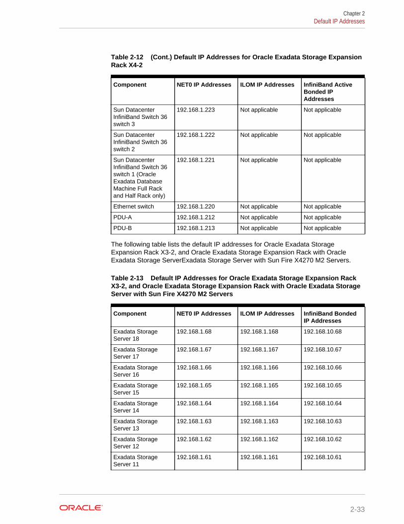
Table 2-12 (Cont.) Default IP Addresses for Oracle Exadata Storage ExpansionRack X4-2
Component NET0 IP Addresses ILOM IP Addresses InfiniBand ActiveBonded IPAddresses
Sun DatacenterInfiniBand Switch 36switch 3
192.168.1.223 Not applicable Not applicable
Sun DatacenterInfiniBand Switch 36switch 2
192.168.1.222 Not applicable Not applicable
Sun DatacenterInfiniBand Switch 36switch 1 (OracleExadata DatabaseMachine Full Rackand Half Rack only)
192.168.1.221 Not applicable Not applicable
Ethernet switch 192.168.1.220 Not applicable Not applicable
PDU-A 192.168.1.212 Not applicable Not applicable
PDU-B 192.168.1.213 Not applicable Not applicable
The following table lists the default IP addresses for Oracle Exadata StorageExpansion Rack X3-2, and Oracle Exadata Storage Expansion Rack with OracleExadata Storage ServerExadata Storage Server with Sun Fire X4270 M2 Servers.
Table 2-13 Default IP Addresses for Oracle Exadata Storage Expansion RackX3-2, and Oracle Exadata Storage Expansion Rack with Oracle Exadata StorageServer with Sun Fire X4270 M2 Servers
Component NET0 IP Addresses ILOM IP Addresses InfiniBand BondedIP Addresses
Exadata StorageServer 18
192.168.1.68 192.168.1.168 192.168.10.68
Exadata StorageServer 17
192.168.1.67 192.168.1.167 192.168.10.67
Exadata StorageServer 16
192.168.1.66 192.168.1.166 192.168.10.66
Exadata StorageServer 15
192.168.1.65 192.168.1.165 192.168.10.65
Exadata StorageServer 14
192.168.1.64 192.168.1.164 192.168.10.64
Exadata StorageServer 13
192.168.1.63 192.168.1.163 192.168.10.63
Exadata StorageServer 12
192.168.1.62 192.168.1.162 192.168.10.62
Exadata StorageServer 11
192.168.1.61 192.168.1.161 192.168.10.61
Chapter 2Default IP Addresses
2-33
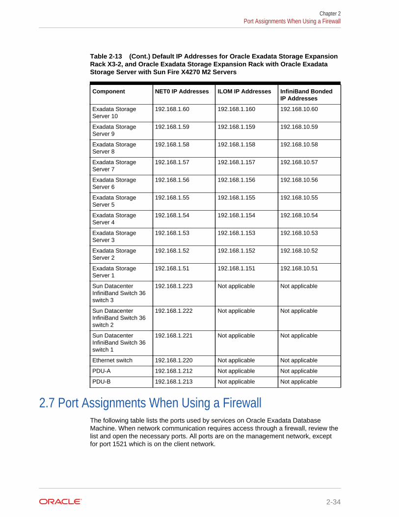
Table 2-13 (Cont.) Default IP Addresses for Oracle Exadata Storage ExpansionRack X3-2, and Oracle Exadata Storage Expansion Rack with Oracle ExadataStorage Server with Sun Fire X4270 M2 Servers
Component NET0 IP Addresses ILOM IP Addresses InfiniBand BondedIP Addresses
Exadata StorageServer 10
192.168.1.60 192.168.1.160 192.168.10.60
Exadata StorageServer 9
192.168.1.59 192.168.1.159 192.168.10.59
Exadata StorageServer 8
192.168.1.58 192.168.1.158 192.168.10.58
Exadata StorageServer 7
192.168.1.57 192.168.1.157 192.168.10.57
Exadata StorageServer 6
192.168.1.56 192.168.1.156 192.168.10.56
Exadata StorageServer 5
192.168.1.55 192.168.1.155 192.168.10.55
Exadata StorageServer 4
192.168.1.54 192.168.1.154 192.168.10.54
Exadata StorageServer 3
192.168.1.53 192.168.1.153 192.168.10.53
Exadata StorageServer 2
192.168.1.52 192.168.1.152 192.168.10.52
Exadata StorageServer 1
192.168.1.51 192.168.1.151 192.168.10.51
Sun DatacenterInfiniBand Switch 36switch 3
192.168.1.223 Not applicable Not applicable
Sun DatacenterInfiniBand Switch 36switch 2
192.168.1.222 Not applicable Not applicable
Sun DatacenterInfiniBand Switch 36switch 1
192.168.1.221 Not applicable Not applicable
Ethernet switch 192.168.1.220 Not applicable Not applicable
PDU-A 192.168.1.212 Not applicable Not applicable
PDU-B 192.168.1.213 Not applicable Not applicable
2.7 Port Assignments When Using a FirewallThe following table lists the ports used by services on Oracle Exadata DatabaseMachine. When network communication requires access through a firewall, review thelist and open the necessary ports. All ports are on the management network, exceptfor port 1521 which is on the client network.
Chapter 2Port Assignments When Using a Firewall
2-34
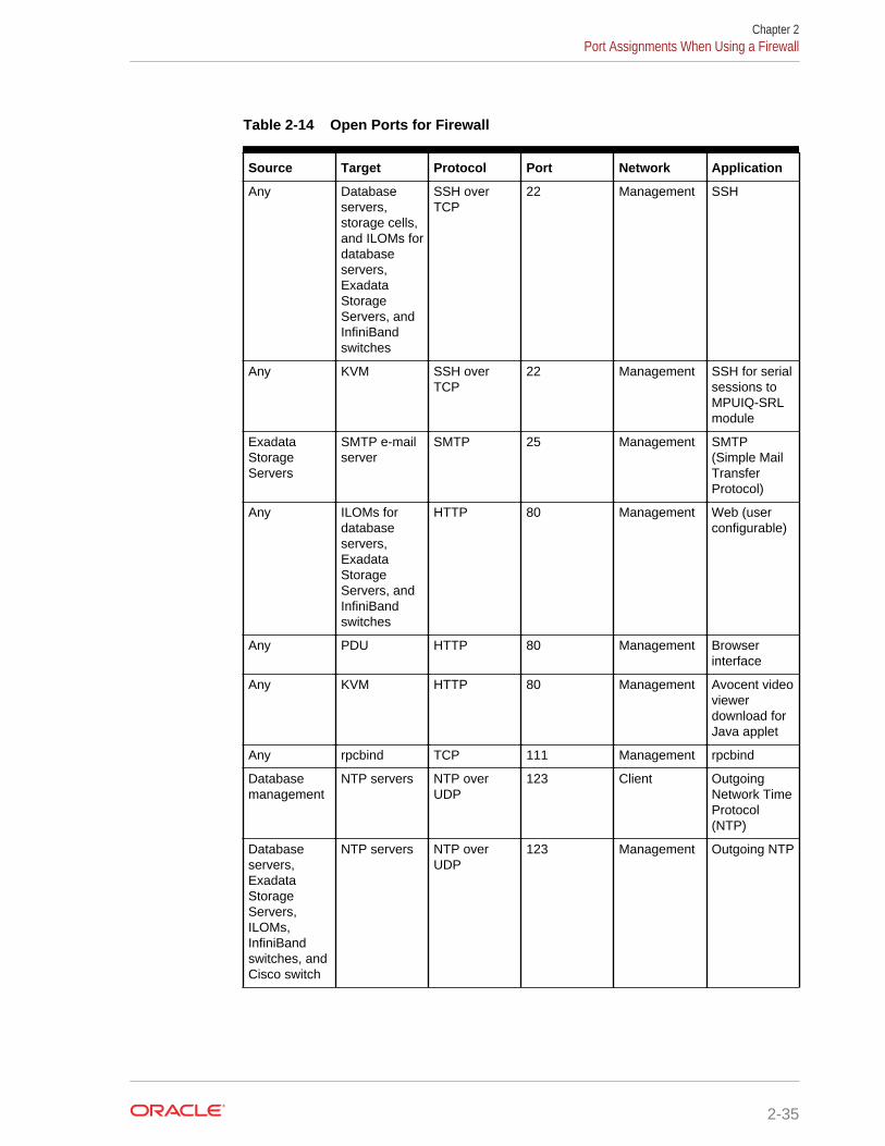
Table 2-14 Open Ports for Firewall
Source Target Protocol Port Network Application
Any Databaseservers,storage cells,and ILOMs fordatabaseservers,ExadataStorageServers, andInfiniBandswitches
SSH overTCP
22 Management SSH
Any KVM SSH overTCP
22 Management SSH for serialsessions toMPUIQ-SRLmodule
ExadataStorageServers
SMTP e-mailserver
SMTP 25 Management SMTP(Simple MailTransferProtocol)
Any ILOMs fordatabaseservers,ExadataStorageServers, andInfiniBandswitches
HTTP 80 Management Web (userconfigurable)
Any PDU HTTP 80 Management Browserinterface
Any KVM HTTP 80 Management Avocent videoviewerdownload forJava applet
Any rpcbind TCP 111 Management rpcbind
Databasemanagement
NTP servers NTP overUDP
123 Client OutgoingNetwork TimeProtocol(NTP)
Databaseservers,ExadataStorageServers,ILOMs,InfiniBandswitches, andCisco switch
NTP servers NTP overUDP
123 Management Outgoing NTP
Chapter 2Port Assignments When Using a Firewall
2-35
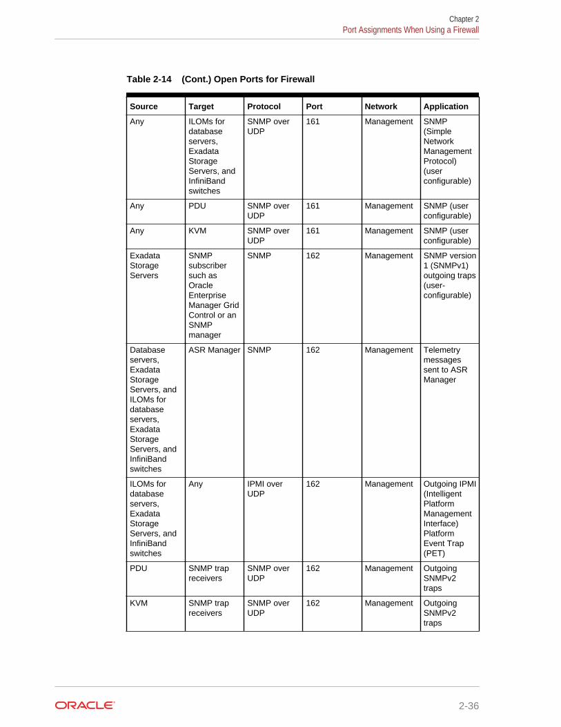
Table 2-14 (Cont.) Open Ports for Firewall
Source Target Protocol Port Network Application
Any ILOMs fordatabaseservers,ExadataStorageServers, andInfiniBandswitches
SNMP overUDP
161 Management SNMP(SimpleNetworkManagementProtocol)(userconfigurable)
Any PDU SNMP overUDP
161 Management SNMP (userconfigurable)
Any KVM SNMP overUDP
161 Management SNMP (userconfigurable)
ExadataStorageServers
SNMPsubscribersuch asOracleEnterpriseManager GridControl or anSNMPmanager
SNMP 162 Management SNMP version1 (SNMPv1)outgoing traps(user-configurable)
Databaseservers,ExadataStorageServers, andILOMs fordatabaseservers,ExadataStorageServers, andInfiniBandswitches
ASR Manager SNMP 162 Management Telemetrymessagessent to ASRManager
ILOMs fordatabaseservers,ExadataStorageServers, andInfiniBandswitches
Any IPMI overUDP
162 Management Outgoing IPMI(IntelligentPlatformManagementInterface)PlatformEvent Trap(PET)
PDU SNMP trapreceivers
SNMP overUDP
162 Management OutgoingSNMPv2traps
KVM SNMP trapreceivers
SNMP overUDP
162 Management OutgoingSNMPv2traps
Chapter 2Port Assignments When Using a Firewall
2-36
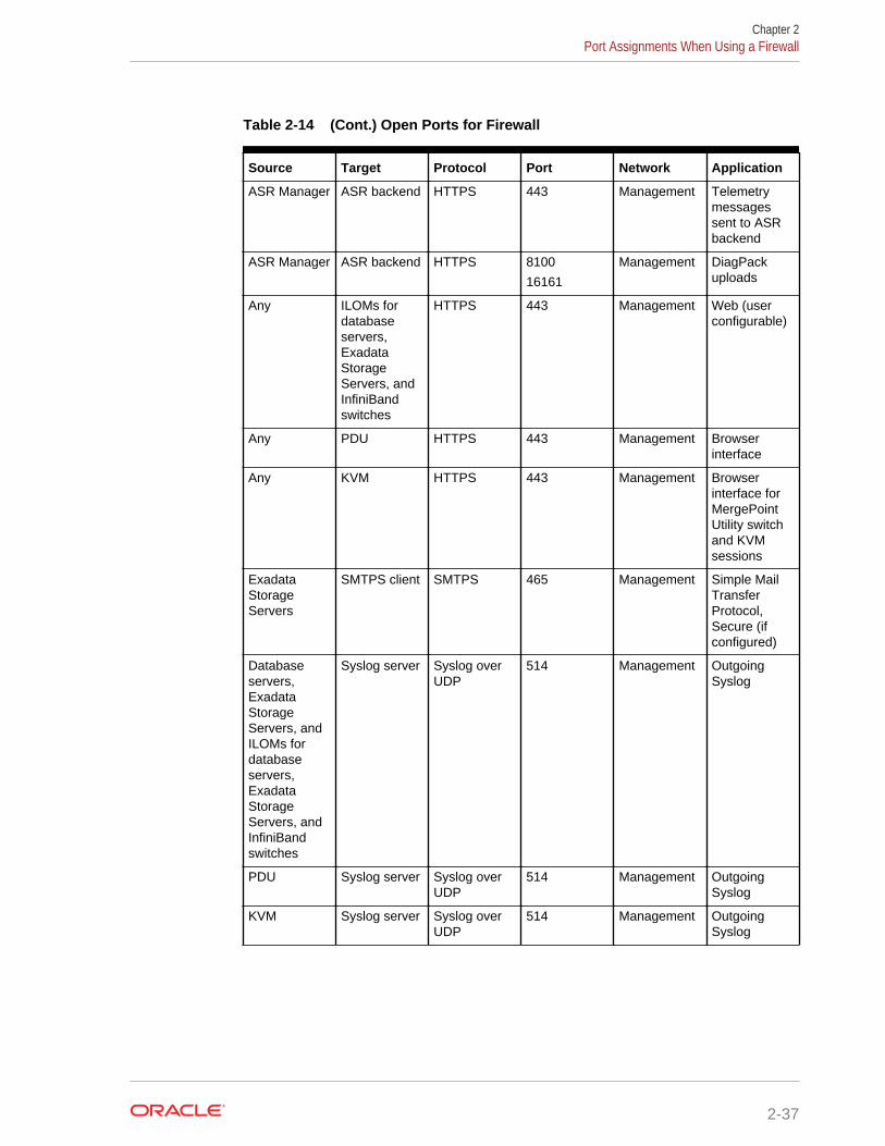
Table 2-14 (Cont.) Open Ports for Firewall
Source Target Protocol Port Network Application
ASR Manager ASR backend HTTPS 443 Management Telemetrymessagessent to ASRbackend
ASR Manager ASR backend HTTPS 8100
16161
Management DiagPackuploads
Any ILOMs fordatabaseservers,ExadataStorageServers, andInfiniBandswitches
HTTPS 443 Management Web (userconfigurable)
Any PDU HTTPS 443 Management Browserinterface
Any KVM HTTPS 443 Management Browserinterface forMergePointUtility switchand KVMsessions
ExadataStorageServers
SMTPS client SMTPS 465 Management Simple MailTransferProtocol,Secure (ifconfigured)
Databaseservers,ExadataStorageServers, andILOMs fordatabaseservers,ExadataStorageServers, andInfiniBandswitches
Syslog server Syslog overUDP
514 Management OutgoingSyslog
PDU Syslog server Syslog overUDP
514 Management OutgoingSyslog
KVM Syslog server Syslog overUDP
514 Management OutgoingSyslog
Chapter 2Port Assignments When Using a Firewall
2-37
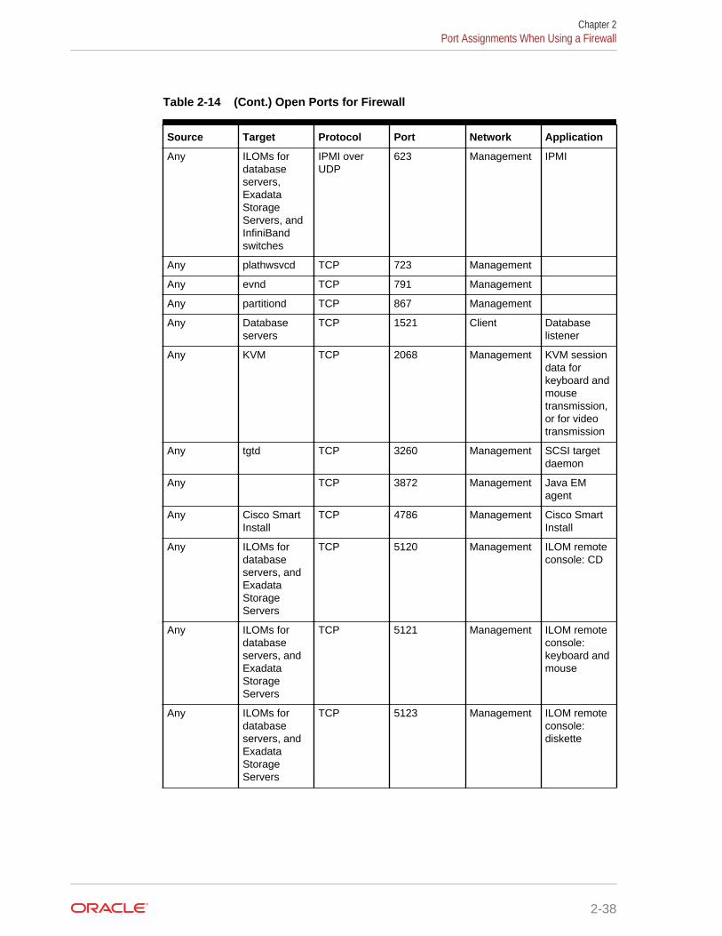
Table 2-14 (Cont.) Open Ports for Firewall
Source Target Protocol Port Network Application
Any ILOMs fordatabaseservers,ExadataStorageServers, andInfiniBandswitches
IPMI overUDP
623 Management IPMI
Any plathwsvcd TCP 723 Management
Any evnd TCP 791 Management
Any partitiond TCP 867 Management
Any Databaseservers
TCP 1521 Client Databaselistener
Any KVM TCP 2068 Management KVM sessiondata forkeyboard andmousetransmission,or for videotransmission
Any tgtd TCP 3260 Management SCSI targetdaemon
Any TCP 3872 Management Java EMagent
Any Cisco SmartInstall
TCP 4786 Management Cisco SmartInstall
Any ILOMs fordatabaseservers, andExadataStorageServers
TCP 5120 Management ILOM remoteconsole: CD
Any ILOMs fordatabaseservers, andExadataStorageServers
TCP 5121 Management ILOM remoteconsole:keyboard andmouse
Any ILOMs fordatabaseservers, andExadataStorageServers
TCP 5123 Management ILOM remoteconsole:diskette
Chapter 2Port Assignments When Using a Firewall
2-38
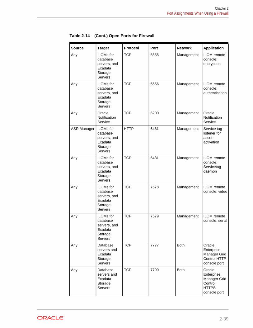
Table 2-14 (Cont.) Open Ports for Firewall
Source Target Protocol Port Network Application
Any ILOMs fordatabaseservers, andExadataStorageServers
TCP 5555 Management ILOM remoteconsole:encryption
Any ILOMs fordatabaseservers, andExadataStorageServers
TCP 5556 Management ILOM remoteconsole:authentication
Any OracleNotificationService
TCP 6200 Management OracleNotificationService
ASR Manager ILOMs fordatabaseservers, andExadataStorageServers
HTTP 6481 Management Service taglistener forassetactivation
Any ILOMs fordatabaseservers, andExadataStorageServers
TCP 6481 Management ILOM remoteconsole:Servicetagdaemon
Any ILOMs fordatabaseservers, andExadataStorageServers
TCP 7578 Management ILOM remoteconsole: video
Any ILOMs fordatabaseservers, andExadataStorageServers
TCP 7579 Management ILOM remoteconsole: serial
Any Databaseservers andExadataStorageServers
TCP 7777 Both OracleEnterpriseManager GridControl HTTPconsole port
Any Databaseservers andExadataStorageServers
TCP 7799 Both OracleEnterpriseManager GridControlHTTPSconsole port
Chapter 2Port Assignments When Using a Firewall
2-39
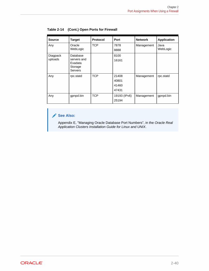
Table 2-14 (Cont.) Open Ports for Firewall
Source Target Protocol Port Network Application
Any OracleWebLogic
TCP 7878
8888
Management JavaWebLogic
Diagpackuploads
Databaseservers andExadataStorageServers
8100
16161
Any rpc.statd TCP 21408
40801
41460
47431
Management rpc.statd
Any gpnpd.bin TCP 19193 (IPv6)
25194
Management gpnpd.bin
See Also:
Appendix E, "Managing Oracle Database Port Numbers", in the Oracle RealApplication Clusters Installation Guide for Linux and UNIX.
Chapter 2Port Assignments When Using a Firewall
2-40
3Using Oracle Exadata DeploymentAssistant
Oracle Exadata Deployment Assistant creates the Oracle Exadata Rack configurationfile. The file automates the installation process. The utility is available from My OracleSupport. Refer to My Oracle Support note 888828.1 for additional information.
Note:
For ease of reading, the name "Oracle Exadata Rack" is used wheninformation refers to both Oracle Exadata Database Machine and OracleExadata Storage Expansion Rack.
• Overview of Oracle Exadata Deployment Assistant
• OEDA Browser-based User Interface
• OEDA Graphical User Interface
• OEDA Command Line Interface
Related Topics
• Exadata Database Machine and Exadata Storage Server Supported Versions (MyOracle Support Doc ID 888828.1)
3.1 Overview of Oracle Exadata Deployment AssistantUse the deployment assistant to create the configuration file for Oracle Exadata Rack. The deployment assistant is used for Oracle Exadata Database Machine, Zero DataLoss Recovery Appliance, and Oracle SuperCluster.
Before Oracle Exadata Rack arrives:
1. Work with your network and database administrators to evaluate the currentnetwork settings, such as current IP address use and network configuration.
2. Define the settings for Oracle Exadata Rack, such as network configuration andbackup method.
3. Run the deployment assistant, and select the type of system. Options are OracleExadata Database Machine, Zero Data Loss Recovery Appliance, and OracleSuperCluster.
Note:
All fields in the deployment assistant are required unless otherwiseindicated.
3-1
4. Generate the configuration file.
Oracle Exadata Deployment Assistant has two main phases:
In phase 1, the customer provides naming, DNS, NTP, and networking details. Thisinformation is collected using the Oracle Exadata Deployment Assistant user interface.At the end of the dialogue with OEDA, configuration files are generated on the client.
In phase 2, the configuration files are copied to the database node, and the validationand installation is completed. See Configuring Oracle Exadata Database MachineUsing OEDA.
Accessibility Note: If you are using Oracle Exadata Deployment Assistant withassistive technology (for accessibility) on Windows, you need to enable Java AccessBridge.
3.1.1 Considerations when Using Oracle Exadata DeploymentAssistant
Review this information when using Oracle Exadata Deployment Assistant (OEDA).
Note the following when using Oracle Exadata Deployment Assistant:
• Oracle Exadata Rack ships with the Oracle Linux operating system installed on thedatabase servers, with the Oracle Linux as the default.
• The rack name is used to generate host names for network interfaces for allsystems. For example, a value of dm01 results in database server host names ofdm01db01, dm01db02, dm01db03, and so on, and Exadata Storage Server host namesof dm01cel01, dm01cel02, dm01cel03, and so on.
In a multi-rack configuration, each Oracle Exadata Rack name should be a uniquename that identifies the machine. Oracle recommends using dm01 for the firstOracle Exadata Rack, dm02 for the second, dm03 for the third, and so on. Up toeighteen Oracle Exadata Racks can be cabled together without additional SunDatacenter InfiniBand Switch 36 switches.
• The backup method information is used to size the Oracle Automatic StorageManagement (Oracle ASM) disk groups created during installation. The amount ofusable disk space varies depending on the backup method. The backup methodsare as follows:
– Backups internal to Oracle Exadata Rack mean database backups are createdonly on disk in the Fast Recovery Area (FRA). In addition to the databasebackups, there are other objects such as Archived Redo Logs and FlashbackLog Files stored in the FRA. The division of disk space between the DATAdisk group and the RECO disk group (the FRA) is 40% and 60%, respectively.
– Backups external to Oracle Exadata Rack mean database backups arecreated on disk or tape media that is external to currently deployed OracleExadata Database Machine, and not on existing Exadata Storage Servers. Ifyou are performing backups to disk storage external to Oracle ExadataDatabase Machine, such as to additional dedicated Exadata Storage Servers,an NFS server, virtual tape library or tape library, then do not reserveadditional space in the RECO disk group when using Oracle ExadataDeployment Assistant.
When choosing this option, the FRA internal to Oracle Exadata Rack containsobjects such as archived redo log files and flashback log files. The division of
Chapter 3Overview of Oracle Exadata Deployment Assistant
3-2
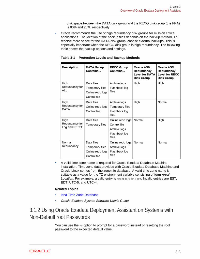
disk space between the DATA disk group and the RECO disk group (the FRA)is 80% and 20%, respectively.
• Oracle recommends the use of high redundancy disk groups for mission criticalapplications. The location of the backup files depends on the backup method. Toreserve more space for the DATA disk group, choose external backups. This isespecially important when the RECO disk group is high redundancy. The followingtable shows the backup options and settings.
Table 3-1 Protection Levels and Backup Methods
Description DATA GroupContains...
RECO GroupContains...
Oracle ASMRedundancyLevel for DATADisk Group
Oracle ASMRedundancyLevel for RECODisk Group
HighRedundancy forALL
Data files
Temporary files
Online redo logs
Control file
Archive logs
Flashback logfiles
High High
HighRedundancy forDATA
Data files
Online redo logs
Control file.
Archive logs
Temporary files
Flashback logfiles
High Normal
HighRedundancy forLog and RECO
Data files
Temporary files
Online redo logs
Control file
Archive logs
Flashback logfiles
Normal High
NormalRedundancy
Data files
Temporary files
Online redo logs
Control file
Online redo logs
Archive logs
Flashback logfiles
Normal Normal
• A valid time zone name is required for Oracle Exadata Database Machineinstallation. Time zone data provided with Oracle Exadata Database Machine andOracle Linux comes from the zoneinfo database. A valid time zone name issuitable as a value for the TZ environment variable consisting of form Area/Location. For example, a valid entry is America/New_York. Invalid entries are EST,EDT, UTC-5, and UTC-4.
Related Topics
• iana Time Zone Database
• Oracle Exadata System Software User's Guide
3.1.2 Using Oracle Exadata Deployment Assistant on Systems withNon-Default root Passwords
You can use the -p option to prompt for a password instead of resetting the rootpassword to the expected default value.
Chapter 3Overview of Oracle Exadata Deployment Assistant
3-3
Starting with the November 2016 release, Oracle Exadata Deployment Assistantsupports deployment on Exadata environments that already have non-default rootpasswords. You can perform the deployment without having to change the rootpassword back to the default. In earlier releases, OEDA expected the root password tobe the default on all the servers in an Exadata environment.
With the new non-default password feature, root passwords can be same or differentand also non-default on each node in a rack. If non-default passwords are already set,add the -p option to the existing command line options when you start up OEDA. Forexample:
./install.sh -cf <config.xml> -s 1 -p
The -p option causes OEDA to prompt for the root password. Make sure you enter thecorrect password because an incorrect password will disable root access for 5 minutesby default, and after 5 failed login attempts, the server will be locked down.
If you want to change the root password on database and storage servers, use thechangePassword.sh utility included with OEDA. It is located in the same directory asinstall.sh.
The following example changes the root password:
./changePassword.sh -cf <config.xml> -userName root
The utility will prompt for the current root password and will allow password changes ofany users in the rack. Note that this option assumes that the storage servers are notlocked down.
Related Topics
• Oracle Exadata Database Machine Security Guide
3.2 OEDA Browser-based User InterfaceThe web-based interface for Oracle Exadata Deployment Assistant (OEDA) isavailable starting with the release October 2018 of OEDA. OEDA Web is available forLinux, OSX and Windows.
You can use this interface to enter configuration details for new racks and also importconfiguration files from the old OEDA interface. Use the Menu button to import andsave.
To use the Web-based version of OEDA, perform the following steps.
1. Download the latest release of OEDA.
Extract the contents of the downloaded compressed file. When you extract thecontents, it creates a directory based on the operating system, such as linux-x64,macosx-x64, or windows-i586, to store the extracted files. This is referred to as theOEDA_HOME directory.
2. Install the software.
Before you can use the web-based interface, you must install and run the WebApplication Server. In the created directed, locate and run the installWls program.You do not have to be logged in as an administrator user to run this program. Useone of the following commands, where the -p option specifies the port number:
• On Linux, Apple, and UNIX:
Chapter 3OEDA Browser-based User Interface
3-4
./installWls.sh -p 7001
• On Microsoft Windows:
installWls.cmd -p 7001
Note:
You can specify a non-default port (for example 8002) by using a valueother than 7001. However, it is not recommended to use port numbersless than 1024.
When you run the installWls program, it first stops and removes any previousinstallation of the OEDA Web Server. Then it installs and starts the latest versionof the OEDA Web Server on the local system.
3. Access the local OEDA Web Server.
After the OEDA Web Server has been installed, you can access the web-basedapplication by opening a browser and entering the following URL:
http://localhost:7001/oeda
Refer to My Oracle Support note 2460104.1 for more information.
New features in the OEDA web interface:
• Ability to support single instance homes
• Ability to have Oracle RAC One Node and single instance databases
• Ability to have more than two users and groups
• Ability to have more than 2 disk groups
• Ability to have more than one database
• Ability to have more than one database home
• Ability to have more than one pluggable database (PDB)
• Ability to have separate Integrated Lights Out Manager (ILOM) subnet
• Ability to have separate ILOM domains
• Network flow provides better support for Oracle VM
3.2.1 Using the Browser-based Version of Oracle Exadata DeploymentAssistant
Use the deployment assistant for initial configuration, and when adding to an existingdeployment. You can import an existing configuration when adding new racks orcomponents.
Have the following available before running the deployment assistant:
• IP addresses
• Machine names
• DNS information
Chapter 3OEDA Browser-based User Interface
3-5
• NTP information for the rack
The following options are available from the OEDA Menu drop-down list:
• About: View information about the web interface software.
• New: Start a new configuration.
• Import: Import an existing configuration file. The file format is XML.
• Save: Save the current configuration to an XML file.
• Diagnostics: Creates a ZIP file that can be used to troubleshoot and diagnosisissues with the OEDA web interface.
• Preferences: Specify your preferences for how the web interface behaves.
• Validate: Check the current configuration for completeness and correctness.
• Exit: Exit OEDA
The following list describes the configuration information you specify in OEDA:
1. Select the hardware for the deployment on the Select Hardware page. Alsoprovide customer information on this page.
2. Choose whether to configuration Oracle VM on the nodes.
3. Enter the management network and private network information on the RackNetworks page.
4. Specify the user and group configuration on the Users and Groups page. You canchoose between Default, Role Separated, or a Custom configuration.
5. Define the clusters on the Define Clusters page for each cluster.
6. Define the disk group layout on the Diskgroups page.
7. Specify the Oracle Database home information for each Oracle home on theCreate Database Home page.
8. Enter the client and backup network information on the Cluster Networks page
9. Configure the email alerts, SNMP alerts, Auto Service Request, Oracle ConfigManager, and Enterprise Manager alerting on the Alerting page.
10. Answer the configuration questionnaire and provide additional information aboutthe deployment in the text field on the Comments page. Information entered in thisfield appears at the bottom of the InstallationTemplate.html file.
11. Click Save and Download to create the configuration files. You are prompted tochoose a location in which to save a ZIP file to your local computer.
12. Copy the ZIP file to a directory on the first database server in Oracle ExadataRack. Use a subdirectory of /u01, such as the /u01/oeda directory. These filesare used by the field engineer to configure the Oracle Exadata Rack.
3.2.2 Select Hardware PageSelect the hardware type being configured and provide customer details.
• Oracle Exadata Database Machine
Supply the following additional information for this choice:
– Rack Size: The size of the rack you are configuring. Your choices are:
Chapter 3OEDA Browser-based User Interface
3-6
* Elastic: (X4-8 and later) A customized number of database servers andstorage servers.
* Full: A standard configuration consisting of:
* 2-socket models (X7-2, X6-2, and so on): Eight 2-socket databaseservers and 14 storage servers
* 8-socket models (X7-8, X6-8, and so on): Two 8-socket databasesevers and 14 storage servers.
* Storage Expansion Racks (X2, X3, and X4): 18 storage servers
* Half: A standard configuration consisting of:
* 2-socket models (X7-2, X6-2, and so on): Four 2-socket databaseservers and 7 storage servers
* Storage Expansion Racks (X2, X3, and X4): Nine storage servers
* Quarter: A standard configuration consisting of:
* 2-socket models (X7-2, X6-2, and so on): Two 2-socket databaseservers and 3storage servers
* Storage Expansion Racks (X2, X3, and X4): Four storage servers
* Eighth: A standard configuration consisting of 2 database servers and 3storage servers with only half the cores enabled in each server. Availablefor 2-socket systems model X3-2 and later.
* Eighth Elastic: A customizable configuration with 2 database servers and3 storage servers. Available for 2-socket systems model X4-2 and later.
– Compute Node, Storage Cell, and Disk Size: The values you can select foreach successive field are determined by the value you selected for theprevious fields:
* X7-2 Compute Node
* X7 Storage Cell
* HC 10TB (High Capacity 10 TB drives)
* EF 6.4 TB (Extreme Flash 6.4 TB drives)
* X7-8 Compute Node
* X7 Storage Cell
* HC 10TB (High Capacity 10 TB drives)
* EF 6.4 TB (Extreme Flash 6.4 TB drives)
* X6-2 Compute Node
* X6 Storage Cell
* EF 3.2TB (Extreme Flash 3.2 TB drives)
* HC 8TB (High Capacity 8 TB drives)
* X6-8 Compute Node
* X6 Storage Cell
* EF 3.2TB (Extreme Flash 3.2 TB drives)
* HC 8TB (High Capacity 8 TB drives)
Chapter 3OEDA Browser-based User Interface
3-7
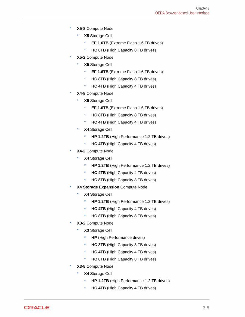
* X5-8 Compute Node
* X5 Storage Cell
* EF 1.6TB (Extreme Flash 1.6 TB drives)
* HC 8TB (High Capacity 8 TB drives)
* X5-2 Compute Node
* X5 Storage Cell
* EF 1.6TB (Extreme Flash 1.6 TB drives)
* HC 8TB (High Capacity 8 TB drives)
* HC 4TB (High Capacity 4 TB drives)
* X4-8 Compute Node
* X5 Storage Cell
* EF 1.6TB (Extreme Flash 1.6 TB drives)
* HC 8TB (High Capacity 8 TB drives)
* HC 4TB (High Capacity 4 TB drives)
* X4 Storage Cell
* HP 1.2TB (High Performance 1.2 TB drives)
* HC 4TB (High Capacity 4 TB drives)
* X4-2 Compute Node
* X4 Storage Cell
* HP 1.2TB (High Performance 1.2 TB drives)
* HC 4TB (High Capacity 4 TB drives)
* HC 8TB (High Capacity 8 TB drives)
* X4 Storage Expansion Compute Node
* X4 Storage Cell
* HP 1.2TB (High Performance 1.2 TB drives)
* HC 4TB (High Capacity 4 TB drives)
* HC 8TB (High Capacity 8 TB drives)
* X3-2 Compute Node
* X3 Storage Cell
* HP (High Performance drives)
* HC 3TB (High Capacity 3 TB drives)
* HC 4TB (High Capacity 4 TB drives)
* HC 8TB (High Capacity 8 TB drives)
* X3-8 Compute Node
* X4 Storage Cell
* HP 1.2TB (High Performance 1.2 TB drives)
* HC 4TB (High Capacity 4 TB drives)
Chapter 3OEDA Browser-based User Interface
3-8
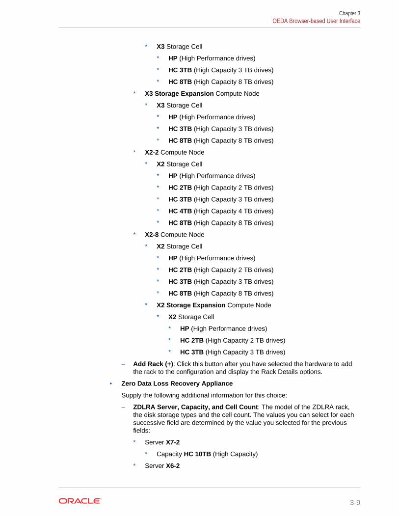
* X3 Storage Cell
* HP (High Performance drives)
* HC 3TB (High Capacity 3 TB drives)
* HC 8TB (High Capacity 8 TB drives)
* X3 Storage Expansion Compute Node
* X3 Storage Cell
* HP (High Performance drives)
* HC 3TB (High Capacity 3 TB drives)
* HC 8TB (High Capacity 8 TB drives)
* X2-2 Compute Node
* X2 Storage Cell
* HP (High Performance drives)
* HC 2TB (High Capacity 2 TB drives)
* HC 3TB (High Capacity 3 TB drives)
* HC 4TB (High Capacity 4 TB drives)
* HC 8TB (High Capacity 8 TB drives)
* X2-8 Compute Node
* X2 Storage Cell
* HP (High Performance drives)
* HC 2TB (High Capacity 2 TB drives)
* HC 3TB (High Capacity 3 TB drives)
* HC 8TB (High Capacity 8 TB drives)
* X2 Storage Expansion Compute Node
* X2 Storage Cell
* HP (High Performance drives)
* HC 2TB (High Capacity 2 TB drives)
* HC 3TB (High Capacity 3 TB drives)
– Add Rack (+): Click this button after you have selected the hardware to addthe rack to the configuration and display the Rack Details options.
• Zero Data Loss Recovery Appliance
Supply the following additional information for this choice:
– ZDLRA Server, Capacity, and Cell Count: The model of the ZDLRA rack,the disk storage types and the cell count. The values you can select for eachsuccessive field are determined by the value you selected for the previousfields:
* Server X7-2
* Capacity HC 10TB (High Capacity)
* Server X6-2
Chapter 3OEDA Browser-based User Interface
3-9
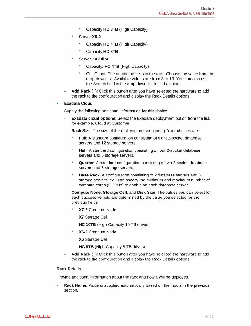
* Capacity HC 8TB (High Capacity)
* Server X5-2
* Capacity HC 4TB (High Capacity)
* Capacity HC 8TB
* Server X4 Zdlra
* Capacity: HC 4TB (High Capacity)
* Cell Count: The number of cells in the rack. Choose the value from thedrop-down list. Available values are from 3 to 13. You can also usethe Search field in the drop-down list to find a value.
– Add Rack (+): Click this button after you have selected the hardware to addthe rack to the configuration and display the Rack Details options.
• Exadata Cloud
Supply the following additional information for this choice:
– Exadata cloud options: Select the Exadata deployment option from the list,for example, Cloud at Customer.
– Rack Size: The size of the rack you are configuring. Your choices are:
* Full: A standard configuration consisting of eight 2-socket databaseservers and 12 storage servers.
* Half: A standard configuration consisting of four 2-socket databaseservers and 6 storage servers.
* Quarter: A standard configuration consisting of two 2-socket databaseservers and 3 storage servers.
* Base Rack: A configuration consisting of 2 database servers and 3storage servers. You can specify the minimum and maximum number ofcompute cores (OCPUs) to enable on each database server.
– Compute Node, Storage Cell, and Disk Size: The values you can select foreach successive field are determined by the value you selected for theprevious fields:
* X7-2 Compute Node
X7 Storage Cell
HC 10TB (High Capacity 10 TB drives)
* X6-2 Compute Node
X6 Storage Cell
HC 8TB (High Capacity 8 TB drives)
– Add Rack (+): Click this button after you have selected the hardware to addthe rack to the configuration and display the Rack Details options.
Rack Details
Provide additional information about the rack and how it will be deployed.
• Rack Name: Value is supplied automatically based on the inputs in the previoussection.
Chapter 3OEDA Browser-based User Interface
3-10
• Rack Prefix: Defines the prefix for network interfaces. The prefix can contain anyalphanumeric character. The prefix cannot contain spaces. The maximum length is20 characters. This field cannot be empty. The default value is dm01.
For example, a value of dm01 results in a database server host name of dm01db01,and a storage server host name of dm01cel01.
• Spine Switch: Click the check box if you want to include a spine switch as part ofthe rack configuration. Do this for each rack that will have a spine switch.
Customer Details
Provide information about the environment in which the rack will be deployed.
• Customer Name: Identifies the customer. This is a free-form field that can containany alphanumeric characters, including spaces. This field cannot be empty.
• Application Name: Identifies the application used with the rack. This is a free-form field that can contain any alphanumeric characters, including spaces. Thisfield cannot be empty.
• Region: Sets the region for the rack. Choose a value from the drop-down list. Youcan also use the Search field to locate a region. Your choices are:
– Africa
– America
– Antarctica
– Arctic
– Asia
– Atlantic
– Australia
– Europe
– Indian
– Other
– Pacific
• Timezone: Sets the time zone where the rack will be installed. The time zonesshown are based on the selected region. Choose a value from the drop-down list.
• Compute Node #: (only for X5-2 and X6-2 ZDLRA Elastic Rack) Specifies thenumber of compute nodes to configure
• Storage Node #: (only for X5-2 and X6-2 ZDLRA Elastic Rack) Specifies thenumber of storage nodes to configure
• DNS Servers: Sets the DNS IP Address. At least one IP address must be entered.For Exadata Cloud, these values are provided for you.
• NTP Servers: Sets the IP Address for the Network Time Protocol (NTP) server. Atleast one IP address must be entered. For Exadata Cloud, these values areprovided for you.
Chapter 3OEDA Browser-based User Interface
3-11
WriteBack Flash Cache
Specify whether to enable WriteBack Flash Cache when the rack is deployed.WriteBack flash cache provides the ability to cache write I/Os directly to PCI flash inaddition to read I/Os. This option is not available for Exadata Cloud.
Your choices are:
• Automatic: Default value. When selected, WriteBack Flash Cache will be enabledif the rack is running a software version that supports WriteBack Flash Cache, andif using WriteBack Flash Cache is a best practice for that software version.
• Disable: This options disables WriteBack Flash Cache, and only read IOs arestored in the Flash Cache.
• Enable: This option enables storing both read and write IOs in the Flash Cache.
Capacity on Demand
(Available for only Exadata racks X3 and later) Click this check box to reduce the initialnumber of active cores on the servers.
If you select this option, a slider bar appears which allows to select the number ofactive cores, with a range that is specific to the hardware model of the databaseserver.
Note:
To qualify for Capacity on Demand, within 3 months after installation, thisExadata system must use either Platinum Services, Oracle EnterpriseManager Harvester (in disconnected or connected mode) or OracleConfiguration Manager (in connected mode).
Add Additional Racks
You can start at the top of the page and provide the information for an additional rack.Click the Add Rack (+) button to add the rack to the configuration. An additional tabappears in the Rack Details section.
Save
After you have entered all the information for the racks being configured, click theSave button in the lower right corner of the page.
3.2.3 Choose Operating System PageSelect the operating system to install on the servers in the rack.
This page is not available for Exadata Cloud configurations.
For Oracle Exadata Rack, your choices are:
• All Linux Ovm: All database servers running Oracle VMs on Oracle Linux.
• All Linux Physical: All database servers installed with Oracle Linux withoutOracle VMs.
Chapter 3OEDA Browser-based User Interface
3-12
• Custom: Specify which database servers are installed with Oracle VMs, andwhich are not.
Choosing this option displays a list of available database servers. You must selectone of the following options for each database server:
– Linux Physical: No Oracle VM
– Linux Dom0: Oracle VM
You can also select the option just under the heading Linux Physical or LinuxDom0 to select that option for all the database servers in the list.
For ZDLRA racks, your choices are:
• All Linux Physical: All compute nodes installed with Oracle Linux without OracleVMs.
• Custom: You can manually select the compute nodes to configure as LinuxPhysical nodes.
3.2.4 Rack Networks PageProvide the information necessary to configure the administration and private networkson the rack.
Each compute node and storage server has two network interfaces for administration.One network provides management access to the operating system through theEthernet interface, and the other network provides access to the Integrated Lights OutManager (ILOM) through the ILOM Ethernet interface. Default administration networkhost names are usually changed to meet corporate naming standards or compatibilitywith existing systems.
In the upper right corner of the Admin Network section is a line that displays the TotalIP Addresses that will be configured for the rack. This value is based on the hardwareyou selected on the Hardware page.
You provide the following information on this page:
Admin Network
Supply values for the following fields. For Exadata Cloud, these values are providedfor you.
• Default gateway for database servers: A check box that indicates that thegateway IP address is the default gateway for the database servers.
• Gateway: Sets the IP address for the gateway. This field cannot be empty.
• Start IP Address: Assigns the starting IP address for the administration networkof the servers and switches. This field cannot be empty.
Oracle Exadata Deployment Assistant (OEDA) generates a pool of consecutive IPaddresses based on the specified Start IP Address. If consecutive IP addressesare not available, then specific IP addresses can be modified during theconfiguration process.
Chapter 3OEDA Browser-based User Interface
3-13
Note:
These addresses are also assigned to the ILOM ports on the databaseand storage servers
• Subnet Mask: Sets the IP address mask for the subnet. You can choose a subnetmask from the drop-down list which contains supported values from 255.0.0.0 to255.255.255.252
• Domain Name: Sets the network domain name. Use lowercase letters for thename. This field cannot be empty.
The domain name specified on this page is used as the domain for all networks. Ifdifferent domains are used for the client and backup networks, then specify theadministration network on this page. The client and backup networks can bechanged on the Cluster Networks page.
• Separate ILOM Network: (Not available with Exadata Cloud) A check box thatindicates that Integrated Lights Out Manager (ILOM) uses a network that isdifferent from the administration network. If you check this option, you must specifythe following additional information for the ILOM network:
– Gateway
– Start IP Address
– Subnet Mask
– Domain Name
Advanced
(Not available with Exadata Cloud) If you click the Advanced button in the upper rightcorner of this page, you can select the following options:
• Remove PDU's — Select this option if you do not want to add administration IPaddresses to the PDUs. If you select this option, then OEDA does not allocate IPaddresses for each of the two PDUs in the rack, and the administration names donot appear in the Admin network Review and Edit section of this page.
• Enable Vlan — Allows you to create VLANs on database servers and storageservers for the admin network, ILOM, client and the backup access network. If youselect this option, then the following additional fields are visible on the AdminNetwork page:
– Vlan — Specifies the VLAN identifier. The value must be a positive integer.
Note:
* If your system will use more than 10 VIP addresses in the clusterand you have VLAN configured for the Oracle Clusterware clientnetwork, then you must use 3 digit VLAN ids.
* Do not use 4 digit VLAN ids because the VLAN name canexceed the 15 character operating system interface name limit.
Chapter 3OEDA Browser-based User Interface
3-14
Modify Masks
(Not available with Exadata Cloud) If you click the button Modify Masks, it opens apopup window where you can enter the following information:
• Compute Name Mask — There is a preview field at the bottom of this window thatshows how the generated administration names will appear based on the valuesyou specify for the following fields:
Note:
In the following fields, the name prefix can contain alphanumericcharacters. The percent signs (%) in the names are replaced by thenumbers entered into the Start ID field. At least one percent sign isrequired in each mask field. If you use more than one percent sign in amask field, the symbols must be contiguous. For example, you can usetest%%-ilom, but not test%new%-ilom.
– Compute Name Mask: The string used to generate administration names foreach database server in this rack. The default string is {Rack Prefix}adm%%,which results in names such as dbm0adm01, dbm0adm02, and so on. This fieldcannot be empty.
– Compute Name Start Id: The starting value to use when generating thedatabase server administration names. The default value is 1. This fieldcannot be empty.
• Compute ILOM Mask — There is a preview field at the bottom of this section thatshows how the generated administration names will appear based on the valuesyou specify for the following fields:
– Compute ILOM Mask: The string used to generate administration names foreach database server ILOM in this rack. The default string is {Compute NameMask}%-ilom, which results in names such as dbm0adm01–ilom, dbm0adm02–ilom,and so on. This field cannot be empty.
– ILOM Name Start Id: The starting value to use when generating the ILOMadministration names. The default value is the same value as Compute NameStart Id. This field cannot be empty.
Note:
Oracle recommends using the same starting IDs for the servers andserver ILOMs.
• Storage Name Mask — There is a preview field at the bottom of this section thatshows how the generated administration names will appear based on the valuesyou specify for the following fields:
– Storage Name Mask: The string used to generate administration names foreach storage server. The default string is {Rack Prefix}celadm%%, which resultsin names such as dbm0celadm01, dbm0celadm02, and so on. This field cannot beempty.
Chapter 3OEDA Browser-based User Interface
3-15
– Storage Name Start Id: The starting value to use when generating thestorage server network names. The default value is 1. This field cannot beempty.
• Storage ILOM Mask — There is a preview field at the bottom of this section thatshows how the generated server names will appear based on the values youspecify for the following fields:
– Storage ILOM Mask: The string used to generate administration names foreach storage server ILOM in this rack. The default string is {Storage NameMask}%-ilom, which results in names such as dbm0celadm01–ilom, dbm0celadm02–ilom, and so on. This field cannot be empty.
– Storage Name Start Id: The starting value to use when generating the ILOMnetwork names. The default value is the same value as Storage Name StartId. This field cannot be empty.
Note:
Oracle recommends using the same starting IDs for the servers andserver ILOMs.
• Switches and PDUs
– Cisco Switch — The string used to generate the administration name for theCisco switch in this rack. The default value is {Rack Prefix}sw-adm%, whichresults in names such as dbm0sw-adm1.
– InfiniBand Spine Switch — The string used to generate the administrationnames for the spine switch, if your rack is configured with one. The defaultvalue is {Rack Prefix}sw-ibs%, which results in names such as dbm0sw-ibs1.
– InfiniBand Leaf Switch — The string used to generate the administrationnames for the second InfiniBand Leaf switch in this rack. The default value is{Rack Prefix}sw-iba%, which results in names such as dbm0sw-iba1.
– InfiniBand Leaf Switch — The string used to generate the administrationnames for the first InfiniBand Leaf switch in this rack. The default value is{Rack Prefix}sw-ibb%, which results in names such as dbm0sw-ibb1.
– PDU-A — The string used to generate the administration names for PowerDistribution Unit (PDU) A in this rack. The default value is {Rack Prefix}sw-pdua%, which results in names such as dbm0sw-pdua1.
– PDU-B — The string used to generate the administration names for PowerDistribution Unit (PDU) B in this rack. The default value is {Rack Prefix}sw-pdub%, which results in names such as dbm0sw-pdub1.
– KVM Switch — (Exadata X2-2 only) The string used to generate theadministration name for the keyboard, video, and mouse (KVM) switch. Thedefault value is {Rack Prefix}sw-kvm%, which results in names such as dbm0sw-kvm1.
After you have entered the custom network name masks, click the Save button at thebottom of the page. To undo your changes, you can either close the window or clickthe Cancel button at the bottom of the page.
Chapter 3OEDA Browser-based User Interface
3-16
Admin network Review and Edit
After you save the input provided for the admin network, the Admin network Reviewand Edit section appears above the Private Network section. Here you can view all theIP addresses and administration names that will be configured for your rack, andmodify them if needed. If you make any modifications to the administration name ortheir IP addresses, click the Update button when you have finished to save yourchanges.
If you are connected to the same network on which the rack will be deployed, you cancheck the validity of the network configuration data. Click the Lookup IP button at thebottom of this section. OEDA will display any invalid IP addresses. The Lookup IPbutton is not available with Exadata Cloud.
Private Network
Provide the information necessary to configure the private network on the rack.
In the upper right corner of the Private Network section is a line that displays the TotalIP Addresses that will be configured for the rack. This value is based on the hardwareyou selected on the Hardware page. For Exadata Cloud, these values are provided foryou.
• Enable active bonding — (Exadata and ZDLRA racks only, X4-2 or higher)Specifies whether active bonding should be enabled for only the private networkon compute nodes. By default this option is selected. You should only use a non-default option if you are adding a compute node to a cluster that contains othercompute nodes that are X3 or earlier models.
• Start IP Address: Assigns the starting IP address for the private network of theservers. This field cannot be empty.
OEDA generates a pool of consecutive IP addresses based on the specified StartIP Address. If consecutive IP addresses are not available, then specific IPaddresses can be modified during the configuration process.
• Subnet Mask: Sets the IP address mask for the subnet. You can choose a subnetmask from the drop-down list. The list contains supported values from255.255.240.0 to 255.255.255.252
• Domain Name: Sets the network domain name. The default value is the domainname value entered for the Admin Network. Use lowercase letters for the name.This field cannot be empty.
(Not available with Exadata Cloud) If you click the Modify Masks button, it opens apopup window where you can modify the generated names for the database andstorage server private names. There are preview fields at the bottom of this windowthat shows how the generated private names will appear based on the values in thename mask fields. The default strings used to generate the private names are:
• Compute private name mask: {Rack prefix}adm%%-priv, which results in namessuch as dbm0adm01–priv, dbm0adm02–priv, and so on
• Cell private name mask: {Rack Prefix}celadm%%-priv, which results in names suchas dbm0celadm01–priv, dbm0celadm02–priv, and so on.
After you have entered the custom private network name masks, click the Save buttonat the bottom of the page. To undo your changes, you can either close the window orclick the Cancel button at the bottom of the page.
Chapter 3OEDA Browser-based User Interface
3-17
After you have entered the private network configuration information, click the Savebutton at the bottom of the page.
Private network Review and Edit
After you save the input provided for the private network, the Private network Reviewand Edit section appears above the User(s) and Groups section. Here you can view allthe IP addresses and private host names that will be configured for your rack, andmodify them if needed. If you make any modifications to the private host names ortheir IP addresses, click the Update button at the bottom of this section when youhave finished to save your changes.
3.2.5 Users and GroupsProvide information about the operating system users to use when installing Oraclesoftware. The user information you provide is saved in a collection, that can bereferenced later in the configuration process.
For Exadata Cloud, the Role Separated option is selected by default and all the valuesare populated automatically. The only values you can change are the group IDnumbers. For ZDLRA racks, the Default option is selected automatically, and the onlyvalues you can modify are the user and group IDs.
The first selection is the type of users you want to define. Your options are:
• Default: (Not available for Exadata Cloud) Use the default installation userinformation. This option creates a single operating system user to own the OracleGrid Infrastructure and Oracle Database software.
• Role Separated: (Not available for ZDLRA) Create users for specific roles for thesoftware installation. The new users are granted only the privileges necessary forthat role.
• Custom: (Exadata racks only) Create software installation users that havecombined roles or special roles and privileges.
If you plan to have multiple installations of Oracle software on your rack that requiredifferent operating system users, then, after you have entered the user information,you can click the Add group (+) button. The information you entered is saved with thelabel UserCollection-1_id. A new section appears on the page where you can enterinformation for an additional group of software installation users with distinct namesand permissions. The new user information collection is automatically assigned thelabel UserCollection-2_id.
If you want to remove a user information collection, click the Delete Group (-) buttonnext to the ID of the group you want to remove.
After you have entered all the user information, click the Save button at the lower rightside of the page to continue.
Default User Information
If you selected to create Default users, then you must supply the following information:
• User Name: The operating system user name for the database software owner.This field cannot be empty. The default value is oracle.
• User Id: The operating system identification number for this user. This field cannotbe empty. The default value is 1001.
Chapter 3OEDA Browser-based User Interface
3-18
• Home Directory: The user home directory. This field cannot be empty. Thedefault value is /home/oracle.
• User Type: This field is not available if you select the Default option. The nameduser will be created as the Grid and Database software owner.
• Group Name: The name of the operating system group that will be the DBAgroup. All the operating system privileges necessary for managing the OracleDatabase software are granted to this group. This field cannot be empty. Thedefault value is dba.
• Group Id: The operating system identification number for this group. This fieldcannot be empty. The default value is 1001.
• Group Type: This field is not available if you select the Default option. The namedgroup will be created as an DBA GROUP group.
• Group Name: The name of the operating system group that will be the installationowner group. All the operating system privileges necessary for installing theOracle Grid Infrastructure and Oracle Database software are granted to this group.This field cannot be empty. The default value is oinstall.
• Group Id: The operating system identification number for this group. This fieldcannot be empty. The default value is 1002.
• Group Type: This field is not available if you select the Default option. The namedgroup will be created as an OINSTALL group.
Role Separated User Information
If you selected to create Role Separated users, then there are two types of users forwhich you must provide user information: Grid and database. The page is split into twosections, one for each user type. The first section defines the Grid users and thesecond section defines the database users.
• User Type: Grid
In this section you specify the user to own the Oracle Grid Infrastructureinstallation, and the role-separated groups used to manage Oracle ASM. You mustprovide information for 3 administrative operating system groups, and theinstallation group. The default administrative group types are ASMDBA,ASMOPER, and ASMADMIN. The group type can be one of the following:
– OINSTALL
– OSDBA
– OSOPER
– OSASM
– ORADBA
– DBA GROUP
– OPER GROUP
– ASMDBA
– ASMOPER
– ASMADMIN
– Software installation user information:
Chapter 3OEDA Browser-based User Interface
3-19
* User Name: The operating system user name for the Oracle GridInfrastructure software owner. This field cannot be empty. The defaultvalue is grid.
* User ID: The operating system identification number for this user. Thisfield cannot be empty. The default value is 1000.
* Home Dir: The user home directory. This field cannot be empty. Thedefault value is /home/grid.
– Oracle ASM DBA group information:
* Group Name: The name of the operating system group that will be theOracle ASM DBA group. The default value is asmdba. Membership in thisgroup enables access to the files managed by Oracle ASM. This fieldcannot be empty.
* Group Id: The operating system identification number for the Oracle ASMDBA group. This field cannot be empty. The default value is 1004.
* Group Type: The group type. The default value is ASMDBA.
– Oracle ASM Operator group information:
* Group Name: The name of the operating system group that will be theOracle ASM Operator group. The default value is asmoper. This group ofoperating system users has a limited set of Oracle ASM instanceadministrative privileges that includes starting and stopping the OracleASM instance. This field cannot be empty.
* Group Id: The operating system identification number for the Oracle ASMOperator group. This field cannot be empty. The default value is 1005.
* Group Type: The group type. The default value is ASMOPER.
– Oracle ASM Administrator group information:
* Group Name: The name of the operating system group that will be theOracle ASM Administrator group. The default value is asmadmin. This fieldcannot be empty.
This group uses SQL to connect to an Oracle ASM instance as SYSASMusing operating system authentication. The SYSASM privileges permitmounting and dismounting of disk groups, and other storageadministration tasks. SYSASM privileges provide no access privileges onan Oracle Database instance.
* Group Id: The operating system identification number for the Oracle ASMAdministrator group. This field cannot be empty. The default value is 1006.
* Group Type: The group type. The default value is ASMADMIN.
– Oracle software installation group information:
* Group Name: The name of the operating system group that owns theOracle Inventory. The default value is oinstall. This field cannot beempty.
* Group Id: The operating system identification number for the OracleInventory group. This field cannot be empty. The default value is 1001.
* Group Type: The group type. This value is automatically set to OINSTALLand cannot be changed.
• User Type: database
Chapter 3OEDA Browser-based User Interface
3-20
In this section you specify the user to own the Oracle Database installation, andthe role-separated groups used to manage Oracle Database. You must provideinformation for 2 administrative operating system groups, and the installationgroup. The default administrative group types are ORADBA and RACOPER. The grouptype can be one of the following:
– OINSTALL
– OSDBA
– OSOPER
– OSASM
– ORADBA
– DBA GROUP
– OPER GROUP
– ASMDBA
– ASMOPER
– ASMADMIN
– Software installation user information:
* User Name: The operating system user name for the Oracle Databasesoftware owner. This field cannot be empty. The default value is oracle.
* User ID: The operating system identification number for this user. Thisfield cannot be empty. The default value is 1001.
* Home Dir: The user home directory. This field cannot be empty. Thedefault value is /home/oracle.
– Oracle Database DBA group information:
* Group Name: The name of the operating system group that will be theOracle Database DBA group. The default value is dba. This field cannot beempty.
* Group Id: The operating system identification number for the OracleDatabase DBA group. This field cannot be empty. The default value is1002.
* Group Type: The group type. The default value is ORADBA.
– Oracle RAC Operator group information:
* Group Name: The name of the operating system group that will be theOracle RAC Operator group, or other group type you select. The defaultvalue is racoper. This group of operating system users has a limited set ofOracle RAC instance administrative privileges that includes starting andstopping the Oracle RAC database instances. This field cannot be empty.
* Group Id: The operating system identification number for the Oracle RACOperator group, or other group type that you select. This field cannot beempty. The default value is 1003.
* Group Type: The group type. The default value is RACOPER.
– Oracle software installation group information:
Chapter 3OEDA Browser-based User Interface
3-21
* Group Name: The name of the operating system group that owns theOracle Inventory. The default value is oinstall. This field cannot beempty.
* Group Id: The operating system identification number for the OracleInventory group. This field cannot be empty. The default value is 1001.
* Group Type: The group type. This value is automatically set to OINSTALLand cannot be changed.
Custom User and Group Information
If you selected the Custom option, then you must provide user and group informationfor managing the Oracle software installations. You can specify multiple users. Youprovide information for the software administrative operating system groups and users.The group type can be one of the following:
• OINSTALL
• OSDBA
• OSOPER
• OSASM
• ORADBA
• DBA GROUP
• OPER GROUP
• ASMDBA
• ASMOPER
• ASMADMIN
For each user you must provide the following information:
• User Name: The operating system user name that will own the Oracle software.This field cannot be empty. The default value is oracle.
• User Id: The operating system identification number for this user. This field cannotbe empty.
• Home Directory: The user home directory. This field cannot be empty. Thedefault value is /home/username.
• User Type: The type of software user. You can choose from the following values:
– Grid and Database: The user will have permissions for both the OracleDatabase and the Oracle Grid Infrastructure software installations.
– Grid: The user will have permissions for the Oracle Grid Infrastructuresoftware installation.
– Database: The user will have permissions for the Oracle Database softwareinstallation.
– custom: The user type does not fit a pre-defined model.
• Group Name: The name of the operating system group to which the user will beassigned. This field cannot be empty.
• Group Id: The operating system identification number for the operating systemgroup. This field cannot be empty.
Chapter 3OEDA Browser-based User Interface
3-22
• Group Type: The group type. You can choose from the list of pre-defined grouptypes.
After you have entered the user and group information, you can click the Add User (+)button to add a new section. You can also click the Add Group (+) button to add anadditional operating system group for the specified user.
Save
After you have entered all the information for the racks being configured, click theSave button in the lower right corner of the page.
3.2.6 Define ClustersMore than one cluster can be defined for a hardware racks. Larger environmentssupport multiple clusters. Each cluster requires a minimum of two physical or virtualcompute nodes, and three storage cells. You cannot mix physical and virtual computenodes in the same cluster. If you selected All Linux Ovm on the Operating Systempage and you have specified multiple clusters, then the compute nodes can appear inmore than one cluster and OEDA will creates a guest for each cluster on the node.Each cluster is independent and can have different software versions.
For Exadata Cloud configurations, there is one cluster created. You can specify thename of the cluster and the usable space for the cluster, but all other details are notmodifiable.
Provide the information for the first cluster and assign nodes to the cluster using theAdd Node (>) button to move selected nodes or the Add All Nodes (>>) button toassign all available nodes to the cluster. If you want to add a second cluster, then clickthe Add Cluster (+) button next to the cluster name tab.
Provide the following information for each cluster in the rack:
• Cluster Name: The cluster name, which must be unique across your enterprise.The cluster name is case-insensitive, must be at least one character long and nomore than 15 characters in length, must be alphanumeric, cannot begin with anumeral, and may contain hyphens (-). Underscore characters (_) are not allowed.This field cannot be empty.
• Inventory Location: The Oracle inventory (oraInventory) directory path. Thedefault value is /u01/app/oraInventory.
• Grid Home Owner: Use the drop-down list to select the collection of userinformation previously created on the Users page. By default, the first usercollection is selected.
• Grid Infrastructure Home Location: The Oracle Grid Infrastructure directorypath, which typically includes the software release number. The default valueis /u01/app/release_number/grid, for example, /u01/app/18.2.0.0/grid.This value is automatically set depending on the value selected for ClusterVersion. You can overwrite the default value.
• Cluster Version: After you select the nodes to assign to this cluster, you will beable to select the cluster version from the drop-down list. The list contains allsupported versions of the Oracle Grid Infrastructure. Choose any of the supportedvalues.
• Base Directory: The base directory for the Oracle Grid Infrastructure software.The default value is /u01/app/grid.
Chapter 3OEDA Browser-based User Interface
3-23
After you assign nodes to the cluster, you can modify the default values for eachcluster, if needed. The following customer information fields appear below theAvailable Machines list:
• Customer Name: The customer name. The default value is the value youprovided earlier on the Hardware page in the Customer Details section.
• Application: The application name or description. The default value is the valueyou provided earlier on the Hardware page in the Customer Details section.
• Region: The geographical location of the rack. The default value is the value youprovided earlier on the Hardware page in the Customer Details section.
• Time zone: The time zone in which the rack is located. The default value is thevalue you provided earlier on the Hardware page in the Customer Details section.
• DNS Servers: The IP addresses for the DNS servers. The default values are thevalues you provided earlier on the Hardware page in the Customer Details section.
• NTP Servers: The IP addresses for the NTP servers. The default values are thevalues you provided earlier on the Hardware page in the Customer Details section.
The following additional information fields help allocate resources across multipleclusters:
• Cores: The number of cores to use for each guest VM for this cluster. This fieldcannot be empty.
• Memory: The amount of memory in GB allocated to the guest VMs, or userdomains (domU), for this cluster. This field cannot be empty.
• Local Disk(GB): The amount of local disk space to use on the servers for thiscluster. This field cannot be empty.
If you assign Oracle VMs to your cluster, then you need to provide the followinginformation:
• Guest Image Version: The Oracle Exadata System Software image version forguest VMs. Use the drop-down list to select the value. Selecting the default optionsets the guest image version to match the image version of dom0.
Note:
The guest image version must be the same as or an earlier version thanthe image version of the management domain (dom0).
3.2.7 DiskgroupsDefine the Oracle ASM disk groups and their sizes for each cluster in the rack. Thispage is not available for Exadata Cloud.
If you specified more than one cluster, use the tabs at the top of this page to selecteach cluster and provide the disk group information.
ZDLRA Racks
For ZDLRA racks, the following information is used:
• Diskgroup name: Automatically set to CATALOG and DELTA
Chapter 3OEDA Browser-based User Interface
3-24
• Diskgroup Type: Automatically set to CATALOG and DELTA
• Redundancy: The CATALOG disk group is configured to use NORMALredundancy. For the DELTA disk group, you can choose either HIGH or NORMAL(default).
• Size: The CATALOG disk group has a size of Default, and the DELTA disk grouphas a size of 95%.
• Size Type: The disk group sizes are specified as percent.
After you have entered the values for the disk groups and clicked Save, the followingfields are then populated with the estimated values:
• CATALOG disk group — The usable space and raw size are set to default.
• DELTA disk group — The values depends on the hardware selected, for example,with NORMAL redundancy selected, there is 312007GB of usable space and624013GB raw disk size for HC 10TB disks.
Exadata Racks
For Exadata racks, you must provide the following information:
• Diskgroup layout: The ratios to use when creating the disk groups. The optionsare:
– Legacy 80% 20% — Useful when using external backups. The DATA diskgroup is assigned 80% of the available disk space and the RECO disk group isassigned 20% of the available disk space.
– Legacy 40% 60% — Useful when using internal backups. The DATA diskgroup is assigned 40% of the available disk space and the RECO disk group isassigned 60% of the available disk space.
– Custom — Select this option when you want a non-standard layout for thedisk groups. For example, if you want to create additional disk groups, or usepercentages that are not 20%, 40%, 60%, or 80%.
• Diskgroup name: The name for the disk group. You must specify a name for eachdisk group you specify. Default names are provided, such as DBFSC1, DATAC1and RECOC1.
Note:
If you selected X7 hardware, then you cannot specify any information forthe DBFS disk group.
• Type: The type of data to store in the disk group. Possible values are DATA, RECO,DBFS (automatically supplied).
• Redundancy: The redundancy level for the disk group. Possible values are HIGH,NORMAL, or UNUSED.
Note:
Oracle recommends the use of HIGH redundancy disk groups for missioncritical applications.
Chapter 3OEDA Browser-based User Interface
3-25
• Size: The amount of available disk space to use when creating this disk group.You can enter either a percentage, such as 40%, or the actual size specified in GBor TB, such as 250GB. For the DBFS disk group, the size is set to Default.
• Size Type: Whether the value specified was a percentage or actual disk size. Thedrop-down list contains the values percent, usable size, or slice size. You mustuse the same Size Type for all disk groups.
You can configure additional disk groups by clicking the Add new diskgroup (+)button. Enter the same information for the new diskgroup as you did for the DATA andRECO disk groups. For the Type, you must specify a different type, such asDBFS_DG. If you try to create more than one DATA or one RECO disk group, you willget an error when you click Save. If you want to remove a disk group, you can click theremove last diskgroup (-) button. You must have at least one DATA and one RECOdisk group.
After you have entered the values for the disk groups, click Save. The following fieldsare then populated with the estimated values:
• Usable Space — The amount of usable disk space available in the disk group,accounting for redundancy, for example 204355GB.
• Raw Size — The total disk space used by the disk group, for example 613066GB.
Advanced Options
In the upper right corner of this page is a check box labeled Advanced. If you click thisbox, then the following options are available:
• Enable sparse diskgroup — Enables the creation of sparse disk groups. Sparsegrid disks can be used to create a sparse disk group to store database files thatwill use a small portion of their allocated space. Sparse grid disks allocate spaceas new data is written to the disk, and therefore have a virtual size that can bemuch larger than the actual physical size.
Note:
To create a sparse disk group, the version of Oracle Grid Infrastructuresoftware needs to be release 12.1.0.2 BP5 or later.
If you choose this option, a new disk group appears in the list, with a default nameof SPARSEC1. Also, the Type field for this disk group is set to SPARSE.
• Configure Acfs — a button that opens a popup window where you can configureOracle ASM Cluster File System (Oracle ACFS). Oracle ACFS provides a generalpurpose file system. The following information is required to configure OracleACFS:
– Enable ACFS for disk group — you must check this option.
– Diskgroup — The disk group to use as the Oracle ACFS disk group, Thedrop-down list contains the names of the disk groups specified on theDiskgroups page.
Chapter 3OEDA Browser-based User Interface
3-26
Note:
You should use a different group than DATA or RECO for OracleACFS. Use the Add new diskgroup (+) button on the Diskgroupspage to add another disk group.
– ACFS Volume Name — The volume name to associate with this disk group.This field cannot be empty.
– ACFS Volume Size — The size of the Oracle ACFS volume. This field cannotbe empty.
– ACFS Mount Path — The mount path for the Oracle ACFS volume. This fieldcannot be empty.
When you have finished configuring Oracle ACFS, click the Save button in the ACFSConfiguration window.
3.2.8 Database HomeProvide information for configuring the Oracle Database software installation.
This page is not available for Exadata Cloud configurations.
Specify how to configure the Oracle Database software installation by providing thefollowing information:
• DB Home Type: The type of Oracle Database deployment — either RAC Home(for Oracle Real Application Clusters (Oracle RAC) or Oracle RAC One Node) orsingle instance.
• Select Cluster: The cluster on which to deploy the Oracle Database software.This is a drop-down list that is populated with the cluster names specified on theClusters page. By default, the first cluster is selected.
• Database Home Name: A name given to the Oracle Database softwareinstallation. This name identifies the program group associated with a particularhome and the Oracle services installed on this home. The Oracle home namemust be between 1 to 127 characters long, and can include only alphanumericcharacters and underscores. This field cannot be empty. The default value isDbHome_1.
• Database Home Version: The version of the Oracle Database software to installin the cluster. Choose the value from the drop-down list. The most recent versionis selected by default.
• Database Home Location: A directory path where the Oracle Database softwarewill be installed. This value is set automatically based on the value specified forthe Database Home Version. For example, if you select version 12.1.0.2 DBBP13,then the Database Home Location is set to /u01/app/oracle/product/12.1.0.2/dbhome_1. After specifying the Database Home Version, you cantype over the default value to use a different location, if needed. This field cannotbe empty.
• Database Home Owner: Use the drop-down list to select the collection of userinformation previously created on the Users page. By default, the first usercollection is selected.
Chapter 3OEDA Browser-based User Interface
3-27
• Base Directory: The Oracle Base directory location. The Oracle Database binaryhome is located underneath the Oracle base path. You can use the same Oraclebase directory for multiple installations of Oracle software. If different operatingsystem users install Oracle software on the same system, then you must create aseparate Oracle base directory for each installation owner. This field cannot beempty. The default value is /u01/app/oracle.
• Available Computes and Selected Computes — If you chose Single InstanceHome for the DB Home Type, then you select the database servers on which youwant to install the Oracle Database software. If you selected RAC Home for theDB Home Type, then the Oracle Database software is automatically installed onevery database server in the specified cluster.Use the Add Node (>) or Add All Nodes (>>) buttons to move servers from theAvailable Computes list to the Selected Computes list. Use the Delete Node (>) orDelete All Nodes (>>) buttons to remove servers from the Selected Computes list.
To specify multiple Oracle homes, use the Add Database Home (+) button at the topof this page, next to the tab for the existing Oracle home. To remove an Oracle Home,click the X on the tab, next to the name of the Oracle home.
When you have finished configuring the Oracle home information, click Save.
3.2.9 DatabaseProvide information about the databases to create in the specified database homedirectories.
For Exadata Cloud configurations, you can specify the name of the database. All otheroptions are pre-configured and cannot be modified.
• Database Type: (Exadata racks only) The type of database to create in thedatabase home selected. If the database software was installed with the typeOracle Real Application Clusters (Oracle RAC) (as specified on the DatabaseHome page), then you can choose to create either a Oracle RAC database or anOracle RAC One Node database. If you selected a DB Home Type of singleinstance for the database home, then the Single Instance DB option is selectedautomatically and cannot be changed.
• Database Name: The name of the database you want to create in the databasehome. The database name (DB_UNIQUE_NAME) portion is a string of no more than 30characters that can contain alphanumeric, underscore (_), dollar ($), and pound(#) characters, but must begin with an alphabetic character. No other specialcharacters are permitted in a database name. The DB_NAME parameter for adatabase is set to the first 8 characters of the database name. The domain portionof the global database name (DB_DOMAIN) uses the value you provided for thedomain when configuring the networks. The values for DB_UNIQUE_NAME.DB_DOMAIN inits entirety must be unique within the enterprise. This field cannot be empty.
• Database Home: The name of the Database Home in which you want to createthe database. This value is automatically populated with the first home specifiedon the Database Home page. Use the drop down list to select the database homename if you specified multiple database homes on the Database Home page.
• Database Owner: Use the drop-down list to select the collection of userinformation previously created on the Users page. By default, the first usercollection is selected.
Chapter 3OEDA Browser-based User Interface
3-28
• Character Sets: (Exadata racks only) Specifies the character set to use with thedatabase. Use the drop-down list to select one of the available values. Charactersets are the encoding schemes used to display characters on your computerscreen. The character set determines what languages can be represented in thedatabase. The recommended value is Unicode AL32UTF8.
• Database Template: (Exadata racks only) The template to use when configuringthe database. Preconfigured databases are based on templates that Oracleprovides or that you create. Each Oracle-provided template is optimized for aparticular workload type. The two options are online transaction processing(OLTP) or data warehousing (DW).
• Block Size: (Exadata racks only) The database block size. The default value is8192. You can use the drop-down list to select a different value. Supported valuesrange from 8KB to 32KB.
• DATA Diskgroup: (Exadata racks only) The name of the Oracle ASM disk groupto use when creating data files for the database. You can use the drop-down list toselect one of the disk groups you configured on the Diskgroups page. The diskgroup selected must have disk group type set to DATA.
• RECO Diskgroup: (Exadata racks only) The name of the Oracle ASM disk groupto use when creating the recovery area for the database. You can use the drop-down list to select one of the disk groups you configured on the Diskgroups page.The disk group selected must have disk group type set to RECO.
• Enable CDB: (Exadata racks only) Select this check box to create the databaseas a Oracle Multitenant container database (CDB) with a single pluggabledatabase (PDB). See "Deciding Between Multitenant Container Databases andNon-CDBs in Oracle RAC" in Oracle Real Application Clusters Installation Guidefor Linux and UNIX for information about whether to select this option. If you selectthis option, then you must provide the following additional information:
– PDB Name: The name of the PDB to create in the container database.
You can use the Add Pdb Name (+) button to add additional PDBs to theconfiguration. If you want to remove a PDB, you can use the Remove Pdb Name(-) button that appears to the right to the PDB name you want to remove.
• Available Computes and Selected Computes — (Exadata racks only) If youchose RAC One Node DB or Single Instance DB for the Database Type, then youselect the database servers on which you want to create the database instance.Selecting one node deploys Oracle RAC One Node on a single node. Oraclerecommends that you select all nodes in the cluster to which you want Oracle RACOne Node to be able to fail over.
Use the Add Node (>) or Add All Nodes (>>) buttons to move servers from theAvailable Computes list to the Selected Computes list. Use the Delete Node (>) orDelete All Nodes (>>) buttons to remove servers from the Selected Computes list.
When you have finished configuring the database configuration information, clickSave.
3.2.10 Cluster NetworksFor Exadata racks and Exadata Cloud configurations, configure the client and backupnetworks for the rack. For ZDLRA racks, configure the Ingest and Replicationnetworks.
Chapter 3OEDA Browser-based User Interface
3-29
Applications access the database servers or compute nodes through the clientEthernet network using Single Client Access Name (SCAN) and Oracle RAC Virtual IP(VIP) addresses. Oracle databases running in Oracle VM guests on Oracle ExadataDatabase Machine are accessed through the client Ethernet network as defined in thissection. Client network configuration in both the management domain (dom0) and userdomains (domUs) is done automatically when the OEDA installation tool creates thefirst user domain during initial deployment.
If VLAN tagging is to be used, then it must be enabled by the customer after the initialdeployment. See the My Oracle Support notes for details.
In the upper right corner of the Cluster Networks page is a line that displays the TotalIP Addresses that will be configured for the rack. This value is based on the hardwareyou selected on the Hardware page. At the top of the section are tabs, eachdesignating one of the clusters you specified on the Clusters page.
Admin Network
For some Exadata rack configurations, at the top of the Cluster Networks section, onthe right side, is a check box Enable Admin network. You can use this option toconfigure an Admin network inside a virtual compute server. This option is notrequired. If you select this option, you can fill in the following information:
• Default gateway for database servers: Select this option if the gateway IPaddress is the default gateway for all database servers
• Defines Domu admin hostname for database servers: Select this option if youwant the name used for the Admin network on a virtual compute server to be usedas the host name for the virtual compute server. If you do not select this option,then the virtual compute server uses the network name assigned to the clientnetwork as the host name.
• Gateway: Sets the IP address for the gateway for the client network. This fieldcannot be empty.
• Start IP Address: The first IP address that will be used for client access to thedatabase servers. This value is filled in automatically, based on the value suppliedfor the gateway. OEDA generates a pool of consecutive IP addresses based onthe specified Start IP Address. If consecutive IP addresses are not available, thenspecific IP addresses can be modified using the Modify Masks button. This fieldcannot be empty.
• Subnet Mask: Sets the IP address mask for the subnet. You can choose a subnetmask from the drop-down list which contains supported values from 255.0.0.0 to255.255.255.252.
• Domain Name: Sets the network domain name for client connections. Uselowercase letters for the name. This field cannot be empty. For Exadata Cloudconfigurations, this value is provided for you.
After you have specified all the configuration details for the Admin network, click theSave button at the bottom of the section, or click Modify Masks to customize thenetwork configuration.
Client Network or Ingest Network
Provide the following information to configure the Client networks for Exadata or Ingestnetworks for ZDLRA racks.
For Exadata racks and ZDLRA racks (but not for Exadata Cloud):
Chapter 3OEDA Browser-based User Interface
3-30
• Default gateway for database servers: Select this option if the gateway IPaddress is the default gateway for all database or compute servers.
• Default hostname for database servers: Select this option if the network namesdefine the host names for the database or compute servers.
• Network Media: (Not for Exadata X7 racks or X7-2 ZDLRA racks) Select thenetwork cable type, either Optical or Copper.
• Client (Ingest) network format: (For Exadata X7 racks or X7-2 ZDLRA racks)Specifies the Ethernet cards, based on the hardware selected on the first pageand the type of cable being used.
Options for X7-2 Systems:
On Exadata X7-2 racks and X7-2 ZDLRA racks, there are 3 available formats forclient networks or ingest networks:
– RJ45/SFP28 Combined on Motherboard
* RJ45 1/10 Gbit
* SFP28 10 Gbit
* SFP28 25 Gbit
– SFP28 PCI Dual Port Card
* SFP28 10 Gbit
* SFP28 25 Gbit
– RJ45 PCI Quad Port Card (extra cost option)
Options for Exadata X7-8 Systems:
On Exadata X7-8 systems, there are 2 available formats for client and backupnetworks:
– RJ45 on Motherboard
– SFP28 PCI Dual Port Cards
* SFP28 10 Gbit
* SFP28 25 Gbit
If you select one of the SFP28 network types on X7-2 or X7-8 systems, you mustadditionally specify whether to use 10 Gbit or 25 Gbit connections.
For Oracle Exadata racks, ZDLRA racks, and Exadata Cloud:
• Bonded: (Not available on X7 Exadata or X7-2 ZDLRA racks, or Exadata Cloud)Select this option if using a bonded network. For X7 racks and Exadata Cloud,only bonded networks are supported.
• LACP: Check this option to enable the Link Aggregation Control Protocol (LACP)on the network.
• Gateway: Sets the IP address for the gateway for the network. This field cannotbe empty.
• Start IP Address: The first IP address that will be used for access to the databaseservers on this network. This value is filled in automatically, based on the valuesupplied for the gateway. OEDA generates a pool of consecutive IP addressesbased on the specified Start IP Address. If consecutive IP addresses are not
Chapter 3OEDA Browser-based User Interface
3-31
available, then specific IP addresses can be modified using the Modify Masksbutton. This field cannot be empty.
• Subnet Mask: Sets the IP address mask for the subnet. You can choose a subnetmask from the drop-down list which contains supported values from 255.0.0.0 to255.255.255.252.
• Domain Name: Sets the network domain name for client or ingest connections.Use lowercase letters for the name. This field cannot be empty. For Exadata Cloudconfigurations, this value is provided for you.
After you have specified all the configuration details for the client or ingest networkconfiguration, click the Save button at the bottom of the section.
Modify Masks
If you click the Modify Masks button, it opens a pop-up window where you can modifythe generated names for the client or ingest network. There are preview fields at thebottom of each section that show how the generated network names will appear basedon the values in the name mask fields. The default strings used to generate thenetwork names are:
• Client Access Details:
– Name:
* Exadata racks: {Rack prefix}db%%, which results in names such asdbm0db01, dbm0db02, and so on
* ZDLRA racks: ingest%%, which results in names such as ingest01,ingest02, and so on
– Start id: The number to start with when generating sequential names.
• Vip details:
– Name:
* Exadata racks: {Rack prefix}db%%-vip, which results in names such asdbm0db01, dbm0db02, and so on
* ZDLRA racks: ingest%%-vip, which results in names such as ingest01–vip,ingest02–vip, and so on
– Start id: The number to start with when generating sequential names.
• Scan details: The configuration details for the single client access network (SCAN)listener.
– Name: The name of the listener. The default value is {Rack prefix}-scan1.
– Port: The network port which the SCAN listener monitors for incomingconnection requests. The default value is 1521.
After you have completed the modifications to the client or ingest networkconfiguration, click the Save button at the bottom of the Client Network Masks window.To undo your changes, you can either close the window or click the Cancel button atthe bottom of the Client Network Masks window.
Advanced
At the very top of the Cluster Networks section, before the Client Network or IngestNetwork configuration details, there is a button for Advanced configuration. If you click
Chapter 3OEDA Browser-based User Interface
3-32
this button, the Advanced options window appears. There are two options you canselect in this window:
• Enable Vlan: Select this option if there is a need for virtual deployments on therack to access additional virtual local area networks (VLANs) on the network, suchas enabling network isolation across user domains.
If you select this option, then in the client or ingest network configuration details,an additional field appears:
– Vlan: The VLAN identifier. The VLAN ID is a numeric value between 1 and4095. You also need to select the Bonded option to enable VLAN. If the Backupor Replication network uses VLAN, then the Client or Ingest network must alsobe configured to use VLAN. If the VLAN ID field is empty, then VLAN is notenabled.
Note:
For all networks, you are responsible for configuring VLAN on the switch.
• Enable InfiniBand Partitioning: Enables InfiniBand partitioning for virtualizedExadata environments. InfiniBand partitions can be defined on a per-cluster basis.If storage servers are shared among multiple clusters, then all clusters will use thesame storage partition key. This option is automatically selected for Exadata Cloudconfigurations.
Client network or Ingest network Review and Edit
After you save the input provided for the client or ingest network, the Client networkReview and Edit or Ingest network Review and Edit section appears. Here you canview all the host names and IP addresses that will be configured for client access tothe database servers in the rack. You can modify any of the settings if needed. If youmake any modifications to the administration name or their IP addresses, click theUpdate button when you have finished to save your changes.
If you are connected to the same network on which the rack will be deployed, you cancheck the validity of the network configuration data. Click the Lookup IP button at thebottom of this section. OEDA will display any invalid IP addresses.
Private Network
This section appears only if you select the Advanced network option Enable InfiniBandPartitioning or if you selected Exadata Cloud for the hardware.
In the upper right corner of the Private Network section is a line that displays the TotalIP Addresses that will be configured for the rack for this section. At the top of thesection are tabs, each designating one of the clusters you specified on the Clusterspage.
You provide the following information for each cluster to configure InfiniBandPartitioning:
• Cluster pkey:
– Pkey: (Not available for Exadata Cloud) Sets the address for the databaseservers or compute nodes. This address is used by all database servers orcompute nodes in the cluster. The first cluster address is set to 0xa010, thesecond cluster address is set to 0xa011, and so on.
Chapter 3OEDA Browser-based User Interface
3-33
Note:
Each cluster must have a unique address.
– Domain Name: (Not available for Exadata Cloud) The domain name for theInfiniBand network, if it is different.
– Start IP Address: Sets the starting IP address for the cluster’s network.Oracle recommends using the default IP address.
– Subnet Mask: (Not available for Exadata Cloud) Sets the subnet mask for theInfiniBand network. The drop-down list contains values from 255.255.240.0 to255.255.255.252.
– Name Mask: (Not available for Exadata Cloud) Defines the mask used togenerate network names for this cluster. The default value is {Rack Prefix}adm%%-priv, which results in names such as dbm0adm01-priv, dbm0adm02-priv, andso on.
– Start Id: (Not available for Exadata Cloud) Sets the starting identifier for thiscluster. The default value is 1.
• Storage pkey (Not available for Exadata Cloud):
– Pkey: Sets the address for the storage servers or cells. This address is usedby all storage servers or cells in the rack. The default value is 0xaa10.
– Domain Name: The domain name for the InfiniBand network for the storageservers or cells, if it is different.
Private network Review and Edit
If you enabled InfiniBand Partitioning, then this section appears after you save theinput provided for the private InfiniBand network. Here you can view all the host namesand IP addresses that will be configured for the private network. You can modify any ofthe settings if needed. If you make any modifications to the Cluster pkey Name orCluster pkey IP addresses, click the Update button when you have finished to saveyour changes.
Backup Network or Replication Network
In the upper right corner of the Backup Network section for Exadata is the optionEnable Backup network. For ZDLRA racks, this option is labeled Enable replicationnetwork. If you select this option, it enables the configuration of a network dedicatedto backups or replication. The Enable Backup network option is automaticallyselected for Exadata Cloud.
In the upper right corner of the Backup Network or Replication Network section is aline that displays the Total IP Addresses that will be configured for each cluster. At thetop of the section are tabs, each designating one of the clusters you specified on theClusters page.
Provide the following information to configure the backup network or replicationnetwork for each cluster:
• Shared client network port: (Not available for Exadata Cloud) Select this option ifthe client and backup networks use the same physical network cables. This optionrequires that both networks have VLAN enabled and share the same network
Chapter 3OEDA Browser-based User Interface
3-34
interface cards (NIC). If this option is not selected, then you must use one set ofcables for the client network and a separate set of cables for the backup network.
• Network Media: (For Exadata X6 racks and earlier and ZDLRA racks) Select thenetwork cable type, either Optical or Copper.
• Backup network format: (For Exadata X7 racks and X7-2 ZDLRA racks only)(Not available for Exadata Cloud) Specifies the Ethernet cards, based on thehardware selected on the first page and the type of cable being used.
Options for Exadata X7-2 racks and X7-2 ZDLRA racks:
On X7-2 racks, there are 3 available formats for client networks.
– RJ45/SFP28 Combined on Motherboard
* RJ45 1/10 Gbit
* SFP28 10 Gbit
* SFP28 25 Gbit
– SFP28 PCI Dual Port Card
* SFP28 10 Gbit
* SFP28 25 Gbit
– RJ45 PCI Quad Port Card (extra cost option)
Options for Exadata X7-8 Racks:
On Exadata X7-8 racks, there are 2 available formats for client and backupnetworks:
– RJ45 on Motherboard
– SFP28 PCI Dual Port Cards
* SFP28 10 Gbit
* SFP28 25 Gbit
If you select one of the SFP28 network types on X7-2 or Exadata X7-8 racks, youmust additionally specify whether to use 10 Gbit or 25 Gbit connections.
• Bonded: (Not available on Exadata X7 racks or Exadata Cloud) Select this optionto use network bonding. For Exadata X7 racks, X7-2 ZDLRA racks, and ExadataCloud, only bonded networks are supported.
• LACP: Check this option to enable the Link Aggregation Control Protocol (LACP)on the network.
• Gateway: Sets the IP address for the gateway for the network. This field cannotbe empty.
• Start IP Address: The first IP address that will be used for the network. This valueis filled in automatically, based on the value supplied for the gateway. OEDAgenerates a pool of consecutive IP addresses based on the specified Start IPAddress. If consecutive IP addresses are not available, then specific IP addressescan be modified using the Modify Masks button. This field cannot be empty.
• Subnet Mask: Sets the IP address mask for the subnet. You can choose a subnetmask from the drop-down list which contains supported values from 255.0.0.0 to255.255.255.252.
Chapter 3OEDA Browser-based User Interface
3-35
• Domain Name: (Not available for Exadata Cloud) Sets the network domain namefor network connections. Use lowercase letters for the name. This field cannot beempty.
After you have specified all the configuration details for the network configuration, clickthe Save button at the bottom of the section.
(Not available for Exadata Cloud) If you click the Modify Masks button, it opens apop-up window where you can modify the generated names for the network. There is apreview field at the bottom of the window that shows how the generated networknames will appear based on the values in the name mask fields. The default stringsused to generate the network names are:
• Name:
– Exadata racks: {Rack prefix}db%%dr, which results in names such asdbm0db01dr, dbm0db02dr, and so on
– ZDLRA racks: {Rack prefix}repl%%, which results in names such asdbm0repl01, dbm0repl02, and so on
• Start id: The number to start with when generating sequential names.
• VIP Name: (For ZDLRA racks) {Rack prefix}repl%%-vip, which results in namessuch as dbm0repl01–vip, dbm0repl02–vip, and so on
• Vip Start id: The number to start with when generating sequential names for theVIP addresses.
(Not available for Exadata Cloud) After you have completed the modifications to thebackup or replication network configuration, click the Save button at the bottom of theBackup Network Masks or Replication Network Masks page. To undo your changes,you can either close the window or click the Cancel button at the bottom of thewindow.
After you have specified all the configuration details for the backup or replicationnetwork configuration, click the Save button at the bottom of the Backup Network orReplication Network section.
Backup or Replication network Review and Edit
If you enabled the Backup network or the Replication network option, then this sectionappears after you save the input provided for the network. Here you can view all thehost names and IP addresses that will be configured for the network. You can modifyany of the settings if needed. If you make any modifications, then click the Updatebutton when you have finished to save your changes.
(Not available for Exadata Cloud) If you are connected to the same network on whichthe rack will be deployed, you can check the validity of the network configuration data.Click the Lookup IP button at the bottom of this section. OEDA will display any invalidIP addresses.
Related Topics
• Enabling 802.1Q VLAN Tagging in Exadata Database Machine over clientnetworks (My Oracle Support Doc ID 1423676.1)
• Implementing Tagged VLAN Interfaces in Oracle VM Environments on Exadata(My Oracle Support Doc ID 2018550.1)
Chapter 3OEDA Browser-based User Interface
3-36
3.2.11 AlertingIn this section you configure alerting (Not available for Exadata Cloud).
You use the following methods for receiving or handling alerts:
• Email with Simple Mail Transfer Protocol (SMTP)
• Simple Network Management Protocol (SNMP)
• Oracle Auto Service Request (ASR)
• Oracle Configuration Manager
• Oracle Enterprise Manager
For ZDLRA, you must configure at least one of the following alerting options:
• Oracle ASR
• SMTP or SNMP alerting
• Oracle Configuration Manager
• Oracle Platinum Services
• Enable Email Alerting: Enables alerts to be delivered automatically throughemail.
– Name: Sets the SMTP email user name that appears in the alert notifications,for example, Oracle Exadata Database Machine. This field cannot be empty.
– Email Address: Sets the SMTP email server used to send alert notifications,for example, mail.example.com. This field cannot be empty.
– SMTP Server: Sets the SMTP email address that sends alert notifications, forexample, [email protected]. This field cannot be empty.
– Port: Sets the SMTP email server port used to send alert notifications, forexample, 25 or 465. This field cannot be empty.
– Send Email Alerts to: Sets the email address for the recipients of the alerts.You can click the Add Email (+) button to add additional recipients. You canuse the Remove Email (-) button to remove an email address that you added.
• Enable SNMP Alerting: Enables using SNMP to deliver alerts.
– SNMP Server: Sets the SNMP server host name., for example,snmp.example.com. This field cannot be empty.
Note:
Additional SNMP targets may be defined after installation of theExadata rack. Refer to the ALTER CELL CellCLI command or the ALTERDBSERVER DBMCLI command.
– Port: Sets the SNMP email server port used to send alert notifications. Thedefault value is 162. This field cannot be empty.
– Community: Sets the SNMP server community. The default value is public.This field cannot be empty.
Chapter 3OEDA Browser-based User Interface
3-37
• Enable ASR Alerting: Enables Oracle Auto Service Request (ASR). Oracle ASRis designed to automatically open service requests when specific rack hardwarefaults occur.
Oracle recommends that you install Oracle ASR Manager on an external,standalone server. The server must be installed have connectivity to the Exadataservers or Recovery Appliance nodes and an outbound Internet connection usingHTTPS or an HTTPS proxy. This server must run an Oracle Solaris or Linuxoperating system.
– ASR Manager Request: The host name of the Oracle ASR Manager server.This field cannot be empty.
– HTTP Proxy Host: If you want to enable an HTTP proxy to upload to OracleASR, then specify the proxy server host name.
– Contact Name: The name of the technical contact person for the rack. Thisfield cannot be empty.
– Contact Email: The e-mail address of the technical contact for the rack. Thisfield cannot be empty.
– HTTP Proxy User: If you want to enable an HTTP proxy to upload to OracleASR, then specify the proxy server user name.
– Port: If you want to enable an HTTP proxy to upload to Oracle ASR, thenspecify the HTTP proxy server port number.
– My Oracle Support Account Name: The email address of the My OracleSupport account. This field cannot be empty.
• Enable OCM Alerting: Enables Oracle Configuration Manager to collectconfiguration information.
Oracle Configuration Manager is used to collect configuration information andupload it to an Oracle repository, for access when needed by Oracle SupportServices.
– MOS Email Address: The My Oracle Support account (email address) toreceive updates from My Oracle Support. This field cannot be empty.
– HTTP Proxy Host: If you use an HTTP proxy to upload configurationinformation to the Oracle repository, then specify the proxy server host name.The proxy server may be between the following:
* Database (compute) servers and Oracle (applicable when you do not haveOracle Support Hub)
* Database (compute) servers and Oracle Support Hub (applicable whenyou have only Oracle Support Hub)
* Oracle Support Hub and Oracle
If passwords are needed, then provide them during installation.
– Support Hub Hostname: The Support Hub server host name. Oracle SupportHub allows Oracle Configuration Manager instances to connect to a singleinternal port (the Oracle Support Hub), and upload configuration data. Thiseliminates the need for each individual Oracle Configuration Manager instancein the database servers to access the Internet. This field cannot be empty.
– HTTP Proxy User: If you want to enable an HTTP proxy to uploadconfiguration information to the Oracle repository, then specify the HTTP proxyserver user name.
Chapter 3OEDA Browser-based User Interface
3-38
– Hub User Name: The Oracle Support Hub operating system user name. Thisfield cannot be empty.
– Port: If you want to enable an HTTP proxy to upload configuration informationto the Oracle repository, then specify the HTTP proxy server port number. Thedefault value is 80.
• Enable EM Alerting: Enables alerts in Oracle Enterprise Manager.
Oracle Enterprise Manager Cloud Control or Oracle Enterprise Manager GridControl is used to monitor the rack. When Oracle Enterprise Manager agents areinstalled on the rack, they can send information to the Oracle Management Server.If you do not have an existing Oracle Management Server, then install a newOracle Management Server on a separate host.
– EM Home Base Location: The base directory for the Oracle EnterpriseManager agents installed on the database or compute servers. The defaultvalue is /u01/app/oracle/product/EMbase. This field cannot be empty.
– OMS HTTPS Upload Port: The port the Oracle Enterprise Manager agentshould use to upload information to the Oracle Management Server. Thedefault value is 4900. This field cannot be empty.
– OMS Host Name: The name of the server or host where the OracleManagement Server repository is installed. This field cannot be empty.
3.2.12 Tape Library ConnectivityOn ZDLRA racks only, you can configure network connection information for tapebackups.
You can configure the tape library for ZDLRA only if you use Oracle Secure Backup asthe media manager for tape backups. You can manually configure other mediamanagers as clients only.
• Use Tape: Select this option if you plan to use Oracle Secure Backup as themedia manager for tape backups. Then you can enter the configuration details.
• Vip IP Address: The IP address of the VIP.
• Vip Name: The alphanumeric name of the VIP. The default value is osbadminvip.{domain_name}.
If you are connected to the same network on which the rack will be deployed, youcan check the validity of the tape library address information. Click the Lookup IPbutton at the bottom of this section. OEDA will display any invalid IP addresses.
• Number of tape libraries: The number of tape libraries available to the ZDLRArack. The default is 1. All tape libraries must be hosted in the same domain. If youselect a value greater than 1, a new tab appears for each tape library. You canenter the configuration details for each tape library on the separate tabs.
• ACLS ACS API: Use the Automated Cartridge System Library Software (ACSLS)API for the tape library. Fill out the following additional fields:
– ACSLS Server: The name of the server running ACSLS
– ACS ID: The ACS identification number
• ACSLS FC-SCSI: Use the Automated Cartridge System Library Software (ACSLS)FC-SCSI for the tape library. Fill out the following additional fields:
– ACSLS Server: The name of the server running ACSLS
Chapter 3OEDA Browser-based User Interface
3-39
– Logical Library ID: The logical library identification number
• SCSI: Use SCSI to communicate with the tape library. The Simple SAN tapelibrary has no configuration fields. This is the default option.
3.2.13 CommentsEnter any additional information about the deployment in the text field.
For Oracle Exadata Rack, this section contains a list of questions about theconfiguration to help ensure a smooth installation and configuration process for yourrack. You can type in the answers in the text field.
For all deployments, you can provide additional comments about your environment orthe deployment in this field.
When you have finished providing the information, click Save and Download. You areprompted to save a ZIP file containing the deployment and configuration files. Themain configuration files are:
Note:
Do not edit or modify any of the generated files.
• Customer_name-rack_prefix.xml: This is the main configuration file used bythe installation process.
• Customer_name-rack_prefix-checkip.sh: A script you run on the installedrack to verify all the IP addresses you specified in OEDA are available and readyfor deployment.
• Customer_name-rack_prefix-InstallationTemplate.html: This file isan HTML report of all the data captured in the web user interface. The questionsand answers from the Comments section of OEDA appear at the bottom of thisfile.
• Customer_name-rack_prefix-platinum.csv: This file is used when firstimaging of the nodes in the rack by Oracle Advanced Customer Support.
• Customer_name-rack_prefix-preconf_pkey.csv: If you configuredInfiniBand partitioning, this file is created. This file is used when PKEY security isenabled in the interconnect.
3.3 OEDA Graphical User InterfaceThe Oracle Exadata Deployment Assistant (OEDA) Java-based interface walks youthrough several configuration details screens, where you provide information abouthow Oracle Exadata Rack should be configured.
OEDA runs on a client. The client must run one of the following operating systems:
• Oracle Linux x86-64
• Oracle Linux SPARC (64-bit)
• Oracle Solaris x86-64 (64-bit)
Chapter 3OEDA Graphical User Interface
3-40
• Oracle Solaris SPARC (64-bit)
• Microsoft Windows
• Apple OS X (64-bit)
Download the appropriate file for the client operating system. For example, if you wantto run OEDA on a Microsoft Windows client, then download the Microsoft Windowsfile. The operating system of the client on which you run OEDA does not have tomatch the operating system of the engineered system.
When you run the config.sh program, it starts the OEDA graphical user interface.
The OEDA interface walks you through several configuration details screens, whereyou provide information about your Oracle Exadata Rack configuration, and thengenerates a configuration file. The configuration file is then used to configure theOracle Exadata Rack.
3.3.1 Using the GUI Interface for Oracle Exadata DeploymentAssistant
Use the deployment assistant for initial configuration, and when adding to an existingdeployment. You can import an existing configuration when adding new racks orcomponents.
Have the following information available before running the deployment assistant:
• IP addresses
• Machine names
• DNS information
• NTP information for the rack
The following buttons are available on each Oracle Exadata Deployment Assistantpage:
• Help: View context-sensitive help.
• Import: Import an existing configuration file. The file format is XML.
• Back: View the previous page.
• Next: View the next page.
• Cancel: Cancel the configuration process.
The following procedure describes how to use the deployment assistant:
Notes:
Explanations for each field on the pages are provided in the other sections ofthis chapter.
1. Ensure the machine that is used to run Oracle Exadata Deployment Assistant hasOracle JRE 1.6 or later.
Accessibility Note: For screen reader and screen magnifier users: Accessibilitytesting is conducted only on the Windows platform. The JRE version must be
Chapter 3OEDA Graphical User Interface
3-41
1.7.0_80 for the Java Access Bridge to function correctly with the assistivetechnology such as JAWS and ZoomText. JRE 1.7.0_80 is shipped with OracleExadata Deployment Assistant for Windows in the November 2015 release.
2. Copy the operating system-specific directory to the machine that will run OracleExadata Deployment Assistant. The following directories are available:
linux-x64macos-x64solaris-sparcv9solaris-x64windows-i586
Note:
• The deployment assistant is available in the directory of the latestBundle Patch.
• The operating system-specific directory should match the operatingsystem of the machine that will run the deployment assistant.
3. Start the deployment assistant using one of the following commands:
• On Linux, Apple, or UNIX:
./config.sh
• On Microsoft Windows:
./config.cmd
The Oracle Exadata Deployment Assistant window appears.
4. Click Next.
5. Enter the customer details on the Customer Details page, and click Next.
6. Select the hardware for the deployment on the Hardware Selection page, and clickNext.
7. Enter the customer information on the Define Customer Network page, and clickNext.
8. Enter the information for the management network on the Administration Networkpage, and click Next.
Note:
To change the default names of the administration network, click Modify.After changing the fields, click Save to save the changes.
9. Enter the client network information on the Client Ethernet Network page, and clickNext.
Chapter 3OEDA Graphical User Interface
3-42
Note:
To change the default names of the client network, click Modify. Afterchanging the fields, click Save to save the changes.
10. Enter the InfiniBand information on the InfiniBand Network page, and click Next.
Note:
To change the default names of the InfiniBand network, click Modify.After changing the fields, click Save to save the changes.
11. Enter the backup information on the Backup Network page, and click Next.
Note:
To change the default names of the backup network, click Modify. Afterchanging the fields, click Save to save the changes.
12. Enter the operating system information on the Identify Compute Node Base OSconfiguration page, and click Next.
13. Review, and edit the information for the management and private networks, andclick Next.
14. Define the clusters on the Define Clusters page for each cluster, and click Next.
15. Review and edit the cluster information for each cluster, and click Next.
16. Enter the e-mail alert information on the Cell Alerting page, and click Next.
17. Enter the Oracle Configuration Manager information on the Oracle ConfigurationManager page, and click Next.
18. Enter the Auto Service Request (ASR) information on the Auto Service Requestpage, and click Next.
19. Enter the Oracle Enterprise Manager Grid Control information on the Grid ControlAgent page, and click Next.
20. Enter additional information about the deployment in the text field. Informationentered in the field appears at the bottom of the InstallationTemplate.htmlfile.
21. Click Next to create the configuration file.
22. Enter a file name, and click OK to create the file, or Cancel to not create the file.
23. Copy the configuration files to a directory in the /u01 directory, such as the /u01/oeda directory, on the first database server in Oracle Exadata Rack.
The file is located in the /tmp/OneCommand directory on Linux, Apple, and UNIXsystems, and the drive:\OneCommand directory on Microsoft Windows systems. Thedrive depends on the where deployment assistant was run on the MicrosoftWindows system.
Chapter 3OEDA Graphical User Interface
3-43
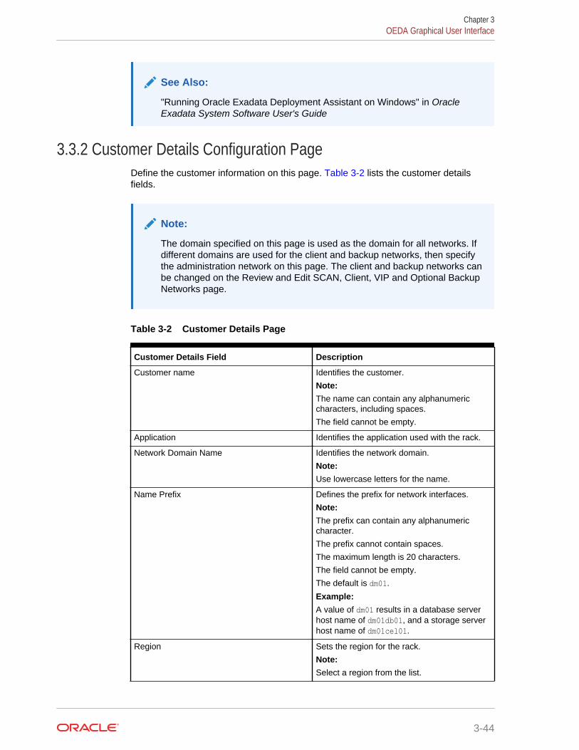
See Also:
"Running Oracle Exadata Deployment Assistant on Windows" in OracleExadata System Software User's Guide
3.3.2 Customer Details Configuration PageDefine the customer information on this page. Table 3-2 lists the customer detailsfields.
Note:
The domain specified on this page is used as the domain for all networks. Ifdifferent domains are used for the client and backup networks, then specifythe administration network on this page. The client and backup networks canbe changed on the Review and Edit SCAN, Client, VIP and Optional BackupNetworks page.
Table 3-2 Customer Details Page
Customer Details Field Description
Customer name Identifies the customer.
Note:The name can contain any alphanumericcharacters, including spaces.
The field cannot be empty.
Application Identifies the application used with the rack.
Network Domain Name Identifies the network domain.
Note:Use lowercase letters for the name.
Name Prefix Defines the prefix for network interfaces.
Note:The prefix can contain any alphanumericcharacter.
The prefix cannot contain spaces.
The maximum length is 20 characters.
The field cannot be empty.
The default is dm01.
Example:A value of dm01 results in a database serverhost name of dm01db01, and a storage serverhost name of dm01cel01.
Region Sets the region for the rack.
Note:Select a region from the list.
Chapter 3OEDA Graphical User Interface
3-44
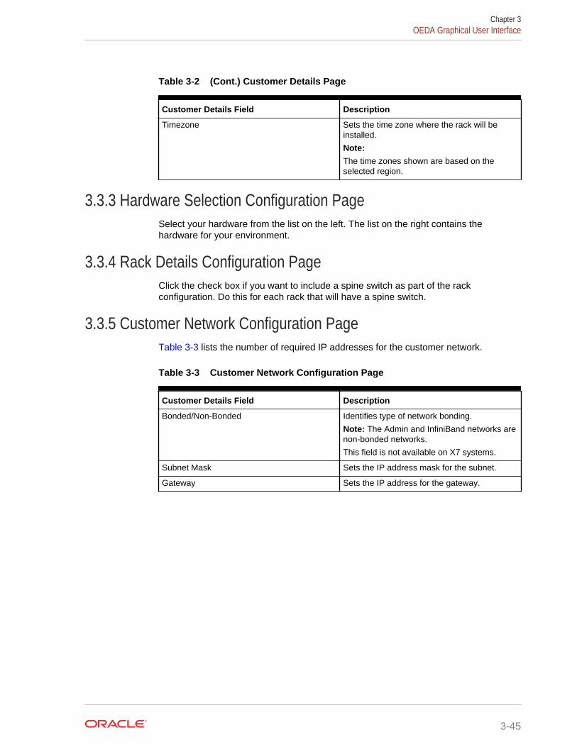
Table 3-2 (Cont.) Customer Details Page
Customer Details Field Description
Timezone Sets the time zone where the rack will beinstalled.
Note:The time zones shown are based on theselected region.
3.3.3 Hardware Selection Configuration PageSelect your hardware from the list on the left. The list on the right contains thehardware for your environment.
3.3.4 Rack Details Configuration PageClick the check box if you want to include a spine switch as part of the rackconfiguration. Do this for each rack that will have a spine switch.
3.3.5 Customer Network Configuration PageTable 3-3 lists the number of required IP addresses for the customer network.
Table 3-3 Customer Network Configuration Page
Customer Details Field Description
Bonded/Non-Bonded Identifies type of network bonding.
Note: The Admin and InfiniBand networks arenon-bonded networks.
This field is not available on X7 systems.
Subnet Mask Sets the IP address mask for the subnet.
Gateway Sets the IP address for the gateway.
Chapter 3OEDA Graphical User Interface
3-45
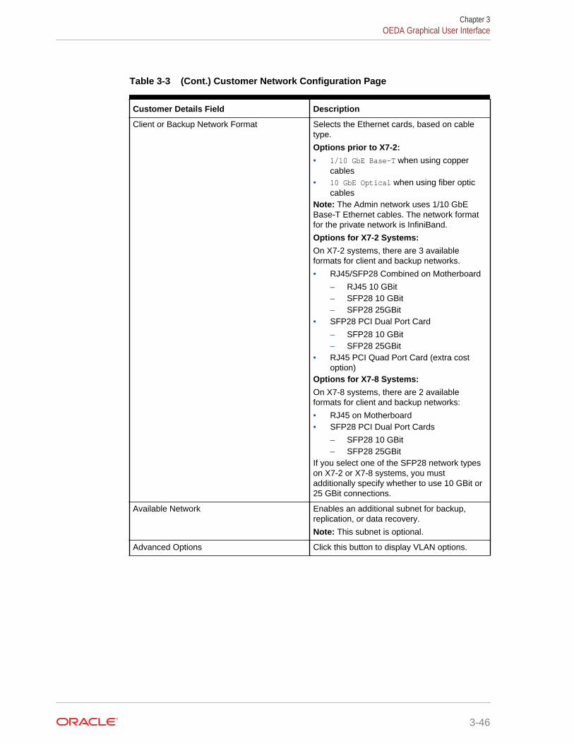
Table 3-3 (Cont.) Customer Network Configuration Page
Customer Details Field Description
Client or Backup Network Format Selects the Ethernet cards, based on cabletype.
Options prior to X7-2:• 1/10 GbE Base-T when using copper
cables• 10 GbE Optical when using fiber optic
cablesNote: The Admin network uses 1/10 GbEBase-T Ethernet cables. The network formatfor the private network is InfiniBand.
Options for X7-2 Systems:On X7-2 systems, there are 3 availableformats for client and backup networks.
• RJ45/SFP28 Combined on Motherboard
– RJ45 10 GBit– SFP28 10 GBit– SFP28 25GBit
• SFP28 PCI Dual Port Card
– SFP28 10 GBit– SFP28 25GBit
• RJ45 PCI Quad Port Card (extra costoption)
Options for X7-8 Systems:On X7-8 systems, there are 2 availableformats for client and backup networks:
• RJ45 on Motherboard• SFP28 PCI Dual Port Cards
– SFP28 10 GBit– SFP28 25GBit
If you select one of the SFP28 network typeson X7-2 or X7-8 systems, you mustadditionally specify whether to use 10 GBit or25 GBit connections.
Available Network Enables an additional subnet for backup,replication, or data recovery.
Note: This subnet is optional.
Advanced Options Click this button to display VLAN options.
Chapter 3OEDA Graphical User Interface
3-46
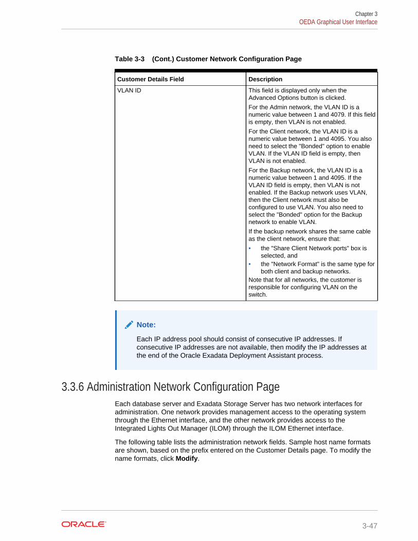
Table 3-3 (Cont.) Customer Network Configuration Page
Customer Details Field Description
VLAN ID This field is displayed only when theAdvanced Options button is clicked.
For the Admin network, the VLAN ID is anumeric value between 1 and 4079. If this fieldis empty, then VLAN is not enabled.
For the Client network, the VLAN ID is anumeric value between 1 and 4095. You alsoneed to select the "Bonded" option to enableVLAN. If the VLAN ID field is empty, thenVLAN is not enabled.
For the Backup network, the VLAN ID is anumeric value between 1 and 4095. If theVLAN ID field is empty, then VLAN is notenabled. If the Backup network uses VLAN,then the Client network must also beconfigured to use VLAN. You also need toselect the "Bonded" option for the Backupnetwork to enable VLAN.
If the backup network shares the same cableas the client network, ensure that:
• the "Share Client Network ports" box isselected, and
• the "Network Format" is the same type forboth client and backup networks.
Note that for all networks, the customer isresponsible for configuring VLAN on theswitch.
Note:
Each IP address pool should consist of consecutive IP addresses. Ifconsecutive IP addresses are not available, then modify the IP addresses atthe end of the Oracle Exadata Deployment Assistant process.
3.3.6 Administration Network Configuration PageEach database server and Exadata Storage Server has two network interfaces foradministration. One network provides management access to the operating systemthrough the Ethernet interface, and the other network provides access to theIntegrated Lights Out Manager (ILOM) through the ILOM Ethernet interface.
The following table lists the administration network fields. Sample host name formatsare shown, based on the prefix entered on the Customer Details page. To modify thename formats, click Modify.
Chapter 3OEDA Graphical User Interface
3-47
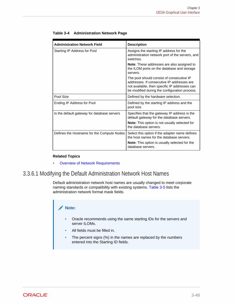
Table 3-4 Administration Network Page
Administration Network Field Description
Starting IP Address for Pool Assigns the starting IP address for theadministration network port of the servers, andswitches.
Note: These addresses are also assigned tothe ILOM ports on the database and storageservers.
The pool should consist of consecutive IPaddresses. If consecutive IP addresses arenot available, then specific IP addresses canbe modified during the configuration process.
Pool Size Defined by the hardware selection.
Ending IP Address for Pool Defined by the starting IP address and thepool size.
Is the default gateway for database servers Specifies that the gateway IP address is thedefault gateway for the database servers.
Note: This option is not usually selected forthe database servers.
Defines the Hostname for the Compute Nodes Select this option if the adapter name definesthe host names for the database servers.
Note: This option is usually selected for thedatabase servers.
Related Topics
• Overview of Network Requirements
3.3.6.1 Modifying the Default Administration Network Host NamesDefault administration network host names are usually changed to meet corporatenaming standards or compatibility with existing systems. Table 3-5 lists theadministration network format mask fields.
Note:
• Oracle recommends using the same starting IDs for the servers andserver ILOMs.
• All fields must be filled in.
• The percent signs (%) in the names are replaced by the numbersentered into the Starting ID fields.
Chapter 3OEDA Graphical User Interface
3-48
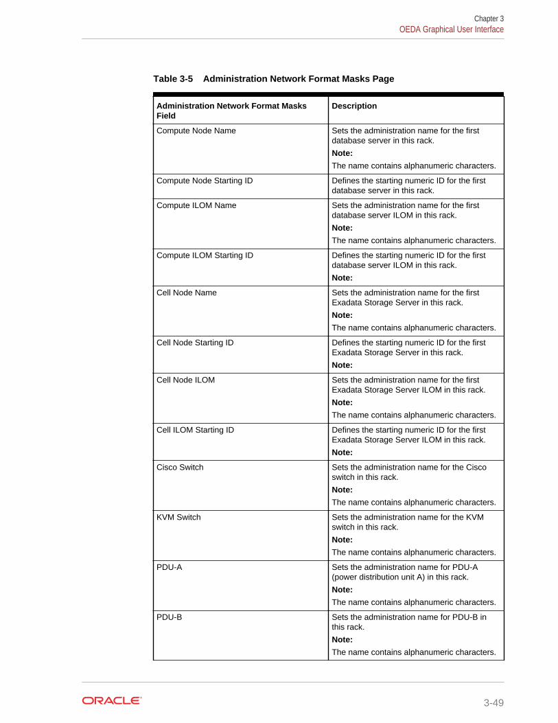
Table 3-5 Administration Network Format Masks Page
Administration Network Format MasksField
Description
Compute Node Name Sets the administration name for the firstdatabase server in this rack.
Note:The name contains alphanumeric characters.
Compute Node Starting ID Defines the starting numeric ID for the firstdatabase server in this rack.
Compute ILOM Name Sets the administration name for the firstdatabase server ILOM in this rack.
Note:The name contains alphanumeric characters.
Compute ILOM Starting ID Defines the starting numeric ID for the firstdatabase server ILOM in this rack.
Note:
Cell Node Name Sets the administration name for the firstExadata Storage Server in this rack.
Note:The name contains alphanumeric characters.
Cell Node Starting ID Defines the starting numeric ID for the firstExadata Storage Server in this rack.
Note:
Cell Node ILOM Sets the administration name for the firstExadata Storage Server ILOM in this rack.
Note:The name contains alphanumeric characters.
Cell ILOM Starting ID Defines the starting numeric ID for the firstExadata Storage Server ILOM in this rack.
Note:
Cisco Switch Sets the administration name for the Ciscoswitch in this rack.
Note:The name contains alphanumeric characters.
KVM Switch Sets the administration name for the KVMswitch in this rack.
Note:The name contains alphanumeric characters.
PDU-A Sets the administration name for PDU-A(power distribution unit A) in this rack.
Note:The name contains alphanumeric characters.
PDU-B Sets the administration name for PDU-B inthis rack.
Note:The name contains alphanumeric characters.
Chapter 3OEDA Graphical User Interface
3-49
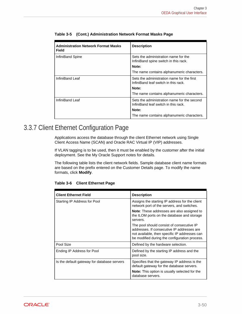
Table 3-5 (Cont.) Administration Network Format Masks Page
Administration Network Format MasksField
Description
InfiniBand Spine Sets the administration name for theInfiniBand spine switch in this rack.
Note:The name contains alphanumeric characters.
InfiniBand Leaf Sets the administration name for the firstInfiniBand leaf switch in this rack.
Note:The name contains alphanumeric characters.
InfiniBand Leaf Sets the administration name for the secondInfiniBand leaf switch in this rack.
Note:The name contains alphanumeric characters.
3.3.7 Client Ethernet Configuration PageApplications access the database through the client Ethernet network using SingleClient Access Name (SCAN) and Oracle RAC Virtual IP (VIP) addresses.
If VLAN tagging is to be used, then it must be enabled by the customer after the initialdeployment. See the My Oracle Support notes for details.
The following table lists the client network fields. Sample database client name formatsare based on the prefix entered on the Customer Details page. To modify the nameformats, click Modify.
Table 3-6 Client Ethernet Page
Client Ethernet Field Description
Starting IP Address for Pool Assigns the starting IP address for the clientnetwork port of the servers, and switches.
Note: These addresses are also assigned tothe ILOM ports on the database and storageservers.
The pool should consist of consecutive IPaddresses. If consecutive IP addresses arenot available, then specific IP addresses canbe modified during the configuration process.
Pool Size Defined by the hardware selection.
Ending IP Address for Pool Defined by the starting IP address and thepool size.
Is the default gateway for database servers Specifies that the gateway IP address is thedefault gateway for the database servers.
Note: This option is usually selected for thedatabase servers.
Chapter 3OEDA Graphical User Interface
3-50
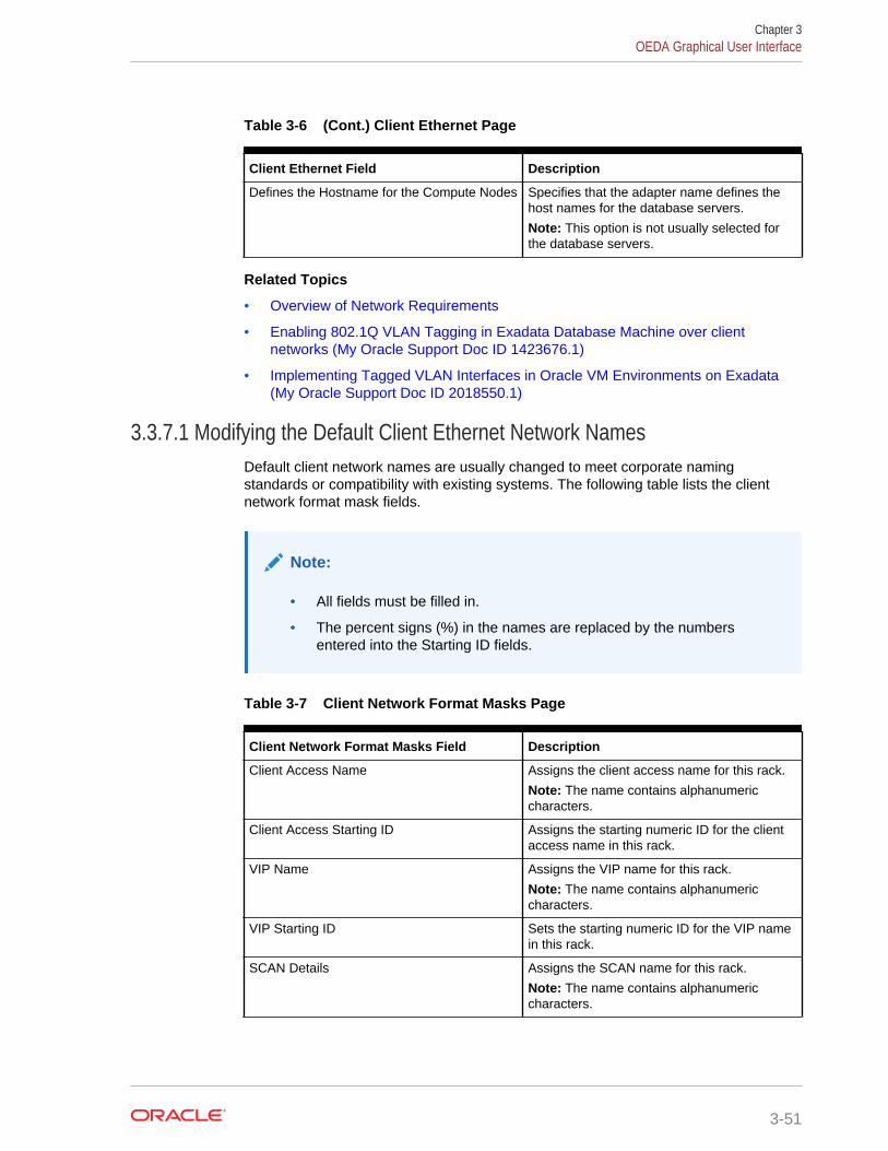
Table 3-6 (Cont.) Client Ethernet Page
Client Ethernet Field Description
Defines the Hostname for the Compute Nodes Specifies that the adapter name defines thehost names for the database servers.
Note: This option is not usually selected forthe database servers.
Related Topics
• Overview of Network Requirements
• Enabling 802.1Q VLAN Tagging in Exadata Database Machine over clientnetworks (My Oracle Support Doc ID 1423676.1)
• Implementing Tagged VLAN Interfaces in Oracle VM Environments on Exadata(My Oracle Support Doc ID 2018550.1)
3.3.7.1 Modifying the Default Client Ethernet Network NamesDefault client network names are usually changed to meet corporate namingstandards or compatibility with existing systems. The following table lists the clientnetwork format mask fields.
Note:
• All fields must be filled in.
• The percent signs (%) in the names are replaced by the numbersentered into the Starting ID fields.
Table 3-7 Client Network Format Masks Page
Client Network Format Masks Field Description
Client Access Name Assigns the client access name for this rack.
Note: The name contains alphanumericcharacters.
Client Access Starting ID Assigns the starting numeric ID for the clientaccess name in this rack.
VIP Name Assigns the VIP name for this rack.
Note: The name contains alphanumericcharacters.
VIP Starting ID Sets the starting numeric ID for the VIP namein this rack.
SCAN Details Assigns the SCAN name for this rack.
Note: The name contains alphanumericcharacters.
Chapter 3OEDA Graphical User Interface
3-51
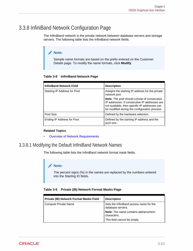
3.3.8 InfiniBand Network Configuration PageThe InfiniBand network is the private network between database servers and storageservers. The following table lists the InfiniBand network fields.
Note:
Sample name formats are based on the prefix entered on the CustomerDetails page. To modify the name formats, click Modify.
Table 3-8 InfiniBand Network Page
InfiniBand Network Field Description
Starting IP Address for Pool Assigns the starting IP address for the privatenetwork port.
Note: The pool should consist of consecutiveIP addresses. If consecutive IP addresses arenot available, then specific IP addresses canbe modified during the configuration process.
Pool Size Defined by the hardware selection.
Ending IP Address for Pool Defined by the starting IP address and thepool size.
Related Topics
• Overview of Network Requirements
3.3.8.1 Modifying the Default InfiniBand Network NamesThe following table lists the InfiniBand network format mask fields.
Note:
The percent signs (%) in the names are replaced by the numbers enteredinto the Starting ID fields.
Table 3-9 Private (IB) Network Format Masks Page
Private (IB) Network Format Masks Field Description
Compute Private Name Sets the InfiniBand access name for thedatabase servers.
Note: The name contains alphanumericcharacters.
This field cannot be empty.
Chapter 3OEDA Graphical User Interface
3-52
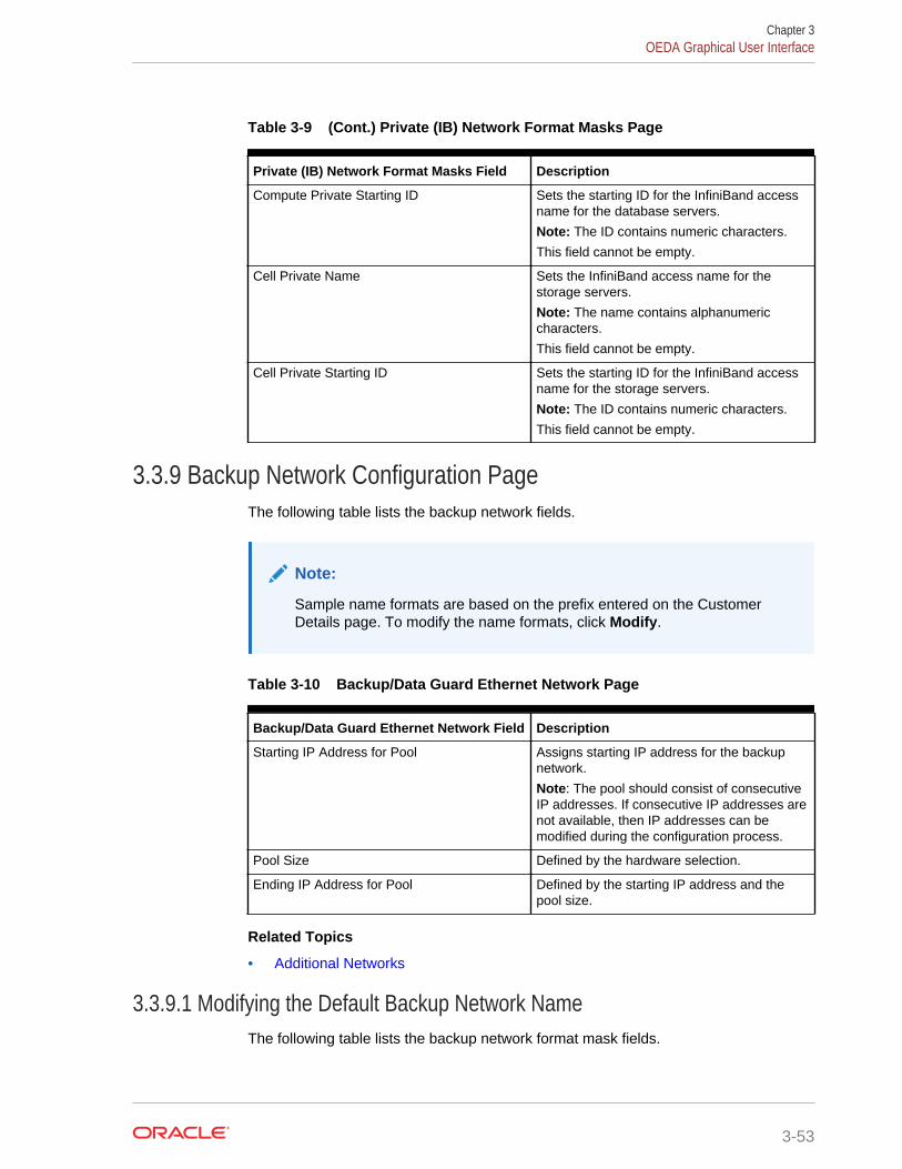
Table 3-9 (Cont.) Private (IB) Network Format Masks Page
Private (IB) Network Format Masks Field Description
Compute Private Starting ID Sets the starting ID for the InfiniBand accessname for the database servers.
Note: The ID contains numeric characters.
This field cannot be empty.
Cell Private Name Sets the InfiniBand access name for thestorage servers.
Note: The name contains alphanumericcharacters.
This field cannot be empty.
Cell Private Starting ID Sets the starting ID for the InfiniBand accessname for the storage servers.
Note: The ID contains numeric characters.
This field cannot be empty.
3.3.9 Backup Network Configuration PageThe following table lists the backup network fields.
Note:
Sample name formats are based on the prefix entered on the CustomerDetails page. To modify the name formats, click Modify.
Table 3-10 Backup/Data Guard Ethernet Network Page
Backup/Data Guard Ethernet Network Field Description
Starting IP Address for Pool Assigns starting IP address for the backupnetwork.
Note: The pool should consist of consecutiveIP addresses. If consecutive IP addresses arenot available, then IP addresses can bemodified during the configuration process.
Pool Size Defined by the hardware selection.
Ending IP Address for Pool Defined by the starting IP address and thepool size.
Related Topics
• Additional Networks
3.3.9.1 Modifying the Default Backup Network NameThe following table lists the backup network format mask fields.
Chapter 3OEDA Graphical User Interface
3-53
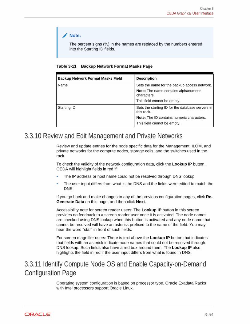
Note:
The percent signs (%) in the names are replaced by the numbers enteredinto the Starting ID fields.
Table 3-11 Backup Network Format Masks Page
Backup Network Format Masks Field Description
Name Sets the name for the backup access network.
Note: The name contains alphanumericcharacters.
This field cannot be empty.
Starting ID Sets the starting ID for the database servers inthis rack.
Note: The ID contains numeric characters.
This field cannot be empty.
3.3.10 Review and Edit Management and Private NetworksReview and update entries for the node specific data for the Management, ILOM, andprivate networks for the compute nodes, storage cells, and the switches used in therack.
To check the validity of the network configuration data, click the Lookup IP button.OEDA will highlight fields in red if:
• The IP address or host name could not be resolved through DNS lookup
• The user input differs from what is the DNS and the fields were edited to match theDNS
If you go back and make changes to any of the previous configuration pages, click Re-Generate Data on this page, and then click Next.
Accessibility note for screen reader users: The Lookup IP button in this screenprovides no feedback to a screen reader user once it is activated. The node namesare checked using DNS lookup when this button is activated and any node name thatcannot be resolved will have an asterisk prefixed to the name of the field. You mayhear the word "star" in front of such fields.
For screen magnifier users: There is text above the Lookup IP button that indicatesthat fields with an asterisk indicate node names that could not be resolved throughDNS lookup. Such fields also have a red box around them. The Lookup IP alsohighlights the field in red if the user input differs from what is found in DNS.
3.3.11 Identify Compute Node OS and Enable Capacity-on-DemandConfiguration Page
Operating system configuration is based on processor type. Oracle Exadata Rackswith Intel processors support Oracle Linux.
Chapter 3OEDA Graphical User Interface
3-54
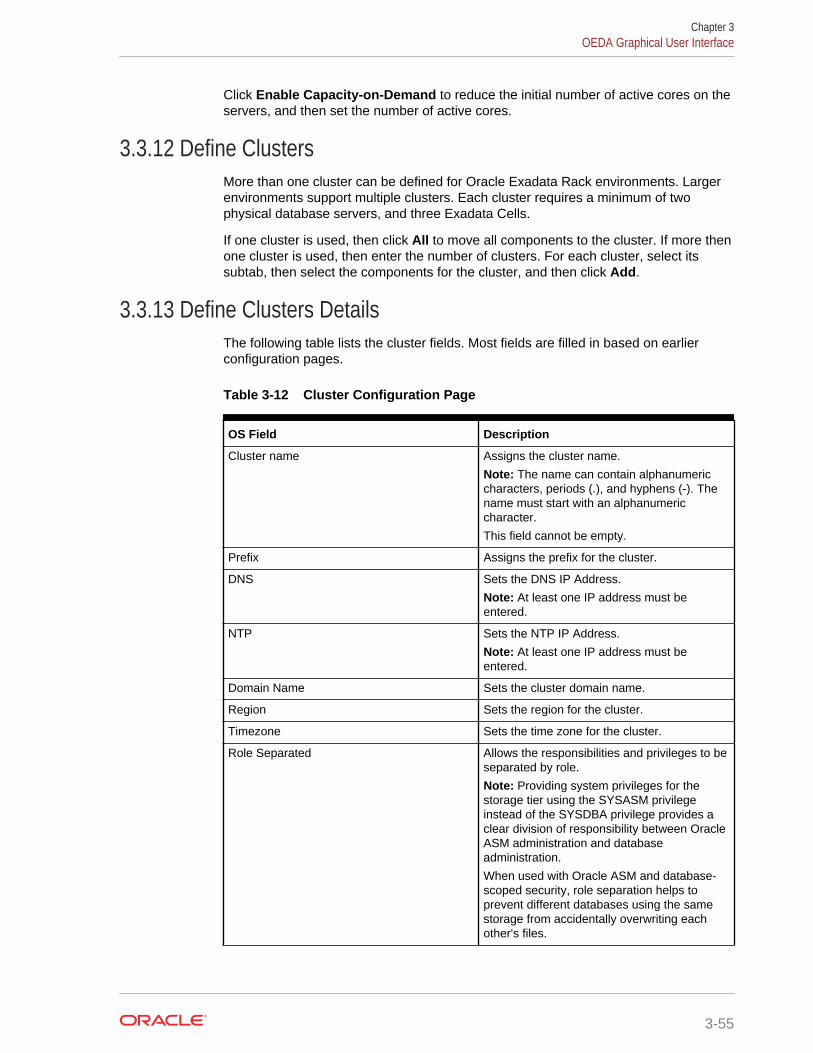
Click Enable Capacity-on-Demand to reduce the initial number of active cores on theservers, and then set the number of active cores.
3.3.12 Define ClustersMore than one cluster can be defined for Oracle Exadata Rack environments. Largerenvironments support multiple clusters. Each cluster requires a minimum of twophysical database servers, and three Exadata Cells.
If one cluster is used, then click All to move all components to the cluster. If more thenone cluster is used, then enter the number of clusters. For each cluster, select itssubtab, then select the components for the cluster, and then click Add.
3.3.13 Define Clusters DetailsThe following table lists the cluster fields. Most fields are filled in based on earlierconfiguration pages.
Table 3-12 Cluster Configuration Page
OS Field Description
Cluster name Assigns the cluster name.
Note: The name can contain alphanumericcharacters, periods (.), and hyphens (-). Thename must start with an alphanumericcharacter.
This field cannot be empty.
Prefix Assigns the prefix for the cluster.
DNS Sets the DNS IP Address.
Note: At least one IP address must beentered.
NTP Sets the NTP IP Address.
Note: At least one IP address must beentered.
Domain Name Sets the cluster domain name.
Region Sets the region for the cluster.
Timezone Sets the time zone for the cluster.
Role Separated Allows the responsibilities and privileges to beseparated by role.
Note: Providing system privileges for thestorage tier using the SYSASM privilegeinstead of the SYSDBA privilege provides aclear division of responsibility between OracleASM administration and databaseadministration.
When used with Oracle ASM and database-scoped security, role separation helps toprevent different databases using the samestorage from accidentally overwriting eachother's files.
Chapter 3OEDA Graphical User Interface
3-55
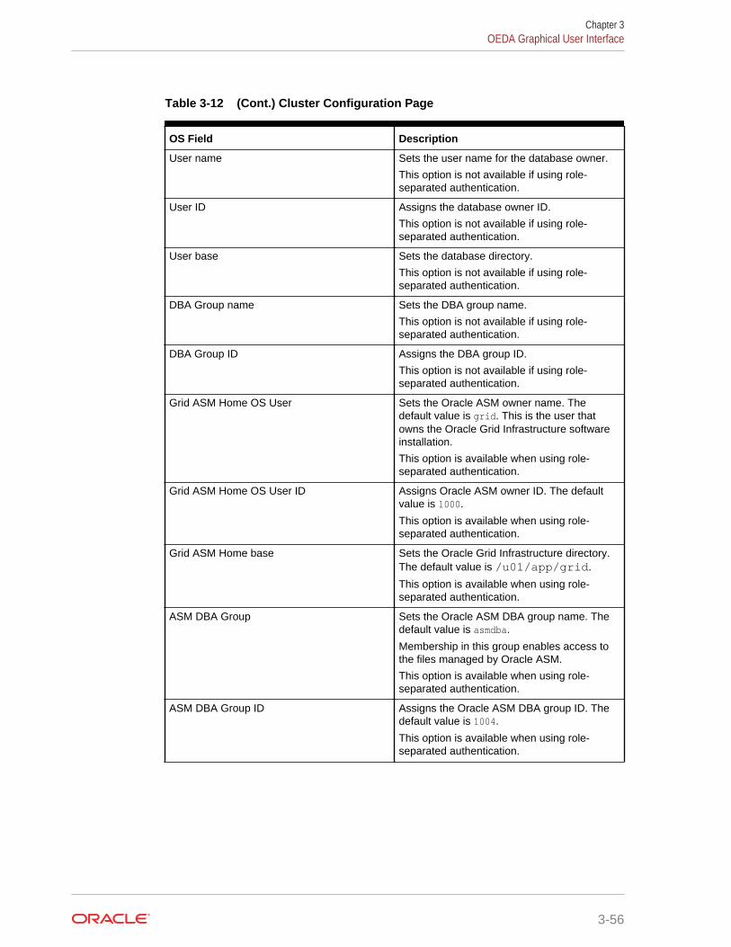
Table 3-12 (Cont.) Cluster Configuration Page
OS Field Description
User name Sets the user name for the database owner.
This option is not available if using role-separated authentication.
User ID Assigns the database owner ID.
This option is not available if using role-separated authentication.
User base Sets the database directory.
This option is not available if using role-separated authentication.
DBA Group name Sets the DBA group name.
This option is not available if using role-separated authentication.
DBA Group ID Assigns the DBA group ID.
This option is not available if using role-separated authentication.
Grid ASM Home OS User Sets the Oracle ASM owner name. Thedefault value is grid. This is the user thatowns the Oracle Grid Infrastructure softwareinstallation.
This option is available when using role-separated authentication.
Grid ASM Home OS User ID Assigns Oracle ASM owner ID. The defaultvalue is 1000.
This option is available when using role-separated authentication.
Grid ASM Home base Sets the Oracle Grid Infrastructure directory.The default value is /u01/app/grid.
This option is available when using role-separated authentication.
ASM DBA Group Sets the Oracle ASM DBA group name. Thedefault value is asmdba.
Membership in this group enables access tothe files managed by Oracle ASM.
This option is available when using role-separated authentication.
ASM DBA Group ID Assigns the Oracle ASM DBA group ID. Thedefault value is 1004.
This option is available when using role-separated authentication.
Chapter 3OEDA Graphical User Interface
3-56
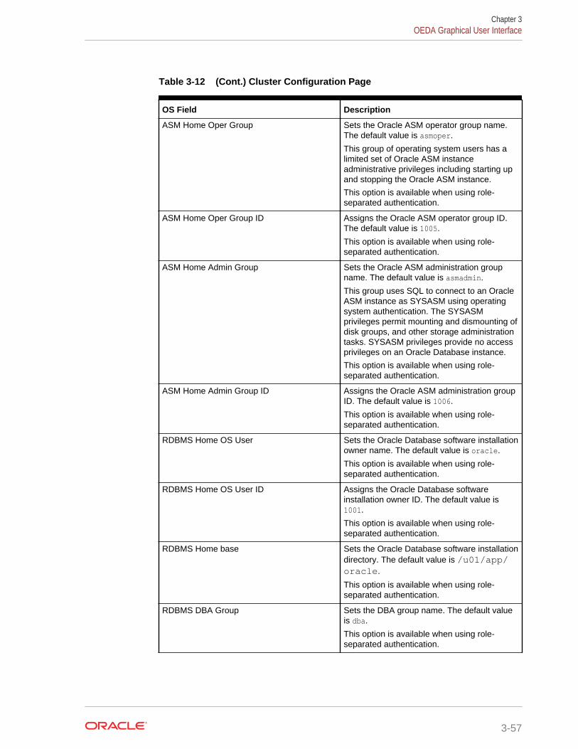
Table 3-12 (Cont.) Cluster Configuration Page
OS Field Description
ASM Home Oper Group Sets the Oracle ASM operator group name.The default value is asmoper.
This group of operating system users has alimited set of Oracle ASM instanceadministrative privileges including starting upand stopping the Oracle ASM instance.
This option is available when using role-separated authentication.
ASM Home Oper Group ID Assigns the Oracle ASM operator group ID.The default value is 1005.
This option is available when using role-separated authentication.
ASM Home Admin Group Sets the Oracle ASM administration groupname. The default value is asmadmin.
This group uses SQL to connect to an OracleASM instance as SYSASM using operatingsystem authentication. The SYSASMprivileges permit mounting and dismounting ofdisk groups, and other storage administrationtasks. SYSASM privileges provide no accessprivileges on an Oracle Database instance.
This option is available when using role-separated authentication.
ASM Home Admin Group ID Assigns the Oracle ASM administration groupID. The default value is 1006.
This option is available when using role-separated authentication.
RDBMS Home OS User Sets the Oracle Database software installationowner name. The default value is oracle.
This option is available when using role-separated authentication.
RDBMS Home OS User ID Assigns the Oracle Database softwareinstallation owner ID. The default value is1001.
This option is available when using role-separated authentication.
RDBMS Home base Sets the Oracle Database software installationdirectory. The default value is /u01/app/oracle.
This option is available when using role-separated authentication.
RDBMS DBA Group Sets the DBA group name. The default valueis dba.
This option is available when using role-separated authentication.
Chapter 3OEDA Graphical User Interface
3-57
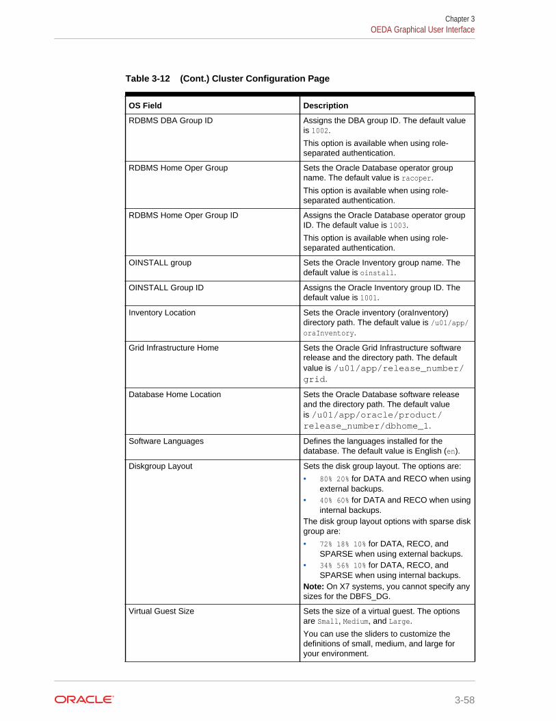
Table 3-12 (Cont.) Cluster Configuration Page
OS Field Description
RDBMS DBA Group ID Assigns the DBA group ID. The default valueis 1002.
This option is available when using role-separated authentication.
RDBMS Home Oper Group Sets the Oracle Database operator groupname. The default value is racoper.
This option is available when using role-separated authentication.
RDBMS Home Oper Group ID Assigns the Oracle Database operator groupID. The default value is 1003.
This option is available when using role-separated authentication.
OINSTALL group Sets the Oracle Inventory group name. Thedefault value is oinstall.
OINSTALL Group ID Assigns the Oracle Inventory group ID. Thedefault value is 1001.
Inventory Location Sets the Oracle inventory (oraInventory)directory path. The default value is /u01/app/oraInventory.
Grid Infrastructure Home Sets the Oracle Grid Infrastructure softwarerelease and the directory path. The defaultvalue is /u01/app/release_number/grid.
Database Home Location Sets the Oracle Database software releaseand the directory path. The default valueis /u01/app/oracle/product/release_number/dbhome_1.
Software Languages Defines the languages installed for thedatabase. The default value is English (en).
Diskgroup Layout Sets the disk group layout. The options are:
• 80% 20% for DATA and RECO when usingexternal backups.
• 40% 60% for DATA and RECO when usinginternal backups.
The disk group layout options with sparse diskgroup are:
• 72% 18% 10% for DATA, RECO, andSPARSE when using external backups.
• 34% 56% 10% for DATA, RECO, andSPARSE when using internal backups.
Note: On X7 systems, you cannot specify anysizes for the DBFS_DG.
Virtual Guest Size Sets the size of a virtual guest. The optionsare Small, Medium, and Large.
You can use the sliders to customize thedefinitions of small, medium, and large foryour environment.
Chapter 3OEDA Graphical User Interface
3-58
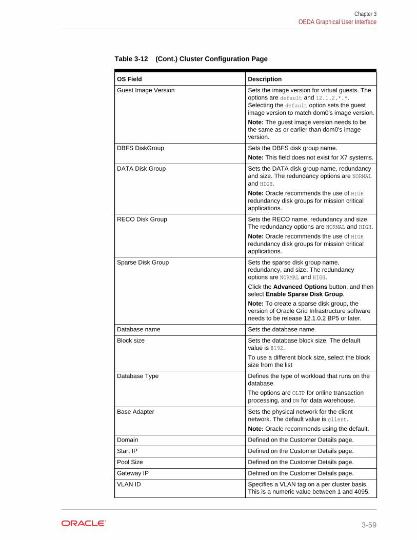
Table 3-12 (Cont.) Cluster Configuration Page
OS Field Description
Guest Image Version Sets the image version for virtual guests. Theoptions are default and 12.1.2.*.*.Selecting the default option sets the guestimage version to match dom0's image version.
Note: The guest image version needs to bethe same as or earlier than dom0's imageversion.
DBFS DiskGroup Sets the DBFS disk group name.
Note: This field does not exist for X7 systems.
DATA Disk Group Sets the DATA disk group name, redundancyand size. The redundancy options are NORMALand HIGH.
Note: Oracle recommends the use of HIGHredundancy disk groups for mission criticalapplications.
RECO Disk Group Sets the RECO name, redundancy and size.The redundancy options are NORMAL and HIGH.
Note: Oracle recommends the use of HIGHredundancy disk groups for mission criticalapplications.
Sparse Disk Group Sets the sparse disk group name,redundancy, and size. The redundancyoptions are NORMAL and HIGH.
Click the Advanced Options button, and thenselect Enable Sparse Disk Group.
Note: To create a sparse disk group, theversion of Oracle Grid Infrastructure softwareneeds to be release 12.1.0.2 BP5 or later.
Database name Sets the database name.
Block size Sets the database block size. The defaultvalue is 8192.
To use a different block size, select the blocksize from the list
Database Type Defines the type of workload that runs on thedatabase.
The options are OLTP for online transactionprocessing, and DW for data warehouse.
Base Adapter Sets the physical network for the clientnetwork. The default value is client.
Note: Oracle recommends using the default.
Domain Defined on the Customer Details page.
Start IP Defined on the Customer Details page.
Pool Size Defined on the Customer Details page.
Gateway IP Defined on the Customer Details page.
VLAN ID Specifies a VLAN tag on a per cluster basis.This is a numeric value between 1 and 4095.
Chapter 3OEDA Graphical User Interface
3-59
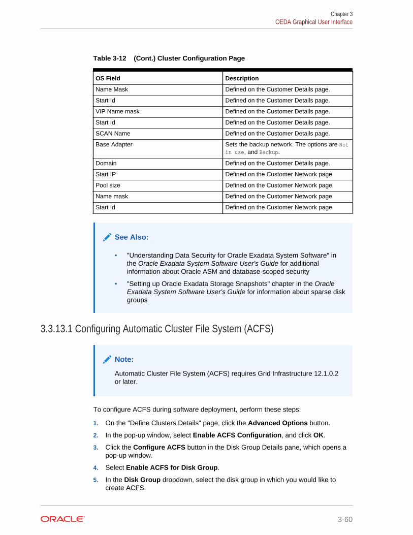
Table 3-12 (Cont.) Cluster Configuration Page
OS Field Description
Name Mask Defined on the Customer Details page.
Start Id Defined on the Customer Details page.
VIP Name mask Defined on the Customer Details page.
Start Id Defined on the Customer Details page.
SCAN Name Defined on the Customer Details page.
Base Adapter Sets the backup network. The options are Notin use, and Backup.
Domain Defined on the Customer Details page.
Start IP Defined on the Customer Network page.
Pool size Defined on the Customer Network page.
Name mask Defined on the Customer Network page.
Start Id Defined on the Customer Network page.
See Also:
• "Understanding Data Security for Oracle Exadata System Software" inthe Oracle Exadata System Software User's Guide for additionalinformation about Oracle ASM and database-scoped security
• "Setting up Oracle Exadata Storage Snapshots" chapter in the OracleExadata System Software User's Guide for information about sparse diskgroups
3.3.13.1 Configuring Automatic Cluster File System (ACFS)
Note:
Automatic Cluster File System (ACFS) requires Grid Infrastructure 12.1.0.2or later.
To configure ACFS during software deployment, perform these steps:
1. On the "Define Clusters Details" page, click the Advanced Options button.
2. In the pop-up window, select Enable ACFS Configuration, and click OK.
3. Click the Configure ACFS button in the Disk Group Details pane, which opens apop-up window.
4. Select Enable ACFS for Disk Group.
5. In the Disk Group dropdown, select the disk group in which you would like tocreate ACFS.
Chapter 3OEDA Graphical User Interface
3-60
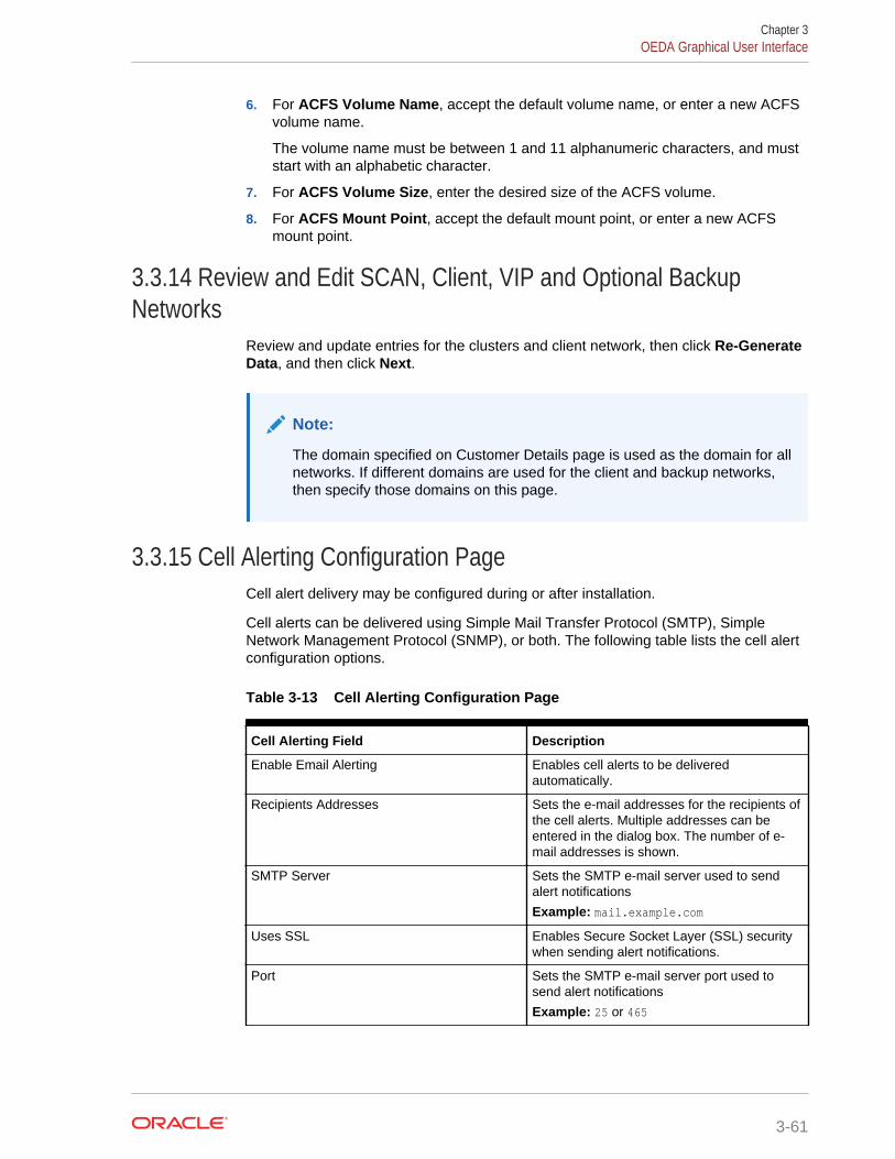
6. For ACFS Volume Name, accept the default volume name, or enter a new ACFSvolume name.
The volume name must be between 1 and 11 alphanumeric characters, and muststart with an alphabetic character.
7. For ACFS Volume Size, enter the desired size of the ACFS volume.
8. For ACFS Mount Point, accept the default mount point, or enter a new ACFSmount point.
3.3.14 Review and Edit SCAN, Client, VIP and Optional BackupNetworks
Review and update entries for the clusters and client network, then click Re-GenerateData, and then click Next.
Note:
The domain specified on Customer Details page is used as the domain for allnetworks. If different domains are used for the client and backup networks,then specify those domains on this page.
3.3.15 Cell Alerting Configuration PageCell alert delivery may be configured during or after installation.
Cell alerts can be delivered using Simple Mail Transfer Protocol (SMTP), SimpleNetwork Management Protocol (SNMP), or both. The following table lists the cell alertconfiguration options.
Table 3-13 Cell Alerting Configuration Page
Cell Alerting Field Description
Enable Email Alerting Enables cell alerts to be deliveredautomatically.
Recipients Addresses Sets the e-mail addresses for the recipients ofthe cell alerts. Multiple addresses can beentered in the dialog box. The number of e-mail addresses is shown.
SMTP Server Sets the SMTP e-mail server used to sendalert notifications
Example: mail.example.com
Uses SSL Enables Secure Socket Layer (SSL) securitywhen sending alert notifications.
Port Sets the SMTP e-mail server port used tosend alert notifications
Example: 25 or 465
Chapter 3OEDA Graphical User Interface
3-61
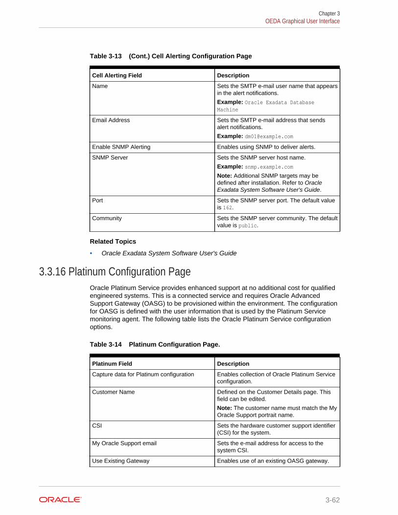
Table 3-13 (Cont.) Cell Alerting Configuration Page
Cell Alerting Field Description
Name Sets the SMTP e-mail user name that appearsin the alert notifications.
Example: Oracle Exadata DatabaseMachine
Email Address Sets the SMTP e-mail address that sendsalert notifications.
Example: [email protected]
Enable SNMP Alerting Enables using SNMP to deliver alerts.
SNMP Server Sets the SNMP server host name.
Example: snmp.example.comNote: Additional SNMP targets may bedefined after installation. Refer to OracleExadata System Software User's Guide.
Port Sets the SNMP server port. The default valueis 162.
Community Sets the SNMP server community. The defaultvalue is public.
Related Topics
• Oracle Exadata System Software User's Guide
3.3.16 Platinum Configuration PageOracle Platinum Service provides enhanced support at no additional cost for qualifiedengineered systems. This is a connected service and requires Oracle AdvancedSupport Gateway (OASG) to be provisioned within the environment. The configurationfor OASG is defined with the user information that is used by the Platinum Servicemonitoring agent. The following table lists the Oracle Platinum Service configurationoptions.
Table 3-14 Platinum Configuration Page.
Platinum Field Description
Capture data for Platinum configuration Enables collection of Oracle Platinum Serviceconfiguration.
Customer Name Defined on the Customer Details page. Thisfield can be edited.
Note: The customer name must match the MyOracle Support portrait name.
CSI Sets the hardware customer support identifier(CSI) for the system.
My Oracle Support email Sets the e-mail address for access to thesystem CSI.
Use Existing Gateway Enables use of an existing OASG gateway.
Chapter 3OEDA Graphical User Interface
3-62
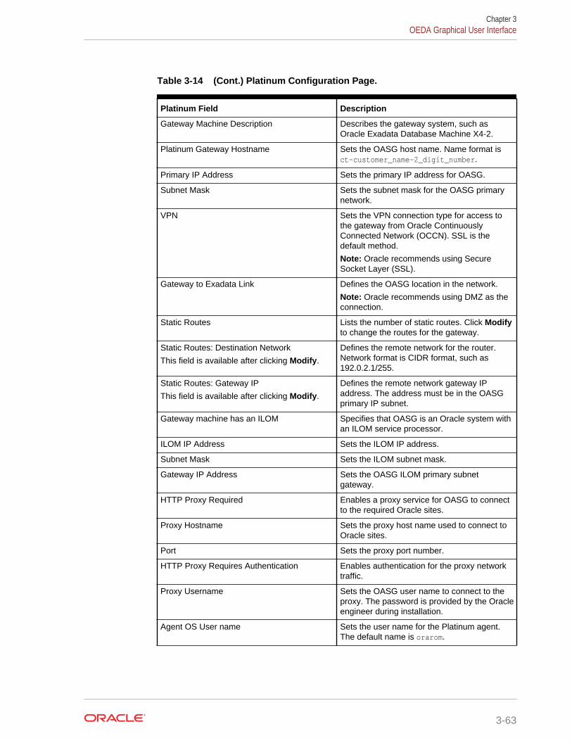
Table 3-14 (Cont.) Platinum Configuration Page.
Platinum Field Description
Gateway Machine Description Describes the gateway system, such asOracle Exadata Database Machine X4-2.
Platinum Gateway Hostname Sets the OASG host name. Name format isct-customer_name-2_digit_number.
Primary IP Address Sets the primary IP address for OASG.
Subnet Mask Sets the subnet mask for the OASG primarynetwork.
VPN Sets the VPN connection type for access tothe gateway from Oracle ContinuouslyConnected Network (OCCN). SSL is thedefault method.
Note: Oracle recommends using SecureSocket Layer (SSL).
Gateway to Exadata Link Defines the OASG location in the network.
Note: Oracle recommends using DMZ as theconnection.
Static Routes Lists the number of static routes. Click Modifyto change the routes for the gateway.
Static Routes: Destination Network
This field is available after clicking Modify.
Defines the remote network for the router.Network format is CIDR format, such as192.0.2.1/255.
Static Routes: Gateway IP
This field is available after clicking Modify.
Defines the remote network gateway IPaddress. The address must be in the OASGprimary IP subnet.
Gateway machine has an ILOM Specifies that OASG is an Oracle system withan ILOM service processor.
ILOM IP Address Sets the ILOM IP address.
Subnet Mask Sets the ILOM subnet mask.
Gateway IP Address Sets the OASG ILOM primary subnetgateway.
HTTP Proxy Required Enables a proxy service for OASG to connectto the required Oracle sites.
Proxy Hostname Sets the proxy host name used to connect toOracle sites.
Port Sets the proxy port number.
HTTP Proxy Requires Authentication Enables authentication for the proxy networktraffic.
Proxy Username Sets the OASG user name to connect to theproxy. The password is provided by the Oracleengineer during installation.
Agent OS User name Sets the user name for the Platinum agent.The default name is orarom.
Chapter 3OEDA Graphical User Interface
3-63
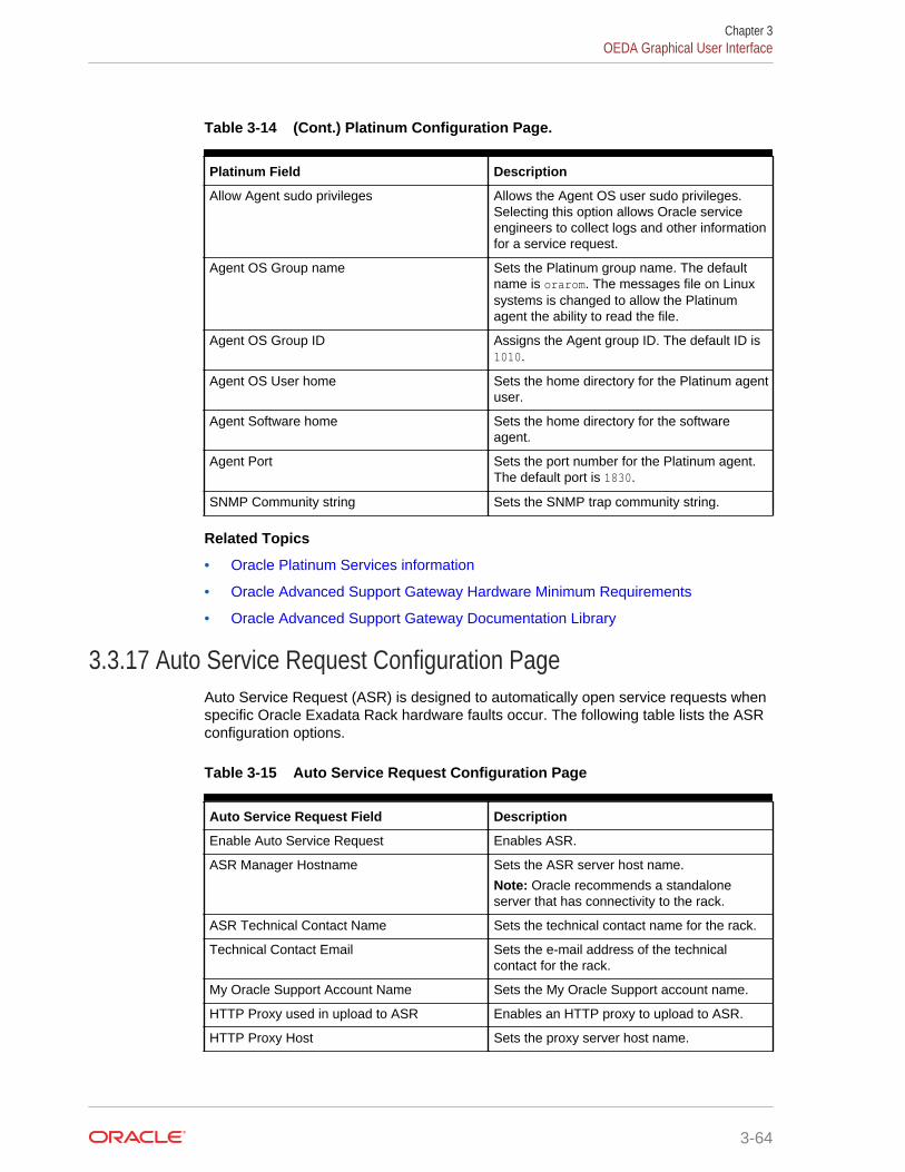
Table 3-14 (Cont.) Platinum Configuration Page.
Platinum Field Description
Allow Agent sudo privileges Allows the Agent OS user sudo privileges.Selecting this option allows Oracle serviceengineers to collect logs and other informationfor a service request.
Agent OS Group name Sets the Platinum group name. The defaultname is orarom. The messages file on Linuxsystems is changed to allow the Platinumagent the ability to read the file.
Agent OS Group ID Assigns the Agent group ID. The default ID is1010.
Agent OS User home Sets the home directory for the Platinum agentuser.
Agent Software home Sets the home directory for the softwareagent.
Agent Port Sets the port number for the Platinum agent.The default port is 1830.
SNMP Community string Sets the SNMP trap community string.
Related Topics
• Oracle Platinum Services information
• Oracle Advanced Support Gateway Hardware Minimum Requirements
• Oracle Advanced Support Gateway Documentation Library
3.3.17 Auto Service Request Configuration PageAuto Service Request (ASR) is designed to automatically open service requests whenspecific Oracle Exadata Rack hardware faults occur. The following table lists the ASRconfiguration options.
Table 3-15 Auto Service Request Configuration Page
Auto Service Request Field Description
Enable Auto Service Request Enables ASR.
ASR Manager Hostname Sets the ASR server host name.
Note: Oracle recommends a standaloneserver that has connectivity to the rack.
ASR Technical Contact Name Sets the technical contact name for the rack.
Technical Contact Email Sets the e-mail address of the technicalcontact for the rack.
My Oracle Support Account Name Sets the My Oracle Support account name.
HTTP Proxy used in upload to ASR Enables an HTTP proxy to upload to ASR.
HTTP Proxy Host Sets the proxy server host name.
Chapter 3OEDA Graphical User Interface
3-64
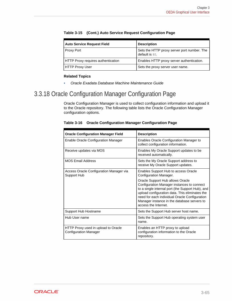
Table 3-15 (Cont.) Auto Service Request Configuration Page
Auto Service Request Field Description
Proxy Port Sets the HTTP proxy server port number. Thedefault is 80.
HTTP Proxy requires authentication Enables HTTP proxy server authentication.
HTTP Proxy User Sets the proxy server user name.
Related Topics
• Oracle Exadata Database Machine Maintenance Guide
3.3.18 Oracle Configuration Manager Configuration PageOracle Configuration Manager is used to collect configuration information and upload itto the Oracle repository. The following table lists the Oracle Configuration Managerconfiguration options.
Table 3-16 Oracle Configuration Manager Configuration Page
Oracle Configuration Manager Field Description
Enable Oracle Configuration Manager Enables Oracle Configuration Manager tocollect configuration information.
Receive updates via MOS Enables My Oracle Support updates to bereceived automatically.
MOS Email Address Sets the My Oracle Support address toreceive My Oracle Support updates.
Access Oracle Configuration Manager viaSupport Hub
Enables Support Hub to access OracleConfiguration Manager.
Oracle Support Hub allows OracleConfiguration Manager instances to connectto a single internal port (the Support Hub), andupload configuration data. This eliminates theneed for each individual Oracle ConfigurationManager instance in the database servers toaccess the Internet.
Support Hub Hostname Sets the Support Hub server host name.
Hub User name Sets the Support Hub operating system username.
HTTP Proxy used in upload to OracleConfiguration Manager
Enables an HTTP proxy to uploadconfiguration information to the Oraclerepository.
Chapter 3OEDA Graphical User Interface
3-65
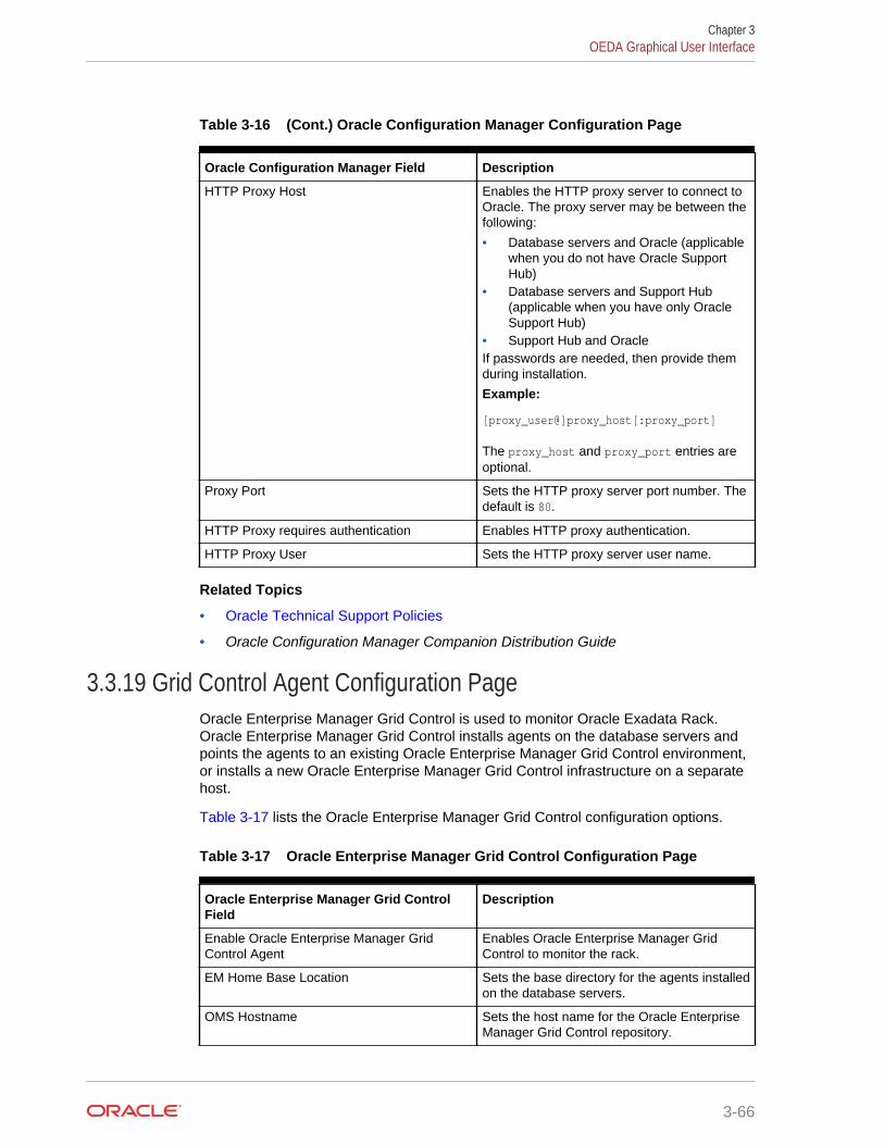
Table 3-16 (Cont.) Oracle Configuration Manager Configuration Page
Oracle Configuration Manager Field Description
HTTP Proxy Host Enables the HTTP proxy server to connect toOracle. The proxy server may be between thefollowing:
• Database servers and Oracle (applicablewhen you do not have Oracle SupportHub)
• Database servers and Support Hub(applicable when you have only OracleSupport Hub)
• Support Hub and OracleIf passwords are needed, then provide themduring installation.
Example:
[proxy_user@]proxy_host[:proxy_port]
The proxy_host and proxy_port entries areoptional.
Proxy Port Sets the HTTP proxy server port number. Thedefault is 80.
HTTP Proxy requires authentication Enables HTTP proxy authentication.
HTTP Proxy User Sets the HTTP proxy server user name.
Related Topics
• Oracle Technical Support Policies
• Oracle Configuration Manager Companion Distribution Guide
3.3.19 Grid Control Agent Configuration PageOracle Enterprise Manager Grid Control is used to monitor Oracle Exadata Rack.Oracle Enterprise Manager Grid Control installs agents on the database servers andpoints the agents to an existing Oracle Enterprise Manager Grid Control environment,or installs a new Oracle Enterprise Manager Grid Control infrastructure on a separatehost.
Table 3-17 lists the Oracle Enterprise Manager Grid Control configuration options.
Table 3-17 Oracle Enterprise Manager Grid Control Configuration Page
Oracle Enterprise Manager Grid ControlField
Description
Enable Oracle Enterprise Manager GridControl Agent
Enables Oracle Enterprise Manager GridControl to monitor the rack.
EM Home Base Location Sets the base directory for the agents installedon the database servers.
OMS Hostname Sets the host name for the Oracle EnterpriseManager Grid Control repository.
Chapter 3OEDA Graphical User Interface
3-66
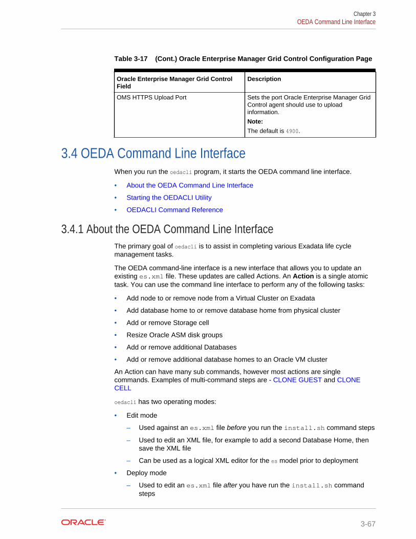
Table 3-17 (Cont.) Oracle Enterprise Manager Grid Control Configuration Page
Oracle Enterprise Manager Grid ControlField
Description
OMS HTTPS Upload Port Sets the port Oracle Enterprise Manager GridControl agent should use to uploadinformation.
Note:The default is 4900.
3.4 OEDA Command Line InterfaceWhen you run the oedacli program, it starts the OEDA command line interface.
• About the OEDA Command Line Interface
• Starting the OEDACLI Utility
• OEDACLI Command Reference
3.4.1 About the OEDA Command Line InterfaceThe primary goal of oedacli is to assist in completing various Exadata life cyclemanagement tasks.
The OEDA command-line interface is a new interface that allows you to update anexisting es.xml file. These updates are called Actions. An Action is a single atomictask. You can use the command line interface to perform any of the following tasks:
• Add node to or remove node from a Virtual Cluster on Exadata
• Add database home to or remove database home from physical cluster
• Add or remove Storage cell
• Resize Oracle ASM disk groups
• Add or remove additional Databases
• Add or remove additional database homes to an Oracle VM cluster
An Action can have many sub commands, however most actions are singlecommands. Examples of multi-command steps are - CLONE GUEST and CLONECELL
oedacli has two operating modes:
• Edit mode
– Used against an es.xml file before you run the install.sh command steps
– Used to edit an XML file, for example to add a second Database Home, thensave the XML file
– Can be used as a logical XML editor for the es model prior to deployment
• Deploy mode
– Used to edit an es.xml file after you have run the install.sh commandsteps
Chapter 3OEDA Command Line Interface
3-67
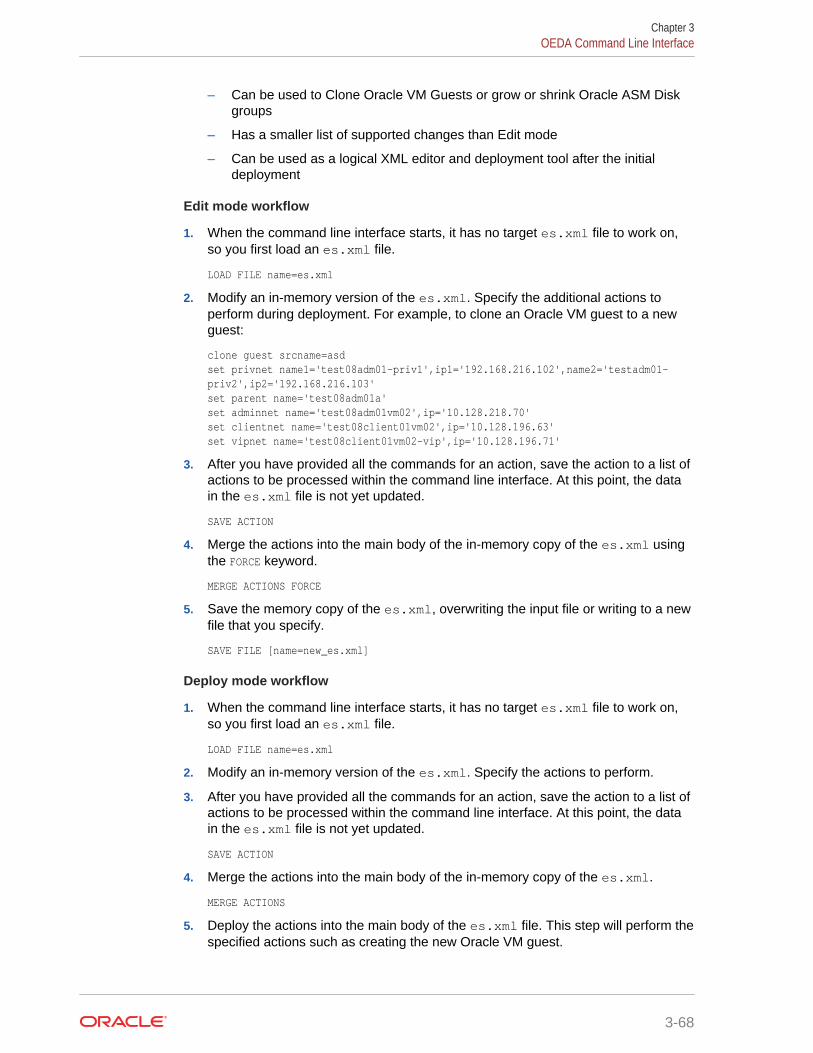
– Can be used to Clone Oracle VM Guests or grow or shrink Oracle ASM Diskgroups
– Has a smaller list of supported changes than Edit mode
– Can be used as a logical XML editor and deployment tool after the initialdeployment
Edit mode workflow
1. When the command line interface starts, it has no target es.xml file to work on,so you first load an es.xml file.
LOAD FILE name=es.xml
2. Modify an in-memory version of the es.xml. Specify the additional actions toperform during deployment. For example, to clone an Oracle VM guest to a newguest:
clone guest srcname=asdset privnet name1='test08adm01-priv1',ip1='192.168.216.102',name2='testadm01-priv2',ip2='192.168.216.103'set parent name='test08adm01a'set adminnet name='test08adm01vm02',ip='10.128.218.70'set clientnet name='test08client01vm02',ip='10.128.196.63'set vipnet name='test08client01vm02-vip',ip='10.128.196.71'
3. After you have provided all the commands for an action, save the action to a list ofactions to be processed within the command line interface. At this point, the datain the es.xml file is not yet updated.
SAVE ACTION
4. Merge the actions into the main body of the in-memory copy of the es.xml usingthe FORCE keyword.
MERGE ACTIONS FORCE
5. Save the memory copy of the es.xml, overwriting the input file or writing to a newfile that you specify.
SAVE FILE [name=new_es.xml]
Deploy mode workflow
1. When the command line interface starts, it has no target es.xml file to work on,so you first load an es.xml file.
LOAD FILE name=es.xml
2. Modify an in-memory version of the es.xml. Specify the actions to perform.
3. After you have provided all the commands for an action, save the action to a list ofactions to be processed within the command line interface. At this point, the datain the es.xml file is not yet updated.
SAVE ACTION
4. Merge the actions into the main body of the in-memory copy of the es.xml.
MERGE ACTIONS
5. Deploy the actions into the main body of the es.xml file. This step will perform thespecified actions such as creating the new Oracle VM guest.
Chapter 3OEDA Command Line Interface
3-68
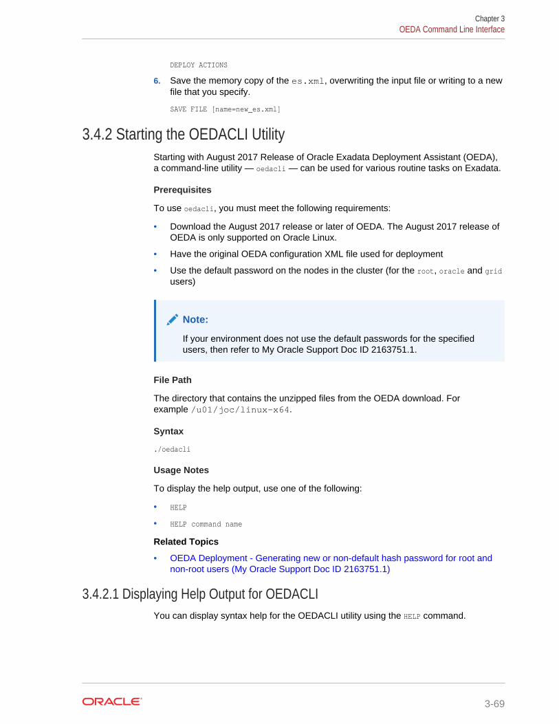
DEPLOY ACTIONS
6. Save the memory copy of the es.xml, overwriting the input file or writing to a newfile that you specify.
SAVE FILE [name=new_es.xml]
3.4.2 Starting the OEDACLI UtilityStarting with August 2017 Release of Oracle Exadata Deployment Assistant (OEDA),a command-line utility — oedacli — can be used for various routine tasks on Exadata.
Prerequisites
To use oedacli, you must meet the following requirements:
• Download the August 2017 release or later of OEDA. The August 2017 release ofOEDA is only supported on Oracle Linux.
• Have the original OEDA configuration XML file used for deployment
• Use the default password on the nodes in the cluster (for the root, oracle and gridusers)
Note:
If your environment does not use the default passwords for the specifiedusers, then refer to My Oracle Support Doc ID 2163751.1.
File Path
The directory that contains the unzipped files from the OEDA download. Forexample /u01/joc/linux-x64.
Syntax
./oedacli
Usage Notes
To display the help output, use one of the following:
• HELP
• HELP command name
Related Topics
• OEDA Deployment - Generating new or non-default hash password for root andnon-root users (My Oracle Support Doc ID 2163751.1)
3.4.2.1 Displaying Help Output for OEDACLIYou can display syntax help for the OEDACLI utility using the HELP command.
Chapter 3OEDA Command Line Interface
3-69
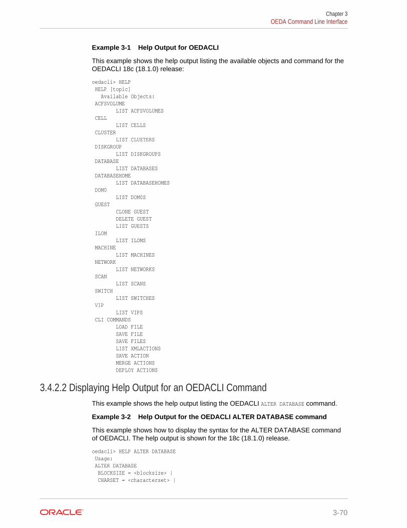
Example 3-1 Help Output for OEDACLI
This example shows the help output listing the available objects and command for theOEDACLI 18c (18.1.0) release:
oedacli> HELP HELP [topic] Available Objects: ACFSVOLUME LIST ACFSVOLUMES CELL LIST CELLS CLUSTER LIST CLUSTERS DISKGROUP LIST DISKGROUPS DATABASE LIST DATABASES DATABASEHOME LIST DATABASEHOMES DOM0 LIST DOM0S GUEST CLONE GUEST DELETE GUEST LIST GUESTS ILOM LIST ILOMS MACHINE LIST MACHINES NETWORK LIST NETWORKS SCAN LIST SCANS SWITCH LIST SWITCHES VIP LIST VIPS CLI COMMANDS LOAD FILE SAVE FILE SAVE FILES LIST XMLACTIONS SAVE ACTION MERGE ACTIONS DEPLOY ACTIONS
3.4.2.2 Displaying Help Output for an OEDACLI CommandThis example shows the help output listing the OEDACLI ALTER DATABASE command.
Example 3-2 Help Output for the OEDACLI ALTER DATABASE command
This example shows how to display the syntax for the ALTER DATABASE commandof OEDACLI. The help output is shown for the 18c (18.1.0) release.
oedacli> HELP ALTER DATABASE Usage: ALTER DATABASE BLOCKSIZE = <blocksize> | CHARSET = <characterset> |
Chapter 3OEDA Command Line Interface
3-70
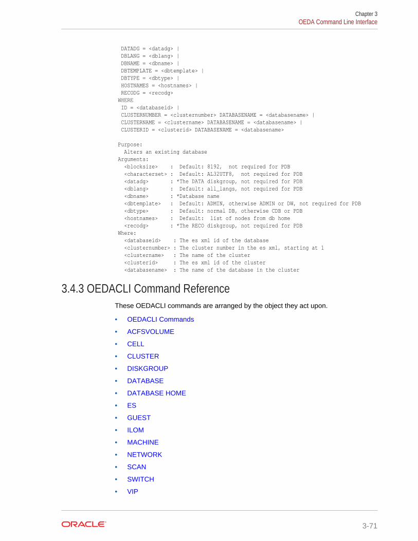
DATADG = <datadg> | DBLANG = <dblang> | DBNAME = <dbname> | DBTEMPLATE = <dbtemplate> | DBTYPE = <dbtype> | HOSTNAMES = <hostnames> | RECODG = <recodg> WHERE ID = <databaseid> | CLUSTERNUMBER = <clusternumber> DATABASENAME = <databasename> | CLUSTERNAME = <clustername> DATABASENAME = <databasename> | CLUSTERID = <clusterid> DATABASENAME = <databasename> Purpose: Alters an existing database Arguments: <blocksize> : Default: 8192, not required for PDB <characterset> : Default: AL32UTF8, not required for PDB <datadg> : *The DATA diskgroup, not required for PDB <dblang> : Default: all_langs, not required for PDB <dbname> : *Database name <dbtemplate> : Default: ADMIN, otherwise ADMIN or DW, not required for PDB <dbtype> : Default: normal DB, otherwise CDB or PDB <hostnames> : Default: list of nodes from db home <recodg> : *The RECO diskgroup, not required for PDB Where: <databaseid> : The es xml id of the database <clusternumber> : The cluster number in the es xml, starting at 1 <clustername> : The name of the cluster <clusterid> : The es xml id of the cluster <databasename> : The name of the database in the cluster
3.4.3 OEDACLI Command ReferenceThese OEDACLI commands are arranged by the object they act upon.
• OEDACLI Commands
• ACFSVOLUME
• CELL
• CLUSTER
• DISKGROUP
• DATABASE
• DATABASE HOME
• ES
• GUEST
• ILOM
• MACHINE
• NETWORK
• SCAN
• SWITCH
• VIP
Chapter 3OEDA Command Line Interface
3-71
3.4.3.1 OEDACLI CommandsThese commands are used to interact with OEDACLI, to load and save files, and tomerge, save, and deploy actions.
• LOAD FILE
• SAVE ACTION
• MERGE ACTIONS
• DEPLOY ACTIONS
• SAVE FILE
• SAVE FILES
• LIST XMLACTIONS
3.4.3.1.1 LOAD FILEUse this command to load an engineered system XML file (es.xml) into OEDACLImemory for editing.
Syntax
LOAD FILE NAME=filename
Arguments
• NAME : Specifies the name of an existing engineered system XML file
Example 3-3 Loading a File into OEDACLI for Editing
oedacli> LOAD FILE NAME=Oracle-test12.xml SUCCESS - file loaded OK Customer : testadm01 - Oracle
3.4.3.1.2 SAVE ACTIONUse this command to save the current action to engineered system XML memorycopy.
Syntax
SAVE ACTION [FORCE]
Arguments
Specify FORCE if the action should be auto-merged into the engineered system model.
Note:
The engineered system configuration should be saved as a file using asubsequent SAVE FILE command.
Chapter 3OEDA Command Line Interface
3-72
3.4.3.1.3 MERGE ACTIONSUse this command to merge the current actions into the other actions in theEngineered System model.
Syntax
MERGE ACTIONS [FORCE]
Arguments
Specify FORCE if you do not want this action to be processed by a DEPLOY ACTIONScommand.
3.4.3.1.4 DEPLOY ACTIONSUse this command to execute all actions from the Actions section of the engineeredsystems XML file.
Syntax
DEPLOY ACTIONS
Example 3-4 Deploying the Actions to Add a Database
oedacli> DEPLOY ACTIONS Deploying Action ID : 4 add database dbname='testdb' DATADG='DATAC1' RECODG='RECOC1' where DBHOMEID='c0_databaseHome' Deploying ADD DATABASE Running datapatch on database 'testdb' Done... Done
3.4.3.1.5 SAVE FILEUse this command to save a current set of actions to a new engineered system XMLfile.
Syntax
SAVE FILE [ NAME=filename ]
Arguments
The optional argument, NAME, is used to specify the name of a new engineered systemXML file. If you do not specify the NAME argument, then this command overwrites thesource file.
3.4.3.1.6 SAVE FILESUse this command to generate a new set of configuration files from OEDA.
Syntax
SAVE FILES LOCATION = dirname
Chapter 3OEDA Command Line Interface
3-73
Arguments
The LOCATION argument specifies the directory in which the new file set will be created.
Usage Notes
If the specified directory does not exist, it will be created.
3.4.3.1.7 LIST XMLACTIONSThis command lists the current actions created by OEDACLI.
Syntax
LIST XMLACTIONS
3.4.3.2 ACFSVOLUMEYou can add, alter, delete, or list Oracle ACFS volumes.
• ADD ACFSVOLUME
• ALTER ACFSVOLUME
• DELETE ACFSVOLUME
• LIST ACFSVOLUME
3.4.3.2.1 ADD ACFSVOLUMEThis command adds Oracle ASM Cluster File System (Oracle ACFS) volumes.
Syntax
ADD ACFSVOLUME VOLUMENAME = volume_name | VOLUMESIZE = volume_size | MOUNTPATH = mountpath WHERE DISKGROUPID = diskgroup_id | CLUSTERNUMBER = cluster_number DISKGROUPNAME = diskgroup_name | CLUSTERNAME = cluster_name DISKGROUPNAME diskgroup_name | CLUSTERID = cluster_id DISKGROUPNAME = diskgroup_name
Arguments
You can specify the following attributes for the new Oracle ACFS volume:
• VOLUMENAME : Specifies a unique name for the new volume
• VOLUMESIZE : A number that specifies the size of the new volume in GB
• MOUNTPATH : Specifies the file system mount path for the new volume
The following arguments are available in the WHERE clause:
• DISKGROUPID : Specifies the es.xml ID for the container disk group
• CLUSTERNUMBER : Specifies the cluster number in the es.xml, starting at 1
• CLUSTERNAME : Specifies the name of the cluster
Chapter 3OEDA Command Line Interface
3-74
• CLUSTERID : Specifies the es.xml ID of the cluster
• DISKGROUPNAME : Specifies the name of the container disk group
3.4.3.2.2 ALTER ACFSVOLUMEThis command alters an existing Oracle ASM Cluster File System (Oracle ACFS)volume.
Syntax
ALTER ACFSVOLUME VOLUMENAME = volume_name | VOLUMESIZE = volume_size | MOUNTPATH = mountpath WHERE ID = acfs_volume_id | DISKGROUPID = diskgroup_id VOLUMENAME = volume_name| CLUSTERNUMBER = cluster_number DISKGROUPNAME = diskgroup_name VOLUMENAME = volume_name| CLUSTERNAME = cluster_name DISKGROUPNAME diskgroup_name VOLUMENAME = volume_name| CLUSTERID = cluster_id DISKGROUPNAME = diskgroup_name VOLUMENAME = volume_name
Arguments
You can modify the following attributes of the Oracle ACFS volume:
• VOLUMENAME : Specifies a new, unique volume name
• VOLUMESIZE : A number that specifies the new size of the volume in GB
• MOUNTPATH : Specifies the new file system mount path for the volume
The following arguments are available in the WHERE clause:
• ID : Specifies the es.xml ID for an existing Oracle ACFS volume
• DISKGROUPID : Specifies the es.xml ID for the container disk group
• CLUSTERNUMBER : Specifies the cluster number in the es.xml, starting at 1
• CLUSTERNAME : Specifies the name of the cluster
• CLUSTERID : Specifies the es.xml ID of the cluster
• DISKGROUPNAME : Specifies the name of the container disk group
• VOLUMENAME : Specifies the name of the existing Oracle ACFS volume
3.4.3.2.3 DELETE ACFSVOLUMEThis command deletes an existing Oracle ASM Cluster File System (Oracle ACFS)volume.
Syntax
DELETE ACFSVOLUMEWHERE ID = acfs_volume_id | DISKGROUPID = diskgroup_id VOLUMENAME = volume_name| CLUSTERNUMBER = cluster_number DISKGROUPNAME = diskgroup_name VOLUMENAME = volume_name|
Chapter 3OEDA Command Line Interface
3-75
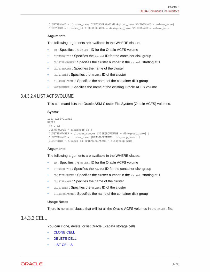
CLUSTERNAME = cluster_name DISKGROUPNAME diskgroup_name VOLUMENAME = volume_name| CLUSTERID = cluster_id DISKGROUPNAME = diskgroup_name VOLUMENAME = volume_name
Arguments
The following arguments are available in the WHERE clause:
• ID : Specifies the es.xml ID for the Oracle ACFS volume
• DISKGROUPID : Specifies the es.xml ID for the container disk group
• CLUSTERNUMBER : Specifies the cluster number in the es.xml, starting at 1
• CLUSTERNAME : Specifies the name of the cluster
• CLUSTERID : Specifies the es.xml ID of the cluster
• DISKGROUPNAME : Specifies the name of the container disk group
• VOLUMENAME : Specifies the name of the existing Oracle ACFS volume
3.4.3.2.4 LIST ACFSVOLUMEThis command lists the Oracle ASM Cluster File System (Oracle ACFS) volumes.
Syntax
LIST ACFSVOLUMESWHERE ID = id | DISKGROUPID = diskgroup_id | CLUSTERNUMBER = cluster_number [DISKGROUPNAME = diskgroup_name] | CLUSTERNAME = cluster_name [DISKGROUPNAME diskgroup_name] | CLUSTERID = cluster_id [DISKGROUPNAME = diskgroup_name]
Arguments
The following arguments are available in the WHERE clause:
• ID : Specifies the es.xml ID for the Oracle ACFS volume
• DISKGROUPID : Specifies the es.xml ID for the container disk group
• CLUSTERNUMBER : Specifies the cluster number in the es.xml, starting at 1
• CLUSTERNAME : Specifies the name of the cluster
• CLUSTERID : Specifies the es.xml ID of the cluster
• DISKGROUPNAME : Specifies the name of the container disk group
Usage Notes
There is no WHERE clause that will list all the Oracle ACFS volumes in the es.xml file.
3.4.3.3 CELLYou can clone, delete, or list Oracle Exadata storage cells.
• CLONE CELL
• DELETE CELL
• LIST CELLS
Chapter 3OEDA Command Line Interface
3-76
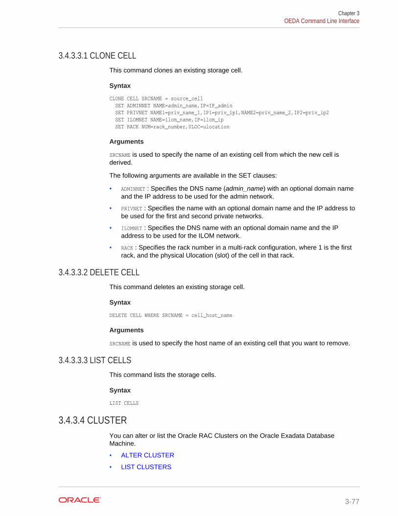
3.4.3.3.1 CLONE CELLThis command clones an existing storage cell.
Syntax
CLONE CELL SRCNAME = source_cell SET ADMINNET NAME=admin_name,IP=IP_admin SET PRIVNET NAME1=priv_name_1,IP1=priv_ip1,NAME2=priv_name_2,IP2=priv_ip2 SET ILOMNET NAME=ilom_name,IP=ilom_ip SET RACK NUM=rack_number,ULOC=ulocation
Arguments
SRCNAME is used to specify the name of an existing cell from which the new cell isderived.
The following arguments are available in the SET clauses:
• ADMINNET : Specifies the DNS name (admin_name) with an optional domain nameand the IP address to be used for the admin network.
• PRIVNET : Specifies the name with an optional domain name and the IP address tobe used for the first and second private networks.
• ILOMNET : Specifies the DNS name with an optional domain name and the IPaddress to be used for the ILOM network.
• RACK : Specifies the rack number in a multi-rack configuration, where 1 is the firstrack, and the physical Ulocation (slot) of the cell in that rack.
3.4.3.3.2 DELETE CELLThis command deletes an existing storage cell.
Syntax
DELETE CELL WHERE SRCNAME = cell_host_name
Arguments
SRCNAME is used to specify the host name of an existing cell that you want to remove.
3.4.3.3.3 LIST CELLSThis command lists the storage cells.
Syntax
LIST CELLS
3.4.3.4 CLUSTERYou can alter or list the Oracle RAC Clusters on the Oracle Exadata DatabaseMachine.
• ALTER CLUSTER
• LIST CLUSTERS
Chapter 3OEDA Command Line Interface
3-77
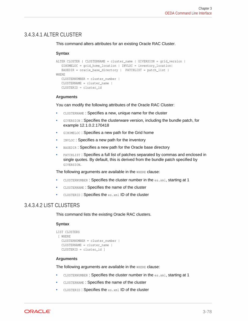
3.4.3.4.1 ALTER CLUSTERThis command alters attributes for an existing Oracle RAC Cluster.
Syntax
ALTER CLUSTER { CLUSTERNAME = cluster_name | GIVERSION = grid_version | GIHOMELOC = grid_home_location | INVLOC = inventory_location| BASEDIR = oracle_base_directory | PATCHLIST = patch_list }WHERE CLUSTERNUMBER = cluster_number | CLUSTERNAME = cluster_name | CLUSTERID = cluster_id
Arguments
You can modify the following attributes of the Oracle RAC Cluster:
• CLUSTERNAME : Specifies a new, unique name for the cluster
• GIVERSION : Specifies the clusterware version, including the bundle patch, forexample 12.1.0.2.170418
• GIHOMELOC : Specifies a new path for the Grid home
• INVLOC : Specifies a new path for the inventory
• BASEDIR : Specifies a new path for the Oracle base directory
• PATCHLIST : Specifies a full list of patches separated by commas and enclosed insingle quotes. By default, this is derived from the bundle patch specified byGIVERSION.
The following arguments are available in the WHERE clause:
• CLUSTERNUMBER : Specifies the cluster number in the es.xml, starting at 1
• CLUSTERNAME : Specifies the name of the cluster
• CLUSTERID : Specifies the es.xml ID of the cluster
3.4.3.4.2 LIST CLUSTERSThis command lists the existing Oracle RAC clusters.
Syntax
LIST CLUSTERS [ WHERE CLUSTERNUMBER = cluster_number | CLUSTERNAME = cluster_name | CLUSTERID = cluster_id ]
Arguments
The following arguments are available in the WHERE clause:
• CLUSTERNUMBER : Specifies the cluster number in the es.xml, starting at 1
• CLUSTERNAME : Specifies the name of the cluster
• CLUSTERID : Specifies the es.xml ID of the cluster
Chapter 3OEDA Command Line Interface
3-78
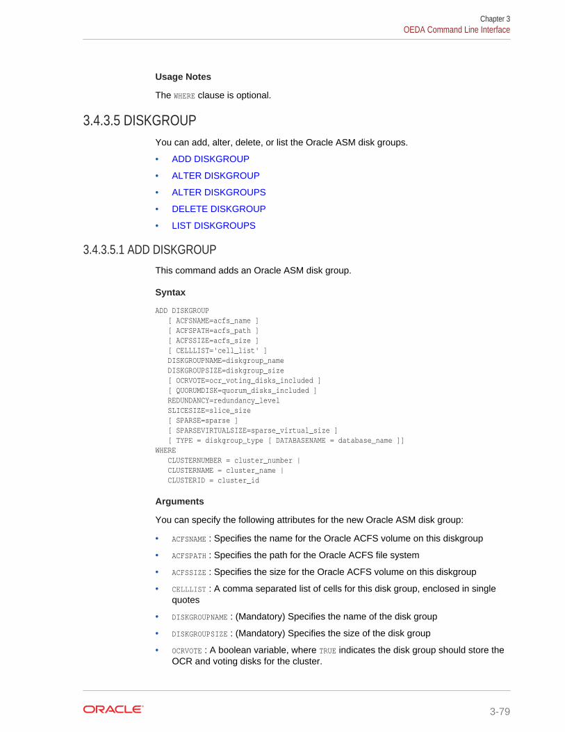
Usage Notes
The WHERE clause is optional.
3.4.3.5 DISKGROUPYou can add, alter, delete, or list the Oracle ASM disk groups.
• ADD DISKGROUP
• ALTER DISKGROUP
• ALTER DISKGROUPS
• DELETE DISKGROUP
• LIST DISKGROUPS
3.4.3.5.1 ADD DISKGROUPThis command adds an Oracle ASM disk group.
Syntax
ADD DISKGROUP [ ACFSNAME=acfs_name ] [ ACFSPATH=acfs_path ] [ ACFSSIZE=acfs_size ] [ CELLLIST='cell_list' ] DISKGROUPNAME=diskgroup_name DISKGROUPSIZE=diskgroup_size [ OCRVOTE=ocr_voting_disks_included ] [ QUORUMDISK=quorum_disks_included ] REDUNDANCY=redundancy_level SLICESIZE=slice_size [ SPARSE=sparse ] [ SPARSEVIRTUALSIZE=sparse_virtual_size ] [ TYPE = diskgroup_type [ DATABASENAME = database_name ]]WHERE CLUSTERNUMBER = cluster_number | CLUSTERNAME = cluster_name | CLUSTERID = cluster_id
Arguments
You can specify the following attributes for the new Oracle ASM disk group:
• ACFSNAME : Specifies the name for the Oracle ACFS volume on this diskgroup
• ACFSPATH : Specifies the path for the Oracle ACFS file system
• ACFSSIZE : Specifies the size for the Oracle ACFS volume on this diskgroup
• CELLLIST : A comma separated list of cells for this disk group, enclosed in singlequotes
• DISKGROUPNAME : (Mandatory) Specifies the name of the disk group
• DISKGROUPSIZE : (Mandatory) Specifies the size of the disk group
• OCRVOTE : A boolean variable, where TRUE indicates the disk group should store theOCR and voting disks for the cluster.
Chapter 3OEDA Command Line Interface
3-79
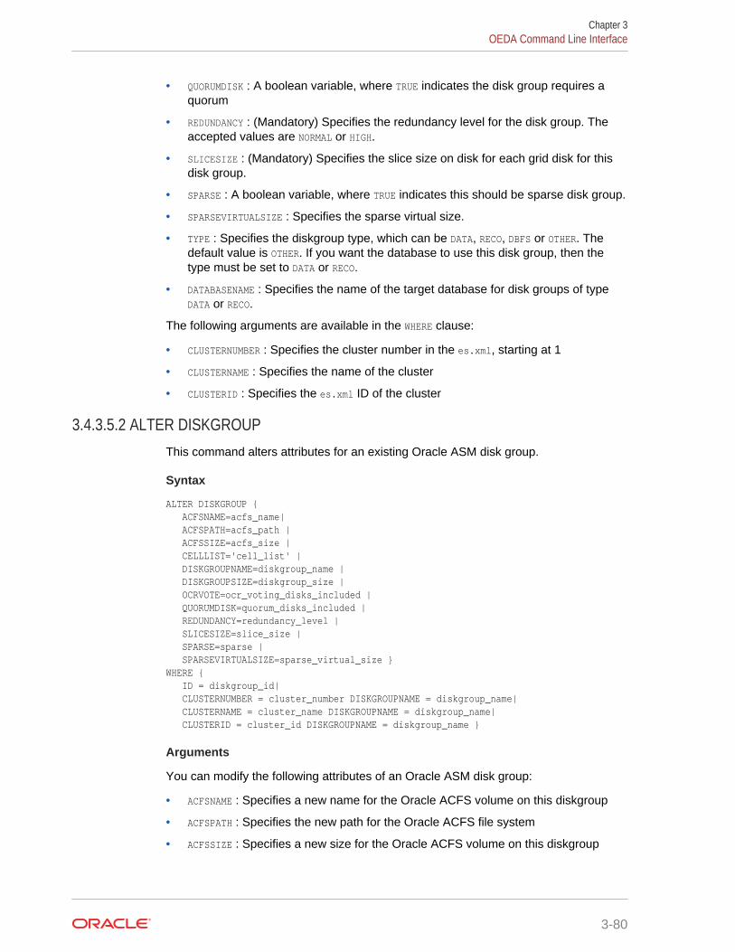
• QUORUMDISK : A boolean variable, where TRUE indicates the disk group requires aquorum
• REDUNDANCY : (Mandatory) Specifies the redundancy level for the disk group. Theaccepted values are NORMAL or HIGH.
• SLICESIZE : (Mandatory) Specifies the slice size on disk for each grid disk for thisdisk group.
• SPARSE : A boolean variable, where TRUE indicates this should be sparse disk group.
• SPARSEVIRTUALSIZE : Specifies the sparse virtual size.
• TYPE : Specifies the diskgroup type, which can be DATA, RECO, DBFS or OTHER. Thedefault value is OTHER. If you want the database to use this disk group, then thetype must be set to DATA or RECO.
• DATABASENAME : Specifies the name of the target database for disk groups of typeDATA or RECO.
The following arguments are available in the WHERE clause:
• CLUSTERNUMBER : Specifies the cluster number in the es.xml, starting at 1
• CLUSTERNAME : Specifies the name of the cluster
• CLUSTERID : Specifies the es.xml ID of the cluster
3.4.3.5.2 ALTER DISKGROUPThis command alters attributes for an existing Oracle ASM disk group.
Syntax
ALTER DISKGROUP { ACFSNAME=acfs_name| ACFSPATH=acfs_path | ACFSSIZE=acfs_size | CELLLIST='cell_list' | DISKGROUPNAME=diskgroup_name | DISKGROUPSIZE=diskgroup_size | OCRVOTE=ocr_voting_disks_included | QUORUMDISK=quorum_disks_included | REDUNDANCY=redundancy_level | SLICESIZE=slice_size | SPARSE=sparse | SPARSEVIRTUALSIZE=sparse_virtual_size }WHERE { ID = diskgroup_id| CLUSTERNUMBER = cluster_number DISKGROUPNAME = diskgroup_name| CLUSTERNAME = cluster_name DISKGROUPNAME = diskgroup_name| CLUSTERID = cluster_id DISKGROUPNAME = diskgroup_name }
Arguments
You can modify the following attributes of an Oracle ASM disk group:
• ACFSNAME : Specifies a new name for the Oracle ACFS volume on this diskgroup
• ACFSPATH : Specifies the new path for the Oracle ACFS file system
• ACFSSIZE : Specifies a new size for the Oracle ACFS volume on this diskgroup
Chapter 3OEDA Command Line Interface
3-80
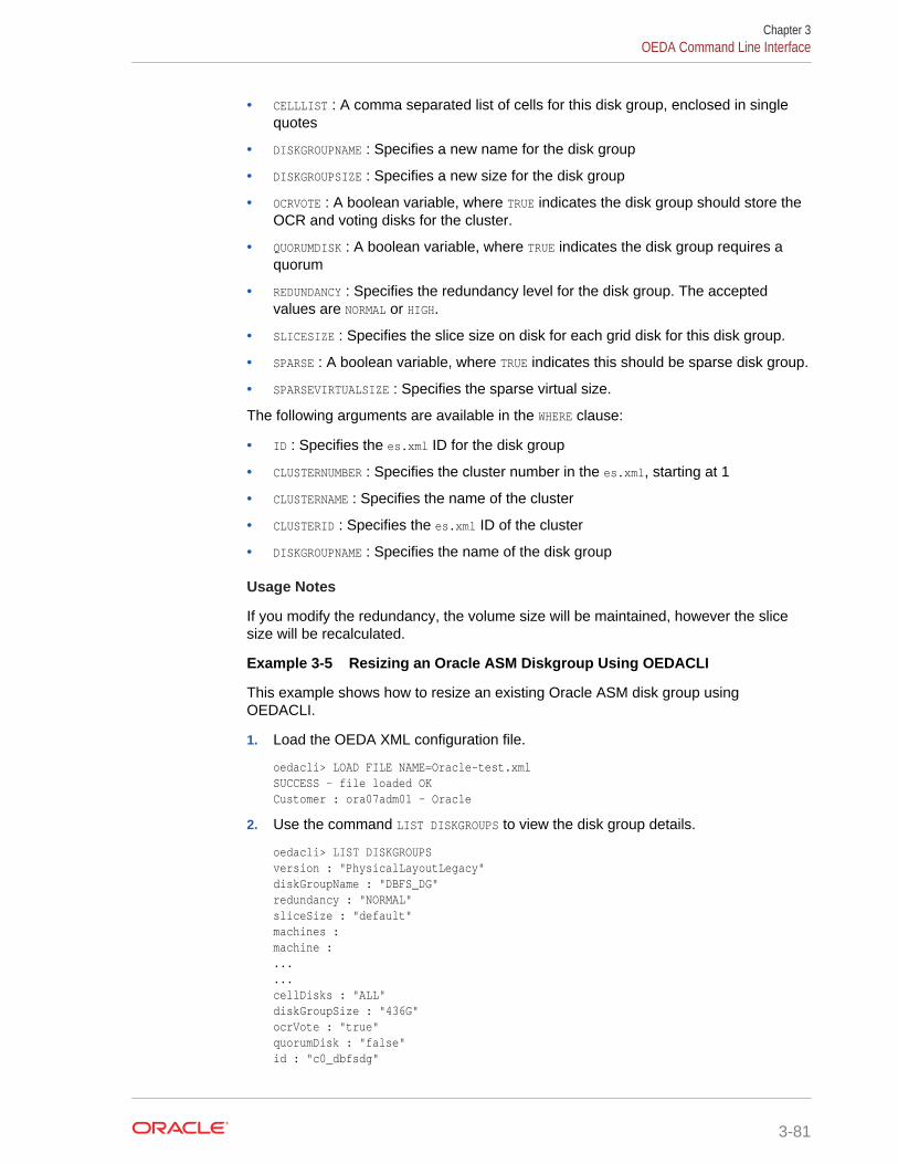
• CELLLIST : A comma separated list of cells for this disk group, enclosed in singlequotes
• DISKGROUPNAME : Specifies a new name for the disk group
• DISKGROUPSIZE : Specifies a new size for the disk group
• OCRVOTE : A boolean variable, where TRUE indicates the disk group should store theOCR and voting disks for the cluster.
• QUORUMDISK : A boolean variable, where TRUE indicates the disk group requires aquorum
• REDUNDANCY : Specifies the redundancy level for the disk group. The acceptedvalues are NORMAL or HIGH.
• SLICESIZE : Specifies the slice size on disk for each grid disk for this disk group.
• SPARSE : A boolean variable, where TRUE indicates this should be sparse disk group.
• SPARSEVIRTUALSIZE : Specifies the sparse virtual size.
The following arguments are available in the WHERE clause:
• ID : Specifies the es.xml ID for the disk group
• CLUSTERNUMBER : Specifies the cluster number in the es.xml, starting at 1
• CLUSTERNAME : Specifies the name of the cluster
• CLUSTERID : Specifies the es.xml ID of the cluster
• DISKGROUPNAME : Specifies the name of the disk group
Usage Notes
If you modify the redundancy, the volume size will be maintained, however the slicesize will be recalculated.
Example 3-5 Resizing an Oracle ASM Diskgroup Using OEDACLI
This example shows how to resize an existing Oracle ASM disk group usingOEDACLI.
1. Load the OEDA XML configuration file.
oedacli> LOAD FILE NAME=Oracle-test.xml SUCCESS - file loaded OK Customer : ora07adm01 - Oracle
2. Use the command LIST DISKGROUPS to view the disk group details.
oedacli> LIST DISKGROUPSversion : "PhysicalLayoutLegacy" diskGroupName : "DBFS_DG" redundancy : "NORMAL" sliceSize : "default" machines : machine : ... ... cellDisks : "ALL" diskGroupSize : "436G" ocrVote : "true" quorumDisk : "false" id : "c0_dbfsdg"
Chapter 3OEDA Command Line Interface
3-81
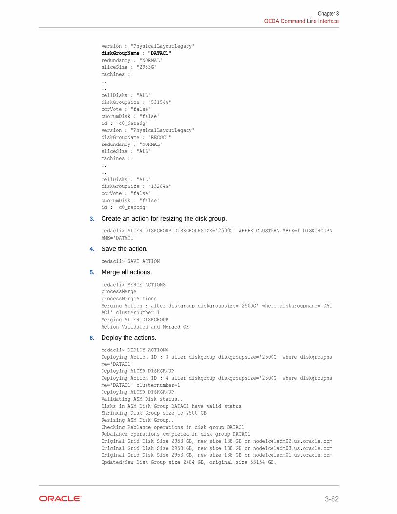
version : "PhysicalLayoutLegacy" diskGroupName : "DATAC1" redundancy : "NORMAL" sliceSize : "2953G" machines : .. .. cellDisks : "ALL" diskGroupSize : "53154G" ocrVote : "false" quorumDisk : "false" id : "c0_datadg" version : "PhysicalLayoutLegacy" diskGroupName : "RECOC1" redundancy : "NORMAL" sliceSize : "ALL" machines : .. .. cellDisks : "ALL" diskGroupSize : "13284G" ocrVote : "false" quorumDisk : "false" id : "c0_recodg"
3. Create an action for resizing the disk group.
oedacli> ALTER DISKGROUP DISKGROUPSIZE='2500G' WHERE CLUSTERNUMBER=1 DISKGROUPNAME='DATAC1'
4. Save the action.
oedacli> SAVE ACTION
5. Merge all actions.
oedacli> MERGE ACTIONSprocessMerge processMergeActions Merging Action : alter diskgroup diskgroupsize='2500G' where diskgroupname='DATAC1' clusternumber=1 Merging ALTER DISKGROUPAction Validated and Merged OK
6. Deploy the actions.
oedacli> DEPLOY ACTIONS Deploying Action ID : 3 alter diskgroup diskgroupsize='2500G' where diskgroupname='DATAC1' Deploying ALTER DISKGROUP Deploying Action ID : 4 alter diskgroup diskgroupsize='2500G' where diskgroupname='DATAC1' clusternumber=1 Deploying ALTER DISKGROUP Validating ASM Disk status.. Disks in ASM Disk Group DATAC1 have valid status Shrinking Disk Group size to 2500 GB Resizing ASM Disk Group.. Checking Reblance operations in disk group DATAC1 Rebalance operations completed in disk group DATAC1 Original Grid Disk Size 2953 GB, new size 138 GB on node1celadm02.us.oracle.com Original Grid Disk Size 2953 GB, new size 138 GB on node1celadm03.us.oracle.com Original Grid Disk Size 2953 GB, new size 138 GB on node1celadm01.us.oracle.com Updated/New Disk Group size 2484 GB, original size 53154 GB.
Chapter 3OEDA Command Line Interface
3-82
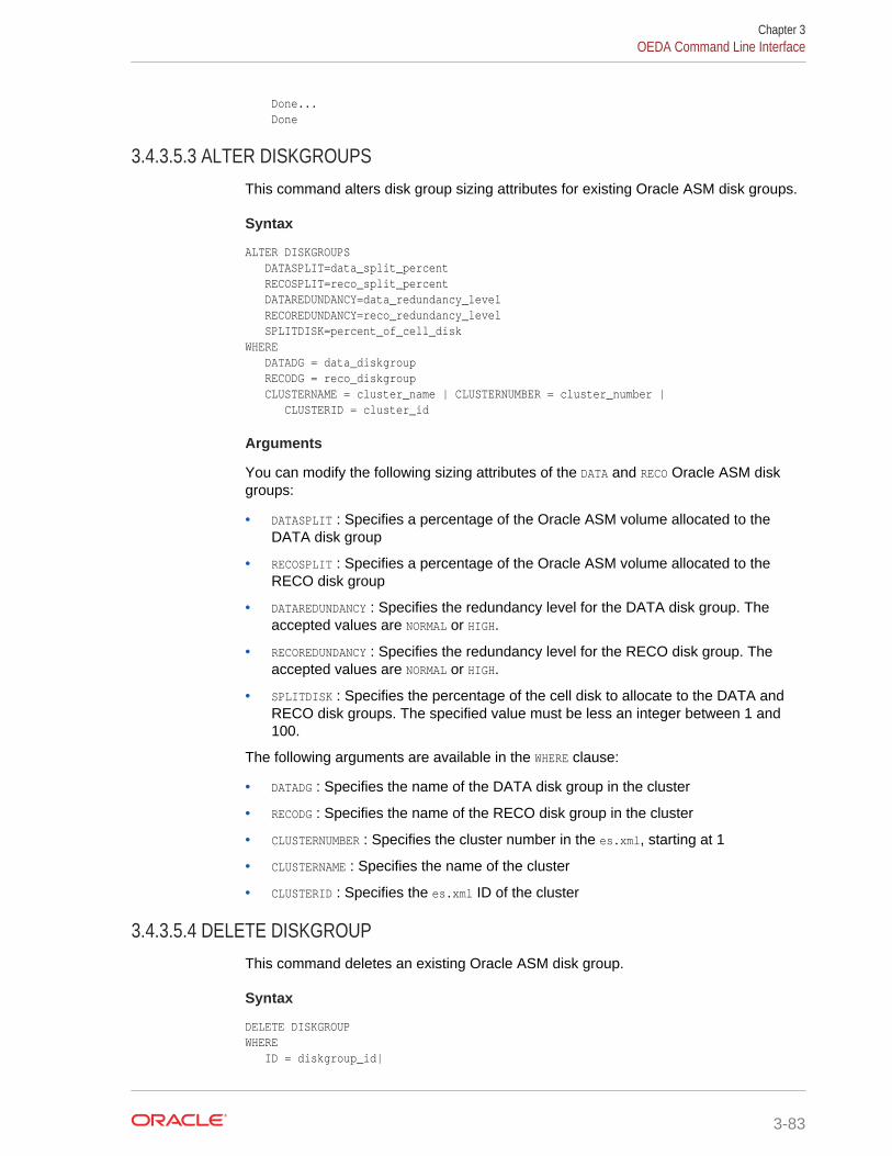
Done... Done
3.4.3.5.3 ALTER DISKGROUPSThis command alters disk group sizing attributes for existing Oracle ASM disk groups.
Syntax
ALTER DISKGROUPS DATASPLIT=data_split_percent RECOSPLIT=reco_split_percent DATAREDUNDANCY=data_redundancy_level RECOREDUNDANCY=reco_redundancy_level SPLITDISK=percent_of_cell_diskWHERE DATADG = data_diskgroup RECODG = reco_diskgroup CLUSTERNAME = cluster_name | CLUSTERNUMBER = cluster_number | CLUSTERID = cluster_id
Arguments
You can modify the following sizing attributes of the DATA and RECO Oracle ASM diskgroups:
• DATASPLIT : Specifies a percentage of the Oracle ASM volume allocated to theDATA disk group
• RECOSPLIT : Specifies a percentage of the Oracle ASM volume allocated to theRECO disk group
• DATAREDUNDANCY : Specifies the redundancy level for the DATA disk group. Theaccepted values are NORMAL or HIGH.
• RECOREDUNDANCY : Specifies the redundancy level for the RECO disk group. Theaccepted values are NORMAL or HIGH.
• SPLITDISK : Specifies the percentage of the cell disk to allocate to the DATA andRECO disk groups. The specified value must be less an integer between 1 and100.
The following arguments are available in the WHERE clause:
• DATADG : Specifies the name of the DATA disk group in the cluster
• RECODG : Specifies the name of the RECO disk group in the cluster
• CLUSTERNUMBER : Specifies the cluster number in the es.xml, starting at 1
• CLUSTERNAME : Specifies the name of the cluster
• CLUSTERID : Specifies the es.xml ID of the cluster
3.4.3.5.4 DELETE DISKGROUPThis command deletes an existing Oracle ASM disk group.
Syntax
DELETE DISKGROUP WHERE ID = diskgroup_id|
Chapter 3OEDA Command Line Interface
3-83
CLUSTERNUMBER = cluster_number DISKGROUPNAME = diskgroup_name| CLUSTERNAME = cluster_name DISKGROUPNAME = diskgroup_name| CLUSTERID = cluster_id DISKGROUPNAME = diskgroup_name
Arguments
The following arguments are available in the WHERE clause:
• ID : Specifies the es.xml ID for the disk group
• CLUSTERNUMBER : Specifies the cluster number in the es.xml, starting at 1
• CLUSTERNAME : Specifies the name of the cluster
• CLUSTERID : Specifies the es.xml ID of the cluster
• DISKGROUPNAME : Specifies the name of the disk group
3.4.3.5.5 LIST DISKGROUPSThis command lists the existing Oracle ASM disk groups.
Syntax
LIST DISKGROUPS [ WHERE ID = diskgroup_id| CLUSTERNUMBER = cluster_number | CLUSTERNAME = cluster_name | CLUSTERID = cluster_id ]
Arguments
The following arguments are available in the WHERE clause:
• ID : Specifies the es.xml ID for the disk group
• CLUSTERNUMBER : Specifies the cluster number in the es.xml, starting at 1
• CLUSTERNAME : Specifies the name of the cluster
• CLUSTERID : Specifies the es.xml ID of the cluster
• DISKGROUPNAME : Specifies the name of the disk group
3.4.3.6 DATABASEYou can add, alter, delete, or list the Oracle databases.
• ADD DATABASE
• ALTER DATABASE
• DELETE DATABASE
• LIST DATABASES
3.4.3.6.1 ADD DATABASEThis command adds an Oracle database, or a CDB or PDB to an existing CDB.
Chapter 3OEDA Command Line Interface
3-84
Syntax
ADD DATABASE [ BLOCKSIZE = blocksize ] [ CHARSET = database_character_set DATADG = data_diskgroup [ DBLANG = database_language ] DBNAME = database_name [ DBTEMPLATE = database_template ] [ DBTYPE = database_type ] [ HOSTNAMES = 'host_names' ] RECODG = reco_diskgroupWHERE { DBHOMEID = database_home_id | CLUSTERNUMBER = cluster_number DBHOMELOC = database_home_location | CLUSTERNAME = cluster_name DBHOMELOC = database_home_location | CLUSTERID = cluster_id DBHOMELOC = database_home_location | CLUSTERNUMBER = cluster_number CDBNAME = container_database_name | CLUSTERNAME = cluster_name CDBNAME = container_database_name | CLUSTERID = cluster_id CDBNAME = container_database_name }
Arguments
You can specify the following attributes for the new Oracle database:
• BLOCKSIZE : Specifies the block size for the new database. The default value is8192. This argument is not required for pluggable databases.
• CHARSET : Specifies the character set to use for the new database. The defaultvalue is AL32UTF8. This argument is not required for pluggable databases.
• DATADG : (Mandatory) Specifies the name of the DATA disk group for the newdatabase. This argument is not required for pluggable databases.
• DBLANG : Specifies the language to use for the new database. The default value isall_langs. This argument is not required for pluggable databases.
• DBNAME : (Mandatory) Specifies the name of the new database.
• DBTEMPLATE : Specifies the template to use when creating the new database, ADMINor DW. The default value is ADMIN. This argument is not required for pluggabledatabases.
• DBTYPE : Specifies the type of database to create. The accepted values are normalDB, CDB, or PDB. The default value is normal DB.
• HOSTNAMES : Specifies a comma-separated list of host names on which the databaseshould run. The default value is the list of nodes registered with the databasehome.
• RECODG : (Mandatory) Specifies the name of the RECO disk group for the newdatabase. This argument is not required for pluggable databases.
The following arguments are available in the WHERE clause:
• DBHOMEID : Specifies the es.xml ID of the database home.
• CLUSTERNUMBER : Specifies the cluster number in the es.xml, starting at 1
• CLUSTERNAME : Specifies the name of the cluster
• CLUSTERID : Specifies the es.xml ID of the cluster
Chapter 3OEDA Command Line Interface
3-85
• DBHOMELOCATION : Specifies the path for the target database home.
• CDBNAME : Specifies the database name for the container database. This argumentis required only when DBTYPE is set to PDB.
Example 3-6 Adding a New Oracle Database Using OEDACLI
This example shows how to add a new database to the configuration.
1. Load the OEDA XML configuration file.
oedacli> LOAD FILE NAME=Oracle-test.xml SUCCESS - file loaded OK Customer : ora07adm01 - Oracle
2. Use the command LIST DATABASEHOMES to identify the databasehome_id associatedwith the target database home. This database home will be used to create the newdatabase.
oedacli> LIST DATABASEHOMESversion : "CloneInstall" cluster : id : "c0_clusterHome" databaseHomeName : "c0_DbHome_0" databaseSwOwner : "c0_oracle" databaseVersion : "12.2.0.1.170718" databaseHomeLoc : "/u01/app/oracle/product/12.2.0.1/dbhome_1" inventoryLocation : "/u01/app/oraInventory" language : "all_langs" machines : machine : ... ... patches : patch : patchNumber : "26133434" basedir : "/u01/app/oracle" useZfs : "false" id : "c0_databaseHome1"
3. Create an action for creating the new database. You must provide a name for thenew database, and the names of the DATA and RECO disk groups that the newdatabase should use. Also, use the ID retrieved in the previous step to specify theOracle Home in which to create this database.
oedacli> ADD DATABASE DBNAME='testdb' DATADG='DATAC1' RECODG='RECOC1' WHERE DBHOMEID='c0_databaseHome'
4. Save the action.
oedacli> SAVE ACTION
5. Merge all actions.
oedacli> MERGE ACTIONSprocessMerge processMergeActions Merging Action : add database dbname='testdb' DATADG='DATAC1' RECODG='RECOC1' where DBHOMEID='c0_databaseHome' Merging ADD DATABASE Action Validated and Merged OK
6. Save the action to a new Engineered Systems XML configuration file.
oedacli> SAVE FILE NAME ='cli-test-2databases.xml' File : cli-test-2databases.xml saved OK
Chapter 3OEDA Command Line Interface
3-86
7. Deploy the actions.
oedacli> DEPLOY ACTIONS Deploying Action ID : 4 add database dbname='testdb' DATADG='DATAC1' RECODG='RECOC1' where DBHOMEID='c0_databaseHome' Deploying ADD DATABASE Running datapatch on database 'testdb' Done... Done
3.4.3.6.2 ALTER DATABASEThis command alters an existing Oracle database.
Syntax
ALTER DATABASE [ BLOCKSIZE = blocksize ] [ CHARSET = database_character_set DATADG = data_diskgroup [ DBLANG = database_language ] DBNAME = database_name [ DBTEMPLATE = database_template ] [ DBTYPE = database_type ] [ HOSTNAMES = 'host_names' ] RECODG = reco_diskgroupWHERE ID = database_id | CLUSTERNUMBER = cluster_number DATABASENAME = database_name | CLUSTERNAME = cluster_name DATABASENAME = database_name | CLUSTERID = cluster_id DATABASENAME = database_name
Arguments
You can modify the following attributes for the Oracle database:
• BLOCKSIZE : Specifies the new block size for the database. The default value is8192. This argument is not required for pluggable databases.
• CHARSET : Specifies the new character set to use for the database. The defaultvalue is AL32UTF8. This argument is not required for pluggable databases.
• DATADG : (Mandatory) Specifies the name of the DATA disk group for the database.This argument is not required for pluggable databases.
• DBLANG : Specifies the new language to use for the database. The default value isall_langs. This argument is not required for pluggable databases.
• DBNAME : (Mandatory) Specifies the name of the database.
• DBTEMPLATE : Specifies the template to use when creating the database, ADMIN or DW.The default value is ADMIN. This argument is not required for pluggable databases.
• DBTYPE : Specifies the type of database to create. The accepted values are normalDB, CDB, or PDB. The default value is normal DB.
• HOSTNAMES : Specifies a comma-separated list of host names on which the databaseshould be created. The default value is the list of nodes registered with thedatabase home.
• RECODG : (Mandatory) Specifies the name of the RECO disk group for the database.This argument is not required for pluggable databases.
Chapter 3OEDA Command Line Interface
3-87
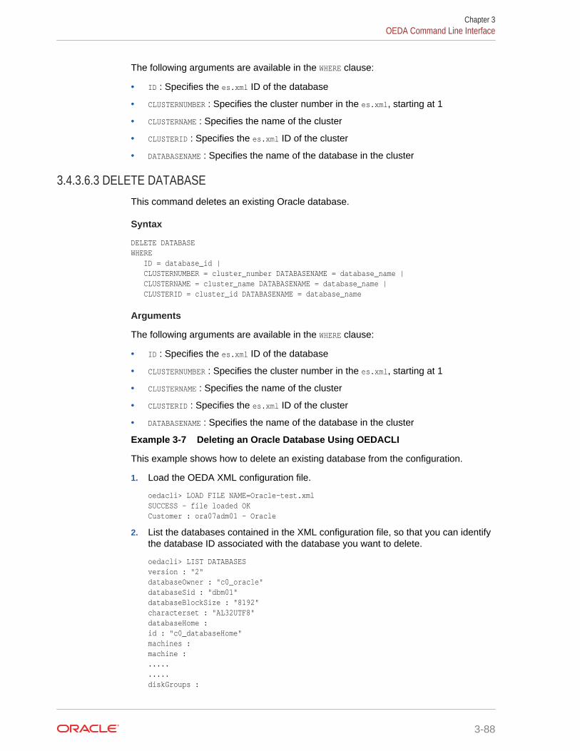
The following arguments are available in the WHERE clause:
• ID : Specifies the es.xml ID of the database
• CLUSTERNUMBER : Specifies the cluster number in the es.xml, starting at 1
• CLUSTERNAME : Specifies the name of the cluster
• CLUSTERID : Specifies the es.xml ID of the cluster
• DATABASENAME : Specifies the name of the database in the cluster
3.4.3.6.3 DELETE DATABASEThis command deletes an existing Oracle database.
Syntax
DELETE DATABASE WHERE ID = database_id | CLUSTERNUMBER = cluster_number DATABASENAME = database_name | CLUSTERNAME = cluster_name DATABASENAME = database_name | CLUSTERID = cluster_id DATABASENAME = database_name
Arguments
The following arguments are available in the WHERE clause:
• ID : Specifies the es.xml ID of the database
• CLUSTERNUMBER : Specifies the cluster number in the es.xml, starting at 1
• CLUSTERNAME : Specifies the name of the cluster
• CLUSTERID : Specifies the es.xml ID of the cluster
• DATABASENAME : Specifies the name of the database in the cluster
Example 3-7 Deleting an Oracle Database Using OEDACLI
This example shows how to delete an existing database from the configuration.
1. Load the OEDA XML configuration file.
oedacli> LOAD FILE NAME=Oracle-test.xml SUCCESS - file loaded OK Customer : ora07adm01 - Oracle
2. List the databases contained in the XML configuration file, so that you can identifythe database ID associated with the database you want to delete.
oedacli> LIST DATABASESversion : "2" databaseOwner : "c0_oracle" databaseSid : "dbm01" databaseBlockSize : "8192" characterset : "AL32UTF8" databaseHome : id : "c0_databaseHome" machines : machine : ..... ..... diskGroups :
Chapter 3OEDA Command Line Interface
3-88
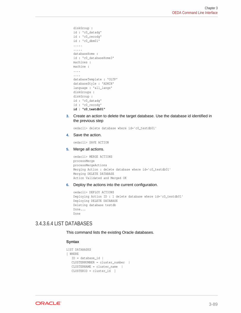
diskGroup : id : "c0_datadg" id : "c0_recodg" id : "c0_dbm01" ..... ..... databaseHome : id : "c0_databaseHome3" machines : machine : .... .... databaseTemplate : "OLTP" databaseStyle : "ADMIN" language : "all_langs" diskGroups : diskGroup : id : "c0_datadg" id : "c0_recodg" id : "c0_testdb01"
3. Create an action to delete the target database. Use the database id identified inthe previous step
oedacli> delete database where id='c0_testdb01'
4. Save the action.
oedacli> SAVE ACTION
5. Merge all actions.
oedacli> MERGE ACTIONS processMerge processMergeActions Merging Action : delete database where id='c0_testdb01' Merging DELETE DATABASE Action Validated and Merged OK
6. Deploy the actions into the current configuration.
oedacli> DEPLOY ACTIONS Deploying Action ID : 1 delete database where id='c0_testdb01' Deploying DELETE DATABASE Deleting database testdb Done... Done
3.4.3.6.4 LIST DATABASESThis command lists the existing Oracle databases.
Syntax
LIST DATABASES [ WHERE ID = database_id | CLUSTERNUMBER = cluster_number | CLUSTERNAME = cluster_name | CLUSTERID = cluster_id ]
Chapter 3OEDA Command Line Interface
3-89
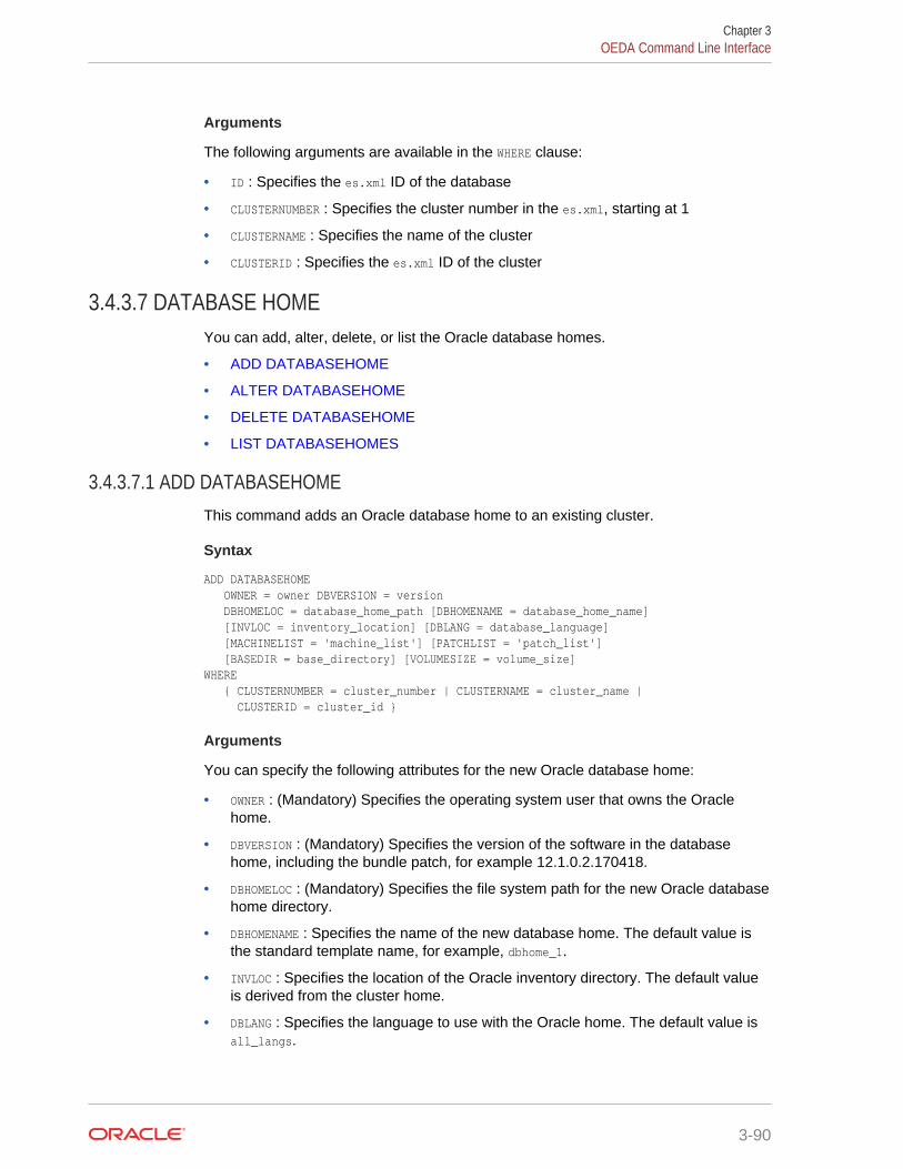
Arguments
The following arguments are available in the WHERE clause:
• ID : Specifies the es.xml ID of the database
• CLUSTERNUMBER : Specifies the cluster number in the es.xml, starting at 1
• CLUSTERNAME : Specifies the name of the cluster
• CLUSTERID : Specifies the es.xml ID of the cluster
3.4.3.7 DATABASE HOMEYou can add, alter, delete, or list the Oracle database homes.
• ADD DATABASEHOME
• ALTER DATABASEHOME
• DELETE DATABASEHOME
• LIST DATABASEHOMES
3.4.3.7.1 ADD DATABASEHOMEThis command adds an Oracle database home to an existing cluster.
Syntax
ADD DATABASEHOME OWNER = owner DBVERSION = version DBHOMELOC = database_home_path [DBHOMENAME = database_home_name] [INVLOC = inventory_location] [DBLANG = database_language] [MACHINELIST = 'machine_list'] [PATCHLIST = 'patch_list'] [BASEDIR = base_directory] [VOLUMESIZE = volume_size]WHERE { CLUSTERNUMBER = cluster_number | CLUSTERNAME = cluster_name | CLUSTERID = cluster_id }
Arguments
You can specify the following attributes for the new Oracle database home:
• OWNER : (Mandatory) Specifies the operating system user that owns the Oraclehome.
• DBVERSION : (Mandatory) Specifies the version of the software in the databasehome, including the bundle patch, for example 12.1.0.2.170418.
• DBHOMELOC : (Mandatory) Specifies the file system path for the new Oracle databasehome directory.
• DBHOMENAME : Specifies the name of the new database home. The default value isthe standard template name, for example, dbhome_1.
• INVLOC : Specifies the location of the Oracle inventory directory. The default valueis derived from the cluster home.
• DBLANG : Specifies the language to use with the Oracle home. The default value isall_langs.
Chapter 3OEDA Command Line Interface
3-90
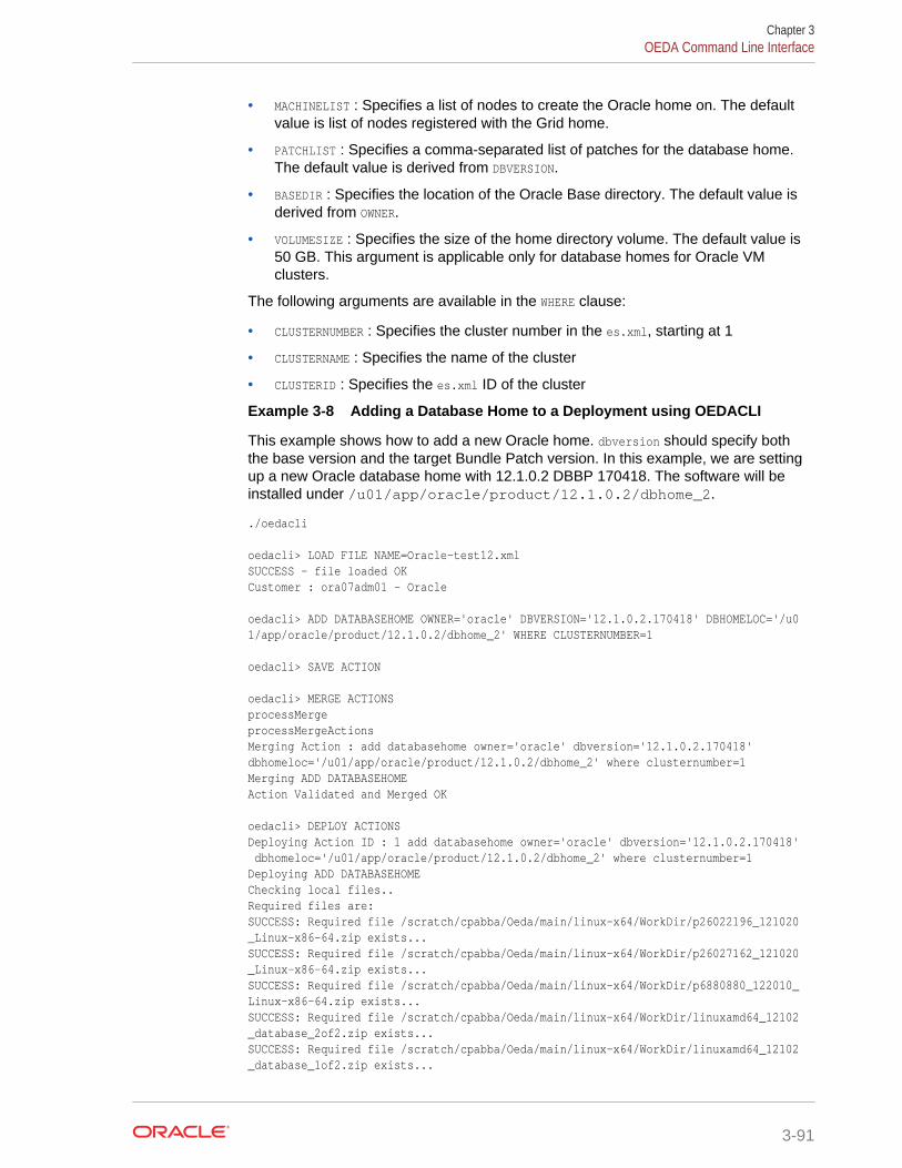
• MACHINELIST : Specifies a list of nodes to create the Oracle home on. The defaultvalue is list of nodes registered with the Grid home.
• PATCHLIST : Specifies a comma-separated list of patches for the database home.The default value is derived from DBVERSION.
• BASEDIR : Specifies the location of the Oracle Base directory. The default value isderived from OWNER.
• VOLUMESIZE : Specifies the size of the home directory volume. The default value is50 GB. This argument is applicable only for database homes for Oracle VMclusters.
The following arguments are available in the WHERE clause:
• CLUSTERNUMBER : Specifies the cluster number in the es.xml, starting at 1
• CLUSTERNAME : Specifies the name of the cluster
• CLUSTERID : Specifies the es.xml ID of the cluster
Example 3-8 Adding a Database Home to a Deployment using OEDACLI
This example shows how to add a new Oracle home. dbversion should specify boththe base version and the target Bundle Patch version. In this example, we are settingup a new Oracle database home with 12.1.0.2 DBBP 170418. The software will beinstalled under /u01/app/oracle/product/12.1.0.2/dbhome_2.
./oedacli
oedacli> LOAD FILE NAME=Oracle-test12.xmlSUCCESS - file loaded OK Customer : ora07adm01 - Oracle
oedacli> ADD DATABASEHOME OWNER='oracle' DBVERSION='12.1.0.2.170418' DBHOMELOC='/u01/app/oracle/product/12.1.0.2/dbhome_2' WHERE CLUSTERNUMBER=1
oedacli> SAVE ACTION
oedacli> MERGE ACTIONSprocessMerge processMergeActions Merging Action : add databasehome owner='oracle' dbversion='12.1.0.2.170418' dbhomeloc='/u01/app/oracle/product/12.1.0.2/dbhome_2' where clusternumber=1 Merging ADD DATABASEHOME Action Validated and Merged OK
oedacli> DEPLOY ACTIONSDeploying Action ID : 1 add databasehome owner='oracle' dbversion='12.1.0.2.170418' dbhomeloc='/u01/app/oracle/product/12.1.0.2/dbhome_2' where clusternumber=1 Deploying ADD DATABASEHOME Checking local files.. Required files are: SUCCESS: Required file /scratch/cpabba/Oeda/main/linux-x64/WorkDir/p26022196_121020_Linux-x86-64.zip exists... SUCCESS: Required file /scratch/cpabba/Oeda/main/linux-x64/WorkDir/p26027162_121020_Linux-x86-64.zip exists... SUCCESS: Required file /scratch/cpabba/Oeda/main/linux-x64/WorkDir/p6880880_122010_Linux-x86-64.zip exists... SUCCESS: Required file /scratch/cpabba/Oeda/main/linux-x64/WorkDir/linuxamd64_12102_database_2of2.zip exists... SUCCESS: Required file /scratch/cpabba/Oeda/main/linux-x64/WorkDir/linuxamd64_12102_database_1of2.zip exists...
Chapter 3OEDA Command Line Interface
3-91
Copying required files... Checking status of remote files... Checking status of existing files on remote nodes... Getting status of local files... Copying file: linuxamd64_12102_database_1of2.zip to node node1adm01.us.oracle.com Copying file: linuxamd64_12102_database_2of2.zip to node node1adm01.us.oracle.com Copying file: p26022196_121020_Linux-x86-64.zip to node node1adm01.us.oracle.com Copying file: p26027162_121020_Linux-x86-64.zip to node node1adm01.us.oracle.com Copying file: p26022196_121020_Linux-x86-64.zip to node node1adm02.us.oracle.com Copying file: p26027162_121020_Linux-x86-64.zip to node node1adm02.us.oracle.com Completed copying files... Extracting files... Completed extracting files... Validating nodes for database readiness... Installing database software ... Running database installer on node node1adm01.us.oracle.com ... Please wait... After running database installer... Patching... Done... Done
3.4.3.7.2 ALTER DATABASEHOMEThis command alters an existing Oracle database home.
Syntax
ALTER DATABASEHOME OWNER = owner | DBVERSION = version | DBHOMELOC = database_home_path | DBHOMENAME = database_home_name | INVLOC = inventory_location | DBLANG = language | MACHINELIST = 'machine_list' | PATCHLIST = 'patch_list' | BASEDIR = base_directory WHERE ID = database_home_id | CLUSTERNUMBER = cluster_number DBHOMELOC = database_home_path | CLUSTERNAME = cluster_name DBHOMELOC = database_home_path | CLUSTERID = cluster_id DBHOMELOC = database_home_path
Arguments
You can modify the following attributes for the Oracle database home:
• OWNER : Specifies the operating system user that owns the Oracle home.
• DBVERSION : Specifies the version of the software in the database home, includingthe bundle patch, for example 12.1.0.2.170418.
• DBHOMELOC : Specifies the file system path for the new Oracle database homedirectory.
• DBHOMENAME : Specifies the new name of the database home. The database homename must be unique within a cluster.
• INVLOC : Specifies the location of the Oracle inventory directory.
• DBLANG : Specifies the supported languages for the Oracle home.
Chapter 3OEDA Command Line Interface
3-92
• MACHINELIST : Specifies a list of nodes. The nodes must exist within the cluster.
• PATCHLIST : Specifies a comma-separated, custom list of patches for the databasehome.
• BASEDIR : Specifies the location of the Oracle Base directory.
The following arguments are available in the WHERE clause:
• ID : Specifies the es.xml ID for the database home
• CLUSTERNUMBER : Specifies the cluster number in the es.xml, starting at 1
• CLUSTERNAME : Specifies the name of the cluster
• CLUSTERID : Specifies the es.xml ID of the cluster
• DBHOMELOC : Specifies the path for the database home directory.
3.4.3.7.3 DELETE DATABASEHOMEThis command removes an existing Oracle database home.
Syntax
DELETE DATABASEHOME WHERE ID = database_home_id | CLUSTERNUMBER = cluster_number DBHOMELOC = database_home_path | CLUSTERNAME = cluster_name DBHOMELOC = database_home_path | CLUSTERID = cluster_id DBHOMELOC = database_home_path
Arguments
The following arguments are available in the WHERE clause:
• ID : Specifies the es.xml ID for the database home
• CLUSTERNUMBER : Specifies the cluster number in the es.xml, starting at 1
• CLUSTERNAME : Specifies the name of the cluster
• CLUSTERID : Specifies the es.xml ID of the cluster
• DBHOMELOC : Specifies the path for the database home directory.
Usage Notes
The database home you are deleting must not contain any dependent databases.
Example 3-9 Removing an Existing Oracle Database Home
This example shows how to delete an existing Oracle Database home directory.
oedacli> LOAD FILE NAME=Oracle-test12.xml SUCCESS - file loaded OK Customer : ora07adm01 - Oracle
oedacli> DELETE DATABASEHOME WHERE id='c0_databaseHome1'
oedacli> SAVE ACTION
oedacli> MERGE ACTIONS processMerge processMergeActions
Chapter 3OEDA Command Line Interface
3-93
Merging Action : delete databasehome where id='c0_databaseHome1' Merging DELETE DATABASEHOME Action Validated and Merged OK
oedacli> DEPLOY ACTIONS Deploying Action ID : 3 delete databasehome where id='c0_databaseHome1' Deploying DELETE DATABASEHOME Validating Oracle home.. Deinstalling database home c0_DbHome_1 Unmounting file system.. Updating /etc/fstab entries... Done... Done
3.4.3.7.4 LIST DATABASEHOMESThis command lists the existing Oracle database homes.
Syntax
LIST DATABASEHOMES[ WHERE ID = database_home_id | CLUSTERNUMBER = cluster_number NAME = database_home_name | CLUSTERNAME = cluster_name NAME = database_home_name | CLUSTERID = cluster_id NAME = database_home_name ]
Arguments
The following arguments are available in the WHERE clause:
• ID : Specifies the es.xml ID for the target database home
• CLUSTERNUMBER : Specifies the cluster number in the es.xml, starting at 1
• CLUSTERNAME : Specifies the name of the cluster
• CLUSTERID : Specifies the es.xml ID of the cluster
• NAME : Specifies the name of the target database home
3.4.3.8 ESYou can alter a limited number of attributes of an engineered system.
• ALTER ES
3.4.3.8.1 ALTER ESThis command alters the attributes of an engineered system.
Syntax
ALTER ES PAAS = 'pass_mode' | CUSTOMERNAME = customer_name | CUSTOMERDEPT = customer_dept
Arguments
You can modify the following attributes for the engineered system:
Chapter 3OEDA Command Line Interface
3-94
• PAAS : A boolean value, TRUE or FALSE, which specifies whether to enable PaaSmode.
• CUSTOMERNAME : Specifies the customer name.
• CUSTOMERDEPT : Specifies the customer department.
3.4.3.9 GUESTYou can clone or delete an Oracle VM guest.
• CLONE GUEST
• DELETE GUEST
3.4.3.9.1 CLONE GUESTThis command clones an existing Oracle VM guest.
Syntax
CLONE GUEST SRCNAME = source_guest SET PARENT NAME=parent_name SET ADMINNET NAME=admin_name,IP=IP_admin SET PRIVNET NAME1=priv_name_1,IP1=priv_ip1,NAME2=priv_name_2, IP2=priv_ip2 [ SET INTERCONNECT NAME1=priv_name_1,IP1=priv_ip1, NAME2=priv_name_2, IP2=priv_ip2 ] SET CLIENTNET NAME=client_name,IP=client_ip SET VIPNET NAME=vip_name,IP=vip_ip
Arguments
SRCNAME is used to specify the name of an existing DomU from which the new DomU isderived.
The following arguments are available in the SET clauses:
• PARENT : Specifies the host name of the Dom0 use to host this new guest
• ADMINNET : Specifies the DNS name with an optional domain name and the IPaddress to be used for the admin network
• PRIVNET : Specifies the DNS name with an optional domain name and the IPaddress to be used for the first and second private networks
• INTERCONNECT : Specifies the DNS name with an optional domain name and the IPaddress to be used for the first and second private interconnects
• CLIENTNET : Specifies the DNS name with an optional domain name and the IPaddress to be used for the client network
• VIPNET : Specifies the DNS name with an optional domain name and the IPaddress to be used for the VIP network
Usage Notes
The SET INTERCONNECT clause is only required if the compute nodes are configured withInfiniBand security (PKEYS).
Chapter 3OEDA Command Line Interface
3-95
3.4.3.9.2 DELETE GUESTThis command deletes an existing Oracle VM guest, removing the instance, home,and Oracle Clusterware from the cluster.
Syntax
DELETE GUEST WHERE SRCNAME = node_name
Arguments
SRCNAME is used to specify the host name of an existing DomU that you want to delete.
3.4.3.10 ILOMYou can alter or list the ILOMS in the loaded es.xml file.
• ALTER ILOM
• LIST ILOMS
3.4.3.10.1 ALTER ILOMThis command alters attributes of an ILOM.
Syntax
ALTER ILOM { DNSSERVERS='dns_servers' | NTPSERVERS= 'ntp_servers' | TIMEZONE = timezone } WHERE { ID = ilom_id | HOSTNAME = hostname | ILOMNAME = ilom_hostname }
Arguments
You can specify the following attributes for the ILOM:
• DNSSERVERS : Specifies a comma-separated list of DNS servers that is enclosed insingle quotes.
• NTPSERVERS : Specifies a comma-separated list of NTP servers that is enclosed insingle quotes.
• TIMEZONE : Specifies a valid time zone for the ILOM.
The following arguments are available in the WHERE clause:
• ID : Specifies the es.xml ID for the target ILOM
• HOSTNAME : Specifies the current host name of the target machine
• ILOMNAME : Specifies the current host name of the ILOM
3.4.3.10.2 LIST ILOMSThis command lists the ILOMs in the es.xml file.
Chapter 3OEDA Command Line Interface
3-96
Syntax
LIST ILOMS [ WHERE { ID = ilom_id | HOSTNAME = hostname | ILOMNAME = ilom_hostname } ]
Arguments
The following arguments are available in the WHERE clause:
• ID : Specifies the es.xml ID for the target ILOM
• HOSTNAME : Specifies the current host name of the target machine
• ILOMNAME : Specifies the current host name of the ILOM
Usage Notes
If you do not specify a WHERE clause, then this command lists all the ILOMs in thees.xml file.
3.4.3.11 MACHINEYou can alter or list the machines in the es.xml file.
• ALTER MACHINE
• LIST MACHINES
3.4.3.11.1 ALTER MACHINEThis command alters attributes of a compute node or storage cell in an engineeredsystem.
Syntax
ALTER MACHINE { DNSSERVERS='dns_servers' | GATEWAYADAPTER=gateway_adapter | HOSTNAMEADAPTER=hostname_adapter | NTPSERVERS= 'ntp_servers' | TIMEZONE = timezone } WHERE { ID = machine_id | HOSTNAME = hostname | CLUSTERNUMBER = cluster_number COMPUTENUMBER = compute_number | CLUSTERNUMBER = cluster_number STORAGENUMBER = storage_number | CLUSTERNAME = cluster_name COMPUTENUMBER = compute_number | CLUSTERNAME = cluster_name STORAGENUMBER = storage_number | CLUSTERID = cluster_id COMPUTENUMBER = compute_number | CLUSTERID = cluster_id STORAGENUMBER = storage_number }
Arguments
You can specify the following attributes for the machine:
• DNSSERVERS : Specifies a comma-separated list of DNS servers that is enclosed insingle quotes.
• GATEWAYADAPTER : Specifies the network adapter to use as the machine gateway.Valid values are ADMIN or CLIENT.
Chapter 3OEDA Command Line Interface
3-97
• HOSTNAMEADAPTER : Specifies the network adapter to use as the host name. Validvalues are ADMIN or CLIENT.
• NTPSERVERS : Specifies a comma-separated list of NTP servers that is enclosed insingle quotes.
• TIMEZONE : Specifies a valid time zone for the machine.
The following arguments are available in the WHERE clause:
• ID : Specifies the es.xml ID for the target machine
• HOSTNAME : Specifies the current host name of the target machine
• CLUSTERNUMBER : Specifies the cluster number in the es.xml, starting at 1
• CLUSTERNAME : Specifies the name of the cluster
• CLUSTERID : Specifies the es.xml ID of the cluster
• COMPUTENUMBER : Specifies the compute node number in the cluster, starting at 1
• STORAGENUMBER : Specifies the storage cell number in the cluster, starting at 1
3.4.3.11.2 LIST MACHINESThis command lists the machine available in the es.xml file for an engineered system.
Syntax
LIST MACHINES { WHERE TYPE = type | ID = machine_id [ TYPE = type ] | CLUSTERNUMBER = cluster_number [ TYPE = type ] | CLUSTERNAME = cluster_name [ TYPE = type ] | CLUSTERID = cluster_id [ TYPE = type ] }
Arguments
The following arguments are available in the WHERE clause:
• TYPE : Specifies the machine type. The valid values are COMPUTE, CELL, STORAGE, DOM0,GUEST, or DOMU.
• ID : Specifies the es.xml ID for an individual machine
• CLUSTERNUMBER : Specifies the cluster number in the es.xml, starting at 1
• CLUSTERNAME : Specifies the name of the cluster
• CLUSTERID : Specifies the es.xml ID of the cluster
Usage Notes
If you do not specify a WHERE clause, then this command lists all the machines definedin the es.xml file.
3.4.3.12 NETWORKYou can add, alter, delete, or list the networks defined in the XML configuration file.
• ADD NETWORK
Chapter 3OEDA Command Line Interface
3-98
• ALTER NETWORK
• DELETE NETWORK
• LIST NETWORKS
3.4.3.12.1 ADD NETWORKThis command adds a network record to a machine in the existing configuration.
Syntax
ADD NETWORK NETWORKTYPE=network_type HOSTNAME=hostname IP=ip_addr NETMASK=netmask DOMAINNAME=domain_name MASTER=master [ GATEWAY=gateway] [ SSHENABLED=ssh_enabled ] [ MAC=mac_addr ] [ NICSPEED=nic_speed [ SLAVE='slave'] [ PKEY=pkey ] [ PKEYNAME=pkey_name ] [ STATUS = status ] [ LACP=lacp ] [ VLANID=vlan_id ] [ NATHOSTNAME=nat_host_name ] [ NATIP=nat_ip_addr ] [ NATDOMAINNAME=nat_domain_name ] [ NATNETMASK=nat_mask ] WHERE { HOSTNAME = hostname | CLUSTERNAME = cluster_name COMPUTENUMBER=compute_number | CLUSTERNAME = cluster_name STORAGENUMBER=storage_number | CLUSTERNUMBER = cluster_number COMPUTENUMBER=compute_number | CLUSTERNUMBER = cluster_number STORAGENUMBER=storage_number }
Arguments
You can specify the following attributes when adding a network:
• NETWORKTYPE : (Mandatory) Specifies the type of network, which can be ADMIN,CLIENT, BACKUP, PRIVATE, OTHER, INGESTVIP, REPLICATIONVIP, or ILOM.
• HOSTNAME : (Mandatory) Specifies the short host name for the network
• IP : (Mandatory) Specifies the IP address of the network
• NETMASK : (Mandatory) Specifies the netmask of the network
• DOMAINNAME : (Mandatory) Specifies the domain name of the network
• MASTER : (Mandatory) Specifies the master adapter name
• GATEWAY : Specifies the network subnet gateway
• SSHENABLED : A Boolean variable where TRUE indicates SSH should be enabled forthis adapter
• MAC : Specifies the MAC address
• NICSPEED : (Only for X7 2 socket compute nodes), either 10000 or 25000
• SLAVE : Specifies a space-separated list of slave devices for a bonded network,enclosed in single quotes
• PKEY : (For Private networks only) Specifies the pkey
• PKEYNAME : (For Private networks only) Specifies the pkey name
• STATUS : Specifies the status of the network
• LACP : A Boolean variable where TRUE indicates that LACP should be enabled
• VLANID : Specifies the VLAN Id if network is a VLAN network and not private
Chapter 3OEDA Command Line Interface
3-99
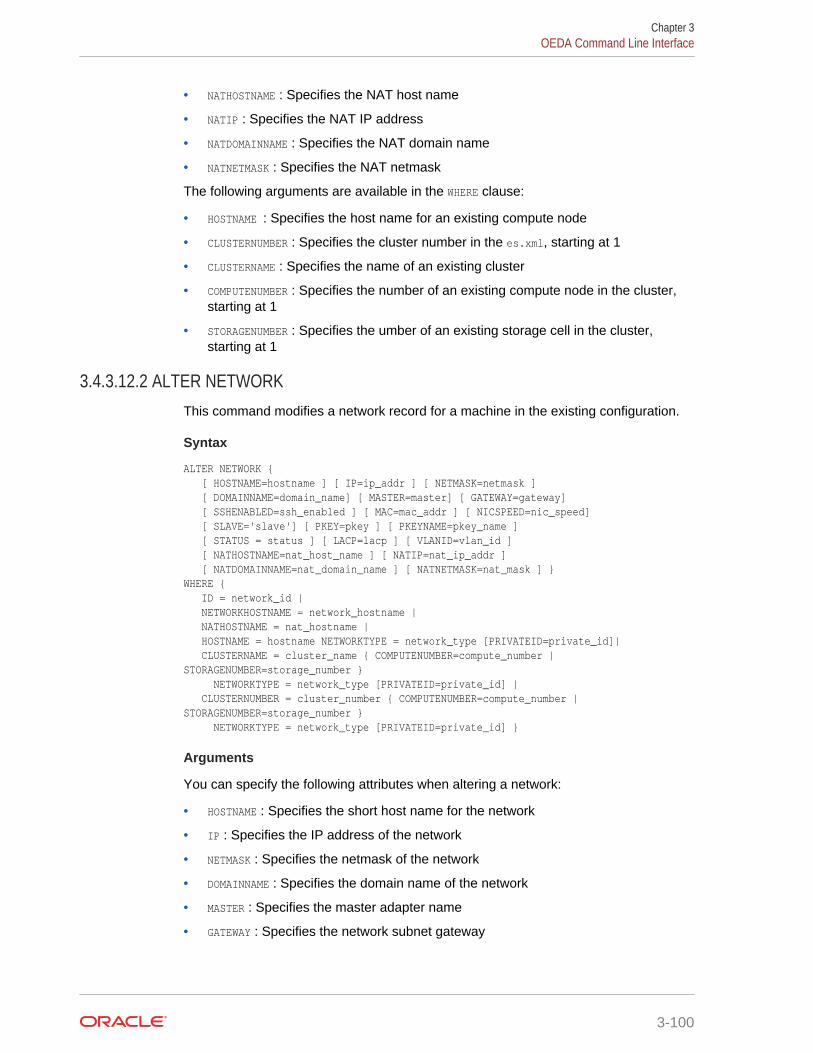
• NATHOSTNAME : Specifies the NAT host name
• NATIP : Specifies the NAT IP address
• NATDOMAINNAME : Specifies the NAT domain name
• NATNETMASK : Specifies the NAT netmask
The following arguments are available in the WHERE clause:
• HOSTNAME : Specifies the host name for an existing compute node
• CLUSTERNUMBER : Specifies the cluster number in the es.xml, starting at 1
• CLUSTERNAME : Specifies the name of an existing cluster
• COMPUTENUMBER : Specifies the number of an existing compute node in the cluster,starting at 1
• STORAGENUMBER : Specifies the umber of an existing storage cell in the cluster,starting at 1
3.4.3.12.2 ALTER NETWORKThis command modifies a network record for a machine in the existing configuration.
Syntax
ALTER NETWORK { [ HOSTNAME=hostname ] [ IP=ip_addr ] [ NETMASK=netmask ] [ DOMAINNAME=domain_name] [ MASTER=master] [ GATEWAY=gateway] [ SSHENABLED=ssh_enabled ] [ MAC=mac_addr ] [ NICSPEED=nic_speed] [ SLAVE='slave'] [ PKEY=pkey ] [ PKEYNAME=pkey_name ] [ STATUS = status ] [ LACP=lacp ] [ VLANID=vlan_id ] [ NATHOSTNAME=nat_host_name ] [ NATIP=nat_ip_addr ] [ NATDOMAINNAME=nat_domain_name ] [ NATNETMASK=nat_mask ] } WHERE { ID = network_id | NETWORKHOSTNAME = network_hostname | NATHOSTNAME = nat_hostname | HOSTNAME = hostname NETWORKTYPE = network_type [PRIVATEID=private_id]| CLUSTERNAME = cluster_name { COMPUTENUMBER=compute_number | STORAGENUMBER=storage_number } NETWORKTYPE = network_type [PRIVATEID=private_id] | CLUSTERNUMBER = cluster_number { COMPUTENUMBER=compute_number | STORAGENUMBER=storage_number } NETWORKTYPE = network_type [PRIVATEID=private_id] }
Arguments
You can specify the following attributes when altering a network:
• HOSTNAME : Specifies the short host name for the network
• IP : Specifies the IP address of the network
• NETMASK : Specifies the netmask of the network
• DOMAINNAME : Specifies the domain name of the network
• MASTER : Specifies the master adapter name
• GATEWAY : Specifies the network subnet gateway
Chapter 3OEDA Command Line Interface
3-100
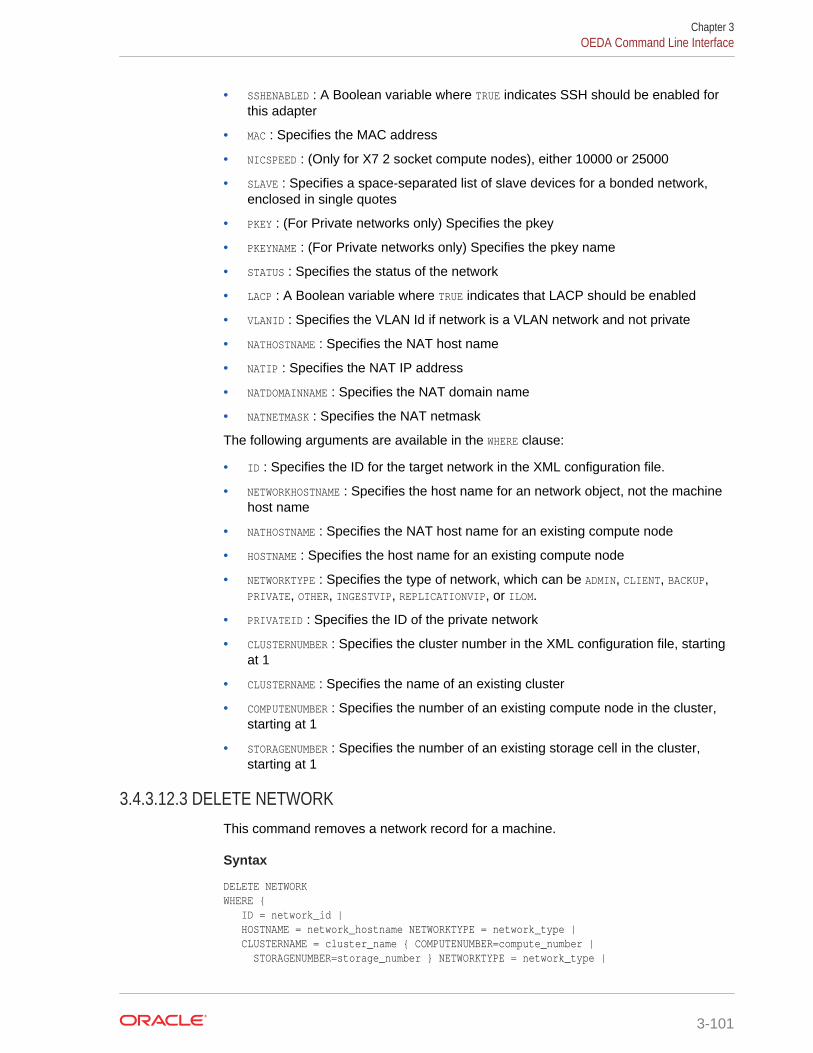
• SSHENABLED : A Boolean variable where TRUE indicates SSH should be enabled forthis adapter
• MAC : Specifies the MAC address
• NICSPEED : (Only for X7 2 socket compute nodes), either 10000 or 25000
• SLAVE : Specifies a space-separated list of slave devices for a bonded network,enclosed in single quotes
• PKEY : (For Private networks only) Specifies the pkey
• PKEYNAME : (For Private networks only) Specifies the pkey name
• STATUS : Specifies the status of the network
• LACP : A Boolean variable where TRUE indicates that LACP should be enabled
• VLANID : Specifies the VLAN Id if network is a VLAN network and not private
• NATHOSTNAME : Specifies the NAT host name
• NATIP : Specifies the NAT IP address
• NATDOMAINNAME : Specifies the NAT domain name
• NATNETMASK : Specifies the NAT netmask
The following arguments are available in the WHERE clause:
• ID : Specifies the ID for the target network in the XML configuration file.
• NETWORKHOSTNAME : Specifies the host name for an network object, not the machinehost name
• NATHOSTNAME : Specifies the NAT host name for an existing compute node
• HOSTNAME : Specifies the host name for an existing compute node
• NETWORKTYPE : Specifies the type of network, which can be ADMIN, CLIENT, BACKUP,PRIVATE, OTHER, INGESTVIP, REPLICATIONVIP, or ILOM.
• PRIVATEID : Specifies the ID of the private network
• CLUSTERNUMBER : Specifies the cluster number in the XML configuration file, startingat 1
• CLUSTERNAME : Specifies the name of an existing cluster
• COMPUTENUMBER : Specifies the number of an existing compute node in the cluster,starting at 1
• STORAGENUMBER : Specifies the number of an existing storage cell in the cluster,starting at 1
3.4.3.12.3 DELETE NETWORKThis command removes a network record for a machine.
Syntax
DELETE NETWORK WHERE { ID = network_id | HOSTNAME = network_hostname NETWORKTYPE = network_type | CLUSTERNAME = cluster_name { COMPUTENUMBER=compute_number | STORAGENUMBER=storage_number } NETWORKTYPE = network_type |
Chapter 3OEDA Command Line Interface
3-101
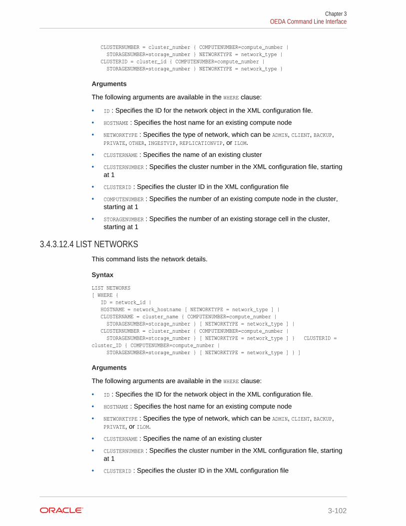
CLUSTERNUMBER = cluster_number { COMPUTENUMBER=compute_number | STORAGENUMBER=storage_number } NETWORKTYPE = network_type | CLUSTERID = cluster_id { COMPUTENUMBER=compute_number | STORAGENUMBER=storage_number } NETWORKTYPE = network_type }
Arguments
The following arguments are available in the WHERE clause:
• ID : Specifies the ID for the network object in the XML configuration file.
• HOSTNAME : Specifies the host name for an existing compute node
• NETWORKTYPE : Specifies the type of network, which can be ADMIN, CLIENT, BACKUP,PRIVATE, OTHER, INGESTVIP, REPLICATIONVIP, or ILOM.
• CLUSTERNAME : Specifies the name of an existing cluster
• CLUSTERNUMBER : Specifies the cluster number in the XML configuration file, startingat 1
• CLUSTERID : Specifies the cluster ID in the XML configuration file
• COMPUTENUMBER : Specifies the number of an existing compute node in the cluster,starting at 1
• STORAGENUMBER : Specifies the number of an existing storage cell in the cluster,starting at 1
3.4.3.12.4 LIST NETWORKSThis command lists the network details.
Syntax
LIST NETWORKS [ WHERE { ID = network_id | HOSTNAME = network_hostname [ NETWORKTYPE = network_type ] | CLUSTERNAME = cluster_name { COMPUTENUMBER=compute_number | STORAGENUMBER=storage_number } [ NETWORKTYPE = network_type ] | CLUSTERNUMBER = cluster_number { COMPUTENUMBER=compute_number | STORAGENUMBER=storage_number } [ NETWORKTYPE = network_type ] } CLUSTERID = cluster_ID { COMPUTENUMBER=compute_number | STORAGENUMBER=storage_number } [ NETWORKTYPE = network_type ] } ]
Arguments
The following arguments are available in the WHERE clause:
• ID : Specifies the ID for the network object in the XML configuration file.
• HOSTNAME : Specifies the host name for an existing compute node
• NETWORKTYPE : Specifies the type of network, which can be ADMIN, CLIENT, BACKUP,PRIVATE, or ILOM.
• CLUSTERNAME : Specifies the name of an existing cluster
• CLUSTERNUMBER : Specifies the cluster number in the XML configuration file, startingat 1
• CLUSTERID : Specifies the cluster ID in the XML configuration file
Chapter 3OEDA Command Line Interface
3-102
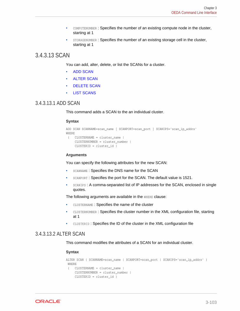
• COMPUTENUMBER : Specifies the number of an existing compute node in the cluster,starting at 1
• STORAGENUMBER : Specifies the number of an existing storage cell in the cluster,starting at 1
3.4.3.13 SCANYou can add, alter, delete, or list the SCANs for a cluster.
• ADD SCAN
• ALTER SCAN
• DELETE SCAN
• LIST SCANS
3.4.3.13.1 ADD SCANThis command adds a SCAN to the an individual cluster.
Syntax
ADD SCAN SCANNAME=scan_name [ SCANPORT=scan_port ] SCANIPS='scan_ip_addrs'WHERE { CLUSTERNAME = cluster_name | CLUSTERNUMBER = cluster_number | CLUSTERID = cluster_id }
Arguments
You can specify the following attributes for the new SCAN:
• SCANNAME : Specifies the DNS name for the SCAN
• SCANPORT : Specifies the port for the SCAN. The default value is 1521.
• SCANIPS : A comma-separated list of IP addresses for the SCAN, enclosed in singlequotes.
The following arguments are available in the WHERE clause:
• CLUSTERNAME : Specifies the name of the cluster
• CLUSTERNUMBER : Specifies the cluster number in the XML configuration file, startingat 1
• CLUSTERID : Specifies the ID of the cluster in the XML configuration file
3.4.3.13.2 ALTER SCANThis command modifies the attributes of a SCAN for an individual cluster.
Syntax
ALTER SCAN { SCANNAME=scan_name | SCANPORT=scan_port | SCANIPS='scan_ip_addrs' } WHERE { CLUSTERNAME = cluster_name | CLUSTERNUMBER = cluster_number | CLUSTERID = cluster_id }
Chapter 3OEDA Command Line Interface
3-103
Arguments
You can modify the following attributes for the SCAN:
• SCANNAME : Specifies the DNS name for the SCAN
• SCANPORT : Specifies the port for the SCAN.
• SCANIPS : A comma-separated list of IP addresses for the SCAN, enclosed in singlequotes.
The following arguments are available in the WHERE clause:
• CLUSTERNAME : Specifies the name of the cluster
• CLUSTERNUMBER : Specifies the cluster number in the XML configuration file, startingat 1
• CLUSTERID : Specifies the ID of the cluster in the XML configuration file
3.4.3.13.3 DELETE SCANThis command removes a SCAN for an individual cluster.
Syntax
DELETE SCAN WHERE { CLUSTERNAME = cluster_name | CLUSTERNUMBER = cluster_number | CLUSTERID = cluster_id }
Arguments
The following arguments are available in the WHERE clause:
• CLUSTERNAME : Specifies the name of the cluster
• CLUSTERNUMBER : Specifies the cluster number in the XML configuration file, startingat 1
• CLUSTERID : Specifies the ID of the cluster in the XML configuration file
3.4.3.13.4 LIST SCANSThis command lists the SCAN details for all clusters or for an individual cluster.
Syntax
LIST SCANS [ WHERE { SCANID = scan_id | CLUSTERNAME = cluster_name | CLUSTERNUMBER = cluster_number | CLUSTERID = cluster_id } ]
Arguments
The following arguments are available in the WHERE clause:
• SCANID : Specifies the ID of the SCAN object in the XML configuration file
Chapter 3OEDA Command Line Interface
3-104
• CLUSTERNAME : Specifies the name of the cluster
• CLUSTERNUMBER : Specifies the cluster number in the XML configuration file, startingat 1
• CLUSTERID : Specifies the ID of the cluster in the XML configuration file
Usage Notes
If you do not specify a WHERE clause, then this command lists details about all theSCANS for all the clusters in the XML configuration file.
3.4.3.14 SWITCHYou can alter or list the switches.
• ALTER SWITCH
• LIST SWITCHES
3.4.3.14.1 ALTER SWITCHThis command alters attributes of an individual switch.
Syntax
ALTER SWITCH { DNSSERVERS='dns_servers' | NTPSERVERS= 'ntp_servers' | TIMEZONE = timezone } WHERE { ID = switch_id | HOSTNAME = switch_name }
Arguments
You can modify the following attributes for a switch:
• DNSSERVERS : Specifies a comma-separated list of DNS servers that is enclosed insingle quotes.
• NTPSERVERS : Specifies a comma-separated list of NTP servers that is enclosed insingle quotes.
• TIMEZONE : Specifies a valid time zone for the switch.
The following arguments are available in the WHERE clause:
• ID : Specifies the switch ID in the XML configuration file
• HOSTNAME : Specifies the host name of the switch
3.4.3.14.2 LIST SWITCHESThis command lists the switch details for all switches or for an individual switch.
Syntax
LIST SWITCHES [ WHERE { ID = switch_id | HOSTNAME = switch_name } ]
Chapter 3OEDA Command Line Interface
3-105
Arguments
The following arguments are available in the WHERE clause:
• ID : Specifies the switch ID in the XML configuration file
• HOSTNAME : Specifies the host name of the switch
Usage Notes
If you do not specify a WHERE clause, then this command lists the details for allswitches.
3.4.3.15 VIPYou can add, alter, delete, or list the VIPs for the clusters.
• ADD VIP
• ALTER VIP
• DELETE VIP
• LIST VIPS
3.4.3.15.1 ADD VIPThis command adds a VIP for an individual node in a cluster.
Purpose
This command does not add additional VIPs. You should only use this command afterpreviously issuing a DELETE VIP command.
Syntax
ADD VIP NAME=vip_name DOMAINNAME=domain_name IP=vip_ip_addr WHERE { HOSTNAME = hostname | CLUSTERNAME = cluster_name COMPUTENUMBER = compute_number | CLUSTERNUMBER = cluster_number COMPUTENUMBER = compute_number | CLUSTERID = cluster_id COMPUTENUMBER = compute_number }
Arguments
You can specify the following attributes when adding a VIP:
• NAME : Specifies the short DNS name for the VIP
• DOMAINNAME : Specifies the domain name for the VIP
• IP : Specifies the IP address for the VIP
The following arguments are available in the WHERE clause:
• HOSTNAME : Specifies the host name for the compute node in the cluster
• CLUSTERNUMBER : Specifies the cluster number in the es.xml, starting at 1
• CLUSTERNAME : Specifies the name of the cluster
• CLUSTERID : Specifies the es.xml ID of the cluster
Chapter 3OEDA Command Line Interface
3-106
• COMPUTENUMBER : Specifies the compute node number in the cluster, starting at 1
Usage Notes
When adding a VIP to a compute node, the node must not already have a VIP defined.
3.4.3.15.2 ALTER VIPThis command alters the attributes of a VIP for an individual node in a cluster.
Syntax
ALTER VIP { NAME=vip_name | DOMAINNAME=domain_name | IP=vip_ip_addr } WHERE { HOSTNAME = hostname | CLUSTERNAME = cluster_name COMPUTENUMBER = compute_number | CLUSTERNUMBER = cluster_number COMPUTENUMBER = compute_number | CLUSTERID = cluster_id COMPUTENUMBER = compute_number }
Arguments
You can modify the following attributes for the VIP:
• NAME : Specifies the short DNS name for the VIP
• DOMAINNAME : Specifies the domain name for the VIP
• IP : Specifies the IP address for the VIP
The following arguments are available in the WHERE clause:
• HOSTNAME : Specifies the host name for the compute node in the cluster
• CLUSTERNUMBER : Specifies the cluster number in the es.xml, starting at 1
• CLUSTERNAME : Specifies the name of the cluster
• CLUSTERID : Specifies the es.xml ID of the cluster
• COMPUTENUMBER : Specifies the compute node number in the cluster, starting at 1
3.4.3.15.3 DELETE VIPThis command removes a VIP from an individual node in a cluster.
Syntax
DELETE VIP WHERE { ID = vip_id | HOSTNAME = hostname | CLUSTERNAME = cluster_name COMPUTENUMBER = compute_number | CLUSTERNUMBER = cluster_number COMPUTENUMBER = compute_number | CLUSTERID = cluster_id COMPUTENUMBER = compute_number }
Arguments
The following arguments are available in the WHERE clause:
• ID : Specifies the ID for the VIP in the XML configuration file
• HOSTNAME : Specifies the host name for the compute node in the cluster
Chapter 3OEDA Command Line Interface
3-107
• CLUSTERNUMBER : Specifies the cluster number in the XML configuration file, startingat 1
• CLUSTERNAME : Specifies the name of the cluster
• CLUSTERID : Specifies the ID of the cluster in the XML configuration file
• COMPUTENUMBER : Specifies the compute node number in the cluster, starting at 1
3.4.3.15.4 LIST VIPSThis command lists the VIPs for all clusters or for an individual node in a cluster.
Syntax
LIST VIPS [ WHERE { HOSTNAME = hostname | CLUSTERNAME = cluster_name [ COMPUTENUMBER = compute_number ] | CLUSTERNUMBER = cluster_number [ COMPUTENUMBER = compute_number ] | CLUSTERID = cluster_id [ COMPUTENUMBER = compute_number ] }
Arguments
The following arguments are available in the WHERE clause:
• ID : Specifies the ID for the VIP in the XML configuration file
• HOSTNAME : Specifies the host name for the compute node in the cluster
• CLUSTERNUMBER : Specifies the cluster number in the XML configuration file, startingat 1
• CLUSTERNAME : Specifies the name of the cluster
• CLUSTERID : Specifies the ID of the cluster in the XML configuration file
• COMPUTENUMBER : Specifies the compute node number in the cluster, starting at 1
Usage Notes
If you do not specify a WHERE clause, then this command lists the VIPs for all clusters.
Chapter 3OEDA Command Line Interface
3-108
4Installing Oracle Exadata DatabaseMachine or Oracle Exadata StorageExpansion Rack at the Site
This chapter describes how to move, install and configure the hardware through topowering on the system.
Note:
For ease of reading, the name "Oracle Exadata Rack" is used wheninformation refers to both Oracle Exadata Database Machine and OracleExadata Storage Expansion Rack.
4.1 Reviewing Safety GuidelinesBefore Oracle Exadata Rack arrives, the following safety precautions should bereviewed to ensure the site is safe, as well as ready for delivery.
Failing to observe these precautions can result in injury, equipment damage, ormalfunction.
• Do not block ventilation openings.
• Do not install Oracle Exadata Rack in a location that is exposed to direct sunlightor near a device that may become hot.
• Do not install Oracle Exadata Rack in a location that is exposed to excessive dust,corrosive gases, or air with high salt concentrations.
• Do not install Oracle Exadata Rack in a location that is exposed to frequentvibrations. Install Oracle Exadata Rack on a flat, level surface.
• Use a power outlet that uses proper grounding. When using shared grounding, thegrounding resistance must not be greater than 10 ohms. Ensure that your facilityadministrator or a qualified electrical engineer verifies the grounding method forthe building, and performs the grounding work.
• Be sure that each grounding wire used for Oracle Exadata Rack is usedexclusively for Oracle Exadata Rack. Also be sure to observe the precautions,warnings, and notes about handling that appear on labels on the equipment.
• Do not place cables under the equipment or stretch the cables too tightly.
• Do not disconnect power cords from the equipment while its power is on.
• If you cannot reach the connector lock when disconnecting LAN cables, then pressthe connector lock with a flathead screwdriver to disconnect the cable. You coulddamage the system board if you force your fingers into the gap rather than using aflathead screwdriver.
4-1
• Do not place anything on top of Oracle Exadata Rack or perform any work directlyabove the rack.
• Do not let the room temperature rise sharply, especially in winter. Suddentemperature changes can cause condensation to form inside Oracle ExadataRack. Allow for a sufficient warm-up period prior to server operation.
• Do not install Oracle Exadata Rack near a photocopy machine, air conditioner,welding machine, or any other equipment that generates loud, electronic noises.
• Avoid static electricity at the installation location. Static electricity transferred toOracle Exadata Rack can cause malfunctions. Static electricity is often generatedon carpets.
• Confirm the supply voltage and frequency match the electrical ratings indicated forOracle Exadata Rack.
• Do not insert anything into any Oracle Exadata Rack opening, unless doing so ispart of a documented procedure. Oracle Exadata Rack contains high-voltageparts. If a metal object or other electrically-conductive object enters an opening inOracle Exadata Rack, then it could cause a short circuit. This could result inpersonal injury, fire, electric shock, and equipment damage.
• When using single phase power distribution units (PDUs), note the following:
– PDU A input 0 and PDU B input 2 must be on the same phase.
– PDU A input 1 and PDU B input 1 must be on the same phase.
– PDU A input 2 and PDU B input 0 must be on the same phase.
The inputs are labeled where they come out of the PDU. Connecting cables asdescribed ensures the phases are balanced on both sides, A and B, in case of afailover.
See Also:
• Important Safety Information for Sun Hardware Systems (816-7190)included with the rack
• Oracle Engineered System Safety and Compliance Guide, ComplianceModel No.: ESY27
4.2 Unpacking Oracle Exadata RackThe unpacking location should be determined during the site planning process. Thefollowing image shows the Oracle Exadata Rack shipping crate.
Chapter 4Unpacking Oracle Exadata Rack
4-2
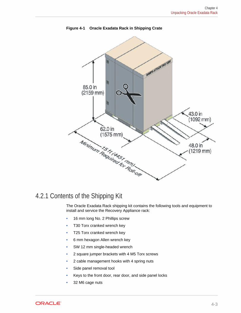
Figure 4-1 Oracle Exadata Rack in Shipping Crate
4.2.1 Contents of the Shipping KitThe Oracle Exadata Rack shipping kit contains the following tools and equipment toinstall and service the Recovery Appliance rack:
• 16 mm long No. 2 Phillips screw
• T30 Torx cranked wrench key
• T25 Torx cranked wrench key
• 6 mm hexagon Allen wrench key
• SW 12 mm single-headed wrench
• 2 square jumper brackets with 4 M5 Torx screws
• 2 cable management hooks with 4 spring nuts
• Side panel removal tool
• Keys to the front door, rear door, and side panel locks
• 32 M6 cage nuts
Chapter 4Unpacking Oracle Exadata Rack
4-3
• 32 M6 screws
• Cage nut mounting tool
• SW 17 mm single-headed wrench is included on the shipping pallet
Note:
The following items are not included in the shipping kit:
• No. 2 Phillips screwdriver
• Antistatic wrist strap
4.2.2 Removing Oracle Exadata Rack from the Shipping Crate
Note:
Oracle strongly recommends that you use professional movers whenunpacking and installing Oracle Exadata Rack.
The following procedure describes how to unpack Oracle Exadata Rack:
1. Unpack Oracle Exadata Rack carefully from the packaging and shipping pallet asfollows:
Note:
Before unpacking the rack from the shipping carton, refer to the labels onthe carton and to the instructions that they provide.
a. Remove the shipping carton bands.
b. Remove the yellow fasteners and carton top.
c. Remove the carton sides and inner top.
WARNING:
Rocking or tilting the rack can cause the rack to fall over and causeserious injury or death.
2. Remove the shipping kit.
3. Attach the ramps to the shipping pallet as follows:
a. Remove the ramps from the pallet sides.
b. Obtain the parts bag from inside the cabinet.
Chapter 4Unpacking Oracle Exadata Rack
4-4
c. Adjust the leveling bolts on the ramps and connect the ramps to the palletwheel track.
d. Verify that leveling feet are up before moving rack.
4. Carefully roll Oracle Exadata Rack off the shipping pallet as follows:
a. Unfasten the exterior shipping brackets from the pallet.
b. Unfasten the interior shipping brackets from the pallet.
Note:
Use care when removing the shipping brackets from underneathOracle Exadata Rack. Access to the inside shipping brackets mightbe limited.
c. Roll the cabinet down the ramps to the level floor. Oracle recommends havingthree people available to move the rack down the ramp: two people on bothsides to help guide the rack and one person in back.
5. Save the shipping brackets used to secure the rack to the shipping pallet. Do notdispose of these brackets, because you cannot order replacement brackets.
6. Recycle the packaging properly. Follow local laws and guidelines to dispose of thematerial.
See Also:
• Sun Rack II User's Guide at https://docs.oracle.com/cd/E19657-01/html/E29153/index.html
• Oracle Rack Cabinet 1242 User's Guide at http://docs.oracle.com/cd/E85660_01/html/E87280/index.html for X7 systems
4.3 Placing Oracle Exadata Rack in Its Allocated SpaceThis section describes how to position, stabilize, and ground Oracle Exadata Rack.
4.3.1 Moving Oracle Exadata RackThe following procedure describes how to move Oracle Exadata Rack:
1. Ensure the doors are closed and secured.
2. Ensure the leveling and stabilizing feet on the rack are raised and out of the way.
3. Push Oracle Exadata Rack from behind to the installation site.
When moving Oracle Exadata Rack to the installation site, the front casters do notturn; you must steer the unit by moving the rear casters. You can safely maneuverOracle Exadata Rack by carefully pushing it. Figure 4-2 shows the correct way topush the rack.
Chapter 4Placing Oracle Exadata Rack in Its Allocated Space
4-5
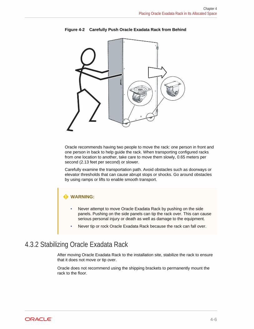
Figure 4-2 Carefully Push Oracle Exadata Rack from Behind
Oracle recommends having two people to move the rack: one person in front andone person in back to help guide the rack. When transporting configured racksfrom one location to another, take care to move them slowly, 0.65 meters persecond (2.13 feet per second) or slower.
Carefully examine the transportation path. Avoid obstacles such as doorways orelevator thresholds that can cause abrupt stops or shocks. Go around obstaclesby using ramps or lifts to enable smooth transport.
WARNING:
• Never attempt to move Oracle Exadata Rack by pushing on the sidepanels. Pushing on the side panels can tip the rack over. This can causeserious personal injury or death as well as damage to the equipment.
• Never tip or rock Oracle Exadata Rack because the rack can fall over.
4.3.2 Stabilizing Oracle Exadata RackAfter moving Oracle Exadata Rack to the installation site, stabilize the rack to ensurethat it does not move or tip over.
Oracle does not recommend using the shipping brackets to permanently mount therack to the floor.
Chapter 4Placing Oracle Exadata Rack in Its Allocated Space
4-6
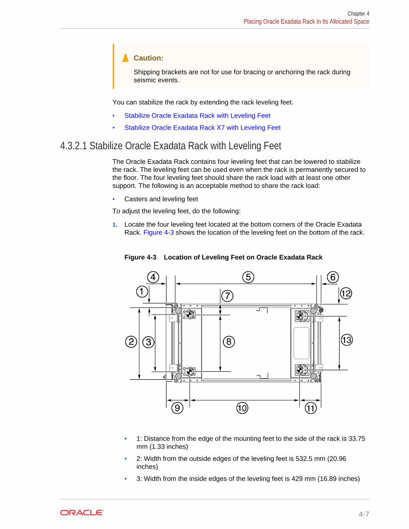
Caution:
Shipping brackets are not for use for bracing or anchoring the rack duringseismic events.
You can stabilize the rack by extending the rack leveling feet.
• Stabilize Oracle Exadata Rack with Leveling Feet
• Stabilize Oracle Exadata Rack X7 with Leveling Feet
4.3.2.1 Stabilize Oracle Exadata Rack with Leveling FeetThe Oracle Exadata Rack contains four leveling feet that can be lowered to stabilizethe rack. The leveling feet can be used even when the rack is permanently secured tothe floor. The four leveling feet should share the rack load with at least one othersupport. The following is an acceptable method to share the rack load:
• Casters and leveling feet
To adjust the leveling feet, do the following:
1. Locate the four leveling feet located at the bottom corners of the Oracle ExadataRack. Figure 4-3 shows the location of the leveling feet on the bottom of the rack.
Figure 4-3 Location of Leveling Feet on Oracle Exadata Rack
• 1: Distance from the edge of the mounting feet to the side of the rack is 33.75mm (1.33 inches)
• 2: Width from the outside edges of the leveling feet is 532.5 mm (20.96inches)
• 3: Width from the inside edges of the leveling feet is 429 mm (16.89 inches)
Chapter 4Placing Oracle Exadata Rack in Its Allocated Space
4-7
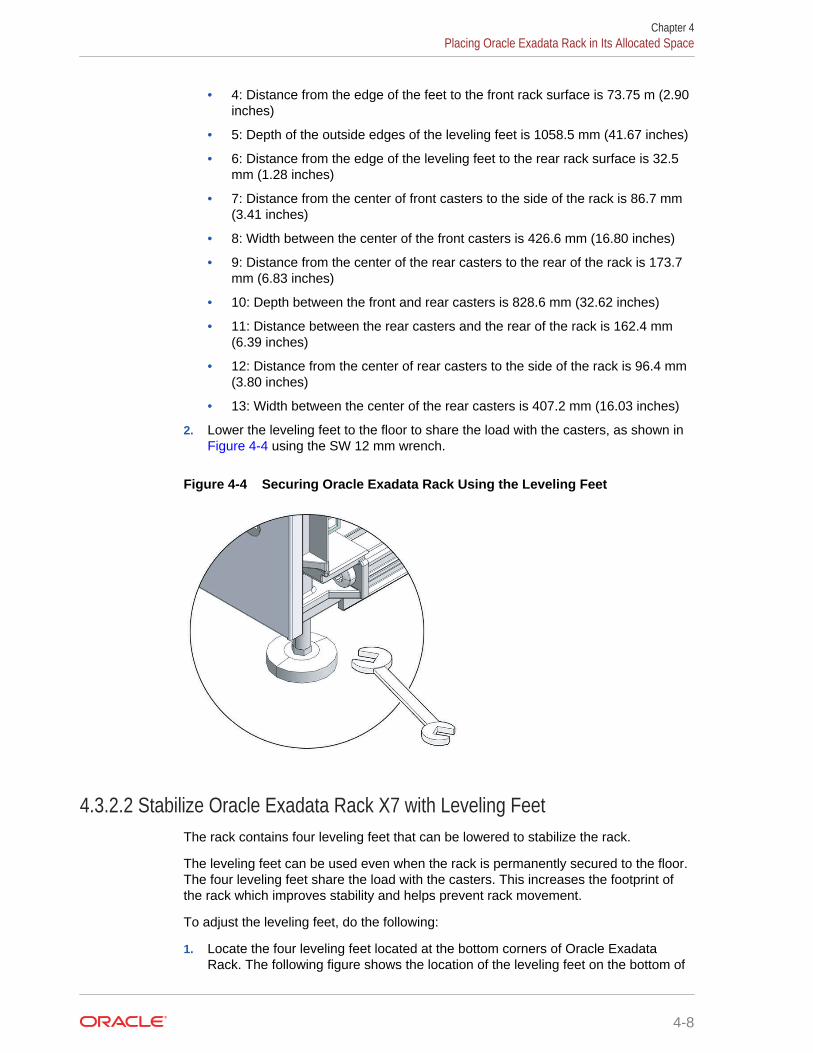
• 4: Distance from the edge of the feet to the front rack surface is 73.75 m (2.90inches)
• 5: Depth of the outside edges of the leveling feet is 1058.5 mm (41.67 inches)
• 6: Distance from the edge of the leveling feet to the rear rack surface is 32.5mm (1.28 inches)
• 7: Distance from the center of front casters to the side of the rack is 86.7 mm(3.41 inches)
• 8: Width between the center of the front casters is 426.6 mm (16.80 inches)
• 9: Distance from the center of the rear casters to the rear of the rack is 173.7mm (6.83 inches)
• 10: Depth between the front and rear casters is 828.6 mm (32.62 inches)
• 11: Distance between the rear casters and the rear of the rack is 162.4 mm(6.39 inches)
• 12: Distance from the center of rear casters to the side of the rack is 96.4 mm(3.80 inches)
• 13: Width between the center of the rear casters is 407.2 mm (16.03 inches)
2. Lower the leveling feet to the floor to share the load with the casters, as shown in Figure 4-4 using the SW 12 mm wrench.
Figure 4-4 Securing Oracle Exadata Rack Using the Leveling Feet
4.3.2.2 Stabilize Oracle Exadata Rack X7 with Leveling FeetThe rack contains four leveling feet that can be lowered to stabilize the rack.
The leveling feet can be used even when the rack is permanently secured to the floor.The four leveling feet share the load with the casters. This increases the footprint ofthe rack which improves stability and helps prevent rack movement.
To adjust the leveling feet, do the following:
1. Locate the four leveling feet located at the bottom corners of Oracle ExadataRack. The following figure shows the location of the leveling feet on the bottom of
Chapter 4Placing Oracle Exadata Rack in Its Allocated Space
4-8
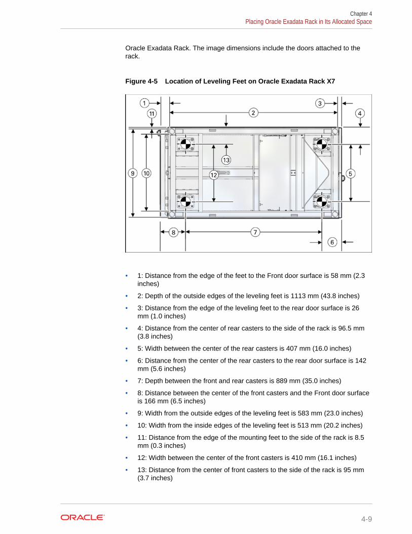
Oracle Exadata Rack. The image dimensions include the doors attached to therack.
Figure 4-5 Location of Leveling Feet on Oracle Exadata Rack X7
• 1: Distance from the edge of the feet to the Front door surface is 58 mm (2.3inches)
• 2: Depth of the outside edges of the leveling feet is 1113 mm (43.8 inches)
• 3: Distance from the edge of the leveling feet to the rear door surface is 26mm (1.0 inches)
• 4: Distance from the center of rear casters to the side of the rack is 96.5 mm(3.8 inches)
• 5: Width between the center of the rear casters is 407 mm (16.0 inches)
• 6: Distance from the center of the rear casters to the rear door surface is 142mm (5.6 inches)
• 7: Depth between the front and rear casters is 889 mm (35.0 inches)
• 8: Distance between the center of the front casters and the Front door surfaceis 166 mm (6.5 inches)
• 9: Width from the outside edges of the leveling feet is 583 mm (23.0 inches)
• 10: Width from the inside edges of the leveling feet is 513 mm (20.2 inches)
• 11: Distance from the edge of the mounting feet to the side of the rack is 8.5mm (0.3 inches)
• 12: Width between the center of the front casters is 410 mm (16.1 inches)
• 13: Distance from the center of front casters to the side of the rack is 95 mm(3.7 inches)
Chapter 4Placing Oracle Exadata Rack in Its Allocated Space
4-9
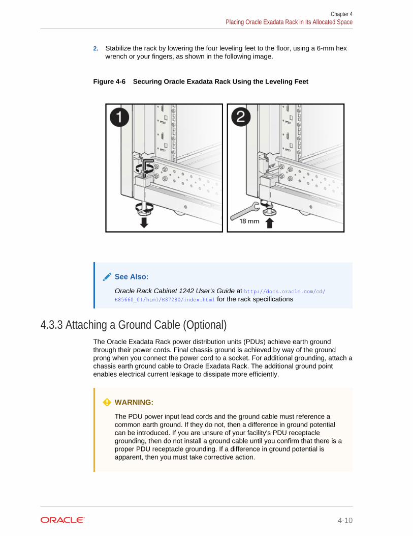
2. Stabilize the rack by lowering the four leveling feet to the floor, using a 6-mm hexwrench or your fingers, as shown in the following image.
Figure 4-6 Securing Oracle Exadata Rack Using the Leveling Feet
See Also:
Oracle Rack Cabinet 1242 User's Guide at http://docs.oracle.com/cd/E85660_01/html/E87280/index.html for the rack specifications
4.3.3 Attaching a Ground Cable (Optional)The Oracle Exadata Rack power distribution units (PDUs) achieve earth groundthrough their power cords. Final chassis ground is achieved by way of the groundprong when you connect the power cord to a socket. For additional grounding, attach achassis earth ground cable to Oracle Exadata Rack. The additional ground pointenables electrical current leakage to dissipate more efficiently.
WARNING:
The PDU power input lead cords and the ground cable must reference acommon earth ground. If they do not, then a difference in ground potentialcan be introduced. If you are unsure of your facility's PDU receptaclegrounding, then do not install a ground cable until you confirm that there is aproper PDU receptacle grounding. If a difference in ground potential isapparent, then you must take corrective action.
Chapter 4Placing Oracle Exadata Rack in Its Allocated Space
4-10
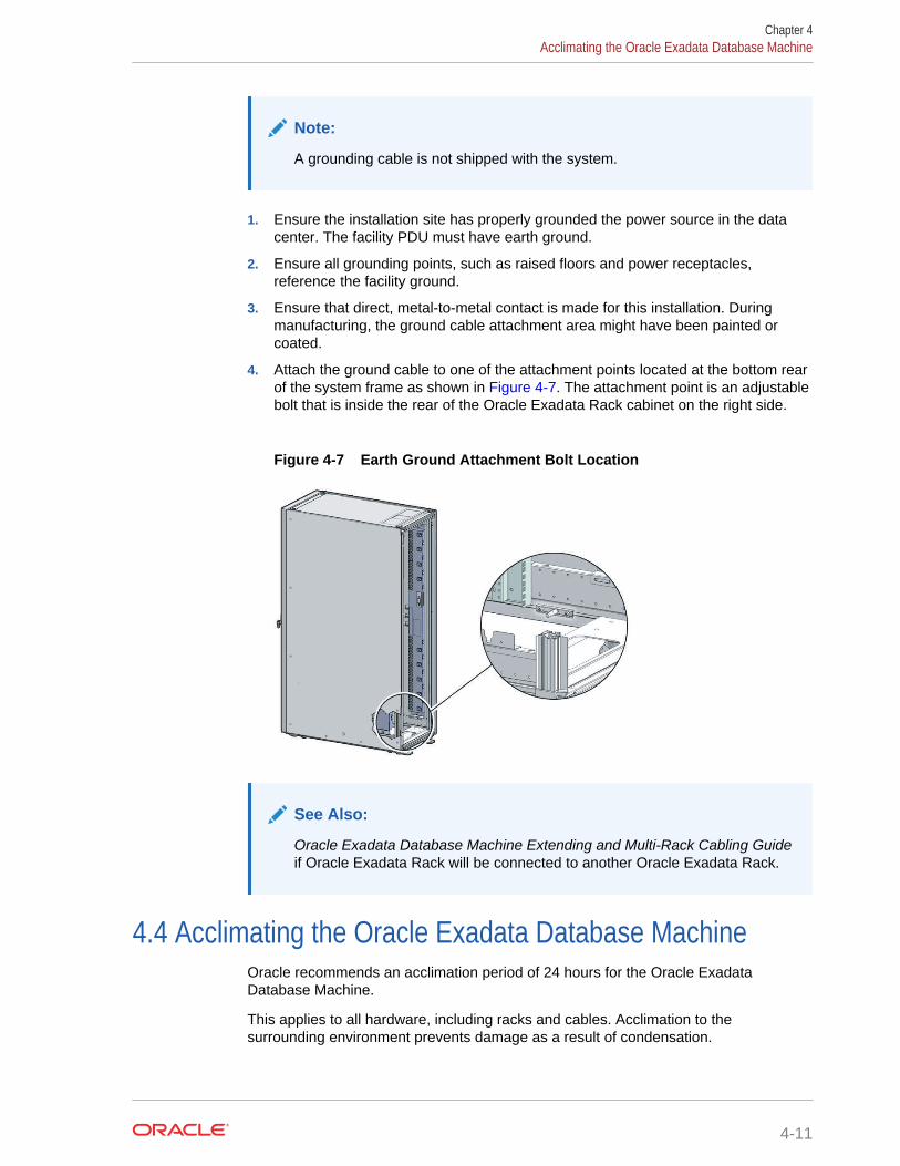
Note:
A grounding cable is not shipped with the system.
1. Ensure the installation site has properly grounded the power source in the datacenter. The facility PDU must have earth ground.
2. Ensure all grounding points, such as raised floors and power receptacles,reference the facility ground.
3. Ensure that direct, metal-to-metal contact is made for this installation. Duringmanufacturing, the ground cable attachment area might have been painted orcoated.
4. Attach the ground cable to one of the attachment points located at the bottom rearof the system frame as shown in Figure 4-7. The attachment point is an adjustablebolt that is inside the rear of the Oracle Exadata Rack cabinet on the right side.
Figure 4-7 Earth Ground Attachment Bolt Location
See Also:
Oracle Exadata Database Machine Extending and Multi-Rack Cabling Guideif Oracle Exadata Rack will be connected to another Oracle Exadata Rack.
4.4 Acclimating the Oracle Exadata Database MachineOracle recommends an acclimation period of 24 hours for the Oracle ExadataDatabase Machine.
This applies to all hardware, including racks and cables. Acclimation to thesurrounding environment prevents damage as a result of condensation.
Chapter 4Acclimating the Oracle Exadata Database Machine
4-11
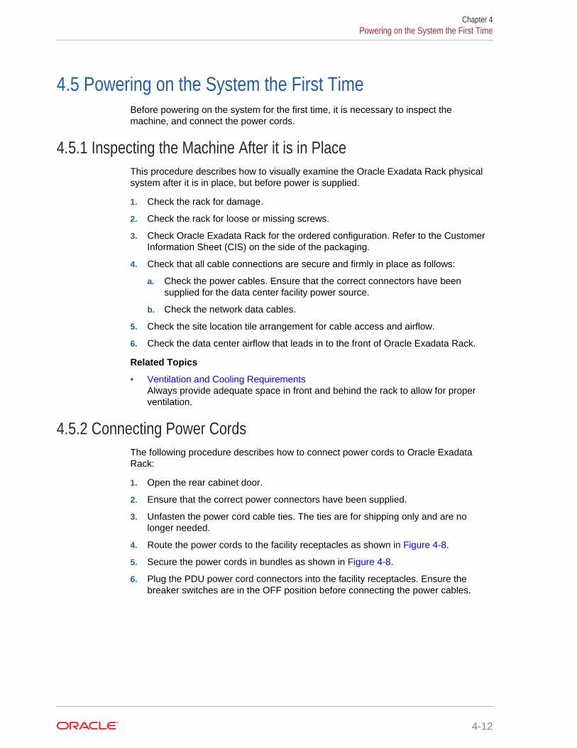
4.5 Powering on the System the First TimeBefore powering on the system for the first time, it is necessary to inspect themachine, and connect the power cords.
4.5.1 Inspecting the Machine After it is in PlaceThis procedure describes how to visually examine the Oracle Exadata Rack physicalsystem after it is in place, but before power is supplied.
1. Check the rack for damage.
2. Check the rack for loose or missing screws.
3. Check Oracle Exadata Rack for the ordered configuration. Refer to the CustomerInformation Sheet (CIS) on the side of the packaging.
4. Check that all cable connections are secure and firmly in place as follows:
a. Check the power cables. Ensure that the correct connectors have beensupplied for the data center facility power source.
b. Check the network data cables.
5. Check the site location tile arrangement for cable access and airflow.
6. Check the data center airflow that leads in to the front of Oracle Exadata Rack.
Related Topics
• Ventilation and Cooling RequirementsAlways provide adequate space in front and behind the rack to allow for properventilation.
4.5.2 Connecting Power CordsThe following procedure describes how to connect power cords to Oracle ExadataRack:
1. Open the rear cabinet door.
2. Ensure that the correct power connectors have been supplied.
3. Unfasten the power cord cable ties. The ties are for shipping only and are nolonger needed.
4. Route the power cords to the facility receptacles as shown in Figure 4-8.
5. Secure the power cords in bundles as shown in Figure 4-8.
6. Plug the PDU power cord connectors into the facility receptacles. Ensure thebreaker switches are in the OFF position before connecting the power cables.
Chapter 4Powering on the System the First Time
4-12
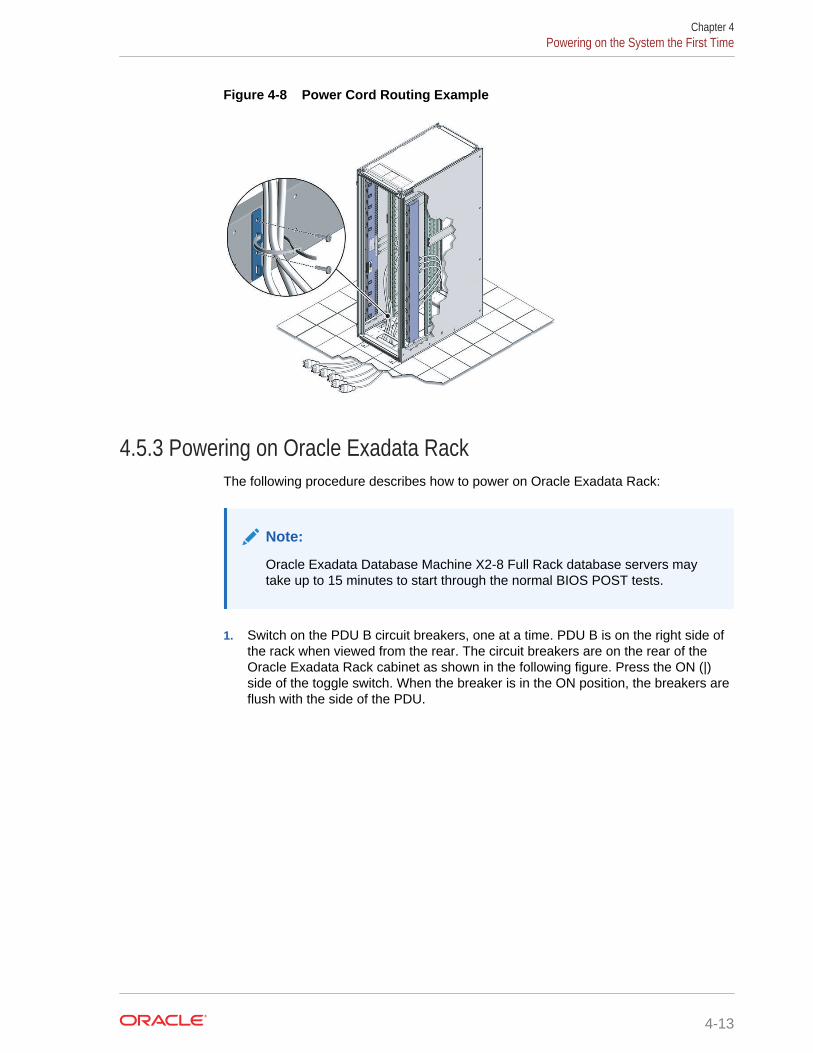
Figure 4-8 Power Cord Routing Example
4.5.3 Powering on Oracle Exadata RackThe following procedure describes how to power on Oracle Exadata Rack:
Note:
Oracle Exadata Database Machine X2-8 Full Rack database servers maytake up to 15 minutes to start through the normal BIOS POST tests.
1. Switch on the PDU B circuit breakers, one at a time. PDU B is on the right side ofthe rack when viewed from the rear. The circuit breakers are on the rear of theOracle Exadata Rack cabinet as shown in the following figure. Press the ON (|)side of the toggle switch. When the breaker is in the ON position, the breakers areflush with the side of the PDU.
Chapter 4Powering on the System the First Time
4-13
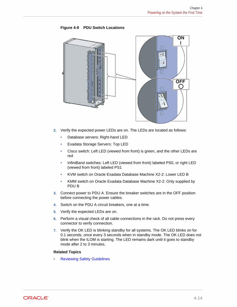
Figure 4-9 PDU Switch Locations
2. Verify the expected power LEDs are on. The LEDs are located as follows:
• Database servers: Right-hand LED
• Exadata Storage Servers: Top LED
• Cisco switch: Left LED (viewed from front) is green, and the other LEDs arered
• InfiniBand switches: Left LED (viewed from front) labeled PS0, or right LED(viewed from front) labeled PS1
• KVM switch on Oracle Exadata Database Machine X2-2: Lower LED B
• KMM switch on Oracle Exadata Database Machine X2-2: Only supplied byPDU B
3. Connect power to PDU A. Ensure the breaker switches are in the OFF positionbefore connecting the power cables.
4. Switch on the PDU A circuit breakers, one at a time.
5. Verify the expected LEDs are on.
6. Perform a visual check of all cable connections in the rack. Do not press everyconnector to verify connection.
7. Verify the OK LED is blinking standby for all systems. The OK LED blinks on for0.1 seconds, once every 3 seconds when in standby mode. The OK LED does notblink when the ILOM is starting. The LED remains dark until it goes to standbymode after 2 to 3 minutes.
Related Topics
• Reviewing Safety Guidelines
Chapter 4Powering on the System the First Time
4-14
5Configuring Oracle Exadata DatabaseMachine
This chapter describes how to configure the system, accounts, and software for OracleExadata Database Machine.
Note:
• For ease of reading, the name "Oracle Exadata Rack" is used wheninformation refers to both Oracle Exadata Database Machine and OracleExadata Storage Expansion Rack.
• The procedures in this chapter are applicable to Oracle Exadata StorageExpansion Rack as well as Oracle Exadata Database Machine.
• The procedures in this chapter use the information from Oracle ExadataDatabase Machine Deployment Assistant (OEDA). Be sure to run OEDAbefore starting the procedures in this chapter.
Related Topics
• Oracle Sun Database Machine Setup/Configuration Best Practices (My OracleSupport Doc ID 1274318.1)
5.1 Configuring Sun Datacenter InfiniBand Switch 36 SwitchThe following procedure describes how to configure the Sun Datacenter InfiniBandSwitch 36 switches.
1. Log in to the first database server as the root user. The first database server is thelowest database server in the rack, which is rack position U16.
Note:
If you do not have the password for the root user, then contact OracleSupport Services.
2. Use SSH to log in to the Sun Datacenter InfiniBand Switch 36 switch as the ilom-admin user. Find the default IP address for the Sun Datacenter InfiniBand Switch36 switch for your system in "Default IP Addresses". The following is an exampleof the command:
3. Use spsh to open the Integrated Lights Out Manager (ILOM) command lineinterface.
5-1
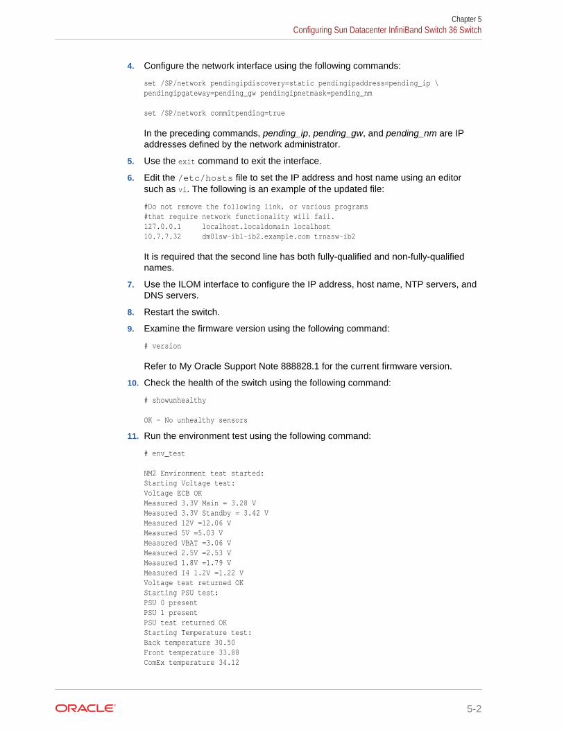
4. Configure the network interface using the following commands:
set /SP/network pendingipdiscovery=static pendingipaddress=pending_ip \pendingipgateway=pending_gw pendingipnetmask=pending_nm
set /SP/network commitpending=true
In the preceding commands, pending_ip, pending_gw, and pending_nm are IPaddresses defined by the network administrator.
5. Use the exit command to exit the interface.
6. Edit the /etc/hosts file to set the IP address and host name using an editorsuch as vi. The following is an example of the updated file:
#Do not remove the following link, or various programs#that require network functionality will fail.127.0.0.1 localhost.localdomain localhost10.7.7.32 dm01sw-ib1-ib2.example.com trnasw-ib2
It is required that the second line has both fully-qualified and non-fully-qualifiednames.
7. Use the ILOM interface to configure the IP address, host name, NTP servers, andDNS servers.
8. Restart the switch.
9. Examine the firmware version using the following command:
# version
Refer to My Oracle Support Note 888828.1 for the current firmware version.
10. Check the health of the switch using the following command:
# showunhealthy
OK - No unhealthy sensors
11. Run the environment test using the following command:
# env_test
NM2 Environment test started:Starting Voltage test:Voltage ECB OKMeasured 3.3V Main = 3.28 VMeasured 3.3V Standby = 3.42 VMeasured 12V =12.06 VMeasured 5V =5.03 VMeasured VBAT =3.06 VMeasured 2.5V =2.53 VMeasured 1.8V =1.79 VMeasured I4 1.2V =1.22 VVoltage test returned OKStarting PSU test:PSU 0 presentPSU 1 presentPSU test returned OKStarting Temperature test:Back temperature 30.50Front temperature 33.88ComEx temperature 34.12
Chapter 5Configuring Sun Datacenter InfiniBand Switch 36 Switch
5-2
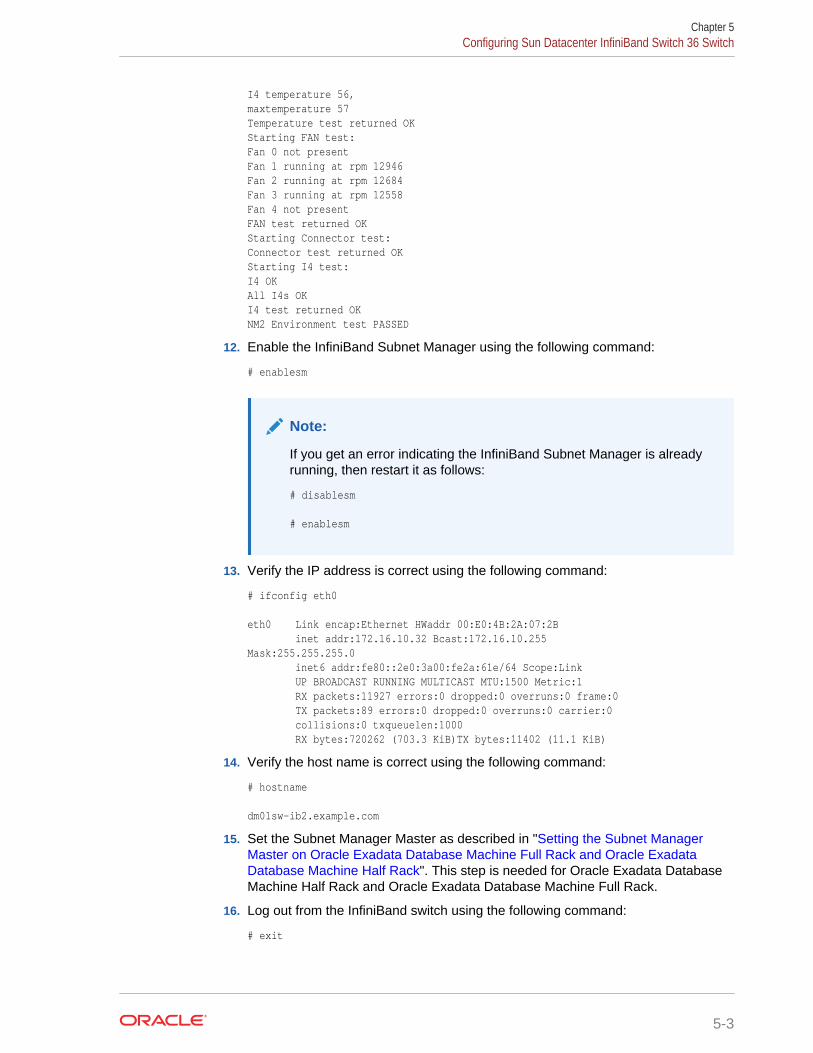
I4 temperature 56,maxtemperature 57Temperature test returned OKStarting FAN test:Fan 0 not presentFan 1 running at rpm 12946Fan 2 running at rpm 12684Fan 3 running at rpm 12558Fan 4 not presentFAN test returned OKStarting Connector test:Connector test returned OKStarting I4 test:I4 OKAll I4s OKI4 test returned OKNM2 Environment test PASSED
12. Enable the InfiniBand Subnet Manager using the following command:
# enablesm
Note:
If you get an error indicating the InfiniBand Subnet Manager is alreadyrunning, then restart it as follows:
# disablesm
# enablesm
13. Verify the IP address is correct using the following command:
# ifconfig eth0
eth0 Link encap:Ethernet HWaddr 00:E0:4B:2A:07:2B inet addr:172.16.10.32 Bcast:172.16.10.255Mask:255.255.255.0 inet6 addr:fe80::2e0:3a00:fe2a:61e/64 Scope:Link UP BROADCAST RUNNING MULTICAST MTU:1500 Metric:1 RX packets:11927 errors:0 dropped:0 overruns:0 frame:0 TX packets:89 errors:0 dropped:0 overruns:0 carrier:0 collisions:0 txqueuelen:1000 RX bytes:720262 (703.3 KiB)TX bytes:11402 (11.1 KiB)
14. Verify the host name is correct using the following command:
# hostname
dm01sw-ib2.example.com
15. Set the Subnet Manager Master as described in "Setting the Subnet ManagerMaster on Oracle Exadata Database Machine Full Rack and Oracle ExadataDatabase Machine Half Rack". This step is needed for Oracle Exadata DatabaseMachine Half Rack and Oracle Exadata Database Machine Full Rack.
16. Log out from the InfiniBand switch using the following command:
# exit
Chapter 5Configuring Sun Datacenter InfiniBand Switch 36 Switch
5-3
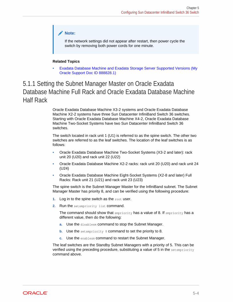
Note:
If the network settings did not appear after restart, then power cycle theswitch by removing both power cords for one minute.
Related Topics
• Exadata Database Machine and Exadata Storage Server Supported Versions (MyOracle Support Doc ID 888828.1)
5.1.1 Setting the Subnet Manager Master on Oracle ExadataDatabase Machine Full Rack and Oracle Exadata Database MachineHalf Rack
Oracle Exadata Database Machine X3-2 systems and Oracle Exadata DatabaseMachine X2-2 systems have three Sun Datacenter InfiniBand Switch 36 switches.Starting with Oracle Exadata Database Machine X4-2, Oracle Exadata DatabaseMachine Two-Socket Systems have two Sun Datacenter InfiniBand Switch 36switches.
The switch located in rack unit 1 (U1) is referred to as the spine switch. The other twoswitches are referred to as the leaf switches. The location of the leaf switches is asfollows:
• Oracle Exadata Database Machine Two-Socket Systems (X3-2 and later): rackunit 20 (U20) and rack unit 22 (U22)
• Oracle Exadata Database Machine X2-2 racks: rack unit 20 (U20) and rack unit 24(U24)
• Oracle Exadata Database Machine Eight-Socket Systems (X2-8 and later) FullRacks: Rack unit 21 (U21) and rack unit 23 (U23)
The spine switch is the Subnet Manager Master for the InfiniBand subnet. The SubnetManager Master has priority 8, and can be verified using the following procedure:
1. Log in to the spine switch as the root user.
2. Run the setsmpriority list command.
The command should show that smpriority has a value of 8. If smpriority has adifferent value, then do the following:
a. Use the disablesm command to stop the Subnet Manager.
b. Use the setsmpriority 8 command to set the priority to 8.
c. Use the enablesm command to restart the Subnet Manager.
The leaf switches are the Standby Subnet Managers with a priority of 5. This can beverified using the preceding procedure, substituting a value of 5 in the setsmprioritycommand above.
Chapter 5Configuring Sun Datacenter InfiniBand Switch 36 Switch
5-4
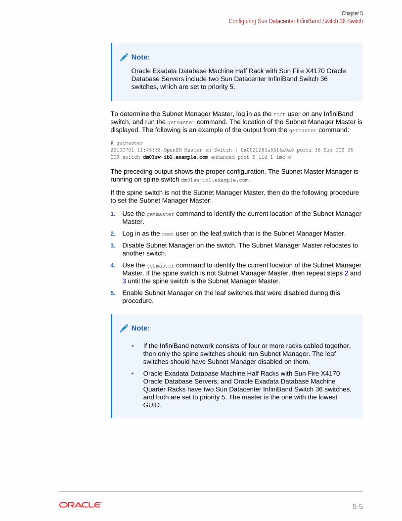
Note:
Oracle Exadata Database Machine Half Rack with Sun Fire X4170 OracleDatabase Servers include two Sun Datacenter InfiniBand Switch 36switches, which are set to priority 5.
To determine the Subnet Manager Master, log in as the root user on any InfiniBandswitch, and run the getmaster command. The location of the Subnet Manager Master isdisplayed. The following is an example of the output from the getmaster command:
# getmaster20100701 11:46:38 OpenSM Master on Switch : 0x0021283a8516a0a0 ports 36 Sun DCS 36QDR switch dm01sw-ib1.example.com enhanced port 0 lid 1 lmc 0
The preceding output shows the proper configuration. The Subnet Master Manager isrunning on spine switch dm01sw-ib1.example.com.
If the spine switch is not the Subnet Manager Master, then do the following procedureto set the Subnet Manager Master:
1. Use the getmaster command to identify the current location of the Subnet ManagerMaster.
2. Log in as the root user on the leaf switch that is the Subnet Manager Master.
3. Disable Subnet Manager on the switch. The Subnet Manager Master relocates toanother switch.
4. Use the getmaster command to identify the current location of the Subnet ManagerMaster. If the spine switch is not Subnet Manager Master, then repeat steps 2 and 3 until the spine switch is the Subnet Manager Master.
5. Enable Subnet Manager on the leaf switches that were disabled during thisprocedure.
Note:
• If the InfiniBand network consists of four or more racks cabled together,then only the spine switches should run Subnet Manager. The leafswitches should have Subnet Manager disabled on them.
• Oracle Exadata Database Machine Half Racks with Sun Fire X4170Oracle Database Servers, and Oracle Exadata Database MachineQuarter Racks have two Sun Datacenter InfiniBand Switch 36 switches,and both are set to priority 5. The master is the one with the lowestGUID.
Chapter 5Configuring Sun Datacenter InfiniBand Switch 36 Switch
5-5
See Also:
• "Enable the Subnet Manager" in Sun Datacenter InfiniBand Switch 36User's Guide
• "Disable the Subnet Manager" in Sun Datacenter InfiniBand Switch 36User's Guide
• Oracle Exadata Database Machine System Overview for hardwarecomponent information
• Cabling tables in Oracle Exadata Database Machine System Overview
5.2 Configuring the Cisco Ethernet SwitchYou must perform an initial configuration of the Cisco Ethernet switch.
• Configuring the Cisco Catalyst 4948 Ethernet Switch
• Configuring the Cisco Nexus 93108-1G or 9348 Ethernet Switch
5.2.1 Configuring the Cisco Catalyst 4948 Ethernet SwitchThe Cisco Catalyst 4948 Ethernet switch supplied with Oracle Exadata Rack isminimally configured during installation.
The minimal configuration disables IP routing, and sets the following:
• Host name
• IP address setup
• Subnet mask
• Default gateway
• Domain name
• Name server
• NTP server
• Time
• Time zone
Before configuring the switch, note the following:
• The Cisco Ethernet switch should not be connected until the running configurationhas been verified, and any necessary changes have been made by the networkadministrator.
• The Cisco Ethernet switch should not be connected to the customer network untilthe IP addresses on all components have been configured in Oracle ExadataRack. This is to prevent any duplicate IP address conflicts which are possible dueto the default addresses set in the components when shipped.
Note that the Cisco 4948E-F switch supports multiple uplinks to the customer networkby utilizing ports 49 - 52. This is a more complicated switch setup due to the redundantconnectivity, and should be performed by the customer's network administrator.
Chapter 5Configuring the Cisco Ethernet Switch
5-6
The following procedure describes how to configure the Cisco Ethernet switch.Configuration should be done with the network administrator.
1. Connect a serial cable from the Cisco switch console to a laptop or similar device.An Oracle supplied rollover cable is pre-installed on the Cisco serial console port.Obtain the appropriate adapter and connect it at the end of the rollover cable. AnOracle P/N 530-3100 RJ45-DB9 adapter as used on ILOM ports will also work,connected at the end of the network cable.
2. Ensure the terminal session is recorded on the laptop by logging the output. Theoutput can be used as a reference that the switch has been configured correctly.The default serial port speed is 9600 baud, 8 bits, no parity, 1 stop bit, and nohandshake.
Switch con0 is now availablePress RETURN to get started.
3. Change to the enable mode.
Switch> enablePassword: ******Switch#
Note:
If you do not have the password, then contact Oracle Support Services.
4. Check the current version on the swtich.
Switch# show version Cisco IOS Software, Catalyst 4500 L3 Switch Software (cat4500e-IPBASEK9-M), Version 15.2(3)E2, RELEASE SOFTWARE (fc1)Technical Support: http://www.cisco.com/techsupportCopyright (c) 1986-2014 by Cisco Systems, Inc.Compiled Tue 11-Mar-14 18:28 by prod_rel_team
ROM: 12.2(44r)SG12zdlra1sw-ip uptime is 1 minuteSystem returned to ROM by reloadSystem image file is "bootflash:cat4500e-ipbasek9-mz.152-3.E2.bin"Hobgoblin Revision 22, Fortooine Revision 1.40...
Configuration register is 0x2102
Switch#
The version of the Cisco 4948E-F switch firmware purchased and shipped byOracle with Exadata Database Machine X6 is IPBASEK9-MZ, which includestelnet and ssh support. Currently the full release version string is cat4500e-ipbasek9-mz.152-3.E2.bin.
5. Configure the network for a single VLAN. The following example assumes you areusing IPv4 addressing.
Switch# configure terminalEnter configuration commands,one per line.End with CNTL/Z.Switch(config)# interface vlan 1Switch(config-if)# ip address 10.7.7.34 255.255.255.0
Chapter 5Configuring the Cisco Ethernet Switch
5-7
Switch(config-if)# endSwitch# *Sep 15 14:12:06.309:%SYS-5-CONFIG_I:Configured from console by consoleSwitch# write memoryBuilding configuration...Compressed configuration from 2474 bytes to 1066 bytes [OK ]
6. (Optional) Disable the default IP routing setting, and configure the default gateway.This step is required if IP routing is not used on the switch.
Switch#configure terminalEnter configuration commands,one per line.End with CNTL/Z.Switch(config)#no ip routingSwitch(config)#ip default-gateway 10.7.7.1Switch(config)#end *Sep 15 14:12:46.309:%SYS-5-CONFIG_I:Configured from console by consoleSwitch#write memoryBuilding configuration...Compressed configuration from 2492 bytes to 1070 bytes [OK ]
Note:
If IP routing is required on the switch, then leave the IP routing setting asthe default, and configure the default gateway.
Switch#configure terminalEnter configuration commands,one per line.End with CNTL/Z.Switch(config)#ip route 0.0.0.0 0.0.0.0 10.7.7.1Switch(config)#end*Sep 15 14:13:26.013:%SYS-5-CONFIG_I:Configured from console by consoleSwitch#write memoryBuilding configuration...Compressed configuration from 2502 bytes to 1085 bytes [OK ]
7. Set the host name of the switch.
Switch#configure terminalEnter configuration commands,one per line.End with CNTL/Z.Switch(config)#hostname exa1sw-ipexa1sw-ip(config)#endexa1sw-ip#write memoryBuilding configuration...Compressed configuration from 3789 bytes to 1469 bytes [OK ]
The system host name is used as the prompt name.
8. Configure up to three DNS servers.
exa1sw-ip#configure terminalEnter configuration commands,one per line.End with CNTL/Z.exa1sw-ip(config)#ip domain-name example.comexa1sw-ip(config)#ip name-server 10.7.7.3exa1sw-ip(config)#ip name-server 198.51.100.5 exa1sw-ip(config)#ip name-server 10.8.160.1exa1sw-ip(config)#end *Sep 15 14:26:37.045:%SYS-5-CONFIG_I:Configured from console by consoleexa1sw-ip#write memoryBuilding configuration...Compressed configuration from 2603 bytes to 1158 bytes [OK ]
Chapter 5Configuring the Cisco Ethernet Switch
5-8
If you do not have DNS service available, you must still set the domain-name forthe SSH keys to be configurable.
9. (Optional) Set the password.
exa1sw-ip #configure terminalEnter configuration commands,one per line.End with CNTL/Z.exa1sw-ip(config)#enable password welcome1exa1sw-ip(config)#enable secret welcome1 The enable secret you have chosen is the same as your enable password.This is not recommended.Re-enter the enable secret.exa1sw-ip(config)#endexa1sw-ip#write memory *Sep 15 14:25:05.893:%SYS-5-CONFIG_I:Configured from console by consoleBuilding configuration...Compressed configuration from 2502 bytes to 1085 bytes [OK ]
10. Verify telnet access is disabled.
exa1sw-ip#configure terminalEnter configuration commands,one per line. End with CNTL/Z.exa1sw-ip(config)#line vty 0 15exa1sw-ip(config)#login% Login disabled on line 1, until 'password' is set% Login disabled on line 2, until 'password' is set ...% Login disabled on line 16, until 'password' is setexa1sw-ip(config)#end
If the login command returns output as shown above, then telnet access has beendisabled. If instead you get a prompt, then disable telnet access.
exa1sw-ip(config-line)#no passwordexa1sw-ip(config-line)#endexa1sw-ip#write memory Building configuration...Compressed configuration from 3786 bytes to 1468 bytes [OK ]
11. (Optional) Configure SSH access on the Cisco switch.
exa1sw-ip#configure terminalEnter configuration commands,one per line. End with CNTL/Z.exa1sw-ip(config)#crypto key generate rsa% You already have RSA keys defined named exa1sw-ip.example.com.% Do you really want to replace them? [yes/no]: yesChoose the size of the key modulus in the range of 360 to 2048 foryour General Purpose Keys. Choosing a key modulus greater than 512may take a few minutes.
How many bits in the modulus [512]: 768% Generating 768 bit RSA keys, keys will be non-exportable...[OK]
exa1sw-ip(config)#exa1sw-ip(config)#username admin password 0 welcome1exa1sw-ip(config)#line vty 0 15exa1sw-ip(config-line)#transport input sshexa1sw-ip(config-line)#exitexa1sw-ip(config)#aaa new-modelexa1sw-ip(config)#exa1sw-ip(config)#ip ssh time-out 60exa1sw-ip(config)#ip ssh authentication-retries 3exa1sw-ip(config)#ip ssh version 2exa1sw-ip(config)#end
Chapter 5Configuring the Cisco Ethernet Switch
5-9
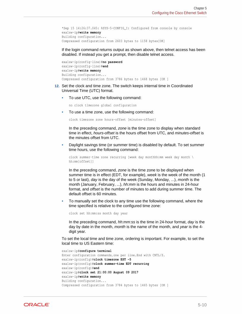
*Sep 15 14:26:37.045: %SYS-5-CONFIG_I: Configured from console by consoleexa1sw-ip#write memoryBuilding configuration...Compressed configuration from 2603 bytes to 1158 bytes[OK]
If the login command returns output as shown above, then telnet access has beendisabled. If instead you get a prompt, then disable telnet access.
exa1sw-ip(config-line)#no passwordexa1sw-ip(config-line)#endexa1sw-ip#write memory Building configuration...Compressed configuration from 3786 bytes to 1468 bytes [OK ]
12. Set the clock and time zone. The switch keeps internal time in CoordinatedUniversal Time (UTC) format.
• To use UTC, use the following command:
no clock timezone global configuration
• To use a time zone, use the following command:
clock timezone zone hours-offset [minutes-offset]
In the preceding command, zone is the time zone to display when standardtime in effect, hours-offset is the hours offset from UTC, and minutes-offset isthe minutes offset from UTC.
• Daylight savings time (or summer time) is disabled by default. To set summertime hours, use the following command:
clock summer-time zone recurring [week day monthhh:mm week day month \hh:mm[offset]]
In the preceding command, zone is the time zone to be displayed whensummer time is in effect (EDT, for example), week is the week of the month (1to 5 or last), day is the day of the week (Sunday, Monday, ...), month is themonth (January, February, ...), hh:mm is the hours and minutes in 24-hourformat, and offset is the number of minutes to add during summer time. Thedefault offset is 60 minutes.
• To manually set the clock to any time use the following command, where thetime specified is relative to the configured time zone:
clock set hh:mm:ss month day year
In the preceding command, hh:mm:ss is the time in 24-hour format, day is theday by date in the month, month is the name of the month, and year is the 4-digit year.
To set the local time and time zone, ordering is important. For example, to set thelocal time to US Eastern time:
exa1sw-ip#configure terminalEnter configuration commands,one per line.End with CNTL/Z.exa1sw-ip(config)#clock timezone EST -5 exa1sw-ip(config)#clock summer-time EDT recurringexa1sw-ip(config)#endexa1sw-ip#clock set 21:00:00 August 09 2017exa1sw-ip#write memoryBuilding configuration...Compressed configuration from 3784 bytes to 1465 bytes [OK ]
Chapter 5Configuring the Cisco Ethernet Switch
5-10
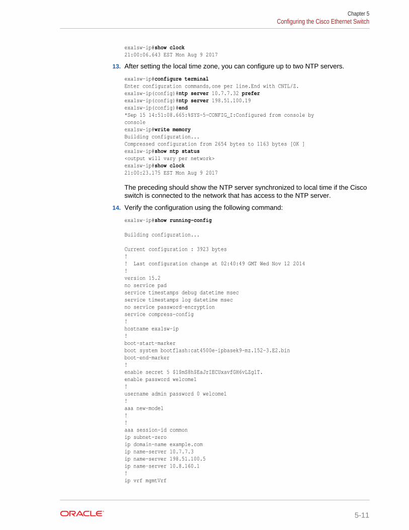
exa1sw-ip#show clock21:00:06.643 EST Mon Aug 9 2017
13. After setting the local time zone, you can configure up to two NTP servers.
exa1sw-ip#configure terminalEnter configuration commands,one per line.End with CNTL/Z.exa1sw-ip(config)#ntp server 10.7.7.32 preferexa1sw-ip(config)#ntp server 198.51.100.19exa1sw-ip(config)#end*Sep 15 14:51:08.665:%SYS-5-CONFIG_I:Configured from console byconsoleexa1sw-ip#write memoryBuilding configuration...Compressed configuration from 2654 bytes to 1163 bytes [OK ]exa1sw-ip#show ntp status<output will vary per network>exa1sw-ip#show clock21:00:23.175 EST Mon Aug 9 2017
The preceding should show the NTP server synchronized to local time if the Ciscoswitch is connected to the network that has access to the NTP server.
14. Verify the configuration using the following command:
exa1sw-ip#show running-config
Building configuration...
Current configuration : 3923 bytes!! Last configuration change at 02:40:49 GMT Wed Nov 12 2014!version 15.2no service padservice timestamps debug datetime msecservice timestamps log datetime msecno service password-encryptionservice compress-config!hostname exa1sw-ip!boot-start-markerboot system bootflash:cat4500e-ipbasek9-mz.152-3.E2.binboot-end-marker!enable secret 5 $1$mS8h$EaJrIECUxavfGH6vLZg1T.enable password welcome1!username admin password 0 welcome1!aaa new-model!!aaa session-id commonip subnet-zeroip domain-name example.comip name-server 10.7.7.3ip name-server 198.51.100.5ip name-server 10.8.160.1!ip vrf mgmtVrf
Chapter 5Configuring the Cisco Ethernet Switch
5-11
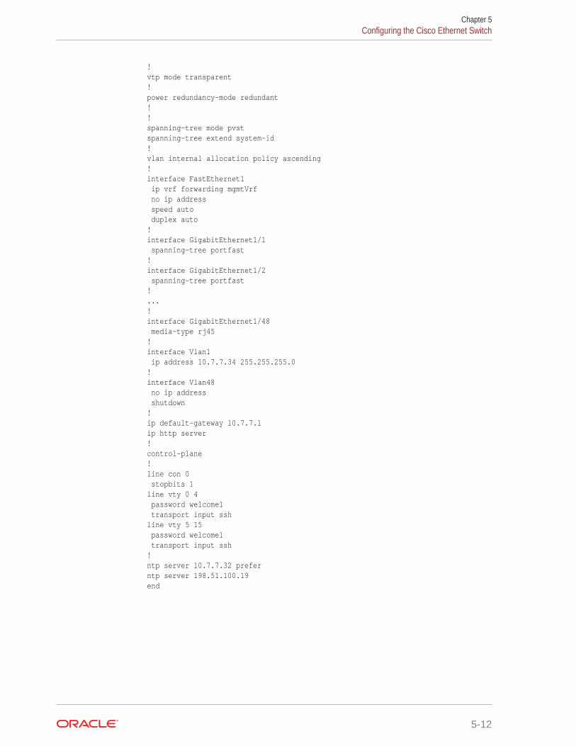
!vtp mode transparent!power redundancy-mode redundant!!spanning-tree mode pvstspanning-tree extend system-id!vlan internal allocation policy ascending!interface FastEthernet1 ip vrf forwarding mgmtVrf no ip address speed auto duplex auto!interface GigabitEthernet1/1 spanning-tree portfast!interface GigabitEthernet1/2 spanning-tree portfast!...!interface GigabitEthernet1/48 media-type rj45!interface Vlan1 ip address 10.7.7.34 255.255.255.0!interface Vlan48 no ip address shutdown!ip default-gateway 10.7.7.1ip http server!control-plane!line con 0 stopbits 1line vty 0 4 password welcome1 transport input sshline vty 5 15 password welcome1 transport input ssh!ntp server 10.7.7.32 preferntp server 198.51.100.19end
Chapter 5Configuring the Cisco Ethernet Switch
5-12
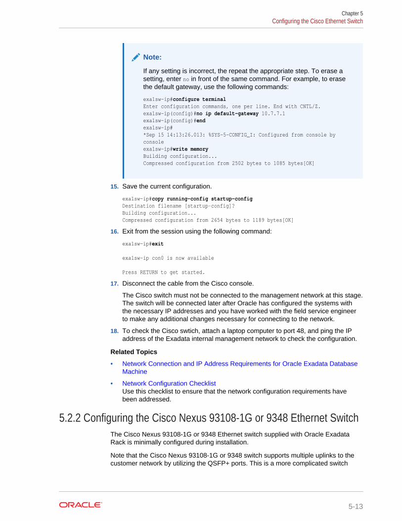
Note:
If any setting is incorrect, the repeat the appropriate step. To erase asetting, enter no in front of the same command. For example, to erasethe default gateway, use the following commands:
exa1sw-ip#configure terminalEnter configuration commands, one per line. End with CNTL/Z.exa1sw-ip(config)#no ip default-gateway 10.7.7.1exa1sw-ip(config)#endexa1sw-ip# *Sep 15 14:13:26.013: %SYS-5-CONFIG_I: Configured from console by consoleexa1sw-ip#write memoryBuilding configuration...Compressed configuration from 2502 bytes to 1085 bytes[OK]
15. Save the current configuration.
exa1sw-ip#copy running-config startup-configDestination filename [startup-config]?Building configuration...Compressed configuration from 2654 bytes to 1189 bytes[OK]
16. Exit from the session using the following command:
exa1sw-ip#exit
exa1sw-ip con0 is now available
Press RETURN to get started.
17. Disconnect the cable from the Cisco console.
The Cisco switch must not be connected to the management network at this stage.The switch will be connected later after Oracle has configured the systems withthe necessary IP addresses and you have worked with the field service engineerto make any additional changes necessary for connecting to the network.
18. To check the Cisco swtich, attach a laptop computer to port 48, and ping the IPaddress of the Exadata internal management network to check the configuration.
Related Topics
• Network Connection and IP Address Requirements for Oracle Exadata DatabaseMachine
• Network Configuration ChecklistUse this checklist to ensure that the network configuration requirements havebeen addressed.
5.2.2 Configuring the Cisco Nexus 93108-1G or 9348 Ethernet SwitchThe Cisco Nexus 93108-1G or 9348 Ethernet switch supplied with Oracle ExadataRack is minimally configured during installation.
Note that the Cisco Nexus 93108-1G or 9348 switch supports multiple uplinks to thecustomer network by utilizing the QSFP+ ports. This is a more complicated switch
Chapter 5Configuring the Cisco Ethernet Switch
5-13
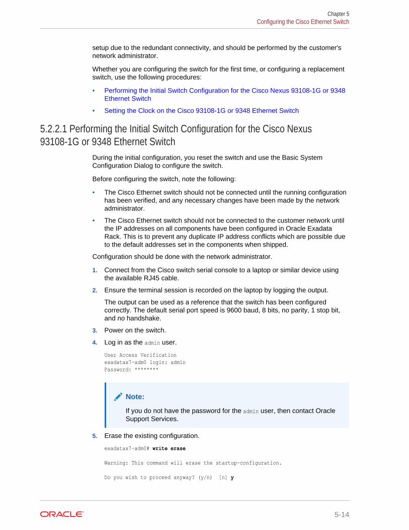
setup due to the redundant connectivity, and should be performed by the customer'snetwork administrator.
Whether you are configuring the switch for the first time, or configuring a replacementswitch, use the following procedures:
• Performing the Initial Switch Configuration for the Cisco Nexus 93108-1G or 9348Ethernet Switch
• Setting the Clock on the Cisco 93108-1G or 9348 Ethernet Switch
5.2.2.1 Performing the Initial Switch Configuration for the Cisco Nexus93108-1G or 9348 Ethernet Switch
During the initial configuration, you reset the switch and use the Basic SystemConfiguration Dialog to configure the switch.
Before configuring the switch, note the following:
• The Cisco Ethernet switch should not be connected until the running configurationhas been verified, and any necessary changes have been made by the networkadministrator.
• The Cisco Ethernet switch should not be connected to the customer network untilthe IP addresses on all components have been configured in Oracle ExadataRack. This is to prevent any duplicate IP address conflicts which are possible dueto the default addresses set in the components when shipped.
Configuration should be done with the network administrator.
1. Connect from the Cisco switch serial console to a laptop or similar device usingthe available RJ45 cable.
2. Ensure the terminal session is recorded on the laptop by logging the output.
The output can be used as a reference that the switch has been configuredcorrectly. The default serial port speed is 9600 baud, 8 bits, no parity, 1 stop bit,and no handshake.
3. Power on the switch.
4. Log in as the admin user.
User Access Verificationexadatax7-adm0 login: adminPassword: ********
Note:
If you do not have the password for the admin user, then contact OracleSupport Services.
5. Erase the existing configuration.
exadatax7-adm0# write erase
Warning: This command will erase the startup-configuration.
Do you wish to proceed anyway? (y/n) [n] y
Chapter 5Configuring the Cisco Ethernet Switch
5-14
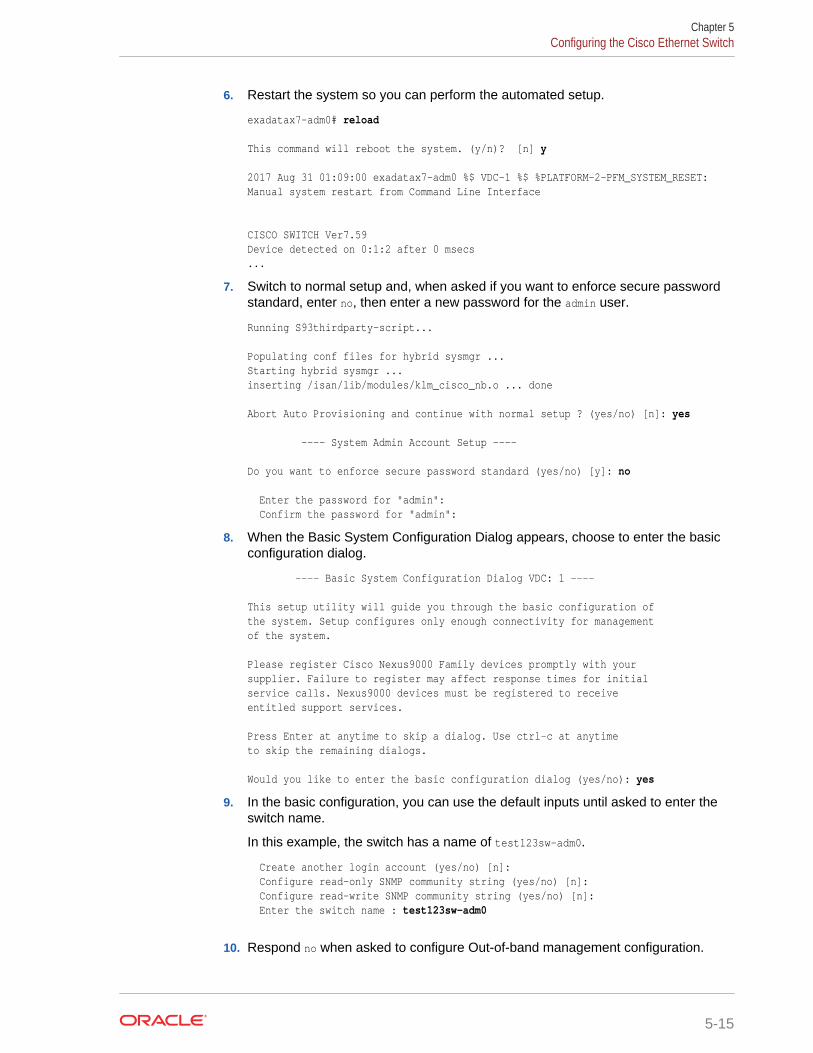
6. Restart the system so you can perform the automated setup.
exadatax7-adm0# reload
This command will reboot the system. (y/n)? [n] y
2017 Aug 31 01:09:00 exadatax7-adm0 %$ VDC-1 %$ %PLATFORM-2-PFM_SYSTEM_RESET: Manual system restart from Command Line Interface
CISCO SWITCH Ver7.59Device detected on 0:1:2 after 0 msecs ...
7. Switch to normal setup and, when asked if you want to enforce secure passwordstandard, enter no, then enter a new password for the admin user.
Running S93thirdparty-script...
Populating conf files for hybrid sysmgr ...Starting hybrid sysmgr ...inserting /isan/lib/modules/klm_cisco_nb.o ... done
Abort Auto Provisioning and continue with normal setup ? (yes/no) [n]: yes
---- System Admin Account Setup ----
Do you want to enforce secure password standard (yes/no) [y]: no
Enter the password for "admin": Confirm the password for "admin":
8. When the Basic System Configuration Dialog appears, choose to enter the basicconfiguration dialog.
---- Basic System Configuration Dialog VDC: 1 ----
This setup utility will guide you through the basic configuration ofthe system. Setup configures only enough connectivity for managementof the system.
Please register Cisco Nexus9000 Family devices promptly with yoursupplier. Failure to register may affect response times for initialservice calls. Nexus9000 devices must be registered to receive entitled support services.
Press Enter at anytime to skip a dialog. Use ctrl-c at anytimeto skip the remaining dialogs.
Would you like to enter the basic configuration dialog (yes/no): yes
9. In the basic configuration, you can use the default inputs until asked to enter theswitch name.
In this example, the switch has a name of test123sw-adm0.
Create another login account (yes/no) [n]: Configure read-only SNMP community string (yes/no) [n]: Configure read-write SNMP community string (yes/no) [n]: Enter the switch name : test123sw-adm0
10. Respond no when asked to configure Out-of-band management configuration.
Chapter 5Configuring the Cisco Ethernet Switch
5-15
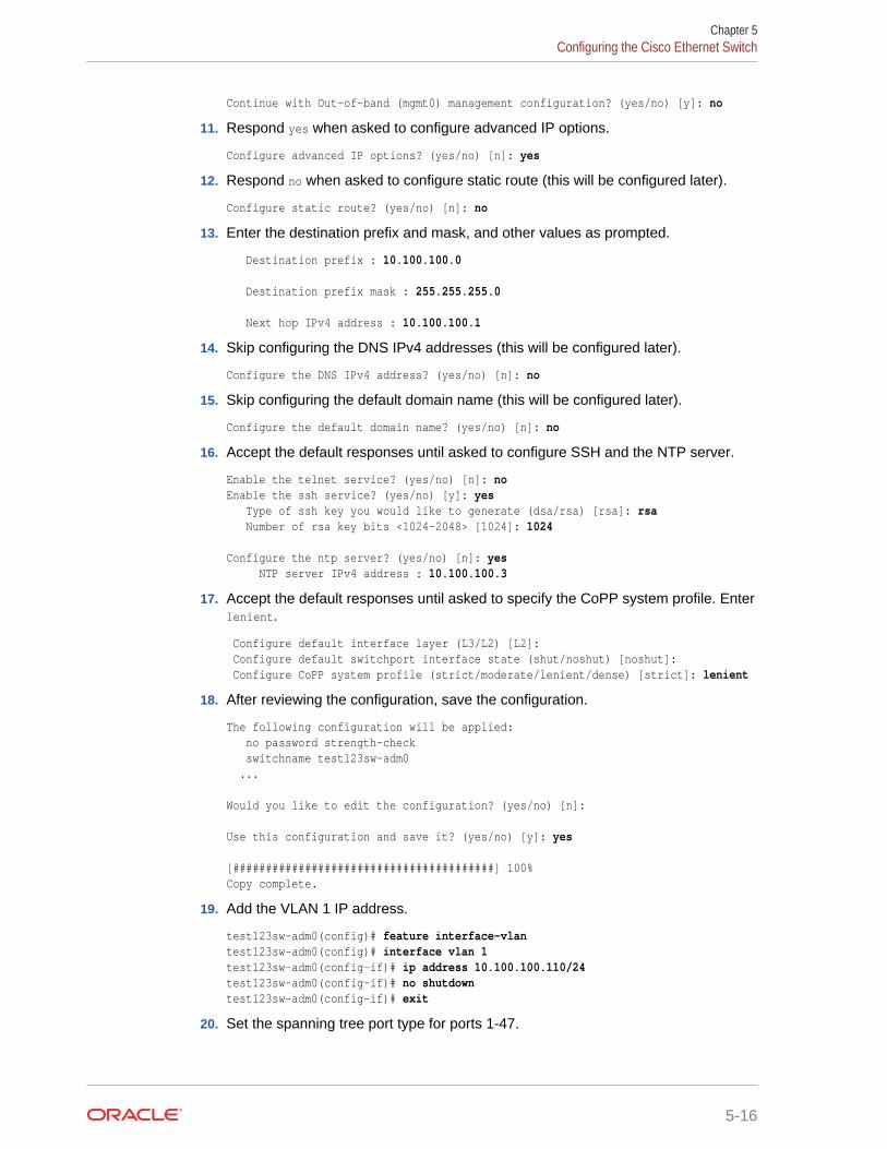
Continue with Out-of-band (mgmt0) management configuration? (yes/no) [y]: no
11. Respond yes when asked to configure advanced IP options.
Configure advanced IP options? (yes/no) [n]: yes
12. Respond no when asked to configure static route (this will be configured later).
Configure static route? (yes/no) [n]: no
13. Enter the destination prefix and mask, and other values as prompted.
Destination prefix : 10.100.100.0
Destination prefix mask : 255.255.255.0
Next hop IPv4 address : 10.100.100.1
14. Skip configuring the DNS IPv4 addresses (this will be configured later).
Configure the DNS IPv4 address? (yes/no) [n]: no
15. Skip configuring the default domain name (this will be configured later).
Configure the default domain name? (yes/no) [n]: no
16. Accept the default responses until asked to configure SSH and the NTP server.
Enable the telnet service? (yes/no) [n]: noEnable the ssh service? (yes/no) [y]: yes Type of ssh key you would like to generate (dsa/rsa) [rsa]: rsa Number of rsa key bits <1024-2048> [1024]: 1024 Configure the ntp server? (yes/no) [n]: yes NTP server IPv4 address : 10.100.100.3
17. Accept the default responses until asked to specify the CoPP system profile. Enterlenient.
Configure default interface layer (L3/L2) [L2]: Configure default switchport interface state (shut/noshut) [noshut]: Configure CoPP system profile (strict/moderate/lenient/dense) [strict]: lenient
18. After reviewing the configuration, save the configuration.
The following configuration will be applied: no password strength-check switchname test123sw-adm0 ...
Would you like to edit the configuration? (yes/no) [n]:
Use this configuration and save it? (yes/no) [y]: yes
[########################################] 100%Copy complete.
19. Add the VLAN 1 IP address.
test123sw-adm0(config)# feature interface-vlantest123sw-adm0(config)# interface vlan 1test123sw-adm0(config-if)# ip address 10.100.100.110/24test123sw-adm0(config-if)# no shutdowntest123sw-adm0(config-if)# exit
20. Set the spanning tree port type for ports 1-47.
Chapter 5Configuring the Cisco Ethernet Switch
5-16
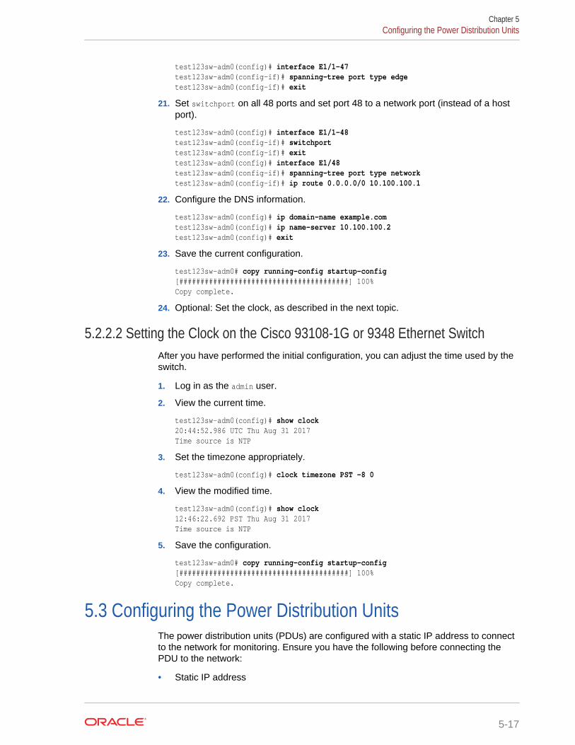
test123sw-adm0(config)# interface E1/1-47test123sw-adm0(config-if)# spanning-tree port type edgetest123sw-adm0(config-if)# exit
21. Set switchport on all 48 ports and set port 48 to a network port (instead of a hostport).
test123sw-adm0(config)# interface E1/1-48test123sw-adm0(config-if)# switchporttest123sw-adm0(config-if)# exittest123sw-adm0(config)# interface E1/48test123sw-adm0(config-if)# spanning-tree port type networktest123sw-adm0(config-if)# ip route 0.0.0.0/0 10.100.100.1
22. Configure the DNS information.
test123sw-adm0(config)# ip domain-name example.comtest123sw-adm0(config)# ip name-server 10.100.100.2test123sw-adm0(config)# exit
23. Save the current configuration.
test123sw-adm0# copy running-config startup-config[########################################] 100%Copy complete.
24. Optional: Set the clock, as described in the next topic.
5.2.2.2 Setting the Clock on the Cisco 93108-1G or 9348 Ethernet SwitchAfter you have performed the initial configuration, you can adjust the time used by theswitch.
1. Log in as the admin user.
2. View the current time.
test123sw-adm0(config)# show clock20:44:52.986 UTC Thu Aug 31 2017Time source is NTP
3. Set the timezone appropriately.
test123sw-adm0(config)# clock timezone PST -8 0
4. View the modified time.
test123sw-adm0(config)# show clock12:46:22.692 PST Thu Aug 31 2017Time source is NTP
5. Save the configuration.
test123sw-adm0# copy running-config startup-config [########################################] 100%Copy complete.
5.3 Configuring the Power Distribution UnitsThe power distribution units (PDUs) are configured with a static IP address to connectto the network for monitoring. Ensure you have the following before connecting thePDU to the network:
• Static IP address
Chapter 5Configuring the Power Distribution Units
5-17
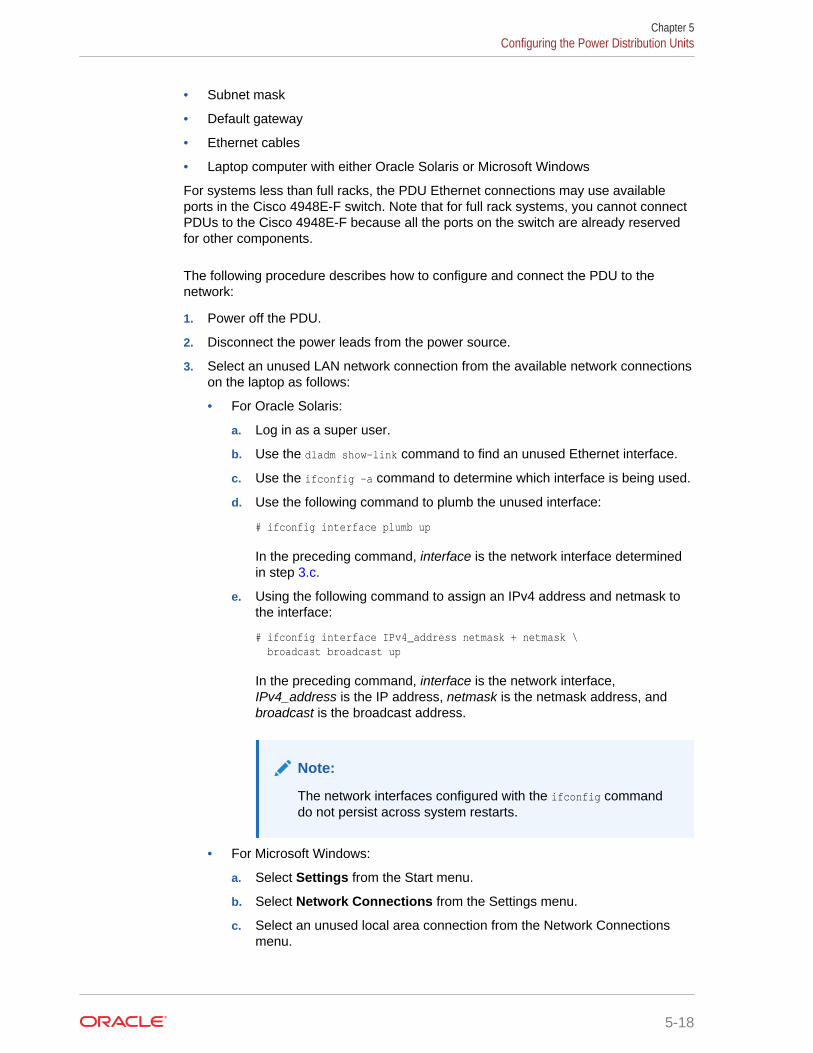
• Subnet mask
• Default gateway
• Ethernet cables
• Laptop computer with either Oracle Solaris or Microsoft Windows
For systems less than full racks, the PDU Ethernet connections may use availableports in the Cisco 4948E-F switch. Note that for full rack systems, you cannot connectPDUs to the Cisco 4948E-F because all the ports on the switch are already reservedfor other components.
The following procedure describes how to configure and connect the PDU to thenetwork:
1. Power off the PDU.
2. Disconnect the power leads from the power source.
3. Select an unused LAN network connection from the available network connectionson the laptop as follows:
• For Oracle Solaris:
a. Log in as a super user.
b. Use the dladm show-link command to find an unused Ethernet interface.
c. Use the ifconfig -a command to determine which interface is being used.
d. Use the following command to plumb the unused interface:
# ifconfig interface plumb up
In the preceding command, interface is the network interface determinedin step 3.c.
e. Using the following command to assign an IPv4 address and netmask tothe interface:
# ifconfig interface IPv4_address netmask + netmask \ broadcast broadcast up
In the preceding command, interface is the network interface,IPv4_address is the IP address, netmask is the netmask address, andbroadcast is the broadcast address.
Note:
The network interfaces configured with the ifconfig commanddo not persist across system restarts.
• For Microsoft Windows:
a. Select Settings from the Start menu.
b. Select Network Connections from the Settings menu.
c. Select an unused local area connection from the Network Connectionsmenu.
Chapter 5Configuring the Power Distribution Units
5-18
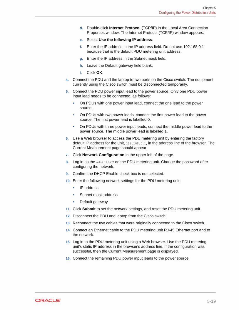
d. Double-click Internet Protocol (TCP/IP) in the Local Area ConnectionProperties window. The Internet Protocol (TCP/IP) window appears.
e. Select Use the following IP address.
f. Enter the IP address in the IP address field. Do not use 192.168.0.1because that is the default PDU metering unit address.
g. Enter the IP address in the Subnet mask field.
h. Leave the Default gateway field blank.
i. Click OK.
4. Connect the PDU and the laptop to two ports on the Cisco switch. The equipmentcurrently using the Cisco switch must be disconnected temporarily.
5. Connect the PDU power input lead to the power source. Only one PDU powerinput lead needs to be connected, as follows:
• On PDUs with one power input lead, connect the one lead to the powersource.
• On PDUs with two power leads, connect the first power lead to the powersource. The first power lead is labelled 0.
• On PDUs with three power input leads, connect the middle power lead to thepower source. The middle power lead is labelled 1.
6. Use a Web browser to access the PDU metering unit by entering the factorydefault IP address for the unit, 192.168.0.1, in the address line of the browser. TheCurrent Measurement page should appear.
7. Click Network Configuration in the upper left of the page.
8. Log in as the admin user on the PDU metering unit. Change the password afterconfiguring the network.
9. Confirm the DHCP Enable check box is not selected.
10. Enter the following network settings for the PDU metering unit:
• IP address
• Subnet mask address
• Default gateway
11. Click Submit to set the network settings, and reset the PDU metering unit.
12. Disconnect the PDU and laptop from the Cisco switch.
13. Reconnect the two cables that were originally connected to the Cisco switch.
14. Connect an Ethernet cable to the PDU metering unit RJ-45 Ethernet port and tothe network.
15. Log in to the PDU metering unit using a Web browser. Use the PDU meteringunit's static IP address in the browser's address line. If the configuration wassuccessful, then the Current Measurement page is displayed.
16. Connect the remaining PDU power input leads to the power source.
Chapter 5Configuring the Power Distribution Units
5-19
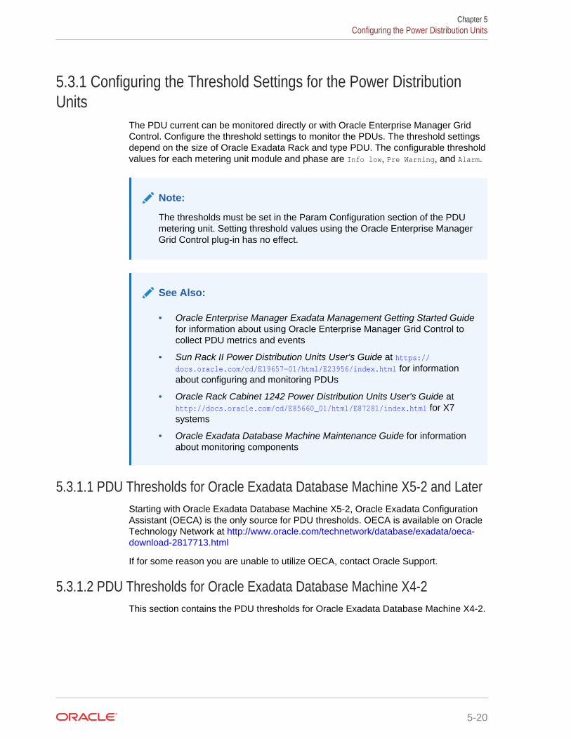
5.3.1 Configuring the Threshold Settings for the Power DistributionUnits
The PDU current can be monitored directly or with Oracle Enterprise Manager GridControl. Configure the threshold settings to monitor the PDUs. The threshold settingsdepend on the size of Oracle Exadata Rack and type PDU. The configurable thresholdvalues for each metering unit module and phase are Info low, Pre Warning, and Alarm.
Note:
The thresholds must be set in the Param Configuration section of the PDUmetering unit. Setting threshold values using the Oracle Enterprise ManagerGrid Control plug-in has no effect.
See Also:
• Oracle Enterprise Manager Exadata Management Getting Started Guidefor information about using Oracle Enterprise Manager Grid Control tocollect PDU metrics and events
• Sun Rack II Power Distribution Units User's Guide at https://docs.oracle.com/cd/E19657-01/html/E23956/index.html for informationabout configuring and monitoring PDUs
• Oracle Rack Cabinet 1242 Power Distribution Units User's Guide at http://docs.oracle.com/cd/E85660_01/html/E87281/index.html for X7systems
• Oracle Exadata Database Machine Maintenance Guide for informationabout monitoring components
5.3.1.1 PDU Thresholds for Oracle Exadata Database Machine X5-2 and LaterStarting with Oracle Exadata Database Machine X5-2, Oracle Exadata ConfigurationAssistant (OECA) is the only source for PDU thresholds. OECA is available on OracleTechnology Network at http://www.oracle.com/technetwork/database/exadata/oeca-download-2817713.html
If for some reason you are unable to utilize OECA, contact Oracle Support.
5.3.1.2 PDU Thresholds for Oracle Exadata Database Machine X4-2This section contains the PDU thresholds for Oracle Exadata Database Machine X4-2.
Chapter 5Configuring the Power Distribution Units
5-20
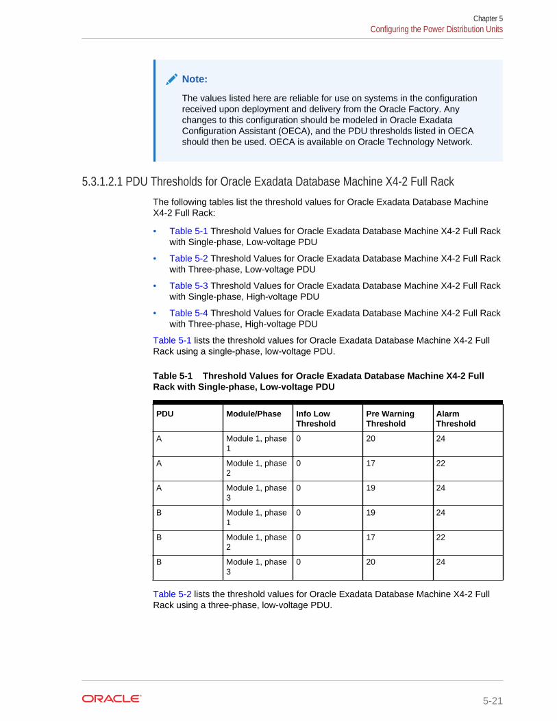
Note:
The values listed here are reliable for use on systems in the configurationreceived upon deployment and delivery from the Oracle Factory. Anychanges to this configuration should be modeled in Oracle ExadataConfiguration Assistant (OECA), and the PDU thresholds listed in OECAshould then be used. OECA is available on Oracle Technology Network.
5.3.1.2.1 PDU Thresholds for Oracle Exadata Database Machine X4-2 Full RackThe following tables list the threshold values for Oracle Exadata Database MachineX4-2 Full Rack:
• Table 5-1 Threshold Values for Oracle Exadata Database Machine X4-2 Full Rackwith Single-phase, Low-voltage PDU
• Table 5-2 Threshold Values for Oracle Exadata Database Machine X4-2 Full Rackwith Three-phase, Low-voltage PDU
• Table 5-3 Threshold Values for Oracle Exadata Database Machine X4-2 Full Rackwith Single-phase, High-voltage PDU
• Table 5-4 Threshold Values for Oracle Exadata Database Machine X4-2 Full Rackwith Three-phase, High-voltage PDU
Table 5-1 lists the threshold values for Oracle Exadata Database Machine X4-2 FullRack using a single-phase, low-voltage PDU.
Table 5-1 Threshold Values for Oracle Exadata Database Machine X4-2 FullRack with Single-phase, Low-voltage PDU
PDU Module/Phase Info LowThreshold
Pre WarningThreshold
AlarmThreshold
A Module 1, phase1
0 20 24
A Module 1, phase2
0 17 22
A Module 1, phase3
0 19 24
B Module 1, phase1
0 19 24
B Module 1, phase2
0 17 22
B Module 1, phase3
0 20 24
Table 5-2 lists the threshold values for Oracle Exadata Database Machine X4-2 FullRack using a three-phase, low-voltage PDU.
Chapter 5Configuring the Power Distribution Units
5-21
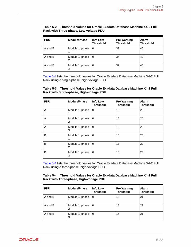
Table 5-2 Threshold Values for Oracle Exadata Database Machine X4-2 FullRack with Three-phase, Low-voltage PDU
PDU Module/Phase Info LowThreshold
Pre WarningThreshold
AlarmThreshold
A and B Module 1, phase1
0 32 40
A and B Module 1, phase2
0 34 42
A and B Module 1, phase3
0 32 40
Table 5-3 lists the threshold values for Oracle Exadata Database Machine X4-2 FullRack using a single-phase, high-voltage PDU.
Table 5-3 Threshold Values for Oracle Exadata Database Machine X4-2 FullRack with Single-phase, High-voltage PDU
PDU Module/Phase Info LowThreshold
Pre WarningThreshold
AlarmThreshold
A Module 1, phase1
0 18 23
A Module 1, phase2
0 16 20
A Module 1, phase3
0 18 23
B Module 1, phase1
0 18 23
B Module 1, phase2
0 16 20
B Module 1, phase3
0 18 23
Table 5-4 lists the threshold values for Oracle Exadata Database Machine X4-2 FullRack using a three-phase, high-voltage PDU.
Table 5-4 Threshold Values for Oracle Exadata Database Machine X4-2 FullRack with Three-phase, High-voltage PDU
PDU Module/Phase Info LowThreshold
Pre WarningThreshold
AlarmThreshold
A and B Module 1, phase1
0 18 21
A and B Module 1, phase2
0 18 21
A and B Module 1, phase3
0 16 21
Chapter 5Configuring the Power Distribution Units
5-22
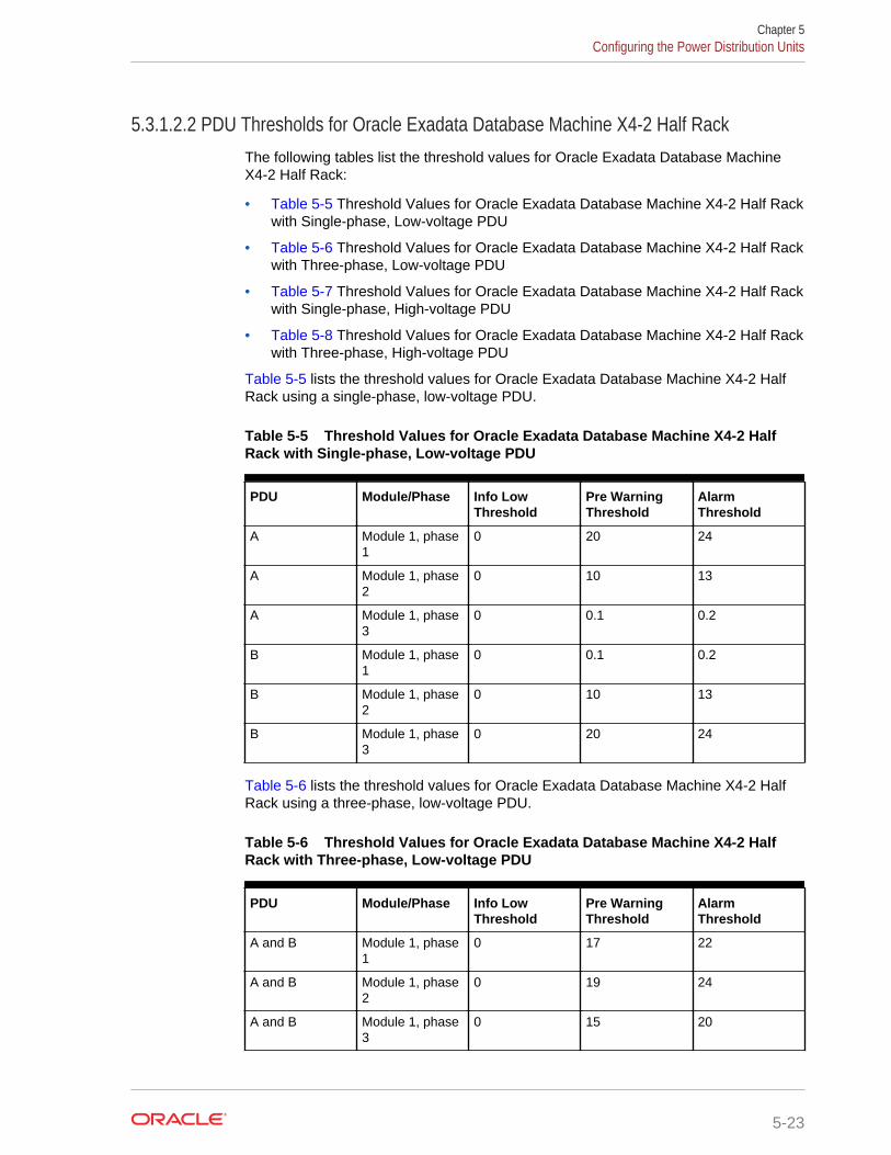
5.3.1.2.2 PDU Thresholds for Oracle Exadata Database Machine X4-2 Half RackThe following tables list the threshold values for Oracle Exadata Database MachineX4-2 Half Rack:
• Table 5-5 Threshold Values for Oracle Exadata Database Machine X4-2 Half Rackwith Single-phase, Low-voltage PDU
• Table 5-6 Threshold Values for Oracle Exadata Database Machine X4-2 Half Rackwith Three-phase, Low-voltage PDU
• Table 5-7 Threshold Values for Oracle Exadata Database Machine X4-2 Half Rackwith Single-phase, High-voltage PDU
• Table 5-8 Threshold Values for Oracle Exadata Database Machine X4-2 Half Rackwith Three-phase, High-voltage PDU
Table 5-5 lists the threshold values for Oracle Exadata Database Machine X4-2 HalfRack using a single-phase, low-voltage PDU.
Table 5-5 Threshold Values for Oracle Exadata Database Machine X4-2 HalfRack with Single-phase, Low-voltage PDU
PDU Module/Phase Info LowThreshold
Pre WarningThreshold
AlarmThreshold
A Module 1, phase1
0 20 24
A Module 1, phase2
0 10 13
A Module 1, phase3
0 0.1 0.2
B Module 1, phase1
0 0.1 0.2
B Module 1, phase2
0 10 13
B Module 1, phase3
0 20 24
Table 5-6 lists the threshold values for Oracle Exadata Database Machine X4-2 HalfRack using a three-phase, low-voltage PDU.
Table 5-6 Threshold Values for Oracle Exadata Database Machine X4-2 HalfRack with Three-phase, Low-voltage PDU
PDU Module/Phase Info LowThreshold
Pre WarningThreshold
AlarmThreshold
A and B Module 1, phase1
0 17 22
A and B Module 1, phase2
0 19 24
A and B Module 1, phase3
0 15 20
Chapter 5Configuring the Power Distribution Units
5-23
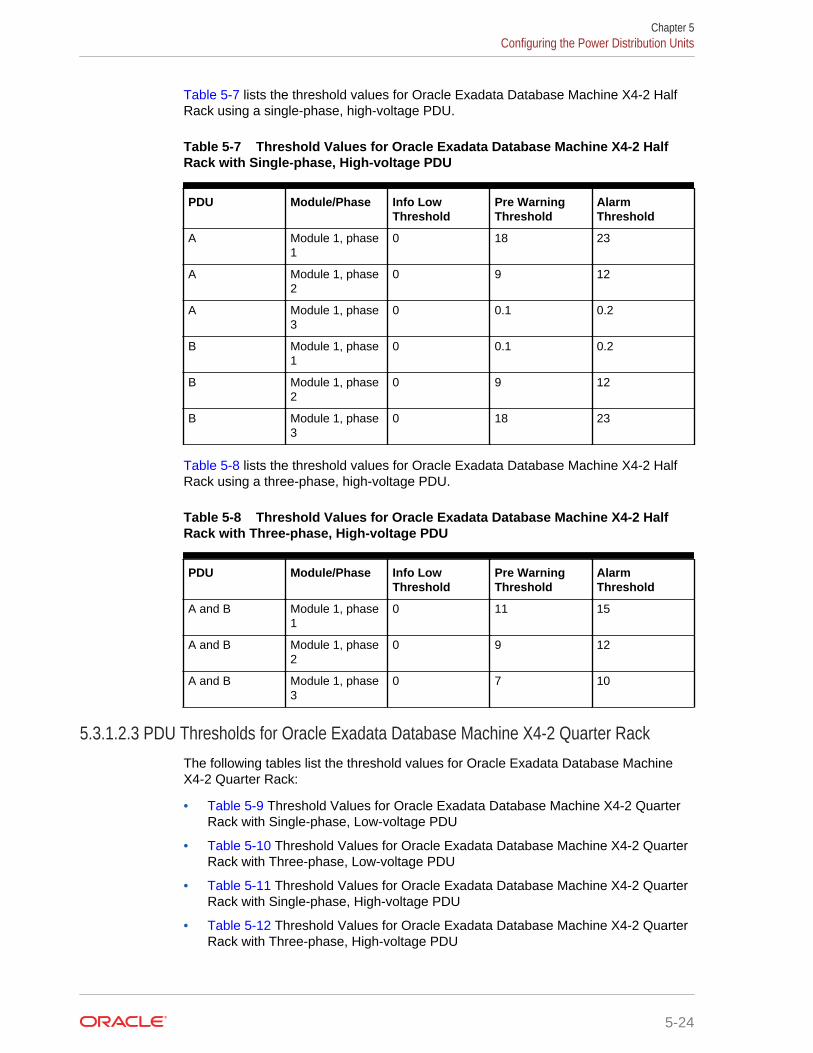
Table 5-7 lists the threshold values for Oracle Exadata Database Machine X4-2 HalfRack using a single-phase, high-voltage PDU.
Table 5-7 Threshold Values for Oracle Exadata Database Machine X4-2 HalfRack with Single-phase, High-voltage PDU
PDU Module/Phase Info LowThreshold
Pre WarningThreshold
AlarmThreshold
A Module 1, phase1
0 18 23
A Module 1, phase2
0 9 12
A Module 1, phase3
0 0.1 0.2
B Module 1, phase1
0 0.1 0.2
B Module 1, phase2
0 9 12
B Module 1, phase3
0 18 23
Table 5-8 lists the threshold values for Oracle Exadata Database Machine X4-2 HalfRack using a three-phase, high-voltage PDU.
Table 5-8 Threshold Values for Oracle Exadata Database Machine X4-2 HalfRack with Three-phase, High-voltage PDU
PDU Module/Phase Info LowThreshold
Pre WarningThreshold
AlarmThreshold
A and B Module 1, phase1
0 11 15
A and B Module 1, phase2
0 9 12
A and B Module 1, phase3
0 7 10
5.3.1.2.3 PDU Thresholds for Oracle Exadata Database Machine X4-2 Quarter RackThe following tables list the threshold values for Oracle Exadata Database MachineX4-2 Quarter Rack:
• Table 5-9 Threshold Values for Oracle Exadata Database Machine X4-2 QuarterRack with Single-phase, Low-voltage PDU
• Table 5-10 Threshold Values for Oracle Exadata Database Machine X4-2 QuarterRack with Three-phase, Low-voltage PDU
• Table 5-11 Threshold Values for Oracle Exadata Database Machine X4-2 QuarterRack with Single-phase, High-voltage PDU
• Table 5-12 Threshold Values for Oracle Exadata Database Machine X4-2 QuarterRack with Three-phase, High-voltage PDU
Chapter 5Configuring the Power Distribution Units
5-24
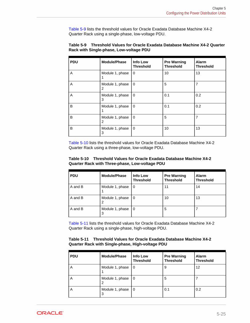
Table 5-9 lists the threshold values for Oracle Exadata Database Machine X4-2Quarter Rack using a single-phase, low-voltage PDU.
Table 5-9 Threshold Values for Oracle Exadata Database Machine X4-2 QuarterRack with Single-phase, Low-voltage PDU
PDU Module/Phase Info LowThreshold
Pre WarningThreshold
AlarmThreshold
A Module 1, phase1
0 10 13
A Module 1, phase2
0 5 7
A Module 1, phase3
0 0.1 0.2
B Module 1, phase1
0 0.1 0.2
B Module 1, phase2
0 5 7
B Module 1, phase3
0 10 13
Table 5-10 lists the threshold values for Oracle Exadata Database Machine X4-2Quarter Rack using a three-phase, low-voltage PDU.
Table 5-10 Threshold Values for Oracle Exadata Database Machine X4-2Quarter Rack with Three-phase, Low-voltage PDU
PDU Module/Phase Info LowThreshold
Pre WarningThreshold
AlarmThreshold
A and B Module 1, phase1
0 11 14
A and B Module 1, phase2
0 10 13
A and B Module 1, phase3
0 5 7
Table 5-11 lists the threshold values for Oracle Exadata Database Machine X4-2Quarter Rack using a single-phase, high-voltage PDU.
Table 5-11 Threshold Values for Oracle Exadata Database Machine X4-2Quarter Rack with Single-phase, High-voltage PDU
PDU Module/Phase Info LowThreshold
Pre WarningThreshold
AlarmThreshold
A Module 1, phase1
0 9 12
A Module 1, phase2
0 5 7
A Module 1, phase3
0 0.1 0.2
Chapter 5Configuring the Power Distribution Units
5-25
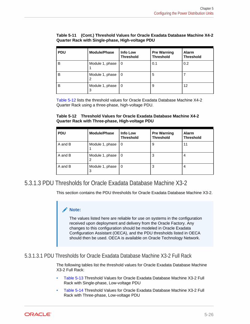
Table 5-11 (Cont.) Threshold Values for Oracle Exadata Database Machine X4-2Quarter Rack with Single-phase, High-voltage PDU
PDU Module/Phase Info LowThreshold
Pre WarningThreshold
AlarmThreshold
B Module 1, phase1
0 0.1 0.2
B Module 1, phase2
0 5 7
B Module 1, phase3
0 9 12
Table 5-12 lists the threshold values for Oracle Exadata Database Machine X4-2Quarter Rack using a three-phase, high-voltage PDU.
Table 5-12 Threshold Values for Oracle Exadata Database Machine X4-2Quarter Rack with Three-phase, High-voltage PDU
PDU Module/Phase Info LowThreshold
Pre WarningThreshold
AlarmThreshold
A and B Module 1, phase1
0 9 11
A and B Module 1, phase2
0 3 4
A and B Module 1, phase3
0 3 4
5.3.1.3 PDU Thresholds for Oracle Exadata Database Machine X3-2This section contains the PDU thresholds for Oracle Exadata Database Machine X3-2.
Note:
The values listed here are reliable for use on systems in the configurationreceived upon deployment and delivery from the Oracle Factory. Anychanges to this configuration should be modeled in Oracle ExadataConfiguration Assistant (OECA), and the PDU thresholds listed in OECAshould then be used. OECA is available on Oracle Technology Network.
5.3.1.3.1 PDU Thresholds for Oracle Exadata Database Machine X3-2 Full RackThe following tables list the threshold values for Oracle Exadata Database MachineX3-2 Full Rack:
• Table 5-13 Threshold Values for Oracle Exadata Database Machine X3-2 FullRack with Single-phase, Low-voltage PDU
• Table 5-14 Threshold Values for Oracle Exadata Database Machine X3-2 FullRack with Three-phase, Low-voltage PDU
Chapter 5Configuring the Power Distribution Units
5-26
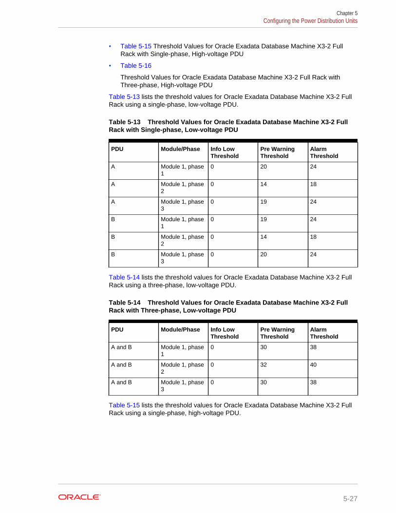
• Table 5-15 Threshold Values for Oracle Exadata Database Machine X3-2 FullRack with Single-phase, High-voltage PDU
• Table 5-16
Threshold Values for Oracle Exadata Database Machine X3-2 Full Rack withThree-phase, High-voltage PDU
Table 5-13 lists the threshold values for Oracle Exadata Database Machine X3-2 FullRack using a single-phase, low-voltage PDU.
Table 5-13 Threshold Values for Oracle Exadata Database Machine X3-2 FullRack with Single-phase, Low-voltage PDU
PDU Module/Phase Info LowThreshold
Pre WarningThreshold
AlarmThreshold
A Module 1, phase1
0 20 24
A Module 1, phase2
0 14 18
A Module 1, phase3
0 19 24
B Module 1, phase1
0 19 24
B Module 1, phase2
0 14 18
B Module 1, phase3
0 20 24
Table 5-14 lists the threshold values for Oracle Exadata Database Machine X3-2 FullRack using a three-phase, low-voltage PDU.
Table 5-14 Threshold Values for Oracle Exadata Database Machine X3-2 FullRack with Three-phase, Low-voltage PDU
PDU Module/Phase Info LowThreshold
Pre WarningThreshold
AlarmThreshold
A and B Module 1, phase1
0 30 38
A and B Module 1, phase2
0 32 40
A and B Module 1, phase3
0 30 38
Table 5-15 lists the threshold values for Oracle Exadata Database Machine X3-2 FullRack using a single-phase, high-voltage PDU.
Chapter 5Configuring the Power Distribution Units
5-27
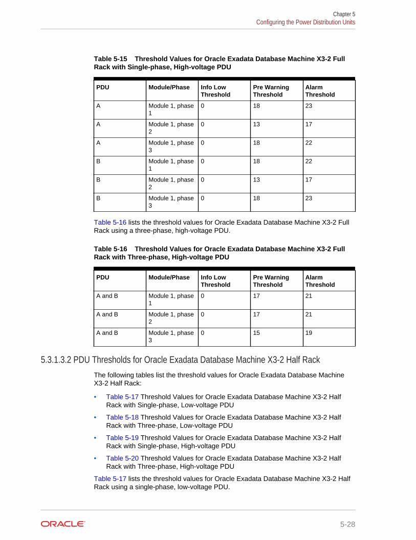
Table 5-15 Threshold Values for Oracle Exadata Database Machine X3-2 FullRack with Single-phase, High-voltage PDU
PDU Module/Phase Info LowThreshold
Pre WarningThreshold
AlarmThreshold
A Module 1, phase1
0 18 23
A Module 1, phase2
0 13 17
A Module 1, phase3
0 18 22
B Module 1, phase1
0 18 22
B Module 1, phase2
0 13 17
B Module 1, phase3
0 18 23
Table 5-16 lists the threshold values for Oracle Exadata Database Machine X3-2 FullRack using a three-phase, high-voltage PDU.
Table 5-16 Threshold Values for Oracle Exadata Database Machine X3-2 FullRack with Three-phase, High-voltage PDU
PDU Module/Phase Info LowThreshold
Pre WarningThreshold
AlarmThreshold
A and B Module 1, phase1
0 17 21
A and B Module 1, phase2
0 17 21
A and B Module 1, phase3
0 15 19
5.3.1.3.2 PDU Thresholds for Oracle Exadata Database Machine X3-2 Half RackThe following tables list the threshold values for Oracle Exadata Database MachineX3-2 Half Rack:
• Table 5-17 Threshold Values for Oracle Exadata Database Machine X3-2 HalfRack with Single-phase, Low-voltage PDU
• Table 5-18 Threshold Values for Oracle Exadata Database Machine X3-2 HalfRack with Three-phase, Low-voltage PDU
• Table 5-19 Threshold Values for Oracle Exadata Database Machine X3-2 HalfRack with Single-phase, High-voltage PDU
• Table 5-20 Threshold Values for Oracle Exadata Database Machine X3-2 HalfRack with Three-phase, High-voltage PDU
Table 5-17 lists the threshold values for Oracle Exadata Database Machine X3-2 HalfRack using a single-phase, low-voltage PDU.
Chapter 5Configuring the Power Distribution Units
5-28
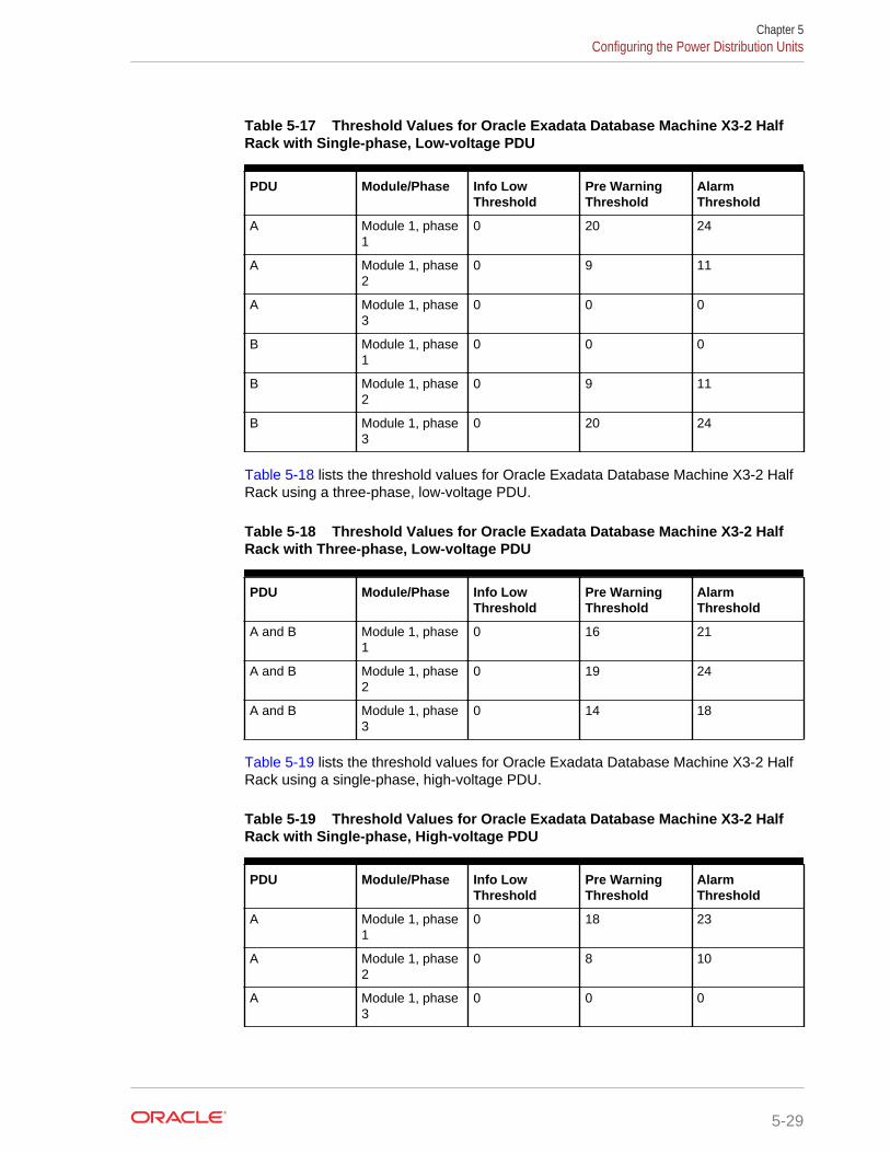
Table 5-17 Threshold Values for Oracle Exadata Database Machine X3-2 HalfRack with Single-phase, Low-voltage PDU
PDU Module/Phase Info LowThreshold
Pre WarningThreshold
AlarmThreshold
A Module 1, phase1
0 20 24
A Module 1, phase2
0 9 11
A Module 1, phase3
0 0 0
B Module 1, phase1
0 0 0
B Module 1, phase2
0 9 11
B Module 1, phase3
0 20 24
Table 5-18 lists the threshold values for Oracle Exadata Database Machine X3-2 HalfRack using a three-phase, low-voltage PDU.
Table 5-18 Threshold Values for Oracle Exadata Database Machine X3-2 HalfRack with Three-phase, Low-voltage PDU
PDU Module/Phase Info LowThreshold
Pre WarningThreshold
AlarmThreshold
A and B Module 1, phase1
0 16 21
A and B Module 1, phase2
0 19 24
A and B Module 1, phase3
0 14 18
Table 5-19 lists the threshold values for Oracle Exadata Database Machine X3-2 HalfRack using a single-phase, high-voltage PDU.
Table 5-19 Threshold Values for Oracle Exadata Database Machine X3-2 HalfRack with Single-phase, High-voltage PDU
PDU Module/Phase Info LowThreshold
Pre WarningThreshold
AlarmThreshold
A Module 1, phase1
0 18 23
A Module 1, phase2
0 8 10
A Module 1, phase3
0 0 0
Chapter 5Configuring the Power Distribution Units
5-29
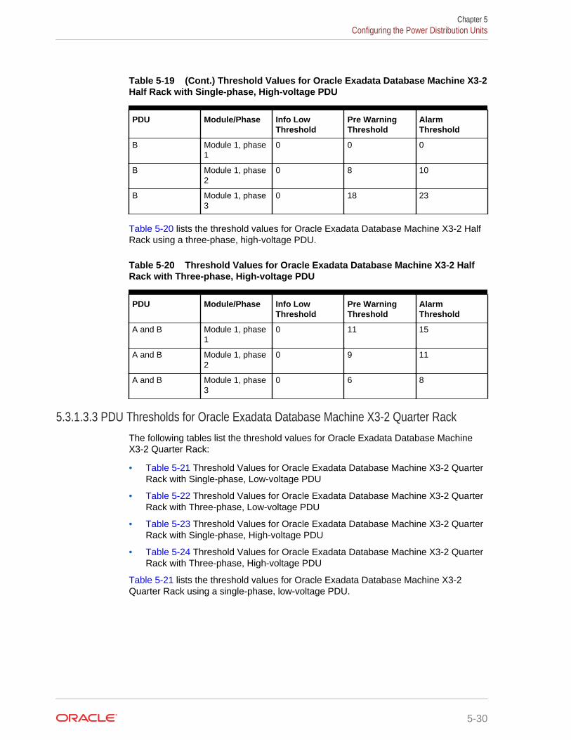
Table 5-19 (Cont.) Threshold Values for Oracle Exadata Database Machine X3-2Half Rack with Single-phase, High-voltage PDU
PDU Module/Phase Info LowThreshold
Pre WarningThreshold
AlarmThreshold
B Module 1, phase1
0 0 0
B Module 1, phase2
0 8 10
B Module 1, phase3
0 18 23
Table 5-20 lists the threshold values for Oracle Exadata Database Machine X3-2 HalfRack using a three-phase, high-voltage PDU.
Table 5-20 Threshold Values for Oracle Exadata Database Machine X3-2 HalfRack with Three-phase, High-voltage PDU
PDU Module/Phase Info LowThreshold
Pre WarningThreshold
AlarmThreshold
A and B Module 1, phase1
0 11 15
A and B Module 1, phase2
0 9 11
A and B Module 1, phase3
0 6 8
5.3.1.3.3 PDU Thresholds for Oracle Exadata Database Machine X3-2 Quarter RackThe following tables list the threshold values for Oracle Exadata Database MachineX3-2 Quarter Rack:
• Table 5-21 Threshold Values for Oracle Exadata Database Machine X3-2 QuarterRack with Single-phase, Low-voltage PDU
• Table 5-22 Threshold Values for Oracle Exadata Database Machine X3-2 QuarterRack with Three-phase, Low-voltage PDU
• Table 5-23 Threshold Values for Oracle Exadata Database Machine X3-2 QuarterRack with Single-phase, High-voltage PDU
• Table 5-24 Threshold Values for Oracle Exadata Database Machine X3-2 QuarterRack with Three-phase, High-voltage PDU
Table 5-21 lists the threshold values for Oracle Exadata Database Machine X3-2Quarter Rack using a single-phase, low-voltage PDU.
Chapter 5Configuring the Power Distribution Units
5-30
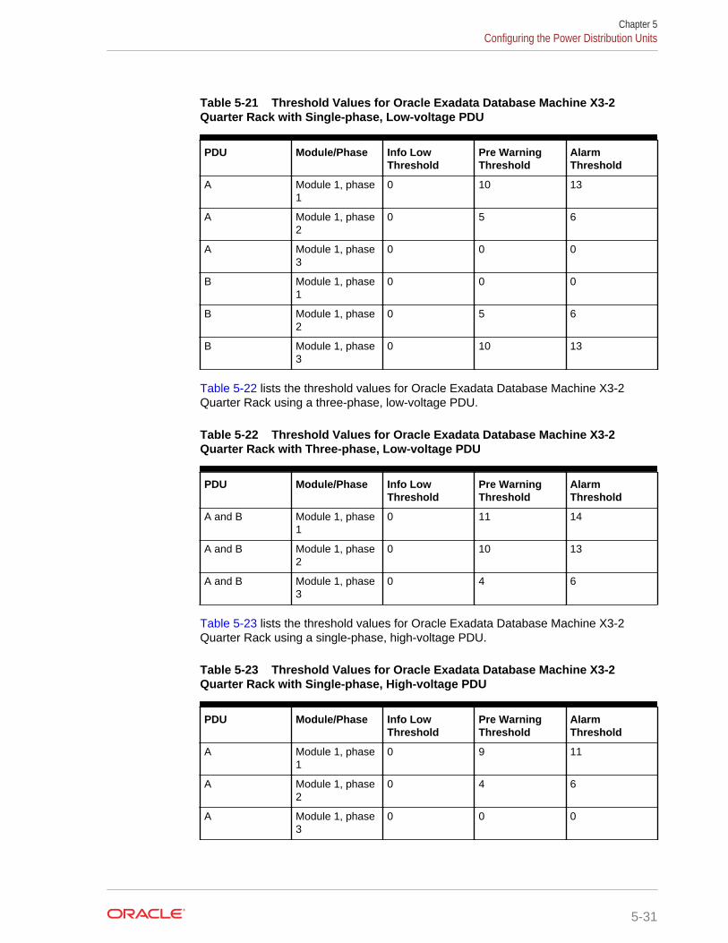
Table 5-21 Threshold Values for Oracle Exadata Database Machine X3-2Quarter Rack with Single-phase, Low-voltage PDU
PDU Module/Phase Info LowThreshold
Pre WarningThreshold
AlarmThreshold
A Module 1, phase1
0 10 13
A Module 1, phase2
0 5 6
A Module 1, phase3
0 0 0
B Module 1, phase1
0 0 0
B Module 1, phase2
0 5 6
B Module 1, phase3
0 10 13
Table 5-22 lists the threshold values for Oracle Exadata Database Machine X3-2Quarter Rack using a three-phase, low-voltage PDU.
Table 5-22 Threshold Values for Oracle Exadata Database Machine X3-2Quarter Rack with Three-phase, Low-voltage PDU
PDU Module/Phase Info LowThreshold
Pre WarningThreshold
AlarmThreshold
A and B Module 1, phase1
0 11 14
A and B Module 1, phase2
0 10 13
A and B Module 1, phase3
0 4 6
Table 5-23 lists the threshold values for Oracle Exadata Database Machine X3-2Quarter Rack using a single-phase, high-voltage PDU.
Table 5-23 Threshold Values for Oracle Exadata Database Machine X3-2Quarter Rack with Single-phase, High-voltage PDU
PDU Module/Phase Info LowThreshold
Pre WarningThreshold
AlarmThreshold
A Module 1, phase1
0 9 11
A Module 1, phase2
0 4 6
A Module 1, phase3
0 0 0
Chapter 5Configuring the Power Distribution Units
5-31
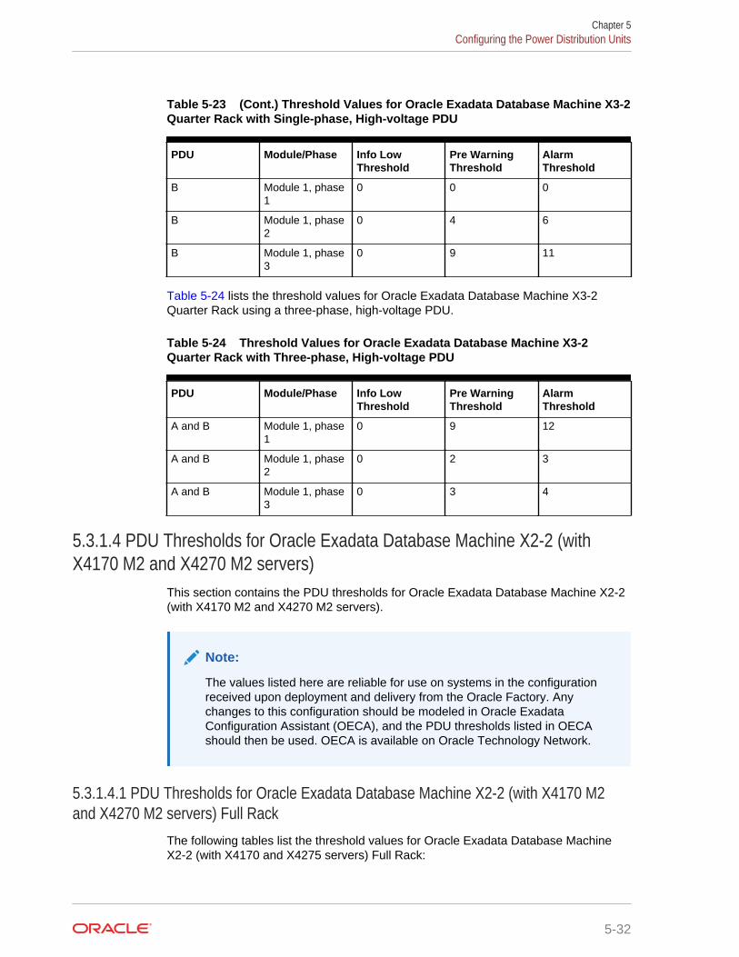
Table 5-23 (Cont.) Threshold Values for Oracle Exadata Database Machine X3-2Quarter Rack with Single-phase, High-voltage PDU
PDU Module/Phase Info LowThreshold
Pre WarningThreshold
AlarmThreshold
B Module 1, phase1
0 0 0
B Module 1, phase2
0 4 6
B Module 1, phase3
0 9 11
Table 5-24 lists the threshold values for Oracle Exadata Database Machine X3-2Quarter Rack using a three-phase, high-voltage PDU.
Table 5-24 Threshold Values for Oracle Exadata Database Machine X3-2Quarter Rack with Three-phase, High-voltage PDU
PDU Module/Phase Info LowThreshold
Pre WarningThreshold
AlarmThreshold
A and B Module 1, phase1
0 9 12
A and B Module 1, phase2
0 2 3
A and B Module 1, phase3
0 3 4
5.3.1.4 PDU Thresholds for Oracle Exadata Database Machine X2-2 (withX4170 M2 and X4270 M2 servers)
This section contains the PDU thresholds for Oracle Exadata Database Machine X2-2(with X4170 M2 and X4270 M2 servers).
Note:
The values listed here are reliable for use on systems in the configurationreceived upon deployment and delivery from the Oracle Factory. Anychanges to this configuration should be modeled in Oracle ExadataConfiguration Assistant (OECA), and the PDU thresholds listed in OECAshould then be used. OECA is available on Oracle Technology Network.
5.3.1.4.1 PDU Thresholds for Oracle Exadata Database Machine X2-2 (with X4170 M2and X4270 M2 servers) Full Rack
The following tables list the threshold values for Oracle Exadata Database MachineX2-2 (with X4170 and X4275 servers) Full Rack:
Chapter 5Configuring the Power Distribution Units
5-32
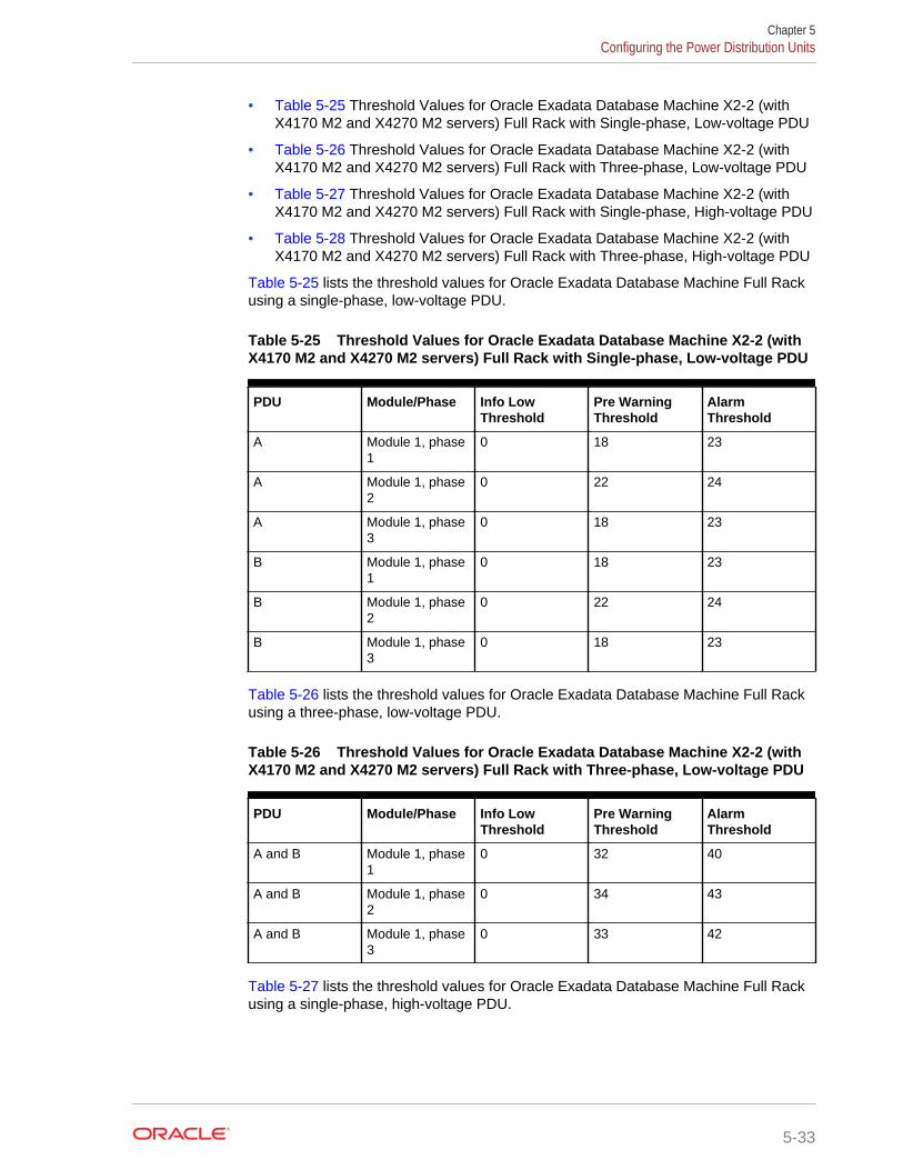
• Table 5-25 Threshold Values for Oracle Exadata Database Machine X2-2 (withX4170 M2 and X4270 M2 servers) Full Rack with Single-phase, Low-voltage PDU
• Table 5-26 Threshold Values for Oracle Exadata Database Machine X2-2 (withX4170 M2 and X4270 M2 servers) Full Rack with Three-phase, Low-voltage PDU
• Table 5-27 Threshold Values for Oracle Exadata Database Machine X2-2 (withX4170 M2 and X4270 M2 servers) Full Rack with Single-phase, High-voltage PDU
• Table 5-28 Threshold Values for Oracle Exadata Database Machine X2-2 (withX4170 M2 and X4270 M2 servers) Full Rack with Three-phase, High-voltage PDU
Table 5-25 lists the threshold values for Oracle Exadata Database Machine Full Rackusing a single-phase, low-voltage PDU.
Table 5-25 Threshold Values for Oracle Exadata Database Machine X2-2 (withX4170 M2 and X4270 M2 servers) Full Rack with Single-phase, Low-voltage PDU
PDU Module/Phase Info LowThreshold
Pre WarningThreshold
AlarmThreshold
A Module 1, phase1
0 18 23
A Module 1, phase2
0 22 24
A Module 1, phase3
0 18 23
B Module 1, phase1
0 18 23
B Module 1, phase2
0 22 24
B Module 1, phase3
0 18 23
Table 5-26 lists the threshold values for Oracle Exadata Database Machine Full Rackusing a three-phase, low-voltage PDU.
Table 5-26 Threshold Values for Oracle Exadata Database Machine X2-2 (withX4170 M2 and X4270 M2 servers) Full Rack with Three-phase, Low-voltage PDU
PDU Module/Phase Info LowThreshold
Pre WarningThreshold
AlarmThreshold
A and B Module 1, phase1
0 32 40
A and B Module 1, phase2
0 34 43
A and B Module 1, phase3
0 33 42
Table 5-27 lists the threshold values for Oracle Exadata Database Machine Full Rackusing a single-phase, high-voltage PDU.
Chapter 5Configuring the Power Distribution Units
5-33
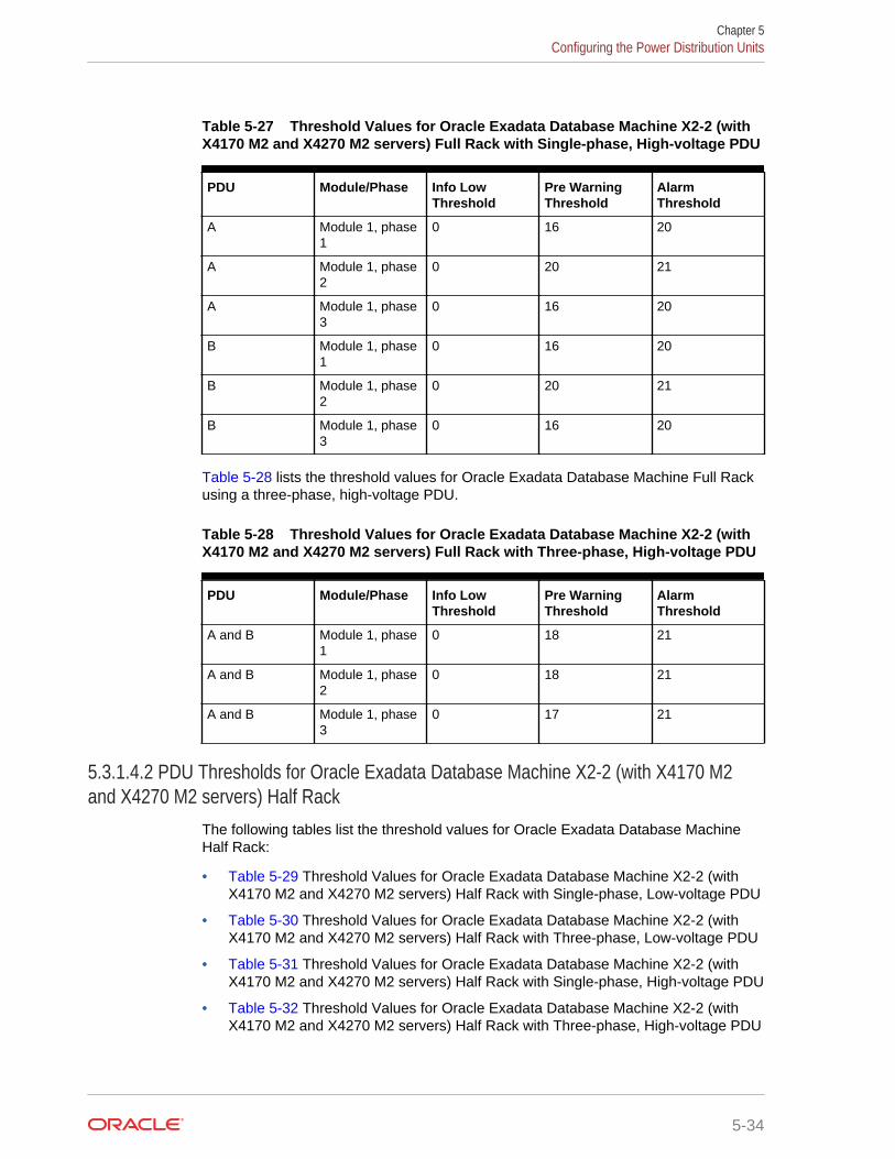
Table 5-27 Threshold Values for Oracle Exadata Database Machine X2-2 (withX4170 M2 and X4270 M2 servers) Full Rack with Single-phase, High-voltage PDU
PDU Module/Phase Info LowThreshold
Pre WarningThreshold
AlarmThreshold
A Module 1, phase1
0 16 20
A Module 1, phase2
0 20 21
A Module 1, phase3
0 16 20
B Module 1, phase1
0 16 20
B Module 1, phase2
0 20 21
B Module 1, phase3
0 16 20
Table 5-28 lists the threshold values for Oracle Exadata Database Machine Full Rackusing a three-phase, high-voltage PDU.
Table 5-28 Threshold Values for Oracle Exadata Database Machine X2-2 (withX4170 M2 and X4270 M2 servers) Full Rack with Three-phase, High-voltage PDU
PDU Module/Phase Info LowThreshold
Pre WarningThreshold
AlarmThreshold
A and B Module 1, phase1
0 18 21
A and B Module 1, phase2
0 18 21
A and B Module 1, phase3
0 17 21
5.3.1.4.2 PDU Thresholds for Oracle Exadata Database Machine X2-2 (with X4170 M2and X4270 M2 servers) Half Rack
The following tables list the threshold values for Oracle Exadata Database MachineHalf Rack:
• Table 5-29 Threshold Values for Oracle Exadata Database Machine X2-2 (withX4170 M2 and X4270 M2 servers) Half Rack with Single-phase, Low-voltage PDU
• Table 5-30 Threshold Values for Oracle Exadata Database Machine X2-2 (withX4170 M2 and X4270 M2 servers) Half Rack with Three-phase, Low-voltage PDU
• Table 5-31 Threshold Values for Oracle Exadata Database Machine X2-2 (withX4170 M2 and X4270 M2 servers) Half Rack with Single-phase, High-voltage PDU
• Table 5-32 Threshold Values for Oracle Exadata Database Machine X2-2 (withX4170 M2 and X4270 M2 servers) Half Rack with Three-phase, High-voltage PDU
Chapter 5Configuring the Power Distribution Units
5-34
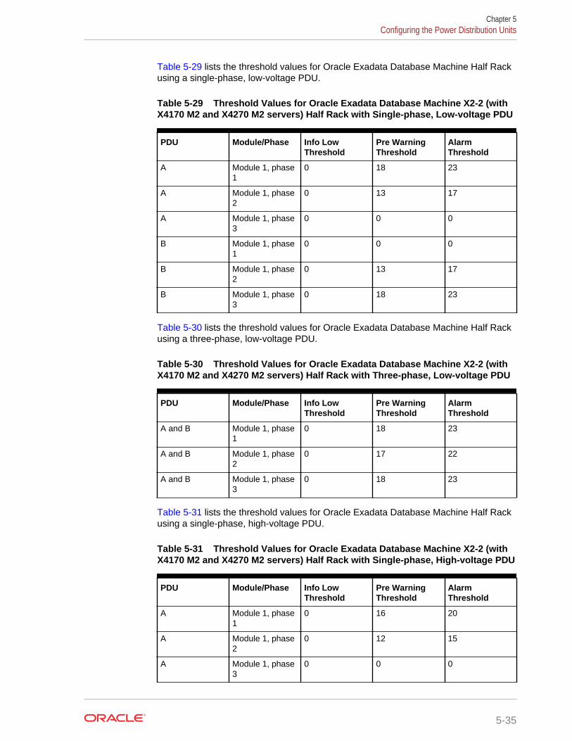
Table 5-29 lists the threshold values for Oracle Exadata Database Machine Half Rackusing a single-phase, low-voltage PDU.
Table 5-29 Threshold Values for Oracle Exadata Database Machine X2-2 (withX4170 M2 and X4270 M2 servers) Half Rack with Single-phase, Low-voltage PDU
PDU Module/Phase Info LowThreshold
Pre WarningThreshold
AlarmThreshold
A Module 1, phase1
0 18 23
A Module 1, phase2
0 13 17
A Module 1, phase3
0 0 0
B Module 1, phase1
0 0 0
B Module 1, phase2
0 13 17
B Module 1, phase3
0 18 23
Table 5-30 lists the threshold values for Oracle Exadata Database Machine Half Rackusing a three-phase, low-voltage PDU.
Table 5-30 Threshold Values for Oracle Exadata Database Machine X2-2 (withX4170 M2 and X4270 M2 servers) Half Rack with Three-phase, Low-voltage PDU
PDU Module/Phase Info LowThreshold
Pre WarningThreshold
AlarmThreshold
A and B Module 1, phase1
0 18 23
A and B Module 1, phase2
0 17 22
A and B Module 1, phase3
0 18 23
Table 5-31 lists the threshold values for Oracle Exadata Database Machine Half Rackusing a single-phase, high-voltage PDU.
Table 5-31 Threshold Values for Oracle Exadata Database Machine X2-2 (withX4170 M2 and X4270 M2 servers) Half Rack with Single-phase, High-voltage PDU
PDU Module/Phase Info LowThreshold
Pre WarningThreshold
AlarmThreshold
A Module 1, phase1
0 16 20
A Module 1, phase2
0 12 15
A Module 1, phase3
0 0 0
Chapter 5Configuring the Power Distribution Units
5-35
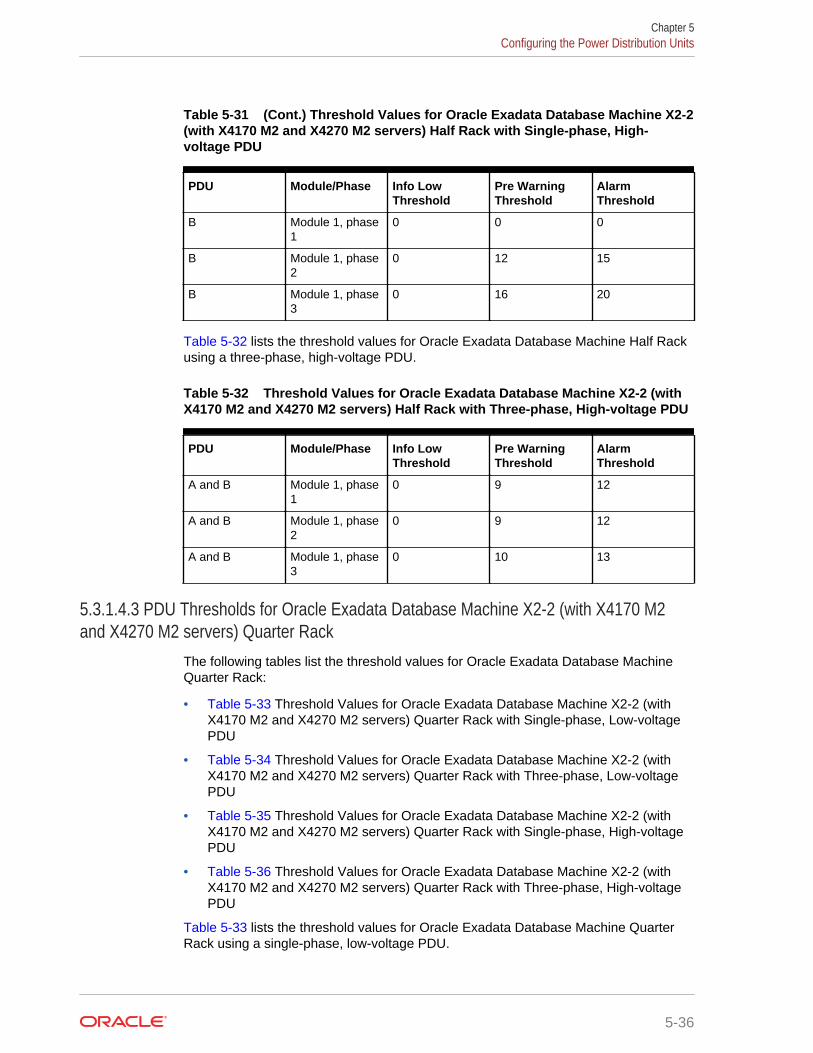
Table 5-31 (Cont.) Threshold Values for Oracle Exadata Database Machine X2-2(with X4170 M2 and X4270 M2 servers) Half Rack with Single-phase, High-voltage PDU
PDU Module/Phase Info LowThreshold
Pre WarningThreshold
AlarmThreshold
B Module 1, phase1
0 0 0
B Module 1, phase2
0 12 15
B Module 1, phase3
0 16 20
Table 5-32 lists the threshold values for Oracle Exadata Database Machine Half Rackusing a three-phase, high-voltage PDU.
Table 5-32 Threshold Values for Oracle Exadata Database Machine X2-2 (withX4170 M2 and X4270 M2 servers) Half Rack with Three-phase, High-voltage PDU
PDU Module/Phase Info LowThreshold
Pre WarningThreshold
AlarmThreshold
A and B Module 1, phase1
0 9 12
A and B Module 1, phase2
0 9 12
A and B Module 1, phase3
0 10 13
5.3.1.4.3 PDU Thresholds for Oracle Exadata Database Machine X2-2 (with X4170 M2and X4270 M2 servers) Quarter Rack
The following tables list the threshold values for Oracle Exadata Database MachineQuarter Rack:
• Table 5-33 Threshold Values for Oracle Exadata Database Machine X2-2 (withX4170 M2 and X4270 M2 servers) Quarter Rack with Single-phase, Low-voltagePDU
• Table 5-34 Threshold Values for Oracle Exadata Database Machine X2-2 (withX4170 M2 and X4270 M2 servers) Quarter Rack with Three-phase, Low-voltagePDU
• Table 5-35 Threshold Values for Oracle Exadata Database Machine X2-2 (withX4170 M2 and X4270 M2 servers) Quarter Rack with Single-phase, High-voltagePDU
• Table 5-36 Threshold Values for Oracle Exadata Database Machine X2-2 (withX4170 M2 and X4270 M2 servers) Quarter Rack with Three-phase, High-voltagePDU
Table 5-33 lists the threshold values for Oracle Exadata Database Machine QuarterRack using a single-phase, low-voltage PDU.
Chapter 5Configuring the Power Distribution Units
5-36
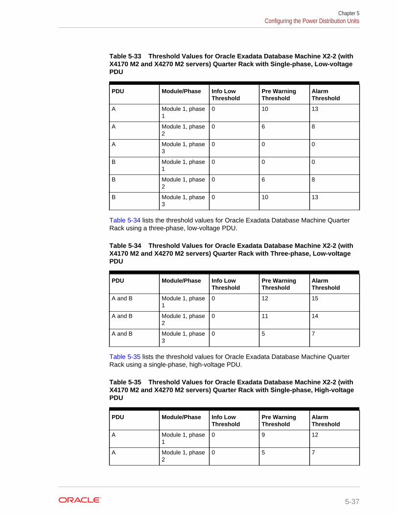
Table 5-33 Threshold Values for Oracle Exadata Database Machine X2-2 (withX4170 M2 and X4270 M2 servers) Quarter Rack with Single-phase, Low-voltagePDU
PDU Module/Phase Info LowThreshold
Pre WarningThreshold
AlarmThreshold
A Module 1, phase1
0 10 13
A Module 1, phase2
0 6 8
A Module 1, phase3
0 0 0
B Module 1, phase1
0 0 0
B Module 1, phase2
0 6 8
B Module 1, phase3
0 10 13
Table 5-34 lists the threshold values for Oracle Exadata Database Machine QuarterRack using a three-phase, low-voltage PDU.
Table 5-34 Threshold Values for Oracle Exadata Database Machine X2-2 (withX4170 M2 and X4270 M2 servers) Quarter Rack with Three-phase, Low-voltagePDU
PDU Module/Phase Info LowThreshold
Pre WarningThreshold
AlarmThreshold
A and B Module 1, phase1
0 12 15
A and B Module 1, phase2
0 11 14
A and B Module 1, phase3
0 5 7
Table 5-35 lists the threshold values for Oracle Exadata Database Machine QuarterRack using a single-phase, high-voltage PDU.
Table 5-35 Threshold Values for Oracle Exadata Database Machine X2-2 (withX4170 M2 and X4270 M2 servers) Quarter Rack with Single-phase, High-voltagePDU
PDU Module/Phase Info LowThreshold
Pre WarningThreshold
AlarmThreshold
A Module 1, phase1
0 9 12
A Module 1, phase2
0 5 7
Chapter 5Configuring the Power Distribution Units
5-37
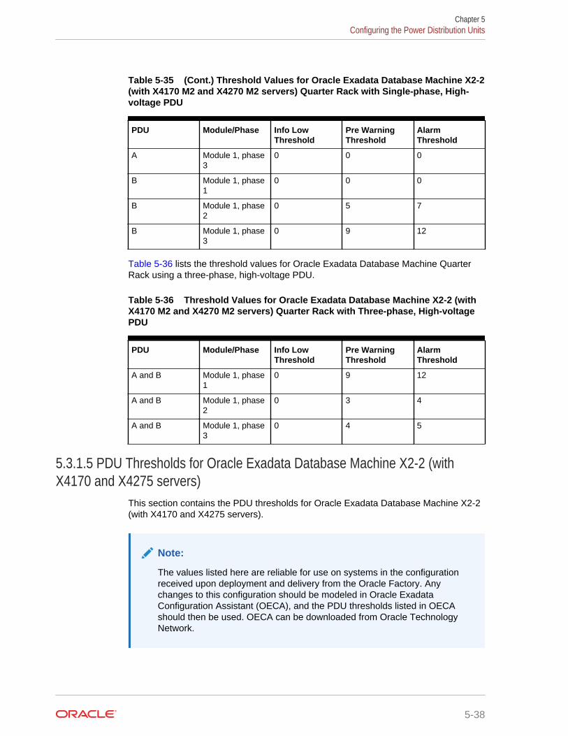
Table 5-35 (Cont.) Threshold Values for Oracle Exadata Database Machine X2-2(with X4170 M2 and X4270 M2 servers) Quarter Rack with Single-phase, High-voltage PDU
PDU Module/Phase Info LowThreshold
Pre WarningThreshold
AlarmThreshold
A Module 1, phase3
0 0 0
B Module 1, phase1
0 0 0
B Module 1, phase2
0 5 7
B Module 1, phase3
0 9 12
Table 5-36 lists the threshold values for Oracle Exadata Database Machine QuarterRack using a three-phase, high-voltage PDU.
Table 5-36 Threshold Values for Oracle Exadata Database Machine X2-2 (withX4170 M2 and X4270 M2 servers) Quarter Rack with Three-phase, High-voltagePDU
PDU Module/Phase Info LowThreshold
Pre WarningThreshold
AlarmThreshold
A and B Module 1, phase1
0 9 12
A and B Module 1, phase2
0 3 4
A and B Module 1, phase3
0 4 5
5.3.1.5 PDU Thresholds for Oracle Exadata Database Machine X2-2 (withX4170 and X4275 servers)
This section contains the PDU thresholds for Oracle Exadata Database Machine X2-2(with X4170 and X4275 servers).
Note:
The values listed here are reliable for use on systems in the configurationreceived upon deployment and delivery from the Oracle Factory. Anychanges to this configuration should be modeled in Oracle ExadataConfiguration Assistant (OECA), and the PDU thresholds listed in OECAshould then be used. OECA can be downloaded from Oracle TechnologyNetwork.
Chapter 5Configuring the Power Distribution Units
5-38
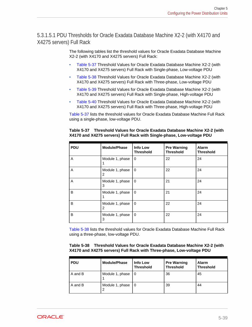
5.3.1.5.1 PDU Thresholds for Oracle Exadata Database Machine X2-2 (with X4170 andX4275 servers) Full Rack
The following tables list the threshold values for Oracle Exadata Database MachineX2-2 (with X4170 and X4275 servers) Full Rack:
• Table 5-37 Threshold Values for Oracle Exadata Database Machine X2-2 (withX4170 and X4275 servers) Full Rack with Single-phase, Low-voltage PDU
• Table 5-38 Threshold Values for Oracle Exadata Database Machine X2-2 (withX4170 and X4275 servers) Full Rack with Three-phase, Low-voltage PDU
• Table 5-39 Threshold Values for Oracle Exadata Database Machine X2-2 (withX4170 and X4275 servers) Full Rack with Single-phase, High-voltage PDU
• Table 5-40 Threshold Values for Oracle Exadata Database Machine X2-2 (withX4170 and X4275 servers) Full Rack with Three-phase, High-voltage PDU
Table 5-37 lists the threshold values for Oracle Exadata Database Machine Full Rackusing a single-phase, low-voltage PDU.
Table 5-37 Threshold Values for Oracle Exadata Database Machine X2-2 (withX4170 and X4275 servers) Full Rack with Single-phase, Low-voltage PDU
PDU Module/Phase Info LowThreshold
Pre WarningThreshold
AlarmThreshold
A Module 1, phase1
0 22 24
A Module 1, phase2
0 22 24
A Module 1, phase3
0 21 24
B Module 1, phase1
0 21 24
B Module 1, phase2
0 22 24
B Module 1, phase3
0 22 24
Table 5-38 lists the threshold values for Oracle Exadata Database Machine Full Rackusing a three-phase, low-voltage PDU.
Table 5-38 Threshold Values for Oracle Exadata Database Machine X2-2 (withX4170 and X4275 servers) Full Rack with Three-phase, Low-voltage PDU
PDU Module/Phase Info LowThreshold
Pre WarningThreshold
AlarmThreshold
A and B Module 1, phase1
0 36 45
A and B Module 1, phase2
0 39 44
Chapter 5Configuring the Power Distribution Units
5-39
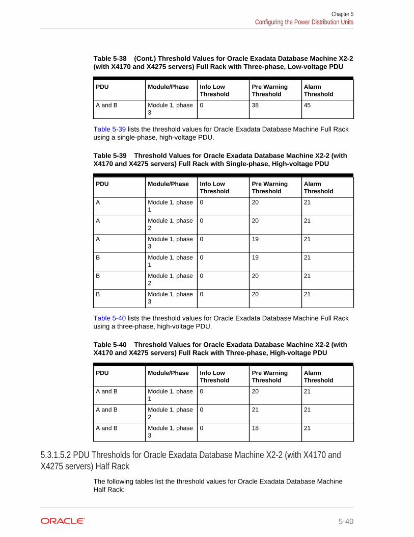
Table 5-38 (Cont.) Threshold Values for Oracle Exadata Database Machine X2-2(with X4170 and X4275 servers) Full Rack with Three-phase, Low-voltage PDU
PDU Module/Phase Info LowThreshold
Pre WarningThreshold
AlarmThreshold
A and B Module 1, phase3
0 38 45
Table 5-39 lists the threshold values for Oracle Exadata Database Machine Full Rackusing a single-phase, high-voltage PDU.
Table 5-39 Threshold Values for Oracle Exadata Database Machine X2-2 (withX4170 and X4275 servers) Full Rack with Single-phase, High-voltage PDU
PDU Module/Phase Info LowThreshold
Pre WarningThreshold
AlarmThreshold
A Module 1, phase1
0 20 21
A Module 1, phase2
0 20 21
A Module 1, phase3
0 19 21
B Module 1, phase1
0 19 21
B Module 1, phase2
0 20 21
B Module 1, phase3
0 20 21
Table 5-40 lists the threshold values for Oracle Exadata Database Machine Full Rackusing a three-phase, high-voltage PDU.
Table 5-40 Threshold Values for Oracle Exadata Database Machine X2-2 (withX4170 and X4275 servers) Full Rack with Three-phase, High-voltage PDU
PDU Module/Phase Info LowThreshold
Pre WarningThreshold
AlarmThreshold
A and B Module 1, phase1
0 20 21
A and B Module 1, phase2
0 21 21
A and B Module 1, phase3
0 18 21
5.3.1.5.2 PDU Thresholds for Oracle Exadata Database Machine X2-2 (with X4170 andX4275 servers) Half Rack
The following tables list the threshold values for Oracle Exadata Database MachineHalf Rack:
Chapter 5Configuring the Power Distribution Units
5-40
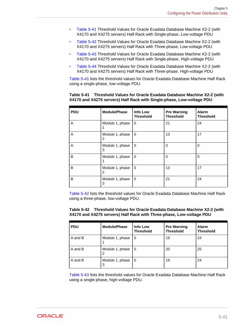
• Table 5-41 Threshold Values for Oracle Exadata Database Machine X2-2 (withX4170 and X4275 servers) Half Rack with Single-phase, Low-voltage PDU
• Table 5-42 Threshold Values for Oracle Exadata Database Machine X2-2 (withX4170 and X4275 servers) Half Rack with Three-phase, Low-voltage PDU
• Table 5-43 Threshold Values for Oracle Exadata Database Machine X2-2 (withX4170 and X4275 servers) Half Rack with Single-phase, High-voltage PDU
• Table 5-44 Threshold Values for Oracle Exadata Database Machine X2-2 (withX4170 and X4275 servers) Half Rack with Three-phase, High-voltage PDU
Table 5-41 lists the threshold values for Oracle Exadata Database Machine Half Rackusing a single-phase, low-voltage PDU.
Table 5-41 Threshold Values for Oracle Exadata Database Machine X2-2 (withX4170 and X4275 servers) Half Rack with Single-phase, Low-voltage PDU
PDU Module/Phase Info LowThreshold
Pre WarningThreshold
AlarmThreshold
A Module 1, phase1
0 21 24
A Module 1, phase2
0 13 17
A Module 1, phase3
0 0 0
B Module 1, phase1
0 0 0
B Module 1, phase2
0 13 17
B Module 1, phase3
0 21 24
Table 5-42 lists the threshold values for Oracle Exadata Database Machine Half Rackusing a three-phase, low-voltage PDU.
Table 5-42 Threshold Values for Oracle Exadata Database Machine X2-2 (withX4170 and X4275 servers) Half Rack with Three-phase, Low-voltage PDU
PDU Module/Phase Info LowThreshold
Pre WarningThreshold
AlarmThreshold
A and B Module 1, phase1
0 19 24
A and B Module 1, phase2
0 20 25
A and B Module 1, phase3
0 19 24
Table 5-43 lists the threshold values for Oracle Exadata Database Machine Half Rackusing a single-phase, high-voltage PDU.
Chapter 5Configuring the Power Distribution Units
5-41

Table 5-43 Threshold Values for Oracle Exadata Database Machine X2-2 (withX4170 and X4275 servers) Half Rack with Single-phase, High-voltage PDU
PDU Module/Phase Info LowThreshold
Pre WarningThreshold
AlarmThreshold
A Module 1, phase1
0 19 21
A Module 1, phase2
0 12 15
A Module 1, phase3
0 0 0
B Module 1, phase1
0 0 0
B Module 1, phase2
0 12 15
B Module 1, phase3
0 19 21
Table 5-44 lists the threshold values for Oracle Exadata Database Machine Half Rackusing a three-phase, high-voltage PDU.
Table 5-44 Threshold Values for Oracle Exadata Database Machine X2-2 (withX4170 and X4275 servers) Half Rack with Three-phase, High-voltage PDU
PDU Module/Phase Info LowThreshold
Pre WarningThreshold
AlarmThreshold
A and B Module 1, phase1
0 11 14
A and B Module 1, phase2
0 11 14
A and B Module 1, phase3
0 10 13
5.3.1.5.3 PDU Thresholds for Oracle Exadata Database Machine X2-2 (with X4170 andX4275 servers) Quarter Rack
The following tables list the threshold values for Oracle Exadata Database MachineQuarter Rack:
• Table 5-45
Threshold Values for Oracle Exadata Database Machine X2-2 (with X4170 andX4275 servers) Quarter Rack with Single-phase, Low-voltage PDU
• Table 5-46
Threshold Values for Oracle Exadata Database Machine X2-2 (with X4170 andX4275 servers) Quarter Rack with Three-phase, Low-voltage PDU
• Table 5-47
Threshold Values for Oracle Exadata Database Machine X2-2 (with X4170 andX4275 servers) Quarter Rack with Single-phase, High-voltage PDU
Chapter 5Configuring the Power Distribution Units
5-42
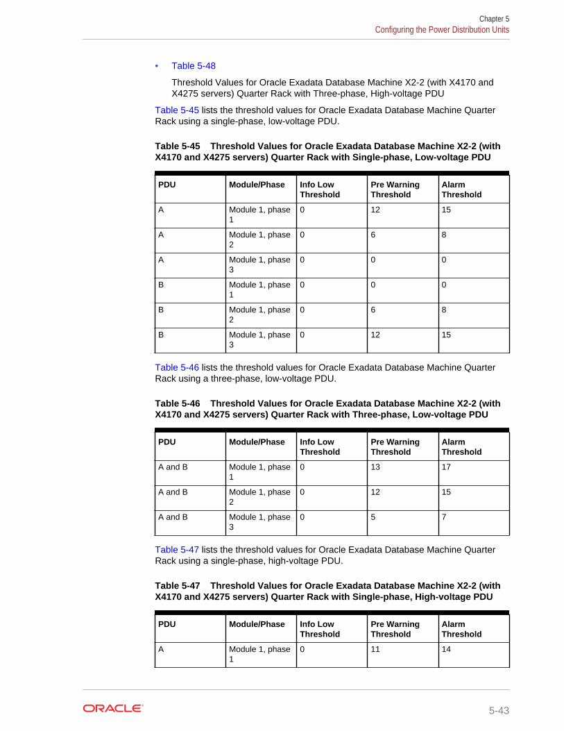
• Table 5-48
Threshold Values for Oracle Exadata Database Machine X2-2 (with X4170 andX4275 servers) Quarter Rack with Three-phase, High-voltage PDU
Table 5-45 lists the threshold values for Oracle Exadata Database Machine QuarterRack using a single-phase, low-voltage PDU.
Table 5-45 Threshold Values for Oracle Exadata Database Machine X2-2 (withX4170 and X4275 servers) Quarter Rack with Single-phase, Low-voltage PDU
PDU Module/Phase Info LowThreshold
Pre WarningThreshold
AlarmThreshold
A Module 1, phase1
0 12 15
A Module 1, phase2
0 6 8
A Module 1, phase3
0 0 0
B Module 1, phase1
0 0 0
B Module 1, phase2
0 6 8
B Module 1, phase3
0 12 15
Table 5-46 lists the threshold values for Oracle Exadata Database Machine QuarterRack using a three-phase, low-voltage PDU.
Table 5-46 Threshold Values for Oracle Exadata Database Machine X2-2 (withX4170 and X4275 servers) Quarter Rack with Three-phase, Low-voltage PDU
PDU Module/Phase Info LowThreshold
Pre WarningThreshold
AlarmThreshold
A and B Module 1, phase1
0 13 17
A and B Module 1, phase2
0 12 15
A and B Module 1, phase3
0 5 7
Table 5-47 lists the threshold values for Oracle Exadata Database Machine QuarterRack using a single-phase, high-voltage PDU.
Table 5-47 Threshold Values for Oracle Exadata Database Machine X2-2 (withX4170 and X4275 servers) Quarter Rack with Single-phase, High-voltage PDU
PDU Module/Phase Info LowThreshold
Pre WarningThreshold
AlarmThreshold
A Module 1, phase1
0 11 14
Chapter 5Configuring the Power Distribution Units
5-43
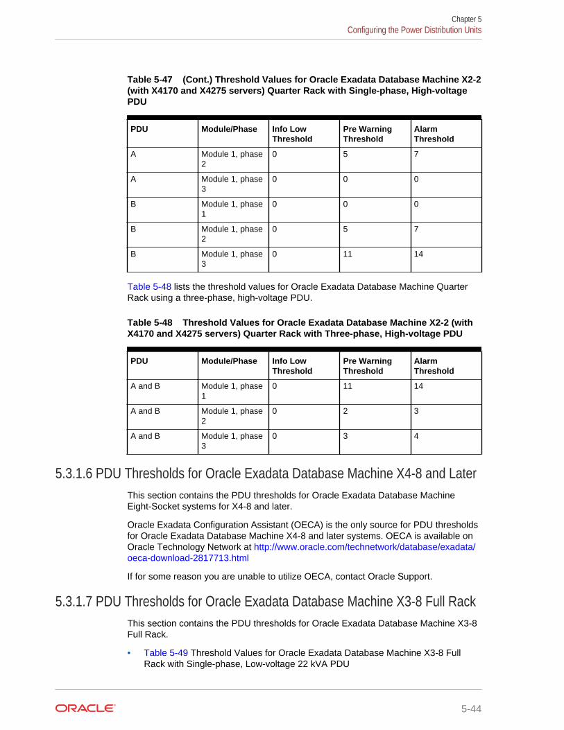
Table 5-47 (Cont.) Threshold Values for Oracle Exadata Database Machine X2-2(with X4170 and X4275 servers) Quarter Rack with Single-phase, High-voltagePDU
PDU Module/Phase Info LowThreshold
Pre WarningThreshold
AlarmThreshold
A Module 1, phase2
0 5 7
A Module 1, phase3
0 0 0
B Module 1, phase1
0 0 0
B Module 1, phase2
0 5 7
B Module 1, phase3
0 11 14
Table 5-48 lists the threshold values for Oracle Exadata Database Machine QuarterRack using a three-phase, high-voltage PDU.
Table 5-48 Threshold Values for Oracle Exadata Database Machine X2-2 (withX4170 and X4275 servers) Quarter Rack with Three-phase, High-voltage PDU
PDU Module/Phase Info LowThreshold
Pre WarningThreshold
AlarmThreshold
A and B Module 1, phase1
0 11 14
A and B Module 1, phase2
0 2 3
A and B Module 1, phase3
0 3 4
5.3.1.6 PDU Thresholds for Oracle Exadata Database Machine X4-8 and LaterThis section contains the PDU thresholds for Oracle Exadata Database MachineEight-Socket systems for X4-8 and later.
Oracle Exadata Configuration Assistant (OECA) is the only source for PDU thresholdsfor Oracle Exadata Database Machine X4-8 and later systems. OECA is available onOracle Technology Network at http://www.oracle.com/technetwork/database/exadata/oeca-download-2817713.html
If for some reason you are unable to utilize OECA, contact Oracle Support.
5.3.1.7 PDU Thresholds for Oracle Exadata Database Machine X3-8 Full RackThis section contains the PDU thresholds for Oracle Exadata Database Machine X3-8Full Rack.
• Table 5-49 Threshold Values for Oracle Exadata Database Machine X3-8 FullRack with Single-phase, Low-voltage 22 kVA PDU
Chapter 5Configuring the Power Distribution Units
5-44
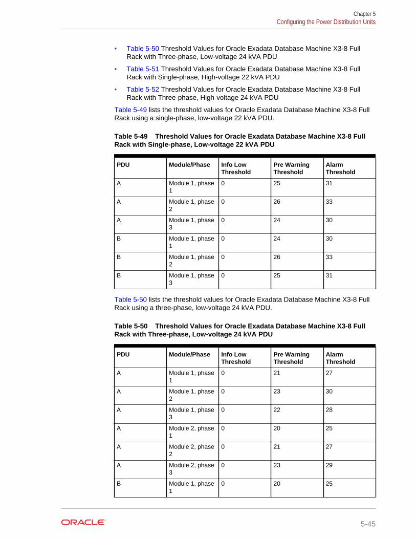
• Table 5-50 Threshold Values for Oracle Exadata Database Machine X3-8 FullRack with Three-phase, Low-voltage 24 kVA PDU
• Table 5-51 Threshold Values for Oracle Exadata Database Machine X3-8 FullRack with Single-phase, High-voltage 22 kVA PDU
• Table 5-52 Threshold Values for Oracle Exadata Database Machine X3-8 FullRack with Three-phase, High-voltage 24 kVA PDU
Table 5-49 lists the threshold values for Oracle Exadata Database Machine X3-8 FullRack using a single-phase, low-voltage 22 kVA PDU.
Table 5-49 Threshold Values for Oracle Exadata Database Machine X3-8 FullRack with Single-phase, Low-voltage 22 kVA PDU
PDU Module/Phase Info LowThreshold
Pre WarningThreshold
AlarmThreshold
A Module 1, phase1
0 25 31
A Module 1, phase2
0 26 33
A Module 1, phase3
0 24 30
B Module 1, phase1
0 24 30
B Module 1, phase2
0 26 33
B Module 1, phase3
0 25 31
Table 5-50 lists the threshold values for Oracle Exadata Database Machine X3-8 FullRack using a three-phase, low-voltage 24 kVA PDU.
Table 5-50 Threshold Values for Oracle Exadata Database Machine X3-8 FullRack with Three-phase, Low-voltage 24 kVA PDU
PDU Module/Phase Info LowThreshold
Pre WarningThreshold
AlarmThreshold
A Module 1, phase1
0 21 27
A Module 1, phase2
0 23 30
A Module 1, phase3
0 22 28
A Module 2, phase1
0 20 25
A Module 2, phase2
0 21 27
A Module 2, phase3
0 23 29
B Module 1, phase1
0 20 25
Chapter 5Configuring the Power Distribution Units
5-45
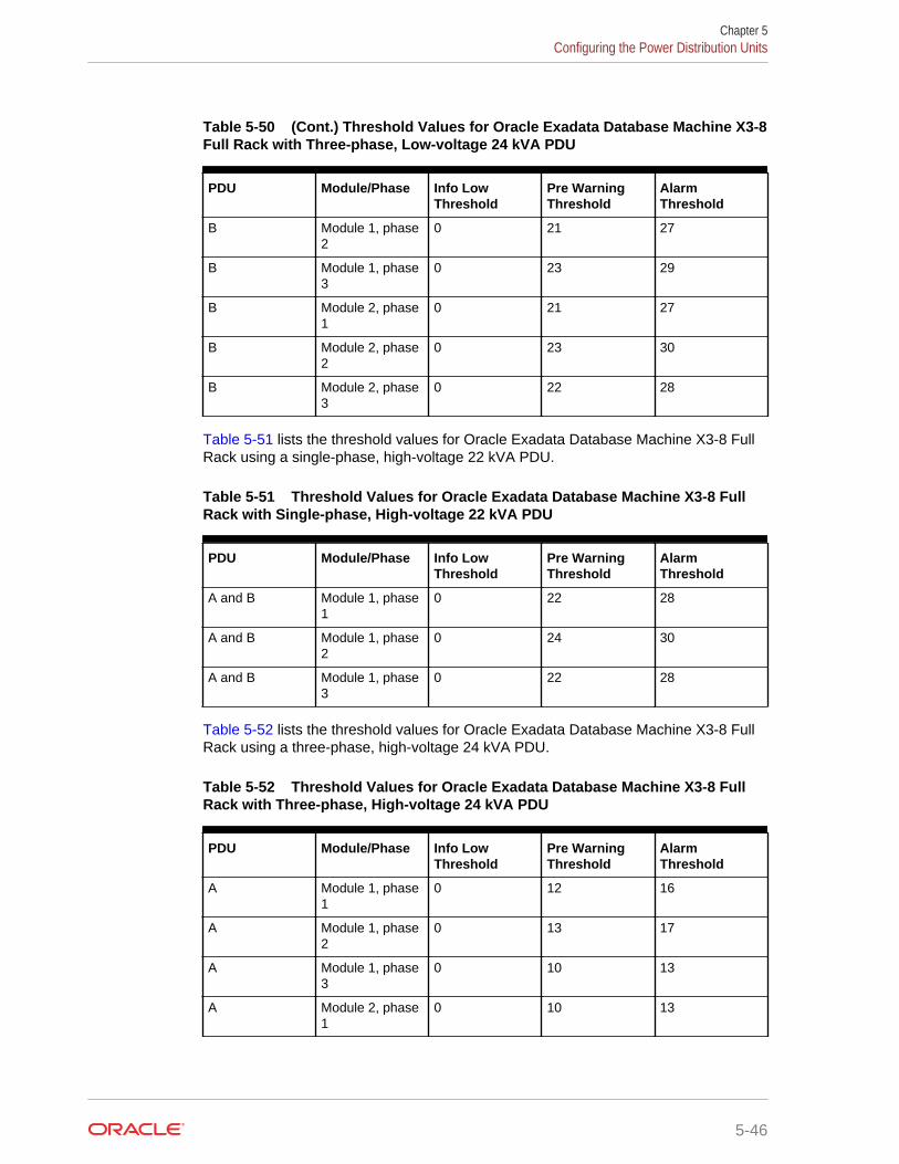
Table 5-50 (Cont.) Threshold Values for Oracle Exadata Database Machine X3-8Full Rack with Three-phase, Low-voltage 24 kVA PDU
PDU Module/Phase Info LowThreshold
Pre WarningThreshold
AlarmThreshold
B Module 1, phase2
0 21 27
B Module 1, phase3
0 23 29
B Module 2, phase1
0 21 27
B Module 2, phase2
0 23 30
B Module 2, phase3
0 22 28
Table 5-51 lists the threshold values for Oracle Exadata Database Machine X3-8 FullRack using a single-phase, high-voltage 22 kVA PDU.
Table 5-51 Threshold Values for Oracle Exadata Database Machine X3-8 FullRack with Single-phase, High-voltage 22 kVA PDU
PDU Module/Phase Info LowThreshold
Pre WarningThreshold
AlarmThreshold
A and B Module 1, phase1
0 22 28
A and B Module 1, phase2
0 24 30
A and B Module 1, phase3
0 22 28
Table 5-52 lists the threshold values for Oracle Exadata Database Machine X3-8 FullRack using a three-phase, high-voltage 24 kVA PDU.
Table 5-52 Threshold Values for Oracle Exadata Database Machine X3-8 FullRack with Three-phase, High-voltage 24 kVA PDU
PDU Module/Phase Info LowThreshold
Pre WarningThreshold
AlarmThreshold
A Module 1, phase1
0 12 16
A Module 1, phase2
0 13 17
A Module 1, phase3
0 10 13
A Module 2, phase1
0 10 13
Chapter 5Configuring the Power Distribution Units
5-46
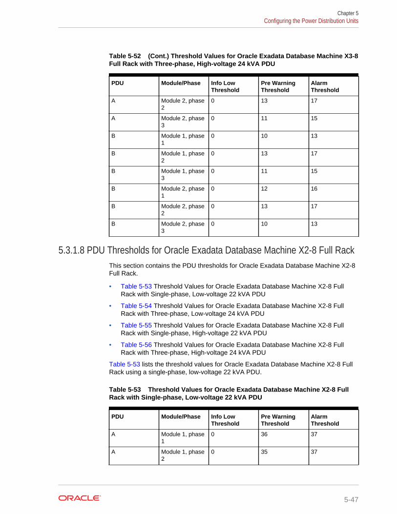
Table 5-52 (Cont.) Threshold Values for Oracle Exadata Database Machine X3-8Full Rack with Three-phase, High-voltage 24 kVA PDU
PDU Module/Phase Info LowThreshold
Pre WarningThreshold
AlarmThreshold
A Module 2, phase2
0 13 17
A Module 2, phase3
0 11 15
B Module 1, phase1
0 10 13
B Module 1, phase2
0 13 17
B Module 1, phase3
0 11 15
B Module 2, phase1
0 12 16
B Module 2, phase2
0 13 17
B Module 2, phase3
0 10 13
5.3.1.8 PDU Thresholds for Oracle Exadata Database Machine X2-8 Full RackThis section contains the PDU thresholds for Oracle Exadata Database Machine X2-8Full Rack.
• Table 5-53 Threshold Values for Oracle Exadata Database Machine X2-8 FullRack with Single-phase, Low-voltage 22 kVA PDU
• Table 5-54 Threshold Values for Oracle Exadata Database Machine X2-8 FullRack with Three-phase, Low-voltage 24 kVA PDU
• Table 5-55 Threshold Values for Oracle Exadata Database Machine X2-8 FullRack with Single-phase, High-voltage 22 kVA PDU
• Table 5-56 Threshold Values for Oracle Exadata Database Machine X2-8 FullRack with Three-phase, High-voltage 24 kVA PDU
Table 5-53 lists the threshold values for Oracle Exadata Database Machine X2-8 FullRack using a single-phase, low-voltage 22 kVA PDU.
Table 5-53 Threshold Values for Oracle Exadata Database Machine X2-8 FullRack with Single-phase, Low-voltage 22 kVA PDU
PDU Module/Phase Info LowThreshold
Pre WarningThreshold
AlarmThreshold
A Module 1, phase1
0 36 37
A Module 1, phase2
0 35 37
Chapter 5Configuring the Power Distribution Units
5-47
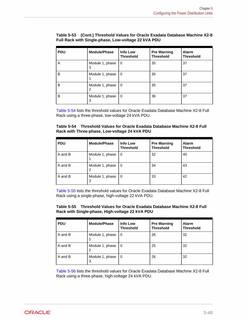
Table 5-53 (Cont.) Threshold Values for Oracle Exadata Database Machine X2-8Full Rack with Single-phase, Low-voltage 22 kVA PDU
PDU Module/Phase Info LowThreshold
Pre WarningThreshold
AlarmThreshold
A Module 1, phase3
0 35 37
B Module 1, phase1
0 35 37
B Module 1, phase2
0 35 37
B Module 1, phase3
0 36 37
Table 5-54 lists the threshold values for Oracle Exadata Database Machine X2-8 FullRack using a three-phase, low-voltage 24 kVA PDU.
Table 5-54 Threshold Values for Oracle Exadata Database Machine X2-8 FullRack with Three-phase, Low-voltage 24 kVA PDU
PDU Module/Phase Info LowThreshold
Pre WarningThreshold
AlarmThreshold
A and B Module 1, phase1
0 32 40
A and B Module 1, phase2
0 34 43
A and B Module 1, phase3
0 33 42
Table 5-55 lists the threshold values for Oracle Exadata Database Machine X2-8 FullRack using a single-phase, high-voltage 22 kVA PDU.
Table 5-55 Threshold Values for Oracle Exadata Database Machine X2-8 FullRack with Single-phase, High-voltage 22 kVA PDU
PDU Module/Phase Info LowThreshold
Pre WarningThreshold
AlarmThreshold
A and B Module 1, phase1
0 26 32
A and B Module 1, phase2
0 25 32
A and B Module 1, phase3
0 26 32
Table 5-56 lists the threshold values for Oracle Exadata Database Machine X2-8 FullRack using a three-phase, high-voltage 24 kVA PDU.
Chapter 5Configuring the Power Distribution Units
5-48
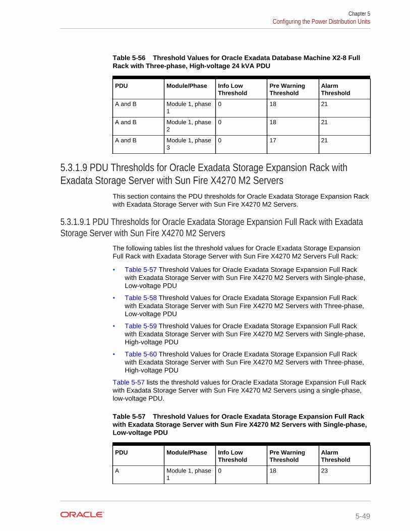
Table 5-56 Threshold Values for Oracle Exadata Database Machine X2-8 FullRack with Three-phase, High-voltage 24 kVA PDU
PDU Module/Phase Info LowThreshold
Pre WarningThreshold
AlarmThreshold
A and B Module 1, phase1
0 18 21
A and B Module 1, phase2
0 18 21
A and B Module 1, phase3
0 17 21
5.3.1.9 PDU Thresholds for Oracle Exadata Storage Expansion Rack withExadata Storage Server with Sun Fire X4270 M2 Servers
This section contains the PDU thresholds for Oracle Exadata Storage Expansion Rackwith Exadata Storage Server with Sun Fire X4270 M2 Servers.
5.3.1.9.1 PDU Thresholds for Oracle Exadata Storage Expansion Full Rack with ExadataStorage Server with Sun Fire X4270 M2 Servers
The following tables list the threshold values for Oracle Exadata Storage ExpansionFull Rack with Exadata Storage Server with Sun Fire X4270 M2 Servers Full Rack:
• Table 5-57 Threshold Values for Oracle Exadata Storage Expansion Full Rackwith Exadata Storage Server with Sun Fire X4270 M2 Servers with Single-phase,Low-voltage PDU
• Table 5-58 Threshold Values for Oracle Exadata Storage Expansion Full Rackwith Exadata Storage Server with Sun Fire X4270 M2 Servers with Three-phase,Low-voltage PDU
• Table 5-59 Threshold Values for Oracle Exadata Storage Expansion Full Rackwith Exadata Storage Server with Sun Fire X4270 M2 Servers with Single-phase,High-voltage PDU
• Table 5-60 Threshold Values for Oracle Exadata Storage Expansion Full Rackwith Exadata Storage Server with Sun Fire X4270 M2 Servers with Three-phase,High-voltage PDU
Table 5-57 lists the threshold values for Oracle Exadata Storage Expansion Full Rackwith Exadata Storage Server with Sun Fire X4270 M2 Servers using a single-phase,low-voltage PDU.
Table 5-57 Threshold Values for Oracle Exadata Storage Expansion Full Rackwith Exadata Storage Server with Sun Fire X4270 M2 Servers with Single-phase,Low-voltage PDU
PDU Module/Phase Info LowThreshold
Pre WarningThreshold
AlarmThreshold
A Module 1, phase1
0 18 23
Chapter 5Configuring the Power Distribution Units
5-49
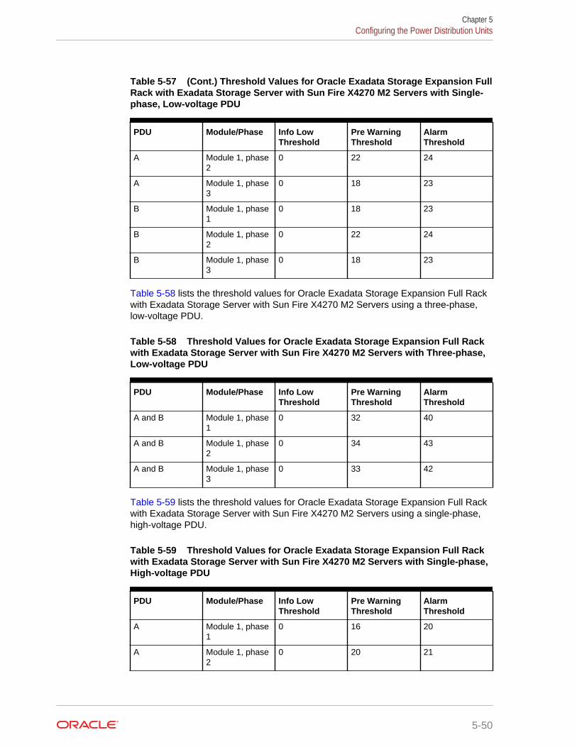
Table 5-57 (Cont.) Threshold Values for Oracle Exadata Storage Expansion FullRack with Exadata Storage Server with Sun Fire X4270 M2 Servers with Single-phase, Low-voltage PDU
PDU Module/Phase Info LowThreshold
Pre WarningThreshold
AlarmThreshold
A Module 1, phase2
0 22 24
A Module 1, phase3
0 18 23
B Module 1, phase1
0 18 23
B Module 1, phase2
0 22 24
B Module 1, phase3
0 18 23
Table 5-58 lists the threshold values for Oracle Exadata Storage Expansion Full Rackwith Exadata Storage Server with Sun Fire X4270 M2 Servers using a three-phase,low-voltage PDU.
Table 5-58 Threshold Values for Oracle Exadata Storage Expansion Full Rackwith Exadata Storage Server with Sun Fire X4270 M2 Servers with Three-phase,Low-voltage PDU
PDU Module/Phase Info LowThreshold
Pre WarningThreshold
AlarmThreshold
A and B Module 1, phase1
0 32 40
A and B Module 1, phase2
0 34 43
A and B Module 1, phase3
0 33 42
Table 5-59 lists the threshold values for Oracle Exadata Storage Expansion Full Rackwith Exadata Storage Server with Sun Fire X4270 M2 Servers using a single-phase,high-voltage PDU.
Table 5-59 Threshold Values for Oracle Exadata Storage Expansion Full Rackwith Exadata Storage Server with Sun Fire X4270 M2 Servers with Single-phase,High-voltage PDU
PDU Module/Phase Info LowThreshold
Pre WarningThreshold
AlarmThreshold
A Module 1, phase1
0 16 20
A Module 1, phase2
0 20 21
Chapter 5Configuring the Power Distribution Units
5-50
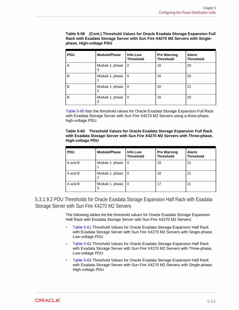
Table 5-59 (Cont.) Threshold Values for Oracle Exadata Storage Expansion FullRack with Exadata Storage Server with Sun Fire X4270 M2 Servers with Single-phase, High-voltage PDU
PDU Module/Phase Info LowThreshold
Pre WarningThreshold
AlarmThreshold
A Module 1, phase3
0 16 20
B Module 1, phase1
0 16 20
B Module 1, phase2
0 20 21
B Module 1, phase3
0 16 20
Table 5-60 lists the threshold values for Oracle Exadata Storage Expansion Full Rackwith Exadata Storage Server with Sun Fire X4270 M2 Servers using a three-phase,high-voltage PDU.
Table 5-60 Threshold Values for Oracle Exadata Storage Expansion Full Rackwith Exadata Storage Server with Sun Fire X4270 M2 Servers with Three-phase,High-voltage PDU
PDU Module/Phase Info LowThreshold
Pre WarningThreshold
AlarmThreshold
A and B Module 1, phase1
0 18 21
A and B Module 1, phase2
0 18 21
A and B Module 1, phase3
0 17 21
5.3.1.9.2 PDU Thresholds for Oracle Exadata Storage Expansion Half Rack with ExadataStorage Server with Sun Fire X4270 M2 Servers
The following tables list the threshold values for Oracle Exadata Storage ExpansionHalf Rack with Exadata Storage Server with Sun Fire X4270 M2 Servers:
• Table 5-61 Threshold Values for Oracle Exadata Storage Expansion Half Rackwith Exadata Storage Server with Sun Fire X4270 M2 Servers with Single-phase,Low-voltage PDU
• Table 5-62 Threshold Values for Oracle Exadata Storage Expansion Half Rackwith Exadata Storage Server with Sun Fire X4270 M2 Servers with Three-phase,Low-voltage PDU
• Table 5-63 Threshold Values for Oracle Exadata Storage Expansion Half Rackwith Exadata Storage Server with Sun Fire X4270 M2 Servers with Single-phase,High-voltage PDU
Chapter 5Configuring the Power Distribution Units
5-51
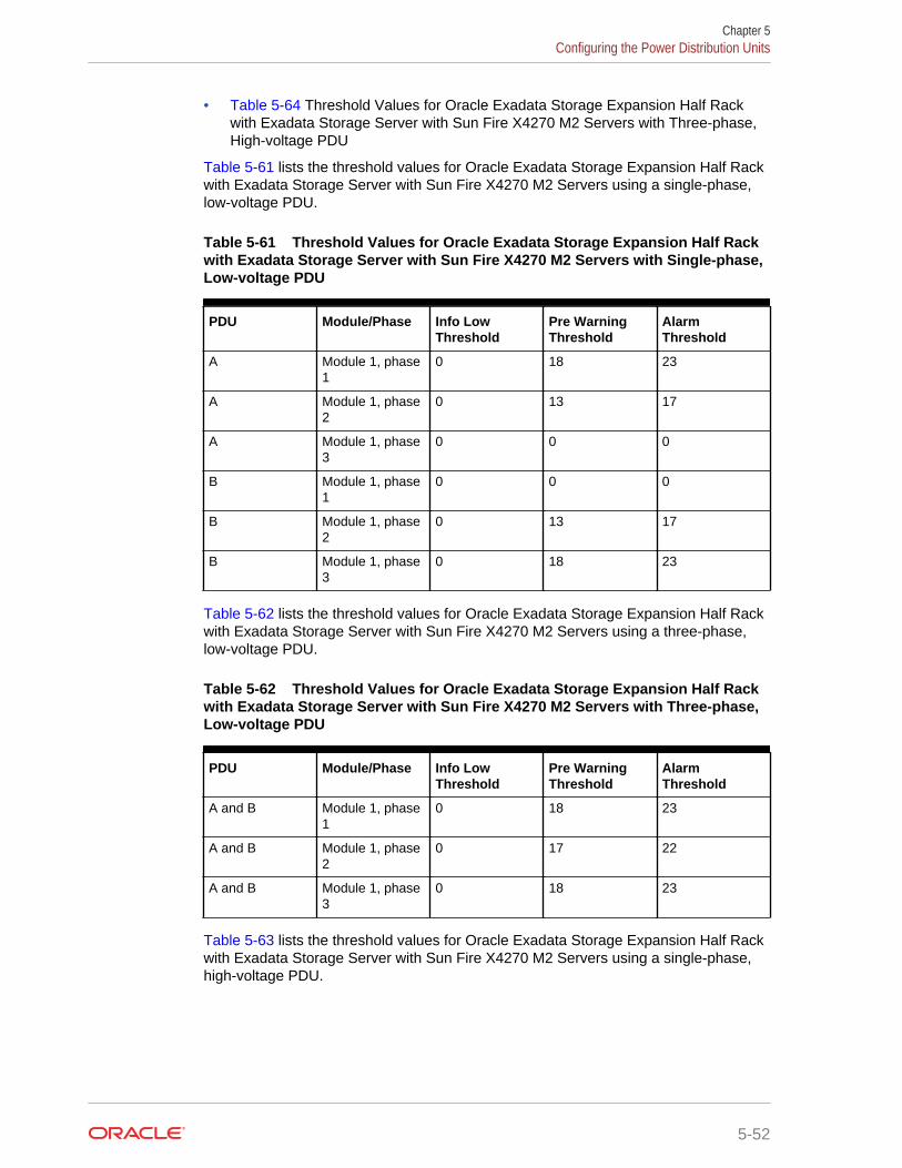
• Table 5-64 Threshold Values for Oracle Exadata Storage Expansion Half Rackwith Exadata Storage Server with Sun Fire X4270 M2 Servers with Three-phase,High-voltage PDU
Table 5-61 lists the threshold values for Oracle Exadata Storage Expansion Half Rackwith Exadata Storage Server with Sun Fire X4270 M2 Servers using a single-phase,low-voltage PDU.
Table 5-61 Threshold Values for Oracle Exadata Storage Expansion Half Rackwith Exadata Storage Server with Sun Fire X4270 M2 Servers with Single-phase,Low-voltage PDU
PDU Module/Phase Info LowThreshold
Pre WarningThreshold
AlarmThreshold
A Module 1, phase1
0 18 23
A Module 1, phase2
0 13 17
A Module 1, phase3
0 0 0
B Module 1, phase1
0 0 0
B Module 1, phase2
0 13 17
B Module 1, phase3
0 18 23
Table 5-62 lists the threshold values for Oracle Exadata Storage Expansion Half Rackwith Exadata Storage Server with Sun Fire X4270 M2 Servers using a three-phase,low-voltage PDU.
Table 5-62 Threshold Values for Oracle Exadata Storage Expansion Half Rackwith Exadata Storage Server with Sun Fire X4270 M2 Servers with Three-phase,Low-voltage PDU
PDU Module/Phase Info LowThreshold
Pre WarningThreshold
AlarmThreshold
A and B Module 1, phase1
0 18 23
A and B Module 1, phase2
0 17 22
A and B Module 1, phase3
0 18 23
Table 5-63 lists the threshold values for Oracle Exadata Storage Expansion Half Rackwith Exadata Storage Server with Sun Fire X4270 M2 Servers using a single-phase,high-voltage PDU.
Chapter 5Configuring the Power Distribution Units
5-52
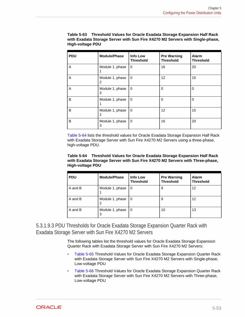
Table 5-63 Threshold Values for Oracle Exadata Storage Expansion Half Rackwith Exadata Storage Server with Sun Fire X4270 M2 Servers with Single-phase,High-voltage PDU
PDU Module/Phase Info LowThreshold
Pre WarningThreshold
AlarmThreshold
A Module 1, phase1
0 16 20
A Module 1, phase2
0 12 15
A Module 1, phase3
0 0 0
B Module 1, phase1
0 0 0
B Module 1, phase2
0 12 15
B Module 1, phase3
0 16 20
Table 5-64 lists the threshold values for Oracle Exadata Storage Expansion Half Rackwith Exadata Storage Server with Sun Fire X4270 M2 Servers using a three-phase,high-voltage PDU.
Table 5-64 Threshold Values for Oracle Exadata Storage Expansion Half Rackwith Exadata Storage Server with Sun Fire X4270 M2 Servers with Three-phase,High-voltage PDU
PDU Module/Phase Info LowThreshold
Pre WarningThreshold
AlarmThreshold
A and B Module 1, phase1
0 9 12
A and B Module 1, phase2
0 9 12
A and B Module 1, phase3
0 10 13
5.3.1.9.3 PDU Thresholds for Oracle Exadata Storage Expansion Quarter Rack withExadata Storage Server with Sun Fire X4270 M2 Servers
The following tables list the threshold values for Oracle Exadata Storage ExpansionQuarter Rack with Exadata Storage Server with Sun Fire X4270 M2 Servers:
• Table 5-65 Threshold Values for Oracle Exadata Storage Expansion Quarter Rackwith Exadata Storage Server with Sun Fire X4270 M2 Servers with Single-phase,Low-voltage PDU
• Table 5-66 Threshold Values for Oracle Exadata Storage Expansion Quarter Rackwith Exadata Storage Server with Sun Fire X4270 M2 Servers with Three-phase,Low-voltage PDU
Chapter 5Configuring the Power Distribution Units
5-53
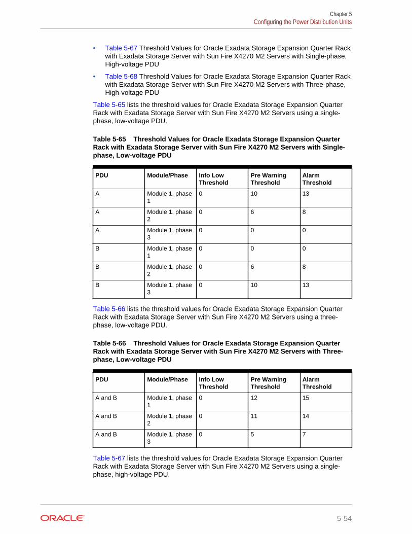
• Table 5-67 Threshold Values for Oracle Exadata Storage Expansion Quarter Rackwith Exadata Storage Server with Sun Fire X4270 M2 Servers with Single-phase,High-voltage PDU
• Table 5-68 Threshold Values for Oracle Exadata Storage Expansion Quarter Rackwith Exadata Storage Server with Sun Fire X4270 M2 Servers with Three-phase,High-voltage PDU
Table 5-65 lists the threshold values for Oracle Exadata Storage Expansion QuarterRack with Exadata Storage Server with Sun Fire X4270 M2 Servers using a single-phase, low-voltage PDU.
Table 5-65 Threshold Values for Oracle Exadata Storage Expansion QuarterRack with Exadata Storage Server with Sun Fire X4270 M2 Servers with Single-phase, Low-voltage PDU
PDU Module/Phase Info LowThreshold
Pre WarningThreshold
AlarmThreshold
A Module 1, phase1
0 10 13
A Module 1, phase2
0 6 8
A Module 1, phase3
0 0 0
B Module 1, phase1
0 0 0
B Module 1, phase2
0 6 8
B Module 1, phase3
0 10 13
Table 5-66 lists the threshold values for Oracle Exadata Storage Expansion QuarterRack with Exadata Storage Server with Sun Fire X4270 M2 Servers using a three-phase, low-voltage PDU.
Table 5-66 Threshold Values for Oracle Exadata Storage Expansion QuarterRack with Exadata Storage Server with Sun Fire X4270 M2 Servers with Three-phase, Low-voltage PDU
PDU Module/Phase Info LowThreshold
Pre WarningThreshold
AlarmThreshold
A and B Module 1, phase1
0 12 15
A and B Module 1, phase2
0 11 14
A and B Module 1, phase3
0 5 7
Table 5-67 lists the threshold values for Oracle Exadata Storage Expansion QuarterRack with Exadata Storage Server with Sun Fire X4270 M2 Servers using a single-phase, high-voltage PDU.
Chapter 5Configuring the Power Distribution Units
5-54
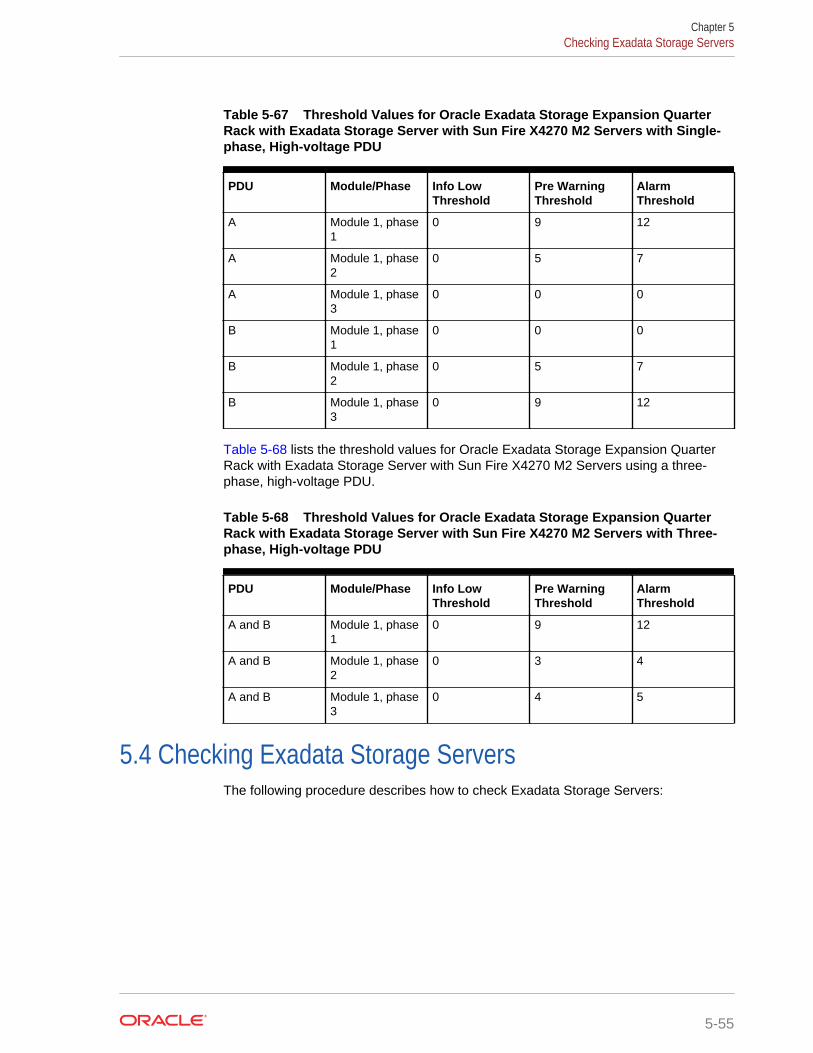
Table 5-67 Threshold Values for Oracle Exadata Storage Expansion QuarterRack with Exadata Storage Server with Sun Fire X4270 M2 Servers with Single-phase, High-voltage PDU
PDU Module/Phase Info LowThreshold
Pre WarningThreshold
AlarmThreshold
A Module 1, phase1
0 9 12
A Module 1, phase2
0 5 7
A Module 1, phase3
0 0 0
B Module 1, phase1
0 0 0
B Module 1, phase2
0 5 7
B Module 1, phase3
0 9 12
Table 5-68 lists the threshold values for Oracle Exadata Storage Expansion QuarterRack with Exadata Storage Server with Sun Fire X4270 M2 Servers using a three-phase, high-voltage PDU.
Table 5-68 Threshold Values for Oracle Exadata Storage Expansion QuarterRack with Exadata Storage Server with Sun Fire X4270 M2 Servers with Three-phase, High-voltage PDU
PDU Module/Phase Info LowThreshold
Pre WarningThreshold
AlarmThreshold
A and B Module 1, phase1
0 9 12
A and B Module 1, phase2
0 3 4
A and B Module 1, phase3
0 4 5
5.4 Checking Exadata Storage ServersThe following procedure describes how to check Exadata Storage Servers:
Chapter 5Checking Exadata Storage Servers
5-55
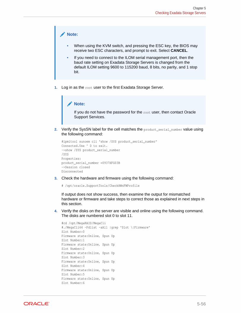
Note:
• When using the KVM switch, and pressing the ESC key, the BIOS mayreceive two ESC characters, and prompt to exit. Select CANCEL.
• If you need to connect to the ILOM serial management port, then thebaud rate setting on Exadata Storage Servers is changed from thedefault ILOM setting 9600 to 115200 baud, 8 bits, no parity, and 1 stopbit.
1. Log in as the root user to the first Exadata Storage Server.
Note:
If you do not have the password for the root user, then contact OracleSupport Services.
2. Verify the SysSN label for the cell matches the product_serial_number value usingthe following command:
#ipmitool sunoem cli "show /SYS product_serial_number"Connected.Use ^ D to exit.->show /SYS product_serial_number/SYSProperties:product_serial_number =0937XFG03B->Session closedDisconnected
3. Check the hardware and firmware using the following command:
# /opt/oracle.SupportTools/CheckHWnFWProfile
If output does not show success, then examine the output for mismatchedhardware or firmware and take steps to correct those as explained in next steps inthis section.
4. Verify the disks on the server are visible and online using the following command.The disks are numbered slot 0 to slot 11.
#cd /opt/MegaRAID/MegaCli#./MegaCli64 -Pdlist -aAll |grep "Slot \|Firmware"Slot Number:0Firmware state:Online, Spun UpSlot Number:1Firmware state:Online, Spun UpSlot Number:2Firmware state:Online, Spun UpSlot Number:3Firmware state:Online, Spun UpSlot Number:4Firmware state:Online, Spun UpSlot Number:5Firmware state:Online, Spun UpSlot Number:6
Chapter 5Checking Exadata Storage Servers
5-56
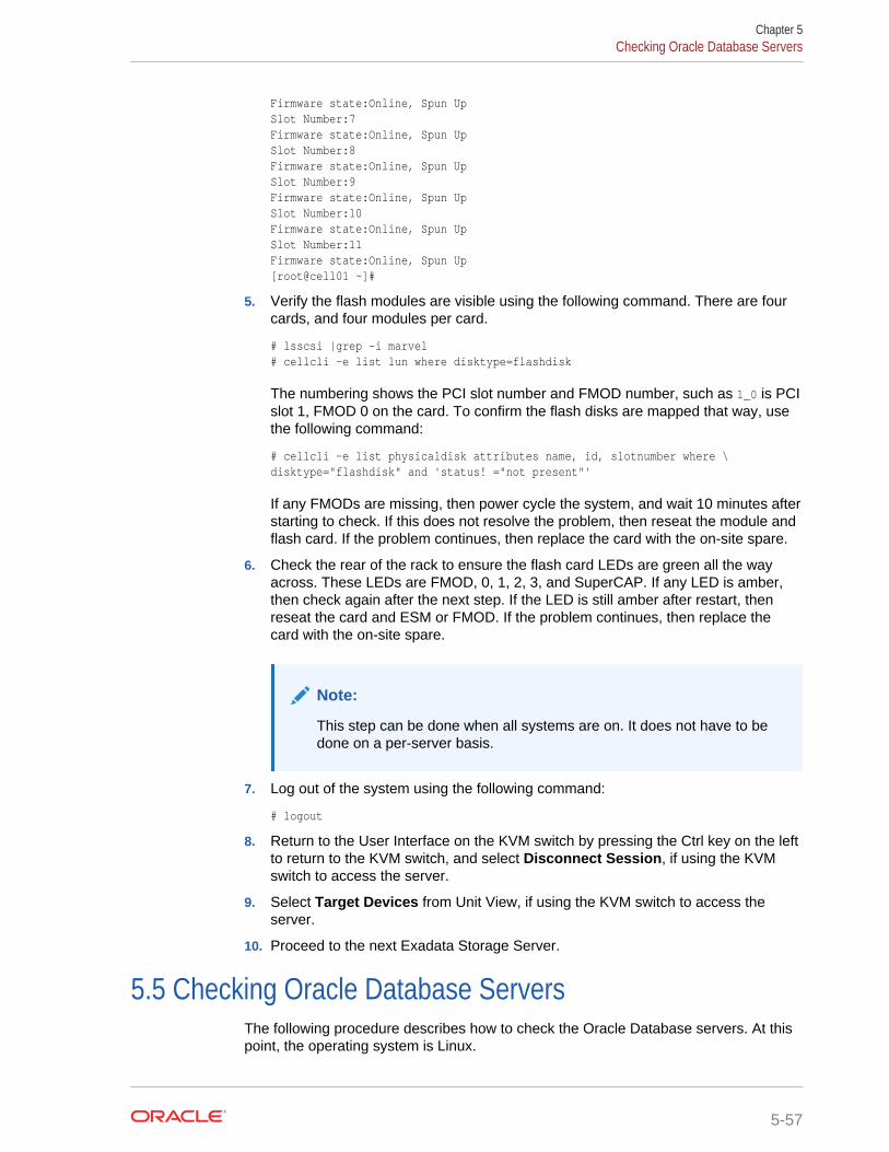
Firmware state:Online, Spun UpSlot Number:7Firmware state:Online, Spun UpSlot Number:8Firmware state:Online, Spun UpSlot Number:9Firmware state:Online, Spun UpSlot Number:10Firmware state:Online, Spun UpSlot Number:11Firmware state:Online, Spun Up[root@cell01 ~]#
5. Verify the flash modules are visible using the following command. There are fourcards, and four modules per card.
# lsscsi |grep -i marvel# cellcli -e list lun where disktype=flashdisk
The numbering shows the PCI slot number and FMOD number, such as 1_0 is PCIslot 1, FMOD 0 on the card. To confirm the flash disks are mapped that way, usethe following command:
# cellcli -e list physicaldisk attributes name, id, slotnumber where \disktype="flashdisk" and 'status! ="not present"'
If any FMODs are missing, then power cycle the system, and wait 10 minutes afterstarting to check. If this does not resolve the problem, then reseat the module andflash card. If the problem continues, then replace the card with the on-site spare.
6. Check the rear of the rack to ensure the flash card LEDs are green all the wayacross. These LEDs are FMOD, 0, 1, 2, 3, and SuperCAP. If any LED is amber,then check again after the next step. If the LED is still amber after restart, thenreseat the card and ESM or FMOD. If the problem continues, then replace thecard with the on-site spare.
Note:
This step can be done when all systems are on. It does not have to bedone on a per-server basis.
7. Log out of the system using the following command:
# logout
8. Return to the User Interface on the KVM switch by pressing the Ctrl key on the leftto return to the KVM switch, and select Disconnect Session, if using the KVMswitch to access the server.
9. Select Target Devices from Unit View, if using the KVM switch to access theserver.
10. Proceed to the next Exadata Storage Server.
5.5 Checking Oracle Database ServersThe following procedure describes how to check the Oracle Database servers. At thispoint, the operating system is Linux.
Chapter 5Checking Oracle Database Servers
5-57
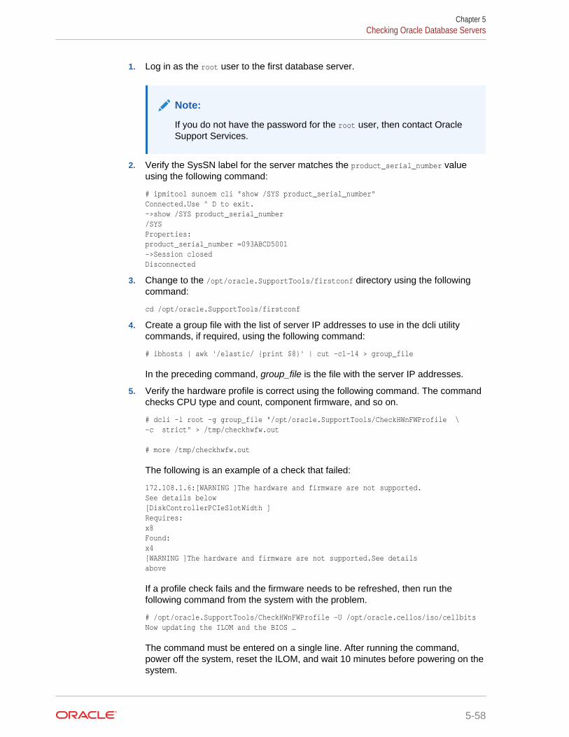
1. Log in as the root user to the first database server.
Note:
If you do not have the password for the root user, then contact OracleSupport Services.
2. Verify the SysSN label for the server matches the product_serial_number valueusing the following command:
# ipmitool sunoem cli "show /SYS product_serial_number"Connected.Use ^ D to exit.->show /SYS product_serial_number/SYSProperties:product_serial_number =093ABCD5001->Session closedDisconnected
3. Change to the /opt/oracle.SupportTools/firstconf directory using the followingcommand:
cd /opt/oracle.SupportTools/firstconf
4. Create a group file with the list of server IP addresses to use in the dcli utilitycommands, if required, using the following command:
# ibhosts | awk '/elastic/ {print $8}' | cut -c1-14 > group_file
In the preceding command, group_file is the file with the server IP addresses.
5. Verify the hardware profile is correct using the following command. The commandchecks CPU type and count, component firmware, and so on.
# dcli -l root -g group_file "/opt/oracle.SupportTools/CheckHWnFWProfile \-c strict" > /tmp/checkhwfw.out
# more /tmp/checkhwfw.out
The following is an example of a check that failed:
172.108.1.6:[WARNING ]The hardware and firmware are not supported.See details below[DiskControllerPCIeSlotWidth ]Requires:x8Found:x4[WARNING ]The hardware and firmware are not supported.See detailsabove
If a profile check fails and the firmware needs to be refreshed, then run thefollowing command from the system with the problem.
# /opt/oracle.SupportTools/CheckHWnFWProfile -U /opt/oracle.cellos/iso/cellbitsNow updating the ILOM and the BIOS …
The command must be entered on a single line. After running the command,power off the system, reset the ILOM, and wait 10 minutes before powering on thesystem.
Chapter 5Checking Oracle Database Servers
5-58
6. Verify the disks on the server are visible and online using the following command.
# cd /opt/MegaRAID/MegaCli# ./MegaCli64 -Pdlist -aAll |grep "Slot \|Firmware"Slot Number: 0Firmware state:Online, Spun UpDevice Firmware Level: 0868Slot Number:1Firmware state:Online, Spun UpDevice Firmware Level: 0868Slot Number:2Firmware state:Online, Spun UpDevice Firmware Level: A2A8Slot Number:3...
7. Examine the output of the following command:
/opt/MegaRAID/MegaCli/MegaCli64 -LdInfo -LAll -aAll
8. (Oracle Exadata Database Machine based on Sun Fire X4170 Oracle DatabaseServers only) Check that the ILOM is configured for the proper fan cooling on eachdatabase server using the following command:
# ipmitool sunoem cli "show /SP/policy"
• If the policy is present and enabled, then no additional steps are needed.
• If the policy is present and disabled, then enable the policy using the followingcommand:
# ipmitool sunoem cli "set /SP/policy FLASH_ACCELERATOR_CARD_ \INSTALLED=enabled"
The command must be entered as a single line.
9. Log out of the system using the following command:
# logout
10. Return to the User Interface on the KVM switch by pressing the Ctrl key on the leftto return to the KVM switch, and select Disconnect Session, if using the KVMswitch to access the server.
11. Select Target Devices from Unit View, and proceed to the next database server, ifusing the KVM switch to access the server.
12. Verify that NTP servers are configured the same for all servers using the followingcommand. The command is run on each database server individually.
ntpq -p
5.6 Performing Additional Checks and ConfigurationThe following procedure describes additional checks and configuration steps forOracle Exadata Rack:
1. (Oracle Exadata Database Machine only) Log in to the first database server as theroot user.
2. Change to the firstconf directory using the following command:
# cd /opt/oracle.SupportTools/firstconf
Chapter 5Performing Additional Checks and Configuration
5-59
3. Create a group file with the list of IP addresses to use in the dcli utility commands,if needed
4. Verify the rack master serial number is set correctly using the following command:
# dcli -l root -g group_file "ipmitool sunoem cli 'show \/SP system_identifier'" > /tmp/show-rack-csn.out
# more /tmp/show-rack-csn.out
If none of the serial numbers are set, then contact Oracle Support Services. If oneserial number is not set correctly, then run the following command to correct it:
ipmitool sunoem cli 'set /SP system_identifier= \"Exadata Database Machine rack_type xxxxAKyyyy"'
In the preceding command, rack_type is X2-2 or X2-8, depending on the rack.
5. Ensure disk cache policy is set to Disabled using the following command as theroot user on the first database server in the cluster:
dcli -g /opt/oracle.SupportTools/onecommand/all_group -l root \/opt/MegaRAID/MegaCli/MegaCli64 -LdPdInfo -aALL | grep -i 'Disk Cache Policy'
The following is an example of the output from the command:
dm01db01: Disk Cache Policy : Disableddm01db02: Disk Cache Policy : Disableddm01db03: Disk Cache Policy : Disabled...dm01cel01: Disk Cache Policy : Disableddm01cel02: Disk Cache Policy : Disabled...
If any server shows different output, then identify the LUN and use the followingcommand to reset the policy to Disabled:
MegaCli64 -LDSetProp -DisDskCache -LUNn -a0
In the preceding command, LUNn is the LUN number, such as L2.
5.7 Verifying the InfiniBand NetworkThe following procedure describes how to verify the InfiniBand network:
1. Visually check all the InfiniBand cable connections within the rack. The port lightsshould be on, and the LEDs should be on. Do not press each connector to verifyconnectivity.
2. Log in as the root user on any component in the rack.
3. Verify the InfiniBand topology using the following commands:
# cd /opt/oracle.SupportTools/ibdiagtools# ./verify-topology [-t rack_size]
The following example shows the output when the network components arecorrect.
[DB Machine Infiniband Cabling Topology Verification Tool ]Is every external switch connected to every internal switch......[SUCCESS ]Are any external switches connected to each other................[SUCCESS ]
Chapter 5Verifying the InfiniBand Network
5-60
Are any hosts connected to spine switch..........................[SUCCESS ]Check if all hosts have 2 CAs to different switches..............[SUCCESS ]Leaf switch check:cardinality and even distribution..............[SUCCESS ]Check if each rack has an valid internal ring....................[SUCCESS ]
In the preceding command, rack_size is the size of the rack. The -t rack_sizeoption is needed if the rack is Oracle Exadata Database Machine Half Rack orOracle Exadata Database Machine Quarter Rack. Use halfrack for OracleExadata Database Machine Half Rack, and quarterrack for Oracle ExadataDatabase Machine Quarter Rack.
The following example shows the output when there is a bad InfiniBand switch toInfiniBand cable connection:
#./verify-topology[DB Machine Infiniband Cabling Topology Verification Tool ]Is every external switch connected to every internal switch......[SUCCESS ]Are any external switches connected to each other................[SUCCESS ]Are any hosts connected to spine switch..........................[SUCCESS ]Check if all hosts have 2 CAs to different switches..............[SUCCESS ]Leaf switch check:cardinality and even distribution..............[SUCCESS ]Check if each rack has an valid internal ring....................[ERROR ]
Switches 0x21283a87cba0a0 0x21283a87b8a0a0 have 6 connections between them.They should have at least 7 links between them
The following example shows the output when there is a bad InfiniBand cable on adatabase server:
#./verify-topology[DB Machine Infiniband Cabling Topology Verification Tool ]Is every external switch connected to every internal switch......[SUCCESS ]Are any external switches connected to each other................[SUCCESS ]Are any hosts connected to spine switch..........................[SUCCESS ]Check if all hosts have 2 CAs to different switches..............[ERROR ]Node db01 has 1 endpoints.(Should be 2)Port 2 of this node is not connected to any switch--------fattree End Point Cabling verification failed-----Leaf switch check:cardinality and even distribution..............[ERROR ]Internal QDR Switch 0x21283a87b8a0a0 has fewer than 4 compute nodesIt has only 3 links belonging to compute nodes [SUCCESS ]Check if each rack has an valid internal ring...................[SUCCESS ]
The following example shows the output when there is a bad connection on theswitch and the system:
#./verify-topology[DB Machine Infiniband Cabling Topology Verification Tool ]Is every external switch connected to every internal switch......[SUCCESS ]Are any external switches connected to each other................[SUCCESS ]Are any hosts connected to spine switch..........................[SUCCESS ]Check if all hosts have 2 CAs to different switches..............[ERROR ]
Node burxdb01 has 1 endpoints.(Should be 2) Port 2 of this node is not connected to any switch--------fattree End Point Cabling verifation failed-----Leaf switch check:cardinality and even distribution..............[ERROR ]Internal QDR Switch 0x21283a87b8a0a0 has fewer than 4 compute nodes It has only 3 links belonging to compute nodes...................[SUCCESS ]Check if each rack has an valid internal ring....................[ERROR ]
Chapter 5Verifying the InfiniBand Network
5-61
Switches 0x21283a87cba0a0 0x21283a87b8a0a0 have 6 connections between themThey should have at least 7 links between them
5.8 Imaging a New SystemYou have different options for preparing an Oracle Exadata system for deployment.
• Using ISO Images to Image a New System
• Using Elastic Configuration to Image a New System
• Using ISO to Image a New System
• Using PXE to Image a New System
• Using USB to Image a New System
• Updates to Imaging Parameters
Using a preconf.csv file with the PXE, USB and ISO options enables an unattendedfirst boot configuration and greatly simplifies the installation but is not mandatory. It ispossible to boot from the installation media and follow the prompts to configure thesystem.
Starting with Oracle Exadata System Software release 19.1.0, Secure Eraser isautomatically started during re-imaging if the hardware supports Secure Eraser. Thissignificantly simplifies the re-imaging procedure while maintaining performance. Now,when re-purposing a rack, you only have to image the rack and the secure dataerasure is taken care of transparently as part of the process.
In release 12.1.2.2.0 and above, the installation media has been simplified, and it is nolonger necessary to build files using the ImageMaker process.
Refer to My Oracle Support note 1306961.1 for additional details on valid options forimaging 12.1.2.1.0 and earlier releases.
5.8.1 Using ISO Images to Image a New SystemIn versions prior to 12.1.2.2.0, ISO images are available as patches that you candownload for bare metal imaging an Exadata system. This is now the default methodin 12.1.2.2.0 and above. You are no longer required to build the ISO files usingimagemaker. Patches are available for both database nodes and cells. You can usethe ISO images to boot the server using a virtual media device on the ILOM (from theDevices menu of the ILOM console). For example, the two ISO images available for12.1.2.1.1 are listed in the following table.
Chapter 5Imaging a New System
5-62
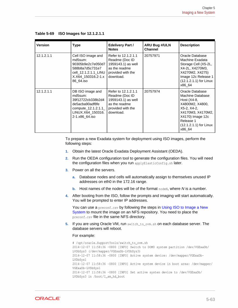
Table 5-69 ISO Images for 12.1.2.1.1
Version Type Edelivery Part /Notes
ARU Bug #/ULNChannel
Description
12.1.2.1.1 Cell ISO image andmd5sum:90305b9e2c7e050d7588b8a7d5c731e7cell_12.1.2.1.1_LINUX.X64_150316.2-1.x86_64.iso
Refer to 12.1.2.1.1Readme (Doc ID1959143.1) as wellas the readmeprovided with thedownload.
20757971 Oracle DatabaseMachine ExadataStorage Cell (X5-2L,X4-2L, X4270M3,X4270M2, X4275)Image 12c Release 1(12.1.2.1.1) for Linuxx86_64
12.1.2.1.1 DB ISO image andmd5sum:39f12722cb338b2d4de5acba90adf8fecompute_12.1.2.1.1_LINUX.X64_150316.2-1.x86_64.iso
Refer to 12.1.2.1.1Readme (Doc ID1959143.1) as wellas the readmeprovided with thedownload.
20757974 Oracle DatabaseMachine DatabaseHost (X4-8,X4800M2, X4800,X5-2, X4-2,X4170M3, X4170M2,X4170) Image 12cRelease 1(12.1.2.1.1) for Linuxx86_64
To prepare a new Exadata system for deployment using ISO images, perform thefollowing steps:
1. Obtain the latest Oracle Exadata Deployment Assistant (OEDA).
2. Run the OEDA configuration tool to generate the configuration files. You will needthe configuration files when you run applyElasticConfig.sh later.
3. Power on all the servers.
a. Database nodes and cells will automatically assign to themselves unused IPaddresses on eth0 in the 172.16 range.
b. Host names of the nodes will be of the format nodeN, where N is a number.
4. After booting from the ISO, follow the prompts and imaging will start automatically.You will be prompted to enter IP addresses.
You can use a preconf.csv by following the steps in Using ISO to Image a NewSystem to mount the image on an NFS repository. You need to place thepreconf.csv file in the same NFS directory.
5. If you are using Oracle VM, run switch_to_ovm.sh on each database server. Thedatabase servers will reboot.
For example:
# /opt/oracle.SupportTools/switch_to_ovm.sh2014-12-07 11:58:36 -0800 [INFO] Switch to DOM0 system partition /dev/VGExaDb/LVDbSys3 (/dev/mapper/VGExaDb-LVDbSys3)2014-12-07 11:58:36 -0800 [INFO] Active system device: /dev/mapper/VGExaDb-LVDbSys12014-12-07 11:58:36 -0800 [INFO] Active system device in boot area: /dev/mapper/VGExaDb-LVDbSys12014-12-07 11:58:36 -0800 [INFO] Set active systen device to /dev/VGExaDb/LVDbSys3 in /boot/I_am_hd_boot
Chapter 5Imaging a New System
5-63
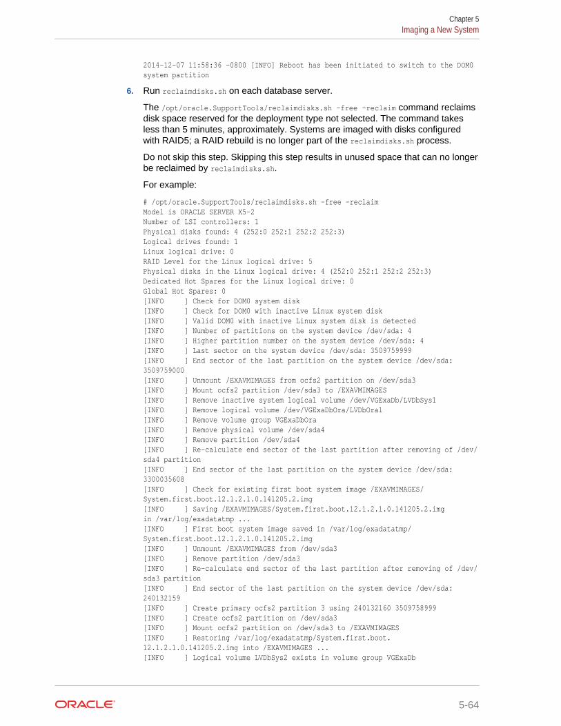
2014-12-07 11:58:36 -0800 [INFO] Reboot has been initiated to switch to the DOM0 system partition
6. Run reclaimdisks.sh on each database server.
The /opt/oracle.SupportTools/reclaimdisks.sh -free -reclaim command reclaimsdisk space reserved for the deployment type not selected. The command takesless than 5 minutes, approximately. Systems are imaged with disks configuredwith RAID5; a RAID rebuild is no longer part of the reclaimdisks.sh process.
Do not skip this step. Skipping this step results in unused space that can no longerbe reclaimed by reclaimdisks.sh.
For example:
# /opt/oracle.SupportTools/reclaimdisks.sh -free -reclaimModel is ORACLE SERVER X5-2Number of LSI controllers: 1Physical disks found: 4 (252:0 252:1 252:2 252:3)Logical drives found: 1Linux logical drive: 0RAID Level for the Linux logical drive: 5Physical disks in the Linux logical drive: 4 (252:0 252:1 252:2 252:3)Dedicated Hot Spares for the Linux logical drive: 0Global Hot Spares: 0[INFO ] Check for DOM0 system disk[INFO ] Check for DOM0 with inactive Linux system disk[INFO ] Valid DOM0 with inactive Linux system disk is detected[INFO ] Number of partitions on the system device /dev/sda: 4[INFO ] Higher partition number on the system device /dev/sda: 4[INFO ] Last sector on the system device /dev/sda: 3509759999[INFO ] End sector of the last partition on the system device /dev/sda: 3509759000[INFO ] Unmount /EXAVMIMAGES from ocfs2 partition on /dev/sda3[INFO ] Mount ocfs2 partition /dev/sda3 to /EXAVMIMAGES[INFO ] Remove inactive system logical volume /dev/VGExaDb/LVDbSys1[INFO ] Remove logical volume /dev/VGExaDbOra/LVDbOra1[INFO ] Remove volume group VGExaDbOra[INFO ] Remove physical volume /dev/sda4[INFO ] Remove partition /dev/sda4[INFO ] Re-calculate end sector of the last partition after removing of /dev/sda4 partition[INFO ] End sector of the last partition on the system device /dev/sda: 3300035608[INFO ] Check for existing first boot system image /EXAVMIMAGES/System.first.boot.12.1.2.1.0.141205.2.img[INFO ] Saving /EXAVMIMAGES/System.first.boot.12.1.2.1.0.141205.2.img in /var/log/exadatatmp ...[INFO ] First boot system image saved in /var/log/exadatatmp/System.first.boot.12.1.2.1.0.141205.2.img[INFO ] Unmount /EXAVMIMAGES from /dev/sda3[INFO ] Remove partition /dev/sda3[INFO ] Re-calculate end sector of the last partition after removing of /dev/sda3 partition[INFO ] End sector of the last partition on the system device /dev/sda: 240132159[INFO ] Create primary ocfs2 partition 3 using 240132160 3509758999[INFO ] Create ocfs2 partition on /dev/sda3[INFO ] Mount ocfs2 partition on /dev/sda3 to /EXAVMIMAGES[INFO ] Restoring /var/log/exadatatmp/System.first.boot.12.1.2.1.0.141205.2.img into /EXAVMIMAGES ...[INFO ] Logical volume LVDbSys2 exists in volume group VGExaDb
Chapter 5Imaging a New System
5-64
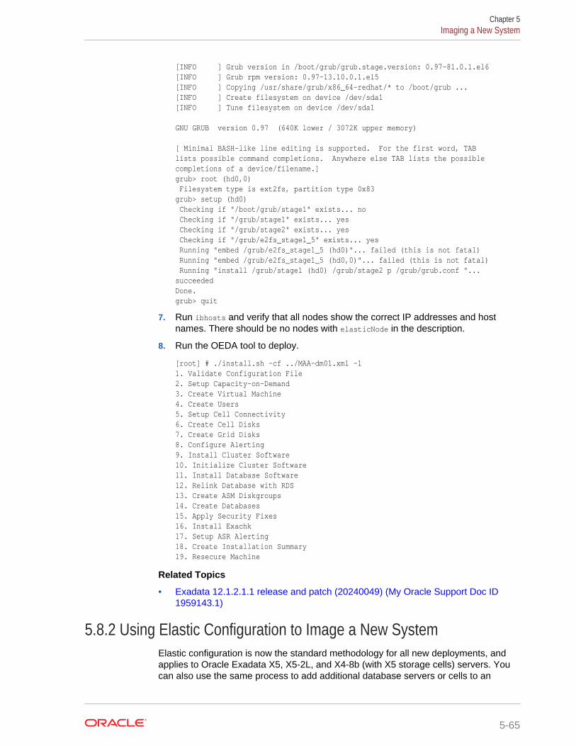
[INFO ] Grub version in /boot/grub/grub.stage.version: 0.97-81.0.1.el6[INFO ] Grub rpm version: 0.97-13.10.0.1.el5[INFO ] Copying /usr/share/grub/x86_64-redhat/* to /boot/grub ...[INFO ] Create filesystem on device /dev/sda1[INFO ] Tune filesystem on device /dev/sda1
GNU GRUB version 0.97 (640K lower / 3072K upper memory)
[ Minimal BASH-like line editing is supported. For the first word, TABlists possible command completions. Anywhere else TAB lists the possiblecompletions of a device/filename.]grub> root (hd0,0) Filesystem type is ext2fs, partition type 0x83grub> setup (hd0) Checking if "/boot/grub/stage1" exists... no Checking if "/grub/stage1" exists... yes Checking if "/grub/stage2" exists... yes Checking if "/grub/e2fs_stage1_5" exists... yes Running "embed /grub/e2fs_stage1_5 (hd0)"... failed (this is not fatal) Running "embed /grub/e2fs_stage1_5 (hd0,0)"... failed (this is not fatal) Running "install /grub/stage1 (hd0) /grub/stage2 p /grub/grub.conf "... succeededDone.grub> quit
7. Run ibhosts and verify that all nodes show the correct IP addresses and hostnames. There should be no nodes with elasticNode in the description.
8. Run the OEDA tool to deploy.
[root] # ./install.sh -cf ../MAA-dm01.xml -l1. Validate Configuration File2. Setup Capacity-on-Demand3. Create Virtual Machine 4. Create Users 5. Setup Cell Connectivity 6. Create Cell Disks 7. Create Grid Disks 8. Configure Alerting 9. Install Cluster Software 10. Initialize Cluster Software 11. Install Database Software 12. Relink Database with RDS 13. Create ASM Diskgroups 14. Create Databases 15. Apply Security Fixes 16. Install Exachk 17. Setup ASR Alerting 18. Create Installation Summary 19. Resecure Machine
Related Topics
• Exadata 12.1.2.1.1 release and patch (20240049) (My Oracle Support Doc ID1959143.1)
5.8.2 Using Elastic Configuration to Image a New SystemElastic configuration is now the standard methodology for all new deployments, andapplies to Oracle Exadata X5, X5-2L, and X4-8b (with X5 storage cells) servers. Youcan also use the same process to add additional database servers or cells to an
Chapter 5Imaging a New System
5-65
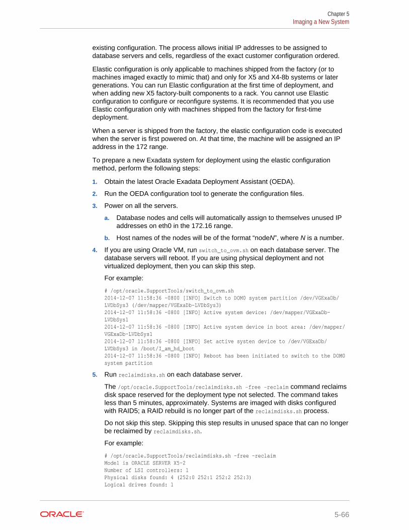
existing configuration. The process allows initial IP addresses to be assigned todatabase servers and cells, regardless of the exact customer configuration ordered.
Elastic configuration is only applicable to machines shipped from the factory (or tomachines imaged exactly to mimic that) and only for X5 and X4-8b systems or latergenerations. You can run Elastic configuration at the first time of deployment, andwhen adding new X5 factory-built components to a rack. You cannot use Elasticconfiguration to configure or reconfigure systems. It is recommended that you useElastic configuration only with machines shipped from the factory for first-timedeployment.
When a server is shipped from the factory, the elastic configuration code is executedwhen the server is first powered on. At that time, the machine will be assigned an IPaddress in the 172 range.
To prepare a new Exadata system for deployment using the elastic configurationmethod, perform the following steps:
1. Obtain the latest Oracle Exadata Deployment Assistant (OEDA).
2. Run the OEDA configuration tool to generate the configuration files.
3. Power on all the servers.
a. Database nodes and cells will automatically assign to themselves unused IPaddresses on eth0 in the 172.16 range.
b. Host names of the nodes will be of the format “nodeN”, where N is a number.
4. If you are using Oracle VM, run switch_to_ovm.sh on each database server. Thedatabase servers will reboot. If you are using physical deployment and notvirtualized deployment, then you can skip this step.
For example:
# /opt/oracle.SupportTools/switch_to_ovm.sh2014-12-07 11:58:36 -0800 [INFO] Switch to DOM0 system partition /dev/VGExaDb/LVDbSys3 (/dev/mapper/VGExaDb-LVDbSys3)2014-12-07 11:58:36 -0800 [INFO] Active system device: /dev/mapper/VGExaDb-LVDbSys12014-12-07 11:58:36 -0800 [INFO] Active system device in boot area: /dev/mapper/VGExaDb-LVDbSys12014-12-07 11:58:36 -0800 [INFO] Set active systen device to /dev/VGExaDb/LVDbSys3 in /boot/I_am_hd_boot2014-12-07 11:58:36 -0800 [INFO] Reboot has been initiated to switch to the DOM0 system partition
5. Run reclaimdisks.sh on each database server.
The /opt/oracle.SupportTools/reclaimdisks.sh -free -reclaim command reclaimsdisk space reserved for the deployment type not selected. The command takesless than 5 minutes, approximately. Systems are imaged with disks configuredwith RAID5; a RAID rebuild is no longer part of the reclaimdisks.sh process.
Do not skip this step. Skipping this step results in unused space that can no longerbe reclaimed by reclaimdisks.sh.
For example:
# /opt/oracle.SupportTools/reclaimdisks.sh -free -reclaimModel is ORACLE SERVER X5-2Number of LSI controllers: 1Physical disks found: 4 (252:0 252:1 252:2 252:3)Logical drives found: 1
Chapter 5Imaging a New System
5-66
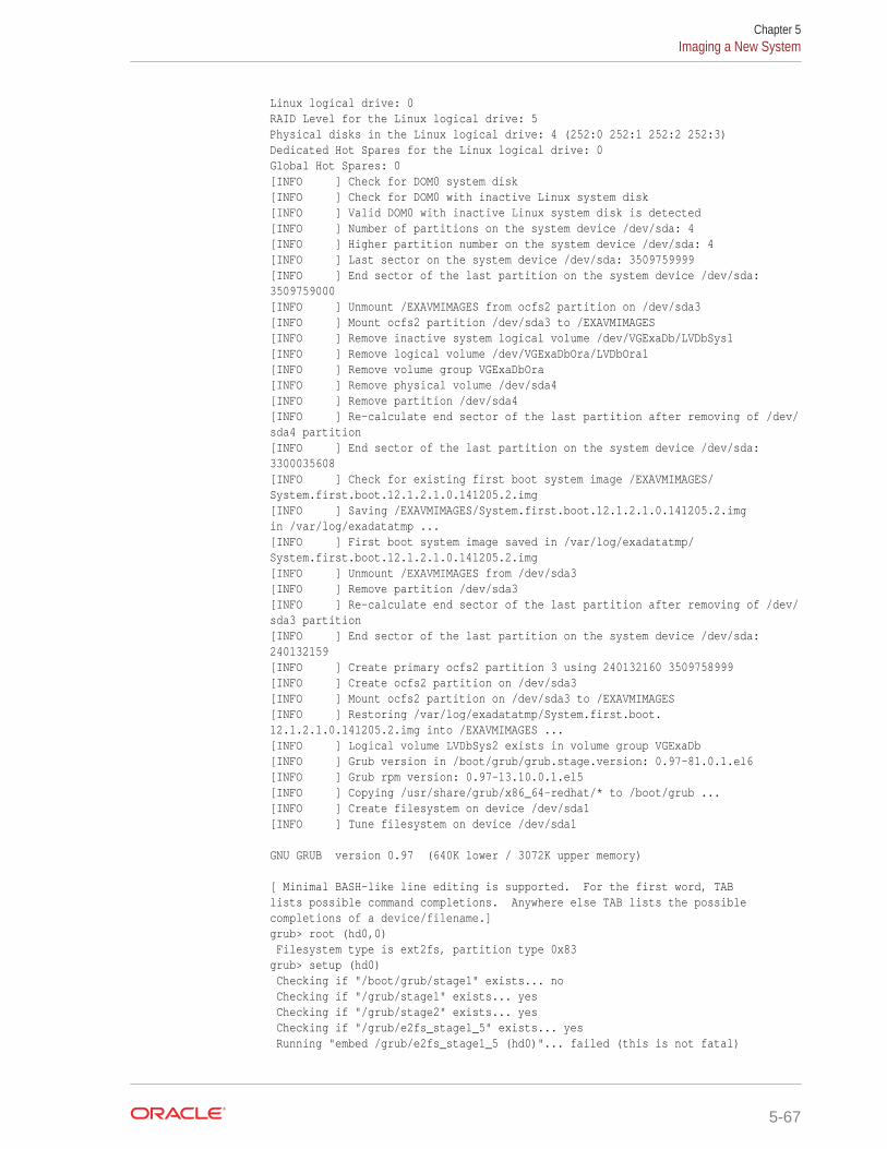
Linux logical drive: 0RAID Level for the Linux logical drive: 5Physical disks in the Linux logical drive: 4 (252:0 252:1 252:2 252:3)Dedicated Hot Spares for the Linux logical drive: 0Global Hot Spares: 0[INFO ] Check for DOM0 system disk[INFO ] Check for DOM0 with inactive Linux system disk[INFO ] Valid DOM0 with inactive Linux system disk is detected[INFO ] Number of partitions on the system device /dev/sda: 4[INFO ] Higher partition number on the system device /dev/sda: 4[INFO ] Last sector on the system device /dev/sda: 3509759999[INFO ] End sector of the last partition on the system device /dev/sda: 3509759000[INFO ] Unmount /EXAVMIMAGES from ocfs2 partition on /dev/sda3[INFO ] Mount ocfs2 partition /dev/sda3 to /EXAVMIMAGES[INFO ] Remove inactive system logical volume /dev/VGExaDb/LVDbSys1[INFO ] Remove logical volume /dev/VGExaDbOra/LVDbOra1[INFO ] Remove volume group VGExaDbOra[INFO ] Remove physical volume /dev/sda4[INFO ] Remove partition /dev/sda4[INFO ] Re-calculate end sector of the last partition after removing of /dev/sda4 partition[INFO ] End sector of the last partition on the system device /dev/sda: 3300035608[INFO ] Check for existing first boot system image /EXAVMIMAGES/System.first.boot.12.1.2.1.0.141205.2.img[INFO ] Saving /EXAVMIMAGES/System.first.boot.12.1.2.1.0.141205.2.img in /var/log/exadatatmp ...[INFO ] First boot system image saved in /var/log/exadatatmp/System.first.boot.12.1.2.1.0.141205.2.img[INFO ] Unmount /EXAVMIMAGES from /dev/sda3[INFO ] Remove partition /dev/sda3[INFO ] Re-calculate end sector of the last partition after removing of /dev/sda3 partition[INFO ] End sector of the last partition on the system device /dev/sda: 240132159[INFO ] Create primary ocfs2 partition 3 using 240132160 3509758999[INFO ] Create ocfs2 partition on /dev/sda3[INFO ] Mount ocfs2 partition on /dev/sda3 to /EXAVMIMAGES[INFO ] Restoring /var/log/exadatatmp/System.first.boot.12.1.2.1.0.141205.2.img into /EXAVMIMAGES ...[INFO ] Logical volume LVDbSys2 exists in volume group VGExaDb[INFO ] Grub version in /boot/grub/grub.stage.version: 0.97-81.0.1.el6[INFO ] Grub rpm version: 0.97-13.10.0.1.el5[INFO ] Copying /usr/share/grub/x86_64-redhat/* to /boot/grub ...[INFO ] Create filesystem on device /dev/sda1[INFO ] Tune filesystem on device /dev/sda1
GNU GRUB version 0.97 (640K lower / 3072K upper memory)
[ Minimal BASH-like line editing is supported. For the first word, TABlists possible command completions. Anywhere else TAB lists the possiblecompletions of a device/filename.]grub> root (hd0,0) Filesystem type is ext2fs, partition type 0x83grub> setup (hd0) Checking if "/boot/grub/stage1" exists... no Checking if "/grub/stage1" exists... yes Checking if "/grub/stage2" exists... yes Checking if "/grub/e2fs_stage1_5" exists... yes Running "embed /grub/e2fs_stage1_5 (hd0)"... failed (this is not fatal)
Chapter 5Imaging a New System
5-67
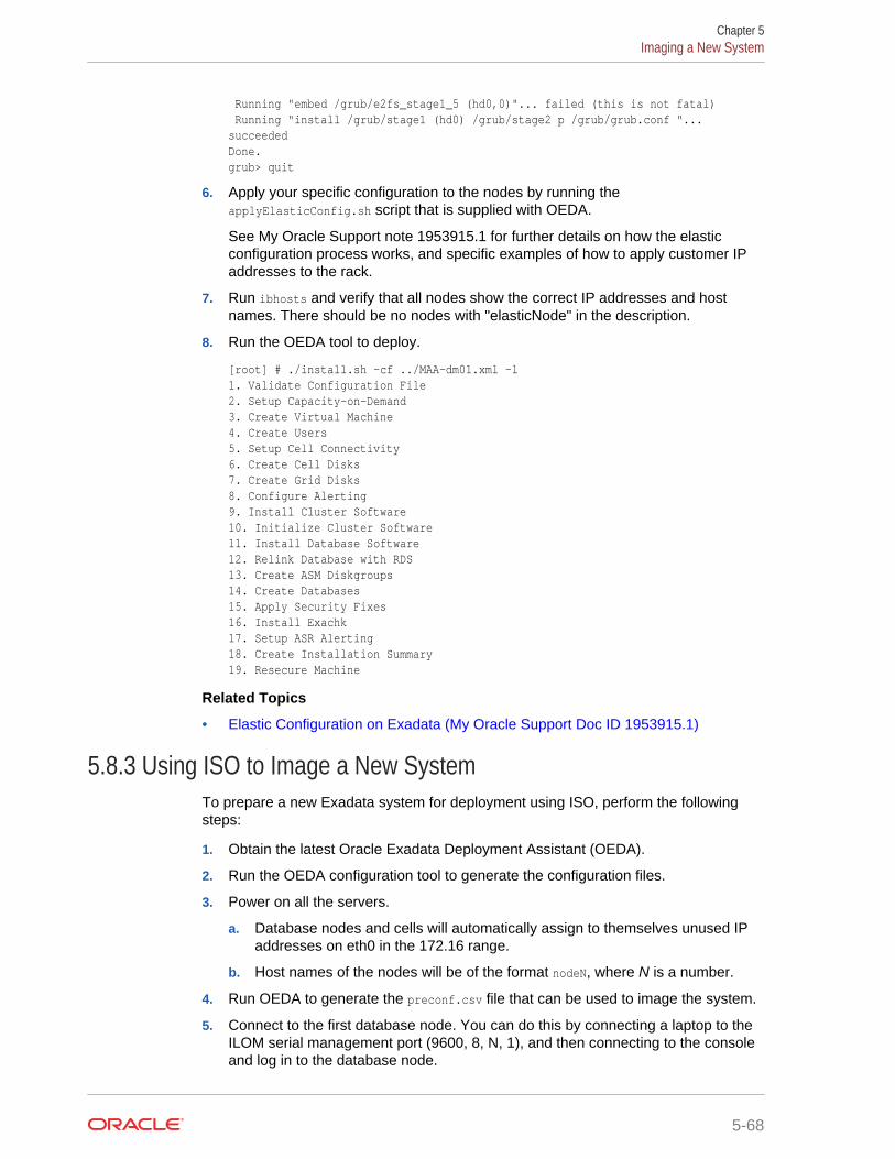
Running "embed /grub/e2fs_stage1_5 (hd0,0)"... failed (this is not fatal) Running "install /grub/stage1 (hd0) /grub/stage2 p /grub/grub.conf "... succeededDone.grub> quit
6. Apply your specific configuration to the nodes by running theapplyElasticConfig.sh script that is supplied with OEDA.
See My Oracle Support note 1953915.1 for further details on how the elasticconfiguration process works, and specific examples of how to apply customer IPaddresses to the rack.
7. Run ibhosts and verify that all nodes show the correct IP addresses and hostnames. There should be no nodes with "elasticNode" in the description.
8. Run the OEDA tool to deploy.
[root] # ./install.sh -cf ../MAA-dm01.xml -l1. Validate Configuration File2. Setup Capacity-on-Demand3. Create Virtual Machine 4. Create Users 5. Setup Cell Connectivity 6. Create Cell Disks 7. Create Grid Disks 8. Configure Alerting 9. Install Cluster Software 10. Initialize Cluster Software 11. Install Database Software 12. Relink Database with RDS 13. Create ASM Diskgroups 14. Create Databases 15. Apply Security Fixes 16. Install Exachk 17. Setup ASR Alerting 18. Create Installation Summary 19. Resecure Machine
Related Topics
• Elastic Configuration on Exadata (My Oracle Support Doc ID 1953915.1)
5.8.3 Using ISO to Image a New SystemTo prepare a new Exadata system for deployment using ISO, perform the followingsteps:
1. Obtain the latest Oracle Exadata Deployment Assistant (OEDA).
2. Run the OEDA configuration tool to generate the configuration files.
3. Power on all the servers.
a. Database nodes and cells will automatically assign to themselves unused IPaddresses on eth0 in the 172.16 range.
b. Host names of the nodes will be of the format nodeN, where N is a number.
4. Run OEDA to generate the preconf.csv file that can be used to image the system.
5. Connect to the first database node. You can do this by connecting a laptop to theILOM serial management port (9600, 8, N, 1), and then connecting to the consoleand log in to the database node.
Chapter 5Imaging a New System
5-68
6. Obtain the eth0 MAC address for each database node. This is the fru_macaddressfield from /SYS/MB/NET0 in the ILOM (or through ip addr if logged into the console).
a. Connect to the other database nodes using ssh from the console.
b. Run ibhosts to get a list of node names and IP addresses.
7. Insert the MAC addresses using uppercase characters in the seventh field of thepreconf.csv file for each node. This field should be empty, that is, you should seetwo consecutive comma characters (,,). For example:
orhb42-b08-01,us.oracle.com,db,eth0,eth0,Management,00:10:E0:69:34:52,10.196.3.106,255.255.224.0,10.196.31.250,orhb42-b08-01-priv,Private:active-bond-ib,192.168.10.15,255.255.255.0,,,America/Los_Angeles
8. Run ipconf to verify the generated preconf.csv file. This can be done on anyExadata server, and although not required, it is useful to ensure the preconf.csv isvalid before proceeding.
# ipconf -verify -preconf /tmp/preconf.csv[Info]: ipconf command line: /opt/oracle.cellos/ipconf.pl -verify -preconf /tmp/preconf -nocodes[Done]: Pre config verification OK
9. If you are using versions prior to 12.1.2.2.0, proceed to step 11 to useImageMaker to create the image files.
If you are using version 12.1.2.2.0 or later, it is no longer necessary to useimagemaker to create the image files. The relevant PXE, ISO, and USB image fileshave already been created in the patches themselves. Simply download the patchcontaining the prebuilt image file from Oracle Software Delivery Cloud and placethe downloaded ISO .iso image file in the appropriate location. For 12.1.2.2.0 thepatch numbers can be obtained from My Oracle Support note 2038073.1. Thereare separate ImageMaker files for database nodes and cells.
Note : For image version 12.1.2.2.0 the format of the downloadable imagefiles has changed.
There will be an image file in the downloaded zip file. For example, the databasenode zip file will contain:
compute_12.1.2.2.0_LINUX.X64_150917-1.x86_64.iso
For cell image, the file will be similar to:
cell_12.1.2.2.0_LINUX.X64_150917-1.x86_64.iso
10. (For 12.1.2.2.0 and above) Follow the steps in the patch README.txt to copy theISO file and optional preconf.csv file into place.
a. After download, unzip the file as root user for the following ISO image.
b2d6d9ac61e2e673d05fba11ec65107d compute_12.1.2.2.0_LINUX.X64_150917-1.x86_64.iso
Chapter 5Imaging a New System
5-69
Note:
• ISO + preconf.csv is supported only if the ISO image ismounted on an NFS repository in ILOM and the preconf.csvfile is located in the same NFS directory. All other methods ofmounting the ISO image in ILOM (SAMBA URI and JavaRemote Console) and burning ISO image to DVD will not workwith the preconf.csv file. For instructions on how to mount theISO image from a NFS central repository, see "Configure a HostStorage Device Redirection Session" in the Oracle X5 SeriesServers Administration Guide
• Because of possible late echos of text to the console, be awarethat the boot process will be waiting for input to complete theinteractive ipconf by prompting for Nameserver:
• Due to a bug, ipconf will prompt you twice to enter the networksettings.
b. Proceed to step 15, and boot the system with the ISO image and followinstallation prompts. The ISO can be made available with a preconf.csvfollowing the steps in the Note box above, or as virtual media on the ILOM ofthe node to be reimaged when a preconf.csv is not used.
Steps 11 to 14, which create the image files, can be skipped.
11. Download the imagemaker kit to prepare and create the files for the USB drive.
This kit is available publicly on the Oracle Software Delivery Cloud(edelivery.oracle.com) site under “Oracle Database Products -> Linux x86-64”.There are separate ImageMaker files for database nodes and cells.
12. After download, unzip the first file, called something similar to V75080-01.zip, andthen unzip the subsequent file as well. Perform the unzips as the root user. Thenuntar the file.
# unzip V75080-01.zip
# unzip cellImageMaker_12.1.2.1.1_LINUX.X64_150316.2-1.x86_64.zip
# tar -pxvf cellImageMaker_12.1.2.1.1_LINUX.X64_150316.2-1.x86_64.tar
View the README_FOR_FACTORY.txt file in the resulting directory for additional details.
13. Run makeImageMedia.sh to build the ISO file for imaging.
For building images for 12.1.2.1.0 and above, the recommendedmakeImageMedia.sh options for building ISO images are:
a. (12.1.2.1.0 up to 12.2.1.1.0) Change directory to the dl180 or dl360 directory.
b. (12.2.1.1.0 and above) Change directory to the cell or compute directory.
c. Make the ISO file.
./makeImageMedia.sh -factory -stit -reboot-on-success -nodisktests [-preconf preconf_file] filename.iso
For ISO imaging, note that you must run makeImageMedia.sh from an OracleExadata database server if you are using the -preconf option.
Chapter 5Imaging a New System
5-70
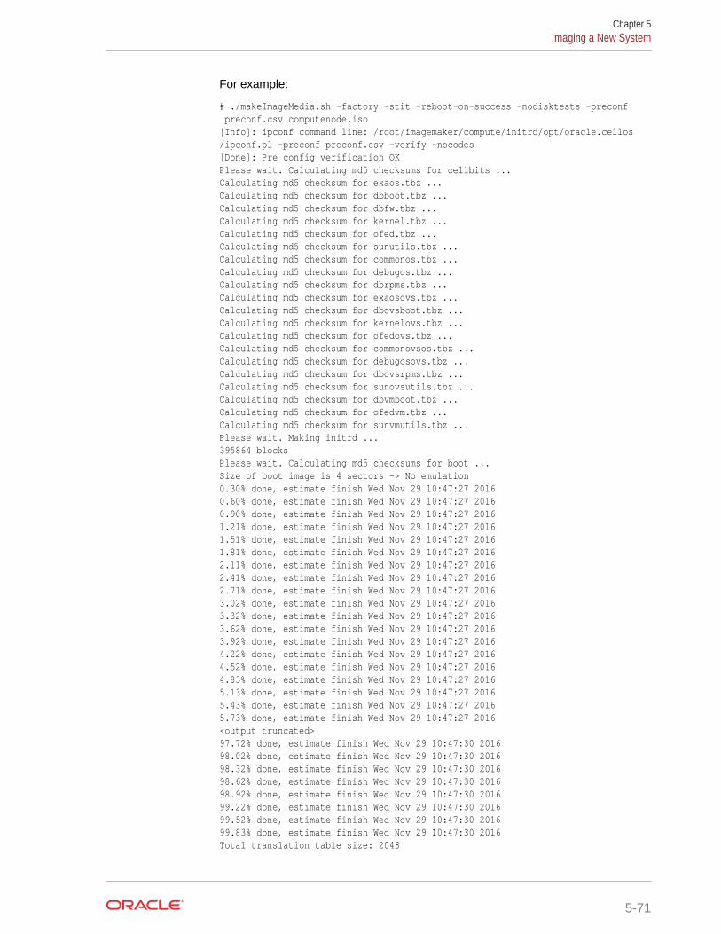
For example:
# ./makeImageMedia.sh -factory -stit -reboot-on-success -nodisktests -preconf preconf.csv computenode.iso[Info]: ipconf command line: /root/imagemaker/compute/initrd/opt/oracle.cellos/ipconf.pl -preconf preconf.csv -verify -nocodes[Done]: Pre config verification OKPlease wait. Calculating md5 checksums for cellbits ...Calculating md5 checksum for exaos.tbz ...Calculating md5 checksum for dbboot.tbz ...Calculating md5 checksum for dbfw.tbz ...Calculating md5 checksum for kernel.tbz ...Calculating md5 checksum for ofed.tbz ...Calculating md5 checksum for sunutils.tbz ...Calculating md5 checksum for commonos.tbz ...Calculating md5 checksum for debugos.tbz ...Calculating md5 checksum for dbrpms.tbz ...Calculating md5 checksum for exaosovs.tbz ...Calculating md5 checksum for dbovsboot.tbz ...Calculating md5 checksum for kernelovs.tbz ...Calculating md5 checksum for ofedovs.tbz ...Calculating md5 checksum for commonovsos.tbz ...Calculating md5 checksum for debugosovs.tbz ...Calculating md5 checksum for dbovsrpms.tbz ...Calculating md5 checksum for sunovsutils.tbz ...Calculating md5 checksum for dbvmboot.tbz ...Calculating md5 checksum for ofedvm.tbz ...Calculating md5 checksum for sunvmutils.tbz ...Please wait. Making initrd ...395864 blocksPlease wait. Calculating md5 checksums for boot ...Size of boot image is 4 sectors -> No emulation0.30% done, estimate finish Wed Nov 29 10:47:27 20160.60% done, estimate finish Wed Nov 29 10:47:27 20160.90% done, estimate finish Wed Nov 29 10:47:27 20161.21% done, estimate finish Wed Nov 29 10:47:27 20161.51% done, estimate finish Wed Nov 29 10:47:27 20161.81% done, estimate finish Wed Nov 29 10:47:27 20162.11% done, estimate finish Wed Nov 29 10:47:27 20162.41% done, estimate finish Wed Nov 29 10:47:27 20162.71% done, estimate finish Wed Nov 29 10:47:27 20163.02% done, estimate finish Wed Nov 29 10:47:27 20163.32% done, estimate finish Wed Nov 29 10:47:27 20163.62% done, estimate finish Wed Nov 29 10:47:27 20163.92% done, estimate finish Wed Nov 29 10:47:27 20164.22% done, estimate finish Wed Nov 29 10:47:27 20164.52% done, estimate finish Wed Nov 29 10:47:27 20164.83% done, estimate finish Wed Nov 29 10:47:27 20165.13% done, estimate finish Wed Nov 29 10:47:27 20165.43% done, estimate finish Wed Nov 29 10:47:27 20165.73% done, estimate finish Wed Nov 29 10:47:27 2016<output truncated>97.72% done, estimate finish Wed Nov 29 10:47:30 201698.02% done, estimate finish Wed Nov 29 10:47:30 201698.32% done, estimate finish Wed Nov 29 10:47:30 201698.62% done, estimate finish Wed Nov 29 10:47:30 201698.92% done, estimate finish Wed Nov 29 10:47:30 201699.22% done, estimate finish Wed Nov 29 10:47:30 201699.52% done, estimate finish Wed Nov 29 10:47:30 201699.83% done, estimate finish Wed Nov 29 10:47:30 2016Total translation table size: 2048
Chapter 5Imaging a New System
5-71
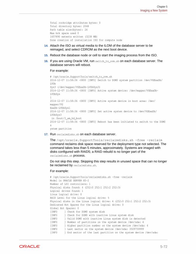
Total rockridge attributes bytes: 0Total directory bytes: 2048Path table size(bytes): 26Max brk space used 01657890 extents written (3238 MB)Done creation of installation ISO for compute node
14. Attach the ISO as virtual media to the ILOM of the database server to bereimaged, and select CDROM as the next boot device.
15. Reboot the database node or cell to start the imaging process from the ISO.
16. If you are using Oracle VM, run switch_to_ovm.sh on each database server. Thedatabase servers will reboot.
For example:
# /opt/oracle.SupportTools/switch_to_ovm.sh2014-12-07 11:58:36 -0800 [INFO] Switch to DOM0 system partition /dev/VGExaDb/LVDbSys3 (/dev/mapper/VGExaDb-LVDbSys3)2014-12-07 11:58:36 -0800 [INFO] Active system device: /dev/mapper/VGExaDb-LVDbSys12014-12-07 11:58:36 -0800 [INFO] Active system device in boot area: /dev/mapper/VGExaDb-LVDbSys12014-12-07 11:58:36 -0800 [INFO] Set active systen device to /dev/VGExaDb/LVDbSys3 in /boot/I_am_hd_boot2014-12-07 11:58:36 -0800 [INFO] Reboot has been initiated to switch to the DOM0 system partition
17. Run reclaimdisks.sh on each database server.
The /opt/oracle.SupportTools/reclaimdisks.sh -free -reclaimcommand reclaims disk space reserved for the deployment type not selected. Thecommand takes less than 5 minutes, approximately. Systems are imaged withdisks configured with RAID5; a RAID rebuild is no longer part of thereclaimdisks.sh process.
Do not skip this step. Skipping this step results in unused space that can no longerbe reclaimed by reclaimdisks.sh.
For example:
# /opt/oracle.SupportTools/reclaimdisks.sh -free -reclaimModel is ORACLE SERVER X5-2Number of LSI controllers: 1Physical disks found: 4 (252:0 252:1 252:2 252:3)Logical drives found: 1Linux logical drive: 0RAID Level for the Linux logical drive: 5Physical disks in the Linux logical drive: 4 (252:0 252:1 252:2 252:3)Dedicated Hot Spares for the Linux logical drive: 0Global Hot Spares: 0[INFO ] Check for DOM0 system disk[INFO ] Check for DOM0 with inactive Linux system disk[INFO ] Valid DOM0 with inactive Linux system disk is detected[INFO ] Number of partitions on the system device /dev/sda: 4[INFO ] Higher partition number on the system device /dev/sda: 4[INFO ] Last sector on the system device /dev/sda: 3509759999[INFO ] End sector of the last partition on the system device /dev/sda:
Chapter 5Imaging a New System
5-72
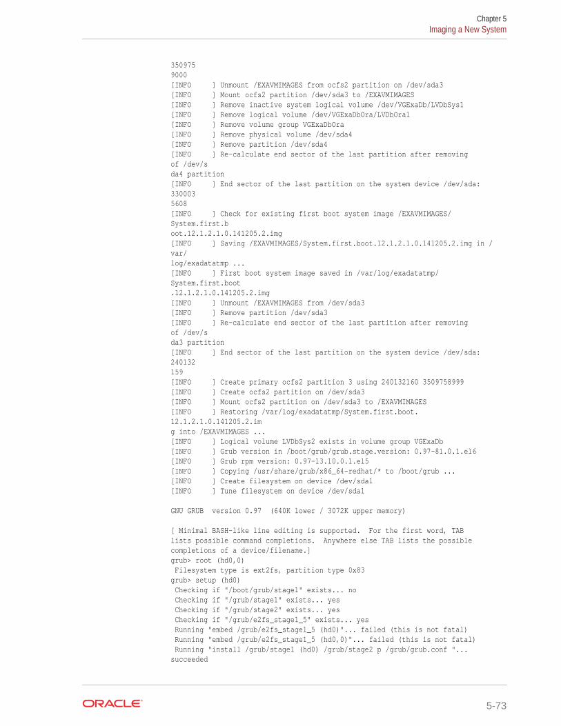
3509759000[INFO ] Unmount /EXAVMIMAGES from ocfs2 partition on /dev/sda3[INFO ] Mount ocfs2 partition /dev/sda3 to /EXAVMIMAGES[INFO ] Remove inactive system logical volume /dev/VGExaDb/LVDbSys1[INFO ] Remove logical volume /dev/VGExaDbOra/LVDbOra1[INFO ] Remove volume group VGExaDbOra[INFO ] Remove physical volume /dev/sda4[INFO ] Remove partition /dev/sda4[INFO ] Re-calculate end sector of the last partition after removing of /dev/sda4 partition[INFO ] End sector of the last partition on the system device /dev/sda: 3300035608[INFO ] Check for existing first boot system image /EXAVMIMAGES/System.first.boot.12.1.2.1.0.141205.2.img[INFO ] Saving /EXAVMIMAGES/System.first.boot.12.1.2.1.0.141205.2.img in /var/log/exadatatmp ...[INFO ] First boot system image saved in /var/log/exadatatmp/System.first.boot.12.1.2.1.0.141205.2.img[INFO ] Unmount /EXAVMIMAGES from /dev/sda3[INFO ] Remove partition /dev/sda3[INFO ] Re-calculate end sector of the last partition after removing of /dev/sda3 partition[INFO ] End sector of the last partition on the system device /dev/sda: 240132159[INFO ] Create primary ocfs2 partition 3 using 240132160 3509758999[INFO ] Create ocfs2 partition on /dev/sda3[INFO ] Mount ocfs2 partition on /dev/sda3 to /EXAVMIMAGES[INFO ] Restoring /var/log/exadatatmp/System.first.boot.12.1.2.1.0.141205.2.img into /EXAVMIMAGES ...[INFO ] Logical volume LVDbSys2 exists in volume group VGExaDb[INFO ] Grub version in /boot/grub/grub.stage.version: 0.97-81.0.1.el6[INFO ] Grub rpm version: 0.97-13.10.0.1.el5[INFO ] Copying /usr/share/grub/x86_64-redhat/* to /boot/grub ...[INFO ] Create filesystem on device /dev/sda1[INFO ] Tune filesystem on device /dev/sda1
GNU GRUB version 0.97 (640K lower / 3072K upper memory)
[ Minimal BASH-like line editing is supported. For the first word, TABlists possible command completions. Anywhere else TAB lists the possiblecompletions of a device/filename.]grub> root (hd0,0) Filesystem type is ext2fs, partition type 0x83grub> setup (hd0) Checking if "/boot/grub/stage1" exists... no Checking if "/grub/stage1" exists... yes Checking if "/grub/stage2" exists... yes Checking if "/grub/e2fs_stage1_5" exists... yes Running "embed /grub/e2fs_stage1_5 (hd0)"... failed (this is not fatal) Running "embed /grub/e2fs_stage1_5 (hd0,0)"... failed (this is not fatal) Running "install /grub/stage1 (hd0) /grub/stage2 p /grub/grub.conf "... succeeded
Chapter 5Imaging a New System
5-73
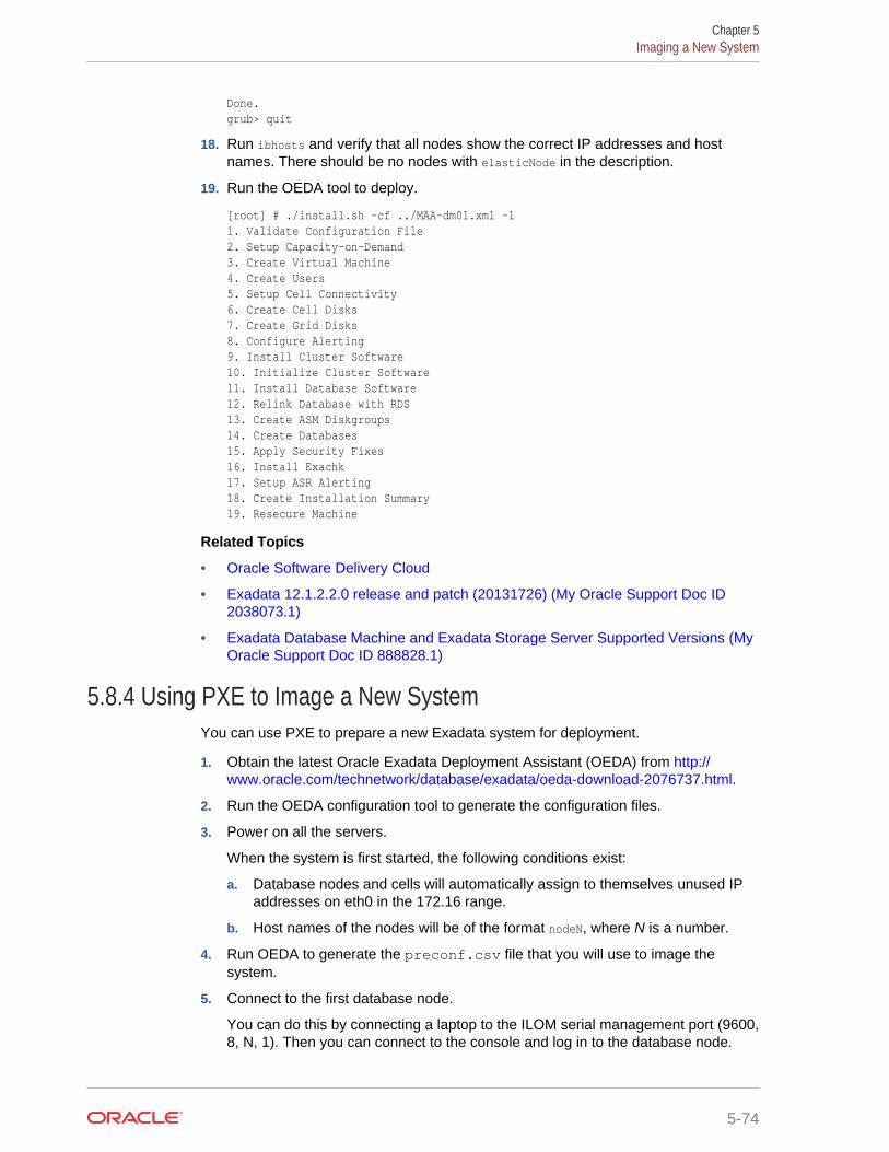
Done.grub> quit
18. Run ibhosts and verify that all nodes show the correct IP addresses and hostnames. There should be no nodes with elasticNode in the description.
19. Run the OEDA tool to deploy.
[root] # ./install.sh -cf ../MAA-dm01.xml -l1. Validate Configuration File2. Setup Capacity-on-Demand3. Create Virtual Machine 4. Create Users 5. Setup Cell Connectivity 6. Create Cell Disks 7. Create Grid Disks 8. Configure Alerting 9. Install Cluster Software 10. Initialize Cluster Software 11. Install Database Software 12. Relink Database with RDS 13. Create ASM Diskgroups 14. Create Databases 15. Apply Security Fixes 16. Install Exachk 17. Setup ASR Alerting 18. Create Installation Summary 19. Resecure Machine
Related Topics
• Oracle Software Delivery Cloud
• Exadata 12.1.2.2.0 release and patch (20131726) (My Oracle Support Doc ID2038073.1)
• Exadata Database Machine and Exadata Storage Server Supported Versions (MyOracle Support Doc ID 888828.1)
5.8.4 Using PXE to Image a New SystemYou can use PXE to prepare a new Exadata system for deployment.
1. Obtain the latest Oracle Exadata Deployment Assistant (OEDA) from http://www.oracle.com/technetwork/database/exadata/oeda-download-2076737.html.
2. Run the OEDA configuration tool to generate the configuration files.
3. Power on all the servers.
When the system is first started, the following conditions exist:
a. Database nodes and cells will automatically assign to themselves unused IPaddresses on eth0 in the 172.16 range.
b. Host names of the nodes will be of the format nodeN, where N is a number.
4. Run OEDA to generate the preconf.csv file that you will use to image thesystem.
5. Connect to the first database node.
You can do this by connecting a laptop to the ILOM serial management port (9600,8, N, 1). Then you can connect to the console and log in to the database node.
Chapter 5Imaging a New System
5-74
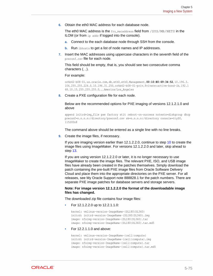
6. Obtain the eth0 MAC address for each database node.
The eth0 MAC address is the fru_macaddress field from /SYS/MB/NET0 in theILOM (or from ip addr if logged into the console).
a. Connect to the each database node through SSH from the console.
b. Run ibhosts to get a list of node names and IP addresses.
7. Insert the MAC addresses using uppercase characters in the seventh field of thepreconf.csv file for each node.
This field should be empty, that is, you should see two consecutive commacharacters (,,).
For example:
orhb42-b08-01,us.oracle.com,db,eth0,eth0,Management,00:10:E0:69:34:52,10.196.3.106,255.255.224.0,10.196.31.250,orhb42-b08-01-priv,Private:active-bond-ib,192.168.10.15,255.255.255.0,,,America/Los_Angeles
8. Create a PXE configuration file for each node.
Below are the recommended options for PXE imaging of versions 12.1.2.1.0 andabove
append initrd=img_file pxe factory stit reboot-on-success notests=diskgroup dhcp preconf=n.n.n.n:/directory/preconf.csv sk=n.n.n.n:/directory console=ttyS0,115200n8
The command above should be entered as a single line with no line breaks.
9. Create the image files, if necessary.
If you are imaging version earlier than 12.1.2.2.0, continue to step 10 to create theimage files using ImageMaker. For versions 12.1.2.2.0 and later, skip ahead tostep 13.
If you are using version 12.1.2.2.0 or later, it is no longer necessary to useImageMaker to create the image files. The relevant PXE, ISO, and USB imagefiles have already been created in the patches themselves. Simply download thepatch containing the pre-built PXE image files from Oracle Software DeliveryCloud and place them into the appropriate directories on the PXE server. For allreleases, see My Oracle Support note 888828.1 for the patch numbers. There areseparate PXE image patches for database servers and storage servers.
Note: For image version 12.1.2.2.0 the format of the downloadable imagefiles has changed.
The downloaded zip file contains four image files:
• For 12.1.2.2.0 up to 12.2.1.1.0:
kernel: vmlinux-version-ImageName-{DL180|DL360}initrd: initrd-version-ImageName-{DL180|DL360}.imgimage: nfsimg-version-ImageName-{DL180|DL360}.tarimage: nfsimg-version-ImageName-{DL180|DL360}.tar.md5
• For 12.2.1.1.0 and above:
kernel: vmlinux-version-ImageName-{cell|compute}initrd: initrd-version-ImageName-{cell|compute}.imgimage: nfsimg-version-ImageName-{cell|compute}.tarimage: nfsimg-version-ImageName-{cell|compute}.tar.md5
Chapter 5Imaging a New System
5-75
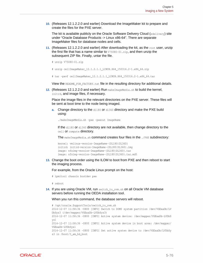
10. (Releases 12.1.2.2.0 and earlier) Download the ImageMaker kit to prepare andcreate the files for the PXE server.
The kit is available publicly on the Oracle Software Delivery Cloud (edelivery) siteunder “Oracle Database Products -> Linux x86-64”. There are separateImageMaker files for database nodes and cells.
11. (Releases 12.1.2.2.0 and earlier) After downloading the kit, as the root user, unzipthe first file that has a name similar to V75080-01.zip, and then unzip thesubsequent ZIP file. Finally, untar the file.
# unzip V75080-01.zip
# unzip cellImageMaker_12.1.2.1.1_LINUX.X64_150316.2-1.x86_64.zip
# tar -pxvf cellImageMaker_12.1.2.1.1_LINUX.X64_150316.2-1.x86_64.tar
View the README_FOR_FACTORY.txt file in the resulting directory for additional details.
12. (Releases 12.1.2.2.0 and earlier) Run makeImageMedia.sh to build the kernel,initrd, and image files, if necessary.
Place the image files in the relevant directories on the PXE server. These files willbe sent at boot time to the node being imaged.
a. Change directory to the dl180 or dl360 directory and make the PXE buildusing:
./makeImageMedia.sh -pxe -pxeout ImageName
If the dl180 or dl360 directory are not available, then change directory to thecell or compute directory.
The makeImageMedia.sh command creates four files in the ./PXE subdirectory:
kernel: vmlinux-version-ImageName-{DL180|DL360}initrd: initrd-version-ImageName-{DL180|DL360}.imgimage: nfsimg-version-ImageName-{DL180|DL360}.tarimage: nfsimg-version-ImageName-{DL180|DL360}.tar.md5
13. Change the boot order using the ILOM to boot from PXE and then reboot to startthe imaging process.
For example, from the Oracle Linux prompt on the host:
# ipmitool chassis bootdev pxe
# reboot
14. If you are using Oracle VM, run switch_to_ovm.sh on all Oracle VM databaseservers before running the OEDA installation tool.
When you run this command, the database servers will reboot.
# /opt/oracle.SupportTools/switch_to_ovm.sh2014-12-07 11:58:36 -0800 [INFO] Switch to DOM0 system partition /dev/VGExaDb/LVDbSys3 (/dev/mapper/VGExaDb-LVDbSys3)2014-12-07 11:58:36 -0800 [INFO] Active system device: /dev/mapper/VGExaDb-LVDbSys12014-12-07 11:58:36 -0800 [INFO] Active system device in boot area: /dev/mapper/VGExaDb-LVDbSys12014-12-07 11:58:36 -0800 [INFO] Set active systen device to /dev/VGExaDb/LVDbSys3 in /boot/I_am_hd_boot
Chapter 5Imaging a New System
5-76
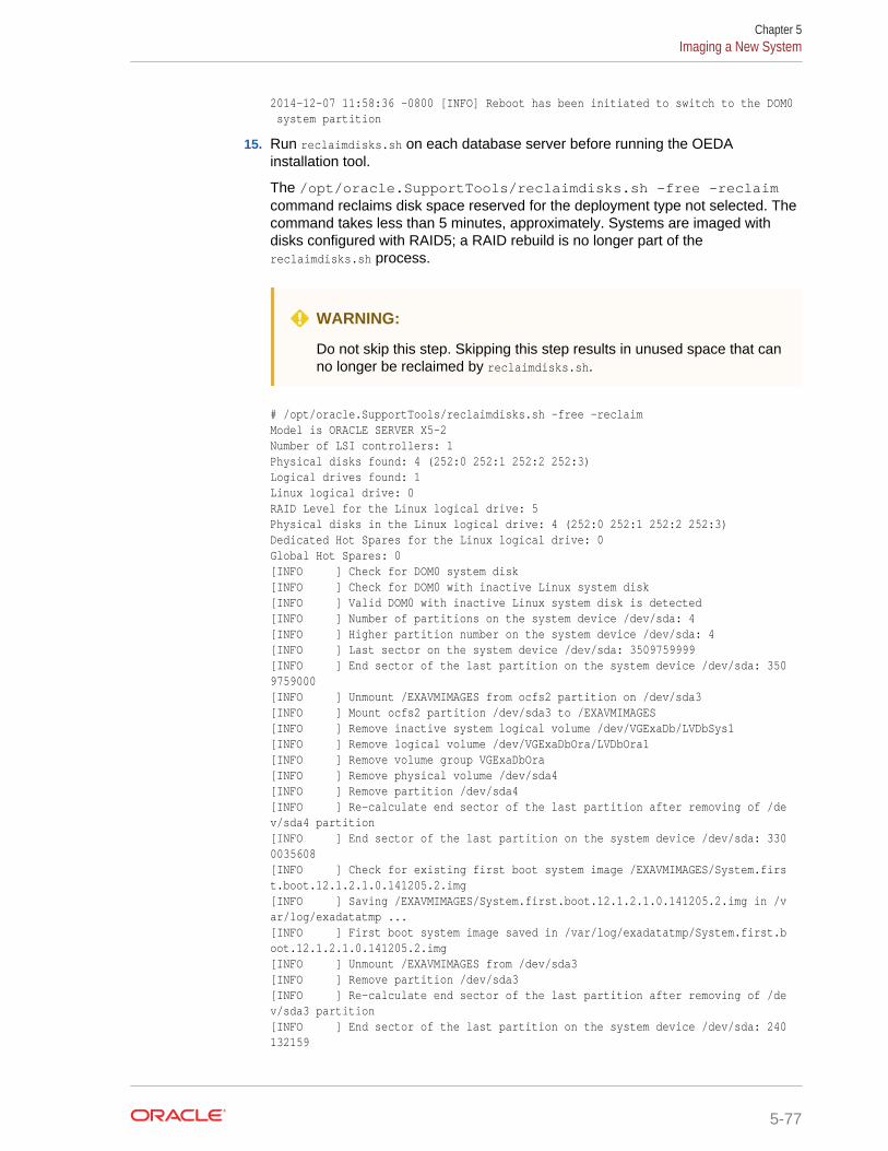
2014-12-07 11:58:36 -0800 [INFO] Reboot has been initiated to switch to the DOM0 system partition
15. Run reclaimdisks.sh on each database server before running the OEDAinstallation tool.
The /opt/oracle.SupportTools/reclaimdisks.sh -free -reclaimcommand reclaims disk space reserved for the deployment type not selected. Thecommand takes less than 5 minutes, approximately. Systems are imaged withdisks configured with RAID5; a RAID rebuild is no longer part of thereclaimdisks.sh process.
WARNING:
Do not skip this step. Skipping this step results in unused space that canno longer be reclaimed by reclaimdisks.sh.
# /opt/oracle.SupportTools/reclaimdisks.sh -free -reclaimModel is ORACLE SERVER X5-2Number of LSI controllers: 1Physical disks found: 4 (252:0 252:1 252:2 252:3)Logical drives found: 1Linux logical drive: 0RAID Level for the Linux logical drive: 5Physical disks in the Linux logical drive: 4 (252:0 252:1 252:2 252:3)Dedicated Hot Spares for the Linux logical drive: 0Global Hot Spares: 0[INFO ] Check for DOM0 system disk[INFO ] Check for DOM0 with inactive Linux system disk[INFO ] Valid DOM0 with inactive Linux system disk is detected[INFO ] Number of partitions on the system device /dev/sda: 4[INFO ] Higher partition number on the system device /dev/sda: 4[INFO ] Last sector on the system device /dev/sda: 3509759999[INFO ] End sector of the last partition on the system device /dev/sda: 3509759000[INFO ] Unmount /EXAVMIMAGES from ocfs2 partition on /dev/sda3[INFO ] Mount ocfs2 partition /dev/sda3 to /EXAVMIMAGES[INFO ] Remove inactive system logical volume /dev/VGExaDb/LVDbSys1[INFO ] Remove logical volume /dev/VGExaDbOra/LVDbOra1[INFO ] Remove volume group VGExaDbOra[INFO ] Remove physical volume /dev/sda4[INFO ] Remove partition /dev/sda4[INFO ] Re-calculate end sector of the last partition after removing of /dev/sda4 partition[INFO ] End sector of the last partition on the system device /dev/sda: 3300035608[INFO ] Check for existing first boot system image /EXAVMIMAGES/System.first.boot.12.1.2.1.0.141205.2.img[INFO ] Saving /EXAVMIMAGES/System.first.boot.12.1.2.1.0.141205.2.img in /var/log/exadatatmp ...[INFO ] First boot system image saved in /var/log/exadatatmp/System.first.boot.12.1.2.1.0.141205.2.img[INFO ] Unmount /EXAVMIMAGES from /dev/sda3[INFO ] Remove partition /dev/sda3[INFO ] Re-calculate end sector of the last partition after removing of /dev/sda3 partition[INFO ] End sector of the last partition on the system device /dev/sda: 240132159
Chapter 5Imaging a New System
5-77
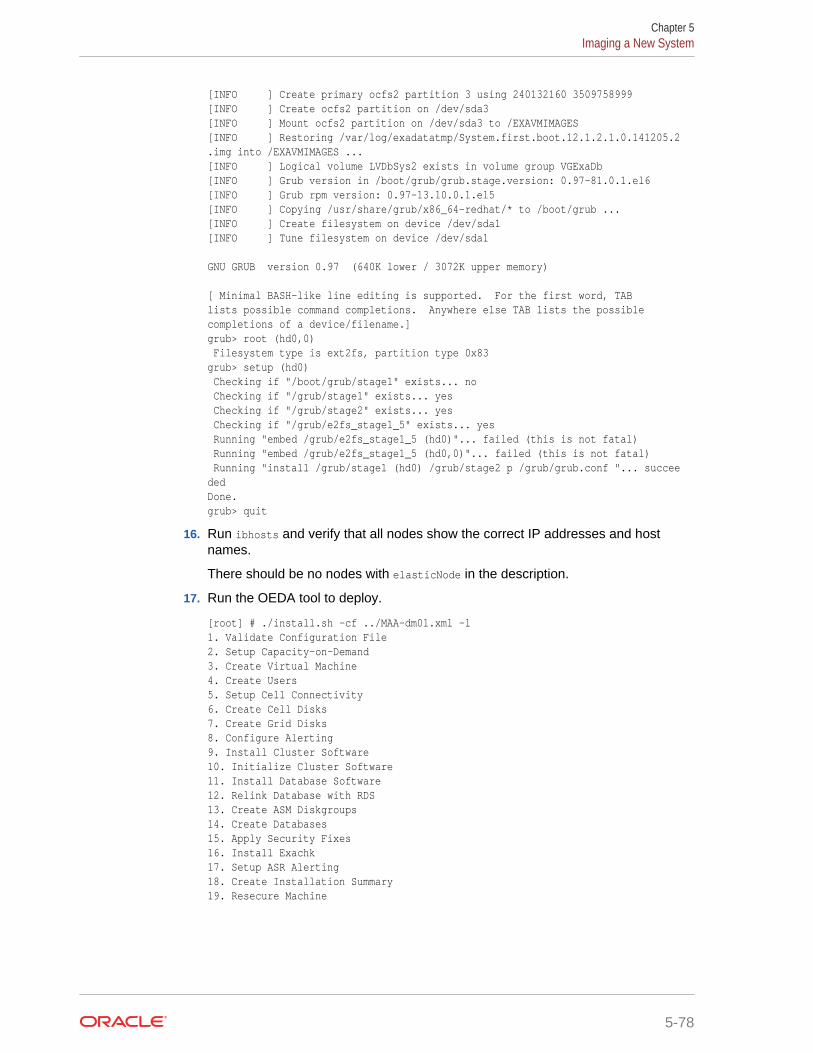
[INFO ] Create primary ocfs2 partition 3 using 240132160 3509758999[INFO ] Create ocfs2 partition on /dev/sda3[INFO ] Mount ocfs2 partition on /dev/sda3 to /EXAVMIMAGES[INFO ] Restoring /var/log/exadatatmp/System.first.boot.12.1.2.1.0.141205.2.img into /EXAVMIMAGES ...[INFO ] Logical volume LVDbSys2 exists in volume group VGExaDb[INFO ] Grub version in /boot/grub/grub.stage.version: 0.97-81.0.1.el6[INFO ] Grub rpm version: 0.97-13.10.0.1.el5[INFO ] Copying /usr/share/grub/x86_64-redhat/* to /boot/grub ...[INFO ] Create filesystem on device /dev/sda1[INFO ] Tune filesystem on device /dev/sda1
GNU GRUB version 0.97 (640K lower / 3072K upper memory)
[ Minimal BASH-like line editing is supported. For the first word, TABlists possible command completions. Anywhere else TAB lists the possiblecompletions of a device/filename.]grub> root (hd0,0) Filesystem type is ext2fs, partition type 0x83grub> setup (hd0) Checking if "/boot/grub/stage1" exists... no Checking if "/grub/stage1" exists... yes Checking if "/grub/stage2" exists... yes Checking if "/grub/e2fs_stage1_5" exists... yes Running "embed /grub/e2fs_stage1_5 (hd0)"... failed (this is not fatal) Running "embed /grub/e2fs_stage1_5 (hd0,0)"... failed (this is not fatal) Running "install /grub/stage1 (hd0) /grub/stage2 p /grub/grub.conf "... succeededDone.grub> quit
16. Run ibhosts and verify that all nodes show the correct IP addresses and hostnames.
There should be no nodes with elasticNode in the description.
17. Run the OEDA tool to deploy.
[root] # ./install.sh -cf ../MAA-dm01.xml -l1. Validate Configuration File2. Setup Capacity-on-Demand3. Create Virtual Machine 4. Create Users 5. Setup Cell Connectivity 6. Create Cell Disks 7. Create Grid Disks 8. Configure Alerting 9. Install Cluster Software 10. Initialize Cluster Software 11. Install Database Software 12. Relink Database with RDS 13. Create ASM Diskgroups 14. Create Databases 15. Apply Security Fixes 16. Install Exachk 17. Setup ASR Alerting 18. Create Installation Summary 19. Resecure Machine
Chapter 5Imaging a New System
5-78
5.8.5 Using USB to Image a New SystemTo prepare a new Exadata system for deployment using USB, perform the followingsteps:
1. Obtain the latest Oracle Exadata Deployment Assistant (OEDA).
2. Run OEDA to generate the preconf.csv file that you can use to image the system.
3. Power on all the servers.
a. Database nodes and cells will automatically assign to themselves unused IPaddresses on eth0 in the 172.16 range.
b. Host names of the nodes will be of the format nodeN, where N is a number.
4. Connect to the first database node. You can do this by connecting a laptop to theILOM serial management port (9600, 8, N, 1), and then connecting to the consoleand logging in to the database node.
5. Obtain the eth0 MAC address for each database node. This is the fru_macaddressfield from /SYS/MB/NET0 in the ILOM, or use the command ip addr if logged intothe console.
a. Connect to the other database nodes using SSH from the console.
b. Run ibhosts to get a list of node names and IP addresses.
6. Insert the MAC addresses using uppercase characters in the seventh field of thepreconf.csv file for each node. This field should be empty, that is, you should seetwo consecutive comma characters (,,). For example, if the MAC address is00:10:E0:69:34:52:
orhb42-b08-01,us.oracle.com,db,eth0,eth0,Management,00:10:E0:69:34:52,10.196.3.106,255.255.224.0,10.196.31.250,orhb42-b08-01-priv,Private:active-bond-ib,192.168.10.15,255.255.255.0,,,America/Los_Angeles
7. Run ipconf to verify the generated preconf.csv file. This can be done on anyOracle Exadata server, and although not required, it is useful to ensure thepreconf.csv file is valid before proceeding.
# ipconf -verify -preconf /tmp/preconf.csv[Info]: ipconf command line: /opt/oracle.cellos/ipconf.pl -verify -preconf /tmp/preconf -nocodes[Done]: Pre config verification OK
8. For versions prior to 12.1.2.2.0 proceed to step 11 to use ImageMaker to createthe image files.
If you are using version 12.1.2.2.0 or later, it is no longer necessary to useimagemaker to create the image files in version 12.1.2.2.0. The relevant PXE, ISO,and USB image files have already been created in the patches themselves. Simplydownload the patch containing the prebuilt image file from Oracle SoftwareDelivery Cloud (edelivery) and place the downloaded USB .img image file onto theUSB drive. For 12.1.2.2.0 the patch numbers can be obtained from My OracleSupport note 2038073.1 . There are separate ImageMaker files for databasenodes and cells.
Note : For image version 12.1.2.2.0 the format of the downloadable imagefiles has changed.
Chapter 5Imaging a New System
5-79
There will be an image file in the downloaded zip file. For example, the databasenode zip file will containcomputeImageMaker_12.1.2.2.0_LINUX.X64_150917.x86_64.img. For cell images, thefile will be similar to cellImageMaker_12.1.2.2.0_LINUX.X64_150917.x86_64.img.
9. (For 12.1.2.2.0 and above) Follow the steps in the patch README.txt file to copy thefile and optional preconf.csv file onto the USB drive.
a. Place the computeImageMaker_12.1.2.2.0_LINUX.X64_150917.x86_64.img file in adirectory on a Linux server.
b. Verify that the md5sums match: f3daae6a9757d4feb4a0f4262e610945computeImageMaker_12.1.2.2.0_LINUX.X64_150917.x86_64.img
c. Prepare the USB drive using a command similar to the following,where /dev/sdd is the name of the inserted USB drive:
# dd if=/dev/zero of=/dev/sdd bs=1M count=100 oflag=direct
You can determine the exact name of the USB drive by looking in /var/log/messages after inserting the USB drive.
d. Write the .img file to the USB drive. This may take 15 minutes or more and nooutput is shown during the operation.
# dd if=filename.img of=/dev/sdd bs=1M oflag=direct
e. Rescan the partition table on Linux to recognize the new partition:
# partprobe
f. Verify that the USB is mountable as long as the system supports ext4 filesystem. This must be an Oracle Linux 6 system for this step even if theprevious dd command was run on an Oracle Linux 5 system.
mount /dev/sdd1 /mnt
g. (Optional) Prepare and place the preconf.csv file on the USB drive. The filename must be preconf.csv on the USB drive. The preconf.csv file must containMAC addresses for each node in the order to be used during the image. If nopreconf.csv file is used during imaging, the node will prompt for its networkconfiguration the first time it boots up.
# cp /path/preconf.csv /mnt/preconf.csv
# umount /mnt
The umount command above ensures that the file system is synchronized.
h. Proceed to step 15. Steps 11 to 14, which create the image files, can beskipped.
10. Download the ImageMaker kit to prepare and create the files for the USB drive.This kit is available publicly on the Oracle Software Delivery Cloud (edelivery) siteunder “Oracle Database Products -> Linux x86-64”. There are separateImageMaker files for database nodes and cells.
11. After downloading ImageMaker, unzip the first file, which is named similar toV75080-01.zip, and then also unzip the subsequent file. Perform the unzip as theroot user. Then untar the file.
# unzip V75080-01.zip
# unzip cellImageMaker_12.1.2.1.1_LINUX.X64_150316.2-1.x86_64.zip
Chapter 5Imaging a New System
5-80
# tar -pxvf cellImageMaker_12.1.2.1.1_LINUX.X64_150316.2-1.x86_64.tar
View the README_FOR_FACTORY.txt file in the resulting directory for additional details
12. Insert a blank USB device in the slot of the server where ImageMaker wasunpacked.
13. Run makeImageMedia.sh to build the kernel, initrd, and image files for the USBdevice. makeImageMedia.sh will prompt to confirm creation of the image on the USBdevice. For building 12.1.2.1.0 and above images, the recommendedmakeImageMedia.sh options for building USB bootable media are:
a. (For 12.1.2.1.0 up to 12.2.1.1.0) Change directory to the dl180 or dl360directory.
b. (For 12.2.1.1.0 and above) Change directory to the cell or compute directory.
c. Make files for the USB.
./makeImageMedia.sh -factory -stit -reboot-on-success -nodisktests [-preconf path_to_preconf_file]
For USB imaging, note the following:
• makeImageMedia.sh must be run from an Oracle Exadata database server ifusing the -preconf option.
• Storage servers and database servers can hang during boot when attemptinga reimage using a bootable USB created with the makeImageMedia.sh scriptprovided with storage cell and Linux database host images available on theOracle Software Delivery Cloud (edelivery). To work around the issue, see MyOracle Support note 1919001.1
14. After the USB drive has been prepared, place it into the slot of the server to beimaged. Ensure the image type matches the server type (database node or cell).
15. Reboot the database node or cell to start the imaging process from USB.
16. If you are using Oracle VM, run switch_to_ovm.sh on each database server. Thedatabase servers will reboot.
For example:
# /opt/oracle.SupportTools/switch_to_ovm.sh2014-12-07 11:58:36 -0800 [INFO] Switch to DOM0 system partition /dev/VGExaDb/LVDbSys3 (/dev/mapper/VGExaDb-LVDbSys3)2014-12-07 11:58:36 -0800 [INFO] Active system device: /dev/mapper/VGExaDb-LVDbSys12014-12-07 11:58:36 -0800 [INFO] Active system device in boot area: /dev/mapper/VGExaDb-LVDbSys12014-12-07 11:58:36 -0800 [INFO] Set active systen device to /dev/VGExaDb/LVDbSys3 in /boot/I_am_hd_boot2014-12-07 11:58:36 -0800 [INFO] Reboot has been initiated to switch to the DOM0 system partition
17. Run reclaimdisks.sh on each database server.
The /opt/oracle.SupportTools/reclaimdisks.sh -free -reclaim command reclaimsdisk space reserved for the deployment type not selected. The command takesless than 5 minutes, approximately. Systems are imaged with disks configuredwith RAID5; a RAID rebuild is no longer part of the reclaimdisks.sh process.
Do not skip this step. Skipping this step results in unused space that can no longerbe reclaimed by reclaimdisks.sh.
Chapter 5Imaging a New System
5-81
For example:
# /opt/oracle.SupportTools/reclaimdisks.sh -free -reclaimModel is ORACLE SERVER X5-2Number of LSI controllers: 1Physical disks found: 4 (252:0 252:1 252:2 252:3)Logical drives found: 1Linux logical drive: 0RAID Level for the Linux logical drive: 5Physical disks in the Linux logical drive: 4 (252:0 252:1 252:2 252:3)Dedicated Hot Spares for the Linux logical drive: 0Global Hot Spares: 0[INFO ] Check for DOM0 system disk[INFO ] Check for DOM0 with inactive Linux system disk[INFO ] Valid DOM0 with inactive Linux system disk is detected[INFO ] Number of partitions on the system device /dev/sda: 4[INFO ] Higher partition number on the system device /dev/sda: 4[INFO ] Last sector on the system device /dev/sda: 3509759999[INFO ] End sector of the last partition on the system device /dev/sda: 3509759000[INFO ] Unmount /EXAVMIMAGES from ocfs2 partition on /dev/sda3[INFO ] Mount ocfs2 partition /dev/sda3 to /EXAVMIMAGES[INFO ] Remove inactive system logical volume /dev/VGExaDb/LVDbSys1[INFO ] Remove logical volume /dev/VGExaDbOra/LVDbOra1[INFO ] Remove volume group VGExaDbOra[INFO ] Remove physical volume /dev/sda4[INFO ] Remove partition /dev/sda4[INFO ] Re-calculate end sector of the last partition after removing of /dev/sda4 partition[INFO ] End sector of the last partition on the system device /dev/sda: 3300035608[INFO ] Check for existing first boot system image /EXAVMIMAGES/System.first.boot.12.1.2.1.0.141205.2.img[INFO ] Saving /EXAVMIMAGES/System.first.boot.12.1.2.1.0.141205.2.img in /var/log/exadatatmp ...[INFO ] First boot system image saved in /var/log/exadatatmp/System.first.boot.12.1.2.1.0.141205.2.img[INFO ] Unmount /EXAVMIMAGES from /dev/sda3[INFO ] Remove partition /dev/sda3[INFO ] Re-calculate end sector of the last partition after removing of /dev/sda3 partition[INFO ] End sector of the last partition on the system device /dev/sda: 240132159[INFO ] Create primary ocfs2 partition 3 using 240132160 3509758999[INFO ] Create ocfs2 partition on /dev/sda3[INFO ] Mount ocfs2 partition on /dev/sda3 to /EXAVMIMAGES[INFO ] Restoring /var/log/exadatatmp/System.first.boot.12.1.2.1.0.141205.2.img into /EXAVMIMAGES ...[INFO ] Logical volume LVDbSys2 exists in volume group VGExaDb[INFO ] Grub version in /boot/grub/grub.stage.version: 0.97-81.0.1.el6[INFO ] Grub rpm version: 0.97-13.10.0.1.el5[INFO ] Copying /usr/share/grub/x86_64-redhat/* to /boot/grub ...[INFO ] Create filesystem on device /dev/sda1[INFO ] Tune filesystem on device /dev/sda1
GNU GRUB version 0.97 (640K lower / 3072K upper memory)
[ Minimal BASH-like line editing is supported. For the first word, TABlists possible command completions. Anywhere else TAB lists the possiblecompletions of a device/filename.]grub> root (hd0,0)
Chapter 5Imaging a New System
5-82
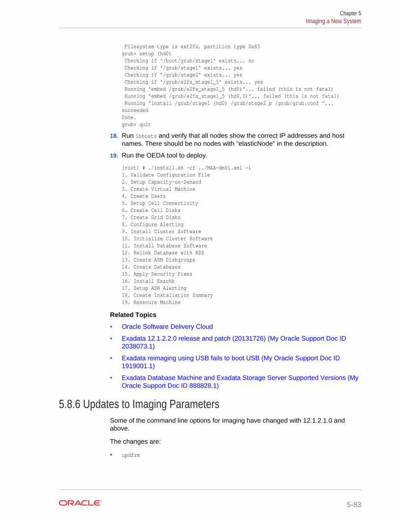
Filesystem type is ext2fs, partition type 0x83grub> setup (hd0) Checking if "/boot/grub/stage1" exists... no Checking if "/grub/stage1" exists... yes Checking if "/grub/stage2" exists... yes Checking if "/grub/e2fs_stage1_5" exists... yes Running "embed /grub/e2fs_stage1_5 (hd0)"... failed (this is not fatal) Running "embed /grub/e2fs_stage1_5 (hd0,0)"... failed (this is not fatal) Running "install /grub/stage1 (hd0) /grub/stage2 p /grub/grub.conf "... succeededDone.grub> quit
18. Run ibhosts and verify that all nodes show the correct IP addresses and hostnames. There should be no nodes with "elasticNode" in the description.
19. Run the OEDA tool to deploy.
[root] # ./install.sh -cf ../MAA-dm01.xml -l1. Validate Configuration File2. Setup Capacity-on-Demand3. Create Virtual Machine 4. Create Users 5. Setup Cell Connectivity 6. Create Cell Disks 7. Create Grid Disks 8. Configure Alerting 9. Install Cluster Software 10. Initialize Cluster Software 11. Install Database Software 12. Relink Database with RDS 13. Create ASM Diskgroups 14. Create Databases 15. Apply Security Fixes 16. Install Exachk 17. Setup ASR Alerting 18. Create Installation Summary 19. Resecure Machine
Related Topics
• Oracle Software Delivery Cloud
• Exadata 12.1.2.2.0 release and patch (20131726) (My Oracle Support Doc ID2038073.1)
• Exadata reimaging using USB fails to boot USB (My Oracle Support Doc ID1919001.1)
• Exadata Database Machine and Exadata Storage Server Supported Versions (MyOracle Support Doc ID 888828.1)
5.8.6 Updates to Imaging ParametersSome of the command line options for imaging have changed with 12.1.2.1.0 andabove.
The changes are:
• updfrm
Chapter 5Imaging a New System
5-83
Do NOT use the updfrm option in any form. It will be removed from the imagingoptions in the future. Allow the firmware to be updated automatically upon initialboot instead.
• dualboot
dualboot is no longer required with 12.1.2.1.0 as there is no support for Solaris. Ithas no meaning in releases 12.1.2.1.0 and above.
• factory
The meaning of the factory keyword has changed as of 12.1.2.1.0. The use of"factory" now enforces additional options such as "ovs=yes". This should be usedfor all imaging, regardless of the ultimate system configuration (Oracle VM,Physical etc.)
• OVS=yes|no
This option defaults to "no". However it is not recommended to use this at allbecause it may change in the future. In its place, use the "factory" option which willoverride some default options.
There are some additional command line options which may be useful:
• To create a hot spare on dbnodes, use the enable_hot_spare option.
– makeImageMedia.sh option: -enable_hot_spare
– PXE option: enable_hot_spare
• To force active bond or no active bond for InfiniBand interfaces (mainly forexpansion rack cases), use the active-bond-ib option.
– makeImageMedia.sh option: -active-bond-ib <yes|no>
– PXE option: active-bond-ib=<yes|no>
The README_FOR_FACTORY.txt file shipped with the imagemaker software explains eachoption in more detail.
Related Topics
• Exadata 12.1.2.2.0 release and patch (20131726) (My Oracle Support Doc ID2038073.1)
• Reimaging Exadata Cell Node Guidance (My Oracle Support Doc ID 2151671.1)
5.9 Performing Initial Elastic Configuration of OracleExadata Database Machine
This topic provides background information on elastic configuration and describes howto perform the initial configuration of Oracle Exadata Database Machine.
You need the configuration file generated by Oracle Exadata Database MachineDeployment Assistant.
Elastic configuration is new in Exadata version 12.1.2.1.0. It applies to all rackconfigurations, such as the following:
• Racks ordered with a standard number of database nodes and cells, for example,quarter or half racks
• Rack configurations that feature additional database nodes and cells
Chapter 5Performing Initial Elastic Configuration of Oracle Exadata Database Machine
5-84
• Oracle Exadata Database Machine Two-Socket X5 generation and later StorageServers
Starting with the Oracle Exadata Database Machine Two-Socket X5 generation ofStorage Servers, the same process can also be used to add additional databaseservers or cells to an existing configuration.
The process allows initial IP addresses to be assigned to database servers and cells,regardless of the exact customer configuration ordered. The customer specificconfiguration can then be applied to the nodes. The procedure can be run from anydatabase node (usually the first node,) and also from a cell in cases where expansioninvolves adding only cell nodes.
Every Exadata system has a pre-defined method for the cabling of nodes to theInfiniBand switch ports. Therefore, there is a fixed mapping from each node's locationin the rack to the ports of the InfiniBand switches. Assuming the rack is alwayspopulated following this map, a node's rack unit location can be identified by queryingthe InfiniBand fabric to determine the InfiniBand switch port the node is connected to.Once found, that information is used to determine the rack unit location of the node.With this information, nodes can be allocated initial IP addresses based on their rackunit location, with nodes lower in the rack getting lower IP addresses.
Note:
• If a RAID rebuild/reconstruction (that is, a disk replacement orexpansion) is in progress, wait until it is finished before performing thesteps in this section. The reason is that the reclaimdisks.sh script isblocked from running until the RAID rebuild/reconstruction is complete.
• Disk space for unused system partitions must be reclaimed beforeinstalling software. Use the following script to reclaim the disk space:
/opt/oracle.SupportTools/reclaimdisks.sh -free -reclaim
• My Oracle Support note 1953915.1 for detailed information about theconfiguration process.
1. Open a console session to the first database server. The first database server isthe lowest database server in the rack, which is rack position U16. In the case ofan expansion involving only cells, the procedure should be run from a cell insteadof a database node.
Note:
The network connection and configuration for Oracle Exadata DatabaseMachine has not occurred yet.
2. Log in as the root user on the first database server.
Chapter 5Performing Initial Elastic Configuration of Oracle Exadata Database Machine
5-85
Note:
If you do not have the password for the root user, then contact OracleSupport Services.
3. Verify all servers are configured with the 172.16 IP address for the ETH0 interfaceusing the following command:
# ibhosts
Ca : 0x0010e00001486fb8 ports 2 "node10 elasticNode 172.16.2.46,172.16.2.46 ETH0"Ca : 0x0010e00001491228 ports 2 "node9 elasticNode 172.16.2.45,172.16.2.45 ETH0"Ca : 0x0010e000014844f8 ports 2 "node8 elasticNode 172.16.2.44,172.16.2.44 ETH0"Ca : 0x0010e00001488218 ports 2 "node4 elasticNode 172.16.2.40,172.16.2.40 ETH0"Ca : 0x0010e000014908b8 ports 2 "node2 elasticNode 172.16.2.38,172.16.2.38 ETH0"Ca : 0x0010e0000148ca68 ports 2 "node1 elasticNode 172.16.2.37,172.16.2.37 ETH0"Ca : 0x0010e00001485fd8 ports 2 "node3 elasticNode 172.16.2.39,172.16.2.39 ETH0"
Each server description should be hostname elasticNode. ipaddress ETH0.
4. (Optional on database servers) Switch to the Oracle VM when using virtualizationon the rack using the following command:
Note that database servers will reboot during this step.
Note:
It is not possible or supported to switch between physical and Oracle VMconfiguration.
# /opt/oracle.SupportTools/switch_to_ovm.sh
On database servers, run reclaimdisks.sh. This is necessary in all deploymentscenarios.
# /opt/oracle.SupportTools/reclaimdisks.sh -free -reclaim
If Oracle VM was chosen, this step locks in the image as Oracle VM. Going backand forth will not be possible.
reclaimdisks.sh performs partition reconfiguration and a few other necessaryconfiguration changes that take typically less than a minute to complete.
5. On database servers, verify disk configuration.
# /opt/oracle.SupportTools/reclaimdisks.sh -check
If the system is a physical (bare metal) deployment, the last line of output will bethe following:
Valid. Booted: Linux. Layout: Linux.
If the system is an Oracle VM deployment, the last line of output will be thefollowing:
Chapter 5Performing Initial Elastic Configuration of Oracle Exadata Database Machine
5-86

Valid. Booted: DOM0. Layout: DOM0.
6. Copy Oracle Exadata Database Machine Deployment Assistant configuration filesto the database server using one of the following methods. If adding only cellservers, the steps can be run from a cell.
• Using a USB flash drive on Linux:
a. Copy the configuration file to a USB flash drive.
b. Connect the USB drive to the database server or cell.
c. Locate the USB drive using the following command:
for x in `ls -1 /sys/block`; do udevadm info --attribute-walk --path=/sys/block/$x | grep \-iq 'DRIVERS=="usb-storage"'; if [ $? -eq 0 ] ; then echo /dev/${x}1; \fi ; done
The expected output is similar to:
/dev/sdb1
Note:
If an X6 or X5 EF cell is used, the command will also return thetwo internal USB drives, usually /dev/sda1 and /dev/sdb1.The newly inserted USB drive will be the additional device,usually /dev/sdc1.
The expected output is similar to:
/dev/sda1/dev/sdb1/dev/sdc1
The internal USBs can be identified by viewing mdstat:
# grep md4 /proc/mdstat | awk '{print $5,$6;}'
d. Create a directory on the database server or cell using the followingcommand:
# mkdir /mnt/usb
e. Create a directory for the installation using the following command:
# mkdir /opt/oracle.SupportTools/onecommand
If the directory already exists, then rename the existing one toonecommand.old, and then re-create the empty directory.
Note: Do not use a directory under /u01 or /EXAVMIMAGES becausereclaimdidsks.sh will fail if there is content in those directories.
f. Mount the device. Use the device name given in step 6.c. The following isan example of the command.
# mount -t vfat /dev/sdb1 /mnt/usb
Chapter 5Performing Initial Elastic Configuration of Oracle Exadata Database Machine
5-87
g. Copy Oracle Exadata Deployment Assistant and the configuration filesfrom the USB flash drive to the onecommand directory on the databaseserver or cell using the following command:
# cp /mnt/usb/path_to_file/*.* /opt/oracle.SupportTools/onecommand
In the preceding command, path_to_file is the directory path to theconfiguration file on the USB flash drive.
h. Unmount the USB flash drive using the following command:
# umount /mnt/usb
i. Remove the USB flash drive from the database server or cell.
• Using a temporary network connection:
This option is only needed if there were IP address conflicts, and OracleExadata Database Machine is not already connected to the network.
a. Connect a network cable to the Ethernet port labeled NET0 on the back ofthe first database server.
b. Bring up the eth0:1 interface as follows:
# ifconfig eth0:1 real_ip netmask real_netmask up
In the preceding command, real_ip is the IP address to assign to thedatabase server, and real_netmask is the subnet mask to assign to thedatabase server.
c. Add the default route as follows:
# route add -net 0.0.0.0 netmask 0.0.0.0 gw real_gateway
In the preceding command, real_gateway is the default gateway to use forthe database server.
d. Copy the configuration files to the /opt/oracle.SupportTools/onecommand directory on the database server or cell using a file transferutility such as scp.
e. Disconnect the network cable from Ethernet port NET0.
Note:
It is not necessary to reconfigure the network because thenetwork is reconfigured automatically during the restart step.
7. Verify all servers are configured with the 172.16 IP address for the ETH0 interfaceusing the following command:
# ibhosts
No server description should include elasticNode in its description.
8. Run the applyElasticConfig.sh script using the following command:
# cd /opt/oracle.SupportTools/onecommand/linux-x64# ./applyElasticConfig.sh -cf customer_name-configFile.xml
Chapter 5Performing Initial Elastic Configuration of Oracle Exadata Database Machine
5-88
The applyElasticConfig.sh script performs network configuration for all databaseservers and Exadata Storage Servers. All servers restart at the end of the process.
9. Connect the corporate network cable for the management network to the CiscoEthernet switch.
10. Connect the corporate network cables for the client access network to thedatabase servers.
11. Restart all database servers and Exadata Storage Servers.
12. Log in to the first database server (or cell, if only cells were added for expansion)to verify network connectivity using the following commands:
# cd /opt/oracle.SupportTools/onecommand/linux-x64#./checkip.sh -cf configuration_file
In the preceding command, configuration_file is the name of the configuration filefrom Oracle Exadata Deployment Assistant, and includes the full path.
Note:
• The checkip.sh script can be run on a server outside of OracleExadata Database Machine to verify network connectivity to OracleExadata Database Machine. Copy the checkip.sh file to the externalsystem, and run the command as shown in this step.
• If the command is run from a Microsoft Windows machine, then thecommand is checkip.cmd.
• Download the version of Oracle Exadata Deployment Assistant forthe relevant platform.
13. Use Oracle Exadata Deployment Assistant to install and configure the software forOracle Exadata Database Machine.
See Also:
• Oracle Exadata Database Machine System Overview for rack layoutinformation
• Oracle Exadata Database Machine Maintenance Guide for informationabout restarting the servers
Related Topics
• Adding Additional Elastic Nodes to an Existing RackYou can add nodes to an existing rack using elastic configuration.
• Elastic Configuration on Exadata (My Oracle Support Doc ID 1953915.1)
Chapter 5Performing Initial Elastic Configuration of Oracle Exadata Database Machine
5-89
See Also:
5.10 Adding Additional Elastic Nodes to an Existing RackYou can add nodes to an existing rack using elastic configuration.
The elastic configuration procedure described in "Performing Initial ElasticConfiguration of Oracle Exadata Database Machine" can also be used to add newservers to an existing rack. The new servers and existing servers must be at least X5.The procedure assigns IP addresses to the new database servers and cells, inpreparation for adding them into existing setups. The addition of X5, X6, or X7 serversinto previous generation racks using this methodology is not supported.
The XML configuration file generated by the Oracle Exadata Deployment Assistantmust contain the existing nodes, plus the new nodes to be added. The same elasticconfiguration procedures described in the previous section should be followed, and theapplyElasticConfig.sh script that runs as part of step 8 determines which nodes arenew, and assigns IP addresses accordingly.
When adding only storage cells, you can run the applyElasticConfig.sh script from acell server rather than a database server.
5.11 Loading the Configuration Information and Installing theSoftware
Oracle Exadata Deployment Assistant loads the network settings, creates the useraccounts, installs Oracle Database software, and secures the system based on theinformation the configuration files. You can also choose to do the process manually.
Note:
• To enable a supported, non-English language, set the followingenvironment variables before starting the configuration:
export LANG=preferred_languageexport LC_ALL=preferred_language
• To copy the database image to a USB drive, use the procedure in thedatabase maintenance chapter of Oracle Exadata Database MachineMaintenance Guide For releases 12.1.2.1.0 and later, the system usedto create the image must be running Oracle Linux 6.
Chapter 5Adding Additional Elastic Nodes to an Existing Rack
5-90
See Also:
Using Oracle Exadata Deployment Assistant for descriptions of theconfiguration files generated by Oracle Exadata Database MachineDeployment Assistant
5.11.1 Configuring Oracle Exadata Database Machine Using OEDAOracle Exadata Deployment Assistant (OEDA)is used to configure Oracle ExadataDatabase Machine.
The deployment assistant works with the information provided in OEDA.
The following procedure describes how to configure Oracle Exadata DatabaseMachine using OEDA:
1. Go to My Oracle Support.
2. Download the latest OEDA, and follow the steps in the associated README file.
3. Download all necessary Oracle Exadata System Software and Oracle Databasepatches. See My Oracle Support note 888828.1 for details.
4. Log in as the root user on the first database server.
Note:
If you do not have the password for the root user, then contact OracleSupport Services.
5. Copy the configuration file from the machine that was used to run OEDA tothe /opt/oracle.SupportTools/onecommand directory on the first databaseserver of the Oracle Exadata Rack.
6. Create a directory named WorkDir on the first database server.
7. Put the downloaded software and patches in the WorkDir directory.
8. Apply the OEDA update according to the instructions included in the README file.
9. Change to the following directory:
# cd /opt/oracle.SupportTools/onecommand
10. Run the following command to configure Oracle Exadata Rack:
# ./install.sh -cf configuration_file [-s step_number | \ -r step_numberA stepnumberB]
Note:
If the configuration is run from a Microsoft Windows machine, then thecommand is install.cmd.
Chapter 5Loading the Configuration Information and Installing the Software
5-91
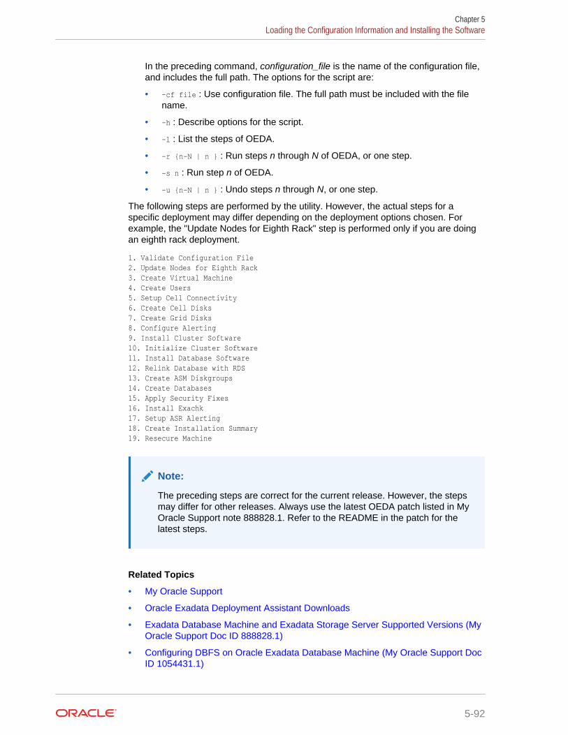
In the preceding command, configuration_file is the name of the configuration file,and includes the full path. The options for the script are:
• -cf file : Use configuration file. The full path must be included with the filename.
• -h : Describe options for the script.
• -l : List the steps of OEDA.
• -r {n-N | n } : Run steps n through N of OEDA, or one step.
• -s n : Run step n of OEDA.
• -u {n-N | n } : Undo steps n through N, or one step.
The following steps are performed by the utility. However, the actual steps for aspecific deployment may differ depending on the deployment options chosen. Forexample, the "Update Nodes for Eighth Rack" step is performed only if you are doingan eighth rack deployment.
1. Validate Configuration File2. Update Nodes for Eighth Rack3. Create Virtual Machine4. Create Users5. Setup Cell Connectivity6. Create Cell Disks7. Create Grid Disks8. Configure Alerting9. Install Cluster Software10. Initialize Cluster Software11. Install Database Software12. Relink Database with RDS13. Create ASM Diskgroups14. Create Databases15. Apply Security Fixes16. Install Exachk17. Setup ASR Alerting18. Create Installation Summary19. Resecure Machine
Note:
The preceding steps are correct for the current release. However, the stepsmay differ for other releases. Always use the latest OEDA patch listed in MyOracle Support note 888828.1. Refer to the README in the patch for thelatest steps.
Related Topics
• My Oracle Support
• Oracle Exadata Deployment Assistant Downloads
• Exadata Database Machine and Exadata Storage Server Supported Versions (MyOracle Support Doc ID 888828.1)
• Configuring DBFS on Oracle Exadata Database Machine (My Oracle Support DocID 1054431.1)
Chapter 5Loading the Configuration Information and Installing the Software
5-92
See Also:
• Oracle Exadata System Software User's Guide for additional informationabout security for Oracle Exadata Database Machine and OracleExadata System Software
• Oracle Exadata Database Machine Security Guide for additionalinformation about re-securing Oracle Exadata Database Machine
5.11.2 Configuring Oracle Database and Oracle ASM Instances forOracle Exadata Database Machine Manually
Oracle Database and Oracle Automatic Storage Management (Oracle ASM) 11gRelease 2 (11.2) or later must be installed on the database server. Follow theinstructions for installing Oracle Database and Oracle ASM provided in the appropriateversion of the Oracle Database Installation Guide for your platform.
Note:
To fully utilize the Hardware Assisted Resilient Data (HARD) features,ensure the DB_BLOCK_CHECKSUM initialization parameter is set toTYPICAL (default) or FULL.
When installing Oracle Database, you must select the Oracle ASM storage option. Ifyou are installing Oracle Real Application Clusters (Oracle RAC), then refer to theplatform-specific Oracle Clusterware and Oracle RAC installation guides, such asOracle Grid Infrastructure Installation and Upgrade Guide and Oracle Real ApplicationClusters Installation Guide.
If you are consolidating databases and need to have more than one database with thesame DB_UNIQUE_NAME on the Oracle Exadata Database Machine, then you mustconfigure Oracle ASM clusters on the storage cells and configure ASM-scopedsecurity.
Note:
For Oracle RAC, you must shut down the entire cluster, and then restart thecluster after the database and cell software have been installed, and the cellconfiguration files are in place.
The recommended procedure is to install the latest version of the Oracle software onOracle Exadata Database Machine using Oracle Exadata Deployment Assistant(OEDA). If you choose to install the software manually, then do the following:
Chapter 5Loading the Configuration Information and Installing the Software
5-93
Note:
Disk space for unused system partitions must be reclaimed before installingsoftware. Use the following script to reclaim the disk space:
/opt/oracle.SupportTools/reclaimdisks.sh -free -reclaim
If a RAID rebuild or reconstruction (that is, a disk replacement or expansion)is in progress, wait until it is finished before running the reclaimdisks.shscript. The reason is that the reclaimdisks.sh script is blocked from runninguntil the RAID rebuild or reconstruction is complete.
1. Install Oracle Grid Infrastructure for a cluster software as described in Oracle GridInfrastructure Installation and Upgrade Guide for Linux.
2. Install Oracle Database software as described in Oracle Real Application ClustersInstallation Guide for Linux and UNIX.
3. Apply the latest patches for Oracle Database software and Oracle ExadataSystem Software.
After the cells are configured as described in Oracle Exadata System Software User'sGuide, and the database and Oracle ASM instances are installed, the instances mustbe configured to use the cells as part of an Oracle ASM disk group. The requiredconfiguration involves updating the initialization parameter file of both the databaseand Oracle ASM instances. Additionally, Oracle ASM disk groups must be created toaccess storage cells.
You can update the initialization parameter file of the Oracle ASM or the databaseinstance while the instance is running, but the instance must be restarted if youmanually update the initialization parameter file. If you update an initializationparameter dynamically using the SQL ALTER SYSTEM or ALTER SESSION commands, thenthere is no need to restart the instance.
In addition, for the database, you can configure a new Oracle Database ResourceManager plan, rather than using the default plans.
Related Topics
• About ASM-Scoped Security Mode
• Exadata Database Machine and Exadata Storage Server Supported Versions (MyOracle Support Doc ID 888828.1)
• List of Critical Patches Required For Oracle 11.2 DBFS and DBFS Client (MyOracle Support Doc ID 1150157.1)
• Configuring DBFS on Oracle Exadata Database Machine (My Oracle Support DocID 1054431.1)
• Oracle Exadata Best Practices (My Oracle Support Doc ID 757552.1)
Chapter 5Loading the Configuration Information and Installing the Software
5-94
See Also:
• Oracle Automatic Storage Management Administrator's Guide foradditional information about starting and connecting to an Oracle ASMinstance
• Oracle Exadata System Software User's Guide for additional informationabout I/O resources
• Oracle Exadata System Software User's Guide for information aboutconfiguring the database servers to use Oracle Exadata Storage Servers
5.11.2.1 Configuring the Compatible Parameter for a Database InstanceOracle recommends using the best practices for Oracle Exadata System Softwareavailable at My Oracle Support.
To configure a database instance to access cell storage, ensure that theCOMPATIBLE parameter is set to 11.2.0.2 or later in the database initialization file.
You can view the initialization parameter file from the operating system or use theSQL*Plus administration command SHOW PARAMETER if the database is running. Forexample:
SQL> SHOW PARAMETERSQL> SHOW PARAMETER compatible
If necessary, set the COMPATIBLE initialization parameter in the initializationparameter file to 11.2.0.2 or later. For example:
COMPATIBLE='11.2.0.2'
The COMPATIBLE parameter cannot be changed dynamically. If you change thevalue in the initialization parameter file, then the database must be shut down andrestarted for the change to take effect.
5.11.2.2 Configuring Initialization Parameters for an Oracle ASM InstanceTo enable an Oracle ASM instance to discover and access Exadata Storage Servergrid disks, you must configure the ASM_DISKSTRING initialization parameter asfollows:
• Set the ASM_DISKSTRING initialization parameter to the empty string ('') todiscover all grid disks on the cells listed in the cellip.ora file. This causes OracleASM discovery for /dev/raw/* and any ASMLIB disks on any non-Exadata StorageServers.
• Set the ASM_DISKSTRING initialization parameter to restrict the discovery byOracle ASM to only specific sets of disks, as shown in the examples.
– To discover only a subset of cells, use a pattern for the ASM_DISKSTRINGvalue such as the following:
o/cell-connect-info-pattern/griddisk-name-pattern.
For example:
Chapter 5Loading the Configuration Information and Installing the Software
5-95
ASM_DISKSTRING = 'o/*/data*'
– To discover non-Exadata Storage Server disks and all grid disks on all thecells specified in the cellip.ora file, use a wildcard pattern for ExadataStorage Server grid disks. For example:
ASM_DISKSTRING = '/dev/rdsk/disk*', 'o/*/*'
You can change the ASM_DISKSTRING initialization parameter when the Oracle ASMinstance is running with the SQL ALTER SYSTEM command. If you edit theASM_DISKSTRING initialization parameter in the initialization parameter file when theOracle ASM instance is running, then the Oracle ASM instance must be shut downand restarted for the change to take effect.
See Also:
• Oracle Automatic Storage Management Administrator's Guide foradditional information about the following:
– Oracle ASM discovery strings
– starting up and connecting to an Oracle ASM instance
• Oracle Database Reference for additional information about theASM_DISKSTRING initialization parameter
• Oracle Database SQL Language Reference for additional informationabout the ALTER SYSTEM command
5.11.2.3 Using the Same DB_UNIQUE_NAME for Multiple Database InstancesYou can create database instances that use the same DB_UNIQUE_NAME value if thedatabases are associated with separate Oracle ASM clusters.
Starting with Oracle Exadata System Software release 19.1.0, Oracle Multitenantdatabase clusters sharing the same storage can contain database instances that usethe same DB_UNIQUE_NAME.
WARNING:
If you configure databases to have the same DB_UNIQUE_NAME, then thosedatabases cannot be backed up to Oracle Zero Data Loss RecoveryAppliance.
1. Create Oracle ASM clusters for the database clusters that use identicalDB_UNIQUE_NAME values for the database instances.
Each database instance that uses the same DB_UNIQUE_NAME must be in a separateOracle ASM cluster. The Oracle ASM cluster name is used to qualify theDB_UNIQUE_NAME in I/O Resource Management (IORM), Exadata Smart FlashCache, and Exadata Smart Scan Offload operations.
2. Configure ASM-scoped security for each cluster database.
Chapter 5Loading the Configuration Information and Installing the Software
5-96
When configuring ASM-scoped security, the Oracle ASM client must be configuredas an ASMCLUSTER client.
If you already have ASM-scoped security configured, but the Oracle ASM client isnot configured as an ASMCLUSTER client, then you can use the ASSIGN KEYcommand upgrade the key to an ASMCLUSTER key.
3. Create the databases in each cluster using the same DB_UNIQUE_NAME.
Related Topics
• Setting Up Oracle ASM-Scoped Security on Oracle Exadata Storage Servers
• Upgrading ASM-Scoped Security Key for ASMCLUSTER
5.12 Installing Oracle Enterprise Manager Cloud ControlOracle Exadata Database Machine should be monitored using Oracle EnterpriseManager Cloud Control. Ensure that the Enterprise Manager environment isconfigured for high availability and disaster recovery to ensure sufficient monitoring ofthe Exadata environments.
Related Topics
• Oracle Enterprise Manager Cloud Control Basic Installation Guide
• Installation and Deployment in Oracle Enterprise Manager Exadata ManagementGetting Started Guide
• Configuring Enterprise Manager for High Availability in Oracle Enterprise ManagerCloud Control Advanced Installation and Configuration Guide
• Oracle Enterprise Manager Cloud Control Advanced Installation and ConfigurationGuide
• Discovery in Oracle Enterprise Manager Cloud Control Administrator's Guide
• How to Configure Oracle Configuration Manager for Oracle Exadata DatabaseMachine (My Oracle Support Doc ID 1319476.1)
• MAA Best Practices website
Chapter 5Installing Oracle Enterprise Manager Cloud Control
5-97
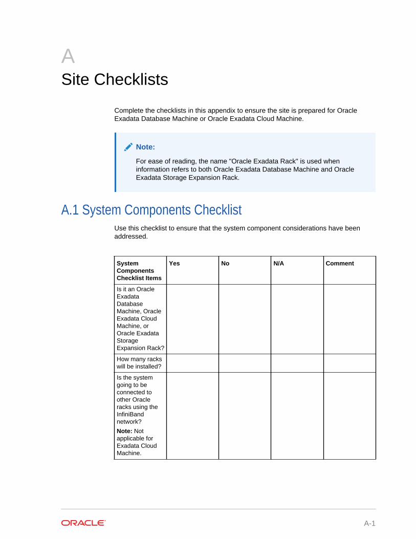
ASite Checklists
Complete the checklists in this appendix to ensure the site is prepared for OracleExadata Database Machine or Oracle Exadata Cloud Machine.
Note:
For ease of reading, the name "Oracle Exadata Rack" is used wheninformation refers to both Oracle Exadata Database Machine and OracleExadata Storage Expansion Rack.
A.1 System Components ChecklistUse this checklist to ensure that the system component considerations have beenaddressed.
SystemComponentsChecklist Items
Yes No N/A Comment
Is it an OracleExadataDatabaseMachine, OracleExadata CloudMachine, orOracle ExadataStorageExpansion Rack?
How many rackswill be installed?
Is the systemgoing to beconnected toother Oracleracks using theInfiniBandnetwork?
Note: Notapplicable forExadata CloudMachine.
A-1

SystemComponentsChecklist Items
Yes No N/A Comment
If an OracleExadataDatabaseMachine will beconnected toother Oracleracks using theInfiniBandnetwork, thenhave a SunDatacenterInfiniBand Switch36 (spine switch)and cables beenordered?
Is the rackinstallation anaddition to anexisting system?If yes, refer to the Oracle ExadataDatabaseMachineExtending andMulti-RackCabling Guide forcablinginformation.
Has the multi-rack cablingservice beenpurchased andthe correctnetworkingcomponentsbeen ordered?
Are all OracleExadataDatabaseMachine racksadjacent to eachother?
Appendix ASystem Components Checklist
A-2
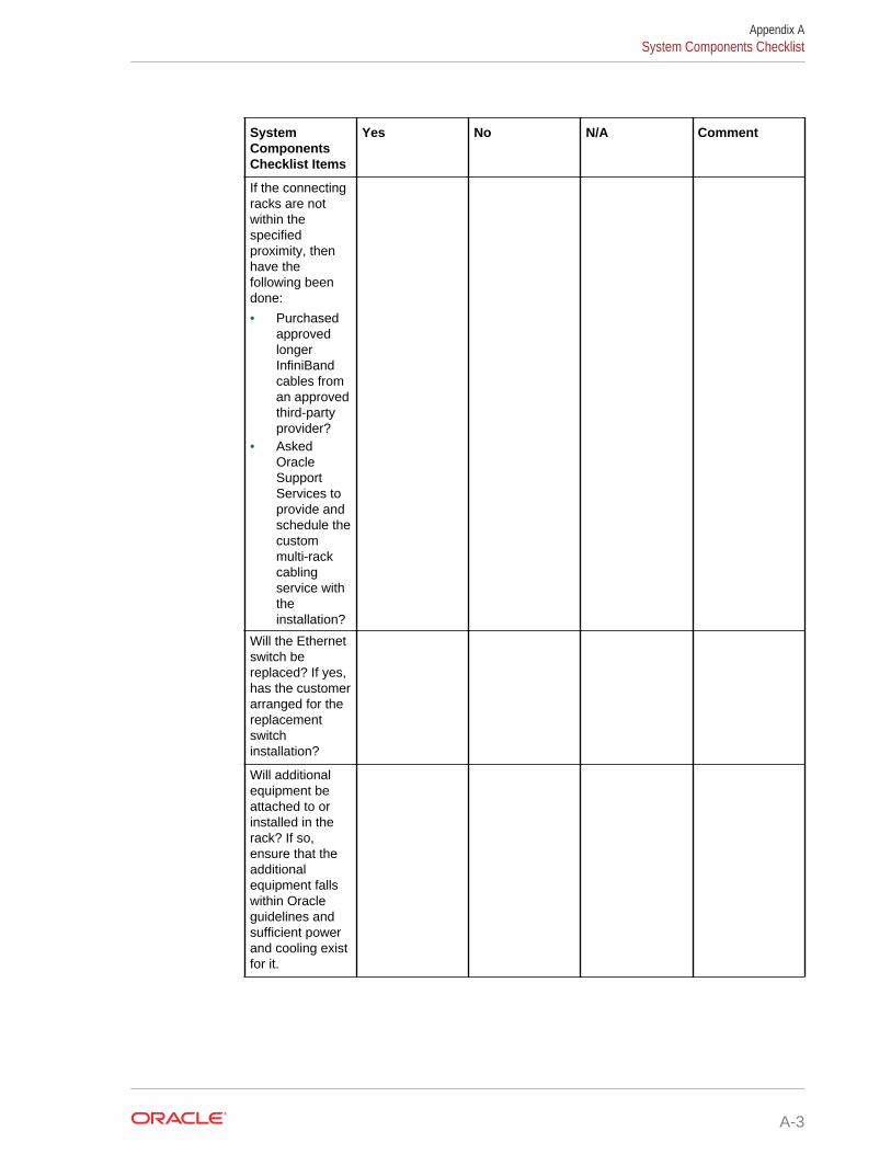
SystemComponentsChecklist Items
Yes No N/A Comment
If the connectingracks are notwithin thespecifiedproximity, thenhave thefollowing beendone:
• PurchasedapprovedlongerInfiniBandcables froman approvedthird-partyprovider?
• AskedOracleSupportServices toprovide andschedule thecustommulti-rackcablingservice withtheinstallation?
Will the Ethernetswitch bereplaced? If yes,has the customerarranged for thereplacementswitchinstallation?
Will additionalequipment beattached to orinstalled in therack? If so,ensure that theadditionalequipment fallswithin Oracleguidelines andsufficient powerand cooling existfor it.
Appendix ASystem Components Checklist
A-3
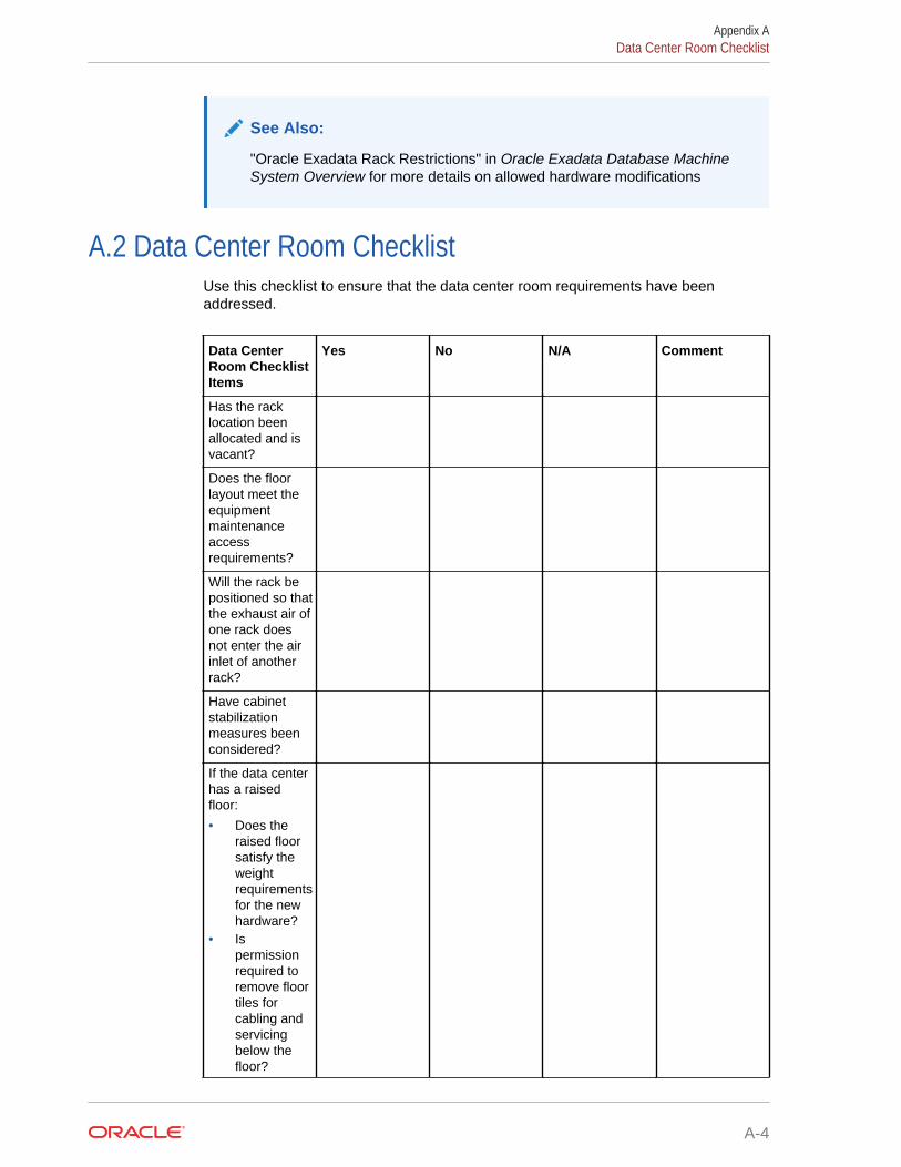
See Also:
"Oracle Exadata Rack Restrictions" in Oracle Exadata Database MachineSystem Overview for more details on allowed hardware modifications
A.2 Data Center Room ChecklistUse this checklist to ensure that the data center room requirements have beenaddressed.
Data CenterRoom ChecklistItems
Yes No N/A Comment
Has the racklocation beenallocated and isvacant?
Does the floorlayout meet theequipmentmaintenanceaccessrequirements?
Will the rack bepositioned so thatthe exhaust air ofone rack doesnot enter the airinlet of anotherrack?
Have cabinetstabilizationmeasures beenconsidered?
If the data centerhas a raisedfloor:
• Does theraised floorsatisfy theweightrequirementsfor the newhardware?
• Ispermissionrequired toremove floortiles forcabling andservicingbelow thefloor?
Appendix AData Center Room Checklist
A-4
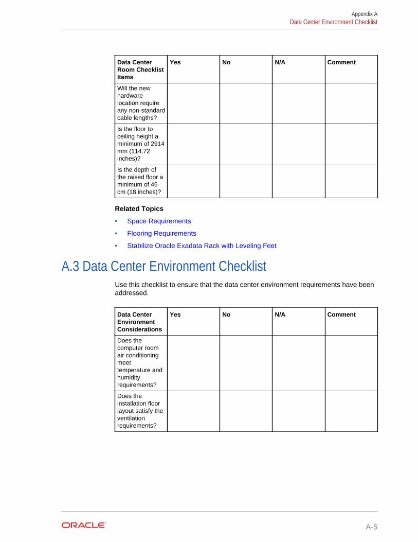
Data CenterRoom ChecklistItems
Yes No N/A Comment
Will the newhardwarelocation requireany non-standardcable lengths?
Is the floor toceiling height aminimum of 2914mm (114.72inches)?
Is the depth ofthe raised floor aminimum of 46cm (18 inches)?
Related Topics
• Space Requirements
• Flooring Requirements
• Stabilize Oracle Exadata Rack with Leveling Feet
A.3 Data Center Environment ChecklistUse this checklist to ensure that the data center environment requirements have beenaddressed.
Data CenterEnvironmentConsiderations
Yes No N/A Comment
Does thecomputer roomair conditioningmeettemperature andhumidityrequirements?
Does theinstallation floorlayout satisfy theventilationrequirements?
Appendix AData Center Environment Checklist
A-5
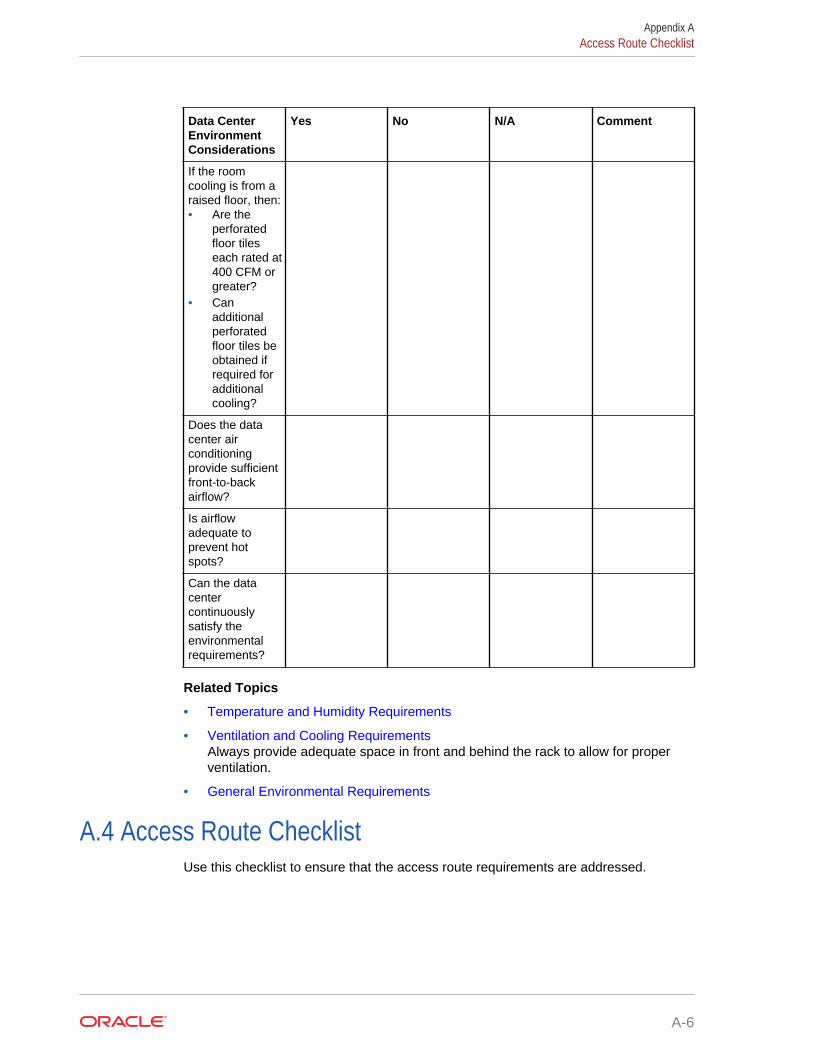
Data CenterEnvironmentConsiderations
Yes No N/A Comment
If the roomcooling is from araised floor, then:• Are the
perforatedfloor tileseach rated at400 CFM orgreater?
• Canadditionalperforatedfloor tiles beobtained ifrequired foradditionalcooling?
Does the datacenter airconditioningprovide sufficientfront-to-backairflow?
Is airflowadequate toprevent hotspots?
Can the datacentercontinuouslysatisfy theenvironmentalrequirements?
Related Topics
• Temperature and Humidity Requirements
• Ventilation and Cooling RequirementsAlways provide adequate space in front and behind the rack to allow for properventilation.
• General Environmental Requirements
A.4 Access Route ChecklistUse this checklist to ensure that the access route requirements are addressed.
Appendix AAccess Route Checklist
A-6
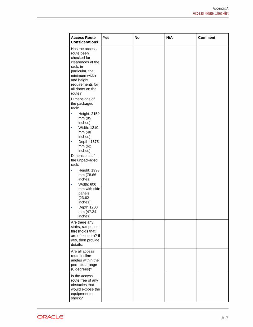
Access RouteConsiderations
Yes No N/A Comment
Has the accessroute beenchecked forclearances of therack, inparticular, theminimum widthand heightrequirements forall doors on theroute?
Dimensions ofthe packagedrack:
• Height: 2159mm (85inches)
• Width: 1219mm (48inches)
• Depth: 1575mm (62inches)
Dimensions ofthe unpackagedrack:
• Height: 1998mm (78.66inches)
• Width: 600mm with sidepanels(23.62inches)
• Depth 1200mm (47.24inches)
Are there anystairs, ramps, orthresholds thatare of concern? Ifyes, then providedetails.
Are all accessroute inclineangles within thepermitted range(6 degrees)?
Is the accessroute free of anyobstacles thatwould expose theequipment toshock?
Appendix AAccess Route Checklist
A-7
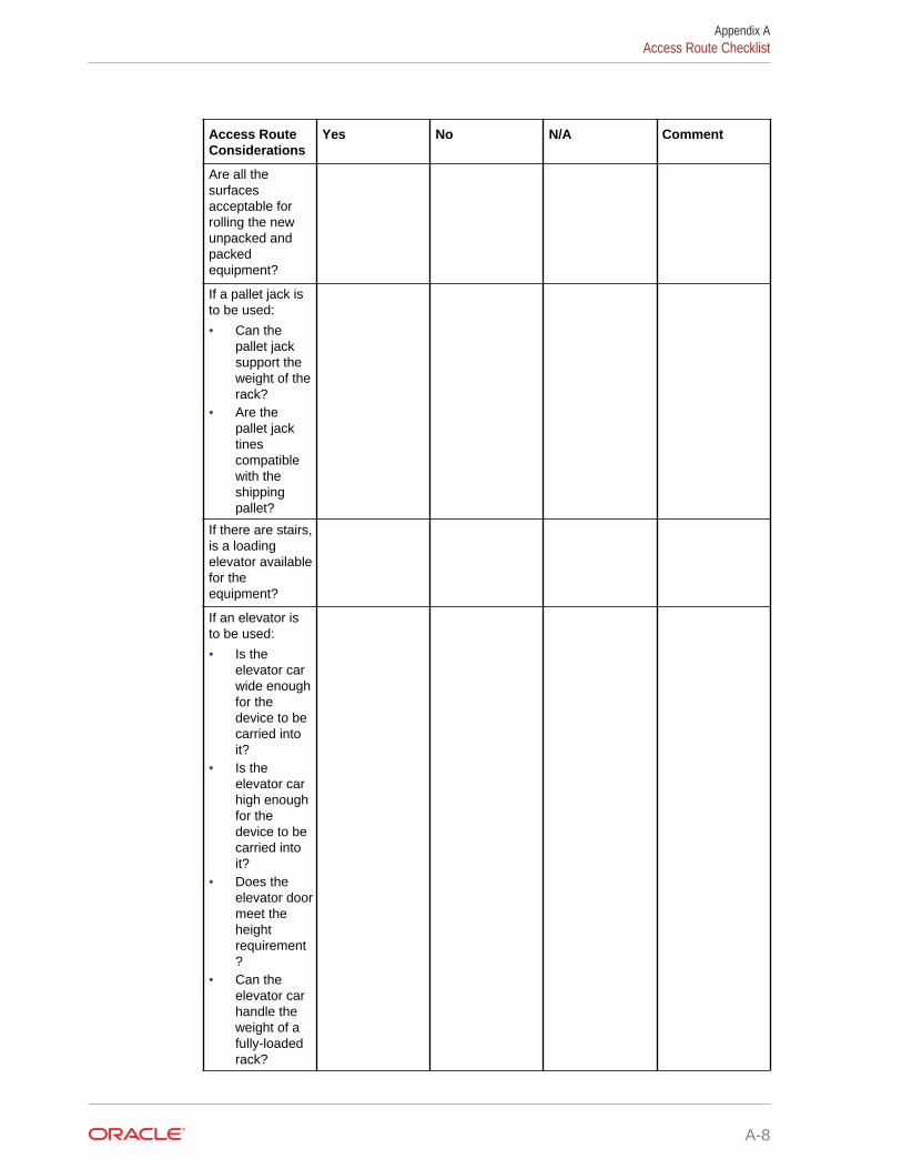
Access RouteConsiderations
Yes No N/A Comment
Are all thesurfacesacceptable forrolling the newunpacked andpackedequipment?
If a pallet jack isto be used:
• Can thepallet jacksupport theweight of therack?
• Are thepallet jacktinescompatiblewith theshippingpallet?
If there are stairs,is a loadingelevator availablefor theequipment?
If an elevator isto be used:
• Is theelevator carwide enoughfor thedevice to becarried intoit?
• Is theelevator carhigh enoughfor thedevice to becarried intoit?
• Does theelevator doormeet theheightrequirement?
• Can theelevator carhandle theweight of afully-loadedrack?
Appendix AAccess Route Checklist
A-8
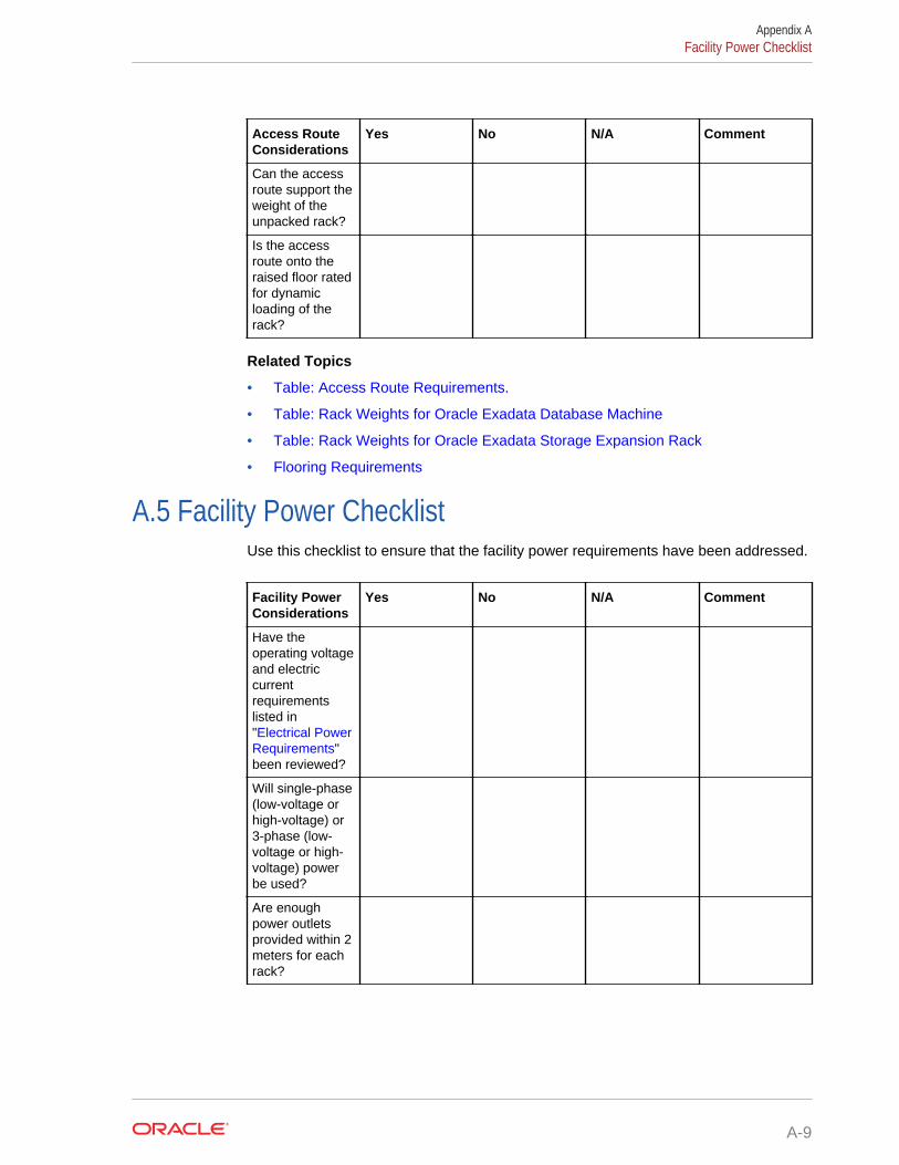
Access RouteConsiderations
Yes No N/A Comment
Can the accessroute support theweight of theunpacked rack?
Is the accessroute onto theraised floor ratedfor dynamicloading of therack?
Related Topics
• Table: Access Route Requirements.
• Table: Rack Weights for Oracle Exadata Database Machine
• Table: Rack Weights for Oracle Exadata Storage Expansion Rack
• Flooring Requirements
A.5 Facility Power ChecklistUse this checklist to ensure that the facility power requirements have been addressed.
Facility PowerConsiderations
Yes No N/A Comment
Have theoperating voltageand electriccurrentrequirementslisted in"Electrical PowerRequirements"been reviewed?
Will single-phase(low-voltage orhigh-voltage) or3-phase (low-voltage or high-voltage) powerbe used?
Are enoughpower outletsprovided within 2meters for eachrack?
Appendix AFacility Power Checklist
A-9
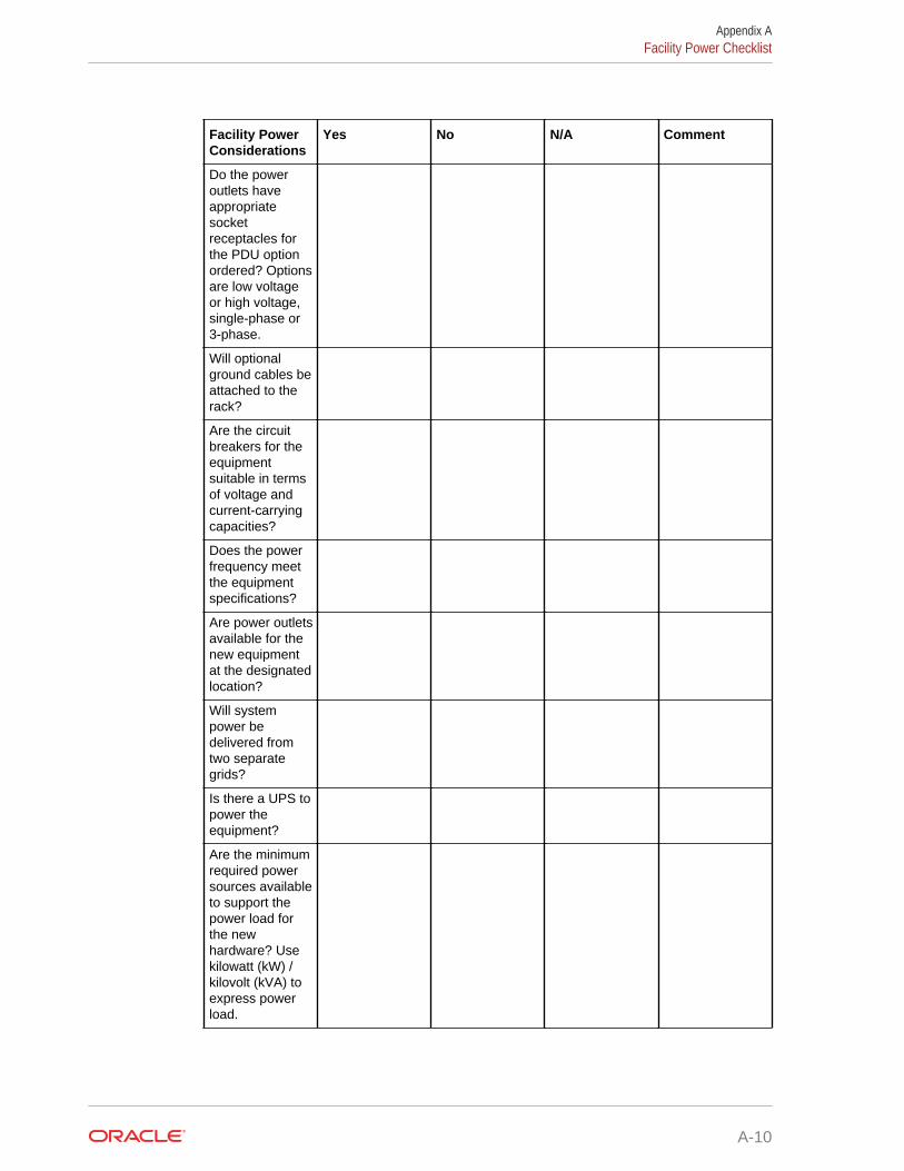
Facility PowerConsiderations
Yes No N/A Comment
Do the poweroutlets haveappropriatesocketreceptacles forthe PDU optionordered? Optionsare low voltageor high voltage,single-phase or3-phase.
Will optionalground cables beattached to therack?
Are the circuitbreakers for theequipmentsuitable in termsof voltage andcurrent-carryingcapacities?
Does the powerfrequency meetthe equipmentspecifications?
Are power outletsavailable for thenew equipmentat the designatedlocation?
Will systempower bedelivered fromtwo separategrids?
Is there a UPS topower theequipment?
Are the minimumrequired powersources availableto support thepower load forthe newhardware? Usekilowatt (kW) /kilovolt (kVA) toexpress powerload.
Appendix AFacility Power Checklist
A-10
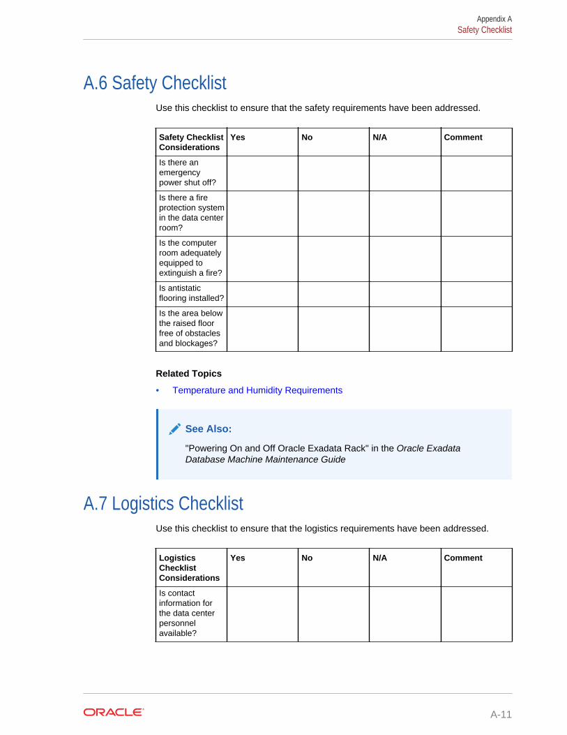
A.6 Safety ChecklistUse this checklist to ensure that the safety requirements have been addressed.
Safety ChecklistConsiderations
Yes No N/A Comment
Is there anemergencypower shut off?
Is there a fireprotection systemin the data centerroom?
Is the computerroom adequatelyequipped toextinguish a fire?
Is antistaticflooring installed?
Is the area belowthe raised floorfree of obstaclesand blockages?
Related Topics
• Temperature and Humidity Requirements
See Also:
"Powering On and Off Oracle Exadata Rack" in the Oracle ExadataDatabase Machine Maintenance Guide
A.7 Logistics ChecklistUse this checklist to ensure that the logistics requirements have been addressed.
LogisticsChecklistConsiderations
Yes No N/A Comment
Is contactinformation forthe data centerpersonnelavailable?
Appendix ASafety Checklist
A-11
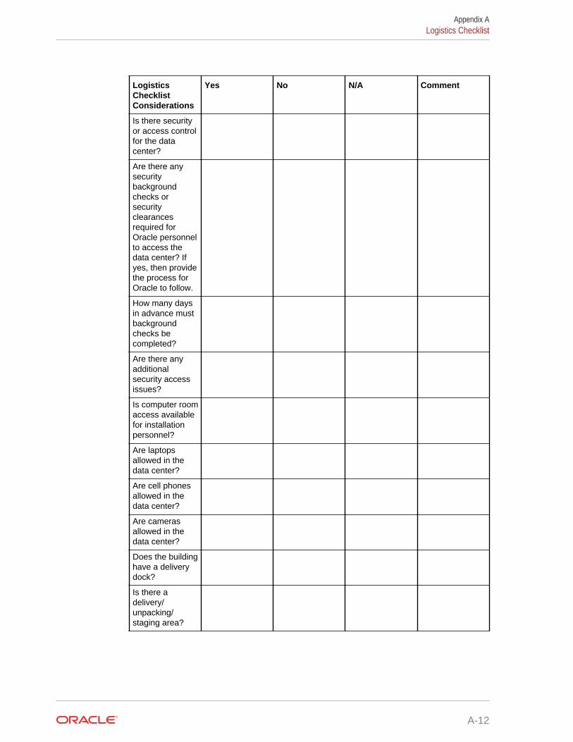
LogisticsChecklistConsiderations
Yes No N/A Comment
Is there securityor access controlfor the datacenter?
Are there anysecuritybackgroundchecks orsecurityclearancesrequired forOracle personnelto access thedata center? Ifyes, then providethe process forOracle to follow.
How many daysin advance mustbackgroundchecks becompleted?
Are there anyadditionalsecurity accessissues?
Is computer roomaccess availablefor installationpersonnel?
Are laptopsallowed in thedata center?
Are cell phonesallowed in thedata center?
Are camerasallowed in thedata center?
Does the buildinghave a deliverydock?
Is there adelivery/unpacking/staging area?
Appendix ALogistics Checklist
A-12
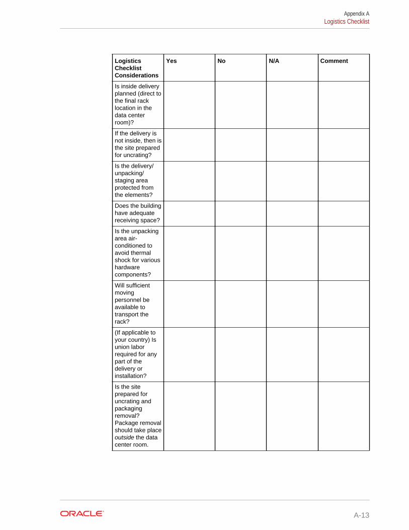
LogisticsChecklistConsiderations
Yes No N/A Comment
Is inside deliveryplanned (direct tothe final racklocation in thedata centerroom)?
If the delivery isnot inside, then isthe site preparedfor uncrating?
Is the delivery/unpacking/staging areaprotected fromthe elements?
Does the buildinghave adequatereceiving space?
Is the unpackingarea air-conditioned toavoid thermalshock for varioushardwarecomponents?
Will sufficientmovingpersonnel beavailable totransport therack?
(If applicable toyour country) Isunion laborrequired for anypart of thedelivery orinstallation?
Is the siteprepared foruncrating andpackagingremoval?Package removalshould take placeoutside the datacenter room.
Appendix ALogistics Checklist
A-13

LogisticsChecklistConsiderations
Yes No N/A Comment
Is uncrating ofcabinet andcabinetpackagingremovalrequired?
Are there anyrestrictions ondelivery trucklength, width orheight?
Is there storagespace (cabinet)for the ride alongspares? If not,does thecustomer allowcardboard boxesand otherpacking materialin the computerroom, since thespares arepacked incardboardboxes?
Is there a timeconstraint ondock access? Ifyes, pleaseprovide timeconstraints.
Is a tail or side liftrequired on thedelivery carrier tounload theequipment at thedelivery dock?
Will any specialequipment berequired to placethe rack in thedata centerroom? Examples:
• Stair walkers• Lifters• Ramps• Steel plates• Floor covers
Appendix ALogistics Checklist
A-14
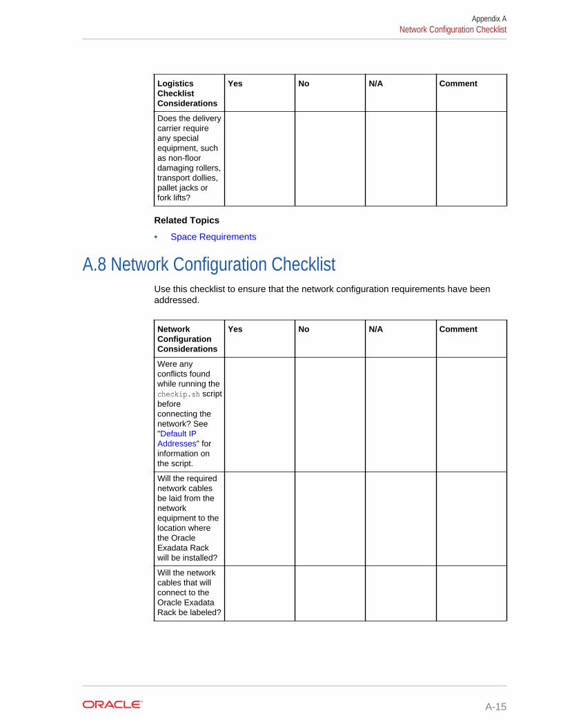
LogisticsChecklistConsiderations
Yes No N/A Comment
Does the deliverycarrier requireany specialequipment, suchas non-floordamaging rollers,transport dollies,pallet jacks orfork lifts?
Related Topics
• Space Requirements
A.8 Network Configuration ChecklistUse this checklist to ensure that the network configuration requirements have beenaddressed.
NetworkConfigurationConsiderations
Yes No N/A Comment
Were anyconflicts foundwhile running thecheckip.sh scriptbeforeconnecting thenetwork? See"Default IPAddresses" forinformation onthe script.
Will the requirednetwork cablesbe laid from thenetworkequipment to thelocation wherethe OracleExadata Rackwill be installed?
Will the networkcables that willconnect to theOracle ExadataRack be labeled?
Appendix ANetwork Configuration Checklist
A-15
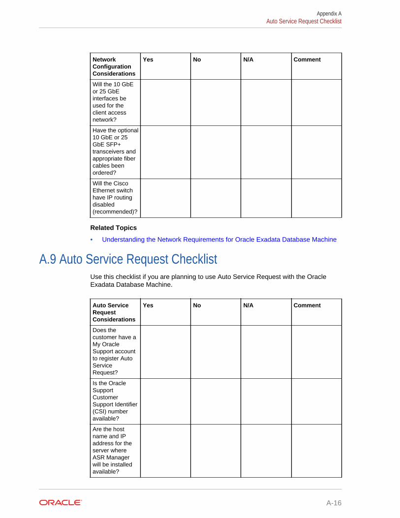
NetworkConfigurationConsiderations
Yes No N/A Comment
Will the 10 GbEor 25 GbEinterfaces beused for theclient accessnetwork?
Have the optional10 GbE or 25GbE SFP+transceivers andappropriate fibercables beenordered?
Will the CiscoEthernet switchhave IP routingdisabled(recommended)?
Related Topics
• Understanding the Network Requirements for Oracle Exadata Database Machine
A.9 Auto Service Request ChecklistUse this checklist if you are planning to use Auto Service Request with the OracleExadata Database Machine.
Auto ServiceRequestConsiderations
Yes No N/A Comment
Does thecustomer have aMy OracleSupport accountto register AutoServiceRequest?
Is the OracleSupportCustomerSupport Identifier(CSI) numberavailable?
Are the hostname and IPaddress for theserver whereASR Managerwill be installedavailable?
Appendix AAuto Service Request Checklist
A-16
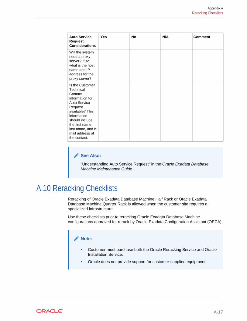
Auto ServiceRequestConsiderations
Yes No N/A Comment
Will the systemneed a proxyserver? If so,what is the hostname and IPaddress for theproxy server?
Is the CustomerTechnicalContactinformation forAuto ServiceRequestavailable? Thisinformationshould includethe first name,last name, and e-mail address ofthe contact.
See Also:
"Understanding Auto Service Request" in the Oracle Exadata DatabaseMachine Maintenance Guide
A.10 Reracking ChecklistsReracking of Oracle Exadata Database Machine Half Rack or Oracle ExadataDatabase Machine Quarter Rack is allowed when the customer site requires aspecialized infrastructure.
Use these checklists prior to reracking Oracle Exadata Database Machineconfigurations approved for rerack by Oracle Exadata Configuration Assistant (OECA).
Note:
• Customer must purchase both the Oracle Reracking Service and OracleInstallation Service.
• Oracle does not provide support for customer-supplied equipment.
Appendix AReracking Checklists
A-17

RerackingConsiderations
Yes No N/A Comment
Has the customerpurchased theOracle RerackingService?
Is there a cartcapable ofcarrying theweight of theservers to movethe componentsand associatedcabling from thesupplied rack tothe customersupplied rack?
Is the target rackempty?
Please attachpictures of thetarget rack(inside andoutside).
Do the targetrack dimensionsmeet thefollowingrequirements?
• Height: 42RU
• Width: 600mm (23.62inches)
• Depth: 1112mm (43.78inches)without frontand reardoors
If the rack is lessthan 42 RU, thenthe rack must beat least 30 RUtall and thecustomer mustprovidecompatible PDUsto install in thetarget rack.
Appendix AReracking Checklists
A-18
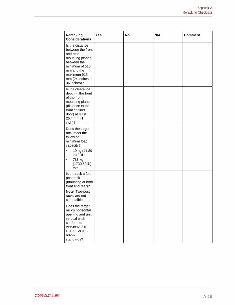
RerackingConsiderations
Yes No N/A Comment
Is the distancebetween the frontand rearmounting planesbetween theminimum of 610mm and themaximum 915mm (24 inches to36 inches)?
Is the clearancedepth in the frontof the frontmounting plane(distance to thefront cabinetdoor) at least25.4 mm (1inch)?
Does the targetrack meet thefollowingminimum loadcapacity?
• 19 kg (41.89lb) / RU
• 785 kg(1730.63 lb)total
Is the rack a four-post rack(mounting at bothfront and rear)?
Note: Two-postracks are notcompatible.
Does the targetrack's horizontalopening and unitvertical pitchconform toANSI/EIA 310-D-1992 or IEC60297standards?
Appendix AReracking Checklists
A-19
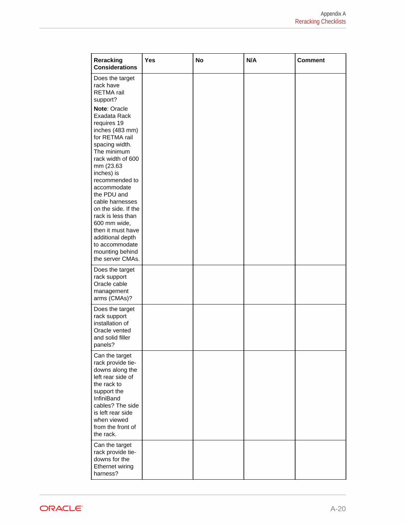
RerackingConsiderations
Yes No N/A Comment
Does the targetrack haveRETMA railsupport?
Note: OracleExadata Rackrequires 19inches (483 mm)for RETMA railspacing width.The minimumrack width of 600mm (23.63inches) isrecommended toaccommodatethe PDU andcable harnesseson the side. If therack is less than600 mm wide,then it must haveadditional depthto accommodatemounting behindthe server CMAs.
Does the targetrack supportOracle cablemanagementarms (CMAs)?
Does the targetrack supportinstallation ofOracle ventedand solid fillerpanels?
Can the targetrack provide tie-downs along theleft rear side ofthe rack tosupport theInfiniBandcables? The sideis left rear sidewhen viewedfrom the front ofthe rack.
Can the targetrack provide tie-downs for theEthernet wiringharness?
Appendix AReracking Checklists
A-20
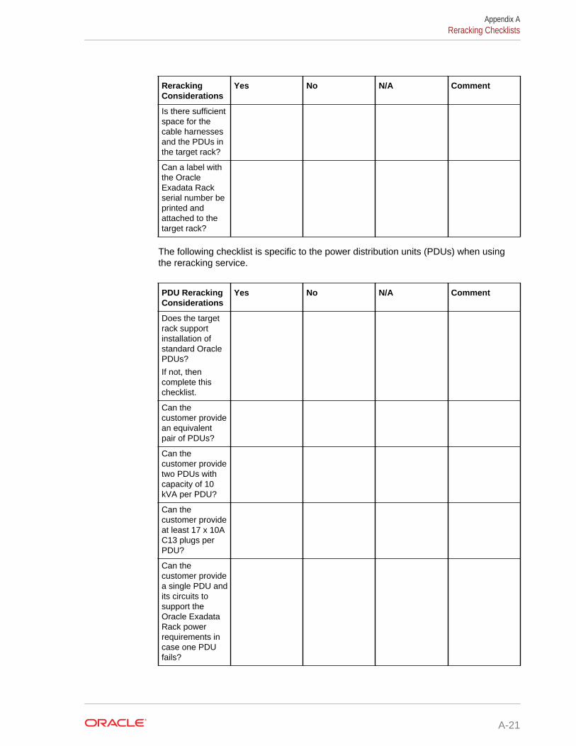
RerackingConsiderations
Yes No N/A Comment
Is there sufficientspace for thecable harnessesand the PDUs inthe target rack?
Can a label withthe OracleExadata Rackserial number beprinted andattached to thetarget rack?
The following checklist is specific to the power distribution units (PDUs) when usingthe reracking service.
PDU RerackingConsiderations
Yes No N/A Comment
Does the targetrack supportinstallation ofstandard OraclePDUs?
If not, thencomplete thischecklist.
Can thecustomer providean equivalentpair of PDUs?
Can thecustomer providetwo PDUs withcapacity of 10kVA per PDU?
Can thecustomer provideat least 17 x 10AC13 plugs perPDU?
Can thecustomer providea single PDU andits circuits tosupport theOracle ExadataRack powerrequirements incase one PDUfails?
Appendix AReracking Checklists
A-21
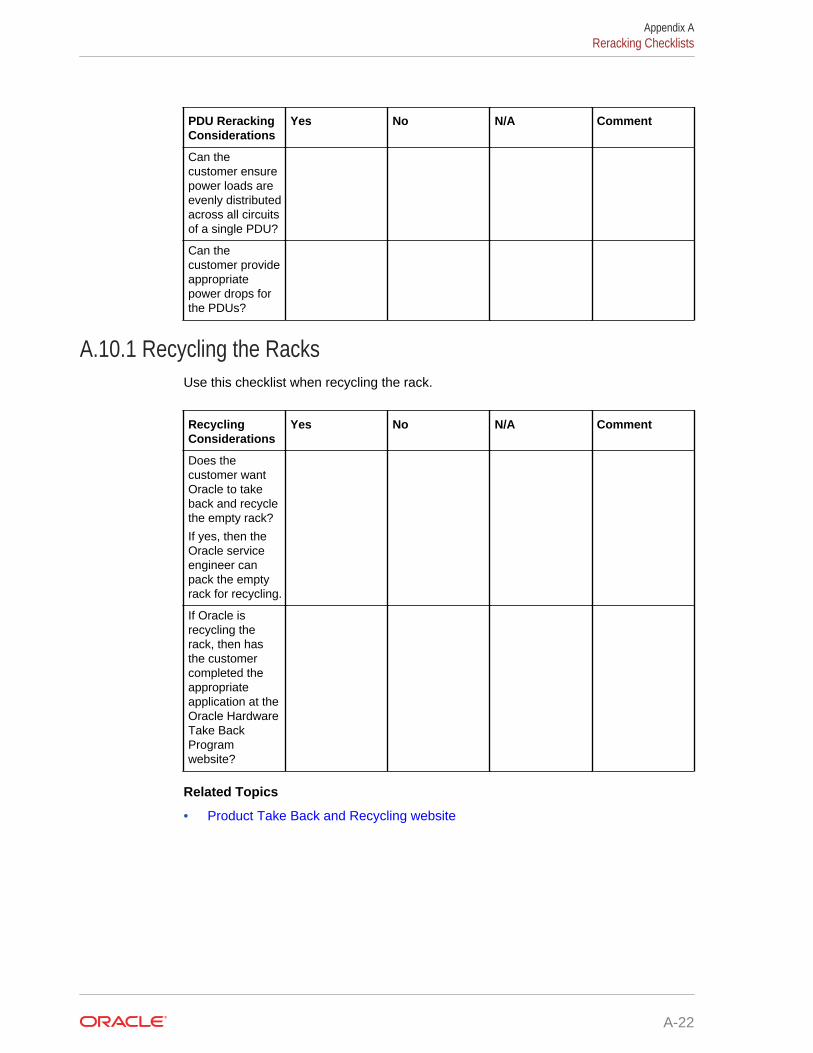
PDU RerackingConsiderations
Yes No N/A Comment
Can thecustomer ensurepower loads areevenly distributedacross all circuitsof a single PDU?
Can thecustomer provideappropriatepower drops forthe PDUs?
A.10.1 Recycling the RacksUse this checklist when recycling the rack.
RecyclingConsiderations
Yes No N/A Comment
Does thecustomer wantOracle to takeback and recyclethe empty rack?
If yes, then theOracle serviceengineer canpack the emptyrack for recycling.
If Oracle isrecycling therack, then hasthe customercompleted theappropriateapplication at theOracle HardwareTake BackProgramwebsite?
Related Topics
• Product Take Back and Recycling website
Appendix AReracking Checklists
A-22
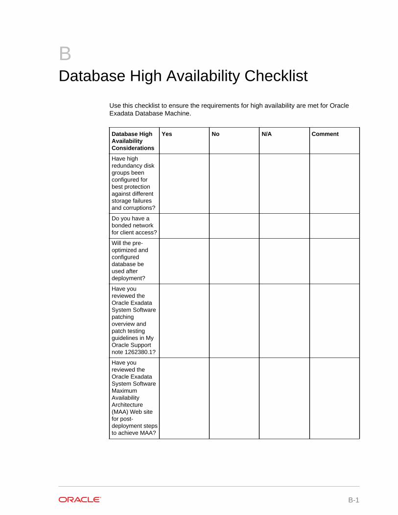
BDatabase High Availability Checklist
Use this checklist to ensure the requirements for high availability are met for OracleExadata Database Machine.
Database HighAvailabilityConsiderations
Yes No N/A Comment
Have highredundancy diskgroups beenconfigured forbest protectionagainst differentstorage failuresand corruptions?
Do you have abonded networkfor client access?
Will the pre-optimized andconfigureddatabase beused afterdeployment?
Have youreviewed theOracle ExadataSystem Softwarepatchingoverview andpatch testingguidelines in MyOracle Supportnote 1262380.1?
Have youreviewed theOracle ExadataSystem SoftwareMaximumAvailabilityArchitecture(MAA) Web sitefor post-deployment stepsto achieve MAA?
B-1
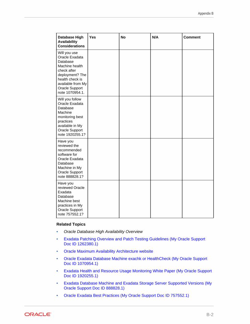
Database HighAvailabilityConsiderations
Yes No N/A Comment
Will you useOracle ExadataDatabaseMachine healthcheck afterdeployment? Thehealth check isavailable from MyOracle Supportnote 1070954.1.
Will you followOracle ExadataDatabaseMachinemonitoring bestpracticesavailable in MyOracle Supportnote 1920255.1?
Have youreviewed therecommendedsoftware forOracle ExadataDatabaseMachine in MyOracle Supportnote 888828.1?
Have youreviewed OracleExadataDatabaseMachine bestpractices in MyOracle Supportnote 757552.1?
Related Topics
• Oracle Database High Availability Overview
• Exadata Patching Overview and Patch Testing Guidelines (My Oracle SupportDoc ID 1262380.1)
• Oracle Maximum Availability Architecture website
• Oracle Exadata Database Machine exachk or HealthCheck (My Oracle SupportDoc ID 1070954.1)
• Exadata Health and Resource Usage Monitoring White Paper (My Oracle SupportDoc ID 1920255.1)
• Exadata Database Machine and Exadata Storage Server Supported Versions (MyOracle Support Doc ID 888828.1)
• Oracle Exadata Best Practices (My Oracle Support Doc ID 757552.1)
Appendix B
B-2
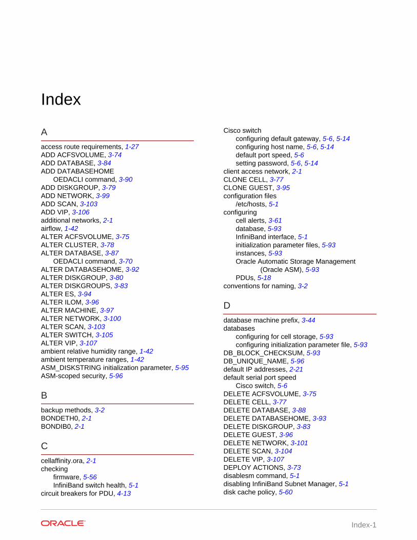
Index
Aaccess route requirements, 1-27ADD ACFSVOLUME, 3-74ADD DATABASE, 3-84ADD DATABASEHOME
OEDACLI command, 3-90ADD DISKGROUP, 3-79ADD NETWORK, 3-99ADD SCAN, 3-103ADD VIP, 3-106additional networks, 2-1airflow, 1-42ALTER ACFSVOLUME, 3-75ALTER CLUSTER, 3-78ALTER DATABASE, 3-87
OEDACLI command, 3-70ALTER DATABASEHOME, 3-92ALTER DISKGROUP, 3-80ALTER DISKGROUPS, 3-83ALTER ES, 3-94ALTER ILOM, 3-96ALTER MACHINE, 3-97ALTER NETWORK, 3-100ALTER SCAN, 3-103ALTER SWITCH, 3-105ALTER VIP, 3-107ambient relative humidity range, 1-42ambient temperature ranges, 1-42ASM_DISKSTRING initialization parameter, 5-95ASM-scoped security, 5-96
Bbackup methods, 3-2BONDETH0, 2-1BONDIB0, 2-1
Ccellaffinity.ora, 2-1checking
firmware, 5-56InfiniBand switch health, 5-1
circuit breakers for PDU, 4-13
Cisco switchconfiguring default gateway, 5-6, 5-14configuring host name, 5-6, 5-14default port speed, 5-6setting password, 5-6, 5-14
client access network, 2-1CLONE CELL, 3-77CLONE GUEST, 3-95configuration files
/etc/hosts, 5-1configuring
cell alerts, 3-61database, 5-93InfiniBand interface, 5-1initialization parameter files, 5-93instances, 5-93Oracle Automatic Storage Management
(Oracle ASM), 5-93PDUs, 5-18
conventions for naming, 3-2
Ddatabase machine prefix, 3-44databases
configuring for cell storage, 5-93configuring initialization parameter file, 5-93
DB_BLOCK_CHECKSUM, 5-93DB_UNIQUE_NAME, 5-96default IP addresses, 2-21default serial port speed
Cisco switch, 5-6DELETE ACFSVOLUME, 3-75DELETE CELL, 3-77DELETE DATABASE, 3-88DELETE DATABASEHOME, 3-93DELETE DISKGROUP, 3-83DELETE GUEST, 3-96DELETE NETWORK, 3-101DELETE SCAN, 3-104DELETE VIP, 3-107DEPLOY ACTIONS, 3-73disablesm command, 5-1disabling InfiniBand Subnet Manager, 5-1disk cache policy, 5-60
Index-1
DNS, 1-49domain name system, 1-49
Eearth ground cable, 4-10elasticConfig.sh script, 5-84electrostatic discharge, 1-42enablesm command, 5-1enabling InfiniBand Subnet Manager, 5-1
Ffiles
configuration, 3-1firewalls
port assignments, 2-34firmware checks, 5-56first database server location, 5-84
Ggetmaster command, 5-4GNS
configuring, 1-49grid naming service, 1-49ground cable, 4-10
Hhigh redundancy, 3-2humidity range, 1-42
IIB0, 2-1IB1, 2-1ILOM
network, 2-1, 2-19InfiniBand
addresses, 1-50bonding names, 2-1commands
version, 5-1private network, 2-1switch health, 5-1switch host name, 5-1
initialization parameter fileASM_DISKSTRING parameter, 5-95database and Oracle ASM instances, 5-93
IP addressesdefault IP addresses, 2-21
IP addresses (continued)Oracle Exadata Database Machine, 1-3, 1-7,
1-9, 1-10, 1-12, 1-14–1-16, 1-18,1-50
Oracle Exadata Storage Expansion HCRack, 1-71
Oracle Exadata Storage Expansion Rack,1-20, 1-22–1-24
Lleaf switches, 5-4leveling feet, 4-7, 4-8LIST ACFSVOLUME, 3-76LIST CELLS, 3-77LIST CLUSTERS, 3-78LIST DATABASEHOMES, 3-94LIST DATABASES, 3-89LIST DISKGROUPS, 3-84LIST ILOMS, 3-96LIST MACHINES, 3-98LIST NETWORKS, 3-102LIST SCANS, 3-104LIST SWITCHES, 3-105LIST VIPS, 3-108LIST XMLACTIONS, 3-74LOAD FILE, 3-72locating
first database server, 5-84PDU circuit breakers, 4-13
Mmanagement network, 2-1MERGE ACTIONS, 3-73minimum ceiling height, 1-26minimum subnet mask, 1-50
Nnaming conventions, 3-2net weights
Oracle Exadata Database Machine, 1-27Oracle Exadata Storage Expansion Rack,
1-27NET0, 2-1NET1, 2-1NET2, 2-1, 2-18NET3, 2-1, 2-18networks
additional, 1-46, 2-1, 2-18channel bonding, 2-10client access, 1-46, 2-1InfiniBand, 2-1
Index
Index-2
networks (continued)management, 1-46, 1-71, 2-1non-bonding, 2-14
normal redundancy, 3-2NUMA node numbers, 2-1
Ooedacli
starting, 3-69OEDACLI
ALTER DATABASE command example, 3-70help output, 3-69, 3-70
OEDACLI commandADD DATABASEHOME, 3-90
open ports, 2-18Oracle Automatic Storage Management (Oracle
ASM)configuring for cell storage, 5-93configuring initialization parameter file, 5-93
Oracle Exadata Deployment Assistant, 3-1Oracle Exadata Deployment Assistant (OEDA),
5-91Oracle Multitenant databases, 5-96
PPDUs
circuit breakers, 4-13configuration, 5-18thresholds, 5-20
perforated tiles, 1-44port assignments, 2-34protection levels, 3-2
Rredundancy
high, 3-2normal, 3-2
relative humidity, 1-42, 1-44
Ssafety guidelines, 4-1SAVE ACTION, 3-72SAVE FILE, 3-73SAVE FILES, 3-73
SCAN addresses, 1-49, 2-1, 2-10, 3-50serial numbers, 5-60setting
Cisco switch time zone, 5-6Subnet Manager Master, 5-4
shipping brackets, 4-2shipping kit, 4-2, 4-3shipping weights
Oracle Exadata Database Machine, 1-27Oracle Exadata Storage Expansion Rack,
1-27Small Form-Factor Pluggable (SFP) modules,
2-1, 2-7spine switches
rack location, 5-4stabilizing Oracle Exadata Rack, 4-8stabilizing rack, 4-7Subnet Manager Master, 5-4Support Hub, 3-65support policies, 3-65
Ttemperature ranges, 1-42thresholds for PDUs, 5-20time zones, 5-6top clearance, 1-26
Uutilities
Oracle Exadata Deployment Assistant(OEDA), 5-91
verify-topology, 5-60
Vverify-topology utility, 5-60verifying
disk cache policy, 5-60InfiniBand switch host name, 5-1InfiniBand topology, 5-60rack master serial number, 5-60
version command, 5-1VIP addresses, 1-49, 2-1, 2-10, 3-50VLAN tagging, 2-20VLANs, 5-6
Index
3