install & operation manual - borg & overström
TRANSCRIPT
Contents
Install & Operation Manual
GB
Dispense options Chilled & AmbientChilled & HotChilled & SparklingChilled, Hot & Sparkling
Telephone+44 (0)1362 695 [email protected]
borgandoverstrom.com
Synergy HouseFakenham RoadMorton On The HillNR9 5SP
Chilled Ambient
2 Model Overview 2 Introduction 3 Controls 4 Floorstanding Version
5 Installation 5 Major Component 5 Water & CO2 Connection 6 CO2 Bottle Installation 7 Level Sensor Assembly
8 Operation 8 Cold Water Connection & Operation 10 Functions & Controls 10 General Safety
11 Maintenance 11 Isolation & Removal 12 Sanitisation Guide 13 Leak Detection 14 Emptying the Carbonation Tank
15 Advanced Troubleshooting
20 Exploded Diagrams & Parts List
26 Technical Information 26 Electrical Circuit Diagrams 30 Flow Diagrams 34 Specification
Install & Operation ManualBorg & Overström GB2
Model Overview
All ModelsAll models are self-contained machines with robust steel framed cabinets and attractively injection moulded plastic front, side and top panels. There is sufficient space internally for most filters to be fitted behind the right side panel.An IEC Power Lead is supplied for connection to the IEC socket found on the rear of all models (An additional Schuko type is supplied for the European market).
ChilledWater is fed into the insulated cold tank under mains pressure. We strongly recommend a Pressure Reducing Valve is fitted to all supplies to regulate the pressure to 3.5 bar/355 KPat. The cold tank is chilled via the outer evaporation coil of the capillary controlled refrigeration compression system. The cold temperature is thermostatically controlled via the adjustment screw on the back of the machine. This is factory set and is not necessary to adjust in most cases (see Controls).
AmbientWater bypasses the cold tank for the ambient dispense option.SparklingWater is chilled as it passes through the coil immediately before dispense or being pumped under pressure into the carbonator which it fitted inside the same coil. The carbonator is also level controlled and allows the sparkling effect to occur through saturation with CO2.
The level control system also incorporates a leak detection device within the unit which switches the machine off in the event of detecting a water leak.
HotHot water is provided by hot water tank with an integrated heater element. The water is supplied directly into the tank under the pressure as connected into the back of the unit. The water fills the tank and hot water is dispensed by displacement. The water flow is controlled by a solenoid.
Introduction
A range of compact water dispensers, available in four different operational types:
• Chilled and Ambient (Low Pressure Tank System)• Chilled and Hot• Chilled and Sparkling• Chilled, Hot and Sparkling
All are available as countertop and floor standing models.
© Copyright Borg & Overström. This manual is printed by Borg & Overström and shall not be reproduced or copied in anyway.
Install & Operation ManualBorg & Overström GB3
ChilledOn/Off Switch: at upper rear of machine, switches cooling operation on/off.*
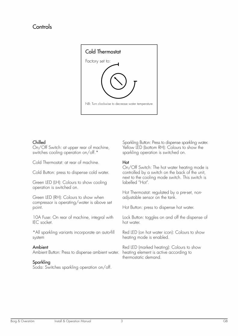
Cold Thermostat: at rear of machine.
Cold Button: press to dispense cold water.
Green LED (LH): Colours to show cooling operation is switched on.
Green LED (RH): Colours to show when compressor is operating/water is above set point.
10A Fuse: On rear of machine, integral with IEC socket.
*All sparkling variants incorporate an auto-fill system
AmbientAmbient Button: Press to dispense ambient water.
SparklingSoda: Switches sparkling operation on/off.
Sparkling Button: Press to dispense sparkling water.Yellow LED (bottom RH): Colours to show the sparkling operation is switched on.
HotOn/Off Switch: The hot water heating mode is controlled by a switch on the back of the unit, next to the cooling mode switch. This switch is labelled “Hot”.
Hot Thermostat: regulated by a pre-set, non-adjustable sensor on the tank.
Hot Button: press to dispense hot water.
Lock Button: toggles on and off the dispense of hot water.
Red LED (on hot water icon): Colours to show heating mode is enabled.
Red LED (marked heating): Colours to show heating element is active according to thermostatic demand.
Controls
Factory set to:
Cold Thermostat
NB: Turn clockwise to decrease water temperature
Install & Operation ManualBorg & Overström GB4
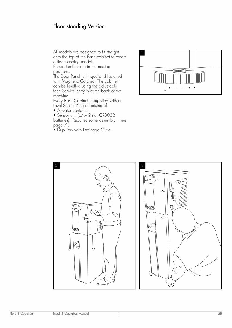
All models are designed to fit straight onto the top of the base cabinet to create a floorstanding model.Ensure the feet are in the nesting positions.The Door Panel is hinged and fastened with Magnetic Catches. The cabinet can be levelled using the adjustable feet. Service entry is at the back of the machine.Every Base Cabinet is supplied with a Level Sensor Kit, comprising of:• A water container.• Sensor unit (c/w 2 no. CR3032 batteries). (Requires some assembly – see page 7).• Drip Tray with Drainage Outlet.
Floor standing Version
1
2 3
Install & Operation ManualBorg & Overström GB5
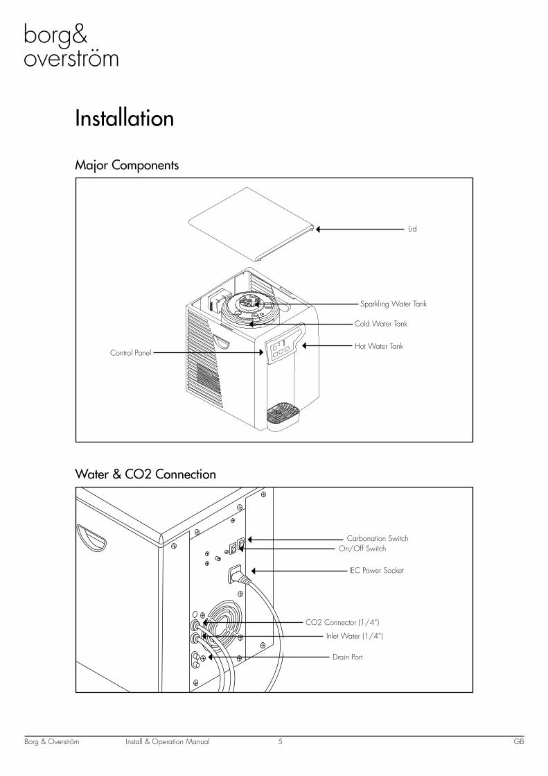
Installation
Major Components
Water & CO2 Connection
Carbonation SwitchOn/Off Switch
IEC Power Socket
CO2 Connector (1/4”)
Inlet Water (1/4”)
Drain Port
Lid
Sparkling Water Tank
Cold Water Tank
Control PanelHot Water Tank
Install & Operation ManualBorg & Overström GB6
COLD
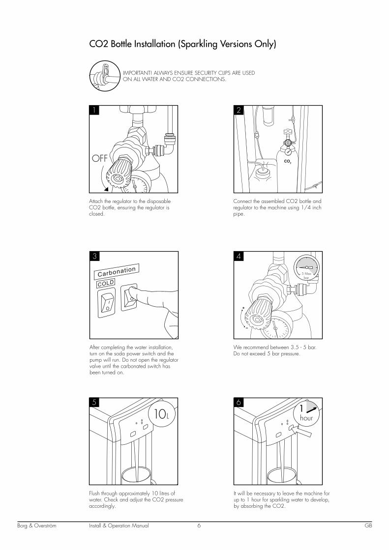
CO2 Bottle Installation (Sparkling Versions Only)
IMPORTANT! ALWAYS ENSURE SECURITY CLIPS ARE USED ON ALL WATER AND CO2 CONNECTIONS.
OFF
10 L1hour
Attach the regulator to the disposable CO2 bottle, ensuring the regulator is closed.
Connect the assembled CO2 bottle and regulator to the machine using 1/4 inch pipe.
After completing the water installation, turn on the soda power switch and the pump will run. Do not open the regulator valve until the carbonated switch has been turned on.
We recommend between 3.5 - 5 bar. Do not exceed 5 bar pressure.
Flush through approximately 10 litres of water. Check and adjust the CO2 pressure accordingly.
It will be necessary to leave the machine for up to 1 hour for sparkling water to develop, by absorbing the CO2.
5 Max bar
1 2
3 4
5 6
Install & Operation ManualBorg & Overström GB7
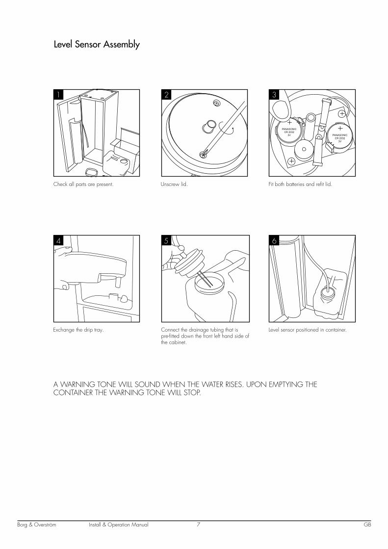
Level Sensor Assembly
PANASONICCR 2032
3V PANASONICCR 2032
3V
Check all parts are present. Unscrew lid. Fit both batteries and refit lid.
Exchange the drip tray. Connect the drainage tubing that is pre-fitted down the front left hand side of the cabinet.
Level sensor positioned in container.
A WARNING TONE WILL SOUND WHEN THE WATER RISES. UPON EMPTYING THE CONTAINER THE WARNING TONE WILL STOP.
1 2 3
4 5 6
Install & Operation ManualBorg & Overström GB8
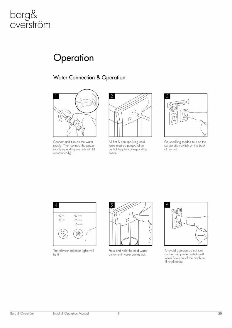
Operation
hot
cold
sparkling
chilling
heating
Water Connection & Operation
Connect and turn on the water supply. Then connect the power supply (sparkling variants will fill automatically).
The relevant indicator lights will be lit.
Press and hold the cold water button until water comes out.
To avoid damage do not turn on the cold power switch until water flows out of the machine. (If applicable)
1
54COLD
All hot & non sparkling cold tanks must be purged of air by holding the corresponding button.
On sparkling models turn on the carbonation switch on the back of the unit.
2
COLD
3
6
Borg & Overström GB9Install & Operation Manual
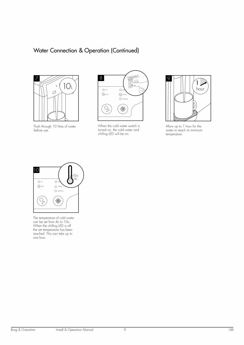
Flush through 10 litres of water before use.
7
10 L
Water Connection & Operation (Continued)
When the cold water switch is turned on, the cold water and chilling LED will be on.
hot
cold
sparkling
chilling
heating
8COLD
Allow up to 1 hour for the water to reach its minimum temperature.
91hour
The temperature of cold water can be set from 4c to 10c. When the chilling LED is off the set temperature has been reached. This can take up to one hour.
hot
cold
sparkling
chilling
heating
10
4c10 c
Install & Operation ManualBorg & Overström GB10
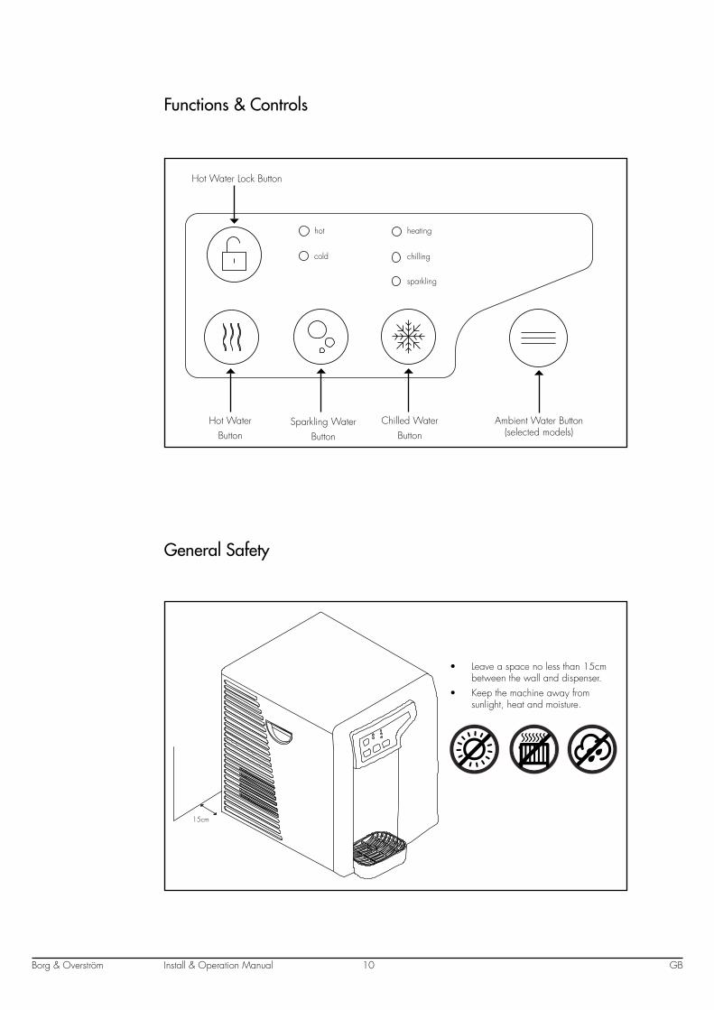
Functions & Controls
hot
cold
sparkling
chilling
heating
General Safety
15cm
• Leave a space no less than 15cm between the wall and dispenser.
• Keep the machine away from sunlight, heat and moisture.
Chilled WaterButton
Sparkling WaterButton
Hot WaterButton
Hot Water Lock Button
Ambient Water Button (selected models)
Install & Operation ManualBorg & Overström GB11
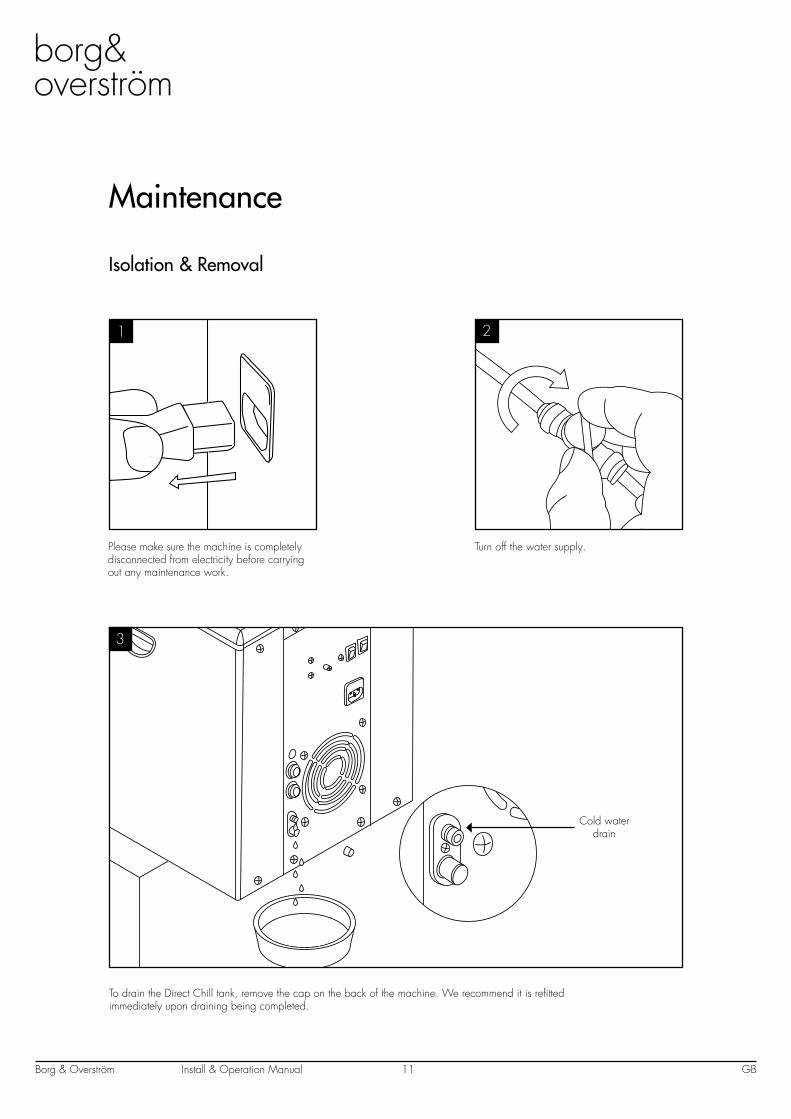
Maintenance
Isolation & Removal
1 2
3
Please make sure the machine is completely disconnected from electricity before carrying out any maintenance work.
Turn off the water supply.
To drain the Direct Chill tank, remove the cap on the back of the machine. We recommend it is refitted immediately upon draining being completed.
Cold water drain
Install & Operation ManualBorg & Overström GB12
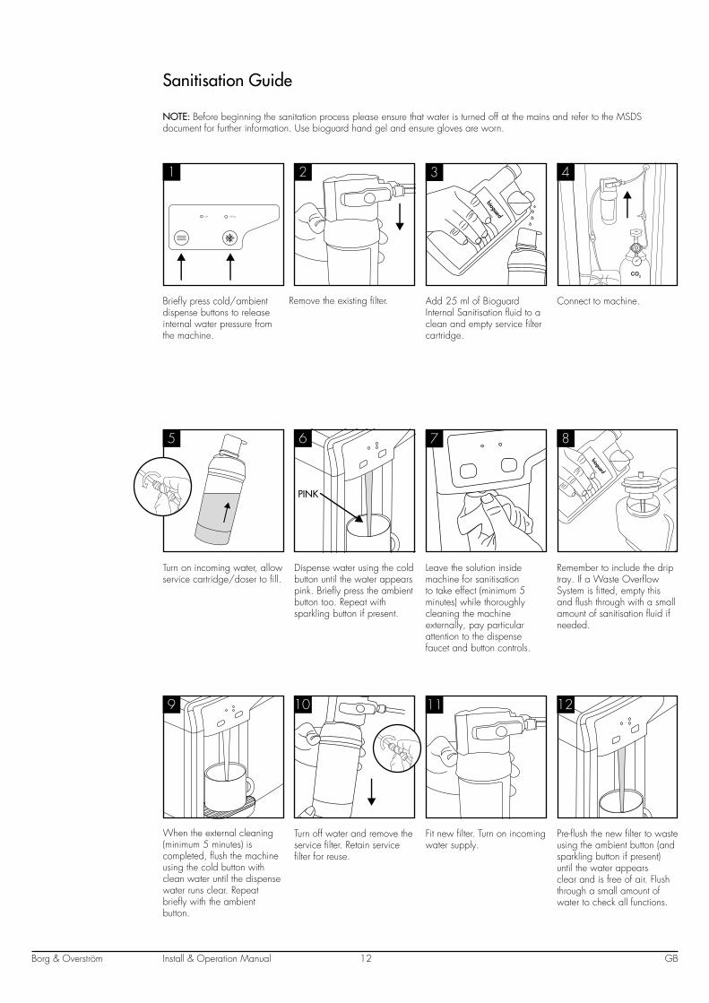
Sanitisation Guide
NOTE: Before beginning the sanitation process please ensure that water is turned off at the mains and refer to the MSDS document for further information. Use bioguard hand gel and ensure gloves are worn.
cold chilling
1 2 3 4
5 6 7 8
9 10 11 12
Briefly press cold/ambient dispense buttons to release internal water pressure from the machine.
Remove the existing filter. Add 25 ml of Bioguard Internal Sanitisation fluid to a clean and empty service filter cartridge.
Connect to machine.
Turn on incoming water, allow service cartridge/doser to fill.
Dispense water using the cold button until the water appears pink. Briefly press the ambient button too. Repeat with sparkling button if present.
Leave the solution inside machine for sanitisation to take effect (minimum 5 minutes) while thoroughly cleaning the machine externally, pay particular attention to the dispense faucet and button controls.
Remember to include the drip tray. If a Waste Overflow System is fitted, empty this and flush through with a small amount of sanitisation fluid if needed.
When the external cleaning (minimum 5 minutes) is completed, flush the machine using the cold button with clean water until the dispense water runs clear. Repeat briefly with the ambient button.
Turn off water and remove the service filter. Retain service filter for reuse.
Fit new filter. Turn on incoming water supply.
Pre-flush the new filter to waste using the ambient button (and sparkling button if present) until the water appears clear and is free of air. Flush through a small amount of water to check all functions.
PINK
Install & Operation ManualBorg & Overström GB13
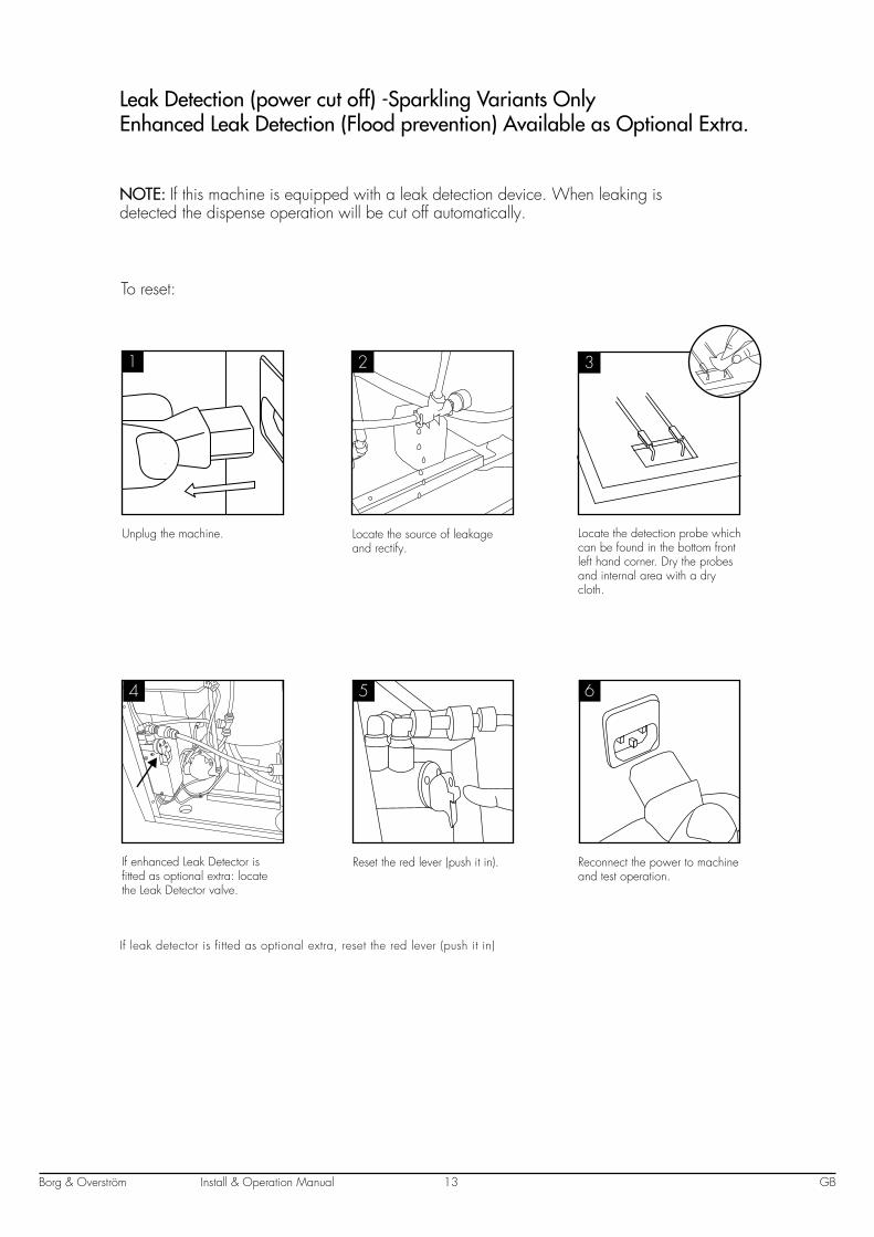
Leak Detection (power cut off) -Sparkling Variants Only Enhanced Leak Detection (Flood prevention) Available as Optional Extra.
NOTE: If this machine is equipped with a leak detection device. When leaking is detected the dispense operation will be cut off automatically.
4 5
HOT
6
To reset:
Unplug the machine. Locate the source of leakage and rectify.
Locate the detection probe which can be found in the bottom front left hand corner. Dry the probes and internal area with a dry cloth.
If enhanced Leak Detector is fitted as optional extra: locate the Leak Detector valve.
Reset the red lever (push it in). Reconnect the power to machine and test operation.
1 2 3
If leak detector is fitted as optional extra, reset the red lever (push it in)
Install & Operation ManualBorg & Overström GB14
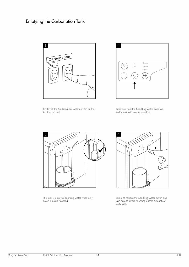
Emptying the Carbonation Tank
CO LD
1
Switch off the Carbonation System switch on the back of the unit.
Press and hold the Sparkling water dispense button until all water is expelled
The tank is empty of sparking water when only CO2 is being released.
Ensure to release the Sparkling water button and take care to avoid releasing excess amounts of CO2 gas.
hot
cold
sparkling
chilling
heating
2
3 4
Install & Operation ManualBorg & Overström GB15
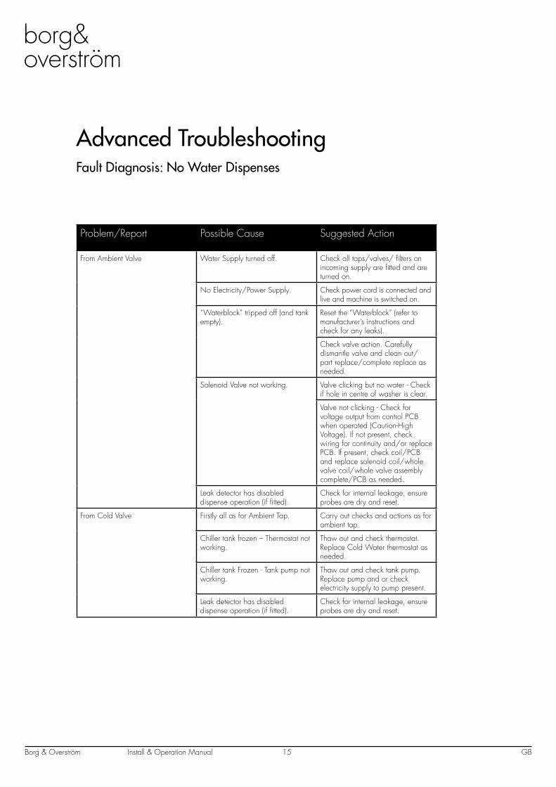
Advanced TroubleshootingFault Diagnosis: No Water Dispenses
Problem/Report Possible Cause Suggested Action
From Ambient Valve Water Supply turned off. Check all taps/valves/ filters on incoming supply are fitted and are turned on.
No Electricity/Power Supply. Check power cord is connected and live and machine is switched on.
“Waterblock” tripped off (and tank empty).
Reset the “Waterblock” (refer to manufacturer’s instructions and check for any leaks).
Check valve action. Carefully dismantle valve and clean out/part replace/complete replace as needed.
Solenoid Valve not working. Valve clicking but no water - Check if hole in centre of washer is clear.
Valve not clicking - Check for voltage output from control PCB when operated (Caution-High Voltage). If not present, check wiring for continuity and/or replace PCB. If present, check coil/PCB and replace solenoid coil/whole valve coil/whole valve assembly complete/PCB as needed.
Leak detector has disabled dispense operation (if fitted).
Check for internal leakage, ensure probes are dry and reset.
From Cold Valve Firstly all as for Ambient Tap. Carry out checks and actions as for ambient tap.
Chiller tank frozen – Thermostat not working.
Thaw out and check thermostat. Replace Cold Water thermostat as needed.
Chiller tank Frozen - Tank pump not working.
Thaw out and check tank pump. Replace pump and or check electricity supply to pump present.
Leak detector has disabled dispense operation (if fitted).
Check for internal leakage, ensure probes are dry and reset.
Install & Operation ManualBorg & Overström GB16
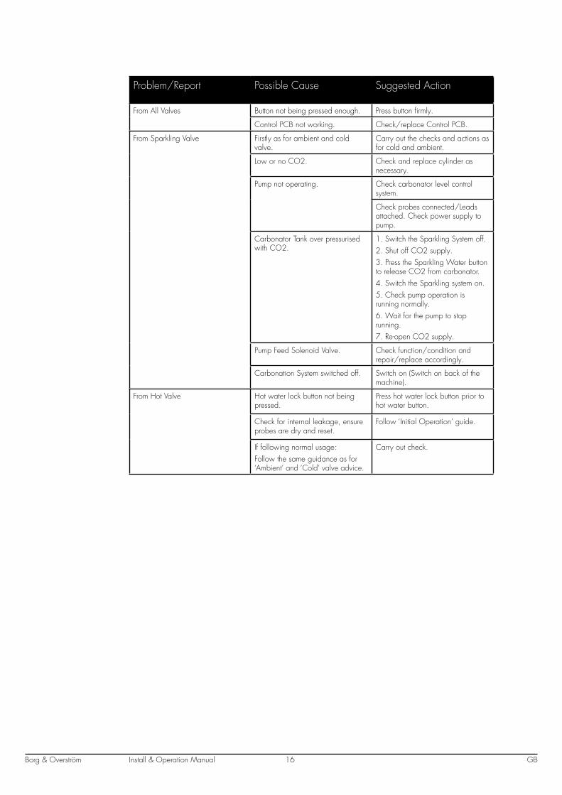
Problem/Report Possible Cause Suggested Action
From All Valves Button not being pressed enough. Press button firmly.
Control PCB not working. Check/replace Control PCB.
From Sparkling Valve Firstly as for ambient and cold valve.
Carry out the checks and actions as for cold and ambient.
Low or no CO2. Check and replace cylinder as necessary.
Pump not operating. Check carbonator level control system.
Check probes connected/Leads attached. Check power supply to pump.
Carbonator Tank over pressurised with CO2.
1. Switch the Sparkling System off.2. Shut off CO2 supply.3. Press the Sparkling Water button to release CO2 from carbonator.4. Switch the Sparkling system on.5. Check pump operation is running normally.6. Wait for the pump to stop running.7. Re-open CO2 supply.
Pump Feed Solenoid Valve. Check function/condition and repair/replace accordingly.
Carbonation System switched off. Switch on (Switch on back of the machine).
From Hot Valve Hot water lock button not being pressed.
Press hot water lock button prior to hot water button.
Check for internal leakage, ensure probes are dry and reset.
Follow ‘Initial Operation’ guide.
If following normal usage: Follow the same guidance as for ‘Ambient’ and ‘Cold’ valve advice.
Carry out check.
Install & Operation ManualBorg & Overström GB17
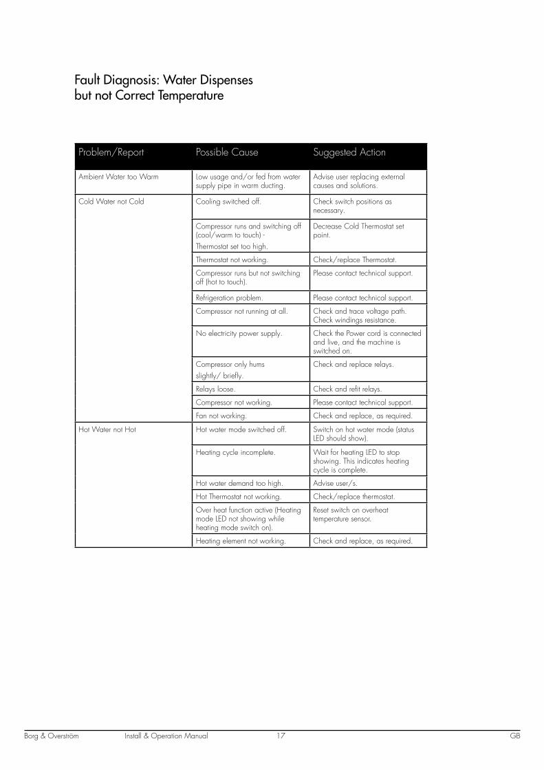
Fault Diagnosis: Water Dispenses but not Correct Temperature
Problem/Report Possible Cause Suggested Action
Ambient Water too Warm Low usage and/or fed from water supply pipe in warm ducting.
Advise user replacing external causes and solutions.
Cold Water not Cold Cooling switched off. Check switch positions as necessary.
Compressor runs and switching off (cool/warm to touch) - Thermostat set too high.
Decrease Cold Thermostat set point.
Thermostat not working. Check/replace Thermostat.
Compressor runs but not switching off (hot to touch).
Please contact technical support.
Refrigeration problem. Please contact technical support.
Compressor not running at all. Check and trace voltage path. Check windings resistance.
No electricity power supply. Check the Power cord is connected and live, and the machine is switched on.
Compressor only hums slightly/ briefly.
Check and replace relays.
Relays loose. Check and refit relays.
Compressor not working. Please contact technical support.
Fan not working. Check and replace, as required.
Hot Water not Hot Hot water mode switched off. Switch on hot water mode (status LED should show).
Heating cycle incomplete. Wait for heating LED to stop showing. This indicates heating cycle is complete.
Hot water demand too high. Advise user/s.
Hot Thermostat not working. Check/replace thermostat.
Over heat function active (Heating mode LED not showing while heating mode switch on).
Reset switch on overheat temperature sensor.
Heating element not working. Check and replace, as required.
Install & Operation ManualBorg & Overström GB18
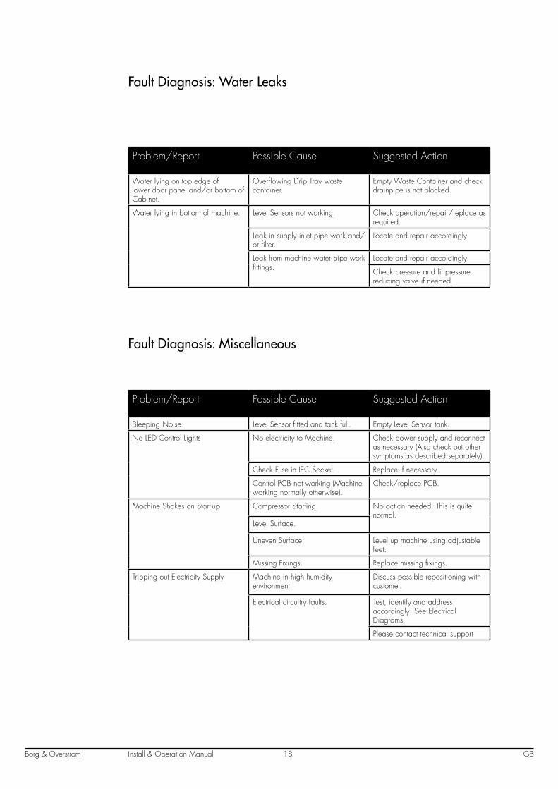
Fault Diagnosis: Water Leaks
Problem/Report Possible Cause Suggested Action
Water lying on top edge of lower door panel and/or bottom of Cabinet.
Overflowing Drip Tray waste container.
Empty Waste Container and check drainpipe is not blocked.
Water lying in bottom of machine. Level Sensors not working. Check operation/repair/replace as required.
Leak in supply inlet pipe work and/or filter.
Locate and repair accordingly.
Leak from machine water pipe work fittings.
Locate and repair accordingly.
Check pressure and fit pressure reducing valve if needed.
Fault Diagnosis: Miscellaneous
Problem/Report Possible Cause Suggested Action
Bleeping Noise Level Sensor fitted and tank full. Empty Level Sensor tank.
No LED Control Lights No electricity to Machine. Check power supply and reconnect as necessary (Also check out other symptoms as described separately).
Check Fuse in IEC Socket. Replace if necessary.
Control PCB not working (Machine working normally otherwise).
Check/replace PCB.
Machine Shakes on Start-up Compressor Starting. No action needed. This is quite normal.
Level Surface.
Uneven Surface. Level up machine using adjustable feet.
Missing Fixings. Replace missing fixings.
Tripping out Electricity Supply Machine in high humidity environment.
Discuss possible repositioning with customer.
Electrical circuitry faults. Test, identify and address accordingly. See Electrical Diagrams.
Please contact technical support
Install & Operation ManualBorg & Overström GB19
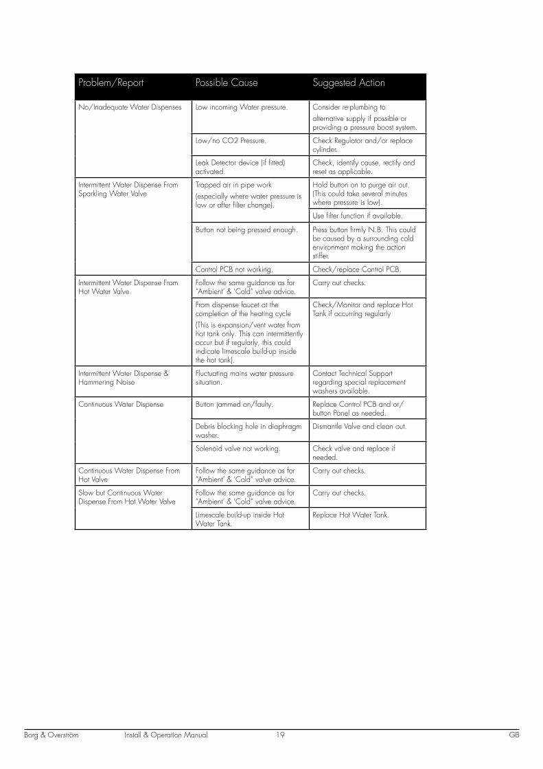
Problem/Report Possible Cause Suggested Action
No/Inadequate Water Dispenses Low incoming Water pressure. Consider re-plumbing to alternative supply if possible or providing a pressure boost system.
Low/no CO2 Pressure. Check Regulator and/or replace cylinder.
Leak Detector device (if fitted) activated.
Check, identify cause, rectify and reset as applicable.
Intermittent Water Dispense From Sparkling Water Valve
Trapped air in pipe work (especially where water pressure is low or after filter change).
Hold button on to purge air out. (This could take several minutes where pressure is low).
Use filter function if available.
Button not being pressed enough. Press button firmly N.B. This could be caused by a surrounding cold environment making the action stiffer.
Control PCB not working. Check/replace Control PCB.
Intermittent Water Dispense From Hot Water Valve
Follow the same guidance as for “Ambient’ & ‘Cold” valve advice.
Carry out checks.
From dispense faucet at the completion of the heating cycle(This is expansion/vent water from hot tank only. This can intermittently occur but if regularly, this could indicate limescale build-up inside the hot tank).
Check/Monitor and replace Hot Tank if occurring regularly
Intermittent Water Dispense & Hammering Noise
Fluctuating mains water pressure situation.
Contact Technical Support regarding special replacement washers available.
Continuous Water Dispense Button jammed on/faulty. Replace Control PCB and or/ button Panel as needed.
Debris blocking hole in diaphragm washer.
Dismantle Valve and clean out.
Solenoid valve not working. Check valve and replace if needed.
Continuous Water Dispense From Hot Valve
Follow the same guidance as for “Ambient’ & ‘Cold” valve advice.
Carry out checks.
Slow but Continuous Water Dispense From Hot Water Valve
Follow the same guidance as for “Ambient’ & ‘Cold” valve advice.
Carry out checks.
Limescale build-up inside Hot Water Tank.
Replace Hot Water Tank.
Install & Operation ManualBorg & Overström GB20
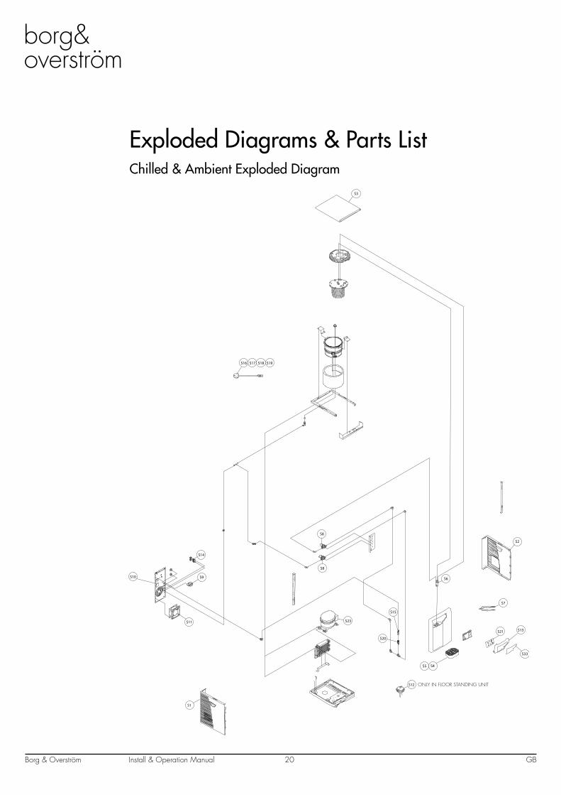
Exploded Diagrams & Parts ListChilled & Ambient Exploded Diagram
S2
S3
S4S5
S6
S21
S7
S23
S8
S8
S9S10
S11
S33
S13
S14
S16 S17 S18 S19
S20
S15
S12
S1
ONLY IN FLOOR STANDING UNIT
Install & Operation ManualBorg & Overström GB21
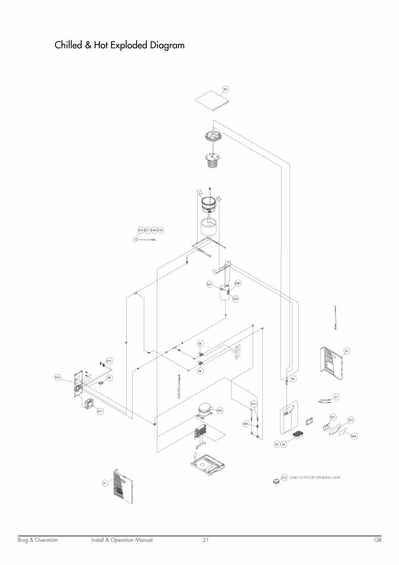
Chilled & Hot Exploded Diagram
S2
S3
S4S5
S6
S31
S7
S24
S8
S8
S9S10
S11
S34
S27 S28
S29
S13
S14
S16 S17 S18 S19
S20
S15
S12
S1
ONLY IN FLOOR STANDING UNIT
Install & Operation ManualBorg & Overström GB22
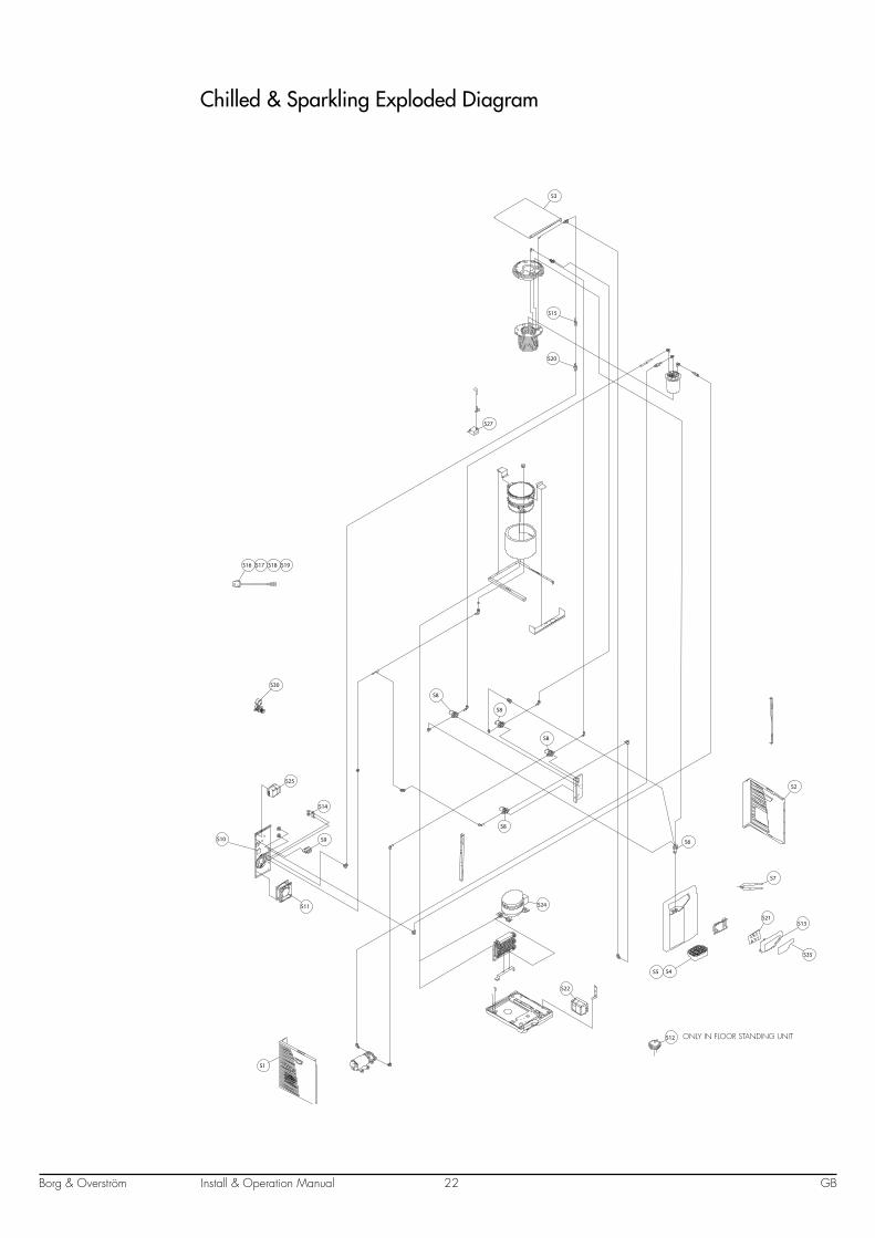
Chilled & Sparkling Exploded Diagram
S1
S2
S3
S4S5
S6
S22
S7
S24
S8
S8
S8
S8
S9
S25
S27
S10
S11
S14
S16 S17 S18 S19
S15
S20
S12
S30
S21
S35
S13
ONLY IN FLOOR STANDING UNIT

Install & Operation ManualBorg & Overström GB23
Chilled, Hot & Sparkling Exploded Diagram
S2
S3
S4S5
S6
S22
S7
S24
S8
S8
S8
S8
S8
S9
S25
S26
S10
S11
S27 S28
S29
S14
S16 S17 S18 S19
S15
S15
S20
S12
S30
S32
S36
S13
S1
ONLY IN FLOOR STANDING UNIT

Borg & Overström GB24Install & Operation Manual
Base Unit Exploded Diagram
S39
S38
S37
S40
Install & Operation ManualBorg & Overström GB25
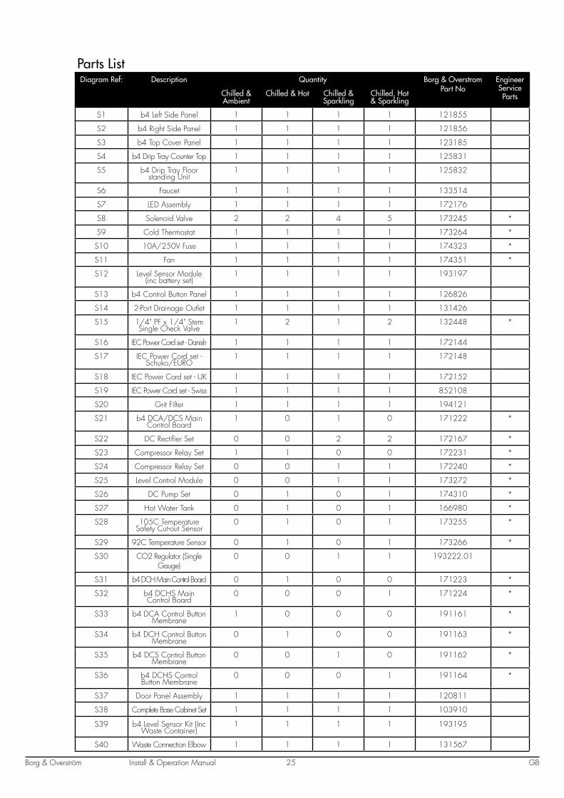
Parts ListDiagram Ref: Description Quantity Borg & Overstrom
Part NoEngineer Service PartsChilled &
AmbientChilled & Hot Chilled &
SparklingChilled, Hot & Sparkling
S1 b4 Left Side Panel 1 1 1 1 121855
S2 b4 Right Side Panel 1 1 1 1 121856
S3 b4 Top Cover Panel 1 1 1 1 123185
S4 b4 Drip Tray Counter Top 1 1 1 1 125831
S5 b4 Drip Tray Floor standing Unit
1 1 1 1 125832
S6 Faucet 1 1 1 1 133514
S7 LED Assembly 1 1 1 1 172176
S8 Solenoid Valve 2 2 4 5 173245 *
S9 Cold Thermostat 1 1 1 1 173264 *
S10 10A/250V Fuse 1 1 1 1 174323 *
S11 Fan 1 1 1 1 174351 *
S12 Level Sensor Module (inc battery set)
1 1 1 1 193197
S13 b4 Control Button Panel 1 1 1 1 126826
S14 2-Port Drainage Outlet 1 1 1 1 131426
S15 1/4" PF x 1/4" Stem Single Check Valve
1 2 1 2 132448 *
S16 IEC Power Cord set - Danish 1 1 1 1 172144
S17 IEC Power Cord set - Schuko/EURO
1 1 1 1 172148
S18 IEC Power Cord set - UK 1 1 1 1 172152
S19 IEC Power Cord set - Swiss 1 1 1 1 852108
S20 Grit Filter 1 1 1 1 194121
S21 b4 DCA/DCS Main Control Board
1 0 1 0 171222 *
S22 DC Rectifier Set 0 0 2 2 172167 *
S23 Compressor Relay Set 1 1 0 0 172231 *
S24 Compressor Relay Set 0 0 1 1 172240 *
S25 Level Control Module 0 0 1 1 173272 *
S26 DC Pump Set 0 1 0 1 174310 *
S27 Hot Water Tank 0 1 0 1 166980 *
S28 105C Temperature Safety Cut-out Sensor
0 1 0 1 173255 *
S29 92C Temperature Sensor 0 1 0 1 173266 *
S30 CO2 Regulator (Single Gauge)
0 0 1 1 193222.01
S31 b4 DCH Main Control Board 0 1 0 0 171223 *
S32 b4 DCHS Main Control Board
0 0 0 1 171224 *
S33 b4 DCA Control Button Membrane
1 0 0 0 191161 *
S34 b4 DCH Control Button Membrane
0 1 0 0 191163 *
S35 b4 DCS Control Button Membrane
0 0 1 0 191162 *
S36 b4 DCHS Control Button Membrane
0 0 0 1 191164 *
S37 Door Panel Assembly 1 1 1 1 120811
S38 Complete Base Cabinet Set 1 1 1 1 103910
S39 b4 Level Sensor Kit (Inc Waste Container)
1 1 1 1 193195
S40 Waste Connection Elbow 1 1 1 1 131567
Install & Operation ManualBorg & Overström GB26
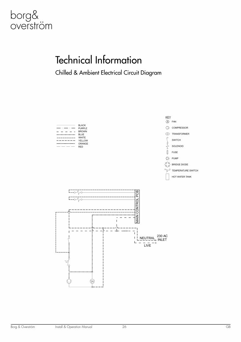
Technical InformationChilled & Ambient Electrical Circuit Diagram
KEYFAN
COMPRESSOR
TRANSFORMER
SWITCH
SOLENOID
FUSE
PUMP
BRIDGE DIODE
TEMPERATURE SWITCH
HOT WATER TANK
MA
IN C
ON
TRO
L P
CB
230 ACINLET
LIVE
NEUTRAL
BROWNBLUEWHITEYELLOWORANGE
PURPLEBLACK
RED
Install & Operation ManualBorg & Overström GB27
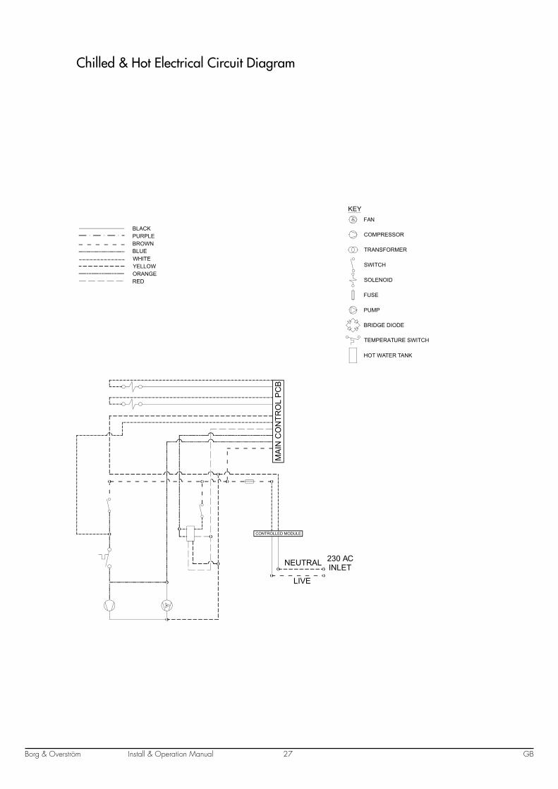
Chilled & Hot Electrical Circuit Diagram
KEYFAN
COMPRESSOR
TRANSFORMER
SWITCH
SOLENOID
FUSE
PUMP
BRIDGE DIODE
TEMPERATURE SWITCH
HOT WATER TANK
MA
IN C
ON
TRO
L P
CB
230 ACINLET
LIVE
NEUTRAL
BROWNBLUEWHITEYELLOWORANGE
PURPLEBLACK
RED
CONTROLLED MODULE
Install & Operation ManualBorg & Overström GB28
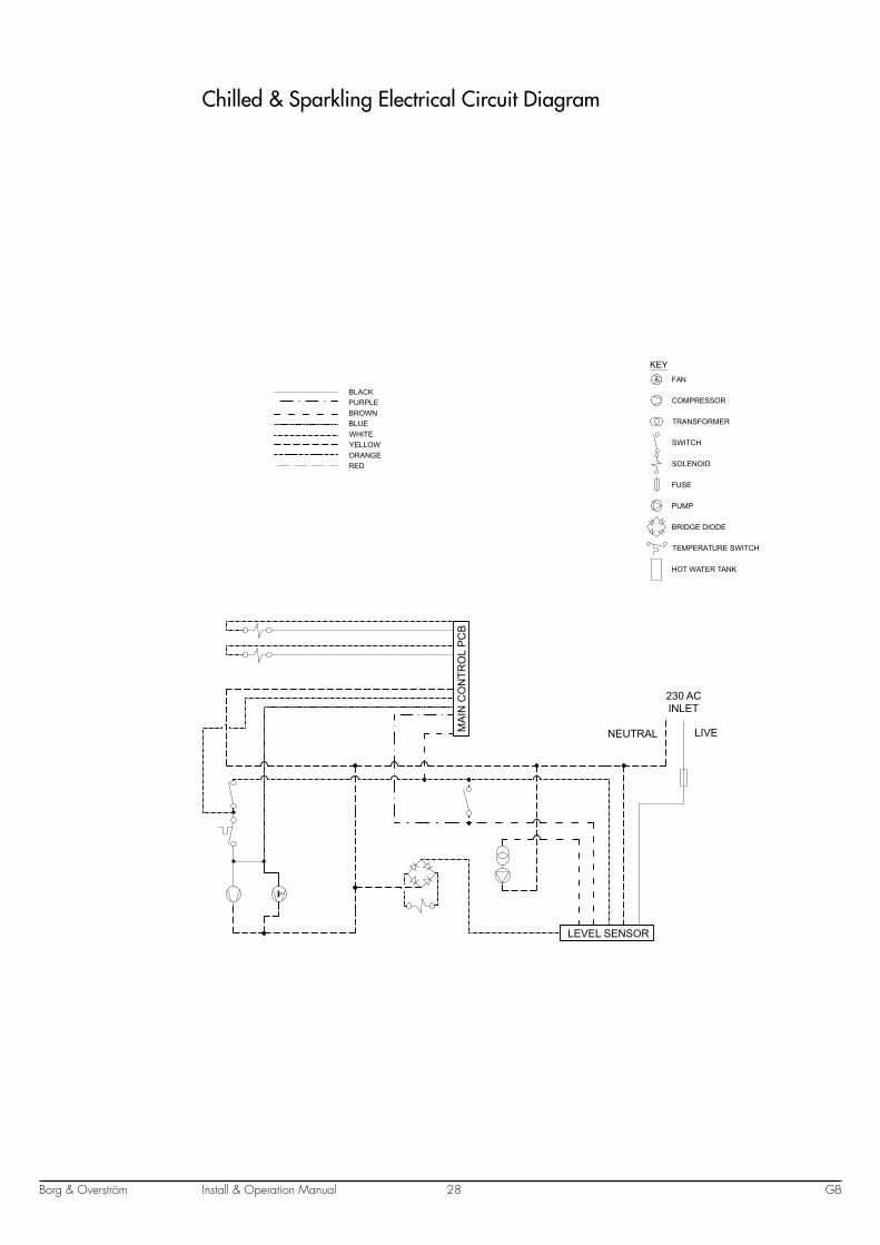
Chilled & Sparkling Electrical Circuit Diagram
KEYFAN
COMPRESSOR
TRANSFORMER
SWITCH
SOLENOID
FUSE
PUMP
BRIDGE DIODE
TEMPERATURE SWITCH
HOT WATER TANK
LEVEL SENSOR
MA
IN C
ON
TRO
L P
CB
230 ACINLET
LIVENEUTRAL
BROWNBLUEWHITEYELLOWORANGE
PURPLEBLACK
RED
Borg & Overström GB29Install & Operation Manual
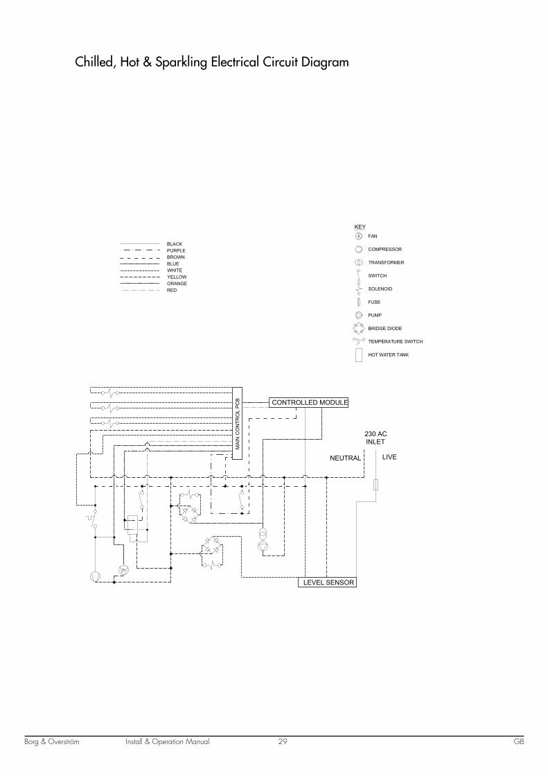
Chilled, Hot & Sparkling Electrical Circuit Diagram
KEYFAN
COMPRESSOR
TRANSFORMER
SWITCH
SOLENOID
FUSE
PUMP
BRIDGE DIODE
TEMPERATURE SWITCH
HOT WATER TANK
LEVEL SENSOR
CONTROLLED MODULE
230 ACINLET
LIVENEUTRAL
BROWNBLUEWHITEYELLOWORANGE
PURPLEBLACK
RED
MA
IN C
ON
TRO
L PC
B

Install & Operation ManualBorg & Overström GB30
Chilled & Ambient Water Pathway Diagram
LEAK DETECTOR
EXTERNAL WATER FILTER WATER IN
4 WAY SPIGOTWATER OUT
NON-RETURN VALVE
AMBIENT WATERSOLENOID
GRIT FILTER
DIRECT CHILL TANK& COMPRESSOR
CHILLED WATERSOLENOID
OPTIONAL
CHILLED
AMBIENT
Install & Operation ManualBorg & Overström GB31
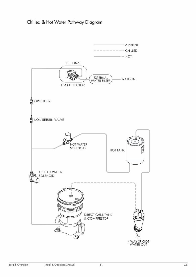
Chilled & Hot Water Pathway Diagram
EXTERNAL WATER FILTER WATER IN
4 WAY SPIGOTWATER OUT
NON-RETURN VALVE
GRIT FILTER
HOT TANK
HOT WATERSOLENOID
CHILLED WATERSOLENOID
OPTIONAL
LEAK DETECTOR
AMBIENT
CHILLED
HOT
DIRECT CHILL TANK& COMPRESSOR
Install & Operation ManualBorg & Overström GB32
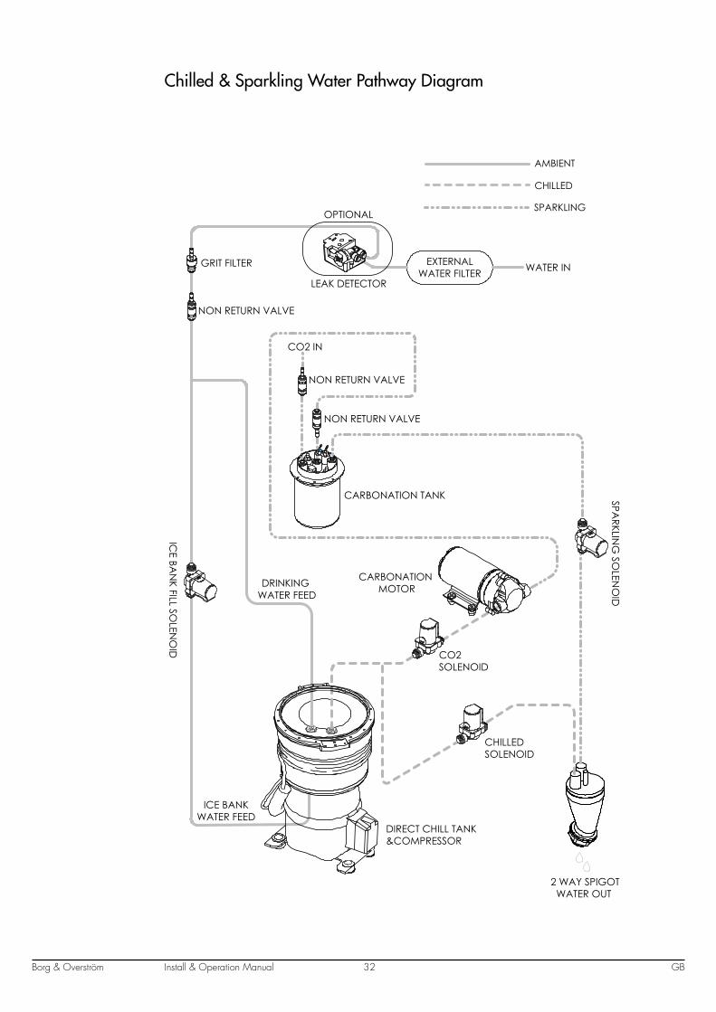
Chilled & Sparkling Water Pathway Diagram
OPTIONAL
LEAK DETECTOR
CHILLEDSOLENOID
ICE BA
NK FILL SO
LENO
ID
CO2SOLENOID
DIRECT CHILL TANK&COMPRESSOR
CARBONATION MOTOR
CARBONATION TANK
NON RETURN VALVE
NON RETURN VALVE
NON RETURN VALVE
GRIT FILTER
CO2 IN
WATER IN EXTERNALWATER FILTER
SPARKLIN
G SO
LENO
ID
2 WAY SPIGOT WATER OUT
AMBIENT
CHILLED
SPARKLING
DRINKING WATER FEED
ICE BANKWATER FEED
Install & Operation ManualBorg & Overström GB33
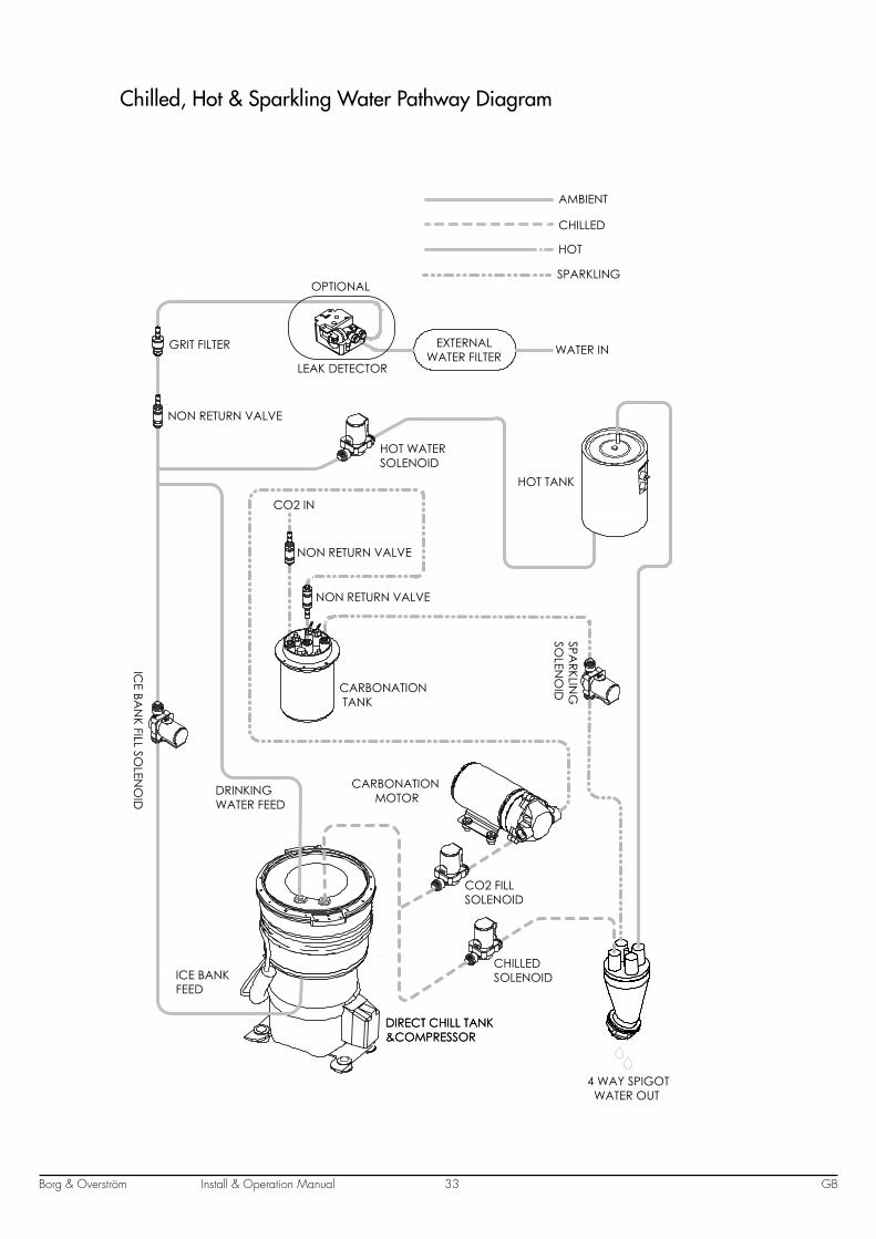
Chilled, Hot & Sparkling Water Pathway Diagram
CHILLEDSOLENOID
ICE BA
NK FILL SO
LENO
ID
CO2 FILLSOLENOID
DIRECT CHILL TANK&COMPRESSORDIRECT CHILL TANK&COMPRESSOR
CARBONATION MOTOR
CARBONATION TANK
NON RETURN VALVE
NON RETURN VALVE
NON RETURN VALVE
GRIT FILTER
CO2 IN
WATER IN EXTERNALWATER FILTER
SPARKLIN
GSO
LENO
ID
HOT TANK
HOT WATERSOLENOID
4 WAY SPIGOT WATER OUT
SPARKLING
AMBIENT
CHILLED
HOT
OPTIONAL
LEAK DETECTOR
DRINKING WATER FEED
ICE BANKFEED
Install & Operation ManualBorg & Overström GB34
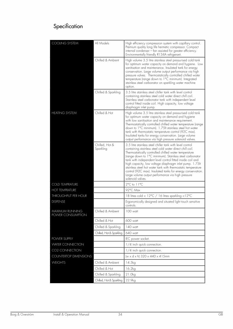
Specification
COOLING SYSTEM All Models High efficiency compression system with capillary control. Premium quality long life hermetic compressor. Compact internal condenser – fan assisted for greater efficiency. Environmentally friendly R134A refrigerant.
Chilled & Ambient High volume 3.5 litre stainless steel pressurised cold tank for optimum water capacity on demand and hygiene. Low sanitisation and maintenance. Insulated tank for energy conservation. Large volume output performance via high pressure valves. Thermostatically controlled chilled water temperature (range down to 1°C minimum). Integrated stainless steel carbonator on sparkling water machine option.
Chilled & Sparkling 3.5 litre stainless steel chiller tank with level control containing stainless steel cold water direct chill coil. Stainless steel carbonator tank with independent level control fitted inside coil. High capacity, low voltage diaphragm inlet pump.
HEATING SYSTEM Chilled & Hot High volume 3.5 litre stainless steel pressurised cold tank for optimum water capacity on demand and hygiene with low sanitisation and maintenance requirement. Thermostatically controlled chilled water temperature (range down to 1°C minimum). 1.75lt stainless steel hot water tank with thermostatic temperature control (92C max). Insulated tanks for energy conservation. Large volume output performance via high pressure solenoid valves.
Chilled, Hot & Sparkling
3.5 litre stainless steel chiller tank with level control containing stainless steel cold water direct chill coil. Thermostatically controlled chilled water temperature (range down to 1°C minimum). Stainless steel carbonator tank with independent level control fitted inside coil and high capacity, low voltage diaphragm inlet pump. 1.75lt stainless steel hot water tank with thermostatic temperature control (92C max). Insulated tanks for energy conservation. Large volume output performance via high pressure solenoid valves.
COLD TEMPRATURE 2°C to 11°C
HOT TEMPRATURE 92°C Max
THROUGHPUT PER HOUR 18 litres cold < 12°C / 16 litres sparkling <12°C
DISPENSE Ergonomically designed and situated light touch sensitive controls.
MAXIMUM RUNNING POWER CONSUMPTION
Chilled & Ambient 100 watt
Chilled & Hot 600 watt
Chilled & Sparkling 140 watt
Chilled, Hot & Sparkling 640 watt
POWER SUPPLY IEC power socket.
WATER CONNECTION 1/4 inch quick connection.
CO2 CONNECTION 1/4 inch quick connection.
COUNTERTOP DIMENSIONS (w x d x h) 320 x 440 x 415mm
WEIGHTS Chilled & Ambient 14.5kg
Chilled & Hot 16.2kg
Chilled & Sparkling 21.0kg
Chilled, Hot & Sparkling 22.9kg

Borg & Overström GB35Install & Operation Manual

Borg & Overström GB36Install & Operation Manual