insp repts 50-269/95-03,50-270/95-03 & 50-287/95-03 on
TRANSCRIPT

UNITED STATES NUCLEAR REGULATORY COMMISSION
REGION II 101 MARIETTA STREET, N.W., SUITE 2900
ATLANTA, GEORGIA 30323-0199
Report Nos.: 50-269/95-03, 50-270/95-03 and 50-287/95-03
Licensee: Duke Power Company 422 South Church Street Charlotte, NC 28242-0001
Docket Nos.: 50-269, 50-270 and 50-287
License Nos.: DPR-38, DPR-47 and DPR-55
Facility Name: Oconee Units 1, 2 and 3
Inspection Conducted: February 26 - March 25, 1995
Inspector: / . E. Hafmon, Senior R dent/nspector Date Signed
W. K. Poertner, Resident Inspector L. A. Ke 1ler, Resident Inspector P. G., phrey, Re ident Inspector
Approved by: *k /V.rlenA Chief Dte Signed
Reactor Projects Branch 3
SUMMARY
Scope: This routine, resident inspection was conducted in the areas of plant operations, surveillance testing, maintenance activities, onsite engineering and technical assistance, plant support, inspection of open items, and review of licensee event reports. Inspections were performed during normal and backshift hours and on weekends.
Results: An Unresolved Item was identified in Plant Operations regarding the misalignment of a valve in the Auxiliary Service Water System, paragraph 2.d.
Within the area of Engineering, one Violation with 2 examples was identified that involved calculation errors associated with the maximum power output limits of the Keowee Hydro Units, paragraph 4.b. Additionally, the need for a Technical Specification change to clarify the number of High Pressure Injection Pumps required for reactor modes of operation was identified as an Inspector Followup Item, paragraph 6.a.
Enclosure 2
9505030140 9504216 QPDR ADOCK 05 0002 9
2
Plant Support activities of the Nuclear Safety Review Board were well organized and aggressively pursued resolution of plant problems, paragraph 5.b. In addition, the transportation and storage of a spent fuel assemblies canister was well planned and coordinated, paragraph 5.a.
Enclosure 2

REPORT DETAILS
1. Persons Contacted
Licensee Employees
*B. Peele, Station Manager *L. Azzarello, Mechanical Systems Engineer *E. Burchfield, Regulatory Compliance Manager *D. Coyle, Systems Engineering Manager J. Davis, Engineering Manager T. Coutu, Operations Support Manager *W. Foster, Safety Assurance Manager *J. Hampton, Vice President, Oconee Site D. Hubbard, Superintendent, Instrument and Electrical (I&E) C. Little, Electrical Systems/Equipment Manager *J. Smith, Regulatory Compliance *G. Rothenberger, Operations Superintendent R. Sweigart, Work Control Superintendent *L. Wilkie, Safety Review Manager
Other licensee employees contacted included technicians, operators, mechanics, security force members, and staff engineers.
*Attended exit interview.
2. Plant Operations (71707)
a. General
The inspectors reviewed plant operations throughout the reporting period to verify conformance with regulatory requirements, Technical Specifications (TS), and administrative controls. Control room logs, shift turnover records, temporary modification log, and equipment removal and restoration records were reviewed routinely. Discussions were conducted with plant operations, maintenance, chemistry, health physics, instrument & electrical (I&E), and engineering personnel.
Activities within the control rooms were monitored on an almost daily basis. Inspections were conducted on day and night shifts, during weekdays and on weekends. Inspectors attended some shift changes to evaluate shift turnover performance. Actions observed were conducted as required by the licensee's Administrative Procedures. The complement of licensed personnel on each shift inspected met or exceeded the requirements of TS. Operators were responsive to plant annunciator alarms and were cognizant of plant conditions.
Enclosure 2

2
Plant tours were taken throughout the reporting period on a routine basis. During the plant tours, ongoing activities, housekeeping, security, equipment status, and radiation control practices were observed.
b. Plant Status
All three units operated at or near full power throughout the inspection period.
c. Reactor Building Tour While At Power
On February 28, 1995, the inspector accompanied licensee personnel on a tour of accessible areas in the Unit 3 Reactor Building (RB) while at 100 percent power. The licensee's purpose for the RB entry was to identify boron leaks in order to plan the necessary repair activities for the June 1995 refueling outage. The inspector noted that ALARA (As Low As Reasonable Achievable) principles were followed and that the radiation protection requirements were adequate. The inspector did not identify unsecured equipment or debris, and concluded that the general cleanliness of the RB was adequate.
d. Configuration Control Of Plant Equipment
A non-licensed operator found Unit 2 Condenser Circulating Water valve 2CCW-110 in the closed position on March 23, 1995. The valve was in the supply line of the Auxiliary Service Water System. It is required to be in the open position to provide emergency feedwater to the 2A Once Through Steam Generator per calculation OSC-2262 (Tornado Protection Analysis) in the event of the designated emergency. It had been opened and verified open on October 29, 1994, per operations checklist OP/2/A/1104/12, Condenser Circulating Water System, Enclosure 4.19, Valve Checklist, and 4.20, Valve Checklist Verification.
The operator noted the closed valve during a Job Performance Measures exercise and generated a Problem Identification Process Report (PIP 2-095-0350). However, the event was similar to that found by the licensee on August 15, 1994, when the comparable valves in Units 1 and 3 were found in the closed position. At that time, the licensee determined that those valves were not realigned after completion of hydrostatic tests performed on June 2 and 3, 1995. The licensee stated that realignment was thought to be accomplished under the feedwater system alignment since most of the valves involved in the hydrostatic test were in the feedwater system. As a result, the auxiliary service water valves were missed in the realignment. The reason for the misalignment of Unit 2 valve 2CCW-110 has not been determined. As a result, an
Enclosure 2
3
Unresolved Item will be opened, URI 50-270/95-03-03, Valve Configuration.
Within the areas reviewed, the licensee's actions were determined to be appropriate with the exception of a misaligned valve.
3. Maintenance and Surveillance Testing (62703 and 61726)
a. Maintenance activities were observed and/or reviewed during the reporting period to verify that work was performed by qualified personnel and that approved procedures adequately described work that was not within the skill of the craft. Activities, procedures and work orders (WO) were examined to verify that proper authorization and clearance to begin work was given, cleanliness was maintained, contamination exposure was controlled, equipment was properly returned to service, and limiting conditions for operation were met.
Maintenance activities observed or reviewed in whole or in part are as follows:
(1) Investigate And Repair "B" Sullair Compressor, WO 95020040 Task 01
The inspector observed troubleshooting and repair in progress associated with the "B" Sullair Compressor which had dumped oil on the floor. The equipment, which serves as a backup air supply for the three units at Oconee, was classified as non-safety and the work effort was performed in accordance with Duke Class G criteria. The discharge check valve was suspected of failing in the shut position, causing the rotor to rotate in the reverse direction and the subsequent oil dump.
The work order included the performance of maintenance procedure MP/O/B/3007/009, Compressors - Sullair Frequent and Periodic Inspections and Preventative Maintenance. This procedure presented guidelines for monthly, semi-annual and annual preventive maintenance that included air filter inspection, cleaning or replacement, oil addition, oil and oil filter changeouts, and oil separator element replacement. The maintenance activity was accomplished in accordance with the controlling procedure and the inspector did not identify any deficiencies.
(2) Investigate and Repair Delta Pressure On Unit 2 Feedwater Valves, WO 95020475
Maintenance activities were reviewed by the inspector to investigate and evaluate an increased pressure differential
Enclosure 2
4
(72 psid vs 35 psid normal) across the 2B steam generator feedwater control valve (2FDW-41). The activity was performed on March 13, 1995, and consisted of an evaluation of pressure transmitter 2FDW PT0032, which measures differential pressure across the 2A steam generator feedwater control valve (2FDW-32). The feedwater control circuitry utilizes input from the differential pressure transmitters in both feedwater lines to control the feedwater to the steam generators.
Operation of the feedwater system was placed in manual control to allow manipulation of the instrument root valves at pressure transmitter 2FDW PT0032. The purpose was to check for leakage at the transmitter equalization valve. Although no leakage was identified, the effort was successful in the elimination of suspect equipment that could be causing the unexplained high pressure drop across control valve 2FDW-41.
The work effort was performed satisfactorily; however, the condition causing the high pressure differential across the valve was not determined. The licensee continues to monitor and investigate this condition.
(3) Replace/Calibrate Reactor Protection System Feedwater Pump Discharge'Pressure Switches, WO 95005574
Replacement of the Unit 3 Feedwater Pump Discharge Pressure and Feedwater Pump Control Oil Pressure Switches was observed in progress by the inspector. The activity was necessary because the existing pressure switches were exhibiting excessive drift and had been placed on an increased calibration frequency. The cause of the calibration drift was attributed to problems associated with the switch diaphragm. The switches being replaced were Static-O-Ring Models 11013805N and 1101380106N, which had a 316 stainless steel welded wetted diaphragm with a 2 layer polyamide tertiary diaphragm. The replacement switches were Static-O-Ring Models 1101401231N and 110140123N, which have 316 stainless steel welded wetted diaphragm and 1 layer of Teflon coated polyamide tertiary diaphragm. (Note: The licensee also plans to change out these switches on Units 1 and 2.)
The inspector questioned use of a work order as opposed to a design change. The concern was that the replacement switch models may not be documented and later purchases would not be for the correct equipment. However, engineering had documented the change and submitted an Acceptable Substitute Request (Form NPP-212D) to ensure documentation update.
Enclosure 2

5
The inspector determined the activity to be acceptable and accomplished in accordance with the requirements specified in the procedure.
(4) Replace Powdex Conductivity Probes, WO 95006002 Task 01
The inspectors reviewed work activities associated with this corrective maintenance activity. The conductivity probes were replaced due to frayed electrical connections. Work activities reviewed were performed satisfactorily. No deficiencies were noted.
(5) Infrared Thermography Survey of Condensate Booster Pump C, WO 94073066 Task 01
The inspectors reviewed work activities associated with this preventive maintenance (PM) activity. This PM is performed semi-annually and consists of checking the breaker cubicle for electrical hot spots. The work activity was accomplished per procedure MP/0/B/3016/012, Using Inframetric Model 600 Scanner. The maintenance activity was accomplished in accordance with the controlling procedure and the inspectors did not identify any deficiencies.
(6) Calibrate Unit 1 Auxiliary Instrument Air (AIA) Instrumentation, WO 94083457 Task 01
On March 16, 1995, the inspector observed calibration of various instruments associated with the 1 AIA air compressor. All activities observed were satisfactory.
(7) Lubrication PM on 3C Spent Fuel Cooling Pump, WO 95017147 Task 01
The inspector verified that the correct lubricant was used and that the work was accomplished in accordance with the licensee's generic pump lubrication procedure (MP/0/A/1840/040). All activities observed were satisfactory.
b. The inspectors observed surveillance activities to ensure they were conducted with approved procedures and in accordance with site directives. The inspectors reviewed surveillance performance, as well as system alignments and restorations. The inspectors assessed the licensee's disposition of any discrepancies which were identified during the surveillance.
Enclosure 2

* 6
Surveillance activities observed or reviewed in whole or in part are as follows:
(1) Turbine Driven Emergency Feedwater Test, PT/2/A/0600/12
The inspector reviewed testing of the Unit 2 turbine driven emergency feedwater pump on February 27, 1995. The equipment alignment for the test was in accordance with the procedure and test instruments were within their calibration date allowances. The purpose of the test was to demonstrate operability of the pump as required per TS Sections 3.4, 4.0.4 and 4.9.
The activity was performed to acceptable standards.
(2) Engineered Safeguards System Logic Subsystem 2 High Pressure Injection and Reactor Building Isolation Channel 2 On-Line Test, IP/O/A/0310/13A
The inspectors reviewed testing of the Unit 1 Engineered Safeguards System conducted on March 24, 1995. The procedure implements the requirements of TS 4.1.1, Table 4.1-1, Item 14. The TS requires that a logic test be performed monthly. The inspectors verified that the testing was accomplished in accordance with the procedure and that the acceptance criteria was met. No deficiencies were noted.
(3) Unit 1 Motor Driven Emergency Feedwater (MDEFW) Pump Test, PT/1/A/0600/13
On March 15, 1995, the inspector observed the operability test of the 1A MDEFW pump. The inspector verified that the test was performed in accordance with procedure and that all parameters met the acceptance criteria.
Within the areas reviewed, licensee activities were satisfactory. No violations or deviations were identified.
4. Onsite Engineering (37551)
During the inspection period, the inspectors assessed the effectiveness of the onsite design and engineering processes by reviewing engineering evaluations, operability determinations, modification packages and other areas involving the Engineering Department.
a. Measured Capacities of the 125vdc Control Batteries
Unit 3 control battery 3CA was tested on March 1, 1995. Its measured capacity was 77.97 percent. Capacity should be at 80
Enclosure 2

7
percent or greater to comply with design calculations and the Design Basis Documents. As addressed in Inspection Report 50269,270,287/95-01, the licensee performed calculation OSC-5938 on January 5, 1995, to determine acceptable operability of the 2CB battery when it was tested and found to be at 77 percent capacity. This calculation utilized the maximum design basis load for all batteries and was applied to the 3CA battery as well. In addition to control batteries 3CA and 2CB, a third battery (2CA) was measured at 80.2 percent.capacity.
All six control batteries (Exide FTC-23) are utilized as a backup for various safety-related equipment during an accident involving a loss of electrical power. Representatives from Exide have been involved and the licensee reported that Exide will provide replacements for those battery cells which tested low. However, a delivery schedule was not available at the end of the inspection period. Inspection of this issue will continue under Inspector Followup Item 50-270/95-01-01, Control Battery Capacities.
b. Inadequate QA-1 Calculations Involving Keowee Hydro Unit (KHU) Power Limits
On October 12, 1992, the licensee discovered a single failure vulnerability due to the "zone overlap" of certain differential current protective relays (LER 269/92-16). As discussed in LER 269/92-16, and paragraph 7.a of this report, the corrective action to eliminate this vulnerability (opening the breaker disconnects on the overhead path of the KHU aligned to the underground path) resulted in the inability to simultaneously generate both KHUs to the grid. The licensee, for financial reasons, determined that the inability to simultaneously generate both KHUs to the grid was unacceptable. Therefore, the development of a modification to preclude this single failure and allow simultaneous generation to the grid was initiated. This modification was eventually designated NSM-52966.
On January 11, 1993, the on-going "Keowee Single Failure Analysis" identified the technical inoperability of the KHUs while generating to the grid during certain power/lake level combinations, due to turbine overspeed (LER 269/93-01). A KHU generating to the system grid at a high load when an emergency start initiated, would separate from the grid and overspeed. Under certain power/lake level combinations the speed would reach the overspeed trip setpoint, which trips the unit and opens the field breakers and prevents their reclosure. As a result, operation of a KHU to the system grid was limited to 66 MW. This limit was documented in calculation OSC-6003, Revision 0, "Keowee Operating Limits to Prevent Overspeed Due to Load Rejection." The basis for the 66 MW limit was load rejection test data from initial startup. These initial startup load rejection tests were
Enclosure 2

8
conducted at 22, 44, 66, 88 and 100 MW. Since the test at 88 MW resulted in an overspeed trip and the test at 66 MW did not, 66 MW was chosen as the load limit.
On May 20, 1993, OSC-6003 was revised (Revision 1) to change the 66 MW operating limit to 75 MW. This was based on load rejection tests conducted during April 1993 and calculation KC-UNIT-1-20097.
On May 16, 1994, another scenario was found that could render the emergency power system inoperable due to overspeeding following separation from the grid (LER 269/93-01, Revision 1). The scenario involves both KHUs generating to the grid when a LOCA/LOOP occurs. Both units receive an emergency start signal, separate from the grid, and then overspeed due to load rejection. This results in above normal frequency output such that the electrical supply to certain safety-related motors yields a lower starting torque, requiring longer time to accelerate which could result in a motor trip on overcurrent. The licensee expanded the scope of NSM-52966 to eliminate the possibility of overspeed/overfrequency while allowing simultaneous generation of both KHUs to the grid.
On January 19, 1995, the licensee made a presentation to NRC regarding their proposed modification (NSM-52966) that, if implemented, would enable them to generate both KHUs simultaneously to the grid. At this meeting, members of NRC's Electrical Engineering Licensing Branch (EELB) expressed concern over the licensee's 75 MW operating limit in that it appeared to be non-conservative when compared to the 1971 startup test data. At the meeting, EELB representatives requested additional information on benchmarking of the computer model and instrument uncertainties used in the calculations that established the 75 MW limit. The EELB representatives agreed to visit Oconee to review the requested information.
On January 26, 1995, EELB representatives visited the Oconee site to review the relevant calculations associated with NSM-52966. The EELB representatives noted that calculation KC-UNIT-1-2-0106, "Keowee Power Operating Restrictions for NSM-52966" was nonconservative in that it did not properly account for potential instrument inaccuracies associated with previous test data used in this calculation. The EELB representatives requested that the licensee review the other QA-1 calculation associated with overspeed (OSC-6003) to see if it was also non-conservative. The licensee subsequently determined that OSC-6003, Revision 1, was non-conservative in that it did not take into account instrument accuracy uncertainties for those instruments used to collect test data, and a non-conservative instrument accuracy was used for the KHU watt meter. On January 27, 1995, the licensee suspended KHU
Enclosure 2
III9 generation to the grid until the load limit calculation could be revised. On January 27, 1995, OSC-6003 was revised (Revision 2) to establish a new load limit of 56 MW. On March 12, 1995, the licensee determined that the KHUs had been past inoperable for 31 hours and 3 minutes since the 75 MW load limits were imposed in May 1993. The inspectors were concerned that there were errors in QA-1 calculations and that these calculations were independently reviewed and approved without identifying these errors. The use of non-conservative instrument accuracies in OSC-6003, Revision 1, is identified as Example 1 of Violation 50-269,270,287/95-03-02: Calculation Errors Associated with Keowee Output Limit.
OSC-6003, was revised (Revision 3) on March 14, 1995, in order to raise the maximum power output limit for a KHU from 56 MW to 69 MW. The statistical analysis methodology utilized to reduce instrument accuracy uncertainties was incorrect for this revision. Utilizing the appropriate statistical methodology should have resulted in a maximum power limit of 68 MW. This calculation was independently reviewed and approved without identifying the error. The non-conservative limit of 69 MW was subsequently incorporated into OP/0/A/2000/041, "Keowee-Modes Of Operation" on March 14, 1995. The use of an incorrect statistical method is identified as Example 2 of Violation 50-269,270,287/95-03-02: Calculation Errors Associated with Keowee Outp-ut Limit.
Within the areas reviewed, one violation was identified.
5. Plant Support (71750 and 40500)
a. Provide Support For Spent Fuel Shipment 3/6 ISFSI, WO 95018043 Task 01
The inspector reviewed the licensee's efforts during the transportation and storage of a canister containing 24 spent fuel assemblies on March 17, 1995. The canister had been installed in a cask for transporting from the Unit 1-2 spent fuel pool to the onsite Independent Spent Fuel Storage Installation (ISFSI). Maintenance Procedure MP/0/A/1500/007, Independent Spent Fuel Storage Installation, was utilized and complied with during the shipping and storage activity.
Thirty-two canisters have been stored in the dry storage facility which has capacity to store a total of 40 canisters. However, the licensee informed the inspector of their plans to construct 20 additional ISFSI modules during 1995.
The activity was conducted in accordance with the procedure and was well planned and coordinated.
Enclosure 2

b. Self-Assessment
During the inspection period, the inspectors attended several of the Nuclear Safety Review Board (NSRB) meetings conducted on-site March 22 and 23, 1995. The NSRB reviewed a wide range of issues and questioned the station staff closely regarding each. The meeting was well organized and placed appropriate emphasis on issues and programs important to safety. Board members aggressively pursued answers to their questions and resolution of their concerns.
6. Inspection of Open Items (92901, 92902 and 92904)
The following open items were reviewed using licensee reports, inspection records, and discussions with licensee personnel, as appropriate:
a. (Closed) Unresolved Item (URI) 50-269,270,287/90-30-01: Clarification of Technical Specification 3.3.1
This item addressed high pressure injection (HPI) operability requirements below 60 percent full power operation. TS 3.3.1 requires only two HPI pumps be operable below 60 percent power and that three HPI pumps be operable above 60 percent power. In November 1990, the licensee identified that below 60 percent power an injection line nozzle break could result in insufficient flow to the reactor core assuming a single failure if only two HPI pumps were operable. The licensee reported this condition per LER 269/90-15 and established administrative controls to require that three HPI pumps be operable prior to exceeding 350 degrees F to ensure adequate core cooling flow could be obtained assuming a single failure. This item was reviewed for enforcement action in Inspection Report 50-269,270,287/90-34 and a non-cited violation was issued. This URI remained open pending completion of a TS change to clarify the high pressure injection system operability requirements. The licensee had not completed the TS change submittal to revise TS 3.3.1 as of the end of this inspection period. Since the enforcement aspects of this URI have been reviewed previously and a Non-cited Violation was issued, this URI is closed. The review/submittal of the revision to TS 3.3.1 is identified as Inspector Followup Item 50-269,270,287/95-03-01: Clarification of TS 3.3.1.
b. (Closed) Violation 50-269/93-03-01, Failure to Follow Refueling Procedure
This violation involved two separate instances of mispositioned fuel assemblies during the December 1992 refueling outage core off-load and reload. The licensee determined that both instances were caused by human error on the part of the refueling bridge
Enclosure 2

* 11
trolley operators. The operators failed to perform an adequate self check when positioning the bridge trolley.
The immediate corrective action was to properly place the mispositioned fuel assemblies. In addition, refueling procedures (OP/1,2,3,/A 1502/07) were revised to require independent verification of bridge trolley position by an individual other than the operator.
After completing the procedure change, the refueling outages for Units 2 and 3 were completed with no mispositioning events. However, In May of 1994, during the Unit 1 refueling outage, two more instances of mispositioning fuel assemblies occurred. This latest event resulted in Violation 50-269,270,287/94-16-01 and the imposition of a civil penalty due to the ineffectiveness of previous corrective actions. As followup on this matter will be pursued under this latest violation, Violation 50-269/93-03-01 is considered closed.
c. (Closed) Violation 50-269,287/93-03-02, Failure to Follow Procedures, Two Examples
The two examples of this Violation, associated corrective actions, and inspector reviews are described in the closure statements of the applicable Licensee Event Reports (LER) in Paragraph 7 below. Example 1 involved the operators mistakenly leaving the Emergency Feedwater (EFW) control valves in the manual position (LER 287/9301). Example 2 involved the inadvertent actuation of an Engineered Safety Feature (ESF) actuation signal during a cooldown and depressurization of the Unit 1 reactor coolant system (LER 269/93-02). Accordingly, Violation 50-269,287/93-03-02 is closed.
7. Review of Licensee Event Reports (92700)
The below listed LERs were reviewed to determine if the information provided met NRC requirements. The determination included: adequacy of description, compliance with TS and regulatory requirements, corrective actions taken, existence of potential generic problems, reporting requirements satisfied, and the relative safety significance of each event. The following LERs were closed:
a. (Closed) LER 269/92-16: Postulated Single Failure That Would Result in the Loss Of Emergency Power System as Result of a Design Deficiency
On October 12, 1992, during the performance of a single failure analysis for the Keowee Emergency Power System, the licensee determined that the potential existed for a single fault to cause a loss of both Oconee emergency power paths (overhead and
Enclosure 2

12
underground). This vulnerability existed since plant construction and was the result of a design oversight.
A network of current transformers, differential relays and lockout relays are employed to monitor and isolate faults on the Keowee electrical distribution busses. Faults are detected by comparing the electrical current balance for various zones within the electrical distribution system. The licensee's design employs overlapping of various protective zones to ensure protection of the entire power system. There are protective zone overlaps located at the Keowee overhead air circuit breakers (ACBs). The licensee determined that a fault occurring within the overlap region of the overhead path breaker (ACB-1 or 2) associated with the Keowee unit aligned to the underground path, could disable both the overhead and underground paths. Due to this particular zone protection overlap, both the generator (87G) and the transformer (87T) zone protection relays would detect the postulated fault. The 87T relay would lock out the overhead power path by opening both KHUs' overhead breakers. The 87G relay would open (and lock out) both the underground path breaker and the overhead breaker (also opened by the 87T) for the KHU aligned to the underground path. This would leave only the underground path for the Keowee unit originally aligned to the overhead path, which would require manually closing in the underground path breaker associated with that unit. No credit is given in the design/licensing basis for manual manipulations in the LOCA/LOOP accident.
To preclude this single failure vulnerability, the licensee established administrative requirements to open the disconnects for the overhead breaker associated with the unit aligned to the underground path. The inspectors verified that this configuration removes the single failure vulnerability in question by removing the zone overlap region for the unit aligned to the underground path. Additionally, the inspectors verified that removing this particular overlap region does not impact the ability of the protective relaying to protect the remaining zone areas. This configuration is acceptable for nuclear safety, but prevents the licensee from generating both KHUs to the commercial grid at the same time. Since Keowee is routinely used during peak demand periods, the licensee has proposed a modification to the Keowee breaker protective relaying circuitry that would eliminate the single failure vulnerability and allow simultaneous generation of both KHUs to the grid. This proposed modification (NSM-52966) is currently being reviewed by NRR.
Another corrective action discussed in this LER was the completion of the single failure analysis for the Keowee electrical distribution system. The inspectors verified that the single failure analysis was completed. The inspectors did not evaluate
Enclosure 2
II 13
the adequacy of this analysis other than the specific concerns addressed by this LER.
b. (Closed) LER 269/93-02, Operator Inattention to Detail Results in an Unplanned Protective System Actuation During Unit Shutdown
On January 29, 1993, Unit 1 operators were performing procedure OP/1/A/1102/10, Controlling Procedure for Unit Shutdown, to cool down and depressurize Unit 1's Reactor Coolant System (RCS) to repair a leaking core flood tank isolation valve. The reactor was shut down with Group 1 rods at 50 percent withdrawn in accordance with the procedure. Shortly after he began RCS depressurization via manual operation of pressurizer spray, the operator's attention was diverted by a control rod drive (CRD) position indication problem. RCS pressure decreased below the 1810 psig Low RCS Pressure Trip setpoint, and a trip signal was generated. After responding to the unexpected trip, operators continued the cooldown and depressurization in accordance with the procedure.
As part of the corrective actions, the operator and the Control Room Supervisor prepared and presented a "Lessons Learned" briefing to all 5 operating crews. Additionally, the operating procedure was revised to require inserting the Group 1 control rods at 1900 psig in the shutdown sequence. The previous revision had required the operator to stop the depressurization prior to reaching the trip setpoint, and insert the rods prior to proceeding. This incident was cited as Example 2 of Violation 50-269,287/93-03-02, Failure to Follow Procedures. The inspector reviewed the revised procedure and verified that training records reflected that the shift briefings had been conducted.
c. (Closed) LER 269/93-03, Design Deficiency Results in the Technical Inoperability of the Alternate Reactor Coolant Makeup System
On February 18, 1993, the licensee determined that the Secondary Shutdown Facility (SSF) Reactor Coolant Makeup Pump (RCMU) for Unit 1 was inoperable due to excessive nitrogen preload pressure in the suction stabilizer accumulator's bladder. This condition could have prevented the bladder and the pump from operating correctly during a postulated Engineered Safety Feature (ESF) actuation.
The root cause of this event was determined to be an oversight in the bladder design calculation. The design calculation had neglected to include the temperature effect on the bladder pressure when the RCMU pump is aligned to take suction on the Spent Fuel Pool during certain accident scenarios.
Corrective actions included venting the excess pressure from the bladder and completing the scheduled Design Basis Documentation
Enclosure 2
II 14
(DBD) study for the SSF and the RCMU system. The inspector verified that the bladder had been vented to the new setpoint on February 21, 1993, and that the DBD was completed and issued in November 1994. This item is closed.
d. (Closed) LER 287/93-01, Reactor Trip on Lost Signal Due to Technician Inattention to Detail, Followed by Operator Misalignment of Automatic Emergency Feedwater Paths
On January 26, 1993, Unit 3 tripped from 100 percent power when a technician's error during troubleshooting created a false low turbine generator output (Megawatt) signal. The false signal caused the Integrated Control System (ICS) to open the turbine control valves wide open, increase reactor power, and increase feedwater demand in an attempt to recover the "lost" generator megawatts. The ensuing transient resulted in reducing main steam pressure and a resultant decrease in the steam driven main feedwater pumps' output pressure. The Accident Mitigation System Actuation Circuitry (AMSAC) started the Emergency Feedwater (EFW) pumps and tripped the main turbine generator, which tripped the reactor. The unit trip response was normal.
Following the trip, control room operators took manual control of the EFW control valves to prevent overcooling the RCS, but neglected to replace the control valve selector switch back in auto as required by procedure. Leaving the selector switch in manual would have prevented automatic response of the EFW system if called upon. This failure of the operators to follow procedures was identified as Example 1 of NRC Violation 50-269,287/93-03-02, Failure to Follow Procedures.
The technicians had been using a multimeter on a power factor meter transformer in Unit 3. During this troubleshooting effort the technicians had inadvertently selected the multimeter's function to read current instead of voltage. This caused the Transformer's "X" and "Y" phase fuses to blow and indicate a loss of Generator Megawatt output to the ICS.
Corrective actions included inserting blank plugs in the current measuring jacks of all controlled multimeters. The inspector verified that the tool issue room had installed the blank plugs. This issue is closed.
8. Exit Interview
The inspection scope and findings were summarized on March 29, 1995, with those persons indicated in paragraph 1 above. The inspectors described the areas inspected and discussed in detail the inspection
findings in the Summary and listed below. The licensee did not
identify
Enclosure 2
15
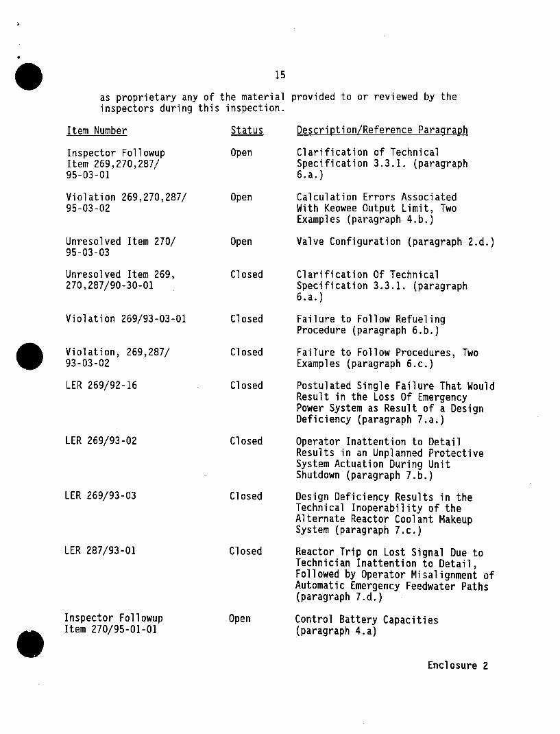
as proprietary any of the material provided to or reviewed by the inspectors during this inspection.
Item Number Status Description/Reference Paragraph
Inspector Followup Open Clarification of Technical Item 269,270,287/ Specification 3.3.1. (paragraph 95-03-01 6.a.)
Violation 269,270,287/ Open Calculation Errors Associated 95-03-02 With Keowee Output Limit, Two
Examples (paragraph 4.b.)
Unresolved Item 270/ Open Valve Configuration (paragraph 2.d.) 95-03-03
Unresolved Item 269, Closed Clarification Of Technical 270,287/90-30-01 Specification 3.3.1. (paragraph
6.a.)
Violation 269/93-03-01 Closed Failure to Follow Refueling Procedure (paragraph 6.b.)
Violation, 269,287/ Closed FaiTure to Follow Procedures, Two 93-03-02 Examples (paragraph 6.c.)
LER 269/92-16 Closed Postulated Single Failure That Would Result in the Loss Of Emergency Power System as Result of a Design Deficiency (paragraph 7.a.)
LER 269/93-02 Closed Operator Inattention to Detail Results in an Unplanned Protective System Actuation During Unit Shutdown (paragraph 7.b.)
LER 269/93-03 Closed Design Deficiency Results in the Technical Inoperability of the Alternate Reactor Coolant Makeup System (paragraph 7.c.)
LER 287/93-01 Closed Reactor Trip on Lost Signal Due to Technician Inattention to Detail, Followed by Operator Misalignment of Automatic Emergency Feedwater Paths (paragraph 7.d.)
Inspector Followup Open Control Battery Capacities Item 270/95-01-01 (paragraph 4.a)
Enclosure 2