inmarsat-c felcom15.pdf
TRANSCRIPT

INMARSAT-CMOBILE EARTH STATION
MODEL FELCOM 15

The paper used in this manualis elemental chlorine free.
FURUNO Authorized Distributor/DealerFURUNO Authorized Distributor/Dealer
9-52 Ashihara-cho,9-52 Ashihara-cho,Nishinomiya 662-8580, JAPANNishinomiya 662-8580, JAPAN
Telephone :Telephone : 0798-65-21110798-65-2111FaxFax 0798-65-42000798-65-4200::
FIRST EDITION :FIRST EDITION : DEC.DEC. 20022002Printed in JapanPrinted in JapanAll rights reserved.All rights reserved.G4G4 :: SEP.SEP. 12, 200512, 2005
Pub. No.Pub. No. OME-56350OME-56350*00080934904**00080934904**00080934904**00080934904*(( AKMUAKMU )) FELCOM15FELCOM15
* 0 0 0 8 0 9 3 4 9 0 4 ** 0 0 0 8 0 9 3 4 9 0 4 *
*OME56350G40**OME56350G40**OME56350G40**OME56350G40*
* O M E 5 6 3 5 0 G 4 0 ** O M E 5 6 3 5 0 G 4 0 *

i
SAFETY INSTRUCTIONS
Leave the equipment powered whileunderway. (For antenna maintenanceand the like, turn off the power at themains switchboard.)
Distress cannot be communicated unlessthe equipment is powered.
Do not disassemble or modify theequipment.
Fire, electrical shock or serious injury canresult.
Turn off the power immediately at theship's mains switchboard if waterleaks into the equipment or the equip-ment is emitting smoke or fire.
Continued use of the equipment can causefire or electrical shock. Contact yourdealer for advice.
Do not locate the terminal unit nearwater or places subject to water splash.
Electrical shock, fire or personal injury mayresullt
Any repair work must be done by alicensed radio technician.
Improper repair work can cause electricalshock or fire.
Do not open the equipment.
Hazardous voltage which cancause electrical shock, burn or serious injury exists inside the equipment. Only qualified personnel should work inside the equipment.
Hazardous microwave.Do not approach within 60 cm of the antenna radome when it is transmitting.
Microwave radiation can be harmful to the human body, particularly the eyes.
WARNINGWARNING
Radiation Level At
10W/m 0.6 m2 WARNING LABELA warning label is attached to the terminal unit. Do not remove the label.If the label is missing or damaged,contact your dealer about replacement.
Name: Warning Label (2)Type: 03-129-1001-1Code No.: 100-236-741
WARNINGTo avoid electrical shock, do not remove cover. No user-serviceableparts inside.
Use the proper fuse.
Use of a wrong fuse can result in fire orpermanent damage to the equipment.
This equipment is intended for marineapplication.
CAUTIONCAUTION
Do not operate the equipment withwet hands.
Electrical shock may result.
WARNINGWARNING

ii
TABLE OF CONTENTS FOREWORD ........................................................................................................ vi SYSTEM CONFIGURATION.............................................................................. viii INMARSAT C SYSTEM OVERVIEW ................................................................... ix
1. OPERATIONAL OVERVIEW......................................................................... 1-1 1.1 Terminal Unit ............................................................................................................. 1-1
1.1.1 Turning the power on/off ................................................................................. 1-1 1.1.2 DISTRESS button........................................................................................... 1-1 1.1.3 Diagnostics ..................................................................................................... 1-1 1.1.4 Floppy disk drive, floppy disks ........................................................................ 1-2 1.1.5 Audio alarm..................................................................................................... 1-2 1.1.6 Adjusting brilliance.......................................................................................... 1-2
1.2 Keyboard................................................................................................................... 1-3 1.2.1 Key description ............................................................................................... 1-3 1.2.2 Shortcut keys.................................................................................................. 1-5 1.2.3 Function key description ................................................................................. 1-5
1.3 Distress Alert/Received Call Unit IC-305, Alarm Unit IC-306...................................... 1-6 1.4 Printer PP-510 (option).............................................................................................. 1-7 1.5 Standby Display......................................................................................................... 1-8
1.5.1 Display indications .......................................................................................... 1-9 1.6 Menu Overview ....................................................................................................... 1-13 1.7 Error Messages and Alerts ...................................................................................... 1-14 1.8 Using a PC (local supply) ........................................................................................ 1-15
1.8.1 Installing software ......................................................................................... 1-15 1.8.2 Starting up, quitting the application ............................................................... 1-19
2. SYSTEM INITIALIZATION ............................................................................ 2-1 2.1 System Settings ........................................................................................................ 2-1
2.1.1 Confirming the main terminal .......................................................................... 2-1 2.1.2 System setup.................................................................................................. 2-2
2.2 Terminal Setup .......................................................................................................... 2-6 2.3 Login and Logout....................................................................................................... 2-8
2.3.1 Login............................................................................................................... 2-8 2.3.2 Logout........................................................................................................... 2-10
2.4 EGC Settings ...........................................................................................................2-11 2.4.1 What is the EGC (Enhanced Group Call) service?.........................................2-11 2.4.2 EGC setup .................................................................................................... 2-13 2.4.3 Adding EGC channels................................................................................... 2-16 2.4.4 Saving, printing EGC messages automatically.............................................. 2-18
2.5 Adding NCS Channels............................................................................................. 2-20 2.6 LES List................................................................................................................... 2-22
2.6.1 Displaying toll charges .................................................................................. 2-22 2.6.2 Registering LES to LES list ........................................................................... 2-24 2.6.3 Editing the LES list........................................................................................ 2-25 2.6.4 Printing the LES list....................................................................................... 2-26

iii
2.7 Station List ............................................................................................................... 2-27 2.7.1 Adding stations to the station list ................................................................... 2-27 2.7.2 Editing the station list .................................................................................... 2-30 2.7.3 Printing the station list ................................................................................... 2-31
2.8 Entering Own Ship’s Position................................................................................... 2-32 2.9 Creating a Directory................................................................................................. 2-33
2.9.1 Creating a directory where to store messages............................................... 2-33 2.9.2 Specifying directory where to store messages............................................... 2-35
2.10 E-mail Service/SMS Station List............................................................................... 2-36 2.11 E-mail Setup............................................................................................................ 2-39 2.12 Saving, Loading System Settings ............................................................................ 2-40
2.12.1 Saving system settings to a floppy disk ......................................................... 2-40 2.12.2 Loading system settings to the terminal unit .................................................. 2-40
3. FILE OPERATIONS.......................................................................................3-1 3.1 Files and Working Areas ............................................................................................ 3-1 3.2 Preparing Files .......................................................................................................... 3-2
3.2.1 Preparing a routine file .................................................................................... 3-2 3.2.2 Preparing a confidential file ............................................................................. 3-3 3.2.3 Editor menu setup ........................................................................................... 3-4 3.2.4 Working with text ............................................................................................. 3-5
3.3 Saving Files ............................................................................................................. 3-10 3.3.1 Formatting a floppy disk ................................................................................ 3-11 3.3.2 Saving files.................................................................................................... 3-12
3.4 Opening Files .......................................................................................................... 3-14 3.4.1 Opening files ................................................................................................. 3-14 3.4.2 Switching between files ................................................................................. 3-14 3.4.3 Opening a file when both working areas are occupied................................... 3-15
3.5 Saving a File Under a New Name............................................................................ 3-16 3.6 Printing Files on Floppy Disks.................................................................................. 3-17 3.7 Combining Files....................................................................................................... 3-17 3.8 Deleting Files........................................................................................................... 3-18 3.9 Renaming Files........................................................................................................ 3-19 3.10 Decoding E-mail Attachment.................................................................................... 3-20
4. INMARSAT C COMMUNICATIONS ..............................................................4-1 4.1 Transmitting............................................................................................................... 4-1
4.1.1 Code description ............................................................................................. 4-1 4.1.2 Transmitting prepared message ...................................................................... 4-2 4.1.3 Transmitting a file stored on a floppy disk...................................................... 4-15 4.1.4 Canceling transmission on a message awaiting transmission ....................... 4-16 4.1.5 Requesting delivery status ............................................................................ 4-17 4.1.6 Accessing the 2-digit code services............................................................... 4-20 4.1.7 Displaying the send message log .................................................................. 4-22
4.2 Receiving................................................................................................................. 4-23 4.2.1 When a message is received ........................................................................ 4-23 4.2.2 Setting the receive alarm............................................................................... 4-24 4.2.3 Displaying, printing received messages......................................................... 4-25

iv
4.2.4 Automatically printing received messages .................................................... 4-28 4.2.5 Saving received messages to a floppy disk................................................... 4-28 4.2.6 Automatically saving received messages to a floppy disk ............................. 4-29 4.2.7 Deleting received messages......................................................................... 4-30
4.3 Log.......................................................................................................................... 4-31 4.3.1 Displaying and printing the display log .......................................................... 4-31 4.3.2 Automatic printing of display log.................................................................... 4-32
4.4 EGC Messages ....................................................................................................... 4-33 4.4.1 Displaying and reprinting EGC messages..................................................... 4-33 4.4.2 Displaying EGC closed network ID (ENID).................................................... 4-34 4.4.3 Receiving EGC distress or urgent message.................................................. 4-35 4.4.4 Displaying the EGC message log.................................................................. 4-35
5. DATA REPORTING AND POLLING............................................................... 5-1 5.1 Data Reporting .......................................................................................................... 5-1
5.1.1 Setting a data report ....................................................................................... 5-2 5.1.2 Setting a message report................................................................................ 5-4 5.1.3 Automatic printing of data report, polling command......................................... 5-7
5.2 Polling ....................................................................................................................... 5-8 5.2.1 Polling commands........................................................................................... 5-8 5.2.2 Other polling commands ............................................................................... 5-10 5.2.3 Polling reception ............................................................................................5-11
5.3 DNID (Data Network Identification).......................................................................... 5-12 5.3.1 Displaying DNID ........................................................................................... 5-12 5.3.2 Enabling/Disabling DNID............................................................................... 5-12
6. DISTRESS OPERATIONS ............................................................................ 6-1 6.1 Transmitting the Distress Alert................................................................................... 6-1 6.2 Transmitting the Distress Alert with Nature of Distress Specified ............................... 6-2 6.3 Distress Message...................................................................................................... 6-4 6.4 Testing the Distress Button........................................................................................ 6-5
7. OTHER FUNCTIONS .................................................................................... 7-1 7.1 Aborting an Operation ............................................................................................... 7-1 7.2 Scanning NCS Common Channel ............................................................................. 7-2 7.3 Choosing EGC Receiving Channel............................................................................ 7-3 7.4 Choosing NCS Channel ............................................................................................ 7-4 7.5 LES Information ........................................................................................................ 7-5
8. E-MAIL BY PC............................................................................................... 8-1 8.1 Overview................................................................................................................... 8-1
8.1.1 Overview of mail functions .............................................................................. 8-1 8.1.2 E-mail restrictions ........................................................................................... 8-2 8.1.3 E-mail precautions .......................................................................................... 8-2
8.2 Connection of FELCOM 15 with single PC ................................................................ 8-4 8.3 Function Settings....................................................................................................... 8-5
8.3.1 Setting IP address and subnet mask............................................................... 8-5 8.3.2 Enabling DHCP settings.................................................................................. 8-6 8.3.3 Gateway setting .............................................................................................. 8-7

v
8.3.4 Restricting access ........................................................................................... 8-8 8.3.5 Restricting outgoing message size .................................................................. 8-9 8.3.6 Automatically converting attachments ...........................................................8-10 8.3.7 Connection of FELCOM 15 to shipboard LAN mail server............................. 8-11 8.3.8 Selective forwarding ...................................................................................... 8-13
8.4 E-mail Client Setup Example ................................................................................... 8-15 8.5 SMTP Error Messages............................................................................................. 8-16
9. MAINTENANCE, TROUBLESHOOTING......................................................9-1 9.1 General Checking and Maintenance..........................................................................9-1 9.2 Diagnostics................................................................................................................ 9-2
9.2.1 Self test at power on........................................................................................ 9-2 9.2.2 Testing the terminal unit through the keyboard, displaying program
version no. ...................................................................................................... 9-2 9.3 Performance Verification (PV) Test ............................................................................ 9-3
9.3.1 PV test sequence ............................................................................................ 9-3 9.3.2 PV test procedure............................................................................................ 9-4 9.3.3 Displaying PV test results................................................................................ 9-5
9.4 System Status Monitor ............................................................................................... 9-6 9.5 Replacing the Battery................................................................................................. 9-8 9.6 Replacing the Fuse.................................................................................................... 9-8 9.7 Error Messages ......................................................................................................... 9-9
9.7.1 Equipment trouble messages .......................................................................... 9-9 9.7.2 Warning messages........................................................................................ 9-10
APPENDIX ......................................................................................................AP-1 Menu Tree....................................................................................................................... AP-1 International Telex/Telephone Country Code List ............................................................ AP-9 LES List ........................................................................................................................ AP-17 International Telex Abbreviations................................................................................... AP-18 International Telegraphy Alphabet ................................................................................. AP-19 Messages ..................................................................................................................... AP-20 Digital Interface (IEC 61162-1 2nd Edition)..................................................................... AP-23 Parts List....................................................................................................................... AP-34 Parts Location............................................................................................................... AP-36
SPECIFICATIONS........................................................................................... SP-1
INDEX .............................................................................................................. IN-1
Declaration of conformity

vi
FOREWORD
Introduction FURUNO Electric Company thanks you for considering and purchasing the FELCOM 15 Inmarsat C Mobile Earth Station. We are confident you will discover why the FURUNO name has become synonymous with quality and reliability. Mainly consisting of an antenna unit and a terminal unit, the FELCOM 15 provides the full range of distress and general communication services for mobile and fixed terrestrial subscribers in the Inmarsat C communication network. Its compact size permits installation where space is limited. FURUNO designs and manufactures this equipment with much attention to operation and maintenance simplicity. However, please read and follow the recommended procedures for operation and maintenance to get the most out of the equipment. This manual provides a brief introduction to the Inmarsat C system (pages ix thru xiv). For more detailed information, refer to the information below.
Inmarsat C Maritime Customer Relations Officer Maritime Services Operations Department International Maritime Satellite Organization (Inmarsat) Address: 99 City Road, London, EC1Y 1AX, UK Telephone: +44 20 7728 1777 (Switchboard) Fax: +44 20 7728 1142 URL: www.inmarsat.com E-mail [email protected]
vii
Features • Conforms to the following standards: IMO A.807(19), MSC.68(68) Annex 4,
MSC/Cir 682, IMO A.694(17), IEC 61097-4 (1994), IMO A.664(16), IEC 60945 (2002), IEC 61162-1 (2000).
• E-mail facility. (To send E-mail, register with an LES which provides e-mail services.)
• Built-in Enhanced Group Call (EGC) receiver permits operation as EGC-only receiver.
• Terminal unit accepts a wide variety of peripheral equipment: Distress Message Controller (DMC), PC, navigator, etc.
• Connection of external terminal unit for operation from remote location such as the bridge.
• Store-and-forward telex communication (public telex network)
• Data reporting and Polling
• GPS receiver (option) built in the terminal unit provides GPS-generated position.
• Diagnostic programs for maintenance
• Terminal unit provides a floppy disk drive for storage of received and transmitted messages on floppy disks.
• Menu driven operation
Program Number PC Board Program No. Version No. Date of Modification
RF CON CPU 1650159 03 5/2004 TERM CPU 1650162 03 5/2004

viii
SYSTEM CONFIGURATION
Printer**PP-510
ANTENNAUNIT
IC-115
TERMINAL UNITIC-215
JUNCTIONBOX
IC-315
Navigator
SHIP'S MAINS100-115/200-230VAC1φ, 50/60 Hz
: Standard Supply: Option: Local Supply
SHIP'S MAINS12/24 VDC
AC-DC Power SupplyPR-240-CE
* For 12 VDC ship's mains, DC-DC converter is required to use PP-510.
Distress Message ControllerDMC-5
PersonalComputer
(PC/AT compatible)
EGC Printer**PP-505
Shipboard LAN (Ethernet)GPS receiver
OP16-24
Mini Keyboard
DGPS
CATEGORY OF UNITS
Unit Category
Terminal Unit Protected from weather
Antenna Unit Exposed to weather
Other Units Protected from weather
** = Mandatory for EGC operation as required by IMO RES. A.664(16).
Distress Alert/Received Call Unit
IC-305
Alarm UnitIC-306
24 VDC
Printer
SSAS Alert UnitIC-307
OR
SSAS Alert UnitIC-307
(Max. 3 units)
ix
INMARSAT C SYSTEM OVERVIEW
Introduction The Inmarsat C system provides worldwide telex and data transmission and reception of written information to owners of an Inmarsat C transceiver or a terrestrial telex network via satellite. Further, e-mail can be sent via the internet. Communication mode is store-and-forward telex, which means all information sent are first stored at an LES and then delivered to designated party. An EGC (Enhanced Group Call) receiver is built in the FELCOM 15 to receive the following types of messages, broadcast by LESs:
• SafetyNETTM-governments and maritime authorities can use this service to distribute maritime safety information to ships within selected areas.
• FleetNETTM-commercial subscription organizations or shipping companies can use this service to transmit trade information (for example, company news or market prices) simultaneously to a selected group of ships, to provide up-to-the-minute information.
• EGC system-related is sent by Inmarsat to certain shipping companies and geographical areas.
FELCOM 15 allows you to make distress calls. They are given immediate priority over all other calls, and are automatically routed to a land-based Rescue Co-ordination Centre (RCC). Besides its primary application of ship-shore, shore-ship or ship-ship communications, the Inmarsat C service has also proved beneficial to trucking firms who have found it indispensable for communicating with their vehicles. In this manual, however, we will concentrate on ship applications, the main application.

INMARSAT C SYSTEM
x
Inmarsat C System Configuration
0.0 m
-/+: To set option
0.0 m
-/+: To set option
0.0 m
-/+: To set option
OCC
SCCNCS
LES LES LES
Same as left Same as left Same as left
Satellite
MES
AOR-West AOR-East IOR POR
OCC: Operation Control CenterSCC: Satellite Control CenterNCS: Network Coordination StationMES: Mobile Earth StationLES: Land Earth Station
Inmarsat C system configuration

INMARSAT C SYSTEM
xi
The Inmarsat C system consists of the Operation Control Center (OCC), Satellite Control Centers (SCC), Network Coordination Stations (NCS), Land Earth Stations (LES) and Mobile Earth Stations (MES). The OCC, located at Inmarsat’s London headquarters, coordinates a wide range of activities in the Inmarsat system, including commissioning of mobile earth stations. The Inmarsat C system divides the world into four regions and each region is covered by its own satellite.
Inmarsat system satellites
Region Satellite Satellite Position AOR-West Inmarsat 3, F4 54.0°W AOR-East Inmarsat 3, F2 15.5°W IOR Inmarsat 3, F1 64.0°E POR Inmarsat 3, F3 178.0°E
In each region there is one NCS and several LESs. The NCS keeps track of all Inmarsat C transceivers in its region and broadcasts information such as navigational warnings, weather reports and news. The LESs provide the link between the MES and the terrestrial telecommunications networks via satellite.

INMARSAT C SYSTEM
xii
AR
EA
PO
RIO
RA
OR
-EA
ST
AO
R-W
ES
T
SAT
ELL
ITE
NA
ME
INM
AR
SAT
-3, F
3IN
MA
RS
AT-3
, F1
INM
AR
SAT
-3, F
2IN
MA
RS
AT-3
, F4
PO
SIT
ION
178°
E64
.0°E
15.5
°W54
.0°W
Cov
erag
e ar
ea o
f Inm
arsa
t sat
ellit
es

INMARSAT C SYSTEM
xiii
Communications Network The illustration below shows the Inmarsat C communications network.
NetworkCoordinationStation (NCS)
NCS/NCS Signaling Link
NCS Common Channel
Mobile EarthStation (MES)
Data TerminalEquipment (DTE)
Enhanced GroupCalling (EGC) Receiver
Data CircuitTerminatingEquipment
(DCE)
MES SignalingChannel
MES MessageChannel
LES TDMChannel
Land EarthStation(LES)
NCS/LESSignaling Link
TerrestrialCommunicationsNetwork
DataCommunicationsNetwork
Telex Network
Inmarsat C communications network
NCS common channel The NCS has two major functions: 1) Transmitting information on a common channel. 2) Transmitting EGC messages to MESs. NCS/LES signaling link This is the link between NCS and all LESs in its
region. All EGC messages pass through this link. LES TDM channel This channel carries the circuit control signal for
MES and transmits messages from LES to MES. MES message channel This channel carries messages from MES to LES. MES signaling channel This channel transmits requests, distress alerts, data
reports, etc. In addition, it carries login and logout from MES to NCS.
NCS/NCS signaling link This is the link between NCSs. It exchanges data between MESs operating in different ocean regions.
MES interface The MES consists of the Data Circuit Terminating Equipment (DCE) and the Data Terminal Equipment (DTE). The DCE consists of the antenna unit, and the DTE consists of a terminal unit, a keyboard and printer.
Terrestrial network The major functions of the LESs are: interface 1) Telex store-and-forward conversion 2) Handling EGC messages 3) Handling distress alerts 4) Data Reporting and Polling

INMARSAT C SYSTEM
xiv
Types of MES There are three types of MES: class 1, class 2 and class 3. This FELCOM 15 is a class 2 MES.
Class 1: 1) Transmits messages to LES 2) Receives messages from LES Class 2: 1) The functions of class 1 plus operation as an EGC receiver
when not transmitting or receiving. 2) EGC-only receiver Class 3: The function of class 1 plus simultaneous operation as an
EGC-only receiver.
Peripheral Equipment
The following equipment can be additionally connected to the FELCOM 15. Distress Message Controller (DMC-5) The DMC-5 provides for transmission and monitoring of the distress alert. For further details, refer to the operator’s manual of the DMC-5.
Inmarsat CFELCOM 15
Distress Message Controller DMC-5 Distress message controller system

1-1
1. OPERATIONAL OVERVIEW
1.1 Terminal Unit The terminal unit is the heart of the FELCOM 15 system, creating, transmitting and receiving messages.
POWERswitch
DISTRESSbutton
Floppy diskdrive
Terminal unit IC-215
1.1.1 Turning the power on/off
Press the [POWER] switch to power or turn off the terminal unit, antenna unit, Distress Alert/Received Call Unit and Alarm Unit. Note: The example screens shown in this manual may not match the screens
you see on your display. The screen you see depends on your system configuration and equipment settings.
1.1.2 DISTRESS button
Use the [DISTRESS] button to transmit the distress alert when there is a life-endangering situation on your ship.
1.1.3 Diagnostics When the terminal unit is turned on it automatically checks itself for proper operation. For detailed information, see Chapter 8.

1. OPERATIONAL OVERVIEW
1-2
1.1.4 Floppy disk drive, floppy disks The terminal unit provides a floppy disk drive for storing transmitted and received messages on floppy disks. The floppy disks used with the system are 2HD (1.44 MB) and 2DD (720 KB).
1.1.5 Audio alarm The audio alarm is released in the following instances.
EGC message received Unit Telex, e-mail
received
Distress acknowledge
received Distress Urgency Other
Troubledetected
Terminal Unit YES YES YES YES NO YES Distress Alert/Received Call Unit
NO YES YES YES NO NO
Alarm Unit YES NO NO NO NO YES Distress Message Controller
NO YES YES YES NO NO
1.1.6 Adjusting brilliance
Raising brilliance: Press [Alt] + [F7]. Lowering brilliance: Press [Alt] + [F6].

1. OPERATIONAL OVERVIEW
1-3
1.2 Keyboard The FELCOM 15 is almost 100% keyboard controlled. Operation is carried out with the function keys, numbered F1-F10 at the top of the keyboard. The figure below shows keyboard layout.
~
` 21 3 4 5 6 7 8 9 0 - =
_ +)* ( 9 *87^ &%$#@!
Q W E R T Y U I O P
[ ]
{ }
\
|
A S D F G H J K L : +
;
"
'
Tab
Caps Lock
Z X C V B N M < > ? /
/.,
1 2 3
4 5 6
0Shift
Fn Ctrl Alt Alt Ctrl
Home End PgDn
PgUp
Shift
Enter
Backspace
Esc F1 F2 F3 F4 F5 F6 F7 F8 F9 F10 NumLock
Prt Sc
SysRq
ScrollLock
Pause
Break
Insert Delete
C
FileEdit
TransmitEGC
ReportsLogs
OptionsSetup StopAlarm
PositionFunctionKeys
Keyboard
1.2.1 Key description
Esc Cancels key input and returns to previous display screen.
F1-F10 These are the function keys, and they choose menus.
Backspace Deletes the character to the left of the cursor. Insert Works the same as “paste.” See “Copying and
pasting text” in paragraph 3.2.4. Delete Deletes the character selected with the cursor. Home Moves the cursor to the top of the message being
edited. End Moves the cursor to the bottom of the message
being edited. PgUp Goes to the previous page of the edit screen. PgDn Goes to the next page of the edit screen. [↑ ], [↓ ], [←], [→] Control the cursor. Enter Registers key input; inserts carriage return in TX
message. Shift Chooses upper or lower case alphabet. Press and
hold down the key and then press the [Caps Lock] to get upper or lower case alphabet. Note that only upper case alphabet are used in telex.
Alt Executes the shortcut key operation when combined with an alphabet key. See paragraph 1.2.2.

1. OPERATIONAL OVERVIEW
1-4
Space Inserts a space. In addition, it displays the file list, a partial view of a file, etc., depending on menu.
Caps Lock Turns upper case alphabet input on or off. The Caps Lock LED lights when upper case alphabet input is on.
Tab Inserts horizontal tab characters. The number of tab characters the key can insert per line of text can be programmed for two, four or eight tabs.
Ctrl Works in combination with alphabet keys as follows: Ctrl + [M]: Same as Enter. Ctrl + [H]: Same As Back Space. Ctrl + [I]: Same as Insert. Ctrl + [V]: Same as Overwrite+Insert on Edit Mode in the Editor Setup menu.
Fn Combined with an arrow key, it scrolls screen (↑ , ↓ ), or shifts cursor (←, →).
Num Lock Turns numeric input on or off. Note that you cannot enter alphabet when the Num Lock LED is lit.
Note 1: In telex, lower case, #, &, *, $, @, %, etc. are not used. A full list of
characters useable in telex appears in the Appendix. For e-mail all characters and symbols may be used.
Note 2: € (Euro mark) on the 5
%
C key cannot be used.

1. OPERATIONAL OVERVIEW
1-5
1.2.2 Shortcut keys The FELCOM 15 provides the keyboard shortcuts shown below for commonly used functions.
Shortcut keys
Shortcut key Function [Alt]+[N] Same as New in File menu [Alt]+[O] Same as Open in File menu [Alt]+[Q] Same as Close in File menu [Alt]+[D] Same as Delete in File menu [Alt]+[S] Same as Save in File menu [Alt]+[P] Same as Print in File menu [Alt]+[X] Same as Undo [Delete] Same as Cut in Edit menu [Alt]+[C] Same as Copy in Edit menu [Insert] Same as Paste in Edit menu [Fn] + ← Same as Top of Text in Edit menu [Fn] + → Same as End of Text in Edit menu [Alt]+[V] Same as Change Window in Edit menu
1.2.3 Function key description Function key description
Menu Description File (F1) Processes files. Edit (F2) Provides text editing facilities. Transmit (F3) Transmits messages. EGC (F4) Sets up EGC message facilities. Reports (F5) Sets up data/message reporting function. Logs (F6) Displays sent and received message logs. Options (F7) Login, logout; testing facilities. Setup (F8) Sets up the system. Position (F9) Enter your ship’s position manually. StopAlarm (F10) Silences audio alarm.

1. OPERATIONAL OVERVIEW
1-6
1.3 Distress Alert/Received Call Unit IC-305, Alarm Unit IC-306 Distress Alert/Received Call Unit IC-305
The [DISTRESS] button functions to transmit the distress alert. To transmit the distress alert, press the button until its lamp lights continuously. For further details on how to transmit the distress alert, see paragraph 6.1. The IC-305 releases the audio alarm and the lamp in the [ALARM ACK] button flashes when an EGC distress or urgency broadcast is received. Press the [ALARM ACK] button to acknowledge the alarm, and the alarm tone changes. To silence the alarm and extinguish the lamp, press the function key F10 on the keyboard of the terminal unit. Alarm Unit IC-306
The IC-306 releases the audio alarm and flashes the lamp in its [ALARM RESET] button when a telex or e-mail is received. To silence the audio alarm in this case, press the [ALARM RESET] button on the IC-306. In addition to telex or e-mail notification, the audio alarm sounds and the lamp flashes also for the equipment trouble listed below. To acknowledge this alarm, press the [ALARM RESET] button, and the alarm tone changes. To silence the alarm and flashing of the button in case of external equipment abnormality, press the [F10] key on the keyboard. • “Unsync” condition (MES is not synchronized with satellite) continues for six
minutes. (UNSYNC appears at the bottom of the screen.) • BBER is over 80% (BBER of 080 or higher appears on the system status
monitor.)
Note: The equipment cannot scan automatically in the above two situations. Reselect ocean region referring to paragraph 7.2.
• Printer has no paper • No data is received from internal or external GPS navigator • Update position alert (manual position input) when position has not been
updated for four hours. • Equipment trouble (synthesizer, oscillator, etc.)
Distress Alert/Received Call UnitIC-305
Alarm UnitIC-306
ALARM UNIT
ACK
I
MES ALARMS ANDINCOMING MESSAGES
Distress Alert/Received Call Unit IC-305, Alarm Unit IC-306

1. OPERATIONAL OVERVIEW
1-7
1.4 Printer PP-510 (option) The PP-510 prints transmitted and received messages. The POWER switch is on the right side of the unit. The lamp on the switch lights when the power is on. If the paper is set correctly the ON LINE lamp also lights. When both those lamps are lit, the printer is ready to print information received from the terminal unit. For further details, refer to the PP-510’s operator’s manual.
Printer PP-510

1. OPERATIONAL OVERVIEW
1-8
1.5 Standby Display After the equipment is turned on and the diagnostic test has been conducted, the standby display appears, showing the system status monitor. The system status monitor provides various operating information. For a detailed description, see paragraph 8.4.
File Edit Transmit EGC Reports Logs Options Setup Position StopAlarm
DateTime
Position
Waypoint
Course 345.5 DEGSpeed 10.2 KTSCurrent NCSCurrent ChannelCurrent TDMMES StatusGPS Status
DCE Memory
02-02-2501:32 (UTC)
LAT 34:30.00NLON 135:00.00ELATLON
344 (IOR) LOGOUTNCS CCNCS CCIdle****
32818 Bytes free
IMN:BBERC/NSend LevelRx AGC LevelREF Offset FreqSynthe Local VCXO Control 131
Antenna Power Supply
Water TemperatureWater Current
DirectionSpeed
Depth
443156710000OK ( 0 dB)OK ( 0)OK (254)OK ( 0 Hz)OK
OK
Current State: IDLE
DCE F15 Ver. ##
RetuningNCS: IOR LOGOUT LAT: 34:30.00N LON: 135:00.00E
02-02-25 01:32 (UTC)
68.2 DEG
232 DEG1.9 KTS
##: Program Version No. of RF CON Board
Standby display After the diagnostic test has been completed, the equipment automatically starts synchronizing itself with a satellite. When the indication “Retuning” is replaced with “ SYNC(NCS), the synchronization process is completed. Then, you are ready to receiving EGC messages. For further details see paragraph 2.4. Note: When the caution shown below appears, it is necessary to change the
LES ID in the distress alert setup to match current ocean region. For further details, see paragraph 6.2.
CAUTION
Pre-set LES ID for DISTRESS ALERT is invalid in the present ocean region.Please input preferred LES ID in the [Distress Alert Setup] menu.

1. OPERATIONAL OVERVIEW
1-9
1.5.1 Display indications The display is divided in three sections: 1) The function menu area 2) The working area 3) The operating status area
File Edit Transmit EGC Reports Logs Options Setup Position StopAlarm(1) (2)
(3)(4a)(4b)
(5)(6) (7)(8)
(9) (10) (10)
2) WORKING AREA
1) FunctionMenu
3) OperatingStatus
Location of display indications
Below are the indications and meanings of the items in parentheses in the illustration above. (1) Distress alert information message
No display (no distress alert) Sending Distress Alert Sending Distress Alert Test Distress Acknowledgement Received Distress Message Call Activated Distress Message Call Acknowledged Distress Button Test Mode (2) Communication network mode
No display Normal operation Restoration Mode Problem at NCS (Flashing) Restoration Mode Previously designated LES is transmitting the (Reverse video) NCS common channel signal.

1. OPERATIONAL OVERVIEW
1-10
(3) Terminal unit status
IDLE Idle (awaiting receiving, awaiting transmitting) IDLE (PENDING) Awaiting reply from LES SENDING Sending RECEIVING Receiving LOGIN Logged in with NCS LOGOUT Logging out with NCS DISTRESS ALERT When own vessel is transmitting the distress alert Data Report Sending data report TESTING Performance Verification (PV) testing TEST SETUP Requesting PV testing SCANNING NCS scanning EGC RECEIVER EGC-only receiver operation (Reverse video) Delivery Status Req. Transmitting delivery status request Forced Clearing Stopping receiving, transmitting, or scanning (4a) Communication status
CALLING Now calling WAITING FOR ACKNOWLEDGEMENT Waiting for acknowledgement from LES. RECEIVING EGC MESSAGE Now receiving EGC message WAITING FOR BACKOFF Waiting to transmit data report Successful Login. Login was successful Login failed. Login failed Successful Logout Logout was successful Logout failed. Logout failed Successful Distress Alert. Distress alert successfully Distress Alert Failed Distress alert could not be transmitted. Successful Forced Clearing. Forced clearing successful Forced Clearing Failed. Forced clearing unsuccessful SENDING MESSAGE PACKETS. Sending TX message packets WAITING FOR ACKNOWLEDGEMENT Waiting for acknowledgement from LES Successful sending to LES. Message successfully sent to LES Sending message failed. Message could not be sent to LES Call rejected. LES rejected your message Call pending. LES temporarily suspending communications Received Call. Call received from LES Received Call(ITA2). Call(ITA2) received from LES RECEIVING MESSAGE PACKETS Receiving message packets CLEARING Clearing TX sequence Successful receiving. You successfully received message Receiving failed. You could not receive message Successful Data Report. Data report successfully sent. Data Report failure. Data report could not be sent. PV TEST CALL is rejected. PV test call rejected by NCS

1. OPERATIONAL OVERVIEW
1-11
PV TEST CALL is pending. PV test pending by LES TEST-RECEIVING MESSAGE Receiving test message from LES TEST-SENDING MESSAGE Sending test message to LES TEST-DISTRESS ALERT Sending test distress alert to LES WAITING FOR ACTIVATION Waiting start of PV test WAITING FOR TEST RESULT Waiting for results of PV test CLEARING Clearing PV test PV TEST is Completed. PV test is completed. PV TEST Failure. PV test failed.
(4b) RF CON/CPU’s program version number
DCE F15 Ver. XX (XX = Version Number) Note: Error message is displayed when equipment abnormality is detected. (5) Frame synchronization
Blank Changing channel, or during transmission SYNC (NCS) Synchronizing with NCS SYNC (LES) Synchronizing with LES MES Sig. Ch Changing MES signaling channel MES Msg. Ch Changing MES message channel UNSYNC Out of synchronization Retuning Synchronizing with NCS or LES (6) Ocean region receiving
No display Out of synch with satellite AOR-W Atlantic Ocean Region-West AOR-E Atlantic Ocean Region-East IOR Indian Ocean Region POR Pacific Ocean Region (7) Logging status
LOGOUT Logged out with ocean region LOGIN Logged in with ocean region LOGIN (Flashing) Logging in with ocean region

1. OPERATIONAL OVERVIEW
1-12
(8) Other information
No display No receive message in memory, or printer is operating.
REC. MESSAGE EXISTS Displayed when a routine message has (Reverse video) not been printed, or a confidential message is
received. Data Report When data reporting is activated. (Reverse video) Message Report Message report setting is activated. (Reverse video)
(9) Date and time display
With connection of a navigator (internal GPS navigator or external navigator), date and time (received from satellite) are displayed. Manually input date and time are also displayed. (10) Ship’s position
With connection of a navigator (internal GPS navigator or external navigator), ships position is displayed in latitude and longitude and updated every 30 seconds, or manually input position is displayed.

1. OPERATIONAL OVERVIEW
1-13
1.6 Menu Overview Operation of the FELCOM 15 is carried out through a menu system which you access with the function keys at the top of the screen. The example below shows how to choose menu options from the Editor Setup menu. 1. Press the [F8] key to display the Setup menu.
Setup
File Edit Transmit EGC Reports Logs Options Setup Position StopAlarm
1. Distress Alert Setup2. System Setup3. Editor Setup4. Terminal Setup5. EGC Setup6. Auto Mode Setup7. E-Mail Setup8. Directories9. Configuration
Setup menu 2. Choose desired menu by pressing appropriate numeric key. For example,
press the [3] key to show the Editor Setup menu. Note: You may also choose a menu with the [↑ ] and [↓ ] keys, pressing
[Enter] after making selection.
Setup
2. System Setup3. Editor Setup4. Terminal Setup5. EGC Setup6. Auto Mode Setup7. E-Mail Setup8. Directories9. Configuration
Editor Setup
AsciiInsertONON4 Char69BlockFull Screen
File Edit Transmit EGC Reports Logs Options Setup Position StopAlarm
Text Mode Edit ModeWord WrapLine No. Tab Width Column WidthCursor TypeScroll
Editor setup menu
3. Choose desired menu item by pressing the [↑ ] or [↓ ] keys followed by the [Enter] key. A window displaying the options for the item selected or an alphanumeric data entry window appears depending on your selection. For example, choose Word Wrap.
ONOFF
Word wrap options window

1. OPERATIONAL OVERVIEW
1-14
4. Press the [↓ ] or [↑ ] key to choose option desired and press the [Enter] key. 5. Press the [Esc] key several times to return to the standby display.
Note: On some menus the update window appears after you press the [Esc] key. This is done to ask you to confirm settings. Yes is selected; press the [Enter] key to register settings, or press [→] to choose No and press the [Enter] key to escape.
1.7 Error Messages and Alerts The terminal unit displays error messages and alerts, in the CAUTION window, to call your attention to misoperation, failed operation and system error. A list of error messages appears in Chapter 8 and alerts appear in the Appendix. To erase an error message or alert, press the [Esc] key.
No. Message File Station LES Priority Send Status Delivery
Send Message Log
Log
CAUTIONNo Message.
<Press ESC key to continue>
File Edit Transmit EGC Reports Logs Options Setup Position StopAlarm
1. Send Message Log2. Receive Message Log
Location of error messages and alerts
Update
Yes No

1. OPERATIONAL OVERVIEW
1-15
1.8 Using a PC (local supply) When using a PC as a sub terminal, the optional FD-ROM is required. The sub terminal only functions for communications; initial settings, etc. are conducted from the main terminal. FD-ROM Code No.: 004-438-920 Type: 16-5-0164 PC requirements • OS: Windows 98, 2000, ME, XP • Memory: Min. 32 MB • Hard disk: Min. 20 MB free space • CPU: 100 MHz or better • Floppy disk drive Windows is a registered trademark of Microsoft Corporation in the US and other countries used under license.
1.8.1 Installing software After installing the equipment, install the FELCOM 15 software (F15PC) in the PC as follows: 1. Turn on the PC. 2. Set FD-ROM in floppy disk drive. 3. Click the icon of “SETUP.EXE” in the floppy disk. The setup procedure
begins, showing the welcome dialog box.
Welcome dialog box
1. OPERATIONAL OVERVIEW
1-16
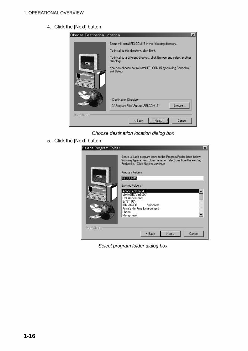
4. Click the [Next] button.
Choose destination location dialog box
5. Click the [Next] button.
Select program folder dialog box

1. OPERATIONAL OVERVIEW
1-17
6. Click the [Next] button.
Start copying files dialog box 7. Click the [Next] button and the installation begins. When the installation is
completed, the FELCOM 15 dialog box appears.
FELCOM 15 dialog box

1. OPERATIONAL OVERVIEW
1-18
8. Click the Close button ( )at the top right corner of the dialog box. The “Setup Complete” dialog box appears.
Setup complete dialog box
Note: If you want to launch the program file now click the box next to “Yes, Launch the program file.” The application will launch after the completion of step 9.
9. Click the [Finish] button. The FELCOM 15 PC application shortcut is created on the desktop.
Note: To uninstall the F15 application see the operator’s manual for the PC.

1. OPERATIONAL OVERVIEW
1-19
1.8.2 Starting up, quitting the application For information about PC operating procedures, see the owner�s manual of the PC. 1. Turn on the terminal unit. 2. Turn on the PC. 3. Double-click the FELCOM 15 icon to start the application.
4. To quit the application, press the [F12] key while pressing the [Alt] key. (You
may also quit the application by clicking the Close button.) Then, the following window appears.
OK to quit system?
Yes
No
5. Press the [←] key to choose Yes and then press the [Enter] key. 6. Turn off the PC according to Windows operating procedure. 7. Turn off the terminal unit. Note 1: If the application is quit using a method different from that described
above newly changed settings will not be memorized. Note 2: The procedures described in this manual are intended for use with the
terminal unit. Operation from a PC is similar, however key names, etc. may be different and some functions are not available. The functions not available with a PC are as follows:
Keying Sequence Function not available with PC F3-1 Distress priority selection on Transmit Message F7-1 Login F7-2 Logout F7-3 Abort (forced clearing) F7-4 Select NCS (selection of NCS common channel) F7-5 Ocean Region (selection of ocean region) F7-7 Functions other than �PV Test Result� and
�Diagnostic Test� on Test menu F8-1 Distress Alert Setup F8-2 Functions other than IMN on System Setup menu F8-5 EGC Setup F8-9 EGC and NCS Channel Lists on Configuration menu (registration of EGC and NCS channels) F9 Position (manual input of position)

1. OPERATIONAL OVERVIEW
1-20
Operation for PC
Choose the printer connected to the PC as follows: 1. Press function key [F1] to open the File menu.
File
ALT-NALT-OALT-QALT-S
ALT-D
ALT-P
1. New2. Open3. Close4. Save
5. Delete6. Rename
7. Print
8. Print Setting
9. MIME (Decode)
File Edit Transmit EGC Reports Logs Options Setup Position StopAlarm
File menu
2. Press the [8] key to open the Print Setting window.
No PrinterWindows Printer
PP-510
Please select Printerand press Enter key.
Print Setting
Print setting 3. Press [↓] or [↑] to choose appropriate printer.
No Printer: Choose this item if no printer is connected. Windows Printer: Choose if a PC-use printer is connected. PP-510: Choose if PP-510 is connected.
4. Press the [Enter] key to finish. .

2-1
2. SYSTEM INITIALIZATIONThis chapter provides the information necessary for initializing the FELCOM 15. Once the equipment is initialized, you need do no more than press a few keys to get fully automatic transmission and reception. Inmarsat assigns an MES an Inmarsat Mobile Number (IMN) when it applies for Inmarsat registration. The IMN is necessary to communicate in the Inmarsat system. It is entered into the FELCOM 15 during the installation.
2.1 System Settings 2.1.1 Confirming the main terminal
The main terminal is where you set up the system. (You cannot set up the system from an external terminal.) Confirm that the main terminal is selected as below. 1. Press the [F8] key to choose the Setup menu.
Setup
File Edit Transmit EGC Reports Logs Options Setup Position StopAlarm
1. Distress Alert Setup2. System Setup3. Editor Setup4. Terminal Setup5. EGC Setup6. Auto Mode Setup7. E-Mail Setup8. Directories9. Configuration
Setup menu
If your screen looks something like the one shown in the illustration above, you are using the main terminal. (If you are using an external terminal, some menu items appear in gray.)

2. SYSTEM INITIALIZATION
2-2
2.1.2 System setup The System Setup menu provides for input of date, time, operating mode, and port function. 1. Press the [F8] key to choose the Setup menu.
Setup
File Edit Transmit EGC Reports Logs Options Setup Position StopAlarm
1. Distress Alert Setup2. System Setup3. Editor Setup4. Terminal Setup5. EGC Setup6. Auto Mode Setup7. E-Mail Setup8. Directories9. Configuration
Setup menu
2. Press the [2] key to display the System Setup menu. Setup
9. Configuration
System Setup
03:11 02-02-25 (YY-MM-DD)
INMARSAT-COFFINTINTINT
System Date & TimeIMNMES Operation ModeNav PortActive PortMessage Output PortEGC Output PortNetwork SetupCommand Window
Entered at installation(Cannot be changed.)
System setup menu
3. System Date & Time is selected; press the [Enter] key to open the date entry window.
Setup
9. Configuration
System Setup
02-02-25 (YY-MM-DD)
INMARSAT-COFFINTINTINT
System Date & TimeIMNMES Operation ModeNav PortActive PortMessage Output PortEGC Output PortNetwork SetupCommand Window
System setup menu, date entry window
4. Enter the date with the numeric keys. (Entry of date is not necessary if a GPS navigator is connected to the FELCOM 15.)
5. Press the [Enter] key to close the window. (Note that the IMN is entered during installation. The IMN window cannot be opened.)
6. Press the [↓ ] key twice to choose MES Operation Mode.

2. SYSTEM INITIALIZATION
2-3
7. Press the [Enter] key to open the MES operation mode options window. Setup
9. Configuration
System Setup
01:53 02-02-25 (YY-MM-DD)
IORINMARSAT-COFFINTEXTEXT
INMARSAT-CEGC
System Date & TimeIMNMES Operation ModeNav PortActive PortMessage Output PortEGC Output PortNetwork SetupCommand Window
System setup menu, MES operation mode options window
8. Press the [↓ ] or [↑ ] key to choose operating mode, INMARSAT-C or EGC. The INMARSAT-C setting provides telex communications and operates as an EGC receiver when the equipment is not transmitting or receiving. The EGC setting enables EGC-only operation. In this case, “Current State: EGC RECEIVER” appears (reverse video) at the bottom of the screen.
9. Press the [Enter] key to close the window. 10. Press the [↓ ] key to choose Nav Port. 11. Press the [Enter] key to open the nav port options window.
Setup
9. Configuration
System Setup
01:53 02-02-25 (YY-MM-DD)
INMARSAT-CEXTINTINT
System Date & TimeIMNMES Operation Mode INMARSAT-CNav PortActive PortMessage Output PortEGC Output PortNetwork SetupCommand Window
OFFEXTINT
System setup menu, nav port options window
12. Press the [↓ ] or [↑ ] key to choose the navigator which is interfaced to the FELCOM 15. OFF: No navigator interfaced or manual input of position EXT: Choose this setting to use external navigator. If two or more navigators
are connected, the FELCOM 15 automatically chooses ship’s position data in the order of GPS, Loran C, and DECCA.
INT: Use the GPS receiver (option) built in the terminal unit.
Note: If there is no navigator (Nav Port setting is “OFF”), you should enter position manually, in the Position menu. Refer to paragraph 2.8.
13. Press the [Enter] key to close the window. 14. Press the [↓ ] key to choose Active Port.

2. SYSTEM INITIALIZATION
2-4
15. Press the [Enter] key to open the active port options window. Setup
9. Configuration
System Setup
01:53 02-02-25 (YY-MM-DD)
INMARSAT-COFF
DTE1DTE1
INTALL
System Date & TimeIMNMES Operation ModeNav PortActive PortMessage Output PortEGC Output PortNetwork SetupCommand Window
System setup menu, active port options window
16. Press the [↓ ] or [↑ ] key to choose active port (terminal unit); “INT” or “ALL” as appropriate. INT: Use main terminal unit. ALL: Use the terminal unit (PC, etc.) connected to the DTE port on the main
terminal.
17. Press the [Enter] key to close the window. 18. Press the [↓ ] key to choose Message Output Port. 19. Press the [Enter] key to open the message output port options window.
Setup
9. Configuration
System Setup
01:53 02-02-25 (YY-MM-DD)
INMARSAT-CINTOFFDTE1
System Date & TimeIMNMES Operation ModeActive PortNav PortMessage Output PortEGC Output PortNetwork SetupCommand Window
INTEXTINT+EXTAUTO
System setup menu, message output port options window
20. Press the [↓ ] or [↑ ] key to choose the terminal unit where you want to route received messages. INT: All received messages are routed to the main terminal. EXT: All received messages are routed to the terminal unit connected to
the DTE port on the main terminal unit. INT+EXT: All received messages are routed to both the main and external
terminal units. AUTO: The sub address for the DTE port is 001. Received messages
having the sub address of 001 are routed to the DTE terminal. Messages having a sub address other than 001 are routed to the main terminal.
21. Press the [Enter] key to close the window. 22. Press the [↓ ] key to choose EGC Output Port.

2. SYSTEM INITIALIZATION
2-5
23. Press the [Enter] key to open the EGC output port options window. Setup
9. Configuration
System Setup
01:53 02-02-25 (YY-MM-DD)
INMARSAT-COFFINTINT
System Date & TimeIMNMES Operation ModeNav PortActive PortMessage Output PortEGC Output PortNetwork SetupCommand Window
INTINT+EXT
System setup menu, EGC output port options window
24. Press the [↓ ] or [↑ ] key to choose the terminal unit where to route receive EGC messages; INT, main terminal; INT+EXT, main and auxiliary terminals.
25. Press the [Enter] key to close the window. 26. Press the [Esc] key to open the update window.
Setup
9. Configuration
System Setup
System Date & TimeIMNMES Operation ModeNav PortActive PortMessage Output PortEGC Output PortNetwork SetupCommand Window
01:53 02-02-25 (YY-MM-DD)
INMARSAT-COFFINTINTINT
Update
Yes NoSee paragraph 2.1.3 Not used.
System setup menu, update window
27. Yes is selected; press the [Enter] key to update system settings. 28. Press the [Esc] key to return to the standby display.

2. SYSTEM INITIALIZATION
2-6
2.2 Terminal Setup The Terminal Setup menu provides for selection of date display format, currency unit, screen saver on/off and window colors. 1. Press the [F8] key to choose the Setup menu. 2. Press the [4] key to display the Terminal Setup screen.
Terminal Setup
YY-MM-DDUS$ON
Date Disp. FormCurrency UnitScreen SaverWindow Color
Terminal Setup menu
3. Date Disp. Form is selected; press the [Enter] key to open its options window.
YY-MM-DDMMM-DD-YYDD-MMM-YY
Date options 4. Press the [↓ ] or [↑ ] key to choose date display format desired and then press
the [Enter] key to close the window. 5. Press the [↓ ] key to choose Currency Unit. 6. Press the [Enter] key to open the currency unit options window.
SDRUS$EURYENOTHER
Currency unit options 7. Press the [↓ ] or [↑ ] key to choose the currency unit to use to calculate toll
charges. SDR means Special Drawing Right and it is the common unit charge used by all LES to assess toll charges. For OTHER (for currency not shown in menu) enter currency unit name (4 characters max.). Your selection appears next to Currency Unit in the Terminal Setup menu.
8. Press the [Enter] key to close the window. 9. Press the [↓ ] key to choose Screen Saver. 10. Press the [Enter] key to open the screen saver options window. 11. Press the [↓ ] or [↑ ] key to choose “ON” or “OFF” as appropriate. ON to use
screen saver, OFF to disable the screen saver. The screen saver automatically starts up 10 minutes after there is no key operation. To release the screen saver, press any key.
12. Press the [Enter] key to close the window. 13. Press the [↓ ] key to choose Window Color and press the [Enter] key.
Window Color
Window Color SetupDefault Color
Window color change menu

2. SYSTEM INITIALIZATION
2-7
14. You may change the background and foreground colors for the various display screens on the terminal unit as follows: Choose Window Color Setup and press the [Enter] key.
Window Color Setup
Window : Base Window Fore Color : L_WHITE Back Color : BLUE
To Change: ENTER To Change Value: L<=>R
Window color setup menu
b) Window is selected; use the [→] or [←] key to choose the item to adjust and then press the [Enter] key.
Base Window: Standby display RCV Message Display: Receive message display EGC Message Display: EGC message display EDIT1 – EDIT 2: Editor screens 1 and 2 Function: Menu Sub Menu1 – Sub Menu4: Sub menus 1-4 Message: Status message
1:2:|||||||
MENU
< [1] UNTITLED1 >
EDIT BASE WINDOW
CAUTIONMESSAGE
File Edit Transmit EGC Reports Logs Options Setup Position StopAlarm
Location of items
Press the [↓ ] key to choose Fore Color. Press the [→] or [←] key to choose foreground color desired and then press the
[Enter] key. e) Repeat steps b-d to set color for other items. f) Press the [↓ ] key to choose Back Color. Press the [→] or [←] key to choose
background color desired and then press the [Enter] key. g) To set colors for other windows repeat steps a-f. h) Finally press the [Enter] key to show the Update window. i) Yes is selected; press the [Enter] key. j) Press the [Esc] key to return to the Terminal Setup menu.

2. SYSTEM INITIALIZATION
2-8
Note: To restore all default color settings, choose Window Color from the Terminal Setup menu, choose Default Color, press the [Enter] key, and then press the [Enter] key again.
15. Press the [Esc] key twice to return to the standby display.
2.3 Login and Logout Each time the terminal unit is turned on, register your vessel with the Inmarsat C system to enable communications between your vessel and an LES. This is called login. Note that you can transmit the distress alert or receive EGC messages even if you are not logged in. If you will not be using the FELCOM 15 for a prolonged period, you should logout from the Inmarsat C system, before turning off the terminal unit. The Inmarsat C system will then register you as inactive, notifying anyone trying to call you that you are currently unavailable. If you do not log out before turning off the power, some LESs may attempt to send a message to you. They may charge your correspondent, even if you don’t receive the message.
2.3.1 Login 1. Confirm that “SYNC (NCS)” appears at the bottom of the screen. 2. Press the [F7] key to display the Options menu.
Options
File Edit Transmit EGC Reports Logs Options Setup Position StopAlarm
1. Login2. Logout3. Abort4. Select NCS5. Ocean Region6. LES Information7. Test
Options menu
3. Press the [1] key to display the Login screen.
OptionsLogin
Start
NoYesYes
Login screen

2. SYSTEM INITIALIZATION
2-9
Note: The terminal unit must be “idle” to login. (“Current State: IDLE” appears at the bottom of the screen.) When it is not idle, “Ignored: MES is not idle.” appears. Press the [Esc] key to return to the standby display. Wait until the terminal unit becomes idle.
4. Yes is selected; press the [Enter] key to start login. 5. Login begins and the screen should now look something like the illustration
below, with “LOGIN” flashing.
Current State: LOGINCALLINGDCE F15 Ver. **
02-02-25 02:02 (UTC) LAT: 34:30.00N LON: 135:30.00E
LOGIN replaces IDLE.Flashing during login
SYNC ( NCS )NCS: IOR LOGIN
OptionsLogin
Starting Login Process.Press any key to escape.
File Edit Transmit EGC Reports Logs Options Setup Position StopAlarm
Appearance of display screen during login
When login is completed, the message “Successful Login.” appears. Then, the terminal unit goes into “Idle” status and LOGIN stops flashing.
6. Press the [Esc] key to return to the standby display.

2. SYSTEM INITIALIZATION
2-10
2.3.2 Logout 1. Press the [F7] key to display the Options menu. 2. Press the [2] key to display the logout screen.
Note: The terminal unit must be “idle” to logout. When it is not idle, “Ignored: MES is not idle.” appears. Press the [Esc] key to return to the standby display. Wait until the terminal unit becomes idle.
Current State: IDLESuccessful Login.DCE F15 Ver.**
SYNC ( NCS )NCS: IOR LOGIN
02-02-25 02:04 (UTC) LAT: 34:30.00N LON: 135:30.00E
OptionsLogout
Start
Yes No
File Edit Transmit EGC Reports Logs Options Setup Position StopAlarm
Options menu, logout screen
3. Yes is selected; press the [Enter] key to start logout. The screen now looks something like the illustration below.
Current State: LOGOUTCALLING
DCE F16 Ver. **
02-02-25 02:02 (UTC) LAT: 34:30.00N LON: 135:30.00E
SYNC ( NCS )NCS: IOR LOGIN
OptionsLogout
Starting Logout Process.Press any key to escape.
File Edit Transmit EGC Reports Logs Options Setup Position StopAlarm
Appearance of display screen during logout
4. When logout is completed, “Successful Logout.” appears and “Current State” changes from LOGOUT to IDLE. Then, turn off the FELCOM 15.

2. SYSTEM INITIALIZATION
2-11
2.4 EGC Settings 2.4.1 What is the EGC (Enhanced Group Call) service?
The EGC service enables EGC information providers to send SafetyNETTM, FleetNETTM and System messages via an LES to a specific groups of ships, or to all ships within a defined geographical area. Each type of EGC service is sent as follows: 1) The information provider prepares the message, and then accesses the
appropriate Country of the international telex network to send the message to an LES.
2) The LES processes and forwards it to the NCS for the ocean region designated by the provider.
3) Then, the NCS broadcasts the message throughout the ocean region. (The operator may choose the EGC messages to receive by position (one position) and geographical position (nine areas). For further details see paragraph 2.4.2.)
Satellite
NCS common channel
MES
MES
MES
NCS
Ch1
Ch2
Ch3
LES1
LES2
LES3
Ch1-Ch3 are dedicatedchannels for each LES.
Information Provider* Meteorological body* Navtex station* Coast guard* Rescue center* Shipping company, etc.
The EGC system
Three EGC services are available: 1) SafetyNETTM
This provides a means for information providers to distribute Maritime Safety Information (MSI) from shore-to-ship. Authorized information providers include: a) Hydrographic Offices, for navigational warnings b) National Weather Services, for meteorological warnings and forecasts c) Rescue Co-ordination Center, for shore-to-ship distress alerts and other
urgent information d) International Ice Patrol, for North Atlantic ice hazards

2. SYSTEM INITIALIZATION
2-12
2) FleetNETTM This service allows authorized information providers such as commercial subscription services, shipping companies and governments, which have registered with a LES that supports FleetNETTM, to broadcast messages to selected group of MESs. Typical applications of FleetNETTM are a) Fleet or company broadcasts b) News broadcasts c) Commercial weather services d) Market quotations e) Government broadcasts to all vessels on a country’s registration
3) System
EGC system-related is sent by Inmarsat to certain ship groups and geographical areas.

2. SYSTEM INITIALIZATION
2-13
2.4.2 EGC setup The FELCOM 15 receives EGC messages directed to its present position and Navarea without further programming. The EGC Setup screen lets you choose additional areas for which to receive messages and also the Navtex station and type of message for Coastal Warning (NAVTEX Re-broadcast). 1. Press the [F8] key to display the Setup menu.
Setup1. Distress Alert Setup2. System Setup3. Editor Setup4. Terminal Setup5. EGC Setup6. Auto Mode Setup7. E-Mail Setup8. Directories9. Configuration
File Edit Transmit EGC Reports Logs Options Setup Position StopAlarm
Setup menu
2. Press the [5] key to display the EGC Setup menu.
Setup
EGC Setup
Ice reportsMeteo. forecastsPilot serviceDECCA messagesLORAN messages
OFFOFFOFFOFFOFF
OMEGA messagesSATNAV messagesOther navaid msgQRU (no message)
OFFOFFOFFOFF
: :
OFF
Receive EGC AreaAdditional Position
NavareaFixed AreaWaypoint (from NAV Equipment)
NAVTEXStation CodeType of Message (Can't reject other report)
EGC setup menu 3. The cursor is selecting Additional Position, where you can enter the L/L
position of an ocean region you want to receive broadcasts about. Press the [Enter] key to open the additional position entry window.
4. Enter position as follows: a) Enter latitude (XX° XXX). b) Press the [N] or [S] key as appropriate to enter coordinate. c) Enter longitude (XXX° XXX). d) Press the [E] or [W] key as appropriate enter coordinate.
5. Press the [Enter] key to close the additional position entry window. 6. Press the [↓ ] key to choose Navarea.

2. SYSTEM INITIALIZATION
2-14
7. Press the [Enter] key to open the navarea entry window.
Setup
EGC Setup
Ice reportsMeteo. forecastsPilot serviceDECCA messagesLORAN messages
OFFOFFOFFOFFOFF
OMEGA messagesSATNAV messagesOther navaid msgQRU (no message)
OFFOFFOFFOFF
: :
OFF
Receive EGC AreaAdditional Position
NavareaFixed AreaWaypoint (from NAV Equipment)
NAVTEXStation CodeType of Message (Can't reject other report)
EGC setup menu, Navarea entry window 8. Enter additional Navarea(s) (I-XVI, up to nine) in two digits, referring to the
illustration below for code number.
Navareas
9. Press the [Enter] key to close the navarea entry window. Note: “Fixed Area” is where you enter fixed areas (max. 3) for chart
correction service. However, this service is not yet available; enter no data.
10. Press the [↓ ] key to choose Waypoint.

2. SYSTEM INITIALIZATION
2-15
11. Press the [Enter] key to open the waypoint options window.
SetupEGC Setup
Ice reportsMeteo. forecastsPilot serviceDECCA messagesLORAN messages
OFFOFFOFFOFFOFF
OMEGA messagesSATNAV messagesOther navaid msgQRU (no message)
OFFOFFOFFOFF
: :
OFF
Receive EGC AreaAdditional Position
NavareaFixed AreaWaypoint (from NAV Equipment)
NAVTEXStation CodeType of Message (Can't reject other report)
ONOFF
EGC setup menu, waypoint options window 12. Choose ON to receive broadcasts for the area which contains the destination
waypoint set on the navigator. 13. Press the [Enter] key to close the waypoint options window. 14. Press the [↓ ] key to choose Station Code. 15. Press the [Enter] key to open the station code entry window.
Setup
EGC Setup
Ice reportsMeteo. forecastsPilot serviceDECCA messagesLORAN messages
OFFOFFOFFOFFOFF
OMEGA messagesSATNAV messagesOther navaid msgQRU (no message)
OFFOFFOFFOFF
: :
OFF
Receive EGC AreaAdditional Position
NavareaFixed AreaWaypoint (from NAV Equipment)
NAVTEXStation CodeType of Message (Can't reject other report)
EGC setup menu, station code entry window 16. Enter the navtex station code (A-Z) of the navarea, in upper case alphabet.
For details about navtex stations, consult the operator’s manual of the navtex receiver.
17. Press the [Enter] key to close the station code entry window. 18. Choose message type to receive: Use the arrow keys to choose message
type, press the [Enter] key, choose ON or OFF as appropriate, and press the [Enter] key. Note: Navtex messages “Coastal navigational information”, “Meteorological
warning” and “Search and rescue alert” (they do not appear on the EGC Setup menu) must always be received.

2. SYSTEM INITIALIZATION
2-16
19. Press the [Esc] key to open the update window.
Setup
EGC Setup
Receive EGC AreaAdditional Position
NavareaFixed AreaWaypoint (from NAV Equipment)
NAVTEXStation CodeType of Message (Can't reject other report)
Ice reportsMeteo. forecastsPilot serviceDECCA messagesLORAN messages
OFFOFFOFFOFFOFF
OMEGA messagesSATNAV messagesOther navaid msgQRU (no message)
OFFOFFOFFOFF
: :
OFF
Update
Yes No
EGC setup menu, update window 20. Yes is selected; press the [Enter] key to update EGC settings. 21. Press the [Esc] key to return to the standby display.
2.4.3 Adding EGC channels The EGC Channel List stores EGC channels. There are currently four EGC channels, one for each satellite. These four channels are pre-programmed into the unit and marked in the EGC Channel List with asterisks. When more EGC channels become available you can add them to the list as below. 1. Press the [F8] key to display the Setup menu. 2. Press the [9] key to display the Configuration menu. 3. Press the [3] key to display the EGC Channel List.
SetupConfiguration
EGC Channel List
12580* 10840* 11088*
ENTER: Set ESC: Quit
File Edit Transmit EGC Reports Logs Options Setup Position StopAlarm
11080*
EGC channel list
4. Using the arrow keys, place the cursor where there is no data entered. Current EGC channels are marked with an asterisk. These channels cannot be changed.

2. SYSTEM INITIALIZATION
2-17
5. Press the [Enter] key to open the EGC channel list entry screen. Setup
Configuration
EGC Channel List
11080* 10840* 11088*
ENTER: Set ESC: Quit
12580*11080*
EGC channel list entry screen
6. Enter EGC channel frequency code. The EGC channel frequency code range is 6000-14000.
7. Press the [Enter] key to close the text window. 8. Press the [Esc] key to open the update window.
SetupConfiguration
EGC Channel List
11080* 12580* 10840* 11088*
ENTER: Set ESC: Quit
Update
Yes No
EGC channel list, update window
9. Yes is selected; press the [Enter] key to register input. Note: If the EGC channel frequency code entered is invalid, the message
"Input Error: Channel No." appears. Clear the error message by pressing the [Esc] key. Place the cursor at the invalid frequency, press the [Enter] key and enter correct frequency.
10. Press the [Esc] key twice to return to the standby display.

2. SYSTEM INITIALIZATION
2-18
2.4.4 Saving, printing EGC messages automatically You may save and print EGC messages automatically as below. Automatically saving EGC messages
1. Press the [F8] key to display the Setup menu. 2. Press the [6] key to display the Auto Mode Setup menu.
Auto Mode Setup
Auto Log Print OFFReceive Alarm OFFAuto Receive Message Save OFFAuto Receive Message Print OFFData Report & Polling Print OFFAuto EGC Message SaveAuto EGC Message Print
Auto mode setup menu
3. Press the [↓ ] or [↑ ] key to choose Auto EGC Message Save and then press the [Enter] key.
Auto Mode Setup
Auto EGC Message SaveSystem OFFFleetNET OFFSafetyNET (Routine) OFFSafetyNET (Safety) OFFSafetyNET (Urgent & Distress) ON
Auto EGC message save menu 4. Press the [↓ ] or [↑ ] key to choose message type and then press the [Enter]
key. 5. Choose ON or OFF as appropriate and press the [Enter] key to close the
window. Note: When SafetyNET (Safety) is turned off, SafetyNET (Safety) on the
Auto EGC Message Print menu is automatically turned on. 6. Press the [Esc] key three times to return to the standby display.
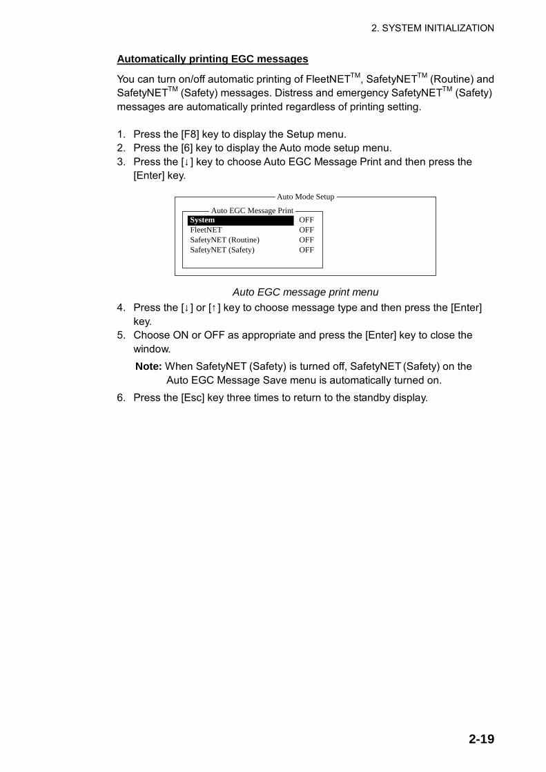
2. SYSTEM INITIALIZATION
2-19
Automatically printing EGC messages
You can turn on/off automatic printing of FleetNETTM, SafetyNETTM (Routine) and SafetyNETTM (Safety) messages. Distress and emergency SafetyNETTM (Safety) messages are automatically printed regardless of printing setting. 1. Press the [F8] key to display the Setup menu. 2. Press the [6] key to display the Auto mode setup menu. 3. Press the [↓ ] key to choose Auto EGC Message Print and then press the
[Enter] key.
Auto Mode Setup
Auto EGC Message PrintSystem OFFFleetNET OFFSafetyNET (Routine) OFFSafetyNET (Safety) OFF
Auto EGC message print menu 4. Press the [↓ ] or [↑ ] key to choose message type and then press the [Enter]
key. 5. Choose ON or OFF as appropriate and press the [Enter] key to close the
window. Note: When SafetyNET (Safety) is turned off, SafetyNET (Safety) on the
Auto EGC Message Save menu is automatically turned on. 6. Press the [Esc] key three times to return to the standby display.

2. SYSTEM INITIALIZATION
2-20
2.5 Adding NCS Channels This section shows you how to add NCS channels to the NCS Channel List. 19 channels can be listed per each ocean region. Currently, there are four NCS channels, and they are marked with asterisks in the list. Add NCS channels to the list as below when they become operational. 1. Press the [F8] key to display the Setup menu. 2. Press the [9] key to display the Configuration menu. 3. Press the [4] key to display the NCS Channel List.
SetupConfiguration
NCS Channel List
No AOR (WEST)FREQ
11080*0102030405060708
ENTER: Set ESC: Quit
AOR (EAST)FREQ
12580*
ID
1441111111
PORFREQ
12580*
ID
2442222222
IORFREQ
10840*
ID
3443333333
ID
0440000000
NCS channel list 4. Use the arrow keys to place the cursor in a blank ID column. 5. Press the [Enter] key to open the data entry window. 6. Enter NCS channel ID number, in two digits (leading zero is not necessary).
The ID number range is 45-63. 7. Press the [Enter] key to close the window. 8. With the [→] key, choose the frequency column. 9. Press the [Enter] key to open the frequency entry window. 10. Enter NCS channel frequency code. The frequency code range is
6000-14000. 11. Press the [Enter] key to close the window. 12. Press the [Esc] key to open the update window.
SetupConfiguration
NCS Channel List
No AOR (WEST)FREQ
11080*
ID
0440000000
0102030405060708
ENTER: Set ESC: Quit
AOR (EAST)FREQ
12580*
ID
1441111111
PORFREQ
12580*
ID
2442222222
IORFREQ
10840*
ID
3443333333
Update
Yes NoYes
NCS channel list, update window
13. Yes is selected; press the [Enter] key to register input.

2. SYSTEM INITIALIZATION
2-21
Note: If the ID or frequency entered is invalid the message "Input Error: NCS ID" (for invalid ID) or "Input Error: Channel No." (for invalid frequency) appears. Clear the error message by pressing the [Esc] key. Place the cursor at the invalid ID or frequency code. Then, press the [Enter] key and enter correct ID or frequency.
14. Press the [Esc] key twice to return to the standby display.

2. SYSTEM INITIALIZATION
2-22
2.6 LES List The LES List provides for storage of 44 LES names per ocean region. By entering approximate toll charges in the LES list, you can see that information on the Transmit message menu.
2.6.1 Displaying toll charges Main LESs (LES name and ID) are already registered; but, toll charges are not. To display toll charges when transmitting do the following: 1. Press the [F8] key to display the Setup menu.
Setup
File Edit Transmit EGC Reports Logs Options Setup Position StopAlarm
1. Distress Alert Setup2. System Setup3. Editor Setup4. Terminal Setup5. EGC Setup6. Auto Mode Setup7. E-Mail Setup8. Directories9. Configuration
Setup menu 2. Press the [9] key to display the Configuration menu.
Setup
Configuration
1. Station List2. LES List3. EGC Channel List4. NCS Channel List5. E-Mail/ SMS Service List6. Save/Load
8. Directories9. Configuration
Configuration menu

2. SYSTEM INITIALIZATION
2-23
3. Press the [2] key to display the LES List. LES List
Ctrl+P: Print ENTER: List Entry ESC: Quit
AOR (WEST)Name
Telenor S.S.IncStratos M.N.KDDITelenor S.S.ASTelecom Italia
AOR (EAST)Name
Telenor S.S.IncStratos M.NKDDI
Korea Telecom
PORName
Stratos M.N.KDDITelenor S.S.ASOTEVSNL
Korea Telecom
IORName
No
0102030405060708
Telenor S.S.IncStratos M.NKDDITelenor S.S.AS
LES list
4. Using the arrow keys, choose the LES for which you want to enter toll charges. For example, choose KDDI in IOR.
5. Press the [Enter] key. Setup
ConfigurationLES List
Ctrl+P: Print ENTER: List Entry ESC: Quit
AOR (WEST)Name
Telenor S.S.IncGOONHILLYBURUM/YAMAGUCHIEIK/TELENORFUCINO
AOR (EAST)Name
Telenor S.S.IncNETELY/BT/TELENYAMAGUCHI
KUMSAN
PORName
IORName
No
0102030405060708
Telenor S.S.IncStratos M.N.KDDITelenor S.S.AS
Stratos M.N.KDDITelenor S.S.NSOTEVSNL
Korea Telecom
: : 005:
NameIDRemarksCharge (US$/256bit) TELEX *****.** FAX *****.** E-Mail *****.** SMS *****.** PSDN *****.** X400 *****.** DNID *****.** SPEC *****.**
Erase the Name to delete this LES.
LES list, LES data entry window 6. Press the [↓] key to choose TELEX and press the [Enter] key to open the text
entry window. 7. Enter telex charges (per 256 bit) and press the [Enter] key.
Enter the toll charges assigned by LES. 8. Enter toll charges for other items similarly. 9. Press the [Esc] key to return to the LES list. 10.Press the [Esc] key three times to return to the standby display.
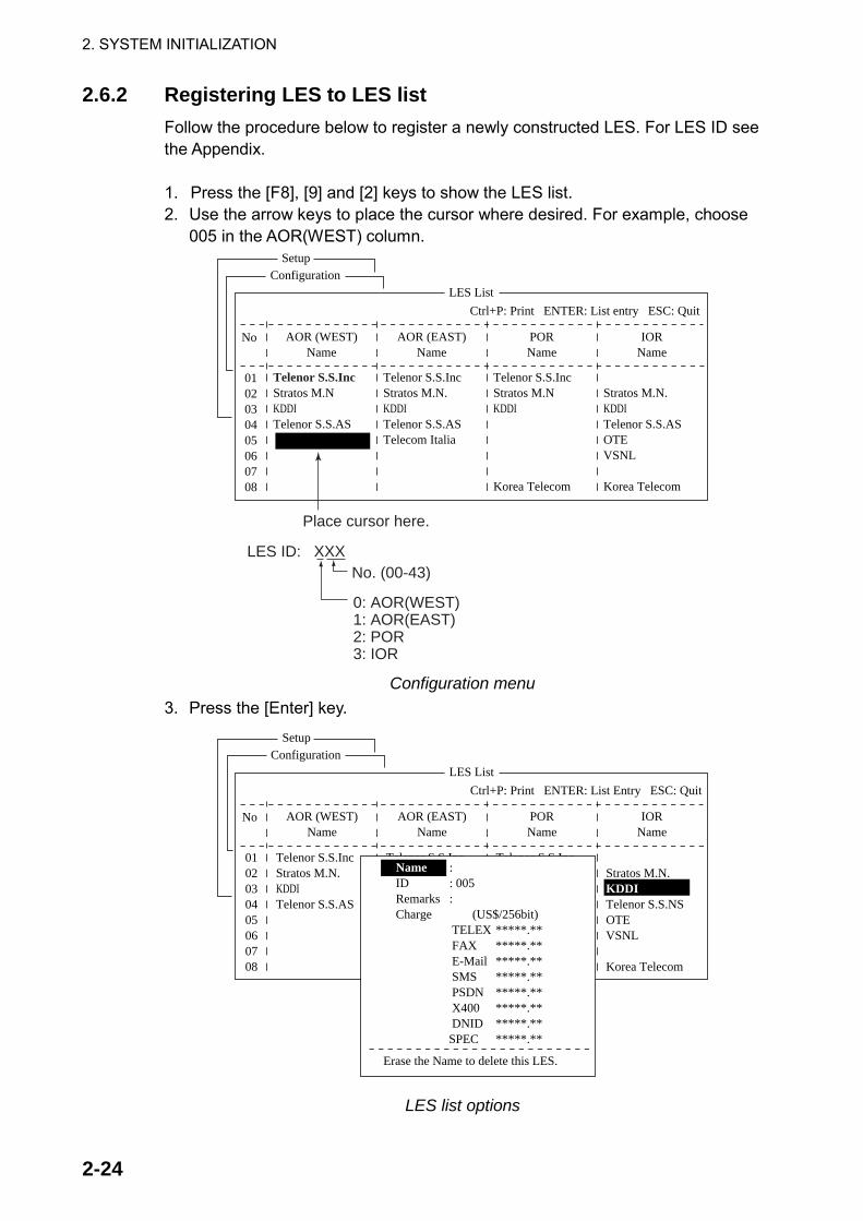
2. SYSTEM INITIALIZATION
2-24
2.6.2 Registering LES to LES list Follow the procedure below to register a newly constructed LES. For LES ID see the Appendix. 1. Press the [F8], [9] and [2] keys to show the LES list. 2. Use the arrow keys to place the cursor where desired. For example, choose
005 in the AOR(WEST) column. Setup
ConfigurationLES List
Ctrl+P: Print ENTER: List entry ESC: Quit
AOR (WEST)Name
AOR (EAST)Name
PORName
IORName
No
0102030405060708
Place cursor here.
LES ID: XXX
0: AOR(WEST)1: AOR(EAST)2: POR3: IOR
No. (00-43)
Telenor S.S.IncStratos M.N.KDDITelenor S.S.ASTelecom Italia
Telenor S.S.IncStratos M.NKDDI
Korea Telecom
Stratos M.N.KDDITelenor S.S.ASOTEVSNL
Korea Telecom
Telenor S.S.IncStratos M.NKDDITelenor S.S.AS
Configuration menu
3. Press the [Enter] key. Setup
ConfigurationLES List
Ctrl+P: Print ENTER: List Entry ESC: Quit
AOR (WEST)Name
Telenor S.S.IncGOONHILLYBURUM/YAMAGUCHIEIK/TELENORFUCINO
AOR (EAST)Name
Telenor S.S.IncNETELY/BT/TELENYAMAGUCHI
KUMSAN
PORName
IORName
No
0102030405060708
Telenor S.S.IncStratos M.N.KDDITelenor S.S.AS
Stratos M.N.KDDITelenor S.S.NSOTEVSNL
Korea Telecom
: : 005:
NameIDRemarksCharge (US$/256bit) TELEX *****.** FAX *****.** E-Mail *****.** SMS *****.** PSDN *****.** X400 *****.** DNID *****.** SPEC *****.**
Erase the Name to delete this LES.
LES list options

2. SYSTEM INITIALIZATION
2-25
4. Name is selected; press the [Enter] key to open the text entry window.
Name :ID :Remarks :Charge (US$/256bit) TELEX *****.** FAX *****.** E-Mail *****.** SMS *****.** PSDN *****.** X400 *****.** DNID *****.** SPEC *****.**
Erase the Name to delete this LES.
LES list, text entry window 5. Enter LES name (maximum 15 characters). 6. Press the [Enter] key. 7. Press the [↓] key to choose Remarks. 8. Press the [Enter] key. 9. Enter remarks (up to 20 characters). 10. Press the [Enter] key. 11. Press the [↓] key to choose TELEX and press the [Enter] key. 12. Enter TELEX toll charges (per 256 bit) and press the [Enter] key. 13. Enter toll charges for other items similarly. 14. Press the [Esc] key to return to the LES list. 15. Repeat steps 2-14 to enter another LES. 16.Press the [Esc] key three times to return to the standby display.
2.6.3 Editing the LES list 1. Press the [F8], [9] and [2] keys to shown the LES list. 2. Use the arrow keys to choose the LES you want to edit. 3. Press the [Enter] key. 4. Do the following:
Change station name: Press the [↓] or [↑] key to choose Name and then press the [Enter] key. Press the [Backspace] key to erase name and then enter new name. Press the [Enter] key. Delete station: Press the [↓] or [↑] key to choose Name and then press the [Enter] key. Press the [Backspace] key to erase name and then press the [Enter] key.
5. Press the [Esc] key to quit. 6. Press the [Esc] key three times to return to the standby display.

2. SYSTEM INITIALIZATION
2-26
2.6.4 Printing the LES list 1. Press [F8], [9] and [2] to display the LES list. 2. To print the LES list, press the [P] key while pressing the [Ctrl] key.
LES List ( Printed at 02-02-25 02:33 )
+++++ AOR (WEST) ++++No.01020304122122
+++++ AOR (EAST) +++++No.01
NameTelenor S.S.IncStratos M.N.KDDITelenor S.S.ASXantic (NED)France TelecomXantic (AUS)
NameTelenor S.S.Inc
LES ID001002003004012021022
LES ID101
RemarksUSACANADAJAPANNORWAYNETHERLANDSFRANCEAUSTRALIA
RemarksUSA
Sample LES list printout 3. To return to the standby display, press the [Esc] key three times.

2. SYSTEM INITIALIZATION
2-27
2.7 Station List 2.7.1 Adding stations to the station list
The FELCOM 15 provides an “address book” for storing 99 station IDs. Enter station IDs as below. 1. Press the [F8] key to display the Setup menu. 2. Press the [9] key to display the Configuration menu. 3. Press the [1] key to display the Station List.
SetupConfiguration
Station List
Ctrl+P: PrintPage Up, Page Down: MoveSort (Ctrl+G: Group, Ctrl+N: Station Name, Ctrl+T: Type)
Group Station Name Type Code ID / Address
File Edit Transmit EGC Reports Logs Options Setup Position StopAlarm
0102030405060708
abc xyz Seagull
E-MailE-MailTELEX
abc@ furuno.co.jpxyz@ furuno.co.jp584 463609999
Sample station list
Note: You may sort the list by group name, station name or communication type as follows: Group name: Each press of [Ctrl] + [G] sorts the list by group name, ascending or descending order. Station name: Each press of [Ctrl] + [N] sorts the list by station name, in ascending or descending order. Comm. type: Each press of [Ctrl] + [T] sorts the list by communication type, in ascending or descending order.
4. Press the [↓] key to place the cursor on a blank line. 5. Press the [Enter] key.
Station Group Station NameDestination Type TELEXPrefix CodeCountry CodeStation IDModem TypeAddressRemarks
Erase the Name to delete this station.
Station list items

2. SYSTEM INITIALIZATION
2-28
6. Press the [Enter] key to open the station group entry window. 7. Enter station group name, using up to five characters. 8. Press the [Enter] key to close the window. 9. Press the [↓] key to choose Station Name. 10. Press the [Enter] key to open the station name entry window. 11. Enter station name, using up to 15 characters. 12. Press the [Enter] key to close the window. 13. Press the [↓] key to choose Destination Type. 14. Press the [Enter] key to open the destination type window.
TELEXFAXE-MailSMSPSDNX400DNIDSPECTELEX (Prefixed)FAX (Prefixed)PSDN (Prefixed)X400 (Prefixed)DNID (Prefixed)SPEC (Prefixed)
Destination (communication) type options TELEX: Telex communication FAX: Facsimile service E-Mail: E-mail (electronic mail) Service SMS: Short Message Service PSDN: Packet Switched Data Network
- to an office computer via a data network using X.25 standard. X400: For future use DNID: Data Network ID. Not used. SPEC: Ship-to shore requests for safety service, accessed by using special
2-digit codes 15. Press the [↓] or [↑] key to choose destination type desired. 16. Press the [Enter] key to close the window. Follow appropriate procedure on
the next several pages. Procedure for Telex
1. Press the [↓] key to choose Country Code. 2. Press the [Enter] key. 3. For ship-to-shore telex, enter international telex country code; ship-to-ship
telex, enter ocean region. A list of international telex country codes appears in the Appendix. Ocean Region AOR-East: 581 POR: 582 IOR: 583 AOR-West: 584
4. Press the [Enter] key. 5. Press the [↓] key to choose Station ID.

2. SYSTEM INITIALIZATION
2-29
6. Press the [Enter] key to open the station ID entry window. 7. Enter telex subscriber number (for ship-to-shore) or MES Inmarsat Mobile
Number (for ship-to-ship). Up to 15 characters, including space, can be entered.
8. Press the [Enter] key to close the window. 9. Press the [↓] key to choose Remarks. 10. Press [Enter] to open the remarks entry window. 11. Enter remarks, using up to 20 characters. 12. Press the [Enter] key to close the window. 13. Press the [Esc] key to return to the station list. 14. To enter another “telex” station, repeat the procedure from step 4 on page
2-27. 15. Press the [Esc] key three times to return to the standby display. Procedure for FAX
1. Press the [↓] key to choose Country Code. 2. Press the [Enter] key to open the country code entry window. 3. Enter international telephone code of subscriber. See the Appendix for list of
telephone codes. 4. Press the [Enter] key to close the window. 5. Press the [↓] key to Station ID. 6. Press the [Enter] key to open the station ID entry window. 7. Enter fax number. 8. Press the [Enter] key to close the window. 9. Press the [↓] key to choose Modem Type. 10. Press the [Enter] key to open the modem type options window.
Modem Type
300bps Duplex1200bps Duplex2400bps Duplex 600/1200bps2400/1200bps2400bps Duplex4800/2400bps9600bps Duplex
T30V21V22V22B V23V26B V26TV27TV32Other
FAXV.21V.22V.22bisV.23V.26bisV.26terV.27terV.32
Modem type options window
11. Press the [↓] or [↑] key to choose mode type of subscriber. For a landline fax or a fax-equipped Inmarsat B MES, choose “T30 FAX.”
12. Press the [Enter] key to close the window. 13. Press the [↓] to choose Remarks. 14. Press the [Enter] key. 15. Enter remarks, using up to 20 characters. 16. Press the [Enter] key to close the window. 17. Press the [Esc] key to return to the station list. 18. To enter another “FAX” station, repeat the procedure from step 4 on page
2-27. 19. Press the [Esc] key three times to return to the standby display.

2. SYSTEM INITIALIZATION
2-30
Procedure for E-mail
1. Press the [↓] key to choose Address. 2. Press the [Enter] key to open the e-mail address entry window. 3. Enter recipient’s e-mail address. 4. Press the [Enter] key to close the window. 5. Press the [↓] to choose Remarks. 6. Press the [Enter] key. 7. Enter remarks, using up to 20 characters. 8. Press the [Enter] key to close the window. 9. Press the [Esc] key to return to the station list. 10. To enter another “E-mail” station, repeat the procedure from step 4 on page
2-27. 12. Press the [Esc] key three times to return to the standby display. Procedure for SMS
1. Press the [↓] key to choose Address. 2. Press the [Enter] key to open the e-mail address entry window. 3. Enter recipient’s mobile phone number, beginning with country code. 4. Press the [Enter] key to close the window. 5. Press the [↓] to choose Remarks. 6. Press the [Enter] key. 7. Enter remarks, using up to 20 characters. 8. Press the [Enter] key to close the window. 9. Press the [Esc] key to return to the station list. 10. To enter another SMS recipient, repeat the procedure from step 4 on page
2-27. 11. Press the [Esc] key three times to return to the standby display.
2.7.2 Editing the station list
1. Press [F8], [9] and [1] to display the Station List.
SetupConfiguration
Station List
Ctrl+P: PrintPage Up, Page Down: MoveSort (Ctrl+G: Group, Ctrl+N: Station Name, Ctrl+T: Type)
Group Station Name Type Code ID / Address
File Edit Transmit EGC Reports Logs Options Setup Position StopAlarm
0102030405060708
abc xyz Seagull
E-MailE-MailTELEX
abc@ furuno.co.jpxyz@ furuno.co.jp584 463609999
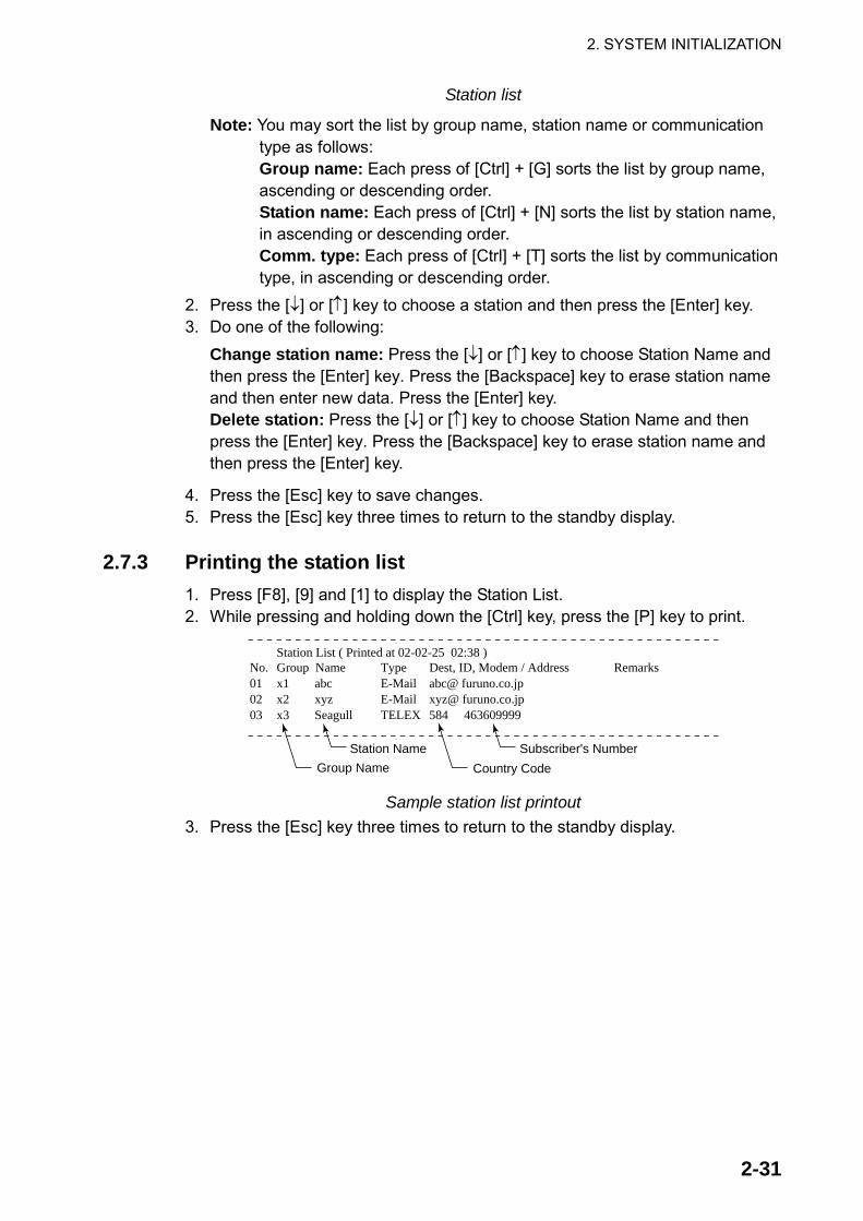
2. SYSTEM INITIALIZATION
2-31
Station list
Note: You may sort the list by group name, station name or communication type as follows: Group name: Each press of [Ctrl] + [G] sorts the list by group name, ascending or descending order. Station name: Each press of [Ctrl] + [N] sorts the list by station name, in ascending or descending order. Comm. type: Each press of [Ctrl] + [T] sorts the list by communication type, in ascending or descending order.
2. Press the [↓] or [↑] key to choose a station and then press the [Enter] key. 3. Do one of the following:
Change station name: Press the [↓] or [↑] key to choose Station Name and then press the [Enter] key. Press the [Backspace] key to erase station name and then enter new data. Press the [Enter] key. Delete station: Press the [↓] or [↑] key to choose Station Name and then press the [Enter] key. Press the [Backspace] key to erase station name and then press the [Enter] key.
4. Press the [Esc] key to save changes. 5. Press the [Esc] key three times to return to the standby display.
2.7.3 Printing the station list 1. Press [F8], [9] and [1] to display the Station List. 2. While pressing and holding down the [Ctrl] key, press the [P] key to print.
No.010203
Group Namex1 abcx2 xyzx3 Seagull
TypeE-MailE-MailTELEX
Dest, ID, Modem / Addressabc@ furuno.co.jpxyz@ furuno.co.jp584 463609999
Station List ( Printed at 02-02-25 02:38 )Remarks
Station Name Subscriber's Number
Country CodeGroup Name
Sample station list printout 3. Press the [Esc] key three times to return to the standby display.

2. SYSTEM INITIALIZATION
2-32
2.8 Entering Own Ship’s Position When there is no navigation data or Nav Port in the System Setup menu is set for OFF, enter ship’s position manually as follows: 1. Press the [F9] key to display the Position menu.
Ship Position
34:30.00N135:30.00E
File Edit Transmit EGC Reports Logs Options Setup Position StopAlarm
LATLON
Ship position window
2. Press the [Enter] key to open the latitude entry window.
00:00.00N000:00.00E
Ship Position
LATLON
34:30.00N
Latitude entry window 3. Enter latitude (XX° XX.XX) and then press the [N] or [S] key as appropriate to
enter coordinate. 4. Press the [Enter] key to close the window. 5. Press the [↓ ] key to choose LON. 6. Press the [Enter] key to open the longitude entry window.
00:00.00N000:00.00E
Ship Position
135:30.00ELATLON
Longitude entry window 7. Enter longitude (XXX° XX.XX) and then press the [E] or [W] key as
appropriate to enter coordinate. 8. Press the [Enter] key to close the window. 9. Press the [Esc] key to open the update window.
Ship Position
LATLON
34:50.00N000:00.00E
Update
NoYesYes
File Edit Transmit EGC Reports Logs Options Setup Position StopAlarm
Ship position, update 10. Yes is selected; press the [Enter] key to update position and close the Ship
Position menu. The position entered appears at the bottom right corner of the system status monitor screen. It is also entered on “Update Distress Alert” screen (see Chapter 6).

2. SYSTEM INITIALIZATION
2-33
2.9 Creating a Directory You can create and specify the directory where to save incoming and outgoing messages to a floppy disk. If no directory is made, the messages are saved to the root directory of the floppy disk.
2.9.1 Creating a directory where to store messages The procedure below shows how to create a directory on a floppy disk. 1. Insert a floppy disk in the disk drive. 2. Press the [F8] key to display the Setup menu. 3. Press the [8] key to display the Directories menu.
Directories
Message DirectoryEGC Message Directory
Directories menu
4. Press the [↑ ] key to choose Message Directory and then press the [Enter] key.
Setup
File Edit Transmit EGC Reports Logs Options Setup Position StopAlarm
5. EGC Setup6. Auto Mode Setup7. E-Mail Setup8. Directories9. Configuration
Directories
Message DirectoryEGC M<DIR><essag>456ABC <DIR> e <DIDirectory
Message Directory
To View: SPACE Make Dir: INS Remove Dir: DEL
2002-02-28 20:53
[A:\ ] Filename Size Date & Time<No Files>
0 Files exist 1456640 bytes free
Setup menu, message directory 5. Press the [Insert] key.
Make Directory
Directory name entry window

2. SYSTEM INITIALIZATION
2-34
6. Enter directory name and press the [Enter] key. Entered name appears.
Setup
5. EGC Setup6. Auto Mode Setup7. E-Mail Setup8. Directories9. Configuration
Directories
Message DirectoryEGC M<DIR><essa>456ABC <DIR> e <DIDirectory
Message Directory[A:\ ABC\ . ] Filename Size Date & Time.ABC281 .. .
<DIR><DIR>
2002-02-28 20:542002-02-15 02:13
Root directory(Top of floppy disk hierarchy)
Directory name
Message directory
Note 1: To create a directory within a directory (at step 6), repeat steps 5 and 6.
Note 2: To return to the root directory, place the cursor on [. .] and press the [Enter] key.
7. Press the [↑ ] key. 8. When the floppy disk drive lamp goes off, press the [Esc] key to show the
update window. 9. Yes is selected; press the [Enter] key. 10. Press the [Esc] key twice to return to the standby display. Then, received
messages (transmitted messages) are saved to the directory created above.
Note 1: To remove a directory, do steps 1-4 in the above procedure, choose the directory to remove and then press the [Delete] key.
Note 2: A directory for EGC messages can also be made as above. In this case choose EGC Message Directory at step 4.

2. SYSTEM INITIALIZATION
2-35
2.9.2 Specifying directory where to store messages You may specify the directory where to store messages on a floppy disk as follows: 1. Press the [F8] and [8] keys to show the Directories menu. 2. Press the [↑ ] key to choose Message Directory and press the [Enter] key.
Setup
5 GC Set p
Directories
Message DirectoryEGC M<DIR><essa>456ABC <DIR> e <DIDirectory
Message Directory[A:\ ABC\ . ] Filename Size Date & Time・ABC281 .・・�
<DIR><DIR>
2002-02-28 20:542002-02-15 02:13
Root directory(Top of floppy disk hierarchy)��
Message directory 3. Press the [↓ ] key to place the cursor on [●●]. 4. Press the [Enter] key. Root directory is displayed. 5. Press the [↓ ] or [↑ ] key to choose a directory. 6. Press the [Enter] key. 7. Press the [↑ ] key to place the cursor on the top line ([A: ]). The floppy disk
drive lamp lights. 8. When the floppy disk drive lamp goes off, press the [Esc] key to show the
update window. 9. Yes is selected; press the [Enter] key. 10. Press the [Esc] key twice to return to the standby display. Note: The directory where to store EGC messages can also be created. In this
case choose EGC Message Directory at step 2.

2. SYSTEM INITIALIZATION
2-36
2.10 E-mail Service/SMS Station List E-mail service providers and SMS stations are already registered in the FELCOM 15. To add new e-mail service providers or SMS stations, follow the procedure below. 1. Press the [F8] key to display the Setup menu. 2. Press the [9] key to display the Configuration menu.
Setup
Configuration
1. Station List2. LES List3. EGC Channel List4. NCS Channel List5. E-Mail/SMS Service List6. Save/Load
8. Directories9. Configuration
Setup menu, configuration
3. Press the [5] key to display the E-Mail/SMSService List. Setup
8. Directories9. Configuration
Configuration
1. Station List2. LES List3. EGC Channel List4. NCS Channel List5. E-Mail Service List
E-Mail/SMS Service List
LES Name AOR.W AOR.E POR IOR
0102030405060708
Telenor S.S.IncXantic (NED)Stratos M.N.Telenor S.S.ASKDDISingapore T.France TelecomXantic (AUS)
001 101 201 321012 112 212 312002 102 202 302004 104 304003 103 203 303 210 328321 321 321 321322 322 322 322
Setup menu, E-Mail/SMS service list

2. SYSTEM INITIALIZATION
2-37
4. Press the [↓] to choose a blank line in the Station Name column and then press the [Enter] key.
OFF
Service LES NameService ID (E-Mail) (SMS)LES ID(AORW)
(AORE)(POR)(IOR)
To:Cc:Subject:Separator:SMS:Attach File(MIME)
Enter data for LES which offers e-mail services. For details contact LES directly.
ExampleEnter data of the KDDI LES as follows:
Service LES Name KDDIService ID (E-Mail) 28Service ID (SMS) 66LES ID (AORW) 004
(AORE) 104 (POR) 204
(IOR) 304To: To:Cc: CC:Subject: Subject:Separator: BlankSMS: BlankAttach File(MIME) ON(UUENCODE)
5. Press the [Enter] key to open the service LES name entry window.
OFF
Service LES NameService ID (E-Mail)Service ID (SMS)LES ID(AORW)
(AORE)(POR)(IOR)
To:Cc:Subject:Separator:SMS:Attach File(MIME)
Service station list, service station name entry window 6. Type in LES which provides e-mail service. 7. Press the [Enter] key to close the window. 8. Press the [↓] key to choose Service ID (E-Mail). 9. Press the [Enter] key to open the service ID entry window. 10. Enter E-mail Service ID (Special Access) Code. 11. Press the [Enter] key to close the window. 12. Press the [↓] key to choose Service ID (SMS). 13. Press the [Enter] key to open the Service ID (SMS) entry window. 14. Enter SMS Service ID (Special Access Code) 15. Press the [Enter] key to close the window. 16. Press the [↓] key to choose LES ID. 17. Press the [Enter] key to open the LES ID entry window. 18. Enter ID of AOR-W. 19. Press the [Enter] key to close the window. 20. Repeat steps 17-19 to enter AOR-East, POR and IOR.

2. SYSTEM INITIALIZATION
2-38
21. Press the [↓] key to choose “To:.” 22. Press the [Enter] key to open the “to” header entry window. 23. Type appropriate “To” header (for example, TO:, to+, etc.). 24. Press the [Enter] key to close the “to” header entry window. 25. Press the [↓] key to choose “Cc:.” 26. Press the [Enter] key to open the “Cc” header entry window. 27. Type appropriate “Cc” header (for example, CC:, cc+, etc.). 28. Press the [Enter] key to close the “Cc” header entry window. 29. Press the [↓] key to choose “Subject:.” 30. Press the [Enter] key to open the subject entry window. 31. Type appropriate Subject header (for example, Subject:, subject+, etc.). 32. Press the [Enter] key to close the window. 33. Press the [↓] key to choose “Separator.” 34. Press the [Enter] key to open the separator entry window. 35. Type appropriate Separator (for example, blank space, STX:, etc.). 36. Press the [Enter] key to close the window. 37. Press the [↓] key to choose SMS. 38. Press the [Enter] key to open the SMS window. 39. If it is necessary to enter special Prefix “sms+” before telephone number,
enter the keyword now. For example, for Singapore Telecom enter sms+8190123456789.
40. Press the [Enter] key to close the window. 41. Press the [↓] key to choose “Attach File (MIME).” 42. Press the [Enter] key to open the Attach File (MIME) window. 43. Choose ON(BASE64), ON(UUENCODE) or OFF as appropriate.
BASE64: General text converter UUENCODE: UNIX text converter
44. Press the [Enter] key to close the window. 45. Press the [Esc] key four times to return to the standby display.

2. SYSTEM INITIALIZATION
2-39
2.11 E-mail Setup Choose the LES where to forward e-mail. Also, you may need to register with an LES which provides e-mail services. 1. Press the [F8] key to display the Setup menu. 2. Press the [7] key to choose E-mail Setup.
Setup
Comsat
E-Mail Setup
LES Name AOR.W AOR.E POR IOR
01 Telnor S.S.Inc 001 101 201 321
7. E-Mail Setup8. Directories9. Configuration
6. Auto Mode Setup
E-mail setup
3. Press the [Enter] key to open the e-mail station list. E-Mail Setup
LES Name AOR.W AOR.E POR IOR
0102030405060708
Telenor S.S.IncXantic (NED)Stratos M.N.Telenor S.S.ASKDDISingapore T.France TelecomXantic (AUS)
001 101 201 321012 112 212 312002 102 202 302004 104 204 304003 103 203 303 210 328321 321 321 321322 322 322 322
E-mail station list
4. Press the [↓] or [↑] key to choose the LES where e-mail is to be sent. 5. Press the [Enter] key. 6. Press the [Esc] key twice to return to the standby display.

2. SYSTEM INITIALIZATION
2-40
2.12 Saving, Loading System Settings You can save system settings to a floppy disk and load them into the terminal unit. This is useful for having a backup copy of system settings.
2.12.1 Saving system settings to a floppy disk 1. Insert a formatted floppy disk in the disk drive. (For how to format a floppy
disk, see paragraph 3.3.1.) 2. Press the [F8] key to show the Setup menu. 3. Press the [9] key to open the Configuration menu. 4. Press the [6] key to choose Save/Load.
Save/LoadSave to FDLoad from FD
5. Save to FD is selected; press the [Enter] key.
1. ALL2. Station List3. LES List4. E-Mail/SMS Service List5. Other
Save to FD
6. Key in the numeric corresponding to the item you want to save. Then, the
“OK to save?” appears. ALL: All contents (Distress Alert Setup) Station List: Station List LES List: LES List E-Mail/SMS Service List: E-mail service/SMS service list Other: Other than Distress Alert Setup menu, Station List, LES List, E-mail service/SMS service list.
7. Yes is selected; press the [Enter] key to save chosen system setting to the floppy disk.
2.12.2 Loading system settings to the terminal unit
1. Insert floppy disk which contains system settings in the disk drive. 2. Press the [F8] key to show the Setup menu. 3. Press the [9] key to open the Configuration menu. 4. Press the [6] key to choose Save/Load. 5. Press the [↓] key to choose Load from FD and press the [Enter] key.
1. ALL2. Station List3. LES List4. E-Mail/SMS Service List5. Other
Load from FD
6. Press appropriate numeric key to choose the item to load. The “OK to load”
window appears. 7. Yes is selected; press the [Enter] key to load chosen system setting.

3-1
3. FILE OPERATIONSThis chapter describes how to prepare, edit, save and print files (messages).
3.1 Files and Working Areas To create a new message it is necessary to open a new file. After a new file is opened, one of two working areas in the internal memory is secured to create the message. The term “open a file” also refers to the loading of a prepared file into a working area. When you remove a file from a working area this is called “closing a file.”
INTERNAL MEMORY
FLOPPY DISK MEMORY
FILE 1
FILE 2
FILE 3
TWO WORKING AREAS
1
Display
2
LCD
Can select one for display.(Change Windowon Edit menu)
FELCOM 15’smemory
Internal memory

3. FILE OPERATIONS
3-2
3.2 Preparing Files There are two types of files: routine and confidential. Files can be assigned a file name and saved to a floppy disk for later use. A message may contain maximum 32 Kbytes of characters.
3.2.1 Preparing a routine file 1. Press the [F1] key to display the File menu.
File
ALT-NALT-OALT-QALT-S
ALT-D
ALT-P
1. New2. Open3. Close4. Save
5. Delete6. Rename
7. Print
8. Format Disk
9. MIME (Decode)
File Edit Transmit EGC Reports Logs Options Setup Position StopAlarm
File menu
2. Press the [1] key to choose New. The display should now look something like the illustration below.
Cursor can be a square or an underline.
<[1] UNTITLED1>
0001|
TELEX----*---------+---------+---------+---------+---------+---------+---------<
1 Char. [ Line 1/ 1 Col. 1 ] [Insert ]
File Edit Transmit EGC Reports Logs Options Setup Position StopAlarm
Text editor screen
Note: When two working areas are opened and you try to open a third file, the message “Save this message” appears. When this occurs close an open file to free a working area.
3. The cursor is on the first line. Type your message. 4. To transmit the message you have just prepared, go to paragraph 4.1.2. To
save it to a floppy disk, for future transmission, go to paragraph 3.3.2.

3. FILE OPERATIONS
3-3
3.2.2 Preparing a confidential file If communicating with another FELCOM 15, you can prepare a confidential message by entering “S???-addressee code(-password):” in the first line of the message text. You can also receive confidential messages containing this header from a land subscriber or any MES which uses the FELCOM 15. There are two types of confidential messages: message with addressee code and message with both addressee code and password. When the FELCOM 15 receives a confidential message, the message is neither displayed nor printed immediately. To display or print the contents of a confidential message, the recipient executes the procedure shown in paragraph 4.2.3. Addressee code and password
Caller and recipient agree beforehand on both the addressee code and the password. The addressee code might be the title of the recipient; for example, CAPTAIN. The password could be the classification of the message; for example, SECRET. Preparing message with addressee code
Type the addressee code as shown in the illustration below and then type the text of message.
S???-addressee code: (text of message)
maximum 8 characters
Be sure to enter colon.
Addressee code Preparing message with both addressee code and password
Type the addressee code and password as shown in the illustration below and then type the text of message.
S???-addressee code-password: (text of message)
maximum 8 characters
Be sure to enter colon.
Addressee code and password
When the recipient receives a message with both addressee code and password, he must enter the password to view contents of the message.

3. FILE OPERATIONS
3-4
3.2.3 Editor menu setup The Editor menu sets the parameters of the text editor. 1. Press the [F8] key to display the Setup menu. 2. Press the [3] key to display the Editor Setup menu.
Setup
2. System Setup3. Editor Setup4. Terminal Setup5. EGC Setup6. Auto Mode Setup7. E-Mail Setup8. Directories9. Configuration
Editor Setup
AsciiInsertONON4 Char69BlockFull Screen
File Edit Transmit EGC Reports Logs Options Setup Position StopAlarm
Text Mode Edit ModeWord WrapLine No. Tab Width Column WidthCursor TypeScroll
Editor setup menu
3. The illustration above shows the default editor setup settings. To change settings: a) Press the [↓ ] or [↑ ] key to choose item. b) Press the [Enter] key to open corresponding options window. c) Choose setting with the [↓ ] or [↑ ] key. d) Press the [Enter] key to register setting. e) Press the [Esc] key twice to return to the standby display.
Text Mode: Choose “Telex” when creating a telex message. Only upper case alphabet is permitted in telex. Use “ASCII” when creating an e-mail message. Upper and lower case alphabet may be used in an e-mail.
Edit Mode: Choose “Insert” (insert character at cursor location) or “Overwrite” (write over character at cursor location).
Word Wrap: Turns on/off automatic hyphenation at the end of a line.
Line No.: Turns line number display on or off.
Tab Width: Sets horizontal tab width; two, four or eight tabs per line.
Column Width: Choose 69 for Telex or 40 to 80 for ASCII.
Cursor Type: Chooses cursor configuration, “■“ or underline.
Scroll: Sets how much the screen moves up over the page (Full Screen or Half Screen) when [PgUp] or [PgDn] key is operated.

3. FILE OPERATIONS
3-5
Cursor can be a square or an underline.
<[1] UNTITLED1>
0001|
TELEX----*---------+---------+---------+---------+---------+---------+---------<
1 Char. [ Line 1/ 1 Col. 1 ] [Insert ]
Line NumberDisplayed if Line No. is turned on inEditor Setup menu.
File Edit Transmit EGC Reports Logs Options Setup Posirion StopAlarm
Text editor screen
3.2.4 Working with text
Cutting and pasting text
1. Use the arrow keys to place the cursor on the first character of the text to be cut.
2. Highlight the text to be cut by pressing the [→] key while pressing and holding the [Shift] key. You can use the [←] or [→] key to adjust the highlight. The figure below shows the appearance of highlighted text.
<[1] UNTITLED1>
TELEX----*---------+---------+---------+---------+---------+---------+---------<
173 Char. [ Line 2/ 3 Col. 55 ] [Insert ]
0001 WE ARE CONFIDENT THAT YOU WILL ENJOY MANY YEARS OF OPERATION WITH0002 THIS INMARSAT STANDARD C MOBILE EARTH STATION CONGRATULATIONS 0003 CONGRATULATIONS ON YOUR CHOICE OF FURUNO FELCOM
Highlight
Appearance of highlighted text
3. Press the [F2] key to choose the Edit menu. Edit
1. Cut 2. Copy 3. Paste 4. Insert (With Citation)5. Select All 6. Search or Replace7. Goto Line8. Time or Pos. Ins9. Change Window
DELALT-CINS
ALT-A
ALT-V
Edit menu 4. Press the [1] key to choose Cut. The highlighted text is cut and the remaining
text is reformatted. If a mistake is made, you can immediately restore the text by pressing the [Insert] key.

3. FILE OPERATIONS
3-6
5. To move text to a new location after it has been cut, place the cursor at the exact spot in the message where the cut text is to start. When the text cursor is placed correctly, press the [F2] key and then the [3] (Paste) key.
Copying and pasting text
1. Choose the text you want to copy. <[1] UNTITLED1>
TELEX----*---------+---------+---------+---------+---------+---------+---------<
131 Char. [ Line 2/ 2 Col. 66 ] [Insert ]
0001 THE FURUNO FELCOM INMARSAT STANDARD C MOBILE EARTH STATION, A0002 SATELLITE COMMUNICATIONS UNIT PACKAGE FOR VIRTUALLY EVERY VESSEL.
Appearance of highlighted text
2. Press the [F2] key to display the Edit menu. 3. Press the [2] key to choose Copy. The text selected is copied to the
clipboard. 4. Place the cursor at the exact spot on the message where the copied text is to
start.
<[1] UNTITLED1>
TELEX----*---------+---------+---------+---------+---------+---------+---------<
131 Char. [ Line 2/ 2 Col. 66 ] [Insert ]
0001 THE FURUNO FELCOM INMARSAT STANDARD C MOBILE EARTH STATION, A0002 SATELLITE COMMUNICATIONS UNIT PACKAGE FOR VIRTUALLY EVERY VESSEL.0003
Cursor
Cursor selects location where to paste text 5. Press the [F2] key followed by the [3] key. The text is placed at the cursor
location. <[1] UNTITLED1>
TELEX----*---------+---------+---------+---------+---------+---------+---------<
137 Char. [ Line 3/ 3 Col. 5 ] [Insert ]
0001 THE FURUNO FELCOM INMARSAT STANDARD C MOBILE EARTH STATION, A0002 SATELLITE COMMUNICATIONS UNIT PACKAGE FOR VIRTUALLY EVERY VESSEL.0003 UNIT
Text pasted at cursor location

3. FILE OPERATIONS
3-7
Insert (with Citation)
When you reply to a received message, you can insert the received message. “>” is placed at the head of the received message to distinguish it from your message. Select All
Chooses the entire current file for cut and copy. Search and Replace
Searching text The Search feature lets you search for text in a forward or backward direction. 1. At the Edit menu, press the [6] key to choose “6 Search or Replace.”
1. Search Alt-F2. Replace Alt-R
Search or Replace
Search and replace menu 2. Press the [1] key to choose “1. Search.”
Search Word Direction Forward
Search
Search window 3. Search Word is selected; press the [Enter] key to show the search word entry
window. 4. Type the word to find and press the [Enter] key. 5. Press the [↓] key to choose Direction and press the [Enter] key.
Search Word Direction
Search
ForwardBack
Direction window 6. Press the [↓] or [↑] key to choose direction to search from the cursor location;
Forward or Back and press the [Enter] key. 7. Press the [Esc] key.
Search Start?
Yes No
Search start window

3. FILE OPERATIONS
3-8
8. Yes is selected; press the [Enter] key. When the unit finds the word, the cursor stops at the first character of the word. If the string could not be found, the message “Not Found (To Quit: ESC)” appears. Press the [Esc] key to quit.
9. To continue the search, press the [Enter] key. Replacing text The Replace feature helps you replace every occurrence of a word or phase with another word or phase in a file. 1. At the Edit menu, press the [6] key to choose “6 Search or Replace.”
1. Search Alt-F2. Replace Alt-R
Search or Replace
Search and replace menu 2. Press the [2] key to choose “2. Replace.”
Search Word Replace WordDirection ForwardQuery or ALL Query
Replace
Replace menu 3. Search Word is selected; press the [Enter] key to open the search word entry
window. 4. Enter search word and then press the [Enter] key. 5. Press the [↓ ] key to choose Replace Word and press the [Enter] key. 6. Enter replace word and then press the [Enter] key. 7. Press the [↓ ] key to choose Direction and then press the [Enter] key.
Search Word ABC Replace Word 123Direction ForwardQuery or ALL Query
Replace
ForwardBack
Replace menu, direction menu 8. Press the [↓] or [↑] key to choose direction to search from the cursor location
and press the [Enter] key. 9. Press the [↓ ] key to choose Query or All and then press the [Enter] key.
Search Word ABC Replace Word 123Direction Query or ALL Query
Replace
QueryAll
Replace menu, query or all

3. FILE OPERATIONS
3-9
10. Press the [↓] or [↑] key to choose Query or All. Query: Stop at each occurrence of word to answer yes or no to
replacement. All: Replace every occurrence of word without stopping to confirm.
11. Press the [Esc] key.
Replace Start?
Yes No
Replace start window 12. Yes is selected; press the [Enter] key to start the replacement. If you selected
“All” at step 10 all occurrences of the search word are replaced with the replace word. If the string could not be found, the message “Not Found (To quit: ESC)” appears. Press the [Esc] key to quit. If you selected “Query” at step 10, the message below appears when the search word is found. Press the [Enter] key to replace the word, or hit the Space bar to go to the next occurrence of the search word.
Replace OK? (OK: ENTER Pass: SPACE To quit: ESC)
Go to line
Moves the cursor to the desired line in the current file. Goto Line
1. Top of Text HOME2. End of Text END3. Goto Line
Goto line options 1. Top of text: Go to top of text 2. End of text: Go to end of text 3. Go to line: Specify line number to go to
Time or Pos. Ins
Inserts time or position in a sentence. 1. At the Edit menu, press the [8] key to choose “8. Time or Pos. Ins.”
1. Time2. Position
Time or Pos. Ins.
Time or position insert options
2. Press the [1] key to insert time; [2] key to insert position at the cursor position.

3. FILE OPERATIONS
3-10
3.3 Saving Files After you have created a message you may wish to save it to a floppy disk, for future use. The types of floppy disk used with the system are 2HD and 2DD. Inserting a floppy disk
Gently insert a floppy disk in the disk drive on the front panel of the terminal unit. Handle floppy disks carefully to prevent damage to the disk, which could cause loss of data. Ejecting a floppy disk
Press the eject button on the right side of the drive and then remove the disk.
Care and handling of floppy disks
• Do not remove a floppy disk from the drive while the operating lamp on the disk drive is lit. Damage to the disk may result.
• The tab on the disk slides up to reveal a hole in the housing (or slides down, to cover the hole). Open the hole to write-protect the disk.
Hole opened: Write protect
Tab
Floppy disk

3. FILE OPERATIONS
3-11
3.3.1 Formatting a floppy disk To save a message to a floppy disk the disk must first be formatted. Formatting prepares the disk so that information can be written to its surface. 1. Insert a blank floppy disk into the disk drive. 2. Press the [F1] key. 3. Press the [8] key (Format Disk).
FileFormat Disk
Insert new disk.And select media type.
6. Rename
7. Print
8. Format Disk
9. MIME (Decode)
2HD (1.44MB)2DD (720kB)
Format disk, disk type options
4. Press the [↓] or [↑] key to choose appropriate media type. 5. Press the [Enter] key.
Format Disk
Insert new disk.And select media type.
Start
Yes No
Format disk, format start window 6. Press the [←] key to choose Yes and then press the [Enter] key to format the
disk. The screen shows a progress bar as below. When formatting is completed, the floppy disk drive lamp goes off.
Format Disk8%
If there is no floppy disk in the drive, the message “FD access failure: Drive not ready.” appears. Press the [Esc] key to erase the message and then insert a floppy disk in the drive.
Note: If formatting failed, the message (flashing) “Format failed, press any key to continue.” appears.

3. FILE OPERATIONS
3-12
3.3.2 Saving files You can save a message two ways: Save it without losing your place on the screen (called “save”), or save it before clearing the screen (called “close”). Save file, retain place on screen
1. Press the [F1] key to display the File menu. 2. Press the [4] key. The screen should look something like the one below.
<[1] UNTITLED1>
0001|THE FURUNO FELCOM 12 INMARSAT STANDARD C MOBILE EARTH STATION, A0002|SATELLITE COMMUNICATIONS UNIT PACKAGE FOR VIRTUALLY EVERY VESSEL.
----*---------+---------+---------+---------+---------+---------+---------<
File
ALT-NALT-OALT-QALT-S
ALT-D
ALT-P
Save[A:\ ]
To View: SPACE Make Dir: INS Remove Dir: DEL
868372
6794864
02-02-25 02:3302-02-25 02:5202-02-25 02:5902-02-25 03:13
Filename Size Date & TimeE0970715.001E0970715.002E0970715.003E0970715.004 4 Files exist 579584 bytes free
File Edit Transmit EGC Reports Logs Options Setup Position StopAlarm
Col. 4 ] [Insert ]
Save window
3. Enter a file name, up to eight characters with extension name (three characters). You may not use a colon, quotation mark or semicolon or vertical line.
(file name) . (extension name)
3 charactersperiod8 characters
Configuration of file name 4. Press the [Enter] key to save the file to the disk and keep it on the screen.

3. FILE OPERATIONS
3-13
Save file, clear screen
1. Press the [F1] key to display the File menu. 2. Press the [3] key. The message “Save this message?” appears on the
screen.
<[1] A:\SEIZOUSE>
NT THAT YOU WILL ENJOY MANY YEARS OF OPERATION WITHSTANDARD C MOBILE EARTH STATION FELCOM S ON YOUR CHOICE OF FURUNO FELCOM.
----*---------+---------+---------+---------+---------+---------+---------<
File
TELEX 178 Char. [ Line 3/ 3 Col. 52 ] [Insert ]
File Edit Transmit EGC Reports Logs Options Setup Position StopAlarm
1. New2. Open3. Close4. Save
5. Delete6. Rename
7. Print
8. Format Disk
9. MIME (Decode)
ALT-NALT-OALT-QALT-S
ALT-D
ALT-P
Save this message?
Yes No
File menu
3. Yes is selected; press the [Enter] key.
<[1] A:\SEIZOUSE>
NT THAT YOU WILL ENJOY MANY YEARS OF OPERATION WITHSTANDARD C MOBILE EARTH STATION FELCOMS ON YOUR CHOICE IF FURUNO FELCOM.
----*---------+---------+---------+---------+---------+---------+---------<
File
1. New2. Open3. Close4. Save
5. Delete6. Rename
7. Print
8. Format Disk
9. MIME (Decode)
ALT-NALT-OALT-QALT-S
ALT-D
ALT-P
ASCII Col. 4 } [Insert ]
Save[A:\ ]
To View: SPACE Make Dir: INS Remove Dir: DEL
9014242
868372
6794864
1910
02-02-25 20:5402-02-25 02:1302-02-25 05:4202-02-25 02:3302-02-25 02:5202-02-25 02:5902-02-25 03:1302-02-25 03:48
Filename Size Date & TimeABC281 . COIEKI . COMTEST.E0970715.001E0970715.002E0970715.003E0970715.004E0970715.005 74 Files exist 578560 bytes free
File Edit Transmit EGC Reports Logs Options Setup Position StopAlarm
Type filename here
Save window 4. Enter a file name. 5. Press the [Enter] key to save the file name and clear the screen.
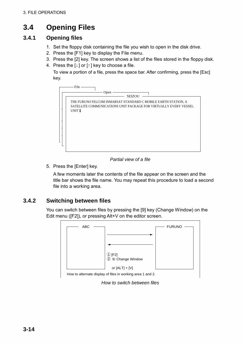
3. FILE OPERATIONS
3-14
3.4 Opening Files 3.4.1 Opening files
1. Set the floppy disk containing the file you wish to open in the disk drive. 2. Press the [F1] key to display the File menu. 3. Press the [2] key. The screen shows a list of the files stored in the floppy disk. 4. Press the [↓ ] or [↑ ] key to choose a file.
To view a portion of a file, press the space bar. After confirming, press the [Esc] key.
File
1. New2. Open3. Close4. Save
5. Delete6. Rename
7. Print
8. Format Disk
9. MIME (Decode)
ALT-NALT-OALT-QALT-S
ALT-D
ALT-P
OpenSEIZOU
THE FURUNO FELCOM INMARSAT STANDARD C MOBILE EARTH STATION, ASATELLITE COMMUNICATIONS UNIT PACKAGE FOR VIRTUALLY EVERY VESSEL.UNIT
Partial view of a file 5. Press the [Enter] key.
A few moments later the contents of the file appear on the screen and the title bar shows the file name. You may repeat this procedure to load a second file into a working area.
3.4.2 Switching between files
You can switch between files by pressing the [9] key (Change Window) on the Edit menu ([F2]), or pressing Alt+V on the editor screen.
[F2] 9: Change Window
or [ALT] + [V]
How to alternate display of files in working area 1 and 2.
FURUNOABC
12
How to switch between files

3. FILE OPERATIONS
3-15
3.4.3 Opening a file when both working areas are occupied If both working areas in the memory are occupied when you attempt to open a file, you are asked if you want to save the file currently chosen before closing it to open another file.
Save this message?
Yes No
Prompt for closing a file 1. To save the file, press the [Enter] key. (Choose “No” and press the [Enter]
key if you do not need to save the file. Go to step 4.)
<[1] A:\SEIZOUSE>
NT THAT YOU WILL ENJOY MANY YEARS OF OPERATION WITHSTANDARD C MOBILE EARTH STATION FELCOMS ON YOUR CHOICE IF FURUNO FELCOM.
----*---------+---------+---------+---------+---------+---------+---------<
File
1. New2. Open3. Close4. Save
5. Delete6. Rename
7. Print
8. Format Disk
9. MIME (Decode)
ALT-NALT-OALT-QALT-S
ALT-D
ALT-P
ASCII Col. 4 } [Insert ]
Save[A:\SEIZOSE ]
To View: SPACE Make Dir: INS Remove Dir: DEL
9014242
868372
6794864
1910
02-02-25 20:5402-02-25 02:1302-02-25 05:4202-02-25 02:3302-02-25 02:5202-02-25 02:5902-02-25 03:1302-02-25 03:48
Filename Size Date & TimeABC281 . COIEKI . COMTEST.E0970715.001E0970715.002E0970715.003E0970715.004E0970715.005 74 Files exist 578560 bytes free
File Edit Transmit EGC Reports Logs Options Setup Position StopAlarm
Save window 2. To enter same file name as edited file, press the [Enter] key.
File already exists. Overwrite?
Yes No
Overwrite file window 3. Yes is selected; press the [Enter] key. 4. Press the [↑] or [↓] key to choose file to open and then press the [Enter] key.

3. FILE OPERATIONS
3-16
3.5 Saving a File Under a New Name 1. Open a file referring to paragraph 3.4.1. 2. Edit the file. 3. Press the [F1] key. 4. Press the [3] (Close) or [4] (Save) key depending on your objective. [3] saves
the file and closes the screen; [4] saves file and keeps position on the screen.
<[1] A:\SEIZOUSE>
NT THAT YOU WILL ENJOY MANY YEARS OF OPERATION WITHSTANDARD C MOBILE EARTH STATION FELCOM S ON YOUR CHOICE OF FURUNO FELCOM.
----*---------+---------+---------+---------+---------+---------+---------<
File
TELEX 178 Char. [ Line 3/ 3 Col. 52 ] [Insert ]
File Edit Transmit EGC Reports Logs Options Setup Position StopAlarm
1. New2. Open3. Close4. Save
5. Delete6. Rename
7. Print
8. Format Disk
9. MIME (Decode)
ALT-NALT-OALT-QALT-S
ALT-D
ALT-P
Save this message?
Yes Yes No
Save window
5. For “Close,” press the [Enter] key. 6. Press the [Backspace] key to delete original file name. Enter file name for
new file.
<[1] A:\SEIZOUSE>
NT THAT YOU WILL ENJOY MANY YEARS OF OPERATION WITHSTANDARD C MOBILE EARTH STATION FELCOMS ON YOUR CHOICE IF FURUNO FELCOM.
----*---------+---------+---------+---------+---------+---------+---------<
File
1. New2. Open3. Close4. Save
5. Delete6. Rename
7. Print
8. Format Disk
9. MIME (Decode)
ALT-NALT-OALT-QALT-S
ALT-D
ALT-P
ASCII Col. 4 } [Insert ]
Save[A:\SEIZOSE ]
To View: SPACE Make Dir: INS Remove Dir: DEL
9014242
868372
6794864
1910
02-02-25 20:5402-02-25 02:1302-02-25 05:4202-02-25 02:3302-02-25 02:5202-02-25 02:5902-02-25 03:1302-02-25 03:48
Filename Size Date & TimeABC281 . COIEKI . COMTEST.E0970715.001E0970715.002E0970715.003E0970715.004E0970715.005 74 Files exist 578560 bytes free
File Edit Transmit EGC Reports Logs Options Setup Position StopAlarm
Save window 7. Press the [Enter] key.
Note: Should you decide to save the file under the original name, skip step 6. The screen shown right appears. Overwrite the file by pressing the [Enter] key, or choose “No” and press the [Enter] key to escape.
File already exists. Overwrite?
Yes No

3. FILE OPERATIONS
3-17
3.6 Printing Files on Floppy Disks You can print out a hard copy of a file stored on a floppy disk. 1. Press the [F1] key to display the File menu. 2. Press the [7] key. A list of files stored on the disk appears.
Print[A:\R0970729 ]
To View: SPACE Make Dir: INS Remove Dir: DEL
4121391178362029
128146
02-01-10 07:2102-01-10 06:2202-02-25 06:2902-02-23 04:5302-02-18 08:5502-01-14 10:0302-02-11 15:0202-02-10 17:37
Filename Size Date & TimeR0970729.001SEIZOU .SEIZOUSE.T0715 .T7170 .TEST .TXTTESTCAL .YANOT 75 Files exist 578560 bytes free
Print window 3. Press the [↑] or [↓] key to choose a file. To get a partial display of the file, tap
the space bar. After confirming the file, press the [Esc] key. 4. Press the [Enter] key to print the file.
3.7 Combining Files In the procedure below we’ll combine file A and B. 1. Open file A. 2. Open file B. 3. Place the cursor at the beginning of the file B. While pressing and holding
down the [Shift] key, press the [↓ ] key to highlight the entire file. (You can also choose a portion of the file.)
4. Press the [C] key while holding down the [Alt] key to place file B on the clipboard.
5. Press the [V] key while holding down the [Alt] key to switch to File A. 6. Press the [→] key while holding down the [Fn] key followed by the [Enter] key
to place the cursor at the end of file A. 7. Press the [Insert] key. File B is inserted at the end of the file A.

3. FILE OPERATIONS
3-18
3.8 Deleting Files 1. Press the [F1] key to display the File menu. 2. Press the [5] key. A list of files stored on the disk appears.
File
1. New2. Open3. Close4. Save
5. Delete6. Rename
7. Print
8. Format Disk
9. MIME (Decode)
ALT-NALT-OALT-QALT-S
ALT-D
ALT-P
Delete[A:\ABC28 ]
To View: SPACE Make Dir: INS Remove Dir: DEL
9019014242
868372
6794864
02-01-10 20:5302-01-10 20:5402-02-25 02:1302-02-23 05:4202-02-18 02:3302-01-14 02:5202-02-11 02:5902-02-10 03:13
Filename Size Date & TimeABC28 .ABC281 .COIEKI . COMTEST.E0970715.001E0970715.002E0970715.003E0970715.004 75 Files exist 578560 bytes free
Delete window
3. Press the [↑] or [↓] key to choose the file you want to delete. To verify the contents of that file, tap the space bar. After confirming the contents, press the [Esc] key.
4. Press the [Enter] key. The prompt “OK to delete file?” appears. File
1. New2. Open3. Close4. Save
5. Delete6. Rename
7. Print
8. Format Disk
9. MIME (Decode)
ALT-NALT-OALT-QALT-S
ALT-D
ALT-P
Delete[A:\ABC28 ]
To View: SPACE Make Dir: INS Remove Dir: DEL
901901
4242
868372
6794864
02-01-10 20:5302-01-10 20:5402-02-25 02:1302-02-23 05:4297-07-15 02:5297-07-15 02:5997-07-15 03:13
Filename Size Date & TimeABC28 .ABC281 .COIEKI . COMTEST.E0970715.001E0970715.002E0970715.003E0970715.004 75 Files exist 578560 bytes free
OK to delete file?
Yes Yes No
Delete window
5. Press the [Enter] key to delete the file.

3. FILE OPERATIONS
3-19
3.9 Renaming Files Do the following to rename a file. 1. Press the [F1] key. 2. Press the [6] key.
File
1. New2. Open3. Close4. Save
5. Delete6. Rename
7. Print
8. Format Disk
9. MIME (Decode)
ALT-NALT-OALT-QALT-S
ALT-D
ALT-P
Rename[A:\Test ]
To View: SPACE Make Dir: INS Remove Dir: DEL
901901
4242
868372
6794864
02-01-10 20:5302-01-10 20:5402-02-25 02:1302-02-23 05:4202-02-18 02:3302-01-14 02:5202-02-11 02:5902-02-10 03:13
Filename Size Date & TimeTest ABC281 .COIEKI . COMTEST.E0970715.001E0970715.002E0970715.003E0970715.004 75 Files exist 578560 bytes free
Rename window
3. Press the [↑] or [↓] key to choose the file you want to rename. 4. Press the [Enter] key.
Enter new filename
Rename
Test
File name entry window 5. Delete old file name, and then type new file name. 6. Press the [Enter] key.
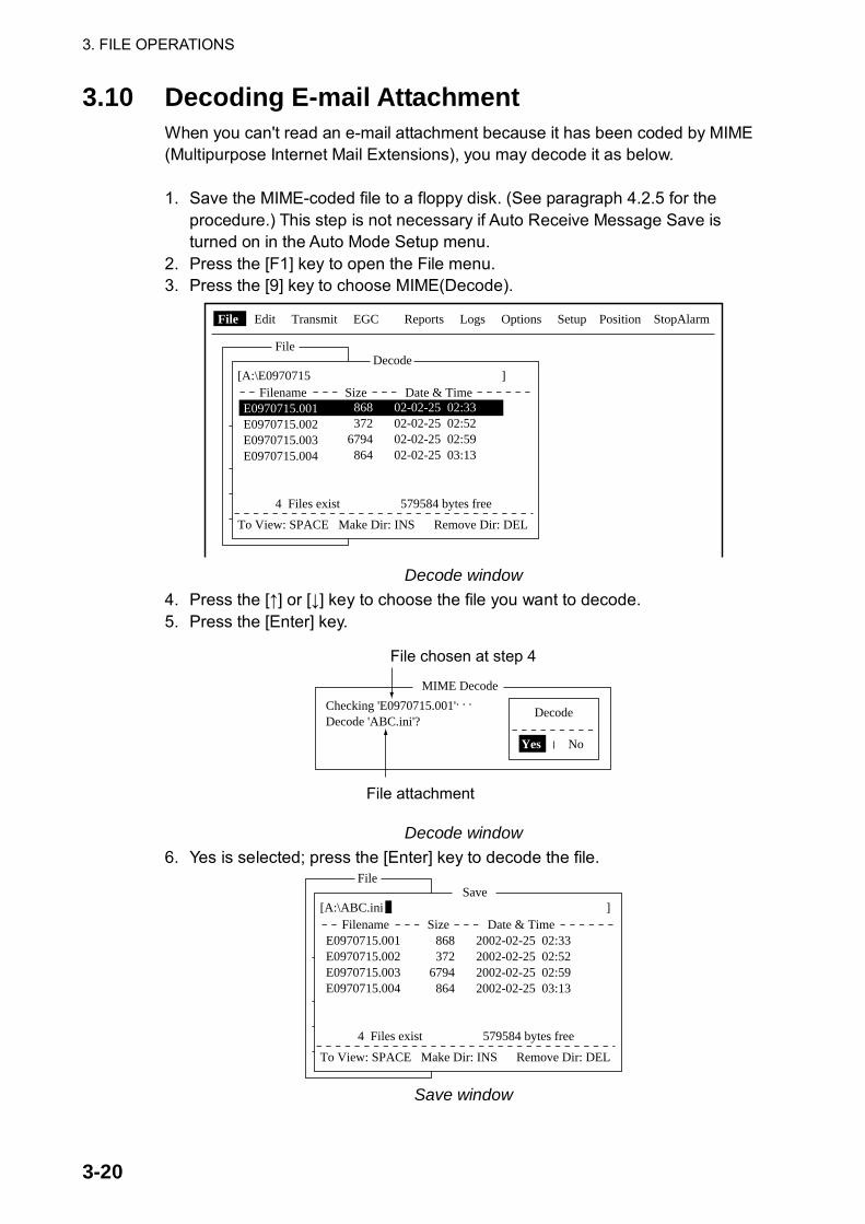
3. FILE OPERATIONS
3-20
3.10 Decoding E-mail Attachment When you can't read an e-mail attachment because it has been coded by MIME (Multipurpose Internet Mail Extensions), you may decode it as below. 1. Save the MIME-coded file to a floppy disk. (See paragraph 4.2.5 for the
procedure.) This step is not necessary if Auto Receive Message Save is turned on in the Auto Mode Setup menu.
2. Press the [F1] key to open the File menu. 3. Press the [9] key to choose MIME(Decode).
File
1. New2. Open3. Close4. Save
5. Delete6. Rename
7. Print
8. Format Disk
9. MIME (Decode)
ALT-NALT-OALT-QALT-S
ALT-D
ALT-P
Decode[A:\E0970715 ]
To View: SPACE Make Dir: INS Remove Dir: DEL
File Edit Transmit EGC Reports Logs Options Setup Position StopAlarm
868372
6794864
02-02-25 02:3302-02-25 02:5202-02-25 02:5902-02-25 03:13
Filename Size Date & TimeE0970715.001E0970715.002E0970715.003E0970715.004
4 Files exist 579584 bytes free
Decode window
4. Press the [↑] or [↓] key to choose the file you want to decode. 5. Press the [Enter] key.
MIME Decode
Checking 'E0970715.001'. . .
Decode 'ABC.ini'?Decode
Yes No
File chosen at step 4
File attachment
Decode window 6. Yes is selected; press the [Enter] key to decode the file.
File
1. New2. Open3. Close4. Save
5. Delete6. Rename
7. Print
8. Format Disk
9. MIME (Decode)
ALT-NALT-OALT-QALT-S
ALT-D
ALT-P
Save[A:\ABC.ini ]
To View: SPACE Make Dir: INS Remove Dir: DEL
Filename Size Date & TimeE0970715.001E0970715.002E0970715.003E0970715.004
4 Files exist 579584 bytes free
2002-02-25 02:332002-02-25 02:522002-02-25 02:592002-02-25 03:13
868372
6794864
Save window

3. FILE OPERATIONS
3-21
7. To change file name, press the [Backspace] key to erase the file name, new file name and then press the [Enter] key. After decoding the file the screen looks something like the one shown below.
MIME Decode
Checking 'E0970715.001' . . .
Decode 'ABC.ini'?Now decoding. . .
Complete.Decoded 1 file (s).Press any key to escape.
MIME decode screen
8. Press the [Esc] key twice to return to the standby display. 9. Press the [F1] and [2] keys in that order. 10. Press the [↑] or [↓] key to choose the file selected at step 7 and then press
the [Enter] key.

3. FILE OPERATIONS
3-22
(This page intentionally left blank.)

4-1
4. INMARSAT C COMMUNICATIONS This chapter explains how to transmit and receive. Before conducting any communications, be sure to login with the NCS in your area, following the instructions in paragraph 2.3.1. To transmit e-mail, you may need to register for e-mail services with appropriate LES which provides such services. Further, it is necessary to register with appropriate LES to receive e-mail from land mail system. For further details, contact appropriate LES.
4.1 Transmitting To transmit a message, create the message, attach the address of the recipient and then send it to the LES. The address of the recipient in the Inmarsat C system is his telex number, for transmission via landline, or MES Inmarsat Mobile Number (IMN), when transmitting to a ship. The message can be one you’ve just prepared or one stored on a floppy disk. (Messages cannot be transmitted by direct keyboard input.)
4.1.1 Code description Code can be specified at the terminal unit. IA5: International alphabet No. 5, ASCII code (7 bit).
Specify this code to transmit English containing lower case alphabet. ITA2: No. 2 international communications alphabet (5 bit). Specify this code for
message which contains only No. 2 international communications alphabet (see A-11). ITA2 code is transmitted faster than IA5 code. Land-based telex equipment uses ITA2. The LES converts all codes into ITA2. Code which cannot be converted is shown with the question mark (?).
DATA: Data (8 bit). Use this code to transmit data.

4. INMARSAT C COMMUNICATIONS
4-2
Message language, subscriber, destination type and code
Message Subscriber Destination Type Code Remarks
Inmarsat C MES Telex IA5
Telex Telex ITA2
Fax PSTN IA5 Modem type “T30”
English
E-mail E-mail IA5
Inmarsat C MES PSDN DATA
Fax Not available
Russian
E-mail E-mail DATA
Inmarsat C MES PSDN DATA
Telex Not available
Fax Not available
Japanese
E-mail E-mail DATA
Inmarsat C MES PSDN DATA Data
Land Network PSDN DATA
4.1.2 Transmitting prepared message
This section explains how to transmit a message you have just prepared, via fax, telex, e-mail or SMS. For distress transmission, see Chapter 6. For 2-digit code services, see the table in paragraph 4.1.6. Transmitting a message to a station registered on station list
1. Prepare message on the screen. For e-mail or SMS, set Text Mode in the Editor Setup menu to Ascii. See paragraph 3.2.3. For e-mail attachment, prepare the attachment and save it to a floppy disk. SMS messages over 160 characters in length are sent in parts.
2. Press the [F3] key to display the Transmit menu.
25 Char. [ Line 2/ 2 Col. 1 ]
<[1] UNTITLED1>
TELEX----*---------+---------+---------+---------+---------+---------+---------<
[Insert ]
Transmit
1. Transmit Message2. Cancel3. Request Delivery Status
File Edit Transmit EGC Reports Logs Options Setup Position StopAlarm
Transmit menu

4. INMARSAT C COMMUNICATIONS
4-3
3. Press the [1] key to display the Transmit Message menu.
25 Char. [ Line 2/ 2 Col. 1 ]
<[1] UNTITLED1>
----*---------+---------+---------+---------+---------+---------+---------< [Insert ]
Transmit
1. Transmit Message2. Cancel3. Request Delivery Status
Transmit Message
NormalMessage now being edited Size 24
TELEX
ON00:00ImmediateIA5
File Edit Transmit EGC Reports Logs Options Setup Position StopAlarm
PriorityMessage FileStation Name Cost ********.**(US$)Destination Type
Prefix CodeCountry/Ocean CodeStation IDModem TypeAddressSubjectAttach File
LES IDOption Confirmation Send Delay Delivery Delay Code[ TRANSMIT ]
Displays communication charge. See paragraph 2.6.1.
Transmit message menu
4. Press the [↓ ] key twice to choose Station Name. 5. Press the [Enter] key to open the Station List.
DateTime
Position
Waypoint
CourseSpeedCurrent NCSCurrent ChannelCurrent TDMMES StatusGPS Status
DCE Memory
97-08-0401:32 (UTC)
LATLONLATLON
DEGKTS
344 (IOR) LOGOUTNCS CCNCS CCIdle****
32818 Bytes free
BBERC/NSend levelRxIF AGC LevelREF Offset FreqSynthe 1st local
3rd localSynthesizerTX2nd Local
Antenna Power Supply
Water TemperatureWater Current
DirectionSpeed
Depth
003OK ( 36dB)OK ( 0)OK (135)OK ( 0Hz)OKOKOKOKOK
DEG
DEGKTS
Transmit
1. Transmit Message2. Cancel3. Request Delivery Status
Transmit Message
Normal Size 0
TELEX8265-2111
303 (YAMAGUCHI)
ENTER: Station List DEL:
25 Char. [ Line 2/ 2 Col. 1 ] [Insert ]
File Edit Transmit EGC Reports logs Options Setup StopAlarm
Station List
Group Station Name Type Code ID / Address
321343199999
TELEXTELEX
81583
FURUNO FRNINMBTSTS
0102030405060708
: Select SPACE: Select Stations B.SPACE: Cancel Mark INS: EditSort (Ctrl+G: Group, Ctrl+N: Station Name, Ctrl+T: Type)
E-MailE-Mail
[email protected]@furuno.co.jp
Seagull whale
PriorityMessage FStation NaDestination
CountryStation Modem AddressSubject
Attach LES Option Confirm Send D Deliver Code [ TRANSMIT ]
Transmit message menu, station list

4. INMARSAT C COMMUNICATIONS
4-4
6. Press the [↑] or [↓] key to choose station and then press the [Enter] key. To choose multiple stations* (simultaneous transmission), choose a station and then press the Space bar. Selected stations are marked with an asterisk (in case of Telex or FAX). For e-mail address, press the Space bar to choose “To” “Cc,” Blank, “To”… consecutively. * = Max. 10 telex stations, 7 FAX, 10 e-mail, and one SMS.
Station List
Group Station Name Type Code ID / Address
321343199999
TELEXTELEX
81583
FURUNO FRNINMBTSTS
0102030405060708
: Select SPACE: Select Stations B.SPACE: Cancel Mark INS: EditSort (Ctrl+G: Group, Ctrl+N: Station Name, Ctrl+T: Type)
E-MailE-Mail
[email protected]@furuno.co.jp
Seagull whale
**
Station list
Note 1: Messages having different communication format or prefix code (two-digit code) cannot be sent simultaneously.
Note 2: To cancel selection (erase asterisk, To or Cc), choose station and press the [Backspace] key.
Note 3: You may sort the list by group name, station name or communication type as follows: Group name: Each press of [Ctrl] + [G] sorts the list by group name, ascending or descending order. Station name: Each press of [Ctrl] + [N] sorts the list by station name, in ascending or descending order. Comm. type: Each press of [Ctrl] + [T] sorts the list by communication type, in ascending or descending order.
Note 4: You may edit the communication charges (see paragraph 2.7.1) from the Station List by pressing the [Insert] key. After editing charges, press the [Esc] key. “OK to save” appears; press the [Enter] key.
7. For E-mail follow the procedure below. For other communication formats, go to step 8. (1) Press the [↓] key to choose Subject. (2) Press the [Enter] key to open subject entry window. (3) Type subject. (4) Press the [Enter] key to close the window. (5) To attach a file, press the [↓] key to choose Attach File.

4. INMARSAT C COMMUNICATIONS
4-5
(6) Press the [Enter] key to open the attach file window.
25 Char. [ Line 2/ 2 Col. 1 ]
<[1] UNTITLED1>
----*---------+---------+---------+---------+---------+---------+---------< [Insert ]
Transmit
1. Transmit Message2. Cancel3. Request Delivery Status
Transmit Message
NormalMessage now being edited Size 24
201 (SANTA PAULA)
Select File
ENTER: Select DEL: Remove
PriorityMessage FileStation Name Cost ********.**(US$) Destination Type
Prefix CodeCountry/Ocean CodeStation IDModem TypeAddressSubjectAttach File
LES IDOption Confirmation Send Delay Delivery Delay Code [ TRANSMIT ]
Transmit message menu, select file window opened
(7) Press the [Enter] key to open the file list window. (8) Press the [↑] or [↓ ] key to choose a file and then press the [Enter] key. (9) Press the [Esc] key to close the window.
8. Press the [↓ ] key to choose LES ID. If the communication format is e-mail, the LES set in paragraph 2.11 appears.
9. Press the [Enter] key to open the LES setting window.
25 Char. [ Line 2/ 2 Col. 1 ]
<[1] UNTITLED1>
[Insert ]
Transmit
1. Transmit Message2. Cancel3. Request Delivery Status
Transmit Message
NormalMessage now being edited Size 24
TELEX
201 (SANTA PAULA)
PriorityMessage FileStation Name Cost ********.**(US$) Destination Type
Prefix CodeCountry/Ocean CodeStation IDModem TypeAddressSubjectAttach File
LES IDOption Confirmation Send Delay Delivery Delay Code [ TRANSMIT ]
NameTelenor S.S.Inc KDDIKorea TelecomSingapore Telecom
LES ID201202203208210
RemarksUSA
JAPANKOREASINGAPORE (NCS, ID244)
LES ID options
10. Press the [↑] or [↓ ] key to choose LES desired. Note: You may edit the communication charges (see paragraph 2.7.1) from
the Station List by pressing the [Insert] key. After editing charges, press the [Esc] key. “OK to save” appears; press the [Enter] key.
11. Press the [Enter] key to close the window. 12. Press the [↓ ] key to choose Confirmation.

4. INMARSAT C COMMUNICATIONS
4-6
13. Press the [Enter] key to open the confirmation window. 14. To request notification of delivery from the LES, choose ON. If not necessary
choose OFF. 15. Press the [Enter] key to close the window. 16. Press the [↓] key to choose Send Delay. 17. Press the [Enter] key to open the send delay entry window. 18. To send a message after a certain delay, enter a time up to 99 hours 59
minutes. (The Send Delay is used to time message arrival to suit recipient’s office hours.)
19. Press the [Enter] key to close the window. 20. Press the [↓] key to choose Delivery Delay. 21. Press the [Enter] key to open the delivery delay options window. 22. Delivery Delay requests the LES for “Immediate” or “Deferred” transmission
to the recipient designated. Press the [↑] or [↓] key to choose Immediate or Deferred. For information on this service, consult with LES where message is to be sent.
23. Press the [Enter] key to close the window. 24. Press the [↓] key to choose Code and press the [Enter] key. 25. Press the [↑] or [↓] key to choose “IA5 (for e-mail, fax) ”, “ITA2 (for telex)”
“DATA” or “SMS” as appropriate. 26. Press the [Enter] key to close the window. 27. Press the [↓] key to place the cursor on TRANSMIT. 28. Press the [Enter] key to open the start window.
DateTime
Position
Waypoint
CourseSpeedCurrent NCSCurrent ChannelCurrent TDMMES StatusGPS Status
DCE Memory
97-08-0401:32 (UTC)
LATLONLATLON
DEGKTS
344 (IOR) LOGOUTNCS CCNCS CCIdle****
32818 Bytes free
BBERC/NSend levelRxIF AGC LevelREF Offset FreqSynthe 1st local
3rd localSynthesizerTX2nd Local
Antenna Power Supply
Water TemperatureWater Current
DirectionSpeed
Depth
Transmit Message
NormalSEISETU.TXT Size 46FURUNO Cost ********.** (US$)TELEX
81321
303 (KDDI) Start
NoYes ON00:00Immediate IA5
PriorityMessage FileStation NameDestination Type
Prefix CodeCountry/Ocean CodeStation IDModem TypeAddressSubjectAttach File
LES IDOption Confirmation Send Delay Delivery Delay Code [ TRANSMIT ]
Transmit message screen 29. Press the [Enter] key to send the message to the message queue. (To
escape, choose “No” and press the [Enter] key.) The message “Message is entered in sending Queue. Press any key.” appears. Note 1: If some data has not been entered, the message “Input Error: xx.”
(xx: error content) appears. Note 2: When you send a message which contains more than 32 KB of data,
the message “Message file is too large (but sent only with 32 KB).”

4. INMARSAT C COMMUNICATIONS
4-7
Note 3: Messages sent to the message queue may contain up to 32 KB of
data. If data is larger than 32 KB, the message “Cannot enter this message to sending Queue. Press any key.” appears.
30. Press the [Esc] key twice to return to the standby display. The message(s) will be transmitted according to the Send Delay setting. “Current State: SENDING” appears at the bottom of the screen while the message is being transmitted. If the message was transmitted successfully, “Successful Sending message” appears and the TX message is printed (if “Confirmation is ON). You can view details about the message in the Display Log (see paragraph 4.3).
Sent MessageDELIVERY CONFIRMATION OFF
Message File : 00FOX.TXT Message Size : 277 charactersLES : Stratos M.N. Date : 02-03-10Priority : Normal Time : 06:06 (UTC)Destination : TELEX (Prefixed) 00111222222222222222 (IA5)
00111333333333333333 00111444444444444444
Display log printout example (“Confirmation” OFF)
When Confirmation is ON and you receive a delivery status message, the message “Delivery Status received for (file name).” appears and the delivery status message is printed.
Sent MessageDELIVERY CONFIRMED
Message File : 00FOX.TXT Message Size : 277 charactersLES : Stratos M.N. Date : 02-03-10Priority : Normal Time : 06:06 (UTC)Destination : TELEX (Prefixed) 00111222222222222222 (IA5)
Display log printout example (“Confirmation” ON, message delivered)
Sent Message but not deliveredDELIVERY FAILURE : xxx
Message File : 00FOX.TXT Message Size : 277 charactersLES : Stratos M.N. Date : 02-03-10Priority : Normal Time : 06:06 (UTC)Destination : TELEX (Prefixed) 00111222222222222222 (IA5)
Display log printout example (“Confirmation” ON, message not delivered)
Sent Message but not deliveredDELIVERY STATUS NOT RECEIVED (In case of timeout)
Message File : 00FOX.TXT Message Size : 277 charactersLES : Stratos M.N. Date : 02-03-10Priority : Normal Time : 06:06 (UTC)Destination : TELEX (Prefixed) 00111222222222222222 (IA5)
Display log printout example (“Confirmation” ON, delivery status not received)

4. INMARSAT C COMMUNICATIONS
4-8
TRANSMIT MESSAGE STATUS The terminal unit displays transmit message status as follows:
Message Send failed. This appears if the message could notbe transmitted because of technical reasons such as satellitemalfunction, signal degradation, or no reply from LES. Try to�transmit the message again.
Message Send rejected. This appears when the LES rejectsthe message because of non-technical reasons such as unpaidsubscriber's fee.
Message Send pending.This appears when the circuits at the LES are busy. Your message will be transmitted when a circuitbecomes clear.
Transmitting a message to a station not registered on station list
1. Prepare message. For e-mail or SMS, set Text Mode in the Editor Setup menu to Ascii. See paragraph 3.2.3. For e-mail attachment, prepare the attachment and save it to a floppy disk. SMS messages over 160 characters in length are sent in parts.
2. Press the [F3] key to display the Transmit menu. 3. Press the [1] key to show the Transmit Message menu.
25 Char. [ Line 2/ 2 Col. 1 ]
<[1] UNTITLED1>
----*---------+---------+---------+---------+---------+---------+---------< [Insert ]
Transmit
1. Transmit Message2. Cancel3. Request Delivery Status
Transmit Message
NormalMessage now being edited Size 24
TELEX
ON00:00ImmediateIA5
File Edit Transmit EGC Reports Logs Options Setup Position StopAlarm
PriorityMessage FileStation Name Cost ********.**(US$)Destination Type
Prefix CodeCountry/Ocean CodeStation IDModem TypeAddressSubjectAttach File
LES IDOption Confirmation Send Delay Delivery Delay Code[ TRANSMIT ]
Displays communication charge. See paragraph 2.6.1.
Transmit message menu

4. INMARSAT C COMMUNICATIONS
4-9
4. Press the [↓] key three times to choose the Destination Type. 5. Press the [Enter] key to open the destination type options window.
25 Char. [ Line 2/ 2 Col. 1 ]
<[1] UNTITLED1>
----*---------+---------+---------+---------+---------+---------+---------< [Insert ]
Transmit
1. Transmit Message2. Cancel3. Request Delivery Status
Transmit MessageNormalMessage now being edited Size 24
TELEX
PriorityMessage FileStation Name Cost ********.**(US$) Destination Type
Prefix CodeCountry/Ocean CodeStation IDModem TypeAddressSubjectAttach File
LES IDOption Confirmation Send Delay Delivery Delay Code IA5[ TRANSMIT ]
TELEXFAXE-MailSMSPSDNX400DNIDSPECTELEX (Prefixed)FAX (Prefixed)PSDN (Prefixed)X400 (Prefixed)DNID (Prefixed)SPEC (Prefixed)
Transmit message menu, destination type options window
6. Press the [↑] or [↓] key to choose Destination Type among “TELEX,” “FAX", “E-mail” or "SMS" as appropriate.
7. Press the [Enter] key to close the window. 8. Continue the procedure according to destination type:
TELEX (Prefixed): Page 4-10 FAX: Page 4-12 E-mail: Page 4-13 SMS: Page 4-14

4. INMARSAT C COMMUNICATIONS
4-10
Communication type: TELEX (Prefixed) 1. Press the [↓ ] key to choose Country/Ocean Code. 2. Press the [Enter] key to open the country/ocean code entry window.
25 Char. [ Line 2/ 2 Col. 1 ]
<[1] UNTITLED1>
----*---------+---------+---------+---------+---------+---------+---------< [Insert ]
Transmit
1. Transmit Message2. Cancel3. Request Delivery Status
Transmit Message
NormalMessage now being edited Size 24
TELEX
ON00:00ImmediateIA5
PriorityMessage FileStation Name Cost ********.**(US$) Destination Type
Prefix CodeCountry/Ocean CodeStation IDModem TypeAddressSubjectAttach File
LES IDOption Confirmation Send Delay Delivery Delay Code[ TRANSMIT ]
Transmit message menu, country/ocean code window 3. For ship-to-shore telex, enter recipient’s telex country code. For example, to
use KDDI (Japan) enter 720. For ship-to-ship telex, enter recipient’s ocean region.
Ocean Region AOR-East: 581 POR: 582 IOR: 583 AOR-West: 584
4. Press the [Enter] key to close the window. 5. Press the [↓ ] key to choose Station ID. 6. Press the [Enter] key to open the station ID entry window.
25 Char. [ Line 2/ 2 Col. 1 ]
<[1] UNTITLED1>
----*---------+---------+---------+---------+---------+---------+---------< [Insert ]
Transmit
1. Transmit Message2. Cancel3. Request Delivery Status
Transmit Message
NormalMessage now being edited Size 24
TELEX
ON00:00ImmediateIA5
PriorityMessage FileStation Name Cost ********.**(US$) Destination Type
Prefix CodeCountry/Ocean CodeStation IDModem TypeAddressSubjectAttach File
LES IDOption Confirmation Send Delay Delivery Delay Code[ TRANSMIT ]
Transmit message menu, station ID window opened

4. INMARSAT C COMMUNICATIONS
4-11
7. Type either recipient’s telex subscriber number (ship-to-shore) or IMN (ship-to-ship).
8. Press the [Enter] key to close the window. 9. Press the [↓ ] key to choose LES ID. 10. Press the [Enter] key to open the LES ID entry window.
25 Char. [ Line 2/ 2 Col. 1 ]
<[1] UNTITLED1>
[Insert ]
Transmit
1. Transmit Message2. Cancel3. Request Delivery Status
Transmit Message
NormalMessage now being edited Size 24
TELEX
201 (SANTA PAULA)
PriorityMessage FileStation Name Cost ********.**(US$) Destination Type
Prefix CodeCountry/Ocean CodeStation IDModem TypeAddressSubjectAttach File
LES IDOption Confirmation Send Delay Delivery Delay Code [ TRANSMIT ]
NameTelenor S.S.Inc KDDIKorea TelecomSingapore Telecom
LES ID201202203208210
RemarksUSA
JAPANKOREASINGAPORE (NCS, ID244)
LED ID entry window
11. Press the [↑] or [↓ ] key to choose LES. 12. Press the [Enter] key to close the LES ID entry window. 13. Follow from step 12 on page 4-5.

4. INMARSAT C COMMUNICATIONS
4-12
Communication type: FAX 1. Press the [↓ ] key to choose Country/Ocean Code. 2. Press the [Enter] key to open the country/ocean code entry window. 3. Enter country code of recipient, referring to the list in the Appendix. 4. Press the [Enter] key to close the window. 5. Press the [↓ ] key to choose Station ID. 6. Press the [Enter] key to open the station ID entry window. 7. Enter recipient’s fax number. 8. Press the [Enter] key to close the window. 9. Press the [↓ ] key to choose Modem Type. 10. Press the [Enter] key to open the modem type options window.
25 Char. [ Line 2/ 2 Col. 1 ]
<[1] UNTITLED1>
----*---------+---------+---------+---------+---------+---------+---------< [Insert ]
Transmit
1. Transmit Message2. Cancel3. Request Delivery Status
Transmit Message
NormalMessage now being edited Size 24
FAX
201 (SANTA PAULA)
Modem Type
300bps Duplex1200bps Duplex2400bps Duplex 600/1200bps2400/1200bps2400bps Duplex4800/2400bps9600bps Duplex
PriorityMessage FileStation Name Cost ********.**(US$)Destination Type
Prefix CodeCountry/Ocean CodeStation IDModem TypeAddressSubjectAttach File
LES IDOption Confirmation Send Delay Delivery Delay Code IA5 [ TRANSMIT ]
T30V21V22V22B V23V26B V26TV27TV32Other
FAXV.21V.22V.22bisV.23V.26bisV.26terV.27terV.32
Transmit message menu, modem type options window
11. Press the [↑] or [↓ ] key to choose modem type. For transmission to landline fax or to fax-equipped Inmarsat B MES, choose “T30.” (You cannot transmit a FAX to another Inmarsat C MES.)
12. Press the [Enter] key to close the window. 13. Press the [↓ ] key to choose LES ID. 14. Press the [Enter] key to open the LES ID window. 15. Press the [↑] or [↓ ] key to choose LES ID. 16. Press the [Enter] key to close the window. 17.Follow from step 12 on page 4-5.

4. INMARSAT C COMMUNICATIONS
4-13
Communication type: E-mail 1. Press the [↓ ] key to choose Address. 2. Press the [Enter] key to open the address entry window.
25 Char. [ Line 2/ 2 Col. 1 ]
<[1] UNTITLED1>
----*---------+---------+---------+---------+---------+---------+---------
Transmit
1. Transmit Message2. Cancel3. Request Delivery Status
Transmit Message
NormalMessage now being edited Size 24
INET
201 (Telenor S.S.Inc)
ON 00:00 Immediate IA5
PriorityMessage FileStation Name Cost ********.**(US$) Destination Type
Prefix CodeCountry/Ocean CodeStation IDModem TypeAddressSubjectAttach File
LES IDOption Confirmation Send Delay Delivery Delay Code [ TRANSMIT ]
Transmit message menu, address entry window 3. Type recipient’s e-mail address. 4. Press the [Enter] key to close the window. 5. Press the [↓ ] key to choose Subject. 6. Press the [Enter] key to open the subject entry window.
25 Char. [ Line 2/ 2 Col. 1 ]
<[1] UNTITLED1>
----*---------+---------+---------+---------+---------+---------+---------
Transmit
1. Transmit Message2. Cancel3. Request Delivery Status
Transmit Message
NormalMessage now being edited Size 24
INET
201 (Telenor S.S.Inc)
ON00:00Immediate IA5
PriorityMessage FileStation Name Cost ********.**(US$) Destination Type
Prefix CodeCountry/Ocean CodeStation IDModem TypeAddressSubjectAttach File
LES IDOption Confirmation Send Delay Delivery Delay Code [ TRANSMIT ] Transmit message menu, subject entry window opened
7. Type subject. 8. Press the [Enter] key to close the window. 9. If you want to attach a file, press the [↓ ] key to choose Attach File.

4. INMARSAT C COMMUNICATIONS
4-14
10. Press the [Enter] key to open the select file window.
25 Char. [ Line 2/ 2 Col. 1 ]
<[1] UNTITLED1>
----*---------+---------+---------+---------+---------+---------+---------< [Insert ]
Transmit
1. Transmit Message2. Cancel3. Request Delivery Status
Transmit Message
NormalMessage now being edited Size 24
201 (SANTA PAULA)
Select File
ENTER: Select DEL: Remove
PriorityMessage FileStation Name Cost ********.**(US$) Destination Type
Prefix CodeCountry/Ocean CodeStation IDModem TypeAddressSubjectAttach File
LES IDOption Confirmation Send Delay Delivery Delay Code [ TRANSMIT ]
Transmit message menu, select file window
11. Press the [Enter] key to open the file list window. 12. Press the [↑] or [↓] key to choose a file and then press the [Enter] key to close
the window. To choose another, press the [Enter] key and then choose another file.
13. Press the [Esc] key to close the window. The LES ID selected at paragraph 2.11 appears.
14. Follow from step 12 on page 4-5. Communication type: SMS
1. Press the [↓] key to choose Address. 2. Press the [Enter] key to open the address entry window. 3. Type recipient’s mobile phone number. 4. Press the [Enter] key to close the window. 5. Press the [↓] key to choose LES ID. 6. Press the [Enter] key to open the LES ID selection window. 7. Choose LES ID. 8. Press the [Enter] key to close the window. 9. Follow from step 12 on page 4-5.

4. INMARSAT C COMMUNICATIONS
4-15
4.1.3 Transmitting a file stored on a floppy disk 1. Close any open files. 2. Insert floppy disk containing file to be sent. 3. Press the [F3] key to display the Transmit menu.
Transmit
File Edit Transmit EGC Reports Logs Options Setup Position StopAlarm
1. Transmit Message2. Cancel3. Request Delivery Status
Transmit menu
4. Press the [1] key to choose Transmit Message.
File Edit Transmit EGC Reports Logs Options Setup Position StopAlarm
DateTime
Position
Waypoint
CourseSpeedCurrent NCSCurrent ChannelCurrent TDMMES StatusGPS Status
DCE Memory
97-08-0401:32 (UTC)
LATLONLATLON
DEGKTS
344 (IOR) LOGOUTNCS CCNCS CCIdle****
32818 Bytes free
BBERC/NSend levelRxIF AGC LevelREF Offset FreqSynthe 1st local
3rd localSynthesizerTX2nd Local
Antenna Power Supply
Water TemperatureWater Current
DirectionSpeed
Depth
Transmit
1. Transmit Message2. Cancel3. Request Delivery Status
Transmit Message
Normal Size 24
TELEX
8265-2111
303 (KDDI)ON00:00Immediate IA5
PriorityMessage FileStation Name Cost ********.**(US&)Destination Type
Prefix CodeCountry/Ocean CodeStation IDModem TypeAddressSubjectAttach File
LES IDOption Confirmation Send Delay Delivery Delay Code[ TRANSMIT ]
Transmit message menu
5. Press the [↓ ] key to choose Message File and press the [Enter] key. Send
[A:\SEIZOUSE ]
To View: SPACE Make Dir: INS Remove Dir: DEL
Filename Size Date & TimeIIT .JJJ .R0970714.001R0970718.001R0970729.001SEIZOU .SEIZOU .TXTSEIZOUSE. 70 Files exist 590848 bytes free
907813
497331341213939
178
02-01-08 19:3002-01-28 20:5702-01-29 05:5602-02-25 00:2502-02-25 07:2102-02-25 06:2202-02-25 21:2202-02-25 01:44
File list
6. Press the [↑] or [↓ ] key to choose a file and press the [Enter] key. (You can view a part of a file by tapping the space bar. After confirming the contents, press the [Esc] key.)

4. INMARSAT C COMMUNICATIONS
4-16
Note: When an e-mail with attachment is sent, the file volume increases by 1.5 times because of MIME coding. In this case, you can do the following to lower toll charges: a) Select file to attach from Message File. b) Choose DATA from Code.
7. To transmit the message to a station registered on the station list, follow from step 12 on page 4-5. To transmit to a station not listed on the station list, follow from step 4 on page 4-9.
4.1.4 Canceling transmission on a message awaiting transmission
As noted earlier a transmit message is held in the buffer, usually until it is transmitted satisfactorily. To cancel transmission on a message held in the buffer, do the following: 1. Press the [F3] key to display the Transmit menu. 2. Press the [2] key to display the Cancel screen.
<[1] UNTITLED1>
TELEX----*---------+---------+---------+---------+---------+---------+---------<
25 Char. [ Line 2/ 2 Col. 1 ] [Insert ]
Transmit
File Edit Transmit EGC Reports Logs Options Setup Position StopAlarm
1. Transmit Message2. Cancel
No.01
Station LESSANTA PAUL
Cancel
Message Fileedit_msg.001
PriorityNormal
Send StatusWaiting
Delivery
Cancel screen
Send status Waiting: Waiting to transmit message. Sending: Now sending message. Fail: Failed transmission Rejected: Message rejected by LES. Pending: LES circuits occupied.
3. Press the [↑] or [↓ ] key to choose the message you want to cancel.

4. INMARSAT C COMMUNICATIONS
4-17
4. Press the [Enter] key to open the cancel window.
<[1] UNTITLED1>
ASCII----*---------+---------+---------+---------+---------+---------+---------<
25 Char. [ Line 2/ 2 Col. 1 ] [Insert ]
Transmit
Cancel
No.0102
Message FileABCFELCOM
StationFURUNOFUSA
LESTelenor S.S.IncTelenor S.S.Inc
PriorityNormalNormal
Send StatusWaitingSending
Delivery
Cancel
NoYes
File Edit Transmit EGC Reports Logs Options Setup Position StopAlarm
1. Transmit Message
Cancel window
5. Press the [Enter] key to cancel a message, or choose “No” and press the [Enter] key to escape from the Cancel menu.
6. Press the [Esc] key twice to return to the standby display.
4.1.5 Requesting delivery status Automatically receiving delivery status
You can automatically receive delivery status of messages you send to a LES, by selecting “Confirming ON” in the Transmit Message menu. Transmitted messages which request delivery status appear in the Message Status List. The Message Status List holds delivery status information for 30 messages. When the list is full, the oldest entry is deleted to make room for the latest. 1. Press the [F3] key to show the Transmit menu.
Transmit
File Edit Transmit EGC Reports Logs Options Setup Position StopAlarm
1. Transmit Message2. Cancel3. Request Delivery Status
Transmit menu
2. Press the [3] key to display the Request Delivery Status list. If no messages exist, “No message.” appears.
Request Delivery Status
Delivery
OCC(002)
CompleteEEE(001)?????
Message FileABCDEFGHIJKLMNOedit msg.002edit msg.001
No.01020304050607
StationFURUNOFURUNOASDFASDF
ABCDEFGHIJ
LESKDDIKDDIKDDIKDDIKDDIKDDIKDDI
PriorityNormalNormalNormalNormalNormalNormalNormal
Send StatusWaitingSending02-02-26 9:4002-02-25 20:1602-01-23 16:0902-01-22 9:4802-01-20 12:34
Sample request delivery states

4. INMARSAT C COMMUNICATIONS
4-18
Message status list description
No.: Message number Message File: File name. For no file name, “edit msg. 00X” appears (X =
number from 001-999). Station: Name of remote party (recipient) LES: The LES which received the message. Priority: Normal or distress Send Status: The transmission status from the MES (own ship) to the LES;
waiting or sending, and data and time of transmission for messages transmitted.
Delivery: The delivery status from the LES to the recipient. Complete: Message transmitted successfully White space: Delivery status not yet received Reason for no delivery:
OCC(002): Delivery tried (twice), but recipient busy. ABS: Absent subscriber BK: Message aborted BMC:No end of message or end of transmission received DER: Out of Order DTE: Remote DTE clearing EOS: Element of Service not subscribed (E-mail) FMT: Format error IAB: Invalid answerback INC: Inconsistent Request (E-mail) INF: Call the Network Information service INV: Invalid Call ITD: Awaiting delivery LDE: Maximum message length exceeded LPE: Local Procedure Error NA: Access Barred NC: Network Congestion NCH: Subscriber’s number has been changed NP: Not Obtainable NRC: Reverse charging acceptance not subscribed RIS: Recipient Improperly Specified (E-mail) RDI: Redirected call RPE: Remote Procedure Error RSB: Retransmission still being attempted TMD: Maximum number of addresses exceeded UNK: Unknown status (for example when the Logical channel number is zero)
Note: Some codes may not be used depending on LES.

4. INMARSAT C COMMUNICATIONS
4-19
Manually requesting delivery status
You can manually request an LES for delivery status of a message you have transmitted within the past 24 hours. 1. Press the [F3] key to display the Transmit menu. 2. Press the [3] key to display the Request Delivery Status list.
Request Delivery Status
No.0102
Message FileABCedit msg.002
StationFURUNOFURUNO
LESKDDIKDDI
PriorityNormalNormal
Send Status02-02-25 16:10
Delivery
Request delivery status display 3. Press the [↑] or [↓ ] key to choose a file. 4. Press the [Enter] key. The start window appears.
Request Delivery Status
No.0102
Message FileABCedit msg.002
StationFURUNOFURUNO
LESKDDIKDDI
PriorityNormalNormal
Send Status02-02-25 16:10
Delivery
Start
NoYes
Sample message file list 5. Yes is selected; press the [Enter] key to request status. If request was
successful the message “Successful Deliver Status Request.” appears. 6. Press the [Esc] key twice to return to the standby display. Several minutes later the message “Delivery status received for (file name)” appears on the display. The reply from the LES appears in the Delivery column of the Request Delivery Status list.

4. INMARSAT C COMMUNICATIONS
4-20
4.1.6 Accessing the 2-digit code services A range of special safety and general maritime services, known as the 2-digit code services, may be transmitted. The list on the next page shows the 2-digit code services available. To access a 2-digit code service do the following: 1. Using the text editor, prepare message requesting a 2-digit code service. 2. Press the [F3] key to open the Transmit menu. 3. Press the [1] key to display the Transmit Message menu.
25 Char. [ Line 2/ 2 Col. 1 ]
<[1] UNTITLED1>
----*---------+---------+---------+---------+---------+---------+---------< [Insert ]
Transmit
1. Transmit Message2. Cancel3. Request Delivery Status
Transmit Message
NormalMessage now being edited Size 24
TELEX
ON00:00ImmediateIA5
File Edit Transmit EGC Reports Logs Options Setup Position StopAlarm
PriorityMessage FileStation Name Cost ********.**(US$)Destination Type
Prefix CodeCountry/Ocean CodeStation IDModem TypeAddressSubjectAttach File
LES IDOption Confirmation Send Delay Delivery Delay Code[ TRANSMIT ]
Transmit message menu 4. Press the [↓ ] key three times to choose Destination Type. 5. Press the [Enter] key to open the destination type options window. 6. Press the [↓ ] or [↑] key to choose SPEC (Special). 7. Press the [Enter] key to close the window. 8. Press the [↓ ] key to choose Station ID. 9. Press the [Enter] key to open the station ID entry window. 10. Key in 2-digit code referring to the table on the next page. 11. Press the [Enter] key to close the window.

4. INMARSAT C COMMUNICATIONS
4-21
Maritime safety service 2-digit code
Code Content Remarks 31 Maritime enquiries Desirable for requesting information
including service offerings. 32 Medical advice Used for requesting medical advice. 33 Technical assistance Desirable for addressing technical enquiries
to appropriate personnel. 37 Time and charges
requested at end of call Desirable for mobile operator when sending traffic for a third party.
38 Medical assistance Used for requesting medical assistance. 39 Maritime assistance Used for requesting maritime search and
rescue assistance 41 Meteorological reports Necessary for ease of addressing weather
reports from ship to meteorological centers.42 Navigational hazards and
warnings Used for making urgent navigational meteorological danger reports.
43 Ship position reports Used for routing of messages to ship safety reporting systems.
12. Press the [↓ ] key to choose LES ID. 13. Press the [Enter] key to open the LES window. 14. Press the [↑] or [↓ ] key to choose appropriate LES and press the [Enter] key. 15. Press the [↓ ] key to choose TRANSMIT. 16. Press the [Enter] key to show the start window. 17. Press the [Enter] key to transmit the message prepared.
Note: If some data is missing the message “Input error.xx (xx: error) is displayed.
18. Press the [Esc] key twice to return to the standby display. The message “Current State: SENDING” appears at the bottom of the screen during transmission. If the message was transmitted successfully “Successful Sending message” appears and the message is printed (Confirmation is turned ON). You can see the contents on the Display Log.
Note 1: At present, not all LESs are offering the 2-digit code services. Contact the LES Operations Coordinator directly for information.
Note 2: Some 2-digit code services may be provided free of charge by LESs, while other services are available for a fee, in some cases at reduced rates. For information, contact the LES directly.

4. INMARSAT C COMMUNICATIONS
4-22
4.1.7 Displaying the send message log 1. Press the [F6] key to display the Logs menu.
Logs
1. Send Message Log2. Receive Message Log3. EGC Log4. Log
Logs menu 2. Press the [1] key to show the Send Message Log. The contents are the same
as the Request Deliver Status list. (See page 4.17.) Send Message Log
Delivery
OCC(002)
Complete
Message FileABCDEFGHIJKLMNO
No.0102030405
StationFURUNOFURUNOASDFASDF
ABCDEFGHIJ
LESKDDIKDDIKDDIKDDIKDDI
PriorityNormalNormalNormalNormalNormal
Send StatusWaitingSending02-02-26 9:4002-02-25 20:1602-01-23 16:09
ENTER: Show Details
Send message log 3. Press the [↑] or [↓ ] key to choose a file. 4. Press the [Enter] key to show data.
Send Message Detail
Destination Type: E-Mail
Station [email protected]
Subject Test
LES ID: 203 (KDDI) Message Ref. No. : 00001125
Attach File ABC DEF
Up to 10 stations displayedin case of multiple addressees Attachment file
Number assigned by LES
Send message details (example: e-mail 5. Press the [Esc] key three times to return to the standby display.

4. INMARSAT C COMMUNICATIONS
4-23
4.2 Receiving 4.2.1 When a message is received
Each time the FELCOM 15 receives a telex or e-mail it displays the message “Successful Receiving message.” If Auto Receive Message Save and Auto Receive Message Print in the Auto Mode Setup are set for ON, the message is automatically saved and printed (except confidential and password affixed messages). Received message alarm
If Receive Alarm in the Auto Mode Setup menu is set for ON, the audio sounds when a telex or e-mail is received. You may silence the alarm with the [F10] key. Receive message
Each message received is assigned a message number. This number is also used when saving the file to a floppy disk.
R
Receive
0
0: main DTE1: ext. DTE
0 2
year
0 2
month
2 5.
day
0 0 1
receivemessage no.
Message number Log
The Log (see paragraph 4.3) shows message number, priority, date and time of transmission, LES ID and file size (in bytes) of the latest 50 received and transmitted messages. Printing
When Auto Receive Message Print in the Auto Mode Setup menu is set for ON, received messages (except confidential and password affixed messages) are automatically printed. Manual printing is also available. Saving and filing
Received messages are filed in the Display Message List, at the terminal unit specified with Message Output Port on the System Setup menu. The Display Message List shows the following:
Received message no. LES ID Priority File size (in bytes) Message classification Password for confidential messages Date and time of transmission Status

4. INMARSAT C COMMUNICATIONS
4-24
4.2.2 Setting the receive alarm An audio alarm may be set to sound when a routine or confidential telex message or e-mail is received. The factory setting is OFF. 1. Press the [F8] key to display the Setup menu. 2. Press the [6] key to display the Auto Mode Setup menu.
Auto Mode Setup
Auto Log Print OFFReceive Alarm OFFAuto Receive Message Save OFFAuto Receive Message Print OFFData Report & Polling Print OFFAuto EGC Message SaveAuto EGC Message Print
Auto mode setup menu 3. Press the [↑] or [↓ ] key to choose Receive Alarm. 4. Press the [Enter] key to open the receive alarm options window. 5. To enable the audio alarm, choose ON. The alarm will be released when a
routine or confidential message is received. 6. Press the [Enter] key to close the window. 7. Press the [Esc] key twice.

4. INMARSAT C COMMUNICATIONS
4-25
4.2.3 Displaying, printing received messages Received messages (except confidential or password affixed) are automatically printed when the Auto Receive Message Print in the Auto Mode Setup is turned on. To print confidential or password affixed messages follow the procedure below. If you cannot read an e-mail attachment, because it is MIME-coded, go to paragraph 3.10. 1. Press the [F6] key to show the Logs menu.
Logs
1. Send Message Log2. Receive Message Log3. EGC Log4. Log
Logs menu
2. Press the [2] key to display the list of received messages.
Received Message Log
Message No.R0971106.001R0971105.002R0971105.001R0971024.001
LESKDDIKDDIKDDIKDDI
PriorityNormalNormalDistressNormal
Addressee
CAPTAIN
Rec date & Time02-02-06 16:1002-02-05 17:3002-02-05 14:1502-01-24 13:20
StatusSaved
PrintedSaved
Memory Available: 12345 Bytes
Size32767
20012348251
ENTER: Display S: Save D: Delete
Receive message log Display message list description
Message No.: Received message no. LES: LES name Priority: Normal or distress Size: Size of file in bytes Addressee: Addressee code appears for confidential messages.
Nothing appears for routine messages. Rec date & time: Date and time message was received. Status: Printed: message printed Saved: message saved to floppy disk No display: not yet printed confidential message, or
printer malfunction Memory available: Memory available in the terminal unit
3. Press the [↑] or [↓ ] key to choose a file. To get a partial display of a file selected, tap the space bar. Press the [Esc] key after confirming contents.

4. INMARSAT C COMMUNICATIONS
4-26
4. Press the [Enter] key for routine messages and messages with addressee code (no password).
Display Receive Message <R0971123.002->
FROM FURUNOTO FRONTIER
THE QUICK BROWN FOX JUMPS OVER LAZY DOG.ABCDEFGHIJKLMNOPQRSTUVWXYZ. 1234567890
Ctrl+P: Print
Sample received message
For messages with both addressee code and password, the password entry window appears. Enter the password and then press the [Enter] key. If the password is entered incorrectly, the buzzer sounds. Reenter the password.
Receive Message Log
Message No.R0021106.001R0021105.002R0021105.001R0021101.001R0021024.001
LESKDDIKDDIKDDIKDDIKDDI
PriorityNormalNormalDistressNormalNormal
Addressee
CAPTAIN
OFFICER
Rec date & Time02-11-06 16:1002-11-05 17:3002-11-05 14:1502-11-01 3:4502-10-24 13:20
StatusSavedPrintedPrintedPrintedSaved
Memory Available: 3317 Bytes
Size32767
200123432568251
Enter: Display S: Save D: Delete
PASS WORD:
Location of password 5. To print a message, press the [P] key while pressing the [Ctrl] key.
Receive Message (SECRET)
Message No.Message Ref. No.LESPriorityMessage SizeReceive Date & Time
abcdefghijklmnopqrstuvwxyz........
: R0970323.001: 00000000: LES or LES ID: Normal (or Distress): 205 characters: 02-02-25
Appears only for confidential messages
Text
Sample printout 6. Press the [Esc] key three times to return to the standby display.

4. INMARSAT C COMMUNICATIONS
4-27
About attachments
The FELCOM 15 receives a file with an attachment over a landline two ways. (The method depends on LES.) • Mail main text and text mail which includes information about the attachment.
• Attachment data
Receive Message Log
Message No.R0021105.002R0021105.001R0021104.001R0021101.001R0021024.001
LESKDDIKDDIDDIKDDIKDDIKDDI
PriorityNormalNormalDistressNormalNormal
Addressee
OFFICER
Rec date & Time02-11-05 17:4002-11-05 17:3002-11-04 14:1502-11-01 3:4502-10-24 13:20
StatusPrintedPrintedPrintedPrintedSaved
Memory Available: 3317 Bytes
Size18
210123432568251
Enter: Display S: Save D: Delete
Mail and attachment file data
Attachment data
Receive message log
Some files stored on the Receive Message Log may not be readable. Choose the file and press the [Enter] key. If the file is unreadable, because it is in a language other than English, press the [Esc] key to return to the Receive Message Log. Insert a floppy disk in the disk drive and press the [S] key. Insert the floppy disk in a PC and open the file from the PC.
One attachmentDisplay Receive Message <R0021105.001->
FROM : FURUNOTO: FRONTIER
1 attachment18 bytes, test
Text
Ctrl+P: Print
Attachment name Example of main text and text mail with attachment data

4. INMARSAT C COMMUNICATIONS
4-28
4.2.4 Automatically printing received messages You may automatically print received messages (except confidential or password affixed) as follows: 1. Press the [F8] key to display the Setup menu. 2. Press the [6] key to display the Auto Mode Setup menu.
Auto Mode Setup
Auto Log Print OFFReceive Alarm OFFAuto Receive Message Save OFFAuto Receive Message Print OFFData Report & Polling Print OFFAuto EGC Message SaveAuto EGC Message Print
Auto mode setup menu 3. Press the [↑] or [↓] key to choose Auto Receive Message Print. 4. Press the [Enter] key. 5. Press the [↑] key to choose ON. 6. Press the [Enter] key to close the window. 7. Press the [Esc] key twice.
4.2.5 Saving received messages to a floppy disk 1. Press the [F6] key. 2. Press the [2] key to display the Receive Message Log.
Receive Message Log
Message No.R0971106.001R0971105.002R0971105.001R0971101.001R0971024.001
LESKDDIKDDIKDDIKDDIKDDI
PriorityNormalNormalDistressNormalNormal
Addressee
CAPTAIN
OFFICER
Rec date & Time02-02-04 16:1002-02-05 17:3002-02-05 14:1502-02-01 3:4502-01-24 13:20
StatusSavedPrintedPrintedPrintedSaved
Memory Available: 3317 Bytes
Size32767
200123432568251
ENTER: Display S: Save D: Delete
Sample delete message screen 3. Press the [↑] or [↓] key to choose a file. To confirm contents of a file, press the
[Enter] key. For confidential messages the password entry window appears after pressing the [Enter] key. Enter the password and press the [Enter] key.
4. Press the [S] key to copy the file to the floppy disk. For confidential messages the password entry window appears. Enter password and press the [Enter] key. The password is saved to the floppy disk.
Note: If a file by that name already exists on the floppy disk, “Already exist on
FD.” appears.

4. INMARSAT C COMMUNICATIONS
4-29
4.2.6 Automatically saving received messages to a floppy disk You may automatically save received messages other than confidential or password-affixed messages to the floppy disk as follows: 1. Press the [F8] key. 2. Press the [6] key to display the Auto Mode Setup menu.
Auto Mode Setup
Auto Log Print OFFReceive Alarm OFFAuto Receive Message Save OFFAuto Receive Message Print OFFData Report & Polling Print OFFAuto EGC Message SaveAuto EGC Message Print
Auto mode setup menu 3. Press the [↑] or [↓] key to choose Auto Receive Message Save. 4. Press the [Enter] key to open the auto receive message save options
window. 5. Press the [↑] key to choose “ON”. 6. Press the [Enter] key to close the window. 7. Press the [Esc] key twice.
Note: To designate directory where to store receive messages, see paragraph
2.9.2.

4. INMARSAT C COMMUNICATIONS
4-30
4.2.7 Deleting received messages 1. Press the [F6] key to display the Logs menu. 2. Press the [2] key to choose Receive Message Log.
Message No.R0971106.001R0971105.002R0971105.001R0971101.001R0971024.001
LESKDDIKDDIKDDIKDDIKDDI
PriorityNormalNormalDistressNormalNormal
Addressee
CAPTAIN
OFFICER
Rec date & Time02-02-04 16:1002-02-05 17:3002-02-05 14:1502-02-01 3:4502-01-24 13:20
StatusSavedPrintedPrintedPrintedSaved
Memory Available: 3317 Bytes
Size32767
200123432568251
Receive Message Log
ENTER: Display S: Save D: Delete
Sample receive message log 3. Press the [↑] or [↓] key to choose the message you want to delete. You can
confirm the contents of the message by pressing the [Enter] key. For password-affixed messages, the password entry window appears. Enter the password and press the [Enter] key. After confirming the contents, press the [Esc] key.
4. Press the [D] key. You are asked if you are sure to delete the message. For password affixed-message, the password entry window appears. Enter password and press the [Enter] key.
Receive Message Log
Message No.R0021106.001R0021105.002R0021105.001R0021101.001R0021024.001
LESKDDIKDDIIKDDIKDDIKDDI
PriorityNormalNormalDistressNormalNormal
Addressee
CAPTAIN
OFFICER
Rec date & Time02-11-06 16:1002-11-05 17:3002-11-05 14:1502-11-01 3:4502-10-24 13:20
StatusSavedPrintedPrintedPrintedSaved
Memory Available: 3317 Bytes
Size32767
200123432568251
Enter: Display S: Save D: Delete
Delete
NoYes
Delete window 5. Press the [Enter] key to delete the message, or choose No and then press
the [Enter] key to escape. 6. Press the [Esc] key twice to return to the standby display.

4. INMARSAT C COMMUNICATIONS
4-31
4.3 Log The Log stores the particulars of the latest 50 received and transmitted messages. When the log becomes full, the oldest message is automatically deleted.
4.3.1 Displaying and printing the display log 1. Press the [F6] key to display the Logs menu. 2. Press the [4] key to show the Display Log.
S/RSR
Message No.T0971110.001R0971110.001
TypeTELEXTELEX
PriNrmDis
Date02-02-2502-02-25
Time19:1019:25
LES302302
StationFURUNO
CondSuccessSuccess
Size12345
3650102
50 (max)
Ctrl+P: Print
...
1
2 3 4 5 6 7 8 9 10 11 Log
Sample display log
3. To scroll the Display Log screen, press the [↓ ] key several times. 4. To print the log, press the [P] key while pressing the [Ctrl] key and press the
[P] key. To stop printing, press the [Esc] key. Display log description
1) Log no. 2) S/R S: Send message, R: Received message 3) Message No.: Message no. or file name 4) Type: Message type (Telex, e-mail, etc.) 5) Pri: Priority; Normal or Distress 6) Date: Date message was received (transmitted). 7) Time: Time message was received (transmitted). 8) LES: ID of LES which handled the message 9) Station: Transmitting station name. Blank for unregistered station or
received message. 10) Size: Size of message in bytes 11) Cond: Transmission results. Blank if a received message. Success: Successful transmission Fail: Failed transmission Rejected: Message rejected by LES

4. INMARSAT C COMMUNICATIONS
4-32
4.3.2 Automatic printing of display log The Display Log can be automatically printed every 24 hours as follows: 1. Press the [F8] key to display the Setup menu. 2. Press the [6] key to display the Auto Mode Setup menu.
Auto Mode Setup
Auto Log Print OFFReceive Alarm OFFAuto Receive Message Save OFFAuto Receive Message Print OFFData Report & Polling Print OFFAuto EGC Message SaveAuto EGC Message Print
Auto mode setup menu 3. Auto Log Print is selected; press the [Enter] key. 4. Press the [↑] key to choose ON. 5. Press the [Enter] key to close the window. 6. Press the [Esc] key twice to return to the standby display. The log will be
printed at 00:00 (UTC) each day.

4. INMARSAT C COMMUNICATIONS
4-33
4.4 EGC Messages When an EGC message is received, RECEIVING EGC MESSAGE appears at the bottom left corner of the display. If Auto Message Save in the Auto Mode Setup is ON, EGC messages are automatically printed. EGC messages are automatically received, printed and saved to the terminal unit selected with EGC Output Port on the System Setup menu. The memory capacity for EGC message is 32 Kbytes. When the EGC message memory becomes full, the oldest EGC message is automatically deleted.
4.4.1 Displaying and reprinting EGC messages 1. Press the [F4] key.
EGC
1. Display EGC Message2. EGC Network ID
EGC menu 2. Press the [1] key to show the Display EGC Message screen.
: 00472: KDDI: Urgent: 285 characters: 02-11-02 06:08 (UTC)
File Edit Transmit EGC Reports Logs Options Setup Position StopAlarm
Display EGC Message <E0021102.023>
EGC Message --- MET Navarea Warning or MET Forecast ---Message Sequence No.LESPrioritySizeReceive Date & Time
ZCZCNAVAREA XI WARNINGNAVAREA XI 0752.ARAFURA SEA.DERELICT F/V PARTIALLY SUBMERGED ADRIFTIN 10-12.6S 133-19.6E, GEODETIC DATUMUNKNOWN, AT 180200Z NOV.CANCEL 0749/02.
Ctrl+P: Print Ctrl+S: Save ¬: Previous ®: Next
Sample Display EGC message screen 3. Press the [↑] or [↓] key to scroll the screen. 4. To print a message, press the [P] key while pressing the [Ctrl] key. To stop
printing, press the [Esc] key. 5. Press the [Esc] key to return to the standby display. EGC messages can be automatically saved to a floppy disk. See paragraph 2.4.4 for details.

4. INMARSAT C COMMUNICATIONS
4-34
4.4.2 Displaying EGC closed network ID (ENID) To join a FleetNETTM service, an MES must be registered with an information provider. The information provider adds the MES to the group which is to receive the service, by downloading a Group Call ID (via an LES which supports FleetNETTM broadcasts), uniquely addressed to the MES. The MES stores the ID and can accept broadcasts from the information provider. The MES operator cannot change this stored EGC closed network IDs (ENIDs). Up to 64 ENIDs are stored on a non-volatile memory. The ENID stored can be accessed for downloading and deleting via the satellite path. It is possible for an MES operator to inhibit (or activate as required), via the terminal unit, selected ENIDs previously downloaded. Along with the ENID the name of the information provider is stored. In the event that a download command is received and the ENID storage area is full, an ENID which has been inhibited (de-activated) by the MES operator will be written over. If none has been inhibited, then the new download is not accepted. Follow the procedure below to inhibit or activate an ENID. 1. Press the [F4] key to display EGC menu. 2. Press the [2] key to display the EGC Network ID List.
1. Display EGC Message2. EGC Network ID
EGC
ENTER: Activate SPACE: Inhibit Ctrl+P: Print ESC: QuitMark '*' means activation
0102030405060708
*** *****
0000100002040010400204003040050400604007
202202202202202202202202
FURUNOFURUNOFURUNOFURUNOFURUNOFURUNOFURUNOFURUNO
EGC Network ID List
File Edit Transmit EGC Reports Logs Options Setup Position StopAlarm
EGC network ID list 3. Press the [↑] or [↓] key to choose the ENID you want inhibit (or activate). 4. Press the space bar to inhibit, or the [Enter] key to activate. The asterisk
mark disappears when an ENID is inhibited. 5. Press the [Esc] key to return to the standby display.

4. INMARSAT C COMMUNICATIONS
4-35
4.4.3 Receiving EGC distress or urgent message When the FELCOM 15 receives an EGC distress or an urgent message, the audio alarm sounds from its terminal unit, the Distress Alert/Received Call Unit IC-305 and the Distress Message Controller DMC-5. To silence the alarm, do the following:
FELCOM 15: Function key [F10] (StopAlarm) on the terminal unit IC-305: Function key [F10] (StopAlarm) DMC-5: [ALARM RST] key
4.4.4 Displaying the EGC message log 1. Press the [F6] key to show the Logs menu. 2. Press the [3] key to display the EGC Message Log.
EGC Message Log
Message No. LES Priority Size Seq. No. Rec date&Time TypeE0021118.028 KDDI Urgent 428 01641 02-11-18 10:27 METE0021117.002 KDDI Safety 1455 02035 02-11-17 05:23 U.M Rct Memory available: 32767 Bytes_ _ _ _ _ _ _ _ _ _ _ _ _ _ _ _ _ _ _ _ _ _ _ _ _ _ _ _ _ _ _ _ _ _ _ _ _ _ _ _ _ _ _ _ _ _ _ _ ENTER: Display S: Save D: Delete
EGC message log Scroll: Press the [↑] or [↓] key. Display message:Press the [Enter] key. Save message: Insert floppy disk and press the [S] key. Delete message: Press the [D] key. The Delete window appears and Yes is selected; press the [Enter] key.
3. Press the [Esc] key twice to return to the standby display.

4. INMARSAT C COMMUNICATIONS
4-36
(This page intentionally left blank.)

5-1
5. DATA REPORTING AND POLLINGThis chapter provides the information necessary for data reporting and polling reception. Data reporting provides automatic data transmission at regular intervals from your ship to your home office. When your ship receives a polling command from your home office; that is, a request for navigation data from your ship, it automatically transmits this data to your home office. No operator intervention is required during polling reception.
Data reportMessage report
Polling
Satellite
Mobile Earth Station Land Earth Station Subscriber
5.1 Data Reporting Data reporting provides automatic data transmission at predetermined intervals from your ship to your home office. The data are position, speed, bearing and other data sent from a navigator or an interface unit. The data transmitted from the FELCOM 15 is temporarily stored in a data reporting file at the LES. When an operator at your home office accesses the LES, the LES delivers the data to your home office. Some LESs may deliver it without being accessed. Data reporting can be initiated by setting a data report on the FELCOM 15 or receiving a polling command from your home office. FELCOM 15 offers two types of reports as follows:
• Data report (on MES signaling channel)
Refer to paragraph 5.1.1.
• Message report (on MES message channel)
Refer to paragraph 5.1.2.

5. DATA REPORTING AND POLLING
5-2
5.1.1 Setting a data report 1. Press the [F5] key to display the Reports menu.
Reports
1. Data Report2. Message Report3. Data Network ID Reports menu
2. Press the [1] key to choose Data Report. Data Report
1. Data Report 12. Data Report 23. Data Report 34. Data Report 4
Date report menu 3. Press [1], [2], [3] or [4] as appropriate.
Data Report
OFF2
Regular Interval00:101 (- - - : No Limit)
Data Report ProgrammingStatusReport LengthDestination
DNIDLES IDMember No.
ActivationInterval TimeReport TimesStart Time1 - - : - -Start Time2 - - : - -Start Time3 - - : - -Start Time4 - - : - -
Data report menu 4. Status is selected; press the [Enter] key to open the status options window. 5. Press the [↓] or [↑] key to choose “ON” or “OFF” as appropriate.
ON: Data report on OFF: Data report off
6. Press the [Enter] key to close the window. 7. Press the [↓ ] key to choose Report Length. 8. Press the [Enter] key to open the report length options window. 9. Press the [↓] or [↑] key to choose “1”, “2” or “3” as appropriate.
1: Position 2: Position, speed, course, depth 3: Spare (not used)
10. Press the [Enter] key to close the window. 11. Press the [↓ ] key to choose Destination. 12. Press the [Enter] to show the DNID (Data Network ID) list. 13. Choose DNID desired and press the [Enter] key. (LES ID and Member No.
are automatically selected according to DNID.) 14. Press the [↓ ] key to choose Activation. 15. Press the [Enter] key to open the activation options window.

5. DATA REPORTING AND POLLING
5-3
16. Press the [↓] or [↑] key to choose “Regular Interval” or “Daily” as appropriate. 17. Press the [Enter] key to close the window. 18. Do one of the following depending on the selection you made at step 16.
“Regular Interval” selected at step 16 (1) Press the [↓ ] key to choose Interval Time. (2) Press the [Enter] key to open the interval time entry window. (3) Key in the interval time. The interval should be at least 10 minutes. (4) Press the [Enter] key to close the window. (5) Press the [↓ ] key to choose Report Times. (6) Press the [Enter] key to open the report times entry window. (7) Key in the report times, or press the [Back Space] key to display “---“ to
choose “No Limit” to transmit data until the “Status” setting is turned OFF. (8) Press the [Enter] key to close the window.
“Daily” selected at step 16 (1) Press the [↓ ] key to choose Start Time 1. (2) Press the [Enter] key to open the start time entry window. (3) Key in the start time, in 24-hour notation. (4) Press the [Enter] key to close the window. (5) If necessary key in start times for Start Time 2-4.
19. Press the [Esc] key to show the update window. Data Report
OFF2
Regular Interval01:00
24 (- - - : No Limit)- - : - -- - : - -- - : - -- - : - -
Update
NoYes
Data Report ProgrammingStatusReport LengthDestination
DNIDLES IDMember No.
ActivationInterval TimeReport TimesStart Time1Start Time2Start Time3Start Time4
Data report menu (regular interval reporting) 20. Yes is selected; press the [Enter] key to register settings. 21. Press the [Esc] key twice to return to the standby display.

5. DATA REPORTING AND POLLING
5-4
5.1.2 Setting a message report 1. Press the [F5] key to display the Reports menu.
Reports
1. Data Report2. Message Report3. Data Network ID Reports menu
2. Press the [2] key to display the Message Report menu. Message Report
1. Message Report 12. Message Report 23. Message Report 34. Message Report 4
Message report menu 3. Press [1], [2], [3] or [4] as appropriate
Message Report
OFF
TELEX
Regular Interval00:10
1 (- - - : No Limit)- - : - -- - : - -- - : - -- - : - -NAV
PIN CodeMessage Report Programming
StatusStation Name
Destination TypePrefix CodeCountry/Ocean CodeStation IDModem TypeAddressSubject
LES IDActivation
Interval TimeReport TimesStart Time1Start Time2Start Time3Start Time4
Report Contents File
Message report menu
PIN code is unrelated to data reporting, however it is necessary for polling (see paragraph 5.2). Enter PIN code as shown below.
4. PIN Code is selected; press the [Enter] key to open the PIN code entry window.
5. Key in PIN code, using up to eight digits. The PIN code is a password used in message reports. When a ship receives a polling command w/PIN code from a shore subscriber and the code matches that of the ship, the ship sends a message report.
6. Press the [Enter] key to close the window. 7. Press the [↓ ] key to choose Status. 8. Press the [Enter] key to open the status options window.

5. DATA REPORTING AND POLLING
5-5
9. Press the [↓] or [↑] key to choose “ON” or “OFF” as appropriate. ON: Message report on OFF: Message report off
10. Press the [Enter] key to close the window. 11. Press the [↓ ] key to choose Station Name. 12. Press the [Enter] key to display the Station List. 13. Press the [↓] or [↑] key to choose a station.
Note: You may sort the list by group name, station name or communication type as follows: Group name: Each press of [Ctrl] + [G] sorts the list by group name, ascending or descending order. Station name: Each press of [Ctrl] + [N] sorts the list by station name, in ascending or descending order. Comm. type: Each press of [Ctrl] + [T] sorts the list by communication type, in ascending or descending order.
14. Press the [Enter] key to close the window. 15. For e-mail following a)-d) below. For other communication formats, go to step
16. a) Press the [↓ ] key to choose Subject. b) Press the [Enter] key to show the title window. c) Type title. d) Press the [Enter] key to close the window.
16. Press the [↓ ] key to choose LES ID. 17. Press the [Enter] key to display the LES List. 18. Press the [↓] or [↑] key to choose an LES. 19. Press the [Enter] key to close the window. 20. Press the [↓ ] key to choose Activation. 21. Press the [Enter] key to open the activation options window. 22. Press the [↓] or [↑] key to choose “Regular Interval” or “Daily” as appropriate. 23. Press the [Enter] key to close the window. 24. Do one of the following depending on the selection you made at step 22.
“Regular Interval” selected at step 22 (1) Press the [↓] to choose Interval Time. (2) Press the [Enter] key to open the interval time entry window. (3) Key in the interval time. (4) Press the [Enter] key to close the window. (5) Press the [↓ ] key to choose Report Times. (6) Press the [Enter] key to open the report times entry window. (7) Key in the report times, or press the [Back Space] key to display “---“ to
choose “No Limit” to transmit data until the “Status” setting is turned OFF. (8) Press the [Enter] key to close the window.

5. DATA REPORTING AND POLLING
5-6
“Daily” is selected at step 22 (1) Press the [↓] to choose Start Time 1. (2) Press the [Enter] key to open the start time entry window. (3) Key in the start time. (4) Press the [Enter] key to close the window. (5) If necessary, key in the start time of Start Times 2-4.
25. Press the [↓ ] key to choose Report Contents. 26. Press the [Enter] key to open the report contents options window. 27. Press the [↓] or [↑ ] key to choose the contents of message report and press
the [Enter] key to close the window. NAV: Position, speed, course NAV+SEA INF: Position, speed, course, water temperature, current, depth NAV(R): Position, speed, course. The difference between this and “NAV”
above is that blank areas in data are shortened to lessen toll charge.
FILE: Choose a file. (When chosen “FILE” is activated. Choose file with cursor and press the [Enter] key.)
28. Press the [Esc] key to show the update window.
Message Report
12345678
ONFRNINMBTSTSESTELEX
583343199710
303 (KDDI)Daily01:00
24 (- - - : No Limit)08:00
NAV
Update
NoYes
PIN CodeMessage Report Programming
StatusStation Name
Destination TypePrefix CodeCountry/Ocean CodeStation IDModem TypeSubject
LES IDActivation
Interval TimeReport TimesStart Time1Start Time2Start Time3Start Time4
Report Contents File
Message report screen 29. Yes is selected; press the [Enter] key. 30. Press the [Esc] key twice to return to the standby display.

5. DATA REPORTING AND POLLING
5-7
5.1.3 Automatic printing of data report, polling command Data reports and polling commands are automatically printed, in the default state. If you do not require automatic printing of data reports or polling commands do the following: 1. Press the [F8] key to open the Setup menu. 2. Press the [6] key to choose Auto Mode Setup.
Auto Mode Setup
Auto Log Print OFFReceive Alarm OFFAuto Receive Message Save OFFAuto Receive Message Print OFFData Report & Polling Print OFFAuto EGC Message SaveAuto EGC Message Print
Auto mode setup menu 3. Press the [↓] or [↑] key to choose Data Report & Polling Print. 4. Press the [Enter] key to open the options window. 5. Press the [↓] key to choose OFF. (Choose ON to automatically print data
report and polling command.) 6. Press the [Enter] key to close the window. 7. Press [Esc] key twice to return to the standby display.

5. DATA REPORTING AND POLLING
5-8
5.2 Polling When the FELCOM 15 receives a polling command from your home office it automatically transmits data to your home office. The data are position, speed, bearing and other data sent from a navigator or an interface unit. A polling command from your home office can also activate a data report or message report if the corresponding setting is completed on the FELCOM 15. If a polling command with a file name is received, the FELCOM 15 transmits the file to your home office.
5.2.1 Polling commands This paragraph shows you how to make the polling command at your home office. There are two kinds of polling commands: one is sent on the MES signalling channel and the other is sent on the MES message channel. Polling command on MES signalling channel
Request a land station to make the polling command because the format varies with land station. Polling command on MES message channel
To make the polling command, enter D???, hyphen, PIN code (max. 8 digits), hyphen, file name, colon. To send file data, type a hyphen and file name. Then, only the file specified in the directory of the Message Directory is transmitted. If neither hyphen nor file name is entered, nav data (own ship position, course, speed, etc) is transmitted. For PIN Code setting, refer to the next page.
D???-XXXXXXXX-TEST:
PIN Code
File Name
Polling command
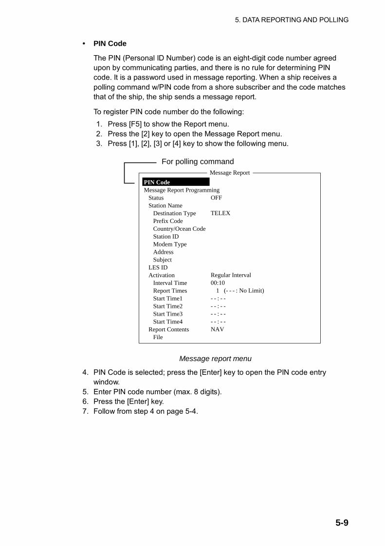
5. DATA REPORTING AND POLLING
5-9
• PIN Code
The PIN (Personal ID Number) code is an eight-digit code number agreed upon by communicating parties, and there is no rule for determining PIN code. It is a password used in message reporting. When a ship receives a polling command w/PIN code from a shore subscriber and the code matches that of the ship, the ship sends a message report.
To register PIN code number do the following: 1. Press [F5] to show the Report menu. 2. Press the [2] key to open the Message Report menu. 3. Press [1], [2], [3] or [4] key to show the following menu.
Message Report
OFF
TELEX
Regular Interval00:10
1 (- - - : No Limit)- - : - -- - : - -- - : - -- - : - -NAV
PIN CodeMessage Report Programming
StatusStation Name
Destination TypePrefix CodeCountry/Ocean CodeStation IDModem TypeAddressSubject
LES IDActivation
Interval TimeReport TimesStart Time1Start Time2Start Time3Start Time4
Report Contents File
For polling command
Message report menu
4. PIN Code is selected; press the [Enter] key to open the PIN code entry window.
5. Enter PIN code number (max. 8 digits). 6. Press the [Enter] key. 7. Follow from step 4 on page 5-4.

5. DATA REPORTING AND POLLING
5-10
5.2.2 Other polling commands Telex
P???/PIN Code/TELEX/LES number/Country number/Subscriber’s number/File name: E-mail
P???/PIN Code/EMAIL/LES number/ E-mail address/File name: Public Switched Telephone Network
P???/PIN Code/PSTN/Modem type/LES number/Country number/Subscriber’s number/File name: Modem type is selected from T30, V21, V22B, V22, V23, V26B, V26T, V27T or V32. Packet Switched Data Network
P???/PIN Code/PSDN/LES number/Country number/Subscriber’s number/File name: Data Network Identification
P???/PIN Code/DNID/LES number/Subscriber’s number/File name: Facsimile
P???/PIN Code/FAX/LES number/Country number/Subscriber’s number/File name: 2-digit telex service
P???/PIN Code/SPEC/LES number/Country number/Subscriber’s number/File name: For ship-to-ship communication, country number is ocean region number. Subscriber’s number includes Station ID, Telex ID, etc. If file name is not specified (/:), position, speed, bearing, water temperature, current and depth are transmitted. Furthermore, / is deleted (:), position, speed and bearing are transmitted. For example, you transmit polling command to MES of PIN code 12345678 via KDDI station (Pacific Ocean: 203) specifying telex number 720-5644325. Then, that MES transmits position, speed, bearing, water temperature, current and depth. P???/12345678/TELEX/203/720/5644325/: To have other MES transmit position, speed and bearing by e-mail to [email protected], for example, use the following command. P???/12345678/EMAIL/203/[email protected]:

5. DATA REPORTING AND POLLING
5-11
5.2.3 Polling reception No operator intervention is required during polling reception. The printer (printer PP-510 optionally available) prints the status of polling reception and transmits data in response to polling request as shown below.
POLLING Message - - - Program Unreserved Data Reporting - - -DNID : 0004 LES ID : 101 (Telnor S.S.Inc)Sub Address : 000 Member Number : 001 Response: No ResponseReceive Data & Time: 02-02-25 00:01 (UTC)
Start Frame: 00030 Interval: 00030
02-02-25 00:01 (UTC)Data Report Program has been initiated by Polling.
POLLING Message - - - Initiate Unreserved Data Reporting - - -DNID :0004 LES ID :101 (Telnor S.S.Inc)Sub Address : 000 Member Number :001 Response: Data ReportReceive Data & Time: 02-02-25 00:01 (UTC)
Start Frame: 00030 Interval: 00030
Data Reported (Poll Response)LES :Telnor S.S.Inc Date : 02-02-25DNID :00004 Time : 00:03 (UTC)Member No. :001
Position LAT 10:14.03N LON 124:36.81E
02-02-25 00:06 (UTC)Successful Data Report Sending.
Data reportingTX start frame (time)
TX interval
TX data set on Data Report
ReceivedPollingCommand
Receive Message
Message No. : R0020205.002Message Ref. No. : 00616923LES : KDDIPriority : NormalMessage Size : 121 charactersReceive Data & Time : 02-02-25 04:07 (UTC)
KDD INMARSAT-C SERVICE 25-FEB-02 04:02:28 UTC REF:616923XXXXXXXXX ABCD X via KDDI LES
D???-12345678-test:test
02-02-25 04:09 (UTC)Successful Sending message.
Sent MessageDELIVERY CONFIRMATION OFF
Message File : Report Message Size : 284 charactersLES : KDDI Date : 02-02-25Priority : Normal Time : 04:09 (UTC)Destination : TELEX 582 (IA5)
582+Date & Time 02-02-25 04:07 (UTC)Position LAT 12:34.56N Water Temp 32.1
LON 123:45.67E Water Current 22.3 KTSCourse 321.1 111.0Speed 1.1 KTS Depth 123.4FT
Tx messagerecipient andTX data
ReceivedPollingCommand
Tx messagerecipient andTX data
Sample MES signaling channel printout
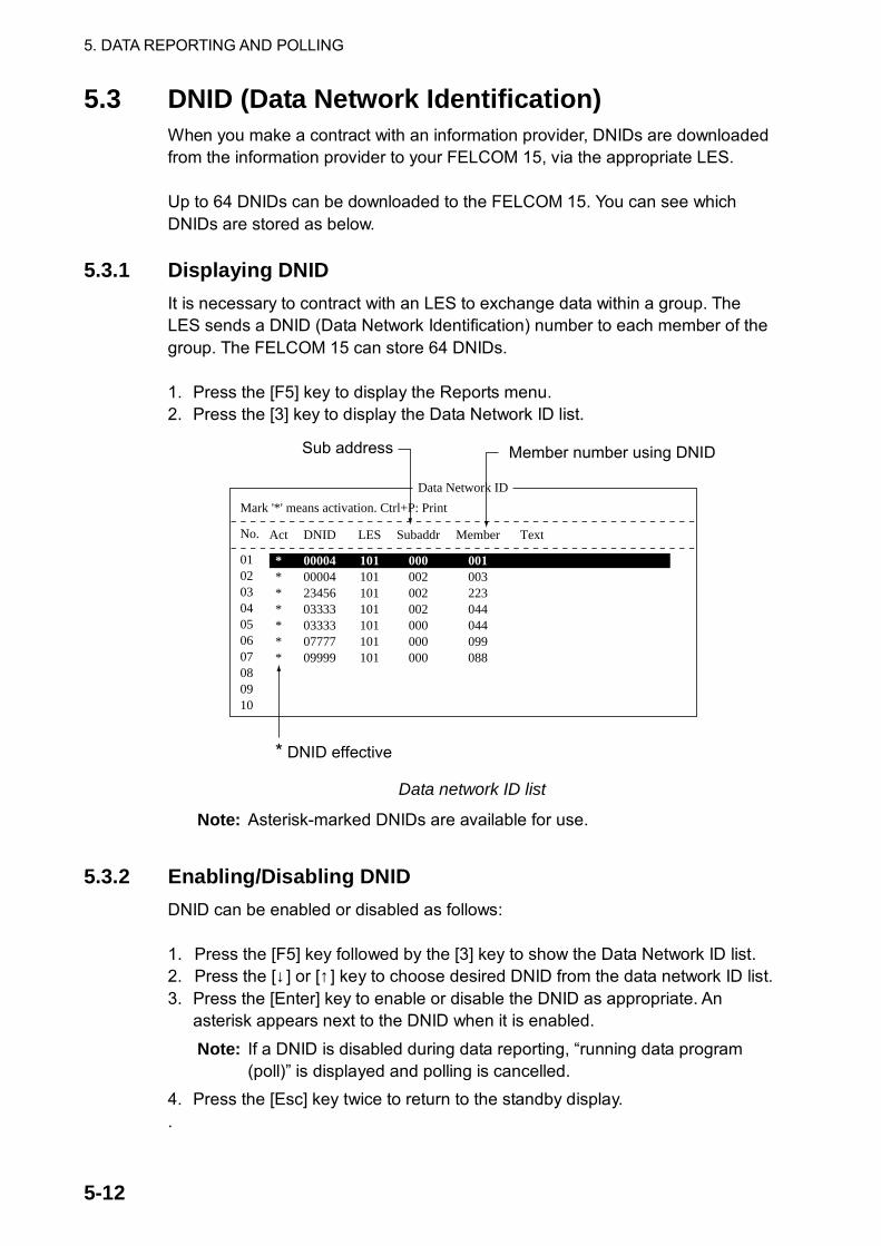
5. DATA REPORTING AND POLLING
5-12
5.3 DNID (Data Network Identification) When you make a contract with an information provider, DNIDs are downloaded from the information provider to your FELCOM 15, via the appropriate LES. Up to 64 DNIDs can be downloaded to the FELCOM 15. You can see which DNIDs are stored as below.
5.3.1 Displaying DNID It is necessary to contract with an LES to exchange data within a group. The LES sends a DNID (Data Network Identification) number to each member of the group. The FELCOM 15 can store 64 DNIDs. 1. Press the [F5] key to display the Reports menu. 2. Press the [3] key to display the Data Network ID list.
Data Network ID
Mark '*' means activation. Ctrl+P: Print
No.
01020304050607080910
Act
*******
DNID
00004000042345603333033330777709999
LES
101101101101101101101
Subaddr
000002002002000000000
Member
001003223044044099088
Text
* DNID effective
Sub address Member number using DNID
Data network ID list
Note: Asterisk-marked DNIDs are available for use.
5.3.2 Enabling/Disabling DNID
DNID can be enabled or disabled as follows: 1. Press the [F5] key followed by the [3] key to show the Data Network ID list. 2. Press the [↓ ] or [↑ ] key to choose desired DNID from the data network ID list. 3. Press the [Enter] key to enable or disable the DNID as appropriate. An
asterisk appears next to the DNID when it is enabled. Note: If a DNID is disabled during data reporting, “running data program
(poll)” is displayed and polling is cancelled. 4. Press the [Esc] key twice to return to the standby display. .

6-1
6. DISTRESS OPERATIONS
6.1 Transmitting the Distress Alert Set the LES where to send the distress alert, referring to steps 1-3 in paragraph 6.2. When a life-endangering situation arises on your vessel and you do not have the time to specify the nature of distress, do the following to transmit the distress alert to an LES. 1. Open the cover of the [DISTRESS] button on the terminal unit or the Distress
Alert Unit/Received Call Unit IC-305. 2. Press the [DISTRESS] button until the lamp in the button lights continuously
(about four seconds). The distress alert will not be transmitted until the lamp in the button lights continuously and the audio alarm sounds. The message “Sending Distress Alert” appears on the screen while the distress alert is being transmitted. When you receive acknowledgment of the distress alert from an LES, the message “Distress Acknowledgement Received” appears on the screen, the lamp in the [DISTRESS] button flashes slowly and the audio alarm sounds intermittently. To silence the audio alarm, press the [F10] key on the keyboard.
Note: The [DISTRESS] button on the FELCOM 15 or the Distress Alert/Receive Call Unit IC-305 cannot be used to silence the audio alarm for incoming distress or EGC urgency broadcast. The [DISTRESS] button is for transmitting distress alert for own ship. It cannot be used to silence the audio alarm. Use the [F10] key to silence the audio alarm.

6. DISTRESS OPERATIONS
6-2
6.2 Transmitting the Distress Alert with Nature of Distress Specified When a life-endangering situation arises on your vessel and there is time to specify nature of distress and recipient (LES) of distress alert send own ship data (position, time, speed and course) as follows: 1. Press the [F8] key to display the Setup menu. 2. Press the [1] key to display the Distress Alert Setup screen.
Distress Alert Setup
LES IDUpdate TimePosition
ProtocolNatureCourseSpeed
303 (KDDI)06:23 02-02-25 (YY-MM-DD)LAT 35:00NLON 135:00EMaritimeUndesignated18710 KTS
Distress Alert setup screen 3. Press the [Enter] key to display the LES ID list. Press the [↓ ] or [↑ ] key to
choose a suitable LES and then press the [Enter] key. 4. Press the [↓ ] key to choose Update Time and then press the [Enter] key. 5. Enter time and then press the [Enter] key. 6. Press the [↓ ] key to choose Position and then press the [Enter] key. 7. Enter position in latitude and longitude. Enter co-ordinate with appropriate
alphabet key N, S, E or W. 8. Press the [Enter] key to close the window.
Note: The menu item Protocol is fixed at Maritime. 9. Press the [↓ ] key to choose Nature. 10. Press the [Enter] key to display the Nature of Distress list and then choose
appropriate nature of distress. If nature of distress is not specified, “Undesignated” is automatically selected. Undesignated Listing Fire/Explosion Sinking Flooding Disabled & Adrift Collision Abandoning ship Grounding Further assistance required Piracy or armed attack
11. Press the [Enter] key to close the list. 12. Press the [↓ ] key to choose Course and then press the [Enter] key. 13. Enter course and then press the [Enter] key. 14. Press the [↓ ] key to choose Speed and then press the [Enter] key. 15. Enter speed and then press the [Enter] key.

6. DISTRESS OPERATIONS
6-3
16.Press the [Esc] key to show the update window.
Setup
Distress Alert Setup
LES IDUpdate TimePosition
ProtocolNatureCourseSpeed
303 (KDDI)06:23 02-02-25 (YY-MM-DD)LAT 30:00NLON 140:00EMaritimeGrounding1870 KTS Update
NoYes
Distress alert setup, update window 17. Yes is selected; press the [Enter] key to register settings.
Setup
Distress Alert Setup
LES IDUpdate TimePosition
ProtocolNatureCourseSpeed
Distress Alert updated.Press any key to escape.
303 (KDDI) 06:23 02-02-25 (YY-MM-DD)LAT 30:00NLON 140:00EMaritimeGrounding1870 KTS
Distress alert setup, distress alert updated 18. Open the cover of the [DISTRESS] button on the terminal unit or the Distress
Alert Unit/Received Call Unit IC-305. 19. Press the [DISTRESS] button until the lamp in the button lights continuously
(about four seconds). The distress alert will not be transmitted until the lamp in the button lights continuously and the audio alarm sounds. The message “Sending Distress Alert” appears on the screen while the distress alert is being transmitted. When you receive acknowledgment of the distress alert from an LES, the message “Distress Acknowledgement Received” appears on the screen, the lamp flashes slowly and the audio alarm sounds intermittently. To silence the audio alarm, press the [F10] key on the keyboard.

6. DISTRESS OPERATIONS
6-4
6.3 Distress Message The distress alert provides the minimum distress information: own vessel’s ID, speed, course, L/L position and nature of distress. After receiving the distress alert acknowledgment from an LES and you are not pressed for time, you may send a distress message as below to provide more detailed information. 1. Press the [F1] key followed by the [1] key to display the editor screen. 2. Type distress message. Below is an example.
MAYDAY MAYDAY MAYDAY
THIS IS
I NEED HELP
Ship's name
: Type of assistance required
Sample distress message
3. Press the [F3] key. 4. Press the [1] key to choose Transmit Message. The screen should look
something like the illustration below.
25 Char. [ Line 2/ 2 Col. 1 ]
<[1] UNTITLED1>
----*---------+---------+---------+---------+---------+---------+---------< [Insert ]
Transmit
1. Transmit Message2. Cancel3. Request Delivery Status
Transmit Message
NormalMessage now being edited Size 63
TELEX
PriorityMessage FileStation Name Cost ********.** (US$)Destination Type
Prefix CodeCountry/Ocean CodeStation IDModem TypeAddressSubjectAttach File
LES IDOption Confirmation Send Delay Delivery Delay Code[ TRANSMIT ]
ON00:00Immediate IA5
Transmit message screen
5. Priority is selected; press the [Enter] key to open the priority options window. 6. Press the [↓ ] key to choose Distress. 7. Press the [Enter] key to close the window. 8. Press the [↓ ] key to choose LES ID. 9. Press the [Enter] key to open the LES list. 10. Press the [↓ ] or [↑] key to choose the LES where the distress message is to
be transmitted, preferably the one where the distress alert was transmitted. 11. Press the [Enter] key to close the LES list. 12. Press the [↓ ] key to place the cursor on TRANSMIT.

6. DISTRESS OPERATIONS
6-5
13. Press the [Enter] key. The display should look similar to the illustration below.
25 Char. [ Line 2/ 2 Col. 1 ]
<[1] UNTITLED1>
----*---------+---------+---------+---------+---------+---------+---------< [Insert ]
Transmit
1. Transmit Message2. Cancel3. Request Delivery Status
Transmit Message
DistressMessage now being edited Size 63
TELEX
000SEARCH AND RESCUE
303(KDDI) Start
NoYes
PriorityMessage File Station Name Cost ********.**(US$)Destination Type
Prefix CodeCountry/Ocean CodeStation IDModem TypeAddressSubjectAttach File
LES IDOption Confirmation Send Delay Delivery Delay Code [ TRANSMIT ]
ON00:00Immediate IA5
Transmit message screen with send start confirmation prompt 14. Press the [Enter] key to transmit the distress message to the LES.
The message “Distress Message Call Activated.” appears (in red) while the distress message is being transmitted. When you receive acknowledgment from an LES, the message “Distress Message Call Acknowledged.” appears and flashes.
Note: Country/Ocean Code and Station ID are not required in a distress message.
6.4 Testing the Distress Button The [DISTRESS] button on the terminal unit and the Distress Alert/Received Call Unit IC-305 may be tested as below without transmitting the distress signal. Note that the distress alert cannot be transmitted while testing the [DISTRESS] button. 1. Press the [F7] key to display the Options menu.
Options
1. Login2. Logout3. Abort4. Select NCS5. Ocean Region6. LES Information7. Test
FELCOM 15 functions as Inmarsat MES
Options
1. Login2. Logout3. Abort4. Select EGC Ch.5. LES Information6. Test
FELCOM 15 functions as EGC receiver
Options menu

6. DISTRESS OPERATIONS
6-6
2. Press the [7] key ([6] key when the FELCOM 15 functions as an EGC receiver) to display the Test menu.
Test
1. PV Test2. PV Test Result3. Self Test4. Distress Alert Button Test
Test menu 3. Press the [4] key.
1. Login2. Logout3. Abort4. Select NCS5. Ocean Region6. Test
Options
1. PV Test2. PV Test Result3. Self Test4. Distress Alarm Button Test
TestDistress Alert Button TestStart
NoYes
Distress alert button mode screen 4. Press the [Enter] key to start the test. The buzzer sounds repeatedly,
signifying the start of the test mode. Further, the message “Distress buttons are under test. Cancel the test mode if a real distress alert needs to sent.” is displayed in red.
1. Login2. Logout3. Abort4. Select NCS5. Ocean Region6. Test
Options
1. PV Test2. PV Test Result3. Self Test4. Distress Alarm Button Test
Test
Distress alert button test mode.Press any key to escape.
Distress Alert Button Test
CAUTIONINF: Distress Buttons entered into TEST MODE.
<Press ESC key to continue> Distress alert button test
5. Open the [DISTRESS] button cover. 6. Press the [DISTRESS] button four seconds. The buzzer sounds rapidly for
three seconds and then sounds repeatedly, as in step 4. The message “Distress Button works correctly.” appears if the button is working properly.
7. Close the [DISTRESS] button cover. 8. To escape from the test, press the [Esc] key on the keyboard of the terminal
unit twice. The test mode alarm stops and the message shown below appears to notifying you that normal operation has been restored.
CAUTIONINF: Distress Buttons returned to NORMAL OPERATION.
<Press ESC key to continue>
Distress buttons returned to normal state 9. Press the [Esc] key three times to return to the standby display.

7-1
7. OTHER FUNCTIONSThis chapter describes how to abort operation, scan NCS, choose EGC and NCS channels and display LES information.
7.1 Aborting an Operation You can abort transmission, receiving or scanning (on the NCS common channel) as follows: 1. Press the [F7] key to display the Options menu.
Options
1. Login2. Logout3. Abort4. Select NCS5. Ocean Region6. LES Information7. Test
Options menu (when FELCOM functions as Inmarsat MES) 2. Press the [3] key to choose Abort.
1. Login2. Logout3. Abort4. Select NCS5. Ocean Region6. Test
OptionsAbort
Start
NoYes
Abort screen 3. Yes is selected; press the [Enter] key to abort current operation.
The message “FORCED CLEARING” replaces “SENDING” or “RECEIVING” at the bottom of the screen. When the process has been aborted, the message “Process Aborted. Press any key to escape.” appears.
Note: If aborting is attempted in modes other than those mentioned above, the message “Ignored: Can not abort current process.” appears.

7. OTHER FUNCTIONS
7-2
7.2 Scanning NCS Common Channel Scanning is possible when the FELCOM 15 is in idle state and functions as an Inmarsat C receiver. If the FELCOM 15 is not in idle state the message “Ignored: MES is not idle.” appears. Wait until the equipment becomes idle. 1. Press the [F7] key to display the Options menu. 2. Press the [5] key to display the Ocean Region menu.
1. Login2. Logout3. Abort4. Select NCS5. Ocean Region6. Test
Options
Ocean Region
AutoWest-AtlanticEast-AtlanticPacificIndian
NCS you are currently tuned to appears in reverse video. Ocean region menu
3. Press the [↓ ] or [↑ ] key to choose another NCS and press the [Enter] key. If Auto is selected, FELCOM 15 scans all ocean regions in turn.
1. Login2. Logout3. Abort4. Select NCS5. Ocean Region6. Test
Options
Ocean Region
AutoWest-AtlanticEast-AtlanticPacificIndian
Start
NoYes
NCS scan confirmation screen 4. Yes is selected; press the [Enter] key to start the scanning.
The message “Starting Scan Process. Press any key to escape.” appears during the scanning.
5. Press the [Esc] key twice to return to the standby display.

7. OTHER FUNCTIONS
7-3
7.3 Choosing EGC Receiving Channel EGC channel can be selected when the terminal unit is set to operate as an EGC-only receiver. However, this procedure is shown for reference only; currently there is only one EGC channel per NCS. 1. Press the [F7] key to display the Options menu.
Options
1. Login2. Logout3. Abort4. Select EGC Ch.5. LES Information6. Test
Options menu (when FELCOM functions as EGC receiver)
2. Press the [4] key to choose Select EGC Ch.
35:00.00N135:00.00E
EGC Channel List
12580* 10840* 11088*
ENTER: Set ESC: Quit
11080*
EGC channel list 3. Choose desired channel and then press the [Enter] key. 4. Press the [Esc] key to return to the standby display.

7. OTHER FUNCTIONS
7-4
7.4 Choosing NCS Channel You may select NCS common channel as shown below. Currently, each satellite transmits one global beam. In the future, the satellites will transmit multiple spot beams, namely, the NCS will have multiple channels. 1. Press the [F7] key to display the Options menu. 2. Press the [4] key to display the NCS Channel List.
1. Login2. Logout3. Abort4. Select NCS5. Ocean Region6. Test
Options
NCS Channel List
No AOR (WEST)FREQ
11080*
ID
0440000000
0102030405060708
ENTER: Set ESC: Quit
AOR (EAST)FREQ
12580*
ID
1441111111
PORFREQ
12580*
ID
2442222222
IORFREQ
10840*
ID
3443333333
NCS channel list 3. Choose desired channel and then press the [Enter] key. 4. Press the [Esc] key to return to the standby display.

7. OTHER FUNCTIONS
7-5
7.5 LES Information Each time you log in LES data is automatically downloaded through the NCS common channel to the FELCOM 15, and saved to the LES Information display. You may view this display as follows: 1. Press the [F7] key to show the Option menu.
Options
1. Login2. Logout3. Abort4. Select NCS5. Ocean Region6. LES Information7. Test
FELCOM 15 functions as Inmarsat MES
Options
1. Login2. Logout3. Abort4. Select EGC Ch.5. LES Information6. Test
FELCOM 15 functions as EGC receiver
Options menu
2. Press the [6] key (Inmarsat MES) or [5] key (EGC receiver) to show the LES Information display.
LES ID Name Status Services TDM Ch.201 Telnor S.S.Inc 11111000 AS-----EL 11982202 Stratos M.N. 11111000 AS-----EL 11826203 KDDI 11111000 AS-----EL 11806204 11111000 AS-----EL 11762208 Korea Telecom 11111000 AS-----EL 11778210 Singapore Telecom 11111000 AS-----EL 11842211 Beijing Marine 11111000 AS-----EL 11754212 KDDI 11111000 AS-----EL 11802
LES Information
B8-B1
LES information display 3. Use the [↑] or [↓] key to scroll the list. 4. Press the [Esc] key twice to return to the standby display. Description of LES information table
Bit No. Status Flag Meaning 1 600 bps B8 Return link speed 0 300 bps 1 Operational B7 Operational or spare satellite
operation 0 Spare 1 In service B6 LES status 0 Out of service 1 Clear B5 LES status 0 Congested 1 Terrestrial links open B4 Used only by land earth stations0 Terrestrial links closed B3-1 Spare
Services:

7. OTHER FUNCTIONS
7-6
Alphabet shown only when Flag is “1” for a bit.
Bit No. Flag Meaning Display 1 Maritime distress alerting A 1B8 0 Maritime distress alerting None 1 SafetyNET traffic S 1B7 0 No SafetyNET traffic None 1 Inmarsat-C traffic C 1B6 0 No Inmarsat-C traffic None 1 Store and Forward T 1B5 0 No Store and Forward None 1 Half Duplex H 1B4 0 No Half Duplex None 1 Full Duplex D 1B3 0 No Full Duplex None 1 Closed Network N 1B2 0 No Closed Network None 1 FleetNET Traffic F 1B1 0 No FleetNET Traffic None 1 Prefixed store and forward message supported P 2B8 0 Prefixed store and forward message not supported None 1 Land mobile alerting 2B7 0 No Land mobile alerting 1 Aero-C service supported 2B6 0 Aero-C service not supported
Not used
1 ITA2 transmission supported I 2B5 0 ITA2 transmission not supported None 1 Data transmission supported B 2B4 0 Data transmission not supported None 1 Basic X.400 supported X 2B3 0 Basic X.400 not supported None 1 Enhanced X.400 supported E 2B2 0 Enhanced X.400 not supported None 1 Low power C MES supported L 2B1 0 Low power C MES not supported None
TDM Ch.: TDM channel used by LES to transmit.

8-1
8. E-MAIL BY PC
8.1 Overview The FELCOM 15 incorporates various e-mail protocols including POP3 and SMTP. Connected to a LAN via the Ethernet(10Base-T) port on a PC, the FELCOM 15 can send and receive e-mail using the PC’s e-mail application, for example, Outlook Express.
8.1.1 Overview of mail functions • Mail gateway
Received mail may be forwarded to specific mail server.
• Selective forwarding Received mail which contains a keyword can be forwarded to the mail address which appears after the keyword in a message.
• Access restriction A specific PC on a network can be designated to send mail.
• Automatic attachment decoding MIME-encoded mail sent from a network can be automatically decoded by UUENCODE or BINARY decoding format.
• Outgoing message size restriction The administrator of the FELCOM 15 can specify maximum outgoing message size (Max. size 32KB) allowable for the PC client. This allows control over the size of mail messages which can be sent by the PC client.

8. E-MAIL BY PC
8-2
8.1.2 E-mail restrictions The Inmarsat C e-mail system has restrictions not found on the land-based e-mail system. Further there are some restrictions which apply to the FELCOM 15. • Use 7-bit characters in the Subject field, text and attachment. Some LES may
not use 8-bit characters (Japanese, etc). Since most LES use 7-bit characters in the header, 8-bit characters may not be properly received.
US-ASCII characters
Space ( 0 8 @ H P X ` h p x
! ) 1 9 A I Q Y a i q y
” * 2 : B J R Z b j r z
# + 3 ; C K S [ c k s {
$ , 4 < D L T \ d l t |
% - 5 = E M U ] e m u }
& . 6 > F N V ¯ f n v ~
’ / 7 ? G O W _ g o w
• The maximum number of simultaneous transmissions is 32. Any simultaneous transmission in excess of that amount will not be sent. When transmitting, wait until the message “Successful Sending message.” appears before transmitting another message.
• The maximum number of characters available for the “Subject” field is 60. • The maximum number of characters per line is 1000. Characters in excess of
1000 will not be transmitted. Use maximum 1000 character per line. • The maximum number of multiple addressees is 10. Any number in excess of
that amount will not be transmitted. • Destination cannot be specified as “Bcc:”. “Bcc: is automatically changed to
“Cc:” because Bcc is not used in Inmarsat C. • Set the encoding format on the PC’s e-mail client to BASE64.
8.1.3 E-mail precautions • Confirm the port chosen to output received messages from the FELCOM 15.
Set Message Output Port on the System Setup menu to INT or INT+EXT. • Set the mail format at the e-mail client for “Text.” HTML increases
communication charges because of its large size. • The FELCOM 15 does not have account management functions, for example,
multiple accounts. • All received and transmitted messages (incl. those on a LAN) are saved to
the communications log. The log may be printed in real time or when desired. • Sending and receiving stations should use the same font to read each others’
messages. Use of different fonts may result in unreadable characters.

8. E-MAIL BY PC
8-3
• When a file with an attachment is transmitted from land, the LES (e-mail service provider) separately forwards the file and attachment to the intended MES. The file name for the attachment as received at the FELCOM 15 is “ATTACH.DAT.” For that reason request that land-based e-mail with attachment contain the attachment file name in the text of the message.
• File and accompanying attachment are sent separately regardless of the delivery address specified with the auto delivery keyword. The message file is delivered according to the auto delivery keyword setting and the attachment goes to the Mail Address set on Mail Gateway.

8. E-MAIL BY PC
8-4
8.2 Connection of FELCOM 15 with single PC Received messages are stored in the FELCOM 15. Messages are transmitted by the PC’s e-mail client.
FURUNO
LAN portFELCOM 15
PC
10BASE-T(100BASE-T)Cross cable
FELCOM 15 and single PC Parts required
• 10BASE-T or 100BASE-T cross cable • PC (with LAN port or LAN card) Wiring
1. Remove the plate from the LAN port at the rear of the terminal unit. 2. Connect the cross cable between the LAN port on the terminal unit and the
LAN port on the PC. Settings on FELCOM 15
Default settings are as below. It is not necessary to set IP address and subnet mask if their default values are used. IP address: 172.31.16.1 Subnet mask: 255.255.0.0 Message size: 8 KB* Attachment decoding format: UUENCODE** * Setting may be changed. See paragraph 8.3.5 ** Setting may be changed. See paragraph 8.3.6. Settings on PC
Set network settings on the PC. For details refer to the PC’s owner’s manual.
Item Setting IP address 172.31.16.100 Subnet mask 255.255.0.0

8. E-MAIL BY PC
8-5
8.3 Function Settings For network setting, consult your shipboard LAN administrator.
8.3.1 Setting IP address and subnet mask Set IP address and subnet mask as below if they are different from their default settings, in case that DHCP is off. 1. Press [F8] and [2] to show the System Setup menu. 2. Press the [↓ ] or [↑ ] key to choose Network Setup and then press the [Enter]
key. Network Setup
NetworkMail Gateway
Network setup menu 3. Choose Network and then press the [Enter] key.
Network
IP Address 172. 31. 16. 1Subnet Mask 255.255. 0. 0DHCP OFFGateway . . .
Network menu 4. IP address is selected; press the [Enter] key. 5. Enter IP Address and then press the [Enter] key. 6. Press the [↓ ] key to choose Subnet Mask and then press the [Enter] key. 7. Enter subnet mask and then press the [Enter] key. 8. Press the [Esc] key to show the Update window. 9. Yes is selected; press the [Enter] key to update settings. The message
“Press ESC key to Restart FELCOM15.” appears if the IP Address was changed. Press the [Esc] key to restart the FELCOM 15. If the subnet mask setting was only changed go to the next step.
10. Press the [Esc] key three times to return to the standby display.

8. E-MAIL BY PC
8-6
8.3.2 Enabling DHCP settings With DHCP turned on, IP address and subnet mask are automatically assigned when a DHCP server resides on a LAN. The default DHCP setting is OFF.
Procedure
1. Press [F8] and [2] to show the System Setup menu. 2. Press the [↓ ] or [↑ ] key to choose Network Setup and then press the [Enter]
key. 3. Choose Network and then press the [Enter] key. 4. Press the [↓ ] key to choose DHCP and then press the [Enter] key. 5. Press the [↑ ] key to choose ON and then press the [Enter] key. 6. Press the [Esc] key to open the update window. 7. Yes is selected; press the [Enter] key to update settings. The message
“Press ESC key to Restart FELCOM15.” appears. 8. Press the [Esc] key to restart. 9. After restarting has been completed, confirm that IP address and subnet
mask have been assigned.

8. E-MAIL BY PC
8-7
8.3.3 Gateway setting Set gateway IP address when mail is sent from a PC on a different network through a router.
FURUNO
FELCOM 15
HUB
PCPCPC
HUB
Router
Network 1
Network 2
LAN Port
PCPC PC
Note: If the router has DHCP, turn on DHCP in the Network menu to automatically assign IP address, subnet mask and gateway.
Procedure
1. Press [F8] and [2] to show the System Setup menu. 2. Press the [↓ ] or [↑ ] key to choose Network Setup and then press the [Enter]
key. 3. Choose Network and then press the [Enter] key. 4. Press the [↓ ] key to choose Gateway and then press the [Enter] key. 5. Enter gateway IP address (IP address set on router) and then press the
[Enter] key. 6. Press the [Esc] key to open the update window. 7. Yes is selected; press the [Enter] key to update settings. The message
“Press ESC key to Restart FELCOM15.” appears. 8. Press the [Esc] key to restart.

8. E-MAIL BY PC
8-8
8.3.4 Restricting access Specify the IP address of the PC which is to be used to send and receive e-mail. A PC not specified cannot send e-mail but it can receive e-mail. If no IP address is specified, all PCs connected to the LAN can send and transmit e-mail. For example, the IP address of the PC allowed to perform e-mail functions is 172.31.16.5. Then, only that PC on the LAN can send mail.
FURUNO
FELCOM 15
PCPC PC PC
172.31.16.1
172.31.16.5172.31.16.4172.31.16.3172.31.16.2
Can send mail
OKSent mail is rejected
Cannotsend mail
Cannotsend mailCannot
send mail
Procedure
1. Press [F8] and [2] to show the System Setup menu. 2. Press the [↓ ] or [↑ ] key to choose Network Setup and then press the [Enter]
key. 3. Press the [↓ ] key to choose Mail Gateway and then press the [Enter] key.
Mail Gateway
SMTP Enable IP Address . . . Send Limit Size (KB) 8Attach UUENCODEDelivery To Server Server IP . . . Address Mode FIXED Mail Address Auto Delivery Keyword
Mail gateway menu 4. Choose SMTP Enable IP Address and then press the [Enter] key. 5. Enter IP address of PC which is to send e-mail and then press the [Enter]
key. 6. Press the [Esc] key to show the Update window. 7. Yes is selected; press the [Enter] key to update settings. 8. Press the [Esc] key three times to return to the standby display.

8. E-MAIL BY PC
8-9
8.3.5 Restricting outgoing message size The FELCOM15 administrator may limit the size of outgoing messages. When a PC client attempts to send an e-mail message which is larger than permitted, the message “Data size too large” appears and the message is not sent. Note that attachments are encoded which increases messages by 1.5 times. Procedure
1. Press [F8] and [2] to display the System Setup menu. 2. Press the [↓ ] or [↑ ] key to choose Network Setup and then press the [Enter]
key. 3. Press the [↓ ] key to choose Mail Gateway and then press the [Enter] key. 4. Press the [↓ ] key to choose Send Limit Size (KB) and then press the [Enter]
key. 5. Press the [↓ ] or [↑ ] key to choose maximum message size to send within
shipboard LAN. The choices are 2, 4, 6, 8, 10, 16 and 32 (KB). 6. Press the [Enter] key. 7. Press the [Esc] key to show Update window. 8. Yes is selected; press the [Enter] key to update settings. 9. Press the [Esc] key three times to return to the standby display.

8. E-MAIL BY PC
8-10
8.3.6 Automatically converting attachments Using the default setting, mail (MIME encoded) sent from a PC in a network is encoded with UUENCODE. For Inmarsat C use UUENCODE. If the intended receiver does not use UUENCODE, an attachment may be unreadable. In this case, change the encode format to BINARY and re-send then message. In the BINARY setting the attachment file name is not sent to the receiver. To switch to BINARY follow the procedure below.
Note: Some LES do not use the BINARY format. Contact your LES for details. Procedure
1. Press [F8] and [2] to display the System Setup menu. 2. Press the [↓ ] or [↑ ] key to choose Network Setup and then press the [Enter]
key. 3. Press the [↓ ] key to choose Mail Gateway and then press the [Enter] key. 4. Press the [↓ ] key to choose Attach and then press the [Enter] key. 5. Press the [↑] or [↓ ] key to choose the encoding format for attachments:
UUENCODE, or BINARY. For Inmarsat C use UUENCODE. 6. Press the [Enter] key. 7. Press the [Esc] key to show Update window. 8. Yes is selected; press the [Enter] key to update settings. 9. Press the [Esc] key three times to return to the standby display.

8. E-MAIL BY PC
8-11
8.3.7 Connection of FELCOM 15 to shipboard LAN mail server When a mail server is installed on a LAN, received mail is forwarded to the mail server via the LAN. The illustration below shows how mail is forwarded to the mail server. Mail server: 172.32.16.10 LAN domain name: ship.furuno.co.jp Forwarding mail address: [email protected] (IP Address: 172.31.16.2)
Note: If there is no mail server, disregard the procedure below.
Procedure
1. Press [F8] and [2] to display the System Setup menu. 2. Press the [↓ ] or [↑ ] key to choose Network Setup and then press the [Enter]
key. 3. Press the [↓ ] key to choose Mail Gateway and then press the [Enter] key.
Mail Gateway
SMTP Enable IP Address . . . Send Limit Size (KB) 8Attach UUENCODEDelivery To Server Server IP . . . Address Mode FIXED Mail Address Auto Delivery Keyword
4. Press the [↓ ] key to choose Delivery To and then press the [Enter] key. 5. Press the [↓ ] key to choose Server and then press the [Enter] key.
PC Mailer: A mail-dedicated PC is connected to the FELCOM 15. The mail received by the FELCOM 15 can be read by the PCs. Server: FELCOM 15 is connected to mail server connected to a LAN. Mail received by the FELCOM 15 is forwarded to the mail server.
6. Press the [↓ ] key to choose Server IP and then press the [Enter] key.

8. E-MAIL BY PC
8-12
7. Enter server IP address and then press the [Enter] key. 8. Press the [↓ ] key to choose Address Mode and then press the [Enter] key. 9. Press the [↑] key to choose FIXED.
Auto: When the keyword (entered in Auto Delivery Keyword) is found in the text of a message, the message is sent to the address which appears after the keyword. If the keyword is not found the mail is delivered to “Mail Address.” Fixed: Message is sent mail address specified in Mail Address.
10. Press the [Enter] key. 11. Press the [↓ ] key to choose Mail Address and press the [Enter] key. 12. Enter IP address of PC where the e-mail server is to forward e-mail and then
press the [Enter] key. 13. Press the [Esc] key to open the Update window. 14. Yes is selected; press the [Enter] key to update settings. The message
“Press ESC key to Restart FELCOM15.” appears. 15. Press the [Esc] key to restart.

8. E-MAIL BY PC
8-13
8.3.8 Selective forwarding When a keyword is found in a message the message is forwarded to the address which appears after the keyword. For example, the keyword is “/+forward+/[email protected]”. The keyword “+forward” is found and the message is then forwarded to [email protected]. To use selective forwarding with a land-based subscriber, you should request the land-based subscriber to do the following:
• Insert the keyword and mail address on the first line of the message. • Do not insert a space in the keyword or mail address. • Maximum number of mail addresses is 10 Mail server IP address: 172.31.16.10 LAN domain name: ship.furuno.co.jp Mail address to forward to: [email protected] (IP address: 172.31.16.2) Keyword: /+forward+/
FURUNO
FELCOM 15
PC
PC PC
Domain name;
ship.furuno.co.jp
POP3- USER : felcom- Password : xxxxx
POP3- USER : smith- Password : xxxxx
POP3- USER : 4431099010
- Password : xxxxxxxxx
Incoming E-Mail message
Forwarding all e-Mail messages
172.31.16.1
172.31.16.10172.31.16.2
172.31.16.3
172.31.16.4
Mail Server
MSG. 1
MSG. 3
MSG. 1
MSG. 2
MSG 1 MSG2 MSG3
To: ****@***.*** Subject: …….. Test mail
/+forward+/[email protected] is test message……
To: ****@***.*** Subject: …….. Test mail This is test message……
To: ****@***.*** Subject: …….. Test mail
/+forward+/[email protected] /+forward+/[email protected] This is test message……

8. E-MAIL BY PC
8-14
Procedure
1. Press [F8] and [2] to display the System Setup menu. 2. Press the [↓ ] or [↑ ] key to choose Network Setup and then press the [Enter]
key. 3. Press the [↓ ] key to choose Mail Gateway and then press the [Enter] key. 4. Press the [↓ ] key to choose Delivery To and then press the [Enter] key. 5. Press the [↓ ] key to choose Server and then press the [Enter] key. 6. Press the [↓ ] key to choose Server IP and then press the [Enter] key. 7. Enter mail server IP address and then press the [Enter] key. 8. Press the [↓ ] key to choose Address Mode and then press the [Enter] key. 9. Press the [↑] or [↑ ] key to choose auto. (FIXED: Messages are delivered to
PC specified in Mail Address.) 10. Press the [↓ ] key to choose Mail Address and press the [Enter] key. 11. Enter the mail address corresponding to the mail server which is to receive
mail and then press the [Enter] key. Mail not containing the keyword will be sent to this address.
12. Press the [↓ ] key to choose Auto Delivery Keyword. 13. Press the [Enter] key to open the auto delivery keyword entry window. 14. Enter auto delivery keyword. Enter characters (incl. symbol) not normally
found in your e-mail documents. Maximum 15 characters may be entered. Upper and lower case letters are not distinguished in the search for keyword.
15. Press the [Esc] key to open the update window. 16. Yes is selected; press the [Enter] key to update settings. The message
“Press ESC key to Restart FELCOM 15.” Is displayed. 17. Press the [Esc] key to restart.
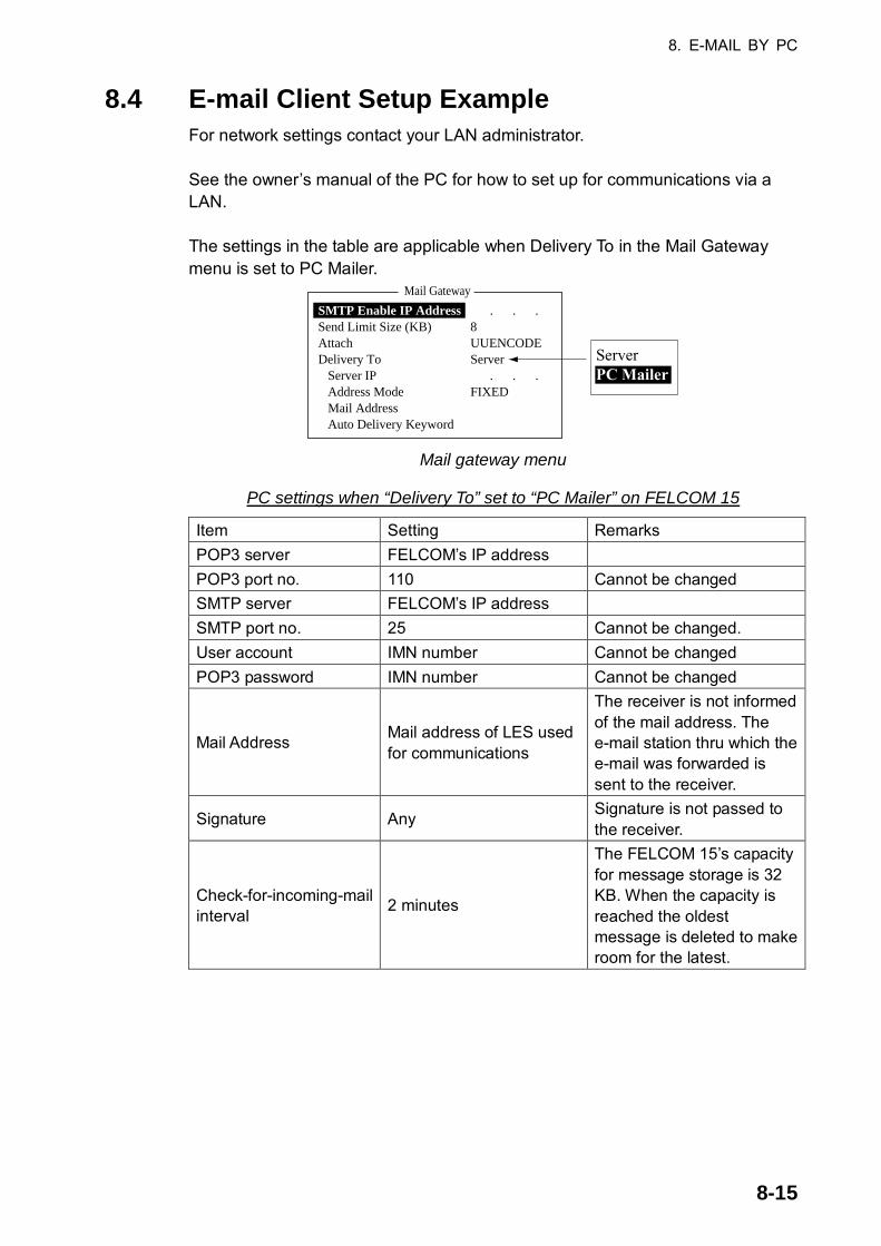
8. E-MAIL BY PC
8-15
8.4 E-mail Client Setup Example For network settings contact your LAN administrator. See the owner’s manual of the PC for how to set up for communications via a LAN. The settings in the table are applicable when Delivery To in the Mail Gateway menu is set to PC Mailer.
Mail Gateway
SMTP Enable IP Address . . . Send Limit Size (KB) 8Attach UUENCODEDelivery To Server Server IP . . . Address Mode FIXED Mail Address Auto Delivery Keyword
ServerPC Mailer
Mail gateway menu
PC settings when “Delivery To” set to “PC Mailer” on FELCOM 15
Item Setting Remarks POP3 server FELCOM’s IP address POP3 port no. 110 Cannot be changed SMTP server FELCOM’s IP address SMTP port no. 25 Cannot be changed. User account IMN number Cannot be changed POP3 password IMN number Cannot be changed
Mail Address Mail address of LES used for communications
The receiver is not informed of the mail address. The e-mail station thru which the e-mail was forwarded is sent to the receiver.
Signature Any Signature is not passed to the receiver.
Check-for-incoming-mail interval 2 minutes
The FELCOM 15’s capacity for message storage is 32 KB. When the capacity is reached the oldest message is deleted to make room for the latest.

8. E-MAIL BY PC
8-16
8.5 SMTP Error Messages The table below shows the SMTP error messages which may appear when communication error between the FELCOM 15 and the e-mail client is found. Check the e-mail client whenever an SMTP error message appears.
SMTP error messages
Message Meaning sorry, system busy now. The Tx message queue is full. current LES out of service area. Selected service provider is not within current
ocean area. no target address. Delivery address has not been set. too many address. The number of delivery addresses is more than
the system can handle. Send message type mismatch. Address parameter error Send message parameter mismatch. Address parameter error Illegal address. Invalid character used in delivery address, or
invalid domain name (no period entered) Mail data abnormal. Abnormal mail header Data size too large. Size of message is larger than set with Send
Size Limit on the Mail Gateway menu. Your address access denied. The SMTP Enable IP Address on

9-1
9. MAINTENANCE, TROUBLESHOOTINGThis chapter provides the information necessary for the maintenance and checking of the FELCOM 15. Please review the safety information at the beginning of this manual before attempting any maintenance procedures.
9.1 General Checking and Maintenance Turn off the power before conducting any maintenance procedures other than the cleaning of the terminal unit. Cleaning the terminal unit
Wipe the LCD carefully to prevent scratching, using tissue paper and an LCD cleaner. To remove dirt or salt deposits, use an LCD cleaner, wiping slowly with tissue paper so as to dissolve the dirt or salt. Change paper frequently so the salt or dirt will not scratch the LCD. Do not use solvents such as thinner, acetone or benzine for cleaning; they can remove paint and marks or deform the equipment. Checking connectors and earth terminal
Check that the connectors and earth terminal on the terminal unit are tightly fastened. If the copper strap (earth material) has rusted, clean it. Floppy disk drive head
The floppy disk is coated with a magnetic material which stores the information entered into the disk. If this material is damaged by foreign material adhering to the disk drive head it may not be possible to read from or write to the disk. Clean the head regularly with a cleaning floppy disk to prevent loss of data. When the power can’t be turned on
When the terminal unit cannot be turned on do the following:
• Check that the power cable connector on the rear panel of the terminal unit for tightness.
• Check if the ship’s mains switchboard is turned on.
• Have a qualified technician check the power voltage at the power connector on the rear of the terminal unit.

9. MAINTENANCE, TROUBLESHOOTING
9-2
9.2 Diagnostics The system is equipped with a diagnostic test which checks it for proper operation.
9.2.1 Self test at power on The terminal unit performs the ROM sum test and RAM read and write test when turned on. If the test results are normal the equipment goes into standby. If error is found you cannot transmit.
9.2.2 Testing the terminal unit through the keyboard, displaying program version no. This test can only be initiated from the main terminal and it must be idle condition to execute the test. 1. Press the [F7] key to display the Options menu.
Options
1. Login2. Logout3. Abort4. Select NCS5. Ocean Region6. LES Information7. Test
FELCOM functions asInmarsat MES
Options
1. Login2. Logout3. Abort4. Select EGC Ch.5. LES Information6. Test
FELCOM functions asEGC receiver
Options menu 2. Press the [7] key ([6] key if FELCOM functions as an EGC receiver) to
display the Test menu.
1. Login2. Logout3. Abort4. Select NCS5. Ocean Region6. Test
Options
Test
1. PV Test2. PV Test Result3. Diagnostic Test4. Distress Alert Button Test
Test menu 3. Press the [3] key to choose Diagnostic Test.
1. Login2. Logout3. Abort4. Select NCS5. Ocean Region6. Test
Options
1. PV Test2. PV Test Result3. Self Test4. Distress Alarm Button Test
Test
Start
NoYesYes
Diagnostic Test
Start window 4. Yes is selected; press the [Enter] key to start the test. The message “Now
testing” (flashing) appears during the testing.

9. MAINTENANCE, TROUBLESHOOTING
9-3
When the test is completed, the screen shows the test results as shown at the top of the next page.
1. Login2. Logout3. Abort4. Select NCS5. Ocean Region6. Test
Options
1. PV Test2. PV Test Result3. Self Test4. Distress Alarm Button Test
Test
TERM CPU
ROMRAMDRAM
Press any key to escape.
1650162-XX
OKOKOK
RFCON CPU
ROMRAMEEPROMGPS*
1650159-XX
OKOKOKOK
Program No.(XX = Version No.)
* = Internal GPS. "**" shown when no internal GPS receiver is installed.
Diagnostic Test
Sample communication unit self test results
The results are shown as OK or NG (No Good), and any NG is accompanied by the audio alarm. For any NG, contact your dealer for advice.
5. Press the [Esc] key to stop the test and return to the Test menu. Note: Diagnostic test-related error messages appear at the bottom of the screen
as follows: TROUBLE: RFCON CPU ROM NG TROUBLE: RFCON CPU RAM NG, TROUBLE: RFCON CPU EEPROM NG.
9.3 Performance Verification (PV) Test After the FELCOM is installed, the installer usually confirms that it is functioning properly, by logging in and conducting the PV test. This test consists of the receiving a test message from an LES, transmitting a message to an LES and a distress alert test. The results of the test appear on the PV test result display. The PV test cannot be conducted from an auxiliary terminal unit. Note that the test can also be initiated by an NCS.
9.3.1 PV test sequence 1. Choose PV Test from the Test menu. 2. The MES requests an NCS to conduct the PV test. 3. NCS acknowledges request for testing. 4. The MES, upon receiving acknowledgment from NCS, goes into pending
state. 5. NCS will choose an LES to perform the test. 6. The LES transmits a test message to the MES. 7. The MES transmits a test message to the LES. 8. The LES receives test message. 9. The MES automatically transmits the distress alert test within two minutes
after completion of step 8.

9. MAINTENANCE, TROUBLESHOOTING
9-4
10. When the distress alert test is finished, the LES sends the results of the PV test to the MES.
9.3.2 PV test procedure 1. Confirm that the terminal unit is in idle condition and logged in. 2. Press the [F7] key to display the Options menu. 3. Press the [7] key to choose Test. 4. Press the [1] key to choose PV Test.
1. Login2. Logout3. Abort4. Select NCS5. Ocean Region6. Test
Options
1. PV Test2. PV Test Result3. Self Test4. Distress Alarm Button Test
Test
PV Test
Start
NoYesYes
PV test screen 5. Yes is selected; press the [Enter] key to transmit the PV test request to NCS.
1. Login2. Logout3. Abort4. Select NCS5. Ocean Region6. Test
Options
1. PV Test2. PV Test Result3. Self Test4. Distress Alarm Button Test
Test
Starting PV Test Process.Press any key to escape.
PV Test
PV test screen
Note: If the terminal unit is not idle when the test is initiated, the screen displays “Ignored: MES is not idle now. Cannot start PV Test.” And if you are not logged in, “Ignored: MES is not Login. Please operate Login.” appears.
6. Press the [Esc] key to return to the standby display. 7. The (automatic) testing sequence is as follows:
a) The screen displays “Current State: Idle (pending!)” when you receive the acknowledge signal from the NCS.
b) When preparations for testing have been completed, “Current State: TESTING” appears at the bottom of the screen. Further, the following message appears.
Automatic test mode: Normal communication disabled.Do not press any distress button unless you are in distress.
c) Receive a message from the LES. Send a test message to the LES. d) Then, the distress alert test is automatically conducted after you have sent a
test message. Do not operate the equipment at this time. e) When testing has been completed, “Current State: IDLE” appears at the
bottom of the screen.
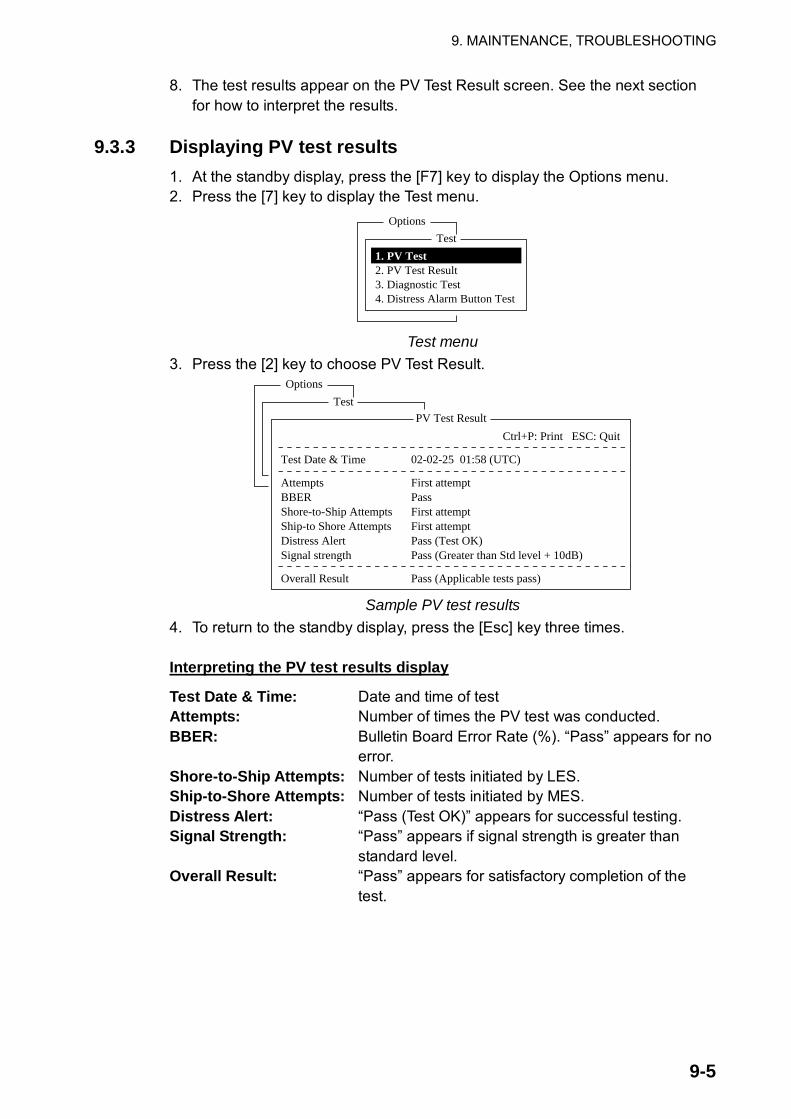
9. MAINTENANCE, TROUBLESHOOTING
9-5
8. The test results appear on the PV Test Result screen. See the next section for how to interpret the results.
9.3.3 Displaying PV test results
1. At the standby display, press the [F7] key to display the Options menu. 2. Press the [7] key to display the Test menu.
1. Login2. Logout3. Abort4. Select NCS5. Ocean Region6. Test
Options
Test
1. PV Test2. PV Test Result3. Diagnostic Test4. Distress Alarm Button Test
Test menu
3. Press the [2] key to choose PV Test Result.
1. Login2. Logout3. Abort4. Select NCS5. Ocean Region6. Test
Options
1. PV Test2. PV Test Result3. Self Test4. Distress Alarm Button Test
Test
Test Date & Time
AttemptsBBERShore-to-Ship AttemptsShip-to Shore AttemptsDistress AlertSignal strength
Overall Result
02-02-25 01:58 (UTC)
First attemptPassFirst attemptFirst attemptPass (Test OK)Pass (Greater than Std level + 10dB)
Pass (Applicable tests pass)
Ctrl+P: Print ESC: Quit
PV Test Result
Sample PV test results
4. To return to the standby display, press the [Esc] key three times. Interpreting the PV test results display
Test Date & Time: Date and time of test Attempts: Number of times the PV test was conducted. BBER: Bulletin Board Error Rate (%). “Pass” appears for no
error. Shore-to-Ship Attempts: Number of tests initiated by LES. Ship-to-Shore Attempts: Number of tests initiated by MES. Distress Alert: “Pass (Test OK)” appears for successful testing. Signal Strength: “Pass” appears if signal strength is greater than
standard level. Overall Result: “Pass” appears for satisfactory completion of the
test.

9. MAINTENANCE, TROUBLESHOOTING
9-6
9.4 System Status Monitor The system status monitor, which is always displayed, provides date, time, equipment status and navigation data.
File Edit Transmit EGC Reports Logs Options Setup Position StopAlarm
DateTime
Position
Waypoint
Course 345.5 DEGSpeed 10.2 KTSCurrent NCSCurrent ChannelCurrent TDMMES StatusGPS Status
DCE Memory
02-02-2501:32 (UTC)
LAT 34:30.00NLON 135:00.00ELATLON
344 (IOR) LOGOUTNCS CCNCS CCIdle****
32818 Bytes free
IMN:BBERC/NSend LevelRx AGC LevelREF Offset FreqSynthe Local VCXO Control 131
Antenna Power Supply
Water TemperatureWater Current
DirectionSpeed
Depth
443156710000OK ( 0 dB)OK ( 0)OK (254)OK ( 0 Hz)OK
OK
Current State: IDLE
DCE F15 Ver. ##
RetuningNCS: IOR LOGOUT LAT: 34:30.00N LON: 135:00.00E
02-02-25 01:32 (UTC)
68.2 DEG
232 DEG1.9 KTS
##: Program Version No. of RF CON Board
System status monitor display Interpreting the system status monitor
Date: Current date Time: Current time Position: Own ship’s L/L position (either manual entry or
automatic input by navigator) Waypoint: L/L position of destination waypoint set on navigator Course: Course Speed: Ship’s speed Current NCS: NCS your vessel is logged in with Current Channel: Channel in use Current TDM: Channel TDM MES Status: Operational status of MES GPS Status: Receiving signal status from GPS receiver. CST: Cold Start ACK: Acquired; Almanac data acquired IMP: Impossible; cannot receive GPS signal
INT: Interrupted; object interfering with reception of GPS signal
ALM: Receiving the almanac 2D, 3D: Position-fixing method by 2D or 3D

9. MAINTENANCE, TROUBLESHOOTING
9-7
DCE Memory: Memory remaining in communication unit BBER: Bulletin Board Error Rate (%) C/N: Check of circuit status with LES, receiving circuit in
antenna unit and RF CON/CPU Board in communication unit. OK appears for figure greater than 31.
Send Level: TX level check. At transmission, OK appears for figure greater than 123. At reception, OK appears for figure lower than 32.
RX AGC Level: Check of the receiving circuit of the antenna unit and the RF CON/CPU Board in the communication unit. OK appears for figure greater than 60.
REF Offset Freq: OK appears for figure lower than 150. Synthe Local: Check of RF CON/CPU Board. VCXO Control: Oscillator frequency control value. Antenna Power Supply: NG appears for discontinuity or short in antenna
cable. OK is shown if the antenna is receiving electrical power.
Temperature*: Water temperature Water Current*
Direction: Tidal current direction Speed: Tidal current speed
Depth*: Depth of water * = Requires data from appropriate sensor.

9. MAINTENANCE, TROUBLESHOOTING
9-8
9.5 Replacing the Battery The lithium battery in the terminal unit is used to backup system settings when the power is turned off. The life of this battery is about five years, however actual life depends on usage. When the battery is dead, the terminal unit automatically reverts to default system settings. When this occurs, contact your dealer to request replacement of the battery. Lithium Battery
Name: BTT(L1) Code No.: 000-144-941 Type: CR2450-F2ST2L
9.6 Replacing the Fuse The 15A fuse (for 12 VDC) or 7A fuse (for 24 VDC) in the power cable protects the equipment from overcurrent and reverse polarity. If the fuse blows, find out the case before replacing it. If it blows again after replacement, contact your dealer for advice. Be sure to use the correct fuse. Use of a wrong will damage the equipment and void the warranty.
CAUTIONUse the proper fuse.
Use of a wrong fuse can result in damageto the equipment.
Fuses 12 VDC
Code No.: 000-549-014 Type: FGBO 15A AC125V
24 VDC Code No. 000-549-013 Type: FGBO 7A AC125V
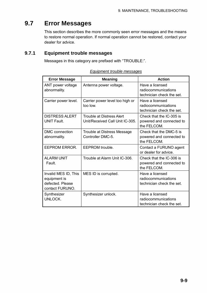
9. MAINTENANCE, TROUBLESHOOTING
9-9
9.7 Error Messages This section describes the more commonly seen error messages and the means to restore normal operation. If normal operation cannot be restored, contact your dealer for advice.
9.7.1 Equipment trouble messages Messages in this category are prefixed with “TROUBLE:”.
Equipment trouble messages
Error Message Meaning Action ANT power voltage abnormality.
Antenna power voltage. Have a licensed radiocommunications technician check the set.
Carrier power level. Carrier power level too high or too low.
Have a licensed radiocommunications technician check the set.
DISTRESS ALERT UNIT Fault.
Trouble at Distress Alert Unit/Received Call Unit IC-305.
Check that the IC-305 is powered and connected to the FELCOM.
DMC connection abnormality.
Trouble at Distress Message Controller DMC-5.
Check that the DMC-5 is powered and connected to the FELCOM.
EEPROM ERROR. EEPROM trouble. Contact a FURUNO agent or dealer for advice.
ALARM UNIT Fault.
Trouble at Alarm Unit IC-306. Check that the IC-306 is powered and connected to the FELCOM.
Invalid MES ID, This equipment is defected. Please contact FURUNO.
MES ID is corrupted. Have a licensed radiocommunications technician check the set.
Synthesizer UNLOCK.
Synthesizer unlock. Have a licensed radiocommunications technician check the set.

9. MAINTENANCE, TROUBLESHOOTING
9-10
9.7.2 Warning messages Messages in this category are prefixed with “WARNING:”
Warning messages
Error Message Meaning Action BBER over 80%. Scanning NCS start manually.
BBER (Bulletin Board Error Rate) exceeded 80%.
Select NCS manually.
Cannot enter new DNID. Memory full for DNIDs.
Memory for DNIDs is full. Delete unnecessary DNIDs to enter new ones.
Cannot enter new ENID. Memory full for ENIDs.
Memory for ENIDs is full. Delete unnecessary ENIDs to enter new ones.
Cannot find NCS CC in all region. Scanning is continued.
No NCS found in region. Scanning automatically continues.
Cannot find NCS CC in preferred region. Scanning all region is started.
NCS could not be found in region selected. Scanning started to find NCS.
If NCS could not be found, contact you dealer for advice.
External NAV equipment failure.
No navigation data from navigator.
Check navigator.
Internal GPS UNIT failure.
GPS signal could not be detected.
Internal GPS receiver may be damaged if this message appears frequently. Contact your dealer for advice.
Synchronization loss. Please change EGC channel.
Your station is not synchronized with selected EGC channel.
Change EGC channel.
Synchronization loss. Please check the current ocean region.
Your station is not synchronized with selected NCS.
Change NCS.

AP-1
APPENDIX
Menu Tree F1: File
1. New2. Open3. Close4. Save5. Delete6. Rename7. Print8. Format Disk9. MIME (Decode)
2HD (1.44MB), 2DD (720kB)
F2: Edit1. Cut2. Copy3. Paste4. Insert (With Citation)5. Select All6. Search or Replace
7. Goto Line
8. Time or Pos. Ins
9. Change Window
1. Search
2. Replace
1. Top of Text2. End of Text3. Goto Line1. Time2. Position
Search WordDirectionSearch WordReplace WordDirectionQuery or All
Chooses line to go to.
Forward, Back
Forward, BackQuery, All

APPENDIX
AP-2
Confirmation ON, OFFSend Delay 00:00 - 99:59; 00:00Delivery Delay Immediate, DeferredCode IA5, ITA2, DATA
F3: Transmit
1. Transmit Message
2. Cancel3. Request Delivery Status
PriorityMessage FileStation NameDestination TypePrefix Code (Prefix selected)Country/Ocean CodeStation IDModem Type (FAX, FAX prefixed selected) Address (E-mail, SMS)Subject (For e-mail)Attach File (For e-mail)LED ID
Option
Normal, Distress
Select MessageSelect Message
T30 FAXV21 V.21 300bps DuplexV22 V.22 1200bps DuplexV22B V.22bis 2400bps DuplexV23 V.23 600/1200bpsV26B V.26bis 2400/1200bpsV26T V.26ter 2400bps DuplexV27T V.27ter 4800bps/2400bpsV32 V.32 9600bps DuplexOther
TELEXFAXE-MailCSDNPSDNX400DNIDSPECTELEX (Prefixed)FAX (Prefixed)PSDN (Prefixed)X400 (Prefixed)DNID (Prefixed)SPEC (Prefixed)
F4: EGC1. Display EGC Message2. EGC Network ID
TRANSMIT

APPENDIX
AP-3
F5: Reports1. Data Report
2. Message Report
1. Data Report 1
2. Data Report 23. Data Report 34. Data Report 41. Message Report 1
StatusReport LengthDestinationActivation Interval Time (Regular Interval chosen) Report Times Start Time 1 (Daily chosen) Start Time 2 (Daily chosen) Start Time 3 (Daily chosen) Start Time 4 (Daily chosen)Same as Data Report 1Same as Data Report 1same as Data Report 1PIN CodeStatusStation NameDestination Type Prefix Code (Prefix chosen) Country/Ocean Code Station ID Modem Type FAX, FAX Prefixed chosen) Address (E-Mail, SMS chosen) Subject (E-Mail chosen)
ON, OFF1, 2, 3DNID selectionRegular Interval, Daily00:10-99:59; 00:10
1 - 999; 1, - - - (No Limit)00:00 - 23:5900:00 - 23:5900:00 - 23:5900:00 - 23:59
Max. 8 digitsON, OFFSubscriber selectionTELEXFAXE-MailSMSPSDNX400DNIDSPECTELEX (Prefixed)FAX (Prefixed)PSDN (Prefixed)X400 (Prefixed)DNID (Prefixed)SPEC (Pefixed)
T30 FAXV21 V.21 300bps DuplexV22 V.22 1200bps DuplexV22B V.22bis 2400bps DuplexV23 V.23 600/1200bpsV26B V.26bis 2400/1200bpsV26T V.26ter 2400bps DuplexV27T V.27ter 4800/2400bpsV32 V.32 9600bps DuplexOther

APPENDIX
AP-4
3. Data Network ID
2. Message Report 23. Message Report 34. Message Report 4
LES IDActivation Interval Time (Regular Interval chosen) Report Times Start Time 1 (Daily chosen) Start Time 2 (Daily chosen) Start Time 3 (Daily chosen) Start Time 4 (Daily chosen)Report Contents
File (File chosen)Same as Message Report 1Same as Message Report 1Same as Message Report 1
LES selectionRegular Interval, Daily00:10 - 99:59; 00:10
1 - 999; 1, - - - (No Limit)00:00 - 23:5900:00 - 23:5900:00 - 23:5900:00 - 23:59NAV, NAV+SEA INF, NAV (R), FILEFile selection
F6: Logs1. Send Message Log2. Receive Message Log3. EGC Log4. Log
F7: Options (FELCOM functions as Inmarsat MES)1. Login2. Logout3. Abort4. Select NCS5. Ocean Region6. LES Information7. Test
Yes, NoYes, NoYes, No
Auto, West-Atlantic, East-Atlantic, Pacific, Indian
1. PV Test2. PV Test Result3. Diagnostic Test4. Distress Alert Button Test
Yes, No
Yes, NoYes, No
F7: Options (FELCOM functions as EGC receiver)1. Login2. Logout3. Abort4. Select EGC Ch.5. LES Information6. Test
Yes, NoYes, NoYes, No
1. PV Test2. PV Test Result3. Diagnostic Test4. Distress Alert Button Test
Yes, No
Yes, NoYes, No

APPENDIX
AP-5
F8: Setup1. Distress Alert Setup
2. System Setup
LES IDUpdate TimePositionProtocolNature
CourseSpeedSystem Date & TimeIMNMES Operation ModeNav PortActive PortMessage Output PortEGC Output PortNetwork Setup
Command Window
LES selection00:00 - 23:59Latitude and longitude inputMaritimeUndesignated, Fire/Explosion, Flooding,Collision, Grounding, Listing, Sinking,Disabled & Adrift, Abandoning shipFurther assistance required,Piracy or Armed attack0 - 999; 00 - 99; 0Date inputIMN inputINMARSAT-C, EGCOFF, EXT, INTINT, ALLINT, EXT, INT+EXT, AUTOINT, INT+EXTNetwork
Mail Gateway
IP AddressSubnet MaskDHCPGatewaySMTP Enable IP AddressSend Limit Size (KB) 2, 4,
6, 8,
Attach
Delivery To
Server IP (Server chosen)Address Mode (Server chosen)Mail Address (Server chosen)Auto Delivery Keyword (Auto chosen)
(For service technicians.)
ON, OFF
10, 16, 32UUENCODE,BINARYPc Mailer, Server
FIXED, Auto

APPENDIX
AP-6
3. Editor Setup
4. Terminal Setup
5. EGC Setup
Text ModeEdit ModeWord WrapLine No.Tab WidthColumn WidthCursor TypeScrollDate Disp. FormCurrency UnitScreen SaverWindow Color
Additional PositionNavareaFixed AreaWaypoint (Destination waypoint seton navigator)Station CodeType of Message Ice reports Meteo. forecasts Pilot service DECCA messages LORAN messages OMEGA messages SATNAV messages Other navaid msg QRU (no message)
Telex, AsciiInsert, OverwriteON, OFFON, OFF2 Char, 4 Char, 8 CharTelex (Fixed at 69), ASCII (40 - 80, 69)Block, UnderlineFull Screen, Half ScreenYY-MM-DD, MMM-DD-YY, DD-MMM-YYSDR, US$, EUR, YEN, OTHER (Currency unit input, 4 digits max.)ON, OFFWindow Color Setup
Default Color1 position9 areas max.
ON, OFF
A - Z
ON, OFF ON, OFF ON, OFF ON, OFF ON, OFF ON, OFF ON, OFF ON, OFF ON, OFF
RCV Message Display,EGC Message Display,EDIT 1, EDIT 2,Function, SUB Menu 1,SUB Menu 2,SUB Menu 3,SUB Menu 4,Message,Base WindowL-WHITE, YELLOW,L-MAGENTA, L-RED,L-CYAN, L-GREEN,L-BLUE, GRAY,WHITE, BROWN,MAGENTA, RED,CYAN, GREEN, BLUE, BLACK
Window
Fore ColorBack Color
Yes, No

APPENDIX
AP-7
6. Auto Mode Setup
7. E-mail Setup8. Directories
9. Configuration
Auto Log PrintReceive AlarmAuto Receive Message SaveAuto Receive Message PrintData Report & Polling PrintAuto EGC Message Save
Auto EGC Message Print
LES settingMessage DirectoryEGC Message Directory1. Station List(Max. 99 stations)
ON, OFFON, OFFON, OFFON, OFFON, OFFSystemFleetNETSafetyNET (Routine)SafetyNET (Safety)SafetyNET (Urgent&Distress)SystemFleetNETSafetyNET (Routine)SafetyNET (Safety)
Station GroupStation NameDestination TypePrefix Code(Prefix chosen)Country CodeStation ID
Modem Type (FAX, FAX prefixed chosen)
E-Mail Address(E-Mail, SMS chosen)Remarks
ON, OFFON, OFFON, OFF
ON, OFF
ON, OFF
ON, OFFON, OFFON, OFF
ON, OFF
Max. 5 charactersMax. 5 charactersTELEXFAXE-MailSMSPSDNX400DNIDSPECTELEX (Prefixed)FAX (Prefixed)PSDN (Prefixed)X400 (Prefixed)DNID (Prefixed)SPEC (Prefixed)T30 FAXV21 V.21 300bps DuplexV22 V.22 1200bps DuplexV22B V.22bis 2400bps DuplexV23 V.23 600/1200bpsV26B V.26bis 2400/1200bpsV26T V.26ter 2400bps DuplexV27T V.27ter 4800/2400bpsV32 V.32 9600bps DuplexOther
Max. 20 characters

APPENDIX
AP-8
Max. 15 charactersMax. 20 charactersEnter charges per 256 bit
Max. 19 charactersMax. 9 charactersMax. 4 characters3 digits3 digits3 digits3 digitsMax. 9 charactersMax. 9 charactersMax. 9 charactersMax. 9 charactersMax. 4 charactersOFF, ON (BASE64)ON (UUENCODE)
NameRemarksCharge (TELEX - SPEC)
Service LES NameService ID (E-mail)Service ID (SMS)LES ID (AORW)LES ID (AORE)LES ID (POR)LES ID (IOR)To:Cc:Subject:Separator:SMS:Attach File (MIME)
Save to FDLoad from FD
2. LES List(44 per ocean�region)3. EGC Channel List (20 per ocean region)4. NCS Channel List (20 per ocean region)5. E-Mail/SMS�Service List(Max. 16)
6. Save/Load
F9: Position
F10: Stop Alarm
LATLON
1. ALL2. Station List3. LES List4. E-Mail/SMS Service List5. Other

APPENDIX
AP-9
International Telex/Telephone Country Code List
Area and Country Remarks for Telex CodeTelephone Country Code
Telex Country Code
Afghanistan
Alaska
Albania
Algeria
American Samoa
American Virgin Is.
Andorra
Angola
Anguilla
Antigua & Barbuda
Argentina
Armenia
Aruba
Ascension
Australia
Australian External Territories
Austria
Azerbaijani
Azores Is.
Bahamas
Bahrain
Bangladesh
Barbados
Belarus
Belgium
Belize
Benin
Bermuda
Bhutan
Bolivia (Rep. of)
Bolivia (ENTAL)
Bosnia-Hercegovina
Botswana
Brazil
British Virgin Is.
Brunei Darussalam
Bulgaria
Burkina Faso
Burundi
Telex calls to former WUI subscribers, insert the figure "9" after the destination code "208".
Disregard the figure "0" at head of subscriber number.
Subscriber numbers are 2XXX or 5XXX
Manual calls 3XXX
Destination code is the same as for Portugal.
Disregard the figure "0" at head of subscriber number.
93
1
355
21
684
1
33
244
1
2
54
7
297
247
61
672
43
994
351
1
973
880
1
7
32
501
229
1
975
591
387
267
55
1
673
359
226
257
79
200
604
408
770
208
590
991
391
393
33
684
303
939
71
766
47
784
404
297
490
780
392
681
46
371
972
290
890
371
309
600
962
38
292
809
67
978
903
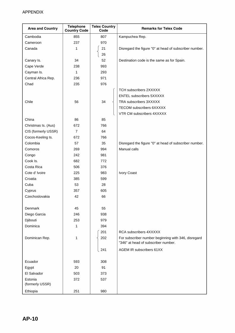
APPENDIX
AP-10
Area and Country Remarks for Telex CodeTelephone Country Code
Telex Country Code
Cambodia
Cameroon
Canada
Canary Is.
Cape Verde
Cayman Is.
Central Africa Rep.
Chad
Chile
China
Christmas Is. (Aus)
CIS (formerly USSR)
Cocos-Keeling Is.
Colombia
Comoros
Congo
Cook Is.
Costa Rica
Cote d' lvoire
Croatia
Cuba
Cyprus
Czechoslovakia
Denmark
Diego Garcia
Djibouti
Dominica
Dominican Rep.
Ecuador
Egypt
El Salvador
Estonia (formerly USSR)
Ethiopia
Kampuchea Rep.
Disregard the figure "0" at head of subscriber number.
Destination code is the same as for Spain.
TCH subscribers 2XXXXX
ENTEL subscribers 5XXXXX
TRA subscribers 3XXXXX
TECOM subscribers 6XXXXX
VTR CM subscribers 4XXXXX
Disregard the figure "0" at head of subscriber number.
Manual calls
Ivory Coast
RCA subscribers 4XXXXX
For subscriber number beginning with 346, disregard "346" at head of subscriber number.
AGEM IR subscribers 61XX
855
237
1
34
238
1
236
235
56
86
672
7
672
57
269
242
682
506
225
385
53
357
42
45
246
253
1
1
593
20
503
372
251
807
970
21
26
52
993
293
971
976
34
85
766
64
766
35
994
981
772
376
983
599
28
605
66
55
938
979
394
201
202
241
308
91
373
537
980

APPENDIX
AP-11
Area and Country Remarks for Telex CodeTelephone Country Code
Telex Country Code
Falkland Is. (Malvinas)
Faroe Is.
Fiji
Finland
France
French Guiana
French Polynesia
Gabon
Gambia
Georgia
Germany (Fed, Rep. of)
Ghana
Gibraltar
Greece
Greenland
Grenada
Guadeloupe
Guam (RCA)
Guatemala
Guiana
Guinea Conakry
Guinea Bissau
Guyana
Haiti
Hawaii
Honduras
Hong Kong
Hungary
Iceland
India
Indonesia
Iran
Iraq
Ireland
Israel
Italy
formerly East Germany
formerly West Germany
Manual calls
RCA subscribers 9XXX
RCA subscribers 8XXX or 2968XX
ITT subscribers 743XXX
WUI subscribers 63XXX or 63XXXX
WUH subscribers 39XXXX
Telex calls to HTC subscribers can be made using Semi-automatic calls.
Disregard the figure "0" at head of subscriber number.
Disregard the figure "0" at head of subscriber number.
500
298
679
358
33
594
689
241
220
7
49
49
233
350
30
299
1
590
671
502
594
224
245
592
509
1
504
852
36
354
91
62
98
964
353
972
39
306
502
701
57
42
300
702
973
996
683
69
41
94
405
601
503
395
299
700
372
300
995
969
295
203
704
705
708
709
(773)
374
802
61
501
81
73
88
491
500
606
43

APPENDIX
AP-12
Area and Country Remarks for Telex CodeTelephone Country Code
Telex Country Code
Jamaica
Japan
Jordan
Kazakhstan
Kenya
Kiribati
Korea (Demo, People's Rep. of)
Korea (Rep. of)
Kuwait
Kyrgyzstan
Lao
Latvia (formerly USSR)
Lebanon
Lesotho
Liberia
Libya
Liechtenstein
Lithunia (formerly USSR)
Luxembourg
Macao
Macedonia
Madagascar
Madeira Is.
Malawi
Malaysia
Maldives Is.
Mali
Malta
Mariana Is.
Marshall Is.
Maritinique
Mauritania
Mauritius
Mexico
Micronesia
Moldova
Monaco
Mongolia
KDDI (for 5 digits)
NTT
Subscriber numbers are 770XX
Subscriber number beginning with 4, 5, 7, 8 and 9 can be reached by Manual Calls.
Destination code is the same as for Portugal.
Subscriber number beginning with 11XX can be reached by Semi-automatic calls.
Disregard the figure "0" at head of subscriber number.
Destination code is the same as for France.
1
81
962
7
254
686
850
82
965
7
856
371
961
266
231
21
41
370
352
853
389
261
351
265
60
960
223
356
671
692
596
222
230
52
691
373
33
976
291
72
493
785
987
761
(899)
801
496
788
804
538
494
963
997
901
45
539
402
808
597
986
404
904
84
896
985
406
403
760
765
298
974
966
22
764
682
42
800

APPENDIX
AP-13
Area and Country Remarks for Telex CodeTelephone Country Code
Telex Country Code
Montserrat
Morocco
Mozambique
Myanmar (formerly Burma)
Namibia
Nauru
Nepal
Netherlands
Netherlands Antilles
New Caledonia
New Zealand
Nicaragua
Niger
Nigeria
Niue Is.
Northern Mariana Is.
Norfolk Is.
Norway
Oman
Pakistan
Palau
Panama
Papua New Guinea
Paraguay
Peru
Philippines
Poland
Portugal
Puerto Rico
Qatar
2XXXX other numbers are for Semi-automatic calls.
TRT subscribers
AACR subscribers
INTEL subscribers
PHILCOM subscribers 2XXXX
RCPI subscribers 7XXXX
GMCR subscribers 4XXXX
ETPI subscribers 6XXXX
CAPWIRE subscribers 1XXXX
For PTT subscribers, insert the figure "8" after the destination code "75".
Disregard the figure "0" at head of subscriber number.
RCA subscribers 2XXX
ITT subscribers 345XXX
C&W, WUI subscribers
ACPR (PRCA) subscribers
1
21
258
95
264
674
977
31
599
687
64
505
227
234
683
670
672
47
968
92
680
507
675
595
51
63
48
351
1
974
396
407
992
83
908
775
891
44
390
706
74
375
975
905
776
766
56
498
82
763
377
378
379
703
305
36
75
63
404
205
206
207
209
497

APPENDIX
AP-14
Area and Country Remarks for Telex CodeTelephone Country Code
Telex Country Code
Reunion
Romania
Russian Federation
Rwanda
Saipan
San Marino
Sao Tome & Principe
Saudi Arabia
Senegal
Seychelles
Sierra Leone
Singapore
Slovak
Slovenia
Solomon Is.
Somalia
South Africa
Spain
Spanish North Africa
Sri Lanka
St. Helena
St. Kitts & Nevis
St. Lucia
St. Pierre & Miquelon
St. Vincent & the Grenadines
Sudan
Suriname
Swaziland
Sweden
Switzerland
Syria
Tajikistan
Taiwan
Tanzania
Thailand
Togo
Tokelau
Tonga
Trinidad & Tobago
Tunisia
Turkey
Turkmenistan
Subscriber numbers are 916XXX
Disregard the figure "0" at head of subscriber number.
Manual calls
Cape Town subscribers XXXXXX
Bophuthatswana subscribers 08XXXX
Transkei subscribers 09XXX
Manual calls 4XXX
262
40
7
250
670
378
239
966
221
248
232
65
42
386
677
252
27
34
34
94
290
1
1
508
1
249
597
268
46
41
963
7
886
255
66
228
690
676
296
21
90
7
961
65
64
909
760
505
967
495
906
965
998
87
66
598
778
900
95
52
52
803
(960)
397
398
204
399
984
304
964
54
45
492
787
769
989
86
977
762
777
294
409
607
789

APPENDIX
AP-15
Area and Country Remarks for Telex CodeTelephone Country Code
Telex Country Code
Turks & Caicos Is.
Tuvalu
U. A. E.
Abu Dhabi
Ajman
Dubai
Fujairah
Ras Al Khaimah
Sharjah
Umm Al Qaiwain
Uganda
Ukraine
United Kingdom
United Arab Emirates
Upper Volta
Uruguay
Uzbekistan
U. S. A.
U. S. A. (Mainland)
U. S. S. R. (Former)
Vanuatu
Vatican
Venezuela
Viet Nam
Wallis & Futuna Is.
Western Samoa
Yemen (Rep. of)
Yugoslavia (Former)
2XXXX, 3XXXX, 5XXXX
695XX
4XXXX
8XXXX
9XXXX
68XXX
697XX
Same as "Burkina Faso".
CCI subscribers 7XXXXXX
ITT subscribers 4XXXXX, 4XXXXXX, 4XXXXXXXXX
RCA subscribers 2XXXXX
WUI subscribers 6XXXX, 6XXXXX, 6XXXXXX
TRT subscribers 1XXXXX, 1XXXXXXXXX
FTCC subscribers 8XXXX, 8XXXXX
GRPHNET subscribers 36XXXXX, 37XXXXX
For WUT subscribers, insert the figure "0" after the destination code "23".
Telex calls to TWX subscribers whose numbers do not contain "0" as the third figure of the 10 figure code can be made as Semi-automatic calls.
Russian Federation
Subscriber number beginning with 561XXX can be made using manual calls
Formerly Yemen (P. D. Rep. of)
Formerly Yemen (Arab Rep.)
1
688
971
256
7
44
971
226
598
7
1
7
678
379
58
84
681
685
969
967
296
774
893
988
680
51
893
978
32
786
23
23
25
640
771
504
31
805
707
779
806
895
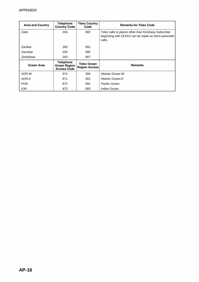
APPENDIX
AP-16
Area and Country Remarks for Telex CodeTelephone Country Code
Telex Country Code
Ocean Area RemarksTelephone
Ocean Region Access Code
Telex Ocean Region Access
Zaire
Zambia
Zanzibar
Zimbabwe
Telex calls to places other than Kinshasa Subscriber beginning with 2XXXX can be made as Semi-automatic calls.
243
260
259
263
982
902
990
907
AOR-W
AOR-E
POR
IOR
Atlantic Ocean-W
Atlantic Ocean-E
Pacific Ocean
Indian Ocean
874
871
872
873
584
581
582
583

APPENDIX
AP-17
LES List April/2002
Land earth station operator Country AOR- E AOR- W IOR PORBeijing Marine China 311 211Bezeq Israel 127 327CAT Thailand 319CP Radio Marconi Portugal 118Embratel Brazil 114France Telecom France 121 021 321 221France Telecom (Ex DeteSat) France 115 333KDDI Japan 103 003 303 203Korea Telecom South Korea 308 208Morviasputnik (Nudel Les) Russia 117 317OTE Greece 120 305Polish Telecom Poland 116 316Saudi Telecom Co Saudi Arabia 125 325Singapore Telecom Singapore 328 210Stratos Mobile Networks Canada 102 002 302 202Telecom Company of Iran Iran 314Telecom Italia Italy 105 335Telenor Satellite Services Inc USA 101 001 201Telenor Satellite Services AS Norway 104 004 304 204Turk Telecom Turkey 110 310Vishipel Vietnam 330VSNL India 306Xantic Netherlands 112 012 312 212Xantic Australia 122 022 322 222

APPENDIX
AP-18
International Telex Abbreviations
noitaiverbbA gninaeM
VDA esivdAKCA egdelwonkcANGA niagA
)SG(IB eybdooGKB .ffotucINFC mrifnoCLOC noitalloCVRC ?evieceruoyodwoHRED redrofotuONWD nwoDEEE rorrE
MF morFAG .daehaoGSNM setuniMMOM )gnitiaW(tiaWITUM detalituM
AN .dettimdatonsirebircsbussihtotecnednopserroCCN stiucricoNHCN .degnahcneebsahrebmuns’rebircsbnS
PN .rebircsbusasiregnolonrotonsiytrapdellacehTRN .rebmunllacruoyetacidnICCO .degagnesirebircsbuS
KO .deergA)0ro(P .noissimsnartruoypotS
)ESP(SLP esaelPRPP repaP
)DCR(P devieceRPAR .niagauoyllaclliwI
DR deeRER otgnirrefeRTPR taepeRYRS yrroSPVS esaelPXAT ?egrahcehtsitahW
GSMTSET ?egassemtsetadnesesaelPURHT noitisopxelethtiwnoitacinummocnierauoY
)XNT(SKT sknahTXLT xeleT

APPENDIX
AP-19
International Telegraphy Alphabet
No.
1
2
3
4
5
6
7
8
9
10
11
12
13
14
15
16
FIGURES
?
:
3
8
BELL
(
)
.
,
9
0
LETTERS
A
B
C
D
E
F
G
H
I
J
K
L
M
N
O
P
No.
17
18
19
20
21
22
23
24
25
26
27
28
29
30
31
32
FIGURES
1
4
'
5
7
=
2
/
6
+
LETTERS
Q
R
S
T
U
V
W
X
Y
Z
CARRIAGE RETURN
LINE FEED
LETTERS
FIGURES
SPACE
BLANK
*
*
*
*
*
* = Cannot be entered.

APPENDIX
AP-20
Messages Below are the various operational messages and their meanings. Messages are arranged according to function key.
[F1] File
1. "Overwrite?" You are asked if you are sure to overwrite file name entered. 2. "OK to save?" You are asked if you are sure to save a file. 3. "OK to delete file?" You are asked if it is OK to delete selected file. 4. "Can't delete." File cannot be deleted. 5. "Enter new filename" Enter a new file name (to save file under new name.) 6. "Can't rename." Cannot rename file. 7. "Insert new disk for drive " You are asked to insert a floppy disk in the disk drive. 8. "And select media type" Select media type of floppy disk. 9. "Format start." Formatting of the disk begins. 10. "xx% Completed." Percentage of floppy disk formatted. 11. "Format completed. " Formatting of floppy disk completed. 12. "Format failed." Could not format floppy disk. 13. "Press any key to escape." Press any key to escape and erase message shown. 14. "Abort process." Formatting aborted. 15. "Drive not ready." No floppy disk in disk drive. 16. "Write protected." Floppy disk is write protected. 17. "Drive error." Floppy disk may be defective. 18. "Checking " Checking MIME-coded file. 19. "Decode ?" Decode Base64 coded file. 20. "Now decoding..." Decoding file. 21. "Complete." File decoding completed.

APPENDIX
AP-21
22. "Decode failed. " File could not be decoded. 23. "This terminal not support this code."
File could not be decoded because type of code not supported. 24. "Decoded 1 file(s)." Decode MIME coded file. 25. "This file is not encoding." Cannot encode file selected. 26. "File is already exist. Overwrite?" You are asked if it is OK to write over MIME-coded file. 27. “Directory not found.” You have specified a directory which does not exist on a floppy disk.
[F3]: Transmit
1. "Input Error : Message File." Invalid message selected for transmission. 2. "Input Error : Country/Ocean Code."
Invalid country/ocean code entered. 3. "Input Error : Station ID." Invalid station ID entered. 4. "Input Error : Modem Type." Invalid mode type entered. (For FAX, choose T30.) 5. "Input Error : E-Mail Address." Invalid e-mail address entered. 6. "Input Error : LES ID." Invalid LES ID entered. 7. "Input Error : Send Delay." Invalid send delay time entered. 8. "Input Error : Prefix Code." Invalid prefix code entered. 9. "Invalid character detected in message." Invalid character found in TX message. 10. "Don't support E-Mail service in this NCS." Selected NCS does not handle e-mail. 11. "Input Error : Too many stations." You have selected too many stations to transmit to. 12. "Message file is too large (but send only with 32KB)."
The size of the file you want to send is larger than 32,000 bytes. (The file can be sent, but only the first 32,000 bytes of information will be received.)
13. "Attach file is too large." The size of the attachment you want to send is larger than 32,000 bytes.
14. "Attach file (file name) is not found." Cannot find attached file. 15. "Message is entered in sending Queue. Press any key." Tx message entered into queue. 16. "Can't enter this message to sending Queue. Press any key." Could not enter TX message into queue.

APPENDIX
AP-22
17. "Can't delivery a mail to server." Message cannot be forwarded to shipboard mail server.
18. "DHCP server not exist." IP address cannot be acquired because DHCP server does not exist.
[F5]: Data report
1. "Input Error : Country/Ocean Code." Invalid country/ocean code entered.
2. "Input Error : Station ID." Invalid station ID entered. 3. "Input Error : LES ID." Invalid LES ID entered. 4. "Input Error : Interval Time" Invalid interval time entered. 5. "Input Error : Start Time" Invalid start time entered. 6. "Input Error : Modem Type" Invalid modem type entered. 7. "Input Error : Report Contents" Invalid report contents entered. 8. "Input Error : Report Times" Invalid number of report times entered. 9. "Input Error : Destination" Invalid destination entered. 10. "Input Error : E-Mail Address" Invalid e-mail address entered. 11. "Don't support E-Mail service in this NCS." NCS does not handle e-mail. 12. "Input Error : Prefix Code" Invalid prefix code entered.
[F7]: PV test
1. "Starting PV Test Process." Going into PV test mode. 2. "Automatic test mode: Normal communication disabled." Going into automatic test mode – all communications are disabled. 3. "Do not press any distress button unless you are in distress." Do not operate the [DISTRESS] button except in an emergency.
Printing
1. "Can't enter in Print Que." 2. "Print Que is Full." 3. "Can't print. PRINTER NOT READY." 4. "Can't print. Paper Low." 5. "Disk full. Can't enter in Print Que."

APPENDIX
AP-23
Digital Interface (IEC 61162-1 2nd Edition) Output sentences GGA, GLL, GSV, RMC, VTG, ZDA
Input sentences BWC, BWR, DBT, GGA, GLL, MTW, RMA, RMB, RMC, VDR, VTG, WPL, ZDA
Transmission interval GLL, GGA, VTG, RMC: 2 s ZDA: 1 s GSV: 10 s
Data transmission Data is transmitted in serial asynchronous form in accordance with the standard referenced in 2.1 of IEC 61162-1. The first bit is a start bit and is followed by data bits, least-significant-bit as illustrated below. The following parameters are used: Baud rate: 4800 Data bits: 8 (D7 = 0), parity none Stop bits: 1
D0 D1 D2 D3 D4 D5 D6 D7
Startbit
StopbitData bits

APPENDIX
AP-24
Data sentences Input sentences
BWC - Bearing and distance to waypoint - great circle
$--BWC, hhmmss.ss, llll.ll, a yyyyy.yy, a, x.x, T, x.x, M, x.x, N, c--c, a*hh<CR><LF>
ChecksumMode indicator(see note 1)Waypoint ID*
Distance, nautical miles
Bearing, degrees trueWaypoint longitude, E/W*
Bearing, degrees magnetic*
Waypoint latitude, N/S*UTC of observation*
NOTE 1: Positioning system Mode indicator: A = Autonomous D = Differential E = Estimated (dead reckoning) M = Manual input S = Simulator N = Data not validThe Mode indicator field shall not be a null field.
*: Not used

APPENDIX
AP-25
BWR - Bearing and distance to waypoint - rhumb line
DBT - Depth below transducer
$--DBT,x.x,f,x.x,M,x.x,F*hh<CR><LF> | | | | | | | | | | | | | +--------- 4 | | | | +--+----------- 3 | | +--+----------------- 2 +--+----------------------- 1
1. Water depth, feet 2. Water depth, m 3. Water depth, fathoms 4. Checksum

APPENDIX
AP-26
GGA – Global positioning system(GPS) fix data
$--GGA,hhmmss.ss,llll.lll,a,yyyyy.yyy,a,x,xx,x.x,x.x,M,x.x,M,x.x,xxxx*hh<CR><LF> | | | | | | | | | | | | | | | | | | | | | | | | | | | | | +-- 11 | | | | | | | | | | | | | +---- 10 | | | | | | | | | | | | +--------- 9 | | | | | | | | | | +---+------------ 8 | | | | | | | | +---+------------------ 7 | | | | | | | +------------------------- 6 | | | | | | +---------------------------- 5 | | | | | +------------------------------- 4 | | | +----+--------------------------------- 3 | +---+--------------------------------------------- 2 +------------------------------------------------------------- 1
1. UTC of position 2. Latitude, N/S 3. Longitude, E/W 4. GPS quality indicator (see note) 5. Number of satllite in use,00-12, may be different from the number in view 6. Horizontal dilution of precision 7. Antenna altitude above/below mean sealevel, m 8. Geoidal separation, m 9. Age of differential GPS data 10. Differential reference station ID, 0000-1023 11. ChecksumNOTE0 = fix not available or invalid1 = GPS SPS mode, fix valid2 = differential GPS, SPS mode, fix valid3 = GPS PPS mode, fix valid4 = Real Time Kinetic. Satellite system used in RTK mode with fixed integers5 = Float RTK. Satellite system used in RTK mode with floating fingers6 = Estimated (dead reckoning) mode7 = Manual input mode8 = Simulator modeThe GPS quality indicator shall not be a null field.

APPENDIX
AP-27
GLL - Geographic position - latitude/longitude $--GLL,llll.lll,a,yyyyy.yyy,a,hhmmss.ss,A,a*hh<CR><LF> | | | | | | | | | | | | | | | +------- 6 | | | | | | +--------- 5 | | | | | +----------- 4 | | | | +---------------- 3 | | +------+----------------------- 2 +---+----------------------------------- 1
1. Latitude, N/S 2. Longitude, E/W 3. UTC of position 4. Status: A=data valid, V=data invalid 5. Mode indicator(see note) 6. Checksum
NOTE Positioning system Mode indicator: A = Autonomous D = Differential E = Estimated (dead reckoning) M = Manual input S = Simulator N = Data not valid
The Mode indicator field supplements the Status field. The Status field shall be set to V=invalid for all values of Operating Mode except for A=Autonomous and D=Differential. The positioning system Mode indicator and Status field shall not be null fields.
MTW - Water temperature $--MTW,x.x,C*hh<CR><LF> | | | | | +--------- 2 +--+----------- 1
1. Temperature, degrees C 2. Checksum

APPENDIX
AP-28
RMA - Recommended minimum specific LORAN-C data $--RMA,A,llll.lll,a,yyyyy.yy,a,x.x,x.x,x.x,x.x,x.x,a,a*hh<CR><LF> | | | | | | | | | | | | | | | | | | | | | | | | | +------- 10 | | | | | | | | | | | +--------- 9 | | | | | | | | | +---+----------- 8 | | | | | | | | +------------------ 7 | | | | | | | +---------------------- 6 | | | | | | +-------------------------- 5 | | | | | +------------------------------ 4 | | | +----+--------------------------------- 3 | +---+-------------------------------------------- 2 +------------------------------------------------------- 1
1. Status: A=data valid, V=blink, cycle or SNR warning 2. Latitude, degrees N/S 3. Longitude, degrees E/W 4. Time difference A, microseconds 5. Time difference B, microseconds 6. Speed over ground, knots 7. Course over ground, degrees true 8. Magnetic variation(see note 1),degree E/W 9. Mode indicator(see note 2) 10. Checksum
NOTE 1 - Easterly variation(E) subtracts from true course Westerly variation(W) adds to true course
NOTE 2 Positioning system Mode indicator: A = Autonomous D = Differential E = Estimated (dead reckoning) M = Manual input S = Simulator N = Data not valid
The Mode indicator field supplements the Status field. The Status field shall be set to V=invalid for all values of Operating Mode except for A=Autonomous and D=Differential. The positioning system Mode indicator and Status field shall not be null fields.

APPENDIX
AP-29
RMB - Recommended minimum navigation information
$--RMB,A,x.x,a,c--c,c--c,llll.lll,a,yyyyy.yyy,a,x.x,x.x,x.x,A,a*hh<CR><LF> | | | | | | | | | | | | | | | | | | | | | | | | | | | | | +--- 13 | | | | | | | | | | | | | +----- 12 | | | | | | | | | | | | +------- 11 | | | | | | | | | | | +---------- 10 | | | | | | | | | | +-------------- 9 | | | | | | | | | +------------------ 8 | | | | | | | +-----+--------------------- 7 | | | | | +----+--------------------------------- 6 | | | | +--------------------------------------------- 5 | | | +-------------------------------------------------- 4 | | +------------------------------------------------------ 3 | +--------------------------------------------------------- 2 +------------------------------------------------------------ 1
1. Data status: A=data valid, V=navigation receiver warning 2. Cross track error(see note 2) n.miles 3. Direction to steer L/R 4. Origin waypoint ID 5. Destination waypoint ID 6. Destination waypoint latitude,N/S 7. Destination waypoint longitude,E/W 8. Range to destination, n.miles(see note 1) 9. Bearing to destination, degrees true 10. Destination closing velocity, knots 11. Arrival status: A=arrival circle entered or perpendicular passed 12. Mode indicator(see note 3) 13. Checksum
NOTES 1 If range to destination exceeds 999.9 nautical miles, display 999.9. 2 If cross track error exceeds 9.99 nautical miles, display 9.99.
3 Positioning system Mode indicator: A = Autonomous D = Differential E = Estimated (dead reckoning) M = Manual input S = Simulator N= Data not valid
The Mode indicator field supplements the Status field. The Status field shall be set to V=invalid for all values of Operating Mode except for A=Autonomous and D=Differential. The positioning system Mode indicator and Status field shall not be null fields.

APPENDIX
AP-30
RMC - Recommended minimum specific GPS/TRANSIT data $--RMC,hhmmss.ss,A,llll.lll,a,yyyyy.yyy,a,x.x,x.x,xxxxxx,x.x,a,a*hh<CR><LF> | | | | | | | | | | | | | | | | | | | | | | | | | +--- 10 | | | | | | | | | | | +----- 9 | | | | | | | | | +--+------- 8 | | | | | | | | +--------------- 7 | | | | | | | +--------------------- 6 | | | | | | +------------------------- 5 | | | | +---+---------------------------- 4 | | +---+---------------------------------------- 3 | +--------------------------------------------------- 2 +---------------------------------------------------------- 1
1. UTC of position fix 2. Status: A=data valid, V=navigation receiver warning 3. Latitude, N/S 4. Longitude, E/W 5. Speed over ground, knots 6. Course over ground, degrees true 7. Date: dd/mm/yy 8. magnetic variation, degrees E/W 9. Mode indicator(see note) 10. Checksum
NOTE Positioning system Mode indicator: A = Autonomous D = Differential E = Estimated (dead reckoning) M = Manual input S = Simulator N = Data not valid
The Mode indicator field supplements the Status field. The Status field shall be set to V=invalid for all values of Operating Mode except for A=Autonomous and D=Differential. The positioning system Mode indicator and Status field shall not be null fields.
VDR - Set and drift $--VDR,x.x,T,x.x,M,x.x,N*hh<CR><LF> | | | | | | | | | | | | | +--------- 4 | | | | +--+----------- 3 | | +---+----------------- 2 +--+----------------------- 1 1. Direction, degrees true 2. Direction, degrees magnetic 3. Current speed, knots 4. Checksum

APPENDIX
AP-31
VTG - Course over ground and ground speed $--VTG,x.x,T,x.x,M,x.x,N,x.x,K,a*hh<CR><LF> | | | | | | | | | | | | | | | | | | | +------- 6 | | | | | | | | +--------- 5 | | | | | | +--+----------- 4 | | | | +--+----------------- 3 | | +--+----------------------- 2 +--+----------------------------- 1
1. Course over ground, degrees true 2. Course over ground, degrees magnetic 3. Speed over ground, knots 4. Speed over ground, km/h 5. Mode indicator(see note) 6. Checksum
NOTE Positioning system Mode indicator: A = Autonomous D = Differential E = Estimated (dead reckoning) M = Manual input S = Simulator N = Data not valid
The positioning system Mode indicator field shall not be a null field.
ZDA - Time and date
$--ZDA,hhmmss.ss,xx,xx,xxxx,xx,xx*hh<CR><LF> | | | | | | | | | | | | | +--------- 7 | | | | | +----------- 6 | | | | +-------------- 5 | | | +------------------ 4 | | +---------------------- 3 | +------------------------- 2 +--------------------------------- 1
1. UTC 2. Day, 01 to 31(UTC) 3. Month, 01 to 12(UTC) 4. Year(UTC) 5. Local zone hours, 00h to +-13h 6. Local zone minutes, 00 to +59 as local hours 7. Checksum

APPENDIX
AP-32
Output sentences
GGA, GLL, RMC, VTG, ZDA – see Input sentences GSV - GNSS satellites in view
$--GSV,x,x,xx,xx,xx,xxx,xx.........,xx,xx,xxx,xx*hh<CR><LF | | | | | | | | | | | | | | | | | | | | | | | | | | | +--------- 10 | | | | | | | | | +--+--+---+----------- 9 | | | | | | | +-----+------------------------ 8 | | | | | | +--------------------------------- 7 | | | | | +------------------------------------- 6 | | | | +---------------------------------------- 5 | | | +------------------------------------------- 4 | | +---------------------------------------------- 3 | +------------------------------------------------- 2 +--------------------------------------------------- 1
1. Total number of messages, 1 to 9 2. Message number, 1 to 9 3. Total number of satellites in view 4. Satellite ID number 5. Elevation, ddegrees, 90deg maximum 6. Azimuth, degrees true, 000 to 359 7. SNR(C/No) 00-99 dB-Hz, null when not tracking 8. Second and third SVs 9. Fourth SV 10. Checksum

APPENDIX
AP-33
Serial interface I/O circuit
.
.
.
.
.
TD_A 6
TD_B 7
RD_A 8
RD_B 9
GND 10
<
<
<
<
<
1
3®�
®
GND5
4
PC400U9
R42 270
R37 270
7
6 DTDE
RE_NRD
4321
A
B
U11LTC1488CS8
R38 10
R40 10
8
C11
3.3 V
FL23EXC_CET102U
FL29EXC_CET102U
FL28EXC_CET102U
FL27EXC_CET102U
16P0209JUNCTION
J2

APPENDIX
AP-34
Parts List This equipment contains complex modules in which fault diagnosis and repair down to component level are not practical (IMO A.694(17)/8.3.1. Only some discrete components are used. FURUNO Electric Co., Ltd. believes identifying these components is of no value for shipboard maintenance; therefore, they are not listed in the manual. Major modules can be located on the parts location photos on the next several pages.
Ref.Dwg. C5635-K01-A Page
F U R U N O Model FELCOM 15Unit
TERMINAL UNIT IC-215ELECTRICAL PARTS LIST
Oct-02 Blk.No.SYMBOL TYPE CODE No. REMARKS SHIPPABLE
ASSEMBLY
PRINTED CIRCUIT BOARDB2 16P0208A, RF CON/CPU 004-439-200 XB3 16P0209, TERM CPU 004-439-300 XB4 16P0211, PWR 004-439-120 XB5 16P0212, SW 004-439-100 XB6 16P0226, MCN 004-439-220 XB10 16P0214, PWR C 004-439-170 X
ASSEMBLYB7 JU-226A032FC, FDD 000-146-045 XB8 NL6448BC33-46, LCD 000-144-814 XB9 GN-79L5A-N, GN-79 (option) 000-146-179 X

APPENDIX
AP-35
F U R U N O Model FELCOM 15Unit
ANTENNA UNIT IC-115ELECTRICAL PARTS LIST
Oct-02 Blk.No.SYMBOL TYPE CODE No. REMARKS SHIPPABLE
ASSEMBLY
PRINTED CIRCUIT BOARDB2 16P0206, ANT B 004-439-020 XB3 16P0207, ANT RF 004-439-040 X
Ref.Dwg. C5635-K04-A Page
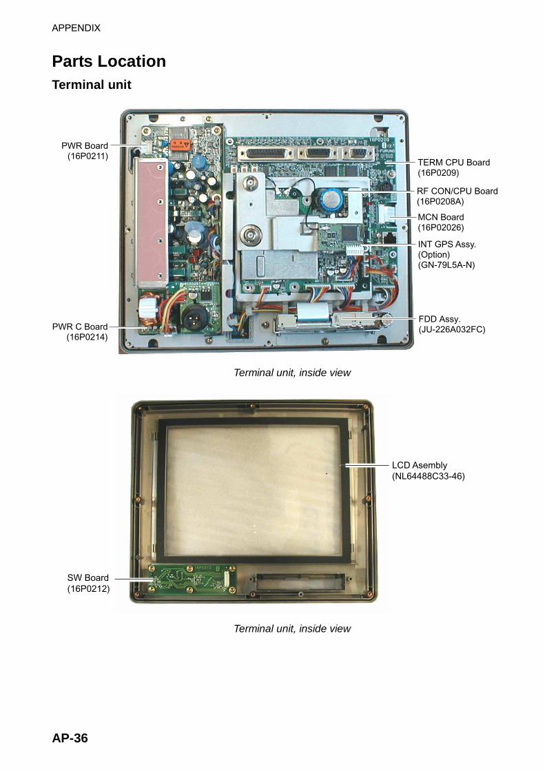
APPENDIX
AP-36
Parts Location Terminal unit
TERM CPU Board(16P0209)
INT GPS Assy.(Option)(GN-79L5A-N)
PWR Board(16P0211)
PWR C Board(16P0214)
RF CON/CPU Board(16P0208A)
FDD Assy.(JU-226A032FC)
MCN Board(16P02026)
Terminal unit, inside view
SW Board(16P0212)
LCD Asembly(NL64488C33-46)
Terminal unit, inside view

APPENDIX
AP-37
Antenna unit
ANT RF Board(16P0207)
ANT B Board(16P0206)
Antenna unit, cover opened

APPENDIX
AP-38
(This page intentionally left blank.)

SP-1 E5635S01G 031016
SPECIFICATIONS OF INMARSAT C MES FELCOM 15
1 GENERAL 1.1 Transmitting Frequency 1626.5 to 1646.5 MHz
1.2 Receiving Frequency 1530.0 to 1545.0 MHz
1.3 Channel Interval 5 kHz
1.4 G/T Better than -23 dB/K (elevation angle 5°)
1.5 EIRP 12 to 16 dBW (elevation angle 5°)
1.6 Modulation BPSK
1.7 Modulation Rate 1200 sps
1.8 Coding Convolution with coding rate 1/2 and constraint length 7
1.9 Decoding Viterbi decoder
1.10 Navigation Data Interface IEC61162-1, Internal GPS Board (option)
Input Data Sentences BWC, BWR, GGA, GLL, VTG, WPL, RMA, RMB, RMC, MTW,
DBT, VDR, ZDA
Output Data Sentences GGA, ZDA, GLL, VTG, RMC, GSV
1.11 EGC Receiver Built in (EGC: Enhanced Group Call)
2 ANTENNA UNIT 2.1 Antenna Type Daisy Loop Antenna
2.2 Gain
Horizontal: Omnidirectional
Vertical: 0 dBi or more (angle of elevation: 90°)
+1.3 dBi or more (angle of elevation: 5°)
2.3 Declination Clockwise circular
2.4 Axial Ratio Within 6 dB (5° to 90°)
2.5 VSWR 1.5 or less (50 ohm)
3 POWER SOURCE 12-24 VDC: 13.0-5.0 A (Transmit), 1.7-0.9 A (Receive)
4 ENVIRONMENTAL CONDITION 4.1 Ambient Temperature
Above deck equipment: -35°C to +55°C
Below deck equipment: -15°C to +55°C
4.2 Relative Humidity 95% (at +40°C)
4.3 Waterproof (IEC 60529)
Antenna Unit IPX6
Others IPX0
4.4 Vibration IEC 60945

SP-2 E5635S01F
5 COATING COLOR 5.1 Antenna Unit Upper: N9.5, Lower: 2.5PB3.5/10
5.2 Terminal Unit N3.0
5.3 Others 2.5GY5/1.5

IN-1
INDEX A Aborting .......................................................7-1 Alarm Unit IC-306........................................1-6 Audio alarm..................................................1-2
B Background color.........................................2-7 Battery replacement ....................................9-8 Brilliance ......................................................1-2
C Colors
background..............................................2-7 foreground ...............................................2-6
Currency unit ...............................................2-6
D Data report
preparing..................................................5-2 printing .....................................................5-7
Date format.......................................................2-6 manual input ............................................2-3
Delivery status automatic confirmation ..........................4-17 manual confirmation ..............................4-19
Diagnostics displaying program no. ............................9-2 testing terminal unit .................................9-2
Digital interface.............................................23 Directory
creating ..................................................2-33 specifying directory where to store
messages ..........................................2-35 Display indications.......................................1-9 Distress Alert/Received Call Unit IC-305
description ...............................................1-6 testing distress button..............................6-5 transmitting distress alert ........................6-1
DISTRESS button........................................1-1 testing ......................................................6-5 transmitting distress alert ........................6-1 distress alert transmission, nature of
distress not specified...........................6-1 distress alert transmission, nature of
distress specified.................................6-2
distress message .............................6-4, 6-6 testing distress button ......................6-5, 6-6
DNID displaying .............................................. 5-12 enabling/disabling ................................. 5-12
E Editor Setup menu ...................................... 3-4 EGC
description............................................. 2-11 EGC channels ....................................... 2-16 ENID...................................................... 4-34 message log.......................................... 4-35 message printing................................... 4-33 Printing messages automatically .......... 2-19 receiving channel selection..................... 7-3 receiving EGC distress or urgent
message............................................ 4-35 Saving messages automatically ........... 2-18 setup...................................................... 2-13
E-mail service list ............................................. 2-36 setup...................................................... 2-39
E-mail (by PC) attachment decoding format ................. 8-10 connection of single PC .......................... 8-4 e-mail client setting ............................... 8-15 gateway settings ..................................... 8-7 IP address ............................................... 8-5 mail gateway ......................................... 8-11 overview .................................................. 8-1 restricting access .................................... 8-8 restricting outgoing message size .......... 8-9 restrictions............................................... 8-2 selective forwarding .............................. 8-13 SMTP error messages.......................... 8-16 subnet mask............................................ 8-5
ENID.......................................................... 4-34 Error messages........................................... 9-9
F Files
combining.............................................. 3-17 Decoding MIME files ............................. 3-20 deleting.................................................. 3-18

INDEX
IN-2
opening..................................................3-14 printing files on floppy disks ..................3-17 renaming................................................3-19 saving ....................................................3-12 saving under new name ........................3-16 switching between two ..........................3-14
Floppy disks ejecting ..................................................3-10 formatting...............................................3-11 handling .................................................3-10 inserting .................................................3-10 printing files on ......................................3-17
Formatting floppy disk ...............................3-11 Function key description..............................1-5 Fuse replacement........................................9-8
I Inmarsat C system ........................................ ix International telegraphy alphabet...........AP-19 International telex abbreviations ............AP-18 International telex/telephone country
code list.................................................AP-9
K Keyboard .....................................................1-3
L LES
editing stations.......................................2-25 printing LES list......................................2-26 registering stations ................................2-24 toll charges ............................................2-22
LES IDs...................................................AP-17 LES information...........................................7-5 Log
displaying...............................................4-31 printing (automatic)................................4-32 printing (manual)....................................4-31
Logging in....................................................2-8 Logging out................................................2-10
M Maintenance ................................................9-1 Menu overview ..........................................1-13 Menu tree .................................................AP-1 Message report............................................5-4 Messages
deleting received ...................................4-30 preparation of confidential .......................3-3 preparation of routine ..............................3-2
printing received automatically ............. 4-28 saving received automatically............... 4-29
Messages (alerts) .................................. AP-20 MIME......................................................... 3-20
N NCS
channel selection .................................... 7-4 scanning.................................................. 7-2
NCS channels adding ................................................... 2-20
P Parts list ................................................. AP-34 Parts location ......................................... AP-36 Polling
commands............................................... 5-8 printing commands.................................. 5-7 reception ............................................... 5-11
Port setup EGC output port ...................................... 2-4 Message output port ............................... 2-4 Nav port................................................... 2-3 Terminal unit to use (Active port) ............ 2-4
Position automatic input of.................................... 2-3 manual input of ..................................... 2-32
POWER switch ........................................... 1-1 Printer PP-510 ............................................ 1-7 Printer selection ........................................ 1-20 Printing
data report............................................... 5-7 EGC messages..................................... 4-33 EGC messages (automatically) ............ 2-19 files on floppy disks............................... 3-17 LES list .................................................. 2-26 log (automatic) ...................................... 4-32 log (manual) .......................................... 4-31 polling command..................................... 5-7 received messages (automatically) ...... 4-28 station list .............................................. 2-31
Program no. list.............................................vii PV test
procedure................................................ 9-4 results...................................................... 9-5 sequence................................................. 9-3

INDEX
IN-3
R Receiving
attachments ...........................................4-27 description .............................................4-23 displaying received messages ..............4-25 EGC distress or urgent message ..........4-35 printing received messages (automatically)
...........................................................4-28 receive alarm on/off ...............................4-24 saving received messages to floppy disk
(automatically) ...................................4-29 Replacing text..............................................3-8
S Saving
EGC messages (automatically).............2-18 file under new name..............................3-16 files ........................................................3-12 received messages to floppy disk
(automatically) ...................................4-29 received messages to floppy disk
(manually) ..........................................4-28 Screensaver ................................................2-6 Searching text..............................................3-7 Send message log.....................................4-22 Shortcut key.................................................1-5 Standby display ...........................................1-8 Station list
adding stations ......................................2-27 editing stations.......................................2-30 printing ...................................................2-31
System configuration ................................... viii System settings
loading................................................... 2-40 saving.................................................... 2-40
System setup .............................................. 2-2 System status monitor ................................ 9-6
T Terminal setup............................................. 2-6 Terminal unit................................................ 1-1
display color ............................................ 2-7 testing...................................................... 9-2
Text copying and pasting ................................ 3-6 cutting and pasting .................................. 3-5 go to line.................................................. 3-9 inserting................................................... 3-7 inserting time or position......................... 3-9 replacing.................................................. 3-8 searching................................................. 3-7 selecting all ............................................. 3-7
Transmitting 2-digit code services ............................. 4-20 canceling ............................................... 4-16 file stored on floppy disk ....................... 4-15 message to station not on station list...... 4-8 message to station on station list............ 4-2
W Warning messages ................................... 9-10 Window color............................................... 2-6
