infoplc net intouch dassidirect da server siemens s7-200
DESCRIPTION
dgggbbvgTRANSCRIPT
Tech Note 355 How to use DASSIDirect DAServer Together with Siemens S7-200 PLC
All Tech Notes and KBCD documents and software are provided "as is" without warranty of any kind. See the Terms of Use for more information.
Topic#: 002006 Created: March 2004
This technote will go over the steps necessary to setup communication between the new DASSIDirect DAServer and a Siemens S7-200 PLC.
The TechNote consists of 4 parts:
Configure the S7-200 PLC Configure the DAServer Test the Communication Memory Areas in the S7-200 PLCs and How to Access Them Via DASSIDirect
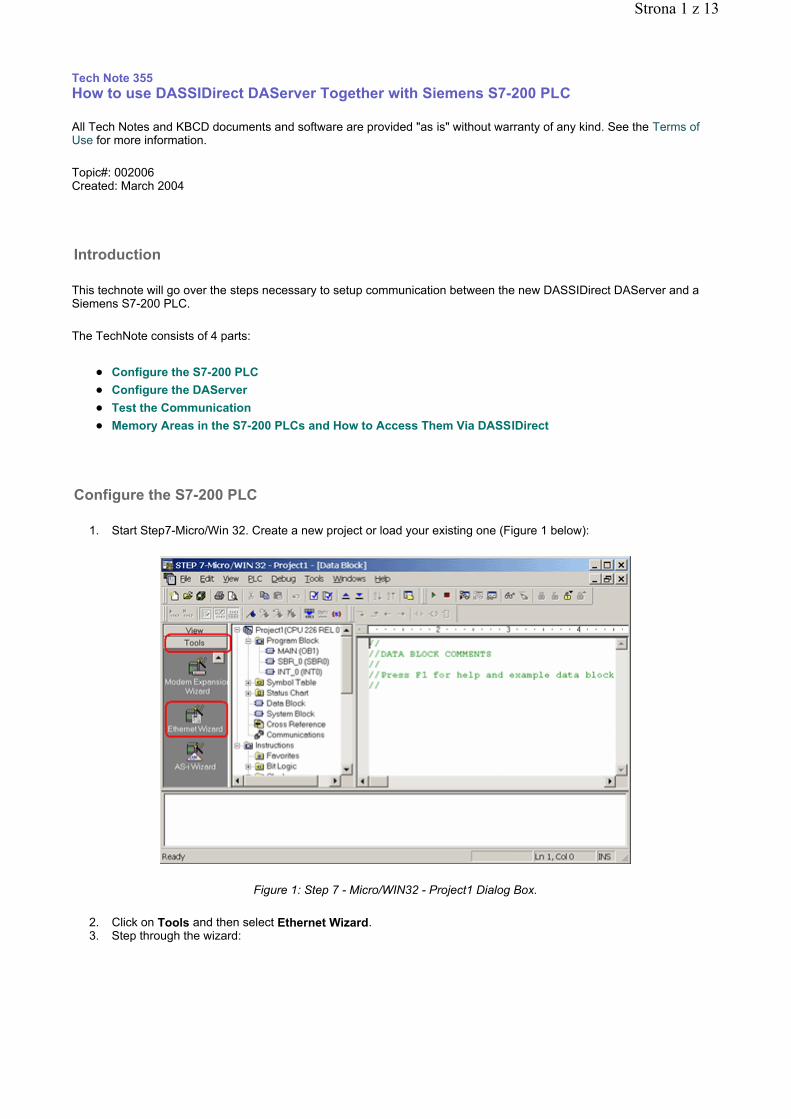
1. Start Step7-Micro/Win 32. Create a new project or load your existing one (Figure 1 below):
Figure 1: Step 7 - Micro/WIN32 - Project1 Dialog Box.
2. Click on Tools and then select Ethernet Wizard. 3. Step through the wizard:
Introduction
Configure the S7-200 PLC
Strona 1 z 13
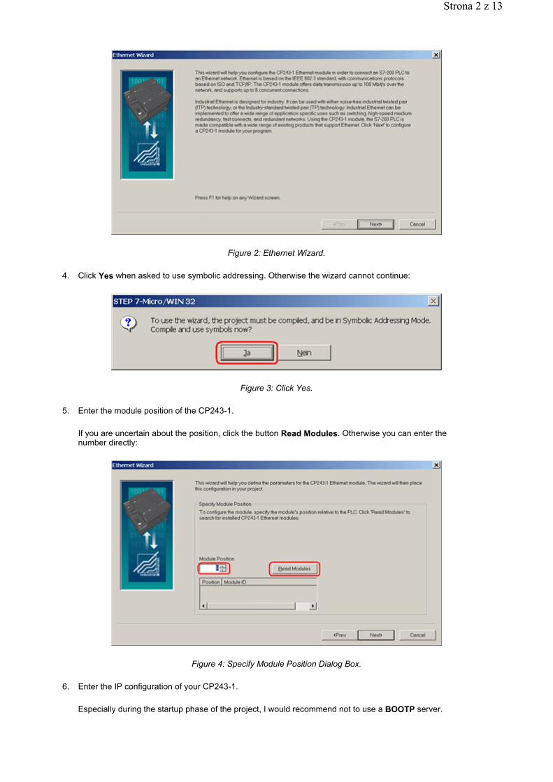
Figure 2: Ethernet Wizard.
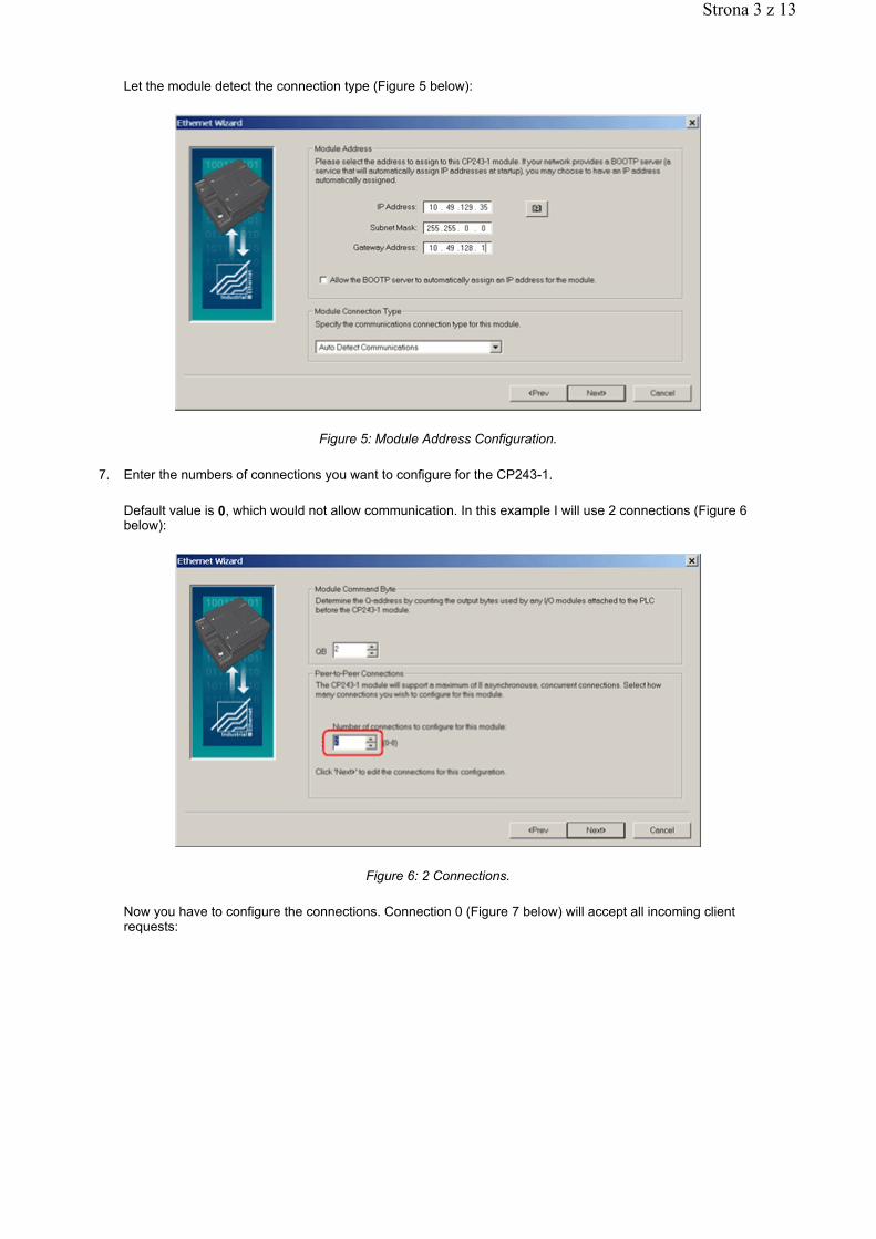
4. Click Yes when asked to use symbolic addressing. Otherwise the wizard cannot continue:
Figure 3: Click Yes.
5. Enter the module position of the CP243-1.
If you are uncertain about the position, click the button Read Modules. Otherwise you can enter the number directly:
Figure 4: Specify Module Position Dialog Box.
6. Enter the IP configuration of your CP243-1.
Especially during the startup phase of the project, I would recommend not to use a BOOTP server.
Strona 2 z 13
Let the module detect the connection type (Figure 5 below):
Figure 5: Module Address Configuration.
7. Enter the numbers of connections you want to configure for the CP243-1.
Default value is 0, which would not allow communication. In this example I will use 2 connections (Figure 6 below):
Figure 6: 2 Connections.
Now you have to configure the connections. Connection 0 (Figure 7 below) will accept all incoming client requests:
Strona 3 z 13
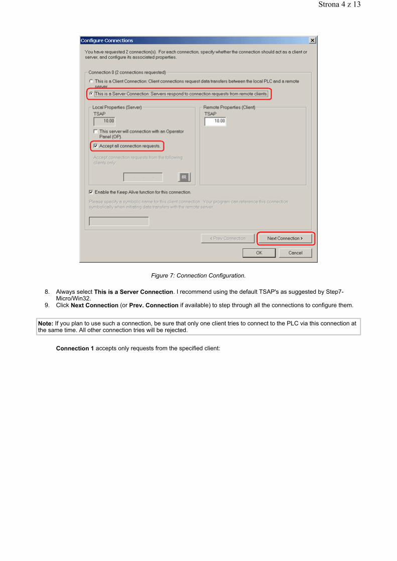
Figure 7: Connection Configuration.
8. Always select This is a Server Connection. I recommend using the default TSAP's as suggested by Step7-Micro/Win32.
9. Click Next Connection (or Prev. Connection if available) to step through all the connections to configure them.
Connection 1 accepts only requests from the specified client:
Note: If you plan to use such a connection, be sure that only one client tries to connect to the PLC via this connection at the same time. All other connection tries will be rejected.
Strona 4 z 13
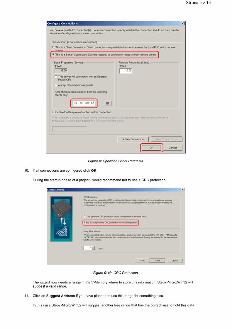
Figure 8: Specified Client Requests.
10. If all connections are configured click OK.
During the startup phase of a project I would recommend not to use a CRC protection:
Figure 9: No CRC Protection.
The wizard now needs a range in the V-Memory where to store this information. Step7-Micro/Win32 will suggest a valid range.
11. Click on Suggest Address if you have planned to use this range for something else.
In this case Step7-Micro/Win32 will suggest another free range that has the correct size to hold this data:
Strona 5 z 13
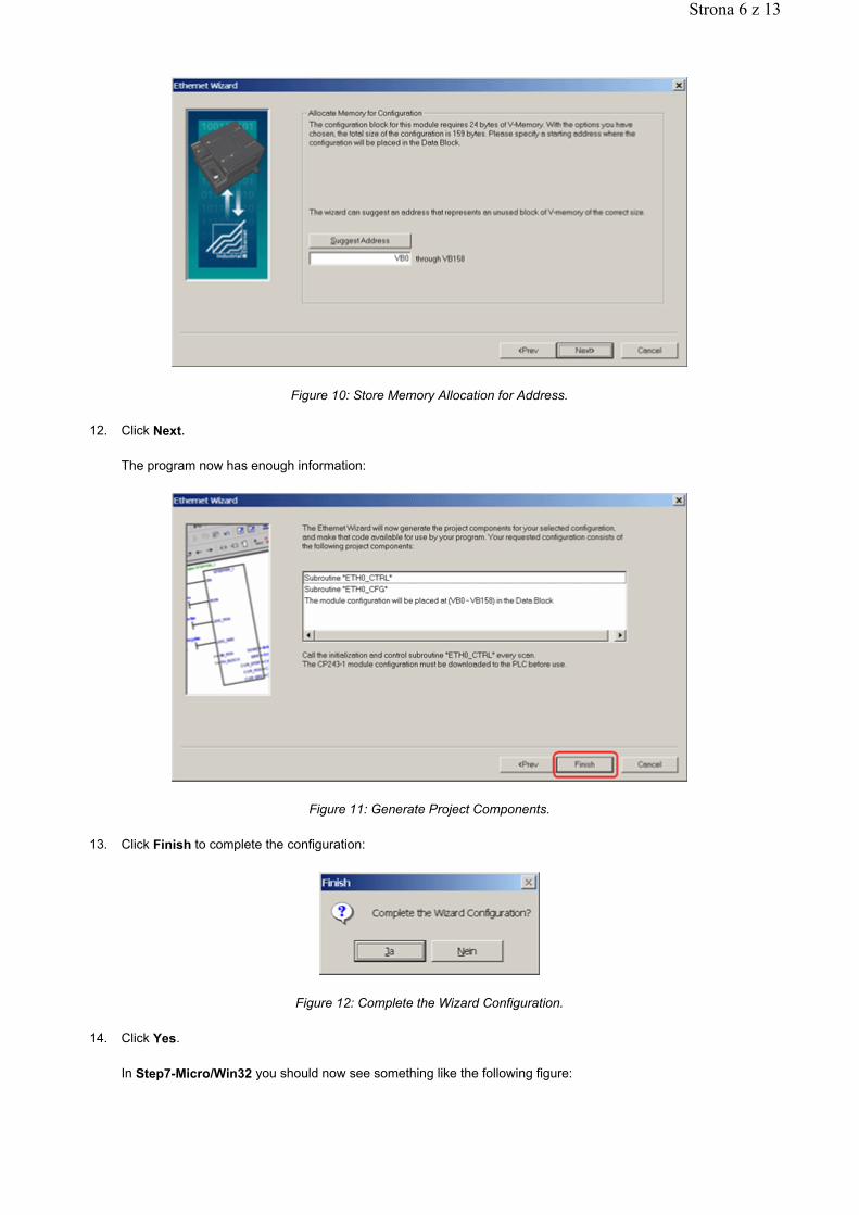
Figure 10: Store Memory Allocation for Address.
12. Click Next.
The program now has enough information:
Figure 11: Generate Project Components.
13. Click Finish to complete the configuration:
Figure 12: Complete the Wizard Configuration.
14. Click Yes.
In Step7-Micro/Win32 you should now see something like the following figure:
Strona 6 z 13
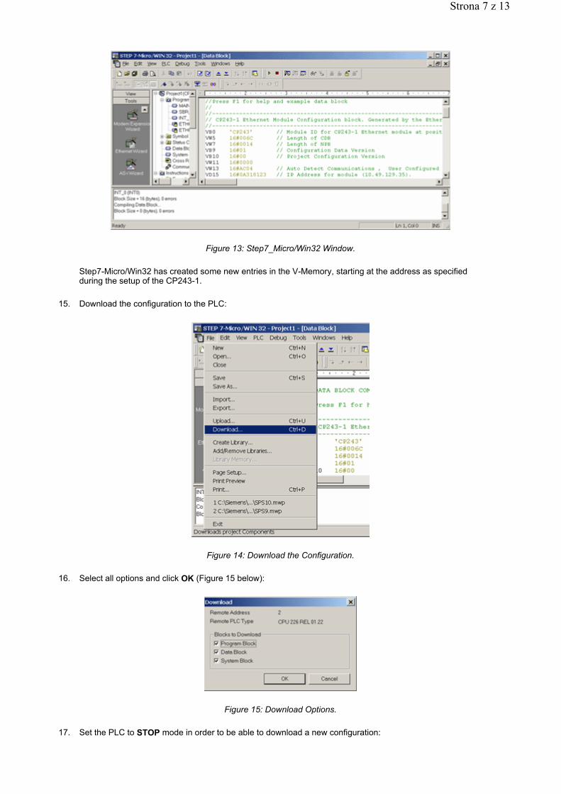
Figure 13: Step7_Micro/Win32 Window.
Step7-Micro/Win32 has created some new entries in the V-Memory, starting at the address as specified during the setup of the CP243-1.
15. Download the configuration to the PLC:
Figure 14: Download the Configuration.
16. Select all options and click OK (Figure 15 below):
Figure 15: Download Options.
17. Set the PLC to STOP mode in order to be able to download a new configuration:
Strona 7 z 13
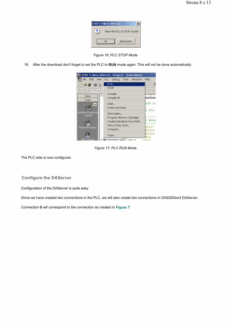
Figure 16: PLC STOP Mode.
18. After the download don't forget to set the PLC to RUN mode again. This will not be done automatically:
Figure 17: PLC RUN Mode.
The PLC side is now configured.
Configuration of the DAServer is quite easy.
Since we have created two connections in the PLC, we will also create two connections in DASSIDirect DAServer.
Connection 0 will correspond to the connection as created in Figure 7:
Configure the DAServer
Strona 8 z 13
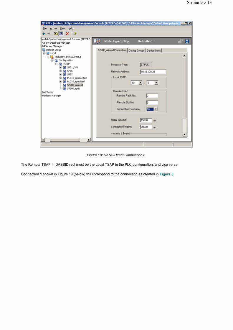
Figure 18: DASSIDirect Connection 0.
The Remote TSAP in DASSIDirect must be the Local TSAP in the PLC configuration, and vice versa.
Connection 1 shown in Figure 19 (below) will correspond to the connection as created in Figure 8:
Strona 9 z 13
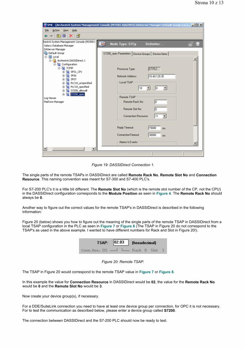
Figure 19: DASSIDirect Connection 1.
The single parts of the remote TSAPs in DASSIDirect are called Remote Rack No, Remote Slot No and Connection Resource. This naming convention was meant for S7-300 and S7-400 PLC's.
For S7-200 PLC's it is a little bit different. The Remote Slot No (which is the remote slot number of the CP, not the CPU) in the DASSIDirect configuration corresponds to the Module Position as seen in Figure 4. The Remote Rack No should always be 0.
Another way to figure out the correct values for the remote TSAP's in DASSIDirect is described in the following information:
Figure 20 (below) shows you how to figure out the meaning of the single parts of the remote TSAP in DASSIDirect from a local TSAP configuration in the PLC as seen in Figure 7 or Figure 8 (The TSAP in Figure 20 do not correspond to the TSAP's as used in the above example. I wanted to have different numbers for Rack and Slot in Figure 20!).
Figure 20: Remote TSAP.
The TSAP in Figure 20 would correspond to the remote TSAP value in Figure 7 or Figure 8.
In this example the value for Connection Resource in DASSIDirect would be 02, the value for the Remote Rack No would be 0 and the Remote Slot No would be 3.
Now create your device group(s), if necessary.
For a DDE/SuiteLink connection you need to have at least one device group per connection, for OPC it is not necessary. For to test the communication as described below, please enter a device group called S7200.
The connection between DASSIDirect and the S7-200 PLC should now be ready to test.
Strona 10 z 13
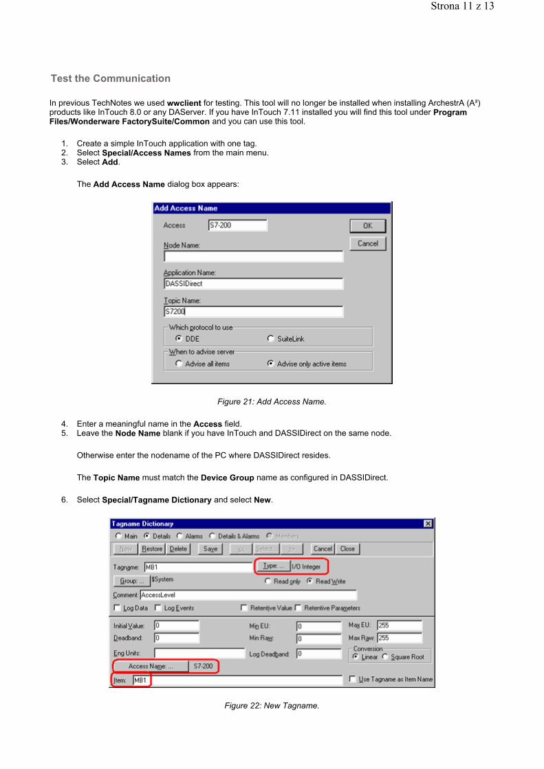
In previous TechNotes we used wwclient for testing. This tool will no longer be installed when installing ArchestrA (A²) products like InTouch 8.0 or any DAServer. If you have InTouch 7.11 installed you will find this tool under Program Files/Wonderware FactorySuite/Common and you can use this tool.
1. Create a simple InTouch application with one tag. 2. Select Special/Access Names from the main menu. 3. Select Add.
The Add Access Name dialog box appears:
Figure 21: Add Access Name.
4. Enter a meaningful name in the Access field. 5. Leave the Node Name blank if you have InTouch and DASSIDirect on the same node.
Otherwise enter the nodename of the PC where DASSIDirect resides.
The Topic Name must match the Device Group name as configured in DASSIDirect.
6. Select Special/Tagname Dictionary and select New.
Figure 22: New Tagname.
Test the Communication
Strona 11 z 13
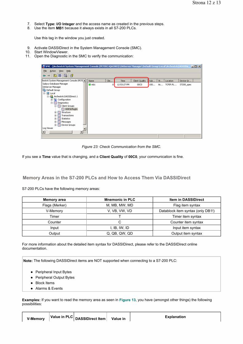
7. Select Type: I/O Integer and the access name as created in the previous steps. 8. Use the item MB1 because it always exists in all S7-200 PLCs.
Use this tag in the window you just created.
9. Activate DASSIDirect in the System Management Console (SMC). 10. Start WindowViewer. 11. Open the Diagnostic in the SMC to verify the communication:
Figure 23: Check Communication from the SMC.
If you see a Time value that is changing, and a Client Quality of 00C0, your communication is fine.
S7-200 PLCs have the following memory areas:
For more information about the detailed item syntax for DASSIDirect, please refer to the DASSIDirect online documentation.
Examples: If you want to read the memory area as seen in Figure 13, you have (amongst other things) the following possibilities:
Memory Areas in the S7-200 PLCs and How to Access Them Via DASSIDirect
Memory area Mnemonic in PLC Item in DASSIDirectFlags (Merker) M, MB, MW, MD Flag item syntax
V-Memory V, VB, VW, VD Datablock item syntax (only DB1!)Timer T Timer item syntax
Counter C Counter item syntaxInput I, IB, IW, ID Input item syntax
Output Q, QB, QW, QD Output item syntax
Note: The following DASSIDirect items are NOT supported when connecting to a S7-200 PLC:
Peripheral Input Bytes Peripheral Output Bytes Block Items Alarms & Events
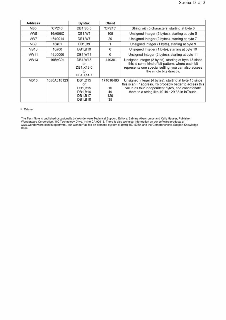
V-Memory Value in PLC DASSIDirect Item Value in Explanation
Strona 12 z 13
P. Crämer
Address Syntax ClientVB0 'CP243' DB1,S0,5 'CP243' String with 5 characters, starting at byte 0VW5 16#006C DB1,W5 108 Unsigned Integer (2 bytes), starting at byte 5VW7 16#0014 DB1,W7 20 Unsigned Integer (2 bytes), starting at byte 7VB9 16#01 DB1,B9 1 Unsigned Integer (1 byte), starting at byte 9VB10 16#00 DB1,B10 0 Unsigned Integer (1 byte), starting at byte 10VW11 16#0000 DB1,W11 0 Unsigned Integer (2 bytes), starting at byte 11VW13 16#AC04 DB1,W13
or DB1,X13.0
to DB1,X14.7
44036 Unsigned Integer (2 bytes), starting at byte 13 since this is some kind of bit-pattern, where each bit
represents one special setting, you can also access the single bits directly.
VD15 16#0A318123 DB1,D15 or
DB1,B15 DB1,B16 DB1,B17 DB1,B18
171016483
10 49 129 35
Unsigned Integer (4 bytes), starting at byte 15 since this is an IP address, it's probably better to access this
value as four independent bytes, and concatenate them to a string like 10.49.129.35 in InTouch.
The Tech Note is published occasionally by Wonderware Technical Support. Editors: Sabrina Abercromby and Kelly Hauser; Publisher: Wonderware Corporation, 100 Technology Drive, Irvine CA 92618. There is also technical information on our software products at www.wonderware.com/support/mmi, our WonderFax fax-on-demand system at (949) 450-5050, and the Comprehensive Support Knowledge Base.
Strona 13 z 13