influence of the microstructure on the deformation … of the microstructure on the deformation...
TRANSCRIPT
Influence of the microstructure on the deformation behaviour of metal
matrix composites
E. Soppaa, S. Schmaudera, G. Fischerb; J. ThesingC, R. RitterC
a Staatliche Materialprüfungsanstalt (MP A) University of Stuttgart, Pfaffenwaldring 32, D
70569 Stuttgart, Germany
b Dortmunder Initiative zur rechnerintegrierten Fertigung (RIF) e. V., Joseph-von-Fraunhofer
Straße 20, D-44227 Dortmund, Germany
CInstitut für Meßtechnik und Experimentelle Mechanik, Technische Universität
Braunschweig, Schleinitzstraße 20, Braunschweig, Germany
Abstract
In this contribution, investigations ofthe influence ofthe microstructure on the macro-, meso
and micro-effects in metal matrix composites are presented by direct combination of
experiment and simulation. The aim of the presented work consists in an improved
understanding of the mechanical behaviour of heterogeneous materials by combining
information of different length scales.
Keywords: metal matrix composites, microstructure, computer simulation, finite elements,
macro-, meso- and micro-Ievel of investigation
1. Introduction
"Tailoring of materials" is still a dream of engineers and scientists because of the unknown
correlation between microstructure and properties of most materials. Real materials are
heterogeneous on different length scales from the nano- up to the macro-Ievel. A special
example are composites, which consist of two or more phases and possess a great variety of
microstructures with different volume fraction, size and shape of the phases, arrangement as
weIl as the grain sizes of the phases. Depending on the length scale of observation/simulation
different details can be investigated. The aim of the present work is an improved
understanding of the deformation behaviour of metal-matrix composites and determination of
microstructure/properties-correlation on different length scales for better prediction of damage
initiation processes and with respect to optimized material design.
2. Materials
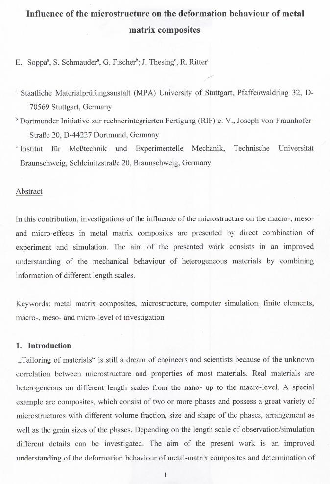
Metal-ceramic composites like AI(6061)/SiC (Fig. 1) and AI(6061)/AI203 1 are highly promi
sing materials because of very interesting mechanical properties. They combine low density
with improved strength, creep and wear resistance, together with sufficient amount of ductility
and stiffness [1, 2].
120 ~m I
Fig.1 Microstructure of AI(6061)/SiC(1 Ovol.%).
3. Methods, results and discussion
In the following chapters the experimental and numerical results obtained on the macro- (3.1),
meso- (3.2) and micro-Ievels (3.3) will be discussed.
3.1 Experimental and numerical investigations of the deformation behaviour of Al/Sie
on the macro-Ievel
The influence of the component2 shape and material properties such as yield stress and work
hardening on the strain and stress distribution in AI/SiC on the macro-Ievel is studied using an
optical grating method [3, 4] and the finite element method for numerical simulations. The
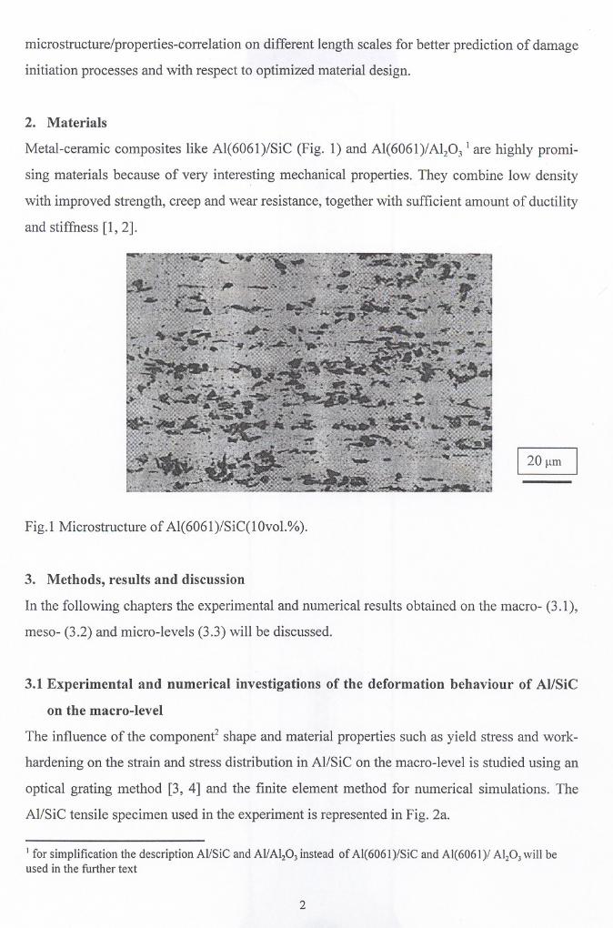
Al/SiC tensile specimen used in the experiment is represented in Fig. 2a.
I for simplification the description Al/SiC and AI/Alz03 instead of AI(6061)/SiC and AI(6061)/ Alz03 will beused in the further text
2
a) b)
1"'----- ..-----7
I,!! ;.c;;;'/.......----- . , \ "".\-
.,\.'0
"5·
\" \
\\\
image planes
i\ Z
/
//
//
/
j"
c)
grating structure
Fig. 2 a) tensile specimen used in the experiment, b) a stochastic Ti02 grating attached onto
the object surface in the middle part of the component, c) a set-up of a stereographie
arrangement.
2 in this context component means a device element3
A stoehastie Ti02 grating was attaehed onto the objeet surfaee in the middle part of the
speeimen in order to optimize the blaek-white eontrast. Images of the objeet surfaee with the
attaehed grating were reeorded by CCD-eameras and digitaIly proeessed by an area-based
matehing algorithm [3]. A set-up of a stereographie arrangement is shown in Fig. 2e. Und er
external loading, the deformation of the speeimen surfaee is equivalent to the ehange of the
distanee between the attaehed optieal marks. Relating the differenees of the loeation of
neighboring marks to their initial distanee, the average strain in the measured field is obtained.
The result is the whole deformation dataset of the investigated area. On the other hand, one
quarter of the speeimen under symmetry boundary eonditions is simulated, by means of finite
element method in plane strain, using the maeroseopie material properties as input-data. The
3-dimensional FE ea1culations are planed in the next future.
-3.0 -2.0 -1.0 0.0 1.0 2.0 3.0
..... 0.43 %·111·
0.82 %'-r
1.22 %-+..
1.61 %",* ..
201 %....
2.41 %,,,-
2.80%.)C.
3.20%
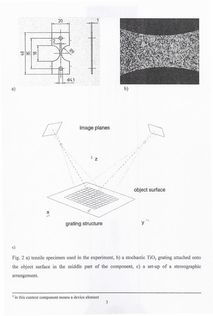
Fig. 3 Comparison between the measured and simulated deformation fields by uniaxial tensile
loading in Al/SiC(l Ovol.%). The ranges and partitioning of the seala are the same for both
types of results.
Fig. 3 shows a eomparison between the measured and simulated deformation fields in
AI/SiC(lOvol.%). The strain patterns are very similar in both eases. The asymmetrie
distribution of the axial strain with respeet to the symmetry planes in the tensile speeimen
observed in the experiment is probably eaused by an inhomogeneous arrangement of the SiC
partic1es or is due to asymmetriealloading. This faets have not been taken into aeeount in the
numerieal ealeulation, where isotropie and maeroseopie material properties as weIl as a
symmetriealloading were used as an input. This problem eould be probably avoided by using
measured experimental displaeements at the edges of the model as boundary eonditions in the
FE-model.
4
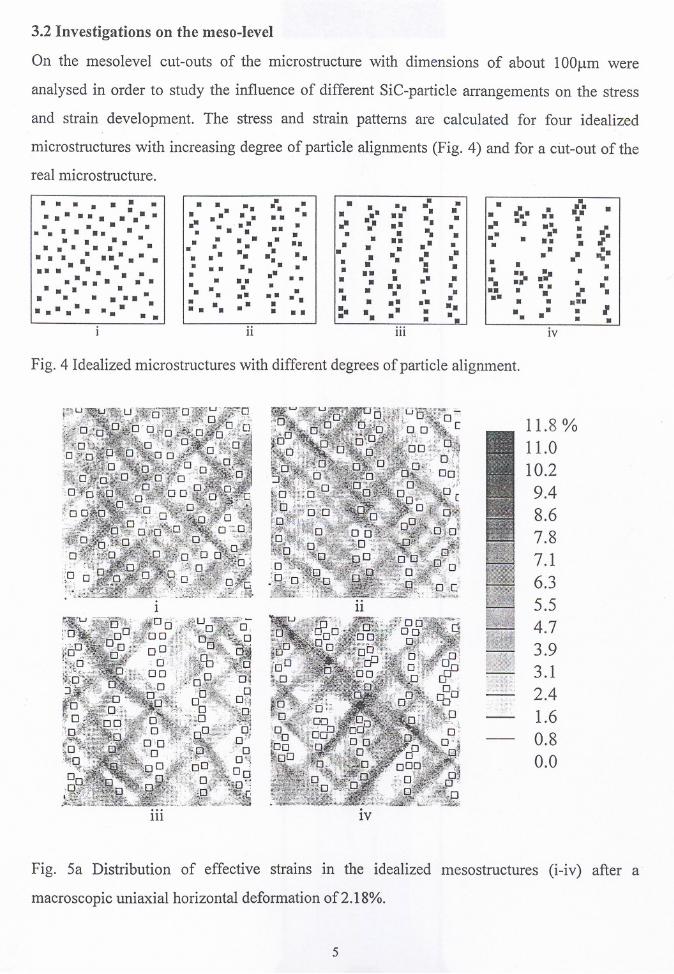
3.2 Investigations on the meso-level
On the mesolevel cut-outs of the microstructure with dimensions of about lOOJ.lmwere
analysed in order to study the influence of different SiC-partic1e arrangements on the stress
and strain development. The stress and strain patterns are calculated for four idealized
microstructures with increasing degree of partic1ealignments (Fig. 4) and for a cut-out of the
real microstructure.
..... - ..........- .• •• •...... - .••••••••• •.... - .•••• a ••••••••••••••••• • •••••••....... - .
••• • ••••••• • ••• ••••• •••• • ••• ••• •••••• • ••• •••••• • ••••• • ••• • ••• • •• •••• • • •• •••••• •• • •••• •• •••
ii
••• ••••••• •••••• .-.•• •••• •••••• ••••••• •• • •••
••••••• •••• •• •••• •• •• •••• •• •• •••••••• ••:. ••• ••
iii
•• •••••••• ••••••••••••••••• •••;-• •• •• •~.• ••• • •• .~••• ••• ••• ••• • •••• ••••• •••••I• ••• • ••
iv
Fig. 4 Idealized microstructures with different degrees of partic1ealignment.
111
11
IV
11.8 %11.010.29.48.67.87.16.35.54.73.93.12.41.60.80.0
Fig. 5a Distribution of effective strains in the idealized mesostructures (i-iv) after a
macroscopic uniaxial horizontal deformation of 2.18%.
5
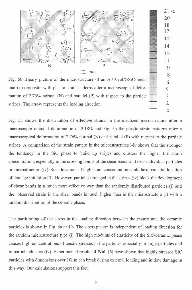
Fig. 5b Binary picture of the microstructure of an AIIlOvol.%SiC-metal
matrix composite with plastic strain patterns after a macroscopical defor
mation of 2.76% normal (N) and parallel (P) with respect to the particle
stripes. The arrow represents the loading direction.
21 %
20
1817
15
14
12
11
9
8
6
5
3
2
o
Fig. 5a shows the distribution of effective strains in the idealized mesostructure after a
macroscopic uni axial deformation of 2.18% and Fig. 5b the plastic strain patterns after a
macroscopical deformation of 2.76% normal (N) and parallel (P) with respect to the particle
stripes. A comparison of the strain pattern in the microstructures i-iv shows that the stronger
the tendency in the SiC phase to build up stripes and clusters the higher the strain
concentration, especially in the crossing points ofthe shear bands and near individual particles
in microstructure (iv). Such locations ofhigh strain concentration could be a potentiallocation
of damage initiation [5]. However, particles arranged in the stripes (iv) block the development
of shear bands in a much more effective way than the randomly distributed particles (i) and
the observed strain in the shear bands is much higher than in the microstructure (i) with a
random distribution of the ceramic phase.
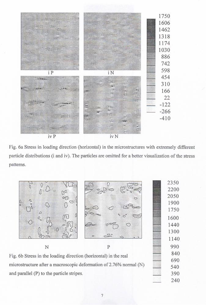
The partitioning of the stress in the loading direction between the matrix and the ceramic
particles is shown in Fig. 6a and b. The stress pattern is independent of loading direction für
the random microstructure type (i). The high modulus of elasticity of the SiC-ceramic phase
causes high concentrations of tensile stresses in the particles especially in large particles and
in particle clusters (iv). Experimental results of Wulf [6] have shown that highly stressed SiC
particles with dimensions over lOl-lm can break during externalloading and initiate damage in
this way. Gur calculations support this fact.
6
iP
iv P
iN
ivN
1750
1606
1462
1318
1174
1030
886
742
598454
310
166
22-122
-266
-410
Fig. 6a Stress in loading direction (horizontal) in the microstructures with extremely different
partic1e distributions (i and iv). The partic1es are omitted for a better visualization ofthe stress
patterns.
Fig. 6b Stress in the loading direction (horizontal) in the real
microstructure after a macroscopic deformation of2.76% normal (N)
and parallel (P) to the partic1e stripes.
2350
2200
2050
1900
1750
1600
1440
1300
1140
990
840
690
540
390
240
PN
7
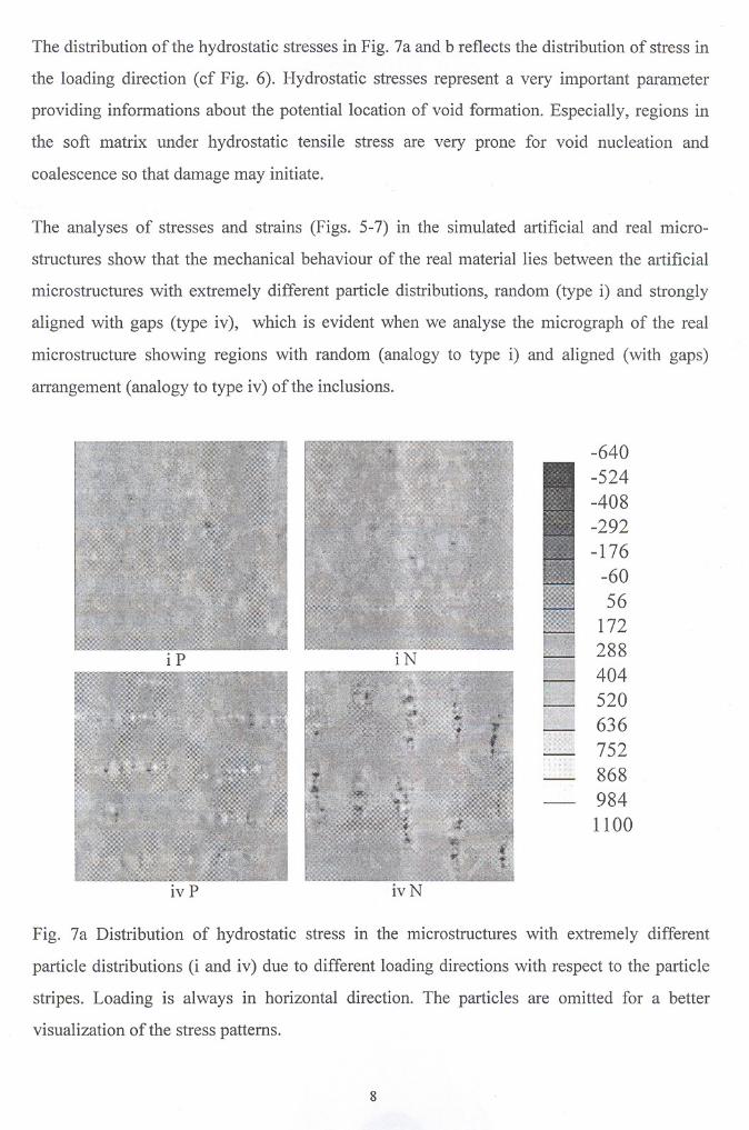
The distribution of the hydrostatic stresses in Fig. 7a and b reflects the distribution of stress in
the loading direction (cf Fig. 6). Hydrostatic stresses represent a very important parameter
providing informations about the potentiallocation of void formation. Especially, regions in
the soft matrix under hydrostatic tensile stress are very prone for void nucleation and
coalescence so that damage may initiate.
The analyses of stresses and strains (Figs. 5-7) in the simulated artificial and real micro
structures show that the mechanical behaviour of the real material lies between the miificial
microstructures with extremely different particle distributions, random (type i) and strongly
aligned with gaps (type iv), which is evident when we analyse the micrograph of the real
microstructure showing regions with random (analogy to type i) and aligned (with gaps)
arrangement (analogy to type iv) ofthe inclusions.
iP
iv P
iN
ivN
-640
-524
-408
-292
-176
-6056
172288
404
520
636
752
868
984
1100
Fig. 7a Distribution of hydrostatic stress in the microstructures with extremely different
particle distributions (i and iv) due to different loading directions with respect to the particle
stripes. Loading is always in horizontal direction. The particles are omitted for a better
visualization of the stress patterns.
8
N P
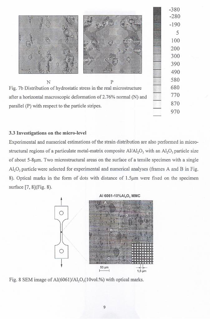
Fig. 7b Distribution of hydrostatic stress in the real microstructure
after a horizontal macroscopic deformation of2.76% normal (N) and
parallel (P) with respect to the partic1e stripes.
-380-280
-190
5
100
200
300
390
490
580
680770
870
970
3.3 Investigations on the micro-level
Experimental and numerical estimations of the strain distribution are also performed in micro
structural regions of a particulate metal-matrix composite All Al203 with an Al203 partic1e size
of about 5-8f!m. Two microstructural areas on the surface of a tensile specimen with a single
Al203 partic1e were selected for experimental and numerical analyses (frames A and B in Fig.
8). Optical marks in the form of dots with distance of 1.5f!m were fixed on the specimen
surface [7, 8](Fig. 8).
t
o
o
Fig. 8 SEM image of AI(6061)/AI20llOvol.%) with optical marks.
9
Area A Area B
1 Binarization 1$///////////1,
'l///I//IIIIII t\j
r . I
I "I matrix
~i ~
1:\ , %
U\\\\\\\~l1l1/////Y mmmf1777~
edge displacementat 3.1 % overall strain
b
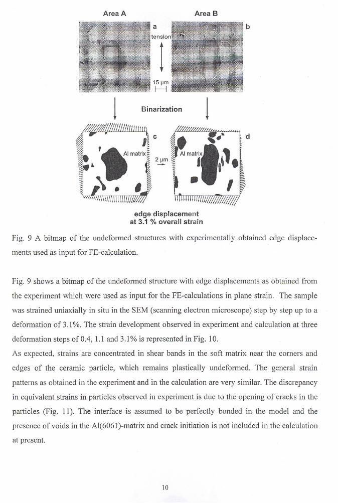
Fig. 9 A bitmap of the undeformed structures with experimentally obtained edge displace
ments used as input for FE-calculation.
Fig. 9 shows a bitmap of the undeformed structure with edge displacements as obtained from
the experiment which were used as input far the FE-calculations in plane strain. The sampie
was strained uniaxially in situ in the SEM (scanning electron microscope) step by step up to a
deformation of 3.1%. The strain development observed in experiment and calculation at three
deformation steps of 0.4, 1.1 and 3.1% is represented in Fig. 10.
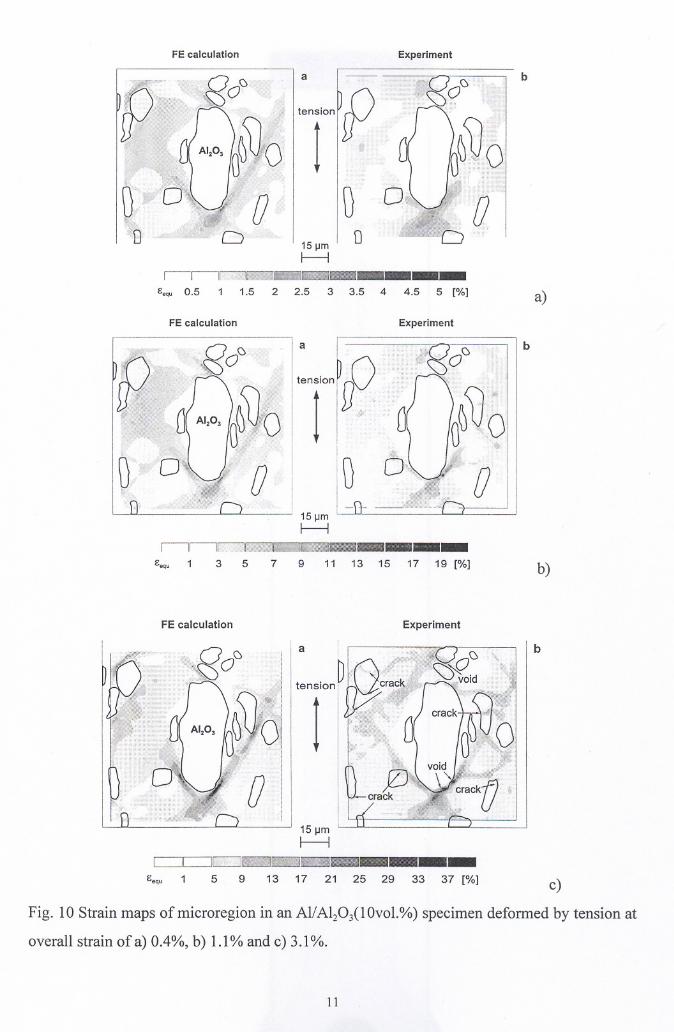
As expected, strains are concentrated in shear bands in the soft matrix near the corners and
edges of the ceramic partic1e, which remains plastically undeformed. The general strain
patterns as obtained in the experiment and in the calculation are very similar. The discrepancy
in equivalent strains in partic1es observed in experiment is due to the opening of cracks in the
partic1es (Fig. 11). The interface is assumed to be perfectly bonded in the model and the
presence ofvoids in the Al(6061)-matrix and crack initiation is not inc1uded in the calculation
at present.
10
FE calculation Experiment
\J
a
IOT"rPI
Ü
15 ~mf------1
11111· .•iWlii@i@iiiiI@•••••• _
Eeq, 0.5 1 1.5 2 2.5 3 3.5 4 4.5 5 [%]
b
a)
FE calculation Experiment
b
b)
FE calculation Experiment
a
15IJmI---l
c:::=Jc:::=Jr.::::=J __ atiii1i.im, _
Eequ 1 5 9 13 17 21 25 29 33 37 [%]
b
c)
Fig. 10 Strain maps ofmicroregion in an Al/A1203(10vol.%) specimen deformed by tension at
overall strain of a) 0.4%, b) 1.1% and c) 3.1%.
11
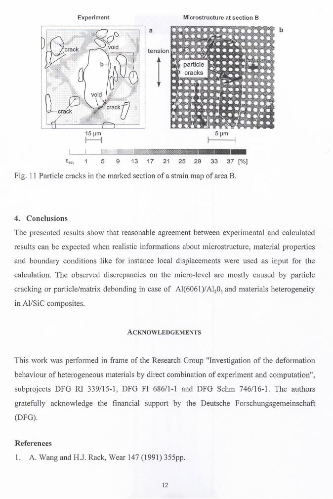
Experiment
a
tension
Microstructure at section B
b
15 11m 5 11m
~ I I
~~II;~f»;1.1w;;;illf,f;Wlll'- _
cequ 1 5 9 13 17 21 25 29 33 37 [%]
Fig. 11 Particle cracks in the marked section of astrain map of area B.
4. Conclusions
The presented results show that reasonable agreement between experimental and calculated
results can be expected when realistic informations about microstructure, material properties
and boundary conditions like for instance local displacements were used as input for the
calculation. The observed discrepancies on the micro-Ievel are mostly caused by particle
cracking or particle/matrix debonding in case of Al(6061)/AI203 and materials heterogeneity
in Al/Sie composites.
ACKNOWLEDGEMENTS
This work was performed in frame of the Research Group "Investigation of the deformation
behaviour of heterogeneous materials by direct combination of experiment and computation",
subprojects DFG Rl 339/15-1, DFG FI 686/1-1 and DFG Schm 746/16-1. The authors
gratefully acknowledge the financial support by the Deutsche Forschungsgemeinschaft
(DFG).
References
1. A. Wang and H.l. Rack, Wear 147 (1991) 355pp.
12
2. A. Wang and H.J. Rack, Acta metall. Mater. 40 (1992) 2301pp.
3. M. Erbe, K. Galanulis, R. Ritter and E. Steck, Engineering Fracture Mechanics Vol. 48,
No. 1 (1994) 103-118pp.
4. H. Neuhäuser, R. Ritter, E. Steck, J. Thesing, H. Wittich and A. Ziegenbein,
Experimental and numerical investigations of the inelastic behaviour of polycristalline
materials on a microscopic scale,.
5. E. Soppa, S. Schmauder, G. Fischer, Numerical and experimental investigations of the
influence of particle alignment on shear band formation in Al/SiC, Proceedings of the 19th
Ris0 International Symposium on Materials Science: Modelling of Structure and
Mechanics of Materials from Microscale to Product, Ris0 National Laboratory, Roskilde
Denmark (1998) 499-504pp.
6. J. Wulf, Neue Finite-elemente-Methoden zur Simulation des Duktilbruchs in Al/SiC,
Reihe 18, Nr. 173, VDI Verlag, Düsseldorf (1995).
7. Y.-L. Liu and G. Fischer, Scripta Mater., Vol. 36, No. 10 (1997) 1187-1194pp.
8. G. Fischer, E. Soppa, S. Schmauder and Y.-L. Liu, Modelling of strain localization in real
microstructural areas of the particle reinforced metal-matrix composite Al 6061-10%
A1203, Proceedings of the 19th Ris0 International Symposium on Materials Science:
Modelling of Structure and Mechanics of Materials from Microscale to Product, Ris0
National Laboratory, Roskilde Denmark (1998) 26l-266pp.
13