inflight entertainment systems manualps engineering ife systems interface manual general rules 2.1...
TRANSCRIPT

9800 Martel Road Lenoir City, TN 37772
www.ps-engineering.com
IInn--fflliigghhtt EEnntteerrttaaiinnmmeenntt SSyysstteemmss IInntteerrffaaccee
MMaannuuaall
Document P/N 200-108-0405
April 2005
System Installation and Interface Manual
PS Engineering, Inc. 2005 © Copyright Notice
Any reproduction or retransmittal of this publication, or any portion thereof, without the expressed written permission of PS Engineering, Inc. is strictly prohibited. For further information contact the Publications Manager at PS Engineering, Inc., 9800 Martel Road, Lenoir City, TN 37772. Phone (865) 988-9800, email [email protected].

Table of Contents
Section I GENERAL INFORMATION..................................................................... 1-1 1.1 INTRODUCTION............................................................................................... 1-1 1.2 SCOPE ................................................................................................................. 1-1 1.3 ABBREVIATIONS ................................................................................................... 1-1
General Rules............................................................................................................. 2-1 2.1 INPUT DEVICES ..................................................................................................... 2-1 2.2 SHIELDING & GROUNDS....................................................................................... 2-1
Intercoms.................................................................................................................... 3-1 3.1 MONO ................................................................................................................... 3-2 3.1.1 PM501............................................................................................................................ 3-2 3.1.2 PM1000DAP (DUAL AUDIO PANEL) ............................................................................. 3-2 3.1.3 PM1000II ....................................................................................................................... 3-2 3.1.4 PM1200.......................................................................................................................... 3-2 3.2 STEREO ................................................................................................................. 3-3 3.2.1 PM3000 4-PLACE ........................................................................................................... 3-3 3.2.2 PM3000 6-PLACE, W/CREW ........................................................................................... 3-3 3.3 PARALLELING MUSIC INPUTS ............................................................................... 3-3
Audio Panels .............................................................................................................. 4-4 4.1 MONO ................................................................................................................... 4-4 4.1.1 PMA4000....................................................................................................................... 4-4 4.1.2 PMA6000 MONO ........................................................................................................... 4-4 4.2 STEREO ................................................................................................................. 4-5 4.2.1 PMA6000 STEREO (DISCONTINUED)............................................................................. 4-5 4.2.2 PMA7000-SERIES .......................................................................................................... 4-5 4.3 PMA8000 ............................................................................................................. 4-6
In Flight Entertainment Systems................................................................................ 5-8 5.1 IFE SYSTEMS AND FEATURES .............................................................................. 5-8 5.2 PCD7100 .............................................................................................................. 5-9 5.2.1 PCD7100-P .................................................................................................................... 5-9 5.2.2 PCD7100-I ..................................................................................................................... 5-9 5.3 PXE7300 & PXE7300-SR................................................................................. 5-10 5.4 PAV80 ................................................................................................................ 5-12
Integrated Systems................................................................................................... 6-12 6.1 PMA7000-CD .................................................................................................... 6-13 6.2 PMA8000-SR..................................................................................................... 6-14
Table of Tables Table 3-1 Intercom Model Comparison........................................................................... 3-1 Table 5-1 IFE System Comparison.................................................................................. 5-8 Table 6-1 Integrated IFE Systems Comparison............................................................. 6-12

PS Engineering IFE Systems Interface Manual
Table of Figures
Figure 4-2 PMA7000 Music 2 Mute Options.................................................................. 4-6 Figure 4-3 PMA8000 Music 2 Mute Options.................................................................. 4-7 Figure 5-1 PCD7100-P Interface Drawing ...................................................................... 5-9 Figure 5-2 PCD7100-I Loopback detail .......................................................................... 5-9 Figure 5-3 PXE7300 Interface Drawing........................................................................ 5-11 Figure 5-4 PAV80 Interface Drawing ........................................................................... 5-12 Figure 6-1 PMA7000-CD External Volume Control .................................................... 6-13 Figure 6-2 PMA-7000-CD External Music 2 with PCD7100-R ................................... 6-14 Figure 6-3 PMA7000-CD Music 2 muting.................................................................... 6-14 Figure 6-4 PMA8000-SR External Additional Music 2 Input....................................... 6-15 Figure 6-5 PMA8000-SR Dual alternate music inputs .................................................. 6-15 Figure 6-6 PMA8000-SR With PCD7100 or PXE7300 as Music 2.............................. 6-16 Figure 6-7 PMA8000-SR with PCD7100-P/PXE7300 as Music 1 and/or 2 ................. 6-16 Figure 6-8 PMA8000-SR using PXE7300 as control .................................................... 6-16 Figure 6-9 PMA8000-SR using PAV80 as control ....................................................... 6-17
Rev Date Change New 4/21/05 Incorporated final draft changes, released
200-108-0405 Page ii APRIL 2005

PS Engineering IFE Systems Interface Manual
Section I GENERAL INFORMATION
1.1 INTRODUCTION
This manual is designed to provide background information to aid the PS Engineering professional installers to efficiently interface In-flight Entertainment (IFE) System to au-dio panels and intercoms. It contains information regarding the basic interface to com-plex switching combinations.
This document does not replace the Installation Manuals for the specific PS Engi-neering, or other manufacturer’s products. Refer to the product specific installation manual for all of the installation procedures.
1.2 SCOPE
This manual provides interface information for PS Engineering products, including inter-com, audio control panels, and in-flight entertainment systems. It also contains generic information for other types and manufacturers; however, this information is not guaran-teed accurate.
1.3 Abbreviations
CREW Crew intercom mode
ICS Intercom System
IFE In-Flight Entertainment
ISO Isolate intercom mode
L Left Channel
R Right Channel
WRT With Respect To
200-108-0405 1-1 APRIL 2005

PS Engineering IFE Systems Interface Manual
General Rules
2.1 Input devices
NOTE : Use the low level output of any entertainment device to connect to the audio panel. Maximum signal level is 2 VAC p-p. DO NOT use a speaker-level output, this will cause internal damage in the audio panel.
To interface a speaker level, install an AudioLink /PowerLink 101PL2 adapter, available from Crutchfield at 1-800-955-3000 (804)-817-1000, [email protected]
2.2 Shielding & Grounds
Shield grounds should be connected at one end only, preferably at the signal source.
Shield ground and audio low must always be kept separate. Do NOT use the shield as an audio return. For stereo systems use 3-wire with shield.
Intercoms PS Engineering makes a version of intercoms to fit any almost application and budget. However, it is important to consider the IFE limitations when selecting a system and in-terface.
Unit Part Number Stereo/Mono Intercom places
Music inputs
PM501 11800 Mono 4 1
PM1000-DAP 11900D Mono 2+ None
PM1000II 11922 Mono 4 1
PM1000II w/crew
11920 Mono 4 1 + 1
PM1200 11960 Mono 2 1
PM3000 11931 Stereo 4 1
PM3000 w/crew
11932 Stereo 6 1 + 1
Table 3-1 Intercom Model Comparison
200-108-0405 3-1 APRIL 2005

PS Engineering IFE Systems Interface Manual
3.1 Mono
In general, PS Engineering’s monaural intercoms do not support a karaoke (non muted) mode. This is because IFE is not a high priority for monaural intercom buyers.
For PS Engineering IFE systems, such as PCD7100-P, PXE7300 or PAV80, the left and right outputs can be tied together and connected to the entertainment inputs.
3.1.1 PM501 The music input to the PM501 is pin 1, WRT ground, Pin 5.
The PM501 does not support karaoke. The music input will mute in the presence of radio or intercom activity.
3.1.2 PM1000DAP (Dual Audio Panel)
The PM1000DAP Does not support IFE.
3.1.3 PM1000II The PM1000II does not support karaoke. The music input will mute in the presence of radio and intercom activity.
3.1.3.1 PM1000II without crew, P/N 11922 The music input to the PM1000II is pin 20, WRT Pin 7. Music 1 will be heard in all headsets in ALL mode, Music will NOT be heard in the pilot headset in ISO.
3.1.3.2 PM1000II with crew, P/N 11920 The music 1 input to the PM1000II is pin 20, WRT Pin 7. Music 1 will be heard in all headsets in ALL mode, music will NOT be heard in the pilot headset in ISO.
The music 2 input to the 11920 is pin 16, WRT Pin 3. Music 2 will be heard in the pas-senger headsets ONLY when the unit is in CREW mode. Pilot and Copilot positions will hear Music 1 in CREW mode.
3.1.4 PM1200 The music input to the PM1200 is pin 20, WRT Pin 7. Music 1 will be heard in all head-sets in ALL mode, Music will NOT be heard in the pilot headset in ISO.
The PM1200 does not support karaoke mode. The music input will mute in the presence of radio and intercom activity.
200-108-0405 3-2 APRIL 2005

PS Engineering IFE Systems Interface Manual
3.2 Stereo
3.2.1 PM3000 4-place The stereo music inputs to the PM3000 are pin 24 (Left), pin 11 (WRT Pin 7). Music 1 will be heard in all headsets in ALL mode, Music will NOT be heard in the pilot headset in ISO.
The right knob (squelch) incorporates a push/push switch that controls the music mute (karaoke) mode. When the mute inhibit (karaoke) mode is on, music will remain at a con-stant level. When the mute is enabled, the music will be muted –30 dB when there is ra-dio or ICS activity.
3.2.2 PM3000 6-place, w/crew The stereo music #1 inputs to the PM3000 are pin 24 (Left), pin 11 (WRT Pin 1). Music 1 will be heard in all headsets in ALL mode, Music will NOT be heard in the pilot head-set in ISO.
The stereo music #2 inputs to the PM3000 are pin 17 (Left), pin 4 (WRT Pin 7. Music 2 will only be heard in passenger headsets in CREW mode, Music 2 will NOT be heard in the pilot and copilot headset.
The right knob (squelch) incorporates a push/push switch that controls the music mute (karaoke) mode for Music #1. When the mute inhibit (karaoke) mode is on, music will remain at a constant level. When the mute is enabled, the music will be muted –30 dB when there is radio or ICS activity.
Music #2 does not have mute capability, and always remains at a constant level.
3.3 Paralleling music inputs
For stereo music inputs, the Music 1 and Music #2 can be connected together as shown.
We recommend that a switch be used to remove the music from Music 1 when the crew does not want IFE, and the passengers do.
LeftRightLo
Ent. #2 Input
Parallel Music Interconnect
Left
RightLo
Ent. #1 Input
200-108-0405 3-3 APRIL 2005

PS Engineering IFE Systems Interface Manual
Audio Panels PS Engineering, Inc. pioneered the integration of IFE in intercom-equipped audio control panels. The PMA6000-series was an evolution of the PM1000II intercom and PM3000 stereo intercom.
Unit Stereo/Mono Intercom places Music inputs
PMA4000 Mono 4 1
PMA6000M Mono 6 1 + 1
PMA7000 Stereo 6 + 2
PMA8000 Stereo 6 2
4.1 Mono
The rules for a monaural audio panel interface are similar to the rules for a monaural in-tercom.
4.1.1 PMA4000 The PMA4000 has one IFE input. The music input is top connector, pin 13, WRT top connector Pin 25. Music will be heard in all headsets in ALL mode, Music will NOT be heard in the pilot headset in ISO.
When top connector, Pin 5 is connected to airframe ground, the mute is inhibited, putting the unit into karaoke mode.
4.1.2 PMA6000 Mono The PMA6000-series (PMA6000, PMA6000M, PMA6000C PMA6000MC) have two monaural inputs.
The music 1 input to the PMA6000 is pin 4, WRT Pin D of the top connector. Music 1 will be heard in all headsets in ALL mode, music will NOT be heard in the pilot headset in ISO.
Music 2 input to the PMA6000 is pin 2, WRT Pin B of the top connector.
Music 2 will be heard in the passenger headsets ONLY when the unit is in CREW mode. Entertainment 2 does not mute. Pilot and Copilot positions will hear Music 1 in CREW mode.
4.1.2.1 PMA6000 Mono muting The music 1 in PMA6000 will NOT mute unless there is a connection between pins 12 and N of the top connector. PS Engineering recommends a switch between these pins to give the crew control of the music muting. When pins 12 and N are connected, music 1 will mute when there is radio or ICS activity.
200-108-0405 4-4 APRIL 2005

PS Engineering IFE Systems Interface Manual
4.2 Stereo
4.2.1 PMA6000 Stereo (Discontinued) The stereo music #1 inputs to the PMA6000 Stereo are pin 16 (Left), pin 15 (WRT Pin T) of the top connector. Music 1 will be heard in all headsets in ALL mode, Music will NOT be heard in the pilot headset in ISO.
The stereo music #2 inputs to the PMA6000 Stereo are pin 14 (Left), pin 13 (WRT Pin R) of the top connector. Music 2 will only be heard in passenger headsets in CREW mode, Music 2 will NOT be heard in the pilot and copilot headset.
The left knob (ICS volume) incorporates a push/push switch that controls the music mute (karaoke) mode for Music #1. When the mute inhibit (karaoke) mode is on, music will remain at a constant level. When the mute is enabled, the music will be muted –30 dB when there is radio or ICS activity.
The right knob (ICS Squelch) incorporates a push/push switch that controls the music mute (karaoke) mode for Music #2.
4.2.2 PMA7000-Series The IFE inputs to the PMA7000 are completely independent. Music #1 (crew) goes to the crew, and Music #2 always goes to the passengers.
The stereo music #1 (crew) inputs to the PMA7000 Series are pin 16 (Left), pin 15 (WRT Pin T) of the top connector. Music 1 will be heard in pilot and copilot headsets, Music 1 will NOT be heard in the pilot headset in ISO.
Music #1 will mute during any radio or ICS Activity. The mute inhibit (karaoke mode) is controlled through the front panel “ICS” button. In karaoke mode, the LED in the ICS button is lit, indicating that music will not be muted.
The stereo music #2 (passengers) inputs to the PMA7000 Series are pin 14 (Left), pin 13 (WRT Pin R) of the top connector. Music 2 will only be heard in passenger headsets in any mode, Music 2 will never be heard in the pilot and copilot headsets.
Connecting J2 pin V to ground through a SPST switch places the entertainment #2 music source into the Karaoke Mode.
It is also possible to connect Pin V to Pin A, which has a logic low when the AUX button is activated.
200-108-0405 4-5 APRIL 2005

PS Engineering IFE Systems Interface Manual
Music 2 Audio (L)Music 2 Audio (R)Music 2 Lo
D4F
PMA7000Top Conn
C36
Music 1 Audio In (R)Music 1 Lo
Music 1 Audio In (L)
1413R
1615T
PAV80
C36Z
PXE7300
C36Z
PCD7100-P
Z
Figure 4-1 PMA7000 series to IFE Devices
A
V
Alternate Music 2 MuteUsing AUX enable
VMusic 2Mute Control
Figure 4-2 PMA7000 Music 2 Mute Options
4.3 PMA8000
The IFE inputs to the PMA8000 are completely independent. Music #1 goes to the pilot and copilot, and Music #2 always goes to the passengers.
200-108-0405 4-6 APRIL 2005

PS Engineering IFE Systems Interface Manual
Music 2 Audio (L)Music 2 Audio (R)Music 2 Lo
D4F
PMA8000J2 Conn
C36
Music 1 Audio In (R)Music 1 Lo
Music 1 Audio In (L)
262728
232425
PAV80
C36Z
PXE7300
C36Z
PCD7100-P
Z
Figure 4-2 PMA8000 IFE Interconnect Drawing
The stereo music #1 (crew) inputs to the PMA8000 Series are pin 23 (Left), pin 24 (WRT Pin 25) of the J2 connector. Music 1 will be heard in pilot and copilot headsets, Music 1 will NOT be heard in the pilot headset in ISO.
Music #1 will mute during any radio or ICS Activity. The mute inhibit (karaoke mode) is controlled through the front panel “MUTE” button. In karaoke mode, the LED in the MUTE is lit, indicating that music will not be muted.
The stereo music #2 (passengers) inputs to the PMA8000 Series are pin 26 (Left), pin 27 (WRT Pin 28) of the top connector. Music 2 will only be heard in passenger headsets in any mode, Music 2 will never be heard in the pilot and copilot headsets.
Music 2 mute is controlled from J2 pin 13, which can be connected to pin 14 (or ground) through a SPST switch. Making this connection places the entertainment #2 music source into the Karaoke Mode.
If desired, the AUX button can act as the passengers’ mute control. Connect J2 pin 18 (AUX logic) to J2 pin 13 (Entertainment. 2 Mute inhibit).
18
13
Alternate Music 2 MuteUsing AUX enable
13
14
Music 2Mute Control
13 Music 2Mute Control
Figure 4-3 PMA8000 Music 2 Mute Options
200-108-0405 4-7 APRIL 2005

PS Engineering IFE Systems Interface Manual
In Flight Entertainment Systems
5.1 IFE Systems and features
The following table describes the media capability in current products available.
Unit CD MP3 DVD AM/FM SIRIUS AUX
PCD7100-I X X X*
PCD7100-P X X
PXE7300 X X X X
PXE7300-SR X X X X X
PAV80 X X X X X ** * Auxiliary Music input available to passengers in CREW Mode only ** Secondary audio, and secondary audio/video (AXA)
Table 5-1 IFE System Comparison
200-108-0405 5-8 APRIL 2005
PS Engineering IFE Systems Interface Manual
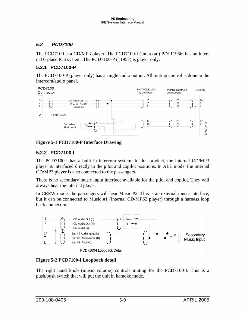
5.2 PCD7100
The PCD7100 is a CD/MP3 player. The PCD7100-I (Intercom) P/N 11956, has an inter-nal 6-place ICS system. The PCD7100-P (11957) is player only.
5.2.1 PCD7100-P The PCD7100-P (player only) has a single audio output. All muting control is done in the intercom/audio panel.
Shield Ground
C36 IFE Audio Out (R)
Audio Lo
PCD7100Connector
IFE Audio Out (L)
1413R
1615T
PMA7000/KMA28Top Connector
262728
232425
PMA8000/GMA430J2 Connector
174
24111
PM3000
1193
2 O
NLY
SecondaryMusic Input
Figure 5-1 PCD7100-P Interface Drawing
5.2.2 PCD7100-I The PCD7100-I has a built in intercom system. In this product, the internal CD/MP3 player is interfaced directly to the pilot and copilot positions. In ALL mode, the internal CD/MP3 player is also connected to the passengers.
There is no secondary music input interface available for the pilot and copilot. They will always hear the internal player.
In CREW mode, the passengers will hear Music #2. This is an external music interface, but it can be connected to Music #1 (internal CD/MPS3 player) through a harness loop back connection.
PCD7100-I Loopback Detail
Ent. #2 Audio LoEnt. #2 Audio Input (R)Ent. #2 Audio Input (L)14
TE
CD Audio LoCD Audio Out (R)CD Audio Out (L)3
C
Figure 5-2 PCD7100-I Loopback detail
The right hand knob (music volume) controls muting for the PCD7100-I. This is a push/push switch that will put the unit in karaoke mode.
200-108-0405 5-9 APRIL 2005
PS Engineering IFE Systems Interface Manual
5.3 PXE7300 & PXE7300-SR
The PXE7300 is a CD/MP3 player with AM/FM radio. It has a single stereo output that is mode controlled from the front panel. In addition to the internal radio and CD player, the PXE7300 can accept an auxiliary audio input such as from an iPOD or the PMA8000-SR Sirius radio.
The PXE7300-SR will also act as the control and interface for a PS Engineering PSM27390 SIRIUS Satellite Radio receiver.
All muting control is done in the intercom/audio panel.
200-108-0405 5-10 APRIL 2005

PS Engineering IFE Systems Interface Manual
Not
es:
Shie
ld G
roun
d
C 3 6IF
E Au
dio
Out
(R)
Audi
o Lo
PX
E73
00 C
onne
ctor
1. A
ll au
dio
wiri
ng m
ust b
e M
IL 2
2750
or 2
7500
2
4 A
WG
min
umum
.. 2.
Pow
er a
nd G
roun
d #1
8AW
G M
il-S
pec
Tefz
el m
inim
um.
L
ight
ing,
Mod
ule
Pow
er &
Gro
und
#22
AW
G m
inim
um.
3. C
ircui
t bre
aker
mus
t be
PU
LL T
YP
E4.
Uns
witc
hed
audi
o pr
esen
ted
to in
puts
1 th
ru 4
is s
umm
ed a
nd p
rovi
ded
at o
utpu
t pin
18
WR
T V
.5.
App
lyin
g a
grou
nd to
Pin
20
will
act
ivat
e th
e A
UX
m
ode,
allo
win
g au
dio
appe
arin
g on
pin
s 16
and
17
to
pas
s to
the
outp
ut w
hen
the
MO
DE
is s
et fo
r AU
X.
6. In
terfa
ce fo
r -S
R V
ersi
on O
nly
S
atel
lite
Ant
enna
Coa
x to
be
RG
-316
or e
quiv
alen
t, an
d
coa
x ru
n sh
ould
not
exc
eed
20 fe
et.
IFE
Audi
o O
ut (
L)
425-
000-
1316
Sat
ellit
e A
nten
na C
onne
ctor
(Blu
e) R
G31
642
5-01
2-17
59 C
onne
ctor
Hou
sing
(12
posi
tions
)42
5-04
0-17
39 C
onne
ctor
Pin
s
Seco
ndar
yM
usic
Inpu
t
Figure 5-3 PXE7300 Interface Drawing
200-108-0405 5-11 APRIL 2005

PS Engineering IFE Systems Interface Manual
5.4 PAV80
The PAV80 is a DVD player that also offers CD/MP3, AM/FM and auxiliary capability.
The AUX can be a audio and video source, such as a GameBoy or other entertainment system. There is also an auxiliary audio input (AUXA) that can be used for iPOD or Sat-ellite Radio units
This IFE system is “Multi-Tasking” because it has two separate stereo audio outputs that can be fed by the Video, CD, radio or external auxiliary source. One output, called Crew or Primary, can be dedicated to the pilot and copilot through Music 1. The Passenger, or secondary output can be dedicated to the Music 2 input and presented to the passengers.
Muting of the IFE is controlled by the intercom or audio panel.
Notes:
PAV80 Connector
Display Power (Note 6)Power Ground
Video Composite Output HiVideo Composite Output Lo
AREV
DATE: SHEET OF
TITLE:
DWN
CKD
APR
DATE
DATE
DATE
REV Change DATE By APR
1. All audio wiring must be MIL 22750 or 27500 24 AWG minumum.. 2. Power and Ground #18AWG Mil-Spec Tefzel minimum. Lighting #22 AWG minimum.3. Circuit breaker must be PULL TYPE4. Video cables must be RG-179/U MIL-C175. S-Video is available for other monitors6. Display power for ONE PVT801 display ONLY
23
Video Interface5-pin DIN
View from solder cupPVT801 Interface
14- 28 VDC Aircraft Power (5 A Breaker)NOTE 3
Antenna InputAntenna Ground
Aircraft Ground
28 V Dimmer14 V Dimmer
Antenna (supplied)
NOTE 4
Figure 5-4 PAV80 Interface Drawing
Integrated Systems PS Engineering makes systems that integrate the IFE with audio control systems. This gives added flexibility, with cost savings in equipment and installation.
Unit Stereo/Mono Intercom places Media Music inputs
PMA7000-CD Stereo 6 + CD/MP3 2
PMA8000-SR Stereo 6 SIRIUS Sat-ellite Radio
2
Table 6-1 Integrated IFE Systems Comparison
200-108-0405 6-12 APRIL 2005

PS Engineering IFE Systems Interface Manual
6.1 PMA7000-CD
The PMA7000-CD is a PMA7000B that controls a PCD7100-R (Remote) CD/MP3 player. The PCD7100-R does not have any controls or display, and is 2-inches tall. The PMA7000-CD uses a serial data control line to provide play, stop forward and back disc commands. The PMA7000-CD can also issue a “power off” commend that will remove the power from the circuitry.
The IFE inputs to the PMA7000-CD are completely independent. Music #1 (crew) goes to the crew, and Music #2 always goes to the passengers. The front-panel music volume control (outer knob) adjusts the Music #1 ONLY.
The stereo music #1 (crew) inputs to the PMA7000-CD Series are pin 16 (Left), pin 15 (WRT Pin T) of the top connector. Music 1 will be heard in pilot and copilot headsets, Music 1 will NOT be heard in the pilot headset in ISO.
Music #1 will mute during any radio or ICS Activity. The mute inhibit (karaoke mode) is controlled through the front panel “ICS” button. In karaoke mode, the LED in the ICS is lit, indicating that music will not be muted.
The stereo music #2 (passengers) inputs to the PMA7000 Series are pin 14 (Left), pin 13 (WRT Pin R) of the top connector. Music 2 will only be heard in passenger headsets in any mode, Music 2 will never be heard in the pilot and copilot headsets.
Music 2 can be paralleled to the PCD7100-R CD/MP3 player. However, we recommend that an external volume control be used, because the front panel volume control does not change the Music 2 input. The PS Part number for the volume control kit is 250-790-0020.
1615T
14
R
13
4311
PCD7100-RJ1
Remote Volume Control
10K ohmAudio Taper
Figure 6-1 PMA7000-CD External Volume Control
Music 2 can also be configured to use either the PCD7100-R OR an external source.
200-108-0405 6-13 APRIL 2005

PS Engineering IFE Systems Interface Manual
1615T
14
R13
4311
PCD7100-RJ1
Alternate Music Interconnect
10K ohmAudio Taper
Figure 6-2 PMA-7000-CD External Music 2 with PCD7100-R
Connecting J2 pin V to ground through a SPST switch places the entertainment #2 music source into the Karaoke Mode.
It is also possible to connect Pin V to Pin A, which has a logic low when the AUX button is activated.
A
V
Alternate Music 2 MuteUsing AUX enable
VMusic 2Mute Control
Figure 6-3 PMA7000-CD Music 2 muting
6.2 PMA8000-SR
PS Engineering’s revolutionary integration is the incorporation of a SIRIUS Satellite Ra-dio into an audio panel. The PMA8000-SR is physically ¼-inch longer than a standard PMA8000, but adds a new IFE dimension.
Like the PMA8000, Music 1 and 2 are independent: Music 1 is connected to the pilot and copilot, Music 2 is connected to the passengers. As shipped from the factory, the SIRIUS Satellite Radio audio is connected to both Music 1 and Music 2. However, by rearranging
200-108-0405 6-14 APRIL 2005

PS Engineering IFE Systems Interface Manual
the internal jumpers, the Sirius output can be controlled through external switching and add additional sources, such as an iPOD or other PS Engineering IFE system.
PMA8000-SRAlternate Music InterconnectMusic 1 SR JumperInstalled
Ent. #2 Input
2423
27
2628
3029
SR Output (R)
SR Output (L)
No Connection
Ent. #2 Input (L)
Ent. #2 Input (R)
No Connection
Figure 6-4 PMA8000-SR External Additional Music 2 Input
By removing the jumpers, music #1 and #2 can be connected to an alternate source
Alternate Music InterconnectA 3-position (on-off-on) can be used to switch entertainment completely off, if desired.
External #2 Input
24
2325
27
2628
3029
SR Output (R)
SR Output (L)
Ent. #1 Input (R)
Ent. #2 Input (L)
Ent. #2 Input (R)
Ent. #1 Input (L)
External #1 Input
Figure 6-5 PMA8000-SR Dual alternate music inputs
It is possible to interface the PMA8000-SR with other PS Engineering IFE systems, to add the CD/MP3 or AM/FM radio capability.
200-108-0405 6-15 APRIL 2005

PS Engineering IFE Systems Interface Manual
Alternate Music InterconnectPXE7300 or PCD7100 to Passenger Music
Ent. #1 Input (L)
SR Output (R)
SR Output (L)
Ent. #1 Input (R)
Ent. #2 Input (L)
Ent. #2 Input (R)C36
Z
IFE Audio Out (R)Audio Lo
IFE Audio Out (L)
PCD7100 orPXE7300
Figure 6-6 PMA8000-SR With PCD7100 or PXE7300 as Music 2
Alternate Music InterconnectPCD7100-P or PXE7300 to BOTH inputsindependentlywith two 2PDT switchs
Ent. #1 Input (L)
24
23
27
2628
3029
SR Output (R)
SR Output (L)
Ent. #1 Input (R)
Ent. #2 Input (L)
Ent. #2 Input (R)3C6Z
IFE Audio Out (R)
Audio LoIFE Audio Out (L)
PCD7100-P orPXE7300
PMA8000-SRJ2
Shield Ground Figure 6-7 PMA8000-SR with PCD7100-P/PXE7300 as Music 1 and/or 2
The PXE7300 has an auxiliary audio input. This could be used to control the PMA8000-SR Sirius radio audio as the AUX mode.
Alternate Music InterconnectusingPXE7300 to controlthe Satellite Radio
Ent. #1 Input (L)
24
23
272628
30292510
SR Output (R)
SR Output (L)
Ent. #1 Input (R)
Ent. #2 Input (L)
Ent. #2 Input (R)3C6Z
AUX Input (R)
Audio Lo
IFE Audio Out (R)
PXE7300 PMA8000-SRJ2
Shield Ground
1617K20
22
Audio Lo
IFE Audio Out (L)
Audio Lo
AUX Input (L)
AUX Audio Lo
AUX Enable
Ground
Shield Ground
Figure 6-8 PMA8000-SR using PXE7300 as control
200-108-0405 6-16 APRIL 2005

PS Engineering IFE Systems Interface Manual
200-108-0405 6-17 APRIL 2005
The PAV80 also has an auxiliary audio input, and could be used to switch the PMA8000-SR Sirius radio.
However, the PAV80 and PMA8000-SR infrared remote controls can interfere with the other unit (PAV80 remote affecting PMA8000-SR, etc.), so they must be used carefully, and the units should not be adjacent to each other.
Alternate Music Interconnectusing PAV80 to controlthe Satellite Radio
Ent. #1 Input (L)
242325
272628
3029
10
SR Output (R)
SR Output (L)
Ent. #1 Input (R)
Ent. #2 Input (L)
Ent. #2 Input (R)
3C6Z
AUX Input (R)
Audio Lo
Pass Audio Out (R)
PAV80 PMA8000-SRJ2
Shield Ground
7HF
Audio Lo
Pass Audio Out (L)
Audio Lo
AUX Input (L)
AUX Audio Lo
Shield Ground
4DF
Audio Lo
Crew IFE Audio (R)
Crew IFE Audio (L)
Audio Lo
Figure 6-9 PMA8000-SR using PAV80 as control