inferring architectural designs from physical sketches ...cutler/publications/iui_sketch_09.pdf ·...
TRANSCRIPT
Inferring Architectural Designs from Physical Sketches:Application to Daylighting Analysis
Barbara Cutler Theodore C. Yapo Yu ShengDepartment of Computer ScienceRensselaer Polytechnic Institute
{cutler,yapot,shengyu}@cs.rpi.edu
ABSTRACTWe present the algorithms and implementation of an inter-active system to capture and interpret an architectural designfrom a collection of small-scale physical elements. The usersketches a proposed design by arranging 3D wall modulesand simple markers for windows, materials, and other designfeatures on a table. The color-coded elements are capturedby a camera mounted above the scene and recognized usingcomputer vision techniques. The architectural design is au-tomatically inferred from this rough physical sketch and aclosed, 3D triangle mesh representation is constructed. Weapply the system to architectural daylighting analysis usingan interactive global illumination simulation that allows de-signers to explore alternative designs and new technologiesfor improving the sustainability of their buildings. The par-ticipants may interactively redesign the geometry and mate-rials of the space by manipulating the physical design ele-ments and visualize the revised lighting simulation.
Author KeywordsArchitectural design, physical sketching, daylighting analy-sis, and image processing.
ACM Classification KeywordsH.5.1 Information Interfaces and Presentation (HCI): Multi-media Information Systems; Artificial, augmented, and vir-tual realities.
INTRODUCTIONWe introduce a system for physically sketching three-dimen-sional architectural designs. Our motivating application isthe analysis and enhancement of daylighting: the use of win-dows and reflective surfaces to allow natural light from thesun and sky to provide effective and interesting internal illu-mination. Appropriate daylighting strategies can reduce en-ergy consumption for electric lighting and create more aes-thetically interesting and comfortable architectural spaces.A heliodon is a traditional daylighting analysis device inwhich a small-scale physical model (often 1/4” = 1’) is af-fixed to a platform and rotated relative to a fixed light source
Permission to make digital or hard copies of all or part of this work forpersonal or classroom use is granted without fee provided that copies arenot made or distributed for profit or commercial advantage and that copiesbear this notice and the full citation on the first page. To copy otherwise, orrepublish, to post on servers or to redistribute to lists, requires prior specificpermission and/or a fee. IUI 2009 Sketch Recognition, February 8 - 11,2009, Sanibel Island, FL, USA.Copyright 2009 ACM 978-1-60558-246-7/07/0004...$5.00.
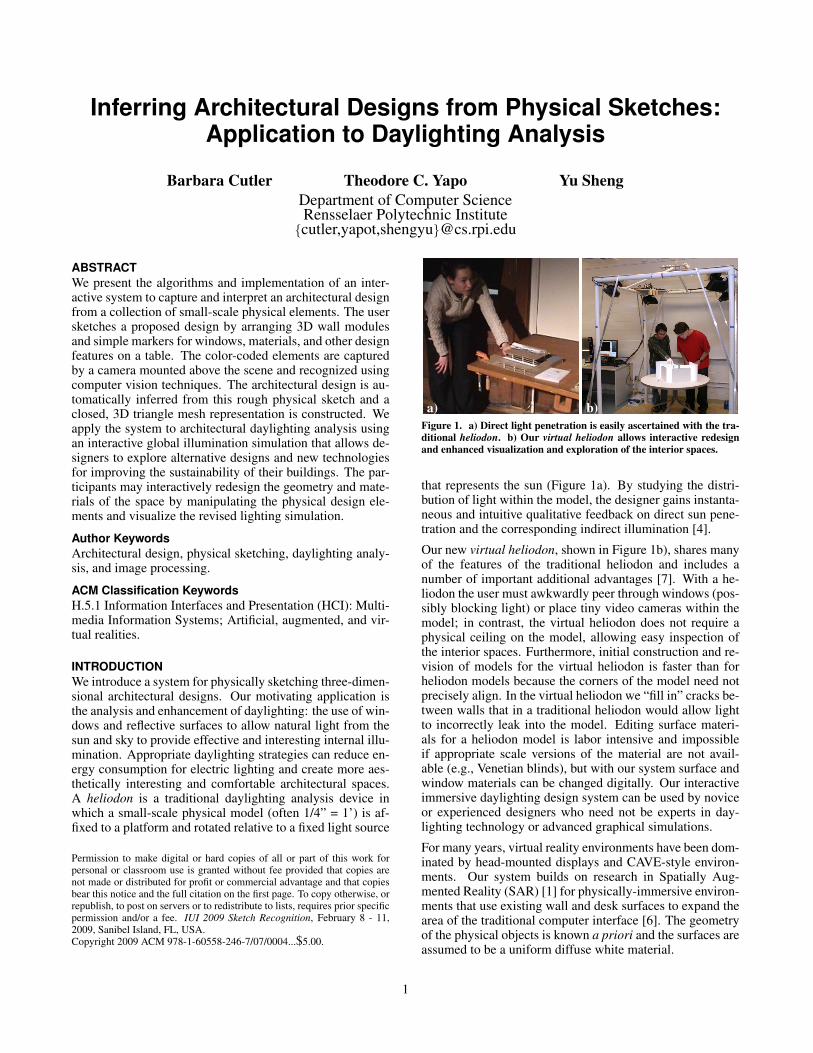
a) b)Figure 1. a) Direct light penetration is easily ascertained with the tra-ditional heliodon. b) Our virtual heliodon allows interactive redesignand enhanced visualization and exploration of the interior spaces.
that represents the sun (Figure 1a). By studying the distri-bution of light within the model, the designer gains instanta-neous and intuitive qualitative feedback on direct sun pene-tration and the corresponding indirect illumination [4].
Our new virtual heliodon, shown in Figure 1b), shares manyof the features of the traditional heliodon and includes anumber of important additional advantages [7]. With a he-liodon the user must awkwardly peer through windows (pos-sibly blocking light) or place tiny video cameras within themodel; in contrast, the virtual heliodon does not require aphysical ceiling on the model, allowing easy inspection ofthe interior spaces. Furthermore, initial construction and re-vision of models for the virtual heliodon is faster than forheliodon models because the corners of the model need notprecisely align. In the virtual heliodon we “fill in” cracks be-tween walls that in a traditional heliodon would allow lightto incorrectly leak into the model. Editing surface materi-als for a heliodon model is labor intensive and impossibleif appropriate scale versions of the material are not avail-able (e.g., Venetian blinds), but with our system surface andwindow materials can be changed digitally. Our interactiveimmersive daylighting design system can be used by noviceor experienced designers who need not be experts in day-lighting technology or advanced graphical simulations.
For many years, virtual reality environments have been dom-inated by head-mounted displays and CAVE-style environ-ments. Our system builds on research in Spatially Aug-mented Reality (SAR) [1] for physically-immersive environ-ments that use existing wall and desk surfaces to expand thearea of the traditional computer interface [6]. The geometryof the physical objects is known a priori and the surfaces areassumed to be a uniform diffuse white material.
1
OVERVIEWOur virtual heliodon system complements modern desktoparchitectural daylighting design software. The user positionsa set of small-scale physical walls within the workspace to“sketch” the 3D geometry of the design. Images capturedby a camera mounted above the scene are processed to de-tect the wall positions. Gaps between the wall are filled toconstruct a closed 3D mesh. The daylighting solution in thevirtual 3D building is computed with respect to both sun andsky illumination. The illumination is then displayed on thephysical walls by 4 calibrated projectors.The efficiency of our interactive global illumination render-ing method [2] makes it possible for users to interact withdaylighting simulations. The user can explore the high-dim-ensional configuration space of the design by adjusting theposition of wall modules to manipulate the geometry of thebuilding. Through a wireless remote mouse, the user canvary the external conditions such as the sun position (time ofday and day of the year) and weather conditions. In additionto visualizing the environment for a single point in time, thesystem allows time-lapse animations as the sun moves acrossthe sky during the course of a day, throughout the season, orunder different weather conditions.
DESIGN ENVIRONMENTOur system prototype centers around a 42” diameter tablewith a matte white surface. The table top provides the can-vas upon which a designer sketches an architectural design.Our sketching tools consist of a number of primitives that theuser arranges on the table top to indicate a particular room orbuilding design. The primitives allow for interior and exte-rior walls, cubicle dividers, different window styles, materialproperties, and building orientation.First, the designer manipulates a set of small-scale (1” = 1’)planar wall modules with a matte white finish. We providethree different heights: 10’ and 8’ for walls and 5’ for cubiclepartitions. The wall tops are covered with strips of coloredpaper allowing their height to be determined by an overheadcamera. Three different styles of window can be placed onany of the planar walls. Window primitives are constructedfrom simple U-shaped matte white cardstock with their topsurface covered in one of three different colors. The win-dow primitives slide over the top of any planar wall to in-dicate the horizontal placement of the window. Our initialprimitives allow the designer a choice of standard, picture(taller than standard), and transom (high, for privacy) win-dow styles. Wide windows may be specified by overlappingtwo or more window primitives of the same color. As withthe wall primitives, the color of the window markers is usedto determine their type from images taken by the overheadcamera. In addition to windows on walls, the designer mayplace skylights into the ceiling of the room by placing lightblue colored markers on the table surface. The location ofthese markers is projected upward to the ceiling to indicatethe actual skylight position. In addition to the planar wallsand dividers, users may indicate curved wall surfaces. We al-low curved physical wall primitives that are circular arcs ofarbitrary radius and length. More complex curved wall sur-faces (an “S”-curve, for example) can be constructed froman appropriate arrangement of circular arcs.
An important consideration for daylighting design is the over-all orientation of a room or building with respect to the car-dinal geographic directions. Thus, an orange “north arrow”primitive is placed anywhere on the table surface. The di-rection of the arrow orients the model with respect to thesimulated sun and sky conditions. Similarly, the designerexercises control over the surface reflectance properties ofthe space through a set of material “tokens”. A red-outlinedtoken is used to choose the wall material, while a green out-line indicates the floor material. A “paint chip” in the centerof the token specifies the surface color.
PRIMITIVE DETECTIONTo capture the geometry of the design sketch, a calibratedoverhead camera acquires images of the table and primitives.Since this single viewpoint precludes accurate photogram-matic determination of object heights, the tops of objects arecolor-coded to indicate distance above the table surface. Theheight and window coding colors are carefully selected toallow robust detection in various lighting conditions: red,green, and blue indicate the three wall heights and cyan, ma-genta, and yellow are used for the different window mark-ers. A nearest-neighbor classifier determines the color classof each pixel in the captured images. The classifier is trainedusing a target consisting of strips of each color on a museumboard background. An image of this target is parsed to findthe strips and the background, and a mean RGB value is cal-culated for each marker color. The background (white) isnormalized to compensate for different lighting conditions.
For an image of a new design, we first perform an automaticwhite balance and exposure compensation. We estimate theillumination on the table surface by averaging the brightest20% of “white” pixels in the scene, where “white” pixels aredetermined by thresholding the saturation component of anHSV-transformed image. This method effectively excludesshadows on the table surface from the illumination estimate.We separately calculate averages for the red, green, and bluecomponents of the illumination and divide the image pix-els by these values to white balance the image and improveclassifier performance under varying illumination. Our ini-tial object detections are performed in image space. Weassign each pixel to a color class and perform connected-components analysis to separate the image into discrete ob-jects. Since both wall markers and material tokens share thesame red and green colors, material tokens are distinguishedby their topological Euler number – material tokens containa hole, while walls are solid regions.
Next, we estimate the positions of planar wall primitives,which are assumed to be vertical and of the exact, fixedheight specified by their color. Since the perspective trans-formation introduced by the camera preserves straight lines,estimation of wall surfaces can be performed in image space.To estimate a wall’s position, we fit a single line to all of theedge pixels of a connected color region. This line, although apoor estimate of either inner or outer wall surface, separatesthe edge pixels into two sets that can then be individuallyfit to find both surfaces. In practice, we use an iterative linefitting that rejects points lying more than 2 pixels from theline as outliers; this effectively ignores the effects of pixelslying on the short wall “ends”. The length of the wall is
2
then estimated by projecting all colored pixels onto the wallsurface lines to find the maximum extents. Finally, usingthe calibrated camera projection matrix, the 2D wall cornerpoints are back-projected to rays in 3D world coordinates[5]. A simple modification of this scheme improves robust-ness greatly: each colored wall top stops 1/2” from each endof the wall, allowing for easy separation of physically touch-ing walls during the connected components step; the lengthof the virtual walls are subsequently extended to match. Thisscheme allows walls of arbitrary thickness and length and inpractice, only a few fixed wall heights are required to modelmost architectural spaces.Skylight estimation is similar to that for walls, except thatall four edges are required, instead of just the longest two.To estimate skylight edges, we use RANSAC [3] to estimateeach edge in turn. Starting with the full set of edge pixelsfor the object, we use RANSAC combined with a simplerobust line fitting algorithm to fit a single line. Pixels whichare considered part of this line (their distance falls withina specified threshold) are then removed, and the process isrepeated to extract the remaining edges.While linear objects in the scene can be estimated in im-age space, pixels corresponding to curved walls must firstbe back-projected into 3D, since circular arcs are not pre-served under perspective transformations. To estimate thecurved walls, we first fit a single circle to all edge points ofthe detected object, and then use the estimated radius to di-vide the edges into an inner and outer set, similar to our wallestimation algorithm. Once points corresponding to the twoarcs are separated, we estimate new radii for each, using acommon center point.To detect the paint chips that specify material properties, weuse the camera as a crude spectrophotometer to estimate theRGB values of these colors. To improve color accuracy, thewhite border around each color swatch is used to performlocal white balancing and illumination compensation beforean average RGB value for the swatch is computed. Finally,the north indicator arrow is distinguished from other objectsin the scene by its orange color. Once classified, the cen-terline of the arrow is determined by a best-fit line, and oneof two possible directions of the arrow chosen by comparingthe center of mass of the object to the geometrical center ofits extent.
MESH GENERATIONThe 3D wall geometry sketched by the user and detectedin the previous image processing stage is not a “watertight”model. The walls may have gaps between them and the cor-ners of the physical walls may overlap and extend beyondtheir natural intersection point. Furthermore, neither ceilingnor windows are explicitly included in the sketch and mustbe inferred. Thus, the geometry must be processed in orderto build a closed 3D triangle mesh model that is appropriatefor computing a radiosity global illumination solution. Sim-ple rectangular box rooms may be constructed as the inter-section of the halfspaces defined by the four walls. However,this convex hull assumption is not always a suitable assump-tion for interior architectural design. In particular, it cannothandle the concavities found in L-shaped rooms or roomswith interior wall partitions.
We developed the following algorithm to handle more gen-eral room designs. First, all edges of the detected wall andskylight geometry are used to build a 2D arrangement oflines on the plane of the table. Cells of the arrangementthat are contained within a wall element are labeled. Nextwe determine the percent enclosure of each of the remainingcells, i.e., what fraction of the 360 degree “view” from thecentroid of the cell is obstructed by walls. In a tightly con-structed model, with very small gaps between the walls, thepercent enclosure for interior cells will be very high. In con-trast, when the gaps are larger the percent enclosure valuewill decrease, especially for cells near the gap. Cells outsideof the room will generally have enclosure values much lessthan 50%. Simply labeling all cells having enclosure valueshigher than a specified threshold works for many models, butrequires careful parameter tuning. Thus, we iteratively selectthe unlabeled cell with the highest enclosure value and allof the cells that lie in the same combination of halfspaces.Furthermore, rather than halting when an arbitrary percentenclosure threshold is no longer met, the iteration processhalts when all walls have been incorporated into the model.Once all cells have been labeled, we systematically gener-ate a closed, watertight model appropriate for CAD model-ing packages and advanced simulations such as physically-accurate rendering. Each interior cell triggers the construc-tion of floor and ceiling triangles. If the cell lies within askylight, the material of the ceiling triangles is set to glass.The edges of interior cells that border non-interior cells trig-ger the construction of wall polygons. These wall polygonsare subdivided into window polygons as necessary. If theintersection is beyond the edge of a physical wall, the poly-gons are marked as fill-in polygons. Once the closed modelis constructed, it is remeshed with a combination of edgesplit, edge flip, edge collapse, and move vertex operations toarrive at a triangle mesh with approximately 1500 polygons,an appropriate number for interactive radiosity simulations.
RESULTS & FUTURE WORKFrom the closed model of the user’s design, a physically-accurate daylighting simulation can be calculated (Figure 2)and displayed on the physical model [7]. The gaps and un-used portions of the walls are specifically labeled in the model:patches corresponding to the projection surfaces, the inter-preted fill-in surfaces necessary to make a closed model, andthe additional unused physical occlusions are identified toensure that the model is correctly rendered. A perspectiveprojection matrix, which represents the projector’s intrinsicand extrinsic parameters, is used to render an image of thesimulation results for each of the four projectors.We have presented a physical sketching interface for archi-tectural design. Our small-scale, low-cost physical designenvironment is practical for academic architectural studiosor professional design firms and suitable for installation ina multi-purpose space such as a conference room. This newdesign tool supports enhanced communication between clientand architect and provides a platform for education in sus-tainable architectural design practice. Preliminary feedbackfrom architecture students about the system has been posi-tive. We plan to conduct formal user studies with our virtualheliodon to compare it with both the traditional heliodon and
3
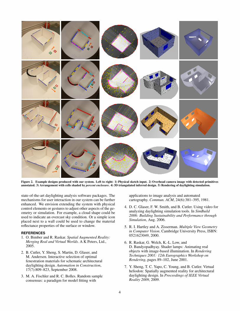
Figure 2. Example designs produced with our system. Left to right: 1) Physical sketch input. 2) Overhead camera image with detected primitivesannotated. 3) Arrangement with cells shaded by percent enclosure. 4) 3D triangulated inferred design. 5) Rendering of daylighting simulation.
state-of-the-art daylighting analysis software packages. Themechanisms for user interaction in our system can be furtherenhanced. We envision extending the system with physicalcontrol elements or gestures to adjust other aspects of the ge-ometry or simulation. For example, a cloud shape could beused to indicate an overcast sky condition. Or a simple iconplaced next to a wall could be used to change the materialreflectance properties of the surface or window.
REFERENCES1. O. Bimber and R. Raskar. Spatial Augmented Reality:
Merging Real and Virtual Worlds. A K Peters, Ltd.,2005.
2. B. Cutler, Y. Sheng, S. Martin, D. Glaser, andM. Andersen. Interactive selection of optimalfenestration materials for schematic architecturaldaylighting design. Automation in Construction,17(7):809–823, September 2008.
3. M. A. Fischler and R. C. Bolles. Random sampleconsensus: a paradigm for model fitting with
applications to image analysis and automatedcartography. Commun. ACM, 24(6):381–395, 1981.
4. D. C. Glaser, F. W. Smith, and B. Cutler. Using video foranalyzing daylighting simulation tools. In SimBuild2006: Building Sustainability and Performance throughSimulation, Aug. 2006.
5. R. I. Hartley and A. Zisserman. Multiple View Geometryin Computer Vision. Cambridge University Press, ISBN:0521623049, 2000.
6. R. Raskar, G. Welch, K.-L. Low, andD. Bandyopadhyay. Shader lamps: Animating realobjects with image-based illumination. In RenderingTechniques 2001: 12th Eurographics Workshop onRendering, pages 89–102, June 2001.
7. Y. Sheng, T. C. Yapo, C. Young, and B. Cutler. Virtualheliodon: Spatially augmented reality for architecturaldaylighting design. In Proceedings of IEEE VirtualReality 2009, 2009.
4