industrial pneumatic actuators - greetings from eng...
TRANSCRIPT
1
Eng R. L. Nkumbwa, MSc, BEng, MIET, MEIZ, REng -2010 Copperbelt University
Industrial Pneumatic Actuators
The operation of a control valve involves positioning its movable part (the plug, ball or vane)
relative to the stationary seat of the valve. The purpose of the valve actuator is to accurately
locate the valve plug in a position dictated by the control signal. The actuator accepts a signal
from the control system and, in response, moves the valve to a fully-open or fully-closed
position, or a more open or a more closed position (depending on whether 'on / off' or
'continuous' control action is used). There are several ways of providing this actuation. This
section will concentrate on the Pneumatic Actuators.
2
Eng R. L. Nkumbwa, MSc, BEng, MIET, MEIZ, REng -2010 Copperbelt University
Pneumatic Actuators
Pneumatic systems are very common, and have much in common with hydraulic systems with a
few key differences. The reservoir is eliminated as there is no need to collect and store the air
between uses in the system. Also because air is a gas it is compressible and regulators are not
needed to recirculate flow. But, the compressibility also means that the systems are not as stiff or
strong. Pneumatic systems respond very quickly, and are commonly used for low force
applications in many locations on the factory floor. Some basic characteristics of pneumatic
systems are:
Stroke from a few millimeters to meters in length (longer strokes have more springiness
The actuators will give a bit - they are springy
Pressures are typically up to 85psi above normal atmosphere
The weight of cylinders can be quite low
Additional equipment is required for a pressurized air supply
Linear and rotatory actuators are available
Dampers can be used to cushion impact at ends of cylinder travel
When designing pneumatic systems care must be taken to verify the operating location. In
particular the elevation above sea level will result in a dramatically different air pressure. For
example, at sea level the air pressure is about 14.7 psi, but at a height of 7,800 ft (Mexico City)
the air pressure is 11.1 psi. Other operating environments, such as in submersibles, the air
pressure might be higher than at sea level.
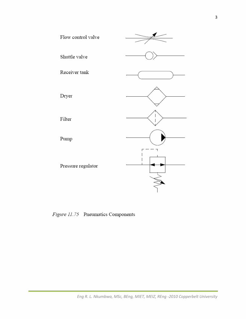
Some symbols for pneumatic systems are shown in Figure 11.75. The flow control valve is used
to restrict the flow, typically to slow motions. The shuttle valve allows flow in one direction, but
blocks it in the other. The receiver tank allows pressurized air to be accumulated. The dryer and
filter help remove dust and moisture from the air, prolonging the life of the valves and cylinders.
3
Eng R. L. Nkumbwa, MSc, BEng, MIET, MEIZ, REng -2010 Copperbelt University
4
Eng R. L. Nkumbwa, MSc, BEng, MIET, MEIZ, REng -2010 Copperbelt University
Pneumatic Actuators - Operation and Options
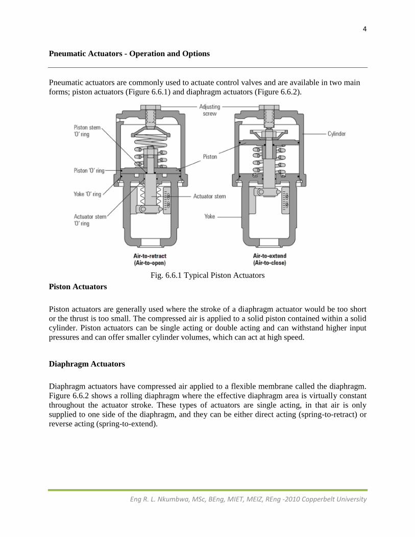
Pneumatic actuators are commonly used to actuate control valves and are available in two main
forms; piston actuators (Figure 6.6.1) and diaphragm actuators (Figure 6.6.2).
Fig. 6.6.1 Typical Piston Actuators
Piston Actuators
Piston actuators are generally used where the stroke of a diaphragm actuator would be too short
or the thrust is too small. The compressed air is applied to a solid piston contained within a solid
cylinder. Piston actuators can be single acting or double acting and can withstand higher input
pressures and can offer smaller cylinder volumes, which can act at high speed.
Diaphragm Actuators
Diaphragm actuators have compressed air applied to a flexible membrane called the diaphragm.
Figure 6.6.2 shows a rolling diaphragm where the effective diaphragm area is virtually constant
throughout the actuator stroke. These types of actuators are single acting, in that air is only
supplied to one side of the diaphragm, and they can be either direct acting (spring-to-retract) or
reverse acting (spring-to-extend).
5
Eng R. L. Nkumbwa, MSc, BEng, MIET, MEIZ, REng -2010 Copperbelt University
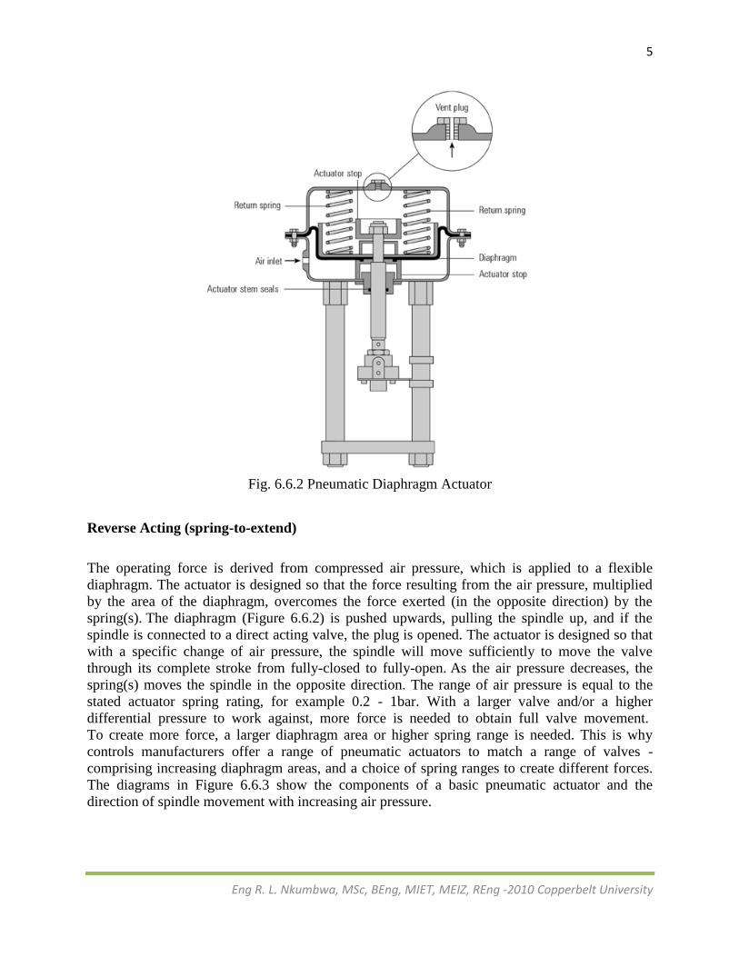
Fig. 6.6.2 Pneumatic Diaphragm Actuator
Reverse Acting (spring-to-extend)
The operating force is derived from compressed air pressure, which is applied to a flexible
diaphragm. The actuator is designed so that the force resulting from the air pressure, multiplied
by the area of the diaphragm, overcomes the force exerted (in the opposite direction) by the
spring(s). The diaphragm (Figure 6.6.2) is pushed upwards, pulling the spindle up, and if the
spindle is connected to a direct acting valve, the plug is opened. The actuator is designed so that
with a specific change of air pressure, the spindle will move sufficiently to move the valve
through its complete stroke from fully-closed to fully-open. As the air pressure decreases, the
spring(s) moves the spindle in the opposite direction. The range of air pressure is equal to the
stated actuator spring rating, for example 0.2 - 1bar. With a larger valve and/or a higher
differential pressure to work against, more force is needed to obtain full valve movement.
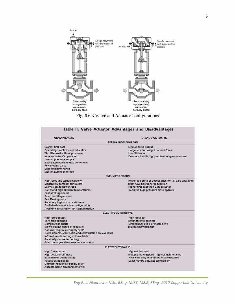
To create more force, a larger diaphragm area or higher spring range is needed. This is why
controls manufacturers offer a range of pneumatic actuators to match a range of valves -
comprising increasing diaphragm areas, and a choice of spring ranges to create different forces.
The diagrams in Figure 6.6.3 show the components of a basic pneumatic actuator and the
direction of spindle movement with increasing air pressure.
6
Eng R. L. Nkumbwa, MSc, BEng, MIET, MEIZ, REng -2010 Copperbelt University
Fig. 6.6.3 Valve and Actuator configurations
7
Eng R. L. Nkumbwa, MSc, BEng, MIET, MEIZ, REng -2010 Copperbelt University
Valve Positioner
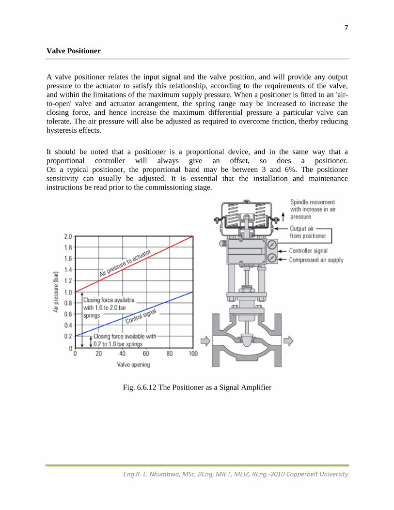
A valve positioner relates the input signal and the valve position, and will provide any output
pressure to the actuator to satisfy this relationship, according to the requirements of the valve,
and within the limitations of the maximum supply pressure. When a positioner is fitted to an 'air-
to-open' valve and actuator arrangement, the spring range may be increased to increase the
closing force, and hence increase the maximum differential pressure a particular valve can
tolerate. The air pressure will also be adjusted as required to overcome friction, therby reducing
hysteresis effects.
It should be noted that a positioner is a proportional device, and in the same way that a
proportional controller will always give an offset, so does a positioner.
On a typical positioner, the proportional band may be between 3 and 6%. The positioner
sensitivity can usually be adjusted. It is essential that the installation and maintenance
instructions be read prior to the commissioning stage.
Fig. 6.6.12 The Positioner as a Signal Amplifier
8
Eng R. L. Nkumbwa, MSc, BEng, MIET, MEIZ, REng -2010 Copperbelt University
Summary - Positioners
1. A positioner ensures that there is a linear relationship between the signal input pressure
from the control system and the position of the control valve. This means that for a given
input signal, the valve will always attempt to maintain the same position regardless of
changes in valve differential pressure, stem friction, diaphragm hysteresis and so on.
2. A positioner may be used as a signal amplifier or booster. It accepts a low pressure air
control signal and, by using its own higher pressure input, multiplies this to provide a
higher pressure output air signal to the actuator diaphragm, if required, to ensure that the
valve reaches the desired position.
3. Some positioners incorporate an electropneumatic converter so that an electrical input
(typically 4 - 20 mA) can be used to control a pneumatic valve.
4. Some positioners can also act as basic controllers, accepting input from sensors.
When should a Positioner be fitted?
A Positioner should be considered in the following circumstances:
1. When accurate valve positioning is required.
2. To speed up the valve response. The positioner uses higher pressure and greater air flow
to adjust the valve position.
3. To increase the pressure that a particular actuator and valve can close against. (To act as
an amplifier).
4. Where friction in the valve (especially the packing) would cause unacceptable hysteresis.
5. To linearise a non-linear actuator.
6. Where varying differential pressures within the fluid would cause the plug position to
vary.
To ensure that the full valve differential pressure can be accepted, it is important to adjust the
positioner zero setting so that no air pressure opposes the spring force when the valve is seating.
Figure 6.6.13 shows a typical positioner. Commonly, this would be known as a P to P positioner
since it takes a pneumatic signal (P) from the control system and provides a resultant pneumatic
output signal (P) to move the actuator.
9
Eng R. L. Nkumbwa, MSc, BEng, MIET, MEIZ, REng -2010 Copperbelt University
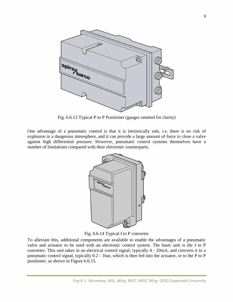
Fig. 6.6.13 Typical P to P Positioner (gauges omitted for clarity)
One advantage of a pneumatic control is that it is intrinsically safe, i.e. there is no risk of
explosion in a dangerous atmosphere, and it can provide a large amount of force to close a valve
against high differential pressure. However, pneumatic control systems themselves have a
number of limitations compared with their electronic counterparts.
Fig. 6.6.14 Typical I to P converter
To alleviate this, additional components are available to enable the advantages of a pneumatic
valve and actuator to be used with an electronic control system. The basic unit is the I to P
converter. This unit takes in an electrical control signal, typically 4 - 20mA, and converts it to a
pneumatic control signal, typically 0.2 - 1bar, which is then fed into the actuator, or to the P to P
positioner, as shown in Figure 6.6.15.
10
Eng R. L. Nkumbwa, MSc, BEng, MIET, MEIZ, REng -2010 Copperbelt University
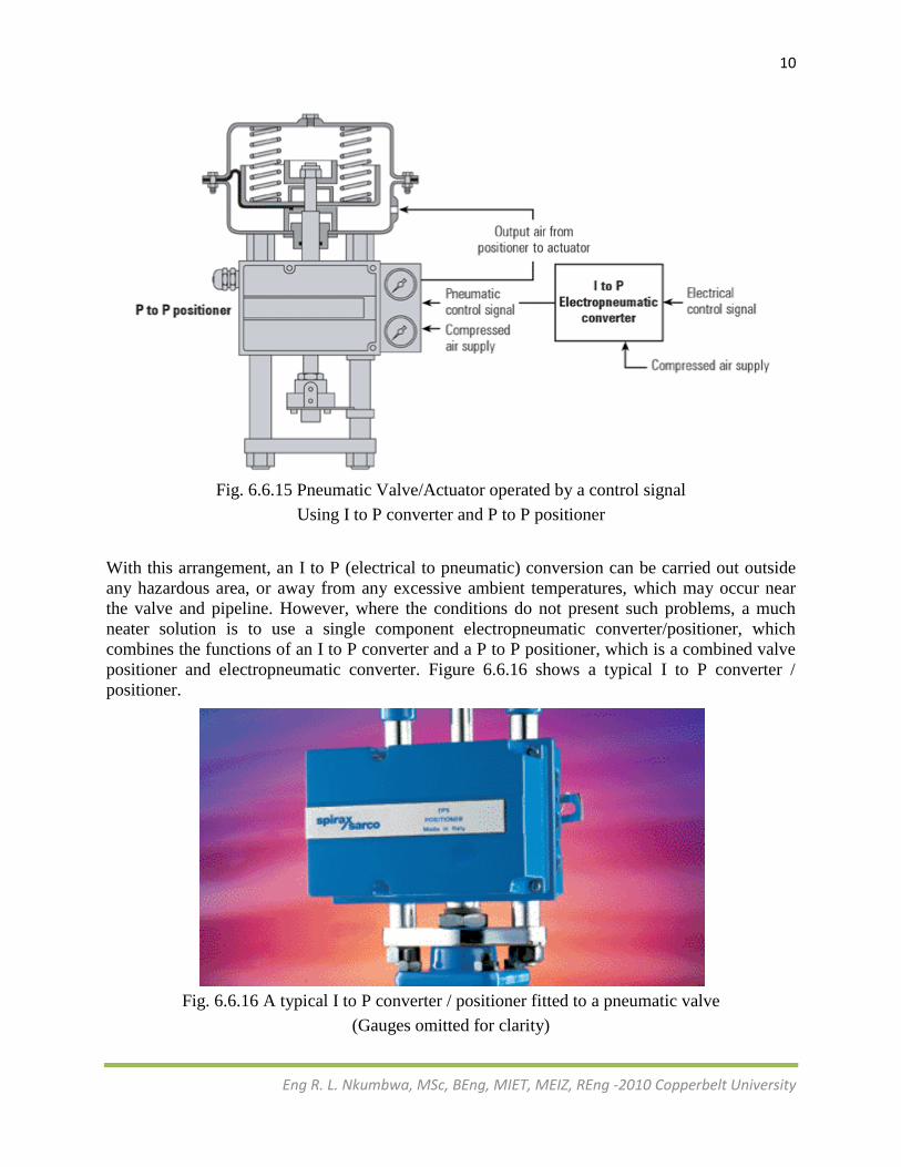
Fig. 6.6.15 Pneumatic Valve/Actuator operated by a control signal
Using I to P converter and P to P positioner
With this arrangement, an I to P (electrical to pneumatic) conversion can be carried out outside
any hazardous area, or away from any excessive ambient temperatures, which may occur near
the valve and pipeline. However, where the conditions do not present such problems, a much
neater solution is to use a single component electropneumatic converter/positioner, which
combines the functions of an I to P converter and a P to P positioner, which is a combined valve
positioner and electropneumatic converter. Figure 6.6.16 shows a typical I to P converter /
positioner.
Fig. 6.6.16 A typical I to P converter / positioner fitted to a pneumatic valve
(Gauges omitted for clarity)
11
Eng R. L. Nkumbwa, MSc, BEng, MIET, MEIZ, REng -2010 Copperbelt University
Most sensors still have analogue outputs (for example 4 - 20mA or 0 - 10V), which can be
converted to digital form. Usually the controller will perform this analogue-to-digital (A/D)
conversion, although technology is now enabling sensors to perform this A/D function
themselves. A digital sensor can be directly connected into a communications system, such as
Fieldbus, and the digitised data transmitted to the controller over a long distance. Compared to
an analogue signal, digital systems are much less susceptible to electrical interference.
Analogue control systems are limited to local transmission over relatively short distances due to
the resistive properties of the cabling. Most electrical actuators still require an analogue control
signal input (for example 4 - 20mA or 0 - 10V), which further inhibits the completion of a digital
communications network between sensors, actuators, and controllers.
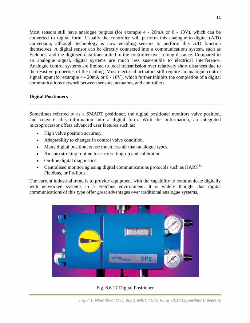
Digital Positioners
Sometimes referred to as a SMART positioner, the digital positioner monitors valve position,
and converts this information into a digital form. With this information, an integrated
microprocessor offers advanced user features such as:
High valve position accuracy.
Adaptability to changes in control valve condition.
Many digital positioners use much less air than analogue types.
An auto stroking routine for easy setting-up and calibration.
On-line digital diagnostics.
Centralised monitoring using digital communications protocols such as HART®,
Fieldbus, or Profibus.
The current industrial trend is to provide equipment with the capability to communicate digitally
with networked systems in a Fieldbus environment. It is widely thought that digital
communications of this type offer great advantages over traditional analogue systems.
Fig. 6.6.17 Digital Positioner
12
Eng R. L. Nkumbwa, MSc, BEng, MIET, MEIZ, REng -2010 Copperbelt University
Selecting a Pneumatic Valve and Actuator
In summary, the following is a list of the major factors that must be considered when selecting a
pneumatic valve and actuator:
Select a valve using the application data.
Determine the valve action required in the event of power failure, fail-open or fail-closed.
Select the valve actuator and spring combination required to ensure that the valve will
open or close against the differential pressure.
Determine if a positioner is required.
Determine if a pneumatic or electric control signal is to be provided. This will determine
whether an I to P converter or, alternatively a combined I to P converter/positioner, is
required.
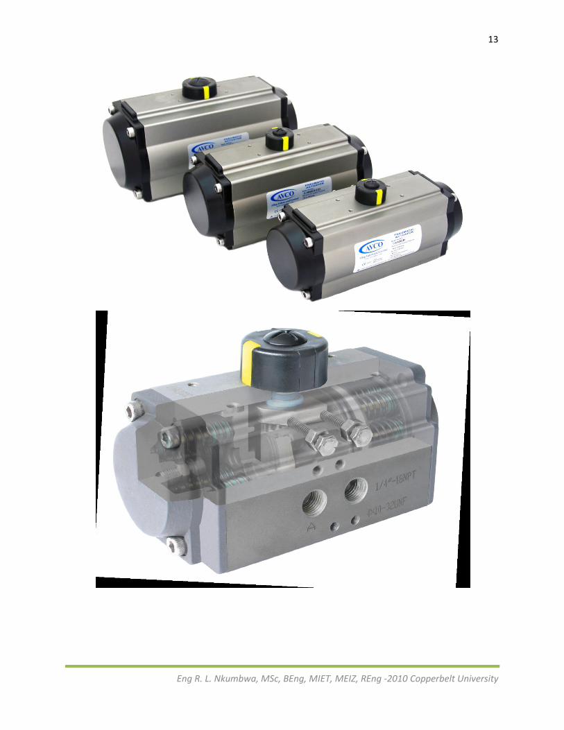
Rotary Pneumatic Actuators and Positioners
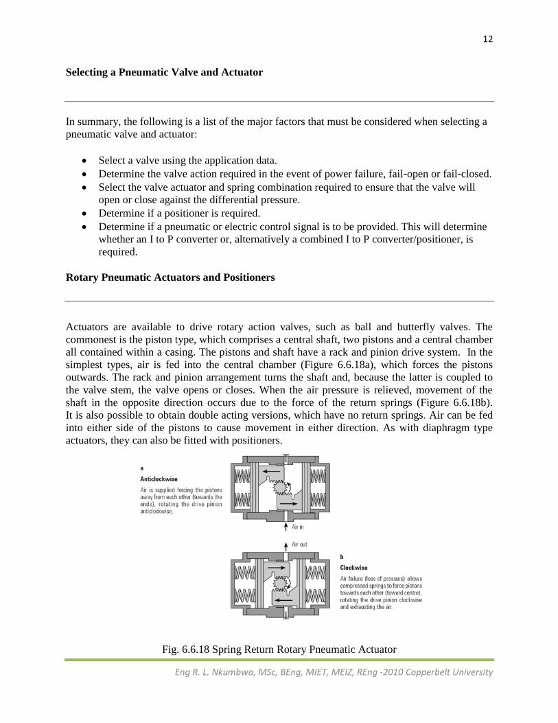
Actuators are available to drive rotary action valves, such as ball and butterfly valves. The
commonest is the piston type, which comprises a central shaft, two pistons and a central chamber
all contained within a casing. The pistons and shaft have a rack and pinion drive system. In the
simplest types, air is fed into the central chamber (Figure 6.6.18a), which forces the pistons
outwards. The rack and pinion arrangement turns the shaft and, because the latter is coupled to
the valve stem, the valve opens or closes. When the air pressure is relieved, movement of the
shaft in the opposite direction occurs due to the force of the return springs (Figure 6.6.18b).
It is also possible to obtain double acting versions, which have no return springs. Air can be fed
into either side of the pistons to cause movement in either direction. As with diaphragm type
actuators, they can also be fitted with positioners.
Fig. 6.6.18 Spring Return Rotary Pneumatic Actuator
13
Eng R. L. Nkumbwa, MSc, BEng, MIET, MEIZ, REng -2010 Copperbelt University
14
Eng R. L. Nkumbwa, MSc, BEng, MIET, MEIZ, REng -2010 Copperbelt University