industial visiting report
TRANSCRIPT
1
INDUSTRIAL VISIT
REPORT
Submitted in partial fulfillment of the requirements
for the award of Bachelors of Technology in Civil Engineering from
University of Kerala
Presented By:
MOHAMMED SAJEEM A
Reg. No. 10417020
DEPARTMENT OF CIVIL ENGINEERING
TRAVANCORE ENGINEERING COLLEGE
OYOOR, KOLLAM - 691516
2014
2
DEPARTMENT OF CIVIL ENGINEERING
TRAVANCORE ENGINEERING COLLEGE
OYOOR, KOLLAM
CERTIFICATE
This is to certify that this “INDUSTRIAL VISIT REPORT” is a bonafide record of
the work done by MOHAMMED SAJEEM A, VIII Semester (10417020), in partial
fulfillment of the requirements for the award of the Degree of Bachelors of
Technology in Civil Engineering from University of Kerala during the year 2014.
COORDINATOR HEAD OF THE DEPARTMENT
Ms. ANJANA ANAND A S Mrs. SREEJA JACOB
ASSISTANT PROFESSOR ASSOCIATE PROFESSOR
DEPT. OF CIVIL ENGINEERING DEPT. OF CIVIL ENGINEERING
TRAVANCORE ENGG. COLLEGE TRAVANCORE ENGG. COLLEGE

3
ACKNOWLEDGEMENT
It is with great pleasure and learning spirit that we bringing out this industrial visit
report. We use this opportunity to express our heartiest gratitude to the support and guidance
offered to us from various sources during the courses and completion of the visit program.
We would like to extend our sincere gratitude to Mrs. Sreeja Jacob, Head of the
Department of Civil Engineering, for providing us the opportunity to undertake this industrial
visit.
We are very much thankful to our coordinator Ms. Anjana Anand A S, Assistant
Professor for sharing her wealthy knowledge.
We convey our sincere gratitude to all the engineers and labourers of Pee Kay steel
casting (P) Ltd. and Dura Tech RMC plant, Calicut for providing us valuable advice and
guidance during the industrial visit and also to all the staffs at Padmanabhapuram palace,
Thuckalay, Tamilnadu for the help and services they rendered.
Above all, we owe our gratitude to the Almighty for showering abundant blessings
upon us. And last but not the least we wish to thank our parents and our friends for helping us
to complete our industrial visit work successfully.
MOHAMMED SAJEEM A
4
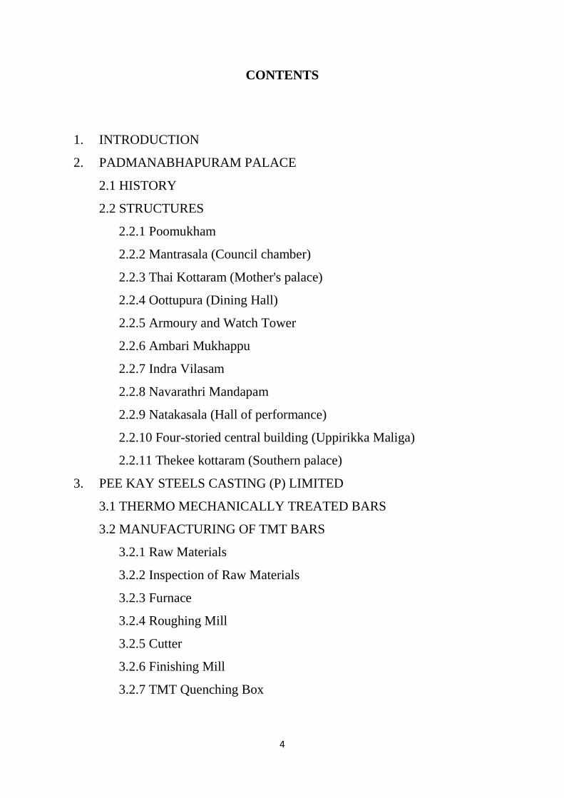
CONTENTS
1. INTRODUCTION
2. PADMANABHAPURAM PALACE
2.1 HISTORY
2.2 STRUCTURES
2.2.1 Poomukham
2.2.2 Mantrasala (Council chamber)
2.2.3 Thai Kottaram (Mother's palace)
2.2.4 Oottupura (Dining Hall)
2.2.5 Armoury and Watch Tower
2.2.6 Ambari Mukhappu
2.2.7 Indra Vilasam
2.2.8 Navarathri Mandapam
2.2.9 Natakasala (Hall of performance)
2.2.10 Four-storied central building (Uppirikka Maliga)
2.2.11 Thekee kottaram (Southern palace)
3. PEE KAY STEELS CASTING (P) LIMITED
3.1 THERMO MECHANICALLY TREATED BARS
3.2 MANUFACTURING OF TMT BARS
3.2.1 Raw Materials
3.2.2 Inspection of Raw Materials
3.2.3 Furnace
3.2.4 Roughing Mill
3.2.5 Cutter
3.2.6 Finishing Mill
3.2.7 TMT Quenching Box
5
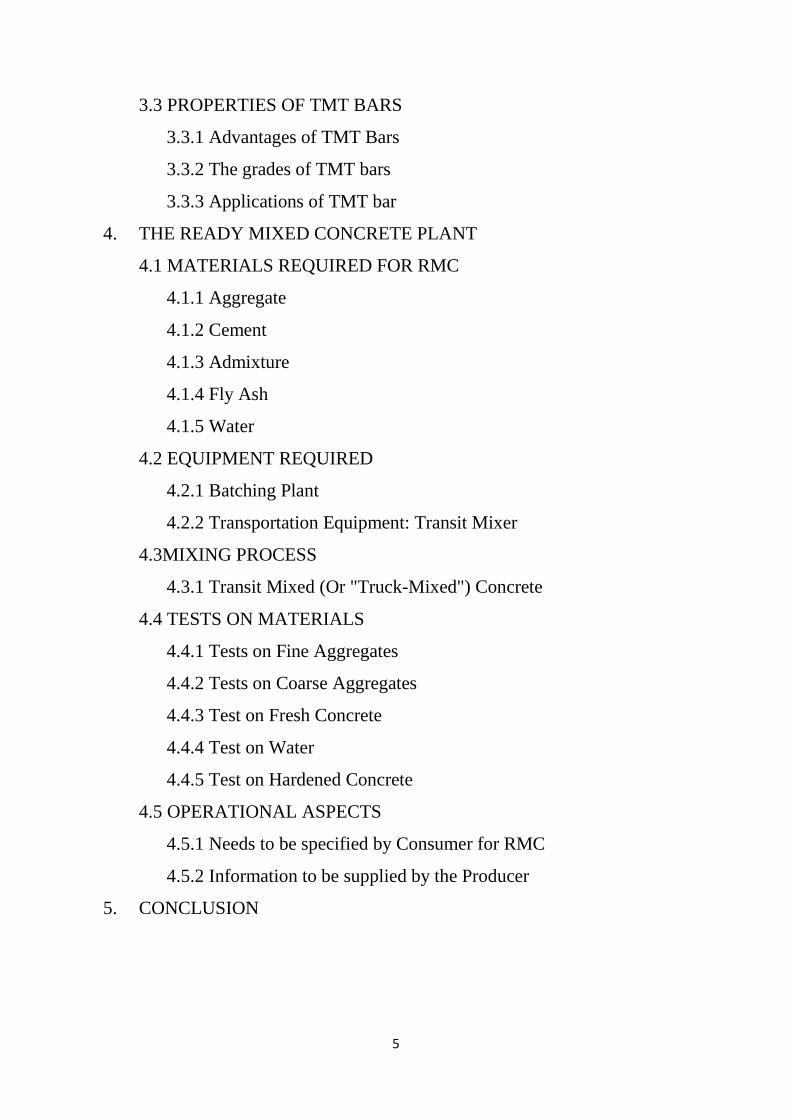
3.3 PROPERTIES OF TMT BARS
3.3.1 Advantages of TMT Bars
3.3.2 The grades of TMT bars
3.3.3 Applications of TMT bar
4. THE READY MIXED CONCRETE PLANT
4.1 MATERIALS REQUIRED FOR RMC
4.1.1 Aggregate
4.1.2 Cement
4.1.3 Admixture
4.1.4 Fly Ash
4.1.5 Water
4.2 EQUIPMENT REQUIRED
4.2.1 Batching Plant
4.2.2 Transportation Equipment: Transit Mixer
4.3MIXING PROCESS
4.3.1 Transit Mixed (Or "Truck-Mixed") Concrete
4.4 TESTS ON MATERIALS
4.4.1 Tests on Fine Aggregates
4.4.2 Tests on Coarse Aggregates
4.4.3 Test on Fresh Concrete
4.4.4 Test on Water
4.4.5 Test on Hardened Concrete
4.5 OPERATIONAL ASPECTS
4.5.1 Needs to be specified by Consumer for RMC
4.5.2 Information to be supplied by the Producer
5. CONCLUSION
6
LIST OF FIGURES
1. THE SREE PADMANABHAPURAM PALACE
2. PADMANABHAPURAM PALACE GROUND FLOOR PLAN
3. THE CLOCK TOWER
4. PADMANABHAPURAM PALACE SECTION
5. EXTERIOR OF POOMUKHAM
6. INTERIOR OF MANTRASALA
7. CLOCK TOWER ELEVATION
8. JACKFRUIT WOOD PILLAR
9. MOTHER PALACE
10. EXTERIOR OF OOTTUPURA
11. INTERIOR OF OOTTUPURA
12. NAVARATHRI MANDAPAM
13. THEKEE KOTTARAM
14. PEE KAY STEEL CASTING (P) LTD. CALICUT
15. TMT MANUFACTURING PROCESS
16. BILLETS STACKED (GREEN COLOUR CODED)
17. FEEDING MECHANISM USED FOR PUSHING INGOTS
18. FURNACE
19. FURNACE EXIT
20. ROUGHING MILL
21. ALIGNMENT OF THE MOTOR, COUPLINGS, BEARINGS
22. DIFFERENT SLOTS
23. SHEARER OR CUTTER
24. PIECES OF ROD CUT FROM CUTTERS
25. FINISHING MILL
7
26. THE SEQUENCE OF THE FINISHING MILL
27. TMT QUENCHING BOX
28. DURA TECH READY MIX CONCRETE PLANT, CALICUT
29. AGGREGATE STORAGE YARD
30. THE CAC ADMIXTURE USED AT DURA TECH
31. DURA TECH BATCHING PLANT, CALICUT
32. THE BATCHING EQUIPMENT AT DURA TECH
33. PROCESS CONTROL SYSTEM
34. TRANSIT MIXER, DURA TECH
35. HELICAL BLADES INSIDE TRANSIT MIXER DRUM
36. COMPRESSION TESTING MACHINE
37. CONCRETE MIXING DRUM
38. PYCNOMETER
39. SLUMP CONE
40. IS COURSE SIEVES
41. IS FINE SIEVES

8
LIST OF TABLES
1. CHEMICAL QUANTITY USED FOR DIFFERENT GRADES OF
STEEL
2.
RE-BAR QUALITY AND CORRESPONDING STRENGTH
9
1.INTRODUCTION
We were fortunate to visit three important civil structures or industries as a part of our
industrial visit of the final semester. With the aim of obtaining different and vast experience,
we selected industries based to three different sub branches of civil engineering. Our first
visit was to the Padmanabhapuram palace which is renowned for its architectural
appeasement. Secondly, Pee Kay steel castings (P) Ltd. helped us know things of
manufacture of steel bars, which is an integral part of structural mechanics. Our final visit to
Dura Tech ready mix concrete plant helped us acquire practical knowledge in the field of
concrete technology.
The Padmanabhapuram Palace is one of the best examples of traditional Kerala
architecture. Some portions of the sprawling complex are also the hallmark of traditional
Kerala style architecture. That’s exactly the reason why we visited the enchanted palace on
Aug.08th.2012 to learn the tremendous Kerala Architecture. The Padmanabhapuram Palace is
located in southern India, a region with high rainfall and a tropical climate. Founded by the
royal family of Travancore, adjoining the State of Kerala, the initial structures date from the
period 1400-1500, with other buildings added incrementally over time.
The purpose of industrial visit is to Pee Kay Steel casting (P) Ltd. Calicut on
Dec.27th.2013 was to learn the manufacturing process of TMT bars. Through this visit we
were able to know the manufacture of steel bars, materials used for it, their need and much
more. Pee Kay steel castings is a modern state-of-art foundry established in 1991. They
manufacture high quality steel castings made of carbon steel, alloy steel, stainless steel,
nickel based steel, duplex steel etc in various sizes and weight. They are also involved in
production of bars and rods of high quality as per Indian standard.
Ready-mix concrete (RMC) is a ready-to-use material, with predetermined mixture of
Cement, sand, aggregates and water. RMC are manufactured in factory as per the
specifications of customers, at a centrally located batching Plant. Our industrial visit to Dura
Tech RMC Plant, Calicut on Dec.28th.2013 was to learn the advantages, the quality control in
the preparation of the concrete and the preparation procedure followed at the ready mix plant.
10
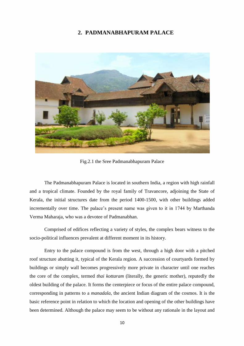
2. PADMANABHAPURAM PALACE
Fig.2.1 the Sree Padmanabhapuram Palace
The Padmanabhapuram Palace is located in southern India, a region with high rainfall
and a tropical climate. Founded by the royal family of Travancore, adjoining the State of
Kerala, the initial structures date from the period 1400-1500, with other buildings added
incrementally over time. The palace’s present name was given to it in 1744 by Marthanda
Verma Maharaja, who was a devotee of Padmanabhan.
Comprised of edifices reflecting a variety of styles, the complex bears witness to the
socio-political influences prevalent at different moment in its history.
Entry to the palace compound is from the west, through a high door with a pitched
roof structure abutting it, typical of the Kerala region. A succession of courtyards formed by
buildings or simply wall becomes progressively more private in character until one reaches
the core of the complex, termed thai kottaram (literally, the generic mother), reputedly the
oldest building of the palace. It forms the centerpiece or focus of the entire palace compound,
corresponding in patterns to a manadala, the ancient Indian diagram of the cosmos. It is the
basic reference point in relation to which the location and opening of the other buildings have
been determined. Although the palace may seem to be without any rationale in the layout and
11
disposition, one comprehends its organization the moment the esoteric rules governing its
design have been revealed. Thus, successive generations of builders in the palace complex
adhered to the rule laid down at the start.
Building science applied in the achievement of Padmanabhapuram involved a
combination of astronomy, astrology, mathematics, religious values, social moves, building
technology and magic. Such traditional building codes account for the overall cohesion in the
design.
Kerala is a region with abundant timber and excellent clay, used for tiles and bricks,
as well as laterite stone, granite and shell lime. While strict rules also existed for the
utilization of various materials and structural solutions, it was by far carpentry was the most
highly developed building art. Type of wood, their relative positions to one another, kinds of
functions to be served, and the types of wood determined by user’s place in the social
hierarchy were all specified in the traditional codes. Hence, one of the outstanding features of
Padmanabhapuram Palace is that these principles were faithfully followed over centuries.
Another significant quality of the buildings at Padmanabhapuram is the sensitive
handling of the light and atmosphere of repose created throughout. The aesthetics importance
of the palace might well be described as a subtle combination of sophisticated understatement
in design and a tactile celebration of material employed.
12
13
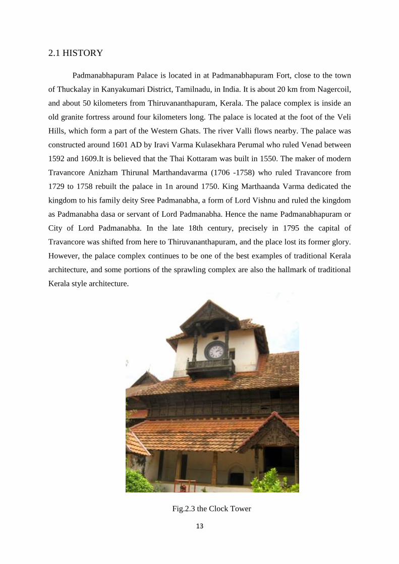
2.1 HISTORY
Padmanabhapuram Palace is located in at Padmanabhapuram Fort, close to the town
of Thuckalay in Kanyakumari District, Tamilnadu, in India. It is about 20 km from Nagercoil,
and about 50 kilometers from Thiruvananthapuram, Kerala. The palace complex is inside an
old granite fortress around four kilometers long. The palace is located at the foot of the Veli
Hills, which form a part of the Western Ghats. The river Valli flows nearby. The palace was
constructed around 1601 AD by Iravi Varma Kulasekhara Perumal who ruled Venad between
1592 and 1609.It is believed that the Thai Kottaram was built in 1550. The maker of modern
Travancore Anizham Thirunal Marthandavarma (1706 -1758) who ruled Travancore from
1729 to 1758 rebuilt the palace in 1n around 1750. King Marthaanda Varma dedicated the
kingdom to his family deity Sree Padmanabha, a form of Lord Vishnu and ruled the kingdom
as Padmanabha dasa or servant of Lord Padmanabha. Hence the name Padmanabhapuram or
City of Lord Padmanabha. In the late 18th century, precisely in 1795 the capital of
Travancore was shifted from here to Thiruvananthapuram, and the place lost its former glory.
However, the palace complex continues to be one of the best examples of traditional Kerala
architecture, and some portions of the sprawling complex are also the hallmark of traditional
Kerala style architecture.
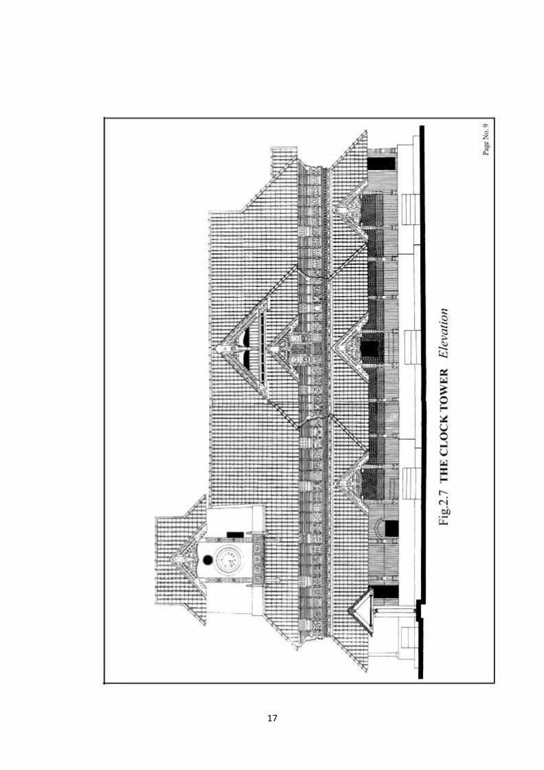
Fig.2.3 the Clock Tower
14
15
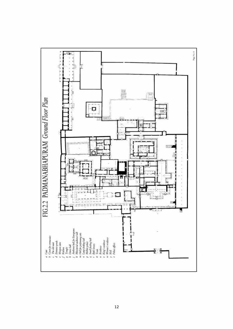
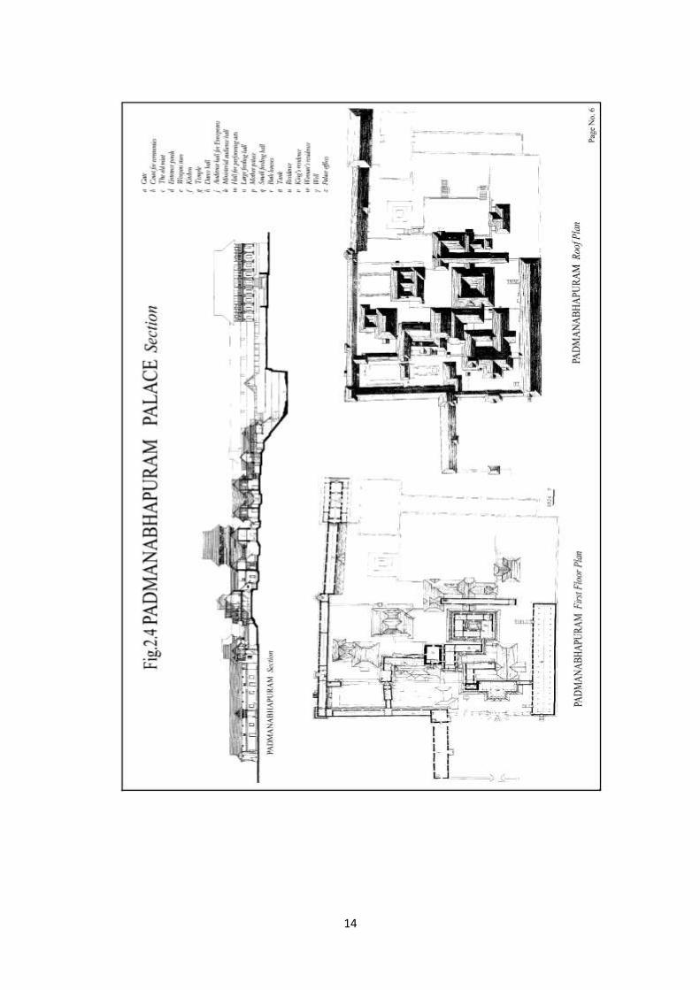
2.2 STRUCTURES
The Padmanabhapuram Palace complex consists of several structures such as
Mantrasala; literal meaning, King's Council Chamber, Thai Kottaram; literal meaning,
Mother's Palace (It meant the mother's palace, where the mother of king resides) – believed to
have been constructed before AD 1550, Nataksala; literal meaning, the Hall of Performance,
or of Performing Arts, A four-storied building at the centre of the Palace complex, Thekee
Kottaram; literal meaning, the Southern Palace. The clock tower in the palace complex has a
300 year old clock, which still keeps time. A big hall now bare, which can accommodate
around 1000 guests, and where ceremonial feasts were held, on auspicious occasions. A
secret passage, now blocked, through which the king, his immediate family members, and
their entourage could escape to another palace, located several kilometers away in the event
of any emergency. Name of this palace is Charottu kottaram. A flight of steps leads to a
bathing pond, which has lost its freshness due to neglect and years of disuse. The structural,
architectural and functional features of which are explained below.
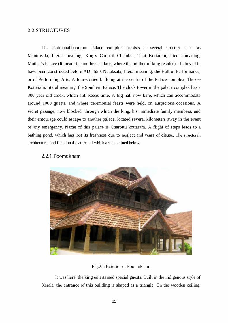
2.2.1 Poomukham
Fig.2.5 Exterior of Poomukham
It was here, the king entertained special guests. Built in the indigenous style of
Kerala, the entrance of this building is shaped as a triangle. On the wooden ceiling,
16
ninety flowers have been carved. Each of them is marvelous and unique. Also do here
feature the rarest of the rare things like hanging brass lamp with a knight on horse-
back, a cot built of seven pieces of polished granite, a Chinese chair presented to the
king by Chinese merchants and the ‘Onavillu” presented to the king as tribute by the
land lords and chieftains of different clans during the onam festival. The ‘Onavillus’
are finest examples of the exquisite history of Kerala style of paintings.
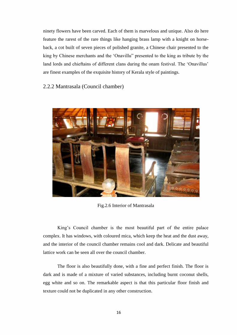
2.2.2 Mantrasala (Council chamber)
Fig.2.6 Interior of Mantrasala
King’s Council chamber is the most beautiful part of the entire palace
complex. It has windows, with coloured mica, which keep the heat and the dust away,
and the interior of the council chamber remains cool and dark. Delicate and beautiful
lattice work can be seen all over the council chamber.
The floor is also beautifully done, with a fine and perfect finish. The floor is
dark and is made of a mixture of varied substances, including burnt coconut shells,
egg white and so on. The remarkable aspect is that this particular floor finish and
texture could not be duplicated in any other construction.
17
18
The Manthrasala is a hall of considerable importance. Generally the term
‘Manthra’ refers to the administration of the kingdom. It was at this hall the king held
discussions with his ministers and prominent citizens and took important decisions.
The building displays a simplicity and purity of the styles of architecture. The wood
carvings across its beam and roof proclaim the expertise of the craftsmanship.
Manthrasala has only one projection and eleven number of ‘Kilivathil’. A Kilivathil is
a tiny window, the shutters of which are beautifully decorated with mirror work in
different hues. Chinese model sittings that adorn the Manthrasala are rich with
wonderful carvings. The floor of the Manthrasala is typical of the rare technology that
was in vogue.
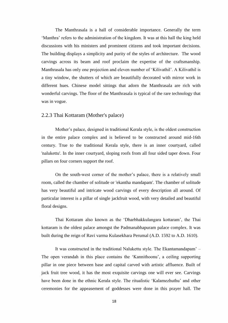
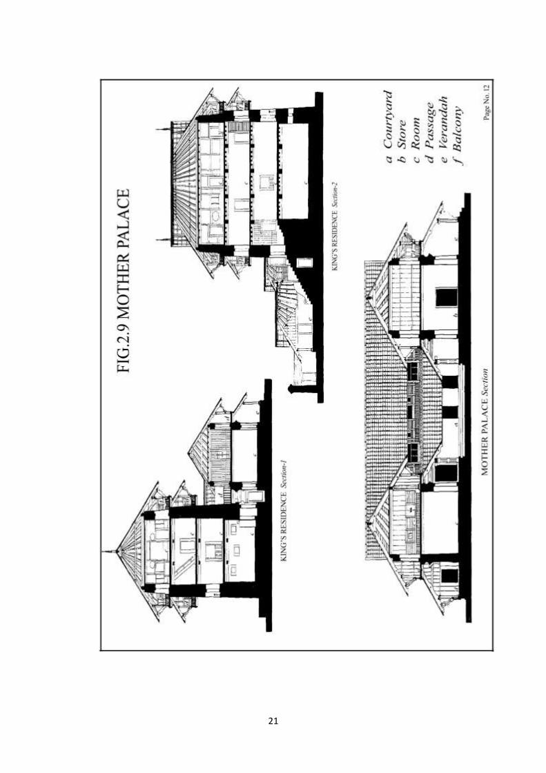
2.2.3 Thai Kottaram (Mother's palace)
Mother’s palace, designed in traditional Kerala style, is the oldest construction
in the entire palace complex and is believed to be constructed around mid-16th
century. True to the traditional Kerala style, there is an inner courtyard, called
'nalukettu'. In the inner courtyard, sloping roofs from all four sided taper down. Four
pillars on four corners support the roof.
On the south-west corner of the mother’s palace, there is a relatively small
room, called the chamber of solitude or 'ekantha mandapam'. The chamber of solitude
has very beautiful and intricate wood carvings of every description all around. Of
particular interest is a pillar of single jackfruit wood, with very detailed and beautiful
floral designs.
Thai Kottaram also known as the ‘Dharbhakkulangara kottaram’, the Thai
kottaram is the oldest palace amongst the Padmanabhapuram palace complex. It was
built during the reign of Ravi varma Kulasekhara Perumal (A.D. 1592 to A.D. 1610).
It was constructed in the traditional Nalukettu style. The Ekantamandapam’ –
The open verandah in this place contains the ‘Kannithoonu’, a ceiling supporting
pillar in one piece between base and capital carved with artistic affluence. Built of
jack fruit tree wood, it has the most exquisite carvings one will ever see. Carvings
have been done in the ethnic Kerala style. The ritualistic ‘Kalamezhuthu’ and other
ceremonies for the appeasement of goddesses were done in this prayer hall. The
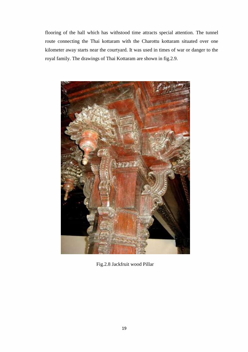
19
flooring of the hall which has withstood time attracts special attention. The tunnel
route connecting the Thai kottaram with the Charottu kottaram situated over one
kilometer away starts near the courtyard. It was used in times of war or danger to the
royal family. The drawings of Thai Kottaram are shown in fig.2.9.
Fig.2.8 Jackfruit wood Pillar

20
21
22
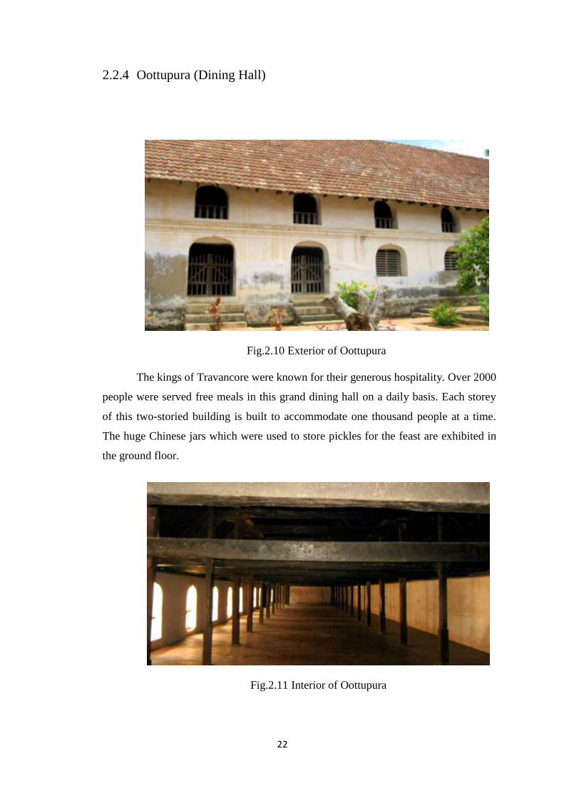
2.2.4 Oottupura (Dining Hall)
Fig.2.10 Exterior of Oottupura
The kings of Travancore were known for their generous hospitality. Over 2000
people were served free meals in this grand dining hall on a daily basis. Each storey
of this two-storied building is built to accommodate one thousand people at a time.
The huge Chinese jars which were used to store pickles for the feast are exhibited in
the ground floor.
Fig.2.11 Interior of Oottupura
23
2.2.5 Armoury and Watch Tower
During the days of royalty, these rooms were used as armory. The construction
of this building is such that it has more length and less breadth, without any windows
or ventilation facilities. There are only two entrances to the armory. At the modern
end there is the watch tower. Form this watch tower any movement in the near
surroundings can be detected. Thousands of different weapons stored here were
confiscated by the British army by order of Col. Macaulay. The rest of the weapons
and equipments are exhibited in the new museum.
2.2.6 Ambari Mukhappu
It was built for the kings to view chariot races (temple cars race) during
festivals and to appear before the public on special occasions. ‘Ambari’ is actually the
seat put on elephants’ back for safaris. The building has been constructed based on the
shape and structure of an ‘Ambari’. The ‘Ambari mukhappu’ is the crowning example
of the craftsmanship of Travancore wood carving.
2.2.7 Indra Vilasam
This building was constructed for accommodation of foreign tourists and
dignitaries coming to visit the king. Unlike other buildings, it has not been
constructed in ethnic Kerala style of architecture. The influence of foreign style of
architecture is evident in the structure of this building.
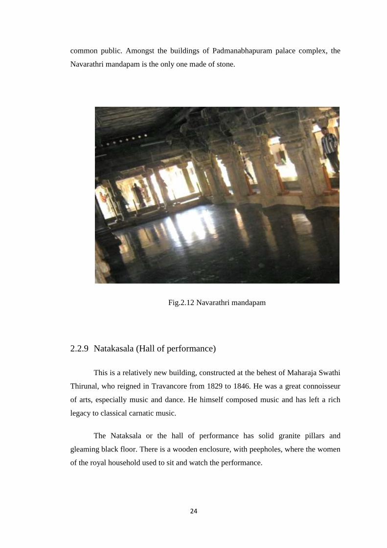
2.2.8 Navarathri Mandapam
King Marthanda varma built the Navarathri mandapam in 1744 A.D. Built of
solid rock, the building is 66 feet long and 27 feet wide. Famed for its unparalleled
architecture, breath taking beauty and intricate and exquisite carvings, the buildings
speaks of the rich cultural and artistic tradition. Various cultural programs were
conducted here, during the Navarathri festival. The dance floor has been polished to
mirror like perfection so much that it is known as ‘Kannadithara’ or mirror floor.
Separate rooms with ‘Kilivathil’ (Small wooden windows built in the wall) have been
made for the kings and his royal train to view the programs without being seen by the
24
common public. Amongst the buildings of Padmanabhapuram palace complex, the
Navarathri mandapam is the only one made of stone.
Fig.2.12 Navarathri mandapam
2.2.9 Natakasala (Hall of performance)
This is a relatively new building, constructed at the behest of Maharaja Swathi
Thirunal, who reigned in Travancore from 1829 to 1846. He was a great connoisseur
of arts, especially music and dance. He himself composed music and has left a rich
legacy to classical carnatic music.
The Nataksala or the hall of performance has solid granite pillars and
gleaming black floor. There is a wooden enclosure, with peepholes, where the women
of the royal household used to sit and watch the performance.
25
2.2.10 Four-storied central building (Uppirikka Maliga)
The four-storied building is located at the centre of the palace complex. The
ground floor houses the royal treasury. The first floor houses the King's bedrooms.
The ornamental bedstead is made of 64 types of herbal and medicinal woods, and was
a gift from the Dutch merchants. Most of the rooms here and in other parts of the
palace complex have built-in recesses in walls for storing weapons like swords and
daggers. The second floor houses the King's resting and study rooms. Here the King
used to spend time during fasting days. The top floor (called upparikka malika) served
as the worship chamber of the royal household. Its walls are covered with exquisite
18th century murals, depicting scenes from the puranas, and also few scenes from the
social life of the Travancore of that time. Ths top floor was supposed to be Sree
Padmanabha Swamy's room. This building was constructed during the reign of King
Marthandavarma. He was also designated as Padmanabha Dasa and used to rule the
Travancore kingdom as a servant of Sree Padmanabha Swamy.
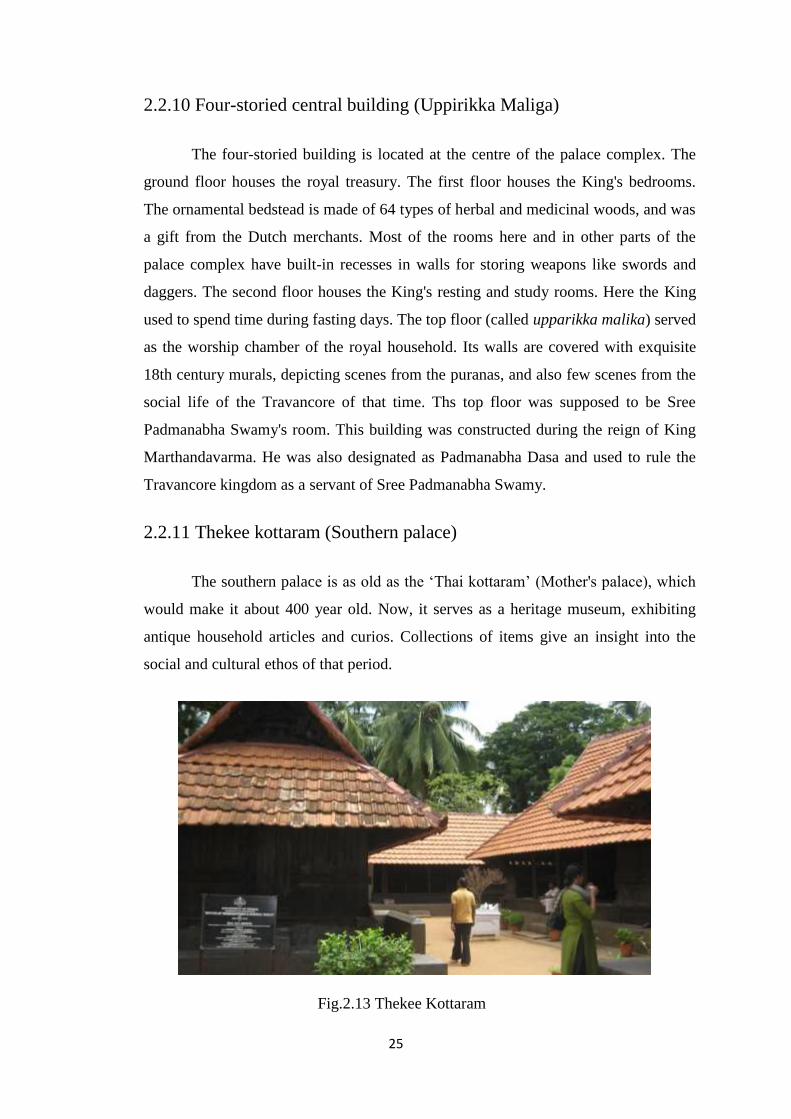
2.2.11 Thekee kottaram (Southern palace)
The southern palace is as old as the ‘Thai kottaram’ (Mother's palace), which
would make it about 400 year old. Now, it serves as a heritage museum, exhibiting
antique household articles and curios. Collections of items give an insight into the
social and cultural ethos of that period.
Fig.2.13 Thekee Kottaram
26
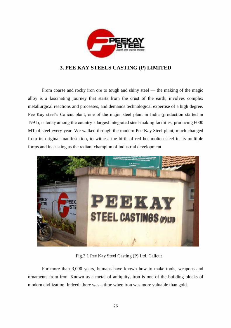
3. PEE KAY STEELS CASTING (P) LIMITED
From coarse and rocky iron ore to tough and shiny steel — the making of the magic
alloy is a fascinating journey that starts from the crust of the earth, involves complex
metallurgical reactions and processes, and demands technological expertise of a high degree.
Pee Kay steel’s Calicut plant, one of the major steel plant in India (production started in
1991), is today among the country’s largest integrated steel-making facilities, producing 6000
MT of steel every year. We walked through the modern Pee Kay Steel plant, much changed
from its original manifestation, to witness the birth of red hot molten steel in its multiple
forms and its casting as the radiant champion of industrial development.
Fig.3.1 Pee Kay Steel Casting (P) Ltd. Calicut
For more than 3,000 years, humans have known how to make tools, weapons and
ornaments from iron. Known as a metal of antiquity, iron is one of the building blocks of
modern civilization. Indeed, there was a time when iron was more valuable than gold.
27
The basic process of making iron and its tougher alloy — steel — have not changed in
the last three millennia. First, the ore has to be found. Then it must be reacted with other
elements at very high temperatures. Third, the liquid steel must be collected and cast into
shape. And, finally, the steel must be treated to give it the properties needed for end use. Steel
is considered a green product because it is 100-percent recyclable and has an infinite life
cycle.
Untreated ore cannot be used to make steel as it reduces the quality of the metal.
Therefore, the raw iron ore is processed at the sinter (or processed iron ore) plant. The coal
used in the plant is cleansed of impurities in coke ovens. Conveyor belts carry metallic-
pellets and sinters — to the heart of the steel plant, the blast furnace. The blast furnace is a
six-storey tall reactor where the seemingly magical transformation of dark iron ore into
glowing hot liquid iron takes place. The ore is charged into the blast furnace along with
fluxes and limestone. Temperatures in the blast furnace reach up to 1,5000 0C and the
resulting metallurgical reaction converts iron oxide into molten iron. The blast furnace works
round the clock.
The red hot liquid metal produced in the blast furnace is collected in the hearth and
‘tapped’ on a near continuous basis through day and night. The process is called casting and,
typically, the steel plant does 10-12 casts in a 24-hour cycle. Pee Kay Steels has a number of
blast furnaces and most of these are operational. Hot metal or molten iron from the blast
furnace is transferred into vessels called torpedoes and transported on rail tracks to the LD, or
Linz Donawitz (named after the towns in Austria where the technology was commercialized),
shop. Here the molten iron is refined into steel using the ‘basic oxygen furnace’ method. One
dedicated to making steel for long products (used mainly in the infrastructure and
construction sectors) and two others for flat steel products (typically used in automobiles and
appliances).
At the LD shop the process begins with charging scrap into the furnace, where
temperatures reach 1,700°C. Large ladles, capable of holding 170 tonnes of liquid metal, pour
the molten iron into the furnace. A water-cooled lance is lowered into the furnace to blow in
pure oxygen. Iron ore (as coolant) and burnt lime and raw dolomite (as flux) are added from
the top. The oxygen removes carbon, silicon, sulphur and phosphorus content from molten
iron and converts it to steel, an alloy that is tougher than iron. One ‘heat’ (a cycle of
steelmaking) takes 45-50 minutes and produces an average of 158 tonnes of molten steel.
28
The properties required for steel depend on the end use. And so, from every heat, a
sample of the molten steel is analyzed to see if it meets the requirement. If there is any
variation, a ‘correction blow’ is ordered. Once perfected to specification, liquid steel — still
aglow at about 1,630- 1,690°C — is tapped into a ladle car positioned under the furnace.
During tapping, Ferro-alloys and aluminum are added directly into the steel ladle for alloying
and deoxidization
This steel goes through further refining, depending on requirement, at the online
purging station, ladle furnace station or RH degasser. Ladles with a holding capacity of 160
tonnes carry the liquid steel to the continuous caster machines. Here the liquid steel finally
takes solid form and is shaped into what are called long products or flat products.
The long products are processed at the wire mill to produce wire rods and bars. Pee
Kay Steels makes a range of long products, including TMT bars. Flat steel is further
processed at the hot rolling mill or cold rolling mill, depending on end use. Cold rolling mills
have a continuous galvanizing line and produce the galvanized steel used in the automotive,
engineering and appliances sectors.
3.1 THERMO MECHANICALLY TREATED STEEL BARS
By adopting thermo mechanically treatment process higher strength of TMT bars is
obtained. In this process, steel bars get intensive cooling immediately after rolling. When the
temperature is suddenly reduced to make surface layer hard, the internal core is hot at the
same time. Due to further cooling in atmosphere and heat from the core, the tempering takes
place. This process is expected to improve properties such as yield strength, ductility and
toughness of TMT bars. With above properties, TMT steel is highly economical and safe for
use. TMT steel bars are more corrosion resistant than Tor steel.
The full form of TMT is Thermo Mechanical Treatment; in this the steel bars are
passed through a specially designed water-cooling system. After the bars pass, the outer
surface of the bars solidifies while the core remains hot. This creates a temperature gradient
in the bars. After the intensive cooling, the bar is exposed to air and the core re-heats the
quenched surface layer by conduction, therefore tempering the external marten site. When the
bars are taken out of the cooling system, the heat flows from the core to the outer surface,
29
further tempering of the bars, which helps them attain higher yield strength. The resulting
heat-treated structure imparts superior strength and toughness to the bars.
The pre-determined cooling of the bar periphery transforms the peripheral structure to
marten site and then annealed through the heat available at the core. The peripheral and core
temperature difference finally equalizes at around 600 degree C and the resultant bar
structure is of tempered marten site at the periphery and of fine-grained ferritepearlite at the
core. Generally speaking, the resultant soft core forms about 65-75 per cent of the area
(depending upon the desired minimum yield strength) and the rest is the hardened periphery.
The equalizing temperature together with the final rolling temperature is the most important
parameter to achieve the required mechanical properties. Finally, when the bar is discharged
on to the Cooling Beds, the remaining austenite transforms into a very fine-grained pearlite
structure.
After this process of thermo mechanical treatment, a dark etched peripheral rim of
tempered marten site and a grey core of ferrite pearlite get formed. The tempered marten site
surface layer is very hard while the microstructure of the core is a very fine-grained ferrite
and pearlite which is quite soft. The result is a structure with a 6 high yield strength combined
with high ductility. Hence from the above data it is seen that the sudden quenching is the key
role in hardening the steel bars. The pressure of the water jets on the hot molten bars
determines the thickness of the marten site structure and is controlled for the required
hardness.
30
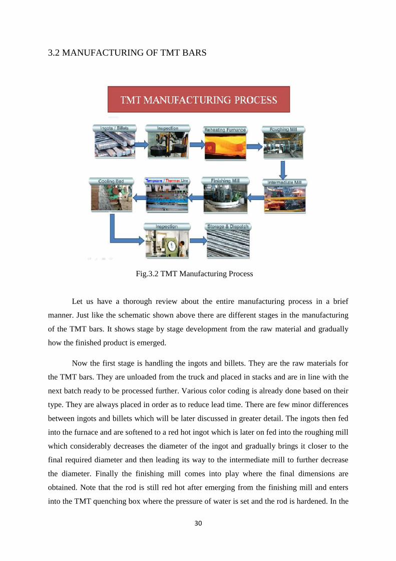
3.2 MANUFACTURING OF TMT BARS
Fig.3.2 TMT Manufacturing Process
Let us have a thorough review about the entire manufacturing process in a brief
manner. Just like the schematic shown above there are different stages in the manufacturing
of the TMT bars. It shows stage by stage development from the raw material and gradually
how the finished product is emerged.
Now the first stage is handling the ingots and billets. They are the raw materials for
the TMT bars. They are unloaded from the truck and placed in stacks and are in line with the
next batch ready to be processed further. Various color coding is already done based on their
type. They are always placed in order as to reduce lead time. There are few minor differences
between ingots and billets which will be later discussed in greater detail. The ingots then fed
into the furnace and are softened to a red hot ingot which is later on fed into the roughing mill
which considerably decreases the diameter of the ingot and gradually brings it closer to the
final required diameter and then leading its way to the intermediate mill to further decrease
the diameter. Finally the finishing mill comes into play where the final dimensions are
obtained. Note that the rod is still red hot after emerging from the finishing mill and enters
into the TMT quenching box where the pressure of water is set and the rod is hardened. In the
31
final stage the rod is placed on the cooling bed and then at last they are stacked together and
are ready for dispatch. Thus this brief summary gives us a proper foundation how the TMT
bars are manufactured.
3.2.1 Raw Materials
The raw materials used in production of TMT bars are of two types. They are
Ingots and Billets. The ingots have a structure similar to a trapezoid. It is like a cuboid
structure but with a little taper included at the sides. This makes the area of one side
of ingot bigger than the other end. These ingots are manufactured by casting process
with either iron ore or iron scrap at a furnace plant. The iron ore or scrap metal is
melted in the furnace and poured in vessels and after cooling the ingots are taken out
of the vessels. The ratio metals used to make the ingots depend upon the order. There
are 5 standard ratios that all ingot furnaces follow. Every ratio has a colour allotted to
it and after manufacturing the ingot are marked with that color so that there is no
margin of error. There are certain specifications given to the ingots. They have certain
optimum sizes at which they are available. Basic ingot size varies from 52 to 60
inches ingot length is used for TMT production 3 types based on the breadth and
height of ingot which are,
3⅟4 X 4⅟4 inches
3⅟2 X 4⅟2 inches
4 X 5 inches
The ingots and billets are almost similar but billets have better finish and there
is less chance of blow holes being present inside within. The final product obtained by
using billets have better finish when compared to the ingots. Billets are more refined
raw material which has less chance of blow holes and smooth surface finish.
13 Billets have no standard color coding or a standard ratio. They are entirely made as
on order. But after manufacturing the billets are supplied with a Heat number (a test
certificate) which elaborates the ratios of metals used and order size. The dimensions
of billets are almost similar to the ingot. The cross section area of a billet is
125.Average mass per length 3.1kg per inch in length.
32
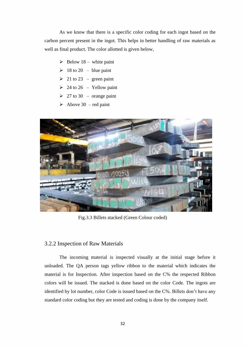
As we know that there is a specific color coding for each ingot based on the
carbon percent present in the ingot. This helps in better handling of raw materials as
well as final product. The color allotted is given below,
Below 18 – white paint
18 to 20 – blue paint
21 to 23 – green paint
24 to 26 – Yellow paint
27 to 30 – orange paint
Above 30 – red paint
Fig.3.3 Billets stacked (Green Colour coded)
3.2.2 Inspection of Raw Materials
The incoming material is inspected visually at the initial stage before it
unloaded. The QA person tags yellow ribbon to the material which indicates the
material is for Inspection. After inspection based on the C% the respected Ribbon
colors will be issued. The stacked is done based on the color Code. The ingots are
identified by lot number, color Code is issued based on the C%. Billets don’t have any
standard color coding but they are tested and coding is done by the company itself.
33
There is a heat number mentioned on Billets which is evidenced to the
Chemical Composition. Before feeding there is a procedure of inspection where there
is a series of chemical tests done which determines the percentage of Carbon,
Sulphur, Phosphorous and Manganese.
The presence of carbon affects the strength where 30 is the maximum.
The presence of sulphur and phosphorous gives more strength where the
Maximum allowable level is 0.060%
3.2.3 Furnace
After quality testing, the ingots are ready to be fed in the furnace. It is
necessary for the ingots to have a high temperature for the rolling process through the
rollers. This is where the furnace comes to play. The ingots are fed into the furnace
wherein they are constantly heated for 4 hours. The material, on exit is suitable to
undergo Rolling. The furnace generates heat energy by the combustion of coal gas,
which is produced in a coal gas plant located nearby. The furnace has three process
namely feeding, Heating, Ejection.
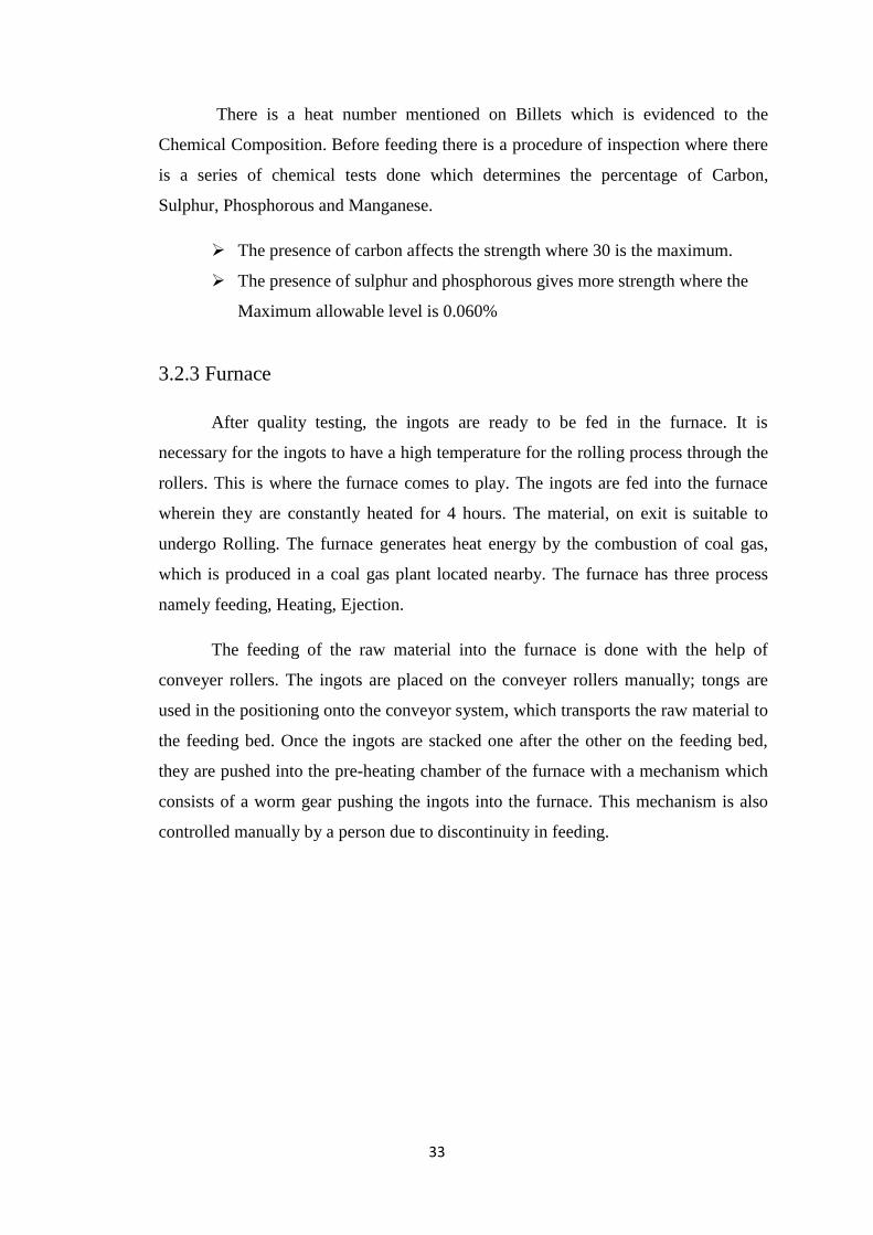
The feeding of the raw material into the furnace is done with the help of
conveyer rollers. The ingots are placed on the conveyer rollers manually; tongs are
used in the positioning onto the conveyor system, which transports the raw material to
the feeding bed. Once the ingots are stacked one after the other on the feeding bed,
they are pushed into the pre-heating chamber of the furnace with a mechanism which
consists of a worm gear pushing the ingots into the furnace. This mechanism is also
controlled manually by a person due to discontinuity in feeding.
34
Fig.3.4 feeding Mechanism used for pushing ingots
Fig.3.5 Furnace
Fig.3.6 Furnace exit
35
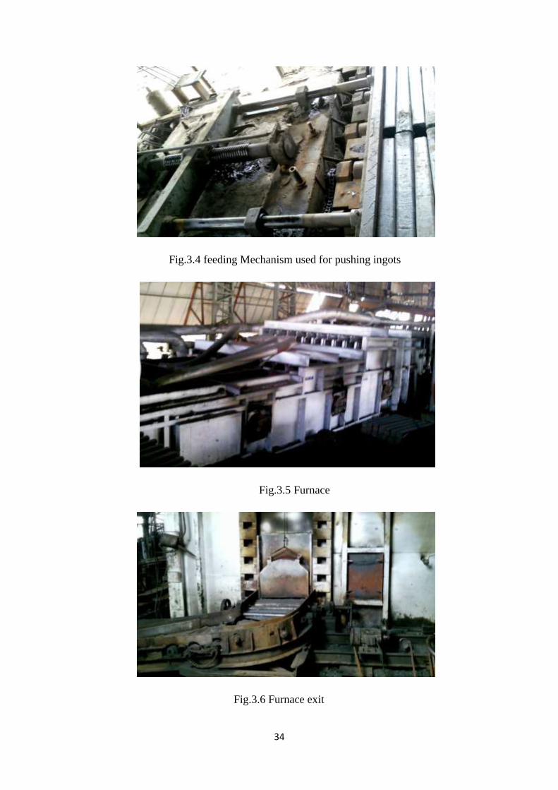
The Heating Chamber or furnace is the chamber where the ingots are made
molten, which makes it feasible to pass it through the rollers. The furnace is a fuel
consuming chamber which works on coal gas. The furnace has a total of 8 burners.
There is a preheating zone, which leads to the intermediate zone ultimately leading to
the final zone. The gas plant is where the coal gas is produced. There is a pipeline
system which leads the gas to the burners. The peak temperature in the furnace goes
up to 1200°C. The gas is streamlined to vary the temperature. Lot of precaution is
taken as there is immense heat in proximity to the furnace. The furnace interior is
made of refractory bricks to withstand the high temperatures. There are also certain
doors at the side for inspection during maintenance. There is another controller near
the exit of the furnace to guide the red hot ingots outside of the furnace and position
them onto the rollers; leading them to the rolling mill.
The fig.3.5 shows the structure of the furnace. Several pipelines can be seen at
the entrance of the furnace, for exhaust. The pipes present near the burners Consist of
the gas fuel pipeline. The doors or gates present at the side are used for inspection or
to replace the refractory bricks during maintenance.
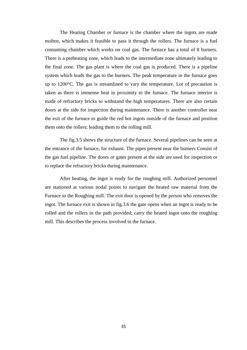
After heating, the ingot is ready for the roughing mill. Authorized personnel
are stationed at various nodal points to navigate the heated raw material from the
Furnace to the Roughing mill. The exit door is opened by the person who removes the
ingot. The furnace exit is shown in fig.3.6 the gate opens when an ingot is ready to be
rolled and the rollers in the path provided; carry the heated ingot onto the roughing
mill. This describes the process involved in the furnace.
36
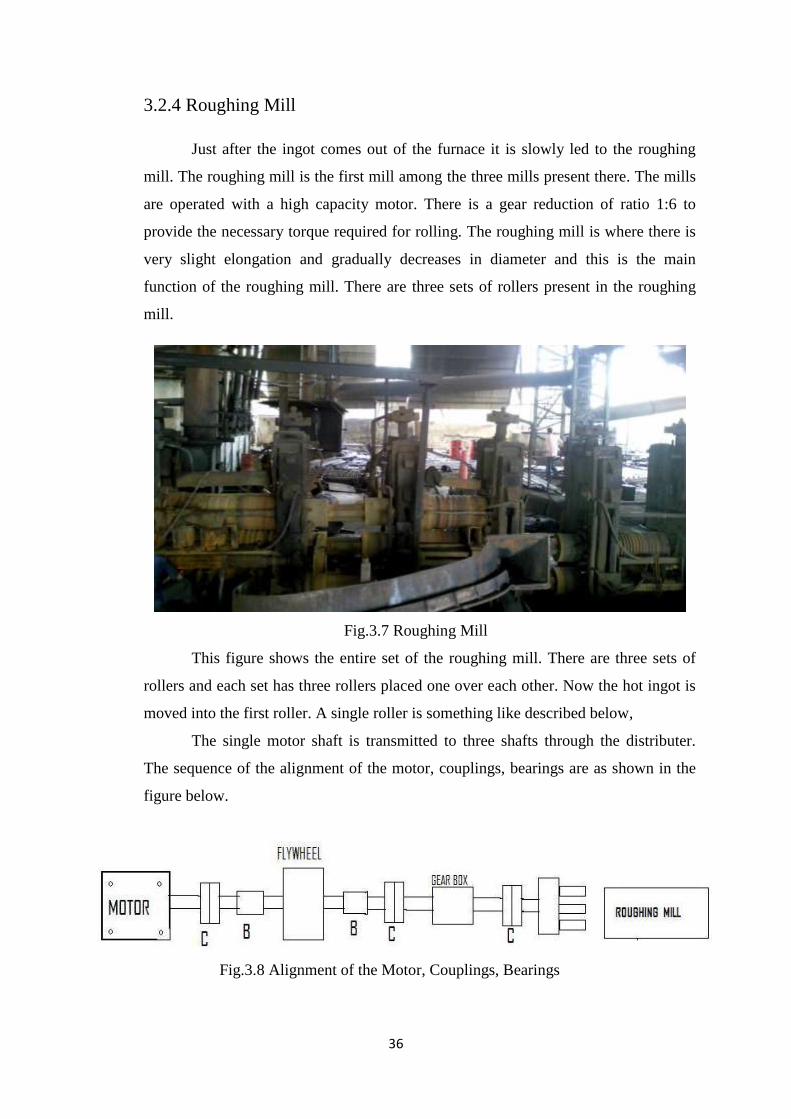
3.2.4 Roughing Mill
Just after the ingot comes out of the furnace it is slowly led to the roughing
mill. The roughing mill is the first mill among the three mills present there. The mills
are operated with a high capacity motor. There is a gear reduction of ratio 1:6 to
provide the necessary torque required for rolling. The roughing mill is where there is
very slight elongation and gradually decreases in diameter and this is the main
function of the roughing mill. There are three sets of rollers present in the roughing
mill.
Fig.3.7 Roughing Mill
This figure shows the entire set of the roughing mill. There are three sets of
rollers and each set has three rollers placed one over each other. Now the hot ingot is
moved into the first roller. A single roller is something like described below,
The single motor shaft is transmitted to three shafts through the distributer.
The sequence of the alignment of the motor, couplings, bearings are as shown in the
figure below.
Fig.3.8 Alignment of the Motor, Couplings, Bearings
37
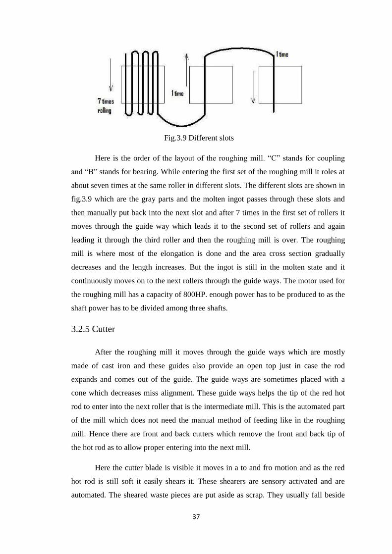
Fig.3.9 Different slots
Here is the order of the layout of the roughing mill. “C” stands for coupling
and “B” stands for bearing. While entering the first set of the roughing mill it roles at
about seven times at the same roller in different slots. The different slots are shown in
fig.3.9 which are the gray parts and the molten ingot passes through these slots and
then manually put back into the next slot and after 7 times in the first set of rollers it
moves through the guide way which leads it to the second set of rollers and again
leading it through the third roller and then the roughing mill is over. The roughing
mill is where most of the elongation is done and the area cross section gradually
decreases and the length increases. But the ingot is still in the molten state and it
continuously moves on to the next rollers through the guide ways. The motor used for
the roughing mill has a capacity of 800HP. enough power has to be produced to as the
shaft power has to be divided among three shafts.
3.2.5 Cutter
After the roughing mill it moves through the guide ways which are mostly
made of cast iron and these guides also provide an open top just in case the rod
expands and comes out of the guide. The guide ways are sometimes placed with a
cone which decreases miss alignment. These guide ways helps the tip of the red hot
rod to enter into the next roller that is the intermediate mill. This is the automated part
of the mill which does not need the manual method of feeding like in the roughing
mill. Hence there are front and back cutters which remove the front and back tip of
the hot rod as to allow proper entering into the next mill.
Here the cutter blade is visible it moves in a to and fro motion and as the red
hot rod is still soft it easily shears it. These shearers are sensory activated and are
automated. The sheared waste pieces are put aside as scrap. They usually fall beside
38
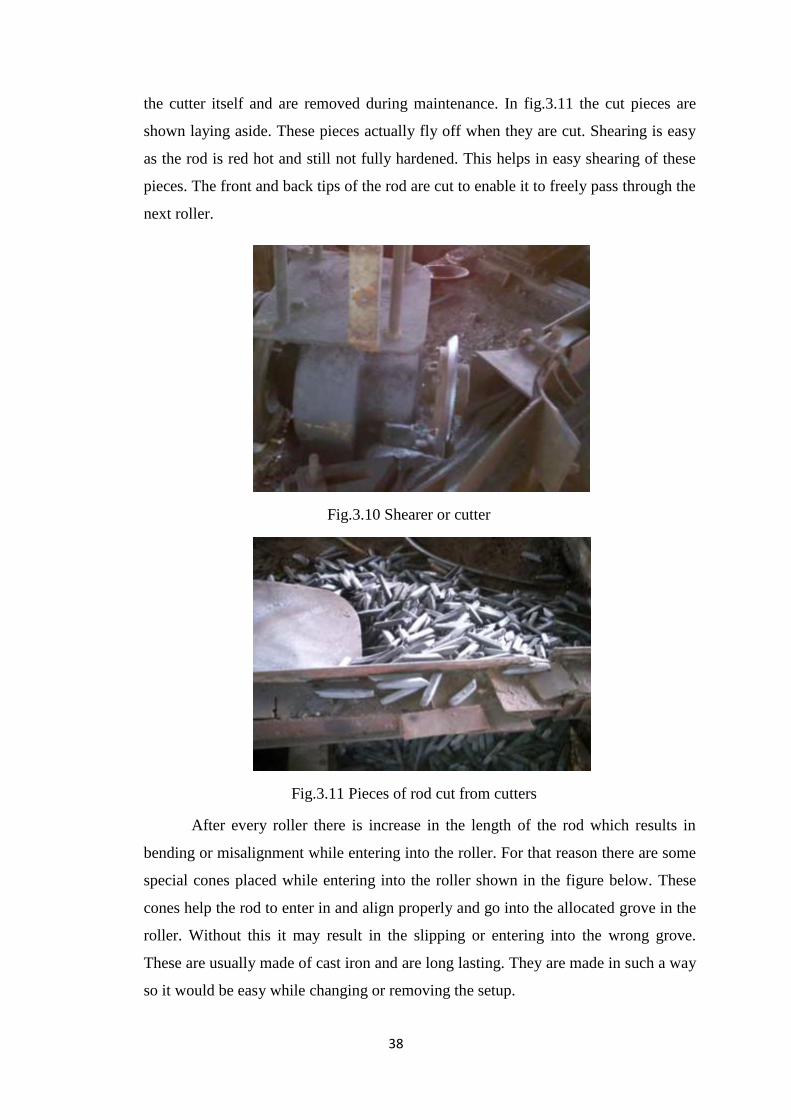
the cutter itself and are removed during maintenance. In fig.3.11 the cut pieces are
shown laying aside. These pieces actually fly off when they are cut. Shearing is easy
as the rod is red hot and still not fully hardened. This helps in easy shearing of these
pieces. The front and back tips of the rod are cut to enable it to freely pass through the
next roller.
Fig.3.10 Shearer or cutter
Fig.3.11 Pieces of rod cut from cutters
After every roller there is increase in the length of the rod which results in
bending or misalignment while entering into the roller. For that reason there are some
special cones placed while entering into the roller shown in the figure below. These
cones help the rod to enter in and align properly and go into the allocated grove in the
roller. Without this it may result in the slipping or entering into the wrong grove.
These are usually made of cast iron and are long lasting. They are made in such a way
so it would be easy while changing or removing the setup.
39
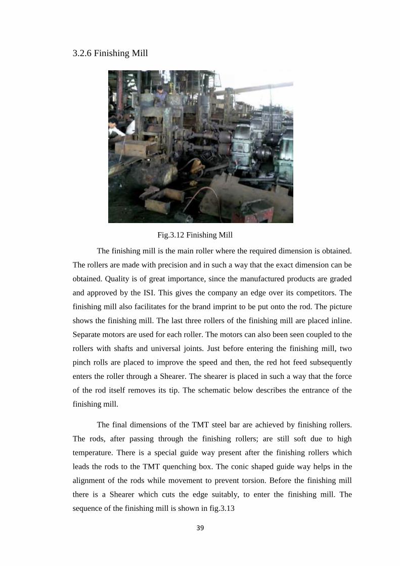
3.2.6 Finishing Mill
Fig.3.12 Finishing Mill
The finishing mill is the main roller where the required dimension is obtained.
The rollers are made with precision and in such a way that the exact dimension can be
obtained. Quality is of great importance, since the manufactured products are graded
and approved by the ISI. This gives the company an edge over its competitors. The
finishing mill also facilitates for the brand imprint to be put onto the rod. The picture
shows the finishing mill. The last three rollers of the finishing mill are placed inline.
Separate motors are used for each roller. The motors can also been seen coupled to the
rollers with shafts and universal joints. Just before entering the finishing mill, two
pinch rolls are placed to improve the speed and then, the red hot feed subsequently
enters the roller through a Shearer. The shearer is placed in such a way that the force
of the rod itself removes its tip. The schematic below describes the entrance of the
finishing mill.
The final dimensions of the TMT steel bar are achieved by finishing rollers.
The rods, after passing through the finishing rollers; are still soft due to high
temperature. There is a special guide way present after the finishing rollers which
leads the rods to the TMT quenching box. The conic shaped guide way helps in the
alignment of the rods while movement to prevent torsion. Before the finishing mill
there is a Shearer which cuts the edge suitably, to enter the finishing mill. The
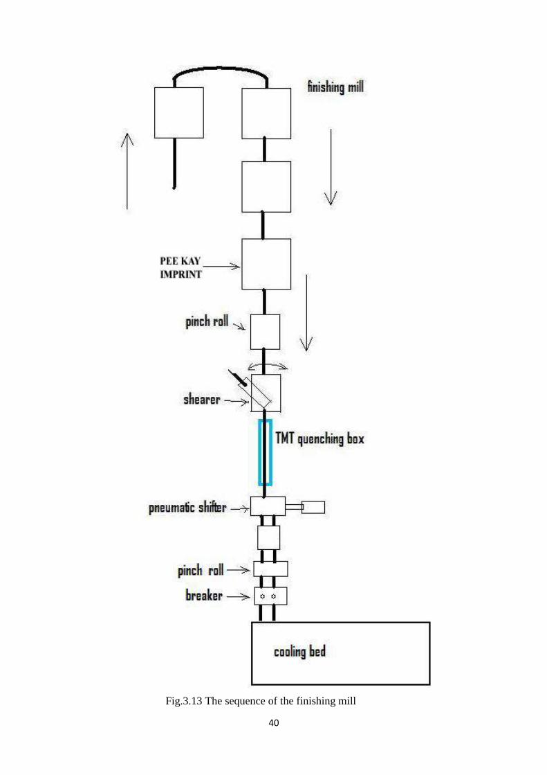
sequence of the finishing mill is shown in fig.3.13
40
Fig.3.13 The sequence of the finishing mill
41
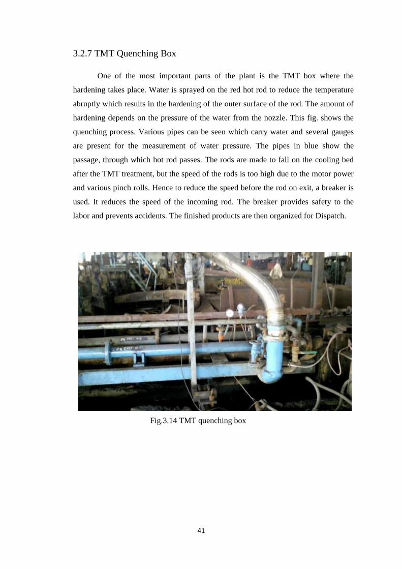
3.2.7 TMT Quenching Box
One of the most important parts of the plant is the TMT box where the
hardening takes place. Water is sprayed on the red hot rod to reduce the temperature
abruptly which results in the hardening of the outer surface of the rod. The amount of
hardening depends on the pressure of the water from the nozzle. This fig. shows the
quenching process. Various pipes can be seen which carry water and several gauges
are present for the measurement of water pressure. The pipes in blue show the
passage, through which hot rod passes. The rods are made to fall on the cooling bed
after the TMT treatment, but the speed of the rods is too high due to the motor power
and various pinch rolls. Hence to reduce the speed before the rod on exit, a breaker is
used. It reduces the speed of the incoming rod. The breaker provides safety to the
labor and prevents accidents. The finished products are then organized for Dispatch.
Fig.3.14 TMT quenching box

42
3.3 PROPERTIES OF TMT BARS
3.3.1 Advantages of TMT Bars
Better Safety of structures: because of higher Strength combined with higher
Ductility.
Easy working at site: owing to better Ductility and Bend ability. Pre-welded
meshes can be made to eliminate manual binding at site. Reduces construction
and fabrication time.
Resists fire: Unlike Tor steel/ CTD Reinforcement bars, TMT bars have high
thermal stability. They are the preferred choice when elevated temperatures of
400-6000 C may be encountered (Chimneys, fires).
Resists corrosion: The TMT process gives the bar superior strength and
anticorrosive properties. Controlled water-cooling prevents the formation of
coarse carbides, which has been cited as the main cause for the corrosive
nature of common bar. Another reason for better corrosion resistance is the
absence of surface stresses caused by the cold twisting process.
Formability: Due to very high elongation values and consistent properties
throughout the length of bar, TMT rebars have excellent workability and
bendability.
Earthquake resistance: The soft ferrite-pearlite core enables the bar to bear
dynamic and seismic loading. TMT bars have high fatigue resistance to
Dynamic/ Seismic loads due to its higher ductility quality. This makes them
most suitable for use in earthquake prone areas.
Malleability: TMT bars are most preferred because of their flexible nature
Fine welding features: TMT rebars (having low carbon content) can be used
for butt and other weld joints without reduction in strength at the weld joints.
Bonding strength: External ribs running across the entire length of the TMT
bar give superior bonding strength between the bar and the concrete. Fulfils
Bond requirements as per IS: 456/78 and IS: 1786/85.
Cost-effective: A high tensile strength and better elongation value gives you
great savings, Reduced Transportation Costs.
43
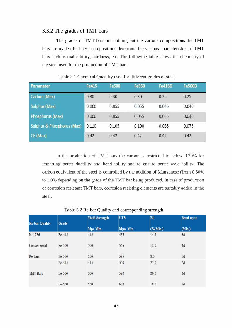
3.3.2 The grades of TMT bars
The grades of TMT bars are nothing but the various compositions the TMT
bars are made off. These compositions determine the various characteristics of TMT
bars such as malleability, hardness, etc. The following table shows the chemistry of
the steel used for the production of TMT bars:
Table 3.1 Chemical Quantity used for different grades of steel
In the production of TMT bars the carbon is restricted to below 0.20% for
imparting better ductility and bend-ability and to ensure better weld-ability. The
carbon equivalent of the steel is controlled by the addition of Manganese (from 0.50%
to 1.0% depending on the grade of the TMT bar being produced. In case of production
of corrosion resistant TMT bars, corrosion resisting elements are suitably added in the
steel.
Re-bar Quality
Table 3.2 Re-bar Quality and corresponding strength

44
3.3.3 Applications of TMT bar
TMT bars find wide applications in different spheres:
General purpose concrete re-enforcement structures
Bridges
Flyovers
Dams
High rise buildings
Industrial structures
Concrete roads
Underground structures
45
4. THE READY MIXED CONCRETE PLANT
Ready Mix Concrete (RMC) is a specialized material in which the cement aggregates
and other ingredients are weigh-batched at a plant in a central mixer or truck mixer, before
delivery to the construction site in a condition ready for placing by the builder. Thus, `fresh'
concrete is manufactured in a plant away from the construction site and transported within the
requisite journey time. The RMC supplier provides two services, firstly one of processing the
materials for making fresh concrete and secondly, of transporting a product within a short
time.
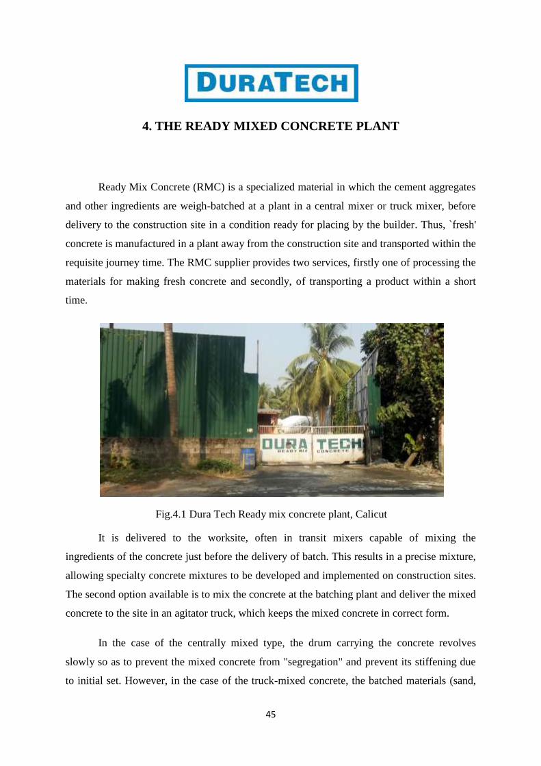
Fig.4.1 Dura Tech Ready mix concrete plant, Calicut
It is delivered to the worksite, often in transit mixers capable of mixing the
ingredients of the concrete just before the delivery of batch. This results in a precise mixture,
allowing specialty concrete mixtures to be developed and implemented on construction sites.
The second option available is to mix the concrete at the batching plant and deliver the mixed
concrete to the site in an agitator truck, which keeps the mixed concrete in correct form.
In the case of the centrally mixed type, the drum carrying the concrete revolves
slowly so as to prevent the mixed concrete from "segregation" and prevent its stiffening due
to initial set. However, in the case of the truck-mixed concrete, the batched materials (sand,
46
gravel and cement) are carried and water is added just at the time of mixing. In this case the
cement remains in contact with the wet or moist material and this phase cannot exceed the
permissible period, which is normally 90 minutes.
The use of the RMC is facilitated through a truck-mounted 'boom placer' that can
pump the product for ready use at multi-storied construction sites. A boom placer can pump
the concrete up 80 meters.
RMC is preferred to on-site concrete mixing because of the precision of the mixture
and reduced worksite confusion. It facilitates speedy construction through programmed
delivery at site and mechanized operation with consequent economy. It also decreases labour,
site supervising cost and project time, resulting in savings. Proper control and economy in use
of raw material results in saving of natural resources. It assures consistent quality through
accurate computerized control of aggregates and water as per mix designs. It minimizes
cement wastage due to bulk handling and there is no dust problem and therefore, pollution-
free.
Ready mix concrete is usually ordered in units of cubic yards or meters. It must
remain in motion until it is ready to be poured, or the cement may begin to solidify. The
ready mix concrete is generally released from the hopper in a relatively steady stream through
a trough system. Workers use shovels and hoes to push the concrete into place. Some projects
may require more than one production run of ready mix concrete, so more trucks may arrive
as needed or additional batches may be produced offsite and delivered.
However there are some disadvantages of RMC to, like double handling, which
results in additional cost and losses in weight, requirement of go downs for storage of cement
and large area at site for storage of raw materials. Aggregates get mixed and impurities creep
in because of wind, weather and mishandling at site. Improper mixing at site, as there is
ineffective control and intangible cost associated with unorganized preparation at site are
other drawbacks of RMC. There are always possibilities of manipulation; manual error and
mischief as concreting are done at the mercy of gangs, who manipulate the concrete mixes
and water cement ratio.
47
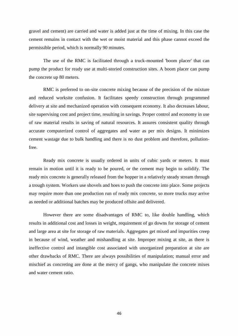
4.1 MATERIALS REQUIRED FOR RMC
4.1.1 Aggregate:
Aggregates are the important constituents in concrete. They give body to the
concrete, reduce shrinkage and effect economy. Earlier, aggregates were considered
as chemically inert materials but now it has been recognised that some of the
aggregates are chemically active and also that certain aggregates exhibit chemical
bond at the interface of aggregate and paste. The mere fact that the aggregates occupy
70-80 per cent of the volume of concrete, their impact on various characteristics and
properties of concrete is undoubtedly considerable. To know more about the
aggregates which constitute major volume in concrete.
Fig.4.2 Aggregate storage yard
Aggregates are divided into two categories from the consideration of size
Coarse aggregate
Fine aggregate
The size of the aggregate bigger than 4.75 mm is considered as coarse
aggregate and aggregate whose size is 4.75 mm and less is considered as fine
aggregate.
48
Sampling procedure for aggregates used in concrete:
Collect the aggregate sample from different locations at different depths
from the site immediately after unloading the aggregates from the trucks.
Collect the samples at least from 10 to 15 locations.
Thoroughly remix the sample collected from various places & depths of
the trucks or from the stocks.
Make a cone from the sample.
Flatten the cone sample to form a circle of uniform thickness.
Divide the cone in to four equal quarters.
Discard any two diagonally opposite segment of quartered sample.
Collect the remaining sample & remix.
Take this remixed aggregate for testing.
The material so sampled only should be taken for testing. The Indian standards
recommend sampling the aggregates as above. However it recommends collecting
samples from different sub lots which are not practical as it takes long time to build
up the lots at site. Hence the method suggested above may be conveniently adopted at
site.
4.1.2 Cement
Cement is a binder material which sets and hardens independently, and can
bind other materials together. Cement is made up of four main compounds tricalcium
silicate (3CaO SiO2), dicalcium Silicate (2CaO SiO2), tricalcium acuminate (3CaO
Al2O3), and tetra-calcium aluminoferrite (4caco Al2O3 Fe2O3).tetra-calcium
aluminoferrite (4CaO Al2O3 Fe2O3). In an abbreviated notation differing from the
normal atomic symbols, these compounds are designated as C3S, C2S, C3A, and
C4AF, where C stands for calcium oxide (lime), S for silica and A for alumina, and F
for iron oxide. Small amounts of uncombined lime and magnesia also are present,
along with alkalis and minor amounts of other elements.
49
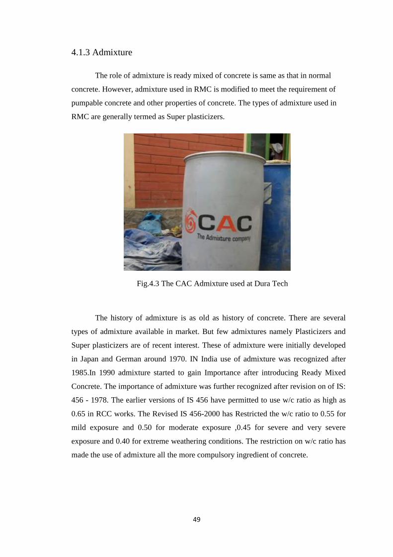
4.1.3 Admixture
The role of admixture is ready mixed of concrete is same as that in normal
concrete. However, admixture used in RMC is modified to meet the requirement of
pumpable concrete and other properties of concrete. The types of admixture used in
RMC are generally termed as Super plasticizers.
Fig.4.3 The CAC Admixture used at Dura Tech
The history of admixture is as old as history of concrete. There are several
types of admixture available in market. But few admixtures namely Plasticizers and
Super plasticizers are of recent interest. These of admixture were initially developed
in Japan and German around 1970. IN India use of admixture was recognized after
1985.In 1990 admixture started to gain Importance after introducing Ready Mixed
Concrete. The importance of admixture was further recognized after revision on of IS:
456 - 1978. The earlier versions of IS 456 have permitted to use w/c ratio as high as
0.65 in RCC works. The Revised IS 456-2000 has Restricted the w/c ratio to 0.55 for
mild exposure and 0.50 for moderate exposure ,0.45 for severe and very severe
exposure and 0.40 for extreme weathering conditions. The restriction on w/c ratio has
made the use of admixture all the more compulsory ingredient of concrete.
50
Admixture is used in RMC are of following types:
Chemical admixture
Mineral admixture
Chemical and mineral admixture
In RMC admixture mainly perform the following functions:
Increasing workability
Accelerate or retard the setting time of concrete.
Reduce segregation and bleeding in concrete.
Improve pump ability.
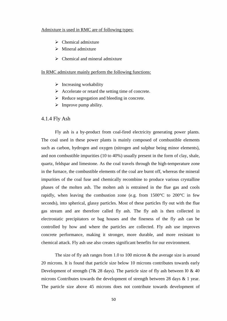
4.1.4 Fly Ash
Fly ash is a by-product from coal-fired electricity generating power plants.
The coal used in these power plants is mainly composed of combustible elements
such as carbon, hydrogen and oxygen (nitrogen and sulphur being minor elements),
and non combustible impurities (10 to 40%) usually present in the form of clay, shale,
quartz, feldspar and limestone. As the coal travels through the high-temperature zone
in the furnace, the combustible elements of the coal are burnt off, whereas the mineral
impurities of the coal fuse and chemically recombine to produce various crystalline
phases of the molten ash. The molten ash is entrained in the flue gas and cools
rapidly, when leaving the combustion zone (e.g. from 1500°C to 200°C in few
seconds), into spherical, glassy particles. Most of these particles fly out with the flue
gas stream and are therefore called fly ash. The fly ash is then collected in
electrostatic precipitators or bag houses and the fineness of the fly ash can be
controlled by how and where the particles are collected. Fly ash use improves
concrete performance, making it stronger, more durable, and more resistant to
chemical attack. Fly ash use also creates significant benefits for our environment.
The size of fly ash ranges from 1.0 to 100 micron & the average size is around
20 microns. It is found that particle size below 10 microns contributes towards early
Development of strength (7& 28 days). The particle size of fly ash between l0 & 40
microns Contributes towards the development of strength between 28 days & 1 year.
The particle size above 45 microns does not contribute towards development of
51
strength even after 1 year and for all practical purpose they should be considered only
as sand.
The fly ash is generally used in the concrete in the following ways.
As partial replace for cement.
As partial replacement for sand.
As simultaneous replacement for both cement and sand.
It is found that fly ash replacement from l0 to 30% increases the development
of Strength up to 3 month or even more depending on the fineness of fly ash & its
reaction with Calcium hydroxide released during primary hydration of cement.
Addition of fly ash as per replacement of cement improves the workability of
concrete for the same water content. This means that the water content can be reduced
for fly ash based concrete. This reduced water cement ratio to some extent can offset
for initial gain of Strength can range from 10 to 25 % of the difference in strength
between the strength of Normal concrete & fly ash concrete.
Fly ash as a partial replacement for sand is uneconomical and sometimes it is
inevitable in pumping concrete especially when coarser types of fine aggregates are
used in concrete. It is also found that partial replacement of fly ash marginally
increases the strength Concrete due to filler effect in the initial stages and due to
pozzolanic action in 28days.Simultaneous use of fly ash as a partial replacement of
cement and sand is good Proposal to increase strength, workability & pump ability of
concrete.
52
4.1.5 Water
The pH value of water should be in between 6.0 and 8.0 according to IS 456-
2000.
Effect of Mixing Sea Water in Concrete
The sea Water generally contains salinity of about 3.5% in which about 80% is
sodium chloride. Many researchers have been conducted to study the corrosion
problem of steel Embedded in concrete where sea water is used as mixing water in
concrete nevertheless the Indian standard is adamant & do not permit using sea water
for mixing or curing in reinforced Concrete constructions, but allows for using of sea
water only for PCC work that too under unavoidable circumstances.
Quality of Water for Curing Concrete Members:
Generally the water that is fit for mixing of water in concrete is also fit for
curing. However where appearance is important, water containing impurities which
cause stains should not to be used. The most important elements that cause stains in
the concrete are iron, and organic matters. It is also found that even sea water also
causes stains in concrete. Hence water containing iron, organic matters and also sea
water should not be used for curing of concrete when appearance is also set as criteria
for the acceptance of concrete.
Quality of Water for Curing Concrete Cubes:
The water that is fit for mixing and curing of water for concrete is also fit for
curing of cubes which are cured under water. However the curing water should not to
be allowed to remain in stagnant condition in water tanks for long time. As a
guideline the water tanks shall be cleaned twice a week or when ph value of water
reaches a value more than 9. The cleaned Water tanks shall be refilled with fresh
water every time.
The cleaning of water is necessary to remove algae and fungus materials
developed inside the water tanks which otherwise alters the setting and strength
gaining properties of Concrete. The low results of such cubes may call for in situ tests
resulting in consequential Delay of the project.
53
4.2 EQUIPMENTS REQUIRED
4.2.1 Batching Plant
The principal functional elements of every stationary concrete production
Plant comprises of the following:
Storage of materials - Silos, containers and bins
Batching arrangement
Measuring and recording equipment
Mixing equipment
Control systems
Electrical, hydraulic and pneumatic drives
Conveying systems (belt / screw conveyors)
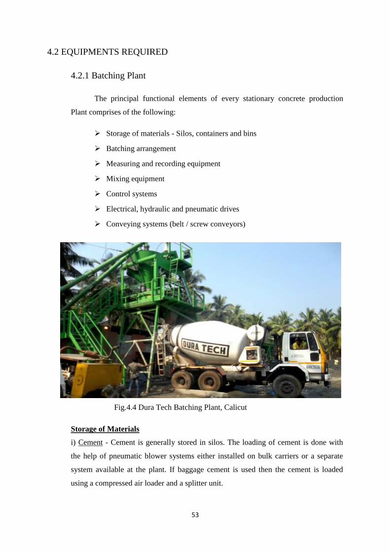
Fig.4.4 Dura Tech Batching Plant, Calicut
Storage of Materials
i) Cement - Cement is generally stored in silos. The loading of cement is done with
the help of pneumatic blower systems either installed on bulk carriers or a separate
system available at the plant. If baggage cement is used then the cement is loaded
using a compressed air loader and a splitter unit.
54
Cement is weighed separately, and is transported from the silo into a mechanical or
electro mechanical weigher by means of a screw conveyor.
ii) Water - Water is generally stored in tanks located close to the plant. It is accurately
measured by a water gauge and microprocessor controlled system. The modern plants
have new litronic MFM 85 moisture recorders. These recorders actually measure the
moisture present in sand while the entire batch flows past. A recording unit calculates
the average moisture value of the sand and passes on the information to the batching
control unit to allow corrective action to be taken. The system operates to an accuracy
of as low as 0.2% relative moisture.
Consistency of the mix is generally checked by visual observation later confirming it
with a workability test like the slump test. However, in modern plants consistency of
the concrete mix is checked by a remote recording system which is automatic, easy
and more accurate.
If concrete is very dry (stiff) the electrical resistance of the batch is measured and if
the concrete is wet the motor output is measured.
Accurate maintenance of the workability (consistency) of one cubic meter batch of
concrete may depend on as little as one litre or less of water. It is scarcely conceivable
that such a production process could be controlled without actually measuring the
workability and later correcting the consistency.
iii) Aggregates - The storage of aggregates is done in various way depending on the
type of plant.
There are basically three types of plants generally in use.
Vertical Production Plant - In this the aggregates are stored above the batching and
mixing elements, in one or more silos. These plants are not suitable for relocation at
short intervals of time. As the aggregates are stored in silos it is relatively easy to
protect the aggregates from very low temperature in winter period.
Horizontal Production Plant
They can be again broadly classified into four types
Star pattern aggregate storage
Storage in tall silo
Storage in pocket silo
Inline aggregate storage silos
55
The star bin storage of aggregates is most popular in India mainly because of climate
conditions. The aggregates can be stored exposed to ambient temperature in different
compartments forming a star type pattern. A storage capacity of up to 1500 CuM is
possible in this type. The star pattern aggregates are stored in four to six
compartments. They are bulked at a 45 degree flow angle against the batching plant's
bulkhead and partition wall of the compartments using a boom type dragline loader.
The drag-line operations are either fully manual, semi automatic or fully automatic.
Fully automatic dragline loader system operator.
The star bin type plant requires more space and as the aggregates are stored in open
they heat up at high ambient temperatures and freeze at very low temperatures. These
types of plants are not suitable in extreme weather conditions.
In silo type storage additional investment for loading equipment such as hopper,
bucket elevator or conveyor belt plus rotary distribution are required. They have large
active storage (up to 500 CuM) in a small areas. Loading is fully automatic,
aggregates are well protected in extreme climatic conditions and storage is very clean.
Batching Arrangements
Batching is the process of measurement of specified quantities of cement,
aggregates, water and admixture, i.e., ingredients of concrete in correct proportion.
The batching arrangement should control and store the materials. For that aggregate
bins provided for storing aggregate and Silos tanks for storing cement and
cementitious materials
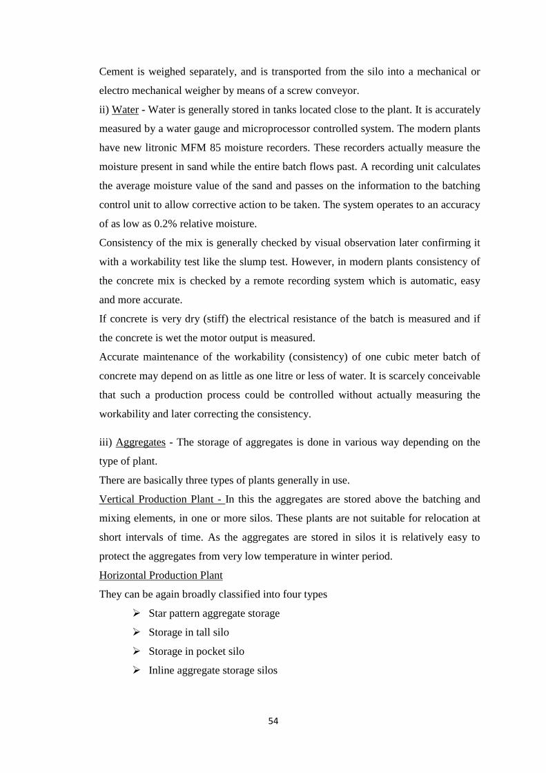
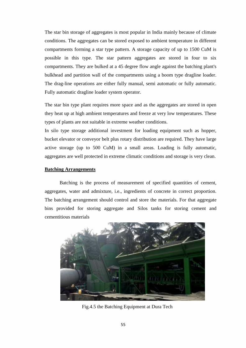
Fig.4.5 the Batching Equipment at Dura Tech
56
Batching Process
Volumetric batching - Not desirable except for small non engineered jobs
Weigh Batching (Mass basis, IS456:2000)
Components of a Batching Plant
Aggregate bins for various types of aggregates.
Feeding mechanisms such as scrappers, conveyors or hoists etc. to transfer
aggregate to scales (balances).
Balance and measuring system.
Cement silos and a conveyor screw or bucket conveyor.
The storage tank for water and water measuring system.
Dispenser for chemical (liquid) admixture.
Mixing Arrangements
There are various types of concrete mixers used on the concrete production
plant. The two basic types are free fall mixers and power mixers. Most of our
indigenously manufactured plants have free fall mixer. Free fall mixer consists of a
rotating drum with blade fixed on the drum's interior. As the drum rotates, the
material inside is lifted and dropped. The drum is loaded and emptied by changing the
direction of rotation, dropping a flap or tipping it.
Most of the imported plants have power mixer. The power mixer sets in
motion the materials positively. The materials get thoroughly mixed by rotating arms.
These mixers have shorter mixing time; give better homogeneity, consistency and
strength to the concrete. Besides, they have better facility for inspection.
If mixing is to be done on difficult concrete mixes, additional agitator is
provided. The pan type mixer with additional agitator or two agitators is claimed to be
far in advance of any if other mixer. Using additional agitators almost halves the
mixing time. The additional agitator is driven by a separate hydraulic system and can
be set to any speed between 0 to 200 revolutions per minute.
57
Control Systems
Almost all imported production plants offer automatic systems for control
functions. These are required for better quality control, higher economy and superior
working conditions. Fully automatic plant control systems with multiple inputs for up
to 120 mixes or template control system are usually housed in a container or control
room of the plant. Micro processor controlled production plants represent the state of
the art in the developed countries.
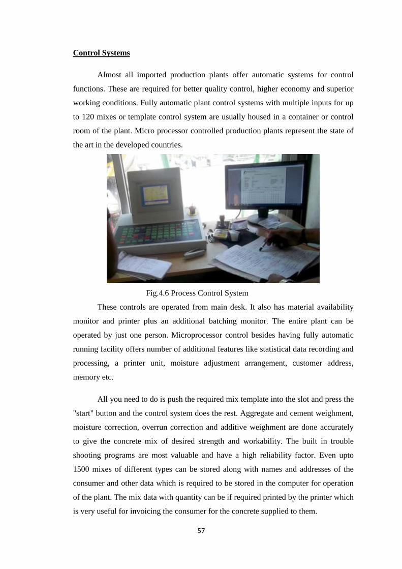
Fig.4.6 Process Control System
These controls are operated from main desk. It also has material availability
monitor and printer plus an additional batching monitor. The entire plant can be
operated by just one person. Microprocessor control besides having fully automatic
running facility offers number of additional features like statistical data recording and
processing, a printer unit, moisture adjustment arrangement, customer address,
memory etc.
All you need to do is push the required mix template into the slot and press the
"start" button and the control system does the rest. Aggregate and cement weighment,
moisture correction, overrun correction and additive weighment are done accurately
to give the concrete mix of desired strength and workability. The built in trouble
shooting programs are most valuable and have a high reliability factor. Even upto
1500 mixes of different types can be stored along with names and addresses of the
consumer and other data which is required to be stored in the computer for operation
of the plant. The mix data with quantity can be if required printed by the printer which
is very useful for invoicing the consumer for the concrete supplied to them.
58
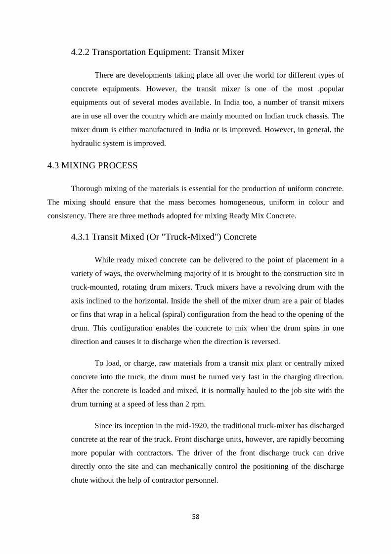
4.2.2 Transportation Equipment: Transit Mixer
There are developments taking place all over the world for different types of
concrete equipments. However, the transit mixer is one of the most .popular
equipments out of several modes available. In India too, a number of transit mixers
are in use all over the country which are mainly mounted on Indian truck chassis. The
mixer drum is either manufactured in India or is improved. However, in general, the
hydraulic system is improved.
4.3 MIXING PROCESS
Thorough mixing of the materials is essential for the production of uniform concrete.
The mixing should ensure that the mass becomes homogeneous, uniform in colour and
consistency. There are three methods adopted for mixing Ready Mix Concrete.
4.3.1 Transit Mixed (Or "Truck-Mixed") Concrete
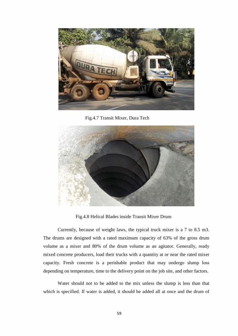
While ready mixed concrete can be delivered to the point of placement in a
variety of ways, the overwhelming majority of it is brought to the construction site in
truck-mounted, rotating drum mixers. Truck mixers have a revolving drum with the
axis inclined to the horizontal. Inside the shell of the mixer drum are a pair of blades
or fins that wrap in a helical (spiral) configuration from the head to the opening of the
drum. This configuration enables the concrete to mix when the drum spins in one
direction and causes it to discharge when the direction is reversed.
To load, or charge, raw materials from a transit mix plant or centrally mixed
concrete into the truck, the drum must be turned very fast in the charging direction.
After the concrete is loaded and mixed, it is normally hauled to the job site with the
drum turning at a speed of less than 2 rpm.
Since its inception in the mid-1920, the traditional truck-mixer has discharged
concrete at the rear of the truck. Front discharge units, however, are rapidly becoming
more popular with contractors. The driver of the front discharge truck can drive
directly onto the site and can mechanically control the positioning of the discharge
chute without the help of contractor personnel.
59
Fig.4.7 Transit Mixer, Dura Tech
Fig.4.8 Helical Blades inside Transit Mixer Drum
Currently, because of weight laws, the typical truck mixer is a 7 to 8.5 m3.
The drums are designed with a rated maximum capacity of 63% of the gross drum
volume as a mixer and 80% of the drum volume as an agitator. Generally, ready
mixed concrete producers, load their trucks with a quantity at or near the rated mixer
capacity. Fresh concrete is a perishable product that may undergo slump loss
depending on temperature, time to the delivery point on the job site, and other factors.
Water should not to be added to the mix unless the slump is less than that
which is specified. If water is added, it should be added all at once and the drum of
60
the truck mixer should be turned minimum of 30 revolutions, or about two minutes, at
mixing speed.
The ASTM C 94, Specification for Ready Mixed Concrete, indicates that the
concrete shall be discharged on the job site within 90 minutes and before 300
revolutions after water was added to the cement. The purchaser may waive this
requirement, when conditions permit.
In certain situations, air-entraining, water reducing, set-retarding or high-range
water reducing admixtures may need to be added to concrete prior to discharge to
compensate for loss of air, high temperatures or long delivery times. The ready mixed
concrete producer will assist the purchaser in such circumstances.
4.4 TESTS ON MATERIALS
4.4.1 Tests on Fine Aggregates
Sieve Analysis
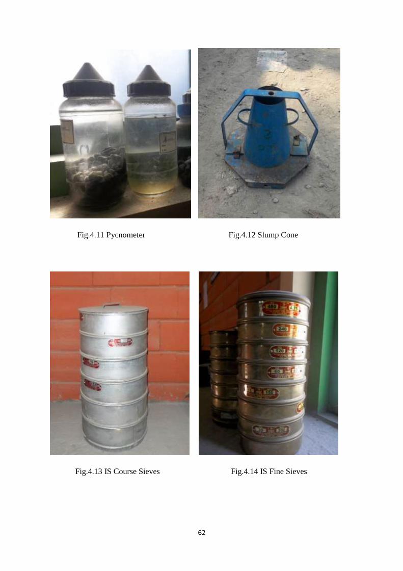
Specific Gravity (Pycnometer Method)
Bulk Density Test
Absorption Test
4.4.2 Tests on Coarse Aggregates
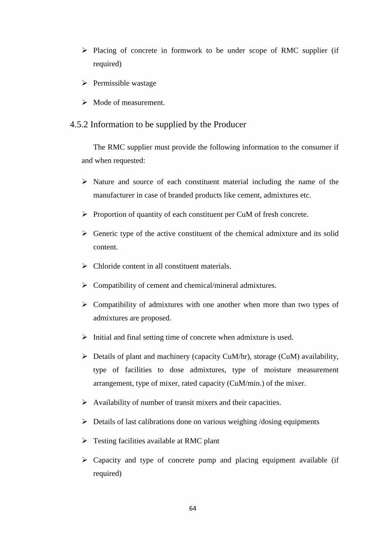
Sieve Analysis
Specific Gravity Test
Aggregate Impact Value Test
Bulk Density Test
Water Absorption Test
Flakiness Index Test
Elongation Index Test
4.4.3 Test on Fresh Concrete
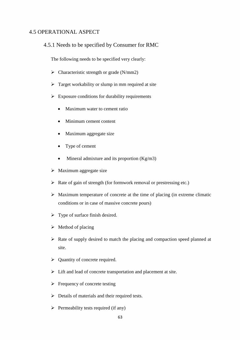
Slump Test
61
4.4.4 Test on Water
pH Value
Chloride
Sulphite
Nitrite
4.4.5 Test on Hardened Concrete
Compressive Strength
Flexure Strength
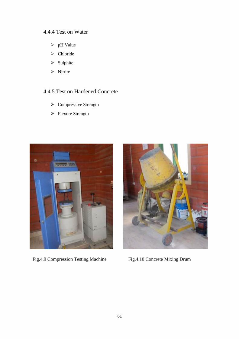
Fig.4.9 Compression Testing Machine Fig.4.10 Concrete Mixing Drum
62
Fig.4.11 Pycnometer Fig.4.12 Slump Cone
Fig.4.13 IS Course Sieves Fig.4.14 IS Fine Sieves
63
4.5 OPERATIONAL ASPECT
4.5.1 Needs to be specified by Consumer for RMC
The following needs to be specified very clearly:
Characteristic strength or grade (N/mm2)
Target workability or slump in mm required at site
Exposure conditions for durability requirements
Maximum water to cement ratio
Minimum cement content
Maximum aggregate size
Type of cement
Mineral admixture and its proportion (Kg/m3)
Maximum aggregate size
Rate of gain of strength (for formwork removal or prestressing etc.)
Maximum temperature of concrete at the time of placing (in extreme climatic
conditions or in case of massive concrete pours)
Type of surface finish desired.
Method of placing
Rate of supply desired to match the placing and compaction speed planned at
site.
Quantity of concrete required.
Lift and lead of concrete transportation and placement at site.
Frequency of concrete testing
Details of materials and their required tests.
Permeability tests required (if any)
64
Placing of concrete in formwork to be under scope of RMC supplier (if
required)
Permissible wastage
Mode of measurement.
4.5.2 Information to be supplied by the Producer
The RMC supplier must provide the following information to the consumer if
and when requested:
Nature and source of each constituent material including the name of the
manufacturer in case of branded products like cement, admixtures etc.
Proportion of quantity of each constituent per CuM of fresh concrete.
Generic type of the active constituent of the chemical admixture and its solid
content.
Chloride content in all constituent materials.
Compatibility of cement and chemical/mineral admixtures.
Compatibility of admixtures with one another when more than two types of
admixtures are proposed.
Initial and final setting time of concrete when admixture is used.
Details of plant and machinery (capacity CuM/hr), storage (CuM) availability,
type of facilities to dose admixtures, type of moisture measurement
arrangement, type of mixer, rated capacity (CuM/min.) of the mixer.
Availability of number of transit mixers and their capacities.
Details of last calibrations done on various weighing /dosing equipments
Testing facilities available at RMC plant
Capacity and type of concrete pump and placing equipment available (if
required)
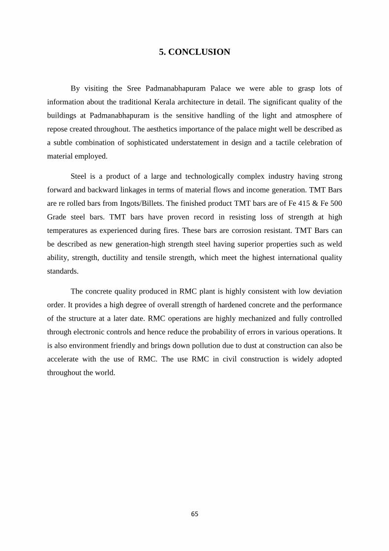
65
5. CONCLUSION
By visiting the Sree Padmanabhapuram Palace we were able to grasp lots of
information about the traditional Kerala architecture in detail. The significant quality of the
buildings at Padmanabhapuram is the sensitive handling of the light and atmosphere of
repose created throughout. The aesthetics importance of the palace might well be described as
a subtle combination of sophisticated understatement in design and a tactile celebration of
material employed.
Steel is a product of a large and technologically complex industry having strong
forward and backward linkages in terms of material flows and income generation. TMT Bars
are re rolled bars from Ingots/Billets. The finished product TMT bars are of Fe 415 & Fe 500
Grade steel bars. TMT bars have proven record in resisting loss of strength at high
temperatures as experienced during fires. These bars are corrosion resistant. TMT Bars can
be described as new generation-high strength steel having superior properties such as weld
ability, strength, ductility and tensile strength, which meet the highest international quality
standards.
The concrete quality produced in RMC plant is highly consistent with low deviation
order. It provides a high degree of overall strength of hardened concrete and the performance
of the structure at a later date. RMC operations are highly mechanized and fully controlled
through electronic controls and hence reduce the probability of errors in various operations. It
is also environment friendly and brings down pollution due to dust at construction can also be
accelerate with the use of RMC. The use RMC in civil construction is widely adopted
throughout the world.