increasing durability of luminarie construction system
TRANSCRIPT

Increasing Durability of Luminarie Construction System
Using and connecting wood outdoors
in temporary projects
Giulio Mariano

Technical Paper Architectural Engineering Graduation Studio June 8th 2016
Increasing Durability in Luminarie Construction System 3
Table of Contents 1 Luminarie 8 1.1 What are Luminarie? 8 1.2 Materials 10 1.3 Construction Process 11 1.3.1 Pre-mounting 1.3.2 Mounting 1.3.3 Dismantling 1.4 Upwind Forces 14 2 Increasing Durability 16 2.1 Coatings 17 2.2 Independent Protection 18 2.2.1 Flashing 2.2.2 Shielding 2.3 Integral Protection 21 2.3.1 Pressure Treatment 2.4 Ground Contact 24 2.5 Corrosion and Wood 26 2.6 Improving Durability of Wood Outdoors 27 3 Research by Design 28 3.1 Demountable joint 29 3.1.1 Reference Project Salt 3.1.2 Design Process 3.1.3 Calculations 3.2.4 Further Improvements 3.2 Ground Contact 39 3.2.1 Reference Project The Playing Field 3.2.2 The Base Design 3.3 Iron Wires 42 3.4 Top End Grain Shield 43
Increasing Durability in Luminarie Construction System 4
Abstract Luminarie construction system uses simple materials as wood poles, iron wire and wood modules to create temporary architectural landscapes in the open air. These wooden structures must withstand time and weather stresses during their life service, may this be 10 days or 1 year. This ability is given by protection techniques and design solutions proper of the temporary architecture as well as of the permanent. This paper focuses on finding these solutions that will extend luminarie construction system durability to weather stresses and time. The results of the research show a set of protection practices for wood structural system used outdoors. The search of design solutions for connecting structural members above ground or to the ground has the scope of reinforcing the current system, without losing the most important features proper to temporality, i.e. demountability and reusability without damaging the structural members. These findings may be helpful to any designer who is approaching the use of wood for outdoors projects, as they outline and discuss the best known practices in the architectural and engineering field. This is done by literature research and research by design methodologies. Keywords: Luminarie, temporary, demountable, wood, exposed, moisture, weather, rain, coating, preservative, treatment, protection, iron wire, ground contact, metal joint, corrosion.
Increasing Durability in Luminarie Construction System 5
Introduction Prior to the 19 century in Europe, much care was given to ephemeral structures in cities, such as triumphal arches, tableaux vivants, and the like, built for specific religious or political celebrations. These singular events, lasting one or a few days, which revealed a political order through the transformed city, were universally significant for the inhabitants, conveying a sense of purpose and a general existential orientation. In a similar way to permanent architecture, ephemeral structures are capable of revealing a ‘poetic image’, one that affects us primarily through our vision and yet is fully sensuous, synesthetic, thus capable of seducing and elevating us to understand our embodied consciousness’s participation in wholeness. (Perez-Gomez, 2006) These ephemeral structures were achieved by temporary construction systems: one of the most particular and effective one, able to withstand our present days is the one of luminarie. Invented in the Baroque period, this system uses wood as the main construction material, due to its lightness and ductility. In origin these structures were covered with painted papier-mâché, later on it was preferred to leave them visible, paint them in white and adorned with small colored oil lamps that completely changed the urban environment during night, while creating enchanted white scenarios during the day. With time the oil lamps were substituted by incandescence lights, and the holes in the main city roads that hosted the vertical poles came in disuse, in favor of a solution that allowed more flexibility: the latter were secured to existing buildings with rope ties, providing firmness to the singular element as well to the whole structure. While the lighting system underwent further improvements (Led lights, rgb bulbs, led strips, etc.) and glued laminated spruce substituted solid wood, the joint system, using fibrous then metal rope, is still adopted nowadays. This system is very effective, reliable, easy to fix and dismantle if related to the time span of the typical festive event, ranging from 5 to 10 days with a maximum of 20, and to the dry weather conditions of the usual context, Italy. However, when the desired permanence of these structures is greater, say 6 months or a year, or the surrounding environmental conditions change, it becomes risky and ineffective: the wood exposed to weather stresses rots, the wire ties used for stability and wood to wood joints weaken, making the whole structure unstable and not suitable to occupy the public space. Furthermore, when these installations are realized in foreign countries, the requests for a certified junction systems fails to be answered, or it is, but in an always different manner. The scope of this research paper is to answer these problems suggesting improvements to the current system, so the research question: What are the most efficient, resilient, weatherproof devices, for improving the use of a wood temporary construction system with no foundations, when exposed to prolonged and/or harsh weather stresses?
Increasing Durability in Luminarie Construction System 6
As a consequence the arguments that will be investigated in order to define this improvements, will regard wood’s behavior, use methodologies, preservative treatments, joining systems, for weather exposed conditions, in order to accomplish a tangible enhancement and reliability in the whole system. Academic and scientific articles regarding moisture condition (Friedriksson, 2013), corrosion of metals in wood products (Zelinka, 2011-2014), sustainable use of wood preservatives (Calkins, 2008), optimal design of exposed wood structures (Schein, 1968), extensive studies regarding timber engineering (Kolb, 2008) and brochures and bulletins from specialized manufacturers and agencies (Simpson Strong Tie, 2008) (AWPA, 2013) will provide the theoretical and practical framework necessary to sustain the conclusions reached. Furthermore case studies, i.e. Salt project by Rintala Eggertsson Architects, The Playing Ground by Assemble, and craftsmanship’s knowledge, Campa Srl., will help in the design phase of the devices. The relevance of this research and its results is to be found in the direct application of the findings in an ongoing business realizing these structures. Moreover these improvements could facilitate the application of the inherent construction system principles for different uses than the current: emergency settlements, camping facilities, pop up structures, pavilions, of which temporariness calls for low (no) footprint, quick construction, dismantling and reusability. The research is part of a Graduation Project in Architectural Engineering at TU Delft. The Project’s goal is to propose a temporary architectural solution for the unused outdoor space of the Marineterrein Area in Amsterdam, which recent events had made property of both government and city hall, previously of the Dutch Navy. The aim is to define a new identity for the Area, mindful of its historical and social role, providing indoor and outdoor spaces for the public, as well as sheltered and pleasant walkways through it. Time for research was limited, directing the choice to speculate, with justified examples and references, on general improvements for using and connecting wood outdoors without the use of foundations, while focusing on designing, prototyping and evaluating a solution for the junction system that is going to be applied in the final design. Once the research methodologies and their limits are explained, Section 1 introduces the subject of the construction system used in luminarie, to give an initial understanding of the methods and technology used nowadays. In Section 2 an overview of protection methods of wood is given, identifying which are going to be used in the system. Relevant details are indeed appointed as the improvements, developed as design solutions in Section 3. Section 4 gathers the conclusions and speculates on further improvements and research.
Increasing Durability in Luminarie Construction System 7
Methodologies Different methodologies have been used in the research. Investigation of realized projects of luminarie was the point of departure: observation of the construction process, of built examples, in first person and from digital media; analysis of the decay of the wooden poles and modules; categorization of the technology used; understanding of the physical laws used to determine resistance against wind forces. Literature, both from books and academic articles, and case studies were the just step forward for gathering knowledge on the answers architects, engineers, scholars, carpenters had given when faced with the problem of making wood resistant to weather stresses. This theoretical knowledge, joined with the practical one of carpenters and architects who helped the author in the process, led to a set of practical improvements, recommendations for the use and maintenance and the design and prototyping of a metal joint system to be used in the design phase of the graduation project. Given more time for research the next phase would have been an accurate consideration of production costs and economical benefits of the choices made for improving the system. Case studies were also very limited in number, being the subject a niche and bridging between what is the architecture of a pavilion and a reusable building system: the majority of pavilions nowadays are designed with no such goal, and those structures which on the contrary are, for example scaffolding systems, are realized in metal and do not designate such a formal flexibility as luminarie. Within the next section the construction system used in luminaire is going to be briefly discussed to give an initial understanding on the subject and highlight problems and areas passible of improvement.
Increasing Durability in Luminarie Construction System 8
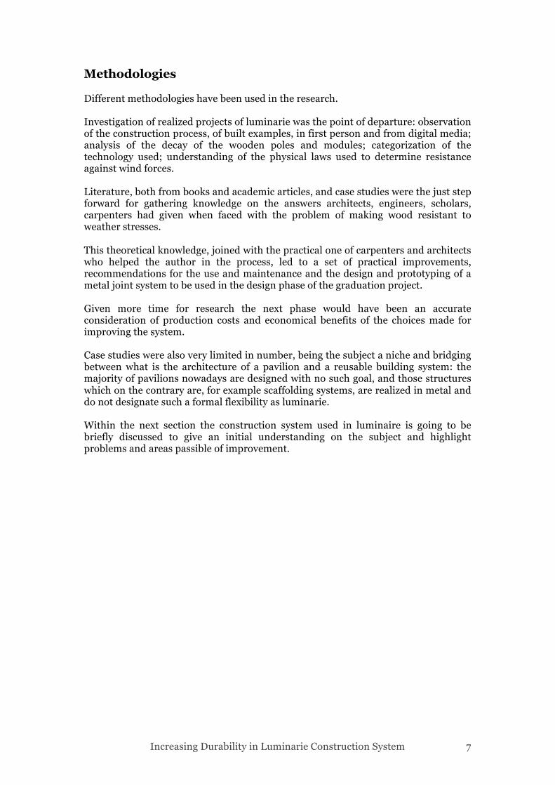
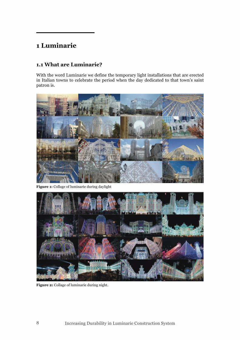
1 Luminarie 1.1 What are Luminarie?
With the word Luminarie we define the temporary light installations that are erected in Italian towns to celebrate the period when the day dedicated to that town’s saint patron is.
Figure 1: Collage of luminarie during daylight
Figure 2: Collage of luminarie during night.
Increasing Durability in Luminarie Construction System 9
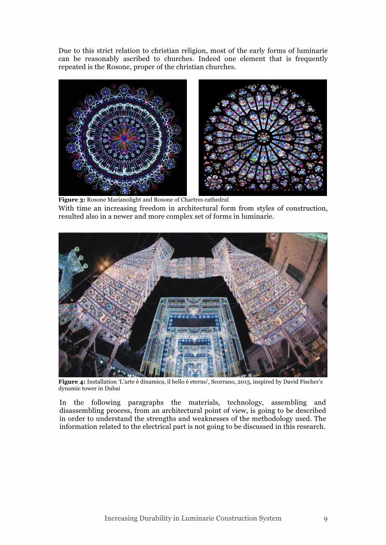
Due to this strict relation to christian religion, most of the early forms of luminarie can be reasonably ascribed to churches. Indeed one element that is frequently repeated is the Rosone, proper of the christian churches.
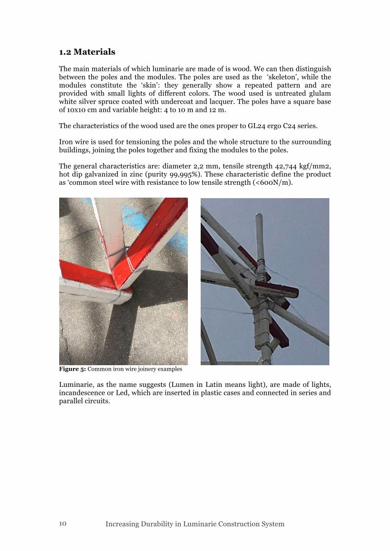
With time an increasing freedom in architectural form from styles of construction, resulted also in a newer and more complex set of forms in luminarie.
Figure 3: Rosone Marianolight and Rosone of Chartres cathedral
In the following paragraphs the materials, technology, assembling and disassembling process, from an architectural point of view, is going to be described in order to understand the strengths and weaknesses of the methodology used. The information related to the electrical part is not going to be discussed in this research.
Figure 4: Installation ‘L’arte è dinamica, il bello è eterno’, Scorrano, 2015, inspired by David Fischer’s dynamic tower in Dubai
Increasing Durability in Luminarie Construction System 10
1.2 Materials
The main materials of which luminarie are made of is wood. We can then distinguish between the poles and the modules. The poles are used as the ‘skeleton’, while the modules constitute the ‘skin’: they generally show a repeated pattern and are provided with small lights of different colors. The wood used is untreated glulam white silver spruce coated with undercoat and lacquer. The poles have a square base of 10x10 cm and variable height: 4 to 10 m and 12 m.
The characteristics of the wood used are the ones proper to GL24 ergo C24 series.
Iron wire is used for tensioning the poles and the whole structure to the surrounding buildings, joining the poles together and fixing the modules to the poles.
The general characteristics are: diameter 2,2 mm, tensile strength 42,744 kgf/mm2, hot dip galvanized in zinc (purity 99,995%). These characteristic define the product as ‘common steel wire with resistance to low tensile strength (<600N/m).
Luminarie, as the name suggests (Lumen in Latin means light), are made of lights, incandescence or Led, which are inserted in plastic cases and connected in series and parallel circuits.
Figure 5: Common iron wire joinery examples
Increasing Durability in Luminarie Construction System 11
1.3 Construction Process
The realization of a light installation of luminarie, previously designed in the studio, can be divided in 3 phases: pre-mounting, mounting (poles, modules), dismantling (modules, poles). Transportation, preparation of construction site, mounting of electrical cable, and testing are not relevant for the scope of the research so they are not discussed.
1.3.1 Pre-mounting
Prior to mounting measurements on the ground need to be done, to verify the position of poles from the technical project. The presence of trees, doors, tow away zones, public lighting poles, sewer covers, crossing, shop’s displays, ramps for the disabled, needs to be verified. As well electrical cables, balconies or terraces, road signs, traffic lights, eventual construction sites not present in the first inspection. Particular attention needs to be addressed to slopes and to ground’s consistency and material. 1.3.2 Mounting 1.3.2.1 Mounting Poles
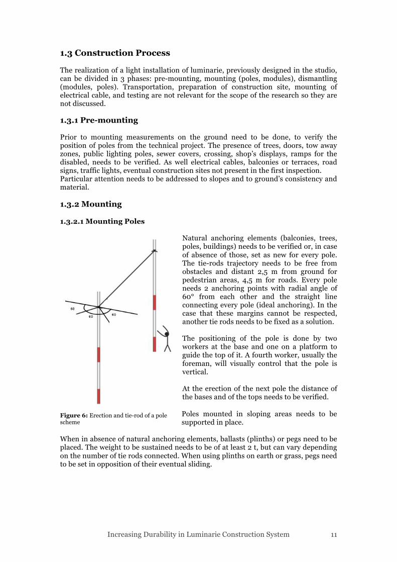
Natural anchoring elements (balconies, trees, poles, buildings) needs to be verified or, in case of absence of those, set as new for every pole. The tie-rods trajectory needs to be free from obstacles and distant 2,5 m from ground for pedestrian areas, 4,5 m for roads. Every pole needs 2 anchoring points with radial angle of 60° from each other and the straight line connecting every pole (ideal anchoring). In the case that these margins cannot be respected, another tie rods needs to be fixed as a solution. The positioning of the pole is done by two workers at the base and one on a platform to guide the top of it. A fourth worker, usually the foreman, will visually control that the pole is vertical. At the erection of the next pole the distance of the bases and of the tops needs to be verified. Poles mounted in sloping areas needs to be supported in place.
When in absence of natural anchoring elements, ballasts (plinths) or pegs need to be placed. The weight to be sustained needs to be of at least 2 t, but can vary depending on the number of tie rods connected. When using plinths on earth or grass, pegs need to be set in opposition of their eventual sliding.
Figure 6: Erection and tie-rod of a pole scheme
Increasing Durability in Luminarie Construction System 12
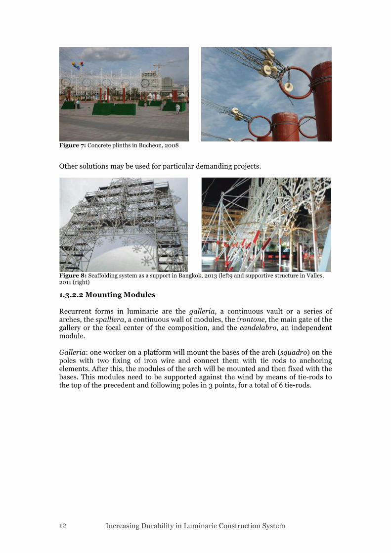
Other solutions may be used for particular demanding projects.
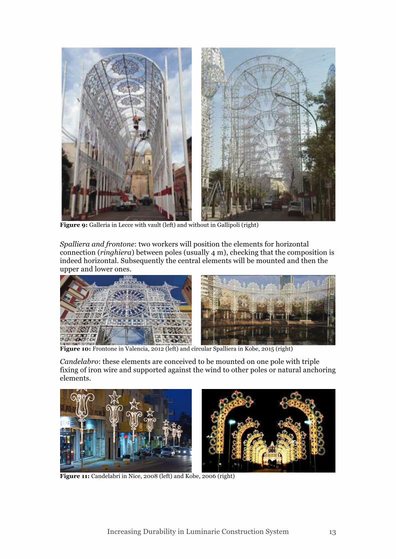
1.3.2.2 Mounting Modules Recurrent forms in luminarie are the galleria, a continuous vault or a series of arches, the spalliera, a continuous wall of modules, the frontone, the main gate of the gallery or the focal center of the composition, and the candelabro, an independent module. Galleria: one worker on a platform will mount the bases of the arch (squadro) on the poles with two fixing of iron wire and connect them with tie rods to anchoring elements. After this, the modules of the arch will be mounted and then fixed with the bases. This modules need to be supported against the wind by means of tie-rods to the top of the precedent and following poles in 3 points, for a total of 6 tie-rods.
Figure 7: Concrete plinths in Bucheon, 2008
Figure 8: Scaffolding system as a support in Bangkok, 2013 (left9 and supportive structure in Valles, 2011 (right)
Increasing Durability in Luminarie Construction System 13
Spalliera and frontone: two workers will position the elements for horizontal connection (ringhiera) between poles (usually 4 m), checking that the composition is indeed horizontal. Subsequently the central elements will be mounted and then the upper and lower ones.
Candelabro: these elements are conceived to be mounted on one pole with triple fixing of iron wire and supported against the wind to other poles or natural anchoring elements.
Figure 9: Galleria in Lecce with vault (left) and without in Gallipoli (right)
Figure 10: Frontone in Valencia, 2012 (left) and circular Spalliera in Kobe, 2015 (right)
Figure 11: Candelabri in Nice, 2008 (left) and Kobe, 2006 (right)
Increasing Durability in Luminarie Construction System 14
1.3.3 Dismantling 1.3.3.1 Dismantling Modules Two workers will dismantle the modules on a platform, one cutting the iron wire fixings and the other one sustaining the modules. The module will then be handed to a third worker responsible of putting it on the truck or temporarily stored in an area on ground. It is necessary to have extra care in cutting the tie-rods: being tensioned cables these will have an uncontrollable elastic behavior when cut. For this reason it is necessary to monitor the area of service of the tie-rod. It is important during this phase to not cut the tie-rods of the poles. The iron wires will then be collected and disposed. 1.3.3.2 Dismantling Poles One worker on a platform will cut the tie-rods tensioning the poles while two other workers will sustain the pole on the ground and dispose it or transport it to the truck. Then a worker will collect the tie-roads. A foreman will control the workers and give directions and another worker will control the traffic. 1.4 Upwind Forces In general for the calculations of upwind forces the whole ‘facade’ is considered as continuous and 65% of it is calculated against upwind forces. So if we consider an element of dimensions 4x0,7 m, its area will be 2,8 m2. The area that will be taken into account for calculations will be 1,82 m2.

Increasing Durability in Luminarie Construction System 15
Increasing Durability in Luminarie Construction System 16
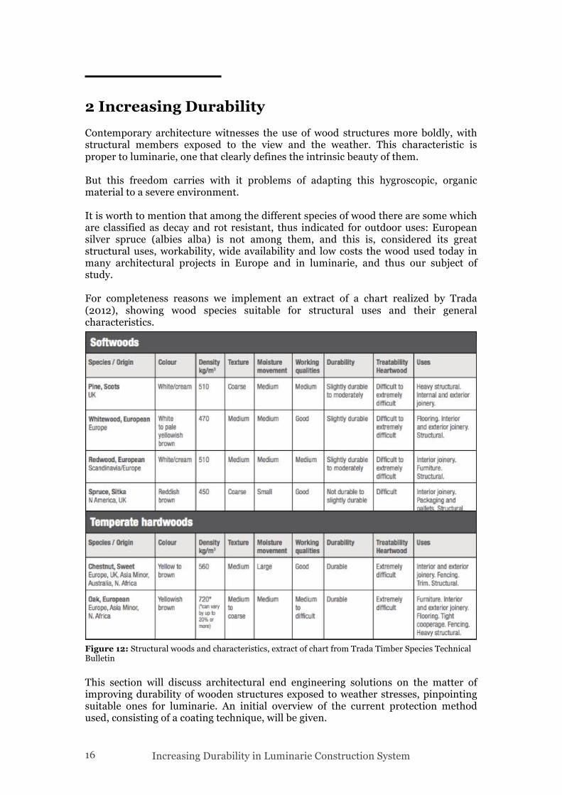
2 Increasing Durability Contemporary architecture witnesses the use of wood structures more boldly, with structural members exposed to the view and the weather. This characteristic is proper to luminarie, one that clearly defines the intrinsic beauty of them. But this freedom carries with it problems of adapting this hygroscopic, organic material to a severe environment. It is worth to mention that among the different species of wood there are some which are classified as decay and rot resistant, thus indicated for outdoor uses: European silver spruce (albies alba) is not among them, and this is, considered its great structural uses, workability, wide availability and low costs the wood used today in many architectural projects in Europe and in luminarie, and thus our subject of study. For completeness reasons we implement an extract of a chart realized by Trada (2012), showing wood species suitable for structural uses and their general characteristics.
This section will discuss architectural end engineering solutions on the matter of improving durability of wooden structures exposed to weather stresses, pinpointing suitable ones for luminarie. An initial overview of the current protection method used, consisting of a coating technique, will be given.
Figure 12: Structural woods and characteristics, extract of chart from Trada Timber Species Technical Bulletin
Increasing Durability in Luminarie Construction System 17
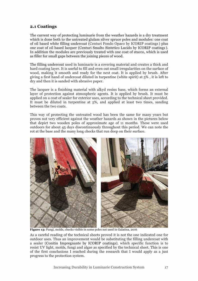
2.1 Coatings The current way of protecting luminarie from the weather hazards is a dry treatment which is done both to the untreated glulam silver spruce poles and modules: one coat of oil based white filling undercoat (Centuri Fondo Opaco by ICORIP coatings ) plus one coat of oil based lacquer (Centuri Smalto Sintetico Lucido by ICORIP coatings ). In addition the modules are previously treated with one coat of stucco, which is used as filler for small gaps between the joining pieces of wood. The filling undercoat used in luminarie is a covering material and creates a thick and hard coating layer. It is useful to fill and even out small irregularities on the surface of wood, making it smooth and ready for the next coat. It is applied by brush. After giving a first hand of undercoat diluted in turpentine (white spirit) at 5% , it is left to dry and then it is sanded with abrasive paper. The lacquer is a finishing material with alkyd resins base, which forms an external layer of protection against atmospheric agents. It is applied by brush. It must be applied on a coat of sealer for exterior uses, according to the technical sheet provided. It must be diluted in turpentine at 5%, and applied at least two times, sanding between the two coats. This way of protecting the untreated wood has been the same for many years but proves not very efficient against the weather hazards as shown in the pictures below that depict two wooden poles of approximate age of 11 months. These were used outdoors for about 45 days discontinuously throughout this period. We can note the rot at the base and the many long checks that run deep on their surface.
As a careful reading of the technical sheets proved it is not the one indicated one for outdoor uses. Thus an improvement would be substituting the filling undercoat with a sealer (Conitin Impregnante by ICORIP coatings), which specific function is to resist UV light, molds, fungi and algae as specified by the technical sheet. This is one of the first conclusions I reached during the research that I would apply as a just progress to the protection system.
Figure 13: Fungi, molds, checks visible in some poles not used in Galatina, 2016
Increasing Durability in Luminarie Construction System 18
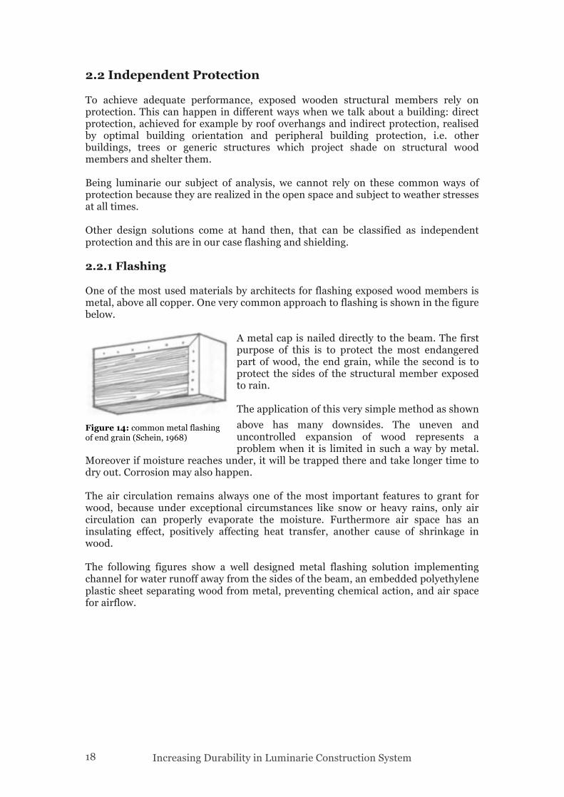
2.2 Independent Protection To achieve adequate performance, exposed wooden structural members rely on protection. This can happen in different ways when we talk about a building: direct protection, achieved for example by roof overhangs and indirect protection, realised by optimal building orientation and peripheral building protection, i.e. other buildings, trees or generic structures which project shade on structural wood members and shelter them. Being luminarie our subject of analysis, we cannot rely on these common ways of protection because they are realized in the open space and subject to weather stresses at all times. Other design solutions come at hand then, that can be classified as independent protection and this are in our case flashing and shielding. 2.2.1 Flashing One of the most used materials by architects for flashing exposed wood members is metal, above all copper. One very common approach to flashing is shown in the figure below.
A metal cap is nailed directly to the beam. The first purpose of this is to protect the most endangered part of wood, the end grain, while the second is to protect the sides of the structural member exposed to rain. The application of this very simple method as shown above has many downsides. The uneven and uncontrolled expansion of wood represents a problem when it is limited in such a way by metal.
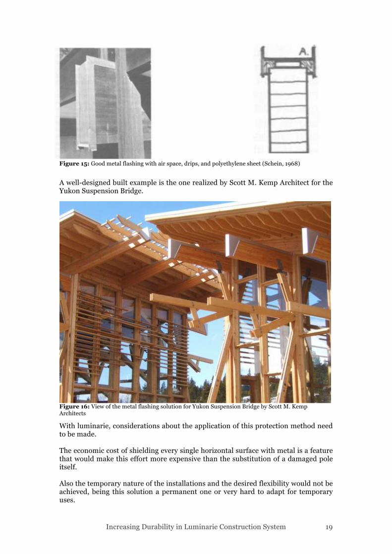
Moreover if moisture reaches under, it will be trapped there and take longer time to dry out. Corrosion may also happen. The air circulation remains always one of the most important features to grant for wood, because under exceptional circumstances like snow or heavy rains, only air circulation can properly evaporate the moisture. Furthermore air space has an insulating effect, positively affecting heat transfer, another cause of shrinkage in wood. The following figures show a well designed metal flashing solution implementing channel for water runoff away from the sides of the beam, an embedded polyethylene plastic sheet separating wood from metal, preventing chemical action, and air space for airflow.
Figure 14: common metal flashing of end grain (Schein, 1968)
Increasing Durability in Luminarie Construction System 19
A well-designed built example is the one realized by Scott M. Kemp Architect for the Yukon Suspension Bridge.
With luminarie, considerations about the application of this protection method need to be made. The economic cost of shielding every single horizontal surface with metal is a feature that would make this effort more expensive than the substitution of a damaged pole itself. Also the temporary nature of the installations and the desired flexibility would not be achieved, being this solution a permanent one or very hard to adapt for temporary uses.
Figure 16: View of the metal flashing solution for Yukon Suspension Bridge by Scott M. Kemp Architects
Figure 15: Good metal flashing with air space, drips, and polyethylene sheet (Schein, 1968)
Increasing Durability in Luminarie Construction System 20
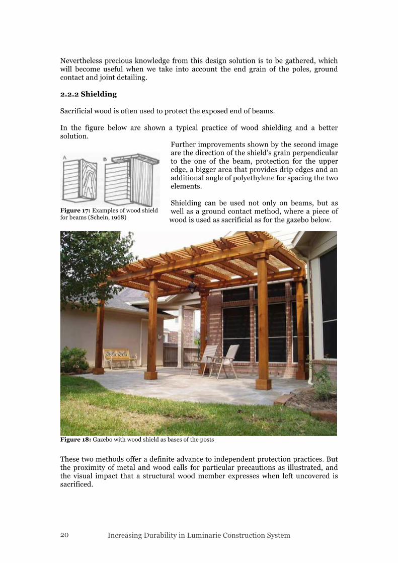
Nevertheless precious knowledge from this design solution is to be gathered, which will become useful when we take into account the end grain of the poles, ground contact and joint detailing. 2.2.2 Shielding Sacrificial wood is often used to protect the exposed end of beams. In the figure below are shown a typical practice of wood shielding and a better solution.
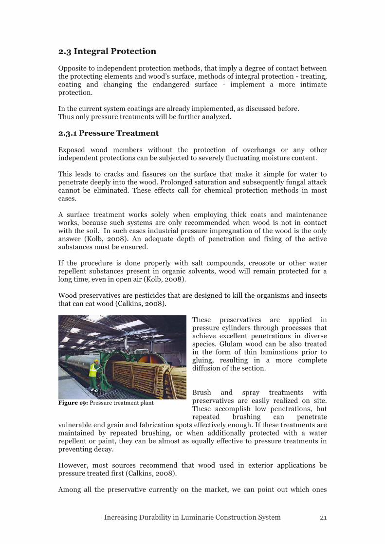
Further improvements shown by the second image are the direction of the shield’s grain perpendicular to the one of the beam, protection for the upper edge, a bigger area that provides drip edges and an additional angle of polyethylene for spacing the two elements. Shielding can be used not only on beams, but as well as a ground contact method, where a piece of wood is used as sacrificial as for the gazebo below.
These two methods offer a definite advance to independent protection practices. But the proximity of metal and wood calls for particular precautions as illustrated, and the visual impact that a structural wood member expresses when left uncovered is sacrificed.
Figure 18: Gazebo with wood shield as bases of the posts
Figure 17: Examples of wood shield for beams (Schein, 1968)
Increasing Durability in Luminarie Construction System 21
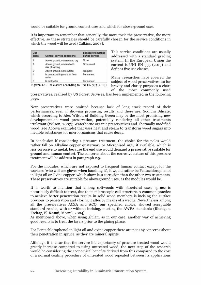
2.3 Integral Protection Opposite to independent protection methods, that imply a degree of contact between the protecting elements and wood’s surface, methods of integral protection - treating, coating and changing the endangered surface - implement a more intimate protection. In the current system coatings are already implemented, as discussed before. Thus only pressure treatments will be further analyzed. 2.3.1 Pressure Treatment Exposed wood members without the protection of overhangs or any other independent protections can be subjected to severely fluctuating moisture content. This leads to cracks and fissures on the surface that make it simple for water to penetrate deeply into the wood. Prolonged saturation and subsequently fungal attack cannot be eliminated. These effects call for chemical protection methods in most cases. A surface treatment works solely when employing thick coats and maintenance works, because such systems are only recommended when wood is not in contact with the soil. In such cases industrial pressure impregnation of the wood is the only answer (Kolb, 2008). An adequate depth of penetration and fixing of the active substances must be ensured. If the procedure is done properly with salt compounds, creosote or other water repellent substances present in organic solvents, wood will remain protected for a long time, even in open air (Kolb, 2008). Wood preservatives are pesticides that are designed to kill the organisms and insects that can eat wood (Calkins, 2008).
These preservatives are applied in pressure cylinders through processes that achieve excellent penetrations in diverse species. Glulam wood can be also treated in the form of thin laminations prior to gluing, resulting in a more complete diffusion of the section. Brush and spray treatments with preservatives are easily realized on site. These accomplish low penetrations, but repeated brushing can penetrate
vulnerable end grain and fabrication spots effectively enough. If these treatments are maintained by repeated brushing, or when additionally protected with a water repellent or paint, they can be almost as equally effective to pressure treatments in preventing decay. However, most sources recommend that wood used in exterior applications be pressure treated first (Calkins, 2008). Among all the preservative currently on the market, we can point out which ones
Figure 19: Pressure treatment plant
Increasing Durability in Luminarie Construction System 22
would be suitable for ground contact uses and which for above ground uses. It is important to remember that generally, the more toxic the preservative, the more effective, so these strategies should be carefully chosen for the service conditions in which the wood will be used (Calkins, 2008).
This service conditions are usually addressed with a standard grading system. In the European Union the current is UNI EN 335 (2013) and defines five use classes. Many researches have covered the subject of wood preservatives, so for brevity and clarity purposes a chart of the most commonly used
preservatives, realized by US Forest Services, has been implemented in the following page. New preservatives were omitted because lack of long track record of their performances, even if showing promising results and these are: Sodium Silicate, which according to Alex Wilson of Building Green may be the most promising new development in wood preservation, potentially rendering all other treatments irrelevant (Wilson, 2007); Waterborne organic preservatives and Thermally modified wood (see Accoya example) that uses heat and steam to transform wood sugars into inedible substances for microorganisms that cause decay. In conclusion if considering a pressure treatment, the choice for the poles would rather fall on Alkaline copper quaternary or Micronised ACQ if available, which is less corrosive to metal, because the end use would demand a preservative suitable for ground and human contact. The concerns about the corrosive nature of this pressure treatment will be address in paragraph 2.5. For the modules, which are not exposed to frequent human contact except for the workers (who will use gloves when handling it), it would rather be Pentachlorophenol in light oil or Oxine copper, which show less corrosion than the other two treatments. These preservatives are suitable for aboveground uses, as the modules would be. It is worth to mention that among softwoods with structural uses, spruce is notoriously difficult to treat, due to its microscopic cell structure. A common practice to achieve better penetration results in solid wood members is incising the surface previous to penetration and closing it after by means of a wedge. Nevertheless among all the preservatives ACZA and ACQ, our specified choice, showed acceptable standard results, with or without incising, meeting the AWPA standards (Rhatigan, Freitag, El-Kasmi, Morrel, 2004). As mentioned above, when using glulam as in our case, another way of achieving good results is to treat the layers prior to the gluing phase. For Pentachlorophenol in light oil and oxine copper there are not any concerns about their penetration in spruce, as they are mineral spirits. Although it is clear that the service life expectancy of pressure treated wood would greatly increase compared to using untreated wood, the next step of the research would be considering the economical benefits derived from this compared to the cost of a normal coating procedure of untreated wood repeated between its applications
Figure 20: Use classes according to UNI EN 335 (2013)
Increasing Durability in Luminarie Construction System 23
plus substitution of the pole when not anymore serviceable. Relying on a comparative study of Wilcox, 1984 and Miller & Graham, 1977, the service life of untreated Douglas Fir in ground contact and above ground contact, respectively 3-6 and 10-15 years, would be of 30+ years when treated with ACQ in both situations. Even if this is a different wood specimen examined, we can get an idea of the size of the improvement in service life.
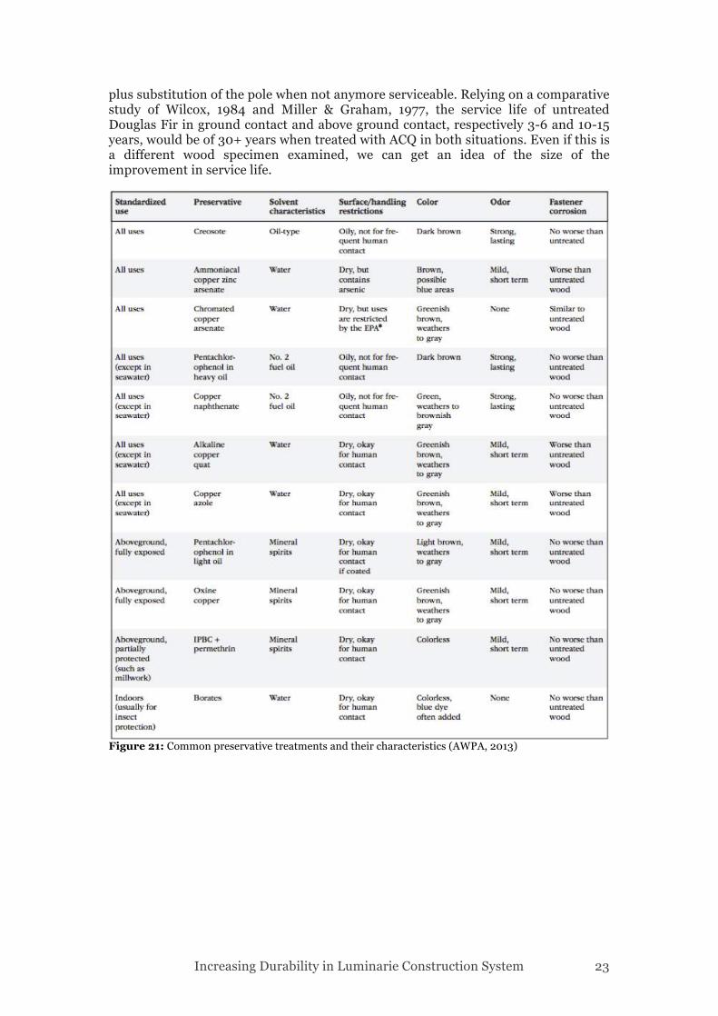
Figure 21: Common preservative treatments and their characteristics (AWPA, 2013)
Increasing Durability in Luminarie Construction System 24
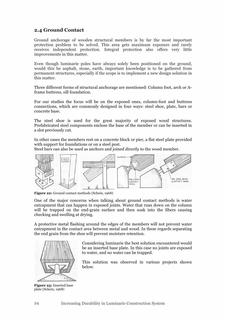
2.4 Ground Contact Ground anchorage of wooden structural members is by far the most important protection problem to be solved. This area gets maximum exposure and rarely receives independent protection. Integral protection also offers very little improvements in this matter. Even though luminarie poles have always solely been positioned on the ground, would this be asphalt, stone, earth, important knowledge is to be gathered from permanent structures, especially if the scope is to implement a new design solution in this matter. Three different forms of structural anchorage are mentioned: Column foot, arch or A-frame buttress, sill foundation. For our studies the focus will be on the exposed ones, column-foot and buttress connections, which are commonly designed in four ways: steel shoe, plate, bars or concrete base. The steel shoe is used for the great majority of exposed wood structures. Prefabricated steel components enclose the base of the member or can be inserted in a slot previously cut. In other cases the members rest on a concrete block or pier, a flat steel plate provided with support for foundations or on a steel post. Steel bars can also be used as anchors and joined directly to the wood member.
One of the major concerns when talking about ground contact methods is water entrapment that can happen in exposed joints. Water that runs down on the column will be trapped on the end-grain surface and then soak into the fibers causing checking and swelling at drying. A protective metal flashing around the edges of the members will not prevent water entrapment in the contact area between metal and wood. In these regards separating the end grain from the shoe will prevent moisture retention.
Considering luminarie the best solution encountered would be an inserted base plate. In this case no joints are exposed to water, and no water can be trapped. This solution was observed in various projects shown below.
Figure 22: Ground contact methods (Schein, 1968)
Figure 23: Inserted base plate (Schein, 1968)
Increasing Durability in Luminarie Construction System 25
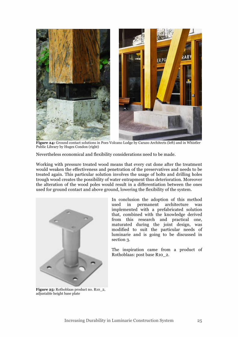
Nevertheless economical and flexibility considerations need to be made. Working with pressure treated wood means that every cut done after the treatment would weaken the effectiveness and penetration of the preservatives and needs to be treated again. This particular solution involves the usage of bolts and drilling holes trough wood creates the possibility of water entrapment thus deterioration. Moreover the alteration of the wood poles would result in a differentiation between the ones used for ground contact and above ground, lowering the flexibility of the system.
In conclusion the adoption of this method used in permanent architecture was implemented with a prefabricated solution that, combined with the knowledge derived from this research and practical one, maturated during the joint design, was modified to suit the particular needs of luminarie and is going to be discussed in section 3. The inspiration came from a product of Rothoblaas: post base R10_2.
Figure 24: Ground contact solutions in Poes Volcano Lodge by Carazo Architects (left) and in Whistler Public Library by Huges Condon (right)
Figure 25: Rothoblaas product no. R10_2, adjustable height base plate
Increasing Durability in Luminarie Construction System 26
2.5 Corrosion and Wood The corrosion of metals when used in contact with wood has been object of studies for a long time. Conclusions are that in most situations untreated wood does not increase atmospherical corrosion. Also the same conclusion can be reached with CCA treated wood (Zelinka, 2011). However, following the recent changes in legislation and certification in Europe, United States, and other governments, CCA has been substituted by other kinds of preservatives, which show less toxicity levels for humans. These new preservatives, which for architectural projects are mostly ACQ and CA, are more corrosive than CCA (Zelinka, 2014), so address the need of using special fasteners, connectors and precautions in every situation where metal and wood are in contact. According to AWPA (American wood protection association) (Anon, 2013) the 300 series stainless steel had good results when it was not used in combination with other metals, however, 410 showed slightly better results. So all stainless steels are not acceptable for use with ACQ treated wood. Testing has shown that among types 304, 305 and 316 stainless steels perform very well with woods that may have excess surface chemicals. Another solution, if the choice is not to use stainless steel, is to use carbon steel, which is hot dip galvanized in hyper pure zinc. A spray or brush treatment of zinc does not solve the corrosion problem. Besides the choice of steel to use with pressure treated wood, general guidelines can be appointed for avoiding corrosion. Since corrosion requires water and contact with the preservatives, design should focus on eliminating wetness and direct contact with the wood. Isolating the steel from the wood with water resistant barrier materials is an extremely effective way to minimize corrosion issues with the ACQ treated wood. Such materials would include polymer tapes, masking, and lining materials. Conversely, materials with a paper or felt component should be avoided as they can hold moisture and increase corrosion according to Strong Tie guidelines (Anon, 2008). Every effort should be made to avoid standing water. Avoiding continual wetness is the most effective way to avoid premature corrosion failures.
Increasing Durability in Luminarie Construction System 27
2.6 Improving Durability of Wood Outdoors For clarity purposes we then summarize the choices we were able to make to improve the durability of wood used in luminarie and in general, in any kind of projects, exposed to wheatear stresses. When coating the filling undercoat should be substituted with the sealer. The preservatives chosen for the pressure treatment are: ACQ (Alkaline copper quaternary) or mACQ (micronized) if available, for the poles; Pentachlorophenol in light oil or Oxine copper for the modules. Protection of exposed end grain will be made by means of a wood shield and a polyethylene sheet combined. The ground anchorage will be made by a custom designed post base. The metal used for the post base and joint is going to be stainless steel 304, 305 or 316 or hot dip galvanized and contact will be avoided by means of a polyethylene sheet. Supplementary information collected, relevant to the design phase and use of wood outdoors, will be discussed introducing the next section where design of the joint, the post base, the wood shield, and iron ties are presented.
Increasing Durability in Luminarie Construction System 28
3 Research by Design The knowledge gathered during the research phase can therefore be summarized, as design guide principles when approaching aboveground joints, ground anchorage, end grain protection and in general using wood outdoors: 1) Coatings and preservatives should be carefully chosen during design phase, according to the conditions of end use in the project 2) Protection of the end grain of structural members, placed horizontally or vertically, aboveground or with ground contact, is imperative by means of flashing, shielding, providing air space and using water resistant membranes 3) Water entrapment in joints should always be avoided 4) Any hole or cut practiced on pressure treated wood needs to be carefully coated, nevertheless it will be source of water entrapment 5) Metals used for fasteners, connectors and joints should be carefully selected, according to the preservative used, to avoid risk of corrosion and failure 6) Contact between wood and metal should be minimized when possible, providing air space for drainage 7) Using water resistant barriers such as polyethylene sheets is a good practice in contact areas between wood and metals 8) When using metals with wood, two different kinds should never be employed in contact with each other Mindful of these guidelines we can proceed with the discussion of the joint design.
Increasing Durability in Luminarie Construction System 29
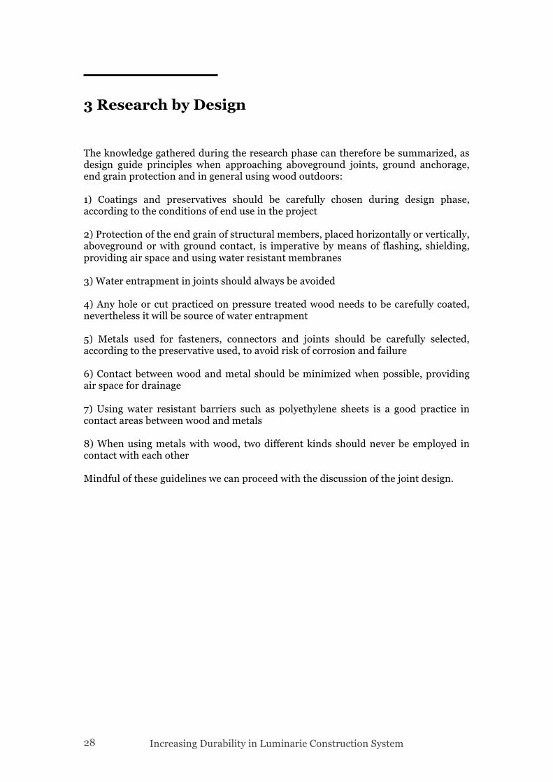
3.1 Demountable Joint Ideally, a demountable construction system is one in which the essential load bearing components of a structure are designed to allow them to be taken apart for re-assembly elsewhere and/or at a later time (Erman, 2002). Another way of approaching this, assuming that all the load-bearing components have the same identical shape, is by focusing on their joining system. This system must be strong enough to transfer working loads to other components and be able to withstand the loads of the whole structure. It should allow easy assembly and disassembly and more importantly, this process should not damage or alter the components. We can then add that this system would always be subjected to weather stresses, that the components are glued laminated square poles of 10cm side, variable lengths up to 12 m and that the system should allow a certain degree of flexibility including adjustable height, distance and angle of the members joined. These are the starting requirements that the demountable joint should satisfy, that influenced the research and determined the design. 3.1.1 Reference Project SALT One project that satisfied a great number of the requirements set for the joint system is Salt by Rintala Eggerttson Architects. The project is briefly described as a whole, then the joint system.
Figure2
Figure 26: Gildehallen for Salt Festival by Rintala Eggertsson Architects
Increasing Durability in Luminarie Construction System 30
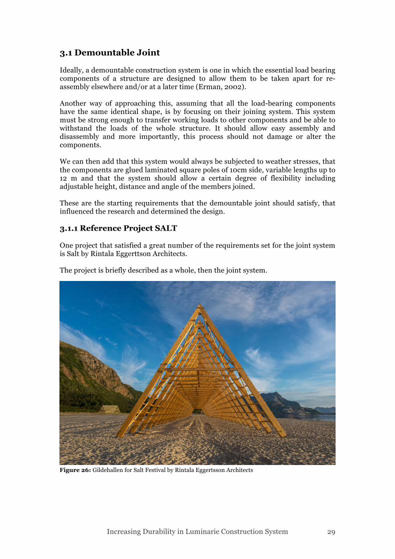
“The rack construction is a flexible structure both in terms of adjustment to all kinds of terrain situations and also when it comes to transporting it over longer distances, like in this case where the client wants to organize cultural events at different locations around the arctic and subarctic area.” [Rintala Eggertsson] The formal inspiration came from traditional Norwegian fish- drying racks. They have been constructed on an island in Norway to host a week long cultural festival, Salt. These temporary wooden buildings create spaces for activities and shelters for the public. The largest structure is composed of a row of A-shaped frames connected by horizontal batons and braced with diagonal struts. Called the Gildehallen, it measures 25 meters in length and is 12 meters high: it holds up to 1,000 people as a venue for music concerts, DJ sets and parties. [Deezen] Another structure realized is a large sauna, called Agora sauna: thermal insulation has been achieved by means of curtains fixed to additional wooden poles on the
inside. The critical area where the threaded rods of the joint could provide draughts had been sealed. The joint used for this project is custom designed with the clear goal of demountabilty. Considering the lack of detailed drawings the joint’s composition was determined by an accurate observation of the photos available.
Figure 27: Agora sauna for Salt Festival by Rintala Eggertsson Architects
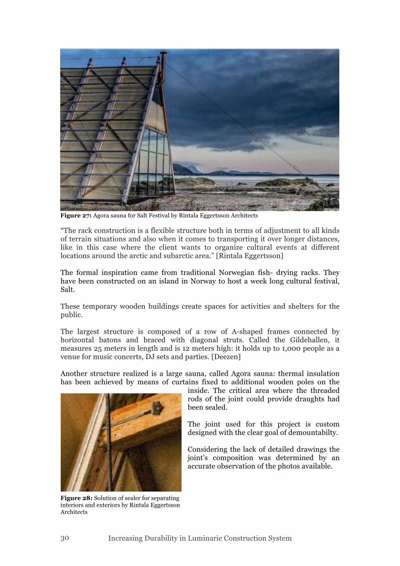
Figure 28: Solution of sealer for separating interiors and exteriors by Rintala Eggertsson Architects
Increasing Durability in Luminarie Construction System 31
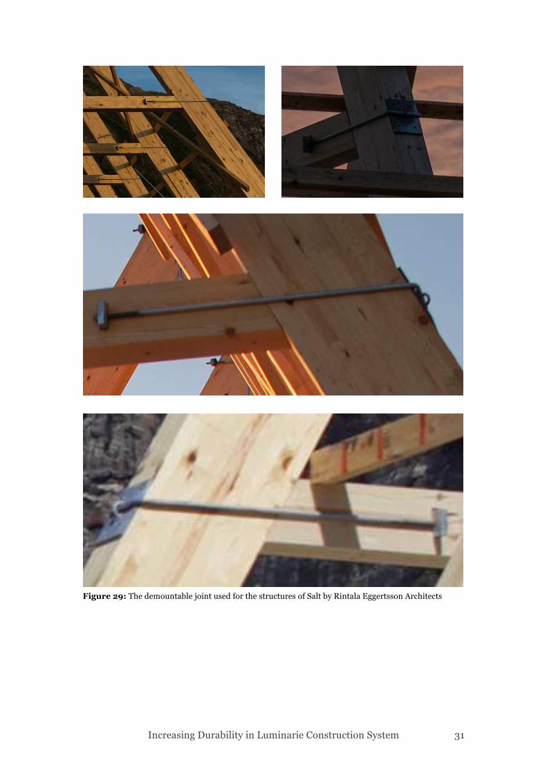
Figure 29: The demountable joint used for the structures of Salt by Rintala Eggertsson Architects
Increasing Durability in Luminarie Construction System 32
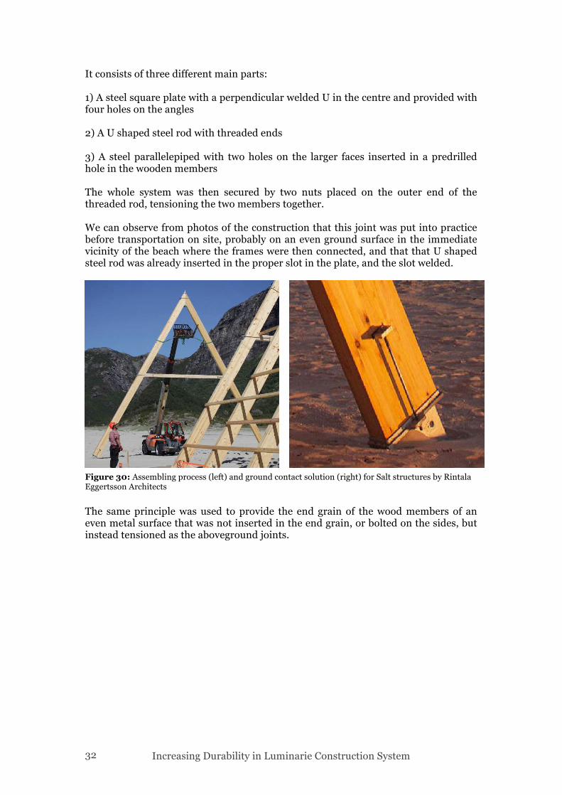
It consists of three different main parts: 1) A steel square plate with a perpendicular welded U in the centre and provided with four holes on the angles 2) A U shaped steel rod with threaded ends 3) A steel parallelepiped with two holes on the larger faces inserted in a predrilled hole in the wooden members The whole system was then secured by two nuts placed on the outer end of the threaded rod, tensioning the two members together. We can observe from photos of the construction that this joint was put into practice before transportation on site, probably on an even ground surface in the immediate vicinity of the beach where the frames were then connected, and that that U shaped steel rod was already inserted in the proper slot in the plate, and the slot welded.
The same principle was used to provide the end grain of the wood members of an even metal surface that was not inserted in the end grain, or bolted on the sides, but instead tensioned as the aboveground joints.
Figure 30: Assembling process (left) and ground contact solution (right) for Salt structures by Rintala Eggertsson Architects
Increasing Durability in Luminarie Construction System 33
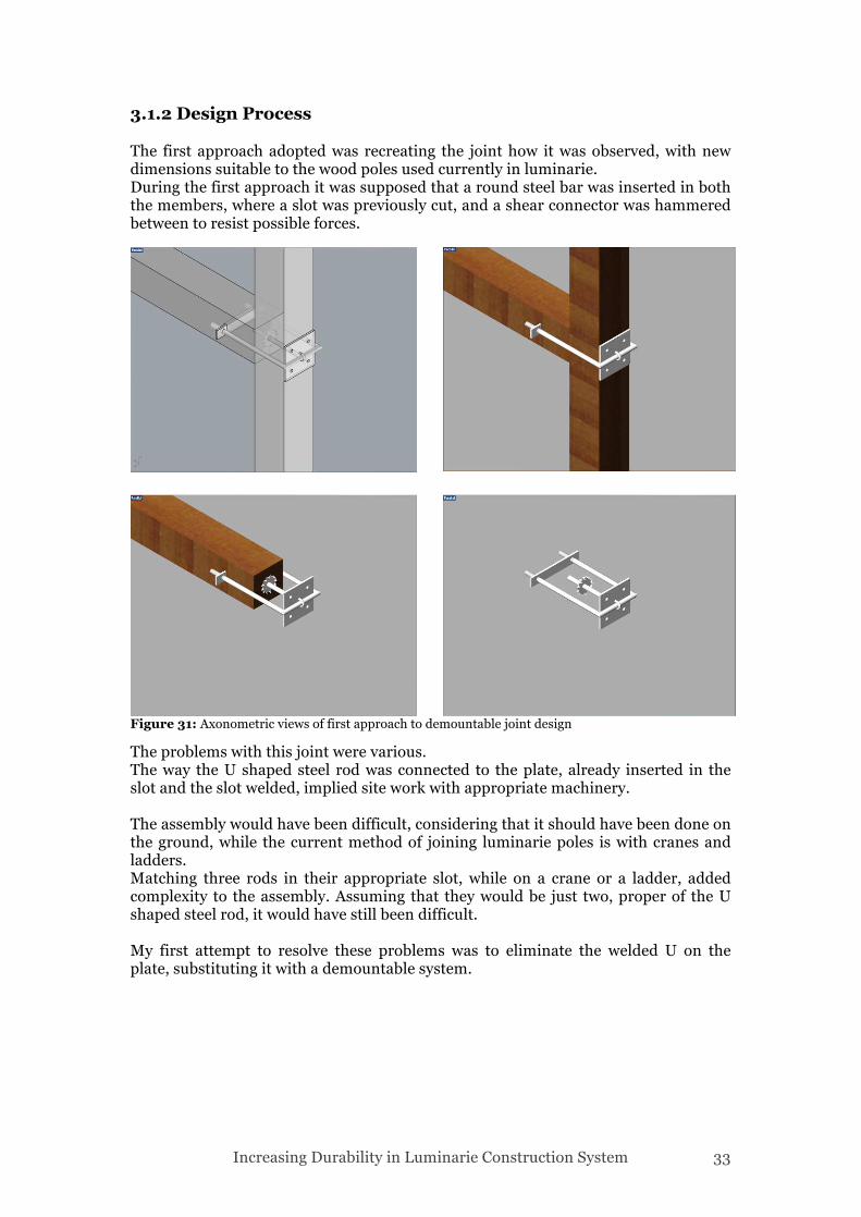
3.1.2 Design Process The first approach adopted was recreating the joint how it was observed, with new dimensions suitable to the wood poles used currently in luminarie. During the first approach it was supposed that a round steel bar was inserted in both the members, where a slot was previously cut, and a shear connector was hammered between to resist possible forces.
The problems with this joint were various. The way the U shaped steel rod was connected to the plate, already inserted in the slot and the slot welded, implied site work with appropriate machinery. The assembly would have been difficult, considering that it should have been done on the ground, while the current method of joining luminarie poles is with cranes and ladders. Matching three rods in their appropriate slot, while on a crane or a ladder, added complexity to the assembly. Assuming that they would be just two, proper of the U shaped steel rod, it would have still been difficult. My first attempt to resolve these problems was to eliminate the welded U on the plate, substituting it with a demountable system.
Figure 31: Axonometric views of first approach to demountable joint design
Increasing Durability in Luminarie Construction System 34
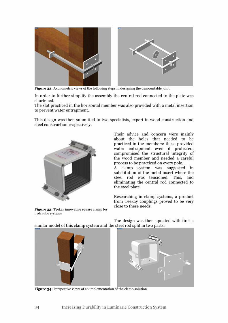
In order to further simplify the assembly the central rod connected to the plate was shortened. The slot practiced in the horizontal member was also provided with a metal insertion to prevent water entrapment. This design was then submitted to two specialists, expert in wood construction and steel construction respectively.
Their advice and concern were mainly about the holes that needed to be practiced in the members: these provided water entrapment even if protected, compromised the structural integrity of the wood member and needed a careful process to be practiced on every pole. A clamp system was suggested in substitution of the metal insert where the steel rod was tensioned. This, and eliminating the central rod connected to the steel plate. Researching in clamp systems, a product from Teekay couplings proved to be very close to these needs. The design was then updated with first a
similar model of this clamp system and the steel rod split in two parts.
Figure 32: Axonometric views of the following steps in designing the demountable joint
Figure 33: Teekay innovative square clamp for hydraulic systems
Figure 34: Perspective views of an implementation of the clamp solution
Increasing Durability in Luminarie Construction System 35
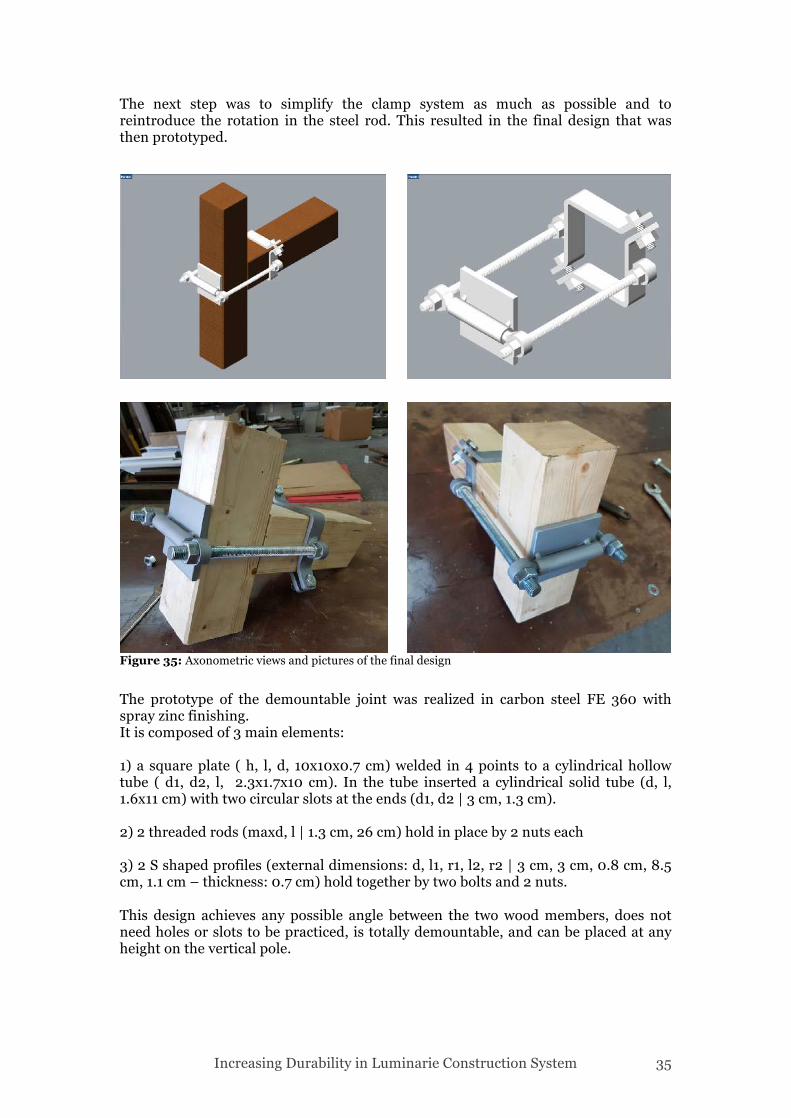
The next step was to simplify the clamp system as much as possible and to reintroduce the rotation in the steel rod. This resulted in the final design that was then prototyped.
The prototype of the demountable joint was realized in carbon steel FE 360 with spray zinc finishing. It is composed of 3 main elements: 1) a square plate ( h, l, d, 10x10x0.7 cm) welded in 4 points to a cylindrical hollow tube ( d1, d2, l, 2.3x1.7x10 cm). In the tube inserted a cylindrical solid tube (d, l, 1.6x11 cm) with two circular slots at the ends (d1, d2 | 3 cm, 1.3 cm). 2) 2 threaded rods (maxd, l | 1.3 cm, 26 cm) hold in place by 2 nuts each 3) 2 S shaped profiles (external dimensions: d, l1, r1, l2, r2 | 3 cm, 3 cm, 0.8 cm, 8.5 cm, 1.1 cm – thickness: 0.7 cm) hold together by two bolts and 2 nuts. This design achieves any possible angle between the two wood members, does not need holes or slots to be practiced, is totally demountable, and can be placed at any height on the vertical pole.
Figure 35: Axonometric views and pictures of the final design
Increasing Durability in Luminarie Construction System 36
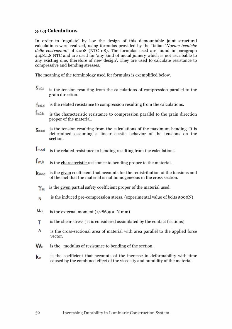
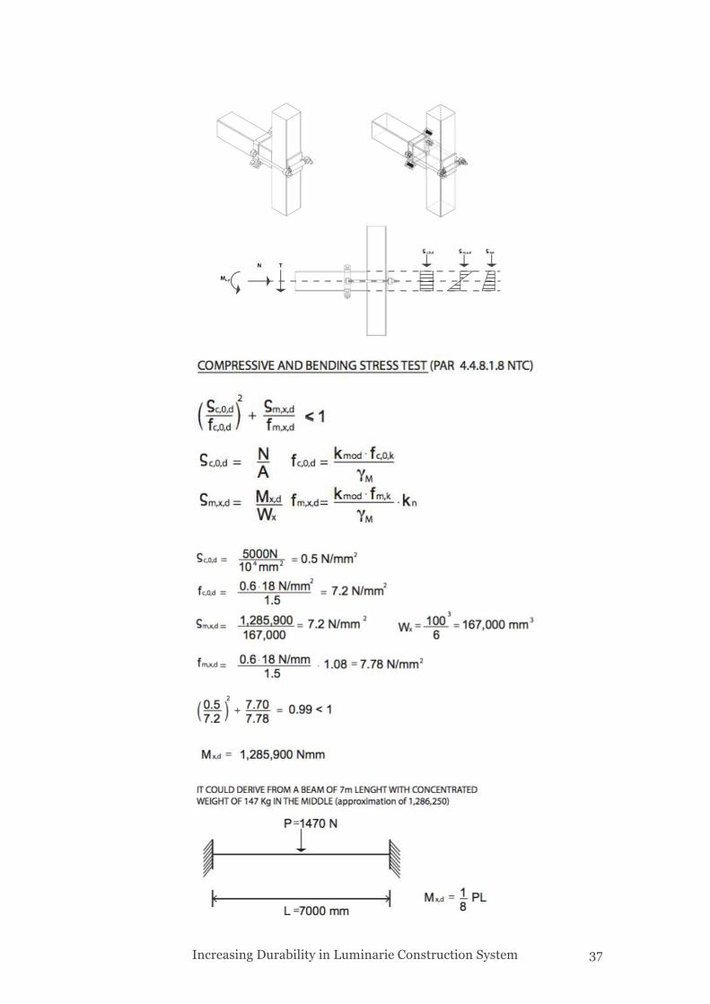
3.1.3 Calculations In order to ‘regulate’ by law the design of this demountable joint structural calculations were realized, using formulas provided by the Italian ‘Norme tecniche delle costruzioni’ of 2008 (NTC 08). The formulas used are found in paragraph 4.4.8.1.8 NTC and are used for ‘any kind of metal joinery which is not ascribable to any existing one, therefore of new design’. They are used to calculate resistance to compressive and bending stresses. The meaning of the terminology used for formulas is exemplified below.
is the tension resulting from the calculations of compression parallel to the grain direction. is the related resistance to compression resulting from the calculations. is the characteristic resistance to compression parallel to the grain direction proper of the material.
is the tension resulting from the calculations of the maximum bending. It is determined assuming a linear elastic behavior of the tensions on the section.
is the related resistance to bending resulting from the calculations.
is the characteristic resistance to bending proper to the material.
is the given coefficient that accounts for the redistribution of the tensions and of the fact that the material is not homogeneous in the cross section.
is the given partial safety coefficient proper of the material used.
is the induced pre-compression stress. (experimental value of bolts 5000N) is the external moment (1,286,900 N mm) is the shear stress ( it is considered assimilated by the contact frictions)
is the cross-sectional area of material with area parallel to the applied force vector.
is the modulus of resistance to bending of the section.
is the coefficient that accounts of the increase in deformability with time caused by the combined effect of the viscosity and humidity of the material.
Increasing Durability in Luminarie Construction System 37
Increasing Durability in Luminarie Construction System 38
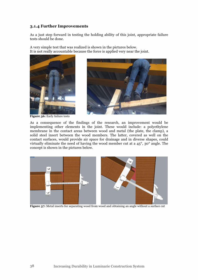
3.1.4 Further Improvements As a just step forward in testing the holding ability of this joint, appropriate failure tests should be done. A very simple test that was realized is shown in the pictures below. It is not really accountable because the force is applied very near the joint.
As a consequence of the findings of the research, an improvement would be implementing other elements in the joint. These would include: a polyethylene membrane in the contact areas between wood and metal (the plate, the clamp), a solid steel insert between the wood members. The latter, covered as well on the contact surfaces, would provide air space for drainage and in diverse shapes, could virtually eliminate the need of having the wood member cut at a 45°, 30° angle. The concept is shown in the pictures below.
Figure 36: Early failure tests
Figure 37: Metal inserts for separating wood from wood and obtaining an angle without a surface cut
Increasing Durability in Luminarie Construction System 39
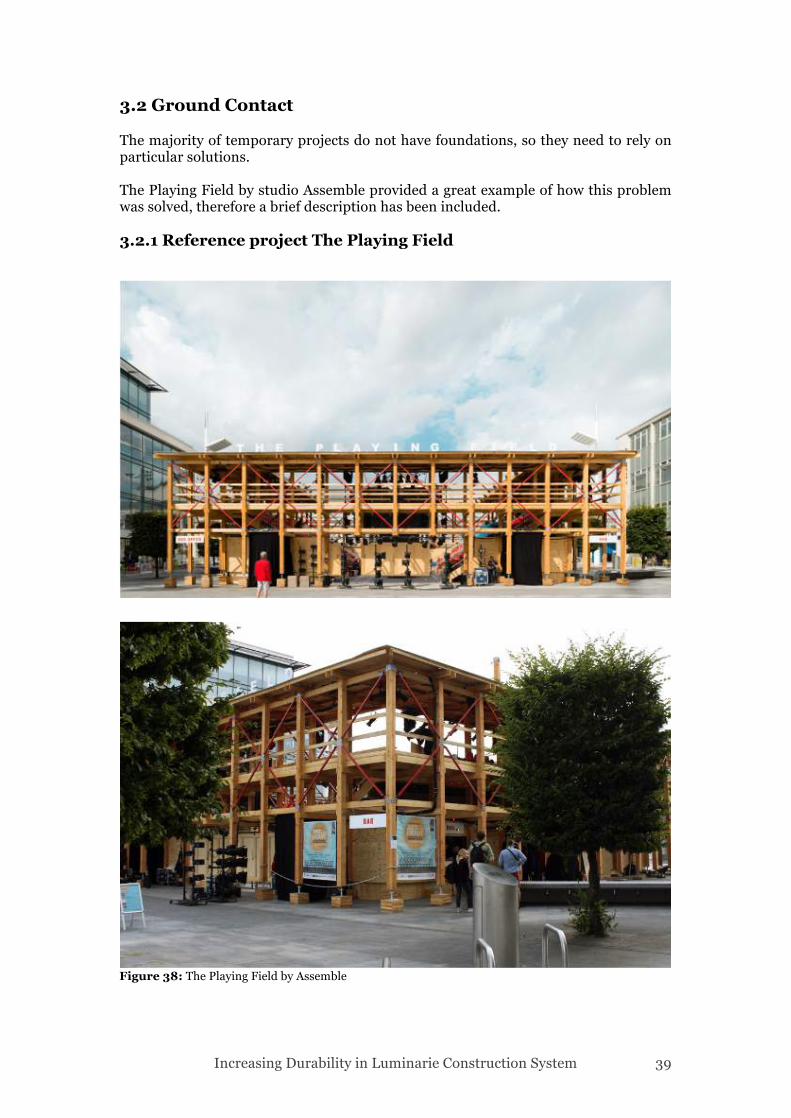
3.2 Ground Contact The majority of temporary projects do not have foundations, so they need to rely on particular solutions. The Playing Field by studio Assemble provided a great example of how this problem was solved, therefore a brief description has been included. 3.2.1 Reference project The Playing Field
Figure 38: The Playing Field by Assemble
Increasing Durability in Luminarie Construction System 40
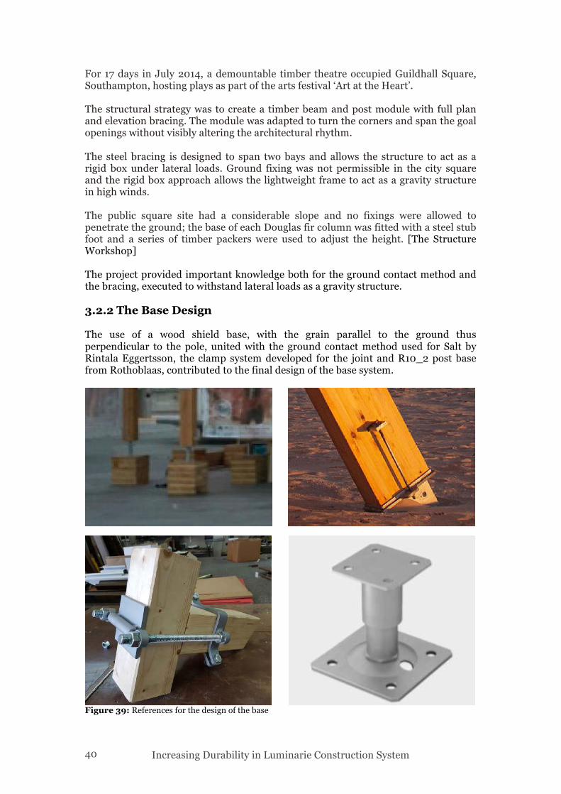
For 17 days in July 2014, a demountable timber theatre occupied Guildhall Square, Southampton, hosting plays as part of the arts festival ‘Art at the Heart’. The structural strategy was to create a timber beam and post module with full plan and elevation bracing. The module was adapted to turn the corners and span the goal openings without visibly altering the architectural rhythm. The steel bracing is designed to span two bays and allows the structure to act as a rigid box under lateral loads. Ground fixing was not permissible in the city square and the rigid box approach allows the lightweight frame to act as a gravity structure in high winds. The public square site had a considerable slope and no fixings were allowed to penetrate the ground; the base of each Douglas fir column was fitted with a steel stub foot and a series of timber packers were used to adjust the height. [The Structure Workshop] The project provided important knowledge both for the ground contact method and the bracing, executed to withstand lateral loads as a gravity structure. 3.2.2 The Base Design The use of a wood shield base, with the grain parallel to the ground thus perpendicular to the pole, united with the ground contact method used for Salt by Rintala Eggertsson, the clamp system developed for the joint and R10_2 post base from Rothoblaas, contributed to the final design of the base system.
Figure 39: References for the design of the base
Increasing Durability in Luminarie Construction System 41
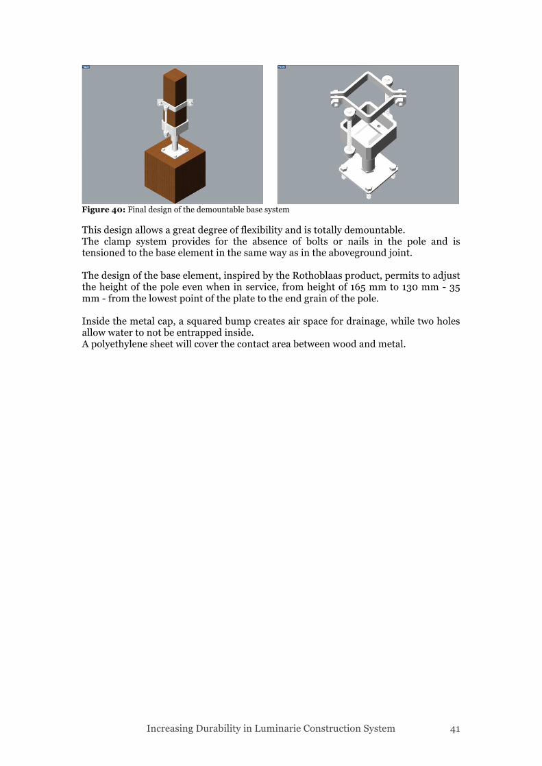
This design allows a great degree of flexibility and is totally demountable. The clamp system provides for the absence of bolts or nails in the pole and is tensioned to the base element in the same way as in the aboveground joint. The design of the base element, inspired by the Rothoblaas product, permits to adjust the height of the pole even when in service, from height of 165 mm to 130 mm - 35 mm - from the lowest point of the plate to the end grain of the pole. Inside the metal cap, a squared bump creates air space for drainage, while two holes allow water to not be entrapped inside. A polyethylene sheet will cover the contact area between wood and metal.
Figure 40: Final design of the demountable base system
Increasing Durability in Luminarie Construction System 42
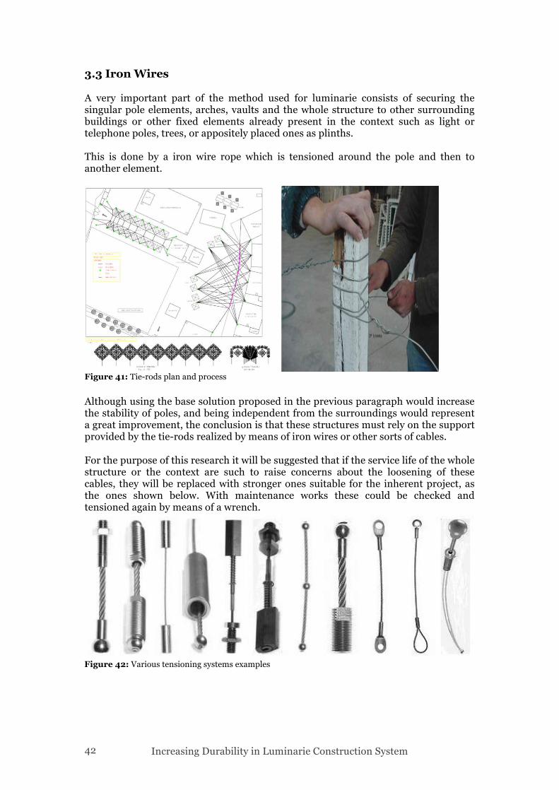
3.3 Iron Wires A very important part of the method used for luminarie consists of securing the singular pole elements, arches, vaults and the whole structure to other surrounding buildings or other fixed elements already present in the context such as light or telephone poles, trees, or appositely placed ones as plinths. This is done by a iron wire rope which is tensioned around the pole and then to another element.
Although using the base solution proposed in the previous paragraph would increase the stability of poles, and being independent from the surroundings would represent a great improvement, the conclusion is that these structures must rely on the support provided by the tie-rods realized by means of iron wires or other sorts of cables. For the purpose of this research it will be suggested that if the service life of the whole structure or the context are such to raise concerns about the loosening of these cables, they will be replaced with stronger ones suitable for the inherent project, as the ones shown below. With maintenance works these could be checked and tensioned again by means of a wrench.
Figure 41: Tie-rods plan and process
Figure 42: Various tensioning systems examples
Increasing Durability in Luminarie Construction System 43
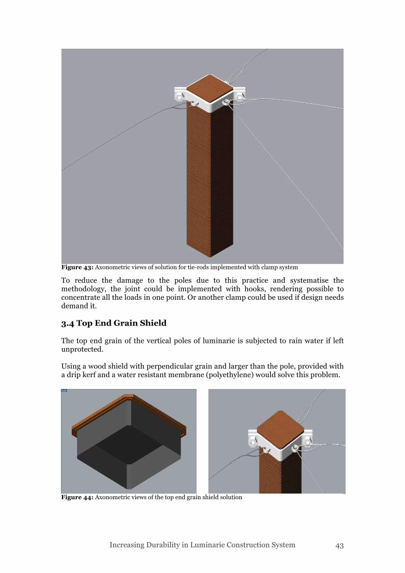
To reduce the damage to the poles due to this practice and systematise the methodology, the joint could be implemented with hooks, rendering possible to concentrate all the loads in one point. Or another clamp could be used if design needs demand it. 3.4 Top End Grain Shield The top end grain of the vertical poles of luminarie is subjected to rain water if left unprotected. Using a wood shield with perpendicular grain and larger than the pole, provided with a drip kerf and a water resistant membrane (polyethylene) would solve this problem.
Figure 43: Axonometric views of solution for tie-rods implemented with clamp system
Figure 44: Axonometric views of the top end grain shield solution
Increasing Durability in Luminarie Construction System 44
4 Conclusions I believe that reusable temporary architecture could better solve seemingly unsolvable problems and succeed in creating a genius loci, raise awareness and interest, adapting to unpredictable demands, encouraging innovation and helping facilitate emerging micro economies: in a sentence “apt response to a civilization in flux”. Approaching the end of this research, I realized that by trying to enhance and improve the current building system of luminarie, I was able to roughly shape a new one, of which features could facilitate unprecedented uses: emergency settlements, camping facilities, pop up structures, pavilions, even theatres (see Assemble example), of which embedded or wanted temporariness calls for low (no) footprint, quick construction, dismantling and reusability. The very few case studies I was able to find in support of the research, raised in me the conviction of the need of a wood based demountable structural system, which is strong, reliable, able to be erected with common tools by untrained workers, provide shelter and quality space, and leave no trace when its presence is not any more needed. Although I may only have developed the joinery system, for aboveground members and for ground contact, indicating a set of rules and improvements for using wood outdoors, the options to make these ‘skeleton’ structures architectural spaces are countless, and will be examined within the frame of the Graduation Project. […] Yet it is imperative that once we embrace ‘lightness’ as an alternative, we become fully aware of its implications, stepping outside a dialectic. As architects or designers we are called to envision a better future, our projects necessarily retain a utopian vector as part of their ethical dimension. Whether we design an ephemeral or a permanent structure, this ethical imperative is primary. In order to embrace it, we must understand that the ephemeral object must simultaneously offer a dwelling place and therefore, paradoxically, be memorable. (Perez-Gomez, 1992)
Increasing Durability in Luminarie Construction System 45
Literature Erman, E., 2002, ‘Demountable Timber Joints for Timber Construction Systems’, Architectural Science Review Fredriksson, M., 2013, ‘Moisture conditions in rain exposed wood joints – Experimental methods and laboratory measurements’, LTH, Lund University Calkins, M., 2008, ‘Materials for Sustainable Sites: A Complete Guide to the Evaluation, Selection and Use of Sustainable Construction Materials’, Wiley Kolb, J., 2008, ‘Systems in Timber Engineering: Loadbearing Structures and Component Layers, Springer Science & Business Media Schein, E., 1968, ‘The Influence of Design on Exposed Wood Buildings of the Puget Sound Area’, U.S. Department of Agriculture and Forest Services Perez-Gomez, A., 1992, ‘Polyphilo, or the Dark Forest Revisited: An Erotic Epiphany of Architecture’, MIT Press Zelinka, S. L., 2014, ‘Corrosion of Metals in Wood Products’, INTECH, Creative Commons Rhatigan, R., Freitag, C., El-Kasmi, S., Morrell, J. J., 2004, ‘Preservative treatment of Scots Pine and Norway Spruce’, Forest Products Journal Vol 54 no. 10 Zelinka, S. L., Stone, D. S., 2011, ‘Corrosion of Metals in Wood: comparing the results of a rapid test method with long term exposure tests across six wood treatments’, Corrosion Science, No. 53 Anon., 2008, ‘Preservative treated wood Simpson Strong-Tie Technical Bulletin’, Simpson Strong Tie, No. T- PTWOOD08-R, Anon., 2013, ‘Standard Method for Determining Corrosion Rates of Metals in Contact with Treating Solutions’, American Wood Protection Association, AWPA E-17 Anon., 2012, ‘Timber Species – Technical Bulletin’, Trada Technology Anon., 2012, ‘Treated Timber – Technical Bulletin’, Trada Technology