incandescent lamp filaments: facet-cooling, failure mechanisms bound... · incandescent lamp...
TRANSCRIPT
R960 Phi/ips Res; Repts 32, 82-95, 1977
INCANDESCENT LAMP FILAMENTS:FACET-COOLING, FAILURE MECHANISMS
by W. LEMS *), H. KINKARTZ and W. LECHNER
AbstractThe life of incandescent single-coil filament lamps; both inert-gas filledand evacuated, was studied. The development of facets can lnftuencelife in two ways: by causing a decrease in temperature, and by influencingthe mechanical stability through formation of notches at d.c. operationbelow 2700 K. The way in which the effective emissivity and electricalresistance are influenced by mass loss and by facet formation is in-vestigated. An analysis of burn-through is given: In about 70 % of allcases the site of initially highest temperature coincides with the finalhighest-temperature spot. For evacuated lamps this value is somewhathigher and the defect responsible for the initial spot appears to be aminimum in wire diameter. For gas-filled lamps the correlation betweenfinal and initial spot is somewhat lower. In this case the defects respon-sible for burn-through appear to bé minima either in coil pitch or in wirediameter, both are of about equal importance.
1. Introduction
In a recent paper 1) we presented preliminary results concerningthe influenceof facet formation on the life of incandescent lamps. For experimental simplicitya straight single-coil filament lamp was chosen which, with respect to.wire thick-ness (37 (.Lm) and gas filling (8 . 104 Nm-2 argon) was considered to be to.some extent representative of a wider variety of lamps (such as GLS lamps).The role of facets in causing a temperature decrease during life, and in leadingto.mechanical instability through formation of notches if the coil is d.c.-operatedbelow 2700 K, was discussed. Also. the correlation of about 70% between thefinal highest-temperature spot with the site of initially highest temperature wasreported.This paper presents additional results on notch formation, and on a' series of
evacuated lamps. The life as a function of temperature, and a discussion of thetransport mechanisms are presented in section 3. Section 4 gives an analysis ofthe factors responsible for the temperature decrease during life (under constant-voltage operation): the' increase in effective emissivity or in electrical resistance. 'Section 5 examines the causes of burn-through, i.e. the relative importance ofdeviations in coil pitch and wire diameter. The conclusions are summarized insection 6. Brief inforrnation on experimental details can be found in section 2.
*) Present address: N. V. Philips' Gloeilampenfabrieken, Elcoma Television Tube DevelopmentDepartment, Eindhoven, Netherlands.
INCANDESCE~T LAMP FILAMENTS: FACET-COOLING. FAILURE MECHANISMS 83.
The influence of defect length and gas-filling on the magnitude of the tempera-ture spot is discussed in an appendix.
2. Experimental details
The experiments were performed on a double-filament stop/flasher lamp(Philips type 12500, 12 V, 20/5 W), a standard type with a gas-filling 'of8· 104 Nm-2 argon and containing a zirconium getter. The investigationswere carried out with the 5W coil, which consists of 130turns, length 7.3 mm,wire diameter 37 fLm,mandrel. diameter 70 fLmand pitch 57 fLm.In addition,321amps were evacuated to 10-3 Nm-2 and, before sealing off, the getter wasregenerated by heating the coil to 2700K for 1.5 minutes. For life tests at lowertemperatures the getter had, to be regularly activated, otherwise early burnoutcaused by the well-known "water cycle" occurred. This ineffectiveness of thegetter, which is attached to the lead wires, is obviously due to its temperaturebeing too low. As raising the temperature of the 5 W coil would interfere withthe low-temperature life test, use was made of the second built-in coil.Early burn-out could be prevented by heating this coil once a week (10minutes
at 2900 K for the gas-filled lamps, and 1 minute at 2700 K for the evacuatedsamples), and thus activating its getter.Alllife tests on the lamps were carried out at constant voltage. The tempera-
ture measurements on the filaments were carried out using a two-wavelengthpyrometer, which enabled us to determine temperature differences of 2 K 2).By scanning along the coil and recording a temperature peak for each turn atemperature profile of the coil was obtained. This scanning was repeated about7 times during the life of the lamp at about equal time intervals. Shortly beforeburn-out was to be expected (as detected by temperature measurements) thelamps were switched off and the filaments, undamaged by e.g. arcing duringburn-out, were taken out of the bulb for examination with the SEM. (ScanningElectron Microsëope).
From the temperature profile we were also able to determine variation inpitch of the coil along its length, which is a possible cause of burn-through.Provided that the scanning speed is sufficiently constant each peak of the pyro-meter signal represents the position of a single turn. By determining the distanceover five consecutive temperature peaks, the average pitch over five turns wasdetermined with a reproducibility of about 1%..Another possible cause of hot spots, variations in wire diameter, was
investigated by determining the coil-wire diameter from SEM pictures of eachturn of the coil. Apart from being tedious, a further disadvantage of the methodis that it is destructive: the filament has to. be taken out of the bulb. For thesereasons we also applied the so-called flash test, which yields qualitative infor-mation on variation in wire diameter 3). The most suitable capacitance (3 fLF)and voltage (200 V) were determined experimentally, which produces a flash
84 W. LEMS. H. K1NKARTZ and W. LECHNER
intensity strong enough for easy detection and at the same time keeps the flashtime short enough to prevent temperature differences along the coil from beingcompensated by heat conductivity. The flash lasting about 50 ms is photo-graphed and subsequently analysed 'by densitometry. -
3. Life as a function of temperature
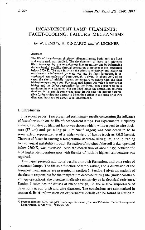
Figure 1 shows an Arrhenius plot: In 7: vs To-1, where 7: is the life andTo the initial burning temperature for inert gas-filled lamps and evacuatedsamples of the same type. The results for the gas-filled lamps at To > 2700 K(To -1 < 3.7' 10-4) have been presented before 1). The main conclusions were
I07r--------------------------------------------,
Fig. 1. An Arrhenius plot of the life of coils. vs initial burning temperature To. The uppervalues refer to: • a.c.- and. d.c.-operated type 12500 (gas-filled) lamps. Above 2700 Kthe results of the type 12500 lamps yield an activation energy of 238 kcal mol= ê ; below2700 K the d.c. results yield 95 kcal mol~l. The lower values (dashed line) represent theevacuated lamps, for which an activation energy of 190 kcal rnol+! is found.
the following. Above 2700 K the life-determining transport mechanism isevaporation. However, the observed life is longer than expected from an extra-polation (based on an activation energy of 205 kcal mol-1, see ref. 4) of theresults obtained at high temperatures (> 3000 K) where no facets developand the cross-section of the wire remains circular. This was explained by theobservation that coils which develop facets show a larger temperature decreaseduring life than coils whose wire cross-sections remain round. This extra tem-perature decrease was attributed to an increase in radiation area, emissivity,or electrical resistance caused by the change in shape due to the-developmentof facets. We shall turn to the relative importance of these factors in section 4.
The additional results obtained in the lower-temperature region confirm thatbelow 2700 K the life of d.c.-operated cojls is determined by formation ofnotches. The observed activation energy of 95 kcal mol "! fits in the range ofvalues generally attributed to surface migration.
i V's=e Ac T", (1)
INCANDESCENT LAMP FILAMENTS: FACET-COOLING. FAILURE MECHANISMS 85
The vacuum lamp results yield an activation energy of 190 kcal mol-1,which lies close to that of evaporation as was to be expected.
In agreement with earlier work 5) the weight loss of the coil at the end oflife, which is estimated from the change in electrical resistance (see section 4),is found to be substantially smaller for the gas-filled lamp than for the vacuumlamp (by a factor of about 3). Although !1T is increased for a given wire orcoil defect when the evacuated lamp is compared with the gas-filled lamp (seesection 5 and appendix), this increase is too small to account for the observeddifference. Nor does the change in shape due to development of facets (exceptin so far as they lead to mechanical instability such as notches) explain thisdifference, as the discrepancy in weight loss is also found with gas-filled lampswhich have burned at high temperature where no facets occur. Axial transport,such as turn-to-turn diffusion 5), can probably explain the "factor of 3".
4. Cooling effect: change in emissivity and electrical resistance
4.1. Effects of mass loss and other changes in shape
The changes in total emissivity and electrical resistance were determined fromthe observed change in temperature and current during life under constant-voltage operation. Let us briefly examine which relations were assumed to bevalid.
Taking only radiation into account and assuming the filament to be athomogeneous temperature, the energy balance can be written as
where i V is the dissipated power, e the coefficient of emissivity, A the radiatingarea, a the Stefan-Boltzman constant, and T the temperature. For both vacuumand gas-filled lamps a T4-dependence was found to be well obeyed in the tem-perature region considered. As e is determined by both the emissivity oftungstenand the geometry of the coil, it is difficult to distinguish between e and A. Wetherefore only consider the product e A as an "effective emissivity". Frommeasuring i and T under constant-voltage operation, and neglecting-the tem-perature dependence of e, we find e A according to
e A i (To)4(e A)o = io .T ' (2)
where the index 0 denotes the initial values.The change in current gives us the change in electrical resistance. However,
as T changes the change in electrical resistance is determined by both the changein specific resistivity (! and in the filament geometry. As we are interested in thechange in filament geometry only, a geometrical resistance factor Rg is used,
86 w. LEMS. H. KINKARTZ and W. LECHNER
where Rg = Rlo, and thus
(3)
Contributions of changes in lattice defect concentrations to e were found tobe negligible at the high temperatures under consideration. Combining (2) and(3) shows that equal relative increases of Rg and e A lead to an identical de-crease of temperature:
eeT) s, sA (To)4e(To) RgO (e A)o = T '
Examining the relations for the simple case of a change in shape caused by .mass loss through homogeneous isotropic evaporation only, in the course.ofwhich the wire cross-section remains circular and the surface characteristicsremain unchanged (s constant), we see that equations (2) and (3) yield:e A/(e A)o = d/do and .Rg/RgO = (do/d)2, where d is the wire diameter. Fromthis follows
(4)
(5)
Relation (5) is useful in helping us to establish whether the condition of changein shape caused by mass loss through homogeneous isotropic evaporation ismet. Apart from plotting e A/(s A)o and Rg/RgO we will therefore also plot(Rgo/Rg)! as a function of time.
4.2. Experimental results (calculated from (2) and (3))
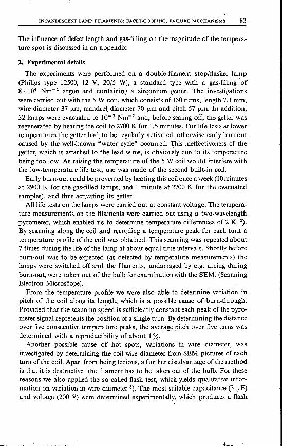
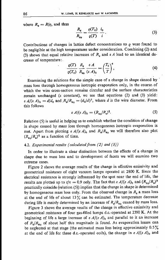
In order to illustrate a clear distinction between the effects of a change inshape due to mass loss and to development of facets we will examine twoextreme cases.Figure 2 shows the average results of the change in effective emissivity and
geometrical resistance of eight vacuum lamps operated at 2800 K. Since theelectrical resistance is strongly influenced by the spot near the end of life, theresults are plotted up to trr: = 0.9 only. The fact that e A/(e A)o and (Rgo/Rg)!practically coincide (relation (5» implies that the change in shape is determinedby homogeneous mass loss only. From the observed change in Rg a mass lossat the end of life of about 13% can be estimated. The temperature decreaseduring life is mainly determined by an increase of Rg/ RgO caused by mass loss.
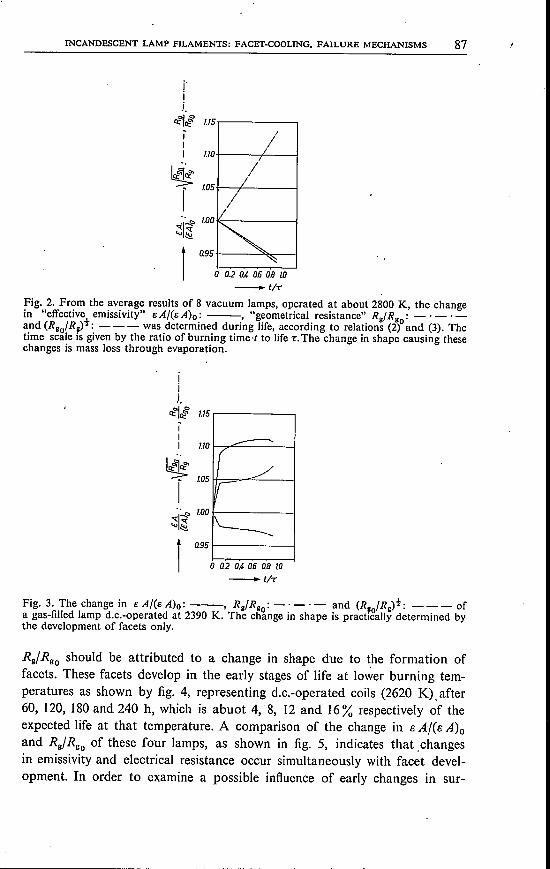
Figure 3 shows the average results of the change in effective emissivity andgeometrical resistance of four gas-filled lamps d.c.-operated at 2390 K. At thebeginning of life a large increase of s A/(e A)o and parallel to it an increaseof Rg/RgO of about half this magnitude is found. As evaporation losses canbe neglected at that stage (the estimated mass loss being approximately 0.5 %at the end of life for these d.c.-operated coils), the change in eA/Cs A)o and
INCANDESCENT LAMP FILAMENTS: FACET-COOLING. FAILURE MECHANISMS 87
j'iJ.
ct4ctc§» 1.15/I
1./0I
~///
r1.05
~11
r o 0.2 0.4. as 0.8 LO-..t/r
Fig. 2. From the average results of 8 vacuum lamps, operated at about 2800 K, the changein "effective emissivity" eA/(eA)o: ---, "geometrical resistance" Rg/Rgo: -'-'-and (Rgo/Rg)t: - - - was determined during life, according to relations (2) and (3). Thetime scale is given by the ratio of burning time·t to life t:The change in shape causing thesechanges is mass loss through evaporation.
jiJ.
ct~o::~ 1.15
1./0
~ 1.05
rI~1.00
~~
ra9S
--------r ~_//
t:I
\._--
o tu O.~U6 0.8 10
-tiT'
Fig. 3. The change in e A/(e A)o: ---, Rg/Rgo: -' -' - and (Rgo/Rg)t: --- ofa gas-filled lamp d.c.-operated at 2390 K. The change in shape is practically determined bythe development of facets only.
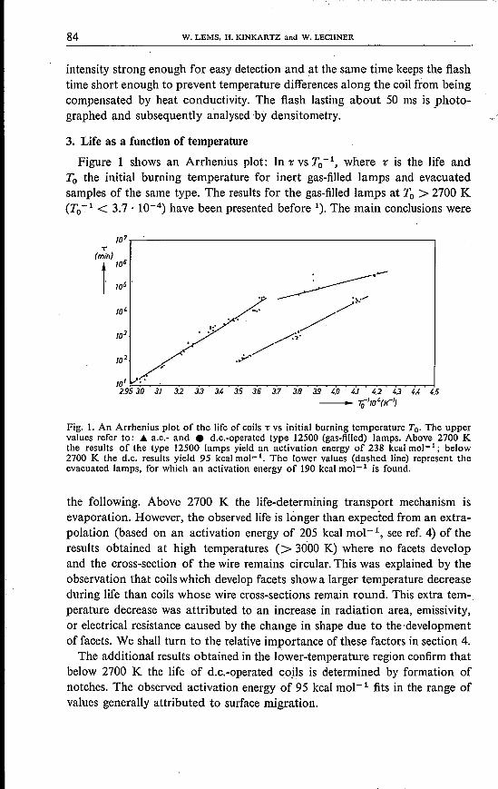
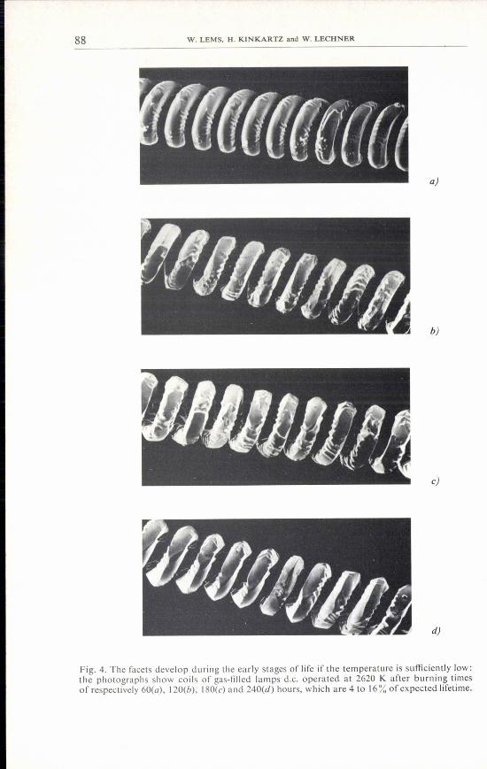
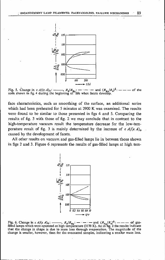
Rg/RgO should be attributed to a change in shape due to ~he formation offacets. These facets develop in the early stages of life at lower burning tem-peratures as shown by fig. 4, representing d.c.-operated coils (2620 K). after60, 120, 180 and 240 h, which is abuot 4, 8, 12 and 16% respectively of theexpected life at that temperature. A comparison of the change in e A/(s A)oand Ra/Rgo of these four lamps, as shown in fig. 5, indicates that .changesin emissivity and electrical resistance occur simultaneously with facet devel-opment. In order to examine a possible influence of early changes in sur-
88 W. LEMS. H. KlNKARTZ and W. LECHNER
a)
b)
c)
d)
Fig. 4. The facets develop during the early stages of life if the temperature is sufficiently low:the photographs show coils of gas-filled lamps d.c. operated at 2620 K after burning timesof respectively 60(a), 120(b), 180(c) and 240(d) hours, which are 4 to 16% of expected lifetime.
100 200-t(h)
, INCANDESCENT LAMP FILAMENTS: FACET-COOLING, FAILURE MECHANISMS . 89
!IJ.
Q:~ct:& 1.15
1.10
.~ 105
r'f~WO~~
-;::::='"/'r:i"--___ -'._
Fig.5. èhange in e A/(e A)o:'--, Ra/Rgo: -'-' - and (Rgo/Rg)t: --- of thecoils shown in fig. 4 during the beginning of life when facets develop.
face characteristics, such as smoothing of the surface, an additional serieswhich had been preheated for 5 minutes at 2900 K was examined. The resultswere found to be similar to those presented in figs 4 and 5. Comparing theresults of fig. 3 with those of fig. 2 we may conclude that in contrast to thehigh-temperature vacuum result the temperature decrease for the low-tem-perature result of fig. 3 is mainly determined by the increase of e A/(s A)ocaused by the development of facets.All other results on vacuum and gas-filled lamps lie in between those shown
in figs 2 and 3. Figure 6 represents the results of gas-filled lamps at high tem-
IiJ.
1l:~1l:& 1.15
1.10
,./
~'
~ --
~ r lOS
~I~100to~
1Q95
o Q2 0.4 0.6 0.8 10
-tiT
Fig. 6. Change in s A/(e A)o: --, Rg/Rgo: - . -' - and (Rgo/Rg)t: - - - of gas-filled lamps which were operated at high temperature (3170 K). As in fig. 2 the results indicatethat the change in shape is due to mass loss through evaporation. The magnitude of thechange is smaller, however, than for the evacuated samples, indicating a smaller mass loss.
90 W. LEMS. H. KINKARTZ and W. LECHNER
peratures (> 3170 K), which, except for the smaller changes in e A/(s A)o andRc/Reo' show characteristics similar to the high-temperature vacuum results offig. 2. The wire again remains smooth and round, but the smaller change inRg/RgO implies a smaller mass loss at the end of life (4-5 %) compared to the13% of the vacuum lamps.
5. Analysis of the causes of burn-through
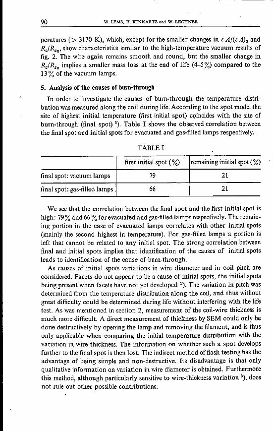
In order to investigate the causes of burn-through the temperature distri-bution was measured along the coil during life. According to the spot model thesite of highest initial temperature (first initial spot) coincides with the site ofburn-through (final spot) 5). Table I shows the observed correlation betweenthe final spot and initial spots for evacuated and gas-filled lamps respectively.
TABLE I
first initial spot (%) remaining initial spot (%)
final spot: vacuum lamps 79 21
final spot: gas-filled lamps 66 21
We see that the correlation between the final spot and the first initial spot ishigh: 79% and 66 % for evacuated and gas-filled lamps respectively. The remain-ing portion in the case of evacuated lamps correlates with other initial spots(mainly the second highest in temperature). For gas-filled lamps a portion isleft that cannot be related to any initial spot. The strong correlation betweenfinal and initial spots implies that identification of the causes of initial spotsleads to identification of the cause of burn-through.
As causes of initial spots variations in wire diameter and in coil pitch areconsidered. Facets do not appear to be a cause of initial spots, the initial spotsbeing present when facets have not yet developed 1). The variation in pitch wasdetermined from the temperature distribution along the coil, and thus withoutgreat difficulty could be determined during life without interfering with the lifetest. As was mentioned in section 2, measurement of the coil-wire thickness ismuch more difficult. A direct measurement of thickness by SEM could only bedone destructively by opening the lamp and removing the filament, and is thusonly applicable when comparing the initial temperature distribution with thevariation in wire thickness. The information on whether such a spot developsfurther to the final spot is then lost. The indirect method of flash testing has theadvantage of being simple and non-destructive. Its disadvantage is that onlyqualitative information on variation in wire diameter is obtained. Furthermorethis method, although particularly sensitive to wire-thickness variation 3), doesnot rule out other possible contributions.
INCANDESCENT LAMP FILAMENTS: FACET-COOLING FAILURE MECHANISMS 91
Deviations in pitch 6.s with respect to the average pitch of the coil s up to-10% were observed. The observed coincidence between the location of thefirst initial and final spot and the locations of the initial minima in pitch both forgas-filled and vacuum lamps is presented in table II.
TABLE II
first initial minimum remaining minimain 6.sfs C%) in 6.sfs C%)
first initial spot 12 7vacuum lamps
final spot 8 21
first initial spot 30 13gas-filled lamps
final spot 44 22
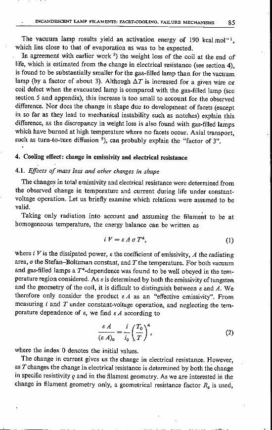
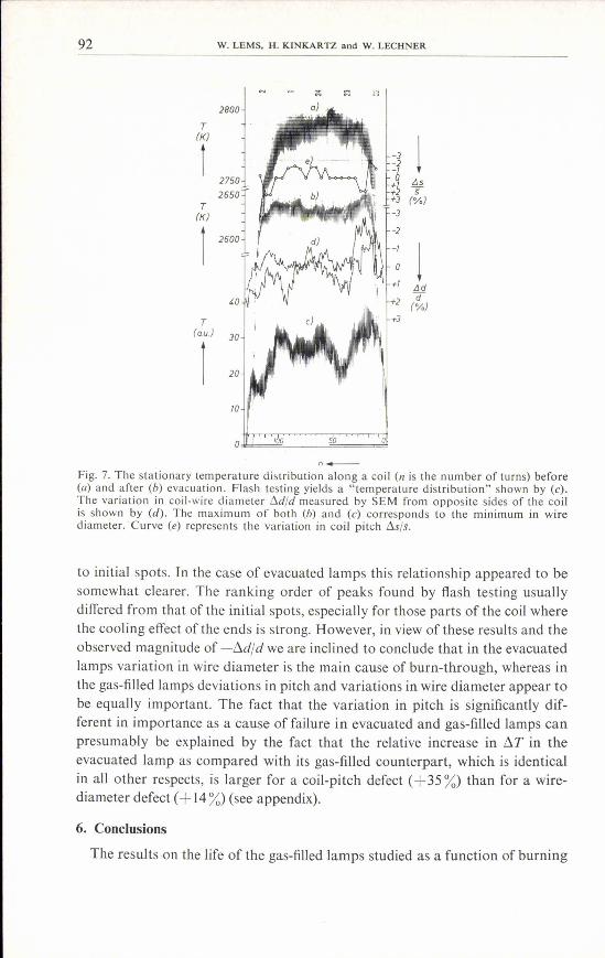
From table II it can be concluded that variations in pitch appear to be animportant cause of failure in gas-filled lamps, whereas in evacuated lamps thiscorrelation is small. As table II indicates, minima in pitch do not always mani-fest themselves as initial temperature spots. Furthermore a number of filamentswere observed to undergo a change in pitch during life, causing a change indefect magnitude. This phenomenon explains those cases when no correlationwith either an initial spot or an initial minimum in pitch was observed. Asalready mentioned, a similar analysis is not possible for variations in wirethickness. Figure 7 shows the temperature distribution of a coil before (a) andafter Cb) the lamp was evacuated. Flash testing with a 50 ms pulse led to the"temperature distribution" shown by curve Cc) determined from the photo-graph taken during heating. The result of the coil wire thickness measurementby SEM is shown by the curve Cd), where both the results obtained from the"front" and "rear" side of the filament are presented. Curve Ce) shows thevariation in pitch. The similarity of curves Cc) and Cd) indicate that the maxi-mum observed by flash testing is indeed caused by a minimum in wire diam-eter. The location of the first initial spot of the evacuated lamp (b) also largelycoincides with the maxima in (c) and (d), indicating that this spot is caused bya minimum in wire diameter. For the gas-filled lamp, however, the situation isdifferent. Here the cooling effects ofthe ends are apparently.greater than for theevacuated lamp, which reduces the influence of constrictions in wire diameterin the vicinity of the coil ends. Comparing the flash test results of 16 gas-filledlamps, ofwhich 8were subsequently evacuated, with the stationary temperaturedistribution we were able in most cases to relate peaks observed by flash testing
92 W. LEMS. H. KINKARTZ and W. LECHNER
T(K)
r
IJdd(%)
1T
(K)
IIJsif(%)
T[ou.)
1
n_Fig. 7. The stationary temperature distribution along a coil Cn is the number of turns) beforeCa) and after Cb) evacuation. Flash testing yields a "ternperature distribution" shown by Cc).The variation in coil-wire diameter tldjd measured by SEM from opposite sides of the coilis shown by Cd). The maximum of both Cb) and Cc) corresponds to the minimum in wirediameter. 'Curve Ce) represents the variation in coil pitch tlsjs.
to initial spots. In the case of evacuated lamps this relationship appeared to besomewhat clearer. The ranking order of peaks found by flash testing usuallydiffered from that of the initial spots, especially for those parts of the coil wherethe cooling effect of the ends is strong. However, in view of these results and theobserved magnitude of -~d/d we are inclined to conclude that in the evacuatedlamps variation in wire diameter is the main cause of burn-through, whereas inthe gas-filled lamps deviations in pitch and variations in wire diameter appear tobe equally important. The fact that the variation in pitch is significantly dif-ferent in importance as a cause of failure in evacuated and gas-filled lamps canpresumably be explained by the fact that the relative increase in ~T in theevacuated lamp as compared with its gas-filled counterpart, which is identicalin all other respects, is larger for a coil-pitch defect (+ 35%) than for a wire-diameter defect (+ 14%) (see appendix).
6. Conclusions
The results -on the life of the gas-filled lamps studied as a function of burning
INCANDESCENT LAMP FILAMENTS: FACET-COOLING. FAILURE MECHANISMS 93
temperature, and the role which facets play, confirmed the preliminary resultspublished earlier 1). Above 2700 K life is independent of the current mode, thetransport mechanism is evaporation, and facets influence life in so far as theycause a temperature decrease. Below 2700 K d.c.-operated coils have a consid-erably shorter life than a.c.-operated ones, and surface migration seems to bethe transport mechanism that leads to the development of notches. Facet for-mation appears to play a role in notch formation, as the facet geometry leads toperiodic constrictions in the wire diameter. As a result of these phenomena thedependence of lamp life on temperature and mode of current is as shown infig. 1. It illustrates that one should be extremely careful in extrapolating high-temperature (forced) life-test results in order to predict life at lower tempera-tures.
The change in shape due to mass loss tends to decrease the effective emis-sivity by decreasing the radiating area, and to increase the electrical resistance.The change in shape due to the development of facets tends to increase bothemissivity and resistance. Which factor dominates in causing the temperaturedecrease during life under constant-voltage operation depends on the relativemagnitude of mass loss and facet development.
In evacuated lamps at high temperature it is only the mass loss that counts:the temperature decrease is mainly determined by the increase in electricalresistance.
In gas-filled lamps at low temperature facet formation gives rise to an in-crease in effective emissivity, and it is this that mainly causes the temperaturedecrease. The mass loss at the end of life was estimated from changes in resist-ance, and was found to be higher by a factor of about 3 in evacuated lampscompared with the gas-filled ones.
A strong correlation is found between the site of burn-through and the firstinitial spot. The defects considered as causes of spots were deviations in coilpitch and in wire diameter. In gas-filled lamps local minima in coil pitch provedto be an important cause of burn-through. The observations by SEM and flashtesting make it plausible that variation in wire diameter is the principal causeof burn-through in the evacuated lamps and, next to the variation in coil pitch,an important cause in the gas-filled lamps. Improving the quality of this lampwould imply obtaining a more constant wire diameter and coil pitch. Therelative importance of thés(; two factors, however, will differ from one type oflamp to the other. Preliminary results indicate that pitch defects are the onlycause of failure in the 100 W/200 V GLS lamp with a coiled-coil filament.
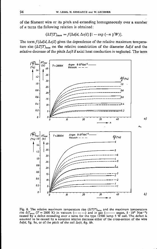
Appendix
For the type 12500 lamp 5W coil investigated, the temperature distributionaround aspot was calculated taking into account the heat conduction along thewire. Assuming the spot to be caused by a decrease of either the cross-section
/
94 W. LEMS. H. KINKARTZ and W. LECHNER
of the filament wire or its pitch and extending homogeneously over a numberof n turns the following relation is obtained:
(llTjT)max =f(lldjd, llsjs) [1 - exp (-n VW)].
The termf(lldjd, llsjs) gives the dependence of the relative maximum tempera-ture rise (llTjT)max on the relative constriction of the diameter lldjd and therelative decrease of the pitch llsjs ifaxial heat conduction is neglected. The term
(!fIJ. IJTmax
(o/,I~): (Kt)::1.2
30
0.8
0.4.
0.2
1.0
!Jd (%)
__ ------------------:d1.0
a)
T=2800K Argon 8'10'Nm-2--Vacuum ---
b)
25
20
0.615
Fig. ~. The relative maximum temperature rise (IlT/T)max and the maximum temperaturerise llTmax (T= 2800 K) in vacuum (----) and in gas (--- argon, B '104 Nm-2)caused by a defect extending over 11 turns for the type 12500 lamp 5 W coil. The defect isassumed to be caused by a constant relative decrease either of the cross-section of the wirelld/d, fig. Ba, or of the pitch of the coil lls/s, fig. Bb.
la
5
o30 40la 20_n
o
Argon 8·IO'Nm-2--Vacuum ---
IJTmax(K)
t40
35
T=2800K 15(%)
__-------------6
1.0
__-------------530
250.8
20
0.615
0.4 la
0.2 5
la 20 30 40-- __ n
INCANDESCENT LAMP FILAMENTS: FACET-COOLING, FAILURE MECHANISMS 95
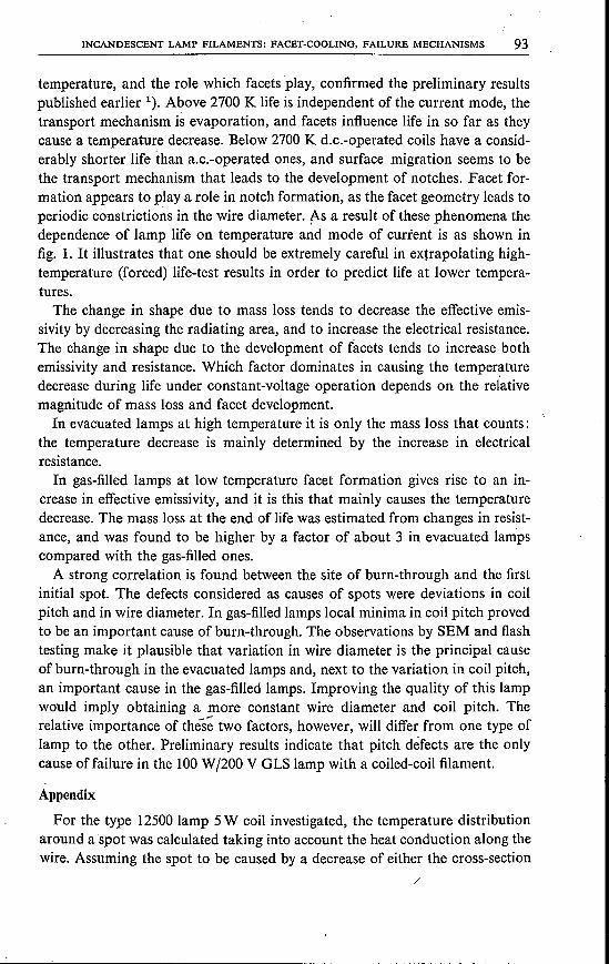
between brackets 'allows for heat conduction. The constant W contains thephysical properties of tungsten, the construction of the filament and lamp andthe burning conditions. This equation, which was already used in the discus-sion of the spot model 6), is similar to the one derived by Prásnik 7) for a straightwire, who also takes heat conduction into account, The effect which coiling hason the effective emissivity, due to multiple reflections and the shadowing effect,was taken into account by using experimental data on coils of different pitch.All previous theoretical treatments 8) of the effect of variations in coil pitch onburn-out have neglected multiple reflections.For our lamp conditions (I1TfT)max was calculated for T = 2800 K and
plotted in figs 8a and b as a function of the relative defects I1dfd and b..sfsrespectively.Special attention is to be paid to a comparison bf the vacuum with the gas
case under the burning conditions (2800 K) mentioned. According to the cal-culation the addition of gas (argon, 8· 104 Nm-2) raises (I1TfT)max for allI1dfd defects by about 14% and for b..sfs defects by about 35% irrespective ofthe number of turns n involved in the defect. This could explain why pitchdefects become relatively more important than diameter defects in a gas-filledlamp as compared with an evacuated lamp.
Philips GmbH Forschungslaboratorium Aachen Aachen, August 1976
REFERENCES1) W. Lems, H. Kinkartz and W. Lechner, Philips Res. Repts 30, 218, 1975.2) W. Lechner and O. Schob, Inst. Phys. Conf. Ser. No. 26 c, 1975.3a) D.' A. Davies, in F. Benesovsky (ed.), Hochschmelzende MetalIe, 3. Plansee-Seminar
1958, Springer-Verlag, Wien 1959,p. 69.3b) G. Comenetz, H. A. Johansen and J. W. Salatka, J. IlIum. Eng. Soc. 2,366,1973.3C) C. W. Dawson, J. L. Nelson, W. F. Radzelovage and H. G. SeIl, J. IlIum. Eng.
Soc. 2, 381, 1973.4) E. R. Plante and A. B. Sessoms, J. Res. Nat! Bur. Stand. 77A, 237, 1973.5) H. Hörster, E. Kauer and W. Lechner, Philips tech. Rev. 32, 155, 1971.6) H. Hörster, E. Kauer and W. Lechner, J. IlIum. Eng. Soc. 1, 309, 1972.7) L. Prásnik, Zeitschr. f. Physik, 99, 710, 1936.80) G. Holst, B.-Lax, E. Oo s terh uis and M. Pirani, Z. f. techno Physik 9, 186, 1928.8b) f. Korefand H. C. Plant, Zeitschr. f. techno Physik 11,515,1930.8C) A. N. Aladyshev, Svetotechnica 5,11, 1973.8d) E. J. Covington, J. IlIum. Eng. Soc. 4, 280, 1975.8e) C. Baker, J. IlIum. Eng. Soc. 5, 3, 1975.