in situ stress - agh university of science and...
TRANSCRIPT
1
In situ stress
Marek Cała – Katedra Geomechaniki, Budownictwa i Geotechniki
Marek Cała – Katedra Geomechaniki, Budownictwa i Geotechniki
In situ stress - the components of stress tensor
2
In situ stress
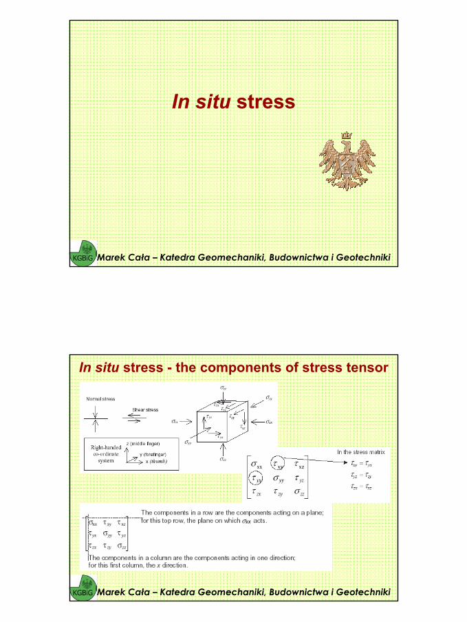
A ‘pop-up’ observed at a quarry site in granite in SoutheasternManitoba and the horizontal stress determined using the USBM Borehole Deformation Gauge in a vertical borehole.
(Quarry ‘popup’. (b) Measured horizontal stress)
Marek Cała – Katedra Geomechaniki, Budownictwa i Geotechniki
In situ stress
Marek Cała – Katedra Geomechaniki, Budownictwa i Geotechniki
Stress is a concept fundamental to Rock Mechanics principles and applications:• There is a pre-existing state in the rock mass and we need to understand it, both
directly, and as a stress state applies to analysis and design.• During rock excavation, the stress state can change dramatically. This is because
rock, which previously contained stress, has been removed and the load must be redistributed.
• Stress is not familiar – it is a tensor quantity and tensors are not encountered in everyday life.
• Distribution of tectonic forces is also complicated by geological factors, with the added uncertainty in that there is no constraint on the total force, as is the casewith gravity loads. Plate motions, interactions at plate boundaries and within plates are all driven by tectonic forces. The magnitude and orientation of the forces have changed over geological time; folds and faults created in response to forces from past epochs, volcanic intrusions, etc. may all have been involved increating the current heterogeneous system that is now subject to the current tectonic regime.
• It is to be expected, therefore, that the magnitude and orientation of these forces may vary considerably within geological systems.
3
In situ stress
Marek Cała – Katedra Geomechaniki, Budownictwa i Geotechniki
Thus, unlike other materials used in engineering design, rock is pre-loaded, by forces that are, in general, of unknown magnitude and orientation. The problem of design in rock is complicated further by the fact that structural features such as joints, fractures, and bedding planes can have an important influence on the ability of the rock mass to resist these forces, i.e. on the strength of the rock mass, as measured over the region, often large, that is affected by the structure. This could have an adverse influence on the stability of the engineering structure.
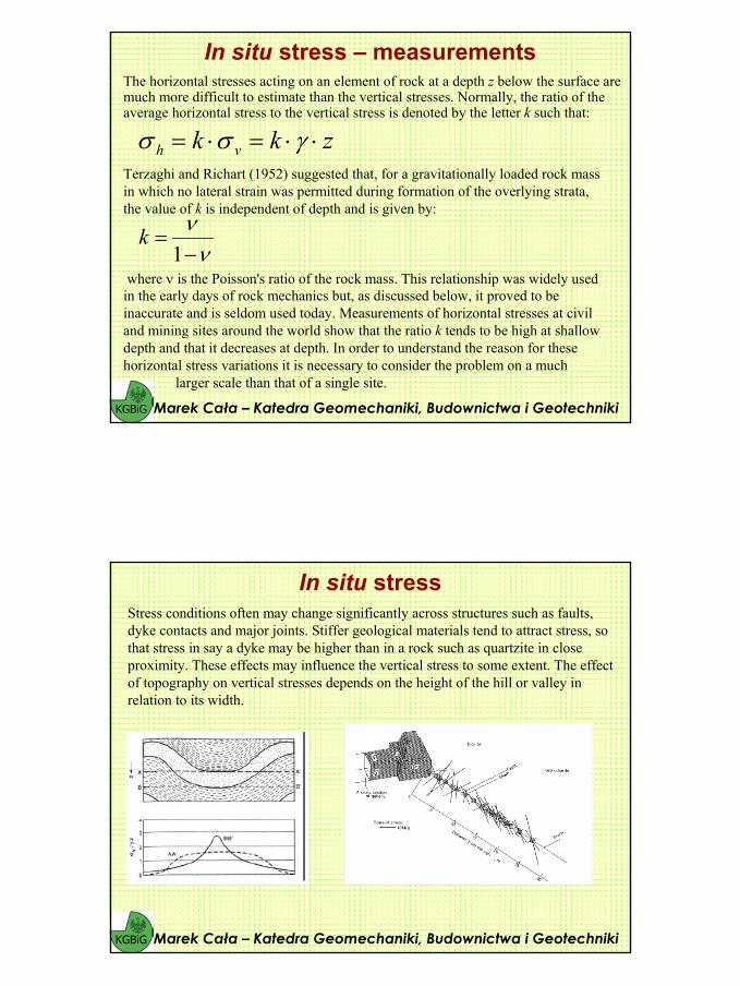
Stress conditions often may change significantly across structures such as faults, dyke contacts and major joints. Stiffer geological materials tend to attract stress, so that stress in say a dyke may be higher than in a rock such as quartzite in close proximity. These effects may influence the vertical stress to some extent.
The effect of topography on vertical stresses depends on the height of the hill or valley in relation to its width.
Many phenomena other than tectonics could result in high and unequal horizontal stresses, in particular near the ground surface.
Such phenomena include residual and thermal stresses, erosion, lateral straining, anisotropy, glaciation and deglaciation, topography, curvature of the Earth and other active geological features and processes. This is not to say that tectonic stresses do not exist, but simply that their contribution to the measured stress
fields may not be as large as previously thought.
Global Plate Tectonics – Jurrasic to Present Day
Marek Cała – Katedra Geomechaniki, Budownictwa i Geotechniki

4
Global Plate Tectonics – Jurrasic to Present Day
Marek Cała – Katedra Geomechaniki, Budownictwa i Geotechniki
Global Plate Tectonics – Jurrasic to Present Day
Marek Cała – Katedra Geomechaniki, Budownictwa i Geotechniki

5
Global Plate Tectonics – Jurrasic to Present Day
Marek Cała – Katedra Geomechaniki, Budownictwa i Geotechniki
Global Plate Tectonics – Jurrasic to Present Day
Marek Cała – Katedra Geomechaniki, Budownictwa i Geotechniki

6
Global Plate Tectonics – Jurrasic to Present Day
Marek Cała – Katedra Geomechaniki, Budownictwa i Geotechniki
Global Plate Tectonics – Jurrasic to Present Day
Marek Cała – Katedra Geomechaniki, Budownictwa i Geotechniki

7
Global Plate Tectonics – Jurrasic to Present Day
Marek Cała – Katedra Geomechaniki, Budownictwa i Geotechniki
Global Plate Tectonics – Jurrasic to Present Day
Marek Cała – Katedra Geomechaniki, Budownictwa i Geotechniki

8
Global Plate Tectonics – Jurrasic to Present Day
Marek Cała – Katedra Geomechaniki, Budownictwa i Geotechniki
Global Plate Tectonics – Jurrasic to Present Day
Marek Cała – Katedra Geomechaniki, Budownictwa i Geotechniki

9
Global Plate Tectonics – Jurrasic to Present Day
Marek Cała – Katedra Geomechaniki, Budownictwa i Geotechniki
Global Plate Tectonics – Jurrasic to Present Day
Marek Cała – Katedra Geomechaniki, Budownictwa i Geotechniki

10
Global Plate Tectonics – Jurrasic to Present Day
Marek Cała – Katedra Geomechaniki, Budownictwa i Geotechniki
Global Plate Tectonics – Jurrasic to Present Day
Marek Cała – Katedra Geomechaniki, Budownictwa i Geotechniki

11
Global Plate Tectonics – Jurrasic to Present Day
Marek Cała – Katedra Geomechaniki, Budownictwa i Geotechniki
Global Plate Tectonics – Jurrasic to Present Day
Marek Cała – Katedra Geomechaniki, Budownictwa i Geotechniki

12
Global Plate Tectonics – Jurrasic to Present Day
Marek Cała – Katedra Geomechaniki, Budownictwa i Geotechniki
Global Plate Tectonics – Jurrasic to Present Day
Marek Cała – Katedra Geomechaniki, Budownictwa i Geotechniki

13
Global Plate Tectonics – Jurrasic to Present Day
Marek Cała – Katedra Geomechaniki, Budownictwa i Geotechniki
Global Plate Tectonics – Jurrasic to Present Day
Marek Cała – Katedra Geomechaniki, Budownictwa i Geotechniki
14
Global Plate Tectonics – Jurrasic to Present Day
Marek Cała – Katedra Geomechaniki, Budownictwa i Geotechniki
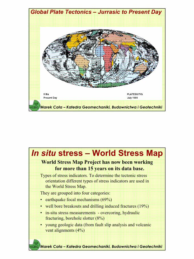
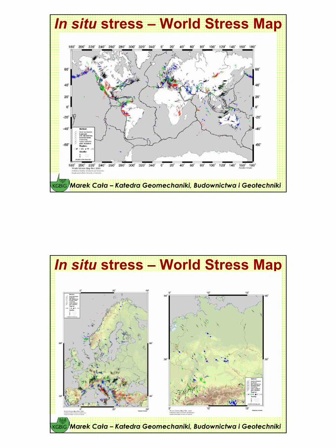
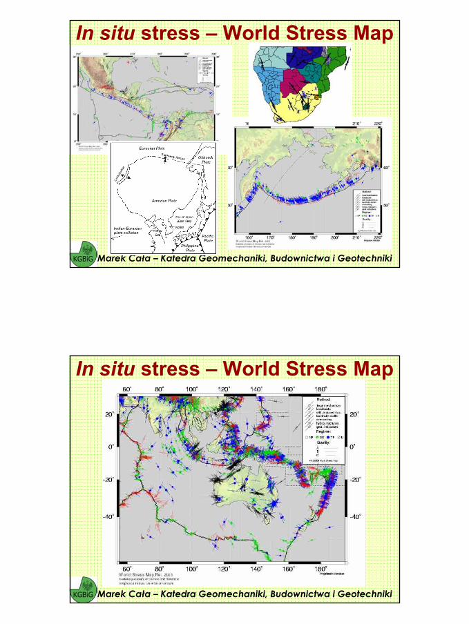
World Stress Map Project has now been working for more than 15 years on its data base.
Types of stress indicators. To determine the tectonic stress orientation different types of stress indicators are used in the World Stress Map.
They are grouped into four categories:• earthquake focal mechanisms (69%) • well bore breakouts and drilling induced fractures (19%) • in-situ stress measurements - overcoring, hydraulic
fracturing, borehole slotter (8%) • young geologic data (from fault slip analysis and volcanic
vent alignments (4%)
Marek Cała – Katedra Geomechaniki, Budownictwa i Geotechniki
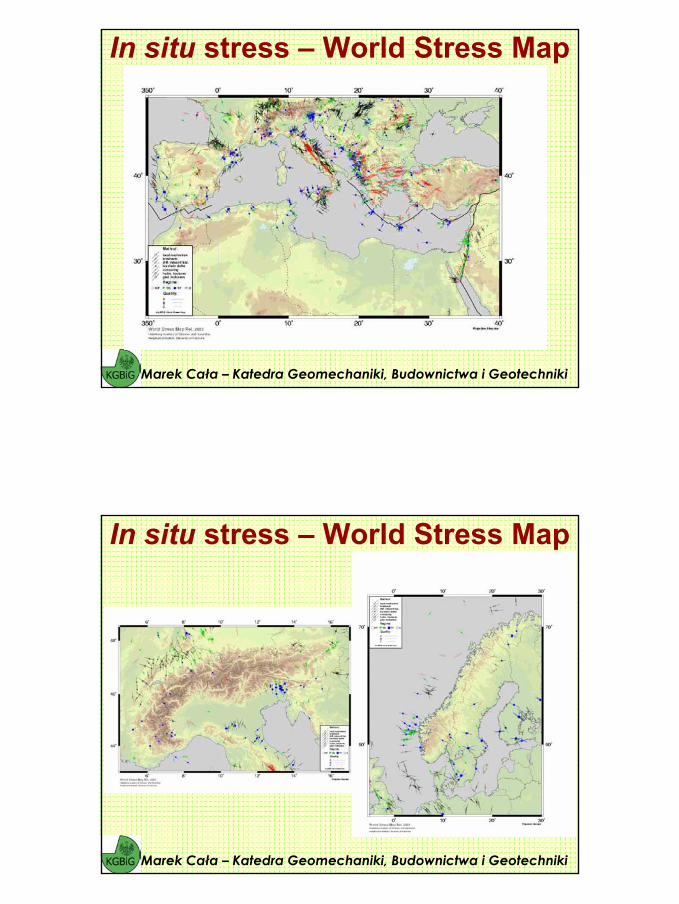
In situ stress – World Stress Map
15
In situ stress – World Stress Map
Marek Cała – Katedra Geomechaniki, Budownictwa i Geotechniki
Marek Cała – Katedra Geomechaniki, Budownictwa i Geotechniki
In situ stress – World Stress Map
16
Marek Cała – Katedra Geomechaniki, Budownictwa i Geotechniki
In situ stress – World Stress Map
Marek Cała – Katedra Geomechaniki, Budownictwa i Geotechniki
In situ stress – World Stress Map
17
Marek Cała – Katedra Geomechaniki, Budownictwa i Geotechniki
In situ stress – World Stress Map
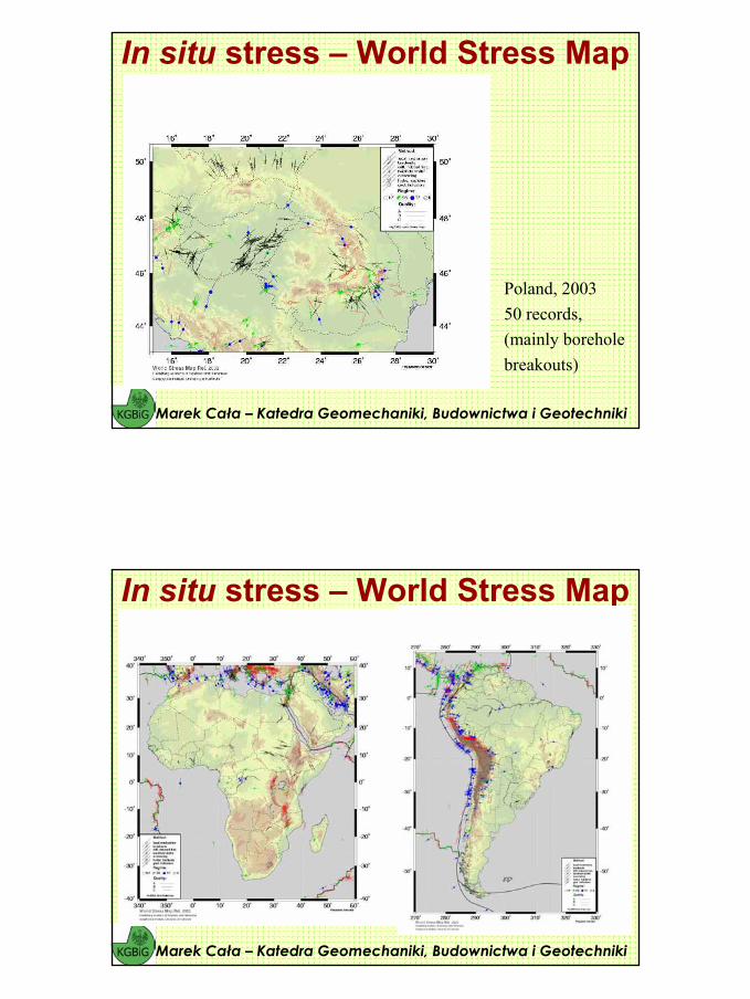
Poland, 200350 records,(mainly borehole breakouts)
Marek Cała – Katedra Geomechaniki, Budownictwa i Geotechniki
In situ stress – World Stress Map
18
Marek Cała – Katedra Geomechaniki, Budownictwa i Geotechniki
In situ stress – World Stress Map
Marek Cała – Katedra Geomechaniki, Budownictwa i Geotechniki
In situ stress – World Stress Map
19
Marek Cała – Katedra Geomechaniki, Budownictwa i Geotechniki
In situ stress – World Stress Map
Marek Cała – Katedra Geomechaniki, Budownictwa i Geotechniki
In situ stress – World Stress Map
20
Marek Cała – Katedra Geomechaniki, Budownictwa i Geotechniki
In situ stress – World Stress Map
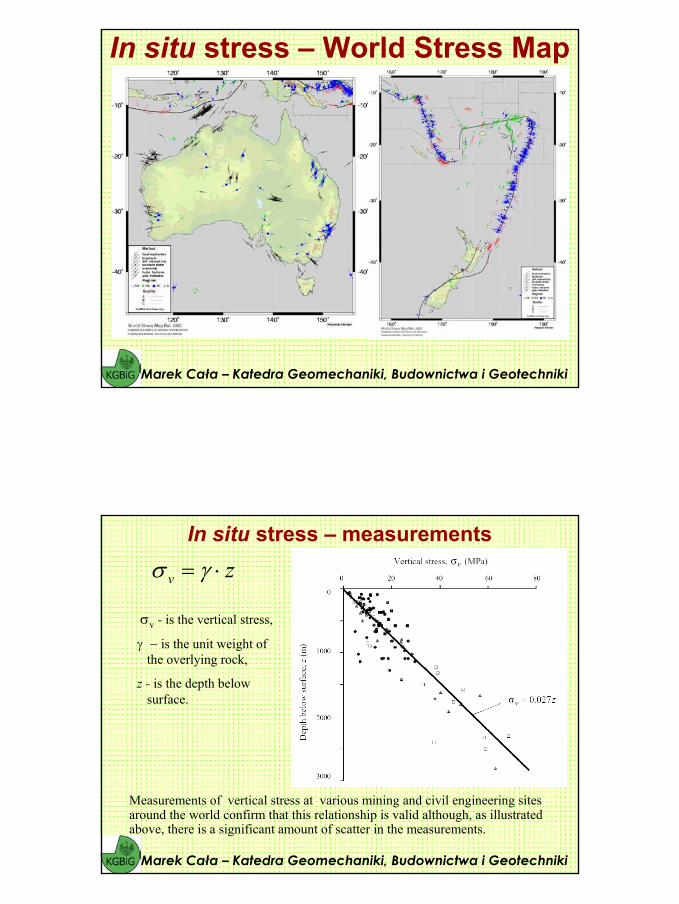
Measurements of vertical stress at various mining and civil engineering sitesaround the world confirm that this relationship is valid although, as illustratedabove, there is a significant amount of scatter in the measurements.
Marek Cała – Katedra Geomechaniki, Budownictwa i Geotechniki
In situ stress – measurementszv ⋅= γσ
σv - is the vertical stress,
γ − is the unit weight of the overlying rock,
z - is the depth below surface.
21
The horizontal stresses acting on an element of rock at a depth z below the surface aremuch more difficult to estimate than the vertical stresses. Normally, the ratio of theaverage horizontal stress to the vertical stress is denoted by the letter k such that:
Marek Cała – Katedra Geomechaniki, Budownictwa i Geotechniki
In situ stress – measurements
zkk vh ⋅⋅=⋅= γσσTerzaghi and Richart (1952) suggested that, for a gravitationally loaded rock massin which no lateral strain was permitted during formation of the overlying strata, the value of k is independent of depth and is given by:
where ν is the Poisson's ratio of the rock mass. This relationship was widely usedin the early days of rock mechanics but, as discussed below, it proved to beinaccurate and is seldom used today. Measurements of horizontal stresses at civil and mining sites around the world show that the ratio k tends to be high at shallow depth and that it decreases at depth. In order to understand the reason for thesehorizontal stress variations it is necessary to consider the problem on a much
larger scale than that of a single site.
νν−
=1
k
Stress conditions often may change significantly across structures such as faults, dyke contacts and major joints. Stiffer geological materials tend to attract stress, so that stress in say a dyke may be higher than in a rock such as quartzite in close proximity. These effects may influence the vertical stress to some extent. The effect of topography on vertical stresses depends on the height of the hill or valley in relation to its width.
Marek Cała – Katedra Geomechaniki, Budownictwa i Geotechniki
In situ stress
22
Sheorey (1994) developed an elasto-static thermal stress model of the earth. This model considers curvature of the crust and variation of elastic constants, density and thermal expansion coefficients through the crust and mantle. A detailed discussion onSheorey’s model is beyond the scope of this presentation, but he did provide a simplified equation which can be used for estimating the horizontal to vertical stress ratio k:
where Eh (GPa) is the average deformation the upper part of the earth’s crust measured in a horizontal direction.
Marek Cała – Katedra Geomechaniki, Budownictwa i Geotechniki
In situ stress – Sheory concept
++=
zEk k
1001.0725.0
Marek Cała – Katedra Geomechaniki, Budownictwa i Geotechniki
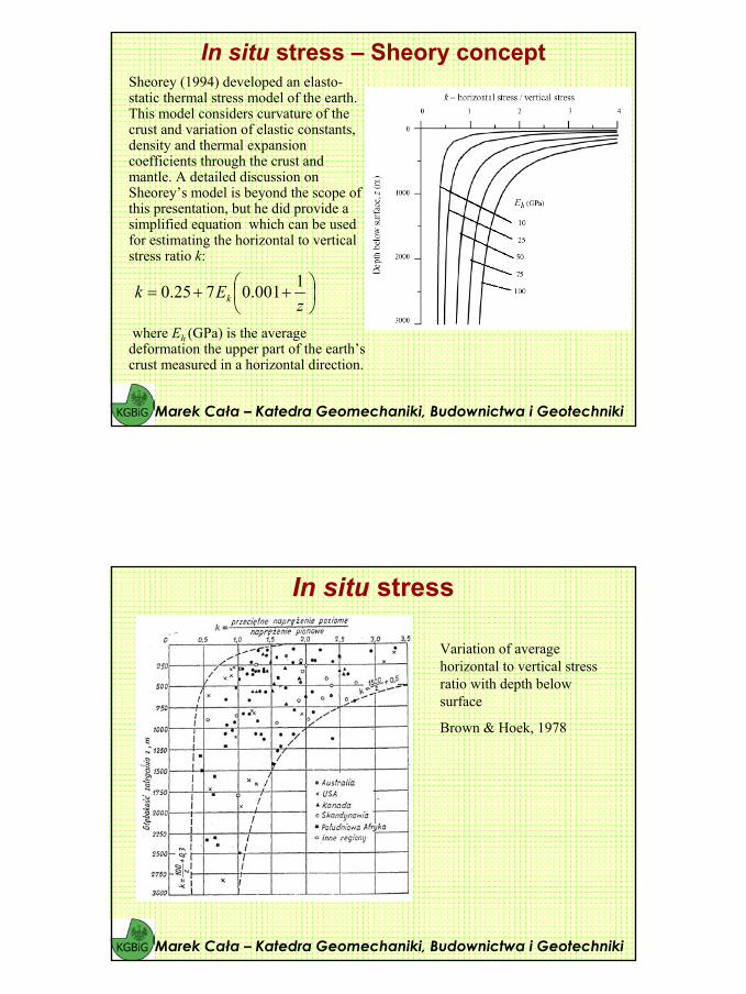
In situ stress
Variation of average horizontal to vertical stress ratio with depth below surface
Brown & Hoek, 1978
23
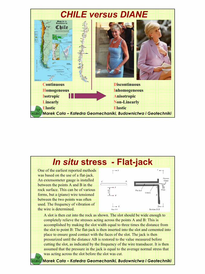
CHILE versus DIANE
Marek Cała – Katedra Geomechaniki, Budownictwa i Geotechniki
ContinuousHomogeneousIsotropicLinearlyElastic
DiscontinuousInhomogeneousAnisotropicNon-LinearlyElastic
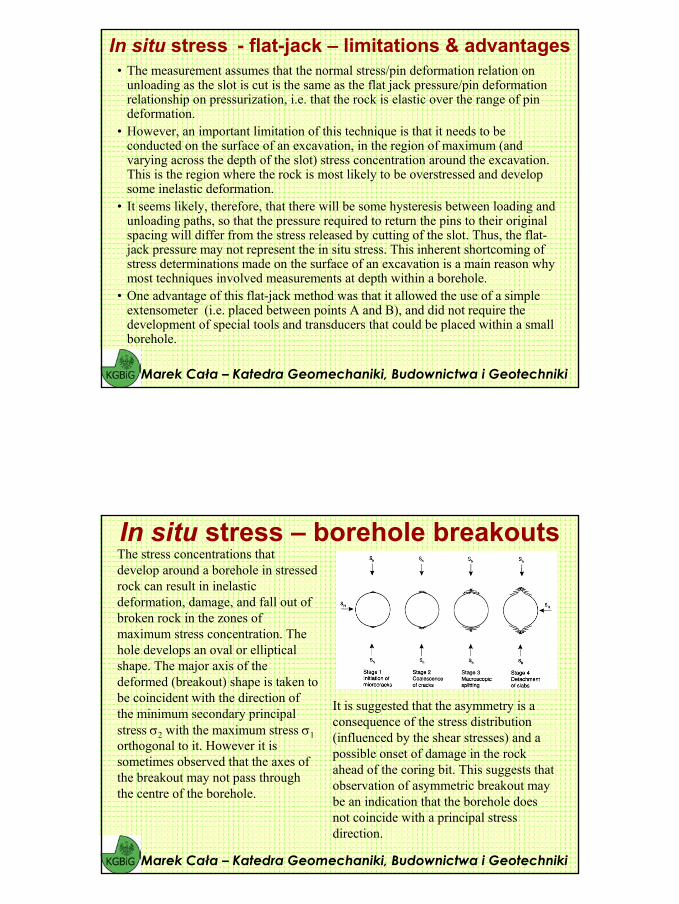
In situ stress - Flat-jack
A slot is then cut into the rock as shown. The slot should be wide enough to completely relieve the stresses acting across the points A and B: This is accomplished by making the slot width equal to three times the distance fromthe slot to point B: The flat-jack is then inserted into the slot and cemented into place to ensure good contact with the faces of the slot. The jack is then pressurized until the distance AB is restored to the value measured beforecutting the slot, as indicated by the frequency of the wire transducer. It is then assumed that the pressure in the jack is equal to the average normal stress that was acting across the slot before the slot was cut.
Marek Cała – Katedra Geomechaniki, Budownictwa i Geotechniki
One of the earliest reported methods was based on the use of a flat-jack. An extensometer gauge is installedbetween the points A and B in the rock surface. This can be of various forms, but a (piano) wire tensioned between the two points was often used. The frequency of vibration of the wire is determined.
24
• The measurement assumes that the normal stress/pin deformation relation on unloading as the slot is cut is the same as the flat jack pressure/pin deformation relationship on pressurization, i.e. that the rock is elastic over the range of pin deformation.
• However, an important limitation of this technique is that it needs to be conducted on the surface of an excavation, in the region of maximum (andvarying across the depth of the slot) stress concentration around the excavation. This is the region where the rock is most likely to be overstressed and developsome inelastic deformation.
• It seems likely, therefore, that there will be some hysteresis between loading and unloading paths, so that the pressure required to return the pins to their original spacing will differ from the stress released by cutting of the slot. Thus, the flat-jack pressure may not represent the in situ stress. This inherent shortcoming of stress determinations made on the surface of an excavation is a main reason why most techniques involved measurements at depth within a borehole.
• One advantage of this flat-jack method was that it allowed the use of a simpleextensometer (i.e. placed between points A and B), and did not require the development of special tools and transducers that could be placed within a smallborehole.
Marek Cała – Katedra Geomechaniki, Budownictwa i Geotechniki
In situ stress - flat-jack – limitations & advantages
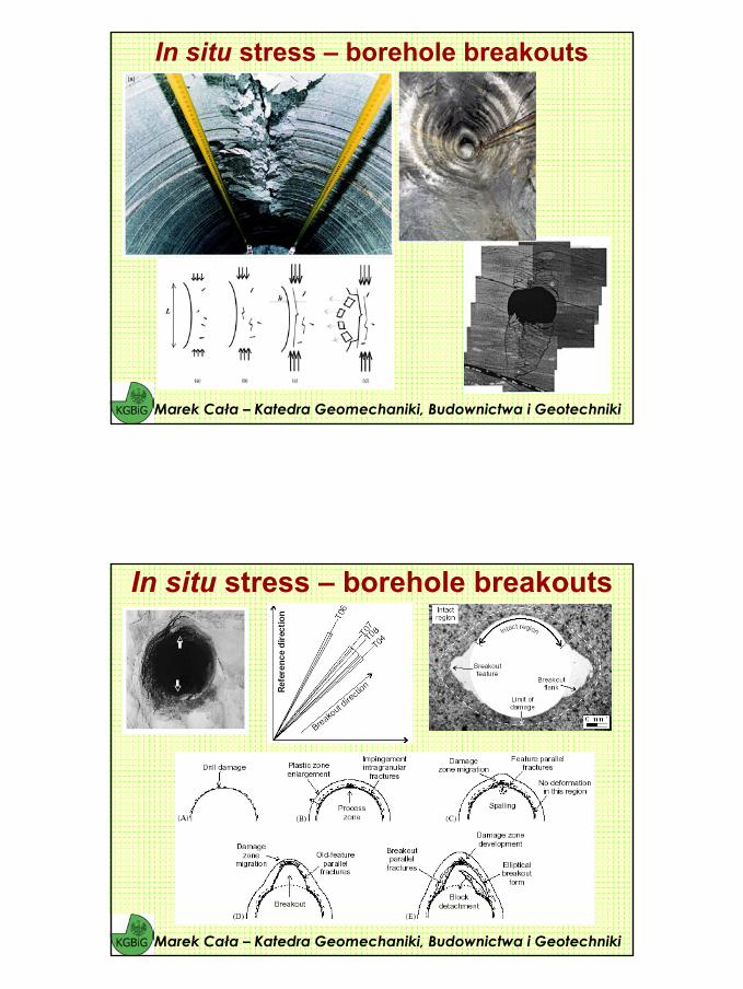
In situ stress – borehole breakouts
Marek Cała – Katedra Geomechaniki, Budownictwa i Geotechniki
The stress concentrations that develop around a borehole in stressed rock can result in inelasticdeformation, damage, and fall out of broken rock in the zones of maximum stress concentration. The hole develops an oval or elliptical shape. The major axis of the deformed (breakout) shape is taken to be coincident with the direction of the minimum secondary principalstress σ2 with the maximum stress σ1orthogonal to it. However it is sometimes observed that the axes of the breakout may not pass throughthe centre of the borehole.
It is suggested that the asymmetry is a consequence of the stress distribution(influenced by the shear stresses) and a possible onset of damage in the rock ahead of the coring bit. This suggests that observation of asymmetric breakout may be an indication that the borehole does not coincide with a principal stress direction.
25
Marek Cała – Katedra Geomechaniki, Budownictwa i Geotechniki
In situ stress – borehole breakouts
In situ stress – borehole breakouts
Marek Cała – Katedra Geomechaniki, Budownictwa i Geotechniki
26
Marek Cała – Katedra Geomechaniki, Budownictwa i Geotechniki
In situ stress – borehole breakouts
Progression of breakout development by combined extension and shear-mode cracking in Darley Dale sandstone. (A) Porosity closes, causing impingement fracture formation, migrating the ‘plastic’ zone into the wall rock. Fractures concentrate into damage zones. (B)Spalling initiates, creating a broad and shallow breakout feature. (C) The damage zone migrates into the wall rock creating breakout parallel fractures. Breakout growth occurs, but also hole enlargement in the orthogonal directions
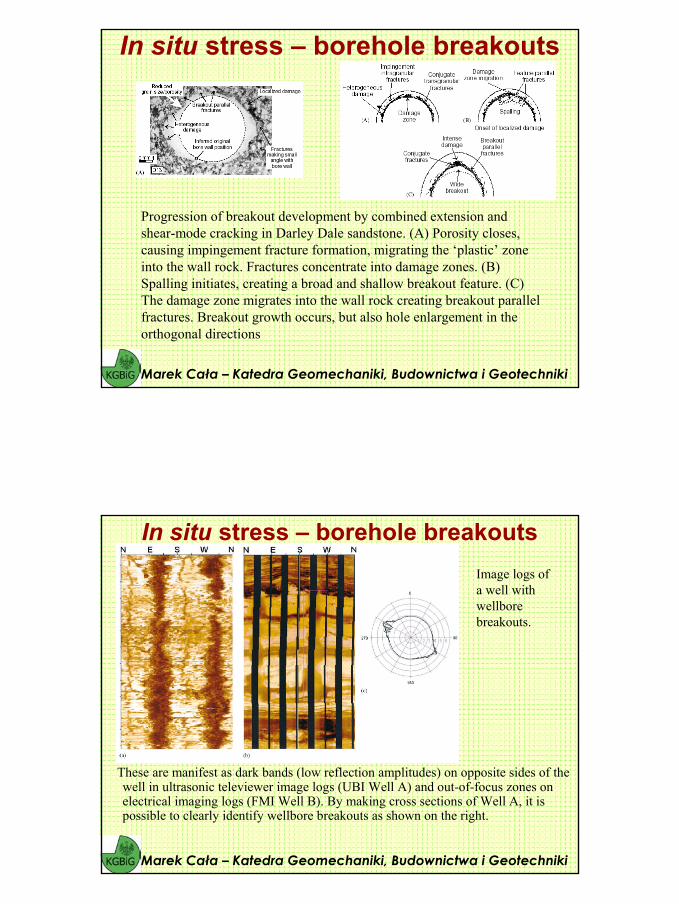
These are manifest as dark bands (low reflection amplitudes) on opposite sides of the well in ultrasonic televiewer image logs (UBI Well A) and out-of-focus zones on electrical imaging logs (FMI Well B). By making cross sections of Well A, it is possible to clearly identify wellbore breakouts as shown on the right.
Marek Cała – Katedra Geomechaniki, Budownictwa i Geotechniki
In situ stress – borehole breakoutsImage logs of a well withwellborebreakouts.
27
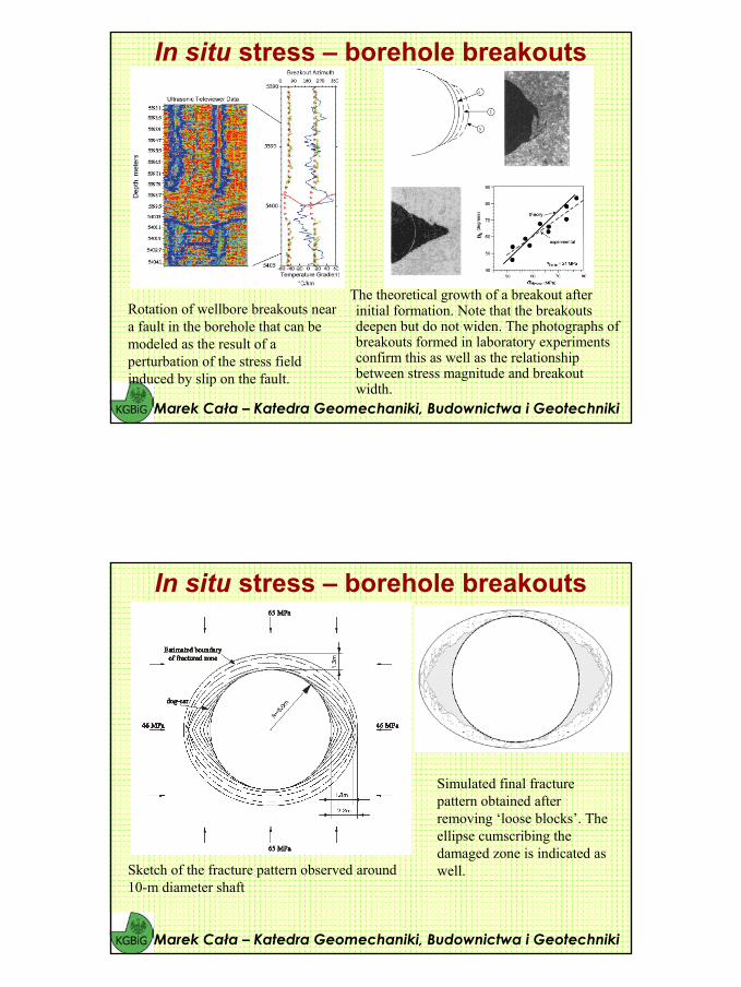
The theoretical growth of a breakout after initial formation. Note that the breakouts deepen but do not widen. The photographs of breakouts formed in laboratory experiments confirm this as well as the relationship between stress magnitude and breakout width.
Marek Cała – Katedra Geomechaniki, Budownictwa i Geotechniki
In situ stress – borehole breakouts
Rotation of wellbore breakouts near a fault in the borehole that can bemodeled as the result of a perturbation of the stress fieldinduced by slip on the fault.
Marek Cała – Katedra Geomechaniki, Budownictwa i Geotechniki
In situ stress – borehole breakouts
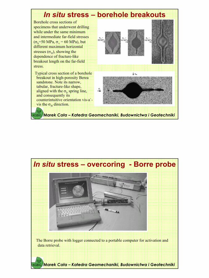
Sketch of the fracture pattern observed around 10-m diameter shaft
Simulated final fracture pattern obtained after removing ‘loose blocks’. The ellipse cumscribing the damaged zone is indicated as well.
28
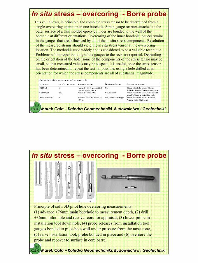
Typical cross section of a borehole breakout in high-porosity Berea sandstone. Note its narrow, tabular, fracture-like shape,aligned with the σh spring line, and consequently its counterintuitive orientation vis-a`-vis the σH direction.
Marek Cała – Katedra Geomechaniki, Budownictwa i Geotechniki
In situ stress – borehole breakoutsBorehole cross sections of specimens that underwent drilling while under the same minimum and intermediate far-field stresses (σh=50 MPa, σv = 60 MPa), but different maximum horizontal stresses (σH), showing the dependence of fracture-like breakout length on the far-fieldstress.
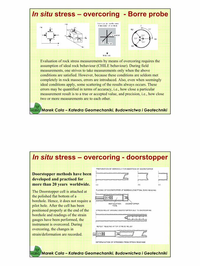
The Borre probe with logger connected to a portable computer for activation anddata retrieval.
Marek Cała – Katedra Geomechaniki, Budownictwa i Geotechniki
In situ stress – overcoring - Borre probe
29
This cell allows, in principle, the complete stress tensor to be determined from a single overcoring operation in one borehole. Strain gauge rosettes attached to the outer surface of a thin molded epoxy cylinder are bonded to the wall of the borehole at different orientations. Overcoring of the inner borehole induces strains in the gauges that are influenced by all of the in situ stress components. Resolution of the measured strains should yield the in situ stress tensor at the overcoring location. The method is used widely and is considered to be a valuable technique. Problems of improper bonding of the gauges to the rock are reported. Depending on the orientation of the hole, some of the components of the stress tensor may besmall, so that measured values may be suspect. It is useful, once the stress tensor has been determined, to repeat the test - if possible, using a hole drilled at anorientation for which the stress components are all of substantial magnitude.
Marek Cała – Katedra Geomechaniki, Budownictwa i Geotechniki
In situ stress – overcoring - Borre probe
Principle of soft, 3D pilot hole overcoring measurements:(1) advance +76mm main borehole to measurement depth, (2) drill+36mm pilot hole and recover core for appraisal, (3) lower probe ininstallation tool down hole, (4) probe releases from installation tool;gauges bonded to pilot-hole wall under pressure from the nose cone,(5) raise installation tool; probe bonded in place and (6) overcore theprobe and recover to surface in core barrel.
Marek Cała – Katedra Geomechaniki, Budownictwa i Geotechniki
In situ stress – overcoring - Borre probe
30
Marek Cała – Katedra Geomechaniki, Budownictwa i Geotechniki
In situ stress – overcoring - Borre probe
Evaluation of rock stress measurements by means of overcoring requires the assumption of ideal rock behaviour (CHILE behaviour). During fieldmeasurements, one strives to take measurements only when the above conditions are satisfied. However, because these conditions are seldom met completely in rock masses, errors are introduced. Also, even when seemingly ideal conditions apply, some scattering of the results always occurs. These errors may be quantified in terms of accuracy, i.e., how close a particular measurement result is to a true or accepted value, and precision, i.e., how close two or more measurements are to each other.
In situ stress – overcoring - doorstopper
Marek Cała – Katedra Geomechaniki, Budownictwa i Geotechniki
Doorstopper methods have been developed and practised for more than 20 years worldwide.
The Doorstopper cell is attached at the polished flat bottom of a borehole. Hence, it does not require a pilot hole. After the cell has been positioned properly at the end of the borehole and readings of the strain gauges have been performed, the instrument is overcored. During overcoring, the changes in strain/deformation are recorded.
31
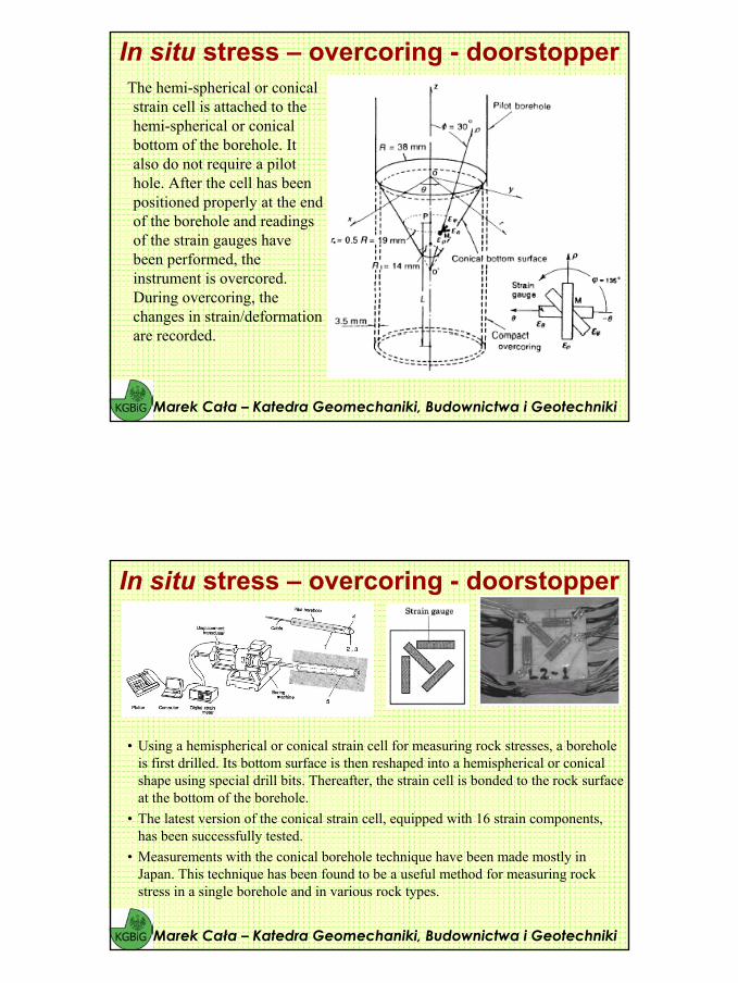
The hemi-spherical or conical strain cell is attached to the hemi-spherical or conical bottom of the borehole. It also do not require a pilot hole. After the cell has been positioned properly at the end of the borehole and readings of the strain gauges have been performed, the instrument is overcored. During overcoring, the changes in strain/deformation are recorded.
Marek Cała – Katedra Geomechaniki, Budownictwa i Geotechniki
In situ stress – overcoring - doorstopper
Marek Cała – Katedra Geomechaniki, Budownictwa i Geotechniki
In situ stress – overcoring - doorstopper
• Using a hemispherical or conical strain cell for measuring rock stresses, a borehole is first drilled. Its bottom surface is then reshaped into a hemispherical or conical shape using special drill bits. Thereafter, the strain cell is bonded to the rock surface at the bottom of the borehole.
• The latest version of the conical strain cell, equipped with 16 strain components, has been successfully tested.
• Measurements with the conical borehole technique have been made mostly in Japan. This technique has been found to be a useful method for measuring rock stress in a single borehole and in various rock types.
32
• Leeman indicates that a doorstopper technique was used as early as 1932 to determine stresses in a rock tunnel below the Hoover Dam in the United States, and also in Russia in 1935. Leeman developed a cell with strain gauges that could be cemented on the bottom of 60mm boreholes and overcored. The cell is often referred to as CSIR (Council for Scientific and Industry Research) Doorstopper and has been used for measurements in 60 m deep boreholes. The CSIR Doorstopper is 35mm in diameter and at the base of the gauge a strain rosetteconsisting of 3 or 4 strain gauges is cemented. The cell is pushed forward by compressed air and glued at the base of a drill hole. Reading of the strain gauges is taken before and after overcoring of the cell. Hence, they do not require a pilot hole.
Marek Cała – Katedra Geomechaniki, Budownictwa i Geotechniki
In situ stress – overcoring - doorstopper
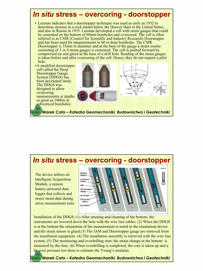
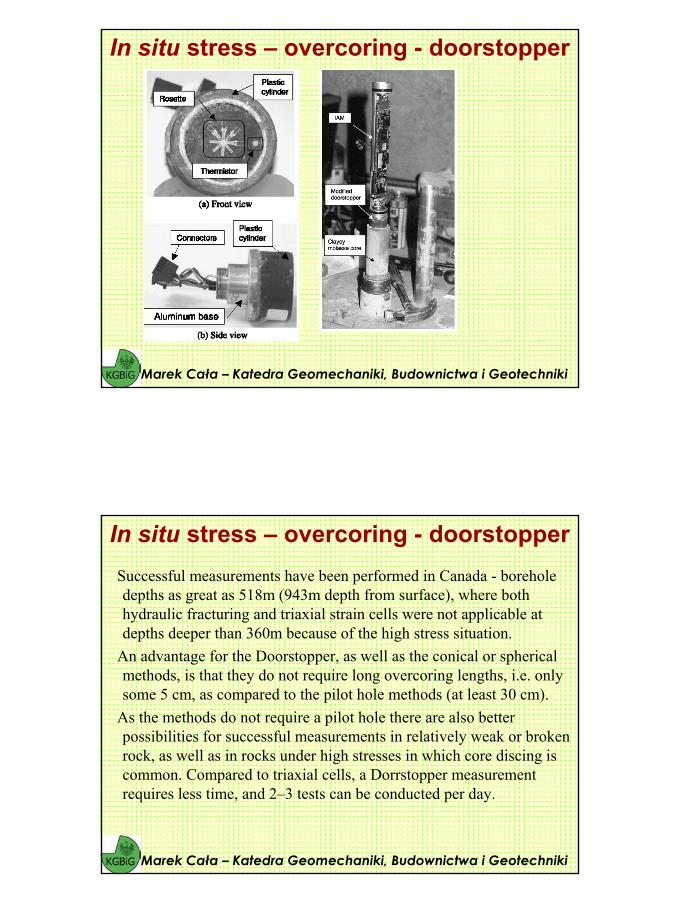
•A modified doorstopper cell called the Deep Doorstopper Gauge System (DDGS) has been developed lately. The DDGS was designed to allow overcoringmeasurements at depths as great as 1000m insubvertical boreholes.
The device utilises an Intelligent Acquisition Module, a remote battery-powered datalogger that collects and stores strain data during stress measurement tests.
Marek Cała – Katedra Geomechaniki, Budownictwa i Geotechniki
In situ stress – overcoring - doorstopper
Installation of the DDGS: (1) After attening and cleaning of the bottom, the instruments are lowered down the hole with the wire line cables. (2) When the DDGS is at the bottom the orientation of the measurement is noted in the orientation device and the strain sensor is glued.(3) The IAM and Doorstopper gauge are removed from the installation equipment. (4) The installation assembly is retrieved with the wire linesystem. (5) The monitoring and overdrilling start, the strain change in the bottom is measured by the time. (6) When overdrilling is completed, the core is taken up and a bi-axial pressure test done to estimate the Young’s modulus.
33
Marek Cała – Katedra Geomechaniki, Budownictwa i Geotechniki
In situ stress – overcoring - doorstopper
Successful measurements have been performed in Canada - boreholedepths as great as 518m (943m depth from surface), where both hydraulic fracturing and triaxial strain cells were not applicable at depths deeper than 360m because of the high stress situation.
An advantage for the Doorstopper, as well as the conical or spherical methods, is that they do not require long overcoring lengths, i.e. only some 5 cm, as compared to the pilot hole methods (at least 30 cm).
As the methods do not require a pilot hole there are also better possibilities for successful measurements in relatively weak or broken rock, as well as in rocks under high stresses in which core discing is common. Compared to triaxial cells, a Dorrstopper measurementrequires less time, and 2–3 tests can be conducted per day.
Marek Cała – Katedra Geomechaniki, Budownictwa i Geotechniki
In situ stress – overcoring - doorstopper
34
• Like the Doorstopper, a small length of the rock is required for overcoring.
• For the conical cell, the stress relief is achieved at an overcoring distance of 70mm and then the strains remain at constant values.
• Hemispherical or conical strain cells have mostly been used inJapan and successful applications have been reported in the literature.
• The disadvantage with the doorstopper is, however, that measurement at one point only enables the stresses in the plane perpendicular to the borehole to be determined.
• Furthermore, the end of the borehole must be flat which require polishing of the hole bottom.
• Disadvantages with the conical or hemispherical cell are that theyrequire preparation of the borehole bottom, either in the form of a cone or as a sphere.
• Another limitation is their poor success in water-filled boreholes.
Marek Cała – Katedra Geomechaniki, Budownictwa i Geotechniki
In situ stress – doorstopper - pluses & minuses
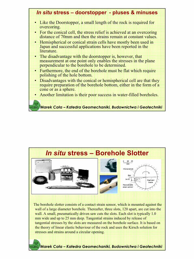
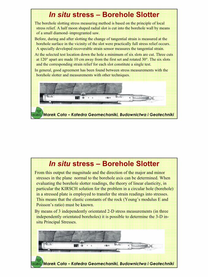
The borehole slotter consists of a contact strain sensor, which is mounted against the wall of a large diameter borehole. Thereafter, three slots, 120 apart, are cut into the wall. A small, pneumatically driven saw cuts the slots. Each slot is typically 1.0mm wide and up to 25 mm deep. Tangential strains induced by release of tangential stresses by the slots are measured on the borehole surface. It is based on the theory of linear elastic behaviour of the rock and uses the Kirsch solution for stresses and strains around a circular opening.
Marek Cała – Katedra Geomechaniki, Budownictwa i Geotechniki
In situ stress – Borehole Slotter
35
The borehole slotting stress measuring method is based on the principle of local stress relief. A half moon shaped radial slot is cut into the borehole wall by means of a small diamond–impregranted saw.
Before, during and after slotting the change of tangential strain is measured at the borehole surface in the vicinity of the slot were practically full stress relief occurs. A specially developed recoverable strain sensor measures the tangential strain.
At the selected test location down the hole a minimum of six slots are cut. Three cuts at 120° apart are made 10 cm away from the first set and rotated 30°. The six slots and the corresponding strain relief for each slot constitute a single test.
In general, good agreement has been found between stress measurements with the borehole slotter and measurements with other techniques.
Marek Cała – Katedra Geomechaniki, Budownictwa i Geotechniki
In situ stress – Borehole Slotter
From this output the magnitude and the direction of the major and minor stresses in the plane normal to the borehole axis can be determined. When evaluating the borehole slotter readings, the theory of linear elasticity, in particular the KIRSCH solution for the problem in a circular hole (borehole) in a stressed plate is employed to transfer the strain readings into stresses. This means that the elastic constants of the rock (Young’s modulus E and Poisson’s ratio) must be known.
By means of 3 independently orientated 2-D stress measurements (in three independently orientated boreholes) it is possible to determine the 3-D in-situ Principal Stresses.
Marek Cała – Katedra Geomechaniki, Budownictwa i Geotechniki
In situ stress – Borehole Slotter
36
Suitable for diamond drilled boreholes of 95 – 103 mmNo over-coringFully recoverable probe, maximal depth 30 m (standard)Dry boreholes of any inclination; no preparationParticular economy: One 2-D stress measurement in only 40 minutes: 10
stress measurements in a single 8 hour shiftExtreme measurement density of up to 10 measurements per borehole meter allows delineation of geological and technical stress profilesInstantaneous control of the measurement during testing and adjustment of the measuring strategyMeasurements in three independently orientated boreholes allows determination of the in-situ 3-D Principal Stresses.
Marek Cała – Katedra Geomechaniki, Budownictwa i Geotechniki
In situ stress – Borehole Slotter
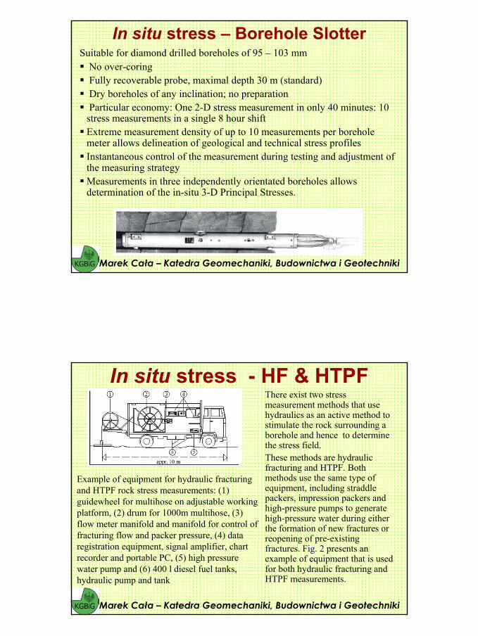
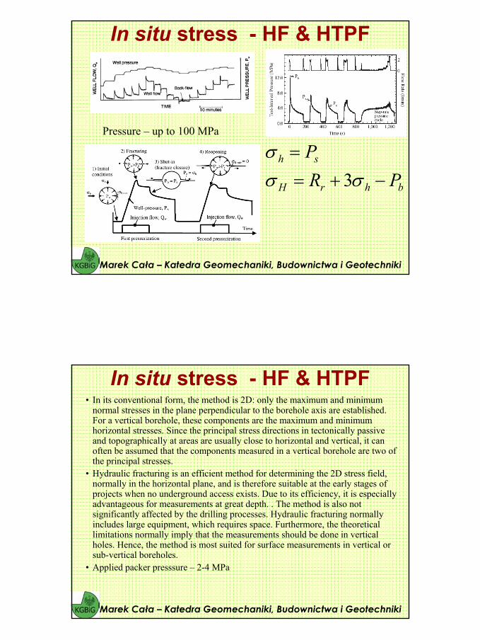
In situ stress - HF & HTPFThere exist two stress measurement methods that usehydraulics as an active method to stimulate the rock surrounding a borehole and hence to determine the stress field. These methods are hydraulic fracturing and HTPF. Both methods use the same type of equipment, including straddle packers, impression packers andhigh-pressure pumps to generate high-pressure water during either the formation of new fractures or reopening of pre-existing fractures. Fig. 2 presents an example of equipment that is used for both hydraulic fracturing and HTPF measurements.
Marek Cała – Katedra Geomechaniki, Budownictwa i Geotechniki
Example of equipment for hydraulic fracturing and HTPF rock stress measurements: (1)guidewheel for multihose on adjustable workingplatform, (2) drum for 1000m multihose, (3) flow meter manifold and manifold for control of fracturing flow and packer pressure, (4) data registration equipment, signal amplifier, chartrecorder and portable PC, (5) high pressure water pump and (6) 400 l diesel fuel tanks, hydraulic pump and tank
37
In situ stress - HF & HTPF
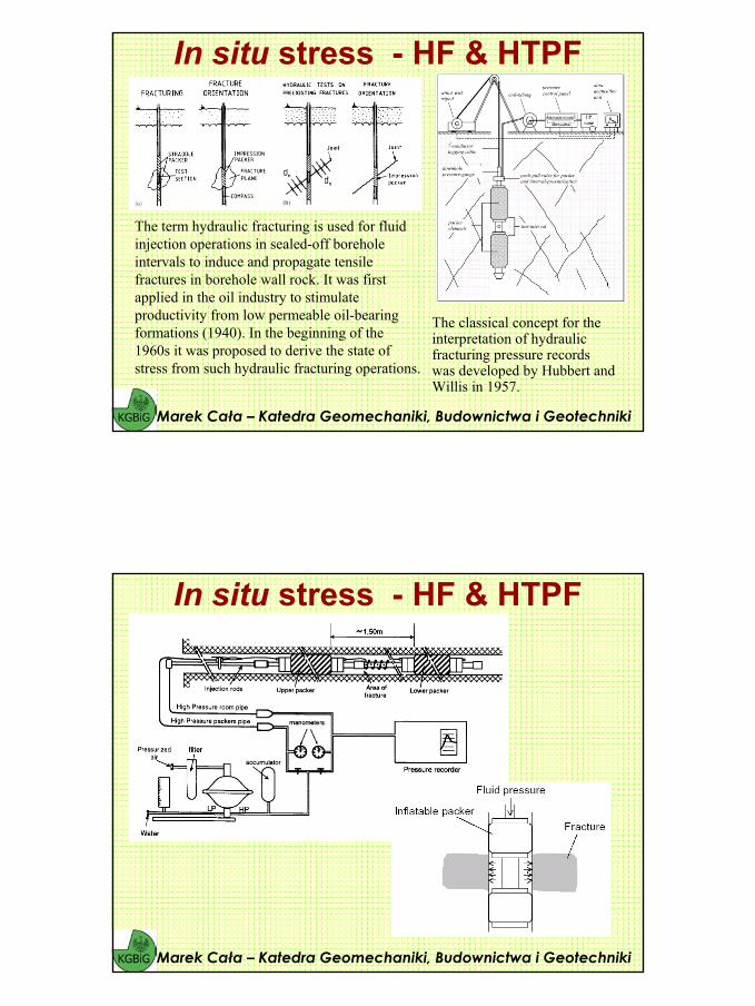
The term hydraulic fracturing is used for fluidinjection operations in sealed-off borehole intervals to induce and propagate tensile fractures in borehole wall rock. It was firstapplied in the oil industry to stimulate productivity from low permeable oil-bearing formations (1940). In the beginning of the1960s it was proposed to derive the state of stress from such hydraulic fracturing operations.
Marek Cała – Katedra Geomechaniki, Budownictwa i Geotechniki
The classical concept for the interpretation of hydraulic fracturing pressure records was developed by Hubbert and Willis in 1957.
In situ stress - HF & HTPF
Marek Cała – Katedra Geomechaniki, Budownictwa i Geotechniki
38
In situ stress - HF & HTPF
Marek Cała – Katedra Geomechaniki, Budownictwa i Geotechniki
There is no theoretical limit to the depth of measurement, provided a stable borehole can access the zone of interest and the rock is elastic and brittle.Classical interpretation of an HF test is possible only if the borehole axis is parallel to one of the principal stresses and is contained in the induced fracture plane. The initiation of ‘en echelon’ fractures may indicate that the borehole axis is not along a principal stress. Excessive deviation invalidates the classical method of interpretation of test results.Principal stress directions are derived from the fracture delineation on theborehole wall under the assumption that fracture attitude persists away from the hole.Evaluation of the maximum principal stress in the plane perpendicular to the borehole axis assumes that the rock mass is linearly elastic, homogeneous, and isotropic. It involves considerations of pore pressureeffects, often dif.cult to ascertain, and requires an assessment of the rock tensile strength.
The following points should be noted with respect to HF:
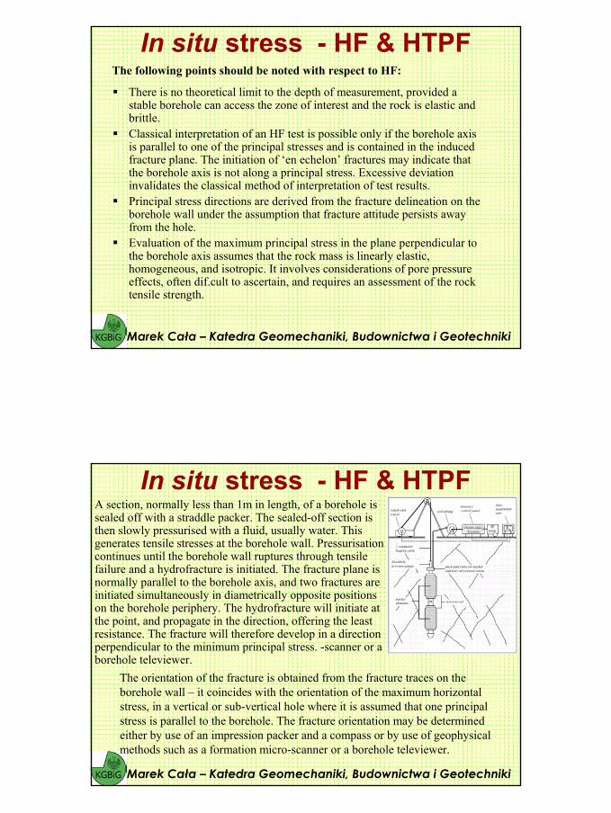
In situ stress - HF & HTPFA section, normally less than 1m in length, of a borehole is sealed off with a straddle packer. The sealed-off section is then slowly pressurised with a fluid, usually water. This generates tensile stresses at the borehole wall. Pressurisation continues until the borehole wall ruptures through tensile failure and a hydrofracture is initiated. The fracture plane is normally parallel to the borehole axis, and two fractures are initiated simultaneously in diametrically opposite positions on the borehole periphery. The hydrofracture will initiate at the point, and propagate in the direction, offering the least resistance. The fracture will therefore develop in a directionperpendicular to the minimum principal stress. -scanner or a borehole televiewer.
Marek Cała – Katedra Geomechaniki, Budownictwa i Geotechniki
The orientation of the fracture is obtained from the fracture traces on the borehole wall – it coincides with the orientation of the maximum horizontal stress, in a vertical or sub-vertical hole where it is assumed that one principal stress is parallel to the borehole. The fracture orientation may be determinedeither by use of an impression packer and a compass or by use of geophysical methods such as a formation micro-scanner or a borehole televiewer.
39
In situ stress - HF & HTPF
Marek Cała – Katedra Geomechaniki, Budownictwa i Geotechniki
Pressure – up to 100 MPa
bhrH
sh
PRP
−+==
σσσ
3
In situ stress - HF & HTPF• In its conventional form, the method is 2D: only the maximum and minimum
normal stresses in the plane perpendicular to the borehole axis are established. For a vertical borehole, these components are the maximum and minimum horizontal stresses. Since the principal stress directions in tectonically passive and topographically at areas are usually close to horizontal and vertical, it can often be assumed that the components measured in a vertical borehole are two of the principal stresses.
• Hydraulic fracturing is an efficient method for determining the 2D stress field, normally in the horizontal plane, and is therefore suitable at the early stages of projects when no underground access exists. Due to its efficiency, it is especially advantageous for measurements at great depth. . The method is also notsignificantly affected by the drilling processes. Hydraulic fracturing normally includes large equipment, which requires space. Furthermore, the theoretical limitations normally imply that the measurements should be done in vertical holes. Hence, the method is most suited for surface measurements in vertical or sub-vertical boreholes.
• Applied packer presssure – 2-4 MPa
Marek Cała – Katedra Geomechaniki, Budownictwa i Geotechniki
40
In situ stress - HF & HTPF• The hydraulic fracturing method allows a direct measurement of the least stress
in the plane perpendicular to the borehole axis, which is normally the leasthorizontal stress, σh and the accuracy is good (±5%). The maximum horizontal stress is calculated from equations including a failure criteria and parametersevaluated from the field pressure data. The accuracy is less good for the maximum horizontal stress (B710– 20% or more). It is shown that the general theory for calculating the major horizontal stress from the hydraulic fracturing suffers from uncertainties in the assumptions—a continuous, linearly elastic, homogenous, and isotropic rock together with the fracture reopening. It is probable that the major horizontal stress, determined from hydraulic fracturing, may be somewhat underestimated when the major principal stress divided by the minor principal stress is close to, or higher than, a factor of 3.
• Classical hydraulic fracturing requires sections in the borehole free from fractures. These sections should be at least a few meters long so that the induced fractures do not interact with existing ones. Hydraulic fracturing may be dif.cult to apply with an acceptable success rate in rock domains with very high stresses, such as when core discing is indicated in the core from core drilling. Geological features, such as foliation planes in gneissic rock, may also affect the possibilities of success as they act as weakness planes and thereby may control the direction
of the initiated fracture.
Marek Cała – Katedra Geomechaniki, Budownictwa i Geotechniki
In situ stress - HF & HTPF
Marek Cała – Katedra Geomechaniki, Budownictwa i Geotechniki
There is no theoretical limit to the depth of measurement, provided a stable borehole can access the zone of interest.The method assumes that isolated pre-existing fractures, or weakness planes, are present in the rock mass, that they are not all aligned within a narrow range of directions and inclinations, and that they can be mechanically opened by hydraulic tests. When the straddled interval includes multiple fractures, it is necessary to verify that only one single fracture hasbeen opened, for the opening of pre-existing fractures change the local stress field.Fractures used in stress computations are delineated on the borehole wall under the assumption that their orientation persists away from the hole.For a complete stress tensor determination, the method requires a theoretical minimum of six tests, each conducted on pre-existing non-parallel fractures; but additional tests are recommended in order to correct for uncertainties. However, when combined with HF tests, only three–four HTPF results are necessary for the maximum horizontal and vertical stress components determination.The method is valid for all borehole orientations. It is independent of pore pressure effects and does not require any material property determination.It assumes that the rock mass is homogeneous within the volume of interest. When tested fractures are distant from one another by more than 50 m, a hypothesis on stress gradients is required.
The following points should be noted with respect to HTPF:

41
In situ stress - HF & HTPF• The HTPF method has been practised for some 15 years. Instead of
inducing new fractures in intact rock, the HTPF method is based on the re-opening of existing fractures found in the borehole wall and therebydetermining the normal stress across the fracture plane. Depending on assumptions made regarding the stress field, the HTPF method allows either a 3D or 2D determination of the stress state. A 3D determinationrequires a larger number of fractures to be tested.
• When conducting HTPF tests, it is of importance that the fracture tested is of a size at which the normal stress can be assumed to be uniform and the geometry of the fracture must be planar. The HTPF method relies only on four field parameters; test depth, shut-in pressure, dip and strike of the tested fracture.
Marek Cała – Katedra Geomechaniki, Budownictwa i Geotechniki
• The shut-in pressure is equivalent to the normal stress acting across the fractureplane. Given these parameters for asufficiently large number of fractures with different strike and dips, either the 2D or 3D stress state can be determined.
In situ stress - HF & HTPFTheoretically the 2D solution requires at least six different fractures to solve the problem. In practise some redundancy, however, is required. For successful measurements, it is suggested that at least 10–12 isolated, pre-existing fractures with different strikes and dips are found and tested in the borehole wall within the depth interval of interest. The 3D alternative of the HTPF method includes less assumptions on the stress field but requires a larger number of fractures to be tested. In the3D alternative the vertical stress does not have to be a principal stress. Theoretically, 12 unknowns exist in the system of equations. In practise, it is suggested that at least 18–20 successful tests are obtained to resolve the 3D stress field.
Marek Cała – Katedra Geomechaniki, Budownictwa i Geotechniki
42
• As compared to classical hydraulic fracturing, the method has the advantages of less limitations as regards geological features.
• Nor does the method require determination of the tensile strength of the rock and it is independent of pore pressure effects.
• As long as a variation in strike and dip of the existing fractures exists in the rock mass, neither weakness planes such as foliation planes nor core discing should cause any problems in obtaining successful measurements.
• The method is more time consuming than hydraulic fracturing as the down-hole equipment must be positioned at the exact location of each discrete fracture to be tested.
• This requires good accuracy in the depth calibration. A drawback,compared to hydraulic fracturing, is also that no preliminary results can be obtained until all field-testing has been completed, field data evaluated and those data processed using computercodes.
Marek Cała – Katedra Geomechaniki, Budownictwa i Geotechniki
In situ stress - HF & HTPF – pluses & minuses
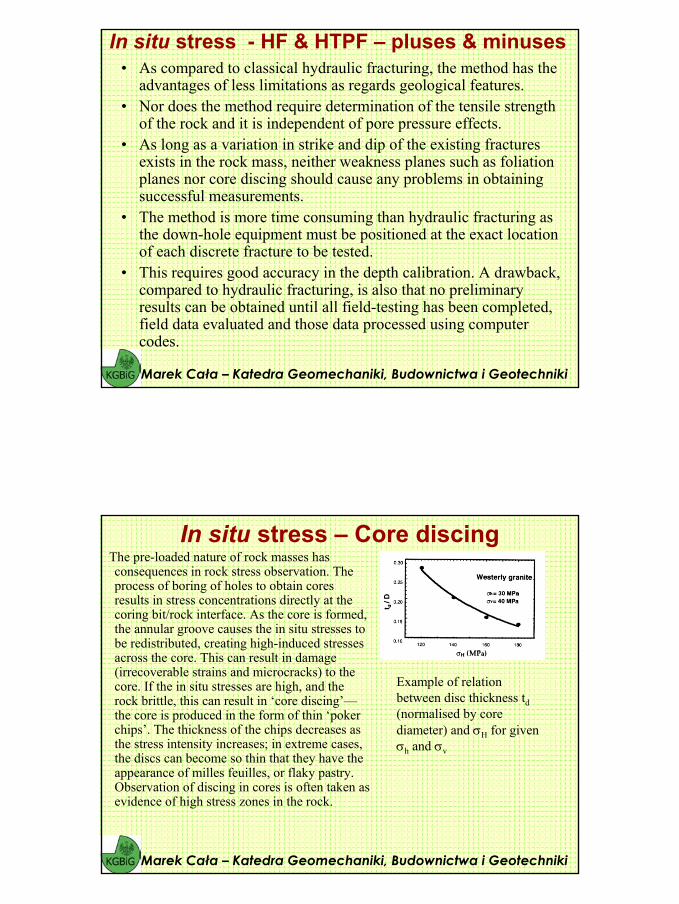
The pre-loaded nature of rock masses has consequences in rock stress observation. The process of boring of holes to obtain cores results in stress concentrations directly at the coring bit/rock interface. As the core is formed, the annular groove causes the in situ stresses to be redistributed, creating high-induced stresses across the core. This can result in damage(irrecoverable strains and microcracks) to the core. If the in situ stresses are high, and the rock brittle, this can result in ‘core discing’—the core is produced in the form of thin ‘poker chips’. The thickness of the chips decreases as the stress intensity increases; in extreme cases, the discs can become so thin that they have theappearance of milles feuilles, or flaky pastry. Observation of discing in cores is often taken as evidence of high stress zones in the rock.
Marek Cała – Katedra Geomechaniki, Budownictwa i Geotechniki
In situ stress – Core discing
Example of relation between disc thickness td(normalised by core diameter) and σH for givenσh and σv
43
The following minimum information is needed for the interpretation:
• the tensile strength of the rock,• Poisson’s ratio of the rock,• the uniaxial compressive strength of the rock,• the mean disc spacing,• the shape of the fracture (morphology) and• the extent of the fracture in the core.The confidence of the interpretation can be increased considerably if the same information can be achieved from both normal coring and overcoring at the same depth level. In practice, core discing can only be used as an indicator for estimation of rock stresses. When corediscing occurs, one can of course also conclude that rockstress concentrations are higher than the rock strength.Such information, obtained already during the drillingstage, is of course valuable and a guide for furtherdecisions.
Marek Cała – Katedra Geomechaniki, Budownictwa i Geotechniki
In situ stress – Core discing
Marek Cała – Katedra Geomechaniki, Budownictwa i Geotechniki
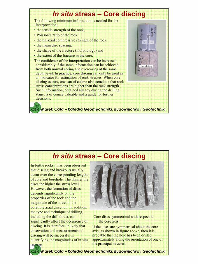
In situ stress – Core discing
Core discs symmetrical with respect to the core axis
In brittle rocks it has been observed that discing and breakouts usually occur over the corresponding lengths of core and borehole. The thinner the discs the higher the stress level. However, the formation of discs depends significantly on the properties of the rock and the magnitude of the stress in the borehole axial direction. In addition, the type and technique of drilling,including the drill thrust, can significantly affect the occurrence of discing. It is therefore unlikely that observation and measurements ofdiscing will be successful in quantifying the magnitudes of in situ stresses.
If the discs are symmetrical about the core axis, as shown in figure above, then it is probable that the hole has been drilled approximately along the orientation of one of the principal stresses.
44
Marek Cała – Katedra Geomechaniki, Budownictwa i Geotechniki
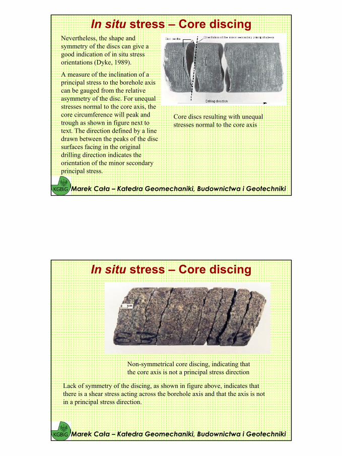
In situ stress – Core discingNevertheless, the shape and symmetry of the discs can give agood indication of in situ stress orientations (Dyke, 1989).
A measure of the inclination of a principal stress to the borehole axis can be gauged from the relative asymmetry of the disc. For unequal stresses normal to the core axis, the core circumference will peak and trough as shown in figure next to text. The direction defined by a line drawn between the peaks of the disc surfaces facing in the original drilling direction indicates theorientation of the minor secondary principal stress.
Core discs resulting with unequal stresses normal to the core axis
Marek Cała – Katedra Geomechaniki, Budownictwa i Geotechniki
In situ stress – Core discing
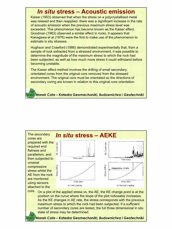
Lack of symmetry of the discing, as shown in figure above, indicates that there is a shear stress acting across the borehole axis and that the axis is not in a principal stress direction.
Non-symmetrical core discing, indicating that the core axis is not a principal stress direction
45
Marek Cała – Katedra Geomechaniki, Budownictwa i Geotechniki
In situ stress – Acoustic emissionKaiser (1953) observed that when the stress on a polycrystallised metal was relaxed and then reapplied, there was a significant increase in the rate of acoustic emission when the previous maximum stress level was exceeded. This phenomenon has become known as the Kaiser effect.Goodman (1963) observed a similar effect in rocks. It appears that Kanagawa et al (1976) were the first to make use of the phenomenon to estimate in situ stresses.
Hughson and Crawford (1986) demonstrated experimentally that, from a sample of rock extracted from a stressed environment, it was possible to determine the magnitude of the maximum stress to which the rock had been subjected, as well as how much more stress it could withstand beforebecoming unstable.
The Kaiser effect method involves the drilling of small secondary, orientated cores from the original core removed from the stressedenvironment. The original core must be orientated so the directions of secondary coring are known in relation to this original core orientation.
Marek Cała – Katedra Geomechaniki, Budownictwa i Geotechniki
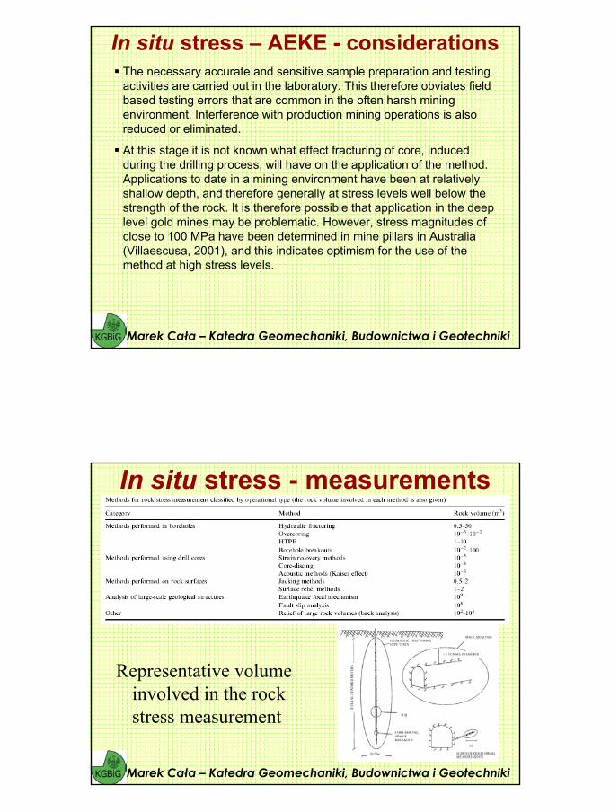
In situ stress – AEKE The secondarycores are prepared with the required end flatness and parallelism, and then subjected to uniaxialcompressive stress whilst the AE from the rock are monitored using sensorsattached to the core. On a plot of the applied stress vs. the AE, the KE change point is at the
position on the curve where the slope of the plot noticeably increases. As the KE changes in AE rate, the stress corresponds with the previousmaximum stress to which the rock had been subjected. If a sufficient number of secondary cores are tested, the full three dimensional in situ state of stress may be determined.
46
Marek Cała – Katedra Geomechaniki, Budownictwa i Geotechniki
In situ stress – AEKE The KE does not occur abruptly at a precisely definable point, but within atransitional zone. The position and abruptness of this zone varies for different types of rock materials, and with the magnitude of the previous stress relative to the strength of the rock. The transition zone becomes large and indistinct if the maximum stress exposure time was brief.
The stress “memory” reduces over time, and hence it is necessary to carry out the tests within a relatively short time after removal of the original core. The length of the “memory” appears to depend on the type of rock. Kurita and Fujii (1979) conclude that no significant recovery of the KE occurs within one month of removal from the stressed environment. Friedel andThill (1990) found that the effect was retained for a period of up to at least 5 months. Other researchers have noted very much shorter retention periods, for example, several hours (Goodman, 1963), one to five days (Yoshikawa and Mogi (1981), three days (Boyce, 1981). These limitations are contradicted by the results of Seto et al (1998), who obtained satisfactory results for in situ stress determinations on cores that had been removed almost two years previously. Their results agreed to within 10% of values determined by other methods.
Marek Cała – Katedra Geomechaniki, Budownictwa i Geotechniki
In situ stress – AEKE - considerationsIt gives a direct measure of stress. It is not dependent on the measurement of strain and the subsequent calculation of stress from strain, which requires the assumption of a relationship between stress and strain for the rock as well as measurement of the deformation properties of the rock. All of these factors can introduce errors.
The full three dimensional in situ state of stress may be determined.
Use can be made of original core obtained for other purposes, such as exploration, making the method cost effective.
Core obtained remotely can be used, and therefore the method is applicable to greenfield sites, before any excavations have been made, as well as to operating mines.
Since small secondary cores are used for the tests, many tests can be carried out using a limited length of original borehole core. Again this makes the method cost effective, with a large number of results being able to be obtained at relatively low cost. The more the number of cores tested, the greater the confidence in the results obtained.
47
Marek Cała – Katedra Geomechaniki, Budownictwa i Geotechniki
In situ stress – AEKE - considerationsThe necessary accurate and sensitive sample preparation and testing activities are carried out in the laboratory. This therefore obviates field based testing errors that are common in the often harsh mining environment. Interference with production mining operations is alsoreduced or eliminated.
At this stage it is not known what effect fracturing of core, induced during the drilling process, will have on the application of the method. Applications to date in a mining environment have been at relatively shallow depth, and therefore generally at stress levels well below the strength of the rock. It is therefore possible that application in the deep level gold mines may be problematic. However, stress magnitudes of close to 100 MPa have been determined in mine pillars in Australia (Villaescusa, 2001), and this indicates optimism for the use of the method at high stress levels.
In situ stress - measurements
Representative volume involved in the rock stress measurement
Marek Cała – Katedra Geomechaniki, Budownictwa i Geotechniki