improving understanding of gasification of woody … 160113... · improving understanding of...
TRANSCRIPT
1
Improving understanding of gasification of woody biomass in a downdraft gasifier
Researcher Sanna Oikari1
Professor Jukka Konttinen2
Research Assistant Roshan Budhathoki2
1 Kokkola University Consortium Chydenius
2 University of Jyväskylä, Dept. of Chemistry
16.1.2013
2
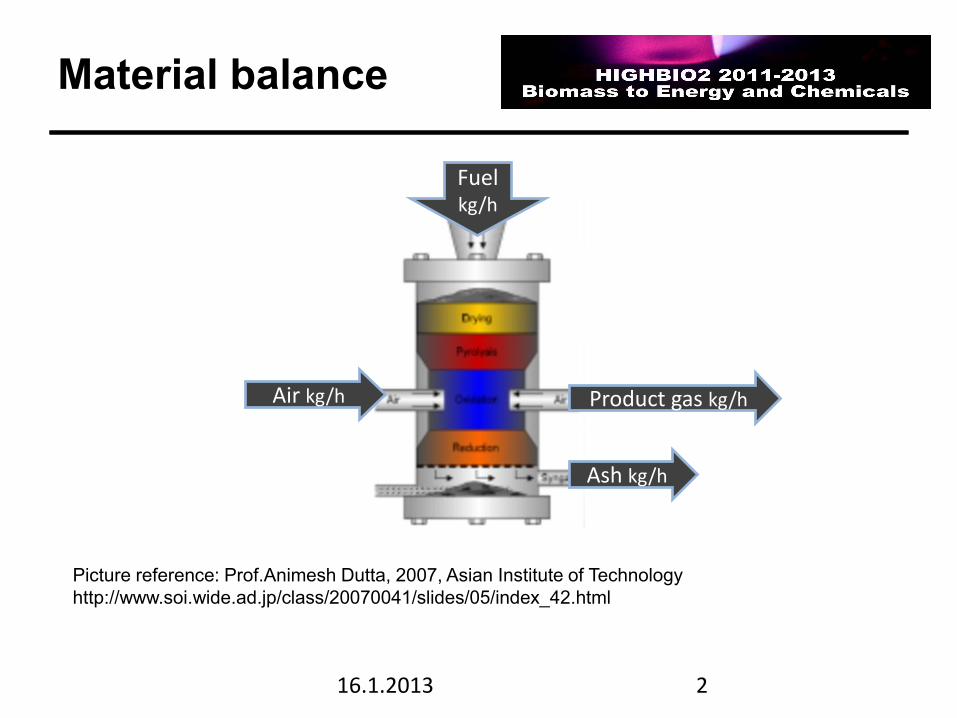
Material balance
16.1.2013
Picture reference: Prof.Animesh Dutta, 2007, Asian Institute of Technology
http://www.soi.wide.ad.jp/class/20070041/slides/05/index_42.html
Fuel kg/h
Air kg/h Product gas kg/h
Ash kg/h
3
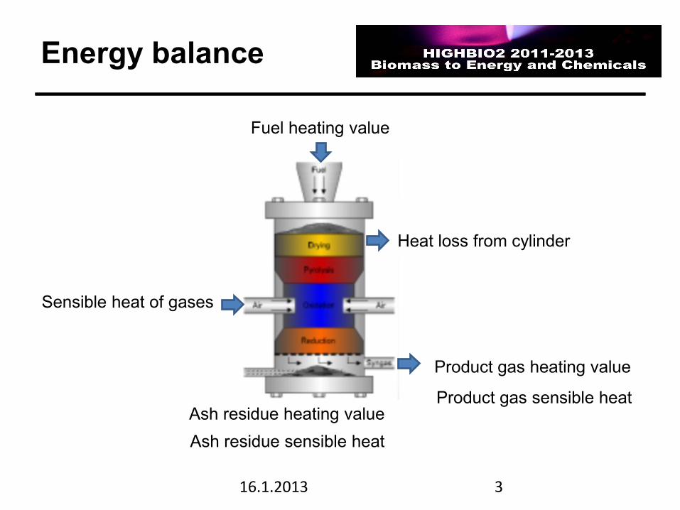
Energy balance
16.1.2013
Fuel heating value
Sensible heat of gases
Product gas heating value
Product gas sensible heat
Heat loss from cylinder
Ash residue heating value
Ash residue sensible heat
Measurements in Energy- and mass balance evaluations
16.1.2013 4
5
Balance measurements
16.1.2013
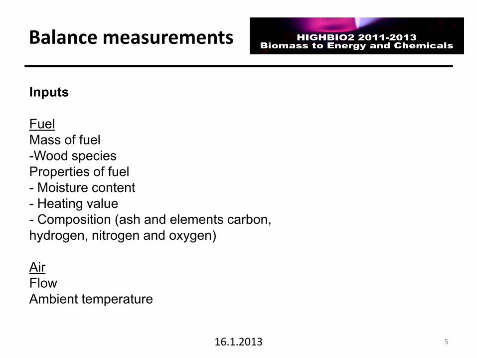
Inputs
Fuel
Mass of fuel
-Wood species
Properties of fuel
- Moisture content
- Heating value
- Composition (ash and elements carbon,
hydrogen, nitrogen and oxygen)
Air
Flow
Ambient temperature
6
Balance measurements
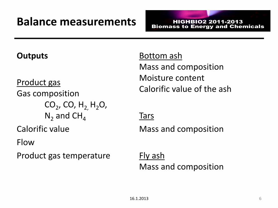
Outputs
Product gas Gas composition CO2, CO, H2, H2O, N2 and CH4
Calorific value
Flow
Product gas temperature
Bottom ash Mass and composition Moisture content Calorific value of the ash
Tars
Mass and composition
Fly ash Mass and composition
16.1.2013
7
Balance measurements
General
• Duration of experiment
• Pressure in process
• Measuring devices used
• Temperatures in furnace (measured at a specific point)
16.1.2013
8
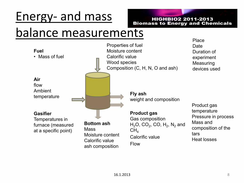
Energy- and mass balance measurements
16.1.2013
Place
Date
Duration of
experiment
Measuring
devices used
Fuel
• Mass of fuel
Air
flow
Ambient
temperature
Gasifier
Temperatures in
furnace (measured
at a specific point)
Properties of fuel
Moisture content
Calorific value
Wood species
Composition (C, H, N, O and ash)
Product gas
temperature
Pressure in process
Mass and
composition of the
tars
Heat losses
Bottom ash
Mass
Moisture content
Calorific value
ash composition
Fly ash
weight and composition
Product gas
Gas composition
H2O, CO2, CO, H2, N2 and
CH4
Calorific value
Flow
9
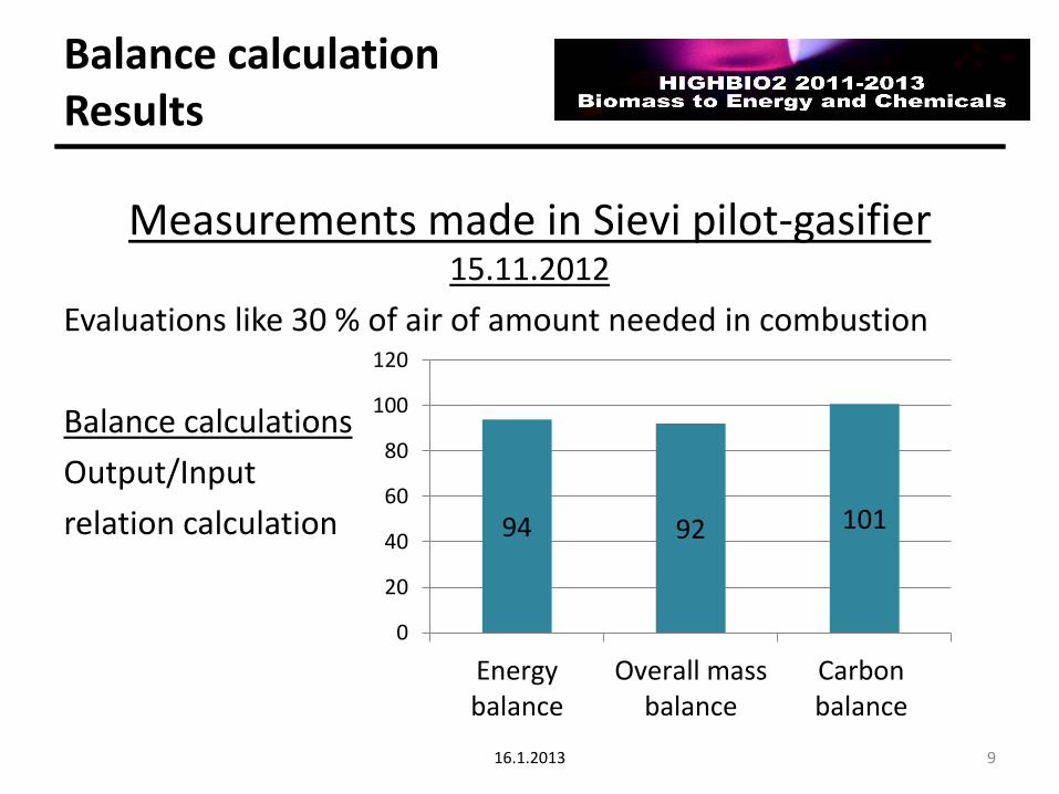
Balance calculation Results
Measurements made in Sievi pilot-gasifier 15.11.2012
Evaluations like 30 % of air of amount needed in combustion
Balance calculations
Output/Input
relation calculation
16.1.2013
94 92 101
0
20
40
60
80
100
120
Energybalance
Overall massbalance
Carbonbalance
10
Modeling benefits • Simulation • A working model can also be applied in design of a
commercial process • Also operator training can become possible
• Understand phenomenon more deeply optimization of gasification process Model needs to be validated with experimental results
16.1.2013
Three zone equilibrium modeling of Fixed bed Gasifier
Research Assistant Roshan Budhathoki
University of Jyväskylä, Dept. of Chemistry
11 16.1.2013
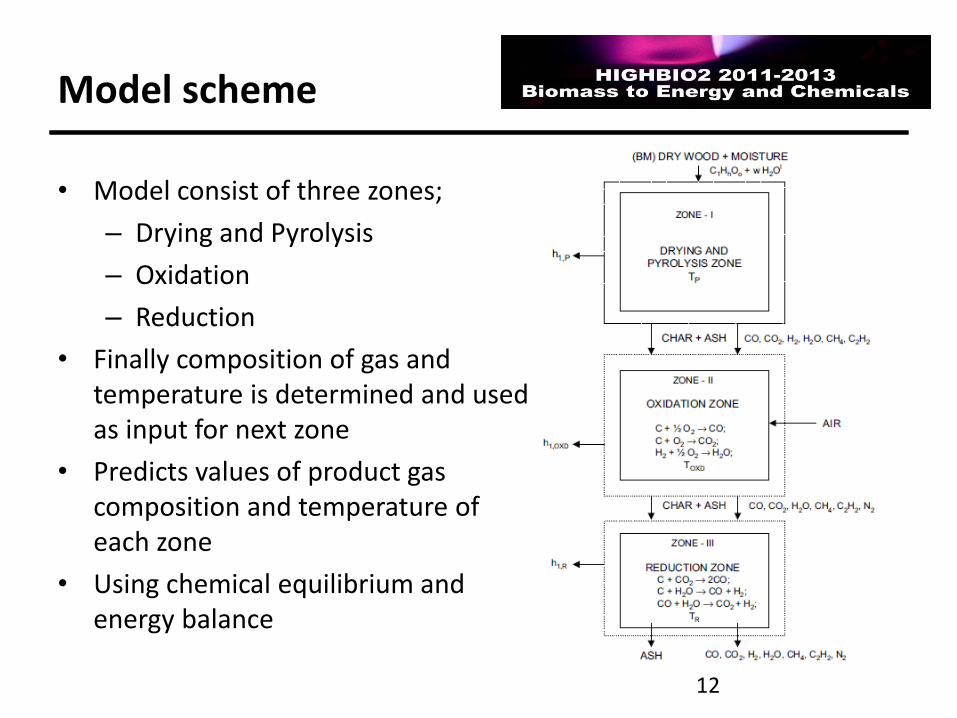
Model scheme
12
• Model consist of three zones;
– Drying and Pyrolysis
– Oxidation
– Reduction
• Finally composition of gas and temperature is determined and used as input for next zone
• Predicts values of product gas composition and temperature of each zone
• Using chemical equilibrium and energy balance
13
Model References
• GILTRAP D.L. et al. A steady state model of gas-char reactions in a downdraft biomass gasifier. Solar Energy, January 2003, Vol. 74, Issue 1, pp. 85-91.
• WANG Y and KINOSHITA C.M. Kinetic model of biomass gasification. Solar Energy, 1993, Vol. 51, pp. 19-25.
• BABU B.V. and SHETH P.N. Modeling and Simulation of Reduction Zone of Downdraft Biomass Gasifier: Effect of Char Reactivity Factor. Energy Conversion and Management, September 2006, Vol. 47, Issues 15-16, pp. 2602-2611
• BABU B.V. and SHETH P.N. Modeling and Simulation of Reduction Zone of Downdraft Biomass Gasifier: Effect of Air to Fuel Ratio. Journal on Engineering and Technology, 2007, Vol. 2, Issue 3, pp. 35-40
• GAO N. and LI A. Modeling and simulation of combined pyrolysis and reduction zone for a downdraft biomass gasifier. Energy Conversion and Management, December 2008, Vol. 49, Issue 12, pp. 3483-3490.
16.1.2013
14
Model References
• KOUFOPANOS C.A., LUCCHESI A. and MASCHIO G. Kinetic modelling of the pyrolysis of biomass and biomass components. The Canadian Journal of Chemical Engineering, February 1989, Vol. 67, Issue 1, pp. 75–84.
• ROY P.C., DATTA A. and CHAKRABORTY N. Modelling of a downdraft biomass gasifier with finite rate kinetics in the reduction zone. International Journal of Energy Research, July 2009, Vol. 33, Issue 9, pp. 833-851.
• ZAINAL Z. A. et al. Prediction of performance of a downdraft gasifier using equilibrium modeling for different biomass materials. Energy Conversion and Management, August 2001, Vol. 42, Issue 12, pp. 1499-1515
• RATNADHARIYA J.K. and CHANNIWALA S.A. Three zone equilibrium and kinetic free modeling of biomass gasifier – a novel approach. Renewable Energy, April 2009, Vol. 34, Issue 4, pp. 1050-1058.
• THUNMAN H. et al. Composition of Volatile Gases and Thermochemical Properties of Wood for Modeling of Fixed or Fluidized Beds. Energy Fuels, 2001, Vol. 15, Issue 6, pp. 1488-1497.
16.1.2013
Assumptions
• Process is isobaric
• The char is modeled as graphite carbon
• Char carry over is negligible
• No heat transfer between the zones
• The overall heat loss is assumed to be 10% of the product of equivalence ratio and HHV of fuel. – Q Tot = 10% × φ ×HHV
• Heat loss in pyrolysis, oxidation and reduction are assumed to be 25, 40 and 35% respectively
• Lamda assumed to be 0,27
15 16.1.2013
16
Assumptions
• Assumptions for pyrolysis zone
– 4/5 of oxygen is associated with fuel H in the form of H2O
– 1/5 of fuel oxygen is associated with fuel carbon and released as CO and CO2
– Etc
• Assumptions for oxidation zone
– Acetylene formed during pyrolysis is fully oxidized
– Hydrogen is also oxidized and converted into water
– Remaining oxygen is consumed in the char reduction to form CO and CO2
– Etc
16.1.2013
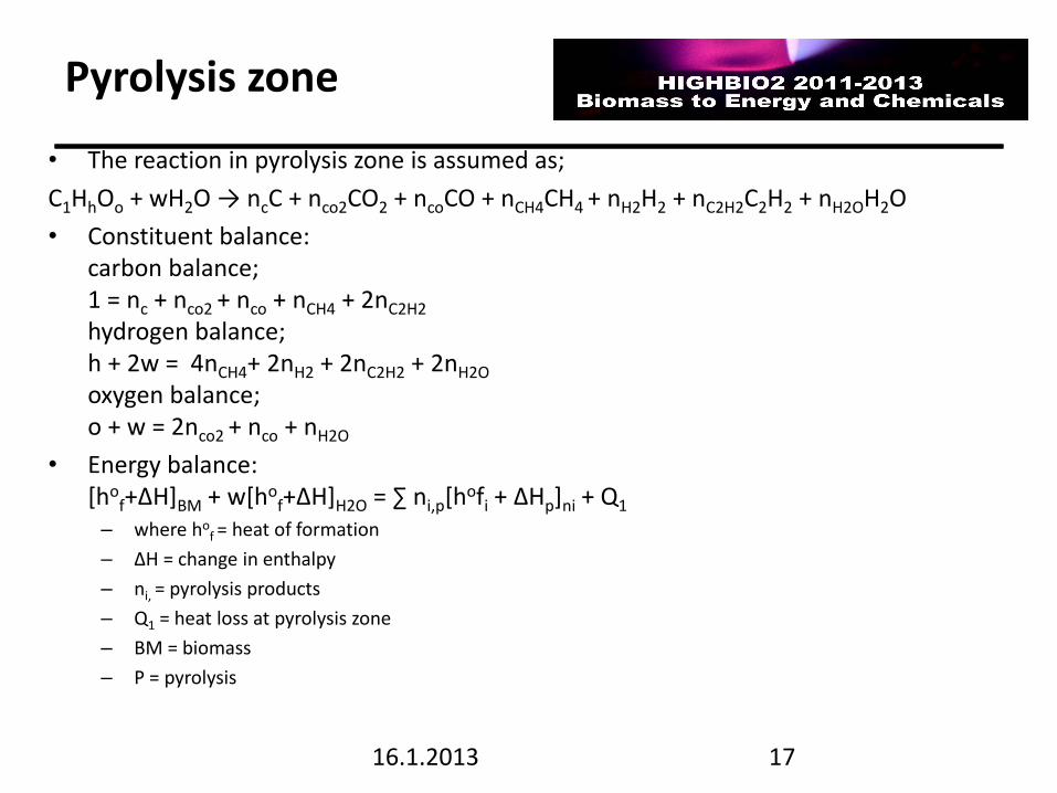
Pyrolysis zone
• The reaction in pyrolysis zone is assumed as;
C1HhOo + wH2O → ncC + nco2CO2 + ncoCO + nCH4CH4 + nH2H2 + nC2H2C2H2 + nH2OH2O
• Constituent balance: carbon balance; 1 = nc + nco2 + nco + nCH4 + 2nC2H2
hydrogen balance; h + 2w = 4nCH4+ 2nH2 + 2nC2H2 + 2nH2O oxygen balance; o + w = 2nco2 + nco + nH2O
• Energy balance: [ho
f+∆H]BM + w[hof+∆H]H2O = ∑ ni,p[hofi + ∆Hp]ni + Q1
– where hof = heat of formation
– ∆H = change in enthalpy
– ni, = pyrolysis products
– Q1 = heat loss at pyrolysis zone
– BM = biomass
– P = pyrolysis
17 16.1.2013
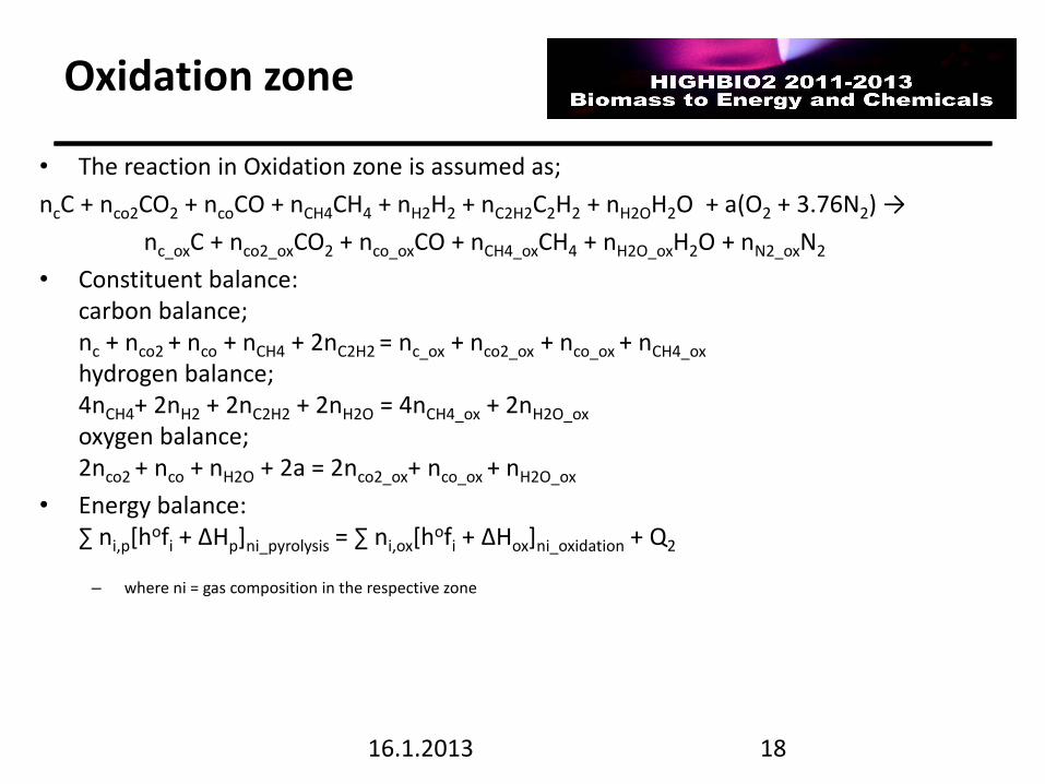
Oxidation zone
• The reaction in Oxidation zone is assumed as;
ncC + nco2CO2 + ncoCO + nCH4CH4 + nH2H2 + nC2H2C2H2 + nH2OH2O + a(O2 + 3.76N2) →
nc_oxC + nco2_oxCO2 + nco_oxCO + nCH4_oxCH4 + nH2O_oxH2O + nN2_oxN2
• Constituent balance: carbon balance; nc + nco2 + nco + nCH4 + 2nC2H2 = nc_ox + nco2_ox + nco_ox + nCH4_ox hydrogen balance; 4nCH4+ 2nH2 + 2nC2H2 + 2nH2O = 4nCH4_ox + 2nH2O_ox oxygen balance; 2nco2 + nco + nH2O + 2a = 2nco2_ox+ nco_ox + nH2O_ox
• Energy balance: ∑ ni,p[hofi + ∆Hp]ni_pyrolysis = ∑ ni,ox[h
ofi + ∆Hox]ni_oxidation + Q2 – where ni = gas composition in the respective zone
18 16.1.2013
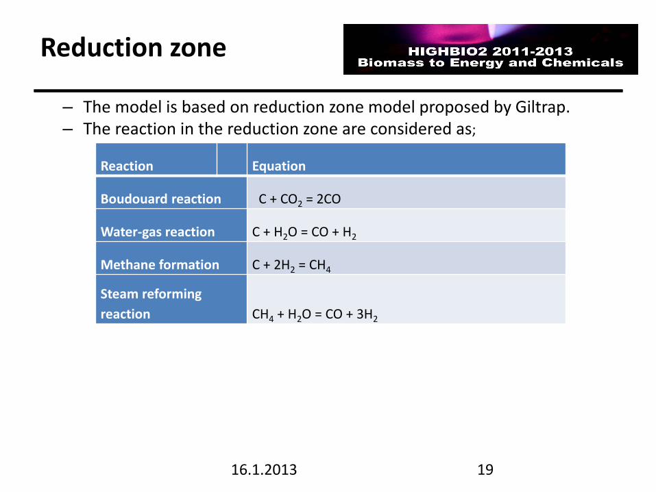
Reduction zone
– The model is based on reduction zone model proposed by Giltrap. – The reaction in the reduction zone are considered as;
19
Reaction Equation
Boudouard reaction C + CO2 = 2CO
Water-gas reaction C + H2O = CO + H2
Methane formation C + 2H2 = CH4
Steam reforming
reaction CH4 + H2O = CO + 3H2
16.1.2013
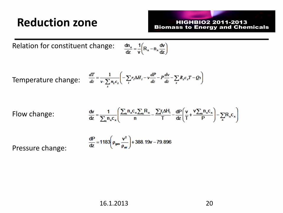
Reduction zone
Relation for constituent change:
Temperature change:
Flow change:
Pressure change:
20 16.1.2013
21
16.1.2013
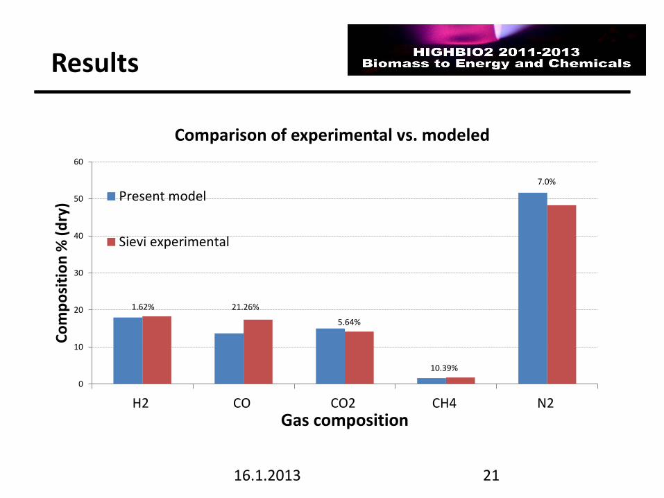
1.62% 21.26%
5.64%
10.39%
7.0%
0
10
20
30
40
50
60
H2 CO CO2 CH4 N2
Co
mp
osi
tio
n %
(d
ry)
Gas composition
Comparison of experimental vs. modeled
Present model
Sievi experimental
Results
22
16.1.2013
05
1015202530354045505560
0 5 10 15 20 25 30
Co
mp
osi
tio
n (
%)
Moisture content (%)
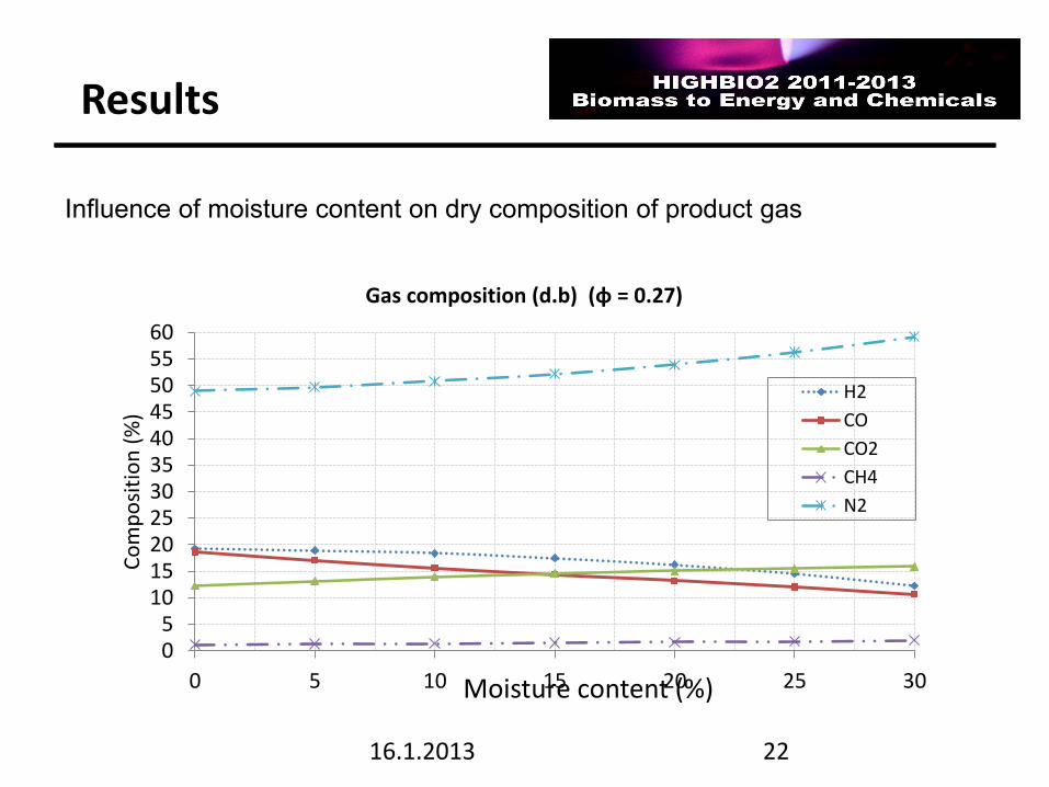
Gas composition (d.b) (φ = 0.27)
H2
CO
CO2
CH4
N2
Influence of moisture content on dry composition of product gas
Results
23
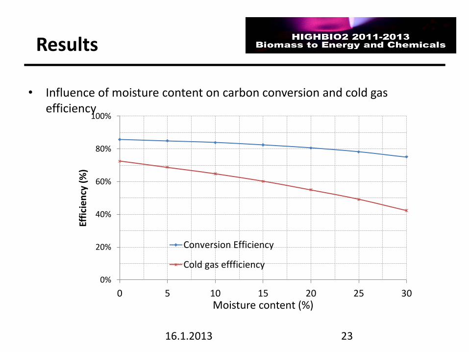
• Influence of moisture content on carbon conversion and cold gas efficiency
16.1.2013
0%
20%
40%
60%
80%
100%
0 5 10 15 20 25 30
Effi
cie
ncy
(%
)
Moisture content (%)
Conversion Efficiency
Cold gas effficiency
Results
24
16.1.2013
0
5
10
15
20
25
30
35
40
45
50
55
60
0,2 0,25 0,3 0,35 0,4 0,45
Co
mp
osi
tio
n (
%)
Equivalence ratio
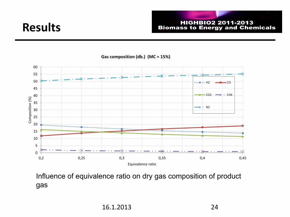
Gas composition (db.) (MC = 15%)
H2 CO
CO2 CH4
N2
Influence of equivalence ratio on dry gas composition of product
gas
Results
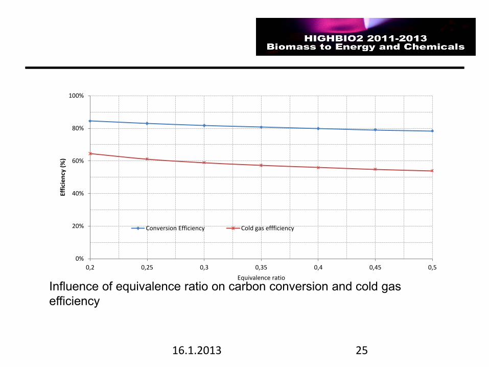
25 16.1.2013
0%
20%
40%
60%
80%
100%
0,2 0,25 0,3 0,35 0,4 0,45 0,5
Effi
cie
ncy
(%
)
Equivalence ratio
Conversion Efficiency Cold gas effficiency
Influence of equivalence ratio on carbon conversion and cold gas
efficiency
26
References
1. PIENINIEMI, K. ja MUILU, Y.; Kaasutus ja tuotekaasun analysointi, in book: Lassi, Ulla ja Wikman, Bodil (ed.), Biomassan kaasutus sähköksi, lämmöksi ja biopolttoaineiksi, HighBio projektijulkaisu, University of Jyväskylä, Kokkola University Consortium Chydenius, Kokkola 2011
Also available in swedish:
Lassi, Ulla ja Wikman, Bodil (ed.), Förgasning av biomassa till värme, elektricitet och biobränslen : publikation för HighBio-projektet, Jyväskylä universitet, Karleby universitetscenter Chydenius, Karleby 2011
2. MUILU, Y.; EK-puukaasu Loppuraportti, Centria tutkimus ja kehitys, Ylivieska, 15.09.2007
3. LAMPINEN, A.; Uusiutuvan liikenne-energian tiekartta. Pohjois-Karjalan
ammattikorkeakoulun julkaisuja B:17, Joensuu 2009, 437 s.4. ALAKANGAS, E. 2000.
Suomessa käytettävien polttoaineiden ominaisuuksia, Otamedia Oy, Espoo, Valtion
teknillinen tutkimuskeskus, VTT tiedotteita 2045.
16.1.2013
27
References
5. SOUZA-SANTOS, M.L. 2010. Solid Fuels Combustion and Gasification, Modeling, Simulation and Equipment Operations, CRC Press Taylor &Francis Group, London
6. David R. Lide (editor). CRC Handbook of Chemistry and Physics, 83rd edition 2002 – 2003. CRC Press LLC, Boca Raton, Florida, USA. p. 8 – 111. 2002
7. Picture reference: Prof.Animesh Dutta, 2007, Asian Institute of Technology http://www.soi.wide.ad.jp/class/20070041/slides/05/index_42.html
8. RATNADHARIYA J.K. and CHANNIWALA S.A. Three zone equilibrium and kinetic free modeling of biomass gasifier – a novel approach. Renewable Energy, April 2009, Vol. 34, Issue 4, pp. 1050-1058.
16.1.2013
28
Conclusions
Calculated mass and energy balances were rather near 100 %.
Model predicted product gas composition reasonable well.
A working model can also be applied in design of a commercial process.
Material and energy balances are one way to analyze and optimize gasification.
16.1.2013
29
16.1.2013