improving of transient stability of power systems by ... · pdf fileimproving of transient...
TRANSCRIPT

Improving of Transient Stability of Power Systems By supplementary
Controllers of UPFC Using Different Fault Conditions
A. KAZEMI and F. MAHAMNIA
Department of Electrical Engineering
Iran University of Science and Technology (IUST)
Tehran
IRAN
[email protected] [email protected]
Abstract-- Long distance AC transmission is often subject to stability problems , which limits the transmission
capability.Large interconnected power systems often suffer from weakly damped swings between
synchronous generators and subsystems.This paper presents two methods , based on the use of nonlinear
system model , to improve transient stability and damping of power swings using UPFC. A state- variable
control strategy has been derived using local available signals of real and reactive power. The results of
simulation tests of two control methods, undertaken using a small multi-machine system model, have been
presented. The simulations show that the methods make good results in different fault places and clearing
time. The results present that controlling series part of UPFC can improve transient stability by state-variable
control method, but simultaneous control of shunt and series part of UPFC can damp voltage oscillations by
direct Lyapunov method.
Key-Words: Transient stability, Local measurement, Flexible ac transmission systems (FACTS) , UPFC ,
Power oscillations damping.
1 Introduction Transient stability is the ability of the system to
return to a normal operating state and generators
remaining in synchoronism , following a large
disturbance , such as multi-phase short-circuit or
switching of lines.
Power systems exhibit various modes of oscillation
due to interactions among system components. Most
of the oscillations are due to synchronous generator
rotors swinging relative to each other. Stressed
power systems are known to exhibit nonlinear
behaviour. Load changes or faults are the main
causes of power oscillations.
If the oscillation is not controlled properly , it may
lead to a total or partial system outage. If no
adequate damping is possible, the oscillations may
be sustained for minutes affecting power flows and
grow to cause loss of synchronism between systems.
Application of power system stabilizer (PSS) has
been one of the first measures to enhance the
damping of power swings. With increasing
transmission line loading over long distances, the
use of conventional PSS might in some cases, not
provide sufficient damping for power swings. PSS
increases damping torque of a generator by affecting
the generator excitation control, while FACTS
devices improve damping by modulating the
equivalent power-angle characteristic of the power
system[1].To increase power system oscillation
stability, the installation of supplementary excitation
control, PSS, is a simple, effective and economical
method.
By using power electronics controllers a Flexible
AC Transmission System which offers greater
control of power flow, secure operation and
damping of power system oscillations. FACTS
devices are used in power systems to improve both
the steady state and dynamic performances of the
systems [2].
Damping can be improved by using one of the
flexible AC transmission systems (FACTS) devices,
which offers an alternative means to mitigate power
system oscillation. Thus, a question of great
importance is the selection of the input signals and a
control strategy for these devices in order to damp
power oscillation in an effective and robust manner.
The work reported here was to derive a state-
variable control using a nonlinear system model in
order to take into account the influence of changing
operating conditions and changes in the network
parameters. To achieve this goal, the direct
Lyapunov method was used [3].
Unlike the PSS at a generator location, the speed
deviations of the machines are not readily available
to a FACTS controller located on a transmission
line. For a UPFC based damping controller, we
WSEAS TRANSACTIONS on POWER SYSTEMS A. KAZEMI and F. MAHAMNIA
ISSN: 1790-5060 547 Issue 7, Volume 3, July 2008
(2)
(4)
(3)
want to use an input signal to the damping
controller from the locally measurable quantities at
the UPFC location. The electrical active and reactive
power flows can be easily measured at the UPFC
location and hence may be used as an input signal to
the damping controller.
The paper [6] used the rate of dissipation of
transient energy as an index to determine and
compare the additional damping provided by a
STATCOM and SSSC. The SSSC can be operated
in many different modes and the final outcome is
such that the SSSC injects a voltage in series with
transmission line [7].
Since a fault appears in any point of a power
system with different clearing times, the ability of
damping controllers in different fault conditions is
important. Stability of the system depends on
operating point before faults and strength of
disturbance [8].
The UPFC parameters can be controlled in order
to achieve maximal desired effect where transient
stability problems appear when bulk power is
transmitted by long transmission lines [9].
In this paper we consider the stabilizing control
of the UPFC by two methods [3,10] , and their
effects for different fault places and clearing delay
times. Ability of two control methods were studied
in the presense of three-phase short circuit with
different durations (100, 150, 200 msec) placed in
different locations.The voltage oscillations are well
damped with direct Lyapunov method. This method
gives better power oscillations damping results.
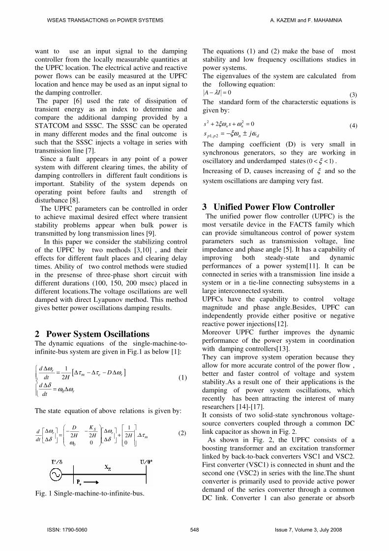
2 Power System Oscillations The dynamic equations of the single-machine-to-
infinite-bus system are given in Fig.1 as below [1]:
[ ]
0
1
2
rm e r
r
dD
dt H
d
dt
ωτ τ ω
δω ω
∆�= ∆ − ∆ − ∆��
�∆� = ∆
��
(1)
The state equation of above relations is given by:
0
1
.2 2 2
0 0
Sr r
m
KDd
H H Hdt
ω ωτ
δ δω
� � � �∆ ∆− −� � � � � �= + ∆� � � � � �∆ ∆ � � � � �� �
�������������
Fig. 1 Single-machine-to-infinite-bus.
The equations (1) and (2) make the base of most
stability and low frequency oscillations studies in
power systems.
The eigenvalues of the system are calculated from
the following equation: 0=− IA λ
The standard form of the characterstic equations is
given by:
02 22 =++ nn ss ωξω�
dnpp js ωξω ±−=2,1 The damping coefficient (D) is very small in
synchronous generators, so they are working in
oscillatory and underdamped states (0 1)ξ< < .
Increasing of D, causes increasing of ξ and so the
system oscillations are damping very fast.
3 Unified Power Flow Controller The unified power flow controller (UPFC) is the
most versatile device in the FACTS family which
can provide simultaneous control of power system
parameters such as transmission voltage, line
impedance and phase angle [5]. It has a capability of
improving both steady-state and dynamic
performances of a power system[11]. It can be
connected in series with a transmission line inside a
system or in a tie-line connecting subsystems in a
large interconnected system.
UPFCs have the capability to control voltage
magnitude and phase angle.Besides, UPFC can
independently provide either positive or negative
reactive power injections[12].
Moreover UPFC further improves the dynamic
performance of the power system in coordination
with damping controllers[13].
They can improve system operation because they
allow for more accurate control of the power flow ,
better and faster control of voltage and system
stability.As a result one of their applications is the
damping of power system oscillations, which
recently has been attracting the interest of many
researchers [14]-[17].
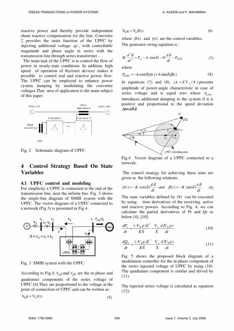
It consists of two solid-state synchronous voltage-
source converters coupled through a common DC
link capacitor as shown in Fig. 2.
As shown in Fig. 2, the UPFC consists of a
boosting transformer and an excitation transformer
linked by back-to-back converters VSC1 and VSC2.
First converter (VSC1) is connected in shunt and the
second one (VSC2) in series with the line.The shunt
converter is primarily used to provide active power
demand of the series converter through a common
DC link. Converter 1 can also generate or absorb
WSEAS TRANSACTIONS on POWER SYSTEMS A. KAZEMI and F. MAHAMNIA
ISSN: 1790-5060 548 Issue 7, Volume 3, July 2008
(7)
(9)
(5)
(6)reactive power and thereby provide independent
shunt reactive compensation for the line. Converter
2 provides the main function of the UPFC by
injecting additional voltage ∆U , with controllable
magnitude and phase angle in series with the
transmission line through series transformer .
The main task of the UPFC is to control the flow of
power in steady-state conditions. In addition, high
speed of operation of thyristor devices makes it
possible to control real and reactive power flow.
The UPFC can be employed to enhance power
system damping by modulating the converter
voltages.That area of application is the main subject
of this paper.
Fig. 2 Schematic diagram of UPFC.
4 Control Strategy Based On State
Variables
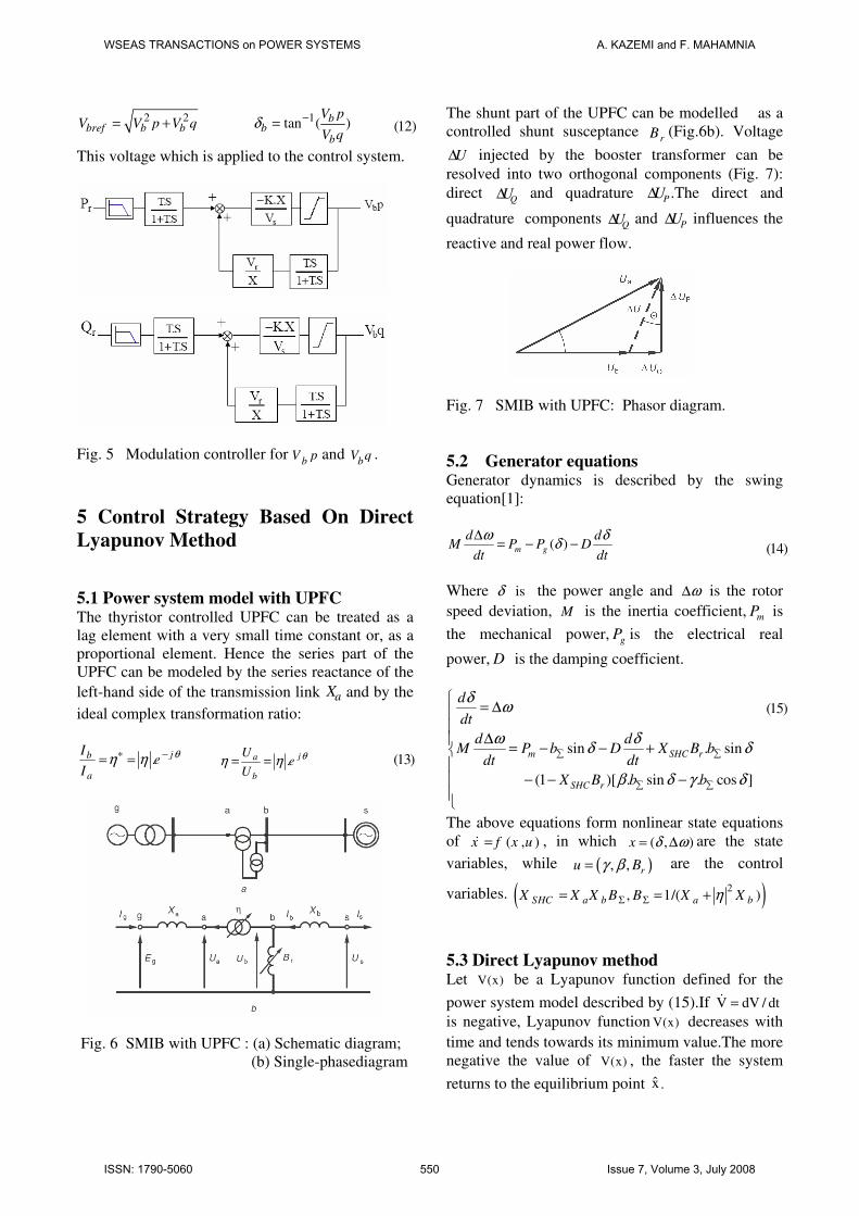
4.1 UPFC control and modeling For simplicity a UPFC is connected at the end of the
transmission line, near the infinite bus. Fig. 3 shows
the single-line diagram of SMIB system with the
UPFC. The vector diagram of a UPFC connected to
a network (Fig.3) is presented in Fig.4 .
Fig. 3 SMIB system with the UPFC.
According to Fig.4, b
V p and b
V q are the in-phase and
quadrature components of the series voltage of
UPFC [4].They are proportional to the voltage at the
point of connection of UPFC and can be written as:
b rV p V (t)γ=
b rV q V (t)β=
where� (t)β and (t)γ are the control variables.
The generator swing equation is :
2
2.sin( )m UPFC
d dM P A D P
dtdt
δ δδ= − − −
where
cos( ) ( ) sin( ) ( )UPFCP A t A tδ γ δ β= − + ���������������������������� (8)
In equations (7) and (8), ( / )rA E V X′= presents
amplitude of power-angle characteristic in case of
series voltage and is equal zero where UPFCP
introduces additional damping to the system if it is
positive and proportional to the speed deviation
/d dtω δ∆ = .
Fig.4 Vector diagram of a UPFC connected to a
network.
The control strategy for achieving these aims are
given as the following relations:
( ) cos( ) ( ) sin( )d d
t K and t Kdt dt
δ δγ δ β δ= − = −
The state variables defined by (9) can be executed
by using time derivatives of the receiving active
and reactive powers. According to Fig. 4, we can
calculate the partial derivatives of Pr and Qr as
below [4], [10]:
( ) ( )b br rV p E d V pdP V
dt KX X dt
′−= − (10)
( ) ( )b br rV q E d V qdQ V
dt KX X dt
′−= − (11)
Fig. 5 shows the proposed block diagram of a
modulation controller for the in-phase component of
the series injected voltage of UPFC by using (10).
The quadrature component is similar and drived by
(11).
The injected series voltage is calculated as equation
(12):
WSEAS TRANSACTIONS on POWER SYSTEMS A. KAZEMI and F. MAHAMNIA
ISSN: 1790-5060 549 Issue 7, Volume 3, July 2008
(13)
(12)
(14)
(15)
2 2= +bref b bV V p V q 1tan ( )−= bb
b
V p
V qδ
This voltage which is applied to the control system.
Fig. 5 Modulation controller for b
V p and b
V q .
5 Control Strategy Based On Direct
Lyapunov Method
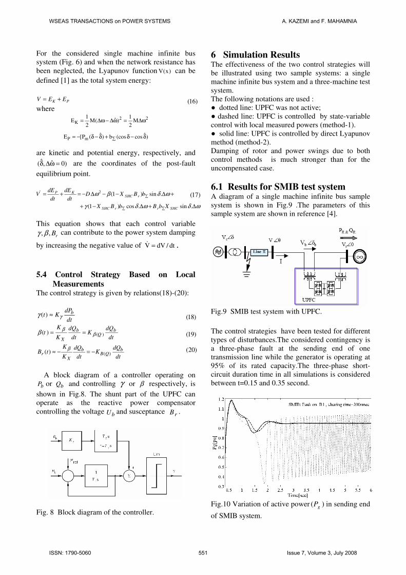
5.1 Power system model with UPFC The thyristor controlled UPFC can be treated as a
lag element with a very small time constant or, as a
proportional element. Hence the series part of the
UPFC can be modeled by the series reactance of the
left-hand side of the transmission link aX and by the
ideal complex transformation ratio:
. jb
a
Ie
I
θη η∗ −= = ������� . ja
b
Ue
U
θη η= =
Fig. 6 SMIB with UPFC : (a) Schematic diagram;
(b) Single-phasediagram
The shunt part of the UPFC can be modelled as a
controlled shunt susceptance rB (Fig.6b). Voltage
U∆ injected by the booster transformer can be
resolved into two orthogonal components (Fig. 7):
direct QU∆ and quadrature� PU∆ .The direct and
quadrature components QU∆ and PU∆ influences the
reactive and real power flow.
Fig. 7 SMIB with UPFC: Phasor diagram.
5.2 Generator equations Generator dynamics is described by the swing
equation[1]:
( )∆
= − −m g
d dM P P D
dt dt
ω δδ
Where δ is the power angle and ∆ω is the rotor
speed deviation, M is the inertia coefficient, mP is
the mechanical power, gP is the electrical real
power, D is the damping coefficient.
sin . sin
(1 )[ . sin . cos ]
� �
� �
�= ∆�
�∆�
= − − +��
− − −���
m SHC r
SHC r
d
dt
d dM P b D X B b
dt dt
X B b b
δω
ω δδ δ
β δ γ δ
The above equations form nonlinear state equations
of ( , )x f x u=� , in which ( , )= ∆x δ ω are the state
variables, while ( ), ,= ru Bγ β are the control
variables. ( )2, 1/( )SHC a b a bX X X B B X XηΣ Σ= = +
5.3 Direct Lyapunov method Let V(x) be a Lyapunov function defined for the
power system model described by (15).If V dV / dt=� is negative, Lyapunov function V(x) decreases with
time and tends towards its minimum value.The more
negative the value of V(x) , the faster the system
returns to the equilibrium point x̂ .
WSEAS TRANSACTIONS on POWER SYSTEMS A. KAZEMI and F. MAHAMNIA
ISSN: 1790-5060 550 Issue 7, Volume 3, July 2008
(16)
(16)
(17)
(18)
(19)
(20)
For the considered single machine infinite bus
system (Fig. 6) and when the network resistance has
been neglected, the Lyapunov function V(x) can be
defined [1] as the total system energy:
= +K PV E E
where
2 2
K
P m
1 1ˆE M( ) M
2 2
ˆ ˆE [P ( ) b (cos cos )�
= ∆ω − ∆ω = ∆ω
= − δ − δ + δ − δ
are kinetic and potential energy, respectively, and
ˆ ˆ( , 0)δ ∆ω = are the coordinates of the post-fault
equilibrium point.
2 (1 ) sin .
(1 ) cos . sin .
P KSHC r
SHC r r SHC
dE dEV D X B b
dt dt
X B b B b X
ω β δ ω
γ δ ω δ ω
�
� �
= + = − ∆ − − ∆ +
+ − ∆ + ∆
�
This equation shows that each control variable
, , rBγ β can contribute to the power system damping
by increasing the negative value of V dV / dt=� .
5.4 Control Strategy Based on Local
Measurements The control strategy is given by relations(18)-(20):
dt
dPKt b
γγ ≈)(
( )( ) b bQ
X
K dQ dQt K
K dt dt
βββ = =
dt
dQK
dt
dQ
K
KtB b
QBb
Xr )()( −=−≈
β
A block diagram of a controller operating on
bP or bQ and controlling γ or β respectively, is
shown in Fig.8. The shunt part of the UPFC can
operate as the reactive power compensator
controlling the voltage bU and susceptance rB .
Fig. 8 Block diagram of the controller.
6 Simulation Results The effectiveness of the two control strategies will
be illustrated using two sample systems: a single
machine infinite bus system and a three-machine test
system.
The following notations are used :
� dotted line: UPFC was not active;
� dashed line: UPFC is controlled by state-variable
control with local measured powers (method-1).
� solid line: UPFC is controlled by direct Lyapunov
method (method-2).
Damping of rotor and power swings due to both
control methods is much stronger than for the
uncompensated case.
6.1 Results for SMIB test system A diagram of a single machine infinite bus sample
system is shown in Fig.9 .The parameters of this
sample system are shown in reference [4].
Fig.9 SMIB test system with UPFC. The control strategies have been tested for different
types of disturbances.The considered contingency is
a three-phase fault at the sending end of one
transmission line while the generator is operating at
95% of its rated capacity.The three-phase short-
circuit duration time in all simulations is considered
between t=0.15 and 0.35 second.
Fig.10 Variation of active power ( )gP in sending end
of SMIB system.
WSEAS TRANSACTIONS on POWER SYSTEMS A. KAZEMI and F. MAHAMNIA
ISSN: 1790-5060 551 Issue 7, Volume 3, July 2008
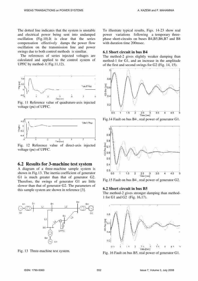
The dotted line indicates that the system is unstable
and electrical power being sent into undamped
oscillation (Fig.10).It is clear that the series
compensation effectively damps the power flow
oscillation on the transmission line and power
swings due to both control methods is similiar.
The references of series injected voltages are
calculated and applied to the control system of
UPFC by method-1( Fig.11,12).
Fig. 11 Reference value of quadrature-axis injected
voltage (pu) of UPFC.
Fig. 12 Reference value of direct-axis injected
voltage (pu) of UPFC.
6.2 Results for 3-machine test system A diagram of a three-machine sample system is
shown in Fig.13. The inertia coefficient of generator
G1 is much greater than that of generator G2.
Therefore, the swings of generator G1 are little
slower than that of generator G2. The parameters of
this sample system are shown in reference [3].
Fig. 13 Three-machine test system.
To illustrate typical results, Figs. 14-23 show real
power variations following a temporary three-
phase short-circuits on buses B4,B5,B6,B7 and B8
with duration time 200msec.
6.1 Short circuit in bus B4 The method-2 gives slightly weaker damping than
method-1 for G1, and an increase in the amplitude
of the first and second swings for G2 (Fig. 14, 15).
Fig.14 Fault on bus B4 , real power of generator G1.
Fig.15 Fault on bus B4 , real power of generator G2.
6.2 Short circuit in bus B5 The method-2 gives stronger damping than method-
1 for G1 and G2 (Fig. 16,17).
Fig. 16 Fault on bus B5, real power of generator G1.
WSEAS TRANSACTIONS on POWER SYSTEMS A. KAZEMI and F. MAHAMNIA
ISSN: 1790-5060 552 Issue 7, Volume 3, July 2008
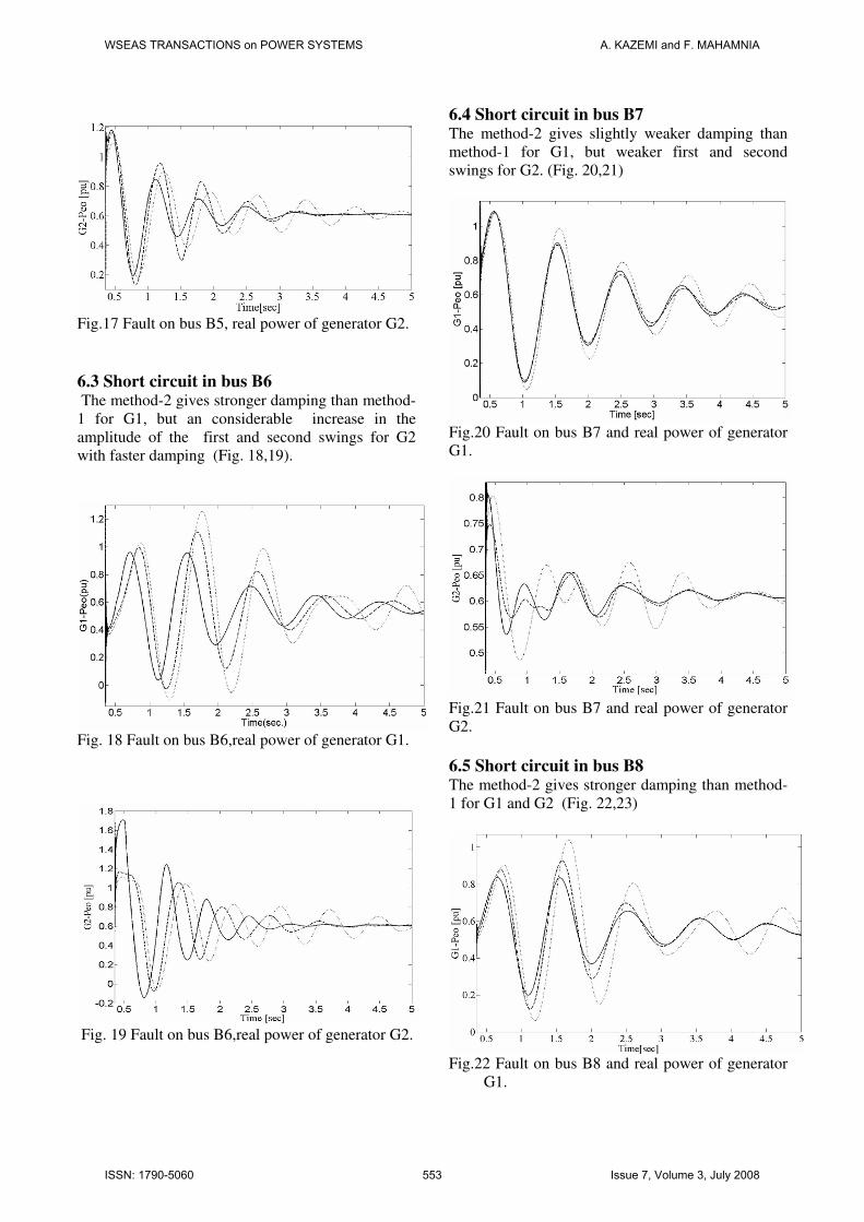
Fig.17 Fault on bus B5, real power of generator G2.
6.3 Short circuit in bus B6 The method-2 gives stronger damping than method-
1 for G1, but an considerable increase in the
amplitude of the first and second swings for G2
with faster damping (Fig. 18,19).
Fig. 18 Fault on bus B6,real power of generator G1.
Fig. 19 Fault on bus B6,real power of generator G2.
6.4 Short circuit in bus B7 The method-2 gives slightly weaker damping than
method-1 for G1, but weaker first and second
swings for G2. (Fig. 20,21)
Fig.20 Fault on bus B7 and real power of generator
G1.
Fig.21 Fault on bus B7 and real power of generator
G2.
6.5 Short circuit in bus B8 The method-2 gives stronger damping than method-
1 for G1 and G2 (Fig. 22,23)
Fig.22 Fault on bus B8 and real power of generator
G1.
WSEAS TRANSACTIONS on POWER SYSTEMS A. KAZEMI and F. MAHAMNIA
ISSN: 1790-5060 553 Issue 7, Volume 3, July 2008
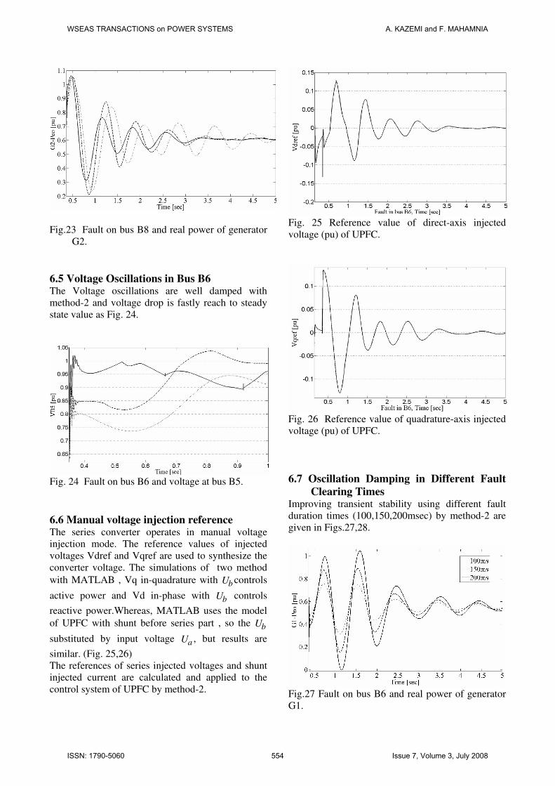
Fig.23 Fault on bus B8 and real power of generator
G2.
6.5 Voltage Oscillations in Bus B6 The Voltage oscillations are well damped with
method-2 and voltage drop is fastly reach to steady
state value as Fig. 24.
Fig. 24 Fault on bus B6 and voltage at bus B5.
6.6 Manual voltage injection reference The series converter operates in manual voltage
injection mode. The reference values of injected
voltages Vdref and Vqref are used to synthesize the
converter voltage. The simulations of two method
with MATLAB , Vq in-quadrature with bU controls
active power and Vd in-phase with bU controls
reactive power.Whereas, MATLAB uses the model
of UPFC with shunt before series part , so the bU
substituted by input voltage aU , but results are
similar. (Fig. 25,26)
The references of series injected voltages and shunt
injected current are calculated and applied to the
control system of UPFC by method-2.
Fig. 25 Reference value of direct-axis injected
voltage (pu) of UPFC.
Fig. 26 Reference value of quadrature-axis injected
voltage (pu) of UPFC.
6.7 Oscillation Damping in Different Fault
Clearing Times Improving transient stability using different fault
duration times (100,150,200msec) by method-2 are
given in Figs.27,28.
Fig.27 Fault on bus B6 and real power of generator
G1.
WSEAS TRANSACTIONS on POWER SYSTEMS A. KAZEMI and F. MAHAMNIA
ISSN: 1790-5060 554 Issue 7, Volume 3, July 2008
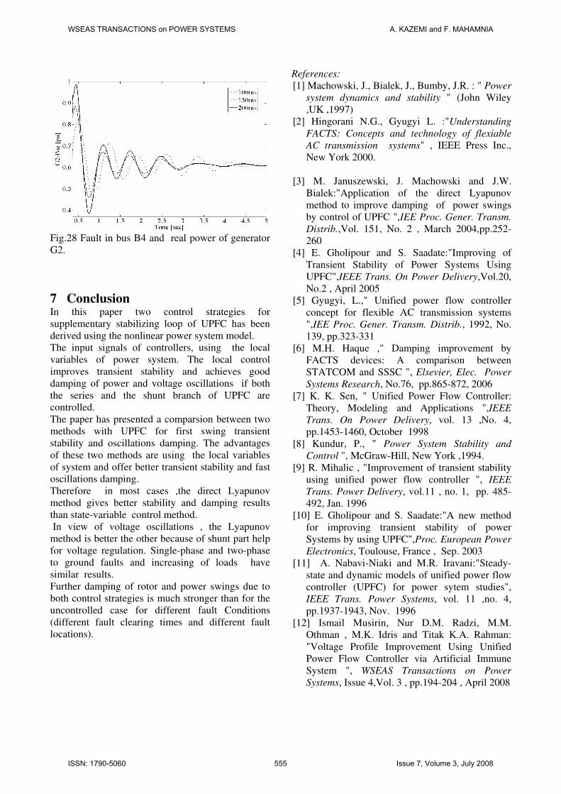
Fig.28 Fault in bus B4 and real power of generator
G2.
7 Conclusion In this paper two control strategies for
supplementary stabilizing loop of UPFC has been
derived using the nonlinear power system model.
The input signals of controllers, using the local
variables of power system. The local control
improves transient stability and achieves good
damping of power and voltage oscillations if both
the series and the shunt branch of UPFC are
controlled.
The paper has presented a comparsion between two
methods with UPFC for first swing transient
stability and oscillations damping. The advantages
of these two methods are using the local variables
of system and offer better transient stability and fast
oscillations damping.
Therefore in most cases ,the direct Lyapunov
method gives better stability and damping results
than state-variable control method.
In view of voltage oscillations , the Lyapunov
method is better the other because of shunt part help
for voltage regulation. Single-phase and two-phase
to ground faults and increasing of loads have
similar results.
Further damping of rotor and power swings due to
both control strategies is much stronger than for the
uncontrolled case for different fault Conditions
(different fault clearing times and different fault
locations).
References:
[1] Machowski, J., Bialek, J., Bumby, J.R. : " Power
system dynamics and stability " (John Wiley
,UK ,1997)
[2] Hingorani N.G., Gyugyi L. :"Understanding
FACTS: Concepts and technology of flexiable
AC transmission systems" , IEEE Press Inc.,
New York 2000.
[3] M. Januszewski, J. Machowski and J.W.
Bialek:"Application of the direct Lyapunov
method to improve damping of power swings
by control of UPFC ",IEE Proc. Gener. Transm.
Distrib.,Vol. 151, No. 2 , March 2004,pp.252-
260
[4] E. Gholipour and S. Saadate:"Improving of
Transient Stability of Power Systems Using
UPFC",IEEE Trans. On Power Delivery,Vol.20,
No.2 , April 2005
[5] Gyugyi, L.," Unified power flow controller
concept for flexible AC transmission systems
",IEE Proc. Gener. Transm. Distrib., 1992, No.
139, pp.323-331
[6] M.H. Haque ," Damping improvement by
FACTS devices: A comparison between
STATCOM and SSSC ", Elsevier, Elec. Power
Systems Research, No.76, pp.865-872, 2006
[7] K. K. Sen, " Unified Power Flow Controller:
Theory, Modeling and Applications ",IEEE
Trans. On Power Delivery, vol. 13 ,No. 4,
pp.1453-1460, October 1998
[8] Kundur, P., " Power System Stability and
Control ", McGraw-Hill, New York ,1994.
[9] R. Mihalic , "Improvement of transient stability
using unified power flow controller ", IEEE
Trans. Power Delivery, vol.11 , no. 1, pp. 485-
492, Jan. 1996
[10] E. Gholipour and S. Saadate:"A new method
for improving transient stability of power
Systems by using UPFC",Proc. European Power
Electronics, Toulouse, France , Sep. 2003
[11] A. Nabavi-Niaki and M.R. Iravani:"Steady-
state and dynamic models of unified power flow
controller (UPFC) for power sytem studies",
IEEE Trans. Power Systems, vol. 11 ,no. 4,
pp.1937-1943, Nov. 1996
[12] Ismail Musirin, Nur D.M. Radzi, M.M.
Othman , M.K. Idris and Titak K.A. Rahman:
"Voltage Profile Improvement Using Unified
Power Flow Controller via Artificial Immune
System ", WSEAS Transactions on Power
Systems, Issue 4,Vol. 3 , pp.194-204 , April 2008
WSEAS TRANSACTIONS on POWER SYSTEMS A. KAZEMI and F. MAHAMNIA
ISSN: 1790-5060 555 Issue 7, Volume 3, July 2008
[13] S.N. Dhurvey and V.K. Chandrakar: "
Performance Comparsion of UPFC in
Coordination with Optimized POD and PSS
On Damping of Power System Oscillations ",
WSEAS Transactions on Power Systems ,
Issue 5 , Vol. 3 , pp.287-299 , May 2008.
[14] V.K.Chandrakar, A.G.Kothari:" RBFN Based
UPFC for Improving transient stability
Performance, WSEAS Transactions on Power
Systems, Issue 1 , Vol. 2 , pp.1-6 , Jan 2007.
[15] K.R. Padiyar , K. Uma Rao : " Modeling and
Control of UPFC for Transient �� Stability " ,
Elsevier, Electrical Power Energy Systems ,
NO.21, pp. 1- 11, 1999.
[16] M.Ghandhari, "Control Lyapunov Functions:
A Control Strategy For Damping of Power
Oscillations in Large Power Systems , PhD
Thesis , Royal Institute of ��� Technology ,
Sweden , 2000.
[17] N.Tambey and M.L. Kothari: " Damping of
power system oscillations with unified
����������power flow controller (UPFC) � , IEE
Proceeding ,Vol. 150, No. 2, March 2003.
Biographies:
Ahad Kazemi was born in Tehran,
Iran, in 1952. He received his M.Sc.
degree in electrical engineering from
Oklahoma State University, U.S.A in
1979. He is currently an associate
professor in electrical engineering
department of Iran University of
Science and Technology, Tehran,
Iran. His research interests are
reactive power control, power
system dynamics, stability and
control and FACTS devices.
Farrokh Mahamnia was born in
Tabriz, Iran, in 1969. He is currently
a M.Sc. student at the department of
electrical engineering at the Iran
University of Science and
Technology, Tehran, Iran. His
research interests are power system
dynamics, stability and control and
FACTS devices.
WSEAS TRANSACTIONS on POWER SYSTEMS A. KAZEMI and F. MAHAMNIA
ISSN: 1790-5060 556 Issue 7, Volume 3, July 2008