improving design workflow in architectural design … design workflow in architectural design...
TRANSCRIPT
Improving Design Workflow in Architectural Design Applications
Stefan Boeykens, Herman Neuckermans K.U.Leuven Department of Architecture, Urban Design and Planning Kasteelpark Arenberg 1, B-3001 Leuven (Belgium) [email protected]
Abstract In architectural design software, there is a trend to integrate the whole design process in a single
application. Design, 3D modeling, drafting, but also design evaluation and presentation are bundled inside
the application. This is especially apparent in applications that adhere to the concept of Building
Information Modeling. When we look at the functionality in these applications, however, a disruption of
the design process can be encountered, preventing the designer to step back and forth throughout the
different design phases or scale levels. Three current architectural design applications are briefly positioned
and compared and potential improvements to the workflow are introduced.
1. INTRODUCTION
1.1. Problem statement Several commercial design applications are available for architects. When focusing on applications for
Computer Aided Architectural Design (CAAD), those following the Building Information Modeling (BIM)
methodology present the most valuable approach. A complete digital building model forms the core
database, from which drawings, 3D models and sections but also quantity estimations and simulations are
derived. The advantages of this methodology are design coherence and productivity. These programs are
being increasingly adopted in architectural practice, but also in engineering offices and by various
consultants.
In terms of the applicability in the design process, however, our experience with these applications
indicates a clear focus on the construction and documentation phase, including only limited support for the
early design stages. Especially the support to transfer the building model throughout the different phases of
the design process is limited and does not allow iterative and recursive exploration.
Such support is important, since the architect will have to make design decisions in the early stages of a
design, with possible far ranging impact.
1.2. Methodology and research context The research presented in this paper fits within a larger research project, which aims at the design and
implementation of an Integrated Design Environment for Architecture (IDEA+) [1]. The development of
this system made extensive use of the MERODE method [2]. This software development method helped to
define a “CORE Object Model” [3], describing a building model from the viewpoint of the designer. This
model forms the structure for IDEA+. In the initial elaboration, several academic research projects have
been evaluated, where different building models were suggested. A first generation of models includes
models such as GARM [4], RATAS [5] and EDM/GBM [6], while a second generation contains models
such as BAS°CAAD [7], SEED [8] and COMBINE2 [9]. However, as motivated in [3], the option was
followed to develop a custom building model for IDEA+.
The current IDEA+ structure, as described in this article, is supported by additional insight into the research
problem, which is gained through several channels:
• study and teaching of common CAAD- and 3D-software. This is partly integrated in the CAAD
courses for the architectural curriculum at the Department of Architecture, Urbanism and Planning
at the K.U.Leuven (Belgium) [10]. A catalog of CAD and design software is also collected in an
online database [11];
• active participation in online forums [12, 13, 14] and local user groups [15, 16] for architects and
designers. These include workshops and user group meetings, to gain insight into the application
of these programs in current practice and participation in beta-testing of some applications;
• study of existing and emerging standards, such as STEP [17] and the Industry Foundation Classes
(IFC) [18], but also common 3D file formats, for the purpose of the exchange of design
information;
• literature study on recent developments in CAAD research, through conferences such as eCAADe
[19] and online mailings lists [20, 21, 22, 23];
• former experience when working in architectural practice and hands-on experience with several
CAAD- and 3D-applications helps understanding the work flow and limitations of design
applications.
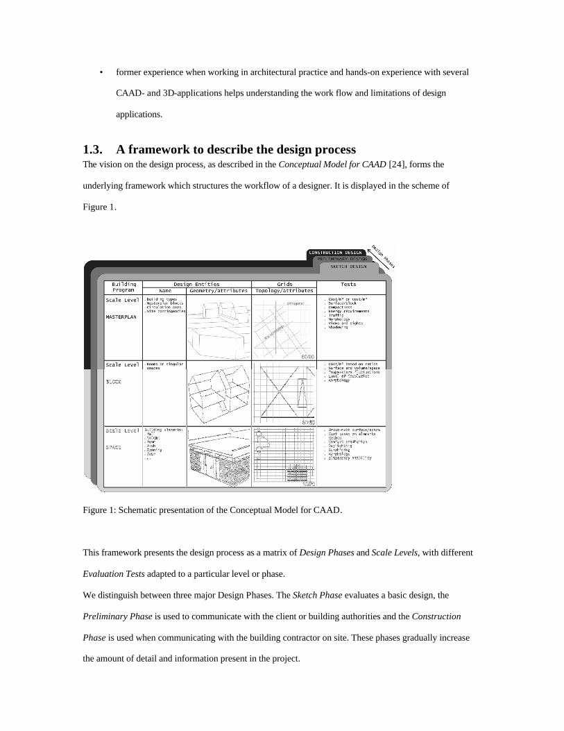
1.3. A framework to describe the design process The vision on the design process, as described in the Conceptual Model for CAAD [24], forms the
underlying framework which structures the workflow of a designer. It is displayed in the scheme of
Figure 1.
Figure 1: Schematic presentation of the Conceptual Model for CAAD.
This framework presents the design process as a matrix of Design Phases and Scale Levels, with different
Evaluation Tests adapted to a particular level or phase.
We distinguish between three major Design Phases. The Sketch Phase evaluates a basic design, the
Preliminary Phase is used to communicate with the client or building authorities and the Construction
Phase is used when communicating with the building contractor on site. These phases gradually increase
the amount of detail and information present in the project.
We also distinguish between three Scale Levels. The Masterplan Level describes the site and the main
building blocks, the Block Level focuses on spaces or rooms inside a building block and the Space Level
handles the separate physical building elements, such as walls, floors or openings. In theory we can extend
them with higher and lower Scale Levels, such as an Urban or a Material Level.
In the design process, the architect explores the design throughout this framework. A system supportive of
this process has to allow Transitions between these levels and phases.
1.4. Article Structure The first section of the article compares three architectural design applications, positioning them based on
their support for the proposed design process. The next section will introduce the IDEA+ concepts, which
illustrate an approach to manage this design workflow, while the last section elaborates on specific
functionality in this system to enable this approach. The conclusion will then expand the current research
and point to future improvements of the proposed structure.
2. COMMON ARCHITECTURAL DESIGN SOFTWARE This section introduces and compares three CAAD applications, marketed for Building Information
Modeling, being Autodesk Architectural Desktop [25], Graphisoft Archicad [26] and Autodesk Revit [27].
The comparison would be more complete with the inclusion of other applications, such as Bentley
Architecture [28], Nemetschek Allplan [29] or BricsCAD Architecturals [30], but the authors’ limited
experience with these systems would not do them justice. The overview briefly positions the concepts of
the three different applications and at the same time points at improvements in the workflow for the design
process as proposed in the Conceptual Model.
2.1. Autodesk Architectural Desktop (ADT) This BIM application from Autodesk [25] is implemented as a module on top of the generic AutoCAD
drawing and modeling software. The software adds parametric Architecture, Engineering and Construction
(AEC) objects to AutoCAD and provides a main workflow for architectural design. These AEC objects
contain common building elements, but also annotation and documentation objects. In ADT general
AutoCAD techniques are combined with these AEC objects to define an assembly of a building. Different
floor levels are placed in separate documents and collected using the XRef technique, where external
documents are referenced inside other documents.
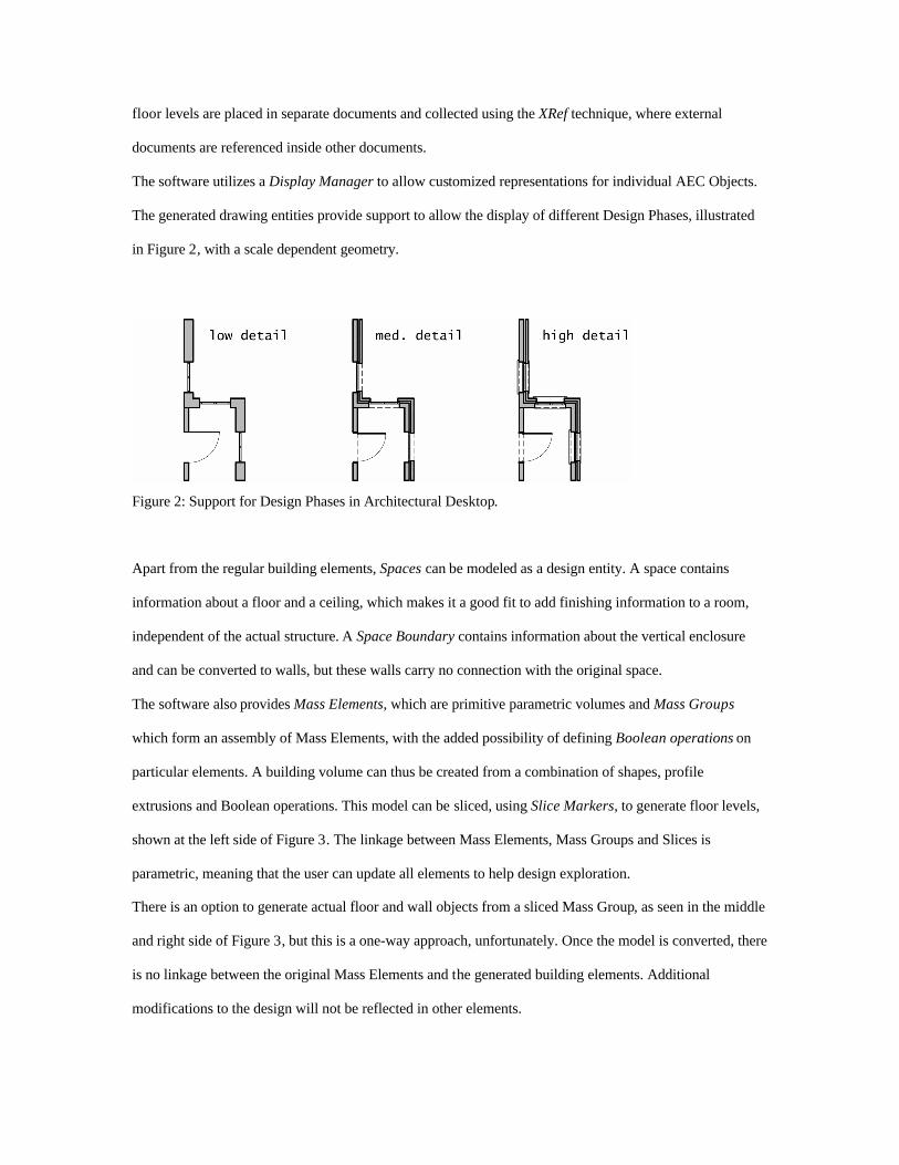
The software utilizes a Display Manager to allow customized representations for individual AEC Objects.
The generated drawing entities provide support to allow the display of different Design Phases, illustrated
in Figure 2, with a scale dependent geometry.
Figure 2: Support for Design Phases in Architectural Desktop.
Apart from the regular building elements, Spaces can be modeled as a design entity. A space contains
information about a floor and a ceiling, which makes it a good fit to add finishing information to a room,
independent of the actual structure. A Space Boundary contains information about the vertical enclosure
and can be converted to walls, but these walls carry no connection with the original space.
The software also provides Mass Elements, which are primitive parametric volumes and Mass Groups
which form an assembly of Mass Elements, with the added possibility of defining Boolean operations on
particular elements. A building volume can thus be created from a combination of shapes, profile
extrusions and Boolean operations. This model can be sliced, using Slice Markers, to generate floor levels,
shown at the left side of Figure 3. The linkage between Mass Elements, Mass Groups and Slices is
parametric, meaning that the user can update all elements to help design exploration.
There is an option to generate actual floor and wall objects from a sliced Mass Group, as seen in the middle
and right side of Figure 3, but this is a one-way approach, unfortunately. Once the model is converted, there
is no linkage between the original Mass Elements and the generated building elements. Additional
modifications to the design will not be reflected in other elements.
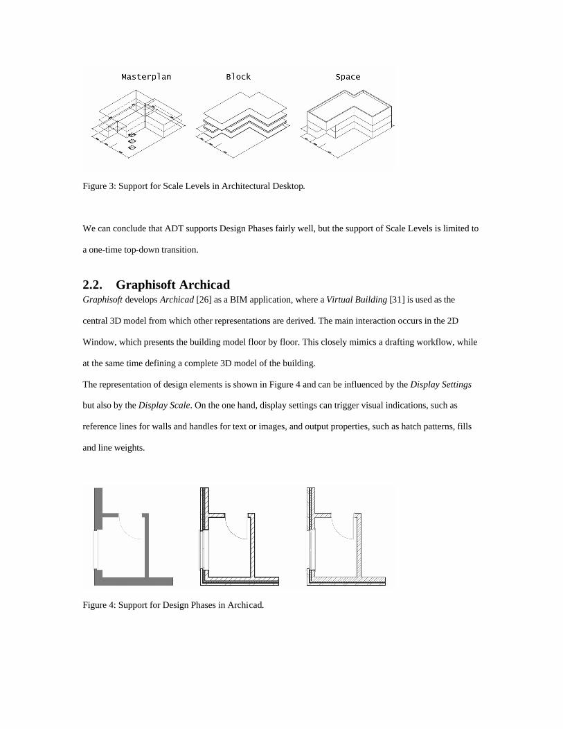
Figure 3: Support for Scale Levels in Architectural Desktop.
We can conclude that ADT supports Design Phases fairly well, but the support of Scale Levels is limited to
a one-time top-down transition.
2.2. Graphisoft Archicad Graphisoft develops Archicad [26] as a BIM application, where a Virtual Building [31] is used as the
central 3D model from which other representations are derived. The main interaction occurs in the 2D
Window, which presents the building model floor by floor. This closely mimics a drafting workflow, while
at the same time defining a complete 3D model of the building.
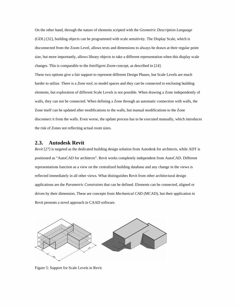
The representation of design elements is shown in Figure 4 and can be influenced by the Display Settings
but also by the Display Scale. On the one hand, display settings can trigger visual indications, such as
reference lines for walls and handles for text or images, and output properties, such as hatch patterns, fills
and line weights.
Figure 4: Support for Design Phases in Archicad.
On the other hand, through the nature of elements scripted with the Geometric Description Language
(GDL) [32], building objects can be programmed with scale sensitivity. The Display Scale, which is
disconnected from the Zoom Level, allows texts and dimensions to always be drawn at their regular point
size, but more importantly, allows library objects to take a different representation when this display scale
changes. This is comparable to the Intelligent Zoom concept, as described in [24].
These two options give a fair support to represent different Design Phases, but Scale Levels are much
harder to utilize. There is a Zone tool, to model spaces and they can be connected to enclosing building
elements, but exploration of different Scale Levels is not possible. When drawing a Zone independently of
walls, they can not be connected. When defining a Zone through an automatic connection with walls, the
Zone itself can be updated after modifications to the walls, but manual modifications to the Zone
disconnect it from the walls. Even worse, the update process has to be executed manually, which introduces
the risk of Zones not reflecting actual room sizes.
2.3. Autodesk Revit Revit [27] is targeted as the dedicated building design solution from Autodesk for architects, while ADT is
positioned as “AutoCAD for architects”. Revit works completely independent from AutoCAD. Different
representations function as a view on the centralized building database and any change in the views is
reflected immediately in all other views. What distinguishes Revit from other architectural design
applications are the Parametric Constraints that can be defined. Elements can be connected, aligned or
driven by their dimension. These are concepts from Mechanical CAD (MCAD), but their application in
Revit presents a novel approach in CAAD software.
Figure 5: Support for Scale Levels in Revit.
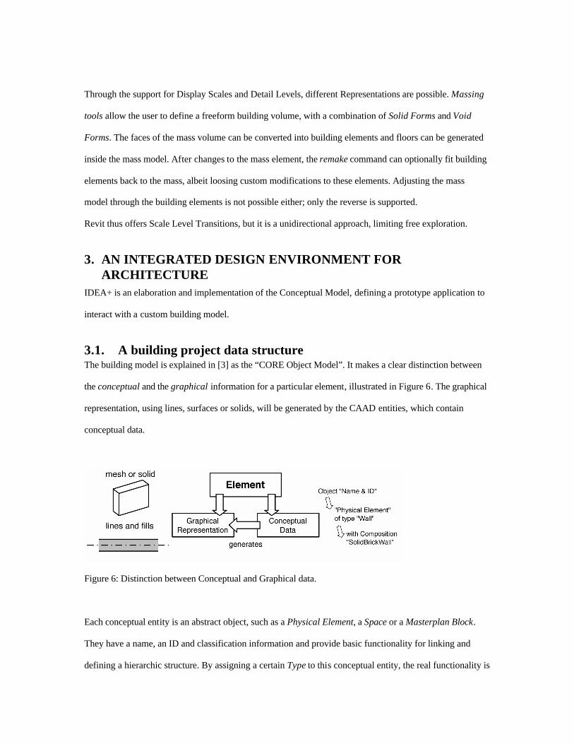
Through the support for Display Scales and Detail Levels, different Representations are possible. Massing
tools allow the user to define a freeform building volume, with a combination of Solid Forms and Void
Forms. The faces of the mass volume can be converted into building elements and floors can be generated
inside the mass model. After changes to the mass element, the remake command can optionally fit building
elements back to the mass, albeit loosing custom modifications to these elements. Adjusting the mass
model through the building elements is not possible either; only the reverse is supported.
Revit thus offers Scale Level Transitions, but it is a unidirectional approach, limiting free exploration.
3. AN INTEGRATED DESIGN ENVIRONMENT FOR ARCHITECTURE
IDEA+ is an elaboration and implementation of the Conceptual Model, defining a prototype application to
interact with a custom building model.
3.1. A building project data structure The building model is explained in [3] as the “CORE Object Model”. It makes a clear distinction between
the conceptual and the graphical information for a particular element, illustrated in Figure 6. The graphical
representation, using lines, surfaces or solids, will be generated by the CAAD entities, which contain
conceptual data.
Figure 6: Distinction between Conceptual and Graphical data.
Each conceptual entity is an abstract object, such as a Physical Element, a Space or a Masterplan Block.
They have a name, an ID and classification information and provide basic functionality for linking and
defining a hierarchic structure. By assigning a certain Type to this conceptual entity, the real functionality is
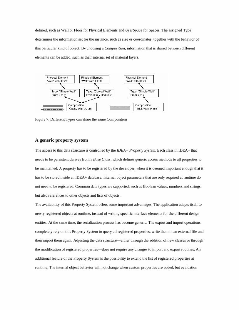
defined, such as Wall or Floor for Physical Elements and UserSpace for Spaces. The assigned Type
determines the information set for the instance, such as size or coordinates, together with the behavior of
this particular kind of object. By choosing a Composition, information that is shared between different
elements can be added, such as their internal set of material layers.
Figure 7: Different Types can share the same Composition
A generic property system
The access to this data structure is controlled by the IDEA+ Property System. Each class in IDEA+ that
needs to be persistent derives from a Base Class, which defines generic access methods to all properties to
be maintained. A property has to be registered by the developer, when it is deemed important enough that it
has to be stored inside an IDEA+ database. Internal object parameters that are only required at runtime do
not need to be registered. Common data types are supported, such as Boolean values, numbers and strings,
but also references to other objects and lists of objects.
The availability of this Property System offers some important advantages. The application adapts itself to
newly registered objects at runtime, instead of writing specific interface elements for the different design
entities. At the same time, the serialization process has become generic. The export and import operations
completely rely on this Property System to query all registered properties, write them in an external file and
then import them again. Adjusting the data structure—either through the addition of new classes or through
the modification of registered properties—does not require any changes to import and export routines. An
additional feature of the Property System is the possibility to extend the list of registered properties at
runtime. The internal object behavior will not change when custom properties are added, but evaluation
tests might rely on them or the user can choose to engage them in the project, using Property Connections,
as discussed in section 4.3.
This was an important achievement for a data structure evolving alongside the prototype application.
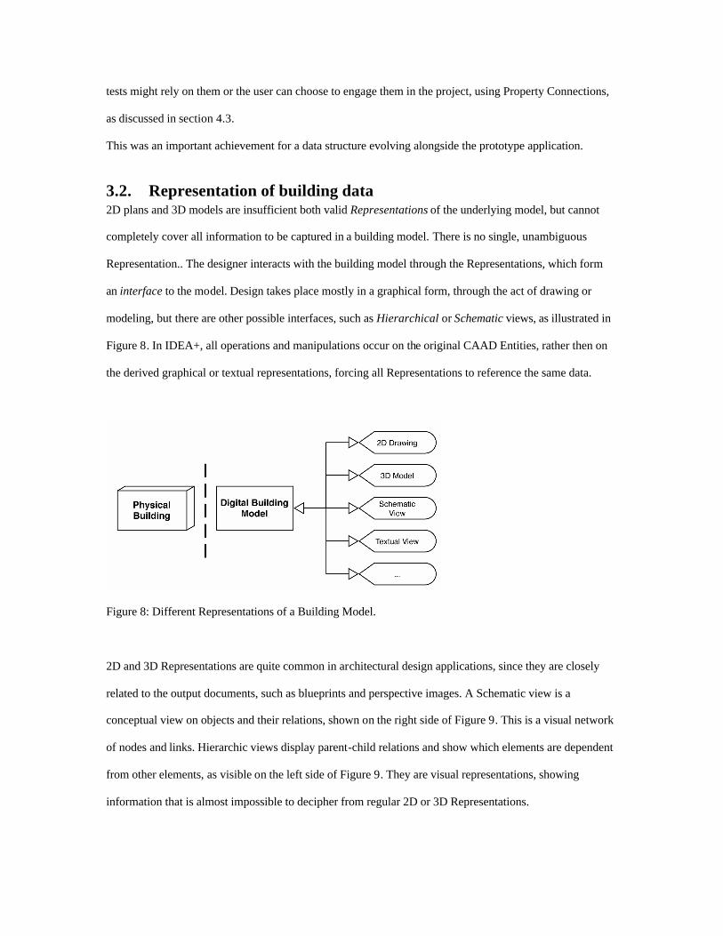
3.2. Representation of building data 2D plans and 3D models are insufficient both valid Representations of the underlying model, but cannot
completely cover all information to be captured in a building model. There is no single, unambiguous
Representation.. The designer interacts with the building model through the Representations, which form
an interface to the model. Design takes place mostly in a graphical form, through the act of drawing or
modeling, but there are other possible interfaces, such as Hierarchical or Schematic views, as illustrated in
Figure 8. In IDEA+, all operations and manipulations occur on the original CAAD Entities, rather then on
the derived graphical or textual representations, forcing all Representations to reference the same data.
Figure 8: Different Representations of a Building Model.
2D and 3D Representations are quite common in architectural design applications, since they are closely
related to the output documents, such as blueprints and perspective images. A Schematic view is a
conceptual view on objects and their relations, shown on the right side of Figure 9. This is a visual network
of nodes and links. Hierarchic views display parent-child relations and show which elements are dependent
from other elements, as visible on the left side of Figure 9. They are visual representations, showing
information that is almost impossible to decipher from regular 2D or 3D Representations.

Figure 9: Example of Schematic and Hierarchic Views
3.3. Transitions between Design Phases and Scale Levels The design of an architectural project is a process. Throughout the design, the architect refines, elaborates
and rethinks the design in an iterative sequence. Based on previous design experience, on project
characteristics, on feedback from different parties involved or evaluation tests, the design is constantly
adapted, refined and hopefully improved. One of the enhancements IDEA+ proposes compared to existing
CAAD applications, is integrated support of transitions. The design environment should support the design
throughout all Design Phases and Scale Levels, depicted with the two-way arrows in Figure 10.
Figure 10: Scheme with possible Transitions.
This is of particular importance in the early design stages, where the architect explores the design over
different Scale Levels, going either from the generic to the detail or vice-versa. At the same time, when the
design evolves over different Design Phases, the model should not be started all over again.
The architect might change back and forth at any time within the same design project. It hardly makes
sense to force the designer to work on different models or in different applications. It is therefore of utmost
importance that the design environment allows the design to follow along this exploration.
In a Scale Level Transition the scope of the building changes. This is often a top-down approach from the
global level to the specific details. It is, however, perfectly valid to adopt a bottom-up approach, starting
from a construction detail and scaling up to a global building system. This might be the strategy for a
construction company standardizing its construction process. IDEA+ explicitly allows the design to be
initiated at any Scale Level. The architect can freely explore other Scale Levels during the design process.
In a Design Phase Transition, on the other hand, the chronological order of a design is followed, although
the reverse transition is supported for design exploration and feedback. Evaluating the design in a more
detailed phase might lead to adjustments that might be performed back in the sketch or preliminary phase.
This should not invalidate data that was already embedded in later Design Phases. Building information
only moves forward, chronologically with the different phases. The Representations, however, allow a
visually coherent display of earlier phases.
In the IDEA+ project, these concepts are currently being elaborated into a workable prototype, to allow
future design studio testing to validate and refine the transitions approach.
3.4. Integrated evaluation tests A designer can perform evaluation tests in different Design Phases or Scale Levels. A rough test with
default parameters can be executed early in the design process, while a more elaborate test could be
performed in a later Design Phase, when more data is available. The test has to adapt or limit itself to
appropriate levels and phases. A distinction has to be made between tests which extract and report
information and tests which, based on some simulation, add information to the elements or which may even
modify the properties of elements.
A first test category is Data Extraction, which includes reporting tools and data exporters. A Rendering test
is set up, which exports the generated 3D Representation as a series of input files for the Radiance
rendering system [33]. This is a suite of lighting simulation tools, allowing realistic physically based
renderings, with accurate lighting level simulation. This provides valuable feedback about the influence of
lighting on the project. Rather then embedding a full rendering engine inside the main design application,
the program simply generates the input files and executes the external rendering application. This simplifies
the implementation, but still provides usable results. Integrating these results back into the project data,
however, is not supported by this test.
A second test category is Data Generation, which can explicitly use the results of some simulation and add
them to the main project. These tests can produce a graphical chart, creating drawing entities inside the
project, but they can also write their results directly inside the properties of the elements. The test could
update some existing properties or can even add extra properties to the elements. The results of the test thus
become part of the project and they are stored and kept with the elements on which the test has been
executed. The IDEA+ Property System provides means to add extra data to existing elements, using
Extended Properties. A cost estimation test is being developed, which stores results alongside the objects.
This is important when the test is performed on other Scale Levels, where these results can improve the
accuracy of the test.
4. IMPLEMENTATION OF POSSIBLE SOLUTIONS The IDEA+ data structure and prototype provide some features to assist the design workflow. They are
described in this section.
4.1. Creating a grid of reference points To allow a design to be elaborated in different Scale Levels, while maintaining the integrity of the model,
Reference Points are introduced. These are positions in the model which can be shared between design
entities. They act as control points for elements, allowing them to be connected to each other and to
maintain these connections during modifications. These Reference Points build up a Reference Grid.
Adjusting the grid can translate Reference Points and the elements from which they are referenced. A
regular grid can be manipulated into an irregular grid, by transforming grid lines. This is illustrated in the
graphical mockup of Figure 11. Deleting grid lines will disconnect the Reference Points without the need to
delete the associated building elements, while moving the control points of elements to existing grid points
can establish a new connection.
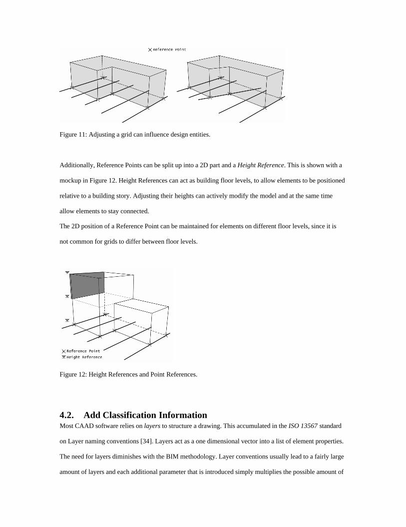
Figure 11: Adjusting a grid can influence design entities.
Additionally, Reference Points can be split up into a 2D part and a Height Reference. This is shown with a
mockup in Figure 12. Height References can act as building floor levels, to allow elements to be positioned
relative to a building story. Adjusting their heights can actively modify the model and at the same time
allow elements to stay connected.
The 2D position of a Reference Point can be maintained for elements on different floor levels, since it is
not common for grids to differ between floor levels.
Figure 12: Height References and Point References.
4.2. Add Classification Information Most CAAD software relies on layers to structure a drawing. This accumulated in the ISO 13567 standard
on Layer naming conventions [34]. Layers act as a one dimensional vector into a list of element properties.
The need for layers diminishes with the BIM methodology. Layer conventions usually lead to a fairly large
amount of layers and each additional parameter that is introduced simply multiplies the possible amount of
layers, until a point where the whole layer system becomes unmanageable. A better solution is to translate
these parameters into actual attributes of building elements.
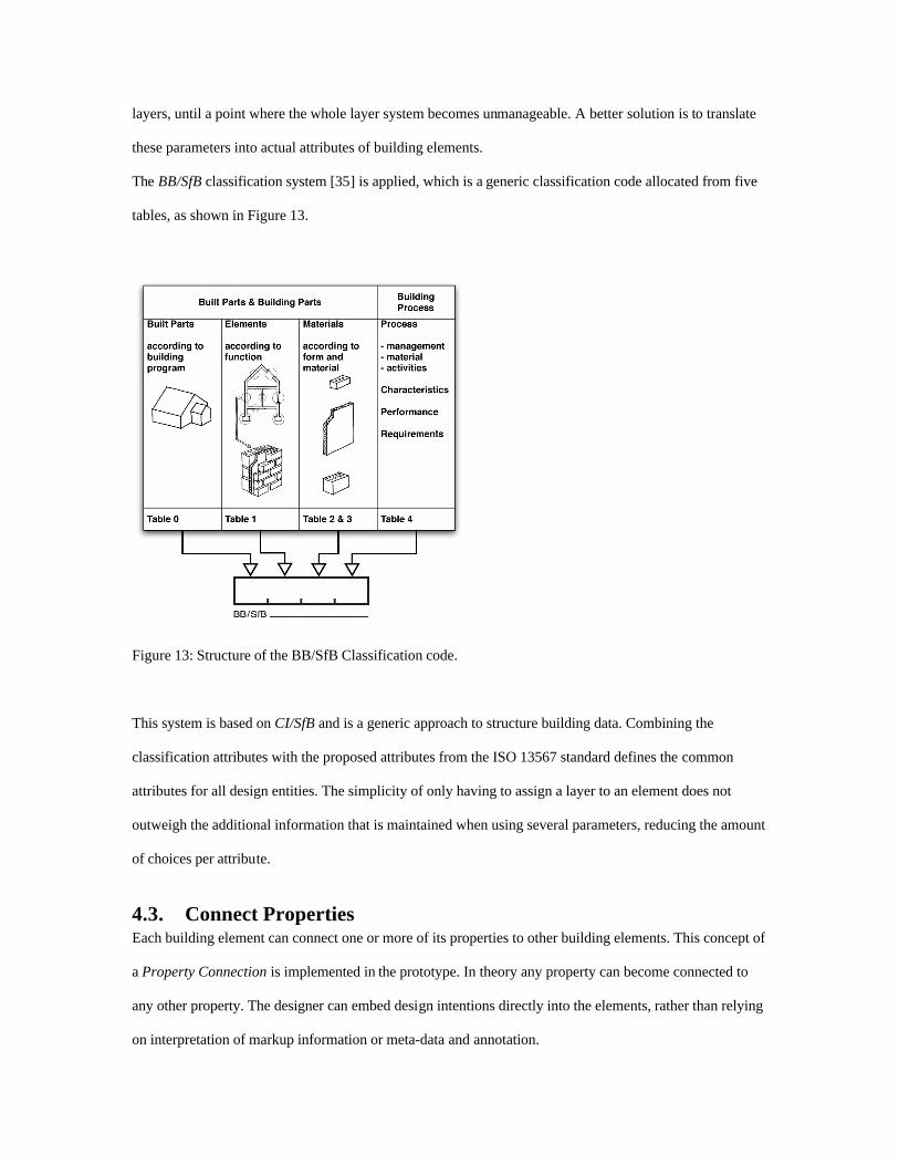
The BB/SfB classification system [35] is applied, which is a generic classification code allocated from five
tables, as shown in Figure 13.
Figure 13: Structure of the BB/SfB Classification code.
This system is based on CI/SfB and is a generic approach to structure building data. Combining the
classification attributes with the proposed attributes from the ISO 13567 standard defines the common
attributes for all design entities. The simplicity of only having to assign a layer to an element does not
outweigh the additional information that is maintained when using several parameters, reducing the amount
of choices per attribute.
4.3. Connect Properties Each building element can connect one or more of its properties to other building elements. This concept of
a Property Connection is implemented in the prototype. In theory any property can become connected to
any other property. The designer can embed design intentions directly into the elements, rather than relying
on interpretation of markup information or meta-data and annotation.
Typical examples of Parameter Expressions include relating wall heights to floor levels and the alignment
of Reference Points with regard to other Reference Points. The Property Connection system needs to be
transparent to the user, so it utilizes a dedicated Connection Manager and the Schematic Representation, to
keep an overview on all available connections and the objects they influence.
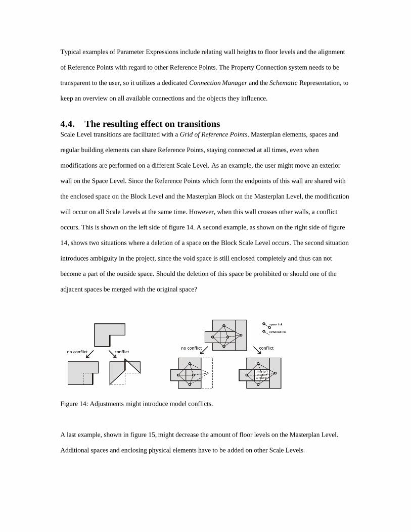
4.4. The resulting effect on transitions Scale Level transitions are facilitated with a Grid of Reference Points. Masterplan elements, spaces and
regular building elements can share Reference Points, staying connected at all times, even when
modifications are performed on a different Scale Level. As an example, the user might move an exterior
wall on the Space Level. Since the Reference Points which form the endpoints of this wall are shared with
the enclosed space on the Block Level and the Masterplan Block on the Masterplan Level, the modification
will occur on all Scale Levels at the same time. However, when this wall crosses other walls, a conflict
occurs. This is shown on the left side of figure 14. A second example, as shown on the right side of figure
14, shows two situations where a deletion of a space on the Block Scale Level occurs. The second situation
introduces ambiguity in the project, since the void space is still enclosed completely and thus can not
become a part of the outside space. Should the deletion of this space be prohibited or should one of the
adjacent spaces be merged with the original space?
Figure 14: Adjustments might introduce model conflicts.
A last example, shown in figure 15, might decrease the amount of floor levels on the Masterplan Level.
Additional spaces and enclosing physical elements have to be added on other Scale Levels.
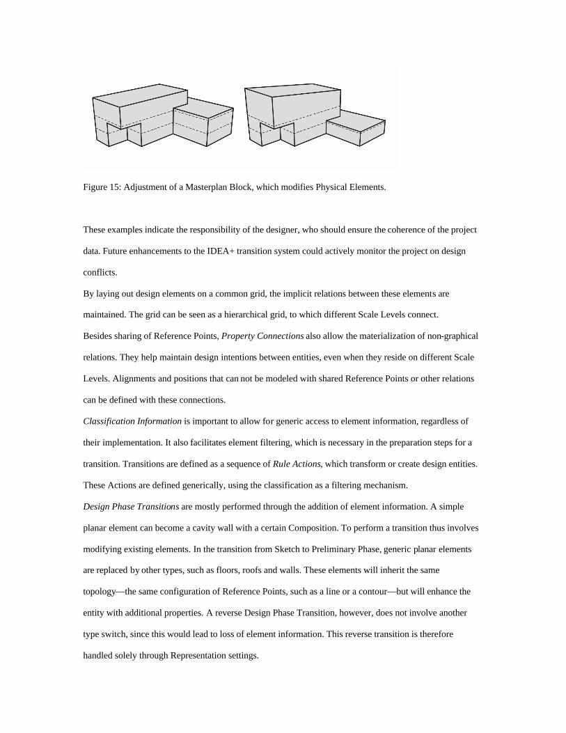
Figure 15: Adjustment of a Masterplan Block, which modifies Physical Elements.
These examples indicate the responsibility of the designer, who should ensure the coherence of the project
data. Future enhancements to the IDEA+ transition system could actively monitor the project on design
conflicts.
By laying out design elements on a common grid, the implicit relations between these elements are
maintained. The grid can be seen as a hierarchical grid, to which different Scale Levels connect.
Besides sharing of Reference Points, Property Connections also allow the materialization of non-graphical
relations. They help maintain design intentions between entities, even when they reside on different Scale
Levels. Alignments and positions that can not be modeled with shared Reference Points or other relations
can be defined with these connections.
Classification Information is important to allow for generic access to element information, regardless of
their implementation. It also facilitates element filtering, which is necessary in the preparation steps for a
transition. Transitions are defined as a sequence of Rule Actions, which transform or create design entities.
These Actions are defined generically, using the classification as a filtering mechanism.
Design Phase Transitions are mostly performed through the addition of element information. A simple
planar element can become a cavity wall with a certain Composition. To perform a transition thus involves
modifying existing elements. In the transition from Sketch to Preliminary Phase, generic planar elements
are replaced by other types, such as floors, roofs and walls. These elements will inherit the same
topology—the same configuration of Reference Points, such as a line or a contour—but will enhance the
entity with additional properties. A reverse Design Phase Transition, however, does not involve another
type switch, since this would lead to loss of element information. This reverse transition is therefore
handled solely through Representation settings.
Scale Level Transitions have to create additional building elements, if required. When a Masterplan block
is initially created, it does not contain any walls or floors. They can be added in the transition to the Space
and Block Level, the former creating spaces and rooms and the latter creating actual building elements. The
reverse transition depends on the potential existence of such a Masterplan block. This could be generated as
the outline of the building, containing Reference Points from all external walls. If, however, these building
elements have already been generated from a prior Masterplan Block, we only need to update them.
5. CONCLUSION Through the experience with current design applications, limitations in the design workflow have been
identified. The research and development of an integrated design environment for architecture proposes
some enhancements, to better support the design process, through enabling Design Phase and Scale Level
transitions. This is elaborated with a custom building data structure and a prototype design application. This
prototype is a work in progress and does not aspire to replace existing design applications. It is hoped,
however, that it might influence and open the discussion on better support for the early stages of the design.
Future research aspects can focus on more elaborate support for embedding design decisions into the design
environment. Aspects from constraint modeling and parametric design form an important reference
framework in this research. It is also important that the design environment is applied in design exercises,
to refine and improve the workflow with feedback from practicing designers. This requires, however, a
more mature version of the prototype.
Acknowledgements This research is partly funded by the Research fund, K.U.Leuven (OT/2000/18).
References
1. Boeykens, S. and Neuckermans, H., Implementation of an Architectural Design Environment. The
development of IDEA+. In: E-activities in design and design education, 9th EuropIA International
Conference, EIA, Istanbul (Turkey), 2003, 6 pages.
2. Dedene, G. and Snoeck, M., M.E.R.O.D.E.: A Model-driven Entity-Relationship Object-oriented
DEvelopment method, ACM SIGSOFT Software Engineering notes, 1994, 19(3).
3. Hendricx, A., A Core Object Model for Architectural Design, PhD thesis, K.U.Leuven, Dept.
ASRO, Leuven (Belgium), 2000.
4. Gielingh, W., General AEC reference model (GARM) an aid for the integration of application
specific product definition models, In: Conceptual Modelling of Buildings, Papers from CIB
W75+W78 workshop, Lund (Sweden), 1988, pages 165–178.
5. Björk, B. C., The RATAS project - developing an infrastructure for computer integrated
construction, In: ASCE Journal of Computing in Civil Engineering, 8(4), 1994, pages 401–419.
6. Eastman, C. M. and Siabiris, A., A generic building product model incorporating building type
information, In: Automation in Construction, Vol. 3, 1995, pages 283–304.
7. Ekholm, A. and Fridqvist, S., The BAS°CAAD information system for design - principles,
implementation, and a design scenario, In Computer in Building / Proceedings of the CAAD
Futures 1999 Conference, Atlanta, Georgia (USA), 1999, pp.149-164.
8. http://www.seedling.org [14-8-2006]
9. Augenbroe, G., The COMBINE project: a global assessment. In Modeling of buildings through
their life-cycle, Publication 180 in CIB Proceedings, Stanford California, (USA), 1995, pages
163–171.
10. http://caad.asro.kuleuven.be [14-8-2006]
11. http://www2.asro.kuleuven.be/asro/English/HOME/SBs [14-8-2006]
12. http://archicad-talk.graphisoft.com [14-8-2006]
13. http://www.augi.com [14-8-2006]
14. http://www.3dbuzz.com [14-8-2006]
15. http://users.skynet.be/bert.nijs/VAGG [14-8-2006]

16. http://www.c3a.be [14-8-2006]
17. Björk, B. C. and Wix, J., An introduction to STEP, VTT and Wix Mclelland Ltd., 1991.
18. http://www.iai-international.org [14-8-2006]
19. http://www.ecaade.org [14-8-2006]
20. http://www.upfrontezine.com [14-8-2006]
21. http://www.aecbytes.com [14-8-2006]
22. http://www.aeccafe.com [14-8-2006]
23. http://www.laiserin.com [14-8-2006]
24. Neuckermans, H., A conceptual model for CAAD, Automation in Construction, 1992, 1(1):1–6.
25. http://www.autodesk.com/adt [14-8-2006]
26. http://www.graphisoft.com/products/archicad [14-8-2006]
27. http://www.autodesk.com/revit [14-8-2006]
28. http://www.bentley.com/architecture [14-8-2006]
29. http://www.nemetschek.com/allplan [14-8-2006]
30. http://www.bricscad.com [14-8-2006]
31. http://www.graphisoft.com/products/virtual_building [14-8-2006]
32. http://www.graphisoft.com/products/archicad/object_technology [14-8-2006]
33. Larson, G. W. and Shakespeare, R., Rendering with Radiance: The Art and Science of Lighting
Visualization, Morgan Kaufmann, 1998.
34. Björk, B. C., Löwnertz, K., and Kiviniemi, A., ISO 13567, The proposed international standard for
structuring layers in computer aided building design, in: Computers in the Practice of Building and
Civil Engineering, Proceedings of the Worldwide ECCE Symposium, Finland, 1997, pages 85–89.
35. De Troyer, F., Neuckermans, H., Havenne, D., and Simon, F., BB/SfB Tabellen, Regie der
Gebouwen, Brussels (Belgium), (available in Dutch and French), 1990.