improvement of diffuse solar irradiance measurements with noncosine instruments
TRANSCRIPT
Improvement of diffuse solar irradiancemeasurements with noncosine instruments
A. de La Casiniere, T. Cabot, A. I. Bokoye, and J. L. Pinedo
As a result of sky radiance anisotropy, significant errors spoil diffuse solar irradiance data obtained bymeans of noncosine-true instruments, which happens in spite of knowledge of the relative cosine re-sponse. To reduce these errors we recommend a method that involves an additional measurement ofdiffuse irradiance from a horizon band. The efficiency of the so-called double-measurement method isfound to be optimum for a 25° horizon band elevation. We confirm the feasibility of the method withrelevance tests that use diffuse solar spectral measurements carried out on cloudless skies by means ofan UV spectroradiometer. © 1996 Optical Society of America
Key words: Diffuse solar irradiance, cosine effect, solar spectral measurements.
1. Introduction
A solar irradiance measuring instrument consists ofa receiver and a detector. The receiver can be usedto collect solar radiation and transmit it to the detec-tor. Inmodern instruments one can use the detectorto convert this radiation, directly or indirectly, intoan electrical signal. For example, in a classic pyra-nometer the receiver consists roughly of two super-posed glass domes and of a highly absorbent layercoating the detector, the latter being a thermoelectricor a photoelectric sensor. At the other end of therange of irradiance measuring instruments, and inaccordance with the Kondratyev1 description, the re-ceiver of a global or diffuse spectroradiometer is adiffusing device that can be used to mix the radiationfrom the whole sky dome and to light the entrance slitof a monochromator used as a detector.Since broadband solar diffuse irradiance may ac-
count for a large part of global solar radiation it wouldhave to be evaluated, in many applications, with thesame accuracy as solar direct irradiance. This ob-servation is even truer for the UV band that is cur-rently widely monitored; indeed, the scattering by airmolecules and aerosols is especially efficient for short-wave radiation, and the diffuse component of solar
The authors are with Equipe de Recherche sur les Interactionsentre Rayonnement Solaire et Atmosphere, Universite JosephFourier, 17 Quai Claude Bernard, 38000 Grenoble, France.Received 28 June 1995; revised manuscript received 16 Febru-
ary 1996.0003-6935y96y306069-07$10.00y0© 1996 Optical Society of America
spectral irradiance is particularly intense in this lat-ter wavelength range.Since solar scattered radiation is generally
strongly anisotropic and arrives from the whole skydome within a solid angle of 2p sr, solar diffuse irra-diance measurements require instruments fittedwith cosine-true receivers. In other words, the sig-nal yielded by the coupled detector would have to berigorously proportional to the angle of incidence co-sine of given direct beams that irradiate the receiver.Some recent studies pointed out that the receivers ofsolar instruments, even those as commonly used aspyranometers, are not perfectly cosine and need apreliminary optical characterization with a view toapplying a suitable correction factor to measure-ments ~see Refs. 2–4 for the UV band, Ref. 5 for theUV and visible bands, and Ref. 6 for broadband in-struments!. Unfortunately, as far as diffuse irradi-ance is concerned, such optical correction factors fullycompensate for the receiver’s imperfection only whenthe sky radiance is isotropic. If the sky radiance isanisotropic an error is inevitably introduced, theamount of which was estimated by La Casiniere etal.,5 depending on the receiver’s imperfection level,the measuring method used, and the values of vari-ous geographic parameters. In this case the onlyway to obtain a full correction would be to know thespatial distribution of the radiance in all directions ofthe sky vault.The receivers of instruments that one can use to
measure horizontal solar irradiances are generallyaxisymmetrical around their vertical axis, that is,around the zenith direction. For this reason theyare sensitive only to variations with zenith angle of
20 October 1996 y Vol. 35, No. 30 y APPLIED OPTICS 6069
the sky crown radiances ~radiances averaged over 2pof the azimuth angle!. Knowledge of such crown ra-diances would then be sufficient to determine the fullcorrection factor, but too many measurements wouldstill be necessary. On the other hand, a measuringprocess that includes only two isotropic sky zones ofdistinct crown-radiance values is easier to develop.We present a double-measurement method based
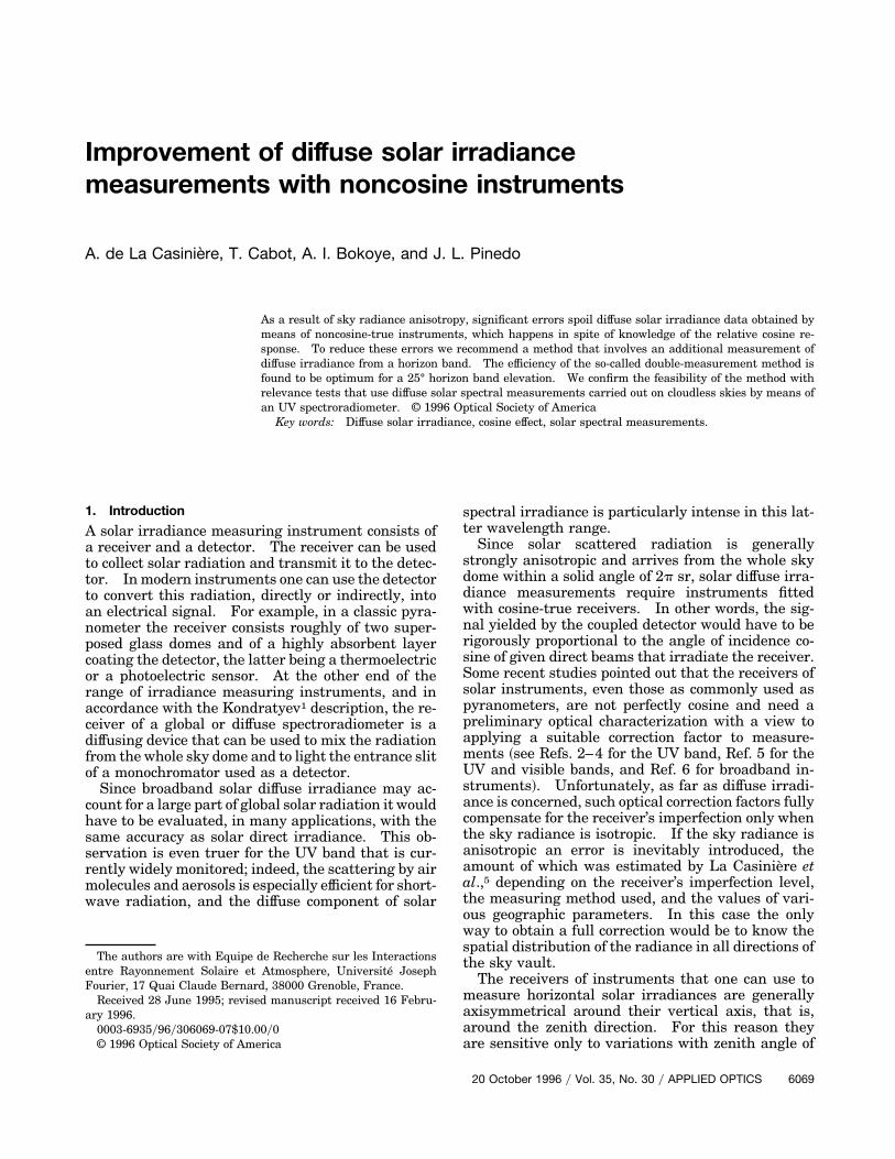
on the above considerations, with a view to improvingthe determination of broadband or spectral solar dif-fuse irradiances when the receiver is not sufficientlycosine true. With this method we divide the skyvault into two isotropic radiance zones: a horizonband and a complementary zenith calotte @Fig. 1~a!#.The theoretical study as well as the trial runs aredone in clear-sky conditions that allow the process tobe optimized. However, since dividing the sky intotwo distinct radiance zones is always a more realisticassumption than to take complete radiance isotropyfor granted, this double-measurement method mustalso be capable of improving the diffuse irradiancedeterminations in other stable sky conditions.
2. Previous Theoretical Study
A. Overall Spectral Correction Factor
Let an axisymmetric horizontal receiver be subject todirect solar irradianceEl~u*! inWm22 mm21 becauseof its monochromatic beams that form an angle ofincidence u* with its axis ~solar zenith angle!. Thenthe coupled detector yields an electrical signal Vl~u*!such as
El~u*! 5 k~u*, l!Vl~u*!. (1)
Fig. 1. HB and ZC zones of the sky vault, with practical mea-surement processes of corresponding horizontal diffuse irradi-ances.
6070 APPLIED OPTICS y Vol. 35, No. 30 y 20 October 1996
The term k~u*, l! is the angular calibration coeffi-cient of the measuring instrument, written k~0, l! fornormal incidence. The horizontal irradiance canthen be expressed as
El~u*! 5 k~0, l!Vl~u*!yc~u*, l!, (2)
where c~u*, l! is the spectral relative cosine responsethat is equal to one, independent of angle u* andwavelength l, if the receiver were cosine true. Frompreviously determined values of factor c~u*, l! bymeans of optical methods, it would then be easy toinfer the exact direct solar irradiance El~u*!.The determination of Dhl, the so-called spectral
horizontal solar diffuse irradiance, requires a moredifficult process. It involves knowing the monochro-matic sky vault radiance Il~u, f! ~W m22 sr21 mm21!in all the directions defined by u and f, which are,respectively, the zenith angle and the azimuth @Fig.1~a!#. If Vl is the corresponding signal yielded bythe detector, the diffuse irradiance can be written assuggested by La Casiniere et al.5:
Dhl 5 C~l!k~0, l!Vl, (3)
where
C~l! 5 *u50
py2
sin u cos uF*f50
2p
Il~u, f!dfGdu
3 H*u50
py2
c~u, l!sin u cos uF*f50
2p
Il~u, f!dfGduJ21
.
(4)
Because the termC~l! deals with the whole sky vault,here we refer to it as the overall spectral correctionfactor ~SCF!, which would be equal to one if the re-ceiver were cosine true. For broadband instrumentssuch as pyranometers, there are no grounds for ex-plicating the wavelength and the overall SCF is aconstant for a given sky radiance distribution. Todelete the generally unknown function Il~u, f! fromEq. ~4!, the sky radiance is frequently assumed to beisotropic. The overall SCF is then noted C~l! andthe diffuse irradiance can be written as follows:
Dhl < Dhl9 5 C~l!k~0, l!Vl. (5)
B. Partial Spectral Correction Factors
We now consider the sky vault as divided into twoisotropic radiance zones as in Fig. 1: a horizon band~HB! of which angular elevation is x, and its comple-mentary zenith calotte ~ZC! with c 5 py2 2 x as theopening angle. The spectral horizontal diffuse irra-diance that is due to the HB and ZC, respectively, arethen written as Dhlx and Dhlc, with correspondingsignals beingVlx andVlc so that their sum equalsVl.A process quite similar to the one used to obtain
Eqs. ~3! and ~4! ~see, for example, La Casiniere5! al-lows us to obtain:
Dhlx 5 Cx~l!k~0, l!Vlx, (6)
where
Cx~l! 5 *u5c
py2
sin u cos uF*f50
2p
Il~u, f!dfGdu
3 H*u5c
py2
c~u, l!sin u cos uF*f50
2p
Il~u, f!dfGduJ21
,
(7)
Dhlc 5 Cc~l!k~0, l!Vlc, (8)
where
Cc~l! 5 *u50
c
sin u cos uF*f50
2p
Il~u, f!dfGdu
3 H*u50
c
c~u, l!sin u cos uF*f50
2p
Il~u, f!dfGduJ21
.
(9)
Although the sum of Eqs. ~7! and ~9! does not equalC~l!, coefficients Cx~l! and Cc~l! are referred to hereas partial ~SCF’s!. They are written as Cx~l! andCc~l! when each of the HB and ZC sky zones areassumed to have an isotropic ~and generally different!radiance, which means that the Il~u, f! function dis-appears from Eqs. ~7! and ~9!.
3. Double-Measurement Method
A. Optimum Horizon Band Elevation
Given the above considerations, one must write thespectral horizontal diffuse irradiance as the followingfunction of partial SCF’s:
Dhl 5Dhlx 1Dhlc 5 k~0, l!@Cx~l!Vlx 1Cc~l!Vlc#. (10)
Since the spatial variations of Il~u, f! are generallyunknown, it is possible only to assume that
Dhl <Dhl0 5 k~0, l!@Cx~l!Vlx 1Cc~l!Vlc#. (11)
If Eqs. ~3! and ~10! are strictly equivalent, the Dhl9and Dhl0 irradiance values given by approximations~5! and ~11!, respectively, are different. The true skyradiance distribution is inevitably better describedwhen one assumes that the vault is divided into twoisotropic zones than if one were to presume it to befully isotropic; then Dhl0 must be closer to Dhl thanto Dhl9.By means of an appropriate double-measurement
method, such as that described in Subsection 3.B, it ispossible to obtain the two partial signals Vlx and Vlc.Now the question is: does a ZC opening angle c existthat would minimize the relative difference ~Dhl 2Dhl0!yDhl between the true value and the approxi-mation ~11! value of the diffuse irradiance. Because
one can write
~Dhl 2Dhl0!yDhl 5 12 $Cc~l!@C~l! 2Cx~l!#
2Cx~l!@C~l! 2Cc~l!#%
3 $C~l!@~Cc~l! 2Cx~l!#%21, (12)
such a problem can be solved for cloudless skies if onewere to use one of the several existing models ofrelative sky radiance distribution. Because of itssimplicity, the model we adopted for this study is theone proposed by Page.7 It draws heavily from theresearch of Steven and Unsworth8 and follows theprinciple of Liebelt formulation. This is a nonspec-tral model that was developed as a function of theLinke turbidity factor TL. For lack of anything bet-ter we spectrally adapted it as follows:
Il~u, f!yIl~0, 0! 5 @a1 1 a2 exp~23h! 1 a3 cos2 h#
3 @1 2 exp~20.088 TLycos u!#
3 $@a1 1 a2 exp~23u*! 1 a3 cos2 u*#
3 @1 2 exp~20.088 TL!#%21, (13)
where a1 5 0.89952 0.0053 ~py22 u*!, a2 5 0.615511.9687TL, a3 5 0.4092 0.0096 ~py22 u*!, and h is theangle between the Sun’s position and a selected pointin the sky. TL can be interpreted as the number ofpure and dry atmospheres to be superposed to achievetotal direct solar irradiance that is really observed onthe ground. This factor is easy to obtain from totaldirect irradiance measurements but, in spite of thesignificant improvements reported recently by Grenieret al.,9,10 it remains sensitive to the atmospheric watervapor content and, consequently, is not quite satisfac-tory as a pure turbidity index.Note that the Page model is open to criticism be-
cause of the claim that it can be used to describe thesky radiance distribution from ground data only ~re-gardless of the nature of the aerosols, their size dis-tribution, and their vertical profile!. However theerrors inferred by such an approximation are ex-pected to be tolerable for a first approach.We carried out our research based on c~u, l! values
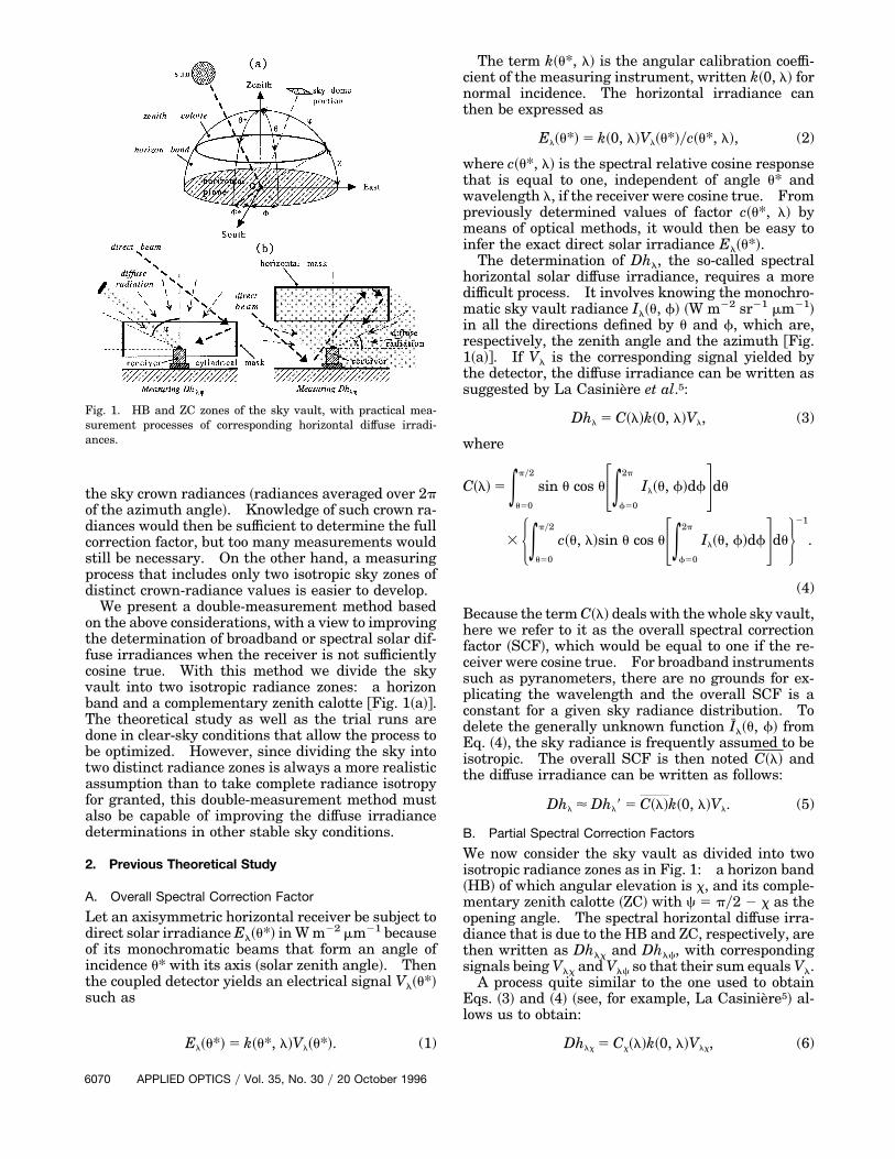
of a good common flat plate UV diffuser ~namely, the200–1100-nm Opal manufactured by Oriel! that wasused as the receiver for a solar diffuse spectroradiom-eter. A diffuser was preferred to an integratingsphere because the latter is expensive, bulky, has lowtransmittance, and cannot fully accept a 2p sr incidentflux. In addition, its entrance hole has to be protectedby a silica glass dome during routine outdoormeasure-ments. The c~u, l! variations of the diffuser as a func-tion of u, which were determined from 290–900 nm in5–10-nm steps, are drawn in Fig. 2 for wavelengths of300, 500, 700, and 890 nm only.The error that occurs when one assumes the sky
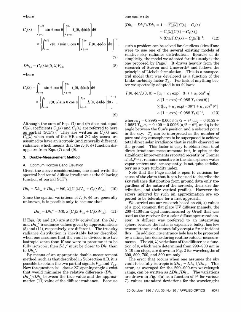
vault to be fully isotropic is ~Dhl 2 Dhl9!yDhl. Thiserror, as averaged for the 290–900-nm wavelengthrange, can be written as DDhlyDhl. The variationsare drawn in Fig. 3~a! as a function of u* for variousTL values ~standard deviations for the wavelengths
20 October 1996 y Vol. 35, No. 30 y APPLIED OPTICS 6071
are shown at the bottom of the graph!. When oneaverages for the same wavelength range, the ~Dhl 2Dhl0!yDhl error can be written as dDhlyDhl.Figure 3~b! shows, as an example, the variations ofdDhlyDhl calculated from Eq. ~12! as a function of cfor TL 5 3.0 and various u* values ~the dDhlyDhl
value that corresponds to c 5 0° or c 5 90°, is pre-cisely DDhlyDhl!. Analyzing sets of dDhlyDhl
curves obtained for TL values of 2.1, 3.0, 4.0, and 5.0,one can generally observe a minimum at approxi-
Fig. 2. Relative cosine response of the UV diffuser for the selectedwavelengths of 300, 500, 700, and 890 nm.
Fig. 3. Error on diffuse irradiance, averaged in wavelength,brought about by the single-measurement method for ~a! variousTL values and ~b! by the double-measurement method for TL 5 3.0.
6072 APPLIED OPTICS y Vol. 35, No. 30 y 20 October 1996
mately c 5 65°. Therefore, the HB elevation anglethat was adopted as an optimum is x 5 25°. Withsuch an angle, the improvement brought about by thedouble-measurement method reaches 4% for low so-lar heights and weak turbidities. Because this per-centage is an averaged wavelength value, theimprovement may greatly exceed 4% in specific spec-tral bands as UV-B or the IR.Overall and partial SCF values calculated in iso-
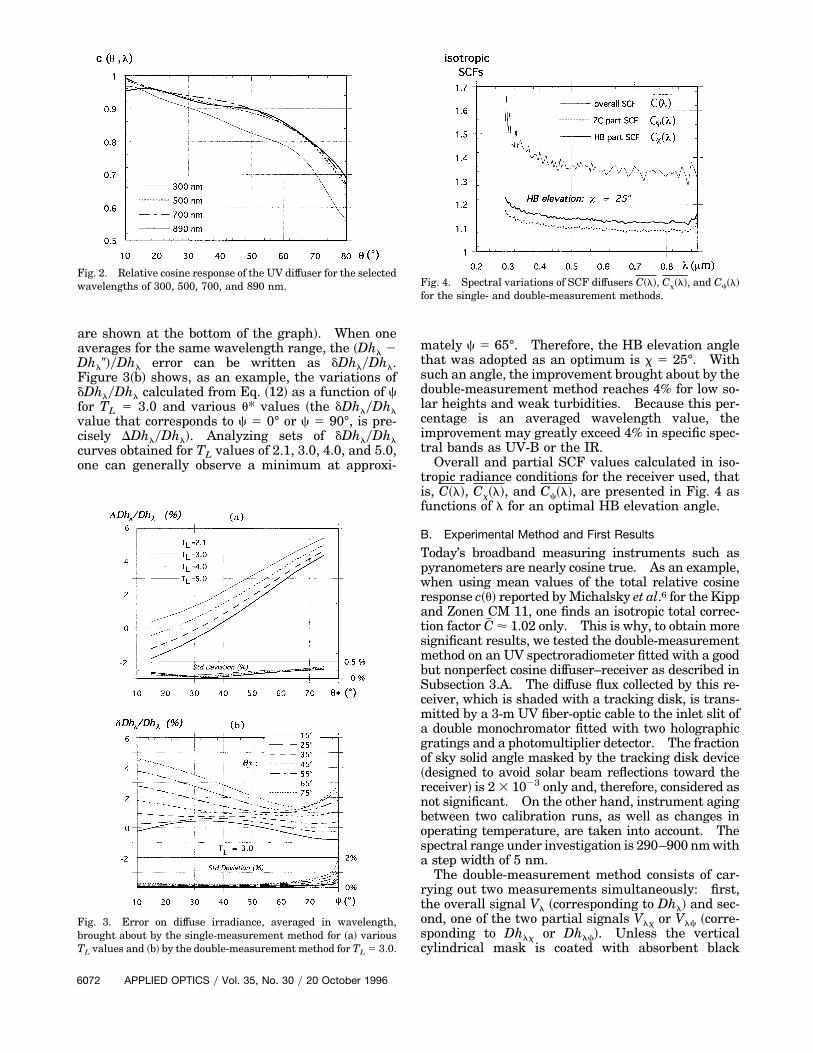
tropic radiance conditions for the receiver used, thatis, C~l!, Cx~l!, and Cc~l!, are presented in Fig. 4 asfunctions of l for an optimal HB elevation angle.
B. Experimental Method and First Results
Today’s broadband measuring instruments such aspyranometers are nearly cosine true. As an example,when using mean values of the total relative cosineresponse c~u! reported byMichalsky et al.6 for the Kippand Zonen CM 11, one finds an isotropic total correc-tion factor C# ' 1.02 only. This is why, to obtain moresignificant results, we tested the double-measurementmethod on an UV spectroradiometer fitted with a goodbut nonperfect cosine diffuser–receiver as described inSubsection 3.A. The diffuse flux collected by this re-ceiver, which is shaded with a tracking disk, is trans-mitted by a 3-m UV fiber-optic cable to the inlet slit ofa double monochromator fitted with two holographicgratings and a photomultiplier detector. The fractionof sky solid angle masked by the tracking disk device~designed to avoid solar beam reflections toward thereceiver! is 23 1023 only and, therefore, considered asnot significant. On the other hand, instrument agingbetween two calibration runs, as well as changes inoperating temperature, are taken into account. Thespectral range under investigation is 290–900 nmwitha step width of 5 nm.The double-measurement method consists of car-
rying out two measurements simultaneously: first,the overall signal Vl ~corresponding to Dhl! and sec-ond, one of the two partial signals Vlx or Vlc ~corre-sponding to Dhlx or Dhlc!. Unless the verticalcylindrical mask is coated with absorbent black
Fig. 4. Spectral variations of SCF diffusers C~l!, Cx~l!, and Cc~l!for the single- and double-measurement methods.
paint, it might reflect undesirable direct solar beamsonto the receiver. Therefore measurement of Vlc isnot recommended. Conversely, a horizontal maskthat serves to cut ZC diffuse radiation allows one toobtain an accurate value for Vlx ~although the latteris smaller than Vlc when x 5 25°!, because directbeams cannot reach the receiver except after severalreflections @Fig. 1~b!#. The desired Vlc value canthen be obtained from the difference Vl 2 Vlx.Several careful test measurements were carried out
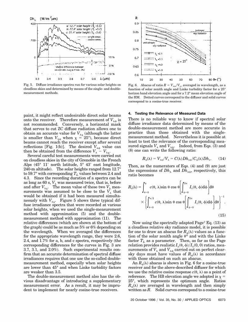
on cloudless skies in the city of Grenoble in the FrenchAlps ~45° 119 north latitude, 5° 439 east longitude,240-m altitude!. The solar heights ranged from 12.7°to 59.7° with corresponding TL values between 2.4 and4.3. Since the recording duration of a spectra can beas long as 60 s, Vl was measured twice, that is, beforeand after Vlx. The mean value of these two Vl mea-surements was assumed to be close to the Vl thatwould be obtained if it had been measured simulta-neously with Vlx. Figure 5 shows three typical dif-fuse irradiance spectra that were recorded at varioussolar heights, when we used the single-measurementmethod with approximation ~5! and the double-measurement method with approximation ~11!. Therelative differences ~which are shown at the bottom ofthe graph! could be as much as 5% or 6% depending onthe wavelength. When we averaged the differencesfor the appropriate wavelength range, they were 2.6,2.4, and 1.7% for a, b, and c spectra, respectively ~thecorresponding differences for the curves in Fig. 3 are3.7, 3.1, and 2.0%!. Such experimental results con-firm that an accurate determination of spectral diffuseirradiances requires that one use the so-called double-measurement method, especially when solar heightsare lower than 45° and when Linke turbidity factorsare weaker than 3.5.The double-measurement method also has the ob-
vious disadvantage of introducing a supplementarymeasurement error. As a result, it may be impru-dent to implement for nearly cosine-true receivers.
Fig. 5. Diffuse irradiance spectra run for various solar heights oncloudless skies and determined by means of the single- and double-measurement methods.
4. Testing the Relevance of Measured Data
There is no reliable way to know if spectral solardiffuse irradiance data determined by means of thedouble-measurement method are more accurate inpractice than those obtained with the single-measurement method. Nevertheless it is possible atleast to test the relevance of the corresponding mea-sured signals Vl and Vlc. Indeed, from Eqs. ~3! and~8! one can write the following ratio:
Rc~l! 5 VlcyVl 5 C~l!DhlcyCc~l!Dhl. (14)
Then, as the numerators of Eqs. ~4! and ~9! are justthe expressions of Dhl and Dhlc, respectively, thisratio becomes
Rc~l! 5 *u50
c
c~u, l!sin u cos uF*f50
2p
Il~u, f!dfGdu
3 H*u50
py2
c~u, l!sin u cos uF*f50
2p
Il~u, f!dfGduJ21
.
(15)
Now using the spectrally adapted Page7 Eq. ~13! asa cloudless relative sky radiance model, it is possiblefor one to draw an abacus for Rc~l! values as a func-tion of the solar zenith angle u* and with the Linkefactor TL as a parameter. Then, as far as the Pagerelation provides realistic Il~u, f!yIl~0, 0! ratios, mea-surements of Vl and Vlc carried out on perfect clear-sky days must have values of Rc~l! in accordancewith those obtained on such an abacus.An Rc~l! abacus is shown in Fig. 6 for a cosine-true
receiver and for the above-described diffuser for whichwe use the relative cosine response c~u, l! as a point ofreference. The HB elevation angle we adopted is x 525°, which represents the optimum angle. RatiosRc~l! are averaged in wavelength and then simplywritten asR. Solid curves correspond to a cosine-true
Fig. 6. Abacus of ratio R 5 VlcyVl, averaged in wavelength, as afunction of solar zenith angle and Linke turbidity factor for a 25°horizon band elevation angle and for a 7.2° mean elevation angle ofthe HM. Dotted curves correspond to the diffuser and solid curvescorrespond to a cosine-true receiver.
20 October 1996 y Vol. 35, No. 30 y APPLIED OPTICS 6073
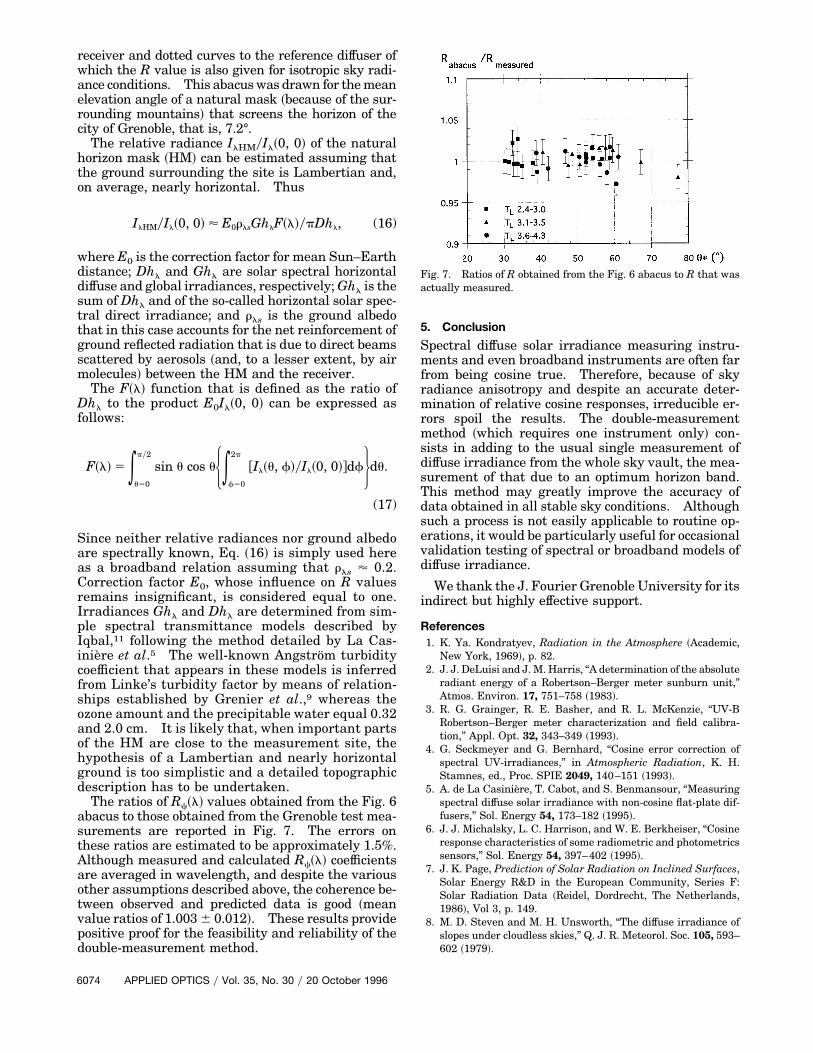
receiver and dotted curves to the reference diffuser ofwhich the R value is also given for isotropic sky radi-ance conditions. This abacuswas drawn for themeanelevation angle of a natural mask ~because of the sur-rounding mountains! that screens the horizon of thecity of Grenoble, that is, 7.2°.The relative radiance IlHMyIl~0, 0! of the natural
horizon mask ~HM! can be estimated assuming thatthe ground surrounding the site is Lambertian and,on average, nearly horizontal. Thus
IlHMyIl~0, 0! < E0rlsGhlF~l!ypDhl, (16)
where E0 is the correction factor for mean Sun–Earthdistance; Dhl and Ghl are solar spectral horizontaldiffuse and global irradiances, respectively;Ghl is thesum of Dhl and of the so-called horizontal solar spec-tral direct irradiance; and rls is the ground albedothat in this case accounts for the net reinforcement ofground reflected radiation that is due to direct beamsscattered by aerosols ~and, to a lesser extent, by airmolecules! between the HM and the receiver.The F~l! function that is defined as the ratio of
Dhl to the product E0Il~0, 0! can be expressed asfollows:
F~l! 5 *u50
py2
sin u cos uH*f50
2p
@Il~u, f!yIl~0, 0!#dfJdu.
(17)
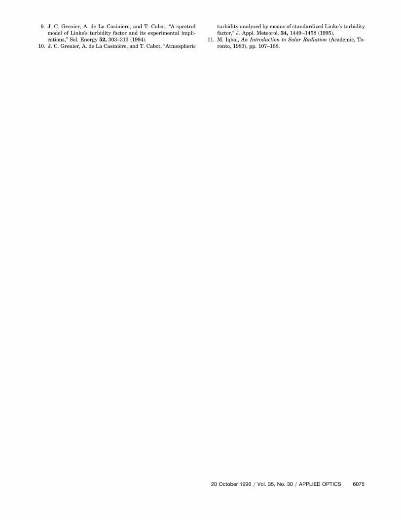
Since neither relative radiances nor ground albedoare spectrally known, Eq. ~16! is simply used hereas a broadband relation assuming that rls ' 0.2.Correction factor E0, whose influence on R valuesremains insignificant, is considered equal to one.Irradiances Ghl and Dhl are determined from sim-ple spectral transmittance models described byIqbal,11 following the method detailed by La Cas-iniere et al.5 The well-known Angstrom turbiditycoefficient that appears in these models is inferredfrom Linke’s turbidity factor by means of relation-ships established by Grenier et al.,9 whereas theozone amount and the precipitable water equal 0.32and 2.0 cm. It is likely that, when important partsof the HM are close to the measurement site, thehypothesis of a Lambertian and nearly horizontalground is too simplistic and a detailed topographicdescription has to be undertaken.The ratios of Rc~l! values obtained from the Fig. 6
abacus to those obtained from the Grenoble test mea-surements are reported in Fig. 7. The errors onthese ratios are estimated to be approximately 1.5%.Although measured and calculated Rc~l! coefficientsare averaged in wavelength, and despite the variousother assumptions described above, the coherence be-tween observed and predicted data is good ~meanvalue ratios of 1.0036 0.012!. These results providepositive proof for the feasibility and reliability of thedouble-measurement method.
6074 APPLIED OPTICS y Vol. 35, No. 30 y 20 October 1996
5. Conclusion
Spectral diffuse solar irradiance measuring instru-ments and even broadband instruments are often farfrom being cosine true. Therefore, because of skyradiance anisotropy and despite an accurate deter-mination of relative cosine responses, irreducible er-rors spoil the results. The double-measurementmethod ~which requires one instrument only! con-sists in adding to the usual single measurement ofdiffuse irradiance from the whole sky vault, the mea-surement of that due to an optimum horizon band.This method may greatly improve the accuracy ofdata obtained in all stable sky conditions. Althoughsuch a process is not easily applicable to routine op-erations, it would be particularly useful for occasionalvalidation testing of spectral or broadband models ofdiffuse irradiance.
We thank the J. Fourier Grenoble University for itsindirect but highly effective support.
References1. K. Ya. Kondratyev, Radiation in the Atmosphere ~Academic,
New York, 1969!, p. 82.2. J. J. DeLuisi and J.M.Harris, “A determination of the absolute
radiant energy of a Robertson–Berger meter sunburn unit,”Atmos. Environ. 17, 751–758 ~1983!.
3. R. G. Grainger, R. E. Basher, and R. L. McKenzie, “UV-BRobertson–Berger meter characterization and field calibra-tion,” Appl. Opt. 32, 343–349 ~1993!.
4. G. Seckmeyer and G. Bernhard, “Cosine error correction ofspectral UV-irradiances,” in Atmospheric Radiation, K. H.Stamnes, ed., Proc. SPIE 2049, 140–151 ~1993!.
5. A. de La Casiniere, T. Cabot, and S. Benmansour, “Measuringspectral diffuse solar irradiance with non-cosine flat-plate dif-fusers,” Sol. Energy 54, 173–182 ~1995!.
6. J. J. Michalsky, L. C. Harrison, and W. E. Berkheiser, “Cosineresponse characteristics of some radiometric and photometricssensors,” Sol. Energy 54, 397–402 ~1995!.
7. J. K. Page, Prediction of Solar Radiation on Inclined Surfaces,Solar Energy R&D in the European Community, Series F:Solar Radiation Data ~Reidel, Dordrecht, The Netherlands,1986!, Vol 3, p. 149.
8. M. D. Steven and M. H. Unsworth, “The diffuse irradiance ofslopes under cloudless skies,” Q. J. R. Meteorol. Soc. 105, 593–602 ~1979!.
Fig. 7. Ratios of R obtained from the Fig. 6 abacus to R that wasactually measured.
9. J. C. Grenier, A. de La Casiniere, and T. Cabot, “A spectralmodel of Linke’s turbidity factor and its experimental impli-cations,” Sol. Energy 52, 303–313 ~1994!.
10. J. C. Grenier, A. de La Casiniere, and T. Cabot, “Atmospheric
turbidity analyzed by means of standardized Linke’s turbidityfactor,” J. Appl. Meteorol. 34, 1449–1458 ~1995!.
11. M. Iqbal, An Introduction to Solar Radiation ~Academic, To-ronto, 1983!, pp. 107–168.
20 October 1996 y Vol. 35, No. 30 y APPLIED OPTICS 6075