improved heavy haul turnout design using clothoidal geometry · turnout geometry design: in 1999...
TRANSCRIPT
Improved Heavy Haul Turnout Design Using Clothoidal Geometry
Presented By:
Stephen Ashmore, Director of Engineering Standards and Technology, Union Pacific Railroad Gary Click, Technical Director, voestalpine Nortrak Inc.
Table of Contents Abstract: .................................................................................................................................................................................... Author Biographies: .................................................................................................................................................................. Introduction: ............................................................................................................................................................................. Problem Areas with Existing Concrete Tie Switches: ................................................................................................................ Development of the Clothoid Turnouts: ................................................................................................................................... Turnout Geometry Design: ....................................................................................................................................................... Controlling Turnout Track Modulus: Under-Tie Pads and Transition Ties: ............................................................................... Improving Subgrade Quality Using Asphalt Underlayment: ..................................................................................................... Clothoidal Turnout Installation: ................................................................................................................................................ Ongoing Performance Monitoring: ........................................................................................................................................... Conclusions and Future Work: .................................................................................................................................................. Special Thanks and Recognition: ............................................................................................................................................... References: ............................................................................................................................................................................... Abstract: Union Pacific Railroad operates multiple critical routes, with annual traffic in excess of 150 million gross tons, which utilize concrete ties. Over time this large amount of traffic, combined with high axle loads, takes its toll on our infrastructure. One of the most common sources of maintenance interventions is the power operated concrete tie turnouts within control points that allow trains to cross between tracks. In late 2011 UPRR and Nortrak worked together to analyze current risks and developed a next generation #20 turnout design with the main goals being a reduction in maintenance interventions and improved reliability. Eight of these next generation turnouts were installed in the fall of 2012 in Nebraska on the UPRR Columbus Subdivision.
Geometry was highlighted as an area that could improve turnout performance by adjusting the design away from the standard AREA geometry and utilizing a design based on Clothoidalal Spiral Geometry, Nortrak felt they could drastically change the loading pattern during a turnout move. This revised design not only reduces peak loading, but moves the highest loading back into the turnout further reducing its impact on the weaker point section. In addition to these changes UPRR installed asphalt sub-base between the ballast and sub-grade layer on four of the eight turnouts in an effort to improve long term surface quality. Two of the test turnouts also contained under-tie padding in an effort to control modulus throughout the turnout.
UPRR continues to evaluate the performance of these test turnouts and overall has been very satisfied with their performance.
© AREMA 2013®148
Author Biographies:
STEPHEN ASHMORE – Methods and Research – Union Pacific Railroad
Email: [email protected]
Stephen graduated with a Bachelor’s degree in Construction Engineering Tech from the University of Nebraska in 2005. After graduating Stephen came to work for Union Pacific as a member of the management training program. Stephen has held various positions including Manager of Track Maintenance, Senior Manager Methods and Research and Director Engineering Standards and Technology. Stephen also holds a MBA – Finance from Bellevue University.
GARY CLICK – Technical Director – voestalpine Nortrak, Inc.
Email: [email protected]
Gary graduated with a Bachelor’s Degree in Mechanical Engineering Technology from the University of Tennessee, Martin in 1973. After graduation Gary worked for CBI Nuclear Co. for 14 years engaged in the building of commercial nuclear power plants and other private, government and military nuclear projects. After operating a precision machine shop for 6 years Gary joined Nortrak in 1993 where he has worked for 20 years, 3 as Birmingham General Manager and as Technical Director for the last 17 years.
© AREMA 2013® 149
Introduction: Union Pacific is constantly looking for ways to drive down maintenance interventions in its critical corridors. As
traffic increases and track availability gets smaller, UPRR needs track components that are going to meet the stringent demands of the heavy axle load environment. In 2011 UPRR Engineering began an extensive research project into the overall performance of turnouts in HAL service. The goals of this study were as follows:
1. Determine the overall life cycles of major components of the switches. 2. Determine key maintenance areas that can be improved to reduce maintenance interventions in the switches. 3. Determine performance of wood tie turnouts in HAL service vs. concrete tie turnouts for long term gage
resistance and component wear. 4. Determine the impact that changes in track modulus was playing in switch performance.
UPRR engaged voestalpine Nortrak to participate in this project and in late 2011 a joint field inspection study was
conducted. At this same time a project plan was put in place to replace eight critical turnouts on the UPRR Columbus Subdivision between Columbus, NE and Fremont, NE. These turnouts composed two entire control points and would be a critical interchange point between the two mainlines. A site visit was conducted and it was determined that these locations would be a great location to test new technologies and concepts that could help reduce the maintenance requirements on the switches and improve long term performance.
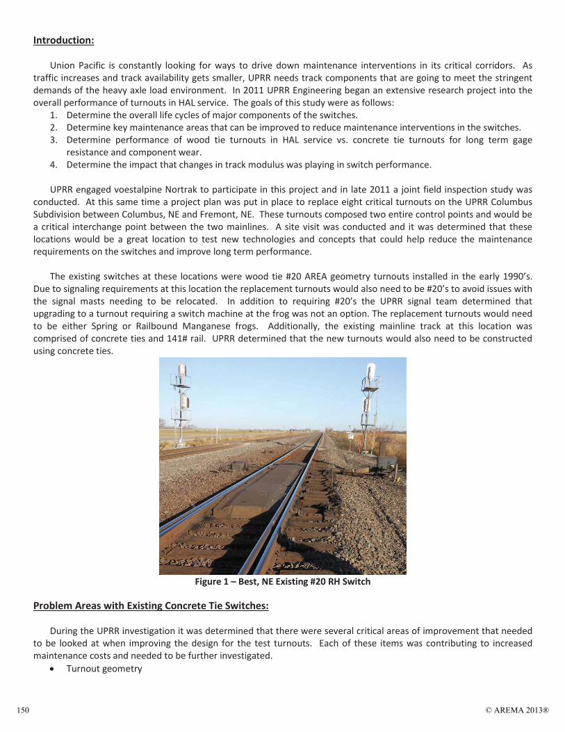
The existing switches at these locations were wood tie #20 AREA geometry turnouts installed in the early 1990’s.
Due to signaling requirements at this location the replacement turnouts would also need to be #20’s to avoid issues with the signal masts needing to be relocated. In addition to requiring #20’s the UPRR signal team determined that upgrading to a turnout requiring a switch machine at the frog was not an option. The replacement turnouts would need to be either Spring or Railbound Manganese frogs. Additionally, the existing mainline track at this location was comprised of concrete ties and 141# rail. UPRR determined that the new turnouts would also need to be constructed using concrete ties.
Figure 1 – Best, NE Existing #20 RH Switch
Problem Areas with Existing Concrete Tie Switches:
During the UPRR investigation it was determined that there were several critical areas of improvement that needed to be looked at when improving the design for the test turnouts. Each of these items was contributing to increased maintenance costs and needed to be further investigated.
Turnout geometry
© AREMA 2013®150
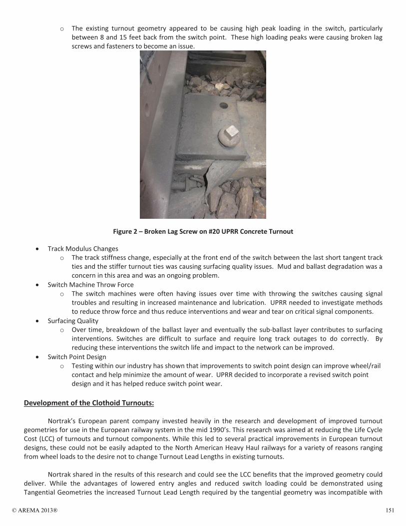
o The existing turnout geometry appeared to be causing high peak loading in the switch, particularly between 8 and 15 feet back from the switch point. These high loading peaks were causing broken lag screws and fasteners to become an issue.
Figure 2 – Broken Lag Screw on #20 UPRR Concrete Turnout
Track Modulus Changes o The track stiffness change, especially at the front end of the switch between the last short tangent track
ties and the stiffer turnout ties was causing surfacing quality issues. Mud and ballast degradation was a concern in this area and was an ongoing problem.
Switch Machine Throw Force o The switch machines were often having issues over time with throwing the switches causing signal
troubles and resulting in increased maintenance and lubrication. UPRR needed to investigate methods to reduce throw force and thus reduce interventions and wear and tear on critical signal components.
Surfacing Quality o Over time, breakdown of the ballast layer and eventually the sub-ballast layer contributes to surfacing
interventions. Switches are difficult to surface and require long track outages to do correctly. By reducing these interventions the switch life and impact to the network can be improved.
Switch Point Design o Testing within our industry has shown that improvements to switch point design can improve wheel/rail
contact and help minimize the amount of wear. UPRR decided to incorporate a revised switch point design and it has helped reduce switch point wear.
Development of the Clothoid Turnouts: Nortrak’s European parent company invested heavily in the research and development of improved turnout geometries for use in the European railway system in the mid 1990’s. This research was aimed at reducing the Life Cycle Cost (LCC) of turnouts and turnout components. While this led to several practical improvements in European turnout designs, these could not be easily adapted to the North American Heavy Haul railways for a variety of reasons ranging from wheel loads to the desire not to change Turnout Lead Lengths in existing turnouts. Nortrak shared in the results of this research and could see the LCC benefits that the improved geometry could deliver. While the advantages of lowered entry angles and reduced switch loading could be demonstrated using Tangential Geometries the increased Turnout Lead Length required by the tangential geometry was incompatible with
© AREMA 2013® 151
existing Signals Interlockings. This started a search for a solution that incorporated the benefits of Tangential Geometry with fitting inside the Turnout Lead constraints of existing AREMA designs. The answer was to use a turnout design that incorporated tangent Clothoid Spirals instead of vertex non-tangent circular arcs or tangent circular arcs to define the track centerlines.
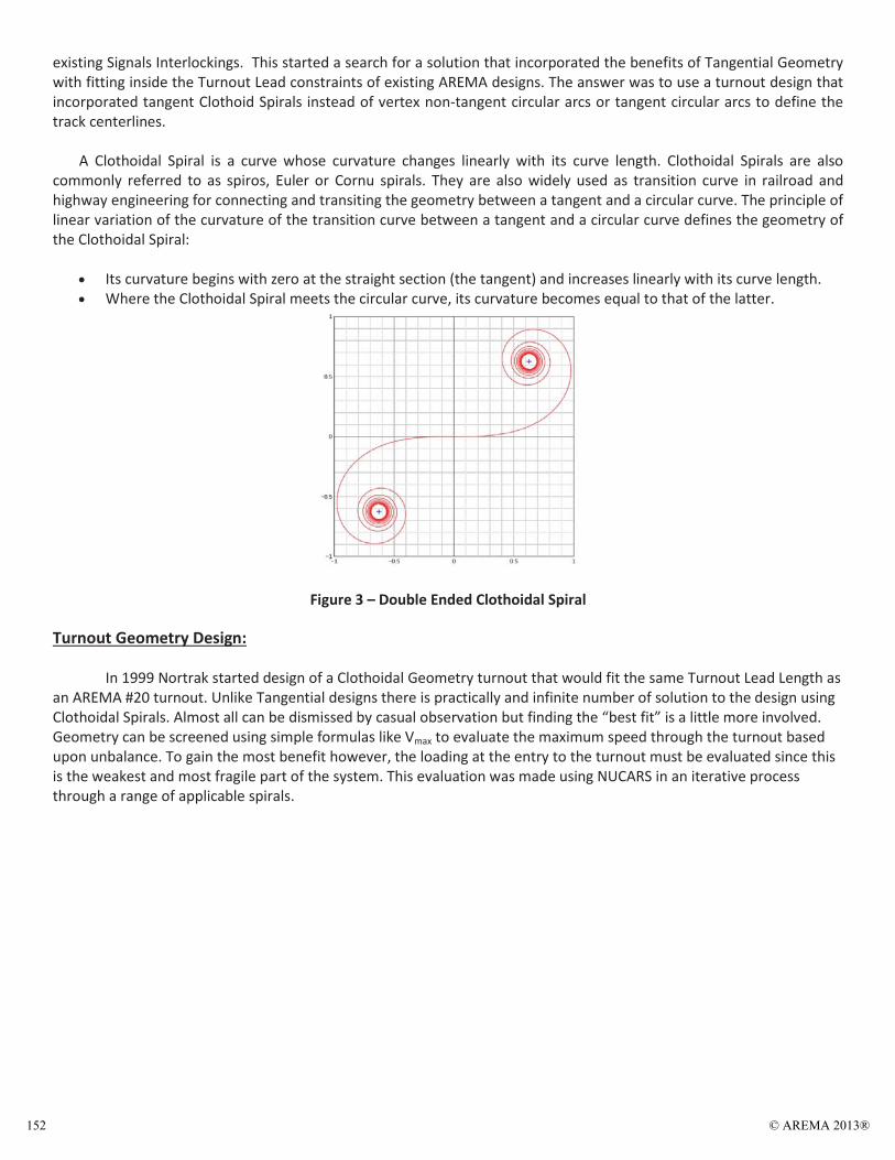
A Clothoidal Spiral is a curve whose curvature changes linearly with its curve length. Clothoidal Spirals are also commonly referred to as spiros, Euler or Cornu spirals. They are also widely used as transition curve in railroad and highway engineering for connecting and transiting the geometry between a tangent and a circular curve. The principle of linear variation of the curvature of the transition curve between a tangent and a circular curve defines the geometry of the Clothoidal Spiral:
Its curvature begins with zero at the straight section (the tangent) and increases linearly with its curve length. Where the Clothoidal Spiral meets the circular curve, its curvature becomes equal to that of the latter.
Figure 3 – Double Ended Clothoidal Spiral
Turnout Geometry Design:
In 1999 Nortrak started design of a Clothoidal Geometry turnout that would fit the same Turnout Lead Length as an AREMA #20 turnout. Unlike Tangential designs there is practically and infinite number of solution to the design using Clothoidal Spirals. Almost all can be dismissed by casual observation but finding the “best fit” is a little more involved. Geometry can be screened using simple formulas like Vmax to evaluate the maximum speed through the turnout based upon unbalance. To gain the most benefit however, the loading at the entry to the turnout must be evaluated since this is the weakest and most fragile part of the system. This evaluation was made using NUCARS in an iterative process through a range of applicable spirals.
© AREMA 2013®152
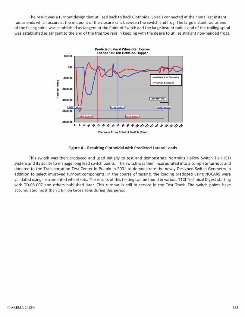
The result was a turnout design that utilized back to back Clothoidal Spirals connected at their smallest instant radius ends which occurs at the midpoint of the closure rails between the switch and frog. The large instant radius end of the facing spiral was established as tangent at the Point of Switch and the large instant radius end of the trailing spiral was established as tangent to the end of the frog toe rails in keeping with the desire to utilize straight non-handed frogs.
Figure 4 – Resulting Clothoidal with Predicted Lateral Loads
This switch was then produced and used initially to test and demonstrate Nortrak’s Hollow Switch Tie (HST) system and its ability to manage long lead switch points. The switch was then incorporated into a complete turnout and donated to the Transportation Test Center in Pueblo in 2001 to demonstrate the newly Designed Switch Geometry in addition to select improved turnout components. In the course of testing, the loading predicted using NUCARS were validated using instrumented wheel sets. The results of this testing can be found in various TTCI Technical Digest starting with TD-05-007 and others published later. This turnout is still in service in the Test Track. The switch points have accumulated most than 1 Billion Gross Tons during this period.
© AREMA 2013® 153
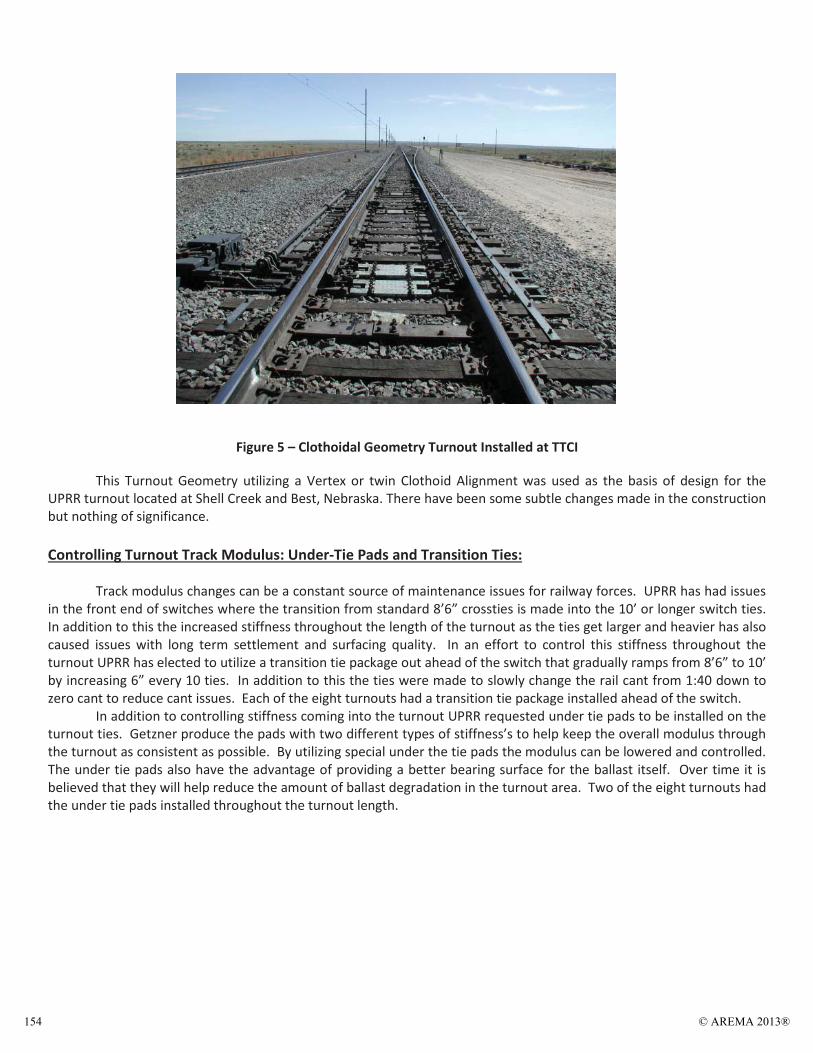
Figure 5 – Clothoidal Geometry Turnout Installed at TTCI
This Turnout Geometry utilizing a Vertex or twin Clothoid Alignment was used as the basis of design for the UPRR turnout located at Shell Creek and Best, Nebraska. There have been some subtle changes made in the construction but nothing of significance. Controlling Turnout Track Modulus: Under-Tie Pads and Transition Ties:
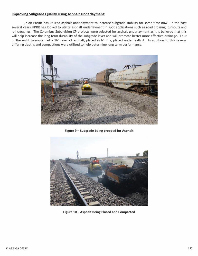
Track modulus changes can be a constant source of maintenance issues for railway forces. UPRR has had issues in the front end of switches where the transition from standard 8’6” crossties is made into the 10’ or longer switch ties. In addition to this the increased stiffness throughout the length of the turnout as the ties get larger and heavier has also caused issues with long term settlement and surfacing quality. In an effort to control this stiffness throughout the turnout UPRR has elected to utilize a transition tie package out ahead of the switch that gradually ramps from 8’6” to 10’ by increasing 6” every 10 ties. In addition to this the ties were made to slowly change the rail cant from 1:40 down to zero cant to reduce cant issues. Each of the eight turnouts had a transition tie package installed ahead of the switch.
In addition to controlling stiffness coming into the turnout UPRR requested under tie pads to be installed on the turnout ties. Getzner produce the pads with two different types of stiffness’s to help keep the overall modulus through the turnout as consistent as possible. By utilizing special under the tie pads the modulus can be lowered and controlled. The under tie pads also have the advantage of providing a better bearing surface for the ballast itself. Over time it is believed that they will help reduce the amount of ballast degradation in the turnout area. Two of the eight turnouts had the under tie pads installed throughout the turnout length.
© AREMA 2013®154
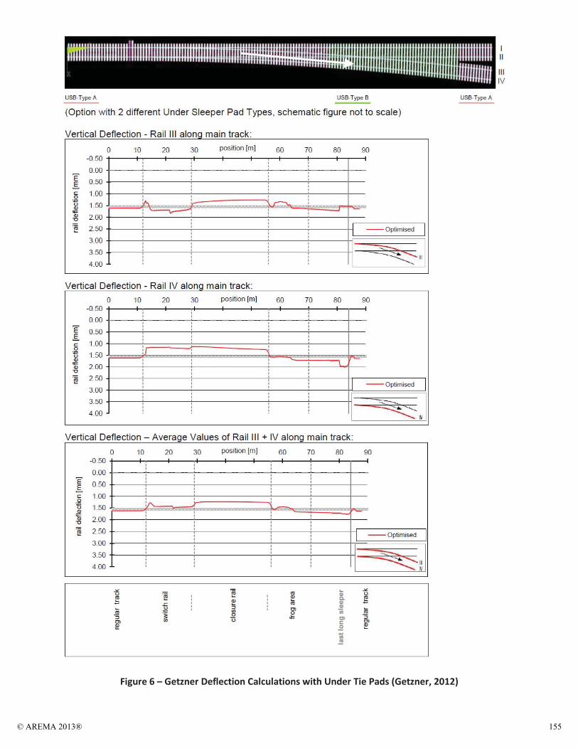
Figure 6 – Getzner Deflection Calculations with Under Tie Pads (Getzner, 2012)
© AREMA 2013® 155
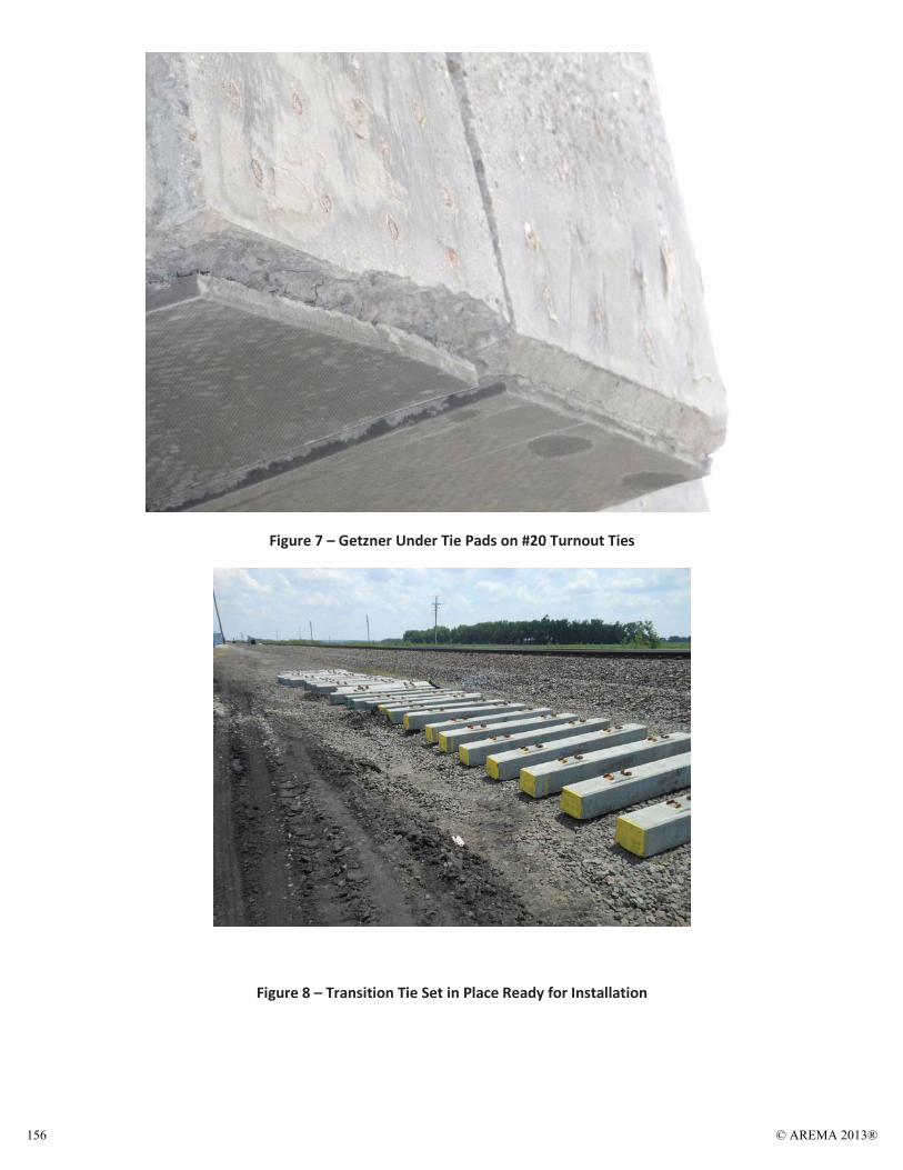
Figure 7 – Getzner Under Tie Pads on #20 Turnout Ties
Figure 8 – Transition Tie Set in Place Ready for Installation
© AREMA 2013®156
Improving Subgrade Quality Using Asphalt Underlayment: Union Pacific has utilized asphalt underlayment to increase subgrade stability for some time now. In the past several years UPRR has looked to utilize asphalt underlayment in spot applications such as road crossing, turnouts and rail crossings. The Columbus Subdivision CP projects were selected for asphalt underlayment as it is believed that this will help increase the long term durability of the subgrade layer and will promote better more effective drainage. Four of the eight turnouts had a 16” layer of asphalt, placed in 6” lifts, placed underneath it. In addition to this several differing depths and compactions were utilized to help determine long term performance.
Figure 9 – Subgrade being prepped for Asphalt
Figure 10 – Asphalt Being Placed and Compacted
© AREMA 2013® 157
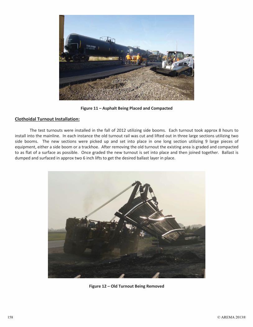
Figure 11 – Asphalt Being Placed and Compacted
Clothoidal Turnout Installation:
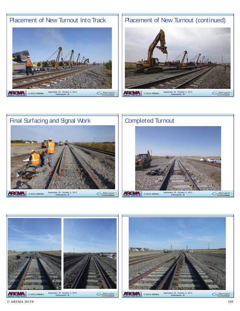
The test turnouts were installed in the fall of 2012 utilizing side booms. Each turnout took approx 8 hours to install into the mainline. In each instance the old turnout rail was cut and lifted out in three large sections utilizing two side booms. The new sections were picked up and set into place in one long section utilizing 9 large pieces of equipment, either a side boom or a trackhoe. After removing the old turnout the existing area is graded and compacted to as flat of a surface as possible. Once graded the new turnout is set into place and then joined together. Ballast is dumped and surfaced in approx two 6 inch lifts to get the desired ballast layer in place.
Figure 12 – Old Turnout Being Removed
© AREMA 2013®158
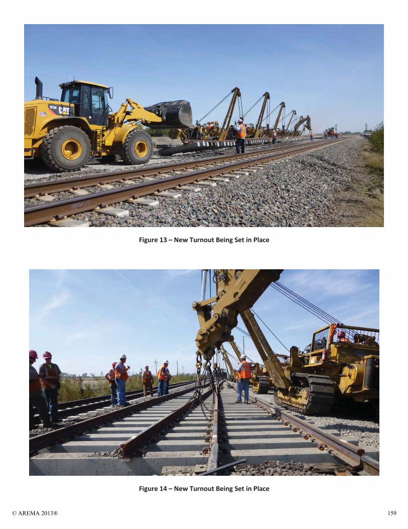
Figure 13 – New Turnout Being Set in Place
Figure 14 – New Turnout Being Set in Place
© AREMA 2013® 159
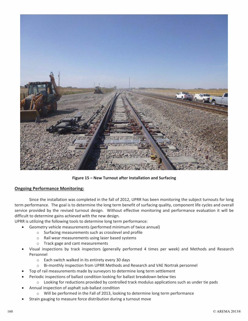
Figure 15 – New Turnout after Installation and Surfacing
Ongoing Performance Monitoring:
Since the installation was completed in the fall of 2012, UPRR has been monitoring the subject turnouts for long term performance. The goal is to determine the long term benefit of surfacing quality, component life cycles and overall service provided by the revised turnout design. Without effective monitoring and performance evaluation it will be difficult to determine gains achieved with the new design. UPRR is utilizing the following tools to determine long term performance:
Geometry vehicle measurements (performed minimum of twice annual) o Surfacing measurements such as crosslevel and profile o Rail wear measurements using laser based systems o Track gage and cant measurements
Visual inspections by track inspectors (generally performed 4 times per week) and Methods and Research Personnel
o Each switch walked in its entirety every 30 days o Bi-monthly inspection from UPRR Methods and Research and VAE Nortrak personnel
Top of rail measurements made by surveyors to determine long term settlement Periodic inspections of ballast condition looking for ballast breakdown below ties
o Looking for reductions provided by controlled track modulus applications such as under tie pads Annual inspection of asphalt sub-ballast condition
o Will be performed in the Fall of 2013, looking to determine long term performance Strain gauging to measure force distribution during a turnout move
© AREMA 2013®160
Rail wear and component wear measurements Switch machine throw force to determine effectiveness of new design in distributing the load Ground Penetrating Radar to determine ballast quality and if possible sub-grade quality
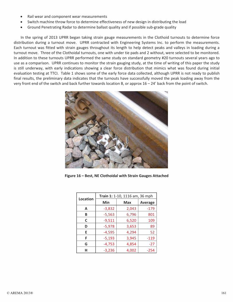
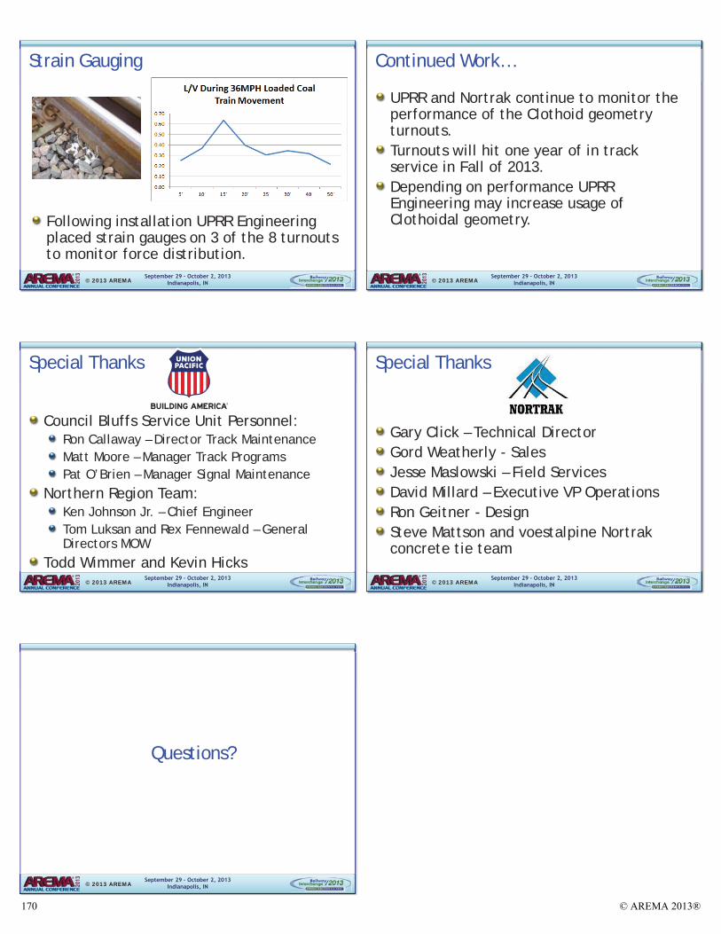
In the spring of 2013 UPRR began taking strain gauge measurements in the Clothoid turnouts to determine force distribution during a turnout move. UPRR contracted with Engineering Systems Inc. to perform the measurements. Each turnout was fitted with strain gauges throughout its length to help detect peaks and valleys in loading during a turnout move. Three of the Clothoidal turnouts, one with under tie pads and 2 without, were selected to be monitored. In addition to these turnouts UPRR performed the same study on standard geometry #20 turnouts several years ago to use as a comparison. UPRR continues to monitor the strain gauging study, at the time of writing of this paper the study is still underway, with early indications showing a clear force distribution that mimics what was found during initial evaluation testing at TTCI. Table 1 shows some of the early force data collected, although UPRR is not ready to publish final results, the preliminary data indicates that the turnouts have successfully moved the peak loading away from the very front end of the switch and back further towards location B, or approx 16 – 24’ back from the point of switch.
Figure 16 – Best, NE Clothoidal with Strain Gauges Attached
Location Train 1: 1-10, 1116 am, 36 mph
Min Max Average A -3,832 2,043 -179 B -5,563 6,796 801 C -9,511 6,520 109 D -5,978 3,653 89 E -4,595 4,294 52 F -5,193 3,945 -119 G -4,753 4,854 -27 H -3,236 4,002 -254
© AREMA 2013® 161
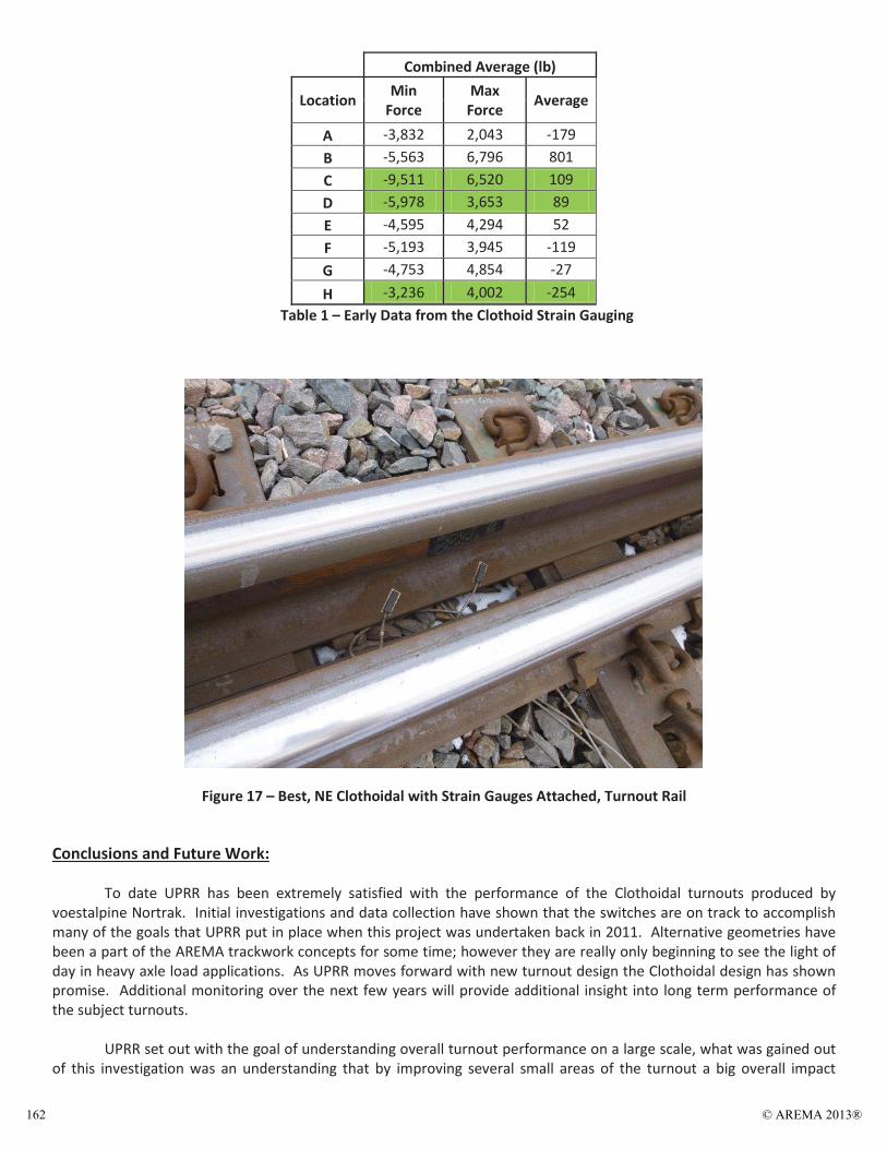
Combined Average (lb)
Location Min Force
Max Force Average
A -3,832 2,043 -179 B -5,563 6,796 801 C -9,511 6,520 109 D -5,978 3,653 89 E -4,595 4,294 52 F -5,193 3,945 -119 G -4,753 4,854 -27 H -3,236 4,002 -254
Table 1 – Early Data from the Clothoid Strain Gauging
Figure 17 – Best, NE Clothoidal with Strain Gauges Attached, Turnout Rail
Conclusions and Future Work:
To date UPRR has been extremely satisfied with the performance of the Clothoidal turnouts produced by voestalpine Nortrak. Initial investigations and data collection have shown that the switches are on track to accomplish many of the goals that UPRR put in place when this project was undertaken back in 2011. Alternative geometries have been a part of the AREMA trackwork concepts for some time; however they are really only beginning to see the light of day in heavy axle load applications. As UPRR moves forward with new turnout design the Clothoidal design has shown promise. Additional monitoring over the next few years will provide additional insight into long term performance of the subject turnouts.
UPRR set out with the goal of understanding overall turnout performance on a large scale, what was gained out
of this investigation was an understanding that by improving several small areas of the turnout a big overall impact
© AREMA 2013®162
would be made on performance. When approached with this challenge voestalpine Nortrak stepped to the plate and presented an innovative concept that attempts to take ideas gained from year of experience and research and put them into practice. By taking many different concepts and practices and executing them effectively, both parties used their best Engineering ideas and concepts and put them into action to develop a turnout that is cutting edge.
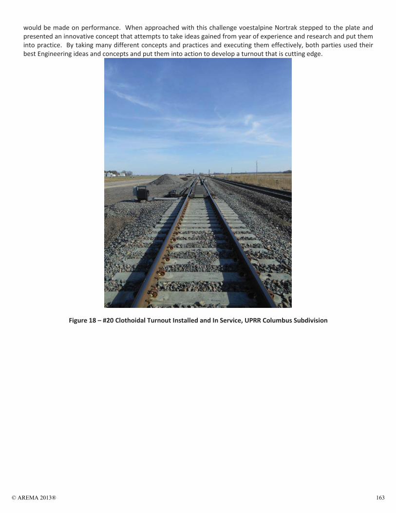
Figure 18 – #20 Clothoidal Turnout Installed and In Service, UPRR Columbus Subdivision
© AREMA 2013® 163

Figure 19 - #20 Clothoid Turnout Installed and In Service, UPRR Columbus Subdivision
Special Thanks and Recognition: Union Pacific Railroad, without the support of these individuals this project would not have happened. Ron Callaway, DTM Council Bluffs Matt Moore, MTP Council Bluffs Kenneth Johnson, CE Northern Region Rex Fennewald, Gen Dir Northern Region Todd Wimmer and Kevin Hicks, UPRR Standards Group voestalpine Nortrak Gord Weatherly Dan Pauli David Millard Ron Geitner Steve Mattson and the voestalpine Concrete Tie Team References: Getzner Company (2012) - Finite Element Calculations for Heavy Haul Turnout with Under Sleeper pads for voestalpine Nortrak (Concrete Ties). Provided to voestalpine Nortrak and UPRR on 3/29/2012. Transportation Test Center - Technical Digest on Turnout Geometries.
© AREMA 2013®164
Sept
embe
r 29
– O
ctob
er 2
, 20
13
Indi
anap
olis
, IN
Impr
oved
Hea
vy H
aul T
urno
ut D
esig
n U
sing
Clo
thoi
dal G
eom
etry
9:00
– 9
:30
AM
Tues
day,
Oct
ober
1,
2013
Tr
ack
Brea
kout
Ses
sion
© 2
013
AR
EM
A
© AREMA 2013® 165
September 29 – October 2, 2013 Indianapolis, IN
Authors
Stephen Ashmore Director Engineering Standards and Technology, Union Pacific Railroad
Gary Click Technical Director, voestalpine Nortrak Inc.
© 2013 AREMASeptember 29 – October 2, 2013
Indianapolis, IN
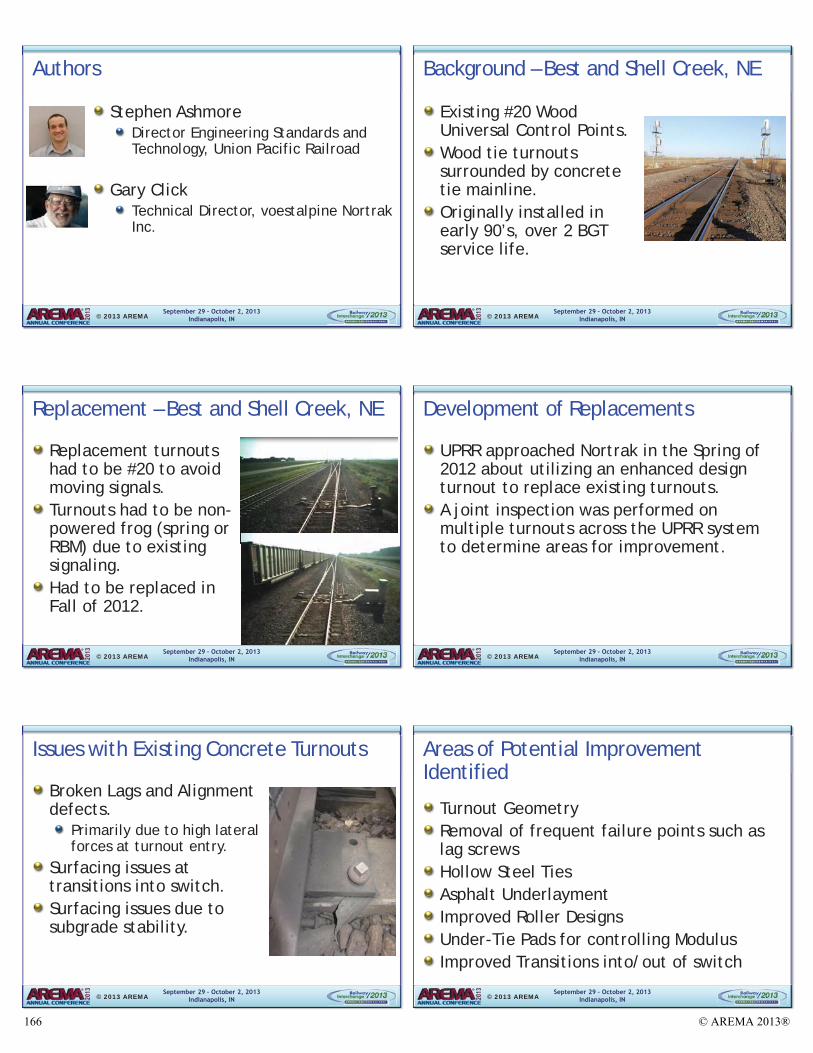
Background – Best and Shell Creek, NE
Existing #20 Wood Universal Control Points. Wood tie turnouts surrounded by concrete tie mainline. Originally installed in early 90’s, over 2 BGT service life.
© 2013 AREMA
September 29 – October 2, 2013 Indianapolis, IN
Replacement – Best and Shell Creek, NE
Replacement turnouts had to be #20 to avoid moving signals. Turnouts had to be non-powered frog (spring or RBM) due to existing signaling.Had to be replaced in Fall of 2012.
© 2013 AREMASeptember 29 – October 2, 2013
Indianapolis, IN
Development of Replacements
UPRR approached Nortrak in the Spring of 2012 about utilizing an enhanced design turnout to replace existing turnouts. A joint inspection was performed on multiple turnouts across the UPRR system to determine areas for improvement.
© 2013 AREMA
September 29 – October 2, 2013 Indianapolis, IN
Issues with Existing Concrete Turnouts
Broken Lags and Alignment defects.
Primarily due to high lateral forces at turnout entry.
Surfacing issues at transitions into switch. Surfacing issues due to subgrade stability.
© 2013 AREMASeptember 29 – October 2, 2013
Indianapolis, IN
Areas of Potential Improvement Identified
Turnout Geometry Removal of frequent failure points such as lag screws Hollow Steel Ties Asphalt Underlayment Improved Roller Designs Under-Tie Pads for controlling Modulus Improved Transitions into/out of switch
© 2013 AREMA
© AREMA 2013®166
September 29 – October 2, 2013 Indianapolis, IN
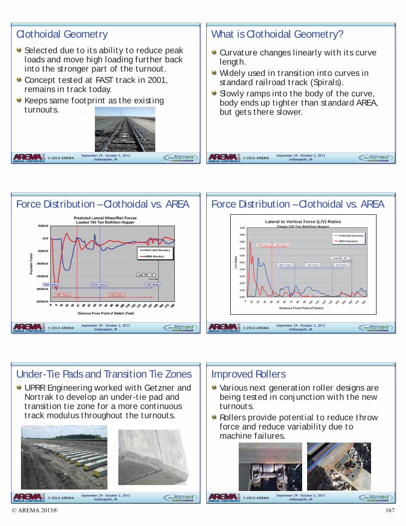
Clothoidal Geometry Selected due to its ability to reduce peak loads and move high loading further back into the stronger part of the turnout. Concept tested at FAST track in 2001, remains in track today. Keeps same footprint as the existing turnouts.
© 2013 AREMASeptember 29 – October 2, 2013
Indianapolis, IN
What is Clothoidal Geometry?
Curvature changes linearly with its curve length.Widely used in transition into curves in standard railroad track (Spirals). Slowly ramps into the body of the curve, body ends up tighter than standard AREA, but gets there slower.
© 2013 AREMA
September 29 – October 2, 2013 Indianapolis, IN
Force Distribution – Clothoidal vs. AREA
© 2013 AREMASeptember 29 – October 2, 2013
Indianapolis, IN
Force Distribution – Clothoidal vs. AREA Lateral to Vertical Force (L/V) Ratios
Empty 100 Ton BethGon Hopper
0.00
0.10
0.20
0.30
0.40
0.50
0.60
0.70
0.80
0.90
1.00
0 10 20 30 40 50 60 70 80 90 100
110
120
130
140
150
160
170
180
L/V
Rat
ioClothoidal Geometry
AREA Standard
Distance From Point of Switch
Lead 156' -1/2"
2100' Radius 4100' Radius4000' Radius
3329' Radius3603' Radius
© 2013 AREMA
September 29 – October 2, 2013 Indianapolis, IN
Under-Tie Pads and Transition Tie Zones UPRR Engineering worked with Getzner and Nortrak to develop an under-tie pad and transition tie zone for a more continuous track modulus throughout the turnouts.
© 2013 AREMASeptember 29 – October 2, 2013
Indianapolis, IN
Improved Rollers Various next generation roller designs are being tested in conjunction with the new turnouts.Rollers provide potential to reduce throw force and reduce variability due to machine failures.
© 2013 AREMA
© AREMA 2013® 167
September 29 – October 2, 2013 Indianapolis, IN
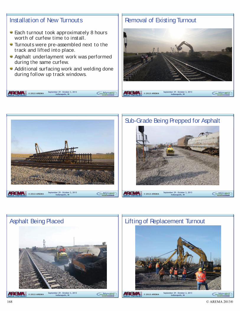
Installation of New Turnouts
Each turnout took approximately 8 hours worth of curfew time to install. Turnouts were pre-assembled next to the track and lifted into place. Asphalt underlayment work was performed during the same curfew. Additional surfacing work and welding done during follow up track windows.
© 2013 AREMASeptember 29 – October 2, 2013
Indianapolis, IN
Removal of Existing Turnout
© 2013 AREMA
September 29 – October 2, 2013 Indianapolis, IN © 2013 AREMA
September 29 – October 2, 2013 Indianapolis, IN
Sub-Grade Being Prepped for Asphalt
© 2013 AREMA
September 29 – October 2, 2013 Indianapolis, IN
Asphalt Being Placed
© 2013 AREMASeptember 29 – October 2, 2013
Indianapolis, IN
Lifting of Replacement Turnout
© 2013 AREMA
© AREMA 2013®168
September 29 – October 2, 2013 Indianapolis, IN
Placement of New Turnout Into Track
© 2013 AREMASeptember 29 – October 2, 2013
Indianapolis, IN
Placement of New Turnout (continued)
© 2013 AREMA
September 29 – October 2, 2013 Indianapolis, IN
Final Surfacing and Signal Work
© 2013 AREMASeptember 29 – October 2, 2013
Indianapolis, IN
Completed Turnout
© 2013 AREMA
September 29 – October 2, 2013 Indianapolis, IN © 2013 AREMA
September 29 – October 2, 2013 Indianapolis, IN © 2013 AREMA
© AREMA 2013® 169
September 29 – October 2, 2013 Indianapolis, IN
Strain Gauging
Following installation UPRR Engineering placed strain gauges on 3 of the 8 turnouts to monitor force distribution.
© 2013 AREMASeptember 29 – October 2, 2013
Indianapolis, IN
Continued Work…
UPRR and Nortrak continue to monitor the performance of the Clothoid geometry turnouts.Turnouts will hit one year of in track service in Fall of 2013. Depending on performance UPRR Engineering may increase usage of Clothoidal geometry.
© 2013 AREMA
September 29 – October 2, 2013 Indianapolis, IN
Special Thanks
Council Bluffs Service Unit Personnel: Ron Callaway – Director Track Maintenance Matt Moore – Manager Track Programs Pat O’Brien – Manager Signal Maintenance
Northern Region Team: Ken Johnson Jr. – Chief Engineer Tom Luksan and Rex Fennewald – General Directors MOW
Todd Wimmer and Kevin Hicks © 2013 AREMA
September 29 – October 2, 2013 Indianapolis, IN
Special Thanks
Gary Click – Technical Director Gord Weatherly - Sales Jesse Maslowski – Field Services David Millard – Executive VP Operations Ron Geitner - Design Steve Mattson and voestalpine Nortrak concrete tie team
© 2013 AREMA
September 29 – October 2, 2013 Indianapolis, IN
Questions?
© 2013 AREMA
© AREMA 2013®170