improved drainage and frost criteria for … · entitled "design and application details for...
TRANSCRIPT
IMPROVED DRAINAGE AND FROST ACTION C R I T E R I A FOR NEW JERSEY PAVEMENT DESIGN, VOLUME I11
ROAD SUBSURFACE DRAINAGE D E S I G N , CONSTRUCTION AND MAINTENANCE GUIDE
FOR PAVEMENTS
A F i n a l Report
March 1984
BY
GEORGE S. KOZLOV, AUTHOR
Divis ion of Research and Demonstration
New Jersey Department of Transportat ion
In cooperat ion with
U. S. Department of Transportat ion
Federal Highway Administration
"The con ten t s o f t h i s r e p o r t reflect the views o f
the author who is re spons ib l e f o r the facts and the
accuracy of t h e data presented herein. The con-
t e n t s do no t n e c e s s a r i l y ref lect t h e o f f i c i a l views
o r p o l i c i e s o f the State o r t h e Federal Highway
Administration. This r e p o r t does not c o n s t i t u t e a
s t anda rd , s p e c i f i c a t i o n , o r r egu la t ion . "
r
I .

1. Repcrt No.
FHWA/NJ-84/015
12. Sponsorins Agency Name ond Address
Federal Highway Admin i s t ra t i on Washington, D.C. 20590
2. Government Accession No. 3. Recipient's Cotalog No.
F i n a l
Road Subsurface Drainage Design, Construct ion and
7. Author's.
George S. Kozlov, P r o j e c t Engineer 9 .
Guide f o r P a v w n t z "
Performing Organization Nome and Address
New Jersey Department o f Transpor tat ion
1035 Parkway Avenue D i v i s i o n o f Research and Demonstration
Trenton, NJ 08625 II
15. Supplementary Notes
Prepared i n cooperation w i t h the FHWA. p u b l i c a t i o n s prepared as p a r t o f t h i s research i s presented on pages x i - x i v .
An annotated l i s t i n g o f t h e o t h e r
6. Perlorming Orpanixation Code
N.A. 8. P.r+ormong Organlratlon Report No.
84-0 15- 7740 10. Work Unit No.
N.A.
NJ HPR Study 7740 11. Controct or Gront N o .
13. Type o f Report and Perlo: Coverec
16. Abstroct
17. Key Words
Subsurface drainage, i n f i l t r a t i o n water, ground water, drainage layers, c o l l e c t o r systems, i n t e r c e p t o r drains, r a t i o n a l a n a l y t i c a l methods.
I
This Volume 111 r e p o r t o f a three-volume se r ies on subsurface road dra inage i s o f f e r e d as a guide f o r so l v ing the problem o f road subsurface drainage. The i n t e n t i s t o formulate improved design methods and cons t ruc t i on and maintenance procedures f o r road i n t e r n a l drainage systems as a means f o r c o n t r o l l i n g water w i t h i n pavements. systems capable t o c o n t r o l water i n t e r n a l movements, a t l e a s t t o l i m i t i t s damaging e f f e c t and t o extend road l i f e expectancy. The s o l u t i o n s offered are expected t o be s t r u c t u r a l l y sound and cause no adverse f r o s t ef fects.
This guide i s an e f f o r t t o prov ide i n t e r n a l road drainage
18. Distribution Stolmmmt
Copies a v a i l a b l e on request
19. Securvty Clossof. (o f this repart) 20. Security Clossif . (of th is pogo)
U n c l a s s i f i e d Unc lass i f i ed I 1
21. NO. of Pages 22. Price
166
IMPLEMENTATION STATEMENT
To facil i tate t h e early implementation of t h e internal road drainage, design
concepts developed in this research were outlined in a 1981 Memorandum Report
entitled "Design and Application Details for Highway Drainage Layers". This
preliminary report provided the D e p u t m e n r s pavement designers with sufficient
information to begin incorporating t h e drainage layer concept into new
construction projects. As a result, the highway underdrain system proposed by
the research was used on the truck weigh station on Route 1-78 and will be used
on Route 55, Section 13B. Due t o t h e potential for increased life for pavements
with subsurface drainage, this system is also being considered for inclusion into
t h e final sections of Route 1-287 and the Route 1-78 Alpha by-pass.
Another early publication resulting from this research -- the "Road Surface
Drainage Design Construction and Maintenance Guide for Pavements" -- recommended improved surf ace drainage design procedures which, when coupled
with the developed internal drainage procedures, can provide the most
advantageous solution t o t h e problem of water buildup beneath the roadway.
These surface drainage procedures have yet to be implemented.
In general, throughout this study, the researchers worked closely with t h e
personnel from the operative divisions which would be using the findings of this
research. To further aid in the implementation of t h e research findings and to
avoid any possible misapplications of the proposed solutions, a mutually
beneficial continuation of t h e cooperation between Research and operating
personnel is suggested until at least several large projects have been completed.
To facilitate such implementation, t h e permeameter and t h e modified
compaction equipment have been improved and standardized for easy fabrication
and application. These efforts might result in procedural design refinements.
ii
ACKNOWLEDGMENTS
The intent of this guide is to provide the highway engineer with a
systematic means for solving the internal drainage problems of roadways. Since
part of it, concerning groundwater problems, deals with the basic engineering of
drainage, its solution is based heavily on available drainage engineering
literature. The largest portion of the guide, concerning infiltration water
drainage, covers solutions developed by this research and therefore a r e
innovative and original, even though some similar approaches had been suggested
elsewhere. In this vein, the past and present members of the research team but
especially Bruce Cosaboom, Victor Mottola, and Gregory Mehalchick, are very
deservingly complimented on a job well done.
In some instances concerning groundwater and design in general, t h e
information in a particular reference is considered directly applicable to t h e
Department's needs and verbatim excerpts are used. However, for practical
reasons, quotes are often omitted. Permission for such use of reference
documents has been solicited and secured from Professor Moulton, the author of
a source mentioned below. In presenting this guide then, an expression of
appreciation goes to the following organization and individuals:
1. FHWA, Mr. Harry R. Cedergren, Mr. George A. Avman, and Mr. Ken
H. O'Brien, "Development of Guidelines for the Design of Subsurface
Drainage Systems for Highway Pavement Structural Sectionstt,
February, 1973.
2. FHWA, Dr. Lyle K. Moulton, Ph.D., P.E., "Highway Subdrainage
Design", August, 1980.
iii
TABLE OF CONTENTS
Page
Index of Figures ..................................................... v i
Index of Tables ...................................................... x
A . Introduction and Background .......................................... 1
B . General .............................................................. 2
C . Design of Drainage for Subsurface Water I n f i l t r a t i o n ................. 3
C . l Highway Geometry ...................................... i . ........ 4
C.2 Subsurface Geometry .............................................. 5
C.3 Design o f the Subsurface Drainage Layer ......................... 11
C.3.1 Water I n f i l t r a t i o n and Pr inc ipa ls of Subsurface Drainage ................................................. 14
General Types and Applications o f Open Graded Drainage Layer Materials ............................... 18
C.3.2
C.3.3 Non-Stablilized Open Graded Material Propert ies and Laboratory Test Procedures ........................... 20
C.3.4 Bituminous S tab i l ized Open Graded Material Propert ies and Laboratory Test Procedures ................ 25
Ce3.5 Barriers ................................................. 28
C.4 Design of Water Collect ion Systems .............................. 37
C.4.1 General .................................................. 37
C.4.2 Longitudinal. Transverse Collectors and Outlets .......... 37
C.5 Subsurface Drainage Geometry Design Example ..................... 50
C.5.1 In t e rna l Drainage Design Example ......................... 54
D . Design of Groundwater Drainage ....................................... 56
D.l General ......................................................... 56
D.2
D.3
Class i f ica t ion of the Highway Groundwater Subdrains ............. 58
The Design Analysis ............................................. 62
i v
TABLE OF CONTENTS (Continued)
Page
D.4 Basics o f t he Rational Analytical Methods ..................... 62
D.4.1 Application o f Rational Analytical Methods Examples ............................................... 65
D.5 In t e rcep to r Drains Design Pr inc ip les .......................... 68
D.5.1 Analysis of an Interceptor Drain ....................... 74
D.6 Miscellaneous Groundwater Dralnage ............................ 77
E . Construction and Maintenance ........................................ 77
E.l General ........................................................ 77
E.2 Construction o f Collection Syste lns ............................. 80
E.3 Construction o f NSOG and BSOG Drainage Layers ................. 82
E.4 Maintenance of Subsurface Drainage Systems .................... 90
F . Subsurface Drainage and Pavement Rehabi l i ta t ion ..................... 92
F.l General ........................................................ 92
F.2 Design Guidelines fo r Rehabili tation o f Pavements .............. 94 F.3 Methods of Construction ........................................ 95
References .............................................................. 100
APPENDICES
Appendix A . Drainage Layer Flow Rates. (Q) and Flow Path Lengths (Lh ... 102
Appendix B . Construction and Material Specif icat ion for B O G (Bituminous Stabilized Open Graded) and NSOG (Non- S tab i l i zed Open Graded) Drainage Layers and Subsurface Drainage Collectors ............................. 108
Appendix C . Fa l l ing Head Permeability Test fo r Open Graded Materials .................................................. 132
Appendix D . Laboratory Compaction Tests and Equipment f o r BSOG and NSOG Materials ............................................. 138
V
I
INDEX OF FIGURES
Page
Paths of Flow of Surface Water on Portland Cement
S t r u c t u r a l Section ............................................ 6
Path o f Subsurface Water in Drainage Layer ................... 7
Undrained Roadway Section on Vertical Curve (SAG) ............. 10
Transverse Drains Are Needed on Superelevated Curves .......... 10
In t e rna l ly Drainable Road Cross-Section With Drains
A t t he Edge of Pavement ....................................... 12
In t e rna l ly Drainable Road Cross-Section With Drains
A t t he Edge of Shoulder ....................................... 12
Road Cross-Section Drainable t o the Edge of Pavement
Col lectors ................................................... 13
Road Cross-Section Drainable t o the Edge of Shoulder
Col lectors ................................................... 13
Relation Between Slope and Length of OG Base fo r 50%
Degree of Drainage ........................................... 19
NSOG Gradation Range .......................................... 22
BSOG Gradation Range .......................................... 26
NJ NSOG and Base and Subbase Materials ........................ 34
Figure 1 .
Figure 2 . Figure 3 . Figure 4 . Figure 5 .
Figure 6 .
Figure 7 .
Figure 8 .
Figure 9 .
Figure 10 . Figure 11 . Figure 12 . Figure 13 . Barenberg's Test S i t e ......................................... 36
Figure 14 . Typical Detail of t h e Edge of Pavement Subsurface
Drainage Collectors .......................................... 39
v i
I N D E X OF FIGURES (Continued)
Page
Figure 15 . Typical Detail o f t he Edge of Shoulder Subsurface
Drainage Collectors ........................................... 40
Figure 16 . Typical Transverse Ditch Detail ............................... 41
Figure 17 . Typical Detail o f Drainage Outlet Rip-Rap ..................... 4 2
Figure 18 . Typical Outlet Pipe Entrance Detail ........................... 43
Figure 19 . Nomogram Relating Solut ion of Manning Pipe Flow
Equation t o the Product of a Drain's Flow Rate and
Figure 20 . Figure 21 . Figure 22 .
Figure 23 .
Figure 24 .
Figure 25 . Figure 26 . Figure 27 .
Figure 28 .
Figure 29 .
t h e Distance Between Out le t s .................................. 48
Route 195 Subsurface Drainage Geometry Design Example ......... 51
Route 195 Pavement Cross-Section .............................. 53
Longitudinal In te rceptor Drain Used t o C u t O f f
Seepage and Lower the Groundwater Table ....................... 60
Layer ......................................................... 61
Blanket ....................................................... 64
Rigid Pavement Section in Cut-Dimensions and D e t a i l s .......... 66
Flow Toward a Single In te rceptor Drain ........................ 69
Artesian Flow o f Groundwater In to a Pavement Drainage
Chart f o r Determining Flow Rate in Horizontal Drainage
Flow Toward a Single In te rceptor Drain When the
Drawdown Can B e Considered t o Be Ins igni f icant ................ 70
Chart f o r Determining Flow Rate i n Interceptor
Drain ......................................................... 72
Chart f o r Determining Drawdown Curve fo r Interceptor
Drains ........................................................ 7 3
v i i
INDEX OF FIGURES (Continued) Page
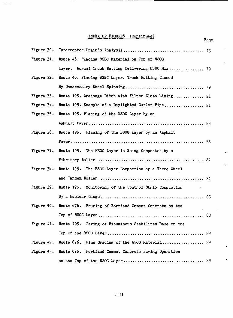
Figure 30 . In te rceptor Drain's Analysis ................................... 76
Figure 31 . Route 46 . Placing BSBC Material on Top of NSOG
Layer . Normal Truck Rutting Delivering BSBC M i x ............... 79
Route 46 . Placing BSBC Layer . Truck Rutting Caused
By Unnecessary Wheel SP inning .................................. 79
Figure 33 . Route 195 . Drainage Ditch with F i l t e r Cloth Lining ............. 81
Figure 34 . Route 195 . Example of a Daylighted Outlet Pipe ................. 81
Figure 32 .
Figure 35 . Route 195 . Placing of t h e NSOG Layer by an
Asphalt Paver .................................................. 83
Route 195 . Figure 36 . Placing of t h e BSOG Layer by an Asphalt
Paver .......................................................... 83
Figure 37 . Route 195 . The NSOG Layer is Being Compacted by a
Vibratory Roller .............................................. 84
Route 195 . The BSOG Layer Compaction by a Three &eel Figure 38 . and Tandem Roller ............................................. 84
Figure 39 . Route 195 . Monitoring of the Control S t r i p Compaction
By a Nuclear Gauge ............................................. 86
Figure 40 . Route 676 . Pouring of Portland Cement Concrete on the
Top of BSOG Layer .............................................. 88
Figure 41 . Route 195 . Paving of Bituminous S tab i l i zed Base on the
Top of t he BSOG Layer .......................................... 88
Figure 42 . Route 676 . Fine Grading of the NSOG Material .................. 89
Figure 4 3 . Route 676 . Portland Cement Concrete Paving Operation
on t h e Top of t h e NSOG Layer ................................... 89
v i i i
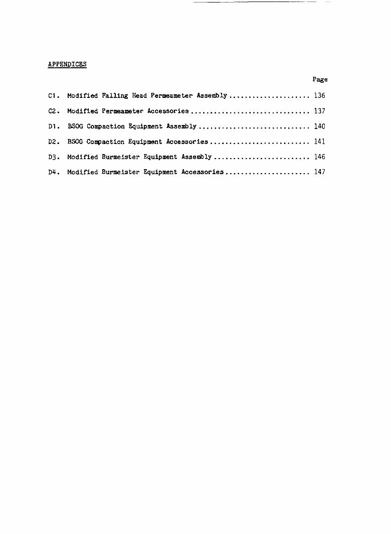
APPENDICES
Page
C1 . Modified Falling Head Permeameter Assembly ..................... 136
C2 . Modified Permeameter Accessories ............................... 137
D1 . BSOG Compaction Equipment Assembly ............................. 140
D2 . BSOG Compaction Equipment Accessories .......................... 141
D 3 . Modified Burmeister Equipment Assembly ......................... 146
D 4 . Modified Burmeister Equipment Accessories ...................... 147
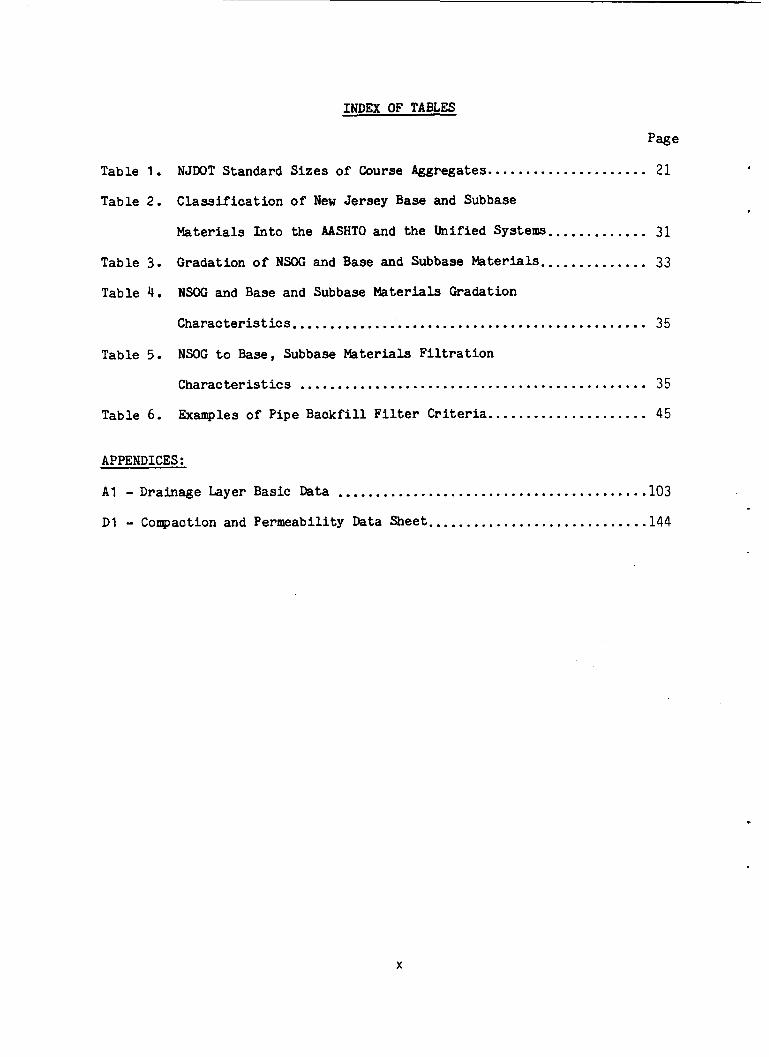
INDEX OF TABLES
Page
NJDOT Standard Sizes of Course Aggregates ..................... 2 1 Table 1 . Table 2 . Class i f i ca t ion of New Jersey Base and Subbase
Materials In to the AASHTO and the Unified Sys tem ............. 31
Gradation of NSOC and Base and Subbase Materials .............. 33 Table 3 . Table 4 . NSOG and Base and Subbase Materials Gradation
Characteristics ............................................... 35
NSOG t o Base. Subbase Materials F i l t r a t i o n Table 5 . Characteristics .............................................. 35
Table 6 . Examples of Pipe Backfi l l F i l t e r Criteria ..................... 45
APPENDICES:
A1
D1
. Drainage Layer Basic h t a ......................................... 103
. Compaction and Permeability Data Sheet ............................. 144
X
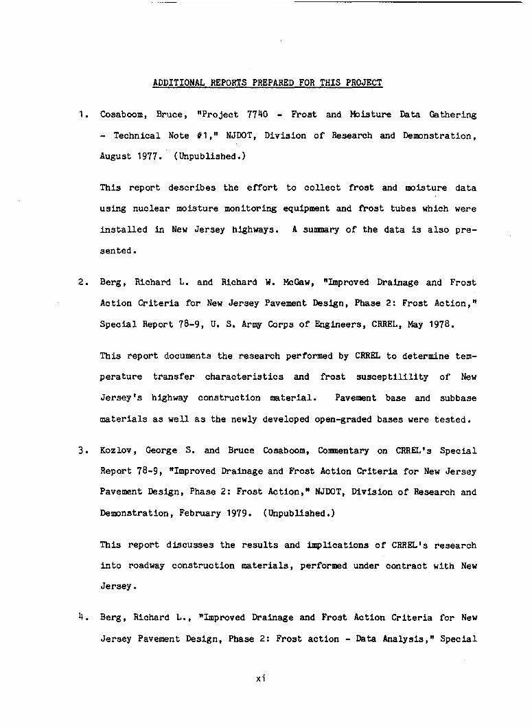
ADDITIONAL REPORTS PREPARED FOR THIS PROJECT
1. Cosaboom, Bruce, "Project 7740 - Frost and Moisture Data Gathering
- Technical Note Il ," NJWT, Division of Research and Demonstration,
August 1977. ( Unpublished.
This repor t describes t h e e f f o r t t o c o l l e c t f r o s t and moisture data
using nuclear moisture monitoring equipment and f r o s t tubes which were
installed i n New Jersey highways. A sumnary of the data is a l s o pre-
sented.
2 . Berg, Richard L. and Richard W. McGaw, "Improved Drainage and F ros t
Action Criteria fo r New Jersey Pavement Design, Phase 2: Frost Action, " Special Report 78-9, U. S. Army Corps of Engineers, CRREL, May 1978.
This repor t documents the research performed by CRREL t o determine tem-
pe ra tu re transfer characteristics and f r o s t s u s c e p t i l i l i t y of New
Je rsey ' s highway construct ion material. Pavement, base and subbase
materials as well a s the newly developed open-graded bases were tested.
3. Kozlov, George S. and Bruce Cosaboom, Comentary on CRREL's Special
Report 78-9, "Improved Drainage and Frost Action Criteria f o r New Jersey
Pavement Design, Phase 2: Frost Action," NJDOT, Division o f Research and
Demonstration, February 1979. (Unpubllshed.)
This repor t d i scusses the r e s u l t s and implicat ions o f CRREL's research
i n t o roadway construct ion materials, performed under cont rac t w i th New
Jersey.
4. Berg, Richard L., "Improved Drainage and Frost Action Criteria for New
Jersey Pavement Design, Phase 2: Fros t ac t ion - Data Analysis," Spec ia l
x i
Report 79-15, U. S. Arw Corps o f Engineers, CRREL, May 1979.
T h i s repor t analyzes temperature, f r o s t and moisture data co l l ec t ed by
New Jersey from 1975 through 1977. Frost penetrat ion using a c t u a l
measured values are compared t o calculated values from a modified
Berggren equation. The effects o f an open-graded layer on f r o s t depth
pene t ra t ion is a l s o discussed.
5. Barker , Walter R. and Robert C. Gunkel, "Improved Drainage and Frost
Action Criteria for New Jersey Pavement Design, Phase I11 S t r u c t u r a l
Strength of Pavement wi th Open-Graded Bases, Geotechnical Laboratory,
U. S. Army Engineer Waterways Experiment S ta t ion , Report No. 79-002-
7740 , August 1979.
This repor t documents the laboratory tests performed by WE3 under
cont rac t with New Jersey on f i v e New Jersey base courses. Three of t h e
materials were conventional bases, the other two open-graded aggregates
bases. Gyratory shear and repeated load t r iaxial compression tests were
conducted t o determine the r e l a t i v e performance of each material.
6. Barenberg, Ernest J. and Douglas Brown, "Modeling of Effects of Moisture
and Drainage o f NJDOT Flexible Pavement Systems," Special Report fo r
FHWA, N J 7740, A p r i l 1981.
T h i s repor t describes the tests and the results o f a model test track
experiment which was designed t o compare performance of conventional
f lexible pavement sec t ions t o those containing open-graded bases when
subjected t o var ious moisture condi t ions and simulated t raff ic loading.
7. Kozlov, George S., "Road Surface Drainage Design, Construction and
Maintenance Guide for Pavements, Technical Guide-NJDOT, Division o f
Research and Demonstration, June 1981.
Th i s technical guide presents a sumnary of the sur face drainage
knowledge necessary for the design, construct ion and maintenance o f
pavements. Procedures wi th examples are provided.
8. Barenberg, Ernest J., "Effect of Moisture and Drainage on Behavior and
Performance of NJWT Rigid Pavement Systems," Special Report f o r FHWA,
N J 7740, July 1981.
The tests and r e s u l t s of a model test track experiment, designed t o com-
pare the performance of conventional r i g i d (PCC) pavement sec t ions t o
those containing open-graded bases when subjected t o var ious moisture
condi t ions and simulated t r a f f i c loadings are presented i n t h i s r epor t .
9. Kozlov, George S., Victor E. Mottola and Gregory Mehalchick, "Improved
Drainage and Frost Action Criteria fo r New Jersey Pavement Design,
Volume I - Invest igat ions fo r Subsurface Drainage Design,tt NJWT,
Division of Research and Demonstration, Report FHWA N J 7740, October
1982.
This repor t presents an assessment o f the s ta te-of- the-ar t f o r subsur-
face road drainage. The laboratory e f f o r t s which were undertaken t o
iden t i fy optimum materials for pavement underdrainage is described.
Also, included are sumnaries of laboratory tests performed by CRREL and
W E S t o determine f r o s t effect and s t r u c t u r a l p rope r t i e s o f conventional
and open-graded drainage bases.
x i i i
10. Kozlov, George S., "Improved Drainage and Fros t Action Criteria f o r New
Jersey Pavement Design, Volume I1 - Experimental Subsurface Drainage
Appllcations Pavements ," NJDOT, Division o f Research and Demonstration,
Report FHWA, N J 7740, Apri l 1983.
This repor t describes t h e ini t ia l inves t iga t ion i n t o t h e need for sub-
surface drainage in New Jersey, i n addi t ion , the cons t ruc t ion , i n s t r u -
mentation and i n i t i a l monitoring of s eve ra l roadways employing an
innovative underdrainage system containing open-graded bases and longi-
tud ina l drains is presented. Also, documented are the resul ts of model
tes t track experiments performed a t the University of I l l i n o i s .

A. INTRODUCTION AND BACKGROUND
A l o t has been sa id about t he need f o r a s o l u t i o n t o t h e problem o f water i n
pavements. A n e c e s s i t y f o r a well organized, p r a c t i c a l and r e l a t i v e l y s imple
subsu r face road drainage m n u a l e x i s t s t h e r e f o r e f o r a long time. For j u s t as
long a time, s o l u t i o n s o f groundwater problems were too o f t e n i n c o r r e c t l y com-
b ined wi th the s u r f a c e i n f i l t r a t i o n phenomena, causing a t times i n e f f i c i e n c y o f
t he first and i n e f f e c t i v e n e s s o f the lat ter. This guide is an a t t e m p t t o remedy
t h i s s i t u a t i o n .
Research by the NJDOT has confirmed t h a t pavement s e r v i c e a b i l i t y can be
improved if water is no t allowed t o accumulate wi th in a pavement's s t r u c t u r a l
s e c t i o n . Adequate s u r f a c e drainage combined wi th a p p r o p r i a t e i n t e r n a l or sub-
s u r f a c e drainage o f f e r s the only practical way o f p reven t ing water bu i ldup
beneath a roadway. In t h i s v e i n , u s e of a drainage l a y e r immediately below the
lower bound l a y e r o f a pavement has been found t o be the most e f f e c t i v e means o f
ach iev ing the necessary degree o f i n t e r n a l drainage. I n a c t u a l a p p l i c a t i o n the
d r a i n a g e l a y e r , intended t o d r a i n o f f only water t h a t normally p e n e t r a t e s t h e
pavement s u r f a c e , r e p l a c e s the top four inches o f the highest unbound l a y e r i n
the pavement s e c t i o n and extends t h e fill width o f the roadway. Water accumu-
lated i n the l a y e r is drained h o r i z o n t a l l y t o a c o l l e c t i o n system wi th appro-
p r i a t e o u t l e t s . The l o n g i t u d i n a l drainage d i t c h e s can be l o c a t e d a t ei ther t h e
edge o f the pavement o r the edge o f the shoulder. Such a system, designed t o
hand le s u r f a c e i n f i l t r a t e d water, should be incorporated i n t o a l l roadway
d e s i g n s .
The groundwater d ra inage , besides the i n t e r c e p t of t he seepage above an
impervious boundary by c u t o f f t r enches , must a l s o lower the water table. The
-L-
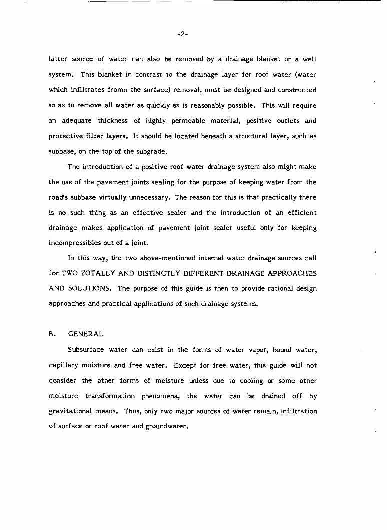
l a t t e r source of water can also be removed by a drainage blanket or a well
system. This blanket in contrast to the drainage layer for roof water (water
which inf i l t ra tes f romn the surface) removal, must be designed and constructed
so as to remove all water as quickly as is reasonably possible. This will require
an adequate thickness of highly permeable material, positive out le ts and
pro tec t ive f i l t e r layers. I t should be located beneath a s t ructural layer, such as
subbase, on the top of t h e subgrade.
The introduction of a positive roof water drainage system also might make
t h e use of t h e pavement joints sealing for t h e purpose of keeping water from t h e
road's subbase virtually unnecessary. The reason for this is t ha t practically t h e r e
is no such th ing as a n ef fec t ive sealer and the introduction of an e f f ic ien t
drainage makes application of pavement joint sealer useful only for keeping
incompressibles out of a joint.
In this way, t h e two above-mentioned internal water drainage sources call
for TWO TOTALLY AND DISTINCTLY DIFFERENT DRAINAGE APPROACHES
AND SOLUTIONS. The purpose of this guide is then to provide rational design
approaches and pract ical applications of such drainage systems.
B. GENERAL
Subsurface water can exist in the forms of water vapor, bound water ,
capillary moisture and f r e e water. Except for f r e e water, this guide will not
consider t he other forms of moisture unless due to cooling or some o ther
moisture t ransformation phenomena, t h e water can be drained off by
gravi ta t ional means. Thus, only t w o major sources of water remain, infiltration
of sur face or roof water and groundwater.
-3 -
A s s t a t e d in the i n t r o d u c t i o n , the basic p r i n c i p l e s o f d ra inage eng inee r ing
developed by t h i s research include d r a i n i n g the roof water through t h e use of a
drainage l a y e r with c o l l e c t o r t r enches and a p p r o p r i a t e o u t l e t s t h a t should b e a
s t a n d a r d f e a t u r e o f a l l new pavements. The groundwater drainage systems w i l l b e
used on ly when groundwater is deemed t o be a problem. It can be in t he form o f
l o n g i t u d i n a l o r t r a n s v e r s e d r a i n s t o i n t e r c e p t f low, o r drainage b l a n k e t s o r
well systems t o lower the water t a b l e and r e l i e v e pore water p res su re .
C. DESIGN OF DRAINAGE FOR SURFACE WATER INFILTRATION
The v a l i d i t y o f the des ign procedures presented i n t h i s guide depend i n a
large degree upon the accuracy and completeness o f t h e des ign , a p p l i c a t i o n and
c o n s t r u c t i o n requirements. The s o l u t i o n s developed by t h i s research are as
rea l i s t ic as p o s s i b l e , while st i l l r e t a i n i n g engineering i n t e g r i t y .
The requirements f o r t h e des ign and a p p l i c a t i o n o f t h e subsurface d r a i n a g e
can be placed i n the following c a t e g o r i e s .
1 . The geometry o f t h e flow domain;
2. t h e p r o p e r t i e s o f t h e d ra inage materials;
3 . t h e proper employment o f t h e d ra inage faci l i t ies and the means f o r t h a t ;
4 . and c l i m a t o l o g i c a l d a t a .
The geometry o f the flow invo lves both t h e geometric des ign of the highway,
related subsurface drainage geometry and the p r e v a i l i n g c o n d i t i o n s as described
i n S e c t i o n C. l . It a l s o h e l p s t o d e f i n e t h e va r ious subsurface d ra inage
problems and t o provide the boundary c o n d i t i o n s that govern t h e i r s o l u t i o n as
i n d i c a t e d i n Sec t ion C.2.
-4 -
The drainage material's fundamental p r o p e r t i e s such as p e r m e a b i l i t y , den-
s i t y , g e o l o g i c a l characteristics, p a r t i c l e shape, etc. define t h e material's
performance and are ou t l ined in Sec t ion C.3. To perform p rope r ly , a d r a i n a g e
material must t ransmit t h e flow o f water, p rope r ly support l o a d s , and most
important ly r e t a i n these Characteristics f o r a reasonable l i fe span o f a road.
Proper employment of such characteristics for the des ign and t h e a p p l i c a t i o n
o f the drainage fac i l i t i es a l s o r e q u i r e s u i t a b l e l i f e time maintenance o f the
system.
The c l ima to log ica l data provide an i n s i g h t i n t o the fundamental source of
a l l subsurface water and the p o t e n t i a l l y adverse effects of f r o s t a c t i o n . I n
t h i s guide there is no need f o r further cons ide ra t ion o f the hydrology o r f r o s t
a c t i o n cri teria a l r eady discussed elsewhere ( 3 s6).
C . l HIGHWAY GEOMETRY
Almost a l l o f t he geometric design features o f a highway can exert some
i n f l u e n c e upon the subsurface drainage. Therefore , be fo re beginning t h e d e s i g n
o f the subsurface drainage system t h e designer should be armed w i t h a s much
information as p o s s i b l e on proposed geometric f e a t u r e s . The data assembled
should include: (a ) l o n g i t u d i n a l grades; ( b ) t r a n s v e r s e g rades ( i n c l u d i n g
supe re l eva t ions ) ; (c) widths o f pavement, shoulder s u r f a c e , base and subbase;
( d ) required th i ckness of pavement elements based on normal s t r u c t u r a l des ign
p r a c t i c e f o r the p a r t i c u l a r area under cons ide ra t ion ; (el dep ths o f c u t s and
f i l ls; ( f ) recomended c u t and f i l l s l o p e s ; and (g) detai ls of d i tches and o t h e r
s u r f a c e d ra inage facil i t ies. I d e a l l y , when ga the r ing t h i s information the
des igne r w i l l have a v a i l a b l e a f in i shed d e t a i l e d set o f t y p i c a l c r o s s - s e c t i o n s
and p r o f i l e s . A t a minimum, a set o f roadway c r o s s - s e c t i o n s showing o r i g i n a l
ground and a t least the g r o s s features of the proposed c o n s t r u c t i o n ( i . e . , c u t
and f i l l s l o p e s , d i t ches , etc.) must be a v a i l a b l e .
The designer should a l s o have a v a i l a b l e a topographic map o f t h e highway ,
c o r r i d o r upon which the f i n a l highway alignment has been superimposed. This map
should be prepared t o such a scale (100 o r 200 scale) t h a t f e a t u r e s p e r t i n e n t t o
both s u r f a c e and subsurface drainage can be c l e a r l y i d e n t i f i e d . For example,
streams, l a k e s , and seasona l ly wet areas above t h e highway may c o n s t i t u t e known
boundaries t o the flow domain.
C. 2 SUBSURFACE GEOMETRY
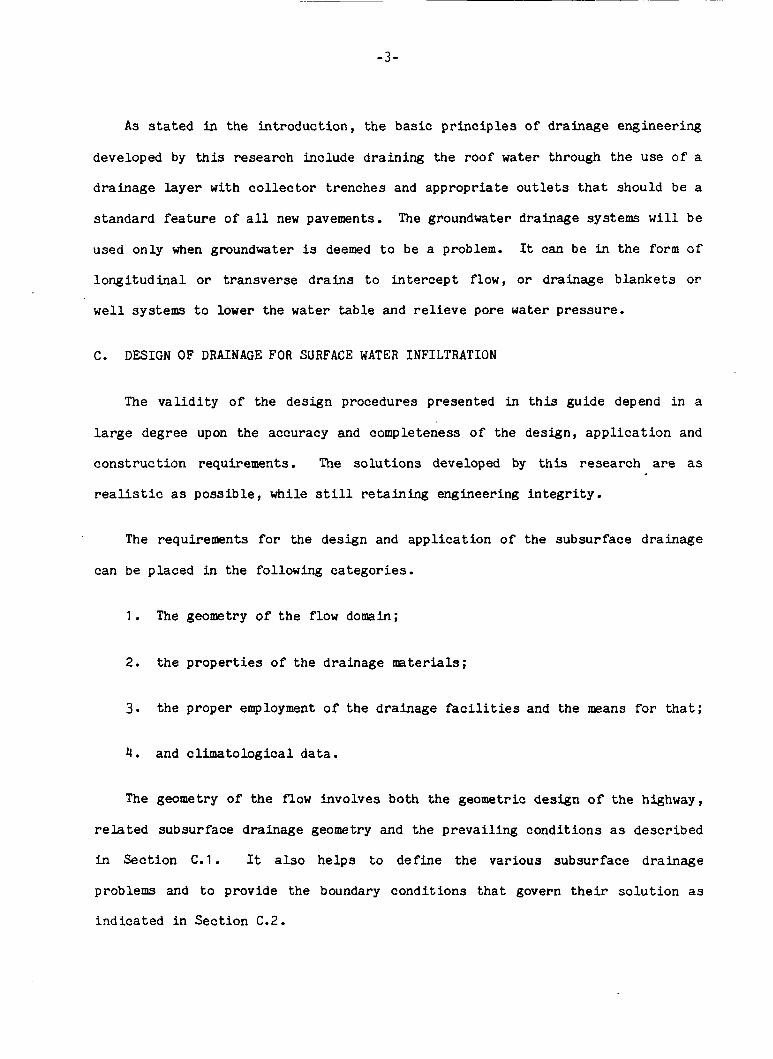
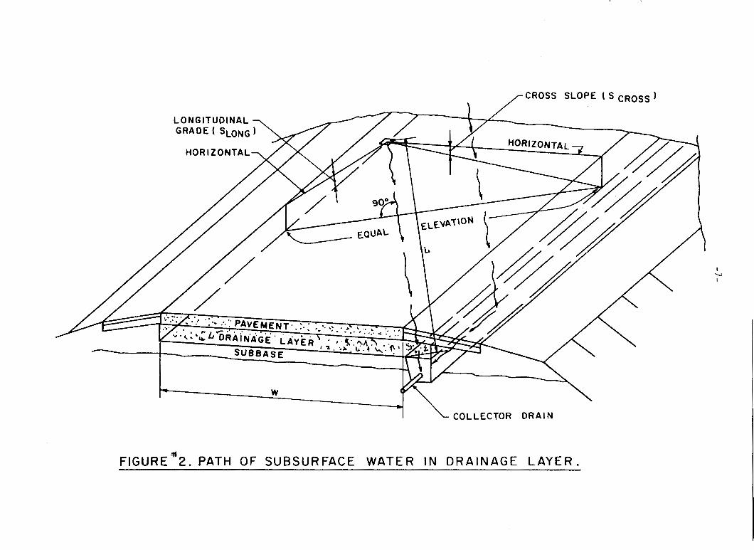
As shown i n Figure 1 , t h e flow of wa te r i n the pavement's d r a i n a g e l a y e r is
l a r g e l y c o n t r o l l e d by the l o n g i t u d i n a l grade o f the roadway, Slow and its c r o s s
s l o p e , Scross. The a c t u a l flow p a t h s w i l l be as d e p i c t e d i n Figure 2 .
A s ou t l i ned i n the s u b j e c t f i g u r e s , when a r o a d ' s p r o f i l e is r e l a t i v e l y
f l a t , water en te r ing the d ra inage l a y e r w i l l f low l a t e r a l l y by v i r t u e o f the
l a y e r ' s c r o s s s lope and empty i n t o the l o n g i t u d i n a l c o l l e c t o r d r a i n s . However,
when there 5.8 a p r o f i l e g rade , the water w i l l a lso flow i n the d i r e c t i o n o f t h e
grade. In c e r t a i n s i t u a t i o n s , t h e combination of p r o f i l e grade and c r o s s s l o p e
w i l l be such as t o c a u s e exceedingly long drainage flow pa ths . I n these i n -
s t a n c e s , s u f f i c i e n t e l e v a t i o n head can b e created t o cause water i n the d ra inage
l a y e r t o a c t u a l l y bleed o u t of the pavement p r i o r t o reaching t h e c o l l e c t o r
drains. Also, the time needed f o r t h e water to reach the c o l l e c t o r can be
exceedingly long, creating an extended pe r iod o f subbase soaking and s o f t e n i n g .
To prevent these p o t e n t i a l problems, %ransve r se i n t e r c e p t o r t r e n c h e s w i t h
drainage p i p e s must b e cons t ruc t ed a t a p p r o p r i a t e l o c a t i o n s a long the roadway.
FIGURE N 0 . I PATHS OF FLOW OF SURFACE WATER IN
PORTLAND CEMENT CONCRETE PAVEMENT STRUCTURAL SECTION
I U I
I COLLECTOR D R A I N
FIGURE#2. P A T H O F S U B S U R F A C E W A T E R I N D R A I N A G E L A Y E R .
-8-
The l o c a t i o n o f the i n t e r c e p t o r c r o s s d r a i n depends on t h e p a r t i c u l a r road-
way geometry. According t o Cedergren, e t a l ( l ) , "In h i l l y t e r r a i n , t h e flow
p a t h s i n subsurface dra inage l a y e r s should never be allowed t o reach e x c e s s i v e
l e n g t h s . To prevent t h i s , it is recommended t h a t c r o s s d r a i n s be requi red
wherever needed to prevent t h e flow p a t h s from exceeding approximately 150
feet."
For a p a r t i c u l a r roadway s i t e , a good estimate o f t h e maximum flow p a t h
length f o r a single lane of pavement can be obtained thru use of equat ions C1
and C2. Equation C3 computes the d i s t a n c e of flow parallel t o t h e grade which
is h e l p f u l i n e s t a b l i s h i n g the a c t u a l s t a t i o n l o c a t i o n s of any needed c r o s s
d r a i n s .
i c L
l 2 'long cross L = W \ / 1 + ( 'S
Where
Scross
S1 = s l o p e o f t h e flow pa th (f t /f t) W = width o f dra inage l a y e r ( l a n e wid th ) ( f t ) L = length o f dra inage pa th (ft) LG
= highway lane c r o s s s l o p e ( f t / f t ) = highway l a n e l o n g i t u d i n a l s l o p e ( f t / f t >
= d i s t a n c e water has t r a v e l l e d i n the d i r e c t i o n parallel t o the grade
Where multi-lane f ac i l i t i e s are involved, the t o t a l length o f flow path is
-9 -
c a l c u l a t e d by adding t o g e t h e r t h e i n d i v i d u a l determinat ions f o r each l ane .
However, as a quick means o f checking i f the 150 f o o t upperbound o f t h e flow
length w i l l b e exceeded, it is suggested t h a t use be made o f the t a b u l a t i o n s
given i n Appendix A. Flow pa th l e n g t h s f o r a wide spectrum of t y p i c a l c r o s s
s l o p e s , l a n e wid ths and numbers, and p r o f i l e grades are a l s o provided. These
t a b u l a t i o n s i n d i c a t e t h a t i n most o f the s i t u a t i o n s encountered i n "highway"
c o n s t r u c t i o n i n New J e r s e y , there w i l l be no need f o r t r a n s v e r s e i n t e r c e p t
d r a i n s . The roads where such d r a i n s would be necessary t y p i c a l l y involve
c o n s t r u c t i o n on the county and municipal r o u t e systems where s t e e p e r l o n g i t u d i -
n a l s l o p e s are encountered.
Exceptions t o the preceding g u i d e l i n e s occur when there is a v e r t i c a l cu rve
o r a supe re l eva ted h o r i z o n t a l curve. The low p o i n t i n a v e r t i c a l cu rve should
have an t r a n s v e r s e i n t e r c e p t o r d r a i n t o faci l i ta te t h e r ap id removal o f water
from the d ra inage l a y e r and p reven t t h e buildup o f pore pressures (see Figure
3 ) . When there is a supe re l eva ted curve on a roadway with l o n g i t u d i n a l edge
drains , it m i g h t be necessary a t the t r a n s i t i o n p o i n t o f the s u p e r e l e v a t i o n t o
u s e a t r a n s v e r s e d r a i n t o prevent the change i n flow d i r e c t i o n s from caus ing
excess ive ly long flow pa ths . This is i l l u s t r a t e d i n Figure 4.
Transverse d r a i n s mst a l s o be used a t each underdrain o u t l e t t o convey
water from the l o n g i t u d i n a l d r a i n s t o the o u t l e t f a c i l i t y . Except f o r v e r t i c a l
sag and supe re l eva ted curve c o n d i t i o n s , t r a n s v e r s e d r a i n s should b e p l aced a t
abou t a 45 degree a n g l e t o the l o n g i t u d i n a l p i p e l i n e .
Normally, t h e o u t l e t p i p e s should be "daylighted". If t h i s is not p o s s i b l e ,
then they should be drained i n t o the n e a r e s t i n l e t s t r u c t u r e . When t h e l a t te r
is the case, it is imperat ive t h a t t h e flow l i n e o f the subsu r face d ra inage
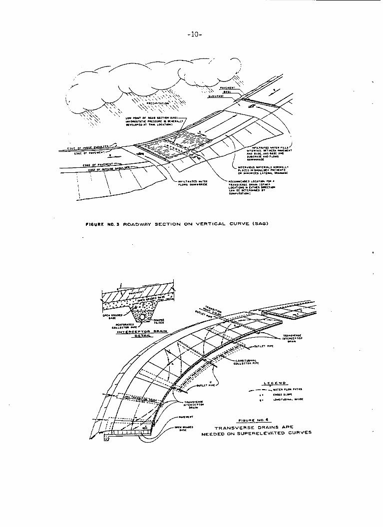
CIGURE NO. 3 ROADWAY SECTION O N VERTICAL CURVE (SAG)
a
-11-
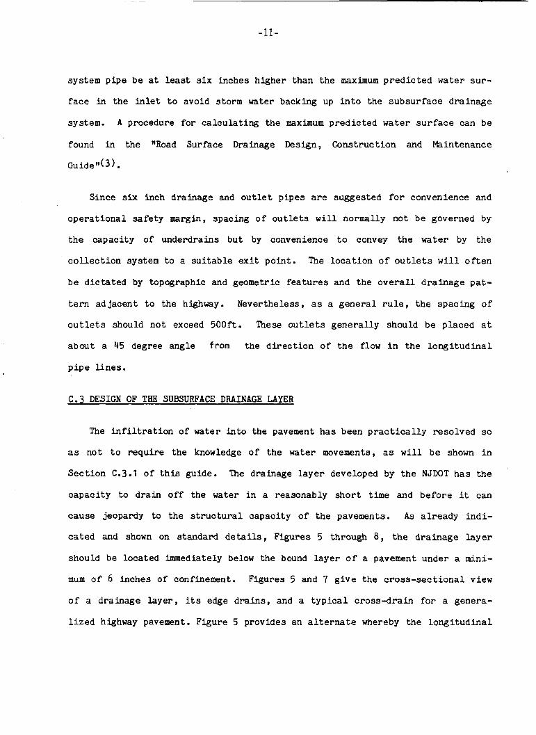
system p i p e be a t least s i x inches higher than t h e maximum p r e d i c t e d water s u r -
face in t h e inlet t o avoid storm water backing up i n t o t h e s u b s u r f a c e d ra inage
system. A procedure f o r c a l c u l a t i n g the maximum p r e d i c t e d water surface can be
found i n the "Road Surface Drainage Design, Cons t ruc t ion and Maintenance
Guide It( 3 . Since six inch drainage and o u t l e t p i p e s are suggested for convenience and
o p e r a t i o n a l s a f e t y margin, spacing of o u t l e t s w i l l normally not be governed by
the capac i ty o f underdrains bu t by convenience t o convey t h e water by the
c o l l e c t i o n system t o a s u i t a b l e e x i t po in t . The l o c a t i o n o f o u t l e t s w i l l o f t e n
be d i c t a t e d by topographic and geometric f e a t u r e s and t h e o v e r a l l d r a i n a g e p a t -
t e r n a d j a c e n t t o the highway. Nevertheless , as a g e n e r a l r u l e , t h e spac ing o f
o u t l e t s should n o t exceed 500f t . These o u t l e t s g e n e r a l l y should be p l aced a t
abou t a 45 degree angle from the d i r e c t i o n o f the flow i n t h e l o n g i t u d i n a l
p i p e l i n e s .
C.3 DESIGN OF THE SUBSURFACE DRAINAGE LAYER
The i n f i l t r a t i o n o f water i n t o the pavement has been p r a c t i c a l l y r e so lved so
as no t t o r e q u i r e the knowledge of the water movements, as w i l l b e shown i n
S e c t i o n C.3.1 o f t h i s guide. The drainage l a y e r developed by the N J W T h a s the
c a p a c i t y t o drain o f f t h e water i n a reasonably s h o r t time and b e f o r e it can
cause jeopardy t o the s t r u c t u r a l capac i ty o f the pavements. A s a l r e a d y i n d i -
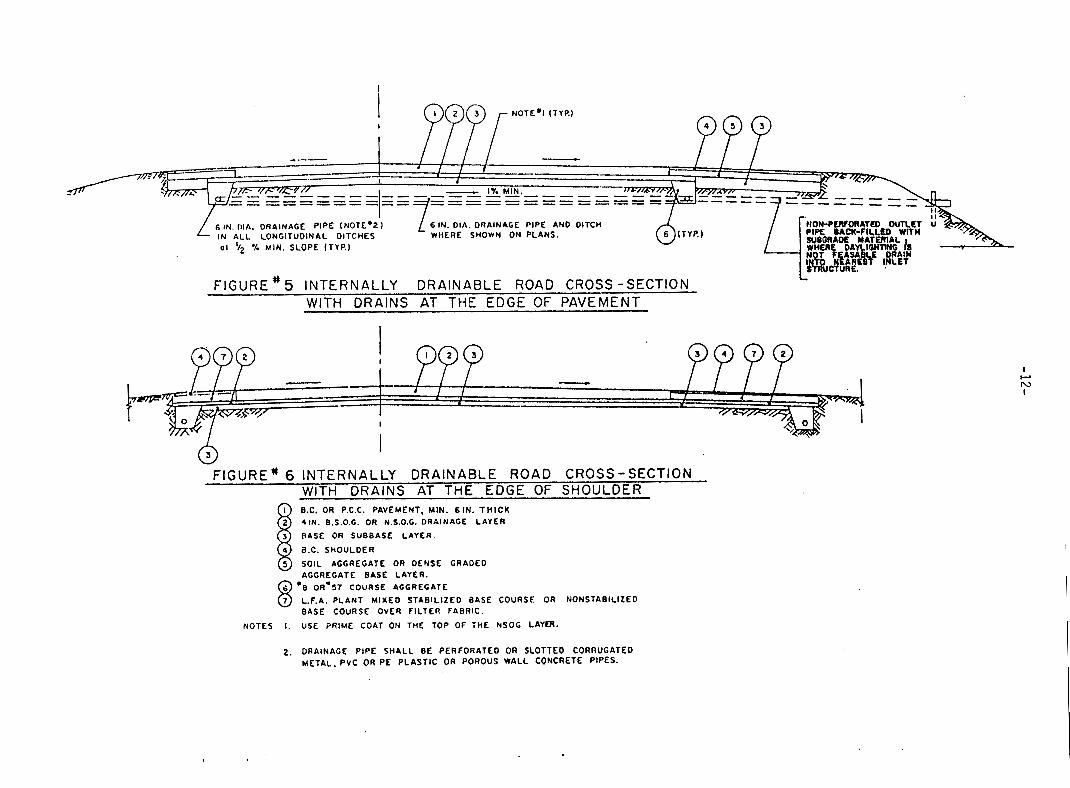
cated and shown on s t anda rd de ta i l s , Figures 5 through 8 , the d r a i n a g e l a y e r
should be loca t ed immediately below the bound l a y e r of a pavement under a mini-
mum o f 6 i nches o f confinement. Figures 5 and 7 g i v e t h e c r o s s - s e c t i o n a l view
of a d ra inage l a y e r , i ts edge d r a i n s , and a t y p i c a l c r o s s - d r a i n f o r a genera-
l i z e d highway pavement. Figure 5 provides an a l t e r n a t e whereby the l o n g i t u d i n a l
4---
61N Il IA, DRAINAGE P IPE INOTE.2) I N A L L LONGITUDINAL DITCHES WHERE SHOWN ON PLANS. 01 92 % WIN. SLOPE ITYP.)
6 IN. DIA. DRAINAGE PIPE AND DITCH
F IGURE' 5 INTERNALLY DRAINABLE ROAD CROSS -SECTION WITH DRAINS AT THE EDGE OF PAVEMENT
F I G U R E * 6 I N T E R N A L L Y D R A I N A B L E R O A D CROSS-SECTION WITH DRAINS AT THE EDGE OF SHOULDER B.C. OR P.C.C. PAVEMENT, MIN. 6 l N . T H I C K 41N. B.S.O.G. OR N.S.O.G. DRAINAGE LAYER 1 BASE OR SUBBASE LAYER.
4 a x . SHOULDER
5 SOIL AGGREGATE OR DENSE GRADED AGGREGATE BASE LAYER.
L.F.A. P L A N T M I X E D STABIL IZED BASE COURSE OR NONSTABlL lZED BASE COURSE OVER F ILTER FABRIC.
a OR*SI C O U R S E AGGREGATE 8' NOTES I. USE PRIME CJAT ON THE TOP OF THE NSOG LAYER.
2. DRAINAGE P IPE S H A L L BE PERFORATED OR SLOTTED CORRUGATED METAL. PVC OR P E PLASTIC OR POROUS WALL CONCRETE PIPES.
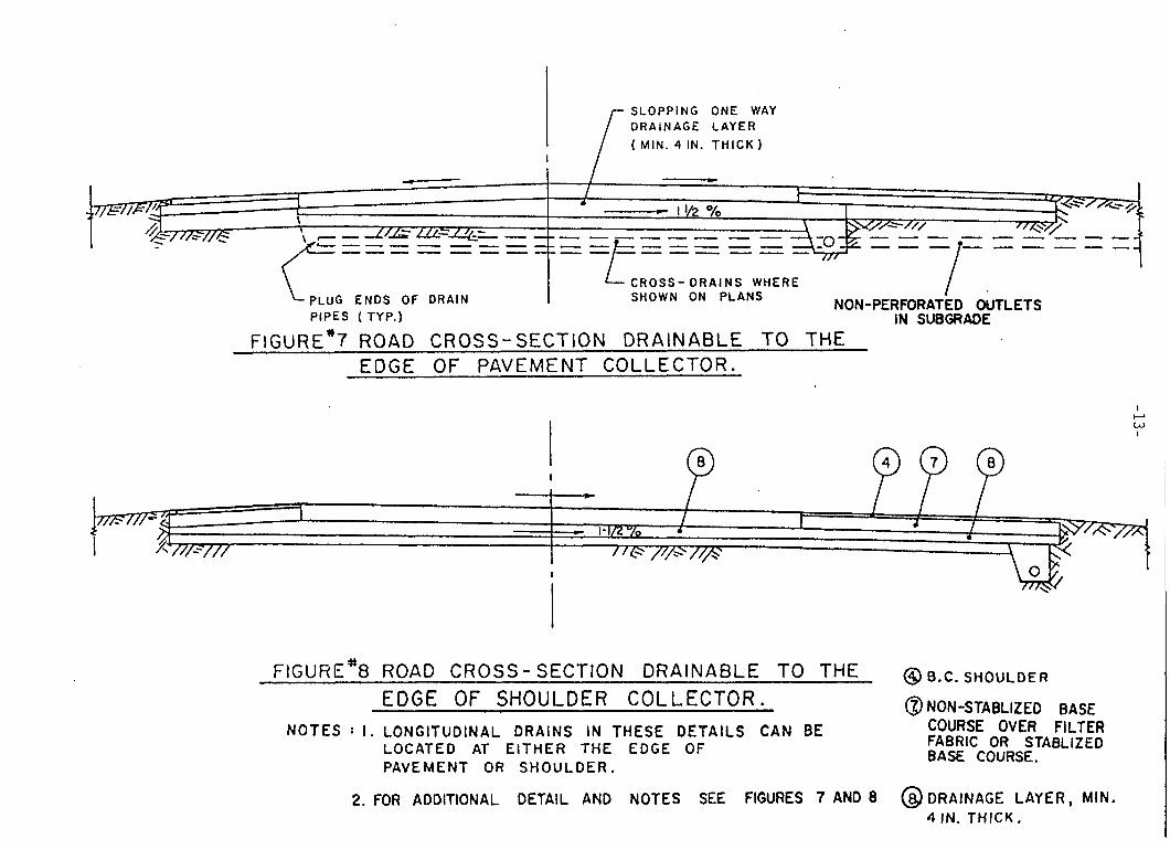
1. 1 t 1 ' - I 1/2 O!o
\ , p m r \ /Z-/ - ,/ 2/ - /
FIGUHE*8 ROAD CROSS- SECTION DRAINABLE TO THE EDGE OF SHOULDER COLLECTOR.
NOTES : 1 . LONGITUDINAL DRAINS IN THESE DETAILS CAN BE LOCATED AT EITHER THE EDGE OF PAVEMENT OR SHOULDER.
2. FOR ADDITIONAL DETAIL AND NOTES SEE FIGURES 7 AND 8
@ 6.C. S H O U L D E R
@ NON-STABLIZED BASE COURSE OVER FILTER FABRIC OR STABLIZED BASE COURSE.
@ DRAINAGE LAYER, MIN. 4 IN. T H I C K ,
I I-J w I

-14-
edge d r a i n s are pos i t i oned a t t h e edge o f t h e pavement, wh i l e F igu re 6 shows t h e
same d r a i n s loca t ed a t t h e edge o f the shoulder . The Figure 6 a l t e r n a t e is pre-
ferred b u t i f c o n s t r u c t i o n c o s t s are o f major concern, o r if t h e d e s i g n con-
s i d e r a t i o n s r e q u i r e , t h e F igu re 5 approach can be used. F igu res 5 and 6 have t h e
c r o s s s l o p e s and grade breaks o f t he d ra inage l a y e r mi r ro r ing t h e pavement su r -
face. Details i n F igu res 7 and 8 are b a s i c a l l y d u p l i c a t e s o f F i g u r e s 5 and 6
excep t that a c o n s t a n t c r o s s s l o p e is requ i r ed o f t h e d ra inage l a y e r . From a
long-term performance s t a n d p o i n t , c o n s t r u c t i o n i n accordance wi th the F igu res 7
and 8 detai ls is bes t . However, f o r ease o f c o n s t r u c t i o n b u t n o t n e c e s s a r i l y
f o r minimized i n s t a l l a t i o n c o s t s , t h e conf igu ra t ion i n F igu res 5 and 6 w i l l fre-
quen t ly be found more a p p r o p r i a t e . O f cou r se , v a r i a t i o n s o f F igu res 5 through 8
are e n t i r e l y feasible as long as they are a p p r o p r i a t e l y developed.
C.3.1 Water I n f i l t r a t i o n and P r i n c i p l e s o f Subsurface Drainage
When s u r f a c e water i s n o t removed fast enough from the roadway area, it
i n f i l t r a t e s the pavement s e c t i o n through t h e po res o f the s u r f a c e , j o i n t s ,
c r a c k s , or po tho le s and, o f c o u r s e , from its sides. This means t h a t a v a r i e t y
of parameters affect t h e i n f i l t r a t i o n process: t h e pavement's material, t h e
material's q u a l i t y , pavement age and l o c a t i o n , climatic c o n d i t i o n s and t ra f f ic
c o n d i t i o n s , j u s t to mention a few. It would r e q u i r e a very large q u a n t i t y o f
data t o even approximate p o s s i b l e average amounts o f s u r f a c e water p e n e t r a t i o n .
Therefore , an a c c u r a t e method f o r determining the a c t u a l amount o f p e n e t r a t i n g
water, in r e a l i t y , is no t a v a i l a b l e . However, as i n d i c a t e d i n t h i s a u t h o r ' s
r e p o r t ( 6 ) an a c c u r a t e determinat ion o f i n f i l t r a t i n g q u a n t i t i e s is n o t r e q u i r e d
i n order t o implement the d ra inage as proposed by t h i s research.
Nevertheless , f o r information o n l y , two w e l l known methods o f p r e d i c t i n g
i n f i l t r a t i o n should be mentioned here.
-15-
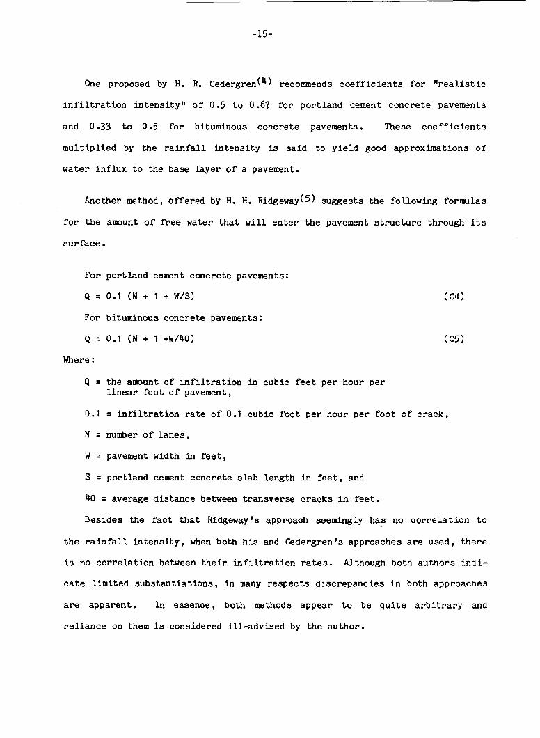
One proposed by H. R. C e d e ~ - g r e n ( ~ ) recommends c o e f f i c i e n t s f o r "real is t ic
i n f i l t r a t i o n i n t e n s i t y " o f 0.5 t o 0.61 f o r p o r t l a n d cement c o n c r e t e pavements
and 0.33 t o 0.5 f o r bituminous conc re t e pavements. These c o e f f i c i e n t s
m u l t i p l i e d by the rainfall i n t e n s i t y is said t o y i e l d good approximations of
water i n f l u x t o the base l a y e r o f a pavement.
Another method, o f f e r e d by H. H. Ridgeway(5) sugges t s t he fol lowing formulas
f o r t he amount o f free water t h a t w i l l e n t e r the pavement s t r u c t u r e through its
s u r f a c e .
For po r t l and cement conc re t e pavements:
Q = 0.1 (N + 1 + W/S) (C4)
For bituminous concrete pavements :
Q = 0.1 (N + 1 +W/40) ( C 5 )
Where :
Q = the amount of i n f i l t r a t i o n i n cubic feet p e r hour p e r l i n e a r f o o t o f pavement,
0.1 = i n f i l t r a t i o n rate o f 0.1 cubic f o o t per hour p e r f o o t o f crack,
N = number o f l a n e s ,
W = pavement width in feet ,
S = port land cement conc re t e s l a b length i n feet , and
40 = average distance between t r a n s v e r s e cracks i n feet.
Besides the fact t h a t Ridgeway's approach seemingly h a s no c o r r e l a t i o n t o
t h e rainfall i n t e n s i t y , when both h i s and Cedergren's approaches are used, there
is no c o r r e l a t i o n between t h e i r i n f i l t r a t i o n rates. Although both a u t h o r s i n d i -
cate l i m i t e d s u b s t a n t i a t i o n s , in many respects d i s c r e p a n c i e s i n both approaches
are apparent . I n e s sence , both methods appear t o be q u i t e a r b i t r a r y and
r e l i a n c e on them is considered i l l - a d v i s e d by t h e au tho r .
-16-
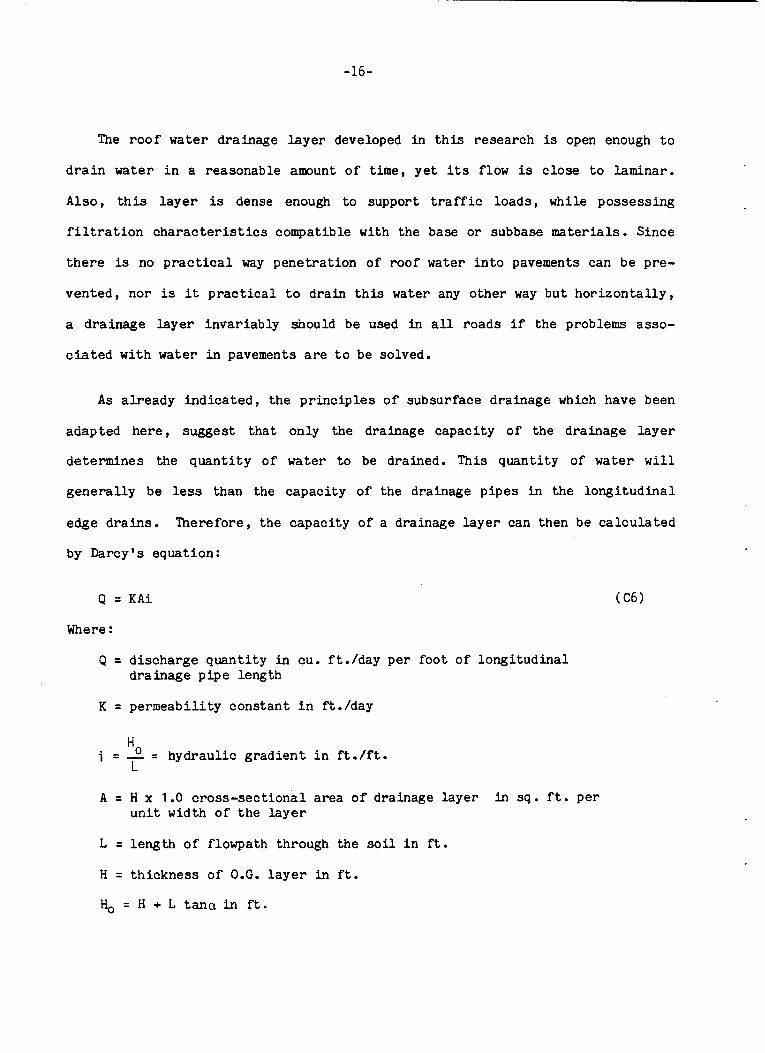
The roo f water drainage l a y e r developed i n t h i s research is open enough t o
d r a i n water i n a reasonable amount o f time, y e t i t s flow is c l o s e t o laminar .
Also, t h i s l a y e r is dense enough t o support t raff ic l o a d s , while posses s ing
f i l t r a t i o n characteristics compatible wi th t h e base o r subbase materials. S ince
there is no p r a c t i c a l way p e n e t r a t i o n o f roof water i n t o pavements can be pre-
v e n t e d , no r is it p r a c t i c a l t o drain t h i s water any o t h e r way b u t h o r i z o n t a l l y ,
a d ra inage l a y e r i n v a r i a b l y should be used i n a l l roads i f the problems asso-
c i a t e d w i t h water i n pavements are to be solved.
As a l r e a d y indicated, the pr inciples o f subsurface d ra inage which have been
adapted here, sugges t t h a t on ly the drainage capac i ty o f t h e drainage l a y e r
de t e rmines the q u a n t i t y o f water t o be drained. This q u a n t i t y of water w i l l
g e n e r a l l y be less than the c a p a c i t y o f t he drainage p i p e s i n the l o n g i t u d i n a l
edge d r a i n s . Therefore , t h e capac i ty o f a drainage l a y e r can then be c a l c u l a t e d
by Darcy's equat ion:
Q = K A i
Where :
Q = discharge q u a n t i t y i n cu. f t . /day p e r f o o t o f l o n g i t u d i n a l d ra inage p i p e length
K = permeab i l i t y c o n s t a n t i n ft./day
Ho i = - = h y d r a u l i c gradient i n f t . / f t . L
A = H x 1 .O c r o s s - s e c t i o n a l area o f drainage l a y e r in sq. f t . p e r u n i t width o f t h e layer
L = length of flowpath through the s o i l i n f t .
H = t h i c k n e s s o f O.G. l a y e r i n f t .
H , = H + L tana i n f t .
-17-
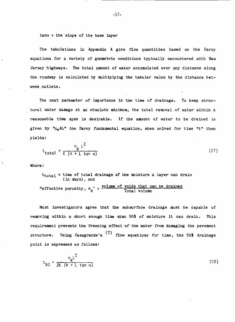
tanci = t h e s lope o f t h e base l a y e r
The t a b u l a t i o n s in Appendix A g i v e flow q u a n t i t i e s based on the Darcy
equa t ions f o r a v a r i e t y of geometric cond i t ions t y p i c a l l y encountered w i t h New
J e r s e y highways. "he t o t a l amount o f water accumulated over any d i s t a n c e a long
the roadway is c a l c u l a t e d by mult iplying the t a b u l a r va lue by the d i s t a n c e b e t -
ween o u t l e t s . The next parameter o f importance is the time o f d ra inage . To keep s t r u c -
t u r a l water damage a t an abso lu te minimum, t h e t o t a l removal o f water w i t h i n a
reasonable t ime span is desirable. If t h e amount o f water t o be d r a i n e d is
given by "neL" the Darcy fundamental equa t ion , when so lved f o r time V 1 I t hen
y i e l d s : n
n L~
K ( H + L tan a ) - e -
Where :
ttotal = time of t o t a l drainage of t h e moisture a l a y e r can d r a i n (in days ) , and
volume of voids t h a t can be d r a i n e d T o t a l volume " e f f e c t i v e p o r o s i t y , ne" =
Most i n v e s t i g a t o r s agree t h a t the subsurface drainage must be capab le o f
removing within a s h o r t enough time span 50% o f moisture it can d r a i n . Th i s
requirement p reven t s t he freezing effect o f t h e water from damaging the pavement
s t r u c t u r e . Using Casagrande's flow equa t ions f o r time, t h e 50% d r a i n a g e
p o i n t is expressed as follows:
2 neL
'50 - 2K (H + L t a n a )
Where :
t50 = time o f d ra inage o f 50% of the m i s t u r e a l a y e r can d r a i n (in days)
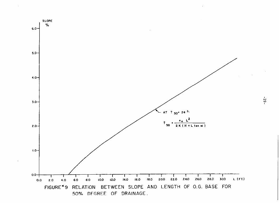
E f f e c t i v e p o r o s i t y has been found t o approximately equa l 80% o f the "abso lu te
p o r o s i t y n" f o r g r a n u l a r t ype materials.
A s i l l u s t r a t e d in Figure 9 , u s ing t h i s formula and assuming ne = 0.3 and K =
1000 ft./day a r i t h m e t i c a l l y it can be shown t h a t a 4 inch (H = 0.33 feet)
drainage l a y e r s lop ing 1/2 t o 10% with r e s p e c t i v e lengths o f 66 t o 670 feet can
be s u f f i c i e n t l y drained t o remain h y d r a u l i c a l l y and s t r u c t u r a l l y f u n c t i o n a l . I n
e s s e n c e , t h e 50% dra inage c o n d i t i o n should be achievable f o r a l l the above con-
d i t i o n s wi th in the 24 hour per iod suggested by New J e r s e y ' s research when us ing
the intended drainage l a y e r design.
Consider ing, however, t h e l i m i t a t i o n s ind ica t ed elsewhere ( 6 ) , c a u t i o n is
suggested i n a p p l i c a t i o n o f these drainage p r i n c i p l e s and a need f o r e x e r c i s i n g
engineer ing judgement i n t h i s des ign approach is a l s o urged. With flow con-
d i t i o n s of open-graded materials bordering on the t u r b u l e n t , t he flow rates w i l l
be lower than those p r e d i c t e d by Darcy's fundamental law. The magnitude o f the
flow rate in t h i s i n s t a n c e would be a matter o f con jec tu re as l i t t l e work has
been done i n s tudying t u r b u l e n t f low i n s o i l s . I n any case, because o f the
p o s s i b l e t u r b u l e n t c o n d i t i o n s there needs t o be a very stable grain s t r u c t u r e i n
t h e drainage l aye r .
C.3.2 General Types and App l i ca t ions of Open-Graded Drainage Layer Materials
T h i s research r e s u l t e d in the development o f two basic types o f open-graded
d ra inage material. The first, which c o n s i s t s o f a p l a i n s t o n e blend is referred
t o as the non- s t ab i l i zed , open graded (NSOG) material, and t h e second t y p e ,
6.0.
5.0.
4.0%
3.0.
2 .o.
I .o.
0.0-
s LOPE %
I I I I I I 1 I I 1 I I I I I
FIGURE'9 RELATION BETWEEN SLOPE AND LENGTH OF O.G. BASE FOR .50°/o DFGREE OF DRAINAGE.
-20-
which c o n s i s t s of a s tone blend c o n t a i n i n g a small q u a n t i t y o f a spha l t t o
enhance s t a b i l i t y , is referred t o as t h e bituminous s tab i l ized open-graded
(BSOG) material.
In any i n t e r n a l road d ra inage d e s i g n either o f the two types , t h e NSOC o r
the BSOG Layers, can be used wi th t h e a p p r o p r i a t e c o l l e c t o r system. I n i t i a l l y
t h e NSOG material was developed p r i m a r i l y f o r use in r i g i d pavement d e s i g n s ,
while the BSOG d ra inage l a y e r was meant f o r use i n f l e x i b l e pavements. It was
o r i g i n a l l y theo r i zed t h a t f o r the unbound NSOG material, r i g i d pavements would
provide better, more uniform load d i s t r i b u t i o n , while t h e BSOC l a y e r w i t h its
s t a b i l i t y provided by asphalt would be more compatible w i t h the f l e x i b l e pave-
ments. Even though both d ra inage materials were used i n f u l l scale expe r imen t s ,
except f o r l abora to ry eva lua t ion and scaled down test track modeling, no conclu-
s i v e performance data are y e t a v a i l a b l e . Thus far, the NSOC material has been
found t o be somewhat better from a s t r u c t u r a l performance s t andpo in t . However,
the BSOG is easier t o c o n s t r u c t . A t t h e p r e s e n t time, it does no t appear t h a t
there w i l l be a great d i f f e r e n t i a l Fn c o s t between the two material types . For
s t r u c t u r a l des ign purposes , both NSOG and BSOC can be assumed t o have a s t r u c -
t u r a l index equ iva len t t o NJDOT Dense Graded Aggregate Base SN = 0.14.
C.3.3 Non-Stabilized Open-Graded Material P r o p e r t i e s and Laboratory Test
Procedures
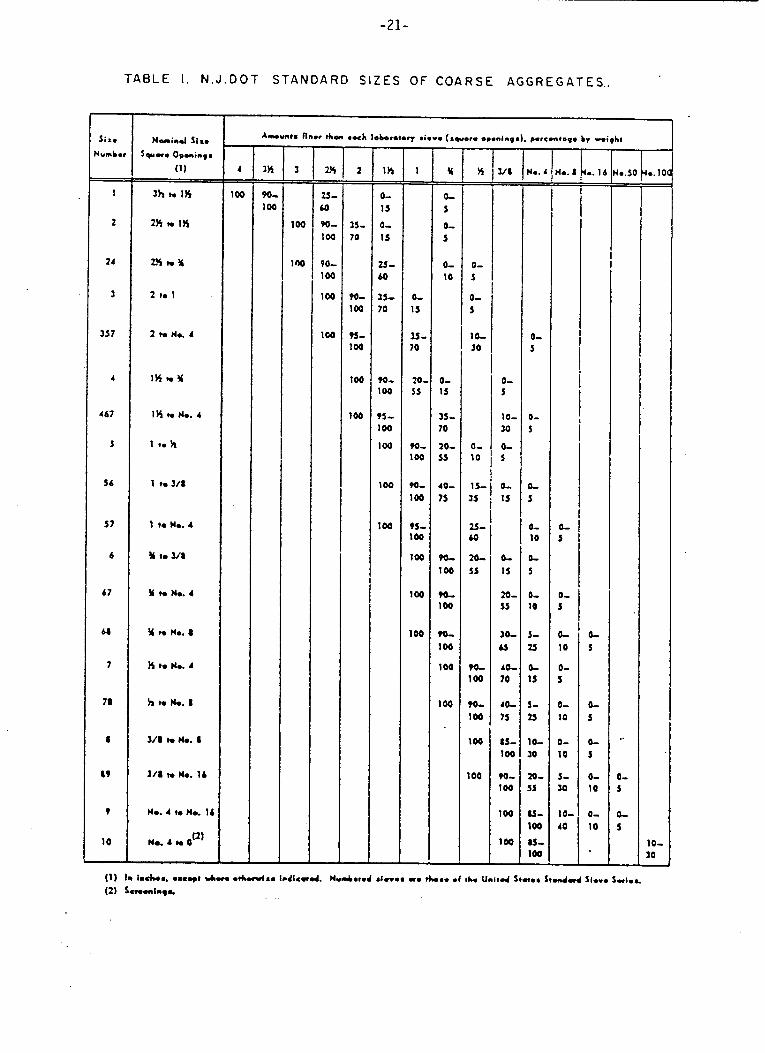
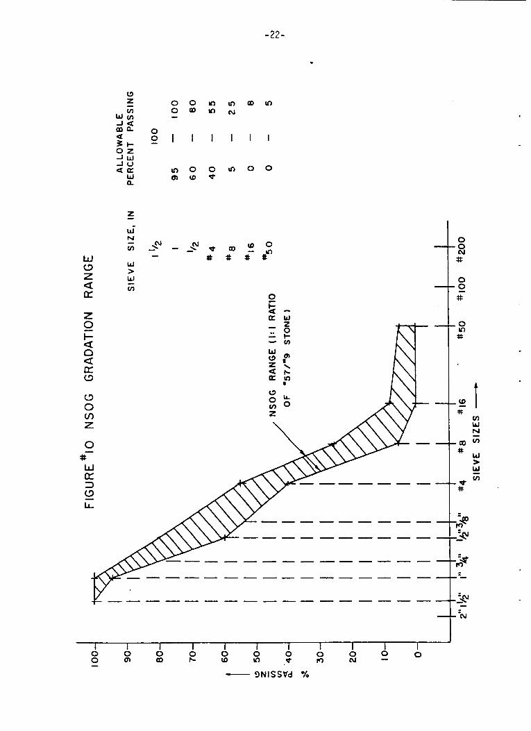
The non-stabi l ized open-graded (NSOG) material must comply w i t h t h e specif i -
c a t i o n i n Appendix B and the master g r a d a t i o n band shown i n Figure 10. It can
be made o f a 50/50 blend o f P57 and #9 s tone spec i f ied i n Table 1 o r might b e
produced as a new standard s i z e mix of coa r se aggregates. If 857 and #9 s t o n e
are mixed, they must i n d i v i d u a l l y meet t h e grading s p e c i f i c a t i o n s and be o f t he
same s o u m e , i.e. s tone type .
- Six.
Numb. - 1
2
1 4
3
3J7
4
4 67
S
56
57
6
67
#
7
78
I
a9
?
10
-
-21-
T A B L E I. N . J . D O T S T A N D A R D S I Z E S OF C O A R S E A G G R E G A T E S . .
- 1H
0- 15
0- 1s
25- 60
35- 70
- -
m- 100
PS- 100
100
100
100
- 1
0- 15
3s- 70
20. 5s
90- 100
m- 100
95- 100
100
100
100
- Y
0- 3
0- J
0- 10
=
0- 15
I S - 70
20- 5s
40- 7s
m
m
100
100
?o- 100
100
100
- n - -
0- 5
0- 5
lb 50
0- 10
1 s- 35
z- 60
20- S5
m 100
?o- 100
100
100
- ua =
0- 5
10- 30
0- S
0- IS
b 13
to- ss
10- u 40- 70
4 0 -
73
15- 100
?O- 100
100
100
-
- q.. I - -
0- 5
0- 3
0- 10
0- 5
0- 10
0- 10
S- 10
10- 40
-22-
0 0 -
0 0 1 -
0 m
I
0 (0
(\J \ -
Y) In
I
0 d
d at
In cu
I
rl)
aD $5
a0
I
0
co - #
In
I
0
0 #In
a w
- i n m
- 3NISSVd X
-23-
Even though only three s p e c i f i c s tone sources were tested i n t h i s research,
(one each f o r a l imestone, t r ap rock and a g n e i s s source) these tested materials
are r e p r e s e n t a t i v e o f t h e predominant s tone t y p e s a v a i l a b l e f o r NJDOT con-
s t r u c t i o n work. However, s i n c e these were not a l l i n c l u s i v e tes ts and were
l a b o r a t o r y rather than f i e l d i n v e s t i g a t i o n s , cau t ion is r e q u i r e d when us ing
crushed s tone from o t h e r sources . There are many s tone s o u r c e s and even a few
o t h e r s tone types t h a t are c u r r e n t l y acceptable f o r s ta te p r o j e c t s . To e n s u r e
t h a t a p a r t i c u l a r s tone type/source is s u i t a b l e f o r NSOG material, the producer
is requ i r ed t o submit f o r approval a p a r t i c u l a r target g r a d a t i o n that is w i t h i n
the band and can be produced wi th h i s aggregate sources . Samples o f materials
w i t h t h i s target g rada t ion are then subjected t o pe rmeab i l i t y t e s t i n g and den-
s i t y and g r a d a t i o n a l s t a b i l i t y eva lua t ion wi th t h e Burmister v i b r a t o r y t ab le .
To be accep tab le the target g rada t ion must provide a pe rmeab i l i t y in the r ange
of 1000 t o 3000 feet p e r day and a stable voids system. I n t h i s c o n t e x t grada-
t i o n a l s t a b i l i t y does no t connotate s t r u c t u r a l s t rength b u t rather it is based
on v i s u a l aspects, i.e., absence o f vo ids , degree of migrat ion and s e g r e g a t i o n ,
hence a stable vo ids system. When a sample is compacted i n t o P l e x i g l a s molds i t
is v i s u a l l y evaluated f o r absence of v o i d s and seg rega t ion , then d e n s i t y is
measured d i r e c t l y i n the mld.
To a s s u r e t ha t adequate cond i t ions are achieved i n t h e f i e l d , in-place gra-
d a t i o n s are r equ i r ed t o be c l o s e to the target g rada t ion . The material's den-
s i t y in the f i e l d is monitored through "con t ro l s t r i p s " and hope fu l ly w i l l be
close t o tha t achieved in the Burmister mold i n t he l abora to ry .
To a s c e r t a i n t h a t the requirements i nd ica t ed above and specified i n t h e NSOG
c o n s t r u c t i o n and material s p e c i f i c a t i o n i n Appendix B and i n t h e NJDOT standard
s p e c i f i c a t i o n Sec t ion 990 - Methods o f Tests (8) are met, new fall ing head per-
meab i l i t y and modified compaction tests are provided. The permeameter s p e c i f i e d
i n Appendix C served well throughout t h e research study. The equipment can be
used wi th confidence on materials having a "K" factor ranging from 100 t o
20,000 feet p e r day. This permeameter g i v e s reasonable r e p e a t a b i l i t y , and t h e
permeabi l i ty c o n s t a n t "K" va lues are probably s l i g h t l y conse rva t ive , hence
a p p l i c a b l e t o t h e s u b j e c t engineer ing problems. When used as a s t anda rd p i e c e
o f testing equipment it should be improved and s tandardized for manufacturing
purposes.
To d u p l i c a t e f i e l d compaction c o n d i t i o n s l a b o r a t o r y compaction procedures
f o r NSOG material were developed and are a l s o provided by the s p e c i f i c a t i o n i n
Appendix D. ASTM s p e c i f i c a t i o n s D-2049(9) provide Burmister Vibratory Table
t es t procedures f o r compaction o f cohes ion le s s s o i l s . As descr ibed i n Appendix
D, the Burmister equipment was modified f o r testing the open-graded materials.
The modif icat ion cons i s t ed of using a P l e x i g l a s mold t o allow viewing o f t h e
samples for eva lua t ion of their g r a d a t i o n a l s t a b i l i t y and f o r d e n s i t y
measurements. The r e l a t i v e l y large P l e x i g l a s c y l i n d e r mold, capable of ho ld ing
15 l b s . o f uncompacted NSOG materials, proved t o be e s s e n t i a l f o r o b t a i n i n g
r e p r e s e n t a t i v e d e n s i t y r e s u l t s . For permeabi l i ty tests, a 4 inch metal mold is
used wi th a 1600 gram specimen f o r c o m p a t i b i l i t y w i t h t h e permeameter. This
equipment should a l s o be s t anda rd ized f o r manufacturing purposes.
It should be noted here tha t i n ou r research wet NSOG s t o n e c o n s i s t e n t l y
y i e lded d e n s i t i e s which were lower than t h a t o f dry s tone ; t h e average d i f -
f e r ence amounting t o approximately 8.5%. This was i n s p i t e o f t he fact t h a t
there appeared t o be no mig ra t ions o f the f i n e materials t o the bottom o f the
-25-
wet sample while considerable migration of f i n e s could be observed in dry
samples. Apparently, f o r t y p i c a l NSOG grada t ions , water somehow decreases
achievable dens i ty while lessening the migration o f f ines . Therefore, while wet
s tone w i l l b e used i n t h e f i e l d t o minimize segregat ion, i n the labora tory , com-
pact ion tes ts only dry s tone must be used. Since densi ty and permeabili ty are
genera l ly inversely r e l a t e d , i f w e use t h e procedure which y i e l d s the maximum
dens i ty (i.e., dry s tone) the assoc ia ted laboratory estimates o f permeabi l i ty
w i l l b e conservative.
C.3.4 Bituminous S tab i l i zed Open-Graded Mater ia l Propert ies and
Laboratory Test Procedures
The q u a l i t y requirements fo r the Bituminous S tab i l i zed Open-Graded (BSOG)
ma te r i a l are spec i f ied in Appendix B. This material must comply wi th t he master
gradat ion band shown i n Figure 11. This grada t ion , b a s i c a l l y c o n s i s t s o f #8
stone (see Table 11, modified by the addi t ion o f some large s i z e aggregate t o
lower material cos t . Since the mater ia l passing the #4 s i eve and r e t a ined on
the #8 s i eve con t ro l s the permeabi l i ty , t h e BSOG gradat ion spec i f i ca t ions on the
#4 s i eve are a l s o s l i g h t l y more r e s t r i c t i v e than t h a t allowed for 18 aggregate.
The aspha l t content f o r the BSOG material should always b e set a t 2 t o 3% by
weight o f t he dry aggregate and mineral f i l l e r . The lower limit o f t h i s range
was determined on the b a s i s of a thorough coat ing of the s tone p a r t i c l e s . The
upper l i m i t on the o ther hand was establ ished as t h e asphal t conten t a t which
the excess begins t o drain. Admixing o f an an t i - s t r ipp ing agent t o t h e a spha l t
is required fo r the f i e l d appl ica t ions . Also, a small amount of mineral f i l l e r
(2% by weight o f t h e t o t a l mix) is used t o s t i f f e n the a spha l t cement, t o reduce
a s p h a l t d r a i n o f f and t o improve mixture cohesion.

-26-
W c3 z Q a Z 0 I- 0
U W
c3 0 v,
- a a
a
0 0 - I
(D Q,
mc
- # W U 3 W LL -
0 0
I
-
10 (D
0 m
I
0 (D
0 -
I
(\I
al #
In
I
N
(D
t
1 I 1 1 I I I 1 I I 1 (D In z 0 0 0 0 0 - m 6J
0 0 0 0 0 O m m I- 0 - - 3NlSStld %

-27-
As i n the case o f the NSOG material, the contractor is required t o submit
f o r approval a p a r t i c u l a r target gradat ion, t h a t is within the band. The design
approval is based on NJDOT laboratory tests of mixture permeabili ty. The com-
pac t ion o f t he BSOG material is achieved w i t h a Universal Testing Machine a t
pressures o f 1000 p s i fo r traprock and gne iss and 600 p s i f o r l imestone
materials. This provides permeabilities within the required range o f 1000 t o
3000 f t . per day. Field permeabilities should be somewhat higher than t h e
labora tory values since the compaction process wi th the Universal Testing
Machine tends t o c r e a t e a mre closed surface than t h a t achieved i n t he f i e l d .
It should be recognized t h a t t h e laboratory compaction data can se rve as a
guide for f i e l d dens i t i e s . Since the laboratory compaction pressures evolved
from an attempt t o match achievable f ield dens i f ica t ion , t h e laboratory den-
s i t i e s could themselves be used as a rough indica t ion o f t h e probable f ie ld den-
s i t y . However, it could not b e used as a t a r g e t , s ince maximum dens i ty achieved
on a c o n t r o l s t r i p should be the only acceptable target. Nevertheless, a
gene ra l equivalency between laboratory and the con t ro l s t r i p f ie ld data o f f e r s
some assurance t h a t permeabili ty leve ls i n t h e f ie ld a r e somewhat comparable t o
the laboratory values.
To assure compliance with the requirements and the spec i f i ca t ions ind ica ted
above, i n Appendices C and D and h the NJDOT standard spec i f i ca t ion Sec t ion
990(8), permeabili ty tests and modified Universal Testing Machine compaction
procedures are provided. ASTM Specif icat ion D-1075(10), as used in t h e
"Immersion Compression Test" was modified t o s u i t the spec i f i c needs o f BSOG
material compaction. The major modification for t e s t ing drainage l aye r
materials consis ted o f decreasing the compaction pressure specified i n t h e tes t .
-2a-
This was done to minimize the effect of the apparent crushing of particles,
which had caused considerable changes in gradation, a phenomenon that did not
occur in the field. After considering the density levels achieved in the field
tr ials of the BSOG material and evaluating the degree of crushing occurring in
t h e laboratory compression mode of compaction, a compaction pressure of 1000
psi was judged appropriate for traprock and gneiss aggregates and 600 psi for
limestone aggregates. And again, since the researcher could examine only a
limited number of New Jersey stone sources, caution must be exercised when
new sources or types are being introduced.
C.3.5 Barriers
For both the stabilized and non-stabilized open graded drainage layers, i t is
imperative tha t both materials a re applied with some type of barrier, be it some
form of soil stabilization, f i l ter cloth, or filter type soils under, above and/or
adjacent to t h e OG layer and drainage trenches. While the use of soil
stabilization or fi l ter fabric might increase the cost of drainable pavements, no
additional cost should be incurred if materials compatible with fi l ter
requirements (such as the subbases typically specified for New Jersey roadways)
a r e placed under t h e OG layer. In flexible pavement design, the use of LFA soil
stabilization, if structural strength advantages were achieved, could provide
considerable cost savings.
When used as a barrier, the filter fabric can serve two purposes: t o line
t h e drainage trenches and to provide a barrier between the conventional subbase
and the open graded layers, as is exemplified in Figures 6 and 8. Both the
polyester and t h e polypropylene fabrics have been used in experimental construc-
tion. While both materials seem
t o perform as claimed by the manufacturers the polypropylene fabric exhibited a
The la t ter , however, only as a trench lining.
-29-
no t i ceab le de t e r io ra t ion when exposed t o t h e sunl ight f o r a r e l a t i v e l y sho r t
per iod o f time.
When the lime-fly ash o r the port land cement s t ab i l i zed subbase is designed
as a barrier, a three ( 3 ) inch thickness is su f f i c i en t . Since s o i l s t a b i l i z a -
t i o n is inc iden ta l t o t h i s e f f o r t , i t w i l l only be b r i e f l y discussed here. More
detailed information on t h i s s u b j e c t can be found in Appendix A o f the
Experimental Subsurface Drainage Application repor t (”).
There are two genera l methods fo r s t a b i l i z i n g road building materials:
f i e l d mix and p l an t mix.
The f ie ld mix design should be used primarily when i n s i t u s o i l s must be
s t a b i l i z e d . For example, during i n s t a l l a t i o n s of groundwater drainage b lankets ,
t he subgrade s o i l s of ten need t o be s t a b i l i z e d t o provide both a cons t ruc t ion
platform and a barrier between very f i n e s o i l s of the subgrade and the very open
drainage layer . The f i e l d s t a b i l i z a t i o n method a l s o can be selected fo r cos t
saving purposes. This method, however, h a s many drawbacks. Because o f the d i f -
f i c u l t y in achieving good q u a l i t y con t ro l , only 65 t o 75% of the laboratory
design strength development can be expected in a Meld s t a b i l i z a t i o n mix.
Severe d u s t i n g and the l ike problems are a l s o commonplace in t h i s cons t ruc t ion
procedure . The p lan t mix a l t e r n a t e , while being mre expensive, can provide 80 t o 95%
o f the laboratory design strength because the qua l i t y con t ro l s are much easier
t o enforce and the construct ion is simpler and much more precise than i n s i t u
s t a b i l i z a t i o n . O f course, only preselected materials, whether found on the s i t e
or fabricated, can be s t a b i l i z e d in t h i s way.
-30-
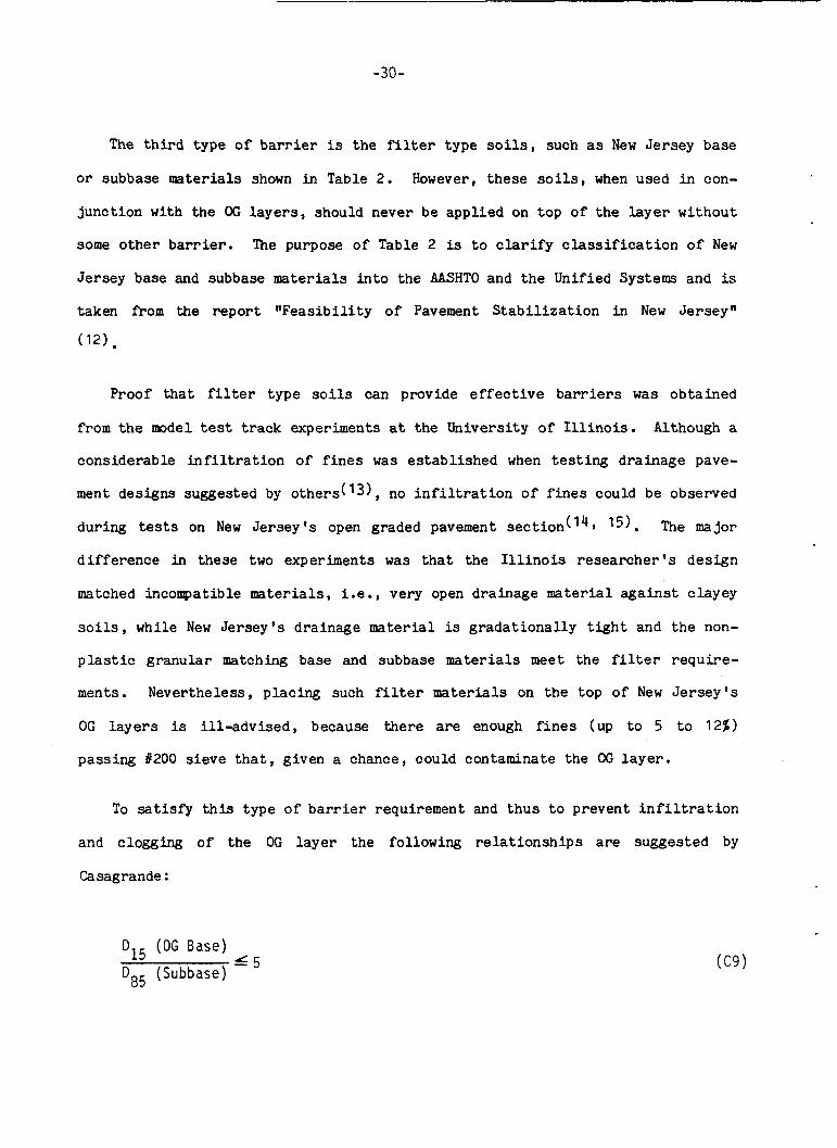
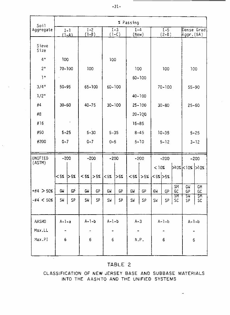
The t h i r d type o f b a r r i e r is the f i l ter type s o i l s , such as New Je r sey base
o r subbase materials shown i n Table 2. However, these s o i l s , when used in con-
j u n c t i o n with t h e OG l a y e r s , should never be a p p l i e d on t o p of t he l a y e r w i thou t
some o t h e r barrier. The purpose o f Table 2 is to c l a r i f y c l a s s i f i c a t i o n o f N e w
Jersey base and subbase materials i n t o t h e AASHTO and t h e Unified Systems and is
taken from the r e p o r t " F e a s i b i l i t y o f Pavement S t a b i l i z a t i o n i n New Je r sey"
(12) .
Proof t h a t f i l ter t y p e s o i l s can provide e f f e c t i v e barriers was ob ta ined
from the mdel test track experiments a t the Universi ty o f I l l i n o i s . Although a
cons ide rab le i n f i l t r a t i o n o f f i n e s was es tab l i shed when testing drainage pave-
ment designs suggested by o t h e r s ( l 3 1 , no i n f i l t r a t i o n o f f i n e s could be observed
du r ing tests on New J e r s e y ' s open graded pavement s e c t i o n (14, 15). The major
d i f f e r e n c e i n these two experiments was t h a t the I l l i n o i s r e s e a r c h e r ' s d e s i g n
matched incompatible materials, i.e., very open d ra inage material against clayey
s o i l s , while New J e r s e y ' s d ra inage material is g r a d a t i o n a l l y t i g h t and the non-
p l a s t i c g ranu la r matching base and subbase materials meet t h e f i l t e r r e q u i r e -
ments. Nevertheless , placing such f i l t e r materials on the t o p of New J e r s e y ' s
OC l a y e r s is i l l - a d v i s e d , because there are enough f i n e s (up t o 5 t o 12%)
pass ing 1200 s i e v e t h a t , given a chance, could contaminate t h e OG l a y e r .
To s a t i s f y t h i s t ype o f barrier requirement and t h u s t o prevent i n f i l t r a t i o n
and clogging of t h e OG l a y e r t h e following r e l a t i o n s h i p s are suggested by
Casagrande :
D I 5 (OG Base) DB5 (Subbase) 6 5
-31-
X Passing
(5%
S o i 1 Yggregate
>5%
-- 1-4
(New)
<5%
1-1 - & E L
>5%
1-2 (1-B)
: lo%
1-3 (1-CI
>lo%
:5% >5%
GW SM
GP GC
e n s e Grad 99r. (5A)
S i e v e S i z e
4 Ii
2 Ii
1
3/4"
1 /,Ii
#4
fi8
#16
650
#200
100
70- 100
100
100
65-100
40-75
100
60-100
100 100
50-95 60- 100 70-100 55-90
40- 100
25-100
20-1 qa 15-85
8-45
5-1 0
30-60 30- 100 30-80 25-60
5-25
0-7
5-30
0-7
5-35
0- 5
10-35
5-12
I N I F IED ( ASTM)
-200 I
-200
I -200 -200
(5% 7% >5% p"; > 5% < 5% I I
GW I GP GW GP GW GP GW GP 1-+4 > 50%
-#4 < 50%
I
sw SP sw I SP sw 1 SP sw I SP
AASHO
Max. L L
Max. P I
A-1-a
- 6
A-1 -b
- 6
A - 1 -b
- 6
A- 3
- N . P .
A-1-b
- A-1-b
- 6 b
TABLE 2
CLASSIFICATION OF NEW JERSEY BASE AND SUBBASE MATERIALS INTO THE AASHTO AND THE UNIFIED SYSTEMS
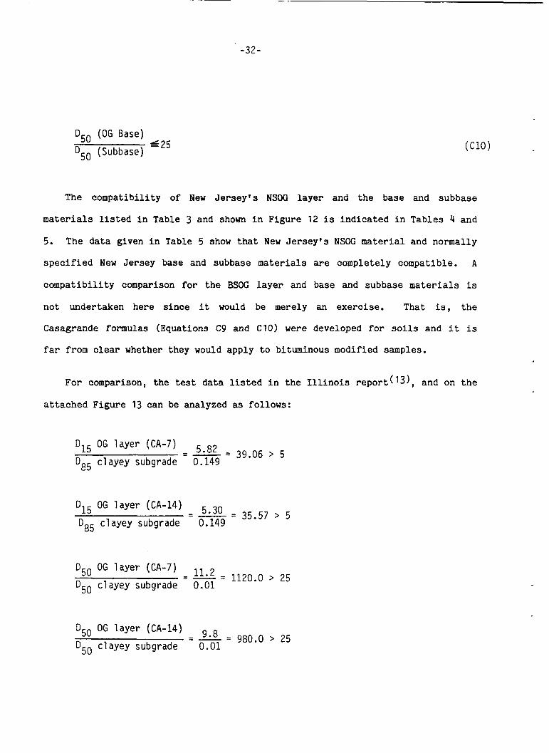
D50 (OG Base)
D50 (Subbase) S 2 5
-32-
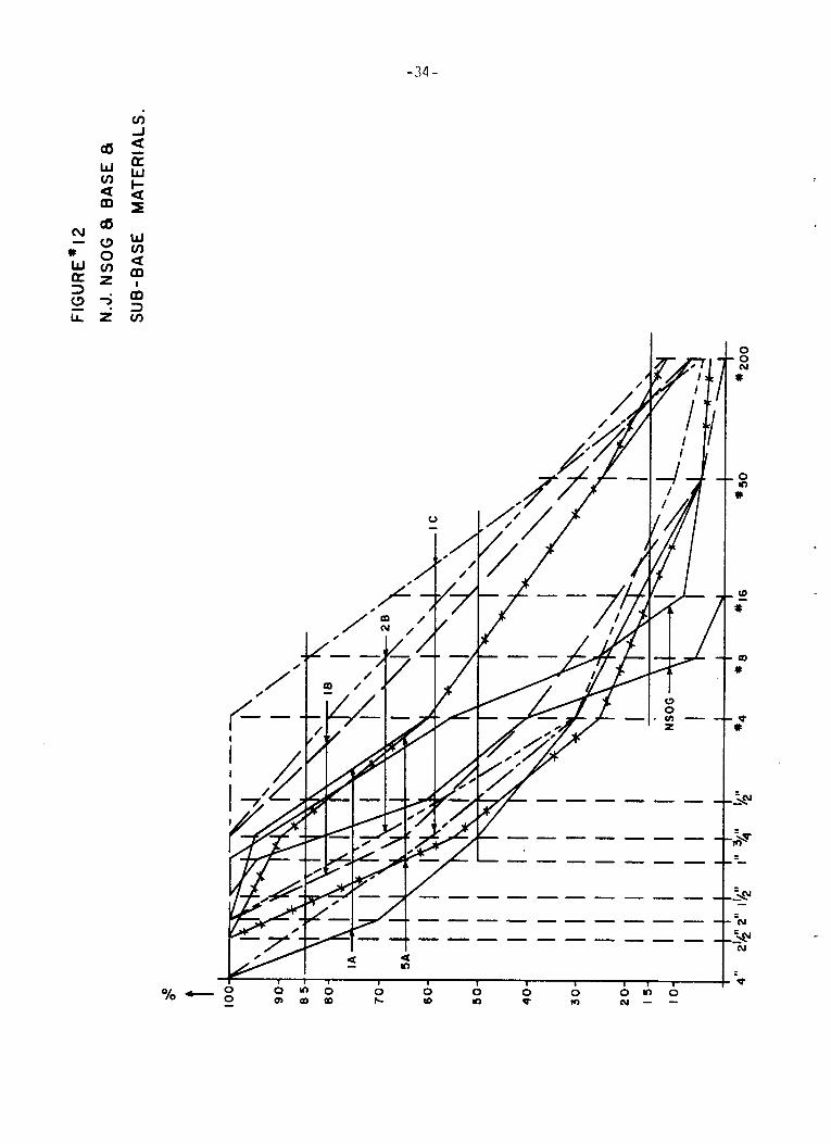
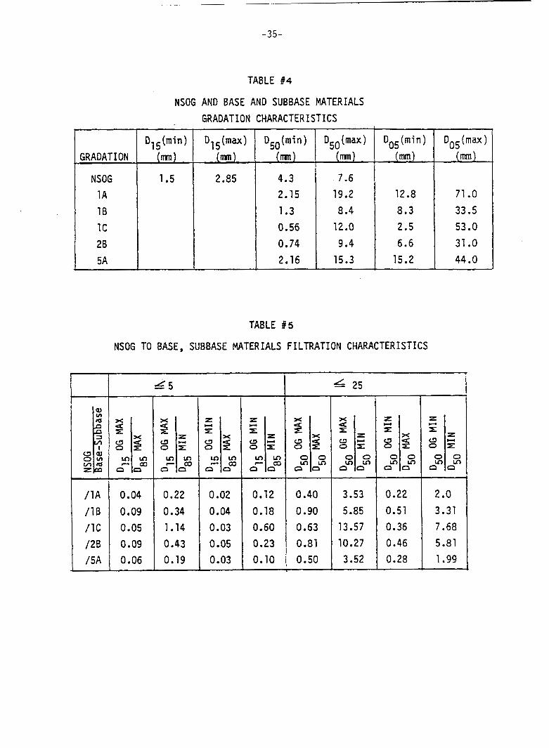
The compatibility of New Jersey's NSOG layer and the base and subbase
materials listed in Table 3 and shown in Figure 12 is indicated in Tables 4 and
5. The data given in Table 5 show that New Jersey's NSOG material and normally
specified New Jersey base and subbase materials are completely compatible. A
compatibility comparison for the BSOC layer and base and subbase materials is
not undertaken here since it would be merely an exercise. That is, the
Casagrande formulas (Equations C9 and ClO) were developed for soils and it is
far from clear whether they would apply to bituminous modified samples.
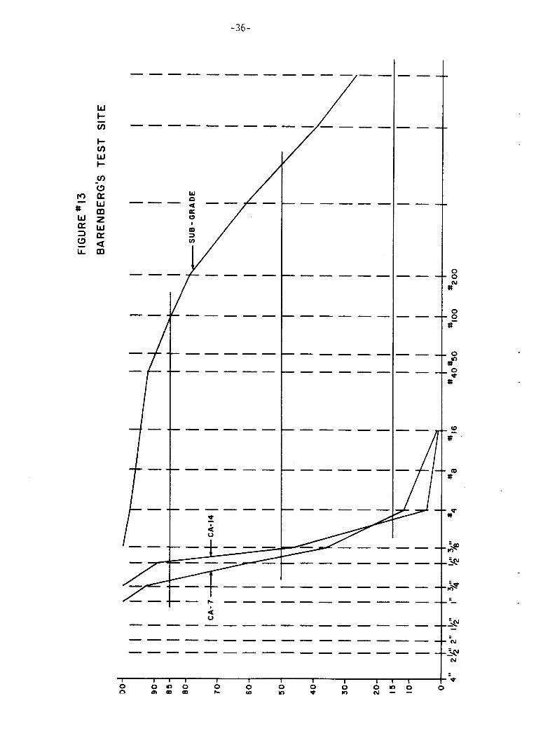
For comparison, the test data listed in the Illinois report(l31, and on the
attached Figure 13 can be analyzed as follows:
D I 5 OG layer (CA-7) - - - - 5 - 8 2 - 39.06 > 5
clayey subgrade 0.149
D15 OG layer (CA-14)
D85 - - - - 5 * 3 0 - 35.57 > 5
cl ayey subgrade 0.149
OG layer (CA-7) - - - - - 1120.0 > 25 D50
D50 clayey subgrade 0.01
D50 OG layer (CA-14)
D50 clayey subgrade 0.01 - - - - 9 * 8 - 980.0 > 25
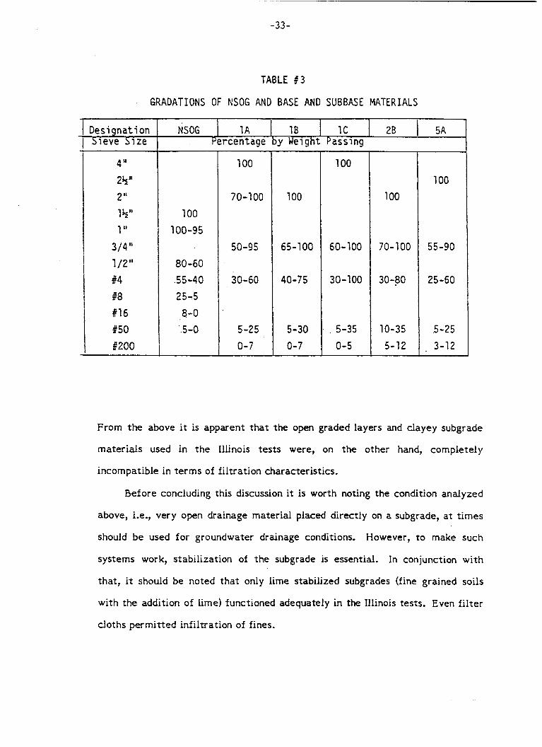
-33-
NSOG
TABLE 9 3
GRADATIONS OF NSOG AND BASE AND SUBBASE MATERIALS
1A 1B IC 1 28 I 5A
4 'I 2 y 1 2 " 1 Y 1 I1
3/411 1 /211 #4
#16 950 6200
n"a
100 100-95
80-60 .55-40 25-5 8-0
'.5-0
100
70-100
50-95
30-60
5-25 0-7
100
55-90
25-60
5-25 . 3-12
From the above it is apparent t h a t the open graded layers and clayey subgrade
mater ia l s used in t h e Illinois tests were, on the other hand, completely
incompatible in t e r m s of f i l t ra t ion character is t ics .
Before concluding this discussion i t is worth noting t h e condition analyzed
above, i.e., very open drainage mater ia l placed direct ly on a subgrade, at t imes
should be used f o r groundwater drainage conditions. However, to make such
sys tems work, s tabi l izat ion of t h e subgrade is essential. In conjunction with
tha t , i t should be noted t h a t only lime stabilized subgrades (fine grained soils
with the addition of lime) functioned adequately in the Illinois tests. Even f i l t e r
c loths permi t ted infiltration of fines.
-34 -
-35-
GRADATION
NSOG 1A 1B 1c 28 5A
TABLE #4
D1 (mi n ) D (max ) D50 (mi n ) D50 (max )
(m) (m) (m) (m)
1.5 2.85 4.3 7.6 2.15 19.2 1.3 8.4 0.56 12.0 0.74 9.4 2.16 15.3
NSOG AND BASE AND SUBBASE MATERIALS GRADATION CHARACTER ISTICS
12.8 71 .O
I
0.22 0.51 0.36 0.46
2 .o 3.31 7.68 5.81
31 .O 15.2 44 .O
3.52
TABLE # S
NSOG TO BASE, SUBBASE MATERIALS FILTRATION CHARACTERISTICS
0.28 1.99
L5 I 25 I
I I I I x 4
a m o x = E z
I I I
0.04 0.22 0.02 0.12 0.40 0.09 0.34 0.04 0.18 0.90 0.05 1.14 0.03 0.60 0.63 0.09 0.43 0.05 0.23 0.81 0.06 0.19 0.03 0.10 , 0.50
3.53 5.85 13.57 10.27
I I
1
-36-
I I l l I I I I I I l l
2 0 c) 0 t 0 m g n r r 0 2 : s c- 0 0
C.4 DESIGN OF WATER COLLECTION SYSTEMS
C. 4.1 General
Some of the features of water co l l ec t ion systems were a l ready discussed i n
the subsurface geometry analysis . Basical ly , physical f e a t u r e s such as t h e use
of longi tudina l and/or t ransverse dra ins , t h e angle of o u t l e t s , dayl ight ing o r
dra in ing the o u t l e t s i n to t h e i n l e t s t ruc tu res and the l i k e were discussed. The
geometric ana lys i s of the loca t ion , spacing and arrangement of c o l l e c t o r s was
a l s o made.
A t t h i s point , two f a c t o r s concerning i n t e r n a l drainage c o l l e c t i o n should be
mentioned. One is v e r t i c a l drainage, the other is dayl ight ing of t he drainage
l a y e r , ins tead of draining i t i n t o the edge drains . Vertical drainage of t h e
i n f i l t r a t i o n water is impractical because of t h e impervious na ture of the sub-
base and t h e complexity and cost of the so lu t ion f o r determinat ion of t h e
subgrades drainage cha rac t e r i s t i c s . On t h e other hand, the dayl ight ing pr in-
c i p l e , a t the glance, appears t o be very tempting, mainly because i t i s s o much
cheaper. However, i t is a general ly well known fact t h a t it is not uncommon f o r
t h i s type of o u t l e t t o become clogged and cease t o function. T h i s would mean a
water buildup under the pavement r e su l t i ng i n a r a p i d d e t e r i o r a t i o n of t h e per-
manent s t ruc ture . Thus, a dra in containing a p i p e is t h e only p o s i t i v e mode of
water co l l ec t ion t h a t appears t o be s u f f i c i e n t l y practical and reliable.
C.4.2 Longitudinal and Transverse Collectors and Out le t s
Figures 14 through 18 provide typ ica l details of longi tudina l and t r ansve r se
c o l l e c t o r designs and o u t l e t s which are either dayl ighted o r terminated i n
i n l e t s . Factors a f f ec t ing co l l ec to r design bas i ca l ly a r e d r a i n a b i l i t y , suscep-
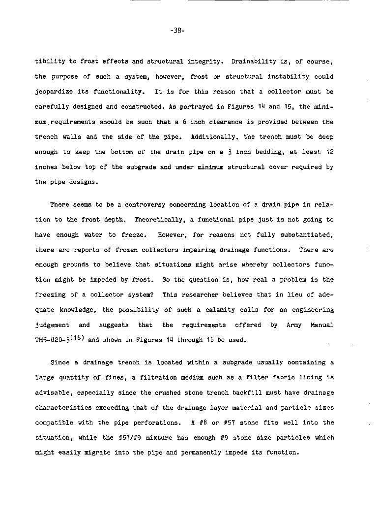
-38-
t i b i l i t y t o f r o s t effects and s t r u c t u r a l i n t e g r i t y . D r a i n a b i l i t y is, of cour se ,
t h e purpose of such a system, however, f r o s t o r s t r u c t u r a l i n s t a b i l i t y could
j e o p a r d i z e its f u n c t i o n a l i t y . It is f o r t h i s reason t h a t a c o l l e c t o r must be
c a r e f u l l y designed and constructed. A s por t rayed i n F igu res 14 and 15, t h e mini-
mum.requirements should be such that a 6 inch c l ea rance is provided between the
t r e n c h walls and the s i d e of the pipe. Addit ional ly , the t r e n c h must be deep
enough t o keep t h e bottom of the d r a i n pipe on a 3 i n c h bedding, a t least 12
i n c h e s below top of the subgrade and under minimum s t r u c t u r a l cover r e q u i r e d by
the p i p e designs.
There seems t o be a controversy concerning l o c a t i o n of a d r a i n p ipe i n rela-
t i o n t o t h e f r o s t depth. Theore t i ca l ly , a f u n c t i o n a l p ipe j u s t is no t going t o
have enough water t o f reeze. However, f o r reasons not f u l l y s u b s t a n t i a t e d ,
there are r e p o r t s of f rozen c o l l e c t o r s impairing d ra inage func t ions . There are
enough grounds t o b e l i e v e t h a t s i t u a t i o n s might arise whereby c o l l e c t o r s func-
t i o n might be impeded by f r o s t . So the quest ion is, how real a problem is t h e
f r e e z i n g of a c o l l e c t o r system? Th i s researcher b e l i e v e s t h a t i n l i e u of ade-
q u a t e knowledge, t he p o s s i b i l i t y of such a calamity calls f o r an e n g i n e e r i n g
judgement and sugges t s that the requirements o f f e r e d by Army Manual
TM5-820-3(16) and shown i n Figures 14 through 16 be used.
S i n c e a drainage t rench is l oca t ed within a subgrade u s u a l l y c o n t a i n i n g a
large q u a n t i t y of f i n e s , a f i l t r a t i o n medium such as a f i l t e r fabric l i n i n g is
a d v i s a b l e , e s p e c i a l l y s i n c e the crushed s tone t r ench b a c k f i l l must have d r a i n a g e
characteristics exceeding t h a t of t h e drainage l a y e r material and p a r t i c l e s i z e s
compatible w i t h the pipe pe r fo ra t ions . A #8 or #57 s t o n e fits well i n t o t h e
s i t u a t i o n , while the #57/#9 mixture has enough 19 s t o n e s ize par t ic les which
might e a s i l y migrate i n t o t h e p ipe and permanently impede its funct ion.
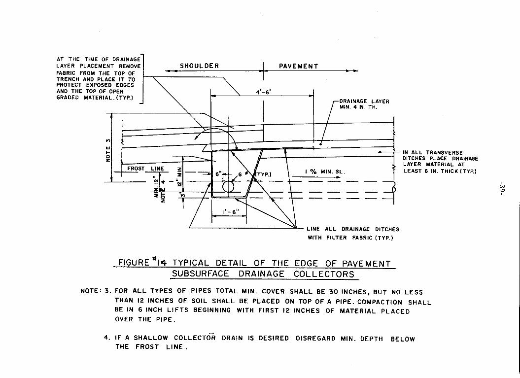
LAYER PLACEMENT REMOVE SHOULDER PAVE MEN T AT THE TIME OF DRAINAGE
FABRIC FROM THE TOP OF T TRENCH AND PLACE I T TO PROTECT EXPOSED EDGES AND THE TOP OF OPEN GRADED MATERIAL. (TYP.)
1 _ _ -
\
A I F
' I I \ I , I I
wI c
i l i I \ I I .I I i IN A L L TRANSVERSE
DITCHES PLACE DRAINAGE LAYER MATERIAL AT LEAST 6 IN. THICK (TYP.)
I w a
I
' L ! 3 x L LINE A L L DRAINAGE DITCHES WITH FILTER FABRIC (TYP.)
F lGURE*14 TYPICAL DETAIL OF THE EDGE O F PAVEMENT SUBSURFACE DRAINAGE COLLECTORS
NOTE: 3. FOR A L L TYPES OF PIPES TOTAL MIN. COVER SHALL BE 30 INCHES, BUT NO LESS THAN 12 INCHES OF SOIL SHALL BE PLACED ON TOP OF A PIPE. COMPACTION BE IN 6 INCH L IFTS BEGINNING WITH FIRST 12 INCHES OF MATERIAL PLACED OVER THE PIPE.
SHALL
4. IF A SHALLOW COLLECTOR DRAIN IS DESIRED DISREGARD MIN. DEPTH BELOW THE FROST L I N E .
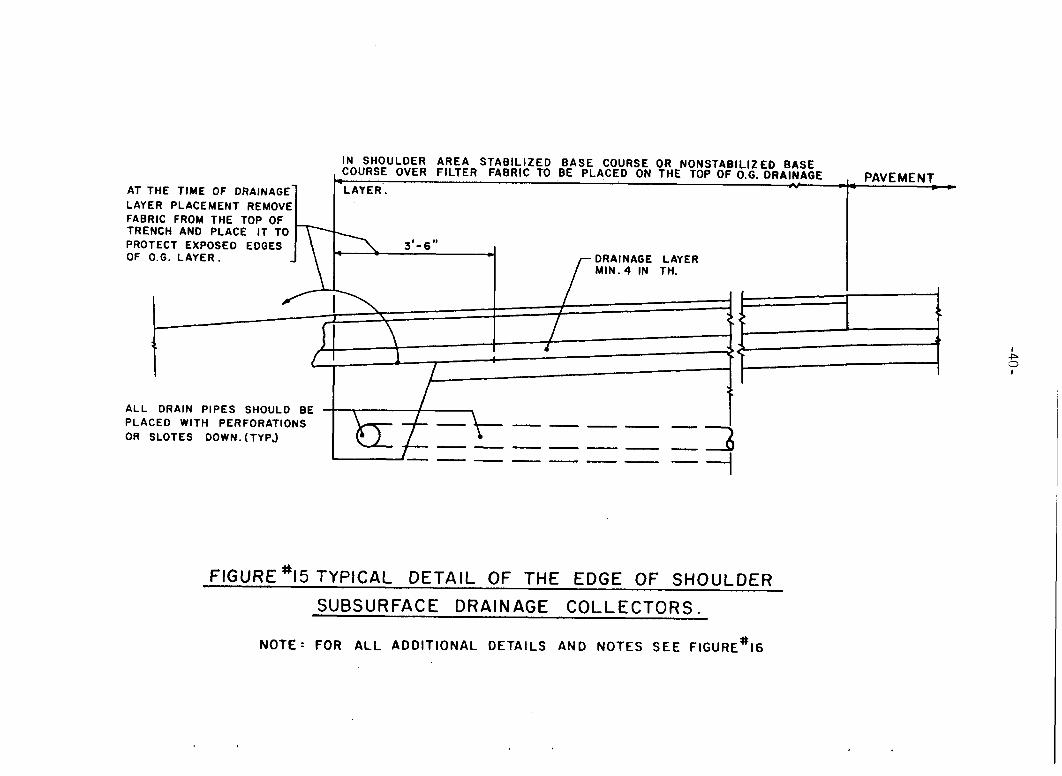
LAYER PLACEMENT REMOVE AT THE TIME OF DRAJNAGE
FABRIC FROM THE TOP OF TRENCH AND PLACE I T TO PROTECT EXPOSED EDGES OF O.G. LAYER.
I N SHOULDER AREA S T A B I L I Z E D B A S E COURSE OR NONSTABILIZEO BASE COURSE OVER FILTER FABRIC TO BE PLACED ON THE TOP OF O.G. DRAINAGE
LAYER. - I _ _ PAVEMENT -
DRAINAGE LAYER MIN. 4 IN TH. I-
A L L DRAIN PIPES SHOULD BE PLACED WITH PERFORATIONS OR SLOTES DOWN. (TYPJ
- I d
FlGURE'15 TYPICAL D E T A I L OF THE EDGE OF SHOULDER SUBSURFACE DRAINAGE C O L L E C T O R S .
I P '3
I
N O T E - FOR ALL ADDIT IONAL DETAILS AND NOTES SEE FIGURE'16

6 IN . DRAINAGE LAYER r M A T E R I A L IN DR. DITCHES ONLY. I
I W l t I I 1 S U B GRADE
6" *8 OR*57 COURSE FRO T LINE\ s
r' 'up- AGGREGATE IN I i l w DRAINAGE DITCHES = & z
L i FIGURE*lG TYPICAL TRANSVERSE DITCH DETAIL
NOTE 3 FOR ALL TYPES OF PIPES TOTAL MIN. COVER SHALL BE 30 INCHES, BUT NO LESS THAN 12 INCHES OF SOIL SHALL BE PLACED ON TOP O F A PIPE. COMPACTION SHALL BE IN 6 INCH LIFTS BEGINNING WITH 12 INCHES OF MATERIAL PLACED OVER THE P IPE.
4. IF A SHALLOW COLLECTOR DRAIN IS DESIRED DESREGARD MIN. DEPTH BELOW THE FROST .L INE.

-42-
DR. O U T L E T
ROCK B A C K F I L L AROUND PIPE 3'-0'' WIDE (TYP. )
ROCK BACKFl LL O U T L I N E
FIGURE #17 TYPICAL DETAIL OF ~ R A I N A G E OUT- LET WITH ROCK BACKFILL
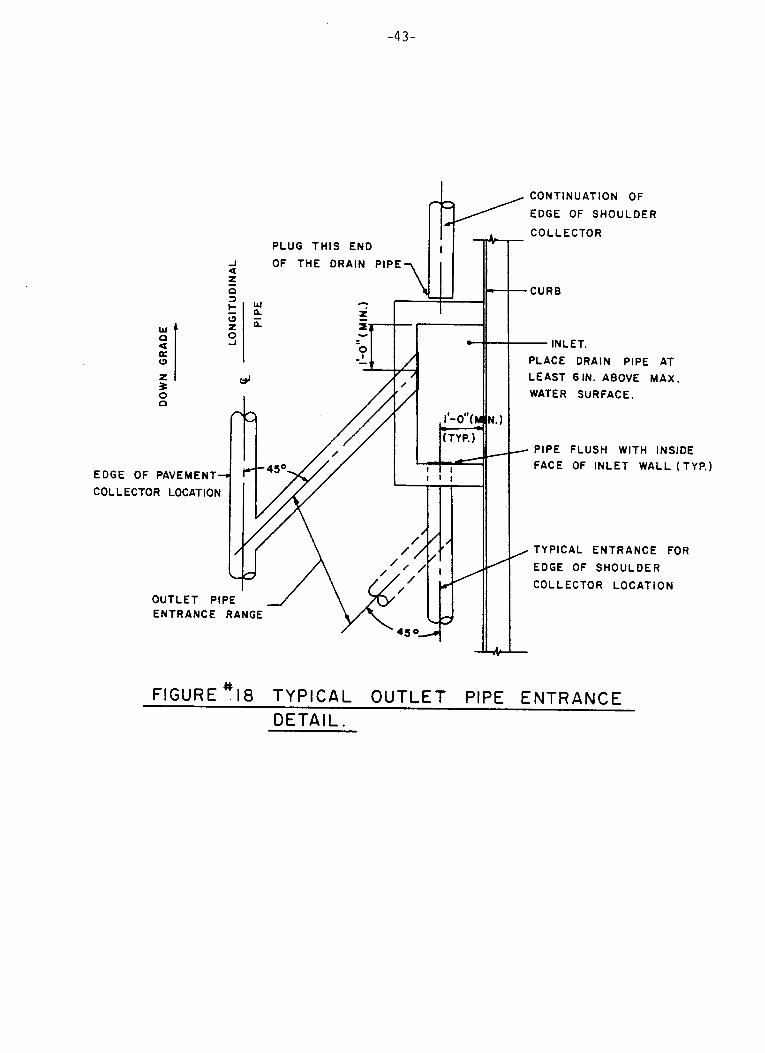
-43-
- 0 z 0 'I K J
0
zl 3 0 0
EDGE OF PAVEMENT- COLLECTOR LOCATION
PLUG THIS END OF THE DRAIN PIPE
CONTINUATION OF
EDGE OF SHOULDER
- CO L L ECTO R
-CURB
- INLET. PLACE DRAIN PIPE AT LEAST 61N. ABOVE MAX. WATER SURFACE.
- PIPE FLUSH WITH INSIDE FACE OF INLET WALL (TYP.)
, TYPICAL ENTRANCE FOR
EDGE OF SHOULDER
C O L L ECTO R LOCAT I0 N
FIGURE ?I8 TYPICAL OUTLET PIPE ENTRANCE DETAIL.
According to an Army manual(l7), the respective filter criteria for pre-
vention of soil migration into pipes with circular and slotted holes are:
D85 of filter material hole diameter > 1.0
D85 of filter material > 1.2
slot width (C12)
Assuming 3/8 inch circular holes or 3/16 inch slots, the filter criteria for
the subject stone sizes, shown in Table 6 indicate that the use of #9 stone in
proximity of such perforated drainage pipes is simply ill-advised. While the #9
stone mix alone will definitely infiltrate a pipe, its combination with #57
stone theoretically satisfies the filtration requirements. Nevertheless, a mix
consisting of 50% #9 stone and exposed to a turbulent flow might cause clogging
of drain pipes. Thus only the P8 or $57 stone sizes should be used for back
filling trenches.
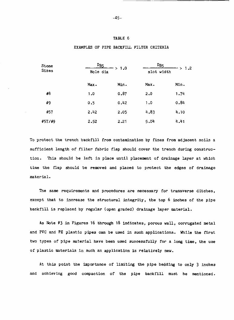
-45-
Stone S izes
#8
#9
157
#57/#9
TABLE 6
EXAMPLES OF PIPE BACKFILL FILTER CRITERIA
> 1.2 D85 s l o t width
D85 > 1.0 Hole d i a
Max Min . Max. Min . 1 .o 0.87 2 .o 1.74
0 e 5 0.42 1 .o 0.84
2.42 2.05 4.83 4.10
2.52 2.21 5.04 4.41
To p r o t e c t the t rench b a c k f i l l from contamination by f i n e s from adjacent s o i l s a
s u f f i c i e n t length o f f i l t e r fabric f l ap should cover the t rench during construc-
t i on . This should be l e f t i n place u n t i l placement o f drainage l aye r a t which
time the f lap should be remved and placed t o protect the edges of drainage
material.
The same requirements and procedures are necessary f o r t ransverse d i t c h e s ,
except t h a t t o increase t h e s t r u c t u r a l i n t e g r i t y , t h e top 6 inches of t h e p i p e
b a c k f i l l is replaced by regular (open graded) drainage l aye r mater ia l .
As Note 13 i n Figures 16 through 18 indicates, porous wall, corrugated metal
and PVC and PE p l a s t i c p ipes can be used i n such appl ica t ions . While the first
two types of p i p e material have been used successfu l ly f o r a long time, t h e use
of p l a s t i c materials i n such an appl ica t ion is r e l a t i v e l y new.
A t t h i s p o i n t t h e importance o f limiting the p ipe bedding to only 3 inches
and achieving good compaction of the p ipe b a c k f i l l must be mentioned.

-46-
Experience has shown tha t the use of more than 3 inches of bedding p rov ides t o o
much undrainable space below a drain p ipe , and t h e s t r u c t u r a l s t r e n g t h , espe-
c i a l l y with p l a s t i c p i p e s , in large measure depends on the proper compaction o f
t h e b a c k f i l l material. Improper handl ing of ei ther cri teria could impede t h e
c o l l e c t o r s s t r u c t u r a l i n t e g r i t y .
I n August 1982, t h e c o s t per f o o t of 6 inch diameter drainage p i p e d e l i v e r e d
t o the s i t e on t h e average was: f o r s tee l p ipe $2.10, f o r porous c o n c r e t e p i p e
$1.60, f o r PE t ub ing $0.60 and f o r PVC p ipe $0.80. Considering the c o s t o f
abou t $13.00 per f o o t o f d ra inage t r e n c h , complete w i t h p ipe and the b a c k f i l l ,
the p r i c e of the p ipe does no t seem so c r i t i ca l and is o f a lesser importance in
the s e l e c t i o n o f the t y p e of pipe.
TRB r e p o r t 225(18) suggests c a u t i o n i n spec i fy ing p las t ic materials f o r
drainage p ip ing . The problem wi th p l a s t i c s is tha t they are man-made materials
and t h e r e f o r e , as i n a l l o t h e r materials, manufacturing parameters govern t h e
q u a l i t y o f the product. As TRB Report #225 states: "ASTM s p e c i f i c a t i o n s con-
tain requirements f o r s t r u c t u r a l p r o p e r t i e s o f both the compounds used i n p i p e
and the p i p e i t se l f . A review o f these s p e c i f i c a t i o n s shows t h a t they do no t
provide p o s i t i v e a s su rance that bu r i ed (p las t ic ) p ipe products can meet even t h e
most basic des ign cri teria set f o r t h he re in . Furthermore, products meeting a
given s p e c i f i c a t i o n can posses s s i g n i f i c a n t l y d i f f e r e n t and unknown s t r u c t u r a l
properties. F i n a l l y , a product meeting t h e s t anda rd a t the time of manufacture
may be changed g r e a t l y by exposure t o s u n l i g h t by the time it is i n s t a l l e d . "
-47-
The manufacturers o f these products , however, since t h i s TRB r e p o r t was
pub l i shed i n 1980, have been improving q u a l i t y o f t h e i r p roduc t s as is reflected
i n the changes o f t he ASTM s p e c i f i c a t i o n . A t p r e s e n t , t h e r e f o r e , t o p rov ide t h e
b e s t s u i t a b l e products f o r the purpose the s p e c i f i c a t i o n i n Appendix B are
offered.
A s a l r e a d y indicated, the s tandarized use o f sFX inch d ra inage and o u t l e t
p i p e s is suggested f o r convenience and o p e r a t i o n a l s a f e t y , t h a t is, from an
i n s t a l l a t i o n , fbnct ioning and maintenance p o i n t of view. However, i f need b e ,
the c a p a c i t y o f such p ipes can be c a l c u l a t e d using a comon p i p e flow
(Manning's) formula under the condi t ion o f free s u r f a c e flow i n a p i p e condu i t .
This is shown below and i n t h e Figure 19.
The Manning fo ruu la f o r the capac i ty o f a p i p e running full is then:
A l t e r n a t e l y the d i scha rge capac i ty can be ca l cu la t ed as a product o f a flow rate
i n a d r a i n and the d i s t a n c e between o u t l e t s :
Q =
where :
Q =
n = d =
q =
L =
s =
a p i p e discharge capac i ty in cubic feet p e r second o r cubic feet p e r day Manning's roughness f a c t o r p i p e diameter i n feet s l o p e i n feet p e r f o o t discharge q u a n t i t y i n cu. f t . p e r day p e r f o o t o f drainage p i p e l eng th d i s t a n c e between o u t l e t s i n feet
T o faci l i ta te computations o f discharge c a p a c i t y , the use of Figure 19 is
suggested. This nomograph relates Elanning's p ipe flow equa t ion t o the product
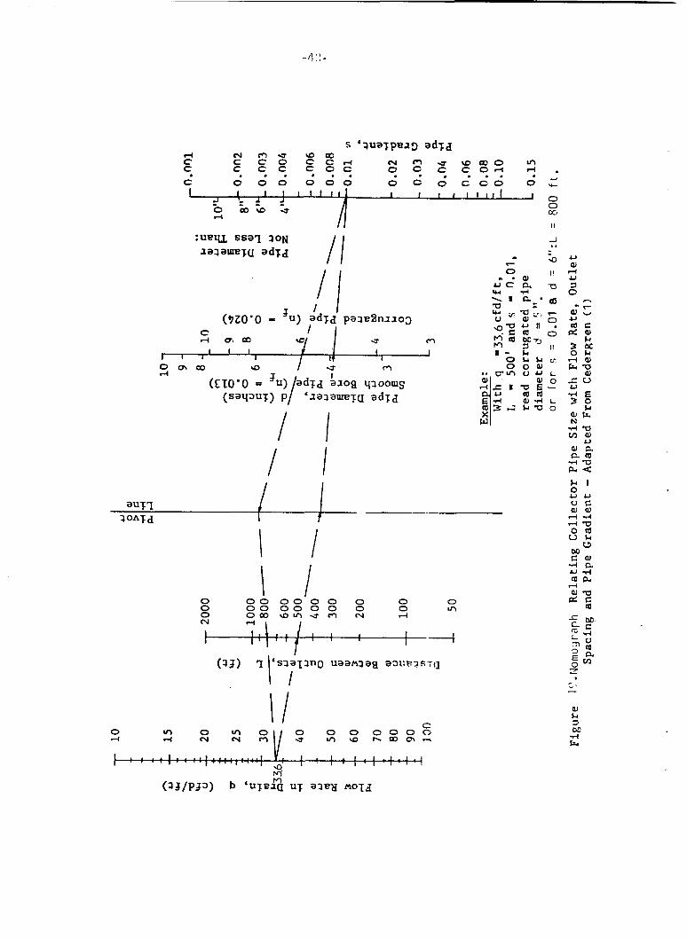
0 0 0 00’0 0 0 0 0 0 00 0 0 0 0 0 0 ul 0 o m a m u r n hl rl
\I

-49-
o f a d r a i n ' s flow rate and t h e d i s t a n c e between o u t l e t s . Figure 19 is based on
s t u d i e s of Cedergren e t a l ( l ) and Moulton(2).
An example problem i l l u s t r a t i n g the use o f the nomograph is presen ted i n a
l a te r subsec t ion . A t t h i s stage, s u f f i c e it t o say tha t the drainage q u a n t i t y
"q" i n essence is t he flow rate o f t he open graded drainage l a y e r as computed
from equa t ion C6. The t o t a l amount o f water accumulated over a d i s t a n c e a long
t h e roadway is the t o t a l discharge q u a n t i t y which should be less than o r e q u a l
t o t h e p i p e d i scha rge capac i ty "Qn. The d r a i n p i p e discharge capacity "Qn could
then be used t o d e f i n e the spacing o f the o u t l e t s . However, s i n c e the a u t h o r
recommends the s t anda rd ized use of 6" diameter d r a i n and o u t l e t p i p e s , i n most
i n s t a l l a t i o n s the p i p e s w i l l be oversized. Therefore , the spacing o f o u t l e t s
normally is no t governed by the capac i ty o f underdrains b u t by convenience in
des ign ing a c o l l e c t i o n system t o convey the water t o a s u i t a b l e e x i t p o i n t .
Normally the o u t l e t p i p e s should be day l igh ted , a s is shown i n F igu re 17,
b u t i f t h i s is not p o s s i b l e , then the water should b e drained i n t o t h e n e a r e s t
i n l e t s t r u c t u r e , as indicated i n Figure 18. When latter is the case, i t is
impera t ive t h a t the i n v e r t e l e v a t i o n o f the subsurface drainage system p i p e be
a t least six inches higher than the maximum predicted water surface i n the
i n l e t ( 3 ) to avoid storm water backing up i n t o t h e Subsurface drainage system.
The t y p i c a l o u t l e t p i p e en t r ance de ta i l shown i n Figure 18 can accomodate a n
inlet s t r u c t u r e l o c a t i o n o u t s i d e the l ine of t he l o n g i t u d i n a l c o l l e c t o r d r a i n
(i.e. when the c o l l e c t o r is placed a t the edge of the pavement) o r t h e i n l e t s
are l o c a t e d in l i n e w i t h the l o n g i t u d i n a l c o l l e c t o r (i.e. when a n edge o f
shou lde r c o l l e c t o r is used). However, p l ac ing the l o n g i t u d i n a l d r a i n s a t the
edge o f a shou lde r c a n , in t h i s respect, cause a number o f problems. F i r s t ,
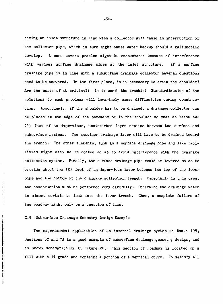
-50-
having an in le t s t r u c t u r e i n l i n e wi th a c o l l e c t o r w i l l cause an i n t e r r u p t i o n o f
t h e c o l l e c t o r p i p e , which in t u r n might cause water backup should a malfunct ion
develop. A more s e v e r e problem might be encountered because o f i n t e r f e r e n c e
w i t h v a r i o u s s u r f a c e drainage p i p e s a t the i n l e t s t r u c t u r e . If a s u r f a c e
d r a i n a g e p i p e is i n l i n e with a subsurface drainage c o l l e c t o r s e v e r a l q u e s t i o n s
need t o b e answered. I n t h e first p l a c e , is it necessary t o d r a i n t h e s h o u l d e r ?
Are t h e c o s t s of it c r i t i ca l? Is it worth the t r o u b l e ? S tanda rd iza t ion o f t he
s o l u t i o n s t o such problems w i l l i nva r i ab ly cause d i f f i c u l t i e s d u r i n g cons t ruc -
t i o n . Accordingly, i f the shou lde r has t o be d ra ined , a drainage c o l l e c t o r can
be p laced a t the edge o f the pavement o r in t h e shoulder so t h a t a t least two
(2) feet of an impervious, undis turbed l a y e r remains between the s u r f a c e and
s u b s u r f a c e systems. The shou lde r drainage l a y e r w i l l have t o be drained toward
the t r e n c h . The o t h e r e lements , such as a su r face drainage p i p e and l i k e faci-
l i t i e s might a l s o be r e l o c a t e d so as t o avoid i n t e r f e r e n c e wi th t he d ra inage
c o l l e c t i o n system. F i n a l l y , the s u r f a c e drainage p ipe could be lowered so as t o
p rov ide about two (2) feet o f an impervious l a y e r between the top o f t h e lower
p i p e and the bottom o f t he d ra inage c o l l e c t i o n t rench. Espec ia l ly i n t h i s case,
the c o n s t r u c t i o n must be performed very c a r e f u l l y . Otherwise the d ra inage water
is almost c e r t a i n t o l e a k i n t o the lower t rench. Then, a complete f a i l u r e o f
t he roadway might only be a ques t ion o f time.
C.5 Subsurface Drainage Geometry Design Example
The experimental a p p l i c a t i o n o f a n i n t e r n a l drainage system on Route 195,
S e c t i o n s 6C and 7 A i s a good example of subsurface drainage geometry d e s i g n , and
is shown schemat i ca l ly i n Figure 20. This s e c t i o n o f roadway is l o c a t e d on a
f i l l w i t h a 1% grade and c o n t a i n s a p o r t i o n o f a v e r t i c a l curve. To sat isfy a l l
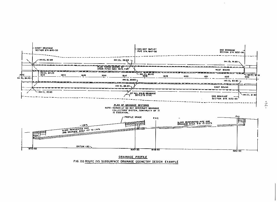
START DRAINAGE SECTION STA.1642*50
I t DAYLIOHT OUTLET 't PIPE STA.1647*50 END DRAINAGE
I
EAST BOUND -_I--- , ,
END DRAINAGE SECTION S T A 1632.65
-45' A L L SOLID DRAINAGE
I N V E L 89 .203) '
- INV E L 0 3 6 5 ,* OUTLETS ITYR) ------------ _ _ - _ _ - _ _ _ ------_ _ _ _ _ _ _ _ _ ----:- ----------------- -- ---- ----_ _ _ _ _ _ _ _ _ _ _ _ _ _ _ _ _ _ _ _ _ _ _ -
9 L A N Or DR A M ! J L W i L W l NOTE1 NORMALLY DO NOT INTL RRUPT ORAINIOE
COLLECTORS' SYSTEM, CONTINUITY OF I T IS ESSENTIAL.
P V) PROFILE GRADE P V C .
p~ p RFORATED PIPE AND $ & N A G ~ DIlCH 0 % To 05'%
1642.50 1 6 4 0 * 5 0 DATUM 80 \
1641* 50
DRAINAGE PROFILE FIG. 20 ROUTE 195 SUBSURFACE DRAINAGE GEOMETRY DESIGN EXAMPLE
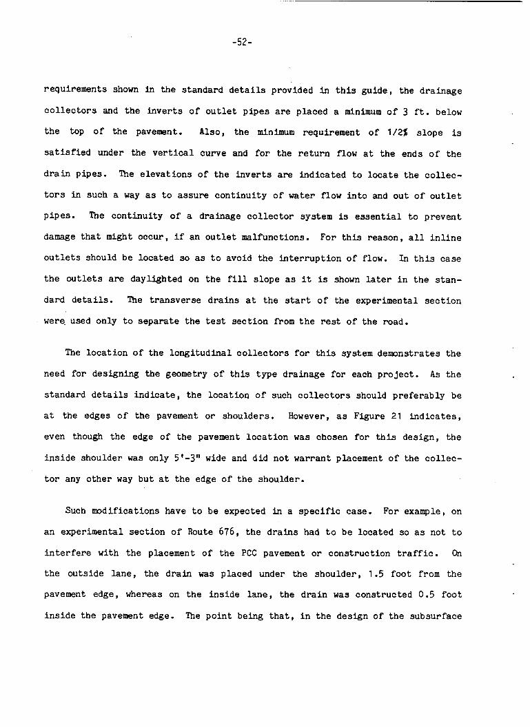
-52-
requirements shown in t h e s t anda rd detai ls provided i n t h i s gu ide , the d ra inage
c o l l e c t o r s and the i n v e r t s o f o u t l e t p i p e s are placed a minimum o f 3 f t . below
the top of the pavement. Also, the minimum requirement o f 1/2% s l o p e is
s a t i s f i e d under the v e r t i c a l curve and for t h e r e t u r n flow a t the ends o f t h e
d r a i n pipes . The e l e v a t i o n s of the i n v e r t s are i n d i c a t e d t o l o c a t e t h e c o l l e c -
t o r s i n such a way as t o a s s u r e c o n t i n u i t y of water flow i n t o and o u t of o u t l e t
p i p e s . The c o n t i n u i t y o f a drainage c o l l e c t o r system is e s s e n t i a l t o p reven t
damage t h a t might occur , i f an o u t l e t malfunctions. For t h i s reason, a l l i n l i n e
o u t l e t s should be loca ted so as t o avoid the i n t e r r u p t i o n o f flow. In t h i s case
the o u t l e t s are dayl ighted on t h e f i l l s l o p e as it is shown later i n t he s t a n -
dard details . The t r a n s v e r s e d r a i n s a t the start o f the experimental s e c t i o n
were, used only t o s e p a r a t e t h e tes t s e c t i o n from t h e rest o f the road.
The l o c a t i o n o f the l o n g i t u d i n a l c o l l e c t o r s f o r t h i s system d e m n s t r a t e s t h e
need f o r designing the geometry o f t h i s t y p e drainage f o r each p r o j e c t . As t he
s t anda rd detai ls i n d i c a t e , the l o c a t i o n of such c o l l e c t o r s should p r e f e r a b l y be
a t the edges o f the pavement o r shoulders . However, as Figure 21 indicates,
even though t h e edge o f t h e pavement l o c a t i o n was chosen f o r t h i s des ign , t h e
i n s i d e shoulder was only 5'-3" wide and d i d n o t warrant placement o f t he c o l l e c -
t o r any o t h e r way b u t a t t h e edge o f t h e shoulder.
Such m d i f i c a t i o n s have t o be expected in a s p e c i f i c case. For example, on
an experimental s e c t i o n o f Route 676, the d r a i n s had t o be loca ted so as not t o
i n t e r f e r e w i t h t he placement o f t h e PCC pavement o r cons t ruc t ion t raff ic . On
the o u t s i d e l a n e , the d r a i n was placed under t h e shou lde r , 1.5 f o o t from the
pavement edge, whereas on the i n s i d e l a n e , t he d r a i n was constructed 0.5 f o o t
i n s i d e t h e pavement edge. The p o i n t being t h a t , i n t he design o f t h e subsurface
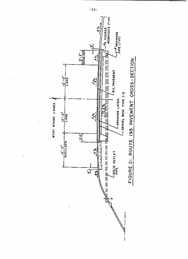
-53-
f t 7fE. '
-54-
drainage systems, t h e s tandards (such as t h e s t anda rd de ta i l s provided h e r e i n )
can be used, b u t on ly as gu ides for designing each i n d i v i d u a l d r a i n a g e
s i t u a t i o n . However, by i tself the roo f water d ra inage approach o f f e r e d in t h i s
gu ide has a l r eady been simplified by s t a n d a r d i z a t i o n , such as a 4 i nch d r a i n a g e
blanket under a minimum o f 6 inches of pavement s u r f a c i n g , 6 inch c o l l e c t o r s ,
p r e s e t g rada t ions , etc. For the matter o f fac t , t h i s d r a i n a b l e pavement d e s i g n
i n g e n e r a l is so s i m p l i f i e d that there is on ly l i m i t e d engineer ing of each spe-
c i f i c case required.
C.5.1 I n t e r n a l Drainage Design Example
To i l l u s t r a t e the i n t e r n a l drainage p r i n c i p l e s developed by t h i s research
and t h e des ign procedures o f f e r e d by t h i s g u i d e , the fol lowing des ign example is
provided.
I n t h i s example t h e th i ckness o f t he d ra inage l a y e r , the diameter o f t h e
drain c o l l e c t o r and the spacing o f the o u t l e t s w i l l be checked f o r r e l a t i v e l y
s e v e r e rainfall and i n f i l i t r a t i o n cond i t ions .
Also, f o r t h i s design, t h e p h y s i c a l data w i l l b e assumed t o b e t h e same as
tha t f o r the Route 1-195 experiment. The geometry and p h y s i c a l dimensions o f
t ha t p r o j e c t are shown in f i g u r e s 20 and 21. The d ra inage material is assumed
t o be an NSOG l a y e r wi th a permeabi l i ty c o n s t a n t o f 1000 f t l d a y .
The design rainfall w i l l b e assumed t o be the one y e a r s torm f o r N . J . (1.4
i n c h h o u r maximum) the i n f i l t r a t i o n rate is expected t o be 0.5. The re fo re , t he
probable amount o f i n f i l t r a t i o n can be c a l c u l a t e d as:
q = Area x I n f i l t r a t i o n Rate x R a i n f a l l
-55-
From Appendix "A", f o r a 12 f t . l a n e w i t h 1 1/28 cross-s lope and 12 f t . shou lde r
w i t h 4% cross-slope, both s lop ing about 1% l o n g i t u d i n a l l y , t h e maximum d r a i n a g e
path length, L, is 26.79 f t . Given the same parameters, a 4 inch NSOG drainage
l a y e r wi th a pe rmeab i l i t y c o n s t a n t K = 1000 ft . /day h a s a discharge c a p a c i t y Q =
13.5 cu. f t . /day and a time o f d ra inage , t = 4.70 hours. For a 1.0 f t . width o f
t h i s drainage l a y e r ,
q = 24.00 x 1.0 x O S 5 12 = 1.4 cu. ft./hour
o r
q = 1.4 x 24 = 33.6
The re fo re , about half
cu. f t . /day > 13.5 cu. f t . /day.
my down the drainage p a t h , t h e drainage l a y e r rill be
running fill, and the excess water, n o t being able to i n f i l t r a t e the pavement
s t r u c t u r e , must be drained on the s u r f a c e , i -e. , where it should have been
drained i n the first place.
However, by inc reas ing the th i ckness o f the l a y e r the c a p a c i t y can be
increased as fo l lows :
q= K x A x i =33.60 CU. f t . /day
From Appendix "A" a t the same l o c a t i o n the t o t a l head is:
Ho z H + L x t a n a s 0.33 + L x t a n a = 1.10 f t .
L tans= 1.10 - 0.33 = 0.77 f t .
o r :
Ho = H + 0.77;
and :
- - ' + 0.029; Ho - ti + 0.77 - L 26.79 26.79
i = - -
-56-
There fo re :
q = 1000 x H x 1.0 x (- + 0.029) = 33.60 26.79
and t h e c a l c u l a t e d d ra inage l a y e r t h i c k n e s s H =
i nches .
.64 f t . or approximately .5
The next s t e p is to determine t h e p i p e size needed for t h e system or a l ter-
n a t e l y t h e d i s c h a r g e c a p a c i t y of t h e s tandardized 6 inch p ipe can be
e s t a b l i s h e d . The nomograph on Figure 21 can provide both answers.
I n t h e first case, s t a r t i n g from t h e lef t s i d e o f t he nomograph a t t h e "flow
rate i n a d r a i n q ( c f d / f t . ) " going through t h e "dis tance between out le t s" L =
500 f t . a p i p e d i s c h a r g e c a p a c i t y Q = qL can be e s t a b l i s h e d a t t h e "pivot l ine" .
By connecting t h i s p o i n t with t h e p i p e g r a d i e n t S = 0.01 the corrugated p i p e
d i ame te r "d" can be read. For a 7.5 inch t h i c k drainage l a y e r , an approximately
5 inch d i ame te r p i p e w i t h a 500 f t . o u t l e t spacing would suffice.
S t a r t i n g from t h e same 1% "pipe g r a d i e n t " and t h e 6 inch" corrugated pipe",
f o r t h e same 7.5 inch d ra inage l a y e r , an 800 f t . o u t l e t spacing would b e ade-
q u a t e .
D. DESIGN OF GROUND WATER DRAINAGE
D.l GENERAL
The a n a l y s i s and s o l u t i o n s of t h e ground water drainage problems o f f e r e d
h e r e are adapted from Pro fes so r Lyle K. Moulton's pub l i ca t ion "Highway
Subdrainage Design"@). A t times verbatum e x c e r p t s are used.
-57-
A ground water con t ro l system r e f e r s t o subsurface drainage s p e c i f i c a l l y
designed t o remove or cont ro l the flow of groundwater. Such a subsurface
dra inage system may perform a number o f the following funct ions:
1 . In te rcept o r cutoff the seepage above an impervious boundary; and
2. draw-down o r lower t h e water tab le .
Often such a system may apply t o more than one funct ion, such as t h e i n t e r -
cep tor drain which not only c u t s o f f the flow but a l s o draws down the water
table. Such subdrainage systems a r e commonly iden t i f i ed i n terms of t h e i r loca-
t i o n and geometry. Unlike i n f i l t r a t i o n water drainage systems - which should
b e used as a standard fea ture on a l l new construct ion, - a groundwater dra inage
system is t o be used only when and where it is needed. This means it must be
designed t o f i t each case individual ly and i n t h e most cases it w i l l c o n s i s t o f
some form of interceptor . Furthermore, the quant i ty o f flow and the means of
its d isposa l must be known for a ground water drainage sys t em t o be adequately
func t iona l . In most cases , l i t t l e o r no water gets i n t o the pavement s e c t i o n from t h i s
source. However, i n cases where ground water does e n t e r t h e pavement (e.g. as a
r e s u l t o f high water table o r a r t e s i an flow) the necessary water drawdown o f t e n
can be accomplished by a properly designed drainage blanket of high per-
meabi l i ty . Normally, such drainage blankets are located beneath the subbase on
the top of the subgrade so as t o keep water from sa tu ra t ing the pavement foun-
da t ion . This l aye r , i n con t r a s t t o a drainage l aye r f o r t h e removal o f roo f
water, must be designed and constructed so as t o r e m v e a l l water as soon as it
is reasonably possible. The reader w i l l recall t h a t f o r rooftjater dra inage ,
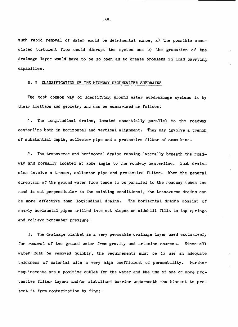
-58-
such r a p i d removal o f water would be d e t r i m e n t a l s i n c e , a ) the p o s s i b l e a s so -
ciated t u r b u l e n t flow could d i s r u p t t he system and b) t h e g r a d a t i o n o f the
drainage l a y e r would have t o be so open as t o create problems i n load c a r r y i n g
c a p a c i t i e s . D. 2 CLASSIFICATION OF THE HIGHWAY GROUNDWATER SUBDRAINS
The most comnon way of i d e n t i f y i n g ground water subdrainage systems is by
the i r l o c a t i o n and geometry and can be summarized as fol lows:
1. The l o n g i t u d i n a l d r a i n s , located e s s e n t i a l l y p a r a l l e l t o t h e roadway
They may invo lve a t r e n c h c e n t e r l i n e both in h o r i z o n t a l and v e r t i c a l alignment.
o f s u b s t a n t i a l depth, c o l l e c t o r p i p e and a p r o t e c t i v e f i l t e r o f some kind.
2. The t r a n s v e r s e and h o r i z o n t a l d r a i n s running l a t e r a l l y beneath the road-
way and normally loca t ed a t some angle t o the roadway c e n t e r l i n e . Such d r a i n s
a l s o invo lve a t r e n c h , c o l l e c t o r p ipe and p r o t e c t i v e f i l t e r . When the g e n e r a l
d i r e c t i o n o f the ground water flow t e n d s t o be p a r a l l e l t o t h e roadway (when the
road is cut perpendicular t o the e x i s t i n g c o n d i t i o n s ) , the t r a n s v e r s e d r a i n s can
be more e f f e c t i v e than l o g i t u d i n a l d r a i n s . The h o r i z o n t a l d r a i n s c o n s i s t o f
n e a r l y h o r i z o n t a l p i p e s d r i l l e d i n t o c u t s l o p e s o r s i d e h i l l fills t o t a p s p r i n g s
and r e l l e v e porewater p re s su re .
3 . The d ra inage b l anke t is a very permeable d ra inage l a y e r used e x c l u s i v e l y
f o r removal o f the ground water from g r a v i t y and a r t e s i a n sources . S ince a l l
water must be removed qu ick ly , t h e requirements must be t o use an adequate
t h i c k n e s s of material w i t h a very h igh c o e f f i c i e n t o f pe rmeab i l i t y . F u r t h e r
requirements are a p o s i t i v e o u t l e t f o r t h e water and t h e use o f one o r more pro-
t e c t i v e f i l t e r l a y e r s and/or s t a b i l i z e d barrier underneath t h e b l anke t t o pro-
t e c t i t from contamination by f i n e s .
-59-
4 . The well systems o r v e r t i c a l wells can be used t o c o n t r o l the flow of
ground water and t o r e l i e v e pore water p r e s s u r e s . They may be pumped t o tem-
p o r a r a l y lower the water table during cons t ruc t ion . Often they are provided
w i t h some sort of c o l l e c t i o n system so t h a t they are f r e e l y drained a t t h e i r
bottom.
5. Frequent ly , du r ing the course o f highway c o n s t r u c t i o n and maintenance,
local seepage c o n d i t i o n s are encountered which r e q u i r e subsurface d ra inage to
r e m v e the excess moisture o r r e l i e v e porewater p re s su res . Such c o n d i t i o n s may
r e q u i r e a drainage b lanke t w i th p i p e o u t l e t s , l o n g i t u d i n a l o r t r a n s v e r s e d r a i n s
o r some combination o f these systems.
When i n t e r c e p t i n g the flow o f ground water o r drawing down the free water
s u r f a c e is no t r e a d i l y p o s s i b l e , it w i l l be necessary t o inc lude seepage from
t h i s s o u m e when designing pavement drainage. Two p o s s i b l e sources o f ground
water, a l r e a d y mentioned, should be considered :
1 . Gravi ty drainage shown in Figure 22 and
2. Ar t e s i an flow i l l u s t r a t e d in Figure 23.
I n either case, the average inflow rate can be estimated by means o f a flow n e t
a n a l y s i s o r by use of r a t i o n a l a n a l y t i c a l methods. While these methods y i e l d
o n l y approximate s o l u t i o n s , they are deemed adequate f o r the purpose and are
adopted for use in t h i s guide. To f u r t h e r Simplify the a n a l y s i s of groundwater
problems, a number of graphical des ign a ids have been prepared which can b e
r e a d i l y appl ied by the highway engineer. The approach adopted here is f u l l y
d i s c u s s e d in P ro fes so r Moulton's r e p o r t ( 2 ) , however, only the basic information
is presen ted i n t h i s guide.
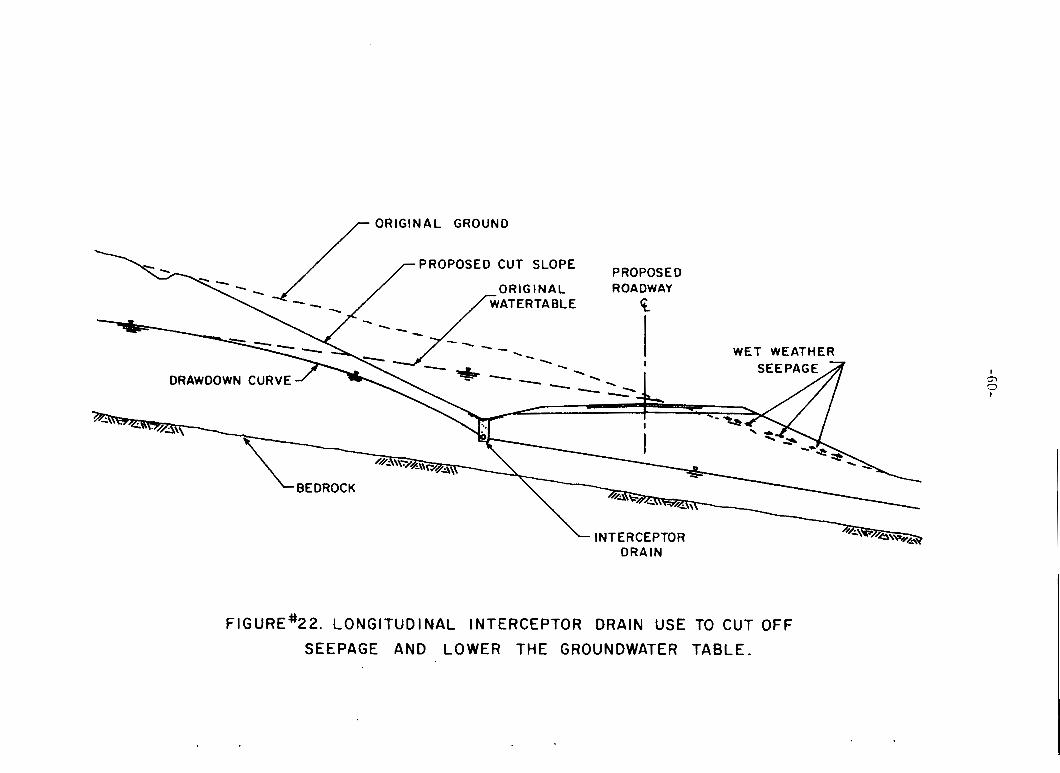
/ ORIGINAL GROUND
\ \
DRAWDOWN CURVE
INTERCEPTOR DRAIN
ih
I
FIGURE'22. LONGITUDINAL INTERCEPTOR DRAIN USE TO CUT OFF
SEEPAGE AND LOWER THE GROUNDWATER TABLE.

-61-
* U 3
-a -d 4 0 a
3 0 c3 a
I I I
J 4
c3
0
z a -
a P LL
yc
a W W & a w -
0 0 N z 0 U 0 %I-
a m 0
I t , 0 r t
c-
a k
a
W
3 0
z 4 m W I-
- a
-62 -
D.3 THE DESIGN ANALYSIS
The a n a l y s i s o f the p r o t e c t i v e f i l t e r l a y e r s o r s t a b i l i z e d barriers as well
as the des ign o f the d ra inage b l a n k e t o r t h e c o l l e c t o r systems have been a l r e a d y
d i scussed i n the preceeding s e c t i o n s on i n t e r n a l d ra inage design.
The use of the s o i l s t a b i l i z a t i o n b a r r i e r s most l i k e l y would provide n o t
on ly t h e necessary p r o t e c t i o n f o r the h igh ly open drainage l a y e r s used i n
s o l v i n g groundwater problems , b u t a l s o could provide a good c o n s t r u c t i o n p l a t -
form, i f proper c o n s t r u c t i o n procedures were app l i ed .
A s t o the des ign o f a ground water d ra inage b l anke t , since the pe rmeab i l i t y
requirements are bound t o change w i t h the changes o f the a v a i l a b l e water quan-
t i t ies , a d i f f e r e n t and cons ide rab ly s i m p l i e r approach could probably be used.
I n essence , v a r i o u s r e a d i l y a v a i l a b l e crushed s t o n e aggregates could be
classified by the i r probable permeabilities. Using the Darcy flow formula and
knowing the g r a d i e n t of the drainage, a n a p p r o p r i a t e combination of the b l a n k e t
t h i c k n e s s and the materials w i t h accep tab le p e r m e a b i l i t i e s could be then
selected. Regretably , however , no such c l a s s i f i c a t i o n o f a v a i l a b l e New J e r s e y
materials was performed because no ground water d ra inage research was undertaken
i n t h i s study.
D.4 BASICS OF THE RATIONAL ANALYTICAL METHODS
Frequen t ly , it is p o s s i b l e t o i n t e r c e p t t h e flow o f ground water and/or draw
down the free water s u r f a c e so t h a t l i t t l e o r no water gets i n t o t h e pavement
s e c t i o n fiom t h i s source. However, under some circumstances, it may not be
p o s s i b l e t o c o n t r o l the flow o f ground water in t h i s way, and it w i l l be
necessary t o inc lude seepage from t h i s source i n designing pavement drainage.
-63 -
Two poss ib le sources of groundwater should be considered :
and ( b ) a r t e s i an flow.
(a) g rav i ty drainage ,
For the case of grav i ty drainage, the average inflow rate, qg , can be es t i -
mated by the use of Figure 24, which was prepared t o facil i tate approximate com-
pu ta t ions of t h i s type. In either case, the first s t ep w i l l b e the determin-
a t i o n o f the "radius o f influence" o r drawdown influence d i s t ance , which can b e
estimated, f o r practical purposes, by means o f t h e expression
L i = 3.8 (H - where :
L i is the h f l u e n c e dis tance ( feet) and
(H - h) is the amount of drawdown (feet) .
Once t h e value of L i has been determined, Figure 24 can be used t o determine
the t o t a l quant i ty of upward flow, 42, i n t o the drainage blanket. The average
inflow rate can then be computed from t h e re la t ionship :
- q2 - - qg 0.5W'
where :
qg is the square
q2 is the (cubic
U is the
Although the
design inflow rate from gravi ty drainage (cubic feet /day/ foot o f drainage layer) t o t a l upward flow i n t o one half' of t h e drainage blanket feet /day/ l inear foot o f roadway) and width o f the drainage l a y e r ( feet) .
so lu t ion given i n Figure 24 is based upon a symmetrical con-
f i g u r a t i o n of g rav i ty flow, very l i t t l e e r r o r is introduced i f the flow con-
d i t i o n s are not exactly symnetrical because o f roadway cross s lope , v a r i a t i o n i n
depth o f the impervious boundary, e t c . Under these condi t ions, the use o f
average values of H , H, and L i i n Figure 24 w i l l be s a t i s f ac to ry .

0.1' ' I I " I I I I 1 1 1 1 I I I I I l l
10.0 20.0 50.0 100.0 0.5 1 .o 2 .o 5.0 L - HO
Figure 24. Chart for Determining F l o w Rate in Horizontal
Drainage Blanket
-65-
For the case o f a r t e s i a n flow, the average inflow r a t e can b e estimated by
the use of Darcy's L a w , i n the form:
AH q a = K l q -
0
where :
qa is the design inflow rate from a r t e s i a n flow (cubic feet/ daylsquare foot o f drainage layer ) is the excess a r t e s i a n head ( fee t ) , and
Ho is the thickness o f subgrade s o i l between the a r t e s i a n aqu i f e r and t h e drainage l aye r , as shown i n Figure 23.
AH
D.4.1 Application o f Rational Analyt ical Methods - Examples
Exanple 1 . Gravity Flow of Ground Water In to a Pavement Drainage Layer
Consider the flow s i t u a t i o n shown i n Figure 25. The na t ive s o i l is a s i l t y sand
wi th a measured c o e f f i c i e n t o f permeabili ty,
K = 0.34 pfd. The average drawdown, determined from Figure 25, is: ( H - b ) Thus, the inf luence dis tance can be determined from Equation ( D l ) as L i = 3.8(5) = 19.0. Entering Figure 24 wi th (Li + 0.5W)/H0 = (19.0 + 22)/20 = 2.05, and W / H , = 44/20 = 2.2, it is found t h a t
= (25.0 - 20.0) = 5.0'.
K(H-%)/2% = 0.74.
There f o r e ,
42 = 0.34 (5)/2(0.74) = 1.15 c f d l f t .
F ina l ly , the average inflow rate from the g rav i ty flow o f ground water can
be calculated from Equation (D2) as
I n the a c t u a l design of a drainage sys tem, such as t h a t shown in Figure 25,
some g rav i ty seepage i n addi t ion t o qg would have t o be considered. This flow
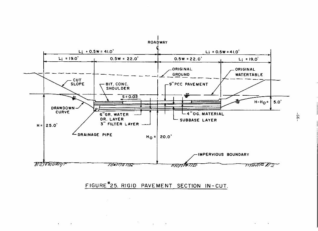
I ROADWAY
I Li + 0 . 5 W =41.0'
4 L i + 0.5W = 41.0' - - c
I L i = 19.0' L i = 19.0' _ _ 0 . 5 w = 22.0' w - 0.5W = 2 2 . 0 ' - _ - - - - c
.--z
- ---- - A _ _ ----- - - - 1 ----- \ r- CUT
BIT. CONC. SHOULDER
DRAW DOW N CURVE
6"GR. WATER DR. LAYER 3" FILTER LAYER
H o :
25.0 '
DRAINAGE PIPE
/ I 9"PCC PAVEMENT r
T 1 I
I I'OG. MATERI
SUBBASE LAYER
20.0'
IMPERVIOUS BOUNDARY
% //[SH/- e
FIGURE'25. RIGID PAVEMENT SECTION IN-CUT.
. . . -67-
is designated as q1 i n Figure 2 4 , and its magnitude would be
= K ( H - Ho) 2 /2Li = 0.34(5)2/2(19.0) = 0.224 c f d / f t . 91
The q1 flow from the left side would only be considered i n the des ign of the
c o l l e c t o r dra in . However, in t h i s case, the q1 flow from the r i g h t s i d e would
have t o be carried over t o the l e f t side t o the co l l ec to r dra in and, t h u s , would
have t o be considered i n the design of t he drainage blanket.
Example 2. Artesian Flow of Goundwater In to a Pavement Drainage Layer.
Consider the flow s i t u a t i o n shown i n Figure 23. The subgrade s o i l above t h e
a r t e s i a n aqu i f e r is a clayey silt wi th a coe f f i c i en t of permeabili ty:
K = 0.07 fpd.
A piezometer i n s t a l l e d during the course o f t h e subsurface explora t ion
program a t t h i s s i t e showed t h a t the piezometric head of the water i n t h e ar te-
s i a n l a y e r was about 8 feet above the bottom of the proposed pavement drainage
l a y e r , as shown i n Figure 23. Using Equation (D3>, w i t h A H = 8.0*, I& = 15.0*,
and K = 0.07 fpd , gives:
o.070 = 0.037 c f d / s f t . 9, = 15.0
It should be noted a t t h i s point t h a t the quant i ty of groundwater t h a t f lows
i n t o pavement drainage l aye r s is often r e l a t i v e l y small. However, it should not
be automatical ly concluded t h a t inflow from groundwater sources can be
neglected. The designer should estimate the inflow from &. sources , s ince t h e
cumulative effect of small inflows from severa l sources may be q u i t e s i g n i f i -
can t .
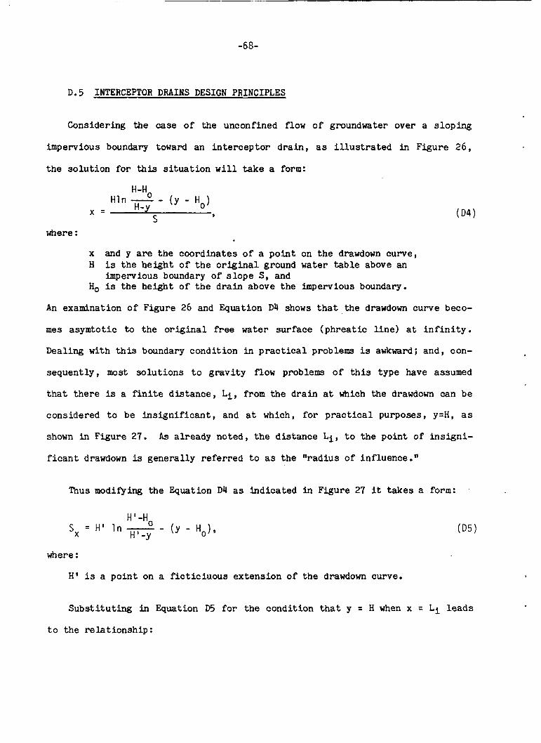
~
-68-
D.5 INTERCEPTOR DRAINS DESIGN PRINCIPLES
Considering the case of the unconfined flow of groundwater over a s loping
impervious boundary toward an i n t e rcep to r d ra in , as i l l u s t r a t e d in Figure 26,
the so lu t ion fo r this s i t u a t i o n w i l l take a form:
H-H, H -y
Hln - - (y - Ha) S
x = 9
where :
x and y are the coordinates of a poin t on the drawdown curve, H is the height of t h e o r i g i n a l ground water t a b l e above an
impervious boundary of s lope S, and Ho is the height of t h e d ra in above t h e impervious boundary.
An examination of Figure 26 and Equation D4 shows t h a t the drawdown curve beco-
mes asymtotic to t h e o r i g i n a l free water surface (phreatic l i n e ) a t i n f i n i t y .
Dealing wi th t h i s boundary condition i n practical problems is awkward; and, con-
sequent ly , most so lu t ions t o grav i ty flow problems of t h i s type have assumed
tha t there is a f i n i t e d i s tance , L i , from the dra in a t which the drawdown can be
considered t o be in s ign i f i can t , and a t which, f o r p r a c t i c a l purposes, y=H, a s
shown i n Figure 27. A s already noted, the d is tance L i , t o t he point of i n s ign i -
f i c a n t drawdown is general ly referred t o as the " rad ius of influence."
Thus modifying the Equation D4 as indicated i n Figure 27 it takes a form: '
H1-Ho HI-y
Sx = H' In - - (y - Ho),
where :
H' is a po in t on a f i c t i c iuous extension of t h e drawdown curve.
Subs t i tu t ing in Equation D5 fo r the condition t h a t y = H when x = L i leads
t o the re la t ionship :
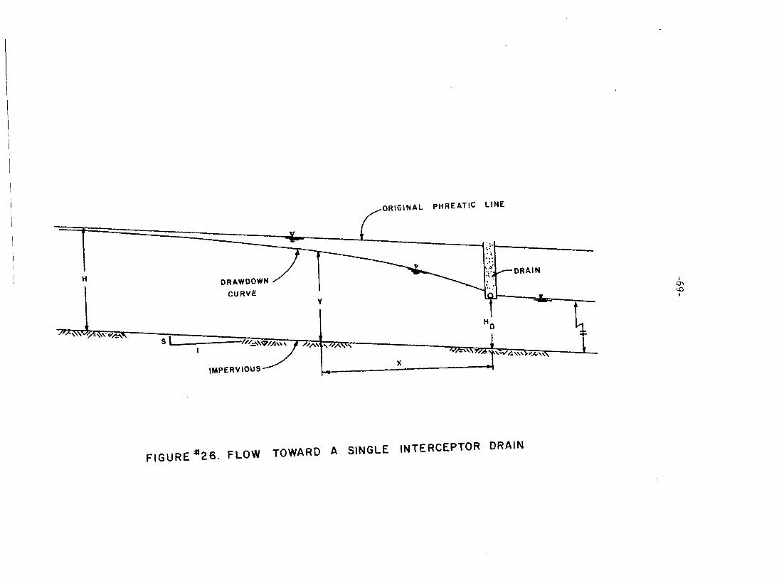
DRAWDOWN CURVE
I cn CD I
FIGURE * 2 6 . FLOW TOWARD A SINGLE INTERCEPTOR DRAIN
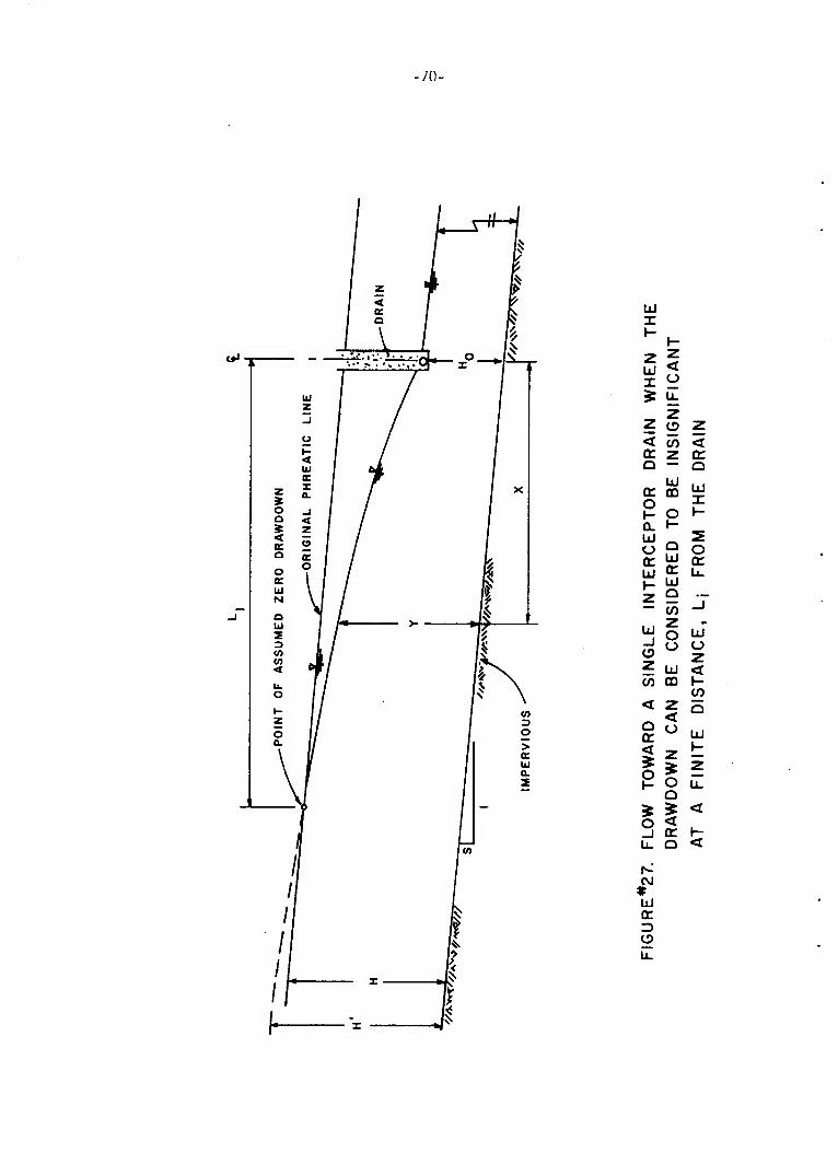
- 7 0 -
W I I-
.- -I
W L
P
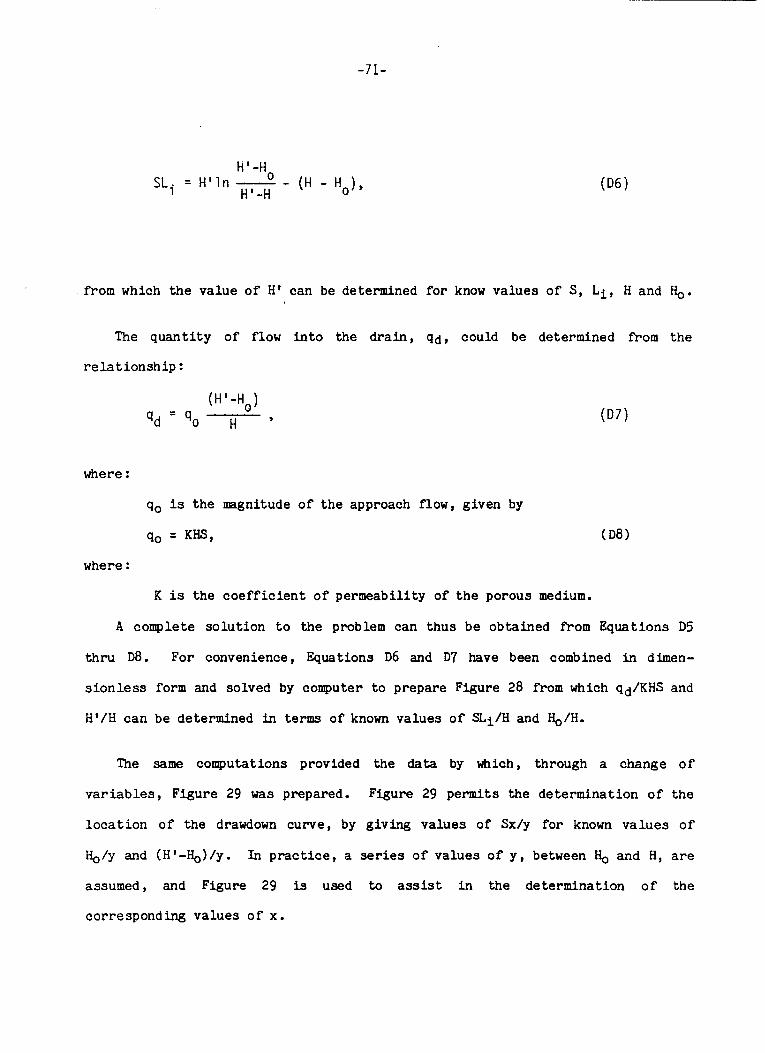
-71-
W - H o SLi = H ' l n - - (H - H o ) ' H I - H
from which the value of H f can be determined fo r know values of S, L i , H and b.
The quant i ty of flow i n t o the dra in , qd, could be determined from the
r e l a t i o n s h i p :
- (H' -Ho) qd - '0 H '
where :
qo is the magnitude of t he approach flow, given by
qo = KW, (D8)
where :
K is the coe f f i c i en t of permeability of t h e porous medium.
A complete so lu t ion t o the problem can thus be obtained from Equations D5
t h ru D8. For convenience, Equations D6 and D7 have been combined i n dimen-
s i o n l e s s form and solved by computer t o prepare Figure 28 from which qd/KHS and
H' /H can be determined in terms of known values of S L i / H and q / H .
The same computations provided t h e data by which, through a change o f
va r i ab le s , Figure 29 was prepared. Figure 29 permits the determination of the
l o c a t i o n of the drawdown curve, by giving values of Sx/y fo r known va lues o f
&/y and (H'-&,)/y. In practice, a series o f values of y , between Ho and H, are
assumed, and Figure 29 is used to assist i n the determination o f t h e
corresponding values o f x.
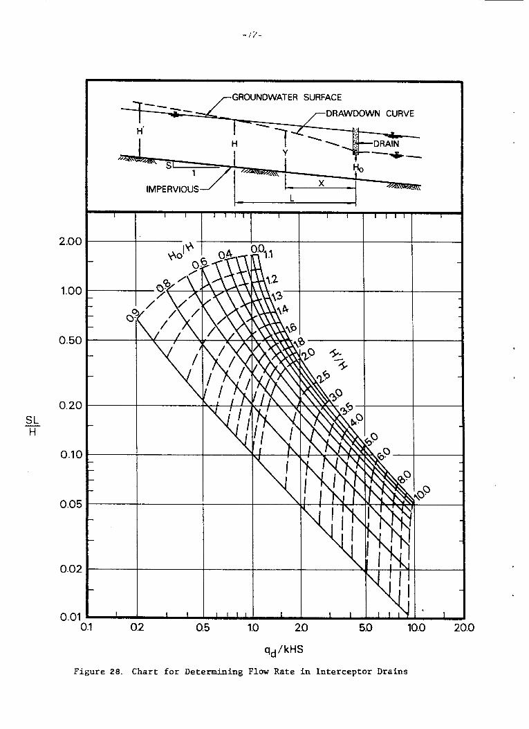
SL H -
2.00
1.00
0.50
0.20
0.10
0.05
0.02
0.01 0.1 0.2 0.5 1.0 20 5.0 10.0 20.0
qd / kHS
Figure 28. Chart for Determining Flow Rate i n Interceptor Drains
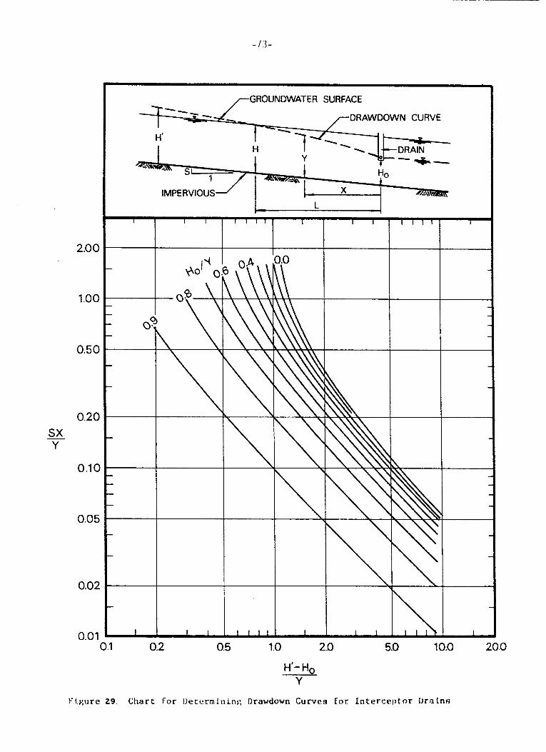
2.00
1.00
0.5C
0.2c
0.1c
0.05
0.02
/-GROUNDWATER SURFACE
0.0 1 0.1 0.2 0.5 1 .o 2.0 5.0 10.0 20.0
H'- Ho Y
Flv,rire 29 Chart For Uetormlninr ; Drawdown Curves for Interceptor Drntns
-74-
I n order to use Figures 28 and 29 f o r any highway d ra inage problem, i t is
necessary t o have an estimate o f the d i s t a n c e , L i , beyond which the drawdown can
be considered t o be i n s i g n i f i c a n t . As noted p rev ious ly , t h i s d i s t a n c e can be
approximated f o r p r a c t i c a l purposes by means o f Equation D1.
Using the p r i n c i p l e s j u s t o u t l i n e d and consider ing each d r a i n s e p a r a t e l y a
subsu r face drainage system o f m u l t i p l e i n t e r c e p t o r drains can be designed. The
same p r i n c i p l e s should be app l i ed f o r s o l u t i o n of a system of symmetrical
drawdown d ra ins . The de ta i l s o f such s o l u t i o n s can be found in t h e r e p o r t ,
FHWA-TS-OO-224(2) . Although the method o f a n a l y s i s i l l u s t r a t e d above y i e l d s a complete s o l u t i o n
t o t h e problem o f a single i n t e r c e p t o r d r a i n , it should be recognized t h a t the
s e l e c t i o n o f t h e proper l o c a t i o n o f t h e d r a i n invo lves cons ide rab le judgment and
may even involve a t r ia l and e r r o r p r o c e s s , p a r t i c u l a r l y i f the d r a i n is being
used t o lower the watertable and reduce porewater p r e s s u r e s t o achieve a c e r t a i n
measure o f s l o p e s t a b i l i t y .
D.5.1 Analysis o f an I n t e r c e p t o r Drain - Examples
Consider the proposed c o n s t r u c t i o n shown i n Figure 22 and, f o r t h i s problem,
(a ) compute t h e reduced flow rate , qd/K, i n t o the d r a i n and (b ) p l o t t h e loca-
t i o n o f the drawdown curve (free water s u r f a c e ) . The detailed dimensions of t h e
problem are given i n Figure 30. I n o rde r t o keep t h e l e f t branch o f the free
water s u r f a c e from breaking o u t through t h e c u t s l o p e and t o lower the r i g h t
branch o f the free water s u r f a c e well below the pavement s t r u c t u r a l system, t h e
underdrain was set below t h e d i t c h l i n e a t a depth o f 5 feet . It is proposed t o
pave t h e d i t c h over the d r a i n t o avoid i n f i l t r a t i o n and clogging.
,
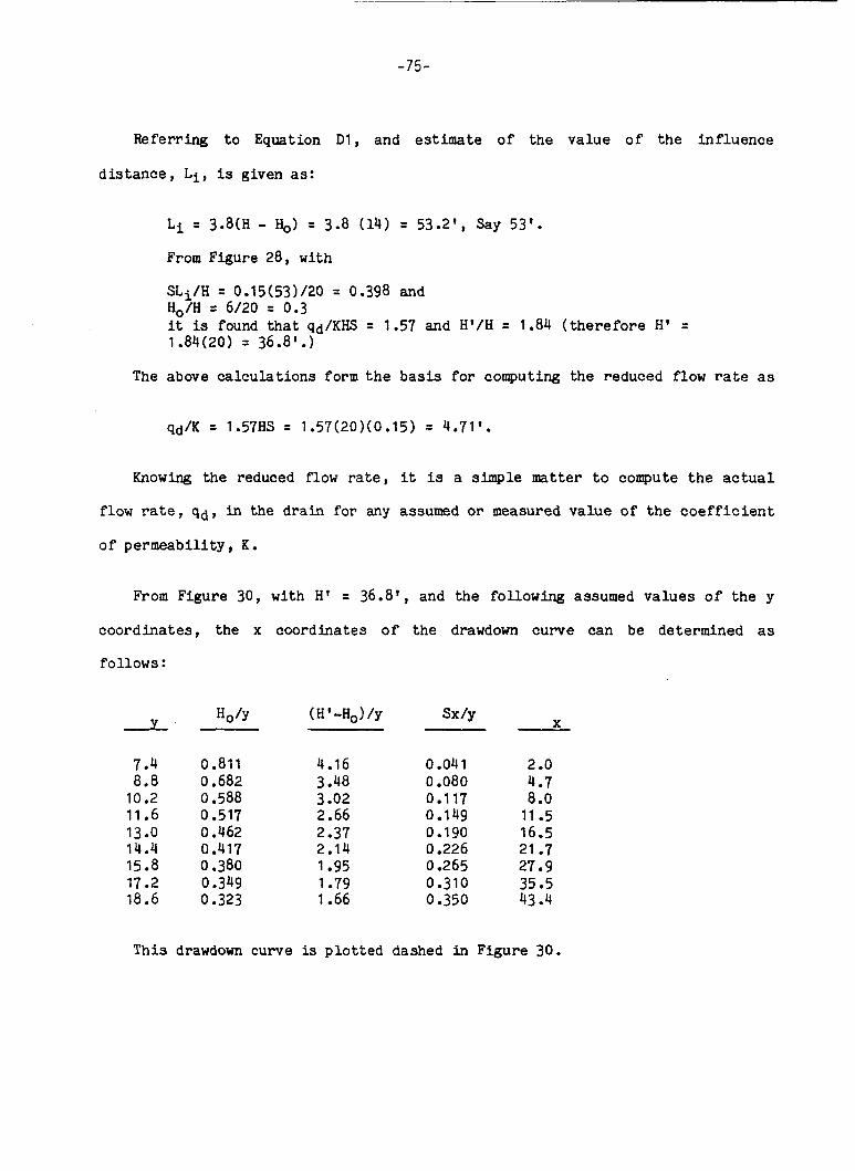
-75-
Referring t o Equation Dl, and estimate of t h e value o f the inf luence
d i s t ance , L i , is given as:
L i = 3.8(H - I-&,) = 3.8 (14) = 53.2', Say 53'.
From Figure 28, wi th
S L i / H = 0.15(53)/20 = 0.398 and Ho/H = 6/20 = 0.3 it is found that qd/KHS = 1.57 and H' /H = 1.84 ( the re fo re H' = 1.84(20) = 36.8l.I
The above calculat ions form t h e basis f o r computing the reduced flow rate as
Knowing the reduced flow r a t e , it is a simple matter t o compute the a c t u a l
flow ra te , qd, i n the dra in for any assumed o r measured va lue of t h e c o e f f i c i e n t
of permeabi l i ty , K.
From Figure 30, wi th H' = 36.8', and the following assumed va lues o f t he y
coord ina tes , t h e x coordinates o f the drawdown curve can be determined as
follows:
Y
7.4 8.8
10.2 11.6 13.0 14.4 15.8 17.2 18.6
sx/y
0.811 0.682 0.588 0.517 0.462 0.417 0.380 0.349 0 -323
4.16 3.48 3.02 2.66 2 -37 2.14 1.95 1.79 1.66
0.041 0.080 0.1 17 0.149 0.190 0.226 0.265
0.350 0.310
X
2 .o 4.7 8 .O
11.5 16.5 21.7 27.9 35.5 43.4
This drawdown curve is plo t ted dashed i n Figure 30.

-76-
- 0
v c 0 n n e
0
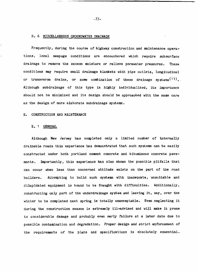
-77-
D. 6 MISCELLANEOUS GROUNDWATER DRAINAGE
Frequently, during the course of highway construct ion and maintenance opera-
t i o n s , l o c a l seepage condi t ions a re encountered which require subsurface
drainage t o r e m v e the excess moisture or r e l i eve porewater pressures . These
condi t ions may r equ i r e small drainage blankets wi th pipe o u t l e t s , l ong i tud ina l
' o r t ransverse d ra ins , o r some combination of these drainage sys t ems( l l ) .
Although subdrainage of t h i s type is hlghly individual ized, its importance
should not be minimized and its design should be approached with the same care
as the design o f more e labora te subdrainage systems.
E. CONSTRUCTION AND MAINTENANCE
E. 1 GENERAL
Although New Jersey has completed only a l imi ted number o f i n t e r n a l l y
drainable roads t h i s experience has demonstrated t h a t such systems can be e a s i l y
constructed under both port land cement concrete and bituminous concrete pave-
ments. Importantly, t h i s experience has a l s o shown the possible p i t f a l l s t h a t
can occur when less than concerned a t t i t u d e e x i s t s on the pa r t o f the road
bu i lde r s . Attempting t o bui ld such systems with inadequate, unsui tab le and
d i lap ida ted equipment is bound t o be fraught w i t h d i f f icu l t ies . Addit ional ly ,
cons t ruc t ing only p a r t o f the underdrainage system and leaving it , s a y , over the
win ter t o b e completed next s p r i n g is t o t a l l y unacceptable. Even neglect ing it
during the cons t ruc t ion season is extremely i l l -advised and w i l l make it prone
t o considerable damage and probably even ear ly f a i l u r e a t a later date due t o
poss ib le contamination and degradation. Proper design and s t r i c t enforcement of
the requirements o f t h e plans and spec i f ica t ions is absolutely e s s e n t i a l .
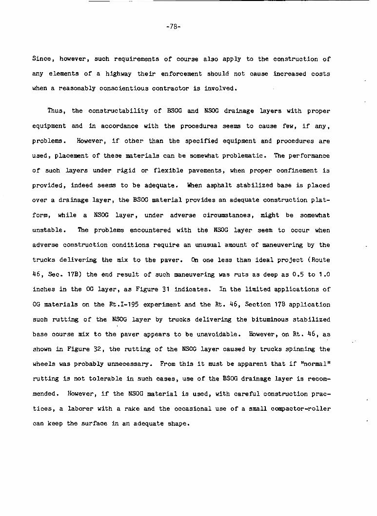
-78-
S i n c e , however, such requirements of course a l s o apply t o t h e c o n s t r u c t i o n o f
any elements of a highway t h e i r enforcement should not cause increased c o s t s
when a reasonably c o n s c i e n t i o u s c o n t r a c t o r is involved.
Thus, the c o n s t r u c t a b i l i t y o f BSOG and NSOG drainage l a y e r s w i t h proper
equipment and in accordance wi th t h e procedures seems t o cause few, i f any,
problems. However, i f o t h e r than t h e s p e c i f i e d equipment and procedures are
used, placement of these materials can b e somewhat problematic. The performance
o f such l a y e r s under r i g i d o r f lexible pavements, when proper confinement is
provided, indeed seems t o be adequate. When asphal t s t a b i l i z e d base is placed
over a dra inage l a y e r , the BSOG material provides a n adequate cons t ruc t ion p l a t -
form, while a NSOG l a y e r , under adverse circumstances, might be somewhat
uns tab le . The problems encountered w i t h t he NSOG l a y e r seem t o occur when
adverse cons t ruc t ion c o n d i t i o n s r e q u i r e an unusual amount of maneuvering by the
t r u c k s d e l i v e r i n g the mix t o the paver. On one less than ideal p r o j e c t (Route
46 , Sec. 17B) the end r e s u l t o f such maneuvering was r u t s as deep as 0.5 t o 1 .O
inches i n the OG l a y e r , as Figure 31 i n d i c a t e s . I n t h e l imi ted a p p l i c a t i o n s of
OG materials on the Rt.1-195 experiment and t h e R t . 46, Sect ion 17B a p p l i c a t i o n
such r u t t i n g o f the NSOG l a y e r by t r u c k s d e l i v e r i n g t h e bituminous s t a b i l i z e d
base course mix t o the paver appears t o be unavoidable. However, on R t . 46 , as
shown in Figure 32, t he r u t t i n g of the NSOG l a y e r caused by t rucks spinning the
wheels was probably unnecessary. From t h i s it must be apparent t h a t if "normaltt
r u t t i n g is not t o l e r a b l e i n such cases, use of the BSOG drainage layer is recom-
mended. However, i f the NSOG material is used , wi th c a r e f u l cons t ruc t ion prac-
t ices , a l a b o r e r w i t h a rake and t h e occas iona l use o f a small compactor-roller
can keep the s u r f a c e i n an adequate shape.
-79-
FIGURE 31. Route 46, P l a c i n g BSBC M a t e r i a l on Top o f NSOG Layer . "Normal" Truck R u t t i n g D e l i v e r i n g BSBC Mix
FIGURE 32. Route 46, P l x i n g BSBC Layer. Truck R u t t i n g Caused by Unnecessary Wheels Sp inn ing
-80-
The best means f o r i nc lud ing the s p e c i a l underdrainage in roadways is first
t o c o n s t r u c t a l l subbase. If r e q u i r e d , t h e t o p of the subbase is t h e n s t a b i -
l i zed o r t h e f i l t e r c l o t h barrier is placed t o provide a c o n s t r u c t i o n p l a t f o r m
and t o p reven t the i n t r u s i o n o f f i n e s i n t o t h e ove r ly ing drainage l a y e r . Th i s
is followed by the cons t ruc t ion o f t h e c o l l e c t i o n system. The drainage l a y e r is
then placed.
I r r e s p e c t i v e o f the proper des ign and c o n s t r u c t i o n o f a subsurface d r a i n a g e
system some maintenance w i l l b e r equ i r ed t o i n s u r e t h e system's con t inuous
o p e r a t i o n . T o the e x t e n t p o s s i b l e , a l l f e a t u r e s of the system should be
designed f o r minimum maintenance. Nevertheless , a program of con t inu ing r e g u l a r
i n s p e c t i o n s , preventive-type maintenance and r epa i r - type maintenance must be
a n t i c i p a t e d .
E .2 CONSTRUCTION OF THE COLLECTION SYSTEMS
I n c o n s t r u c t i n g the l o n g i t u d i n a l and t r a n s v e r s e c o l l e c t o r s , t h e procedure
should be t o excavate through the subbase t o a p resc r ibed depth. Then, as shown
i n Figure 33 the t r ench should be l i n e d wi th f i l t e r c l o t h by u n r o l l i n g it by
hand f o r about 30 feet ahead o f the backf i l l ing ope ra t ion . While two l a b o r e r s
hold the edges, a t h i r d man should walk t he f i l t e r fabric conforming it t o t h e
dimensions of the t rench. After t h a t , a drainage p i p e should be p l aced on 3
i nches o f 118 s tone bedding and backfi l led with #8 stone. Beginning 12 inches
above t h e t o p of t h e p ipe , the b a c k f i l l i n the t r e n c h e s must be compacted i n 6
inch lifts by 3 t o 4 passes o f a v i b r a t o r y p l a t e compactor.
The c o n s t r u c t i o n o f the o u t l e t d i tches is similar, except s o l i d wall
(non-perforated) p ipes and r e g u l a r subgrade soils for bedding and t h e b a c k f i l l
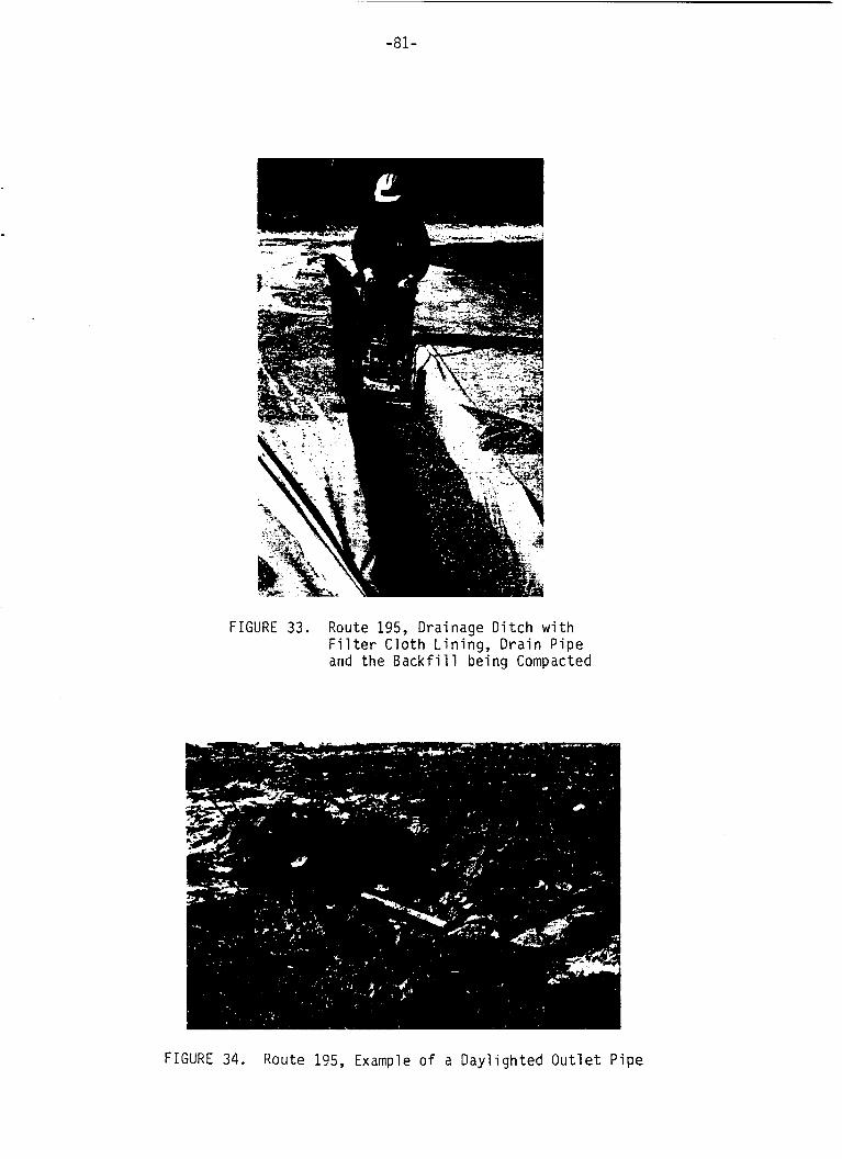
-81-
FIGURE 33. Route 195, Drainage D i t c h w i t h F i l t e r C loth L in ing, D ra in Pipe and the Backf i 1 1 being Compacted
FIGURE 34. Route 195, Example o f a Dayl ighted O u t l e t Pipe
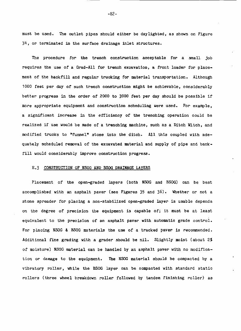
-82-
must be used. The o u t l e t p ipes should either be day l igh ted , as shown on F igure
34, o r terminated i n t h e s u r f a c e d ra inage i n l e t s t r u c t u r e s .
The procedure f o r the t r ench cons t ruc t ion acceptable f o r a small job
r e q u i r e s t h e use o f a Grad-All f o r t r ench excavat ion, a f r o n t l oade r f o r place-
ment o f the b a c k f i l l and r e g u l a r t ruck ing f o r material t r a n s p o r t a t i o n . Although
1000 feet per day o f such t r e n c h cons t ruc t ion might be achievable , c o n s i d e r a b l y
better progress i n the order o f 2000 to 3000 feet per day should be poss ib le i f
more a p p r o p r i a t e equipment and c o n s t r u c t i o n scheduling were used. For example,
a s i g n i f i c a n t i n c r e a s e i n the e f f i c i e n c y of the t renching o p e r a t i o n could be
realized if use would be made of a t renching machine, such as a Ditch Witch, and
modified t r u c k s t o "funnel" s t o n e i n t o the d i t c h . A l l t h i s coupled w i t h ade-
q u a t e l y scheduled r e m v a l o f the excavated material and supply of p i p e and back-
f i l l would cons ide rab ly improve cons t ruc t ion progress.
E.3 CONSTRUCTION OF NSOG AND BSOG DRAINAGE LAYERS
Placement o f the open-graded l a y e r s (both NSOG and BSOG) can be bes t
accomplished w i t h an asphal t paver (see Figures 35 and 3 6 ) . Whether o r not a
s t o n e spreader f o r placing a non-stabi l ized open-graded l a y e r is u s a b l e depends
on the degree o f p r e c i s i o n the equipment is capable of ; it must be a t least
e q u i v a l e n t t o t he p r e c i s i o n o f an asphal t paver with automatic grade c o n t r o l .
For p l a c i n g NSOG & BSOG materials the use o f a tracked paver is recommended.
Add i t iona l f i n e grading with a grader should be n i l . S l i g h t l y moist ( a b o u t 2%
o f moisture) NSOG material can be handled by a n a s p h a l t paver wi th no modif ica-
t i o n o r damage t o the equipment. The NSOG material should be compacted by a
v i b r a t o r y r o l l e r , while the BSOG l a y e r can be compacted wi th s t a n d a r d s t a t i c
r o l l e r s (three wheel breakdown r o l l e r followed by tandem f i n i s h i n g r o l l e r ) as
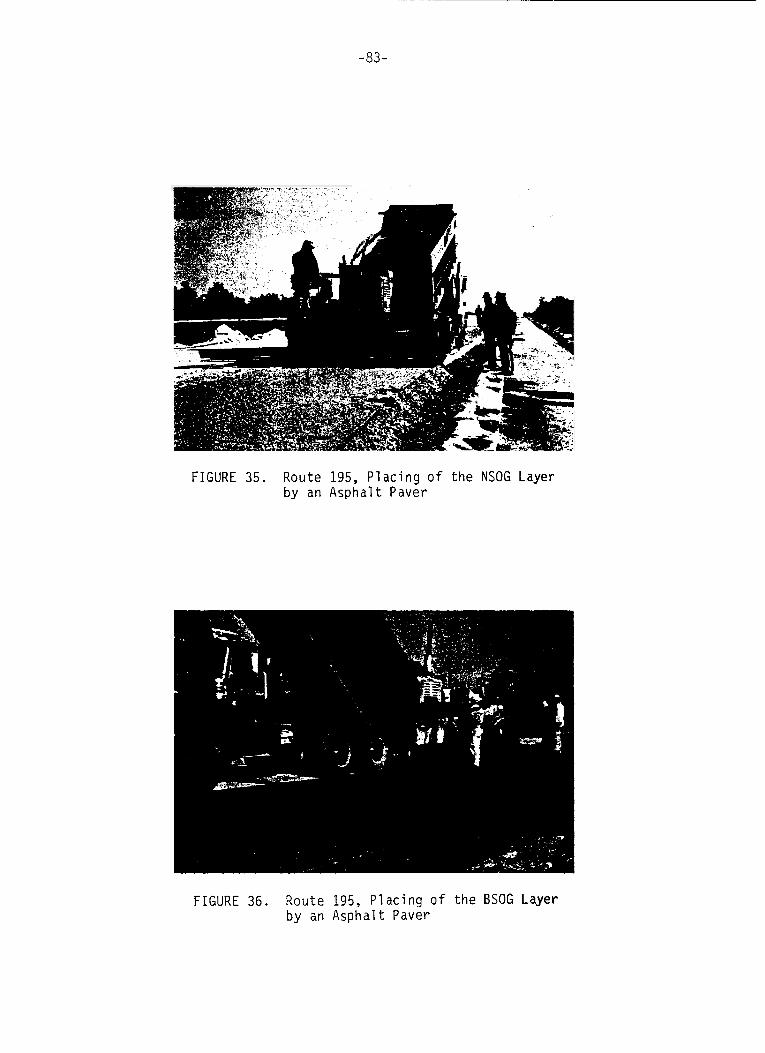
-83-
FIGURE 35. Route 195, Placing of the NSOG Layer by an Asphalt Paver
F I G U R E 36. Route 195, Placing o f the BSOG Layer by an Asphalt Paver
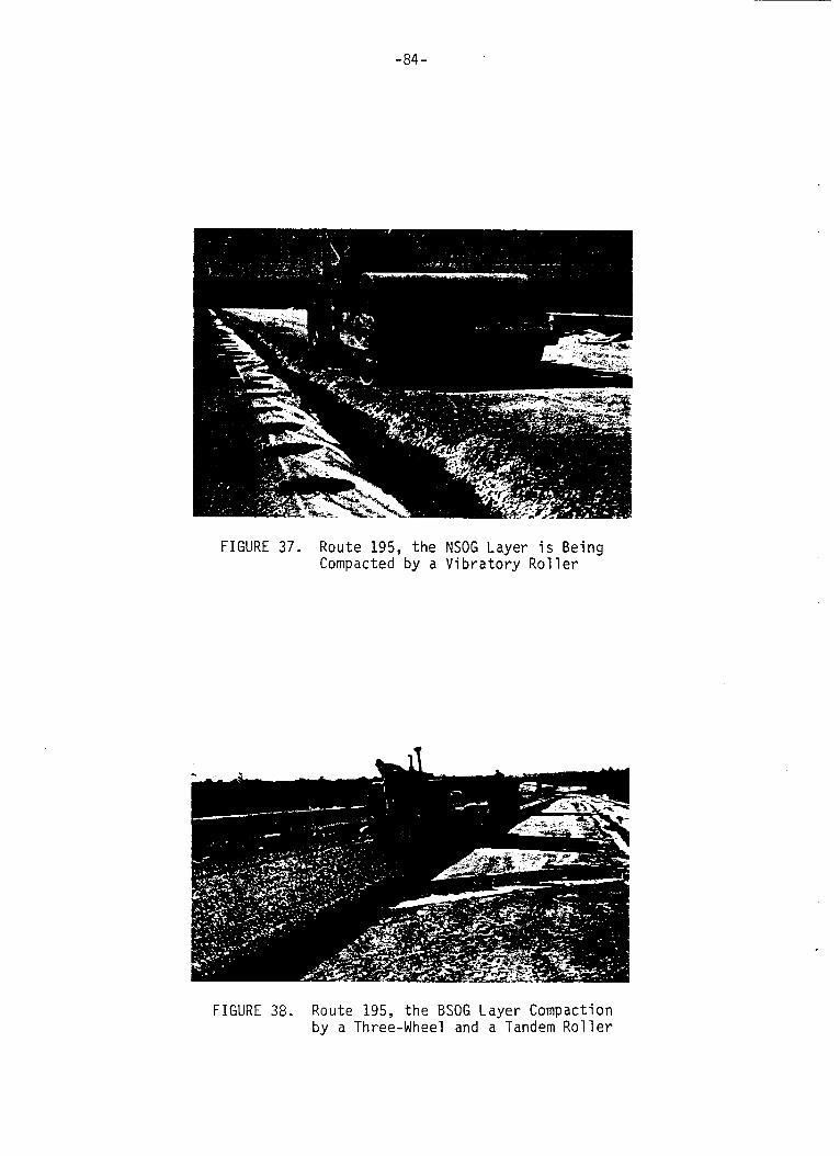
-84-
FIGURE 37. Route 195, the NSOG Layer i s Being Compacted by a Vibratory Rol le r
FIGURE 38. Route 195, the BSOG Layer Compaction by a Three-Wheel and a Tandem Rol le r
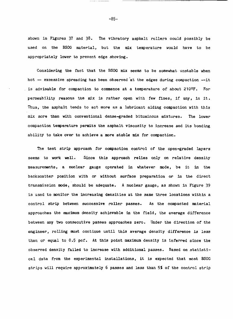
-85-
shown i n Figures 37 and 38. The v ibra tory a s p h a l t r o l l e r s could possibly be
used on t h e BSOC material, but the mix temperature would have t o be
appropriately lower t o prevent edge shoving.
Considering the fact t h a t the BSOC mix seems t o be somewhat unstable when
hot - excessive spreading has been observed 'at the edges during compaction --it
is advisable for compaction to commence a t a temperature of about 2100F. For
permeabi l i ty reasons the mix is rather open wi th few f ines , i f any, i n i t .
Thus, the asphalt tends t o act more as a lubr icant a iding compaction with t h i s
mix more than with conventional dense-graded bituminous mixtures. The lower
compaction temperature permits the asphal t v i scos i ty t o increase and its bonding
a b i l i t y t o take over t o achieve a more stable mix fo r compaction.
The test s t r i p approach for compaction con t ro l of the open-graded l aye r s
seems t o work well. Since t h i s approach relies only on r e l a t i v e dens i ty
measurements, a nuclear gauge operated i n whatever mode, be it i n the
backscat ter posi t ion wi th or without surface preparat ion o r i n the direct
transmission mode, should be adequate. A nuclear gauge, as shown i n Figure 39
is used t o monitor the increasing d e n s i t i e s a t the same three loca t ions within a
c o n t r o l s t r i p between successive r o l l e r passes. As the compacted mater ia l
approaches the maximum dens i ty achievable i n the f i e l d , the average d i f fe rence
between any two consecutive passes approaches zero. Under the d i r e c t i o n o f the
engineer , ro l l i ng must continue u n t i l t h i s average densi ty d i f fe rence is l e s s
than o r equal t o 0.5 pcf . A t t h i s po in t maximum densi ty is in fer red s ince the
observed densi ty failed t o increase with add i t iona l passes. Based on statisti-
c a l data from the experimental i n s t a l l a t i o n s , it is expected t h a t most BSOC
s t r i p s w i l l r equi re approximately 6 passes and less than 5% of the con t ro l s t r i p
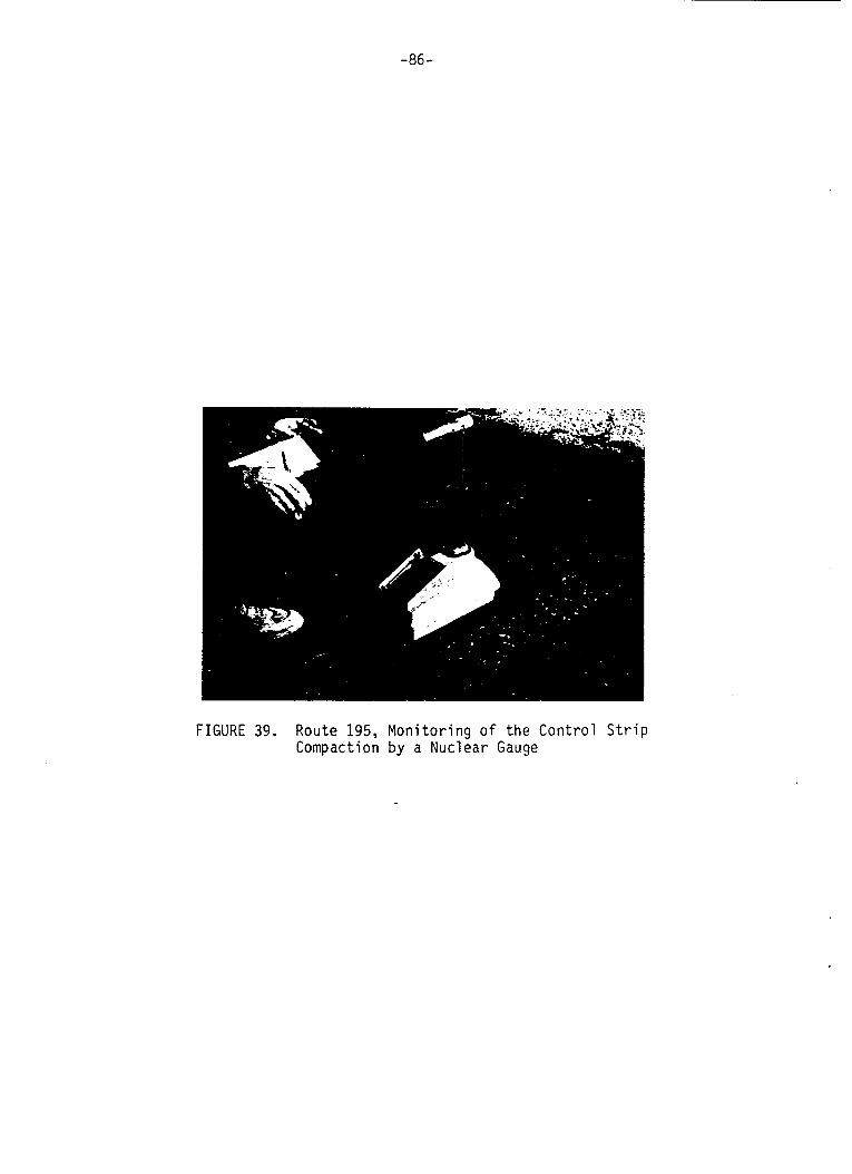
-86-
FIGURE 39. Route 195, Monitoring of the Control Strip Compaction by a Nuclear Gauge
-87-
a p p l i c a t i o n s should r e q u i r e more than 10 passes. For NSOC c o n t r o l s t r i p s the
average number of r equ i r ed passes should b e approximately f i v e .
A s a l r e a d y stated, cons t ruc t ion o f pavement cour ses above t h e open-graded
l a y e r s should n o t be d i f f i c u l t i f proper equipment is used. After it h a s
coo led , t h e BSOG material hardenes i n t o a very firm l a y e r which r e p r e s e n t s a n
adequate c o n s t r u c t i o n p l a t fo rm f o r both the po r t l and cement and bi tuminous
c o n c r e t e su r fac ings . It should be mentioned t h a t t he anchor p i n s f o r t he
c o n c r e t e pavement forms can be d r iven through t h e bituminous s t a b i l i z e d open
graded and lime-fly ash s t a b i l i z e d l a y e r s without d i f f i c u l t y . Placement o f the
PCC pavement on t h e BSOG l a y e r is shown i n Figure 40, while Figure 41 shows t h e
paving of the bituminous s t a b i l i z e d base on a BSOG l a y e r .
After the cons t ruc t ion o f the NSOG l a y e r , no problems should b e expected i n
e i ther grading o r setting forms f o r po r t l and cement conc re t e pavement. The form
work can be placed on the non-stabi l ized open-graded material wi thou t d i f f i c u l t y
and the hold down p i n s can be dr iven e a s i l y through t h e non- s t ab i l i zed open-
graded l a y e r into the s t a b i l i z e d material using a pneumatic hanmer. A s shown
i n F igu re 42, a f i n e grading machine r i d i n g on the forms can be used t o a c h i e v e
f i n i s h e d g rade , followed by a small r o l l e r t o compact and smooth o u t t h e s u r -
face.
Conventional paving procedures i l l u s t r a t e d in Figure 43 is a l l t h a t is
necessa ry f o r placement o f concrete on t h e NSOG l a y e r .
No shrinkage cracks i n t h e concrete road slabs and l i t t l e i n f i l t r a t i o n o f
the c o n c r e t e i n t o the either open-graded l a y e r h a s been observed. The l a t e r
case should d i s p e l fears o f excessive f r i c t i o n between underlying open-graded
material and t h e pavement s l abs .
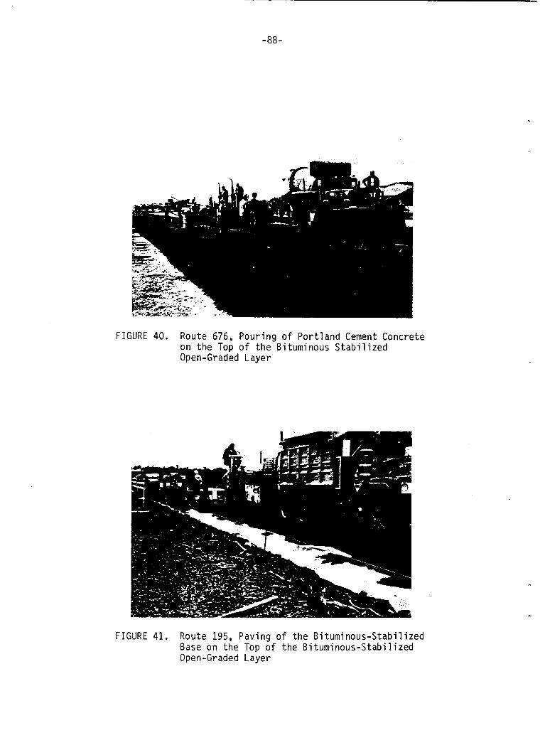
-88-
FIGURE 40. Route 676, Pouring o f Portland Cement Concrete on the Top o f the Bituminous Stabilized Open-Graded Layer
FIGURE 41. Route 195, Paving o f the Bituminous-Stabilized Base on the Top o f the Bituminous-Stabilized Open-Graded Layer
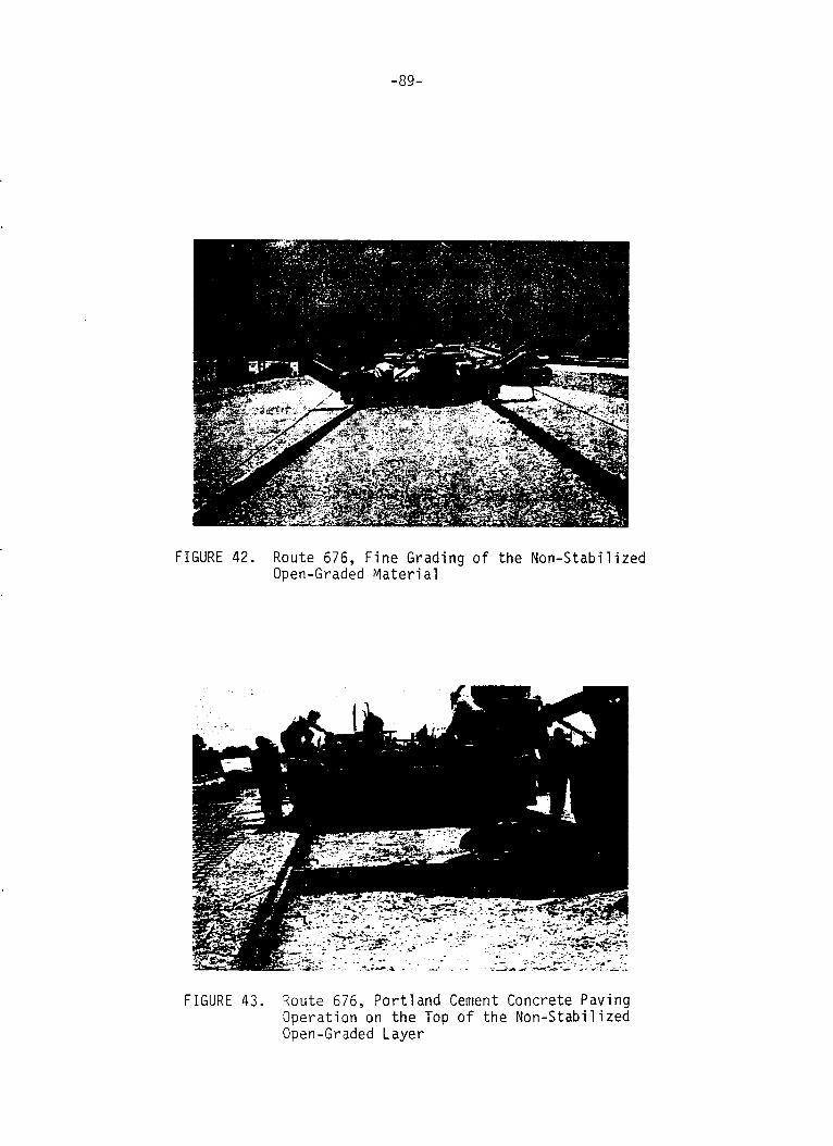
-89-
FIGURE 42. Route 676, F i n e Grading o f t he Non-Stabi l ized Open-Graded M a t e r i a l
F I G U R E 43. Route 676, P o r t l a n d Cement Concrete Paving Operat ion on t h e Top o f t h e Non-Stabi l ized Open - Gr aded L aye r
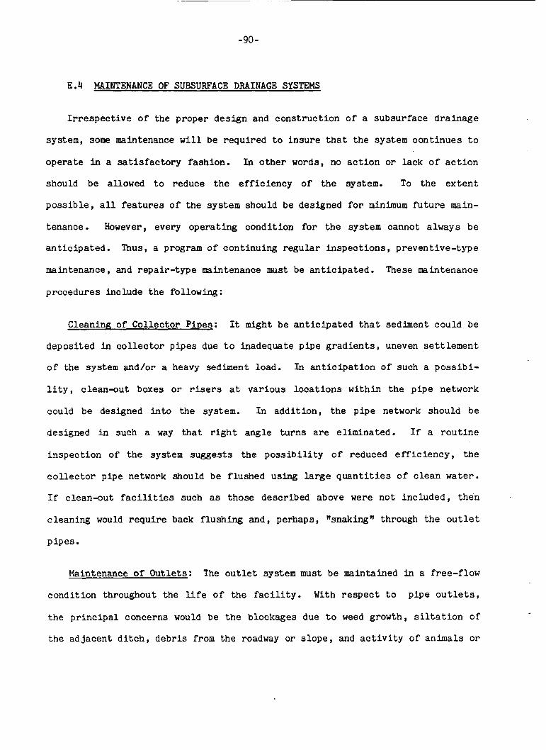
-90-
E.4 MAINTENANCE OF SUBSURFACE DRAINAGE SYSTEMS
I r r e s p e c t i v e o f the p rope r d e s i g n and c o n s t r u c t i o n o f a subsu r face d r a i n a g e
system, some maintenance w i l l be r equ i r ed t o i n s u r e t h a t t h e system c o n t i n u e s t o
operate i n a s a t i s f a c t o r y fashion. In o t h e r words, no a c t i o n o r lack o f a c t i o n
should be allowed t o reduce the e f f i c i e n c y o f the system. To the e x t e n t
p o s s i b l e , a l l f e a t u r e s o f the system should be designed f o r minimum f u t u r e main-
tenance. However, every o p e r a t i n g c o n d i t i o n f o r the system cannot a lways be
a n t i c i p a t e d . Thus, a program o f con t inu ing r e g u l a r i n s p e c t i o n s , prevent ive- type
maintenance, and r epa i r - type maintenance must be a n t i c i p a t e d . These maintenance
procedures include the following:
Cleaning of C o l l e c t o r Pipes: It might be a n t i c i p a t e d t h a t sediment could be
depos i t ed i n c o l l e c t o r p i p e s due t o inadequate p ipe g r a d i e n t s , uneven s e t t l e m e n t
o f the system and/or a heavy sediment load. In a n t i c i p a t i o n o f such a p o s s i b i -
l i t y , c l ean -ou t boxes o r risers a t v a r i o u s l o c a t i o n s wi th in the p i p e network
could be designed i n t o t h e system. I n a d d i t i o n , the p i p e network should be
designed i n such a way that r i g h t ang le t u r n s are e l imina ted . I f a r o u t i n e
i n s p e c t i o n o f t he system sugges t s t h e p o s s i b i l i t y o f reduced e f f i c i e n c y , t he
c o l l e c t o r p ipe network should be f lu shed using large q u a n t i t i e s o f c l e a n water.
I f c l ean -ou t f ac i l i t i e s such as those described above were n o t i n c l u d e d , t hen
c l ean ing would r e q u i r e back f l u s h i n g and, perhaps, "snaking" through the o u t l e t
p i p e s .
Maintenance of Ou t l e t s : The o u t l e t system must be maintained i n a free-f low
c o n d i t i o n throughout t h e l i f e o f t h e f a c i l i t y . With respect t o p ipe o u t l e t s ,
the p r i n c i p a l concerns would be the blockages due t o weed growth, s i l t a t i o n of
t h e ad jacen t d i t c h , deb r i s from the roadway o r s l o p e , and a c t i v i t y o f an ima l s o r
-91-
man. In addi t ion , f l a p valves in s t a l l ed on o u t l e t s t o minimize blockages due t o
animal a c t i v i t y or backflow could become stuck because of some of the aforemen-
t ioned causes a s well as damage t o or corrosion of the valve hinge. Only
through per iodic inspection can these circumstances be i d e n t i f i e d and sub-
sequent ly r e c t i f i e d . Such inspect ions should be made p r i o r t o seasonal per iods
o f heavy rainfall as well as following pa r t i cu la r ly heavy r a h f a l l events and/or
a t least once every three months.
In addi t ion t o the o u t l e t s themselves, t he o u t l e t markers should be
maintained i n good condition. Damaged markers should be repaired or replaced
immediately. Any marker destroyed or damaged during o ther construct ion or main-
tenance a c t i v i t i e s should be immediately reported f o r replacement or repair.
Miscellaneous Maintenance and Other Considerations: Careful per iodic
inspec t ions are the key to adequate maintenance of the subsurface drainage
system. However, o ther related maintenance a c t i v i t i e s associated wi th t he pave-
ment, pavement shoulder, surface drainage systems, ice/snow con t ro l and removal,
right-of-way mwbg, etc. can a l l have an impact on the operat ion and main-
tenance of the subsurface drainage system. Although the maintenance o f t he sub-
surface drainage system might not take precedence over one o f the aforementioned
a c t i v i t i e s , it must not be relegated t o an i n s ign i f i can t s t a t u s . For example,
a l though mwing is an essen t i a l maintenance a c t i v i t y , it has a p o t e n t i a l l y
de t r imenta l effect on the o u t l e t system. That i s , the mowing mch ines could
damage the o u t l e t s through impact with the o u t l e t s during the m o w i n g operat ions.
If the l ike l ihood of such an occurrence is high, use of erosion c o n t r o l aprons
o r chemical weed con t ro l could be u t i l i z e d i n l ieu of mowing.
Maintenance tha t insures the e f f i c i e n t co l l ec t ion and removal of sur face
water w i l l a l s o general ly improve the operation of the subsurface drainage

-92-
system. Timely repairs of damage t o surface drainage structures, p ipes ,
d i t c h e s , e tc . , w i l l contr ibute t o the proper operation of the subsurface
drainage system. Likewise, timely and caut ious repairs of damaged pavement and
pavement shoulder sec t ions w i l l be benef ic ia l t o the underdrain system.
Those responsible fo r the care of the subsurface drainage systems should
maintain d e t a i l e d as-bui l t p lans o f t h e systems t o faci l i ta te subsequent repairs
and replacements. In addi t ion , a separate record o f the loca t ion of drainage
f ac i l i t i e s , p a r t i c u l a r l y ou t l e t s , should be maintained so t h a t these f ac i l i t i e s
can be easily located by maintenance personnel. Inspection records should be
kept along wi th records of each maintenance a c t i v i t y required by the system. I f
these records are k e p t i n a continuous fashion they may suggest the need f o r
some more s u b s t a n t i a l e f f o r t s t o prevent t h e recurrence o f some continuing main-
tenance problem. The information concerning the modification of condi t ions
ad jacen t t o the subsurface drainage sys tem must a l s o be d i l i g e n t l y gathered and
assessed. Any modification or change t h a t would adversely affect t h e operat ion
o f the subsurface drainage system (e.g. changes in the surface drainage facil i-
t ies etc.) should be corrected promptly t o mitigate t h e po ten t i a l ly de t r imenta l
effects.
F. SUBSURFACE DRAINAGE AND PAVEMENT REHABILITATION
F.l GENERAL
Like most o the r highway agencies, the focus of the work program of t h e NJDOT
is increas ingly d i rec ted a t preserving and maintaining the highway network,
rather than making addi t ions t o the system. For example, about 90% of the pro-
jects cu r ren t ly in i t ia ted by the Department's Design unit concern resur fac ing o r
recons t ruc t ion , while only about 10% involve new construction.
-93-
On a t least c e r t a i n o f these candidate r ehab i l i t a t ion p ro jec t s , t h e e x i s t i n g
d i s t ress was caused by water-induced damage. Therefore, t o provide an e f f e c t i v e
s o l u t i o n t o the problem on these p ro jec t s , t h e proposed r e h a b i l i t a t i o n technique
must address the water-in-the-pavement i ssue . This repor t sec t ion o u t l i n e s a
design and construct ion methodology which would permi t the i n t e r n a l drainage
concept developed i n t h i s research t o be appl ied t o t h e r e h a b i l i t a t i o n p r o j e c t s
which now cons t i t u t e the major focus of t h e Department's work.
If it needs t o be said, the open-graded drainage so lu t ion subsequently
descr ibed herein is not a panacea and should be used se l ec t ive ly on only those
p r o j e c t s where warranted. Obviously, if the pavement damage on a proposed reha-
b i l i t a t i o n project is caused by f ac to r s o ther than subsurface water , only con-
ven t iona l r e s to ra t ion techniques should be performed s ince the p r o j e c t 's
drainage ostensibly is functioning by some na tu ra l means (such as permeable
enough subgrades .)
I n a highly urbanized, heavily t ra f f icked state such as New Je rsey , imple-
mentation o f any type of r e h a b i l i t a t i o n so lu t ion can pose problems. These nor-
mal construct ion problems can be accentuated by applying t h e p a r t i c u l a r so lu t ion
proposed here for a l l e v i a t i n g water-related damage. That is, as noted ear l ier
i n t h i s r epor t , t raff ic de f in i t e ly should not be rerouted over an open graded
drainage l aye r due t o poss ib le problems of s t a b i l i t y (e.g., shoving and r u t t i n g )
and/or contamination o f the drainage layer. Traffic cont ro l on a p r o j e c t
incorporat ing an open-graded drainage layer thus would requi re a p a r t i c u l a r l y
well-thought-out plan. Secondly, s ince an in t e rna l ly drainable pavement
r equ i r e s a subs t an t i a l ly th i cke r sec t ion than a conventional resurfacing ( i .e . , 10 inches), i n a highly urbanized area, t h i s so lu t ion would have t o be a p p l i e d
4
-Y4-
as a reconstruct ion rather than an overlay due t o problem i n meeting the eleva-
t i o n o f existing highway appurtenances (e.g., barrier curb, sidewalks).
While use of t h e so lu t ion proposed here thus requires spec ia l t raff ic
con t ro l measures and a higher i n i t i a l cos t , it seems t o be t h e only v i ab le
approach. Consider the a l t e r n a t e : If a conventional r ehab i l i t a t ion technique
(e.g., resurfacing) is appl ied t o a pavement whose foundation has been under-
mined by inadequate subsurface drainage, t h i s w i l l only temporarily postpone t h e
i nev i t ab le fur ther d i s in t eg ra t ion o f the pavement s t r u c t u r e , r e s u l t i n g t o a
large degree i n a useless expenditure of scarce lnaintenance funds. A discussion
o f the economic aspec ts involved in the use of the open graded drainage so lu t ion
on r ehab i l i t a t ion p ro jec t s is described i n an informal Department repor t ('9).
F.2 DESIGN GUIDELINES FOR SUBSURFACE DRAINAGE ON PAVEMENT REHABILITATION
The recommended approach fo r pavement r ehab i l i t a t ion p ro jec t s , where the
drainage is inadequate proposes construct ing an overlay consis t ing o f four
inches of B O G material d i r e c t l y on the ex is t ing pavement surfacing and dra in ing
it i n t o drainage trenches and o u t l e t s as detailed else where i n t h i s guide. Due
t o possible s t a b i l i t y problems during the construct ion, NSOG material is not
suggested fo r use in such a r e h a b i l i t a t i o n e f f o r t .
As noted earlier i n t h i s r e p o r t , t o insure adequate confinement and s t a b i -
l i t y , the BSOG drainage l a y e r must be overlayed with a minimum of three inches
o f bituminous s t ab i l i zed base and three inches of bituminous surfacing.
While some refinements/modifications of t h e above suggested design methodo-
logy may be poss ib le as we gain further experience, a t the present time, an
-95-
at tempt t o apply the i n t e r n a l drainage so lu t ion t o only parts o f a road (e.g.,
i n the shoulder areas only) appears i l l -advised . Such a par t ia l so lu t ion might
no t only be unsuccessful, but a l s o conceivably could cause an increased poss ib i -
l i t y f o r distress (e.g., through the c rea t ion of a "bathtub" effect) .
In t r ans i t i on a reas between the existing and rehabili tated s e c t i o n s o f road-
way, protect ion for the newly i n s t a l l e d subsurface drainage facilities should be
provided through use of a f i l t r a t i o n media (e.g., a f i l t e r fabric) a t t h e
beginning and end of the pro jec t . To ensure proper functioning of t he system,
adequate drainage o u t l e t s must be i n s t a l l e d within the p ro jec t l i m i t s .
A s i n the construction of new pavements, the recommended subsurface d r a i n s
are designed t o handle water which infiltrates the pavement area only. It is
assumed that the surface drainage is funct ioning and that the runoff from t h e
surrounding areas w i l l be drained by it.
Where groundwater is an expected problem an inves t iga t ion o f the water
b e a r i n g strata should be made, including depth and permeabili ty o f t he strata
and a m u n t o f water ca r r i ed by it. This inves t iga t ion w i l l a l low the des igner
t o increase the p ipe size to insure adequate capac i t i e s f o r a l l sources o f
water.
F3. METHODS OF CONSTRUCTION
The general i n t e r n a l drainage cons t ruc t ion procedures suggested fo r new
construct ion should be followed fo r r e h a b i l i t a t i o n p ro jec t s . Addit ional ly , t o
prevent damage t o the subsurface drainage system during cons t ruc t ion , t he
following sequence of construct ion should be followed:
-96-
1. Prepare the ex i s t ing pavement surface so t h a t i t is s t r u c t u r a l l y sound
and reasonably clean. Badly unstable slabs should be repaired o r otherwise
s tabi l ized p r i o r t o i n s t a l l a t i o n o f t he open graded layer .
2. Construct drainage ditches and pipe network. No d i t ches s h a l l be l e f t
open (without backfil l) for more than 24 hours.
3 . Construct 4 Inch BSOG drainage base course a t the loca t ions shown on the
plans. The underdrain network and the drainage base course shal l be pro tec ted
a t a l l times from any contamination tha t might diminish t h e i r a b i l i t y t o
t r anspor t water u n t i l pavement is constructed over it. Any contaminated o r
damaged drainage base course or drainage elements caused by the con t r ac to r ' s
negligence s h a l l be replaced by the contractor a t no cos t t o t he state. Only
traffic necessary fo r construct ion o f these pavement sec t ions w i l l be permitted
on the drainage base course. All o the r traffic must be detoured.
4. Immediately following the construct ion of t h e drainage base course the
cont rac tor shall "seal" its outer edges wi th the bituminous s t a b i l i z e d base
course.
Any area of the drainage course which becomes impaired by i n f i l t r a t i o n and
clogging shall be reconstructed a t t h e d i r ec t ion of the Engineer. During the
construct ion of t h e drainage course and u n t i l the Contractor has e n t i r e l y
covered the course with pavement o r o ther "sealing" l a y e r s , it s h a l l be the
Contractor 's respons ib i l i ty t o maintain drainage of the job s i te such t h a t f i n e
material is not allowed t o wash i n t o and clog any p a r t o f the drainage system.
Spec i f ic de ta i l s of t he procedure described above are as follows:
Trench Excavation, P ipe LavinR and Backfi l l : Excavation , p i p e laying , and
backf i l l i ng of t renches s h a l l be performed as d i rec ted by t h i s gu ide .
-97-
It s h a l l be the Contractor 's respons ib i l i ty to provide drainage of t h e road-
way such t h a t t h e open-graded b a c k f i l l of trenches does not become clogged w i t h
e ros ion material. Where the o u t l e t p i p e s fo r these underdrains en te r manhole o r
i n l e t bas in s t r u c t u r e s , the Contractor s h a l l take necessary means t o prevent a l l
soil from entering the p ipes through the basin.
Bituminous-Stabilized DrainaRe Layer : A drainage base course s h a l l be
placed in t h e required areas, and compacted t o the prescribed thicknesses , and
grade. The methods of construct ion s h a l l be as specif ied i n t h i s guide.
Construction Staainq: To avoid extensive obstruct ion of traffic flow and
impairment o f t r a f f i c s a fe ty , t h e construction sequence should be such as t o
keep a t least one lane e a s i l y accessible a t a l l times. To achieve t h i s , the
cons t ruc t ion should begin wi th the excavation of longi tudina l di tches a t the
edges o f the ex i s t ing pavement, the placement of p i p e network and the p ipe
backfi l l .
Since the normal capaci ty o f a paving operation is about 1500 tons p e r day,
approximately a lane-mile of a 4 inch t h i c k , 12 f t . wide layer can be placed i n
a day. This means t h a t one lane-mile o r two half lane-miles o f 4 inch drainage
l a y e r can be placed in one l i f t i n a day. However, only U g h t t ra f f ic should be
allowed on the completed drainage base course and only that which is necessary
f o r the construct ion o f the pavement t o be placed above t h i s base course. In
fact , t he drainage base course should not serve as a haul road fo r cons t ruc t ion
opera t ions eleswhere on the p ro jec t , on the other hand, an excessively t h i c k
l a y e r m i g h t cause dangerous dr iving conditions. Thusly, to p ro tec t the d r i v e r
o f a vehic le , the f inc t ion ing of the drainage layer and t o faci l i ta te construc-
t i o n e i ther full width o r lane a t a time placement o f the bituminous s t a b i l i z e d

-98-
d r a i n a g e base w i l l be permitted. If f u l l wid th paving is not used, then the
paving opera t ion sha l l commence a t the outs ide edge o f the underdrain t r e n c h i n
the o u t s i d e shoulder and progress a c r o s s the width of t h e roadway.
Immediately following the cons t ruc t ion o f the open-graded base course , t h e
Cont rac tor shal l "seal" the o u t e r edges o f the course and the shoulder wi th
bituminous stabil ized base course. I n no case s h a l l these edges be left unpro-
tected and s u b j e c t t o i n f i l t r a t i o n . In the case of four or six l ane roads , a l l
traffic should be re routed t o one s i d e of t h e highway and the pavement r e h a b i l i -
t a t i o n i n i t i a t e d on the opposi te s i d e . The cons t ruc t ion then can proceed by
placing first a days production of the four inch drainage l a y e r and then the
fo l lowing day topping t h a t l a y e r wi th bituminous s t a b i l i z e d base. The r e q u i r e d
q u a n t i t y o f s tabi l ized base i n the shoulder areas would a l s o be placed during
the second day. This procedure would be repeated u n t i l t h e e n t i r e highway had
been paved in one d i r e c t i o n wi th both the drainage and s t a b i l i z e d base mixtures.
A t t h a t time the MABC pavement l a y e r could be placed. While o ther i n c i d e n t a l
work c o n t i n u e s , t ra f f ic could then be rerouted t o the overlayed s i d e and rehabi-
l i t a t i o n work started on the oppos i te s i d e i n t he same sequence.
In i n s t a n c e s o f two-lane roadways where a lane a t the time must be worked
on, w h i l e keeping an adjacent l a n e open, a somewhat adverse procedure w i l l have
t o be adopted. With t h i s approach, a t any one time t raff ic w i l l be re routed t o
one s ide o f t he road using both the normal t raff ic lane and shoulder f o r the two
d i r e c t i o n s o f t r a v e l . S t a r t i n g on one side o f the pavement, after completion o f
enough o f dra inage system, t h a t can be protected wi th in 24 hours , days produc-
t i o n o f the four inch drainage l a y e r and BSBC shoulder l a y e r f o u r inches t h i c k
should be cons t ruc ted . The next day while keeping the oppos i te s i d e open t o

-99-
traffic the previous day's drainage and shoulder l aye r s should be covered by
three inches of BSBC. On t he t h i r d day, while opening the overlayed s ide t o
t r a f f i c , on the opposi te s i d e the amount of drainage system t h a t can be pro-
t ec t ed within 24 hours should be completed. On the fourth day, a day's produc-
t i o n of t h e drainage l aye r and of the matching BSBC shoulder l a y e r should be
cons t ruc ted . On t he f i f t h day the last drainage and shoulder l a y e r s e c t i o n s
should be covered by three inches of BSBC. Subsequent days cons t ruc t ion should
commence as before u n t i l completion of said sec t ion r e h a b i l i t a t i o n , a t which
time the MABC pavement l aye r can b e prudently constructed and o the r i n c i d e n t a l
work accomplished.
- 100-
REFERENCES
Cedergreen, Harry R., Arman Jorge A. and O'Brien, Ken H. , Development of Gu ide l ines f o r the Design and Subsurface Drainage Systems for Highway Pavement S t ruc tu ra l Sec t ions , FHWA, February , 1983.
1.
2.
3.
4.
5.
6.
7 .
8.
9.
10.
11.
12.
13.
Moulton, Lyle K., PH.D.P.E., Highway Subdrainage Design, FHWA, August , 1980.
Kozlov, George S., Road Surface Drainage Design, Construction and Maintenance Guide for Pavements, June, 1981
Cedergreen, Harry R. , O'Brien, K. H., and Arm, Jorge A., Guidelines f o r t he Design of Subsurface Drainage Systems f o r Highway S t ruc tu ra l Sec t ions , June, 1972.
Ridgeway, Dallas H., I n f i l t r a t i o n of Hater Through the Pavement Surface, TRB 616, p. 98-100.
Kozlov, George S., Mottola, Victor E., Mehalchick, Gregory, Improved Drainage and Front Action Criteria for New Jersey Pavement Design, Volume I - Inves t iga t ions fo r Subsurface Drainage Design, FHWA, N . J . P ro jec t 7740, October, 1962.
Casagrande, A., ASCE and W. L. Shannon Associates, M. ASCE, Base Course Drainage for Airport Pavements, Proceedings, Volume 7 7 , June, 1951
NJDOT, 1980 Supplement t o the Standard Spec i f ica t ions fo r Road and Bridge Construction.
1980 Annual Book of ASTM Standards, Pa r t 19, and Rock.
Natural B u i l d i n g Stones, s o i l
1980 Annual Book of ASTM Standards, Part 15, Road and Paving Materials; Bituminous and Polymeric Materials fo r Highway Construction, Water-Proofing and Roofing, and Pipe; Traveled Surface Charac te r i s t ics .
Kozlov, George S., Mottola, Victor E. , Mehalchick, Gregory , Improved Drainage and Frost Action Criteria for New Jersey Pavement Design, Volume 11, Experimental Subsurface Drainage Applications, 1983.
Mottola, Victor E., F e a s i b i l i t y of Pavement S tab i l i za t ion in N e w Jersey, September , 1982 (unpublished) . Barenberg, Ernest J. and Tayabji , Shriaz D., Evaluation of Typical Pavement Drainage Sys tem U s i n g Open Graded Bituminous Aggregate Mixture Drainage Layers, May 1974.
14 . Barenberg, Ernest J. and Brown, Douglas, Modeling o f Ef fec ts of Moisture and Drainge on NJDOT F lex ib le Pavement Systems, Apri l , 1981.

-101-
REFERENCES (Continued)
15. Barenberg, Ernest J., Ef fec ts o f Moisture and Drainage on Behavior and Performance of NJDOT Rigid Pavement Systems, Ju ly 1981.
16. Drainage and Erosion-Control S t ruc tu res fo r Ai r f ie lds and Hel ipor t s , Department of t h e Army Technical Manual, TM 5-820-3, Ju ly , 1965.
17. Subsurface Drainage F a c i l i t i e s f o r Ai r f ie lds , Department o f the Army Technical Manual, TM-5-820-2, August 1965.
18. R. E. Chambers, T. J. McGrath, F. J. Heger, Plastic P i p e fo r Subsurface Drainage of Transportation Facil i t ies, TRB r e p o r t 225 , October , 1980
19. Kozlov, George S., Rehabi l i ta t ion o f Pavements Damaged by Inadequate Subsur- face Road Drainage, March, 1979.
-102-
DRAINAGE LAYER
FLOW RATES, Q
AND
FLOW PATH LENGTHS, L
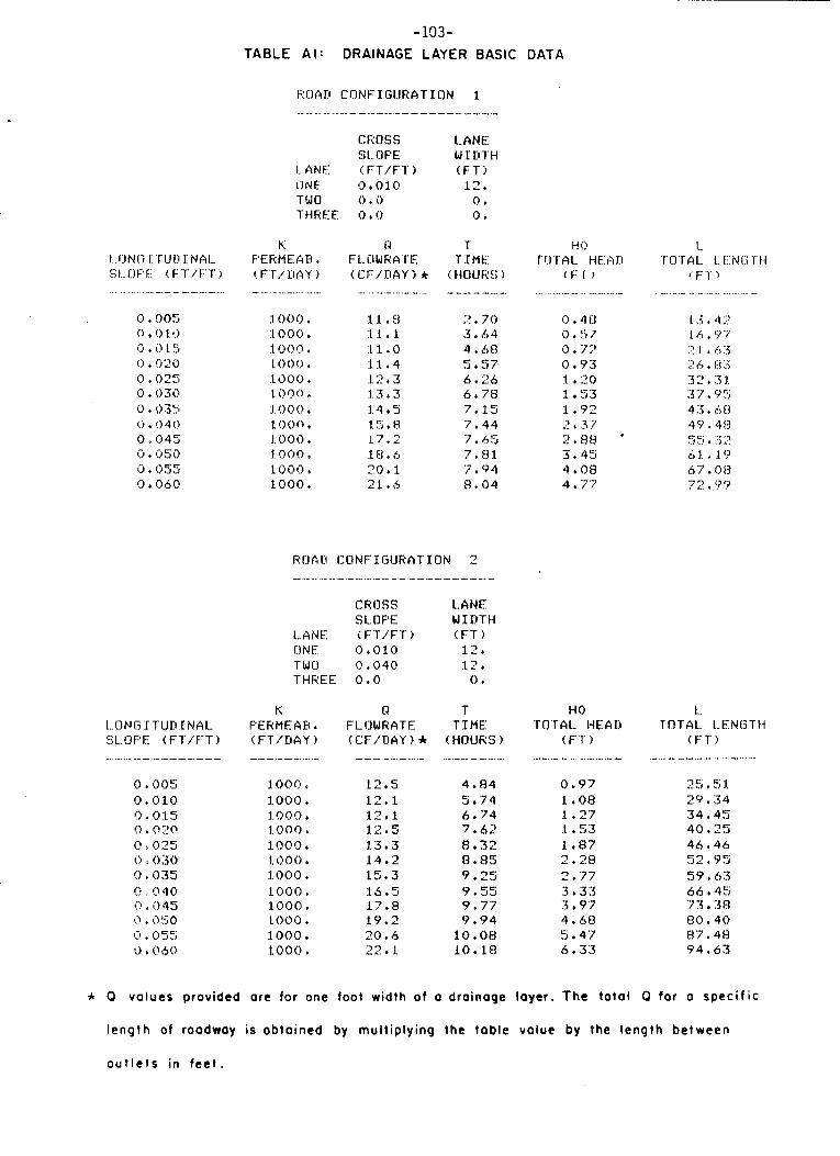
-103- T A B L E A l : DRAINAGE LAYER BASIC DATA
................ .- - ... .- ... - - .- - - - ._ - - -
CROSS LANE SL- OPE W I D T H
LANE i FT/FT j ( F T ) i)NE 0.010 12. TWO 0,0 0. THREE 0 . 0 0.
I... I:) N o :I: 'r u !:I I N G I.. S I... I:) F' Ei. ! F 'I /' F:' T j ........... - .. - - .- _. ...
0 . 0 0 5 0 + 0 1 icJ , 3 1 5
( j ,
0 t 025 0 . 030 0 t 035 0 t !I40 0 i. 1345 0 . 1350 0 + 055 0 + 060
K F'ERMEGB + (. F'T'.~rtisY )
- ......... _. ..........
1000. :I. 000 1000. .to00 . 1300. logo 1
1.0 0 0 4
1000. I . !I 0 0 , SO00 t 1000 t :Loo0 t
N T F 1- CI W RATE (C:F'/DAY j rt tiOUR!:; 1
T I M E
-. .. .- .- ....... - .... .- ... - .- .- .....
11.8 I?. 70 1l.1 3 . 6.4 .l 1 . 0 4 . 68 11.4 5.57 12.3 6 + 26 13.3 6.78 1.4 t 5 7.15 15.8 7.44 .17 . 2 7 . c,g :18,6 ?,HI 20.1 7.94 21 .,s 8.04
CROSS LANE
LANE i FTT/FT ) ( F T ) CINE i).010 12. -r w CI {! + 040 12. THREE 0.0 0 .
SL.OFE w I ri'rci
K R T FERMEAH + FLOWRATE T I M E ( F T / D A Y 1 ( C F i D A Y ! * (HOURS ) - - - .. - ........... ....
1000 +
1.000 4
1000. 1000 +
1.000 . 1000. 1000 * .LOO0 + 1000. t 000 . 1.000 1000 4
12.5 12.1 12.1 1.2.5 1.3.3 14.2 15+3 l6.5
119.2 20.6 22.1
17.8
4.84 5.74 6.74 7.62 8.32 8.85 9.25 9.55 9.77 9.94 10. OH io . i a
1-1 0 T13 T A L HECAKt
( F r ) .- ...... - - ..............
0 . 4 I:) i) . 5 7 0.7:' 0 . 93 1.20 1 53 1.92 2 , 3 7 2.88 * 3.45
4.77 4 . ~ 8
HO T O T A L HEAD
( F T ) - - __ - .- - .- - -
0.97 1.08 1 ,27 1.53 1 +87
2.77 3.33 3.97 4.68 5.47 6 . 3 3
2.28
1.. 1 n T AL. I... E N (3 T li
( F ' r ) .- .... _. - .- ........ ....
2 5 + 5 :I. 2P. 34 34 + 45 40 t 25 46 e 46 52.95 59 t 63 66 + 45 7 3 3 8 80 t 4 0 87 I4H 94 * 63
* 0 values provided ore for one foot width of a drainage layer. The tota l 0 for o speci f ic
length of roadway is obtoined by multiplying the table value by the length between
o u t l e t s in f e e t .
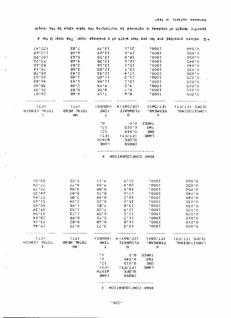
( .I. .::I ) t i .I. Cl N 13 -1 '1 V .1. (3 .L
"'I
! .I .A j I4 1. !3 N :3 '1 "'I v .L (3 1
- 1
E8'L 89'9 E9+% 89'P E8.E 80'E Eb'Z 88'T Eb'T ao* Ea.0 89'0
-"-..----.I
(Id) I:IVliH ' l V . L O 1
OH
T TZ Y'6l: 0.131: 5 " Y T 'E !; T L ' Z T t'ZT Z 'TT 1 ' O T 2'6 L ' t l 9'8
000 T ' 000 T 'OOOT 0001
'000T ' 000 T * 00(! T ' O O O T * 000 T 000 T
'000T * OOOT
I .- ................. - - - - ..... -
'000T + 000 T '000T 000 T ' 000 T 000 T
' O W T ' 000 T '0001 '000T '000T '000T
- - -- .- _- - - - ( A W W l J ) ' Y W 3 W Y 3 d
?I
3 3 Y H . L urn1 3N0
3NWl
......
.- -. -. ............ -. ........ .... - - _ _ ............... .- __ ..... _ _ E N ( I S . I . V ! J I I ~ I ~ ~ N C ) : I IIWOY
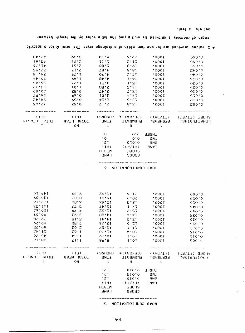
6E'E K6.Z T S ' Z 5.T * z 6L ' 'I 6V'T 5.: z 1: 'I#* T E8.0 6Y'O 6S'O ES'O
................ -. ........ ....... .... -. - -. - - -. - _. -.
( l.3) (1.4) H l 9 N 3 1 -1 v LO 1. W 3 H lW101
-1 OH
............. ._ ... _ _ ............. .... ............ -. ._ - __ .. .- (LA)
UW3H .'lVl.Ol 0 H
OZ'Z I T ' S 00'1; LEl'tr O L ' P 13b'tr TZ't7 88'E LP'E TO' !? PE'Z L T ' Z
'0001 0001 ' 000 T ' 000 T 000 1- 000 1 ' O O O T
0 0 0 T ' 000 T '0001: * 000 T
OOOT
-..- .- ....
.- ._ -. - ... - - ....... -, ...... -. ..... - -. ............ _. ... -_ ................. .- _. - ....
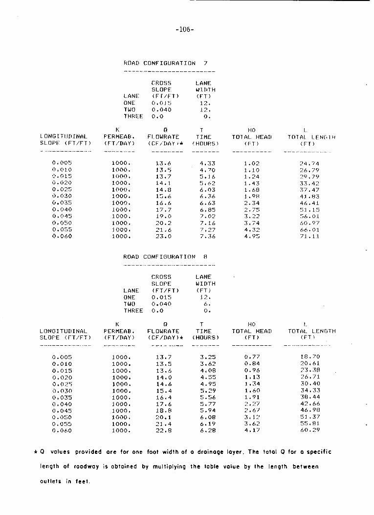
-106-
ROAD CONFIGURATION 7 - -.-.-- _..--
1. CING 1' TIJD I NAL.. SL.[3FE: (F'T'iFT?
0.005 I? . G 1. 0 0 . 0 1. 5 5 t G 2 G 0 + 025 0 ' 030 G 0155 0.040 0.045 0 . 050 0.055 0 4 060
CROSS LANE SI-OFF' W I ItTH
L.ANE ( F i / F T ) (FT 1 CINE 0 + G 1. 5 1 2 . TWO 0 t 040 1.2 t THREE 0.0 0 .
.- -- -.. -. .- - ....... - ............... - ....
1.000 . 1.000 , :1 o(?o t 1 G O O * 1000. 1000, 100Q. 1 G i i 0 , 3.000 * 1000. 1000. 1000
1 3 , 6 1 3 . 5 13.7 14, 1 14. t3 :15 b 16 + C; 17*? 19.0 20.2 21.6 23 0
4 * 33 4+'0 5 1 5 5 t t! 2 6'03 6 + 3 6 6.63 6.85 :? . 02 74 i t i .;; * 2 7 7 + 3 6
- - ...... - ...... - - ....
1 + G 2 1. . 1.0 1 , 2 4 1 . 4 3 1 .b l ! :1 . 98 2.34 2.75 3 + 22 3.74 4 * 32 4.95
.. -- ........... ..................
2 4 , '7 4 ;! 6 , 7 '7 7 c7 , 7 (9 3 3 + 4 2 3 -7 . 4 7 4.1.. 83 4 0 . 4 1 :,:i:1 '1':; !'i 6 * (? :I. h (j . '9 '7 6 6 t 0 :I. 7:1 t :I :1.
....
+ .. i.
R O A I l CONFIGIJRAT1C)N t3 .- -. ...... ........... - .......... .- - ..
CROSS L A N E st.. OPE WIDTH
LANE: ( FT/F T ) ( F T j ONE 0 . 0 1 :5 12. TWO 0 040 ci + THREE 0.0 0
K 0 T HO I... 1.. C)N G I' T U Kl I N A 1.. FERMEAB + FL.OWRATE T I ME TOTAL HEAI:I 'r [I 1 A I... I... EL N (3 'T' t.1 SI...OF'E I F T / F T ? (FT/TIAY) ( C F / D A Y ) + (HOIJRS ) ( F T ) !FT?
-.-.-I--.- .- _. ........ .... .- ................... .- . - - - -. _. -- - ._ _.. -. -._
0.005 0,010 0.015 0.020 0 0 2 5 0.030 0 + 035 0 + 040 0.045 0 * 050 G + G 5 5 0.060
1000. 1000 1000. 1000 . 1000. 1000, 1000. 1.000, 1000I 1000. :I_ 000 4
1000.
13.7 13.5 13.6 14.0 14.6 15.4 1 6 4 4 17.6
20 1 21 . *4 22.8
i.a.8
3.25 3.62
4.55 4.95 ..I 2 Y 5 t 56 5 , 7 7 5 . 9 4 6.08 6 . 1 9 6 t 28
4.08
c
0.77 0.84 0.96 1.13 3. 34 1 A0 1.91 2 . 27 I!. 67 3 , i " 3.67 4.17
:I_ n . 7 0 20 + 6 :l 2 3 . 3 8 2 6 t 7 :t 3 (? . 4 0 3 4 , 3 3 38 4 44 4 2 + 6 h 46 t Y 8 5 1. , 3 7 >.> \.> t (3 1 60. 29
CC.
* 0 voluer provided ore for one foot width of o droinaqe layer. The total Q for o specif ic
length of roadway is obtained by multiplying the table value by the length between
outlets in fee t .
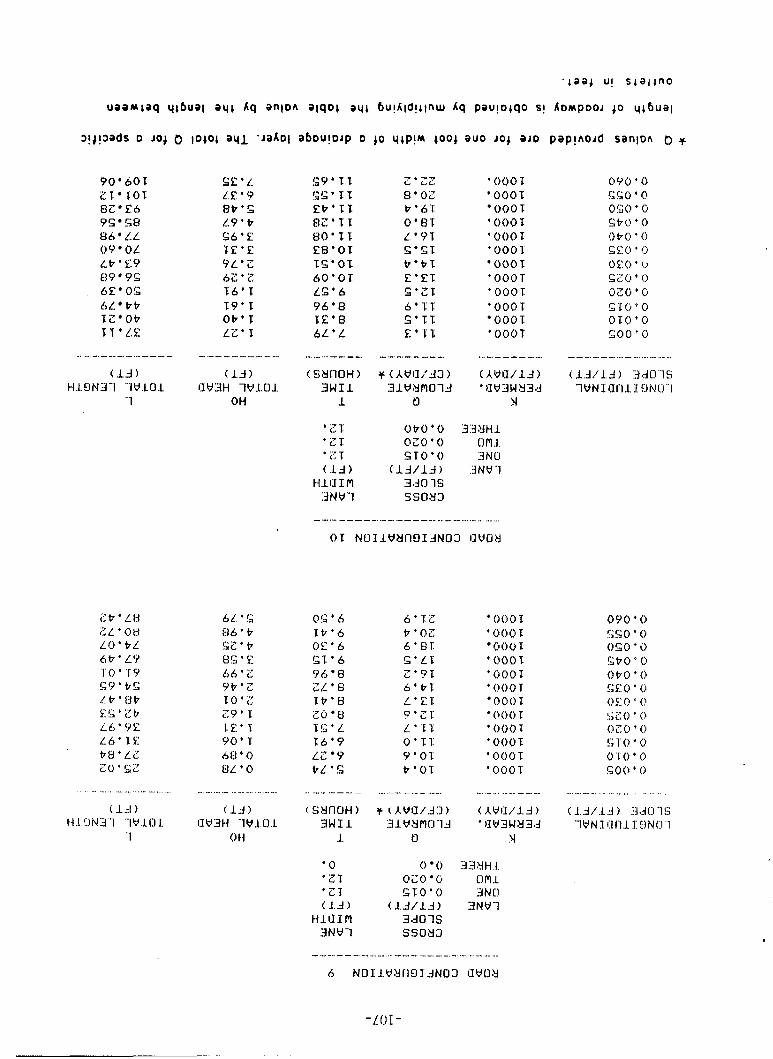
90 601 ZT TOT 82 E6 9s 5x3 86 LL 0 9 O L Ltr ' EY 89 9s 6E OE 6L tt TZ Otr T T ' L E
S9'1T !;G*Tl Et'll RZ'TT 80'1T
T.G.01 6O'OT LS.6 Y6'8 T E ' 8 6 L ' L
Ea*oz
Z ' Z Z 8'OZ t'6T 0'8T L 'YT E ' G T t r ' t 1 E'ET S ' Z T 6'TT Z ' T T E ' " T
+ 000 5 000'5 000'1 '00OT * 0001 '0001 0001
* OOOT ' 000 1: ' OOOT
OOOT * OOOT
(13) H .L 9 N 3'1 "1 W .LO1
-1
--- --- ........... .......
0!; '6 1:t .b Or ' 6 S7'6 Y b 8 Z L ' 6 T t ' 8 ZO 8 TS 'L ?6'Y L.2 Y tL's
O O O T ' 000 T
OOUT '(!OOT ' 000 1 ' 000 T 000 T 000 T
'000T * 000T ' 000 1 ' O O O T
... .... ... .... .... .. . ._ _. ... ._. .- ....... " .... ... .... - - - ,... _._ _. - -. _- .._ .... .... .. ._ .... - - .... . . ... .., .... . .. .. ... ..
t 1.4 ) H.1 !.IN3 -1 '1W.LO L
'1
'0 0 0 0z0 (i (> T
' Z T S T O ' O 1.d 1 ( 13/lS)
H1.UIM 3 . d O l S 3NW1 SSOY3
, ... 3 3 YH -1
3NO 3NWl
c) m .L
-108-
CONSTRUCTION AND MATERIAL SPECIFICATION
FOR BSOG (BITUMINOUS STABILIZED OPEN GRADED) DRAINAGE LAYER,
NSOG (NON-STABILIZED OPEN GRADED) DRAINAGE LAYER
AND
SUBSURFACE DRAINAGE COLLECTORS
-109-
The specifications given in this appendix make reference to
other specification sections included in the NJDOT Standards for Road
and Bridge Construction. Non-New Jersey agencies should cite appro-
priate provisions from their own standard specifications. To aid in
making the necessary substitutions, the specification references given
in this appendix are described here. They are listed in order of
their appearance in the appendix.
1. Subsection 901.04 - Broken Stone - specifies geologic etc. character i s t i cs of crushed st one.
2. Section 990 - Methods of Tests - specifies new falling head permeability and modified compaction tests for O.G. materials. These
specifications are available in Appendix C and D.
3. Subsection 203.04 - Equipment - specifies equipment such as rollers, compactors, etc.
4. Subsection 208.04 - Preparation of Subbase and Subgrade - specifies placing and preparation methods for subbase materials.
5. Subsection 902.02 - Cutback Asphalts - specifies prime coat mater i a1 s .
6. Subsection 404.13 - Conditioning of Existing Surface - specifies condition of the base course prior to placement of overlying material.
7. Subsection 302.09 - Tolerances - specifies permissible thickness tolerances.
8. Subsection 105.19 - Maintenance - specifies contractors' obligations to maintain all aspects of the construction work in an
acceptable condition until the project is accepted by the NJDOT.

-110-
9. Subsection 902.01 - Asphalt Cements - specifies asphaltic material characteristics, preparation tests, etc.
10. Subsection 404.04 - Equipment - specifies equipment necessary for construction of bituminous concrete pavements.
11. Subsection 404.05 - Bituminous Concrete Batch Plants - specifies hand1 ing preparation and storage etc. of bituminous concrete materials.
12. Subsection 404.11 - Small Tools - specifies handling of tools needed for bituminous sampling and testing.
13. Subsection 404.14 - Transportation and Delivery of Mixture - specifies how bituminous mixtures are to be transported from the plant
to the paver.
14. Subsection 404.15 - Spreading and Finishing - specifies placement technique for bituminous mixtures.
15. Subsection 304.13 - Tolerances - specifies surface smoothness requirements for application of bituminous concrete.
16. Subsection 404.19 - Thickness - specifies thickness tolerances of BSOG drainage layer.
17. Subsection 404.21 - Method of Measurement - speclfles weighing methods for bituminous concrete.
18. Subsection 904.06 - Temperature-Volume Correction Factors; Table 904-1 Temperature-Volume Correction Factors for Asphalt Products.
19. Subsection 404.02 - Materials - specifies requirements for bituminous materials .
20. Subsection 901.03 - Coarse Aggregate - specifies materials and sizes of coarse aggregate including broken stone, washed gravel,
blast furnace slag and boiler slag.
-111-
21. Subsection 913.05 - Porous Concrete Pipe - specifies porous concrete pipe for use in underdrains.
22. Subsection 913.07 - Corrugated Aluminum Alloy Underdrain Pipe - specifies perforated aluminum pipes for use in underdrains.
23. Subsection 913.10 - Corrugated Steel Underdrain Pipe - specifies perforated corrugated steel pipes for use in underdrains.
24. Subsection 913.12 - Plastic Drainage Pipe - specifies the plastic pipes allowed in New Jersey underdrains. PVC pipe must
conform to ASTM 03034 and have a minimum Standard Dimension Ratio
of SDR 35. Polyethylene corrugated drainage pipe must conform to
PASHTO M252 and be heavy duty and perforated.
25. Subsection 913.06 - Corrugated Aluminum Alloy Culvert Pipe and Arches - provides specification for corrugated aluminum pipes.
26. Subsection 913.08 - Corrugated Steel Culvert Pipe and Arches - provides specification for corrugated steel pipes.
27. Subsection 919.06 - Filter Fabric - specifies filter fabric allowed for use In New Jersey.
28. Section 914 - Portland Cement Concrete, Mortar and Grout - provides requirements for concrete.
29. Section 207 - Subsurface Structure Excavation - specifies excavation, bedding backfi 1 1 and compaction requirements for pipes
and culverts.
30. Section 602 - Storm Drains - specifies the materials and construction requirements for laying gravity flow pipes.
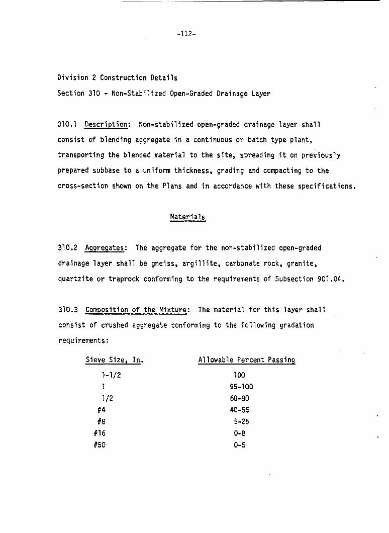
-112-
Division 2 Construction Details
Section 310 - Non-Stabil ized Open-Graded Drainage Layer
310.1 Description: Non-stabilized open-graded drainage layer shall
consist of blending aggregate in a continuous or batch type plant,
transporting the blended material to the site, spreading it on previously
prepared subbase to a uniform thickness, grading and compacting to the
cross-section shown on the Plans and in accordance with these specifications.
Materi a1 s
310.2 Aggregates: The aggregate f o r the non-stabilized open-graded
drainage layer shall be gneiss, argillite, carbonate rock, granite,
quartzite or traprock conforming to the requirements of Subsection 901.04.
310.3 Composition o f the Mixture: The material for this layer shall
consist of crushed aggregate conforming to the following gradation
requirements :
Sieve Size, In.
1-1/2 1 1 /2
#4 68 #16 t50
Allowable Percent Passing
1 00 95- 100 60-80 40-55 5-25 0- 8 0- 5
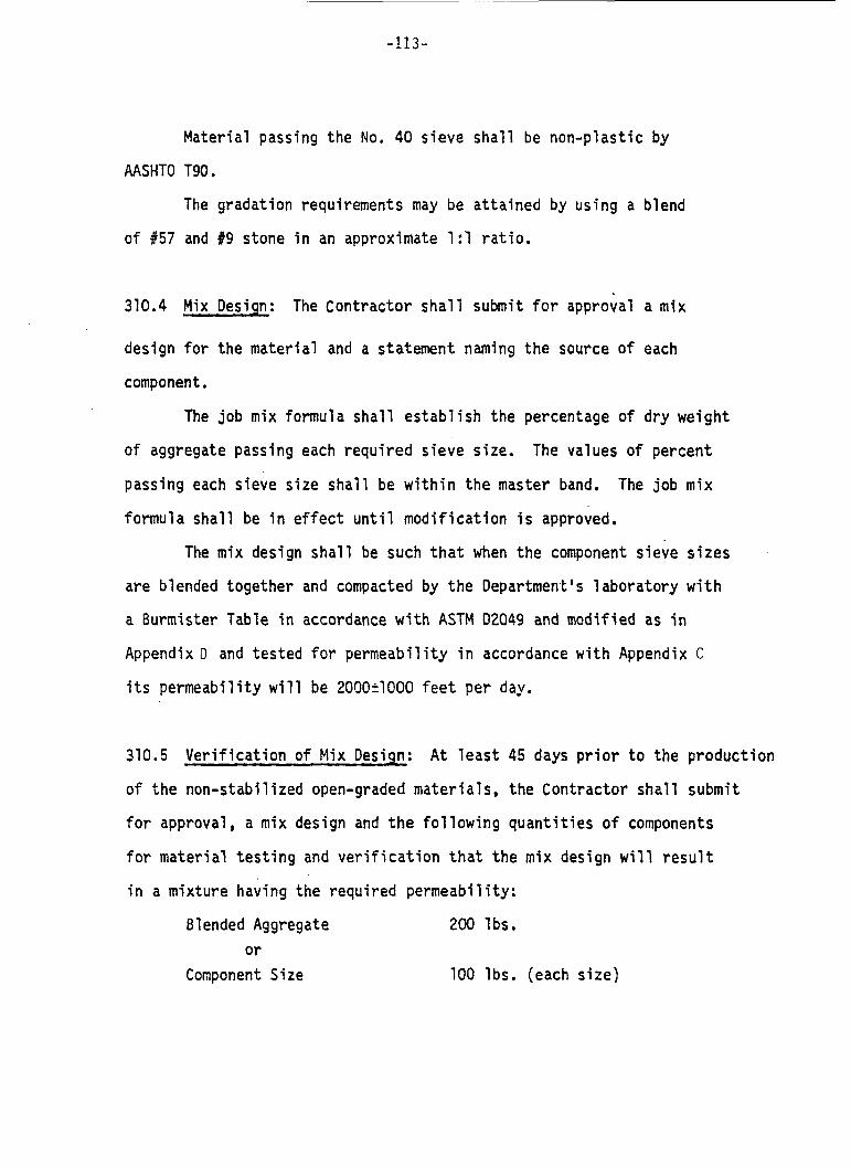
-113-
Material passing the No. 40 sieve shall be non-plastic by
AASHTO T90.
The gradation requirements may be attained by using a blend
of #57 and #9 stone in an approximate 1:l ratio.
310.4 Mix Design: The Contractor shall submit for approval a mix
design for the material and a statement naming the source of each
component.
The job mix formula shall establish the percentage of dry weight
of aggregate passing each required sieve size. The values of percent
passing each sieve size shall be within the master band. The job mix
formula shall be in effect until modification is approved,
The mix design shall be such that when the component sieve sizes
are blended together and compacted by the Department's laboratory with
a Burmister Table in accordance with ASTM 02049 and modified as in
Appendix D and tested for permeability in accordance with Appendix C
its permeability will be 2000+1000 feet per day.
310.5 Verification of Mix Design: At least 45 days prior to the production
of the non-stabilized open-graded materials, the Contractor shall submit
for approval, a mix design and the following quantities of components
for material testing and verification that the mix design will result
in a mixture having the required permeability:
Blended Aggregate or
Component Size
200 lbs.
100 lbs. (each size)
-114-
At the Department's option, verification of the mix design
be done on an annual basis provided the properties and proportions
the material do not change appreciably. If a job is the continuat
of work in progress during the previous construction season using
may
of
on
approved mix designs, and the Contractor verifies in writing that the
same source and character of materials are to be used, the Department
may waive the requirement for the design and verification of the new
mixes. The approved proportions of material will govern during the
progress of the work except that the Contractor may switch to another
previously approved mix design provided that the Engineer is notified at
least three days prior to the change.
any material shall be made until approved by the Engineer, based on the
No change in source or character o f
results of tests of the new design mixes or previously approved mix designs
using new material.
When unsatisfactory results for any specified characteristic of
the work rriake it necessary, the Contractor may establish a new mix design
for approval by the Engineer. In such instances, if the Contractor fails
to take corrective action, the Engineer reserves the right to require an
appropr i ate mixture adjustment . _.
310.6 Equipment: All equipment necessary to mix, transport, place, compact
and finish this layer shall be on the project and approved before work
will be permitted to start. Such equipment shall include a stationary
or portable continuous or batch type pugmill mixer equipped with batching
or metering devices for proportioning the blend or other approved units

-115-
capable of producing a blended material consistently meeting the gradation
requirements, a traveling plant such as a spreader box or asphalt laydown
machine capable of maintaining a uniform rate of travel while spreading
and of laying a lift of uniform consistency and thickness with proper
grade control, motor graders, pneumatic-tired or steel wheeled vibratory
rollers and such other equipment and tools as may be required to perform
the work in a satisfactory manner. The rollers shall conform to the
applicable requirements of Subsection 203.04.
Construction Requ i remen t s
310.7 Mixinq: The crushed aggregates shall be blended together in the
proper proportion as specified in the mix design.
Surge hoppers shall be used to supply aggregates for blending to
meet the required gradation. The blend shall be handled in such a manner
as to prevent contamination, degradation, and segregation.
310.8 Quality Control Testing: The conformance to the mix design
gradation will be determined on the basis of samples taken by the Engineer
at the construction site after placement and tested in accordance with
ASTM D421 and ASTM D422. Samples shall be taken at a rate of one sample
per every 150 cubic yards of drainage layer material.
have a quality control technician available at the plant to ensure that
the mix complies with the specified requirements.
The producer shall
-310.9 Transportation of Mixture: The blend material shall be hauled to
the site in vehicles that will prevent contamination, degradation and
segregation of the mixture. The material shall contain at least a 2%
moisture content to minimize segregation and degradation.
310.10 Preparation of Subbase or Base Course: Preparation o f subbase or
base course shall be performed in accordance with the applicable provisions
of Subsection 208.04 with following modifications.
the plant mixed aggregates the underlying course shall be covered with filter
cloth or a prime coat, moistened with water or stabilized with lime-fly ash
or portland cement as required in the Supplementary Specifications.
Prior to placement of
310.11 Spreadinq: Plant mixed aggregates should be delivered to the prepared
subbase or base course and spread uniformly as possible with a minimum of
manipulation to prevent segregation. The aggregate shall be placed in compacted
lifts not to exceed 4 inches. Spreader boxes or asphalt laydown machines with
automatic grade control shall be used.
310.12 Compaction, Shaping and Finishinq:
(a) Compaction. Fneumatic-tired rollers, or vibratory rollers conforming
to Subsection 205.04 shall be used to provide densification of the material.
One or more control strips shall be constructed at the beginning of the work
for the purpose of determining project compaction requirements. An add4 tional
control strip shall be constructed when a change is made in the type or source
of material, whenever a change occurs in the composition of the material from
the same source, or as directed. Each control strip shall consist of an area
of at least 400 square yards, and shall be of the same material 2s that
specified on the remainder of the project.

-117-
The control strip shall be compacted by a minimum of two passes
with the compaction equipment. A pass is defined as one passage of
one tire, compacting wheel, a vibratory unit over the entire surface
of the layer. Compaction shall continue until no appreciable increase
in density is obtained by additional passes without crushing of aggregate.
Density of the control strip shall be determined in accordance with
current provisions of AASHTO T238 Method A.
Upon completion of compaction, a minimum of ten tests will be
made at random locations to determine the average in-place density
of the control strip. The value of this average shall be the reference
maximum density for non-stabilized open-graded drainage layer material
from the same source used elsewhere on the project.
For the purpose of monitoring conformance to the compaction
requirements, the non-stabil ized open-graded drainage layer constructed
on the project shall be divided by the Engineer into lots consisting
of approximately 5,000 square yards or less of area.
The Engineer shall determine the average lot density of five
randomly selected locations in the lot.
not be less than 95% of the average reference maximum density in the
control strip.
recompacted by the Contractor at his expense and shall be resubmitted
for acceptance. The Engineer will determine the new average lot density.
If this density still fails to meet 95% of the average reference maximum
density, a new control strip will be constructed.
This average lot density shall
If a lot fails to meet this requirement it shall be
-118-
(b) Shaping and Finishinq. After the mixture has been compacted
the surface shall be shaped to the required cross-sections. Prior to
placement o f subsequent bituminous material , the non-stabil ized open- graded material shall be covered with a prime coat materials conforming
to Subsection 902.02 and 404.13.
310.13 Tolerances: The surface and thickness tolerances shall be as
stated in Subsection 302.09, except that 2 1/4" shall be used as the
surface tolerance, low areas shall be corrected by adding material,
grading and compacting. The thickness tolerances shall be 2 1/2".
Thin areas will be corrected by adding material, grading and compacting.
310.14 Maintenance Under Traffic: Maintenance shall be performed as
provided under Subsection 105.19.
course and until the Contractor has entirely covered the course with
pavement or other "sealing" layers, it shall be the Contractor's
responsibility to maintain drainage of the job site such that fine
material is not allowed to wash into and clog any part o f the drainage
system. Any area of the drainage course for which the drainage becomes
impaired during construction shall be reconstructed.
During the construction of the drainage
Only that equipment necessary for the construction of the next
higher pavement course shall be allowed on the drafnage layer.

-119-
Compensation
310.15 Rethod of Measurement: The non-stabil ized open-graded drainage
layer of the thickness shown on the Plans will be measured by the square
yard as determined from dimensions shown on the Plans or as established
by the Engineer. Non-stabi 1 ized open-graded drainage layer of variable
thickness will be measured by the cubic yard. The accepted quantity of
prime coat for which payment will be made will be the number of gallons
used, corrected to 6OoF, as determined by the temperature volume corrections
specified in Table 902-02, Subsection 902.02.
310.16 Basis of Payment: The accepted quantity of non-stabilized open-
graded drainage layer of the thickness specified on the Plans will be
paid for at the contract unit price per square yard complete in place,
as specified.
at the contract unit price per cubic yard.
Should variable thickness be specified, payment will be
Payment will be made under:
Item No. Pay Item Pay Unit
310.01 Non-Stabil ized Open-Graded Drainage
310.02 Non-Stabilized Open-Graded Drainage
404-04 Prime Coat Gal 1 on
Layer, 'I Thick Square Yard
Layer, Variable Thickness Cubic Yard
-120-
Division 2 Construction Details
Section 31 1 - Bituminous-Stabilized Open-Graded Drainage Layer
311.1 Description: Bituminous-stabilized open-graded drainage layer shall
consist of mixing the aggregate and bitumen in a continuous or batch type
plant, transporting the mixture to the site, spreading in on previously
prepared subbase to a uniform thickness, grading and compacting to the
cross-section shown on the Plans and in accordance with these specifications.
Materials
311.2 Aqgregate: The aggregate used in this construction shall be gneiss,
argillite, carbonate rock, granite, quartzite or traprock conforming to
the requirements of Subsection 901.04
311.3 Bituminous Naterial: The bituminous material shall be asphalt
cement conforming to the requirements of Subsection 902.01 for grade
AC-20 or AC-10 unless otherwise directed.
311.4 Anti-Stripping Agent: A heat-stable, anti-stripping additive
satisfactory to the Engineer shall be used. 8
311.5 Composition of the Mixture: The bituminous-stabil ized open-graded
material shall consist of bitumen, anti-stripping agent and aggregate
conforming to the following gradation requirements:

-121-
Sieve Size, In.
1 3/4 1 /2 3/8 84 88 916 9200
Allowable Percent Passing
1 00 95-100 85-100 60-90 15-25 2-10 2-5 *
*Add 2% (by weight of total mix) mineral filler.
The bitumen content shall be 3 f 1/2 percent by weight of dry
aggregate and mineral filler.
311.6 Mix Design: The Contractor shall submit for approval, a job mix
formula for the material and a statement naming the source of each
component.
The job mix formula for the mixture shall establish the percentage
of dry weight of aggregate passing each required sieve size and the
percentage of asphalt cement based upon the weight o f the total mix.
The values o f percent passing each size shall be within the master
gradation band of Subsection 311.5. The job mix formula shall be in
effect until modification is approved.
The mix design shall be such that when the component aggregates
are blended together, mixed with the specified amount of bitumen and
anti-stripping agent at a temperature of 25OoF and compacted at the
-122-
Department's laboratory with an Instron machine at 600 psi for carbonate
rock aggregate and 1000 psi for aggregates of all other stone t y p e
according to ASTM D1074 and Appendix D and tested for permeability
according to Appendix C its permeability will be 2000 * 1000 feet per day.
311.7 Verification o f Mix Design: A t least 45 days prior to the
production of the bituminous open-graded materials, the Coitractor shall
submit for approval, a mix design and the following quantities of components
for material testing and verification that the mix design will result in
a mixture having the required Permeability:
Blended Aggregate 200 lbs.
Bituminous Material 1 Gallon
Anti-Stripping Agent 1 Quart
Mineral Filler 25 lbs.
At the Department's option, verification o f the mix design may be
done on an annual basis provided the properties and proportions of the
material do not change appreciably. The approved proportions of material
will govern during the progress of the work except that the Contractor may
switch to another previously approved mix design provided that the Engineer
is notified at least one day prior to the change.
character of any material shall be made until approved by the Engineer,
No change in source or
based on the results o f tests of the new desfgn mixes or previously
approved mix designs using the new material.

-123-
When unsatisfactory results for any specified characteristic of
the work make it necessary, the Contractor may establish a new mix design
for approval by the Engineer. In such instances, if the Contractor
fails to take corrective action, the Engineer reserves the right to
require an appropriate mixture adjustment.
311.8 Equipment: All equipment necessary for the satisfactory performance
of this construction shall be on the project and approved before work
will be permitted to start.
the applicable requirements of Subsection 404.04 and 404.05 through 404.1 1
In general, the equipment shall conform to
(except that equipment for Marshall Method of Stability i s not necessary).
Construct i on Requirements
311.9 Limitations: The limitation prescribed in Subsection 404.12 shall
apply to this construction with the following additions:
The subbase or base course shall be checked and approved far
enough in advance of spreading the bituminous mixture to permit one day's
paving operation, exception being permitted at the discretion of the
Engineer. The laydown temperature will be 250 5 10 0 F.
311.10 Preparation of Subbase or Base Course: Preparation of the subbase,
or base course shall be performed in accordance with the applicable
provisions of Subsect ion 208.04.
-124-
371 .ll Preparation o f Bituminous Mixtures: The dried aggregates shall
be combined in the mixer in the amount of each fraction of aggregates
required to meet the job mix formula. The bituminous material shall
be weighed or metered and introduction into the mixer in the amount
speci f i ed.
The temperature of the mixture at the discharge from the plant
or surge and storage bins shall be maintained at a minimum of 15 degrees
above the laydown temperature. In no case shall the mixture temperature
exceed 30OoF.
311.12 Quality Assurance Testin9:
(a) Conformance to Job Mix Formula: The conformance to the job
mix formula will be determined on the basis of extraction samples taken
and tested at the mixing plant for manual batch plants and will be
determined by plant printout tickets and hot bin samples for fully
automated batch plants.
gradation band on any sieve or bitumen content, the producer shall
If samples are found to be outside the master
correct the deficiency before continuing production.
(b) Sampling and Testing: Sampling rates and testing for bitumen
content and conformance to gradation master band for manual and automated
batch plants and drum mix plants shall be in accordance with Subsection
903.03 with the following exceptions:
For process control purposes at manual batch plants, the producer's
quality control technician will sample and determine the gradation of
the aggregate components in the hot bin at least twice daily during
-125-
Continuous production of bituminous-stabil ized open-graded materials.
At drum mix plants this process control sampling and testing shall be
performed on material in the cold bins. The resulting bin gradations
shall be theoretically combined using the job mix formula bin pulls to
determine if changes are needed in the aggregate blending process.
Process changes shall be made by the producer to keep the mixture in
gradation control.
311.13 Transportation of Mixture: Transportation and delivery of the
mixture shall be as prescribed in Subsection 404.14.
311.14 Spreading and Finishing: Prior to placement of the bituminous
material, the underlying course shall be covered with filter cloth or
a prime coat, moistened with water or stabilized with lime-fly ash or
portland cement as required fn the Supplementary Specifications.
and finishing the mixture shall conform to the requirements of Subsection
404.15 except that paving full width of the roadway or paving in echelon
need not apply. The mixture shall be placed in compacted lifts not to
exceed 4 inches. No tack coat shall be placed between subsequent layers
or to the surface of the drainage layer prior to placement of subsequent
1 if ts of bituminous concrete pavement.
Spreading
311.15 Compaction: Three-wheeled or vibratory rollers conforming to
Subsection 404.09 shall be used to provide densification of the material.
-126-
The drainage layer shall be compacted in accordance with the
provisions of Subsection 404.16.
constructed at the beginning of the work for the purpose of determining
project compaction requirements. An additional control strip shall be
constructed when a change is made in the type or source o f material,
whenever a change occurs in the composition o f the material from the
same source, or as directed. Each control strip shall consist o f an
area of at least 400 square yards, and shall be of the same material
and thickness as that specified on the remainder o f the project.
One or more control strips shall be
The control strip shall be compacted by a minimum of two passes
with the compaction equipment. A pass is defined as one passage o f one
tire, compacting wheel, or vibratory unit over the entire surface of
the layer. Compaction shall continue until no appreciable increase in
density is obtained by additional passes. Density o f the control strip
shall be determined in accordance with current provisions o f AASHTO T238,
Method A.
Upon completion of compaction, a minimum o f ten tests will be made
at random locations to determine the average in-place density of the
control strip. The value of this average shall be the reference maximum
density for bituminous-stabilized open-graded drainage layer material
from the same source used elsewhere on the project.
For the purpose o f monitoring conformance to the compaction
requirements , the bi tuminous-stabi 1 ized open-graded drainage layer constructed on the project shall be divided by the Engineer into lots
consisting o f approximzrely 5,000 square yards or less of area.

-127-
The Engineer shall determine the average lot density of five
randomly selected locations in the lot.
shall not be less than 95% of the average reference maximum density
in the control strip.
a new control strip will be constructed.
This average lot density
If a lot fails to meet this requirement,
311.16 Tolerances:
(a) Surface Requirements: Shall be in accordance with Sectlon 304.13.
(b) Thickness: The thickness of the drainage layer shall conform
to the requirements of Subsection 404.19, except that payment adjustments
for deficient thickness shall not apply.
311.17 Maintenance Under Traffic: Gaintenance shall be performed as
provided under Subsection 105.19. During the construction of the drainage
course and until the Contractor has entirely covered the course with
pavement or other "sealing" layers, it shall be the Contractor's
responsibility to maintain drainage o f the job site such that fine material
is not allowed to wash into and clog any part of the drainage system.
Any area o f the drainage course for which the drainage becomes impaired
during construction, shall be reconstructed.
Only that equipment necessary for the construction of the next
higher pavement course shall be allowed on the drainage layer.
Compensation
371.18 Method of Measurement: The bituminous-stabilized open-graded
-128-
drainage layer shall be measured by the ton as determined by one of the
methods outlined in 404.21.
The accepted quantity of asphalt cement for which payment will be made
will be the product o f the asphalt content percentage in the approved job
mix formula and the tonnage of bftuminous concrete accepted and complete in
place.
will be the number of gallons used, corrected to 6OoF, as determined by the
The accepted quantity of prime coat for which payment will be made
temperature volume corrections specified in Table 902-2, Subsection 902.02,
311.19 Basis of Payment: The accepted quantity of bituminous-stabilized
open-graded drainage layer will be paid for at the contract unit price
per ton of mixture accepted and complete in place.
Payment for asphalt cement will be made for the quantity as above
determined measured in tons, at the price per ton bid for the item asphalt
cement in the proposal, which price and payement will be full compensation,
for furnishing all asphalt cement necessary to complete the item.
Payment for prime coat will be made for the quantity as above
determined, measured in gallons, at the contract unit price per gallon,
which price and payment will be full compensation, for furnishing and
applying prime coat as required.
Payment will be made under:
Item No. Pay Item Pay Unit
31 1.01 Bituminous-Stabilized Open-Graded Ton
404-02 Asphalt Cement Ton 404-04 Prime Coat Gal 1 on
Drainage Layer
-129-
Section 619 - Subsurface Drainage Collectors
619.01 Description. This work shall consist of the construction of
collector drains and outlets for subsurface drainage layers.
Materials
619.02 Materials. Materials shrl
Subsect ions :
Coarse Aggregate (for backfil
Porous Concrete Pipe
conform to the following
1 901.03
913.05
Corrugated Aluminum Alloy Underdrain Pipe 913.07
Corrugated Steel Underdrain Pipe 913.10
Plastic Drainage Pipe 913.12
Corrugated Aluminum A1 loy Culvert Pipe and Arches 913.06
Corrugated Steel Culvert Pipe and Arches 913.08
F i 1 t er F abr i c 919.06
Portland cement for plugging pipes shall conform to Section 914
for miscellaneous concrete.
-130-
Construction
619.03 Excavation and Backfill. Excavation and backfilling of trenches
shall be i n accordance w i t h Section 207 and the following:
Prior t o corrmencement of the trench excavation the subbase shall
have been stabi 1 i zed where designated, compacted and brought t o the
grade of the bottom of the open-graded drainage course as shown on
the plans. Materials from the trench excavation shall not be placed
on prepared subbase, nor sha l l i t be placed such that i t may interfere
w i t h any subsequent f i l t e r fabric placement, nor in such a manner
that it may be carried i n t o the trench backfill material.
The bottom w i d t h of the trench shall be of such w i d t h that a
6" of clearance is provided between the trench walls, and the sides o f
the pipe. Backfill of the collector pipes shall be w i t h ei ther 88 or
#57 coarse aggregate. Backfill for outlet pipes shall be w i t h material
excavated from the trench. All backfill for underdrain collector pipes
and outlet pipes shall conform t o Section 207 and the following:
Compaction shall begin w i t h the first 6 inches of material placed
over the pipe and shall then continue in 6 inch l i f t s for the remaining
backfill.
619.04 Placing Fi l ter Fabric. Filter fabric shall be placed to encapsu-
l a t e the ent i re trench prior t o placing plpe and backflll.
f i l t e r fabric w i t h a m i n i m u m wid th of 3'6" along the outer edge of the
trench shall be secured t o completely cover the t o p of the trench u n t i l
just prior t o constructing the drainage base course, a t which time the
f i l t e r fabric which covers the t o p of the trench shall be folded back.
A f l a p of
-131-
619.05 Layinq Pipe
Laying pipe shall be i n accordance w i t h Section 602 and the
f ol lowing:
Prior t o placing collector pipes, 3" of the chosen backfill
aggregate shall be placed and leveled t o conform w i t h the invert
elevations of the pipe.
Dead ends of the underdrain collectors shall be closed w i t h a
p i p e cap or plugged w i t h concrete.
After the pipe has been laid, t h e backfilling shall be done so
that the p ipe will not become damaged or displaced. Outlet pipes
shall be metal or concrete, non-perforated or non-porous pipes.
Compensation
619.06 Method of Measurement
Subsurface drainage collector and outlet pipes will be measured
by the linear f o o t along the centerline of the pipe.
619.07 Basis of Payment
Payment will be made under:
Contract Item Unit
Subsurface Drainage Col lector
Payment for outlet pipes will be made i n accordance w i t h Section 602.
Payment for rock excavation will be made i n accordance w i t h
Linear Foot
Section 207.
- . i
-132-
F A L L I N G HEAD P E R M E A B I L I T Y TEST
FOR
OPEN GRADED MATERIALS
-133-
Falling Head Permeability Test for Open-Graded Materials
1.0 Scope:
This method describes a test and related equipment for determining
the permeability of open-graded materials. This test can be used with
confidence on materials having a "K" value ranging from 100 to 20,000
feet /d ay .
2.0 General:
This test and equipment were developed to replace standard falling
head permeameters for use in testing open-graded materials. What resulted
from trial and error was a permeability test method which gives reasonable
repeatability and can be quickly assembled and disassembled - a desirable
feature where a large number o f samples are slated for testing.
The permeameter itself can be easily fabricated from comnonly
The dimensions suggested here were found to be available materials.
convenient for use with the materials available to the researcher, and
are given as a guide. It is necessary, however, to allow for a large
enough standpipe to enable an accurate determination o f the drop time.
It is important to realize that this test does not give the
exact "K" value for a given material.
make determination of an absolute "K" improbable.
head full-scale permeability tests substantiated the validity of this
test method. The "K" values obtained from this test are somewhat
conservative and hence should be applicable to engineering problems.
Head losses and other variables
However, constant
-134-
3.0 Apparatus: (see Figures dC1 and #C2)
3.1 Mold - A 8.5" high x 4" I.D. steel mold, with a #16 standard sieve
screen silver soldered to the bottom of the cylinder as shown in Figure #C2
is used with unstabilized open-graded material.
screen mesh is used for bituminous-stabilized samples.
The same mold without a
3.2 Standpipe - A 22" high x 4" I.D. plastic pipe with a 1/2" diameter
hole located 15.75" from the top and sealed with clear Plexiglas to
allow viewing of the water drop.
no view port is necessary.
If clear plastic is used for the standpipe,
3.3 Rubber Collar - A 4" wide x 16" long strip secured with two stainless
steel hose clamps of rubber join the mold and the plastic standpipe.
3.4 Water Supply - A source of clear water capable of supplying a minimum
of five to six gallons/minute should be available.
3.5 Stopwatch - A stopwatch capable o f measuring up to 30 minutes with
an accuracy of 2 0.1 second should be available.
3.6 Steel Ruler - A steel ruler with 1/100 o f an inch gradations should
be available.
4.0 Test Procedure:
4.1
compacted in the cylinder mold as described and shown in Appendix D. On
top of the mold the plastic standpipe should be secured by a rubber collar
as shown in Figure #C1.
placed on a surface such as the bottom of a sink, to provide first retention
The sample should weigh approximately 1600 grams and shall be properly
In this way, the assembled permeameter should be
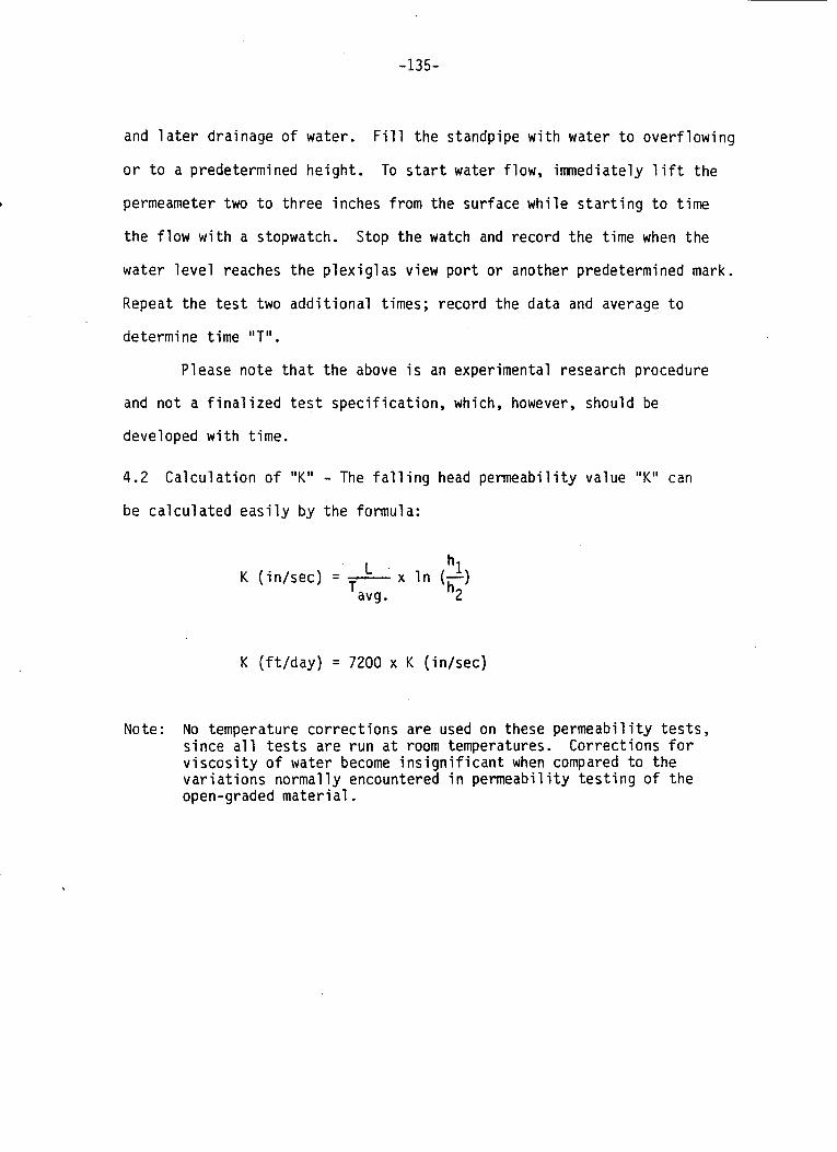
-135-
and l a t e r drainage o f water.
o r t o a predetermined height .
permeameter two t o three inches from the surface wh i l e s t a r t i n g t o t ime
the f l o w w i t h a stopwatch. Stop the watch and record the t ime when the
water l e v e l reaches the P l e x i g l a s view p o r t o r another predetermined mark.
Repeat t h e t e s t two a d d i t i o n a l times; record the data and average t o
determine t ime "T" .
F i l l t he standpipe w i t h water t o ove r f l ow ing
To s t a r t water flow, imnediate ly l i f t the
Please note t h a t t he above i s an experimental research procedure
and n o t a f i n a l i z e d t e s t s p e c i f i c a t i o n , which, however, should be
developed w i t h t ime.
4.2
be ca l cu la ted e a s i l y by the formula:
Ca lcu la t i on o f "K" - The f a l l i n g head permeabi l i ty value "K" can
hl
avg . h2 x I n (-) K ( i n / sec ) = - L
T
K ( f t / day ) = 7200 x K ( in /sec)
Note: No temperature co r rec t i ons are used on these pe rmeab i l i t y t e s t s , s ince a l l t e s t s are r u n a t room temperatures. Correct ions f o r v i s c o s i t y o f water become i n s i g n i f i c a n t when compared t o the v a r i a t i o n s normal ly encountered i n permeabi l i ty t e s t i n g o f the open-graded mate r i a1 .
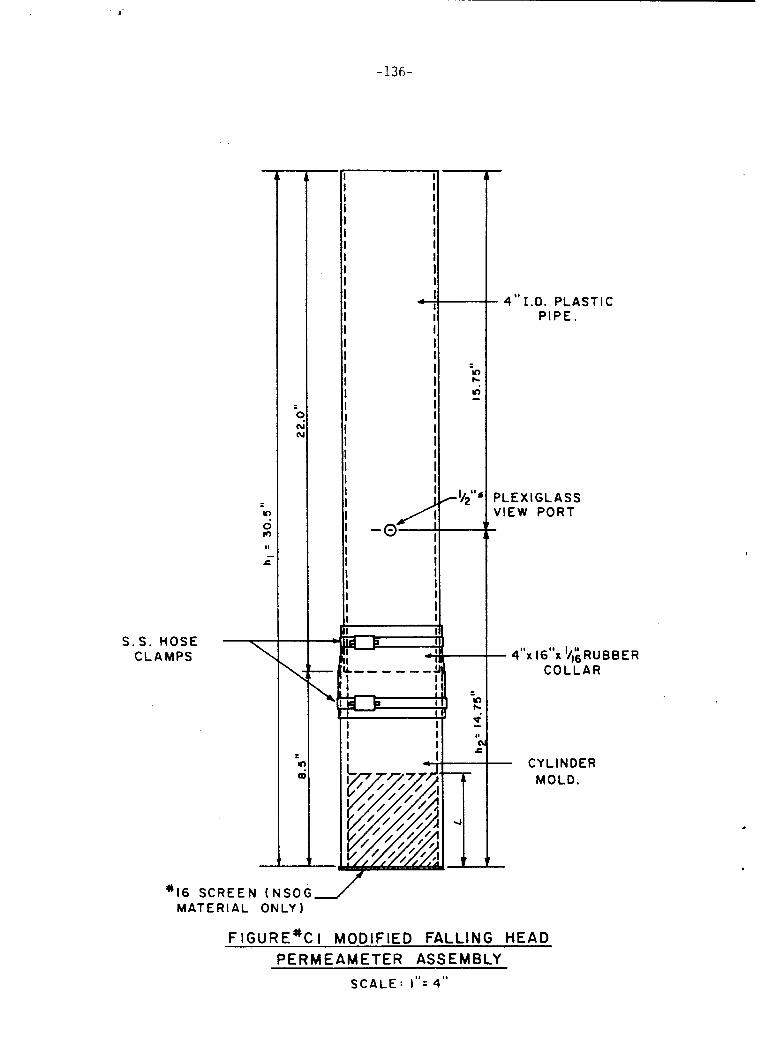
-136-
7 S . S . HOSE CLAMPS
C n n
-
\
Y
a
II I!
* 1 6 S C R E E N ( N S O G J MATERIAL ONLY)
- 4 " I . D . PLASTIC P IPE.
PLEXIGLASS V I E W PORT
- 4 ° K 16"x l ~ l ; ~ ~ ~ ~ ~ ~ COLLAR
- CYLINDER MOLD.
t
.
FIGURE% I MODIFIED FALLING HEAD P E R M E A M E T E R ASS E M B LY
SCALE: I " = 4"

- 1 3 7 -
I -0- I"\
( S I L V E R S O L D E R E D )
CYLINDER MOLD
\!f'.'.' P L E X I G L A S S V I E W P O R T
STANDPIPE ( I F CLEAR PLASTIC IS USED NO VIEW PORT NECESSARY)
F IGURE*C2 MODIFIED PERMEAMETER ASSESSORIES SCALE: 1 " = 4 "
-138-
LABORATORY COMPACTION TESTS AND EQUIPMENT FOR
BSOG AND NSOG MATERIALS
-139-
1 .o
perta
Compaction of Bi tuminous-Stabi 1 ized Open-Graded (BSOG) Materi a1 s
cope:
This method describes briefly var
ning to compaction of BSOG materia
First, a brief description o f the
ous equipment and procedures
apparatus used for laboratory
compaction of BSOG is provided, then a procedure for its use is detailed.
2.0 Apparatus: (see Figures # D 1 and #D2)
The apparatus for compaction of BSOG materials consists of the
following:
2.1 Mechanical Mixer - A Lancaster mixer of small capacity (generally
one sample of 5 lbs) is sufficient to blend the stone - AC mix.
2.2 Compaction Apparatus - These apparatus are described and illustrated in ASTM D1074 with the following modifications:
2.2.1 Mold - A 8.5" high x 4" I.D. steel mold as shown in Figure #D2
shall be used.
2.2.2 Top and bottom plungers - Plungers sha shown in Figure 802 and shall be made of mild
1 have the dimens
steel.
ons as
2.2.3 Half-ring Supports - Two 2 " high x 4" I.D. mild steel spacer-
supports are used prior to compacting the specimens.
2.2.4 Paper discs - 4 inch in diameter should be available.
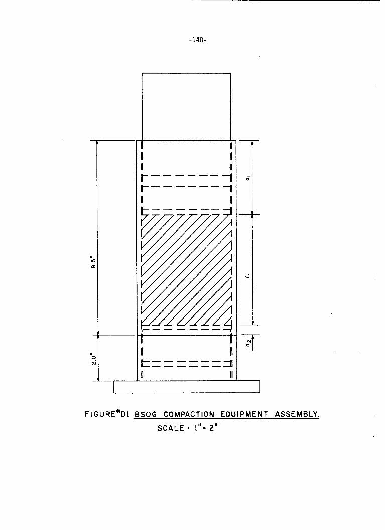
-140-
U II II II r------ 3 I I
n II
R II I II 7-
1 F1GURE"DI BSOG COMPACTION EQUIPMENT ASSEMBLY.
SCALE : I " = 2"
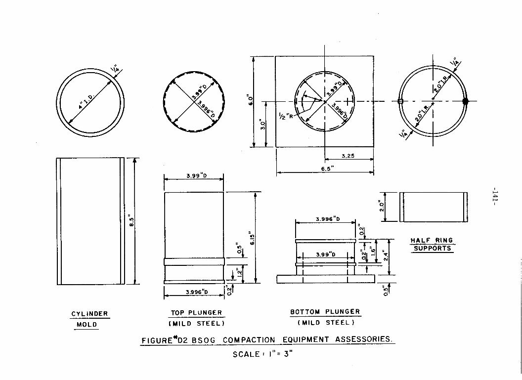
CYLINDER
MOLD
b
I ~ 3.996"D ~
TOP PLUNGER
( M I L D STEEL)
6.5" *
HALF RING SUPPORTS
BOTTOM PLUNGER
( M I L D S T E E L )
F I G U R E%2 8 S 0 Ci COM PACTION EOU I PM ENT ASSESSORIES.
S C A L E : I " = 3"
-142-
3.0 Compact i o n Procedure :
3.1 Sample Compaction - The sample should be approximately 1600 grams
and should be compacted t o the d e n s i t y expected i n actual f i e l d condi t ions.
3.1.1 Weighing of M i x Components - Weigh ou t predetermined p o r t i o n s of
BSOG mix.
3.1.2 Heating of Mix Components - Heat a l l ma te r ia l s t o be blended and
t h e mix ing u t e n s i l s t o appropr ia te temperatures t o assure compaction o f
t h e m i x i n the mold a t 25OoF as fo l l ows :
a. Stone t o 325OF
b. A.C. t o 275OF
c.
I f t he BSOG m i x has a l ready been batched (e.g., samples taken from
Mixing u t e n s i l s and bowls t o 325OF
t h e f i e l d ) , heat t he m i x t o 30OoF.
3.2
Lancaster mixer f o r two minutes o r u n t i l stone i s f u l l y covered by A.C.,
Mix ing Time - The A.C. and stone m i x are blended and mixed by a
whichever comes f i r s t .
3.3 Assemble Mold - L i g h t l y o i l mold and plunger components.
r i n g supports and mold on bottom plunger.
o f mold.
Place h a l f
I n s e r t paper d i s c i n t o bottom
3.4
step i s done i n three stages ( t h r e e equal l i f t s ) .
mix i s rodded 25 t imes using a spa tu la (10 t imes on the surface o f the
F i l l i n g o f Sample Mold - The m i x i s then poured i n t o the mold. This
A f t e r each stage, t he
l a y e r and 15 times around t h e stone-mold i n t e r f a c e ) .
on sample and i n s e r t t op plunger.
Place a pap* d i s c
- 143 -
3 . 5
Universal testing machine or similar device capable of producing accurate
molding pressures up to 2000 psi or 25,000 lbs. total load. Compactive
pressures should be limited to those required in the Appendix B specifi-
cation.
variability of subsequent permeability tests.
Laboratory Compaction Effort - Begin compaction with an Instron
Excessive pressures will crush the aggregates and result in
Compaction should follow
procedures out1 ined in ASTM D1074.
4.0 Density Determination:
4.1 Sample Weight - Weigh each mold and record the weight (W,) to the
nearest gram. After the sample has been placed in the mold, re-weigh
and record WT to the nearest gram. The weight of the sample is
w = WT - WM. 4.2 Sample Dimens
and Table #D1.
on - Determine the sample dimension from Figure #D1
Table #D1, a Compaction and Permeability Data Sheet, can be used
as a handy calculation and recording device for both compaction of
BSOG mixes and permeability tests of all OG materials.
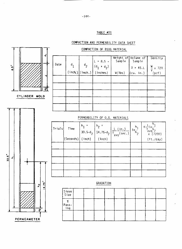
T r i a l s Time
(Seconds)
TABLE b D 1
COMPACTION AND PERMEABIL ITY DATA SHEET
COMPACTION OF BSOG MATERIAL - n Weight o f Sample
Dens i ty Volume o f Sample
v = 45.L
( cu . i n . ) inch.) ( inches) + W ( l b s )
I CYLINDER MOLD
I I PERMEABIL ITY OF O.G. MATERIALS -
h = 1 30. 5-d2
( inch)
h = 2
14. 75-d2
( i nch )
K = L - I n - - hl
Tavqh? x (7200)
( f t . /day)
hl
h2 I n - -
I I
-0-
- GRADATION
PERMEAMETER
-145-
Compaction o f
Non-Stabi l ized Open-Graded (NSOG) Ma te r ia l s
1.0 Scope:
This method covers the t e s t and r e l a t e d equipment developed t o
compact u n s t a b i l i z e d open-graded mate r ia l s (NSOG) t o f i e l d dens i t i es ,
p e r m e a b i l i t y t e s t a l l ow ing both a v i s u a l inspect ion o f t he sample and a *
on the specimen.
2.0 General:
Achieving maximum dens i t y w i t h cohesionless so
ma te r ia l s presents specia l compaction problems. S t a t
1s such as NSOG
c pressures do
l i t t l e t o rearrange p a r t i c l e s and achieve proper compaction; standard
drop hammers (such as P roc to r ' s o r Marsha l l ' s ) achieve more uniform
compaction than s t a t i c pressure bu t a l low t h e m a t e r i a l t o " f l u f f " and
loosen around the hammer. To overcome these d i f f i c u l t i e s Burmister
developed a v i b r a t o r y method o f compaction us ing a s p e c i f i e d surcharge
on t he sample. The Burmister method i s incorporated i n t o ASTM s p e c i f i -
granular s o i l s w i t h l i t t l e c a t i o n (ASTM D-2049), as a method o f t e s t i n g
o r no cohesion, f o r maximum densi ty.
To study NSOG ma te r ia l s the Burmister
were modif ied. Bas ica l l y , the v i b r a t i n g tab
unchanged. However, t o a l low observat ion o f
s equipment and t e s t methods
e s p e c i f i e d by ASTM remains
the compacted sample, t h e
d e n s i t y mold was constructed o f c l e a r P lex ig las instead o f s t e e l , and
fastened t o the v i b r a t i n g t a b l e w i t h plywood r e t a i n e r s , threaded rods and
wing nuts as shown i n Figures #D3 and #D4.
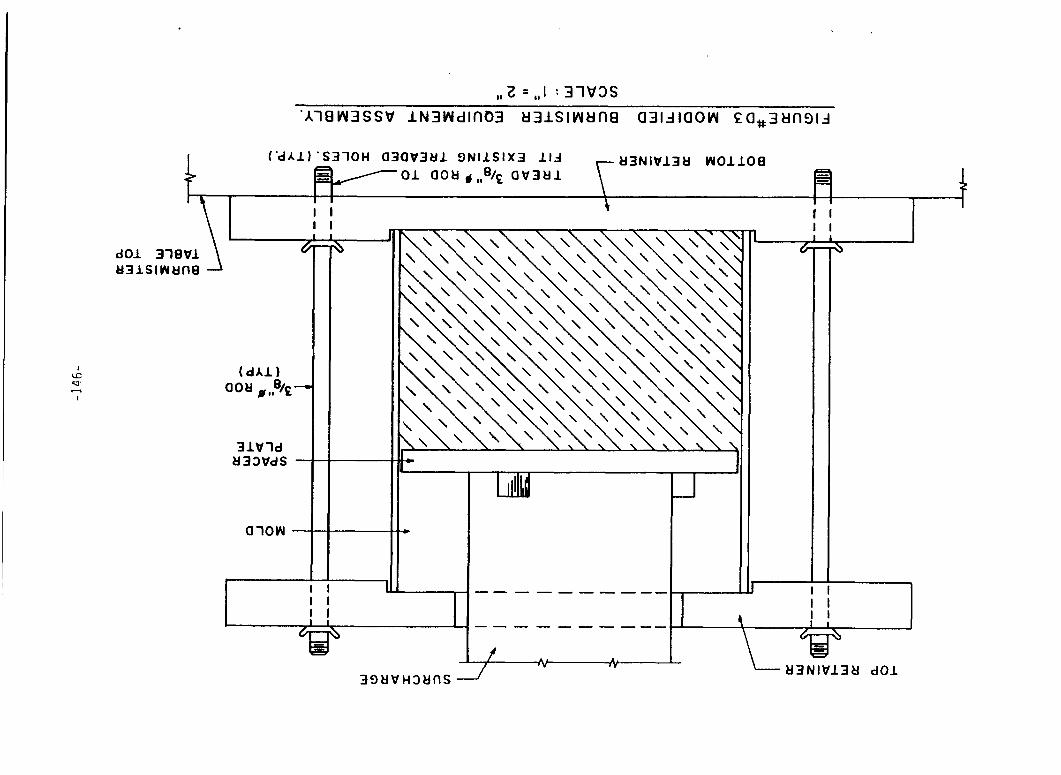
, , 2 =,,I :3 lW3S
31Wld U 3 3 W d S
1
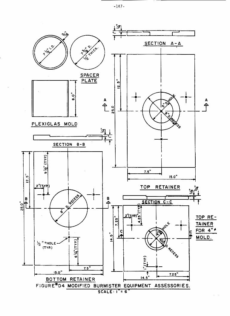
-147-
C U r
SPACER PLATE
A
t r a
SECTION A - A 1
PLEXIGLAS MOLD 3u I I 1 1 - -
I SECTION B - B
I b
*I I
I "I I
7.5 I' I
b 15.0" I- I
BOTTOM RETAINER
I
I- I
, 7.5" 4 15.0"
3 Ll I "Q *)
TOP RETAINER
I I I I
t 7.2 5" 14.5'' I-
~
F l G U R E"D4 MODIFIED BURMISTER EQUIPMENT ASSESSORIES. S C A L E : I " = 6 "
-148-
3.3
and
t a b
The
#D4) - In order
e, plywood reta
bottom retainer
3.0 Apparatus: (see Figures #D3 and #D4)
3.1 Vibrating Table - A Burmister vibratory table meeting ASTM D-2049
specification provides the required vibrational energies.
3.2
3/16" thick.
(lack of segregation) of the samples.
15 pounds of uncompacted NSOG materials.
size appears t o be essential i n obtaining a representative density result .
Plexiglas Mold - A Plexiglas cylinder 8" high x 7.5 'I diameter and
This mold i s used t o study b o t h the density and the integrity
The mold i s capable of holding
This apparently large sample
Plywood Retainers and Threaded Rods and Wing Nuts (see Figures #D3
t o prevent the mold from shifting on the vibrating
ners are f i t t ed over and under the Plexiglas mold.
has a 1/4" deep recess slightly larger t h a n the O . D .
of the Plexiglas cylinder.
prevent lateral movement during vibrating.
The mold i s placed into this recess t o
The t o p retainer i s similar t o the bottom with the exception of
the 5" diameter hole t h r o u g h which the surcharge i s placed.
1/4" deep recess i s routed o u t t o restrain the movement o f the mold.
The entire assembly i s locked t o the vibrating base by three 3/8" diameter
threaded rods with wing nuts.
determine
plates. Please note t h a t the above research procedure i s offered as a
guide.
3.4 Spacer Plate - A plywood disc 7-3/8" in diameter and 1 / 2 " thick i s
placed in the mold on t h e sample.
from sinking i n t o the samples a t an uneven rate d u r i n g compaction.
Aga in , a
Location of predrilled holes on the table
placement of 3/8" diameter rods and the size of the retainer
The spacer prevents the surcharge
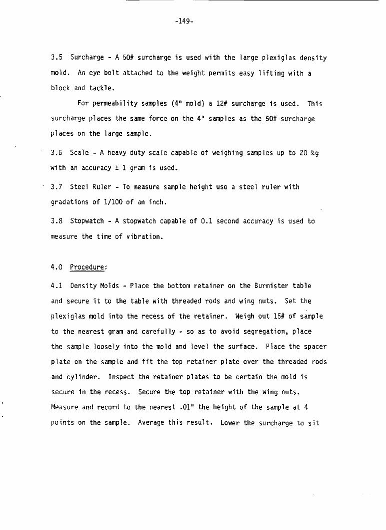
-149-
3.5 Surcharge - A 50# surcharge i s used w i t h the l a r g e P l e x i g l a s d e n s i t y
mold. An eye b o l t attached t o the weight permi ts easy l i f t i n g w i t h a
b lock and tack le .
For pe rmeab i l i t y samples (4" mold) a 12# surcharge i s used. This
surcharge places the same force on the 4" samples as the 50# surcharge
p laces on t h e l a r g e sample.
3.6
w i t h an accuracy f 1 gram i s used.
Scale - A heavy duty scale capable o f weighing samples up t o 20 kg
3.7
gradat ions o f 1/100 o f an inch.
Steel Ruler - To measure sample he igh t use a s t e e l r u l e r w i t h
3.8 Stopwatch - A stopwatch capable of 0.1 second accuracy i s used t o
measure the t ime o f v ib ra t i on .
4.0 Procedure:
4.1
and secure i t t o the t a b l e w i t h threaded rods and wing nuts.
Densi ty Molds - Place the bottom r e t a i n e r on t h e Burmister t a b l e
Set t h e
P l e x i g l a s mold i n t o the recess o f t h e r e t a i n e r .
t o the nearest gram and c a r e f u l l y - so as t o avoid segregation, p lace
t h e sample l o o s e l y i n t o the mold and l e v e l the surface. Place the spacer
p l a t e on t h e sample and f i t the top r e t a i n e r p l a t e over the threaded rods
and c y l i n d e r .
secure i n the recess.
Measure and record t o the nearest .01" t h e he igh t o f t h e sample a t 4
p o i n t s on the sample.
Weigh o u t 15# of sample
Inspect the r e t a i n e r p l a t e s t o be c e r t a i n the mold i s
Secure the top r e t a i n e r w i t h the wing nuts.
Average t h i s r e s u l t . Lower the surcharge t o s i t
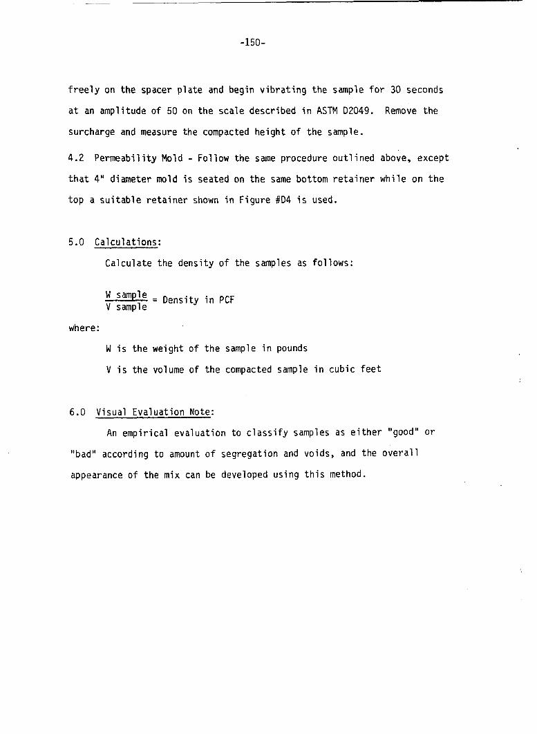
-150-
freely on the spacer plate and begin vibrating the sample for 30 seconds
at an amplitude of 50 on the scale described in ASTM 02049.
surcharge and measure the compacted height of the sample.
Remove the
4.2 Permeability Mold - Follow the same procedure outlined above, except that 4" diameter mold is seated on the same bottom retainer while on the
top a suitable retainer shown in Figure #D4 is used.
5.0 Calculations:
Calculate the density of the samples as follows:
W sam le 2 = Density in PCF V sample
where:
W is the weight of the sample in pounds
V is the volume of the compacted sample in cubic feet
6.0 Visual Evaluation Note:
An empirical evaluation to classify samples as either "good" or
''bad" according to amount of segregation and voids, and the overall
appearance o f the mix can be developed using this method.