implementing ospf - cisco · implementing ospf...
TRANSCRIPT
Implementing OSPF
Open Shortest Path First (OSPF) is an Interior Gateway Protocol (IGP) developed by the OSPF workinggroup of the Internet Engineering Task Force (IETF). Designed expressly for IP networks, OSPF supportsIP subnetting and tagging of externally derived routing information. OSPF also allows packet authenticationwhen sending and receiving packets.
OSPF Version 3 (OSPFv3) expands on OSPF Version 2, providing support for IPv6 routing prefixes.
This module describes the concepts and tasks you need to implement both versions of OSPF on your CiscoNCS 6000 Series Router . The term “OSPF" implies both versions of the routing protocol, unless otherwisenoted.
For more information about OSPF on Cisco IOS XR software and complete descriptions of the OSPFcommands listed in this module, see the Related Documents, on page 80 section of this module. To locatedocumentation for other commands that might appear during execution of a configuration task, searchonline in the
Note
Feature History for Implementing OSPF
This feature was introduced.Release 5.0.0
• Prerequisites for Implementing OSPF , page 2
• Information About Implementing OSPF , page 2
• How to Implement OSPF , page 25
• Configuring IP Fast Reroute Loop-free Alternate, page 70
• Configuration Examples for Implementing OSPF , page 74
• Where to Go Next, page 79
• Additional References, page 80
Routing Configuration Guide for Cisco NCS 6000 Series Routers, Release 5.2.x 1
Prerequisites for Implementing OSPFThe following are prerequisites for implementing OSPF on Cisco IOS XR software:
• Youmust be in a user group associated with a task group that includes the proper task IDs. The commandreference guides include the task IDs required for each command. If you suspect user group assignmentis preventing you from using a command, contact your AAA administrator for assistance.
• Configuration tasks for OSPFv3 assume that you are familiar with IPv6 addressing and basicconfiguration. See the Implementing Network Stack IPv4 and IPv6 on module of the IP Addresses andServices Configuration Guide for Cisco NCS 6000 Series Routers for information on IPv6 routing andaddressing.
• Before you enable OSPFv3 on an interface, you must perform the following tasks:
◦Complete the OSPF network strategy and planning for your IPv6 network. For example, you mustdecide whether multiple areas are required.
◦Enable IPv6 on the interface.
• Configuring authentication (IP Security) is an optional task. If you choose to configure authentication,you must first decide whether to configure plain text or Message Digest 5 (MD5) authentication, andwhether the authentication applies to an entire area or specific interfaces.
Information About Implementing OSPFTo implement OSPF you need to understand the following concepts:
OSPF Functional OverviewOSPF is a routing protocol for IP. It is a link-state protocol, as opposed to a distance-vector protocol. Alink-state protocol makes its routing decisions based on the states of the links that connect source and destinationmachines. The state of the link is a description of that interface and its relationship to its neighboring networkingdevices. The interface information includes the IP address of the interface, network mask, type of network towhich it is connected, routers connected to that network, and so on. This information is propagated in varioustypes of link-state advertisements (LSAs).
A router stores the collection of received LSA data in a link-state database. This database includes LSA datafor the links of the router. The contents of the database, when subjected to the Dijkstra algorithm, extract datato create an OSPF routing table. The difference between the database and the routing table is that the databasecontains a complete collection of raw data; the routing table contains a list of shortest paths to knowndestinations through specific router interface ports.
OSPF is the IGP of choice because it scales to large networks. It uses areas to partition the network into moremanageable sizes and to introduce hierarchy in the network. A router is attached to one or more areas in anetwork. All of the networking devices in an area maintain the same complete database information about thelink states in their area only. They do not know about all link states in the network. The agreement of thedatabase information among the routers in the area is called convergence.
Routing Configuration Guide for Cisco NCS 6000 Series Routers, Release 5.2.x2
Implementing OSPFPrerequisites for Implementing OSPF
At the intradomain level, OSPF can import routes learned using Intermediate System-to-Intermediate System(IS-IS). OSPF routes can also be exported into IS-IS. At the interdomain level, OSPF can import routes learnedusing Border Gateway Protocol (BGP). OSPF routes can be exported into BGP.
Unlike Routing Information Protocol (RIP), OSPF does not provide periodic routing updates. On becomingneighbors, OSPF routers establish an adjacency by exchanging and synchronizing their databases. After that,only changed routing information is propagated. Every router in an area advertises the costs and states of itslinks, sending this information in an LSA. This state information is sent to all OSPF neighbors one hop away.All the OSPF neighbors, in turn, send the state information unchanged. This flooding process continues untilall devices in the area have the same link-state database.
To determine the best route to a destination, the software sums all of the costs of the links in a route to adestination. After each router has received routing information from the other networking devices, it runs theshortest path first (SPF) algorithm to calculate the best path to each destination network in the database.
The networking devices running OSPF detect topological changes in the network, flood link-state updates toneighbors, and quickly converge on a new view of the topology. Each OSPF router in the network soon hasthe same topological view again. OSPF allows multiple equal-cost paths to the same destination. Since alllink-state information is flooded and used in the SPF calculation, multiple equal cost paths can be computedand used for routing.
On broadcast and nonbroadcast multiaccess (NBMA) networks, the designated router (DR) or backup DRperforms the LSA flooding. On point-to-point networks, flooding simply exits an interface directly to aneighbor.
OSPF runs directly on top of IP; it does not use TCP or User Datagram Protocol (UDP). OSPF performs itsown error correction by means of checksums in its packet header and LSAs.
In OSPFv3, the fundamental concepts are the same as OSPF Version 2, except that support is added for theincreased address size of IPv6. New LSA types are created to carry IPv6 addresses and prefixes, and theprotocol runs on an individual link basis rather than on an individual IP-subnet basis.
OSPF typically requires coordination among many internal routers: Area Border Routers (ABRs), which arerouters attached to multiple areas, and Autonomous System Border Routers (ASBRs) that export reroutesfrom other sources (for example, IS-IS, BGP, or static routes) into the OSPF topology. At a minimum,OSPF-based routers or access servers can be configured with all default parameter values, no authentication,and interfaces assigned to areas. If you intend to customize your environment, you must ensure coordinatedconfigurations of all routers.
Key Features Supported in the Cisco IOS XR Software OSPF ImplementationThe Cisco IOS XR Software implementation of OSPF conforms to the OSPF Version 2 and OSPF Version3 specifications detailed in the Internet RFC 2328 and RFC 2740, respectively.
The following key features are supported in the Cisco IOS XR Software implementation:
• Hierarchy—CLI hierarchy is supported.
• Inheritance—CLI inheritance is supported.
• Stub areas—Definition of stub areas is supported.
• NSF—Nonstop forwarding is supported.
• SPF throttling—Shortest path first throttling feature is supported.
• LSA throttling—LSA throttling feature is supported.
Routing Configuration Guide for Cisco NCS 6000 Series Routers, Release 5.2.x 3
Implementing OSPFKey Features Supported in the Cisco IOS XR Software OSPF Implementation
• Fast convergence—SPF and LSA throttle timers are set, configuring fast convergence. The OSPF LSAthrottling feature provides a dynamic mechanism to slow down LSA updates in OSPF during networkinstability. LSA throttling also allows faster OSPF convergence by providing LSA rate limiting inmilliseconds.
• Route redistribution—Routes learned using any IP routing protocol can be redistributed into any otherIP routing protocol.
• Authentication—Plain text and MD5 authentication among neighboring routers within an area issupported.
• Routing interface parameters—Configurable parameters supported include interface output cost,retransmission interval, interface transmit delay, router priority, router “dead” and hello intervals, andauthentication key.
• Virtual links—Virtual links are supported.
• Not-so-stubby area (NSSA)—RFC 1587 is supported.
• OSPF over demand circuit—RFC 1793 is supported.
Comparison of Cisco IOS XR Software OSPFv3 and OSPFv2Much of the OSPFv3 protocol is the same as in OSPFv2. OSPFv3 is described in RFC 2740.
The key differences between the Cisco IOS XR Software OSPFv3 and OSPFv2 protocols are as follows:
• OSPFv3 expands on OSPFv2 to provide support for IPv6 routing prefixes and the larger size of IPv6addresses.
• When using an NBMA interface in OSPFv3, users must manually configure the router with the list ofneighbors. Neighboring routers are identified by the link local address of the attached interface of theneighbor.
• Unlike in OSPFv2, multiple OSPFv3 processes can be run on a link.
• LSAs in OSPFv3 are expressed as “prefix and prefix length” instead of “address and mask.”
• The router ID is a 32-bit number with no relationship to an IPv6 address.
OSPF Hierarchical CLI and CLI InheritanceCisco IOS XR Software introduces new OSPF configuration fundamentals consisting of hierarchical CLI andCLI inheritance.
Hierarchical CLI is the grouping of related network component information at defined hierarchical levels suchas at the router, area, and interface levels. Hierarchical CLI allows for easier configuration, maintenance, andtroubleshooting of OSPF configurations. When configuration commands are displayed together in theirhierarchical context, visual inspections are simplified. Hierarchical CLI is intrinsic for CLI inheritance to besupported.
With CLI inheritance support, you need not explicitly configure a parameter for an area or interface. InCisco IOS XR Software, the parameters of interfaces in the same area can be exclusively configured with asingle command, or parameter values can be inherited from a higher hierarchical level—such as from the areaconfiguration level or the router ospf configuration levels.
Routing Configuration Guide for Cisco NCS 6000 Series Routers, Release 5.2.x4
Implementing OSPFComparison of Cisco IOS XR Software OSPFv3 and OSPFv2
For example, the hello interval value for an interface is determined by this precedence “IF” statement:
If the hello interval command is configured at the interface configuration level, then use the interface configuredvalue, else
If the hello interval command is configured at the area configuration level, then use the area configured value,else
If the hello interval command is configured at the router ospf configuration level, then use the router ospfconfigured value, else
Use the default value of the command.
Understanding hierarchical CLI and CLI inheritance saves you considerable configuration time. SeeConfiguring Authentication at Different Hierarchical Levels for OSPFVersion 2, on page 33 to understandhow to implement these fundamentals. In addition, Cisco IOS XR Software examples are provided inConfiguration Examples for Implementing OSPF , on page 74.
Tip
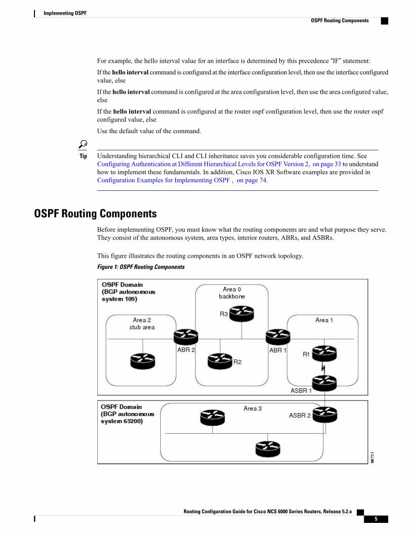
OSPF Routing ComponentsBefore implementing OSPF, you must know what the routing components are and what purpose they serve.They consist of the autonomous system, area types, interior routers, ABRs, and ASBRs.
This figure illustrates the routing components in an OSPF network topology.Figure 1: OSPF Routing Components
Routing Configuration Guide for Cisco NCS 6000 Series Routers, Release 5.2.x 5
Implementing OSPFOSPF Routing Components
Autonomous SystemsThe autonomous system is a collection of networks, under the same administrative control, that share routinginformation with each other. An autonomous system is also referred to as a routing domain. Figure 1: OSPFRouting Components, on page 5 shows two autonomous systems: 109 and 65200. An autonomous systemcan consist of one or more OSPF areas.
AreasAreas allow the subdivision of an autonomous system into smaller, more manageable networks or sets ofadjacent networks. As shown in Figure 1: OSPF Routing Components, on page 5, autonomous system 109consists of three areas: Area 0, Area 1, and Area 2.
OSPF hides the topology of an area from the rest of the autonomous system. The network topology for anarea is visible only to routers inside that area. When OSPF routing is within an area, it is called intra-arearouting. This routing limits the amount of link-state information flood into the network, reducing routingtraffic. It also reduces the size of the topology information in each router, conserving processing and memoryrequirements in each router.
Also, the routers within an area cannot see the detailed network topology outside the area. Because of thisrestricted view of topological information, you can control traffic flow between areas and reduce routingtraffic when the entire autonomous system is a single routing domain.
Backbone Area
A backbone area is responsible for distributing routing information between multiple areas of an autonomoussystem. OSPF routing occurring outside of an area is called interarea routing.
The backbone itself has all properties of an area. It consists of ABRs, routers, and networks only on thebackbone. As shown in Figure 1: OSPF Routing Components, on page 5, Area 0 is an OSPF backbone area.Any OSPF backbone area has a reserved area ID of 0.0.0.0.
Stub Area
A stub area is an area that does not accept route advertisements or detailed network information external tothe area. A stub area typically has only one router that interfaces the area to the rest of the autonomous system.The stub ABR advertises a single default route to external destinations into the stub area. Routers within astub area use this route for destinations outside the area and the autonomous system. This relationship conservesLSA database space that would otherwise be used to store external LSAs flooded into the area. In Figure 1:OSPF Routing Components, on page 5, Area 2 is a stub area that is reached only through ABR 2. Area 0cannot be a stub area.
Not-so-Stubby Area
A Not-so-Stubby Area (NSSA) is similar to the stub area. NSSA does not flood Type 5 external LSAs fromthe core into the area, but can import autonomous system external routes in a limited fashion within the area.
NSSA allows importing of Type 7 autonomous system external routes within an NSSA area by redistribution.These Type 7 LSAs are translated into Type 5 LSAs by NSSAABRs, which are flooded throughout the wholerouting domain. Summarization and filtering are supported during the translation.
Routing Configuration Guide for Cisco NCS 6000 Series Routers, Release 5.2.x6
Implementing OSPFOSPF Routing Components
Use NSSA to simplify administration if you are a network administrator that must connect a central site usingOSPF to a remote site that is using a different routing protocol.
Before NSSA, the connection between the corporate site border router and remote router could not be run asan OSPF stub area because routes for the remote site could not be redistributed into a stub area, and tworouting protocols needed to be maintained. A simple protocol like RIP was usually run and handled theredistribution.With NSSA, you can extend OSPF to cover the remote connection by defining the area betweenthe corporate router and remote router as an NSSA. Area 0 cannot be an NSSA.
RoutersThe OSPF network is composed of ABRs, ASBRs, and interior routers.
Area Border Routers
An area border routers (ABR) is a router with multiple interfaces that connect directly to networks in two ormore areas. An ABR runs a separate copy of the OSPF algorithm and maintains separate routing data for eacharea that is attached to, including the backbone area. ABRs also send configuration summaries for their attachedareas to the backbone area, which then distributes this information to other OSPF areas in the autonomoussystem. In Figure 1: OSPF Routing Components, on page 5, there are two ABRs. ABR 1 interfaces Area1 to the backbone area. ABR 2 interfaces the backbone Area 0 to Area 2, a stub area.
Autonomous System Boundary Routers (ASBR)
An autonomous system boundary router (ASBR) provides connectivity from one autonomous system toanother system. ASBRs exchange their autonomous system routing information with boundary routers inother autonomous systems. Every router inside an autonomous system knows how to reach the boundaryrouters for its autonomous system.
ASBRs can import external routing information from other protocols like BGP and redistribute them asAS-external (ASE) Type 5 LSAs to the OSPF network. If the Cisco IOS XR router is an ASBR, you canconfigure it to advertise VIP addresses for content as autonomous system external routes. In this way, ASBRsflood information about external networks to routers within the OSPF network.
ASBR routes can be advertised as a Type 1 or Type 2 ASE. The difference between Type 1 and Type 2 ishow the cost is calculated. For a Type 2 ASE, only the external cost (metric) is considered when multiplepaths to the same destination are compared. For a Type 1 ASE, the combination of the external cost and costto reach the ASBR is used. Type 2 external cost is the default and is always more costly than an OSPF routeand used only if no OSPF route exists.
Interior Routers
An interior router (such as R1 in Figure 1: OSPF Routing Components, on page 5) is attached to one area(for example, all the interfaces reside in the same area).
OSPF Process and Router IDAn OSPF process is a logical routing entity running OSPF in a physical router. This logical routing entityshould not be confused with the logical routing feature that allows a system administrator (known as theCisco IOS XR Software Owner) to partition the physical box into separate routers.
Routing Configuration Guide for Cisco NCS 6000 Series Routers, Release 5.2.x 7
Implementing OSPFOSPF Process and Router ID
A physical router can run multiple OSPF processes, although the only reason to do so would be to connecttwo or more OSPF domains. Each process has its own link-state database. The routes in the routing table arecalculated from the link-state database. One OSPF process does not share routes with another OSPF processunless the routes are redistributed.
Each OSPF process is identified by a router ID. The router IDmust be unique across the entire routing domain.OSPF obtains a router ID from the following sources, in order of decreasing preference:
• By default, when the OSPF process initializes, it checks if there is a router-id in the checkpointingdatabase.
• The 32-bit numeric value specified by the OSPF router-id command in router configuration mode. (Thisvalue can be any 32-bit value. It is not restricted to the IPv4 addresses assigned to interfaces on thisrouter, and need not be a routable IPv4 address.)
• The ITAL selected router-id.
• The primary IPv4 address of an interface over which this OSPF process is running. The first interfaceaddress in the OSPF interface is selected.
We recommend that the router ID be set by the router-id command in router configuration mode. SeparateOSPF processes could share the same router ID, in which case they cannot reside in the same OSPF routingdomain.
Supported OSPF Network TypesOSPF classifies different media into the following types of networks:
• NBMA networks
• Point-to-point networks (POS)
• Broadcast networks (Gigabit Ethernet)
• Point-to-multipoint
You can configure your Cisco IOS XR network as either a broadcast or an NBMA network.
Route Authentication Methods for OSPFOSPF Version 2 supports two types of authentication: plain text authentication and MD5 authentication. Bydefault, no authentication is enabled (referred to as null authentication in RFC 2178).
OSPV Version 3 supports all types of authentication except key rollover.
Plain Text AuthenticationPlain text authentication (also known as Type 1 authentication) uses a password that travels on the physicalmedium and is easily visible to someone that does not have access permission and could use the password toinfiltrate a network. Therefore, plain text authentication does not provide security. It might protect against afaulty implementation of OSPF or a misconfigured OSPF interface trying to send erroneous OSPF packets.
Routing Configuration Guide for Cisco NCS 6000 Series Routers, Release 5.2.x8
Implementing OSPFSupported OSPF Network Types
MD5 AuthenticationMD5 authentication provides a means of security. No password travels on the physical medium. Instead, therouter uses MD5 to produce a message digest of the OSPF packet plus the key, which is sent on the physicalmedium. Using MD5 authentication prevents a router from accepting unauthorized or deliberately maliciousrouting updates, which could compromise your network security by diverting your traffic.
MD5 authentication supports multiple keys, requiring that a key number be associated with a key.Note
See OSPF Authentication Message Digest Management, on page 22.
Authentication StrategiesAuthentication can be specified for an entire process or area, or on an interface or a virtual link. An interfaceor virtual link can be configured for only one type of authentication, not both. Authentication configured foran interface or virtual link overrides authentication configured for the area or process.
If you intend for all interfaces in an area to use the same type of authentication, you can configure fewercommands if you use the authentication command in the area configuration submode (and specify themessage-digest keyword if you want the entire area to use MD5 authentication). This strategy requires fewercommands than specifying authentication for each interface.
Key RolloverTo support the changing of an MD5 key in an operational network without disrupting OSPF adjacencies (andhence the topology), a key rollover mechanism is supported. As a network administrator configures the newkey into the multiple networking devices that communicate, some time exists when different devices are usingboth a new key and an old key. If an interface is configured with a new key, the software sends two copiesof the same packet, each authenticated by the old key and new key. The software tracks which devices startusing the new key, and the software stops sending duplicate packets after it detects that all of its neighborsare using the new key. The software then discards the old key. The network administrator must then removethe old key from each the configuration file of each router.
Neighbors and Adjacency for OSPFRouters that share a segment (Layer 2 link between two interfaces) become neighbors on that segment. OSPFuses the hello protocol as a neighbor discovery and keep alivemechanism. The hello protocol involves receivingand periodically sending hello packets out each interface. The hello packets list all known OSPF neighborson the interface. Routers become neighbors when they see themselves listed in the hello packet of the neighbor.After two routers are neighbors, they may proceed to exchange and synchronize their databases, which createsan adjacency. On broadcast and NBMA networks all neighboring routers have an adjacency.
Designated Router (DR) for OSPFOn point-to-point and point-to-multipoint networks, the Cisco IOS XR software floods routing updates toimmediate neighbors. No DR or backup DR (BDR) exists; all routing information is flooded to each router.
Routing Configuration Guide for Cisco NCS 6000 Series Routers, Release 5.2.x 9
Implementing OSPFNeighbors and Adjacency for OSPF
On broadcast or NBMA segments only, OSPF minimizes the amount of information being exchanged on asegment by choosing one router to be a DR and one router to be a BDR. Thus, the routers on the segmenthave a central point of contact for information exchange. Instead of each router exchanging routing updateswith every other router on the segment, each router exchanges information with the DR and BDR. The DRand BDR relay the information to the other routers.
The software looks at the priority of the routers on the segment to determine which routers are the DR andBDR. The router with the highest priority is elected the DR. If there is a tie, then the router with the higherrouter ID takes precedence. After the DR is elected, the BDR is elected the same way. A router with a routerpriority set to zero is ineligible to become the DR or BDR.
Default Route for OSPFType 5 (ASE) LSAs are generated and flooded to all areas except stub areas. For the routers in a stub area tobe able to route packets to destinations outside the stub area, a default route is injected by the ABR attachedto the stub area.
The cost of the default route is 1 (default) or is determined by the value specified in the default-cost command.
Link-State Advertisement Types for OSPF Version 2Each of the following LSA types has a different purpose:
• Router LSA (Type 1)—Describes the links that the router has within a single area, and the cost of eachlink. These LSAs are flooded within an area only. The LSA indicates if the router can compute pathsbased on quality of service (QoS), whether it is an ABR or ASBR, and if it is one end of a virtual link.Type 1 LSAs are also used to advertise stub networks.
• Network LSA (Type 2)—Describes the link state and cost information for all routers attached to amultiaccess network segment. This LSA lists all the routers that have interfaces attached to the networksegment. It is the job of the designated router of a network segment to generate and track the contentsof this LSA.
• Summary LSA for ABRs (Type 3)—Advertises internal networks to routers in other areas (interarearoutes). Type 3 LSAs may represent a single network or a set of networks aggregated into one prefix.Only ABRs generate summary LSAs.
• Summary LSA for ASBRs (Type 4)—Advertises an ASBR and the cost to reach it. Routers that aretrying to reach an external network use these advertisements to determine the best path to the next hop.ABRs generate Type 4 LSAs.
• Autonomous system external LSA (Type 5)—Redistributes routes from another autonomous system,usually from a different routing protocol into OSPF.
• Autonomous system external LSA (Type 7)—Provides for carrying external route information withinan NSSA. Type 7 LSAsmay be originated by and advertised throughout an NSSA. NSSAs do not receiveor originate Type 5 LSAs. Type 7 LSAs are advertised only within a single NSSA. They are not floodedinto the backbone area or into any other area by border routers.
• Intra-area-prefix LSAs (Type 9)—A router can originate multiple intra-area-prefix LSAs for every routeror transit network, each with a unique link-state ID. The link-state ID for each intra-area-prefix LSAdescribes its association to either the router LSA or network LSA and contains prefixes for stub andtransit networks.
Routing Configuration Guide for Cisco NCS 6000 Series Routers, Release 5.2.x10
Implementing OSPFDefault Route for OSPF
• Area local scope (Type 10)—Opaque LSAs are not flooded past the borders of their associated area.
• Link-state (Type 11)—The LSA is flooded throughout the AS. The flooding scope of Type 11 LSAsare equivalent to the flooding scope of AS-external (Type 5) LSAs. Similar to Type 5 LSAs, the LSAis rejected if a Type 11 opaque LSA is received in a stub area from a neighboring router within the stubarea. Type 11 opaque LSAs have these attributes:
◦LSAs are flooded throughout all transit areas.
◦LSAs are not flooded into stub areas from the backbone.
◦LSAs are not originated by routers into their connected stub areas.
Link-State Advertisement Types for OSPFv3Each of the following LSA types has a different purpose:
• Router LSA (Type 1)—Describes the link state and costs of a the router link to the area. These LSAsare flooded within an area only. The LSA indicates whether the router is an ABR or ASBR and if it isone end of a virtual link. Type 1 LSAs are also used to advertise stub networks. In OSPFv3, these LSAshave no address information and are network protocol independent. In OSPFv3, router interfaceinformation may be spread across multiple router LSAs. Receivers must concatenate all router LSAsoriginated by a given router before running the SPF calculation.
• Network LSA (Type 2)—Describes the link state and cost information for all routers attached to amultiaccess network segment. This LSA lists all OSPF routers that have interfaces attached to the networksegment. Only the elected designated router for the network segment can generate and track the networkLSA for the segment. In OSPFv3, network LSAs have no address information and arenetwork-protocol-independent.
• Interarea-prefix LSA for ABRs (Type 3)—Advertises internal networks to routers in other areas (interarearoutes). Type 3 LSAs may represent a single network or set of networks aggregated into one prefix.Only ABRs generate Type 3 LSAs. In OSPFv3, addresses for these LSAs are expressed as “prefix andprefix length” instead of “address and mask.” The default route is expressed as a prefix with length 0.
• Interarea-router LSA for ASBRs (Type 4)—Advertises an ASBR and the cost to reach it. Routers thatare trying to reach an external network use these advertisements to determine the best path to the nexthop. ABRs generate Type 4 LSAs.
• Autonomous system external LSA (Type 5)—Redistributes routes from another autonomous system,usually from a different routing protocol into OSPF. In OSPFv3, addresses for these LSAs are expressedas “prefix and prefix length” instead of “address and mask.” The default route is expressed as a prefixwith length 0.
• Autonomous system external LSA (Type 7)—Provides for carrying external route information withinan NSSA. Type 7 LSAsmay be originated by and advertised throughout an NSSA. NSSAs do not receiveor originate Type 5 LSAs. Type 7 LSAs are advertised only within a single NSSA. They are not floodedinto the backbone area or into any other area by border routers.
• Link LSA (Type 8)—Has link-local flooding scope and is never flooded beyond the link with which itis associated. Link LSAs provide the link-local address of the router to all other routers attached to thelink or network segment, inform other routers attached to the link of a list of IPv6 prefixes to associatewith the link, and allow the router to assert a collection of Options bits to associate with the networkLSA that is originated for the link.
Routing Configuration Guide for Cisco NCS 6000 Series Routers, Release 5.2.x 11
Implementing OSPFLink-State Advertisement Types for OSPFv3
• Intra-area-prefix LSAs (Type 9)—A router can originate multiple intra-area-prefix LSAs for every routeror transit network, each with a unique link-state ID. The link-state ID for each intra-area-prefix LSAdescribes its association to either the router LSA or network LSA and contains prefixes for stub andtransit networks.
An address prefix occurs in almost all newly defined LSAs. The prefix is represented by three fields: PrefixLength, Prefix Options, and Address Prefix. In OSPFv3, addresses for these LSAs are expressed as “prefixand prefix length” instead of “address and mask.” The default route is expressed as a prefix with length 0.Inter-area-prefix and intra-area-prefix LSAs carry all IPv6 prefix information that, in IPv4, is included inrouter LSAs and network LSAs. TheOptions field in certain LSAs (router LSAs, network LSAs, interarea-routerLSAs, and link LSAs) has been expanded to 24 bits to provide support for OSPF in IPv6.
In OSPFv3, the sole function of link-state ID in interarea-prefix LSAs, interarea-router LSAs, and autonomoussystem external LSAs is to identify individual pieces of the link-state database. All addresses or router IDsthat are expressed by the link-state ID in OSPF Version 2 are carried in the body of the LSA in OSPFv3.
Virtual Link and Transit Area for OSPFIn OSPF, routing information from all areas is first summarized to the backbone area by ABRs. The sameABRs, in turn, propagate such received information to their attached areas. Such hierarchical distribution ofrouting information requires that all areas be connected to the backbone area (Area 0). Occasions might existfor which an area must be defined, but it cannot be physically connected to Area 0. Examples of such anoccasion might be if your company makes a new acquisition that includes an OSPF area, or if Area 0 itselfis partitioned.
In the case in which an area cannot be connected to Area 0, you must configure a virtual link between thatarea and Area 0. The two endpoints of a virtual link are ABRs, and the virtual link must be configured in bothrouters. The common nonbackbone area to which the two routers belong is called a transit area. A virtual linkspecifies the transit area and the router ID of the other virtual endpoint (the other ABR).
A virtual link cannot be configured through a stub area or NSSA.
This figure illustrates a virtual link from Area 3 to Area 0.
Routing Configuration Guide for Cisco NCS 6000 Series Routers, Release 5.2.x12
Implementing OSPFVirtual Link and Transit Area for OSPF
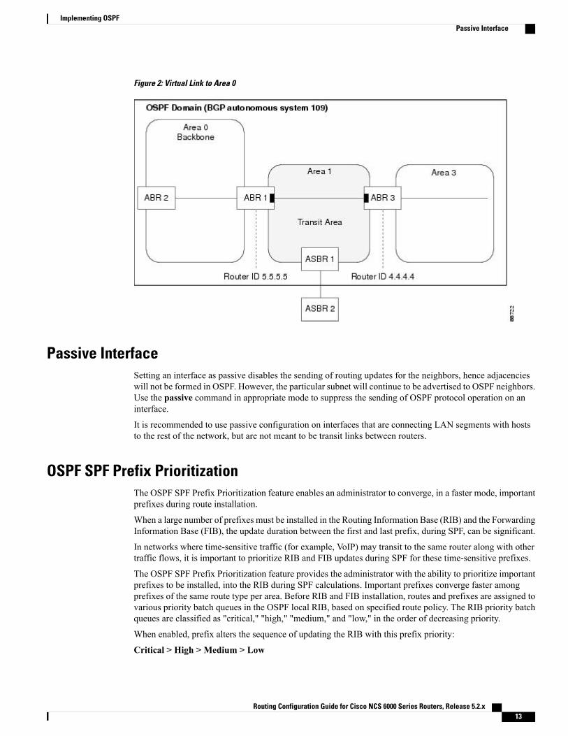
Figure 2: Virtual Link to Area 0
Passive InterfaceSetting an interface as passive disables the sending of routing updates for the neighbors, hence adjacencieswill not be formed in OSPF. However, the particular subnet will continue to be advertised to OSPF neighbors.Use the passive command in appropriate mode to suppress the sending of OSPF protocol operation on aninterface.
It is recommended to use passive configuration on interfaces that are connecting LAN segments with hoststo the rest of the network, but are not meant to be transit links between routers.
OSPF SPF Prefix PrioritizationThe OSPF SPF Prefix Prioritization feature enables an administrator to converge, in a faster mode, importantprefixes during route installation.
When a large number of prefixes must be installed in the Routing Information Base (RIB) and the ForwardingInformation Base (FIB), the update duration between the first and last prefix, during SPF, can be significant.
In networks where time-sensitive traffic (for example, VoIP) may transit to the same router along with othertraffic flows, it is important to prioritize RIB and FIB updates during SPF for these time-sensitive prefixes.
The OSPF SPF Prefix Prioritization feature provides the administrator with the ability to prioritize importantprefixes to be installed, into the RIB during SPF calculations. Important prefixes converge faster amongprefixes of the same route type per area. Before RIB and FIB installation, routes and prefixes are assigned tovarious priority batch queues in the OSPF local RIB, based on specified route policy. The RIB priority batchqueues are classified as "critical," "high," "medium," and "low," in the order of decreasing priority.
When enabled, prefix alters the sequence of updating the RIB with this prefix priority:
Critical > High > Medium > Low
Routing Configuration Guide for Cisco NCS 6000 Series Routers, Release 5.2.x 13
Implementing OSPFPassive Interface
As soon as prefix priority is configured, /32 prefixes are no longer preferred by default; they are placed in thelow-priority queue, if they are not matched with higher-priority policies. Route policies must be devised toretain /32s in the higher-priority queues (high-priority or medium-priority queues).
Priority is specified using route policy, which can be matched based on IP addresses or route tags. DuringSPF, a prefix is checked against the specified route policy and is assigned to the appropriate RIB batch priorityqueue.
These are examples of this scenario:
• If only high-priority route policy is specified, and no route policy is configured for a medium priority:
◦Permitted prefixes are assigned to a high-priority queue.
◦Unmatched prefixes, including /32s, are placed in a low-priority queue.
• If both high-priority and medium-priority route policies are specified, and no maps are specified forcritical priority:
◦Permitted prefixes matching high-priority route policy are assigned to a high-priority queue.
◦Permitted prefixes matching medium-priority route policy are placed in a medium-priority queue.
◦Unmatched prefixes, including /32s, are moved to a low-priority queue.
• If both critical-priority and high-priority route policies are specified, and no maps are specified formedium priority:
◦Permitted prefixes matching critical-priority route policy are assigned to a critical-priority queue.
◦Permitted prefixes matching high-priority route policy are assigned to a high-priority queue.
◦Unmatched prefixes, including /32s, are placed in a low-priority queue.
• If only medium-priority route policy is specified and no maps are specified for high priority or criticalpriority:
◦Permitted prefixes matchingmedium-priority route policy are assigned to a medium-priority queue.
◦Unmatched prefixes, including /32s, are placed in a low-priority queue.
Use the [no] spf prefix-priority route-policy rpl command to prioritize OSPF prefix installation intothe global RIB during SPF.
SPF prefix prioritization is disabled by default. In disabled mode, /32 prefixes are installed into theglobal RIB, before other prefixes. If SPF prioritization is enabled, routes are matched against theroute-policy criteria and are assigned to the appropriate priority queue based on the SPF priority set.Unmatched prefixes, including /32s, are placed in the low-priority queue.
If all /32s are desired in the high-priority queue or medium-priority queue, configure this single routemap:
prefix-set ospf-medium-prefixes0.0.0.0/0 ge 32end-set
Routing Configuration Guide for Cisco NCS 6000 Series Routers, Release 5.2.x14
Implementing OSPFOSPF SPF Prefix Prioritization
Route Redistribution for OSPFRedistribution allows different routing protocols to exchange routing information. This technique can be usedto allow connectivity to span multiple routing protocols. It is important to remember that the redistributecommand controls redistribution into an OSPF process and not from OSPF. See Configuration Examples forImplementing OSPF , on page 74 for an example of route redistribution for OSPF.
OSPF Shortest Path First ThrottlingOSPF SPF throttling makes it possible to configure SPF scheduling in millisecond intervals and to potentiallydelay SPF calculations during network instability. SPF is scheduled to calculate the Shortest Path Tree (SPT)when there is a change in topology. One SPF run may include multiple topology change events.
The interval at which the SPF calculations occur is chosen dynamically and based on the frequency of topologychanges in the network. The chosen interval is within the boundary of the user-specified value ranges. Ifnetwork topology is unstable, SPF throttling calculates SPF scheduling intervals to be longer until topologybecomes stable.
SPF calculations occur at the interval set by the timers throttle spf command. The wait interval indicates theamount of time to wait until the next SPF calculation occurs. Each wait interval after that calculation is twiceas long as the previous interval until the interval reaches the maximum wait time specified.
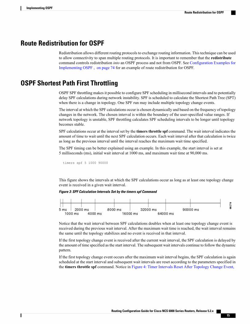
The SPF timing can be better explained using an example. In this example, the start interval is set at5 milliseconds (ms), initial wait interval at 1000 ms, and maximum wait time at 90,000 ms.
timers spf 5 1000 90000
This figure shows the intervals at which the SPF calculations occur as long as at least one topology changeevent is received in a given wait interval.Figure 3: SPF Calculation Intervals Set by the timers spf Command
Notice that the wait interval between SPF calculations doubles when at least one topology change event isreceived during the previous wait interval. After the maximum wait time is reached, the wait interval remainsthe same until the topology stabilizes and no event is received in that interval.
If the first topology change event is received after the current wait interval, the SPF calculation is delayed bythe amount of time specified as the start interval. The subsequent wait intervals continue to follow the dynamicpattern.
If the first topology change event occurs after the maximum wait interval begins, the SPF calculation is againscheduled at the start interval and subsequent wait intervals are reset according to the parameters specified inthe timers throttle spf command. Notice in Figure 4: Timer Intervals Reset After Topology Change Event,
Routing Configuration Guide for Cisco NCS 6000 Series Routers, Release 5.2.x 15
Implementing OSPFRoute Redistribution for OSPF
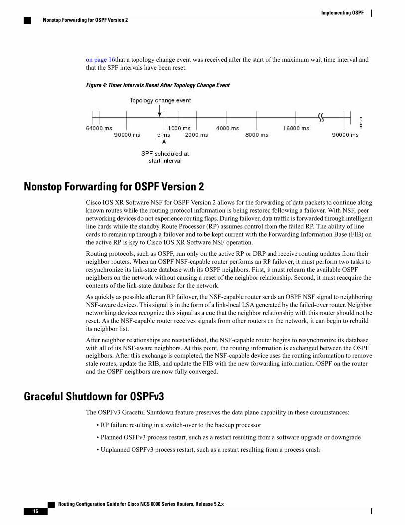
on page 16that a topology change event was received after the start of the maximum wait time interval andthat the SPF intervals have been reset.
Figure 4: Timer Intervals Reset After Topology Change Event
Nonstop Forwarding for OSPF Version 2Cisco IOS XR Software NSF for OSPF Version 2 allows for the forwarding of data packets to continue alongknown routes while the routing protocol information is being restored following a failover. With NSF, peernetworking devices do not experience routing flaps. During failover, data traffic is forwarded through intelligentline cards while the standby Route Processor (RP) assumes control from the failed RP. The ability of linecards to remain up through a failover and to be kept current with the Forwarding Information Base (FIB) onthe active RP is key to Cisco IOS XR Software NSF operation.
Routing protocols, such as OSPF, run only on the active RP or DRP and receive routing updates from theirneighbor routers. When an OSPF NSF-capable router performs an RP failover, it must perform two tasks toresynchronize its link-state database with its OSPF neighbors. First, it must relearn the available OSPFneighbors on the network without causing a reset of the neighbor relationship. Second, it must reacquire thecontents of the link-state database for the network.
As quickly as possible after an RP failover, the NSF-capable router sends an OSPF NSF signal to neighboringNSF-aware devices. This signal is in the form of a link-local LSA generated by the failed-over router. Neighbornetworking devices recognize this signal as a cue that the neighbor relationship with this router should not bereset. As the NSF-capable router receives signals from other routers on the network, it can begin to rebuildits neighbor list.
After neighbor relationships are reestablished, the NSF-capable router begins to resynchronize its databasewith all of its NSF-aware neighbors. At this point, the routing information is exchanged between the OSPFneighbors. After this exchange is completed, the NSF-capable device uses the routing information to removestale routes, update the RIB, and update the FIB with the new forwarding information. OSPF on the routerand the OSPF neighbors are now fully converged.
Graceful Shutdown for OSPFv3The OSPFv3 Graceful Shutdown feature preserves the data plane capability in these circumstances:
• RP failure resulting in a switch-over to the backup processor
• Planned OSPFv3 process restart, such as a restart resulting from a software upgrade or downgrade
• Unplanned OSPFv3 process restart, such as a restart resulting from a process crash
Routing Configuration Guide for Cisco NCS 6000 Series Routers, Release 5.2.x16
Implementing OSPFNonstop Forwarding for OSPF Version 2
In addition, OSPFv3 will unilaterally shutdown and enter the exited state when a critical memory event,indicating the processor is critically low on available memory, is received from the sysmon watch dog process.
This feature supports nonstop data forwarding on established routes while the OSPFv3 routing protocol restarts.Therefore, this feature enhances high availability of IPv6 forwarding.
Modes of Graceful Restart OperationThe operational modes that a router can be in for this feature are restart mode, helper mode, and protocolshutdown mode.
Restart Mode
When the OSPFv3 process starts up, it determines whether it must attempt a graceful restart. The determinationis based on whether graceful restart was previously enabled. (OSPFv3 does not attempt a graceful restart uponthe first-time startup of the router.) When OSPFv3 graceful restart is enabled, it changes the purge timer inthe RIB to a nonzero value. See Configuring OSPFv3 Graceful Restart, on page 54,for descriptions of howto enable and configure graceful restart.
During a graceful restart, the router does not populate OSPFv3 routes in the RIB. It tries to bring up fulladjacencies with the fully adjacent neighbors that OSPFv3 had before the restart. Eventually, the OSPFv3process indicates to the RIB that it has converged, either for the purpose of terminating the graceful restart(for any reason) or because it has completed the graceful restart.
The following are general details about restart mode. More detailed information on behavior and certainrestrictions and requirements appears in Graceful Restart Requirements and Restrictions, on page 19 section.
• If OSPFv3 attempts a restart too soon after the most recent restart, the OSPFv3 process is most likelycrashing repeatedly, so the new graceful restart stops running. To control the period between allowablegraceful restarts, use the graceful-restart interval command.
• When OSFPv3 starts a graceful restart with the first interface that comes up, a timer starts running tolimit the duration (or lifetime) of the graceful restart. You can configure this period with thegraceful-restart lifetime command. On each interface that comes up, a grace LSA (Type 11) is floodedto indicate to the neighboring routers that this router is attempting graceful restart. The neighbors enterinto helper mode.
• The designated router and backup designated router check of the hello packet received from the restartingneighbor is bypassed, because it might not be valid.
Helper Mode
Helper mode is enabled by default. When a (helper) router receives a grace LSA (Type 11) from a router thatis attempting a graceful restart, the following events occur:
• If helper mode has been disabled through the graceful-restart helper disable command, the routerdrops the LSA packet.
• If helper mode is enabled, the router enters helper mode if all of the following conditions are met:
◦The local router itself is not attempting a graceful restart.
◦The local (helping) router has full adjacency with the sending neighbor.
◦The value of lsage (link state age) in the received LSA is less than the requested grace period.
Routing Configuration Guide for Cisco NCS 6000 Series Routers, Release 5.2.x 17
Implementing OSPFGraceful Shutdown for OSPFv3

◦The sender of the grace LSA is the same as the originator of the grace LSA.
• Upon entering helper mode, a router performs its helper function for a specific period of time. This timeperiod is the lifetime value from the router that is in restart mode—minus the value of lsage in thereceived grace LSA. If the graceful restart succeeds in time, the helper’s timer is stopped before it expires.If the helper’s timer does expire, the adjacency to the restarting router is brought down, and normalOSPFv3 functionality resumes.
• The dead timer is not honored by the router that is in helper mode.
• A router in helper mode ceases to perform the helper function in any of the following cases:
◦The helper router is able to bring up a FULL adjacency with the restarting router.
◦The local timer for the helper function expires.
Protocol Shutdown Mode
In this mode the OSPFv3 operation is completely disabled. This is accomplished by flushing self-originatedlink state advertisements (LSAs), immediately bringing down local OSPFv3-supported interfaces, and clearingthe Link State Database (LSDB). The non-local LSDB entries are removed by OSPFv3, These are not flooded(MaxAged).
The protocol shutdown mode can be invoked either manually through the protocol shutdown command thatdisables the protocol instance or when the OSPFv3 process runs out of memory. These events occur whenprotocol shut down is performed:
• The local Router LSA and all local Link LSAs are flushed. All other LSAs are eventually aged out byother OSPFv3 routers in the domain.
• OSPFv3 neighbors not yet in Full state with the local router are brought down with the Kill_Nbr event.
• After a three second delay, empty Hello packets are immediately sent to each neighbor that has an activeadjacency.
◦An empty Hello packet is sent periodically until the dead_interval has elapsed.
◦When the dead_interval elapses, Hello packets are no longer sent.
After a Dead Hello interval delay (4 X Hello Interval), the following events are then performed:
• The LSA database from that OSPFv3 instance is cleared.
• All routes from RIB that were installed by OSPFv3 are purged.
The router will not respond to any OSPF control packets it receives from neighbors while in protocol shutdownstate.
Protocol RestorationThe method of restoring the protocol is dependent on the trigger that originally invoked the shut down. If theOSPFv3was shut down using the protocol shutdown command, then use the no protocol shutdown commandto restore OSPFv3 back to normal operation. If the OSPFv3 was shutdown due to a Critical Memory messagefrom the sysmon, then a Normal Memory message from sysmon, which indicates that sufficient memory hasbeen restored to the processor, restores the OSPFv3 protocol to resume normal operation. When OSPFv3 is
Routing Configuration Guide for Cisco NCS 6000 Series Routers, Release 5.2.x18
Implementing OSPFGraceful Shutdown for OSPFv3
shutdown due to the Critical Memory trigger, it must be manually restarted when normal memory levels arerestored on the route processor. It will not automatically restore itself.
These events occur when the OSPFv3 is restored:
1 All OSPFv3 interfaces are brought back up using the Hello packets and database exchange.
2 The local router and link LSAs are rebuilt and advertised.
3 The router replies normally to all OSPFv3 control messages received from neighbors.
4 Routes learned from other OSPFv3 routers are installed in RIB.
Graceful Restart Requirements and RestrictionsThe requirements for supporting the Graceful Restart feature include:
• Cooperation of a router’s neighbors during a graceful restart. In relation to the router on which OSPFv3is restarting, each router is called a helper.
• All neighbors of the router that does a graceful restart must be capable of doing a graceful restart.
• A graceful restart does not occur upon the first-time startup of a router.
• OSPFv3 neighbor information and database information are not check-pointed.
• An OSPFv3 process rebuilds adjacencies after it restarts.
• To ensure consistent databases after a restart, the OSPFv3 configuration must be identical to theconfiguration before the restart. (This requirement applies to self-originated information in the localdatabase.) A graceful restart can fail if configurations change during the operation. In this case, dataforwarding would be affected. OSPFv3 resumes operation by regenerating all its LSAs andresynchronizing its database with all its neighbors.
• Although IPv6 FIB tables remain unchanged during a graceful restart, these tables eventually mark theroutes as stale through the use of a holddown timer. Enough time is allowed for the protocols to rebuildstate information and converge.
• The router on which OSPFv3 is restarting must send OSPFv3 hellos within the dead interval of theprocess restart. Protocols must be able to retain adjacencies with neighbors before the adjacency deadtimer expires. The default for the dead timer is 40 seconds. If hellos do not arrive on the adjacency beforethe dead timer expires, the router takes down the adjacency. The OSPFv3 Graceful Restart feature doesnot function properly if the dead timer is configured to be less than the time required to send hellos afterthe OSPFv3 process restarts.
• Simultaneous graceful restart sessions on multiple routers are not supported on a single network segment.If a router determines that multiple routers are in restart mode, it terminates any local graceful restartoperation.
• This feature utilizes the available support for changing the purge time of existing OSPFv3 routes in theRouting Information Base (RIB). When graceful restart is enabled, the purge timer is set to 90 secondsby default. If graceful restart is disabled, the purge timer setting is 0.
• This feature has an associated grace LSA. This link-scope LSA is type11.
• According to the RFC, the OSPFv3 process should flush all old, self-originated LSAs during a restart.With the Graceful Restart feature, however, the router delays this flushing of unknown self-originated
Routing Configuration Guide for Cisco NCS 6000 Series Routers, Release 5.2.x 19
Implementing OSPFGraceful Shutdown for OSPFv3
LSAs during a graceful restart. OSPFv3 can learn new information and build new LSAs to replace theold LSAs. When the delay is over, all old LSAs are flushed.
• If graceful restart is enabled, the adjacency creation time of all the neighbors is saved in the systemdatabase (SysDB). The purpose for saving the creation time is so that OSPFv3 can use the originaladjacency creation time to display the uptime for that neighbor after the restart.
Warm Standby and Nonstop Routing for OSPF Version 2OSPFv2 warm standby provides high availability across RP switchovers. With warm standby extensions,each process running on the active RP has a corresponding standby process started on the standby RP. Astandby OSPF process can send and receive OSPF packets with no performance impact to the active OSPFprocess.
Nonstop routing (NSR) allows an RP failover, process restart, or in-service upgrade to be invisible to peerrouters and ensures that there is minimal performance or processing impact. Routing protocol interactionsbetween routers are not impacted by NSR. NSR is built on the warm standby extensions. NSR alleviates therequirement for Cisco NSF and IETF graceful restart protocol extensions.
It is recommended to set the hello timer interval to the default of 10 seconds. OSPF sessions may flapduring switchover if hello-interval timer configured is less then default value.
Note
Warm Standby for OSPF Version 3This feature helps OSPFv3 to initialize itself prior to Fail over (FO) and be ready to function before the failureoccurs. It reduces the downtime during switchover. By default, the router sends hello packets every 40 seconds.
With warm standby process for each OSPF process running on the Active Route Processor, the correspondingOSPF process must start on the Standby RP. There are no changes in configuration for this feature.
Warm-Standby is always enabled. This is an advantage for the systems running OSPFv3 as their IGP whenthey do RP failover.
Load Balancing in OSPF Version 2 and OSPFv3When a router learns multiple routes to a specific network by using multiple routing processes (or routingprotocols), it installs the route with the lowest administrative distance in the routing table. Sometimes therouter must select a route from among many learned by using the same routing process with the sameadministrative distance. In this case, the router chooses the path with the lowest cost (or metric) to thedestination. Each routing process calculates its cost differently; the costs may need to be manipulated toachieve load balancing.
OSPF performs load balancing automatically. If OSPF finds that it can reach a destination through more thanone interface and each path has the same cost, it installs each path in the routing table. The only restrictionon the number of paths to the same destination is controlled by themaximum-paths (OSPF) command.
The range for maximum paths is 1 to 32 and the default number of maximum paths is 32.
Routing Configuration Guide for Cisco NCS 6000 Series Routers, Release 5.2.x20
Implementing OSPFWarm Standby and Nonstop Routing for OSPF Version 2
Multi-Area Adjacency for OSPF Version 2The multi-area adjacency feature for OSPFv2 allows a link to be configured on the primary interface in morethan one area so that the link could be considered as an intra-area link in those areas and configured as apreference over more expensive paths.
This feature establishes a point-to-point unnumbered link in an OSPF area. A point-to-point link provides atopological path for that area, and the primary adjacency uses the link to advertise the link consistent withdraft-ietf-ospf-multi-area-adj-06.
The following are multi-area interface attributes and limitations:
• Exists as a logical construct over an existing primary interface for OSPF; however, the neighbor stateon the primary interface is independent of the multi-area interface.
• Establishes a neighbor relationship with the corresponding multi-area interface on the neighboring router.A mixture of multi-area and primary interfaces is not supported.
• Advertises an unnumbered point-to-point link in the router link state advertisement (LSA) for thecorresponding area when the neighbor state is full.
• Created as a point-to-point network type. You can configure multi-area adjacency on any interface whereonly two OSF speakers are attached. In the case of native broadcast networks, the interface must beconfigured as an OPSF point-to-point type using the network point-to-point command to enable theinterface for a multi-area adjacency.
• Inherits the Bidirectional Forwarding Detection (BFD) characteristics from its primary interface. BFDis not configurable under a multi-area interface; however, it is configurable under the primary interface.
The multi-area interface inherits the interface characteristics from its primary interface, but some interfacecharacteristics can be configured under the multi-area interface configuration mode as shown below:
RP/0/RP0/CPU0:router(config-ospf-ar)# multi-area-interface GigabitEthernet 0/1/0/3RP/0/RP0/CPU0:router(config-ospf-ar-mif)# ?authentication Enable authenticationauthentication-key Authentication password (key)cost Interface costcost-fallback Cost when cumulative bandwidth goes below the thesholddatabase-filter Filter OSPF LSA during synchronization and floodingdead-interval Interval after which a neighbor is declared deaddistribute-list Filter networks in routing updateshello-interval Time between HELLO packetsmessage-digest-key Message digest authentication password (key)mtu-ignore Enable/Disable ignoring of MTU in DBD packetspacket-size Customize size of OSPF packets upto MTUretransmit-interval Time between retransmitting lost link state advertisementstransmit-delay Estimated time needed to send link-state update packet
RP/0/RP0/CPU0:router(config-ospf-ar-mif)#
Label Distribution Protocol IGP Auto-configuration for OSPFLabel Distribution Protocol (LDP) Interior Gateway Protocol (IGP) auto-configuration simplifies the procedureto enable LDP on a set of interfaces used by an IGP instance, such as OSPF. LDP IGP auto-configuration canbe used on a large number of interfaces (for example, when LDP is used for transport in the core) and onmultiple OSPF instances simultaneously.
Routing Configuration Guide for Cisco NCS 6000 Series Routers, Release 5.2.x 21
Implementing OSPFMulti-Area Adjacency for OSPF Version 2
LDP IGP auto-configuration can also be explicitly disabled on an individual interface basis under LDP usingthe igp auto-config disable command. This allows LDP to receive all OSPF interfacesminus the ones explicitlydisabled.
See MPLS Configuration Guide for Cisco NCS 6000 Series Routers for information on configuring LDP IGPauto-configuration.
OSPF Authentication Message Digest ManagementAll OSPF routing protocol exchanges are authenticated and the method used can vary depending on howauthentication is configured. When using cryptographic authentication, the OSPF routing protocol uses theMessage Digest 5 (MD5) authentication algorithm to authenticate packets transmitted between neighbors inthe network. For each OSPF protocol packet, a key is used to generate and verify a message digest that isappended to the end of the OSPF packet. The message digest is a one-way function of the OSPF protocolpacket and the secret key. Each key is identified by the combination of interface used and the key identification.An interface may have multiple keys active at any time.
To manage the rollover of keys and enhance MD5 authentication for OSPF, you can configure a container ofkeys called a keychain with each key comprising the following attributes: generate/accept time, keyidentification, and authentication algorithm.
GTSM TTL Security Mechanism for OSPFOSPF is a link state protocol that requires networking devices to detect topological changes in the network,flood Link State Advertisement (LSA) updates to neighbors, and quickly converge on a new view of thetopology. However, during the act of receiving LSAs from neighbors, network attacks can occur, becausethere are no checks that unicast packets are originating from a neighbor that is one hop away or multiple hopsaway over virtual links.
For virtual links, OSPF packets travel multiple hops across the network; hence, the TTL value can bedecremented several times. For these type of links, a minimum TTL value must be allowed and accepted formultiple-hop packets.
To filter network attacks originating from invalid sources traveling over multiple hops, the Generalized TTLSecurity Mechanism (GTSM), RFC 3682, is used to prevent the attacks. GTSM filters link-local addressesand allows for only one-hop neighbor adjacencies through the configuration of TTL value 255. The TTL valuein the IP header is set to 255 when OSPF packets are originated, and checked on the received OSPF packetsagainst the default GTSM TTL value 255 or the user configured GTSM TTL value, blocking unauthorizedOSPF packets originated from TTL hops away.
Path Computation Element for OSPFv2A PCE is an entity (component, application, or network node) that is capable of computing a network pathor route based on a network graph and applying computational constraints.
PCE is accomplished when a PCE address and client is configured for MPLS-TE. PCE communicates its PCEaddress and capabilities to OSPF then OSPF packages this information in the PCEDiscovery type-length-value(TLV) (Type 2) and reoriginates the RI LSA. OSPF also includes the Router Capabilities TLV (Type 1) inall its RI LSAs. The PCE Discovery TLV contains the PCE address sub-TLV (Type 1) and the Path ScopeSub-TLV (Type 2).
Routing Configuration Guide for Cisco NCS 6000 Series Routers, Release 5.2.x22
Implementing OSPFOSPF Authentication Message Digest Management
The PCE Address Sub-TLV specifies the IP address that must be used to reach the PCE. It should be aloop-back address that is always reachable, this TLV is mandatory, and must be present within the PCEDiscovery TLV. The Path Scope Sub-TLV indicates the PCE path computation scopes, which refers to thePCE ability to compute or participate in the computation of intra-area, inter-area, inter-AS or inter-layer TELSPs.
PCE extensions to OSPFv2 include support for the Router Information Link State Advertisement (RI LSA).OSPFv2 is extended to receive all area scopes (LSA Types 9, 10, and 11). However, OSPFv2 originates onlyarea scope Type 10.
For detailed information for the Path Computation Element feature see the Implementing MPLS TrafficEngineering on module of the MPLS Configuration Guide for Cisco NCS 6000 Series Routers and thefollowing IETF drafts:
• draft-ietf-ospf-cap-09
• draft-ietf-pce-disco-proto-ospf-00
OSPF Queue Tuning ParametersThe OSPF queue tuning parameters configuration allows you to:
• Limit the number of continuous incoming events processed.
• Set the maximum number of rate-limited link-state advertisements (LSAs) processed per run.
• Limit the number of summary or external Type 3 to Type 7 link-state advertisements (LSAs) processedper shortest path first (SPF) iteration within a single SPF run.
• Set the high watermark for incoming priority events.
OSPF IP Fast Reroute Loop Free AlternateThe OSPF IP Fast Reroute (FRR) Loop Free Alternate (LFA) computation supports these:
• Fast rerouting capability by using IP forwarding and routing
• Handles failure in the line cards in minimum time
OSPF Over GRE InterfacesCisco IOS XR software provides the capability to run OSPF protocols over Generic Routing Encapsulation(GRE) tunnel interfaces.
For more information on GRE tunnel interfaces, see Implementing BGP on Cisco IOS XR Software module.
Management Information Base (MIB) for OSPFv3Cisco IOS XR supports full MIBs and traps for OSPFv3, as defined in RFC 5643. The RFC 5643 definesobjects of theManagement Information Base (MIB) for use with the Open Shortest Path First (OSPF) RoutingProtocol for IPv6 ( OSPF version 3).
Routing Configuration Guide for Cisco NCS 6000 Series Routers, Release 5.2.x 23
Implementing OSPFOSPF Queue Tuning Parameters
The OSPFv3 MIB implementation is based on the IETF draftManagement Information Base for OSPFv3 (draft-ietf-ospf-ospfv3-mib-8). Users need to update the NMS application to pick up the new MIB whenupgraded to RFC 5643.
Multiple OSPFv3 Instances
SNMPv3 supports "contexts" that can be used to implement MIB views on multiple OSPFv3 instances, in thesame system.
OSPFv2 Unequal Cost Load BalancingUnequal Cost Load Balancing feature in Cisco IOS XR OSPFv2 feature enables Unequal Cost Multipath(UCMP) calculation based on configured prefix-list and based on variance factor. UCMP path can be calculatedfor all prefixes or only for selected prefixes based on the configuration. Selected interfaces can be excludedto be used as a candidate for UCMP paths. The calculated UCMP paths are then installed in the routinginformation base (RIB) subject to the max-path limit.
The OSPFv2 interior gateway protocol is used to calculate paths to prefixes inside an autonomous system.OSPF calculates up to maximum paths (max-path) equal cost multi-paths (ECMPs) for each prefix, wheremax-path is either limited by the router support or is configured by the user.
UCMP Paths CalculationIn some topologies, alternate paths to prefix exist even though their metric is higher then the metric of thebest path(s). These paths are called Unequal Cost Multipaths (UCMPs). These paths are guaranteed to be loopfree. Users can send some portion of the traffic down these paths to better utilize the available bandwidth.However, the UCMP paths are not discovered by the traditional Dijkstra calculation. Additional computationis required to discover these paths.
Unequal Cost Multipath Load-balancing for OSPFThe unequal cost multipath (UCMP) load-balancing adds the capability with Open Shortest Path First (OSPF)to load-balance traffic proportionally across multiple paths, with different cost. Without UCMP enabled, onlythe best cost paths are discovered by OSPF (ECMP) and alternate higher cost paths are not computed.
Generally, higher bandwidth links have lower IGP metrics configured, so that they form the shortest IGPpaths. With the UCMP load-balancing enabled, IGP can use even lower bandwidth links or higher cost linksfor traffic, and can install these paths to the forwarding information base (FIB). OSPF installs multiple pathsto the same destination in FIB, but each path will have a 'load metric/weight' associated with it. FIB uses thisload metric/weight to decide the amount of traffic that needs to be sent on a higher bandwidth path and theamount of traffic that needs to be sent on a lower bandwidth path.
The UCMP computation is provided under OSPF VRF context, enabling UCMP computation for a particularVRF. For default VRF the configuration is done under the OSPF global mode. The UCMP configuration isalso provided with a prefix-list option, which would limit the UCMP computation only for the prefixes presentin the prefix-list. If prefix-list option is not provided, UCMP computation is done for the reachable prefixesin OSPF. The number of UCMP paths to be considered and installed is controlled using the varianceconfiguration. Variance value identifies the range for the UCMP path metric to be considered for installationinto routing information base (RIB/FIB) and is defined in terms of a percentage of the primary path metric.Total number of paths, including ECMP and UCMP paths together is limited by the max-path configurationor by the max-path capability of the platform.
Routing Configuration Guide for Cisco NCS 6000 Series Routers, Release 5.2.x24
Implementing OSPFOSPFv2 Unequal Cost Load Balancing
There is an option to exclude an interface from being used for UCMP computation. If it is desired that aparticular interface should not be considered as a UCMP nexthop, for any prefix, then use the UCMP excludeinterface command to configure the interface to be excluded from UCMP computation.
Enabling the UCMP configuration indicates that OSPF should perform UCMP computation for the all thereachable OSPF prefixes or all the prefixes permitted by the prefix-list, if the prefix-list option is used. TheUCMP computation happens only after the primary SPF and route calculation is completed. There would bea configurable delay (default delay is 100 ms) from the time primary route calculation is completed and UCMPcomputation is started. Use the UCMP delay-interval command to configure the delay between primary SPFcompletion and start of UCMP computation. UCMP computation will be done during the fast re-routecomputation (IPFRR does not need to be enabled for UCMP computation to be performed). If IPFRR isenabled, the fast re-route backup paths will be calculated for both the primary equal cost multipath ( ECMP)paths and the UCMP paths.
To manually adjust UCMP ratio, use any command that changes the metric of the link.
• By using the bandwidth command in interface configuration mode
• By adjusting the OSPF interface cost on the link
How to Implement OSPFThis section contains the following procedures:
Enabling OSPFThis task explains how to perform the minimumOSPF configuration on your router that is to enable an OSPFprocess with a router ID, configure a backbone or nonbackbone area, and then assign one or more interfaceson which OSPF runs.
Before You Begin
Although you can configure OSPF before you configure an IP address, no OSPF routing occurs until at leastone IP address is configured.
SUMMARY STEPS
1. configure2. Do one of the following:
• router ospf process-name
• router ospfv3 process-name
3. router-id { router-id }4. area area-id5. interface type interface-path-id6. Repeat Step 5 for each interface that uses OSPF.7. log adjacency changes [ detail ] [ enable | disable ]8. commit
Routing Configuration Guide for Cisco NCS 6000 Series Routers, Release 5.2.x 25
Implementing OSPFHow to Implement OSPF
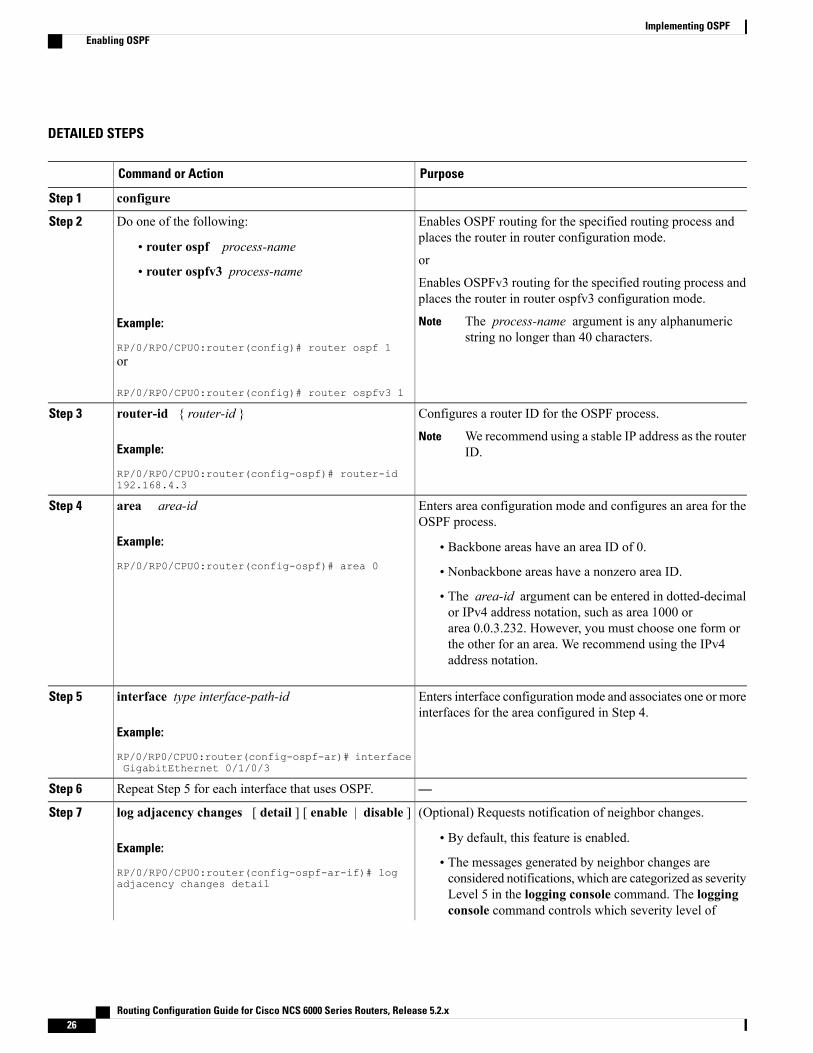
DETAILED STEPS
PurposeCommand or Action
configureStep 1
Enables OSPF routing for the specified routing process andplaces the router in router configuration mode.
Do one of the following:Step 2
• router ospf process-nameor
• router ospfv3 process-nameEnables OSPFv3 routing for the specified routing process andplaces the router in router ospfv3 configuration mode.
Example:
RP/0/RP0/CPU0:router(config)# router ospf 1
The process-name argument is any alphanumericstring no longer than 40 characters.
Note
or
RP/0/RP0/CPU0:router(config)# router ospfv3 1
Configures a router ID for the OSPF process.router-id { router-id }Step 3
Example:
RP/0/RP0/CPU0:router(config-ospf)# router-id192.168.4.3
We recommend using a stable IP address as the routerID.
Note
Enters area configuration mode and configures an area for theOSPF process.
area area-id
Example:
RP/0/RP0/CPU0:router(config-ospf)# area 0
Step 4
• Backbone areas have an area ID of 0.
• Nonbackbone areas have a nonzero area ID.
• The area-id argument can be entered in dotted-decimalor IPv4 address notation, such as area 1000 orarea 0.0.3.232. However, you must choose one form orthe other for an area. We recommend using the IPv4address notation.
Enters interface configurationmode and associates one or moreinterfaces for the area configured in Step 4.
interface type interface-path-id
Example:
RP/0/RP0/CPU0:router(config-ospf-ar)# interfaceGigabitEthernet 0/1/0/3
Step 5
—Repeat Step 5 for each interface that uses OSPF.Step 6
(Optional) Requests notification of neighbor changes.log adjacency changes [ detail ] [ enable | disable ]Step 7
Example:
RP/0/RP0/CPU0:router(config-ospf-ar-if)# logadjacency changes detail
• By default, this feature is enabled.
• The messages generated by neighbor changes areconsidered notifications, which are categorized as severityLevel 5 in the logging console command. The loggingconsole command controls which severity level of
Routing Configuration Guide for Cisco NCS 6000 Series Routers, Release 5.2.x26
Implementing OSPFEnabling OSPF
PurposeCommand or Action
messages are sent to the console. By default, all severitylevel messages are sent.
commitStep 8
Configuring Stub and Not-So-Stubby Area TypesThis task explains how to configure the stub area and the NSSA for OSPF.
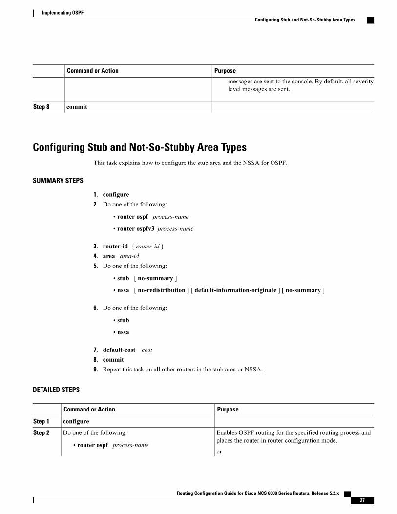
SUMMARY STEPS
1. configure2. Do one of the following:
• router ospf process-name
• router ospfv3 process-name
3. router-id { router-id }4. area area-id5. Do one of the following:
• stub [ no-summary ]
• nssa [ no-redistribution ] [ default-information-originate ] [ no-summary ]
6. Do one of the following:
• stub
• nssa
7. default-cost cost8. commit9. Repeat this task on all other routers in the stub area or NSSA.
DETAILED STEPS
PurposeCommand or Action
configureStep 1
Enables OSPF routing for the specified routing process andplaces the router in router configuration mode.
Do one of the following:Step 2
• router ospf process-nameor
Routing Configuration Guide for Cisco NCS 6000 Series Routers, Release 5.2.x 27
Implementing OSPFConfiguring Stub and Not-So-Stubby Area Types
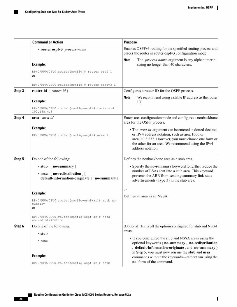
PurposeCommand or Action
Enables OSPFv3 routing for the specified routing process andplaces the router in router ospfv3 configuration mode.
• router ospfv3 process-name
Example:
RP/0/RP0/CPU0:router(config)# router ospf 1
The process-name argument is any alphanumericstring no longer than 40 characters.
Note
or
RP/0/RP0/CPU0:router(config)# router ospfv3 1
Configures a router ID for the OSPF process.router-id { router-id }Step 3
Example:
RP/0/RP0/CPU0:router(config-ospf)# router-id192.168.4.3
We recommend using a stable IP address as the routerID.
Note
Enters area configurationmode and configures a nonbackbonearea for the OSPF process.
area area-id
Example:
RP/0/RP0/CPU0:router(config-ospf)# area 1
Step 4
• The area-id argument can be entered in dotted-decimalor IPv4 address notation, such as area 1000 orarea 0.0.3.232. However, you must choose one form orthe other for an area. We recommend using the IPv4address notation.
Defines the nonbackbone area as a stub area.Do one of the following:Step 5
• stub [ no-summary ] • Specify the no-summary keyword to further reduce thenumber of LSAs sent into a stub area. This keyword• nssa [ no-redistribution ] [
default-information-originate ] [ no-summary ] prevents the ABR from sending summary link-stateadvertisements (Type 3) in the stub area.
Example:
RP/0/RP0/CPU0:router(config-ospf-ar)# stub nosummary
or
Defines an area as an NSSA.
or
RP/0/RP0/CPU0:router(config-ospf-ar)# nssano-redistribution
(Optional) Turns off the options configured for stub and NSSAareas.
Do one of the following:Step 6
• stub• If you configured the stub and NSSA areas using theoptional keywords ( no-summary , no-redistribution• nssa, default-information-originate , and no-summary )
Example:
RP/0/RP0/CPU0:router(config-ospf-ar)# stub
in Step 5, you must now reissue the stub and nssacommands without the keywords—rather than using theno form of the command.
Routing Configuration Guide for Cisco NCS 6000 Series Routers, Release 5.2.x28
Implementing OSPFConfiguring Stub and Not-So-Stubby Area Types
PurposeCommand or Action
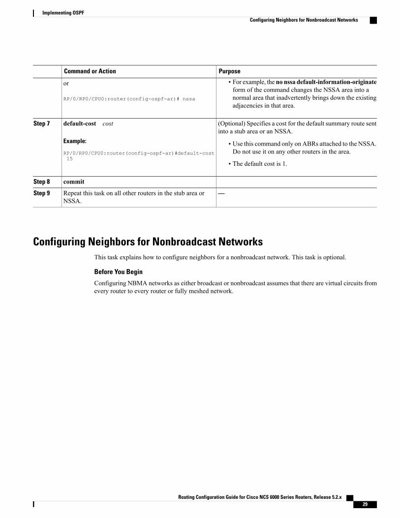
or
RP/0/RP0/CPU0:router(config-ospf-ar)# nssa
• For example, the no nssa default-information-originateform of the command changes the NSSA area into anormal area that inadvertently brings down the existingadjacencies in that area.
(Optional) Specifies a cost for the default summary route sentinto a stub area or an NSSA.
default-cost cost
Example:
RP/0/RP0/CPU0:router(config-ospf-ar)#default-cost15
Step 7
• Use this command only on ABRs attached to the NSSA.Do not use it on any other routers in the area.
• The default cost is 1.
commitStep 8
—Repeat this task on all other routers in the stub area orNSSA.
Step 9
Configuring Neighbors for Nonbroadcast NetworksThis task explains how to configure neighbors for a nonbroadcast network. This task is optional.
Before You Begin
Configuring NBMA networks as either broadcast or nonbroadcast assumes that there are virtual circuits fromevery router to every router or fully meshed network.
Routing Configuration Guide for Cisco NCS 6000 Series Routers, Release 5.2.x 29
Implementing OSPFConfiguring Neighbors for Nonbroadcast Networks
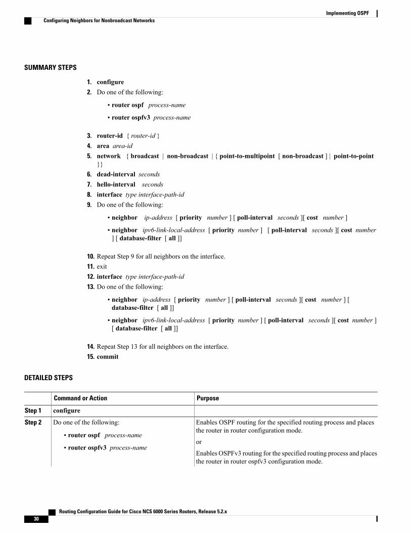
SUMMARY STEPS
1. configure2. Do one of the following:
• router ospf process-name
• router ospfv3 process-name
3. router-id { router-id }4. area area-id5. network { broadcast | non-broadcast | { point-to-multipoint [ non-broadcast ] | point-to-point
}}6. dead-interval seconds7. hello-interval seconds8. interface type interface-path-id9. Do one of the following:
• neighbor ip-address [ priority number ] [ poll-interval seconds ][ cost number ]
• neighbor ipv6-link-local-address [ priority number ] [ poll-interval seconds ][ cost number] [ database-filter [ all ]]
10. Repeat Step 9 for all neighbors on the interface.11. exit12. interface type interface-path-id13. Do one of the following:
• neighbor ip-address [ priority number ] [ poll-interval seconds ][ cost number ] [database-filter [ all ]]
• neighbor ipv6-link-local-address [ priority number ] [ poll-interval seconds ][ cost number ][ database-filter [ all ]]
14. Repeat Step 13 for all neighbors on the interface.15. commit
DETAILED STEPS
PurposeCommand or Action
configureStep 1
Enables OSPF routing for the specified routing process and placesthe router in router configuration mode.
Do one of the following:Step 2
• router ospf process-nameor
• router ospfv3 process-nameEnables OSPFv3 routing for the specified routing process and placesthe router in router ospfv3 configuration mode.
Routing Configuration Guide for Cisco NCS 6000 Series Routers, Release 5.2.x30
Implementing OSPFConfiguring Neighbors for Nonbroadcast Networks
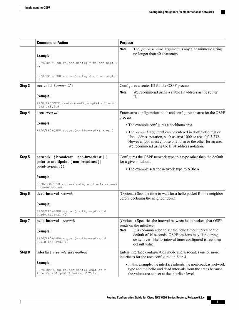
PurposeCommand or Action
Example:
RP/0/RP0/CPU0:router(config)# router ospf 1
The process-name argument is any alphanumeric stringno longer than 40 characters.
Note
or
RP/0/RP0/CPU0:router(config)# router ospfv31
Configures a router ID for the OSPF process.router-id { router-id }Step 3
Example:
RP/0/RP0/CPU0:router(config-ospf)# router-id192.168.4.3
We recommend using a stable IP address as the routerID.
Note
Enters area configuration mode and configures an area for the OSPFprocess.
area area-id
Example:
RP/0/RP0/CPU0:router(config-ospf)# area 0
Step 4
• The example configures a backbone area.
• The area-id argument can be entered in dotted-decimal orIPv4 address notation, such as area 1000 or area 0.0.3.232.However, you must choose one form or the other for an area.We recommend using the IPv4 address notation.
Configures the OSPF network type to a type other than the defaultfor a given medium.
network { broadcast | non-broadcast | {point-to-multipoint [ non-broadcast ] |point-to-point }}
Step 5
• The example sets the network type to NBMA.
Example:
RP/0/RP0/CPU0:router(config-ospf-ar)# networknon-broadcast
(Optional) Sets the time to wait for a hello packet from a neighborbefore declaring the neighbor down.
dead-interval seconds
Example:
RP/0/RP0/CPU0:router(config-ospf-ar)#dead-interval 40
Step 6
(Optional) Specifies the interval between hello packets that OSPFsends on the interface.
It is recommended to set the hello timer interval to thedefault of 10 seconds. OSPF sessions may flap duringswitchover if hello-interval timer configured is less thendefault value.
Note
hello-interval seconds
Example:
RP/0/RP0/CPU0:router(config-ospf-ar)#hello-interval 10
Step 7
Enters interface configuration mode and associates one or moreinterfaces for the area configured in Step 4.
interface type interface-path-id
Example:
RP/0/RP0/CPU0:router(config-ospf-ar)#interface GigabitEthernet 0/2/0/0
Step 8
• In this example, the interface inherits the nonbroadcast networktype and the hello and dead intervals from the areas becausethe values are not set at the interface level.
Routing Configuration Guide for Cisco NCS 6000 Series Routers, Release 5.2.x 31
Implementing OSPFConfiguring Neighbors for Nonbroadcast Networks
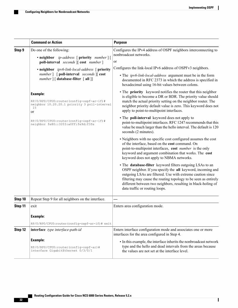
PurposeCommand or Action
Configures the IPv4 address of OSPF neighbors interconnecting tononbroadcast networks.
Do one of the following:Step 9
• neighbor ip-address [ priority number ] [poll-interval seconds ][ cost number ] or
Configures the link-local IPv6 address of OSPFv3 neighbors.• neighbor ipv6-link-local-address [ prioritynumber ] [ poll-interval seconds ][ costnumber ] [ database-filter [ all ]]
• The ipv6-link-local-address argument must be in the formdocumented in RFC 2373 in which the address is specified inhexadecimal using 16-bit values between colons.
Example:
RP/0/RP0/CPU0:router(config-ospf-ar-if)#
• The priority keyword notifies the router that this neighboris eligible to become a DR or BDR. The priority value shouldmatch the actual priority setting on the neighbor router. The
neighbor 10.20.20.1 priority 3 poll-interval15 neighbor priority default value is zero. This keyword does not
apply to point-to-multipoint interfaces.or
RP/0/RP0/CPU0:router(config-ospf-ar-if)#neighbor fe80::3203:a0ff:fe9d:f3fe
• The poll-interval keyword does not apply topoint-to-multipoint interfaces. RFC 1247 recommends that thisvalue be much larger than the hello interval. The default is 120seconds (2 minutes).
• Neighbors with no specific cost configured assumes the costof the interface, based on the cost command. Onpoint-to-multipoint interfaces, cost number is the onlykeyword and argument combination that works. The costkeyword does not apply to NBMA networks.
• The database-filter keyword filters outgoing LSAs to anOSPF neighbor. If you specify the all keyword, incoming andoutgoing LSAs are filtered. Use with extreme caution sincefiltering may cause the routing topology to be seen as entirelydifferent between two neighbors, resulting in black-holing ofdata traffic or routing loops.
—Repeat Step 9 for all neighbors on the interface.Step 10
Enters area configuration mode.exit
Example:
RP/0/RP0/CPU0:router(config-ospf-ar-if)# exit
Step 11
Enters interface configuration mode and associates one or moreinterfaces for the area configured in Step 4.
interface type interface-path-id
Example:
RP/0/RP0/CPU0:router(config-ospf-ar)#interface GigabitEthernet 0/3/0/1
Step 12
• In this example, the interface inherits the nonbroadcast networktype and the hello and dead intervals from the areas becausethe values are not set at the interface level.
Routing Configuration Guide for Cisco NCS 6000 Series Routers, Release 5.2.x32
Implementing OSPFConfiguring Neighbors for Nonbroadcast Networks
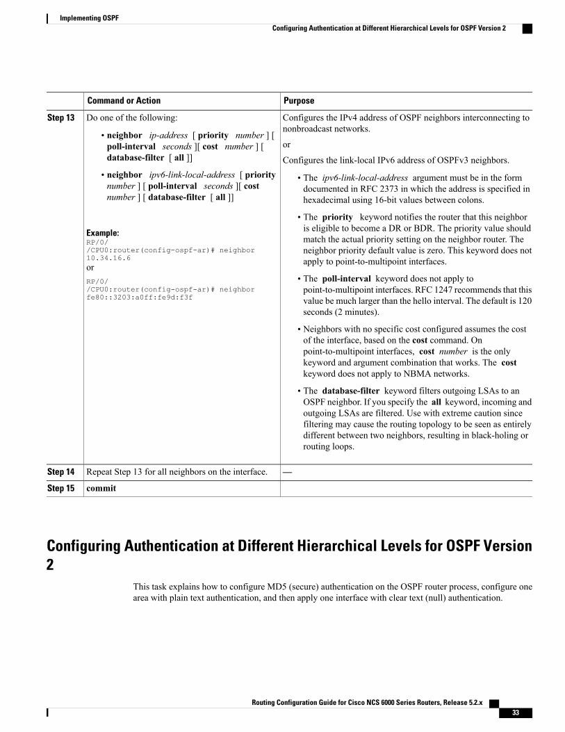
PurposeCommand or Action
Configures the IPv4 address of OSPF neighbors interconnecting tononbroadcast networks.
Do one of the following:Step 13
• neighbor ip-address [ priority number ] [poll-interval seconds ][ cost number ] [database-filter [ all ]]
or
Configures the link-local IPv6 address of OSPFv3 neighbors.• neighbor ipv6-link-local-address [ prioritynumber ] [ poll-interval seconds ][ costnumber ] [ database-filter [ all ]]
• The ipv6-link-local-address argument must be in the formdocumented in RFC 2373 in which the address is specified inhexadecimal using 16-bit values between colons.
• The priority keyword notifies the router that this neighboris eligible to become a DR or BDR. The priority value shouldExample:
RP/0//CPU0:router(config-ospf-ar)# neighbor10.34.16.6
match the actual priority setting on the neighbor router. Theneighbor priority default value is zero. This keyword does notapply to point-to-multipoint interfaces.or
RP/0//CPU0:router(config-ospf-ar)# neighborfe80::3203:a0ff:fe9d:f3f
• The poll-interval keyword does not apply topoint-to-multipoint interfaces. RFC 1247 recommends that thisvalue be much larger than the hello interval. The default is 120seconds (2 minutes).
• Neighbors with no specific cost configured assumes the costof the interface, based on the cost command. Onpoint-to-multipoint interfaces, cost number is the onlykeyword and argument combination that works. The costkeyword does not apply to NBMA networks.
• The database-filter keyword filters outgoing LSAs to anOSPF neighbor. If you specify the all keyword, incoming andoutgoing LSAs are filtered. Use with extreme caution sincefiltering may cause the routing topology to be seen as entirelydifferent between two neighbors, resulting in black-holing orrouting loops.
—Repeat Step 13 for all neighbors on the interface.Step 14
commitStep 15
Configuring Authentication at Different Hierarchical Levels for OSPF Version2
This task explains how to configure MD5 (secure) authentication on the OSPF router process, configure onearea with plain text authentication, and then apply one interface with clear text (null) authentication.
Routing Configuration Guide for Cisco NCS 6000 Series Routers, Release 5.2.x 33
Implementing OSPFConfiguring Authentication at Different Hierarchical Levels for OSPF Version 2
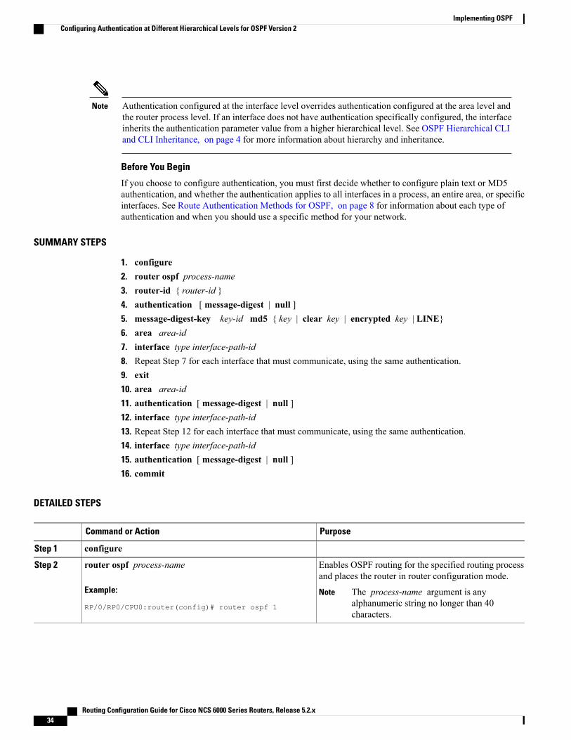
Authentication configured at the interface level overrides authentication configured at the area level andthe router process level. If an interface does not have authentication specifically configured, the interfaceinherits the authentication parameter value from a higher hierarchical level. See OSPF Hierarchical CLIand CLI Inheritance, on page 4 for more information about hierarchy and inheritance.
Note
Before You Begin
If you choose to configure authentication, you must first decide whether to configure plain text or MD5authentication, and whether the authentication applies to all interfaces in a process, an entire area, or specificinterfaces. See Route Authentication Methods for OSPF, on page 8 for information about each type ofauthentication and when you should use a specific method for your network.
SUMMARY STEPS
1. configure2. router ospf process-name3. router-id { router-id }4. authentication [ message-digest | null ]5. message-digest-key key-id md5 { key | clear key | encrypted key | LINE}6. area area-id7. interface type interface-path-id8. Repeat Step 7 for each interface that must communicate, using the same authentication.9. exit10. area area-id11. authentication [ message-digest | null ]12. interface type interface-path-id13. Repeat Step 12 for each interface that must communicate, using the same authentication.14. interface type interface-path-id15. authentication [ message-digest | null ]16. commit
DETAILED STEPS
PurposeCommand or Action
configureStep 1
Enables OSPF routing for the specified routing processand places the router in router configuration mode.
router ospf process-name
Example:
RP/0/RP0/CPU0:router(config)# router ospf 1
Step 2
The process-name argument is anyalphanumeric string no longer than 40characters.
Note
Routing Configuration Guide for Cisco NCS 6000 Series Routers, Release 5.2.x34
Implementing OSPFConfiguring Authentication at Different Hierarchical Levels for OSPF Version 2
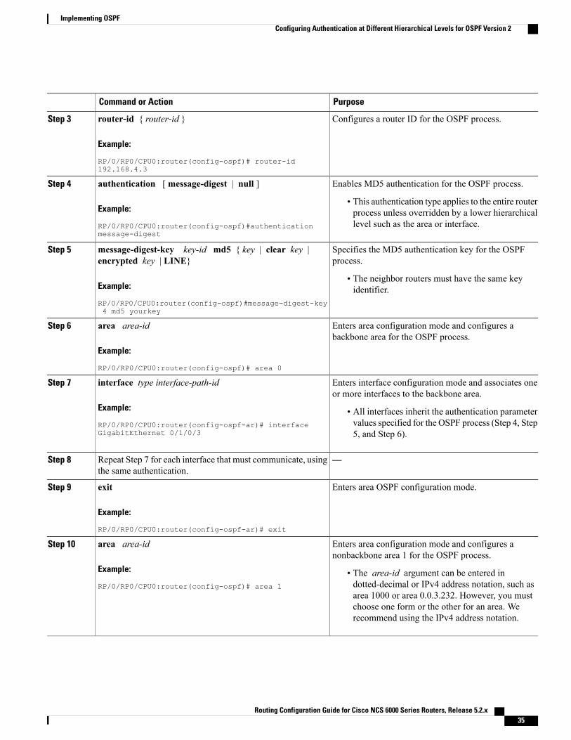
PurposeCommand or Action
Configures a router ID for the OSPF process.router-id { router-id }
Example:
RP/0/RP0/CPU0:router(config-ospf)# router-id192.168.4.3
Step 3
Enables MD5 authentication for the OSPF process.authentication [ message-digest | null ]Step 4
Example:
RP/0/RP0/CPU0:router(config-ospf)#authenticationmessage-digest
• This authentication type applies to the entire routerprocess unless overridden by a lower hierarchicallevel such as the area or interface.
Specifies the MD5 authentication key for the OSPFprocess.
message-digest-key key-id md5 { key | clear key |encrypted key | LINE}
Step 5
Example:
RP/0/RP0/CPU0:router(config-ospf)#message-digest-key4 md5 yourkey
• The neighbor routers must have the same keyidentifier.
Enters area configuration mode and configures abackbone area for the OSPF process.
area area-id
Example:
RP/0/RP0/CPU0:router(config-ospf)# area 0
Step 6
Enters interface configuration mode and associates oneor more interfaces to the backbone area.
interface type interface-path-id
Example:
RP/0/RP0/CPU0:router(config-ospf-ar)# interfaceGigabitEthernet 0/1/0/3
Step 7
• All interfaces inherit the authentication parametervalues specified for the OSPF process (Step 4, Step5, and Step 6).
—Repeat Step 7 for each interface that must communicate, usingthe same authentication.
Step 8
Enters area OSPF configuration mode.exit
Example:
RP/0/RP0/CPU0:router(config-ospf-ar)# exit
Step 9
Enters area configuration mode and configures anonbackbone area 1 for the OSPF process.
area area-id
Example:
RP/0/RP0/CPU0:router(config-ospf)# area 1
Step 10
• The area-id argument can be entered indotted-decimal or IPv4 address notation, such asarea 1000 or area 0.0.3.232. However, you mustchoose one form or the other for an area. Werecommend using the IPv4 address notation.
Routing Configuration Guide for Cisco NCS 6000 Series Routers, Release 5.2.x 35
Implementing OSPFConfiguring Authentication at Different Hierarchical Levels for OSPF Version 2
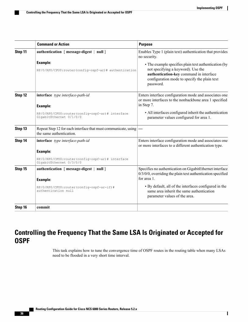
PurposeCommand or Action
Enables Type 1 (plain text) authentication that providesno security.
authentication [ message-digest | null ]
Example:
RP/0/RP0/CPU0:router(config-ospf-ar)# authentication
Step 11
• The example specifies plain text authentication (bynot specifying a keyword). Use theauthentication-key command in interfaceconfiguration mode to specify the plain textpassword.
Enters interface configuration mode and associates oneor more interfaces to the nonbackbone area 1 specifiedin Step 7.
interface type interface-path-id
Example:
RP/0/RP0/CPU0:router(config-ospf-ar)# interfaceGigabitEthernet 0/1/0/0
Step 12
• All interfaces configured inherit the authenticationparameter values configured for area 1.
—Repeat Step 12 for each interface that must communicate, usingthe same authentication.
Step 13
Enters interface configuration mode and associates oneor more interfaces to a different authentication type.
interface type interface-path-id
Example:
RP/0/RP0/CPU0:router(config-ospf-ar)# interfaceGigabitEthernet 0/3/0/0
Step 14
Specifies no authentication on GigabitEthernet interface0/3/0/0, overriding the plain text authentication specifiedfor area 1.
authentication [ message-digest | null ]
Example:
RP/0/RP0/CPU0:router(config-ospf-ar-if)#authentication null
Step 15
• By default, all of the interfaces configured in thesame area inherit the same authenticationparameter values of the area.
commitStep 16
Controlling the Frequency That the Same LSA Is Originated or Accepted forOSPF
This task explains how to tune the convergence time of OSPF routes in the routing table when many LSAsneed to be flooded in a very short time interval.
Routing Configuration Guide for Cisco NCS 6000 Series Routers, Release 5.2.x36
Implementing OSPFControlling the Frequency That the Same LSA Is Originated or Accepted for OSPF
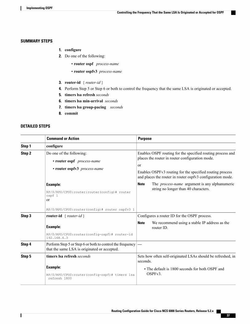
SUMMARY STEPS
1. configure2. Do one of the following:
• router ospf process-name
• router ospfv3 process-name
3. router-id { router-id }4. Perform Step 5 or Step 6 or both to control the frequency that the same LSA is originated or accepted.5. timers lsa refresh seconds6. timers lsa min-arrival seconds7. timers lsa group-pacing seconds8. commit
DETAILED STEPS
PurposeCommand or Action
configureStep 1
Enables OSPF routing for the specified routing process andplaces the router in router configuration mode.
Do one of the following:Step 2
• router ospf process-nameor
• router ospfv3 process-nameEnables OSPFv3 routing for the specified routing processand places the router in router ospfv3 configuration mode.
Example:
RP/0/RP0/CPU0:router:router(config)# routerospf 1
The process-name argument is any alphanumericstring no longer than 40 characters.
Note
or
RP/0/RP0/CPU0:router(config)# router ospfv3 1
Configures a router ID for the OSPF process.router-id { router-id }Step 3
Example:
RP/0/RP0/CPU0:router(config-ospf)# router-id192.168.4.3
We recommend using a stable IP address as therouter ID.
Note
—Perform Step 5 or Step 6 or both to control the frequencythat the same LSA is originated or accepted.
Step 4
Sets how often self-originated LSAs should be refreshed, inseconds.
timers lsa refresh seconds
Example:
RP/0/RP0/CPU0:router(config-ospf)# timers lsa
Step 5
• The default is 1800 seconds for both OSPF andOSPFv3.
refresh 1800
Routing Configuration Guide for Cisco NCS 6000 Series Routers, Release 5.2.x 37
Implementing OSPFControlling the Frequency That the Same LSA Is Originated or Accepted for OSPF
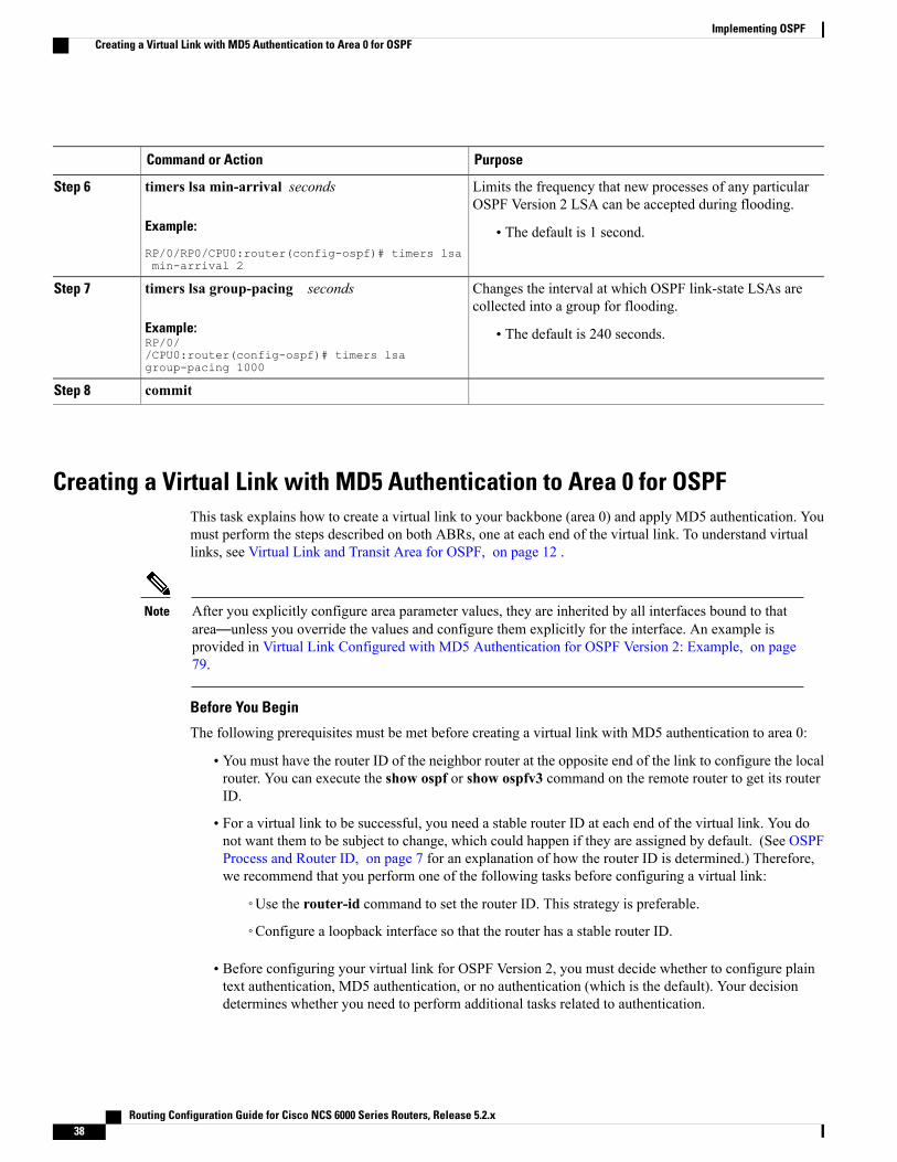
PurposeCommand or Action
Limits the frequency that new processes of any particularOSPF Version 2 LSA can be accepted during flooding.
timers lsa min-arrival seconds
Example:
RP/0/RP0/CPU0:router(config-ospf)# timers lsamin-arrival 2
Step 6
• The default is 1 second.
Changes the interval at which OSPF link-state LSAs arecollected into a group for flooding.
timers lsa group-pacing seconds
Example:RP/0//CPU0:router(config-ospf)# timers lsagroup-pacing 1000
Step 7
• The default is 240 seconds.
commitStep 8
Creating a Virtual Link with MD5 Authentication to Area 0 for OSPFThis task explains how to create a virtual link to your backbone (area 0) and apply MD5 authentication. Youmust perform the steps described on both ABRs, one at each end of the virtual link. To understand virtuallinks, see Virtual Link and Transit Area for OSPF, on page 12 .
After you explicitly configure area parameter values, they are inherited by all interfaces bound to thatarea—unless you override the values and configure them explicitly for the interface. An example isprovided in Virtual Link Configured with MD5 Authentication for OSPF Version 2: Example, on page79.
Note
Before You Begin
The following prerequisites must be met before creating a virtual link with MD5 authentication to area 0:
• You must have the router ID of the neighbor router at the opposite end of the link to configure the localrouter. You can execute the show ospf or show ospfv3 command on the remote router to get its routerID.
• For a virtual link to be successful, you need a stable router ID at each end of the virtual link. You donot want them to be subject to change, which could happen if they are assigned by default. (See OSPFProcess and Router ID, on page 7 for an explanation of how the router ID is determined.) Therefore,we recommend that you perform one of the following tasks before configuring a virtual link:
◦Use the router-id command to set the router ID. This strategy is preferable.
◦Configure a loopback interface so that the router has a stable router ID.
• Before configuring your virtual link for OSPF Version 2, you must decide whether to configure plaintext authentication, MD5 authentication, or no authentication (which is the default). Your decisiondetermines whether you need to perform additional tasks related to authentication.
Routing Configuration Guide for Cisco NCS 6000 Series Routers, Release 5.2.x38
Implementing OSPFCreating a Virtual Link with MD5 Authentication to Area 0 for OSPF
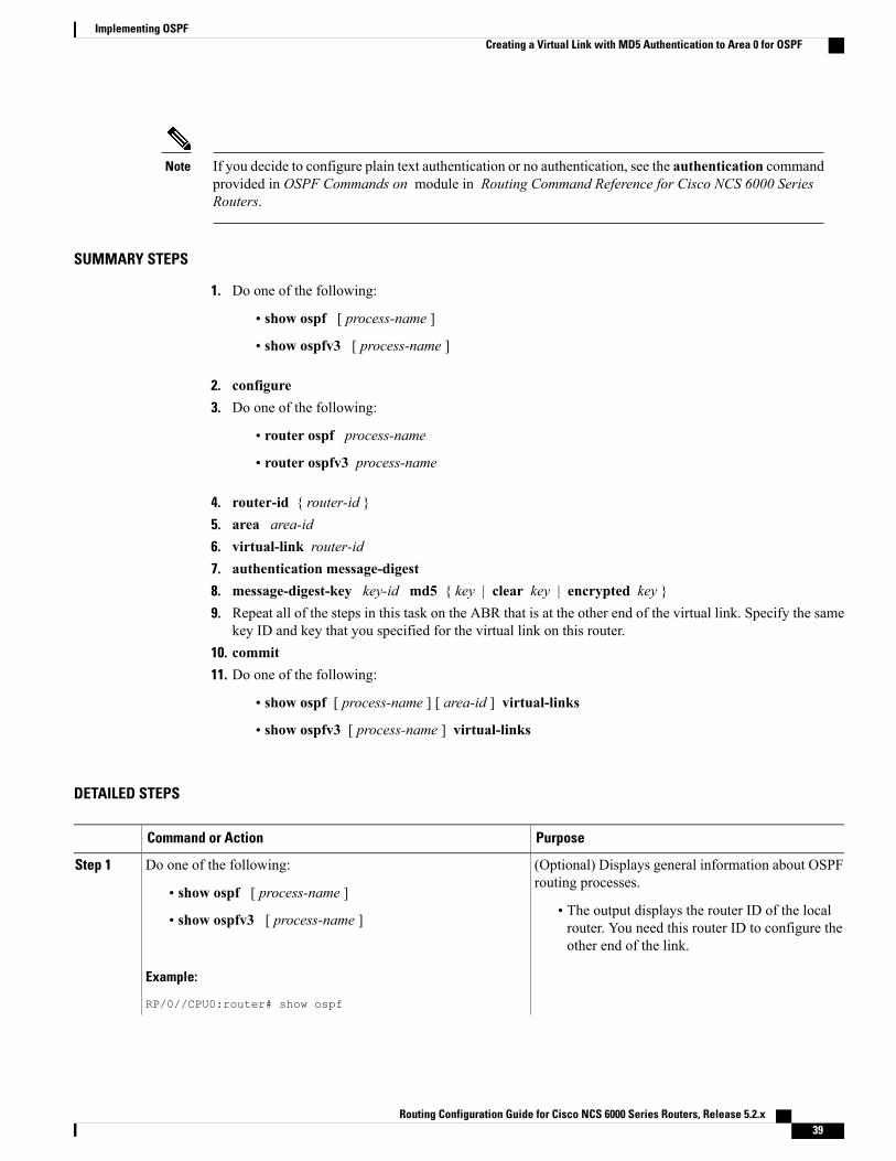
If you decide to configure plain text authentication or no authentication, see the authentication commandprovided in OSPF Commands on module in Routing Command Reference for Cisco NCS 6000 SeriesRouters.
Note
SUMMARY STEPS
1. Do one of the following:
• show ospf [ process-name ]
• show ospfv3 [ process-name ]
2. configure3. Do one of the following:
• router ospf process-name
• router ospfv3 process-name
4. router-id { router-id }5. area area-id6. virtual-link router-id7. authentication message-digest8. message-digest-key key-id md5 { key | clear key | encrypted key }9. Repeat all of the steps in this task on the ABR that is at the other end of the virtual link. Specify the same
key ID and key that you specified for the virtual link on this router.10. commit11. Do one of the following:
• show ospf [ process-name ] [ area-id ] virtual-links
• show ospfv3 [ process-name ] virtual-links
DETAILED STEPS
PurposeCommand or Action
(Optional) Displays general information about OSPFrouting processes.
Do one of the following:Step 1
• show ospf [ process-name ]• The output displays the router ID of the localrouter. You need this router ID to configure theother end of the link.
• show ospfv3 [ process-name ]
Example:
RP/0//CPU0:router# show ospf
Routing Configuration Guide for Cisco NCS 6000 Series Routers, Release 5.2.x 39
Implementing OSPFCreating a Virtual Link with MD5 Authentication to Area 0 for OSPF
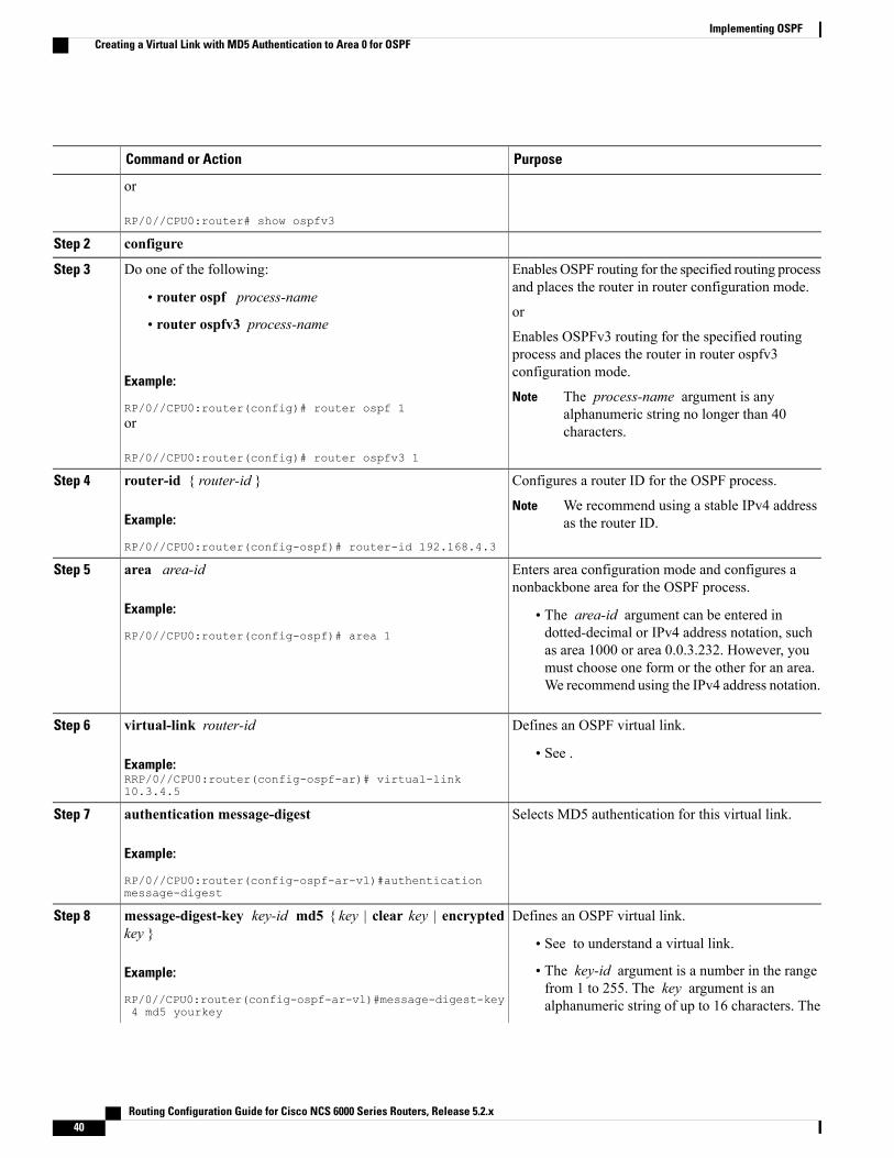
PurposeCommand or Action
or
RP/0//CPU0:router# show ospfv3
configureStep 2
Enables OSPF routing for the specified routing processand places the router in router configuration mode.
Do one of the following:Step 3
• router ospf process-nameor
• router ospfv3 process-nameEnables OSPFv3 routing for the specified routingprocess and places the router in router ospfv3configuration mode.
Example:
RP/0//CPU0:router(config)# router ospf 1The process-name argument is anyalphanumeric string no longer than 40characters.
Note
or
RP/0//CPU0:router(config)# router ospfv3 1
Configures a router ID for the OSPF process.router-id { router-id }Step 4
Example:
RP/0//CPU0:router(config-ospf)# router-id 192.168.4.3
We recommend using a stable IPv4 addressas the router ID.
Note
Enters area configuration mode and configures anonbackbone area for the OSPF process.
area area-id
Example:
RP/0//CPU0:router(config-ospf)# area 1
Step 5
• The area-id argument can be entered indotted-decimal or IPv4 address notation, suchas area 1000 or area 0.0.3.232. However, youmust choose one form or the other for an area.We recommend using the IPv4 address notation.
Defines an OSPF virtual link.virtual-link router-idStep 6
Example:RRP/0//CPU0:router(config-ospf-ar)# virtual-link10.3.4.5
• See .
Selects MD5 authentication for this virtual link.authentication message-digest
Example:
RP/0//CPU0:router(config-ospf-ar-vl)#authenticationmessage-digest
Step 7
Defines an OSPF virtual link.message-digest-key key-id md5 { key | clear key | encryptedkey }
Step 8
• See to understand a virtual link.
Example:
RP/0//CPU0:router(config-ospf-ar-vl)#message-digest-key4 md5 yourkey
• The key-id argument is a number in the rangefrom 1 to 255. The key argument is analphanumeric string of up to 16 characters. The
Routing Configuration Guide for Cisco NCS 6000 Series Routers, Release 5.2.x40
Implementing OSPFCreating a Virtual Link with MD5 Authentication to Area 0 for OSPF
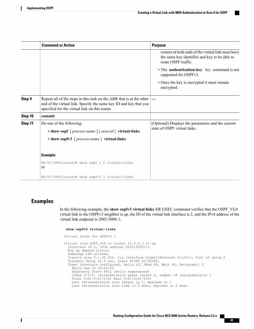
PurposeCommand or Action
routers at both ends of the virtual link must havethe same key identifier and key to be able toroute OSPF traffic.
• The authentication-key key command is notsupported for OSPFv3.
• Once the key is encrypted it must remainencrypted.
—Repeat all of the steps in this task on the ABR that is at the otherend of the virtual link. Specify the same key ID and key that youspecified for the virtual link on this router.
Step 9
commitStep 10
(Optional) Displays the parameters and the currentstate of OSPF virtual links.
Do one of the following:Step 11
• show ospf [ process-name ] [ area-id ] virtual-links
• show ospfv3 [ process-name ] virtual-links
Example:
RP/0//CPU0:router# show ospf 1 2 virtual-linksor
RP/0//CPU0:router# show ospfv3 1 virtual-links
ExamplesIn the following example, the show ospfv3 virtual links XR EXEC command verifies that the OSPF_VL0virtual link to the OSPFv3 neighbor is up, the ID of the virtual link interface is 2, and the IPv6 address of thevirtual link endpoint is 2003:3000::1.
show ospfv3 virtual-links
Virtual Links for OSPFv3 1
Virtual Link OSPF_VL0 to router 10.0.0.3 is upInterface ID 2, IPv6 address 2003:3000::1Run as demand circuitDoNotAge LSA allowed.Transit area 0.1.20.255, via interface GigabitEthernet 0/1/0/1, Cost of using 2Transmit Delay is 5 sec, State POINT_TO_POINT,Timer intervals configured, Hello 10, Dead 40, Wait 40, Retransmit 5Hello due in 00:00:02Adjacency State FULL (Hello suppressed)Index 0/2/3, retransmission queue length 0, number of retransmission 1First 0(0)/0(0)/0(0) Next 0(0)/0(0)/0(0)Last retransmission scan length is 1, maximum is 1Last retransmission scan time is 0 msec, maximum is 0 msec
Routing Configuration Guide for Cisco NCS 6000 Series Routers, Release 5.2.x 41
Implementing OSPFCreating a Virtual Link with MD5 Authentication to Area 0 for OSPF
Check for lines:Virtual Link OSPF_VL0 to router 10.0.0.3 is up
Adjacency State FULL (Hello suppressed)
State is up and Adjacency State is FULL
Summarizing Subnetwork LSAs on an OSPF ABRIf you configured two or more subnetworks when you assigned your IP addresses to your interfaces, youmight want the software to summarize (aggregate) into a single LSA all of the subnetworks that the local areaadvertises to another area. Such summarization would reduce the number of LSAs and thereby conservenetwork resources. This summarization is known as interarea route summarization. It applies to routes fromwithin the autonomous system. It does not apply to external routes injected into OSPF by way of redistribution.
This task configures OSPF to summarize subnetworks into one LSA, by specifying that all subnetworks thatfall into a range are advertised together. This task is performed on an ABR only.
SUMMARY STEPS
1. configure2. Do one of the following:
• router ospf process-name
• router ospfv3 process-name
3. router-id { router-id }4. area area-id5. Do one of the following:
• range ip-address mask [ advertise | not-advertise ]
• range ipv6-prefix / prefix-length [ advertise | not-advertise ]
6. interface type interface-path-id7. commit
DETAILED STEPS
PurposeCommand or Action
configureStep 1
Enables OSPF routing for the specified routing process and placesthe router in router configuration mode.
Do one of the following:Step 2
• router ospf process-nameor
• router ospfv3 process-nameEnables OSPFv3 routing for the specified routing process and placesthe router in router ospfv3 configuration mode.
Routing Configuration Guide for Cisco NCS 6000 Series Routers, Release 5.2.x42
Implementing OSPFSummarizing Subnetwork LSAs on an OSPF ABR
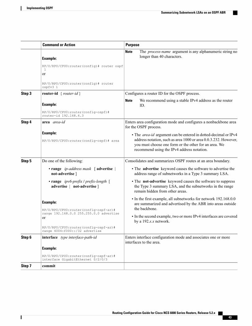
PurposeCommand or Action
Example:
RP/0/RP0/CPU0:router(config)# router ospf1
The process-name argument is any alphanumeric string nolonger than 40 characters.
Note
or
RP/0/RP0/CPU0:router(config)# routerospfv3 1
Configures a router ID for the OSPF process.router-id { router-id }Step 3
Example:
RP/0/RP0/CPU0:router(config-ospf)#router-id 192.168.4.3
We recommend using a stable IPv4 address as the routerID.
Note
Enters area configuration mode and configures a nonbackbone areafor the OSPF process.
area area-id
Example:
RP/0/RP0/CPU0:router(config-ospf)# area
Step 4
• The area-id argument can be entered in dotted-decimal or IPv4address notation, such as area 1000 or area 0.0.3.232. However,you must choose one form or the other for an area. Werecommend using the IPv4 address notation.
Consolidates and summarizes OSPF routes at an area boundary.Do one of the following:Step 5
• range ip-address mask [ advertise |not-advertise ]
• The advertise keyword causes the software to advertise theaddress range of subnetworks in a Type 3 summary LSA.
• The not-advertise keyword causes the software to suppressthe Type 3 summary LSA, and the subnetworks in the rangeremain hidden from other areas.
• range ipv6-prefix / prefix-length [advertise | not-advertise ]
Example:
RP/0/RP0/CPU0:router(config-ospf-ar)#range 192.168.0.0 255.255.0.0 advertise
• In the first example, all subnetworks for network 192.168.0.0are summarized and advertised by the ABR into areas outsidethe backbone.
• In the second example, two or more IPv4 interfaces are coveredby a 192.x.x network.
or
RP/0/RP0/CPU0:router(config-ospf-ar)#range 4004:f000::/32 advertise
Enters interface configuration mode and associates one or moreinterfaces to the area.
interface type interface-path-id
Example:
RP/0/RP0/CPU0:router(config-ospf-ar)#interface GigabitEthernet 0/2/0/3
Step 6
commitStep 7
Routing Configuration Guide for Cisco NCS 6000 Series Routers, Release 5.2.x 43
Implementing OSPFSummarizing Subnetwork LSAs on an OSPF ABR
Redistribute Routes into OSPFThis task redistributes routes from an IGP (could be a different OSPF process) into OSPF.
Before You Begin
For information about configuring routing policy, see Implementing Routing Policy on module in the RoutingConfiguration Guide for Cisco NCS 6000 Series Routers.
SUMMARY STEPS
1. configure2. Do one of the following:
• router ospf process-name
• router ospfv3 process-name
3. router-id { router-id }4. redistribute protocol [ process-id ] { level-1 | level-1-2 | level-2 } [ metric metric-value ] [
metric-type type-value ] [ match { external [ 1 | 2 ]} [ tag tag-value ] [ route-policy policy-name ]5. Do one of the following:
• summary-prefix address mask [ not-advertise ] [ tag tag ]
• summary-prefix ipv6-prefix / prefix-length [ not-advertise ] [ tag tag ]
6. commit
DETAILED STEPS
PurposeCommand or Action
configureStep 1
Enables OSPF routing for the specified routing process and placesthe router in router configuration mode.
Do one of the following:Step 2
• router ospf process-nameor
• router ospfv3 process-nameEnables OSPFv3 routing for the specified routing process andplaces the router in router ospfv3 configuration mode.
Example:
RP/0/RP0/CPU0:router(config)# router ospf 1
The process-name argument is any alphanumeric stringno longer than 40 characters.
Note
or
RP/0/RP0/CPU0:router(config)# router ospfv3 1
Configures a router ID for the OSPF process.router-id { router-id }Step 3
Routing Configuration Guide for Cisco NCS 6000 Series Routers, Release 5.2.x44
Implementing OSPFRedistribute Routes into OSPF
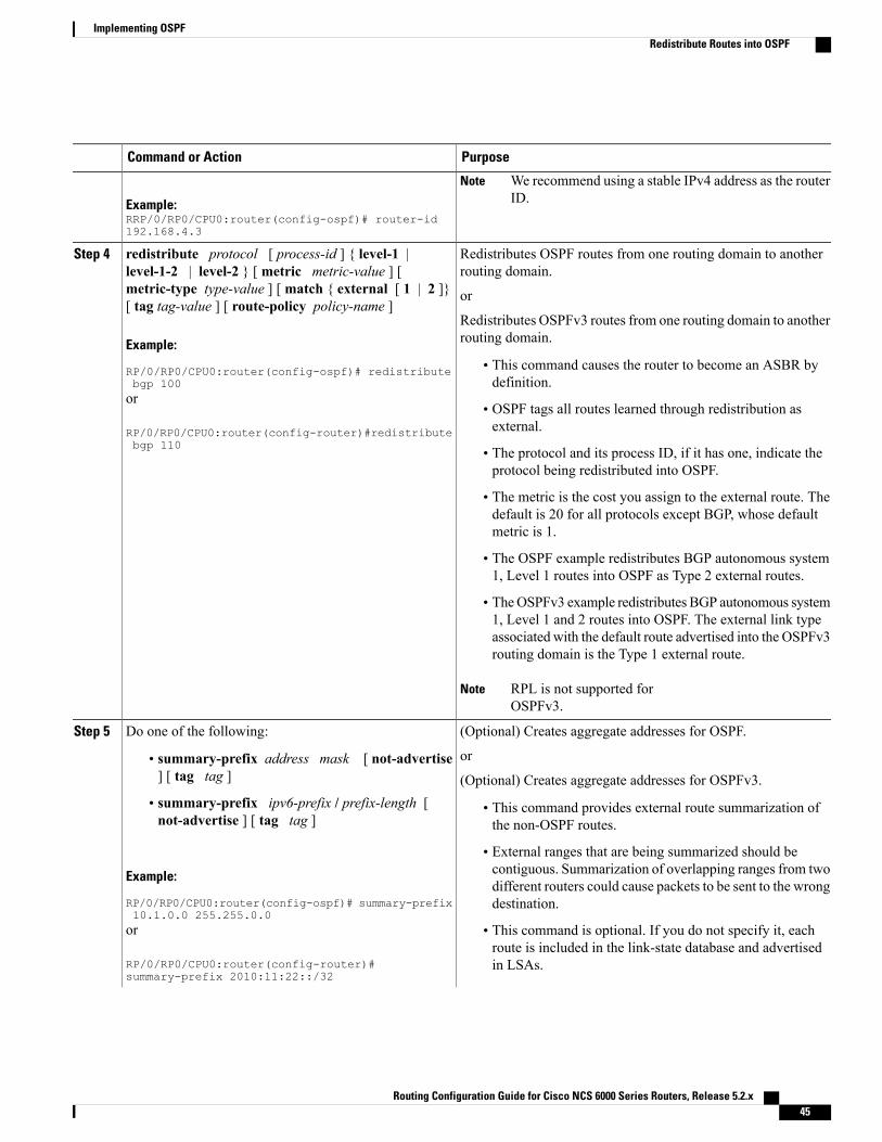
PurposeCommand or Action
Example:RRP/0/RP0/CPU0:router(config-ospf)# router-id192.168.4.3
We recommend using a stable IPv4 address as the routerID.
Note
Redistributes OSPF routes from one routing domain to anotherrouting domain.
redistribute protocol [ process-id ] { level-1 |level-1-2 | level-2 } [ metric metric-value ] [
Step 4
metric-type type-value ] [ match { external [ 1 | 2 ]}[ tag tag-value ] [ route-policy policy-name ]
or
Redistributes OSPFv3 routes from one routing domain to anotherrouting domain.Example:
RP/0/RP0/CPU0:router(config-ospf)# redistributebgp 100
• This command causes the router to become an ASBR bydefinition.
or
RP/0/RP0/CPU0:router(config-router)#redistributebgp 110
• OSPF tags all routes learned through redistribution asexternal.
• The protocol and its process ID, if it has one, indicate theprotocol being redistributed into OSPF.
• The metric is the cost you assign to the external route. Thedefault is 20 for all protocols except BGP, whose defaultmetric is 1.
• The OSPF example redistributes BGP autonomous system1, Level 1 routes into OSPF as Type 2 external routes.
• TheOSPFv3 example redistributes BGP autonomous system1, Level 1 and 2 routes into OSPF. The external link typeassociated with the default route advertised into the OSPFv3routing domain is the Type 1 external route.
RPL is not supported forOSPFv3.
Note
(Optional) Creates aggregate addresses for OSPF.Do one of the following:Step 5
or• summary-prefix address mask [ not-advertise] [ tag tag ] (Optional) Creates aggregate addresses for OSPFv3.
• summary-prefix ipv6-prefix / prefix-length [not-advertise ] [ tag tag ]
• This command provides external route summarization ofthe non-OSPF routes.
• External ranges that are being summarized should becontiguous. Summarization of overlapping ranges from twoExample:
RP/0/RP0/CPU0:router(config-ospf)# summary-prefix10.1.0.0 255.255.0.0
different routers could cause packets to be sent to the wrongdestination.
or
RP/0/RP0/CPU0:router(config-router)#summary-prefix 2010:11:22::/32
• This command is optional. If you do not specify it, eachroute is included in the link-state database and advertisedin LSAs.
Routing Configuration Guide for Cisco NCS 6000 Series Routers, Release 5.2.x 45
Implementing OSPFRedistribute Routes into OSPF
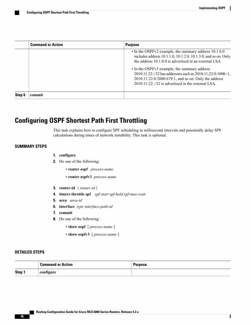
PurposeCommand or Action
• In the OSPFv2 example, the summary address 10.1.0.0includes address 10.1.1.0, 10.1.2.0, 10.1.3.0, and so on. Onlythe address 10.1.0.0 is advertised in an external LSA.
• In the OSPFv3 example, the summary address2010:11:22::/32 has addresses such as 2010:11:22:0:1000::1,2010:11:22:0:2000:679:1, and so on. Only the address2010:11:22::/32 is advertised in the external LSA.
commitStep 6
Configuring OSPF Shortest Path First ThrottlingThis task explains how to configure SPF scheduling in millisecond intervals and potentially delay SPFcalculations during times of network instability. This task is optional.
SUMMARY STEPS
1. configure2. Do one of the following:
• router ospf process-name
• router ospfv3 process-name
3. router-id { router-id }4. timers throttle spf spf-start spf-hold spf-max-wait5. area area-id6. interface type interface-path-id7. commit8. Do one of the following:
• show ospf [ process-name ]
• show ospfv3 [ process-name ]
DETAILED STEPS
PurposeCommand or Action
configureStep 1
Routing Configuration Guide for Cisco NCS 6000 Series Routers, Release 5.2.x46
Implementing OSPFConfiguring OSPF Shortest Path First Throttling
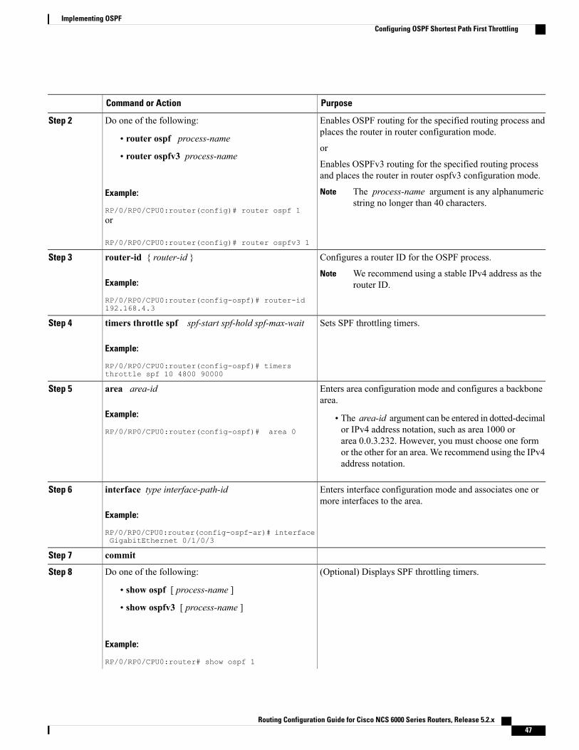
PurposeCommand or Action
Enables OSPF routing for the specified routing process andplaces the router in router configuration mode.
Do one of the following:Step 2
• router ospf process-nameor
• router ospfv3 process-nameEnables OSPFv3 routing for the specified routing processand places the router in router ospfv3 configuration mode.
Example:
RP/0/RP0/CPU0:router(config)# router ospf 1
The process-name argument is any alphanumericstring no longer than 40 characters.
Note
or
RP/0/RP0/CPU0:router(config)# router ospfv3 1
Configures a router ID for the OSPF process.router-id { router-id }Step 3
Example:
RP/0/RP0/CPU0:router(config-ospf)# router-id192.168.4.3
We recommend using a stable IPv4 address as therouter ID.
Note
Sets SPF throttling timers.timers throttle spf spf-start spf-hold spf-max-wait
Example:
RP/0/RP0/CPU0:router(config-ospf)# timersthrottle spf 10 4800 90000
Step 4
Enters area configuration mode and configures a backbonearea.
area area-id
Example:
RP/0/RP0/CPU0:router(config-ospf)# area 0
Step 5
• The area-id argument can be entered in dotted-decimalor IPv4 address notation, such as area 1000 orarea 0.0.3.232. However, you must choose one formor the other for an area. We recommend using the IPv4address notation.
Enters interface configuration mode and associates one ormore interfaces to the area.
interface type interface-path-id
Example:
RP/0/RP0/CPU0:router(config-ospf-ar)# interfaceGigabitEthernet 0/1/0/3
Step 6
commitStep 7
(Optional) Displays SPF throttling timers.Do one of the following:Step 8
• show ospf [ process-name ]
• show ospfv3 [ process-name ]
Example:
RP/0/RP0/CPU0:router# show ospf 1
Routing Configuration Guide for Cisco NCS 6000 Series Routers, Release 5.2.x 47
Implementing OSPFConfiguring OSPF Shortest Path First Throttling
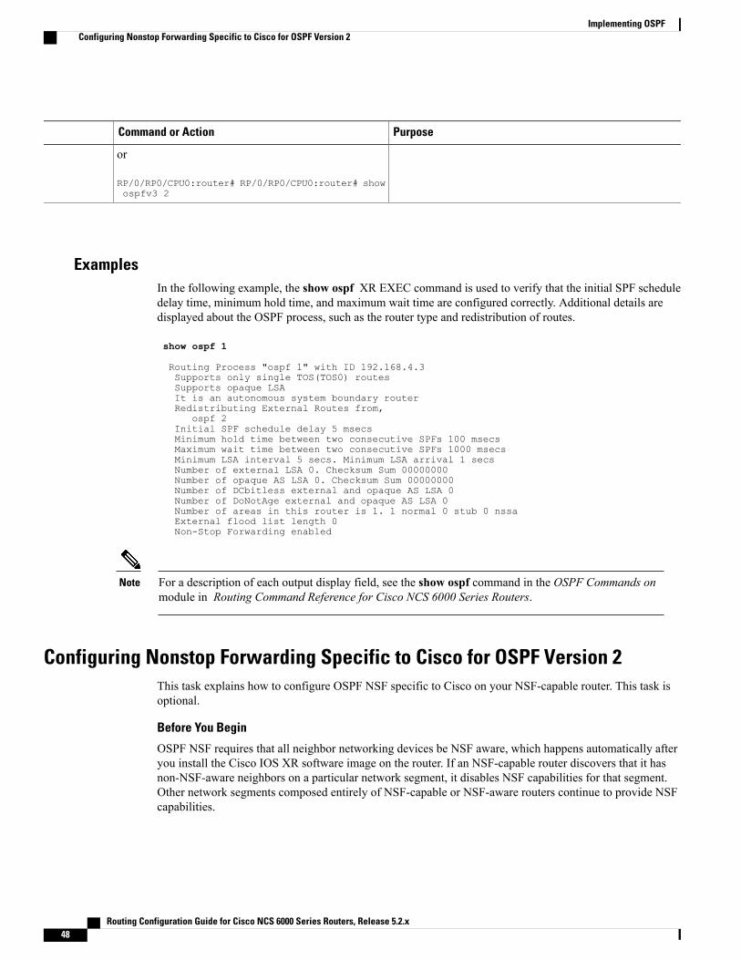
PurposeCommand or Action
or
RP/0/RP0/CPU0:router# RP/0/RP0/CPU0:router# showospfv3 2
ExamplesIn the following example, the show ospf XR EXEC command is used to verify that the initial SPF scheduledelay time, minimum hold time, and maximum wait time are configured correctly. Additional details aredisplayed about the OSPF process, such as the router type and redistribution of routes.
show ospf 1
Routing Process "ospf 1" with ID 192.168.4.3Supports only single TOS(TOS0) routesSupports opaque LSAIt is an autonomous system boundary routerRedistributing External Routes from,
ospf 2Initial SPF schedule delay 5 msecsMinimum hold time between two consecutive SPFs 100 msecsMaximum wait time between two consecutive SPFs 1000 msecsMinimum LSA interval 5 secs. Minimum LSA arrival 1 secsNumber of external LSA 0. Checksum Sum 00000000Number of opaque AS LSA 0. Checksum Sum 00000000Number of DCbitless external and opaque AS LSA 0Number of DoNotAge external and opaque AS LSA 0Number of areas in this router is 1. 1 normal 0 stub 0 nssaExternal flood list length 0Non-Stop Forwarding enabled
For a description of each output display field, see the show ospf command in the OSPF Commands onmodule in Routing Command Reference for Cisco NCS 6000 Series Routers.
Note
Configuring Nonstop Forwarding Specific to Cisco for OSPF Version 2This task explains how to configure OSPF NSF specific to Cisco on your NSF-capable router. This task isoptional.
Before You Begin
OSPF NSF requires that all neighbor networking devices be NSF aware, which happens automatically afteryou install the Cisco IOS XR software image on the router. If an NSF-capable router discovers that it hasnon-NSF-aware neighbors on a particular network segment, it disables NSF capabilities for that segment.Other network segments composed entirely of NSF-capable or NSF-aware routers continue to provide NSFcapabilities.
Routing Configuration Guide for Cisco NCS 6000 Series Routers, Release 5.2.x48
Implementing OSPFConfiguring Nonstop Forwarding Specific to Cisco for OSPF Version 2

The following are restrictions when configuring nonstop forwarding:Note
• OSPF Cisco NSF for virtual links is not supported.
• Neighbors must be NSF aware.
SUMMARY STEPS
1. configure2. router ospf process-name3. router-id { router-id }4. Do one of the following:
• nsf cisco
• nsf cisco enforce global
5. nsf interval seconds6. nsfflush-delay-timeseconds7. nsflifetimeseconds8. nsfietf9. commit
DETAILED STEPS
PurposeCommand or Action
configureStep 1
Enables OSPF routing for the specified routing process and placesthe router in router configuration mode.
router ospf process-name
Example:
RP/0/RP0/CPU0:router(config)# router ospf1
Step 2
The process-name argument is any alphanumeric stringno longer than 40 characters.
Note
Configures a router ID for the OSPF process.router-id { router-id }Step 3
Example:
RP/0/RP0/CPU0:router(config-ospf)#router-id 192.168.4.3
We recommend using a stable IPv4 address as the routerID.
Note
Enables Cisco NSF operations for the OSPF process.Do one of the following:Step 4
• nsf cisco • Use the nsf cisco command without the optional enforce andglobal keywords to abort the NSF restart mechanism on the• nsf cisco enforce global interfaces of detected non-NSF neighbors and allow NSFneighbors to function properly.
Routing Configuration Guide for Cisco NCS 6000 Series Routers, Release 5.2.x 49
Implementing OSPFConfiguring Nonstop Forwarding Specific to Cisco for OSPF Version 2
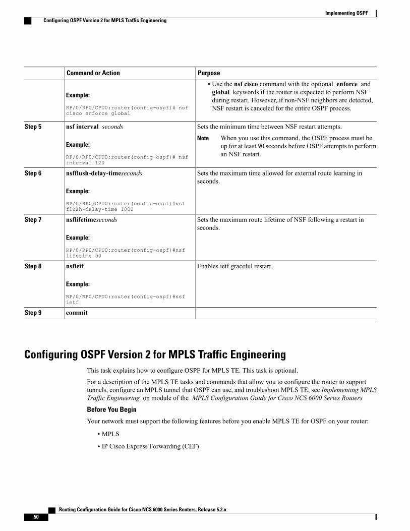
PurposeCommand or Action
Example:
RP/0/RP0/CPU0:router(config-ospf)# nsfcisco enforce global
• Use the nsf cisco command with the optional enforce andglobal keywords if the router is expected to perform NSFduring restart. However, if non-NSF neighbors are detected,NSF restart is canceled for the entire OSPF process.
Sets the minimum time between NSF restart attempts.nsf interval secondsStep 5
Example:
RP/0/RP0/CPU0:router(config-ospf)# nsfinterval 120
When you use this command, the OSPF process must beup for at least 90 seconds before OSPF attempts to performan NSF restart.
Note
Sets the maximum time allowed for external route learning inseconds.
nsfflush-delay-timeseconds
Example:
RP/0/RP0/CPU0:router(config-ospf)#nsfflush-delay-time 1000
Step 6
Sets the maximum route lifetime of NSF following a restart inseconds.
nsflifetimeseconds
Example:
RP/0/RP0/CPU0:router(config-ospf)#nsflifetime 90
Step 7
Enables ietf graceful restart.nsfietf
Example:
RP/0/RP0/CPU0:router(config-ospf)#nsfietf
Step 8
commitStep 9
Configuring OSPF Version 2 for MPLS Traffic EngineeringThis task explains how to configure OSPF for MPLS TE. This task is optional.
For a description of the MPLS TE tasks and commands that allow you to configure the router to supporttunnels, configure an MPLS tunnel that OSPF can use, and troubleshoot MPLS TE, see Implementing MPLSTraffic Engineering on module of the MPLS Configuration Guide for Cisco NCS 6000 Series Routers
Before You Begin
Your network must support the following features before you enable MPLS TE for OSPF on your router:
• MPLS
• IP Cisco Express Forwarding (CEF)
Routing Configuration Guide for Cisco NCS 6000 Series Routers, Release 5.2.x50
Implementing OSPFConfiguring OSPF Version 2 for MPLS Traffic Engineering
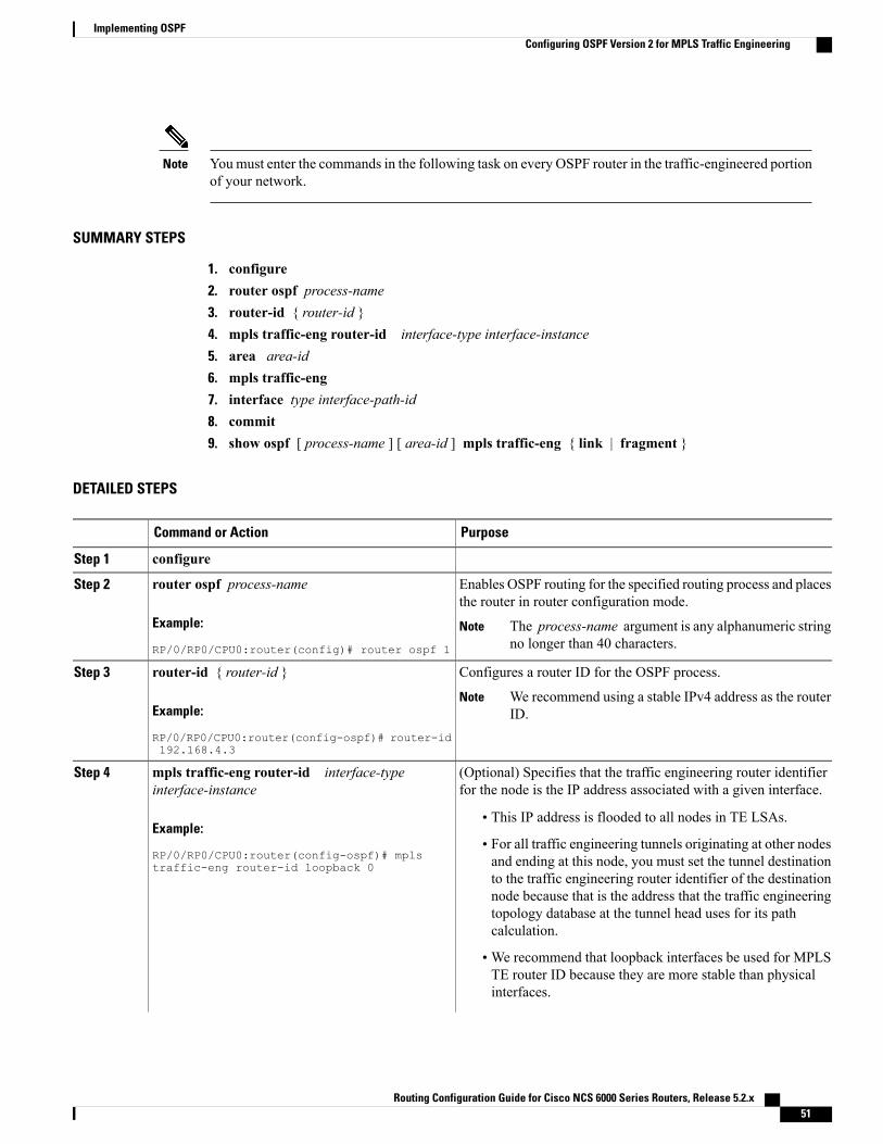
Youmust enter the commands in the following task on every OSPF router in the traffic-engineered portionof your network.
Note
SUMMARY STEPS
1. configure2. router ospf process-name3. router-id { router-id }4. mpls traffic-eng router-id interface-type interface-instance5. area area-id6. mpls traffic-eng7. interface type interface-path-id8. commit9. show ospf [ process-name ] [ area-id ] mpls traffic-eng { link | fragment }
DETAILED STEPS
PurposeCommand or Action
configureStep 1
Enables OSPF routing for the specified routing process and placesthe router in router configuration mode.
router ospf process-name
Example:
RP/0/RP0/CPU0:router(config)# router ospf 1
Step 2
The process-name argument is any alphanumeric stringno longer than 40 characters.
Note
Configures a router ID for the OSPF process.router-id { router-id }Step 3
Example:
RP/0/RP0/CPU0:router(config-ospf)# router-id192.168.4.3
We recommend using a stable IPv4 address as the routerID.
Note
(Optional) Specifies that the traffic engineering router identifierfor the node is the IP address associated with a given interface.
mpls traffic-eng router-id interface-typeinterface-instance
Step 4
Example:
RP/0/RP0/CPU0:router(config-ospf)# mplstraffic-eng router-id loopback 0
• This IP address is flooded to all nodes in TE LSAs.
• For all traffic engineering tunnels originating at other nodesand ending at this node, you must set the tunnel destinationto the traffic engineering router identifier of the destinationnode because that is the address that the traffic engineeringtopology database at the tunnel head uses for its pathcalculation.
• We recommend that loopback interfaces be used for MPLSTE router ID because they are more stable than physicalinterfaces.
Routing Configuration Guide for Cisco NCS 6000 Series Routers, Release 5.2.x 51
Implementing OSPFConfiguring OSPF Version 2 for MPLS Traffic Engineering
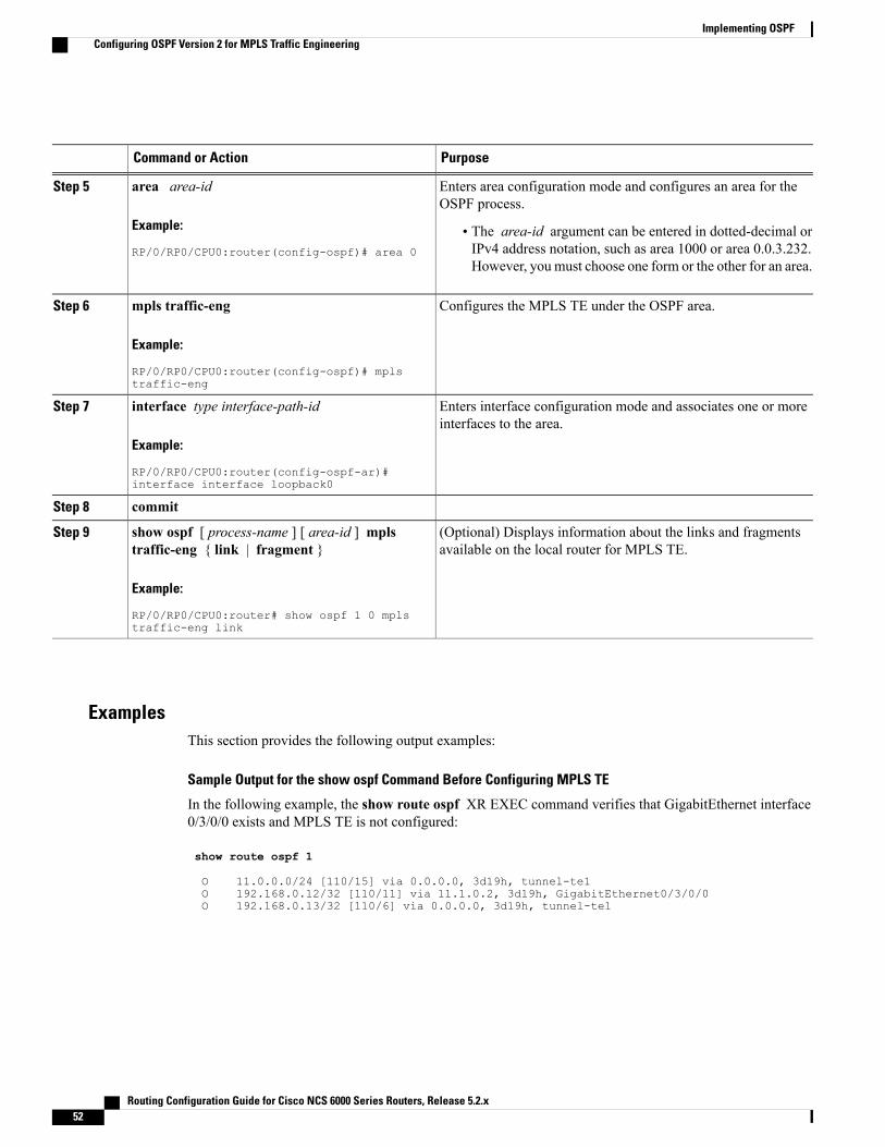
PurposeCommand or Action
Enters area configuration mode and configures an area for theOSPF process.
area area-id
Example:
RP/0/RP0/CPU0:router(config-ospf)# area 0
Step 5
• The area-id argument can be entered in dotted-decimal orIPv4 address notation, such as area 1000 or area 0.0.3.232.However, you must choose one form or the other for an area.
Configures the MPLS TE under the OSPF area.mpls traffic-eng
Example:
RP/0/RP0/CPU0:router(config-ospf)# mplstraffic-eng
Step 6
Enters interface configuration mode and associates one or moreinterfaces to the area.
interface type interface-path-id
Example:
RP/0/RP0/CPU0:router(config-ospf-ar)#interface interface loopback0
Step 7
commitStep 8
(Optional) Displays information about the links and fragmentsavailable on the local router for MPLS TE.
show ospf [ process-name ] [ area-id ] mplstraffic-eng { link | fragment }
Example:
RP/0/RP0/CPU0:router# show ospf 1 0 mplstraffic-eng link
Step 9
ExamplesThis section provides the following output examples:
Sample Output for the show ospf Command Before Configuring MPLS TE
In the following example, the show route ospf XR EXEC command verifies that GigabitEthernet interface0/3/0/0 exists and MPLS TE is not configured:
show route ospf 1
O 11.0.0.0/24 [110/15] via 0.0.0.0, 3d19h, tunnel-te1O 192.168.0.12/32 [110/11] via 11.1.0.2, 3d19h, GigabitEthernet0/3/0/0O 192.168.0.13/32 [110/6] via 0.0.0.0, 3d19h, tunnel-te1
Routing Configuration Guide for Cisco NCS 6000 Series Routers, Release 5.2.x52
Implementing OSPFConfiguring OSPF Version 2 for MPLS Traffic Engineering
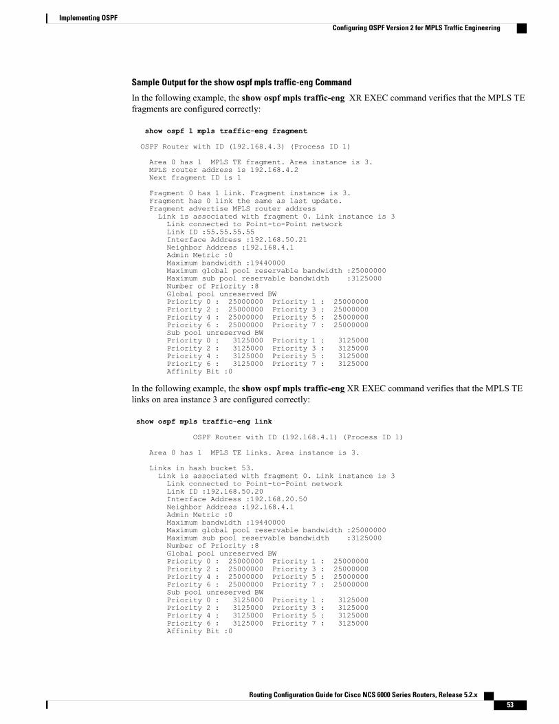
Sample Output for the show ospf mpls traffic-eng Command
In the following example, the show ospf mpls traffic-eng XR EXEC command verifies that the MPLS TEfragments are configured correctly:
show ospf 1 mpls traffic-eng fragment
OSPF Router with ID (192.168.4.3) (Process ID 1)
Area 0 has 1 MPLS TE fragment. Area instance is 3.MPLS router address is 192.168.4.2Next fragment ID is 1
Fragment 0 has 1 link. Fragment instance is 3.Fragment has 0 link the same as last update.Fragment advertise MPLS router addressLink is associated with fragment 0. Link instance is 3Link connected to Point-to-Point networkLink ID :55.55.55.55Interface Address :192.168.50.21Neighbor Address :192.168.4.1Admin Metric :0Maximum bandwidth :19440000Maximum global pool reservable bandwidth :25000000Maximum sub pool reservable bandwidth :3125000Number of Priority :8Global pool unreserved BWPriority 0 : 25000000 Priority 1 : 25000000Priority 2 : 25000000 Priority 3 : 25000000Priority 4 : 25000000 Priority 5 : 25000000Priority 6 : 25000000 Priority 7 : 25000000Sub pool unreserved BWPriority 0 : 3125000 Priority 1 : 3125000Priority 2 : 3125000 Priority 3 : 3125000Priority 4 : 3125000 Priority 5 : 3125000Priority 6 : 3125000 Priority 7 : 3125000Affinity Bit :0
In the following example, the show ospf mpls traffic-eng XR EXEC command verifies that the MPLS TElinks on area instance 3 are configured correctly:
show ospf mpls traffic-eng link
OSPF Router with ID (192.168.4.1) (Process ID 1)
Area 0 has 1 MPLS TE links. Area instance is 3.
Links in hash bucket 53.Link is associated with fragment 0. Link instance is 3Link connected to Point-to-Point networkLink ID :192.168.50.20Interface Address :192.168.20.50Neighbor Address :192.168.4.1Admin Metric :0Maximum bandwidth :19440000Maximum global pool reservable bandwidth :25000000Maximum sub pool reservable bandwidth :3125000Number of Priority :8Global pool unreserved BWPriority 0 : 25000000 Priority 1 : 25000000Priority 2 : 25000000 Priority 3 : 25000000Priority 4 : 25000000 Priority 5 : 25000000Priority 6 : 25000000 Priority 7 : 25000000Sub pool unreserved BWPriority 0 : 3125000 Priority 1 : 3125000Priority 2 : 3125000 Priority 3 : 3125000Priority 4 : 3125000 Priority 5 : 3125000Priority 6 : 3125000 Priority 7 : 3125000Affinity Bit :0
Routing Configuration Guide for Cisco NCS 6000 Series Routers, Release 5.2.x 53
Implementing OSPFConfiguring OSPF Version 2 for MPLS Traffic Engineering
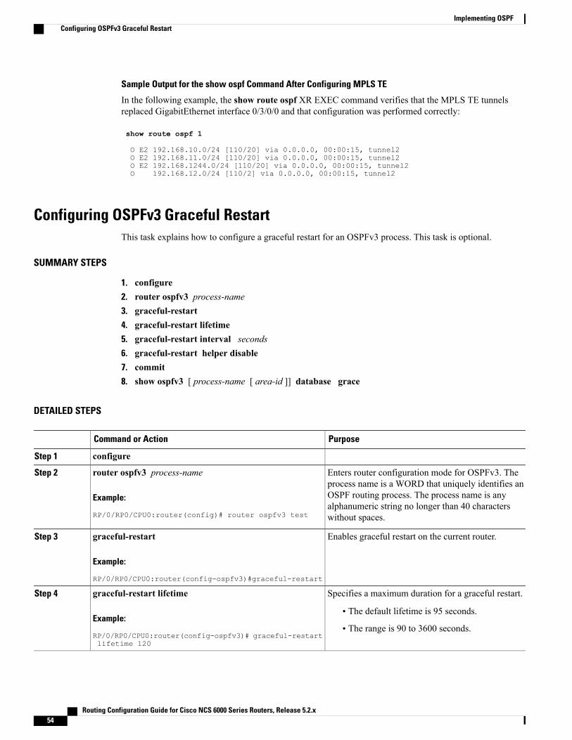
Sample Output for the show ospf Command After Configuring MPLS TE
In the following example, the show route ospf XR EXEC command verifies that the MPLS TE tunnelsreplaced GigabitEthernet interface 0/3/0/0 and that configuration was performed correctly:
show route ospf 1
O E2 192.168.10.0/24 [110/20] via 0.0.0.0, 00:00:15, tunnel2O E2 192.168.11.0/24 [110/20] via 0.0.0.0, 00:00:15, tunnel2O E2 192.168.1244.0/24 [110/20] via 0.0.0.0, 00:00:15, tunnel2O 192.168.12.0/24 [110/2] via 0.0.0.0, 00:00:15, tunnel2
Configuring OSPFv3 Graceful RestartThis task explains how to configure a graceful restart for an OSPFv3 process. This task is optional.
SUMMARY STEPS
1. configure2. router ospfv3 process-name3. graceful-restart4. graceful-restart lifetime5. graceful-restart interval seconds6. graceful-restart helper disable7. commit8. show ospfv3 [ process-name [ area-id ]] database grace
DETAILED STEPS
PurposeCommand or Action
configureStep 1
Enters router configuration mode for OSPFv3. Theprocess name is a WORD that uniquely identifies an
router ospfv3 process-name
Example:
RP/0/RP0/CPU0:router(config)# router ospfv3 test
Step 2
OSPF routing process. The process name is anyalphanumeric string no longer than 40 characterswithout spaces.
Enables graceful restart on the current router.graceful-restart
Example:
RP/0/RP0/CPU0:router(config-ospfv3)#graceful-restart
Step 3
Specifies a maximum duration for a graceful restart.graceful-restart lifetimeStep 4
Example:
RP/0/RP0/CPU0:router(config-ospfv3)# graceful-restartlifetime 120
• The default lifetime is 95 seconds.
• The range is 90 to 3600 seconds.
Routing Configuration Guide for Cisco NCS 6000 Series Routers, Release 5.2.x54
Implementing OSPFConfiguring OSPFv3 Graceful Restart
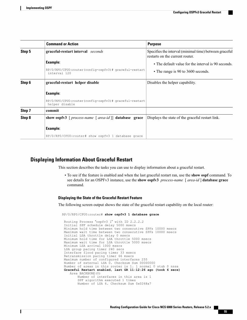
PurposeCommand or Action
Specifies the interval (minimal time) between gracefulrestarts on the current router.
graceful-restart interval seconds
Example:
RP/0/RP0/CPU0:router(config-ospfv3)# graceful-restartinterval 120
Step 5
• The default value for the interval is 90 seconds.
• The range is 90 to 3600 seconds.
Disables the helper capability.graceful-restart helper disable
Example:
RP/0/RP0/CPU0:router(config-ospfv3)# graceful-restarthelper disable
Step 6
commitStep 7
Displays the state of the graceful restart link.show ospfv3 [ process-name [ area-id ]] database grace
Example:
RP/0/RP0/CPU0:router# show ospfv3 1 database grace
Step 8
Displaying Information About Graceful RestartThis section describes the tasks you can use to display information about a graceful restart.
• To see if the feature is enabled and when the last graceful restart ran, use the show ospf command. Tosee details for an OSPFv3 instance, use the show ospfv3 process-name [ area-id ] database gracecommand.
Displaying the State of the Graceful Restart Feature
The following screen output shows the state of the graceful restart capability on the local router:
RP/0/RP0/CPU0:router# show ospfv3 1 database grace
Routing Process “ospfv3 1” with ID 2.2.2.2Initial SPF schedule delay 5000 msecsMinimum hold time between two consecutive SPFs 10000 msecsMaximum wait time between two consecutive SPFs 10000 msecsInitial LSA throttle delay 0 msecsMinimum hold time for LSA throttle 5000 msecsMaximum wait time for LSA throttle 5000 msecsMinimum LSA arrival 1000 msecsLSA group pacing timer 240 secsInterface flood pacing timer 33 msecsRetransmission pacing timer 66 msecsMaximum number of configured interfaces 255Number of external LSA 0. Checksum Sum 00000000Number of areas in this router is 1. 1 normal 0 stub 0 nssaGraceful Restart enabled, last GR 11:12:26 ago (took 6 secs)
Area BACKBONE(0)Number of interfaces in this area is 1SPF algorithm executed 1 timesNumber of LSA 6. Checksum Sum 0x0268a7
Routing Configuration Guide for Cisco NCS 6000 Series Routers, Release 5.2.x 55
Implementing OSPFConfiguring OSPFv3 Graceful Restart
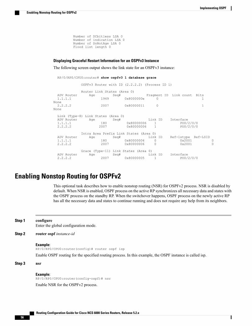
Number of DCbitless LSA 0Number of indication LSA 0Number of DoNotAge LSA 0Flood list length 0
Displaying Graceful Restart Information for an OSPFv3 Instance
The following screen output shows the link state for an OSPFv3 instance:
RP/0/RP0/CPU0:router# show ospfv3 1 database grace
OSPFv3 Router with ID (2.2.2.2) (Process ID 1)
Router Link States (Area 0)ADV Router Age Seq# Fragment ID Link count Bits1.1.1.1 1949 0x8000000e 0 1
None2.2.2.2 2007 0x80000011 0 1
None
Link (Type-8) Link States (Area 0)ADV Router Age Seq# Link ID Interface1.1.1.1 180 0x80000006 1 PO0/2/0/02.2.2.2 2007 0x80000006 1 PO0/2/0/0
Intra Area Prefix Link States (Area 0)ADV Router Age Seq# Link ID Ref-lstype Ref-LSID1.1.1.1 180 0x80000006 0 0x2001 02.2.2.2 2007 0x80000006 0 0x2001 0
Grace (Type-11) Link States (Area 0)ADV Router Age Seq# Link ID Interface2.2.2.2 2007 0x80000005 1 PO0/2/0/0
Enabling Nonstop Routing for OSPFv2This optional task describes how to enable nonstop routing (NSR) for OSPFv2 process. NSR is disabled bydefault. When NSR is enabled, OSPF process on the active RP synchronizes all necessary data and states withthe OSPF process on the standby RP. When the switchover happens, OSPF process on the newly active RPhas all the necessary data and states to continue running and does not require any help from its neighbors.
Step 1 configureEnter the global configuration mode.
Step 2 router ospf instance-id
Example:RP/0/RP0/CPU0:router(config)# router ospf isp
Enable OSPF routing for the specified routing process. In this example, the OSPF instance is called isp.
Step 3 nsr
Example:RP/0/RP0/CPU0:router(config-ospf)# nsr
Enable NSR for the OSPFv2 process.
Routing Configuration Guide for Cisco NCS 6000 Series Routers, Release 5.2.x56
Implementing OSPFEnabling Nonstop Routing for OSPFv2
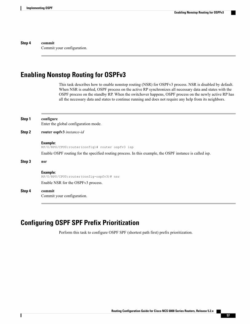
Step 4 commitCommit your configuration.
Enabling Nonstop Routing for OSPFv3This task describes how to enable nonstop routing (NSR) for OSPFv3 process. NSR is disabled by default.When NSR is enabled, OSPF process on the active RP synchronizes all necessary data and states with theOSPF process on the standby RP. When the switchover happens, OSPF process on the newly active RP hasall the necessary data and states to continue running and does not require any help from its neighbors.
Step 1 configureEnter the global configuration mode.
Step 2 router ospfv3 instance-id
Example:RP/0/RP0/CPU0:router(config)# router ospfv3 isp
Enable OSPF routing for the specified routing process. In this example, the OSPF instance is called isp.
Step 3 nsr
Example:RP/0/RP0/CPU0:router(config-ospfv3)# nsr
Enable NSR for the OSPFv3 process.
Step 4 commitCommit your configuration.
Configuring OSPF SPF Prefix PrioritizationPerform this task to configure OSPF SPF (shortest path first) prefix prioritization.
Routing Configuration Guide for Cisco NCS 6000 Series Routers, Release 5.2.x 57
Implementing OSPFEnabling Nonstop Routing for OSPFv3
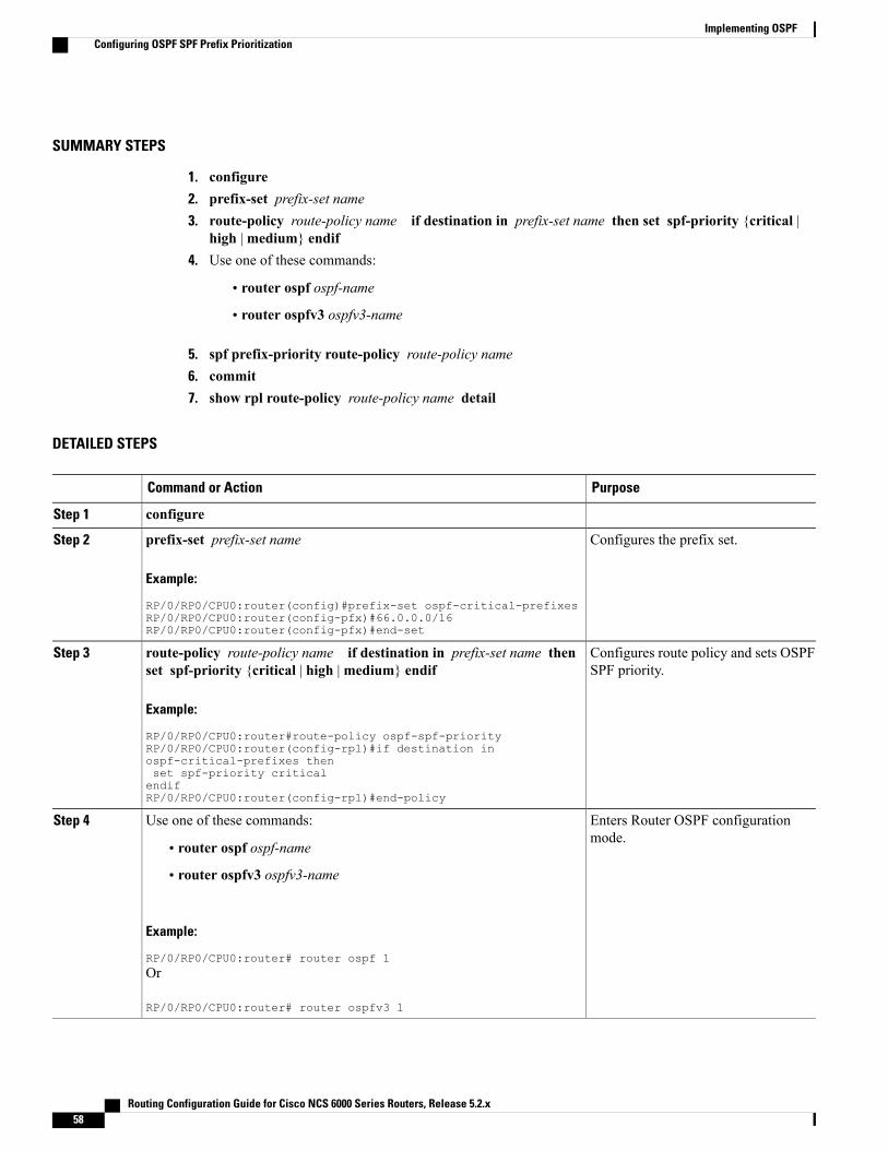
SUMMARY STEPS
1. configure2. prefix-set prefix-set name3. route-policy route-policy name if destination in prefix-set name then set spf-priority {critical |
high |medium} endif4. Use one of these commands:
• router ospf ospf-name
• router ospfv3 ospfv3-name
5. spf prefix-priority route-policy route-policy name6. commit7. show rpl route-policy route-policy name detail
DETAILED STEPS
PurposeCommand or Action
configureStep 1
Configures the prefix set.prefix-set prefix-set name
Example:
RP/0/RP0/CPU0:router(config)#prefix-set ospf-critical-prefixes
Step 2
RP/0/RP0/CPU0:router(config-pfx)#66.0.0.0/16RP/0/RP0/CPU0:router(config-pfx)#end-set
Configures route policy and sets OSPFSPF priority.
route-policy route-policy name if destination in prefix-set name thenset spf-priority {critical | high |medium} endif
Example:
RP/0/RP0/CPU0:router#route-policy ospf-spf-priority
Step 3
RP/0/RP0/CPU0:router(config-rpl)#if destination inospf-critical-prefixes thenset spf-priority criticalendifRP/0/RP0/CPU0:router(config-rpl)#end-policy
Enters Router OSPF configurationmode.
Use one of these commands:Step 4
• router ospf ospf-name
• router ospfv3 ospfv3-name
Example:
RP/0/RP0/CPU0:router# router ospf 1Or
RP/0/RP0/CPU0:router# router ospfv3 1
Routing Configuration Guide for Cisco NCS 6000 Series Routers, Release 5.2.x58
Implementing OSPFConfiguring OSPF SPF Prefix Prioritization
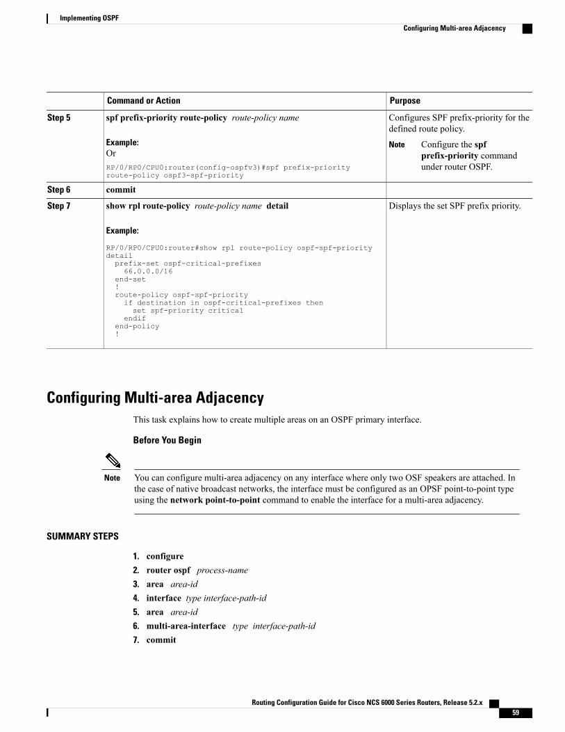
PurposeCommand or Action
Configures SPF prefix-priority for thedefined route policy.
spf prefix-priority route-policy route-policy name
Example:
Step 5
Configure the spfprefix-priority commandunder router OSPF.
NoteOrRP/0/RP0/CPU0:router(config-ospfv3)#spf prefix-priorityroute-policy ospf3-spf-priority
commitStep 6
Displays the set SPF prefix priority.show rpl route-policy route-policy name detail
Example:
RP/0/RP0/CPU0:router#show rpl route-policy ospf-spf-priority
Step 7
detailprefix-set ospf-critical-prefixes66.0.0.0/16
end-set!route-policy ospf-spf-priorityif destination in ospf-critical-prefixes thenset spf-priority critical
endifend-policy!
Configuring Multi-area AdjacencyThis task explains how to create multiple areas on an OSPF primary interface.
Before You Begin
You can configure multi-area adjacency on any interface where only two OSF speakers are attached. Inthe case of native broadcast networks, the interface must be configured as an OPSF point-to-point typeusing the network point-to-point command to enable the interface for a multi-area adjacency.
Note
SUMMARY STEPS
1. configure2. router ospf process-name3. area area-id4. interface type interface-path-id5. area area-id6. multi-area-interface type interface-path-id7. commit
Routing Configuration Guide for Cisco NCS 6000 Series Routers, Release 5.2.x 59
Implementing OSPFConfiguring Multi-area Adjacency
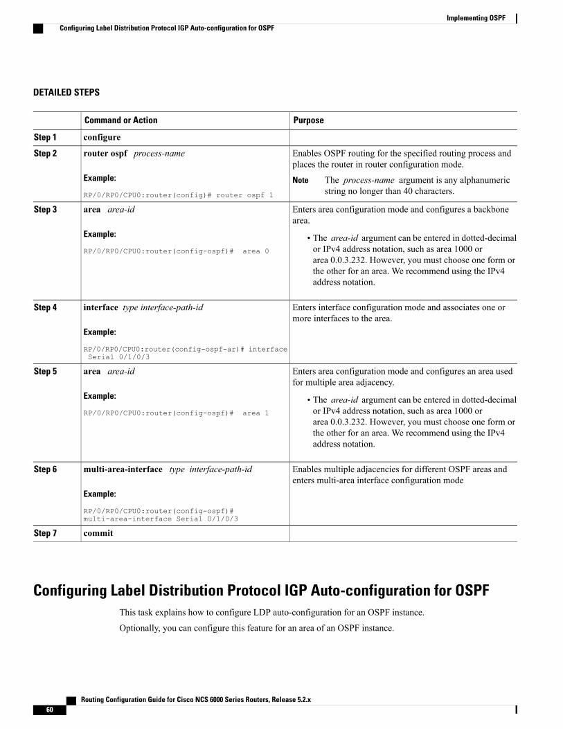
DETAILED STEPS
PurposeCommand or Action
configureStep 1
Enables OSPF routing for the specified routing process andplaces the router in router configuration mode.
router ospf process-name
Example:
RP/0/RP0/CPU0:router(config)# router ospf 1
Step 2
The process-name argument is any alphanumericstring no longer than 40 characters.
Note
Enters area configuration mode and configures a backbonearea.
area area-id
Example:
RP/0/RP0/CPU0:router(config-ospf)# area 0
Step 3
• The area-id argument can be entered in dotted-decimalor IPv4 address notation, such as area 1000 orarea 0.0.3.232. However, you must choose one form orthe other for an area. We recommend using the IPv4address notation.
Enters interface configuration mode and associates one ormore interfaces to the area.
interface type interface-path-id
Example:
RP/0/RP0/CPU0:router(config-ospf-ar)# interfaceSerial 0/1/0/3
Step 4
Enters area configuration mode and configures an area usedfor multiple area adjacency.
area area-id
Example:
RP/0/RP0/CPU0:router(config-ospf)# area 1
Step 5
• The area-id argument can be entered in dotted-decimalor IPv4 address notation, such as area 1000 orarea 0.0.3.232. However, you must choose one form orthe other for an area. We recommend using the IPv4address notation.
Enables multiple adjacencies for different OSPF areas andenters multi-area interface configuration mode
multi-area-interface type interface-path-id
Example:
RP/0/RP0/CPU0:router(config-ospf)#multi-area-interface Serial 0/1/0/3
Step 6
commitStep 7
Configuring Label Distribution Protocol IGP Auto-configuration for OSPFThis task explains how to configure LDP auto-configuration for an OSPF instance.
Optionally, you can configure this feature for an area of an OSPF instance.
Routing Configuration Guide for Cisco NCS 6000 Series Routers, Release 5.2.x60
Implementing OSPFConfiguring Label Distribution Protocol IGP Auto-configuration for OSPF
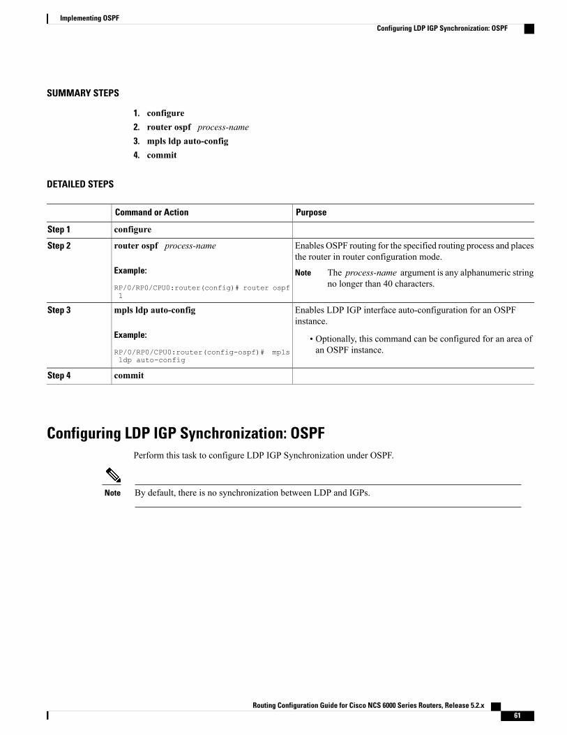
SUMMARY STEPS
1. configure2. router ospf process-name3. mpls ldp auto-config4. commit
DETAILED STEPS
PurposeCommand or Action
configureStep 1
Enables OSPF routing for the specified routing process and placesthe router in router configuration mode.
router ospf process-name
Example:
RP/0/RP0/CPU0:router(config)# router ospf1
Step 2
The process-name argument is any alphanumeric stringno longer than 40 characters.
Note
Enables LDP IGP interface auto-configuration for an OSPFinstance.
mpls ldp auto-config
Example:
RP/0/RP0/CPU0:router(config-ospf)# mplsldp auto-config
Step 3
• Optionally, this command can be configured for an area ofan OSPF instance.
commitStep 4
Configuring LDP IGP Synchronization: OSPFPerform this task to configure LDP IGP Synchronization under OSPF.
By default, there is no synchronization between LDP and IGPs.Note
Routing Configuration Guide for Cisco NCS 6000 Series Routers, Release 5.2.x 61
Implementing OSPFConfiguring LDP IGP Synchronization: OSPF
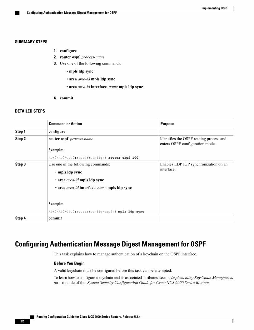
SUMMARY STEPS
1. configure2. router ospf process-name3. Use one of the following commands:
• mpls ldp sync
• area area-idmpls ldp sync
• area area-id interface namempls ldp sync
4. commit
DETAILED STEPS
PurposeCommand or Action
configureStep 1
Identifies the OSPF routing process andenters OSPF configuration mode.
router ospf process-name
Example:
RP/0/RP0/CPU0:router(config)# router ospf 100
Step 2
Enables LDP IGP synchronization on aninterface.
Use one of the following commands:Step 3
• mpls ldp sync
• area area-idmpls ldp sync
• area area-id interface namempls ldp sync
Example:
RP/0/RP0/CPU0:router(config-ospf)# mpls ldp sync
commitStep 4
Configuring Authentication Message Digest Management for OSPFThis task explains how to manage authentication of a keychain on the OSPF interface.
Before You Begin
A valid keychain must be configured before this task can be attempted.
To learn how to configure a keychain and its associated attributes, see the Implementing Key ChainManagementon module of the System Security Configuration Guide for Cisco NCS 6000 Series Routers.
Routing Configuration Guide for Cisco NCS 6000 Series Routers, Release 5.2.x62
Implementing OSPFConfiguring Authentication Message Digest Management for OSPF
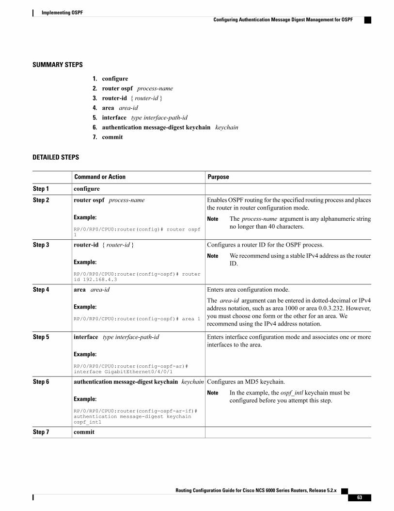
SUMMARY STEPS
1. configure2. router ospf process-name3. router-id { router-id }4. area area-id5. interface type interface-path-id6. authentication message-digest keychain keychain7. commit
DETAILED STEPS
PurposeCommand or Action
configureStep 1
Enables OSPF routing for the specified routing process and placesthe router in router configuration mode.
router ospf process-name
Example:
RP/0/RP0/CPU0:router(config)# router ospf1
Step 2
The process-name argument is any alphanumeric stringno longer than 40 characters.
Note
Configures a router ID for the OSPF process.router-id { router-id }Step 3
Example:
RP/0/RP0/CPU0:router(config-ospf)# routerid 192.168.4.3
We recommend using a stable IPv4 address as the routerID.
Note
Enters area configuration mode.area area-idStep 4
Example:
RP/0/RP0/CPU0:router(config-ospf)# area 1
The area-id argument can be entered in dotted-decimal or IPv4address notation, such as area 1000 or area 0.0.3.232. However,you must choose one form or the other for an area. Werecommend using the IPv4 address notation.
Enters interface configuration mode and associates one or moreinterfaces to the area.
interface type interface-path-id
Example:
RP/0/RP0/CPU0:router(config-ospf-ar)#interface GigabitEthernet0/4/0/1
Step 5
Configures an MD5 keychain.authenticationmessage-digest keychain keychainStep 6
Example:
RP/0/RP0/CPU0:router(config-ospf-ar-if)#
In the example, the ospf_intl keychain must beconfigured before you attempt this step.
Note
authentication message-digest keychainospf_int1
commitStep 7
Routing Configuration Guide for Cisco NCS 6000 Series Routers, Release 5.2.x 63
Implementing OSPFConfiguring Authentication Message Digest Management for OSPF
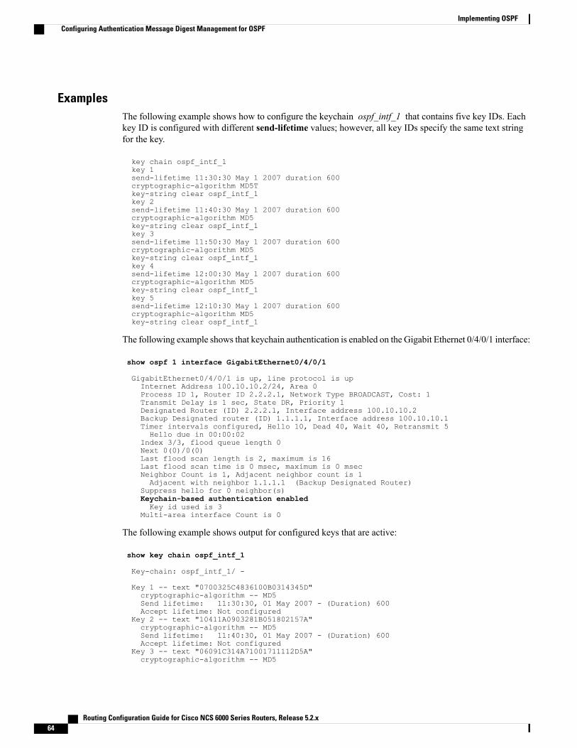
ExamplesThe following example shows how to configure the keychain ospf_intf_1 that contains five key IDs. Eachkey ID is configured with different send-lifetime values; however, all key IDs specify the same text stringfor the key.
key chain ospf_intf_1key 1send-lifetime 11:30:30 May 1 2007 duration 600cryptographic-algorithm MD5Tkey-string clear ospf_intf_1key 2send-lifetime 11:40:30 May 1 2007 duration 600cryptographic-algorithm MD5key-string clear ospf_intf_1key 3send-lifetime 11:50:30 May 1 2007 duration 600cryptographic-algorithm MD5key-string clear ospf_intf_1key 4send-lifetime 12:00:30 May 1 2007 duration 600cryptographic-algorithm MD5key-string clear ospf_intf_1key 5send-lifetime 12:10:30 May 1 2007 duration 600cryptographic-algorithm MD5key-string clear ospf_intf_1
The following example shows that keychain authentication is enabled on the Gigabit Ethernet 0/4/0/1 interface:
show ospf 1 interface GigabitEthernet0/4/0/1
GigabitEthernet0/4/0/1 is up, line protocol is upInternet Address 100.10.10.2/24, Area 0Process ID 1, Router ID 2.2.2.1, Network Type BROADCAST, Cost: 1Transmit Delay is 1 sec, State DR, Priority 1Designated Router (ID) 2.2.2.1, Interface address 100.10.10.2Backup Designated router (ID) 1.1.1.1, Interface address 100.10.10.1Timer intervals configured, Hello 10, Dead 40, Wait 40, Retransmit 5Hello due in 00:00:02
Index 3/3, flood queue length 0Next 0(0)/0(0)Last flood scan length is 2, maximum is 16Last flood scan time is 0 msec, maximum is 0 msecNeighbor Count is 1, Adjacent neighbor count is 1Adjacent with neighbor 1.1.1.1 (Backup Designated Router)
Suppress hello for 0 neighbor(s)Keychain-based authentication enabledKey id used is 3
Multi-area interface Count is 0
The following example shows output for configured keys that are active:
show key chain ospf_intf_1
Key-chain: ospf_intf_1/ -
Key 1 -- text "0700325C4836100B0314345D"cryptographic-algorithm -- MD5Send lifetime: 11:30:30, 01 May 2007 - (Duration) 600Accept lifetime: Not configured
Key 2 -- text "10411A0903281B051802157A"cryptographic-algorithm -- MD5Send lifetime: 11:40:30, 01 May 2007 - (Duration) 600Accept lifetime: Not configured
Key 3 -- text "06091C314A71001711112D5A"cryptographic-algorithm -- MD5
Routing Configuration Guide for Cisco NCS 6000 Series Routers, Release 5.2.x64
Implementing OSPFConfiguring Authentication Message Digest Management for OSPF
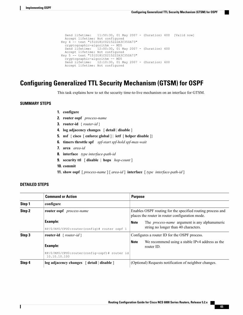
Send lifetime: 11:50:30, 01 May 2007 - (Duration) 600 [Valid now]Accept lifetime: Not configured
Key 4 -- text "151D181C0215222A3C350A73"cryptographic-algorithm -- MD5Send lifetime: 12:00:30, 01 May 2007 - (Duration) 600Accept lifetime: Not configured
Key 5 -- text "151D181C0215222A3C350A73"cryptographic-algorithm -- MD5Send lifetime: 12:10:30, 01 May 2007 - (Duration) 600Accept lifetime: Not configured
Configuring Generalized TTL Security Mechanism (GTSM) for OSPFThis task explains how to set the security time-to-live mechanism on an interface for GTSM.
SUMMARY STEPS
1. configure2. router ospf process-name3. router-id { router-id }4. log adjacency changes [ detail | disable ]5. nsf { cisco [ enforce global ] | ietf [ helper disable ]}6. timers throttle spf spf-start spf-hold spf-max-wait7. area area-id8. interface type interface-path-id9. security ttl [ disable | hops hop-count ]10. commit11. show ospf [ process-name ] [ area-id ] interface [ type interface-path-id ]
DETAILED STEPS
PurposeCommand or Action
configureStep 1
Enables OSPF routing for the specified routing process andplaces the router in router configuration mode.
router ospf process-name
Example:
RP/0/RP0/CPU0:router(config)# router ospf 1
Step 2
The process-name argument is any alphanumericstring no longer than 40 characters.
Note
Configures a router ID for the OSPF process.router-id { router-id }Step 3
Example:
RP/0/RP0/CPU0:router(config-ospf)# router id10.10.10.100
We recommend using a stable IPv4 address as therouter ID.
Note
(Optional) Requests notification of neighbor changes.log adjacency changes [ detail | disable ]Step 4
Routing Configuration Guide for Cisco NCS 6000 Series Routers, Release 5.2.x 65
Implementing OSPFConfiguring Generalized TTL Security Mechanism (GTSM) for OSPF
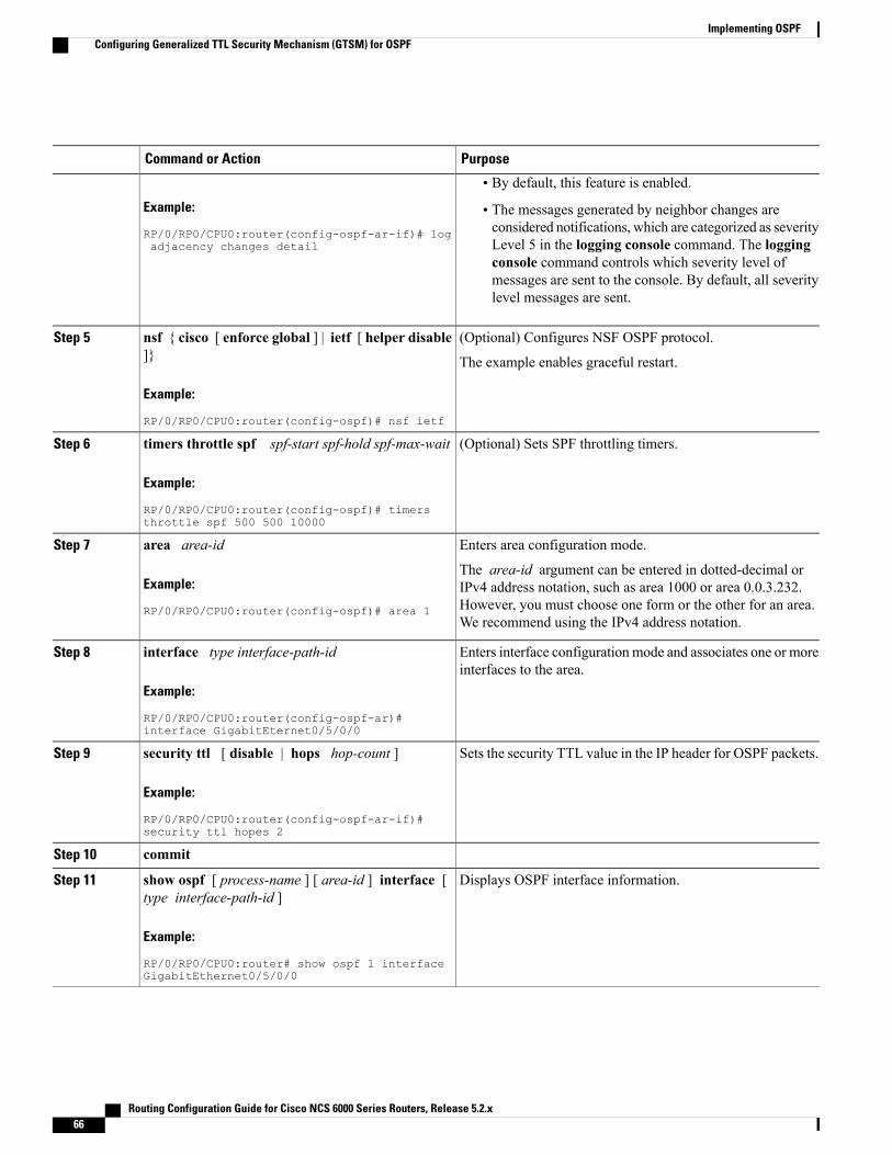
PurposeCommand or Action
Example:
RP/0/RP0/CPU0:router(config-ospf-ar-if)# logadjacency changes detail
• By default, this feature is enabled.
• The messages generated by neighbor changes areconsidered notifications, which are categorized as severityLevel 5 in the logging console command. The loggingconsole command controls which severity level ofmessages are sent to the console. By default, all severitylevel messages are sent.
(Optional) Configures NSF OSPF protocol.nsf { cisco [ enforce global ] | ietf [ helper disable]}
Step 5
The example enables graceful restart.
Example:
RP/0/RP0/CPU0:router(config-ospf)# nsf ietf
(Optional) Sets SPF throttling timers.timers throttle spf spf-start spf-hold spf-max-wait
Example:
RP/0/RP0/CPU0:router(config-ospf)# timersthrottle spf 500 500 10000
Step 6
Enters area configuration mode.area area-idStep 7
Example:
RP/0/RP0/CPU0:router(config-ospf)# area 1
The area-id argument can be entered in dotted-decimal orIPv4 address notation, such as area 1000 or area 0.0.3.232.However, you must choose one form or the other for an area.We recommend using the IPv4 address notation.
Enters interface configurationmode and associates one or moreinterfaces to the area.
interface type interface-path-id
Example:
RP/0/RP0/CPU0:router(config-ospf-ar)#interface GigabitEternet0/5/0/0
Step 8
Sets the security TTL value in the IP header for OSPF packets.security ttl [ disable | hops hop-count ]
Example:
RP/0/RP0/CPU0:router(config-ospf-ar-if)#security ttl hopes 2
Step 9
commitStep 10
Displays OSPF interface information.show ospf [ process-name ] [ area-id ] interface [type interface-path-id ]
Step 11
Example:
RP/0/RP0/CPU0:router# show ospf 1 interfaceGigabitEthernet0/5/0/0
Routing Configuration Guide for Cisco NCS 6000 Series Routers, Release 5.2.x66
Implementing OSPFConfiguring Generalized TTL Security Mechanism (GTSM) for OSPF
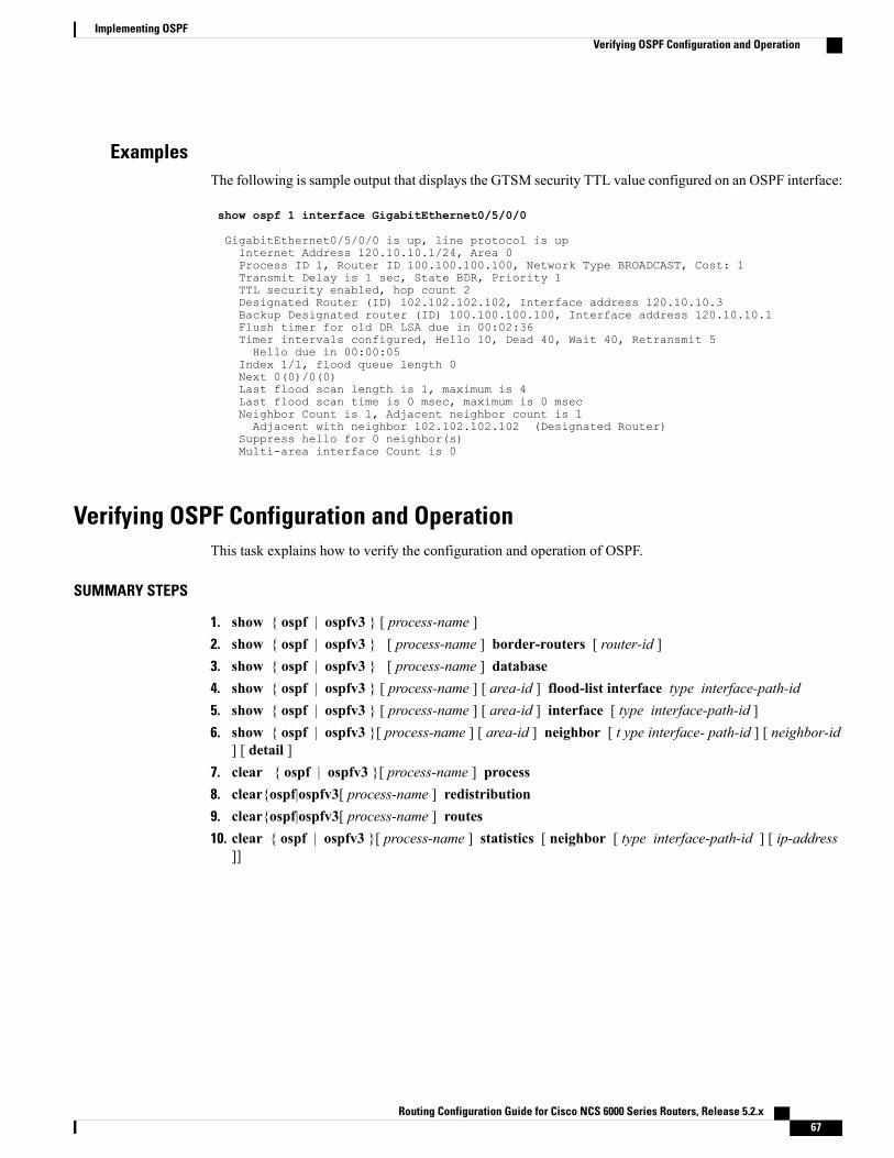
ExamplesThe following is sample output that displays the GTSM security TTL value configured on an OSPF interface:
show ospf 1 interface GigabitEthernet0/5/0/0
GigabitEthernet0/5/0/0 is up, line protocol is upInternet Address 120.10.10.1/24, Area 0Process ID 1, Router ID 100.100.100.100, Network Type BROADCAST, Cost: 1Transmit Delay is 1 sec, State BDR, Priority 1TTL security enabled, hop count 2Designated Router (ID) 102.102.102.102, Interface address 120.10.10.3Backup Designated router (ID) 100.100.100.100, Interface address 120.10.10.1Flush timer for old DR LSA due in 00:02:36Timer intervals configured, Hello 10, Dead 40, Wait 40, Retransmit 5Hello due in 00:00:05
Index 1/1, flood queue length 0Next 0(0)/0(0)Last flood scan length is 1, maximum is 4Last flood scan time is 0 msec, maximum is 0 msecNeighbor Count is 1, Adjacent neighbor count is 1Adjacent with neighbor 102.102.102.102 (Designated Router)
Suppress hello for 0 neighbor(s)Multi-area interface Count is 0
Verifying OSPF Configuration and OperationThis task explains how to verify the configuration and operation of OSPF.
SUMMARY STEPS
1. show { ospf | ospfv3 } [ process-name ]2. show { ospf | ospfv3 } [ process-name ] border-routers [ router-id ]3. show { ospf | ospfv3 } [ process-name ] database4. show { ospf | ospfv3 } [ process-name ] [ area-id ] flood-list interface type interface-path-id5. show { ospf | ospfv3 } [ process-name ] [ area-id ] interface [ type interface-path-id ]6. show { ospf | ospfv3 }[ process-name ] [ area-id ] neighbor [ t ype interface- path-id ] [ neighbor-id
] [ detail ]7. clear { ospf | ospfv3 }[ process-name ] process8. clear{ospf|ospfv3[ process-name ] redistribution9. clear{ospf|ospfv3[ process-name ] routes10. clear { ospf | ospfv3 }[ process-name ] statistics [ neighbor [ type interface-path-id ] [ ip-address
]]
Routing Configuration Guide for Cisco NCS 6000 Series Routers, Release 5.2.x 67
Implementing OSPFVerifying OSPF Configuration and Operation
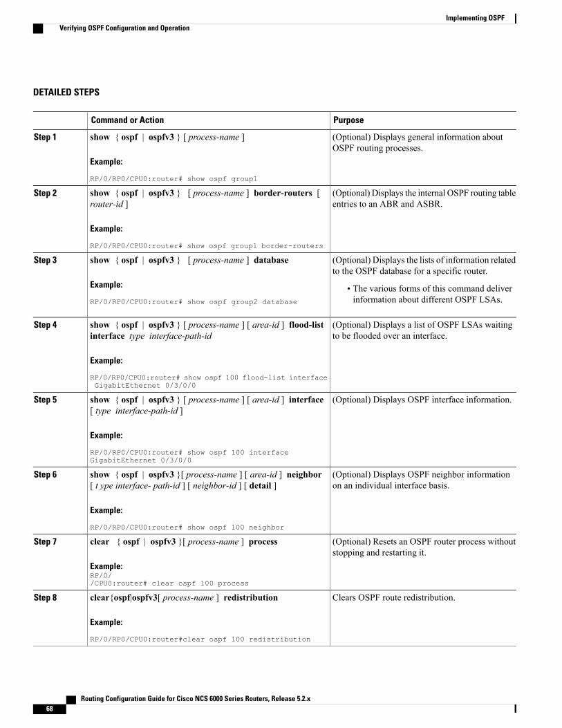
DETAILED STEPS
PurposeCommand or Action
(Optional) Displays general information aboutOSPF routing processes.
show { ospf | ospfv3 } [ process-name ]
Example:
RP/0/RP0/CPU0:router# show ospf group1
Step 1
(Optional) Displays the internal OSPF routing tableentries to an ABR and ASBR.
show { ospf | ospfv3 } [ process-name ] border-routers [router-id ]
Example:
RP/0/RP0/CPU0:router# show ospf group1 border-routers
Step 2
(Optional) Displays the lists of information relatedto the OSPF database for a specific router.
show { ospf | ospfv3 } [ process-name ] database
Example:
RP/0/RP0/CPU0:router# show ospf group2 database
Step 3
• The various forms of this command deliverinformation about different OSPF LSAs.
(Optional) Displays a list of OSPF LSAs waitingto be flooded over an interface.
show { ospf | ospfv3 } [ process-name ] [ area-id ] flood-listinterface type interface-path-id
Example:
RP/0/RP0/CPU0:router# show ospf 100 flood-list interfaceGigabitEthernet 0/3/0/0
Step 4
(Optional) Displays OSPF interface information.show { ospf | ospfv3 } [ process-name ] [ area-id ] interface[ type interface-path-id ]
Step 5
Example:
RP/0/RP0/CPU0:router# show ospf 100 interfaceGigabitEthernet 0/3/0/0
(Optional) Displays OSPF neighbor informationon an individual interface basis.
show { ospf | ospfv3 }[ process-name ] [ area-id ] neighbor[ t ype interface- path-id ] [ neighbor-id ] [ detail ]
Example:
RP/0/RP0/CPU0:router# show ospf 100 neighbor
Step 6
(Optional) Resets an OSPF router process withoutstopping and restarting it.
clear { ospf | ospfv3 }[ process-name ] process
Example:RP/0//CPU0:router# clear ospf 100 process
Step 7
Clears OSPF route redistribution.clear{ospf|ospfv3[ process-name ] redistribution
Example:
RP/0/RP0/CPU0:router#clear ospf 100 redistribution
Step 8
Routing Configuration Guide for Cisco NCS 6000 Series Routers, Release 5.2.x68
Implementing OSPFVerifying OSPF Configuration and Operation
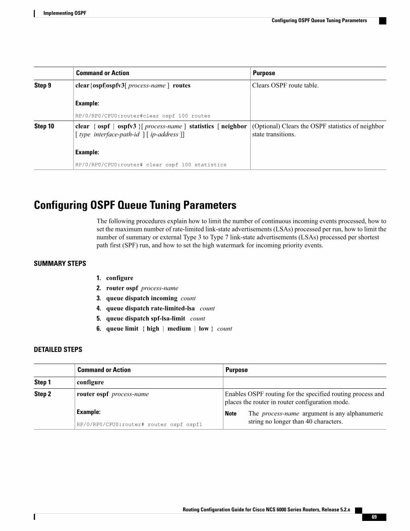
PurposeCommand or Action
Clears OSPF route table.clear{ospf|ospfv3[ process-name ] routes
Example:
RP/0/RP0/CPU0:router#clear ospf 100 routes
Step 9
(Optional) Clears the OSPF statistics of neighborstate transitions.
clear { ospf | ospfv3 }[ process-name ] statistics [ neighbor[ type interface-path-id ] [ ip-address ]]
Example:
RP/0/RP0/CPU0:router# clear ospf 100 statistics
Step 10
Configuring OSPF Queue Tuning ParametersThe following procedures explain how to limit the number of continuous incoming events processed, how toset the maximum number of rate-limited link-state advertisements (LSAs) processed per run, how to limit thenumber of summary or external Type 3 to Type 7 link-state advertisements (LSAs) processed per shortestpath first (SPF) run, and how to set the high watermark for incoming priority events.
SUMMARY STEPS
1. configure2. router ospf process-name3. queue dispatch incoming count4. queue dispatch rate-limited-lsa count5. queue dispatch spf-lsa-limit count6. queue limit { high | medium | low } count
DETAILED STEPS
PurposeCommand or Action
configureStep 1
Enables OSPF routing for the specified routing process andplaces the router in router configuration mode.
router ospf process-name
Example:
RP/0/RP0/CPU0:router# router ospf ospf1
Step 2
The process-name argument is any alphanumericstring no longer than 40 characters.
Note
Routing Configuration Guide for Cisco NCS 6000 Series Routers, Release 5.2.x 69
Implementing OSPFConfiguring OSPF Queue Tuning Parameters
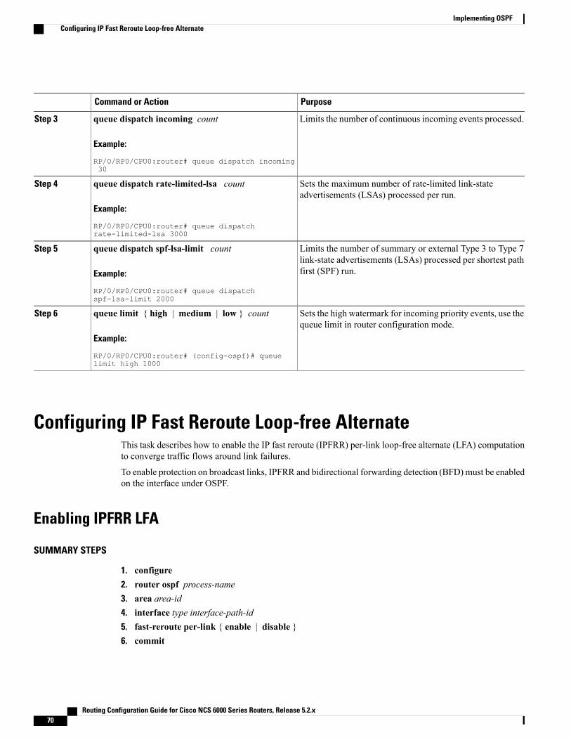
PurposeCommand or Action
Limits the number of continuous incoming events processed.queue dispatch incoming count
Example:
RP/0/RP0/CPU0:router# queue dispatch incoming30
Step 3
Sets the maximum number of rate-limited link-stateadvertisements (LSAs) processed per run.
queue dispatch rate-limited-lsa count
Example:
RP/0/RP0/CPU0:router# queue dispatchrate-limited-lsa 3000
Step 4
Limits the number of summary or external Type 3 to Type 7link-state advertisements (LSAs) processed per shortest pathfirst (SPF) run.
queue dispatch spf-lsa-limit count
Example:
RP/0/RP0/CPU0:router# queue dispatchspf-lsa-limit 2000
Step 5
Sets the high watermark for incoming priority events, use thequeue limit in router configuration mode.
queue limit { high | medium | low } count
Example:
RP/0/RP0/CPU0:router# (config-ospf)# queuelimit high 1000
Step 6
Configuring IP Fast Reroute Loop-free AlternateThis task describes how to enable the IP fast reroute (IPFRR) per-link loop-free alternate (LFA) computationto converge traffic flows around link failures.
To enable protection on broadcast links, IPFRR and bidirectional forwarding detection (BFD) must be enabledon the interface under OSPF.
Enabling IPFRR LFA
SUMMARY STEPS
1. configure2. router ospf process-name3. area area-id4. interface type interface-path-id5. fast-reroute per-link { enable | disable }6. commit
Routing Configuration Guide for Cisco NCS 6000 Series Routers, Release 5.2.x70
Implementing OSPFConfiguring IP Fast Reroute Loop-free Alternate
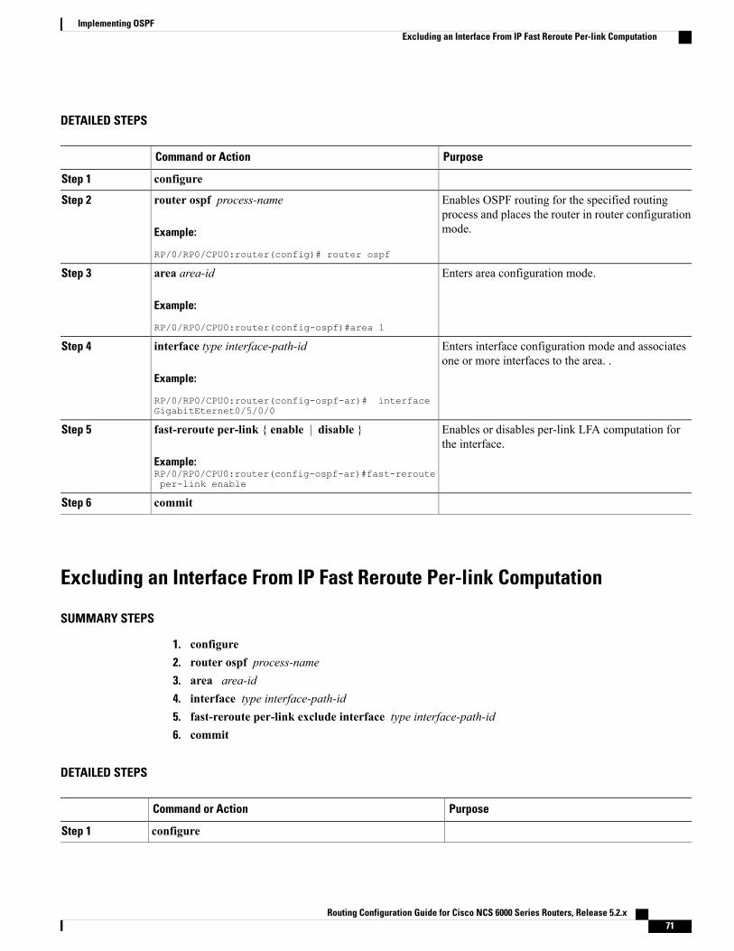
DETAILED STEPS
PurposeCommand or Action
configureStep 1
Enables OSPF routing for the specified routingprocess and places the router in router configurationmode.
router ospf process-name
Example:
RP/0/RP0/CPU0:router(config)# router ospf
Step 2
Enters area configuration mode.area area-id
Example:
RP/0/RP0/CPU0:router(config-ospf)#area 1
Step 3
Enters interface configuration mode and associatesone or more interfaces to the area. .
interface type interface-path-id
Example:
RP/0/RP0/CPU0:router(config-ospf-ar)# interfaceGigabitEternet0/5/0/0
Step 4
Enables or disables per-link LFA computation forthe interface.
fast-reroute per-link { enable | disable }
Example:RP/0/RP0/CPU0:router(config-ospf-ar)#fast-rerouteper-link enable
Step 5
commitStep 6
Excluding an Interface From IP Fast Reroute Per-link Computation
SUMMARY STEPS
1. configure2. router ospf process-name3. area area-id4. interface type interface-path-id5. fast-reroute per-link exclude interface type interface-path-id6. commit
DETAILED STEPS
PurposeCommand or Action
configureStep 1
Routing Configuration Guide for Cisco NCS 6000 Series Routers, Release 5.2.x 71
Implementing OSPFExcluding an Interface From IP Fast Reroute Per-link Computation
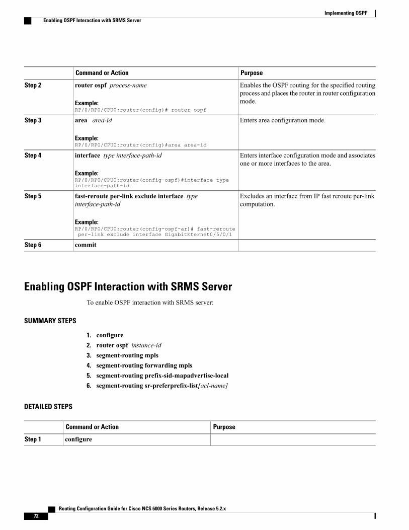
PurposeCommand or Action
Enables the OSPF routing for the specified routingprocess and places the router in router configurationmode.
router ospf process-name
Example:RP/0/RP0/CPU0:router(config)# router ospf
Step 2
Enters area configuration mode.area area-id
Example:RP/0/RP0/CPU0:router(config)#area area-id
Step 3
Enters interface configuration mode and associatesone or more interfaces to the area.
interface type interface-path-id
Example:RP/0/RP0/CPU0:router(config-ospf)#interface typeinterface-path-id
Step 4
Excludes an interface from IP fast reroute per-linkcomputation.
fast-reroute per-link exclude interface typeinterface-path-id
Example:RP/0/RP0/CPU0:router(config-ospf-ar)# fast-rerouteper-link exclude interface GigabitEternet0/5/0/1
Step 5
commitStep 6
Enabling OSPF Interaction with SRMS ServerTo enable OSPF interaction with SRMS server:
SUMMARY STEPS
1. configure2. router ospf instance-id3. segment-routing mpls4. segment-routing forwarding mpls5. segment-routing prefix-sid-mapadvertise-local6. segment-routing sr-preferprefix-list[acl-name]
DETAILED STEPS
PurposeCommand or Action
configureStep 1
Routing Configuration Guide for Cisco NCS 6000 Series Routers, Release 5.2.x72
Implementing OSPFEnabling OSPF Interaction with SRMS Server
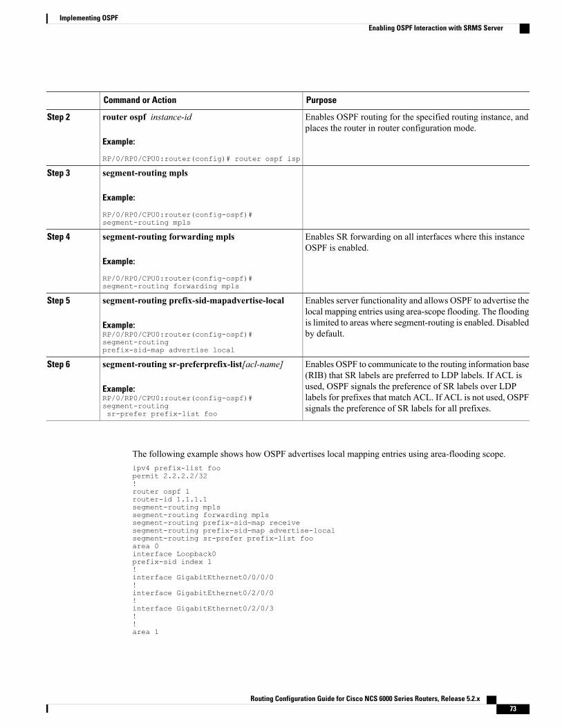
PurposeCommand or Action
Enables OSPF routing for the specified routing instance, andplaces the router in router configuration mode.
router ospf instance-id
Example:
RP/0/RP0/CPU0:router(config)# router ospf isp
Step 2
segment-routing mplsStep 3
Example:
RP/0/RP0/CPU0:router(config-ospf)#segment-routing mpls
Enables SR forwarding on all interfaces where this instanceOSPF is enabled.
segment-routing forwarding mpls
Example:
RP/0/RP0/CPU0:router(config-ospf)#segment-routing forwarding mpls
Step 4
Enables server functionality and allows OSPF to advertise thelocal mapping entries using area-scope flooding. The flooding
segment-routing prefix-sid-mapadvertise-local
Example:RP/0/RP0/CPU0:router(config-ospf)#segment-routingprefix-sid-map advertise local
Step 5
is limited to areas where segment-routing is enabled. Disabledby default.
Enables OSPF to communicate to the routing information base(RIB) that SR labels are preferred to LDP labels. If ACL is
segment-routing sr-preferprefix-list[acl-name]
Example:RP/0/RP0/CPU0:router(config-ospf)#segment-routingsr-prefer prefix-list foo
Step 6
used, OSPF signals the preference of SR labels over LDPlabels for prefixes that match ACL. If ACL is not used, OSPFsignals the preference of SR labels for all prefixes.
The following example shows how OSPF advertises local mapping entries using area-flooding scope.ipv4 prefix-list foopermit 2.2.2.2/32!router ospf 1router-id 1.1.1.1segment-routing mplssegment-routing forwarding mplssegment-routing prefix-sid-map receivesegment-routing prefix-sid-map advertise-localsegment-routing sr-prefer prefix-list fooarea 0interface Loopback0prefix-sid index 1!interface GigabitEthernet0/0/0/0!interface GigabitEthernet0/2/0/0!interface GigabitEthernet0/2/0/3!!area 1
Routing Configuration Guide for Cisco NCS 6000 Series Routers, Release 5.2.x 73
Implementing OSPFEnabling OSPF Interaction with SRMS Server
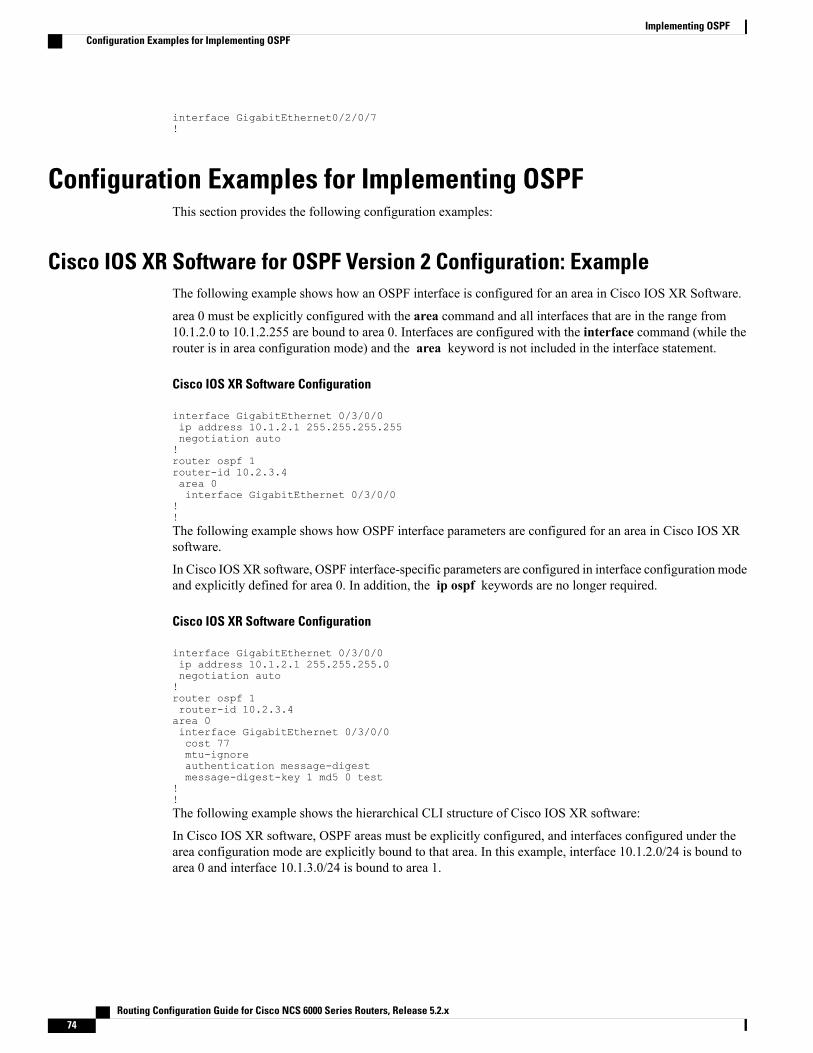
interface GigabitEthernet0/2/0/7!
Configuration Examples for Implementing OSPFThis section provides the following configuration examples:
Cisco IOS XR Software for OSPF Version 2 Configuration: ExampleThe following example shows how an OSPF interface is configured for an area in Cisco IOS XR Software.
area 0 must be explicitly configured with the area command and all interfaces that are in the range from10.1.2.0 to 10.1.2.255 are bound to area 0. Interfaces are configured with the interface command (while therouter is in area configuration mode) and the area keyword is not included in the interface statement.
Cisco IOS XR Software Configuration
interface GigabitEthernet 0/3/0/0ip address 10.1.2.1 255.255.255.255negotiation auto!router ospf 1router-id 10.2.3.4area 0interface GigabitEthernet 0/3/0/0
!!The following example shows how OSPF interface parameters are configured for an area in Cisco IOS XRsoftware.
In Cisco IOS XR software, OSPF interface-specific parameters are configured in interface configuration modeand explicitly defined for area 0. In addition, the ip ospf keywords are no longer required.
Cisco IOS XR Software Configuration
interface GigabitEthernet 0/3/0/0ip address 10.1.2.1 255.255.255.0negotiation auto!router ospf 1router-id 10.2.3.4area 0interface GigabitEthernet 0/3/0/0cost 77mtu-ignoreauthentication message-digestmessage-digest-key 1 md5 0 test
!!The following example shows the hierarchical CLI structure of Cisco IOS XR software:
In Cisco IOS XR software, OSPF areas must be explicitly configured, and interfaces configured under thearea configuration mode are explicitly bound to that area. In this example, interface 10.1.2.0/24 is bound toarea 0 and interface 10.1.3.0/24 is bound to area 1.
Routing Configuration Guide for Cisco NCS 6000 Series Routers, Release 5.2.x74
Implementing OSPFConfiguration Examples for Implementing OSPF
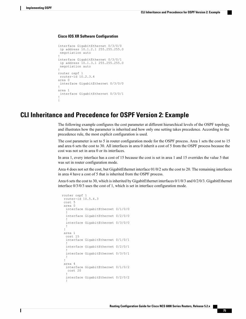
Cisco IOS XR Software Configuration
interface GigabitEthernet 0/3/0/0ip address 10.1.2.1 255.255.255.0negotiation auto!interface GigabitEthernet 0/3/0/1ip address 10.1.3.1 255.255.255.0negotiation auto!router ospf 1router-id 10.2.3.4area 0interface GigabitEthernet 0/3/0/0!area 1interface GigabitEthernet 0/3/0/1!!
CLI Inheritance and Precedence for OSPF Version 2: ExampleThe following example configures the cost parameter at different hierarchical levels of the OSPF topology,and illustrates how the parameter is inherited and how only one setting takes precedence. According to theprecedence rule, the most explicit configuration is used.
The cost parameter is set to 5 in router configuration mode for the OSPF process. Area 1 sets the cost to 15and area 6 sets the cost to 30. All interfaces in area 0 inherit a cost of 5 from the OSPF process because thecost was not set in area 0 or its interfaces.
In area 1, every interface has a cost of 15 because the cost is set in area 1 and 15 overrides the value 5 thatwas set in router configuration mode.
Area 4 does not set the cost, but GigabitEthernet interface 01/0/2 sets the cost to 20. The remaining interfacesin area 4 have a cost of 5 that is inherited from the OSPF process.
Area 6 sets the cost to 30, which is inherited by GigabitEthernet interfaces 0/1/0/3 and 0/2/0/3. GigabitEthernetinterface 0/3/0/3 uses the cost of 1, which is set in interface configuration mode.
router ospf 1router-id 10.5.4.3cost 5area 0interface GigabitEthernet 0/1/0/0!interface GigabitEthernet 0/2/0/0!interface GigabitEthernet 0/3/0/0!!area 1cost 15interface GigabitEthernet 0/1/0/1!interface GigabitEthernet 0/2/0/1!interface GigabitEthernet 0/3/0/1!!area 4interface GigabitEthernet 0/1/0/2cost 20!interface GigabitEthernet 0/2/0/2!
Routing Configuration Guide for Cisco NCS 6000 Series Routers, Release 5.2.x 75
Implementing OSPFCLI Inheritance and Precedence for OSPF Version 2: Example
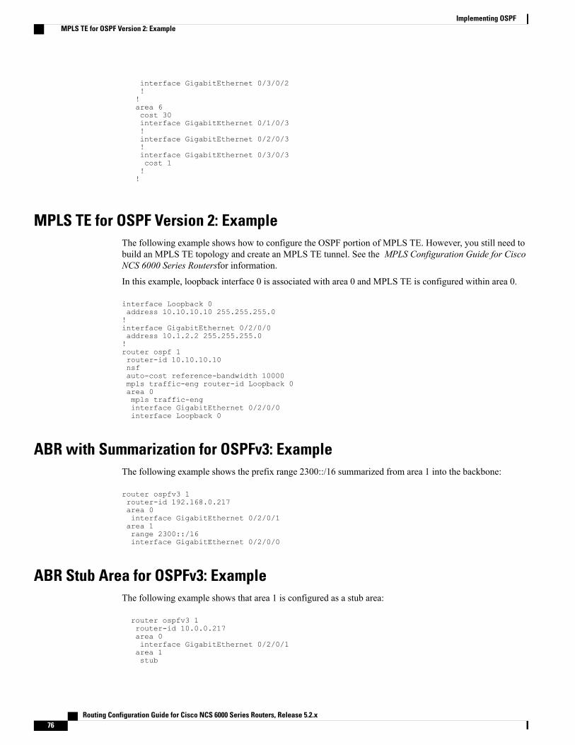
interface GigabitEthernet 0/3/0/2!!area 6cost 30interface GigabitEthernet 0/1/0/3!interface GigabitEthernet 0/2/0/3!interface GigabitEthernet 0/3/0/3cost 1!!
MPLS TE for OSPF Version 2: ExampleThe following example shows how to configure the OSPF portion of MPLS TE. However, you still need tobuild an MPLS TE topology and create an MPLS TE tunnel. See the MPLS Configuration Guide for CiscoNCS 6000 Series Routersfor information.
In this example, loopback interface 0 is associated with area 0 and MPLS TE is configured within area 0.
interface Loopback 0address 10.10.10.10 255.255.255.0!interface GigabitEthernet 0/2/0/0address 10.1.2.2 255.255.255.0!router ospf 1router-id 10.10.10.10nsfauto-cost reference-bandwidth 10000mpls traffic-eng router-id Loopback 0area 0mpls traffic-enginterface GigabitEthernet 0/2/0/0interface Loopback 0
ABR with Summarization for OSPFv3: ExampleThe following example shows the prefix range 2300::/16 summarized from area 1 into the backbone:
router ospfv3 1router-id 192.168.0.217area 0interface GigabitEthernet 0/2/0/1area 1range 2300::/16interface GigabitEthernet 0/2/0/0
ABR Stub Area for OSPFv3: ExampleThe following example shows that area 1 is configured as a stub area:
router ospfv3 1router-id 10.0.0.217area 0interface GigabitEthernet 0/2/0/1area 1stub
Routing Configuration Guide for Cisco NCS 6000 Series Routers, Release 5.2.x76
Implementing OSPFMPLS TE for OSPF Version 2: Example
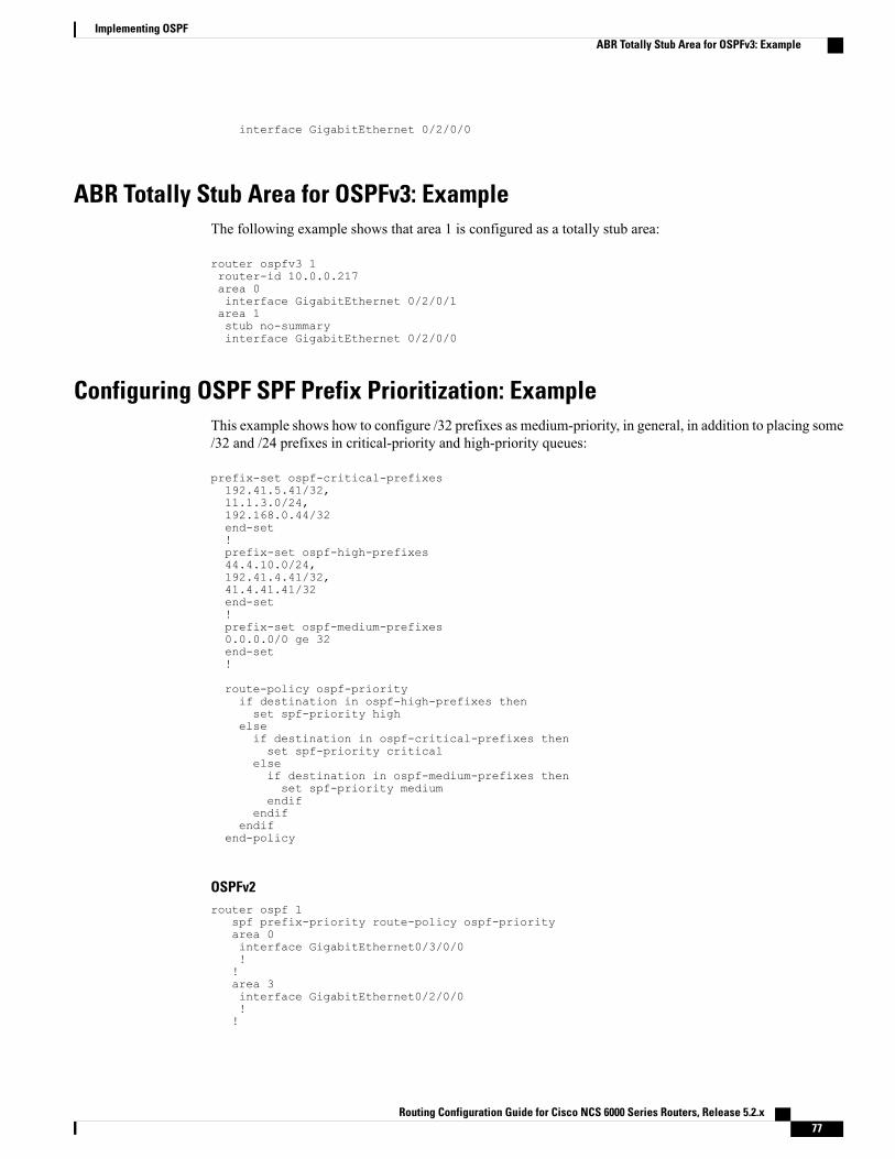
interface GigabitEthernet 0/2/0/0
ABR Totally Stub Area for OSPFv3: ExampleThe following example shows that area 1 is configured as a totally stub area:
router ospfv3 1router-id 10.0.0.217area 0interface GigabitEthernet 0/2/0/1area 1stub no-summaryinterface GigabitEthernet 0/2/0/0
Configuring OSPF SPF Prefix Prioritization: ExampleThis example shows how to configure /32 prefixes as medium-priority, in general, in addition to placing some/32 and /24 prefixes in critical-priority and high-priority queues:
prefix-set ospf-critical-prefixes192.41.5.41/32,11.1.3.0/24,192.168.0.44/32end-set!prefix-set ospf-high-prefixes44.4.10.0/24,192.41.4.41/32,41.4.41.41/32end-set!prefix-set ospf-medium-prefixes0.0.0.0/0 ge 32end-set!
route-policy ospf-priorityif destination in ospf-high-prefixes thenset spf-priority high
elseif destination in ospf-critical-prefixes thenset spf-priority critical
elseif destination in ospf-medium-prefixes thenset spf-priority medium
endifendif
endifend-policy
OSPFv2router ospf 1
spf prefix-priority route-policy ospf-priorityarea 0interface GigabitEthernet0/3/0/0!!area 3interface GigabitEthernet0/2/0/0!!
Routing Configuration Guide for Cisco NCS 6000 Series Routers, Release 5.2.x 77
Implementing OSPFABR Totally Stub Area for OSPFv3: Example
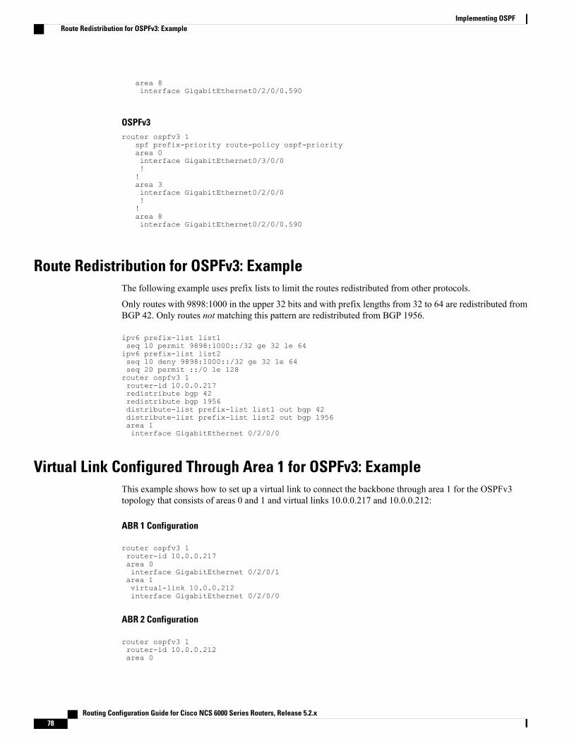
area 8interface GigabitEthernet0/2/0/0.590
OSPFv3router ospfv3 1
spf prefix-priority route-policy ospf-priorityarea 0interface GigabitEthernet0/3/0/0!!area 3interface GigabitEthernet0/2/0/0!!area 8interface GigabitEthernet0/2/0/0.590
Route Redistribution for OSPFv3: ExampleThe following example uses prefix lists to limit the routes redistributed from other protocols.
Only routes with 9898:1000 in the upper 32 bits and with prefix lengths from 32 to 64 are redistributed fromBGP 42. Only routes not matching this pattern are redistributed from BGP 1956.
ipv6 prefix-list list1seq 10 permit 9898:1000::/32 ge 32 le 64ipv6 prefix-list list2seq 10 deny 9898:1000::/32 ge 32 le 64seq 20 permit ::/0 le 128router ospfv3 1router-id 10.0.0.217redistribute bgp 42redistribute bgp 1956distribute-list prefix-list list1 out bgp 42distribute-list prefix-list list2 out bgp 1956area 1interface GigabitEthernet 0/2/0/0
Virtual Link Configured Through Area 1 for OSPFv3: ExampleThis example shows how to set up a virtual link to connect the backbone through area 1 for the OSPFv3topology that consists of areas 0 and 1 and virtual links 10.0.0.217 and 10.0.0.212:
ABR 1 Configuration
router ospfv3 1router-id 10.0.0.217area 0interface GigabitEthernet 0/2/0/1area 1virtual-link 10.0.0.212interface GigabitEthernet 0/2/0/0
ABR 2 Configuration
router ospfv3 1router-id 10.0.0.212area 0
Routing Configuration Guide for Cisco NCS 6000 Series Routers, Release 5.2.x78
Implementing OSPFRoute Redistribution for OSPFv3: Example
interface GigabitEthernet 0/3/0/1area 1virtual-link 10.0.0.217interface GigabitEthernet 0/2/0/0
Virtual Link Configured with MD5 Authentication for OSPF Version 2: ExampleThe following examples show how to configure a virtual link to your backbone and applyMD5 authentication.You must perform the steps described on both ABRs at each end of the virtual link.
After you explicitly configure the ABRs, the configuration is inherited by all interfaces bound to thatarea—unless you override the values and configure them explicitly for the interface.
To understand virtual links, see Virtual Link and Transit Area for OSPF, on page 12.
In this example, all interfaces on router ABR1 use MD5 authentication:
router ospf ABR1router-id 10.10.10.10authentication message-digestmessage-digest-key 100 md5 0 ciscoarea 0interface GigabitEthernet 0/2/0/1interface GigabitEthernet 0/3/0/0area 1interface GigabitEthernet 0/3/0/1virtual-link 10.10.5.5
!!In this example, only area 1 interfaces on router ABR3 use MD5 authentication:
router ospf ABR2router-id 10.10.5.5area 0area 1authentication message-digestmessage-digest-key 100 md5 0 ciscointerface GigabitEthernet 0/9/0/1virtual-link 10.10.10.10area 3interface Loopback 0interface GigabitEthernet 0/9/0/0
!
OSPF Queue Tuning Parameters Configuration: ExampleThe following example shows how to configure the OSPF queue tuning parameters:
router ospf 100queue dispatch incoming 30queue limit high 1500queue dispatch rate-limited-lsa 1000queue dispatch spf-lsa-limit 2000
Where to Go NextTo configure route maps through the RPL for OSPF Version 2, see Implementing Routing Policy on module.
Routing Configuration Guide for Cisco NCS 6000 Series Routers, Release 5.2.x 79
Implementing OSPFVirtual Link Configured with MD5 Authentication for OSPF Version 2: Example
To build an MPLS TE topology, create tunnels, and configure forwarding over the tunnel for OSPF Version2; see MPLS Configuration Guide for Cisco NCS 6000 Series Routers.
Additional ReferencesThe following sections provide references related to implementing OSPF.
Related Documents
Document TitleRelated Topic
Routing Command Reference for Cisco NCS 6000Series Routers
OSPFCommands andOSPFv3Commands: completecommand syntax, commandmodes, command history,defaults, usage guidelines, and examples
Implementing MPLS Traffic Engineering on modulein MPLS Configuration Guide for Cisco NCS 6000Series Routers
MPLS TE feature information
Standards
TitleStandards
OSPF Multi-Area Adjacencydraft-ietf-ospf-multi-area-adj-07.txt
OSPF Protocol Extensions for Path ComputationElement (PCE)
draft-ietf-pce-disco-proto-ospf-08.txt
LDP IGP Synchronizationdraft-ietf-mpls-igp-sync-00.txt
OSPFv3 Graceful Restartdraft-ietf-ospf-ospfv3-graceful-restart-07.txt
MIBs
MIBs LinkMIBs
To locate and downloadMIBs for selected platforms,Cisco IOS releases, and feature sets, use Cisco MIBLocator found at the following URL:
http://www.cisco.com/go/mibs
—
Routing Configuration Guide for Cisco NCS 6000 Series Routers, Release 5.2.x80
Implementing OSPFAdditional References
RFCs
TitleRFCs
The OSPF NSSA OptionRFC 1587
Extending OSPF to Support Demand CircuitsRFC 1793
OSPF Version 2RFC 2328
The OSPF Opaque LSA OptionRFC 2370
OSPF for IPv6RFC 2740
The OSPF Not-So-Stubby Area (NSSA) OptionRFC 3101
OSPF Stub Router AdvertisementRFC 3137
Alternative Implementations of OSPF Area BorderRouters
RFC 3509
Graceful OSPF RestartRFC 3623
Traffic Engineering (TE) Extensions to OSPFVersion2
RFC 3630
The Generalized TTL Security Mechanism (GTSM)RFC 3682
Calculating Interior Gateway Protocol (IGP) RoutesOver Traffic Engineering Tunnels
RFC 3906
OSPF Refresh and Flooding Reduction in StableTopologies
RFC 4136
Label Switched Paths (LSP) Hierarchy withGeneralized Multi-Protocol Label Switching(GMPLS) Traffic Engineering (TE)
RFC 4206
Protocol Extensions for Support of Diffserv-awareMPLS Traffic Engineering
RFC 4124
OSPF Version 2 Management Information BaseRFC 4750
OSPF Out-of-Band Link State Database (LSDB)Resynchronization
RFC 4811
OSPF Restart SignalingRFC 4812
OSPF Link-Local SignalingRFC 4813
Routing Configuration Guide for Cisco NCS 6000 Series Routers, Release 5.2.x 81
Implementing OSPFAdditional References
TitleRFCs
Extensions to OSPF for Advertising Optional RouterCapabilities
RFC 4970
Management Information Base (MIB) for OSPFv3RFC 5643
Technical Assistance
LinkDescription
http://www.cisco.com/techsupportThe Cisco Technical Support website containsthousands of pages of searchable technical content,including links to products, technologies, solutions,technical tips, and tools. Registered Cisco.com userscan log in from this page to access evenmore content.
Routing Configuration Guide for Cisco NCS 6000 Series Routers, Release 5.2.x82
Implementing OSPFAdditional References