impact damage behaviour of shape memory alloy composites
TRANSCRIPT
Impact damage behaviour of shape memory alloy composites
Kelly A. Tsoi a,*, Rudy Stalmans b, Jan Schrooten a, Martine Wevers a, Yiu-Wing Mai c
a Department of Metallurgy and Materials Engineering, Katholieke Universiteit Leuven, Leuven, Belgiumb FLEXMET, Rillaarsebaan 233, B-3200, Aarschot, Belgium
c School of Aerospace, Mechanical and Mechatronic Engineering, The University of Sydney, Sydney, Australia
Received 31 December 2001; received in revised form 24 April 2002
Abstract
Currently there is an increased interest in the use of shape memory alloy composites (SMA composites). Many potential uses have
been found for SMA composites, for example, in shape control and vibration control. However there is not a lot of information
available on the properties of SMA composites since it is still a relatively new area. Recent investigations have been conducted on
their transformational behaviour, which provides the valuable first step information required for implementing these composites
into real structures. However, further work still needs to be completed on other aspects of these composites. This article investigates
the impact damage behaviour of SMA-composites. The results show that for low velocity impact, embedding SMA wires into
composites does not compromise the structure any differently to composites without wires. In fact, it has been shown that for some
cases there is an improvement in the damage resistance of the composites.
# 2002 Elsevier Science B.V. All rights reserved.
Keywords: Shape memory alloys; Adaptive composites; Low velocity impact damage; Superelasticity
1. Introduction
Composite materials are commonly used in structures
which require lightweight, yet strong components.
However there is an increased interest in the use of
embedded shape memory alloy wires in composites to
enhance structural performance, either in vibration
control, or shape control [1�/5]. In general one wants
to create adaptive composites.
Not a lot of research has been conducted on the
behaviour of SMA-composites. Recent research has
determined the transformational behaviour of SMA
composites [6�/9], the vibrational behaviour [1�/5] and
the microscopic properties such as interfacial shear
strength [10�/12] and the stress distribution in the
SMA composites during activation of the wires [13,14].
1.1. SMA-composites
An important factor to whether SMA composites can
be used reliably in daily structures is the behaviour of
the composites during impact. Composite structures in
general are susceptible to a wide range of damage and
defects [15] which are produced during manufacture as
well as during service. Impact damage is one of the
problems that composite structures face, there is simply
no way to avoid impact damage during service, so there
needs to be a way of reducing that damage when it
occurs, reducing it enough so that the integrity of the
structure is not compromised. If these SMA composites
are to be used in structures such as aircraft, high speed
trains and cars, to name but a few applications, the
behaviour of the composites during impact and the
effects of having the wires embedded inside the compo-
sites must be well understood.There are several questions which need to be an-
swered with respect to impact damage when embedding
SMA wires into composites. Firstly if the wires are pre-
strained before embedding, and for many applications
this must be the case, there will be a thermal stress
mismatch during curing. Will these stresses be released
* Corresponding author. Present address: DSTO, 506 Lorimer St.,
3207 Fishermans Bend, UIC, Australia
E-mail address: [email protected] (K.A. Tsoi).
Materials Science and Engineering A342 (2003) 207�/215
www.elsevier.com/locate/msea
0921-5093/02/$ - see front matter # 2002 Elsevier Science B.V. All rights reserved.
PII: S 0 9 2 1 - 5 0 9 3 ( 0 2 ) 0 0 3 1 7 - 9
when an embedded wire is impacted, causing greater
damage, or will there be an improvement in the impact
damage resistance? Paine and Rogers, [16], investigated
the use of superelastic SMA’s embedded into compositematerials to improve the low velocity impact damage of
laminates. They used a cross-ply layup of [028,9028,028] of
graphite/bismaleimide composites with the superelastic
NiTi SMA wires, of diameter 0.3 mm, with no pre-
strain, embedded in the lower 08/908 interface. The
volume fraction of the SMA wires was 2.8%. During the
impact of the specimens they found that their specimens
weren’t clamped sufficiently and they underwent largedeflections and slippage. For these specimens they used
a visual inspection method to compare the amount of
impact damage. On comparison with the reference
graphite laminate it was found that for high-energy
impacts of 18 and 23 J, the SMA wires in the hybrid
laminate prevented complete perforation during the
impact. It was also found that the all graphite laminate
had a larger visible delamination than the hybridcomposite. Paine and Rogers, [16], also used a special
clamping device in order to secure the specimens and to
obtain smaller deflections during impact. For these
samples they found it was more difficult to see
differences in the damage based on a visual inspection.
At the highest impact energy level of 14 J, all graphite
laminate specimens underwent complete perforation
whereas with the hybrid specimens only the layers abovethe SMA wire layer were perforated. It was also
determined that the peak impact forces of the hybrid
specimens were much higher than the all graphite
specimens. The delaminations in the centre of the
laminate were similar in size for both types of specimens.
These results suggest that SMA wires embedded into
composites can actually improve the impact resistance,
at least for simple cross ply layups. However, forapplications to structures, it is rare that cross ply layups
are used and hence an investigation into a multi angle
ply layup is justified and will be discussed in this paper.
1.2. Superelastic SMA
The embedment of superelastic SMA’s was also
investigated, because these wires are able to absorb
and dissipate impact energy which is not the case forother metal wires. Superelastic shape memory alloys
exhibit the property of being able to be completely
deformed at room temperature and returning to their
original shape after unloading. The mechanism behind
superelasticity is the stress induced martensitic transfor-
mation. Normally martensite is formed as the alloy
cools to below a temperature, Ms, under no stress. On
heating, the reverse transformation from martensite toaustenite starts at As and finishes at a temperature, Af. It
is also possible for martensite to be formed above Ms, by
the application of stress. The resulting martensite is
known as stress induced martensite (SIM), and the
transformation of it from its austenitic parent phase is
fully mechanical. There is a thermal limit to when SIM
will no longer be formed and this occurs at temperaturesabove Md, at which the stress required to form SIM is
greater than that needed to move dislocations. Hence,
SIM is formed at temperatures, MsB/T B/Md. Complete
superelasticity occurs when SIM is formed above the
austenitic transformation temperature, Af, but below
Md. When a SMA is heated above its transformation
temperature it becomes austenitic. If a stress is then
applied to the alloy in this state, large deformationstrains can be obtained and SIM is formed. Upon
removal of the stress, the martensite reverts to its
austenitic parent phase and recoverable strains of up
to 8% can be achieved [17].
By embedding these SMA’s into a composite struc-
ture, impact energy will be absorbed by the wires,
transforming them from austenite to martensite. After-
wards the energy is released again by the reversetransformation. Superelastic SMA composites may be
able to improve the damping of structures. This
reversible phenomenon does not occur for other metal
wires.
With this current investigation a series of different
types of wires, including superelastic, martensitic NiTi
and NiTiCu and steel wires, were embedded at different
through thickness positions within a glass/epoxy matrixwith differing pre-strains ranging from no pre-strain to
3%. Differing from previous research efforts, an inves-
tigation into the effects of different volume fractions (Vf)
of SMA wires in the specimens was also made.
2. Materials and methods
2.1. Materials
SMA composite specimens of 125�/125 mm2 were
produced using Strafil G-EPI-140/142 glass fibre epoxy
pre-preg, from Hexcel composites and several different
types of wires. A superelastic 55.1 wt.% Ni balance Ti
wire, straight annealed, obtained from Thomas Bolton
Inc, a martensitic shape memory NiTi wire from SMA,
Inc. (USA), a ternary NiTiCu wire with a singletransformation from Memry (USA), and annealed
stainless steel wires, all of 0.15 mm diameter, were
used. The superelastic wires have a transformation
temperature below zero and were embedded while in
their austenitic state. The binary NiTi wires have
transformation temperatures, Ms�/39.8 8C, Mf�/
29.7 8C, As�/74.4 8C and Af�/81.7 8C and the tern-
ary NiTiCu wires have transformation temperatures,Ms�/46.8 8C, Mf�/38.3 8C, As�/55.6 8C and Af�/
64.2 8C. The martensitic NiTi wires and the stainless
steel wires were not pre-strained. The superelastic wires
K.A. Tsoi et al. / Materials Science and Engineering A342 (2003) 207�/215208
were pre-strained to 0, 1.5 and 3%. The influence of the
wire pre-strain, the wire Vf and the wire position on the
composite’s impact behaviour was investigated.
To allow the SMA wires to be pre-strained andcombined with the pre-preg layers a frame was designed
and made by EPFL, Switzerland. Combs with slots 500
mm apart were situated at either end of the frame. A
continuous SMA wire was then wound between these
two combs and pre-strained to either 0, 1.5 or 3% using
a pre-tensioning knob, which could be held constant
during curing. The wires were then sandwiched between
layers of pre-preg, oriented using a [08,458,908,�/458]2s
layup, where the 0, 45, 90 and �/458 are the ply angles of
the individual pre-preg layers and the 2s indicates that
this layup is repeated twice and then symmetrically
repeated two more times. In total there were 16 pre-preg
layers. The literature, [18], suggests a good resistance
against delamination during impact for this layup. This
laminate offers the opportunity to use a variety of
energies (both low and high) for the impact damagetests. This will also mean there is a greater accuracy due
to less friction from the impact machine. The wires were
aligned along the centre of the plate, covering a width of
16 mm, with a volume fraction of 0.45% (0.5 wires
mm�1), 0.89% (1 wire mm�1) and 1.8% (2 wires mm�1)
and were placed in the centre, off centre at either 1/2, 1/4
or 3/4 of the through thickness of the plates or in the
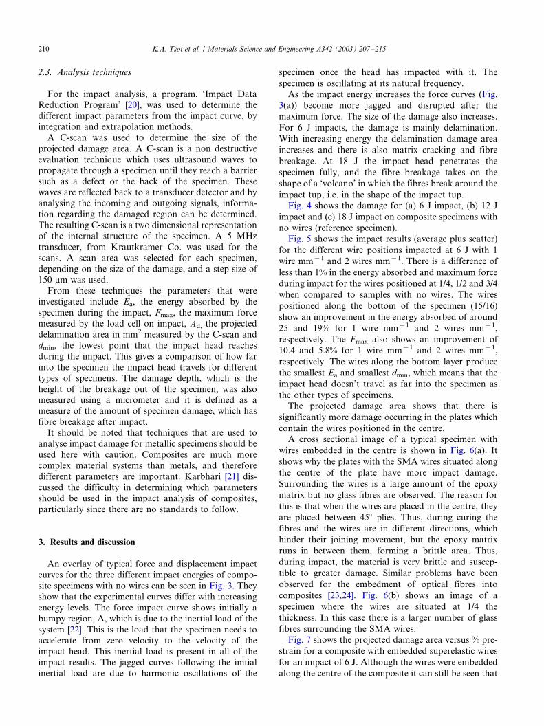
bottom layer (ie. 15/16 ths). One layer of wires wasembedded in the composites. Fig. 1 shows the dimen-
sions of the specimens used. The SMA composites were
cured at 140 8C for 20 min. The glass fibre pre-preg was
used because of its relatively short curing and easy
handling ability. The resulting plates were, on average,
approximately 2.0 mm thick.
2.2. Impact test set-up
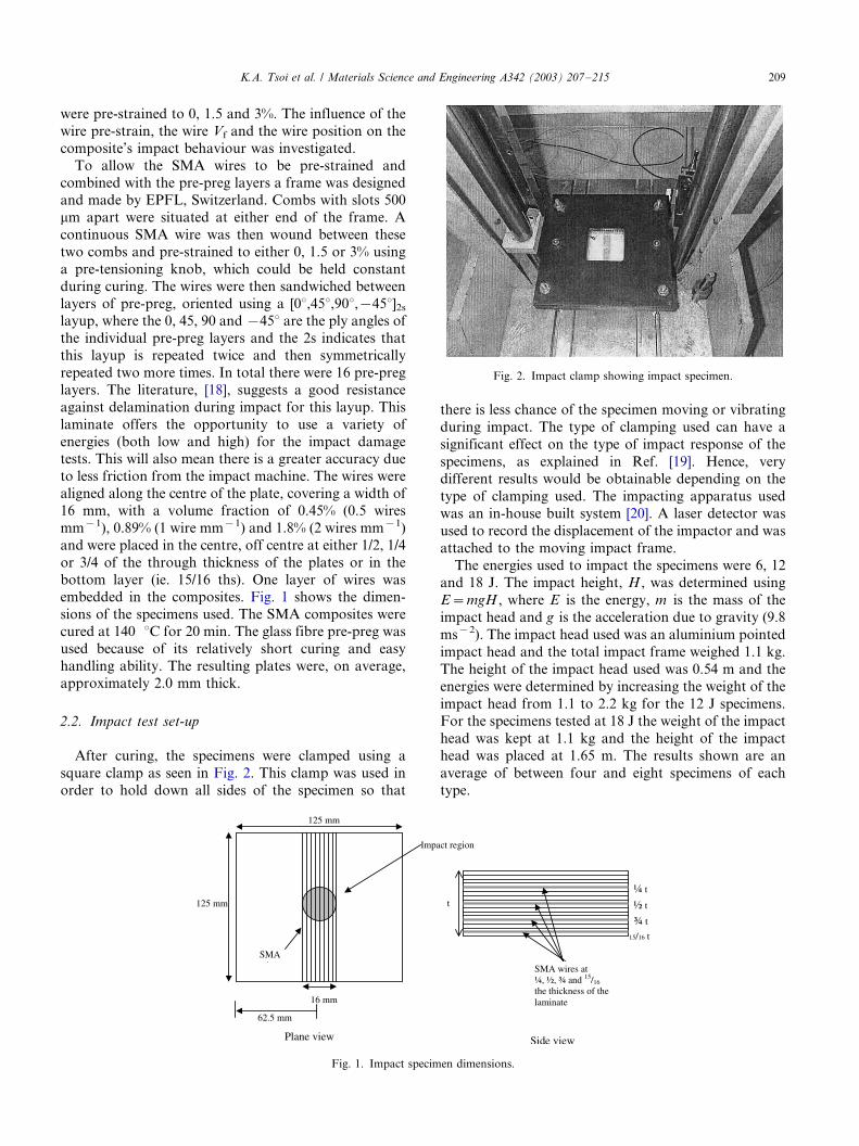
After curing, the specimens were clamped using a
square clamp as seen in Fig. 2. This clamp was used in
order to hold down all sides of the specimen so that
there is less chance of the specimen moving or vibrating
during impact. The type of clamping used can have a
significant effect on the type of impact response of the
specimens, as explained in Ref. [19]. Hence, very
different results would be obtainable depending on the
type of clamping used. The impacting apparatus used
was an in-house built system [20]. A laser detector was
used to record the displacement of the impactor and was
attached to the moving impact frame.
The energies used to impact the specimens were 6, 12
and 18 J. The impact height, H , was determined using
E�/mgH , where E is the energy, m is the mass of the
impact head and g is the acceleration due to gravity (9.8
ms�2). The impact head used was an aluminium pointed
impact head and the total impact frame weighed 1.1 kg.
The height of the impact head used was 0.54 m and the
energies were determined by increasing the weight of the
impact head from 1.1 to 2.2 kg for the 12 J specimens.
For the specimens tested at 18 J the weight of the impact
head was kept at 1.1 kg and the height of the impact
head was placed at 1.65 m. The results shown are an
average of between four and eight specimens of each
type.
Fig. 1. Impact specimen dimensions.
Fig. 2. Impact clamp showing impact specimen.
K.A. Tsoi et al. / Materials Science and Engineering A342 (2003) 207�/215 209
2.3. Analysis techniques
For the impact analysis, a program, ‘Impact Data
Reduction Program’ [20], was used to determine thedifferent impact parameters from the impact curve, by
integration and extrapolation methods.
A C-scan was used to determine the size of the
projected damage area. A C-scan is a non destructive
evaluation technique which uses ultrasound waves to
propagate through a specimen until they reach a barrier
such as a defect or the back of the specimen. These
waves are reflected back to a transducer detector and byanalysing the incoming and outgoing signals, informa-
tion regarding the damaged region can be determined.
The resulting C-scan is a two dimensional representation
of the internal structure of the specimen. A 5 MHz
transducer, from Krautkramer Co. was used for the
scans. A scan area was selected for each specimen,
depending on the size of the damage, and a step size of
150 mm was used.From these techniques the parameters that were
investigated include Ea, the energy absorbed by the
specimen during the impact, Fmax, the maximum force
measured by the load cell on impact, Ad, the projected
delamination area in mm2 measured by the C-scan and
dmin, the lowest point that the impact head reaches
during the impact. This gives a comparison of how far
into the specimen the impact head travels for differenttypes of specimens. The damage depth, which is the
height of the breakage out of the specimen, was also
measured using a micrometer and it is defined as a
measure of the amount of specimen damage, which has
fibre breakage after impact.
It should be noted that techniques that are used to
analyse impact damage for metallic specimens should be
used here with caution. Composites are much morecomplex material systems than metals, and therefore
different parameters are important. Karbhari [21] dis-
cussed the difficulty in determining which parameters
should be used in the impact analysis of composites,
particularly since there are no standards to follow.
3. Results and discussion
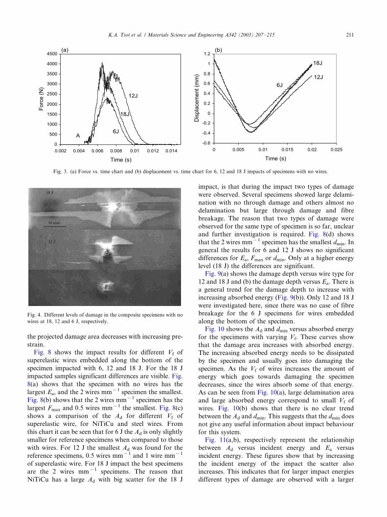
An overlay of typical force and displacement impact
curves for the three different impact energies of compo-
site specimens with no wires can be seen in Fig. 3. They
show that the experimental curves differ with increasing
energy levels. The force impact curve shows initially a
bumpy region, A, which is due to the inertial load of the
system [22]. This is the load that the specimen needs to
accelerate from zero velocity to the velocity of theimpact head. This inertial load is present in all of the
impact results. The jagged curves following the initial
inertial load are due to harmonic oscillations of the
specimen once the head has impacted with it. The
specimen is oscillating at its natural frequency.
As the impact energy increases the force curves (Fig.
3(a)) become more jagged and disrupted after the
maximum force. The size of the damage also increases.
For 6 J impacts, the damage is mainly delamination.
With increasing energy the delamination damage area
increases and there is also matrix cracking and fibre
breakage. At 18 J the impact head penetrates the
specimen fully, and the fibre breakage takes on the
shape of a ‘volcano’ in which the fibres break around the
impact tup, i.e. in the shape of the impact tup.Fig. 4 shows the damage for (a) 6 J impact, (b) 12 J
impact and (c) 18 J impact on composite specimens with
no wires (reference specimen).
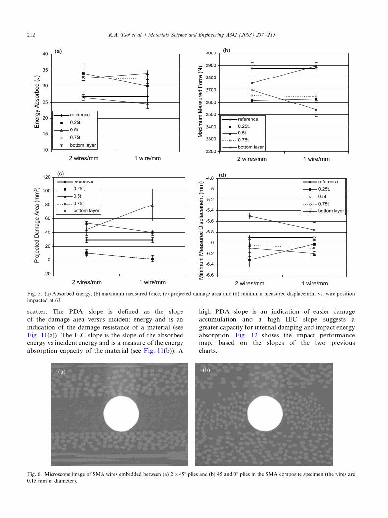
Fig. 5 shows the impact results (average plus scatter)
for the different wire positions impacted at 6 J with 1
wire mm�1 and 2 wires mm�1. There is a difference of
less than 1% in the energy absorbed and maximum force
during impact for the wires positioned at 1/4, 1/2 and 3/4
when compared to samples with no wires. The wires
positioned along the bottom of the specimen (15/16)
show an improvement in the energy absorbed of around
25 and 19% for 1 wire mm�1 and 2 wires mm�1,
respectively. The Fmax also shows an improvement of
10.4 and 5.8% for 1 wire mm�1 and 2 wires mm�1,
respectively. The wires along the bottom layer produce
the smallest Ea and smallest dmin, which means that the
impact head doesn’t travel as far into the specimen as
the other types of specimens.The projected damage area shows that there is
significantly more damage occurring in the plates which
contain the wires positioned in the centre.
A cross sectional image of a typical specimen with
wires embedded in the centre is shown in Fig. 6(a). It
shows why the plates with the SMA wires situated along
the centre of the plate have more impact damage.
Surrounding the wires is a large amount of the epoxy
matrix but no glass fibres are observed. The reason for
this is that when the wires are placed in the centre, they
are placed between 458 plies. Thus, during curing the
fibres and the wires are in different directions, which
hinder their joining movement, but the epoxy matrix
runs in between them, forming a brittle area. Thus,
during impact, the material is very brittle and suscep-
tible to greater damage. Similar problems have been
observed for the embedment of optical fibres into
composites [23,24]. Fig. 6(b) shows an image of a
specimen where the wires are situated at 1/4 the
thickness. In this case there is a larger number of glass
fibres surrounding the SMA wires.
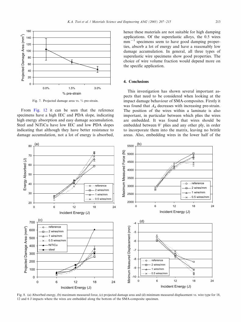
Fig. 7 shows the projected damage area versus % pre-
strain for a composite with embedded superelastic wires
for an impact of 6 J. Although the wires were embedded
along the centre of the composite it can still be seen that
K.A. Tsoi et al. / Materials Science and Engineering A342 (2003) 207�/215210
the projected damage area decreases with increasing pre-
strain.
Fig. 8 shows the impact results for different Vf of
superelastic wires embedded along the bottom of the
specimen impacted with 6, 12 and 18 J. For the 18 J
impacted samples significant differences are visible. Fig.
8(a) shows that the specimen with no wires has the
largest Ea, and the 2 wires mm�1 specimen the smallest.
Fig. 8(b) shows that the 2 wires mm�1 specimen has the
largest Fmax and 0.5 wires mm�1 the smallest. Fig. 8(c)
shows a comparison of the Ad for different Vf of
superelastic wire, for NiTiCu and steel wires. From
this chart it can be seen that for 6 J the Ad is only slightly
smaller for reference specimens when compared to those
with wires. For 12 J the smallest Ad was found for the
reference specimens, 0.5 wires mm�1 and 1 wire mm�1
of superelastic wire. For 18 J impact the best specimens
are the 2 wires mm�1 specimens. The reason that
NiTiCu has a large Ad with big scatter for the 18 J
impact, is that during the impact two types of damage
were observed. Several specimens showed large delami-
nation with no through damage and others almost no
delamination but large through damage and fibre
breakage. The reason that two types of damage were
observed for the same type of specimen is so far, unclear
and further investigation is required. Fig. 8(d) shows
that the 2 wires mm�1 specimen has the smallest dmin. In
general the results for 6 and 12 J shows no significant
differences for Ea, Fmax or dmin. Only at a higher energy
level (18 J) the differences are significant.
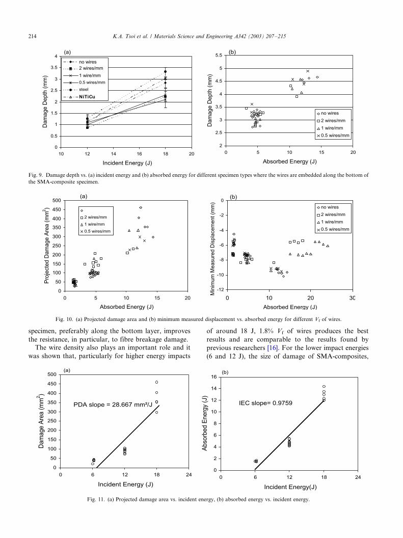
Fig. 9(a) shows the damage depth versus wire type for
12 and 18 J and (b) the damage depth versus Ea. There is
a general trend for the damage depth to increase with
increasing absorbed energy (Fig. 9(b)). Only 12 and 18 J
were investigated here, since there was no case of fibre
breakage for the 6 J specimens for wires embedded
along the bottom of the specimen.
Fig. 10 shows the Ad and dmin versus absorbed energy
for the specimens with varying Vf. These curves show
that the damage area increases with absorbed energy.
The increasing absorbed energy needs to be dissipated
by the specimen and usually goes into damaging the
specimen. As the Vf of wires increases the amount of
energy which goes towards damaging the specimen
decreases, since the wires absorb some of that energy.
As can be seen from Fig. 10(a), large delamination area
and large absorbed energy correspond to small Vf of
wires. Fig. 10(b) shows that there is no clear trend
between the Ad and dmin. This suggests that the dmin does
not give any useful information about impact behaviour
for this system.
Fig. 11(a,b), respectively represent the relationship
between Ad versus incident energy and Ea versus
incident energy. These figures show that by increasing
the incident energy of the impact the scatter also
increases. This indicates that for larger impact energies
different types of damage are observed with a larger
Fig. 3. (a) Force vs. time chart and (b) displacement vs. time chart for 6, 12 and 18 J impacts of specimens with no wires.
Fig. 4. Different levels of damage in the composite specimens with no
wires at 18, 12 and 6 J, respectively.
K.A. Tsoi et al. / Materials Science and Engineering A342 (2003) 207�/215 211
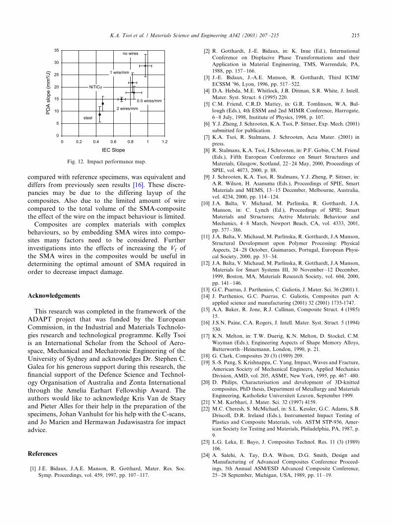
scatter. The PDA slope is defined as the slope
of the damage area versus incident energy and is an
indication of the damage resistance of a material (see
Fig. 11(a)). The IEC slope is the slope of the absorbed
energy vs incident energy and is a measure of the energy
absorption capacity of the material (see Fig. 11(b)). A
high PDA slope is an indication of easier damage
accumulation and a high IEC slope suggests a
greater capacity for internal damping and impact energy
absorption. Fig. 12 shows the impact performance
map, based on the slopes of the two previous
charts.
Fig. 5. (a) Absorbed energy, (b) maximum measured force, (c) projected damage area and (d) minimum measured displacement vs. wire position
impacted at 6J.
Fig. 6. Microscope image of SMA wires embedded between (a) 2�/458 plies and (b) 45 and 08 plies in the SMA composite specimen (the wires are
0.15 mm in diameter).
K.A. Tsoi et al. / Materials Science and Engineering A342 (2003) 207�/215212
From Fig. 12 it can be seen that the reference
specimens have a high IEC and PDA slope, indicating
high energy absorption and easy damage accumulation.
Steel and NiTiCu have low IEC and low PDA slopes
indicating that although they have better resistance to
damage accumulation, not a lot of energy is absorbed,
hence these materials are not suitable for high damping
applications. Of the superelastic alloys, the 0.5 wires
mm�1 specimens seem to have good damping proper-
ties, absorb a lot of energy and have a reasonably lowdamage accumulation. In general, all three types of
superelastic wire specimens show good properties. The
choice of wire volume fraction would depend more on
the specific application.
4. Conclusions
This investigation has shown several important as-
pects that need to be considered when looking at the
impact damage behaviour of SMA-composites. Firstly it
was found that Ad decreases with increasing pre-strain.
The position of the wires within a laminate is alsoimportant, in particular between which plies the wires
are embedded. It was found that wires should be
embedded between 08 plies and any other ply, in order
to incorporate them into the matrix, leaving no brittle
areas. Also, embedding wires in the lower half of the
Fig. 7. Projected damage area vs. % pre-strain.
Fig. 8. (a) Absorbed energy, (b) maximum measured force, (c) projected damage area and (d) minimum measured displacement vs. wire type for 18,
12 and 6 J impacts where the wires are embedded along the bottom of the SMA-composite specimen.
K.A. Tsoi et al. / Materials Science and Engineering A342 (2003) 207�/215 213
specimen, preferably along the bottom layer, improves
the resistance, in particular, to fibre breakage damage.
The wire density also plays an important role and it
was shown that, particularly for higher energy impacts
of around 18 J, 1.8% Vf of wires produces the best
results and are comparable to the results found by
previous researchers [16]. For the lower impact energies
(6 and 12 J), the size of damage of SMA-composites,
Fig. 9. Damage depth vs. (a) incident energy and (b) absorbed energy for different specimen types where the wires are embedded along the bottom of
the SMA-composite specimen.
Fig. 10. (a) Projected damage area and (b) minimum measured displacement vs. absorbed energy for different Vf of wires.
Fig. 11. (a) Projected damage area vs. incident energy, (b) absorbed energy vs. incident energy.
K.A. Tsoi et al. / Materials Science and Engineering A342 (2003) 207�/215214
compared with reference specimens, was equivalent and
differs from previously seen results [16]. These discre-
pancies may be due to the differing layup of the
composites. Also due to the limited amount of wire
compared to the total volume of the SMA-compositethe effect of the wire on the impact behaviour is limited.
Composites are complex materials with complex
behaviours, so by embedding SMA wires into compo-
sites many factors need to be considered. Further
investigations into the effects of increasing the Vf of
the SMA wires in the composites would be useful in
determining the optimal amount of SMA required in
order to decrease impact damage.
Acknowledgements
This research was completed in the framework of the
ADAPT project that was funded by the European
Commission, in the Industrial and Materials Technolo-
gies research and technological programme. Kelly Tsoiis an International Scholar from the School of Aero-
space, Mechanical and Mechatronic Engineering of the
University of Sydney and acknowledges Dr. Stephen C.
Galea for his generous support during this research, the
financial support of the Defence Science and Technol-
ogy Organisation of Australia and Zonta International
through the Amelia Earhart Fellowship Award. The
authors would like to acknowledge Kris Van de Staeyand Pieter Alles for their help in the preparation of the
specimens, Johan Vanhulst for his help with the C-scans,
and Jo Marien and Hermawan Judawisastra for impact
advice.
References
[1] J.E. Bidaux, J.A.E. Manson, R. Gotthard, Mater. Res. Soc.
Symp. Proceedings, vol. 459, 1997, pp. 107�/117.
[2] R. Gotthardt, J.-E. Bidaux, in: K. Inue (Ed.), International
Conference on Displacive Phase Transformations and their
Application in Material Engineering, TMS, Warrendale, PA,
1988, pp. 157�/166.
[3] J.-E. Bidaux, J.-A.E. Manson, R. Gotthardt, Third ICIM/
ECSSM ’96, Lyon, 1996, pp. 517�/522.
[4] D.A. Hebda, M.E. Whitlock, J.B. Ditman, S.R. White, J. Intell.
Mater. Syst. Struct. 6 (1995) 220.
[5] C.M. Friend, C.R.D. Mattey, in: G.R. Tomlinson, W.A. Bul-
lough (Eds.), 4th ESSM and 2nd MIMR Conference, Harrogate,
6�/8 July, 1998, Institute of Physics, 1998, p. 107.
[6] Y.J. Zheng, J. Schrooten, K.A. Tsoi, P. Sittner, Exp. Mech. (2001)
submitted for publication.
[7] K.A. Tsoi, R. Stalmans, J. Schrooten, Acta Mater. (2001) in
press.
[8] R. Stalmans, K.A. Tsoi, J Schrooten, in: P.F. Gobin, C.M. Friend
(Eds.), Fifth European Conference on Smart Structures and
Materials, Glasgow, Scotland, 22�/24 May, 2000, Proceedings of
SPIE, vol. 4073, 2000, p. 88.
[9] J. Schrooten, K.A. Tsoi, R. Stalmans, Y.J. Zheng, P. Sittner, in:
A.R. Wilson, H. Asanuma (Eds.), Proceedings of SPIE, Smart
Materials and MEMS, 13�/15 December, Melbourne, Australia,
vol. 4234, 2000, pp. 114�/124.
[10] J.A. Balta, V. Michaud, M. Parlinska, R. Gotthardt, J.A.
Manson, in: C. Lynch (Ed.), Proceedings of SPIE; Smart
Materials and Structures; Active Materials; Behaviour and
Mechanics, 4�/8 March, Newport Beach, CA, vol. 4333, 2001,
pp. 377�/386.
[11] J.A. Balta, V. Michaud, M. Parlinska, R. Gotthardt, J.A Manson,
Structural Development upon Polymer Processing: Physical
Aspects, 24�/28 October, Guimaraes, Portugal, European Physi-
cal Society, 2000, pp. 33�/34.
[12] J.A. Balta, V. Michaud, M. Parlinska, R. Gotthardt, J.A Manson,
Materials for Smart Systems III, 30 November�/12 December,
1999, Boston, MA, Materials Research Society, vol. 604, 2000,
pp. 141�/146.
[13] G.C. Psarras, J. Parthenios, C. Galiotis, J. Mater. Sci. 36 (2001) 1.
[14] J. Parthenios, G.C. Psarras, C. Galiotis, Composites part A:
applied science and manufacturing (2001) 32 (2001) 1735-1747.
[15] A.A. Baker, R. Jone, R.J. Callinan, Composite Struct. 4 (1985)
15.
[16] J.S.N. Paine, C.A. Rogers, J. Intell. Mater. Syst. Struct. 5 (1994)
530.
[17] K.N. Melton, in: T.W. Duerig, K.N. Melton, D. Stockel, C.M.
Wayman (Eds.), Engineering Aspects of Shape Memory Alloys,
Butterworth�/Heinemann, London, 1990, p. 21.
[18] G. Clark, Composites 20 (3) (1989) 209.
[19] S.-S. Pang, S. Krishnappa, C. Yang, Impact, Waves and Fracture,
American Society of Mechanical Engineers, Applied Mechanics
Division, AMD, vol. 205, ASME, New York, 1995, pp. 467�/480.
[20] D. Philips, Characterisation and development of 3D-knitted
composites, PhD thesis, Department of Metallurgy and Materials
Engineering, Katholieke Universiteit Leuven, September 1999.
[21] V.M. Karbhari, J. Mater. Sci. 32 (1997) 4159.
[22] M.C. Cheresh, S. McMichael, in: S.L. Kessler, G.C. Adams, S.B.
Driscoll, D.R. Ireland (Eds.), Instrumented Impact Testing of
Plastics and Composite Materials, vols. ASTM STP-936, Amer-
ican Society for Testing and Materials, Philadelphia, PA, 1987, p.
9.
[23] L.G. Leka, E. Bayo, J. Composites Technol. Res. 11 (3) (1989)
106.
[24] A. Salehi, A. Tay, D.A. Wilson, D.G. Smith, Design and
Manufacturing of Advanced Composites Conference Proceed-
ings, 5th Annual ASM/ESD Advanced Composite Conference,
25�/28 September, Michigan, USA, 1989, pp. 11�/19.
Fig. 12. Impact performance map.
K.A. Tsoi et al. / Materials Science and Engineering A342 (2003) 207�/215 215