image processing architecture, © 2001-2004 oleh tretiakpage 1lecture 9 ecec-453 image processing...
TRANSCRIPT

Image Processing Architecture, © 2001-2004 Oleh Tretiak Page 1Lecture 9
ECEC-453Image Processing Architecture
Lecture 9, 2/12/ 2004
MPEG 1Oleh Tretiak
Drexel University

Image Processing Architecture, © 2001-2004 Oleh Tretiak Page 2Lecture 9
Review JPEG
Modes Sequential DCT Progressive DCT Lossless Hierarchical
(Lossy) DCT Multiple color components Quantization tables Entropy coding:
DC coefficients ZZ scan, run-length coding, Huffman coding

Image Processing Architecture, © 2001-2004 Oleh Tretiak Page 3Lecture 9
Review: Data Interleaving with Subsampling
Example: a color image with Y (intensity), Cb, Cr, (color) components is subsampled so that one color block corresponds to four Y blocks
MCU1 = Y00 Y01 Y10 Y11 Cr00 Cb00, MCU2 = Y02 Y03 Y12 Y13 Cr01 Cb01
YCrCb01210010101012
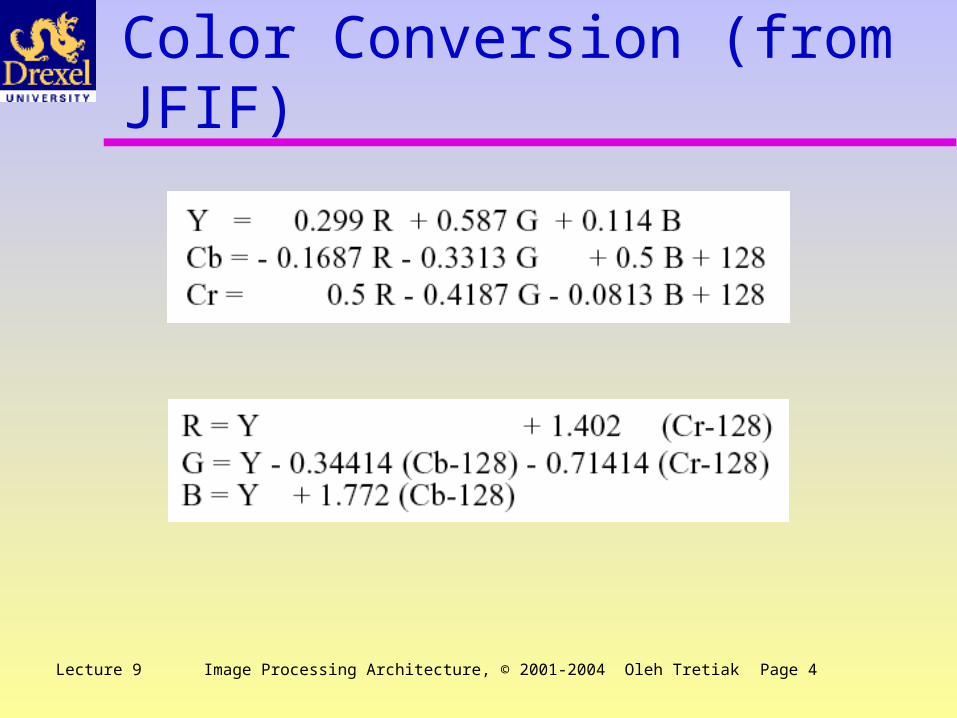
Image Processing Architecture, © 2001-2004 Oleh Tretiak Page 4Lecture 9
Color Conversion (from JFIF)

Image Processing Architecture, © 2001-2004 Oleh Tretiak Page 5Lecture 9
Resolution Reduction Trials
Full Y down by 64 Cb, Cr down by 64

Image Processing Architecture, © 2001-2004 Oleh Tretiak Page 6Lecture 9
RGB reduction
Full R, B reduced by 64

Image Processing Architecture, © 2001-2004 Oleh Tretiak Page 7Lecture 9
Coding AC Coefficients AC coefficients are coded in zig-zag order to maximize possible
runs of zeros. Code unit consist of run length
followed by coefficient size. Baseline coding of size is the
same as for DC differences (Table 2.9)
Example: run of 6 zeros, size = -18. In the table, -18is in category 5. Code is(6/5, 01101). If the Huffmancode for 6/5 is 1101, codeword = 110101101

Image Processing Architecture, © 2001-2004 Oleh Tretiak Page 8Lecture 9
Huffman Coding - Block Diagram

Image Processing Architecture, © 2001-2004 Oleh Tretiak Page 9Lecture 9
Lecture Outline Prediction and motion compensation MPEG-1 and relatives — history Video coding - how MPEG-1 works Details Wrapup Teleconferencing MPEG-2

Image Processing Architecture, © 2001-2004 Oleh Tretiak Page 10Lecture 9
Predicting sequential images
f(t-1) f(t)
f(t)–f(t–1)

Image Processing Architecture, © 2001-2004 Oleh Tretiak Page 11Lecture 9
Motion Compensation Macroblock size
MxN Matching criterion
MAE (mean absolute error) Search window
±p pixel locations Search algorithm
Full search Logarithmic search Parallel Hierarchical One-Dimensional Search Pixel subsampling and projection Hierarchical downsampling

Image Processing Architecture, © 2001-2004 Oleh Tretiak Page 12Lecture 9
Motion Estimation Methods
No compensation
Full search
logarithmicsearch 3 level
hierarchical

Image Processing Architecture, © 2001-2004 Oleh Tretiak Page 13Lecture 9
Video CodingHistory & Standards
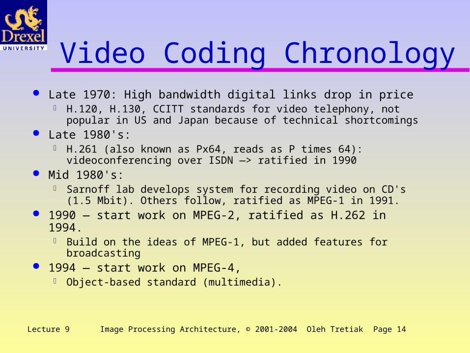
Image Processing Architecture, © 2001-2004 Oleh Tretiak Page 14Lecture 9
Video Coding Chronology Late 1970: High bandwidth digital links drop in price
H.120, H.130, CCITT standards for video telephony, not popular in US and Japan because of technical shortcomings
Late 1980's: H.261 (also known as Px64, reads as P times 64):
videoconferencing over ISDN —> ratified in 1990 Mid 1980's:
Sarnoff lab develops system for recording video on CD's (1.5 Mbit). Others follow, ratified as MPEG-1 in 1991.
1990 — start work on MPEG-2, ratified as H.262 in 1994. Build on the ideas of MPEG-1, but added features for broadcasting
1994 — start work on MPEG-4, Object-based standard (multimedia).

Image Processing Architecture, © 2001-2004 Oleh Tretiak Page 15Lecture 9
MPEG Home Official web site
http://www.chiariglione.org/mpeg/ Information site
http://www.mpeg.org/ History
MPEG-1, the standard for storage and retrieval of moving pictures and audio on storage media (approved Nov. 92)
MPEG-2, the standard for digital television (approved Nov. 94) MPEG-4 version 1, the standard for multimedia applications (approved Oct.
98), version 2, (approved Dec. 99) MPEG-4 versions 3&4 MPEG-7 the content representation standard for multimedia information
search, filtering, management and processing. Started MPEG-21, the multimedia framework.
http://www.chiariglione.org/mpeg/standards/mpeg-21/mpeg-21.htm

Image Processing Architecture, © 2001-2004 Oleh Tretiak Page 16Lecture 9
MPEG-1: How it works Goals What the standard specifies MPEG-1 decoder block diagram

Image Processing Architecture, © 2001-2004 Oleh Tretiak Page 17Lecture 9
MPEG-1: ‘1.5’ Mbps Sample rate reduction in spatial and temporal domains Spatial
Block-based DCT Huffman coding (no arithmetic coding) of motion vectors and
quantized DCT coefficients 352 x 340 pixels, 12 bits per pixel, picture rate 30 pictures per second
—> 30.4 Mbps Coded bit stream 1.15 Mbps (must leave bandwidth for audio) Compression 26:1 Quality better than VHS!
Temporal Block-based motion compensation Interframe coding (two kinds)

Image Processing Architecture, © 2001-2004 Oleh Tretiak Page 18Lecture 9
MPEG-1 Facts Decoder only is specified (encoder is up to implementers) Layered specification Must work in real time over fixed bandwidth media: bit rate
control Must satisfy diverse externally imposed requirements
NTSC vs. PAL Recorded media vs. Broadcast

Image Processing Architecture, © 2001-2004 Oleh Tretiak Page 19Lecture 9
Block Diagram of MPEG Decoder

Image Processing Architecture, © 2001-2004 Oleh Tretiak Page 20Lecture 9
Details and buzzwords Interlace, frame and field, picture NTSC and PAL CCIR 601 SIF Constrained parameter bit stream I, P, & B pictures Bit stream, GOP

Image Processing Architecture, © 2001-2004 Oleh Tretiak Page 21Lecture 9
Legacy Video Standards CRT technology, analog modulation and transmission NTSC (America and Japan)
2 interlaced fields = 1 frame Frame contains 525 lines, about 10% not visible (vertical retrace) 30 frames per second, 60 fields per second RGB in video camera and on CRT display, converted to composite
video (luminance and chrominance in same frequency band) PAL (Europe)
Interlace, etc 625 lines per frame, 25 frames (50 fields) per second Different (better) modulation of color (newer standard)

Image Processing Architecture, © 2001-2004 Oleh Tretiak Page 22Lecture 9
Frames and FieldsField 1Field 21234263264265 Time1234263264265
MPEG 1 works with pictures (~ frames)
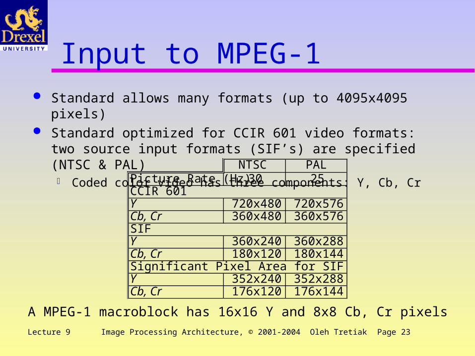
Image Processing Architecture, © 2001-2004 Oleh Tretiak Page 23Lecture 9
Input to MPEG-1 Standard allows many formats (up to 4095x4095 pixels) Standard optimized for CCIR 601 video formats: two source
input formats (SIF’s) are specified (NTSC & PAL) Coded color video has three components: Y, Cb, Cr
A MPEG-1 macroblock has 16x16 Y and 8x8 Cb, Cr pixels
NTSC PALPicture Rate (Hz) 30 25CCIR 601Y 720x480 720x576Cb, Cr 360x480 360x576SIFY 360x240 360x288Cb, Cr 180x120 180x144Significant Pixel Area for SIFY 352x240 352x288Cb, Cr 176x120 176x144

Image Processing Architecture, © 2001-2004 Oleh Tretiak Page 24Lecture 9
Picture Types MPEG-1 is designed to support random access & editing
I — intraframe coding only P — predictive coding B — bi-directional coding
IPB12345678

Image Processing Architecture, © 2001-2004 Oleh Tretiak Page 25Lecture 9
Typical MPEG coding parameters Typical sequence
IPBBPBBPBBPBBPBB (16 frames) Average compression 26.3
Picture Average size
Comp-ression
I 156000 6.5P 62000 16.4B 15000 67.6
Image Processing Architecture, © 2001-2004 Oleh Tretiak Page 26Lecture 9
Video Coder Preprocessing
Color conversion, format translations (interlaced to picture), downsampling
Motion estimation, compensation and coding I pictures — code directly (DCT)
Buffer regulator adjusts quantizer for constant bit rate Entropy code, then decode and IDCT for further use
P pictures — estimate motion, take difference, code difference B pictures — estimate two motion vectors
Form average of two predictive pictures Code difference between current picture and (a) past picture, (b) future
picture or (c) average picture, whichever produces least MAE Reorder pictures for transmission
Suppose we have sequence I1, B2, B3, P4, B5, B6, P7. Send I1, P4, B2, B3, P7, B5, B6.

Image Processing Architecture, © 2001-2004 Oleh Tretiak Page 27Lecture 9
Coded Video Bit Stream Layered representation
1 Sequence layerMay include tables
2 Group of Pictures (GOP) layer
3 Picture layer
4 Slice layer
5 Macroblock layer
6 Block layer

Image Processing Architecture, © 2001-2004 Oleh Tretiak Page 28Lecture 9
Picture of LayersGOP-1GOP-NGOP-2IBBPBB ... PSlice-1Slice-NSlice-2Sequence LayerGOP layerPicture layermb-1mb-2mb-n012333YCrCbSlice layerMacroblock layerBlock layer

Image Processing Architecture, © 2001-2004 Oleh Tretiak Page 29Lecture 9
MPEG-1Performance

Image Processing Architecture, © 2001-2004 Oleh Tretiak Page 30Lecture 9
Coding constraints (minimum) Constrained parameter bit stream. Every MPEG-1 decoder
should support these parameters
Coding Parameter ValueHorizontal Picture Size 768 pixels
Vertical Picture Size 576 linesMacroblocks/picture 396
Macroblock rate 9900/secPicture rate 30/sec
Range of motion vectors +/- 64 pixels @ half-pixel resolution
Size of input buffer 327,680 bitsBit rate 1856 kbits/sec

Image Processing Architecture, © 2001-2004 Oleh Tretiak Page 31Lecture 9
Macroblock Coding: I & P I pictures
Divided into slices and macroblocks No motion compensation Each macroblock can have different quantization DC and AC coded differently, as in JPEG Different coding tables from JPEG
P pictures Divided into slices and macroblocks Option: no motion compensation Option: can code block as inter or intra (like I picture) Can skip macroblock (replace with previous). Great compression

Image Processing Architecture, © 2001-2004 Oleh Tretiak Page 32Lecture 9
Coding Image Blocks B pictures
Inter or intra? Forward, backward, interpolational? Code block or skip? Quantization step?
I P B Zero MV Skipped TotalI 3300 3300P 897 8587 5128 568 15180B 60 7356 22845 429 30690
Picture Type
Macroblock type

Image Processing Architecture, © 2001-2004 Oleh Tretiak Page 33Lecture 9
MPEG-1 Wrap-up Data below for decoder, SIF pictures, 2 B pictures per P IDCT must be precise, because of inter-frame coding MPEG-1 does not deliver quality acceptable for broadcast —>
MPEG-2
Decoding Function Load (%)Bit-stream header parsing 0.44 0.44Huffman decoding and dequantization 19.00Inverse DCT 22.10Motion compensation 38.64Color transformation and display 19.82
Image Processing Architecture, © 2001-2004 Oleh Tretiak Page 34Lecture 9
MPEG-1: ‘1.5’ Mbps Sample rate reduction in spatial and temporal domains Spatial
Block-based DCT Huffman coding (no arithmetic coding) of motion vectors and
quantized DCT coefficients 352 x 340 pixels, 12 bits per pixel, picture rate 30 pictures per second
—> 30.4 Mbps Coded bit stream 1.15 Mbps (must leave bandwidth for audio) Compression 26:1 Quality better than VHS!
Temporal Block-based motion compensation Interframe coding (two kinds)

Image Processing Architecture, © 2001-2004 Oleh Tretiak Page 35Lecture 9
Video Teleconferencing Comprehensive Standard: H.320 Components of H.320
H.261: Video coding, 64 to 1920 kbits/sec G.722, G.726, G.728: Audio coding from 16 kbits/sec to 64
kbits/sec H.221: Multiplexing of audio and video (frame based rather than
packet based) H.230 and H.242: Handshaking and control H.233: encryption

Image Processing Architecture, © 2001-2004 Oleh Tretiak Page 36Lecture 9
Generic Video Telephone System

Image Processing Architecture, © 2001-2004 Oleh Tretiak Page 37Lecture 9
H.261 Features Common Interchange Format
Interoperability between 25 fps and 30 fps countries 252 pix/line, 288 line, 30 fps noninterlace Terminal equipment converts frame and line numbers Y Cb Cr components, color sub-sampled by a factor of 2 in both
directions Coding
DCT, 8x8, 4 Y and 2 chrominance per masterblock I and P frames only, P blocks can be skipped Motion compensation optional, only integer compensation (Optional) forward error correction coding

Image Processing Architecture, © 2001-2004 Oleh Tretiak Page 38Lecture 9
H.261 vs MPEG-1 Similarities
CIF, SIF, non-interlaced DCT technology
Differences H.261 uses mostly P frames, no B frames H.261 typical bit rates much lower (down to 64 kbits/sec)
Low bit rates achieved by reducing frame rate and picture count Simpler motion compensations End-to-end coding delay must be low
Conclusion: Same technology, different design to meet different needs

Image Processing Architecture, © 2001-2004 Oleh Tretiak Page 39Lecture 9
MPEG 2i, i = 0, 1 History & Goals Expanding universe of video coding What are MPEG-2 profiles? Features of MPEG-2

Image Processing Architecture, © 2001-2004 Oleh Tretiak Page 40Lecture 9
MPEG-2 Goals Compatibility with MPEG-1 Good picture quality Flexibility in input format Random access capability (I pictures) Capability for fast forward, fast reverse play, stop frame Bit stream scalability Low delay for 2-way communications (videoconferencing) Resilience to bit errors

Image Processing Architecture, © 2001-2004 Oleh Tretiak Page 41Lecture 9
MPEG-2 Implications No reason to restrict to CCIR 601
High resolution can be included (HDTV) No single standard can satisfy all requirements
Family of standards Most applications use a small set of the features
Toolkit approach

Image Processing Architecture, © 2001-2004 Oleh Tretiak Page 42Lecture 9
MPEG-2 profiles A profile is a subset of the entire MPEG-2 bit-stream syntax
Simple Main 4:2:2 SNR Spatial High Multiview
Each profile has several levels (resolution quality) Low — MPEG1 Main — CCIR 601 High-1440 (Video Editing) High (HDTV)

Image Processing Architecture, © 2001-2004 Oleh Tretiak Page 43Lecture 9
Features of MPEG-2 Support of both non-interlaced and interlaced pictures Color handling
Y Cb Cr color space Several subsampling schemes are used
4:2:0, 4:2:2, 4:4:4 MPEG-2 sequence can be either frames or fields
Both frame prediction and field prediction are supportedThere can be motion between two fields in a frame, so that
frame prediction is more tricky In frame prediction, both fields constitute one picture In field prediction, either field in the previous frame or the
previous field in this frame can be used as referenceRobustified coding of motion vectors to protect against bit
errorsSpecial prediction modes: 16x8, dual-prime