ilumtech technical catalogue
TRANSCRIPT

Connected Lighting
Technical catalogue
1 Year Warranty The Company reserves the right to change any product specifications without prior notification.
Key features• Four independent relay contacts• 10 A maximum switching current per contact• Push button for manual control (test function)• One DALI address for each contact (DALI device type 7,
EN 62386-208)
FunctionAfter powering-up the device, an internal test sequence is initiated that lasts for no more than 2 seconds. The device then acts in Normal Mode and awaits DALI commands.The ‘STATUS‘ LED indicator is lit when the DALI bus is correctly supplied. LED indicators 1 to 4 show the current status of each relay: a lit LED means the corresponding relay is switched on, an unlit LED means the corresponding relay is switched off.
Test modeTest Mode can be activated at any time by pressing the push button ‘TEST’. A short push of the button, for a period less than 3 seconds, changes which relay is selected, indicated by the corresponding LED indicator blinking. By pressing the push button for a period of more than 3 seconds the selected relay is switched on/off, indicated by the way in which the LED indicator blinks (predominantly on means the relay is switched on, predominantly off means the relay is switched off). The device will return to Normal Mode after 5 seconds of push button inactivity.
ConnectionsMains cable Wires AWG 24-12 (0.2-2.5 mm²)DALI cable Wires AWG 28-16 (0.08-1.5 mm²)Relays cable Wires AWG 24-12 (0.2-2.5 mm²)
PowerMains supply 220-240 V AC / 50-60 HzMax. system power 6 WDALI consumption < 2 mARelay loads 10 A (per contact)Insulation 4 kV
Mechanical dataHousing 4U DIN rail box 71 mm wideWeight 300 gIP rating IP 20
Operating conditionsAmbient temp. range 0 ºC - + 40 ºCMax. relative humidity 85 % (non-condensing)Storage temp. range -40 °C - +70 °C
Conformance with regulationsEN 55015 Limits and methods of
measurement of radio disturbance characteristics of electrical lighting and similar equipment
EN 61547 Equipment for general lighting purposes EMC immunity requirementsEN 60950-1 Information technology equipment
– Safety – Part 1: General requirements
EN 62386-208 Digital addressable lighting interface
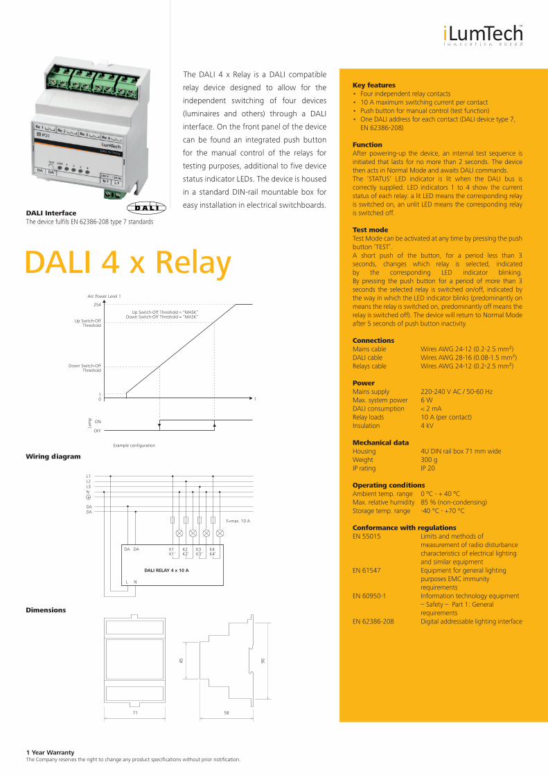
The DALI 4 x Relay is a DALI compatible
relay device designed to allow for the
independent switching of four devices
(luminaires and others) through a DALI
interface. On the front panel of the device
can be found an integrated push button
for the manual control of the relays for
testing purposes, additional to five device
status indicator LEDs. The device is housed
in a standard DIN-rail mountable box for
easy installation in electrical switchboards.
DALI 4 x Relay
DALI RELAY 4 x 10 A
DA
L1L2L3N
DADA
DA
L N
F=max. 10 A
K1K1’
K2K2’
K3K3’
K4K4’
Lam
p
ON
OFF
Arc Power Level 1
254
Up Switch-OffThreshold
Up Switch-Off Threshold = “MASK” Down Switch-Off Threshold = “MASK”
Example configuration
t
Down Switch-OffThreshold
10
9045
71 58
DALI Interface The device fulfils EN 62386-208 type 7 standards
Wiring diagram
Dimensions
1 Year Warranty The Company reserves the right to change any product specifications without prior notification.
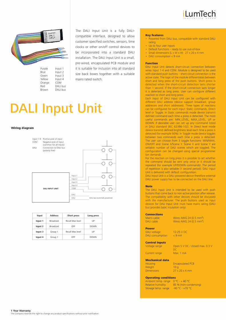
The DALI Input Unit is a fully DALI-
compatible interface, designed to allow
customer specified switches, sensors, time
clocks or other on/off control devices to
be incorporated into a standard DALI
installation. The DALI Input Unit is a small,
pre-wired, encapsulated PCB module and
it is suitable for inclusion into all standard
size back boxes together with a suitable
mains rated switch.
Purple Input 1 Blue Input 2 Green Input 3 Yellow Input 4Orange COM Red DALI bus Brown DALI bus
Key features• Powered from DALI bus, compatible with standard DALI
rating• Up to four user inputs• Default functions – ready to use out-of-box• Small dimensions (L x W x H): 27 x 20 x 4 mm• DALI consumption < 9 mA
FunctionDALI Input Unit detects short-circuit connection between wires Input 1-4 and COM. Module is designed to be used with standard push buttons – short-circuit connection is the active state. The logic of the module differentiates between short and long press of the push buttons. Short press is detected when the short-circuit detection lasts shorter than 1 second. If the short-circuit connection lasts longer it is detected as long press. User can configure different reaction to short and long press. Each input of DALI Input Unit can be configured with different DALI address (device support broadcast, group addresses and short addresses). Three types of reactions can be configured for each input: Static commands, Direct level or Toggle. In Static commands mode device transmit defined command each time a press is detected. The most useful commands are: MIN_LEVEL, MAX_LEVEL, UP or DOWN. If desirable user can set up any command listed in DALI standard (IEC 62386-102). In Direct level mode device transmit defined brightness level each time a press is detected (for example 50%). In Toggle mode device toggles between two commands each time a press is detected. The user can choose from 3 toggle functions: MIN/MAX, ON/OFF and Scene X/Scene Y. Scene X and Scene Y are settable number of DALI scenes which are toggled. The configuration can be changed using special programmer (on demand).For the reaction on long press it is possible to set whether the command should be sent only once or it should be repeated (for example UP/DOWN commands). The period of repetition is also settable (1 second period). DALI Input Unit is delivered with default configuration.DALI Input Unit is a DALI powered device therefore external DALI power supply has to be connected on the DALI line.
Note The DALI Input Unit is intended to be used with push buttons that come back to non-active position after release. The compatibility with other devices should be discussed with the manufacturer. The push buttons used as input devices for DALI Input Unit must have mains rating (DALI bus provides basic insulation only).
ConnectionsMains cable Wires AWG 24 (0.5 mm²)DALI cable Wires AWG 24 (0.5 mm²)
PowerDALI voltage 12-25 V DCDALI consumption < 9 mA
Control InputsVoltage range Open 5 V DC / closed max. 0.3 V
DCCurrent range Max. 1 mA
Mechanical dataHousing Encapsulated PCBWeight 10 gDimensions 27 x 20 x 4 mm
Operating conditionsAmbient temp. range 0 ºC - + 40 ºCRelative humidity 85 % (non-condensing)Storage temp. range -40 °C - +70 °C
DALI Input UnitWiring diagram
Input 1-4 Positive pole of inputCOM Negative pole of input (common for all inputs)DALI Connection to DALI bus (polarity free)
Input Address Short press Long press
Input 1 Broadcast Recall Max level UP
Input 2 Broadcast OFF DOWN
Input 3 Group 1 Recall Max level UP
Input 4 Group 1 OFF DOWN
DALI INPUT UNIT
DALI bus (externally powered)DALI
DALI
COM
Input 4
Input 3
Input 2
Input 1
1 Year Warranty The Company reserves the right to change any product specifications without prior notification.
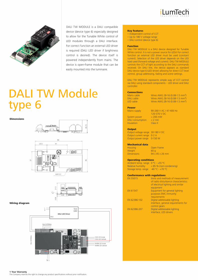
DALI TW MODULE is a DALI compatible
device (device type 6) especially designed
to allow for the Tunable White control of
LED modules through a DALI interface.
For correct function an external LED driver
is required (DALI LED driver if brightness
control is desired). The device itself is
powered independently from mains. The
device is open-frame module that can be
easily mounted into the luminaire.
Key features• Independent control of CCT• Up to 180 V voltage range• DALI control (device type 6)
FunctionDALI TW MODULE is a DALI device designed for Tunable White control. It is not a power source for LEDs! For correct function an external LED driver must be used (constant current). Selection of the LED driver depends on the LED load used (forward voltage and current). DALI TW MODULE controls the CCT of light according to the DALI commands received. On DALI line, the device appears as standard DALI device type 6 (LED driver) allowing for direct CCT level control, group addressing, fading and scene settings.
DALI TW MODULE represents simple way of CCT control via DALI using standard components – LED driver and DALI controller.
ConnectionsMains cable Wires AWG 28-16 (0.08-1.5 mm²)DALI cable Wires AWG 28-16 (0.08-1.5 mm²)LED cable Wires AWG 28-16 (0.08-1.5 mm²)
PowerMains supply 90-260 V AC / 47-400 Hz 120-370 V DCSystem power < 200 mWDALI consumption < 2 mAInsulation Class II
OutputOutput voltage range 30-180 V DCOutput current range 0-2 AOutput power range 0-150 W
Mechanical dataHousing Open FrameWeight 60 gDimensions 94 x 45 x 26 mm
Operating conditionsAmbient temp. range 0 ºC - +55 ºCRelative humidity < 85 % (non-condensing)Storage temp. range -40 °C - +70 °C
Conformance with regulationsEN 55015 limits and methods of measurement
of radio disturbance characteristics of electrical lighting and similar equipment
EN 61547 Equipment for general lighting purposes EMC immunity requirements
EN 62386-102 Digital addressable lighting interface, general requirements for control gears
EN 62386-207 Digital addressable lighting interface, LED drivers
DALI TW Module type 6Dimensions
4x /o 3.2
4526
.15
41
94
21.5
3.05
1.6
23.5
37
Wiring diagram
DALI LED Driver
COLD LED Anode
DALI EXTERNAL
DALI
VoutLN
LN
GND
DALI
INTE
RNAL
WARM LED Anode
COLD LED Cathode
WARM LED Cathode

1 Year Warranty The Company reserves the right to change any product specifications without prior notification.
DALI TW MODULE is a DALI compatible
device (device type 8) especially designed
to allow for the Tunable White control of
LED modules through a DALI interface.
For correct function an external LED driver
is required (DALI LED driver if brightness
control is desired). The device itself is
powered independently from mains. The
device is open-frame module that can be
easily mounted into the luminaire.
Key features• Independent control of CCT• Up to 180 V voltage range• DALI control (device type 8) – one address only
FunctionDALI TW MODULE is a DALI device designed for Tunable White control. It is not a power source for LEDs! For correct function an external LED driver must be used (constant current). Selection of the LED driver depends on the LED load used (forward voltage and current). DALI TW MODULE controls the CCT of light according to the DALI commands received. On DALI line, the device appears with one address as standard DALI device type 8 (Colour control) allowing for direct brightness and CCT level control, group addressing, and fading and scene settings.
DALI TW MODULE represents simple way of CCT control via DALI using standard components – LED driver and DALI controller (DALI controller must support DALI type 8).
ConnectionsMains cable Wires AWG 28-16 (0.08-1.5 mm²)DALI cable Wires AWG 28-16 (0.08-1.5 mm²)LED cable Wires AWG 28-16 (0.08-1.5 mm²)
PowerMains supply 90-260 V AC / 47-400 Hz 120-370 V DCSystem power < 200 mWDALI consumption < 2 mAInsulation Class II
OutputOutput voltage range 30-180 V DCOutput current range 0-2 AOutput power range 0-150 W
Mechanical dataHousing Open FrameWeight 60 gDimensions 94 x 45 x 26 mm
Operating conditionsAmbient temp. range 0 ºC - +55 ºCRelative humidity < 85 % (non-condensing)Storage temp. range -40 °C - +70 °C
Conformance with regulationsEN 55015 Limits and methods of
measurement of radio disturbance characteristics of electrical lighting and similar equipment
EN 61547 Equipment for general lighting purposes EMC immunity requirements
EN 62386-102 Digital addressable lighting interface, general requirements for control gears
EN 62386-207 Digital addressable lighting interface, LED drivers
EN 62386-209 Digital addressable lighting interface, Colour control
DALI TW Module type 8Dimensions
4x /o 3.2
4526
.15
41
94
21.5
3.05
1.6
23.5
37
Wiring diagram
DALI LED Driver
COLD LED Anode
DALI EXTERNAL
DALI
V outLN
LN
GND
DALI
INTE
RNAL
WARM LED Anode
COLD LED Cathode
WARM LED Cathode
1 Year Warranty The Company reserves the right to change any product specifications without prior notification.
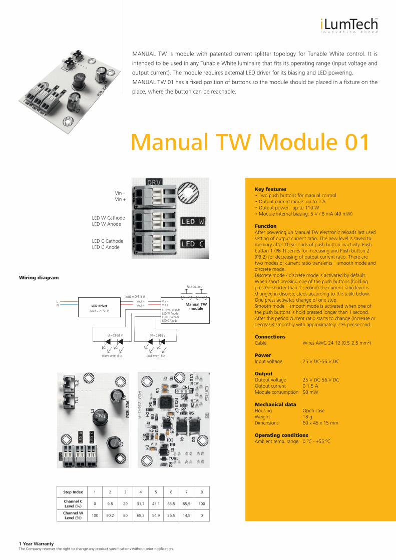
Manual TW Module 01
Wiring diagram
MANUAL TW is module with patented current splitter topology for Tunable White control. It is
intended to be used in any Tunable White luminaire that fits its operating range (input voltage and
output current). The module requires external LED driver for its biasing and LED powering.
MANUAL TW 01 has a fixed position of buttons so the module should be placed in a fixture on the
place, where the button can be reachable.
Key features• Two push buttons for manual control• Output current range: up to 2 A• Output power: up to 110 W• Module internal biasing: 5 V / 8 mA (40 mW)
FunctionAfter powering up Manual TW electronic reloads last used setting of output current ratio. The new level is saved to memory after 10 seconds of push button inactivity. Push button 1 (PB 1) serves for increasing and Push button 2 (PB 2) for decreasing of output current ratio. There are two modes of current ratio transients – smooth mode and discrete mode. Discrete mode / discrete mode is activated by default. When short pressing one of the push buttons (holding pressed shorter than 1 second) the current ratio level is changed in discrete steps according to the table below. One press activates change of one step. Smooth mode – smooth mode is activated when one of the push buttons is hold pressed longer than 1 second. After this period current ratio starts to change (increase or decrease) smoothly with approximately 2 % per second.
ConnectionsCable Wires AWG 24-12 (0.5-2.5 mm²)
PowerInput voltage 25 V DC-56 V DC
OutputOutput voltage 25 V DC-56 V DCOutput current 0-1.5 AModule consumption 50 mW
Mechanical dataHousing Open caseWeight 18 gDimensions 60 x 45 x 15 mm
Operating conditionsAmbient temp. range 0 ºC - +55 ºC
Vin -Vin +
LED W CathodeLED W Anode
LED C CathodeLED C Anode
Step Index 1 2 3 4 5 6 7 8
Channel C Level (%)
0 9,8 20 31,7 45,1 63,5 85,5 100
Channel W Level (%)
100 90,2 80 68,3 54,9 36,5 14,5 0
LED driver Manual TWmodule
LN
(Vout = 25-56 V)
Iout = 0-1.5 A
Vf = 25-56 V
Warm white LEDs Cold white LEDs
Vf = 25-56 V
Push buttons
Vin −Vout −Vout + Vin +
LED W CathodeLED W AnodeLED C CathodeLED C Anode
1 Year Warranty The Company reserves the right to change any product specifications without prior notification.
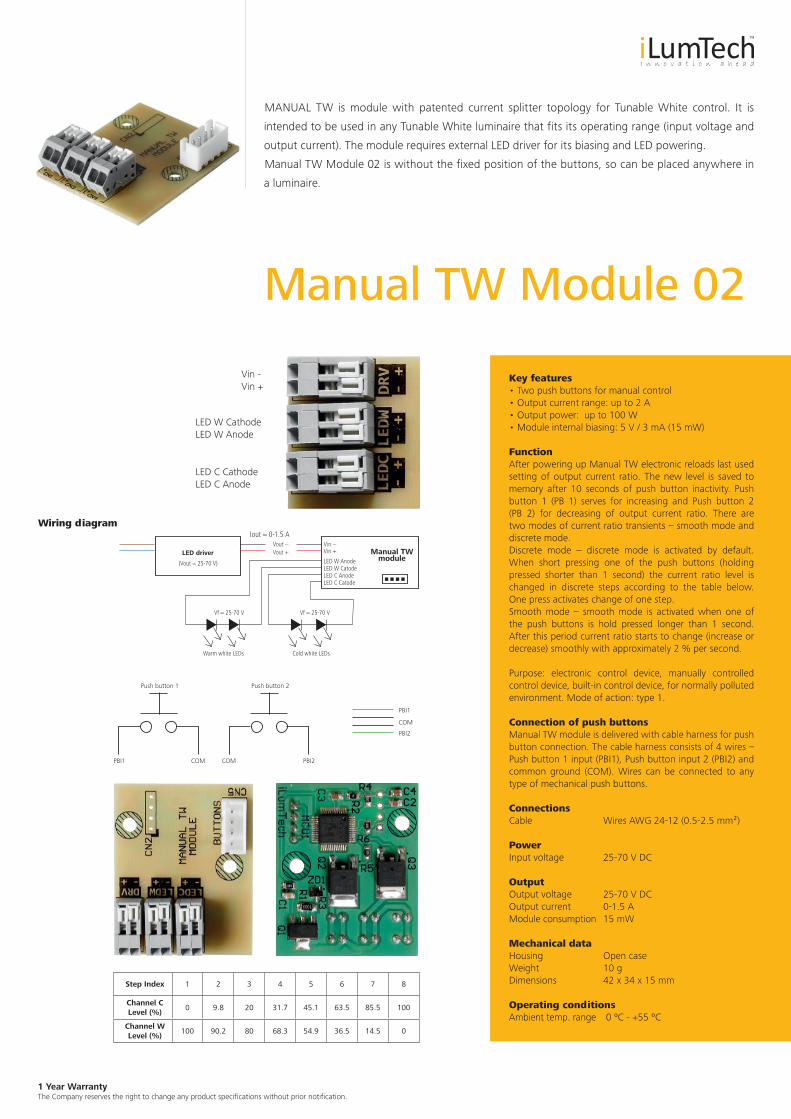
Manual TW Module 02
Wiring diagram
MANUAL TW is module with patented current splitter topology for Tunable White control. It is
intended to be used in any Tunable White luminaire that fits its operating range (input voltage and
output current). The module requires external LED driver for its biasing and LED powering.
Manual TW Module 02 is without the fixed position of the buttons, so can be placed anywhere in
a luminaire.
Key features• Two push buttons for manual control• Output current range: up to 2 A• Output power: up to 100 W• Module internal biasing: 5 V / 3 mA (15 mW)
FunctionAfter powering up Manual TW electronic reloads last used setting of output current ratio. The new level is saved to memory after 10 seconds of push button inactivity. Push button 1 (PB 1) serves for increasing and Push button 2 (PB 2) for decreasing of output current ratio. There are two modes of current ratio transients – smooth mode and discrete mode. Discrete mode – discrete mode is activated by default. When short pressing one of the push buttons (holding pressed shorter than 1 second) the current ratio level is changed in discrete steps according to the table below. One press activates change of one step.Smooth mode – smooth mode is activated when one of the push buttons is hold pressed longer than 1 second. After this period current ratio starts to change (increase or decrease) smoothly with approximately 2 % per second.
Purpose: electronic control device, manually controlled control device, built-in control device, for normally polluted environment. Mode of action: type 1.
Connection of push buttonsManual TW module is delivered with cable harness for push button connection. The cable harness consists of 4 wires – Push button 1 input (PBI1), Push button input 2 (PBI2) and common ground (COM). Wires can be connected to any type of mechanical push buttons.
ConnectionsCable Wires AWG 24-12 (0.5-2.5 mm²)
PowerInput voltage 25-70 V DC
OutputOutput voltage 25-70 V DCOutput current 0-1.5 AModule consumption 15 mW
Mechanical dataHousing Open caseWeight 10 gDimensions 42 x 34 x 15 mm
Operating conditionsAmbient temp. range 0 ºC - +55 ºC
Vin -Vin +
LED W CathodeLED W Anode
LED C CathodeLED C Anode
Step Index 1 2 3 4 5 6 7 8
Channel C Level (%)
0 9.8 20 31.7 45.1 63.5 85.5 100
Channel W Level (%)
100 90.2 80 68.3 54.9 36.5 14.5 0
LED driver Manual TWmodule
(Vout = 25-70 V)
Iout = 0-1.5 A
Vf = 25-70 V
Warm white LEDs Cold white LEDs
Vf = 25-70 V
Vin −Vout −Vout + Vin +
LED W AnodeLED W CatodeLED C AnodeLED C Catode
PBI2
Push button 1
PBI1 COM
Push button 2
COM
PBI1
PBI2
COM
1 Year Warranty The Company reserves the right to change any product specifications without prior notification.
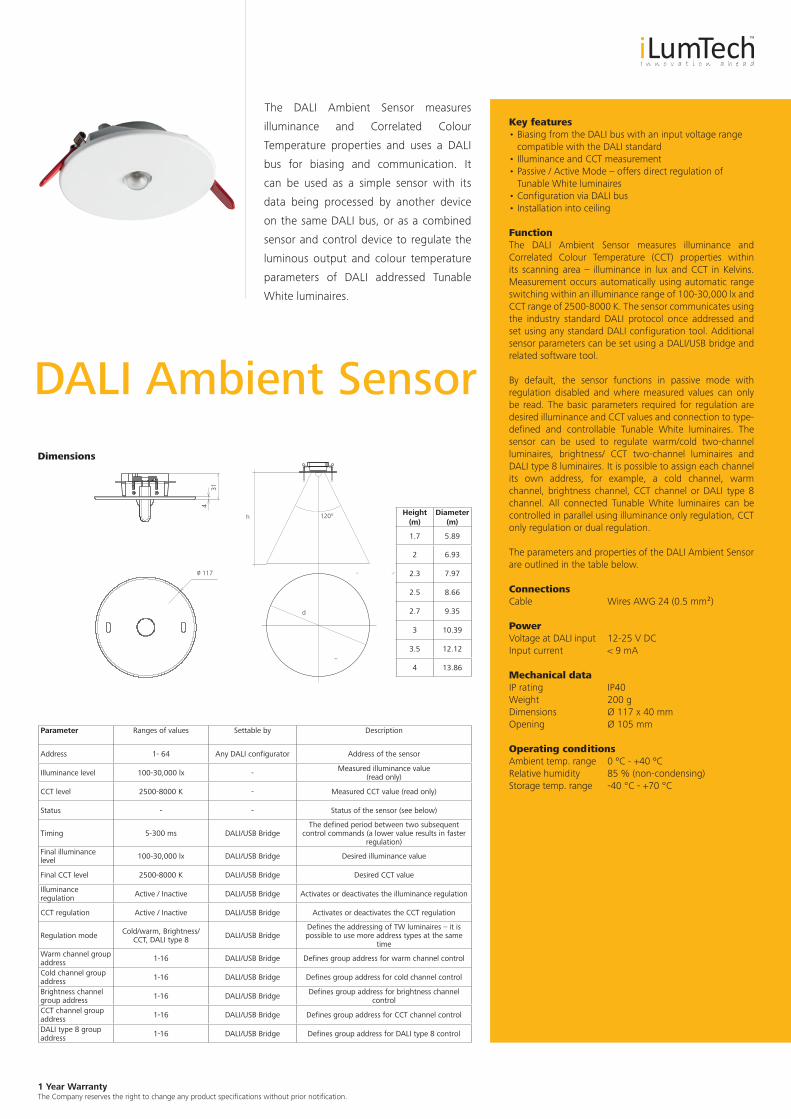
The DALI Ambient Sensor measures
illuminance and Correlated Colour
Temperature properties and uses a DALI
bus for biasing and communication. It
can be used as a simple sensor with its
data being processed by another device
on the same DALI bus, or as a combined
sensor and control device to regulate the
luminous output and colour temperature
parameters of DALI addressed Tunable
White luminaires.
DALI Ambient SensorDimensions
Key features• Biasing from the DALI bus with an input voltage range
compatible with the DALI standard • Illuminance and CCT measurement • Passive / Active Mode – offers direct regulation of
Tunable White luminaires • Configuration via DALI bus • Installation into ceiling
FunctionThe DALI Ambient Sensor measures illuminance and Correlated Colour Temperature (CCT) properties within its scanning area – illuminance in lux and CCT in Kelvins. Measurement occurs automatically using automatic range switching within an illuminance range of 100-30,000 lx and CCT range of 2500-8000 K. The sensor communicates using the industry standard DALI protocol once addressed and set using any standard DALI configuration tool. Additional sensor parameters can be set using a DALI/USB bridge and related software tool.
By default, the sensor functions in passive mode with regulation disabled and where measured values can only be read. The basic parameters required for regulation are desired illuminance and CCT values and connection to type-defined and controllable Tunable White luminaires. The sensor can be used to regulate warm/cold two-channel luminaires, brightness/ CCT two-channel luminaires and DALI type 8 luminaires. It is possible to assign each channel its own address, for example, a cold channel, warm channel, brightness channel, CCT channel or DALI type 8 channel. All connected Tunable White luminaires can be controlled in parallel using illuminance only regulation, CCT only regulation or dual regulation.
The parameters and properties of the DALI Ambient Sensor are outlined in the table below.
ConnectionsCable Wires AWG 24 (0.5 mm²)
PowerVoltage at DALI input 12-25 V DCInput current < 9 mA
Mechanical dataIP rating IP40Weight 200 gDimensions Ø 117 x 40 mmOpening Ø 105 mm
Operating conditionsAmbient temp. range 0 ºC - +40 ºCRelative humidity 85 % (non-condensing)Storage temp. range -40 °C - +70 °C
Parameter Ranges of values Settable by Description
Address 1- 64 Any DALI configurator Address of the sensor
Illuminance level 100-30,000 lx - Measured illuminance value (read only)
CCT level 2500-8000 K - Measured CCT value (read only)
Status - - Status of the sensor (see below)
Timing 5-300 ms DALI/USB BridgeThe defined period between two subsequent
control commands (a lower value results in faster regulation)
Final illuminance level 100-30,000 lx DALI/USB Bridge Desired illuminance value
Final CCT level 2500-8000 K DALI/USB Bridge Desired CCT value
Illuminance regulation Active / Inactive DALI/USB Bridge Activates or deactivates the illuminance regulation
CCT regulation Active / Inactive DALI/USB Bridge Activates or deactivates the CCT regulation
Regulation mode Cold/warm, Brightness/CCT, DALI type 8 DALI/USB Bridge
Defines the addressing of TW luminaires – it is possible to use more address types at the same
timeWarm channel group address 1-16 DALI/USB Bridge Defines group address for warm channel control
Cold channel group address 1-16 DALI/USB Bridge Defines group address for cold channel control
Brightness channel group address 1-16 DALI/USB Bridge Defines group address for brightness channel
controlCCT channel group address 1-16 DALI/USB Bridge Defines group address for CCT channel control
DALI type 8 group address 1-16 DALI/USB Bridge Defines group address for DALI type 8 control
Height(m)
Diameter(m)
1.7 5.89
2 6.93
2.3 7.97
2.5 8.66
2.7 9.35
3 10.39
3.5 12.12
4 13.86
/o 117
431
h
d
120°

1 Year Warranty The Company reserves the right to change any product specifications without prior notification.
DALI Ambient Sensor Outdoor is a sensor of
illuminance and correlated colour temperature
that uses DALI bus for biasing and the
communication. Besides of the sensing features
it is also capable of regulation of variously
addressed Tunable White luminaires. DALI
Ambient Sensor can therefore act as simple
sensor, whose data are processed by another
device on DALI bus or it can act as control
device for automatic control of illuminance
and correlated colour temperature. DALI
Ambient Sensor Outdoor is suitable for outdoor
application (IP 65).
DALI Ambient SensorOutdoorDimensions
Key features• Biasing from DALI bus, input voltage range is compatible
with DALI standard• Illuminance and CCT sensing• Passive / Active mode – offers direct regulation of
Tunable White luminaires• Configuration via DALI bus • Installation ceiling surfaced
FunctionDALI Ambient Sensor senses the light conditions in the area – illuminance in luxes and correlated colour temperature (CCT) in Kelvins. The measurement runs automatically with automatic range switching. The range of measured illuminance is from 100 lx to 30 000 lx. The range of CCT measurement is from 2 500 K to 8 000 K. For the communication the sensor uses DALI protocol typical for lighting installations. The sensor reacts on its address that is possible to set using any standard DALI configuration tool. Other parameters of the sensor can be set only using DALI/USB Bridge and its software tool.
By default the sensor is in passive mode therefore any regulation is disabled – it is possible to read-out measured values only. The basic parameters for the regulation are final values of illuminance and CCT. Then it is necessary to define the type of regulated Tunable White luminaires. DALI Ambient Sensor can control the luminaires with two channels of cold/warm type; two channels of brightness/CCT type and DALI type 8 luminaires. For each channels it is possible to set its DALI group address independently (cold channel, warm channel, brightness channel, CCT channel, DALI type 8). The sensor can control all types of Tunable White luminaires in parallel. The regulation of illuminance and CCT can be activated or deactivated independently or it can also run in parallel (concurrent regulation of illuminance and CCT). The parameters of the DALI Ambient Sensor and its properties are summarized in the table below.
ConnectionsCable Wires AWG 24 (0.5 mm²)
PowerVoltage at DALI input 12-25 V DCInput current < 9 mA
Mechanical dataIP rating IP65Weight 214 gDimensions 82 x 112 x 55 mm
Operating conditionsAmbient temp. range -20 ºC - +60 ºCRelative humidity 85 % (non-condensing)Storage temp. range -40 °C - +70 °C
Parameter Ranges of values
Settable by Description
Address 1 to 64 Any DALI configurator Address of the sensor
Illuminance level 100-30,000 lx - Measured value of illuminance (read only)
CCT level 2500-8000 K - Measured value of CCT (read only)
Status - - Status of the sensor (see below)
Timing 5-300 ms DALI/USB Bridge Parameter defines period between two subsequent control commands (lower value means faster regulation)
Final illuminance level 100-30,000 lx DALI/USB Bridge Desired illuminance value
Final CCT level 2500-8000 K DALI/USB Bridge Desired CCT value
Illuminance regulation
Active / Non-active DALI/USB Bridge Activates or deactivates the illuminance regulation
CCT regulation Active / Non-active DALI/USB Bridge Activates or deactivates the CCT regulation
Regulation mode
Cold/Warm, Brightness/CCT, DALI
type 8
DALI/USB Bridge Defines the addressing of TW luminaires, it is possible to use more addressing types concurrently
Warm channel group address 1- 6 DALI/USB Bridge Define group address for warm channel control
Cold channel group address 1-16 DALI/USB Bridge Define group address for cold channel control
Brightness channel group address 1-16 DALI/USB Bridge Define group address for brightness channel control
CCT channel group address 1- 6 DALI/USB Bridge Define group address for CCT channel control
DALI type 8 group address 1-16 DALI/USB Bridge Define group address for DALI type 8 control
Holes(2) are designed for M4 PAN Head Machine screws use
/o 5
R 4,25
95,4
68
60 70
Assembly
49 55
1 Year Warranty The Company reserves the right to change any product specifications without prior notification.
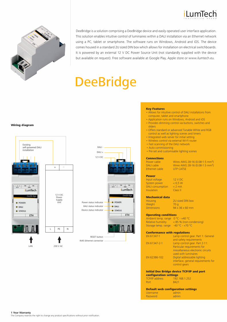
DeeBridge
Wiring diagram
DeeBridge is a solution comprising a DeeBridge device and easily operated user interface application.
This solution enables intuitive control of luminaires within a DALI installation via an Ethernet network
using a PC, tablet or smartphone. The software runs on Windows, Android and iOS. The device
comes housed in a standard 2U sized DIN box which allows for installation on electrical switchboards.
It is powered by an external 12 V DC Power Source Unit (not standardly supplied with the device
but available on request). Free software available at Google Play, Apple store or www.ilumtech.eu.
Key Features • Allows for intuitive control of DALI installations from
computer, tablet and smartphone• Application runs on Windows, Android and iOS• Provides dimming control via buttons, switches and
sliders• Offers standard or advanced Tunable White and RGB
control as well as lighting scenes and timers• Integrated web server for initial setting• Wireless control via external Wi-Fi router• Fast scanning of the DALI network• Auto commissioning• Pre-set and customisable lighting scenes
ConnectionsPower cable Wires AWG 28-16 (0.08-1.5 mm²)DALI cable Wires AWG 28-16 (0.08-1.5 mm²)Ethernet cable UTP CAT5E
PowerInput voltage 12 V DCSystem power < 0,5 WDALI consumption < 2 mAInsulation Class II
Mechanical dataHousing 2U sized DIN boxWeight 70 gDimensions 94 x 36 x 60 mm
Operating conditionsAmbient temp. range 0 °C - +40 °CRelative humidity < 85 % (non-condensing)Storage temp. range -40 °C - +70 °C
Conformance with regulationsEN 61347-1 Lamp control gear. Part 1: General
and safety requirementsEN 61347-2-1 Lamp control gear. Part 2-11:
Particular requirements for miscellaneous electronic circuits used with luminaires
EN 62386-102 Digital addressable lighting interface, general requirements for control gears
Initial Dee Bridge device TCP/IP and port configuration settingsTCP/IP address 192.168.1.252Port 8421
Default web configuration settingsUsername adminPassword admin
LAN 230 V AC
Existing self-powered DALI installation
12 V DCPowerSupplyUnit
+ -
L PE N
DALI -
DALI +
12 V DC
Power status indicator
DALI status indicator
Device status indicator
RESET button
RJ45 Ethernet connector
1 Year Warranty The Company reserves the right to change any product specifications without prior notification.
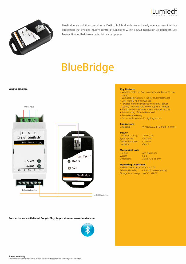
BlueBridge
BlueBridge is a solution comprising a DALI to BLE bridge device and easily operated user interface
application that enables intuitive control of luminaires within a DALI installation via Bluetooth Low
Energy (Bluetooth 4.1) using a tablet or smartphone.
Key Features• Wireless control of DALI installation via Bluetooth Low
Energy• Compatibility with most tablets and smartphones• User friendly Android GUI app • Powered from the DALI bus (no external power
source) − external DALI Power Supply is needed!• Pluggable DALI terminals – easy to install and use• Fast scanning of the DALI network• Auto commissioning• Pre-set and customisable lighting scenes
ConnectionsDALI cable Wires AWG 28-16 (0.08-1.5 mm2)
PowerDALI input voltage 12-25 V DCSystem power < 0.25 WDALI consumption < 10 mAInsulation Class II
Mechanical dataHousing ABS plastic boxWeight 50 gDimensions 35 x 67.3 x 15 mm
Operating ConditionsAmbient temp. range 0 °C - +40 °CRelative Humidity < 85 % (non-condensing)Storage temp. range -40 °C - +70 °C
Free software available at Google Play, Apple store or www.ilumtech.eu
Mains input
Output to DALI bus
to DALI luminaires
Wiring diagram
1 Year Warranty The Company reserves the right to change any product specifications without prior notification.
DALI Power Supply
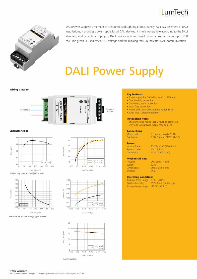
DALI Power Supply is a member of the Connected Lighting product family. As a basic element of DALI
installations, it provides power supply for all DALI devices. It is fully compatible according to the DALI
standard, and capable of supplying DALI devices with an overall current consumption of up to 250
mA. The green LED indicates DALI voltage and the blinking red LED indicates DALI communication.
Key features• Power supply for DALI devices up to 250 mA• Over-heating protection• DALI overcurrent protection• Input fuse protection• Power and communication indication LEDs• Wide input voltage operation
Installation notes• The connected mains supply must be protected• Only one DALI power supply may be used
ConnectionsMains cable 0.5-4 mm2 (AWG 20-10)DALI cable 0.08-2.5 mm2 (AWG 28-12)
PowerInput voltage 85-264 V AC (47-63 Hz)System power Max. 3.7 WDALI output 18 V DC (250 mA)
Mechanical dataHousing 2U sized DIN boxWeight 82 gDimensions 90 x 36 x 58 mmIP rating IP20
Operating conditionsAmbient temp. range 0 °C - +40 °CRelative humidity 85 % (non-condensing)Storage temp. range -40 °C - +70 °C
Wiring diagram
Mains input Output to DALI bus
Characteristics
Efficiency by input voltage (@50 % load)
Power factor by input voltage (@50 % load)
Load regulation
Effic
ienc
y (%
)
60
55
50
45
400 50 100 150 200 250 300
Input Voltage (V)
50 % Load
Effic
ienc
y (%
)
60
55
50
45
40
0.00 0.05 0.10 0.15 0.20 0.25
Load Current (A)
VIN=230 V ACVIN=110 V AC
Pow
er F
acto
r
0.55
0.50
0.45
0.40
0.35
0.30
0.250.00 0.05 0.10 0.15 0.20 0.25
Load Current (A)
VIN=230 V ACVIN=110 V AC
Out
put
Volta
ge (V
)
25
20
15
10
5
00.00 0.05 0.10 0.15 0.20 0.25
Load Current (A)
VIN=230 V ACVIN=110 V AC
0.65
0.60
0.55
0.50
0.45
0.40
0.35
0.300 50 100 150 200 250 300
Input Voltage (V)
50 % Load
Pow
er F
acto
r
1 Year Warranty The Company reserves the right to change any product specifications without prior notification.
DALI/USB Bridge
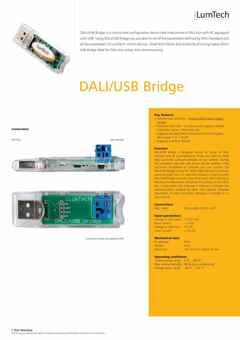
DALI/USB Bridge is a control and configuration device that interconnects DALI bus with PC equipped
with USB. Using DALI/USB Bridge you are able to set all the parameters defined by DALI standard and
all the parameters of iLumTech control devices. Small form factor and simplicity of wiring makes DALI/
USB Bridge ideal for DALI bus setup and commissioning.
Key features• Isolated from DALI bus – external DALI Power Supply needed• Powered from USB – no extra power supplies needed• Small form factor – flash stick size • Supports standard DALI commands for control gears device type 1, 6, 7 and 8• Supports iLumTech devices FunctionDALI/USB Bridge is designed mainly for setup of DALI network and its commissioning. Firstly you have to install DALI Controller software available on our website. During the installation also the USB drivers will be installed. After successful installation of software you can connect the DALI/USB Bridge to your PC. When DALI network is correctly powered green LED is lit. Red LED indicator is flashing when DALI/USB Bridge transmits data while green LED indicator is flashing simultaneously indicating the activity on the DALI line. If only green LED indicator is flashing it indicates the communication initiated by other DALI devices. Detailed description of DALI Controller software is included in its user manual.
ConnectionsDALI cable Wires AWG 24 (0.5 mm²)
Input parametersVoltage at DALI input 12-25 V DCInput current < 2 mAVoltage at USB input 5 V DCInput Current < 10 mA
Mechanical dataIP coverage IP20Weight 50 gDimension 70 x 23 mm, height 20 mm
Operating conditionsAmbient temp. range 0 ºC - +40 ºCMax. relative humidity 85 % (non-condensing)Storage temp. range -40 °C - +70 °C
Connection
DALI terminal
Connection to DALI bus (polarity free)
USB Plug
1 Year Warranty The Company reserves the right to change any product specifications without prior notification.
DLS Touch Panel II
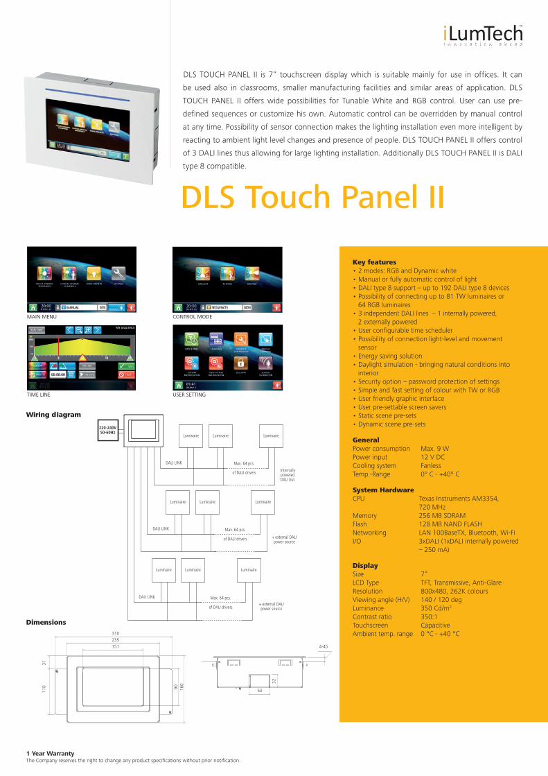
DLS TOUCH PANEL II is 7“ touchscreen display which is suitable mainly for use in offices. It can
be used also in classrooms, smaller manufacturing facilities and similar areas of application. DLS
TOUCH PANEL II offers wide possibilities for Tunable White and RGB control. User can use pre-
defined sequences or customize his own. Automatic control can be overridden by manual control
at any time. Possibility of sensor connection makes the lighting installation even more intelligent by
reacting to ambient light level changes and presence of people. DLS TOUCH PANEL II offers control
of 3 DALI lines thus allowing for large lighting installation. Additionally DLS TOUCH PANEL II is DALI
type 8 compatible.
Key features• 2 modes: RGB and Dynamic white• Manual or fully automatic control of light• DALI type 8 support – up to 192 DALI type 8 devices• Possibility of connecting up to 81 TW luminaires or 64 RGB luminaires• 3 independent DALI lines – 1 internally powered, 2 externally powered• User configurable time scheduler• Possibility of connection light-level and movement sensor• Energy saving solution• Daylight simulation - bringing natural conditions into interior• Security option – password protection of settings• Simple and fast setting of colour with TW or RGB• User friendly graphic interface• User pre-settable screen savers• Static scene pre-sets• Dynamic scene pre-sets
GeneralPower consumption Max. 9 WPower input 12 V DCCooling system FanlessTemp.-Range 0° C - +40° C
System HardwareCPU Texas Instruments AM3354, 720 MHzMemory 256 MB SDRAMFlash 128 MB NAND FLASHNetworking LAN 100BaseTX, Bluetooth, Wi-FiI/O 3xDALI (1xDALI internally powered – 250 mA)
DisplaySize 7“LCD Type TFT, Transmissive, Anti-GlareResolution 800x480, 262K coloursViewing angle (H/V) 140 / 120 degLuminance 350 Cd/m2
Contrast ratio 350:1Touchscreen CapacitiveAmbient temp. range 0 °C - +40 °C
InternallypoweredDALI bus
DALI LINK
DALI LINK
DALI LINK
Max. 64 pcs.
of DALI drivers
Max. 64 pcs.
of DALI drivers
Max. 64 pcs.
of DALI drivers
+ external DALIpower source
+ external DALIpower source
Luminaire Luminaire Luminaire
Luminaire Luminaire Luminaire
Luminaire Luminaire Luminaire
220-240V50-60Hz
4-45
32
50
310
90
31
160
110
235151
CONTROL MODE
USER SETTINGTIME LINE
MAIN MENU
Wiring diagram
Dimensions
1 Year Warranty The Company reserves the right to change any product specifications without prior notification.
DALI PLC Bridge
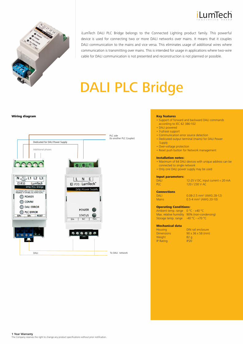
iLumTech DALI PLC Bridge belongs to the Connected Lighting product family. This powerful
device is used for connecting two or more DALI networks over mains. It means that it couples
DALI communication to the mains and vice versa. This eliminates usage of additional wires where
communication is transmitting over mains. This is intended for usage in applications where two-wire
cable for DALI communication is not presented and reconstruction is not planned or possible.
Key features• Support of forward and backward DALI commands
according to IEC 62 386-102• DALI powered • 3-phase support• Communication error source detection• Dedicated output terminal (mains) for DALI Power Supply• Over-voltage protection• Reset push button for Network management
Installation notes:• Maximum of 64 DALI devices with unique address can be
connected to single network• Only one DALI power supply may be used
Input parameters:DALI 12-25 V DC, input current < 20 mAPLC 120 / 230 V AC
ConnectionsDALI 0.08-2.5 mm2 (AWG 28-12)Mains 0.5-4 mm2 (AWG 20-10)
Operating Conditions:Ambient temp. range 0 °C - +40 °CMax. relative humidity 90% (non-condensing)Storage temp. range -40 °C - +70 °C
Mechanical dataHousing DIN rail enclosureDimensions 90 x 36 x 58 (mm)Weight 82 gIP Rating IP20
PLC side(to another PLC Coupler)
To DALI networkDALI
Wiring diagram
Additional phases
Dedicated for DALI Power Supply
1 Year Warranty The Company reserves the right to change any product specifications without prior notification.
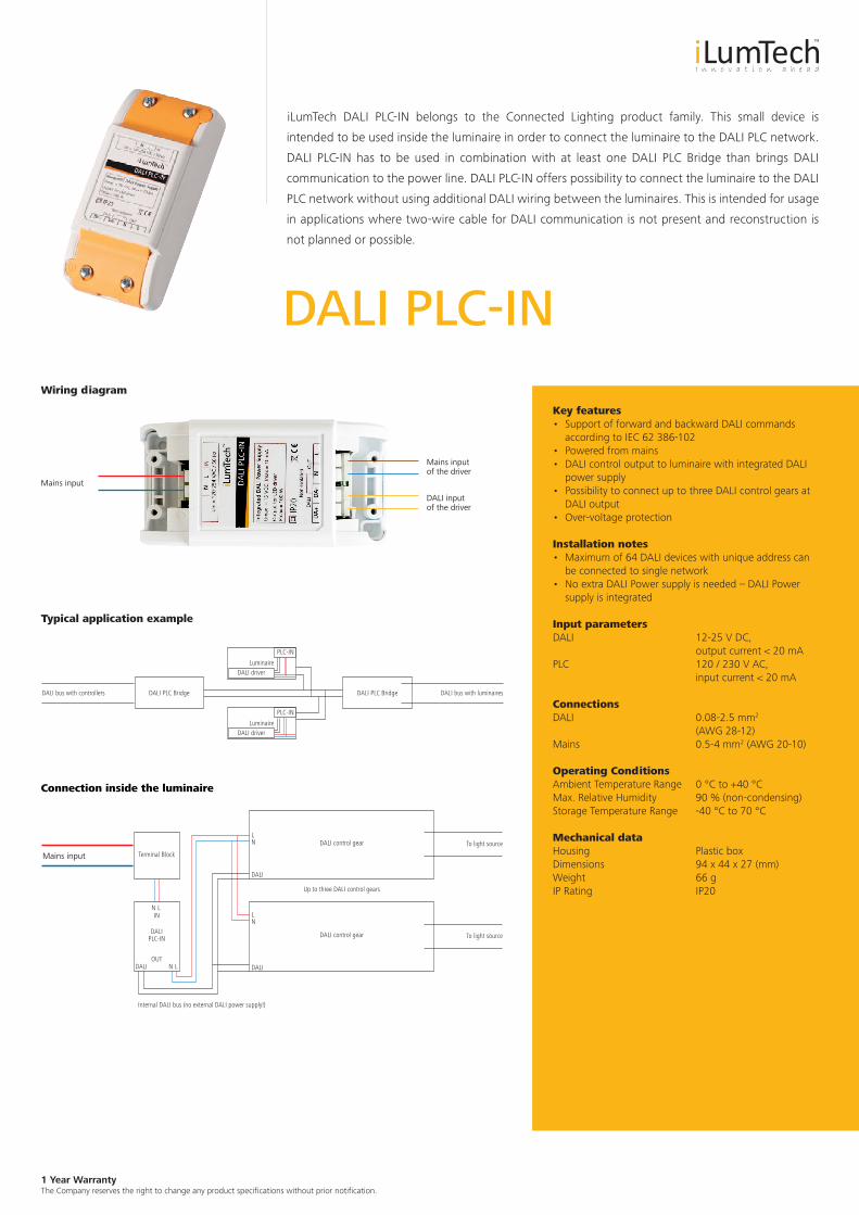
DALI PLC-IN
iLumTech DALI PLC-IN belongs to the Connected Lighting product family. This small device is
intended to be used inside the luminaire in order to connect the luminaire to the DALI PLC network.
DALI PLC-IN has to be used in combination with at least one DALI PLC Bridge than brings DALI
communication to the power line. DALI PLC-IN offers possibility to connect the luminaire to the DALI
PLC network without using additional DALI wiring between the luminaires. This is intended for usage
in applications where two-wire cable for DALI communication is not present and reconstruction is
not planned or possible.
Key features• Support of forward and backward DALI commands
according to IEC 62 386-102• Powered from mains• DALI control output to luminaire with integrated DALI power supply • Possibility to connect up to three DALI control gears at DALI output• Over-voltage protection
Installation notes• Maximum of 64 DALI devices with unique address can
be connected to single network• No extra DALI Power supply is needed – DALI Power supply is integrated
Input parametersDALI 12-25 V DC, output current < 20 mAPLC 120 / 230 V AC, input current < 20 mA
ConnectionsDALI 0.08-2.5 mm2 (AWG 28-12)Mains 0.5-4 mm2 (AWG 20-10)
Operating ConditionsAmbient Temperature Range 0 °C to +40 °CMax. Relative Humidity 90 % (non-condensing)Storage Temperature Range -40 °C to 70 °C
Mechanical dataHousing Plastic boxDimensions 94 x 44 x 27 (mm)Weight 66 gIP Rating IP20
Wiring diagram
Mains input
DALI input of the driver
Luminaire
Luminaire
DALI PLC Bridge DALI PLC Bridge DALI bus with luminairesDALI bus with controllers
PLC-IN
PLC-IN
DALI driver
DALI driver
Terminal Block
DALI control gear
DALI control gearDALIPLC-IN
Mains input
To light source
To light source
Up to three DALI control gears
Internal DALI bus (no external DALI power supply!)
Typical application example
Connection inside the luminaire
Mains input of the driver
LNIN
LNDALIOUT
DALI
DALI
NL
NL
1 Year Warranty The Company reserves the right to change any product specifications without prior notification.
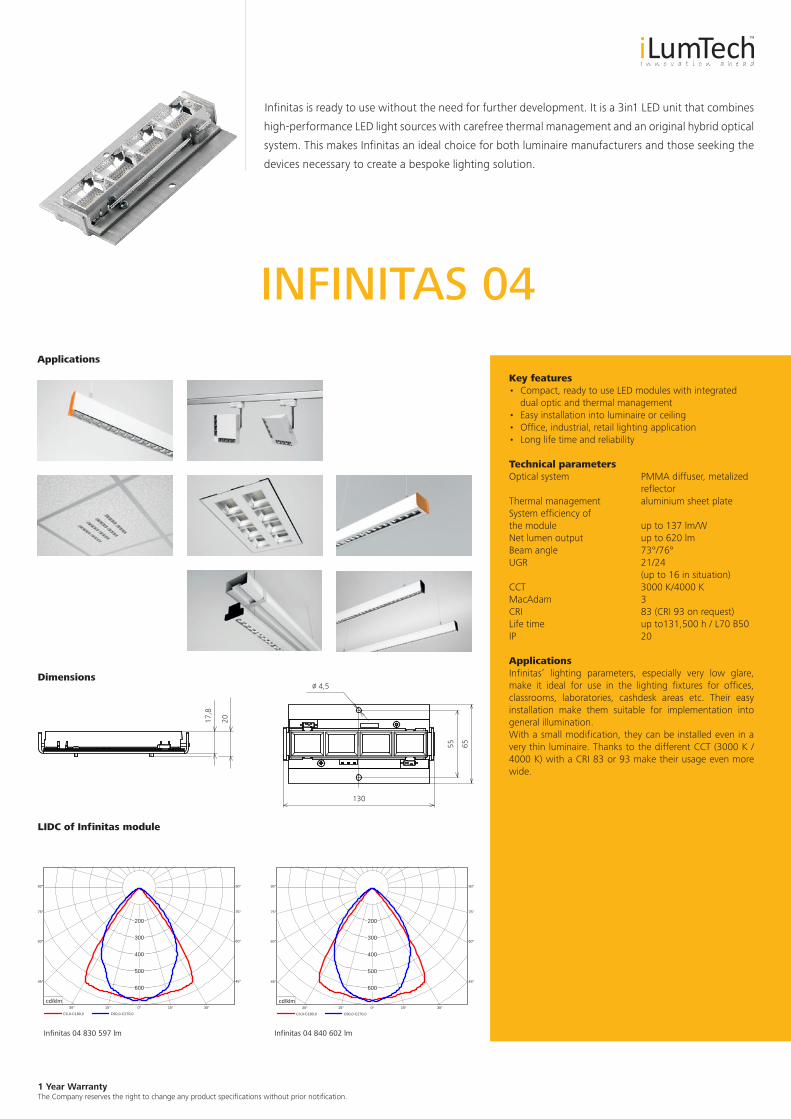
INFINITAS 04
Infinitas is ready to use without the need for further development. It is a 3in1 LED unit that combines
high-performance LED light sources with carefree thermal management and an original hybrid optical
system. This makes Infinitas an ideal choice for both luminaire manufacturers and those seeking the
devices necessary to create a bespoke lighting solution.
Key features• Compact, ready to use LED modules with integrated
dual optic and thermal management• Easy installation into luminaire or ceiling• Office, industrial, retail lighting application• Long life time and reliability
Technical parametersOptical system PMMA diffuser, metalized reflectorThermal management aluminium sheet plateSystem efficiency of the module up to 137 lm/WNet lumen output up to 620 lmBeam angle 73°/76°UGR 21/24 (up to 16 in situation)CCT 3000 K/4000 KMacAdam 3CRI 83 (CRI 93 on request)Life time up to131,500 h / L70 B50IP 20
ApplicationsInfinitas’ lighting parameters, especially very low glare, make it ideal for use in the lighting fixtures for offices, classrooms, laboratories, cashdesk areas etc. Their easy installation make them suitable for implementation into general illumination. With a small modification, they can be installed even in a very thin luminaire. Thanks to the different CCT (3000 K / 4000 K) with a CRI 83 or 93 make their usage even more wide.
/o 4,5
130
55 65
17,8
20
Dimensions
C0,0-C180,0 C90,0-C270,0
90°90°
75°
60°
45°
30° 15° 0° 15° 30°
45°
60°
75°
200
300
400
500
600
cd/klm
C0,0-C180,0 C90,0-C270,0
90°90°
75°
60°
45°
30° 15° 0° 15° 30°
45°
60°
75°
200
300
400
500
600
cd/klm
LIDC of Infinitas module
Infinitas 04 840 602 lmInfinitas 04 830 597 lm
Applications
1 Year Warranty The Company reserves the right to change any product specifications without prior notification.
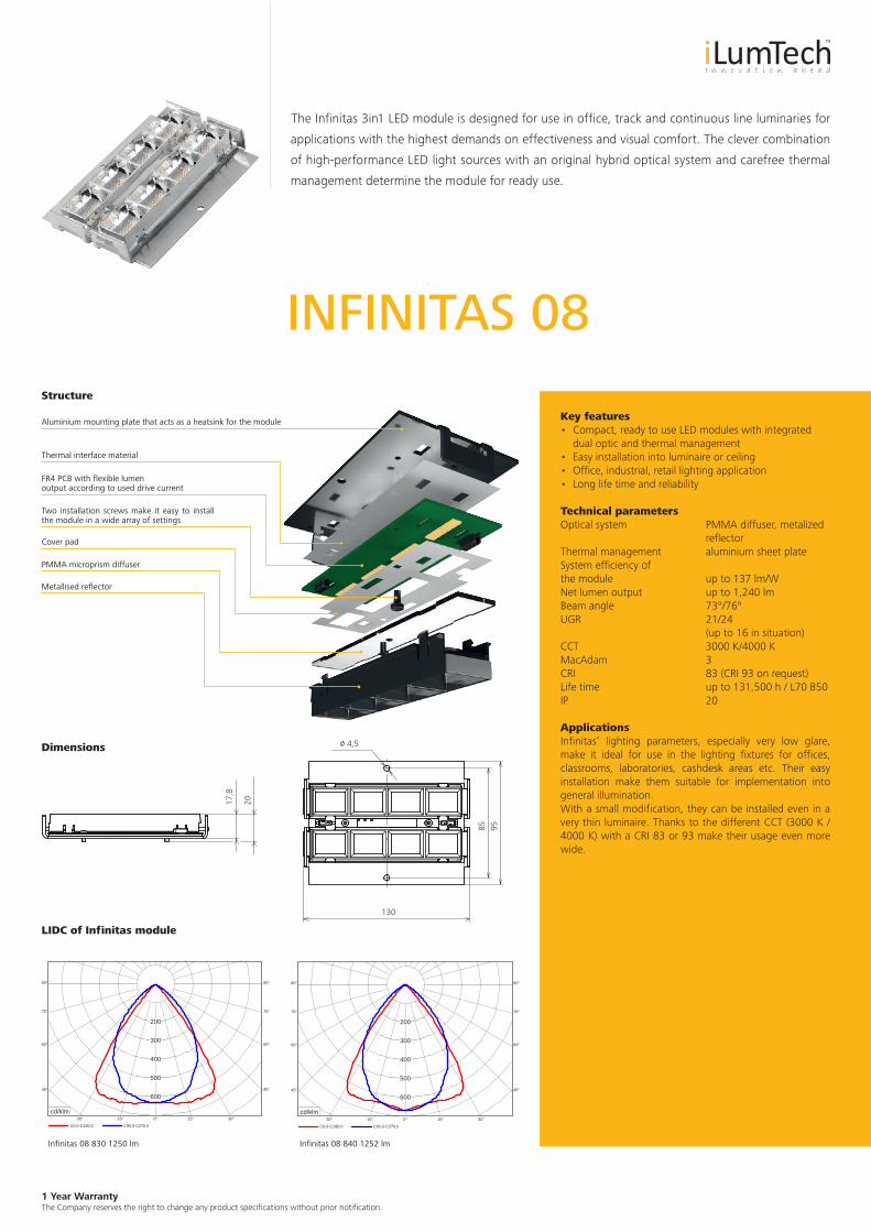
INFINITAS 08
The Infinitas 3in1 LED module is designed for use in office, track and continuous line luminaries for
applications with the highest demands on effectiveness and visual comfort. The clever combination
of high-performance LED light sources with an original hybrid optical system and carefree thermal
management determine the module for ready use.
Key features• Compact, ready to use LED modules with integrated
dual optic and thermal management• Easy installation into luminaire or ceiling• Office, industrial, retail lighting application• Long life time and reliability
Technical parametersOptical system PMMA diffuser, metalized reflectorThermal management aluminium sheet plateSystem efficiency of the module up to 137 lm/WNet lumen output up to 1,240 lmBeam angle 73°/76°UGR 21/24 (up to 16 in situation)CCT 3000 K/4000 KMacAdam 3CRI 83 (CRI 93 on request)Life time up to 131,500 h / L70 B50IP 20
ApplicationsInfinitas’ lighting parameters, especially very low glare, make it ideal for use in the lighting fixtures for offices, classrooms, laboratories, cashdesk areas etc. Their easy installation make them suitable for implementation into general illumination. With a small modification, they can be installed even in a very thin luminaire. Thanks to the different CCT (3000 K / 4000 K) with a CRI 83 or 93 make their usage even more wide.
Structure
17,8
20
Aluminium mounting plate that acts as a heatsink for the module
Thermal interface material
FR4 PCB with flexible lumen output according to used drive current
Two installation screws make it easy to install the module in a wide array of settings
Cover pad
PMMA microprism diffuser
Metallised reflector
Dimensions
LIDC of Infinitas module
Infinitas 08 830 1250 lm Infinitas 08 840 1252 lm
/o 4,5
130
85 95
C0,0-C180,0 C90,0-C270,0
90°90°
75°
60°
45°
30° 15° 0° 15° 30°
45°
60°
75°
200
300
400
500
600
cd/klm
C0,0-C180,0 C90,0-C270,0
90°90°
75°
60°
45°
30° 15° 0° 15° 30°
45°
60°
75°
200
300
400
500
600
cd/klm
1 Year Warranty The Company reserves the right to change any product specifications without prior notification.
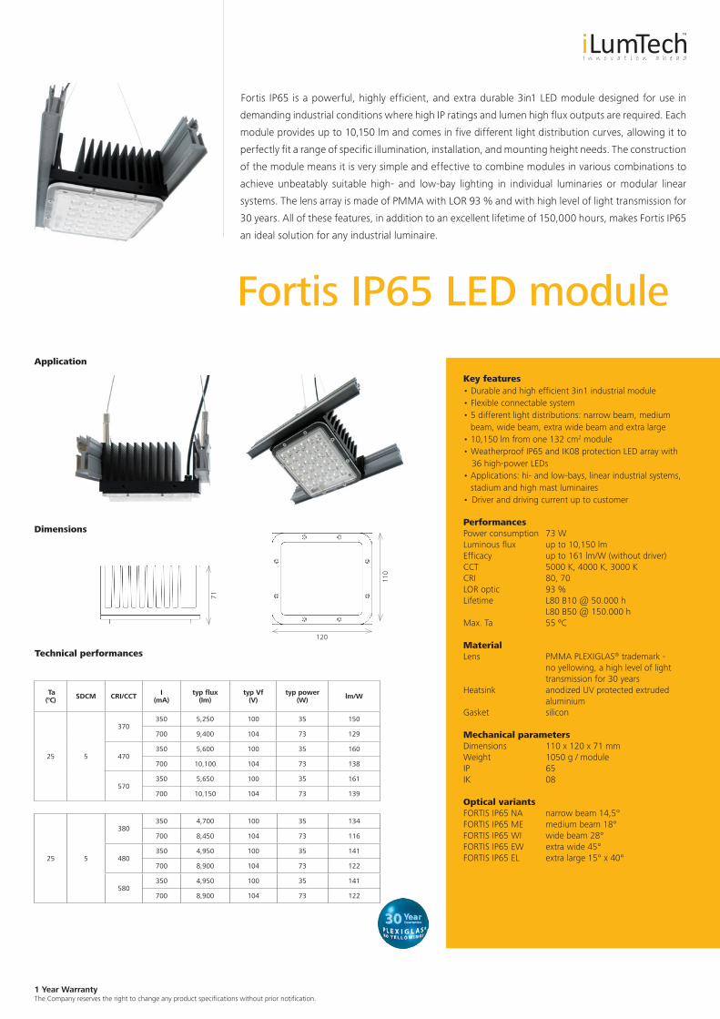
Fortis IP65 LED module
Fortis IP65 is a powerful, highly efficient, and extra durable 3in1 LED module designed for use in
demanding industrial conditions where high IP ratings and lumen high flux outputs are required. Each
module provides up to 10,150 lm and comes in five different light distribution curves, allowing it to
perfectly fit a range of specific illumination, installation, and mounting height needs. The construction
of the module means it is very simple and effective to combine modules in various combinations to
achieve unbeatably suitable high- and low-bay lighting in individual luminaries or modular linear
systems. The lens array is made of PMMA with LOR 93 % and with high level of light transmission for
30 years. All of these features, in addition to an excellent lifetime of 150,000 hours, makes Fortis IP65
an ideal solution for any industrial luminaire.
Dimensions
Key features• Durable and high efficient 3in1 industrial module• Flexible connectable system• 5 different light distributions: narrow beam, medium beam, wide beam, extra wide beam and extra large• 10,150 lm from one 132 cm2 module • Weatherproof IP65 and IK08 protection LED array with 36 high-power LEDs• Applications: hi- and low-bays, linear industrial systems, stadium and high mast luminaires• Driver and driving current up to customer
PerformancesPower consumption 73 W Luminous flux up to 10,150 lm Efficacy up to 161 lm/W (without driver)CCT 5000 K, 4000 K, 3000 KCRI 80, 70LOR optic 93 %Lifetime L80 B10 @ 50.000 h L80 B50 @ 150.000 hMax. Ta 55 ºC
MaterialLens PMMA PLEXIGLAS® trademark -
no yellowing, a high level of light transmission for 30 years
Heatsink anodized UV protected extruded aluminium
Gasket silicon
Mechanical parametersDimensions 110 x 120 x 71 mmWeight 1050 g / moduleIP 65IK 08
Optical variantsFORTIS IP65 NA narrow beam 14,5°FORTIS IP65 ME medium beam 18°FORTIS IP65 WI wide beam 28°FORTIS IP65 EW extra wide 45° FORTIS IP65 EL extra large 15° x 40°
Ta (°C) SDCM CRI/CCT I
(mA)typ flux
(lm)typ Vf
(V)typ power
(W) lm/W
25 5
370350 5,250 100 35 150
700 9,400 104 73 129
470350 5,600 100 35 160
700 10,100 104 73 138
570350 5,650 100 35 161
700 10,150 104 73 139
25 5
380350 4,700 100 35 134
700 8,450 104 73 116
480350 4,950 100 35 141
700 8,900 104 73 122
580350 4,950 100 35 141
700 8,900 104 73 122
Technical performances
120
110
71
Application

iLumTech906 02 Dojč 419 SlovakiaEmail: [email protected]