iko linear
TRANSCRIPT

E-122
LBE/LBD/LBB/LM/LME/LMB
Linear Bushing is a high precision linear motion rolling guide which travels along a shaft toachieve endless linear motion. In the external cylinder, a retainer, steel balls, etc. are compactlyincorporated. Wide variations in size are available for selections suitable for each application.
Low frictional linear motionSteel balls are accurately guided by a retainer, so lowfrictional resistance and stable linear motion can beachieved.
Wide variationsFor each dimensional series, standard, adjustableclearance and open types are available with and withoutseals, so the best linear bushing for the application may be selected.
Stainless steel typeLinear Bushings made of stainless steel are alsoavailable. This type is suitable for applications wherecorrosion resistance is important.
Simple replacement of conventional plain bushingsIt is easy to use Linear Bushings instead of conventionalplain bushings, because both types are used with around shaft, and no major redesign is necessary.
Retainer
Steel ball
External cylinder
Structure of Linear Bushing
Linear Bushing
586-595 05.2.25 11:21 AM ページ E-122
E-1231N=0.102kgf=0.2248lbs.1mm=0.03937inch
E
LB
E,
LB
D,
LB
B,
LM
, L
ME
, L
MB
Without end seals
With two end seals
Without end seals
With two end seals
Without end seals
With two end seals
LBBLMB
LBB … AJLMB … AJ
LBB … OPLMB … OP
LBB … UU
LBB … UU AJ
LBB … UU OP
Open type
Adjustable clearance type
Standard type
Dimensionseries
External cylinder shape
Sealing Model code
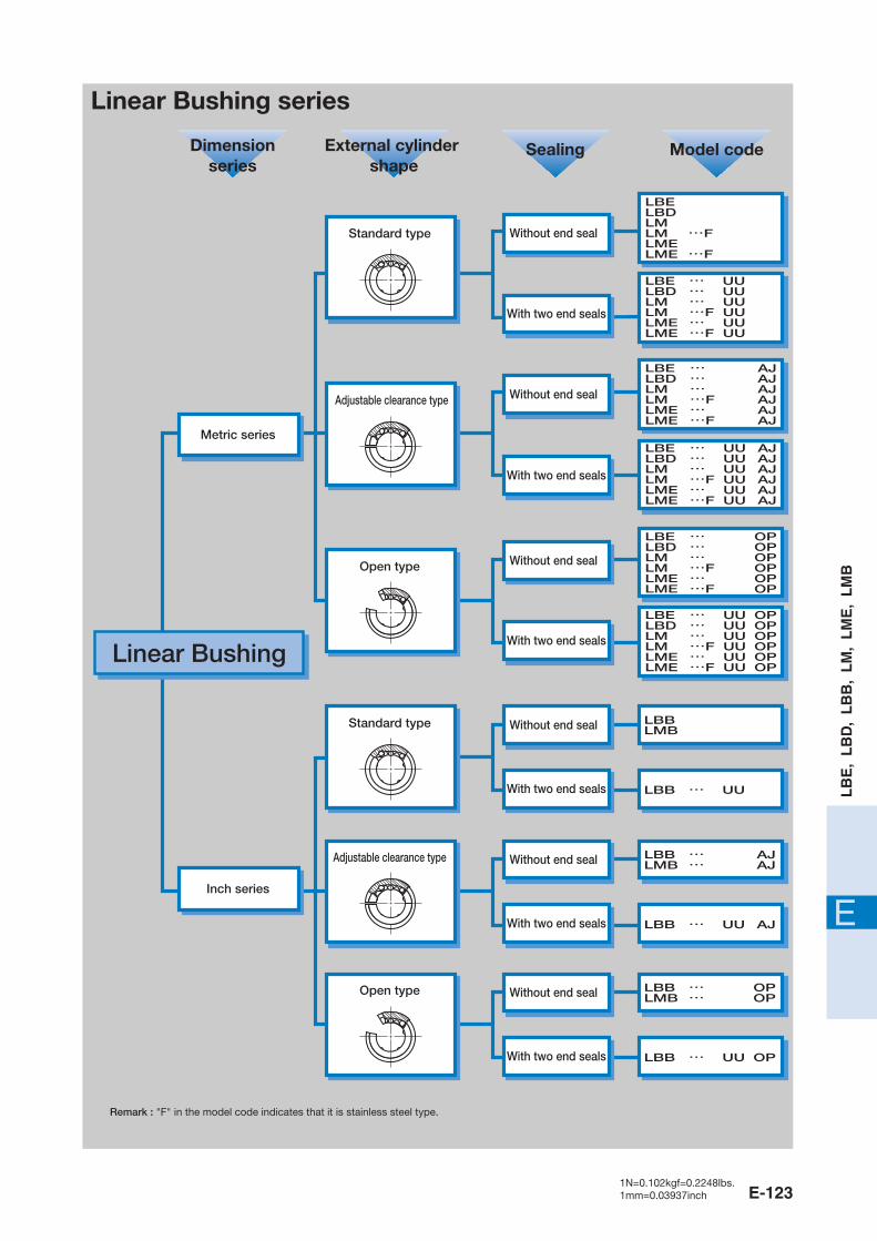
Linear Bushing series
Metric series
Inch series
LBELBDLMLM …FLMELME …F
LBE … UULBD … UULM … UULM …F UULME … UULME …F UU
LBE … AJLBD … AJLM … AJLM …F AJLME … AJLME …F AJ
LBE … UU AJLBD … UU AJLM … UU AJLM …F UU AJLME … UU AJLME …F UU AJ
LBE … OPLBD … OPLM … OPLM …F OPLME … OPLME …F OP
LBE … UU OPLBD … UU OPLM … UU OPLM …F UU OPLME … UU OPLME …F UU OP
Standard type
Adjustable clearance type
Open type
Without end seals
With two end seals
Without end seals
With two end seals
Without end seals
With two end seals
Remark : "F" in the model code indicates that it is stainless steel type.
Linear Bushing
586-595 05.2.25 11:21 AM ページ E-123

E-124
LM
LBE
29 AJ10
12
19 N F UU
OPUU
P
Series�
Inscribed circle diameter�
Outside diameter of external cylinder�
Length of external cylinder�
Retainer material�
Material�
Sealing�
External cylinder shape�
Accuracy class�
�
1
2
3
6
5
4
8
7
9
Model code
Size
Materialsymbol
Part code
Shape code
Classification symbol
LB series
LM series
2 Inscribed circle diameter
3 Outside diameter of external cylinder
Metric series :LBE, LBD, LM, LME�
Inch series :LBB, LMB1 Series
For the metric series, indicate the inscribed circle diameter in mm. For the inch series, indicate the inscribed circle diameter in the unit of 1/16 inch.
For the metric series, indicate the outside diameter of external cylinder in mm. For the inch series, indicate the outside diameter of external cylinder in the unit of 1/16 inch.
Identification number and specificationThe specification of Linear Bushing is indicated by the identification number, consisting of a model code, a size, a material symbol, a part code, a shape code and a classification symbol.
586-595 05.2.25 11:21 AM ページ E-124
E-1251N=0.102kgf=0.2248lbs.1mm=0.03937inch
E
LB
E,
LB
D,
LB
B,
LM
, L
ME
, L
MB
外筒の形状�
External cylinder shape
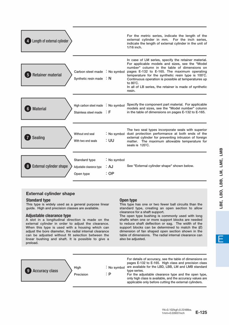
5 Retainer material
4 Length of external cylinderFor the metric series, indicate the length of the external cylinder in mm. For the inch series, indicate the length of external cylinder in the unit of 1/16 inch.
Carbon steel made :No symbol�
Synthetic resin made :N
In case of LM series, specify the retainer material. For applicable models and sizes, see the "Model number" column in the table of dimensions on pages E-132 to E-165. The maximum operating temperature for the synthetic resin type is 100˚C. Continuous operation is possible at temperatures up to 80˚C.In all of LB series, the retainer is made of synthetic resin.
For details of accuracy, see the table of dimensions on pages E-132 to E-165. High class and precision class are available for the LBD, LBB, LM and LMB standard type series.For the adjustable clearance type and the open type, only high class is available, and the accuracy values are applicable only before cutting the external cylinders.
6 MaterialHigh carbon steel made :No symbol�
Stainless steel made :F
Specify the component part material. For applicable models and sizes, see the "Model number" column in the table of dimensions on pages E-132 to E-165.
7 SealingWithout end seal :No symbol�
With two end seals :UU
Standard type :No symbol�
Adjustable clearance type :AJ�
Open type :OP
The two seal types incorporate seals with superior dust protection performance at both ends of the external cylinder for preventing intrusion of foreign matter. The maximum allowable temperature for seals is 120˚C.
8 External cylinder shape See "External cylinder shape" shown below.
High :No symbol�
Precision :P9 Accuracy class
Standard type�This type is widely used as a general purpose linear guide. High and precision classes are available.
Open type�This type has one or two fewer ball circuits than the standard type, creating an open section to allow clearance for a shaft support.The open type bushing is commonly used with long shafts when one or more support blocks are needed to reduce shaft deflection or sag. The width of the support blocks can be determined to match the (E) dimension of fan shaped open section shown in the table of dimensions. The radial internal clearance can also be adjusted.
Adjustable clearance type�A slot in a longitudinal direction is made on the external cylinder in order to adjust the clearance. When this type is used with a housing which can adjust the bore diameter, the radial internal clearance can be adjusted without fit selection between the linear bushing and shaft. It is possible to give a preload.
586-595 05.2.25 11:21 AM ページ E-125
E-126
Load RatingLoad Rating
�
Summarized descriptions of load ratings of Linear Bushing are given below. For details of load rating definitions and load calculations, see "General description".
The basic dynamic load rating is defined as the constant load both in direction and magnitude under which a group of identical Linear Bushings are individually operated and 90% of the units in the group can travel 50 x 103 meters free from material damage due to rolling contact fatigue.
The basic static load rating is defined as the static load that gives a prescribed constant contact stress at the center of the contact area between the rolling element and raceway receiving the maximum load.
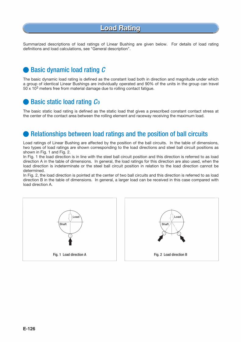
Fig. 1 Load direction A Fig. 2 Load direction B
Basic dynamic load rating C
Basic static load rating C 0
Load ratings of Linear Bushing are affected by the position of the ball circuits. In the table of dimensions, two types of load ratings are shown corresponding to the load directions and steel ball circuit positions as shown in Fig. 1 and Fig. 2.In Fig. 1 the load direction is in line with the steel ball circuit position and this direction is referred to as load direction A in the table of dimensions. In general, the load ratings for this direction are also used, when the load direction is indeterminate or the steel ball circuit position in relation to the load direction cannot be determined.In Fig. 2, the load direction is pointed at the center of two ball circuits and this direction is referred to as load direction B in the table of dimensions. In general, a larger load can be received in this case compared with load direction A.
Relationships between load ratings and the position of ball circuits
Shaft
Load
Shaft
Load
586-595 05.2.25 11:21 AM ページ E-126

E-1271N=0.102kgf=0.2248lbs.1mm=0.03937inch
E
LB
E,
LB
D,
LB
B,
LM
, L
ME
, L
MB
Precautions for UsePrecautions for Use
Table 1 Surface hardness and roughness of raceway
Adjustable clearance and open type Linear Bushings can be adjusted for radial internal clearance if they are used with a housing which can adjust the bore diameter.However, if the degree of the adjustment is excessive, deformation at the contact points between steel balls and shaft or external cylinder becomes large, resulting in short life. Therefore, it is recommended to prepare a shaft with a specified fit tolerance and adjust the radial internal clearance to zero or minimal preload by matching the individual components.The clearance is adjusted while checking with a dial gage. The adjustment is generally completed when the shaft is rotated in an unloaded condition and light resistance is caused by the rotation of shaft. In this condition, the radial internal clearance becomes zero or minimal preload. For open type Linear Bushings having three rows of ball circuits, clearance adjustment can not be made.
Since Linear Bushings operate with a shaft as a raceway surface, the shaft should be heat-treated and ground. Recommended surface hardness and roughness of the shaft are shown in Table 1, and also recommended minimum effective hardening depth of the raceway is shown in Table 2.
Fig. 3 Example of clearance adjustment
Item Recommended value Remarks
Surfacehardness
Surfaceroughness
58~64HRC
0.2μmRa or better (0.8μmRy or better)
Clearance
Raceway surface
When the raceway hardness is less than the necessary hardness, multiply load ratings by the hardness factor.
When the required accuracy is not severe, a surface roughness of about 0.8μmRa (3.2μmRy) is adequate.
Table 2 Minimum effective hardening depth
Shaft diameter
over incl.
Recommended minimumeffective hardening depth
unit : mm
–2850
100
2850
100150
0.81.01.52.0
2
1
586-595 05.2.25 11:21 AM ページ E-127

E-128
Shell typeStop ringSpacer Needle Roller Bearing
Load
�
Linear Bushings can be used with oil or grease lubrication. A good quality lithium-soap base grease is recommended for grease lubrication.
Fig. 5 Fig. 6
Fig. 4 Example of configuration for long stroke linear motion and rotation
Lubrication3
�
Open type Linear Bushings having three rows of ball circuits can be used only for the load direction shown in Fig. 5. If two Linear Bushings are used in parallel, by considering the load distribution, the arrangement shown in Fig. 6 is recommended.This type can not be adjusted for radial internal clearance.
Precaution for use of Open type Linear Bushing having three rows of ball circuits5
Linear Bushings can only be operated in linear motion and can not be rotated. When linear motion in short stroke length and rotation are both required, 0000 Stroke Rotary Bushing (See page E-176.) is recommended. If linear motion in long stroke length and rotation are both required, a combination of Linear Bushing and Needle Roller Bearing as shown in Fig. 4 is recommended.
When rotational motion is present4
586-595 05.2.25 11:21 AM ページ E-128
E-1291N=0.102kgf=0.2248lbs.1mm=0.03937inch
E
LB
E,
LB
D,
LB
B,
LM
, L
ME
, L
MB
Precautions for MountingPrecautions for Mounting
D-0.3
Fw-0.03
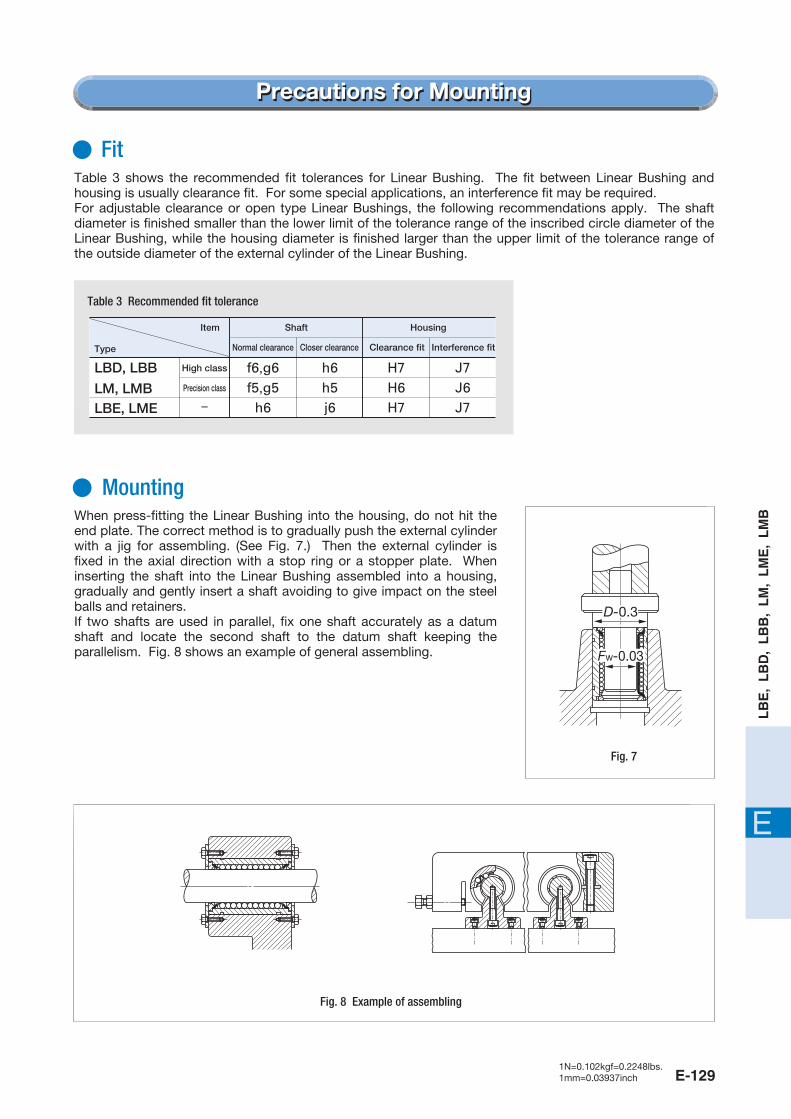
Table 3 shows the recommended fit tolerances for Linear Bushing. The fit between Linear Bushing and housing is usually clearance fit. For some special applications, an interference fit may be required.For adjustable clearance or open type Linear Bushings, the following recommendations apply. The shaft diameter is finished smaller than the lower limit of the tolerance range of the inscribed circle diameter of the Linear Bushing, while the housing diameter is finished larger than the upper limit of the tolerance range of the outside diameter of the external cylinder of the Linear Bushing.
Table 3 Recommended fit tolerance
Item Shaft Housing
Type Normal clearance Closer clearance Clearance fit Interference fit
LBD, LBB
LM, LMBLBE, LME
High class
Precision class�
-�
f6,g6f5,g5
h6
h6h5j6
H7H6H7
J7J6J7
Fit
When press-fitting the Linear Bushing into the housing, do not hit the end plate. The correct method is to gradually push the external cylinder with a jig for assembling. (See Fig. 7.) Then the external cylinder is fixed in the axial direction with a stop ring or a stopper plate. When inserting the shaft into the Linear Bushing assembled into a housing, gradually and gently insert a shaft avoiding to give impact on the steel balls and retainers.If two shafts are used in parallel, fix one shaft accurately as a datum shaft and locate the second shaft to the datum shaft keeping the parallelism. Fig. 8 shows an example of general assembling.
Mounting
Fig. 7
Fig. 8 Example of assembling
586-595 05.2.25 11:21 AM ページ E-129
E-130
AccessoriesAccessories
In order to achieve full performance of Linear Bushing, heat-treated and ground steel shafts with high accuracy are available. Commercial shafts can also be delivered upon request. For details, consult .
Steel shaft for Linear Bushing
Support blocks are prepared for supporting the ends of shaft for Linear Bushing. For details, consult .
Shaft support block
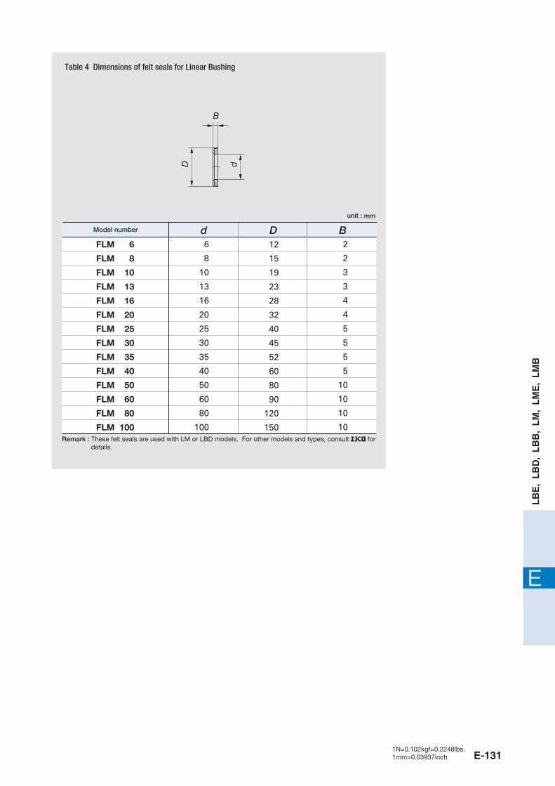
Felt seals are available for Linear Bushing without end seal. If dust protection and minimal frictional resistance in linear motion are both required, felt seals are recommended.Dimensions of felt seals are shown in Table 4.
Felt seals for Linear Bushing
586-595 05.2.25 11:21 AM ページ E-130
E-1311N=0.102kgf=0.2248lbs.1mm=0.03937inch
E
LB
E,
LB
D,
LB
B,
LM
, L
ME
, L
MB
Table 4 Dimensions of felt seals for Linear Bushing
B
D dFLM 6
FLM 8
FLM 10
FLM 13
FLM 16
FLM 20
FLM 25
FLM 30
FLM 35
FLM 40
FLM 50
FLM 60
FLM 80
FLM 100
6
8
10
13
16
20
25
30
35
40
50
60
80
100
12
15
19
23
28
32
40
45
52
60
80
90
120
150
2
2
3
3
4
4
5
5
5
5
10
10
10
10
d D B
Remark : These felt seals are used with LM or LBD models. For other models and types, consult fordetails.
Model number
unit : mm
586-595 05.2.25 11:21 AM ページ E-131

E-132 E-1331N=0.102kgf=0.2248lbs.1mm=0.03937inch
E
LB
E,
LB
D,
LB
B,
LM
, L
ME
, L
MB
h
E
α�
D FW
C
C1
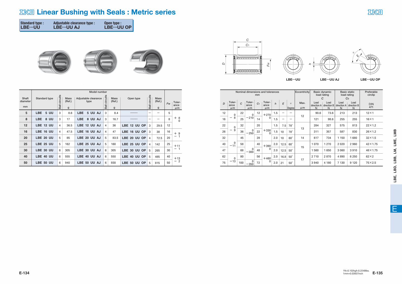
LBE…AJLBE LBE…OP
Standard type :LBE
Adjustable clearance type :LBE…AJ
Open type :LBE…OP
Shaft diameter
mm
Standard type
Model number
Mass(Ref.)
g
Mass(Ref.)
gFw
Open typeToler-anceμm
Mass(Ref.)
g
Adjustable clearancetype
LBE 5
LBE 8
LBE 12
LBE 16
LBE 20
LBE 25
LBE 30
LBE 40
LBE 50
5
8
12
16
20
25
30
40
50
8.6
16.9
36.5
47
84.5
161
305
555
935
LBE 5 AJ
LBE 8 AJ
LBE 12 AJ
LBE 16 AJ
LBE 20 AJ
LBE 25 AJ
LBE 30 AJ
LBE 40 AJ
LBE 50 AJ
+ 80
+ 9- 1
+11- 1
+13- 2
Bal
lcir
cuits
Bal
lcir
cuits
Bal
lcir
cuits
Eccentricity Basic dynamic load rating
Preferable circlip
Max.
μm
Loaddirection AN
Loaddirection BN
12
16
22
26
32
40
47
62
75
0- 8
22
25
32
36
45
58
68
80
100
0-210
12
14
20
22
28
40
48
56
72
1.5
1.5
1.5
1.5
2.0
2.0
2.0
2.0
2.0
-
-
7.5
10
10
12.5
12.5
16.8
21
-
-
78゜
78゜
60゜
60゜
50゜
50゜
50゜
+2700 12
13
14
15
17
+3300
+3900
+4600
0-250
0-300
0-350
0- 9
0-11
0-13
90.6
121
284
311
617
1 070
1 560
2 710
3 940
73.6
98.6
327
357
734
1 270
1 650
2 870
4 180
213
255
575
587
1 150
2 020
3 060
4 890
7 130
213
255
813
830
1 680
2 960
3 910
6 250
9 120
12×1
16×1
22×1.2
26×1.2
32×1.5
42×1.75
48×1.75
62×2
75×2.5
Linear Bushing : Metric series
D Toler-anceμm
C Toler-anceμm
C1 h E α
C
Basic static load rating
Loaddirection AN
Loaddirection BN
DIN471
C0
Toler-anceμm Degree
Nominal dimensions and tolerancesmm
3
3
4
4
5
5
6
6
6
8.4
16.6
35.5
46.5
83
159
300
545
925
----
----
LBE 12 OP
LBE 16 OP
LBE 20 OP
LBE 25 OP
LBE 30 OP
LBE 40 OP
LBE 50 OP
3
3
4
4
5
5
6
6
6
-
-
29.5
37.5
72
141
265
480
815
-
-
3
3
4
4
5
5
5
5
8
12
16
20
25
30
40
50
596-607 05.2.25 11:22 AM ページ E-132
E-134 E-1351N=0.102kgf=0.2248lbs.1mm=0.03937inch
E
LB
E,
LB
D,
LB
B,
LM
, L
ME
, L
MB
h
E
α�
D FW
C
C1
LBE…UU AJLBE…UU LBE…UU OP
Standard type :LBE…UU
Adjustable clearance type :LBE…UU AJ
Open type :LBE…UU OP
Shaft diameter
mm
Standard type
Model number
Mass(Ref.)
g
Mass(Ref.)
gFw
Open typeToler-anceμm
Mass(Ref.)
g
Adjustable clearancetype
LBE 5 UU
LBE 8 UU
LBE 12 UU
LBE 16 UU
LBE 20 UU
LBE 25 UU
LBE 30 UU
LBE 40 UU
LBE 50 UU
5
8
12
16
20
25
30
40
50
8.6
17
36.5
47.5
85
162
305
555
940
LBE 5 UU AJ
LBE 8 UU AJ
LBE 12 UU AJ
LBE 16 UU AJ
LBE 20 UU AJ
LBE 25 UU AJ
LBE 30 UU AJ
LBE 40 UU AJ
LBE 50 UU AJ
+ 80
+ 9- 1
+11- 1
+13- 2
Bal
lcir
cuits
Bal
lcir
cuits
Bal
lcir
cuits
Eccentricity Basic dynamic load rating
Preferable circlip
Max.
μm
Loaddirection AN
Loaddirection BN
12
16
22
26
32
40
47
62
75
0- 8
22
25
32
36
45
58
68
80
100
0-210
12
14
20
22
28
40
48
56
72
1.5
1.5
1.5
1.5
2.0
2.0
2.0
2.0
2.0
-
-
7.5
10
10
12.5
12.5
16.8
21
-
-
78゜
78゜
60゜
60゜
50゜
50゜
50゜
+2700 12
13
14
15
17
+3300
+3900
+4600
0-250
0-300
0-350
0- 9
0-11
0-13
90.6
121
284
311
617
1 070
1 560
2 710
3 940
73.6
98.6
327
357
734
1 270
1 650
2 870
4 180
213
255
575
587
1 150
2 020
3 060
4 890
7 130
213
255
813
830
1 680
2 960
3 910
6 250
9 120
12×1
16×1
22×1.2
26×1.2
32×1.5
42×1.75
48×1.75
62×2
75×2.5
Linear Bushing with Seals : Metric series
D Toler-anceμm
C Toler-anceμm
C1 h E α
C
Basic static load rating
Loaddirection AN
Loaddirection BN
DIN471
C0
Toler-anceμm Degree
Nominal dimensions and tolerancesmm
3
3
4
4
5
5
6
6
6
8.4
16.7
36
47
83.5
160
305
550
930
----
----
LBE 12 UU OP
LBE 16 UU OP
LBE 20 UU OP
LBE 25 UU OP
LBE 30 UU OP
LBE 40 UU OP
LBE 50 UU OP
3
3
4
4
5
5
6
6
6
-
-
29.5
38
72.5
142
265
485
815
-
-
3
3
4
4
5
5
5
5
8
12
16
20
25
30
40
50
596-607 05.2.25 11:22 AM ページ E-134

E-136 E-1371N=0.102kgf=0.2248lbs.1mm=0.03937inch
E
LB
E,
LB
D,
LB
B,
LM
, L
ME
, L
MB
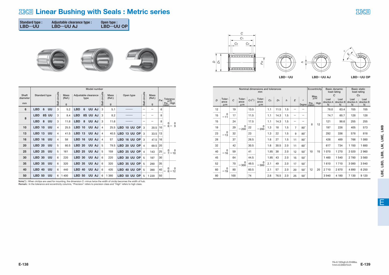
Standard type :LBD
Adjustable clearance type :LBD…AJ
Open type :LBD…OP
Shaft diameter
mm
Standard type
Model number
Mass(Ref.)
g
Mass(Ref.)
gFw
Open typeToleranceμm
Pre-cision
High
Mass(Ref.)
g
Adjustable clearancetype
LBD 6
LBD 8S
LBD 8
LBD 10
LBD 13
LBD 16
LBD 20
LBD 25
LBD 30
LBD 35
LBD 40
LBD 50
6
8
10
13
16
20
25
30
35
40
50
5.1
8.3
11.8
25.5
41.5
58
80
160
220
320
440
1 390
LBD 6 AJ
LBD 8S AJ
LBD 8 AJ
LBD 10 AJ
LBD 13 AJ
LBD 16 AJ
LBD 20 AJ
LBD 25 AJ
LBD 30 AJ
LBD 35 AJ
LBD 40 AJ
LBD 50 AJ
0- 6
0- 9
0- 7
0-10
0- 8
0-12
Bal
lcir
cuits
Bal
lcir
cuits
Bal
lcir
cuits
Eccentricity Basic dynamic load rating
Max.μm Load
direction AN
Loaddirection BN
12
15
15
19
23
28
32
40
45
52
60
80
0-11
19
17
24
29
32
37
42
59
64
70
80
100
0-200
13.5
11.5
17.5
22
23
26.5
30.5
41
44.5
49.5
60.5
74
1.5
1.5
1.5
1.5
1.5
1.5
2.0
2.0
2.0
2.0
2.0
2.0
11.5
14.3
14.3
18
22
27
30.5
38
43
49
57
76.5
1.1
1.1
1.1
1.3
1.3
1.6
1.6
1.85
1.85
2.1
2.1
2.6
-
-
-
7
9
11
11
12
15
17
20
25
-
-
-
80゜
80゜
80゜
60゜
50゜
50゜
50゜
50゜
50゜
0-200
8
10
12
12
15
20
0-300
0-300
0-13
0-16
0-19
78.0
74.7
121
197
292
426
617
1 070
1 460
1 610
2 710
3 940
63.4
60.7
98.6
226
336
489
734
1 270
1 540
1 710
2 870
4 180
155
128
255
405
578
766
1 150
2 020
2 780
3 080
4 890
7 130
155
128
255
573
818
1 080
1 680
2 960
3 560
3 940
6 250
9 120
Linear Bushing : Metric series
D Toler-anceμm
C Toler-anceμm
C1(1 ) hD1C2 E α
C
Basic static load rating
Loaddirection AN
Loaddirection BN
C0
Toler-anceμm Degree
Nominal dimensions and tolerancesmm
3
3
3
4
4
4
5
5
6
6
6
6
5.0
8.1
11.5
25
40.5
57
79
158
215
315
435
1 380
----
----
----
LBD 10 OP
LBD 13 OP
LBD 16 OP
LBD 20 OP
LBD 25 OP
LBD 30 OP
LBD 35 OP
LBD 40 OP
LBD 50 OP
3
3
3
4
4
4
5
5
6
6
6
6
-
-
-
20.5
33
47
69
142
196
280
390
1 220
-
-
-
3
3
3
4
4
5
5
5
5
6
8
8
10
13
16
20
25
30
35
40
50
HighPre-cision
Note(1) : When circlips are used for mounting, the dimension C1 minus twice the width of circlip becomes the width of hub.Remark : In the tolerance and eccentricity columns, "Precision" refers to precision class and "High" refers to high class.
h
E
α�
D D1
FW
C
C1
C2 C2
LBD…AJLBD LBD…OP
596-607 05.2.25 11:22 AM ページ E-136
E-138 E-1391N=0.102kgf=0.2248lbs.1mm=0.03937inch
E
LB
E,
LB
D,
LB
B,
LM
, L
ME
, L
MB
h
E
α�
D FW
C
C1
C2 C2
D1
LBD…UU AJLBD…UU LBD…UU OP
Standard type :LBD…UU
Adjustable clearance type :LBD…UU AJ
Open type :LBD…UU OP
Shaft diameter
mm
Standard type
Model number
Mass(Ref.)
g
Mass(Ref.)
gFw
Open typeToleranceμm
Pre-cision
High
Mass(Ref.)
g
Adjustable clearancetype
LBD 6 UU
LBD 8S UU
LBD 8 UU
LBD 10 UU
LBD 13 UU
LBD 16 UU
LBD 20 UU
LBD 25 UU
LBD 30 UU
LBD 35 UU
LBD 40 UU
LBD 50 UU
6
8
10
13
16
20
25
30
35
40
50
5.2
8.4
11.8
25.5
41.5
58
80.5
161
220
320
440
1 400
LBD 6 UU AJ
LBD 8S UU AJ
LBD 8 UU AJ
LBD 10 UU AJ
LBD 13 UU AJ
LBD 16 UU AJ
LBD 20 UU AJ
LBD 25 UU AJ
LBD 30 UU AJ
LBD 35 UU AJ
LBD 40 UU AJ
LBD 50 UU AJ
0- 6
0- 9
0- 7
0-10
0- 8
0-12
Bal
lcir
cuits
Bal
lcir
cuits
Bal
lcir
cuits
Eccentricity Basic dynamic load rating
Max.μm Load
direction AN
Loaddirection BN
12
15
15
19
23
28
32
40
45
52
60
80
0-11
19
17
24
29
32
37
42
59
64
70
80
100
0-200
13.5
11.5
17.5
22
23
26.5
30.5
41
44.5
49.5
60.5
74
1.5
1.5
1.5
1.5
1.5
1.5
2.0
2.0
2.0
2.0
2.0
2.0
11.5
14.3
14.3
18
22
27
30.5
38
43
49
57
76.5
1.1
1.1
1.1
1.3
1.3
1.6
1.6
1.85
1.85
2.1
2.1
2.6
-
-
-
7
9
11
11
12
15
17
20
25
-
-
-
80゜
80゜
80゜
60゜
50゜
50゜
50゜
50゜
50゜
0-200
8
10
12
12
15
20
0-300
0-300
0-13
0-16
0-19
78.0
74.7
121
197
292
426
617
1 070
1 460
1 610
2 710
3 940
63.4
60.7
98.6
226
336
489
734
1 270
1 540
1 710
2 870
4 180
155
128
255
405
578
766
1 150
2 020
2 780
3 080
4 890
7 130
155
128
255
573
818
1 080
1 680
2 960
3 560
3 940
6 250
9 120
Linear Bushing with Seals : Metric series
D Toler-anceμm
C Toler-anceμm
C1(1 ) hD1C2 E α
C
Basic static load rating
Loaddirection AN
Loaddirection BN
C0
Toler-anceμm Degree
Nominal dimensions and tolerancesmm
3
3
3
4
4
4
5
5
6
6
6
6
5.1
8.2
11.6
25.5
40.5
57
79.5
159
220
320
435
1 380
----
----
----
LBD 10 UU OP
LBD 13 UU OP
LBD 16 UU OP
LBD 20 UU OP
LBD 25 UU OP
LBD 30 UU OP
LBD 35 UU OP
LBD 40 UU OP
LBD 50 UU OP
3
3
3
4
4
4
5
5
6
6
6
6
-
-
-
20.5
33.5
47.5
69.5
143
197
280
390
1 220
-
-
-
3
3
3
4
4
5
5
5
5
6
8
8
10
13
16
20
25
30
35
40
50
HighPre-cision
Note(1) : When circlips are used for mounting, the dimension C1 minus twice the width of circlip becomes the width of hub.Remark : In the tolerance and eccentricity columns, "Precision" refers to precision class and "High" refers to high class.
596-607 05.2.25 11:22 AM ページ E-138

E-140 E-1411N=0.102kgf=0.2248lbs.1mm=0.03937inch
E
LB
E,
LB
D,
LB
B,
LM
, L
ME
, L
MB
Standard type :LBB
Adjustable clearance type :LBB…AJ
Open type :LBB…OP
Shaft diameter
mm(inch)
Standard type
Model number
Mass(Ref.)
g
Mass(Ref.)
gFw
Open typeToleranceμm
Pre-cision
High
Mass(Ref.)
g
Adjustable clearancetype
LBB 4
LBB 6
LBB 8
LBB 10
LBB 12
LBB 16
LBB 20
LBB 24
LBB 32
6.350
9.525
12.700
15.875
19.050
25.400
31.750
38.100
50.800
(1/4)
(3/8)
(1/2)
(5/8)
(3/4)
(1)
(11/4)
(11/2)
(2)
7.1
10.3
32
65
79.5
147
325
535
1 040
----
----
LBB 8 AJ
LBB 10 AJ
LBB 12 AJ
LBB 16 AJ
LBB 20 AJ
LBB 24 AJ
LBB 32 AJ
0- 8
0-13
0-10
0-15
0-20
Bal
circ
uits
Bal
lcir
cuits
Bal
lcir
cuits
Eccen-tricity
Basic dynamic load rating
Max.μm Load
direction AN
Loaddirection BN
12.700
15.875
22.225
28.575
31.750
39.688
50.800
60.325
76.200
0-10
19.050
22.225
31.750
38.100
41.275
57.150
66.675
76.200
101.600
0-381
12.98
16.15
24.46
28.04
29.61
44.53
50.92
61.26
81.07
-
-
1.588
2.381
2.381
2.381
2.381
3.175
3.175
12.04
15.16
21.21
27.30
30.33
37.85
48.51
57.53
72.64
0.99
0.99
1.17
1.42
1.42
1.73
1.73
2.18
2.62
-
-
7.938
9.525
11.112
14.288
15.875
19.050
25.400
-
-
50゜
60゜
60゜
60゜
50゜
50゜
50゜
0-200
8
9
10
11
12
13
14
15
17
0-300
0-508
0-13
0-15
80.0
117
290
424
608
1 070
1 920
2 460
3 960
64.9
134
333
488
724
1 280
2 030
2 610
4 190
156
227
577
766
1 150
2 020
3 570
4 330
7 140
156
320
816
1 080
1 680
2 960
4 570
5 540
9 130
Linear Bushing : Inch series
D Toler-anceμm
C Toler-anceμm
C1(1 ) hD1C2 E α
C
Basic static load rating
Loaddirection AN
Loaddirection BN
C0
Toler-anceμm Degree
Nominal dimensions and tolerancesmm
3
4
4
4
5
5
6
6
6
-
-
31.5
64
78.5
145
320
530
1 030
----
----
LBB 8 OP
LBB 10 OP
LBB 12 OP
LBB 16 OP
LBB 20 OP
LBB 24 OP
LBB 32 OP
-
-
4
4
5
5
6
6
6
-
-
28
54
68.5
127
285
470
915
-
-
3
3
4
4
5
5
5
6.350
9.525
12.700
15.875
19.050
25.400
31.750
38.100
50.800
HighPre-cision
Note(1) : When circlips are used for mounting, the dimension C1 minus twice the width of circlip becomes the width of hub.Remark : In the tolerance and eccentricity columns, "Precision" refers to precision class and "High" refers to high class.
1/4
3/8
1/2
5/8
3/4
1
11/4
11/2
2
1/2
5/8
7/8
11/8
11/4
19/16
2
23/8
3
3/4
7/8
11/4
11/2
15/8
21/4
25/8
3
4
1/16
3/32
3/32
3/32
3/32
1/8
1/8
5/16
3/8
7/16
9/16
5/8
3/4
1
h
E
α�
D D1
FW
C
C1
C2 C2
LBB…AJLBB LBB…OP
596-607 05.2.25 11:22 AM ページ E-140

E-142 E-1431N=0.102kgf=0.2248lbs.1mm=0.03937inch
E
LB
E,
LB
D,
LB
B,
LM
, L
ME
, L
MB
Standard type :LBB…UU
Adjustable clearance type :LBB…UU AJ
Open type :LBB…UU OP
Shaft diameter
mm(inch)
Standard type
Model number
Mass(Ref.)
g
Mass(Ref.)
gFw
Open typeToleranceμm
Pre-cision
High
Mass(Ref.)
g
Adjustable clearancetype
LBB 4 UU
LBB 6 UU
LBB 8 UU
LBB 10 UU
LBB 12 UU
LBB 16 UU
LBB 20 UU
LBB 24 UU
LBB 32 UU
6.350
9.525
12.700
15.875
19.050
25.400
31.750
38.100
50.800
(1/4)
(3/8)
(1/2)
(5/8)
(3/4)
(1)
(11/4)
(11/2)
(2)
7.1
10.4
32
65
80
148
325
535
1 040
----
----
LBB 8 UU AJ
LBB 10 UU AJ
LBB 12 UU AJ
LBB 16 UU AJ
LBB 20 UU AJ
LBB 24 UU AJ
LBB 32 UU AJ
0- 8
0-13
0-10
0-15
0-20
Bal
lcir
cuits
Bal
lcir
cuits
Bal
lcir
cuits
Eccen-tricity
Basic dynamic load rating
Max.μm Load
direction AN
Loaddirection BN
12.700
15.875
22.225
28.575
31.750
39.688
50.800
60.325
76.200
0-10
19.050
22.225
31.750
38.100
41.275
57.150
66.675
76.200
101.600
0-381
12.98
16.15
24.46
28.04
29.61
44.53
50.92
61.26
81.07
-
-
1.588
2.381
2.381
2.381
2.381
3.175
3.175
12.04
15.16
21.21
27.30
30.33
37.85
48.51
57.53
72.64
0.99
0.99
1.17
1.42
1.42
1.73
1.73
2.18
2.62
-
-
7.938
9.525
11.112
14.288
15.875
19.050
25.400
-
-
50゜
60゜
60゜
60゜
50゜
50゜
50゜
0-200
8
9
10
11
12
13
14
15
17
0-300
0-508
0-13
0-15
80.0
117
290
424
608
1 070
1 920
2 460
3 960
64.9
134
333
488
724
1 280
2 030
2 610
4 190
156
227
577
766
1 150
2 020
3 570
4 330
7 140
156
320
816
1 080
1 680
2 960
4 570
5 540
9 130
Linear Bushing with Seals : Inch series
D Toler-anceμm
C Toler-anceμm
C1(1 ) hD1C2 E α
C
Basic static load rating
Loaddirection AN
Loaddirection BN
C0
Toler-anceμm Degree
Nominal dimensions and tolerancesmm
3
4
4
4
5
5
6
6
6
-
-
31.5
64
79
145
320
530
1 030
----
----
LBB 8 UU OP
LBB 10 UU OP
LBB 12 UU OP
LBB 16 UU OP
LBB 20 UU OP
LBB 24 UU OP
LBB 32 UU OP
-
-
4
4
5
5
6
6
6
-
-
28
54
69
128
290
475
920
-
-
3
3
4
4
5
5
5
6.350
9.525
12.700
15.875
19.050
25.400
31.750
38.100
50.800
HighPre-cision
Note(1) : When circlips are used for mounting, the dimension C1 minus twice the width of circlip becomes the width of hub.Remark : In the tolerance and eccentricity columns, "Precision" refers to precision class and "High" refers to high class.
1/4
3/8
1/2
5/8
3/4
1
11/4
11/2
2
1/2
5/8
7/8
11/8
11/4
19/16
2
23/8
3
3/4
7/8
11/4
11/2
15/8
21/4
25/8
3
4
1/16
3/32
3/32
3/32
3/32
1/8
1/8
5/16
3/8
7/16
9/16
5/8
3/4
1
h
E
α�
D FW
C
C1
C2 C2
D1
LBB…UU AJLBB…UU LBB…UU OP
596-607 05.2.25 11:22 AM ページ E-142
E-144 E-1451N=0.102kgf=0.2248lbs.1mm=0.03937inch
E
LB
E,
LB
D,
LB
B,
LM
, L
ME
, L
MB
Standard type :LM�LM…N(Synthetic resin retainer)
Adjustable clearance type :LM… AJ�LM…N AJ(Synthetic resin retainer)
Open type :LM… OP�LM…N OP(Synthetic resin retainer)
LM 61219
LM 61219N
LM 81517
LM 81517N
LM 81524
LM 81524N
LM 101929
LM 101929N
LM 122130
LM 122130N
LM 132332
LM 132332N
LM 162837
LM 162837N
LM 203242
LM 203242N
LM 254059
LM 254059N
LM 304564
LM 304564N
LM 355270
LM 355270N
LM 406080
LM 406080N
LM 5080100
LM 5080100N
4
4
4
4
4
4
4
4
4
4
4
4
4
4
5
5
6
6
6
6
6
6
6
6
6
6
8.5
7.6
11
10.4
17
15
36
29.5
42
31.5
49
43
78
69.5
100
98
260
220
290
250
425
390
675
585
1 740
1 580
LM 61219N AJ
LM 81517N AJ
LM 81524N AJ
LM 101929N AJ
LM 122130 AJ
LM 122130N AJ
LM 132332 AJ
LM 132332N AJ
LM 162837 AJ
LM 162837N AJ
LM 203242 AJ
LM 203242N AJ
LM 254059 AJ
LM 254059N AJ
LM 304564 AJ
LM 304564N AJ
LM 355270 AJ
LM 355270N AJ
LM 406080 AJ
LM 406080N AJ
LM 5080100 AJ
LM 5080100N AJ
–
4
–
4
–
4
–
4
4
4
4
4
4
4
5
5
6
6
6
6
6
6
6
6
6
6
80.7
87.4
121
179
259
266
426
562
920
1 350
1 610
2 030
3 940
92.7
100
139
206
298
306
489
668
974
1 430
1 710
2 150
4 180
167
160
255
354
503
506
766
1 010
1 780
2 500
3 080
3 620
7 130
237
226
361
501
711
716
1 080
1 470
2 280
3 200
3 940
4 640
9 120
–
7.5
–
10
–
14.7
–
29
41
31
48
42
77
68
98
95
255
216
285
245
420
384
665
579
1 720
1 560
LM 101929N OP
LM 122130 OP
LM 122130N OP
LM 132332 OP
LM 132332N OP
LM 162837 OP
LM 162837N OP
LM 203242 OP
LM 203242N OP
LM 254059 OP
LM 254059N OP
LM 304564 OP
LM 304564N OP
LM 355270 OP
LM 355270N OP
LM 406080 OP
LM 406080N OP
LM 5080100 OP
LM 5080100N OP
–
3
3
3
3
3
3
3
4
4
5
5
5
5
5
5
5
5
5
5
–
23
32
25
37.5
34
60
52
85
69
220
188
245
210
355
335
575
500
1 480
1 340
gFw D C C2 D1
C C0
h E α�C1( 1 )
Bal
l cir
cuits
gBal
l cir
cuits
gBal
l cir
cuits
Model number
Adjustable clearance typeStandard type
mm
Open type
6
8
10
12
13
16
20
25
30
35
40
50
10
8
8
6
12
13
16
20
25
30
35
40
50
19
15
15
12
21
23
28
32
40
45
52
60
80
29
24
17
19
30
32
37
42
59
64
70
80
100
1.3
1.1
1.1
1.1
1.3
1.3
1.6
1.6
1.85
1.85
2.1
2.1
2.6
1
–
1
–
1
–
1
–
1.5
1.5
1.5
1.5
2
2.5
2.5
3
3
6.8
–
–
–
–
8
9
11
11
12
15
17
20
25
80
–
–
–
–
80
80
80
60
50
50
50
50
50
22
17.5
11.5
13.5
23
23
26.5
30.5
41
44.5
49.5
60.5
74
18
14.3
14.3
11.5
20
22
27
30.5
38
43
49
57
76.5
–
–
–
–
–
–
Basic dynamicload rating
Nominal dimensions and tolerancesmm
Basic staticload rating
Max.μm
Toleranceμm
0
– 6
0
– 9 0
–200
0
–300
0
–200
0
–300
8
10
12
12
15
20
0
– 7
0
– 8
0
–12
0
–19
0
–10
0
–16
0
–13
0
–11
C
C1
D
C2 C2
D1
FW
h
E
α�
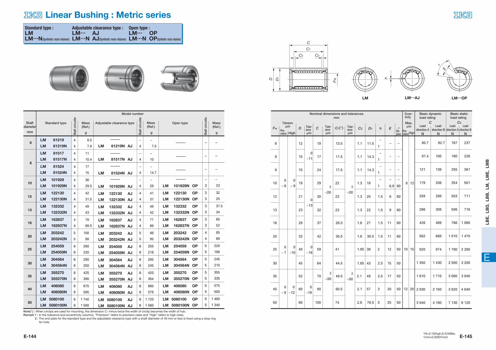
LM LM…AJ LM…OP
Shaft diameter
Mass (Ref.)
Mass (Ref.)
Mass (Ref.) Toler-
anceμm
Toler-anceμm
Toler-anceμm
De-gree HighPre-
cisionPre-cision High
Load direction A
N
Load direction B
N
Load direction A
N
Load direction B
N
Note( 1 ) : When circlips are used for mounting, the dimension C1 minus twice the width of circlip becomes the width of hub.
Remark 1 : In the tolerance and eccentricity columns, "Precision" refers to precision class and "High" refers to high class. 2 : The end plate for the standard type and the adjustable clearance type with a shaft diameter of 40 mm or less is fixed using a stop ring for hole.
Eccen-tricity
Linear Bushing : Metric series
608-629 05.2.25 11:23 AM ページ E-144
E-146 E-1471N=0.102kgf=0.2248lbs.1mm=0.03937inch
E
LB
E,
LB
D,
LB
B,
LM
, L
ME
, L
MB
LM 6090110
LM 6090110N
LM 80120140
LM 100150175
LM 120180200
LM 150210240
6
6
6
6
8
8
6
6
6
6
8
8
2 000
1 860
4 480
9 620
15 000
20 300
1 980
1 820
4 440
9 540
14 900
20 200
5
5
5
5
6
6
1 700
1 610
3 810
8 180
11 600
15 700
LM 6090110 AJ
LM 6090110N AJ
LM 80120140 AJ
LM 100150175 AJ
LM 120180200 AJ
LM 150210240 AJ
LM 6090110 OP
LM 6090110N OP
LM 80120140 OP
LM 100150175 OP
LM 120180200 OP
LM 150210240 OP
4 760
8 710
14 500
25 800
35 600
5 040
9 220
15 300
25 500
35 100
8 150
14 500
22 800
44 300
61 200
10 400
18 500
29 200
49 400
68 200
gD C C2 D1
C C0
h E α�C1( 1 )
Bal
l cir
cuits
gBal
l cir
cuits
gBal
l cir
cuits
Model number
Adjustable clearance typeStandard type
mm
Open type
60
80
100
120
150
120
150
100
80
60
180
210
150
120
90
200
240
175
140
110
158.6
170.6
125.5
105.5
85
4
4
3
3
3
85
105
50
40
30
80
80
50
50
50
4.15
5.15
4.15
4.15
3.15
175
204
145
116
86.5
Max.μm
Toleranceμm
0
– 9
0
–15
0
–10
0
–20
0
–400
0
–400
0
–300
0
–300
0–13
0–25
0
–22
0–25
0–29
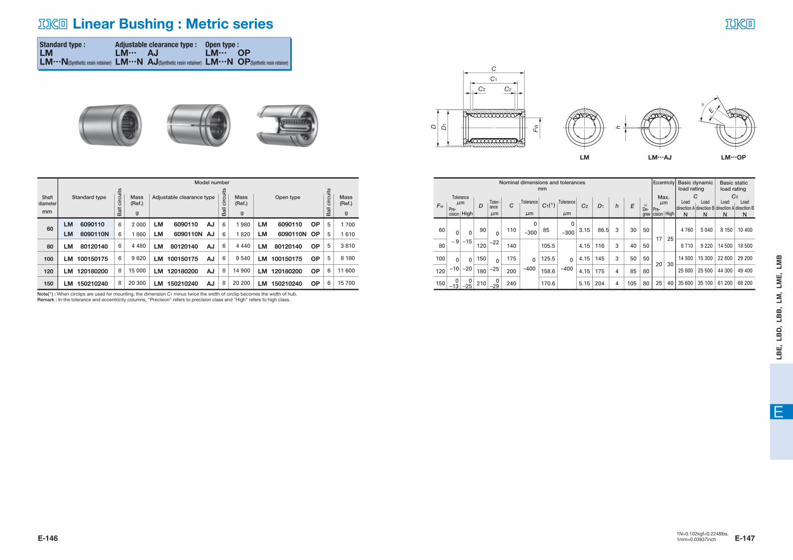
Standard type :�LM�LM…N(Synthetic resin retainer)
Adjustable clearance type :�LM… AJ�LM…N AJ(Synthetic resin retainer)
Open type :�LM… OP�LM…N OP(Synthetic resin retainer)
17 25
20 30
25 40
Fw
Nominal dimensions and tolerancesmm
C
C1
D
C2 C2
D1
FW h
E
α�
LM LM…AJ LM…OP
Shaft diameter
Mass (Ref.)
Mass (Ref.)
Mass (Ref.)
Pre-cision High
Toler-anceμm
Tolerance
μm
Tolerance
μm
Eccentricity
Pre-cision
De-gree High
Basic dynamic load rating
Basic static load rating
Load direction A
N
Load direction B
N
Load direction A
N
Load direction B
N
Note( 1 ) : When circlips are used for mounting, the dimension C1 minus twice the width of circlip becomes the width of hub.
Remark : In the tolerance and eccentricity columns, "Precision" refers to precision class and "High" refers to high class.
Linear Bushing : Metric series
608-629 05.2.25 11:23 AM ページ E-146

E-148 E-1491N=0.102kgf=0.2248lbs.1mm=0.03937inch
E
LB
E,
LB
D,
LB
B,
LM
, L
ME
, L
MB
h
C
C1
D
C2 C2
D1
FW
E
α�
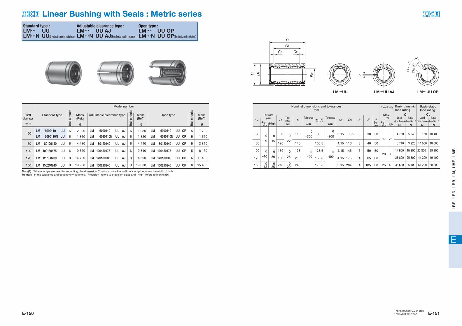
Standard type :�LM… UU�LM…N UU(Synthetic resin retainer)
Adjustable clearance type :�LM… UU AJ�LM…N UU AJ(Synthetic resin retainer)
Open type :�LM… UU OP�LM…N UU OP(Synthetic resin retainer)
LM 61219 UU
LM 61219N UU
LM 81517 UU
LM 81517N UU
LM 81524 UU
LM 81524N UU
LM 101929 UU
LM 101929N UU
LM 122130 UU
LM 122130N UU
LM 132332 UU
LM 132332N UU
LM 162837 UU
LM 162837N UU
LM 203242 UU
LM 203242N UU
LM 254059 UU
LM 254059N UU
LM 304564 UU
LM 304564N UU
LM 355270 UU
LM 355270N UU
LM 406080 UU
LM 406080N UU
LM 5080100 UU
LM 5080100N UU
4
4
4
4
4
4
4
4
4
4
4
4
4
4
5
5
6
6
6
6
6
6
6
6
6
6
8.5
7.6
11
10.4
17
15
31
29.5
41
31.5
49
43
78
69.5
100
98
260
220
290
250
410
390
675
585
1 740
1 580
LM 61219N UU AJ
LM 81517N UU AJ
LM 81524N UU AJ
LM 101929N UU AJ
LM 122130 UU AJ
LM 122130N UU AJ
LM 132332 UU AJ
LM 132332N UU AJ
LM 162837 UU AJ
LM 162837N UU AJ
LM 203242 UU AJ
LM 203242N UU AJ
LM 254059 UU AJ
LM 254059N UU AJ
LM 304564 UU AJ
LM 304564N UU AJ
LM 355270 UU AJ
LM 355270N UU AJ
LM 406080 UU AJ
LM 406080N UU AJ
LM 5080100 UU AJ
LM 5080100N UU AJ
–
4
–
4
–
4
–
4
4
4
4
4
4
4
5
5
6
6
6
6
6
6
6
6
6
6
80.7
87.4
121
179
259
266
426
562
920
1 350
1 610
2 030
3 940
92.7
100
139
206
298
306
489
668
974
1 430
1 710
2 150
4 180
167
160
255
354
503
506
766
1 010
1 780
2 500
3 080
3 620
7 130
237
226
361
501
711
716
1 080
1 470
2 280
3 200
3 940
4 640
9 120
–
7.5
–
10
–
14.7
–
29
40
31
48
42
77
68
98
95
255
216
285
245
405
384
665
579
1 720
1 560
LM 101929N UU OP
LM 122130 UU OP
LM 122130N UU OP
LM 132332 UU OP
LM 132332N UU OP
LM 162837 UU OP
LM 162837N UU OP
LM 203242 UU OP
LM 203242N UU OP
LM 254059 UU OP
LM 254059N UU OP
LM 304564 UU OP
LM 304564N UU OP
LM 355270 UU OP
LM 355270N UU OP
LM 406080 UU OP
LM 406080N UU OP
LM 5080100 UU OP
LM 5080100N UU OP
–
3
3
3
3
3
3
3
4
4
5
5
5
5
5
5
5
5
5
5
–
23
31
25
37.5
34
60
52
85
69
220
188
245
210
346
335
575
500
1 480
1 340
gD C C2 D1
C C0
h E α�C1( 1 )
Bal
l cir
cuits
gBal
l cir
cuits
gBal
l cir
cuits
Model number
Adjustable clearance typeStandard type
mm
Open type
6
8
10
12
13
16
20
25
30
35
40
50
10
8
8
6
12
13
16
20
25
30
35
40
50
19
15
15
12
21
23
28
32
40
45
52
60
80
29
24
17
19
30
32
37
42
59
64
70
80
100
1.3
1.1
1.1
1.1
1.3
1.3
1.6
1.6
1.85
1.85
2.1
2.1
2.6
1
–
1
–
–
1
1
–
1.5
1.5
1.5
1.5
2
2.5
2.5
3
3
–
–
–
–
6.8
8
9
11
11
12
15
17
20
25
80
–
–
–
–
80
80
80
60
50
50
50
50
50
22
17.5
11.5
13.5
23
23
26.5
30.5
41
44.5
49.5
60.5
74
18
14.3
14.3
11.5
20
22
27
30.5
38
43
49
57
76.5
–
–
–
–
–
–
Basic dynamicload rating
Basic staticload rating
Max.μm
Toleranceμm
0
– 6
0
– 7
0
–10
0
– 8
0
–12
0
– 9 0
–200
0
–200
0
–300
0
–300
0
–11
0
–13
0
–16
0
–19
8
10
12
12
15
20
Fw
LM…UU LM…UU AJ LM…UU OP
Nominal dimensions and tolerancesmm
Shaft diameter
Mass (Ref.)
Mass (Ref.)
Mass (Ref.)
Pre-cision High
Toler-anceμm
Toler-anceμm
Toler-anceμm
Eccen-tricity
De-gree
Pre-cision High
Loaddirection A
N
Loaddirection B
N
Load direction A
N
Load direction B
N
Note( 1 ) : When circlips are used for mounting, the dimension C1 minus twice the width of circlip becomes the width of hub.
Remark 1 : In the tolerance and eccentricity columns, "Precision" refers to precision class and "High" refers to high class. 2 : The end plate for the standard type and the adjustable clearance type with a shaft diameter of 40mm or less is fixed using a stop ring for hole.
Linear Bushing with Seals : Metric series
608-629 05.2.25 11:23 AM ページ E-148
E-150 E-1511N=0.102kgf=0.2248lbs.1mm=0.03937inch
E
LB
E,
LB
D,
LB
B,
LM
, L
ME
, L
MB
LM 6090110 UU
LM 6090110N UU
LM 80120140 UU
LM 100150175 UU
LM 120180200 UU
LM 150210240 UU
6
6
6
6
8
8
6
6
6
6
8
8
2 000
1 860
4 480
9 620
14 700
19 900
1 980
1 820
4 440
9 540
14 600
19 800
5
5
5
5
6
6
1 700
1 610
3 810
8 180
11 400
15 400
LM 6090110 UU AJ
LM 6090110N UU AJ
LM 80120140 UU AJ
LM 100150175 UU AJ
LM 120180200 UU AJ
LM 150210240 UU AJ
LM 6090110 UU OP
LM 6090110N UU OP
LM 80120140 UU OP
LM 100150175 UU OP
LM 120180200 UU OP
LM 150210240 UU OP
4 760
8 710
14 500
25 800
35 600
5 040
9 220
15 300
25 500
35 100
8 150
14 500
22 800
44 300
61 200
10 400
18 500
29 200
49 400
68 200
gD C C2 D1
C C0
h E α�C1( 1 )
Bal
l cir
cuits
gBal
l cir
cuits
gBal
l cir
cuits
Model number
Adjustable clearance typeStandard type
mm
Open type
60
80
100
120
150
120
150
100
80
60
180
210
150
120
90
200
240
175
140
110
158.6
170.6
125.5
105.5
85
4
4
3
3
3
85
105
50
40
30
80
80
50
50
50
4.15
5.15
4.15
4.15
3.15
175
204
145
116
86.5
Eccentricity
Max.μm
Toleranceμm
0
– 9
0
–15
0
–22
0
–300
0
–300
0
–20
0
–25
0
–10
0–13
0–25
0–29
0–400
0–400
17 25
20 30
25 40
Standard type :�LM… UU�LM…N UU(Synthetic resin retainer)
Adjustable clearance type :�LM… UU AJ�LM…N UU AJ(Synthetic resin retainer)
Open type :�LM… UU OP�LM…N UU OP(Synthetic resin retainer)
Fw
Nominal dimensions and tolerancesmm
h
C
C1
D
C2 C2
D1
FW
E
α�
LM…UU LM…UU AJ LM…UU OP
Shaft diameter
Mass (Ref.)
Mass (Ref.)
Mass (Ref.) Toler-
anceμm
Tolerance�μm
Tolerance�μmPre-
cision High De-gree
Pre-cision High
Basic dynamic load rating
Basic static load rating
Load direction A
N
Load direction B
N
Load direction A
N
Load direction B
N
Note( 1 ) : When circlips are used for mounting, the dimension C1 minus twice the width of circlip becomes the width of hub.
Remark : In the tolerance and eccentricity columns, "Precision" refers to precision class and "High" refers to high class.
Linear Bushing with Seals : Metric series
608-629 05.2.25 11:23 AM ページ E-150

E-152 E-1531N=0.102kgf=0.2248lbs.1mm=0.03937inch
E
LB
E,
LB
D,
LB
B,
LM
, L
ME
, L
MB
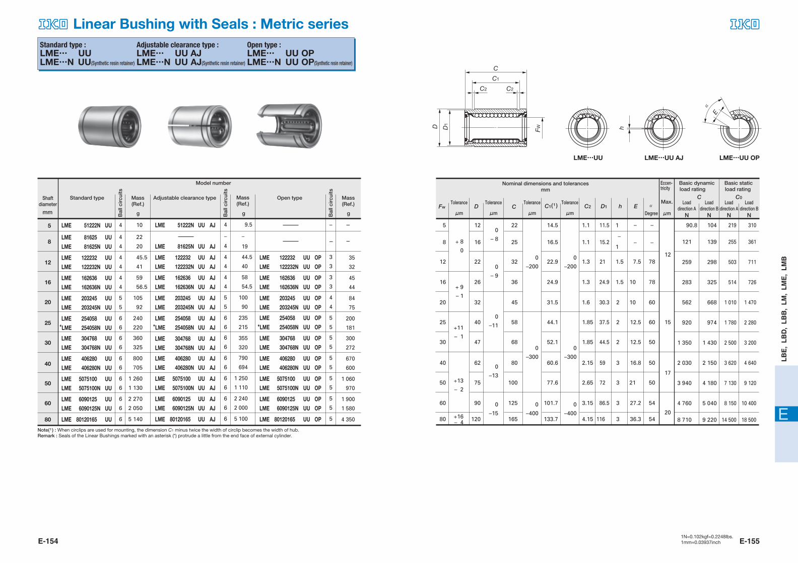
Standard type :�LME�LME…N(Synthetic resin retainer)
Adjustable clearance type :�LME… AJ�LME…N AJ(Synthetic resin retainer)
Open type :�LME… OP�LME…N OP(Synthetic resin retainer)
LME 51222N
LME 81625
LME 81625N
LME 122232
LME 122232N
LME 162636
LME 162636N
LME 203245
LME 203245N
LME 254058
LME 254058N
LME 304768
LME 304768N
LME 406280
LME 406280N
LME 5075100
LME 5075100N
LME 6090125
LME 6090125N
LME 80120165
4
4
4
4
4
4
4
5
5
6
6
6
6
6
6
6
6
6
6
6
10
22.5
20
45.5
41
59
56.5
105
92
240
220
360
325
800
705
1 260
1 130
2 270
1 860
5 140
LME 51222N AJ
LME 81625N AJ
LME 122232 AJ
LME 122232N AJ
LME 162636 AJ
LME 162636N AJ
LME 203245 AJ
LME 203245N AJ
LME 254058 AJ
LME 254058N AJ
LME 304768 AJ
LME 304768N AJ
LME 406280 AJ
LME 406280N AJ
LME 5075100 AJ
LME 5075100N AJ
LME 6090125 AJ
LME 6090125N AJ
LME 80120165 AJ
4
–
4
4
4
4
4
5
5
6
6
6
6
6
6
6
6
6
6
6
90.8
121
259
283
562
920
1 350
2 030
3 940
4 760
8 710
104
139
298
325
668
974
1 430
2 150
4 180
5 040
9 220
219
255
503
514
1 010
1 780
2 500
3 620
7 130
8 150
14 500
310
361
711
726
1 470
2 280
3 200
4 640
9 120
10 400
18 500
9.5
–
19
44.5
40
58
54.5
100
90
235
215
355
320
790
694
1 250
1 110
2 240
1 820
5 100
–
3
3
3
3
4
4
5
5
5
5
5
5
5
5
5
5
5
1
–
1
35
32
45
44
84
75
200
181
300
272
670
600
1 060
970
1 900
1 610
4 350
LME 122232 OP
LME 122232N OP
LME 162636 OP
LME 162636N OP
LME 203245 OPLME 203245N OP
LME 254058 OP
LME 254058N OP
LME 304768 OP
LME 304768N OP
LME 406280 OP
LME 406280N OP
LME 5075100 OP
LME 5075100N OP
LME 6090125 OP
LME 6090125N OP
LME 80120165 OP
gD C C2 D1
C C0
h E α�C1( 1 )
Bal
l cir
cuits
gBal
l cir
cuits
gBal
l cir
cuits
Model number
Adjustable clearance typeStandard type
mm
Open type
5
8
12
16
20
25
30
40
50
60
80
16
12
8
5
20
25
30
40
50
60
80
–
–
– + 8
0
+ 9
– 1
0
– 8
0
– 9
0
–11
0
–13
0
–15
+11
– 1
+13
– 2
+16– 4
26
22
16
12
32
40
47
62
75
90
120
36
32
25
22
45
58
68
80
100
125
165
1.5
1.5
2
2
2
3
3
3
3
10
7.5
–
–
10
12.5
12.5
16.8
21
27.2
36.3
78
78
–
–
60
60
50
50
50
54
54
1.3
1.3
1.1
1.1
1.6
1.85
1.85
2.15
2.65
3.15
4.15
24.9
21
15.2
11.5
30.3
37.5
44.5
59
72
86.5
116
24.9
22.9
16.5
14.5
31.5
44.1
52.1
60.6
77.6
101.7
133.7
0–200
0–300
0–400
0–200
0–300
0–400
12
15
17
20
Fw
�
Nominal dimensions and tolerancesmm
C
C1
D
C2 C2
D1
FW
LME LME…AJ LME…OP
h
E
α�
Shaft diameter
Mass (Ref.)
Mass (Ref.)
Mass (Ref.) Tolerance
�μm
Tolerance�μm
Tolerance�μm
Tolerance�μm Degree
Eccen-tricity
Max.
μm
Basic dynamic load rating
Basic static load rating
Loaddirection A
N
Load direction B
N
Load direction A
N
Load direction B
N
Note( 1 ) : When circlips are used for mounting, the dimension C1 minus twice the width of circlip becomes the width of hub.
Linear Bushing : Metric series
608-629 05.2.25 11:23 AM ページ E-152
E-154 E-1551N=0.102kgf=0.2248lbs.1mm=0.03937inch
E
LB
E,
LB
D,
LB
B,
LM
, L
ME
, L
MB
LME 51222N UU
LME 81625 UU
LME 81625N UU
LME 122232 UU
LME 122232N UU
LME 162636 UU
LME 162636N UU
LME 203245 UU
LME 203245N UU
LME 254058 UU*LME 254058N UU
LME 304768 UU
LME 304768N UU
LME 406280 UU
LME 406280N UU
LME 5075100 UU
LME 5075100N UU
LME 6090125 UU
LME 6090125N UU
LME 80120165 UU
4
4
4
4
4
4
4
5
5
6
6
6
6
6
6
6
6
6
6
6
10
22
20
45.5
41
59
56.5
105
92
240
220
360
325
800
705
1 260
1 130
2 270
2 050
5 140
LME 51222N UU AJ
LME 81625N UU AJ
LME 122232 UU AJ
LME 122232N UU AJ
LME 162636 UU AJ
LME 162636N UU AJ
LME 203245 UU AJ
LME 203245N UU AJ
LME 254058 UU AJ*LME 254058N UU AJ
LME 304768 UU AJ
LME 304768N UU AJ
LME 406280 UU AJ
LME 406280N UU AJ
LME 5075100 UU AJ
LME 5075100N UU AJ
LME 6090125 UU AJ
LME 6090125N UU AJ
LME 80120165 UU AJ
4
–
4
4
4
4
4
5
5
6
6
6
6
6
6
6
6
6
6
6
90.8
121
259
283
562
920
1 350
2 030
3 940
4 760
8 710
104
139
298
325
668
974
1 430
2 150
4 180
5 040
9 220
219
255
503
514
1 010
1 780
2 500
3 620
7 130
8 150
14 500
310
361
711
726
1 470
2 280
3 200
4 640
9 120
10 400
18 500
9.5
–
19
44.5
40
58
54.5
100
90
235
215
355
320
790
694
1 250
1 110
2 240
2 000
5 100
–
3
3
3
3
4
4
5
5
5
5
5
5
5
5
5
5
5
35
32
45
44
84
75
200
181
300
272
670
600
1 060
970
1 900
1 580
4 350
LME 122232 UU OP
LME 122232N UU OP
LME 162636 UU OP
LME 162636N UU OP
LME 203245 UU OP
LME 203245N UU OP
LME 254058 UU OP
*LME 254058N UU OP
LME 304768 UU OP
LME 304768N UU OP
LME 406280 UU OP
LME 406280N UU OP
LME 5075100 UU OP
LME 5075100N UU OP
LME 6090125 UU OP
LME 6090125N UU OP
LME 80120165 UU OP
gD C C2 D1
C C0
h E α�C1( 1 )
Bal
l cir
cuits
gBal
l cir
cuits
gBal
l cir
cuits
Model number
Adjustable clearance typeStandard type
mm
Open type
5
8
12
16
20
25
30
40
50
60
80
16
12
8
5
20
25
30
40
50
60
80
–
–
– + 8
0
+ 9
– 1
+11
– 1
+13
– 2
+16– 4
26
22
16
12
32
40
47
62
75
90
120
36
32
25
22
45
58
68
80
100
125
165
1
–
1
1.5
1.5
2
2
2
3
3
3
3
10
7.5
–
–
10
12.5
12.5
16.8
21
27.2
36.3
78
78
–
–
60
60
50
50
50
54
54
1.3
1.3
1.1
1.1
1.6
1.85
1.85
2.15
2.65
3.15
4.15
24.9
21
15.2
11.5
30.3
37.5
44.5
59
72
86.5
116
0
– 8
0
– 9
0
–11
0
–13
0
–15
0
–200
0
–300
0
–200
0
–300
0
–400
0
–400
24.9
22.9
16.5
14.5
31.5
44.1
52.1
60.6
77.6
101.7
133.7
12
15
17
20
Standard type :�LME… UU�LME…N UU(Synthetic resin retainer)
Adjustable clearance type :�LME… UU AJ�LME…N UU AJ(Synthetic resin retainer)
Open type :�LME… UU OP�LME…N UU OP(Synthetic resin retainer)
Fw
Nominal dimensions and tolerancesmm
h
C
C1
D
C2 C2
D1
FW
E
α�
LME…UU LME…UU AJ LME…UU OP
Mass (Ref.)
Mass (Ref.)
Mass (Ref.)
Shaft diameter Tolerance
�μm
Tolerance�μm
Tolerance�μm
Tolerance�μm Degree
Load direction B
N
Load direction A
N
Load direction B
N
Eccen-tricity
Max.
μm
Loaddirection A
N
Basic dynamic load rating
Basic staticload rating
Note( 1 ) : When circlips are used for mounting, the dimension C1 minus twice the width of circlip becomes the width of hub.
Remark : Seals of the Linear Bushings marked with an asterisk (*) protrude a little from the end face of external cylinder.
Linear Bushing with Seals : Metric series
608-629 05.2.25 11:23 AM ページ E-154

E-156 E-1571N=0.102kgf=0.2248lbs.1mm=0.03937inch
E
LB
E,
LB
D,
LB
B,
LM
, L
ME
, L
MB
Standard type :�LMB�LMB…N(Synthetic resin retainer)
Adjustable clearance type :�LMB… AJ�LMB…N AJ(Synthetic resin retainer)
Open type :�LMB… OP�LMB…N OP(Synthetic resin retainer)
LMB 4812
LMB 4812N
LMB 61014
LMB 61014N
LMB 81420
LMB 81420N
LMB 101824
LMB 101824N
LMB 122026
LMB 122026N
LMB 162536
LMB 162536N
LMB 203242
LMB 203242N
LMB 243848
LMB 243848N
LMB 324864
LMB 324864N
LMB 406080
LMB 487296
LMB 6496128
3
4
4
4
4
4
4
4
5
5
6
6
6
6
6
6
6
6
6
6
6
9.1
8.5
27.5
12.5
44
40
85
76
98
95
220
200
490
440
730
670
1 530
1 140
2 400
4 400
11 000
LMB 4812N AJ
LMB 61014N AJ
LMB 81420 AJ
LMB 81420N AJ
LMB 101824 AJ
LMB 101824N AJ
LMB 122026 AJ
LMB 122026N AJ
LMB 162536 AJ
LMB 162536N AJ
LMB 203242 AJ
LMB 203242N AJ
LMB 243848 AJ
LMB 243848N AJ
LMB 324864 AJ
LMB 324864N AJ
LMB 406080 AJ
LMB 487296 AJ
LMB 6496128 AJ
–
4
–
4
4
4
4
4
5
5
6
6
6
6
6
6
6
6
6
6
6
( 2 )
82.6
94.8
264
424
554
923
1 370
2 010
3 960
5 190
8 620
17 000
( 2 )�67.0
109
303
488
659
978
1 450
2 130
4 190
5 490
9 120
18 000
( 2 )
168
174
505
766
1 000
1 780
2 510
3 610
7 140
9 090
14 500
28 600
( 2 )
168
246
714
1 080
1 470
2 280
3 210
4 620
9 130
11 600
18 500
36 500
–
8.0
–
12
43
38
83
74
96
93
218
198
485
430
720
660
1 510
1 120
2 380
4 360
10 900
LMB 81420 OP
LMB 81420N OP
LMB 101824 OP
LMB 101824N OP
LMB 122026 OP
LMB 122026N OP
LMB 162536 OP
LMB 162536N OP
LMB 203242 OP
LMB 203242N OP
LMB 243848 OP
LMB 243848N OP
LMB 324864 OP
LMB 324864N OP
LMB 406080 OP
LMB 487296 OP
LMB 6496128 OP
3
3
3
3
4
4
5
5
5
5
5
5
5
5
5
5
5
33.5
28
64
57
81
76
190
170
415
370
620
570
1 300
980
2 040
3 740
9 350
gD C C2 D1
C C0
h E α�C1( 1 )
Bal
l cir
cuits
gBal
l cir
cuits
gBal
l cir
cuits
Model number
Adjustable clearance typeStandard type
mm(inch)
Open type
(1/4)
(3/8)
(1/2)
(5/8)
(3/4)
(1)
(11/4)
(11/2)
(2)
(21/2)
(3)
(4)
1
–
1
–
1.5
1.5
1.5
1.5
2.5
3
3
3
3
3
–
–
10.7
9.5
8.7
11.8
14.7
17.7
24.7
29.5
39.6
49.5
80
–
–
60
80
50
50
50
50
50
50
50
28.04
24.46
16.15
12.98
29.61
44.53
50.92
61.26
81.07
100.99
120.04
158.95
1.422
1.168
0.992
0.992
1.422
1.727
1.727
2.184
2.616
3.048
3.048
3.53
26.899
20.853
14.935
11.906
29.870
37.306
47.904
56.870
72.085
90.220
109.474
145.923
–
–
–
–
Basic dynamicload rating
Basic staticload rating
Max.μm
Tolerance�μm
0
– 6
0
– 9
0
–11
0
–13
0
–16
0
–19
0
–22
0
–25
0
– 7
0
–10
0
– 8
0
–12
0
– 9
0
–15
0
–10
0
–20
8
17
20
12
10 15
12 20
25
30
15.875
12.700
9.525
6.350
19.050
25.400
31.750
38.100
50.800
63.500
76.200
101.600
1/4
3/8
1/2
5/8
3/4
1
11/2
11/4
21/2
2
3
4
28.575
22.225
15.875
12.700
31.750
39.688
50.800
60.325
76.200
95.250
114.300
152.400
1/2
5/8
7/8
11/8
11/4
19/16
2
23/8
3
33/4
41/2
6
38.100
31.750
22.225
19.050
41.275
57.150
66.675
76.200
101.600
127.000
152.400
203.200
3/4
7/8
11/2
11/4
15/8
21/4
25/8
3
4
5
6
8
0
–200
0
–200
0
–300
0
–300
0
–400
0
–400
Fw
Nominal dimensions and tolerancesmm
C
C1
D
C2 C2
D1
FW
LMB LMB…AJ LMB…OP
h
E
α�
Shaft diameter
Mass(Ref.)
Mass(Ref.)
Mass(Ref.) Toler-
anceμm
Toler-anceμmPre-
cision High
Toler-anceμm Pre-
cision HighDe-gree
Eccen-tricity
Load direction A
N
Load direction B
N
Load direction A
N
Load direction B
N
Note( 1 ) : When circlips are used for mounting, the dimension C1 minus twice the width of circlip becomes the width of hub.
( 2 ) : The load rating for three rows of ball circuits is shown as a representative value.
Remark : In the tolerance and eccentricity columns, "Precision" refers to precision class and "High" refers to high class.
101.600
76.200
63.500
50.800
38.100
31.750
25.400
19.050
15.875
12.700
6.350
9.525
Linear Bushing : Inch series
608-629 05.2.25 11:23 AM ページ E-156

E-158 E-1591N=0.102kgf=0.2248lbs.1mm=0.03937inch
E
LB
E,
LB
D,
LB
B,
LM
, L
ME
, L
MB
Standard type :�LM… F�LM…N F(Synthetic resin retainer)
Adjustable clearance type :�LM… F AJ�LM…N F AJ(Synthetic resin retainer)
Open type :�LM… F OP�LM…N F OP(Synthetic resin retainer)
LM 61219 F
LM 61219N F
LM 81517 F
LM 81517N F
LM 81524 F
LM 81524N F
LM 101929 F
LM 101929N F
LM 122130 F
LM 122130N F
LM 132332 F
LM 132332N F
LM 162837 F
LM 162837N F
LM 203242 F
LM 203242N F
LM 254059 F
LM 254059N F
LM 304564 F
LM 304564N F
LM 355270 F
LM 355270N F
LM 406080 F
LM 406080N F
LM 5080100 F
LM 5080100N F
LM 6090110 F
LM 6090110N F
4
4
4
4
4
4
4
4
4
4
4
4
4
4
5
5
6
6
6
6
6
6
6
6
6
6
6
6
8.5
7.6
11
10.4
17
15
36
29.5
42
31.5
49
43
78
69.5
100
98
260
220
290
250
410
390
654
585
1 700
1 580
2 000
1 860
LM 61219N F AJ
LM 81517N F AJ
LM 81524N F AJ
LM 101929N F AJ
LM 122130 F AJ
LM 122130N F AJ
LM 132332 F AJ
LM 132332N F AJ
LM 162837 F AJ
LM 162837N F AJ
LM 203242 F AJ
LM 203242N F AJ
LM 254059 F AJ
LM 254059N F AJ
LM 304564 F AJ
LM 304564N F AJ
LM 355270 F AJ
LM 355270N F AJ
LM 406080 F AJ
LM 406080N F AJ
LM 5080100 F AJ
LM 5080100N F AJ
LM 6090110 F AJ
LM 6090110N F AJ
–
4
–
4
–
4
–
4
4
4
4
4
4
4
5
5
6
6
6
6
6
6
6
6
6
6
6
6
80.7
87.4
121
179
259
266
426
562
920
1 350
1 610
2 030
3 940
4 760
92.7
100
139
206
298
306
489
668
974
1 430
1 710
2 150
4 180
5 040
167
160
255
354
503
506
766
1 010
1 780
2 500
3 080
3 620
7 130
8 150
237
226
361
501
711
716
1 080
1 470
2 280
3 200
3 940
4 640
9 120
10 400
–
7.5
–
10
–
14.7
–
29
41
31
48
42
77
68
98
95
255
216
285
245
405
384
640
579
1 680
1 560
1 980
1 820
LM 101929N F OP
LM 122130 F OP
LM 122130N F OP
LM 132332 F OP
LM 132332N F OP
LM 162837 F OP
LM 162837N F OP
LM 203242 F OP
LM 203242N F OP
LM 254059 F OP
LM 254059N F OP
LM 304564 F OP
LM 304564N F OP
LM 355270 F OP
LM 355270N F OP
LM 406080 F OP
LM 406080N F OP
LM 5080100 F OP
LM 5080100N F OP
LM 6090110 F OP
LM 6090110N F OP
–
3
3
3
3
3
3
3
4
4
5
5
5
5
5
5
5
5
5
5
5
5
–
23
32
25
37.5
34
60
52
85
69
220
188
245
210
346
335
546
500
1 420
1 340
1 650
1 610
gD C C2 D1
C C0
h E α�C1( 1 )
Bal
l cir
cuits
gBal
l cir
cuits
Bal
l cir
cuits
g
Model number
Adjustable clearance typeStandard type
mm
Open type
6
8
10
12
13
16
20
25
30
35
40
50
60
10
8
8
6
12
13
16
20
25
30
35
40
50
60
19
15
15
12
21
23
28
32
40
45
52
60
80
90 110
29
24
17
19
30
32
37
42
59
64
70
80
100
1.3
1.1
1.1
1.1
1.3
1.3
1.6
1.6
1.85
1.85
2.1
2.1
2.6
3.15
1
–
1
–
1
–
1
–
1.5
1.5
1.5
1.5
2
2.5
2.5
3
3
3
8
–
–
–
–
8
9
11
11
12
15
17
20
25
30
80
–
–
–
–
80
80
80
60
50
50
50
50
50
50
22
17.5
11.5
13.5
23
23
26.5
30.5
41
44.5
49.5
60.5
74
85
18
14.3
14.3
11.5
20
22
27
30.5
38
43
49
57
76.5
86.5
–
–
–
–
–
–
Basic dynamicload rating
Basic staticload rating
Max.μm
Tolerance�μm
0
– 6 0
–200
0
–300
0
–200
0
–300
0
–11
0
–13
0
–16
0
–19
0
–22
0
– 7
0
– 8
0
– 9
0
– 9
0
–10
0
–12
0
–15
8
10
12
17
12
15
20
25
Fw
Nominal dimensions and tolerancesmm
C
C1
D
C2 C2
D1
FW
LM…F LM…F AJ LM…F OP
h
E
α�
Mass(Ref.)
Mass(Ref.)
Mass(Ref.)
Shaft diameter
Pre-cision High
Toler-anceμm
Tolerance�μm
Tolerance�μm
De-gree
Pre-cision High
Eccen-tricity
Loaddirection A
N
Loaddirection B
N
Load direction A
N
Load direction B
N
Note( 1 ) : When circlips are used for mounting, the dimension C1 minus twice the width of circlip becomes the width of hub. Remark 1 : In the tolerance and eccentricity columns, "Precision" refers to precision class and "High" refers to high class.
2 : The end plate for the standard type and the adjustable clearance type with a shaft diameter of 40 mm or less is fixed using a stop ring for hole.
Stainless Steel Linear Bushing : Metric series
608-629 05.2.25 11:23 AM ページ E-158

E-160 E-1611N=0.102kgf=0.2248lbs.1mm=0.03937inch
E
LB
E,
LB
D,
LB
B,
LM
, L
ME
, L
MB
Standard type :�LM… F UU�LM…N F UU(Synthetic resin retainer)
Adjustable clearance type :�LM… F UU AJ�LM…N F UU AJ(Synthetic resin retainer)
Open type :�LM… F UU OP�LM…N F UU OP(Synthetic resin retainer)
LM 61219 F UU
LM 61219N F UU
LM 81517 F UU
LM 81517N F UU
LM 81524 F UU
LM 81524N F UU
LM 101929 F UU
LM 101929N F UU
LM 122130 F UU
LM 122130N F UU
LM 132332 F UU
LM 132332N F UU
LM 162837 F UU
LM 162837N F UU
LM 203242 F UU
LM 203242N F UU
LM 254059 F UU
LM 254059N F UU
LM 304564 F UU
LM 304564N F UU
LM 355270 F UU
LM 355270N F UU
LM 406080 F UU
LM 406080N F UU
LM 5080100 F UU
LM 5080100N F UU
LM 6090110 F UU
LM 6090110N F UU
4
4
4
4
4
4
4
4
4
4
4
4
4
4
5
5
6
6
6
6
6
6
6
6
6
6
6
6
8.5
7.6
11
10.4
17
15
31
29.5
41
31.5
49
43
78
69.5
100
98
260
220
290
250
410
390
636
585
1 670
1 580
1 930
1 860
LM 61219N F UU AJ
LM 81517N F UU AJ
LM 81524N F UU AJ
LM 101929N F UU AJ
LM 122130 F UU AJ
LM 122130N F UU AJ
LM 132332 F UU AJ
LM 132332N F UU AJ
LM 162837 F UU AJ
LM 162837N F UU AJ
LM 203242 F UU AJ
LM 203242N F UU AJ
LM 254059 F UU AJ
LM 254059N F UU AJ
LM 304564 F UU AJ
LM 304564N F UU AJ
LM 355270 F UU AJ
LM 355270N F UU AJ
LM 406080 F UU AJ
LM 406080N F UU AJ
LM 5080100 F UU AJ
LM 5080100N F UU AJ
LM 6090110 F UU AJ
LM 6090110N F UU AJ
–
4
–
4
–
4
–
4
4
4
4
4
4
4
5
5
6
6
6
6
6
6
6
6
6
6
6
6
80.7
87.4
121
179
259
266
426
562
920
1 350
1 610
2 030
3 940
4 760
92.7
100
139
206
298
306
489
668
974
1 430
1 710
2 150
4 180
5 040
167
160
255
354
503
506
766
1 010
1 780
2 500
3 080
3 620
7 130
8 150
237
226
361
501
711
716
1 080
1 470
2 280
3 200
3 940
4 640
9 120
10 400
–
7.5
–
10
–
14.7
–
29
40
31
48
42
77
68
98
95
255
216
285
245
405
384
622
579
1 650
1 560
1 910
1 820
LM 101929N F UU OP
LM 122130 F UU OP
LM 122130N F UU OP
LM 132332 F UU OP
LM 132332N F UU OP
LM 162837 F UU OP
LM 162837N F UU OP
LM 203242 F UU OP
LM 203242N F UU OP
LM 254059 F UU OP
LM 254059N F UU OP
LM 304564 F UU OP
LM 304564N F UU OP
LM 355270 F UU OP
LM 355270N F UU OP
LM 406080 F UU OP
LM 406080N F UU OP
LM 5080100 F UU OP
LM 5080100N F UU OP
LM 6090110 F UU OP
LM 6090110N F UU OP
–
3
3
3
3
3
3
3
4
4
5
5
5
5
5
5
5
5
5
5
5
5
–
23
32
25
37.5
34
60
52
85
69
220
188
245
210
346
335
546
500
1 410
1 340
1 580
1 610
gD C C2 D1
C C0
h E α�C1( 1 )
Bal
l cir
cuits
gBal
l cir
cuits
gBal
l cir
cuits
Model number
Adjustable clearance typeStandard type
mm
Open type
6
8
10
12
13
16
20
25
30
35
40
50
60
10
8
8
6
12
13
16
20
25
30
35
40
50
60
19
15
15
12
21
23
28
32
40
45
52
60
80
90 110
29
24
17
19
30
32
37
42
59
64
70
80
100
1.3
1.1
1.1
1.1
1.3
1.3
1.6
1.6
1.85
1.85
2.1
2.1
2.6
3.15
1
–
1
–
1
–
1
–
1.5
1.5
1.5
1.5
2
2.5
2.5
3
3
3
8
–
–
–
–
8
9
11
11
12
15
17
20
25
30
80
–
–
–
–
80
80
80
60
50
50
50
50
50
50
22
17.5
11.5
13.5
23
23
26.5
30.5
41
44.5
49.5
60.5
74
85
18
14.3
14.3
11.5
20
22
27
30.5
38
43
49
57
76.5
86.5
–
–
–
–
–
–
Basic dynamicload rating
Basic staticload rating
Max.μm
Toleranceμm
0
– 6
0
– 9
0
–11
0
–13
0
–200
0
–300
0
–200
0
–300
0
–16
0
–19
0
–22
0
– 7
0
–10
0
– 8
0
–12
0
– 9
0
–15
8
10
12
17
12
15
20
25
Fw
Nominal dimensions and tolerances mm
h
C
C1
D
C2 C2
D1
FW
E
α�
LM…FUU LM…FUU AJ LM…FUU OP
Shaft diameter
Mass(Ref.)
Mass(Ref.)
Mass(Ref.) Toler-
anceμm
Tolerance�μm
Tolerance�μm
De-gree
Pre-cision High
Loaddirection A
N
Loaddirection B
N
Note( 1 ) : When circlips are used for mounting, the dimension C1 minus twice the width of circlip becomes the width of hub. Remark 1 : In the tolerance and eccentricity columns, "Precision" refers to precision class and "High" refers to high class.
2 : The end plate for the standard type and the adjustable clearance type with a shaft diameter of 40 mm or less is fixed using a stop ring for hole.
Pre-cision High
Load direction A
N
Load direction B
N
Eccen-tricity
Stainless Steel Linear Bushing with Seals : Metric series
608-629 05.2.25 11:23 AM ページ E-160
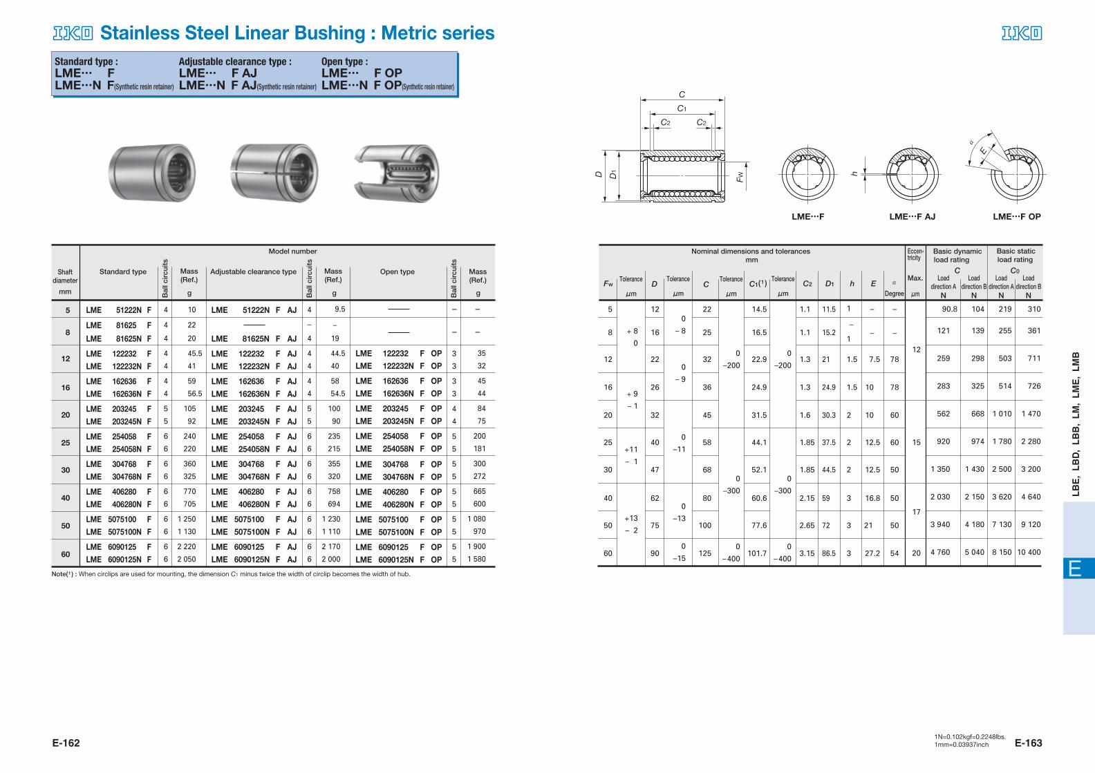
E-162 E-1631N=0.102kgf=0.2248lbs.1mm=0.03937inch
E
LB
E,
LB
D,
LB
B,
LM
, L
ME
, L
MB
Standard type :�LME… F�LME…N F(Synthetic resin retainer)
Adjustable clearance type :�LME… F AJ�LME…N F AJ(Synthetic resin retainer)
Open type :�LME… F OP�LME…N F OP(Synthetic resin retainer)
LME 51222N F
LME 81625 F
LME 81625N F
LME 122232 FLME 122232N F
LME 162636 FLME 162636N F
LME 203245 FLME 203245N F
LME 254058 FLME 254058N F
LME 304768 FLME 304768N F
LME 406280 FLME 406280N F
LME 5075100 FLME 5075100N F
LME 6090125 FLME 6090125N F
4
4
4
4
4
4
4
5
5
6
6
6
6
6
6
6
6
6
6
10
22
20
45.5
41
59
56.5
105
92
240
220
360
325
770
705
1 250
1 130
2 220
2 050
LME 51222N F AJ
LME 81625N F AJ
LME 122232 F AJLME 122232N F AJ
LME 162636 F AJLME 162636N F AJ
LME 203245 F AJLME 203245N F AJ
LME 254058 F AJLME 254058N F AJ
LME 304768 F AJLME 304768N F AJ
LME 406280 F AJLME 406280N F AJ
LME 5075100 F AJLME 5075100N F AJ
LME 6090125 F AJLME 6090125N F AJ
4
–
4
4
4
4
4
5
5
6
6
6
6
6
6
6
6
6
6
9.5
–
19
44.5
40
58
54.5
100
90
235
215
355
320
758
694
1 230
1 110
2 170
2 000
LME 122232 F OPLME 122232N F OP
LME 162636 F OPLME 162636N F OP
LME 203245 F OPLME 203245N F OP
LME 254058 F OPLME 254058N F OP
LME 304768 F OPLME 304768N F OP
LME 406280 F OPLME 406280N F OP
LME 5075100 F OPLME 5075100N F OP
LME 6090125 F OPLME 6090125N F OP
3
3
3
3
4
4
5
5
5
5
5
5
5
5
5
5
35
32
45
44
84
75
200
181
300
272
665
600
1 080
970
1 900
1 580
gBal
l cir
cuits
gBal
l cir
cuits
gBal
l cir
cuits
Model number
Adjustable clearance typeStandard type
mm
Open type
5
8
12
16
20
25
30
40
50
60
–
–
–
–
90.8
121
259
283
562
920
1 350
2 030
3 940
4 760
104
139
298
325
668
974
1 430
2 150
4 180
5 040
219
255
503
514
1 010
1 780
2 500
3 620
7 130
8 150
310
361
711
726
1 470
2 280
3 200
4 640
9 120
10 400
D C C2 D1
C C0
h E α�C1( 1 )
16
12
8
5
20
25
30
40
50
60
0
– 8
0
–200
0
–300
0
–400
0
–200
0
–300
0
–400
0
– 9
0
–11
0
–13
0
–15
+ 8
0
+ 9
– 1
+11
– 1
+13
– 2
26
22
16
12
32
40
47
62
75
90
36
32
25
22
45
58
68
80
100
125
1
–
1
1.5
1.5
2
2
2
3
3
3
10
7.5
–
–
10
12.5
12.5
16.8
21
27.2
78
78
–
–
60
60
50
50
50
54
1.3
1.3
1.1
1.1
1.6
1.85
1.85
2.15
2.65
3.15
24.9
21
15.2
11.5
30.3
37.5
44.5
59
72
86.5
24.9
22.9
16.5
14.5
31.5
44.1
52.1
60.6
77.6
101.7
12
15
17
20
Fw
Nominal dimensions and tolerances mm
C
C1
D
C2 C2
D1
FW
LME…F LME…F AJ LME…F OP
h
E
α�
Mass(Ref.)
Mass(Ref.)
Mass(Ref.)
Shaft diameter Tolerance
�μm
Tolerance�μm
Tolerance�μm
Tolerance�μm
Loaddirection A
N
Load direction B
N
Load direction A
N
Load direction B
NDegree
Eccen-tricity
Max.
μm
Basic dynamic load rating
Basic static load rating
Note( 1 ) : When circlips are used for mounting, the dimension C1 minus twice the width of circlip becomes the width of hub.
Stainless Steel Linear Bushing : Metric series
608-629 05.2.25 11:23 AM ページ E-162

E-164 E-1651N=0.102kgf=0.2248lbs.1mm=0.03937inch
E
LB
E,
LB
D,
LB
B,
LM
, L
ME
, L
MB
Standard type :�LME… F UU�LME…N F UU(Synthetic resin retainer)
Adjustable clearance type :�LME… F UU AJ�LME…N F UU AJ(Synthetic resin retainer)
Open type :�LME… F UU OP�LME…N F UU OP(Synthetic resin retainer)
LME 51222N F UU
LME 81625 F UU
LME 81625N F UU
LME 122232 F UULME 122232N F UU
LME 162636 F UULME 162636N F UU
LME 203245 F UULME 203245N F UU
LME 254058 F UU*LME 254058N F UU
LME 304768 F UULME 304768N F UU
LME 406280 F UULME 406280N F UU
LME 5075100 F UULME 5075100N F UU
LME 6090125 F UULME 6090125N F UU
4
4
4
4
4
4
4
5
5
6
6
6
6
6
6
6
6
6
6
10
22
20
45.5
41
59
56.5
105
92
240
220
360
325
752
705
1 210
1 130
2 160
2 050
LME 51222N F UU AJ
LME 81625N F UU AJ
LME 122232 F UU AJLME 122232N F UU AJ
LME 162636 F UU AJLME 162636N F UU AJ
LME 203245 F UU AJLME 203245N F UU AJ
LME 254058 F UU AJ*LME 254058N F UU AJ
LME 304768 F UU AJLME 304768N F UU AJ
LME 406280 F UU AJLME 406280N F UU AJ
LME 5075100 F UU AJLME 5075100N F UU AJ
LME 6090125 F UU AJLME 6090125N F UU AJ
4
–
4
4
4
4
4
5
5
6
6
6
6
6
6
6
6
6
6
9.5
–
19
44.5
40
58
54.5
100
90
235
215
355
320
740
694
1 190
1 110
2 110
2 000
3
3
3
3
4
4
5
5
5
5
5
5
5
5
5
5
35
32
45
44
84
75
200
181
300
272
645
600
1 050
970
1 850
1 580
gBal
l cir
cuits
gBal
l cir
cuits
gBal
l cir
cuits
Model number
Adjustable clearance typeStandard type
mm
Open type
5
8
12
16
20
25
30
40
50
60
–
–
–
–
90.8
121
259
283
562
920
1 350
2 030
3 940
4 760
104
139
298
325
668
974
1 430
2 150
4 180
5 040
219
255
503
514
1 010
1 780
2 500
3 620
7 130
8 150
310
361
711
726
1 470
2 280
3 200
4 640
9 120
10 400
D C C2 D1
C C0
h E α�C1( 1 )
16
12
8
5
20
25
30
40
50
60
+ 8
00
–200
0
–300
0
–400
0
–200
0
–300
0
–400
0
– 8
0
– 9
0
–11
0
–13
0
–15
+ 9
– 1
+11
– 1
+13
– 2
26
22
16
12
32
40
47
62
75
90
36
32
25
22
45
58
68
80
100
125
1
–
1
1.5
1.5
2
2
2
3
3
3
10
7.5
–
–
10
12.5
12.5
16.8
21
27.2
78
78
–
–
60
60
50
50
50
54
1.3
1.3
1.1
1.1
1.6
1.85
1.85
2.15
2.65
3.15
24.9
21
15.2
11.5
30.3
37.5
44.5
59
72
86.5
24.9
22.9
16.5
14.5
31.5
44.1
52.1
60.6
77.6
101.7
12
15
17
20
Fw
Nominal dimensions and tolerancesmm
h
C
C1
D
C2 C2
D1
FW
E
α�
LME…F UU LME…F UU AJ LME…F UU OP
Shaft diameter
Mass (Ref.)
Mass (Ref.)
Mass (Ref.) Tolerance
�μm
Tolerance�μm
Tolerance�μm
Tolerance�μm
Load direction B
N
Load direction A
N
Load direction B
NDegree
Eccen-tricity
Max.
μm
Basic dynamic load rating
Basic static load rating
Loaddirection A
N
Note( 1 ) : When circlips are used for mounting, the dimension C1 minus twice the width of circlip becomes the width of hub.
Remark : Seals of the Linear Bushings marked with an asterisk (*) protrude a little from the end face of external cylinder.
LME 122232 F UU OPLME 122232N F UU OP
LME 162636 F UU OPLME 162636N F UU OP
LME 203245 F UU OPLME 203245N F UU OP
LME 254058 F UU OP*LME 254058N F UU OP
LME 304768 F UU OPLME 304768N F UU OP
LME 406280 F UU OPLME 406280N F UU OP
LME 5075100 F UU OPLME 5075100N F UU OP
LME 6090125 F UU OPLME 6090125N F UU OP
Stainless Steel Linear Bushing with Seals : Metric series
608-629 05.2.25 11:23 AM ページ E-164