i~(~iresearch electric powerelectric power * i~(~iresearch institute2007-311 bwr vessel &...
TRANSCRIPT
ELECTRIC POWER
* I~(~IRESEARCH INSTITUTE
2007-311 BWR Vessel & Internals Project (BWRVIP)
October 23, 2007.
Document Control DeskU. S. Nuclear Regulatory Commission115 55 Rockville PikeRockville,IvID. 20852
Attention: John Honcharik
Subject: Project No. 704 - BWR Vessel and Internals Inspection Summaries for Fall 2006Outages
Enclosed are. five (5) copies of the document entitled "BWR Vessel and Internals Project, VesselInternals Inspection Summaries for Fall 2006. Outages, October 2007."
The information provided in the enclosed document identifies the BWR internal componentsinspected and generally includes the date or frequency of inspection, the inspection method usedand a summary of results including repair or replacement activities. This information is beingused by the BWvRVIP to track the material performance of the associated vessel internalcomponents. .The enclosed document is being provided to. the NRC for information only.
The information contained in the enclosed document was developed by the individual utilitiesand has been compiled into the enclosed document by the BWRVIP. The BWYRVIP. plans tocontinue to gather such information and to provide periodic updates such as in the encloseddocument.
Representatives of the BWYRVIP would be pleased to. meet with the NRC staff to. discuss anycomments or questions related to. the enclosed document.. If you have any questions on theenclosed document or the general subject of inspection results, please call Chuck Wirtz,BWRVIP Integration Committee Technical Chairman, FirstEnergy, at 440.346.7124.
Sincerely,
Rick LibraExelonChairman, BWR Vessel and Internals Project
Together .. Shaping the Future oF Electricity d7jjUi5
PA2 HLO ye AL enuO OaoIltE CA 94304-1395 USA *650.855.2000 Customer Service 800.313.3774 *www-erixomn A ddcl I eo4'--i3420~~~~elw Hiý-e AvnuPaoAl

BWR Vessel and Internals Project
Vessel Internals Inspection Summaries
for Fall 2006 Outages
October 2007
Table of Contents
Plant Page
1. Cooper Nuclear Station 32. Dresden Unit 3 133. James. A.. FitzPatrick Nuclear Power Plant 204. Oyster Creek Generating Station 355. Peach Bottom Atomic Power Station, Unit 2 46
2
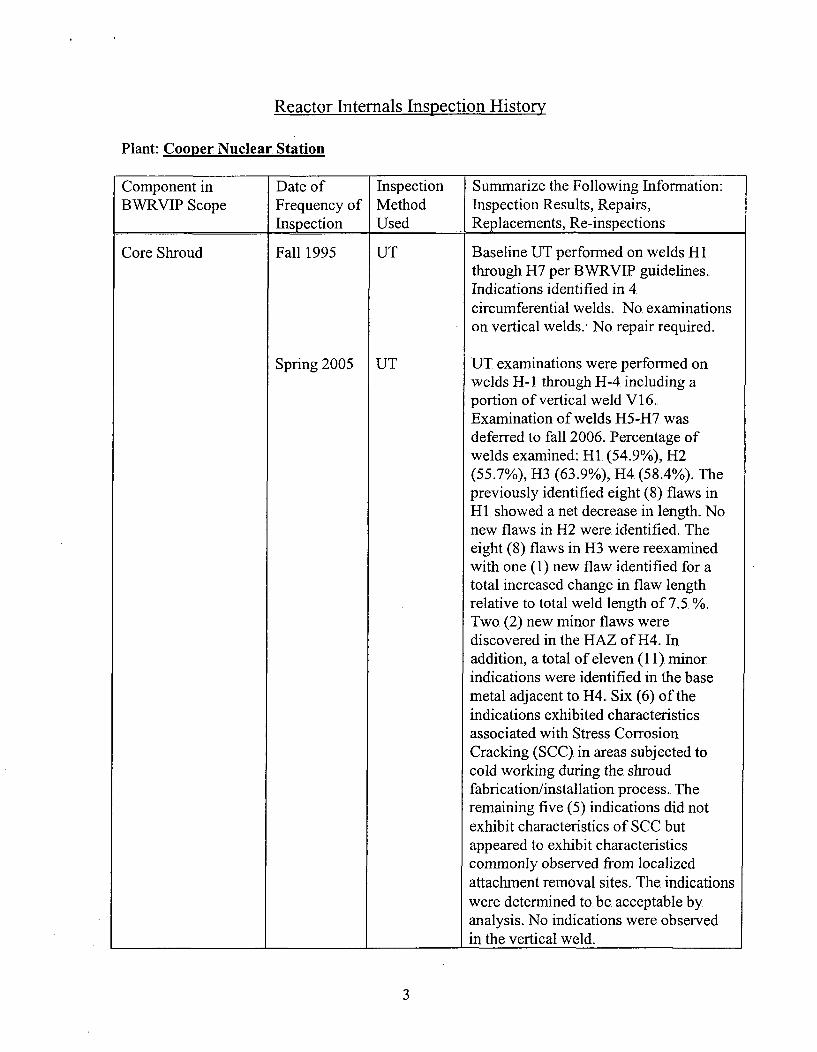
Reactor Internals Inspection History
Plant: Cooper Nuclear Station
Component in fDate of -Inspection Summarize the Following Information:BWRVIP Scope jFrequency of Method Inspection Results, Repairs,
_______________Inspection Used Replacements, Re-inspections
Core Shroud Fall 1995 UT
UTSpring 2005
Baseline UT performned on welds HIthrough H7 per BWVRVIP guidelines.Indications identified in 4circumferential welds.. No. examinationson vertical welds., No. repair required.
UT. examinations were performed onwelds H- I through H-4 including aportion of vertical weld V 16.Examination of welds H5-H7. wasdeferred to fall 2006. Percentage ofwelds examined: HI (54.9%), H2(55.7%), H3 (63.9%), H4 (58.4%). Thepreviously identified eight (8) flaws inHi. showed a net decrease in length. No.new flaws in H2 were identified. Theeight (8), flaws in H3 were reexaminedwith one (1) new flaw identified for atotal increased change in flaw. lengthrelative to. total weld length of 7.5 %.Two. (2) new minor flaws werediscovered in the HAZ of H4.. Inaddition, a total of eleven (11) minorindications were identified in the basemetal adjacent to H4.. Six (6) of theindications exhibited characteristicsassociated with Stress CorrosionCracking (SCC) in areas subjected tocold working during the shroudfabri'cation/installation process.. Theremaining five (5) indications did notexhibit characteristics of SCC butappeared to exhibit characteristicscommonly observed from localizedattachment removal sites.. The. indicationswere determined to. be acceptable byanalysis. No indications were observedin the vertical weld.
3
9.
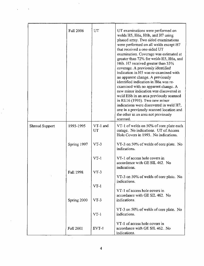
Fall 2006 UT UT examinations were performed onwelds H5, H6a, H6b, and H7 usingphased array. Two sided examinationswere performed on all welds except H7that received a one-sided UTexamination. Coverage was estimated atgreater than 72% for welds H5, H6a, andH6b. H7 received greater than 53%coverage. A previously identifiedindication in H5 was re-examined withno. apparent change. A previouslyidentified indication in H6a was re-examined with no. apparent change. Anew minor indication was discovered inweld H6b. in an area previously scannedin RE 16.(1995). Two new minorindications were discovered in weld H7,one in a previously scanned location andthe other in an area not previouslyscanned.
Shroud Support 1993-1995 VT-i1 and VT-i. of welds on 50% of core plate eachUT outage. .No indications.. UT. of Access
Hole. Covers in 1993... No. indications.
Spring 1997 VT-3 VT-3 on 50% of welds of core plate. No,indications.
VT-i VT- I of access hole covers inaccordance with GE SIL 462.. No.indications.
Fall 1998. VT-3VT-3. on 50% of welds of core plate.. No.indications.
VT-iVT-i. of access hole covers inaccordance with GE SIL 462. No
Spring 2000 VT-3 indications.
VT-3. on 50% of welds of core plate. NoVT-lI indications.
VT- I of access hole covers inFall 2001 EVT-l accordance with GE SIL 462.. No
indications.
4
Spring 2003
Spring 2005
Fall 2006
UT/BVT-i
EVT-1
UT
VT
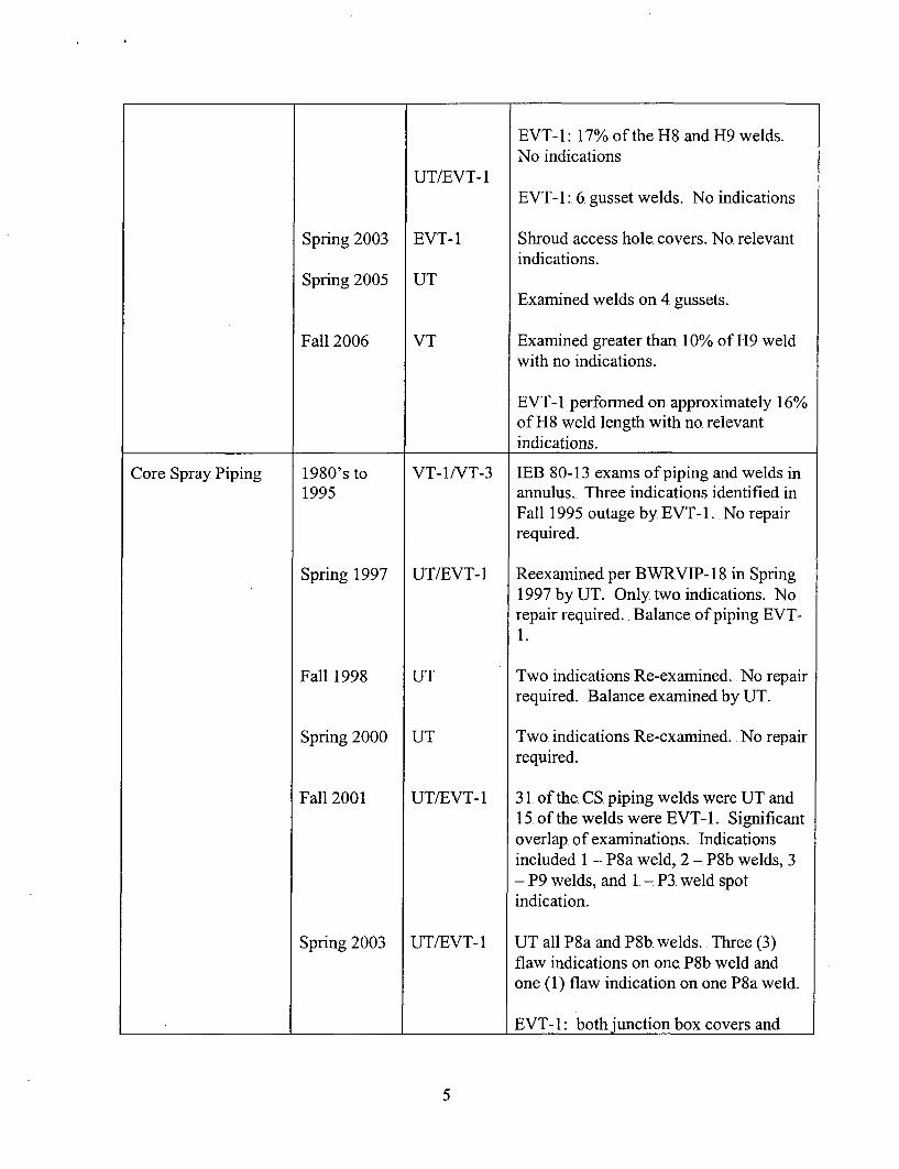
EVT- 1: 17% of the H8. and H9. welds.No indications
EVT-l1: 6. gusset welds. No indications
Shroud access hole covers. No. relevantindications.
Examined welds on 4 gussets.
Examined greater than 10% of H9 weldwith no indications.
EVT-1 performed on approximately 16%of H8 weld length with no relevantindications.
Core Spray Piping 1980's to1995
Spring 1997
Fall 1998
Spring 2000
Fall 2001
Spring 2003
VT-I1/T-3
UT/BVT-i
UT
UT
UT/B VT- 1
UT/BVT-i
IEB 80-13 exams of piping and welds inannulus.. Three indications identified inFall 1995. outage by EVT- 1. No. repairrequired.
Reexamined per BWRVIP- 18 in Spring1997 by UT. Only two indications. Norepair required... Balance of piping EVT-1 .
Two indications Re-examined.. No. repairrequired. .Balance examined by UT..
Two. indications Re-examined.. No repairrequired.
31 of the CS. piping welds were UT and15. of the welds were EVT-1. . Significantoverlap, of examinations. Indicationsincluded 1 P8a weld, 2 - P8b. welds, 3- P9 welds, and 1. - P3. weld spotindication.
UT all P8a and P8b welds.. Three (3)flaw indications on one P8b weld andone (1) flaw indication on one P8a weld.
EVT- 1:. both junction box covers and
5

Spring 2005
Fall 2006
EVT-l
EVT-1/UTJ
accessible portion of P-i, 2-P2 welds, 4-P3 welds, I1-P4a weld, I1-P4b weld, Il-P4cweld, I1-P4d weld. EVT-1. all P8a andP8b welds. No additional indications.
Note: Results are different from previousoutage reports.
The top and bottom surfaces of both P1I'swere examined by EVT- 1. Theexamination revealed that the P 1 .weld isnot a creviced weld. EVT-1. examinationswere performed on both P2 welds, thefour (4) P3 welds, the 4a - 4d welds at190 degrees azimuth, and the P5's, P6's,and P7's, the four (4) P8a's, and the four(4). P8b's.
Performed UT. examinations of P8b.welds. Previous indications showed no.change in size.. Performed EVT-1Iexaminations of piping welds andbracket attachment welds.. No. newrelevant indications observed.
4 +
Core Spray Sparger 1980's to1995
Spring 1997
Fall 1998.
Spring 2000
Fall 2001
VT-i/UT
EVT- 1
EVT- 1
EVT-1
EVT-1
VT- I
IEB 80-13. of welds on sparger. .Noindications.
Sparger and brackets inspected inaccordance with BWYRVLP-18. Debris(wire). in C-sparger Nozzle 15C. wasfound.. No other indications.
Sparger and brackets inspected inaccordance with BWVRVIP- 18.. Debris(wire). in C-sparger Nozzle 15C wasreconfirmed.. No. other indications.
Sparger and brackets inspected inaccordance with BWRVIP-1 8.. Fiveindications dispositioned as acceptable.
All S51, S2, and S4 welds examined withno indications.
All S3a and S3b welds for the C. Core
6
Spring 2003
Spring 2005.
Fall 2006
VT- I
VT- I
EVT-1
N/A
EVT-l1NT-1
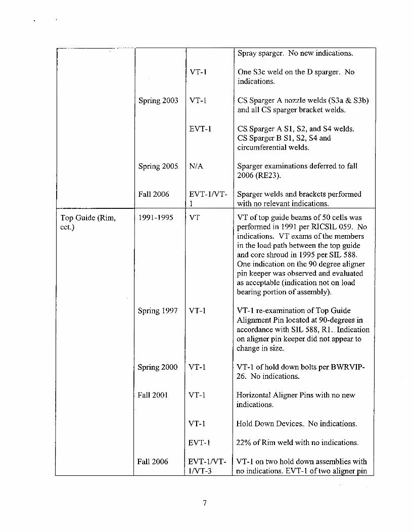
Spray sparger. No new. indications.
One 53c weld on the D sparger. . No.indications.
CS. Sparger A nozzle welds (53a & S3b)and all CS sparger bracket welds.
CS. Sparger A Si1, S2, and S4 welds.CS Sparger B S1, S2, S4 andcircumferential welds..
Sparger examinations deferred to. fall2006 (RE23).
Sparger welds and brackets performedwith no relevant indications.
Top Guide (Rim,ect.)
1991-1995 VT
Spring 1997 1 VT-i
VT of top guide beams of 50 cells wasperformned in 1991 per RICSIL 059.. Noindications. VT exams of the membersin the load path between the top. guideand core shroud in 1995. per SIL 588.One indication on the 90 degree alignerpin keeper was observed and evaluatedas acceptable (indication not on loadbearing portion of assembly).
VT- I re-examination of Top. GuideAlignment Pin located at 90-degrees inaccordance with SIL 588, Ri.. Indicationon aligner pin keeper did not appear tochange in size.
VT- I of hold down bolts per BWVRVIP-26. No indications.
Horizontal Aligner Pins with no. newindications.
Hold Down Devices.. No. indications..
22% of Rim weld with no indications.
VT- I on two hold down assemblies withno. indications. EVT-1. of two. aligner pin
Spring 2000
Fall 2001.
Fall 2006
VT- I
VT-i1
VT-i
EVT- 1
EVT-l1NT-1/VT-3
7
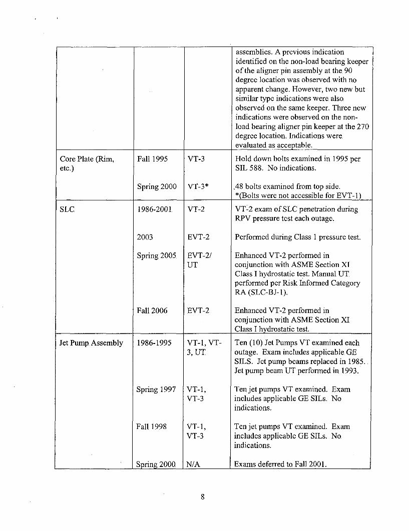
assemblies. A previous indicationidentified on the non-load bearing keeperof the aligner pin assembly at the, 90degree location was observed with noapparent change. However, two new butsimilar type indications were alsoobserved on the same keeper. Three newindications were observed on the non-load bearing aligner pin keeper at the 270degree location. Indications wereevaluated as acceptable.
Core Plate (Rim, Fall 1995 VT-3 Hold down bolts examined in 1995 peretc.) SIL 588. No indications.
Spring 2000 VT-3* .48 bolts examined from top side._________________ __________*(Bolts were not accessible for EWA-),
SLC 1986-2001. VT-2 VT-2 exam of SLC penetration duringRPV. pressure test each outage.
2003 EVT-2 Performed during Class 1 pressure test.
Spring 2005, EVT-2/ Enhanced VT-2 performed inUT conjunction with ASME Section XI
Class I hydrostatic test. Manual UTperformed per Risk Informed CategoryRA (SLC-BJ- 1).
Fall 2006 EVT-2 Enhanced VT-2 performed inconjunction with ASME Section XIClass I hydrostatic. test..
Jet Pump Assembly 1986-1995 VT-i, VT- Ten (10). Jet Pumps VT examined each3, UT outage. Exam includes applicable GE
SILS. Jet pump beams replaced in 1985..Jet pump beam UT performed in 1993.
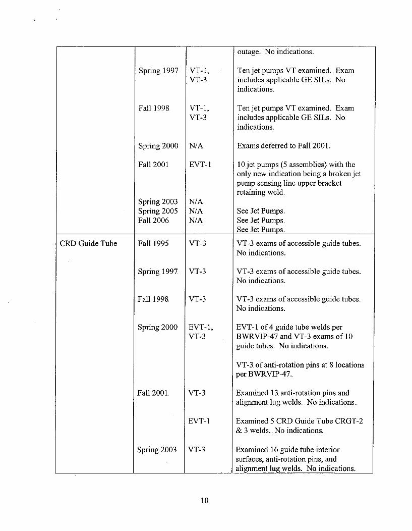
Spring 1997 VT-i, Ten jet pumps VT examined. ExamVT-3 includes applicable GE SILs. No
indications.
Fall 1998 VT-i1, Ten jet pumps VT examined. ExamVT-3 includes applicable GE SILs.. No.
indications.
______________ prig 000 N/A Exams deferred to. Fall 200 1.
8
Fall 2001
Spring 2003
Spring 2005
Fall 2006
EVT-l, VT-1, VT-3
VT-l1/3
VT-iEVT-1VT-3
EVT- 1
VT-iEVT-1VT-3
UT
EVT-iVT-3
EVT-1
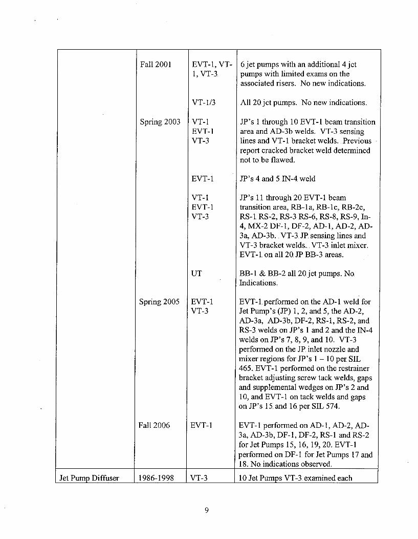
6 jet pumps with an additional 4 jetpumps with limited exams on theassociated risers. No new indications.
All 20 jet pumps. No new indications.
JP's 1 through 10 EVT- I beam transitionarea and AD-3b welds. VT-3 sensinglines and VT- I bracket welds.. Previousreport cracked bracket weld determinednot to be flawed.
JP's 4.and 5.TN-4weld
JP's 11 through 20 EVT-1I beamtransition area, RB-lIa, RB-i1c, RB-2c,RS-1. RS-2, RS-3. RS-6, RS-8, RS-9, In-4, MX-2 DF-i, DF-2, AD-i, AD-2, AD-3a, AD-3b. VT-3. JP. sensing lines andVT-3. bracket welds.. VT-3. inlet mixer.EVT- I on all 20 IP BB-3. areas..
BB- I & BB-2 all 20 jet pumps. No.Indications.
EVT- I performed on the. AD-i1 weld forJet Pump's (JP) 1, 2, and 5, the, AD-2,AD-3a, AD-3b, DF-2, RS-i, RS-2, andRS-3. welds on JP's 1 and 2 and the IN-4welds on JP's 7, 8, 9, and 10. VT-3.performed on the JP. inlet nozzle andmixer regions for JP's 1 - 10. per SIL465.. EVT-i. performed on the restrainerbracket adjusting screw tack welds, gapsand supplemental wedges on JP's 2 and10, and EVT-l1 on tack welds and gapson JP's 15. and 16 per SIL 574.
EVT-i1 performed on AD-i1, AD-2, AD-3a, AD-3b, DF-l, DF-2, RS-i. and RS-2for Jet Pumps 15, 16, 19, 20. EVT- Iperformed on DF- 1 for Jet Pumps i17 and18. No. indications observed.
Jet Pump, Diffuser 11986-1998. J VT-3 1 10 Jet Pumps VT-3. examined each
9
Spring 1997
Fall 1998.
Spring 2000
Fall 2001
Spring 2003Spring 2005.Fall 2006
VT-i1,VT-3
VT-i1,VT-3
N/A
EVT- 1
N/AN/AN/A
outage. No indications.
Ten jet pumps VT examined.. Examincludes applicable GE SILs.. No.indications.
Ten jet pumps VT examined..includes applicable GE SILs.indications.
ExamNo
Exams deferred to. Fall 2001.
10.jet pumps (5 assemblies) with theonly new indication being a broken jetpump sensing line upper bracketretaining weld.
See Jet Pumps.See Jet Pumps.See Jet Pumps.
CRD Guide Tube Fall 1995
Spring 1997.
Fall 1998
Spring 2000
Fall 2001
Spring 2003.
VT-3
VT-3
VT-3
EVT- 1,VT-3
VT-3
EVT-1
VT-3
VT-3. exams of accessible guide tubes..No. indications.
VT-3. exams of accessible guide tubes.No indications.
VT-3 exams of accessible guide tubes.No. indications.
EVT- 1. of 4. guide tube welds perBW;RVIP-47 and VT-3. exams of 10guide. tubes.. No indications.
VT-3. of anti-rotation pins at 8. locationsper BWRVIP-47..
Examined 13. anti-rotation pins andalignment lug welds.. No. indications.
Examined 5. CRD. Guide Tube CRGT-2& 3. welds.. No indications.
Examined 16 guide tube interiorsurfaces, anti-rotation pins, andalig-nment lugz welds. .No indications.
10

Spring 2005 EVT-1 Examined CRD upper guide tube circ.weld CRGT-2-(06-19) and lower guidetube circ weld CRGT-3-(06-19).
Fall 2006 EVT- 1/VT-3
VT-3 performed of CRGT. and alig-nmentpin at one location. EVT-1 performed onCRD upper guide tube ciro weld CRGT-2 and lower guide tube circ. weld CRGT-3 at one location. No indicationsobserved.LCRD Stub Tube N/A N/A No. record of examination..
In-core Housing NA NA No. record of examination back to, 1996
Dry Tube 1989-1991 VT VT exam inl1989, 1990, andl1991lperSIL409R1. All dry tubes replaced in1993. Replaced one dry tube in 2005,(RE22)
Instrument 1986-2005 VT-2 VT-2 exams during RPV pressure testPenetrations each outage.
Vessel ID Brackets 1986-1995 VT-1/VT-3 ASME XI VT-3 exams (VT- I if in thebeltline region) ofjet pump. riser brace,dryer, FW Sparger, Core Spray, guiderod, and surveillance capsule holderbrackets performed once per. interval.No. indications noted..
Spring 1997 VT-lNT-3 10 jet pump riser brackets and weldsexamined. No indications.
Fall 1998 VT-l/VT-3 10 jet pump. riser brackets and weldsexamined.. No indications.
Spring 2000 VT-1/VT-3 Guide rod and FW Sparger Brackets andwelds examined per BWRVIP-48. No.indications
Fall 2001. VT-3 Examined 3 Surveillance holder upperand lower bracket welds. No. indications
Spring 2003. EVT-1 All FW sparger bracket attachment weldsand all dryer support attachment welds.No indications
I1I
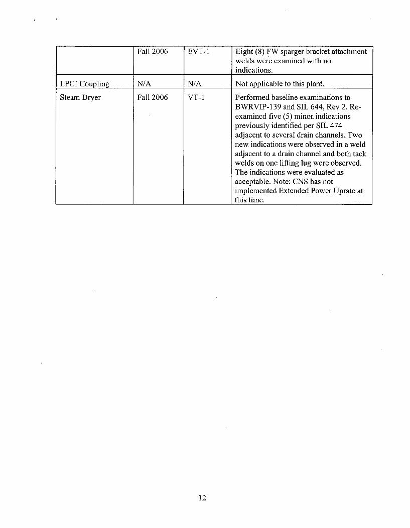
Steam Dryer Fall 2006 VT-i
Eight (8) FW sparger bracket attachmentwelds were examined with no.indications.
Not applicable to this plant..
Performed baseline examinations toBWRVIP-139 and SIL 644, Rev 2.. Re-examined five (5) minor indicationspreviously identified per SIL 474adjacent to several drain channels. Two.new indications were observed in a weldadjacent to a drain channel and both tackwelds on one lifting lug were observed..The indications were evaluated asacceptable. Note: CNS. has notimplemented Extended Power Uprate atthis time.
12
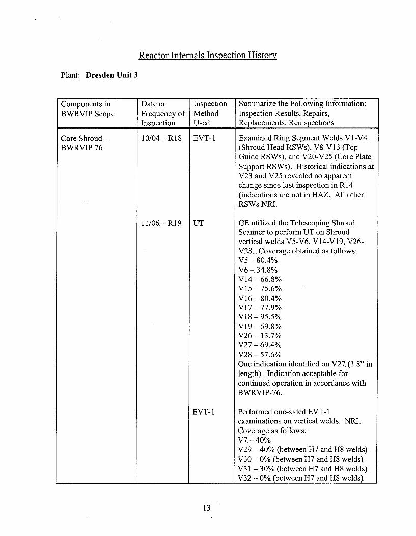
Reactor Internals Inspection Historv
Plant: Dresden Unit 3
Components in Date or Inspection Summarize the Following Information:BWRVIP Scope Frequency of Method Inspection Results, Repairs,
________________Inspection jUsed Replacements, Reinspections
Core Shroud -
BWRVIP 7610/04 - RI 8 EVT- 1
11/06-R19 I UT
Examined Ring Segment Welds V1I-V4(Shroud Head RSWs), V8-V 13 (TopGuide RSWs), and V20-V25 (Core PlateSupport RSWs). Historical indications atV23 and V25 revealed no apparentchange. since last inspection in R 14(indications are not in HAZ. All otherRSWs NMI.
GE utilized the Telescoping ShroudScanner to perform UT on Shroudvertical welds V5-V6, V14-V 19, V26-V28.. Coverage obtained as follows:V5 - 80.4%V6.-- 34.8%V14 - 66.8%Vi 15- 75.6%V1 6 - 80.4%V17.-- 77.9%V18.-- 95.5%V19 - 69.8%V26. -7 13.7%V27. -769.4%
V28 - 5 7.6%One indication identified on V27.(1.8". inlength). Indication acceptable forcontinued operation in accordance withBWRVIP-76.
Performed one-sided EVT- 1examinations on vertical welds. NI..Coverage as follows:V7 -40%V29. -740%. (between H7 and H8. welds).V30 - 0% (between H7 and H8. welds).V3 1.- 30% (between H7 and H8 welds)V32, - 0% (between H7.ad H8. welds)
EVT- 1
13

VT-3, Performed GE recommended inspectionsEVT- 1 of shroud repair hardware. Scope
included inspections to addresssusceptible areas based on indicationsfound at Hatch. One RI identified due toretainer clip. not engage. This retainerclip, is redundant and did not require
___________________ ___________ __________ repair.
Shroud Support - 10/04-- R 18 EVT-1 Examined H8. and H9 between Jet PumpsBWRVIP 38 10.and 11. (132'-177o). NRI.
11/06, - R1 9 EVT-1, VT-3. of all access areas of H9 and EVT-VT-3 1. of 10% of H9 between]]? 10 and 11.
______NR
Core Spray Piping -
BWRVIP 1810/04, - R1 8
11/06 -RI 9
EVT-1
EVT-1
EVT-1
EVT-1
EVT-I
EVT-1
VT-l1/T-3
EVT-1
- Thermal Sleeve to. Tee Welds: IPI,2P1I... NRI..- Cover Plate to. Tee Box Welds: 1P2,2P2. NMI.- Tee Box to Pipe Welds: 1P3, 2P3, 3P3,4P3. . NRI.-. Horizontal Pipe to. Elbow Weld:. 2P4a.NMI.-, Elbow. to Vertical Pipe Weld: 2P4b.NRI.- Eight Core Spray Piping brackets,attachment weld, pad surface and HAZof cladding. NRI.- Performed Core Spray Lower SectionalReplacement (all four downcomers)eliminating inspection of the followingwelds:. 1-4P4c, 1-4P4d, l-4P8a-d, 1-4P5,1-4P6, P7.
Core Spray Lower SectionalReplacement- VT-I1 of all accessible bolting, keepers,ratchets and latch springs. NMI- VT-3. of all repair hardware. NMI
- Thermal Sleeve to. Tee Welds: lPl,2P 1. NMI.- Cover Plate to Tee Box Welds: 1P2,2P2. NMI.-ý Tee Box to, Pipe Welds:. IP3, 2P3, 3P3,
14
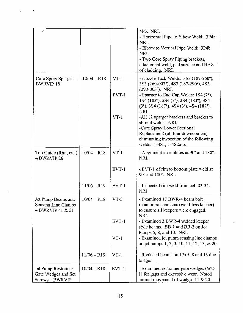
4P3. NRI.- Horizontal Pipe to Elbow Weld: 3P4a.NMI.- Elbow to Vertical Pipe Weld: 3P4b.NMR.- Two Core Spray Piping brackets,attachment weld, pad surface and HAZof cladding. NMI.
Core Spray Sparger- 10/04 -R18 VT-i - Nozzle Tack Welds: 3S3. (187-260'),BWRVIP. 18 3S3 (260-003o), 4S3 (187-290o), 4S3.
(290-0030). NMI.EVT-1 - Sparger to. End Cap. Welds: I1S4 (70),
184 (1830), 2S4 (70),2S4.(1830), 354(30), 35S4 (1870), 4S4 (30), 4S4 (1870).NMI.
VT-i -All 12 sparger brackets and bracket to.shroud welds. NMI.-Core Spray Lower SectionalReplacement (all four downcomers)eliminating inspection of the followingwelds:. -4S1, 1-452a-b..
Top. Guide (Rim, etc.). 10/04 - Ri 8, VT- I - Alignment assemblies at 90'. and 1800.- BWvRVIP. 26 NMI.
EVT-1 - EVT-1. of rim to. bottom plate weld at90' and 1800. NMI.
11/06 - R19 EVT-1 - Inspected rim weld from cell 03-34..______NM
Jet Pump. Beams and 10/04 - R18, VT-3 - Examined 17. BWVR-4 beam boltSensing Line Clamps retainer mechanisms (weld-less keeper)- BWRVIP41. & 5t to. ensure all keepers were. engaged.
NMI.EVT-1 - Examined 3. BWR-4 welded keeper
style beams. BB-1. and BB-2 on JetPumps 5, 8, and 13. NM.
VT-i - Examined jet pump sensing line clampson jet pumps 1, 2, 3, 10, 11, 12, 13, &20.
11/06, - R1 9 VT- I - Replaced beams on JPs 5, 8. and 13. due____ ___ ___to. age.
Jet Pump Restrainer 10/04 - R 18, EVT- 1 - Examined restrainer gate wedges (WD-Gate Wedges and Set 1) for gaps and excessive wear.. NotedScrews - BWRVIP ______ _____normal movement of wedges i1. & 20.
15
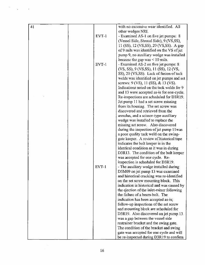
41 with no. excessive wear identified. Allother wedges NRI.
EVT-1I - Examined AS- I on five jet pumps: 8(Vessel Side, Shroud Side), 9. (VS,SS),11 (SS), 12 (VS,SS), 20 (VS,S S). A gapof 9 mils was identified on the VS of jetpump 9, no auxiliary wedge was installedbecause the gap was < 10 mils.
EVT-1 -. Examined AS-2 on five jet pumps:. 8.(VS, SS), 9 (VS,SS), 11 (SS), 12 (VS,SS), 20 (VS,SS). Lack of fusion of tackwelds was identified on jet pumps and setscrews: 9 (VS), 11 (SS), & 13 (VS).Indications noted on the tack welds for 9and 13. were accepted as-is for one-cycle.Re-inspections are scheduled for D3R1 9.Jet pump 11I had a set screw. missingfrom its housing. The set screw wasdiscovered and retrieved from the.annulus, and a scissor-type auxiliarywedge was installed to. replace themissing set screw. Also discoveredduring the inspection of jet pump. 1 I wasa poor quality tack weld on the swing-gate keeper. A review of historical tapeindicates the bolt keeper is in the,identical condition as it was in duringD3R13. The condition of the bolt keeperwas accepted for one cycle. .Re-inspection is scheduled for D3R 19.
EVT-1 - The auxiliary wedge installed duringD3M09 on jet pump 13. was examinedand historical cracking was re-identifiedon the set screw mounting block.. Thisindication is historical and was caused bythe ejection of the inlet-mixer followingthe failure of a beam-bolt.. The.indication has been accepted as-is;follow-up inspections of the set screwand mounting block are scheduled forD3R19. Also discovered on jet pump. 13.was a gap between the vessel siderestrainer bracket and the swing gate.The condition of the bracket and swinggate, was accepted for one cycle and will
________________________ ______1 be re-inspected during D3R1 9 to. confirm
16
VT-i11/06 -R19
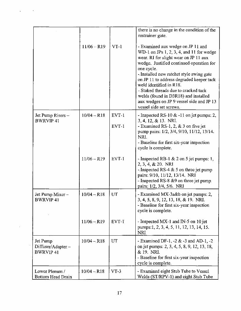
there is no change in the condition of therestrainer gate.
- Examined aux wedge on JP 11. andWD-1, on JPs 1, 2, 3, 4, and 11I for wedgewear.. RI for slight wear on IP 11. auxwedge. Justified continued operation forone. cycle.-. Installed new ratchet style swing gate.on JP 11. to address degraded keeper tackweld identified in R18.-. Staked threads due to cracked tackwelds (found in D3R18) and installedaux wedges on JP 9 vessel side and JP 13vessel side set screws.
Jet Pump Risers -
BWRVIP. 4110/04-7R18 I EVT-1
EVT-1
- Inspected RS-10 & -11 on jet pumps: 2,3, 4, 12, & 13. NRI.- Examined RS -1, 2, & 3 on five jetpump pairs: 1/2, 3/4, 9/10, 11/12, 13/14..NMI.- Baseline for first six-year inspectioncycle is complete.
-. Inspected RB- I & 2 on 5 jet pumps: 1,2, 3,4, & 20., NMI-. Inspected RS-4 & 5 on three jet pumppairs:. 9/10, 11/12, 13/14. NRI, Inspected RS-8 &9 on three jet pump.pairs: 1/2. 3/4. 5/6. NMI
11/06 -,R19 I EVT-1
Jet Pump. Mixer - 10/04 -R18, UT -. Examined MX-3 a&b on jet pumps: 2,BWRVIP. 41 3, 4, 5,8, 9,12, 13, 18, & 19.. NMI.
- Baseline for first six-year. inspectioncycle is complete.
11/06 - R1 9 EVT-1 -Inspected MX-1I and IN-5. on 10 j etpumps: 1, 2, 3, 4, 5, 11, 12, 13, 14, 15.
___NM
Jet Pump 10/04 - R 18 UT -, Examined DF-1, -2 & -3 and AD-i, -2Diffuser/Adapter - on jet pumps: 2, 3, 4, 5,8, 9,12, 13, 18,BWRVIP 41 & 19. NMI.
- Baseline for first six-year. inspection_________________cycle is complete.
Lower Plenum / 10/04 -R18 VT-3 -. Examined eight Stub Tube to. VesselBottom Head Drain ___________Welds (ST/RP V-1). and eight Stub. Tube
17

Cleaning - Section XI/ 2002 BWRVIPINPO AssessmentCommitment
VT-3
VT-3
to CRD Housing Welds (CRDH/ST-i) incells: F7, G6, G7, G8, H7, H8, H9, J8.NMI.
- Inspected two locations for Core Plateto. Stiffener Plate Stitch welds: G7. & G8,beam welds.. NRI.
- Examined two locations for StiffenerPlate to Stiffener Rods welds: G7 andH8 beam tie rods. NMI.- Bottom Head Drain cleaned.
Vessel ID Brackets -
BWRVIP 48.10/04 - RI18
11/06,- R19
EVT- 1
VT-i
EVT-1
VT-3
EVT-1
- Four steam dryer wall support lugs, lugto, pad, and pad to. vessel attachmentwelds.. NMI.
-. Eight feedwater sparger end-bracket lugassemblies. NM.
- Eight feedwater sparger lug to vesselattachment welds. NMI.
-. Inspected the attachment welds for 2Core. Spray piping brackets and all of thesteam dryer wall support lugs inaccordance with ASME Section XI.. NMI
- Inspected piping bracket to. piping weldand bracket to. vessel attachment weld on2 core spray piping brackets., NMI
Reactor PressureVessel - BWRVIP. 05
10/04. - R1 8 UT - Examined vertical welds SCiB, SC2A,SC2C, SC3A, SCOB. NML. Satisfiesthird interval Section XI inspectionrequirements.-. Examined two. original vesselconstruction base metal repair areas inbeltline as required by Section XL. NMI.
Inspected cladding in accordance withASME Section XI. NMI
- Inspected the reactor vessel claddingfrom the shroud flange to the. reactorflange in accordance with ASME SectionXI. NMI
VT-3
11/06-R19 IjVT-3
18
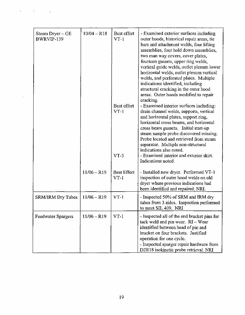
Steam Dryer - GEBWRVIP-1 39
10/04 - R1 8
11/06-R19.
Best effortVT- I
Best effortVT- I
VT-3
Best EffortVT- I
- Examined exterior surfaces includingouter hoods, historical repair areas, tiebars and attachment welds, four liftingassemblies, four hold down assemblies,two. man way covers, cover plates,fourteen gussets, upper ring welds,vertical guide welds, outlet plenum lowerhorizontal welds, outlet plenum verticalwelds, and perforated plates. Multipleindications identified, includingstructural cracking in the outer hoodareas. Outer hoods modified to repaircracking.-. Examined interior surfaces including:.drain channel welds, supports, verticaland horizontal plates, support ring,horizontal cross beams, and horizontalcross beam gussets. Initial start-up.steam sample probe. discovered missing.Probe located and retrieved from steamseparator.. Multiple non-structuralindications also. noted.-. Examined interior and exterior skirt.Indications noted.
-. Installed new dryer. Performed VT-i1inspection of outer hood welds on -olddryer where previous indications hadbeen identified and repaired. NRI.
SRMIIRM Dry Tubes 11/06.- R19 VT-i - Inspected 50% of SRM and 1kM drytubes from 3. sides.. Inspection performed
________________to meet SIL 409., NRI
Feedwater Spargers 11/06 - R19. VT-i -. Inspected all of the end bracket pins fortack weld and pin wear.. RI - Wearidentified between head of pin andbracket on four brackets. Justifiedoperation for one cycle.- Inspected sparger repair hardware from
________________ __________ _________D2Rl 8 isokinetic. probe retrieval. NRI
19
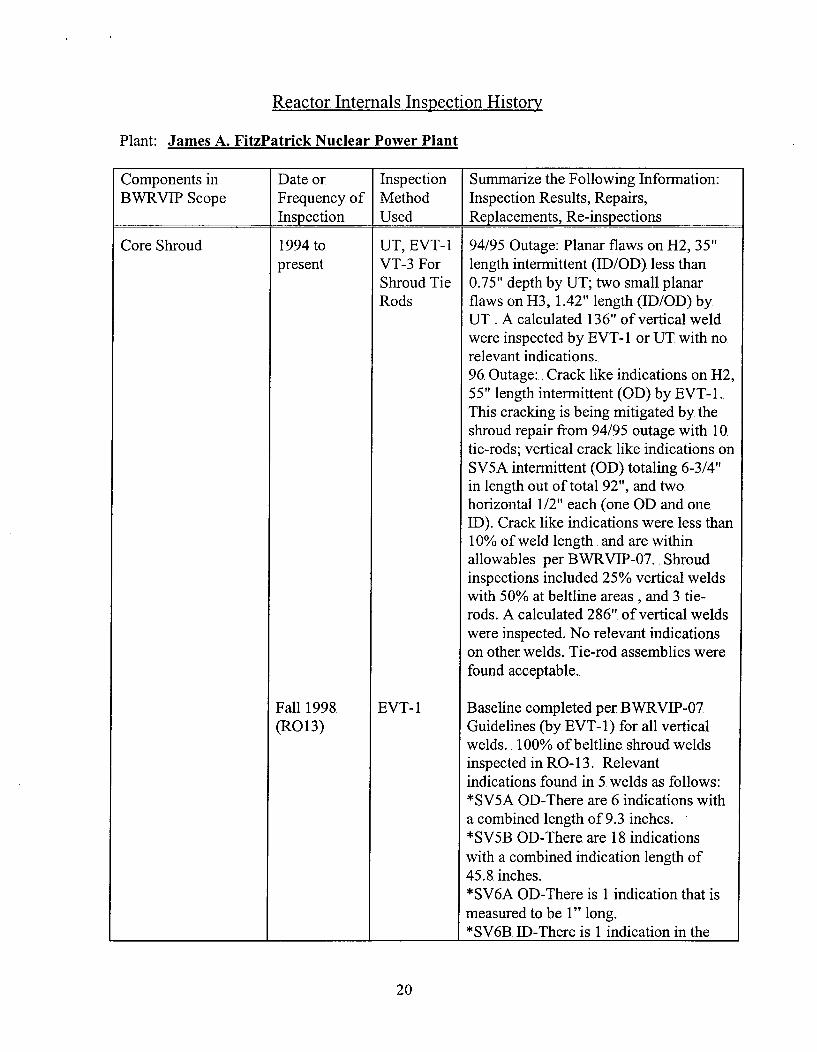
Reactor Internals Inspection History
Plant: James A. FitzPatrick Nuclear Power Plant
Components in Date or Inspection Summarize the Following Information:BWVRVIIP Scope Frequency of Method Inspection Results, Repairs,
________________Inspection Used Replacements, Re-inspections
Core Shroud 1994 to.present
UT, EVT-1IVT-3 ForShroud TieRods
EVT- 1
94/95 Outage: Planar flaws on H2, 35"length intermittent (ID/GD). less than0.75" depth by UT; two small planarflaws on H3, 1.42" length (ID/GD) byUT . A calculated 136" of vertical weldwere inspected by EVT-1I or UT. with no.relevant indications.96. Outage:. Crack like indications on H2,55" length intermittent (GD) by EVT-1.This cracking is being mitigated by theshroud repair from 94/95 outage with 10tie-rods; vertical crack like indications onSV5A intermittent (GD) totaling 6-3/4"in length out of total 92", and two.horizontal 1/2" each (one GD. and oneID). Crack like indications were less than10% of weld length. and are withinallowables per BWRVIP-07.. Shroudinspections included 25% vertical weldswith 50% at beltline areas , and 3. tie-rods. A calculated 286". of vertical weldswere inspected. No. relevant indicationson other welds. Tie-rod assemblies werefound acceptable.
Baseline completed per BWRVIP-07.Guidelines (by. EVT- 1) for all verticalwelds.. 100% of beltline. shroud weldsinspected in RO- 13. Relevantindications found in 5. welds as follows:*SV5A GD-There are 6. indications witha combined length of 9.3 inches.*SV5B. GD-There are 18. indicationswith a combined indication length of45.8. inches..*SV6A GD-There is 1 indication that ismeasured to. be I" long.*SV6B ID-There is 1 indication in the.
Fall 1998(RO 13)
20
i I I
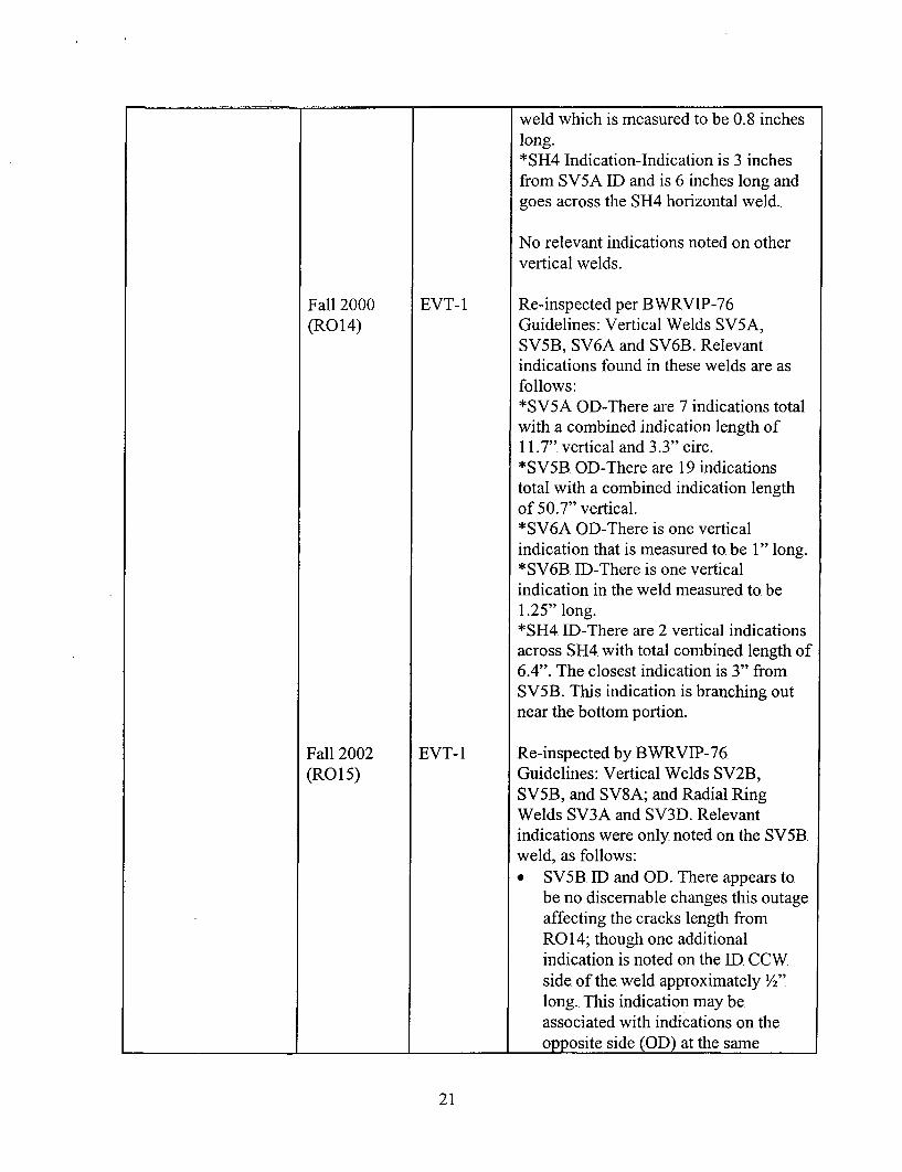
weld which is measured to be 0.8 incheslong.*SH4. Indication-Indication is 3, inchesfrom SV5A ID and is 6 inches long andgoes across the SH4 horizontal weld.
No relevant indications noted on othervertical welds.
Fall 2000 EVT- 1 Re-inspected per BWvRVIP-76(RG 14) Guidelines: Vertical Welds SV5A,
SV5B3, SV6A and SV6B3. Relevantindications found in these welds are asfollows:*SV5A GD-There are 7 indications totalwith a combined indication length of11.7". vertical and 3.3" circ.*SV5B. GD-There are 19 indicationstotal with a combined indication lengthof 50.7" vertical.*SV6A GD-There is one verticalindication that is measured to be 1" long.*SV6B. ID-There is one verticalindication in the weld measured to. be1.25" long.*SH4 11)-There are 2 vertical indicationsacross SH4 with total combined length of6.4". The closest indication is 3" fromSV5B3. This indication is branching outnear the bottom portion.
Fall 2002 EVT- 1 Re-inspected by BWýRVIP-76.(ROl15) Guidelines: Vertical Welds SV2B,
SV5B3, and SV8A; and Radial RingWelds SV3A and SV3D. Relevantindications were only noted on the. SV5B3weld, as follows:
*SV5B ID and GD. There appears to.be no discernable changes this outage.affecting the cracks length fromR014; though one additionalindication is noted on the ID CCWside of the. weld approximately Y27
long. This indication may beassociated with indications on the
_______________ _________ _______I opposite side_(GD)_at the same _
21
I I
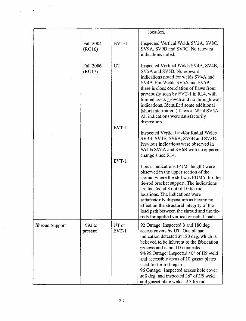
location.
Fall 2004(R0 16)
Fall 2006(RO 17)
EVT-1
UT
EVT-1
EVT- 1
Inspected Vertical Welds SV2A, SV8C,SV9A, SV9B3 and SV9C. No relevantindications noted.
Inspected Vertical Welds SV4A, SV4B3,SV5A and SV5B. No relevantindications noted for welds SV4A andSV4B3. For Welds SV5A and SV5B3,there is close correlation of flaws frompreviously seen by EVT-l1 in RI 4, withlimited crack growth and no through wallindications. Identified some additional(short intermittent) flaws at Weld SV5A.All indications were satisfactorilydisposition
Inspected Vertical and/or Radial WeldsSV3B, SV3E, SV6A, SV6B3 and SV8B.Previous indications were observed inWelds SV6A and SV6B3 with no apparentchange since, R14..
Linear. indications (< 1/2" length). wereobserved in the upper section of theshroud where the slot was EDM'd for thetie-rod bracket support. The indicationsare located at 8 out of 10 tie-rodlocations.. The indications weresatisfactorily disposition as having no.effect on the. structural integrity of theload path between the shroud and the tie-rods for applied vertical or radial loads.
4 4. 4
Shroud Support 1992 topresent
UT orEVT- 1
92 Outage: Inspected 0 and 180 degaccess covers by UT. One planarindication detected at 180 deg, which isbelieved to. be. inherent to the fabricationprocess and is not ID connected.94/95. Outage: Inspected 40" of H9 weldand accessible areas of 10 gusset platesused for tie-rod repair.96. Outage: Inspected access hole coverat 0 deg, and inspected 36" of H9 weldand gzusset plate welds at 3 tie-rod
22

locations.. No relevant indications noted.
Fall 1998 EVT- 1 Baseline. completed per BWRVIP-07 andVT-3 BWVvRVIP-38 guidelines for all shroud
repaired tie rods and load transfer gussetplate welds.*7 out of 10 tie. rod assemblies inspected(by EVT-1I/VT-3) in Fall 1998. Norelevant indications noted.*All load transfer gusset plate. welds and12 inches of H9. weld each side of thegussets were. examined by EVI- 1. 7 outof 10 gussets inspected in R0 13. Norelevant indications noted.
Examined by EVT-1I the access holecover at 180. degrees.. No relevantindications noted.
Fall - No. inspections during RO 14 and RO 152000/2002
Fall 2004 EVT- 1 Inspected two. shroud support gussetplate welds and 12 inches of H9. top weldeach side of the gussets. No. relevantindications noted.
Fall 2006. EVT-1 Inspected all ten shroud repair tie-rodsystems and corresponding shroudsupport gusset welds at same locations..No. relevant indications were noted.
Inspected top. portion of horizontal weldH9. at each side of tie-rod locations andbetween gussets at 1800. No relevantindications were noted..
VT- 1 Inspected the access hole cover at 1800,with no relevant indications noted..
Core Spray Piping 1987 to. VT-3, IEB. 80-13 of piping and welds inpresent MVT-1I or annulus. One clamp, repair in 1988 at
EVT-1 cracked weld in "B" loop at 190 degbelow upper elbow piping. Welds werebrushed and inspected by EVT- 1. per
________________________ _______BWvRVfP- 18, in Fall, 1996.. No relevant
23
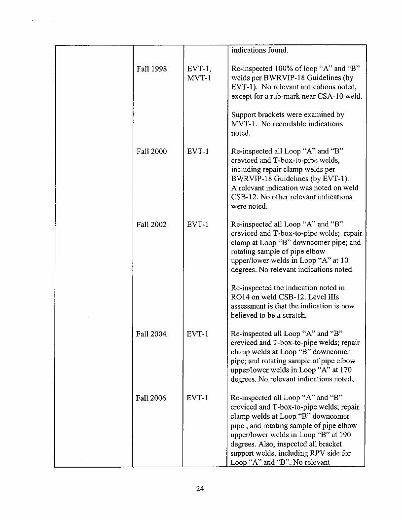
indications found.
Fall 1998. EVT-l1, Re-inspected 100% of loop "A" and "B".MVT- 1 welds per BW;RVIP- 18 Guidelines (by
EVT-1). No relevant indications noted,except for a rub-mark near CSA- 10 weld.
Support brackets were examined byMVT- 1. No recordable indicationsnoted.
Fall 2000 EVI- 1 Re-inspected all Loop. "A" and "B"creviced and T-box-to-pipe welds,including repair clamp. welds perBWRVIP- 18. Guidelines (by EVT- 1).,A relevant indication was noted on weldCSB-12. No. other relevant indicationswere noted.
Fall 2002 EVT-1 Re-inspected all Loop "A" and "B"creviced and T-box-to-pipe welds; repairclamp. at Loop. "B" downcomer pipe; androtating sample of pipe elbowupper/lower welds in Loop "A". at 10degrees.. No. relevant indications noted.
Re-inspected the indication noted inR0 14. on weld CSB- 12. Level IIlsassessment is that the indication is nowbelieved to be a scratch.
Fall 2004 EVT-1 Re-inspected all Loop "A". and "B"creviced and T-box-to-pipe welds; repairclamp welds at Loop "B" downcomerpipe; and rotating sample. of pipe elbowupper/lower welds in Loop, "A". at 170degrees. No. relevant indications noted.
Fall 2006. EVT-1 Re-inspected all Loop "A" and "B"creviced and T-box-to-pipe welds; repairclamp welds at Loop, "B" downcomerpipe, and rotating sample of pipe elbowupper/lower welds in Loop "B" at 190.degrees. Also, inspected all bracketsupport welds, including RPV side for
1Loop "A" and "B". No relevant
24

indications noted.4 4 +
Core Spray Sparger 1987 topresent
Fall 1998.
Fall 2000,
Fall 2002
Fall 2004
Fall 2006
VT-3,MVT-lI orEVT-l
EVT-1,MVT- 1
EVT-l
VT-i1
VT-I
EVT-1,and VT-I.
IEB. 80-13. of sparger and welds.. MVT-lIand EVT-l inspections per BVWRVIP-18in Fall, 1996. An indication characterizedas weld profile deficiency was recordedon spray nozzle D-28. Historical IVVIdata was reviewed and the indication waspreviously noted and dispositioned asacceptable.
Re-inspected 100% of sparger piping"A" and "B" welds per BWRVIP-l18Guidelines (EVT-1 /MVT- 1) includingtee boxes, end caps, drain welds, andsupport brackets. No relevant indicationsnoted.
No. inspections during R0 14
Re-inspected all T-box and end caps tosparger pipe welds at Loops "A", "B","C", and "D". No. relevant indicationsnoted.
Re-inspected. Sparger "C". and "D"nozzle welds, and supporting brackets at"A". and "B". No relevant indicationsnoted.
Re-inspected all sparger bracket supportwelds at "C". and "D". No. relevantindications noted.
Re-inspected by EVT-1. all T-box andend caps to pipe welds, and by VT- I allbracket welds at spargers "A", "B", "C"9& "D". Re-inspected by VT- 1, all nozzleand drain to sparger welds at spargers"A"9 & "B". No relevant indicationsnoted.
Top. Guide (Rim, etc.) 1988, 92 and VT-3, and 2 cells inspected in 1988. and in 1992; 494/95 EVT-l cells in 1994. Additional inspections
included, alignment wedges , hold downbolts, and rim welds at several locations
_________________I_ (EVT- I at rim welds in 94/95).. No.
25

relevant indications noted.
Fall 1998. N/A No inspections during R0 13
Fall 2000 VT-i1, and A total of 4 hold down assemblies wereVT-3 examined by VT- I and 3 alignment pin
assemblies by VT-3 per BWRVJP-26.Guidelines. No indications were noted.
Fall 2002 N/A No. inspections in ROI 15 and R0 16-and 2004
Fall 2006. VT-i and Inspected by VT- I hold-down assembliesVT-3 at 0. and 180 degrees (top only as below
top. guide is inaccessible). Inspectedsampling of top guide surfaces by VT-i/VT-3. Also, inspected aligner pins at 0and 180 degrees by VT-i.. No. relevant
________________ ____ ___ ___ _________ indications noted.
Core Plate (Rim, etc.). 1992 and 94 VT-3 Inspection at one core plate in 1992.Inspected approximately 25% of holddown bolting in 1994/95. No. relevantindications noted.
Fall 1998. VT-3 Inspected 100% of hold down bolting.No. relevant indications noted..
Fall 2000. VT-3. Inspected core plate plugs at 5. corelocations. No relevant indications noted.
Fall 2002 - No. inspections during R0 15.
Fall 2004 VT-3 Inspected a total of 6 core plate plugs (attwo. locations). No relevant indicationsnoted.
Fall 2006 VT3Inspected core plate plugs and thesurrounding core plate surface at fourLPRM locations. No relevant indicationsnoted.
SLC Fall 2000 EVT-2 Performed Enhanced VT-2 on SLCnozzle-to-safe end weld during RPV.System Leakage Test per BW~RVIP-27
_________________ ___________ _________Guidelines. Test was "Accepted".
26
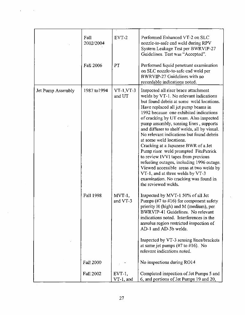
Fall EVT-2 Performned Enhanced VT-2 on SLC2002/2004 nozzle-to-safe end weld during RPV
System Leakage Test per BWRVIP-27Guidelines. Test was "Accepted".
Fall 2006 PT Performed liquid penetrant examinationon SLC nozzle-to-safe end weld perBWvRVJP-27 Guidelines with no
__________recordable indications noted.
Jet Pump Assembly 1987. to1994
Fall 1998.
Fall 2000
Fall 2002
VT-i ,VT-3and UT
MVT-1,and VT-3.
EVT-1,VT-i1, and
Inspected all riser brace attachmentwelds by VT-i. No relevant indicationsbut found debris at some weld locations..Have replaced all jet pump beams in1992 because one exhibited indicationsof cracking by UT exam. Also inspectedpump. assembly, sensing lines, supportsand diffuser to shelf welds, all by visual..No. relevant indications but found debrisat some weld locations.Cracking at a Japanese BWYR of a JetPump. riser .weld prompted FitzPatrickto review IVVI tapes from previousrefuieling outages, including 1996. outage.Viewed accessible areas at two welds byVT-i1, and at three welds by VT-3,examination. No cracking was found in.the reviewed welds.
Inspected by MVT- 1 5 0% of all JetPumps (#7. to # 16) for component safetypriority H (high). and M (medium), perBWRVJP-4i1 Guidelines. No relevantindications noted. Interferences in theannulus region restricted inspection ofAD-i1 and AD-3b welds.
Inspected by VT-3 sensing lines/bracketsat same jet pumps (47 to # 16). .Norelevant indications noted.
No. inspections during R0 14
Completed inspection of Jet Pumps 5. and6, and portions of Jet Pumps 19. and 20,
27
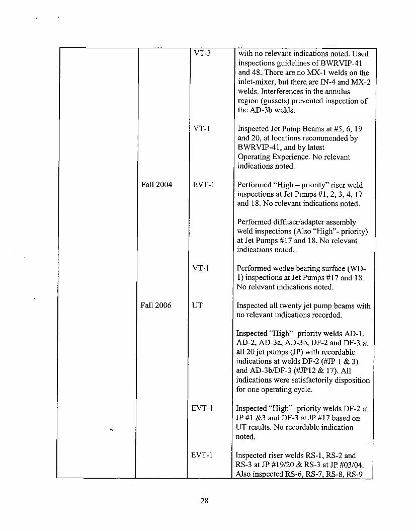
VT-3 with no relevant indications noted. Usedinspections guidelines of BWRVIP-41and 48.. There are no MX-1I welds on theinlet-mixer, but there are IN-4 and MX-2welds. Interferences in the annulusregion (gussets) prevented inspection ofthe AD-3b welds.
VT- I Inspected Jet Pump Beams at #5, 6, 19and 20, at locations recommended byBWRVIP-4 1, and by latestOperating Experience. No relevantindications noted.
Fall 2004 EVT- 1 Performed "High - priority". riser weldinspections at Jet Pumps #1, 2, 3, 4, 17and 18.. No. relevant indications noted..
Performed diffuser/adapter assemblyweld inspections (Also "High"-. priority)at Jet Pumps # 17. and 18. No. relevantindications noted..
VT- I Performed wedge bearing surface (WD-1) inspections at Jet Pumps #17. and 18.No. relevant indications noted.
Fall 2006. UT Inspected all twenty jet pump. beams withno relevant indications recorded.
Inspected "High"- priority welds AD-i1,AD-2, AD-3a, AD-3b, DF-2 and DF-3 atall 20 jet pumps (JP) with recordableindications at welds DF-2 (#JRP 1. & 3)and AD-3b/DF-3. (#JIP12 & 17)., Allindications were satisfactorily dispositionfor one operating cycle.
EVT- 1 Inspected "High"- priority welds DF-2 atJIP#I &3.and DF-3.at JP# 17 based onUT results. No recordable indicationnoted.
EVT- 1 Inspected riser welds RS- 1, RS-2 andRS-3 at JP. #19/20 & RS-3 at IP #03/04.,
IAlso, inspected RS-6, RS-7, RS-8. RS-9.
28
EVT-l
VT-i
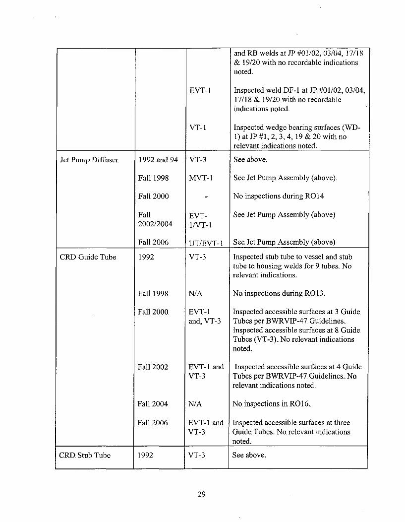
and RB. welds at JP #01/02, 03/04, 17/18& 19/20 with no. recordable indicationsnoted.
Inspected weld DF-1I at JP #01/02, 03/04,17/18 & 19/20. with no recordableindications noted.
Inspected wedge bearing surfaces (WD-1) at JP. #1, 2, 3,4, 19 &20 with norelevant indications noted.
4 1 1
Jet Pump Diffuser 1992 and 94
Fall 1998
Fall 2000
Fall2002/2004
Fall 2006
VT-3
MVT-1
EVT-1/VT-i
UTfEVT-1
See above.
See Jet Pump. Assembly (above).
No. inspections during R0 14
See Jet Pump. Assembly (above)
See. Jet Pump Assembly (above)
CRD. Guide Tube 1992
Fall 1998
Fall 2000
Fall 2002
Fall 2004
Fall 2006.
VT-3
N/A
EVT-1and, VT-3
EVT-lI andVT-3
N/A
EVT-1. andVT-3
Inspected stub. tube to. vessel and stubtube to housing welds for 9. tubes. Norelevant indications.
No. inspections during R0 13.
Inspected accessible surfaces at 3 Guide.Tubes per BWRVJP-47. Guidelines..Inspected accessible surfaces at 8. GuideTubes (VT-3). No relevant indicationsnoted.
Inspected accessible surfaces at 4 GuideTubes per BWRVJP-47. Guidelines.. No.relevant indications noted.
No inspections in R0 16-
Inspected accessible surfaces at threeGuide. Tubes. No. relevant indicationsnoted.
CRD Stub Tube 1992 VT-3 See above.
29
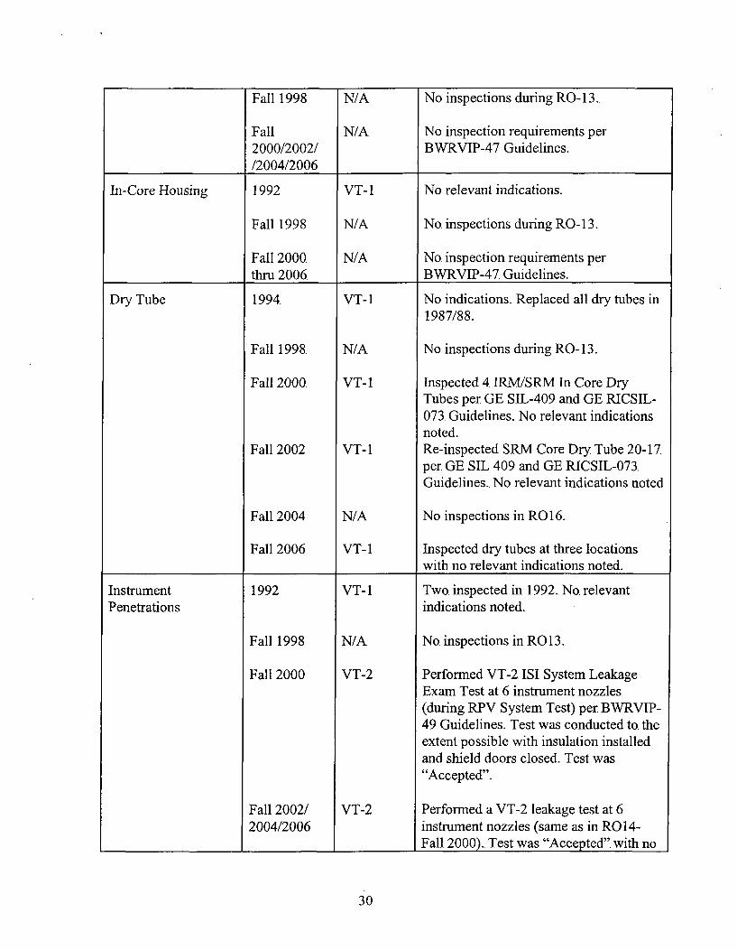
Fall 1998. N/A No inspections during RO- 13..
Fall N/A No. inspection requirements per2000/2002/ BWrRVIP-47 Guidelines./2004/2006 _____
In-Core Housing 1992 VT- I No relevant indications.
Fall 1998 N/A No. inspections duri ng RO- 13.
Fall 2000 N/A No. inspection requirements perthru 2006. BWRVIP-47. Guidelines.
Dry Tube 1994 VT-i No. indications. Replaced all dry. tubes in1987/88.
Fall 1998. N/A No. inspections during RO- 13.,
Fall 2000. VT-i I Inspected 4 IRM/SRM In Core DryTubes per GE SIL-409 and GE RICSIL-073, Guidelines. No relevant indicationsnoted.
Fall 2002 VT-i Re-inspected SRM Core Dry. Tube 20-17.per GE SIL 409 and GE RICSIL-073.Guidelines.. No relevant indications noted
Fall 2004. N/A No inspections in R0 16.
Fall 2006 VT-i Inspected dry. tubes at three locationswith no relevant indications noted.
Instrument 1992 VT-i Two inspected in i992.. No. relevantPenetrations indications noted..
Fall 1998. N/A No. inspections in R0 13.,
Fall 2000 VT-2 Performed VT-2 151 System LeakageExam Test at 6. instrument nozzles(during RPV System Test) per BWVRVIP-49 Guidelines. Test was conducted to. the.extent possible with insulation installedand shield doors closed. Test was"Accepted".
Fall 2002/ VT-2 Performed a VT-2 leakage test at 62004/2006 instrument nozzles (same as in ROl14-
________________ __________ _________Fall 2000).. Test was "Accepted". with no
30
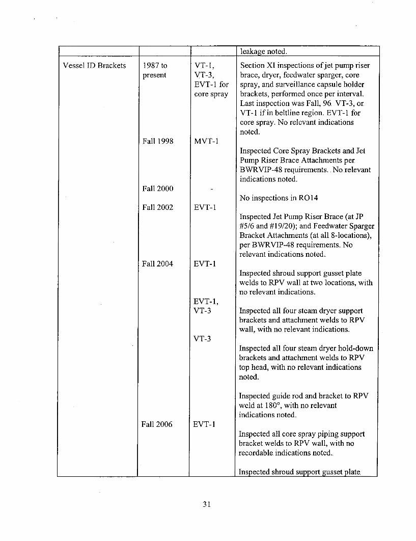
_ _ _ _ _ _I __I_ _ I leakage noted.
Vessel ID Brackets 1987 to.present
Fall 1998
Fall 2000
Fall 2002
Fall 2004
Fall 2006.
VT-i1,VT-3,EVT-1I forcore spray
MVT-1
EVT- 1
EVT-1
EVT- 1,VT-3
VT-3
EVT- 1
Section XI inspections of jet pump riserbrace, dryer, feedwater sparger, corespray, and surveillance capsule holderbrackets, performned once per interval.Last inspection Was Fall, 96. VT-3, orVT-i1 if in beltline region. EVT- 1 forcore spray. No relevant indicationsnoted.
Inspected Core Spray Brackets and JetPump Riser Brace Attachments perBWRVIP-48 requirements. .No. relevantindications noted.
No inspections in R014
Inspected Jet Pump Riser Brace (at JP#5/6. and # 19/20); and Feedwater SpargerBracket Attachments (at all 8-locations),per BWiRVIP-48 requirements. No.relevant indications noted..
Inspected shroud support gusset platewelds to. RPV wall at two. locations, withno relevant indications.
Inspected all four steam dryer supportbrackets and attachment welds to RPVwall, with no. relevant indications.
Inspected all four steam dryer hold-downbrackets and attachment welds to. RPVtop. head, with no relevant indicationsnoted.
Inspected guide rod and bracket to RPVweld at 1800, with no relevantindications noted.
Inspected all core spray piping supportbracket welds to RPV wall, with norecordable indications noted.
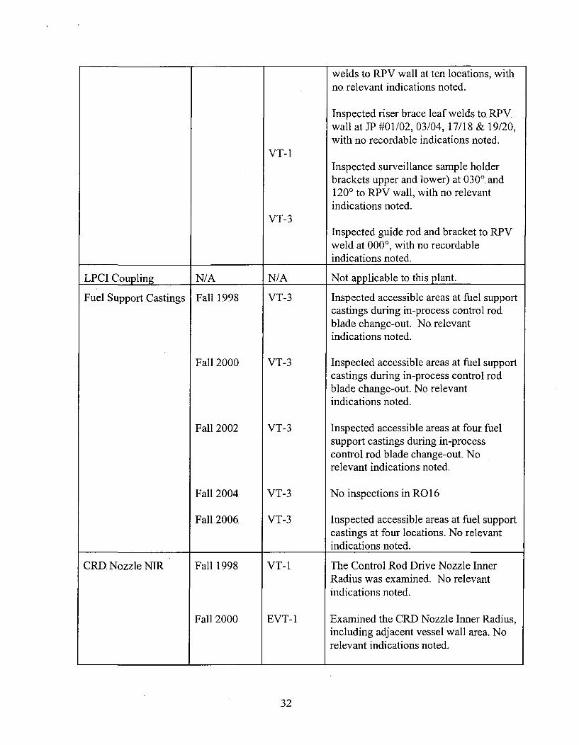
Inspected shroud support gusset plate
31
1 1 1
VT-i
welds to RPV wall at ten locations, withno. relevant indications noted.
Inspected riser brace leaf welds to. RPV.wall at JP #01/02, 03/04, 17/18, & 19/20,with no recordable indications noted.
Inspected surveillance sample holderbrackets upper and lower) at 0300. and1200 to. RPV wall, with no relevantindications noted.
Inspected guide rod and bracket to RPVweld at 0000, with no recordableindications noted.
VT-3
LPCI Coupling N/A N/A Not applicable to. this plant.
Fu el Support Castings Fall 1998 VT-3 Inspected accessible areas at fuel supportcastings during in-process control rodblade change-out. No. relevantindications noted.
Fall 2000 VT-3 Inspected accessible areas at fuel supportcastings during in-process control rodblade change-out. No relevantindications noted.
Fall 2002 VT-3 Inspected accessible areas at four fuelsupport castings during in-processcontrol rod blade change-out.. Norelevant indications noted.
Fall 2004. VT-3 No. inspections in RO 16
Fall 2006. VT-3 Inspected accessible areas at fuel supportcastings at four locations. No. relevantindications noted.
CRD Nozzle NIR Fall 1998. VT- I The Control Rod Drive Nozzle InnerRadius was examined. No relevantindications noted.
Fall 2000 EVT- 1 Examined the CRD Nozzle Inner Radius,including adjacent vessel wall area. Norelevant indications noted.
32

Fall 2002, I N/A No. inspections in R15, R16. and R17.12004 & 20061
Steam Dryer Fall 1998 VT-3 Inspected 25% of shroud head bolts atMoisture Separator storage pit. No relevant indications
noted.
Fall 2000. VT-3 and Re-inspected by VT-3 all areas of theEVT- 1 steam dryer support ring and by EVT- 1
previously found cracks (1992/1994). Atotal of 10. indications were noted in2000 (R01I4),with no. discernablechanges from previous inspection.
Fall 2004. VT-i1 and Inspected steam dryer integrity per SILVT-3 644 Supplement 1 (steam dryer integrity)
and INPO GE 18796 (steam dryer hoodcrack and tie. bar recordable visualindications), guidelines. Two relevantindications areas were noted. Theseindications resulted in expanded scope.with additional brushing and evaluations.These indications are in the HAZ ofvibration block welds and at a drainchannel. All indications weresatisfactorily dispositions by.calculations. Plans are to. re-inspect theindications in R0 17.
Inspected steam dryer hold-downs andsupport brackets and attachment weldswith no relevant indications noted.
VT-3 Inspected steam separator lifting rod eye.assemblies, and 25% of shroud headbolts with no. relevant indications noted.
Fall 2006. VT-i Inspected selected welds on the steamdryer (per requirements of BWvRVP- 139.over those recommended by SIL 644). Arelevant indication was noted at theintersection of H-2 and V-7. welds (SWquadrant), and the weld was grind outand repaired in R 17.
Inspected previous relevant indications
33
Surveillance CapsuleSpecimen Holder
Lower Plenum
Feedwater Sparger
Fall 2000
Fall 2006.
Fall 2000
Fall 2002,2004 & 2006.
Fall 2002
Fall 2004 &2006
VT- I andVT-3
VT- I
VT-3
VT-i
VT-3
VT-i
UT
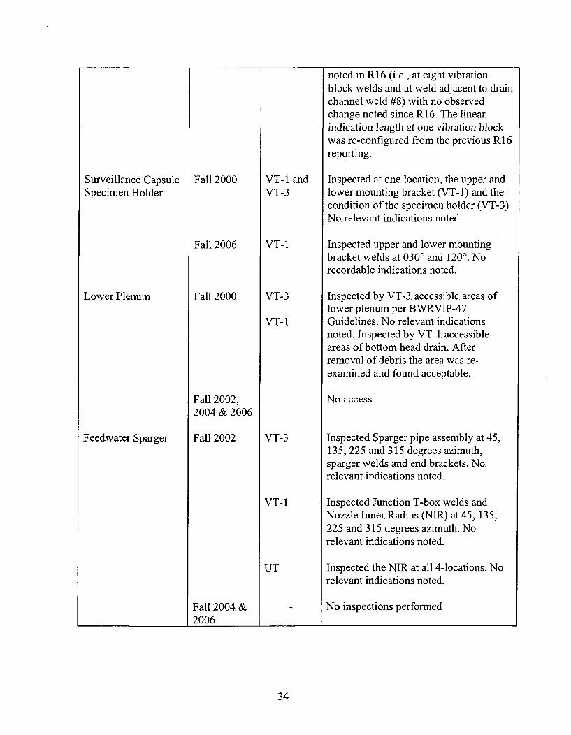
noted in R 16. (i.e., at eight vibrationblock welds and at weld adjacent to drainchannel weld #8) with no observedchange. noted since R 16. The linearindication length at one vibration blockwas re-configured from the previous R16reporting.
Inspected at one location, the upper andlower mounting bracket (VT-i) and thecondition of the specimen holder (VT-3)No. relevant indications noted.
Inspected upper and lower mountingbracket welds at 0300 and 120'. No.recordable indications noted.
Inspected by VT-3. accessible. areas oflower plenum per BWvRVIP-47.Guidelines. No relevant indicationsnoted. Inspected by VT-i1. accessibleareas of bottom head drain.. Afterremoval of debris the area was re-examined and found acceptable.
No access
Inspected Sparger pipe assembly at 45,135, 225. and 315 degrees azimuth,sparger welds and end brackets. No.relevant indications noted..
Inspected Junction T-box welds andNozzle Inner. Radius (NIR). at 45, 135,225. and 315. degrees azimuth. No.relevant indications noted.
Inspected the NTR at all 4-locations. No.relevant indications noted.
No. inspections performed
34

Reactor Internals Inspection History
Plant: Oyster Creek Generating~ Station
Components in JDate or fInspection Summarize the Following Information:.BWR VIP Scope Frequency of Method Inspection Result, Repairs,
Inspection Used Replacements, Reinspections
Steam Dryer Fall 2006 Visual Re-inspect Steam Dryer Indicationsidentified during previous outages.
EVT- 1 cracks in hold-down area from1R19.
VT- I all 4 lifting lugs and EVT-1.indications on 135 deg. lug.
BWVVRVIP- 13 9 required inspections (top.side) completed. New fatigue indicationswere identified that required repair.Dryer repair project completed with 2areas stop. drilled and one crack in center
________________ __________baffle plate was cut out.
Core Shroud Fall 2006 EVT- 1 V-9 inspection of ID and OD. Twohorizontal indications (transverse. to theweld). were found adjacent to. verticalweld on the ID surface. The. indicationswere 2.75. and 1 inch in length and 30and 35. inches above horizontal weld H5.A technical evaluation was completed to,use-as-is.
VT-3 Tie-Rods at 170 deg, 220 deg and3 10 deg.. No. findings.
VT-i. of Upper Bracket to Shroud Ledgeinterface on all 10. Tie Rods. No findings.
Fall 2004 None No Examinations Required.
Fall 2002 None No Examinations Required.
Fall 2000 EVT-l V-3, V-4, V-i15 and V- 16. This was aone sided exam from the GD.. No.
____ ___ ____ ___ ___ ___ ___findings.
35
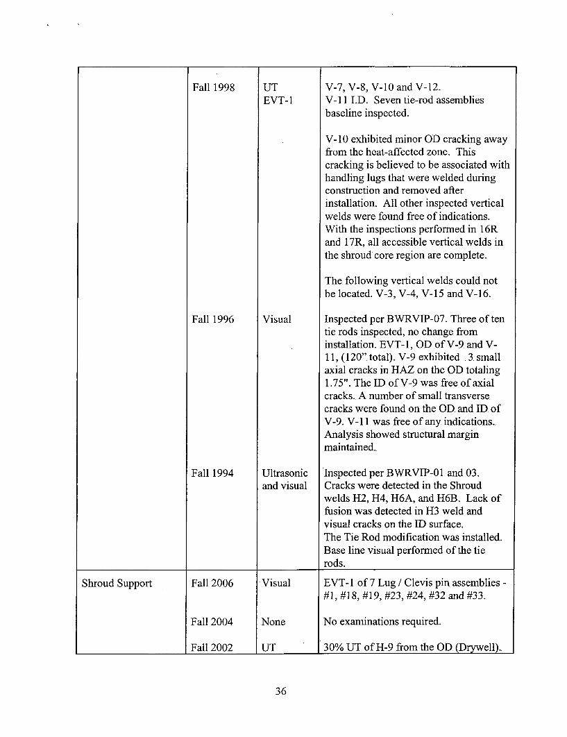
Fall 1998 UT V-7, V-8, V-10 and V-12.EVT-1 V-1l.1.1). Seven tie-rod assemblies
baseline inspected.
V-10 exhibited minor GD cracking awayfrom the heat-affected zone. Thiscracking is believed to be associated withhandling lugs that were welded duringconstruction and removed afterinstallation. All other inspected verticalwelds were found free of indications.With the inspections performed in 16Rand 17R, all accessible vertical welds inthe shroud core region are complete..
The following vertical welds could notbe located. V-3, V-4, V-i15 and V- 16.
Fall 1996, Visual Inspected per BWRVIP-07. Three of tentie rods inspected, no. change frominstallation. EVT- 1, GD of V-9 and V-11, (120". total). V-9 exhibited .3. smallaxial cracks in HAZ on the GD totaling1.75". The ID of V-9 was free of axialcracks.. A number of small transversecracks were found on the GD. and ID. ofV-9., V-il1. was free of any indications.Analysis showed structural marginmaintained..
Fall 1994. Ultrasonic Inspected per BWRVIP-01. and 03.and visual Cracks were detected in the Shroud
welds H2, H4, 116A, and H6B.. Lack offusion was detected in H3 weld andvisual cracks on the mD surface.The Tie Rod modification was installed.Base line visual performed of the tie
Irods.
Shroud Support Fall 2006 Visual EVT- 1. of 7 Lug / Clevis pin assemblies -
#1, #18, #19, #23, #24, #32 and #33.
Fall 2004 None No examinations required.
_____________Fall 2002 UT 30% UT of H-9 from the GD. (Drywell)..
36
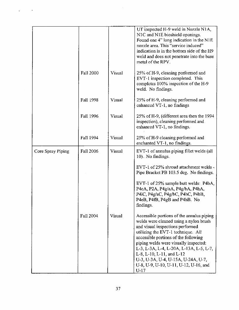
UT inspected H-9 weld in Nozzle NIA,Ni1C and NlIE bioshield openings.Found one 4" long indication in the N IEnozzle. area. This "service induced"indication is in the bottom side of the H9weld and does not penetrate into the basemetal of the RPV.
Fall 2000 Visual 25% of H-9, cleaning performed andEVT-1 inspection completed. Thiscompletes 100% inspection of the H-9weld. No findings.
Fall 1998 Visual 25% of H-9, cleaning performned andenhanced VT-i, no findings
Fall 1996. Visual 25% of H-9, (different area then the 1994inspection), cleaning performned andenhanced VT-i, no findings.
Fall 1994 Visual 25% of H-9. cleaning performed and_______________enchanted VT-i, no findings.
Core Spray Piping Fall 2006. Visual EVT- 1 of annulus piping fillet welds (all10). No. findings.
EVT- 1. of 25% shroud attachment welds -
Pipe Bracket PB 103.5 deg. No findings.
EVT- 1. of 25% sample butt welds:. P4bA,P4cA, P2A, P4g/aA, P4g/bA, P4hA,P4iC, P4g/aC, P4g/bC, P4hC, P4bB,P4eB, P4fB, P4gB and P4hB. No.findings.
Fall 2004 Visual Accessible portions of the annulus pipingwelds were cleaned using a nylon brushand visual inspections performedutilizing the EVT- 1 technique.. Allaccessible portions of the followingpiping welds were visually inspected:L-3, L-3A, L-4, L-20A, L-13A, L-5, L-7,L-8, L-10, L-1 1, and L-12U-3, U-3A, U-4, U-iSA, U-24A, U-7,U-8, U-9, U-i10, U-li1, U- 12, U- 16, andU- 17
37
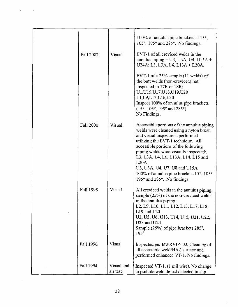
100% of annulus pipe brackets at 150,1050. 195' and 2850. No findings.
Fall 2002 Visual EVT-l1. of all creviced welds in theannulus piping =U3, U3A, U4, UlISA +U24A; L3, L3A, L4, L13A + L20A.
EVT-lI of a 25% sample (11I welds). ofthe butt welds (non-creviced) notinspected in 17R or 18R:Ul,U15,U1 7,U1 8,U19,U20L1,L9,L13,L16,L20Inspect 100% of annulus pipe brackets(150, 1050, 1950 and 2850)
No. Findings.,
Fall 2000 Visual Accessible portions of the annulus pipingwelds were cleaned using a nylon brushand visual inspections performedutilizing the EVT- 1 technique. Allaccessible portions of the followingpiping welds were visually inspected:.L3, L3A, L4, L6, Ll3A, L14, L15 andL20AU3, U3A, U4, U7, U8 and U15A100% of annulus pipe brackets 150, 1050195 0 and 28 50.. No. findings.
Fall 1998. Visual All creviced welds in the annulus piping;sample, (25%) of the non-creviced weldsin the annulus piping:.L2, L9, L10, LlIi, L12, L13, L17, L18,L 19. and L20U2, U5, U6, U1 3, U1 4, U1l5, U2 1, U22,U23. and U24Sample (25%). of pipe brackets 2850,1950
Fall 1996 Visual Inspected per BWfRVIP- 03. Cleaning ofall accessible weldIHAZ surface andperformed enhanced VT-i. No findings.
Fall 1994 Visual and Inspected VT-l, (1 mil wire). No. change________________air test Ito pinhole, weld defect detected in slip
38
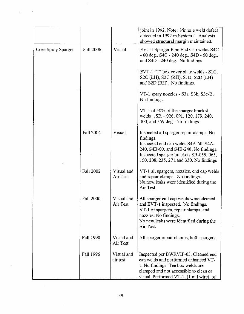
joint in 1992. Note: Pinhole weld defectdetected in 1992 in System L. Analysisshowed structural margin maintained.
1- -t
Core Spray Sparger Fall 2006
Fall 2004
Fall 2002
Fall 2000
Fall 1998.
Fall 1996.
Visual
Visual
Visual andAir Test
Visual andAir Test
Visual andAir Test
Visual andair test
EVT- 1 Sparger Pipe End Cap. welds 54C.- 60 deg., S4C - 240 deg., S41) - 60. deg.,and S41) - 240 deg. No findings.
EVT- 1 "T" box cover plate welds - S IC,52C (LH), 52C (RH), SiD, S21) (LH)and S21) (RH). No. findings..
VT-i. spray nozzles - 53a, 53b, S3c-B.No findings.
VT- I of 50% of the sparger bracketwelds - SB. - 026, 091, 120, 179, 240,300, and 359 deg. No findings.
Inspected all sparger repair clamps. Nofindings.Inspected end cap. welds 54A-60, 54A-240, 54B-60, and S413-240. No. findings.Inspected sparger brackets SB-055, 065,150, 208, 235, 271. and 330. No findings
VT-i1 all spargers, nozzles, end cap. weldsand repair clamps. No findings..No. new. leaks were identified during theAir Test.
All sparger end cap. welds were. cleanedand EVT- 1. inspected.. No. findings.VT-i1 of spargers, repair clamps, andnozzles.. No. findings.No. new. leaks were identified during the.Air Test..
All sparger repair clamps, both spargers.
Inspected per BWRVIP-03. Cleaned endcap. welds and performed enhanced VT-1. No findings. Tee, box welds areclamped and not accessible to clean orvisual. Performed VT-i, (1. nuil wire), of
39

Fall 1994
1978 -1980.
Visual andAir Test
Visual
sparger piping and nozzles. No. findings.
Perfonmed VT-i, (1 mil wire) of spargerpiping and nozzles. No findings.
(2) Cracks in sparger piping. Repairclamps installed.Note: Cracking found in sparger. in1978; repaired with clamps. Sparger hasbeen inspected and air tested everyoutage since then; report submitted to,NRC for approval for restart everyoutage.
I I
Top, Guide Fall 2006.
Fall 2004
Fall 2002
Fall 2000.
Fall 1998
Fall 1996.
Visual
Visual
Visual
Visual
None.
Ultrasonic
EVT- 1 of selected known flaws in gridbeamis:. #4, VT-3 and VT-6. One. areashowed no growth, while the other two,had grown between 0.25" and 0.75". fromthe 2002 outage to the 2006. outage.. Aflaw evaluation was performed to use-as-is.
VT- I of top. guide hold down bolts at 303.and 123. degrees. No. findings.EVT- 1 of VT-6. crack showed nomeasurable growth. Could not visuallylocate two other existing UT. indications.
EVT- 1 of two existing cracks measuredin 1 8R outage. (#3. and #5).. No change. tocrack length identified.
Top guide hold down bolt assembly.VT-3. at 330 and 2130.Top. guide. beam to rim fillet welds VT- Iat 330 and 2130.. No. findings..
VT-i1 of two existing cracks (#3 and #5)with cleaning. Both cracks measured onboth sides. Crack #5 showed approx. 1",growth. Crack #3 showed no measurablegrowth.
Not required for this outage. by analysis..
12 indications emanating from notches
40
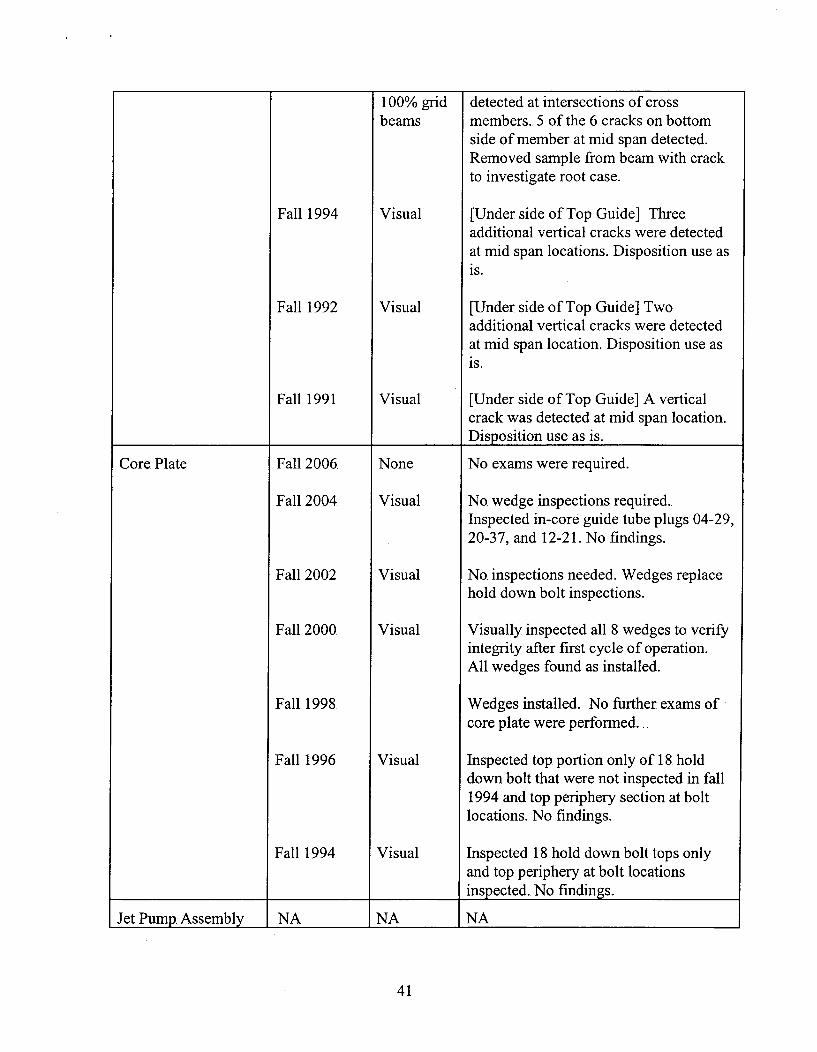
100% grid detected at intersections of crossbeams members. 5 of the 6 cracks on bottom
side of member at mid span detected.Removed sample from beam with crackto investigate root case.
Fall 1994 Visual [Under side of Top Guide] Three.additional vertical cracks were detectedat mid span locations. Disposition use asis.
Fall 1992 Visual [Under side of Top Guide] Twoadditional vertical cracks were detectedat mid span location. Disposition use asis.
Fall 1991 Visual [Under side of Top Guide] A verticalcrack was detected at mid span location.
_________________ __________ __________ Disposition use as is.
Core Plate Fall 2006. None No. exams were required.
Fall 2004 Visual No. wedge inspections required.Inspected in-core guide tube plugs 04-29,20-37, and 12-21. No findings.
Fall 2002 Visual No. inspections needed. Wedges replacehold down bolt inspections.
Fall 2000 Visual Visually inspected all 8 wedges to. verifytintegrity after first cycle of operation.All wedges found as installed.
Fall 1998. Wedges installed. No further exams ofcore plate were performed..
Fall 1996 Visual Inspected top. portion only of 18. holddown bolt that were not inspected in fall1994 and top periphery section at boltlocations. No findings.
Fall 1994 Visual Inspected 18 hold down bolt tops onlyand top periphery at bolt locationsinspected.. No findings.
Jet Pump. Assembly I NA I NA I NA,
41
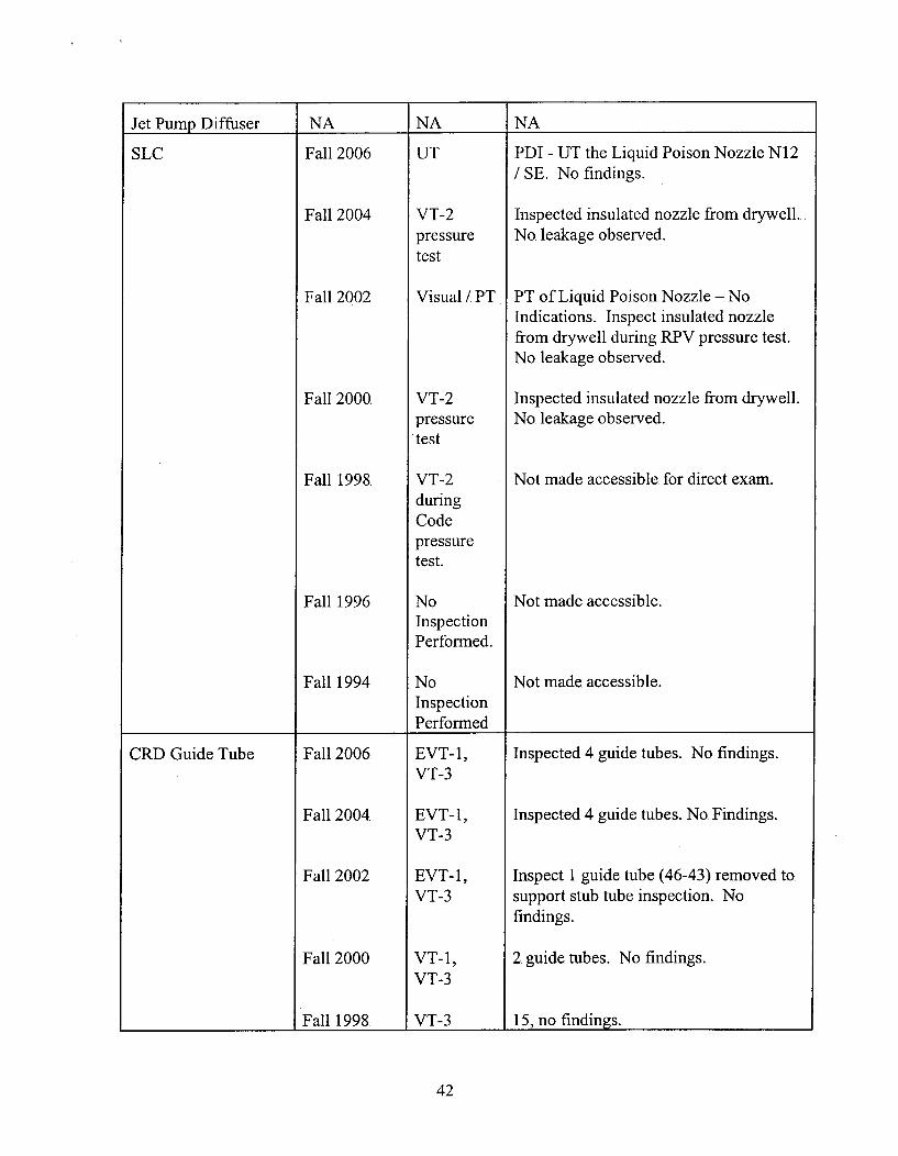
Jet Pump Diffuser INA I NA INA
SLC Fall 2006
Fall 2004
Fall 2002
Fall 2000
Fall 1998.
Fall 1996
Fall 1994
UT
VT-2pressuretest
Visual / PT
VT-2pressuretest
VT-2duringCodepressuretest.
NoInspectionPerformed.
NoInspectionPerformed
PDI - UT. the Liquid Poison Nozzle N12/ SE. No. findings.
Inspected insulated nozzle from drywell.No. leakage observed.
PT of Liquid Poison Nozzle - NoIndications. Inspect insulated nozzle.from drywell during RPV pressure test.No. leakage observed.
Inspected insulated nozzle from drywell.No. leakage observed.
Not made accessible. for direct exam.
Not made accessible.
Not made accessible.
1 4 4
CRD. Guide Tube Fall 2006.
Fall 2004
Fall 2002
Fall 2000
Fall 1998.
EVT- 1,VT-3
EVT-1,VT-3
EVT-l,VT-3
VT-i,VT-3
VT-3
Inspected 4 guide tubes. No findings.
Inspected 4 guide tubes. No. Findings..
Inspect 1 guide tube (46-43) removed to.support stub tube inspection. Nofindings.
2 guide tubes. No findings.
15, no. findings..
42
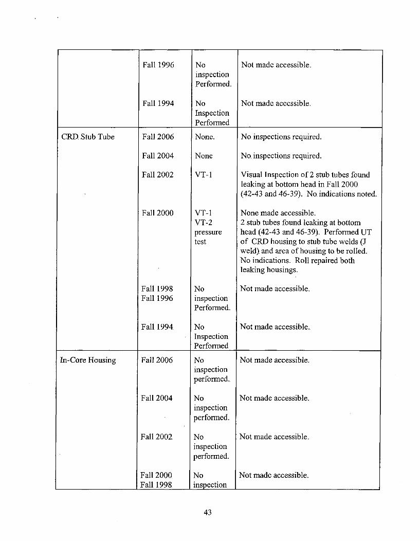
Fall 1996. No Not made accessible.inspectionPerformned.
Fall 1994 No Not made accessible.Inspection
___________Performned
CRD. Stub Tube Fall 2006 None. No inspections required.
Fall 2004 None No inspections required.
Fall 2002 VT-i Visual Inspection of 2 stub. tubes foundleaking at bottom head in Fall 2000.(42-43. and 46-39). No. indications noted.
Fall 2000 VT- I None made accessible.VT-2 2 stub tubes found leaking at bottompressure head (42-43 and 46-3 9). Performed UTtest of -CRD housing to stub tube welds (J
weld). and area of housing to. be rolled..No. indications.. Roll repaired bothleaking housings.
Fall 1998 No Not made accessible.Fall 1996 inspection
Performed..
Fall 1994 No Not made accessible.InspectionPerform-ed
In-Core Housing Fall 2006 No Not made accessible..inspectionperformed.
Fall 2004 No Not made accessible.inspectionperformed.
Fall 2002 No Not made accessible.inspectionperformed.
Fall 2000 No Not made accessible.________________Fall 1998 inspection I__________________
43
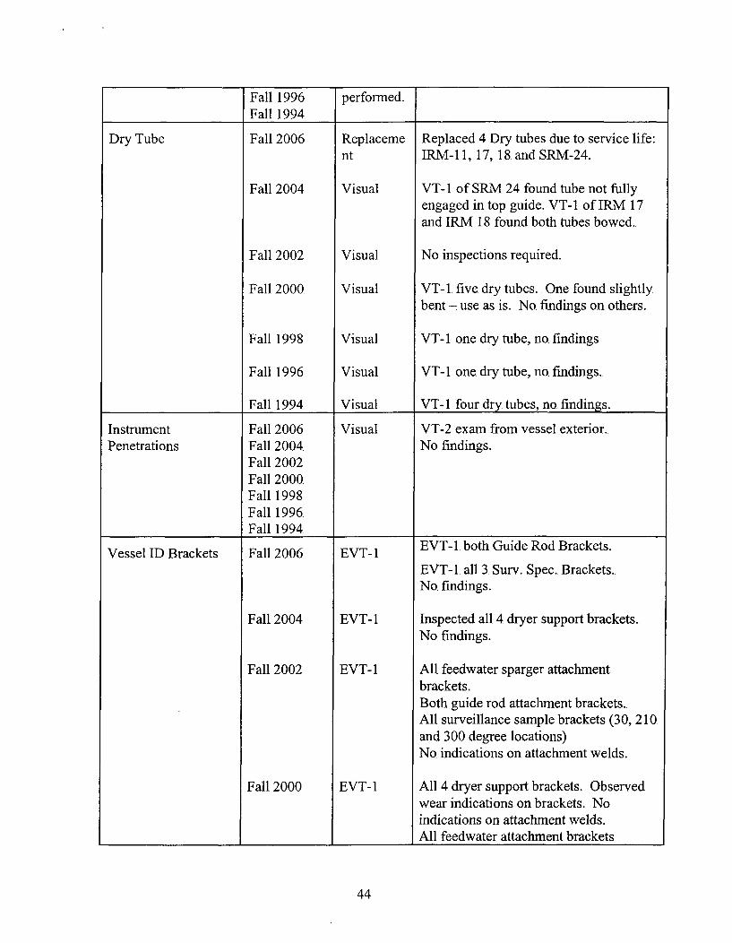
Fall 1996 performed.______ _____ _____ Fall 1994 _ _ _ _ _
Dry Tube Fall 2006 Replacemne Replaced 4 Dry tubes due to service life:nt IRM-i11, 17, 18. and SRM-24.
Fall 2004 Visual VT- I of SRM 24 found tube not fullyengaged in top guide. VT- I of IRM 17and IRM 18 found both tubes bowed.
Fall 2002 Visual No, inspections required.
Fall 2000. Visual VT-i. five dry tubes. One found slightly
bent - use. as is. No. findings on others.
Fall 1998 Visual VT- I one dry tube, no findings
Fall 1996 Visual VT- I one dry tube, no findings.,
Fall 1994 Visual VT-i1 four dry tubes, no. findings.
Instrument Fall 2006 Visual VT-2 exam from vessel exterior.Penetrations Fall 2004. No. findings.,
Fall 2002Fall 2000Fall 1998Fall 1996.Fall 1994.
Vessel ID Brackets Fall 2006. EVT-1 EVT-1. both Guide Rod Brackets.EVT-1. all 3. Surv. Spec.. Brackets.No. findings.,
Fall 2004 EVT- 1 Inspected all 4 dryer support brackets.No findings.
Fall 2002 EVT- 1 All feedwater sparger attachmentbrackets.Both guide rod attachment brackets..All surveillance sample brackets (3 0, 210and 300. degree locations)No. indications on attachment welds.
Fall 2000 EVT-1 All 4 dryer support brackets. Observedwear indications on brackets. No.indications on attachment welds.All feedwater attachment brackets
44

inspected. No indications on attachmentwelds.Cracks observed on feedwater sparger toend bracket welds (non-safety-relatedcomponent) on 2 ends.
Fall 1998 VT- I VT- I of accessible portions of weld onFall 1996. guide rod brackets, steam dryer brackets,Fall 1994 surveillance sample brackets. All
__________ ________attachment welds; no findings..
LPCI Coupling NA NA NA
Fuel Support Casting Fall 2006 Visual None inspected.
Fall 2004 Visual None inspected.
Fall 2002 Visual None inspected.
Fall 2000 Visual VT-3. (2). support casting. No findings.
Fall 1998 Visual VT-3. (24) support castings. No. findings.
Fall 1996 Visual VT-3 (25). support castings. No. findings.
_____________Fall 1994 Visual IVT-3. (17). support castings. No. findings.Note: All indications left "as is" were analyzed and structural margins were acceptable
for continued service..
45

Reactor Internals Inspection History
Plant: Peach Bottom Atomic Power Station, Unit 2
Components in Date or Inspection Summarize the Following Information:BWRVIP Scope Frequency of Method Inspection Results, Repairs,
_______________Inspection Used Replacements, Reinspections
Core Shroud 1994
1996
2002
UT & VT
UT
UT
Comprehensive UT Baseline of someCategory "C" circumferential welds(H-2, H-3, H-4, and H-5) per BWRVIP-01, Rev. 0.Partial UT baseline of welds H-i1, H-6,and H-7, w/ partial EnhancedVT- I of H-6. GD.Exams per BWiR-VIP Core Shroud NDEUncertainty and Procedure Standard,dated November 21, 1994.Indications identified on ID of H-i, H-3,H-4, and H-6, and GD of H-4 and H-5.Full structural margins calculated usingtwo cycles of crack growth forcomprehensively examined welds, onecycle for welds with limited exams.No indications identified on H-2 andH-7.
Comprehensive UT of welds H-1, H-6and H-7. per BWRVIIP-0 1, Rev. 1.Exams per BW;RVIP-03.Indications identified on ID of welds H-1, H-6 and H-7, on GD of weldH-1.Full structural margins calculated usingtwo cycles of crack growth.
Reexaminations planned per BWRVIP-76
Comprehensive UT of welds H- I throughH-7. per BW;RVIP-76.Indications identified on each weld.UT of Vertical welds V-i through V-4.No indications identified.Reexamninations scheduled per BVWRVIP-76.
46
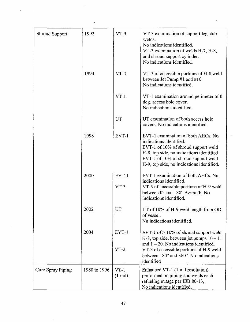
Shroud Support 1992 VT-3 VT-3 examination of support leg stubwelds.No. indications identified.VT-3. examination of welds H-7, H-8,and shroud support cylinder.No. indications identified.
1994 VT-3 VT-3. of accessible portions of H-8 weldbetween Jet Pump. #1 and #10.No indications identified.
VT-I VT- I examination around perimeter of 0deg.. access hole cover.No. indications identified.
UT UT. examination of both access holecovers. No. indications identified.
1998 EVT-1 EVT-1I examination of both AHCs. Noindications identified.EVT- 1 of 10% of shroud support weldH-8, top. side, no. indications identified.EVT- 1 of 10% of shroud support weldH-9, top side, no indications identified.
2000 EVT-1 EVT-1. examination of both AHCs. No.indications identified.
VT-3 VT-3. of accessible portions of H-9. weldbetween 00 and 1800. Azimuth. Noindications identified.
2002 UT UT of 10% of H-9. weld length from OD.of vessel.No indications identified.
2004 EVT-l EVT-1. of > 10% of shroud support weldH-8, top. side, between jet pumps 10 -11.and 1. - 20. No indications identified.
VT-3 VT-3. of accessible. portions of H-9 weldbetween 1800 and 3600. No indicationsidentified
Core. Spray Piping 1980 to 1996 VT- I Enhanced VT- I (1 mil resolution)(1mi), performed on piping and welds each
refueling outage per LEB. 80-13,_______________ _________ ________ No. indications identified.
47
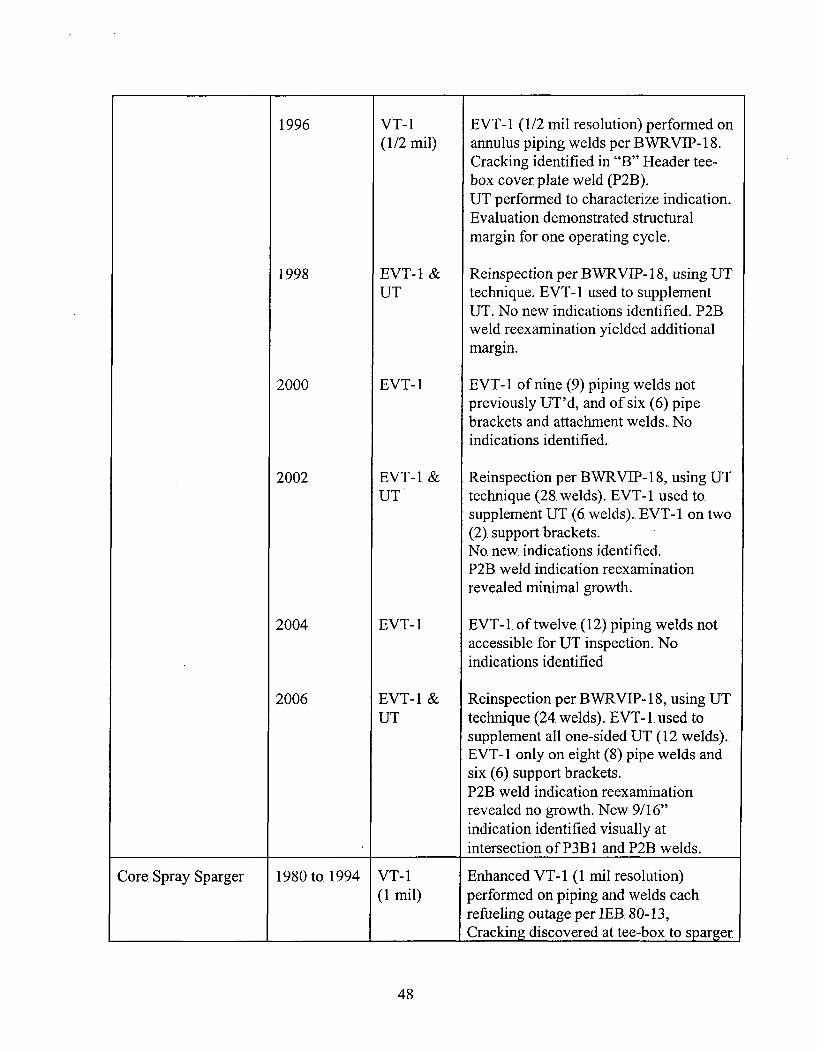
1996 VT- I EVT-1 (1/2 mil resolution) performed on(1 /2 mi ) annulus piping welds per BWRVIP- 18-
Cracking identified in "B" Header tee-box cover plate weld (P2).UT performned to characterize indication.Evaluation demonstrated structuralmargin for one operating cycle.
1998 EVT- 1 & Reinspection per B WRVIP- 18, using UTUT technique. EVT-1I used to supplement
UT. No new indications identified. P2B.weld reexamination yielded additionalmargin.
2000 EVT-1 EVT-1I of nine (9) piping welds notpreviously UT'd, and of six (6) pipebrackets and attachment welds. Noindications identified.
2002 EVT- 1 & Reinspection per BWRVIP- 18, using UTUT technique (28. welds). EVT- 1 used to.
supplement UT (6. welds). EVT-1I on two(2). support brackets..No. new indications identified.P2B. weld indication reexaminationrevealed minimal growth.
2004 EVT-l EVT- 1. of twelve (12). piping welds notaccessible for UT. inspection. No.indications identified
2006 EVT- 1 & Reinspection per BWR VIP- 18, using UTUT technique (24 welds). EVT- 1. used to
supplement all one-sided UT (12. welds).EVT-1I only on eight (8) pipe welds andsix (6). support brackets.P2B. weld indication reexaminationrevealed no growth. New 9/16"indication identified visually atintersection of P3B 1 and P2B. welds.
Core Spray Sparger 1980 to.1994 VT-i Enhanced VT-i1 (1 mil resolution)I refueling outage per IEB 80-13,
________________ ___________________Cracking discovered at tee-box to sparger
48
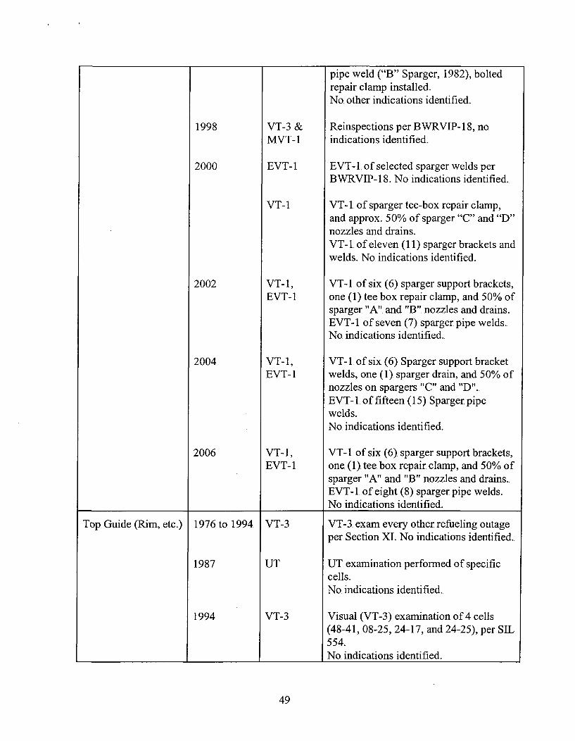
pipe weld ("B" Sparger, 1982), boltedrepair clamp installed.No. other indications identified.
1998 VT-3 & Reinspections per B WRVIP- 18, no.MVT-i indications identified.
2000 EVT-i EVT-i. of selected sparger welds perBWRVIP- 18. No indications identified..
VT- I VT-i. of sparger tee-box repair clamp,and approx. 50% of sparger "C"9 and "D"nozzles and drains.VT-i1. of eleven (11) sparger brackets andwelds. No. indications identified.
2002 VT-i1, VT-i. of six (6) sparger support brackets,EVT-i one (1) tee box repair clamp, and 50% of
sparger "A". and "B". nozzles and drains.EVT-i. of seven (7) sparger pipe welds..No. indications identified.
2004 VT-i, VT- I of six (6) Sparger support bracketEVT-i welds, one (1) sparger drain, and 50% of
nozzles on spargers "C" and "D"..EVT- 1. of fifteen (i5) Sparger pipewelds.No. indications identified.
2006 VT-i, VT-i. of six (6) sparger support brackets,EVT-i one (1). tee box repair clamp, and 50% of
sparger "A" and "B". nozzles and drains..EVT-i. of eight (8) sparger pipe welds..
_______________ __________No indications identified.
Top. Guide (Rim, etc.) 1976. to. 1994 VT-3 VT-3. exam every other refueling outageper Section XI. No indications identified..
1987 UT UT. examination perfonned of specificcells.No. indications identified.
1994 VT-3 Visual (VT-3) examination of 4 cells(48-41, 08-25, 24-17, and 24-25), per SIL554.No. indications identified.
49

1996 VT-3 Visual (VT-3) of 2 aligner pins (0 deg.And 270 deg.), per SIL 588.
___________No indications identified.
Core Plate (Rim, etc.) 1996 VT-3 VT-3. examination of all accessible holddown bolts (cell 16-57, and area at 0 and270 deg. Azimuth.
________________ __________ _________ No indications identified.
SLC 1992 PT Surface (PT) examination of nozzle to.safe end weld per Section XI.No. indications identified.
1998 PT & UT PT and UT ofNl10 nozzle to safe-end, no.indications identified.
2002 PT Extended dwell time Liquid Penetrantexamination of entire safe end.No indications identified.
2006 PT Extended dwell time Liquid Penetrantexamination of entire safe end..No indications identified.
Jet Pump Assembly 1976 -1996 VT-3 Visual VT-3 of all jet pump. componentsperformed every other refueling outage..
1981 VT & UT VT and UT examination performed on all20. hold down beams. No. indicationsidentified..
1994 VT Restrainer bracket wedge misalignmentand wear identified on several wedges..Evaluations found condition acceptablewithout repair.One restrainer bracket set screw tackweld found cracked.. Evaluations foundcondition acceptable without repair.
1996 VT Restrainer bracket wedge conditions andset screw tack welds remain unchanged,condition acceptable without repair.
1998 MVT-l MVT-lI of:. RS-1I weld on all 10 risers,RS-2 & RS-3. welds on 6 of 10 risers. No.
__________ _________indications identified.
50

UT UT of all 20 hold down beams. Noindications identified.
2000 EVT-1 EVT-1 of adjusting screw tack weld (jetpump 7) and RS-2 & RS-3 on 5. of 10risers. No indications identified.
2002 EVT-1 EVT-1. of fifty (50) Medium priorityweld locations.EVT-1. of transition region of two (2)hold down beams.No indications identified
2004 EVT-1 EVT-l. of forty one (41) medium prioritywelds, to complete 50% baselineinspections. No indications identified.
UT UT performed on all twenty (20) holddown beams(3 zones, BB-1, BB-2, and BB-3).. No.indications identified.
VT- I VT- I on all twenty (20) Inlet Mixer mainwedges. Thirteen (13) jet pumpsexhibited additional wear at main wedge-to-restrainer bracket interface. Performedexpanded scope of inspections on thesejet pumps.. Set screw gaps identified atfive (5). jet pumps. No additionalproblems identified. Installed eight (8).slip joint clamps and three (3) set screwauxiliary spring wedges, to. mitigate wearbelieved to be caused by vibration.
2006 VT-i, VT-i. of twenty (20) WD-1 locations.EVT- 1, EVT- 1 of five (5) lN-4 welds, and two.VT-3 (2). riser braces-to-vessel attachment
welds.. VT-3. of eight (8) Slip JointClamps and three (3) Auxiliary SpringWedges.. Expanded EVT- I scope onthree (3) jet pumps due to WD-1I
Ifindings.
Jet Pump. Diffuser 1998, MVT-1 MVT- 1 of:. AD- I & AD-2 welds on 12 of20 pumps, AD-3A & B welds on 11 of20 pumps, and DF-2 weld on 10 of 20pumps. No indications identified.
51
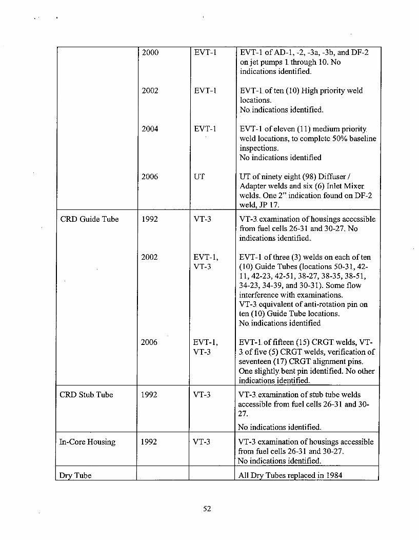
2000 EVT-1 EVT- 1 of AD-i1, -2, -3a, -3b, and DF-2on jet pumps 1. through 10. Noindications identified.
2002 EVT-1 EVT-1. of ten (10) High priority weldlocations.No. indications identified.
2004 EVT-1 EVT-1. of eleven (11) medium priorityweld locations, to. complete. 50% baselineinspections.No indications identified
2006 UT UT of ninety eight (98) Diffuser/Adapter welds and six (6) Inlet Mixerwelds.. One 2". indication found on DF-2weld, JP 17.
CRD. Guide Tube 1992 VT-3 VT-3. examination of housings accessiblefrom fuel cells 26-3 1 and 30-27. No.indications identified.
2002 EVT-l1, EVT-1. of three (3). welds on each of tenVT-3 (10). Guide Tubes (locations 50-3 1, 42-
11, 42-23, 42-51, 38-27, 38-35, 38-51,34-23, 34-39, and 30-31). Some flow.interference with examinations.VT-3. equivalent of anti-rotation pin onten (10). Guide Tube locations.No. indications identified
2006 EVT-1, EVT-1. of fifteen (15). CRGT welds, VT-VT-3 3. of five (5) CRGT welds, verification of
seventeen (17). CRGT alignment pins.One slightly bent pin identified. No. otherindications identified.
CRD Stub Tube 1992 VT-3 VT-3. examination of stub tube weldsaccessible from fuel cells 26-31. and 30-27.
________________ __________ _________No. indications identified.
In-Core Housing 1992 VT-3 VT-3. examination of housings accessiblefrom fuiel cells 26-3 1. and 30-27.
_________________No indications identified.
Dry Tube All Dry Tubes replaced in 1.984
52

1994 VT- I VT-i. examination of 1kM Dry Tube 2D,at core location 37-32.
1997 N/A All 1kM and SRM tubes replaced w/Wide Range. Monitoring tubes in 1997.
__________No. inspections required.
Instrument 1976. to. PT PT examination performned on allPenetrations present instrument nozzle to safe end welds once
per interval, per Section XI.
No indications identified.
LPCI Coupling .N/A for this plant
Vessel ID Brackets 1976 to VT- I or VT- I and VT-3 of all ID bracket weldspresent VT-3 performned once per interval per ASME
Section XIL No. indications identified.
2000 EVT- 1 EVT- 1 of six (6). Core Spray pipingbrackets.. No indications identified.
2002 EVT-1 EVT-1. of two. (2) Core Spray pipingbrackets, two. (2). Steam Dryer supportbrackets, and five (5) Jet Pump. Riserbrackets attachment welds.No. indications identified.
2004 EVT-1 EVT-1. of two. (2) Steamn Dryer supportbrackets and three (3) Jet Pump riserbrace attachment welds.
VT-3 VT-3 of four (4) Steam Dryer hold downbrackets and three (3) lower surveillancebrackets. No. indications identified..
2006 EVT- 1, EVT-1. / VT-3 of twelve (12) FeedwaterVT-3, VT- Sparger attachment bracket welds..1 EVT-it / VT-i1 of two (2) Jet Pump. riser.
brace-to-vessel welds.No. indications identified.Minor anomalies incidentally identifiedon several FW Sparger bracket pins..
Steam Dryer 2002 VT-i, VT-i1 of all drain channel welds.. VT-i1 ofVT-3 upper and lower dryer bank tie bar welds
and baffle plate welds. VT-3 of dryer_______________ _________ ________bank end and top covers, and instrument
53

, , I a
tubing and supports.
One (1) central bank upper tie barsevered, and one (1). instrument tubesupport-to-baffle plate broken. Broken tiebar and instrument tube removed fromdryer. New, stiffer tie bars welded to.central dryer banks.
2004 VT- I VT- I of five (5) replaced central bankupper tie bars, ten (10) original bankupper tie bars, and outer bank hoods @internal reinforcing plates and end platewelds, per SIL 644, Supp. 1.No indications identified.
2006 VT-i Completed all remaining BWRVIP-139recommended inspections on seventyfour (74) locations. One small indication(7/16") identified at base of drainchannel vertical weld.. No otherindications identified.
Steam Separator 2006 VT-i VT- I examinations performed on asample of upper and lower shroud headbolt support ring gussets.. 12 of 24 lowerring gussets revealed degradation. Noindications on upper support ring gussets..Indications acceptable for continued
_________________ ___________ _________ service.
54