igp emulation printronix graphics...
TRANSCRIPT
IGP® / PGL® Emulation
Printronix Graphics Language
Programmer’s Reference Manual
Thermal Series Printers

Printronix Auto ID Technology, Inc. makes no representations or warranties of any kind regarding this material, including, but not limited to, implied warranties of merchantability and fitness for a particular purpose. Printronix Auto ID Technology, Inc. shall not be held responsible for errors contained herein or any omissions from this material or for any damages, whether direct, indirect, incidental or consequential, in connection with the furnishing, distribution, performance or use of this material. The information in this manual is subject to change without notice.
This document contains proprietary information protected by copyright. No part of this document may be reproduced, copied, translated or incorporated in any other material in any form or by any means, whether manual, graphic, electronic, mechanical or otherwise, without the prior written consent of Printronix Auto ID Technology, Inc.
COPYRIGHT © 2016 PRINTRONIX AUTO ID TECHNOLOGY, INC.
All rights reserved.
Trademark Acknowledgements
IBM and IBM PC are registered trademarks of International Business Machines Corp.
IGP, LinePrinter Plus, PGL, and Printronix are registered trademarks of Printronix, Inc.
This product uses Intellifont Scalable typefaces and Intellifont technology. Intellifont is a registered trademark of Agfa Division, Miles Incorporated (Agfa).
CG Triumvirate are trademarks of Agfa Division. CG Times, based on Times New Roman under license from The Monotype Corporation Plc is a product of Agfa.
Table of Contents Trademark Acknowledgements .................................................................... 2
Table of Contents ................................................................................................ 3
Introduction ..................................................................... 9 About this Manual ................................................................................................ 9
Warnings and Special Information ................................................................ 9
Related Documentation ................................................................................ 9
The IGP/PGL Emulation ...................................................................................... 9
Features ........................................................................................................ 9
How the IGP/PGL Operates ........................................................................ 10
Modes of Operation .................................................................................... 11
Alphanumeric Data ..................................................................................... 17
Incremental Data ......................................................................................... 17
Configuring The IGP/PGL With The Control Panel .................................... 17
Flash Memory Storage ...................................................................................... 18
Flash Memory Utilization ............................................................................. 18
Printers with SD or EMC Capability ............................................................ 18
Printers without SD or EMC Capability ....................................................... 19
Commands ................................................................... 21
IGP/PGL Command Standards ......................................................................... 21
Special Function Control Code (SFCC) ...................................................... 21
Semicolon (;) ............................................................................................... 21
Uppercase ................................................................................................... 21
Inline Commands ........................................................................................ 21
Line Terminator ........................................................................................... 22
Printable Character ..................................................................................... 22
Spaces ........................................................................................................ 22
Command Parameters ................................................................................ 22
Form Name ................................................................................................. 22
Prompt ......................................................................................................... 23
Numeric Values ........................................................................................... 23
Comments in Command Lines ................................................................... 23
Storing Data ................................................................................................ 23
Uncompressed and Packed Bits Compression .......................................... 23
Character Position.Dot Position (CP.DP) Format ....................................... 23
Command Codes ............................................................................................... 25
Data Fields for Alphanumeric and Incremental Data .................................. 25
Alphanumerics ............................................................................................ 25
Alphanumerics, Incremental Fields ............................................................. 30
Alphanumerics, Incremental: Fixed Data Fields ......................................... 33
Alphanumerics, Incremental: Dynamic Data Fields .................................... 35
Boxes .......................................................................................................... 38
Cancel ......................................................................................................... 41
Circle ........................................................................................................... 42
Compressed Print (Density) ........................................................................ 43
Clock Element Format ................................................................................ 43
Configuration ............................................................................................... 45
Corners ....................................................................................................... 49
CREATE ...................................................................................................... 51
Dark Printing ............................................................................................... 52
Define Month Names .................................................................................. 52
Delete Font ................................................................................................. 53
Delete Form ................................................................................................ 54
Delete Logo ................................................................................................. 54
Directory ...................................................................................................... 55
Duplication, Horizontal ................................................................................ 55
Duplication, Vertical .................................................................................... 57
Ellipse .......................................................................................................... 58
Emulation Switching .................................................................................... 59
End .............................................................................................................. 59
Enquiry ........................................................................................................ 59
Execute Form Mode .................................................................................... 59
Execute Form: General Format .................................................................. 60
Execute Form: Electronic Vertical Format Unit ........................................... 62
Execute Form: Dynamic Alphanumeric Data .............................................. 63
Execute Form: Dynamic Bar Code Data ..................................................... 64
Execute Form: Dynamic Logo..................................................................... 64
Execute Form: Incremental Dynamic Data ................................................. 65
Supplying Dynamic Data for Incremental Fields ......................................... 66
Execute Form: Overlay Data ....................................................................... 67
Expanded Print ........................................................................................... 67
Font ............................................................................................................. 68
Font Load .................................................................................................... 70
Form Length ................................................................................................ 71
Hex Character Encoding ............................................................................. 72
Ignore Sequence ......................................................................................... 73
Line Spacing ............................................................................................... 73
Lines, Diagonal ........................................................................................... 73
Lines, Horizontal ......................................................................................... 74
Lines, Vertical ............................................................................................. 75
Link .............................................................................................................. 76
Listen ........................................................................................................... 79
Logo Call ..................................................................................................... 79
Logo Mode, Create ..................................................................................... 81
Normal Mode .............................................................................................. 83
Optimize ...................................................................................................... 83
Page Number .............................................................................................. 84
Paper ........................................................................................................... 84
Paper Instruction - Data Bit 8 ...................................................................... 88
Paper Instruction (PI) Enable/Disable ......................................................... 88
PCX Logo .................................................................................................... 89
PNG Logo ................................................................................................... 90
Print File ...................................................................................................... 92
Printer Alert ................................................................................................. 92
Printer Identification .................................................................................... 96
LINE MATRIX ............................................................................................. 96
Printer Mode ............................................................................................... 96
Printer Status .............................................................................................. 99
Quiet .......................................................................................................... 100
Recall ........................................................................................................ 100
Repeat ....................................................................................................... 101
Reset ......................................................................................................... 101
Reverse Print ............................................................................................ 101
RFID .......................................................................................................... 102
RFWTAG ................................................................................................... 102
RFRTAG ................................................................................................... 111
Scale ......................................................................................................... 113
LINE MATRIX ........................................................................................... 114
Scaling ...................................................................................................... 114
Select Format ............................................................................................ 116
Set The Time or Date ................................................................................ 116
Setup ......................................................................................................... 117
Special Function Control Code Change ................................................... 118
TIFF Logo.................................................................................................. 119
VERIFY ..................................................................................................... 120
Bar Codes ................................................................... 124 Overview .......................................................................................................... 124
User-Defined Variable Bar Code Ratios ................................................... 125
User-Defined Variable Ratios for Postal Barcodes ................................... 126
PDF Character Sizes [PDF [;LOC] [;FONT]] ............................................. 127
Magnification Specifications ...................................................................... 129
Bar Codes ........................................................................................................ 134
Australian 4-State ..................................................................................... 134
Aztec Barcode ........................................................................................... 139
BC412 BARCODE .................................................................................... 143
Codabar .................................................................................................... 147
Code 35 ..................................................................................................... 151
Code 39 ..................................................................................................... 153
Code 93 ..................................................................................................... 160
Code 128A, 128B and 128C ..................................................................... 165
EAN 8 ........................................................................................................ 176
EAN 13 ...................................................................................................... 181
FIM ............................................................................................................ 187
GS1-128 .................................................................................................... 193
GS1 Databar ............................................................................................. 205
GS1 Datamatrix ........................................................................................ 212
HIBC Barcode ........................................................................................... 221
Intelligent Mail 4-State Barcode ................................................................ 223
Interleaved 2/5 (I-2/5), German I-2/5, and ITF-14 .................................... 226
Matrix ........................................................................................................ 231
Maxicode ................................................................................................... 235
MSI ............................................................................................................ 240
PDF417 ..................................................................................................... 245
Planet ........................................................................................................ 253
Plessey ...................................................................................................... 258
POSTNET ................................................................................................. 263
PostBar and Royal Mail (KIX) ................................................................... 267
QR Barcode .............................................................................................. 270
Telepen ..................................................................................................... 275
UPC-A ....................................................................................................... 281
UPC-E and UPC-E0 .................................................................................. 287
UPCSHIP .................................................................................................. 294
UPS 11 ...................................................................................................... 298
Incremental Bar Code Fields ........................................................................... 302
Incrementing Bar Code Data .................................................................... 302
Incremental Bar Code Fixed Data Fields .................................................. 304
Incremental Bar Code Dynamic Data Fields ............................................. 305
Duplicating Incremental Bar Code Fields ................................................. 307
Form Examples And Exercises .................................. 308
Form Examples ............................................................................................... 308
CREATE Mode (Allowed – no SFCC required) ........................................ 308
NORMAL Mode (Not Allowed – SFCC required) ...................................... 308
EXECUTE Mode (Not Allowed – SFCC required) .................................... 308
Example: Create Commands .................................................................... 309
Example: Using The Setup Command ..................................................... 310
Example: Dynamic Data ........................................................................... 311
Dynamic Alphanumeric Fields .................................................................. 313
Example: Auto Increment Fields ............................................................... 316
Form Exercise ................................................................................................. 319
Creating A Box And Corners..................................................................... 319
Adding Horizontal And Vertical Lines ....................................................... 321
Adding Fixed Alphanumeric Text .............................................................. 322
Adding A Bar Code ................................................................................... 324
Logo Exercise .................................................................................................. 326
Creating A Logo ........................................................................................ 328
Form Design .................................................................................................... 330
Page Layout Considerations ..................................................................... 330
Planning The Form Layout ........................................................................ 330
Creating A Form And Adding Form Components ..................................... 334
Directory Command ......................................................................................... 337
Example .................................................................................................... 337
Delete Command ............................................................................................. 338
Example .................................................................................................... 338
Solving Program Errors ................................................................................... 338
Example .................................................................................................... 339
Multinational And International Character Sets .......... 340
Multinational Character Sets ........................................................................... 340
Supported Character Sets ........................................................................ 340
Unicode Character Set .................................................................................... 343
Double Byte Character Set .............................................................................. 344
Accessing Characters and Character Sets ..................................................... 344
Error Codes ................................................................ 360 IGP/PGL Emulation Error Codes ..................................................................... 360
Horizontal Line Errors ............................................................................... 361
Vertical Line Errors ................................................................................... 362
Box Errors ................................................................................................. 363
Corner Errors ............................................................................................ 364
Alpha Errors .............................................................................................. 365
Logo Errors ............................................................................................... 366
Create Errors ............................................................................................ 367
Execute Errors .......................................................................................... 368
Miscellaneous Errors ................................................................................ 369
Bar Code Errors ........................................................................................ 370
Reverse Print Errors ................................................................................. 372
Miscellaneous Errors ................................................................................ 372
Incremental Fields Errors .......................................................................... 373
Miscellaneous Errors ................................................................................ 373
Multinational Character Set Errors ............................................................ 374
Font Errors ................................................................................................ 375
Bar Code Errors ........................................................................................ 376
Miscellaneous Errors ................................................................................ 376
Compatibility Across Models ...................................... 378 Overview .......................................................................................................... 378
Normal Mode Commands ............................................................................... 378
Create Mode Commands ................................................................................ 380
Execute Mode Commands .............................................................................. 382
Standard ASCII Character Set ................................... 384
Grid Programs And Samples ...................................... 386
Page Boundaries ........................................................ 390 Paper Selection and Maximum Values ........................................................... 390
Create Form Mode .................................................................................... 390
Execute Form Mode .................................................................................. 390
Setting Top/Bottom Margins ..................................................................... 391
Setting Left Margins .................................................................................. 392
Vertical Paper Motion ................................................. 396 Introduction ...................................................................................................... 396
Paper Motion Using Line Feeds and Form Feeds .......................................... 396
Paper Motion using the PI Line (Relative Line Slewing) ................................. 396
Paper Motion using the EVFU ......................................................................... 397
General EVFU Programming ......................................................................... 397
EVFU Programming Sequence ...................................................................... 398
Using the EVFU ............................................................................................ 399
Clearing the EVFU Memory ........................................................................... 400
EVFU Example............................................................................................. 400
Typefaces ................................................................... 404 Standard Typefaces ........................................................................................ 404
Thermal ..................................................................................................... 404
Line Matrix................................................................................................. 404
PGL-DBCS ................................................................. 406 TWOBYTE Command Syntax (Thermal) .................................................. 406
TWOBYTE Command Syntax (Line Matrix) ............................................. 408
EXECUTE Mode Command Syntax (Common) ....................................... 411
Contact Information .................................................... 412 Printronix Customer Support Center ............................................................... 412
Corporate Offices ...................................................................................... 413
9
Introduction
About this Manual This manual explains how to use the IGP®/PGL® (Intelligent Graphics Printing/Printronix Graphics Language). Use this manual in conjunction with your printer's Administrator’s Manual for complete printer-IGP/PGL compatibility.
Warnings and Special Information
Information requiring special attention is highlighted under special headings. Always read and comply with this information. The heading reveals the nature of the information:
WARNING WARNING tells you about conditions that could cause you physical harm.
CAUTION CAUTION tells you about conditions that could damage the printer or related equipment.
IMPORTANT IMPORTANT gives you information vital to proper operation.
NOTE: Provides information affecting IGP/PGL operation considered important enough to emphasize.
Related Documentation
For RFID commands, refer to the RFID Labeling Reference Manual.
The IGP/PGL Emulation IGP/PGL is the Intelligent Graphics Printing software for the Printronix Graphics Language, which is designed for Printronix printers. The IGP/PGL provides on-line forms, bar codes, and many alphanumeric text-generation capabilities and is compatible with earlier versions of Printronix IGP protocol and programming. IGP/PGL graphics processing features are detailed below.
Features
On-Line Form and Label Generation makes it easy to create forms or labels with a “preprinted” look for each application. IGP/PGL programs control all graphic functions, dramatically reducing host computer programming and processing time.
Graphic capabilities include boxes, vertical and horizontal lines with user- selectable thickness, logos, and special alphanumeric print features. Forms and graphic designs can be duplicated horizontally and vertically.
Alphanumeric data can appear as prepositioned “fixed” information (entered when the form is created), can be overlaid onto the form (positioned in a specific location after the form is created), or may be dynamically merged with the form.
Selectable Bar Codes provide you with the appropriate bar code for your application using standard wide-to-narrow ratios. A wide selection of bar codes are available: Australian 4-State, Codabar, Code 39, Code 93, Code 128 Subset A, B and C, Data Matrix, EAN 8, EAN 13, FIM, Interleaved 2 of 5, German I-2/5, ITF 14, Matrix, Maxicode, MSI A through D, PDF-417, Planet, Plessey, POSTNET, USPS Intelligent Mail, PostBar, Royal Mail,
UCC/EAN-128, UPC-A, UPC-E, UPCSHIP, and UPS 11. UPC and EAN bar codes can also specify add-on
10
data. See Table 11 on page 124 for a complete list of bar codes.
Expanded and Compressed Character Print attract attention where needed. Alphanumeric height and width are controlled independently for a wide range of character sizes up to 139 times the standard character size (up to 13.9 inches wide and tall). Compressed print sizes of 10 to 30 characters per inch (cpi) are available.
Rotated Alphanumerics permit new concepts in form design. Normal, expanded, and compressed character strings can be rotated 90 degrees clockwise or counterclockwise, or they can be printed upside down.
Logos are easily created using alphanumeric commands and add a variety of print and shading features for a “customized” appearance to forms, reports, and labels. You can define the format of the logo using TIFF files and PCX raster data as well as the standard IGP/PGL dots. Logos can also be dynamically merged with the form.
Reversed Print permits highlighting and contrasting by printing white characters on a dark background.
Automatic Increment/Decrement Capability allows batch form processing. You can identify individual numeric and bar code data fields, which includes automatic increment or decrement functions.
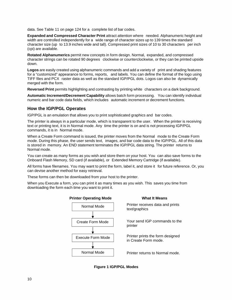
How the IGP/PGL Operates
IGP/PGL is an emulation that allows you to print sophisticated graphics and bar codes.
The printer is always in a particular mode, which is transparent to the user. When the printer is receiving text or printing text, it is in Normal mode. Any time the printer is on and is not processing IGP/PGL commands, it is in Normal mode.
When a Create Form command is issued, the printer moves from the Normal mode to the Create Form mode. During this phase, the user sends text, images, and bar code data to the IGP/PGL. All of this data is stored in memory. An END statement terminates the IGP/PGL data string. The printer returns to Normal mode.
You can create as many forms as you wish and store them on your host. You can also save forms to the Onboard Flash Memory, SD card (if available), or Extended Memory Cartridge (if available).
All forms have filenames. You may want to print the form, label it, and store it for future reference. Or, you can devise another method for easy retrieval.
These forms can then be downloaded from your host to the printer.
When you Execute a form, you can print it as many times as you wish. This saves you time from downloading the form each time you want to print it.
Printer Operating Mode What It Means
Printer receives data and prints text/graphics
Your send IGP commands to the printer
Printer prints the form designed in Create Form mode.
Printer returns to Normal mode.
Figure 1 IGP/PGL Modes
Normal Mode
Create Form Mode
Execute Form Mode
Normal Mode
11
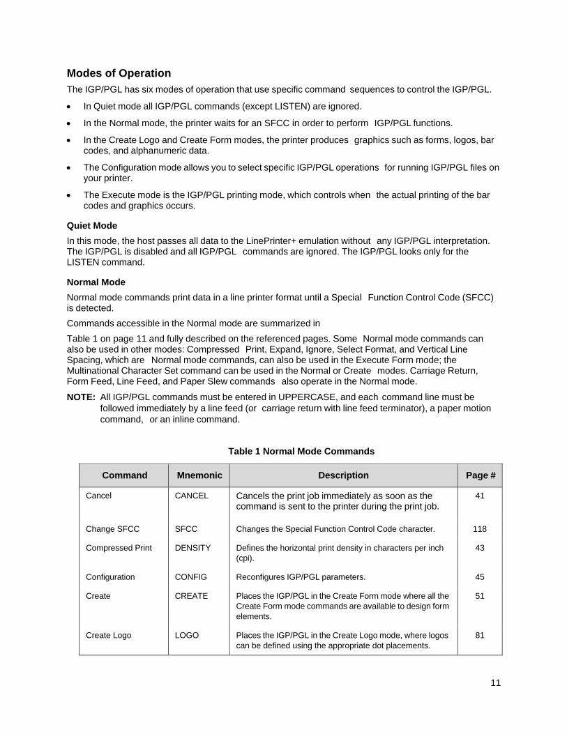
Modes of Operation
The IGP/PGL has six modes of operation that use specific command sequences to control the IGP/PGL.
In Quiet mode all IGP/PGL commands (except LISTEN) are ignored.
In the Normal mode, the printer waits for an SFCC in order to perform IGP/PGL functions.
In the Create Logo and Create Form modes, the printer produces graphics such as forms, logos, bar codes, and alphanumeric data.
The Configuration mode allows you to select specific IGP/PGL operations for running IGP/PGL files on your printer.
The Execute mode is the IGP/PGL printing mode, which controls when the actual printing of the bar codes and graphics occurs.
Quiet Mode
In this mode, the host passes all data to the LinePrinter+ emulation without any IGP/PGL interpretation. The IGP/PGL is disabled and all IGP/PGL commands are ignored. The IGP/PGL looks only for the LISTEN command.
Normal Mode
Normal mode commands print data in a line printer format until a Special Function Control Code (SFCC) is detected.
Commands accessible in the Normal mode are summarized in
Table 1 on page 11 and fully described on the referenced pages. Some Normal mode commands can also be used in other modes: Compressed Print, Expand, Ignore, Select Format, and Vertical Line Spacing, which are Normal mode commands, can also be used in the Execute Form mode; the Multinational Character Set command can be used in the Normal or Create modes. Carriage Return, Form Feed, Line Feed, and Paper Slew commands also operate in the Normal mode.
NOTE: All IGP/PGL commands must be entered in UPPERCASE, and each command line must be followed immediately by a line feed (or carriage return with line feed terminator), a paper motion command, or an inline command.
Table 1 Normal Mode Commands
Command Mnemonic Description Page #
Cancel CANCEL Cancels the print job immediately as soon as the command is sent to the printer during the print job.
41
Change SFCC SFCC Changes the Special Function Control Code character. 118
Compressed Print DENSITY Defines the horizontal print density in characters per inch (cpi).
43
Configuration CONFIG Reconfigures IGP/PGL parameters. 45
Create CREATE Places the IGP/PGL in the Create Form mode where all the Create Form mode commands are available to design form elements.
51
Create Logo LOGO Places the IGP/PGL in the Create Logo mode, where logos can be defined using the appropriate dot placements.
81
12
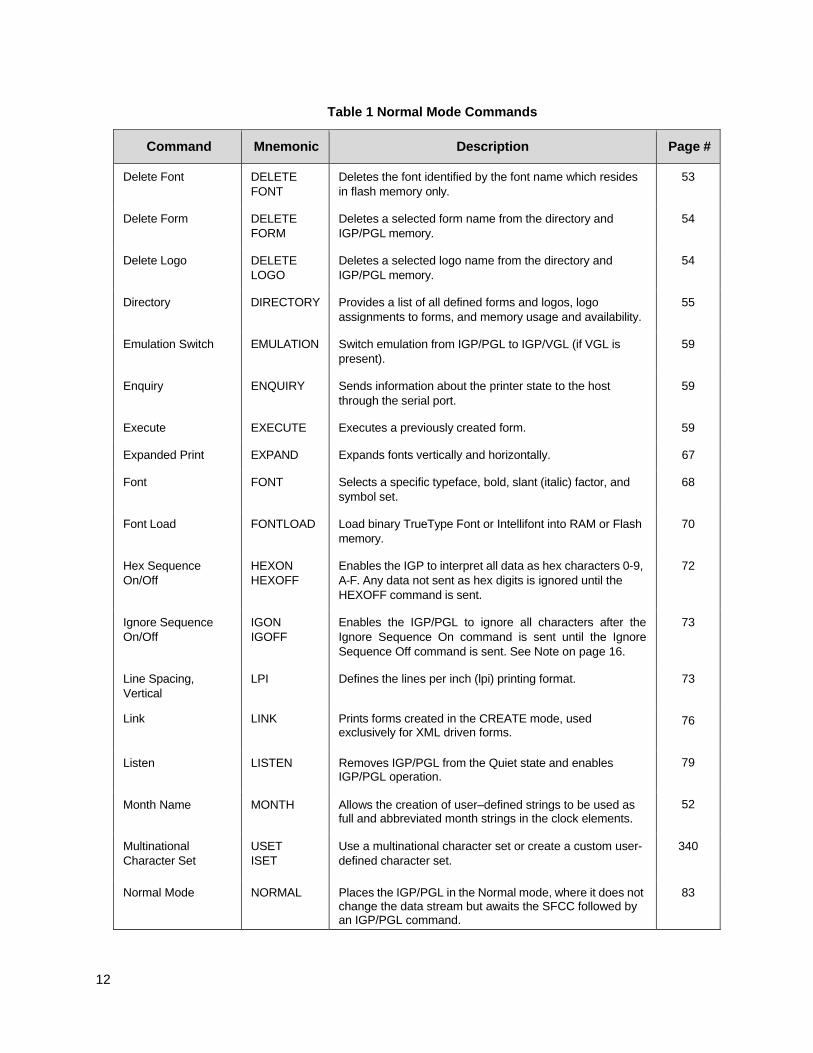
Table 1 Normal Mode Commands
Command Mnemonic Description Page #
Delete Font DELETE FONT
Deletes the font identified by the font name which resides in flash memory only.
53
Delete Form DELETE FORM
Deletes a selected form name from the directory and IGP/PGL memory.
54
Delete Logo DELETE LOGO
Deletes a selected logo name from the directory and IGP/PGL memory.
54
Directory DIRECTORY Provides a list of all defined forms and logos, logo assignments to forms, and memory usage and availability.
55
Emulation Switch EMULATION Switch emulation from IGP/PGL to IGP/VGL (if VGL is present).
59
Enquiry ENQUIRY Sends information about the printer state to the host through the serial port.
59
Execute EXECUTE Executes a previously created form. 59
Expanded Print EXPAND Expands fonts vertically and horizontally. 67
Font FONT Selects a specific typeface, bold, slant (italic) factor, and symbol set.
68
Font Load FONTLOAD Load binary TrueType Font or Intellifont into RAM or Flash memory.
70
Hex Sequence On/Off
HEXON HEXOFF
Enables the IGP to interpret all data as hex characters 0-9, A-F. Any data not sent as hex digits is ignored until the HEXOFF command is sent.
72
Ignore Sequence On/Off
IGON IGOFF
Enables the IGP/PGL to ignore all characters after the Ignore Sequence On command is sent until the Ignore Sequence Off command is sent. See Note on page 16.
73
Line Spacing, Vertical
LPI Defines the lines per inch (lpi) printing format. 73
Link LINK Prints forms created in the CREATE mode, used exclusively for XML driven forms.
76
Listen LISTEN Removes IGP/PGL from the Quiet state and enables IGP/PGL operation.
79
Month Name MONTH Allows the creation of user–defined strings to be used as full and abbreviated month strings in the clock elements.
52
Multinational Character Set
USET ISET
Use a multinational character set or create a custom user- defined character set.
340
Normal Mode NORMAL Places the IGP/PGL in the Normal mode, where it does not change the data stream but awaits the SFCC followed by an IGP/PGL command.
83
13
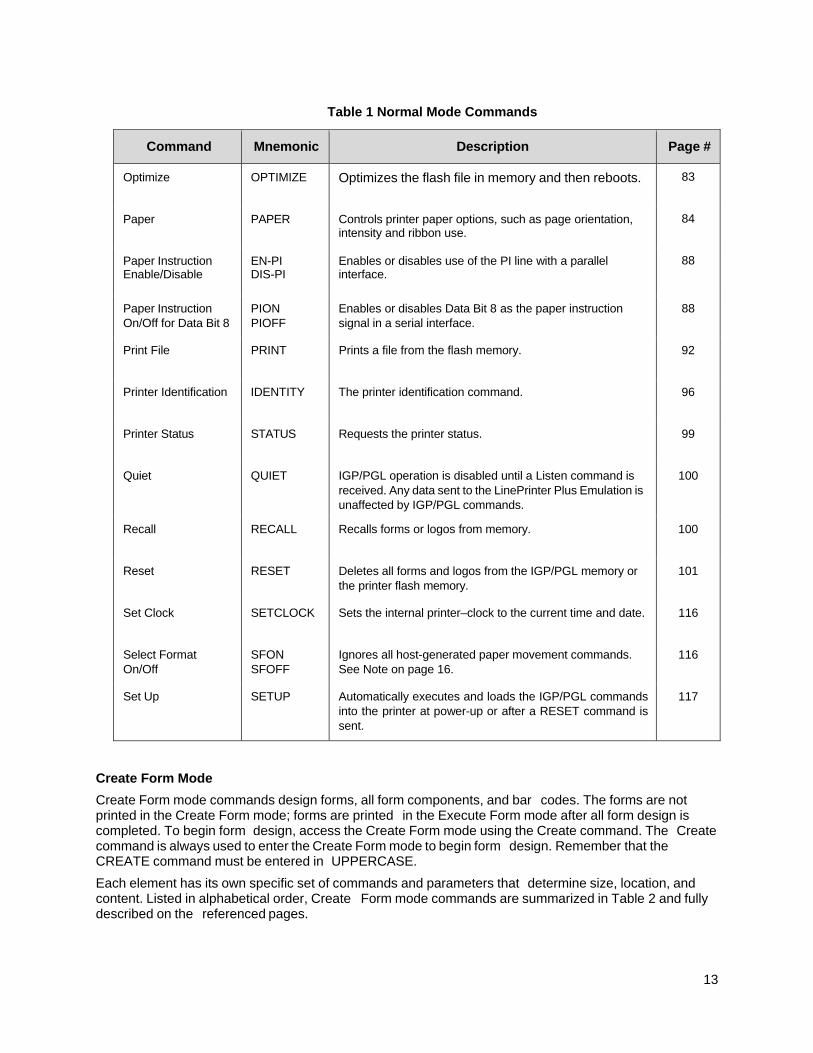
Table 1 Normal Mode Commands
Command Mnemonic Description Page #
Optimize OPTIMIZE Optimizes the flash file in memory and then reboots. 83
Paper PAPER Controls printer paper options, such as page orientation, intensity and ribbon use.
84
Paper Instruction Enable/Disable
EN-PI DIS-PI
Enables or disables use of the PI line with a parallel interface.
88
Paper Instruction On/Off for Data Bit 8
PION PIOFF
Enables or disables Data Bit 8 as the paper instruction signal in a serial interface.
88
Print File PRINT Prints a file from the flash memory. 92
Printer Identification IDENTITY The printer identification command. 96
Printer Status STATUS Requests the printer status. 99
Quiet QUIET IGP/PGL operation is disabled until a Listen command is received. Any data sent to the LinePrinter Plus Emulation is unaffected by IGP/PGL commands.
100
Recall RECALL Recalls forms or logos from memory. 100
Reset RESET Deletes all forms and logos from the IGP/PGL memory or the printer flash memory.
101
Set Clock SETCLOCK Sets the internal printer–clock to the current time and date. 116
Select Format On/Off
SFON SFOFF
Ignores all host-generated paper movement commands. See Note on page 16.
116
Set Up SETUP Automatically executes and loads the IGP/PGL commands into the printer at power-up or after a RESET command is sent.
117
Create Form Mode
Create Form mode commands design forms, all form components, and bar codes. The forms are not printed in the Create Form mode; forms are printed in the Execute Form mode after all form design is completed. To begin form design, access the Create Form mode using the Create command. The Create command is always used to enter the Create Form mode to begin form design. Remember that the CREATE command must be entered in UPPERCASE.
Each element has its own specific set of commands and parameters that determine size, location, and content. Listed in alphabetical order, Create Form mode commands are summarized in Table 2 and fully described on the referenced pages.
14
The following commands are included for compatibility, and are not recommended for use: CUT, ENQUIRY, SMODE, and XON.
Print Boundaries
Print area boundaries exist for the paper size selected. All Create Form mode commands require you to identify the location for the components in your form. Boundary checking for form elements is performed only when the form length is specified. This ensures that forms can be created regardless of the type of paper you have loaded or margins you have set. The IGP/PGL checks the boundaries before the form is executed to assure that it fits on the loaded paper size. If the debug option is used in the create statement, the boundaries are checked against the current paper size. Refer to Appendix C for more information regarding page boundary guidelines.
Table 2 Create Form Mode Commands
Command Mnemonic Description Page #
Alphanumerics ALPHA Defines size, location, and content of alphanumeric characters and dynamic alphanumeric data fields.
25
Alpha, Incremental
ALPHA Defines starting data and increment amount for fixed auto- increment fields.
30
Bar Codes BARCODE Each bar code type has its own command to define size,
location, orientation, and data as described in the Bar
Codes chapter.
124
Boxes BOX Defines size, location, and thickness of boxes. 38
Circle CIRCLE Produces a circle on the printed table. 42
Corners CORNER Defines vertical and horizontal length, location, and thickness of a set of four corners.
49
Duplication, Horizontal
HDUP Defines the number of horizontal duplications of an element and the spacing between duplications.
55
Duplication, Vertical
VDUP Defines the number of vertical duplications of an element and the spacing between duplications.
57
Ellipse ELLIPSE Produces an Ellipse. 58
End END Terminates the Create Form mode. 59
Font FONT Selects a specific typeface, bold, slant (italic) factor, and symbol set.
68
Form Length LFORM Specifies form length by total number of lines at 6 or 8 lpi. 71
Ignore Sequence On/Off
IGON IGOFF
Enables the IGP/PGL to ignore all characters after the Ignore Sequence On command is sent until the Ignore Sequence Off command is sent. See Note on page 16.
73
Lines, Diagonal DIAG Defines the location, size, and thickness of diagonal lines. 73
Lines, Horizontal HORZ Defines the location, size, and thickness of horizontal lines
74
Lines, Vertical VERT Defines the location, size, and thickness of vertical lines. 75
15
Table 2 Create Form Mode Commands
Command Mnemonic Description Page #
Logo Call
LOGO Specifies the location of a previously defined logo.
79
Logo Mode, Create LOGODEF Defines vertical and horizontal length and dot placement for logos.
81
Multinational Character Set
ISET Use a multinational character set or create a custom user- defined character set.
340
Page Number PAGE Defines the location for automatically incremented page numbers.
84
Printer Mode PMODE Selects the print mode of the printer for the next set of data and allows different print modes to be specified for use within the form.
96
Reset RESET Deletes all forms and logos from the IGP/PGL memory or the printer flash memory.
101
Reverse Print REVERSE Defines the location for white-on-black printing and selects the background shade.
101
RFWTAG RFWTAG Specifies the RFWTAG command. 102
RFRTAG RFRTAG Specifies the RFRTAG command. 111
Scale SCALE Defines the vertical spacing and horizontal pitch for data positioning in character or dot columns and rows.
113
Scaling SMODE Permits graphic elements (such as corners or boxes) to retain their physical shapes and sizes when printed in a horizontal and vertical density other than the base density of 60 x 72 dpi.
114
Select Format On/Off
SFON SFOFF
Ignores all host-generated paper movement commands. See Note on page 16.
116
VERIFY VERIFY The command to verify data of a dynamic field. 120
Create Logo Mode
The Create Logo mode is used in the Create Form mode. The Create Logo mode creates a logo design; this predefined logo is then “called” into a form in the Create Form mode. (The logo must be defined before it is “called.”)
Execute Form Mode
The Execute Form mode prints forms created in the Create Form mode. Execute Form mode commands are summarized in Table 3 and fully described on the referenced pages. Carriage Return, Form Feed, and Line Feed commands also operate in the Execute Form mode. Remember that the EXECUTE Form command must be entered in UPPERCASE, and that a single line spacing (or a line containing overlay data) must separate an EXECUTE command from a NORMAL command.
16
NOTE: Some systems pad the data stream with characters and spaces. If the IGP/PGL file on your system contains padded characters or spaces before the SFCC, this data must be ignored before the IGP/PGL can operate. The Ignore Sequence (IGON/IGOFF) command, discussed on page 73, is provided for this purpose.
Similarly, at times you may also need the IGP/PGL to ignore host- originated paper movement commands (carriage return, line feed, form feed, etc.) in lengthy data streams. Select Format (SFON/ SFOFF), discussed on page 116, is provided for this purpose. In addition, the Quiet command, (page 100), can be used to pass data unchanged to the printer.
Table 3 Execute Form Commands
Command Mnemonic Description Page #
Compressed Print DENSITY Defines the horizontal print density in characters per inch (cpi).
43
Dynamic Alphanumeric Data
AFn Executes the dynamic alphanumeric data provided after the (cc) EXECUTE command.
63
Dynamic Bar Code Data
BFn Executes the dynamic bar code data provided after the (cc)EXECUTE command.
64
Dynamic Logo GFn Executes the dynamic logo data provided after the (cc)EXECUTE command.
64
Expanded Print EXPAND Expands fonts vertically and horizontally. 67
Font FONT Selects a specific typeface, bold, slant (italic) factor, and symbol set.
68
Hex Sequence On/Off
HEXON HEXOFF
Enables the IGP to interpret all data as hex characters 0-9, A-F. Any data not sent as hex digits is ignored until the HEXOFF command is sent.
72
Ignore Sequence On/Off
IGON IGOFF
Enables the IGP/PGL to ignore all characters after the Ignore Sequence On command is sent until the Ignore Sequence Off command is sent. See Note on page 16.
73
Incremental IAFn Executes the incremental dynamic alphanumeric data 66 Alphanumeric provided after the (cc) EXECUTE command. Dynamic Data
Incremental Bar IBFn Executes the incremental dynamic bar code data provided 66 Code Dynamic Data after the (cc)EXECUTE command.
Line Spacing, Vertical
LPI Defines the lines per inch (lpi) printing format. 73
Multinational Character Set
ISET Selects one of the multinational character sets. 340
Normal Mode NORMAL Places the IGP/PGL in the Normal mode, where it does not 83 change the data stream but awaits the SFCC followed by an IGP/PGL command.
Paper PAPER Controls printer paper options, such as page orientation, 84 intensity and ribbon use.
17
Table 3 Execute Form Commands
Command Mnemonic Description Page #
Reset RESET Deletes all forms and logos from the IGP/PGL memory or the printer flash memory.
101
Repeat REPEAT Repeats a form a given number of times including all the dynamic data.
101
Select Format On/Off
SFON SFOFF
Ignores all host-generated paper movement commands. See Note on page 16.
116
Alphanumeric Data
Based on the requirements of a specific application, you can use one of three methods to print alphanumeric data on a form: Fixed data, Overlay data, and Dynamic data. These methods are described in more detail in the Commands chapter.
Fixed data prints on each form in the same “prepositioned” location, unless the location changes in the form definition. Company name, address, logo, and phone number are typical examples of alphanumeric data that can be “fixed” onto the form.
Overlay data is variable alphanumeric data positioned on the page with line feeds and spaces to fit into exact locations. For example, specific data can be “overlayed” onto a blank form as if you were typing data into the appropriate blanks on a preprinted form. Customer names, addresses, and order numbers are examples of data overlayed onto a form.
Dynamic data is variable data entered into specific locations on each form. Each time the form prints, a command enters new data in those locations. Customer names, addresses, or any type of variable alphanumeric or bar code data can be provided dynamically.
Incremental Data
The incremental data feature allows you to update alphanumeric and bar code data fields in an alphabetical or numeric manner automatically with just one set of data sent from the host computer.
Alphanumeric and bar code incremental fields can be used with fixed (static) data input as part of the Create Form mode or with dynamic data supplied in the Execute Form mode.
The incremental fields can be increased or decreased, repeated at specified intervals before updating, and reset to the starting value after a specified number of increments.
Configuring The IGP/PGL With The Control Panel
Matching certain printer operational settings to those of the host computer is known as printer configuration. The settings, or configuration parameters, such as selecting the host interface, active emulation, and printer control options, are adjusted according to the printer function switch descriptions in your printer's Administrator’s Manual. Configure the IGP/PGL in the same way you would configure the printer for other features.
You can select IGP/PGL default parameters directly from the control panel as explained in your Administrator’s Manual, or by control codes as explained in the “Commands” chapter. Your Administrator’s Manual also contains detailed configuration menus and diagrams, as well as descriptions of each configuration parameter available with your printer.
18
Flash Memory Storage Flash Memory Utilization
All printers have a certain amount of onboard, non-removable flash memory on the main controller board that can be used for permanent storage.
Depending on the application, this Onboard Flash Memory may not be sufficient. Certain models of Printronix printers can be ordered with a removable flash memory cartridge called Expanded Memory Cartridge (EMC), while other models have an SD card slot. Both the SD card and EMC can be used to extend the range of permanent data storage for applications. For printers with SD capability, the extended range of data storage can be significant (GB).
Since SD/EMC capable printers have two storage choices (allowing the same file name to exist on both SD/EMC and Onboard Flash Memory), a hierarchy (search order) is required for finding, reading, writing, and deleting files. This hierarchy is described below.
Printers with SD or EMC Capability
For printers that support SD or EMC, files can exist on one or more memory types (SD/EMC, Onboard Flash Memory, and DRAM). The parameter DISK is used within different PGL commands to select Onboard Flash Memory as the permanent storage location. The parameter EMC selects either Extended Memory Cartridge or SD card depending on the printer’s capabilities. A hierarchy for finding, reading, writing, and deleting files is necessary and is described below.
Read
NOTE: For commands including EXECUTE, LOGO in create mode, PRINT, RECALL, DIRECTORY, FONT, and XML data stream.
Regardless of which parameters are used, all objects are first searched in DRAM.
When an SD card or EMC is installed, the printer searches them, along with Onboard Flash Memory regardless of the parameter, EMC and DISK. The search stops at the first occurrence when the file is found. If the file is not found, an error message is printed.
When the SD card or EMC is not installed, only DRAM and Onboard Flash Memory are searched.
Write
NOTE: For commands including CREATE, LINK, LOGO in normal mode for PCX and TIFF, SETUP, and FONTLOAD.
Regardless of which parameters are used, all objects are stored in DRAM.
When an SD card or EMC is installed, using the parameter EMC will also store the object there. The parameter DISK will either write to Onboard Flash Memory or SD/EMC based on the “Storage Select” front panel menu.
When an SD card or EMC is not installed, the parameter EMC will result in an error message. The parameter DISK, however, will write to Onboard Flash Memory regardless of the "Storage Select" menu setting.
Delete
NOTE: For commands including DELETE FONT, DELETE FORM, DELETE LOGO, DELETE LINK, RESET, and OPTIMIZE.
Regardless of which parameters are used, all objects are deleted from DRAM.
When an SD card or EMC is installed, the parameter EMC will also delete the file from that location. The parameter DISK deletes the file from either Onboard Flash Memory or SD/EMC based on the "Storage Select" front panel menu.

19
When the SD card or EMC is not installed, the parameter EMC causes an error message to print. The parameter DISK, however, will delete data from Onboard Flash Memory regardless of the "Storage Select" menu setting.
Printers without SD or EMC Capability
When the EMC parameter is included with a PGL command, printers without SD or EMC capability will access Onboard Flash Memory instead, since the EMC is not supported on these printers.

20
21
Commands
IGP/PGL Command Standards IGP/PGL commands have many options and a specific format that you must follow to obtain the desired results. Certain elements are standard for all IGP/PGL commands. These command standards are described in the following sections. Familiarize yourself with the meaning and use of these standards before operating the IGP/PGL.
Special Function Control Code (SFCC)
The SFCC identifies a command directed to the IGP/PGL to enable a specific IGP/PGL function. Based on the host computer interface requirements, various characters can be selected as the SFCC, such as the caret (^) or a tilde (~). The SFCC must be placed before a command or data is entered.
The examples in this manual use the tilde as the SFCC; always substitute the actual SFCC required by your system wherever the tilde is shown. In the general command formats, the SFCC is represented by (cc).
You can select the SFCC using the CONFIG command (page 45), the Special Function Control Code Change command (page 118) or the control panel (see the Administrator’s Manual).
Semicolon (;)
Each parameter (alpha data, options, etc.) on the command line is separated by a semicolon. Blank spaces between the semicolon and the next parameter are not allowed. A missing or misplaced semicolon causes an error message.
Uppercase
The IGP/PGL is “case sensitive.” ALL commands must be entered in uppercase.
Inline Commands
The SFCC, usually a “~”, was required to be the first character on a new line. It may now appear anywhere on the command line. There is a configuration option that determines whether any data preceding a command is printed or ignored.
All IGP/PGL commands begin with the Special Function Control Code (SFCC) and end with a valid line terminator. When the command does not end with a valid line terminator, it must end with the SFCC to form an inline command line. This syntax applies only to the commands in Normal mode.
Example:
~DIRECTORY~~DELETE LOGO;*ALL~~DIRECTORY
Another inline command syntax is to replace the valid line terminator with the inline terminator command (~CR, ~LF, ~FF, or ~LT), and to enclose the entire command line with the SFON/SFOFF command. This syntax applies to all PGL commands.
Example:
~SFON~DIRECTORY~LF~DELETE LOGO;*ALL~LF~DIRECTORY~LF~SFOFF
The following example is to use no motion line terminator, ~LT, to print two Normal mode texts on the same line with the different font.
22
~SFON~FONT;FACE 93952;POINT 12~LT~FONT;FACE 92250~LTabcdefg~LT~SFOFF
Line Terminator
Each command line must be terminated by a line feed (or a carriage return with a line feed), or a paper motion command. When an inline command is not followed by a valid line terminator, it must also end with the SFCC. The command line will not be accepted if not properly terminated. Refer to your system Administrator’s Manual for your system keyboard and your printer configuration codes to determine which key(s) (such as ENTER, LINE FEED, RETURN, etc.) perform a line feed, carriage return with line feed, or form feed function.
Printable Character
To print, alphanumeric and bar code data must be enclosed by a printable character (a delimiter). This delimiter is represented by (D) in the command format. In this manual, an asterisk (*) is used in most examples as the printable character. (The parentheses are not entered.) Any printable character can be used as this delimiter except a slash (/) or the SFCC. The same printable character must be used at both the beginning and end of the text to be printed and cannot be used within the text.
Spaces
Spaces are used in the general command formats to visually separate individual command parameters. Supply the appropriate information for the command parameter, but do not enter the spaces in the command sequence; they are shown simply as a visual aid to illustrate where one command parameter ends and another begins.
Command Parameters
Most commands include a number of parameters. Some are optional, and some are required. Each parameter must be separated by a semicolon (;) unless noted otherwise. Throughout this manual, actual commands required for input are shown exactly as they must be entered and all parameters associated with that command are shown in italics. Optional parameters are enclosed in brackets [ ], but do not enter the brackets.
Parentheses indicate variable data. You have a choice of what to enter, but you must enter something. Do not enter the parentheses themselves.
Form Name
You must use alphanumeric characters to identify the document (form or logo) you are creating (a maximum of 15 alphanumeric characters). The Form Name is also used to identify the form during the Execute Form mode. The valid Form Name characters are listed below and also apply to Logo Name. The SFCC can also be used in the Form Name. No spaces are allowed between any of the Form Name characters.
Table 4 Valid Form Name Characters
A through Z (upper and lowercase) Left and right parentheses ( )
0 through 9 Tilde ~
Dollar sign $ Single quotes ‘ ’
Percent sign % Exclamation Point !
Dash - Pound sign #
At sign @ Ampersand &
Left and right braces { }
23
Prompt
The prompt is the symbol (e.g., a dollar sign, period or greater than symbol) used to indicate that the host computer is ready for data input. In this manual, the prompt is shown as a period (.).
Numeric Values
In this manual, a lowercase n in the command represents a numeric value. If a command parameter includes a lowercase n, it must be substituted with an appropriate numeric value. If the lowercase n is part of an optional parameter and the option is not selected, a value for n is not required.
Comments in Command Lines
To aid in maintenance of a form or logo, comments can be added to many command lines within the CREATE or CREATE LOGO mode. Comments must be preceded by a slash (/). Do NOT use the /comment feature on lines containing an SFCC (e.g., commands used within NORMAL or EXECUTE mode). Throughout this manual, comments are provided in parenthesis beside most command lines for better understanding of IGP/PGL operation but should not be included in your IGP/PGL files. See Form Examples on page 308 for some examples.
Storing Data
To send data to the IGP/PGL, use a system command, such as PRINT. (Entering data through the keyboard does not store data in nonvolatile IGP/PGL memory.) Once stored in memory, the data remains until deleted, the IGP/PGL is reset with the RESET command, or until the printer is turned off.
IGP/PGL files can be permanently stored to, deleted from, and retrieved from the Onboard Flash Memory by ending CREATE, CREATE LOGO, DELETE FORM, DELETE LOGO, EXECUTE, and DIRECTORY commands with ;DISK.
For example, the following command creates a form named ORDER and stores it in the Onboard Flash Memory:
(cc)CREATE;ORDER;DISK
Executing a form or calling a logo will access the flash memory automatically if the object is not found in RAM.
NOTE: While the printer does not contain a floppy disk drive, the ;DISK command has been retained to provide backward compatibility with earlier printer models and command syntax.
Uncompressed and Packed Bits Compression
PGL logos support uncompressed and packed bits compression methods. CCITT and LZR (used for color) compression methods are not supported. Refer to your application's documentation about TIFF files.
Character Position.Dot Position (CP.DP) Format
The CP.DP format is a special parameter available with the IGP/PGL commands. CP.DP format allows two elements plotted at nearly the same character location to be offset to eliminate overlapping. Specifying starting and ending rows and columns is its most frequent use.
Each character location is a cell. Each cell is a grid 12 dot rows high by 6 dot columns wide (printing at 6 lpi and 10 cpi). The CP.DP format allows a character cell position (CP) and a specific
dot position (DP) within the cell to be identified as shown in
Figure 2. The DP portion of the CP.DP format specifies a location down (in reference to rows) and to the right (in reference to columns) within the character cell position.
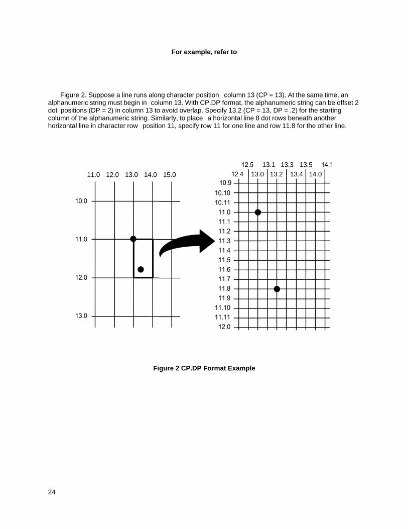
24
For example, refer to
Figure 2. Suppose a line runs along character position column 13 (CP = 13). At the same time, an alphanumeric string must begin in column 13. With CP.DP format, the alphanumeric string can be offset 2 dot positions (DP = 2) in column 13 to avoid overlap. Specify 13.2 (CP = 13, DP = .2) for the starting column of the alphanumeric string. Similarly, to place a horizontal line 8 dot rows beneath another horizontal line in character row position 11, specify row 11 for one line and row 11.8 for the other line.
Figure 2 CP.DP Format Example
13.1 13.3 13.5
11.0 12.0 13.0 14.0 15.0 13.0 13.2 13.4 14.0
25
Command Codes Data Fields for Alphanumeric and Incremental Data
Based upon the requirements of a specific application, three methods are used to print alphanumeric data on the form: fixed (or prepositioned) data, overlay data, and dynamic data.
Fixed Data
Fixed data is entered during the Create Form mode as part of the form definition. It appears as prepositioned information similar to other form elements. The fixed data is printed on each form in the same location and can only be changed by changing the form definition. Your company's name, address, logo, or phone number are typical examples of alphanumeric data that can be fixed onto the form.
Overlay Data
Overlay data is variable alphanumeric data entered during the Execute Form mode by positioning the information with line feeds and spaces into an exact location. In general, a page of data is overlaid onto a form similar to typing data in the appropriate blanks of a preprinted form. Each page of overlay data is separated by form feeds to correspond to each form printed. Customer names, addresses, and order numbers are examples of variable data that can be overlaid onto the form.
Dynamic Data
Dynamic data is variable data entered by command during the Execute Form mode. The dynamic data is entered into a location previously defined in the Create Form mode. Any number of locations can be identified during the Create Form mode as part of the form definition. A command during the Execute Form mode enters new data in the identified location(s) each time the form prints. Dynamic data is the most efficient method of supplying variable data to the form. Again, customer names, addresses, or any type of logo, variable alphanumeric, or bar code data can be provided dynamically.
Incremental Data Fields
The incremental data fields feature allows alphanumeric (and bar code) data fields to automatically update numerically or alphabetically with just one set of data sent from the host computer. A maximum of 65,535 fields can print with incremental fields automatically updated. Alphanumeric incremental fields can be used with fixed (static) data input as part of the Create Form mode or with dynamic data supplied in the Execute Form mode. Incremental data fields cannot be used with Overlay data.
Alphanumerics
Purpose Defines and positions alphanumeric data on a “preprinted” static data field or as a dynamic data field.
Mode CREATE
Format ALPHA [R;] [E;] [Cn;] [AFn;L;] [T;] [RJUST; or CJUST;] [NLZ;] [DIR;] [UC;] [DARK;] [POINT;] [HSn; or HSDn;] SR; SC; VE; HE; (D)text(D) STOP
ALPHA The Alphanumeric command; enter ALPHA.
R The optional reverse printing (white on black) parameter. Enter R to specify a black background.
NOTE: The D parameter, used in earlier IGP/PGL versions, is ignored in IGP/PGL. In addition, the L parameter, also used in earlier IGP/PGL versions to specify a long reverse field for descending characters in dynamic alphanumeric data, is now provided automatically in IGP/PGL. The IGP/PGL ignores these parameters if found in a command line.
26
E The optional elongated character parameter. Enter E to specify elongated character printing. Elongated characters are double height and single width. If used, the VE and HE parameters must be set to 0, or an error message will result. Elongated character printing is also available with rotated alphanumerics.
Cn The optional horizontal compression parameter. Enter C. n = any number between 10 and 30, specifying the number of horizontal characters per inch (cpi). 10 cpi is the default value. 10A = 10 cpi OCR-A. 10B = 10 cpi OCR-B. If used, the VE and HE parameters must be set to 0, or an error message will result.
AFn;L The optional dynamic data field parameters for identifying the alphanumeric string location on a form and for designating the length of the alphanumeric string. If these parameters are used, the actual text cannot be entered during the Create Form mode; it must be entered dynamically during the Execute Form mode. Dynamically entering data during the Execute Form mode permits changes to the alphanumeric text without redefining or re- creating the form. To use this field, perform the following steps:
a. Enter AF.
b. Replace n with a number ranging from 0 through 512 to identify the alphanumeric string location on the form. The SR and SC parameters are used to specify the exact location of the alphanumeric field identified by n.
c. Replace L with a number equal to the number of characters in the dynamic alphanumeric string ranging from 0 through 255.
d. Dynamically enter the alphanumeric string itself in the Execute Form mode. The length of the alphanumeric string must be equal to or less than the value assigned to the length (L) parameter. Refer to Execute Form: Dynamic Alphanumeric Data on page 63.
e. If the dynamic data field is used, do not enter the text parameter.
T Optional parameter which truncates the dynamic data field when it exceeds the maximum length defined by the L parameter. When T is not used, a data length error is printed instead.
RJUST Right text alignment where the starting column (SC) points to the right end of the text string. If RJUST is not specified, the default is left alignment.
CJUST Center text alignment where the starting column (SC) points to the center of the text string. If CJUST is not specified, the default is left alignment.
NLZ Suppresses the leading zero.
DIR Optional parameter for rotating a character string. Use the following codes to indicate the direction of character rotation and to specify an uppercase-only character string:
a. Enter CW for 90 degree clockwise rotation.
b. Enter CCW for 90 degree counterclockwise rotation.
27
c. Enter INV for inverted characters (180 degree rotation).
The default orientation prints character strings in the standard horizontal format.
NOTE: Alpha rotation parameters (CW, CCW, INV) require more memory to implement than the default orientation. Thus, characters selected for rotation may appear in the default orientation. Selecting a smaller font will correct the problem.
UC Enter UC to specify uppercase-only characters. When uppercase-only is specified, all lowercase alpha character codes are converted automatically to uppercase. Consequently, do not specify uppercase-only characters if lowercase characters are required.
DARK Optional parameter to produce bolder text. Enter DARK or D. (D is also allowed in the ALPHA command only.) More information about dark printing is provided on page 52.
POINT Optional parameter that changes the units for the vertical and horizontal expansion values. Enter POINT. When the POINT parameter is present the VE value defines the font height in 1/72 of an inch (i.e. points). If the HE value is non-zero, it defines the character width in 1/72 of an inch, otherwise the character width is the standard width for the chosen height. Cannot be used with elongated (E) and compressed (Cn) parameters.
HSn or HSDn Horizontal Spacing. The value n indicates the number of extra dots to add between each character.
HS = the value is in 60 DPI dots HSD = the value is in printer dots. This parameter is used only for proportional fonts.
SR Defines the starting row of the alphanumeric data. Enter a value ranging from row 1 through one less than the length of the form. Character row or dot row is specified based on the Scale command (page 113), or use the CP.DP format (page 23).
SC Defines the starting column of the alphanumeric data. Enter a value ranging from column 1 through one less than the width of the form. Character column or dot column is specified based on the Scale command ( page 113), or use the CP.DP format (page 23).
VE Defines the vertical expansion factor to enlarge characters vertically. Enter a value from 0 through 139. Zero specifies the standard font (no expansion). A VE value must be entered. Use vertical expansion with 12 point font size only. Elongated (E) and compressed (Cn) characters cannot be used with a vertical expansion other than zero.
HE Defines the horizontal expansion factor to enlarge characters horizontally. Enter a value from 0 through 139. Zero specifies the standard font (no expansion). An HE value must be entered. Use horizontal expansion with 12 point font size only. Elongated (E) and compressed (Cn) characters cannot be used with a horizontal expansion other than zero.
(D) The printable character identifying the start and finish of the alphanumeric string. Enter any printable character other than a slash (/), the SFCC, or a character used within the alphanumeric string itself. You must use the same character at both ends of the
28
alphanumeric string, but it will not print with the data.
text The group of ASCII characters (the alphanumeric string) to print. Enter any of the standard ASCII printable characters (except the character used to delimit the string in the (D) parameter). The data appears as “prepositioned” information on the form beginning at the location specified by SR and SC. This is the “fixed” or static alphanumeric data; once defined on the form, it is changed only by redefining the form using the Alphanumerics command.
When DBCS character set is selected by ISET or SYMSET, and DBCS font is selected by FONT NAME, DBCS data will print.
STOP Stop indicates the end of the Alphanumeric command; enter STOP, and the IGP/PGL will wait for a new command. If not entered, the IGP/PGL will wait for another set of Alphanumeric command parameters.
Comments
As dynamic data, the location of the alphanumeric field is established in the Create Form mode and the actual alphanumeric data is continuously redefined before placement on the form in the Execute Form mode. You can also rotate and reverse print the alphanumeric string using this command.
Example
The following program and example in Figure 3 illustrates the Alphanumeric command capabilities. To illustrate positioning, starting row and column are indicated on the example but do not necessarily reflect actual location on the page. Notice the same starting row is used for all “EXAMPLE” characters, and they are all aligned on the same baseline (or bottom), regardless of expanded or compressed parameters. The string rotates around the point of intersection of the starting row and columns shown by the “pinwheel” E. A rotated 10 cpi character establishes the baseline for all character sizes.
ALPHA 36;37;4;4;*E* 36;41;2;3;*X* 36;44;2;2;*A* 36;46;1;1;*M* (Single-size character, expanded font) C13;36;47;0;0;*P* C15;36;48;0;0;*L* C17;36;49;0;0;*E* CW;36;60;2;2;*CLOCK* CW;42;60;4;4;*WISE* CCW;58;26;2;3;*COUNTER* CCW;45.5;26;2;2;*CLOCK* CCW;39.2;26;1;1;*WISE* INV;54.5;58;0;0;*INVERTED* R;INV;54.5;49;0;0;*REVERSE PRINT* 45;48;0;0;*E* CW;UC;45;48;0;0;*e* (Lowercase converted to uppercase) CCW;45;48;0;0;*E* INV;45;48;0;0;*E* STOP
29
Figure 3 Alphanumberic Example
ROW 36
COLUMN 37 COLUMN 49
ROW 45
ROW 39.2
ROW 58
ROW 54.5
COLUMN 26
COLUMN 48
COLUMN 60
COLUMN 58
30
Alphanumerics, Incremental Fields
Purpose The incremental fields feature updates alphanumeric (and bar code) data fields in a numeric or alphabetical manner automatically using just one set of data sent from the host computer. Incremental alphanumeric data fields can be applied to fixed (static) data (page 33), or dynamic data (page 35).
Mode CREATE (for fixed data) or EXECUTE (for dynamic data)
NOTE: Throughout the discussion of incremental fields, the term “increment” or “incremental” means the field is automatically updated by a specified amount (or increment). The field can actually be increased/decreased in specified increments/decrements within the command.
Comments
Incremental fields can increase or decrease, repeat at specified intervals before updating, and reset to the starting value after a specified number of increments. A maximum of 65,535 fields can be defined.
Using Incremental Alphanumeric Data
Incrementing is controlled with the STEPMASK and STARTDATA command parameters as described in Table 5. The parameters are part of the Incremental Alphanumeric Fixed Data command or part of the Execute command when using incremental alphanumeric dynamic data.
The STEPMASK parameter performs the following three functions:
1. It defines the increment amount (step);
2. It defines the number of characters allowed in the data field (STARTDATA); and
3. It provides a “mask” to link or unlink subfields of the data to be incremented independently. The data provided in the STEPMASK field combined with the data in the STARTDATA field determine the result of these functions.
The increment amount is defined by the numeric value of the STEPMASK data. For example, a STEPMASK value of 1 increments the STARTDATA by 1; a STEPMASK value of 2 increments the STARTDATA by 2.
The maximum number of characters allowed in the STARTDATA field is defined by the number of characters in the STEPMASK field; the STARTDATA field cannot contain more characters than used in the STEPMASK field.
Linked and unlinked masking of subfields within the STARTDATA is defined by the L value in the STEPMASK field. L indicates linked but non-incremental data in the corresponding position of the STARTDATA field; any alpha character other than L in the STEPMASK field indicates a non-incremental, non-linked STARTDATA subfield.
31
Table 5 Increment Alphanumeric
STEPMASK START DATA Character Type and Function
0 - 9 A - Z Alpha characters incremented by amount in STEPMASK field
0 - 9 0 - 9 Numeric characters incremented by amount in STEPMASK field
0 - 9 Space Same character type as character in the next right adjacent, linked increment position. Character type will be numeric if in least significant position.
0 - 9 Not A - Z or 0 - 9 Error
Not 0 - 9 or L Any Non-incrementing alphanumeric character
L Any Linked, non-incrementing alphanumeric character
The examples on the following pages illustrate incremental alphanumeric data fields. All cases in the examples use a repeat count parameter value of 1 and a reset count parameter value of 0. The three vertical dots illustrate the natural progression for each column and unit of data based on the incremental count and its impact on linked and unlinked data fields.
STARTDATA: STEPMASK:
Printed Results:
Description
Linked subfields: ABC and 123RPT = 1 RST = 0
Value
32
STARTDATA: STEPMASK:
Printed Results:
Value
Description
Two separate but linked numericsubfields: 1 and 123, while fixed dataABC is non-incrementing RPT = 1 RPT = 0
STARTDATA: STEPMASK:
Printed Results:
Value
Two separate unlinked subfields: ABC and 3, while fixed data 1 and 2is non-incrementing RPT = 1 RPT = 0
STARTDATA: STEPMASK:
Value
Description
Single numeric field with leadingspaces (_) RPT = 1 RPT = 0 Printed Results:
STARTDATA: STEPMASK:
Printed Results:
Value
_
_
Description
Two separate but linked numericsubfields: AA and 98, with leadingspace (_); fixed data AA is non-incrementing RPT = 1 RST = 0
33
Alphanumerics, Incremental: Fixed Data Fields
Purpose To automatically increment/decrement fixed alphanumeric data fields.
Mode CREATE
NOTE: In the command format below, incremental alphanumeric command parameters are shown in boldface type; standard alphanumeric command parameters and optional non-incremental parameters are shown in italics. Due to space constraints, the command parameters are separated into two lines. During actual IGP/PGL input, DO NOT separate command parameters.
Format ALPHA [R;] [E;] [Cn;] I; [DIR;] [UC;] [DARK;] [POINT;] [HSn or HSDn;] SR; SC; VE; HE;[idir] STEPMASK; [RPTn;] [RSTn;] (D)STARTDATA(D) STOP
I Identifies this alphanumeric command as an Incremental Alphanumeric command; enter I.
idir The optional increment direction parameter to specify an increment (add) or decrement (subtract) to the data. Enter a plus sign (+) or leave the field blank to increment (the default). Enter a minus sign (-) to decrement.
STEPMASK Defines the increment amount (step), the number of character positions in the data field, and provides a mask to control the increment function on specific parts of the data. Enter the appropriate value. Refer to Table 5 o page 31 for complete information on STEPMASK parameter values.
STARTDATA: STEPMASK:
Printed Results:
Value
Single numeric field decremented by 1, while fixed data 9 and AA are non-incrementing.
STARTDATA: STEPMASK:
Printed Results:
Value
Description
Two separate but linked alphasubfields: A and R, with leadingspace (_); fixed data 42 is non-incrementing RPT = 1 RST = 0
34
RPTn The optional incremental repeat count parameter to specify the number of times a particular field value is repeated before it is incremented. A repeated field value is useful when printing multiple rows/columns of identical labels before increasing to the next value.
To use the repeat count parameter, enter RPT and replace n with a numeric value ranging from 1 through 65535 to specify the repeat count. The default repeat count parameter is 1, which will increment the field value each time it prints.
RSTn The optional incremental reset count parameter to specify the number of times an incremented field is printed (on one or more forms) before it is reset to the starting value. A reset count is useful when printing a hierarchy of fields where a low-level field generates a sequence of numbers, is reset, and the next higher field level is incremented (such as in a unit/box/carton application). To use the reset count parameter, enter RST and replace n with a number ranging from 1 through 65535 to specify the reset count. The default reset count value is 0.
STARTDATA Defines the starting value of the incrementing field. Enter the appropriate value. Refer to Using Incremental Alphanumeric Data on page 30 for complete information on STARTDATA and STEPMASK parameter values.
The maximum amount of STARTDATA characters must be equal to or less than the number of characters in the STEPMASK field. If the number of data characters is less than the number used in STEPMASK, the data will print right justified with preceding spaces. Characters allowed for incrementing fields (STEPMASK values of 0 - 9) are numeric 0 - 9 and alpha A - Z (uppercase only). Any printable character is allowed in non- incrementing fields (STEPMASK values not 0 - 9).The STARTDATA must be enclosed within standard printable character delimiters just as a standard alphanumeric data field is enclosed within delimiters.
Comments
The Incremental Alphanumeric Fixed Data Fields command is a revised version of the standard IGP/PGL alphanumeric command, but it does not replace the standard alphanumeric command.
~CREATE;TEST;288 (Enters Create Form mode) VDUP;3;6 (Repeat alpha string) ALPHA (Alpha command) I;6;5;4;4;-00001;*12345* STOP (Ends Alpha command) VDUP;OFF END (Terminates Create Form mode) ~EXECUTE;TEST (Prints form)
~NORMAL
35
Alphanumerics, Incremental: Dynamic Data Fields
Purpose Automatically increments/decrements dynamic alphanumeric data fields. Specifies the location and size of the incremental dynamic data field during the Create Form mode; STEPMASK and STARTDATA parameters are supplied in the Execute command during the Execute Form mode.
Mode CREATE
NOTE: In the command format below, incremental alphanumeric command parameters are shown in boldface type; standard alphanumeric command parameters and optional non-incremental parameters are shown in italics.
Format ALPHA [R;] [E;] [Cn;] IAFn;L;[T;] [DIR;] [UC;] [DARK;] [POINT;] [HSn or HSDn;] SR; SC; VE; HE STOP
IAFn;L Identifies this alphanumeric command as an Incremental Alphanumeric Dynamic Data Field command. The command parameter string identifies the incremental dynamic data field location on the form and defines the length of the alphanumeric data. If these parameters are used, the STEPMASK and STARTDATA parameters cannot be entered in the Create Form mode; they are entered dynamically during the Execute Forms mode. To use the incremental dynamic data field, perform the following steps:
a. Enter IAF to specify an incremental alphanumeric dynamic data field.
b. Replace n with a number ranging from 0 through 512 to identify the alphanumeric string location on the form. The standard alphanumeric SR and SC command parameters specify the exact location of the field identified by n.
c. Replace L with a number equal to the number of characters in the dynamic alphanumeric string (STARTDATA) ranging from 1 through 255.
d. Dynamically enter the STEPMASK and STARTDATA parameters in the Execute Form mode. The length of the data
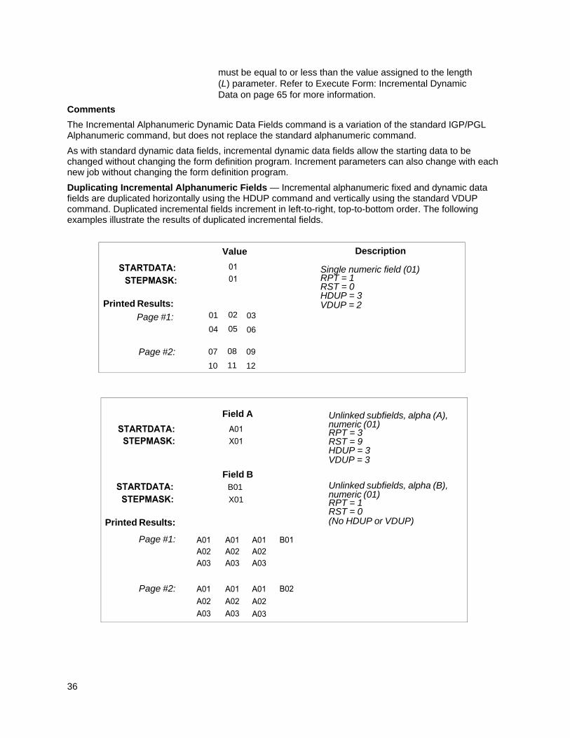
36
must be equal to or less than the value assigned to the length (L) parameter. Refer to Execute Form: Incremental Dynamic Data on page 65 for more information.
Comments
The Incremental Alphanumeric Dynamic Data Fields command is a variation of the standard IGP/PGL Alphanumeric command, but does not replace the standard alphanumeric command.
As with standard dynamic data fields, incremental dynamic data fields allow the starting data to be changed without changing the form definition program. Increment parameters can also change with each new job without changing the form definition program.
Duplicating Incremental Alphanumeric Fields — Incremental alphanumeric fixed and dynamic data fields are duplicated horizontally using the HDUP command and vertically using the standard VDUP command. Duplicated incremental fields increment in left-to-right, top-to-bottom order. The following examples illustrate the results of duplicated incremental fields.
Field A
Unlinked subfields, alpha (A),numeric (01) RPT = 3 RST = 9 HDUP = 3 VDUP = 3
Field BB01
X01
Printed Results:
Page #1:
Unlinked subfields, alpha (B),numeric (01) RPT = 1 RST = 0 (No HDUP or VDUP)
Page #2:
Value
Description Single numeric field (01) RPT = 1 RST = 0 HDUP = 3 VDUP = 2
Printed Results:
Page #1:
Page #2:
02
05
01
04
03
06
08
11
07
10
09
12
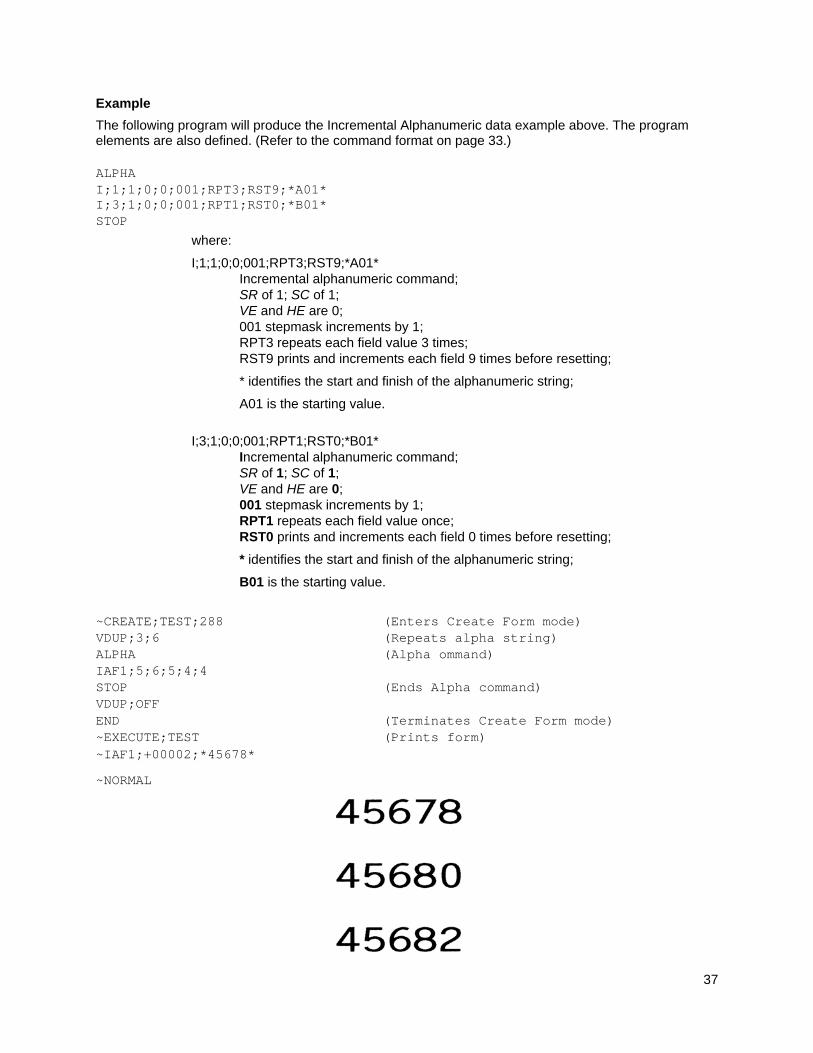
37
Example
The following program will produce the Incremental Alphanumeric data example above. The program elements are also defined. (Refer to the command format on page 33.) ALPHA I;1;1;0;0;001;RPT3;RST9;*A01* I;3;1;0;0;001;RPT1;RST0;*B01* STOP
where:
I;1;1;0;0;001;RPT3;RST9;*A01* Incremental alphanumeric command; SR of 1; SC of 1; VE and HE are 0; 001 stepmask increments by 1; RPT3 repeats each field value 3 times; RST9 prints and increments each field 9 times before resetting;
* identifies the start and finish of the alphanumeric string;
A01 is the starting value.
I;3;1;0;0;001;RPT1;RST0;*B01*
Incremental alphanumeric command; SR of 1; SC of 1; VE and HE are 0; 001 stepmask increments by 1; RPT1 repeats each field value once; RST0 prints and increments each field 0 times before resetting;
* identifies the start and finish of the alphanumeric string;
B01 is the starting value.
~CREATE;TEST;288 (Enters Create Form mode) VDUP;3;6 (Repeats alpha string) ALPHA (Alpha ommand) IAF1;5;6;5;4;4 STOP (Ends Alpha command) VDUP;OFF END (Terminates Create Form mode) ~EXECUTE;TEST (Prints form) ~IAF1;+00002;*45678*
~NORMAL
38
Boxes
Purpose Produces any variety of rectangular boxes.
Mode CREATE
Format BOX LT;SR;SC;ER;EC[;RD] STOP
BOX The Box command; enter BOX. Boxes expand down and to the right from the given row and column.
LT Defines the line thickness, measured in dots. Line thickness is based on dot dimensions of 1/72” both horizontally and vertically, so that line thickness is equal in both directions. Enter a value of 1 or greater.
SR Defines the starting row of the box. Enter a value ranging from row 1 through one less than the length of the form. Character row or dot row in millimeters is specified based on the Scale command (page 113), or use the CP.DP format (page 23).
SC Defines the starting column of the box. Enter a value ranging from column 1 through one less than the width of the form. Character column or dot column in millimeters is specified based on the Scale command (page 113), or use the CP.DP format (page 23).
ER Defines the ending row of the box. Enter a value ranging from row 2 through the last row of the form. The ending row must be greater than the starting row. Character row or dot row in millimeters is specified based on the Scale command (page 113), or use the CP.DP format (page 23).
EC Defines the ending column of the box. Enter a value ranging from column 2 through the last column of the form. The ending column must be greater than the starting column. Character column or dot column in millimeters is specified based on the Scale command ((page 113), or use the CP.DP format (page 23).
RD Optional parameter. Defines the degree of corner–rounding. Accept values from 0 (no rounding) to 8 (heaviest rounding). The default value is 0. This option is currently applicable for non-impact printers only.
STOP Stop indicates the end of the Box command; enter STOP, and the IGP/PGL will wait for a new command. If not entered, the IGP/PGL will wait for another set of Box command parameters.
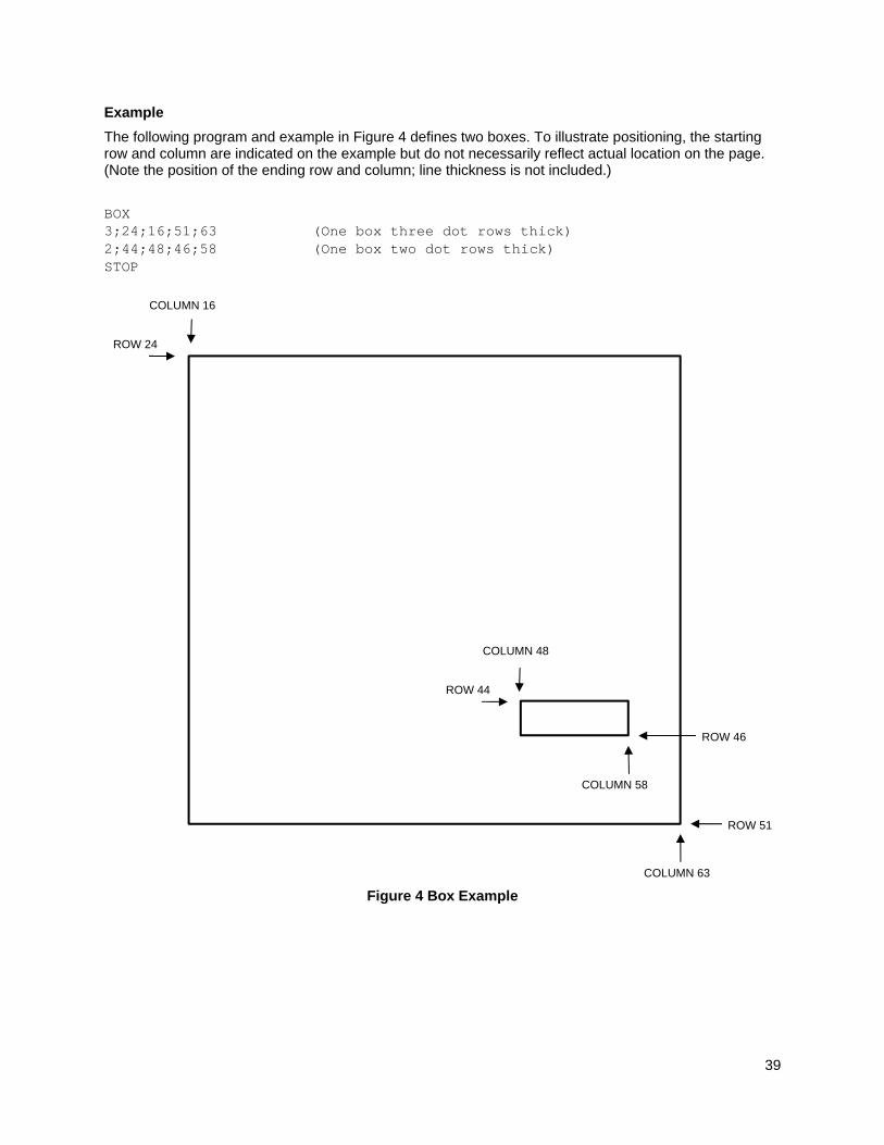
39
Example
The following program and example in Figure 4 defines two boxes. To illustrate positioning, the starting row and column are indicated on the example but do not necessarily reflect actual location on the page. (Note the position of the ending row and column; line thickness is not included.)
BOX 3;24;16;51;63 (One box three dot rows thick) 2;44;48;46;58 (One box two dot rows thick) STOP
Figure 4 Box Example
ROW 24
COLUMN 16
ROW 44
COLUMN 48
COLUMN 63
COLUMN 58
ROW 46
ROW 51
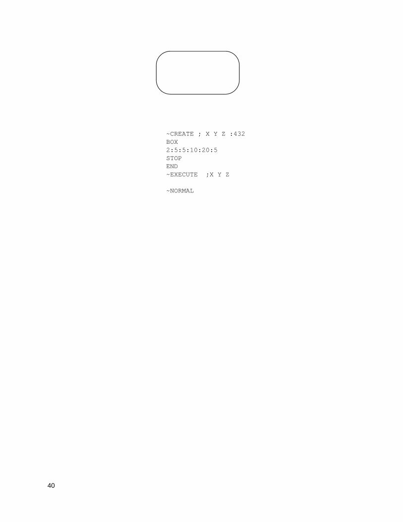
40
~CREATE ; X Y Z :432 BOX 2:5:5:10:20:5 STOP END ~EXECUTE ;X Y Z ~NORMAL
41
Cancel
Purpose To cancel the print job immediately when the command is sent to the printer. When received, printing will stop and any data received prior to the CANCEL command will be cleared from the buffers.
Mode NORMAL
Format (cc) CANCEL
(cc) The Special Function Control Code.
CANCEL The cancel command. Enter CANCEL.
Comment
1. The cancel command will take effect only when a snooper (preparser) is enabled. Any of the following commands will enable the snooper for all ports. You can also enable preparser by using the front panel. Send the following command to the printer before sending the job. ~CONFIG SNOOP;CANCEL;PAR END ~CONFIG SNOOP;CANCEL;ETH END ~CONFIG SNOOP;CANCEL;SER END
The CANCEL command works if it is received from any port. PAR, ETH, and SER are listed as compatible with old PGL commands.
To disable a snooper, send the following command to the printer before sending the job.
~CONFIG
SNOOP;OFF
END
2. After the snooper is enabled, the cancel command can be sent to the printer during the print job through any port.
Example
The following example shows the format of cancel command. ~CANCEL
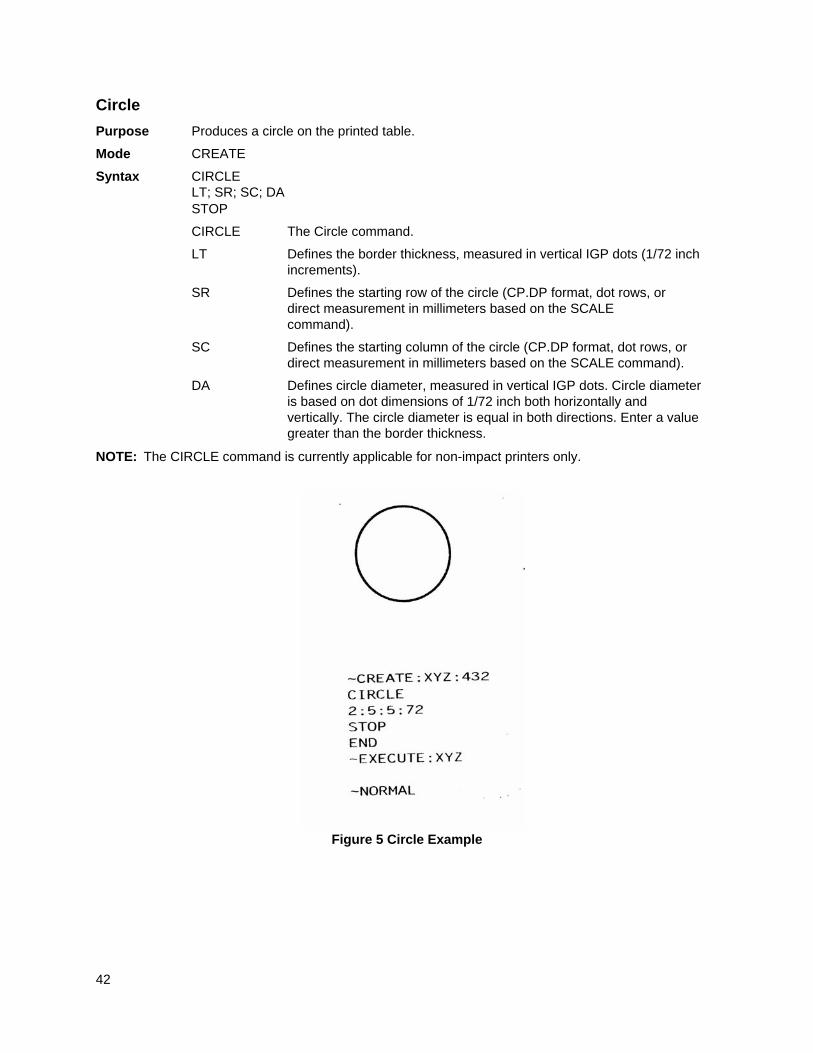
42
Circle
Purpose Produces a circle on the printed table.
Mode CREATE
Syntax CIRCLE LT; SR; SC; DA STOP
CIRCLE The Circle command.
LT Defines the border thickness, measured in vertical IGP dots (1/72 inch increments).
SR Defines the starting row of the circle (CP.DP format, dot rows, or direct measurement in millimeters based on the SCALE command).
SC Defines the starting column of the circle (CP.DP format, dot rows, or direct measurement in millimeters based on the SCALE command).
DA Defines circle diameter, measured in vertical IGP dots. Circle diameter is based on dot dimensions of 1/72 inch both horizontally and vertically. The circle diameter is equal in both directions. Enter a value greater than the border thickness.
NOTE: The CIRCLE command is currently applicable for non-impact printers only.
Figure 5 Circle Example
43
Compressed Print (Density)
Purpose Defines the horizontal print density in characters per inch (cpi).
Mode NORMAL, EXECUTE
Format (cc) DENSITY;n
(cc) The Special Function Control Code.
DENSITY The Density command; enter DENSITY.
n Selects the density in cpi, OCR-A, or OCR-B; enter a value of 10, 12, 13, 15, 17 or 20 to specify the density in characters per inch (the default is 10 cpi), or 10A to select 10 cpi OCR-A or 10B to select 10 cpi OCR-B.
Comments
Print density formats of 10, 12, 13, 15, 17 or 20 cpi are available. If you need to print at 30 cpi, use the Alphanumerics command Cn parameter, as described on page 26. Standard print density is 10 cpi. After a Density command is entered, all subsequent alphanumerics print at the specified density until another Density command, a Normal mode command, or a Reset command is entered. The Density command also permits the standard printer editing function (carriage return editing). After the Density command is entered, data in the print buffer can be edited as described in your printer Administrator’s Manual.
Example
The following command selects 15 cpi printing format until another Density command, a Normal mode command, or a Reset command is entered.
~DENSITY;15
Clock Element Format
Purpose Embeds Realtime Clock information in an ALPHA and/or BARCODE data field.
Format <CI><SIGN><OFFSET><DOT or COMMA><TYPE>
<CI> The Clock Indicator character, as defined by the CLOCK parameter in the ALPHA and/or BARCODE commands. See the ALPHA and BARCODE command descriptions for details.
<SIGN> Sign for the offset, can be “+” to add or “-” to subtract.
<OFFSET> Offset to the selected clock type. This is an amount of time to add to or subtract from the selected clock element value. Also referred to as “Sell-By” Date.
<DOT or COMMA>
The “.” character indicates that this sequence will be printed, and the given offset will be used.
The comma (,) indicates that this sequence will not be printed. It will only be used to specify the offset.
TYPE The clock element to display. See the following table for available elements.
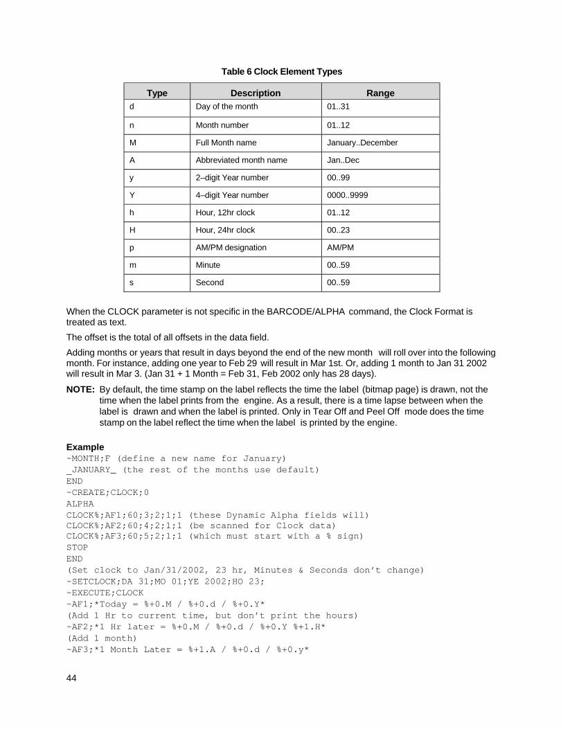
44
Table 6 Clock Element Types
Type Description Range
d Day of the month 01..31
n Month number 01..12
M Full Month name January..December
A Abbreviated month name Jan..Dec
y 2–digit Year number 00..99
Y 4–digit Year number 0000..9999
h Hour, 12hr clock 01..12
H Hour, 24hr clock 00..23
p AM/PM designation AM/PM
m Minute 00..59
s Second 00..59
When the CLOCK parameter is not specific in the BARCODE/ALPHA command, the Clock Format is treated as text.
The offset is the total of all offsets in the data field.
Adding months or years that result in days beyond the end of the new month will roll over into the following month. For instance, adding one year to Feb 29 will result in Mar 1st. Or, adding 1 month to Jan 31 2002 will result in Mar 3. (Jan 31 + 1 Month = Feb 31, Feb 2002 only has 28 days).
NOTE: By default, the time stamp on the label reflects the time the label (bitmap page) is drawn, not the time when the label prints from the engine. As a result, there is a time lapse between when the label is drawn and when the label is printed. Only in Tear Off and Peel Off mode does the time stamp on the label reflect the time when the label is printed by the engine.
Example ~MONTH;F (define a new name for January) JANUARY_ (the rest of the months use default) END ~CREATE;CLOCK;0 ALPHA CLOCK%;AF1;60;3;2;1;1 (these Dynamic Alpha fields will) CLOCK%;AF2;60;4;2;1;1 (be scanned for Clock data) CLOCK%;AF3;60;5;2;1;1 (which must start with a % sign) STOP END (Set clock to Jan/31/2002, 23 hr, Minutes & Seconds don’t change) ~SETCLOCK;DA 31;MO 01;YE 2002;HO 23; ~EXECUTE;CLOCK ~AF1;*Today = %+0.M / %+0.d / %+0.Y* (Add 1 Hr to current time, but don’t print the hours) ~AF2;*1 Hr later = %+0.M / %+0.d / %+0.Y %+1.H* (Add 1 month) ~AF3;*1 Month Later = %+1.A / %+0.d / %+0.y*
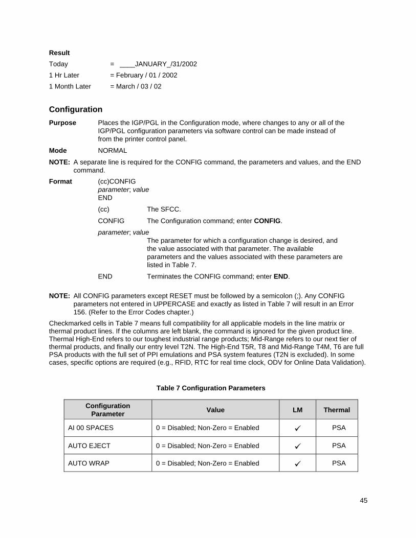
45
Result
Today = ____JANUARY_/31/2002
1 Hr Later = February / 01 / 2002
1 Month Later = March / 03 / 02
Configuration
Purpose Places the IGP/PGL in the Configuration mode, where changes to any or all of the IGP/PGL configuration parameters via software control can be made instead of from the printer control panel.
Mode NORMAL
NOTE: A separate line is required for the CONFIG command, the parameters and values, and the END command.
Format (cc)CONFIG parameter; value END
(cc) The SFCC.
CONFIG The Configuration command; enter CONFIG.
parameter; value The parameter for which a configuration change is desired, and
the value associated with that parameter. The available parameters and the values associated with these parameters are listed in Table 7.
END Terminates the CONFIG command; enter END.
NOTE: All CONFIG parameters except RESET must be followed by a semicolon (;). Any CONFIG parameters not entered in UPPERCASE and exactly as listed in Table 7 will result in an Error 156. (Refer to the Error Codes chapter.)
Checkmarked cells in Table 7 means full compatibility for all applicable models in the line matrix or thermal product lines. If the columns are left blank, the command is ignored for the given product line. Thermal High-End refers to our toughest industrial range products; Mid-Range refers to our next tier of thermal products, and finally our entry level T2N. The High-End T5R, T8 and Mid-Range T4M, T6 are full PSA products with the full set of PPI emulations and PSA system features (T2N is excluded). In some cases, specific options are required (e.g., RFID, RTC for real time clock, ODV for Online Data Validation).
Table 7 Configuration Parameters
Configuration Parameter
Value LM Thermal
AI 00 SPACES 0 = Disabled; Non-Zero = Enabled PSA
AUTO EJECT 0 = Disabled; Non-Zero = Enabled PSA
AUTO WRAP 0 = Disabled; Non-Zero = Enabled PSA
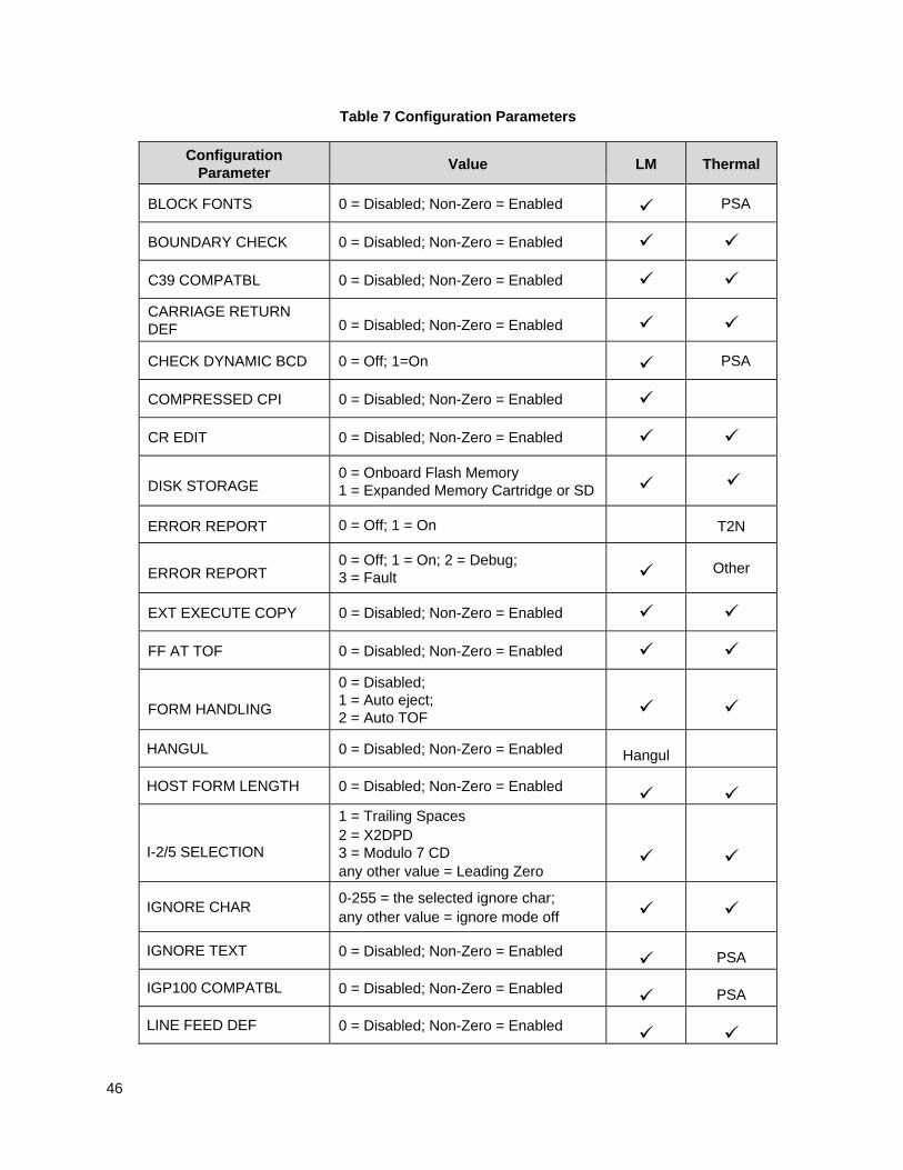
46
Table 7 Configuration Parameters
Configuration Parameter
Value LM Thermal
BLOCK FONTS 0 = Disabled; Non-Zero = Enabled PSA
BOUNDARY CHECK 0 = Disabled; Non-Zero = Enabled
C39 COMPATBL 0 = Disabled; Non-Zero = Enabled
CARRIAGE RETURN DEF 0 = Disabled; Non-Zero = Enabled
CHECK DYNAMIC BCD 0 = Off; 1=On PSA
COMPRESSED CPI 0 = Disabled; Non-Zero = Enabled
CR EDIT 0 = Disabled; Non-Zero = Enabled
DISK STORAGE 0 = Onboard Flash Memory 1 = Expanded Memory Cartridge or SD
ERROR REPORT 0 = Off; 1 = On T2N
ERROR REPORT 0 = Off; 1 = On; 2 = Debug; 3 = Fault Other
EXT EXECUTE COPY 0 = Disabled; Non-Zero = Enabled
FF AT TOF 0 = Disabled; Non-Zero = Enabled
FORM HANDLING
0 = Disabled; 1 = Auto eject; 2 = Auto TOF
HANGUL 0 = Disabled; Non-Zero = Enabled Hangul
HOST FORM LENGTH 0 = Disabled; Non-Zero = Enabled
I-2/5 SELECTION
1 = Trailing Spaces 2 = X2DPD 3 = Modulo 7 CD any other value = Leading Zero
IGNORE CHAR 0-255 = the selected ignore char; any other value = ignore mode off
IGNORE TEXT 0 = Disabled; Non-Zero = Enabled PSA
IGP100 COMPATBL 0 = Disabled; Non-Zero = Enabled PSA
LINE FEED DEF 0 = Disabled; Non-Zero = Enabled
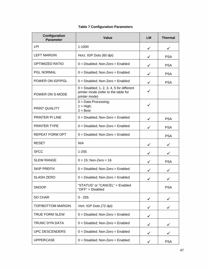
47
Table 7 Configuration Parameters
Configuration Parameter
Value LM Thermal
LPI 1-1000
LEFT MARGIN Horz. IGP Dots (60 dpi) PSA
OPTIMIZED RATIO 0 = Disabled; Non-Zero = Enabled PSA
PGL NORMAL 0 = Disabled; Non-Zero = Enabled PSA
POWER ON IGP/PGL 0 = Disabled; Non-Zero = Enabled PSA
POWER ON S-MODE
0 = Disabled; 1, 2, 3, 4, 5 for different printer mode (refer to the table for printer mode)
PRINT QUALITY
0 = Data Processing; 1 = High; 2 = Best
PRINTER PI LINE 0 = Disabled; Non-Zero = Enabled PSA
PRINTER TYPE 0 = Disabled; Non-Zero = Enabled PSA
REPEAT FORM OPT 0 = Disabled; Non-Zero = Enabled PSA
RESET N/A
SFCC 1-255
SLEW RANGE 0 = 15; Non-Zero = 16 PSA
SKIP PREFIX 0 = Disabled; Non-Zero = Enabled
SLASH ZERO 0 = Disabled; Non-Zero = Enabled
SNOOP “STATUS” or “CANCEL” = Enabled “OFF” = Disabled PSA
SO CHAR 0 - 255
TOP/BOTTOM MARGIN Vert. IGP Dots (72 dpi)
TRUE FORM SLEW 0 = Disabled; Non-Zero = Enabled
TRUNC DYN DATA 0 = Disabled; Non-Zero = Enabled
UPC DESCENDERS 0 = Disabled; Non-Zero = Enabled
UPPERCASE 0 = Disabled; Non-Zero = Enabled PSA
48
Table 7 Configuration Parameters
Configuration Parameter
Value LM Thermal
UPCASE DOT 0 0 = Disabled; Non-Zero = Enabled PSA
USER-DEF RATIO 0 = Disabled; Non-Zero = Enabled PSA
VAR FORM ADJUST 0, 1, ..., 30
VAR FORM TYPE
0 = Add Nothing 1 = Add 2 = Add; X
Comments
The IGP/PGL configuration parameters available are defined in your Administrator’s Manual.
Any or all parameters can be used within one CONFIG command, and they can be listed in any order. List each parameter;value on a separate line, terminating with the END command. Default configuration values can be reset using the CONFIG command.
Parameters not followed by a value, and parameters followed by any non-zero value are interpreted as “true” or “enabled” values. For carriage return and line feed definitions, a zero value does not change the data stream. However, for non-zero values, a carriage return character or line feed character will be interpreted as a carriage return plus a line feed.
Parameters not listed in this command remain unchanged. If a parameter error is detected for parameters other than 0 or 1 (i.e., SFCC, Top/Bottom Margin, Left Margin), the value will default to the current configuration from flash memory.
Example 1
The following command enables IGP/PGL Auto Wrap, disables Auto Eject, and selects 6 lpi printing.
~CONFIG AUTO WRAP;1 AUTO EJECT;0 LPI;6 END
Example 2
The following command resets all control panel IGP/PGL configuration parameters back to default values. ~CONFIG RESET END
49
Corners
Purpose Defines corner sets.
Mode CREATE
Format CORNER
LT;SR;SC;ER;EC;VL;HL
STOP
CORNER The Corner command; enter CORNER. Corners expand down and to the right from the given row and column.
LT Defines the line thickness, measured in dots. Line thickness is based on dot dimensions of 1/72” both horizontally and vertically, so that line thickness is equal in both directions. Enter a value of 1 or greater.
SR Defines the starting row of the corner. Enter a value ranging from row 1 through one less than the length of the form. Character row or dot row in millimeters is specified based on the Scale command (page 113), or use the CP.DP format (page 23).
SC Defines the starting column of the corner. Enter a value ranging from column 1 through one less than the width of the form. Character column or dot column in millimeters is specified based on the Scale command (page 113), or use the CP.DP format (page 23).
ER Defines the ending row of the corner. Enter a value ranging from row 2 through the last row of the form. The ending row must be greater than the starting row. Character row or dot row in millimeters is specified based on the Scale command (page 113), or use the CP.DP format (page 23).
EC Defines the ending column of the corner. Enter a value ranging from column 2 through the last column of the form. The ending column must be greater than the starting column. Character column or dot column in millimeters is specified based on the Scale command (page 113), or use the CP.DP format (page 23).
VL Defines the length of the vertical arm (including the line thickness) of each corner in the set. Enter a value of 1 or greater specified in character or dot rows based on the Scale command (page 113), or use the CP.DP format (page 23).
HL Defines the length of the horizontal arm (including the line thickness) of each corner in the set. Enter a value of 1 or greater specified in character or dot columns based on the Scale command (page 113), or use the CP.DP format (page 23).
STOP Stop indicates the end of the CORNER command; enter STOP, and the IGP/PGL will wait for a new command. If not entered, the IGP/PGL will wait for another set of Corner command parameters.
50
Example The following program specifies a corner set as shown in
Figure 6. To illustrate positioning, the starting row and column are indicated on the example but do not necessarily reflect actual location on the page. (Note the position of the ending row and ending column; they do not include the line thickness.)
CORNER 5;27;27;42;55;4;6 (Each corner in the set is 5 dot rows thick, 4 character STOP rows high, 6 character columns wide)
Figure 6 Corner Example
ROW 27
COLUMN 27
ROW 42
COLUMN 55
VERTICAL LENGTH 4 ROWS
HORIZONTAL LENGTH 6 COLUMNS
51
CREATE
Purpose Places the IGP/PGL in the Create Form mode, where forms and form elements can be defined using the appropriate commands.
Mode NORMAL
Format (cc)CREATE; [/]formname [;FL] [;NOMOTION] [;DISK] (cc)
The Special Function Control Code.
CREATE The Create Form mode command; enter CREATE.
/ The optional debug character to check the program line by line for incorrect parameters and print boundaries using the current page size; enter the slash symbol (/) to debug the program. No checks are made until the completed program is sent to the IGP/PGL for storage (when the form is executed by printing the file with the IGP/PGL program). Then the form name is entered into the directory, and the program is evaluated. If errors are detected, the program will print, line by line (including the error on the line where the error occurs), followed by the error-free sections of the form. Correct all errors and delete the slash. Refer to Solving Program Errors on page 338.
formname Defines the form name of the form being created. The form name should be no more than 15 characters in length. Refer to page 22 for a list of allowable form name characters. If a form is created with the same name as a form already existing in memory, the newly created form will replace the existing form. All future reference to the form (editing, executing, or deleting the form from the directory) must be made using the assigned name.
FL The optional forms length parameter to specify the length of the form in IGP dot rows. (Form length cannot exceed the physical length of the page.
Refer to Appendix C). Specify the form length in one of four ways:
a. Enter 0 to define a form of unspecified length. The form ends after the longest element specified in CREATE mode.
b. Enter a value for the form length ranging from 1 through 65535 to specify the forms length in IGP dot rows.
c. Do not specify this parameter. A default of 792 IGP dots (11 inches) is then selected.
d. Enter X to define the form length of undetermined length Upon EXECUTE mode, the form’s length is determined by the physical page length setting (which depends on the paper orientation).
NOMOTION The optional parameter that tells the printer not to move the paper after execution of the form if the form does not print anything on the paper. If the form has commands such as Alpha or Barcode commands that require printing, this parameter will have no effect and the paper will always move. By default, PGL will always move the paper with or without the print graphic command.
NOTE: NOMOTION is primarily used in RFID applications to program RFID tags.
52
DISK Optional parameter to store the form to the Onboard Flash Memory. Enter DISK. For XML driven forms, use the DISK option. See Link on page 76 for a description and example on XML forms. Enter EMC to store the form to the SD card or External Memory Cartridge. See Flash Memory Utilization on page 18.
Example
The following command creates a form named ORDER with the default forms length:
(cc)CREATE;ORDER
Dark Printing
A DARK parameter, available in the Alpha, Reverse, and Bar Code commands, is like the double-strike feature in impact printers which produces bolder, darker text, denser black backgrounds for reverse print, and extra- dark, more readable bar codes.
Reverse and Bar Code commands automatically print in the DARK mode in thermal printers; therefore, a DARK parameter in the command line is ignored. However, a DARK parameter used with alphanumeric text in the ALPHA command will print using a bold font. In any event, print speed is not reduced when using the DARK parameter with thermal printers.
For barcodes, the Dark parameter fills in the space between two adjacent dots in the horizontal direction. The DARK parameter will take affect if there is more than one dot in the horizontal direction. The DARK parameter will not take affect if there is only one dot on the horizontal direction.
For example, the Intelligent Mail 4-State barcode contains a bar only one dot wide. In the horizontal rotation (0 or 180 degrees), the DARK option will not take affect since there is only one dot for each bar in the horizontal direction. However, in the vertical rotation (90 or 270 degrees), the DARK option will take effect since there is more than one dot for each bar in the horizontal direction. For barcodes such as EAN, whose bar is more than one dot wide, the DARK option will take effect in both vertical and horizontal rotations since in both rotations, there is more than one dot for each bar in the horizontal direction.
Define Month Names
Purpose Allows the creation of user-definable strings to be used as full and abbreviated month strings in the clock elements. This allows users to create these names in any language.
Mode NORMAL
Format (cc) MONTH;F or A;
Name01
Name02
..
Name12
END
MONTH The define Month Names command.
F Define Full Month Names (Translations for clock element “M”)
A Define Abbreviated Month Names (Translations for clock element “A”)
END Ends the command.
53
Comments
Every Month Name to be defined must be entered on it’s own line, terminated by a line terminator.
Empty Names will be set to their full default value. Defaults for “F” are the English month names (January–December). For the “A” parameter, the defaults are the 3–letter abbreviated English month names (Jan–Dec).
The command may be ended without defining all 12 names, the non–defined names will not change.
Example
See Clock Element Format on page 43.
Delete Font
Purpose Deletes the font identified by the font name which resides in flash memory or RAMDISK memory.
Mode NORMAL
Format (cc) DELETE FONT;fontname;[DISK]
(cc) The Special Function Control.
DELETE FONT The Delete Font Command; enter DELETE FONT.
fontname Identifies the font to be deleted. Enter the name of the font exactly as it was created.
DISK Optional parameter. Enter DISK to delete the font from Onboard Flash Memory. Enter EMC to delete the font from the SD card or External Memory Cartridge. When DISK is not specified, the font is deleted from RAMDISK.
See Flash Memory Storage on page 18.
Comment
When loading fonts to RAMDISK, the printer files will not be saved to RAMDISK when the printer is powered off. When loading fonts to flash memory, the printer files will be saved when the printer is powered off. Both RAMDISK and flash memory support file operations such as saving, reading, and deleting files. Removing all font files with *ALL as fontname is not currently supported.
Example
The following example deletes a downloaded true type font named times.ttf from flash memory.
~DELETE FONT;times.ttf;DISK
NOTE: The space of files deleted from flash are not reclaimed for general use within the flash file system until an Optimize&Reboot operation is performed. It is not recommended to frequently store or delete files to flash. If the Optimize&Reboot operation is not available in the menu system, then deleted files are reclaimed by the printer for general use.
54
Delete Form
Purpose Deletes the form identified by the form name from memory.
Mode NORMAL
Format (cc)DELETE FORM;formname [;DISK]
DELETE FORM The Delete Form command.
formname Identifies the form to be deleted. You can delete all forms by entering *ALL as the form name.
DISK If applicable, the form deletes from both RAM and FLASH. Enter DISK to delete the form from Onboard Flash Memory. Enter EMC to delete the form from the SD card or External Memory Cartridge. See Flash Memory Storage on page 18.
NOTE: The space of files deleted from flash are not reclaimed for general use within the flash file system until an Optimize&Reboot operation is performed. It is not recommended to frequently store or delete files to flash. If the Optimize&Reboot operation is not available in the menu system, the deleted files are reclaimed by the printer for general use.
Delete Logo
Purpose Deletes the logo identified by the logo name from memory.
Mode NORMAL
Format (cc)DELETE LOGO;logoname [;DISK]
DELETE LOGO The Delete Form command.
logoname Identifies the logo to be deleted. You can delete all logos by entering *ALL as the logo name.
DISK If applicable, the logo deletes from both RAM and FLASH.
Enter DISK to delete the logo from Onboard Flash Memory.
Enter EMC to delete the logo from the SD card or External Memory Cartridge. See Flash Memory Storage on page 18.
NOTE: The space of files deleted from flash are not reclaimed for general use within the flash file system until an Optimize&Reboot operation is performed. It is not recommended to frequently store or delete files to flash. If the Optimize&Reboot operation is not available in the menu system, then deleted files are reclaimed by the printer for general use.
55
Directory
Purpose Prints the following information: (1) all defined forms and logos, (2) logo assignment to forms, and (3) memory usage and availability for DRAM, Onboard Flash Memory, and SD/EMC (if available).
Mode NORMAL
Format (cc)DIRECTORY[;DISK or ;EMC]
(cc) The Special Function Control Code.
DIRECTORY The Directory command; enter DIRECTORY.
DISK or EMC Optional parameter to specify the forms and logos stored in permanent memory. Enter DISK for Onboard Flash Memory or enter EMC to include the SD card or Extended Memory Cartridge.
Comments
As many forms and logos as printer memory allows may be stored in IGP/PGL memory. If the memory is full, the form will not print; available space in the memory must be at least the size of the form being executed.
For more information, refer to the Directory Example on page 337.
Duplication, Horizontal
Purpose Defines both the number of times form elements are duplicated horizontally and the spacing between each duplication.
Mode CREATE
Format HDUP;dup#;offset# elements to be duplicated HDUP;OFF
HDUP The Horizontal Duplication command; enter HDUP.
dup# Specifies the duplication number, which is the number of times the entered form element(s) will repeat horizontally. Enter a value ranging from 1 through 255.
offset# Specifies the horizontal offset to establish the horizontal spacing between each duplication of the form element(s) specified in the body of the command. Enter a value in terms of dot or character columns based on the Scale command (page 113), or use the CP.DP format (page 23). The offset is from starting column to starting column.
HDUP;OFF Terminates the Horizontal Duplication command; enter HDUP;OFF. If not entered, the IGP/PGL expects another form element to be defined for duplication. A single HDUP command can define different types of elements for duplication.
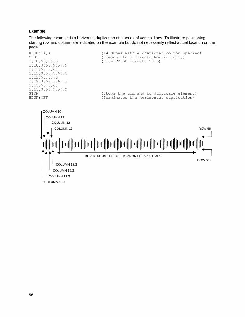
56
Example
The following example is a horizontal duplication of a series of vertical lines. To illustrate positioning, starting row and column are indicated on the example but do not necessarily reflect actual location on the page.
HDUP;14;4 (14 dupes with 4-character column spacing) VERT (Command to duplicate horizontally) 1;10;59;59.6 (Note CP.DP format: 59.6) 1;10.3;58.9;59.9 1;11;58.6;60 1;11.3;58.3;60.3 1;12;58;60.6 1;12.3;58.3;60.3 1;13;58.6;60 1;13.3;58.9;59.9 STOP (Stops the command to duplicate element) HDUP;OFF (Terminates the horizontal duplication)
ROW 58
COLUMN 10
COLUMN 11
COLUMN 12
COLUMN 13
COLUMN 10.3
COLUMN 11.3
COLUMN 12.3
COLUMN 13.3 ROW 60.6
DUPLICATING THE SET HORIZONTALLY 14 TIMES
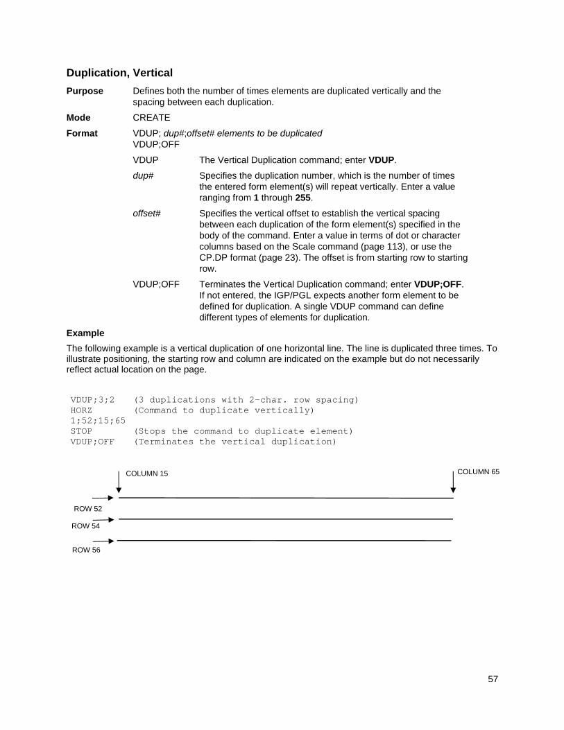
57
Duplication, Vertical
Purpose Defines both the number of times elements are duplicated vertically and the spacing between each duplication.
Mode CREATE
Format VDUP; dup#;offset# elements to be duplicated VDUP;OFF
VDUP The Vertical Duplication command; enter VDUP.
dup# Specifies the duplication number, which is the number of times the entered form element(s) will repeat vertically. Enter a value ranging from 1 through 255.
offset# Specifies the vertical offset to establish the vertical spacing between each duplication of the form element(s) specified in the body of the command. Enter a value in terms of dot or character columns based on the Scale command (page 113), or use the CP.DP format (page 23). The offset is from starting row to starting row.
VDUP;OFF Terminates the Vertical Duplication command; enter VDUP;OFF. If not entered, the IGP/PGL expects another form element to be defined for duplication. A single VDUP command can define different types of elements for duplication.
Example
The following example is a vertical duplication of one horizontal line. The line is duplicated three times. To illustrate positioning, the starting row and column are indicated on the example but do not necessarily reflect actual location on the page.
VDUP;3;2 (3 duplications with 2-char. row spacing) HORZ (Command to duplicate vertically) 1;52;15;65 STOP (Stops the command to duplicate element) VDUP;OFF (Terminates the vertical duplication)
COLUMN 15 COLUMN 65
ROW 52
ROW 54
ROW 56
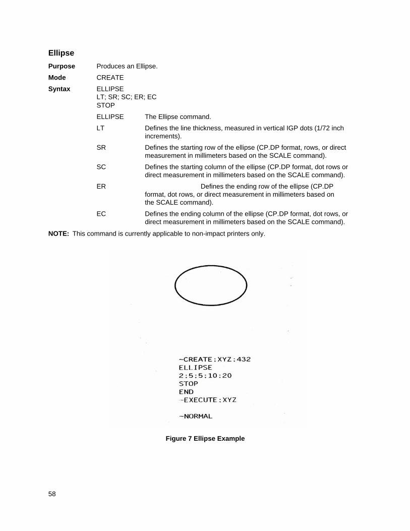
58
Ellipse
Purpose Produces an Ellipse.
Mode CREATE
Syntax ELLIPSE LT; SR; SC; ER; EC STOP
ELLIPSE The Ellipse command.
LT Defines the line thickness, measured in vertical IGP dots (1/72 inch increments).
SR Defines the starting row of the ellipse (CP.DP format, rows, or direct measurement in millimeters based on the SCALE command).
SC Defines the starting column of the ellipse (CP.DP format, dot rows or direct measurement in millimeters based on the SCALE command).
ER Defines the ending row of the ellipse (CP.DP format, dot rows, or direct measurement in millimeters based on the SCALE command).
EC Defines the ending column of the ellipse (CP.DP format, dot rows, or direct measurement in millimeters based on the SCALE command).
NOTE: This command is currently applicable to non-impact printers only.
Figure 7 Ellipse Example
59
Emulation Switching
Purpose To switch the active emulation from IGP/PGL to the emulation selected.
Mode NORMAL
Format (cc)EMULATION; emulation
(cc) The Special Function Control Code.
EMULATION The Emulation Switch command.
emulation Specifies the emulation to activate. Enter V to switch to VGL and P to switch to ZGL.
Comments
The switching of emulations causes IGP/PGL to perform a soft reset. Therefore, front panel selections return to their saved state, and all forms and logos resident in RAM memory are deleted.
Enter V to select VGL and P for ZGL.
End
Purpose Terminates the current mode of operation and must be used before entering a new mode command (EXECUTE, LOGO, NORMAL, or even CREATE).
Mode CREATE
Format END
Comments
After the End command is received, the IGP/PGL flushes program errors, stores the error-free portions of the form program just completed, and then returns to the Normal mode. If the debug slash (/) is included in the Create command, the program prints with any corresponding error messages.
Enquiry
Purpose To send information (a status byte) about the printer state to the host through the serial port. This command is ignored if the current host interface is not the serial port. This is an online command and is not required to be followed by a terminator.
Mode NORMAL, CREATE, or EXECUTE
Format (cc) ENQUIRY
ENQUIRY The Enquiry command. Enter ENQUIRY.
Execute Form Mode
How to Use the Execute Command
Forms are printed in the Execute Form mode. In addition to printing the form in the Execute Form mode, variable data can also be entered onto the form “dynamically” during the Execute Form mode. This dynamic data input during the Execute Form mode includes page numbers, alphanumeric data fields, and bar code data fields. Pagination, described on page 84, is performed in the Execute Form mode. Dynamic alphanumeric and bar code data require additional commands within the Execute Form mode.
The fastest method for repeated forms printing is to use the form feed character. Rather than sending a series of Execute/Normal commands, which slows the process by performing an open-print-close form sequence, the form feed character instructs the IGP/PGL to start a new page with new EVFU, dynamic and overlay data using the existing Execute commands for the form. The EVFU Data-Dynamic Data-
60
Overlay Data-Form Feed Character sequence can be repeated indefinitely while maintaining the optimum print speed within the original Execute command.
Remember, when a form count is not specified, a single line spacing (or a line containing overlay data) must always separate an EXECUTE command from a NORMAL command.
To Execute Forms Rapidly
In order to save reloading time, the IGP/PGL remembers the last form executed. However, a form must be loaded if it was not the last form executed, if it was used with a CREATE command since the last EXECUTE, or if any logo has been created.
When the form to be executed is found in memory, it is loaded and execution resumes; otherwise, the “FORM NOT FOUND” error is printed.
Print Formats in the Execute Form Mode
The Execute Form mode has two print formats. The standard execute command format, shown on page 60, is used for executing non-incremental data and incremental fixed data. An incremental Execute command format, containing two additional parameters, is used for executing incremental dynamic data and is discussed on page 65.
During the Execute Form mode, the IGP/PGL responds to regular print format commands such as 8 lpi, and elongated characters. Some commands can be used in other modes in addition to the Execute Form mode. For example, Compressed Print, Expanded Print, Execute, Ignore, Select Format, and Vertical Line Spacing, which are also Normal mode commands, can be used in the Execute or Create Form modes. The IGP/PGL alternate character set can also be used in the Execute Form mode.
Execute Form: General Format
Purpose Prints forms created in the CREATE mode.
Mode NORMAL
Format (cc)EXECUTE ;formname [;SAVEDYN] [;PAGE n] [;FC] [;ICNTn] [;FCNTn] [;IRSTn] [;DISK]
[;DISK] [EVFU Data] [(cc)AFn; (D)ASCII text(D)] [(cc)BFn; (D)data(D)] [(cc)DFn; (D)data(D)] [(cc)AFn; <DFn>] [(cc)BFn; <DFn>] [(cc)GFn; (D)logoname(D)] [(cc)IAFn; [idir] STEPMASK;[RPTn;] [RSTn;] (D)STARTDATA(D)] [(cc)IBFn; [idir] STEPMASK;[RPTn;] [RSTn;] (D)STARTDATA(D)] [(cc)IDFn; [idir] STEP;[RPTn;][RSTn;] (D)STARTDATA(D)] [Overlay Data]
[Form Feed character] (cc)NORMAL
(cc) The Special Function Control Code.
EXECUTE The Execute Form command; enter EXECUTE.
formname Identifies a previously defined form by name. Enter the form name exactly as used when created.
SAVEDYN The optional command to have dynamic fields saved across forms that are separated with a form feed character.
PAGE n The optional Pagination command; enter PAGE, a space, and replace n with the decimal number of the starting page in a
61
sequence of multiple pages. The number may be eight digits long and range between 0 and 99999999. The next page after 99999999 is 0. Be sure to leave a blank space between the PAGE command and the n value. The page number will print on the form in the location defined by the Page Number command in the Create Form mode. If the location of the pagination field was not specified in the Create Form mode, the page field is printed in the upper left corner of the form.
FC The optional form count parameter specifies the number of copies of the form to print. Enter the appropriate number. When the last page prints, the IGP/PGL returns to the Normal mode automatically. Do not use the form count parameter if dynamic data (AFn and BFn parameters), incremental data (FCNT, ICNT, or IRST parameters), overlay data, or EVFU data are used in the Execute command.
FCNTn The optional incremental form count. Enter FCNT (functions the same as ICNT and the form count value). However, with FCNT, both incremental dynamic data (IAF or IBF) and non-incremental dynamic data (AF or BF) will be printed on each page. With ICNT, only incremental dynamic data will be printed on each page and non-incremental dynamic data will only be printed on the first page.
ICNTn The optional incremental form count. Enter ICNT and the Incremental value as described in the Execute Incremental Dynamic Data command described on page 65.
IRSTn The optional incremental reset count parameter.Enter IRST and the reset value as described in the Execute Incremental Dynamic Data command described on page 65.
DISK Optional parameter that specifies to recall the form from Onboard Flash Memory. Enter DISK. To recall the form from the SD Card or Expanded Memory Cartridge, enter EMC. This option is not required since the printer automatically searches DRAM, the Expanded Memory Cartridge, and Flash. See Flash Memory Storage on page 18.
EVFU Data Optional parameter to use the EVFU to overlay data onto the form. (“EVFU Data” is not part of the Execute command. It is shown in the command sequence to indicate that actual EVFU data can be entered following the Execute command.) Enter EVFU data as described in Appendix D and on page 62.
(cc)AFn;(D)ASCII text(D) The Execute Dynamic Alphanumeric Data command. Enter the dynamic alphanumeric data during the Execute Form mode as described in Execute Form: Dynamic Alphanumeric Data on page 63.
(cc)BFn;(D)data(D) The Execute Dynamic Bar Code Data command. Enter the dynamic bar code data during the Execute Form mode as described in Execute Form: Dynamic Bar Code Data on page 64.
(cc)DFn;(D)data(D) Refer to RFWTAG on page 102.
62
(cc)AFn;<DFn> Prints RFID tag data as ALPHA TEXT, refer to RFWTAG on page 102 for an example.
(cc)BFn;<DFn> Prints RFID tag data as Barcode data. Refer to RFWTAG on page 102 for an example.
(cc)DFn;<DFm> Use the contents of dynamic RFID field DFm in the dynamic RFID field DFn.
(cc)GFn;(D)logoname(D) The Execute Dynamic Logo Command. Enter the name of the logo during the Execute Form mode as described in Execute Form: Dynamic Logo on page 64.
(cc)IAFn; [idir] STEPMASK; [RPTn;] [RSTn;] (D)STARTDATA(D) The Execute Incremental Dynamic Alphanumeric Data command. Supply the data as described on page 66.
(cc)IDFn; [idir] STEP; [RPTn;][RSTn;](D)STARTDATA(D) Refer to RFWTAG on page 102.
(cc)IBFn; [idir] STEPMASK; [RPTn;] [RSTn;] (D)STARTDATA(D) The Execute Incremental Dynamic Bar Code Data command. Supply the data as described on page 66.
Overlay Data Overlay data can be entered during the Execute Form mode. (The words “Overlay Data” are not part of the Execute command. They are shown in the command sequence to indicate that actual overlay data can be entered following the Execute command.) Refer to Execute Form: Overlay Data on page 67.
Form Feed Character Optional command instructing the IGP/PGL to start a new page with new EVFU, dynamic, and overlay data using the existing Execute commands for the current form. This EVFU Data-Dynamic Data and Overlay Data-Form Feed Character sequence can be repeated indefinitely, while maintaining the optimum print speed, within the original Execute command.
(cc)NORMAL The Normal mode command. If the form count parameter was not used in the Execute command, enter the SFCC and NORMAL to return the IGP/PGL to the Normal mode. The Normal mode command is input following all other Execute commands to enter variable data. (Refer to the following sections.) Input a line terminator to leave a blank line before entering the Normal command.
Execute Form: Electronic Vertical Format Unit
Purpose Provides an efficient method of automatically skipping to a specified print line during repetitive printing tasks.
Mode EXECUTE
Format See Appendix D.
63
Comments
The Electronic Vertical Format Unit (EVFU) is used as overlay data within the Execute Form mode. Detailed EVFU information is provided in Appendix D.
The EVFU must be loaded while in the Execute Form mode and immediately following the Execute command. After executing the form and returning to Normal mode, the EVFU information is automatically deleted from printer memory. To print the form again, re-send the EVFU command.
Several key points to operating the EVFU are listed below.
Send EVFU commands immediately following the Execute command or the format form feeds.
The EVFU can be unloaded by issuing an END LOAD command only.
The number of lines slewed is dictated by the current line spacing (lpi) setting.
In those circumstances where the EVFU is being used to control the forms length only, the IGP/PGL forms length parameter can be used in place of the EVFU.
The maximum number of EVFU channels is 192.
Changing the LPI unloads the EVFU.
Execute Form: Dynamic Alphanumeric Data
Purpose Incorporates the dynamic alphanumeric data into a previously identified location of a form.
Mode EXECUTE
Format (cc)AFn;(D)ASCII text(D)
(cc) The Special Function Control Code.
AFn Indicates a dynamic alphanumeric field (AF) and its data (n). Enter AF and replace n with the number of the data field corresponding to the number used to identify the field when it was defined with the Alphanumeric command in the Create Form mode.
(D) The printable character identifying the start and finish of the alphanumeric data. Enter any printable character other than a slash (/), the SFCC, or a character used within the data. The same character must be used at both ends of the data field but will not be printed with the data.
ASCII text The group of ASCII characters (the alphanumeric string) to print. Enter any of the standard ASCII printable characters (except the character used as delimiters described in the (D) parameter). The data appears on the form at the location identified by n.
NOTE: Commands can appear anywhere in the overlay text with IGP/PGL, but it is recommended they are placed at the beginning.
Comments
The location for the Dynamic alphanumeric data must have been previously identified using the AFn;L parameters of the alphanumerics command in the Create Form mode. Inputting individual commands enters the new data into the identified location each time the form is printed.
You can repeat the (cc)AFn;(D)ASCII text(D) sequence to complete as many data fields as you defined on the form in the Create Form mode. You can also combine the Execute Dynamic Bar Code Data command in the same Execute command sequence. Each “page” of dynamic data (the dynamic fields, data, and overlay data) for the form must be separated from the next page of new dynamic data by a form feed.
64
Execute Form: Dynamic Bar Code Data
Purpose Incorporates the dynamic bar code data into a previously identified location of a form.
Mode EXECUTE
Format (cc)BFn;(D)data field(D)
(cc) The Special Function Control Code.
BFn Indicates a dynamic bar code field (BF) and its data (n). Enter BF and replace n with the number of the data field corresponding to the number used to identify the field when it was defined with the bar code command during the Create Form mode.
(D) The printable character (quotation marks for example) identifying the start and finish of the bar code data. Enter any printable character other than a slash (/), the SFCC, or a character used within the data. The same character must be used at both ends of the data field but will not be printed with the data.
data field Enter the characters for the bar code data. The type of characters allowed in the data varies with the type of bar code. Refer to the data field descriptions for the selected bar code types. The data appears on the form at the location identified by n.
NOTE: Commands can appear anywhere in the overlay text with IGP/PGL, but it is recommended they are placed at the beginning.
Comments
The bar code location must have been previously identified using the BFn;L parameters of a bar code command in the Create Form mode. Then use the appropriate bar code command to enter the bar code data in that location. Inputting individual commands enters new bar code data into the identified location each time the form is printed.
You can repeat the (cc)BFn;(D)data field(D) sequence to complete as many bar code data fields as were defined on the form in the Create Form mode. You can also combine the Execute Dynamic Alphanumeric Data command in the same Execute command sequence. Each “page” of dynamic data (the dynamic fields, data, and overlay data) for the form must be separated from the next page of new dynamic data by a form feed.
Execute Form: Dynamic Logo
Purpose Incorporates the dynamic graphic logo into a previously identified location of a form.
Mode EXECUTE
Format (cc)GFn;(D)logoname(D)
(cc) The Special Function Control Code.
GFn Indicates the dynamic logo field. Enter GF and replace n with the number of the field corresponding to when it was defined with the Logo Call command during the CREATE form mode.
(D) The printable character identifying the start and finish of the alphanumeric data. Enter any printable character other than a slash (/), the SFCC, or a character used within the data. The same character must be used at both ends of the data field but will not be included in the logo name.
65
logoname Enter the logo name. If the logo is not found in DRAM, the flash memory is searched.
Comments
The logo location must have been previously identified using the GFn parameters of a logo command in the Create Form mode. Then use the appropriate logo command to enter the logo data in that location. Inputting individual commands enters new logo data into the identified location each time the form is printed. You can repeat the (cc)GFn;(D)logoname(D) sequence to complete as many logo data fields as were defined on the form in the Create Form mode. You can also combine the Execute Dynamic Alphanumeric Data command in the same Execute command sequence. Each “page” of dynamic data (the dynamic fields, data, and overlay data) for the form must be separated from the next page of new dynamic data by a form feed.
NOTE: There are no incremental logos.
Execute Form: Incremental Dynamic Data
Purpose Incorporates incremental/decremental capability to dynamic alphanumeric or bar code data supplied as a part of the Execute Form mode.
Mode NORMAL
NOTE: In the command below, incremental Execute parameters are shown in boldface type; standard Execute command parameters are shown in italics. The general Execute format is shown on page 60.
Format (cc)EXECUTE; formname [;PAGEn] [;FC] [;ICNTn] [;IRSTn]
ICNTn Identifies the incremental form count to specify the number of forms to generate with the incremental fields automatically updated. Enter ICNT and replace n with a value ranging from 1 through 65535 to specify the number of forms.
IRSTn The optional incremental reset count parameter to specify the number of forms to generate before resetting all incremental fields to their starting values. The reset count parameter is useful in dividing the total number of forms generated into multiple groups of identical copies. To use this parameter, enter IRST and replace n with a value ranging from 1 through 65535 to specify the reset count (how many forms generated before resetting the incremental fields). If the reset count value is equal to or greater than the incremental count value, the reset will never occur.
Example
The following forms were generated from ICNT6, IRST2. (To duplicate incremental fields within a form, refer to page 35.)
0 3 0 3 0 3
1 4 1 4 1 4
2 5 2 5 2 5
form1 form2 form3 form4 form5 form6 = ICNT6
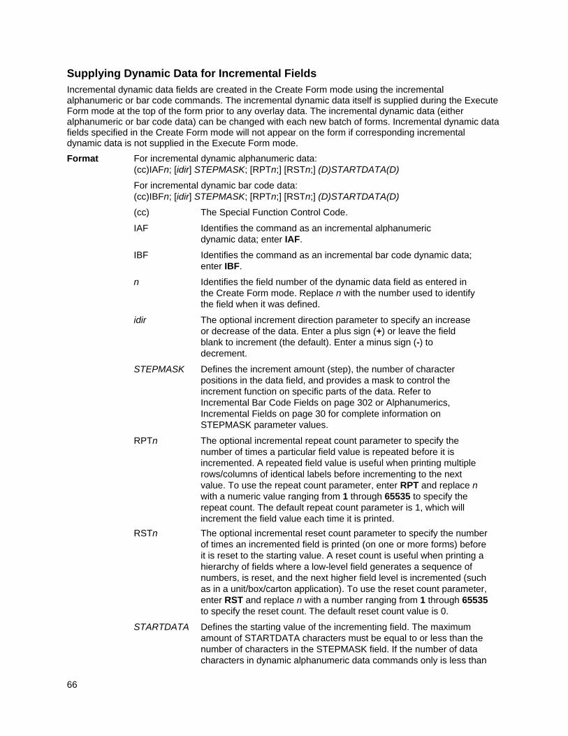
66
Supplying Dynamic Data for Incremental Fields
Incremental dynamic data fields are created in the Create Form mode using the incremental alphanumeric or bar code commands. The incremental dynamic data itself is supplied during the Execute Form mode at the top of the form prior to any overlay data. The incremental dynamic data (either alphanumeric or bar code data) can be changed with each new batch of forms. Incremental dynamic data fields specified in the Create Form mode will not appear on the form if corresponding incremental dynamic data is not supplied in the Execute Form mode.
Format For incremental dynamic alphanumeric data: (cc)IAFn; [idir] STEPMASK; [RPTn;] [RSTn;] (D)STARTDATA(D)
For incremental dynamic bar code data: (cc)IBFn; [idir] STEPMASK; [RPTn;] [RSTn;] (D)STARTDATA(D)
(cc) The Special Function Control Code.
IAF Identifies the command as an incremental alphanumeric dynamic data; enter IAF.
IBF Identifies the command as an incremental bar code dynamic data; enter IBF.
n Identifies the field number of the dynamic data field as entered in the Create Form mode. Replace n with the number used to identify the field when it was defined.
idir The optional increment direction parameter to specify an increase or decrease of the data. Enter a plus sign (+) or leave the field blank to increment (the default). Enter a minus sign (-) to decrement.
STEPMASK Defines the increment amount (step), the number of character positions in the data field, and provides a mask to control the increment function on specific parts of the data. Refer to Incremental Bar Code Fields on page 302 or Alphanumerics, Incremental Fields on page 30 for complete information on STEPMASK parameter values.
RPTn The optional incremental repeat count parameter to specify the number of times a particular field value is repeated before it is incremented. A repeated field value is useful when printing multiple rows/columns of identical labels before incrementing to the next value. To use the repeat count parameter, enter RPT and replace n with a numeric value ranging from 1 through 65535 to specify the repeat count. The default repeat count parameter is 1, which will increment the field value each time it is printed.
RSTn The optional incremental reset count parameter to specify the number of times an incremented field is printed (on one or more forms) before it is reset to the starting value. A reset count is useful when printing a hierarchy of fields where a low-level field generates a sequence of numbers, is reset, and the next higher field level is incremented (such as in a unit/box/carton application). To use the reset count parameter, enter RST and replace n with a number ranging from 1 through 65535 to specify the reset count. The default reset count value is 0.
STARTDATA Defines the starting value of the incrementing field. The maximum amount of STARTDATA characters must be equal to or less than the number of characters in the STEPMASK field. If the number of data characters in dynamic alphanumeric data commands only is less than
67
the number used in STEPMASK, the data will print right justified with preceding spaces. (Leading spaces are not provided for bar code data.) For dynamic bar code data, the type of characters allowed for incrementing fields is based on the type of bar code. Refer to the individual bar code descriptions in the Bar Codes chapter for information on valid type and quantity of data characters. The STARTDATA must be enclosed within standard printable character delimiters just as a standard data field is enclosed within delimiters.
Execute Form: Overlay Data
Overlay data is variable alphanumeric data entered onto a predefined form. The form is completed by positioning the data in the exact location it will appear on the form when printed. The data is placed horizontally using tabs and spaces, and vertically using line feeds, form feeds, and the EVFU.
For example, if the serial number field on the form begins at character row 22, and column 14, enter 22 line feeds, space over 14 columns, and input serial number overlay data. An entire form can be completed with a page of overlay data in this manner. Overlay data at the end of a form is printed on a new form until all overlay data is used. Then, to advance to the next form, use a form feed.
The IGP/PGL Electronic Vertical Format Unit can be used to control vertical spacing of the overlay data. In place of line feed commands input individually, the EVFU can be programmed (during the Execute Form mode) to slew the overlay data page to the predetermined lines with a single command.
NOTE: When using the IGP/PGL, the Dynamic Data command and Overlay IGP/PGL commands may be issued on the same line as the overlay text to synchronize the printer with systems that count lines (e.g., I.B.M.). See the IGP/PGL command standard for inline command format on page 21.
Expanded Print
Purpose Selects font sizes other than the default font.
Mode NORMAL, EXECUTE
Format (cc)EXPAND;VE;HE
(cc) The Special Function Control Code.
EXPAND The Expanded Print command; enter EXPAND.
VE Specifies the vertical expansion factor; enter a value ranging from 0 through 139. Use vertical expansion with 12 point font size only.
HE Specifies the horizontal expansion factor; enter a value ranging from 0 through 139. Use horizontal expansion with 12 point font size only.
NOTE: Both VE and HE parameters must be zero or non-zero. One expansion value cannot be specified as 0 if the other is not. A VE or HE setting of 1 expands the appropriate plane but produces single- size characters. A VE and HE setting of 0 produces standard-size characters.
Comments
The Expanded Print command uses the 0.10-inch, 10 cpi Gothic typeface as the default base value from which alphanumeric characters are expanded. (Refer to the Font command on page 68 for more information about available typefaces and styles.)
The character height can be up to a maximum of 13.9 inches, which means if a page is 13.9 inches high, you can print a character that fills the entire height of the page.
68
After an Expanded Print command is entered, all subsequent alphanumerics print at the specified expansion until another Expanded Print command, a Normal mode command, or a Reset command is entered. An Expanded Print command with VE and HE set to 0 selects standard character printing.
Example
The following command results in character printing at 25 times its vertical and 40 times its horizontal size.
~EXPAND;25;40
Font
Purpose Selects typefaces other than the default Gothic font.
Mode NORMAL, CREATE, EXECUTE
Format (cc)FONT [;FACE #] [NAME #] [;BOLD #] [;BLOCK #] [;SLANT #] [;SYMSET #] [;POINT #] [;SPACE #] [;ZERO #] [WIDTH#]
NOTE: The font is activated according to the changed options upon receipt of the font command.
(cc) The Special Function Control Code. (If you are using the Font command in the CREATE mode, do not enter the SFCC.)
FONT The Font command; enter FONT.
FACE # Identifies the specific typeface. Enter FACE, a space, and the 5 digit typeface number representing the selected typeface.
93952 = Courier New Bold
93779 = Letter Gothic Bold
Other font numbers correspond to optional typefaces. Refer to the font instructions for typeface numbers.
Do not use this command to select OCR-A and OCR-B. Instead, use either the Cn parameter in the Alphanumerics command or use the Compressed Print Density command.
NOTE: FACE # 1, 2 and 3 are for importing HP Soft Fonts. Please contact your distributor for further information.
NAME # Selects a font by its file name. Enter NAME, a space, and the file name of the font, including its extension. The maximum length of the name is 8 characters and the maximum length of the extension is 3 characters.
For example, “93952.sf” specifies Courier New Bold (Intellifont), and “arial.ttf” would represent Arial (TrueType).
If this parameter is used, then the FACE parameter should not be used.
BOLD # Selects a bold attribute. Enter BOLD, a space, and ON or 1 to turn bold on, or OFF or 0 for no bold attribute.
BLOCK # Is used to select block fonts. A value of zero turns the block fonts off and uses scalable fonts (the default). A value of 1 uses the block font set, and a value of 2 uses the first alternate block font set.
SLANT # Selects a slanting factor. (Slant is similar to italic, but also offers a backward slant.) Enter SLANT, a space, and RIGHT or 1 for a typical italic slant, LEFT or -1 for a backward slant, or OFF or 0 for no slant attribute.
69
SYMSET # Selects a font symbol set other than the default ASCII symbol set. Enter SYMSET, a space, and ‘UTF8’ to select the UTF8 character set or enter a number following the space to select the corresponding symbol set.
POINT # Selects the point size for the current typeface. Enter POINT, a space, and a point size ranging from 4 through 999. Point sizes are available in quarter-point increments. Horizontal pitch is automatically adjusted based on the point size selected.
The POINT parameter cannot be used when in CREATE mode. Use the point parameter of the ALPHA command for the text in CREATE mode.
SPACE # Selects a spacing alignment scheme, where applicable. Enter SPACE, a space, followed by a value 0 through 3.
ZERO # It is used to select the slash zero option. A value of 0 turns off the slash zero, and a non-zero value turns on the slash zero. All ALPHA commands and text printer are affected.
WIDTH # Selects the character width for the current typeface. Enter WIDTH, space, and a width size (from 4 to 999). Width sizes are available in quarter point increments.
The WIDTH parameter cannot be used when in CREATE mode. Use the point parameter of the ALPHA command for the text in CREATE mode.
NOTE: The standard fonts available depends on the printer:
Thermal
Letter Gothic Bold (#93779), Courier New Bold (#93952), CG Triumvirate Bold Condensed (#92250), OCR-A (#90993), OCR-B (#91409), CG Times (#92500), GC Triumverate (#92244), and CG Triumverate Bold (#92248)
Line Matrix
Letter Gothic Bold (#93779).
Comments
Font parameters in Normal and Execute modes do not affect the fonts that have already been established and saved on a form.
Font commands issued in the Create mode affect only the current form being created and not any of the fonts on other forms or for Execute or Normal mode text.
You can use any or all Font parameters, listed in any order, in a single Font command. (Do not list font parameters on separate lines.) Parameters and symbol sets not specified retain the previously selected value. Parameters incorrectly specified retain the previously selected value.
All Font command parameters are reset to default values upon receiving a NORMAL, RESET, CONFIG;RESET, or new CREATE command. Multiple font commands within a single form will save the last font command parameters specified. Symbol sets can also be selected using the ISET or USET commands. (Refer to the Multinational And International Character Sets chapter 5.)
To change font width and height, use the Compressed Print (Density) or Expanded Print commands described on page 43 and page 67, respectively.
70
Example
The following command selects the Letter Gothic font (#93779) with a right slant. This font will continue to print until another Font command, a Normal mode command, or a Reset command is entered.
~FONT;FACE 93779;SLANT RIGHT
The FONT;NAME command also supports Andalé fonts from four different Andalé cartridges (Traditional Chinese, Simplified Chinese, Korean, and Japanese). All Andalé fonts support UTF-8, ASCII, and DBCS data which cover most of the characters in Unicode 3.0.
To select an Andalé font with the FONT;NAME command, use one of the following commands:
FONT;NAME anmdt.ttf (Traditional Chinese Andalé)
FONT;NAME anmds.ttf (Simplified Chinese Andalé)
FONT;NAME anmdk.ttf (Korean Andalé)
FONT;NAME anmdj.ttf (Japanese Andalé)
Font Load
Purpose Load binary TrueType Font (.ttf) or Intellifont (.sf) into RAMDISK or Flash memory.
Mode NORMAL
Format (cc)FONTLOAD; name; size [;DISK] data END
(cc) The Special Function Control Code. FONTLOAD The Font
Load command; enter FONTLOAD.
name Specify associated binary TrueType font or Intellifont data by name. Enter the name of the font, including its extension. The maximum length of the name is 8 characters and the maximum length of the extension is 3 characters. For example, 93952.sf specifies Courier New Bold (Intellifont) and arial.ttf would represent Arial (TrueType).
size Enter the size, in bytes, of the binary TrueType font or Intellifont data.
DISK Optional parameter to store the binary data to Onboard Flash Memory. Enter DISK for Onboard Flash Memory. Enter EMC for the SD card or External Memory Cartridge. When DISK is not specified, the font is stored on RAMDISK. Refer to Flash Memory Storage on page 18.
data The binary TrueType font or Intellifont data to be stored in memory.
END Ends the FONTLOAD command. Enter END.
Comment
When loading fonts to RAMDISK, the printer files will not be saved to RAMDISK when the printer is powered off. When loading fonts to flash memory, the printer files will be saved when the printer is powered off. Both RAMDISK and flash memory support file operations such as saving, reading, and deleting files.
71
Example 1
Example 1 loads the Arial TrueType font (arial.ttf) to RAMDISK with 10489 bytes of binary data.
~FONTLOAD;arial.ttf;10489 <font data=10489 bytes>END
Example 2
The following command loads the Arial TrueType font (arial.ttf) to Onboard Flash Memory, SD card, or Extended Memory Cartridge based on the front panel menu "Storage Select" with 10489 bytes of binary data.
~FONTLOAD;arial.ttf;10489;DISK <font data=10489 bytes>END
Example 3
The following command loads the Arial TrueType font (arial.ttf) to SD card or Extended Memory Cartridge with 10489 bytes of binary data. For printers without this external storage capability, this font will be loaded into Onboard Flash Memory.
~FONTLOAD;arial.ttf;10489;EMC <font data=10489 bytes>END
Form Length
Purpose Sets the length of the form to a specific number of lines at 6 or 8 lpi.
Mode CREATE
Format LFORM6;n or LFORM8;n
LFORM6 The Form Length command for 6 lpi forms; enter LFORM6.
LFORM8 The Form Length command for 8 lpi forms; enter LFORM8.
n Specifies the forms length in total number of lines allowed per form. The range depends on the paper size used and the top/bottom margin setting. Table 8 shows the appropriate form lengths for the paper size used when the top and bottom page margin settings are zero. An error message will result if the maximum line values are exceeded.
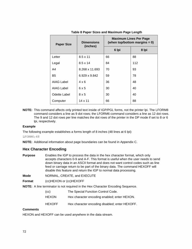
72
NOTE: This command affects only printed text inside of IGP/PGL forms, not the printer lpi. The LFORM8 command considers a line as 9 dot rows; the LFORM6 command considers a line as 12 dot rows. The 9 and 12 dot rows per line matches the dot rows of the printer in the DP mode if set to 8 or 6 lpi, respectively.
Example
The following example establishes a forms length of 8 inches (48 lines at 6 lpi):
LFORM6;48
NOTE: Additional information about page boundaries can be found in Appendix C.
Hex Character Encoding
Purpose Enables the IGP to process the data in the hex character format, which only accepts characters 0-9 and A-F. This format is useful when the user needs to send down binary data in an ASCII format and does not want control codes such as line feed or carriage return to be part of the binary data. The command HEXOFF will disable this feature and return the IGP to normal data processing.
Mode NORMAL, CREATE, and EXECUTE
Format (cc)HEXON or (cc)HEXOFF
NOTE: A line terminator is not required in the Hex Character Encoding Sequence.
(cc) The Special Function Control Code.
HEXON Hex character encoding enabled; enter HEXON.
HEXOFF Hex character encoding disabled; enter HEXOFF.
Comments
HEXON and HEXOFF can be used anywhere in the data stream.
Table 8 Paper Sizes and Maximum Page Length
Paper Size
Dimensions
(inches)
Maximum Lines Per Page (when top/bottom margins = 0)
6 lpi 8 lpi
Letter 8.5 x 11 66 88
Legal 8.5 x 14 84 112
A4 8.268 x 11.693 70 93
B5 6.929 x 9.842 59 78
AIAG Label 4 x 6 36 48
AIAG Label 6 x 5 30 40
Odette Label
Computer
8 x 5
14 x 11
30
66
40
88
73
Ignore Sequence
Purpose Enables the IGP/PGL to ignore all characters after the Ignore Sequence On (IGON) command is entered. All characters are ignored until the Ignore Sequence Off (IGOFF) command is entered.
Mode NORMAL, CREATE, or EXECUTE
Format (cc)IGON or (cc)IGOFF
NOTE: A line terminator is not required in the Ignore Sequence.
(cc) The Special Function Control Code.
IGON Ignore Sequence On command. Enter IGON.
IGOFF Exits Ignore Sequence. Enter IGOFF.
Comments
IGON and IGOFF can also be used anywhere in the data stream.
NOTE: Commands in PTX_SETUP are not ignored.
Line Spacing
Purpose Defines the lines per inch (lpi) printing format.
Mode NORMAL, EXECUTE
Format (cc)LPI;n
(cc) The Special Function Control Code.
LPI The Vertical Line Spacing command; enter LPI.
n Selects the line spacing in lpi; enter a value from 1 through 1000. The accuracy of the line spacing is limited to the resolution of the target printer.
Comments
Standard line spacing is 6 lpi. After a Vertical Line Spacing command is entered, all subsequent alphanumerics print at the specified lpi until another Vertical Line Spacing command, a Normal mode command, or a Reset command is entered.
Example
The following command selects 9 lpi printing format until another Line Spacing command, a Normal mode command, or a Reset command is entered.
~LPI;9
Lines, Diagonal
Purpose Produces a diagonal line.
Mode CREATE
Syntax DIAG LT; SR; SC; ER; EC STOP
DIAG The Diagonal command.
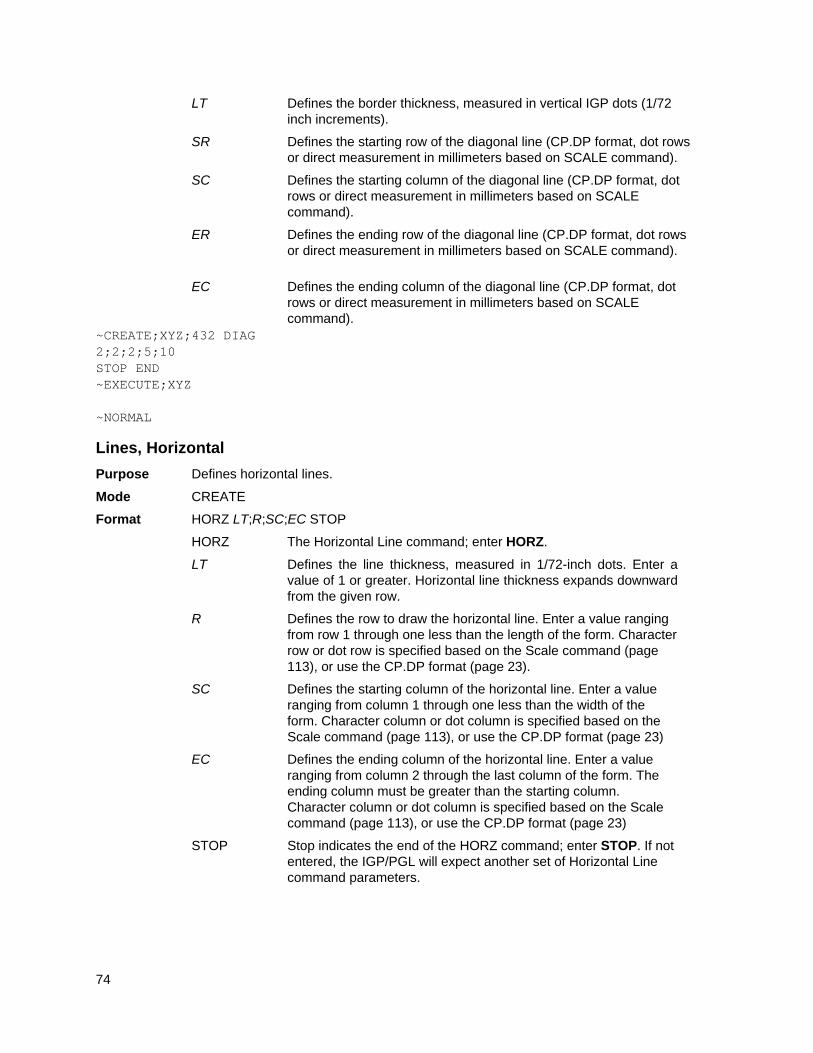
74
LT Defines the border thickness, measured in vertical IGP dots (1/72 inch increments).
SR Defines the starting row of the diagonal line (CP.DP format, dot rows or direct measurement in millimeters based on SCALE command).
SC Defines the starting column of the diagonal line (CP.DP format, dot rows or direct measurement in millimeters based on SCALE command).
ER Defines the ending row of the diagonal line (CP.DP format, dot rows or direct measurement in millimeters based on SCALE command).
EC Defines the ending column of the diagonal line (CP.DP format, dot rows or direct measurement in millimeters based on SCALE command).
~CREATE;XYZ;432 DIAG 2;2;2;5;10 STOP END ~EXECUTE;XYZ ~NORMAL
Lines, Horizontal
Purpose Defines horizontal lines.
Mode CREATE
Format HORZ LT;R;SC;EC STOP
HORZ The Horizontal Line command; enter HORZ.
LT Defines the line thickness, measured in 1/72-inch dots. Enter a value of 1 or greater. Horizontal line thickness expands downward from the given row.
R Defines the row to draw the horizontal line. Enter a value ranging from row 1 through one less than the length of the form. Character row or dot row is specified based on the Scale command (page 113), or use the CP.DP format (page 23).
SC Defines the starting column of the horizontal line. Enter a value ranging from column 1 through one less than the width of the form. Character column or dot column is specified based on the Scale command (page 113), or use the CP.DP format (page 23)
EC Defines the ending column of the horizontal line. Enter a value ranging from column 2 through the last column of the form. The ending column must be greater than the starting column. Character column or dot column is specified based on the Scale command (page 113), or use the CP.DP format (page 23)
STOP Stop indicates the end of the HORZ command; enter STOP. If not entered, the IGP/PGL will expect another set of Horizontal Line command parameters.
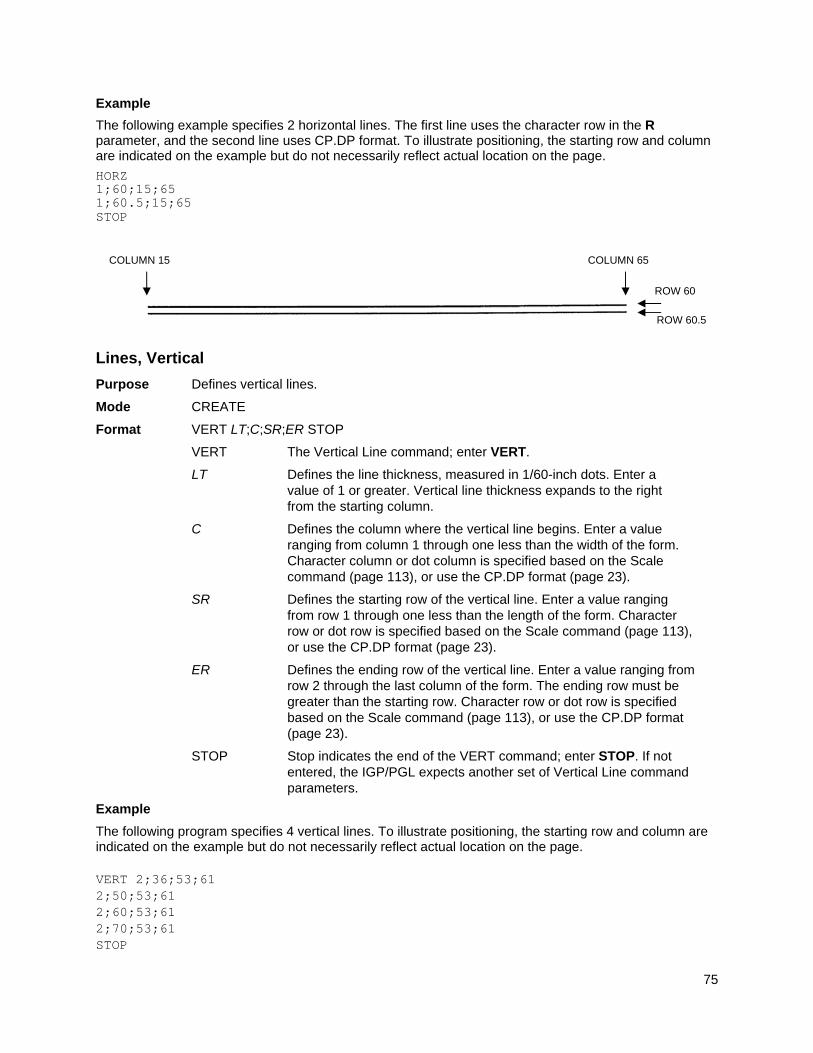
75
Example
The following example specifies 2 horizontal lines. The first line uses the character row in the R parameter, and the second line uses CP.DP format. To illustrate positioning, the starting row and column are indicated on the example but do not necessarily reflect actual location on the page.
HORZ 1;60;15;65 1;60.5;15;65 STOP
Lines, Vertical
Purpose Defines vertical lines.
Mode CREATE
Format VERT LT;C;SR;ER STOP
VERT The Vertical Line command; enter VERT.
LT Defines the line thickness, measured in 1/60-inch dots. Enter a value of 1 or greater. Vertical line thickness expands to the right from the starting column.
C Defines the column where the vertical line begins. Enter a value ranging from column 1 through one less than the width of the form. Character column or dot column is specified based on the Scale command (page 113), or use the CP.DP format (page 23).
SR Defines the starting row of the vertical line. Enter a value ranging from row 1 through one less than the length of the form. Character row or dot row is specified based on the Scale command (page 113), or use the CP.DP format (page 23).
ER Defines the ending row of the vertical line. Enter a value ranging from row 2 through the last column of the form. The ending row must be greater than the starting row. Character row or dot row is specified based on the Scale command (page 113), or use the CP.DP format (page 23).
STOP Stop indicates the end of the VERT command; enter STOP. If not entered, the IGP/PGL expects another set of Vertical Line command parameters.
Example
The following program specifies 4 vertical lines. To illustrate positioning, the starting row and column are indicated on the example but do not necessarily reflect actual location on the page. VERT 2;36;53;61 2;50;53;61 2;60;53;61 2;70;53;61 STOP
ROW 60
COLUMN 15 COLUMN 65
ROW 60.5
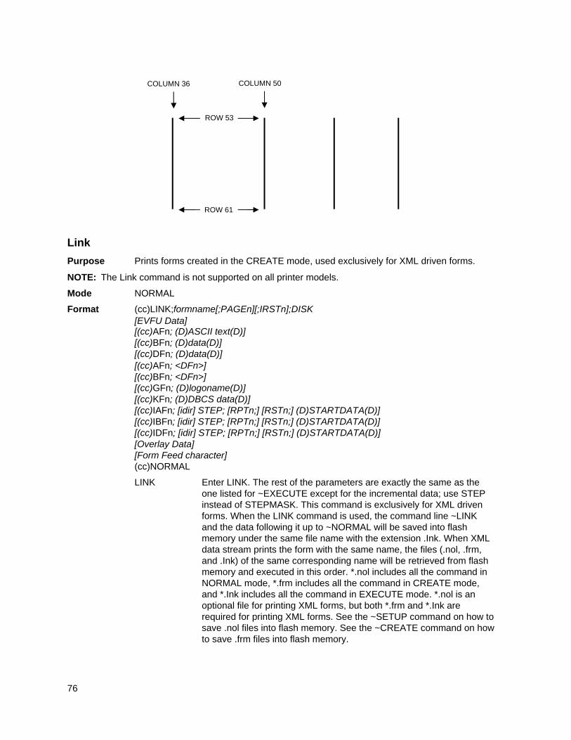
76
Link
Purpose Prints forms created in the CREATE mode, used exclusively for XML driven forms.
NOTE: The Link command is not supported on all printer models.
Mode NORMAL
Format (cc)LINK;formname[;PAGEn][;IRSTn];DISK [EVFU Data] [(cc)AFn; (D)ASCII text(D)] [(cc)BFn; (D)data(D)] [(cc)DFn; (D)data(D)] [(cc)AFn; <DFn>] [(cc)BFn; <DFn>] [(cc)GFn; (D)logoname(D)] [(cc)KFn; (D)DBCS data(D)] [(cc)IAFn; [idir] STEP; [RPTn;] [RSTn;] (D)STARTDATA(D)] [(cc)IBFn; [idir] STEP; [RPTn;] [RSTn;] (D)STARTDATA(D)] [(cc)IDFn; [idir] STEP; [RPTn;] [RSTn;] (D)STARTDATA(D)] [Overlay Data] [Form Feed character] (cc)NORMAL
LINK Enter LINK. The rest of the parameters are exactly the same as the one listed for ~EXECUTE except for the incremental data; use STEP instead of STEPMASK. This command is exclusively for XML driven forms. When the LINK command is used, the command line ~LINK and the data following it up to ~NORMAL will be saved into flash memory under the same file name with the extension .Ink. When XML data stream prints the form with the same name, the files (.nol, .frm, and .Ink) of the same corresponding name will be retrieved from flash memory and executed in this order. *.nol includes all the command in NORMAL mode, *.frm includes all the command in CREATE mode, and *.Ink includes all the command in EXECUTE mode. *.nol is an optional file for printing XML forms, but both *.frm and *.Ink are required for printing XML forms. See the ~SETUP command on how to save .nol files into flash memory. See the ~CREATE command on how to save .frm files into flash memory.
COLUMN 36 COLUMN 50
ROW 61
ROW 53
77
formname Identifies a previously defined form by name. The form name is not case sensitive.
PAGEn PAGEn is the same as the one listed in the ~EXECUTE command. Refer to the ~EXECUTE command for a parameter description.
IRSTn IRSTn is the same as the one listed in the ~EXECUTE command. Refer to the ~EXECUTE command for a parameter description.
DISK Enter DISK to save the LINK file into FLASH. This parameter is required for the LINK command.
[(cc)AFn; (D)data(D)]
[(cc)BFn; (D)data(D)]
[(cc)CFn; (D)data(D)]
data The data will be the tag name defined in XML data file, which will be replaced with the tag value defined in XML data file and be printed as print data on the label.
For incremental dynamic alphanumeric data:
(cc)IAFn;[idir] STEP[idir]step;[RPTn;] [RSTn;] (D)STARTDATA(D)
For incremental dynamic barcode data: (cc)IBFn;[idir]
STEP[idir]step;[RPTn;] [RSTn;] (D)STARTDATA(D)
For incremental dynamic radio frequency identification data:
(cc)IDFn;[idir] STEP[idir]step;[RPTn;] [RSTn;] (D)STARTDATA(D)
STEP Define the step increment or decrement. Use this parameter for incremental dynamic data used in an XML driven form.
STARTDATA The data will be the tag name defined in XML data file, which will be replaced with the tag value defined in XML data file and be printed as print data on the label. The tag value will increment.
Comments
The form count option FC/ICNT/FCNT used in the EXECUTE command is ignored in the LINK command. The form count of XML driven forms is determined by the _QUANTITY attribute in XML data stream.
For XML driven forms, since both SETUP (*.nol) and LINK file (*.Ink) are stored only in FLASH, the user can delete the flash files through the front panel option. (See the SETUP command for a description.)
Example 1
The following is an example of how the ~LINK command works with XML driven forms. ~SETUP;ROLL // saved in FLASH as ROLL.nol ~CONFIG TOP/BOTTOM MARGIN;0 SLASH ZERO;0 HOST FORM LENGTH;0 END ~PAPER;CUT 0;INTENSITY 0;ROTATE 0;SPEED IPS 4;LABELS 2;WIDTH 41 ~SETUPEND
78
~CREATE;ROLL;432;DISK //saved in FLASH as ROLL.fm ALPHA IAF1;10;5;5;3;3 AF2;10;10;5;3;3 15;5;3;3;*This is an XML driven form* STOP END ~LINK;ROLL;DISK //Saved in FLASH as ROLL.Ink ~IAF1;STEP+1;”employee” ~AF2;*company* ~NORMAL
The following is a complete XML data stream which will print three copies of the above form, where “employee” and “company” are the tag names. The tag names will be replaced with the tag value “1234567” and “IBM”. The tag value will print as print data. <?xml version=“1.0” standalone=“no”?> <!DOCTYPE labels SYSTEM “label.dtd”> <labels _FORMAT=“ROLLJOB” _QUANTITY=“3” _JOBNAME=“job1”> <label _FORMAT=“ROLL”> <variable name=“employee”>1234567</variable> <variable name=“company”>IBM</variable> </label> </labels>
Example 2
The following is an example of how the ~LINK command works with XML driven forms for RFID label. ~CREATE;EPC;144;DISK SCALE;DOT;203;203 RFWTAG;64 64;IDF1;H STOP RFRTAG;64 64;DF2;H STOP ALPHA POINT;90;60;16;8;“EPC:” IAF1;16;POINT;90;160;16;8 STOP END ~LINK;EPC;DISK ~IDF1;STEP+1;“employee” ~IAF1;<DF2> ~NORMAL
The following is a complete XML data stream which will print three copies of the above form, where “employee” is the tag name. The tag name will be replaced with the tag value “1000000007788506”. The XML tag value is also the RFID tag write data in this example. The RFID read data will print on paper as ALPHA field.
79
<?xml version=“1.0” standalone=“no”?> <!DOCTYPE labels SYSTEM “label.dtd”> <labels_FORMAT=“EPC” _QUANTITY=“3” _JOBNAME=“job1”> <label> <variable name=“employee”>1000000007788506</variable> </label> </labels>
Listen
Purpose Disables the IGP/PGL from the “quiet” state and enables the IGP/PGL for standard operation. (The Quiet command is explained on page 100).
Mode NORMAL
Format (cc)LISTEN
(cc) The Special Function Control Code.
LISTEN The Listen command; enter LISTEN.
NOTE: When the IGP/PGL is in the quiet state, the currently selected line printer emulation commands are active. Refer to your printer's LinePrinter Plus Emulation Programmer's Reference Manual for a description of these commands.
Logo Call
Purpose Selects and positions previously defined logo(s). (The logo itself is actually defined separately in the Create Logo mode.) The logo may be defined using TIFF files, PCX raster data, or IGP/PGL dots.
Mode CREATE
Format LOGO [GFn;]SR;SC;logoname[;ROT] [;DISK] STOP
LOGO The Logo Call command; enter LOGO.
GFn The optional dynamic field for identifying the logo location on the form. If this parameter is used, the actual logo name cannot be entered here; it must be entered dynamically in Execute Form mode (see page 64). Dynamically entering the logo name permits changes to the graphics without redefining the form. To use this field, perform the following steps:
a. Enter GF.
b. Replace n with a number from 0 through 512 to identify the logo location on the form. The SR and SC parameters are used to specify the exact location of the logo identified by n.
SR Defines the starting row of the logo. The SR (and SC) parameter specifies the location for the logo based on the upper left corner of the grid in which the logo was defined. Enter a value ranging from row 1 through one less than the length of the form. Character row or dot row is specified based on the Scale command (page 113), or use the CP.DP format (page 23).
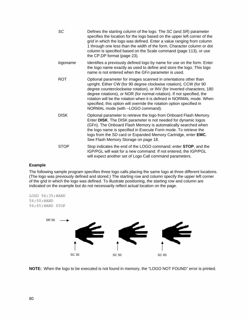
80
SC Defines the starting column of the logo. The SC (and SR) parameter specifies the location for the logo based on the upper left corner of the grid in which the logo was defined. Enter a value ranging from column 1 through one less than the width of the form. Character column or dot column is specified based on the Scale command (page 113), or use the CP.DP format (page 23).
logoname Identifies a previously defined logo by name for use on the form. Enter the logo name exactly as used to define and store the logo. This logo name is not entered when the GFn parameter is used.
ROT Optional parameter for images scanned in orientations other than upright. Either CW (for 90 degree clockwise rotation), CCW (for 90 degree counterclockwise rotation), or INV (for Inverted characters; 180 degree rotations), or NOR (for normal rotation). If not specified, the rotation will be the rotation when it is defined in NORMAL mode. When specified, this option will override the rotation option specified in NORMAL mode (with ~LOGO command).
DISK Optional parameter to retrieve the logo from Onboard Flash Memory. Enter DISK. The DISK parameter is not needed for dynamic logos (GFn). The Onboard Flash Memory is automatically searched when the logo name is specified in Execute Form mode. To retrieve the logo from the SD card or Expanded Memory Cartridge, enter EMC. See Flash Memory Storage on page 18.
STOP Stop indicates the end of the LOGO command; enter STOP, and the IGP/PGL will wait for a new command. If not entered, the IGP/PGL will expect another set of Logo Call command parameters.
Example
The following sample program specifies three logo calls placing the same logo at three different locations. (The logo was previously defined and stored.) The starting row and column specify the upper left corner of the grid in which the logo was defined. To illustrate positioning, the starting row and column are indicated on the example but do not necessarily reflect actual location on the page. LOGO 56;35;HAND 56;50;HAND 56;65;HAND STOP
NOTE: When the logo to be executed is not found in memory, the “LOGO NOT FOUND” error is printed.
SC 35
SR 56
SC 50 SC 65
81
Logo Mode, Create
Purpose Places the IGP/PGL in the Create Logo mode, where logos can be defined using the appropriate dot placements. (See TIFF Logo, page 119, and PCX Logo, page 89, commands to define logos using TIFF or PCX data.)
Mode NORMAL, CREATE
Format (NORMAL)
(cc)LOGO; logoname; VL; HL [;DOT] [;DISK] row#;dot;dot1-dot2;dot END
Format (CREATE)
LOGODEF;logoname;VL;HL(T)] row#;dot;dot1-dot2;dot END
(cc) The Special Function Control Code.
LOGO The Logo command; enter LOGO.
LOGODEF The CREATE mode Logo command; enter LOGODEF.
logoname Enter a maximum of 15 alphanumeric characters for the name of the logo. (Refer to page 22 for a list of allowable Logo Name characters.) All future references to this logo (Delete Logo or Logo Call commands) must use this name. If a logo is defined with the same name as a logo already existing in memory, the newly defined logo will replace the existing logo.
VL Defines the vertical length of the logo grid in dot rows; enter a value sufficient for the vertical size of the logo, not exceeding 252. The dot rows are vertically spaced 1/72-inch apart.
HL Defines the horizontal length of the logo grid in dot columns; enter a value sufficient for the horizontal size of the logo, not exceeding 240. On each row, the dots are horizontally spaced 1/60-inch apart.
DOT Optional parameter. Enter DOTS. If used, the logo description and dimensions VL;HL are given in printer dots, which are based on the printer DPI. Otherwise, the DOT default is 60x72. Also, when the DOT parameter is used, there is no limit on the size of the logo as there is when using IGP dots.
(T) A line terminator (i.e., LF, FF) must separate the LOGO line from the beginning of the TIFF raster data.
DISK In NORMAL mode use this parameter to store the logo to Onboard Flash Memory. Enter DISK. Do not use this parameter in CREATE mode. To store the logo in the SD card or Expanded Memory Cartridge, enter EMC. See Flash Memory Storage on page 18.
row# Identifies the row number for each row of dots in the logo. Enter each row number on a separate command line. Rows are numbered sequentially from top to bottom.
dot Identifies a single dot position in the row. Enter each dot number used. Dots are numbered sequentially from left to right.
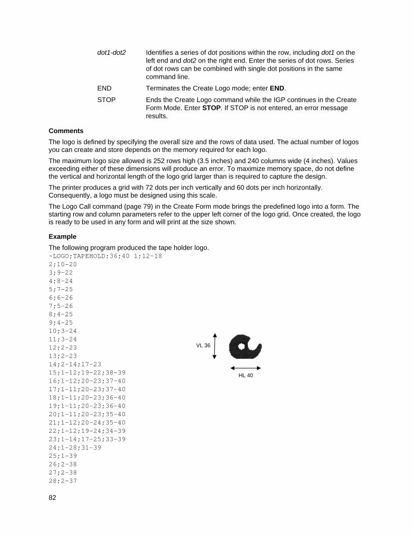
82
dot1-dot2 Identifies a series of dot positions within the row, including dot1 on the left end and dot2 on the right end. Enter the series of dot rows. Series of dot rows can be combined with single dot positions in the same command line.
END Terminates the Create Logo mode; enter END.
STOP Ends the Create Logo command while the IGP continues in the Create Form Mode. Enter STOP. If STOP is not entered, an error message results.
Comments
The logo is defined by specifying the overall size and the rows of data used. The actual number of logos you can create and store depends on the memory required for each logo.
The maximum logo size allowed is 252 rows high (3.5 inches) and 240 columns wide (4 inches). Values exceeding either of these dimensions will produce an error. To maximize memory space, do not define the vertical and horizontal length of the logo grid larger than is required to capture the design.
The printer produces a grid with 72 dots per inch vertically and 60 dots per inch horizontally. Consequently, a logo must be designed using this scale.
The Logo Call command (page 79) in the Create Form mode brings the predefined logo into a form. The starting row and column parameters refer to the upper left corner of the logo grid. Once created, the logo is ready to be used in any form and will print at the size shown.
Example
The following program produced the tape holder logo. ~LOGO;TAPEHOLD;36;40 1;12-18 2;10-20 3;9-22 4;8-24 5;7-25 6;6-26 7;5-26 8;4-25 9;4-25 10;3-24 11;3-24 12;2-23 13;2-23 14;2-14;17-23 15;1-12;19-22;38-39 16;1-12;20-23;37-40 17;1-11;20-23;37-40 18;1-11;20-23;36-40 19;1-11;20-23;36-40 20;1-11;20-23;35-40 21;1-12;20-24;35-40 22;1-12;19-24;34-39 23;1-14;17-25;33-39 24;1-28;31-39 25;1-39 26;2-38 27;2-38 28;2-37
HL 40
VL 36
83
29;3-37 30;3-36 31;3-36 32;4-35 33;5-34 34;6-33 35;7-32 36;9-30 END
Normal Mode
Purpose Places the IGP/PGL in the Normal mode of operation, where the data stream is not changed but monitored for a Special Function Control Code followed by an IGP/PGL command.
Mode NORMAL, EXECUTE
Format (cc)NORMAL
(cc) The Special Function Control Code.
NORMAL The Normal mode command; enter NORMAL.
Comments
Normal mode is entered automatically when the printer is powered on with IGP/PGL. In Normal mode, the IGP/PGL uses the default font and line spacing values, unless otherwise configured with explicit commands.
A blank line or overlay data must always separate an EXECUTE command from a NORMAL command, unless a form count is given for the EXECUTE.
Optimize
Purpose Performs the same function as the front panel menu “Optimize&Reboot.” Optimizes the flash file in memory and then reboots.
NOTE: The Optimize command is not supported on all printer models. Some models do not require this function to reclaim flash. If this command is not supported, it will be absorbed.
Mode NORMAL
Format (cc) OPTIMIZE
(cc) The Special Function Control Code
OPTIMIZE The optimize command. Enter OPTIMIZE.
Example
The following example shows the format of optimize command.
~OPTIMIZE
84
Page Number
Purpose Defines where a page number is placed on a form and automatically increases the page number on each page.
Mode CREATE
Format PAGE;SR;SC
PAGE The Page Number command; enter PAGE.
SR Defines the starting row of the page number. Enter a value ranging from row 1 through one less than the length of the form. Character row or dot row is specified based on the Scale command (page 113), or use the CP.DP format (page 23).
SC Defines the starting column of the page number. Enter a value ranging from column 1 through one less than the width of the form. Character column or dot column is specified based on the Scale command (page 113), or use the CP.DP format (page 23).
If the SR or SC extends beyond the page boundaries, an Error 76 will occur in the Execute Form mode, and default page number SR SC values (row 1, column 1) are used.
Comments
To begin automatically incrementing the page numbers, the starting page number must be specified during the Execute command.
Example
The following command places the page numbers at row 60 column 70 on the form.
PAGE;60;70
Paper
Purpose Controls printer paper options, such as page orientation, intensity and ribbon use.
Mode NORMAL, EXECUTE, CREATE
NOTE: More than one option may follow the paper command.
Format (cc)PAPER[;option[ #]]
NOTE: Not all options may be available with your printer. Consult your Administrator’s Manual to determine which options are available. If an option is not available, the emulation will ignore the corresponding command.
(cc) The Special Function Control Code.
NOTE: SFCC should not be used in the CREATE mode.
Checkmarked cells in Table 9 means full compatibility for all applicable models in the line matrix or thermal product lines. If the columns are left blank, the command is ignored for the given product line. Thermal High-End refers to our toughest industrial range products; Mid-Range refers to our next tier of thermal products, and finally our entry level T2N. The High-End T5R, T8 and Mid-Range T4M, T6 are full PSA products with the full set of PPI emulations and PSA system features (T2N is excluded). In some cases, specific options are required (e.g., RFID, RTC for real time clock, ODV for Online Data Validation).
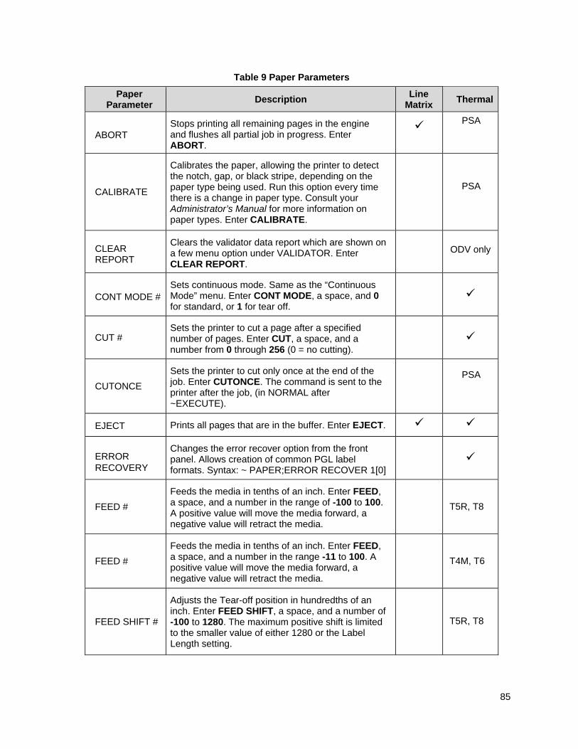
85
Table 9 Paper Parameters
Paper Parameter
Description Line
Matrix Thermal
ABORT Stops printing all remaining pages in the engine and flushes all partial job in progress. Enter ABORT.
PSA
CALIBRATE
Calibrates the paper, allowing the printer to detect the notch, gap, or black stripe, depending on the paper type being used. Run this option every time there is a change in paper type. Consult your Administrator’s Manual for more information on paper types. Enter CALIBRATE.
PSA
CLEAR REPORT
Clears the validator data report which are shown on a few menu option under VALIDATOR. Enter CLEAR REPORT.
ODV only
CONT MODE # Sets continuous mode. Same as the “Continuous Mode” menu. Enter CONT MODE, a space, and 0 for standard, or 1 for tear off.
CUT # Sets the printer to cut a page after a specified number of pages. Enter CUT, a space, and a number from 0 through 256 (0 = no cutting).
CUTONCE
Sets the printer to cut only once at the end of the job. Enter CUTONCE. The command is sent to the printer after the job, (in NORMAL after ~EXECUTE).
PSA
EJECT Prints all pages that are in the buffer. Enter EJECT.
ERROR RECOVERY
Changes the error recover option from the front panel. Allows creation of common PGL label formats. Syntax: ~ PAPER;ERROR RECOVER 1[0]
FEED #
Feeds the media in tenths of an inch. Enter FEED, a space, and a number in the range of -100 to 100. A positive value will move the media forward, a negative value will retract the media.
T5R, T8
FEED #
Feeds the media in tenths of an inch. Enter FEED, a space, and a number in the range -11 to 100. A positive value will move the media forward, a negative value will retract the media.
T4M, T6
FEED SHIFT #
Adjusts the Tear-off position in hundredths of an inch. Enter FEED SHIFT, a space, and a number of -100 to 1280. The maximum positive shift is limited to the smaller value of either 1280 or the Label Length setting.
T5R, T8
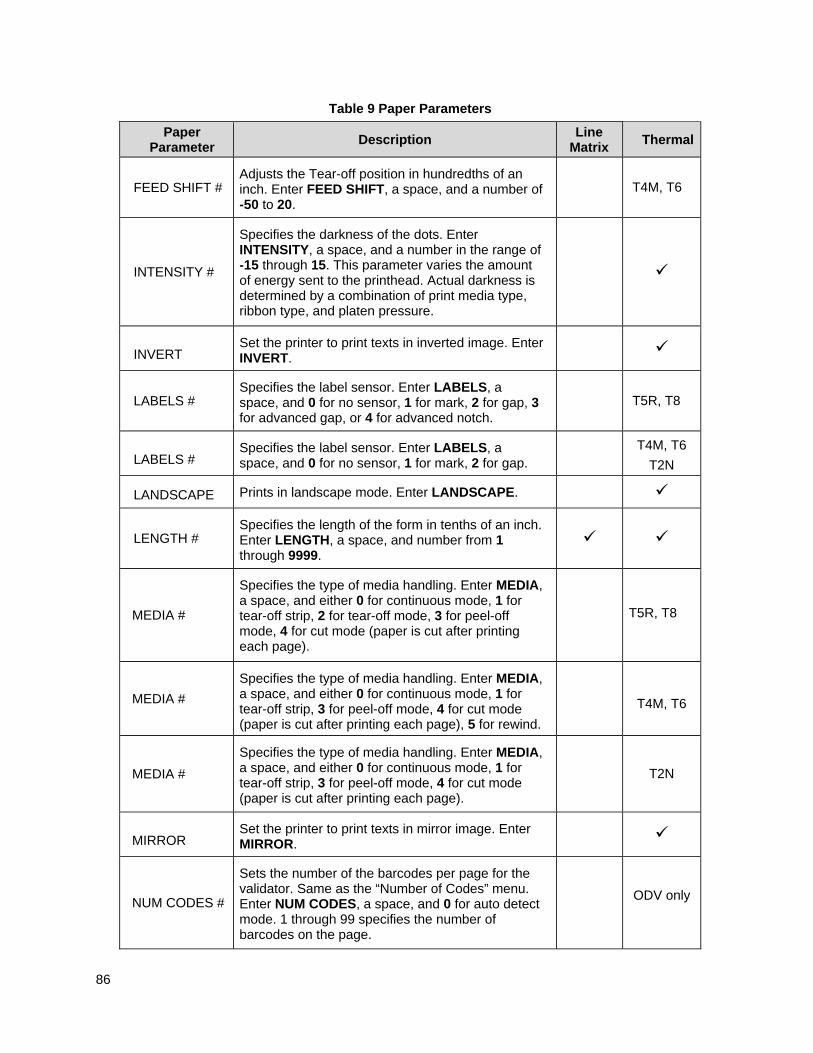
86
Table 9 Paper Parameters
Paper Parameter
Description Line
Matrix Thermal
FEED SHIFT # Adjusts the Tear-off position in hundredths of an inch. Enter FEED SHIFT, a space, and a number of -50 to 20.
T4M, T6
INTENSITY #
Specifies the darkness of the dots. Enter INTENSITY, a space, and a number in the range of -15 through 15. This parameter varies the amount of energy sent to the printhead. Actual darkness is determined by a combination of print media type, ribbon type, and platen pressure.
INVERT Set the printer to print texts in inverted image. Enter INVERT.
LABELS # Specifies the label sensor. Enter LABELS, a space, and 0 for no sensor, 1 for mark, 2 for gap, 3 for advanced gap, or 4 for advanced notch.
T5R, T8
LABELS # Specifies the label sensor. Enter LABELS, a space, and 0 for no sensor, 1 for mark, 2 for gap.
T4M, T6
T2N
LANDSCAPE Prints in landscape mode. Enter LANDSCAPE.
LENGTH # Specifies the length of the form in tenths of an inch. Enter LENGTH, a space, and number from 1 through 9999.
MEDIA #
Specifies the type of media handling. Enter MEDIA, a space, and either 0 for continuous mode, 1 for tear-off strip, 2 for tear-off mode, 3 for peel-off mode, 4 for cut mode (paper is cut after printing each page).
T5R, T8
MEDIA #
Specifies the type of media handling. Enter MEDIA, a space, and either 0 for continuous mode, 1 for tear-off strip, 3 for peel-off mode, 4 for cut mode (paper is cut after printing each page), 5 for rewind.
T4M, T6
MEDIA #
Specifies the type of media handling. Enter MEDIA, a space, and either 0 for continuous mode, 1 for tear-off strip, 3 for peel-off mode, 4 for cut mode (paper is cut after printing each page).
T2N
MIRROR Set the printer to print texts in mirror image. Enter MIRROR.
NUM CODES #
Sets the number of the barcodes per page for the validator. Same as the “Number of Codes” menu. Enter NUM CODES, a space, and 0 for auto detect mode. 1 through 99 specifies the number of barcodes on the page.
ODV only
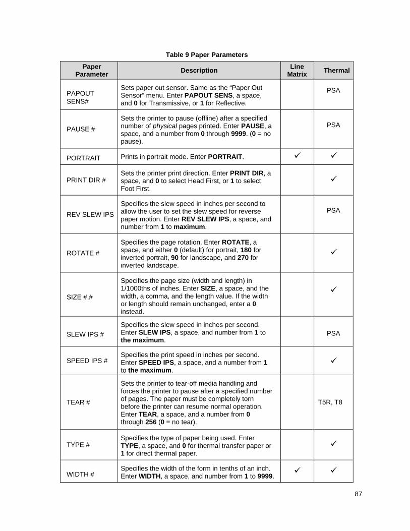
87
Table 9 Paper Parameters
Paper Parameter
Description Line
Matrix Thermal
PAPOUT SENS#
Sets paper out sensor. Same as the “Paper Out Sensor” menu. Enter PAPOUT SENS, a space, and 0 for Transmissive, or 1 for Reflective.
PSA
PAUSE #
Sets the printer to pause (offline) after a specified number of physical pages printed. Enter PAUSE, a space, and a number from 0 through 9999. (0 = no pause).
PSA
PORTRAIT Prints in portrait mode. Enter PORTRAIT.
PRINT DIR # Sets the printer print direction. Enter PRINT DIR, a space, and 0 to select Head First, or 1 to select Foot First.
REV SLEW IPS
Specifies the slew speed in inches per second to allow the user to set the slew speed for reverse paper motion. Enter REV SLEW IPS, a space, and number from 1 to maximum.
PSA
ROTATE #
Specifies the page rotation. Enter ROTATE, a space, and either 0 (default) for portrait, 180 for inverted portrait, 90 for landscape, and 270 for inverted landscape.
SIZE #,#
Specifies the page size (width and length) in 1/1000ths of inches. Enter SIZE, a space, and the width, a comma, and the length value. If the width or length should remain unchanged, enter a 0 instead.
SLEW IPS #
Specifies the slew speed in inches per second. Enter SLEW IPS, a space, and number from 1 to the maximum.
PSA
SPEED IPS # Specifies the print speed in inches per second. Enter SPEED IPS, a space, and a number from 1 to the maximum.
TEAR #
Sets the printer to tear-off media handling and forces the printer to pause after a specified number of pages. The paper must be completely torn before the printer can resume normal operation. Enter TEAR, a space, and a number from 0 through 256 (0 = no tear).
T5R, T8
TYPE # Specifies the type of paper being used. Enter TYPE, a space, and 0 for thermal transfer paper or 1 for direct thermal paper.
WIDTH # Specifies the width of the form in tenths of an inch. Enter WIDTH, a space, and number from 1 to 9999.
88
Table 9 Paper Parameters
Paper Parameter
Description Line
Matrix Thermal
NOTE: The range for the SLEW IPS, REV SLEW IPDS, and SPEED IPS options depends on the thermal printer being used. If the value specified is less than the minimum or greater than the maximum allowed by your printer, the command is ignored.
Comments
The maximum speed (REV SLEW IPS, SPEED IPS, SLEW SPEED IPS) varies based on the product. Please refer to the appropriate Administrator’s Manual for these values.
You can use any or all Paper parameters, listed in any order, in a single Paper command. (Do not list any parameters on separate lines.) Parameters not specified or specified incorrectly retain the previously selected value. All Paper command parameters are reset to default values upon receiving a RESET command. Multiple paper commands within a single form will save the last paper command parameters specified.
Changing orientation between Portrait and Landscape may cause previously defined forms to produce boundary error messages when the form is executed because width and height values are switched.
Example
Based on power-up printer defaults, the following command selects the inverted portrait orientation.
~PAPER;ROTATE 180
Paper Instruction - Data Bit 8
Purpose Enables or disables data bit 8 as the paper instruction signal when the IGP/PGL is configured for a serial interface. (This command has no effect on a parallel interface.)
Mode NORMAL
Format (cc)PION or (cc)PIOFF
(cc) The Special Function Control Code.
PION The Data Bit 8 Paper Instruction On command; enter PION. When this command is sent, 7 data bits are allowed; data bit 8 is enabled as the paper instruction.
When data bit 8 is set high, the PION command skips to a specified print line. When data bit 8 is set low, the PION command prints data characters.
PIOFF The Data Bit 8 Paper Instruction Off command; enter PIOFF. When this command is sent, 8 data bits are allowed for character data because data bit 8 is disabled as the paper instruction. Subsequent occurrences of data bit 8 in the data stream cause printing from the extended character set.
Paper Instruction (PI) Enable/Disable
Purpose Enables or disables use of the PI line using a parallel I/O device. (This command does not enable/disable PI line sensing; it enables or disables use of the “sensed” PI line.)
Mode NORMAL
89
Format (cc)EN-PI or (cc)DIS-PI
(cc) The Special Function Control Code.
EN-PI The Enable PI command; enter EN-PI. When this command is enabled, the IGP/PGL senses PI line, the 8 bits of data are interpreted as a paper instruction command, and the PI line itself is ignored.
DIS-PI The Disable PI command; enter DIS-PI. When the Disable PI command is sent, the 8 bits of data are interpreted as printable characters, and not as a paper instruction command.
PCX Logo
Purpose Places the IGP/PGL in the Create Logo mode, where logos can be defined using the PCX file format.
Mode NORMAL, CREATE
Format (NORMAL)
(cc)LOGO;logoname;PCX[;TRIM][;ROT][;DISK] PCX raster data (cc)RASTEREND END
Format (CREATE)
LOGODEF;logoname;PCX[;TRIM][;ROT] (T) PCX raster data (cc)RASTEREND STOP
NOTE: The logos defined in CREATE mode are independent of the forms being defined at the same time. The logo can be used by other forms, and must be deleted by using the ~RESET or ~DELETE LOGO command.
(cc) The Special Function Control Code. LOGO The
Logo command; enter LOGO.
LOGODEF The CREATE mode LOGODEF command; enter LOGODEF.
logoname Enter a maximum of 15 alphanumeric characters for the name of the logo. (Refer to page 22 for a list of allowable Logo Name characters.) All future references to this logo (Delete Logo or Logo Call commands) must use this name. If a logo is defined with the same name as a logo already existing in memory, the newly defined logo will replace the existing logo.
PCX The command denoting raster data in PCX format; enter PCX.
TRIM Optional parameter that removes extra white space bounding the image, which saves memory inside the printer. Also helps position the image in an IGP/PGL form. Enter TRIM.
ROT Optional parameter for images scanned in orientations other than upright. Enter either CW (for 90 degrees clockwise rotation), CCW (for 90 degree counterclockwise rotation), or INV (for inverted characters; 180 degrees rotations.) (This parameter is not for printing rotated logos but rather for handling scanned rotated images. Logos are rotated automatically to match the current page orientation when they are called from an IGP/PGL form being executed.)
DISK Optional parameter to store the logo to Onboard Flash Memory. Enter
90
DISK. Do not use this parameter in CREATE mode. To store the logo in the SD card or Expanded Memory Cartridge, enter EMC. See Flash Memory Storage on page 18.
(T) A line terminator (i.e., LF, FF) must separate the LOGO line from the beginning of the PCX raster data.
PCX raster data Scanned data in PCX format; data must be black and white. Grey scales or color PCX files are currently not supported. Both uncompressed and compressed formats are supported.
(cc) The Special Function Control Code.
RASTEREND Denotes the end of the PCX raster data. Enter RASTEREND.
END Terminates the PCX logo; enter END.
STOP Ends the Create Logo command while the IGP continues in the Create Form Mode. Enter STOP. If STOP is not entered, an error message results.
Comments
The size and number of raster image logos are bounded by printer memory. Also note that each rotation used requires a copy of the image; therefore, the number of rotations used affects the printer memory available.
The logo call command in the Create Form mode brings the predefined logo into a form. The starting row and column parameters refer to the upper left corner of the logo grid. Once created, the logo is ready to be used in any form.
Raster images may contain data that is interpreted by your host as control codes. This may affect the way the host sends data to the printer. Consult your host's Administrator’s Manual for sending binary data.
Be careful when editing PCX output files because most TEXT editors insert carriage returns and line feeds. If a PCX file must be edited, use a binary or hex editor.
NOTE: The LOGO line must be terminated with an LF (hex 0A) or FF (hex 0C), and then immediately followed by the PCX raster data. The IGON and IGOFF commands can be used with the PCX raster data to ignore extraneous control or ASCII characters.
PNG Logo
Purpose Places the IGP/PGL in the Create Logo mode, where logos can be defined using the PNG file format.
Mode NORMAL, CREATE
Format (NORMAL)
(cc)LOGO;logoname;PNG[;TRIM][;ROT][;DISK] PNG raster data (cc)RASTEREND END
Format (CREATE)
LOGODEF;logoname;PNG[;TRIM][;ROT] (T) PNG raster data (cc)RASTEREND STOP
NOTE: The logos defined in CREATE mode are independent of the forms being defined at the same time. The logo can be used by other forms, and must be deleted by using the ~RESET or ~DELETE LOGO command.
(cc) The Special Function Control Code.
91
LOGO The Logo command; enter LOGO.
LOGODEF The CREATE mode LOGODEF command; enter LOGODEF.
logoname Enter a maximum of 15 alphanumeric characters for the name of the logo. (Refer to page 22 for a list of allowable Logo Name characters.) All future references to this logo (Delete Logo or Logo Call commands) must use this name. If a logo is defined with the same name as a logo already existing in memory, the newly defined logo will replace the existing logo.
PNG The command denoting raster data in PNG format; enter PNG.
TRIM Optional parameter that removes extra white space bounding the image, which saves memory inside the printer. Also helps position the image in an IGP/PGL form. Enter TRIM.
ROT Optional parameter for images scanned in orientations other than upright. Enter either CW (for 90 degrees clockwise rotation), CCW (for 90 degree counterclockwise rotation), or INV (for inverted characters; 180 degrees rotations.) (This parameter is not for printing rotated logos but rather for handling scanned rotated images. Logos are rotated automatically to match the current page orientation when they are called from an IGP/PGL form being executed.)
DISK Optional parameter to store the logo to Onboard Flash Memory. Enter DISK. Do not use this parameter in CREATE mode. To store the logo in the SD card or Expanded Memory Cartridge, enter EMC. See Flash Memory Storage on page 18.
(T) A line terminator (i.e., LF, FF) must separate the LOGO line from the beginning of the PNG raster data.
PNG raster data Scanned data in PNG format; data must be black and white. Grey
scales or color PNG files are currently not supported.
(cc) The Special Function Control Code.
RASTEREND Denotes the end of the PNG raster data. Enter RASTEREND.
END Terminates the PNG logo; enter END.
STOP Ends the Create Logo command while the IGP continues in the Create Form Mode. Enter STOP. If STOP is not entered, an error message results.
Comments
The size and number of raster image logos are bounded by printer memory. Also note that each rotation used requires a copy of the image; therefore, the number of rotations used affects the printer memory available.
The logo call command in the Create Form mode brings the predefined logo into a form. The starting row and column parameters refer to the upper left corner of the logo grid. Once created, the logo is ready to be used in any form.
Raster images may contain data that is interpreted by your host as control codes. This may affect the way the host sends data to the printer. Consult your host's Administrator’s Manual for sending binary data.
Be careful when editing PNG output files because most TEXT editors insert carriage returns and line feeds. If a PNG file must be edited, use a binary or hex editor.
92
NOTE: The LOGO line must be terminated with an LF (hex 0A) or FF (hex 0C), and then immediately followed by the PNG raster data. The IGON and IGOFF commands can be used with the PNG raster data to ignore extraneous control or ASCII characters.
Print File
Purpose Prints files from the Onboard Flash Memory. Print File can be used to show the SETUP functions that exist.
Mode NORMAL
Format (cc)PRINT;filename
(cc) The Special Function Control Code.
PRINT The Print File command; enter PRINT.
filename The filename to be printed.
Comments
Do not use wildcard characters because the Print File command will attempt to print any file in the Onboard Flash Memory.
Example
Example of how to print SETUP.PTR:
~PRINT;SETUP.PTR
Printer Alert
Purpose To set the printer alert condition. After the alert condition is set and the condition event occurs, the printer responds immediately with an alert message for the corresponding condition. The alert message is sent back to the host.
Mode NORMAL
Format (cc) ALERT; TYPE n; DEST n; SET n; CLEAR n
(cc) The Special Function Control Code.
ALERT The printer alert command. Enter ALERT.
TYPE n The condition type. Enter TYPE, a space, and a letter from the following list:
A = paper out B = ribbon out C = printhead over-temp D = printhead under-temp E = head open F = power supply over temp G = ribbon-in warning (direct thermal mode) H = rewind full I = defaulted printer J = cut error K = printer paused L = batch job completed M = label take N = head element out
93
O = runtime error P = forced error b = binary flags
94
DEST n The destination to route alert to. Enter DEST, a space, and a letter:
A = serial port B = ethernet data port C = ethernet status port R = Return Status Port (return port determined by FP setting)
SET n Enable condition set alert. Enter SET, a space, and 1 to enable or 0 to disable.
CLEAR n Enable condition clear alert. Enter CLEAR, a space, and 1 to enable or 0 to disable.
Comment
Currently, only the condition type L (batch job completed) and b (binary flags) are supported.
Example 1
The following example shows the format of printer alert command, where the printer responds with an alert message “BATCH JOB NOT COMPLETED” before the job is completed, and an alert message “BATCH JOB COMPLETED” when the batch job is completed. The alert message is sent back to the host through Serial.
~ALERT; TYPE L; DEST A; SET 1; CLEAR 1
Example 2
The following example shows the alert command format in which the printer will respond with an alert message whenever one of the supported states change. The alert message is sent to the host through the port selected by the ‘Ret. Status Port’ FP setting.
NOTE: The CLEAR setting will have no effect on this alert type. The response send will always be 10 bytes long. The meaning of the status bytes is explained in the table below.
~ALERT;TYPE b;DEST R;SET 1;CLEAR 0
Status Byte
Bit Status Description
Byte 0 7..0 Response Start Marker STX character
Byte 1 7 Online 1 = printer online, 0 = printer offline
6 Error 1 = error , 0 = no error
5 Not Used Always 1
4 Processing 1 = processing, 0 = not processing
3 Printing 1 = printing, 0 = not printing
2 Power Save 1 = in power save mode, 0 = not in power save mode
1 Warning 1 = warning state, 0 = no warning state
0 FEXP For Future Expansion
95
Status Byte
Bit Status Description
Byte 2 7 Print Head Open 1 = print head open, 0 = print head closed
6 Paper 1 = paper out, 0 = no paper out
5 Not used Always 1
4 Ribbon Out 1 = ribbon out, 0 = no ribbon out
3 Cutter Fault 1 = cutter fault, 0 = no cutter fault
2 ODV max retry fail 1 = max retry fail, 0 = no max retry fail
1 RFID max retry fail 1 = max retry fail, 0 = no max retry fail
0 TOF Detect Fault 1 = TOF detect fault, 0 = no TOF detect fault
Byte 3 7 Ribbon Low 1 = ribbon low, 0 = no ribbon low
6 FEXP For Future Expansion
5 Not used Always 1
4 FEXP For Future Expansion
3 FEXP For Future Expansion
2 FEXP For Future Expansion
1 FEXP For Future Expansion
0 FEXP For Future Expansion
Byte 4 7 Label Fed 1 = label fed, 0 = no label fed
6 Label OK 1 = label OK, label not OK
5 Not used Always 1
4 Label Failed 1 = label failed, 0 = label not failed
3 Label Present 1 = label present, 0 = label taken
2 Label Cut 1 = label cut, 0 = no label cut
1 FEXP For Future Expansion
0 FEXP For Future Expansion
Byte 5..8
7..0 FEXP Bit 5 always 1
Byte 9 7..0 Response End Marker ETX character
96
Printer Identification
Purpose To request the printer identification. When the command is sent to the printer, the information containing the printer identification is sent back to the host. The information contains the model, software version, dots per millimeter setting, and memory size.
Mode NORMAL
Format (cc) IDENTITY
(cc) The Special Function Control Code
IDENTITY The printer identification command. Enter IDENTITY.
Command When the printer receives this command it will return the information to the host as such:
T53060,V1.16K,12,512KB
T53060 = printer model V1.16K = software
version
12 = dots/mm
512KB = memory
Example
The following example shows the format of printer identification command.
~IDENTITY
LINE MATRIX
Printer Mode Purpose Selects the print mode of the printer for the next set of data and allows different print
modes to be specified for use within the form.
Mode CREATE
Format PMODE; type [;width][;rmode] MODE;SR ...... STOP
PMODE The Printer Mode command. Enter PMODE. The PMODE command must be the first command entered following the CREATE command.
type Indicates the type of printer used with the IGP/PGL. Enter L to specify L150 or L150B printers, enter S to specify standard MVP and MVP 150B printers, 3 to specify P3000 printers, 6 to specify P6000 printers, and 9 to specify P9000 printers.
width An optional parameter specifying a forms width of 136-character columns. Currently, this parameter is not supported; the default value forms width is 132 character columns.
rmode An optional parameter specifying the “return mode” of the printer following the Execute Form Mode.
97
Enter 1, 2, 3, 4, or 5 to specify printer modes 1 through 5, respectively. If this mode is not specified, the printer remains in the mode effective at the end of the Execute Form Mode. The return print mode is effective when new data is received following the Execute Form Mode.
MODE Specifies up to 8 different print modes to be used within the form beginning on the row defined by the SR parameter. Enter the appropriate print mode number. This mode will remain effective within the form until a new print mode is defined by another MODE;SR sequence or the end of form is reached.
As described in your printer Administrator’s Manual, print densities and maximum line lengths vary with each print mode. Form elements such as boxes or vertical lines may be printed at varying densities or suffer horizontal compression due to a print mode change in the body of the form.
SR Defines the starting row of the print mode used within the form. The row number can range from 1 to one less than the length of the form. Character row or dot row is specified based on the Scale command, which refers to the SMODE command table of densities (page 113), or use the CP.DP format (page 23)
Comments
The PMODE command is useful for ensuring the printer is set for the proper print mode to print bar codes or alphanumeric data. Up to eight MODEs can be specified within one PMODE command.
Horizontal compression of elements occurs when the print mode is changed to a mode with a different density. For example, on an L150 printer, a box is constructed using print mode 2 (density of 60 dpi/10 cpi horizontal) for standard data processing applications. The SR and SC parameters of the box command produce a box 6 inches wide (6 inches at 60 dpi = 360 dots, or 6 inches at 10 cpi = 60 character spaces). If the same box is generated in print mode 4 (density of 72.5 dpi/12.1 cpi horizontal) for a bar code application, the box will be compressed to an approximate width of 4.9 inches due to the higher dot density of print mode 4 (360 dots at 72.5 dpi = 4.9 inches).
To compensate for the compression, modify the program generating the form elements to accommodate the dot density of the new print mode. To produce the 6-inch wide box at the 72.5 dpi horizontal print mode, the box SR and SC parameters must be modified to accommodate 435 dots (6 inches at 72.5 dpi = 435 dots, or 6 inches at 12.1 cpi = 72.6 character spaces). Starting and ending row and column data must be calculated in terms of character or dot scaling, based on the IGP/PGL Scale command (page 113). This type of horizontal compression is illustrated in Example 2, below.
Example 1
The following sample program places an L150 printer in Mode 4 beginning on form line number 1 (to print bar codes, for example) and places the printer in Mode 2 upon receipt of new data after the form is executed. ~CREATE;EXAMPLE PMODE;L;2 4;1 STOP
Example 2
In the following horizontal compression examples, starting and ending row and column information is provided for reference and does not reflect the exact location on the page. Character scaling is used. The example below illustrates a 6-inch wide box in L150 Mode 2; the next example illustrates the same box (compressed) in L150 Mode 4; and the last example illustrates a modified box command to produce a 6-inch wide box in L150 Mode 4.
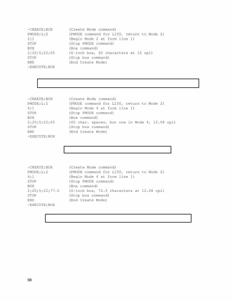
98
~CREATE;BOX (Create Mode command) PMODE;L;2 (PMODE command for L150, return to Mode 2) 2;1 (Begin Mode 2 at form line 1) STOP (Stop PMODE command) BOX (Box command) 2;20;5;22;65 (6-inch box, 60 characters at 10 cpi) STOP (Stop box command) END (End Create Mode) ~EXECUTE;BOX
~CREATE;BOX (Create Mode command) PMODE;L;2 (PMODE command for L150, return to Mode 2) 4;1 (Begin Mode 4 at form line 1) STOP (Stop PMODE command) BOX (Box command) 2;20;5;22;65 (60 char. spaces, but now in Mode 4, 12.08 cpi) STOP (Stop box command) END (End Create Mode) ~EXECUTE;BOX
~CREATE;BOX (Create Mode command) PMODE;L;2 (PMODE command for L150, return to Mode 2) 4;1 (Begin Mode 4 at form line 1) STOP (Stop PMODE command) BOX (Box command) 2;20;5;22;77.5 (6-inch box, 72.5 characters at 12.08 cpi) STOP (Stop box command) END (End Create Mode) ~EXECUTE;BOX
99
Printer Status
Purpose To request the printer status. When the printer status command is sent to the printer, data containing the printer status is sent back to the host.
Mode NORMAL
Format (cc) STATUS
(cc) The Special Function Control Code.
STATUS The printer status command. Enter STATUS.
Comment
1. The printer status command will take effect when a snooper (preparser) is enabled. Any of the following commands will enable the snooper for all ports. You can also enable preparser by using the front panel. Send the following command to the printer before sending the job.
~CONFIG SNOOP;STATUS;PAR END
~CONFIG SNOOP;STATUS;ETH END
~CONFIG SNOOP;STATUS;SER END
The STATUS command works if it is received from any port. PAR, ETH, and SER are listed as compatible with old PGL commands.
To disable a snooper, send the following command to the printer before sending the job.
~CONFIG SNOOP;OFF END
2. After the snooper is enabled, the printer status command can be sent to the printer through any port.
3. When the printer status command is sent to the printer, a data string is sent back to the host through the serial port in the following format:
~STATUS
BUSY;n (n=0 no data in buffer, n=1 data in buffer)
PAPER;n (n=0 paper not out, n=1 paper out)
RIBBON;n (n=0 ribbon not out, n=1 ribbon out)
PRINT HEAD;n (n=0 print head down, n=1 print head up)
COUNT;n (n = the number of pages that remains to be printed)
GAP;n (n=0 gap detected, n=1 gap not found)
HEAD HOT;n (n=0 head not hot, n=1 head hot)
CUT COUNT;n (n=number of times the cutter has cut)
PRINT DIST;n (n=distance in inches printed by this print head)
PRCT COMPLETE;n (n=percentage of last label that was printed when an error occurred)
100
TOF SYNCED;n (n=0 printer has not synchronized with TOF, n=1 printer has synchronized with TOF1)
SENSED DIST;n (n=sensed label length in dots2)
END
The status response values depends on the printer model. If the status value is not supported by a printer model it will return 0 for that status value.
Example
The following example shows the format of the printer status command.
~STATUS
Quiet
Purpose Places the IGP/PGL in the Quiet mode, where all data passed to the LP+ emulation is unaffected by IGP/PGL commands except for the LISTEN, SFON/SFOFF, IGON/IGOFF and PTX_SETUP commands, or another QUIET command.
Mode NORMAL
Format (cc)QUIET
(cc) The Special Function Control Code.
QUIET The Quiet command; enter QUIET. The IGP/PGL remains in the quiet state until the Listen command is received.
Comments
In the Quiet mode IGP/PGL ignores all commands except LISTEN, SFON/SFOFF, IGON/IGOFF, PTX_SETUP or another QUIET command. All commands for the currently selected protocol in the LinePrinter+ will be interpreted. See the LinePrinter Plus Programmer's Reference Manual for details.
The IGP/PGL remains quiet until the Listen command (page 79), enables standard IGP/PGL operation. The Quiet command is ignored if the IGP/PGL is in the Execute Form mode. The Quiet command is ignored for printers that do not have the LP+ emulation resident.
Recall
Purpose Loads the user pre-stored program setup file, SETUP.PTX, from the Onboard Flash Memory into the printer. This is done without sending a system reset.
Mode NORMAL
Format (cc)RECALL[;filename]
(cc) The Special Function Control Code.
RECALL The Recall command; enter RECALL.
filename The name of the file to recall. This parameter is optional. If not present, the default file SETUP.PTX is loaded.
Comments
The file SETUP.PTX is also automatically recalled into the printer upon a RESET command.
101
Repeat
Purpose Used during EXECUTE mode to repeat a form a given number of times including all the dynamic data. This command is ignored if the Form Count or incremental parameter is used in the EXECUTE command.
Mode EXECUTE
Syntax (cc)REPEAT;n
REPEAT The REPEAT command. Enter REPEAT.
n The number of times to repeat the form with the same dynamic data.
Comments
When a REPEAT command is encountered in EXECUTE mode, PGL will store the repeat count. Actual printing of the form will not be initiated by the REPEAT command. The form will be printed repeatedly (depending on the repeat count) with the same dynamic data after a NORMAL (or FF) command is encountered. Incremental data will be automatically incremented/decremented after each form. There are no limits to the number of times the REPEAT command can be used within any given EXECUTE sequence. Overlay text will not be repeated.
Reset
Purpose Deletes all forms and logos from IGP/PGL memory. The Reset performs the following tasks:
• Prints any objects in the current page
• Selects the portrait orientation
• Deletes all forms and logos resident in memory
• Sets the font to the default Gothic 12 point/10CPI
• Releases all user-defined character mappings
• Runs the SETUP.PTX file if present
Mode NORMAL, CREATE, or EXECUTE
Format (cc)RESET
(cc) The Special Function Control Code.
RESET The Reset command; enter RESET.
Reverse Print
Purpose Defines an area of the form where form elements are reverse printed (white on black).
Mode CREATE
Format REVERSE [DARK;]SR;SC;ER;EC STOP
REVERSE The Reverse Printing command; enter REVERSE.
DARK Optional parameter to select a denser black background. Enter DARK, or D, to select the denser background. More information about dark printing is provided on page 52.
102
SR Defines the starting row of the reverse print field. Enter a value ranging from row 1 through one less than the length of the form. Character row or dot row is specified based on the Scale command (page 113), or use the CP.DP format (page 23).
SC Defines the starting column of the reverse print field. Enter a value ranging from column 1 through one less than the width of the form. Character column or dot column is specified based on the Scale command (page 113), or use the CP.DP format (page 23).
ER Defines the ending row of the reverse print field. Enter a value ranging from row 2 through the last row of the form. The ending row must be greater than the starting row. Character row or dot row is specified based on the Scale command (page 113), or use the CP.DP format (page 23).
EC Defines the ending column of the reverse print field. Enter a value ranging from column 2 through the last column of the form. The ending column must be greater than the starting column. Character column or dot column is specified based on the Scale command (page 113), or use the CP.DP format (page 23).
STOP Stop indicates the end of the REVERSE command; enter STOP, and the IGP/PGL will wait for a new command. If not entered, the IGP/PGL will expect another set of Reverse Print command parameters.
Comments
You can use reverse print with all form elements (alpha, lines, boxes, etc.). The IGP/PGL can also reverse print bar codes, but reverse printed bar codes are unreadable by bar code scanning devices.
RFID
IMPORTANT For all examples make sure Label Length in the menu matches the physical length of the installed media.
RFWTAG
Purpose The RFWTAG command is used to program an RFID tag (embedded in a smart label) using structured data format. The data structure of an RFID tag can consist of one or more bit fields. Each bit field specifies its own field length, the data format, the field type plus additional options if the type is incremental, and finally the field value.
NOTE: The RFWTAG command is supported only on Thermal printers.
Mode CREATE
Format RFWTAG[;LOCKn[;format]];size[;mem bank]
(Bit Field)+
STOP
RFWTAG Specifies the RFWTAG command, enter RFWTAG;
LOCKn[;format] or PERMALOCKn[;format] Optional parameter to lock the data block to prevent it from being overwritten. By default, the data are not locked initially. n is the
103
passcode. The acceptable values for n are 1 to FFFFFFFF in hex, a 4 bytes data. When the LOCKn option is used to lock any memory bank, which at the same time is programmed with the write data, the same passcode will be written on ACS memory bank. The ACS memory bank will also be locked if ACS is not locked at the time of the operation. If ACS is already locked at the time of the operation, the passcode needs to match the current content of ACS so that the memory bank lock takes effect. The passcode (n) can also be in dynamic format. For dynamic format, enter LOCK<DFn>, where DFn is the dynamic field defined in EXECUTE mode. Both LOCK and PERMALOCK share the same syntax. For differences in functionality, see Note 12 on page 105.
format An optional parameter to specify the format for the passcode data. Enter B for binary, D for decimal, and H for hexadecimal. The default is decimal if format is not specified.
size A decimal number specifying the overall bit length of the memory bank.
mem bank Specifies which tag logical memory area that this command will be applied. If omitted, it defaults to the EPC memory area. Other areas include Identification, User Data, Access area and Kill area. Enter one of the following values:
‘EPC’ – EPC 12 bytes data area (default)
‘TID’ – Tag identification 8 bytes area (currently not applicable for RFWTAG)
‘USR’ – User 32 bytes area
‘ACS’ – 4 bytes access code area
‘KIL’ – 4 bytes kill code area
‘PC’ – 2 bytes PC code area (Gen 2 tags only)
NOTE: New tags, such as RSI IN47 Crkscr, support 240 bits of EPC memory and 512 bits of USR memory.
Bit Field A line description of a bit field and must have one of the following syntax formats:
1. For non-incremental data (both static and dynamic) length;[DFn;]format;(D)datafield(D)
2. For incremental fixed data length;I;format;STEP[idir]step;[RPTn;] [RSTn;](D)startdata(D)
3. For dynamic incremental data length;IDFn;format;
length A decimal number specifying the bit length of a field within a tag. The maximum length for each DFn field of NON-HEX format is 64 bits. For hexadecimal format, the bit length can be up to the maximum bit length specified for the corresponding memory bank.
DFn Optional parameter to indicate this field has dynamic data. Replace n with a number ranging from 1 to 512 to identify the field number of this particular field. If this option is used, datafield is ignored, and dynamic data must be entered via the DF command in the EXECUTE mode.
104
IDFn Enter IDF to indicate this field is a bit field with dynamical assignment of increment (or decrement) data. The step and startdata parameters will be supplied by the IDF command in the EXECUTE mode. Replace n with a number ranging from 1 to 512 to identify the field number of this bit field. Dynamically enter the step and startdata parameters using the IDF command in the EXECUTE mode.
NOTE: 1. The same field number cannot be used in both DFn and IDFn.
2. If a field is defined as IDFn, it must be referenced as IDFn later for consistency. The same applies for DFn.
3. If <IDFn> syntax is used for merging data into AFn or BFn, neither DFn, AFn, or BFn will be incremented. The increment only takes place in the ~DFn command where the STEP is specified.
format A letter specifying the format of the data field. B – binary, D – decimal, H – hexadecimal
(D) Delimiter designating the start and end of static data for this bit field. Replace (D) with any printable character, except the SFCC and the slash character (/).
datafield The static data of this static field. It is a mandatory parameter of bit field with static data.
I Identifies this field is an incremental bit field.
STEP Specifies that the incremental data field will use the step method. Enter STEP;. The STEP option replaces the STEPMASK option that is used in Alpha and Barcode.
idir Enter a plus sign (+) or leave the field blank to increment (default). Enter a minus sign (–) to decrement.
step A decimal number specifies the amount to increment/decrement each time the form is executed. The increment is at bit level and will automatically wrap based on the field size.
RPTn The optional incremental repeat count parameters to specify the number of times a particular field value is repeated before it is incremented. The default repeat count parameter n is 1, which will increment the field value each time it prints. The repeat count can range from 1 to 65535.
RSTn The optional incremental reset count parameter to specify the number of times an incremented field is printed before it is reset to the starting value. By default, there is no reset count. The reset count parameter n can range from 1 to 65535.
startdata Defines the value of the field or the starting value of the incremented field. If the field is dynamic, the value will be specified later in the EXECUTE mode. The data must be specified within a pair of delimiters (D). The delimiter (D) cannot be a “/” or SFCC character since the “/” will comment out the rest of the line and SFCC is reserved for PGL commands. If “R” or “S” is used as delimiters, the data pattern must not comprise of the keywords in the incrementing options. Since the delimiters could be different from one value to another, proper care must be taken to avoid one of the letters mentioned above.
105
NOTE: 1. The RFWTAG command cannot be mixed with RFWRITE in the same form.
2. Each field structure must be specified in a single line and in the order it appears in the RFID tag from MSB bits to LSB bits (left to right). The sum of all the field lengths must match the size of the tag.
3. The host data are read in as ASCII characters. They would be converted to binary representation for the base field on the field format. Therefore, if the converted value is larger than the maximum value that a field can hold, an error will be reported. If the data value is smaller than the specified field length, on the other hand, the field will be padded to the left with zero bits.
4. Unlike the Alpha and Barcode command which use STEPMASK for incremental data, RFWTAG uses the STEP which will increment or decrement at bit level.
5. 432 IGP dots in the ~CREATE line specifies a 6 inch label. 6 inches = 432 (IGP dots)/72 (dpi)
Use 144 for 2 inch labels and 288 for 4 inch labels.
6. ACS and KIL are similar to other memory banks. ACS contains the passcode which is used for LOCK and UNLOCK operations. KIL contains the killcode which is used to kill a tag. The user can write to or read from KIL memory bank, but the functionality of killing a tag is not currently applicable. Also, once ACS and KIL are locked, both cannot be written to or read from. For other memory banks, EPC, USR, and TID, once locked, they can be read from but not written to.
7. There are two ways to program the ACS memory area. One is to write to the ACS memory area directly with RFWTAG. The other is to use the LOCK option while writing to other memory banks. If ACS is not previously locked, then LOCK option will lock the memory bank and also write the passcode to ACS and lock ACS. When write to ACS with RFWTAG, ACS is not automatically locked. To lock ACS, use LOCKn with RFWTAG, where the passcode (n) should be the same as the write data to ASC.
8. There is only one passcode, the content of ACS memory bank, for each tag. The same passcode is used to lock or unlock any memory bank in that tag.
9. For LOCKn and UNLOCKn, the passcode (n) (which includes the dynamic format <DFn>) does not accept incremental data. This also applies to the ACS and KIL memory banks. The write data to the ACS and KIL memory banks do not accept incremental data because the ACS memory bank contains passcodes for LOCK and UNLOCK operations, and the KIL memory bank contains a killcode to kill a tag. Incremental data do not apply to passcodes or killcodes.
10. When LOCK<DFn> and UNLOCK<DFn> are used in the same form with the same dynamic data (the passcode), the dynamic format <DFn> needs to be a different dynamic number for LOCK and UNLOCK since it is designed with a unique dynamic number that can be linked to only one object type. In this case, LOCK is linked to RFWTAG object and UNLOCK is linked to RFRTAG object. Although both options use the same passcode, the dynamic format needs to be in a different dynamic number in the same form.
11. Because PC field is related to EPC field, when PC RFWTAG is used in the form, it must be followed immediately by EPC RFWTAG, or else an error will be reported. Also, by specification, the first 5 bits of PC data need to comply with the length of EPC data, or else an error will be reported. For example, for 96 bits EPC, the 5 bits of PC data is 00110. For 64 bits EPC, the first 5 bits of PC data is 00100. Also, LOCK option is not and will not be supported for PC field, since PC field works with EPC field (which already supports LOCK option).
12. Both LOCK and PERMALOCK requires the user to enter the password. Once the tag is permanently locked with the PERMALOCK command, it cannot be unlocked again; the tag can only be read from and never be written to once it is permanently locked. On the other hand, after the tag is locked with the LOCK command, it can be unlocked again with the same password.
106
For PERMALOCK (ex, EPC), the password must match the current content of ACS bank for PERMALOCK to work. If the current content of ACS bank is null (0x0) which could be the case for the brand new tag, the password for PERMALOCK EPC will be 0x0. If you use a different password for PERMALOCK, you need to write (RFWTAG) the new content (password) to ACS first, and then use this new password to PERMALOCK EPC.
For LOCK (ex, EPC), the password may be different from the current content of ACS. When a new password is used to lock EPC where ACS is not locked, this new password is written to ACS and locks ACS at the same time while locking EPC. For new tags where ACS is not locked and has all null data, you can lock EPC with a new password directly without writing to ACS first.
Example 1
The following example programs an SGTIN–64 value into the RFID tag that is embedded in a 4x6 smart label. Assume that the SGTIN–64 value is provided as a single number. ~CREATE;SGTIN–64;432 RFWTAG;64 64;H;*87D0034567ABCDEF* /EPC number STOP END ~EXECUTE;SGTIN–64;1 ~NORMAL
Example 2
Same as Example 1, except the EPC number is broken into its component parts. Assume that the SGTIN–64 value has the Header = 2d, Filter Value = 5d, EPC Manager Index = 15383d, Object Class = 703710d or 0xABCDE, and the Serial Number = 0123456d.
~CREATE;SGTIN–64;432 RFWTAG;64 2;B;*10* /Header 3;D;*5* /Filter Value 14;D;*15383* /EPC Manager Index 20;H;*ABCDE* /Object Class 25;D;*0000123456* /Serial Number STOP END ~EXECUTE;SGTIN–64;1 ~NORMAL
Example 3
Same as Example 2, except it uses a dynamic method. This example also shows how to program another RFID tag without redefining the data structure of the SGTIN–64.
~CREATE;SGTIN–64;432 RFWTAG;64 2;DF1;B /Header 3;DF2;D /Filter Value 14;DF3;D /EPC Manager Index 20;DF4;H /Object Class 25;DF5;D /Serial Number STOP ALPHA AF1;18;10;5;3;3 STOP
107
END ~EXECUTE;SGTIN–64 ~DF1;*10* /Header ~DF2;*5* /Filter Value ~DF3;*15383* /EPC Manager Index ~DF4;*ABCDE* /Object Class ~DF5;*0000123456* /Serial Number ~AF1;<DF5> /Print serial number on label ~NORMAL ~EXECUTE;SGTIN–64 ~DF1;*10* /Header ~DF2;*5* /Filter Value ~DF3;*15383* /EPC Manager Index ~DF4;*ABCDE* /Object Class ~DF5;*0000123456* /Serial Number
> ~AF1;<DF5> /Print serial number on label ~NORMAL
Example 4
This example shows how to program a roll of 1500 smart labels with SGTIN–64 values, where the Header = 2d, Filter Value = 5d, EPC Manager Index = 15383d, Object Class = 703710d or 0xABCDE, and the Serial Number starting from 0000000 to 0001499d.
~CREATE;SGTIN–64;432 RFWTAG;64 2;B;*10* /Header 3;D;*5* /Filter Value 14;D;*15383* /EPC Manager Index 20;H;*ABCDE* /Object Class 25;I;D;STEP1;*0* /Serial Number STOP END ~EXECUTE;SGTIN–64;ICNT1500 ~NORMAL
Example 5
This example shows how to program a 96 bit RFID tag. A SGTIN–96 format is used and the EPC number is broken into its component parts. Assume that the SGTIN–96 value has the Header = 48, Filter Value = 5d, EPC Manager Index = 123456d, Object Class = 777777d or 0xBDE31, and the Serial Number = 123456d.
NOTE: 96 bit tags must be broken up as in Examples 2, 3, and 4, and no field can be more than 64 bits in length if the format is binary or decimal. There is no restriction on the bit length if the format is hexadecimal.
~CREATE;SGTIN–96;432 RFWTAG;96 8;B;*00110000* /Header 3;D;*5* /Filter Value 3;D;*6* /Partition 20;D;*123456* /EPC Manager Index 24;D;*777777* /Object Class 38;D;*123456* /Serial Number STOP END ~EXECUTE;SGTIN–96;1
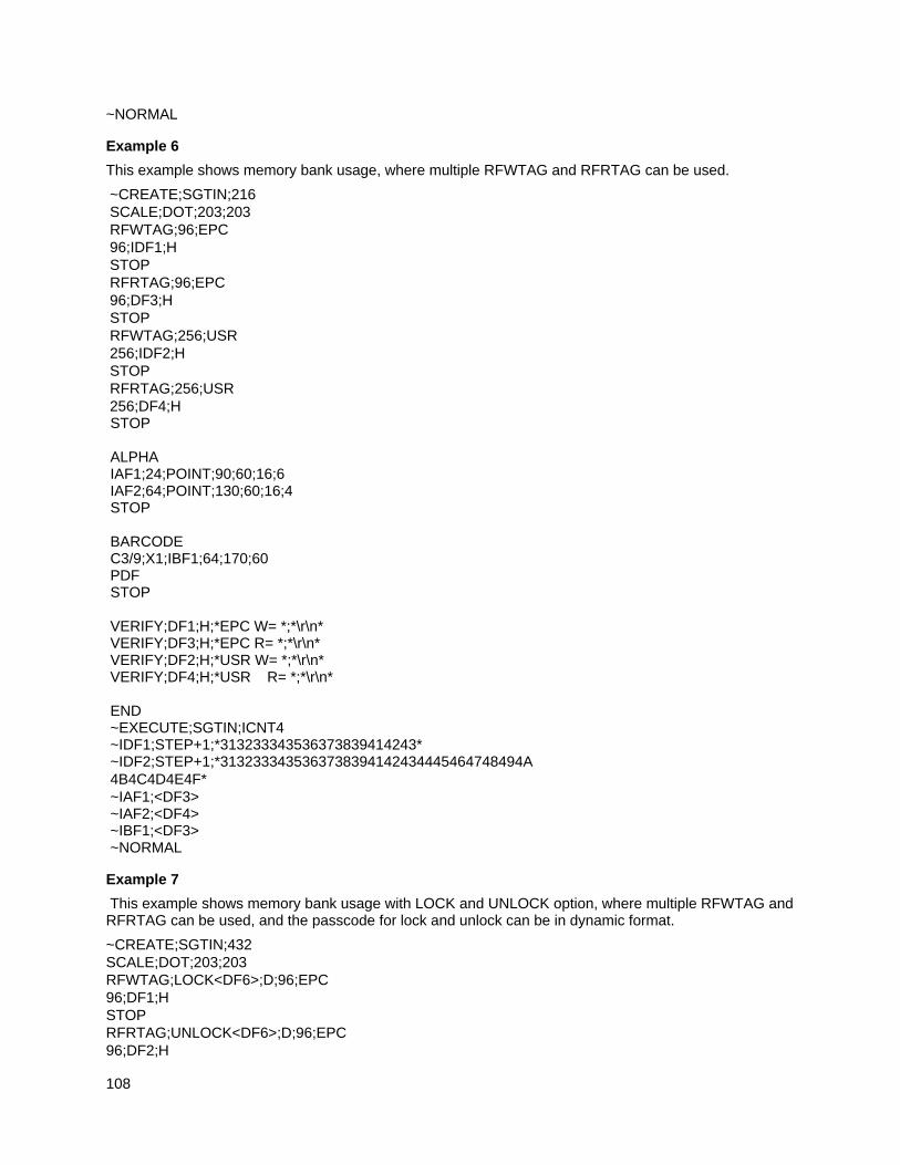
108
~NORMAL
Example 6
This example shows memory bank usage, where multiple RFWTAG and RFRTAG can be used.
~CREATE;SGTIN;216 SCALE;DOT;203;203 RFWTAG;96;EPC 96;IDF1;H STOP RFRTAG;96;EPC 96;DF3;H STOP RFWTAG;256;USR 256;IDF2;H STOP RFRTAG;256;USR 256;DF4;H STOP ALPHA IAF1;24;POINT;90;60;16;6 IAF2;64;POINT;130;60;16;4 STOP BARCODE C3/9;X1;IBF1;64;170;60 PDF STOP VERIFY;DF1;H;*EPC W= *;*\r\n* VERIFY;DF3;H;*EPC R= *;*\r\n* VERIFY;DF2;H;*USR W= *;*\r\n* VERIFY;DF4;H;*USR R= *;*\r\n* END ~EXECUTE;SGTIN;ICNT4 ~IDF1;STEP+1;*313233343536373839414243* ~IDF2;STEP+1;*3132333435363738394142434445464748494A 4B4C4D4E4F* ~IAF1;<DF3> ~IAF2;<DF4> ~IBF1;<DF3> ~NORMAL
Example 7
This example shows memory bank usage with LOCK and UNLOCK option, where multiple RFWTAG and RFRTAG can be used, and the passcode for lock and unlock can be in dynamic format.
~CREATE;SGTIN;432 SCALE;DOT;203;203 RFWTAG;LOCK<DF6>;D;96;EPC 96;DF1;H STOP RFRTAG;UNLOCK<DF6>;D;96;EPC 96;DF2;H
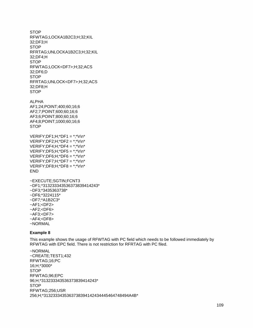
109
STOP RFWTAG;LOCKA1B2C3;H;32;KIL 32;DF3;H STOP RFRTAG;UNLOCKA1B2C3;H;32;KIL 32;DF4;H STOP RFWTAG;LOCK<DF7>;H;32;ACS 32;DF6;D STOP RFRTAG;UNLOCK<DF7>;H;32;ACS 32;DF8;H STOP ALPHA AF1;24;POINT;400;60;16;6 AF2;7;POINT;600;60;16;6 AF3;6;POINT;800;60;16;6 AF4;8;POINT;1000;60;16;6 STOP VERIFY;DF1;H;*DF1 = *;*\r\n* VERIFY;DF2;H;*DF2 = *;*\r\n* VERIFY;DF4;H;*DF4 = *;*\r\n* VERIFY;DF5;H;*DF5 = *;*\r\n* VERIFY;DF6;H;*DF6 = *;*\r\n* VERIFY;DF7;H;*DF7 = *;*\r\n* VERIFY;DF8;H;*DF8 = *;*\r\n* END ~EXECUTE;SGTIN;FCNT3 ~DF1;*313233343536373839414243* ~DF3;*3435363738* ~DF6;*3224115* ~DF7;*A1B2C3* ~AF1;<DF2> ~AF2;<DF6> ~AF3;<DF7> ~AF4;<DF8> ~NORMAL
Example 8
This example shows the usage of RFWTAG with PC field which needs to be followed immediately by RFWTAG with EPC field. There is not restriction for RFRTAG with PC filed.
~NORMAL ~CREATE;TEST1;432 RFWTAG;16;PC 16;H;*3000* STOP RFWTAG;96;EPC 96;H;*313233343536373839414243* STOP RFWTAG;256;USR 256;H;*3132333435363738394142434445464748494A4B*
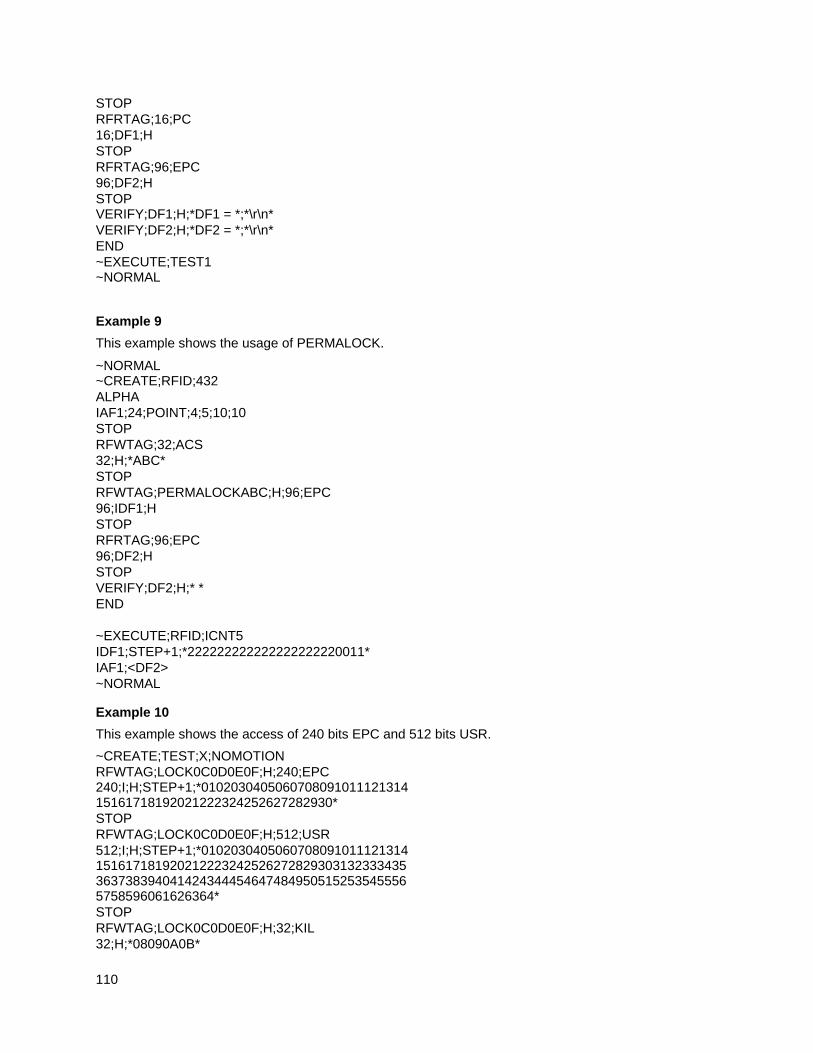
110
STOP RFRTAG;16;PC 16;DF1;H STOP RFRTAG;96;EPC 96;DF2;H STOP VERIFY;DF1;H;*DF1 = *;*\r\n* VERIFY;DF2;H;*DF2 = *;*\r\n* END ~EXECUTE;TEST1 ~NORMAL
Example 9
This example shows the usage of PERMALOCK.
~NORMAL ~CREATE;RFID;432 ALPHA IAF1;24;POINT;4;5;10;10 STOP RFWTAG;32;ACS 32;H;*ABC* STOP RFWTAG;PERMALOCKABC;H;96;EPC 96;IDF1;H STOP RFRTAG;96;EPC 96;DF2;H STOP VERIFY;DF2;H;* * END ~EXECUTE;RFID;ICNT5 IDF1;STEP+1;*222222222222222222220011* IAF1;<DF2> ~NORMAL
Example 10
This example shows the access of 240 bits EPC and 512 bits USR.
~CREATE;TEST;X;NOMOTION RFWTAG;LOCK0C0D0E0F;H;240;EPC 240;I;H;STEP+1;*0102030405060708091011121314 15161718192021222324252627282930* STOP RFWTAG;LOCK0C0D0E0F;H;512;USR 512;I;H;STEP+1;*0102030405060708091011121314 151617181920212223242526272829303132333435 363738394041424344454647484950515253545556 5758596061626364* STOP RFWTAG;LOCK0C0D0E0F;H;32;KIL 32;H;*08090A0B*
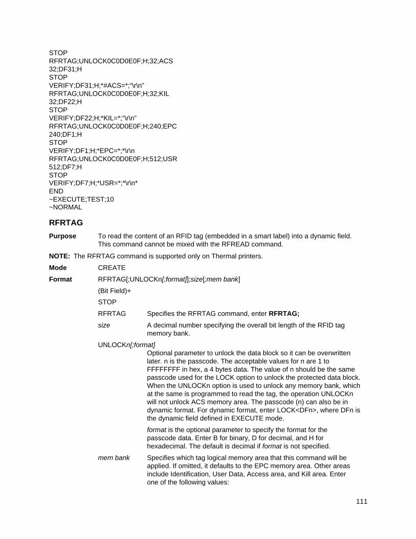
111
STOP RFRTAG;UNLOCK0C0D0E0F;H;32;ACS 32;DF31;H STOP VERIFY;DF31;H;*#ACS=*;“\r\n” RFRTAG;UNLOCK0C0D0E0F;H;32;KIL 32;DF22;H STOP VERIFY;DF22;H;*KIL=*;“\r\n” RFRTAG;UNLOCK0C0D0E0F;H;240;EPC 240;DF1;H STOP VERIFY;DF1;H;*EPC=*;*\r\n RFRTAG;UNLOCK0C0D0E0F;H;512;USR 512;DF7;H STOP VERIFY;DF7;H;*USR=*;*\r\n* END ~EXECUTE;TEST;10 ~NORMAL
RFRTAG
Purpose To read the content of an RFID tag (embedded in a smart label) into a dynamic field. This command cannot be mixed with the RFREAD command.
NOTE: The RFRTAG command is supported only on Thermal printers.
Mode CREATE
Format RFRTAG[;UNLOCKn[;format]];size[;mem bank]
(Bit Field)+
STOP
RFRTAG Specifies the RFRTAG command, enter RFRTAG;
size A decimal number specifying the overall bit length of the RFID tag memory bank.
UNLOCKn[;format] Optional parameter to unlock the data block so it can be overwritten later. n is the passcode. The acceptable values for n are 1 to FFFFFFFF in hex, a 4 bytes data. The value of n should be the same passcode used for the LOCK option to unlock the protected data block. When the UNLOCKn option is used to unlock any memory bank, which at the same is programmed to read the tag, the operation UNLOCKn will not unlock ACS memory area. The passcode (n) can also be in dynamic format. For dynamic format, enter LOCK<DFn>, where DFn is the dynamic field defined in EXECUTE mode.
format is the optional parameter to specify the format for the passcode data. Enter B for binary, D for decimal, and H for hexadecimal. The default is decimal if format is not specified.
mem bank Specifies which tag logical memory area that this command will be applied. If omitted, it defaults to the EPC memory area. Other areas include Identification, User Data, Access area, and Kill area. Enter one of the following values:
112
‘EPC’ – EPC 12 bytes data area (default)
‘TID’ – Tag identification 8 bytes area
‘USR’ – User 32 bytes area
‘ACS’ – 4 bytes access code area
‘KIL’ – 4 bytes kill code area
‘PC’ – 2 bytes PC code area (Gen 2 tags only)
Bit Field A line description of a bit field; must have one of the following syntax formats: length;DFn;format
length A decimal number specifying the bit length of a field within a tag. The maximum length is 64 bits for binary or decimal format. For hexadecimal format, the bit length can be up to the maximum bit length specified for the corresponding memory bank.
DFn Indicate dynamic data field to store the read result. Replace n with a number ranging from 1 to 512 to identify the field number of this particular field.
format A letter specifying the representation format of the field data.
B – binary, D – decimal, H – hexadecimal
NOTE: 1. Multiple RFRTAG commands are allowed in the same form but the same DFn field cannot be defined multiple times.
2. The DF field length is restricted to 64 bits for binary or decimal format and must be a multiple of 8 bits. The sum of all field lengths must be equal to the tag size.
3. The first field always start at the MSB bit. The bit length of a field dictates the start bit of the next field, etc. As a result, DF fields will not overlap each other.
4. RFRTAG does not allow incremental fields (with the “I” prefix).
5. 432 IGP dots in the ~CREATE line specifies a 6 inch label. 6 inches = 432 (IGP dots)/72 (dpi)
Use 144 for 2 inch labels and 288 for 4 inch labels.
Example
Same as Example 4 on page 107, except the increment is dynamic and the result is merged into Alpha to print on the smart label.
~CREATE;SGTIN–64;432 RFWTAG;64 2;B;*10* /Header 3;D;*5* /Filter Value 14;D;*15383* /EPC Manager Index 20;D;*123456* /Object Class 25;IDF1;H /Serial Number STOP RFRTAG;64 64;DF2;H; STOP ALPHA
113
IAF1;16;3;12;0;0 STOP END ~EXECUTE;SGTIN–64;ICNT1500 ~IDF1;STEP+1;*0* ~IAF1;<DF2>
~NORMAL
NOTE: 1. The <IDF1> usage does not increment the DF1 field. It merges the DF1 content into the AF1 field, keeping the same representation previously defined for IDF1.
2. The use of IAF1 is to print alpha on every label. If AF1 is used instead, only the first label is printed. The AF1 field is not incremented either since it is using the result from the DF1 merge.
Scale
Purpose Defines the vertical line spacing and the horizontal pitch of the form for data positioning specified by character row and column or dot row and column.
Mode CREATE
Format SCALE;DOT[;horz;vert] or SCALE;CHAR[;lpi] [;cpi] or SCALE;MM
SCALE The Scale command; enter SCALE.
DOT Specifies the dot scale. Enter DOT.
horz/vert Gives resolution for the dot parameter. Default is 60 dpi horizontal) by 72 dpi (vertical).
CHAR Specifies the character scale. Enter CHAR.
MM Specifies the scale will be in millimeters. Enter MM.
lpi The optional vertical line spacing parameter (in lines per inch) for character scaling. Enter: any integer value from 1 through 1000. The default is 6 lpi. For line matrix printers, enter 6, 8, 9, or 10.
cpi The optional horizontal pitch parameter (in characters per inch) for character scaling. Enter 10, 12, 13, 15, 17, or 20. The default is 10 cpi.
Comments
If the character scale is selected, starting row/column or ending row/column parameters are specified by character row and column. The lines per inch (lpi) value for a character scale form can be set to any integer value from 1 through the target DPI. Characters per inch (cpi) horizontally can be either 10, 12, 13, 15, 17, or 20. For example, on a printer with a maximum print width of 80 columns, an 8-1/2 x 11-inch form at the 6 lpi 10 cpi default has 66 rows and 80 columns in the character scale. (Refer to your printer Administrator’s Manual to determine your maximum print boundaries.)
If the dot scale is selected, the parameters are specified in dot row and column. For example, based on a 60 dpi horizontal and 72 dpi vertical dot scale, a form of 8-1/2 x 11 inches has 792 rows (72 dpi x 11 inches) and 510 columns (60 dpi x 8-1/2 inches), and a form of 8 x 11 inches has 792 rows and 480 columns. Refer to Appendix C for more information about maximum values with other paper sizes.
The default scale factor uses character row and column (6 lpi and 10 cpi). Anytime CP.DP format (page 23) is used, the scale assumes 6 lpi and 10 cpi and a 60 x 72 dpi format.
114
You can change the Scale at any time during forms creation by using either of the Scale commands. Elements designed before the scale change will print at the former scale, while those elements following the scale change will print at the current scale.
NOTE: Scale affects data position, not the printed data itself. For example, alphanumeric data printed at 10 cpi will still print at 10 cpi after a Scale change; however, where the data is placed on the page is affected. Also, Scale affects line thickness if dot scale and horizontal/vertical scaling are given.
LINE MATRIX
Scaling
Purpose Permits graphic elements (such as corners or boxes) to retain their physical shapes and sizes when printed in a horizontal and vertical density other than the base density of 60 x 72 dpi (60 horizontal x 72 vertical dots per inch). This command allows IGP/PGL programs developed for other printers to be automatically scaled for execution on MVP and P3000 Series printers so that the printed output appears the same as the original output.
Mode CREATE
Format SMODE; pt; sm [;em]
SMODE The Scale command; enter SMODE.
pt Defines the printer type. Enter one of the Printer Type codes shown in Table 10 to select the type of printer.
sm Defines the scale mode. Enter one of the Scale Mode codes shown in Table 10 to select the scaling mode and corresponding dot density.
em Optional parameter to define the exit mode. This optional parameter is useful when the normal print mode is different from the print mode used for IGP/PGL graphics. The exit mode returns the IGP/PGL to a specified printer mode after the form is printed. Enter a new Scale Mode code (according to the printer type selected) from Table 10.
Comments
Dot density varies by printer mode. Selecting a different printer mode selects a different horizontal and vertical dot density. This varying density can affect graphic elements created in one particular mode but printed in a different mode. Be sure that graphic elements designed in the IGP/PGL Create Form Mode are defined using a base density of 60 x 72 dpi so that the SMODE command will produce the desired results.
The following application rules must be considered when using SMODE:
a. When used in the Create Form mode, the SMODE command must be the first command on the line, or an error will occur.
b. All input parameters of the element being defined (starting/ending row, line thickness, bar code height, etc.), will be scaled according to the dot density of the scale mode selected.
c. All graphic elements (such as vertical, horizontal, boxes, etc.), except for logos, will be scaled.
d. All alphanumeric strings with expanded characters (not normal 10 cpi characters) will be scaled.
e. All input parameters of a bar code, except horizontal span, will be scaled.
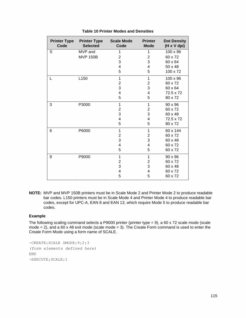
115
Table 10 Printer Modes and Densities
Printer Type Code
Printer Type Selected
Scale Mode Code
Printer Mode
Dot Density (H x V dpi)
S MVP and 1 1 100 x 96 MVP 150B 2 2 60 x 72 3 3 60 x 64 4 4 50 x 48 5 5 100 x 72
L L150 1 1 100 x 96 2 2 60 x 72 3 3 60 x 64 4 4 72.5 x 72 5 5 80 x 72
3 P3000 1 1 90 x 96 2 2 60 x 72 3 3 60 x 48 4 4 72.5 x 72 5 5 80 x 72
6 P6000 1 1 60 x 144 2 2 60 x 72 3 3 60 x 48 4 4 60 x 72 5 5 60 x 72
9 P9000 1 1 90 x 96 2 2 60 x 72 3 3 60 x 48 4 4 60 x 72 5 5 60 x 72
NOTE: MVP and MVP 150B printers must be in Scale Mode 2 and Printer Mode 2 to produce readable bar codes. L150 printers must be in Scale Mode 4 and Printer Mode 4 to produce readable bar codes, except for UPC-A, EAN 8 and EAN 13, which require Mode 5 to produce readable bar codes.
Example
The following scaling command selects a P9000 printer (printer type = 9), a 60 x 72 scale mode (scale mode = 2), and a 60 x 48 exit mode (scale mode = 3). The Create Form command is used to enter the Create Form Mode using a form name of SCALE. ~CREATE;SCALE SMODE;9;2;3 (form elements defined here) END ~EXECUTE;SCALE;1
116
Select Format
Purpose Enables the IGP/PGL to ignore all host-generated paper movement commands (hex 00-1F).
Mode NORMAL, CREATE or EXECUTE
Format (cc)SFON or (cc)SFOFF
NOTE: A line terminator is not required in the Select Format Sequence.
(cc) The Special Function Control Code.
SFON The Select Format On command. Enter SFON.
SFOFF Exits Select Format. Enter SFOFF.
Comments
During Select Format, you may enter the following IGP/PGL paper movement commands. All the commands must be entered in UPPERCASE. These commands can only be used with the Select Format command. If used at any other time, an error condition may result.
Command Paper Movement Function
(cc)CR Sends a carriage return (hex 0D)
(cc)LF Sends a line feed (hex 0A)
(cc)FF Sends a form feed (hex 0C)
(cc)LT Sends a no motion line terminator (hex 03)
Although the Select Format command enables the IGP/PGL to ignore all host-generated paper movement commands, you can input IGP/PGL paper movement commands with Select Format on.
SFON/SFOFF cannot be used during Ignore Sequence (page 73).
Set The Time or Date
Purpose To set the internal printer clock to the current time and date. All the parameters are optional.
NOTE: Since this command sets time, it is important that it is received and processed by the printer quickly. This command should be sent when the printer is online and no other data is in the buffer.
Mode NORMAL
Format (cc)SETCLOCK;[DA nn;] [MO nn;] [YE nnun;] [HO nn;] [MI nn;] [SE nn;]
SETCLOCK The Set Clock command
DA Sets the day of the month. Enter DA followed by a space then a two–digit value from 00–31.
MO Sets the month. Enter MO followed by a space then a two–digit value from 01–12.
YE Sets the year. Enter YE followed by a space than a four digit value from 0000–9999.
HO Sets the hour. Enter HO followed by a space then a two–digit value from 00–23.
MI Sets the minutes. Enter MI followed by a space then a two–digit value from 00–59.
117
SE Sets the seconds. Enter SE followed by a space then a two–digit value from 00–59.
Example
See Clock Element Format on page 43.
Setup
Purpose The SETUP command can be used in two different ways, with the formname and without the formname. When the formname is not entered, the given data under SETUP will be stored into FLASH under the name setup.ptx. This file is then loaded from FLASH and processed as host data whenever printer power is applied or when the RESET or RECALL command is sent. When the formname is entered, SETUP is currently being used in XML driven form to save all commands in NORMAL mode into a FLASH file with the extension .nol, and later to be processed along with two other FLASH saved files, *.frm and *.Ink to print an XML form.
Mode NORMAL
Format (cc)SETUP [;formname] [;DISK]
host data
(cc)SETUPEND
(cc) The Special Function Control Code.
SETUP The Setup command; enter SETUP.
formname This is a parameter used exclusively for XML driven form. When the formname is entered, the host data following ~SETUP and up to ~SETUPEND will be saved into FLASH under the same formname with the extension, *.nol. The data following SETUP can be only the commands in NORMAL mode. When XML data stream comes in to print the form under the same formname, the file with the same name and extension, .nol will be retrieved from the FLASH and executed along with two other FLASH file of the same name, *.frm (CREATE form) and .Ink (LINK form). See the description and example listed for the ~LINK command, on page 76. The form name is not case sensitive.
DISK Optional parameter to store the file to Onboard Flash Memory. Enter DISK. Enter EMC to store the file to the SD card or Expanded Memory Cartridge. When the option is not specified, it stores the file to Onboard Flash Memory by default. See Flash Memory Storage on page 18.
host data When the parameter formname is not entered, the host data can be any IGP/PGL command, form definition, text, etc. to be stored and executed at power-up. However, when the parameter formname is entered, the host data can only be any IGP/PGL command in NORMAL mode.
SETUPEND Finishes storing host data and returns the printer to the NORMAL mode. Enter SETUPEND.
118
Comments
When SETUP is used for non–XML driven form, the formname is not given because the RESET command causes the setup routine to be executed, the RESET command cannot be in the SETUP information or an infinite loop will occur.
If IGP/PGL commands have not been added between the SETUP and SETUPEND commands, the SETUP.PTX file on the Onboard Flash Memory automatically deletes, and no IGP/PGL SETUP commands execute upon printer power-up.
SETUP.PTX is automatically created by the IGP/PGL when the ~SETUPEND command is received. When the SETUP.PTX file is not in the Onboard Flash Memory, no extra IGP/PGL commands are performed on power-up.
When SETUP is used for XML driven form (the formname is given), the DELETE FORM command (*.frm) used under SETUP to delete both FLASH or DRAM form cannot be the same name as the formname used in SETUP. *ALL cannot be used because XML form relies on the successful execution of *.frm which happens after the execution of the SETUP file (*.nol).
For XML driven form, since both SETUP (*.nol) and LINK file (*.Ink) are stored only in FLASH, the users can delete the flash files through the front panel option. See the Link command on page 76 for a description and example.
Example 1 (for XML form)
~SETUP;TESTXML ~DELETE LOGO;epc300.tif ~DELETE LOGO;PCXLOGO ~LOGO;PCXLOGO;PCX <Raster Data>~RASTEREND END ~SETUPEND ~CREATE;TESTXML;432;DISK SCALE;DOT;100;100 LOGO 40;40;PCXLOGO STOP LOGO 40;292;epc300.tif STOP ALPHA AF1;16;POINT;140;180;14;11 STOP END ~LINK;TESTXML;DISK ~AF1;$BUSINESS_PARTNER$ ~NORMAL
Special Function Control Code Change
Purpose Changes the current Special Function Control Code (SFCC).
Mode NORMAL or EXECUTE
Format (cc)SFCC; n or (cc)SFCC; ‘n’
(cc) The current Special Function Control Code.
119
SFCC; Specifies the Special Function Control Code change command. Enter SFCC; (the semicolon is required.)
n Represents the ASCII numeric value for the new SFCC. Replace n with an ASCII value from 0 through 255.
‘n’ Represents the hexadecimal value for a printable character as the new SFCC. Replace ‘n’ with a hexadecimal value from 20 through 7F. If representing the new SFCC in hexadecimal, it must be enclosed in single quotes.
Comments
When the SFCC is changed using the SFCC command, the change is effective immediately and the old SFCC is no longer recognized.
When printer power is turned off and on, the SFCC returns to the configuration default. The configuration default SFCC can also be re-selected by sending the command: (cc)SFCC; ‘ ’
Example
The following example, using both the ASCII and hexadecimal values, changes the SFCC from the tilde (~) to the caret (^).
~SFCC;94 or ~SFCC;’5E’
TIFF Logo
Purpose Places the IGP/PGL in the Create Logo mode, where logos can be defined using a Tagged Image File Format (TIFF).
Mode NORMAL, CREATE
Format (NORMAL)
(cc)LOGO;logoname;TIFF[;TRIM][;ROT][;DISK](T) TIFF raster data (cc)RASTEREND END
Format (CREATE)
LOGODEF;logoname;TIFF[;TRIM][;ROT] (T) TIFF raster data (cc)RASTEREND STOP
(cc) The Special Function Control Code.
LOGO The Logo command; enter LOGO.
logoname Enter a maximum of 15 alphanumeric characters for the name of the logo. (Refer to page 22 for a list of allowable Logo Name characters.) All future references to this logo (Delete Logo or Logo Call commands) must use this name. If a logo is defined with the same name as a logo already existing in memory, the newly defined logo will replace the existing logo.
TIFF The command denoting raster data in TIFF format; enter TIFF.
120
TRIM Optional parameter that removes extra white space bounding the image, which saves memory inside the printer. Also helps position the image in an IGP/PGL form. Enter TRIM.
ROT Optional parameter for images scanned in orientations other than upright. Enter either CW (for 90 degrees clockwise rotation), CCW (for 90 degree counterclockwise rotation), or INV (for inverted characters; 180 degrees rotations.)
DISK Optional parameter to store the logo to Onboard Flash Memory. Not allowed for logos defined in CREATE mode. When defining a logo in NORMAL mode, enter DISK to store the logo to Onboard Flash Memory, or enter EMC to store the logo in the SD card or Expanded Memory Cartridge. See Flash Memory Storage on page 18 for details.
(T) A line terminator (i.e., LF, FF) must separate the LOGO line from the beginning of the TIFF raster data.
TIFF raster data Scanned data in TIFF format; data must be black and white. Grey scales or color TIFF files are currently not supported. Both uncompressed and packed-bits compression formats are supported.
(cc) The Special Function Control Code.
RASTEREND Denotes the end of the TIFF raster data. Enter RASTEREND.
END Terminates the TIFF logo; enter END.
STOP Ends the Create Logo command while the IGP continues in the Create Form Mode. Enter STOP. If STOP is not entered, an error message results.
Comments
The size and number of raster image logos are bounded by printer memory. Also note that each rotation used requires a copy of the image; therefore, the number of rotations used affects the printer memory available.
The logo call command in the Create Form mode brings the predefined logo into a form. The starting row and column parameters refer to the upper left corner of the logo grid. Once created, the logo is ready to be used in any form and will print at the size shown.
Raster images may contain data that is interpreted by your host as control codes. This may affect the way the host sends data to the printer. Consult your host's Administrator’s Manual for sending binary data.
Be careful when editing TIFF output files because most TEXT editors insert carriage returns and line feeds. If a TIFF file must be edited, use a binary or hex editor.
NOTE: Be careful sending TIFF data. The LOGO line must be terminated and then the TIFF data must follow immediately (with no extra CR/LF's). Otherwise, improper operation will result.
VERIFY
Purpose Request the printer to send to the host the ASCII representation of a dynamic field. The dynamic field could be one of AFn, BFn, or DFn, but cannot be RFn.
NOTE: The Verify command is supported only on Thermal printers.
Mode CREATE
121
Format VERIFY;field;format;(D)ASCIIheader(D);(D)ASCIITrailer(D)
VERIFY The command to verify data of a dynamic field, enter VERIFY;
field The dynamic field AFn, BFn, or DFn that contains the data to be sent to the host.
format A letter specifying the format of the outgoing data to be sent to the host.
B – binary, D – decimal, H – hexadecimal, S – string
Based on the incoming format of the data field, a format conversion may be performed if the outgoing format is not the same. The AFn and BFn format is always S type. The DFn format could be either B, D, or H. Due to the possible conversion the outgoing data stream could be longer than the incoming one. The maximum length for the outgoing data is 512 bytes. If the format request will result in a data stream exceeding the maximum length, an error would be reported.
ASCIIheader A mandatory parameter to specify an ASCII string of characters, which is followed by the RFID data, to be sent by the printer to the host.
ASCIItrailer An optional parameter to specify an ASCII string of characters, which will follow the RFID data, to be sent by the printer to the host.
(D) Delimiter designating the start and end of a character string. Replace (D) with any printable character, except the SFCC and the slash character (/). The string could be empty, i.e. there are not headers preceding the field data.
NOTE: 1. The DFn field must be defined previously in the CREATE mode before it can be specified in the VERIFY command otherwise it will be considered as a syntax error and the VERIFY command will abort.
2. All RFID Read/Write commands are executed first in the order they appear in CREATE mode, followed by Alpha and Barcode commands, and finally VERIFY commands. The VERIFY commands are always executed last although they may appear before other commands in the CREATE mode. The reason for this is to make sure the data are sent back to the host only if other commands are completed and the form is not aborted.
3. If the data comes from a DFn field, the DFn format is the original format before any conversion. If the VERIFY command specifies a different format, the data would then be converted to the new format. If the data comes from an AFn or BFn, the original format is S format.
4. Below is the possible syntax for header and trailer string, 1, VERIFY;DF2;H;*Head = * //Header only 2, VERIFY;DF2;H;*Head = *; *Tail* //Header & trailer 3, VERIFY;DF2;H;**;*Tail* //Trailer only 4, VERIFY;DF2;H;*Head = *;** //Header only
To insert the CR/LF character, add “\r” and “\n” as CR/LF characters, such as
VERIFY;DF2;H;*Head=*; *Tail\r\n* //this will display “Head=<tag data>Tail<CR><LF>”
If the user wants to display “\r” or “\n” as normal text character, do the following:
VERIFY;DF2;H;*Header\\r\\n* //this will display “Header\r\n” on the screen, where double back slash “\\” (0x5C 0x5C) will be replaced with one back slash ‘\’ (0x5C).
122
The characters \r and \n can be inserted anywhere in the header string and trailer string.
To summarize, \r –> 0x0D //CR \n –> 0x0A //LF \\ –> \ //one back slash
Example 1
This example requests the printer to send to the host the content of the RFID tag, in hexadecimal format, both before and after the RFWTAG command writes data to the tag. Also, the label is not moved.
~CREATE;VERIFY;432;NOMOTION RFRTAG;64 64;DF1;H STOP VERIFY;DF1;H;*TagBefore=* RFWTAG; 64 2;B;*01* 6;D;*29* 24;H;*466958* 17;H;*ABC* 15;D;*1234* STOP RFRTAG;64 64;DF2;H STOP VERIFY;DF2;H;*TagAfter=* END ~EXECUTE;VERIFY;1 ~NORMAL
TagBefore=A5A500005D055E04 <== Whatever data inside the tag before
TagAfter=5D466958055E04D2 <== Should match with RFWTAG command
Example 2
This example reads a roll of 1500 pre-programmed smart labels.
~CREATE;READONLY;432 RFRTAG;64 64;DF1;H STOP VERIFY;DF1;H;** END ~EXECUTE;READONLY;1500 ~NORMAL A5A500005D055E04 <== Whatever data....
another 1498 lines of RFID
data................. A5A50000000550D4 <== Whatever data
123
Example 3
This example requests the printer to program a roll of 2000 smart labels using the RFWTAG command with incremental field. Then, it sends the actual data from each of the 2000 tags to the host.
~CREATE;SIMPLE;432;NOMOTION RFWTAG;64 2;B;*01* 6;D;*29* 24;H;*466958* 17;H;*ABC* 15;I;D;STEP+1;*0000*
STOP RFRTAG; 64 64;DF1;H STOP VERIFY;DF1;H;*Data=* END ~EXECUTE;SIMPLE;ICNT2000 ~NORMAL
Data=5D466958055E0000 <== Should be the newly programmed data.
Data=5D466958055E0001 ....another 1996 lines of RFID data .................
Data=5D466958055E07CE Data=5D466958055E07CF <== Should be the newly
programmed data
124
Bar Codes
Overview A bar code is a graphic representation of alphanumeric characters. Bar codes are produced by entering bar code data in the Create Form Mode. The IGP bar codes are listed in Table 11, with detailed bar code information provided on the referenced pages. All parameters must be separated by a semicolon (;) unless noted otherwise. Throughout this chapter, actual commands required for input are shown exactly as they must be entered, while all parameters associated with that command are shown in italics. Optional parameters are enclosed in brackets. Spaces are used only to visually separate the command parameters, but do not enter these spaces in your command.
The single most important consideration when printing a bar code is to ensure the bar code will be scanned properly. Incorporating a bar code quality procedure in the printing process is the best way to ensure that bar codes are being printed correctly. A properly implemented validation procedure will increase overall bar code quality, reduce waste from misprinted bar codes, and achieve high first-time read rates, which is an increasingly important factor in newer, more efficient systems where manually entered data is not acceptable as a backup function. Validation also minimizes the costs of returned products due to poor reading or unaccountable bar codes. For more information on bar code validation, contact your Printronix representative or visit our web site at www.printronix.com.
Table 11 Available Bar Codes
Bar Code Mnemonic Symbol Length Code Set Page No.
Australian 4-State AUSTPOST Variable Alphanumeric 134
Aztec (Thermal) AZTEC Variable Alphanumeric 139
BC412 (Thermal) BC412 Variable Alphanumeric 143
Codabar CODABAR Variable Alphanumeric 147
Code 35 C35 Variable Alphanumeric 151
Code 39 C3/9 Variable Alphanumeric 153
Code 93 CODE93 Variable Alphanumeric 160
Code 128 – A, B or C
C128A C128B C128C
Variable Alphanumeric 165
EAN8 EAN8 7 digits Numeric 176
EAN13 EAN13 12 digits Numeric 181
FIM FIM n/a A, B, C or D 187
German I-2/5 I25GERMAN 11 or 13 digits Numeric 226
GS1-128, formerly UCC/EAN-128
UCC-128 Variable Alphanumeric 193
125
Table 11 Available Bar Codes
Bar Code Mnemonic Symbol Length Code Set Page No.
GS1 Databar, formerly RSS14
RSS14 Variable Alphanumeric 205
GS1 Datamatrix, formerly Datamatrix
DATAMATRIX
Variable Alphanumeric 212
Intelligent Mail 4-State INTMAIL 20, 25, 29, or 31 digits
Alphanumeric 223
Interleaved 2/5 I-2/5 Variable Numeric 226
ITF-14 ITF14 13 digits Numeric 226
Matrix MATRIX Variable Numeric 231
Maxicode (Thermal) MAXICODE Variable Alphanumeric 235
MSI MSI 13 or 14 digits Numeric 240
PDF417 PDF417 Variable Alphanumeric 245
Planet PLANET 11 digits Numeric 253
Plessey PLESSEY Variable Alphanumeric 258
POSTNET POSTNET 5, 9, or 11 digits Numeric 263
PostBar POSTBAR Variable 0-3 267
QR Code QRCODE Variable Alphanumeric 270
Royal Mail ROYALBAR Variable Alphanumeric 267
Telepen TELEPEN Variable Alphanumeric 275
UPC-A UPC-A 11 digits Numeric 281
UPC-E and UPC-E0 UPC-E UPC-E0
11 or 6 digits Numeric 287
UPCSHIP UPCSHIP 13 digits Numeric 294
UPS11 UPS11 10 digits Alphanumeric 298
User-Defined Variable Bar Code Ratios
The user-defined variable ratio for bar codes is an optional parameter. The default ratios shown in Table 14 are overridden by the variable ratio feature. Four- and eight-digit ratios can be used, depending upon the bar code selected. Ratio data must be decimal values greater than 0. Enter R, followed by the actual bar code ratio. A colon must separate each element of the ratio.
Like standard bar code ratios, user-defined ratios are also interpreted from left to right, measuring the size of each bar or space, in dot width, in the following pattern: narrow bar : narrow space : wide bar : wide space. See Table 14 for the number of values needed. If the D parameter is specified, the ratios are represented in printer dots instead of IGP dots (60 x 72 dpi).
User-defined ratios can be disabled from the front panel menu. See your Administrator’s Manual for details.
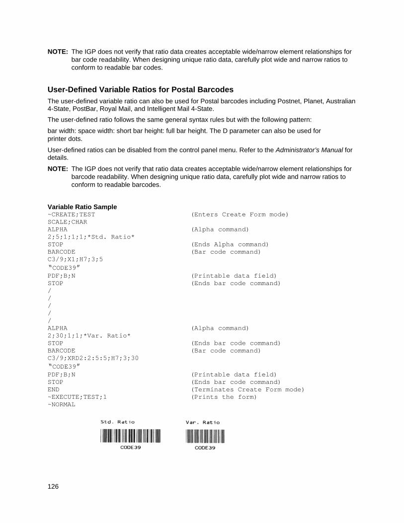
126
NOTE: The IGP does not verify that ratio data creates acceptable wide/narrow element relationships for bar code readability. When designing unique ratio data, carefully plot wide and narrow ratios to conform to readable bar codes.
User-Defined Variable Ratios for Postal Barcodes
The user-defined variable ratio can also be used for Postal barcodes including Postnet, Planet, Australian 4-State, PostBar, Royal Mail, and Intelligent Mail 4-State.
The user-defined ratio follows the same general syntax rules but with the following pattern:
bar width: space width: short bar height: full bar height. The D parameter can also be used for printer dots.
User-defined ratios can be disabled from the control panel menu. Refer to the Administrator’s Manual for details.
NOTE: The IGP does not verify that ratio data creates acceptable wide/narrow element relationships for barcode readability. When designing unique ratio data, carefully plot wide and narrow ratios to conform to readable barcodes.
Variable Ratio Sample ~CREATE;TEST (Enters Create Form mode) SCALE;CHAR ALPHA (Alpha command) 2;5;1;1;1;*Std. Ratio* STOP (Ends Alpha command) BARCODE (Bar code command) C3/9;X1;H7;3;5 “CODE39” PDF;B;N (Printable data field) STOP (Ends bar code command) / / / / / ALPHA (Alpha command) 2;30;1;1;*Var. Ratio* STOP (Ends bar code command) BARCODE (Bar code command) C3/9;XRD2:2:5:5;H7;3;30 “CODE39” PDF;B;N (Printable data field) STOP (Ends bar code command) END (Terminates Create Form mode) ~EXECUTE;TEST;1 (Prints the form) ~NORMAL
127
PDF Character Sizes [PDF [;LOC] [;FONT]]
For UPC and EAN bar codes, a smaller Letter Gothic font will be substituted for OCR-A or OCR-B when the bar code symbol is not large enough to accommodate a 10 CPI font.
For all other bar codes, OCR-A and OCR-B will print at 10 CPI. However, when using the Normal font, the PDF will be automatically sized to fit the length of the bar code symbol, if necessary.
IMPACT
NOTE: Vertical bar codes print only in standard 10 cpi font because OCR fonts cannot be rotated. If an OCR-type font is selected with a vertical bar code command, the standard 10 cpi font is substituted automatically.
Table 12 IGP/PGL Bar Code Specification Summary for 12-Mil Tip Impact Printers
Description
Magnification Parameter
Average Narrow Element
Width (mils)
Character Density (cpi)
Ratio
Codabar X1 16.7 5.4 4:3:2:1
Code 39
X1 13.8 4.5 3:1 X1A 13.8 5.5 2:1 X1B 13.8 5.0 2.5:1 X2 31.0 2.3 2.3:1 X3 44.8 1.5 2.5:1
X4 58.6 1.2 2.4:1
Code 128A X1 13.8 6.5 4:3:2:1 Code 128B X1.5 20.7 5.0 4:3:2:1
Code 93 X2 27.3 3.3 4:3:2:1
UPS 11 X3 41.4 2.2 4:3:2:1
X4 55.2 1.7 4:3:2:1
Code 128C X1 13.8 13.2 4:3:2:1 UCC/EAN-128 X1.5 20.7 9.9 4:3:2:1
GS1-128, formerly X2 27.3 6.5 4:3:2:1
UCC/EAN-128 X3 41.4 4.4 4:3:2:1
X4 55.2 3.3 4:3:2:1
EAN 8 and 13 default 13.8 1.05 MAG 4:3:2:1
Interleaved 2/5 X1 13.8 8.1 3:1 German I-2/5 X1A 17.2 7.1 2.6:1
ITF-14 X1B 13.8 10.4 2:1
Matrix
X2 31.0 4.2 2.3:1 X2A 27.6 5.2 2:1 X3 44.8 2.8 2.5:1
X4 58.6 2.2 2.4:1
MSI-A X1 13.8 7.6 3:1 MSI-B X2 20.7 5.0 2.5:1 MSI-C X3 27.6 3.8 2.3:1 MSI-D
X4 34.5 3.0 2.3:1 Plessey
UPC-A and E default 13.8 1.05 MAG 4:3:2:1
PostBar
Royal Mail Australian Post
X1 X1A
n/a n/a n/a
Planet
POSTNET Per U.S. Postal Service Publication 25: A Guide to Business Mail Preparation (USPS Certified)
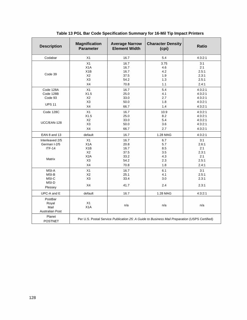
128
Table 13 PGL Bar Code Specification Summary for 16-Mil Tip Impact Printers
Description Magnification
Parameter Average Narrow Element Width
Character Density (cpi)
Ratio
Codabar X1 16.7 5.4 4:3:2:1
Code 39
X1 16.7 3.75 3:1 X1A 16.7 4.6 2:1 X1B 16.7 4.2 2.5:1 X2 37.5 1.9 2.3:1 X3 54.2 1.3 2.5:1
X4 70.8 1.1 2.4:1
Code 128A X1 16.7 5.4 4:3:2:1 Code 128B X1.5 25.0 4.1 4:3:2:1
Code 93 X2 33.0 2.7 4:3:2:1
UPS 11 X3 50.0 1.8 4:3:2:1
X4 66.7 1.4 4:3:2:1
Code 128C X1 16.7 10.9 4:3:2:1
UCC/EAN-128
X1.5 25.0 8.2 4:3:2:1 X2 33.0 5.4 4:3:2:1 X3 50.0 3.6 4:3:2:1
X4 66.7 2.7 4:3:2:1
EAN 8 and 13 default 16.7 1.28 MAG 4:3:2:1
Interleaved 2/5 X1 16.7 6.7 3:1 German I-2/5 X1A 20.8 5.7 2.6:1
ITF-14 X1B 16.7 8.5 2:1
Matrix
X2 37.5 3.5 2.3:1 X2A 33.2 4.3 2:1 X3 54.2 2.3 2.5:1
X4 70.8 1.8 2.4:1
MSI-A X1 16.7 6.1 3:1 MSI-B X2 25.1 4.1 2.5:1 MSI-C X3 33.4 3.0 2.3:1 MSI-D
X4 41.7 2.4 2.3:1 Plessey
UPC-A and E default 16.7 1.28 MAG 4:3:2:1
PostBar Royal Mail
Australian Post
X1 X1A
n/a n/a n/a
Planet
POSTNET Per U.S. Postal Service Publication 25: A Guide to Business Mail Preparation (USPS Certified)
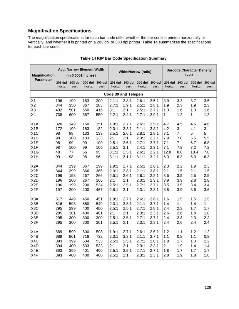
129
Magnification Specifications
The magnification specifications for each bar code differ whether the bar code is printed horizontally or vertically, and whether it is printed on a 203 dpi or 300 dpi printer. Table 14 summarizes the specifications for each bar code.
Table 14 IGP Bar Code Specification Summary
Magnification Parameter
Avg. Narrow Element Width
(in 0.0001 inches) Wide:Narrow (ratio) Barcode Character Density
(cpi)
203 dpi 203 dpi 300 dpi 300 dpi horiz. vert. horiz. vert.
203 dpi 203 dpi 300 dpi 300 dpi horiz. vert. horiz. vert.
203 dpi 203 dpi 300 dpi 300 dpi horiz. vert. horiz. vert.
Code 39 and Telepen
X1 196 199 183 200 2.1:1 2.8:1 2.6:1 2.5:1 3.9 3.3 3.7 3.5 X2 344 350 367 283 2.7:1 1.9:1 2.5:1 2.8:1 1.9 2.3 1.9 2.3 X3 492 501 550 416 3:1 2:1 2.5:1 2.7:1 1.3 1.6 1.3 1.6 X4 738 600 667 550 2.2:1 2.4:1 2.7:1 2.9:1 1 1.2 1 1.2
X1A 320 149 150 151 1.9:1 2.7:1 2.6:1 2.5:1 4.7 4.5 4.6 4.6 X1B 172 199 183 182 2.3:1 3.3:1 2.1:1 3.8:1 4.2 3 4.1 3 X1C 98 98 133 133 2.5:1 2.6:1 2.8:1 2.8:1 7.1 7 5 5 X1D 98 100 133 133 2:1 2:1 2.3:1 2.2:1 7.9 7.8 5.5 5.5 X1E 98 99 99 100 2.5:1 2.5:1 2.7:1 2.7:1 7.1 7 6.7 6.8 X1F 98 100 99 100 2.5:1 2:1 2.4:1 2.3:1 7.1 7.8 7.2 7.2 X1G 48 77 66 95 3.1:1 2.5:1 2.6:1 2.2:1 12.8 8.8 10.4 7.8 X1H 99 98 98 96 3.1:1 3.1:1 3.1:1 3.2:1 6.3 6.3 6.3 6.3
X2A 344 299 367 299 1.9:1 2.7:1 2.5:1 2.6:1 2.3 2.2 1.9 2.3 X2B 344 399 366 365 2.3:1 3.3:1 2.1:1 3.8:1 2.1 1.5 2.1 1.5 X2C 196 198 267 266 2.5:1 2.6:1 2.8:1 2.8:1 3.5 3.5 2.5 2.5 X2D 196 200 267 266 2:1 2:1 2.3:1 2.3:1 3.9 3.9 2.8 2.8 X2E 196 199 200 534 2.5:1 2.5:1 2.7:1 2.7:1 3.5 3.5 3.4 3.4 X2F 197 200 200 467 2.5:1 2:1 2.3:1 2.3:1 3.5 3.9 3.6 3.6
X3A 517 449 450 451 1.9:1 2.7:1 2.6:1 2.6:1 1.6 1.5 1.5 1.5 X3B 516 598 550 549 2.3:1 3.3:1 2.1:1 3.7:1 1.4 1 1.4 1 X3C 295 299 400 400 2.5:1 2.5:1 2.7:1 2.8:1 2.4 2.3 1.7 1.7 X3D 295 301 400 401 2:1 2:1 2.3:1 2.3:1 2.6 2.6 1.8 1.8 X3E 295 300 300 300 2.5:1 2.5:1 2.7:1 2.7:1 2.4 2.3 2.3 2.2 X3F 295 300 300 301 2.5:1 2:1 2.3:1 2.3:1 2.4 2.6 2.4 2.4
X4A 689 599 600 598 1.9:1 2.7:1 2.6:1 2.6:1 1.2 1.1 1.2 1.2 X4B 689 801 716 732 2.3:1 3.3:1 2.1:1 3.7:1 1.1 0.8 1.1 0.8 X4C 393 399 534 533 2.5:1 2.5:1 2.7:1 2.8:1 1.8 1.7 1.3 1.2 X4D 394 400 533 533 2:1 2:1 2.3:1 2.3:1 2 1.9 1.4 1.4 X4E 393 399 401 400 2.5:1 2.5:1 2.7:1 2.7:1 1.8 1.7 1.7 1.7 X4F 393 400 400 400 2.5:1 2:1 2.3:1 2.3:1 2.8 1.9 1.8 1.8
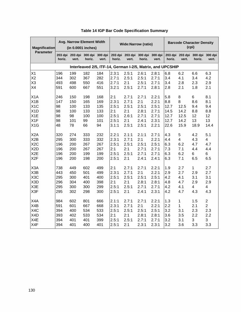
130
Table 14 IGP Bar Code Specification Summary
Magnification Parameter
Avg. Narrow Element Width
(in 0.0001 inches) Wide:Narrow (ratio) Barcode Character Density
(cpi)
203 dpi 203 dpi 300 dpi 300 dpi horiz. vert. horiz. vert.
203 dpi 203 dpi 300 dpi 300 dpi horiz. vert. horiz. vert.
203 dpi 203 dpi 300 dpi 300 dpi horiz. vert. horiz. vert.
Interleaved 2/5, ITF-14, German I-2/5, Matrix, and UPCSHIP
X1 196 199 182 184 2.3:1 2.5:1 2.6:1 2.8:1 6.8 6.2 6.6 6.3 X2 344 302 367 282 2.7:1 2.5:1 2.5:1 2.7:1 3.4 4.1 3.4 4.2 X3 493 498 550 416 2.7:1 2:1 2.5:1 2.7:1 3.4 2.8 2.3 2.9 X4 591 600 667 551 3.2:1 2.5:1 2.7:1 2.8:1 2.8 2.1 1.8 2.1
X1A 246 150 198 168 2:1 2.7:1 2.7:1 2.2:1 5.8 8 6 8.1 X1B 147 150 165 169 2.3:1 2.7:1 2:1 2.2:1 8.8 8 8.6 8.1 X1C 98 100 133 135 2.5:1 2.5:1 2.5:1 2.5:1 12.7 12.5 9.4 9.4 X1D 98 100 133 133 2:1 2:1 2.8:1 2.7:1 14.5 14.2 8.8 8.8 X1E 98 98 100 100 2.5:1 2.6:1 2.7:1 2.7:1 12.7 12.5 12 12 X1F 98 101 99 101 2.5:1 2:1 2.4:1 2.3:1 12.7 14.2 13 13 X1G 48 78 66 94 3.1:1 2.5:1 2.5:1 2.2:1 22.6 15.9 18.9 14.4
X2A 320 274 333 232 2.2:1 2.1:1 2.1:1 2.7:1 4.3 5 4.2 5.1 X2B 295 300 333 332 2.3:1 2.7:1 2:1 2.2:1 4.4 4 4.3 4 X2C 196 200 267 267 2.5:1 2.5:1 2.5:1 2.5:1 6.3 6.2 4.7 4.7 X2D 196 200 267 267 2:1 2:1 2.7:1 2.7:1 7.3 7.1 4.4 4.4 X2E 196 200 199 199 2.5:1 2.5:1 2.7:1 2.7:1 6.3 6.2 6 6 X2F 196 200 198 200 2.5:1 2:1 2.4:1 2.4:1 6.3 7.1 6.5 6.5
X3A 738 449 602 499 2:1 2.7:1 2.7:1 2.2:1 1.9 2.7 1 2.7 X3B 443 450 501 499 2.3:1 2.7:1 2:1 2.2:1 2.9 2.7 2.9 2.7 X3C 295 300 401 400 2.5:1 2.5:1 2.5:1 2.5:1 4.2 4.1 3.1 3.1 X3D 296 304 400 398 2:1 2:1 2.8:1 2.8:1 4.8 4.7 2.9 2.9 X3E 295 300 300 299 2.5:1 2.5:1 2.7:1 2.7:1 4.2 4.1 4 4 X3F 295 302 298 300 2.5:1 2:1 2.4:1 2.3:1 4.2 4.7 4.3 4.3
X4A 984 602 801 666 2.1:1 2.7:1 2.7:1 2.2:1 1.3 1 1.5 2 X4B 591 601 667 668 2.3:1 2.7:1 2:1 2.2:1 2.2 1 2.1 2 X4C 394 400 534 533 2.5:1 2.5:1 2.5:1 2.5:1 3.2 3.1 2.3 2.3 X4D 393 402 533 534 2:1 2:1 2.8:1 2.8:1 3.6 3.5 2.2 2.2 X4E 394 401 401 399 2.5:1 2.5:1 2.7:1 2.7:1 3.2 3.1 3 3 X4F 394 401 400 401 2.5:1 2:1 2.3:1 2.3:1 3.2 3.6 3.3 3.3
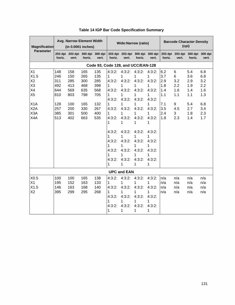
131
Table 14 IGP Bar Code Specification Summary
Magnification Parameter
Avg. Narrow Element Width
(in 0.0001 inches) Wide:Narrow (ratio) Barcode Character Density
(cpi)
203 dpi 203 dpi 300 dpi 300 dpi horiz. vert. horiz. vert.
203 dpi 203 dpi 300 dpi 300 dpi horiz. vert. horiz. vert.
203 dpi 203 dpi 300 dpi 300 dpi horiz. vert. horiz. vert.
Code 93, Code 128, and UCC/EAN-128
X1 148 158 165 135 4:3:2: 4:3:2: 4:3:2: 4:3:2: 6.2 6 5.4 6.8 X1.5 246 150 265 135 1 1 1 1 3.7 6 3.6 6.8 X2 311 285 300 285 4:3:2: 4:3:2: 4:3:2: 4:3:2: 2.9 3.2 2.9 3.2 X3 492 413 468 398 1 1 1 1 1.8 2.2 1.9 2.2 X4 644 569 635 568 4:3:2: 4:3:2: 4:3:2: 4:3:2: 1.4 1.6 1.4 1.6 X5 810 803 798 705 1 1 1 1 1.1 1.1 1.1 1.3 4:3:2: 4:3:2: 4:3:2: 4:3:2: X1A 128 100 165 132 1 1 1 1 7.1 9 5.4 6.8 X2A 257 200 330 267 4:3:2: 4:3:2: 4:3:2: 4:3:2: 3.5 4.5 2.7 3.4 X3A 385 301 500 400 1 1 1 1 2.4 3 1.8 2.3 X4A 513 402 663 535 4:3:2: 4:3:2: 4:3:2: 4:3:2: 1.8 2.3 1.4 1.7
1 1 1 1
4:3:2: 4:3:2: 4:3:2: 4:3:2: 1 1 1 1 4:3:2: 4:3:2: 4:3:2: 4:3:2: 1 1 1 1 4:3:2: 4:3:2: 4:3:2: 4:3:2: 1 1 1 1 4:3:2: 4:3:2: 4:3:2: 4:3:2: 1 1 1 1
UPC and EAN
X0.5 100 100 165 138 4:3:2: 4:3:2: 4:3:2: 4:3:2: n/a n/a n/a n/a X1 195 152 163 133 1 1 1 1 n/a n/a n/a n/a X1.5 146 163 168 140 4:3:2: 4:3:2: 4:3:2: 4:3:2: n/a n/a n/a n/a X2 395 299 295 268 1 1 1 1 n/a n/a n/a n/a
4:3:2: 4:3:2: 4:3:2: 4:3:2: 1 1 1 1 4:3:2: 4:3:2: 4:3:2: 4:3:2: 1 1 1 1
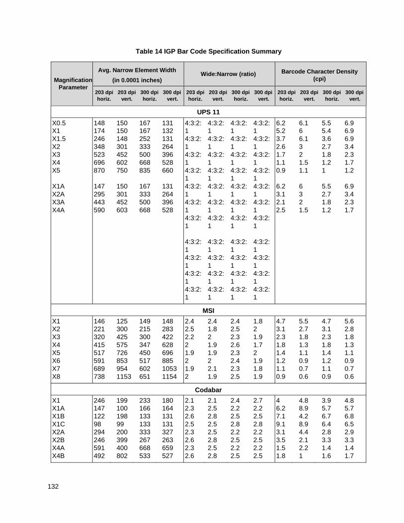
132
Table 14 IGP Bar Code Specification Summary
Magnification Parameter
Avg. Narrow Element Width
(in 0.0001 inches) Wide:Narrow (ratio) Barcode Character Density
(cpi)
203 dpi 203 dpi 300 dpi 300 dpi horiz. vert. horiz. vert.
203 dpi 203 dpi 300 dpi 300 dpi horiz. vert. horiz. vert.
203 dpi 203 dpi 300 dpi 300 dpi horiz. vert. horiz. vert.
UPS 11
X0.5 148 150 167 131 4:3:2: 4:3:2: 4:3:2: 4:3:2: 6.2 6.1 5.5 6.9 X1 174 150 167 132 1 1 1 1 5.2 6 5.4 6.9 X1.5 246 148 252 131 4:3:2: 4:3:2: 4:3:2: 4:3:2: 3.7 6.1 3.6 6.9 X2 348 301 333 264 1 1 1 1 2.6 3 2.7 3.4 X3 523 452 500 396 4:3:2: 4:3:2: 4:3:2: 4:3:2: 1.7 2 1.8 2.3 X4 696 602 668 528 1 1 1 1 1.1 1.5 1.2 1.7 X5 870 750 835 660 4:3:2: 4:3:2: 4:3:2: 4:3:2: 0.9 1.1 1 1.2 1 1 1 1 X1A 147 150 167 131 4:3:2: 4:3:2: 4:3:2: 4:3:2: 6.2 6 5.5 6.9 X2A 295 301 333 264 1 1 1 1 3.1 3 2.7 3.4 X3A 443 452 500 396 4:3:2: 4:3:2: 4:3:2: 4:3:2: 2.1 2 1.8 2.3 X4A 590 603 668 528 1 1 1 1 2.5 1.5 1.2 1.7
4:3:2: 4:3:2: 4:3:2: 4:3:2: 1 1 1 1
4:3:2: 4:3:2: 4:3:2: 4:3:2: 1 1 1 1 4:3:2: 4:3:2: 4:3:2: 4:3:2: 1 1 1 1 4:3:2: 4:3:2: 4:3:2: 4:3:2: 1 1 1 1 4:3:2: 4:3:2: 4:3:2: 4:3:2: 1 1 1 1
MSI
X1 146 125 149 148 2.4 2.4 2.4 1.8 4.7 5.5 4.7 5.6 X2 221 300 215 283 2.5 1.8 2.5 2 3.1 2.7 3.1 2.8 X3 320 425 300 422 2.2 2 2.3 1.9 2.3 1.8 2.3 1.8 X4 415 575 347 628 2 1.9 2.6 1.7 1.8 1.3 1.8 1.3 X5 517 726 450 696 1.9 1.9 2.3 2 1.4 1.1 1.4 1.1 X6 591 853 517 885 2 2 2.4 1.9 1.2 0.9 1.2 0.9 X7 689 954 602 1053 1.9 2.1 2.3 1.8 1.1 0.7 1.1 0.7 X8 738 1153 651 1154 2 1.9 2.5 1.9 0.9 0.6 0.9 0.6
Codabar
X1 246 199 233 180 2.1 2.1 2.4 2.7 4 4.8 3.9 4.8 X1A 147 100 166 164 2.3 2.5 2.2 2.2 6.2 8.9 5.7 5.7 X1B 122 198 133 131 2.6 2.8 2.5 2.5 7.1 4.2 6.7 6.8 X1C 98 99 133 131 2.5 2.5 2.8 2.8 9.1 8.9 6.4 6.5 X2A 294 200 333 327 2.3 2.5 2.2 2.2 3.1 4.4 2.8 2.9 X2B 246 399 267 263 2.6 2.8 2.5 2.5 3.5 2.1 3.3 3.3 X4A 591 400 668 659 2.3 2.5 2.2 2.2 1.5 2.2 1.4 1.4 X4B 492 802 533 527 2.6 2.8 2.5 2.5 1.8 1 1.6 1.7
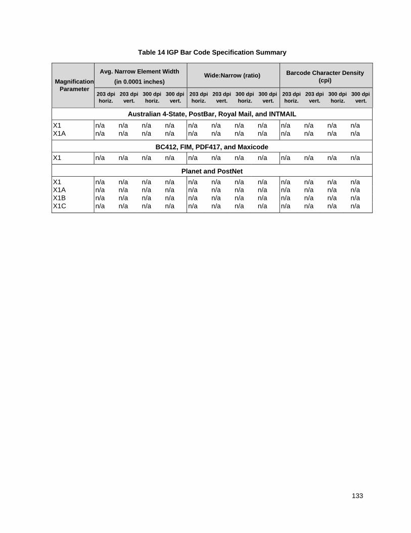
133
Table 14 IGP Bar Code Specification Summary
Magnification Parameter
Avg. Narrow Element Width
(in 0.0001 inches) Wide:Narrow (ratio) Barcode Character Density
(cpi)
203 dpi 203 dpi 300 dpi 300 dpi horiz. vert. horiz. vert.
203 dpi 203 dpi 300 dpi 300 dpi horiz. vert. horiz. vert.
203 dpi 203 dpi 300 dpi 300 dpi horiz. vert. horiz. vert.
Australian 4-State, PostBar, Royal Mail, and INTMAIL
X1 X1A
n/a n/a
n/a n/a
n/a n/a
n/a n/a
n/a n/a
n/a n/a
n/a n/a
n/a n/a
n/a n/a
n/a n/a
n/a n/a
n/a n/a
BC412, FIM, PDF417, and Maxicode
X1 n/a n/a n/a n/a n/a n/a n/a n/a n/a n/a n/a n/a
Planet and PostNet
X1 n/a n/a n/a n/a n/a n/a n/a n/a n/a n/a n/a n/a X1A n/a n/a n/a n/a n/a n/a n/a n/a n/a n/a n/a n/a X1B n/a n/a n/a n/a n/a n/a n/a n/a n/a n/a n/a n/a X1C n/a n/a n/a n/a n/a n/a n/a n/a n/a n/a n/a n/a
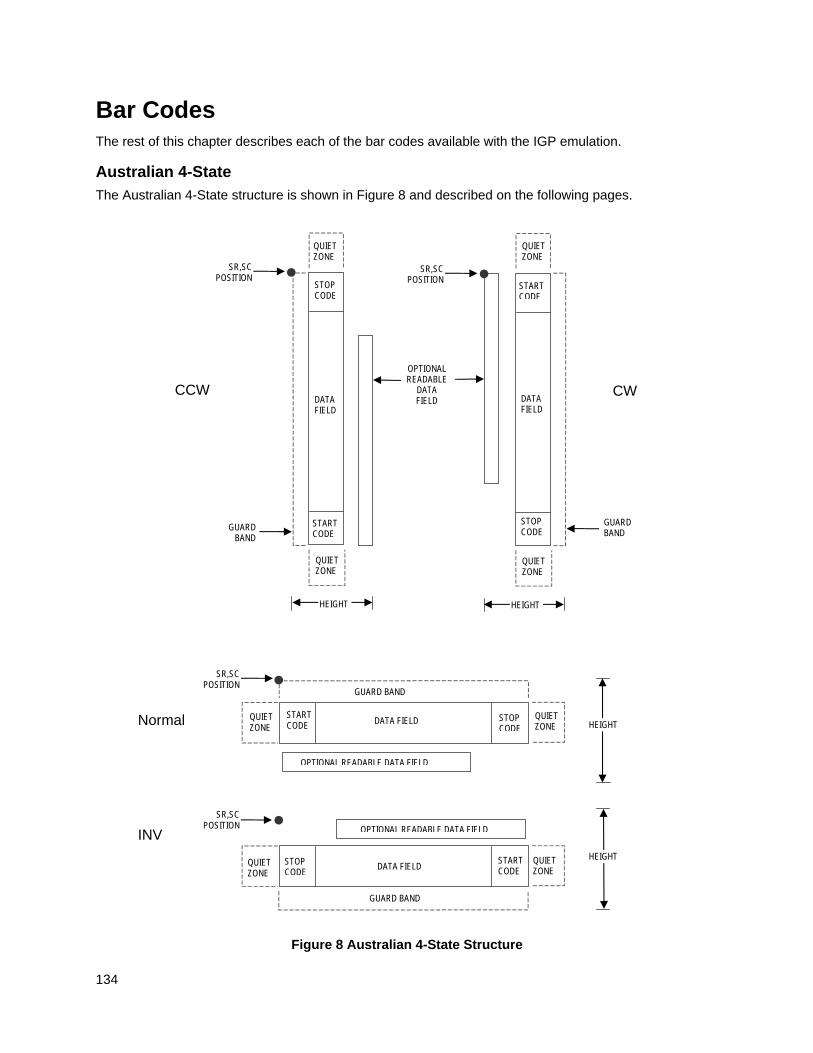
134
Bar Codes The rest of this chapter describes each of the bar codes available with the IGP emulation.
Australian 4-State
The Australian 4-State structure is shown in Figure 8 and described on the following pages.
Figure 8 Australian 4-State Structure
Normal
SR,SC POSITION
GUARD BAND
QUIET ZONE
HEIGHT
SR,SC POSITION
QUIET ZONE
QUIET ZONE
QUIET ZONE
QUIET ZONE
QUIET ZONE
STOP CODE
STOP CODE
STOP CODE
START CODE
START CODE
START CODE
OPTIONAL READABLE DATA FIELD
DATA FIELD
SR,SC POSITION
INV
DATA FIELD
DATA FIELD
GUARD BAND
CCW CW
GUARD BAND
OPTIONAL READABLE
DATA FIELD
HEIGHT HEIGHT
GUARD BAND
HEIGHT QUIET ZONE
QUIET ZONE
STOP CODE
START CODE
OPTIONAL READABLE DATA FIELD
DATA FIELD
SR,SC POSITION
135
The Australian 4-State bar code supports the Australian Postal Service. Australian 4-State bar codes are similar to POSTNET in terms of bar space and width, but have four different types of bars (Full Height, Ascender, Descender, and Tracker), whereas POSTNET only has two bar types (Tall and Short).
The Australian 4-State symbology converts alphanumeric characters into patterns of four bars, using combinations of Full Height, Ascender, Descender, and Trackers. It also adds start and stop bar codes as well as Reed-Solomon parity information.
Quiet Zone
Quiet zones extend on both ends of the bar code to permit the scan to begin and end in a blank area. The quiet zones should be at least 0.25 inches wide and completely blank to ensure accurate reading of the start/stop codes and to prevent adjacent bar codes from overlapping. You are responsible for providing sufficient space on the form for the quiet zones.
Start/Stop Code
The start and stop bars identify the orientation of the bar code. The start bar consists of an ascender bar, and is positioned at the left-most end of the bar code. The stop bar consists of a full height bar, and is positioned at the right- most end of the bar code adjacent to the check digit.
Data Field
Australian 4-State bar codes use four types of bars to encode its data: Full Height, Ascender, Descender, and Tracker. Each Full Height bar is 0.198 inch ± 0.030 inch. The Ascender and Descender bars are about 62.5% of the Full Height bar in length, while the Tracker bar is about 25% of the Full Height bar.
Each bar width is equal, and must be .020-inch ± .005-inch. Horizontal spacing between bars (pitch) must be 22 bars ± 2 bars per inch over any 0.50-inch portion of the bar code.
The Australian 4-State bar code data field consists of four different sections: the FCC, Sorting Number, Customer Data, and Reed-Solomon parity information. The FCC is a two-digit code specifying the format of the barcode (see Table 15). The Sorting Number is an 8-digit code used to sort the mail item. Customer Data is optional and is only allowed on certain formats (as indicated by the FCC selected). The IGP emulation automatically generates the Reed-Solomon parity information and includes it in the barcode.
Check Digit
No check digit is calculated for the Australian 4-State bar code. The Reed- Solomon parity information is automatically included.
Australian 4-State Command Format
BARCODE
AUSTPOST;[FCCn;][INFOn;][DIR;][NLQ;][MAG;][BFn;L;][DARK;]SR;SC (D) [data field] (D)[PDF [;LOC] [;FONT]] STOP
BARCODE The Bar Code command; enter BARCODE.
AUSTPOST Designates bar code type Australian 4-State; enter AUSTPOST.
FCCn Specifies the FCC code, which defines the format of the barcode and its size. If no value is specified, the FCC defaults to a value of 11. Enter FCC, then one of the values shown in Table 15.
INFOn Specifies the format of the customer information field. If no value is specified, the information field defaults to a value of 1. Enter INFO, then one of the values shown in Table 15.
136
Table 15 FCC Codes, Customer Inforamation Fields and Maximum Bar Code Lengths
FCC (FCCn) Customer
Information (INFOn)
Valid Data Maximum Length (Sorting Number +
Customer Data)
11, 87, 45, or 92 n/a Any 8 + 0
59 1 A-Z, a-z, 0-9, space, # 8 + 5
59 2 0-9 8 + 7
59 3 0-3 8 + 15
44, 62 1 A-Z, a-z, 0-9, space, # 8 + 10
44, 62 2 0-9 8 + 15
44, 62 3 0-3 8 + 30
NOTE: For an INFOn value of 3, the digits 0 through 3 represent the following bars: 0 = Full Height; 1 = Ascender; 2 = Descender; 3 = Tracker. Since this is a proprietary encoding, the Customer Data is not included in the optional readable data field.
DIR Optional parameter to orient the bar code structure vertically. Enter CW for clockwise rotation. Enter CCW or VSCAN for counter-clockwise rotation. Enter INV for inverted rotation. If DIR is not entered, the barcode is horizontally oriented.
NLQ Optional parameter optimized to print barcodes at NLQ print density (180x96). This may cause line matrix printers to reverse motion when the form prints. This parameter is ignored for other printer types.
MAG Optional parameter to magnify (horizontally expand) the bar code symbol. The magnification default value is X1. As required for scanning, enter a magnification value from Table 14 on page 129 to increase the magnification. Increasing the magnification adjusts printed character density.
NOTE: The User-Defined variable ratio is not allowed for this barcode.
BFn;L Optional parameters for assigning a dynamic bar code data field location on a form and for designating the length of the data field. With these parameters, the actual data for the bar code data field is dynamically provided during the Execute Form Mode; the data is not specified during the Create Form Mode. To use this field, perform the following steps:
a. Enter BF.
b. Replace n with a number ranging from 0 through 512 to identify the bar code field. The SR and SC parameters specify the exact location of the bar code field identified by n.
c. Replace L with a number equaling the total number of characters in the field. (The actual data provided dynamically during the Execute Form Mode can be less than L.)
d. The information for the data field is entered dynamically during the Execute Form Mode. (Refer to Execute Form: Dynamic Bar Code Data on page 64.) Do not use the data field parameter to enter data
137
when the BFn;L parameters are used. However, refer to the data field description for available characters.
DARK Optional parameter to produce darker looking bar codes. Enter DARK. Refer to Dark Printing on page 52 for more information.
SR Defines the starting row for the bar code. Enter a value ranging from row 1 to one less than the length of the form. Character row or dot row is specified based on the Scale command (page 113), or use the CP.DP format (page 23).
SC Defines the starting column of the bar code. Enter a value ranging from column 1 to one less than the width of the form. Character column or dot column is specified based on the Scale command (page 113), or use the CP.DP format (page 23).
(D) The printable character (delimiter) identifying the start and finish of the data field. Enter any printable character other than a slash (/), the SFCC, or a character used within the data. The same character must be used at both ends of the data field, but it is not printed with the data.
data field Contains the bar code characters. See Data Field on page 135 for a description of the Australian 4- State bar code data field.
PDF Optional parameter to enable printing of the human readable data field. Enter PDF to print the data field. If the parameter is not used, the human readable data will not print. This parameter is not allowed if a null data field is specified.
LOC Optional parameter to identify the location of the printable data field. The default value is B, locating the human readable data below the bar code. A locates the printable data field above bar code. To compensate for printing the 0.1-inch high data, the height of the bar code body is reduced 0.1 inch.
FONT Optional parameter to select the font for the human readable data field. Enter O to select OCR-A font; enter X to select OCR-B font; enter N to select 10 cpi; enter P to select 12 cpi; enter Q to select 13 cpi; enter R to select 15 cpi; enter T to select 17 cpi; enter V to select 20 cpi.
To select a scalable font with user-defined size, enter Nh:w or F;Nh:w. The parameters h (height) and w (width) can each range from 1 to 96, and are expansion factors of a 10 cpi character. Nh:w prints in Letter Gothic (font 93779) regardless of the current active font. By default F;Nh:w uses the Letter Gothic as the current font selection. You can change the default by using the FONT command.
NOTE: Nh:w and F;Nh:w will not print the PDF wider or taller than the barcode. If the height parameter h causes the PDF to print above the horizontal barcode start row or vertical barcode start column, a barcode font Error will occur. If the width parameter w causes the PDF to exceed the barcode width, the PDF width factor w will automatically reduce to fit within the barcode width without causing an error.
STOP Ends the Bar Code command while the IGP continues in the Create Form Mode. Enter STOP. If STOP is not entered, an error message results.
138
Australian 4-State Example ~CREATE;TEST (Enter Create Form mode) BARCODE (Bar code command) AUSTPOST;FCC62;INFO1;9;8 (Australian 4-State bar code, FCC=62, INFO=1, SR 9, SC 8) *00141544adc0gre117* (Data Field; 8-digit Sorting Number + 10 alphanumeric customer data) PDF;A (Printable data field above bar code) STOP (Ends bar code command) BARCODE (Bar code command) AUSTPOST;VSCAN;9;50 (Vertical Australian 4-State bar code, FCC=11, INFO=1, SR 9, SC 50) *00540171* (Data Field; 8-digit Sorting Number) PDF (Printable data field) STOP (Ends bar code command) END (Terminates Create Form mode) ~EXECUTE;TEST;1 (Execute the form, form count of 1) ~NORMAL
SR 9
SC 8
SR 9
SC 50
139
THERMAL
Aztec Barcode
Aztec barcode is a 2-D matrix symbology designed to combine the best characteristics of several 1st generation symbologies, with special attention paid to ease of printing, ease of finding in any orientation, allowance for field distortion, high data security with user-selected redundancy, and efficient storage over the range from small to large data messages. Aztec symbols are made up of an array of square cells with square bullseye in the center.
Command Format
BARCODE
AZTEC; [DIR;] [X[D]n;] [Hn;] [FORMATx,y;] [APPENDx,y;] [INIT;][BFn;L;] [DARK;] SR; SC
[(D)Data Field(D)]
STOP
Parameter Description
X[D]n Optional parameter that designates the x-dimension width of a single square data module in IGP dots, or printer dots if the option [D] is used. Values range from 1 to 1000 printer dots. The y-dimension is calculated by converting the printer dots in the x-direction to printer dots in the y-direction. This parameter is overridden by the H parameter below.
Hn Optional parameter that selects the target height of the entire symbol. When the H parameter is used, the y-dimension of the single square module is computed by dividing the target height by the number of symbol rows. Thus, both the x and y dimension of the square data module will be overridden by this value.
FORMATx,y Optional parameter that specifies the format x (includes error correction), and number of layers y in the symbol as shown in the table below. Note that in formats with x = 0, 1-99, and 102, the number of layers is optimally chosen by PGL.
Format x Description Layers y
0 Default with Error Correction of 23% + 3 codewords.
0
1–99 Fixed Error Correction Percentage of 1–99
0
100 Compact format 1–4
101 Full–range format 1–32
102 Rune format 0
APPENDx,y Optional parameter that specifies that invokes message append (multiple symbols linked together) across x number of symbols. The minimum value of x is 1 and the maximum is 26. The parameter y specifies the length of the Message Append ID string, which is the first y bytes in the data field. Since the Message Append ID string is included with the data,
140
it should be part of the L parameter when dynamic data BF parameter is used.
INIT Optional parameter that specifies that the symbol is a Reader Initialization symbol.
Quiet Zone
The minimum quiet zone is one module width on all four sides.
GuardBand
There are no guardbands for Aztec.
There is no PDF allowed for the Aztec barcode.
Data Field
The format of the data is as follows:
[Message Append ID String][Message Encode String]
The length of the Message Append ID string is based on the values given with the APPEND parameter. If there is no Message Append ID string, then the data is simply the Message Encode string. There is no delimiter between the Message Append ID string and the Message Encode string. For example, if the Message Append ID string is “ABC” and defined to be 3 bytes long while the Message Encode string is “12345”, then the complete data field would be “ABC12345”.
The Message Encode string can consist of any 8-bit data. The maximum number of data depend on three things: (1) format selected (which includes error correction level), (2) number of layers (only valid for Compact and Full- Range formats), and (3) type of data.
ESC signals FNC1 and Extended Channel Escape Character
In the data stream, an ESC character signals the presence of a non-data characters such as FNC1 or Extended Channel Escape characters. To encode a true ESC character, the data stream should have an ESC followed by a second ESC character. Otherwise, the values following ESC have the meaning shown below:
ESC n Description Required Data
Following
ESC ESC Represents an ESC character N/A
ESC 0 Represents a FNC1 character N/A
ESC1 ECE character 1 digit
ESC 2 ECE character 2 digits
ESC 3 ECE character 3 digits
ESC 4 ECE character 4 digits
ESC 5 ECE character 5 digits
ESC 6 ECE character 6 digits
ESC ?? Invalid N/A
141
Symbol Characteristics
The following tables illustrate the maximum data capacities for the Aztec barcode for the Compact and Full-Range Format with all possible layer values.
Table 16 Compact Format Characteristics (Layers 1-4)
Layers
Symbol Size
Codeword Count x Size
Max Text
Max Text
Max 8–Byte
1 15 X 15 17 x 6 13 12 6
2 19 X 19 40 x 6 40 33 19
3 23 X 23 51 x 8 70 57 33
4 27 X 27 76 x 8 110 89 53
Table 17 Full Format Characteristics (Layer 1-32)
Layers
Symbol Size
Codeword Count x Size
Max Text
Max Text
Max 8–Byte
1 19 X 19 21 x 6 18 15 8
2 23 X 23 48 x 6 49 40 24
3 27 X 27 60 x 8 84 68 40
4 31 X 31 88 x 8 128 104 62
5 37 X 37 120 x 8 178 144 87
6 41 X 41 156 x 8 232 187 114
7 45 X 45 196 x 8 294 236 145
8 49 X 49 240 x 8 362 291 179
9 53 X 53 230 x 10 516 414 256
10 57 X 57 272 x 10 516 414 256
11 61 X 61 316 x 10 601 482 298
12 67 X 67 364 x 10 691 554 343
13 71 X 71 416 x 10 793 636 394
14 75 X 75 470 x 10 896 718 446
15 79 X 79 528 x 10 1008 808 502
16 83 X 83 588 x 10 1123 900 559
17 87 X 87 652 x 10 1246 998 621
142
Table 17 Full Format Characteristics (Layer 1-32)
Layers
Symbol Size
Codeword Count x Size
Max Text
Max Text
Max 8–Byte
18 91 X 91 720 x 10 1378 1104 687
19 95 X 95 790 x 10 1511 1210 753
20 101 X 101 864 x 10 1653 1324 824
21 105 X 105 940 x 10 1801 1442 898
22 109 X 109 1020 x 10 1956 1566 976
23 113 X 113 920 x 12 2116 1694 1056
24 117 X 117 992 x 12 2281 1826 1138
25 121 X 121 1066 x 12 2452 1963 1224
26 125 X 125 1144 x 12 2632 2107 1314
27 131 X 131 1224 x 12 2818 2256 1407
28 135 X 135 1306 x 12 3007 2407 1501
29 139 X 139 1392 x 12 3205 2565 1600
30 143 X 143 1480 x 12 3409 2728 1702
31 147 X 147 1570 x 12 3616 2894 1806
32 151 X 151 1664 x 12 3832 3067 1914
Aztec Example
~CREATE AZTEC;792 BARCODE AZTEC;FORMAT100,4;10;5 *ABCDE511111* STOP END ~EXECUTE;AZTEC;1
143
THERMAL
BC412 BARCODE
The BC412 barcode was invented by IBM in 1988 to meet the needs of the semiconductor wafer identification application. The word BC stands for binary code (presence or absence of a bar) and 412 means 4 bar modules in a total of 12 module positions in every character. It is a one dimensional barcode that meets the following requirements: small space, easy scribing, and robust decoding even if the barcode symbols are under poor light contrast. It can achieve a density of 23 characters in less than an inch with a 3.3 mil bar width.
Command Format
BARCODE BC412; [DIR;] [MAG;] [Hn[.m];] [BFn;L;] [DARK;] SR; SC [(D)Data Field(D)] [PDF [;LOC][;F][;FONT[VE:HE]]] STOP
Start Code
The start code is bar,space,space" in all cases.
Termination Code
The stop code is bar,space,bar" in all cases.
Data Field
BC412 can accommodate 35 characters, 0 - 9 and A - Z. The number 0 is used in place of the letter O. The following table lists the character with it's module sequence and the character value.
I = Bar
- = Space
Character
Module Sequence
Character Value
0 I-I-I-I----- 00
1 I-I-I--I---- 15
2 I-I-I---I--- 17
3 I-I-I --- I-- 29
4 I-I-I ---- I- 11
5 I-I--I-I---- 33
6 I-I--I--I--- 19
7 I-I--I---I-- 21
8 I-I--I I- 08
9 I-I---I-I--- 02
A I-I---I--I-- 07
144
Character
Module Sequence
Character Value
B I-I---I---I- 25
C I-I----I-I-- 20
D I-I----I--I- 22
E I-I-----I-I- 09
F I--I-I-I---- 30
G I--I-I--I--- 03
H I--I-I---I-- 06
I I--I-I I- 27
J I--I--I-I--- 16
K I--I--I--I-- 24
L I--I--I---I- 04
M I--I---I-I-- 34
N I--I---I--I- 12
P I--I----I-I- 32
Q I---I-I-I--- 18
R I---I-I--I-- 01
S I---I-I---I- 14
T I---I--I-I-- 13
U I---I--I--I- 26
V I---I---I-I- 05
W I----I-I-I-- 31
X I----I-I--I- 28
Y I----I--I-I- 23
Z I-----I-I-I- 10
Start I--
Stop I-I
145
Check Code
The BC412 has a mod 35 check character. The check character is placed in the second position behind the first data character. The check code is automatically included in the bar structure; however, it is not included in the PDF. The check digit computation is shown below:
Let D = D1D2....Dn be a string of n data characters and C = C1C2....Cn+1 be a string value of n+1 encoded characters.
V1 = Character value of C1. (refer to the table above)
Fo = (Sum of Odd V1) Mod 35.
Fe = (Sum of Even V1) Mod 35
F = (Fo + 2Fe) Mod 35
The second character is the check character. Hence, designate the second character of C1C2.... to be the check character of D.
Set C2 = 0. Therefore C1C3C4....Cn+1 = D1D2D3....Dn
Calculate Fo, Fe, and F
C2 = the character that has the check character value 17F Mod 35
Example:
Assume that the data character string is AQ1557 Form the character string C = A0Q1557
Fo = (7 + 18 + 33 + 21) Mod 35
= 79 Mod 35
= 9
Fe = (0 + 11 + 19) Mod 35
= 34 Mod 35
= 34
F = (9 + 2*34) Mod 35
= 77 Mod 35
= 7
Character value of the check character is = 17*7 Mod 35
= 119 Mod 35
= 14
Cross reference in the table above, 14 is the character value of character 'S'. Hence the check character is ’S’.
GuardBand
Normally, there are guardbands 0.10 inches both above and below the bars of the barcode. However, if it is a non-rotated barcode with the PDF below, then the bottom guardband is reduced to 0.07 inches (1/14 inch). The difference (0.03 inches) is then subtracted from the overall height of the barcodes. This is done to provide compatibility with IGP-X00 products.
Magnification
There is only one pre-defined magnification for BC412, X1 which is the default magnification.
There are two values that comprise the dot ratio: bar and a space. Therefore, user-defined ratios for this barcode should have these two values defined, in the order previously specified.
146
Height
The barcode can range from 0.3 - 9.9 inches tall. Default is 0.9 inches. If the minimum height of 0.3 inch is selected, the PDF is not allowed.
NOTE: the maximum VE allowed in the PDF is dependent on the height of the entire barcode.
The PDF is not included unless requested. If included, it is separated from the bars by a guardband. The default font type used for the PDF is N. The check character is not included in the PDF.
~CREATE;TEST BARCODE BC412;H10;5;5 *12345ABCDE* STOP END
~EXECUTE;TEST
~NORMAL
Figure 9 BC412 Barcode
147
Codabar
The Codabar structure is shown in Figure 10 and described on the following pages.
Figure 10 Codabar Structure
Normal
LOWER GUARD BAND
HEIGHT
QUIET ZONE
QUIET ZONE
STOP CODE
START CODE
OPTIONAL READABLE DATA FIELD
DATA FIELD
SR,SC POSITION
INV
SR,SC POSITION
QUIET ZONE
STOP CODE
START CODE
QUIET ZONE
OPTIONAL READABLE DATA FIELD
LOWER GUARD BAND
UPPER GUARD BAND
UPPER GUARD BAND
DATA FIELD HEIGHT
OPTIONAL CHECK DIGIT
OPTIONAL CHECK DIGIT
CCW
LOWER GUARD BAND
QUIET ZONE
SR,SC POSITION
STOP CODE
START CODE
QUIET ZONE
OPTIONAL READABLE DATA FIELD
UPPER GUARD
BAND
DATA FIELD
HEIGHT
OPTIONAL CHECK
DIGIT
SR,SC POSITION
QUIET ZONE
STOP CODE
START CODE
QUIET ZONE
DATA FIELD
LOWER GUARD
BAND
UPPER GUARD BAND
CW
OPTIONAL CHECK DIGIT
HEIGHT
148
Quiet Zone
Both ends of the bar code structure require blank quiet zones. The quiet zones must be at least 0.25 inches wide and completely blank to ensure accurate reading of the start/stop codes and to prevent adjacent bar codes from overlapping. Be sure to provide sufficient space on the form for the quiet zones.
Start/Stop Codes
The start/stop code is a unique character identifying the leading and trailing end of the bar code. The start/stop code is automatically produced with each bar code. The start/stop code structure permits bidirectional bar code scanning.
Data Field
The bar code symbol uses a series of wide and narrow bars and spaces to represent standard alphanumeric characters. Each wide or narrow bar or space is one element; each character in the data field has nine elements. The structure is three wide elements (bars or spaces) out of the nine total elements which compose one character.
Readable Data
The optional readable data field provides a readable interpretation of the bar code data. It can be printed above or below the bar code symbol.
Check Digit
The optional modulo-43 check digit can be inserted into the bar code to verify accurate scanning.
Codabar Command Format
BARCODE CODABAR [CD];[DIR;] [MAG;] [Hn[.m];] [BFn;L;] [DARK;] SR;SC (D) [data field] (D) [PDF [;LOC] [;FONT]] STOP
BARCODE The Bar Code command; enter BARCODE.
CODABAR CD
Designates bar code type Codabar; enter CODABAR. To calculate and plot the optional modulo-43 check digit with the bar code symbol automatically, enter CD.
DIR Optional parameter to orient the bar code structure vertically. Enter CW for clockwise rotation. Enter CCW or VSCAN for counter-clockwise rotation. Enter INV for inverted rotation. If DIR is not entered, the barcode is horizontally oriented.
MAG Optional parameter to magnify (horizontally expand) the bar code symbol. The magnification default value is X1. As required for scanning, enter a magnification value from Table 14 on page 129 to increase the magnification. Increasing the magnification adjusts printed character density. You can also use XR or XRD as defined on page 125.
NOTE: You must specify four digits for MAG for User Defined variable ratio. There are four values that comprise the dot ratio: narrow bar, narrow space, wide bar, and wide space. User-defined ratios for this barcode should have these four values defined in the order specified.
Hn[.m] Optional parameter to adjust the overall height (vertical expansion) of the bar code symbol (including the upper and lower 0.1-inch guard bands and any human readable data). Height adjustments are made in 0.1-inch increments; enter H and a value from 3 through 99 to select height
149
adjustments from 0.3 through 9.9 inches. The default value is 0.9 inch.
[.m] is an additional number of dots for the bar code height. (Dots are in the current dot scale.)
NOTE: If 0.3 inches is the selected height, the PDF cannot be included.
BFn;L Optional parameters for assigning a dynamic bar code data field location on a form and for designating the length of the data field. With these parameters, the actual data for the bar code data field is dynamically provided during the Execute Form Mode; the data is not specified during the Create Form Mode. To use this field, perform the following steps:
a. Enter BF.
b. Replace n with a number ranging from 0 through 512 to identify the bar code field. The SR and SC parameters specify the exact location of the bar code field identified by n.
c. Replace L with a number equaling the total number of characters in the field. (The actual data provided dynamically during the Execute Form Mode can be less than L.)
d. The information for the data field is entered dynamically during the Execute Form Mode. (Refer to Execute Form: Dynamic Bar Code Data on page 64.) Do not use the data field parameter to enter data when the BFn;L parameters are used. However, refer to the data field description for available characters.
DARK Optional parameter to produce darker looking bar codes. Enter DARK. Refer to Dark Printing on page 52 for more information.
SR Defines the starting row for the bar code. Enter a value ranging from row 1 to one less than the length of the form. Character row or dot row is specified based on the Scale command (page 113), or use the CP.DP format (page 23).
SC Defines the starting column of the bar code. Enter a value ranging from column 1 to one less than the width of the form. Character column or dot column is specified based on the Scale command (page 113), or use the CP.DP format (page 23).
(D) The printable character (delimiter) identifying the start and finish of the data field. Enter any printable character other than a slash (/), the SFCC, or a character used within the data. The same character must be used at both ends of the data field, but it is not printed with the data.
data field Contains the bar code characters. A null data field (no characters) is permitted. The data field can contain any of the characters listed in Table 18 except the SFCC, and the first character and the last character in the data field must be either A, B, C, or D. The length of the data field is variable; however, the maximum length is usually limited to 32 characters to minimize potential reading errors.
PDF Optional parameter to enable printing of the human readable data field. Enter PDF to print the data field. If the parameter is not used, the human readable data will not print. This parameter is not allowed if a null data field is specified.
LOC Optional parameter to identify the location of the printable data field. The default value is B, locating the human readable data below the bar code.
150
A locates the printable data field above bar code. To compensate for printing the 0.1-inch high data, the height of the bar code body is reduced 0.1 inch.
FONT Optional parameter to select the font for the human readable data field. Enter O to select OCR-A font; enter X to select OCR-B font; enter N to select 10 cpi; enter P to select 12 cpi; enter Q to select 13 cpi; enter R to select 15 cpi; enter T to select 17 cpi; enter V to select 20 cpi.
To select a scalable font with user-defined size, enter Nh:w or F;Nh:w. The parameters h (height) and w (width) can each range from 1 to 96, and are expansion factors of a 10 cpi character. Nh:w prints in Letter Gothic (font 93779) regardless of the current active font. By default F;Nh:w uses the Letter Gothic as the current font selection. You can change the default by using the FONT command.
NOTE: Nh:w and F;Nh:w will not print the PDF wider or taller than the barcode. If the height parameter h causes the PDF to print above the horizontal barcode start row or vertical barcode start column, a barcode font Error will occur. If the width parameter w causes the PDF to exceed the barcode width, the PDF width factor w will automatically reduce to fit within the barcode width without causing an error.
STOP Ends the Bar Code command while the IGP continues in the Create Form Mode. Enter STOP. If STOP is not entered, an error message results.
Table 18 Codabar Character Set
Character Hex Character Hex
0 30 - 2D
1 31 $ 24
2 32 : 3A
3 33 / 2F
4 34 . 2E
5 35 + 2B
6 36 A 41
7 37 B 42
8 38 C 43
9 39 D 44
151
Codabar Example
~CREATE;TEST;288 (Enter Create Form mode) BARCODE (Bar code command) CODABAR;VSCAN;X1;H7;5;20 (Vertical Codabar bar code, MAG 1,SR 5, SC 20) *A12345B* (Data Field) PDF;B;N (Printable data field) STOP (Ends bar code command) END (Terminates Create Form mode) ~EXECUTE;TEST ~NORMAL
Code 35
The Code35 barcode is used in high speed processing and postal automation. The bar structure to be composed is simple and the safety of the barcode is excellent. Print speed is fast, so it is suitable for high speed reader of optical character. Each number in the data field contains the bar that indicates the start, so self-search is possible. The barcode is good for the error check.
Command Format
BARCODE
C35; [DIR;] [MAG;] [Hn[.m];] [BFn;L;] [DARK;] SR; SC
[(D)Data Field(D)]
STOP
Start Code
Each number in the data field contains the bar that indicate the start.
Data Field
Code 35 can accommodate 10 characters, 0 - 9. The following table lists the character with it’s module sequence. Each character is composed of 6 bars of same kind which include 2 empty bars ( bars removed from their place) and one start bar. Data Field is written form left to right, but barcode symbol is composed in an order of left to right which starts with the rightmost character in the data field to the leftmost character.
I = Bar E = Empty Bar S = Start Bar – = Space
SR 5
SC 20
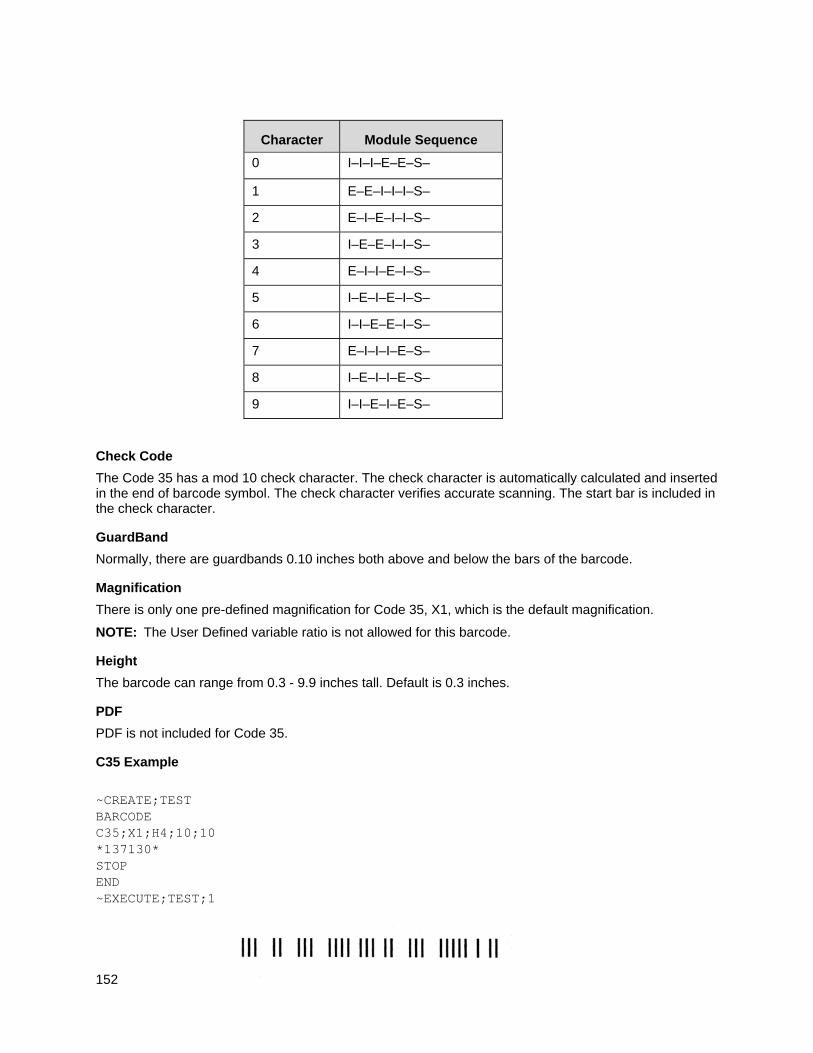
152
Character Module Sequence
0 I–I–I–E–E–S–
1 E–E–I–I–I–S–
2 E–I–E–I–I–S–
3 I–E–E–I–I–S–
4 E–I–I–E–I–S–
5 I–E–I–E–I–S–
6 I–I–E–E–I–S–
7 E–I–I–I–E–S–
8 I–E–I–I–E–S–
9 I–I–E–I–E–S–
Check Code
The Code 35 has a mod 10 check character. The check character is automatically calculated and inserted in the end of barcode symbol. The check character verifies accurate scanning. The start bar is included in the check character.
GuardBand
Normally, there are guardbands 0.10 inches both above and below the bars of the barcode.
Magnification
There is only one pre-defined magnification for Code 35, X1, which is the default magnification.
NOTE: The User Defined variable ratio is not allowed for this barcode.
Height
The barcode can range from 0.3 - 9.9 inches tall. Default is 0.3 inches.
PDF is not included for Code 35.
C35 Example
~CREATE;TEST BARCODE C35;X1;H4;10;10 *137130* STOP END ~EXECUTE;TEST;1
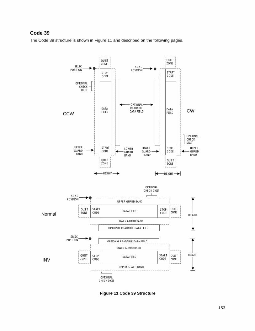
153
Code 39
The Code 39 structure is shown in Figure 11 and described on the following pages.
Figure 11 Code 39 Structure
Normal
LOWER GUARD BAND
HEIGHT
QUIET ZONE
QUIET ZONE
STOP CODE
START CODE
OPTIONAL READABLE DATA FIELD
DATA FIELD
SR,SC POSITION
INV
SR,SC POSITION
QUIET ZONE
STOP CODE
START CODE
QUIET ZONE
OPTIONAL READABLE DATA FIELD
LOWER GUARD BAND
UPPER GUARD BAND
UPPER GUARD BAND
DATA FIELD HEIGHT
OPTIONAL CHECK DIGIT
OPTIONAL CHECK DIGIT
CCW
LOWER GUARD BAND
QUIET ZONE
SR,SC POSITION
STOP CODE
START CODE
QUIET ZONE
OPTIONAL READABLE DATA FIELD
UPPER GUARD
BAND
DATA FIELD
HEIGHT
OPTIONAL CHECK
DIGIT
SR,SC POSITION
QUIET ZONE
STOP CODE
START CODE
QUIET ZONE
DATA FIELD
LOWER GUARD
BAND
UPPER GUARD BAND
CW
OPTIONAL CHECK DIGIT
HEIGHT
154
Quiet Zone
Both ends of the bar code structure require blank quiet zones. The quiet zones must be at least 0.25 inches wide and completely blank to ensure accurate reading of the start/stop codes and to prevent adjacent bar codes from overlapping. Be sure to provide sufficient space on the form for the quiet zones.
Start/Stop Codes
The start/stop code is a unique character identifying the leading and trailing end of the bar code. The start/stop code is automatically produced with each bar code. The start/stop code structure permits bidirectional bar code scanning.
Data Field
The bar code symbol uses a series of wide and narrow bars and spaces to represent standard alphanumeric characters. Each wide or narrow bar or space is one element; each character in the data field has nine elements. The structure is three wide elements (bars or spaces) out of the nine total elements which compose one character.
For HIBC barcode, the data field is a variable length field consisting of only the following characters: 1-9, A-Z, -, ., $, /, +, %, and space.
Readable Data
The optional readable data field provides a readable interpretation of the bar code data. It can be printed above or below the bar code symbol.
Check Digit
The optional modulo-43 check digit can be inserted into the bar code to verify accurate scanning.
For HIBC barcode, a mandatory modulo-43 checkdigit is inserted at the end of the data.
Unless requested, the PDF is not included. If included, it is separated from the bars by a guardband. The default font type used for PDF is N. Non-printable characters are printed as spaces. The check digit is included in the PDF.
For HIBC barcode, PDF is preceded with ‘+’, a Flag Character which is an identifier used to differentiate HIBC symbols from other non-healthcare related barcode symbols. A pair of asterisks (*) encloses the human readable field, including the check digit.
Code 39 Command Format
NOTE: Although commonly referred to as Code “39”, you must enter the command as “C3/9” (including the slash) during IGP input.
BARCODE C3/9 [CD]; [HIBC;] [DIR;] [MAG;] [Hn[.m];] [BFn;L;] [DARK;]SR;SC [(D) [data field] (D)[PDF [;LOC] [;FONT]] STOP
BARCODE The Bar Code command; enter BARCODE.
C3/9 CD Designates bar code type C39; enter C3/9. To calculate and plot the optional modulo-43 check digit with the bar code symbol automatically, enter CD.
HIBC The Health Industry Bar Code (HIBC) is encoded in either Code 128 or Code 39 symbology. Enter HIBC. In a global setting, HIBC identifies health industry products, in any quantity, of any lot or serial number, with
155
any expiration date. HIBC represents two kinds of information: Primary and Secondary Identification. Primary Identification represents product identity and Secondary Identification represents the attributes of Lot or Batch Code, Serial Number, and Expiration date.
When encoding HIBC barcode in UCC-128, HIBC is essentially a UCC-128 barcode. The encoding uses the same module 10 check digit and data format. The only addition is an Application Identifier (AI) parameter. For Primary Data Structure use AI (01), and for Secondary Data Structure use AI (22) or AI (240). To use UCC-128 to encode HIBC, be sure to use the correct AI parameter to obtain the desired results.
DIR Optional parameter that allows for rotating a barcode. Enter CW for clockwise rotation. Enter CCW or VSCAN for counter-clockwise rotation. Enter INV for inverted rotation. If DIR is not entered, the barcode is horizontally oriented.
MAG Optional parameter to magnify (horizontally expand) the bar code symbol. The magnification default value is X1. As required for scanning, enter a magnification value from Table 14 on page 129 to increase the magnification. Increasing the magnification adjusts printed character density. You can also use XR or XRD as defined on page 125.
NOTE: You must specify four digits for MAG for User Defined variable ratio. There are four values that comprise the dot ratio: narrow bar, narrow space, wide bar, and wide space. User-defined ratios for this barcode should have these four values defined in the order specified.
Hn[.m] Optional parameter to adjust the overall height (vertical expansion) of the bar code symbol (including the upper and lower 0.1-inch guard bands and any human readable data). Height adjustments are made in 0.1-inch increments plus dots; enter H and a value from 3 through 99 to select height adjustments from 0.3 through 9.9 inches. The default value is 0.9 inch. [.m] is an additional number of dots for the bar code height. (Dots are in the current dot scale.)
NOTE: If 0.3 inches is the selected height, the PDF cannot be included.
BFn;L Optional parameters for assigning a dynamic bar code data field location on a form and for designating the length of the data field. With these parameters, the actual data for the bar code data field is dynamically provided during the Execute Form Mode; the data is not specified during the Create Form Mode. To use this field, perform the following steps:
a. Enter BF.
b. Replace n with a number ranging from 0 through 512 to identify the bar code field. The SR and SC parameters specify the exact location of the bar code field identified by n.
c. Replace L with a number equaling the total number of characters in the field. (The actual data provided dynamically during the Execute Form Mode can be less than L.)
d. The information for the data field is entered dynamically during the Execute Form Mode. (Refer to Execute Form: Dynamic Bar Code Data on page 64.) Do not use the data field parameter to enter data when the BFn;L parameters are used. However, refer to the data field description for available characters.
DARK Optional parameter to produce darker looking bar codes. Enter DARK. Refer to Dark Printing on page 52 for more information.
156
SR Defines the starting row for the bar code. Enter a value ranging from row 1 to one less than the length of the form. Character row or dot row is specified based on the Scale command (page 113), or use the CP.DP format (page 23).
SC Defines the starting column of the bar code. Enter a value ranging from column 1 to one less than the width of the form. Character column or dot column is specified based on the Scale command (page 113), or use the CP.DP format (page 23).
(D) The printable character (delimiter) identifying the start and finish of the data field. Enter any printable character other than a slash (/), the SFCC, or a character used within the data. The same character must be used at both ends of the data field, but it is not printed with the data.
data field Contains the bar code characters. A null data field (no characters) is permitted. The data field can contain any of the characters listed in Table 20 except the SFCC. The length of the data field is variable; however, the maximum length is usually limited to 32 characters to minimize potential reading errors.
PDF Optional parameter to enable printing of the human readable data field. Enter PDF to print the data field. If the parameter is not used, the human readable data will not print. This parameter is not allowed if a null data field is specified.
LOC Optional parameter to identify the location of the printable data field. The default value is B, locating the human readable data below the bar code. A locates the printable data field above bar code. To compensate for printing the 0.1-inch high data, the height of the bar code body is reduced 0.1 inch.
FONT Optional parameter to select the font for the human readable data field. Enter O to select OCR-A font; enter X to select OCR-B font; enter N to select 10 cpi; enter P to select 12 cpi; enter Q to select 13 cpi; enter R to select 15 cpi; enter T to select 17 cpi; enter V to select 20 cpi.
To select a scalable font with user-defined size, enter Nh:w or F;Nh:w. The parameters h (height) and w (width) can each range from 1 to 96, and are expansion factors of a 10 cpi character. Nh:w prints in Letter Gothic (font 93779) regardless of the current active font. By default F;Nh:w uses the Letter Gothic as the current font selection. You can change the default by using the FONT command.
NOTE: Nh:w and F;Nh:w will not print the PDF wider or taller than the barcode. If the height parameter h causes the PDF to print above the horizontal barcode start row or vertical barcode start column, a barcode font Error will occur. If the width parameter w causes the PDF to exceed the barcode width, the PDF width factor w will automatically reduce to fit within the barcode width without causing an error.
STOP Ends the Bar Code command while the IGP continues in the Create Form Mode. Enter STOP. If STOP is not entered, an error message results.
157
Code 39 Symbology
Listed below are the Narrow Element Widths (N.E.W.) and Wide to Narrow (W:N) ratios at various magnification factors when printed on the thermal printer at 203 dp.
NOTE: The resulting ratios occur with or without using the scale.dot command.
Table 19 Narrow Element Widths And Wide To Narrow Ratios
Mag Factor
N.E.W. (PRM)
N.E.W. (Actual)
W:N (PRM)
W:N (Actual)
X1 16.7 19.0 2.95:1 2.5:1
A 16.7 17.2 2.13:1 1.9:1**
B 13.7 17.2 2.82:1 2.3:1
C 13.6 9.8 2.4:1 2.5:1
D 13.7 19.7 2.09:1 2.0:1**
E 10.6 9.3 2.70:1 2.6:1
F 10.7 9.8 2.38:1 2.5:1
G 7.4 4.8 2.62:1 3.2:1**
**W:N out of spec
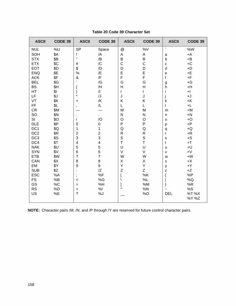
158
Table 20 Code 39 Character Set
ASCII CODE 39 ASCII CODE 39 ASCII CODE 39 ASCII CODE 39
NUL %U SP Space @ %V ` %W SOH $A ! /A A A a +A STX $B " /B B B b +B ETX $C # /C C C c +C EOT $D $ /D D D d +D ENQ $E % /E E E e +E ACK $F & /F F F f +F BEL $G ' /G G G g +G BS $H ( /H H H h +H HT $I ) /I I I i +I LF $J * /J J J j +J VT $K + /K K K k +K FF $L , /L L L l +L CR $M — — M M m +M SO $N . . N N n +N SI $O / /O O O o +O DLE $P 0 0 P P p +P DC1 $Q 1 1 Q Q q +Q DC2 $R 2 2 R R r +R DC3 $S 3 3 S S s +S DC4 $T 4 4 T T t +T NAK $U 5 5 U U u +U SYN $V 6 6 V V v +V ETB $W 7 7 W W w +W CAN $X 8 8 X X x +X EM $Y 9 9 Y Y y +Y SUB $Z : /Z Z Z z +Z ESC %A ; %F [ %K { %P FS %B < %G \ %L | %Q GS %C = %H ] %M } %R RS %D > %I ^ %N ~ %S US %E ? %J %O DEL %T %X
%Y %Z
NOTE: Character pairs /M, /N, and /P through /Y are reserved for future control character pairs.
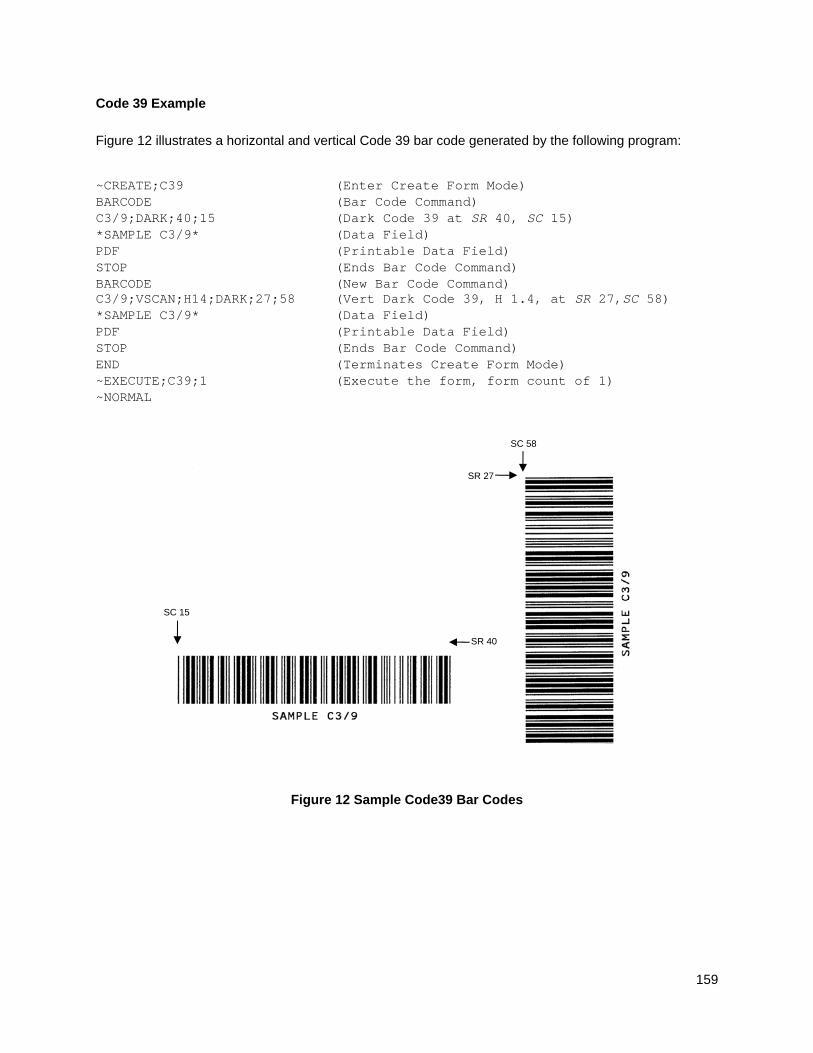
159
Code 39 Example
Figure 12 illustrates a horizontal and vertical Code 39 bar code generated by the following program:
~CREATE;C39 (Enter Create Form Mode) BARCODE (Bar Code Command) C3/9;DARK;40;15 (Dark Code 39 at SR 40, SC 15) *SAMPLE C3/9* (Data Field) PDF (Printable Data Field) STOP (Ends Bar Code Command) BARCODE (New Bar Code Command) C3/9;VSCAN;H14;DARK;27;58 (Vert Dark Code 39, H 1.4, at SR 27,SC 58) *SAMPLE C3/9* (Data Field) PDF (Printable Data Field) STOP (Ends Bar Code Command) END (Terminates Create Form Mode) ~EXECUTE;C39;1 (Execute the form, form count of 1) ~NORMAL
Figure 12 Sample Code39 Bar Codes
SR 27
SC 58
SC 15
SR 40
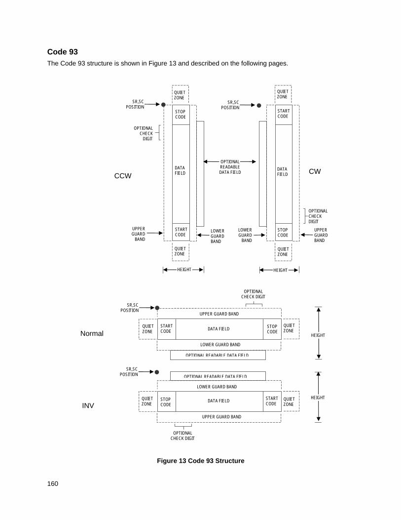
160
Code 93
The Code 93 structure is shown in Figure 13 and described on the following pages.
Figure 13 Code 93 Structure
Normal
LOWER GUARD BAND
HEIGHT
QUIET ZONE
QUIET ZONE
STOP CODE
START CODE
OPTIONAL READABLE DATA FIELD
DATA FIELD
SR,SC POSITION
INV
SR,SC POSITION
QUIET ZONE
STOP CODE
START CODE
QUIET ZONE
OPTIONAL READABLE DATA FIELD
LOWER GUARD BAND
UPPER GUARD BAND
UPPER GUARD BAND
DATA FIELD HEIGHT
OPTIONAL CHECK DIGIT
OPTIONAL CHECK DIGIT
CCW
LOWER GUARD BAND
QUIET ZONE
SR,SC POSITION
STOP CODE
START CODE
QUIET ZONE
OPTIONAL READABLE DATA FIELD
UPPER GUARD
BAND
DATA FIELD
HEIGHT
OPTIONAL CHECK
DIGIT
SR,SC POSITION
QUIET ZONE
STOP CODE
START CODE
QUIET ZONE
DATA FIELD
LOWER GUARD
BAND
UPPER GUARD BAND
CW
OPTIONAL CHECK DIGIT
HEIGHT
161
Quiet Zone
Both ends of the bar code structure require blank quiet zones. The quiet zones must be at least 0.25 inches wide and completely blank to ensure accurate reading of the start/stop codes and to prevent adjacent bar codes from overlapping. Be sure to provide sufficient space on the form for the quiet zones.
Start/Stop Codes
The start/stop code is a unique character identifying the leading and trailing end of the bar code. The start/stop code is automatically produced with each bar code. The start/stop code structure permits bidirectional bar code scanning.
Data Field
The bar code symbol uses a series of varying width bars and spaces to represent an extensive character set. The bars and spaces vary in width from one through four modules. Each character consists of three bars and three spaces that total 11 modules.
Readable Data
The optional readable data field provides a readable interpretation of the bar code data. It can be printed above or below the bar code symbol.
Check Digit
Two modulo-47 check digits are automatically calculated and inserted in the bar code symbol. The check digit verifies accurate scanning. The start code is included in the check digit algorithm.
Code 93 Command Format
BARCODE CODE93; [DIR;] [MAG;] [Hn[.m];] [BFn;L;][DARK;] SR;SC (D) [data field] (D) [PDF [;LOC] [;FONT]] STOP
BARCODE The Bar Code command; enter BARCODE.
CODE93 Designates bar code type Code 93; enter CODE93.
DIR Optional parameter that allows for rotating a barcode. Enter CW for clockwise rotation. Enter CCW or VSCAN for counter-clockwise rotation. Enter INV for inverted rotation. If DIR is not entered, the barcode is horizontally oriented.
MAG Optional parameter to magnify (horizontally expand) the bar code symbol. The magnification default value is X1. Increasing the magnification adjusts printed character density as shown in Table 14 on page 129. You can also use XR or XRD as defined on page 125. (You must specify 8 digits for MAG for variable ratio.)
NOTE: There are eight values that comprise the dot ratio: narrow bar, narrow space, 2x narrow bar, 2x narrow space, 3x narrow bar, 3x narrow space, 4x narrow bar, and 4x narrow space. User-defined ratios for this barcode should have these eight values defined in the order specified.
Hn[.m] Optional parameter to adjust the overall height (vertical expansion) of the bar code symbol (including the upper and lower 0.1-inch guard bands and any human readable data). Height adjustments are made in 0.1-inch increments; enter H and a value from 3 through 99 to select height adjustments from 0.3 through 9.9 inches. The default
162
value is 0.9 inch.
[.m] is an additional number of dots for the bar code height. (Dots are in the current dot scale.)
NOTE: If 0.3 inches is the selected height, the PDF cannot be included.
BFn;L Optional parameters for assigning a dynamic bar code data field location on a form and for designating the length of the data field. With these parameters, the actual data for the bar code data field is dynamically provided during the Execute Form Mode; the data is not specified during the Create Form Mode. To use this field, perform the following steps:
a. Enter BF.
b. Replace n with a number ranging from 0 through 512 to identify the bar code field. The SR and SC parameters specify the exact location of the bar code field identified by n.
c. Replace L with a number equaling the total number of characters in the field. (The actual data provided dynamically during the Execute Form Mode can be less than L.)
d. The information for the data field is entered dynamically during the Execute Form Mode. (Refer to Execute Form: Dynamic Bar Code Data on page 64.) Do not use the data field parameter to enter data when the BFn;L parameters are used. However, refer to the data field description for available characters.
DARK Optional parameter to produce darker looking bar codes. Enter DARK. Refer to Dark Printing on page 52 for more information.
SR Defines the starting row for the bar code. Enter a value ranging from row 1 to one less than the length of the form. Character row or dot row is specified based on the Scale command (page 113), or use the CP.DP format (page 23).
SC Defines the starting column of the bar code. Enter a value ranging from column 1 to one less than the width of the form. Character column or dot column is specified based on the Scale command (page 113), or use the CP.DP format (page 23).
(D) The printable character (delimiter) identifying the start and finish of the data field. Enter any printable character other than a slash (/), the SFCC, or a character used within the data. The same character must be used at both ends of the data field, but it will not print with the data.
data field Enter the data for the bar code. A null data field (no characters) is permitted. The length of the data field is variable; however, the maximum length is usually limited to 32 characters to minimize potential reading errors. The data field can contain any of the characters listed in Table 21, except the system SFCC.
PDF Optional parameter to enable printing of the human readable data field. Enter PDF to print the data field. If the parameter is not used, the human readable data will not print. This parameter is not allowed if a null data field was specified.
LOC Optional parameter to identify the location of the printable data field. The
163
default value is B, locating the human readable data below the bar code. A locates the printable data field above bar code. To compensate for printing the 0.1-inch high data, the height of the bar code body is reduced 0.1 inch.
FONT Optional parameter to select the font for the human readable data field. Enter O to select OCR-A font; enter X to select OCR-B font; enter N to select 10 cpi; enter P to select 12 cpi; enter Q to select 13 cpi; enter R to select 15 cpi; enter T to select 17 cpi; enter V to select 20 cpi.
To select a scalable font with user-defined size, enter Nh:w or F;Nh:w. The parameters h (height) and w (width) can each range from 1 to 96, and are expansion factors of a 10 cpi character. Nh:w prints in Letter Gothic (font 93779) regardless of the current active font. By default F;Nh:w uses the Letter Gothic as the current font selection. You can change the default by using the FONT command.
NOTE: Nh:w and F;Nh:w will not print the PDF wider or taller than the barcode. If the height parameter h causes the PDF to print above the horizontal barcode start row or vertical barcode start column, a barcode font Error will occur. If the width parameter w causes the PDF to exceed the barcode width, the PDF width factor w will automatically reduce to fit within the barcode width without causing an error.
STOP Ends the Bar Code command while the IGP continues in the Create Form Mode. Enter STOP. If STOP is not entered, an error message results.
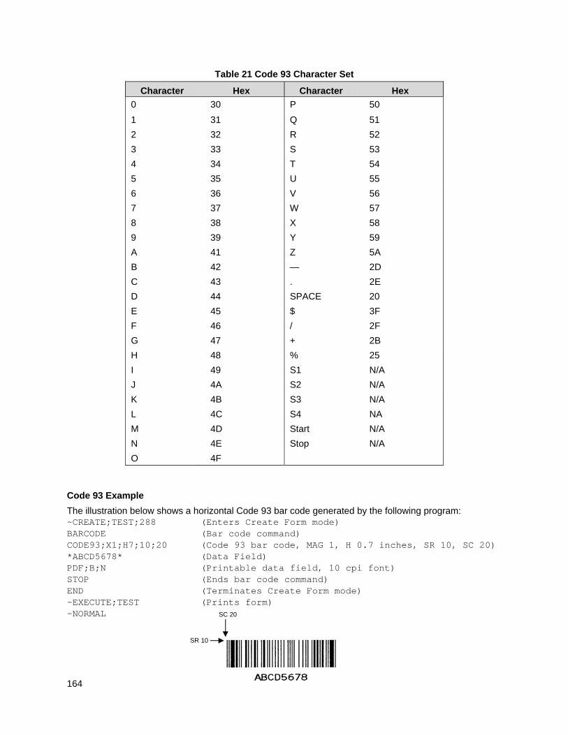
164
Table 21 Code 93 Character Set
Character Hex Character Hex
0 30 P 50
1 31 Q 51
2 32 R 52
3 33 S 53
4 34 T 54
5 35 U 55
6 36 V 56
7 37 W 57
8 38 X 58
9 39 Y 59
A 41 Z 5A
B 42 — 2D
C 43 . 2E
D 44 SPACE 20
E 45 $ 3F
F 46 / 2F
G 47 + 2B
H 48 % 25
I 49 S1 N/A
J 4A S2 N/A
K 4B S3 N/A
L 4C S4 NA
M 4D Start N/A
N 4E Stop N/A
O 4F
Code 93 Example
The illustration below shows a horizontal Code 93 bar code generated by the following program: ~CREATE;TEST;288 (Enters Create Form mode) BARCODE (Bar code command) CODE93;X1;H7;10;20 (Code 93 bar code, MAG 1, H 0.7 inches, SR 10, SC 20) *ABCD5678* (Data Field) PDF;B;N (Printable data field, 10 cpi font) STOP (Ends bar code command) END (Terminates Create Form mode) ~EXECUTE;TEST (Prints form) ~NORMAL
SR 10
SC 20
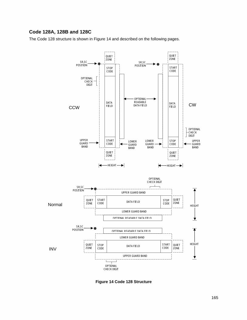
165
Code 128A, 128B and 128C
The Code 128 structure is shown in Figure 14 and described on the following pages.
Figure 14 Code 128 Structure
Normal
LOWER GUARD BAND
HEIGHT
QUIET ZONE
QUIET ZONE
STOP CODE
START CODE
OPTIONAL READABLE DATA FIELD
DATA FIELD
SR,SC POSITION
INV
SR,SC POSITION
QUIET ZONE
STOP CODE
START CODE
QUIET ZONE
OPTIONAL READABLE DATA FIELD
LOWER GUARD BAND
UPPER GUARD BAND
UPPER GUARD BAND
DATA FIELD HEIGHT
OPTIONAL CHECK DIGIT
OPTIONAL CHECK DIGIT
CCW
LOWER GUARD BAND
QUIET ZONE
SR,SC POSITION
STOP CODE
START CODE
QUIET ZONE
OPTIONAL READABLE DATA FIELD
UPPER GUARD
BAND
DATA FIELD
HEIGHT
OPTIONAL CHECK
DIGIT
SR,SC POSITION
QUIET ZONE
STOP CODE
START CODE
QUIET ZONE
DATA FIELD
LOWER GUARD
BAND
UPPER GUARD BAND
CW
OPTIONAL CHECK DIGIT
HEIGHT
166
Quiet Zone
Both ends of the bar code structure require blank quiet zones. The quiet zones must be at least 0.25 inches wide and completely blank to ensure accurate reading of the start/stop codes and to prevent adjacent bar codes from overlapping. Be sure to provide sufficient space on the form for the quiet zones.
Start/Stop Codes
The start/stop codes identify the leading and trailing end of the bar code. Each of the Code 128 subsets uses a unique start code and a common stop code, both automatically provided by the IGP. The start/stop code structure permits bidirectional bar code scanning.
Code 128A Data Field
The bar code symbol uses a series of varying width bars and spaces to represent an extensive character set (64 ASCII characters and 32 control characters). The bars and spaces vary in width from one through four modules. Each character consists of three bars and three spaces that total 11 modules.
Code 128B Data Field
The bar code symbol uses a series of varying width bars and spaces to represent an extensive character set (96 ASCII characters and seven control characters). The bars and spaces vary in width from one through four modules. Each character consists of three bars and three spaces that total 11 modules.
Code 128C Data Field
The bar code symbol uses a series of varying width bars and spaces to represent 100 pairs of numeric digits (00 through 99) and 3 control characters. The bars and spaces vary in width from 1 through 4 modules. Each character consists of three bars and three spaces that total 11 modules.
Readable Data
The optional readable data field provides a readable interpretation of the bar code data. It can be printed above or below the bar code symbol.
Data Field
For HIBC barcode, the data filed is a variable length consisting of only the following characters: 1-9, A-Z, -, ., $, /, +, %, and space.
NOTE: The Health Industry Bar Code (HIBC) is encoded in either Code 128 or Code 39 symbology. In a global setting, HIBC identifies health industry products, in any quantity, of any lot or serial number, with any expiration date. HIBC represents two kinds of information: Primary and Secondary Identification. Primary Identification represents product identity and Secondary Identification represents the attributes of Lot or Batch Code, Serial Number, and Expiration date.
Check Digit
The modulo-103 check digit is automatically calculated and inserted in the bar code symbol. The check digit verifies accurate scanning. The start code is included in the check digit algorithm.
For HIBC barcode, a mandatory modulo-43 checklist is inserted at the end of the data.
Code 128 Command Format
BARCODE C128A or C128B or C128C; [HIBC;] [DIR;] [MAG;] [Hn[.m];] [BFn;L;] [DARK;] SR; SC (D) [data field] (D) [PDF [;LOC] [;FONT] [;MAX]] STOP
167
BARCODE The Bar Code command; enter BARCODE. C128A, C128B or C12BC
Designates bar code type Code 128; enter C128A, C128B or C128C.
HIBC The Health Industry Bar Code (HIBC) is encoded in either Code 128 or Code 39 symbology. Enter HIBC. In a global setting, HIBC can uniquely identify any health industry product, in any quantity, of any lot or serial number, with any expiration date. HIBC represents two kinds of information: Primary and Secondary Identification. Primary Identification represents product identity and Secondary Identification represents the attributes of Lot or Batch Code, Serial Number, and Expiration date.
When encoding HIBC barcode in UCC-128, HIBC is essentially a UCC-128 barcode. The encoding uses the same module 10 check digit and data format. The only addition is an Application Identifier (AI) parameter. For Primary Data Structure use AI (01), and for Secondary Data Structure use AI (22) or AI (240). To use UCC-128 to encode HIBC, be sure to use the correct AI parameter to obtain the desired results.
DIR Optional parameter that allows for rotating a barcode. Enter CW for clockwise rotation. Enter CCW or VSCAN for counter-clockwise rotation. Enter INV for inverted rotation. If DIR is not entered, the barcode is horizontally oriented.
MAG Optional parameter to magnify (horizontally expand) the bar code symbol. The magnification default value is X1. Increasing the magnification adjusts printed character density as shown in Table 14 on page 129. You can also use XR or XRD as defined on page 125. (You must specify 8 digits for MAG for variable ratio.) There are eight values that comprise the dot ratio: narrow bar, narrow space, 2x narrow bar, 2x narrow space, 3x narrow bar, 3x narrow space, 4x narrow bar, and 4x narrow space. User-defined ratios for this barcode should have these eight values defined in the order as specified.
Hn[.m] Optional parameter to adjust the overall height (vertical expansion) of the bar code symbol (including the upper and lower 0.1-inch guard bands and any human readable data). Height adjustments are made in 0.1-inch increments; enter H and a value from 3 through 99 to select height adjustments from 0.3 through 9.9 inches. The default value is 0.9 inch.
[.m] is an additional number of dots for the bar code height. (Dots are in the current dot scale.)
NOTE: If 0.3 inches is the selected height, the PDF cannot be included.
BFn;L Optional parameters for assigning a dynamic bar code data field location on a form and for designating the length of the data field. With these parameters, the actual data for the bar code data field is dynamically provided during the Execute Form Mode; the data is not specified during the Create Form Mode. To use this field, perform the following steps.
a. Enter BF.
b. Replace n with a number ranging from 0 through 512 to identify the bar code field. The SR and SC parameters specify the exact location of the bar code field identified by n.
c. Replace L with a number equaling the total number of characters in the field. (The actual data provided dynamically during the Execute
168
Form Mode can be less than L.)
d. The information for the data field is entered dynamically during the Execute Form Mode. (Refer to Execute Form: Dynamic Bar Code Data on page 64.) Do not use the data field parameter to enter data when the BFn;L parameters are used. However, refer to the data field description for available characters.
DARK Optional parameter to produce darker looking bar codes. Enter DARK. Refer to Dark Printing on page 52 for more information.
SR Defines the starting row for the bar code. Enter a value ranging from row 1 to one less than the length of the form. Character row or dot row is specified based on the Scale command (page 113), or use the CP.DP format (page 23).
SC Defines the starting column of the bar code. Enter a value ranging from column 1 to one less than the width of the form. Character column or dot column is specified based on the Scale command (page 113), or use the CP.DP format (page 23).
(D) The printable character (delimiter) identifying the start and finish of the data field. Enter any printable character other than a slash (/), the SFCC, or a character used within the data. The same character must be used at both ends of the data field, but it will not print with the data.
data field Enter the data for the bar code. A null data field (no characters) is permitted. Whenever a string of 6 or more contiguous numeric digits are detected, the IGP automatically inserts a Code C at the start of the numeric string and outputs numeric digit pairs packed into single bar code characters. When the string is broken (non-numeric data or an unpaired numeric digit occurs), the IGP automatically inserts a Code B and returns to normal C128B symbols. The length of the data field is variable; however, the maximum length is usually limited to 32 characters to minimize potential reading errors. The data field can contain any of the characters listed in Table 22 through Table 24, except the system SFCC.
PDF Optional parameter to enable printing of the human readable data field. Enter PDF to print the data field. If the parameter is not used, the human readable data will not print. This parameter is not allowed if a null data field was specified.
LOC Optional parameter to identify the location of the printable data field. The default value is B, locating the human readable data below the bar code. A locates the printable data field above bar code. To compensate for printing the 0.1-inch high data, the height of the bar code body is reduced 0.1 inch.
FONT Optional parameter to select the font for the human readable data field. Enter O to select OCR-A font; enter X to select OCR-B font; enter N to select 10 cpi; enter P to select 12 cpi; enter Q to select 13 cpi; enter R to select 15 cpi; enter T to select 17 cpi; enter V to select 20 cpi.
To select a scalable font with user-defined size, enter Nh:w or F;Nh:w. The parameters h (height) and w (width) can each range from 1 to 96, and are expansion factors of a 10 cpi character. Nh:w prints in Letter Gothic (font 93779) regardless of the current active font. By default F;Nh:w uses the Letter Gothic as the current font selection. You can change the default by using the FONT command.
169
NOTE: Nh:w and F;Nh:w will not print the PDF wider or taller than the barcode. If the height parameter h causes the PDF to print above the horizontal barcode start row or vertical barcode start column, a barcode font Error will occur. If the width parameter w causes the PDF to exceed the barcode width, the PDF width factor w will automatically reduce to fit within the barcode width without causing an error.
MAX Optional parameter to specify the maximum number of data printed in the PDF. If all data should be printed, do not use this parameter. Valid values are from 1 through 128. For example, if the barcode data is “12345” and a MAX value of 3 is specified, the PDF would print “123”.
STOP Ends the Bar Code command while the IGP continues in the Create Form Mode. Enter STOP. If STOP is not entered, an error message results.
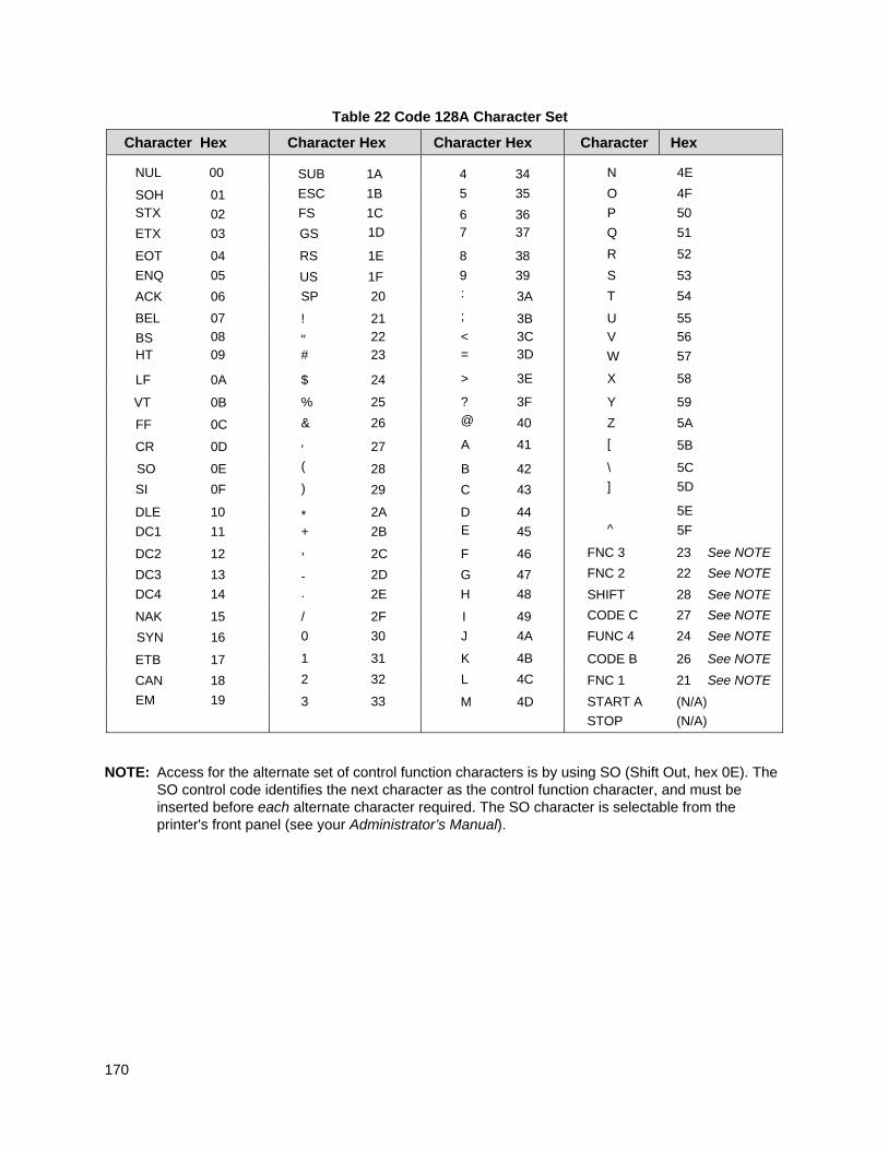
170
Table 22 Code 128A Character Set
Character Hex Character Hex Character Hex Character Hex
NUL 00 SUB 1A 4 34 N 4E
SOH 01 ESC 1B 5 35 O 4F
STX 02 FS 1C 6 36 P 50
ETX 03 GS 1D 7 37 Q 51
EOT 04 RS 1E 8 38 R 52
ENQ 05 US 1F 9 39 S 53
ACK 06 SP 20 : 3A T 54
BEL 07 ! 21 ; 3B U 55
BS 08 " 22 < 3C V 56 HT 09 # 23 = 3D W 57
LF 0A $ 24 > 3E X 58
VT 0B % 25 ? 3F Y 59
FF 0C & 26 @ 40 Z 5A
CR 0D ' 27 A 41 [ 5B
SO 0E ( 28 B 42 \ 5C
SI 0F ) 29 C 43 ] 5D
DLE 10 * 2A D 44 5E
DC1 11 + 2B E 45 ^ 5F
DC2 12 , 2C F 46 FNC 3 23 See NOTE
DC3 13 - 2D G 47 FNC 2 22 See NOTE
DC4 14 . 2E H 48 SHIFT 28 See NOTE
NAK 15 / 2F I 49 CODE C 27 See NOTE
SYN 16 0 30 J 4A FUNC 4 24 See NOTE
ETB 17 1 31 K 4B CODE B 26 See NOTE
CAN 18 2 32 L 4C FNC 1 21 See NOTE
EM 19 3 33 M 4D START A (N/A)
STOP (N/A)
NOTE: Access for the alternate set of control function characters is by using SO (Shift Out, hex 0E). The
SO control code identifies the next character as the control function character, and must be inserted before each alternate character required. The SO character is selectable from the printer's front panel (see your Administrator’s Manual).
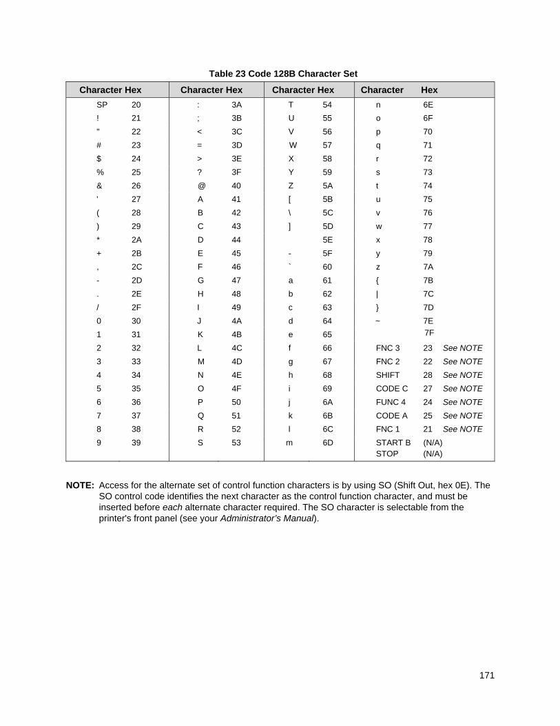
171
Table 23 Code 128B Character Set
Character Hex Character Hex Character Hex Character Hex
SP 20 : 3A T 54 n 6E
! 21 ; 3B U 55 o 6F
" 22 < 3C V 56 p 70
# 23 = 3D W 57 q 71
$ 24 > 3E X 58 r 72
% 25 ? 3F Y 59 s 73
& 26 @ 40 Z 5A t 74
' 27 A 41 [ 5B u 75
( 28 B 42 \ 5C v 76
) 29 C 43 ] 5D w 77
* 2A D 44 5E x 78
+ 2B E 45 - 5F y 79
, 2C F 46 ` 60 z 7A
- 2D G 47 a 61 { 7B
. 2E H 48 b 62 | 7C
/ 2F I 49 c 63 } 7D
0 30 J 4A d 64 ~ 7E
1 31 K 4B e 65 7F
2 32 L 4C f 66 FNC 3 23 See NOTE
3 33 M 4D g 67 FNC 2 22 See NOTE
4 34 N 4E h 68 SHIFT 28 See NOTE
5 35 O 4F i 69 CODE C 27 See NOTE
6 36 P 50 j 6A FUNC 4 24 See NOTE
7 37 Q 51 k 6B CODE A 25 See NOTE
8 38 R 52 l 6C FNC 1 21 See NOTE
9
39 S 53 m 6D START B (N/A) STOP (N/A)
NOTE: Access for the alternate set of control function characters is by using SO (Shift Out, hex 0E). The
SO control code identifies the next character as the control function character, and must be inserted before each alternate character required. The SO character is selectable from the printer's front panel (see your Administrator’s Manual).
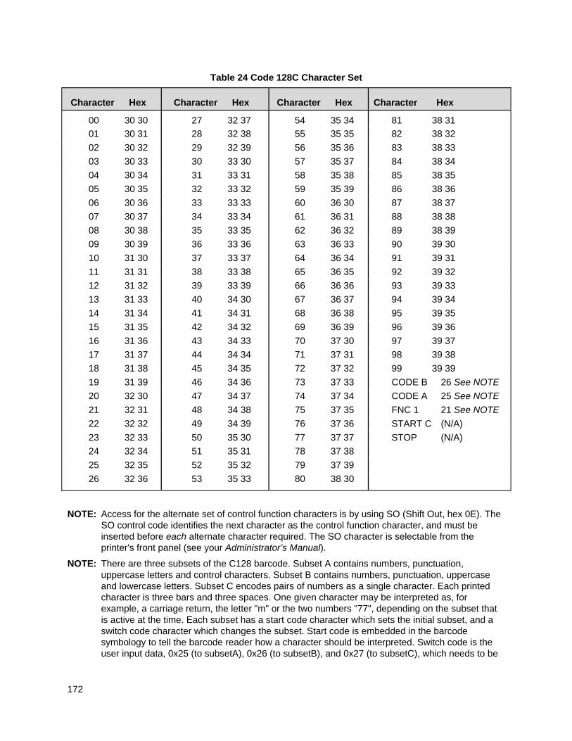
172
Table 24 Code 128C Character Set
Character
Hex
Character
Hex
Character
Hex
Character Hex
00 30 30 27 32 37 54 35 34 81 38 31
01 30 31 28 32 38 55 35 35 82 38 32
02 30 32 29 32 39 56 35 36 83 38 33
03 30 33 30 33 30 57 35 37 84 38 34
04 30 34 31 33 31 58 35 38 85 38 35
05 30 35 32 33 32 59 35 39 86 38 36
06 30 36 33 33 33 60 36 30 87 38 37
07 30 37 34 33 34 61 36 31 88 38 38
08 30 38 35 33 35 62 36 32 89 38 39
09 30 39 36 33 36 63 36 33 90 39 30
10 31 30 37 33 37 64 36 34 91 39 31
11 31 31 38 33 38 65 36 35 92 39 32
12 31 32 39 33 39 66 36 36 93 39 33
13 31 33 40 34 30 67 36 37 94 39 34
14 31 34 41 34 31 68 36 38 95 39 35
15 31 35 42 34 32 69 36 39 96 39 36
16 31 36 43 34 33 70 37 30 97 39 37
17 31 37 44 34 34 71 37 31 98 39 38
18 31 38 45 34 35 72 37 32 99 39 39
19 31 39 46 34 36 73 37 33 CODE B 26 See NOTE
20 32 30 47 34 37 74 37 34 CODE A 25 See NOTE
21 32 31 48 34 38 75 37 35 FNC 1 21 See NOTE
22 32 32 49 34 39 76 37 36 START C (N/A)
23 32 33 50 35 30 77 37 37 STOP (N/A)
24 32 34 51 35 31 78 37 38
25 32 35 52 35 32 79 37 39
26 32 36 53 35 33 80 38 30
NOTE: Access for the alternate set of control function characters is by using SO (Shift Out, hex 0E). The SO control code identifies the next character as the control function character, and must be inserted before each alternate character required. The SO character is selectable from the printer's front panel (see your Administrator’s Manual).
NOTE: There are three subsets of the C128 barcode. Subset A contains numbers, punctuation, uppercase letters and control characters. Subset B contains numbers, punctuation, uppercase and lowercase letters. Subset C encodes pairs of numbers as a single character. Each printed character is three bars and three spaces. One given character may be interpreted as, for example, a carriage return, the letter "m" or the two numbers "77", depending on the subset that is active at the time. Each subset has a start code character which sets the initial subset, and a switch code character which changes the subset. Start code is embedded in the barcode symbology to tell the barcode reader how a character should be interpreted. Switch code is the user input data, 0x25 (to subsetA), 0x26 (to subsetB), and 0x27 (to subsetC), which needs to be

173
preceded with the SO (Shift Out, 0x0E) character to tell which subset to switch to, and will be replaced with the corresponding start code during the data parsing.
There are three different commands to invoke a C128 barcode in PGL. They are C128A, C128B and C128C. However, these commands do not set the initial subset as you might expect. Instead, the default behavior is that the subset is automatically switched, so that the number of printed characters is minimized by using subset C to print pairs of numerals as a single character, and by avoiding unnecessary subset changes.
The default behavior is called "automatic mode". In automatic mode, no switch codes are included in the data by the user to force one of the subsets to be active. The starting subset as well as any subset switching are selected by the printer automatically. Manual mode is started if the subset switching codes are inserted in the data sent to the printer.
In automatic mode, the starting subset selection criteria are: long strings of number pairs will cause a start in set C; a letter, punctuation, or an unpaired number will cause a start in set B, and a control character will cause a start in set A. After starting in one set, a switch will be automatically be made by PGL if the number of printed characters can be reduced (i.e. a switch to set C to print pairs of numbers with a single character), or if the data cannot be found in the current subset. The printer will switch from A to B for a lowercase letter, from A to C for a long string of paired numbers, from B to A for a control character, from B to C for a long string of paired numbers, from C to A for a control character, and from C to B for an unpaired number or any letter or punctuation. In automatic mode, the printer puts the start codes into the barcode itself; they are not part of the user input data in the PGL barcode command.
If a subset switch code is inserted in the barcode data to start the desired subset, the printer leaves automatic mode and enters "manual mode". However, in manual mode, automatically subset switches can still take place when the data cannot be found in the current subset. Once a different subset is automatically switched due to the data cannot be found in the current specified subset, the switched subset will stay until the end of the data or the encounter of another subset switch code.
If a subset switch code is inserted as the first character in the data string, the barcode will start in that subset. No effort is made to minimize the barcode character count. That means sending the PGL barcode command C128C with data starting with the switch to A code (shiftout and %) followed by ten numerals, will result in barcode characters of Start-A followed by ten numeral characters using subset A.
If a subset switch code is the first character and the next character is not in that character set, the printer may start in the commanded set and then immediately switch to the set that includes the second character. For example, sending a Switch-to-C code followed by a carriage return and 10 numerals may result in a data field of Start-C, Switch-to-A, and ten numerals using subset A. In other words, once manual mode is entered by using a switch code, the user is presumed to be selecting the desired data field; the printer will automatically switch subsets when required to print the correct data characters, but is not required to optimize the barcode length. There is no way to exit manual mode and re-enter automatic mode in the same data stream.
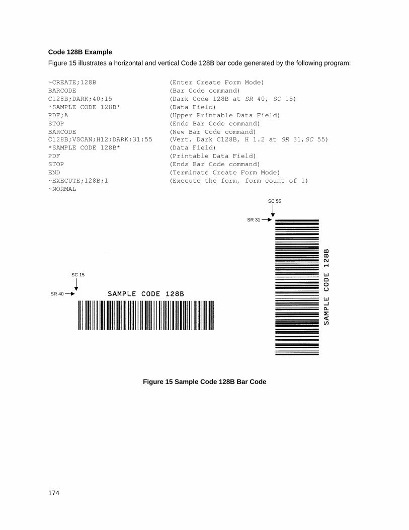
174
Code 128B Example
Figure 15 illustrates a horizontal and vertical Code 128B bar code generated by the following program:
~CREATE;128B (Enter Create Form Mode) BARCODE (Bar Code command) C128B;DARK;40;15 (Dark Code 128B at SR 40, SC 15) *SAMPLE CODE 128B* (Data Field) PDF;A (Upper Printable Data Field) STOP (Ends Bar Code command) BARCODE (New Bar Code command) C128B;VSCAN;H12;DARK;31;55 (Vert. Dark C128B, H 1.2 at SR 31,SC 55) *SAMPLE CODE 128B* (Data Field) PDF (Printable Data Field) STOP (Ends Bar Code command) END (Terminate Create Form Mode) ~EXECUTE;128B;1 (Execute the form, form count of 1) ~NORMAL
Figure 15 Sample Code 128B Bar Code
SR 40
SC 15
SR 31
SC 55
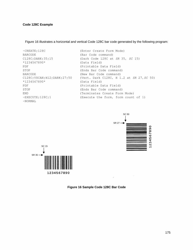
175
Code 128C Example
Figure 16 illustrates a horizontal and vertical Code 128C bar code generated by the following program:
~CREATE;128C (Enter Create Form Mode) BARCODE (Bar Code command) C128C;DARK;35;15 (Dark Code 128C at SR 35, SC 15) *1234567890* (Data Field) PDF (Printable Data Field) STOP (Ends Bar Code command) BARCODE (New Bar Code command) C128C;VSCAN;H12;DARK;27;50 (Vert. Dark C128C, H 1.2 at SR 27,SC 50) *1234567890* (Data Field) PDF (Printable Data Field) STOP (Ends Bar Code command) END (Terminates Create Form Mode) ~EXECUTE;128C;1 (Execute the form, form count of 1) ~NORMAL
Figure 16 Sample Code 128C Bar Code
SR 35
SC 15
SR 27
SC 50
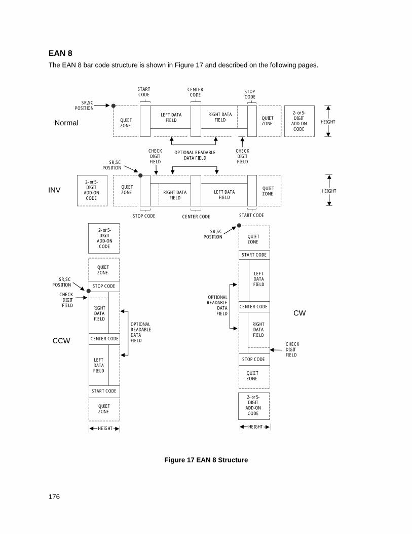
176
EAN 8
The EAN 8 bar code structure is shown in Figure 17 and described on the following pages.
Figure 17 EAN 8 Structure
CENTER CODE
CENTER CODE
Normal
QUIET ZONE
STOP CODE SR,SC
POSITION
INV
QUIET ZONE
OPTIONAL READABLE
DATA FIELD
HEIGHT
CCW
QUIET ZONE
SR,SC POSITION
CENTER CODE
START CODE
QUIET ZONE
OPTIONAL READABLE DATA FIELD
CHECK DIGIT FIELD
HEIGHT
SR,SC POSITION
QUIET ZONE
STOP CODE
START CODE
QUIET ZONE
CW
LEFT DATA FIELD
RIGHT DATA FIELD
2- or 5- DIGIT
ADD-ON CODE
2- or 5- DIGIT
ADD-ON CODE
HEIGHT QUIET ZONE
CENTER CODE
QUIET ZONE
STOP CODE START CODE
LEFT DATA FIELD
RIGHT DATA FIELD
CHECK DIGIT FIELD
2- or 5- DIGIT
ADD-ON CODE
RIGHT DATA FIELD
LEFT DATA FIELD
START CODE
CHECK DIGIT FIELD
LEFT DATA FIELD
RIGHT DATA FIELD
STOP CODE
2- or 5- DIGIT
ADD-ON CODE
HEIGHT
CHECK DIGIT FIELD
SR,SC POSITION
OPTIONAL READABLE DATA FIELD
177
Quiet Zone
Both ends of the bar code structure have blank quiet zones. The quiet zones must be at least 0.25 inches wide and completely blank to ensure accurate reading of the start/stop codes and to prevent adjacent bar codes from overlapping. The IGP automatically produces the left quiet zone; you must provide sufficient space on the form for the right quiet zone.
Start/Center/Stop Codes
The start/center/stop codes are special character codes marking those portions of the bar code. These codes are automatically provided.
Data Field
The bar code symbol uses a series of varying width bars and spaces to represent a limited character set (numbers 0-9 and Special Characters Start, Center, and Stop). The bars and spaces vary in width from one through four modules. Each character consists of two bars and two spaces that total seven modules. The symbol coding of the left data field is different from the right data field to permit read direction sensing.
The optional 2- or 5-digit add-on data, placed within the quotes at the end of the bar code, typically identifies a periodical issue number or price, respectively.
Readable Data
The human readable data field provides a readable interpretation of the bar code data. It can either be suppressed or printed below the bar code symbol.
Check Digit
The modulo-10 check digit is automatically calculated and inserted in the bar code symbol. The check digit verifies accurate scanning.
EAN 8 Command Format
BARCODE EAN8 [+n]; [DIR;] [SCB;] [MAG;] [Hn[.m];] [BFn;] [DARK;] SR; SC (D)data field(D) [PDF [;LOC] [;FONT]]
STOP
BARCODE The Bar Code command; enter BARCODE.
EAN8 Designates bar code type EAN 8; enter EAN8.
+n Optional parameter to provide a 2- or 5-digit add-on code at the end of the bar code data field. Enter a plus sign (+) and a value of 2 or 5. The first bar of the add-on code is separated by nine modules from the last bar of the EAN symbol and a left guard pattern. No center or right guard pattern exists.
DIR Optional parameter that allows for rotating a barcode. Enter CW for clockwise rotation. Enter CCW or VSCAN for counter-clockwise rotation. Enter INV for inverted rotation. If DIR is not entered, the barcode is horizontally oriented.
SCB This option shortens the length of the center guard bars, which are normally full length. Enter SCB.
MAG Optional parameter to magnify (horizontally expand) the bar code symbol. The magnification default value is X1. Increasing the magnification adjusts printed character density as shown in Table 14 on page 129. You can also use XR or XRD as defined on page 125. You
178
must specify 8 digits for MAG for variable ratio.
NOTE: There are eight values that comprise the dot ratio: narrow bar, narrow space, 2x narrow bar, 2x narrow space, 3x narrow bar, 3x narrow space, 4x narrow bar, and 4x narrow space. User-defined ratios for this barcode should have these eight values defined in the order specified.
Hn[.m] Optional parameter to adjust the overall height (vertical expansion) of the bar code symbol (including the upper and lower 0.1-inch guard bands and any human readable data). Height adjustments are made in 0.1-inch increments; enter H and a value from 2 through 99 to select height adjustments from 0.2 through 9.9 inches. If any value less than 3 is selected, then the PDF must be suppressed using the PDF Font parameter S. The default value is 1.3 inches. [.m] is an additional number of dots for the bar code height. (Dots are in the current dot scale.)
BFn Optional parameter for assigning a dynamic bar code data field location on a form. With this parameter, the actual data for the bar code data field is dynamically provided during the Execute Form Mode; the data is not specified during the Create Form Mode. To use this field:
a. Enter BF.
b. Replace n with a number ranging from 0 through 512 to identify the bar code field. The SR and SC parameters specify the exact location of the bar code field identified by n.
c. The length of the data field need not be specified since it is fixed at seven digits, plus any add-on data.
d. The information for the data field is entered dynamically during the Execute Form Mode. (Refer toExecute Form: Dynamic Bar Code Data on page 64.) Do not use the data field parameter to enter data when the BFn parameters are used. However, refer to the data field description for available characters.
DARK Optional parameter to produce darker looking bar codes. Enter DARK. Refer to Dark Printing on page 52 for more information.
SR Defines the starting row for the bar code. Enter a value ranging from row 1 to one less than the length of the form. Character row or dot row is specified based on the Scale command (page 113), or use the CP.DP format (page 23).
SC Defines the starting column of the bar code. Enter a value ranging from column 1 to one less than the width of the form. Character column or dot column is specified based on the Scale command (page 113), or use the CP.DP format (page 23).
(D) The printable character (delimiter) identifying the start and finish of the data field. Enter any printable character other than a slash (/), the SFCC, or a character used within the data. The same character must be used at both ends of the data field, but it is not printed with the data.
data field The characters of the bar code data are restricted to exactly seven digits. If the 2- or 5-digit add-on data option is used, include this data at the end of the data field. The characters available for the data field are 0 through 9 (hex 30 through 39).
PDF Optional parameter to print the human readable data field. The data field prints automatically unless the PDF-suppress command is specified in
179
the FONT parameter. The human readable data field can be printed above or below the bar code symbol. This parameter is not allowed if a null data field is specified. If no PDF command is entered, the data field will print automatically in the default OCR-B font.
LOC Optional parameter to identify the location of the printable data field. The default value is B, locating the human readable data below the bar code. A locates the printable data field above bar code. To compensate for printing the 0.1-inch high data, the height of the bar code body is reduced 0.1 inch.
FONT Optional parameter to select the font for the human readable data field. Enter O to select OCR-A font; enter X to select OCR-B font; enter N to select 10 cpi; enter P to select 12 cpi; enter Q to select 13 cpi; enter R to select 15 cpi; enter T to select 17 cpi; enter V to select 20 cpi. Enter S to suppress the PDF entirely.
To select a scalable font with user-defined size, enter Nh:w or F;Nh:w. The parameters h (height) and w (width) can each range from 1 to 96, and are expansion factors of a 10 cpi character. Nh:w prints in Letter Gothic (font 93779) regardless of the current active font. By default F;Nh:w uses the Letter Gothic as the current font selection. You can change the default by using the FONT command.
NOTE: Nh:w and F;Nh:w will not print the PDF wider or taller than the barcode. If the height parameter h causes the PDF to print above the horizontal barcode start row or vertical barcode start column, a barcode font Error will occur. If the width parameter w causes the PDF to exceed the barcode width, the PDF width factor w will automatically reduce to fit within the barcode width without causing an error.
STOP Ends the Bar Code command while the IGP continues in the Create Form Mode. Enter STOP. If STOP is not entered, an error message results.
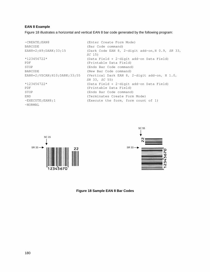
180
EAN 8 Example
Figure 18 illustrates a horizontal and vertical EAN 8 bar code generated by the following program:
~CREATE;EAN8 (Enter Create Form Mode) BARCODE (Bar Code command) EAN8+2;H9;DARK;33;15 (Dark Code EAN 8, 2-digit add-on,H 0.9, SR 33,
SC 15) *123456722* (Data Field + 2-digit add-on Data Field) PDF (Printable Data Field) STOP (Ends Bar Code command) BARCODE (New Bar Code command) EAN8+2;VSCAN;H10;DARK;33;55 (Vertical Dark EAN 8, 2-digit add-on, H 1.0, SR 33, SC 55) *123456722* (Data Field + 2-digit add-on Data Field) PDF (Printable Data Field) STOP (Ends Bar Code command) END (Terminates Create Form Mode) ~EXECUTE;EAN8;1 (Execute the form, form count of 1) ~NORMAL
Figure 18 Sample EAN 8 Bar Codes
SR 33
SC 15
SR 33
SC 55
181
EAN 13
The EAN 13 bar code structure is shown in Figure 19 and described on the following pages.
Figure 19 EAN 13 Structure
CENTER CODE
CENTER CODE
Normal
QUIET ZONE
STOP CODE SR,SC
POSITION
INV
QUIET ZONE
OPTIONAL READABLE
DATA FIELD
HEIGHT
CCW
QUIET ZONE
SR,SC POSITION
CENTER CODE
START CODE
QUIET ZONE
OPTIONAL READABLE DATA FIELD
CHECK DIGIT FIELD
HEIGHT
SR,SC POSITION
QUIET ZONE
STOP CODE
START CODE
QUIET ZONE
CW
LEFT DATA FIELD
RIGHT DATA FIELD
2- or 5- DIGIT
ADD-ON CODE
2- or 5- DIGIT
ADD-ON CODE
HEIGHT QUIET ZONE
CENTER CODE
QUIET ZONE
STOP CODE START CODE
LEFT DATA FIELD
RIGHT DATA FIELD
CHECK DIGIT FIELD
2- or 5- DIGIT
ADD-ON CODE
RIGHT DATA FIELD
LEFT DATA FIELD
START CODE
CHECK DIGIT FIELD
LEFT DATA FIELD
RIGHT DATA FIELD
STOP CODE
2- or 5- DIGIT
ADD-ON CODE
HEIGHT
CHECK DIGIT FIELD
SR,SC POSITION
OPTIONAL READABLE DATA FIELD
NUMBER SYSTEM
CHARACTER N
N
N
N NUMBER SYSTEM CHARACTER
NUMBER SYSTEM
CHARACTER
NUMBER SYSTEM
CHARACTER
182
Quiet Zone
Quiet zones extend on both ends of the bar code to permit the scan to begin and end in a blank area. The IGP automatically produces an 11-module wide left quiet zone; you are responsible for providing sufficient space (minimum of seven modules) on the form for the right quiet zone. The number system character is also printed automatically in the left quiet zone.
Start/Center/Stop Codes
The start/center/stop codes are special character codes marking those portions of the bar code. These codes are automatically provided.
Number System Character
The number system character field allows you to provide a code to a class or type of item. The first character in the data field is used as the number system character.
Data Field
The bar code symbol uses a series of varying width bars and spaces to represent a limited character set (numbers 0-9 and Special Characters Start, Center, and Stop). The bars and spaces vary in width from one through four modules. Each character consists of two bars and two spaces that total seven modules. The symbol coding of the left data field is different from the right data field to permit read direction sensing.
The optional 2 or 5-digit add-on data field is placed within the quotes at the end of the bar code data and typically identifies a periodical issue number or price, respectively.
Readable Data
The human readable data field provides a readable interpretation of the bar code data. It can either be suppressed or printed below the bar code symbol.
Check Digit
The modulo-10 check digit is automatically calculated and inserted in the bar code symbol. The check digit verifies accurate scanning. The number system character is included in the check digit algorithm.
EAN 13 Command Format
BARCODE EAN13 [+n]; [DIR;] [SCB;] [MAG;] [Hn[.m];] [BFn;] [DARK;]SR;SC (D)data field(D) [PDF [;LOC] [;FONT]] STOP
BARCODE The Bar Code command; enter BARCODE.
EAN13 Designates bar code type EAN 13; enter EAN13.
+n Optional parameter to provide a 2- or 5-digit add-on code at the end of the bar code data field. Enter a plus sign (+) and a value of 2 or 5. The first bar of the add-on code is separated by nine modules from the last bar of the EAN symbol and a left guard pattern. No center or right guard pattern exists.
DIR Optional parameter that allows for rotating a barcode. Enter CW for clockwise rotation. Enter CCW or VSCAN for counter-clockwise rotation. Enter INV for inverted rotation. If DIR is not entered, the barcode is horizontally oriented.
SCB This option shortens the length of the center guard bars, which are
183
normally full length. Enter SCB.
MAG Optional parameter to magnify (horizontally expand) the bar code symbol. The magnification default value is X1. Increasing the magnification adjusts printed character density as shown in Table 14 on page 129. You can also use XR or XRD as defined on page 125. (You must specify 8 digits for MAG for variable ratio.)
NOTE: There are eight values that comprise the dot ratio: narrow bar, narrow space, 2x narrow bar, 2x narrow space, 3x narrow bar, 3x narrow space, 4x narrow bar, and 4x narrow space. User-defined ratios for this barcode should have these eight values defined in the order specified.
Hn[.m] Optional parameter to adjust the overall height (vertical expansion) of the bar code symbol (including the upper and lower 0.1-inch guard bands and any human readable data). Height adjustments are made in 0.1-inch increments; enter H and a value from 2 through 99 to select height adjustments from 0.2 through 9.9 inches. If any value less than 3 is selected, then the PDF must be suppressed using the PDF Font parameter S. The default value is 1.3 inches. [.m] is an additional number of dots for the bar code height. (Dots are in the current dot scale.)
BFn Optional parameter for assigning a dynamic bar code data field location on a form. With this parameter, the actual data for the bar code data field is dynamically provided during the Execute Form Mode; the data is not specified during the Create Form Mode. To use this field, perform the following steps:
a. Enter BF.
b. Replace n with a number ranging from 0 through 512 to identify the bar code field. The SR and SC parameters specify the exact location of the bar code field identified by n.
c. The length of the data field need not be specified, since it is fixed at 12 digits, plus any add-on data.
d. The information for the data field is entered dynamically during the Execute Form Mode. (Refer to Execute Form: Dynamic Bar Code Data on page 64.) Do not use the data field parameter to enter data when the BFn parameters are used. However, refer to the data field description for available characters.
DARK Optional parameter to produce darker looking bar codes. Enter DARK. Refer to Dark Printing on page 52 for more information.
SR Defines the starting row for the bar code. Enter a value ranging from row 1 to one less than the length of the form. Character row or dot row is specified based on the Scale command (page 113), or use the CP.DP format (page 23).
SC Defines the starting column of the bar code. Enter a value ranging from column 1 to one less than the width of the form. Character column or dot column is specified based on the Scale command (page 113), or use the CP.DP format (page 23).
(D) The printable character (delimiter) identifying the start and finish of the data field. Enter any printable character other than a slash (/), the SFCC, or a character used within the data. The same character must be used at both ends of the data field, but it is not printed with the data.
184
data field Enter the characters of the bar code data, restricted to exactly 12 digits. If the 2- or 5-digit add-on data option is used, include this data at the end of the data field. The characters available for the data field are 0 through 9 (hex 30 through 39). The first character is interpreted as the number system character.
The left side of the data field (or lower side on vertically oriented symbols) can be encoded in either format A or format B as determined by the value of the number system character. (A bar code character is not produced for the number system character.) The number system character is derived from the left side data field encoding. The right side of the data field (or upper side on vertically oriented symbols) and check digit are always encoded in format C. Table 25 defines the left side data field format based on the number system character.
PDF Optional parameter which affects printing of the human readable data field. The data field will print automatically in the OCR-B font (default) unless the PDF-suppress command is specified in the FONT parameter. The human readable data field can be printed above or below the bar code symbol. This parameter is not allowed if a null data field is specified.
LOC Optional parameter to identify the location of the printable data field. The default value is B, locating the human readable data below the bar code. A locates the printable data field above bar code. To compensate for printing the 0.1-inch high data, the height of the bar code body is reduced 0.1 inch.
FONT Optional parameter to select the font for the human readable data field. Enter O to select OCR-A font; enter X to select OCR-B font; enter N to select 10 cpi; enter P to select 12 cpi; enter Q to select 13 cpi; enter R to select 15 cpi; enter T to select 17 cpi; enter V to select 20 cpi. Enter S to suppress the PDF entirely.
To select a scalable font with user-defined size, enter Nh:w or F;Nh:w. The parameters h (height) and w (width) can each range from 1 to 96, and are expansion factors of a 10 cpi character. Nh:w prints in Letter Gothic (font 93779) regardless of the current active font. By default F;Nh:w uses the Letter Gothic as the current font selection. You can change the default by using the FONT command.
NOTE: Nh:w and F;Nh:w will not print the PDF wider or taller than the barcode. If the height parameter h causes the PDF to print above the horizontal barcode start row or vertical barcode start column, a barcode font Error will occur. If the width parameter w causes the PDF to exceed the barcode width, the PDF width factor w will automatically reduce to fit within the barcode width without causing an error.
STOP Ends the Bar Code command while the IGP continues in the Create Form Mode. Enter STOP. If STOP is not entered, an error message results.
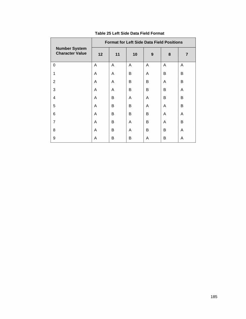
185
Table 25 Left Side Data Field Format
Number System Character Value
Format for Left Side Data Field Positions
12
11
10
9
8
7
0 A A A A A A
1 A A B A B B
2 A A B B A B
3 A A B B B A
4 A B A A B B
5 A B B A A B
6 A B B B A A
7 A B A B A B
8 A B A B B A
9 A B B A B A
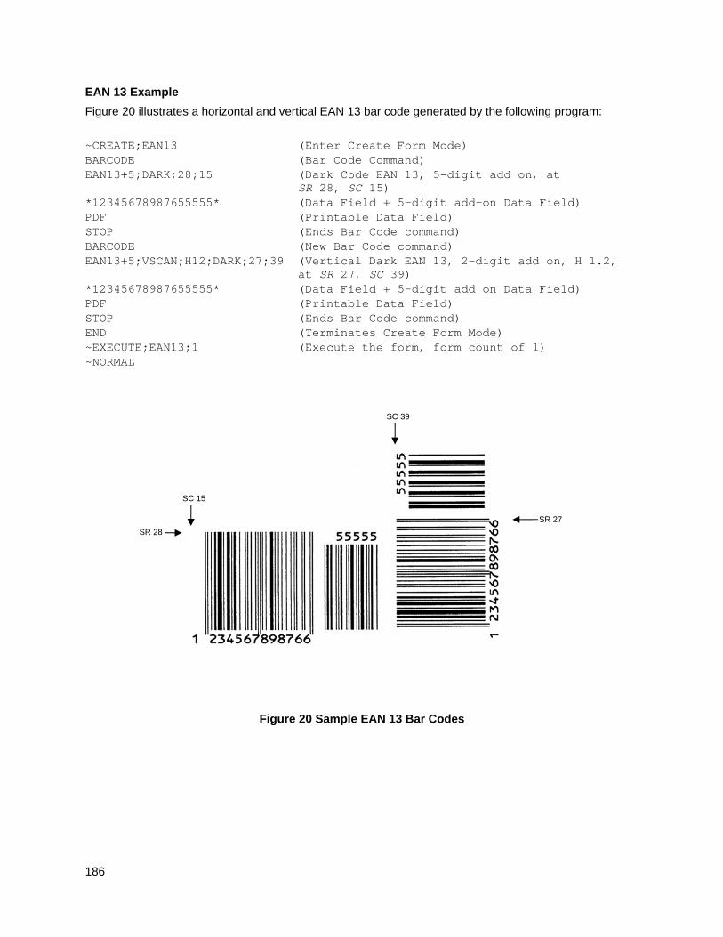
186
EAN 13 Example
Figure 20 illustrates a horizontal and vertical EAN 13 bar code generated by the following program:
~CREATE;EAN13 (Enter Create Form Mode) BARCODE (Bar Code Command) EAN13+5;DARK;28;15 (Dark Code EAN 13, 5-digit add on, at
SR 28, SC 15) *12345678987655555* (Data Field + 5-digit add-on Data Field) PDF (Printable Data Field) STOP (Ends Bar Code command) BARCODE (New Bar Code command) EAN13+5;VSCAN;H12;DARK;27;39 (Vertical Dark EAN 13, 2-digit add on, H 1.2,
at SR 27, SC 39) *12345678987655555* (Data Field + 5-digit add on Data Field) PDF (Printable Data Field) STOP (Ends Bar Code command) END (Terminates Create Form Mode) ~EXECUTE;EAN13;1 (Execute the form, form count of 1) ~NORMAL
Figure 20 Sample EAN 13 Bar Codes
SR 28
SC 15
SR 27
SC 39
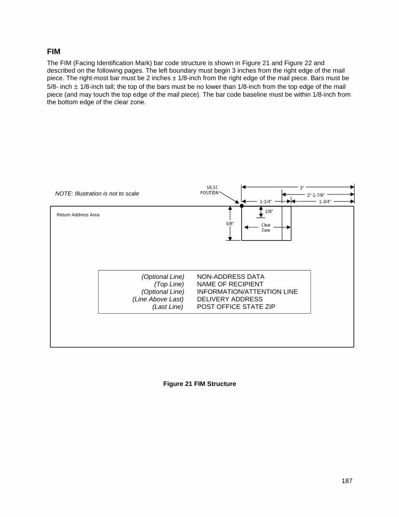
187
FIM
The FIM (Facing Identification Mark) bar code structure is shown in Figure 21 and Figure 22 and described on the following pages. The left boundary must begin 3 inches from the right edge of the mail piece. The right-most bar must be 2 inches ± 1/8-inch from the right edge of the mail piece. Bars must be 5/8- inch ± 1/8-inch tall; the top of the bars must be no lower than 1/8-inch from the top edge of the mail piece (and may touch the top edge of the mail piece). The bar code baseline must be within 1/8-inch from the bottom edge of the clear zone.
Figure 21 FIM Structure
(Optional Line) NON-ADDRESS DATA (Top Line) NAME OF RECIPIENT (Optional Line) INFORMATION/ATTENTION LINE (Line Above Last) DELIVERY ADDRESS (Last Line) POST OFFICE STATE ZIP
SR,SC POSITION
5/8”
3”
2”-1-7/8” 1-3/4” 1-1/4”
1/8”
Clear Zone
Return Address Area
NOTE: Illustration is not to scale
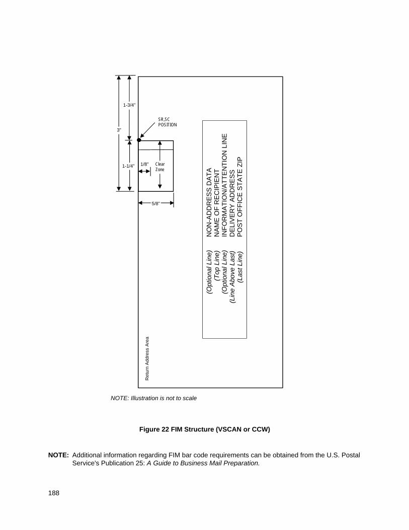
188
Figure 22 FIM Structure (VSCAN or CCW)
NOTE: Additional information regarding FIM bar code requirements can be obtained from the U.S. Postal Service's Publication 25: A Guide to Business Mail Preparation.
SR,SC POSITION
5/8”
3”
1-3/4”
1-1/4” 1/8” Clear Zone
Ret
urn
Add
ress
Are
a
NOTE: Illustration is not to scale
(
Opt
iona
l Lin
e)
NO
N-A
DD
RE
SS
DA
TA
(T
op L
ine)
N
AM
E O
F R
EC
IPIE
NT
(O
ptio
nal L
ine)
IN
FO
RM
AT
ION
/AT
TE
NT
ION
LIN
E
(Lin
e A
bove
Las
t)
DE
LIV
ER
Y A
DD
RE
SS
(La
st L
ine)
P
OS
T O
FF
ICE
ST
AT
E Z
IP
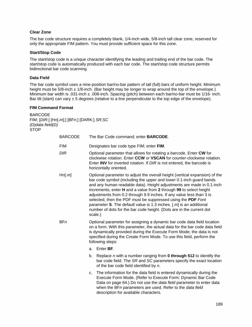
189
Clear Zone
The bar code structure requires a completely blank, 1/4-inch wide, 5/8-inch tall clear zone, reserved for only the appropriate FIM pattern. You must provide sufficient space for this zone.
Start/Stop Code
The start/stop code is a unique character identifying the leading and trailing end of the bar code. The start/stop code is automatically produced with each bar code. The start/stop code structure permits bidirectional bar code scanning.
Data Field
The bar code symbol uses a nine-position bar/no-bar pattern of tall (full) bars of uniform height. Minimum height must be 5/8-inch ± 1/8-inch. (Bar height may be longer to wrap around the top of the envelope.) Minimum bar width is .031-inch ± .008-inch. Spacing (pitch) between each bar/no-bar must be 1/16- inch. Bar tilt (slant) can vary ± 5 degrees (relative to a line perpendicular to the top edge of the envelope).
FIM Command Format
BARCODE FIM; [DIR;] [Hn[.m];] [BFn;] [DARK;] SR;SC (D)data field(D) STOP
BARCODE The Bar Code command; enter BARCODE.
FIM Designates bar code type FIM; enter FIM.
DIR Optional parameter that allows for rotating a barcode. Enter CW for clockwise rotation. Enter CCW or VSCAN for counter-clockwise rotation. Enter INV for inverted rotation. If DIR is not entered, the barcode is horizontally oriented.
Hn[.m] Optional parameter to adjust the overall height (vertical expansion) of the bar code symbol (including the upper and lower 0.1-inch guard bands and any human readable data). Height adjustments are made in 0.1-inch increments; enter H and a value from 2 through 99 to select height adjustments from 0.2 through 9.9 inches. If any value less than 3 is selected, then the PDF must be suppressed using the PDF Font parameter S. The default value is 1.3 inches. [.m] is an additional number of dots for the bar code height. (Dots are in the current dot scale.)
BFn Optional parameter for assigning a dynamic bar code data field location on a form. With this parameter, the actual data for the bar code data field is dynamically provided during the Execute Form Mode; the data is not specified during the Create Form Mode. To use this field, perform the following steps:
a. Enter BF.
b. Replace n with a number ranging from 0 through 512 to identify the bar code field. The SR and SC parameters specify the exact location of the bar code field identified by n.
c. The information for the data field is entered dynamically during the Execute Form Mode. (Refer to Execute Form: Dynamic Bar Code Data on page 64.) Do not use the data field parameter to enter data when the BFn parameters are used. Refer to the data field description for available characters.
190
DARK Optional parameter to produce darker looking bar codes. Enter DARK. Refer to Dark Printing on page 52 for more information.
SR Defines the starting row for the bar code. Enter a value 1/8-inch from the top edge of the mail piece. Character row or dot row is specified based on the Scale command (page 113), or use the CP.DP format (page 23).
SC Defines the starting column of the bar code. Enter a value ranging from column 1 to one less than the width of the form. Character column or dot column is specified based on the Scale command (page 113), or use the CP.DP format (page 23).
(D) The printable character (delimiter) identifying the start and finish of the data field. Enter any printable character other than a slash (/), the SFCC, or a character used within the data. The same character must be used at both ends of the data field, but it is not printed with the data.
data field A single-character data field to designate one of four available FIM patterns: A, B, C, or D. Based on your application (check with your Postal Service for more information), enter one of the following FIM types:
A Used only on courtesy reply envelopes bearing a preprinted POSTNET bar code (page 263); it requires a luminescent stamp or meter mark to be accepted in the facer/canceler.
B Used on Business Reply Mail, Penalty Mail, and Franked Mail without a preprinted POSTNET bar code, and does not require luminescent indicia.
C Used on Business Reply Mail, Penalty Mail, or Franked Mail bearing a preprinted POSTNET bar code (page 263).
D Used on OCR readable mail (usually courtesy reply window envelopes) without a preprinted POSTNET bar code.
STOP Ends the Bar Code command while the IGP continues in the Create Form Mode. Enter STOP. If STOP is not entered, an error message results.
FIM Example
Figure 23 below illustrates a horizontal FIMB bar code generated by the following program without the POSTNET preprinted bar code (POSTNET is discussed on page 263.)
~CREATE;FIMB (Enter Create Form Mode) ALPHA (Alpha command) 23;11;0;0;*ACME MOTOR, INC.* 25;11;0;0;*ATTN: CUSTOMER SERVICE* 27;11;0;0;*P.O. BOX 200* 29;11;0;0;*USCITY, CA 12345-6789* STOP (Ends Alpha command) BARCODE (Bar Code command) FIM;DARK;15;22 (Dark FIM Bar Code at SR 15, SC 22) *B* (Data field selecting FIMB Bar Code) STOP (Ends FIMB Bar Code command) END (Terminates Create Form Mode) ~EXECUTE;FIMB;1 (Executes the form, form count of 1) ~NORMAL
191
Figure 23 Sample FIMB Bar Code
Figure 24 illustrates a horizontal FIMC bar code generated by the following program and bears the preprinted POSTNET bar code.
~CREATE;FIMC (Enter Create Form Mode) ALPHA (Alpha command) 23;11;0;0;*ACME MOTOR, INC.* 25;11;0;0;*ATTN: CUSTOMER SERVICE* 27;11;0;0;*P.O. BOX 2000* 29;11;0;0;*USCITY, CA 12345-6789* STOP (Ends Alpha command) BARCODE (Bar Code command) FIM;DARK;17;25 (Dark FIM Bar Code at SR 17, SC 25) *C* (Data field selecting FIMC Bar Code) STOP (Ends Bar Code command) BARCODE (New Bar Code command) POSTNET;DARK;33.3;15 (Dark POSTNET Bar Code at SR 33.3, SC 15) *927149559* (POSTNET data field) STOP (Ends POSTNET Bar Code command) END (Terminates Create Form Mode) ~EXECUTE;FIMC;1 (Executes the form, form count of 1) ~NORMAL
SR 15
SC 22
192
Figure 24 Sample FIMC Bar Code
SR 15
SC 22
SR 33.3
SC 15
193
GS1-128
NOTE: GS1-128 is formerly known as UCC/EAN-128.
Figure 25 GS1-128 Structure
Normal
LOWER GUARD BAND
HEIGHT
QUIET ZONE
QUIET ZONE
STOP CODE
START CODE
OPTIONAL READABLE DATA FIELD
DATA FIELD
SR,SC POSITION
INV
SR,SC POSITION
QUIET ZONE
STOP CODE
START CODE
QUIET ZONE
OPTIONAL READABLE DATA FIELD
LOWER GUARD BAND
UPPER GUARD BAND
UPPER GUARD BAND
DATA FIELD HEIGHT
OPTIONAL CHECK DIGIT
OPTIONAL CHECK DIGIT
CCW
LOWER GUARD BAND
QUIET ZONE
SR,SC POSITION
STOP CODE
START CODE
QUIET ZONE
OPTIONAL READABLE DATA FIELD
UPPER GUARD
BAND
DATA FIELD
HEIGHT
OPTIONAL CHECK
DIGIT
SR,SC POSITION
QUIET ZONE
STOP CODE
START CODE
QUIET ZONE
DATA FIELD
LOWER GUARD
BAND
UPPER GUARD BAND
CW
OPTIONAL CHECK DIGIT
HEIGHT
194
UCC/EAN-128 uses the same bar code and character set as Code 128. However, in UCC/EAN-128, the Function 1 character FNC1 immediately follows the start code. The FNC1 character has been reserved exclusively for UCC/EAN-128.
The UCC/EAN-128 data structure requires an Application Identifier (AI) at the beginning of bar code data. Each AI determines the format and length of the data which follows. Refer to Table 26 for more details. Each AI field in the barcode data needs to be separated with <SO>!, where <SO> is the default OxE.
Table 26 UCC/EAN-128 Application Identifiers
Application Identifier (AI)
Content Format
00 Serial Shipping Container Code n2+n18
01 Global Trade Item NumberTM n2+n14
02 Item Num. of Goods Within Another Unit n2+n14
10 Batch or Lot Number n2+an..20
11 (*) Production Date (YYMMDD) n2+n6
12 Due Date (YYMMDD) n2+n6
13 (*) Packaging Date (YYMMDD) n2+n6
15 (*) Sell By Date (Quality) (YYMMDD) n2+n6
17 (*) Expiration Date (Safety) (YYMMDD) n2+n6
20 Product Variant n2+n2
21 Serial Number n2+an..20
22 HIBC = Quantity, Date, Batch and Link n2+an..29
23 (**) Lot Number (Transitional Use) n3+n..19
37 Quantity of Units Contained (For Use With AI 02 Only) n2+n..8
240 Additional Product ID Assigned By Manufacturer n3+an..30
241 Customer part number n3+an..30
242 Made-to-Order Variation Number n3+n..6
250 Secondary Serial Number n3+an..30
251 Reference to source entity n3+an..30
253 Global Document Type Identifier (GDTI) n3+n13+n..17
254 GLN Extension Component n3+an..20
30 Quantity n2+n..8
310 (***) Net Weight, Kilograms n4+n6
311 (***) Length or 1st Dimension, Meters n4+n6
312 (***) Width, Diameter or 2nd Dimension, Meters n4+n6
313 (***) Depth, Thickness, Height or 3rd Dimension, Meters n4+n6
314 (***) Area, Square Meters n4+n6
315 (***) Volume, Liters n4+n6
316 (***) Volume, Cubic Meters n4+n6
195
Table 26 UCC/EAN-128 Application Identifiers
Application Identifier (AI)
Content Format
320 (***) Net Weight, Pounds n4+n6
321 (***) Length Or 1st Dimension, Inches n4+n6
322 (***) Length Or 1st Dimension, Feet n4+n6
323 (***) Length Or 1st Dimension, Yards n4+n6
324 (***) Width, Diameter, or 2nd Dimension, Inches n4+n6
325 (***) Width, Diameter, or 2nd Dimension, Feet n4+n6
326 (***) Width, Diameter, or 2nd Dimension, Yards n4+n6
327 (***) Depth, Thickness, Height, or 3rd Dimension, Inches n4+n6
328 (***) Depth, Thickness, Height, or 3rd Dimension, Feet n4+n6
329 (***) Depth, Thickness, Height, or 3rd Dimension, Yards n4+n6
330 (***) Gross Weight-Kilograms n4+n6
331 (***) Length or 1st Dimension, Logistics n4+n6
332(***) Width, Diameter, or 2nd Dimension, Meters, Logistics n4+n6
333 (***) Depth, Thickness, Height or 3rd Dimension, Meters, Logistics n4+n6
334 (***) Area, Square Meters, Logistics n4+n6
335 (***) Gross Volume, Liters n4+n6
336 (***) Gross Volume, Cubic Meters n4+n6
337 (***) Kilograms Per Square Meter n4+n6
340 (***) Gross Weight, Pounds n4+n6
341 (***) Length Or 1st Dimension, Inches, Logistics n4+n6
342 (***) Length Or 1st Dimension, Feet, Logistics n4+n6
343 (***) Length Or 1st Dimension, Yards, Logistics n4+n6
344 (***) Width, Diameter, or 2nd Dimension, Inches, Logistics n4+n6
345 (***) Width, Diameter, or 2nd Dimension, Feet, Logistics n4+n6
346 (***) Width, Diameter, or 2nd Dimension, Yards, Logistics n4+n6
347 (***) Depth, Thickness, Height or 3rd Dimension, Inches, Logistics n4+n6
348 (***) Depth, Thickness, Height or 3rd Dimension, Feet, Logistics n4+n6
349 (***) Depth, Thickness, Height or 3rd Dimension, Yards, Logistics n4+n6
350 (***) Area, Square Inches n4+n6
351 (***) Area, Square Feet n4+n6
352 (***) Area, Square Yards n4+n6
353 (***) Area, Square Inches, Logistics n4+n6
354 (***) Area, Square Feet, Logistics n4+n6
355 (***) Area, Square Yards, Logistics n4+n6
196
Table 26 UCC/EAN-128 Application Identifiers
Application Identifier (AI)
Content Format
356 (***) Net Weight, Troy Ounce n4+n6
357 (***) Net Volume, Ounces n4+n6
360 (***) Volume, Quarts n4+n6
361 (***) Volume, Gallons n4+n6
362 (***) Gross Volume, Quarts n4+n6
363 (***) Gross Volume, Gallons n4+n6
364 (***) Volume, Cubic Inches n4+n6
365 (***) Volume, Cubic Feet n4+n6
366 (***) Volume, Cubic Yards n4+n6
367 (***) Gross Volume, Cubic Inches n4+n6
368 (***) Gross Volume, Cubic Inches n4+n6
369 (***) Gross Volume, Cubic Inches n4+n6
390 (n) Amount payable-single monetary area n4+n..15
391 (n) Amount payable with ISO currency code n4+n3+n..15
392 (n) Amount payable for a Variable Measure Trade Item single monetary unit
n4+n..15
393 (n) Amount payable for a Variable Measure Trade Item - with ISO currency code
n4+n3+n..15
400 Customer's Purchase Order Number n3+an..30
401 Consignment Number n3+an..30
402 Shipment Identification Number N3+n17
403 Routing code N3+an..30
410 Ship To (Deliver To) Location Code Using EAN-13 n3+n13
411 Bill To (Invoice To) Location Code Using EAN-13 n3+n13
412 Purchase From (Location Code of Party From Whom Goods Are Purchased)
n3+n13
413 Ship For UCC/EAN Location Code n3+n13
414 EAN Location Code For Physical Identification n3+n13
415 EAN.UCC Global Location Number of the invoicing party n3+n13
420 Ship To (Deliver To) Postal Code Within a Single Postal Authority
n3+an..20
421 Ship To (Deliver To) Postal Code With 3-Digit ISO Country Code Prefix
n3+n3+an..9
422 Country of origin of a trade item n3+n3
423 Country of initial processing N3+n3+n..12
424 Country of processing n3+n3
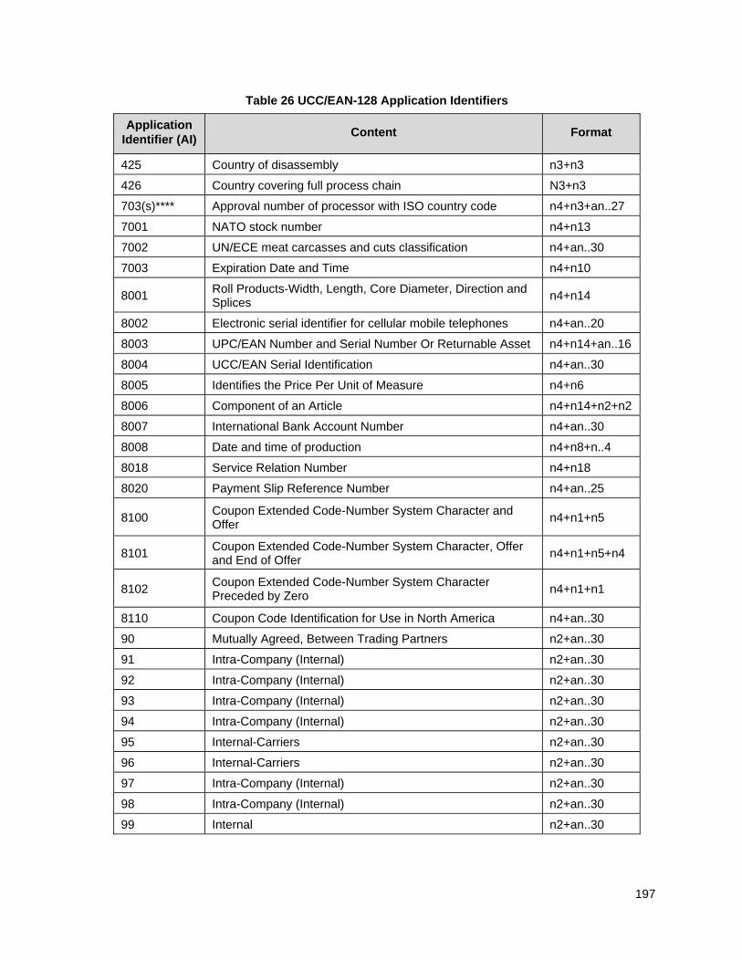
197
Table 26 UCC/EAN-128 Application Identifiers
Application Identifier (AI)
Content Format
425 Country of disassembly n3+n3
426 Country covering full process chain N3+n3
703(s)**** Approval number of processor with ISO country code n4+n3+an..27
7001 NATO stock number n4+n13
7002 UN/ECE meat carcasses and cuts classification n4+an..30
7003 Expiration Date and Time n4+n10
8001 Roll Products-Width, Length, Core Diameter, Direction and Splices
n4+n14
8002 Electronic serial identifier for cellular mobile telephones n4+an..20
8003 UPC/EAN Number and Serial Number Or Returnable Asset n4+n14+an..16
8004 UCC/EAN Serial Identification n4+an..30
8005 Identifies the Price Per Unit of Measure n4+n6
8006 Component of an Article n4+n14+n2+n2
8007 International Bank Account Number n4+an..30
8008 Date and time of production n4+n8+n..4
8018 Service Relation Number n4+n18
8020 Payment Slip Reference Number n4+an..25
8100 Coupon Extended Code-Number System Character and Offer
n4+n1+n5
8101 Coupon Extended Code-Number System Character, Offer and End of Offer
n4+n1+n5+n4
8102 Coupon Extended Code-Number System Character Preceded by Zero
n4+n1+n1
8110 Coupon Code Identification for Use in North America n4+an..30
90 Mutually Agreed, Between Trading Partners n2+an..30
91 Intra-Company (Internal) n2+an..30
92 Intra-Company (Internal) n2+an..30
93 Intra-Company (Internal) n2+an..30
94 Intra-Company (Internal) n2+an..30
95 Internal-Carriers n2+an..30
96 Internal-Carriers n2+an..30
97 Intra-Company (Internal) n2+an..30
98 Intra-Company (Internal) n2+an..30
99 Internal n2+an..30
198
(*) To indicate only year and month, DD must be filled with “00”
(**) Plus one digit for length indication (***) Plus one digit for decimal point indication (****) The fourth digit of this AI, “s,” indicates the sequence of the processors in the supply chain.
Data Value Representation: a - alphabetic characters n - numeric characters an - alpha-numeric characters n3 - 3 numeric characters, fixed length an..3 - up to 3 alpha-numeric characters n..3 - up to 3 numeric characters
Quiet Zone
Both ends of the bar code structure require blank quiet zones. The quiet zones must be at least 0.25 inches wide and completely blank to ensure accurate reading of the start/stop codes and to prevent adjacent bar codes from overlapping. You must provide sufficient space on the form for the quiet zones.
Start/Stop Codes
The start and stop codes identify the leading and trailing ends of the bar code. UCC/EAN-128 uses unique start codes for character subsets B and C, and a stop code common to both. An automatic mode switching feature is used to generate the correct start code based on the first four data field characters.
Data Field
UCC/EAN-128 bar codes require a special character called “Function 1” (FNC1) to immediately follow the start code. IGP automatically supplies this character, so it must not be included in the data field by the user.
A character is made up of three bars and three spaces, each varying in width from 1 through 4 modules, for a total of eleven modules. The number of modules making up the bars is even. The stop code has four bars and is 13 modules wide.
The character set for UCC/EAN-128 is the same as the character set for Code 128. Every character is interpreted according to the currently active character subset. UCC/EAN-128 uses subset B and subset C only. Subset B, shown in Table 23 (page 171), includes all standard alphanumeric keyboard characters, lowercase alphabetical characters, and special characters. Subset C interprets the characters as pairs of numbers 00 through 99, along with some special characters, as shown in Table 24 (page 172). The start code or subset switch code determines whether a particular bar code character is decoded as one character or as a pair of numbers.
Readable Data
The optional printed data field (PDF) provides a human-readable interpretation of the bar code data. When the printed data field is enabled by use of the “PDF” parameter, the overall height of the bars is reduced to make room for a guard band and the human-readable characters. The printed data field will be formatted with spaces or parentheses denoting particular data fields such as the application identifier. Special characters such as start, stop, subset switch, modulo-103 check digit, and FNC1 do not appear in the human-readable data.
The readable data is oriented along the bar code from start code to stop code. It may be positioned above or below a bar code, and the bar code may be horizontal, vertical, or inverted.
Modulo-103 Check Digit
A modulo-103 check digit is automatically calculated and inserted in the bar code symbol immediately in front of the stop code, in the same manner as the Code 128 bar code. The check digit verifies accurate scanning. The start code is included in the check digit algorithm. The modulo-103 check digit is not displayed in the readable data field.
199
Modulo-10 Data Field Check Digit for SSCC-18 and SCC-14
AI 00 (called the Serial Shipping Container Code, or SSCC-18) takes eighteen additional numerical data bytes. The last data byte is a modulo-10 check digit on the preceding seventeen data bytes. Counting the two zeros of the application identifier, the modulo-10 check digit is the twentieth byte in the data field.
AI 01 (called the Shipping Container Code, or SCC-14) takes fourteen additional numerical data bytes. The last data byte is a modulo-10 check digit on the preceding thirteen data bytes. Counting the zero and the one of the application identifier, the modulo-10 check digit is the sixteenth byte in the data field.
The modulo-10 data field check digit for both SSCC-18 and SCC-14 is printed in the bar code as the second half of the last number pair using subset C. It is displayed in the human-readable data field as the twentieth byte for SSCC-18 or the sixteenth byte for SCC-14.
IGP automatically calculates the modulo-10 check digit for SSCC-18 if only 17 data digits are provided following the application identifier of 00. This is also true for SSCC-14 if only 15 digits are supplied. For concatenated barcodes, an FNC1 must be inserted for the checkdigit character so that PGL will calculate it.
GS1-128 Command Format
BARCODE UCC-128; [DIR;] [MAG;] [Hn[.m];] [BFn;L;] [DARK;] SR;SC (D)data field(D) [PDF [;LOC] [;FONT]] STOP
BARCODE The Bar Code command; enter BARCODE.
UCC-128 Designates bar code type Code UCC-128; enter UCC-128.
DIR Optional parameter that allows for rotating a barcode. Enter CW for clockwise rotation. Enter CCW or VSCAN for counter-clockwise rotation. Enter INV for inverted rotation. If DIR is not entered, the barcode is horizontally oriented.
MAG Optional parameter to magnify the bar code symbol by increasing the width of the bars and spaces. The magnification default value is X1. Increasing the magnification adjusts printed character density as shown in Table 14 on page 129. You can also use XR or XRD as defined on page 125.
NOTE: A valid UCC/EAN-128 bar code can be no larger than 165 mm (6.5 inches) wide.
NOTE: There are eight values that comprise the dot ratio: narrow bar, narrow space, 2x narrow bar, 2x narrow space, 3x narrow bar, 3x narrow space, 4x narrow bar, and 4x narrow space. User-defined ratios for this barcode should have these eight values defined in the order specified.
Hn[.m] Optional parameter to adjust the overall height of the bar code symbol (including the upper and lower 0.1 inch guard bands and any human-readable data). Height adjustments are made in 0.1 inch increments; enter H and a value from 3 through 99 to select height adjustments from 0.3 through 9.9 inches. The default value is 0.9 inch. [.m] is an additional number of dots for the bar code height. (Dots are in the current scale).
NOTE: If 0.3 inches is the selected height, the PDF cannot be included.
BFn;L Optional parameters for assigning a dynamic bar code data field location on a form and for designating the length of the data field. With these parameters, the actual data for the bar code data field is dynamically provided during the Execute Form Mode; the data is not specified during the Create Form Mode. To use this field, perform the following steps:
200
a. Enter BF.
b. Replace n with a number ranging from 0 through 512 to identify the bar code field. The SR and SC parameters specify the exact location of the bar code field identified by n.
c. Replace L with the maximum number of characters in the field. The actual data provided dynamically during the Execute Form Mode can be less than L. It is permitted to supply no data at all.
d. The information for the data field is entered dynamically during the Execute Form Mode. (Refer to Execute Form: Dynamic Bar Code Data on page 64.) Do not use the data field parameter to enter data when the BFn;L parameters are used. However, refer to the data field description for available characters to use during Execute Form Mode.
DARK Optional parameter to produce darker looking bar codes. Enter DARK. Refer to Dark Printing on page 52 for more information.
SR Defines the starting row for the bar code. Enter a value ranging from row 1 to one less than the length of the form. Character row or dot row is specified based on the Scale command, or use the CP.DP format.
SC Defines the starting column of the bar code. Enter a value ranging from column 1 to one less than the width of the form. Character column or dot column is specified based on the Scale command, or use the CP.DP format.
(D) The printable character (delimiter) identifying the start and finish of the data field. Enter any printable character other than a slash (/), the SFCC, or a character used within the data. The same character must be used on both ends of the data field. It will not print with the data.
data field The bar code data. The data field for UCC/EAN- 128 consists of an “application identifier” (AI) of two to four numbers, followed by data of appropriate length (variable or fixed) and type (numeric or alphanumeric). See Table 26 for a list of application identifiers and their associated data fields.
The FNC1 character is required as the first character after the start code for UCC/EAN-128 bar codes, and IGP will always generate it automatically. It will appear in the bar code but not in the human-readable field. Do not supply FNC1 in the data field.
The start code and subset switching is done automatically by IGP based on the data field contents so that the bar code length is minimized. Subset C encodes each pair of numbers as a single bar code character, providing a higher character density. If the first four data digits are numbers, the bar code starts in subset C; otherwise it starts in subset B. The subset will switch from B to C at any point in the data field if the next four characters are numbers, and will switch from C to B if the next two characters are not numbers or only one character remains.
The data field can contain any of the characters listed in Table 26 except the system SFCC and the character used as a delimiter.
PDF Optional parameter to enable printing of the human readable data field. Enter PDF to print the data field. If this parameter is not used, the human readable data will not print.
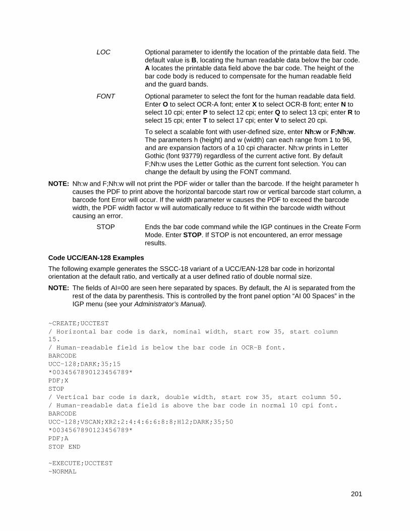
201
LOC Optional parameter to identify the location of the printable data field. The default value is B, locating the human readable data below the bar code. A locates the printable data field above the bar code. The height of the bar code body is reduced to compensate for the human readable field and the guard bands.
FONT Optional parameter to select the font for the human readable data field. Enter O to select OCR-A font; enter X to select OCR-B font; enter N to select 10 cpi; enter P to select 12 cpi; enter Q to select 13 cpi; enter R to select 15 cpi; enter T to select 17 cpi; enter V to select 20 cpi.
To select a scalable font with user-defined size, enter Nh:w or F;Nh:w. The parameters h (height) and w (width) can each range from 1 to 96, and are expansion factors of a 10 cpi character. Nh:w prints in Letter Gothic (font 93779) regardless of the current active font. By default F;Nh:w uses the Letter Gothic as the current font selection. You can change the default by using the FONT command.
NOTE: Nh:w and F;Nh:w will not print the PDF wider or taller than the barcode. If the height parameter h causes the PDF to print above the horizontal barcode start row or vertical barcode start column, a barcode font Error will occur. If the width parameter w causes the PDF to exceed the barcode width, the PDF width factor w will automatically reduce to fit within the barcode width without causing an error.
STOP Ends the bar code command while the IGP continues in the Create Form Mode. Enter STOP. If STOP is not encountered, an error message results.
Code UCC/EAN-128 Examples
The following example generates the SSCC-18 variant of a UCC/EAN-128 bar code in horizontal orientation at the default ratio, and vertically at a user defined ratio of double normal size.
NOTE: The fields of AI=00 are seen here separated by spaces. By default, the AI is separated from the rest of the data by parenthesis. This is controlled by the front panel option “AI 00 Spaces” in the IGP menu (see your Administrator’s Manual).
~CREATE;UCCTEST / Horizontal bar code is dark, nominal width, start row 35, start column 15. / Human-readable field is below the bar code in OCR-B font. BARCODE UCC-128;DARK;35;15 *0034567890123456789* PDF;X STOP / Vertical bar code is dark, double width, start row 35, start column 50. / Human-readable data field is above the bar code in normal 10 cpi font. BARCODE UCC-128;VSCAN;XR2:2:4:4:6:6:8:8;H12;DARK;35;50 *0034567890123456789* PDF;A STOP END ~EXECUTE;UCCTEST ~NORMAL
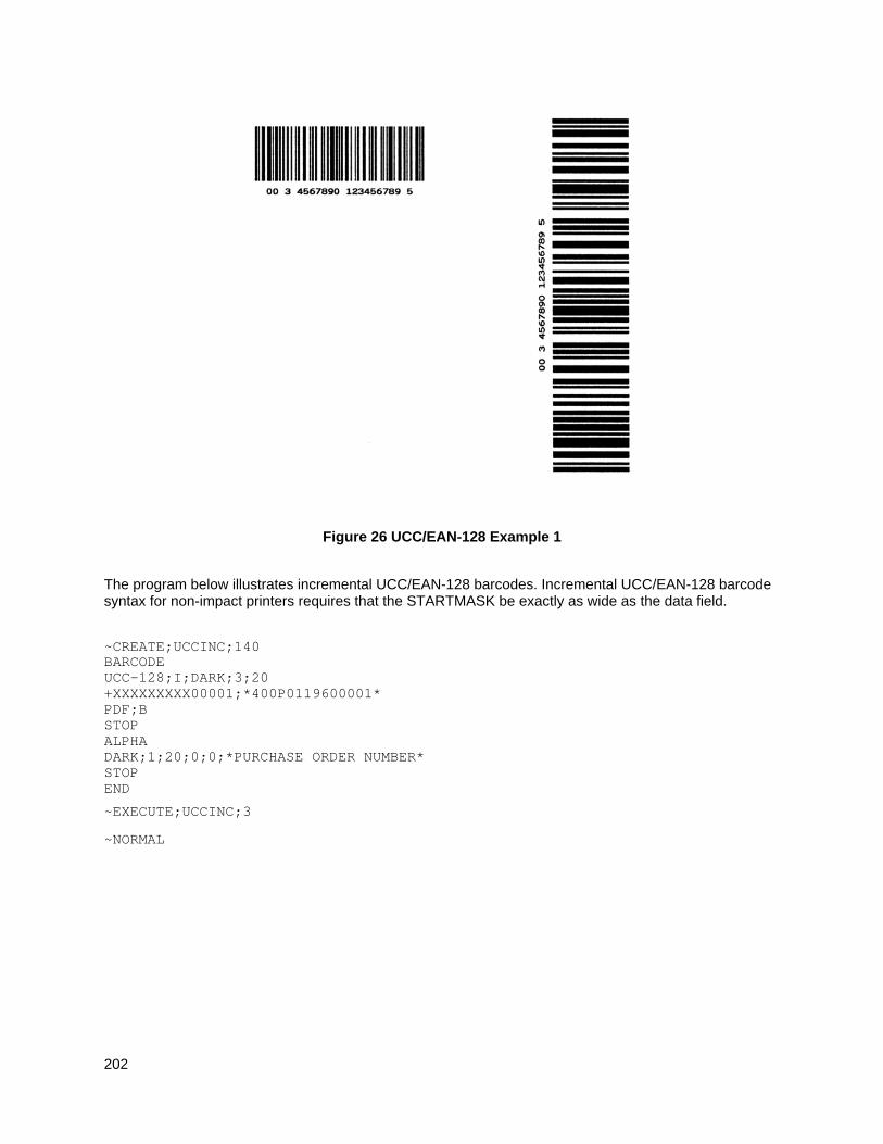
202
Figure 26 UCC/EAN-128 Example 1
The program below illustrates incremental UCC/EAN-128 barcodes. Incremental UCC/EAN-128 barcode syntax for non-impact printers requires that the STARTMASK be exactly as wide as the data field.
~CREATE;UCCINC;140 BARCODE UCC-128;I;DARK;3;20 +XXXXXXXXX00001;*400P0119600001* PDF;B STOP ALPHA DARK;1;20;0;0;*PURCHASE ORDER NUMBER* STOP END
~EXECUTE;UCCINC;3
~NORMAL
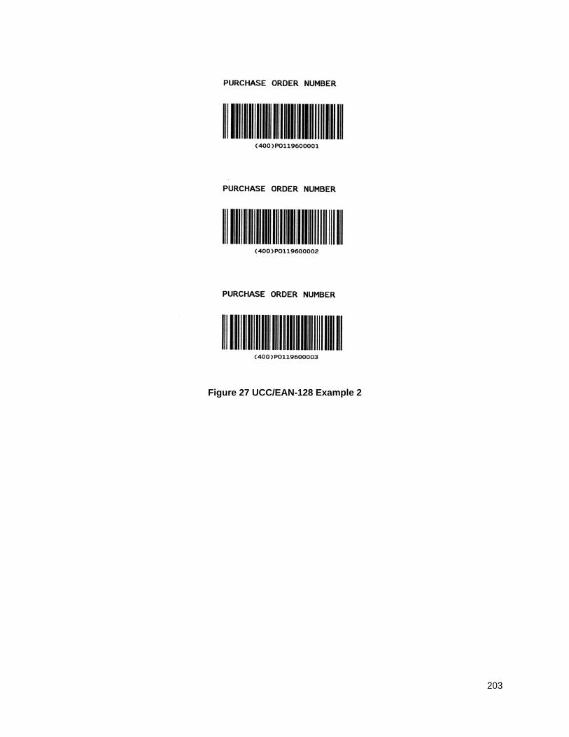
203
Figure 27 UCC/EAN-128 Example 2
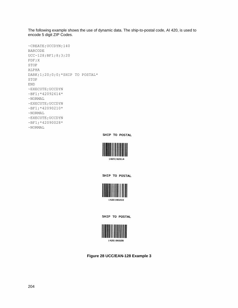
204
The following example shows the use of dynamic data. The ship-to-postal code, AI 420, is used to encode 5 digit ZIP Codes.
~CREATE;UCCDYN;140 BARCODE UCC-128;BF1;8;3;20 PDF;X STOP ALPHA DARK;1;20;0;0;*SHIP TO POSTAL* STOP END ~EXECUTE;UCCDYN ~BF1;*42092614* ~NORMAL ~EXECUTE;UCCDYN ~BF1;*42090210* ~NORMAL ~EXECUTE;UCCDYN ~BF1;*42090028* ~NORMAL
Figure 28 UCC/EAN-128 Example 3
205
THERMAL
GS1 Databar
NOTE: GS1 Databar is formerly known as RSS14 Barcode.
The GS1 Databar barcode is a linear symbology that encodes the primary data in UCC/EAN-128 format. In addition, the RSS14 barcode can have an optional 2-D composite portion that encodes any secondary data the user wants to include (such as additional AI element information).
This primary data portion follows the UCC/EAN-128 format. For all RSS14 variations except RSS-Expanded, the primary data portion is restricted to the AI (application identifier) of “01”. Given a maximum of 15 digits, it drops the AI of “01” and encodes a 13 digit identification number for use on small items. The symbol consists of five regions, namely the left guard, the left data character, the check character, the right data character and the right guard. The mod-10 checkdigit is not encoded in the actual barcode, but is included in the PDF data automatically by PGL.
RSS-14 Databar
The RSS14 Databar barcode type uses AI of 01 and must come with 13 digits following the AI. The symbol consists of a left guard, 1st data character, left finder pattern, 2nd data character, 4th data character, right finder pattern, 3rd data character, and finally the right guard. The height of the bars for the symbol is 33x the vertical element supplied in the MAG parameter.
RSS-14 Databar Truncated
The RSS14TRU barcode type is the same as the RSS-14 Databar barcode except that the height of the bars for the symbol is only 13x the vertical element supplied in the MAG parameter.
RSS-14 Databar Stacked
The RSS14STK barcode type is a RSS-14 Databar Truncated format in which the symbol is split into two rows. The top row is 5x the vertical element supplied in the MAG parameter, a row separator is 1x the vertical element, and the bottom row is 7x the vertical element in height. RSS-14 Stacked is used when the available space is too narrow for RSS Limited.
RSS-14 Databar Stacked Omnidirectional
The RSS14OMNI barcode type is a full height RSS-14 Databar in which the symbol is split into two rows. The top row is thus 33x the vertical element supplied in the MAG parameter, a row separator is 3x the vertical element, and the bottom row is 33x the vertical element in height. RSS-14 Omnidirectional is used when the available space is too narrow for
RSS-14 Databar.
RSS-14 Databar Limited
The RSS14LIM is also an RSS-14 Databar barcode type but cannot be read by omnidirectional scanners and has a height that is only a fraction of what is used for the full height RSS-14 Databar symbol.
The symbol consists of a left guard, left data character, check character, right data character, and finally the right guard. The height of the bars for the symbol is 10x the vertical element supplied in the MAG parameter. The item number that follows the AI of “01” must be within a range of 0 to 1999999999999.
RSS-14 Databar Expanded
The RSS14EXP is a superset of the RSS-14 Databar barcode type because it is not restricted to just an AI of “01”. The RSS14EXP barcode can encode up to 74 numeric or 41 alphabetic characters, including multiple (concatenated) AI formats. The height of the bars for the symbol is 34x the vertical element supplied in the MAG parameter.
206
RSS-14 Databar Expanded Stacked
RSS-14 Expanded Stacked uses the same identifier RSS14EXP in the PGL command but also uses the SEG parameter to determine the maximum number of segments to use per row. RSS-14 Databar expanded is capable of encoding 22 segments of data and by default the barcode will encode the entire 22 segments in one row (SEG parameter equivalent of 22). However, the SEG parameter can be used to limit the number of segments per row (2 segments per row minimum without composites, 4 minimum with composites) such that the barcode will be stacked from 1-11 rows. The height of each row of the symbol is 34 times the vertical element supplied in the MAG parameter. When stacking, a row separator of 3 times the vertical element supplied is used between each set of rows. Since the number of segments in the barcode might not be a multiple of the value selected, all rows of the RSS Expanded barcode might not be the same width.
UPC–A, UPC–E, EAN–8 and EAN–13
These types (UPCACOMP, UPCECOMP, EAN8COMP, EAN13COMP) combine a linear barcode of the EAN/UPC symbology (EAN–13, EAN–8, UPC–A or UPC–E), with a 2D Composite Component.
UCC/EAN-128 & Composite Component A or B
UCC/EAN-128 & Composite Component C
These RSS types (UCCACOMP and UCCCCOMP) encode the linear barcode in UCC/EAN–128 format just like RSS Expanded, and are not restricted to an IA of “01”. The linear barcode portion can encode up to 48 characters.
Left & Right Guard
All RSS-14 variations always starts with a left guard which is space followed by a bar. It ends with a right guard which is a space followed by a bar. The left & right guards are automatically added.
Command Format
BARCODE
RSS14 or RSS14LIM or RSS14STK or RSS14TRU or RSS14OMNI or RSS14EXP or UPCACOMP or UPCECOMP or EAN8COMP or EAN13COMP or UCCACOMP or UCCCCOMP; [DIR;] [MAG;][SEGn;][BFn;L;] [DARK;] SR; SC
[(D)Data Field(D)]
[PDF [;LOC][;F][;FONT[VE:HE]]]
STOP
Parameter Description
SEGn Optional parameter that designates the maximum number of segments of data to encode in a row for RSS-14 Expanded (RSS14EXP). This parameter is ignored for all other RSS types.
Data Field
Format of the Data Field: “primary data | 2–D composite data”
NOTE: 2–D composite data is included by putting a “|” character after the primary data. This character must be included when counting data for the L parameter within the dynamic data declaration BFn;L.
The sections below list the specific format requirements for each individual RSS–14 subtype:
207
Data Field for RSS-14 Limited
The item number for AI of “01” must be less than 1999999999999 or an error flagging invalid data will be printed.
Data Field for RSS-14 Expanded
Format of the Data Field: “primary data”
For RSS-14 Expanded, multiple sets of UCC/EAN-128 AI values and their data can be included in the primary data, up to 74 digits or 41 alphabetic characters. The data field can also include FNC1 characters, encoded the same way as done for PGL Code 128 and UCC/EAN-128 barcodes. If the data field is using an AI of “00” and/or AI of “01” and the mod-10 checkdigit character is not included, then the data field must include a FNC1 character in its place so that PGL inserts the checkdigit character at the right position. If the mod-10 checkdigit character, it will be used and not overwritten by PGL.
Table 27 Various Encoding Methods and Characteristics for RSS-14 Expanded
AI Element Strings Description
(01) and other AIs Used for leading AI of (01) with supplementary AIs.
any AIs Used for encoding data that does not lead with an AI of (01).
(01) and (3103) The AI (01) must have an indicator digit of 9. The AI (3103) variable weight element must have a weight of 0-32, 767 kilograms.
(01) and (3202)/(3203) The AI (01) must have an indicator digit of 9. The AI (3202) weight field must have a weight of 0-99,999 pounds. The AI (3203) must have a weight of 0-22,767 pounds.
(01) and (392x) The AI (01) must have an indicator digit of 9. The AI (392x) price may only have from zero to three digits to the right of the decimal point (x=0 to 3).
(01) and (393x) The AI (01) must have an indicator digit of 9. The AI (393x) price may only have from zero to three digits to the right of the decimal point (x=0 to 3).
(01), (310x), and (11) The AI (01) must have an indicator digit of 9. The AI (310x) metric weight must be 0-99,999. The AI (11) production date has no limitations.
(01), (320x), and (11) The AI (01) must have an indicator digit of 9. The AI (320x) english weight must be 0-99,999. The AI (11) production date has no limitations.
(01), (310x), and (13) The AI (01) must have an indicator digit of 9. The AI (310x) metric weight must be 0-99,999. The AI (13) packaging date has no limitations.
(01), (320x), and (13) The AI (01) must have an indicator digit of 9. The AI (320x) english weight must be 0- 99,999. The AI (13) packaging date has no limitations.
208
Table 27 Various Encoding Methods and Characteristics for RSS-14 Expanded
AI Element Strings Description
(01), (310x), and (15) The AI (01) must have an indicator digit of 9. The AI (310x) metric weight must be 0-99,999. The AI (15) “best before” date has no limitations.
(01), (320x), and (15) The AI (01) must have an indicator digit of 9. The AI (320x) english weight must be
0-99,999. The AI (15) “best before” date has no limitations.
(01), (310x), and (17) The AI (01) must have an indicator digit of 9. The AI (310x) metric weight must be 0-99,999. The AI (17) expiration date has no limitations.
(01), (320x), and (17) The AI (01) must have an indicator digit of 9. The AI (320x) english weight must be
0-99,999. The AI (17) expiration date has no limitations.
Data Field for other RSS-14 Variations
Format of the Data Field: “primary data”
All other RSS-14 types (not including RSS-14 Expanded) have primary data that is restricted to a maximum of 15 digits from 0 through 9. The first two digits MUST be “01” or an error is returned. The value “01” is not encoded in the barcode data, nor is the mod 10 checkdigit that is used for UCC/EAN-128 symbols with AI of “01”. However, they show up in the printable data field. If less than 15 is encoded, the leading zeros (following the 2-digit AI of “01”) are encoded to make a 15-digit barcode. A check digit mod 89 is automatically added. The data characters are positioned in the barcode as the left data character and the right data characters.
Data Field for Composite UPC–A
Encodes a UPC–A linear barcode, up to 11 digits are accepted, the check digit will be added by the printer. If less than 11 digits are supplied, the printer will left-pad the data with zeros. Sending data longer than 11 digits can result in an incorrect barcode.
Data Field for Composite UPC–E
Encodes a UPC–E linear barcode, up to 10 digits are accepted, which should comply with the UPC–E standards or an error will generate.
Data Field for Composite EAN–13
Encodes an EAN13 linear barcode, up to 12 digits are accepted, the check digit will be added by the printer. If less than 12 digits are supplied, the printer will left-pad the data with zeros.
Data Field for Composite EAN–8
Encodes an EAN8 linear barcode, up to 7 digits are accepted, the check digit will be added by the printer. If less than 7 digits are supplied, the printer will left-pad the data with zeros. Sending data longer than 7 digits can result in an incorrect barcode.
209
Data Field for Composite UCC/EAN–128 & Composite Component A/B or C
Encodes a UCC/EAN–128 linear barcode, up to 48 characters are accepted for the primary data. Similar to RSS–14 Expanded, these types can combine multiple Application Identifiers in the primary data. Type UCCACOMP uses Composite Component A or B, and UCCCCOMP uses Composite Component C as 2D Barcode. See the following descriptions of the 2D Composite Components.
2D Composite Component Data Field
The type of 2D Composite Component is chosen based on the selected linear component, and on the amount of supplementary data to be encoded.
Composite Component –A
You can encode up to 56 digits of alphanumeric data. It is designed for efficient encoding of supplemental application identifier data. CC–A can be combined with any of the EAN.UCC System symbols except for ITF–14. This code is based on MicroPDF417.
Composite Component–B
You can encode up to 338 digits of alphanumeric data. CC–B can be combined with any of the EAN.UCC System symbols except for ITF–14. This code is based on MicroPDF417. It is only used if the data string is too long to be encoded in CC–A.
Composite Component–C
You can encode up to 2361 digits of alphanumeric data. It can only be combined with UCC/EAN–128 (type UCCCCOMP). This code is based on PDF417 and has multiple widths to match the UCC/EAN–128 width and can have from 3 to 90 rows.
Check Code
The RSS family has a mod 89 check character with respect to the primary data. This check digit is not implicitly added, but is calculated from digits 2-15 of the data entered. The check digit is positioned between the left data character and the right data character.
GuardBand
There is no guardband for RSS-14 barcodes.
Magnification
The default magnification is X1, which is about 10 mils for a narrow element width. Pre-defined magnifications for horizontal and vertical barcodes are defined for X0.5 and X1. The ratio format is narrow bar element: vertical height element. The narrow space element is the same as the narrow bar element. The user-defined ratios for this barcode should have these two values defined in the order specified.
Height
The height command is not included as a valid parameter for the RSS-14 barcode because the height is determined by the declared barcode type. The height of the barcode is directly affected by the second parameter in the magnification ratio.
The height of the linear portion of the barcode however can be specified, but only for types UCCACOMP and UCCCCOMP. This height is to be specified as a required third ratio element for the user-defined magnification parameter XR[D].
narrow bar element:vertical height element:linear height element
NOTE: The linear height element is also affected by second parameter. For example, when specifying a user-defined ratio of XRD4:4:6, the vertical height element is 4, so the height of the linear portion of the barcode will be 24 (4 x 6).
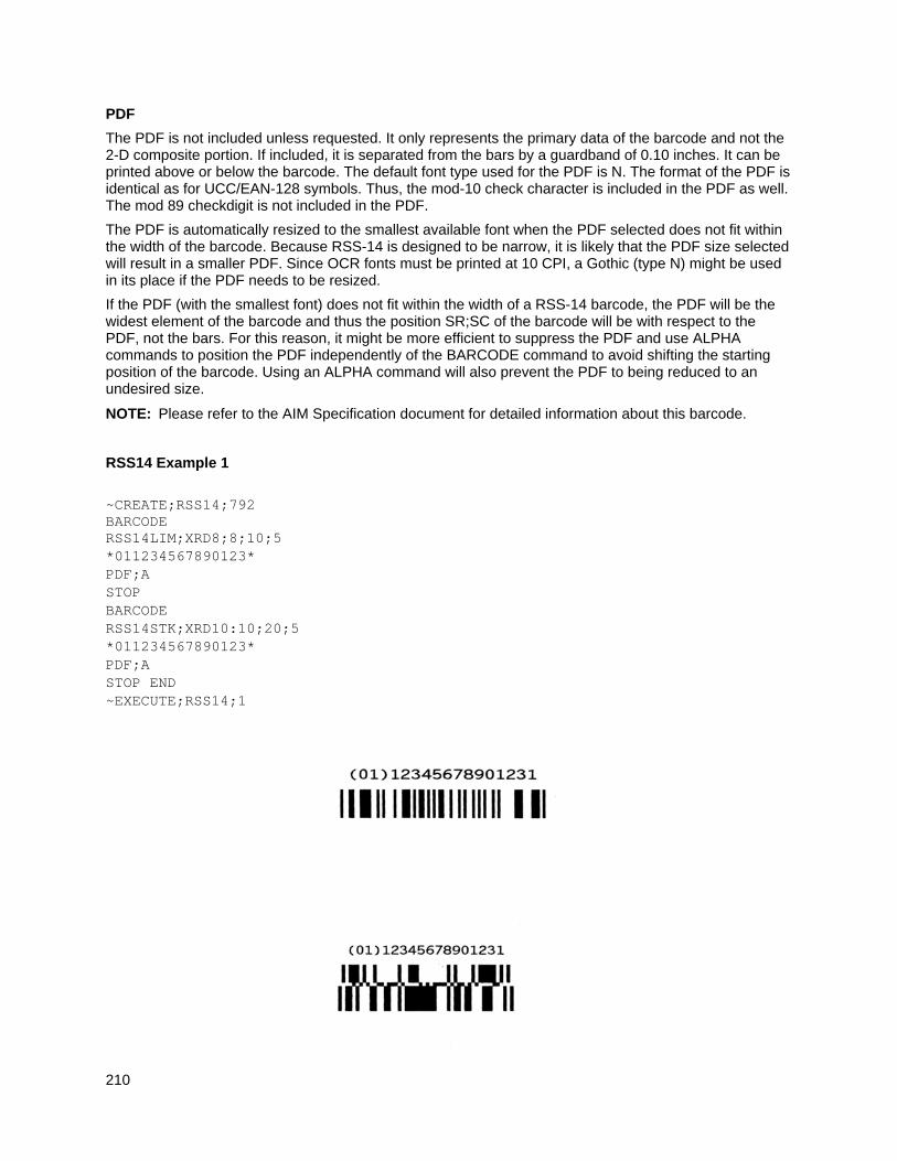
210
The PDF is not included unless requested. It only represents the primary data of the barcode and not the 2-D composite portion. If included, it is separated from the bars by a guardband of 0.10 inches. It can be printed above or below the barcode. The default font type used for the PDF is N. The format of the PDF is identical as for UCC/EAN-128 symbols. Thus, the mod-10 check character is included in the PDF as well. The mod 89 checkdigit is not included in the PDF.
The PDF is automatically resized to the smallest available font when the PDF selected does not fit within the width of the barcode. Because RSS-14 is designed to be narrow, it is likely that the PDF size selected will result in a smaller PDF. Since OCR fonts must be printed at 10 CPI, a Gothic (type N) might be used in its place if the PDF needs to be resized.
If the PDF (with the smallest font) does not fit within the width of a RSS-14 barcode, the PDF will be the widest element of the barcode and thus the position SR;SC of the barcode will be with respect to the PDF, not the bars. For this reason, it might be more efficient to suppress the PDF and use ALPHA commands to position the PDF independently of the BARCODE command to avoid shifting the starting position of the barcode. Using an ALPHA command will also prevent the PDF to being reduced to an undesired size.
NOTE: Please refer to the AIM Specification document for detailed information about this barcode.
RSS14 Example 1
~CREATE;RSS14;792 BARCODE RSS14LIM;XRD8;8;10;5 *011234567890123* PDF;A STOP BARCODE RSS14STK;XRD10:10;20;5 *011234567890123* PDF;A STOP END ~EXECUTE;RSS14;1
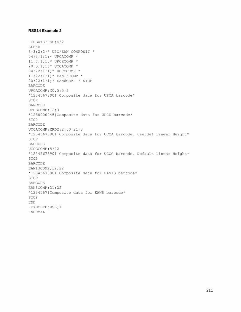
211
RSS14 Example 2
~CREATE;RSS;432 ALPHA 3;3;2;2;* UPC/EAN COMPOSIT * 04;3;1;1;* UPCACOMP * 11;3;1;1;* UPCECOMP * 20;3;1;1;* UCCACOMP * 04;22;1;1;* UCCCCOMP * 11;22;1;1;* EAN13COMP * 20;22;1;1;* EAN8COMP * STOP BARCODE UPCACOMP;X0.5;5;3 *12345678901|Composite data for UPCA barcode* STOP BARCODE UPCECOMP;12;3 *1230000045|Composite data for UPCE barcode* STOP BARCODE UCCACOMP;XRD2:2:50;21;3 *12345678901|Composite data for UCCA barcode, userdef Linear Height* STOP BARCODE UCCCCOMP;5;22 *12345678901|Composite data for UCCC barcode, Default Linear Height* STOP BARCODE EAN13COMP;12;22 *12345678901|Composite data for EAN13 barcode* STOP BARCODE EAN8COMP;21;22 *1234567|Composite data for EAN8 barcode* STOP END ~EXECUTE;RSS;1 ~NORMAL
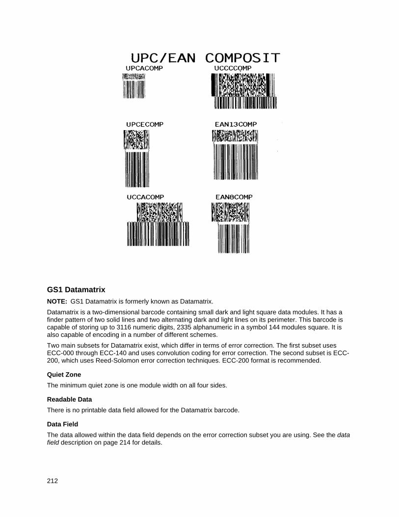
212
GS1 Datamatrix
NOTE: GS1 Datamatrix is formerly known as Datamatrix.
Datamatrix is a two-dimensional barcode containing small dark and light square data modules. It has a finder pattern of two solid lines and two alternating dark and light lines on its perimeter. This barcode is capable of storing up to 3116 numeric digits, 2335 alphanumeric in a symbol 144 modules square. It is also capable of encoding in a number of different schemes.
Two main subsets for Datamatrix exist, which differ in terms of error correction. The first subset uses ECC-000 through ECC-140 and uses convolution coding for error correction. The second subset is ECC-200, which uses Reed-Solomon error correction techniques. ECC-200 format is recommended.
Quiet Zone
The minimum quiet zone is one module width on all four sides.
Readable Data
There is no printable data field allowed for the Datamatrix barcode.
Data Field
The data allowed within the data field depends on the error correction subset you are using. See the data field description on page 214 for details.
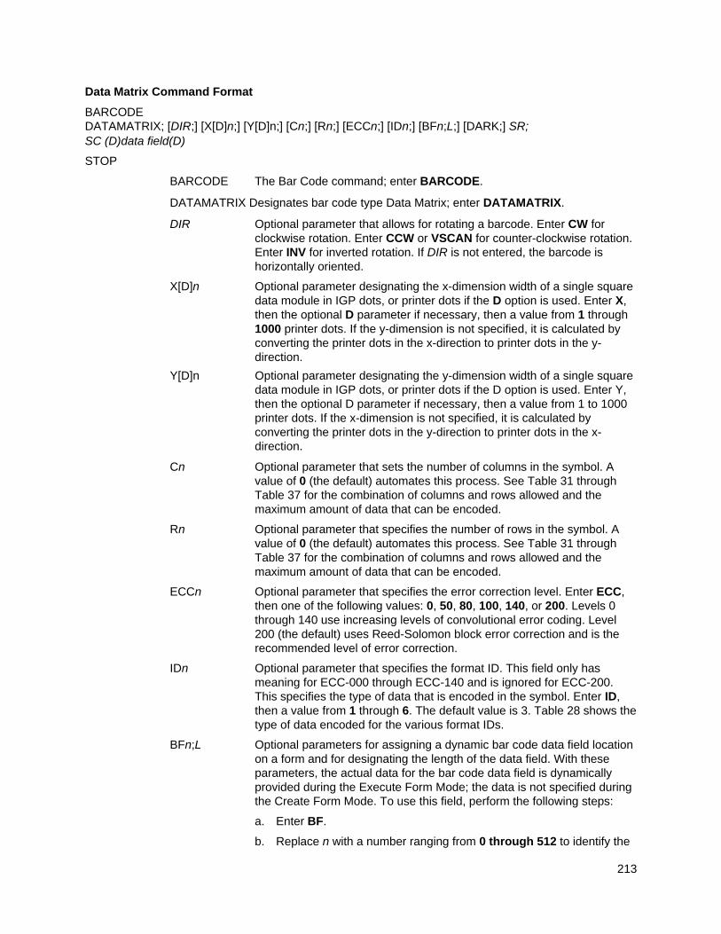
213
Data Matrix Command Format
BARCODE DATAMATRIX; [DIR;] [X[D]n;] [Y[D]n;] [Cn;] [Rn;] [ECCn;] [IDn;] [BFn;L;] [DARK;] SR; SC (D)data field(D)
STOP
BARCODE The Bar Code command; enter BARCODE.
DATAMATRIX Designates bar code type Data Matrix; enter DATAMATRIX.
DIR Optional parameter that allows for rotating a barcode. Enter CW for clockwise rotation. Enter CCW or VSCAN for counter-clockwise rotation. Enter INV for inverted rotation. If DIR is not entered, the barcode is horizontally oriented.
X[D]n Optional parameter designating the x-dimension width of a single square data module in IGP dots, or printer dots if the D option is used. Enter X, then the optional D parameter if necessary, then a value from 1 through 1000 printer dots. If the y-dimension is not specified, it is calculated by converting the printer dots in the x-direction to printer dots in the y-direction.
Y[D]n Optional parameter designating the y-dimension width of a single square data module in IGP dots, or printer dots if the D option is used. Enter Y, then the optional D parameter if necessary, then a value from 1 to 1000 printer dots. If the x-dimension is not specified, it is calculated by converting the printer dots in the y-direction to printer dots in the x-direction.
Cn Optional parameter that sets the number of columns in the symbol. A value of 0 (the default) automates this process. See Table 31 through Table 37 for the combination of columns and rows allowed and the maximum amount of data that can be encoded.
Rn Optional parameter that specifies the number of rows in the symbol. A value of 0 (the default) automates this process. See Table 31 through Table 37 for the combination of columns and rows allowed and the maximum amount of data that can be encoded.
ECCn Optional parameter that specifies the error correction level. Enter ECC, then one of the following values: 0, 50, 80, 100, 140, or 200. Levels 0 through 140 use increasing levels of convolutional error coding. Level 200 (the default) uses Reed-Solomon block error correction and is the recommended level of error correction.
IDn Optional parameter that specifies the format ID. This field only has meaning for ECC-000 through ECC-140 and is ignored for ECC-200. This specifies the type of data that is encoded in the symbol. Enter ID, then a value from 1 through 6. The default value is 3. Table 28 shows the type of data encoded for the various format IDs.
BFn;L Optional parameters for assigning a dynamic bar code data field location on a form and for designating the length of the data field. With these parameters, the actual data for the bar code data field is dynamically provided during the Execute Form Mode; the data is not specified during the Create Form Mode. To use this field, perform the following steps:
a. Enter BF.
b. Replace n with a number ranging from 0 through 512 to identify the
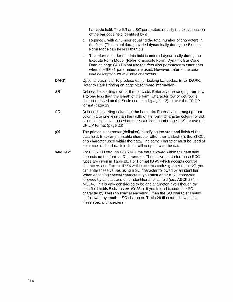
214
bar code field. The SR and SC parameters specify the exact location of the bar code field identified by n.
c. Replace L with a number equaling the total number of characters in the field. (The actual data provided dynamically during the Execute Form Mode can be less than L.)
d. The information for the data field is entered dynamically during the Execute Form Mode. (Refer to Execute Form: Dynamic Bar Code Data on page 64.) Do not use the data field parameter to enter data when the BFn;L parameters are used. However, refer to the data field description for available characters.
DARK Optional parameter to produce darker looking bar codes. Enter DARK. Refer to Dark Printing on page 52 for more information.
SR Defines the starting row for the bar code. Enter a value ranging from row 1 to one less than the length of the form. Character row or dot row is specified based on the Scale command (page 113), or use the CP.DP format (page 23).
SC Defines the starting column of the bar code. Enter a value ranging from column 1 to one less than the width of the form. Character column or dot column is specified based on the Scale command (page 113), or use the CP.DP format (page 23).
(D) The printable character (delimiter) identifying the start and finish of the data field. Enter any printable character other than a slash (/), the SFCC, or a character used within the data. The same character must be used at both ends of the data field, but it will not print with the data.
data field For ECC-000 through ECC-140, the data allowed within the data field depends on the format ID parameter. The allowed data for these ECC types are given in Table 28. For Format ID #5 which accepts control characters and Format ID #6 which accepts codes greater than 127, you can enter these values using a SO character followed by an identifier. When encoding special characters, you must enter a SO character followed by at least one other identifier and its field (i.e., ASCII 254 = ^d254). This is only considered to be one character, even though the data field holds 5 characters (^d254). If you intend to code the SO character by itself (no special encoding), then the SO character should be followed by another SO character. Table 29 illustrates how to use these special characters.
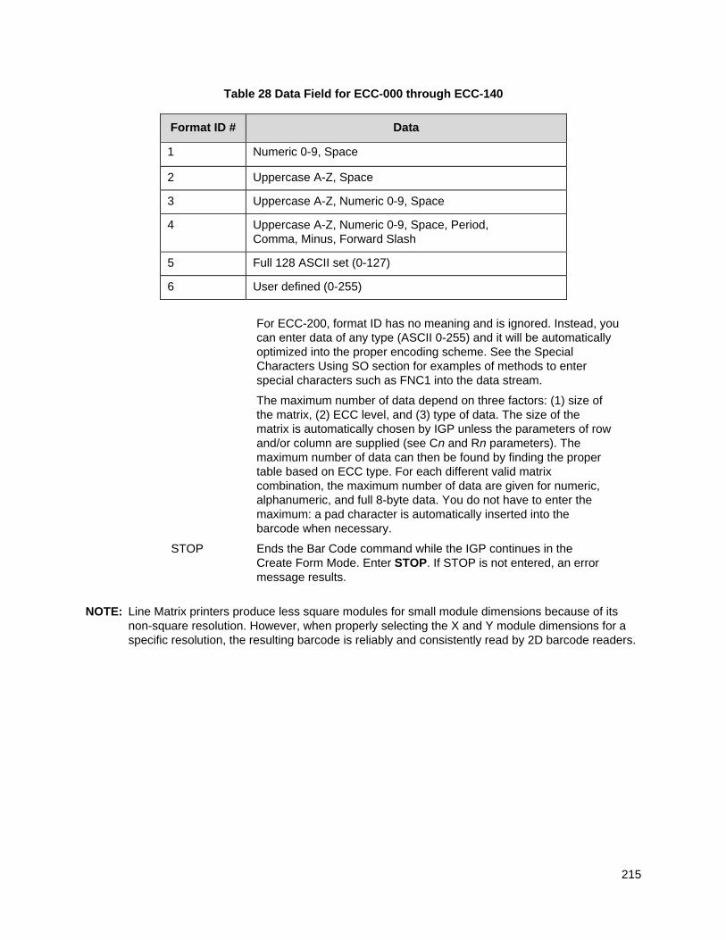
215
Table 28 Data Field for ECC-000 through ECC-140
Format ID # Data
1 Numeric 0-9, Space
2 Uppercase A-Z, Space
3 Uppercase A-Z, Numeric 0-9, Space
4 Uppercase A-Z, Numeric 0-9, Space, Period, Comma, Minus, Forward Slash
5 Full 128 ASCII set (0-127)
6 User defined (0-255)
For ECC-200, format ID has no meaning and is ignored. Instead, you can enter data of any type (ASCII 0-255) and it will be automatically optimized into the proper encoding scheme. See the Special Characters Using SO section for examples of methods to enter special characters such as FNC1 into the data stream.
The maximum number of data depend on three factors: (1) size of the matrix, (2) ECC level, and (3) type of data. The size of the matrix is automatically chosen by IGP unless the parameters of row and/or column are supplied (see Cn and Rn parameters). The maximum number of data can then be found by finding the proper table based on ECC type. For each different valid matrix combination, the maximum number of data are given for numeric, alphanumeric, and full 8-byte data. You do not have to enter the maximum: a pad character is automatically inserted into the barcode when necessary.
STOP Ends the Bar Code command while the IGP continues in the Create Form Mode. Enter STOP. If STOP is not entered, an error message results.
NOTE: Line Matrix printers produce less square modules for small module dimensions because of its non-square resolution. However, when properly selecting the X and Y module dimensions for a specific resolution, the resulting barcode is reliably and consistently read by 2D barcode readers.
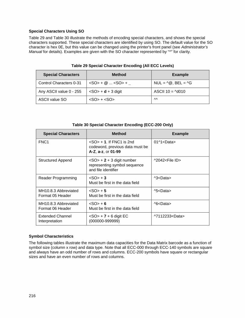
216
Special Characters Using SO
Table 29 and Table 30 illustrate the methods of encoding special characters, and shows the special characters supported. These special characters are identified by using SO. The default value for the SO character is hex 0E, but this value can be changed using the printer's front panel (see Administrator’s Manual for details). Examples are given with the SO character represented by “^” for clarity.
Table 29 Special Character Encoding (All ECC Levels)
Special Characters Method Example
Control Characters 0-31 <SO> + @ ... <SO> + _ NUL = ^@, BEL = ^G
Any ASCII value 0 - 255 <SO> + d + 3 digit ASCII 10 = ^d010
ASCII value SO <SO> + <SO> ^^
Table 30 Special Character Encoding (ECC-200 Only)
Special Characters Method Example
FNC1 <SO> + 1. If FNC1 is 2nd codeword, previous data must be A-Z, a-z, or 01-99
01^1<Data>
Structured Append <SO> + 2 + 3 digit number representing symbol sequence and file identifier
^2042<File ID>
Reader Programming <SO> + 3 Must be first in the data field
^3<Data>
MH10.8.3 Abbreviated Format 05 Header
<SO> + 5 Must be first in the data field
^5<Data>
MH10.8.3 Abbreviated Format 06 Header
<SO> + 6 Must be first in the data field
^6<Data>
Extended Channel Interpretation
<SO> + 7 + 6 digit EC (000000-999999)
^7112233<Data>
Symbol Characteristics
The following tables illustrate the maximum data capacities for the Data Matrix barcode as a function of symbol size (column x row) and data type. Note that all ECC-000 through ECC-140 symbols are square and always have an odd number of rows and columns. ECC-200 symbols have square or rectangular sizes and have an even number of rows and columns.
217
Table 31 ECC-000 Characteristics
(Row x Column) Maximum Numeric Maximum
Alphanumeric Maximum 8-Byte
Data
9 X 9 3 characters 2 characters 1 character
11 X 11 12 characters 8 characters 5 characters
13 X 13 24 characters 16 characters 10 characters
15 X 15 37 characters 25 characters 16 characters
17 X 17 53 characters 35 characters 23 characters
19 X 19 72 characters 48 characters 31 characters
21 X 21 92 characters 61 characters 40 characters
23 X 23 115 characters 76 characters 50 characters
25 X 25 140 characters 93 characters 61 characters
27 X 27 168 characters 112 characters 73 characters
29 X 29 197 characters 131 characters 86 characters
31 X 31 229 characters 153 characters 100 characters
33 X 33 264 characters 176 characters 115 characters
35 X 35 300 characters 200 characters 131 characters
37 X 37 339 characters 226 characters 148 characters
39 X 39 380 characters 253 characters 166 characters 41 X 41 424 characters 282 characters 185 characters
43 X 43 469 characters 313 characters 205 characters
45 X 45 500 characters 345 characters 226 characters
47 X 47 560 characters 378 characters 248 characters
49 X 49 596 characters 413 characters 271 characters
Table 32 ECC-050 Characteristics
(Row x Column) Maximum Numeric Maximum
Alphanumeric Maximum 8-Byte
Data
11 X 11 1 character 1 character not supported
13 X 13 10 characters 6 characters 4 characters
15 X 15 20 characters 13 characters 9 characters
17 X 17 32 characters 21 characters 14 characters
19 X 19 46 characters 30 characters 20 characters
21 X 21 61 characters 41 characters 27 characters
23 X 23 78 characters 52 characters 34 characters
25 X 25 97 characters 65 characters 42 characters
27 X 27 118 characters 78 characters 51 characters
29 X 29 140 characters 93 characters 61 characters
31 X 31 164 characters 109 characters 72 characters
33 X 33 190 characters 126 characters 83 characters
35 X 35 217 characters 145 characters 95 characters
37 X 37 246 characters 164 characters 108 characters
39 X 39 277 characters 185 characters 121 characters
41 X 41 310 characters 206 characters 135 characters
218
Table 32 ECC-050 Characteristics
(Row x Column) Maximum Numeric Maximum
Alphanumeric Maximum 8-Byte
Data
43 X 43 344 characters 229 characters 150 characters
45 X 45 380 characters 253 characters 166 characters
47 X 47 418 characters 278 characters 183 characters
49 X 49 457 characters 305 characters 200 characters
Table 33 ECC-080 Characteristics
(Row x Column) Maximum Numeric Maximum Alphanumeric
Maximum 8-Byte Data
13 X 13 4 characters 3 characters 2 characters 15 X 15 13 characters 9 characters 6 characters
17 X 17 24 characters 16 characters 10 characters
19 X 19 36 characters 24 characters 16 characters
21 X 21 50 characters 33 characters 22 characters
23 X 23 65 characters 43 characters 28 characters
25 X 25 82 characters 54 characters 36 characters
27 X 27 100 characters 67 characters 44 characters
29 X 29 120 characters 80 characters 52 characters
31 X 31 141 characters 94 characters 62 characters
33 X 33 164 characters 109 characters 72 characters
35 X 35 188 characters 125 characters 82 characters
37 X 37 214 characters 143 characters 94 characters
39 X 39 242 characters 161 characters 106 characters
41 X 41 270 characters 180 characters 118 characters
43 X 43 301 characters 201 characters 132 characters
45 X 45 333 characters 222 characters 146 characters
47 X 47 366 characters 244 characters 160 characters
49 X 49 402 characters 268 characters 176 characters
219
Table 34 ECC-100 Characteristics
(Row x Column) Maximum Numeric Maximum
Alphanumeric Maximum 8-Byte
Data
13 X 13 1 character 1 character not supported
15 X 15 8 characters 5 characters 3 characters
17 X 17 16 characters 11 characters 7 characters
19 X 19 25 characters 17 characters 11 characters
21 X 21 36 characters 24 characters 15 characters
23 X 23 47 characters 31 characters 20 characters
25 X 25 60 characters 40 characters 26 characters
27 X 27 73 characters 49 characters 32 characters
29 X 29 88 characters 59 characters 38 characters
31 X 31 104 characters 69 characters 62 characters
33 X 33 121 characters 81 characters 53 characters
35 X 35 140 characters 93 characters 61 characters
37 X 37 159 characters 106 characters 69 characters
39 X 39 180 characters 120 characters 78 characters
41 X 41 201 characters 134 characters 88 characters
43 X 43 224 characters 149 characters 98 characters
45 X 45 248 characters 165 characters 108 characters
47 X 47 273 characters 182 characters 119 characters
49 X 49 300 characters 200 characters 131 characters
Table 35 ECC-140 Characteristics
(Row x Column) Maximum Numeric Maximum
Alphanumeric Maximum 8-Byte
Data
17 X 17 2 characters 1 character 1 character
19 X 19 6 characters 4 characters 3 characters
21 X 21 12 characters 8 characters 5 characters
23 X 23 17 characters 11 characters 7 characters
25 X 25 24 characters 16 characters 10 characters
27 X 27 30 characters 20 characters 13 characters
29 X 29 38 characters 25 characters 16 characters
31 X 31 46 characters 30 characters 20 characters
33 X 33 54 characters 36 characters 24 characters
35 X 35 64 characters 42 characters 28 characters
37 X 37 73 characters 49 characters 32 characters
39 X 39 84 characters 56 characters 36 characters
41 X 41 94 characters 63 characters 41 characters
43 X 43 106 characters 70 characters 46 characters
45 X 45 118 characters 78 characters 51 characters
47 X 47 130 characters 87 characters 57 characters
49 X 49 144 characters 96 characters 63 characters
220
Table 36 ECC-200 Square Characteristics
(Row x Column) Maximum Numeric Maximum
Alphanumeric Maximum 8-Byte
Data
10 X 10 6 characters 3 characters 1 character
12 X 12 10 characters 6 characters 3 characters
14 X 14 16 characters 10 characters 6 characters
16 X 16 24 characters 16 characters 10 characters
18 X 18 36 characters 25 characters 16 characters
20 X 20 44 characters 31 characters 20 characters
22 X 22 60 characters 43 characters 28 characters
24 X 24 72 characters 52 characters 34 characters
26 X 26 88 characters 64 characters 42 characters
32 X 32 124 characters 91 characters 60 characters
36 X 36 172 characters 127 characters 84 characters
40 X 40 228 characters 169 characters 112 characters
44 X 44 288 characters 214 characters 142 characters
48 X 48 348 characters 259 characters 172 characters
52 X 52 408 characters 304 characters 202 characters
64 X 64 560 characters 418 characters 278 characters
72 X 72 736 characters 550 characters 366 characters
80 X 80 912 characters 682 characters 454 characters
88 X 88 1152 characters 862 characters 574 characters
96 X 96 1392 characters 1042 characters 694 characters
104 X 104 1632 characters 1222 characters 814 characters
120 X 120 2100 characters 1573 characters 1048 characters
132 X 132 2608 characters 1954 characters 1302 characters
144 X 144 3116 characters 2335 characters 1556 characters
Table 37 ECC-200 Rectangular Characteristics
(Row x Column) Maximum Numeric Maximum
Alphanumeric Maximum 8-Byte
Data
8 X 18 10 characters 6 characters 3 characters
8 X 32 20 characters 13 characters 8 characters
12 X 26 32 characters 22 characters 14 characters
12 X 36 44 characters 31 characters 20 characters
16 X 36 64 characters 46 characters 30 characters
16 X 48 98 characters 72 characters 47 characters
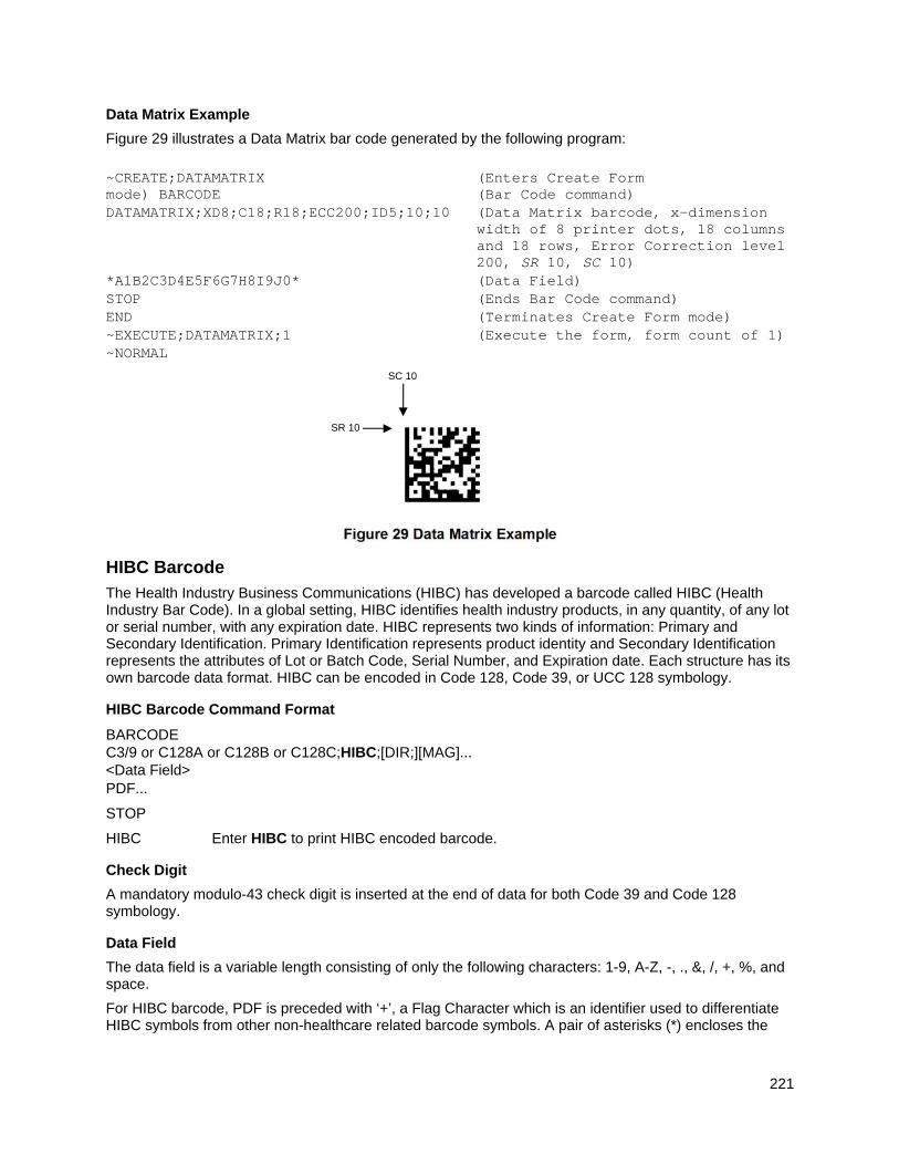
221
Data Matrix Example
Figure 29 illustrates a Data Matrix bar code generated by the following program:
~CREATE;DATAMATRIX (Enters Create Form mode) BARCODE (Bar Code command) DATAMATRIX;XD8;C18;R18;ECC200;ID5;10;10 (Data Matrix barcode, x-dimension
width of 8 printer dots, 18 columns and 18 rows, Error Correction level 200, SR 10, SC 10)
*A1B2C3D4E5F6G7H8I9J0* (Data Field) STOP (Ends Bar Code command) END (Terminates Create Form mode) ~EXECUTE;DATAMATRIX;1 (Execute the form, form count of 1) ~NORMAL
Figure 29 Data Matrix Example
HIBC Barcode
The Health Industry Business Communications (HIBC) has developed a barcode called HIBC (Health Industry Bar Code). In a global setting, HIBC identifies health industry products, in any quantity, of any lot or serial number, with any expiration date. HIBC represents two kinds of information: Primary and Secondary Identification. Primary Identification represents product identity and Secondary Identification represents the attributes of Lot or Batch Code, Serial Number, and Expiration date. Each structure has its own barcode data format. HIBC can be encoded in Code 128, Code 39, or UCC 128 symbology.
HIBC Barcode Command Format
BARCODE C3/9 or C128A or C128B or C128C;HIBC;[DIR;][MAG]... <Data Field> PDF...
STOP
HIBC Enter HIBC to print HIBC encoded barcode.
Check Digit
A mandatory modulo-43 check digit is inserted at the end of data for both Code 39 and Code 128 symbology.
Data Field
The data field is a variable length consisting of only the following characters: 1-9, A-Z, -, ., &, /, +, %, and space.
For HIBC barcode, PDF is preceded with ‘+’, a Flag Character which is an identifier used to differentiate HIBC symbols from other non-healthcare related barcode symbols. A pair of asterisks (*) encloses the
SR 10
SC 10
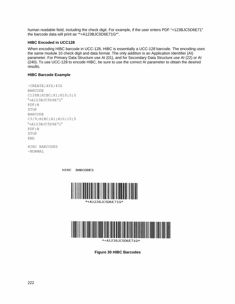
222
human readable field, including the check digit. For example, if the user enters PDF “+123BJC5D6E71” the barcode data will print as “*+A123BJC5D6E71G*”.
HIBC Encoded in UCC128
When encoding HIBC barcode in UCC-128, HIBC is essentially a UCC-128 barcode. The encoding uses the same module 10 check digit and data format. The only addition is an Application Identifier (AI) parameter. For Primary Data Structure use AI (01), and for Secondary Data Structure use AI (22) or AI (240). To use UCC-128 to encode HIBC, be sure to use the correct AI parameter to obtain the desired results.
HIBC Barcode Example
~CREATE;XYZ;432 BARCODE C128B;HIBC;X1;H10;5;5 “+A123BJC5D6E71“ PDF;B STOP BARCODE C3/9;HIBC;X1;H10;15;5 “+A123BJC5D6E71“ PDF;B STOP END
HIBC BARCODES ~NORMAL
Figure 30 HIBC Barcodes
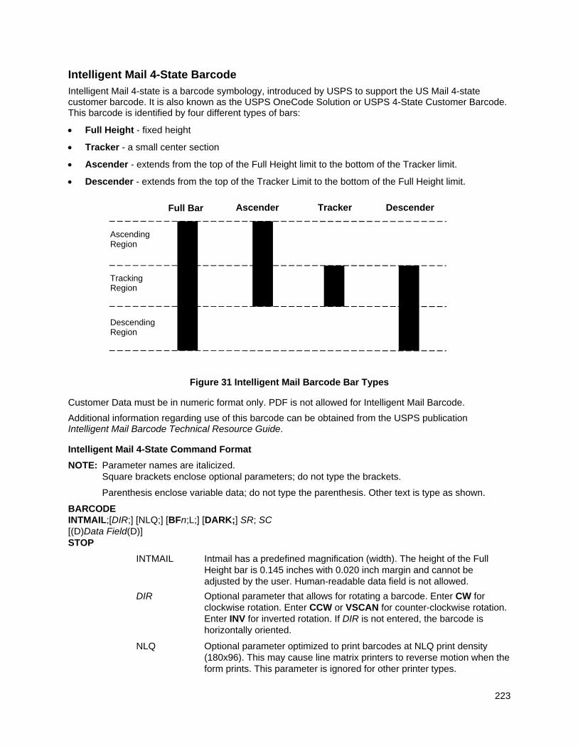
223
Intelligent Mail 4-State Barcode
Intelligent Mail 4-state is a barcode symbology, introduced by USPS to support the US Mail 4-state customer barcode. It is also known as the USPS OneCode Solution or USPS 4-State Customer Barcode. This barcode is identified by four different types of bars:
Full Height - fixed height
Tracker - a small center section
Ascender - extends from the top of the Full Height limit to the bottom of the Tracker limit.
Descender - extends from the top of the Tracker Limit to the bottom of the Full Height limit.
Figure 31 Intelligent Mail Barcode Bar Types
Customer Data must be in numeric format only. PDF is not allowed for Intelligent Mail Barcode.
Additional information regarding use of this barcode can be obtained from the USPS publication Intelligent Mail Barcode Technical Resource Guide.
Intelligent Mail 4-State Command Format
NOTE: Parameter names are italicized. Square brackets enclose optional parameters; do not type the brackets.
Parenthesis enclose variable data; do not type the parenthesis. Other text is type as shown.
BARCODE INTMAIL;[DIR;] [NLQ;] [BFn;L;] [DARK;] SR; SC [(D)Data Field(D)] STOP
INTMAIL Intmail has a predefined magnification (width). The height of the Full Height bar is 0.145 inches with 0.020 inch margin and cannot be adjusted by the user. Human-readable data field is not allowed.
DIR Optional parameter that allows for rotating a barcode. Enter CW for clockwise rotation. Enter CCW or VSCAN for counter-clockwise rotation. Enter INV for inverted rotation. If DIR is not entered, the barcode is horizontally oriented.
NLQ Optional parameter optimized to print barcodes at NLQ print density (180x96). This may cause line matrix printers to reverse motion when the form prints. This parameter is ignored for other printer types.
Ascending Region
Full Bar Ascender Tracker Descender
Tracking Region
Descending Region
224
BFn;L Optional parameters for assigning a dynamic bar code data field location on a form and for designating the length of the data field. With these parameters, the actual data for the barcode data field is dynamically provided during the Execute Form Mode; the data is not specified during the Create Form Mode. To use this field, perform the following steps:
a. Enter BF.
b. Replace n with a number ranging from 0 to 512 to identify the barcode field. The SR and SC parameters specify the exact location of the barcode field identified by n.
c. Replace L with a number equal to the total number of characters in the field. The data field must be numeric and contain exactly 20, 25, 29, or 31 digits. An empty field is also allowed.
d. The information for Data Field is entered dynamically during the Execute Form Mode. (Refer to Execute Form: Dynamic Bar Code Data on page 64.) Do not use Data Field to enter data when the BFn;L parameters are used. Refer to the Data Field description for available characters.
DARK Optional parameter to produce darker looking bar codes. This has no affect on horizontally oriented barcodes. Enter DARK. Refer to Dark Printing on page 52 for more information.
SR Defines the starting row for the barcode. Enter a value within the range of the 4-inch vertical address block. Character row or dot row is specified based on the Scale command (page 113), or use the CP.DP format (page 23).
SC Defines the starting column of the barcode. Enter a value between the 1/2-inch left and right margins of the mail piece. Character column or dot column is specified based on the SCALE command (page 113), or use the CP.DP format (page 23).
(D) Data Field (D) Delimiters (D) can be any character not present in the data field. The
leading delimiter must be identical to the trailing delimiter. All Data Field characters are numeric.
Table 38 shows the valid parameters for the all the fields. The Tracking Code is 20 digits in length. The Routing Code is optional, but if it is included, it must be 5, 9 or 11 digits in length. The maximum total input data is 31 numeric digits. PGL encodes any length of input data into a 4-state customer barcode string consisting of 65 bars.
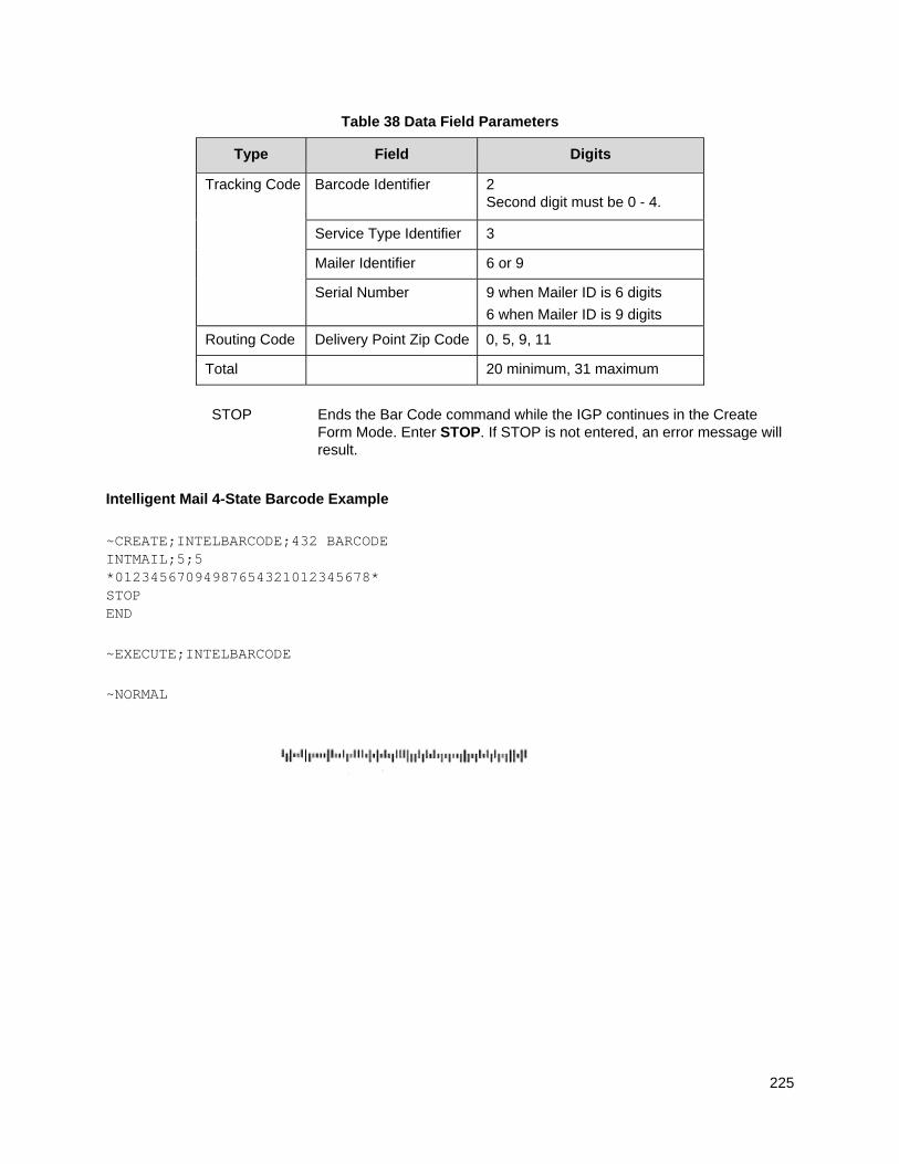
225
Table 38 Data Field Parameters
Type Field Digits
Tracking Code Barcode Identifier 2 Second digit must be 0 - 4.
Service Type Identifier 3
Mailer Identifier 6 or 9
Serial Number 9 when Mailer ID is 6 digits
6 when Mailer ID is 9 digits
Routing Code Delivery Point Zip Code 0, 5, 9, 11
Total 20 minimum, 31 maximum
STOP Ends the Bar Code command while the IGP continues in the Create Form Mode. Enter STOP. If STOP is not entered, an error message will result.
Intelligent Mail 4-State Barcode Example
~CREATE;INTELBARCODE;432 BARCODE INTMAIL;5;5 *01234567094987654321012345678* STOP END
~EXECUTE;INTELBARCODE
~NORMAL
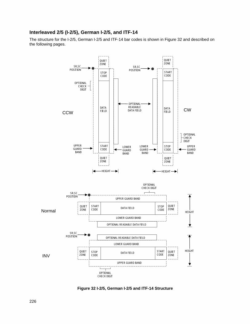
226
Interleaved 2/5 (I-2/5), German I-2/5, and ITF-14
The structure for the I-2/5, German I-2/5 and ITF-14 bar codes is shown in Figure 32 and described on the following pages.
Figure 32 I-2/5, German I-2/5 and ITF-14 Structure
Normal
LOWER GUARD BAND
HEIGHT
QUIET ZONE
QUIET ZONE
STOP CODE
START CODE
OPTIONAL READABLE DATA FIELD
DATA FIELD
SR,SC POSITION
INV
SR,SC POSITION
QUIET ZONE
STOP CODE
START CODE
QUIET ZONE
OPTIONAL READABLE DATA FIELD
LOWER GUARD BAND
UPPER GUARD BAND
UPPER GUARD BAND
DATA FIELD HEIGHT
OPTIONAL CHECK DIGIT
OPTIONAL CHECK DIGIT
CCW
LOWER GUARD BAND
QUIET ZONE
SR,SC POSITION
STOP CODE
START CODE
QUIET ZONE
OPTIONAL READABLE DATA FIELD
UPPER GUARD
BAND
DATA FIELD
HEIGHT
OPTIONAL CHECK
DIGIT
SR,SC POSITION
QUIET ZONE
STOP CODE
START CODE
QUIET ZONE
DATA FIELD
LOWER GUARD
BAND
UPPER GUARD BAND
CW
OPTIONAL CHECK DIGIT
HEIGHT
227
Quiet Zone
Both ends of the bar code structure have blank quiet zones. The quiet zones must be at least 0.25 inches wide and completely blank to ensure accurate reading of the start/stop codes and to prevent adjacent bar codes from overlapping. You must provide sufficient space on the form for the quiet zones.
Start/Stop Codes
Unique start and stop codes permit bidirectional scanning. Both start and stop codes contain bars and spaces. They are automatically produced.
Data Field
The bar code symbol uses a series of wide and narrow bars and spaces to represent numeric characters. The structure is 2 wide elements (bars or spaces) and 3 narrow elements. In the bar code, two characters are interleaved (paired); bars are used to represent the first character in the pair and spaces are used to represent the second character in the pair.
German I-2/5 and ITF-14 are special cases of Interleaved 2/5 bar codes. While Interleaved 2/5 has a variable data field, German I-2/5 is restricted to 11 or 13 digits, and ITF-14 is restricted to 13 digits.
Readable Data
The optional readable data field provides a readable interpretation of the bar code data. It can be printed above or below the bar code symbol.
Check Digit
The modulo-10 check digit can be inserted into the bar code to verify accurate scanning.
Interleaved 2/5 can be printed with or without a check digit, but German I-2/5 and ITF-14 have the check digit automatically included.
I-2/5, German I-2/5, and ITF-14 Command Format
BARCODE I-2/5 [CD]; or I25GERMAN; or ITF14; [DIR;] [MAG;] [Hn[.m];] [BFn;L;] [DARK;] SR; SC (D)data field(D) [PDF [;LOC] [;FONT]] STOP
BARCODE The Bar Code command; enter BARCODE.
I-2/5 CD Designates bar code type Interleaved 2/5; enter I-2/5. To calculate and plot the optional modulo-10 check digit with the bar code symbol automatically, enter CD.
I25GERMAN Designates German Interleaved 2/5; enter I25GERMAN. The mod-10 check digit is automatically included.
ITF14 Designates ITF-14; enter ITF14. The mod-10 check digit is automatically included.
DIR Optional parameter that allows for rotating a barcode. Enter CW for clockwise rotation. Enter CCW or VSCAN for counter-clockwise rotation. Enter INV for inverted rotation. If DIR is not entered, the barcode is horizontally oriented.
MAG Optional parameter to magnify (horizontally expand) the bar code symbol. The magnification default value is X1. As required for scanning, enter a magnification value from Table 14 on page 129 to
228
increase the magnification. Increasing the magnification adjusts printed character density. You can also use XR or XRD as defined on page 125.
NOTE: You must specify four digits for MAG for User Defined variable ratio. There are four values that comprise the dot ratio: narrow bar, narrow space, wide bar, and wide space. User-defined ratios for this barcode should have these four values defined in the order specified.
Hn[.m] Optional parameter to adjust the overall height (vertical expansion) of the bar code symbol (including the upper and lower 0.1-inch guard bands and any human readable data). Height adjustments are made in 0.1-inch increments; enter H and a value from 3 through 99 to select height adjustments from 0.3 through 9.9 inches. The default value is 0.9-inch.
[.m] is an additional number of dots for the bar code height. (Dots are in the current dot scale.)
NOTE: If 0.3 inches is the selected height, the PDF cannot be included.
BFn;L Optional parameters for assigning a dynamic bar code data field location on a form and for designating the length of the data field. With these parameters, the actual data for the bar code data field is dynamically provided during the Execute Form Mode; the data is not specified during the Create Form Mode. To use this field, perform the following steps:
a. Enter BF.
b. Replace n with a number ranging from 0 through 512 to identify the bar code field. The SR and SC parameters specify the exact location of the bar code field identified by n.
c. Replace L with a number equaling the total number of characters in the field. (The actual data provided dynamically during the Execute Form Mode can be less than L.)
d. The information for the data field is entered dynamically during the Execute Form Mode. (Refer to Execute Form: Dynamic Bar Code Data on page 64.) Do not use the data field parameter to enter data when the BFn;L parameters are used. However, refer to the data field description for available characters.
DARK Optional parameter to produce darker looking bar codes. Enter DARK. Refer to Dark Printing on page 52 for more information.
SR Defines the starting row for the bar code. Enter a value ranging from row 1 to one less than the length of the form. Character row or dot row is specified based on the Scale command (page 113), or use the CP.DP format (page 23).
SC Defines the starting column of the bar code. Enter a value ranging from column 1 to one less than the width of the form. Character column or dot column is specified based on the Scale command (page 113), or use the CP.DP format (page 23).
(D) The printable character (delimiter) identifying the start and finish of the data field. Enter any printable character other than a slash (/), the SFCC, or a character used within the data. The same
229
character must be used at both ends of the data field, but it will not print with the data.
data field Interleaved 2/5: Enter the characters for the bar code data. A null data field (no characters) is permitted. The length of the data field is variable; however, the maximum length is usually limited to 32 characters to minimize potential reading errors. An even number of characters are required for the interleaving process. Consequently, if an odd number of characters are entered in the data field, a leading zero is added automatically. The characters available for the data field are 0 through 9 (hex 30 through 39).
German I-2/5: The data field must be 11 or 13 digits exactly.
ITF-14: The data field must be 13 digits exactly.
PDF Optional parameter to enable printing of the human readable data field. Enter PDF to print the data field. If the parameter is not used, the human readable data is not printed. This parameter is not allowed if a null data field was specified. For German I-2/5, fields of the data are separated by dots and spaces.
LOC Optional parameter to identify the location of the printable data field. The default value is B, locating the human readable data below the bar code. A locates the printable data field above bar code. To compensate for printing the 0.1-inch high data, the height of the bar code body is reduced 0.1-inch.
FONT Optional parameter to select the font for the human readable data field. Enter O to select OCR-A font; enter X to select OCR-B font; enter N to select 10 cpi; enter P to select 12 cpi; enter Q to select 13 cpi; enter R to select 15 cpi; enter T to select 17 cpi; enter V to select 20 cpi.
To select a scalable font with user-defined size, enter Nh:w or F;Nh:w. The parameters h (height) and w (width) can each range from 1 to 96, and are expansion factors of a 10 cpi character. Nh:w prints in Letter Gothic (font 93779) regardless of the current active font. By default F;Nh:w uses the Letter Gothic as the current font selection. You can change the default by using the FONT command.
NOTE: Nh:w and F;Nh:w will not print the PDF wider or taller than the barcode. If the height parameter h causes the PDF to print above the horizontal barcode start row or vertical barcode start column, a barcode font Error will occur. If the width parameter w causes the PDF to exceed the barcode width, the PDF width factor w will automatically reduce to fit within the barcode width without causing an error.
STOP Ends the Bar Code command while the IGP continues in the Create Form Mode. Enter STOP. If STOP is not entered, an error message results.
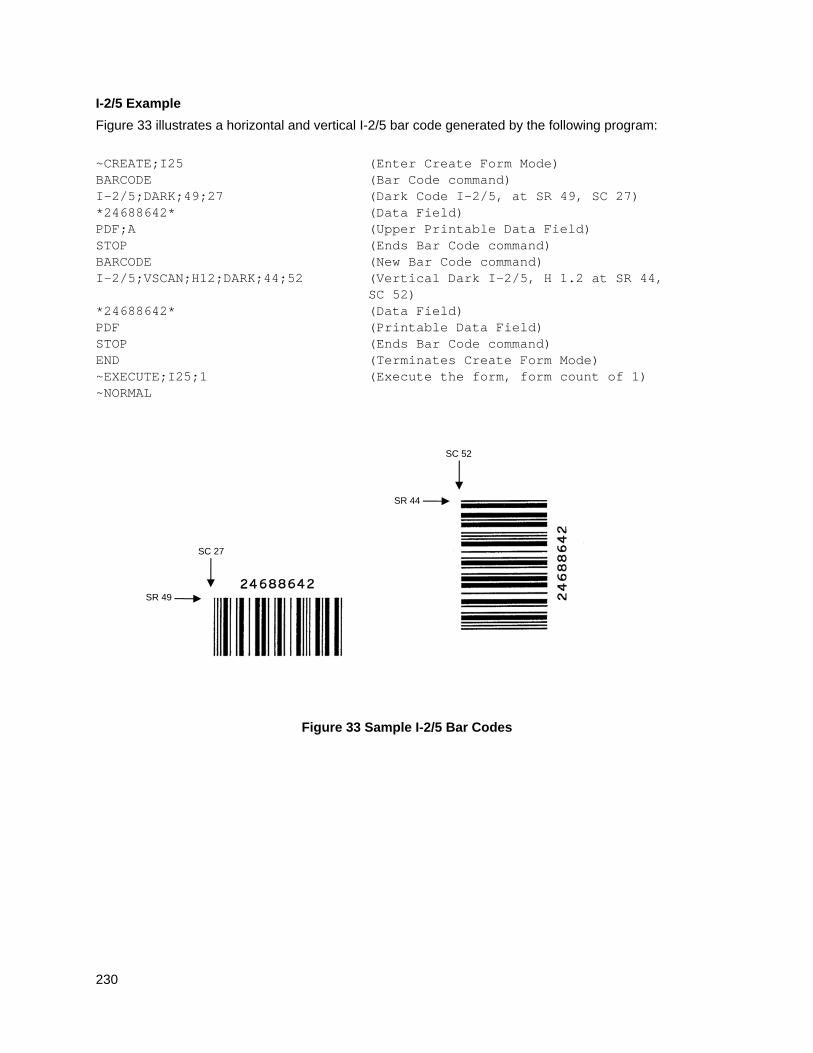
230
I-2/5 Example
Figure 33 illustrates a horizontal and vertical I-2/5 bar code generated by the following program:
~CREATE;I25 (Enter Create Form Mode) BARCODE (Bar Code command) I-2/5;DARK;49;27 (Dark Code I-2/5, at SR 49, SC 27) *24688642* (Data Field) PDF;A (Upper Printable Data Field) STOP (Ends Bar Code command) BARCODE (New Bar Code command) I-2/5;VSCAN;H12;DARK;44;52 (Vertical Dark I-2/5, H 1.2 at SR 44, SC 52) *24688642* (Data Field) PDF (Printable Data Field) STOP (Ends Bar Code command) END (Terminates Create Form Mode) ~EXECUTE;I25;1 (Execute the form, form count of 1) ~NORMAL
Figure 33 Sample I-2/5 Bar Codes
SR 44
SC 52
SR 49
SC 27
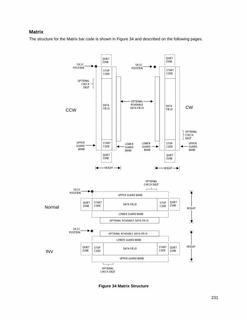
231
Matrix
The structure for the Matrix bar code is shown in Figure 34 and described on the following pages.
Figure 34 Matrix Structure
Normal
LOWER GUARD BAND
HEIGHT
QUIET ZONE
QUIET ZONE
STOP CODE
START CODE
OPTIONAL READABLE DATA FIELD
DATA FIELD
SR,SC POSITION
INV
SR,SC POSITION
QUIET ZONE
STOP CODE
START CODE
QUIET ZONE
OPTIONAL READABLE DATA FIELD
LOWER GUARD BAND
UPPER GUARD BAND
UPPER GUARD BAND
DATA FIELD HEIGHT
OPTIONAL CHECK DIGIT
OPTIONAL CHECK DIGIT
CCW
LOWER GUARD BAND
QUIET ZONE
SR,SC POSITION
STOP CODE
START CODE
QUIET ZONE
OPTIONAL READABLE DATA FIELD
UPPER GUARD
BAND
DATA FIELD
HEIGHT
OPTIONAL CHECK
DIGIT
SR,SC POSITION
QUIET ZONE
STOP CODE
START CODE
QUIET ZONE
DATA FIELD
LOWER GUARD
BAND
UPPER GUARD BAND
CW
OPTIONAL CHECK DIGIT
HEIGHT
232
Quiet Zone
Both ends of the bar code structure have blank quiet zones. The quiet zones must be at least 0.25 inches wide and completely blank to ensure accurate reading of the start/stop codes and to prevent adjacent bar codes from overlapping. You must provide sufficient space on the form for quiet zones.
Start/Stop Codes
Unique start and stop codes permit bidirectional scanning. Both start and stop codes contain bars and spaces. They are automatically produced.
Data Field
The bar code symbol uses a series of wide and narrow bars and spaces to represent numeric characters. The structure is 2 wide elements (bars or spaces) and 3 narrow elements. In the bar code, each character encoded is separated by a narrow space.
Readable Data
The optional readable data field provides a readable interpretation of the bar code data. It can be printed above or below the bar code symbol.
Check Digit
The modulo-10 check digit can be inserted into the bar code to verify accurate scanning.
Matrix Command Format
BARCODE MATRIX [CD]; [DIR;] [MAG;] [Hn[.m];] [BFn;L;] [DARK;] SR; SC (D) [data field] (D) [PDF [;LOC] [;FONT]] STOP
BARCODE The Bar Code command; enter BARCODE.
MATRIX CD Designates bar code type Matrix; enter MATRIX. To calculate and plot the optional modulo-10 check digit with the bar code symbol automatically, enter CD.
DIR Optional parameter that allows for rotating a barcode. Enter CW for clockwise rotation. Enter CCW or VSCAN for counter-clockwise rotation. Enter INV for inverted rotation. If DIR is not entered, the barcode is horizontally oriented.
MAG Optional parameter to magnify (horizontally expand) the bar code symbol. The magnification default value is X1. As required for scanning, enter a magnification value from Table 14 on page 129 to increase the magnification. Increasing the magnification adjusts printed character density. You can also use XR or XRD as defined on page 125.
NOTE: You must specify four digits for MAG for User Defined variable ratio. There are four values that comprise the dot ratio: narrow bar, narrow space, wide bar, and wide space. User-defined ratios for this barcode should have these four values defined in the order specified.
Hn[.m] Optional parameter to adjust the overall height (vertical expansion) of the bar code symbol (including the upper and lower 0.1-inch guard bands and any human readable data). Height adjustments are made in 0.1-inch increments; enter H and a value from 3 through 99 to select height adjustments from 0.3 through 9.9 inches. The default value is 0.9-inch.
233
[.m] is an additional number of dots for the bar code height. (Dots are in the current dot scale.)
NOTE: If 0.3 inches is the selected height, the PDF cannot be included.
BFn;L Optional parameters for assigning a dynamic bar code data field location on a form and for designating the length of the data field. With these parameters, the actual data for the bar code data field is dynamically provided during the Execute Form Mode; the data is not specified during the Create Form Mode. To use this field, perform the following steps:
a. Enter BF.
b. Replace n with a number ranging from 0 through 512 to identify the bar code field. The SR and SC parameters specify the exact location of the bar code field identified by n.
c. Replace L with a number equaling the total number of characters in the field. (The actual data provided dynamically during the Execute Form Mode can be less than L.)
d. The information for the data field is entered dynamically during the Execute Form Mode. (Refer to Execute Form: Dynamic Bar Code Data on page 64.) Do not use the data field parameter to enter data when the BFn;L parameters are used. However, refer to the data field description for available characters.
DARK Optional parameter to produce darker looking bar codes. Enter DARK. Refer to Dark Printing on page 52 for more information.
SR Defines the starting row for the bar code. Enter a value ranging from row 1 to one less than the length of the form. Character row or dot row is specified based on the Scale command (page 113), or use the CP.DP format (page 23).
SC Defines the starting column of the bar code. Enter a value ranging from column 1 to one less than the width of the form. Character column or dot column is specified based on the Scale command (page 113), or use the CP.DP format (page 23).
(D) The printable character (delimiter) identifying the start and finish of the data field. Enter any printable character other than a slash (/), the SFCC, or a character used within the data. The same character must be used at both ends of the data field, but it will not print with the data.
data field Enter the characters for the bar code data. A null data field (no characters) is permitted. The length of the data field is variable; however, the maximum length is usually limited to 32 characters to minimize potential reading errors. An even number of characters are required for the interleaving process. Consequently, if an odd number of characters are entered in the data field, a leading zero is added automatically. The characters available for the data field are 0 through 9 (hex 30 through 39).
PDF Optional parameter to enable printing of the human readable data field. Enter PDF to print the data field. If the parameter is not used, the human readable data is not printed. This parameter is not allowed if a null data field was specified.
LOC Optional parameter to identify the location of the printable data field. The default value is B, locating the human readable data below the bar code.
234
A locates the printable data field above bar code. To compensate for printing the 0.1-inch high data, the height of the bar code body is reduced 0.1-inch.
FONT Optional parameter to select the font for the human readable data field. Enter O to select OCR-A font; enter X to select OCR-B font; enter N to select 10 cpi; enter P to select 12 cpi; enter Q to select 13 cpi; enter R to select 15 cpi; enter T to select 17 cpi; enter V to select 20 cpi.
To select a scalable font with user-defined size, enter Nh:w or F;Nh:w. The parameters h (height) and w (width) can each range from 1 to 96, and are expansion factors of a 10 cpi character. Nh:w prints in Letter Gothic (font 93779) regardless of the current active font. By default F;Nh:w uses the Letter Gothic as the current font selection. You can change the default by using the FONT command.
NOTE: Nh:w and F;Nh:w will not print the PDF wider or taller than the barcode. If the height parameter h causes the PDF to print above the horizontal barcode start row or vertical barcode start column, a barcode font Error will occur. If the width parameter w causes the PDF to exceed the barcode width, the PDF width factor w will automatically reduce to fit within the barcode width without causing an error.
STOP Ends the Bar Code command while the IGP continues in the Create Form Mode. Enter STOP. If STOP is not entered, an error message results.
Matrix Example
Figure 35 illustrates a horizontal and vertical Matrix bar code generated by the following program:
~CREATE;MATRIX (Enter Create Form Mode) BARCODE (Bar Code command) MATRIX;DARK;49;27 (Dark Code Matrix, at SR 49, SC 27) *24688642* (Data Field) PDF (Printable Data Field) STOP (Ends Bar Code command) BARCODE (New Bar Code command) MATRIX;VSCAN;H12;DARK;44;52 (Vertical Dark Matrix, H 1.2 at SR 44, SC 52) *24688642* (Data Field) PDF (Printable Data Field) STOP (Ends Bar Code command) END (Terminates Create Form Mode) ~EXECUTE;MATRIX;1 (Execute the form, form count of 1) ~NORMAL
SR
SC
SR
SC
235
Figure 35 Sample Matrix Bar Codes
THERMAL
Maxicode
The Maxicode bar code is a fixed size matrix symbology made up of an offset of rows of hexagonal elements arranged around a unique finder pattern.
Maxicode is suitable for high speed scanning applications, and is capable of encoding all of the 256 ASCII characters.
Readable Data
The Maxicode bar code does not support a human readable form.
Data Field
The data field of a Maxicode bar code is divided into a primary message and a secondary message. The primary message has a fixed structure, while the secondary message has a free format. The maximum number of characters encoded in the message depends on the error correction mechanism used. When the Standard Error Correction (SEC) method is in use (see the Mn definition, below) a maximum of 84 symbol characters can be encoded. Each segment in the secondary message is 21 characters long.
Maxicode Command Format
BARCODE MAXICODE [Mn;] [Z;] [DIR;] [BFn;L;] [DARK;] SR; SC (D)data field(D) STOP
BARCODE The Bar Code command; enter BARCODE.
MAXICODE Designates bar code type Maxicode; enter MAXICODE. Mn Parameter that specifies the bar code mode. Valid values are 2, 3, 4, 6,
and D. Default value is 2.
Table 39 defines the modes supported.
Table 39 Maxicode Bar Code Modes
Mode Definition
2 Primary and secondary messages employ SEC. Primary message is a structured carrier message with a numeric postal code.
3 Primary and secondary messages employ SEC. Primary message is a structured carrier message with an alphanumeric postal code.
4 Primary and secondary messages together encode up to 93 characters.
6 Primary and secondary messages together encode up to 93 characters. For reader configuration purposes only.
D Optional parameter that allows for postponing the definition of the mode until form execution. When used, the first character of the dynamic barcode data is used as the mode. The character is extracted and not used as barcode data. This mode should be used with BFn.
236
Z Specifies the zipper option. Enter Z.
DIR Optional parameter that allows for rotating a barcode. Enter CW for clockwise rotation. Enter CCW or VSCAN for counter-clockwise rotation. Enter INV for inverted rotation. If DIR is not entered, the barcode is horizontally oriented.
BFn;L Optional parameter for assigning a dynamic bar code data field location on a form and for designating the length of the data field. With these parameters, the actual data for the bar code data field is dynamically provided during the Execute Form Mode; the data is not specified during the Create Form Mode. To use this field, perform the following steps:
a. Enter BF.
b. Replace n with a number ranging from 0 through 512 to identify the bar code field. The SR and SC parameters specify the exact location of the bar code field identified by n.
c. Replace L with a number equaling the total number of characters in the field. (The actual data provided dynamically during the Execute Form Mode can be less than L.)
d. The information for the data field is entered dynamically during the Execute Form Mode. (Refer to Execute Form: Dynamic Bar Code Data on page 64.) Do not use the data field parameter to enter data when the BFn;L parameters are used. However, refer to the data field description for available characters.
DARK Optional parameter to produce darker looking bar codes. This parameter is ignored.
D Optional parameter that allows for postponing the definition of the mode until form execution. When used, the first character of the dynamic barcode data is used as the mode. The character is extracted and not used as barcode data. This mode should be used with BFn.
SR Defines the starting row for the bar code. Enter a value ranging from row 1 to one less than the length of the form. Character row or dot row is specified based on the Scale command (page 113), or use the CP.DP format (page 23).
SC Defines the starting column of the bar code. Enter a value ranging from column 1 to one less than the width of the form. Character column or dot column is specified based on the Scale command (page 113), or use the CP.DP format (page 23).
(D) The printable character (delimiter) identifying the start and finish of the data field. Enter any printable character other than a slash (/), the SFCC, or a character used within the data. The same character must be used at both ends of the data field, but it will not print with the data.
data field There are two different ways the Maxicode data field can be formatted:
Standard Data Field The modes 2 and 3 have their primary message structured as shown in Table 40. The data following the primary message is the secondary message and has a free format.
237
Table 40 Standard Data Fields
Character Positions
Title
Data
0 - 2 Class of Service Numeric
3 - 5 Country Code Numeric
6 - 14 Postal Code 9 Digit Numeric for US OR 6 Digit Alphanumeric for Canada
15, 16 Separator '>A'
17 - ... Secondary Message Free Format
UPS Shipping Data Field
This syntax begins with seven encoded data characters followed by a date (yy). The first four characters are the Message Header and the next five are the Transportation Data Format Header. The format of the Message Header is “[)>Rs”. The Transportation Data Format Header is “01Gs<yy>” where <yy> is the year, and “G's” and “R's” are control characters. The structure is shown in Table 41.
Table 41 UPS Shipping Data Fields
Character Positions
Title
Data
0 - 3 Message Header [)>Rs
4 - 8 Transportation Data Format Header
01Gs<yy>
9 - 17 Postal Code 9 Digit Numeric for US or 6 Digit Alphanumeric for Canada
18 Separator Gs
19 - 21 Country Code Numeric
22 Separator Gs
23 - 25 Class of Service Numeric
26 Separator Gs
27 - ... Secondary Message As per the UPS Guide To Barcoding
STOP Ends the Bar Code command while the IGP continues in the Create Form Mode. Enter STOP. If STOP is not entered, an error message results.
238
Maxicode Control Characters
The non-printable control characters can be generated by using the switch characters defined in Table 42.
NOTE: <pp> = Shift Out Character
Table 42 Maxicode Control Characters
Control Character Alternate Character
NUL <pp>SP
SOH <pp>!
STX <pp>"
ETX <pp>#
EOT <pp>$
ENQ <pp>%
ACK <pp>&
BEL <pp>'
BS <pp>(
HT <pp>)
LF <pp>*
VT <pp>+
FF <pp>,
CR <pp>-
SO <pp>.
SI <pp>/
DLE <pp>`
DC1 <pp>a
DC2 <pp>b
DC3 <pp>c
DC4 <pp>d
NAK <pp>e
SYN <pp>f
ETB <pp>g
CAN <pp>h
EM <pp>i
SUM <pp>j
ESC <pp>k
FS <pp>l
GS <pp>m
RS <pp>n
US <pp>o
239
Maxicode Examples
Figure 36 illustrates a Maxicode bar code generated by the following program:
NOTE: “|” in the bar code represents the Shift Out Character.
~CREATE;MAXI (Enter Create Form Mode) BARCODE (Bar Code command) MAXICODE;32;37 (Dark Bar Code MAXICODE at SR 32, SC 27) *999840068107317|;This is a secondary message.* (Data Field) STOP (Ends Bar Code command) END (Terminates Create Form Mode) ~EXECUTE;MAXI;1 (Execute the form, form count of 1) ~NORMAL
Figure 36 Sample MAXICODE Bar Code
Figure 37 illustrates a MAXICODE bar code generated by the following program:
NOTE: “|” in the bar code represents the Shift Out Character.
~CREATE;MAXI (Enter Create Form Mode) BARCODE (Bar Code command) MAXICODE;32;54 (Dark Bar Code MAXICODE at SR 32, SC 54) *[)>|n01|m96841706672|m840|m001|m1Z12345675|mUPSN|m12345E|m089| m|m1/1|m10.1|mY|m|m|mUT|n|$* (Data Field) STOP (Ends Bar Code command) END (Terminates Create Form Mode) ~EXECUTE;MAXI;1 (Execute the form, form count of 1) ~NORMAL
Figure 37 Sample MAXICODE Bar Code
240
MSI
The MSI bar code structure is shown in Figure 38 and described on the following pages.
Figure 38 MSI Structure
Normal
LOWER GUARD BAND
HEIGHT
QUIET ZONE
QUIET ZONE
STOP CODE
START CODE
OPTIONAL READABLE DATA FIELD
DATA FIELD
SR,SC POSITION
INV
SR,SC POSITION
QUIET ZONE
STOP CODE
START CODE
QUIET ZONE
OPTIONAL READABLE DATA FIELD
LOWER GUARD BAND
UPPER GUARD BAND
UPPER GUARD BAND
DATA FIELD HEIGHT
OPTIONAL CHECK DIGIT
OPTIONAL CHECK DIGIT
CCW
LOWER GUARD BAND
QUIET ZONE
SR,SC POSITION
STOP CODE
START CODE
QUIET ZONE
OPTIONAL READABLE DATA FIELD
UPPER GUARD
BAND
DATA FIELD
HEIGHT
OPTIONAL CHECK
DIGIT
SR,SC POSITION
QUIET ZONE
STOP CODE
START CODE
QUIET ZONE
DATA FIELD
LOWER GUARD
BAND
UPPER GUARD BAND
CW
OPTIONAL CHECK DIGIT
HEIGHT
241
Quiet Zone
Both ends of the bar code structure require blank quiet zones. The quiet zones must be at least 0.25-inches wide and completely blank to ensure accurate reading of the start/stop codes and to prevent adjacent bar codes from overlapping. You must provide sufficient space on the form for the quiet zones.
Start/Stop Code
Unique start and stop codes permit bidirectional scanning. Both start and stop codes contain bars and spaces. They are automatically produced.
Data Field
The bar code symbol uses a series of wide and narrow bars and spaces to represent each numeric character. The structure is four wide elements (bars or spaces) and four narrow elements. Each character contains four data bits, with each 0-bit made up of a narrow bar/wide space arrangement and each 1- bit made up of a wide bar/narrow space arrangement.
Readable Data
The optional readable data field provides a readable interpretation of the bar code data. It can be printed above or below the bar code symbol.
Check Digit
If specified, the modulo-10 or modulo-11 (or both) check digit is automatically calculated and inserted in the bar code symbol. The check digit verifies accurate scanning.
MSI Command Format
BARCODE MSI n; [DIR;] [MAG;] [Hn[.m];] [BFn;L;] [DARK;] SR; SC (D) [data field] (D) [PDF [;LOC] [;FONT]] STOP
BARCODE The Bar Code command; enter BARCODE.
MSI Designates bar code type MSI; enter MSI.
n Designates the type of check digit combinations for the bar code. Replace n with one of the following codes to specify the check digit.
A single-digit modulo-10 followed by a second modulo-10 digit
B single-digit modulo-11 followed by a single modulo-10 digit
C single-digit modulo-10
D single-digit modulo-11
DIR Optional parameter that allows for rotating a barcode. Enter CW for clockwise rotation. Enter CCW or VSCAN for counter-clockwise rotation. Enter INV for inverted rotation. If DIR is not entered, the barcode is horizontally oriented.
MAG Optional parameter to magnify (horizontally expand) the bar code symbol. The magnification default value is X1. As required for scanning, enter a magnification value from Table 14 on page 129 to increase the magnification. Increasing the magnification adjusts printed character density.
You can also use XR or XRD as defined on page 125.
242
NOTE: You must specify four digits for MAG for User Defined variable ratio. There are four values that comprise the dot ratio: narrow bar, narrow space, wide bar, and wide space. User-defined ratios for this barcode should have these four values defined in the order specified.
Hn[.m] Optional parameter to adjust the overall height (vertical expansion) of the bar code symbol (including the upper and lower 0.1-inch guard bands and any human readable data). Height adjustments are made in 0.1-inch increments; enter H and a value from 3 through 99 to select height adjustments from 0.3 through 9.9 inches. The default value is 0.9-inch.
[.m] is an additional number of dots for the bar code height. (Dots are in the current dot scale.)
NOTE: If 0.3 inches is the selected height, the PDF cannot be included.
BFn;L Optional parameters for assigning a dynamic bar code data field location on a form and for designating the length of the data field. With these parameters, the actual data for the bar code data field is dynamically provided during the Execute Form Mode; the data is not specified during the Create Form Mode. To use this field:
a. Enter BF.
b. Replace n with a number ranging from 0 through 512 to identify the bar code field. The SR and SC parameters specify the exact location of the bar code field identified by n.
c. Replace L with a number equaling the total number of characters in the field. (The actual data provided dynamically during the Execute Form Mode can be less than L.)
d. The information for the data field is entered dynamically during the Execute Form Mode. (Refer to Execute Form: Dynamic Bar Code Data on page 64.) Do not use the data field parameter to enter data when the BFn;L parameters are used. However, refer to the data field description for available characters.
DARK Optional parameter to produce darker looking bar codes. Enter DARK. Refer to Dark Printing on page 52 for more information.
SR Defines the starting row for the bar code. Enter a value ranging from row 1 to one less than the length of the form. Character row or dot row is specified based on the Scale command (page 113), or use the CP.DP format (page 23).
SC Defines the starting column of the bar code. Enter a value ranging from column 1 to one less than the width of the form. Character column or dot column is specified based on the Scale command (page 113), or use the CP.DP format (page 23).
(D) The printable character (delimiter) identifying the start and finish of the data field. Enter any printable character other than a slash (/), the SFCC, or a character used within the data. The same character must be used at both ends of the data field, but it will not print with the data.
data field Enter the characters for the bar code data. A null data field (no characters) is permitted. The length of the data field is variable; however, a maximum of 14 data characters are allowed if a one-character check digit field is specified; a maximum of 13 data characters are allowed if a two-character check digit field is specified. The characters available for the data field are 0 through 9 (hex 30 through 39).
243
PDF Optional parameter to enable printing of the human readable data field. Enter PDF to print the data field. If the parameter is not used, the human readable data will not print.
LOC Optional parameter to identify the location of the printable data field. The default value is B, locating the human readable data below the bar code. A locates the printable data field above the bar code. To compensate for printing the 0.1-inch high data, the height of the bar code body is reduced 0.1-inch.
FONT Optional parameter to select the font for the human readable data field. Enter O to select OCR-A font; enter X to select OCR-B font; enter N to select 10 cpi; enter P to select 12 cpi; enter Q to select 13 cpi; enter R to select 15 cpi; enter T to select 17 cpi; enter V to select 20 cpi.
To select a scalable font with user-defined size, enter Nh:w or F;Nh:w. The parameters h (height) and w (width) can each range from 1 to 96, and are expansion factors of a 10 cpi character. Nh:w prints in Letter Gothic (font 93779) regardless of the current active font. By default F;Nh:w uses the Letter Gothic as the current font selection. You can change the default by using the FONT command.
NOTE: Nh:w and F;Nh:w will not print the PDF wider or taller than the barcode. If the height parameter h causes the PDF to print above the horizontal barcode start row or vertical barcode start column, a barcode font Error will occur. If the width parameter w causes the PDF to exceed the barcode width, the PDF width factor w will automatically reduce to fit within the barcode width without causing an error.
STOP Ends the Bar Code command while the IGP continues in the Create Form Mode. Enter STOP. If STOP is not entered, an error message results.
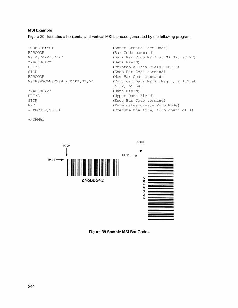
244
MSI Example
Figure 39 illustrates a horizontal and vertical MSI bar code generated by the following program:
~CREATE;MSI (Enter Create Form Mode) BARCODE (Bar Code command) MSIA;DARK;32;27 (Dark Bar Code MSIA at SR 32, SC 27) *24688642* (Data Field) PDF;X (Printable Data Field, OCR-B) STOP (Ends Bar Code command) BARCODE (New Bar Code command) MSIB;VSCAN;X2;H12;DARK;32;54 (Vertical Dark MSIB, Mag 2, H 1.2 at SR 32, SC 54) *24688642* (Data Field) PDF;A (Upper Data Field) STOP (Ends Bar Code command) END (Terminates Create Form Mode) ~EXECUTE;MSI;1 (Execute the form, form count of 1) ~NORMAL
Figure 39 Sample MSI Bar Codes
SR 32
SC 27
SR 32
SC 54
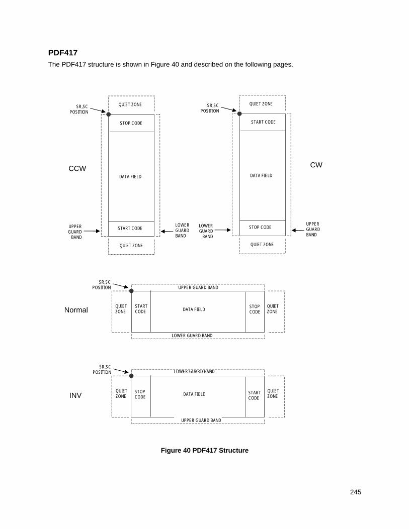
245
PDF417
The PDF417 structure is shown in Figure 40 and described on the following pages.
Figure 40 PDF417 Structure
LOWER GUARD BAND
LOWER GUARD BAND
UPPER GUARD BAND
SR,SC POSITION
STOP CODE
START CODE
QUIET ZONE
UPPER GUARD
BAND
DATA FIELD
QUIET ZONE
LOWER GUARD BAND
SR,SC POSITION
START CODE
STOP CODE
QUIET ZONE
LOWERGUARD
BAND
DATA FIELD
QUIET ZONE
UPPER GUARD BAND
SR,SC POSITION
STOP CODE
START CODE
QUIET ZONE DATA FIELD
QUIET ZONE
UPPER GUARD BAND
SR,SC POSITION
STOP CODE
START CODE
QUIET ZONE DATA FIELD
QUIET ZONE
Normal
INV
CCW CW
246
Quiet Zone
Both ends of the bar code structure require blank quiet zones. The quiet zones must be at least 0.25 inches wide and completely blank to ensure accurate reading of the start/stop codes and to prevent adjacent bar codes from overlapping. Be sure to provide sufficient space on the form for the quiet zones.
Start/Stop Codes
The start/stop codes identify the leading and trailing end of the bar code.
Data Field
PDF417 provides twelve modes to encode data. The first three are pre- established (the remaining nine are user modes, which can be defined by users or industry associations according to specific applications):
1. Extended Alphanumeric Compaction mode (EXC). Comprised of four sub-modes, this mode offers encodation of all printable ASCII characters. This is the default mode; the IGP uses shift or latch characters to enable other modes.
2. Binary/ASCII Plus mode. This offers encodation for all uppercase ASCII characters only, printable or not, and binary values.
3. Numeric Compaction mode. This offers encodation for numeric values to a density of almost 3 digits per code word.
4. The IGP will automatically switch between modes to provide the smallest encodation for the data.
Security Level
PDF417 can detect and correct errors. Each label has 2 code words of error detection. You can select the error correction capacity based on application needs. Specify a security level in the range of 0 - 8, at the time of printing. PDF417 can also recover from omissions and misdecodes of code words. Since it requires two code words to recover from a misdecode, one to detect the error and one to correct for it, a given security level can support half the number of misdecodes that it can of undecoded words.
Print Data Field is not offered due to the large amount of data that can be encoded.
PDF417 Command Format
BARCODE PDF417; [MICRO or MACRO;] [DIR;] [X[D]n;] [Y[D]n;] [(Hn)| (Wn);] [ASPECTh:w;] [(Rn) | (Cn);] [BIN;] [S[%]n;][BFn;L;] [DARK;] SR; SC [(D)data field(D)] STOP
BARCODE The Bar Code command; enter BARCODE.
PDF417 Designates bar code type PDF417; enter PDF417.
MICRO Selects Micro-PDF417. See Table 43 on page 250.
MACRO Selects Macro-PDF417. This enables encoding of a Macro Control Block in the data field using escape sequences. See Table 44 and Table 45 on page 252.
DIR Optional parameter that allows for rotating a barcode. Enter CW for clockwise rotation. Enter CCW or VSCAN for counter-clockwise rotation. Enter INV for inverted rotation. If DIR is not entered, the barcode is horizontally oriented.
247
X[D]n Optional parameter that designates the width of a narrow element in IGP dots, or printer dots if option [D] is used. The default is one IGP dot. For horizontal barcodes, this results in 2/72 inch. For rotated barcodes, this equal 3/120 inch. Values range from 1 to 1000 printer dots.
Y[D]n Optional parameter that designates the height of the narrow element in IGP dots, or printer dots if option [D] is used. The default is one IGP dot. For horizontal barcodes, this results in 2/72 inch. For rotated barcodes, this equals 3/120 inch. Values range from 1 to 100 printer dots.
Hn Optional parameter to adjust the maximum height of the bar code symbol. Height adjustments are made in 0.1-inch increments; enter H and a value from 4 through 99 to select height adjustments from 0.4 through 9.9 inches.
NOTE: The default aspect ratio will be used until the resulting barcode height exceeds the specified maximum.
Parameters Wn, Rn, Cn or ASPECT cannot be entered if this parameter is used.
NOTE: The Micro-PDF417 values range from 1 to 99.
Wn Optional parameter to adjust the maximum width of the symbol based on the narrow element width.
Enter Wn; where n is the overall width in tenths of an inch.
NOTE: The default aspect ratio will be used until the resulting barcode width exceeds the specified maximum.
Parameters Hn, Rn, Cn or ASPECT cannot be entered if this parameter is used.
ASPECTh:w Optional parameter for specifying the symbol height-to-width ratio where h is the height and w is the width, both expressed as integers. The default is 1:2. Parameters Hn, Wn, Rn, or Cn cannot be entered if this parameter is used. This parameter is not applicable to Micro PDF417.
Rn Optional parameter that specifies the number of rows the symbol will have. Enter R followed by the number of rows in the range of 3 through 90 in multiples of 3. Parameters Hn, Wn, Cn or ASPECT cannot be entered if this parameter is used. Micro-PDF417 only allows for a certain predefined combination of Rows and Columns. Therefore both R and C parameters can be specified to select a valid combination. See Table 43 on page 250 for allowed combinations.
NOTE: When these parameters are omitted, the printer automatically determines the smallest possible values.
Cn Optional parameter that specifies the number of columns the symbol will have. Enter C followed by the number of columns in the range of 1 through 90. Parameters Hn, Wn, Rn or ASPECT cannot be entered if this parameter is used. Micro-PDF417 only allows for a certain predefined combination of Rows and Columns. Therefore both R and C parameters can be specified to select a valid combination. See Table 43 on page 250 for allowed combinations.
248
NOTE: When these parameters are omitted, the printer automatically determines the smallest possible values.
BIN Force Micro-PDF417 to encode the data using byte-compaction mode. This provides the best encoding for 8-bit binary data.
S[%]n Optional parameter that specifies the security level. Enter S followed by the security level in the range of 0 through 8. The default is 2. If [%] is included, the security level is specified as a percentage. Valid values range from 0 to 100. Changing the security level can affect the amount of data in the barcode symbol, hence its size. This parameter is not applicable to Micro-PDF417
BFn;L Optional parameters for assigning a dynamic bar code data field location on a form and for designating the length of the data field. With these parameters, the actual data for the bar code data field is dynamically provided during the Execute Form Mode; the data is not specified during the Create Form Mode. To use this field, perform the following steps:
a. Enter BF.
b. Replace n with a number ranging from 0 through 512 to identify the bar code field. The SR and SC parameters specify the exact location of the bar code field identified by n.
c. Replace L with a number equaling the total number of characters in the field. (The actual data provided dynamically during the Execute Form Mode can be less than L.)
d. The information for the data field is entered dynamically during the Execute Form Mode. (Refer toExecute Form: Dynamic Bar Code Data on page 64.) Do not use the data field parameter to enter data when the BFn;L parameters are used. However, refer to the data field description for available characters.
DARK Optional parameter to produce darker looking bar codes. Enter DARK. Refer to Dark Printing on page 52 for more information.
SR Defines the starting row for the bar code. Enter a value ranging from row 1 to one less than the length of the form. Character row or dot row is specified based on the Scale command (page 113), or use the CP.DP format (page 23).
SC Defines the starting column of the bar code. Enter a value ranging from column 1 to one less than the width of the form. Character column or dot column is specified based on the Scale command (page 113), or use the CP.DP format (page 23).
(D) The printable character (delimiter) identifying the start and finish of the data field. Enter any printable character other than a slash (/), the SFCC, or a character used within the data. The same character must be used at both ends of the data field, but it will not print with the data.
249
data field Enter the data for the bar code. A null data field (no characters) is not permitted. The data field can contain any uppercase ASCII characters including carriage returns and line feeds. The length of the data field is variable; however, the maximum length is usually limited to 1024 bytes to minimize potential reading errors.
NOTE: New lines (i.e. carriage returns/line feeds) are allowed in the PDF417 data field and as PDF417 dynamic data field input.
STOP Ends the Bar Code command while the IGP continues in the Create Form Mode. Enter STOP. If STOP is not entered, an error message results.
PDF417 Example
Figure 41 illustrates a horizontal PDF417 bar code generated by the following program:
~CREATE;PDF417 (Enter Create Form Mode) BARCODE (Bar Code command) PDF417;XD3;YD9;S0;37;21 (PDF417; width; height, security level, SR 37, SC 21) *ACME MOTOR SUPPORTS PRINTING OF PDF417 TWO-DIMENSIONAL BAR CODE SYMBOLOGY 123456789012345678901234567890123456789* STOP (Ends Bar Code command) END (Terminate Create Form Mode) ~EXECUTE;PDF;1 (Execute the form) ~NORMAL
Figure 41 Sample PDF417 Bar Code
Micro-PDF417
Micro-PDF417 is a multi-low symbology which may be utilized by applications needing to encode a moderate amount of data in a two-dimensional symbol (up to 150 bytes, 250 to alphanumeric characters, or 366 numeric digits), and when minimizing symbol size is a primary concern. Micro-PDF417 is identical to PDF417 in terms of its encodation modes, error correction method, and symbol character sets. However, Micro-PDF417 replaces PDF417’s 17 module wide start/stop patterns and left/right row indicators with a unique set of 10-module wide Row Address Patterns, which were designed both to reduce overall symbol width and to facilitate linear scanning at row heights as low as 2X.
Unlike PDF417, Micro-PDF417 may only be printed in certain defined combinations of r (number of rows), c (number of columns), and k (number of error correction codewords), up to a maximum of four data columns by 44 rows.
SR 37
SC 21
250
See Table 43 on page 250 for the possible combinations of rows and columns, the maximum allowed data amount, and the error-correction level for each combination.
Table 43 Micro-PDF417 Combinations
Number of Data
Columns
Number of Data Rows
% of Codewords
for Error Correction
Max Uppercase
Alpha Characters
Max Digits Max 8-bit
Characters
1 11 64 6 8 3
14 50 12 17 7
17 41 18 26 10
20 40 22 32 13
24 33 30 44 18
28 29 38 55 22
2 8 50 14 20 8
11 41 24 35 14
14 32 36 52 21
17 29 46 67 27
20 28 56 82 33
23 28 64 93 38
26 29 72 105 43
3 6 67 10 14 6
8 58 18 26 10
10 53 26 38 15
12 50 34 49 20
15 47 46 67 27
20 43 66 96 39
26 41 90 132 54
32 40 114 167 68
38 39 138 202 82
44 38 162 237 97
251
Table 43 Micro-PDF417 Combinations
Number of Data
Columns
Number of Data Rows
% of Codewords
for Error Correction
Max Uppercase
Alpha Characters
Max Digits Max 8-bit
Characters
4 4 50 14 20 8
6 50 22 32 13
8 44 34 49 20
10 40 46 67 27
12 38 58 85 34
15 35 76 111 45
20 33 106 155 63
26 31 142 208 85
32 30 178 261 106
38 29 214 313 128
44 28 250 366 150
MACRO-PDF417
When the MACRO parameter is specified in the PDF417 Command, the data field is scanned for special escape sequences describing a “Macro Control Block” as defined in Appendix G of the Uniform Symbology Specification PDF417.
The escape sequences start with the SO (Shift Out) Character followed by three digits. The default SO character is 14 (0x0E hex), however the examples in this document will use a backslash (92, 0x5C hex) for clarity. The SO character is configurable on the control panel.
The Macro PDF417 Control Block is located at the end of the data field, following the normal PDF417 user data. The parameter uses the following format as shown in Table 44.
252
Table 44 Mandatory Macro-PDF-417 Fields
Field Description
\928 Macro Block Control Header Indicates the start of a Macro block.
0 - 99998 Segment Index Each barcode in a Macro PDF sequence must have a unique segment index that indicates the position of the barcode within the sequence.
\nnn...\nnn File ID A variable number of escape sequences containing values from \000 to \899. Each barcode in a Macro PDF sequence must have the same File ID assigned to it. Zero or more optional Fields may follow the File ID. See the next section for a description of the optional fields.
\922 Terminator The barcode that represents the last segment of a Macro PDF sequence should have the \922 escape sequence at the end of the Macro Block.
A Macro PDF sequence may contain zero or more optional fields. Except for the Segment-Count field, these fields describe global file attributes of the Macro PDF sequence, and therefore do not need to be present in all segments. The optional fields, if present, should be placed after the File ID, and have the layout described in Table 45.
NOTE: Other than the data type and length, the printer does not verify the contents of the optional fields.
Table 45 Optional Macro-PDF-417 Fields
Field Description Data Type
Field Length
\923\000 File Name Text Variable
\923\001 Segment Count 00001 - 99999.
NOTE: If this field is used, it must be present in all segments.
Numeric 5
\923\002 Time Stamp Time in seconds since January 1, 1970 00:00 GMT
Numeric 11
\923\003 Sender Text Variable
\923\004 Addressee Text Variable
\923\005 File Size Numeric Variable
\923\006 Checksum 16-bit CRC checksum over the entire source file. This checksum value must be a decimal value from 0 through 65,535.
Numeric 5
253
Planet
The Planet bar code was introduced by the U.S. Postal Service under the product name “Confirm.” Planet is a 12-digit bar code used to track mail electronically, both inbound and outbound. Under the “Confirm” process, the first two digits of the Planet data field defines the service expected. The next nine digits are customer information, and the last digit is the check digit.
The Planet bar code structure is illustrated in Figure 42 and Figure 43 and described on the following pages. The Planet code can be a part of the address block and appear anywhere within a vertical 4-inch area across the length of the mail piece.
Figure 42 Planet Structure
NOTE: Additional information regarding Planet bar code requirements can be obtained from the U.S. Postal Service's Publication 25: A Guide to Business Mail Preparation.
STOP CODE
SR,SC POSITION
START CODE
QUIET ZONE
QUIET ZONE
QUIET ZONE
QUIET ZONE
BAR CODE DATA FIELD
CHECK DIGIT
Return Address Area Postage Area
ADDRESS BLOCK BAR CODE READ AREA
4”
1/2” 1/2”
NOTE: Illustration is not to scale
254
Figure 43 Planet Structure (VSCAN or CCW)
Quiet Zone
The bar code structure requires a completely blank quiet zone which extends 4.75 inches from the right edge of the mail piece. In addition, a minimum quiet zone of 0.040-inch above and below the bar code data must also be provided. You must provide sufficient space for this zone.
Start/Stop Code
The start and stop codes are referred to as “framing bars” in Planet. The start and stop codes are each one tall bar, one identifying the leading and trailing end of the bar code. The start/stop code is automatically produced with each bar code. The start/stop code structure permits bar code scanning in a left-to- right direction only.
STOP CODE
SR,SC POSITION
START CODE
QUIET ZONE
QUIET ZONE
BAR CODE DATA FIELD
CHECK DIGIT
Ret
urn
Add
ress
Are
a P
osta
ge A
rea
AD
DR
ES
S B
LOC
K B
AR
CO
DE
RE
AD
AR
EA
4”
1/2”
1/2”
NOTE: Illustration is not to scale
255
Data Field
The bar code data produces a single field of 60 bars for an 11-digit data field. The bars are grouped in sets of five. Each set of five bars (comprised of three tall bars and two short bars) represents one of the five digits of the zip code, plus the four-digit zip code extension. If the Advanced Bar Code is used, an additional two-digit code is also added to make an 11-digit data field.
Each bar width is equal, and must be .020-inch ± .005-inch. Each bar height is either a tall (full) or short (half) bar, representing a 1 or 0, respectively. Each tall bar must be .125-inch ± .010-inch; each short bar must be .050-inch ± .010-inch. Horizontal spacing between bars (pitch) must be 22 bars ± 2 bars per inch over any 0.50-inch portion of the bar code. Horizontal spacing at 24 and 20 bars per inch is 0.0416-inch and .050-inch, respectively, with a clear vertical space ranging from 0.012-inch to 0.040-inch between bars.
Check Digit
The twelfth digit represents the automatic check digit character. The check digit is added automatically to verify accurate scanning.
Planet Command Format
BARCODE PLANET; [DIR;] [NLQ;] [BFn;L;] [DARK;] SR; SC (D)data field(D) STOP
BARCODE The Bar Code command; enter BARCODE.
PLANET Designates bar code type Planet; enter PLANET.
DIR Optional parameter that allows for rotating a barcode. Enter CW for clockwise rotation. Enter CCW or VSCAN for counter-clockwise rotation. Enter INV for inverted rotation. If DIR is not entered, the barcode is horizontally oriented.
NLQ Optional parameter optimized to print barcodes at NLQ print density (180x96). This may cause line matrix printers to reverse motion when the form prints. This parameter is ignored for other printer types.
BFn;L Optional parameters for assigning a dynamic bar code data field location on a form and for designating the length of the data field. With these parameters, the actual data for the bar code data field is dynamically provided during the Execute Form Mode; the data is not specified during the Create Form Mode. To use this field, perform the following steps:
a. Enter BF.
b. Replace n with a number ranging from 0 through 512 to identify the bar code field. The SR and SC parameters specify the exact location of the bar code field identified by n.
c. Replace L with a number equaling the total number of characters in the field. The data field must be numeric and contain exactly 11 digits. (The actual data provided dynamically during the Execute Form Mode can be less than L.)
d. The information for the data field is entered dynamically during the Execute Form Mode. (Refer to Execute Form: Dynamic Bar Code Data on page 64.) Do not use the data field parameter to enter data when the BFn;L parameters are used. However, refer to the data field description for available characters.
256
DARK Optional parameter to produce darker looking bar codes. Enter DARK. Refer to Dark Printing on page 52 for more information.
SR Defines the starting row for the bar code. Enter a value within the range of the 4-inch vertical address block. Character row or dot row is specified based on the Scale command (page 113), or use the CP.DP format (page 23).
SC Defines the starting column of the bar code. Enter a value between the 1/2-inch left and right margins of the mail piece. Character column or dot column is specified based on the Scale command (page 113), or use the CP.DP format (page 23).
(D) The printable character (delimiter) identifying the start and finish of the data field. Enter any printable character other than a slash (/) the SFCC, or a character used within the data. The same character must be used at both ends of the data field but it will not print with the data.
data field The bar code data. Enter 11 digits. The available characters for the data field are 0 through 9 (hex 30 through 39).
STOP Ends the Bar Code command while the IGP continues in the Create Form Mode. Enter STOP. If STOP is not entered, an error message will result.
Planet Example
Figure 44 illustrates a horizontal and vertical Planet bar code generated by the following program:
~CREATE;TEST (Enter Create Form Mode) BARCODE (Bar code command) PLANET;DARK;11;15 (Dark Planet bar code at SR 11, SC 15) *01675433738* (11-digit data field) STOP (Ends Bar Code command) BARCODE (Bar code command) PLANET;VSCAN;DARK;5;48 (Dark Vertical bar code Planet at
SR 5, SC 48) *01858022199* (11-digit data field) STOP (Ends Bar Code command) END (Terminates Create Form Mode) ~EXECUTE;TEST;1 (Execute the form, with form count of 1) ~NORMAL
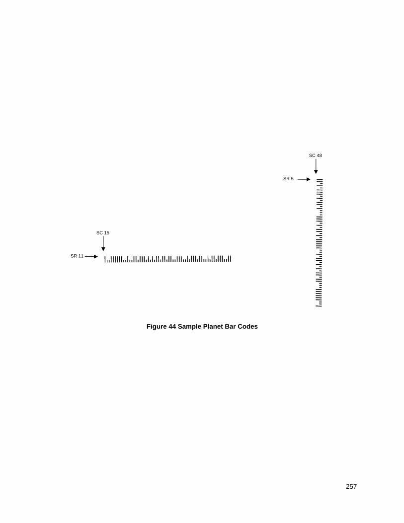
257
Figure 44 Sample Planet Bar Codes
SR 11
SC 15
SR 5
SC 48
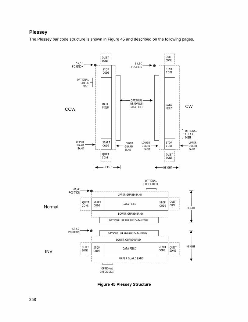
258
Plessey
The Plessey bar code structure is shown in Figure 45 and described on the following pages.
Figure 45 Plessey Structure
Normal
LOWER GUARD BAND
HEIGHT
QUIET ZONE
QUIET ZONE
STOP CODE
START CODE
OPTIONAL READABLE DATA FIELD
DATA FIELD
SR,SC POSITION
INV
SR,SC POSITION
QUIET ZONE
STOP CODE
START CODE
QUIET ZONE
OPTIONAL READABLE DATA FIELD
LOWER GUARD BAND
UPPER GUARD BAND
UPPER GUARD BAND
DATA FIELD HEIGHT
OPTIONAL CHECK DIGIT
OPTIONAL CHECK DIGIT
CCW
LOWER GUARD BAND
QUIET ZONE
SR,SC POSITION
STOP CODE
START CODE
QUIET ZONE
OPTIONAL READABLE DATA FIELD
UPPER GUARD
BAND
DATA FIELD
HEIGHT
OPTIONAL CHECK
DIGIT
SR,SC POSITION
QUIET ZONE
STOP CODE
START CODE
QUIET ZONE
DATA FIELD
LOWER GUARD
BAND
UPPER GUARD BAND
CW
OPTIONAL CHECK DIGIT
HEIGHT
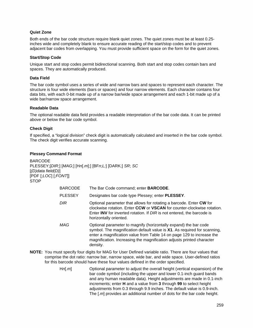
259
Quiet Zone
Both ends of the bar code structure require blank quiet zones. The quiet zones must be at least 0.25-inches wide and completely blank to ensure accurate reading of the start/stop codes and to prevent adjacent bar codes from overlapping. You must provide sufficient space on the form for the quiet zones.
Start/Stop Code
Unique start and stop codes permit bidirectional scanning. Both start and stop codes contain bars and spaces. They are automatically produced.
Data Field
The bar code symbol uses a series of wide and narrow bars and spaces to represent each character. The structure is four wide elements (bars or spaces) and four narrow elements. Each character contains four data bits, with each 0-bit made up of a narrow bar/wide space arrangement and each 1-bit made up of a wide bar/narrow space arrangement.
Readable Data
The optional readable data field provides a readable interpretation of the bar code data. It can be printed above or below the bar code symbol.
Check Digit
If specified, a “logical division” check digit is automatically calculated and inserted in the bar code symbol. The check digit verifies accurate scanning.
Plessey Command Format
BARCODE PLESSEY;[DIR;] [MAG;] [Hn[.m];] [BFn;L;] [DARK;] SR; SC [(D)data field(D)] [PDF [;LOC] [;FONT]] STOP
BARCODE The Bar Code command; enter BARCODE.
PLESSEY Designates bar code type Plessey; enter PLESSEY.
DIR Optional parameter that allows for rotating a barcode. Enter CW for clockwise rotation. Enter CCW or VSCAN for counter-clockwise rotation. Enter INV for inverted rotation. If DIR is not entered, the barcode is horizontally oriented.
MAG Optional parameter to magnify (horizontally expand) the bar code symbol. The magnification default value is X1. As required for scanning, enter a magnification value from Table 14 on page 129 to increase the magnification. Increasing the magnification adjusts printed character density.
NOTE: You must specify four digits for MAG for User Defined variable ratio. There are four values that comprise the dot ratio: narrow bar, narrow space, wide bar, and wide space. User-defined ratios for this barcode should have these four values defined in the order specified.
Hn[.m] Optional parameter to adjust the overall height (vertical expansion) of the bar code symbol (including the upper and lower 0.1-inch guard bands and any human readable data). Height adjustments are made in 0.1-inch increments; enter H and a value from 3 through 99 to select height adjustments from 0.3 through 9.9 inches. The default value is 0.9-inch. The [.m] provides an additional number of dots for the bar code height.
260
(Dots are in the current dot scale.)
NOTE: If 0.3 inches is the selected height, the PDF cannot be included.
BFn;L Optional parameters for assigning a dynamic bar code data field location on a form and for designating the length of the data field. With these parameters, the actual data for the bar code data field is dynamically provided during the Execute Form mode; the data is not specified during the Create Form mode. To use this field:
a. Enter BF.
b. Replace n with a number ranging from 0 through 512 to identify the bar code field. The SR and SC parameters specify the exact location of the bar code field identified by n.
c. Replace L with a number equaling the total number of characters in the field. (The actual data provided dynamically during the Execute Form mode can be less than L.)
d. The information for the data field is entered dynamically during the Execute Form mode. (Refer toExecute Form: Dynamic Bar Code Data on page 64.) Do not use the data field parameter to enter data when the BFn;L parameters are used. However, refer to the data field description for available characters.
DARK Optional parameter to produce darker looking bar codes. Enter DARK. Refer to Dark Printing on page 52 for more information.
SR Defines the starting row for the bar code. Enter a value ranging from row 1 to one less than the length of the form. Character row or dot row is specified based on the Scale command (page 113), or use the CP.DP format (page 23).
SC Defines the starting column of the bar code. Enter a value ranging from column 1 to one less than the width of the form. Character column or dot column is specified based on the Scale command (page 113), or use the CP.DP format (page 23).
(D) The printable character (delimiter) identifying the start and finish of the data field. Enter any printable character other than a slash (/), the SFCC, or a character used within the data. The same character must be used at both ends of the data field, but it will not print with the data.
data field Enter the characters for the bar code data. A null data field (no characters) is permitted. The length of the data field is variable; however, a maximum of 16 data characters is allowed. The characters available for the data field are 0 through 9 and A through F (hex 30 through 39).
PDF Optional parameter to enable printing of the human readable data field. Enter PDF to print the data field. If the parameter is not used, the human readable data will not print.
LOC Optional parameter to identify the location of the printable data field. The default value is B, locating the human readable data below the bar code. A locates the printable data field above the bar code. To compensate for printing the 0.1-inch high data, the height of the bar code body is reduced 0.1-inch.
FONT Optional parameter to select the font for the human readable data field. Enter O to select OCR-A font; enter X to select OCR-B font; enter N to select 10 cpi; enter P to select 12 cpi; enter Q to select 13 cpi; enter R to
261
select 15 cpi; enter T to select 17 cpi; enter V to select 20 cpi.
To select a scalable font with user-defined size, enter Nh:w or F;Nh:w. The parameters h (height) and w (width) can each range from 1 to 96, and are expansion factors of a 10 cpi character. Nh:w prints in Letter Gothic (font 93779) regardless of the current active font. By default F;Nh:w uses the Letter Gothic as the current font selection. You can change the default by using the FONT command.
NOTE: Nh:w and F;Nh:w will not print the PDF wider or taller than the barcode. If the height parameter h causes the PDF to print above the horizontal barcode start row or vertical barcode start column, a barcode font Error will occur. If the width parameter w causes the PDF to exceed the barcode width, the PDF width factor w will automatically reduce to fit within the barcode width without causing an error.
STOP Ends the Bar Code command while the IGP/PGL continues in the Create Form mode. Enter STOP. If STOP is not entered, an error message results.
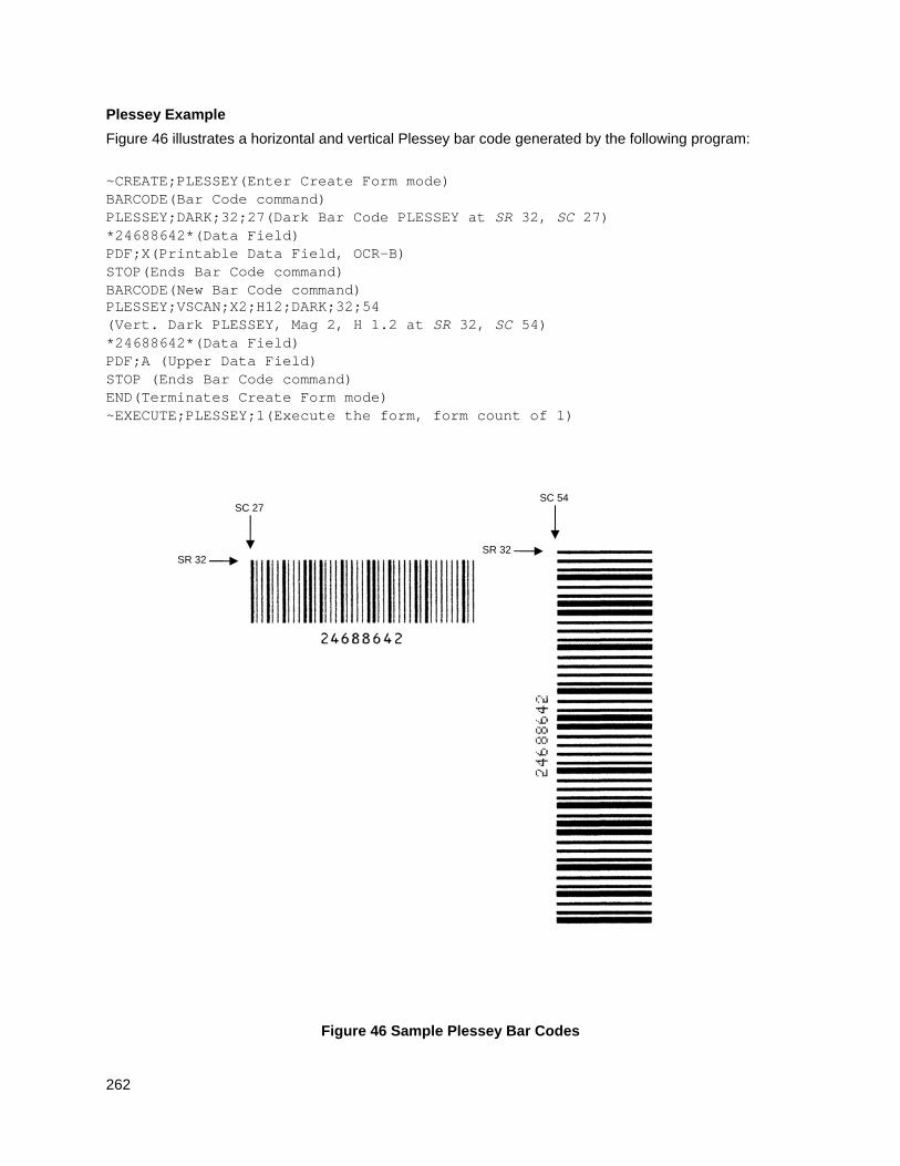
262
Plessey Example
Figure 46 illustrates a horizontal and vertical Plessey bar code generated by the following program:
~CREATE;PLESSEY(Enter Create Form mode) BARCODE(Bar Code command) PLESSEY;DARK;32;27(Dark Bar Code PLESSEY at SR 32, SC 27) *24688642*(Data Field) PDF;X(Printable Data Field, OCR-B) STOP(Ends Bar Code command) BARCODE(New Bar Code command) PLESSEY;VSCAN;X2;H12;DARK;32;54 (Vert. Dark PLESSEY, Mag 2, H 1.2 at SR 32, SC 54) *24688642*(Data Field) PDF;A (Upper Data Field) STOP (Ends Bar Code command) END(Terminates Create Form mode) ~EXECUTE;PLESSEY;1(Execute the form, form count of 1)
Figure 46 Sample Plessey Bar Codes
SR 32
SC 27
SR 32
SC 54
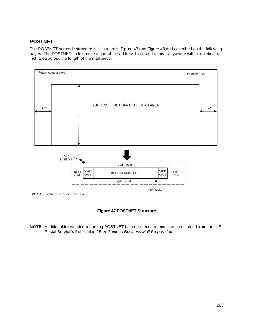
263
POSTNET
The POSTNET bar code structure is illustrated in Figure 47 and Figure 48 and described on the following pages. The POSTNET code can be a part of the address block and appear anywhere within a vertical 4-inch area across the length of the mail piece.
Figure 47 POSTNET Structure
NOTE: Additional information regarding POSTNET bar code requirements can be obtained from the U.S. Postal Service's Publication 25: A Guide to Business Mail Preparation.
STOP CODE
SR,SC POSITION
START CODE
QUIET ZONE
QUIET ZONE
QUIET ZONE
QUIET ZONE
BAR CODE DATA FIELD
CHECK DIGIT
Return Address Area Postage Area
ADDRESS BLOCK BAR CODE READ AREA
4”
1/2” 1/2”
NOTE: Illustration is not to scale
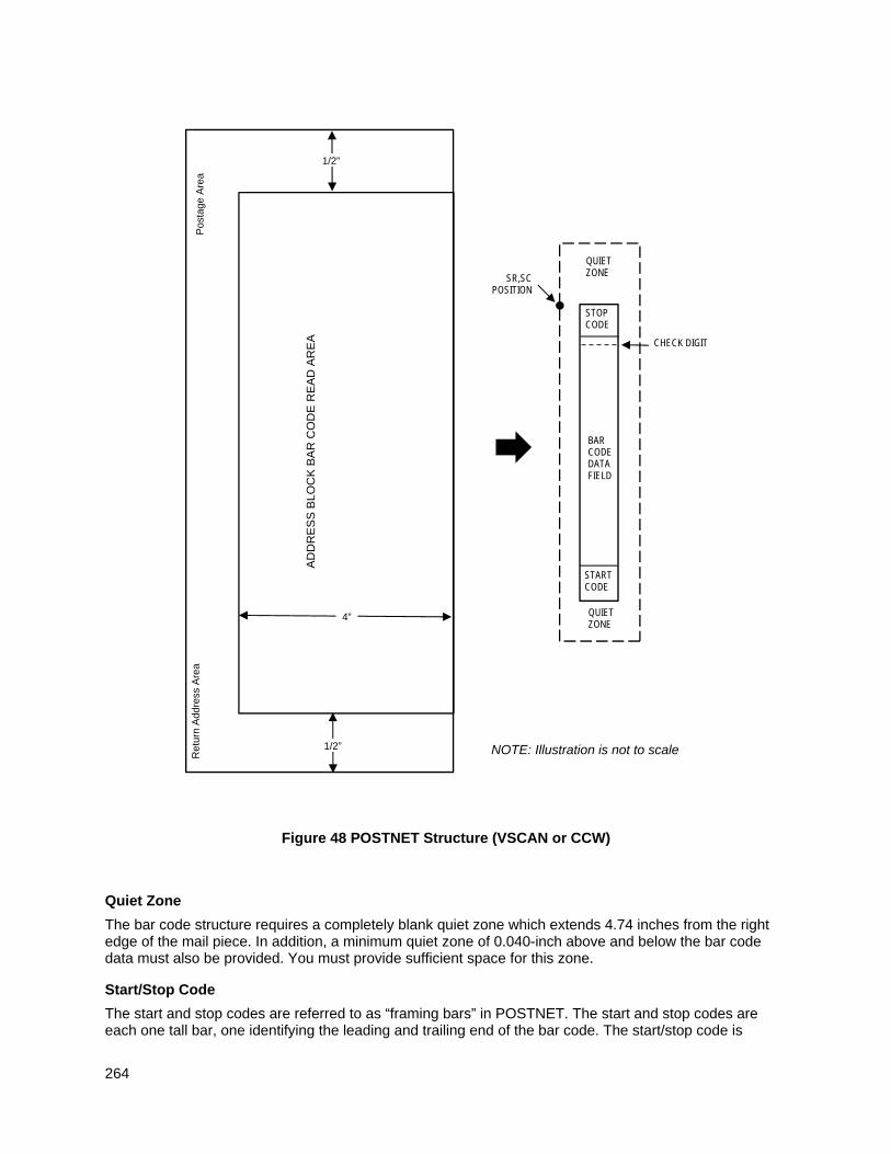
264
Figure 48 POSTNET Structure (VSCAN or CCW)
Quiet Zone
The bar code structure requires a completely blank quiet zone which extends 4.74 inches from the right edge of the mail piece. In addition, a minimum quiet zone of 0.040-inch above and below the bar code data must also be provided. You must provide sufficient space for this zone.
Start/Stop Code
The start and stop codes are referred to as “framing bars” in POSTNET. The start and stop codes are each one tall bar, one identifying the leading and trailing end of the bar code. The start/stop code is
STOP CODE
SR,SC POSITION
START CODE
QUIET ZONE
QUIET ZONE
BAR CODE DATA FIELD
CHECK DIGIT
Ret
urn
Add
ress
Are
a P
osta
ge A
rea
AD
DR
ES
S B
LOC
K B
AR
CO
DE
RE
AD
AR
EA
4”
1/2”
1/2”
NOTE: Illustration is not to scale
265
automatically produced with each bar code. The start/stop code structure permits bar code scanning in a left-to-right direction only.
Data Field
The bar code data produces a single field of 30 bars for a 5-digit field, 50 bars for a 9-digit data field, or 60 bars for an 11-digit data field. The bars are grouped in sets of five. Each set of five bars (comprised of two tall bars and three short bars) represents one of the five digits of the zip code, plus the four-digit zip code extension. If the Advanced Bar Code is used, an additional two-digit code is also added to make an 11-digit data field.
Each bar width is equal, and must be .020-inch ± .005-inch. Each bar height is either a tall (full) or short (half) bar, representing a 1 or 0, respectively. Each tall bar must be .125-inch ± .010-inch; each short bar must be .050-inch ± .010-inch. Horizontal spacing between bars (pitch) must be 22 bars ± 2 bars per inch over any 0.50-inch portion of the bar code. Horizontal spacing at 24 and 20 bars per inch is 0.0416-inch and .050-inch, respectively, with a clear vertical space ranging from 0.012-inch to 0.040-inch between bars.
Check Digit
The sixth, tenth or twelfth digit represents the automatic check digit character for the 5, 9 or 11-digit data field, respectively. The check digit is added automatically to verify accurate scanning.
POSTNET Command Format
BARCODE POSTNET; [DIR;] [NLQ;] [BFn;L;] [DARK;] SR; SC (D)data field(D) STOP
BARCODE The Bar Code command; enter BARCODE.
POSTNET Designates bar code type POSTNET; enter POSTNET.
DIR Optional parameter that allows for rotating a barcode. Enter CW for clockwise rotation. Enter CCW or VSCAN for counter-clockwise rotation. Enter INV for inverted rotation. If DIR is not entered, the barcode is horizontally oriented.
NLQ Optional parameter optimized to print barcodes at NLQ print density (180x96). This may cause line matrix printers to reverse motion when the form prints. This parameter is ignored for other printer types.
BFn;L Optional parameters for assigning a dynamic bar code data field location on a form and for designating the length of the data field. With these parameters, the actual data for the bar code data field is dynamically provided during the Execute Form Mode; the data is not specified during the Create Form Mode. To use this field, perform the following steps:
a. Enter BF.
b. Replace n with a number ranging from 0 through 512 to identify the bar code field. The SR and SC parameters specify the exact location of the bar code field identified by n.
c. Replace L with a number equaling the total number of characters in the field. The data field must be numeric and contain exactly 5, 9 or 11 digits. (The actual data provided dynamically during the Execute Form Mode can be less than L.)
d. The information for the data field is entered dynamically during the
266
Execute Form Mode. (Refer to Execute Form: Dynamic Bar Code Data on page 64.) Do not use the data field parameter to enter data when the BFn;L parameters are used. However, refer to the data field description for available characters.
DARK Optional parameter to produce darker looking bar codes. Enter DARK. Refer to Dark Printing on page 52 for more information.
SR Defines the starting row for the bar code. Enter a value within the range of the 4-inch vertical address block. Character row or dot row is specified based on the Scale command (page 113), or use the CP.DP format (page 23).
SC Defines the starting column of the bar code. Enter a value between the 1/2-inch left and right margins of the mail piece. Character column or dot column is specified based on the Scale command (page 113), or use the CP.DP format (page 23).
(D) The printable character (delimiter) identifying the start and finish of the data field. Enter any printable character other than a slash (/) the SFCC, or a character used within the data. The same character must be used at both ends of the data field but it will not print with the data.
data field The bar code data. Enter 5 digits (for zip code), 9 digits for a nine-digit zip code, or 11 digits (for the Delivery Point Bar Code format). The available characters for the data field are 0 through 9 (hex 30 through 39).
STOP Ends the Bar Code command while the IGP continues in the Create Form Mode. Enter STOP. If STOP is not entered, an error message will result.
POSTNET Example
Figure 49 illustrates a horizontal and vertical POSTNET bar code generated by the following program: ~CREATE;POSTNET (Enter Create Form Mode) BARCODE (Bar code command) POSTNET;DARK;10;40 (Dark POSTNET bar code at SR 10, SC 40) *601159912* (ZIP + 4 data field 60115-9912) STOP (Ends Bar Code command) END (Terminates Create Form Mode) ~CREATE;POSTNET (Enter Create Form Mode) BARCODE (Bar code command) POSTNET;VSCAN;DARK;10;20 (Dark Vertical bar code POSTNET at SR 10, SC 40) *601159912* (ZIP + 4 data field 60115-9912) STOP (Ends Bar Code command) END (Terminates Create Form Mode) ~EXECUTE;POSTNET;1 (Execute the form, with form count of 1) ~NORMAL
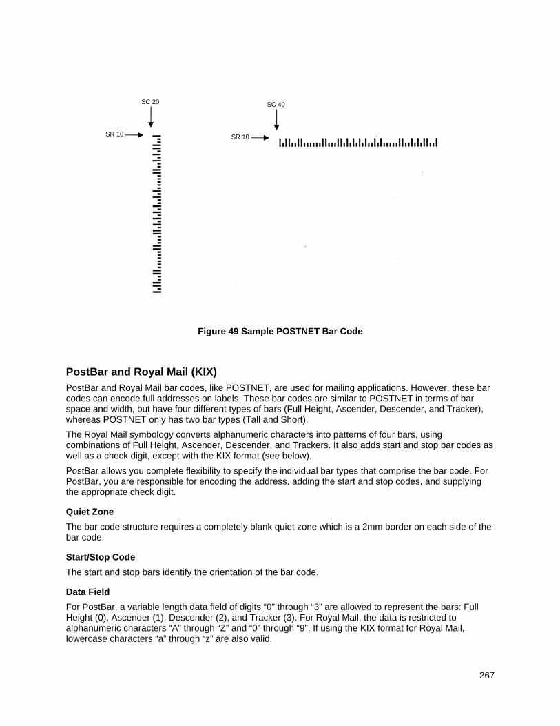
267
Figure 49 Sample POSTNET Bar Code
PostBar and Royal Mail (KIX)
PostBar and Royal Mail bar codes, like POSTNET, are used for mailing applications. However, these bar codes can encode full addresses on labels. These bar codes are similar to POSTNET in terms of bar space and width, but have four different types of bars (Full Height, Ascender, Descender, and Tracker), whereas POSTNET only has two bar types (Tall and Short).
The Royal Mail symbology converts alphanumeric characters into patterns of four bars, using combinations of Full Height, Ascender, Descender, and Trackers. It also adds start and stop bar codes as well as a check digit, except with the KIX format (see below).
PostBar allows you complete flexibility to specify the individual bar types that comprise the bar code. For PostBar, you are responsible for encoding the address, adding the start and stop codes, and supplying the appropriate check digit.
Quiet Zone
The bar code structure requires a completely blank quiet zone which is a 2mm border on each side of the bar code.
Start/Stop Code
The start and stop bars identify the orientation of the bar code.
Data Field
For PostBar, a variable length data field of digits “0” through “3” are allowed to represent the bars: Full Height (0), Ascender (1), Descender (2), and Tracker (3). For Royal Mail, the data is restricted to alphanumeric characters “A” through “Z” and “0” through “9”. If using the KIX format for Royal Mail, lowercase characters “a” through “z” are also valid.
SR 10
SC 20
SR 10
SC 40
268
Each bar width is equal, and must be .020-inch ± .005-inch. Horizontal spacing between bars (pitch) must be 22 bars ± 2 bars per inch over any 0.50- inch portion of the bar code. The height of the bars (Full Height) has a maximum of 0.230 inches and a minimum of 0.165 inches.
Check Digit
For PostBar, you are responsible for encoding and check digit. For Royal Mail, a modulo-6 check digit is inserted at the end of the data field.
KIX Format
The KIX format for Royal Mail does not include the start/stop code or the check digit.
PostBar and Royal Mail Command Format
BARCODE POSTBAR or ROYALBAR; [KIX;][NLQ;][MAG;][BFn;L;][DARK;] SR; SC (D)data field(D) STOP
BARCODE The Bar Code command; enter BARCODE.
POSTBAR or ROYALBAR Designates bar code type PostBar or Royal Mail; enter POSTBAR or
ROYALBAR.
KIX Optional parameter to specify the KIX format for Royal Mail bar codes only; enter KIX.
NLQ Optional parameter optimized to print barcodes at NLQ print density (180x96). This may cause line matrix printers to reverse motion when the form prints. This parameter is ignored for other printer types.
MAG Optional parameter to magnify (horizontally expand) the bar code symbol. The magnification default value is X1. As required for scanning, enter a magnification value to increase the magnification. Increasing the magnification adjusts printed character density. X1A uses shorter bars to reach the minimum height specification that allows it to fit on a 6 LPI line.
NOTE: The User Defined variable ratio is not allowed for this barcode.
BFn;L Optional parameters for assigning a dynamic bar code data field location on a form and for designating the length of the data field. With these parameters, the actual data for the bar code data field is provided dynamically during the Execute Form mode; the data is not specified during the Create Form mode. To use this field, perform the following steps:
a. Enter BF.
b. Replace n with a number ranging from 0 through 512 to identify the bar code field. The SR and SC parameters specify the exact location of the bar code field identified by n.
c. Replace L with a number equaling the total number of characters in the field. (The actual data provided dynamically during the Execute Form Mode can be less than L.)
d. The information for the data field is entered dynamically during the Execute Form mode. (Refer to Execute Form: Dynamic Bar Code Data on page 64.) Do not use the data field parameter to enter data when the BFn;L parameters are used. However, refer to the data
269
field description for available characters.
DARK Optional parameter to produce darker looking bar codes. Enter DARK. Refer to Dark Printing on page 52 for more information.
SR Defines the starting row for the bar code. Character row or dot row is specified based on the Scale command (page 113), or use the CP.DP format (page 23).
SC Defines the starting column of the bar code. Character column or dot column is specified based on the Scale command (page 113), or use the CP.DP format (page 23).
(D) The printable character (delimiter) identifying the start and finish of the data field. Enter any printable character other than a slash (/) the SFCC, or a character used within the data. The same character must be used at both ends of the data field but it will not print with the data.
data field The bar code data. For PostBar, enter values 0 through 3 to represent the four different types of bars. For Royal Mail, enter alphanumeric data (A through Z and 0 through 9). If using the KIX format for Royal Mail, lowercase characters a through z are also valid.
STOP Ends the Bar Code command while the IGP continues in the Create Form Mode. Enter STOP. If STOP is not entered, an error message will result.
PostBar and Royal Mail Examples
Figure 50 illustrates a horizontal Royal Mail bar code generated by the following program:
~CREATE;ROYALBAR (Enter Create Form Mode) BARCODE (Bar Code command) ROYALBAR;X1A;10;40 (Royal Mail bar code at SR 10, SC 40 with MAG 1A) *SN34RD1A* (Data Field) STOP (Ends Bar Code command) END (Terminates Create Form Mode) ~EXECUTE;ROYALBAR;1 (Execute the form, with form count of 1) ~NORMAL
Figure 50 Sample Royal Mail bar code (X1A Magnification)
SR 10
SC 40
270
Figure 51 illustrates a horizontal PostBar bar code generated by the following program:
~CREATE;POSTBAR (Enter Create Form Mode) BARCODE (Bar Code command) POSTBAR;10;40 (PostBar bar code at SR 10, SC 40
with default MAG 1) *10303023123102301031230123210212112210* (Data Field) STOP (Ends Bar Code command) END (Terminates Create Form Mode) ~EXECUTE;POSTBAR;1 (Execute the form, with form count of 1) ~NORMAL
Figure 51 Sample PostBar bar code (X1 Magnification)
QR Barcode
The QR code is a two dimensional general purpose matrix bar code. QR encodes Kanji characters and is a popular symbology in Japan. QR code symbols are square and can be identified by their finder pattern of nested alternating light and dark squares. The QR code is omni-directional and is designed for high speed reading. This bar code is capable of storing up to 7,089 numeric digits, 4,296 alphanumeric characters, 2,953 binary characters, or 1817 Kanji characters in Automatic mode. The data limit may be less if Manual mode is used. If the data to encode is too large to fit in one bar code, the data can be split up and encoded in up to 16 QR bar codes.
Command Format
BARCODE
QRCODE; [DIR;] [X[D]n;] [Y[D]n;] [Tn;] [En;] [Mn;] [In;] [Cn;[Pn; Nn; Rn;]] [BFn;L;] [DARK;] SR; SC
[(D)Data Field(D)]
STOP
Parameter Description
QRCODE Designates bar code type QR Code
DIR Optional parameter that allows for rotating a bar code. Enter CW for clockwise rotation. Enter CCW or VSCAN for counter clockwise rotation. Enter INV for inverted rotation.
If DIR is not entered, the bar code is horizontally oriented.
X[D]n Optional parameter that designates the x dimension width of a single square data module in IGP dots, or printer dots if option [D] is used. Values range from 1 to 1000 printer dots. If the Y[D]n is not used, then the y dimension is calculated by converting the printer dots in the x direction to printer dots in the y direction.
SR 10
SC 40
271
Y[D]n Optional parameter that designates the y dimension height of a single square data module in IGP dots, or printer dots if option [D] is used. Values range from 1 to 1000 printer dots. If the X[D]n is not used, then the x dimension is calculated by converting the printer dots in the y direction to printer dots in the x direction.
Tn Optional parameter that designates the QR code model. There are three models of QR code: Model 1 is the original model developed. Model 2 is an enhanced form of the symbology. Model 3 or Micro QR is a compact version of the symbology. Set T to the following variables depending on the selected model:
1 = Model 1 2 = Model 2 (default) 3 = Micro QR
En Optional parameter that designates the error correction capabilities of the bar code. There are four levels of error correction available.
0 = High density (Level L) which provides 7% error correction capability.
1 = Standard (Level M) which provides 15% error correction capability.
2 = High reliability (Level Q) which provides 25% error correction capability.
3 = Super high reliability (Level H) which provides 30% error correction capability.
The default error correction capability is standard (Level M) which provides 15% error correction capability.
Mn Optional parameter that designates the masking pattern to apply to the bar code data. Applying a masking pattern to the data can improve the readability of the bar code because it can help create a more evenly balanced number of light and dark cells. Valid settings for the masking patterns are as follows:
0 = No Mask (default) 1 = Mask Pattern 1 2 = Mask Pattern 2 3 = Mask Pattern 3 4 = Mask Pattern 4 5 = Mask Pattern 5 6 = Mask Pattern 6 7 = Mask Pattern 7 8 = Mask Pattern 8
In Optional parameter that designates the data entry method. There are two data entry methods: Automatic and Manual. The following values specifies the data entry method:
0 = Automatic (default)
1 = Manual
In automatic data entry mode, the data type is automatically determined along with the appropriate block division. The maximum block division is 200 characters. In manual data entry mode, the user must specify the
272
data type and each data block must contain 200 characters or less. Multiple data blocks must be separated by a comma character (“,”). To use manual data entry mode, perform the following steps:
1. Enter I1
2. In the bar code data section, enter the bar code data with one of the following type preface:
A = Alphanumeric
N = Numeric
Bxxxx = Binary. The total number (a decimal of 4 columns) of binary characters must be specified.
K = Kanji character
Example
AAC-42, N0123456, B0006qrcode
The above data is parsed as follows:
3 data blocks
First data block is alphanumeric: AC-42
Second data block is numeric: 0123456
Third data block is binary: qrcode (6 bytes)
Cn Optional parameter that designates the use of concatenation. If the data to be encoded is too large to fit in one bar code, the data can be split up and encoded in multiple bar codes. Up to 16 QR bar codes can be used to store a single data. When data is split among multiple QR codes, the total number of bar codes or partitions must be specified, along with the sequence number of each partition. A parity data is provided to ensure that the data has been properly concatenated. The valid values for concatenation mode are as follows:
0 = Normal, no concatenation (default)
1 = Concatenation
Nn Required parameter for concatenation mode that specifies the partition sequence number for this bar code. The valid value for this parameter is 1 to 16.
Pn Required parameter for concatenation mode that specifies the total number of bar code partitions. The valid value for this parameter is 1 to 16.
Rn Required parameter for concatenation mode that specifies the parity data for the original bar code data. The value is a single byte hex number ranging from 0x00 to 0xFF. Enter the hex number using 2 ASCII characters. Enter the hex number using 2 ASCII characters.
Example: The parameters C1;N1;P5;R0f specify that concatenation mode is enabled. This bar code is the first one in the sequence of 5 bar codes and the original data has a parity of 0x0F.
BFn;L Optional parameters for assigning a dynamic bar code data field location on a form and for designating the length of the data field. With these parameters, the actual data for the bar code data field is
273
dynamically provided during the Execute Form Mode; the data is not specified during the Create Form Mode. To use this field, perform the following steps:
a. Enter BF.
b. Replace n with a number ranging from 0 through 512 to identify the bar code field. The SR and SC parameters specify the exact location of the bar code field identified by n.
c. Replace L with a number equaling the total number of characters in the field. (The actual data provided dynamically during the Execute Form Mode can be less than L.)
d. The information for the data field is entered dynamically during the Execute Form Mode. Do not use the data field parameter to enter data when the BFn;L parameters are used. However, refer to the data field description for available characters.
DARK Optional parameter to produce darker looking bar codes. Enter DARK. Refer to Dark Printing for more information.
SR Defines the starting row for the bar code. Enter a value ranging from row 1 to one less than the length of the form. Character row or dot row is specified based on the Scale command or the CP.DP format.
SC Defines the start column of the bar code. Enter a value ranging from column 1 to one less than the width of the form. Character column or dot column is specified based on the Scale command, or use the CP.DP format.
(D) The printable character (delimiter) identifying the start and finish of the data field. Enter any printable character other than a slash (/), the SFCC, or a character used within the data. The same character must be used at both ends of the data field, it will not print with the data.
Quiet Zone
In the minimum quiet zone is four cells width on all four sides.
GuardBand
There are no guardbands for QR Code.
There is no PDF allowed for the QR Code.
Data Field
This bar code is capable of storing up to 7,089 numeric digits, 4,296 alphanumeric characters, or 2,953 binary characters in Automatic mode. The maximum data block division is 200 characters. Multiple data block must be separated by a comma character (“,”). In manual data entry mode, a data type identifier must precede each data block. If the data type is binary, a four digit length value must follow immediately after the data type identifier. The following are valid data type identifiers:
A = Alphanumeric
N = Numeric
B = Binary.
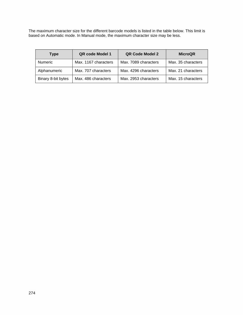
274
The maximum character size for the different barcode models is listed in the table below. This limit is based on Automatic mode. In Manual mode, the maximum character size may be less.
Type QR code Model 1 QR Code Model 2 MicroQR
Numeric Max. 1167 characters Max. 7089 characters Max. 35 characters
Alphanumeric Max. 707 characters Max. 4296 characters Max. 21 characters
Binary 8-bit bytes Max. 486 characters Max. 2953 characters Max. 15 characters
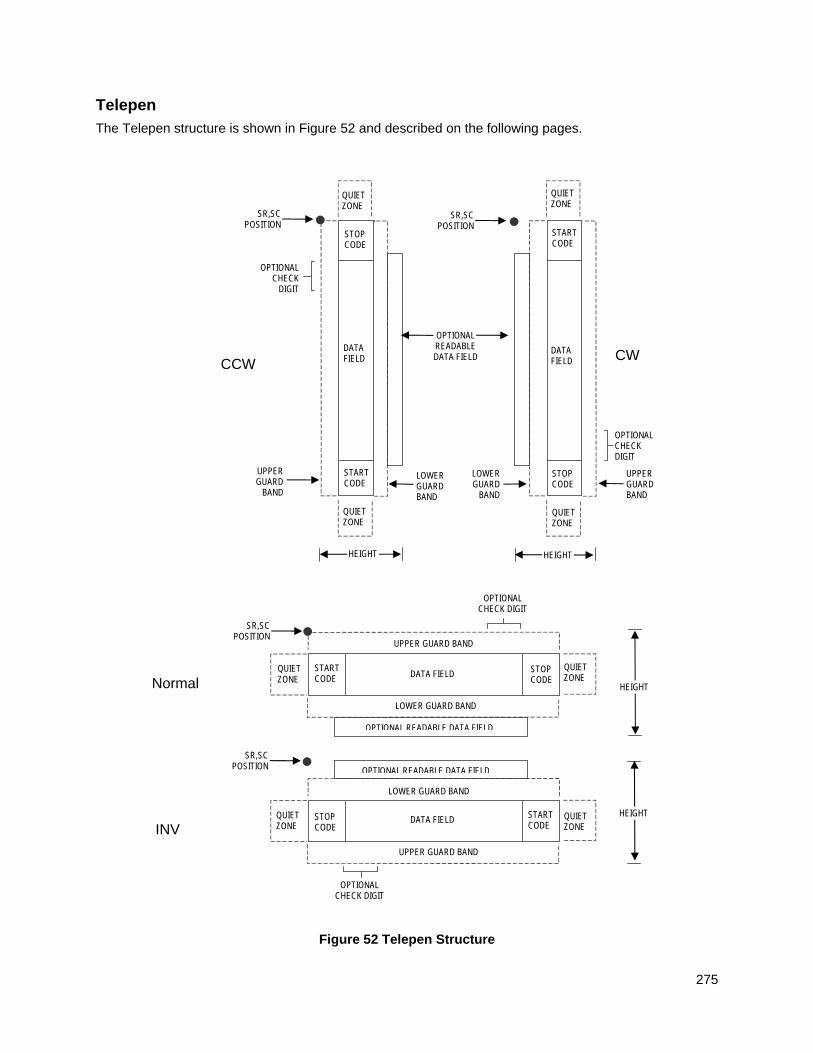
275
Telepen
The Telepen structure is shown in Figure 52 and described on the following pages.
Figure 52 Telepen Structure
Normal
LOWER GUARD BAND
HEIGHT
QUIET ZONE
QUIET ZONE
STOP CODE
START CODE
OPTIONAL READABLE DATA FIELD
DATA FIELD
SR,SC POSITION
INV
SR,SC POSITION
QUIET ZONE
STOP CODE
START CODE
QUIET ZONE
OPTIONAL READABLE DATA FIELD
LOWER GUARD BAND
UPPER GUARD BAND
UPPER GUARD BAND
DATA FIELD HEIGHT
OPTIONAL CHECK DIGIT
OPTIONAL CHECK DIGIT
CCW
LOWER GUARD BAND
QUIET ZONE
SR,SC POSITION
STOP CODE
START CODE
QUIET ZONE
OPTIONAL READABLE DATA FIELD
UPPER GUARD
BAND
DATA FIELD
HEIGHT
OPTIONAL CHECK
DIGIT
SR,SC POSITION
QUIET ZONE
STOP CODE
START CODE
QUIET ZONE
DATA FIELD
LOWER GUARD
BAND
UPPER GUARD BAND
CW
OPTIONAL CHECK DIGIT
HEIGHT
276
Quiet Zone
Both ends of the bar code structure require blank quiet zones. The quiet zones must be at least 0.25 inches wide and completely blank to ensure accurate reading of the start/stop codes and to prevent adjacent bar codes from overlapping. Be sure to provide sufficient space on the form for the quiet zones.
Start/Stop Codes
The start/stop code is a unique character identifying the leading and trailing end of the bar code. The start/stop code is automatically produced with each bar code. The start/stop code structure permits bidirectional bar code scanning.
Data Field
The bar code symbol uses a series of wide and narrow bars and spaces to represent standard alphanumeric characters. Each character is represented by a different series of bars and spaces, both wide and narrow, but is always 16 units in width (for a wide to narrow ratio of 3). Each character starts with a bar and ends with a space.
Readable Data
The optional readable data field provides a readable interpretation of the bar code data. It can be printed above or below the bar code symbol.
Check Digit
A mandatory modulo-127 check digit is inserted into the bar code to verify accurate scanning.
Telepen Command Format
BARCODE TELEPEN; [DIR;] [MAG;] [Hn[.m];] [BFn;L;] [DARK;] SR; SC (D) [data field] (D) [PDF [;LOC] [;FONT]] STOP
BARCODE The Bar Code command; enter BARCODE.
TELEPEN Designates bar code type Telepen; enter TELEPEN.
DIR Optional parameter that allows for rotating a barcode. Enter CW for clockwise rotation. Enter CCW or VSCAN for counter-clockwise rotation. Enter INV for inverted rotation. If DIR is not entered, the barcode is horizontally oriented.
MAG Optional parameter to magnify (horizontally expand) the bar code symbol. The magnification default value is X1. As required for scanning, enter a magnification value from Table 14 on page 129 to increase the magnification. Increasing the magnification adjusts printed character density.
You can also use XR or XRD as defined on page 125.
NOTE: You must specify four digits for MAG for User Defined variable ratio. There are four values that comprise the dot ratio: narrow bar, narrow space, wide bar, and wide space. User-defined ratios for this barcode should have these four values defined in the order specified.
Hn[.m] Optional parameter to adjust the overall height (vertical expansion) of the bar code symbol (including the upper and lower 0.1-inch guard bands and any human readable data). Height adjustments are made in 0.1-inch increments plus dots; enter H and a value from 3 through 99 to select height adjustments from 0.3 through 9.9 inches. The default value is 0.9
277
inch. [.m] is an additional number of dots for the bar code height. (Dots are in the current dot scale.)
NOTE: If 0.3 inches is the selected height, the PDF cannot be included.
BFn;L Optional parameters for assigning a dynamic bar code data field location on a form and for designating the length of the data field. With these parameters, the actual data for the bar code data field is dynamically provided during the Execute Form Mode; the data is not specified during the Create Form Mode. To use this field, perform the following steps:
a. Enter BF.
b. Replace n with a number ranging from 0 through 512 to identify the bar code field. The SR and SC parameters specify the exact location of the bar code field identified by n.
c. Replace L with a number equaling the total number of characters in the field. (The actual data provided dynamically during the Execute Form Mode can be less than L.)
d. The information for the data field is entered dynamically during the Execute Form Mode. (Refer to Execute Form: Dynamic Bar Code Data on page 64.) Do not use the data field parameter to enter data when the BFn;L parameters are used. However, refer to the data field description for available characters.
DARK Optional parameter to produce darker looking bar codes. Enter DARK. Refer to Dark Printing on page 52 for more information.
SR Defines the starting row for the bar code. Enter a value ranging from row 1 to one less than the length of the form. Character row or dot row is specified based on the Scale command (page 113), or use the CP.DP format (page 23).
SC Defines the starting column of the bar code. Enter a value ranging from column 1 to one less than the width of the form. Character column or dot column is specified based on the Scale command (page 113), or use the CP.DP format (page 23).
(D) The printable character (delimiter) identifying the start and finish of the data field. Enter any printable character other than a slash (/), the SFCC, or a character used within the data. The same character must be used at both ends of the data field, but it is not printed with the data.
data field Contains the bar code characters. A null data field (no characters) is permitted. The data field can contain any of the characters listed in Table 46 except the SFCC. The length of the data field is variable; however, the maximum length is usually limited to 32 characters to minimize potential reading errors.
PDF Optional parameter to enable printing of the human readable data field. Enter PDF to print the data field. If the parameter is not used, the human readable data will not print. This parameter is not allowed if a null data field is specified.
LOC Optional parameter to identify the location of the printable data field. The default value is B, locating the human readable data below the bar code. A locates the printable data field above bar code. To compensate for printing the 0.1-inch high data, the height of the bar code body is reduced 0.1 inch.
278
FONT Optional parameter to select the font for the human readable data field. Enter O to select OCR-A font; enter X to select OCR-B font; enter N to select 10 cpi; enter P to select 12 cpi; enter Q to select 13 cpi; enter R to select 15 cpi; enter T to select 17 cpi; enter V to select 20 cpi.
To select a scalable font with user-defined size, enter Nh:w or F;Nh:w. The parameters h (height) and w (width) can each range from 1 to 96, and are expansion factors of a 10 cpi character. Nh:w prints in Letter Gothic (font 93779) regardless of the current active font. By default F;Nh:w uses the Letter Gothic as the current font selection. You can change the default by using the FONT command.
NOTE: Nh:w and F;Nh:w will not print the PDF wider or taller than the barcode. If the height parameter h causes the PDF to print above the horizontal barcode start row or vertical barcode start column, a barcode font Error will occur. If the width parameter w causes the PDF to exceed the barcode width, the PDF width factor w will automatically reduce to fit within the barcode width without causing an error.
STOP Ends the Bar Code command while the IGP continues in the Create Form Mode. Enter STOP. If STOP is not entered, an error message results.
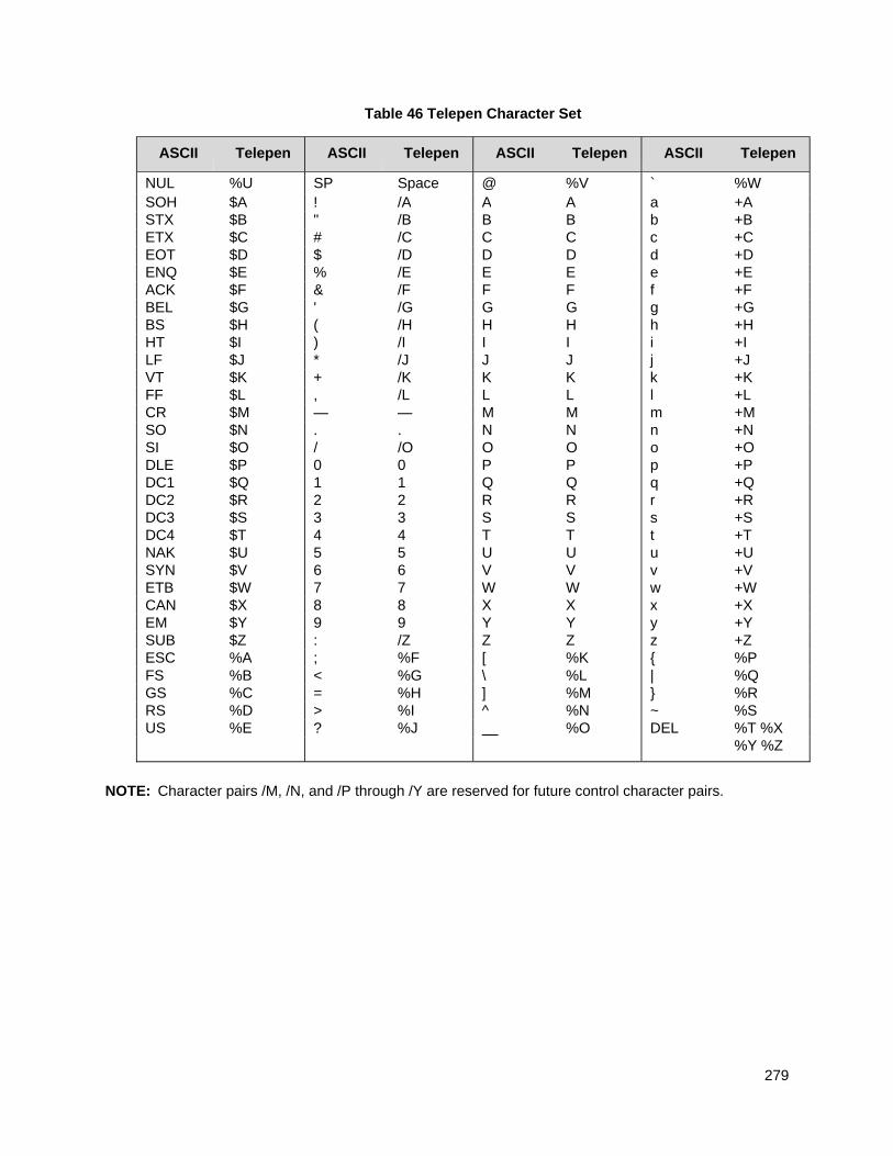
279
Table 46 Telepen Character Set
ASCII Telepen ASCII Telepen ASCII Telepen ASCII Telepen
NUL %U SP Space @ %V ` %W SOH $A ! /A A A a +A STX $B " /B B B b +B ETX $C # /C C C c +C EOT $D $ /D D D d +D ENQ $E % /E E E e +E ACK $F & /F F F f +F BEL $G ' /G G G g +G BS $H ( /H H H h +H HT $I ) /I I I i +I LF $J * /J J J j +J VT $K + /K K K k +K FF $L , /L L L l +L CR $M — — M M m +M SO $N . . N N n +N SI $O / /O O O o +O DLE $P 0 0 P P p +P DC1 $Q 1 1 Q Q q +Q DC2 $R 2 2 R R r +R DC3 $S 3 3 S S s +S DC4 $T 4 4 T T t +T NAK $U 5 5 U U u +U SYN $V 6 6 V V v +V ETB $W 7 7 W W w +W CAN $X 8 8 X X x +X EM $Y 9 9 Y Y y +Y SUB $Z : /Z Z Z z +Z ESC %A ; %F [ %K { %P FS %B < %G \ %L | %Q GS %C = %H ] %M } %R RS %D > %I ^ %N ~ %S US %E ? %J %O DEL %T %X
%Y %Z
NOTE: Character pairs /M, /N, and /P through /Y are reserved for future control character pairs.
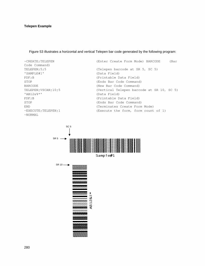
280
Telepen Example
Figure 53 illustrates a horizontal and vertical Telepen bar code generated by the following program:
~CREATE;TELEPEN (Enter Create Form Mode) BARCODE (Bar Code Command) TELEPEN;5;5 (Telepen barcode at SR 5, SC 5) "SAMPLE#1" (Data Field) PDF;B (Printable Data Field) STOP (Ends Bar Code Command) BARCODE (New Bar Code Command) TELEPEN;VSCAN;10;5 (Vertical Telepen barcode at SR 10, SC 5) "AB12&%*" (Data Field) PDF;B (Printable Data Field) STOP (Ends Bar Code Command) END (Terminates Create Form Mode) ~EXECUTE;TELEPEN;1 (Execute the form, form count of 1) ~NORMAL
SR 5
SC 5
SR 10
281
Figure 53 Sample Telepen Bar Codes
UPC-A
The UPC-A bar code structure is shown in Figure 54 and described on the following pages.
Normal HEIGHT QUIET ZONE
SR,SC POSITION
CENTER CODE
OPTIONAL READABLE DATA FIELD
CHECK DIGIT FIELD
QUIET ZONE
STOP CODE START CODE
LEFT DATA FIELD
RIGHT DATA FIELD
2- or 5- DIGIT
ADD-ON CODE NUMBER
SYSTEM CHARACTER
N
NUMBER SYSTEM CHARACTER FIELD
C
CHECK DIGIT CHARACTER
INV 2- or 5- DIGIT
ADD-ON CODE
HEIGHT QUIET ZONE
STOP CODE
RIGHT DATA FIELD
LEFT DATA FIELD
QUIET ZONE
SR,SC POSITION
C
CHECK DIGIT CHARACTER
CHECK DIGIT FIELD
CENTER CODE START CODE NUMBER SYSTEM CHARACTER
N
NUMBER SYSTEM CHARACTER FIELD
2- or 5- DIGIT ADD-ON CODE
QUIET ZONE C
RIGHT DATA FIELD
LEFT DATA FIELD
QUIET ZONE N
START CODE
CENTER CODE
STOP CODE
SR,SC POSITION
CHECK DIGIT FIELD
CHECK DIGIT CHARACTER
NUMBER SYSTEM CHARACTER FIELD
NUMBER SYSTEM CHARACTER
OPTIONAL READABLE
DATA FIELD
OPTIONAL READABLE DATA FIELD
HEIGHT HEIGHT
QUIET ZONE N
NUMBER SYSTEM CHARACTER
CCW
SR,SC POSITION
START CODE
STOP CODE
2- or 5- DIGIT ADD-ON CODE
QUIET ZONE C CHECK DIGIT
CHARACTER
CHECK DIGIT FIELD
RIGHT DATA FIELD
CENTER CODE
LEFT DATA FIELD
NUMBER SYSTEM CHARACTER FIELD
CW
282
Figure 54 UPC-A Structure
Quiet Zone
Quiet zones extend on both ends of the bar code to permit the scan to begin and end in a blank area. The IGP automatically produces an 11-module wide left quiet zone; you are responsible for providing sufficient space (minimum of seven modules) on the form for the right quiet zone. The number system character is also printed automatically in the left quiet zone.
Start/Center/Stop Codes
The start/center/stop codes are special character codes marking those portions of the bar code. These codes are automatically provided.
Number System Character
The number system character field allows you to provide a code to a class or type of item. The first character in the data field is used as the number system character.
Data Field
The bar code symbol uses a series of varying width bars and spaces to represent a limited character set (numbers 0-9 and Special Characters Start, Center, and Stop). The bars and spaces vary in width from one through four modules. Each character consists of two bars and two spaces that total seven modules. The symbol coding of the left data field is different from the right data field to permit read direction sensing.
The optional 2- or 5-digit add-on data field is placed at the end of the bar code and typically identifies a periodical issue number or price, respectively.
Readable Data
The human readable data field provides a readable interpretation of the bar code data. It can either be suppressed or printed above or below the bar code symbol.
Check Digit
The modulo-10 check digit is automatically calculated and inserted in the bar code symbol. The check digit verifies accurate scanning. The number system character is included in the check digit algorithm.
UPC-A Command Format
BARCODE UPC-A [+n];[DIR;] [SCB;] [MAG;] [Hn[.m];] [BFn;] [DARK;] SR; SC (D)data field(D) [PDF [;LOC] [;FONT]] STOP
BARCODE The Bar Code command; enter BARCODE.
UPC-A Designates bar code type UPC-A; enter UPC-A.
+n Optional parameter to provide a 2- or 5-digit add-on code at the end of the bar code data field. Enter a plus sign (+) and a value of 2 or 5. The first bar of the add-on code is separated by nine modules from the last bar of the UPC symbol and a left guard pattern.
DIR Optional parameter that allows for rotating a barcode. Enter CW for clockwise rotation. Enter CCW or VSCAN for counter-clockwise rotation. Enter INV for inverted rotation. If DIR is not entered, the barcode is horizontally oriented.
SCB This option shortens the length of the center guard bars, which are
283
normally full length. Enter SCB.
MAG Optional parameter to magnify (horizontally expand) the bar code symbol. The magnification default value is X1. Enter a magnification value from Table 14 on page 129 to increase the magnification. Increasing the magnification adjusts printed character density. You can also use XR or XRD as defined on page 125. You must specify 8 digits for MAG for variable ratio.
NOTE: There are eight values that comprise the dot ratio: narrow bar, narrow space, 2x narrow bar, 2x narrow space, 3x narrow bar, 3x narrow space, 4x narrow bar, and 4x narrow space. User-defined ratios for this barcode should have these eight values defined in the order specified.
Hn[.m] Optional parameter to adjust the overall height (vertical expansion) of the bar code symbol (including the upper and lower 0.1-inch guard bands and any human readable data). Height adjustments are made in 0.1-inch increments; enter H and a value from 2 through 99 to select height adjustments from 0.2 through 9.9 inches. If any value less than 3 is selected, then the PDF must be suppressed using the PDF Font parameter S. The default value is 1.3 inches. [.m] is an additional number of dots for the bar code height. (Dots are in the current dot scale.)
BFn Optional parameter for assigning a dynamic bar code data field location on a form. With this parameter, the actual data for the bar code data field is dynamically provided during the Execute Form Mode; the data is not specified during the Create Form Mode. To use this field, perform the following steps:
a. Enter BF.
b. Replace n with a number ranging from 0 through 512 to identify the bar code field. The SR and SC parameters specify the exact location of the bar code field identified by n.
c. The length of the data field need not be specified, since it is fixed at 11 digits, plus any add-on data.
d. The information for the data field is entered dynamically during the Execute Form Mode. (Refer toExecute Form: Dynamic Bar Code Data on page 64.) Do not use the data field parameter to enter data when the BFn parameters are used. However, refer to the data field description for available characters.
DARK Optional parameter to produce darker looking bar codes. Enter DARK. Refer to Dark Printing on page 52 for more information.
SR Defines the starting row for the bar code. Enter a value ranging from row 1 to one less than the length of the form. Character row or dot row is specified based on the Scale command (page 113), or use the CP.DP format (page 23).
SC Defines the starting column of the bar code. Enter a value ranging from column 1 to one less than the width of the form. Character column or dot column is specified based on the Scale command (page 113), or use the CP.DP format (page 23).
(D) The printable character (delimiter) identifying the start and finish of the data field. Enter any printable character other than a slash (/), the SFCC, or a character used within the data. (It will not print with the data.) Use the same character at both ends of the data field.

284
285
data field Enter the characters for the bar code data, restricted to exactly 11 digits. If the 2- or 5-digit add-on data option is used, include this data at the end of the data field. The first digit is interpreted as the number system character. The remaining 10 digits are the data field characters. The characters available for the data field are 0 through 9 (hex 30 through 39).
PDF Optional parameter which affects printing of the human readable data field. The data field will print automatically unless the PDF-suppress command is specified in the FONT parameter. UPC-A data fields can be printed above or below the bar code symbol. This parameter is not allowed if a null data field is specified. If the PDF command is not entered in the UPC-A command format, the data field automatically prints in OCR-B.
LOC Optional parameter to identify the location of the printable data field. The default value is B, locating the human readable data below the bar code. A locates the printable data field above bar code. To compensate for printing the 0.1-inch high data, the height of the bar code body is reduced 0.1-inch.
FONT Optional parameter to select the font for the human readable data field. Enter O to select OCR-A font; enter X to select OCR-B font; enter N to select 10 cpi; enter P to select 12 cpi; enter Q to select 13 cpi; enter R to select 15 cpi; enter T to select 17 cpi; enter V to select 20 cpi. Enter S to suppress the PDF entirely.
To select a scalable font with user-defined size, enter Nh:w or F;Nh:w. The parameters h (height) and w (width) can each range from 1 to 96, and are expansion factors of a 10 cpi character. Nh:w prints in Letter Gothic (font 93779) regardless of the current active font. By default F;Nh:w uses the Letter Gothic as the current font selection. You can change the default by using the FONT command.
NOTE: Nh:w and F;Nh:w will not print the PDF wider or taller than the barcode. If the height parameter h causes the PDF to print above the horizontal barcode start row or vertical barcode start column, a barcode font Error will occur. If the width parameter w causes the PDF to exceed the barcode width, the PDF width factor w will automatically reduce to fit within the barcode width without causing an error.
STOP Ends the Bar Code command while the IGP continues in the Create Form Mode. Enter STOP. If STOP is not entered, an error message results.
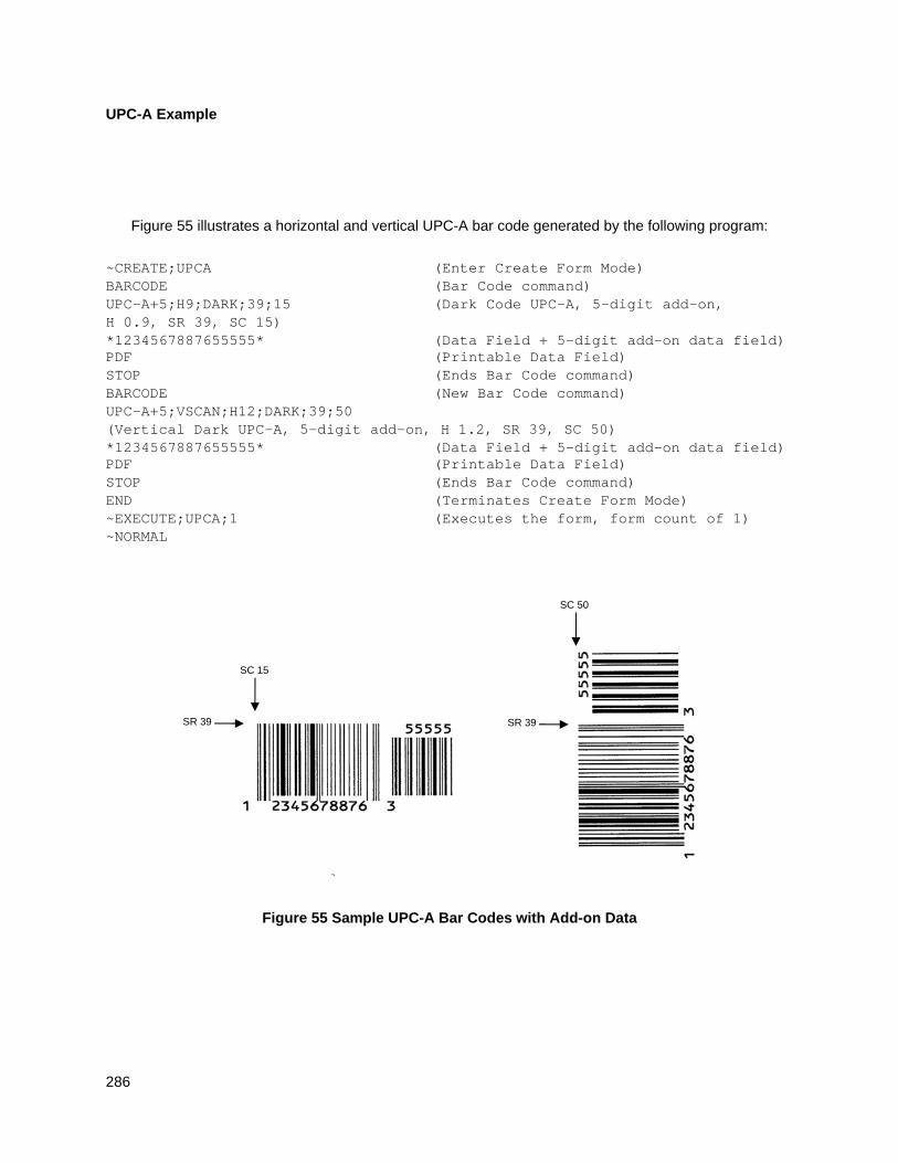
286
UPC-A Example
Figure 55 illustrates a horizontal and vertical UPC-A bar code generated by the following program:
~CREATE;UPCA (Enter Create Form Mode) BARCODE (Bar Code command) UPC-A+5;H9;DARK;39;15 (Dark Code UPC-A, 5-digit add-on, H 0.9, SR 39, SC 15) *1234567887655555* (Data Field + 5-digit add-on data field) PDF (Printable Data Field) STOP (Ends Bar Code command) BARCODE (New Bar Code command) UPC-A+5;VSCAN;H12;DARK;39;50 (Vertical Dark UPC-A, 5-digit add-on, H 1.2, SR 39, SC 50) *1234567887655555* (Data Field + 5-digit add-on data field) PDF (Printable Data Field) STOP (Ends Bar Code command) END (Terminates Create Form Mode) ~EXECUTE;UPCA;1 (Executes the form, form count of 1) ~NORMAL
Figure 55 Sample UPC-A Bar Codes with Add-on Data
SR 39
SC 15
SR 39
SC 50
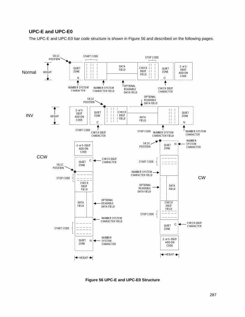
287
UPC-E and UPC-E0
The UPC-E and UPC-E0 bar code structure is shown in Figure 56 and described on the following pages.
Figure 56 UPC-E and UPC-E0 Structure
CHECK DIGIT FIELD
Normal HEIGHT QUIET ZONE
SR,SC POSITION
OPTIONAL READABLE DATA FIELD
QUIET ZONE
STOP CODE START CODE
DATA FIELD
2- or 5- DIGIT
ADD-ON CODE
NUMBER SYSTEM CHARACTER
N
NUMBER SYSTEM CHARACTER FIELD
C
CHECK DIGIT CHARACTER
INV
CCW
CW
HEIGHT
CHECK DIGIT FIELD
QUIET ZONE
SR,SC POSITION
OPTIONAL READABLE DATA FIELD
QUIET ZONE
STOP CODE START CODE
DATA FIELD
2- or 5- DIGIT
ADD-ON CODE
NUMBER SYSTEM CHARACTER
N
NUMBER SYSTEM CHARACTER FIELD
C
CHECK DIGIT CHARACTER
CHECK DIGIT FIELD
2- or 5- DIGIT ADD-ON CODE
QUIET ZONE
C
DATA FIELD
QUIET ZONE
N
START CODE
STOP CODE
SR,SC POSITION
CHECK DIGIT FIELD
CHECK DIGIT CHARACTER
NUMBER SYSTEM CHARACTER FIELD
NUMBER SYSTEM CHARACTER
OPTIONAL READABLE DATA FIELD
HEIGHT
QUIET ZONE
N NUMBER SYSTEM CHARACTER
SR,SC POSITION
START CODE
STOP CODE
NUMBER SYSTEM CHARACTER FIELD
DATA FIELD
OPTIONAL READABLE
DATA FIELD
QUIET ZONE
C CHECK DIGIT CHARACTER
2- or 5- DIGIT ADD-ON CODE
HEIGHT
288
Quiet Zone
Quiet zones extend on both ends of the bar code to permit the scan to begin and end in a blank area. The IGP automatically produces an 11-module wide left quiet zone. You must provide sufficient space (minimum of seven modules) on the form for the right quiet zone. The number system character is also printed automatically in the left quiet zone.
Start/Stop Codes
The start/stop codes are special character codes marking those portions of the bar code. These codes are automatically provided.
Number System Character
The number system character field for all UPC-E and UPC-E0 bar codes must be zero.
Data Field
The bar code symbol uses a series of varying width bars and spaces to represent a limited character set (numbers 0-9 and Special Characters Start and Stop). The bars and spaces vary in width from one through four modules. Each character consists of two bars and two spaces that total seven modules.
For UPC-E, eleven digits are expected, which are compressed down to the six encoded symbol characters. For UPC-E0, six compressed digits are expected.
The optional 2- or 5-digit add-on data field is placed at the end of the bar code and typically identifies a periodical issue number or price, respectively.
Readable Data
The human readable data field provides a readable interpretation of the bar code data. It can either be suppressed or printed above or below the bar code symbol.
Check Digit
The modulo-10 check digit is automatically calculated and inserted in the bar code symbol. The check digit verifies accurate scanning. The number system character is included in the check digit algorithm.
UPC-E and UPC-E0 Command Format
BARCODE type [+n]; [DIR;] [MAG;] [Hn[.m];] [BFn;] [DARK;] SR; SC (D)data field(D) [PDF [;LOC] [;FONT]] STOP
BARCODE The Bar Code command; enter BARCODE.
type Designates bar code type UPC-E or UPC-E0; enter UPC-E or UPC-E0.
+n Optional parameter to provide a 2- or 5-digit add-on code at the end of the bar code. Enter plus (+) and a value of 2 or 5. The first bar of the add-on code is separated by nine modules from the last bar of the UPC symbol and a left guard pattern.
DIR Optional parameter that allows for rotating a barcode. Enter CW for clockwise rotation. Enter CCW or VSCAN for counter-clockwise rotation. Enter INV for inverted rotation. If DIR is not entered, the barcode is horizontally oriented.
MAG Optional parameter to magnify (horizontally expand) the bar code symbol. The magnification default value is X1. Enter a magnification
289
value from Table 14 on page 129 to increase the magnification. Increasing the magnification adjusts printed character density. You can also use XR or XRD as defined on page 125. You must specify 8 digits for MAG for variable ratio.
NOTE: There are eight values that comprise the dot ratio: narrow bar, narrow space, 2x narrow bar, 2x narrow space, 3x narrow bar, 3x narrow space, 4x narrow bar, and 4x narrow space. User-defined ratios for this barcode should have these eight values defined in the order specified.
Hn[.m] Optional parameter to adjust the overall height (vertical expansion) of the bar code symbol (including the upper and lower 0.1-inch guard bands and any human readable data). Height adjustments are made in 0.1-inch increments; enter H and a value from 2 through 99 to select height adjustments from 0.2 through 9.9 inches. If any value less than 3 is selected, then the PDF must be suppressed using the PDF Font parameter S. The default value is 1.3 inches. [.m] is an additional number of dots for the bar code height. (Dots are in the current dot scale.)
BFn Optional parameter for assigning a dynamic bar code data field location on a form. With this parameter, the actual data for the bar code data field is dynamically provided during the Execute Form Mode; the data is not specified during the Create Form Mode. To use this field:
a. Enter BF.
b. Replace n with a number ranging from 0 through 512 to identify the bar code field. The SR and SC parameters specify the exact location of the bar code field identified by n.
c. The length of the data field need not be specified, since it is fixed at 6 or 11 digits, plus any add-on data.
d. The information for the data field is entered dynamically during the Execute Form Mode. (Refer toExecute Form: Dynamic Bar Code Data on page 64.) Do not use the data field parameter to enter data when the BFn parameters are used. However, refer to the data field description for available characters.
DARK Optional parameter to produce darker looking bar codes. Enter DARK. Refer to Dark Printing on page 52 for more information.
SR Defines the starting row for the bar code. Enter a value ranging from row 1 to one less than the length of the form. Character row or dot row is specified based on the Scale command (page 113), or use the CP.DP format (page 23).
SC Defines the starting column of the bar code. Enter a value ranging from column 1 to one less than the width of the form. Character column or dot column is specified based on the Scale command (page 113), or use the CP.DP format (page 23).
(D) The printable character (delimiter) identifying the start and finish of the data field. Enter any printable character other than a slash (/), the SFCC, or a character used within the data. The same character must be used at both ends of the data field but it will not print with the data.
290
data field The characters available for the data field are 0 through 9 (hex 30 through 39).
For UPC-E, eleven digits are expected: Enter the number system character first by entering 0; followed by the five-digit Manufacturer Number; ending with the five-digit Item Number. The Manufacturing Number and Item Number sequences must conform to one of the number pattern sequences shown in Table 47.
The IGP will compress the 11 characters of data down to the six encoded UPC-E symbol characters. Include the 2- or 5-digit add-on data within the quotes at the end of this data field.
For UPC-E0, six digits are expected. These six digits must be a valid compressed UPC-E number. Otherwise, Error 96 will be generated.
PDF Optional parameter which affects printing of the human readable data field. The data field will print automatically unless the PDF-suppress command is specified in the FONT parameter. UPC-E data fields can be printed above or below the bar code symbol. This parameter is not allowed if a null data field is specified. If the PDF is not entered in the UPC-E command format, the data field automatically prints in OCR-B.
LOC Optional parameter to identify the location of the printable data field. The default value is B, locating the human readable data below the bar code. A locates the printable data field above bar code. To compensate for printing the 0.1-inch high data, the height of the bar code body is reduced 0.1-inch.
FONT Optional parameter to select the font for the human readable data field. Enter O to select OCR-A font; enter X to select OCR-B font; enter N to select 10 cpi; enter P to select 12 cpi; enter Q to select 13 cpi; enter R to select 15 cpi; enter T to select 17 cpi; enter V to select 20 cpi. Enter S to suppress the PDF entirely.
To select a scalable font with user-defined size, enter Nh:w or F;Nh:w. The parameters h (height) and w (width) can each range from 1 to 96, and are expansion factors of a 10 cpi character. Nh:w prints in Letter Gothic (font 93779) regardless of the current active font. By default F;Nh:w uses the Letter Gothic as the current font selection. You can change the default by using the FONT command.
NOTE: Nh:w and F;Nh:w will not print the PDF wider or taller than the barcode. If the height parameter h causes the PDF to print above the horizontal barcode start row or vertical barcode start column, a barcode font Error will occur. If the width parameter w causes the PDF to exceed the barcode width, the PDF width factor w will automatically reduce to fit within the barcode width without causing an error.
STOP Ends the Bar Code command while the IGP continues in the Create Form Mode. Enter STOP. If STOP is not entered, an error message results.
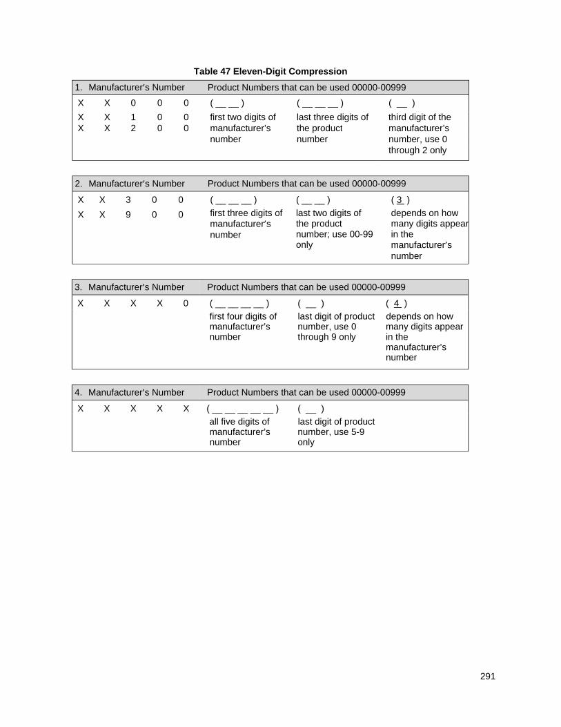
291
Table 47 Eleven-Digit Compression
1. Manufacturer’s Number Product Numbers that can be used 00000-00999
X X 0 0 0 ( __ __ ) ( __ __ __ ) ( __ )
X X 1 0 0 first two digits of last three digits of third digit of the X X 2 0 0 manufacturer’s the product manufacturer’s
number number number, use 0 through 2 only
2. Manufacturer’s Number Product Numbers that can be used 00000-00999
X X 3 0 0 ( __ __ __ )
first three digits of manufacturer’s number
( __ __ )
last two digits of the product number; use 00-99 only
( 3 )
depends on how many digits appear in the manufacturer’s number
X X 9 0 0
3. Manufacturer’s Number Product Numbers that can be used 00000-00999
X X X X 0 ( __ __ __ __ )
first four digits of manufacturer’s number
( __ )
last digit of product number, use 0 through 9 only
( 4 )
depends on how many digits appear in the manufacturer’s number
4. Manufacturer’s Number Product Numbers that can be used 00000-00999
X X X X X ( __ __ __ __ __ )
all five digits of manufacturer’s number
( __ )
last digit of product number, use 5-9 only
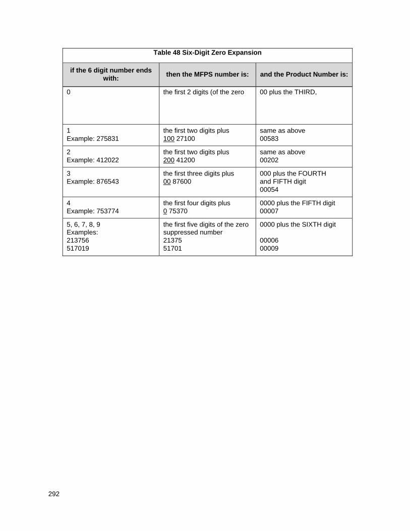
292
Table 48 Six-Digit Zero Expansion
if the 6 digit number ends with:
then the MFPS number is:
and the Product Number is:
0 the first 2 digits (of the zero 00 plus the THIRD,
1 Example: 275831
the first two digits plus 100 27100
same as above 00583
2 Example: 412022
the first two digits plus 200 41200
same as above 00202
3 Example: 876543
the first three digits plus 00 87600
000 plus the FOURTH and FIFTH digit 00054
4 Example: 753774
the first four digits plus 0 75370
0000 plus the FIFTH digit 00007
5, 6, 7, 8, 9 the first five digits of the zero 0000 plus the SIXTH digit Examples: suppressed number 213756 21375 00006 517019 51701 00009
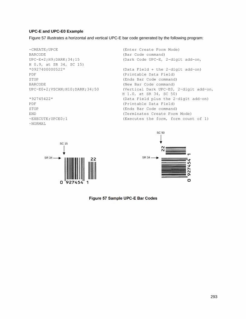
293
UPC-E and UPC-E0 Example
Figure 57 illustrates a horizontal and vertical UPC-E bar code generated by the following program:
~CREATE;UPCE (Enter Create Form Mode) BARCODE (Bar Code command) UPC-E+2;H9;DARK;34;15 (Dark Code UPC-E, 2-digit add-on, H 0.9, at SR 34, SC 15) *0927400000522* (Data Field + the 2-digit add-on) PDF (Printable Data Field) STOP (Ends Bar Code command) BARCODE (New Bar Code command) UPC-E0+2;VSCAN;H10;DARK;34;50 (Vertical Dark UPC-E0, 2-digit add-on,
H 1.0, at SR 34, SC 50) *92745422* (Data Field plus the 2-digit add-on) PDF (Printable Data Field) STOP (Ends Bar Code command) END (Terminates Create Form Mode) ~EXECUTE;UPCE0;1 (Executes the form, form count of 1) ~NORMAL
Figure 57 Sample UPC-E Bar Codes
SR 34
SC 15
SR 34
SC 50
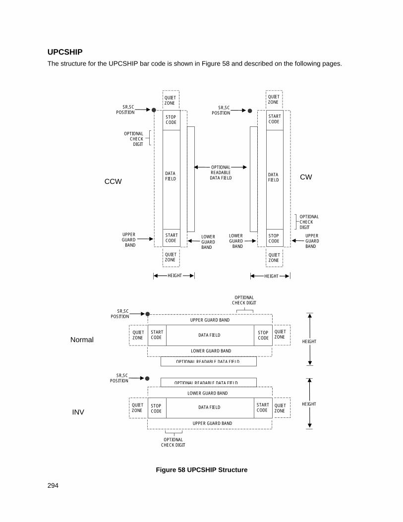
294
UPCSHIP
The structure for the UPCSHIP bar code is shown in Figure 58 and described on the following pages.
Figure 58 UPCSHIP Structure
Normal
LOWER GUARD BAND
HEIGHT
QUIET ZONE
QUIET ZONE
STOP CODE
START CODE
OPTIONAL READABLE DATA FIELD
DATA FIELD
SR,SC POSITION
INV
SR,SC POSITION
QUIET ZONE
STOP CODE
START CODE
QUIET ZONE
OPTIONAL READABLE DATA FIELD
LOWER GUARD BAND
UPPER GUARD BAND
UPPER GUARD BAND
DATA FIELD HEIGHT
OPTIONAL CHECK DIGIT
OPTIONAL CHECK DIGIT
CCW
LOWER GUARD BAND
QUIET ZONE
SR,SC POSITION
STOP CODE
START CODE
QUIET ZONE
OPTIONAL READABLE DATA FIELD
UPPER GUARD
BAND
DATA FIELD
HEIGHT
OPTIONAL CHECK
DIGIT
SR,SC POSITION
QUIET ZONE
STOP CODE
START CODE
QUIET ZONE
DATA FIELD
LOWER GUARD
BAND
UPPER GUARD BAND
CW
OPTIONAL CHECK DIGIT
HEIGHT
295
Quiet Zone
Both ends of the bar code structure have blank quiet zones. The quiet zones must be at least 0.25 inches wide and completely blank to ensure accurate reading of the start/stop codes and to prevent adjacent bar codes from overlapping. You must provide sufficient space on the form for the quiet zones.
Start/Stop Codes
Unique start and stop codes permit bidirectional scanning. Both start and stop codes contain bars and spaces. They are automatically produced.
Data Field
The bar code symbol uses a series of wide and narrow bars and spaces to represent numeric characters. The structure is 2 wide elements (bars or spaces) and 3 narrow elements. The UPCSHIP barcode must contain exactly 13 digits of numeric data.
Readable Data
The optional readable data field provides a readable interpretation of the bar code data. It can be printed above or below the bar code symbol.
Check Digit
The modulo-10 check digit is inserted automatically into the bar code to verify accurate scanning.
UPCSHIP Command Format
BARCODE UPCSHIP; [DIR;] [MAG;] [Hn[.m];] [BFn;] [DARK;] SR; SC [(D)data field(D)] [PDF [;LOC] [;FONT]] STOP
BARCODE The Bar Code command; enter BARCODE.
UPCSHIP Designates bar code type UPCSHIP; enter UPCSHIP.
DIR Optional parameter that allows for rotating a barcode. Enter CW for clockwise rotation. Enter CCW or VSCAN for counter-clockwise rotation. Enter INV for inverted rotation. If DIR is not entered, the barcode is horizontally oriented.
MAG Optional parameter to magnify (horizontally expand) the bar code symbol. The magnification default value is X1. As required for scanning, enter a magnification value from Table 14 on page 129 to increase the magnification. Increasing the magnification adjusts printed character density.
You can also use XR or XRD as defined on page 125.
NOTE: You must specify four digits for MAG for User Defined variable ratio. There are four values that comprise the dot ratio: narrow bar, narrow space, wide bar, and wide space. User-defined ratios for this barcode should have these four values defined in the order specified.
Hn[.m] Optional parameter to adjust the overall height (vertical expansion) of the bar code symbol (including the upper and lower 0.1-inch guard bands and any human readable data). Height adjustments are made in 0.1-inch increments; enter H and a value from 3 through 99 to select height adjustments from 0.3 through 9.9 inches. The default value is 0.9-inch.
[.m] is an additional number of dots for the bar code height. (Dots are in the current dot scale.)
296
NOTE: If 0.3 inches is the selected height, the PDF cannot be included.
BFn Optional parameter for assigning a dynamic bar code data field location on a form. With this parameter, the actual data for the bar code data field is dynamically provided during the Execute Form Mode; the data is not specified during the Create Form Mode. To use this field, perform the following steps:
a. Enter BF.
b. Replace n with a number ranging from 0 through 512 to identify the bar code field. The SR and SC parameters specify the exact location of the bar code field identified by n.
c. The length of the data field need not be specified, since it is fixed at 13 digits, plus any add-on data.
d. The information for the data field is entered dynamically during the Execute Form Mode. (Refer toExecute Form: Dynamic Bar Code Data on page 64.) Do not use the data field parameter to enter data when the BFn parameters are used. However, refer to the data field description for available characters.
DARK Optional parameter to produce darker looking bar codes. Enter DARK. Refer to Dark Printing on page 52 for more information.
SR Defines the starting row for the bar code. Enter a value ranging from row 1 to one less than the length of the form. Character row or dot row is specified based on the Scale command (page 113), or use the CP.DP format (page 23).
SC Defines the starting column of the bar code. Enter a value ranging from column 1 to one less than the width of the form. Character column or dot column is specified based on the Scale command (page 113), or use the CP.DP format (page 23).
(D) The printable character (delimiter) identifying the start and finish of the data field. Enter any printable character other than a slash (/), the SFCC, or a character used within the data. The same character must be used at both ends of the data field, but it will not print with the data.
data field The barcode data. The UPCSHIP barcode requires exactly 13 characters of data. The available characters are 0 through 9 (hex 30 through hex 39). The modulo-10 check digit is automatically included in the barcode.
PDF Optional parameter to enable printing of the human readable data field. Enter PDF to print the data field. If the parameter is not used, the human readable data is not printed.
LOC Optional parameter to identify the location of the printable data field. The default value is B, locating the human readable data below the bar code. A locates the printable data field above bar code. To compensate for printing the 0.1-inch high data, the height of the bar code body is reduced 0.1-inch.
FONT Optional parameter to select the font for the human readable data field. Enter O to select OCR-A font; enter X to select OCR-B font; enter N to select 10 cpi; enter P to select 12 cpi; enter Q to select 13 cpi; enter R to select 15 cpi; enter T to select 17 cpi; enter V to select 20 cpi.
To select a scalable font with user-defined size, enter Nh:w or F;Nh:w.

297
The parameters h (height) and w (width) can each range from 1 to 96, and are expansion factors of a 10 cpi character. Nh:w prints in Letter Gothic (font 93779) regardless of the current active font. By default F;Nh:w uses the Letter Gothic as the current font selection. You can change the default by using the FONT command.
NOTE: Nh:w and F;Nh:w will not print the PDF wider or taller than the barcode. If the height parameter h causes the PDF to print above the horizontal barcode start row or vertical barcode start column, a barcode font Error will occur. If the width parameter w causes the PDF to exceed the barcode width, the PDF width factor w will automatically reduce to fit within the barcode width without causing an error.
STOP Ends the Bar Code command while the IGP continues in the Create Form Mode. Enter STOP. If STOP is not entered, an error message results.
UPCSHIP Example
~CREATE;UPCSHIP (Enter Create Form Mode) BARCODE (Bar Code command) UPCSHIP;H12;9;8 (UPCSHIP Bar Code, height 1.2 inches, at SR 9, SC 8) *0014154401171* (Data Field) PDF (Print Data Field) STOP (Ends Bar Code command) BARCODE (New Bar Code command) UPCSHIP;VSCAN;3;45 (Vertical UPCSHIP Bar Code at SR 3, SC 45) *1141281029432* (Data Field) PDF;A (Print Data Field above the bar code) STOP (Ends Bar Code command) END (Terminates Create Form Mode) ~EXECUTE;UPCSHIP;1 (Execute the form, form count of 1) ~NORMAL
Figure 59 Sample UPCSHIP Bar Codes
SR 9
SC 8
SR 3
SC 45
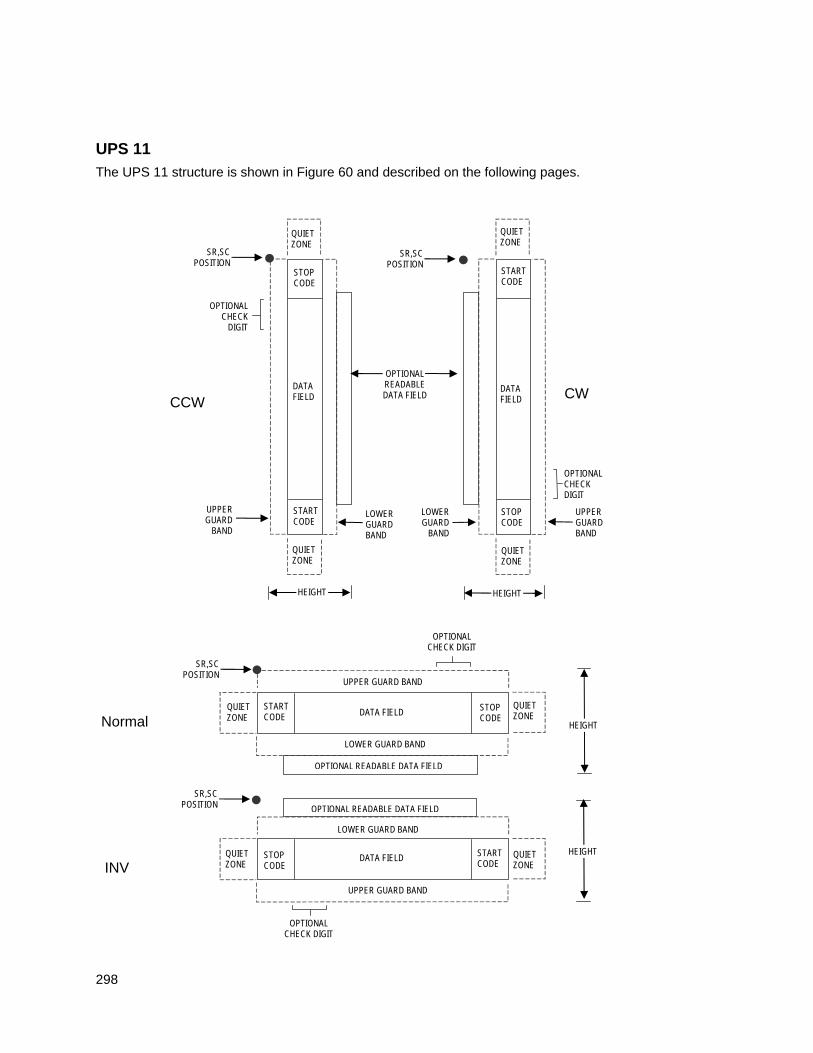
298
UPS 11
The UPS 11 structure is shown in Figure 60 and described on the following pages.
Normal
LOWER GUARD BAND
HEIGHT
QUIET ZONE
QUIET ZONE
STOP CODE
START CODE
OPTIONAL READABLE DATA FIELD
DATA FIELD
SR,SC POSITION
INV
SR,SC POSITION
QUIET ZONE
STOP CODE
START CODE
QUIET ZONE
OPTIONAL READABLE DATA FIELD
LOWER GUARD BAND
UPPER GUARD BAND
UPPER GUARD BAND
DATA FIELD HEIGHT
OPTIONAL CHECK DIGIT
OPTIONAL CHECK DIGIT
CCW
LOWER GUARD BAND
QUIET ZONE
SR,SC POSITION
STOP CODE
START CODE
QUIET ZONE
OPTIONAL READABLE DATA FIELD
UPPER GUARD
BAND
DATA FIELD
HEIGHT
OPTIONAL CHECK
DIGIT
SR,SC POSITION
QUIET ZONE
STOP CODE
START CODE
QUIET ZONE
DATA FIELD
LOWER GUARD
BAND
UPPER GUARD BAND
CW
OPTIONAL CHECK DIGIT
HEIGHT
299
Figure 60 UPS 11 Structure
Quiet Zone
Both ends of the bar code structure require blank quiet zones. The quiet zones must be at least 0.25 inches wide and completely blank to ensure accurate reading of the start/stop codes and to prevent adjacent bar codes from overlapping. Be sure to provide sufficient space on the form for the quiet zones.
Start/Stop Codes
The start/stop codes identify the leading and trailing end of the bar code. Each of the UPS 11 subsets uses a unique start code and a common stop code, both automatically provided by the IGP.
Data Field
UPS 11 is a special case of Code 128 (page 165). This bar code is restricted to 10 data characters. The first character must be 0 through 9 or A through Z. The remaining nine digits must be 0 through 9.
Readable Data
The optional readable data field provides a readable interpretation of the bar code data. It can be printed above or below the bar code symbol.
Check Digit
The modulo-103 check digit is automatically calculated and inserted in the bar code symbol. The check digit verifies accurate scanning. The start code is included in the check digit algorithm.
UPS 11 Command Format
BARCODE UPS11; [DIR;] [MAG;] [Hn[.m];] [BFn;] [DARK;] SR; SC (D)data field(D) [PDF [;LOC] [;FONT]] STOP
BARCODE The Bar Code command; enter BARCODE.
UPS11 Designates bar code type UPS 11; enter UPS11.
DIR Optional parameter that allows for rotating a barcode. Enter CW for clockwise rotation. Enter CCW or VSCAN for counter-clockwise rotation. Enter INV for inverted rotation. If DIR is not entered, the barcode is horizontally oriented.
MAG Optional parameter to magnify (horizontally expand) the bar code symbol. The magnification default value is X1. Increasing the magnification adjusts printed character density as shown in Table 14 on page 129. You can also use XR or XRD as defined on page 125. You must specify 8 digits for MAG for variable ratio.
NOTE: There are eight values that comprise the dot ratio: narrow bar, narrow space, 2x narrow bar, 2x narrow space, 3x narrow bar, 3x narrow space, 4x narrow bar, and 4x narrow space. User-defined ratios for this barcode should have these eight values defined in the order specified.
Hn[.m] Optional parameter to adjust the overall height (vertical expansion) of the bar code symbol (including the upper and lower 0.1-inch guard bands and any human readable data). Height adjustments are made in 0.1-inch increments; enter H and a value from 3 through 99 to select height adjustments from 0.3 through 9.9 inches. The default value is 0.9 inch.
[.m] is an additional number of dots for the bar code height. (Dots are in
300
the current dot scale.)
NOTE: If 0.3 inches is the selected height, the PDF cannot be included.
BFn; Optional parameters for assigning a dynamic bar code data field location on a form and for designating the length of the data field. With these parameters, the actual data for the bar code data field is dynamically provided during the Execute Form Mode; the data is not specified during the Create Form Mode. To use this field, perform the following steps.
a. Enter BF.
b. Replace n with a number ranging from 0 through 512 to identify the bar code field. The SR and SC parameters specify the exact location of the bar code field identified by n.
c. The length of the data field need not be specified, since it is fixed at10 digits.
d. The information for the data field is entered dynamically during the Execute Form Mode. (Refer toExecute Form: Dynamic Bar Code Data on page 64.) Do not use the data field parameter to enter data when the BFn;L parameters are used. However, refer to the data field description for available characters.
DARK Optional parameter to produce darker looking bar codes. Enter DARK. Refer to Dark Printing on page 52 for more information.
SR Defines the starting row for the bar code. Enter a value ranging from row 1 to one less than the length of the form. Character row or dot row is specified based on the Scale command (page 113), or use the CP.DP format (page 23).
SC Defines the starting column of the bar code. Enter a value ranging from column 1 to one less than the width of the form. Character column or dot column is specified based on the Scale command (page 113), or use the CP.DP format (page 23).
(D) The printable character (delimiter) identifying the start and finish of the data field. Enter any printable character other than a slash (/), the SFCC, or a character used within the data. The same character must be used at both ends of the data field, but it will not print with the data.
data field Enter the data for the bar code. This bar code is restricted to 10 data characters. The first character must be 0 through 9 or A through Z. The remaining nine digits must be 0 through 9.
PDF Optional parameter to enable printing of the human readable data field. Enter PDF to print the data field. If the parameter is not used, the human readable data will not print. This parameter is not allowed if a null data field was specified.
LOC Optional parameter to identify the location of the printable data field. The default value is B, locating the human readable data below the bar code. A locates the printable data field above bar code. To compensate for printing the 0.1-inch high data, the height of the bar code body is reduced 0.1 inch.
FONT Optional parameter to select the font for the human readable data field. Enter O to select OCR-A font; enter X to select OCR-B font; enter N to select 10 cpi; enter P to select 12 cpi; enter Q to select 13 cpi; enter R to select 15 cpi; enter T to select 17 cpi; enter V to select 20 cpi.
301
To select a scalable font with user-defined size, enter Nh:w or F;Nh:w. The parameters h (height) and w (width) can each range from 1 to 96, and are expansion factors of a 10 cpi character. Nh:w prints in Letter Gothic (font 93779) regardless of the current active font. By default F;Nh:w uses the Letter Gothic as the current font selection. You can change the default by using the FONT command.
NOTE: Nh:w and F;Nh:w will not print the PDF wider or taller than the barcode. If the height parameter h causes the PDF to print above the horizontal barcode start row or vertical barcode start column, a barcode font Error will occur. If the width parameter w causes the PDF to exceed the barcode width, the PDF width factor w will automatically reduce to fit within the barcode width without causing an error.
STOP Ends the Bar Code command while the IGP continues in the Create Form Mode. Enter STOP. If STOP is not entered, an error message results.
IMPACT
UPS 11 Example
Figure 61 illustrates a vertical UPS 11 bar code generated by the following program:
~CREATE;UPS11 BARCODE UPS11;VSCAN;H9;34;15 *01234567895* PDF STOP END ~EXECUTE;UPS11;1 ~NORMAL
Figure 61 Sample UPS Bar Code
302
Incremental Bar Code Fields With the incremental bar code fields feature, you can update bar code (and alphanumeric) data fields in a numeric or alphabetical manner automatically with just one set of data sent from the host computer. You can print up to 65,535 forms with incremental fields automatically updated.
NOTE: Throughout the discussion of incremental fields, the term “increment” or “incremental” means the field is automatically updated by a specified amount (or increment). You can actually increment the field by a positive amount (added) or a negative amount (subtracted) as specified within the command.
You can use bar code incremental fields with fixed (static) data input as part of the Create Form Mode, or with dynamic data supplied in the Execute Form Mode. New formats and parameters are required in the bar code commands for static and dynamic incremental fields. In addition, the Execute Form command requires a new format and parameters when you use incremental fields with dynamic data. You can increment or decrement incremental fields, repeat at specified intervals before updating, and reset to the starting value after a specified number of increments.
Incrementing Bar Code Data
Incrementing is controlled with the STEPMASK and STARTDATA command parameters as described in Table 49. The parameters are part of the bar code command or part of the Execute command when using the Incremental Bar Code Dynamic Data command.
The STEPMASK parameter performs three functions:
1. It defines the increment amount (step);
2. It defines the number of characters allowed in the data field (STARTDATA); and
3. It provides a “mask” to link or unlink subfields of data for individual incremental activity. The data provided in the STEPMASK field combined with the data in the STARTDATA field determine the result of these functions.
Table 49 Incremental Bar Code Data
STEPMASK STARTDATA Character Type and Function
0-9 A-Z Alpha characters are incremented by amount in STEPMASK field.
0-9 0-9 Numeric characters are incremented by amount in STEPMASK field.
0-9 Space Same character type as character in the next right adjacent, linked increment position. Character type is numeric if in the least significant position.
0-9 Not A-Z or 0-9
Error
Not 0-9 or L Any Non-incrementing alphanumeric character.
L Any Linked, non-incrementing alphanumeric character.
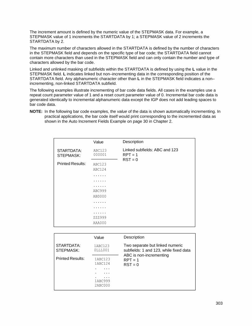
303
The increment amount is defined by the numeric value of the STEPMASK data. For example, a STEPMASK value of 1 increments the STARTDATA by 1; a STEPMASK value of 2 increments the STARTDATA by 2.
The maximum number of characters allowed in the STARTDATA is defined by the number of characters in the STEPMASK field and depends on the specific type of bar code; the STARTDATA field cannot contain more characters than used in the STEPMASK field and can only contain the number and type of characters allowed by the bar code.
Linked and unlinked masking of subfields within the STARTDATA is defined by using the L value in the STEPMASK field. L indicates linked but non–incrementing data in the corresponding position of the STARTDATA field. Any alphanumeric character other than L in the STEPMASK field indicates a non–incrementing, non-linked STARTDATA subfield.
The following examples illustrate incrementing of bar code data fields. All cases in the examples use a repeat count parameter value of 1 and a reset count parameter value of 0. Incremental bar code data is generated identically to incremental alphanumeric data except the IGP does not add leading spaces to bar code data.
NOTE: In the following bar code examples, the value of the data is shown automatically incrementing. In practical applications, the bar code itself would print corresponding to the incremented data as shown in the Auto Increment Fields Example on page 30 in Chapter 2.
STARTDATA: STEPMASK:
Printed Results:
Description
Linked subfields: ABC and 123RPT = 1 RST = 0
Value
STARTDATA: STEPMASK:
Printed Results:
Value
Description
Two separate but linked numeric subfields: 1 and 123, while fixed data ABC is non-incrementing RPT = 1 RST = 0
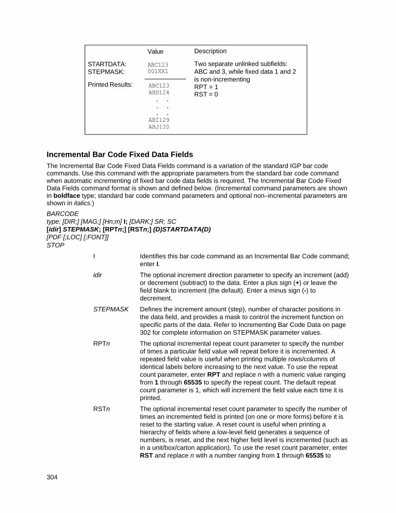
304
Incremental Bar Code Fixed Data Fields
The Incremental Bar Code Fixed Data Fields command is a variation of the standard IGP bar code commands. Use this command with the appropriate parameters from the standard bar code command when automatic incrementing of fixed bar code data fields is required. The Incremental Bar Code Fixed Data Fields command format is shown and defined below. (Incremental command parameters are shown in boldface type; standard bar code command parameters and optional non–incremental parameters are shown in italics.)
BARCODE type; [DIR;] [MAG;] [Hn;m] I; [DARK;] SR; SC [idir] STEPMASK; [RPTn;] [RSTn;] (D)STARTDATA(D) [PDF [;LOC] [;FONT]] STOP
I Identifies this bar code command as an Incremental Bar Code command; enter I.
idir The optional increment direction parameter to specify an increment (add) or decrement (subtract) to the data. Enter a plus sign (+) or leave the field blank to increment (the default). Enter a minus sign (-) to decrement.
STEPMASK Defines the increment amount (step), number of character positions in the data field, and provides a mask to control the increment function on specific parts of the data. Refer to Incrementing Bar Code Data on page 302 for complete information on STEPMASK parameter values.
RPTn The optional incremental repeat count parameter to specify the number of times a particular field value will repeat before it is incremented. A repeated field value is useful when printing multiple rows/columns of identical labels before increasing to the next value. To use the repeat count parameter, enter RPT and replace n with a numeric value ranging from 1 through 65535 to specify the repeat count. The default repeat count parameter is 1, which will increment the field value each time it is printed.
RSTn The optional incremental reset count parameter to specify the number of times an incremented field is printed (on one or more forms) before it is reset to the starting value. A reset count is useful when printing a hierarchy of fields where a low-level field generates a sequence of numbers, is reset, and the next higher field level is incremented (such as in a unit/box/carton application). To use the reset count parameter, enter RST and replace n with a number ranging from 1 through 65535 to
STARTDATA: STEPMASK:
Printed Results:
Value
Description
Two separate unlinked subfields: ABC and 3, while fixed data 1 and 2 is non-incrementing RPT = 1 RST = 0
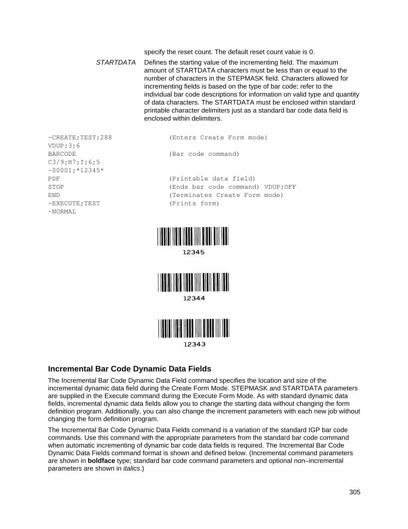
305
specify the reset count. The default reset count value is 0.
STARTDATA Defines the starting value of the incrementing field. The maximum amount of STARTDATA characters must be less than or equal to the number of characters in the STEPMASK field. Characters allowed for incrementing fields is based on the type of bar code; refer to the individual bar code descriptions for information on valid type and quantity of data characters. The STARTDATA must be enclosed within standard printable character delimiters just as a standard bar code data field is enclosed within delimiters.
~CREATE;TEST;288 (Enters Create Form mode) VDUP;3;6 BARCODE (Bar code command) C3/9;H7;I;6;5 -00001;*12345* PDF (Printable data field) STOP (Ends bar code command) VDUP;OFF END (Terminates Create Form mode) ~EXECUTE;TEST (Prints form) ~NORMAL
Incremental Bar Code Dynamic Data Fields
The Incremental Bar Code Dynamic Data Field command specifies the location and size of the incremental dynamic data field during the Create Form Mode. STEPMASK and STARTDATA parameters are supplied in the Execute command during the Execute Form Mode. As with standard dynamic data fields, incremental dynamic data fields allow you to change the starting data without changing the form definition program. Additionally, you can also change the increment parameters with each new job without changing the form definition program.
The Incremental Bar Code Dynamic Data Fields command is a variation of the standard IGP bar code commands. Use this command with the appropriate parameters from the standard bar code command when automatic incrementing of dynamic bar code data fields is required. The Incremental Bar Code Dynamic Data Fields command format is shown and defined below. (Incremental command parameters are shown in boldface type; standard bar code command parameters and optional non–incremental parameters are shown in italics.)
306
BARCODE type; [DIR;] [MAG;] [Hn;m] IBFn;L [DARK;] SR; SC [PDF [;LOC] [;FONT]] STOP
IBFn;L Identifies this bar code command as an Incremental Bar Code Dynamic Data Field command. The command parameter string identifies the incremental dynamic data field location on the form and defines the length of the bar code data. If these parameters are used, do not enter the STEPMASK and STARTDATA parameters in the Create Form Mode; enter them dynamically during the Execute Form Mode. To use the incremental dynamic data field:
a. Enter IBF to specify an incremental bar code dynamic data field.
b. Replace n with a number ranging from 0 through 512 to identify the bar code string location on the form. The standard bar code SR and SC command parameters specify the exact location of the field identified by n.
c. Replace L with a number equal to the number of characters in the dynamic bar code string. The number of characters and type of characters depends on the type of bar code used. Refer to the individual bar code descriptions for information on type and quantity of data allowed for the specific bar code type.
d. Dynamically enter the STEPMASK and STARTDATA parameters in the Execute Form Mode. The length of the data must be less than or equal to the value assigned to the length (L) parameter. Refer to Execute Form: Incremental Dynamic Data on page 65 for more information.
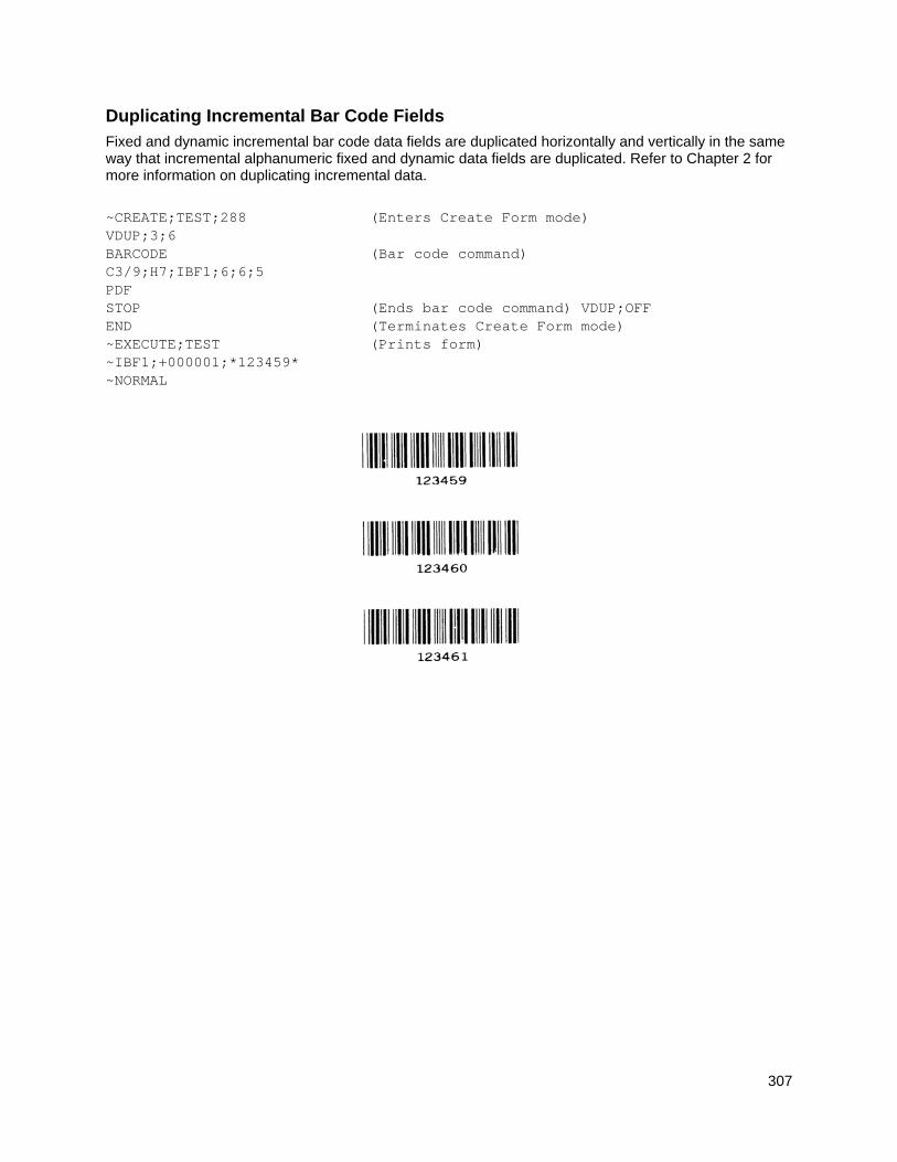
307
Duplicating Incremental Bar Code Fields
Fixed and dynamic incremental bar code data fields are duplicated horizontally and vertically in the same way that incremental alphanumeric fixed and dynamic data fields are duplicated. Refer to Chapter 2 for more information on duplicating incremental data.
~CREATE;TEST;288 (Enters Create Form mode) VDUP;3;6 BARCODE (Bar code command) C3/9;H7;IBF1;6;6;5 PDF STOP (Ends bar code command) VDUP;OFF END (Terminates Create Form mode) ~EXECUTE;TEST (Prints form) ~IBF1;+000001;*123459* ~NORMAL
308
Form Examples And Exercises
Form Examples NOTE: To aid in maintenance of a form or logo, comments can be added to many command lines within
the CREATE or CREATE LOGO mode. Comments must be preceded by a slash (/). Do NOT use the/comment feature on lines containing an SFCC (e.g., commands used within NORMAL or EXECUTE mode). Throughout this manual, comments are provided in parenthesis beside most command lines for better understanding of IGP/PGL operation but should not be included in your IGP/PGL files. Below are some examples of when comments are allowed and NOT allowed.
CREATE Mode (Allowed – no SFCC required) BOX 1;6;15;11;37 /Create Box STOP FONT;BOLD ON /Turn on Bolding BARCODE C128A;X1;H10;BF1;10;11;2 /C128A barcode STOP
NORMAL Mode (Not Allowed – SFCC required) ~NORMAL ~DENSITY;10 ~PAPER;PORTRAIT ~CREATE;XYZ;792
EXECUTE Mode (Not Allowed – SFCC required) ~EXECUTE;XYZ ~AF1;*Data For Alpha*
NOTE: Using a different type of printer or a different configuration could affect the appearance of your printed samples compared to those shown in this manual. Additionally, depending on the paper, top-of- form setting and initial print position, the positioning of your printed samples on the page may vary compared to the examples shown here; these samples have been positioned on the page to correspond with the related text.
The example on the following page demonstrates how to use Create commands in the Create Form mode using the CP.DP format. The printed output for this program is shown in Figure 62 on page 310. (The Hand logo used in this example was previously defined and stored and, thus, is not shown in the form program.) The box surrounding the form represents the paper size.
309
Example: Create Commands ~CREATE;BASICFRM
BOX /LT;SR;SC;ER;EC 1;1;1;25;25 STOP ALPHA /[R;][E;][Cn;][AFn;L;][DIR;][UC;][DARK;][POINT;][HSn;]SR;SC;VE; /HE;(D)ASCIITEXT(D) 3;3;0;0;*STATIC ALPHA DATA* AF1;18;4;3;0;0 /DIR;SR;SC;VE;HE CW;8;4;1;1;*PRINTRONIX* R;15;5;2;2;*IGP* STOP CORNER /LT;SR;SC;ER;EC;VL;HL 1;18;2;23;7;2;2 STOP HDUP;5;1 VERT /LT;C;SR;ER 1;17;18;22 STOP HDUP;OFF VDUP;5;1 HORZ /LT;R;SC;EC 1;18;17;21.1 STOP VDUP;OFF LOGO 10;13;HAND /(PREVIOUSLY DEFINED AND STORED) STOP END ~EXECUTE;BASICFRM ~AF1;*DYNAMIC ALPHA DATA* OVERLAY DATA ~NORMAL
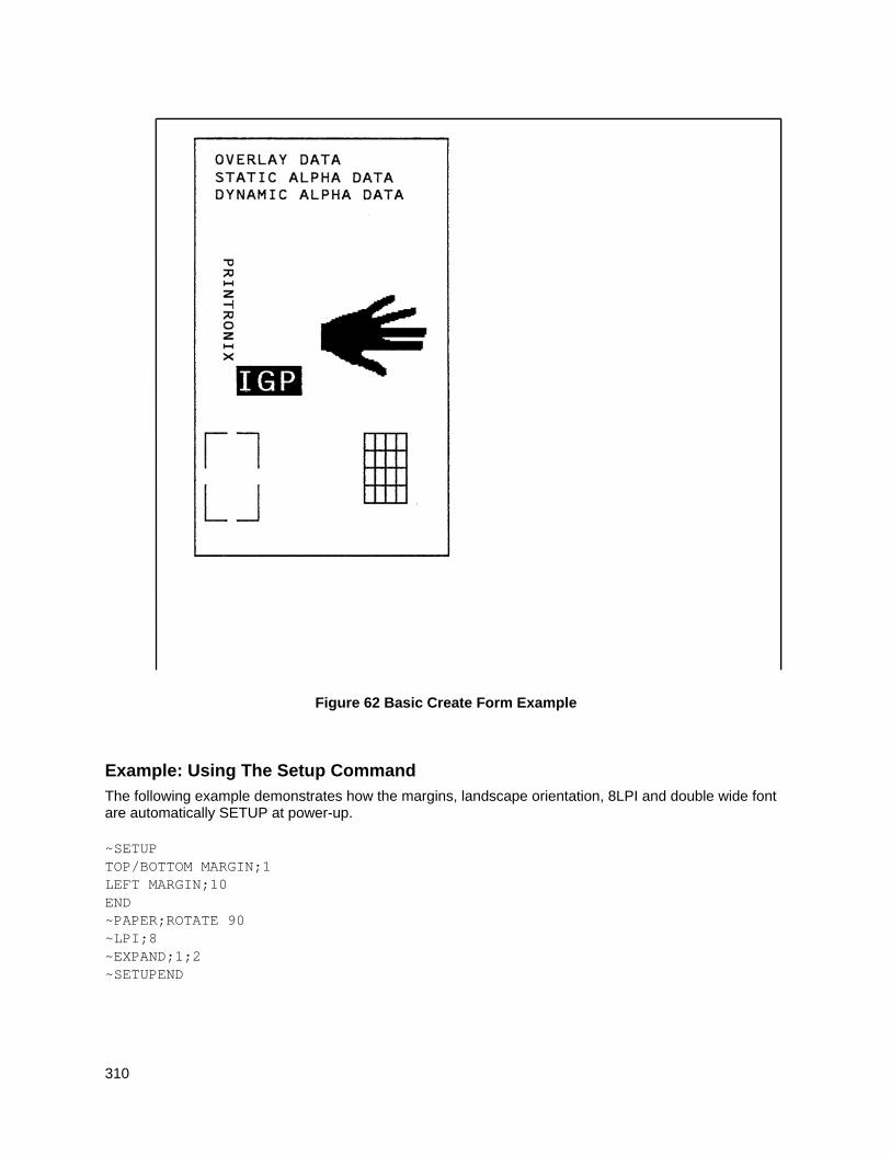
310
Figure 62 Basic Create Form Example
Example: Using The Setup Command
The following example demonstrates how the margins, landscape orientation, 8LPI and double wide font are automatically SETUP at power-up. ~SETUP TOP/BOTTOM MARGIN;1 LEFT MARGIN;10 END ~PAPER;ROTATE 90 ~LPI;8 ~EXPAND;1;2 ~SETUPEND
311
Example: Dynamic Data
The process of executing dynamic alphanumeric and bar code data fields is explained in the following exercises. Each stage includes printing the program; however, the total program may be entered as one unit. Each stage offers the option of choosing features applicable to specific needs.
Basic Design
The SAMPLE program below, shown in Figure 63 is a basic design in CP.DP format and defined by standard Create Form mode command sequences. The label is duplicated twice horizontally on an approximate form size of 8 1/2 x 5 1/2 inches (390 dots), with three bar code locations specified per label. The result is two “forms”: two labels per form, four labels printed on one 8 1/2 x 11 inch “page”. On the next few pages, you will add bar code data, dynamic alphanumeric data, and dynamic bar code data. Then you will execute and print the complete form (Figure 64).
When entering command lines, remember to correctly terminate each line with a line feed or carriage return with line feed. Use your system commands to open a file for the label program. When you have finished, exit the file (if necessary for your system) and print. ~CREATE;SAMPLE;390 (Create Form; form length is 390 dots) HDUP;2;37 (2 horizontal dupes, 37 columns apart) BOX (Box command) 2;3.5;9;30;35 STOP (Stop the Box command) HORZ (Horizontal Line command) 1;14.5;9;35 1;19.5;9;35 1;24.5;9;35 STOP (Stop the Horizontal Line command) CORNER (Begin Corner command) 2;4;11;9;33;1.2;2 2;9.6;11;13.6;33;1.2;2 STOP (Stop the Corner command) ALPHA (Begin Alphanumeric command) 4.8;12;0;0;*FROM:* (This is fixed text on the form) 6.3;12;2;2;*ACME INC.* C15;7.3;16;0;0;*17500 CARTWRIGHT RD.* C15;8.1;16;0;0;*IRVINE , CA 92714* 10;12;0;0;*TO* 14.8;11;0;0;*S.O.* 19.8;11;0;0;*S/N:* 24.8;11;0;0;*P/N:* STOP (Stop the Alphanumerics command) HDUP;OFF (Stop the horizontal duplication) END (End the Create Form mode) ~EXECUTE;SAMPLE;1 (Execute form) ~NORMAL ~EXECUTE;SAMPLE;1 (Execute again to print second form) ~NORMAL ~FF
312
Figure 63 Sample Form
ACME INC. 15345 Barranca Parkway
Irvine, CA 92618
FROM:
TO
S.O.
S/N:
P/N:
ACME INC. 15345 Barranca Parkway
Irvine, CA 92618
FROM:
TO
S.O.
S/N:
P/N:
ACME INC. 15345 Barranca Parkway
Irvine, CA 92618
FROM:
TO
S.O.
S/N:
P/N:
ACME INC. 15345 Barranca Parkway
Irvine, CA 92618
FROM:
TO
S.O.
S/N:
P/N:
313
Bar Code Fields
Identify the location of the data fields for each of the six bar codes (one location at each S.O., S/N, and P/N field on the form). The type of bar code and the human readable data information is also specified within the bar code commands. (Refer to Chapter 3 for detailed bar code information.)
Each bar code must be designated separately. The bar code commands are part of the Create Form mode; therefore, they must be entered in the Create Form mode before the END command. However, because each dynamic field is assigned a unique number, the commands should not be duplicated.
Reopen the file and input the following commands before the END command line but after the HDUP;OFF command.
NOTE: The IGP/PGL will horizontally or vertically duplicate dynamic bar code or alphanumeric data fields if required. This will also duplicate the n parameter identifying the dynamic data fields. If unique data fields are required, do not duplicate the commands.
BARCODE (First bar code command) C3/9;H7;BF1;8;DARK;15.1;10.4 (Upper left S.O. field, assigned #1) C3/9;H7;BF1;8;DARK;15.1;10.4 PDF;O (Print the data field in OCR-A font) STOP (Stop the first bar code command) BARCODE (New bar code command) C3/9;H7;BF2;8;DARK;20;10.4 (Upper left S/N field, assigned #2) PDF;O STOP BARCODE C3/9;H7;BF3;8;DARK;25.5;10.4 (Upper left P/N field, assigned #3) PDF;O STOP BARCODE C3/9;H7;BF4;8;DARK;15.1;47.4 (Upper right S.O. field, assigned #4) PDF;O STOP BARCODE C3/9;H7;BF5;8;DARK;20;47.4 (Upper right S/N field, assigned #5) PDF;O STOP BARCODE C3/9;H7;BF6;8;DARK;25.5;47.4 (Upper right P/N field, assigned #6) PDF;O STOP (Stop the bar code command)
Dynamic Alphanumeric Fields
Identify the location of the dynamic alphanumeric fields using the alphanumerics command. Input the following alphanumeric command lines after the HDUP;OFF command and before the Create Form mode END line. A separate alphanumerics command sequence is used in order to assign unique numbers to each dynamic data field. (If unique identifying numbers were not required, these alphanumeric commands would be added to the existing alphanumeric commands being duplicated to produce the fixed form alphanumeric data.)
NOTE: Before the following dynamic data commands can be entered, delete the form count parameter from the existing Execute command line (the ;1 at the end of the Execute command line shown on the program on page 311). The Form Count parameter cannot be used when data is supplied dynamically. The Execute command line should now read ~EXECUTE;SAMPLE and must be correctly terminated. This is the Execute command for the first page of dynamic data.
314
ALPHA (Begin alpha command for dynamic data) AF1;20;10.8;12;0;0 (AF1 - 1st line of upper left TO area) AF2;20;11.8;12;0;0 (AF2 - 2nd line of upper left TO area) AF3;20;12.8;12;0;0 (AF3 - 3rd line of upper left TO area) AF4;20;10.8;49;0;0 (AF4 - 1st line of lower left TO area) AF5;20;11.8;49;0;0 (AF5 - 2nd line of lower left TO area) AF6;20;12.8;49;0;0 (AF6 - 3rd line of lower left TO area) STOP (Stop the alphanumerics command)
Dynamic Alphanumeric and Bar Code Data
Enter the following dynamic data following the Execute command. These dynamic data commands will supply the variable data to the bar code and alphanumeric fields previously identified in the Create Form mode. After entering the data, exit the file (if necessary with your system) and print. The completed form is shown in Figure 64. ~EXECUTE;SAMPLE ~AF1;*B AND C CO.* (Upper left label addressee) ~AF2;*P.O. BOX 212* ~AF3;*LOS ANGELES, CA 90051* ~AF4;*M. H. INC* (Upper right label addressee) ~AF5;*101 BEACH RD* ~AF6;*MALIBU, CA 97772* ~BF1;*S05995* (Upper left label S.O.) ~BF2;*011233* (Upper left label S/N) ~BF3;*190204* (Upper left label P/N) ~BF4;*S05996* (Upper right label S.O.) ~BF5;*000535* (Upper right label S/N) ~BF6;*104523* (Upper right label P/N) ~FF (Completes 1st form-upper labels) ~AF1;*ABC CORPORATION* (Lower left label addressee) ~AF2;*1234 ANYWHERE ST* ~AF3;*YOUR TOWN, MA 03498* ~AF4;*XYZ COMPUTERS* (Lower right label addressee) ~AF5;*845 N. ALLEN ST* ~AF6;*WEST BEND, OR 97601* ~BF1;*S05997* (Lower left label S.O.) ~BF2;*456789* (Lower left label S/N) ~BF3;*102245* (Lower left label P/N) ~BF4;*S05999* (Lower right label S.O.) ~BF5;*567890* (Lower right label S/N) ~BF6;*103764* (Lower right label P/N) ~NORMAL (Completes 2nd form-lower labels)
Multiple page documents must be separated by a form feed. (The “page” of data includes the Execute command, the dynamic data commands, and the Normal command.) Using the SFON command (described on page 116), a ~FF (form feed) command will allow as many forms as required to print with the appropriate new data supplied dynamically. When the SFOFF command is used, send a hex 0C instead of ~FF to print multiple pages with new dynamic data.
315
Figure 64 Dynamic Data Example
ACME INC. 15345 Barranca Parkway
Irvine, CA 92618
FROM:
TO
S.O.
S/N:
P/N:
SO5995
011233
190204
B AND C CO P.O. BOX 212 LOS ANGELES CA
ACME INC. 15345 Barranca Parkway
Irvine, CA 92618
FROM:
TO
S.O.
S/N:
P/N:
SO5996
000535
104523
M. H. INC 101 BEACH RD MALIBU CA 97772
ACME INC. 15345 Barranca Parkway
Irvine, CA 92618
FROM:
TO
S.O.
S/N:
P/N:
SO5997
456789
102245
ABC CORPORATION 1234 ANYWHERE ST YOUR TOWN MA
ACME INC. 15345 Barranca Parkway
Irvine, CA 92618
FROM:
TO
S.O.
S/N:
P/N:
SO5999
567890
103764
XYZ COMPUTERS 845 N. ALLEN ST WEST BEND OR
316
Example: Auto Increment Fields
The following program, designed in accordance with current specifications for AIAG-B-3 shipping label standards, creates four automatically incrementing/decrementing AIAG labels with alphanumeric and bar code data. The printed output of this program is shown on page 318. ~CREATE;AIAG BOX 1;31.2;1;55.2;66.5 STOP HORZ 1;38.5;1;66.5 1;44.9;1;40 1;49.10;1;40 STOP VERT 1;26;38.5;44.9 1;40;44.9;55.2 STOP ALPHA C15;31.8;2;0;0;*PART NO* C15;32.6;2;0;0;*(P)* I;34.3;9;4;4;00000000001;*A0000000001* C15;38.9;2;0;0;*QUANTITY* C15;39.6;2;0;0;* (Q)* 40.5;8;4;4;*100* C15;41.9;28;0;0;*SPECIAL* C15;42.6;28;0;0;* (C)* I;43.9;34;4;4;-00001;*A20UG* C15;45;2;0;0;*SUPPLIER* C15;45.10;2;0;0;* (V)* 45.7;7;2;2;* 040898755* C15;50.4;2;0;0;*SERIAL* C15;51.2;2;0;0;* (S)* 50.8;7;2;2;* 0002110* C15;54.5;4;0;0;*ACME MOTOR, INC IRVINE CA 92713 (714) 863-1900* STOP BARCODE C3/9;H7;I;DARK;34.7;5.5 X000000002;*A000000002* STOP BARCODE C3/9;H7;DARK;40.9;5.5 *Q100* STOP BARCODE C3/9;H7;I;DARK;38.1;33 -X00002;*CA2OUF* STOP BARCODE C3/9;H7;DARK;45.11;5.5 *V040898755* STOP BARCODE C3/9;H7;DARK;50.9;5.5 *S0002110* STOP
317
BOX 1;1.2;1;25.2;66.5 STOP HORZ 1;8.4;1;66.5 1;14.9;1;40 1;19.6;1;40 STOP VERT 1;26;8.4;14.9 1;40;14.9;25.2 STOP ALPHA C15;1.8;2;0;0;*PART NO* C15;2.6;2;0;0;*(P)* I;4.3;9;4;4;00000000002;*A0000000001* C15;8.9;2;0;0;*QUANTITY* C15;9.6;2;0;0;* (Q)* 10.5;8;4;4;*100* C15;11.9;28;0;0;*SPECIAL* C15;12.6;28;0;0;* (C)* I;13.9;34;4;4;-00002;*A2OUG* C15;15;2;0;0;*SUPPLIER* C15;15.10;2;0;0;* (V)* 15.6;7;2;2;* 040898755* C15;20;2;0;0;*SERIAL* C15;21;2;0;0;* (S)* 20.5;7;2;2;* 0002110* C15;24.5;4;0;0;*ACME MOTOR,INC. IRVINE CA 92713 (714) 863-1900* STOP BARCODE C3/9;H7;I;DARK;4.7;5.5 X000000002;*A000000001* STOP BARCODE C3/9;H7;DARK;10.9;5.5 *Q100* STOP BARCODE C3/9;H7;I;DARK;8.1;33 -X00002;*CA20UG* STOP BARCODE C3/9;H7;DARK;15.7;5.5 *V040898755* STOP BARCODE C3/9;H7;DARK;20.8;5.5 *S0002110* STOP END ~EXECUTE;AIAG;2 ~NORMAL
318
Figure 65 Auto Increment Fields Example
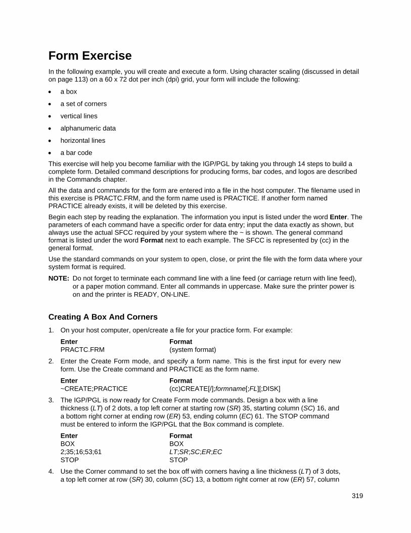
319
Form Exercise In the following example, you will create and execute a form. Using character scaling (discussed in detail on page 113) on a 60 x 72 dot per inch (dpi) grid, your form will include the following:
a box
a set of corners
vertical lines
alphanumeric data
horizontal lines
a bar code
This exercise will help you become familiar with the IGP/PGL by taking you through 14 steps to build a complete form. Detailed command descriptions for producing forms, bar codes, and logos are described in the Commands chapter.
All the data and commands for the form are entered into a file in the host computer. The filename used in this exercise is PRACTC.FRM, and the form name used is PRACTICE. If another form named PRACTICE already exists, it will be deleted by this exercise.
Begin each step by reading the explanation. The information you input is listed under the word Enter. The parameters of each command have a specific order for data entry; input the data exactly as shown, but always use the actual SFCC required by your system where the ~ is shown. The general command format is listed under the word Format next to each example. The SFCC is represented by (cc) in the general format.
Use the standard commands on your system to open, close, or print the file with the form data where your system format is required.
NOTE: Do not forget to terminate each command line with a line feed (or carriage return with line feed), or a paper motion command. Enter all commands in uppercase. Make sure the printer power is on and the printer is READY, ON-LINE.
Creating A Box And Corners
1. On your host computer, open/create a file for your practice form. For example:
Enter Format PRACTC.FRM (system format)
2. Enter the Create Form mode, and specify a form name. This is the first input for every new form. Use the Create command and PRACTICE as the form name.
Enter Format ~CREATE;PRACTICE (cc)CREATE[/];formname[;FL][;DISK]
3. The IGP/PGL is now ready for Create Form mode commands. Design a box with a line thickness (LT) of 2 dots, a top left corner at starting row (SR) 35, starting column (SC) 16, and a bottom right corner at ending row (ER) 53, ending column (EC) 61. The STOP command must be entered to inform the IGP/PGL that the Box command is complete.
Enter Format BOX BOX 2;35;16;53;61 LT;SR;SC;ER;EC STOP STOP
4. Use the Corner command to set the box off with corners having a line thickness (LT) of 3 dots, a top left corner at row (SR) 30, column (SC) 13, a bottom right corner at row (ER) 57, column
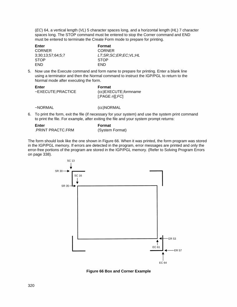
320
(EC) 64, a vertical length (VL) 5 character spaces long, and a horizontal length (HL) 7 character spaces long. The STOP command must be entered to stop the Corner command and END must be entered to terminate the Create Form mode to prepare for printing.
Enter Format CORNER CORNER 3;30;13;57;64;5;7 LT;SR;SC;ER;EC;VL;HL STOP STOP END END
5. Now use the Execute command and form name to prepare for printing. Enter a blank line using a terminator and then the Normal command to instruct the IGP/PGL to return to the Normal mode after executing the form.
Enter Format ~EXECUTE;PRACTICE (cc)EXECUTE;formname [;PAGE n][;FC]
~NORMAL (cc)NORMAL
6. To print the form, exit the file (if necessary for your system) and use the system print command to print the file. For example, after exiting the file and your system prompt returns:
Enter Format .PRINT PRACTC.FRM (System Format)
The form should look like the one shown in Figure 66. When it was printed, the form program was stored in the IGP/PGL memory. If errors are detected in the program, error messages are printed and only the error-free portions of the program are stored in the IGP/PGL memory. (Refer to Solving Program Errors on page 338).
Figure 66 Box and Corner Example
SR 30
SC 13
SR 35
SC 16
ER 53
EC 61 ER 57
EC 64
321
Adding Horizontal And Vertical Lines
7. Now return to the file. When the file reopens, the existing program (the contents of the file) is displayed. Use your system commands to reopen the file. For example:
Enter Format .PRACTC.FRM (System Format)
8. All Create Form mode commands must be entered into the program before the End command line. Add three horizontal lines, each with a thickness (LT) of 1, at rows (R) 40, 45, and 49 and each ranging from column (SC) 16 to column (EC) 61.
Enter Format HORZ HORZ 1;40;16;61 LT;R;SC;EC 1;45;16;61 1;49;16;61 STOP STOP
9. Add two vertical lines, each with a thickness (LT) of 1, both in column (C) 49, one ranging from row (SR) 40 to row (ER) 45 and the other ranging from row (SR) 49 to row (ER) 53.
Enter Format VERT VERT 1;49;40;45 LT;C;SR;ER 1;49;49;53 STOP STOP
The last two commands have added to the form definition. PRACTICE now looks like Figure 67.
Figure 67 Box/Corner Example with Horizontal and Vertical LInes
COLUMN 49
ROW 40
ROW 45
ROW 49
322
Adding Fixed Alphanumeric Text
10. Use the Create Form mode Alpha command to add some fixed alphanumeric text to the form. Specify some compressed print (Cn), the starting row (SR) and starting column (SC) for each alphanumeric string, any vertically (VE) or horizontally (HE) expanded strings, and the alphanumeric string itself which must be within the printable character (quotation marks or asterisks, for example). Substitute your own name, address, etc. in the appropriate areas. If you do not want to include some of the data on your form, do not enter the complete line.
Enter Format ALPHA ALPHA 31;22;0;0;*ACME, INC* [R;][E;][Cn;][AFn;L;][T;][DIR;][UC;][DARK;][POINT;][HSn;]SR;SC;VE;HE;(D)text(D) 32;22;0;0;*17500 CARTWRIGHT ROAD* 33;22;0;0;*IRVINE, CA 92714* 35.9;17;0;0;*SERIAL NUMBER* 40.3;17;0;0;*PART NUMBER* 40.3;50;0;0;*MFG. DATE* 45.3;17;0;0;*DESCRIPTION* 49.3;17;0;0;*INTERFACE* 49.3;50;0;0;*VERSION* C13;31;16;0;0;*FROM:* C15;54;26;0;0;*Call PRINTRONIX for more information.* C15;55;34;0;0;*(714)863-1900* STOP STOP
NOTE: The sample data entered above uses CP.DP format (such as 35.9, 40.3, etc.) in the starting row (SR) parameters. This precisely positions the data to avoid overlapping the alphanumeric data with the box and horizontal line data previously entered. For complete information on CP.DP format, refer to the Commands chapter.
At this point, the PRACTC.FRM file should contain the following form program data: ~CREATE;PRACTICE BOX 2;35;16;53;61 STOP CORNER 3;30;13;57;64;5;7 STOP HORZ 1;40;16;61 1;45;16;61 1;49;16;61 STOP VERT 1;49;40;45 1;49;49;53 STOP ALPHA 31;22;0;0;*ACME, INC.* 32;22;0;0;*17500 CARTWRIGHT ROAD* 33;22;0;0;*IRVINE, CA 92714* 35.9;17;0;0;*SERIAL NUMBER* 40.3;17;0;0;*PART NUMBER* 40.3;50;0;0;*MFG. DATE*
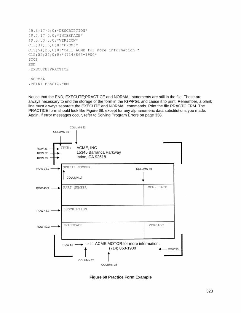
323
45.3;17;0;0;*DESCRIPTION* 49.3;17;0;0;*INTERFACE* 49.3;50;0;0;*VERSION* C13;31;16;0;0;*FROM:* C15;54;26;0;0;*Call ACME for more information.* C15;55;34;0;0;*(714)863-1900* STOP END ~EXECUTE;PRACTICE ~NORMAL .PRINT PRACTC.FRM
Notice that the END, EXECUTE;PRACTICE and NORMAL statements are still in the file. These are always necessary to end the storage of the form in the IGP/PGL and cause it to print. Remember, a blank line must always separate the EXECUTE and NORMAL commands. Print the file PRACTC.FRM. The PRACTICE form should look like Figure 68, except for any alphanumeric data substitutions you made. Again, if error messages occur, refer to Solving Program Errors on page 338.
Figure 68 Practice Form Example
COLUMN 16
SERIAL NUMBER
PART NUMBER
DESCRIPTION
INTERFACE VERSION
MFG. DATE
FROM: ACME, INC 15345 Barranca Parkway Irvine, CA 92618
Call ACME MOTOR for more information. (714) 863-1900
COLUMN 22
COLUMN 50
COLUMN 17
COLUMN 26
COLUMN 34
ROW 31
ROW 32
ROW 33
ROW 35.9
ROW 40.3
ROW 45.3
ROW 49.3
ROW 54
ROW 55
324
Adding A Bar Code
11. Change the form definition by adding bar code type Code 39 (C39), one of the codes available on the IGP/PGL. First, reopen the file. Bar codes are defined in the Create Form mode; therefore, the Bar Code command must be entered before the End command line. In the Bar Code command, specify type C39 and 0.8 inch height (Hn). Use a dynamic bar code data field (BF) identified by the number (n) 1 with a length (L) of 5. The actual data will be provided dynamically in the Execute Form mode. Specify the starting row (SR) 35.7 and starting column (SC) 39, and stop the command.
Enter Format BARCODE BARCODE C3/9;H8;BF1;5;DARK;35.7;39 C3/9[CD]; [DIR;] [MAG;] [Hn[.m];][BFn;L;][DARK;] SR;SC STOP STOP
12. To dynamically input alphanumeric data fields, first identify the locations for the data in the Create Form mode as part of the form definition. Enter the locations in the existing Alpha command sequence (or use a new Alpha command). In the Alpha command sequence, enter the alphanumeric field (AF), the field number (n), length (L), starting row (SR) and column (SC), and any vertical (VE) or horizontal (HE) expansion. To enter this alphanumeric data in the existing Alpha command sequence, the data must be entered before the existing Alpha command STOP line.
Enter Format AF1;7;38.7;19.3;3;3 [R;] [E;] [Cn;][AFn;L;][T;][DIR;][UC;][DARK;] AF2;11;43;20;2;2 [POINT;][HSn;]SR;SC;VE;HE;(D)text(D) AF3;31;47.3;20;2;1 AF4;33;51.3;20;2;1
13. Supply the dynamic data during the Execute Form mode (following the EXECUTE;PRACTICE line). Use the SFCC, specify the dynamic alphanumeric field (AF), bar code field (BF), the field number (corresponding to those just entered in the form definition), and the data itself. (This method can be repeated to supply new data to each form printed by separating the pages of data with a form feed. Refer to Execute Form: Dynamic Alphanumeric Data on page 63.)
Enter Format ~AF1;*49114* (cc)AFn;(D)data(D) ~AF2;*106772-902* ~AF3;*INTELLIGENT GRAPHICS PROCESSOR* ~AF4;*PARALLEL - CENTRONICS* ~BF1;*49114* (cc)BFn;(D)data(D)
14. Now the PRACTC.FRM file contains all the following information (the complete form program). Print the form by printing the file. The completed form is shown in Figure 69 .
~CREATE;PRACTICE BOX 2;35;16;53;61 STOP CORNER 3;30;13;57;64;5;7 STOP HORZ 1;40;16;61 1;45;16;61 1;49;16;61 STOP
325
VERT 1;49;40;45 1;49;49;53 STOP ALPHA 31;22;0;0;*ACME, INC.* 32;22;0;0;*17500 CARTWRIGHT ROAD* 33;22;0;0;*IRVINE, CA 92714* 35.9;17;0;0;*SERIAL NUMBER* 40.3;17;0;0;*PART NUMBER* 40.3;50;0;0;*MFG. DATE* 45.3;17;0;0;*DESCRIPTION* 49.3;17;0;0;*INTERFACE* 49.3;50;0;0;*VERSION* C13;31;16;0;0;*FROM:* C15;54;26;0;0;*Call ACME for more information.* C15;55;34;0;0;*(714)863-1900* AF1;7;38.7;19.3;4;3 AF2;11;43;20;2;2 AF3;31;47.3;20;2;1 AF4;33;51.3;20;2;1 STOP BARCODE C3/9;H8;BF1;5;DARK;35.7;39 STOP END ~EXECUTE;PRACTICE ~AF1;*49114* ~AF2;*106772-902* ~AF3;*INTELLIGENT GRAPHICS PROCESSOR* ~AF4;*PARALLEL - CENTRONICS* ~BF1;*49114* ~NORMAL PRINT PRACTC.FRM
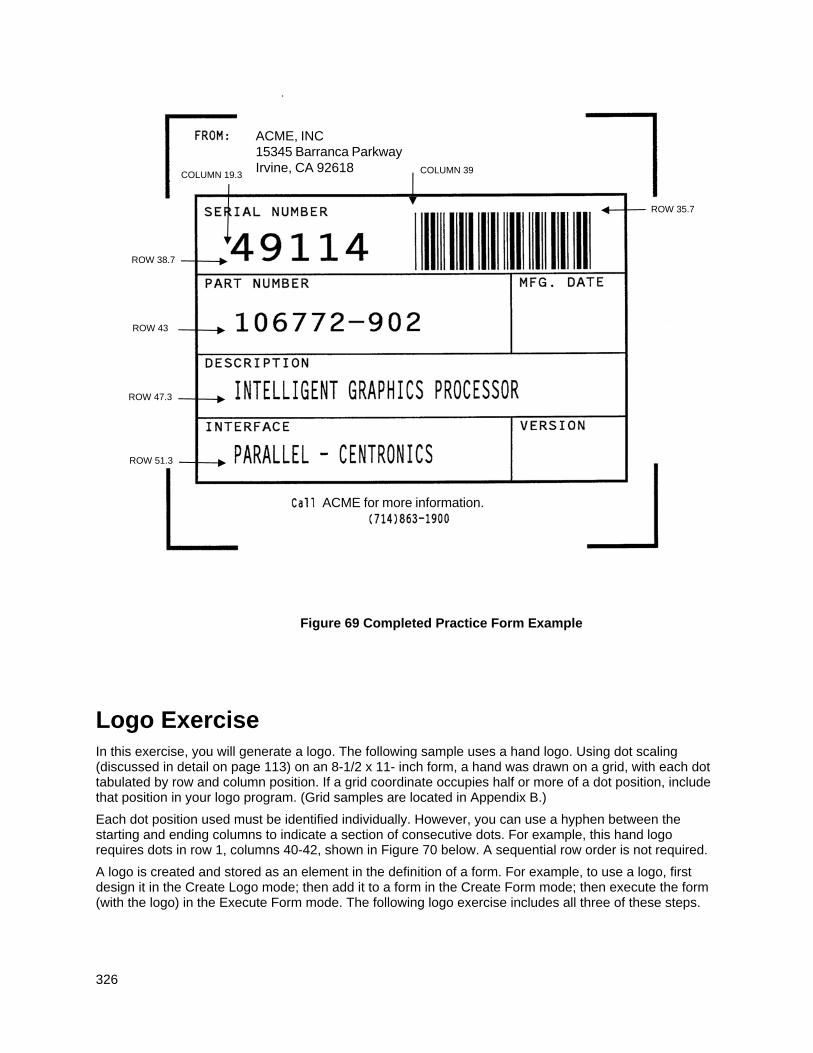
326
Figure 69 Completed Practice Form Example
Logo Exercise In this exercise, you will generate a logo. The following sample uses a hand logo. Using dot scaling (discussed in detail on page 113) on an 8-1/2 x 11- inch form, a hand was drawn on a grid, with each dot tabulated by row and column position. If a grid coordinate occupies half or more of a dot position, include that position in your logo program. (Grid samples are located in Appendix B.)
Each dot position used must be identified individually. However, you can use a hyphen between the starting and ending columns to indicate a section of consecutive dots. For example, this hand logo requires dots in row 1, columns 40-42, shown in Figure 70 below. A sequential row order is not required.
A logo is created and stored as an element in the definition of a form. For example, to use a logo, first design it in the Create Logo mode; then add it to a form in the Create Form mode; then execute the form (with the logo) in the Execute Form mode. The following logo exercise includes all three of these steps.
ACME, INC 15345 Barranca Parkway Irvine, CA 92618
ACME for more information.
COLUMN 39
ROW 38.7
ROW 43
ROW 47.3
ROW 51.3
ROW 35.7
COLUMN 19.3
327
DOT POSITIONS DOT POSITIONS
Row Column Row Column
1 40-42 31 1-36 2 35-42 32 1-39 3 36-42 33 1-58 4 35-42 34 1-58 5 33-41 35 1-58 6 31-40 36 1-58 7 30-38 37 1-58 8 29-36 38 1-57 9 28-35 39 4-24 10 27-34;52-54 40 7-23 11 24-33;48-54 41 8-23 12 22-31;45-54 42 9-23 13 19-30;41-54 43 11-24 14 16-29;38-53 44 12-25 15 13-29;36-51 45 14-27 16 11-29;33-48 46 15-30 17 9-44 47 17-32 18 7-42 48 18-35 19 6-39 49 22-34 20 4-36 50 25-35 21 1-34 51 26-36 22 1-34 52 28-37 23 1-34 53 30-37 24 1-60 54 32-37 25 1-60 55 33-37 26 1-60 56 35-36
27 1-60 28 1-59 29 1-59 30 1-35
Figure 70 Sample Logo
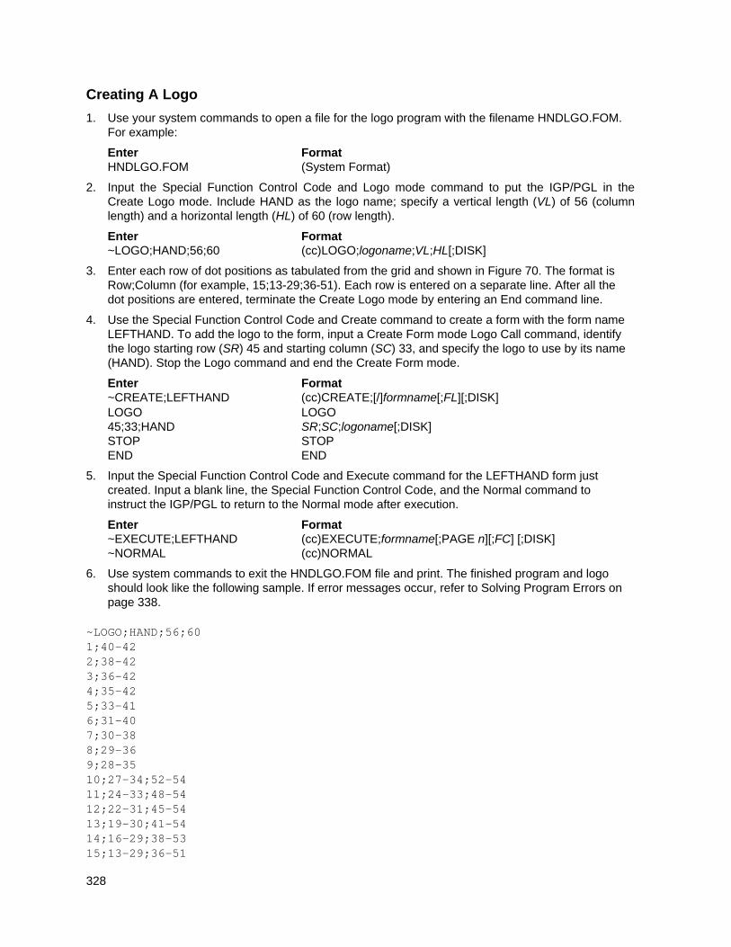
328
Creating A Logo
1. Use your system commands to open a file for the logo program with the filename HNDLGO.FOM. For example:
Enter Format HNDLGO.FOM (System Format)
2. Input the Special Function Control Code and Logo mode command to put the IGP/PGL in the Create Logo mode. Include HAND as the logo name; specify a vertical length (VL) of 56 (column length) and a horizontal length (HL) of 60 (row length).
Enter Format ~LOGO;HAND;56;60 (cc)LOGO;logoname;VL;HL[;DISK]
3. Enter each row of dot positions as tabulated from the grid and shown in Figure 70. The format is Row;Column (for example, 15;13-29;36-51). Each row is entered on a separate line. After all the dot positions are entered, terminate the Create Logo mode by entering an End command line.
4. Use the Special Function Control Code and Create command to create a form with the form name LEFTHAND. To add the logo to the form, input a Create Form mode Logo Call command, identify the logo starting row (SR) 45 and starting column (SC) 33, and specify the logo to use by its name (HAND). Stop the Logo command and end the Create Form mode.
Enter Format ~CREATE;LEFTHAND (cc)CREATE;[/]formname[;FL][;DISK] LOGO LOGO 45;33;HAND SR;SC;logoname[;DISK] STOP STOP END END
5. Input the Special Function Control Code and Execute command for the LEFTHAND form just created. Input a blank line, the Special Function Control Code, and the Normal command to instruct the IGP/PGL to return to the Normal mode after execution.
Enter Format ~EXECUTE;LEFTHAND (cc)EXECUTE;formname[;PAGE n][;FC] [;DISK] ~NORMAL (cc)NORMAL
6. Use system commands to exit the HNDLGO.FOM file and print. The finished program and logo should look like the following sample. If error messages occur, refer to Solving Program Errors on page 338.
~LOGO;HAND;56;60 1;40-42 2;38-42 3;36-42 4;35-42 5;33-41 6;31-40 7;30-38 8;29-36 9;28-35 10;27-34;52-54 11;24-33;48-54 12;22-31;45-54 13;19-30;41-54 14;16-29;38-53 15;13-29;36-51
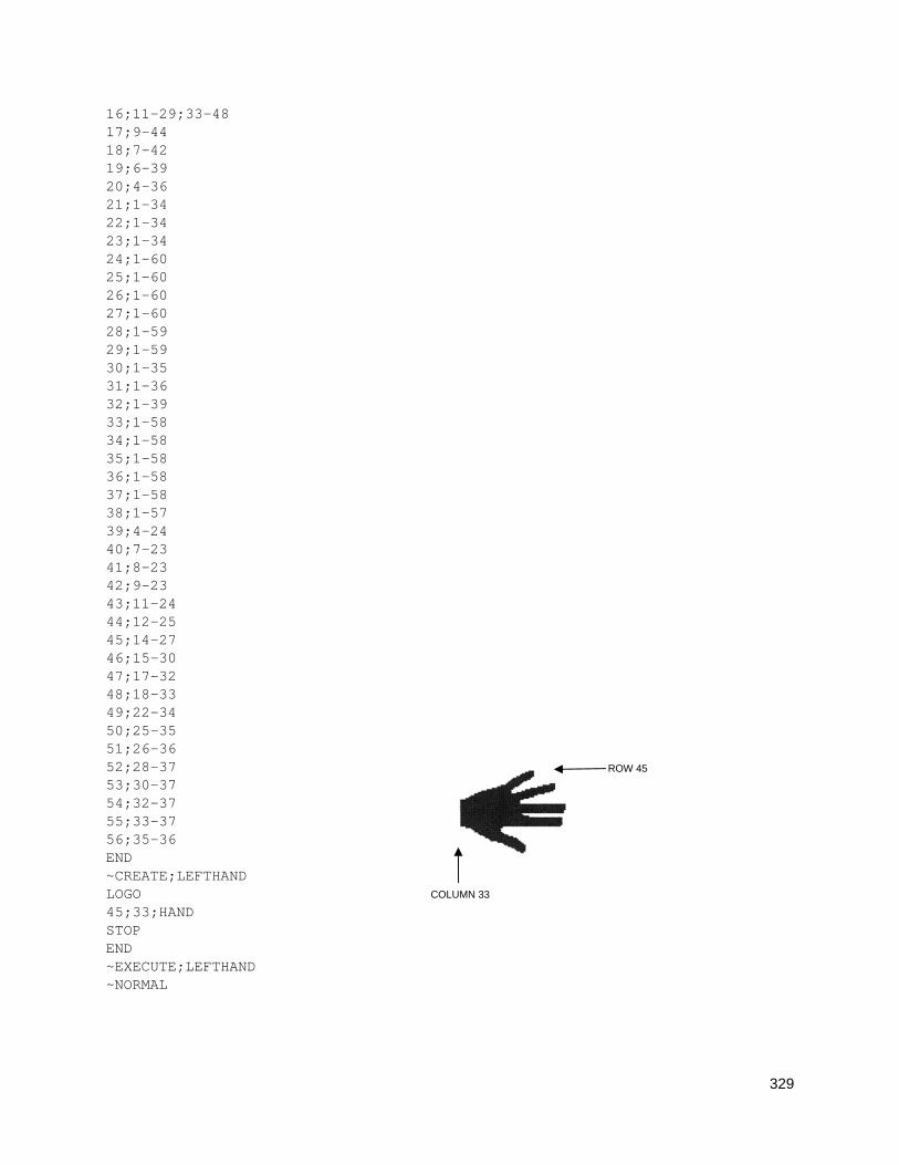
329
16;11-29;33-48 17;9-44 18;7-42 19;6-39 20;4-36 21;1-34 22;1-34 23;1-34 24;1-60 25;1-60 26;1-60 27;1-60 28;1-59 29;1-59 30;1-35 31;1-36 32;1-39 33;1-58 34;1-58 35;1-58 36;1-58 37;1-58 38;1-57 39;4-24 40;7-23 41;8-23 42;9-23 43;11-24 44;12-25 45;14-27 46;15-30 47;17-32 48;18-33 49;22-34 50;25-35 51;26-36 52;28-37 53;30-37 54;32-37 55;33-37 56;35-36 END ~CREATE;LEFTHAND LOGO 45;33;HAND STOP END ~EXECUTE;LEFTHAND ~NORMAL
COLUMN 33
ROW 45
330
Form Design In this exercise, you will produce a complete form by sketching it out on a grid in the same way the logo was designed. Again, this exercise uses character scaling on an 8-1/2 x 11-inch (60 x 72 dpi) page. (Refer to page 113 in the Commands chapter, where character scaling is discussed in detail.)
Page Layout Considerations
At 6 lines per inch (lpi) and 10 characters per inch (cpi) printing, a standard 8- 1/2 x 11-inch sheet of paper has a print area of 66 lines (rows) and 85 characters (columns). (The printable area will vary if you are not printing at 6 lpi and 10 cpi.) Thus, the grid used to design an 8-1/2 x 11-inch form should accommodate this 66 x 85 area. (Appendix C discusses the printable area for different form sizes in more detail.)
Using the grids provided in Appendix B, sketch out the form layout and identify the starting and ending values. These values will be used to input IGP/PGL command parameters.
Planning The Form Layout
In this example, assume you work for the HandCraft Boat Company. Your slogan is “Quality boats crafted by hand,” and the owner, Mr. Handcraft, has asked you to design a simple form that his salespeople can use for special orders. On the form, he wants a logo, the slogan, the customer's name, spaces for other particulars of the order, and a bar code to distinguish the sales region and boat division from other HandCraft enterprises. Begin this 12-step task as described below.
1. First, design the form on the Standard Grid provided in Appendix B. Figure 71 shows the locations of the various form components. Compensate for expanded characters and plan for the logo.
2. Define the logo and then return to the form to add all the form components. Modify the hand logo already on file as the HandCraft logo. Use the Logo Grid in Appendix B, and refer to Figure 72, which shows the dot positions of the hand logo with a boat added to the hand. When dot positions (or a range of dot positions) are not specified, the boat image in the hand emerges.
3. Open a file named HNDCFT.FOM to contain all the form information. As shown in the following example, use the Create Logo mode command, name the logo HANDCRFT, specify the logo height (VL) and width (HL), enter the dot positions used, and end the Logo command.
Enter Format HNDCFT.FOM (System Format) ~LOGO;HANDCRFT;56;60 (cc)LOGO;logoname;VL;HL[;DISK] 1;40-42 row#;dot;dot1-dot2;dot 2;38-42 3;36-42 4;35-42 5;33-41 6;31-40 7;30-38 8;29-36 9;28-35 10;27-34;52-54 11;24-33;48-54 12;22-31;45-54 13;19-30;41-54 14;16-29;38-53 15;13-17;19-29;36-51 16;11-17;20-29;33-48
331
17;9-17;21-44 18;7-17;22-42 19;6-17;22-39 20;4-17;23-36 21;1-17;24-34 22;1-17;25-34 23;1-17;26-34 24;1-17;27-60 25;1-17;28-60 26;1-17;29-60 27;1-17;30-60 28;1-17;31-59 29;1-17;19-59 30;1-17;19-35 31;1-4;33-36 32;1-5;33-39 33;1-6;33-58 34;1-7;33-58 35;1-58 36;1-58 37;1-58 38;1-57 39;4-24 40;7-23 41;8-23 42;9-23 43;11-24 44;12-25 45;14-27 46;15-30 47;17-32 48;18-33 49;22-34 50;25-35 51;26-36 52;28-37 53;30-37 54;32-37 55;33-37 56;35-36 END END
332
Figure 71 Sample Form Design
333
Figure 72 Logo Design
334
Creating A Form And Adding Form Components
4. Now create the form and start adding the form components from the layout grid. (Refer to Figure 71). Use the Special Function Control Code and Create command to define a form named HCBOATS. Use the Box command to define the outer border with a line thickness (LT) 3, top left corner at row (SR) 11 column (SC) 10, and bottom right corner at row (ER) 55, column (EC) 70. In the same Box command sequence, define another box with a line thickness of 2, top left corner at row 28 column 14, and bottom right corner at row 44.9 column 66. After defining the boxes, stop the Box command.
Enter Format ~CREATE;HCBOATS (cc)CREATE;[/]formname[;FL][;DISK] BOX BOX 3;11;10;55;70 LT;SR;SC;ER;EC 2;28;14;44.9;66 STOP STOP
5. Mr. Handcraft would like corners around the slogan. Use the Corner command to define a line thickness (LT) of 2, top left corner at row (SR) 48 column (SC) 24, and bottom right corner at row (ER) 52 column (EC) 56. Make the vertical (VL) corner piece 4 spaces long and the horizontal (HL) corner piece 5 spaces long. Then stop the Corner command.
Enter Format CORNER CORNER 2;48;24;52;56;4;5 LT;SR;SC;ER;EC;VL;HL STOP STOP
6. To make the columns for the special order items, add two vertical lines each with a line thickness (LT) of 1, one line in column (C) 22 and the other line in column 58. Each line will start at row (SR) 28 and end at row (ER) 44.9.
Enter Format VERT VERT 1;22;28;44.9 LT;C;SR;ER 1;58;28;44.9 STOP STOP
7. To add the horizontal lines, define one line and then duplicate that line using the Vertical Duplication command. The line will have a single line thickness (LT), be in row (R) 30.4, starting in column (SC) 14 and ending in column (EC) 66. With vertical duplication, the line will be duplicated (dup#) 6 times with 2.5 row offset (offset#) spacing between each duplication. The Vertical Duplication command must be input, the horizontal line being duplicated must be input, and the Vertical Duplication command must be turned off.
Enter Format VDUP;6;2.5 VDUP;dup#;offset# HORZ HORZ 1;30.4;14;66 LT;R;SC;EC STOP STOP VDUP;OFF VDUP;OFF
8. All the text shown on the grid is fixed into position on the form with a single Alpha command sequence. The starting row, starting column, and text can be taken right from the grid and put into the program.
Enter Format ALPHA ALPHA 14;31;3;2;*HandCraft Boats* [R;][E;][Cn;][AFn;L;][T;][DIR;][UC;][DARK;] 18;14;0;0;*CUSTOMER:* [POINT;][HSn;]SR;SC;VE;HE;(D)text(D)
335
18;51;0;0;*PHONE:* 20;14;0;0;*HULL NO:* 20;49;0;0;*RIGGING:* 22;14;0;0;*COLOR:* 22;43;0;0;*DELIVERY DATE:* 25;31;1;1;*SPECIAL ORDER ITEMS* 27;17;0;0;*ITEM* 27;34;0;0;*DESCRIPTION* 27;60;0;0;*PRICE* 50;26;1;1;*Quality Boats Crafted By Hand* C17;48;14;0;0;*HandCraft Boats* C17;48.10;14;0;0;*123 Boat Way* C17;49.8;14;0;0;*Boat Town, CA* C17;50.6;19;0;0;*333444* C17;51.4;14;0;0;*(714)555-0011* STOP STOP
9. HandCraft Boats uses bar code type Code 128B (C128B) in many applications. Use bar code C128B, height (Hn) of .5-inch, starting at row (SR) 49, column (SC) 59, code the West Coast Sales Region as *WC*, and print the data field (PDF) below the symbol.
NOTE: Due to space constraints, the C128B command below is separated into two lines. During actual input, do not separate the command parameters.
Enter Format BARCODE BARCODE
C128B;H5;49;59 C128B;[DIR;][MAG;][Hn[.m];][BFn;L;][DARK;]SR;SC *WC* [(D)datafield(D)] PDF [PDF[;LOC][;FONT][;MAX]] STOP STOP
NOTE: The decimal point is not entered in the height parameter (H5) above because values are expected in .10-inch increments. Values from 4 to 99 (.4-inch to 9.9 inches) are accepted.
10. Add the logo and end the Create Form mode. Use the Logo Call command, specify the starting row (SR) at 12 and column (SC) at 18 as shown on the grid and call the logo by name (HANDCRFT). (The starting row and column of the logo refer to the upper left corner of the grid used in the logo design.)
Enter Format LOGO LOGO 12;18;HANDCRFT SR;SC;logoname[;DISK] STOP STOP END END
11. Execute the form (HCBOATS), return to the Normal mode (remember the blank line before the NORMAL command), exit the file using your system commands (if necessary), and print the document.
Enter Format ~EXECUTE;HCBOATS (cc)EXECUTE;formname[;PAGE n][;FC][;DISK] ~NORMAL (cc)NORMAL .PRINT HNDCFT.FOM (System Format)
NOTE: Always separate the EXECUTE and NORMAL commands by a line.
Figure 73 shows the finished form. If Mr. Handcraft would like to rearrange the words, change line thickness of a box, etc., simply reopen the file and change the appropriate command lines. Otherwise, his salespeople have a new form for notes on custom orders.
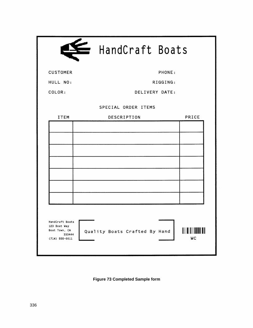
336
Figure 73 Completed Sample form
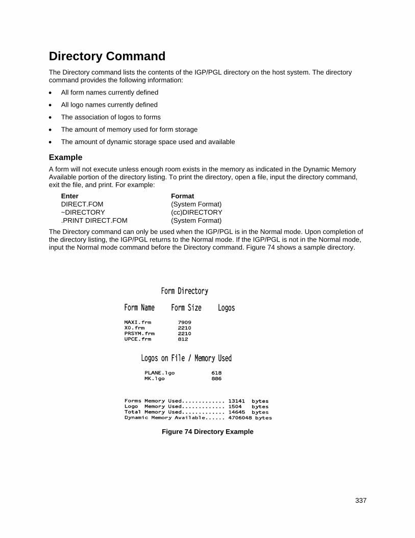
337
Directory Command The Directory command lists the contents of the IGP/PGL directory on the host system. The directory command provides the following information:
All form names currently defined
All logo names currently defined
The association of logos to forms
The amount of memory used for form storage
The amount of dynamic storage space used and available
Example
A form will not execute unless enough room exists in the memory as indicated in the Dynamic Memory Available portion of the directory listing. To print the directory, open a file, input the directory command, exit the file, and print. For example:
Enter Format DIRECT.FOM (System Format) ~DIRECTORY (cc)DIRECTORY .PRINT DIRECT.FOM (System Format)
The Directory command can only be used when the IGP/PGL is in the Normal mode. Upon completion of the directory listing, the IGP/PGL returns to the Normal mode. If the IGP/PGL is not in the Normal mode, input the Normal mode command before the Directory command. Figure 74 shows a sample directory.
Figure 74 Directory Example
338
Delete Command The Delete command deletes any individual form or logo from the Onboard Flash Memory. The deletion of a form includes its directory entry and any alphanumeric or vector information associated with it. The Delete command is used only when the IGP/PGL is in the Normal mode.
Deletion of a logo includes its directory entry and its data in the logo storage area. Deletion of a valid logo which is still combined with a form will not cause an error at the time it is deleted; however, an error will occur if you execute a form that contains a previously deleted logo.
Example
From the directory printed in the preceding section, delete the practice form, the HandCraft Logo, and the HandCraft Boats form. Similar to the format used with other command sequences, the procedure is as follows: open a file, input the commands, exit the file, and print. For example:
Enter Format DELETE.FRM (System Format) ~DELETE FORM;PRACTICE (cc)DELETE FORM;formname ~DELETE FORM;HCBOATS ~DELETE LOGO;HANDCRFT (cc)DELETE LOGO;logoname .PRINT DELETE.FRM (System Format)
NOTE: List the directory again to verify that the forms and logos were deleted.
To delete a form or logo from the Onboard Flash Memory, add the DISK parameter to the above DELETE FORM or DELETE LOGO command:
~DELETE FORM;formname;DISK
~DELETE LOGO;logoname;DISK
A form cannot execute if insufficient space exists in the IGP/PGL memory. The directory Dynamic Memory Available must be greater than the total size (in bytes) of the form. Delete older forms or logos to allow memory space for new forms and logos, or include the Delete command as the last statement in a logo or form program to immediately delete the data after it is processed. Creating a form (or logo) with the same name as an existing IGP/PGL form (or logo) will automatically delete the existing form (or logo).
Solving Program Errors If you make an error in the program to create a form or an element in the form, a coded error message and program line containing the error will print when the form is executed. These error codes are defined in the “Error Codes” chapter.
To solve program errors, perform the following steps:
1. Locate the error message in the listing provided in the “Error Codes” chapter for a description of the error.
2. Analyze the related portion of the program to find the error.
3. Correct the error and reprint the file containing the program.
4. If the error persists or you cannot locate it in the program, use the debug parameter [/] in the Create command as described in the Error Codes chapter. Print the file with the IGP/PGL program. The debug parameter lists the program, line by line (including the error on the line where the error occurs), followed by the error-free sections of the form. Correct the error and print the file again. When the error has been corrected, delete the debug parameter.
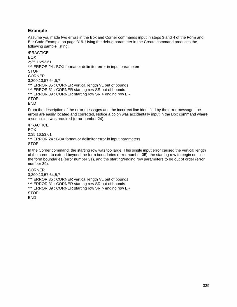
339
Example
Assume you made two errors in the Box and Corner commands input in steps 3 and 4 of the Form and Bar Code Example on page 319. Using the debug parameter in the Create command produces the following sample listing:
/PRACTICE BOX 2;35;16:53;61 *** ERROR 24 : BOX format or delimiter error in input parameters STOP CORNER 3;300;13;57;64;5;7 *** ERROR 35 : CORNER vertical length VL out of bounds *** ERROR 31 : CORNER starting row SR out of bounds *** ERROR 39 : CORNER starting row SR > ending row ER STOP END
From the description of the error messages and the incorrect line identified by the error message, the errors are easily located and corrected. Notice a colon was accidentally input in the Box command where a semicolon was required (error number 24).
/PRACTICE BOX 2;35;16:53;61 *** ERROR 24 : BOX format or delimiter error in input parameters STOP
In the Corner command, the starting row was too large. This single input error caused the vertical length of the corner to extend beyond the form boundaries (error number 35), the starting row to begin outside the form boundaries (error number 31), and the starting/ending row parameters to be out of order (error number 39).
CORNER 3;300;13;57;64;5;7 *** ERROR 35 : CORNER vertical length VL out of bounds *** ERROR 31 : CORNER starting row SR out of bounds *** ERROR 39 : CORNER starting row SR > ending row ER STOP END
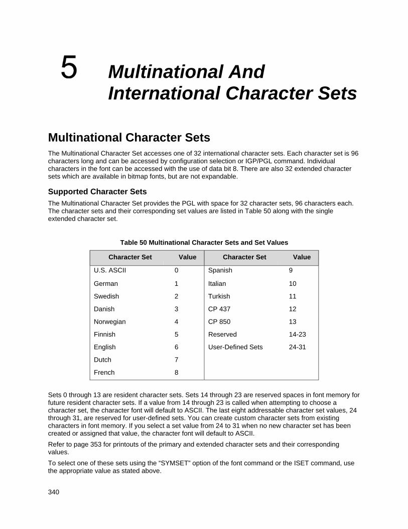
340
Multinational And International Character Sets
Multinational Character Sets The Multinational Character Set accesses one of 32 international character sets. Each character set is 96 characters long and can be accessed by configuration selection or IGP/PGL command. Individual characters in the font can be accessed with the use of data bit 8. There are also 32 extended character sets which are available in bitmap fonts, but are not expandable.
Supported Character Sets
The Multinational Character Set provides the PGL with space for 32 character sets, 96 characters each. The character sets and their corresponding set values are listed in Table 50 along with the single extended character set.
Table 50 Multinational Character Sets and Set Values
Character Set Value Character Set Value
U.S. ASCII 0 Spanish 9
German 1 Italian 10
Swedish 2 Turkish 11
Danish 3 CP 437 12
Norwegian 4 CP 850 13
Finnish 5 Reserved 14-23
English
Dutch
6
7
User-Defined Sets 24-31
French 8
Sets 0 through 13 are resident character sets. Sets 14 through 23 are reserved spaces in font memory for future resident character sets. If a value from 14 through 23 is called when attempting to choose a character set, the character font will default to ASCII. The last eight addressable character set values, 24 through 31, are reserved for user-defined sets. You can create custom character sets from existing characters in font memory. If you select a set value from 24 to 31 when no new character set has been created or assigned that value, the character font will default to ASCII.
Refer to page 353 for printouts of the primary and extended character sets and their corresponding values.
To select one of these sets using the “SYMSET” option of the font command or the ISET command, use the appropriate value as stated above.
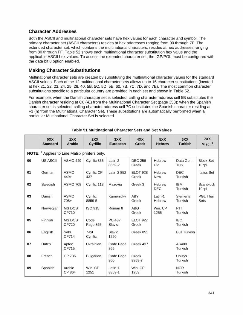
341
Character Addresses
Both the ASCII and multinational character sets have hex values for each character and symbol. The primary character set (ASCII characters) resides at hex addresses ranging from 00 through 7F. The extended character set, which contains the multinational characters, resides at hex addresses ranging from 80 through FF. Table 52 shows each multinational character substitution hex value and the applicable ASCII hex values. To access the extended character set, the IGP/PGL must be configured with the data bit 8 option enabled.
Making Character Substitutions
Multinational character sets are created by substituting the multinational character values for the standard ASCII values. Each of the 12 multinational character sets allows up to 16 character substitutions (located at hex 21, 22, 23, 24, 25, 26, 40, 5B, 5C, 5D, 5E, 60, 7B, 7C, 7D, and 7E). The most common character substitutions specific to a particular country are provided in each set and shown in Table 52.
For example, when the Danish character set is selected, calling character address cell 5B substitutes the Danish character residing at C6 (Æ) from the Multinational Character Set (page 353); when the Spanish character set is selected, calling character address cell 7C substitutes the Spanish character residing at F1 (ñ) from the Multinational Character Set. These substitutions are automatically performed when a particular Multinational Character Set is selected.
Table 51 Multinational Character Sets and Set Values
0XX
Standard 1XX
Arabic 2XX
Cyrillic 3XX
European 4XX
Greek 5XX
Hebrew 6XX
Turkish 7XX
Misc. 1
NOTE: 1 Applies to Line Matrix printers only.
00 US ASCII ASMO 449 Cyrillic 866 Latin 2 8859-2
DEC 256 Greek
Hebrew Old
Data Gen. Turk
Block-Set 10cpi
01 German ASMO 449+
Cyrillic CP 437
Latin 2 852 ELOT 928 Greek
Hebrew New
DEC Turkish
Italics Set
02 Swedish ASMO 708 Cyrillic 113 Mazovia Greek 3 Hebrew DEC
IBM Turkish
Scanblock 10cpi
03 Danish ASMO 708+
Cyrillic 8859-5
Kamenicky ABY Greek
Latin-1 Hebrew
Siemens Turkish
PGL Thai Sets
04 Norwegian MS DOS CP710
ISO 915 Roman 8 ABG Greek
Win. CP 1255
PTT Turkish
05 Finnish MS DOS CP720
Code Page 855
PC-437 Slavic
ELOT 927 Greek
IBC Turkish
06 English Sakr CP714
7-bit Cyrillic
Slavic 1250
Greek 851 Bull Turkish
07 Dutch Aptec Ukrainian Code Page Greek 437 AS400
CP715 865 Turkish
08 French CP 786 Bulgarian Code Page Greek Unisys 860 8859-7 Turkish
09 Spanish Arabic CP 864
Win. CP 1251
Latin 1 8859-1
Win. CP 1253
NCR Turkish
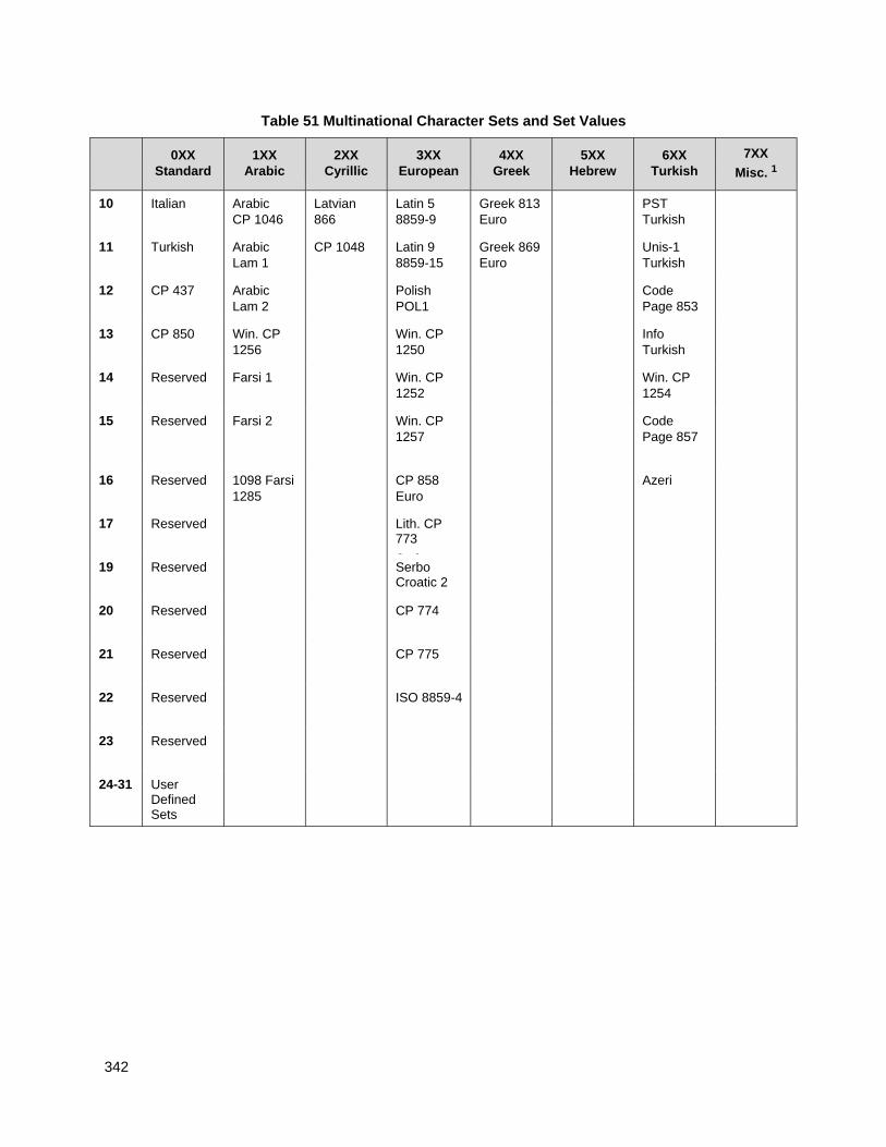
342
Table 51 Multinational Character Sets and Set Values
0XX
Standard 1XX
Arabic 2XX
Cyrillic 3XX
European 4XX
Greek 5XX
Hebrew 6XX
Turkish 7XX
Misc. 1
10 Italian Arabic CP 1046
Latvian 866
Latin 5 8859-9
Greek 813 Euro
PST Turkish
11 Turkish Arabic Lam 1
CP 1048 Latin 9 8859-15
Greek 869 Euro
Unis-1 Turkish
12 CP 437 Arabic Lam 2
Polish POL1
Code Page 853
13 CP 850 Win. CP 1256
Win. CP 1250
Info Turkish
14 Reserved Farsi 1 Win. CP 1252
Win. CP 1254
15 Reserved Farsi 2 Win. CP 1257
Code Page 857
16 Reserved 1098 Farsi 1285
CP 858 Euro
Azeri
17
Reserved
Lith. CP 773
S b
19 Reserved Serbo Croatic 2
20 Reserved CP 774
21 Reserved CP 775
22 Reserved ISO 8859-4
23 Reserved
24-31 User Defined Sets
343
Table 52 Substitution Set Hex Values
Character Set
Substitution Hex Value
U.S. ASCII 21 22 23 24 25 26 40 5B 5C 5D 5E 60 7B 7C 7D 7E
Danish C6 D8 C5 B0 E6 F8 E5
Dutch A3 80 81
English A3
Finnish A4 C4 D6 C5 E4 F6 E5 FC
French E0 FB E7 A7 F4 EA E9 F9 E8 EE
German A7 C4 D6 DC E4 F6 FC DF
Italian A7 B0 E9 83 F9 E0 F2 E8 EC
Norwegian A4 C9 C6 D8 C5 DC E9 E6 F8 E5 FC
Spanish
Swedish
82
A4
C9
C3
C4
D1
D6
D5
C5
A1
DC
E9
E3
E4
F1
F6
F5
E5
BF
FC
Turkish 84 C7 E7 85 86 D6 DC 87 88 89 F6 FC 8A
Unicode Character Set UTF-16 Character Set can be selected by ISET or SYMSET options using the appropriate value in Table 53.
This UTF-16 character set can not be selected via control panel.
Table 53 Unicode Character Sets
8xx Unicode
01 UTF-16 Big-Endian
02 UTF-16 Little-Endian
This UTF-16 character set can only works on:
The fixed data for ALPHA command or TWOBYTE command in CREATE mode.
The dynamic data for AF for ALPHA command or KF for TWOBYTE command in EXECUTE mode.
344
Double Byte Character Set The Double Byte Character set accesses one of the four double byte character sets: GB, Big5, Hangul KSC5601, and Kanji SJIS listed in Table 54.
Table 54 Double Byte Character Sets
11xx DBCS
00 GB18030
01 Big5
02 KSC5601
03 Kanji SJIS
To select one of these sets using the SYMSET option in the font command or the ISET command, use the appropriate value in Table 54.
The GB18030 character set supports GB18030 quad byte encoding.
Accessing Characters and Character Sets OCR Character Sets
Purpose Access OCR-A and OCR-B character sets.
Mode CREATE, NORMAL and EXECUTE
Format See Comments
Comments In the Create mode, you can access OCR fonts using the alphanumeric command. Use the Cn parameter in the ALPHA command (Commands chapter, page 25) for more information.
In the Normal and Execute modes, you can access OCR fonts using the Compressed Print (Density) command (Commands chapter, page 43).
NOTE: OCR fonts are only available in 10 cpi.
LINE MATRIX
Extended Character Sets
Purpose Access extended character sets.
Mode CREATE, NORMAL and EXECUTE
Format See Comments
Comments In the Normal and Execute modes, you can access extended fonts using the ISET Command, page 346. Character sets 32 through 64 are extended character bitmap fonts which are not expandable.
NOTE: The extended character sets are bitmapped fonts and can not be expanded beyond 2 x 2. They are also limited to the portrait orientation.
345
Data Bit 8
You can access individual characters using data bit 8 addressing. The primary character set is ASCII. These character values reside at hex addresses 20 through 7F. The Multinational or extended character sets reside at hex addresses 80 through FF and are accessible without reconfiguration.
NOTE: Data bit 8 must be set high so that Multinational or extended character sets are accessible without reconfiguration. However, the PION/PIOFF command (page 88) must also be set OFF to access these character sets in the hex 80-FF range. A PION setting will cause data in the hex 80-FF range to be interpreted as PI line data instead of extended character set data.
Power-Up Character Set Selection
You can select any one of the 14 resident multinational character sets shown in Table 50 (0 through 13) or any of the International Sets shown in Table 57 as the default character set at printer power-up. The IGP/PGL configuration settings determine which character set is the default character set at power- up. Refer to your Administrator’s Manual to configure the IGP/PGL for a specific character set. (See Select Font in the configuration menu.)
The character font selected at power-up will remain active until either the ISET or SYMSET command is selected or the configuration is changed. OCR and user-definable character sets cannot be configured as the default character set at printer power-up.
User-Defined Set Command (USET)
Purpose Creates custom character sets (except OCR fonts) from existing characters stored on the flash memory.
Mode NORMAL
Format (cc)USET n ca;fa END
(cc) Represents the Special Function Control Code.
USET The User Set command; enter USET.
n Selects USET character set number; enter a value ranging from 1 through 8.
ca Represents the ASCII character cell hex address which will have its contents replaced with the character located in the font address (fa). The ca value must be one of the 16 hex values specified in Table 52 on page 343.
fa Represents the hexadecimal value for the font address of a specified character in the Multinational character set (page 353) which will replace the current contents of ca. The fa value is the character substitution for the cell address (ca). The value of fa may range from hex 20 through FF.
END Ends the USET command.
Comments
You can define up to 16 character substitutions for each of the eight user-definable character sets. It is not necessary to address all 16 spaces available for character substitutions with a single USET command.
346
The character sets in the USET command are numbered 1 through 8. The character set values in the Character Set Selection (ISET) command (page 346) are numbered 24 through 31 and correspond to User Sets 1 through 8. The ISET command accesses and prints that custom character set.
The USET and ISET commands are related as shown in Table 55. Therefore, ISET;24 selects the substitution set defined as USET1, ISET;29 selects USET6, etc.
Table 55 USET-ISET Relationship
USETn corresponds to ISET;n
n = 1 n = 24
n = 2 n = 25
n = 3 n = 26
n = 4 n = 27
n = 5 n = 28
n = 6 n = 29
n = 7 n = 30
n = 8 n = 31
Example
The following example defines User Set 1 to contain the Multinational font addresses B1 (±), A1 (¡), and BF (¿) at the hex cell addresses 23, 24, and 25, respectively. Therefore, if ca = 23 and fa = B1, each time that cell address 23 is received, it will select the character located at font address B1 (±). ~USET1 23;B1 24;A1 25;BF END
User Set 1 now contains the following: the plus or minus sign ± (hex B1) in place of the number sign # (hex 23); the upside down exclamation point ¡ (hex A1) in place of the dollar sign $ (hex 24); and the upside down question mark ¿ (hex BF) in place of the percent sign % (hex 25). To print User Set 1, you must use the ISET command discussed on page 346.
Character Set Selection Command (ISET)
Purpose Accesses one of the multinational (Table 50) or international (Table 57) character sets. Use this command to access a different character set from the configured power-up default character set.
Mode NORMAL, CREATE, and EXECUTE
Format In Normal and Execute modes: (cc)ISET; n or (cc)ISET;‘UTF8’ or ISET;’xx’
In the Create mode (SFCC not required): ISET; n or ISET;‘UTF8’ or ISET;’xx’
(cc) Represents the Special Function Control Code.
ISET The Multinational Character Set command; enter ISET.
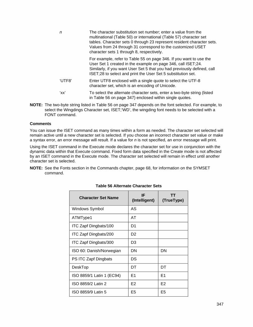
347
n The character substitution set number; enter a value from the multinational (Table 50) or international (Table 57) character set tables. Character sets 0 through 23 represent resident character sets. Values from 24 through 31 correspond to the customized USET character sets 1 through 8, respectively.
For example, refer to Table 55 on page 346. If you want to use the User Set 1 created in the example on page 346, call ISET;24. Similarly, if you want User Set 5 that you had previously defined, call ISET;28 to select and print the User Set 5 substitution set.
‘UTF8’ Enter UTF8 enclosed with a single quote to select the UTF-8 character set, which is an encoding of Unicode.
‘xx’ To select the alternate character sets, enter a two-byte string (listed in Table 56 on page 347) enclosed within single quotes.
NOTE: The two-byte string listed in Table 56 on page 347 depends on the font selected. For example, to select the Wingdings Character set, ISET;’WD’, the wingding font needs to be selected with a FONT command.
Comments
You can issue the ISET command as many times within a form as needed. The character set selected will remain active until a new character set is selected. If you choose an incorrect character set value or make a syntax error, an error message will result. If a value for n is not specified, an error message will print.
Using the ISET command in the Execute mode declares the character set for use in conjunction with the dynamic data within that Execute command. Fixed form data specified in the Create mode is not affected by an ISET command in the Execute mode. The character set selected will remain in effect until another character set is selected.
NOTE: See the Fonts section in the Commands chapter, page 68, for information on the SYMSET command.
Table 56 Alternate Character Sets
Character Set Name
IF (Intelligent)
TT (TrueType)
Windows Symbol AS
ATMType1 AT
ITC Zapf Dingbats/100 D1
ITC Zapf Dingbats/200 D2
ITC Zapf Dingbats/300 D3
ISO 60: Danish/Norwegian DN DN
PS ITC Zapf Dingbats DS
DeskTop DT DT
ISO 8859/1 Latin 1 (EC94) E1 E1
ISO 8859/2 Latin 2 E2 E2
ISO 8859/9 Latin 5 E5 E5
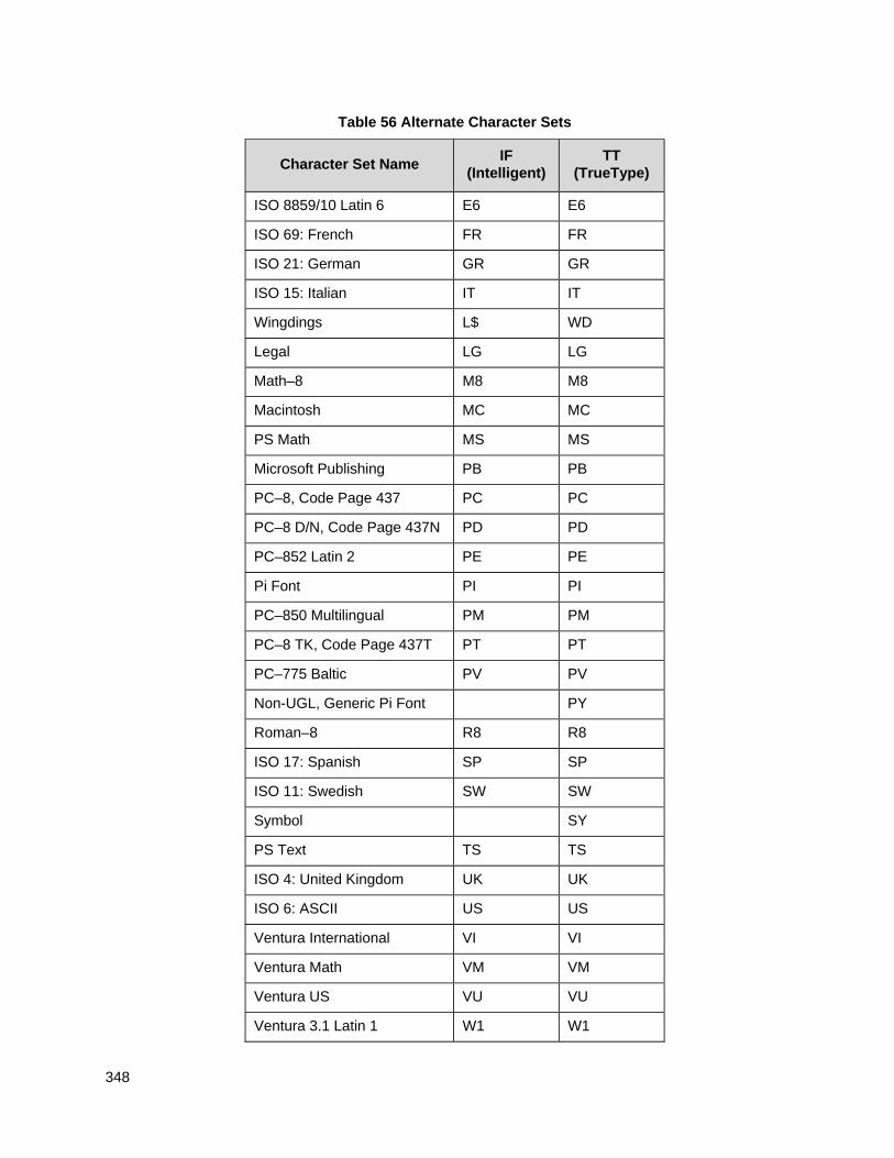
348
Table 56 Alternate Character Sets
Character Set Name
IF (Intelligent)
TT (TrueType)
ISO 8859/10 Latin 6 E6 E6
ISO 69: French FR FR
ISO 21: German GR GR
ISO 15: Italian IT IT
Wingdings L$ WD
Legal LG LG
Math–8 M8 M8
Macintosh MC MC
PS Math MS MS
Microsoft Publishing PB PB
PC–8, Code Page 437 PC PC
PC–8 D/N, Code Page 437N PD PD
PC–852 Latin 2 PE PE
Pi Font PI PI
PC–850 Multilingual PM PM
PC–8 TK, Code Page 437T PT PT
PC–775 Baltic PV PV
Non-UGL, Generic Pi Font PY
Roman–8 R8 R8
ISO 17: Spanish SP SP
ISO 11: Swedish SW SW
Symbol SY
PS Text TS TS
ISO 4: United Kingdom UK UK
ISO 6: ASCII US US
Ventura International VI VI
Ventura Math VM VM
Ventura US VU VU
Ventura 3.1 Latin 1 W1 W1
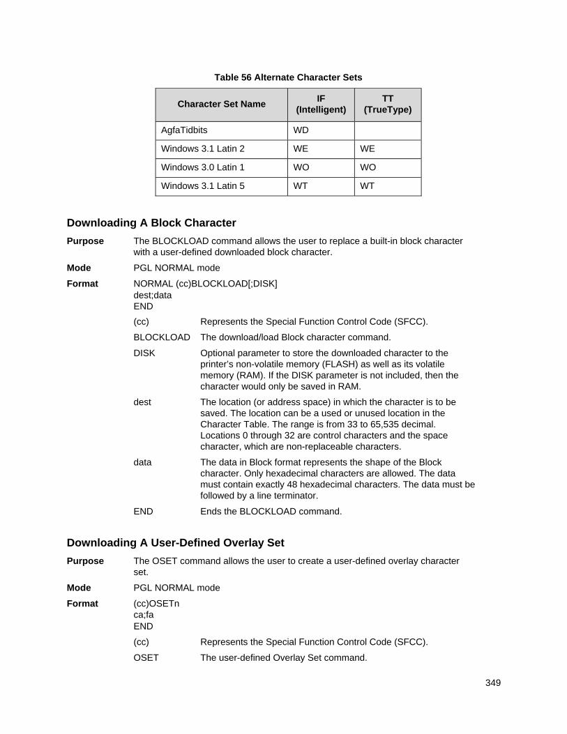
349
Table 56 Alternate Character Sets
Character Set Name
IF (Intelligent)
TT (TrueType)
AgfaTidbits WD
Windows 3.1 Latin 2 WE WE
Windows 3.0 Latin 1 WO WO
Windows 3.1 Latin 5 WT WT
Downloading A Block Character
Purpose The BLOCKLOAD command allows the user to replace a built-in block character with a user-defined downloaded block character.
Mode PGL NORMAL mode
Format NORMAL (cc)BLOCKLOAD[;DISK] dest;data END
(cc) Represents the Special Function Control Code (SFCC).
BLOCKLOAD The download/load Block character command.
DISK Optional parameter to store the downloaded character to the printer’s non-volatile memory (FLASH) as well as its volatile memory (RAM). If the DISK parameter is not included, then the character would only be saved in RAM.
dest The location (or address space) in which the character is to be saved. The location can be a used or unused location in the Character Table. The range is from 33 to 65,535 decimal. Locations 0 through 32 are control characters and the space character, which are non-replaceable characters.
data The data in Block format represents the shape of the Block character. Only hexadecimal characters are allowed. The data must contain exactly 48 hexadecimal characters. The data must be followed by a line terminator.
END Ends the BLOCKLOAD command.
Downloading A User-Defined Overlay Set
Purpose The OSET command allows the user to create a user-defined overlay character set.
Mode PGL NORMAL mode
Format (cc)OSETn ca;fa END
(cc) Represents the Special Function Control Code (SFCC).
OSET The user-defined Overlay Set command.
350
n Selects the overlay character set number. The range is from 1 to 8. The overlay set number 1 through 8 corresponds to the ISET character set selection 16 through 23.
ca The ASCII character cell address in the current character set that will have its contents replaced by the character located in the font address (fa). The range is 33 through 255 decimal. Locations 0 through 32 are control characters and the space character, which are non-replaceable characters.
fa The decimal address of the character (code point) in the character table that will replace the current contents of ca. The value may range from 33 to 65,535. Refer to the Character Table (Appendix C) in the LP+ Programmer’s Reference Manual to determine which locations are used or unused.
Addresses 0-32 are not allowed to avoid confusion between control characters and printable characters. Multiple ca;fa lines can be defined with a single OSET command.
END Ends the OSET command.
NOTE: Only printable locations can be replaced. Control codes and the space character cannot be replaced. If the value of the cell address (ca) points to a control code or a space, then an error will print.
Activating A User-Defined Overlay Set
Purpose An overlay set cannot be accessed until it is requested. Once a user-defined overlay set (Substitution Table) is created, the ISET command can be used to activate it. The ISET command can also be used to access regular (non-overlay) sets such as multinational or international character sets. If an overlay set selected has not been created, then the ISET command would have no effect on the currently selected character set.
Format (cc)ISET;n
(cc) Represents the Special Function Control Code (SFCC).
ISET The character set command.
n The character set number. The valid values are 0 through 31. Overlay sets reside within sets numbered 16 through 23. All other values correspond to non-overlay sets.
Disabling An Overlay Set
The PGL overlay set is activated by the ISET command. It remains active until another character set is selected. When the character set is changed, all overlay sets will be disabled even if the selected set is the same as the previous base character set.
Examples for Downloaded Block Characters & Overlays
This section provides the available block patterns for creating a block character. Each character is composed of 24 bytes (NERF is 32 bytes), which is 48 nibbles of block patterns.
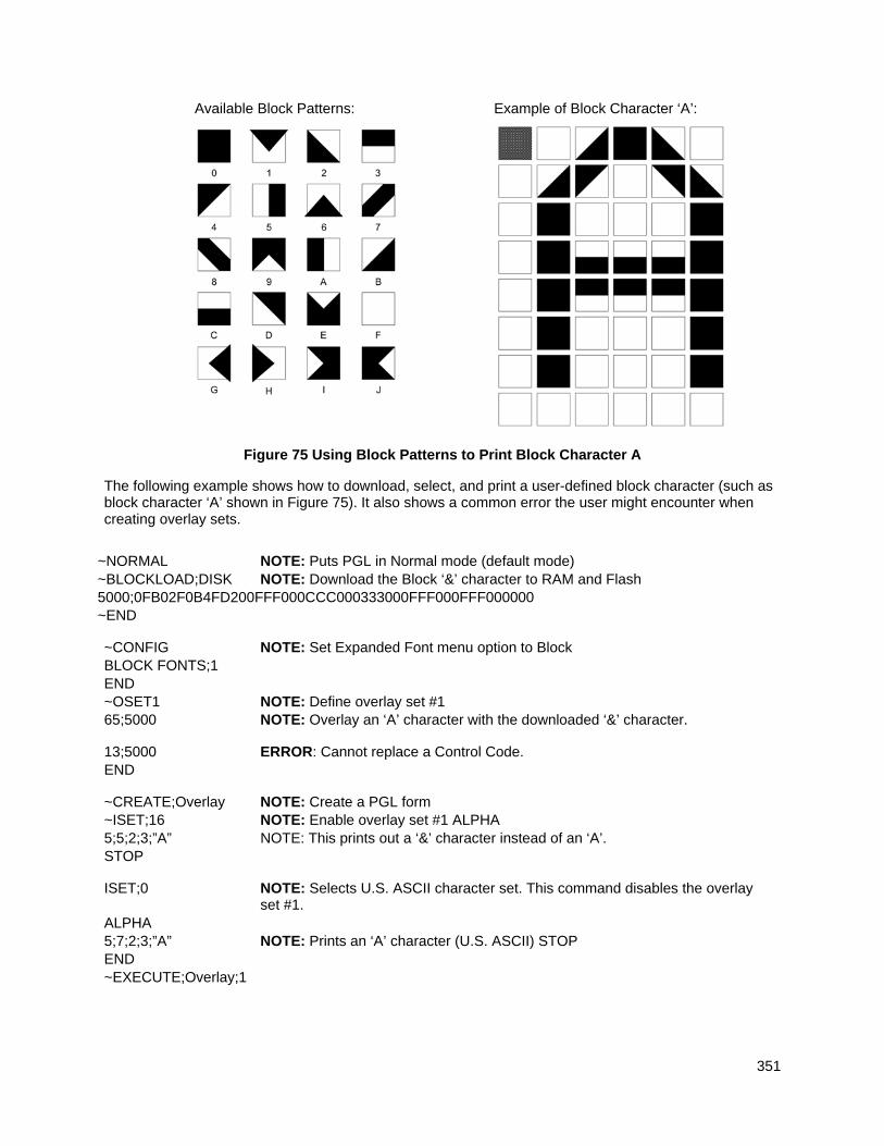
351
Figure 75 Using Block Patterns to Print Block Character A
The following example shows how to download, select, and print a user-defined block character (such as block character ‘A’ shown in Figure 75). It also shows a common error the user might encounter when creating overlay sets.
~NORMAL NOTE: Puts PGL in Normal mode (default mode) ~BLOCKLOAD;DISK NOTE: Download the Block ‘&’ character to RAM and Flash 5000;0FB02F0B4FD200FFF000CCC000333000FFF000FFF000000 ~END
~CONFIG NOTE: Set Expanded Font menu option to Block BLOCK FONTS;1 END ~OSET1 NOTE: Define overlay set #1 65;5000 NOTE: Overlay an ‘A’ character with the downloaded ‘&’ character.
13;5000 ERROR: Cannot replace a Control Code. END
~CREATE;Overlay NOTE: Create a PGL form ~ISET;16 NOTE: Enable overlay set #1 ALPHA 5;5;2;3;”A” NOTE: This prints out a ‘&’ character instead of an ‘A’. STOP
ISET;0 NOTE: Selects U.S. ASCII character set. This command disables the overlay set #1.
ALPHA 5;7;2;3;”A” NOTE: Prints an ‘A’ character (U.S. ASCII) STOP END ~EXECUTE;Overlay;1
Available Block Patterns: Example of Block Character ‘A’:
352
Setting The Expanded Font Menu Option
Purpose To access Block fonts in PGL, user needs to set the Expanded Font menu to Block. This can be done through the front panel or by using the configuration command BLOCK FONTS.
Format (cc)CONFIG BLOCK FONTS;value
END
(cc) Represents the Special Function Control Code (SFCC).
CONFIG The configuration command.
BLOCK FONTS The configuration item.
value 0 to disable, non-zero to enable.
If an overlay set is active and the Expanded Font option is set to Block, the printer first checks the overlay set. The overlay characters have precedence over the base characters, except for control codes and the space character. If an overlay character exists for a particular cell, then that character will print in place of the character in the base character set.
Downloaded Font Menus
The Downloaded Font menu applies to both LP+ Bitmaps and IGP Block downloaded characters. For example, performing a Delete from Flash option deletes both Bitmap and Block downloaded characters from the flash memory. Refer to the Administrator’s Manual for detailed descriptions of the menus and their functions.
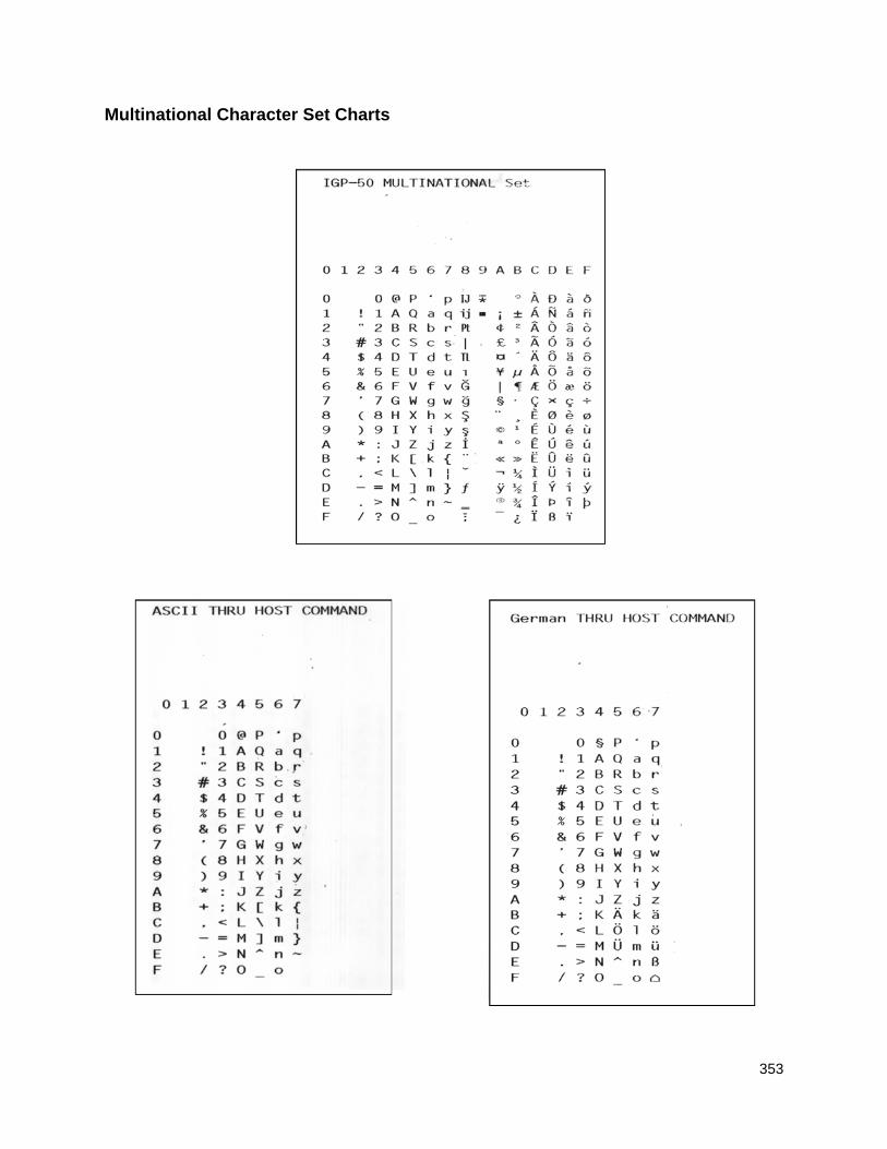
353
Multinational Character Set Charts
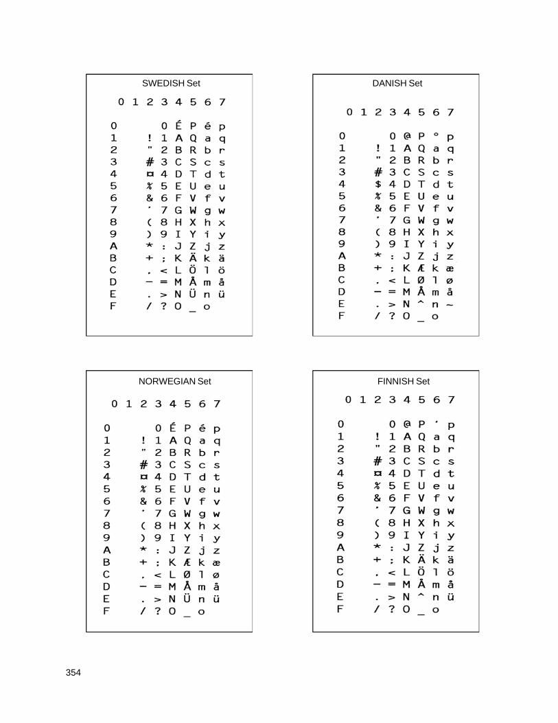
354
SWEDISH Set DANISH Set
FINNISH Set NORWEGIAN Set
355
ENGLISH Set DUTCH Set
FRENCH Set SPANISH Set
356
ITALIAN Set TURKISH Set
357
International Character Sets
The International Character Sets supported are listed in Table 57. Select these sets from the configuration menu “Select Font” option, or through the SYMSET option of the “FONT” command or the ISET command.
See Table 51 for a list of the Multinational Character Sets and their corresponding set values.
Table 57 International Character Sets
Character Set Set Value Character Set Set Value
Standard Sets 00
Arabic Sets 100 US ASCII ASMO 449
German 01 ASMO 449+ 101 Swedish 02 ASMO 708 102 Danish 03 ASMO 708 103 Norwegian 04 MS DOS CP 710 104 Finnish 05 MS DOS CP 720 105 English 06 Sakr CP 714 106 Dutch 07 Aptec CP 715 107 French 08 CP 786 108 Spanish 09 Arabic CP 864 109 Italian 10 Arabic CP 1046 110 Turkish 11 Arabic Lam 1 111 CP 437 12 Arabic Lam 2 112 CP 850 13 Win CP 1256 113
Farsi 1 114 Farsi 2 115 1098 Farsi 1285 116
Cyrillic Sets 200
European Sets 300 Code Page 866 Latin 2 8859-2
Cyrillic CP 437 201 Code Page 852 301 Cyrillic 113 202 Mazovia 302 Cyrillic 8859-5 203 Kamenicky 303 ISO 915 204 Roman 8 304 Code Page 855 205 PC-437 Slavic 305 7-bit Cyrillic 206 Slavic 1250 306 Ukrainian 207 Code Page 865 307 Bulgarian 208 Code Page 860 308 Win CP 1251 209 Latin 1 8859-1 309 Latvian 866 210 Latin 5 8859-9 310 CP 1048 211 Latin 9 8859-15 311
Polish Pol 1 312 Win CP 1250 313 Win CP 1252 314 Win CP 1257 315 CP858 EURO 316 Lith CP773 317 Serbo Croatic1 318 Serbo Croatic2 319 CP 774 320 CP 775 321 ISO 8859-4 322
358
Table 57 International Character Sets
Character Set Set Value Character Set Set Value
Greek Sets Hebrew Sets
DEC 256 Greek 400 Hebrew Old 500 ELOT 928 Greek 401 Hebrew New 501 Greek 3 402 Hebrew DEC 502 ABY Greek 403 Latin-1 Hebrew 503 ABG Greek 404 Win CP 1255 504
ELOT 927 Greek 405 406
Greek 851 Greek 437 407 Greek 8859-7 408 Win CP 1253 409 Creek 813 EURO 410 Greek 869 EURO 411
Turkish Sets 600
Data General Turkish DEC Turkish 601 IBM Turkish 602 Siemens Turkish 603 PTT Turkish 604 IBC Turkish 605 Bull Turkish 606 AS400 Turkish 607 Unisys Turkish 608 NCR Turkish 609 PST Turkish 610 Unis-1 Turkish 611 Code Page 853 612 INFO Turkish 613 Win CP 1254 614 Code Page 857 615 Azeri 616

359
360
Error Codes
IGP/PGL Emulation Error Codes The IGP/PGL provides coded error messages to assist in “debugging” programs. The printer will print an error message number and the program line which contains the error when an error is detected. To help determine exactly where the error occurred, use the following debug command sequence:
(CC)CREATE;/FORM NAME
The slash (/) places the IGP/PGL in a debug mode, and the program prints, line by line, with the error number and message printed below the specific error in the program. The error-free portions of the form will print following the program. After correcting the error(s), print the file again. When the errors have been corrected, delete the slash. (A sample debug listing is shown in Solving Program Errors on page 338.)
In the Execute mode, that part of the form which was correctly defined and stored during the Create mode will print, including any dynamic data and overlay text which was accepted before the error occurred. (Sections containing errors must be corrected before storage in the Directory can take place.) Any error messages will print following the printed form, and processing will continue in the Normal mode.
In the Create Form or Create Logo mode, any error messages will print first, followed by that part of the form/logo which was correctly defined. Incorrectly defined elements are excluded from the form/logo.
The error codes are broken down into categories. In each category, the number preceding each error message is the actual error code reported by the printer, and the error shown in bold is the error message printed.
361
Horizontal Line Errors
01 HORiZontal line starting row SR out of bounds
The row specified by the second parameter in the horizontal line command places the horizontal line outside the boundaries of the form.
02 HORiZontal line starting column SC out of bounds
The left (starting) column of the horizontal line specified by the third parameter in the horizontal line command places the horizontal line outside the boundaries of the form.
03 HORiZontal line ending column EC out of bounds
The right (ending) column of the horizontal line specified by the fourth parameter in the horizontal line command places the horizontal line outside the boundaries of the form.
04 HORiZontal line format or delimiter error Some type of format or delimiter error was detected in the parameters of the horizontal line command. This error is usually caused by one or more of the following:
a. A missing semicolon;
b. A colon in place of a semicolon;
c. Too many or too few parameters in the command string;
d. Alpha characters instead of numeric characters in the parameters.
05 Insufficient memory to store the HORiZontal line
No more room in the IGP/PGL memory exists for another horizontal line. The rest of the horizontal line commands are flushed until the Stop command is found. Processing will then continue normally. To create space in the IGP/PGL memory, delete forms with horizontal line elements that are no longer required.
06 HORiZontal line starting column SC > ending column EC
The left (starting) column parameter of the horizontal line command is greater than or equal to the right (ending) column parameter.
07 HORiZontal line thickness LT error
The thickness of the horizontal line specified by the first parameter in the horizontal line command is incorrect. This error is usually caused by specifying a thickness of zero.
08-09 Not defined.
362
Vertical Line Errors
10 VERTical line starting column SC out of bounds
The column specified by the second parameter in the vertical line command places the vertical line outside the form boundaries.
11 VERTical line starting row SR out of bounds
The upper (starting) row of the vertical line specified by the third parameter in the vertical line command places the vertical line outside the boundaries of the form.
12 VERTical line ending row ER out of bounds
The lower (ending) row of the vertical line specified by the fourth parameter in the vertical line command places the vertical line outside the boundaries of the form.
13 VERTical line format or delimiter error
Some type of format or delimiter error was detected in the parameters of the vertical line command. This error is usually caused by one or more of the following:
a. A missing semicolon;
b. A colon in place of a semicolon;
c. Too many or too few parameters in the command string;
d. Alpha characters instead of numeric characters in the parameters.
14 Insufficient memory to store the VERTical line
No more room in the IGP/PGL memory exists for another vertical line. The rest of the vertical line commands are flushed until the Stop command is found. Processing will then continue normally. To create space in the IGP/PGL memory, delete forms with vertical line elements that are no longer required.
15 VERTical line starting row SR > ending row ER
The upper (starting) row parameter of the vertical line command is greater than or equal to the lower (ending) row parameter.
16 VERTical line thickness LT error
The thickness of the vertical line specified by the first parameter in the vertical line command is incorrect. This error is usually caused by specifying a thickness of zero.
17-19 Not defined.
363
Box Errors
20 BOX starting column SC out of bounds
The left (starting) column specified by the third parameter in the box command places the box outside the form boundaries.
21 BOX starting row SR out of bounds
The upper (starting) row of the box specified by the second parameter in the box command will place the box outside the boundaries of the form.
22 BOX ending column EC out of bounds
The right (ending) column specified by the fifth parameter in the box command places the box outside the form boundaries.
23 BOX ending row ER out of bounds
The lower (ending) row of the box specified by the fourth parameter in the box command will place the box outside the boundaries of the form.
24 BOX format or delimiter error in input parameters
Some type of format or delimiter error was detected in the parameters of the box command. This error is usually caused by one or more of the following:
a. A missing semicolon;
b. A colon in place of a semicolon;
c. Too many or too few parameters in the command string;
d. Alpha characters instead of numeric characters in the parameters.
25 Insufficient memory to store the BOX
No more room in the IGP/PGL memory exists for another box. The rest of the box commands are flushed until the Stop command is found. Processing will then continue normally. To create space in the IGP/PGL memory, delete forms with box elements that are no longer required.
26 BOX starting column SC > ending column EC
The left (starting) column parameter of the box command is greater than or equal to the right (ending) column parameter.
27 BOX starting row SR > ending row ER
The upper (starting) row parameter of the box command is greater than or equal to the lower (ending) row parameter.
28 BOX line thickness LT error
The thickness of the box specified by the first parameter in the box command is incorrect. This error is usually caused by specifying a thickness of zero.
29 Box radius index out of range. The optional parameter, round corner radius index, specified by the last parameter in the box command is out of range.
364
Corner Errors
30 CORNER starting column SC out of bounds
The left (starting) column specified by the third parameter in the corner command places the corner outside the form boundaries.
31 CORNER starting row SR out of bounds
The upper (starting) row of the corner specified by the second parameter in the corner command will place the corner outside the boundaries of the form.
32 CORNER ending column EC out of bounds
The right (ending) column specified by the fifth parameter in the corner command places the corner outside the form boundaries.
33 CORNER ending row ER out of bounds
The lower (ending) row of the corner specified by the fourth parameter in the corner command will place the corner outside the boundaries of the form.
34 CORNER horizontal length HL out of bounds
The length of the horizontal arms of the corner specified by the seventh parameter in the corner command will cause parts of the corner to extend outside the form boundaries.
35 CORNER vertical length VL out of bounds
The length of the vertical arms of the corner specified by the sixth parameter in the corner command will cause parts of the corner to extend above or below the boundaries of the form.
36 CORNER format or delimiter error in input parameters
Some type of format or delimiter error was detected in the parameters of the corner command. This error is usually caused by one or more of the following:
a. A missing semicolon;
b. A colon in place of a semicolon;
c. Too many or too few parameters in the command string;
d. Alpha characters instead of numeric characters in the parameters.
37 Insufficient memory to store the CORNER
No more room in the IGP/PGL memory exists for another corner. The rest of the corner commands are flushed until the Stop command is found. Processing will then continue normally. To create space in the IGP/PGL memory, delete forms with corner elements that are no longer required.
38 CORNER starting column SC > ending column EC
The left (starting) column parameter of the corner command is greater than or equal to the right (ending) column parameter.
39 CORNER starting row SR > ending row ER
The upper (starting) row parameter of the corner command is greater than or equal to the lower (ending) row parameter.
365
Alpha Errors
40 ALPHA leading and trailing delimiters mismatched
The leading delimiter (printable character) of the actual text string was not matched with an ending delimiter before the line terminator was found.
41 ALPHA starting row SR out of bounds
The starting row parameter in the Alpha command will cause the text string to print either above or below the limits of the form.
NOTE: Expanded print text strings expand up from the specified row. This could cause an attempt to print the text string above the top of the form and generate the error message.
42 ALPHA starting column SC out of bounds The starting column parameter in the Alpha command is either extending the alpha
string beyond the left margin of the form or the starting column parameter, plus the actual length of the text is extending the string beyond the right margin of the page.
43 ALPHA string length > 255 characters The string contains more than 255 characters.
44 ALPHA format or delimiter error in input parameters Some type of format or delimiter error was detected in the parameters of the alpha
command. This error is usually caused by one or more of the following:
a. A missing semicolon;
b. A colon in place of a semicolon;
c. Too many or too few parameters in the command string;
d. Alpha characters instead of numeric characters in the parameters.
45 Insufficient memory to store the ALPHA string No more room in the IGP/PGL memory exists for another alpha string. The rest of
the Alpha commands are flushed until the Stop command is found. Processing of the form will then continue normally. To create space in the IGP/PGL memory, delete forms with alpha string elements that are no longer required.
46 ALPHA X expansion HE and Y expansion VE must be zero When the expanded character parameters VE and HE are used within the ALPHA command, both values must be either zero or non-zero values. Use vertical expansion and horizontal expansion with 12 point font size only. If the elongated characters parameter [E] or the compressed characters parameter [Cn] is used in the ALPHA command, the VE and HE values must be set to 0.
47 ALPHA X expansion factor HE out of bounds The horizontal expansion factor is greater than the maximum allowed.
48 ALPHA Y expansion factor VE out of bounds The vertical expansion factor is greater than the maximum allowed.
49 ALPHA compression factor Cn or Density error (10, 10A, 10B, 12, 13, 15, 17, 20)
The optional compression parameter (Cn) which defines the horizontal pitch of the text was specified incorrectly. The pitches currently available are 10, 10A, 10B, 12, 13, 15, 17, and 20 cpi.
366
Logo Errors
50 LOGO horizontal width HL > 240 or dot col> HL a. The horizontal width of the logo is equal to zero or greater than 240. The IGP/PGL
automatically reverts to Normal mode when this occurs.
b. A dot position specified in the logo program exceeds the specified horizontal width of the logo. When this occurs, the buffer is flushed until a line terminator is found, and then logo construction continues normally.
51 LOGO vertical length VL > 252 or dot row n > VL a. The vertical length of the logo is equal to zero or greater than 252. The IGP/PGL
automatically reverts to Normal mode when this occurs.
b. A dot row specified in the logo program exceeds the specified vertical length of the logo. When this occurs, the buffer is flushed until a line terminator is found, and then logo construction continues normally.
52 LOGO hyphen syntax error in input parameters
The beginning or ending dots are out of order, or a parameter is missing. The buffer is flushed until a line terminator is found, and then logo construction continues normally.
53 Insufficient memory to create the LOGO
No more room exists in IGP/PGL memory to construct a logo for the size specified. When this occurs, the IGP/PGL automatically reverts to Normal mode. To create space in IGP/PGL memory, delete forms with logo elements (including the logos) that are no longer required.
54 LOGO format or delimiter error
Some type of format or delimiter error was detected in the Logo command. If this occurs while specifying the size and name of the logo, the IGP/PGL automatically reverts to the Normal mode. If this occurs during the actual construction of the logo, the buffer is flushed until a line terminator is found, and then logo construction continues normally.
55 LOGO call not previously defined
An attempt was made in the Create Form mode to incorporate an undefined logo into a form. This error is not generated during the Logo Form mode. When this error occurs, the buffer is flushed until a line terminator is found, and then forms creation continues normally.
56 Insufficient memory for another LOGO call
IGP/PGL memory cannot store another logo call. To create space in the IGP/PGL memory, delete forms with logo elements (including the logos) no longer required.
57 LOGO call starting row SR out of bounds
During form creation, the parameter specifying the row position of a logo places the logo outside the form boundaries. The buffer is flushed until a line terminator is found, and then processing continues normally.
58 LOGO call starting column SC out of bounds
During form creation, the parameter specifying the column position of a logo places the logo outside the form boundaries. When this occurs, the buffer is flushed until a line terminator is found, and then processing continues normally.
59 LOGO error found in DISK/FLASH file
When the logo was loaded dynamically in Execute Form mode from disk or flash, there was an error in processing the logo.
367
Create Errors
60 Directory full - cannot CREATE the form or LOGO
The directory is full, or no more room exists in the IGP/PGL memory for another form. When this occurs, the IGP/PGL automatically reverts to the Normal mode. To create space in the IGP/PGL memory, delete forms that are no longer required.
61 CREATE function unrecognized
An unrecognizable command is entered during the Create Form mode. At this point, the buffer is flushed until a Stop command is found, and then processing continues.
62 CREATE horizontal duplication parameter HDUP error
Either a format error was detected or a parameter was exceeded. The duplication number must be no greater than 255, and the offset must be no greater than 792 (dot scale). If this error occurs, the Horizontal Duplication command is ignored, and forms processing continues.
63 CREATE vertical duplication parameter VDUP error
Either a format error was detected, or a parameter was exceeded. The duplication number must be no greater than 255 and the offset must be no greater than the specified length of the form. If this error occurs, the Vertical Duplication command is ignored, and forms processing continues.
64 CREATE scale factor parameter SCALE invalid
Either a format error was detected, or a parameter was specified incorrectly. The vertical lines per inch can be specified as 1 to the target DPI. The horizontal characters per inch can be specified only as 10, 12, 13, 15, 17 or 20 cpi. If this error occurs, the Scale command is ignored and forms processing continues.
65 CREATE page starting row PAGE SR out of bounds
When you specify the position of the page parameters with the Page command in the Create Form mode, the row position specified will place the page number above or below the boundaries of the form. When this error occurs, the IGP/PGL will automatically revert to the Normal mode.
66 CREATE page starting column PAGE SC out of bounds
When you specify the position of the page parameters in the Create command, the column position specified will place the page number outside the form boundaries. When this error occurs, the IGP/PGL will automatically revert to the Normal mode.
67 CREATE STOP command missing
This error occurs when the IGP/PGL receives a new function command, an End command, or a mode command without receiving a Stop command. The IGP/PGL will continue to process subsequent commands correctly.
68 Insufficient memory to store the SETUP program
No more room in the IGP/PGL memory exists for storing the SETUP routine.
69 Insufficient memory to store the form
The directory is full, or no more room exists in the IGP/PGL memory for another form. When this occurs, the IGP/PGL automatically reverts to the Normal mode. To create space in the IGP/PGL memory, delete forms that are no longer required.
368
Execute Errors
70 EXECUTE form count parameter FC error
This error occurs when the parameter specifying the number of blank forms to print was entered incorrectly. When this error occurs, the IGP/PGL will automatically revert to the Normal mode. Form count can be from 1 through 65,535.
71 EXECUTE/DELETE form or file not found in the directory
An attempt was made to execute or delete a form which does not exist in the forms directory. When this error occurs, the IGP/PGL reverts to the Normal mode.
72 EXECUTE EVFU load error
This error is generated only during the Execute Form mode while programming the EVFU. If more channels than lines per physical page are specified during a load sequence, this error is generated, and the IGP/PGL automatically reverts to the Normal mode.
73 EXECUTE EVFU terminator invalid
This error is generated only during the Execute Form mode. The EVFU LOAD is missing an END LOAD code. If the line terminator cannot be deciphered, an error is generated, and the IGP/PGL reverts to the Normal mode.
74 Missing delimiter - must be a single quotation mark
When issuing an SFCC change command, the new SFCC character must be contained within two single quotation marks. If the new SFCC character is being identified by the ASCII value, no quotation marks are required.
75 Not defined.
76 EXECUTE page number error
An error was made while specifying the page number used with the form being executed. This error can be generated because of incorrect format or a page number that is too large. The specified page number can range from 0 through 99,999,999. Since the page number is part of the Execute command, the IGP/PGL will automatically revert to the Normal mode.
77 EXECUTE format or delimiter error
A format or delimiter error was detected in the Execute command; the IGP/PGL will automatically revert to the Normal mode. This error is usually caused by one or more of the following:
a. A missing semicolon;
b. A colon in place of a semicolon;
c. Too many or too few parameters in the command string;
d. Alpha characters instead of decimal digits in the parameters;
e. Page command misspelled when specifying the page number.
78 Insufficient memory to EXECUTE the form
Insufficient memory was available to recall and execute a form. The IGP/PGL will automatically revert to the Normal mode.
79 Not defined.
369
Miscellaneous Errors
80 Special function must be called from the NORMAL mode
This special function must be called from the Normal mode and not the Create Form or Execute Form mode. This error is generally due to a missing End command in the Create Form mode. For example, an attempt to enter the Create Form mode while executing a form will cause the IGP/PGL automatically to revert to the Normal mode.
81 No such special function
The special function call was unrecognizable. The IGP/PGL will automatically revert to the Normal mode.
82 Numeric value expected in input parameter
Characters other than numeric digits (0-9) are encountered where digits are expected.
83 Decimal input error in input parameter
The parameter expected was a decimal number. Either the number was not there, or it was too large (greater than 65,535). This error can also be caused by entering an alpha character instead of a numeric character.
84 Missing or wrong delimiter - must be a semicolon ;
The delimiter is either wrong or missing. The delimiter expected is a semicolon.
85 Missing or wrong delimiter - must be a colon :
86 DENSITY param error - 10, 10A, 10B, 12, 13, 15, 17, or 20
The parameters of the Density command are improperly specified. The densities currently implemented are 10, 10A, 10B, 12, 13, 15, 17, and 20 characters per inch. The command is ignored and processing continues.
87 LPI parameter error
The parameters of the LPI command are improperly specified. The allowable range is from 1 through 1000. The command is ignored and processing continues.
88 BARCODE type not supported
The bar code type selected is a valid IGP/PGL bar code, but is not supported by this type of printer.
89 EXPAND parameters out of bounds or format error
The parameters of the Expand command are improperly specified. Either the parameters are out of bounds, or some type of format error was detected. The command is ignored, and processing continues.
370
Bar Code Errors
90 Insufficient memory to store the BARCODE
No more room exists in the IGP/PGL memory for another bar code. The rest of the bar code commands are flushed until the Stop command is found. Processing will then continue.
91 ALPHA/BARCODE syntax error
Some type of syntax (format) error was detected in the parameters of the bar code command. This error is usually caused by one or more of the following:
a. Misspelled keywords;
b. Lowercase used;
c. A missing semicolon;
d. A colon in place of a semicolon;
e. An ending delimiter for the data field was not found;
f. Too many or too few parameters in the command string.
The rest of the command line is flushed until the Stop command is found. Processing will then continue.
92 BARCODE magnification factor MAG out of bounds or not allowed
The magnification factor specified in the bar code command is out of bounds. Refer to the applicable section in the Bar Codes chapter to determine the acceptable magnification values for the bar code symbol being used.
93 BARCODE starting row SR out of bounds
The starting row parameter in the bar code command will cause the bar code symbol to print either above or below the limits of the form.
94 BARCODE starting column SC out of bounds
The starting column parameter in the bar code command will cause the bar code symbol to print either beyond the left margin or the right margin of the form.
95 BARCODE height Hn out of bounds
The height parameter specified in the bar code command is out of bounds. Acceptable values vary based on the barcode symbology. See Chapter 3 for the allowable height range.
96 BARCODE data field has illegal character/format
A character in the data field was not recognized as an acceptable character. Refer to the applicable section in the Bar Codes chapter to determine the acceptable characters for the bar code symbol being used. The missing ending delimiter also causes this error.
97 BARCODE data field too short or too long
The data field in the bar code command has too few or too many data characters. Refer to the applicable section in the Bar Codes chapter to determine the acceptable number of data characters for the bar code symbol being used.
98 BARCODE symbol(s) exceeds the form length
The bar code command causes a bar code symbol to print below the limits of the form. This error occurs on the data field line of the bar code.
99 BARCODE symbol(s) exceeds the form width
The bar code command causes a bar code symbol to print beyond the right margin. This error occurs on the data field line of the bar code.
371
100 BARCODE variable ratio 0 or not ascending
101 BARCODE PDF not allowed or error - LOC: A or B - FONT: N, P, Q, R, T, V, O, X or S
The alternate font was selected for a barcode, an invalid parameter was used, or the selected height of the barcode cannot fit a PDF. Either the alternate font was selected for a barcode or an invalid parameter was used. Acceptable parameters must be “N” for the normal font, “O” for the OCR-A optional font, “X” for the OCR-B optional font, or “S” to suppress printing of the data field, “P” for 12 cpi, “Q” for 13 cpi, “R” for 15 cpi, “T” for 17 cpi, “V” for 20 cpi.
102 Dynamic BARCODE symbol exceeds the form length
The bar code command with a dynamic data field exceeds the limits of the current form length.
103 Dynamic data must be inserted at Top-of-Form
Dynamic data must immediately follow the EXECUTE command before any overlay data.
104 Dynamic BARCODE data field BFn not previously defined
Dynamic data field designated in the Execute Form mode was not defined in the Create Form mode.
105 Dynamic ALPHA/BARCODE/LOGO field AFn/BFn/GFn error must be 0-512
Dynamic alpha field number (AFn), bar code field number (BFn), or logo field number (GFn) must range from 0 through 512.
106 Dynamic BARCODE symbol exceeds the form width
107 Dynamic ALPHA data field AFn not previously defined
The dynamic alpha field number called for was not previously defined in the Create Form mode.
108 BARCODE symbol check digit CD out of bounds
109 Dynamic Alpha/BARCODE field longer than previously defined
The BARCODE data provided exceeds the maximum length for the bar code selected.
110 SFCC decimal input error - must be 01 - 255
The hexadecimal value on the ASCII chart for the Special Function Control Code is not valid. Refer to page 118 to select a valid SFCC.
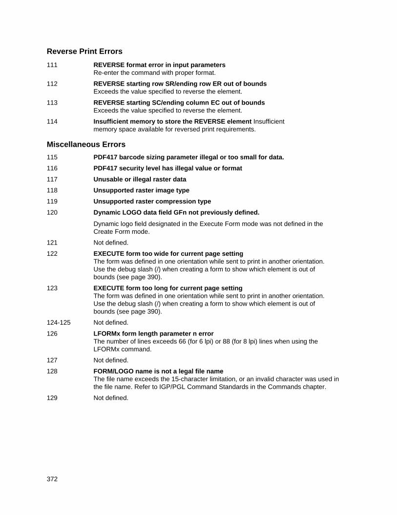
372
Reverse Print Errors
111 REVERSE format error in input parameters Re-enter the command with proper format.
112 REVERSE starting row SR/ending row ER out of bounds Exceeds the value specified to reverse the element.
113 REVERSE starting SC/ending column EC out of bounds Exceeds the value specified to reverse the element.
114 Insufficient memory to store the REVERSE element Insufficient memory space available for reversed print requirements.
Miscellaneous Errors
115 PDF417 barcode sizing parameter illegal or too small for data.
116 PDF417 security level has illegal value or format
117 Unusable or illegal raster data
118 Unsupported raster image type
119 Unsupported raster compression type
120 Dynamic LOGO data field GFn not previously defined.
Dynamic logo field designated in the Execute Form mode was not defined in the Create Form mode.
121 Not defined.
122 EXECUTE form too wide for current page setting The form was defined in one orientation while sent to print in another orientation.
Use the debug slash (/) when creating a form to show which element is out of bounds (see page 390).
123 EXECUTE form too long for current page setting The form was defined in one orientation while sent to print in another orientation.
Use the debug slash (/) when creating a form to show which element is out of bounds (see page 390).
124-125 Not defined.
126 LFORMx form length parameter n error The number of lines exceeds 66 (for 6 lpi) or 88 (for 8 lpi) lines when using the
LFORMx command.
127 Not defined.
128 FORM/LOGO name is not a legal file name The file name exceeds the 15-character limitation, or an invalid character was used in
the file name. Refer to IGP/PGL Command Standards in the Commands chapter.
129 Not defined.
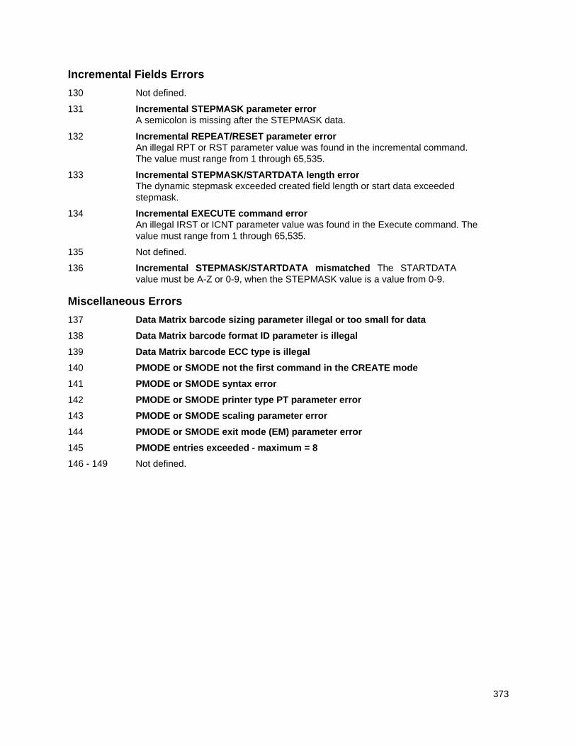
373
Incremental Fields Errors
130 Not defined.
131 Incremental STEPMASK parameter error A semicolon is missing after the STEPMASK data.
132 Incremental REPEAT/RESET parameter error An illegal RPT or RST parameter value was found in the incremental command.
The value must range from 1 through 65,535.
133 Incremental STEPMASK/STARTDATA length error The dynamic stepmask exceeded created field length or start data exceeded
stepmask.
134 Incremental EXECUTE command error An illegal IRST or ICNT parameter value was found in the Execute command. The
value must range from 1 through 65,535.
135 Not defined.
136 Incremental STEPMASK/STARTDATA mismatched The STARTDATA value must be A-Z or 0-9, when the STEPMASK value is a value from 0-9.
Miscellaneous Errors
137 Data Matrix barcode sizing parameter illegal or too small for data
138 Data Matrix barcode format ID parameter is illegal
139 Data Matrix barcode ECC type is illegal
140 PMODE or SMODE not the first command in the CREATE mode
141 PMODE or SMODE syntax error
142 PMODE or SMODE printer type PT parameter error
143 PMODE or SMODE scaling parameter error
144 PMODE or SMODE exit mode (EM) parameter error
145 PMODE entries exceeded - maximum = 8
146 - 149 Not defined.
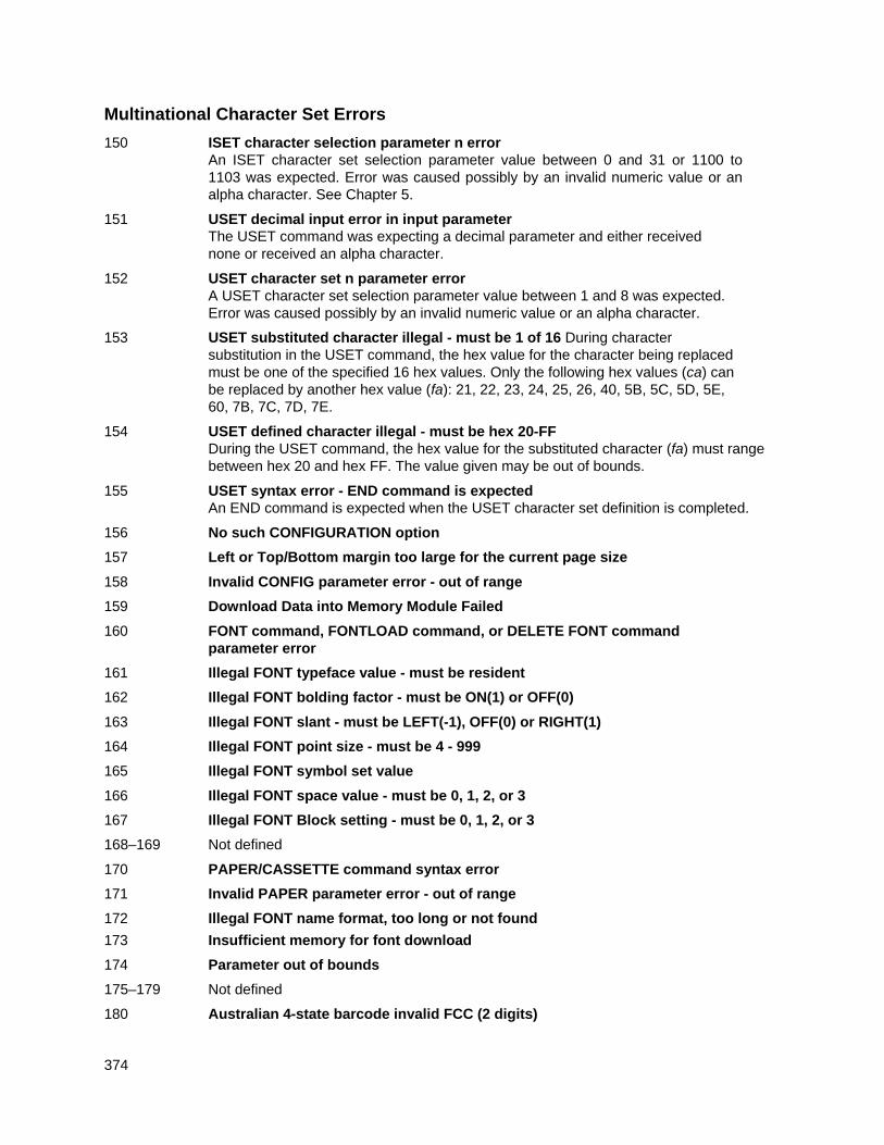
374
Multinational Character Set Errors
150 ISET character selection parameter n error An ISET character set selection parameter value between 0 and 31 or 1100 to
1103 was expected. Error was caused possibly by an invalid numeric value or an alpha character. See Chapter 5.
151 USET decimal input error in input parameter The USET command was expecting a decimal parameter and either received
none or received an alpha character.
152 USET character set n parameter error A USET character set selection parameter value between 1 and 8 was expected.
Error was caused possibly by an invalid numeric value or an alpha character.
153 USET substituted character illegal - must be 1 of 16 During character substitution in the USET command, the hex value for the character being replaced must be one of the specified 16 hex values. Only the following hex values (ca) can be replaced by another hex value (fa): 21, 22, 23, 24, 25, 26, 40, 5B, 5C, 5D, 5E, 60, 7B, 7C, 7D, 7E.
154 USET defined character illegal - must be hex 20-FF During the USET command, the hex value for the substituted character (fa) must range
between hex 20 and hex FF. The value given may be out of bounds.
155 USET syntax error - END command is expected An END command is expected when the USET character set definition is completed.
156 No such CONFIGURATION option
157 Left or Top/Bottom margin too large for the current page size
158 Invalid CONFIG parameter error - out of range
159 Download Data into Memory Module Failed
160 FONT command, FONTLOAD command, or DELETE FONT command parameter error
161 Illegal FONT typeface value - must be resident
162 Illegal FONT bolding factor - must be ON(1) or OFF(0)
163 Illegal FONT slant - must be LEFT(-1), OFF(0) or RIGHT(1)
164 Illegal FONT point size - must be 4 - 999
165 Illegal FONT symbol set value
166 Illegal FONT space value - must be 0, 1, 2, or 3
167 Illegal FONT Block setting - must be 0, 1, 2, or 3
168–169 Not defined
170 PAPER/CASSETTE command syntax error
171 Invalid PAPER parameter error - out of range
172 Illegal FONT name format, too long or not found
173 Insufficient memory for font download
174 Parameter out of bounds
175–179 Not defined
180 Australian 4-state barcode invalid FCC (2 digits)
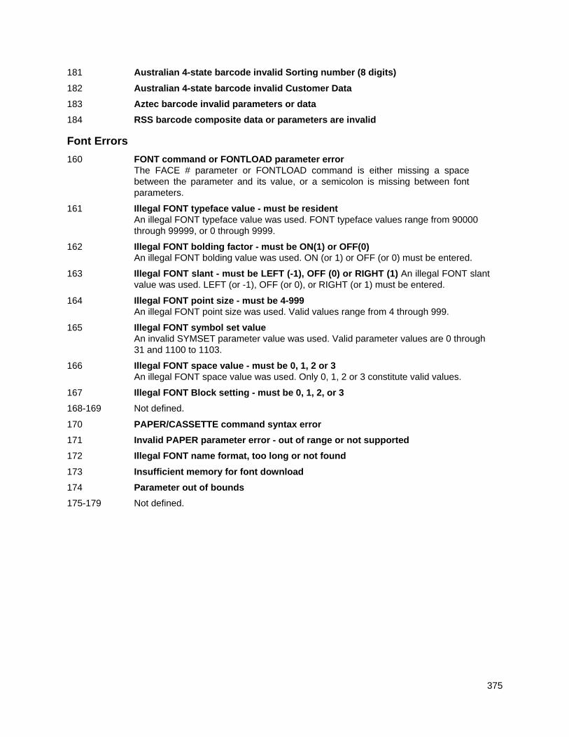
375
181 Australian 4-state barcode invalid Sorting number (8 digits)
182 Australian 4-state barcode invalid Customer Data
183 Aztec barcode invalid parameters or data
184 RSS barcode composite data or parameters are invalid
Font Errors
160 FONT command or FONTLOAD parameter error The FACE # parameter or FONTLOAD command is either missing a space
between the parameter and its value, or a semicolon is missing between font parameters.
161 Illegal FONT typeface value - must be resident An illegal FONT typeface value was used. FONT typeface values range from 90000
through 99999, or 0 through 9999.
162 Illegal FONT bolding factor - must be ON(1) or OFF(0) An illegal FONT bolding value was used. ON (or 1) or OFF (or 0) must be entered.
163 Illegal FONT slant - must be LEFT (-1), OFF (0) or RIGHT (1) An illegal FONT slant value was used. LEFT (or -1), OFF (or 0), or RIGHT (or 1) must be entered.
164 Illegal FONT point size - must be 4-999 An illegal FONT point size was used. Valid values range from 4 through 999.
165 Illegal FONT symbol set value An invalid SYMSET parameter value was used. Valid parameter values are 0 through
31 and 1100 to 1103.
166 Illegal FONT space value - must be 0, 1, 2 or 3 An illegal FONT space value was used. Only 0, 1, 2 or 3 constitute valid values.
167 Illegal FONT Block setting - must be 0, 1, 2, or 3
168-169 Not defined.
170 PAPER/CASSETTE command syntax error
171 Invalid PAPER parameter error - out of range or not supported
172 Illegal FONT name format, too long or not found
173 Insufficient memory for font download
174 Parameter out of bounds
175-179 Not defined.
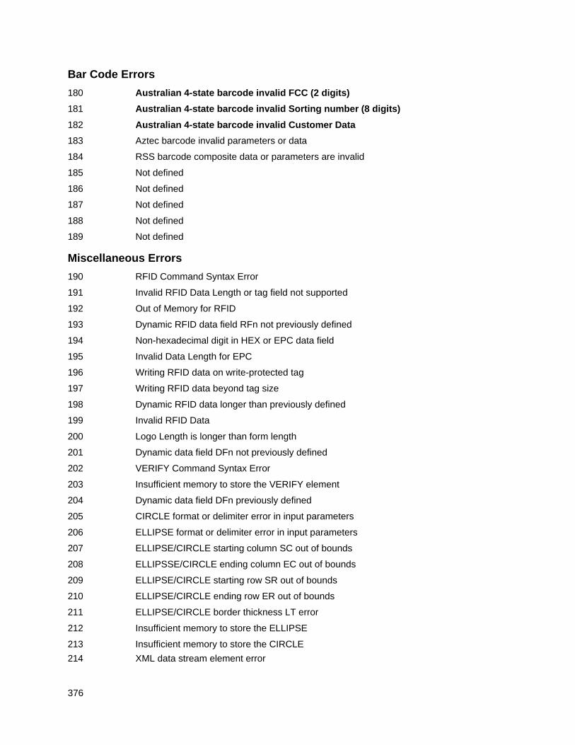
376
Bar Code Errors
180 Australian 4-state barcode invalid FCC (2 digits)
181 Australian 4-state barcode invalid Sorting number (8 digits)
182 Australian 4-state barcode invalid Customer Data
183 Aztec barcode invalid parameters or data
184 RSS barcode composite data or parameters are invalid
185 Not defined
186 Not defined
187 Not defined
188 Not defined
189 Not defined
Miscellaneous Errors
190 RFID Command Syntax Error
191 Invalid RFID Data Length or tag field not supported
192 Out of Memory for RFID
193 Dynamic RFID data field RFn not previously defined
194 Non-hexadecimal digit in HEX or EPC data field
195 Invalid Data Length for EPC
196 Writing RFID data on write-protected tag
197 Writing RFID data beyond tag size
198 Dynamic RFID data longer than previously defined
199 Invalid RFID Data
200 Logo Length is longer than form length
201 Dynamic data field DFn not previously defined
202 VERIFY Command Syntax Error
203 Insufficient memory to store the VERIFY element
204 Dynamic data field DFn previously defined
205 CIRCLE format or delimiter error in input parameters
206 ELLIPSE format or delimiter error in input parameters
207 ELLIPSE/CIRCLE starting column SC out of bounds
208 ELLIPSSE/CIRCLE ending column EC out of bounds
209 ELLIPSE/CIRCLE starting row SR out of bounds
210 ELLIPSE/CIRCLE ending row ER out of bounds
211 ELLIPSE/CIRCLE border thickness LT error
212 Insufficient memory to store the ELLIPSE
213 Insufficient memory to store the CIRCLE
214 XML data stream element error
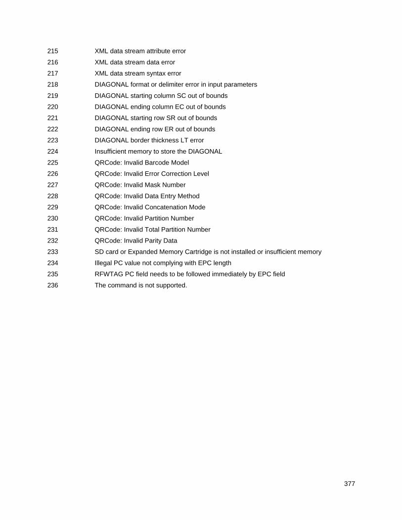
377
215 XML data stream attribute error
216 XML data stream data error
217 XML data stream syntax error
218 DIAGONAL format or delimiter error in input parameters
219 DIAGONAL starting column SC out of bounds
220 DIAGONAL ending column EC out of bounds
221 DIAGONAL starting row SR out of bounds
222 DIAGONAL ending row ER out of bounds
223 DIAGONAL border thickness LT error
224 Insufficient memory to store the DIAGONAL
225 QRCode: Invalid Barcode Model
226 QRCode: Invalid Error Correction Level
227 QRCode: Invalid Mask Number
228 QRCode: Invalid Data Entry Method
229 QRCode: Invalid Concatenation Mode
230 QRCode: Invalid Partition Number
231 QRCode: Invalid Total Partition Number
232 QRCode: Invalid Parity Data
233 SD card or Expanded Memory Cartridge is not installed or insufficient memory
234 Illegal PC value not complying with EPC length
235 RFWTAG PC field needs to be followed immediately by EPC field
236 The command is not supported.
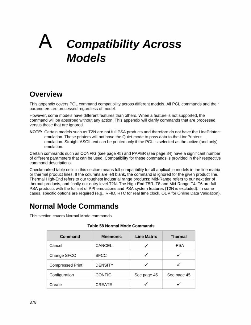
378
Compatibility Across Models
Overview This appendix covers PGL command compatibility across different models. All PGL commands and their parameters are processed regardless of model.
However, some models have different features than others. When a feature is not supported, the command will be absorbed without any action. This appendix will clarify commands that are processed versus those that are ignored.
NOTE: Certain models such as T2N are not full PSA products and therefore do not have the LinePrinter+ emulation. These printers will not have the Quiet mode to pass data to the LinePrinter+ emulation. Straight ASCII text can be printed only if the PGL is selected as the active (and only) emulation.
Certain commands such as CONFIG (see page 45) and PAPER (see page 84) have a significant number of different parameters that can be used. Compatibility for these commands is provided in their respective command descriptions.
Checkmarked table cells in this section means full compatibility for all applicable models in the line matrix or thermal product lines. If the columns are left blank, the command is ignored for the given product line. Thermal High-End refers to our toughest industrial range products; Mid-Range refers to our next tier of thermal products, and finally our entry level T2N. The High-End T5R, T8 and Mid-Range T4, T6 are full PSA products with the full set of PPI emulations and PSA system features (T2N is excluded). In some cases, specific options are required (e.g., RFID, RTC for real time clock, ODV for Online Data Validation).
Normal Mode Commands This section covers Normal Mode commands.
Table 58 Normal Mode Commands
Command Mnemonic Line Matrix Thermal
Cancel CANCEL PSA
Change SFCC SFCC
Compressed Print DENSITY
Configuration CONFIG See page 45 See page 45
Create CREATE
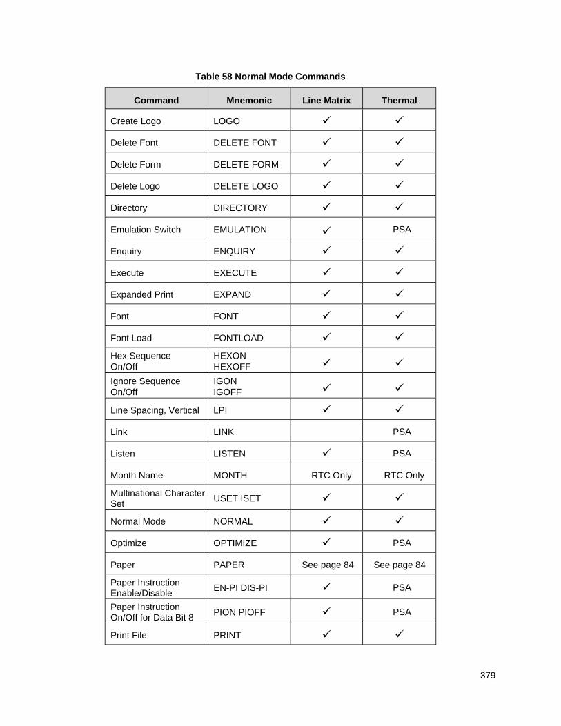
379
Table 58 Normal Mode Commands
Command Mnemonic Line Matrix Thermal
Create Logo LOGO
Delete Font DELETE FONT
Delete Form DELETE FORM
Delete Logo DELETE LOGO
Directory DIRECTORY
Emulation Switch EMULATION PSA
Enquiry ENQUIRY
Execute EXECUTE
Expanded Print EXPAND
Font FONT
Font Load FONTLOAD
Hex Sequence On/Off
HEXON HEXOFF
Ignore Sequence On/Off
IGON IGOFF
Line Spacing, Vertical LPI
Link LINK PSA
Listen LISTEN PSA
Month Name MONTH RTC Only RTC Only
Multinational Character Set
USET ISET
Normal Mode NORMAL
Optimize OPTIMIZE PSA
Paper PAPER See page 84 See page 84
Paper Instruction Enable/Disable
EN-PI DIS-PI PSA
Paper Instruction On/Off for Data Bit 8
PION PIOFF PSA
Print File PRINT
380
Table 58 Normal Mode Commands
Command Mnemonic Line Matrix Thermal
Printer Identification IDENTITY
Printer Status STATUS
Quiet QUIET PSA
Recall RECALL
Reset RESET
Set Clock SETCLOCK RTC only RTC only
Select Format On/Off SFON SFOFF
Set Up SETUP
Create Mode Commands This section covers Create Mode commands.
Table 59 Create Mode Commands
Command Mnemonic Line Matrix Thermal
Alphanumerics ALPHA
Alpha, Incremental ALPHA
Bar Codes BARCODE
Boxes BOX
Circle CIRCLE
Corners CORNER
Duplication, Horizontal HDUP
Duplication, Vertical VDUP
Ellipse ELLIPSE
End END
Font FONT
Form Length LFORM
381
Table 59 Create Mode Commands
Command Mnemonic Line Matrix Thermal
Ignore Sequence On/Off
IGON IGOFF
Lines, Diagonal DIAG
Lines, Horizontal HORZ
Lines, Vertical VERT
Logo Call LOGO
Logo Mode, Create
LOGODEF Multinational Character Set ISET
Page Number PAGE
Printer Mode PMODE
Reset RESET
Reverse Print REVERSE
RFWTAG RFWTAG RFID only
RFRTAG RFRTAG RFID only
Scale SCALE
Scaling SMODE
Select Format On/Off SFON SFOFF
VERIFY VERIFY ODV only
382
Execute Mode Commands This section covers Execute Mode commands.
Table 60 Create Mode Commands
Command Mnemonic Line Matrix Thermal
Compressed Print DENSITY
Dynamic Alphanumeric Data
AFn
Dynamic Bar Code Data BFn
Dynamic Logo GFn
Expanded Print EXPAND
Font FONT
Hex Sequence On/Off
HEXON HEXOFF
Ignore Sequence On/Off
IGON IGOFF
Incremental Alphanumeric Dynamic Data
IAFn
Incremental Bar Code Dynamic Data
IBFn
Line Spacing, Vertical
LPI
Multinational Character Set
ISET
Normal Mode NORMAL
Paper PAPER See page 84 See page 84
Reset RESET
Repeat REPEAT Select Format On/Off
SFON SFOFF

383
384
Standard ASCII Character Set
B7 B6
B5
BITS
0 0
0
0 0
1
0 1
0
0 1
1
1 0
0
1 0
1
1 1
0
1 1
1
COLUMN
0
1
2
3
4
5
6
7 B4 B3 B2 B1 ROW
0 0 0 0
0 NUL 0 0 0
DLE 20 16 10
SP 40 32 20
0 60 48 30
@ 100 64 40
P 120 80 50
140 96 60
p 160 112 70
0 0 0 1
1 SOH 1
1 1
DC1 (XON)
21
17 11
! 41
33 21
1 61
49 31
A 101
65 41
Q 121
81 51
a 141
97 61
q 161
113 71
0 0 1 0
2
STX 2
2 2
DC2 22
18 12
" 42
34 22
2 62
50 32
B 102
66 42
R 122
82 52
b 142
98 62
r 162
114 72
0 0 1 1
3 ETX 3
3 3
DC3 (XOFF)
23
19 13
# 43
35 23
3 63
51 33
C 103
67 43
S 123
83 53
c 143
99 63
s 163
115 73
0 1 0 0
4 EOT
4 4 4
DC4 24 20 14
$ 44 36 24
4 64 52 34
D 104 68 44
T 124 84 54
d 144 100 64
t 164 116 74
0 1 0 1
5 ENQ 5 5 5
NAK 25 21 15
% 45 37 25
5 65 53 35
E 105 69 45
U 125 85 55
e 145 101 65
u 165 117 75
0 1 1 0
6 ACK
6 6 6
SYN 26 22 16
& 46 38 26
6 66 54 36
F 106 70 46
V 126 86 56
f 146 102 66
v 166 118 76
0 1 1 1
7 BEL
7 7 7
ETB 27 23 17
' 47 39 27
7 67 55 37
G 107 71 47
W 127 87 57
g 147 103 67
w 167 119 77
1 0 0 0
8 BS
10 8 8
CAN 30 24 18
( 50 40 28
8 70 56 38
H 110 72 48
X 130 88 58
h 150 104 68
x 170 120 78
1 0 0 1
9 HT
11
9 9
EM 31
25 19
) 51
41 29
9 71
57 39
I 111
73 49
Y 131
89 59
i 151
105 69
y 171
121 79
1 0 1 0
10 LF
12 10 0 A
SUB 32 26 1A
* 52 42 2A
: 72 58 3A
J 112 74 4A
Z 132 90 5A
j 152 106 6A
z 172 122 7A
1 0 1 1
11 VT
13
11 0 B
ESC 33
27 1B
+ 53
43 2B
; 73
59 3B
K 113
75 4B
[ 133
91 5B
k 153
107 6B
{ 173
123 7B
1 1 0 0
12 FF
14
12 0 C
FS 34
28 1C
,
54
44 2C
< 74
60 3C
L 114
76 4C
\ 134
92 5C
l 154
108 6C
| 174
124 7C
1 1 0 1
13 CR
15
13 0 D
GS 35
29 1D
- 55
45 2D
= 75
61 3D
M 115
77 4D
] 135
93 5D
m 155
109 6D
} 175
125 7D
1 1 1 0
14 SO
16 14 0 E
RS 36 30 1E
. 56 46 2E
> 76 62 3E
N 116 78 4E
^ 136 94 5E
n 156 110 6E
~ 176 126 7E
1 1 1 1
15 SI
17 15 0 F
US 37 31 1F
/ 57 47 2F
? 77 63 3F
O 117 79 4F
_ 137 95 5F
o 157 111 6F
DEL 177 127 7F
KEY
OCTAL DECIMAL HEX
ASCII CHARACTER

385
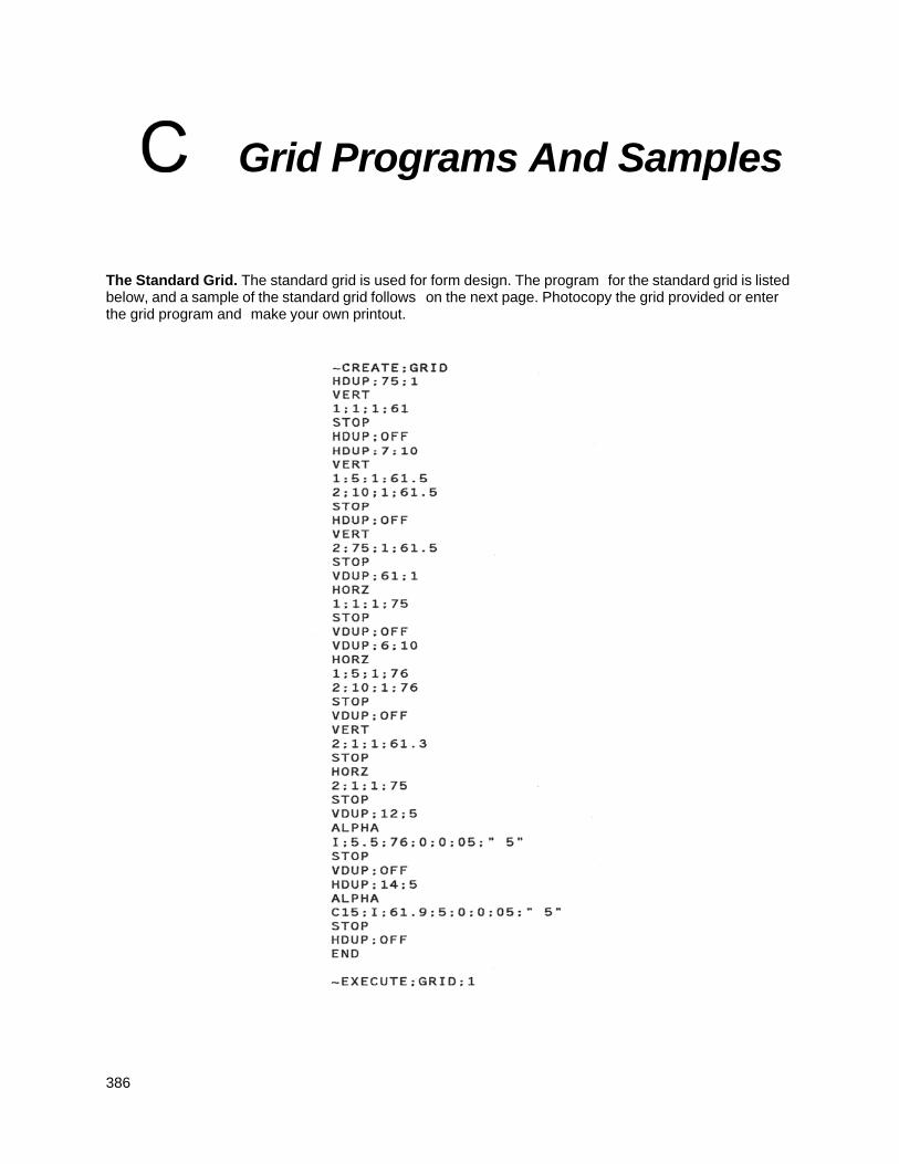
386
Grid Programs And Samples
The Standard Grid. The standard grid is used for form design. The program for the standard grid is listed below, and a sample of the standard grid follows on the next page. Photocopy the grid provided or enter the grid program and make your own printout.
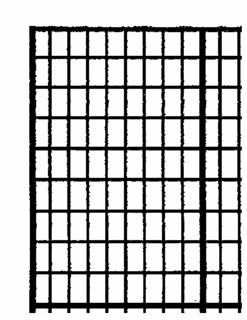
387
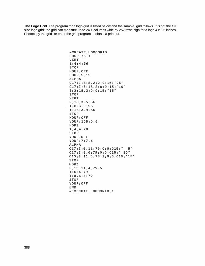
388
The Logo Grid. The program for a logo grid is listed below and the sample grid follows. It is not the full size logo grid; the grid can measure up to 240 columns wide by 252 rows high for a logo 4 x 3.5 inches. Photocopy the grid or enter the grid program to obtain a printout.
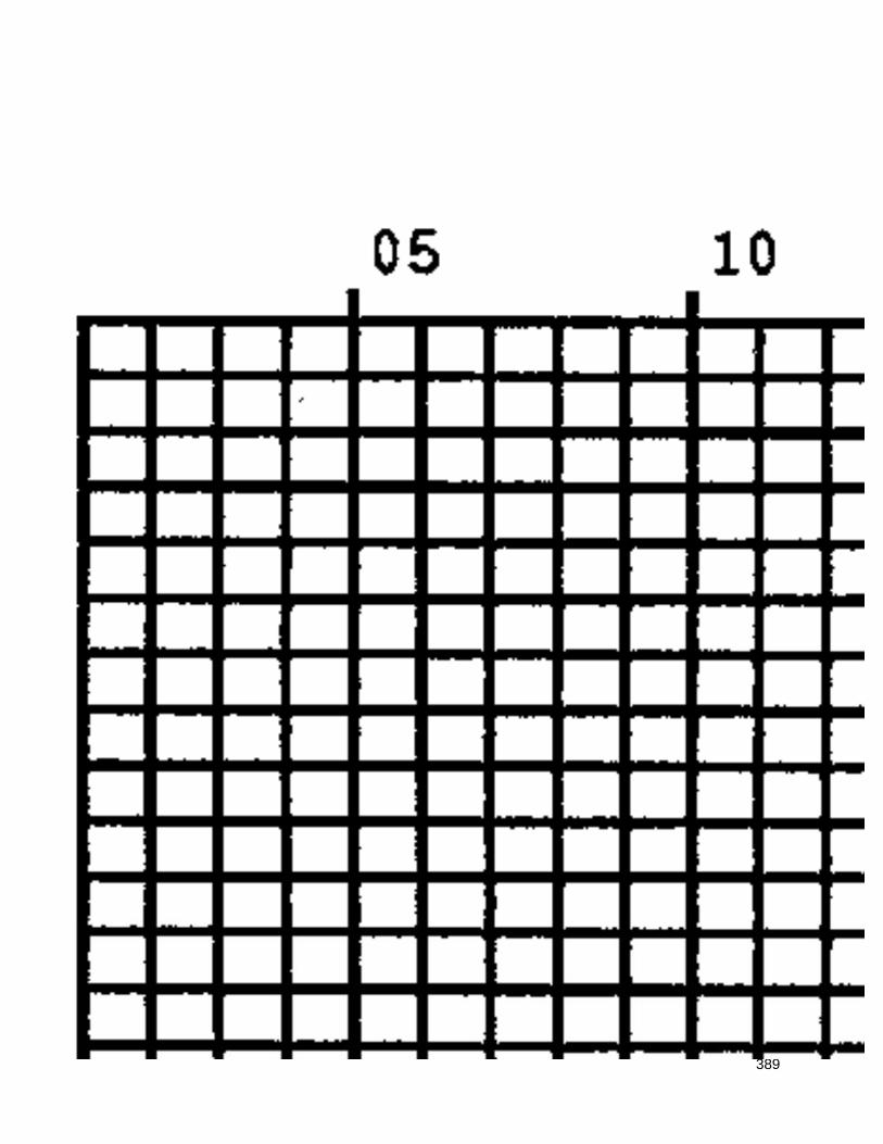
389
390
Page Boundaries
Paper Selection and Maximum Values Most Create Form mode commands require you to identify specific form boundaries using the SR, SC, ER, EC parameters. This appendix addresses the page boundaries affecting IGP/PGL products for both cut-sheet page printers and continuous form printers.
All printers have maximum print boundaries according to the printer type and paper size selected. Refer to your printer Administrator’s Manual for the specific page boundaries associated with your printer. Table 61 shows the print boundaries for page printers using several different widths and lengths.
Note that while both cut-sheet page printers and continuous form printers have specific maximum width values based on paper size, continuous form printers are not bound by the same maximum page length values; on a continuous form printer, if you specify a page length exceeding the actual paper size, the form will continue to print until it is completed.
The maximum dot values such as those shown in Table 61 are necessary to determine the maximum printable area on your form for your printer when modifying top/bottom margin settings or offsetting the values for left margin print positions. The following pages explain how to determine the Top/Bottom Margin and Left Margin requirements for your printer.
Create Form Mode
In the Create Form mode, both the form's length and width used for boundary checking may be specified by the user. However, if the form size is not specified, the form length defaults to 11” and the width is not checked. Boundary checking for form elements is performed only when the form length is specified.
Execute Form Mode
In the Execute Form mode, use the following guidelines to determine if a form will print on the current page size.
Not User-Defined
If the form's length/width is not user-defined, and the minimum length/width is greater than the current page length/ width, minus the margins, then the result will be error 74 or 75.
User-defined
If the form's length/width is user-defined greater than the current page length/ width, minus the margins, then the result will be error 74 or 75.
Not-defined
If the form's length/width is not-defined and the minimum length/width is less than or equal to the current page length/width, minus the margins, then the form length/width will equal the page length/width, minus the margins.
391
Table 61 Paper Sizes and Maximum Print Area
Maximum Dot Value*
Paper Size Dimensions
(inches) Page Width Page Length
Letter 8.0 x 11 481 793
Letter 8.5 x 11 511 793
Legal 8.5 x 14 511 1009
A4 8.268 x 11.693 497 842
B5 6.929 x 9.842 416 709
AIAG Label 4 x 6 241 433
Odette Label 8 x 5 481 361
*How to calculate Maximum Dot Values: 1. Page Length x 72 dpi minus Top and Bottom Margin Values + 1 = maxi- mum height value; 2. Page Width x 60 dpi minus Left Margin Value + 1 = maximum width value. Values exceeding maximum values will produce an error message.
Setting Top/Bottom Margins
Using dot values to identify maximum vertical print positions, the page boundary parameter of an 11-inch form has 792 dot rows at n/72-inch vertical resolution (72 dpi X 11 inches). (See Figure 76.)
With no Top/Bottom Margin configuration setting on an 11-inch form, the first print position is Starting Row 1, Starting Column 1 (A). However, if a Top/ Bottom Margin value is set at 10, then Starting Row 1 is adjusted down by 10 dot rows (B), and the Ending Row is adjusted up 10 dot rows (C), thereby reducing the maximum vertical printable area to 773 dots (793 - [10 + 10]). The greater the top/bottom margin setting, the smaller the printable area on the form.
NOTE: The Top/Bottom margins are set under the LinePrinter+ configuration menu (if present), or from the host by sending the PGL CONFIG command. See the Commands chapter.
392
Figure 76 Top/Bottom Margin Example
Setting Left Margins
Using dot values to identify maximum horizontal print positions, the page boundary parameter of an 8-1/2-inch wide form (85 character columns) has 510 dot columns (1-511) + n/60-inch horizontal resolution (60 dpi X 8.5 inches). (See Figure 76.) Setting a Left Margin value repositions the Starting Column 1 position by the degree of offset required. This offset can be a 0, a positive, or negative value. The following examples explain how setting the Left Margin affects printed output:
No Left Margin Setting. When the Left Margin configuration setting is 0 on an 8-1/2-inch form, the Starting Column is 1, and the Ending Column is 511 (, A and B, respectively).
Positive Left Margin Setting. When the Left Margin setting is 20 on an 8-1/2- inch form, the left margin is offset by 20 dots, and that 20th dot position becomes Starting Column 1 in IGP/PGL memory (A, Figure 78). This 20 dots also offsets the Ending Column by 20 dots, thus narrowing the maximum print width on the form from 511 to 491 dots (B, Figure 78).
Negative Left Margin Setting. With a Left Margin setting of -20 on an 8-1/2- inch form, the left margin is offset -20 dots, and that -20 becomes the Starting Column 1 in IGP/PGL memory (A, Figure 79). This -20 offset appears to expand the horizontal printable area to 531 dots (B, Figure 79); however, the expanded area is actually beyond the addressable range of the 8-1/2-inch- wide form containing the -20 offset position and is, therefore, not accessible. Column 21 is the left-most addressable area on the page.
NOTE: Negative Left Margin configuration is a method of offsetting and printing an existing IGP/PGL file which may otherwise require modification in order to orient the output on the page properly. Use this option if your IGP/PGL file was written for applications where the leftmost printable area is not designated as the first printable character column on the form.
A
B
C
Maximum Character Row 67 Maximum Vertical Dot 793
Maximum Character Column Maximum Horizontal Dot 511
Maximum Vertical Print Area (772 dots)
393
Figure 77 Left Margin Example - No Setting
Figure 78 Left Margin Setting +20 Example
A
B Maximum Character Column Maximum Horizontal Dot 511
Maximum Horizontal Print Area (510 dots)
Maximum Horizontal Print Area (490 dots)
B Maximum Horizontal Dot Column (511) becomes 491 due to +20 offset
A Dot Column 20 Becomes Column 1
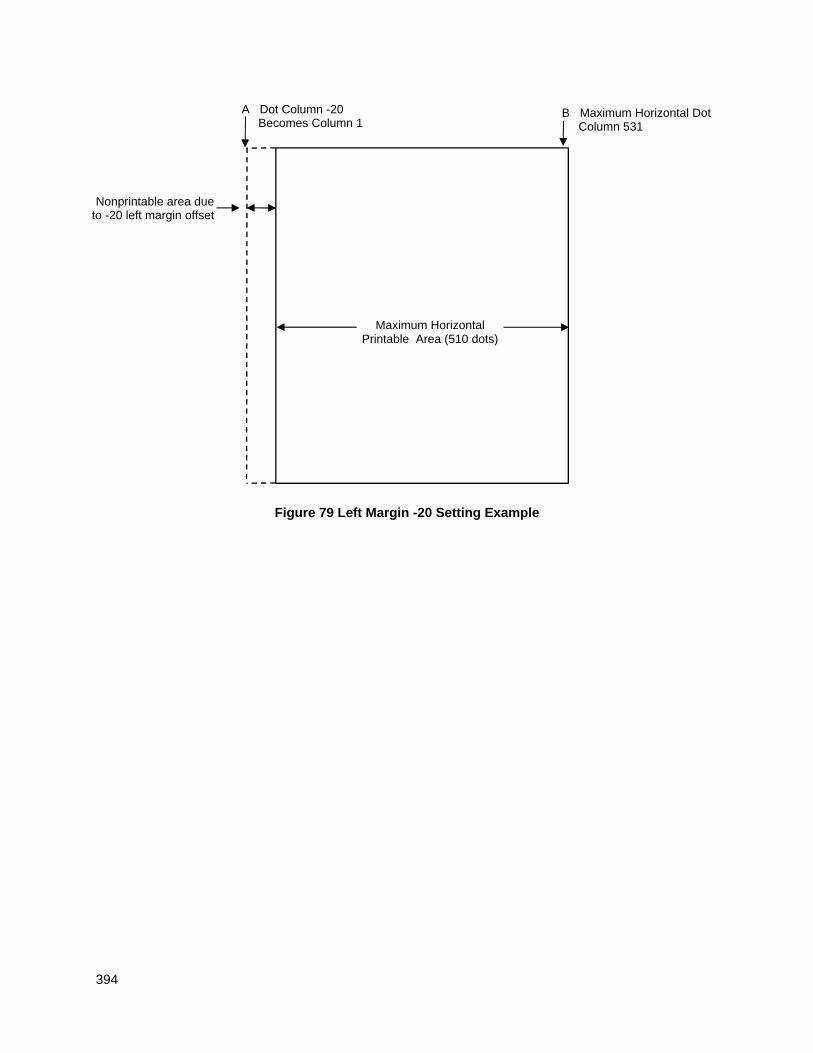
394
Figure 79 Left Margin -20 Setting Example
Maximum Horizontal Printable Area (510 dots)
B Maximum Horizontal Dot Column 531
A Dot Column -20 Becomes Column 1
Nonprintable area due to -20 left margin offset

395
396
Vertical Paper Motion
Introduction There are three methods of advancing the print position with the IGP/PGL which are explained in this appendix:
1. Using line feeds or form feeds;
2. Using the paper instruction (PI) line; or
3. Using the Electronic Vertical Format Unit (EVFU).
In impact printers, print position is adjusted by vertical paper motion down the page. Because no paper motion occurs during forms creation in non-impact printers, advancing the print position refers to cursor movement down the page according to positioning commands received by the host. Throughout this appendix, the term advancing the print position will be used to generically refer to this concept of cursor movement/vertical paper motion.
Paper Motion Using Line Feeds and Form Feeds The most common method of advancing the print position with IGP/PGL is through the use of line feeds and form feeds. A line feed moves the print position down a distance determined by the current line spacing (lpi). In the Normal mode, a form feed character advances the print position to the top of the next page; in the Execute mode, a form feed advances the print position to the top of the next form. Form length is determined by the CREATE command.
Paper Motion using the PI Line (Relative Line Slewing) The method of moving the print position using the PI line results in vertical slews of a specified number of lines relative to the current print position (rather than slewing to a specific line). For this to occur, the following criteria must be met:
1. The PI line must be enabled and set high; and
2. Data bit 5 must be 1 (set).
When a number of blank lines will be skipped on a form, (called “paper slewing”) another method of paper motion may be used. The PI signal can be detected by the IGP/PGL as the 8th data bit in a serial interface, or a separate input line in a parallel interface. (Refer to the EN-PI/DIS-PI command and the PION/PIOFF command on page 88 and page 88 in the Commands chapter, respectively.) When the PI signal is used, bits 6 and 7 are interpreted as 0 values, and characters hex 10 through 1F are interpreted as binary slew commands.
The binary slew commands can skip from 1 through 15 or 1 through 16 lines on the form, depending on how the Slew Range configuration option is configured. Refer to Table 62 which illustrates how lines are skipped for each value. (Note that the state of data bit 5 is the difference between line slewing and using the interface lines as EVFU channel codes.) This type of vertical paper motion occurs whenever the line slewing command is used regardless of whether the EVFU memory is loaded or not.
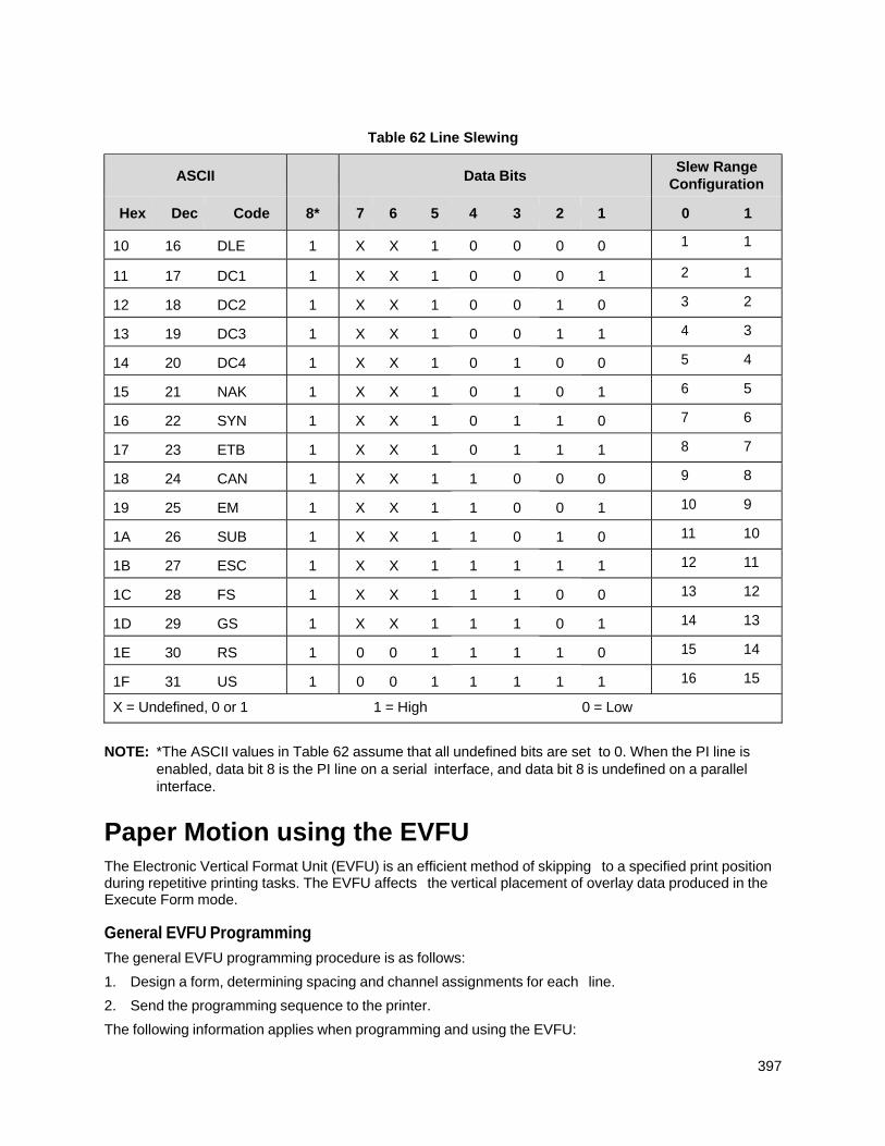
397
Table 62 Line Slewing
ASCII Data Bits Slew Range
Configuration
Hex Dec Code 8* 7 6 5 4 3 2 1 0 1
10 16 DLE 1 X X 1 0 0 0 0 1 1
11 17 DC1 1 X X 1 0 0 0 1 2 1
12 18 DC2 1 X X 1 0 0 1 0 3 2
13 19 DC3 1 X X 1 0 0 1 1 4 3
14 20 DC4 1 X X 1 0 1 0 0 5 4
15 21 NAK 1 X X 1 0 1 0 1 6 5
16 22 SYN 1 X X 1 0 1 1 0 7 6
17 23 ETB 1 X X 1 0 1 1 1 8 7
18 24 CAN 1 X X 1 1 0 0 0 9 8
19 25 EM 1 X X 1 1 0 0 1 10 9
1A 26 SUB 1 X X 1 1 0 1 0 11 10
1B 27 ESC 1 X X 1 1 1 1 1 12 11
1C 28 FS 1 X X 1 1 1 0 0 13 12
1D 29 GS 1 X X 1 1 1 0 1 14 13
1E 30 RS 1 0 0 1 1 1 1 0 15 14
1F 31 US 1 0 0 1 1 1 1 1 16 15
X = Undefined, 0 or 1 1 = High 0 = Low
NOTE: *The ASCII values in Table 62 assume that all undefined bits are set to 0. When the PI line is enabled, data bit 8 is the PI line on a serial interface, and data bit 8 is undefined on a parallel interface.
Paper Motion using the EVFU The Electronic Vertical Format Unit (EVFU) is an efficient method of skipping to a specified print position during repetitive printing tasks. The EVFU affects the vertical placement of overlay data produced in the Execute Form mode.
General EVFU Programming
The general EVFU programming procedure is as follows:
1. Design a form, determining spacing and channel assignments for each line.
2. Send the programming sequence to the printer.
The following information applies when programming and using the EVFU:
398
PI Line. The PI signal can be detected by the IGP/PGL as the 8th data bit in a serial interface, or a separate input line in a parallel interface. (Refer to the EN-PI/DIS-PI command and the PION/PIOFF command on 88 and page 88 in the Commands chapter, respectively.)
Elongated Characters. Elongated (double high) characters can be used within EVFU programs. The EVFU automatically counts one line of elongated characters as two normal character lines.
Paper Runaway Protection. If the EVFU is selected but not loaded when an EVFU command is sent from the host computer, the printer moves the paper a single line feed. If the EVFU is selected and the memory is loaded, a channel code sent from the host, which is not a part of the assigned sequence currently in memory, moves the paper a single line feed.
Line Spacing. The printer can use any line spacing with the EVFU. The EVFU determines the forms length according to the program specifications and the currently selected line spacing. For example, 14-inch paper with 10 lpi line spacing would yield a 140-line form which can be defined by the EVFU. Mixing line spacing on the same form unloads the EVFU.
EVFU Programming Sequence
The EVFU provides 16 channels to identify up to 192 lines. An error results if the EVFU form length exceeds the physical length of the page, and the IGP/ PGL returns to the Normal mode. The number of channels in an EVFU overrides the length of the form as it was defined in the CREATE mode; therefore, the EVFU must be equal to or longer than the form being used.
The EVFU programming sequence is listed below and explained in the following sections.
1. Start load code;
2. Line identification codes; and
3. End load code.
Start Load Code - Hex 1E or 6E
The Start Load code clears and initializes the EVFU memory for channel assignment storage. Refer to Table 63 or Table 64 on page 399 and page 400, respectively, for the appropriate start load code.
Channel Assignment
The EVFU memory has the capacity for 192-line forms. The first line identification code (channel code) in the EVFU load data defines the first line on the form; the second line identification code defines the second line on the form, etc. Each line must have a line identification code.
A single channel code is used repeatedly throughout a form to reserve blank lines between defined channel codes and to maintain the correct forms length. These “filler” channels can be any channel number except channel code 1 (which is reserved for the top-of-form) and channel code 12 (which is reserved as the vertical tab channel). In the EVFU Example which begins on page 400, filler channels are represented by a hex 11 code. Calls are rarely made to filler channels because they do not specify a unique print position on the form.
Channel 1. The top-of-form code, reserved as the first line on the form. The operating program sends the channel 1 code to advance to the top of the next form. After the memory is loaded, a Form Feed code (FF, hex 0C) moves the paper to the next channel 1 (top-of-form).
Channels 2 through 11, 13 and 14. Used as general channel codes (also referred to as line identification codes) or as filler channels. Each line on the form must be identified by a channel code. When the operating program sends the channel code, the print position moves to the line identified by the channel code.
Channel 12. Reserved as the vertical tab channel. The vertical tab code (VT, hex 0B) rapidly advances the print position to the next line identified by the channel 12 code. If channel 12 is not loaded in the EVFU memory, a single line feed is executed when a VT code is sent.
399
End Load - Hex 1F or 6F
The end load code terminates the channel storage and saves the EVFU in memory. Refer to Table 63 or Table 64 on page 399 and page 400, respectively, for the appropriate end load code. Channel codes in excess of 92 channels received prior to the end load code cause an error.
Using the EVFU
Sending the appropriate EVFU channel code to the printer causes any data in the buffer to print and move the print position to the next line on the form having the specified channel number assigned in EVFU memory.
To recognize a data byte as an EVFU instruction, one of the following sets of criteria must be met:
1. The PI line must be enabled and set high;
2. Bits 7 and 6 can be set to 1 or 0; and
3 . Data bit 5 must be 0 (not set).
OR:
1. The PI line must be disabled or low;
2. Bits 7 and 6 must be 0 (not set); and
3. Data bit 5 must be 1 (set).
Given these conditions, the lower four bits of a byte specify the EVFU channel number. Table 63 lists the EVFU channels and their equivalent data bytes when the PI line is enabled; Table 64 lists the EVFU channel and their equivalent data bytes when the PI line is disabled.
Table 63 EVFU Codes - PI Line Enabled
ASCII Data Bits Channel
Hex Dec Code 8* 7 6 5 4 3 2 1 00 0 NUL 1 X X 0 0 0 0 0 1 (TOF) 01 1 SOH 1 X X 0 0 0 0 1 2 02 2 STX 1 X X 0 0 0 1 0 3 03 3 ETX 1 X X 0 0 0 1 1 4 04 4 EOT 1 X X 0 0 1 0 0 5 05 5 ENQ 1 X X 0 0 1 0 1 6 06 6 ACK 1 X X 0 0 1 1 0 7 07 7 BEL 1 X X 0 0 1 1 1 8 08 8 BS 1 X X 0 1 0 0 0 9 09 9 HT 1 X X 0 1 0 0 1 10 0A 10 LF 1 X X 0 1 0 1 0 11 0B 11 VT 1 X X 0 1 0 1 1 12 (VT) 0C 12 FF 1 X X 0 1 1 0 0 13 0D 13 CR 1 X X 0 1 1 0 1 14 6E 110 n 1 1 1 0 1 1 1 0 Start Load 6F 111 o 1 1 1 0 1 1 1 1 End Load
X = Undefined, 0 or 1
1 = High
0 = Low
400
NOTE: *The ASCII values in Table 63 assume that all undefined bits are set to 0. When the PI line is enabled, data bit 8 is the PI line on a serial interface, and data bit 8 is undefined on a parallel interface.
Table 64 EVFU Codes - PI Line Disabled or Not Used
ASCII Data Bits Channel
Hex Dec Code 8 7 6 5 4 3 2 1
10 16 DLE 0 0 0 1 0 0 0 0 1 (TOF)
11 17 DC1 0 0 0 1 0 0 0 1 2
12 18 DC2 0 0 0 1 0 0 1 0 3
13 19 DC3 0 0 0 1 0 0 1 1 4
14 20 DC4 0 0 0 1 0 1 0 0 5
15 21 NAK 0 0 0 1 0 1 0 1 6
16 22 SYN 0 0 0 1 0 1 1 0 7
17 23 ETB 0 0 0 1 0 1 1 1 8
18 24 CAN 0 0 0 1 1 0 0 0 9
19 25 EM 0 0 0 1 1 0 0 1 10
1A 26 SUB 0 0 0 1 1 0 1 0 11
1B 27 ESC 0 0 0 1 1 0 1 1 12 (VT)
1C 28 FS 0 0 0 1 1 1 0 0 13
1D 29 GS 0 0 0 1 1 1 0 1 14
1E 30 RS 0 0 0 1 1 1 1 0 Start Load
1F 31 US 0 0 0 1 1 1 1 1 End Load
X = Undefined, 0 or 1 1 = High 0 = Low
NOTE: Do not use your SFCC as a channel code when using the EVFU.
Clearing the EVFU Memory
The following actions reset (clear) the EVFU memory:
1. Sending only the start load code.
2. Sending a start load code followed immediately by an end load code.
3. A second start load code is received, resulting in re-initialization of the EVFU. (This restarts the EVFU load sequence.)
When the EVFU memory is cleared, the forms length returns to the previously set value.
EVFU Example
The following EVFU example is a 2-inch form at 6 lpi line spacing. Thus, 12 lines on the form must be defined. The form is repeated 3 times. Paper instructions are disabled.
401
Assign Line Identification Codes
Line ID Code Description Assigned Hex Code Start Load Start EVFU 1E Line 1 Top of Form 10 Line 2 Filler 11 Line 3 Filler 11 Line 4 Filler 11 Line 5 Vertical Tab 1B Line 6 First channel stop 13 Line 7 Filler 11 Line 8 Filler 11 Line 9 Second channel stop 12 Line 10 Filler 11 Line 11 Third channel stop 15 Line 12 Filler 11 Stop Load End EVFU 1F
EVFU Format in Execute Mode
The Execute command shown on page 401, derived from the Execute command format on page 60, illustrates how the EVFU data above is incorporated into the Execute command. All other Execute command parameters are shown in italics. (Optional parameters are shown in brackets [ ].) Figure 80 illustrates the printed output from this data.
The boldface line below the EXECUTE command represents the hexadecimal EVFU load sequence which identifies the channel codes at which overlay data will be placed on each form. The example hex values correspond to the line identification codes listed above. Channel codes not described above as Filler channels are assigned unique hex codes. Calls to these channels will print overlay data at specific positions on the form.
The two ~AF lines, also shown in italics, represent the dynamic data. While the EVFU does not affect dynamic data positioning (data placement is defined by the ALPHA statement when the form was created), the commands are shown to specify where they would occur in relation to the EXECUTE command, the EVFU load sequence, and the overlay data.
The four lines of EVFU overlay data (shown in boldface type) follow the two lines of dynamic data. This overlay data is positioned on the form according to the specified channel codes called. The superscript hexadecimal numbers enclosed in < > symbols represent calls to the four unique EVFU channel codes.
(cc)EXECUTE; formname [;PAGE n] [;FC] [;ICNTn] [;IRSTn] [;DISK]
1E 10 11 11 11 1B 13 11 11 12 11 15 11 1F ~AF1;*DYNAMIC DATA #1*
~AF2;*DYNAMIC DATA #2*
<13>DATA FOR LINE 6<17>
<10><12>DATA FOR LINE 9
<1B>DATA FOR VERTICAL TAB CHANNEL
<15>DATA FOR LINE 11
[Form Feed character]
(cc)NORMAL
402
When the IGP/PGL receives a channel call, it searches for that channel from the current print position in the EVFU load sequence to the end of the EVFU load sequence. If that channel is found, the current print position becomes that channel on the same form. If the channel is not found, the search continues from the beginning of the EVFU load sequence to the current print position. If this search is successful, the current form is printed, the next form is called, and the current print position becomes the channel position in the EVFU. If the channel called is not found in either search, the channel call is treated as if it were a line feed.
403
EVFU Channel
Code Sent
Line No. Form Output
Form #1
1E Start Load
10 1 (TOF) (top of form, Form #1) 11 2 11 3 11 4 1B 5
13 6 DATA FOR LINE 6 17 7 (undefined hex 17 causes single line feed) 11 8 12 9 11 10 15 11 11 12
Form #2
10
1 (TOF)
(top of form,
Form #2)
11 2 11 3 11 4 1B 5 13 6 11 7 11 8 12 9 DATA FOR LINE 9 11 10 15 11
11 12
Form #3
10
1 (TOF)
(top of form, Form #3)
11 2 11 3 11 4 1B 5 DATA FOR VERTICAL TAB CHANNEL 13 6 11 7 11 8 12 9 11 10 15 11 DATA FOR LINE 11 11 12
1F
End Load
Figure 80 Sample EVFU Form
404
Typefaces
This appendix illustrates standard typefaces available with IGP/PGL.
Standard Typefaces The standard fonts available depends on the printer. Beside each typeface is the 5-digit value required in the FACE # parameter of the FONT command (see page 68).
Thermal
Table 65 Standard Fonts for Thermal Printers
Font Name Font Face Number
Letter Gothic Bold 93779
Courier New Bold 93952
CG Triumvirate Bold Condensed 92250
CG Times* 92500
CG Triumverate* 92244
CG Triumverate Bold* 92248
OCR-A 90993
OCR-B 91409
* Font is not present in the T2N thermal product.
Line Matrix
Table 66 Standard Fonts for Thermal Printers
Font Name Font Face Number
Letter Gothic Bold 93779

405
406
PGL-DBCS
This appendix describes the additional and unique commands for Printronix Thermal and Line Matrix Printers:
Line Matrix printers include three firmware options with the DBCS fonts embedded: PGL-Hangul KS, PGL-Hanzi GB, PGL-Kanji Shift-JIS emulation software.
Thermal printers have firmware that can be combined with several EMC options with DBCS fonts: Hanzi GB EMC, Hangul KS EMC, Kanji Shift-JIS EMC, and four different Andale EMC options.
PGL-DBCS is an extension to existing PGL (ASCII) that supports Korean KSC, Chinese Hanzi GB, and Japanese Shift-JIS character printing respectively. The differences among those printers are as follows:
PGL-Hangul KS supports KSC code table for Korean character code points used only in South Korea.
PGL-Hanzi GB supports GB code table for simplified Hanzi character code points used in People’s Republic of China. It also supports GB18030 encoding, but the resident font is GB2312 character set.
PGL-Kanji Shift-JIS supports Shift-JIS code table for Kanji character code points used in Japan.
Printers that support Andale options: Simplified Chinese, Traditional Chinese, Korean, and Japanese. Each of these supports Unicode/UTF-8 encoding, but does support not DBCS encoding.
The above differences only affect the DBCS code points but the command syntax and the behavior are similar.
NOTE for THERMAL PRINTERS:
A thermal DBCS-PGL printer has a default DBCS scalable font with supported code table. For example, a PGL-Hangul printer has a Hangul scalable font with KSC code table. Users are able to download additional DBCS scalable fonts into printers by using the FONTLOAD command in the normal mode. If more than one DBCS scalable font exists, users may select a different DBCS font by using the FONT command in the create mode, and ~ISET or SYMSET command to select DBCS character set to print DBCS characters with ALPHA or TWOBYTE command. For thermal printers, refer to the FONTLOAD and FONT command syntax within this manual.
TWOBYTE Command Syntax (Thermal)
Create Form : TWOBYTE Command
Purpose Defines and positions DBCS data on a “pre-printed” static field or as a dynamic data field.
TWOBYTE
[R;] [E;] [Cn;] [KFn;L]; [DIR;] [POINT;]SR; SC; VE; HE;(D)DBCS/SBCS TEXT(D) STOP
TWOBYTE The DBCS characters command; enter TWOBYTE.
R The optional reverse printing (white on black) parameter. Enter R to specify a black background.
407
E The optional elongated character parameter. Enter E to specify elongated character printing. Elongated characters are double height and single width. If used, the VE and HE parameters must be set to 0, or an error message will result. Elongated character printing is also available with rotated DBCS characters.
Cn : The optional horizontal CPI parameter for DBCS character pitch. Where n can be the following:
7.5 CPI, n = 75 6.7 CPI, n = 67 6.0 CPI, n = 60 5.0 CPI, n = 50
n specifies the DBCS character pitch, expressed in CPI. If used, the VE and HE parameters must be set to zero, or an error message will result.
KFn:L The optional dynamic DBCS data field parameter for identifying the DBCS string’s dynamic number assignment and designating the number of DBCS characters allowed. If these parameters are used, the actual text cannot be entered during the Create Form mode; it must be entered dynamically during the Execute Form mode. Dynamically entering data during the Execute mode permits changes to the DBCS text without redefining or re- creating the form. To use this field, perform the following steps:
a. Enter KF.
b. Replace n with a number ranging from 1 through 512 to identify DBCS string location on the form. The SR and SC parameters are used to specify the exact location of the DBCS data field identified by n. Since the TWOBYTE command and the ALPHA command share the same set of identification numbers, therefore do not set the same number for the two commands in one form.
c. Set the length of the dynamic DBCS characters in L ranging from 1 to 127. The actual number of DBCS characters supplied in the EXECUTE mode must be the same or less than this value. In UTF8 mode L should be the same or more than the number of bytes supplied in EXECUTE mode.
d. The DBCS data is not allowed to enter, it can only be supplied in the EXECUTE mode.
DIR Optional parameter for rotating a DBCS character string. Use the following codes to indicate the direction of character rotation:
CW 90 degree clockwise rotation. CCW 90 degree counter clockwise rotation. INV Inverted characters (180 degree rotation)
POINT Optional parameter that changes the units for the vertical and horizontal expansion value. When the point parameter is present the VE value defines the font height in point size where 1 point is 1/72 of an inch. If the HE value is non-zero, it defines the character width in 1/72 of an inch, otherwise the character width is the same as the height. Cannot be used with elongated (E) and compressed (Cn) parameters.
SR Defines the starting row of the DBCS character data field.
408
1 SR < Form Length
SC Defines the starting column of the DBCS character data field.
1 SC < Form Width
VE Defines the vertical expansion factor to enlarge DBCS characters vertically. The factor must ensure that the characters after expansion do not exceed the form boundary limit. The largest value is 63. 0 and 1 specifies the stand font (no expansion), Elongated (E) characters cannot be used with a vertical expansion factor other than 0.
HE Defines the horizontal expansion factor to enlarge DBCS characters horizontally. The factor must ensure that the characters after expansion do not exceed the form boundary limit. The largest value is 63. 0 and 1 specifies the stand font (no expansion), Elongated (E) characters cannot be used with a horizontal expansion factor other than 0.
(D) The printable character identifying the start and finish of the alphanumeric string. Enter any printable character other than a slash (/), the SFCC, or a character used within the alphanumeric string itself. You must use the same character at both ends of the alphanumeric string, but it will not print with the data.
DBCS/SBCS TEXT The group of DBCS/SBCS characters (the alphanumeric string) to print. Enter any of the standard DBCS/SBCS printable characters (except the character used to delimit the string in the (D) parameter). The data appears as “pre-positioned” information on the form beginning at the location specified by SR and SC. This is the “fixed” or static DBCS/SBCS data; once defined on the form, it is changed only by redefining the form using the TWOBYTE command.
STOP Indicates the end of the TWOBYTE command.
Comments
The DBCS TrueType font used by the TWOBYTE command is determined by the current selected font face based on the following three conditions:
If the selected font is found and it is a DBCS font, PGL will use the selected font.
If the selected font is found but it is not a DBCS font, PGL will automatically use the first found DBCS font in memory. If PGL cannot find any DBCS font in memory, the TWOBYTE command will be ignored.
If the selected font is not found, then PGL will automatically use the first found DBCS font in memory. If PGL cannot find any DBCS font in memory, the TWOBYTE command will be ignored.
TWOBYTE Command Syntax (Line Matrix)
Create Form : TWOBYTE Command
Purpose Defines and positions DBCS data on a “pre-printed” static field or as a dynamic data field.
TWOBYTE
[R [D];] [E;] [Fn;] [Pn;] [kFn;L]; [DIR;] SR; SC; VE; HE;(D)DBCS DATA(D) STOP
409
TWOBYTE The DBCS characters command; enter TWOBYTE.
R The optional reverse printing (white on black) parameter. Enter R to specify a black background.
E The optional elongated character parameter. Enter E to specify elongated character printing. Elongated characters are double height and single width. If used, the VE and HE parameters must be set to 0, or an error message will result. Elongated character printing is also available with rotated DBCS characters.
Fn : The optional font size parameter, use the following select font size (default F16):
F16 selects 16x16 matrix font cells (physics size is 8).
F24 selects 24x24 matrix font cells (physics size is 12).
Pn : Optional parameter for pitch between characters. If n is not specified, one default n is automatically assigned based on the actual horizontal expansion factor. When option “Compatible Mode” is set to None, n=12*HE. When option “Compatible Mode” is not set to None, n=12*(HE-1)*2.
KFn:L The optional dynamic DBCS data field parameter for identifying the DBCS string’s dynamic number assignment and designating the number of DBCS characters allowed. If these parameters are used, the actual text cannot be entered during the Create Form mode; it must be entered dynamically during the Execute Form mode. Dynamically entering data during the Execute mode permits changes to the DBCS text without redefining or recreating the form. To use this field, perform the following steps:
a. Enter KF.
b. Replace n with a number ranging from 1 through 512 to identify DBCS string location on the form. The SR and SC parameters are used to specify the exact location of the DBCS data field identified by n. Since the TWOBYTE command and the ALPHA command share the same set of identification numbers, therefore do not set the same number for the two commands in one form.
c. Set the length of the dynamic DBCS characters in L ranging from 1 to 127. The actual number of DBCS characters supplied in the EXECUTE mode must be the same or less than this value. In UTF8 mode L should be the same or more than the number of bytes supplied in EXECUTE mode.
d. The DBCS data is not allowed to enter, it can only be supplied in the EXECUTE mode.
DIR Optional parameter for rotating a DBCS character string. Use the following codes to indicate the direction of character rotation:
CW 90 degree clockwise rotation.
CCW 90 degree counter clockwise rotation.
INV Inverted characters (180 degree rotation)
410
SR Defines the starting row of the DBCS character data field.
1 SR < Form Length
SC Defines the starting column of the DBCS character data field.
1 SC < Form Width
VE Defines the vertical expansion factor to enlarge DBCS characters vertically. The factor must ensure that the characters after expansion do not exceed the form boundary limit. The largest value is 63. 0 and 1 specifies the stand font (no expansion), Elongated (E) characters cannot be used with a vertical expansion factor other than 0.
HE Defines the horizontal expansion factor to enlarge DBCS characters horizontally. The factor must ensure that the characters after expansion do not exceed the form boundary limit. The largest value is 63. 0 and 1 specifies the stand font (no expansion), Elongated (E) characters cannot be used with a horizontal expansion factor other than 0.
(D) The printable character identifying the start and finish of the alphanumeric string. Enter any printable character other than a slash (/), the SFCC, or a character used within the alphanumeric string itself. You must use the same character at both ends of the alphanumeric string, but it will not print with the data.
DBCS/SBCS TEXT The group of DBCS/SBCS characters (the alphanumeric string) to print. Enter any of the standard DBCS/SBCS printable characters (except the character used to delimit the string in the (D) parameter). The data appears as “pre-positioned” information on the form beginning at the location specified by SR and SC. This is the “fixed” or static DBCS/SBCS data; once defined on the form, it is changed only by redefining the form using the TWOBYTE command.
STOP Indicates the end of the TWOBYTE command.
411
EXECUTE Mode Command Syntax (Common)
EXECUTE Form: General Format
Purpose Prints forms created in the CREATE mode.
Mode NORMAL
Format (cc)EXECUTE; formname [;PAGE n] [; FC] [;ICNT n] [;IRST n] [;DISK] [ EVFU Data] [(cc)AF n; (D)ASCII text(D)] [(cc)KF n; (D)DBCS/SBCS text(D)] [(cc)BF n; (D)data(D)] [(cc)GF n; (D)logoname(D)] [(cc)IAF n; [ idir] STEPMASK;[RPT n;] [RST n;] (D)STARTDATA(D)] [(cc)IBF n; [ idir] STEPMASK;[RPT n;] [RST n;] (D)STARTDATA(D)] [Overlay Data] [Form Feed character] (cc)NORMAL
NOTE: This document only describes the command syntax usage for (cc)KFn. Refer to this manual for other command parameters.
(cc)KFn
Purpose Incorporates the dynamic DBCS data into a previously identified location of a form.
Mode EXECUTE
Format [(cc)KF n; (D)DBCS/SBCS text(D)]
(cc)
KFn Indicates a dynamic DBCS data field (KF) and its identification number n which was defined with the TWOBYTE command in the Create form mode.
(D) The separation symbol for identifying the starting and ending of DBCS data. The requirement for this parameter is the same as that for D in the ALPHA command.
DBCS DATA The group of DBCS characters to be printed. The DBCS string appears as the pre-positioned information on the form beginning at the location identified n.

412
Contact Information
Printronix Customer Support Center
IMPORTANT Please have the following information available prior to calling the Printronix Customer Support Center:
• Model number
• Serial number (located on the back of the printer)
• Installed options (i.e., interface and host type if applicable to the problem)
• Configuration printout: Refer to the Administrator’s Manual.
• Is the problem with a new install or an existing printer?
• Description of the problem (be specific)
• Good and bad samples that clearly show the problem (faxing or emailing of these samples may be required)
Americas (844) 307-7120 [email protected]
Europe, Middle East, and Africa +31 (0) 24 3030 340 [email protected]
Asia Pacific +886 3 990 6155 [email protected]
China +86 755 2398 0479 [email protected]
Printronix Auto ID Support: http://PrintronixAutoID.com/support/ Printronix Auto ID Consumables: http://PrintronixAutoID.com/products/consumables/
413
Corporate Offices
Printronix Auto ID 3040 Saturn Street, Suite 200, Brea, CA 92821 U.S.A. Phone: (844) 307-7120 Fax: (657) 258-0817
Printronix Auto ID, EMEA Head Office Georg-Wimmer-Ring 8b D-85604 Zorneding
Germany
Phone: +49 (0) 8106 37979-23
Fax: +49 (0) 8106 37979-05 Printronix Auto ID, Asia Pacific Head Office Taiwan 9F, No. 95, Minquan Rd. Xindian Dist., New Taipei City 231 Taiwan (R.O.C) Phone: +886 3 990 6155 Fax: +886 3 990 6215
Printronix Auto ID, China Head Office Shenzhen New World Center 2510 room No. 6009, Yitian road Futian District, Shenzhen 518000 China
Phone: +86 755 2398 0479 Fax: +86 755 2398 0773
Visit the Printronix web site at www.PrintronixAutoID.com
258780-001D