iglidur x – the high-tech problem solver - ien europe · iglidur® x – the high-tech problem...
TRANSCRIPT

mm
X
iglid
ur®
X
6.1
iglidur® X – The High-TechProblem Solver
Temperature resistant from -100°C to +250°C incontinuous operation
Universal resistance to chemicals
High compressive strength
Very low moisture absorption
Excellent wear resistance through the entiretemperature range
Ph
on
e+
49 -
22
03 -
96
49-1
45F
ax+
49 -
22
03 -
96
49-3
34

X
+ 250º
- 100º
iglid
ur®
X
6.2
When to use iglidur® X plain bearings:
• For pressure loads up to 150 MPa
• For linear movements with stainless steel
• For linear movements, especially athigh temperatures
• When universal resistance tochemicals is required
• Temperature resistant from -100°C to+250°C (short term to + 315°C)
• Very low moisture absorption
• High wear resistance over the entiretemperature range
When not to use iglidur® X plain bearings:
• For very low wear at high loadsiglidur® Q (chapter 18), Z (chapter 22)
• For underwater applicationsiglidur® H (chapter 12), H370 (chapter 15)
• For edge pressureiglidur® Z (chapter 22)
Price index
3 styles
> 250 dimensions
Ø 2–75 mm
The High-Tech Problem Solver
Picture 6.1: High temperature resis-
tant and maintenance free
Picture 6.2: Battery filling
Ph
on
e+
49 -
22
03 -
96
49-1
45F
ax+
49 -
22
03 -
96
49-3
34ig
us®
G
mb
H51
147
Co
log
ne
iglidur® X is defined by its combination of high temperature resistance with compressive strength, along with high resistance to chemicals. iglidur® X is designedfor higher speeds than other iglidur® bearings.
Lifetime calculation, CAD files and much more support www.igus.de/en/x
iglidur® X | The High-Tech Problem Solver
mm
X
6.3
1000
100
10
1
0,1
0,001 0,01 0,1 1 10
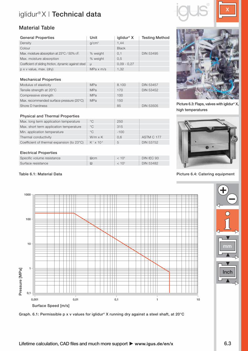
Material Table
Table 6.1: Material Data
General Properties Unit iglidur® X Testing MethodDensity g/cm3 1,44
Colour Black
Max. moisture absorption at 23°C / 50% r.F. % weight 0,1 DIN 53495
Max. moisture absorption % weight 0,5
Coefficient of sliding friction, dynamic against steel µ 0,09 - 0,27
p x v value, max. (dry) MPa x m/s 1,32
Mechanical PropertiesModulus of elasticity MPa 8.100 DIN 53457
Tensile strength at 20°C MPa 170 DIN 53452
Compressive strength MPa 100
Max. recommended surface pressure (20°C) MPa 150
Shore D hardness 85 DIN 53505
Physical and Thermal PropertiesMax. long term application temperature °C 250
Max. short term application temperature °C 315
Min. application temperature °C -100
Thermal conductivity W/m x K 0,6 ASTM C 177
Coefficient of thermal expansion (to 23°C) K-1 x 10⁻⁵ 5 DIN 53752
Electrical PropertiesSpecific volume resistance Ωcm < 105 DIN IEC 93
Surface resistance Ω < 103 DIN 53482
Graph. 6.1: Permissible p x v values for iglidur® X running dry against a steel shaft, at 20°C
Surface Speed [m/s]
Pre
ssu
re [
MP
a]
Picture 6.3: Flaps, valves with iglidur® X,
high temperatures
Picture 6.4: Catering equipment
Lifetime calculation, CAD files and much more support www.igus.de/en/x
iglidur® X | Technical data

X
iglid
ur®
X
6.4
0
0 25 50 75 100
1
2
3
4
5
6
7
8
20 50 80 120 150 200
0
20
40
60
80
160
120
100
140
60°C 23°C
m/s Rotating Oscillating Linear
Continuous 1,5 1,1 5
Short term 3,5 2,5 10
iglidur® X Application Temperature
Minimum - 100 °C
Max., long term + 250 °C
Max., short term + 315 °C
Table 6.2: Maximum surface speeds
Table 6.3: Temperature limits for iglidur® X
Picture 6.5: Application on an inboard
engine
Graph 6.3: Recommended maximum surface pressure of
iglidur® X as a function of temperature
Temperature in °C
Pre
ssu
re [
MP
a]
iglidur® X has an excellent combination of high
temperature resistance, high compressive
strength, and excellent resistance to chemicals.
Surface Pressure
Graph 6.2 shows how iglidur® X plain bearings
deform elastically under load. Graph 6.1 on the
preceding page shows the maximum p x v
values at room temperature. In this case,
the compressive strength of iglidur® X even
measures up to that of steel.
Graph 6.3 shows the special compression
resistance of iglidur® X at very high tempera-
tures. Even at the highest long term appli-
cation temperature of 250°C iglidur® X plain
bearings still withstand a surface pressure
of approximately 30 MPa.
Graph 6.2
Surface Pressure, page 1.18
Permissible Surface Speeds
iglidur® X is designed for higher speeds than
other iglidur® bearings. This is due to its high
temperature resistance and excellent thermal
conductivity. One benefit of this is seen in
the maximum pV value of 1.32 MPa x m/s.
However, in this case, only the smallest radial
loads may act on the bearings. At the given
speeds, friction can cause a temperature
increase to maximum permissible levels.
Surface Speed, page 1.20
p x v value, page 1.22
Graph 6.2: Deformation under pressure and temperature
Def
orm
atio
n in
%
Pressure [MPa]
Inte
rnet
ww
w.ig
us.
de
E-m
ail
info
@ig
us.
de
igus
® G
mb
H51
147
Col
ogne
Lifetime calculation, CAD files and much more support www.igus.de/en/x
iglidur® X | Technical data
X
mm
iglid
ur®
X
6.5
0
1
2
3
4
5
6
7
8
0,05 0,10 0,15 0,20 0,25 0,30 0,35
0,1
0,2
0,3
0,4
0,00
0 10 20 30 40 50 60 70 80 90
0,05
0,10
0,15
0,20
0,25
0,30
0,35
23 °C 150 °C
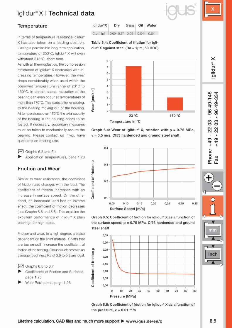
Table 6.4: Coefficient of friction for igli-
dur® X against steel (Ra = 1µm, 50 HRC)
iglidur®X Dry Grease Oil Water
C.o.f. [µ] 0,09 - 0,27 0,09 0,04 0,04
Graph 6.4: Wear of iglidur® X, rotation with p = 0.75 MPa,
v = 0.5 m/s, Cf53 hardended and ground steel shaft
Graph 6.6: Coefficient of friction for iglidur® X as a function of
the pressure, v = 0.01 m/s
Graph 6.5: Coefficient of friction for iglidur® X as a function of
the surface speed; p = 0.75 MPa, Cf53 hardended and ground
steel shaft
Temperature in °C
Surface Speed [m/s]
Co
effi
cien
t o
f fr
icti
on
µC
oef
fici
ent
of
fric
tio
n µ
Pressure [MPa]
Wea
r [µ
m/k
m]
Temperature
In terms of temperature resistance iglidur®
X has also taken on a leading position.
Having a permissible long term application,
temperature of 250°C, iglidur® X will even
withstand 315°C short term.
As with all thermoplastics, the compression
resistance of iglidur® X decreases with in-
creasing temperature. However, the wear
drops considerably when used within the
observed temperature range of 23°C to
150°C. In certain cases, relaxation of the
bearing can even occur at temperatures of
more than 170°C. This leads, after re-cooling,
to the bearing moving out of the housing.
At temperatures over 170°C the axial security
of the bearing in the housing needs to be
tested. If necessary, secondary measures
must be taken to mechanically secure the
bearing. Please contact us if you have
questions on bearing use.
Graphs 6.3 and 6.4
Application Temperatures, page 1.23
Friction and Wear
Similar to wear resistance, the coefficient
of friction also changes with the load. The
coefficient of friction increases with an
increase in surface speed. On the other
hand, an increased load has an inverse
effect: the coefficient of friction decreases
(see Graphs 6.5 and 6.6). This explains the
excellent performance of iglidur® X plain
bearings for high loads.
Friction and wear, to a high degree, are also
dependent on the shaft material. Shafts that
are too smooth increase the coefficient of
friction of the bearing. Ground surfaces with an
average roughness Ra of 0.6 to 0.8 are ideal.
Graphs 6.5 to 6.7
Coefficients of Friction and Surfaces,
page 1.25
Wear Resistance, page 1.26
Ph
on
e+
49 -
22
03 -
96
49-1
45F
ax+
49 -
22
03 -
96
49-3
34
Lifetime calculation, CAD files and much more support www.igus.de/en/x
iglidur® X | Technical data

X
iglid
ur®
X
6.6
0,1 0,4 0,7 1,0 1,3 1,6
0,20
0,30
0,40
0
2,0
4,0
6,0
8,0
10,0
12,0
0
1 2 3 4 50
20
40
60
80
100
120
140
160
180
0
5
10
15
20
25
Shaft Materials
Graphs 6.7 and 6.8 show results of testing
different shaft materials with plain bearings
made of iglidur® X. For low loads in rotating
operation, the best wear values are found
with 303 Stainless and HR Carbon Steel
shafts. However, above a load of 2 MPa the
bearing wear greatly increases with these
two shaft materials. For the higher load
range, hard chromed shafts or Cf53 shafts
are advantageous. In oscillating operation
at low loads, similar wear values for Cf53
and 303 stainless steel shafts occur. The wear
is somewhat higher than during rotational
movements.
If the shaft material you plan to use is not
contained in this list, please contact us.
Graphs 6.8 to 6.10
Shaft Materials, pages 1.28
Installation Tolerances
iglidur® X plain bearings are meant to be
oversized before pressfit. The bearings are
designed for pressfit into a housing ma-
chined to a H7 tolerance. After being assem-
bled into a nominal size housing, the inner dia-
meter adjusts to meet our specified toleran-
ces. Please adhere to the catalogue speci-
fications for housing bore and recommen-
ded shaft sizes. This will help to ensure opti-
mal performance of iglidur® plain bearings.
Please contact an iglidur® technical expert
if you have any question.
Testing Methods, page 1.32/1.33
Chemical Resistance
iglidur® X plain bearings have almost uni-
versal chemical resistance.
The material is only attacked by concentrated
nitric acid and by sulphuric acid with acidity
levels over 65%. The list at the end of this
catalogue provides more comprehensive
detailed information.
Graph 6.11
Chemical Table, pages 70.1Graph 6.10: Wear for oscillating and rotating applications
(p = 2 MPa) with different shaft materials
Wea
r [µ
m/k
m]
Oscillating, p = 2 MPa Rotating, p = 2 MPa
303 Stainless SteelCf53 Steel
Graph 6.9: Wear of iglidur® X with different shaft materials
Load [MPa]
Wea
r [µ
m/k
m]
Hard chromedCf53HR Carbon Steel 304 SS
Graph 6.8: Wear of iglidur® X with different shaft materials,
p = 0.75 MPa, v = 0.5 m/s
Shaft materials
Wea
r [µ
m/k
m]
Graph 6.7: Coefficients of friction as a function of the shaft
surface (Cf53 hardended and ground steel shaft)
Co
effi
cien
t o
f fr
icti
on
µ
Shaft Roughness Ra [µm]
Inte
rnet
ww
w.ig
us.
de
E-m
ail
info
@ig
us.
de
Ph
on
e+
49 -
22
03 -
96
49-1
45F
ax+
49 -
22
03 -
96
49-3
34ig
us®
G
mb
H51
147
Co
log
ne
Lifetime calculation, CAD files and much more support www.igus.de/en/x
iglidur® X | Technical data
H.A
. Alu
min
ium
304
SS
Hig
h gr
ade
Ste
el
Cf5
3
Cf5
3 ha
rdch
rom
ed
Aut
om
atic
Scr
ew S
teel
HR
Car
bon
Ste
el
X
mm
6.7
0,0 0,1 0,2 0,3 0,4 0,5
0,00
0,02
0,04
0,06
0,08
0,10
iglid
ur®
X
iglidur® X
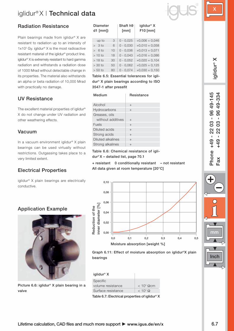
Specific volume resistance < 105 ΩcmSurface resistance < 103 Ω
Graph 6.11: Effect of moisture absorption on iglidur®X plain
bearings
Table 6.5: Essential tolerances for igli-
dur® X plain bearings according to ISO
3547-1 after pressfit
Table 6.7: Electrical properties of iglidur® X
Medium Resistance
Alcohol +Hydrocarbons +Greases, oils
without additives +Fuels +Diluted acids +Strong acids +Diluted alkalines +Strong alkalines +
Picture 6.6: iglidur® X plain bearing in a
valve
Diameter Shaft h9 iglidur® Xd1 [mm]) [mm] F10 [mm]
up to 3 0 - 0,025 +0,006 + 0,046
> 3 to 6 0 - 0,030 +0,010 + 0,058
> 6 to 10 0 - 0,036 +0,013 + 0,071
> 10 to 18 0 - 0,043 +0,016 + 0,086
> 18 to 30 0 - 0,052 +0,020 + 0,104
> 30 to 50 0 - 0,062 +0,025 + 0,125
> 50 to 80 0 - 0,074 +0,030 + 0,150
Moisture absorption [weight %]
Red
uct
ion
of
the
inn
er d
iam
eter
[%
]
Radiation Resistance
Plain bearings made from iglidur® X are
resistant to radiation up to an intensity of
1x10⁵ Gy. iglidur® X is the most radioactive
resistant material of the iglidur® product line.
iglidur® X is extremely resistant to hard gamma
radiation and withstands a radiation dose
of 1000 Mrad without detectable change in
its properties. The material also withstands
an alpha or beta radiation of 10,000 Mrad
with practically no damage.
UV Resistance
The excellent material properties of iglidur®
X do not change under UV radiation and
other weathering effects.
Vacuum
In a vacuum environment iglidur® X plain
bearings can be used virtually without
restrictions. Outgassing takes place to a
very limited extent.
Electrical Properties
iglidur® X plain bearings are electrically
conductive.
Application ExampleP
ho
ne
+49
- 2
2 03
- 9
6 49
-145
Fax
+49
- 2
2 03
- 9
6 49
-334
Table 6.6: Chemical resistance of igli-
dur® X – detailed list, page 70.1
Lifetime calculation, CAD files and much more support www.igus.de/en/x
+ resistant 0 conditionally resistant – not resistant
All data given at room temperature [20°C]
iglidur® X | Technical data
X
6.8
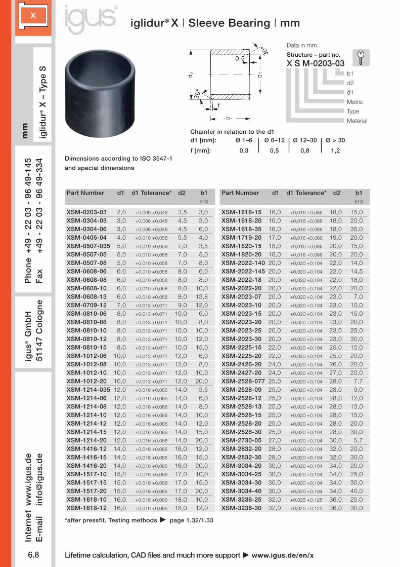
XSM-0203-03 2,0 +0,006 +0,046 3,5 3,0XSM-0304-03 3,0 +0,006 +0,046 4,5 3,0XSM-0304-06 3,0 +0,006 +0,046 4,5 6,0XSM-0405-04 4,0 +0,010 +0,058 5,5 4,0XSM-0507-035 5,0 +0,010 +0,058 7,0 3,5XSM-0507-05 5,0 +0,010 +0,058 7,0 5,0XSM-0507-08 5,0 +0,010 +0,058 7,0 8,0XSM-0608-06 6,0 +0,010 +0,058 8,0 6,0XSM-0608-08 6,0 +0,010 +0,058 8,0 8,0XSM-0608-10 6,0 +0,010 +0,058 8,0 10,0XSM-0608-13 6,0 +0,010 +0,058 8,0 13,8XSM-0709-12 7,0 +0,013 +0,071 9,0 12,0XSM-0810-06 8,0 +0,013 +0,071 10,0 6,0XSM-0810-08 8,0 +0,013 +0,071 10,0 8,0XSM-0810-10 8,0 +0,013 +0,071 10,0 10,0XSM-0810-12 8,0 +0,013 +0,071 10,0 12,0XSM-0810-15 8,0 +0,013 +0,071 10,0 15,0XSM-1012-06 10,0 +0,013 +0,071 12,0 6,0XSM-1012-08 10,0 +0,013 +0,071 12,0 8,0XSM-1012-10 10,0 +0,013 +0,071 12,0 10,0XSM-1012-20 10,0 +0,013 +0,071 12,0 20,0XSM-1214-035 12,0 +0,016 +0,086 14,0 3,5XSM-1214-06 12,0 +0,016 +0,086 14,0 6,0XSM-1214-08 12,0 +0,016 +0,086 14,0 8,0XSM-1214-10 12,0 +0,016 +0,086 14,0 10,0XSM-1214-12 12,0 +0,016 +0,086 14,0 12,0XSM-1214-15 12,0 +0,016 +0,086 14,0 15,0XSM-1214-20 12,0 +0,016 +0,086 14,0 20,0XSM-1416-12 14,0 +0,016 +0,086 16,0 12,0XSM-1416-15 14,0 +0,016 +0,086 16,0 15,0XSM-1416-20 14,0 +0,016 +0,086 16,0 20,0XSM-1517-10 15,0 +0,016 +0,086 17,0 10,0XSM-1517-15 15,0 +0,016 +0,086 17,0 15,0XSM-1517-20 15,0 +0,016 +0,086 17,0 20,0XSM-1618-10 16,0 +0,016 +0,086 18,0 10,0XSM-1618-12 16,0 +0,016 +0,086 18,0 12,0
XSM-1618-15 16,0 +0,016 +0,086 18,0 15,0XSM-1618-20 16,0 +0,016 +0,086 18,0 20,0XSM-1618-35 16,0 +0,016 +0,086 18,0 35,0XSM-1719-20 17,0 +0,016 +0,086 19,0 20,0XSM-1820-15 18,0 +0,016 +0,086 20,0 15,0XSM-1820-20 18,0 +0,016 +0,086 20,0 20,0XSM-2022-140 20,0 +0,020 +0,104 22,0 14,0XSM-2022-145 20,0 +0,020 +0,104 22,0 14,5XSM-2022-18 20,0 +0,020 +0,104 22,0 18,0XSM-2022-20 20,0 +0,020 +0,104 22,0 20,0XSM-2023-07 20,0 +0,020 +0,104 23,0 7,0XSM-2023-10 20,0 +0,020 +0,104 23,0 10,0XSM-2023-15 20,0 +0,020 +0,104 23,0 15,0XSM-2023-20 20,0 +0,020 +0,104 23,0 20,0XSM-2023-25 20,0 +0,020 +0,104 23,0 25,0XSM-2023-30 20,0 +0,020 +0,104 23,0 30,0XSM-2225-15 22,0 +0,020 +0,104 25,0 15,0XSM-2225-20 22,0 +0,020 +0,104 25,0 20,0XSM-2426-20 24,0 +0,020 +0,104 26,0 20,0XSM-2427-20 24,0 +0,020 +0,104 27,0 20,0XSM-2528-077 25,0 +0,020 +0,104 28,0 7,7XSM-2528-09 25,0 +0,020 +0,104 28,0 9,0XSM-2528-12 25,0 +0,020 +0,104 28,0 12,0XSM-2528-13 25,0 +0,020 +0,104 28,0 13,0XSM-2528-15 25,0 +0,020 +0,104 28,0 15,0XSM-2528-20 25,0 +0,020 +0,104 28,0 20,0XSM-2528-30 25,0 +0,020 +0,104 28,0 30,0XSM-2730-05 27,0 +0,020 +0,104 30,0 5,7XSM-2832-20 28,0 +0,020 +0,104 32,0 20,0XSM-2832-30 28,0 +0,020 +0,104 32,0 30,0XSM-3034-20 30,0 +0,020 +0,104 34,0 20,0XSM-3034-25 30,0 +0,020 +0,104 34,0 25,0XSM-3034-30 30,0 +0,020 +0,104 34,0 30,0XSM-3034-40 30,0 +0,020 +0,104 34,0 40,0XSM-3236-25 32,0 +0,025 +0,125 36,0 25,0XSM-3236-30 32,0 +0,025 +0,125 36,0 30,0
X S M-0203-03
d1 [mm]: Ø 1–6 Ø 6–12 Ø 12–30 Ø > 30
f [mm]: 0,3 0,5 0,8 1,2
Part Number d1 d1 Tolerance* d2 b1h13
Part Number d1 d1 Tolerance* d2 b1h13
iglidur® X | Sleeve Bearing | mm
Dimensions according to ISO 3547-1
and special dimensions
mm
iglid
ur®
X –
Typ
e S
Chamfer in relation to the d1
Structure – part no.
b1
d2
d1
Metric
Type
Material
Data in mm
Inte
rnet
ww
w.ig
us.
de
E-m
ail
info
@ig
us.
de
Ph
on
e+
49 -
22
03 -
96
49-1
45F
ax+
49 -
22
03 -
96
49-3
34ig
us®
G
mb
H51
147
Co
log
ne
Lifetime calculation, CAD files and much more support www.igus.de/en/x
*after pressfit. Testing methods page 1.32/1.33

X
mm
6.9
X S M-3539-20
d1 [mm]: Ø 1–6 Ø 6–12 Ø 12–30 Ø > 30
f [mm]: 0,3 0,5 0,8 1,2
XSM-3539-20 35,0 +0,025 +0,125 39,0 20,0XSM-3539-30 35,0 +0,025 +0,125 39,0 30,0XSM-3539-40 35,0 +0,025 +0,125 39,0 40,0XSM-3539-50 35,0 +0,025 +0,125 39,0 50,0XSM-4044-30 40,0 +0,025 +0,125 44,0 30,0XSM-4044-40 40,0 +0,025 +0,125 44,0 40,0XSM-4044-50 40,0 +0,025 +0,125 44,0 50,0XSM-4550-50 45,0 +0,025 +0,125 50,0 50,0XSM-5055-30 50,0 +0,025 +0,125 55,0 30,0XSM-5055-40 50,0 +0,025 +0,125 55,0 40,0XSM-5055-60 50,0 +0,025 +0,125 55,0 60,0XSM-5560-50 55,0 +0,030 +0,150 60,0 50,0XSM-6065-45 60,0 +0,030 +0,150 65,0 45,0XSM-6065-60 60,0 +0,030 +0,150 65,0 60,0XSM-6570-50 65,0 +0,030 +0,150 70,0 50,0XSM-7075-70 70,0 +0,030 +0,150 75,0 70,0
iglid
ur®
X –
Typ
e S
mm
iglidur® X | Sleeve Bearing | mm
Dimensions according to ISO 3547-1
and special dimensions
Chamfer in relation to the d1
Structure – part no.
b1
d2
d1
Metric
Type
Material
Data in mm
Ph
on
e+
49 -
22
03 -
96
49-1
45F
ax+
49 -
22
03 -
96
49-3
34
Part Number d1 d1 Tolerance* d2 b1h13
Lifetime calculation, CAD files and much more support www.igus.de/en/x
*after pressfit. Testing methods page 1.32/1.33
The extreme resistance to chemicals was decisivefor the application of iglidur® X bearings in flangeball valves.

X
6.10
XFM-020406-03 2,0 +0,006 +0,046 4,0 6,0 3,0 1,0XFM-0304-05 3,0 +0,006 +0,046 4,5 7,5 5,0 0,75XFM-0405-04 4,0 +0,010 +0,058 5,5 9,5 4,0 0,75XFM-0405-06 4,0 +0,010 +0,058 5,5 9,5 6,0 0,75XFM-040508-06 4,0 +0,010 +0,058 5,5 8,0 6,0 0,75XFM-0507-05 5,0 +0,010 +0,058 7,0 11,0 5,0 1,0XFM-0608-08 6,0 +0,010 +0,058 8,0 12,0 8,0 1,0XFM-0608-10 6,0 +0,010 +0,058 8,0 12,0 10,0 1,0XFM-060812-20 6,0 +0,006 +0,046 8,0 12,0 20,0 1,0XFM-0810-05 8,0 +0,013 +0,071 10,0 15,0 5,5 1,0XFM-0810-075 8,0 +0,013 +0,071 10,0 15,0 7,5 1,0XFM-0810-08 8,0 +0,013 +0,071 10,0 15,0 8,0 1,0XFM-0810-09 8,0 +0,013 +0,071 10,0 15,0 9,0 1,0XFM-081012-04 8,0 +0,013 +0,071 10,0 12,0 4,0 1,0XFM-081014-31 8,0 +0,013 +0,071 10,0 14,0 31,5 1,0XFM-1012-06 10,0 +0,013 +0,071 12,0 18,0 6,0 1,0XFM-1012-08 10,0 +0,013 +0,071 12,0 15,0 8,0 1,0XFM-1012-09 10,0 +0,013 +0,071 12,0 18,0 9,0 1,0XFM-1012-15 10,0 +0,013 +0,071 12,0 18,0 15,0 1,0XFM-1012-18 10,0 +0,013 +0,071 12,0 18,0 18,0 1,0XFM-1012-22 10,0 +0,013 +0,071 12,0 18,0 22,0 1,0XFM-1214-055 12,0 +0,016 +0,086 14,0 20,0 5,5 1,0XFM-121418-059 12,0 +0,016 +0,086 14,0 18,0 5,9 1,0XFM-1214-09 12,0 +0,016 +0,086 14,0 20,0 9,0 1,0XFM-1214-12 12,0 +0,016 +0,086 14,0 20,0 12,0 1,0XFM-1214-15 12,0 +0,016 +0,086 14,0 20,0 15,0 1,0XFM-121418-039 12,0 +0,016 +0,086 14,0 18,0 3,9 1,0XFM-1416-10 14,0 +0,016 +0,086 16,0 22,0 10,0 1,0XFM-1416-12 14,0 +0,016 +0,086 16,0 22,0 12,0 1,0XFM-1416-17 14,0 +0,016 +0,086 16,0 22,0 17,0 1,0XFM-1517-06 15,0 +0,015 +0,086 17,0 23,0 6,0 1,0XFM-1517-12 15,0 +0,016 +0,086 17,0 23,0 12,0 1,0XFM-1517-17 15,0 +0,016 +0,086 17,0 23,0 17,0 1,0XFM-1618-12 16,0 +0,016 +0,086 18,0 24,0 12,0 1,0XFM-1618-17 16,0 +0,016 +0,086 18,0 24,0 17,0 1,0XFM-1820-12 18,0 +0,016 +0,086 20,0 26,0 12,0 1,0XFM-1820-17 18,0 +0,016 +0,086 20,0 26,0 17,0 1,0XFM-2023-075 20,0 +0,020 +0,104 23,0 30,0 7,5 1,5XFM-2023-11 20,0 +0,020 +0,104 23,0 30,0 11,0 1,5
X F M-0304-05
r = max. 0,5 mm
d1 [mm]: Ø 1–6 Ø 6–12 Ø 12–30 Ø > 30
f [mm]: 0,3 0,5 0,8 1,2
*after pressfit. Testing methods page 1.32/1.33
Part Number d1 d1 Tolerance* d2 d3 b1 b2d13 h13 -0,14
iglidur® X | Flange Bearing | mm
Dimensions according to ISO 3547-1
and special dimensions
mm
iglid
ur®
X –
Typ
e F
Chamfer in relation to the d1
Structure – part no.
b1
d2
d1
Metric
Type
Material
Data in mm
Inte
rnet
ww
w.ig
us.
de
E-m
ail
info
@ig
us.
de
Ph
on
e+
49 -
22
03 -
96
49-1
45F
ax+
49 -
22
03 -
96
49-3
34ig
us®
G
mb
H51
147
Co
log
ne
Lifetime calculation, CAD files and much more support www.igus.de/en/x

mm
X
6.11
XFM-2023-16 20,0 +0,020 +0,104 23,0 30,0 16,5 1,5XFM-2023-21 20,0 +0,020 +0,104 23,0 30,0 21,5 1,5XFM-2528-13 25,0 +0,020 +0,104 28,0 35,0 13,5 1,5XFM-2528-21 25,0 +0,020 +0,104 28,0 35,0 21,0 1,5XFM-252833-08 25,0 +0,020 +0,104 28,0 33,0 8,0 1,0XFM-2730-20 27,0 +0,020 +0,104 30,0 38,0 20,0 1,5XFM-3034-16 30,0 +0,020 +0,104 34,0 42,0 16,0 2,0XFM-3034-26 30,0 +0,020 +0,104 34,0 42,0 26,0 2,0XFM-3034-40 30,0 +0,020 +0,104 34,0 42,0 40,0 2,0XFM-3236-15 32,0 +0,025 +0,125 36,0 45,0 15,0 2,0XFM-3236-26 32,0 +0,025 +0,125 36,0 45,0 26,0 2,0XFM-3539-26 35,0 +0,025 +0,125 39,0 47,0 26,0 2,0XFM-4044-30 40,0 +0,025 +0,125 44,0 52,0 30,0 2,0XFM-4044-40 40,0 +0,025 +0,125 44,0 52,0 40,0 2,0XFM-4550-50 45,0 +0,025 +0,125 50,0 58,0 50,0 2,0XFM-5055-40 50,0 +0,025 +0,125 55,0 63,0 40,0 2,0XFM-6065-40 60,0 +0,030 +0,150 65,0 73,0 40,0 2,0XFM-7075-40 70,0 +0,030 +0,150 75,0 83,0 40,0 2,0XFM-7580-50 75,0 +0,030 +0,150 80,0 88,0 50,0 2,0
X F M-2023-16
r = max. 0,5 mm
d1 [mm]: Ø 1–6 Ø 6–12 Ø 12–30 Ø > 30
f [mm]: 0,3 0,5 0,8 1,2
1– 910–2425–49
500– 9991000–24992500–4999
50– 99100–199200–499
*after pressfit. Testing methods page 1.32/1.33
iglidur® X | Flange Bearing | mm
Dimensions according to ISO 3547-1
and special dimensions
iglid
ur®
X –
Typ
e F
mmChamfer in relation to the d1
Structure – part no.
b1
d2
d1
Metric
Type
Material
Data in mm
Ph
on
e+
49 -
22
03 -
96
49-1
45F
ax+
49 -
22
03 -
96
49-3
34
Part Number d1 d1 Tolerance* d2 d3 b1 b2d13 h13 -0,14
Lifetime calculation, CAD files and much more support www.igus.de/en/x
Type S Type F Type T
Our price breaks are defined by the order quantity.
For the current prices please visit the igus®-Homepagewww.igus.de/enNo minimum order quantities, no surcharges.
Order example

X
6.12
XTM-0620-015 6,0 20,0 1,5 13,0 1,5 1,0 20,0XTM-0818-015 8,0 18,0 1,5 13,0 1,5 1,0 18,0XTM-1018-010 10,0 18,0 1,0 ** ** 0,7 18,0XTM-1224-015 12,0 24,0 1,5 18,0 1,5 1,0 24,0XTM-1426-015 14,0 26,0 1,5 20,0 2,0 1,0 26,0XTM-1524-015 15,0 24,0 1,5 19,5 1,5 1,0 24,0XTM-1630-015 16,0 30,0 1,5 22,0 2,0 1,0 30,0XTM-1832-015 18,0 32,0 1,5 25,0 2,0 1,0 32,0XTM-2036-015 20,0 36,0 1,5 28,0 3,0 1,0 36,0XTM-2238-015 22,0 38,0 1,5 30,0 3,0 1,0 38,0XTM-2442-015 24,0 42,0 1,5 33,0 3,0 1,0 42,0XTM-2644-015 26,0 44,0 1,5 35,0 3,0 1,0 44,0XTM-3254-015 32,0 54,0 1,5 38,0 4,0 1,0 54,0XTM-3862-015 38,0 62,0 1,5 50,0 4,0 1,0 62,0XTM-4266-015 42,0 66,0 1,5 54,0 4,0 1,0 66,0XTM-4874-020 48,0 74,0 2,0 61,0 4,0 1,5 74,0XTM-5278-020 52,0 78,0 2,0 65,0 4,0 1,5 78,0XTM-6290-020 62,0 90,0 2,0 76,0 4,0 1,5 90,0
X T M-0620-015
iglidur® X | Thrust Washer | mmin
ch
iglid
ur®
X –
Typ
e T
Structure – part no.
s
d2
d1
Inch
Type
Material
Data in inches
Inte
rnet
ww
w.ig
us.
de
E-m
ail
info
@ig
us.
de
Ph
on
e+
49 -
22
03 -
96
49-1
45F
ax+
49 -
22
03 -
96
49-3
34ig
us®
G
mb
H51
147
Co
log
ne
Part Number d1 d2 s d4 d5 h d6 +0,25 -0,25 -0,05 -0,12 +0,375 +0,2 +0,12
+0,12 +0,125 -0,2
Dimensions according to ISO 3547-1
and special dimensions
** Design without fixing bore
Lifetime calculation, CAD files and much more support www.igus.de/en/x

X
mm
6.13
X S I -0203-03
XSI-0203-03 1/8 3/16 3/16 ,1269 ,1251 ,1878 ,1873 ,1243 ,1236XSI-0203-05 1/8 3/16 5/16 ,1269 ,1251 ,1878 ,1873 ,1243 ,1236XSI-0203-06 1/8 3/16 3/8 ,1269 ,1251 ,1878 ,1873 ,1243 ,1236XSI-0304-03 3/16 1/4 3/16 ,1892 ,1873 ,2503 ,2497 ,1865 ,1858XSI-0304-04 3/16 1/4 1/4 ,1892 ,1873 ,2503 ,2497 ,1865 ,1858XSI-0304-06 3/16 1/4 3/8 ,1892 ,1873 ,2503 ,2497 ,1865 ,1858XSI-0304-08 3/16 1/4 1/2 ,1892 ,1873 ,2503 ,2497 ,1865 ,1858XSI-0405-04 1/4 5/16 1/4 ,2521 ,2498 ,3128 ,3122 ,2490 ,2481XSI-0405-06 1/4 5/16 3/8 ,2521 ,2498 ,3128 ,3122 ,2490 ,2481XSI-0405-08 1/4 5/16 1/2 ,2521 ,2498 ,3128 ,3122 ,2490 ,2481XSI-0506-04 5/16 3/8 1/4 ,3148 ,3125 ,3753 ,3747 ,3115 ,3106XSI-0506-06 5/16 3/8 3/8 ,3148 ,3125 ,3753 ,3747 ,3115 ,3106XSI-0506-08 5/16 3/8 1/2 ,3148 ,3125 ,3753 ,3747 ,3115 ,3106XSI-0607-04 3/8 15/32 1/4 ,3773 ,3750 ,4691 ,4684 ,3740 ,3731XSI-0607-05 3/8 15/32 5/16 ,3773 ,3750 ,4691 ,4684 ,3740 ,3731XSI-0607-06 3/8 15/32 3/8 ,3773 ,3750 ,4691 ,4684 ,3740 ,3731XSI-0607-08 3/8 15/32 1/2 ,3773 ,3750 ,4691 ,4684 ,3740 ,3731XSI-0607-10 3/8 15/32 5/8 ,3773 ,3750 ,4691 ,4684 ,3740 ,3731XSI-0708-04 7/16 17/32 1/4 ,4406 ,4379 ,5316 ,5309 ,4365 ,4355XSI-0708-08 7/16 17/32 1/2 ,4406 ,4379 ,5316 ,5309 ,4365 ,4355XSI-0708-10 7/16 17/32 5/8 ,4406 ,4379 ,5316 ,5309 ,4365 ,4355XSI-0708-12 7/16 17/32 3/4 ,4406 ,4379 ,5316 ,5309 ,4365 ,4355XSI-0809-04 1/2 19/32 1/4 ,5030 ,5003 ,5941 ,5934 ,4990 ,4980XSI-0809-06 1/2 19/32 3/8 ,5030 ,5003 ,5941 ,5934 ,4990 ,4980XSI-0809-08 1/2 19/32 1/2 ,5030 ,5003 ,5941 ,5934 ,4990 ,4980XSI-0809-10 1/2 19/32 5/8 ,5030 ,5003 ,5941 ,5934 ,4990 ,4980XSI-0809-12 1/2 19/32 3/4 ,5030 ,5003 ,5941 ,5934 ,4990 ,4980XSI-0809-16 1/2 19/32 1 ,5030 ,5003 ,5941 ,5934 ,4990 ,4980XSI-0910-08 9/16 21/32 1/2 ,5655 ,5627 ,6566 ,6559 ,5615 ,5605XSI-0910-12 9/16 21/32 3/4 ,5655 ,5627 ,6566 ,6559 ,5615 ,5605XSI-1011-04 5/8 23/32 1/4 ,6280 ,6253 ,7192 ,7184 ,6240 ,6230XSI-1011-06 5/8 23/32 3/8 ,6280 ,6253 ,7192 ,7184 ,6240 ,6230XSI-1011-08 5/8 23/32 1/2 ,6280 ,6253 ,7192 ,7184 ,6240 ,6230XSI-1011-10 5/8 23/32 5/8 ,6280 ,6253 ,7192 ,7184 ,6240 ,6230XSI-1011-12 5/8 23/32 3/4 ,6280 ,6253 ,7192 ,7184 ,6240 ,6230XSI-1011-16 5/8 23/32 1 ,6280 ,6253 ,7192 ,7184 ,6240 ,6230XSI-1112-14 11/16 25/32 7/8 ,6906 ,6879 ,7817 ,7809 ,6865 ,6855XSI-1214-06 3/4 7/8 3/8 ,7541 ,7507 ,8755 ,8747 ,7491 ,7479
d1 [mm]: Ø 1–6 Ø 6–12 Ø 12–30 Ø > 30
f [mm]: 0,3 0,5 0,8 1,2
Part Number d1 d2 b1 d1* Housing Bore Shaft Sizemax. min. max. min. max. min.
iglidur® X | Sleeve Bearing | inch
iglid
ur®
X –
Typ
e S
inch
Chamfer in relation to the d1
Structure – part no.
b1
d2
d1
Inch
Type
Material
Data in inches
Ph
on
e+
49 -
22
03 -
96
49-1
45F
ax+
49 -
22
03 -
96
49-3
34
Lifetime calculation, CAD files and much more support www.igus.de/en/x
*after pressfit. Testing methods page 1.32/1.33

X
6.14
X S I -1214-08
XSI-1214-08 3/4 7/8 1/2 ,7541 ,7507 ,8755 ,8747 ,7491 ,7479XSI-1214-12 3/4 7/8 3/4 ,7541 ,7507 ,8755 ,8747 ,7491 ,7479XSI-1214-16 3/4 7/8 1 ,7541 ,7507 ,8755 ,8747 ,7491 ,7479XSI-1416-12 7/8 1 3/4 ,8791 ,8757 1,0005 ,9997 ,8741 ,8729XSI-1416-16 7/8 1 1 ,8791 ,8757 1,0005 ,9997 ,8741 ,8729XSI-1618-08 1 1 1/8 1/2 1,0041 1,0007 1,1255 1,1247 ,9991 ,9979XSI-1618-12 1 1 1/8 3/4 1,0041 1,0007 1,1255 1,1247 ,9991 ,9979XSI-1618-16 1 1 1/8 1 1,0041 1,0007 1,1255 1,1247 ,9991 ,9979XSI-1618-24 1 1 1/8 1 1/2 1,0041 1,0007 1,1255 1,1247 ,9991 ,9979XSI-1820-12 1 1/8 1 9/32 3/4 1,1288 1,1254 1,2818 1,2808 1,1238 1,1226XSI-2022-10 1 1/4 1 13/32 5/8 1,2548 1,2508 1,4068 1,4058 1,2488 1,2472XSI-2022-20 1 1/4 1 13/32 1 1/4 1,2548 1,2508 1,4068 1,4058 1,2488 1,2472XSI-2426-12 1 1/2 1 21/32 3/4 1,5048 1,5008 1,6568 1,6558 1,4988 1,4972XSI-2426-16 1 1/2 1 21/32 1 1,5048 1,5008 1,6568 1,6558 1,4988 1,4972XSI-2426-24 1 1/2 1 21/32 1 1/2 1,5048 1,5008 1,6568 1,6558 1,4988 1,4972XSI-2629-20 1 5/8 1 25/32 1 1/4 1,6297 1,6258 1,7818 1,7808 1,6238 1,6222XSI-2831-16 1 3/4 1 15/16 1 1,7547 1,7507 1,9381 1,9371 1,7487 1,7471XSI-3235-24 2 2 3/16 1 1/2 2,0057 2,0011 2,1883 2,1871 1,9981 1,9969XSI-3235-32 2 2 3/16 2 2,0057 2,0011 2,1883 2,1871 1,9981 1,9969XSI-3639-32 2 1/4 2 7/16 2 2,2577 2,2531 2,4377 2,4365 2,2507 2,2489XSI-4447-32 2 3/4 2 15/16 2 2,7570 2,7523 2,9370 2,9358 2,7500 2,7490
d1 [mm]: Ø 1–6 Ø 6–12 Ø 12–30 Ø > 30
f [mm]: 0,3 0,5 0,8 1,2
Part Number d1 d2 b1 d1* Housing Bore Shaft Sizemax. min. max. min. max. min.
iglidur®X | Sleeve Bearing | inchin
ch
iglid
ur®
X –
Typ
e S
Chamfer in relation to the d1
Structure – part no.
b1
d2
d1
Inch
Type
Material
Data in inches
Inte
rnet
ww
w.ig
us.
de
E-m
ail
info
@ig
us.
de
Ph
on
e+
49 -
22
03 -
96
49-1
45F
ax+
49 -
22
03 -
96
49-3
34ig
us®
G
mb
H51
147
Co
log
ne
Lifetime calculation, CAD files and much more support www.igus.de/en/x
*after pressfit. Testing methods page 1.32/1.33

mm
X
6.15
XFI-0203-03 1/8 3/16 3/16 ,312 ,032 ,1269 ,1251 ,1878 ,1873 ,1243 ,1236XFI-0203-06 1/8 3/16 3/8 ,312 ,032 ,1269 ,1251 ,1878 ,1873 ,1243 ,1236XFI-0304-04 3/16 1/4 1/4 ,375 ,032 ,1892 ,1873 ,2503 ,2497 ,1865 ,1858XFI-0304-06 3/16 1/4 3/8 ,375 ,032 ,1892 ,1873 ,2503 ,2497 ,1865 ,1858XFI-0304-08 3/16 1/4 1/2 ,375 ,032 ,1892 ,1873 ,2503 ,2497 ,1865 ,1858XFI-0405-03 1/4 5/16 3/16 ,500 ,032 ,2521 ,2498 ,3128 ,3122 ,2490 ,2481XFI-0405-04 1/4 5/16 1/4 ,500 ,032 ,2521 ,2498 ,3128 ,3122 ,2490 ,2481XFI-0405-06 1/4 5/16 3/8 ,500 ,032 ,2521 ,2498 ,3128 ,3122 ,2490 ,2481XFI-0405-08 1/4 5/16 1/2 ,500 ,032 ,2521 ,2498 ,3128 ,3122 ,2490 ,2481XFI-0405-12 1/4 5/16 3/4 ,500 ,032 ,2521 ,2498 ,3128 ,3122 ,2490 ,2481XFI-0506-04 5/16 3/8 1/4 ,562 ,032 ,3148 ,3125 ,3753 ,3747 ,3115 ,3106XFI-0506-06 5/16 3/8 3/8 ,562 ,032 ,3148 ,3125 ,3753 ,3747 ,3115 ,3106XFI-0506-08 5/16 3/8 1/2 ,562 ,032 ,3148 ,3125 ,3753 ,3747 ,3115 ,3106XFI-0607-04 3/8 15/32 1/4 ,687 ,046 ,3773 ,3750 ,4691 ,4684 ,3740 ,3731XFI-0607-06 3/8 15/32 3/8 ,687 ,046 ,3773 ,3750 ,4691 ,4684 ,3740 ,3731XFI-0607-08 3/8 15/32 1/2 ,687 ,046 ,3773 ,3750 ,4691 ,4684 ,3740 ,3731XFI-0607-12 3/8 15/32 3/4 ,687 ,046 ,3773 ,3750 ,4691 ,4684 ,3740 ,3731XFI-0708-08 7/16 17/32 1/2 ,750 ,046 ,4406 ,4379 ,5316 ,5309 ,4365 ,4355XFI-0809-04 1/2 19/32 1/4 ,875 ,046 ,5030 ,5003 ,5941 ,5934 ,4990 ,4980XFI-0809-06 1/2 19/32 3/8 ,875 ,046 ,5030 ,5003 ,5941 ,5934 ,4990 ,4980XFI-0809-08 1/2 19/32 1/2 ,875 ,046 ,5030 ,5003 ,5941 ,5934 ,4990 ,4980XFI-0809-12 1/2 19/32 3/4 ,875 ,046 ,5030 ,5003 ,5941 ,5934 ,4990 ,4980XFI-0809-16 1/2 19/32 1 ,875 ,046 ,5030 ,5003 ,5941 ,5934 ,4990 ,4980XFI-1011-08 5/8 23/32 1/2 ,937 ,046 ,6280 ,6253 ,7192 ,7184 ,6240 ,6230XFI-1011-12 5/8 23/32 3/4 ,937 ,046 ,6280 ,6253 ,7192 ,7184 ,6240 ,6230XFI-1011-16 5/8 23/32 1 ,937 ,046 ,6280 ,6253 ,7192 ,7184 ,6240 ,6230XFI-1011-24 5/8 23/32 1 1/2 ,937 ,046 ,6280 ,6253 ,7192 ,7184 ,6240 ,6230XFI-1214-08 3/4 7/8 1/2 1,125 ,062 ,7541 ,7507 ,8755 ,8747 ,7491 ,7479XFI-1214-12 3/4 7/8 3/4 1,125 ,062 ,7541 ,7507 ,8755 ,8747 ,7491 ,7479XFI-1214-16 3/4 7/8 1 1,125 ,062 ,7541 ,7507 ,8755 ,8747 ,7491 ,7479XFI-1214-28 3/4 7/8 1 3/4 1,125 ,062 ,7541 ,7507 ,8755 ,8747 ,7491 ,7479XFI-1416-12 7/8 1 3/4 1,250 ,062 ,8791 ,8757 1,0005 ,9997 ,8741 ,8729XFI-1416-16 7/8 1 1 1,250 ,062 ,8791 ,8757 1,0005 ,9997 ,8741 ,8729XFI-1618-08 1 1 1/8 1/2 1,375 ,062 1,0041 1,0007 1,1255 1,1247 ,9991 ,9979XFI-1618-12 1 1 1/8 3/4 1,375 ,062 1,0041 1,0007 1,1255 1,1247 ,9991 ,9979XFI-1618-16 1 1 1/8 1 1,375 ,062 1,0041 1,0007 1,1255 1,1247 ,9991 ,9979XFI-1618-24 1 1 1/8 1 1/2 1,375 ,062 1,0041 1,0007 1,1255 1,1247 ,9991 ,9979XFI-1820-12 1 1/8 1 9/32 3/4 1,562 ,078 1,1288 1,1254 1,2818 1,2808 1,1238 1,1226
X F I -0203-03
r = max. 0,5 mm
d1 [mm]: Ø 1–6 Ø 6–12 Ø 12–30 Ø > 30
f [mm]: 0,3 0,5 0,8 1,2
Structure – part no.
b1
d2
d1
Inch
Type
Material
Data in inches
Part Number d1 d2 b1 d3 b2 d1* Housing Bore Shaft Sizemax. min. max. min. max. min.
iglid
ur®
X –
Typ
e F
inch
iglidur® X | Flange Bearing | inch
Chamfer in relation to the d1
Ph
on
e+
49 -
22
03 -
96
49-1
45F
ax+
49 -
22
03 -
96
49-3
34
Lifetime calculation, CAD files and much more support www.igus.de/en/x
*after pressfit. Testing methods page 1.32/1.33

X
6.16
XFI-2022-20 1 1/4 1 13/32 1 1/4 1,687 ,078 1,2548 1,2508 1,4068 1,4058 1,2488 1,2472XFI-2022-32 1 1/4 1 13/32 2 1,687 ,078 1,2548 1,2508 1,4068 1,4058 1,2488 1,2472XFI-2426-12 1 1/2 1 21/32 3/4 2,000 ,078 1,5048 1,5008 1,6568 1,6558 1,4988 1,4972XFI-2426-16 1 1/2 1 21/32 1 2,000 ,078 1,5048 1,5008 1,6568 1,6558 1,4988 1,4972XFI-2426-24 1 1/2 1 21/32 1 1/2 2,000 ,078 1,5048 1,5008 1,6568 1,6558 1,4988 1,4972XFI-2426-26 1 1/2 1 21/32 1 5/8 2,000 ,078 1,5048 1,5008 1,6568 1,6558 1,4988 1,4972XFI-2831-16 1 3/4 1 15/16 1 2,375 ,093 1,7547 1,7507 1,9381 1,9371 1,7487 1,7471XFI-3235-32 2 2 3/16 2 2,625 ,093 2,0057 2,0011 2,1883 2,1871 1,9981 1,9969XFI-4447-32 2 3/4 2 15/16 2 3,375 ,093 2,7570 2,7523 2,9370 2,9358 2,7500 2,7490
X F I -2022-20
r = max. 0,5 mm
d1 [mm]: Ø 1–6 Ø 6–12 Ø 12–30 Ø > 30
f [mm]: 0,3 0,5 0,8 1,2
Structure – part no.
b1
d2
d1
Inch
Type
Material
Data in inches
iglidur® X | Flange Bearing | inchin
ch
iglid
ur®
X –
Typ
e F
Inte
rnet
ww
w.ig
us.
de
E-m
ail
info
@ig
us.
de
Ph
on
e+
49 -
22
03 -
96
49-1
45F
ax+
49 -
22
03 -
96
49-3
34ig
us®
G
mb
H51
147
Co
log
ne
Chamfer in relation to the d1
Part Number d1 d2 b1 d3 b2 d1* Housing Bore Shaft Sizemax. min. max. min. max. min.
Lifetime calculation, CAD files and much more support www.igus.de/en/x
*after pressfit. Testing methods page 1.32/1.33

6.17
XTI-0814-01 ,500 ,875 ,0585 ,692 ,067 ,040 ,875XTI-1018-01 ,625 1,125 ,0585 ,880 ,099 ,040 1,125XTI-1220-01 ,750 1,250 ,0585 1,005 ,099 ,040 1,250XTI-1424-01 ,875 1,500 ,0585 1,192 ,130 ,040 1,500XTI-1628-01 1,000 1,750 ,0585 1,380 ,130 ,040 1,750XTI-1826-01 1,125 1,625 ,0585 – – ,040 1,625XTI-2034-01 1,250 2,125 ,0585 1,692 ,161 ,040 2,125XTI-2440-01 1,500 2,500 ,0585 2,005 ,192 ,040 2,500XTI-2844-01 1,750 2,750 ,0585 2,255 ,192 ,040 2,750XTI-3248-01 2,000 3,000 ,0895 2,505 ,192 ,070 3,000
X T I -0814-01
mm
X
iglid
ur®
X –
Typ
e T
inch
Part Number d1 d2 s d4 d5 h d6 +,010 -,010 -,0020 ±,005 ,015 +,005 +,008 +,005
iglidur® X | Thrust Washer | inch
Data in inches
Structure – part no.
s
d2
d1
Inch
Type
Material
Ph
on
e+
49 -
22
03 -
96
49-1
45F
ax+
49 -
22
03 -
96
49-3
34
Lifetime calculation, CAD files and much more support www.igus.de/en/x
