ifp-1000 mod 6 051414.ppt - farenhyt guides... · ifp-1000 dact dact • digital alarm communicator...
TRANSCRIPT
IFP-1000 DACTIFP-1000 DACT
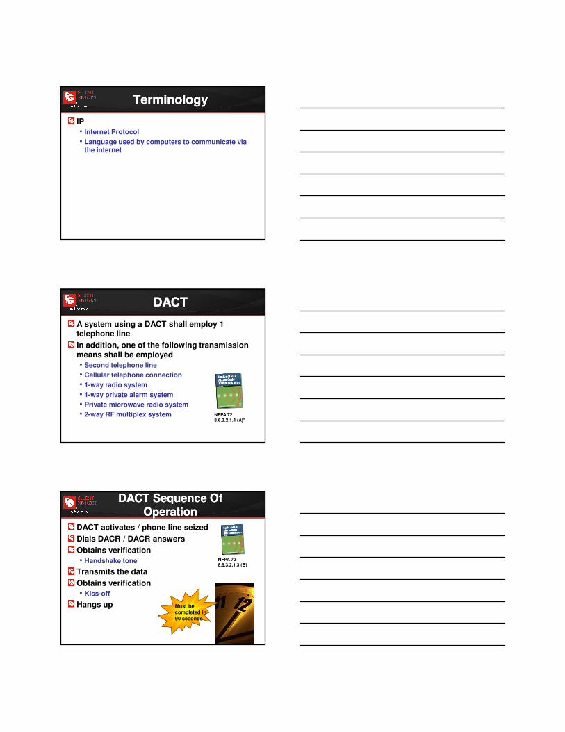
DACT
• Digital Alarm Communicator Transmitter
DACR
• Digital Alarm Communicator Receiver
RJ31X
• Phone jack
• Required by FCC
TerminologyTerminology
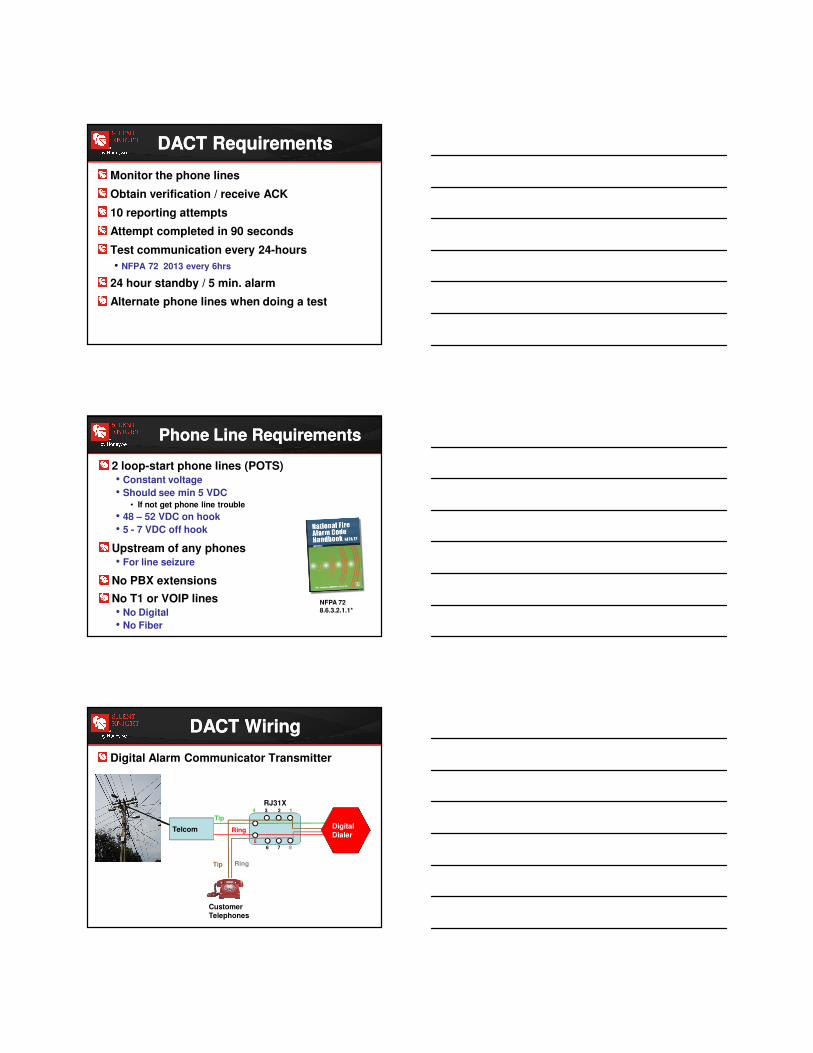
CID• Contact Identification – Reporting format
developed by Ademco Manufacturing
SIA• Security Industrial Association – Reporting format
developed as a standard for reporting to central stations
POTS Line• Plain Old Telephone System
• Copper line
TerminologyTerminology
IP
• Internet Protocol
• Language used by computers to communicate via the internet
TerminologyTerminology
A system using a DACT shall employ 1 telephone line
In addition, one of the following transmission means shall be employed
• Second telephone line
• Cellular telephone connection
• 1-way radio system
• 1-way private alarm system
• Private microwave radio system
• 2-way RF multiplex system NFPA 728.6.3.2.1.4 (A)*
DACTDACT
DACT activates / phone line seized
Dials DACR / DACR answers
Obtains verification
• Handshake tone
Transmits the data
Obtains verification
• Kiss-off
Hangs up Must be completed in
90 seconds
NFPA 728.6.3.2.1.3 (B)
DACT Sequence Of Operation
DACT Sequence Of Operation
Monitor the phone lines
Obtain verification / receive ACK
10 reporting attempts
Attempt completed in 90 seconds
Test communication every 24-hours
• NFPA 72 2013 every 6hrs
24 hour standby / 5 min. alarm
Alternate phone lines when doing a test
DACT RequirementsDACT Requirements
2 loop-start phone lines (POTS)• Constant voltage
• Should see min 5 VDC • If not get phone line trouble
• 48 – 52 VDC on hook
• 5 - 7 VDC off hook
Upstream of any phones• For line seizure
No PBX extensions
No T1 or VOIP lines • No Digital
• No Fiber
NFPA 728.6.3.2.1.1*
Phone Line RequirementsPhone Line Requirements
Digital Alarm Communicator Transmitter
RJ31X12
7 8
4 3
6
5
Digital Dialer
Tip
RingTelcom
Customer Telephones
Tip Ring
DACT WiringDACT Wiring
The model 7860 phone cord is available from Silent Knight for this purpose, or use a
standard RJ31X cord
Telephone ConnectionsTelephone Connections
ReportingReporting
Essentially a “high-speed” call box using public switched telephone lines
In the event of an emergency it will:
• Dial up the central station
• Establish connection
• Transmit the message
• Verify the message
Digital CommunicatorsDigital Communicators
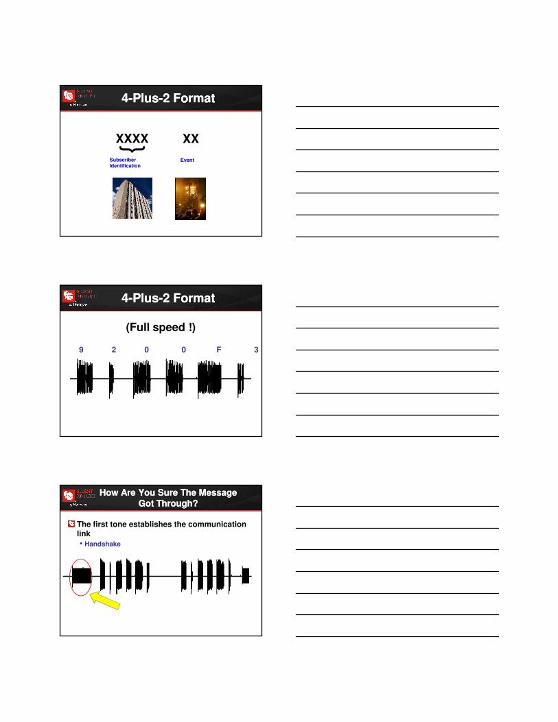
}XXXX XX
SubscriberIdentification
Event
4-Plus-2 Format4-Plus-2 Format
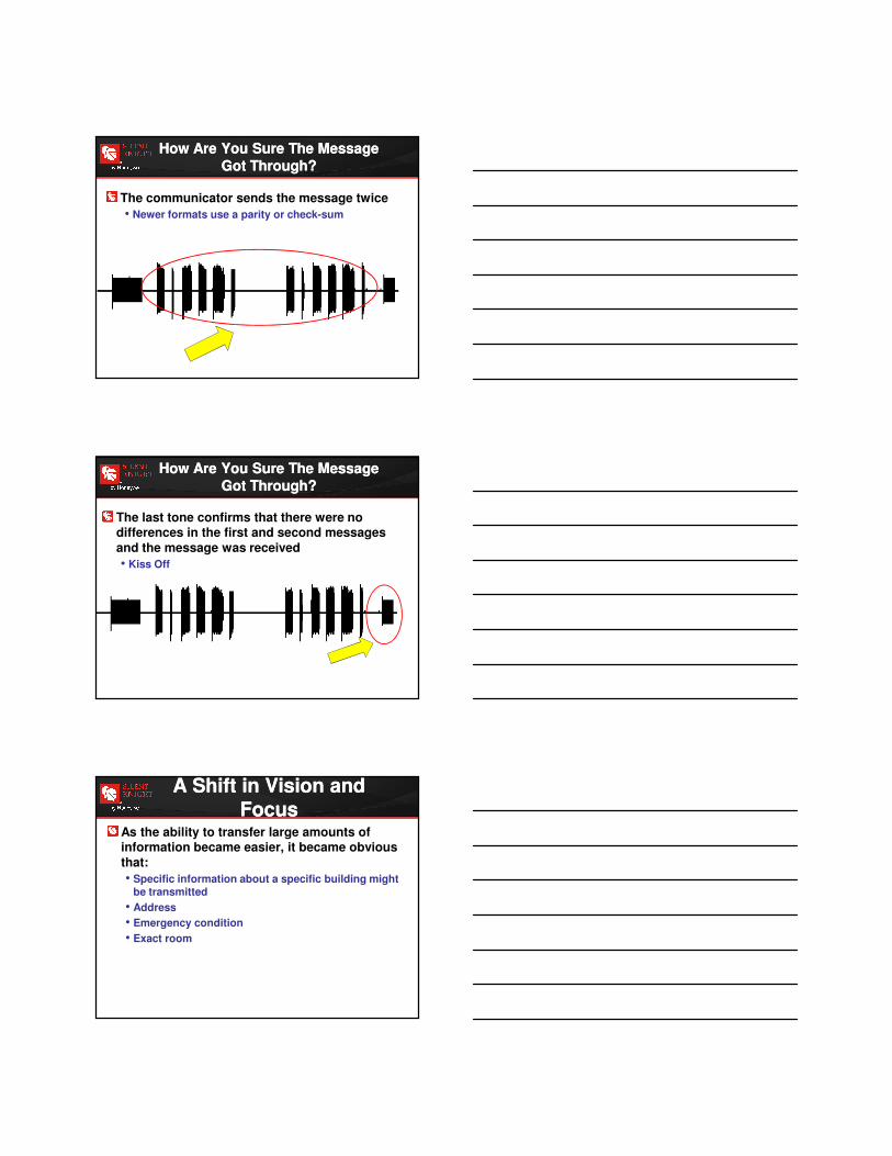
9 2 0 0 F 3
(Full speed !)
4-Plus-2 Format4-Plus-2 Format
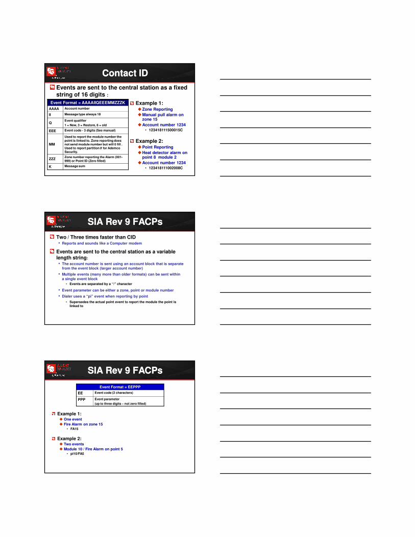
The first tone establishes the communication link
• Handshake
How Are You Sure The Message
Got Through?
How Are You Sure The Message
Got Through?
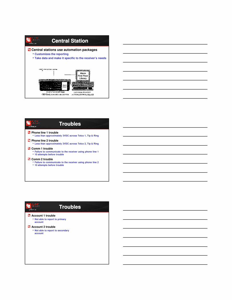
The communicator sends the message twice
• Newer formats use a parity or check-sum
How Are You Sure The Message
Got Through?
How Are You Sure The Message
Got Through?
The last tone confirms that there were no differences in the first and second messages
and the message was received
• Kiss Off
How Are You Sure The Message
Got Through?
How Are You Sure The Message
Got Through?
As the ability to transfer large amounts of information became easier, it became obvious
that:
• Specific information about a specific building might be transmitted
• Address
• Emergency condition
• Exact room
A Shift in Vision and Focus
A Shift in Vision and Focus

In the late 1980s: ADEMCO Contact ID format
It had 2 great advantages:
• Dual Tone Multi-Frequency (DTMF) Signaling
• Touch tone dialing
• Robust format
A Shift in Vision and Focus
A Shift in Vision and Focus
9 2 0 0 - E 3 - 0 - 0 C 0 - 0 0 - 0 0 0
Dual Tone Multiple Frequency Transmission
Dual Tone Multiple Frequency Transmission
(.wav)
About 18 seconds per message!
Full 4-Plus-2 message followed by full ADEMCO Contact ID message
How Much Faster?How Much Faster?
Events are sent to the central station as a fixed string of 16 digits :
Event Format = AAAAIIQEEEMMZZZK
AAAA Account number
II Message type always 18
Q Event qualifier
1 = New, 3 = Restore, 6 = old
EEE Event code - 3 digits (See manual)
MM
Used to report the module number the
point is linked to. Zone reporting does not send module number but will 0 fill . Used to report partition # for Ademco Security.
ZZZZone number reporting the Alarm (001-
999) or Point ID (Zero filled)
K Message sum
Example 1:�Zone Reporting
�Manual pull alarm on zone 15
�Account number 1234
• 123418111500015C
Example 2:�Point Reporting
�Heat detector alarm on point 8 module 2
�Account number 1234
• 123418111002008C
Contact IDContact ID
Two / Three times faster than CID• Reports and sounds like a Computer modem
Events are sent to the central station as a variable length string:
• The account number is sent using an account block that is separate from the event block (larger account number)
• Multiple events (many more than older formats) can be sent within
a single event block
• Events are separated by a “/” character
• Event parameter can be either a zone, point or module number
• Dialer uses a “pi” event when reporting by point
• Supersedes the actual point event to report the module the point is linked to
SIA Rev 9 FACPsSIA Rev 9 FACPs
Event Format = EEPPP
EE Event code (2 characters)
PPP Event parameter
(up to three digits – not zero filled)
Example 1: � One event
� Fire Alarm on zone 15 • FA15
Example 2:� Two events
� Module 10 / Fire Alarm on point 5 • pi10/FA5
SIA Rev 9 FACPsSIA Rev 9 FACPs
Central stations use automation packages
• Customizes the reporting
• Take data and make it specific to the receiver’s needs
Alarm Zone 1
AlarmFirst Floor
Library
Central StationCentral Station
Phone line 1 trouble• Less than approximately 3VDC across Telco 1, Tip & Ring
Phone line 2 trouble • Less than approximately 3VDC across Telco 2, Tip & Ring
Comm 1 trouble• Failure to communicate to the receiver using phone line 1• 10 attempts before trouble
Comm 2 trouble • Failure to communicate to the receiver using phone line 2
• 10 attempts before trouble
TroublesTroubles
Account 1 trouble
• Not able to report to primary
account
Account 2 trouble
• Not able to report to secondary
account
TroublesTroubles
Single Communication Technology
Single Communication Technology
Yes! Account 1234 are you there?
Via Ethernet
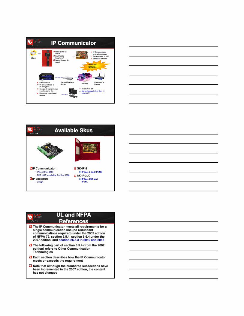
Connects to primary dialer output on panel
Connects via Internet or Intranet with 512 bit AES encryption
Communicates with compatible Teldat Corporation receiver
Can be supervised every 90 seconds!
IP ReceiverIP Communicator
IP CommunicatorIP Communicator
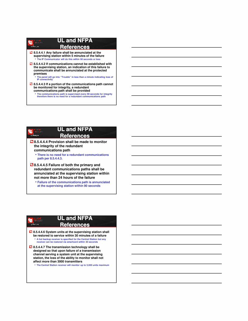
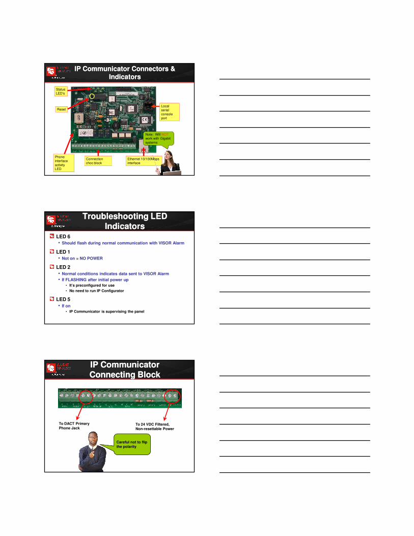
Current Network Architecture
Current Network Architecture
IP CommunicatorIP Communicator
Panel picks up
Line 1
DACT dials
telephone#
Sends Contact ID
report
Alarm
IP Communicator
encrypts message
Encapsulates in UDP
Sends via internet
Customer’s Router
Central Station’sRouter Internet
CMS Receiver
De-encapsulated &
de-encrypted
Contact-ID transmission
over the serial line
Emulating a traditional
receiver
Automation SW
Alarm displays in less than 10
seconds!!!
NFPA 72 2013 26.6.3.1.15.124hrs Backup
NFPA 72 2013 26.6.3.1.15.124hrs Backup
Available SkusAvailable Skus
IP Communicator• IPDact-2 or 2UD
• 2UD NOT available for the 5700
IP Enclosure
• IPENC
SK-IP-2� IPDact-2 and IPENC
SK-IP-2UD
� IPDact-2UD and IPENC
The IP Communicator meets all requirements for a single communication line (no redundant communications required) under the 2002 edition of NFPA 72, section 8.5.4, section 8.6.4 under the 2007 edition, and section 26.6.3 in 2010 and 2013
The following part of section 8.5.4 (from the 2002 edition) refers to Other Communication Technologies
Each section describes how the IP Communicator meets or exceeds the requirement
Note that although the numbered subsections have been incremented in the 2007 edition, the content has not changed
UL and NFPA References
UL and NFPA References
8.5.4.4.1 Any failure shall be annunciated at the supervising station within 5 minutes of the failure• The IP Communicator will do this within 90 seconds or less
8.5.4.4.2 If communications cannot be established with the supervising station, an indication of this failure to communicate shall be annunciated at the protected premises• The panel will go into “Trouble” in less than a minute indicating loss of
IP connectivity
8.5.4.4.3 If a portion of the communications path cannot be monitored for integrity, a redundant communications path shall be provided• The communications path is supervised every 90 seconds for integrity
therefore there is no need for a redundant communications path
UL and NFPA References
UL and NFPA References
8.5.4.4.4 Provision shall be made to monitor the integrity of the redundant
communications path
• There is no need for a redundant communications path per 8.5.4.4.3.
8.5.4.4.5 Failure of both the primary and redundant communications paths shall be
annunciated at the supervising station within not more than 24 hours of the failure
• Failure of the communications path is annunciated at the supervising station within 90 seconds
UL and NFPA References
UL and NFPA References
8.5.4.4.6 System units at the supervising station shall be restored to service within 30 minutes of a failure• A hot backup receiver is specified for the Central Station but any
receiver can be restored via smartcard within 30 seconds
8.5.4.4.7 The transmission technology shall be designed so that upon failure of a transmission channel serving a system unit at the supervising station, the loss of the ability to monitor shall not affect more than 3000 transmitters• The Central Station receiver will monitor up to 3,000 units maximum
UL and NFPA References
UL and NFPA References
Connection choc block
Ethernet 10/100Mbps interface
Local serial
console port
Reset
Status LED’s
Phone interface
activity LED
Note: Will NOTwork with Gigabit
systems
IP Communicator Connectors &
Indicators
IP Communicator Connectors &
Indicators
Troubleshooting LED Indicators
Troubleshooting LED Indicators
LED 6
• Should flash during normal communication with VISOR Alarm
LED 1
• Not on = NO POWER
LED 2
• Normal conditions indicates data sent to VISOR Alarm
• If FLASHING after initial power up
• It’s preconfigured for use
• No need to run IP Configurator
LED 5
• If on
• IP Communicator is supervising the panel
To DACT Primary Phone Jack
To 24 VDC Filtered, Non-resettable Power
Careful not to flip the polarity
IP Communicator Connecting BlockIP Communicator Connecting Block

Torroid
Use care when making the phone line connections at the IP Communicator.
Thin wires can break easily.
InstallationInstallation
Connect the wires of the supplied phone cord to the terminals labeled “TO AP” (P7)
Loop cable through the supplied torroid
Connect using 2 conductor wire, Tip to Tip, Ring to Ring
Note: The phone line connection at the IP
Communicator is not polarity sensitive.
Note: The phone line connection at the IP
Communicator is not polarity sensitive.
Connect one end of power wires
to the terminals marked “GND and “+12/24V (P12)
Loop cable through the supplied
torroid
Connect other end to +24 VDC
non-resettable power
InstallationInstallation
CAUTION!
Failure to observe proper polarity of the
power connection will result in catastrophic damage to IP Communicator!
InstallationInstallation
Connect the IP Communicator to the customer’s network using a CAT5 Ethernet
cable

To program an IP Communicator, you will need the following:
• Windows-based PC with any of the following:
• 9-pin serial COM port
• USB/Serial converter
• Network Interface Card (NIC)
• For serial connection: Serial Cable – P/N ALMSC119
• For Telnet (Ethernet) connection:
• CAT5 RJ45 patch cable
• CAT5 RJ45 crossover patch cable
ALMSC119 Serial Programming Cable
NOT INCLUDED
ProgrammingProgramming
To PC serial connector
Serial Cable ConnectionSerial Cable Connection
CAT5 Patch Cable (straight-through)
Network hub or switch
IP Communicator Programming (Telnet)CAT5 Patch Cable Connection
IP Communicator Programming (Telnet)CAT5 Patch Cable Connection
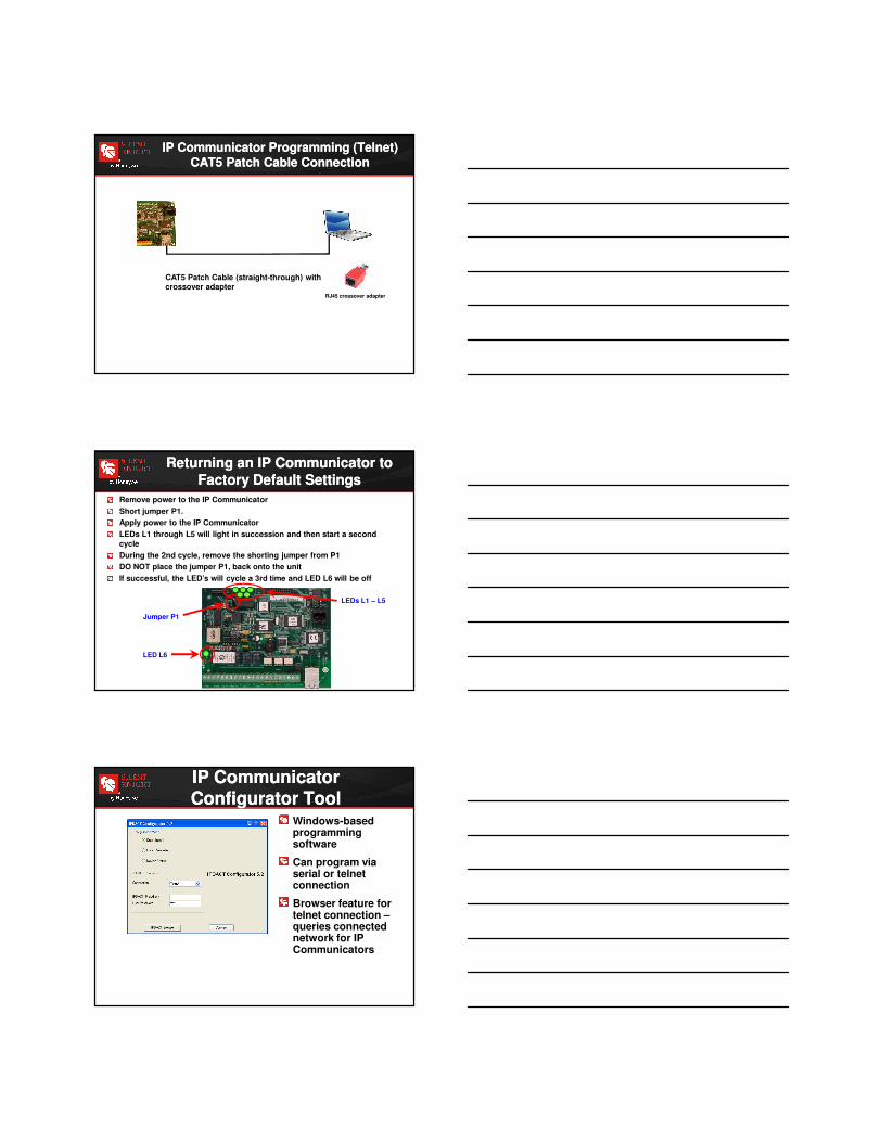
CAT5 Patch Cable (straight-through) with crossover adapter
RJ45 crossover adapter
IP Communicator Programming (Telnet)CAT5 Patch Cable Connection
IP Communicator Programming (Telnet)CAT5 Patch Cable Connection
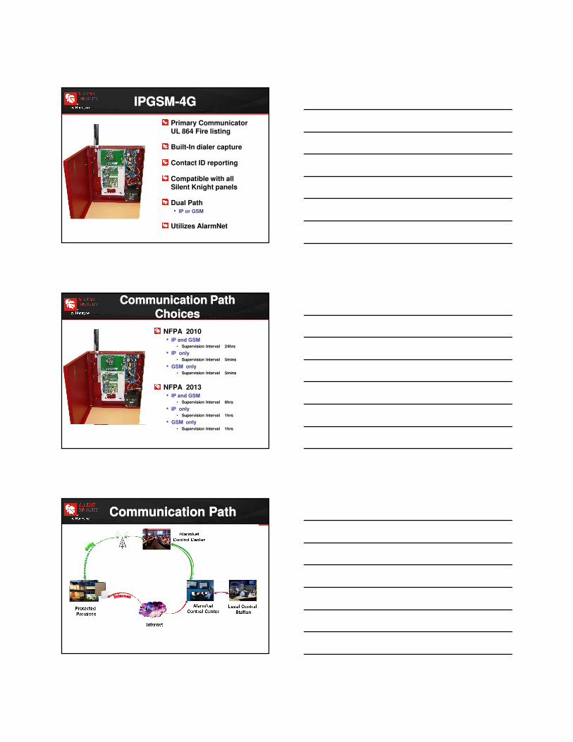
Remove power to the IP Communicator
Short jumper P1.
Apply power to the IP Communicator
LEDs L1 through L5 will light in succession and then start a second cycle
During the 2nd cycle, remove the shorting jumper from P1
DO NOT place the jumper P1, back onto the unit
If successful, the LED’s will cycle a 3rd time and LED L6 will be off
LEDs L1 – L5
Jumper P1
LED L6
Returning an IP Communicator to
Factory Default Settings
Returning an IP Communicator to
Factory Default Settings
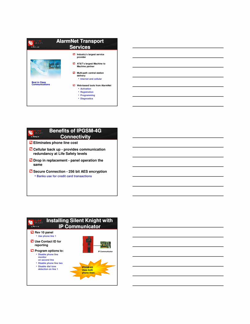
Windows-based programming software
Can program via serial or telnet connection
Browser feature for telnet connection –queries connected network for IP Communicators
IP Communicator Configurator ToolIP Communicator Configurator Tool

IP Communicator Configurator ToolIP Communicator Configurator Tool
Must use COM1 – COM4 for serial connection
For Telnet connection, your laptop must have a static IP Address within the range of the default IP Address of the IP Communicator • 192.168.0.100
Choose 192.168.0.nnn where nnn can be any number from 1 – 254 except 100
IP Communicator Configurator ToolIP Communicator Configurator Tool
Information must be obtained from the customer’s IT Dept. and from the Central Station
Still Have Questions?Still Have Questions?
Take the IP Communicator online
course
IPDACT Configurator Tool online learning
www.silentknight.com
IPGSM-4GIPGSM-4G
Primary Communicator UL 864 Fire listing
Built-In dialer capture
Contact ID reporting
Compatible with all Silent Knight panels
Dual Path• IP or GSM
Utilizes AlarmNet
Communication Path Choices
Communication Path Choices
NFPA 2010• IP and GSM
• Supervision Interval 24hrs
• IP only• Supervision Interval 5mins
• GSM only• Supervision Interval 5mins
NFPA 2013• IP and GSM
• Supervision Interval 6hrs
• IP only• Supervision Interval 1hrs
• GSM only• Supervision Interval 1hrs
Communication PathCommunication Path
AlarmNet Transport Services
AlarmNet Transport Services
Industry’s largest service provider
AT&T’s largest Machine to
Machine partner
Multi-path central station delivery
• Internet and cellular
Web-based tools from AlarmNet
• Activation
• Registration
• Programming
• Diagnostics
Best in Class Communications
Benefits of IPGSM-4G Connectivity
Benefits of IPGSM-4G Connectivity
Eliminates phone line cost
Cellular back up - provides communication redundancy at Life Safety levels
Drop in replacement - panel operation the same
Secure Connection - 256 bit AES encryption
• Banks use for credit card transactions
Rev 10 panel• Use phone line 1
Use Contact ID for reporting
Program options to:• Disable phone line
monitor
on second line
• Disable phone line two
• Disable dial tone detection on line 1
IP Communicator
Installing Silent Knight with IP Communicator
Installing Silent Knight with IP Communicator
IPGSM-4GUses both
phone lines
IPGSM-4GUses both
phone lines

Rev 9 or earlier
• Tie phone line 1 & 2 together
• Tip to tip
• Ring to ring
Use Contact ID for reporting
IP Communicator
Installing Silent Knight with IP Communicator
Installing Silent Knight with IP Communicator
If mixing technologies
• Will be additional monitoring fees
We recommend one or the other
IP Communicator
Installing Silent Knight with other
Transmission Technologies
Installing Silent Knight with other
Transmission Technologies