ieee std 145’-2013 (revision of ieee std 145-1993), ieee...
TRANSCRIPT
IEEE Standard for Definitions of Terms for Antennas
Sponsored by the Antennas Committee
IEEE 3 Park Avenue New York, NY 10016-5997 USA
IEEE Antennas and Propagation Society
IEEE Std 145™-2013 (Revision of
IEEE Std 145-1993)
Authorized licensed use limited to: Stanford University. Downloaded on October 29,2014 at 10:02:39 UTC from IEEE Xplore. Restrictions apply.

Authorized licensed use limited to: Stanford University. Downloaded on October 29,2014 at 10:02:39 UTC from IEEE Xplore. Restrictions apply.

445 Hoes Lane, Piscataway, NJ 08854 USA | http://standards.ieee.org | Tel. +1 732-981-0060 Fax +1 732-562-1571
This is a Redline Document produced by Techstreet, a business of
Thomson Reuters.
This document is intended to provide users with an indication of changes from one edition
to the next. It includes a full-text version of the new document, plus an indication of
changes from the previous version.
Redlines are designed to save time and improve efficiencies by using the latest software
technology to find and highlight document changes. More professionals are using valuable
new technologies like redlines, to help improve outcomes in a fastpaced global business
world.
Because it may not be technically possible to capture all changes accurately, it is
recommended that users consult previous editions as appropriate. In all cases, only the
current base version of this publication is to be considered the official document.
Authorized licensed use limited to: Stanford University. Downloaded on October 29,2014 at 10:02:39 UTC from IEEE Xplore. Restrictions apply.
Redline Processing Notes:
1. Red Text - Red strikethrough text denotes deletions.
2. Blue Text - Blue underlined text denotes modifications and additions.
Authorized licensed use limited to: Stanford University. Downloaded on October 29,2014 at 10:02:39 UTC from IEEE Xplore. Restrictions apply.
IEEE Std 145™-2013 (Revision of
IEEE Std 145-1993)
IEEE Standard for Definitions of Terms for Antennas
Sponsor Antennas Committee of the IEEE Antennas and Propagation Society Approved 11 December 2013 IEEE-SA Standards Board
Authorized licensed use limited to: Stanford University. Downloaded on October 29,2014 at 10:02:39 UTC from IEEE Xplore. Restrictions apply.
Abstract: Definitions for antennas and for systems that incorporate an antenna as a component of the system are established in this standard. Keywords: antennas, definitions, IEEE 145™, terms
•
The Institute of Electrical and Electronics Engineers, Inc. 3 Park Avenue, New York, NY 10016-5997, USA Copyright © 2014 by The Institute of Electrical and Electronics Engineers, Inc. All rights reserved. Published 11 March 2014. Printed in the United States of America. IEEE is a registered trademark in the U.S. Patent & Trademark Office, owned by The Institute of Electrical and Electronics Engineers, Incorporated. PDF: ISBN 978-0-7381-8927-7 STD98546 Print: ISBN 978-0-7381-8928-4 STDPD98546 IEEE prohibits discrimination, harassment, and bullying. For more information, visit http://www.ieee.org/web/aboutus/whatis/policies/p9-26.html. No part of this publication may be reproduced in any form, in an electronic retrieval system or otherwise, without the prior written permission of the publisher.
Authorized licensed use limited to: Stanford University. Downloaded on October 29,2014 at 10:02:39 UTC from IEEE Xplore. Restrictions apply.
Important Notices and Disclaimers Concerning IEEE Standards Documents
IEEE documents are made available for use subject to important notices and legal disclaimers. These notices and disclaimers, or a reference to this page, appear in all standards and may be found under the heading “Important Notice” or “Important Notices and Disclaimers Concerning IEEE Standards Documents.”
Notice and Disclaimer of Liability Concerning the Use of IEEE Standards Documents
IEEE Standards documents (standards, recommended practices, and guides), both full-use and trial-use, are developed within IEEE Societies and the Standards Coordinating Committees of the IEEE Standards Association (“IEEE-SA”) Standards Board. IEEE (“the Institute”) develops its standards through a consensus development process, approved by the American National Standards Institute (“ANSI”), which brings together volunteers representing varied viewpoints and interests to achieve the final product. Volunteers are not necessarily members of the Institute and participate without compensation from IEEE. While IEEE administers the process and establishes rules to promote fairness in the consensus development process, IEEE does not independently evaluate, test, or verify the accuracy of any of the information or the soundness of any judgments contained in its standards.
IEEE does not warrant or represent the accuracy or content of the material contained in its standards, and expressly disclaims all warranties (express, implied and statutory) not included in this or any other document relating to the standard, including, but not limited to, the warranties of: merchantability; fitness for a particular purpose; non-infringement; and quality, accuracy, effectiveness, currency, or completeness of material. In addition, IEEE disclaims any and all conditions relating to: results; and workmanlike effort. IEEE standards documents are supplied “AS IS” and “WITH ALL FAULTS.”
Use of an IEEE standard is wholly voluntary. The existence of an IEEE standard does not imply that there are no other ways to produce, test, measure, purchase, market, or provide other goods and services related to the scope of the IEEE standard. Furthermore, the viewpoint expressed at the time a standard is approved and issued is subject to change brought about through developments in the state of the art and comments received from users of the standard.
In publishing and making its standards available, IEEE is not suggesting or rendering professional or other services for, or on behalf of, any person or entity nor is IEEE undertaking to perform any duty owed by any other person or entity to another. Any person utilizing any IEEE Standards document, should rely upon his or her own independent judgment in the exercise of reasonable care in any given circumstances or, as appropriate, seek the advice of a competent professional in determining the appropriateness of a given IEEE standard.
IN NO EVENT SHALL IEEE BE LIABLE FOR ANY DIRECT, INDIRECT, INCIDENTAL, SPECIAL, EXEMPLARY, OR CONSEQUENTIAL DAMAGES (INCLUDING, BUT NOT LIMITED TO: PROCUREMENT OF SUBSTITUTE GOODS OR SERVICES; LOSS OF USE, DATA, OR PROFITS; OR BUSINESS INTERRUPTION) HOWEVER CAUSED AND ON ANY THEORY OF LIABILITY, WHETHER IN CONTRACT, STRICT LIABILITY, OR TORT (INCLUDING NEGLIGENCE OR OTHERWISE) ARISING IN ANY WAY OUT OF THE PUBLICATION, USE OF, OR RELIANCE UPON ANY STANDARD, EVEN IF ADVISED OF THE POSSIBILITY OF SUCH DAMAGE AND REGARDLESS OF WHETHER SUCH DAMAGE WAS FORESEEABLE.
Translations
The IEEE consensus development process involves the review of documents in English only. In the event that an IEEE standard is translated, only the English version published by IEEE should be considered the approved IEEE standard.
Authorized licensed use limited to: Stanford University. Downloaded on October 29,2014 at 10:02:39 UTC from IEEE Xplore. Restrictions apply.
Official statements
A statement, written or oral, that is not processed in accordance with the IEEE-SA Standards Board Operations Manual shall not be considered or inferred to be the official position of IEEE or any of its committees and shall not be considered to be, or be relied upon as, a formal position of IEEE. At lectures, symposia, seminars, or educational courses, an individual presenting information on IEEE standards shall make it clear that his or her views should be considered the personal views of that individual rather than the formal position of IEEE.
Comments on standards
Comments for revision of IEEE Standards documents are welcome from any interested party, regardless of membership affiliation with IEEE. However, IEEE does not provide consulting information or advice pertaining to IEEE Standards documents. Suggestions for changes in documents should be in the form of a proposed change of text, together with appropriate supporting comments. Since IEEE standards represent a consensus of concerned interests, it is important that any responses to comments and questions also receive the concurrence of a balance of interests. For this reason, IEEE and the members of its societies and Standards Coordinating Committees are not able to provide an instant response to comments or questions except in those cases where the matter has previously been addressed. For the same reason, IEEE does not respond to interpretation requests. Any person who would like to participate in revisions to an IEEE standard is welcome to join the relevant IEEE working group.
Comments on standards should be submitted to the following address:
Secretary, IEEE-SA Standards Board 445 Hoes Lane Piscataway, NJ 08854 USA
Laws and regulations
Users of IEEE Standards documents should consult all applicable laws and regulations. Compliance with the provisions of any IEEE Standards document does not imply compliance to any applicable regulatory requirements. Implementers of the standard are responsible for observing or referring to the applicable regulatory requirements. IEEE does not, by the publication of its standards, intend to urge action that is not in compliance with applicable laws, and these documents may not be construed as doing so.
Copyrights
IEEE draft and approved standards are copyrighted by IEEE under U.S. and international copyright laws. They are made available by IEEE and are adopted for a wide variety of both public and private uses. These include both use, by reference, in laws and regulations, and use in private self-regulation, standardization, and the promotion of engineering practices and methods. By making these documents available for use and adoption by public authorities and private users, IEEE does not waive any rights in copyright to the documents.
Photocopies
Subject to payment of the appropriate fee, IEEE will grant users a limited, non-exclusive license to photocopy portions of any individual standard for company or organizational internal use or individual, non-commercial use only. To arrange for payment of licensing fees, please contact Copyright Clearance Center, Customer Service, 222 Rosewood Drive, Danvers, MA 01923 USA; +1 978 750 8400. Permission to photocopy portions of any individual standard for educational classroom use can also be obtained through the Copyright Clearance Center.
Authorized licensed use limited to: Stanford University. Downloaded on October 29,2014 at 10:02:39 UTC from IEEE Xplore. Restrictions apply.
Updating of IEEE Standards documents
Users of IEEE Standards documents should be aware that these documents may be superseded at any time by the issuance of new editions or may be amended from time to time through the issuance of amendments, corrigenda, or errata. An official IEEE document at any point in time consists of the current edition of the document together with any amendments, corrigenda, or errata then in effect.
Every IEEE standard is subjected to review at least every ten years. When a document is more than ten years old and has not undergone a revision process, it is reasonable to conclude that its contents, although still of some value, do not wholly reflect the present state of the art. Users are cautioned to check to determine that they have the latest edition of any IEEE standard.
In order to determine whether a given document is the current edition and whether it has been amended through the issuance of amendments, corrigenda, or errata, visit the IEEE-SA Website at http://ieeexplore.ieee.org/xpl/standards.jsp or contact IEEE at the address listed previously. For more information about the IEEE SA or IEEE’s standards development process, visit the IEEE-SA Website at http://standards.ieee.org.
Errata
Errata, if any, for all IEEE standards can be accessed on the IEEE-SA Website at the following URL: http://standards.ieee.org/findstds/errata/index.html. Users are encouraged to check this URL for errata periodically.
Patents
Attention is called to the possibility that implementation of this standard may require use of subject matter covered by patent rights. By publication of this standard, no position is taken by the IEEE with respect to the existence or validity of any patent rights in connection therewith. If a patent holder or patent applicant has filed a statement of assurance via an Accepted Letter of Assurance, then the statement is listed on the IEEE-SA Website at http://standards.ieee.org/about/sasb/patcom/patents.html. Letters of Assurance may indicate whether the Submitter is willing or unwilling to grant licenses under patent rights without compensation or under reasonable rates, with reasonable terms and conditions that are demonstrably free of any unfair discrimination to applicants desiring to obtain such licenses.
Essential Patent Claims may exist for which a Letter of Assurance has not been received. The IEEE is not responsible for identifying Essential Patent Claims for which a license may be required, for conducting inquiries into the legal validity or scope of Patents Claims, or determining whether any licensing terms or conditions provided in connection with submission of a Letter of Assurance, if any, or in any licensing agreements are reasonable or non-discriminatory. Users of this standard are expressly advised that determination of the validity of any patent rights, and the risk of infringement of such rights, is entirely their own responsibility. Further information may be obtained from the IEEE Standards Association.
Authorized licensed use limited to: Stanford University. Downloaded on October 29,2014 at 10:02:39 UTC from IEEE Xplore. Restrictions apply.
Copyright © 2014 IEEE. All rights reserved.
vi
Participants
At the time this IEEE standard was completed, the Antennas Definitions Working Group had the following membership:
Antoine Roederer, Chair
Everett Farr Lars Foged Michael Francis Robert Hansen
Randy Haupt Albert Lysko Jeffrey Nanzer Ross Stone
Warren Stutzman David Thiel Jeff Way Karl Warnick
The following members of the individual balloting committee voted on this standard. Balloters may have voted for approval, disapproval, or abstention.
William Byrd Patrick Diamond Alistair Duffy Michael Francis Avraham Freedman David Gregson Randall Groves Michael Gundlach Edward Hare Werner Hoelzl Daniel Hoolihan Tetsushi Ikegami Sergiu Iordanescu Akio Iso Efthymios Karabetsos
Stuart Kerry Thomas Kurihara Arthur H. Light Greg Luri Albert Lysko Roger Marks Jon Martens Michael McInnis Michael Newman Nick S. A. Nikjoo Satoshi Oyama Ulrich Pohl Michael Probasco R. K. Rannow
Maximilian Riegel Michael Roberts Robert Robinson Randall Safier Bartien Sayogo Thomas Starai W. Stone Walter Struppler Kin Sze John Vergis George Vlantis Jeffrey Way Hung-Yu Wei Kwangsee Woo Oren Yuen
Authorized licensed use limited to: Stanford University. Downloaded on October 29,2014 at 10:02:39 UTC from IEEE Xplore. Restrictions apply.

Copyright © 2014 IEEE. All rights reserved.
vii
When the IEEE-SA Standards Board approved this standard on 11 December 2013, it had the following membership:
John Kulick, Chair David J. Law, Vice Chair
Richard H. Hulett, Past Chair Konstantinos Karachalios, Secretary
Masayuki Ariyoshi Peter Balma Farooq Bari Ted Burse Stephen Dukes Jean-Phillippe Faure Alexander Gelman
Mark Halpin Gary Hoffman Paul Houzé Jim Hughes Micahel Janezic Joseph L. Koepfinger* Oleg Logvinov Ron Peterson
Gary Robinson Jon Walter Rosdahl Adrian Stephens Peter Sutherland Yatin Trivedi Phil Winston Yu Yuan
*Member Emeritus
Also included are the following nonvoting IEEE-SA Standards Board liaisons:
Richard DeBlasio, DOE Representative Michael Janezic, NIST Representative
Michelle Turner IEEE Standards Program Manager, Document Development
Michael Kipness
IEEE Standards Program Manager, Technical Program Development
Authorized licensed use limited to: Stanford University. Downloaded on October 29,2014 at 10:02:39 UTC from IEEE Xplore. Restrictions apply.
Copyright © 2014 IEEE. All rights reserved.
viii
Introduction
This introduction is not part of IEEE Std 145™-2013, IEEE Standard for Definitions of Terms for Antennas.
This document is an updated release of standardized definitions for terms commonly used in the field of antennas. It is anticipated that future revisions to this standard will include additional terms, particularly in the field of active signal-processing antennas
Authorized licensed use limited to: Stanford University. Downloaded on October 29,2014 at 10:02:39 UTC from IEEE Xplore. Restrictions apply.
Copyright © 2014 IEEE. All rights reserved.
ix
Contents
1. Overview .................................................................................................................................................... 1 1.1 Scope ................................................................................................................................................... 1 1.2 Purpose ................................................................................................................................................ 1 1.3 Background .......................................................................................................................................... 1
2. Normative references .................................................................................................................................. 4
3. Definition structure ..................................................................................................................................... 4
4. Definitions .................................................................................................................................................. 4
Authorized licensed use limited to: Stanford University. Downloaded on October 29,2014 at 10:02:39 UTC from IEEE Xplore. Restrictions apply.

Authorized licensed use limited to: Stanford University. Downloaded on October 29,2014 at 10:02:39 UTC from IEEE Xplore. Restrictions apply.
IEEE Standard for Definitions of Terms for Antennas
IMPORTANT NOTICE: IEEE Standards documents are not intended to ensure safety, security,
health, or environmental protection, or ensure against interference with or from other devices or
networks. Implementers of IEEE Standards documents are responsible for determining and
complying with all appropriate safety, security, environmental, health, and interference protection
practices and all applicable laws and regulations.
This IEEE document is made available for use subject to important notices and legal
disclaimers. These notices and disclaimers appear in all publications containing this document and
may be found under the heading “Important Notice” or “Important Notices and Disclaimers
Concerning IEEE Documents.” They can also be obtained on request from IEEE or viewed at
http://standards.ieee.org/IPR/disclaimers.html.
1. Overview
1.1 Scope
This standard establishes definitions for antennas and for systems that incorporate an antenna as a
component of the system.
1.2 Purpose
Many individuals and organizations are involved in the design, manufacture, measurement and
use of antennas for many different applications. This standard is intended to provide a set of
standard definitions for the community so that when terminology is used all will understand its
meaning.
Authorized licensed use limited to: Stanford University. Downloaded on October 29,2014 at 10:02:39 UTC from IEEE Xplore. Restrictions apply.
1.3 Background
The definitions of terms contained herein, For the most part, the definitions of terms contained
herein stand alone and are easily understood out of context: However, the terms pertaining to gain,
directivity, and polarization, however,are interrelated, and hence require some elaboration.
The viewpoints taken for polarization are that the is that this term can be used in three related
meanings. It and can apply:
a) To a field vector at some point in space
b) To a plane wave
c) To an antenna
The polarization of a field vector specifies the shape, orientation, and sense of the ellipse that the
extremity of the field vector describes as a function of time. This applies to any field vector: electric
field, magnetic field, velocity field in a plasma, displacement field in a solid, etc. In a single-
frequency plane wave, a specified field vector has the same polarization at every point in space.
This is taken as to be the polarization of the plane wave. Conventionally, In electromagnetics,
conventionally the electric field is considered rather than the magnetic field. However, in a non-
isotropic medium, the polarization state of the plane wave requires consideration of all its vector
components. The third application of the term polarization is to antennas. The polarization of an
antenna in a given direction is that of the plane wave it radiates at large distances in that direction.
By rec iprocity, a plane wave coming from that direction whose with a polarization ellipse that has
the same axial ratio, orientation, and sense will yield the maximum response for a given power
flux density. For best understanding, the three related definitions of polarization should be read in
the above order.
Authorized licensed use limited to: Stanford University. Downloaded on October 29,2014 at 10:02:39 UTC from IEEE Xplore. Restrictions apply.
One departure from previous usage should be noted. The definition of the tilt angle of the
polarization ellipse now requires that it be measured according to the right-hand rule, with the
thumb pointing in a reference direction. For a plane wave, the reference direction is the direction of
propagation. This is advantageous, since it removes any ambiguity about the specification of the
orientation of the polarization ellipse. However, it should be noted, however, that the polarization
of the antenna is defined as that of the wave it radiates, whether it is used for transmitting or
receiving. This means that for the receiving case, the coordinate system used to describe the
polarization of the antenna and the incoming wave are is oriented in opposite directions (see
Clause 11 of IEEE Std 149™-1979, IEEE Standard Test Procedures for Antennas, clause 11,
Polarization.1)). There are two ways to handle this situation. One is to transform the polarization of
the wave into the antenna’s coordinate system. The second is to define a receiving polarization for
the antenna, which is that of the wave to which the antenna is polarization matched. The latter was
chosen both here and in IEEE Std 149-1979. This should not be taken to mean that one cannot use
the antenna’s coordinate system, but rather that if it is done, it should be clearly specified as the
polarization of the incoming wave referred to the antenna’s (transmitting) polarization. The term
receiving polarization can also be applied to a nonreciprocal antenna that may only receive.
The interdependence of gain, polarization, and impedance has led to the inclusion of several
terms, including partial gain, partial directivity, and partial realized gain. The interrelationships of
these terms and the basic terms gain, directivity, and realized gain are best visualized by referring to
the flowchart shown in Figure 1. A similar flow chart can be constructed for a receiving antenna.
1Information on the reference can be found in 1.3
Authorized licensed use limited to: Stanford University. Downloaded on October 29,2014 at 10:02:39 UTC from IEEE Xplore. Restrictions apply.
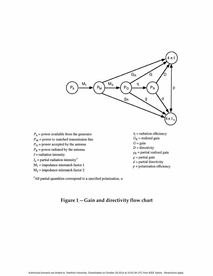
Figure 1 —Gain and directivity flow chart
Authorized licensed use limited to: Stanford University. Downloaded on October 29,2014 at 10:02:39 UTC from IEEE Xplore. Restrictions apply.
It is assumed in this standard that an antenna is a passive linear reciprocal device. Thus, Where
a definition implies the use of an antenna in a transmitting situation, its use in a receiving situation
is thus also implicit, unless specifically stated otherwise. When an antenna or group of antennas is
combined with circuit elements that are active, nonlinear, or nonreciprocal, the combination is
regarded as a system that includes an antenna. Examples of such cases are an adaptive antenna
system and a signal-processing antenna system. The complete conical-scanning, monopulse, and
compound interferometer systems also fall into this category. For terms that are quantitative, it is
understood that frequency must be specified. For those in which phase or polarization is a
significant part of the definition, a coherent source of power is implied. Whenever a term is
commonly used in other fields but has specialized significance in the field of antennas, this is noted
in the title. When applying terms pertaining to radiation characteristics—such as gain,
polarization, beamwidth, etc.—to multiple-beam antennas, each port shall be considered to be that
of a separate antenna with a single main beam. For polarization-diversity systems that may
include active devices, these terms apply to each polarization state for which the antenna is
adjusted. Throughout this standard, where phasors are used or are implied, the time convention
shall be taken to be exp(jωt).
2. Normative references
This standard shall be used in conjunction with the following publication:
The following referenced documents are indispensable for the application of this document (i.e.,
they must be understood and used, so each referenced document is cited in text and its relationship
to this document is explained). For dated references, only the edition cited applies. For undated
references, the latest edition of the referenced document (including any amendments or corrigenda)
applies.
Authorized licensed use limited to: Stanford University. Downloaded on October 29,2014 at 10:02:39 UTC from IEEE Xplore. Restrictions apply.
IEEE Std 149™-1979 (Reaff 1990), IEEE Standard Test Procedures for Antennas (ANSI). 1, 2, 3
3. Definition structure
In these definitions, words or phrases in parentheses that are part of the term can be omitted when
the term is used, provided they are understood from context. Those words or phrases in brackets
can replace the words or phrases that immediately precede them. If bracketed words or phrases
appear in several places in the definition, then all bracketed words or phrases must be used
together in the definitions. For those cases where two or more terms are synonyms, the preferred
term will be defined; the other terms will refer to the preferred term and be listed after the
definition. Abbreviations appear after the term and are enclosed in parentheses. Terms that are no
longer recommended for use are indicated as being deprecated. Synonyms for a term are listed at
the end of the definition.
4. Definitions
For the purposes of this document, the following terms and definitions apply. The IEEE
StandardsDictionary Online should be consulted for terms not defined in this clause. 4
absolute gain (of an antenna): See: gain (in a given direction).
1 IEEE Std 149-1979 was reaffirmed in 2008.
2 This publication is available from The Institute of electrical and Electronics Engineers (http://standards.ieee.org). IEEE publications
are available from the Institute of Electrical and Electronics Engineers, Service Center, 445 Hoes Lane, P.O. Box 1331,
Piscataway, NJ 08855-1331, USA.
3 The IEEE standards or product referred to in this clause are trademarks of The Institute of Electrical and Electronics Engineers, Inc.
4 IEEE Standards Dictionary Online subscription is available at:
http://www.ieee.org/portal/innovate/products/standard/standards_dictionary.html.
Authorized licensed use limited to: Stanford University. Downloaded on October 29,2014 at 10:02:39 UTC from IEEE Xplore. Restrictions apply.
active antenna: An antenna packaged with an active device such as an amplifier or impedance-
matching electronics.
active antenna available gain: For a receiving active array antenna, the ratio of the isotropic
noise response to the available power at the terminals of any passive antenna over the same
bandwidth and in the same isotropic noise environment. See: isotropic noise response.
active antenna available power: For a receiving active array antenna, the power at the output of a
formed beam divided by the active antenna available gain. See: active antenna available gain.
active array antenna system: An array in which all or part of the elements are equipped with their
own transmitter or receiver, or both.
NOTE 1—Ideally, for the transmitting case, amplitudes and phases of the output signals of the
various transmitters are controllable and can be coordinated in order to provide the desired aperture
distribution.
NOTE 2— Often it is only a stage of amplification or frequency conversion that is actually
located at the array elements, with the other stages of the receiver or transmitter remotely located.
active impedance (of an array element): The ratio of the voltage across the terminals of an array
element to the current flowing at those terminals when all array elements are in place and excited.
active reflection coefficient (of an array element): The reflection coefficient at the terminals of an
array element when all array elements are in place and excited.
adaptive antenna system: An antenna system having circuit elements associated with its radiating
elements such that one or more of the antenna’s properties are controlled by the received signal.
Authorized licensed use limited to: Stanford University. Downloaded on October 29,2014 at 10:02:39 UTC from IEEE Xplore. Restrictions apply.
Adcock antenna: A pair of vertical antennas separated by a distance of one-half wavelength or less,
and connected in phase opposition to produce a radiation pattern having the shape of the figure
eight in all planes containing the centers of the two antennas.
Aerial: [Deprecated] See antenna.
Alford loop antenna: A multi-element antenna having approximately equal amplitude currents
that are in phase and uniformly distributed along each of its peripheral elements, and
producing a substantially circular radiation pattern in its principal E-plane.
NOTE—This antenna was originally developed as a four-element, horizontally polarized, UHF loop
antenna.
amplitude pattern: See: radiation pattern.
angle tracking: See: tracking.
annular slot antenna: A slot antenna with the radiating slot having the shape of an annulus.
antenna: That part of a transmitting or receiving system that is designed to radiate or to receive
electromagnetic waves.
NOTE—The term antenna is sometimes used for electromagnetic devices that couple over distances
less than that associated with radiated fields.
antenna array: See: array antenna.
2.14 antenna effect. [Deprecated.]
Authorized licensed use limited to: Stanford University. Downloaded on October 29,2014 at 10:02:39 UTC from IEEE Xplore. Restrictions apply.
antenna boresight error: The angular deviation of the electrical boresight of an antenna from its
reference boresight.
NOTE 1—Does not generally apply for steerable-beam antenna systems where the electrical
boresight direction changes with respect to the reference boresight.
NOTE 2—For steerable-beam antenna systems, the boresight error is the difference in pointing
direction between the actual boresight direction relative to the reference boresight and the
commanded pointing direction relative to the reference boresight.
antenna efficiency of an aperture-type antenna: For an antenna with a specified planar aperture, the
ratio of the maximum effective area of the antenna to the aperture area.
antenna [aperture] illumination efficiency: The ratio, usually expressed in percent, of the
maximum directivity of an antenna [aperture] to its standard directivity. Syn: normalized
directivity; See: standard [reference] directivity.
NOTE—For planar apertures, the standard directivity is calculated by using the projected area of the
actual antenna in a plane transverse to the direction of its maximum radiation intensity.
antenna pattern: See: radiation pattern.
antenna resistance: The real part of the input impedance of an antenna.
aperiodic antenna: An antenna that over an extended frequency range does not exhibit a cyclic
behavior with frequency of either its input impedance or its pattern.
NOTE—This term is often applied to an electrically small monopole or loop containing an active
element as an integral component, with impedance and pattern characteristics varying but slowly
over the extended frequency range.
Authorized licensed use limited to: Stanford University. Downloaded on October 29,2014 at 10:02:39 UTC from IEEE Xplore. Restrictions apply.
aperiodic array: An array with non-uniformly spaced elements.
aperture (of an antenna): A surface, near or on an antenna, on which it is convenient to make
assumptions regarding the field values for the purpose of computing fields at external points.
NOTE—The aperture is often taken as that portion of a plane surface near the antenna,
perpendicular to the direction of maximum radiation, through which the major part of the radiation
passes.
aperture antenna: An antenna with an electrically large physical aperture. See: aperture (of an
antenna).
aperture blockage: A condition resulting from objects lying in the path of rays arriving at or
departing from the aperture of an antenna.
NOTE—For example, the feed, sub-reflector, or support structure produce aperture blockage for a
symmetric reflector antenna.
aperture distribution: The field over the aperture as described by amplitude, phase, and
polarization distributions. Syn: aperture illumination.
aperture illumination: See: aperture distribution.
aperture illumination efficiency: See: antenna illumination efficiency.
area: See: effective area (of an antenna); equivalent flat plate area of a scattering object; partial
effective area (of an antenna, for a given polarization and direction).
Authorized licensed use limited to: Stanford University. Downloaded on October 29,2014 at 10:02:39 UTC from IEEE Xplore. Restrictions apply.
areal beamwidth: For pencil-beam antennas, the product of the two principal half-power
beamwidths. See: principal half-power beamwidths.
array antenna: An antenna comprised of a number of identical radiating elements in a regular
arrange ment and excited to obtain a prescribed radiation pattern.the inputs (or outputs) of which
are combined. Syn: antenna array.
NOTE 1—The regular possible arrangements possible often include onesarrangements in which
the elements can be made congruent by simple translation or rotation.
2—This term is sometimes applied to NOTE 2—For cases where the elements are not identical or
not arranged in a regular fashion. For those cases, qualifiers shallcan be added to distinguish from
the usage implied in this definition. For example, if the elements are randomly located, one may use
the term random array antenna.
array element: In an array antenna, a single radiating element or a convenient grouping of
radiating elements that have fixed relative excitations.
array factor: The radiation pattern of an array antenna when each array element is considered to
radiate isotropically.
NOTE—When the radiation patterns of individual array elements are identical, and the array
elements are congruent under translation, then the product of the array factor and the element
radiation pattern gives the radiation pattern of the entire array.
artificial dielectric: A medium containing a distribution of scatterers, usually metallic, thatwhich
react as a dielectric to radio waves.
NOTE 1—The scatterers are usually small compared to a wavelength and embedded in a
dielectric material whose the effective permittivity and density of which are intrinsically low.
Authorized licensed use limited to: Stanford University. Downloaded on October 29,2014 at 10:02:39 UTC from IEEE Xplore. Restrictions apply.
NOTE 2—The scatterers may be in either a regular arrangement or a random distribution.
axial ratio (of a polarization ellipse): The ratio of the major to minor axes of a polarization ellipse.
NOTE—The axial ratio sometimes carries a sign that is taken as plus if the sense of polarization is
right-handed and minus if it is left-handed. See: sense of polarization.
axial ratio pattern: A graphical representation of the axial ratio of a wave radiated by an antenna
over a radiation pattern cut.
backfire antenna: An antenna consisting of a radiating feed, a reflector element, and a reflecting
surface such that the antenna functions as an open resonator, with radiation from the open end of the
resonator.
back lobe: A radiation lobe whose the axis of which makes an angle of approximately 180 degrees
with respect to the beam axis of an antenna lobe in the half-space opposed to the direction of peak
directivity.
back-scattering cross section: See: monostatic cross section.
bandwidth of an antenna: The range of frequencies within which the performance of the
antenna conforms to a specified standard with respect to some characteristic.
Bayliss distribution, circular: A continuous distribution over a circular planar aperture that yields
a difference pattern with a sidelobe structure similar to that of a sum pattern produced by a Taylor
circular distribution.
Authorized licensed use limited to: Stanford University. Downloaded on October 29,2014 at 10:02:39 UTC from IEEE Xplore. Restrictions apply.
Bayliss distribution, linear: A continuous distribution of a line source that yields a difference
pattern with a sidelobe structure similar to that of a sum pattern produced by a Taylor linear
distribution.
beam (of an antenna): The major lobe of the radiation pattern of an antenna.
beam angle: See: scan angle.
beam axis (of a pencil-beam antenna): The direction within the major lobe of a pencil-beam
antenna for which the radiation intensity is a maximum.
beam coverage solid angle (of an antenna over a specified surface): The solid angle, measured in
steradians, subtended at the antenna by the footprint of the antenna beam on a specified surface.
See: footprint (of an antenna beam on a specified surface). Contrast with: beam solid angle.
beam solid angle: The solid angle through which all the radiated power would stream if the power
per unit solid angle were constant throughout this solid angle and at the maximum value of the
radiation intensity.
beam steering: Changing the direction of the major lobe of a radiation pattern.
beam waveguide: A collection of reflecting mirrors or lenses that transports power.
Beamwidth: See: half-power beamwidth.
Beverage antenna: A directional wire antenna composed of a system of parallel horizontal
conductors from one-half to several wavelengths long, terminated to ground at the far end in its
characteristic impedance. Syn: wave antenna.
Authorized licensed use limited to: Stanford University. Downloaded on October 29,2014 at 10:02:39 UTC from IEEE Xplore. Restrictions apply.
biconical antenna: An antenna consisting of two conical conductors having a common with the
same axis facing in opposite directions and driven at their common vertex.
bistatic cross section: The scattering cross section in any specified direction other than back toward
the source. Contrast with: monostatic cross section.
blade antenna: A form of monopole antenna that is blade-shaped for strength and low aerodynamic
drag.
Boresight: See: electrical boresight; reference boresight.
broadband antenna: An antenna the bandwidth of which is of the order of or greater than 2:1.
Syn: wideband antenna.
broadside array antenna: A linear or planar array antenna whose where the direction of maximum
radiation is perpendicular to the line or to the plane of the array, respectively, of the array.
2.53 cage antenna. A multi-wire element whose wires are so disposed as to resemble a cylinder, in
general of circular cross section; for example, an elongated cage
NOTE—In a linear or planar array antenna, the direction perpendicular to the line or plane of the
array, respectively, is often referred to as the array’s broadside direction.
cardinal plane: For an infinite planar array whose the elements of which are arranged in a regular
lattice, any plane of symmetry normal to the planar array and parallel to an edge of a lattice cell.
NOTE 1—This term can be applied to finite array, usually one containing a large number of
elements, by the assumption that it is a subset of an infinite array with the same lattice arrangement.
Authorized licensed use limited to: Stanford University. Downloaded on October 29,2014 at 10:02:39 UTC from IEEE Xplore. Restrictions apply.
NOTE 2—This term is used to relate the regular geometrical arrangement of the array elements to
the radiation pattern of the antenna.
Cassegrain reflector antenna: A paraboloidal reflector antenna with a convex sub-reflector,
usually hyperboloidal in shape, located between the vertex and the prime focus of the main reflector.
NOTE 1—To improve the aperture efficiency of the antenna, the shapes of the main reflector and
the sub-reflector are sometimes modified.
NOTE 2—There are other alternate forms that are referred to as Cassegrainean. Examples include
the following: oneform in which the sub-reflector is surrounded by a reflecting skirt and onethe
form that utilizes a concave hyperboloidal reflector. When referring to these alternate forms, the
term shallshould be modified in order to differentiate them from the antenna described in the defini
tion.
cheese antenna: A reflector antenna having a cylindrical reflector enclosed by two parallel
conducting plates perpendicular to the cylinder, spaced more than one wavelength apart.
Contrast with: pillbox antenna.
circular array: An array of elements whosethe corresponding points of which lie on a circle. Syn: ring
array.
NOTE—Practical circular arrays may include arrangements of elements that are congruent under
translation or rotation.
circular Bayliss distribution: See: Bayliss distribution, circular.
circular grid array: An array of elements whosethe corresponding points of which lie on coplanar
concentric circles.
Authorized licensed use limited to: Stanford University. Downloaded on October 29,2014 at 10:02:39 UTC from IEEE Xplore. Restrictions apply.
circular multiflare horn antenna: See: compound circular horn antenna.
circularly polarized field vector: At a point in space, a field vector whosethe extremity of which
describes a circle as a function of time.
NOTE—Circular polarization may be viewed as a special case of elliptical polarization where
the axial ratio has become equal to one.
circularly polarized plane wave: A plane wave whose the electric field vector of which is circularly
polarized.
circular scanning: Scanning where the beam axis of the antenna generates a conical surface.
NOTE—This can include the special case where the cone degenerates to a plane.
circular Taylor distribution: See: Taylor distribution, circular.
coaxial antenna: An antenna comprised of an extension to the inner conductor of a coaxial line and
a radiating sleeve that in effect is formed by folding back the outer conductor of the coaxial line.
Contrast with: sleeve-dipole antenna.
collinear array antenna: A linear array of radiating elements, usually dipoles, with their axes lying
in a straight line.
complex conductivity: For isotropic media at a particular point and for a particular frequency, the
ratio of the complex amplitude of the total electric current density to the complex amplitude of the
electric-field strength.
NOTE—The electric-field strength and total current density are both expressed as phasors, with the
latter composed of the conduction-current density plus the displacement-current density.
Authorized licensed use limited to: Stanford University. Downloaded on October 29,2014 at 10:02:39 UTC from IEEE Xplore. Restrictions apply.
complex dielectric constant: The complex permittivity of a physical medium in as a ratio to the
permittivity of free space.
complex permittivity: For isotropic media, the ratio of the complex amplitude of the electric
displacement density to the complex amplitude of the electric-field strength.
complex polarization ratio: For a given field vector at a point in space, the ratio of the complex
amplitudes of two specified orthogonally polarized field vectors into which the given field vector
has been resolved. See: plane wave, NOTE 2.
NOTE—For these amplitudes to define definite phase angles, particular unitary vectors (basis
vectors) must be chosen for each of the orthogonal polarizations. See: polarization vector, especially
NOTE 1.
compound circular horn antenna: A horn antenna of circular cross section with two or more
abrupt changes of flare angle or diameter. Syn: circular multiflare horn antenna.
compound horn antenna: See: compound circular horn antenna; compound rectangular horn
antenna.
compound interferometer system: An antenna system consisting of two or more interferometer
antennas whose the outputs of which are combined using nonlinear circuit elements such that
grating-lobe effects are reduced.
compound rectangular horn antenna: A horn antenna of rectangular cross section in which at least
one pair of opposing sides has two or more abrupt changes of flare angle or spacing. Syn:
rectangular multiflare horn antenna.
Authorized licensed use limited to: Stanford University. Downloaded on October 29,2014 at 10:02:39 UTC from IEEE Xplore. Restrictions apply.
conformal antenna [conformal array]: An antenna [an array] that conforms to a surface whose the
shape of which is determined by considerations other than electromagnetic: for example,
aerodynamic or hydrodynamic.
conformal array: See: conformal antenna.
conical array: A two-dimensional array of elements whose the corresponding points of which lie
on a conical surface.
conical horn: A horn with a circular mouth and fed by a circular waveguide at the throat.
Sometimes the horn interior wall is corrugated for pattern control.
conical scanning: A form of sequential lobing in which the direction of maximum radiation
generates a cone whose the vertex angle of which is of the order of the antenna’s half-power
beamwidth.
NOTE—Such scanning may be either rotating or nutating, according to whether the direction of
polarization rotates or remains unchanged.
contoured beam antenna: A shaped-beam antenna designed in such a way that when its beam
intersects a given surface, the lines of equal power flux density incident upon the surface form
specified contours. See: footprint (of an antenna beam on a specified surface).
co-polarization: That polarization that the antenna is intended to radiate [receive]. See:
polarization pattern, NOTE 1 and NOTE 2.
co-polar (radiation) pattern: A radiation pattern corresponding to the co-polarization. See: co-
polarization.
Authorized licensed use limited to: Stanford University. Downloaded on October 29,2014 at 10:02:39 UTC from IEEE Xplore. Restrictions apply.
co-polar side lobe level, relative: The maximum relative partial directivity (corresponding to the
copolarization) of a side lobe with respect to the maximum partial directivity (corresponding to the
co- polarization) of the antenna.
NOTE—Unless otherwise specified, the co-polar side lobe level shall beis taken to be that of the
highest side lobe of the co- polar radiation pattern.
corner reflector: A reflecting object consisting of two or three mutually intersecting conducting flat
surfaces.
NOTE—Dihedral forms of corner reflectors are frequently used in antennas; trihedral forms with
mutually perpendicular surfaces are more often used as radar targets.
corner reflector antenna: An antenna consisting of a feed and a corner reflector.
corrugated horn (antenna): A hybrid-mode horn antenna produced by cutting narrow transverse
grooves of specified depth in the interior walls of the horn. See: hybrid-mode horn.
cosecant-squared beam antenna: A shaped-beam antenna whose the pattern of which in one
principal plane consists of a main beam with well-defined sidelobes on one side, but with the
absence of nulls over an extended angular region adjacent to the peak of the main beam on the
other side, with the radiation intensity in this region designed to vary as the cosecant-squared of
the angle variable.
NOTE—The most common applications of this antenna are for use in ground-mapping radars and
target-acquisition radars, since the cosecant-squared coverage provides constant signal return for
targets with the same radar cross section at different ranges but a common height.
counterpoise: A system of conductors, elevated above and insulated from the ground, forming a
lower system of conductors of an antenna.
Authorized licensed use limited to: Stanford University. Downloaded on October 29,2014 at 10:02:39 UTC from IEEE Xplore. Restrictions apply.
NOTE—The purpose of a counterpoise is to provide a relatively high capacitance and thus a
relatively low impedance path to Earth. The counterpoise is sometimes used in medium- and low-
frequency applications where it would be more difficult to provide an effective ground connection.
cross-polarization: In a specified plane containing the reference polarization ellipse, the
polarization orthogonal to a specified reference polarization.
NOTE—The reference polarization is usually the co-polarization.
cross-polar (radiation) pattern: A radiation pattern corresponding to the polarization orthogonal
to the co-polarization. See: co-polarization.
cross-polar side lobe level, relative: The maximum relative partial directivity (corresponding to the
cross polarization) of a side lobe with respect to the maximum partial directivity (corresponding to
the co polarization) of the antenna.
NOTE—Unless otherwise specified, the cross-polar side lobe level shall is be taken to be that of the
highest sidelobe of the cross-polar radiation pattern.
cross section: See: bistatic cross section; monostatic cross section; radar cross section;
scattering cross section.
cylindrical antenna: [Deprecated.] See: cylindrical array; cylindrical dipole.
cylindrical array: A two-dimensional array of elements whose the corresponding points of
which lie on a cylindrical surface.
cylindrical dipole (antenna): A dipole, all of whose the transverse cross sections of which are the
same, with the shape of a cross section of a cylinder being circular.
Authorized licensed use limited to: Stanford University. Downloaded on October 29,2014 at 10:02:39 UTC from IEEE Xplore. Restrictions apply.
cylindrical reflector: A reflector that is a portion of a cylindrical surface.
NOTE—The cylindrical surface is usually parabolic, although other shapes may be employed.
density-tapered array antenna: See: space-tapered array antenna.
depolarization: The conversion of power from a reference polarization into the cross polarization.
despun antenna: On a rotating vehicle, an antenna whosethe beam of which is scanned such that
with respect to fixed reference axes, the beam is stationary.
dielectric constant: The real part of the complex dielectric constant.
dielectric resonator antenna: An antenna where the radiation pattern is controlled by
electromagnetic resonances in a dielectric material excited by a probe or by a slot in a ground screen
placed under it.
dielectric rod antenna: An antenna that employs a shaped dielectric rod as the electrically
significant part of a radiating element.
NOTE—The polyrod rod antenna is a notable example of the dielectric rod antenna when
constructed of polystyrene.
difference pattern: A radiation pattern characterized by a pair of main lobes of opposite phase,
separated by a single null, plus a family of side lobes, the latter usually desired to be at a low
level. Contrast with: sum pattern.
NOTE—Antennas used in many radar applications are capable of producing a sum pattern and
two orthogonal difference patterns. The difference patterns can be employed to determine the
position of a target in a right/left and up/down sense by antenna-pattern pointing, which places
the target in the null between the twin lobes of each difference pattern.
Authorized licensed use limited to: Stanford University. Downloaded on October 29,2014 at 10:02:39 UTC from IEEE Xplore. Restrictions apply.
digital beam forming array: An antenna array where beam forming is performed by software
rather than hardware.
dipole: See: dipole antenna; electrically short dipole; folded dipole (antenna); half-wave dipole;
Hertzian electric dipole; Hertzian magnetic dipole; microstrip dipole; sleeve dipole antenna.
dipole antenna: Any one of a class of antennas producing a radiation pattern approximating that
of an elementary electric dipole. Syn: doublet antenna.
NOTE—Common usage considers the dipole antenna to be a metal radiating structure that supports
a line current distribution similar to that of a thin straight wire so energized that the current has a
node only at each end.
directional antenna: An antenna having the property of radiating or receiving electromagnetic
waves more effectively in some direction[s] than others.
NOTE—This term is usually applied to an antenna whose the maximum directivity of which is
significantly greater than that of a half-wave dipole.
directional-null: A sharp minimum in a radiation pattern that has been produced for the purpose
of direction-finding or the suppression of unwanted radiation in a specified direction.
directional-null antenna: An antenna whose the radiation pattern of which contains one or more
directional nulls. See: null-steering antenna system.
directive gain: [Deprecated.] See: directivity.
Authorized licensed use limited to: Stanford University. Downloaded on October 29,2014 at 10:02:39 UTC from IEEE Xplore. Restrictions apply.
directivity (of an antenna) (in a given direction): The ratio of the radiation intensity in a given
direction from the antenna to the radiation intensity averaged over all directions.
NOTE 1—The average radiation intensity is equal to the total power radiated by the antenna divided
by 4π.
NOTE 2—If the direction is not specified, the direction of maximum radiation intensity is implied.
directivity, partial (of an antenna for a given polarization): In a given direction, that part of
the radiation intensity corresponding to a given polarization divided by the total radiation intensity
averaged over all directions.
NOTE—The (total) directivity of an antenna in a specified direction is the sum of the partial
directivities for any two orthogonal polarizations.
director element: A parasitic element located forward of the driven element of an antenna, intended
to increase the directivity of the antenna in the forward direction.
discone antenna: A biconical antenna with one cone being flat, having a vertex angle of 180°.
See: biconical antenna.
2.111 Dolph-Chebyshev array antenna. [Deprecated.] See: Dolph-Chebyshev distribution.
Dolph-Chebyshev distribution: A set of excitation coefficients for an equi-spaced linear array
antenna such that the array factor can be expressed as a Chebyshev polynomial. The sidelobes are of
equal level.
doublet antenna: See: dipole antenna.
driven element: A radiating element coupled directly to the feed line of an antenna.
Authorized licensed use limited to: Stanford University. Downloaded on October 29,2014 at 10:02:39 UTC from IEEE Xplore. Restrictions apply.
effective area (of an antenna) (in a given direction): In a given direction, the ratio of the available
power at the terminals of a receiving antenna to the power flux density of a plane wave incident on
the antenna from that direction, the wave being polarization matched to the antenna. See:
polarization match.
NOTE 1—If the direction is not specified, the direction of maximum radiation intensity is implied.
NOTE 2—The effective area of an antenna in a given direction is equal to the square of the operating
wavelength times its gain in that direction divided by 4π.
NOTE 3— For an active receiving antenna, available power is the active antenna available power.
See: active antenna available power.
effective area, partial (of an antenna for a given polarization and direction): In a given direction,
the ratio of the available power at the terminals of a receiving antenna to the power flux density
of a plane wave incident on the antenna from that direction and with a specified polarization
differing from the receiving polarization of the antenna.
effective height of an antenna (high-frequency usage): The height of the antenna’s center of
radiation above the ground level.
NOTE—For an antenna with a symmetrical current distribution, the center of radiation is the center
of the distribution. For an antenna with an asymmetrical current distribution, the center of radiation
is the center of the current moments when viewed from directions near the direction of maximum
radiation.
effective isotropically radiated power: See: equivalent isotropically radiated power.
Authorized licensed use limited to: Stanford University. Downloaded on October 29,2014 at 10:02:39 UTC from IEEE Xplore. Restrictions apply.
effective length of a linearly polarized antenna: For a linearly polarized antenna receiving a plane
wave from a given direction, the ratio of the magnitude of the open-circuit voltage developed at the
terminals of the antenna to the magnitude of the electric-field strength in the direction of the
antenna’s polarization.
NOTE 1—Alternatively, the effective length is the length of a thin straight conductor oriented
perpendicularly to the given direction and parallel to the antenna’s polarization, having a uniform
current equal to that at the antenna’s terminals and producing the same far-field strength as the
antenna in that direction.
NOTE 2—In low-frequency usage, the effective length of a vertically polarized ground-based
antenna is frequently referred to as effective height. Such usage should not be confused with
effective height of an antenna (high- frequency usage).
effective radiated power (ERP): In a given direction, the relative gain of a transmitting antenna
with respect to the maximum directivity of a half-wave dipole multiplied by the net power
accepted by the antenna from the connected transmitter. Contrast with: equivalent isotropically
radiated power. Syn: equivalent radiated power.
electrical boresight: The tracking axis as determined by an electrical indication, such as the null
direction of a conical-scanning or monopulse antenna system, or the beam-maximum direction of a
highly directive antenna. See: reference boresight.
NOTE—For electronically steerable-beam-antenna systems, the electrical boresight direction
changes to follow the major lobe and/or the monopulse null direction while the reference boresight
remains fixed.
electrically short dipole: A dipole whosethe total length of which is small compared to the
wavelength.
Authorized licensed use limited to: Stanford University. Downloaded on October 29,2014 at 10:02:39 UTC from IEEE Xplore. Restrictions apply.
NOTE—For the common case that the two arms are collinear, the radiation pattern approximates
that of a Hertzian dipole.
electrically small antenna: An antenna whose the dimensions of which are such that it can be
contained within a sphere whose the diameter of which is small compared to a wavelength at the
frequency of operation.
electric dipole: See: Hertzian electric dipole.
electromagnetic lens: See: lens, electromagnetic.
electromagnetic radiation: See: radiation, electromagnetic.
electronic scanning: Scanning an antenna beam by electronic or electric means without moving
parts.Syn: inertialess scanning.
element: See: array element; director element; driven element; linear electric current element;
linear magnetic current element; multi-wire element; parasitic element; radiating element;
reflector element.
element cell (of an array antenna): In an array having a regular arrangement of elements that
can be made congruent by translation, an element and a region surrounding it that when repeated
by translation, covers the entire array without gaps or overlay between cells.
NOTE—There are many possible choices for such a cell. Some may be more convenient than
others for analytic purposes.
elliptically polarized field vector: At a point in space, a field vector whose the extremity of which
describes an ellipse as a function of time.
Authorized licensed use limited to: Stanford University. Downloaded on October 29,2014 at 10:02:39 UTC from IEEE Xplore. Restrictions apply.
NOTE—Any single-frequency field vector is elliptically polarized if “elliptical” is understood in the
wide sense as including circular and linear. Often, However, the expression is often used in the strict
sense, meaning noncircular and nonlinear.
elliptically polarized plane wave.: A plane wave whose the electric-field vector of which is
elliptically polarized.
embedded element pattern: The radiation pattern of an element excited in an array with all other
elements terminated.
NOTE 1—The embedded element pattern depends on the terminations of the other elements.
NOTE 2—Commonly, all terminations are identical.
end capacitor: A conducting element or group of conducting elements, connected at the end of a
radiating element of an antenna, to modify the current distribution on the antenna, thus changing its
input impedance.
end-fire array antenna: A linear array antenna whosethe direction of maximum radiation of which
lies along the line of the array.
E-plane, principal: For a linearly polarized antenna, the plane containing the electric-field vector and
the direction of maximum radiation.
equivalent flat plate area of a scattering object: For a given scattering object, an area equal to
the wavelength times the square root of the ratio of the monostatic cross section to 4π.
Authorized licensed use limited to: Stanford University. Downloaded on October 29,2014 at 10:02:39 UTC from IEEE Xplore. Restrictions apply.
NOTE—A perfectly reflecting plate parallel to the incident wavefront and having this area, if it is
large compared to the wavelength, will have approximately the same monostatic cross section as the
object.
equivalent isotropically radiated power (EIRP): In a given direction, the gain of a transmitting
antenna multiplied by the net power accepted by the antenna from the connected transmitter.
Syn: effective isotropically radiated power.
equivalent radiated power: See: effective radiated power.
equivalent sources: See: Huygens’ sources.
excitation (of an array antenna): For an array of radiating elements, the specification in amplitude
and phase of either the voltage applied to each element or the input current to each element.
excitation coefficients: The relative values in amplitude and phase of the excitation currents or
voltages of the radiating elements of an array antenna. Syn: feeding coefficients.
fan-beam antenna: An antenna producing a major lobe whose the transverse cross section of which
has a large ratio of major to minor dimensions.
far-field (radiation) pattern: Any radiation pattern obtained in the far field of an antenna.
NOTE—Far-field patterns are usually taken over paths on a spherical surface. See: radiation pattern
cut; radiation sphere.
far-field region: That region of the field of an antenna where the angular field distribution is
essentially independent of the distance from a specified point in the antenna’s region.
Authorized licensed use limited to: Stanford University. Downloaded on October 29,2014 at 10:02:39 UTC from IEEE Xplore. Restrictions apply.
NOTE 1—In free space, if the antenna has a maximum overall dimension, D, that which is large
compared to the wavelength, the far-field region is commonly taken to exist at distances greater
than 2 D2/λ from the antenna, with λ being the wavelength. The far-field patterns of certain
antennas – such as multi-beam reflector antennas – are sensitive to variations in phase over their
apertures. For these antennas, 2D2/λ may be inadequate.
NOTE 2—In physical media, if the antenna has a maximum overall dimension, D, that is large
compared to π/|γ|, the far-field region can be taken to begin approximately at a distance equal to
|γ|D2 /π from the antenna, with γ being the propagation constant in the medium.
far-field region in physical media: See: far-field region, NOTE 2.
feed of an antenna: (A) For continuous-aperture antennas, the feed is the primary radiator: for
example, a horn feeding a reflector. (B) For array antennas, that portion of the antenna system
which that functions to produce the excitation coefficients.
feeding coefficients: See: excitation coefficients.
feed line: A transmission line interconnecting an antenna and a transmitter or receiver, or both.
ferrite core loop antenna: A loop antenna containing a high-permeability core.
field pattern: See: radiation pattern.
figure of merit (of an antenna) (G/T): The ratio of the gain to the noise temperature of an antenna.
NOTE 1—Usually the antenna-receiver system figure of merit is specified. For this case, the figure
of merit is the gain of the antenna divided by the system noise temperature referred to the antenna’s
terminals.
Authorized licensed use limited to: Stanford University. Downloaded on October 29,2014 at 10:02:39 UTC from IEEE Xplore. Restrictions apply.
NOTE 2—The system figure of merit at any reference plane in the RF system is the same as that
taken at the antenna’s terminals, since both the gain and system noise temperature are referred to
the same reference plane.
fishbone antenna: An end-fire, traveling-wave antenna consisting of a balanced transmission line to
which is coupled – usually through lumped circuit elements – an array of closely spaced, coplanar
dipoles.
flat-top antenna: A short vertical monopole antenna with an end capacitor whose the elements of
which are all in the same horizontal plane. See: end capacitor; top-loaded vertical antenna.
flush-mounted antenna: An antenna constructed into the surface of a mechanism, or of a vehicle,
without affecting the shape of that surface. Contrast with: conformal antenna.
folded dipole (antenna): An antenna composed of two or more parallel, closely-spaced dipole
antennas connected together at their ends, with one of the dipole antennas fed at its center and the
others short- circuited at their centers.
folded monopole (antenna): A monopole antenna formed from half of a folded dipole with the
unfed element(s) directly connected to the imaging plane.
footprint (of an antenna beam on a specified surface): An area bounded by a contour on a
specified surface formed by the intersection of the surface and that portion of the beam of an
antenna above a specified minimum gain level, the orientation of the beam with respect to the
surface being specified.
fractal antenna: A multiband antenna having a self-similar shape at several different scales.
Fraunhofer pattern: A radiation pattern obtained in the Fraunhofer region of an antenna.
Authorized licensed use limited to: Stanford University. Downloaded on October 29,2014 at 10:02:39 UTC from IEEE Xplore. Restrictions apply.
NOTE—For an antenna focused at infinity, a Fraunhofer pattern is a far-field pattern.
Fraunhofer region: The region in which the field of an antenna is focused.
NOTE 1—In the Fraunhofer region of an antenna focused at infinity, the values of the fields
when calculated from knowledge of the source distribution of an antenna are sufficiently
accurate when the quadratic phase terms (and higher-order terms) are neglected.
NOTE 2—See: NOTE 2 of far-field region for a more-restricted usage.
free-space loss: The loss between two isotropic radiators in free space, expressed as a power ratio.
NOTE—The free-space loss is not due to dissipation, but rather due to the fact that the power flux
density decreases with the square of the separation distance. It and the effective area of the receiving
isotropic antenna increases with the square of the wavelength. The free-loss space is usually
expressed in decibels and is given by the formula 20log (4πr/λ), where R is the separation of the
two antennas and λ is the wavelength.
frequency selective surface: A distribution of elements (usually metallic) on a surface that reflects
or transmits waves at certain frequencies.
Fresnel contour: The locus of points on a surface for which the sum of the distances to a source point
and an observation point is a constant, differing by a multiple of a half-wavelength from the
minimum value of the sum of the distances.
NOTE—This definition applies to media which that are isotropic and homogeneous. For the general
case, the distances along optical paths must be are employed.
Authorized licensed use limited to: Stanford University. Downloaded on October 29,2014 at 10:02:39 UTC from IEEE Xplore. Restrictions apply.
Fresnel lens antenna: An antenna consisting of a feed and a lens (usually planar) that
transmits the radiated power from the feed through the central zone and alternate Fresnel zones of
the illuminating field on the lens. Syn: zone-plate lens antenna.
Fresnel pattern: A radiation pattern obtained in the Fresnel region.
Fresnel region: The region (or regions) adjacent to the region in which the field of an antenna is
focused (that is, just outside the Fraunhofer region).
NOTE 1—In the Fresnel region in space, the values of the fields when calculated from
knowledge of the source distribution of an antenna are insufficiently accurate unless the quadratic
phase terms are taken into account, but are sufficiently accurate if the quadratic phase terms are
included.
NOTE 2—See: NOTE 2 of near-field region, radiating for a more-restricted usage.
Fresnel zone: The region on a surface between successive Fresnel contours.
NOTE—Fresnel zones are usually numbered consecutively, with the first zone containing the
minimum path length.
front-to-back ratio: The ratio of the maximum directivity of an antenna to its directivity in a
specified rearward direction.
NOTE 1—This definition is usually applied to beam-type patterns.
NOTE 2—If the rearward direction is not specified, it shall be is taken to be that of the maximum
directivity in the rearward hemi sphere relative to the antenna’s orientation.
Authorized licensed use limited to: Stanford University. Downloaded on October 29,2014 at 10:02:39 UTC from IEEE Xplore. Restrictions apply.
gain: See: gain, partial (of an antenna for a given polarization); realized gain; realized gain, partial
(of an antenna for a given polarization).
gain (in a given direction): The ratio of the radiation intensity, in a given direction, to the
radiation intensity that would be obtained produced if the power accepted by the antenna were
isotropically radiated. Syn: absolute gain (of an antenna).
NOTE 1—Gain does not include losses arising from impedance and polarization mismatches and
does not depend on the system to which the antenna is connected.
NOTE 2—The radiation intensity corresponding to the isotropically radiated power is equal to the
power accepted by the antenna divided by 4π.
NOTE 3—If an antenna is without dissipative loss, then in any given direction, its gain is equal to its
directivity.
NOTE 4—If the direction is not specified, the direction of maximum radiation intensity is implied.
NOTE 5—The term absolute gain is used in those instances where added emphasis is required to
distinguish gain from relative gain: for example, absolute gain measurements.
gain, partial (of an antenna for a given polarization): In a given direction, that part of the
radiation intensity corresponding to a given polarization divided by the radiation intensity that
would be obtained if the power accepted by the antenna were isotropically radiated.
NOTE—The (total) gain of an antenna in a specified direction is the sum of the partial gains for any
two orthogonal polarizations.
geodesic lens antenna: A lens antenna having a two-dimensional lens with uniform index of
refraction, disposed on a surface such that the rays in the lens follow geodesic (minimal) paths of the
surface.
Authorized licensed use limited to: Stanford University. Downloaded on October 29,2014 at 10:02:39 UTC from IEEE Xplore. Restrictions apply.
grating lobe: A lobe other than the main lobe, produced by an array antenna when the inter-
element spacing is sufficiently large to permit the in-phase addition of radiated fields in more than
one direction.
Gregorian reflector antenna: A paraboloidal reflector antenna with a concave sub-reflector, usually
ellipsoidal in shape, located at a distance from the vertex of the main reflector that is greater than the
prime focal length of the main reflector.
NOTE—To improve the aperture efficiency of the antenna, the shapes of the main reflector and sub-
reflector are sometimes modified.
ground plane: A conducting or reflecting plane functioning to image a radiating structure. Syn:
imaging plane.
ground rod: A conducting rod serving as an electrical connection with the ground.
ground system: That portion of an antenna consisting of a system of conductors or a conducting
surface in or on the ground.
half-power beamwidth: In a radiation-pattern cut containing the direction of the maximum of a
lobe, the angle between the two directions in which the radiation intensity is one-half the maximum
value. See: principal half-power beamwidths.
half-wave dipole: A wire antenna consisting of two straight collinear conductors of equal length,
separated by a small feeding gap, with each conductor approximately a quarter-wavelength long.
NOTE—This antenna gets its name from the fact that its overall length is approximately a half-
wavelength. In practice, the length is usually slightly smaller than a half-wavelength: enough to
cause the input impedance to be pure real (jX=0).
Authorized licensed use limited to: Stanford University. Downloaded on October 29,2014 at 10:02:39 UTC from IEEE Xplore. Restrictions apply.
helical antenna: An antenna whosethe configuration of which is that of a helix.
NOTE—The diameter, pitch, and number of turns in relation to the wavelength provide control of
the polarization state and directivity of helical antennas.
Hertzian electric dipole: An elementary source consisting of a time-harmonic electric current
element of specified direction and infinitesimal length. Syn: linear [lineal] electric current element.
NOTE 1—The continuity equation relating current to charge requires that opposite ends of the
current element be terminated by equal and opposite amounts of electric charge, these amounts also
varying harmonically with time.
NOTE 2—As its length approaches zero, the current must approach infinity in such a manner
that the product of current and length remains finite.
Hertzian magnetic dipole: A fictitious elementary source consisting of a time-harmonic magnetic
current element of specified direction and infinitesimal length. Syn: linear [lineal] magnetic current
element.
NOTE 1—The continuity equation relating current to charge requires that opposite ends of the
current element be terminated by equal and opposite amounts of magnetic charge, these amounts
also varying harmonically with time.
NOTE 2—As its length approaches zero, the current must approaches infinity in such a manner
that the product of current and length remains finite.
NOTE 3—A magnetic dipole has the same radiation pattern as an infinitesimally small electric
current loop.
Authorized licensed use limited to: Stanford University. Downloaded on October 29,2014 at 10:02:39 UTC from IEEE Xplore. Restrictions apply.
hoghorn antenna. A : See: horn reflector antenna consisting of a sectoral horn that physically
intersects a reflec tor in the form of a parabolic cylinder, a part of one of the nonparallel sides of the
horn being removed to form the antenna aperture.
horizontally polarized field vector: A linearly polarized field vector the direction of which is
horizontal.
horizontally polarized plane wave: A plane wave the electric-field vector of which is horizontally
polarized.
2.179 horizontally polarized field vector. A linearly polarized field vector whose direction is
horizontal.
2.180 horizontally polarized plane wave. A plane wave whose electric field vector is horizontally
polarized.
horn (antenna).): An antenna consisting of a waveguide section in which the cross-sectional area
increases towards an open end that is the aperture.
horn reflector antenna: An antenna consisting of a portion of a paraboloidal reflector fed with an
offset horn that physically intersects the reflector, part of the wall of the horn being removed
to form the antenna’s aperture.
NOTE—The horn is usually either pyramidal or conical, with an axis perpendicular to that of the
paraboloid.
H-plane, principal: For a linearly polarized antenna, the plane containing the magnetic-field vector
and the direction of maximum radiation.
Authorized licensed use limited to: Stanford University. Downloaded on October 29,2014 at 10:02:39 UTC from IEEE Xplore. Restrictions apply.
Huygens’ source radiator: An elementary radiator having the radiation properties of an
infinitesimal area of a propagating electromagnetic wavefront.
Huygens’ sources: Electric and magnetic sources that if properly distributed on a closed surface, S,
in substitution for the actual sources inside S will help ensure the result that the electromagnetic
field at all points outside S is unchanged. Syn: equivalent sources.
hybrid-mode horn (antenna): A horn antenna excited by one or more hybrid waveguide modes in
order to produce a specified aperture illumination.
imaging plane: See: ground plane.
Impedance: See: active impedance (of an array element); impedance mismatch factor; input
impedance (of an antenna); intrinsic impedance; isolated impedance (of an array element);
mutual coupling effect (on input impedance of an array element); mutual impedance; self-
impedance of an array element.
impedance mismatch factor: The ratio of the power accepted by an antenna to the power incident at
the antenna’s terminals from the transmitter.
NOTE—The impedance mismatch factor is equal to one minus the magnitude squared of the input
reflection coefficient of the antenna.
inertialess scanning: See: electronic scanning.
input impedance (of an antenna): The impedance presented by an antenna at its terminals.
integrated antenna system: A radiator with an active or nonlinear circuit element or network
incorporated physically within the structure of the radiator.
Authorized licensed use limited to: Stanford University. Downloaded on October 29,2014 at 10:02:39 UTC from IEEE Xplore. Restrictions apply.
intercardinal plane: Any plane that contains the intersection of two successive cardinal planes and is
at an intermediate angular position.
NOTE—In practice, the intercardinal planes are located by dividing the angle between successive
cardinal planes into equal parts. Often, it is sufficient to bisect the angle so that there is only one
intercardinal plane between successive cardinal planes.
interferometer antenna: An array antenna in which the inter-element spacings are large compared
to wavelength and element size so as to produce grating lobes.
intrinsic impedance: [Deprecated in the sense of ] See: input impedance (of an antenna).
invisible range: See: visible range.
isolated impedance (of an array element): The input impedance of a radiating element of an
array antenna with all other elements of the array absent.
isolation between antennas: A measure of power transfer from one antenna to another.
NOTE—The isolation between antennas is the ratio of the power input to one antenna to the power
received by the other, usually expressed in decibels.
isotropic noise response: For a receiving active-array antenna, the noise power at the output of a
formed beam with a noiseless receiver when in an environment with a brightness temperature
distribution that is independent of direction and in thermal equilibrium with the antenna.
isotropic radiator: A hypothetical, lossless antenna having equal radiation intensity in all directions.
NOTE—An isotropic radiator represents a convenient reference for expressing the directive
properties of actual antennas.
Authorized licensed use limited to: Stanford University. Downloaded on October 29,2014 at 10:02:39 UTC from IEEE Xplore. Restrictions apply.
leaky-wave antenna: An antenna that couples power in small increments per unit length, either
continuously or discretely, from a travelling-wave structure to free space.
left-hand polarization of a field vector: See: sense of polarization.
left-hand polarization of a plane wave: See: sense of polarization.
lens antenna: An antenna consisting of an electromagnetic lens and a feed that illuminates it.
lens, electromagnetic: A three-dimensional structure through which electromagnetic waves can
pass, possessing an index of refraction that may be a function of position, and a shape that is
chosen so as to control the exiting aperture illumination.
lineal electric current element: See: Hertzian electric dipole.
lineal magnetic current element: See: Hertzian magnetic dipole.
linear antenna: An antenna consisting of one or more segments of straight conducting cylinders.
NOTE 1—This term has restricted usage, and applies to straight cylindrical wire antennas. This
term should not be confused with the conventional usage of “linear” in circuit theory.
NOTE 2—Contrast with: linear array antenna.
linear array antenna: A one-dimensional array of elements whosethe corresponding points of
which lie along a straight line.
linear Bayliss distribution: See: Bayliss distribution, linear.
linear electric current element: See: Hertzian electric dipole.
Authorized licensed use limited to: Stanford University. Downloaded on October 29,2014 at 10:02:39 UTC from IEEE Xplore. Restrictions apply.
linear magnetic current element: See: Hertzian magnetic dipole.
linear Taylor distribution: See: Taylor distribution, linear.
linearly polarized field vector: At a point in space, a field vector whosethe extremity of which
describes a straight line segment as a function of time.
NOTE—Linear polarization may be viewed as a special case of elliptical polarization where the
axial ratio has become infinite.
linearly polarized plane wave: A plane wave whosethe electric-field vector of which is linearly
polarized.
line source: A continuous distribution of sources of electromagnetic radiation, lying along a line
segment.
NOTE—Most often in practice the line segment is straight.
line source corrector: A linear array antenna feed with radiating element locations and excitations
chosen to correct for aberrations present in the focal-region fields of a reflector.
loaded linear antenna: See: sectionalized linear antenna.
loading: The modification of a basic antenna, such as a dipole or monopole, caused by the
addition of conductors or circuit elements that change the input impedance or current distribution or
both.
lobe: See: back lobe; beam of an antenna; major lobe; minor lobe; sidelobe; shoulder lobe;
vestigial lobe.
Authorized licensed use limited to: Stanford University. Downloaded on October 29,2014 at 10:02:39 UTC from IEEE Xplore. Restrictions apply.
lobe switching: A form of scanning in which the direction of maximum radiation is discretely
changed by switching. See: sequential lobing.
log periodic antenna: Any one of a class of antennas having a structural geometry such that its
impedance and radiation characteristics repeat periodically as the logarithm of frequency.
long-wire antenna: A wire antenna that by virtue of its considerable length in comparison
with the operating wavelength, provides a directional radiation pattern.
loop antenna: An antenna whosethe configuration of which is that of a loop.
NOTE—If the electric current in the loop, or in multiple parallel turns of the loop, is essentially
uniform and the loop circumference is small compared with the wavelength, the radiated pattern
approximates that of a Hertzian magnetic dipole.
loop stick antenna: A loop receiving antenna with a ferrite-rod core used for increasing its
radiation efficiency.
Luneburg lens antenna: A lens antenna with a circular cross section having an index of refraction
varying only in the radial direction such that a feed located on or near a surface or edge of the lens
produces a major lobe diametrically opposite the feed.
magnetic dipole: See: Hertzian magnetic dipole.
main lobe: See: major lobe.
main reflector: The largest reflector of a multiple reflector antenna.
major lobe: The radiation lobe containing the direction of maximum radiation. Syn: main lobe.
Authorized licensed use limited to: Stanford University. Downloaded on October 29,2014 at 10:02:39 UTC from IEEE Xplore. Restrictions apply.
NOTE—In certain antennas, such as multilobed or split-beam antennas, there may exist more than
one major lobe.
maximum relative side lobe level. See: side lobe level, maximum relative.
mean sidelobe level: The average value of the relative power pattern of an antenna taken over a
specified angular region, which that excludes the main beam, the power pattern being relative to the
peak of the main beam.
metamaterial: An arrangement of sub-wavelength material structures that results in bulk
electromagnetic material properties not found in nature or difficult to obtain naturally. See: artificial
dielectric.
microstrip antenna: An antenna that consists of a thin metallic conductor bonded to a thin
grounded dielectric substrate.
NOTE—The metallic conductor typically has some regular shape: for example, rectangular,
circular, or elliptical. Feeding is often by means of a coaxial probe or a microstrip transmission line.
microstrip array: An array of microstrip antennas.
microstrip dipole: A microstrip antenna of rectangular shape with its width much smaller than its
length.
Mills cross antenna system: A multiplicative array antenna system consisting of two linear
receiving arrays positioned at right angles to one another and connected together by a phase
modulator or switch, such that the effective angular response of the output is related to the product
of the radiation patterns of the two arrays.
minor lobe: Any radiation lobe except a major lobe. See: back lobe; sidelobe.
Authorized licensed use limited to: Stanford University. Downloaded on October 29,2014 at 10:02:39 UTC from IEEE Xplore. Restrictions apply.

monopole: An antenna constructed above an imaging plane that produces a radiation pattern
approximating that of an electric dipole in the half-space above the imaging plane.
monopulse: Simultaneous lobing whereby direction-finding information is obtainable from a single
pulse.
monostatic cross section: The scattering cross section in the direction toward the source. Contrast
with: bistatic cross section: Syn: back-scattering cross section.
multi-band antenna: An antenna designed to operate in several distinct frequency bands.
NOTE—Multiband antennas typically include: a) Antennas with one port for all bands. b) Antennas
with separate ports for different bands or groups of bands.
multi-beam antenna: An antenna capable of creating a family of major lobes from a single non-
moving aperture through the use of a multiport feed, with one-to-one correspondence between
input ports and membermajor lobes, the latter characterized by having unique main -beam pointing
directions.
NOTE—Often, the multiple main-beam angular positions are arranged to provide complete
coverage of a solid angle region of space.
2.241 multiple-tuned antenna. An antenna designed to operate, without modification, in any of a
number of pre-set frequency bands.
multiplicative array antenna system: A signal-processing antenna system consisting of two or
more receiving antennas and circuitry in which the effective angular response of the output of the
system is related to the product of the radiation patterns of the separate antennas.
Authorized licensed use limited to: Stanford University. Downloaded on October 29,2014 at 10:02:39 UTC from IEEE Xplore. Restrictions apply.
multi-wire element: A radiating element composed of several wires connected in parallel, the
assemblage being the electrical equivalent of a single conductor larger than any one of the individual
wires.
mutual coupling: Interactions of an antenna with one or more other antennas.
mutual coupling effect (A) (on the radiation pattern of an array antenna). For array antennas, the
change in antenna pattern from the case when a particular feeding structure is attached to the array
and mutual impedances among elements are ignored in deducing the excitation to the case when the
same feeding structure is attached to the array and mutual impedances among elements are
included in deducing the excitation.
(B) (on input impedance of an array element). For array antennas, the change in input impedance
of an array element from the case when all other elements are present but open-circuited to the case
when all other elements are present and excited.
mutual coupling effects: The changes in the radiation pattern and impedance of an antenna due to
mutual coupling.
mutual impedance: The mutual impedance between any two terminal pairs in a multi-element
array antenna is equal to the open-circuit voltage produced at the first terminal pair divided
by the current supplied to the second when all other terminal pairs are open-circuited.
near-field (radiation) pattern: Any radiation pattern obtained in the near field of an antenna. See:
Fresnel pattern.
NOTE—Near-field patterns are usually taken over paths on planar, cylindrical, or spherical
surfaces. See: radiation pattern cut.
near-field region: That part of space between the antenna and the far-field region.
Authorized licensed use limited to: Stanford University. Downloaded on October 29,2014 at 10:02:39 UTC from IEEE Xplore. Restrictions apply.
NOTE—In lossless media, the near field may be further subdivided into reactive and radiating near-
field regions.
2.248 near-field region in physical media. [Deprecated.]
near-field region, radiating: That portion of the near-field region of an antenna between the far
field and the reactive portion of the near-field region, wherein the angular field distribution is
dependent upon the distance from the antenna.
NOTE 1—If the antenna has a maximum overall dimension that is not large compared to the
wavelength, this field region may not exist.
NOTE 2—For an antenna focused at infinity, the radiating near-field region is sometimes referred
to as the Fresnel region on the basis of analogy to optical terminology.
near-field region, reactive: That portion of the near-field region immediately surrounding the
antenna wherein the reactive field predominates.
NOTE—For a very short dipole or equivalent radiator, the outer boundary is commonly taken to
exist at a distance λ/2π from the antenna’s surface, where λ is the wavelength.
noise matching efficiency: For a receiving active array antenna, the ratio of the noise power
contributed by receiver electronics at the output of a formed beam, with the receivers impedance
matched to the array elements for minimum receiver noise temperature, to the actual receiver
electronics noise power at the formed beam output, per unit bandwidth and at a specified
frequency.
noise temperature of an antenna: The temperature of a resistor having an available thermal noise
power per unit bandwidth equal to that at the antenna’s output at a specified frequency.
Authorized licensed use limited to: Stanford University. Downloaded on October 29,2014 at 10:02:39 UTC from IEEE Xplore. Restrictions apply.
NOTE 1—The noise temperature of an antenna depends on its coupling to all noise sources in its
environment, as well as noise generated within the antenna.
NOTE 2—For an active antenna, the temperature of an isotropic thermal noise environment such
that the isotropic noise response is equal to the noise power at the antenna’s output per unit
bandwidth at a specified frequency. See: isotropic noise response.
normalized directivity: See: antenna [aperture] illumination efficiency.
null steering: To control, usually electronically, the direction at which a directional null appears in
the radiation pattern of an operational antenna.
null-steering antenna system: An antenna having in its radiation pattern one or more directional
nulls that can be steered, usually electronically.
offset paraboloidal reflector: See: paraboloidal reflector.
offset paraboloidal reflector antenna: A reflector antenna whosethe main reflector of which is a
portion of a paraboloid that is not symmetrical with respect to its focal axis, and that does not
include the vertex so that aper ture blockage by the feed is reduced or eliminated.
omnidirectional antenna: An antenna having an essentially non-directional pattern in a given plane
of the antenna and a directional pattern in any orthogonal plane. Contrast with: isotropic antenna.
NOTE—For ground-based antennas, the omnidirectional plane is usually horizontal.
orthogonal polarization (with respect to a specified polarization): In a common plane of
polarization, the polarization for which the inner product of the corresponding polarization vector
and that of the specified polarization is equal to zero. See: polarization vector, NOTE 2 for a
Authorized licensed use limited to: Stanford University. Downloaded on October 29,2014 at 10:02:39 UTC from IEEE Xplore. Restrictions apply.
definition of the inner product.
NOTE 1—The two orthogonal polarizations can be represented as two diametrical points on the
Poincaré sphere.
NOTE 2—Two elliptically polarized fields having the same plane of polarization have orthogonal
polarizations if their polarization ellipses have the same axial ratio, major axes at right angles, and
opposite senses of polarization.
parabolic torus reflector: A toroidal reflector formed by rotating a segment of a parabola about
a nonintersecting co-planar line.
paraboloidal reflector: An axially symmetric reflector that is a portion of a paraboloid.
NOTE—This term may be applied to any reflector that is a portion of a paraboloid, provided the
term is appropriately qualified. For example, if the reflector is a portion of a paraboloid but does not
include its vertex, then it may be called an offset paraboloidal reflector.
parallel [perpendicular] polarization: A linear polarization for which the field vector is parallel
[perpendicular] to some reference plane.
NOTE—These terms are applied mainly to uniform plane waves incident upon a plane of
discontinuity (surface of the Earth, surface of a dielectric or a conductor). Then, The convention is
then to take as the reference the plane of incidence: that is, the plane containing the direction of
propagation and the normal to the surface of the discontinuity. If these two directions coincide, the
reference plane must be is specified by some other convention.
parasitic element: A radiating element that is not connected to the feed lines of an antenna and that
materially affects the radiation pattern or impedance of an antenna, or both. Contrast with: driven
element.
Authorized licensed use limited to: Stanford University. Downloaded on October 29,2014 at 10:02:39 UTC from IEEE Xplore. Restrictions apply.
partial directivity (of an antenna, for a given polarization): See: directivity, partial (of an
antenna, for a given polarization).
partial effective area (of an antenna, for a given polarization and direction): See: effective area,
partial (of an antenna for a given polarization and direction).
partial gain (of an antenna for a given polarization): See: gain, partial (of an antenna for a given
polarization).
partial realized gain (of an antenna for a given polarization: See: realized gain, partial (of an
antenna for a given polarization).
passive antenna: An antenna that does not have an integral active device within its structure.
patch antenna: A planar antenna, typically printed and of circular or rectangular shape, located
above a ground plane and parallel to it.
pencil-beam antenna: An antenna the radiation pattern of which consists of a single main lobe
with narrow principal half-power beam widths and sidelobes having relatively low levels.
NOTE—The main lobe usually has approximately elliptical contours of equal radiation intensity in
the angular region around the peak of the main lobe. This type of pattern is diffraction-limited in
practice. It is often called a sum pattern in radar applications.
periscope antenna: An antenna consisting of a very directive feed located close to ground level and
oriented so that its beam illuminates an elevated reflector that is oriented so as to produce a
horizontal beam.
perpendicular polarization: See: parallel polarization.
Authorized licensed use limited to: Stanford University. Downloaded on October 29,2014 at 10:02:39 UTC from IEEE Xplore. Restrictions apply.
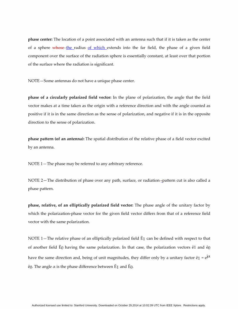
phase center: The location of a point associated with an antenna such that if it is taken as the center
of a sphere whose the radius of which extends into the far field, the phase of a given field
component over the surface of the radiation sphere is essentially constant, at least over that portion
of the surface where the radiation is significant.
NOTE—Some antennas do not have a unique phase center.
phase of a circularly polarized field vector: In the plane of polarization, the angle that the field
vector makes at a time taken as the origin with a reference direction and with the angle counted as
positive if it is in the same direction as the sense of polarization, and negative if it is in the opposite
direction to the sense of polarization.
phase pattern (of an antenna): The spatial distribution of the relative phase of a field vector excited
by an antenna.
NOTE 1—The phase may be referred to any arbitrary reference.
NOTE 2—The distribution of phase over any path, surface, or radiation -pattern cut is also called a
phase pattern.
phase, relative, of an elliptically polarized field vector: The phase angle of the unitary factor by
which the polarization-phase vector for the given field vector differs from that of a reference field
vector with the same polarization.
NOTE 1—The relative phase of an elliptically polarized field Ē1 can be defined with respect to that
of another field Ē0 having the same polarization. In that case, the polarization vectors ê1 and ê0
have the same direction and, being of unit magnitudes, they differ only by a unitary factor ê1 = ejα
ê0. The angle α is the phase difference between Ē1 and Ē0.
Authorized licensed use limited to: Stanford University. Downloaded on October 29,2014 at 10:02:39 UTC from IEEE Xplore. Restrictions apply.
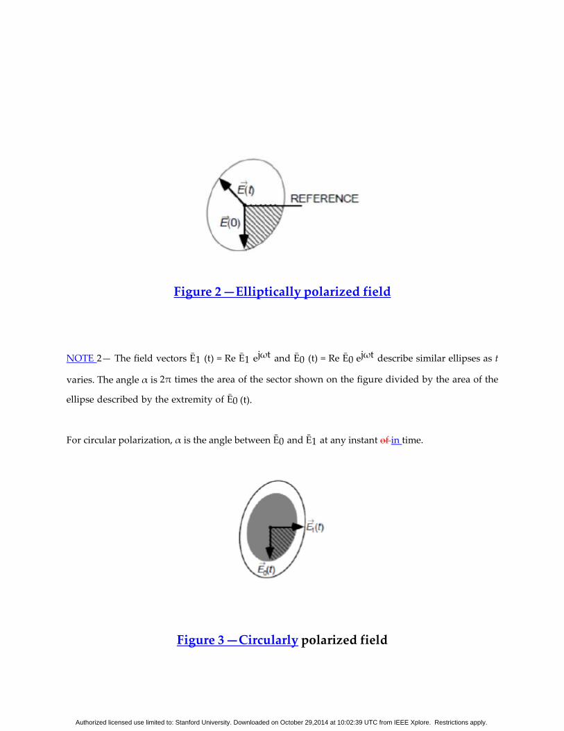
Figure 2 —Elliptically polarized field
NOTE 2— The field vectors Ē1 (t) = Re Ē1 ejωt and Ē0 (t) = Re Ē0 ejωt describe similar ellipses as t
varies. The angle α is 2π times the area of the sector shown on the figure divided by the area of the
ellipse described by the extremity of Ē0 (t).
For circular polarization, α is the angle between Ē0 and Ē1 at any instant of in time.
Figure 3 —Circularly polarized field
Authorized licensed use limited to: Stanford University. Downloaded on October 29,2014 at 10:02:39 UTC from IEEE Xplore. Restrictions apply.
NOTE 3— The phase of an elliptically polarized field vector can be expressed relative to a spatial
direction in its plane of polarization. For example, the phase angle is given by 2π times the area of
the sector shown onin the figure, which is bounded by Ē(0) and the reference, divided by the area
of the ellipse described by Ē(t). The angle is positive if it is in the same direction as the sense of
polarization and negative if it is in the direction opposite to the sense of polarization.
pillbox antenna: A reflector antenna having a cylindrical reflector enclosed by two parallel
conducting plates perpendicular to the cylinder, spaced less than one wavelength apart. Contrast
with: cheese antenna.
planar array: A two-dimensional array of elements whose the corresponding points of which lie in a
plane.
Planar Inverted F Antenna (PIFA): Is a compact antenna with a shorting pin at one corner and a
feed pin located along its length. These are often used in handheld devices.
plane of polarization: A plane containing the polarization ellipse.
NOTE 1—When the ellipse degenerates into a line segment, the plane of polarization is not
uniquely defined. In general, any plane containing the segment is acceptable; however, for a plane
wave in an isotropic medium, the plane of polarization is taken to be normal to the direction of
propagation.
NOTE 2—In optics, the expression plane of polarization is associated with a linearly polarized plane
wave (sometimes called a plane polarized wave) and is defined as a plane containing the field vector of
interest and the direction of propagation. This usage would contradict the above one usage and is
deprecated.
Authorized licensed use limited to: Stanford University. Downloaded on October 29,2014 at 10:02:39 UTC from IEEE Xplore. Restrictions apply.
plane polarized wave: See: plane of polarization.
plane wave: A wave in which the only spatial dependence of the field vectors is through a common
exponential factor whose the exponent of which is a linear function of position.
NOTE 1—In a linear, homogeneous, and isotropic space the electric-field vector, magnetic-field
vector and the propagation vector are mutually perpendicular. The ratio of the magnitude of the
electric-field vector to the magnitude of the magnetic-field vector is equal to the intrinsic impedance
of the medium; for free space, the intrinsic impedance is equal to 376.730 Ω or approximately 120π
Ω.
NOTE 2—A plane wave can be resolved into two component waves corresponding to two
orthogonal polarizations. The total power flux density of the plane wave at a given point in space is
equal to the sum of the power flux densities in the orthogonal component waves.
Poincaré sphere: A sphere whose the points of which are associated in a one-to-one fashion with all
possible polarization states of a plane wave [field vector] according to the following rules: The
longitude equals twice the tilt angle, and the latitude is twice the angle whose the cotangent of
which is the negative of the axial ratio of the polar ization ellipse.
NOTE 1—For this definition, the axial ratio carries a sign. See: axial ratio (of a polarization ellipse),
NOTE.
NOTE 2—The points of the northern hemisphere of the Poincaré sphere represent polarizations
with a left-hand sense and those of the southern hemisphere represent polarization with a right-
hand sense. The north pole represents left-hand circular polarization and the south pole represents
right-hand circular polarization. The points of the equator represent all possible linear
polarizations.
polarization (of an antenna): In a given direction from the antenna, the polarization of the wave
Authorized licensed use limited to: Stanford University. Downloaded on October 29,2014 at 10:02:39 UTC from IEEE Xplore. Restrictions apply.
transmitted by the antenna. See: polarization of a wave radiated by an antenna.
NOTE—When the direction is not stated, the polarization is taken to be the polarization in the
direction of maximum gain.
polarization [of a wave (radiated by an antenna in a specified direction)]: In a specified direction
from an antenna and at a point in its far field, the polarization of the (locally) plane wave that is used
to represent the radiated wave at that point.
NOTE—At any point in the far field of an antenna, the radiated wave can be represented by a plane
wave whose the electric- field strength of which is the same as that of the wave and whose the
direction of propagation of which is in the radial direction from the antenna. As the radial
distance approaches infinity, the radius of curvature of the radiated wave’s phase front also
approaches infinity, and thus in any specified direction, the wave appears locally as a plane wave.
polarization efficiency: The ratio of the power received by an antenna from a given plane
wave of arbitrary polarization to the power that would be received by the same antenna from a
plane wave of the same power flux density and direction of propagation, whose the state of
polarization of which has been adjusted for a maximum received power. Syn: polarization
mismatch factor.
NOTE 1—The polarization efficiency is equal to the square of the magnitude of the inner product
of the polarization vector describing the receiving polarization of the antenna and the polarization
vector of the plane wave incident at the antenna. See: polarization vector, NOTE 2 for definition of
the inner product.
NOTE 2—If the receiving polarization of an antenna and the polarization of an incident plane
wave are properly located as points on the Poincaré sphere, then the polarization efficiency is given
by the square of the cosine of one-half the angular separation of the two points.
Authorized licensed use limited to: Stanford University. Downloaded on October 29,2014 at 10:02:39 UTC from IEEE Xplore. Restrictions apply.
polarization match: The condition that exists when a plane wave, incident upon an antenna from a
given direction, has a polarization that is the same as the receiving polarization of the antenna in
that direction. See: receiving polarization (of an antenna).
polarization mismatch factor: See: polarization efficiency.
polarization mismatch loss: The magnitude, expressed in decibels, of the polarization efficiency.
polarization pattern (of an antenna): (A) The spatial distribution of the polarizations of a field
vector excited by an antenna taken over its radiation sphere. (B) The response of a given antenna to
a linearly polarized plane wave incident from a given direction and whose , the direction of
polarization of which is rotating about an axis parallel to its propagation vector, the response being
plotted as a function of the angle that the direction of polarization makes with a given reference
direction.
NOTE 1—When describing the polarizations over the radiation sphere [definition (A)] or a portion
of it, reference lines shall be is specified over the sphere in order to measure the tilt angles of the
polarization ellipses [see: tilt angle (of a polarization ellipse)] and the direction of polarization for
linear polarizations. An obvious choice, though by no means the only one, is a family of lines
tangent at each point on the sphere to either the θ or φ coordinate line associated with a spherical
coordinate system of the radiation sphere.
Authorized licensed use limited to: Stanford University. Downloaded on October 29,2014 at 10:02:39 UTC from IEEE Xplore. Restrictions apply.
NOTE 2—At each point on the radiation sphere, the polarization is usually resolved into a pair of
orthogonal polarizations, the co-polarization and the cross polarization (See: co-polarization; cross
polarization). To accomplish this, the co- polarization must be is specified at each point on the
radiation sphere. For certain linearly polarized antennas, it is common practice to define the co-
polarization in the following manner. First specify, the orientation of the co-polar electric- field
vector at a pole of the radiation sphere is specified. Then, for all other directions of interest
(points on the radiation sphere), it is required that the angle that the co-polar electric-field vector
makes with each great-circle line through the pole remain constant over that circle, the angle being
that at the pole. In practice, the axis of the antenna’s main beam should be directed along the polar
axis of the radiation sphere. The antenna is then appropriately oriented about this axis to align the
direction of its polarization with that of the defined co-polarization at the pole. This manner of
defining co-polarization can be extended to the case of elliptical polarization by defining the
constant angles using the major axes of the polarization ellipses rather than the co-polar electric-
field vector. The sense of polarization must is also be specified.
NOTE 3—The polarization pattern [definition (B)] generally has the shape of a dumbbell. The
polarization ellipse of the antenna in the given direction is similar to one that can be inscribed in
the dumbbell shape with points of tangency at the maxima and minima points; thus,: the axial ratio
and tilt angle can thus be obtained from the polarization pattern.
polarization-phase vector (for a field vector): The polarization vector among all of those that
define the same polarization that carries the phase information of the field vector whose the
polarization of which it represents. See: polarization vector (for a field vector).
NOTE—The polarization-phase vector of the field vector Ē is given by ē ≡ ĒE, where E is the
magnitude of Ē, that is, the positive square root of Ē*. Ē.
polarization ratio: The magnitude of a complex polarization ratio.
Authorized licensed use limited to: Stanford University. Downloaded on October 29,2014 at 10:02:39 UTC from IEEE Xplore. Restrictions apply.
polarization, receiving (of an antenna): The polarization of a plane wave incident from a given
direction and having a given power flux density that results in maximum available power at the
antenna’s terminals.
NOTE 1—The receiving polarization of an antenna is related to the antenna’s polarization on
transmitting (see definition above) in the following way: In the same plane of polarization, the
polarization ellipses have the same axial ratio, the same sense of polarization, and the same spatial
orientation. Since their senses of polarization and spatial orientation are specified by viewing their
polarization ellipses in the respective directions into which they are propagating, one should note
that (a) although their senses of polarization are the same, they would appear to be opposite if
both waves were viewed in the same direction; and (b) their tilt angles are such that they are the
negative of one another with respect to a common reference.
NOTE 2—The receiving polarization may be used to specify the polarization characteristic of a non-
reciprocal antenna that may transmit and receive arbitrarily different polarizations.
polarization state (of a plane wave [field vector]): See: state of polarization (of a plane wave [field
vector]).
polarization vector (for a field vector): A unitary vector that describes the state of polarization of a
field vector at a given point in space.
NOTE 1—Polarization vectors differing only by a unitary factor (ejα, where α is real) correspond to
the same polarization state.
NOTE 2—The appropriate inner product, <ê1 , ê2>, for two polarization vectors in the same planes
of polarization is given by <ê1 , ê2> = ê1 *. ê2, where ê1 and ê2 represent the polarization vectors
corresponding to polarizations 1 and 2.
Authorized licensed use limited to: Stanford University. Downloaded on October 29,2014 at 10:02:39 UTC from IEEE Xplore. Restrictions apply.
1
NOTE 3—The magnitude of the inner product of polarization vectors representing the same
polarization is equal to unity. The inner product of two polarization vectors representing
orthogonal polarizations is zero.
NOTE 4—The inner product of a polarization vector corresponding to a specified polarization,
ê1, and a complex electric-field vector, Ē, at a point in space will yield the component of the electric-
field vector corresponding to the specified polarization, Ē1, that is Ē1= (ê1 *. Ē) ê1.
NOTE 5—The basis vectors for the components of the polarization vector may correspond to
any two orthogonal polarizations, the most common being two orthogonal linear polarizations or
right-hand and left-hand circular polarizations.
NOTE 6—Contrast with: polarization-phase vector (for a field vector).
Potter horn: A circular horn with one or more abrupt changes in diameter that excites two or more
waveguide modes in order to produce a specified aperture illumination.
power gain: [Deprecated.] See: gain, partial (of an antenna).
power pattern: See: radiation pattern.
power reflectance of a radome: At a given point on a radome, the ratio of the power flux density
that is internally reflected from the radome to that incident on the radome from an internal radiating
source.
power transmittance of a radome: In a given direction, the ratio of the power flux density emerging
from a radome with an internal source to the power flux density that would be obtained if the
radome were removed.
Authorized licensed use limited to: Stanford University. Downloaded on October 29,2014 at 10:02:39 UTC from IEEE Xplore. Restrictions apply.
primary radiator: The radiating element of a reflector or lens antenna that is directly coupled to the
transmitter or receiver directly, or through a feed line.
NOTE—For some applications, an array of radiating elements is employed.
principal E-plane: See: E-plane, principal.
principal half-power beamwidths: For a pattern whose the major lobe of which has a half-power
contour that is essentially elliptical, the half-power beamwidths in the two pattern cuts that
respectively contain the major and minor axes of the ellipse, respectively.
principal H-plane: See: H-plane, principal.
printed circuit antenna: An antenna of some desired shape bonded onto a dielectric substrate.
NOTE—The microstrip antenna is a notable example. See: microstrip antenna.
proximity-coupled dipole array antenna: An array antenna consisting of a series of coplanar
dipoles, loosely coupled to the electromagnetic field of a balanced transmission line, the coupling
being a function of the proximity and orientation of the dipole with respect to the transmission line.
pyramidal horn antenna: A horn antenna, the with flat sides of which form and a
pyramidrectangular aperture, fed by a rectangular waveguide.
NOTE 1—When the horn flare is only in the direction of the electric field, it is called an E-plane horn
antenna.
NOTE 2—When the horn flare is only in the direction of the magnetic field, it is called an H-plane
horn antenna.
Authorized licensed use limited to: Stanford University. Downloaded on October 29,2014 at 10:02:39 UTC from IEEE Xplore. Restrictions apply.
Q of a resonant antenna: The ratio of 2π times the energy stored in the fields excited by the antenna
to the energy radiated and dissipated per cycle.
NOTE—For an electrically small antenna, itthe Q is numerically equal to one-half the magnitude of
the ratio of the incremental change in impedance to the corresponding incremental change in
frequency at resonance, divided by the ratio of the antenna’s resistance to the resonant frequency.
quantization lobes: For an array antenna, significant sidelobes resulting from quantizing the
amplitude and/or phase of the signals at the elements or subarrays.
radar cross section: For a given scattering object upon which a plane wave is incident, that portion of
the scattering cross section corresponding to a specified polarization component of the scattered
wave. See: scattering cross section.
radiating element: A basic subdivision of an antenna that in itself is capable of radiating or receiving
radio waves.
NOTE—Typical examples of a radiating element are a slot, horn, or dipole antenna.
radiating near-field region: See: near-field region, radiating.
radiation efficiency: The ratio of the total power radiated by an antenna to the net power accepted
by the antenna from the connected transmitter.
radiation, electromagnetic: The emission of electromagnetic energy from a finite region in the
form of unguided waves.
radiation intensity: In a given direction, the power radiated from an antenna per unit solid angle.
Authorized licensed use limited to: Stanford University. Downloaded on October 29,2014 at 10:02:39 UTC from IEEE Xplore. Restrictions apply.
radiation pattern: The spatial distribution of a quantity that characterizes the electromagnetic
field generated by an antenna. Syn: antenna pattern.
NOTE 1—The distribution can be expressed as a mathematical function or as a graphical
representation.
NOTE 2—The quantities that are most often used to characterize the radiation from an antenna are
proportional to or equal to power flux density, radiation intensity, directivity, phase, polarization,
and field strength.
NOTE 3—The spatial distribution over any surface or path is also an antenna pattern.
NOTE 4—When the amplitude or relative amplitude of a specified component of the electric-field
vector is plotted graphically, it is called an amplitude pattern, field pattern, or voltage pattern.
When the square of the amplitude or relative amplitude is plotted, it is called a power pattern.
NOTE 5—When the quantity is not specified, an amplitude or power pattern is implied.
radiation pattern cut: Any path on a surface over which a radiation pattern is obtained.
NOTE—For far-field patterns, the surface is that of the radiation sphere. For this case, the path
formed by the locus of points for which θ is a specified constant and φ is a variable is called a
“conical cut.” The path formed by the locus of points for which φ is a specified constant and θ is a
variable is called a “great circle cut.” The conical cut with θ equal to 90° is also a great circle cut. A
spiral path that begins at the north pole (θ = 0°) and ends at the south pole (θ = 180°) is called a
“spiral cut.”
radiation resistance. The ratio of the power radiated by an antenna to the square of the rms
antenna current referred to a specified point.
Authorized licensed use limited to: Stanford University. Downloaded on October 29,2014 at 10:02:39 UTC from IEEE Xplore. Restrictions apply.
NOTE 1—The total power radiated is equal to the power accepted by the antenna minus the
power dissipated in the antenna.
NOTE 2—This term is of limited utility for antennas in lossy media.
radiation sphere (for a given antenna): A large sphere whose the center of which lies within the
volume of the antenna and whose the surface of which lies in the far field of the antenna, over which
quantities characterizing the radiation from the antenna are determined.
NOTE 1—The location of points on the sphere are given in terms of the θ and φ coordinates of a
standard spherical coordinate system whose the origin of which coincides with the center of the
radiation sphere.
NOTE 2—If the antenna has a spherical coordinate system associated with it, then it is desirable
that its coordinate system coincide with that of the radiation sphere.
radiator: Any antenna or radiating element that is a discrete physical and functional entity.
radome: A cover usually intended for protecting an antenna from the effects of its physical
environment without degrading its electrical performance.
random array antenna: See: array antenna.
reactive field (of an antenna): Electric and magnetic fields surrounding an antenna and resulting
in the storage of electromagnetic energy rather than in the radiation of electromagnetic energy.
reactive near-field region: See: near-field region, reactive.
reactive reflector antenna: See: reflective array antenna.
Authorized licensed use limited to: Stanford University. Downloaded on October 29,2014 at 10:02:39 UTC from IEEE Xplore. Restrictions apply.
reactively controlled directive array: An analog adaptive antenna where adaptive beamforming is
achieved by adaptively adjusting the load reactance of parasitic elements.
NOTE—Sometimes also called an ESPAR (Electronically Steerable Parasitic Array Radiator).
realized gain: The gain of an antenna reduced by the losses due to the its impedance mismatch of
the antenna input impedance to a specified impedancefactor.
NOTE—The realized gain depends on the system to which the antenna is connected. It does not
include losses due to polarization mismatch between two antennas in a complete system.
realized gain, partial (of an antenna for a given polarization): The partial gain of an antenna for a
given polarization reduced by the loss due to the its impedance mismatch of the antenna input
impedance to a specified impedancefactor.
realized radiation efficiency: The radiation efficiency of an antenna reduced by its impedance
mismatch factor. Syn: total radiation efficiency.
receiving efficiency: The ratio of the isotropic noise response with a noiseless antenna to the
isotropic noise response. See: isotropic noise response.
NOTE—Equivalent to radiation efficiency for a passive, reciprocal antenna.
receiving polarization (of an antenna): See: polarization, receiving (of an antenna).
reconfigurable antenna: An antenna capable of changing its performance characteristics (resonant
frequency, radiation pattern, polarization, etc.) by mechanically or electrically changing its
architecture.
2.324 rectangular array. [Deprecated.] See: rectangular grid array.
Authorized licensed use limited to: Stanford University. Downloaded on October 29,2014 at 10:02:39 UTC from IEEE Xplore. Restrictions apply.
rectangular grid array.: A regular arrangement of array elements, in a plane, such that lines
connecting corresponding points of adjacent elements form rectangles.
rectangular multiflare horn antenna: See: compound rectangular horn antenna.
reference boresight: A direction established as a reference for the alignment of an antenna. See:
electrical boresight.
NOTE—The direction can be established by optical, electrical, or mechanical means.
reference directivity: See: standard directivity.
reflective reflectarray antenna: An antenna consisting of a feed and an array of reflecting elements
arranged on a surface and adjusted so that the reflected waves from the individual elements
combine to produce a prescribed secondary radiation pattern. Syn: reflective array antenna, reactive
reflector antenna.
NOTE—The reflecting elements are usually waveguides containing electrical phase shifters and are
terminated by short circuits or printed elements providing fixed or adjustable phase-shifts.
reflective array antenna: See: reflectarray antenna.
reflector: See: Cassegrain reflector antenna; corner reflector; cylindrical reflector; Gregorian
reflector antenna; horn reflector antenna; main reflector; offset paraboloidal reflector antenna;
parabolic torus antenna; paraboloidal reflector; reflector antenna; reflector element; spherical
reflector; sub-reflector; toroidal reflector; umbrella reflector antenna.
reflector antenna: An antenna consisting of one or more reflecting surfaces and a radiating
[receiving] feed system.
Authorized licensed use limited to: Stanford University. Downloaded on October 29,2014 at 10:02:39 UTC from IEEE Xplore. Restrictions apply.
NOTE—Specific reflector antennas often carry the name of the reflector used as part of the term
used to specify it: for example, paraboloidal reflector antenna.
reflector element: A parasitic element located in a direction other than forward of the driven
element of an antenna, intended to increase the directivity of the antenna in the forward direction.
relative co-polar sidelobe level: See: co-polar sidelobe, relative.
relative cross-polar sidelobe level: See: cross-polar sidelobe level, relative.
relative gain (of an antenna). The ratio of the gain of an antenna in a given direction to the gain of a
reference antenna.
NOTE—Unless otherwise specified, the maximum gains of the antennas are implied.
relative partial gain (of an antenna with respect to a reference antenna of a given polarization):
In a given direction, the ratio of the partial gain of an antenna, corresponding to the polarization
of the reference antenna, to the maximum gain of the reference antenna.
relative phase of an elliptically polarized field vector: See: phase, relative, of an elliptically
polarized field vector.
relative sidelobe level: See: sidelobe level, relative.
resistance: See: antenna resistance; radiation resistance.
resonant antenna: An antenna which can operate efficiently over a narrow band of around its
resonant frequency. See: resonant frequency (of an antenna).
Authorized licensed use limited to: Stanford University. Downloaded on October 29,2014 at 10:02:39 UTC from IEEE Xplore. Restrictions apply.
resonant frequency (of an antenna): A frequency at which the input impedance of an antenna is
nonreactive.
retrodirective antenna: An antenna which when illuminated by a distant source preferentially
returns power in the direction of the source.
retrodirective antenna. An antenna whose monostatic cross section is comparable to the product of
its maximum directivity and its area projected in the direction toward the source, and is relatively
indepen dent of the source direction.
NOTE—Active devices can be added to enhance the return signal. For this case, the term shall be
qualified by the word active; that is, active retrodirective antenna system.
rhombic antenna: An antenna composed of long wire radiators arranged in such a manner that they
form the sides of a rhombus.
NOTE—The antenna usually is terminated in a resistance. The length of the sides of the rhombus,
the angle between the sides, the elevation above ground, and the value of the termination resistance
are proportioned to give the desired radiation properties.
ridged horn (antenna): A horn antenna in which the waveguide section is ridged.
right-hand polarization of a field vector: See: sense of polarization.
right-hand polarization of a plane wave: See: sense of polarization.
ring array: See: circular array.
scan angle: The angle between the direction of the maximum of the major lobe or a directional null
and a reference direction. Syn: beam angle.
Authorized licensed use limited to: Stanford University. Downloaded on October 29,2014 at 10:02:39 UTC from IEEE Xplore. Restrictions apply.
NOTE 1—The term beam angle applies to the case of a pencil-beam antenna.
NOTE 2—The reference boresight is usually chosen as the reference direction.
scanning (of an antenna beam): A repetitive motion given to the major lobe of an antenna.
scan sector: The angular interval over which the major lobe of an antenna is scanned.
scattering cross section: For a scattering object and an incident plane wave of a given frequency,
polarization, and direction, an area that when multiplied by the power flux density of the incident
wave would yield sufficient power that could produce, by isotropic radiation, the same radiation
intensity as that in a given direction from the scattering object. See: bistatic cross section;
monostatic cross section; radar cross section.
NOTE—The scattering cross section is equal to 4π times the ratio of the radiation intensity of the
scattered wave in a specified direction to the power flux density of the incident plane wave.
secondary radiator: That portion of an antenna having the largest radiating aperture, consisting of a
reflecting surface or a lens, as distinguished from its feed.
sectionalized [loaded] linear antenna: A linear antenna in which reactances are inserted at one or
more points along the length of the antenna.
sector scanning: A modification of circular scanning in which the direction of the antenna beam
generates a portion of a cone or a plane.
self-complementary antenna: An antenna the conducting and non-conducting areas of which are
congruent.
Authorized licensed use limited to: Stanford University. Downloaded on October 29,2014 at 10:02:39 UTC from IEEE Xplore. Restrictions apply.
self-impedance (of an array element): The input impedance of a radiating element of an array
antenna with all other elements in the array open-circuited.
self-phasing array antenna system: A receiving antenna system that introduces a phase
distribution among the array elements so as to maximize the received signal, regardless of the
direction of incidence. Contrast with: retrodirective antenna.
sense of polarization: For an elliptical or circularly polarized field vector, the sense of rotation of
the extremity of the field vector when its origin is fixed.
NOTE—When the plane of polarization is viewed from a specified side, if the extremity of the field
vector rotates clockwise [counterclockwise] the sense is right-handed [left-handed]. For a plane
wave, the plane of polarization shall beis viewed looking in the direction of propagation.
sequential lobing: A direction-determining technique utilizing the signals of partially overlapping
lobes occurring in sequence.
series-fed vertical antenna: A vertical antenna that is insulated from ground and whose the feed
line of which connects between ground and the lower end of the antenna.
shaped-beam antenna: An antenna that is designed to have a prescribed pattern shape differing sig
nificantly from that obtained from a uniform-phase aperture of the same size.
shielded-loop antenna [probe]: An electrically small antenna consisting of a tubular electrostatic
shield formed into a loop with a small gap, and containing one or more wire turns for external
coupling.
shielded-loop probe: See: shielded-loop antenna.
Authorized licensed use limited to: Stanford University. Downloaded on October 29,2014 at 10:02:39 UTC from IEEE Xplore. Restrictions apply.
shoulder lobe: A radiation lobe that has merged with the major lobe, thus causing the major lobe to
have a distortion that is shoulder-like in appearance when displayed graphically. Syn: vestigial lobe.
shunt-fed vertical antenna: A vertical antenna that is connected directly to ground at its base and
whose the feed line of which connects to the antenna between ground and a point suitably
positioned above the base. See: sidelobe.
sidelobe: A radiation lobe in any direction other than that of the major lobe. See: back lobe; co-polar
sidelobe level, relative; cross-polar sidelobe level, relative; mean sidelobe level; minor lobe;
sidelobe level, maximum relative; sidelobe level, relative. Syn: side lobe.
sidelobe level, maximum relative: The maximum relative directivity of the highest sidelobe with
respect to the maximum directivity of the antenna.
sidelobe level, relative: The maximum relative directivity of a sidelobe with respect to the
maximum directivity of an antenna, usually expressed in decibels.
sidelobe suppression: Any process, action, or adjustment to reduce the level of the sidelobes or to
reduce the degradation of the intended antenna system’s performance resulting from the presence of
sidelobes.
signal processing antenna system: An antenna system having circuit elements associated with its
radiating element(s) that perform functions such as multiplication, storage, correlation, and time
modulation of the input signals.
simultaneous lobing: A direction-determining technique utilizing the signals of overlapping lobes
existing at the same time.
sinuous antenna: A broadband antenna in which the arms change direction back and forth from the
center feed to the edge. It provides both circular polarizations, and requires at least two feed
Authorized licensed use limited to: Stanford University. Downloaded on October 29,2014 at 10:02:39 UTC from IEEE Xplore. Restrictions apply.
ports. It has the ability for very wideband performance.
sleeve-dipole antenna: A dipole antenna surrounded in its central portion by a coaxial conducting
sleeve.
sleeve-monopole antenna: An antenna consisting of half of a sleeve-dipole antenna projecting
from a ground plane. Syn: sleeve-stub antenna.
2.371 sleeve-stub antenna. See: sleeve-monopole antenna.
slot antenna: A radiating element formed by a slot in a conducting surface.
smart antenna: An antenna – typically, an array – the characteristics of which are dynamically
controlled using signal processing. See: adaptive antenna system.
solid-beam efficiency: The ratio of the power received over a specified solid angle when an
antenna is isotropically illuminated by uncorrelated and unpolarized waves to the total power
received by the antenna.
NOTE—This term is sometimes used to mean the ratio of the power received corresponding to a
particular polarization over the solid angle to the total power received. Equivalently, the term is
used to mean the ratio of the power radiated over a specified solid angle by the antenna
corresponding to a particular polarization to the total power radiated.
space-tapered array antenna: An array antenna whose the radiation pattern of which is shaped by
varying the density of driven radiating elements over the array surface. Syn: density-tapered array
antenna.
sparse array antenna: An array antenna that contains substantially fewer driven radiating elements
than a conventional uniformly spaced array with the same beamwidth having identical elements.
Authorized licensed use limited to: Stanford University. Downloaded on October 29,2014 at 10:02:39 UTC from IEEE Xplore. Restrictions apply.
Interelement spacings in the sparse array can be chosen such that no large grating lobes are formed
and sidelobes are reduced. See: space- and density-tapered array antenna and thinned array
antenna.
spherical array: A two-dimensional array of elements whose the corresponding points of which lie
on a spherical surface.
spherical reflector: A reflector that is a portion of a spherical surface.
spillover: In the transmitting mode of a reflector antenna, the power from the feed that is not
intercepted by the reflecting elements.
spiral antenna: An antenna consisting of one or more conducting wires or tapes arranged as a spiral.
NOTE—Spiral antennas are usually classified according to the shape of the surface to which
they conform (for example, conical or planar spirals), and according to the mathematical form (for
example, equiangular or archimedean).
squint: A condition in which a specified axis of an antenna – such as the direction of maximum
directivity or of a directional null—departs slightly from a specified reference axis.
NOTE 1—Squint is often the undesired result of a defect in the antenna; buthowever, in certain
cases, squint is intentionally designed in in order to satisfy an operational requirement.
NOTE 2—The reference axis is often taken to be the mechanically defined axis of the antenna: for
example, the axis of a paraboloidal reflector.
squint angle: The angle between a specified axis of an antenna, such as the direction of maximum
directivity or a directional null, and the corresponding reference axis.
Authorized licensed use limited to: Stanford University. Downloaded on October 29,2014 at 10:02:39 UTC from IEEE Xplore. Restrictions apply.
standard [reference] directivity: The maximum directivity from a planar aperture of area A, or from
a line source of length L, when excited with a uniform-amplitude, equiphase distribution.
NOTE 1—For planar apertures in which A >> λ2, the value of the standard directivity is 4πA/λ2,
with λ the wavelength and with radiation confined to a half space.
NOTE 2—For line sources with L >> λ, the value of the standard directivity is 2L/λ.
standing-wave antenna: An antenna whose the excitation of which is essentially equiphase, as the
result of two feeding waves that traverse its length from opposite directions, their combined effect
being that of a standing wave.
state of polarization (of a plane wave [field vector]): At a given point in space, the condition of the
polarization of a plane wave [field vector] as described by the axial ratio, tilt angle, and sense of
polarization. Syn: polarization state (of a plane wave [field vector]).
steerable-beam antenna system: An antenna with a non-moving aperture for which the direction
of the major lobe can be changed by electronically altering the aperture excitation or by
mechanically moving a feed of the antenna.
stepped antenna: See: zoned antenna.
stub antenna: A short, thick monopole.
subarray: A subset of elements in an array that are connected together to a single port.
subreflector: A reflector other than the main reflector of a multiple-reflector antenna.
sum pattern: A radiation pattern characterized by a single main lobe whosethe cross section
Authorized licensed use limited to: Stanford University. Downloaded on October 29,2014 at 10:02:39 UTC from IEEE Xplore. Restrictions apply.
of which is essentially elliptical, and a family of sidelobes, the latter usually at a relatively low level.
NOTE—Antennas that produce sum patterns are often designed to produce a difference pattern and
have application in acquisition and tracking radar systems. Contrast with: difference pattern.
superconducting antenna: An antenna where one or more parts is constructed from
superconducting materials such as YBCO.
Superdirectivity: The condition that occurs when the antenna illumination efficiency directivity is
significantly exceeds 100%higher than that with the array or aperture uniformly excited.
NOTE—Superdirectivity is only obtained at a the cost of a large increase in the ratio of average
stored energy to energy radiated per cycle.
surface wave antenna: An antenna that radiates power from discontinuities in the structure that
interrupt a bound wave on the antenna’s surface.
switched parasitic antenna: An antenna in which the beam is controlled by varying the loading on
one or more closely coupled parasitic element(s).
switched parasitic array antenna: See: switched parasitic antenna.
tapered slot antenna. See: TEM horn [antenna].
Taylor distribution, circular: A continuous distribution of a circular planar aperture that is
equiphase, with the amplitude distribution dependent only on distance from the center of the
Authorized licensed use limited to: Stanford University. Downloaded on October 29,2014 at 10:02:39 UTC from IEEE Xplore. Restrictions apply.
aperture and such as to produce a pattern with a main beam plus sidelobes. The sidelobe structure
is rotationally symmetric, with a specified number of inner sidelobes at a quasi-uniform height, the
remainder of the sidelobes decaying in height with their angular separation from the main beam.
NOTE—Taylor distributions are often sampled to obtain the excitation for a planar array.
Taylor distribution, linear: A continuous distribution of a line source that is symmetric in
amplitude, has a uniform progressive phase, and yields a pattern with a main beam plus sidelobes.
The sidelobe structure is symmetrical, with a specified number of inner sidelobes at a quasi-
uniform height, the remainder of the sidelobes decaying in height with their angular separation
from the main beam.
NOTE—Taylor distributions are often sampled to obtain the excitation for a planarlinear array.
2.393 thinned array antenna. An array antenna that contains substantially fewer driven radiating
elements than a conventional uniformly spaced array with the same beamwidth having identical
elements. Interele ment spacings in the thinned array are chosen such that no large grating lobes are
formed and side lobes are minimized
TEM horn [antenna]: A horn antenna with two mirror-symmetric conductors that guide a
transverse electromagnetic wave. The three-dimensional version has two flat or curved triangular
sides that form a rectangular aperture. Planar versions with straight or curved sides are called
tapered slot antennas, tapered slots with exponentially curved sides are called Vivaldi antennas.
thinned array antenna: A sparse array antenna obtained by terminating or removing a substantial
number of elements from a conventional uniformly spaced array.
NOTE 1—This is often used to reduce the sidelobe level of the full array, and to maintain a narrow
beamwidth with a reduced number of element chains driven with equal amplitudes. See: space- and
Authorized licensed use limited to: Stanford University. Downloaded on October 29,2014 at 10:02:39 UTC from IEEE Xplore. Restrictions apply.
density-tapered array antenna.
NOTE 2—Grating lobes, if any, are in the same directions and at the same relative levels as those
of the fully driven uniformly spaced “parent” array. See: sparse array antenna.
tilt angle (of a polarization ellipse): When the plane of polarization is viewed from a specified
side, the angle measured clockwise from a reference line to the major axis of the ellipse.
NOTE 1—For a plane wave, the plane of polarization shall be is viewed looking in the direction of
propagation.
NOTE 2—The tilt angle is only defined up to a multiple of π radians and is usually taken in the
range (–π/2, +π/2) or (0, π).
top-loaded vertical antenna: A vertical monopole with an additional metallic structure at the top
intended to increase the effective height of the antenna and to change its input impedance.
toroidal reflector: A reflector formed by rotating a segment of a plane curve about a nonintersecting
coplanar line.
NOTE—The plane curve segment is called the torus cross section and the co-planar line is called the
toroidal axis. total radiation efficiency. See: realized radiation efficiency.
tracking: A motion given to the major lobe of an antenna with the intent that a selected moving
target be contained within the major lobe. Syn: angle tracking.
traveling-wave antenna: An antenna whose the excitation of which has a quasi-uniform progressive
phase, as the result of a single feeding wave traversing its length only in one direction only.
2.399 triangular array. [Deprecated.] See: triangular grid array.
Authorized licensed use limited to: Stanford University. Downloaded on October 29,2014 at 10:02:39 UTC from IEEE Xplore. Restrictions apply.
triangular grid array.: A regular arrangement of array elements in a plane, such that lines
connecting corresponding points of adjacent elements form triangles, usually equilateral.
turnstile antenna: An antenna composed of two dipole antennas, perpendicular to each other, with
their axes intersecting at their midpoints. Usually, the currents on the two dipole antennas are equal
and in phase quadrature.
two-dimensional scanning: Scanning the beam of a directive antenna using two degrees of
freedom to provide solid-angle coverage.
2.403 umbrella antenna. A type of top-loaded short vertical antenna in which the top-loading
structure con sists of elements sloping down toward the ground but not connected to it.
umbrella reflector antenna: An antenna constructed in a form similar to an umbrella that can be
folded for storage, or transported and unfolded to form a large reflector antenna for use.
uniform linear array: A linear array of identically oriented and equally spaced radiating elements
having equal current amplitudes and equal phase increments between excitation currents.
V antenna: A V-shaped arrangement of two wire conductors, balanced-fed at the apex, with
included angle, length, and apex height above the Earth chosen so as to give the desired directive
properties to the radiation pattern.
vertex plate (of a reflector antenna): A small auxiliary reflector placed in front of the main reflector
near its vertex for the purpose of reducing the standing waves in the feed due to reflected waves
from the main reflector.
vertically polarized field vector: A linearly polarized field vector whose the direction of which is
vertical.
Authorized licensed use limited to: Stanford University. Downloaded on October 29,2014 at 10:02:39 UTC from IEEE Xplore. Restrictions apply.
vertically polarized plane wave: A plane wave whose the electric-field vector of which is vertically
polarized.
vestigial lobe: See: shoulder lobe.
visible range: For the case in which the field pattern of a continuous line source Lλ wavelengths
long is expressed as a function of ψ (ψ = Lλ cos θ, the angle θ is measured from an axis coincident
with the line source), that part of the infinite range of ψ that corresponds to a variation in the
directional angle θ from π to 0 radians, that is, –Lλ < ψ < Lλ.
NOTE 1—All values of ψ outside the visible range are said to be in the invisible range.
NOTE 2—The formulation of the field pattern as a function of ψ is useful because the sidelobes in
the invisible range are a measure of the Q of the antenna.
NOTE 3—This concept of a visible range can be extended to other antenna types.
Vivaldi antenna: Tapered TEM or quasi-TEM slot antenna with exponential tapered sides and
broadband characteristics.
voltage pattern: See: radiation pattern.
wave antenna: See: Beverage antenna.
waveguide lens: A lens that is comprised of an array of waveguides and is space fed by an
appropriate feed.
whip antenna: A thin, flexible, monopole antenna.
Authorized licensed use limited to: Stanford University. Downloaded on October 29,2014 at 10:02:39 UTC from IEEE Xplore. Restrictions apply.
wideband antenna. See: broadband antenna.
wire antenna: An antenna composed of one or more conductors, each of which is long compared to
the transverse dimensions, and with transverse dimensions of each conductor so small compared to
a wavelength that for the purpose of computation the current can be assumed to flow entirely
longitudinally and to have negligible circumferential variation.
wire-grid lens antenna: A lens antenna constructed of wire grids in which the effective index of
refraction (and thus the path delay) is locally controlled by the dimensions and the spacings of the
wire grid. Contrast with: geodesic lens antenna; Luneberg lens antenna.
Wullenweber antenna: An antenna consisting of a circular array of radiating elements, each
havinghas its maximum directivity along the outward radial, and a feed system that provides a
steerable beam that is narrow in the azimuth plane.
Yagi antenna: [Deprecated.] See: Yagi-Uda antenna.
Yagi-Uda antenna: A linear end-fire wire antenna array consisting of a driven element, a
reflector element, and one or more director elements.
zoned antenna: A lens or reflector antenna having various portions (called zones or steps) that form
a discontinuous surface such that a desired phase distribution of the aperture illumination is
achieved. Syn: stepped antenna.
zone-plate lens antenna: See: Fresnel lens antenna.
Authorized licensed use limited to: Stanford University. Downloaded on October 29,2014 at 10:02:39 UTC from IEEE Xplore. Restrictions apply.

Authorized licensed use limited to: Stanford University. Downloaded on October 29,2014 at 10:02:39 UTC from IEEE Xplore. Restrictions apply.