ieee std 1013-2000 (revision of ieee std 1013-1990) ieee
TRANSCRIPT
The Institute of Electrical and Electronics Engineers, Inc.3 Park Avenue, New York, NY 10016-5997, USA
Copyright © 2001 by the Institute of Electrical and Electronics Engineers, Inc.All rights reserved. Published 16 March 2001. Printed in the United States of America.
Print:
ISBN 0-7381-1942-3 SH94814
PDF:
ISBN 0-7381-1943-1 SS94814
No part of this publication may be reproduced in any form, in an electronic retrieval system or otherwise, without the prior written permission of the publisher.
IEEE Std 1013-2000
(Revision ofIEEE Std 1013-1990)
IEEE Recommended Practice for Sizing Lead-Acid Batteries for Photovoltaic (PV) Systems
Sponsor
IEEE Standards Coordinating Committee 21,Fuel Cells, Photovoltaics, Dispersed Generation, and Energy Storage
Approved 30 March 2000
IEEE-SA Standards Board
Abstract:
A
method for sizing both vented and valve-regulated lead-acid batteries used in terrestrialphotovoltaic (PV) systems is described. Installation, maintenance, safety, testing procedures, andconsideration of battery types other than lead-acid are beyond the scope of this document. Recom-mended practices for the remainder of the electrical systems associated with PV installations are alsobeyond the scope of this document.
Keywords:
photovoltaic power systems, sizing lead-acid battery
Copyright The Institute of Electrical and Electronics Engineers, Inc. Provided by IHS under license with IEEE
Not for ResaleNo reproduction or networking permitted without license from IHS
--``,-`-`,,`,,`,`,,`---
IEEE Standards
documents are developed within the IEEE Societies and the Standards Coordinating Com-mittees of the IEEE Standards Association (IEEE-SA) Standards Board. Members of the committees servevoluntarily and without compensation. They are not necessarily members of the Institute. The standardsdeveloped within IEEE represent a consensus of the broad expertise on the subject within the Institute aswell as those activities outside of IEEE that have expressed an interest in participating in the development ofthe standard.
Use of an IEEE Standard is wholly voluntary. The existence of an IEEE Standard does not imply that thereare no other ways to produce, test, measure, purchase, market, or provide other goods and services related tothe scope of the IEEE Standard. Furthermore, the viewpoint expressed at the time a standard is approved andissued is subject to change brought about through developments in the state of the art and commentsreceived from users of the standard. Every IEEE Standard is subjected to review at least every five years forrevision or reaffirmation. When a document is more than five years old and has not been reaffirmed, it is rea-sonable to conclude that its contents, although still of some value, do not wholly reflect the present state ofthe art. Users are cautioned to check to determine that they have the latest edition of any IEEE Standard.
Comments for revision of IEEE Standards are welcome from any interested party, regardless of membershipaffiliation with IEEE. Suggestions for changes in documents should be in the form of a proposed change oftext, together with appropriate supporting comments.
Interpretations: Occasionally questions may arise regarding the meaning of portions of standards as theyrelate to specific applications. When the need for interpretations is brought to the attention of IEEE, theInstitute will initiate action to prepare appropriate responses. Since IEEE Standards represent a consensus ofall concerned interests, it is important to ensure that any interpretation has also received the concurrence of abalance of interests. For this reason, IEEE and the members of its societies and Standards CoordinatingCommittees are not able to provide an instant response to interpretation requests except in those cases wherethe matter has previously received formal consideration.
Comments on standards and requests for interpretations should be addressed to:
Secretary, IEEE-SA Standards Board445 Hoes LaneP.O. Box 1331Piscataway, NJ 08855-1331USA
IEEE is the sole entity that may authorize the use of certification marks, trademarks, or other designations toindicate compliance with the materials set forth herein.
Authorization to photocopy portions of any individual standard for internal or personal use is granted by theInstitute of Electrical and Electronics Engineers, Inc., provided that the appropriate fee is paid to CopyrightClearance Center. To arrange for payment of licensing fee, please contact Copyright Clearance Center, Cus-tomer Service, 222 Rosewood Drive, Danvers, MA 01923 USA; (978) 750-8400. Permission to photocopyportions of any individual standard for educational classroom use can also be obtained through the Copy-right Clearance Center.
Note: Attention is called to the possibility that implementation of this standard mayrequire use of subject matter covered by patent rights. By publication of this standard,no position is taken with respect to the existence or validity of any patent rights inconnection therewith. The IEEE shall not be responsible for identifying patents forwhich a license may be required by an IEEE standard or for conducting inquiries intothe legal validity or scope of those patents that are brought to its attention.
Copyright The Institute of Electrical and Electronics Engineers, Inc. Provided by IHS under license with IEEE
Not for ResaleNo reproduction or networking permitted without license from IHS
--``,-`-`,,`,,`,`,,`---

Copyright © 2001 IEEE. All rights reserved.
iii
Introduction
[This introduction is not part of IEEE Std 1013-2000, IEEE Recommended Practice for Sizing Lead-Acid Batteries forPhotovoltaic (PV) Systems.]
This recommended practice describes a method for sizing both vented and valve-regulated lead-acid batter-ies used in terrestrial photovoltaic (PV) systems. Installation, maintenance, safety, testing procedures, andconsideration of battery types other than lead-acid are beyond the scope of this document. Recommendedpractices for the remainder of the electrical systems associated with PV installations are also beyond thescope of this document.
The Storage Systems Working Group of the Standards Coordinating Committee 21 on Fuel Cells,Photovoltaics, Dispersed Generation, and Energy Storage (SCC21) that developed this recommendedpractice consisted of the following members:
Jay Chamberlin,
Chair
At the time this standard was approved, IEEE Standards Coordinating Committee 21 on Fuel Cells, Photo-voltaics, Dispersed Generation, and Energy Storage had the following membership:
Richard DeBlasio,
Chair
Stephen Chalmers,
Vice-Chair
Jerry Anderson,
Secretary
The following members of the balloting committee voted on this standard:
Garth CoreyTom HundEd Mahoney
James McDowellLarry MeisnerMichael MooreArne Nilsson
Thomas RuhlmannKen SandersStephen Vechy
Thomas BassoWilliam BottenbergWard BowerJay ChamberlinDouglas DawsonWilliam Ferro
Frank GoodmanKenneth HallKelvin HechtBerry HornbergerJoseph KoepfingerBenjamin Kroposki
Robert McConnellJohn StevensCharles WhitakerJohn WilesJohn WohlgemuthTim Zgonena
Stephen ChalmersJay ChamberlinRichard DeBlasioRobert HammondStephen Hogan
William KaszetaJames McDowallTron MelzlPaul Russell
Miles RussellJohn StevensCharles WhitakerJohn WilesRobert Wills
Copyright The Institute of Electrical and Electronics Engineers, Inc. Provided by IHS under license with IEEE
Not for ResaleNo reproduction or networking permitted without license from IHS
--``,-`-`,,`,,`,`,,`---
iv
Copyright © 2001 IEEE. All rights reserved.
The final conditions for approval of this standard were met on 30 March 2000. This standard was condition-ally approved by the IEEE-SA Standards Board on 8 March 2000, with the following membership:
Donald N. Heirman,
Chair
James T. Carlo,
Vice Chair
Judith Gorman,
Secretary
*Member Emeritus
Also included is the following nonvoting IEEE-SA Standards Board liaison:
Alan Cookson,
NIST Representative
Donald R. Volzka,
TAB Representative
Noelle D. Humenick
IEEE Standards Project Editor
Satish K. AggarwalMark D. BowmanGary R. EngmannHarold E. EpsteinH. Landis FloydJay Forster*Howard M. FrazierRuben D. Garzon
James H. GurneyRichard J. HollemanLowell G. JohnsonRobert J. KennellyJoseph L. Koepfinger*Peter H. LipsL. Bruce McClungDaleep C. Mohla
James W. MooreRobert F. MunznerRonald C. PetersenGerald H. PetersonJohn B. PoseyGary S. RobinsonAkio TojoDonald W. Zipse
Copyright The Institute of Electrical and Electronics Engineers, Inc. Provided by IHS under license with IEEE
Not for ResaleNo reproduction or networking permitted without license from IHS
--``,-`-`,,`,,`,`,,`---
Copyright © 2001 IEEE. All rights reserved.
v
Contents
1. Overview.............................................................................................................................................. 1
1.1 Scope............................................................................................................................................ 11.2 Purpose......................................................................................................................................... 1
2. References............................................................................................................................................ 1
3. Definitions............................................................................................................................................ 2
4. Outline of sizing methodology............................................................................................................. 3
5. Battery reserve considerations ............................................................................................................. 3
6. Load determination .............................................................................................................................. 4
6.1 General considerations................................................................................................................. 46.2 Load data...................................................................................................................................... 56.3 Data analysis ................................................................................................................................ 6
7. Battery capacity and functional-hour rate determination..................................................................... 6
7.1 Unadjusted capacity ..................................................................................................................... 67.2 Battery type selection................................................................................................................... 67.3 Capacity adjustment..................................................................................................................... 77.4 Functional-hour rate..................................................................................................................... 7
8. Determining number of series-connected cells.................................................................................... 8
8.1 Nominal system voltage............................................................................................................... 88.2 Voltage window........................................................................................................................... 88.3 Calculating the number of series-connected cells........................................................................ 9
9. Battery size determination ................................................................................................................. 10
9.1 Cell size selection ...................................................................................................................... 109.2 Number of parallel strings ......................................................................................................... 109.3 Final number of cells ................................................................................................................. 119.4 Final battery capacity................................................................................................................. 119.5 Checks and considerations......................................................................................................... 11
10. Battery sizing worksheets .................................................................................................................. 12
Annex A (informative) Battery characteristics .............................................................................................. 20
Annex B (informative) Examples .................................................................................................................. 24
Annex C (informative) Bibliography............................................................................................................. 39
Copyright The Institute of Electrical and Electronics Engineers, Inc. Provided by IHS under license with IEEE
Not for ResaleNo reproduction or networking permitted without license from IHS
--``,-`-`,,`,,`,`,,`---

vi
Copyright © 2001 IEEE. All rights reserved.Copyright The Institute of Electrical and Electronics Engineers, Inc. Provided by IHS under license with IEEE
Not for ResaleNo reproduction or networking permitted without license from IHS
--``,-`-`,,`,,`,`,,`---

Copyright The Institute of ElectrProvided by IHS under license wNo reproduction or networking p
--``,-`-`,,`,,`,`,,`---
IEEE Recommended Practice for Sizing Lead-Acid Batteries for Photovoltaic (PV) Systems
1. Overview
1.1 Scope
This recommended practice describes a method for sizing both vented and valve-regulated lead-acidbatteries in photovoltaic (PV) systems. Installation, maintenance, safety, testing procedures, andconsideration of battery types other than lead-acid are beyond the scope of this document. Recommendedpractices for the remainder of the electrical systems associated with PV installations are also beyond thescope of this document.
Sizing examples are given for various representative system applications. Iterative techniques to optimizebattery costs, which include consideration of the interrelationship between battery size, PV array size, andweather, are beyond the scope of this document.
1.2 Purpose
This recommended practice is meant to assist system designers in sizing lead-acid batteries for residential,commercial, and industrial PV systems.
2. References
This recommended practice shall be used in conjunction with the following publications. When the follow-ing standards are superseded by an approved revision, the revision should be used.
IEEE Std 485-1997, IEEE Recommended Practice for Sizing Lead-Acid Batteries for StationaryApplications.1
1IEEE publications are available from the Institute of Electrical and Electronics Engineers, 445 Hoes Lane, P.O. Box 1331, Piscataway,NJ 08855-1331, USA (http://standards.ieee.org/).
Copyright © 2001 IEEE. All rights reserved. 1ical and Electronics Engineers, Inc. ith IEEE
Not for Resaleermitted without license from IHS
IEEEStd 1013-2000 IEEE RECOMMENDED PRACTICE FOR SIZING LEAD-ACID
Copyright The Institute of ElectrProvided by IHS under license wNo reproduction or networking p
--``,-`-`,,`,,`,`,,`---
IEEE Std 937-2000, IEEE Recommended Practice for Installation and Maintenance of Lead-Acid Batteriesfor Photovoltaic (PV) Systems.
3. Definitions
The following definitions apply specifically to this recommended practice. For other definitions, see TheAuthoritative Dictionary of IEEE Standards Terms, Seventh Edition [B1].2
3.1 array-to-load ratio: The array-to-load ratio is the average photovoltaic ampere hours available divided bythe average daily load in ampere hours (Ah). The average daily PV ampere hours is calculated by taking theaverage daily solar resource for the month of interest in kilowatt hours per square meter (kWh/m2) times thearray current at its maximum power point under a solar irradiance of 1000 watts per square meter (W/m2).
3.2 cycle life: The number of cycles (discharges and recharges), under specified conditions, that a batterycan undergo before failing to meet its specified end-of-life capacity.
3.3 days of battery reserve: The number of days a fully charged battery can satisfy the load with no contri-bution from the photovoltaic array or auxiliary power source.
3.4 depth of discharge (DOD): The ampere hours removed from a fully charged battery, expressed as a per-centage of its rated capacity at the applicable discharge rate.
3.5 discharge rate: The rate, in amperes, at which current is delivered by a battery. See also: hour rate.
3.6 energy capacity: The energy, usually expressed in watt hours (Wh), that a fully charged battery candeliver under specified conditions.
3.7 hour rate: The discharge rate of a battery expressed in terms of the length of time a fully charged batterycan be discharged at a specific current before reaching a specified end-of-discharge voltage.
3.8 rated capacity (C): The capacity, in ampere hours (Ah), assigned to a cell by its manufacturer for agiven constant-current discharge rate, with a given discharge time, at a specified electrolyte temperature andspecific gravity, to a specific end-of-discharge voltage.
3.9 regulation voltage: The maximum voltage that a charge controller will allow the battery to reach undercharging conditions. At this point the charge controller will either discontinue charging or begin to taper thecharging current to the battery.
3.10 self discharge: The process by which the available capacity of a battery is reduced by internal chemicalreactions (local action).
3.11 self-discharge rate: The amount of capacity reduction in a battery occurring per unit of time as theresult of self-discharge.
3.12 valve-regulated lead-acid cell (VRLA): A lead-acid cell that is sealed except for a valve that opens tothe atmosphere when the internal gas pressure in the cell exceeds the atmospheric pressure by a preselectedamount. Valve-regulated cells provide a means for recombination of internally generated oxygen and thesuppression of hydrogen gas evolution to limit water consumption.
2The numbers in brackets correspond to those of the bibliography in Annex C.
2 Copyright © 2001 IEEE. All rights reserved.ical and Electronics Engineers, Inc. ith IEEE
Not for Resaleermitted without license from IHS
IEEEBATTERIES FOR PHOTOVOLTAIC (PV) SYSTEMS Std 1013-2000
Copyright The Institute of ElectrProvided by IHS under license wNo reproduction or networking p
--``,-`-`,,`,,`,`,,`---
3.13 vented battery: A battery in which the products of electrolysis and evaporation are allowed to escapefreely to the atmosphere. These batteries are commonly referred to as “flooded.”
4. Outline of sizing methodology
The function of a battery used in a PV system is to supply power when the system load exceeds the output ofthe PV array. For a satisfactory PV battery system, many factors should be considered to determine the nec-essary capacity and the number of cells composing the battery. These factors, as follows, will be discussed insubsequent clauses:
— Battery reserve considerations (Clause 5). The length of time that the load should be supported solelyby the battery is established by system design requirements.
— Load determination (Clause 6). Requirements of the application determine the amount of current thatis to be supplied by the battery over a period of time. The peak current and the operational voltagewindow are determined by the system’s load devices.
— Battery capacity and functional-hour rate determination (Clause 7). The battery capacity and its dis-charge functional-hour rate are determined by the specific application load, days of battery reserve,and battery characteristics (see Annex A).
— Determining number of series-connected cells (Clause 8). The system's voltage limits (voltage win-dow) determines the required number of cells in series. Several criteria should be examined to assurea workable system.
— Cell capacity and battery size determination (Clause 9). Once the overall battery capacity and num-ber of cells in series have been determined, the final selection of a specific cell can be made and thefinal battery size can be calculated.
NOTE—Because of the interaction of these factors, an iterative process may be needed to determine the opti-mum battery for the application.
— Battery sizing worksheets (Clause 10). Worksheets that provides a systematic approach to the sizingof a battery for a PV system is presented. The application of the worksheets is explained in accom-panying text.
— Battery characteristics (Annex A). System performance, life, maintenance, and cost are influencedby the type of battery selected for a PV application. Information regarding lead-acid battery charac-teristics is presented.
— Examples (Annex B). Presented are examples demonstrating various aspects of battery sizing.
5. Battery reserve considerations
Photovoltaic power systems may require some battery reserve, both for reliability of service and to providetime for intervention in the event of an unanticipated occurrence such as unusually poor weather or failure ofa system component. The number of days of battery reserve is commonly specified as a system designrequirement, and is based on several considerations including the following:
a) System application. Critical load applications generally require more days of battery reserve thannoncritical applications.
a) System availability. System availability is the minimum percentage of the time that the PV systemshould be able to satisfy the system loads.
Copyright © 2001 IEEE. All rights reserved. 3ical and Electronics Engineers, Inc. ith IEEE
Not for Resaleermitted without license from IHS
IEEEStd 1013-2000 IEEE RECOMMENDED PRACTICE FOR SIZING LEAD-ACID
Copyright The Institute of ElectrProvided by IHS under license wNo reproduction or networking p
--``,-`-`,,`,,`,`,,`---
b) Solar irradiance variability. Daily and seasonal variations in solar irradiance affect the required num-ber of days of battery reserve.
c) Predictability of load. The load may or may not be predictable; also, there may be the possibility ofadjusting the loads, e.g., dropping nonessential loads.
d) Backup power provisions. If the PV system includes provisions for backup power, the desired fre-quency and duration of operation of the backup power source needs to be considered.
e) Accessibility of site. The worst-case time required for correction of any problem should beconsidered.
6. Load determination
6.1 General considerations
The overall duty cycle imposed on the battery is the description of the dc load current and its duration withinthe days of battery reserve, during which it is assumed that no power is provided by the PV array or auxiliarypower source. For ac loads supplied through an inverter, these loads should be tabulated separately, totaled,and combined with the inverter losses to determine the actual dc load on the battery.
The system’s load can be expressed in a tabular or graphical form. As both descriptions start with a tabula-tion of the individual loads and their durations, the tabular form is more general. The load-profile diagram,the graphical representation, is necessary to visualize the interrelationships of the individual loads. For bothload descriptions, all loads expected during a 24 h period are tabulated along with their anticipated dura-tions. Worksheet 1 in Clause 10 provides a convenient method of tabulating load data in accordance with thesizing method of this document.
It may be necessary to consider a longer period of time when a 24 h period does not accurately describe theload profile. For those cases where the load profile exceeds 24 h, an average and a maximum daily loadshould be determined for subsequent battery capacity determinations. Worksheets 2 and 3 in Clause 10provide a convenient method for determining these loads. The average daily load is used in the initialdetermination of the battery size.
Once the battery has been sized, the maximum daily load is used to determine the ability of this battery tosustain it. If the maximum daily load sequence cannot be established, the days should be arranged in theworst possible order, generally with the maximum load day last. The battery’s capacity may need to beincreased to satisfy the maximum daily load in this partially discharged state.
A load-profile diagram is a necessary aid in determining those areas where the battery’s performance needsto be checked to assure load satisfaction. To make a load profile diagram, do the following:
a) Tabulate all the individual loads along with their starting and stopping times.
b) Total the coincident loads for their respective periods of time.
c) Plot the resulting total load versus time of day or elapsed time, as appropriate.
The resulting curve is the load-profile diagram. If the daily loads vary during the days of battery reserve, theindividual daily load-profile diagrams, plotted in sequence, constitutes the system’s load-profile diagram.See Annex B for examples.
4 Copyright © 2001 IEEE. All rights reserved.ical and Electronics Engineers, Inc. ith IEEE
Not for Resaleermitted without license from IHS
IEEEBATTERIES FOR PHOTOVOLTAIC (PV) SYSTEMS Std 1013-2000
Copyright The Institute of ElectrProvided by IHS under license wNo reproduction or networking p
--``,-`-`,,`,,`,
6.2 Load data
The information that should be gathered for each load is discussed in 6.2.1 through 6.2.6.
6.2.1 Momentary current
Loads lasting one minute or less are designated “momentary” loads and are given special consideration. Theampere hour requirements of this type of load are usually very low, but their effect on battery terminal volt-age may be considerable and should be taken into account. Momentary loads can occur repeatedly duringthe duty cycle. Typical momentary loads are as follows:
a) Motor starting currents
b) High inverter surge currents
6.2.2 Running current
Running current is the current required by a load after its starting current has subsided. Certain devicesrequire a constant power, thus the current required will rise as the battery voltage falls. Since the battery volt-age remains relatively constant until near the end of discharge, the running current may be approximated asthe current required at 95% of the system voltage.
NOTE—For certain loads, it is necessary to consider both the momentary and running current components of the load.For example, if an electric motor starts during the duty cycle, both the starting (momentary) current and running currentneed to be considered. The starting current need not be considered if the load was operating at the beginning of the dutycycle, i.e., at the beginning of the days of battery reserve.
6.2.3 Parasitic current
Parasitic losses, such as those resulting from tare losses of charge controllers and inverters, should beincluded as currents. These currents should be included as part of the running-current loads. Considerationof the battery’s self-discharge is recommended as a check (see 9.5) after the battery is selected.
6.2.4 Load duration
The load duration is the time, in hours, of operation of each load. For PV systems, it is very common for loadduration to be expressed in terms of a daily cycle that repeats over the days of battery reserve. If theinception time of a load is known, but the shutdown time is indefinite, it should be assumed that the load willcontinue through the remainder of the days of battery reserve.
6.2.5 Load coincidence
Each load current (momentary or running) is classified as to whether or not it is coincident with any otherloads, and tabulated accordingly. Loads that occur at random are assumed to be coincident loads. This infor-mation, portrayed in the load-profile diagram, is later used in battery selection and to check discharge rate(see 6.3).
6.2.6 Maximum and minimum load voltage
The maximum and minimum voltage at which each load operates properly should be determined and tabu-lated (see 8.2). Voltage drops, such as those associated with cabling, overcurrent protection, and connectors,between the battery and the loads are not to be considered as an adjustment to a load’s maximum voltage.This is because the current and resulting voltage drops can be very low at times, thus exposing the device tobattery terminal voltage. However, these voltage drops should be determined individually for each load
Copyright © 2001 IEEE. All rights reserved. 5ical and Electronics Engineers, Inc. ith IEEE
Not for Resaleermitted without license from IHS
`,,`---
IEEEStd 1013-2000 IEEE RECOMMENDED PRACTICE FOR SIZING LEAD-ACID
Copyright The Institute of ElectrProvided by IHS under license wNo reproduction or networking p
device and added to its minimum operating voltage to ensure that the required minimum voltage will bepresent at the load.
6.3 Data analysis
6.3.1 Ampere hours
It is usually possible to calculate an equivalent daily load by multiplying each load current by its daily dura-tion, and summing the results. If the duration of the momentary load is known, calculate the ampere hourload by multiplying this duration by the momentary current. If the duration of the momentary load is notknown, assume the time to be 1 min and calculate the load accordingly. For voltage-drop considerations, afull-minute duration is used in either case.
If the duty cycle does not repeat each day, it is necessary to describe the load over all the days of batteryreserve. Worksheet 2 in Clause 10 is provided for this purpose. If the graphical form of the load descriptionis used, the ampere hour load is the total area under the load-profile curve.
6.3.2 Currents
The maximum momentary and maximum running currents are determined and are used to calculate thebattery’s maximum discharge current. Since the system loads may operate in various combinations, themaximum current (momentary or running) is the largest summation of the individual loads that can occursimultaneously. If the battery’s maximum discharge current is greater than the 20 h discharge rate and thesequence of loads is known, the method described in IEEE Std 485-19973 may result in a less conservativelysized battery.
7. Battery capacity and functional-hour rate determination
The required battery capacity for a PV application is determined by the number of days of battery reserveand by the characteristics of the load, battery, and installation. A functional-hour rate for the application isdetermined by capacity and load calculations.
7.1 Unadjusted capacity
The unadjusted capacity, in ampere hours, is calculated by multiplying the days of battery reserve by theaverage daily load (in ampere hours/day as determined in Clause 6). This capacity will be adjusted in 7.3 forbattery characteristics and operating conditions.
7.2 Battery type selection
A trial battery type should be selected before proceeding with the sizing process. This is necessary becauseperformance characteristics, such as design depth of discharge and cycle life, are different for the variousbattery types.
If a vented battery is used, it should be selected for the intended application by considering watering inter-vals, the consequences of hydrogen and oxygen evolution, and wear-out mechanisms.
3Information on references can be found in Clause 2.
6 Copyright © 2001 IEEE. All rights reserved.ical and Electronics Engineers, Inc. ith IEEE
Not for Resaleermitted without license from IHS
--``,-`-`,,`,,`,`,,`---
IEEEBATTERIES FOR PHOTOVOLTAIC (PV) SYSTEMS Std 1013-2000
Copyright The Institute of ElectrProvided by IHS under license wNo reproduction or networking p
--``,-`-`,,`,,`,`,,`---
If a valve-regulated battery is used, it should be selected for the intended application by ensuring thatrecombination is effective and that dry-out, thermal runaway, and the consequences of hydrogen and oxygenevolution are considered (see A.4.3).
Annex A provides a more detailed catalog of battery characteristics that should be considered. Reevaluationof the applicability of the trial battery is recommended throughout the sizing process. Refer to manufac-turer’s literature for specific data on the type of battery selected.
7.3 Capacity adjustment
7.3.1 Discharge adjustments
The unadjusted capacity should be modified to assure satisfactory battery cycle life. Battery manufacturersrate lead-acid cells for maximum depth of discharge (MDOD), maximum daily depth of discharge(MDDOD) and end-of-life (EOL) capacity. The battery capacity should be adjusted in the following ways:
a) The capacity adjusted for MDOD is obtained by dividing the unadjusted capacity by MDOD (inpercent).
b) The capacity adjusted for MDDOD is obtained by dividing the maximum daily ampere hours byMDDOD (in percent).
c) The capacity adjusted for life is obtained by dividing the unadjusted capacity by the end-of-lifecapacity expressed in percent of the rated capacity, commonly 80%.
The largest of these three capacities will satisfy the depth-of-discharge and end-of-life adjustments.
7.3.2 Temperature adjustment
The available capacity of a battery is affected by its operating temperature. Cell capacity ratings aregenerally standardized at 25 °C. Capacity increases at temperatures above 25 °C and decreases attemperatures below 25 °C. Capacity is rarely adjusted for warm temperature operation, but adjustments areroutinely made for cold weather applications. Refer to the battery manufacturer’s literature for temperaturecorrection factors. The adjusted capacity determined in 7.3.1 should be corrected by this factor to yieldcapacity adjusted for temperature.
7.3.3 Design margin adjustment
It is prudent design practice to provide a capacity margin to allow for uncertainties in the load determination,e.g., less-than-optimum conditions and load growth. A common practice to provide this design margin is toadd 10–25% to the capacity as determined in 7.3.2.
7.4 Functional-hour rate
In order to correctly size the battery, the discharge rate and ampere hour capacity should be consideredtogether. In continuous load applications, the battery should have sufficient capacity to supply the constantdischarge rate over the number of days of battery reserve. However, in noncontinuous load applications, thedischarge rate varies and could include high rates of discharge periodically throughout the days of batteryreserve. Using an average rate to size the battery could result in insufficient capacity to supply high currentsabove the minimum voltage late in the battery discharge. The functional-hour rate conservatively approxi-mates a single discharge rate that is equivalent to the varying discharge rates of a particular duty cycle. Thefunctional-hour rate used in 9.1, for cell selection, may be greater than the period of battery reserve.
Copyright © 2001 IEEE. All rights reserved. 7ical and Electronics Engineers, Inc. ith IEEE
Not for Resaleermitted without license from IHS
IEEEStd 1013-2000 IEEE RECOMMENDED PRACTICE FOR SIZING LEAD-ACID
Copyright The Institute of ElectrProvided by IHS under license wNo reproduction or networking p
--``,-`-`,,`,,`,`,,`---
The functional-hour rate can be calculated as follows:
a) Compare the sum of coincident running currents (Icoin) with the maximum noncoincident runningcurrent (Inoncoin) and select the larger.
b) Divide the adjusted capacity as determined in 7.3.3 by the maximum running current selected instep a).
Examples:
1—The adjusted battery capacity in a system with 5 days of battery reserve is 150 Ah, with a maximum cur-rent drain of 25 A. The functional-hour rate is 150 divided by 25, or 6 hours.
2—The adjusted battery capacity in a system with 5 days of battery reserve is 150 Ah with a continuous cur-rent drain of 1 A. The functional-hour rate is 150 divided by 1, or 150 hours.
8. Determining number of series-connected cells
A battery is usually composed of a number of identical cells connected in series. The maximum and mini-mum system voltages determine the number of series-connected cells of the battery.
8.1 Nominal system voltage
The lead-acid cell has a nominal voltage of 2 V; therefore, the number of cells may be estimated by dividingthe nominal system voltage by 2. It is common practice to use 6 cells for a 12 V system, 12 cells for a 24 Vsystem, etc., but it is possible that the allowable voltage limits may require adjustment to this general rule.
8.2 Voltage window
The system equipment will always have a voltage range within which the equipment will operate at ratedcapacity and efficiency. If the equipment is exposed to higher- or lower-than-specified voltages, it may bedamaged or operate improperly. This high (Vmax) and low (Vmin) limit of system voltage is called the voltagewindow. The magnitude of this window has a direct effect on the number and capacity of battery cellsselected. The narrower the window, the larger the cell’s capacity needs to be; the wider the window, thesmaller the cell’s capacity can be.
From the tabulated maximum and minimum voltages in 6.2.6, the lowest maximum voltage (Vmax) and thehighest minimum voltage (Vmin) define the voltage window within which all loads in the system will operateproperly (see item 4b of Clause 10). If a charge controller is used, its setpoints should be within this voltagewindow.
When a temperature-compensated charge controller is used, the setpoints vary with the temperature of thebattery. (The temperature used for the voltage compensation should be sensed at the battery.) The voltagesassociated with the anticipated temperature extremes of the battery should be used for this voltage windowcheck. Since the charging voltage of the battery increases with decreasing temperature, generally only thevoltage associated with the lowest anticipated temperature will be of significance.
NOTE—The battery may be excessively overcharged by a voltage less than Vmax. It is recommended that a charge con-troller be used to limit the charge voltage. The consequences of excessive overcharging are described in item a) of 9.5.
8 Copyright © 2001 IEEE. All rights reserved.ical and Electronics Engineers, Inc. ith IEEE
Not for Resaleermitted without license from IHS
IEEEBATTERIES FOR PHOTOVOLTAIC (PV) SYSTEMS Std 1013-2000
Copyright The Institute of ElectrProvided by IHS under license wNo reproduction or networking p
--``,-`-`,,`,,`,`,,`---
8.3 Calculating the number of series-connected cells
The number of series-connected cells is a function of both the voltage window of the loads and themanufacturer’s charging recommendation for the selected cell. An optimum number of cells is determinedby iterative calculations.
8.3.1 Maximum number of cells allowed
The most important aspect of calculating the maximum number of series-connected cells is to ensure anoptimal and safe cell recharge voltage. In determining the maximum number of cells allowed by the system,the following calculation is performed:
When the system has capability for cell equalization or temperature-compensated charging, the maximumassociated voltage should be used for the above calculation provided it does not exceed the manufacturer’srecommendations.
Example:
Assume 2.4 V per cell is the maximum recommended voltage for recharging. The maximum allowable sys-tem voltage is 58 V dc. Then:
therefore, use 24 cells.
8.3.2 Minimum system voltage versus end-of-discharge voltage
To ensure that the battery is not operated below the manufacturer’s recommended end-of-discharge (EOD)voltage, calculate the voltage per cell to which the low limit of the system voltage would allow the cell to bedischarged. This calculated EOD cell voltage should not be below the manufacturer's limit at the func-tional-hour rate. This is determined as:
Example:
Assume the minimum system voltage is 42 V dc. Then:
If the calculated EOD cell voltage is not satisfactory (i.e., is below the manufacturer’s recommended EODvoltage at the functional-hour rate), an adjustment should be made to the minimum system voltage or asmaller number of cells should be used, or both.
NOTE—If the calculation results in an EOD voltage that is greater than that recommended by the manufacturer, the cell,when discharged to the calculated EOD voltage, will supply less capacity than if it were discharged to the recommendedEOD cell voltage.
Maximum number of cells (rounded down)V max
cell recharge voltage--------------------------------------------------=
58 V2.4 V/cell------------------------ 24.17 cells,=
Calculated EOD cell voltageV min
number of cells calculated from 8.3.1------------------------------------------------------------------------------------------=
42 V24 cells------------------ 1.75 V per cell=
Copyright © 2001 IEEE. All rights reserved. 9ical and Electronics Engineers, Inc. ith IEEE
Not for Resaleermitted without license from IHS
IEEEStd 1013-2000 IEEE RECOMMENDED PRACTICE FOR SIZING LEAD-ACID
Copyright The Institute of ElectrProvided by IHS under license wNo reproduction or networking p
--``,-`-`,,`,,`,`,,`---
8.3.3 Multicell unit considerations
If the cell type selected is available only in multicell units, it may be necessary to use a different number ofcells than previously calculated. The conversion from maximum system voltage to number of multicellunits is:
Fractional results are to be rounded down to the next lowest whole number. It is necessary to review the volt-age window calculation to ensure that all system requirements are met.
8.3.4 Optimization
The calculation in 8.3.1 will provide the maximum number of allowable series-connected cells that shouldensure proper system performance. It may be possible to use fewer series-connected cells and yet maintainproper system performance. See Clause 10 for the iterative process that can result in fewer series-connectedcells. However, this could result in other problems, including thermal runaway, under certain conditions [seeitem a) of 9.5].
NOTE—Care should be taken to ensure that the chosen number of battery cells can be charged effectively by a commer-cially available photovoltaic charging system. Nonstandard equipment may be expensive and difficult to obtain.
9. Battery size determination
Battery size is determined by using the results of Clause 7 and Clause 8 to select an appropriate battery thatmeets the load and site requirements.
9.1 Cell size selection
The cell size is selected by using the same manufacturer’s data that was used in 7.2. Choose a cell that meetsthe capacity requirements of 7.3.3 when discharged at the functional-hour rate determined by 7.4 to an EODvoltage that is greater than or equal to the EOD voltage determined by 8.3. When the cell available from themanufacturer does not meet the exact capacity requirement, the next larger capacity cell should be selected.If no single cell has the necessary capacity or its use is not practical for the application, then refer to 9.2. Amanufacturer may list available capacities by one of the following:
a) The capacity of the cell itself
b) The capacity of an individual positive plate
If the manufacturer lists capacity of positive plates, the required number of positive plates may be deter-mined by dividing the capacity requirement as found in 7.3.3 by the positive plate capacity. Fractionalresults are to be rounded up to the next higher whole number.
9.2 Number of parallel strings
Parallel strings are used in order to meet design requirements such as:
— Increasing capacity of an existing battery
— Providing redundancy
Total number of multicell unitsV max
maximum multicell recharge voltage----------------------------------------------------------------------------------------=
10 Copyright © 2001 IEEE. All rights reserved.ical and Electronics Engineers, Inc. ith IEEE
Not for Resaleermitted without license from IHS
IEEEBATTERIES FOR PHOTOVOLTAIC (PV) SYSTEMS Std 1013-2000
Copyright The Institute of ElectrProvided by IHS under license wNo reproduction or networking p
--``,-`-`,,`,,`,`,,`---
— Providing battery reserve while a string is disconnected for maintenance or testing
If cells of sufficiently large capacity are not available or practical, then two or more strings, of equalnumbers of identical series-connected cells, may (consistent with the manufacturer’s recommendations) beconnected in parallel to obtain the necessary capacity.
The number of parallel strings is calculated by dividing the capacity found in 7.3.3 by the selected cellcapacity determined by 9.1 (rounded up).
9.3 Final number of cells
The total number of cells can then be calculated by multiplying the number of series cells determined by 8.3by the number of parallel strings.
9.4 Final battery capacity
The final battery capacity is calculated by multiplying the selected cell capacity by the number of parallelstrings.
9.5 Checks and considerations
There are other considerations with respect to the PV system design, which may affect battery performance.These are as follows:
a) Excessive overcharging. Excessive overcharging may result from factors such as too high an end-of-charge voltage, no high-limit cutoff voltage, or excessive ampere hours recharged for the amperehours discharged. For vented batteries, overcharging will result in the generation and release ofpotentially hazardous quantities of hydrogen and oxygen, and will accelerate water loss. Forvalve-regulated batteries, overcharging also will result in the generation of potentially hazardousquantities of hydrogen and oxygen that may be released. The quantity and composition depends onthe rate and duration of the overcharge, the battery and its valve design, oxygen recombinationefficiency (see A.2), thermal environment, and previous usage of the battery. Consequences of waterloss are different for vented batteries, where the liquid can generally be replaced. In valve-regulatedbatteries, the water lost cannot be replaced and, therefore, life will be shortened. Overchargingvalve-regulated batteries can also cause a potentially hazardous condition known as thermalrunaway. This results in excess heat, which enables the battery to draw ever more current, acondition that continues until the battery releases all its water and the battery is destroyed. For bothvented and valve-regulated batteries, excessive overcharging will increase the rate of positive gridcorrosion and will shorten the battery’s life. If any of the conditions that may lead to overchargingexist, discussion between the PV system designer and the battery manufacturer will be necessary todetermine the preventive and corrective actions.
b) Undercharging. Insufficient time at the available charge rate or too low a charging voltage will resultin an undercharged battery. If either of these conditions exist, discussion between the PV systemdesigner and the battery manufacturer will be necessary to determine the corrective action.
c) High-discharge rate. A momentary load, particularly one occurring at or near the end of the days ofbattery reserve period, may cause the battery voltage to drop below the minimum system voltage. Ifsuch a momentary load is significantly larger than the average load, it is recommended that the bat-tery capacity be sized in accordance with the method of IEEE Std 485-1997 (considering therequired days of battery reserve for the load profile diagram), or a reexamination of the worst caseloads be made and discussed with the PV system designer. If the method of IEEE Std 485-1997 isused, the resulting battery should be reevaluated according to the criteria given in this document. In
Copyright © 2001 IEEE. All rights reserved. 11ical and Electronics Engineers, Inc. ith IEEE
Not for Resaleermitted without license from IHS

IEEEStd 1013-2000 IEEE RECOMMENDED PRACTICE FOR SIZING LEAD-ACID
Copyright The Institute of ElectrProvided by IHS under license wNo reproduction or networking p
--``,-`-`,,`,,`,`,,`---
most cases, if the momentary load is less than the 20 h discharge rate, then the discharge rate will notcause the battery voltage to drop below the minimum system voltage.
d) Freezing of the electrolyte. Freezing a battery’s electrolyte can cause damage and, therefore, shouldbe prevented. The freezing point of the electrolyte (refer to the manufacturer’s literature) should beless than the lowest anticipated operating temperature based on the battery’s lowest design state ofcharge. If not, consider thermal insulation for the battery or increasing the battery capacity and min-imum system voltage.
e) Self-discharge as a battery load. All batteries suffer from an internal capacity loss mechanism knownas self-discharge. The amount of self-discharge (Ah/month) is a function of battery operatingtemperature, type, and age. The self-discharge for the battery type selected, within its operatingenvironment, should be obtained and the resulting capacity loss calculated and added to thecalculated battery capacity, if appropriate.
10. Battery sizing worksheets
Worksheet 1 may be used to organize the manual applications of the procedures outlined previously. Exam-ples of its use are in Annex B. Instructions for use follow; the numbering system corresponds to that of theworksheet.
1) Project name and description. Enter the necessary information.
2) Nominal system voltage. Enter the nominal system voltage (e.g., 12 V, 24 V).
3) Days of battery reserve. Enter the number of days of battery reserve.
4) Load data. Enter the necessary load information for each load device and calculate the daily load foreach device. Worksheet 2 is to be used when the load duty cycle exceeds 1 day (24 hours). The fol-lowing is an explanation of the terms used:
a) DC load device: The identification of the dc loads.
NOTES:
1—If the load is an inverter, a separate calculation should be made of the loads run by the inverter plusinverter losses.
2—If the load device has a momentary current as well as a running current, e.g., a motor, the load deviceshould be treated as two distinct loads, one of which has only a momentary current, the other of whichhas only a running current.
b) Voltage window: The maximum and minimum voltage, Vmax and Vmin, acceptable to each load.(Vmin includes wiring voltage drops.)
c) Momentary currents: The inrush or peak current of each load, e.g., the inrush current requiredto start a motor. If the momentary current and the running current are the same, enter the run-ning current only (column 4d). The two columns, Icoin and Inoncoin, refer to the coincident andnoncoincident currents. The Inoncoin column is used only for loads that will never operate at thesame time as other loads.
d) Running currents: The normal running current of each load, Icoin and Inoncoin. The Inoncoin col-umn is used only for loads that never operate at the same time as other loads. Parasitic currentsare entered as running currents.
e) Constituents of maximum running currents: The loads that can operate in coincidence to gener-ate the maximum running current are identified, if known. If the loads are random, the sum ofall coincident running currents is used.
NOTE—Columns 4f and 4g are provided to facilitate calculations when the load currents, and their dura-tion per occurrence, are identical. Otherwise, enter the total run time in column 4h.
f) Number of occurrences: The number of operational periods of each load for the day.
12 Copyright © 2001 IEEE. All rights reserved.ical and Electronics Engineers, Inc. ith IEEE
Not for Resaleermitted without license from IHS
IEEEBATTERIES FOR PHOTOVOLTAIC (PV) SYSTEMS Std 1013-2000
Copyright The Institute of ElectrProvided by IHS under license wNo reproduction or networking p
--``,-`-`,,`,,`,`,,`---
g) Duration: The hours per operational occurrence for each load.
h) Run time: The hours per day of operation of each load (line 4f times line 4g or the total time).If the run time varies from day to day, use Worksheet 2.
i) Daily load: The ampere hour per day requirements for each load. It is the product of each loadcurrent and its respective run time.
5) Load data summary (using the load data from 4, columns 4a through 4i)
a) Enter the maximum coincident momentary current [refer to the load-profile diagram(s)].
b) Enter the maximum coincident running current [refer to the load-profile diagram(s)].
c) Enter the total from the daily load column of Worksheet 1 or the average daily ampere hoursfrom Worksheet 3, if used.
d) Enter the maximum daily load from Worksheets 2, if used.
e) Enter the greatest of the values in the momentary currents Inoncoin column or from Worksheet 3,if used.
f) Enter the greater of line 5a or line 5e. This value will be used later when checking the ability ofthe battery selected to provide the maximum momentary current.
g) Enter the greatest of the values in the running currents Inoncoin column or from Worksheet 3, ifused.
h) Enter the greater of line 5b or line 5g. This will be used later to calculate the appropriate dis-charge rate for the battery.
i) Enter the greater of line 5f or line 5h.
j) Enter the lowest value from the voltage window Vmax column or from Worksheet 3, if used.
k) Enter the highest value from the voltage window Vmin column or from Worksheet 3, if used.
6) Battery capacity. To complete this section, it is necessary to have the following information:
— Maximum allowable depth of discharge (MDOD), in percent
— Maximum allowable daily depth of discharge (MDDOD), in percent
— End-of-life (EOL) capacity, in percent
— Minimum temperature at which battery is required to support the load, corresponding tempera-ture correction factor from the manufacturer’s literature, in percent
— Design margin, in percent
a) An unadjusted battery capacity is calculated. Enter the product of the days of battery reserveand the total daily load (line 3 times line 5c).
b) Enter MDOD.
c) Adjust the capacity for MDOD (line 6a divided by line 6b).
d) Enter MDDOD.
e) Adjust the capacity for MDDOD (line 5c divided by line 6d, or line 5d divided by line 6d ifWorksheet 3 is used.)
f) Enter EOL.
g) Adjust the capacity for EOL (line 6a divided by line 6f).
h) Enter the largest of the above three capacities.
i) Enter the minimum operating temperature in degrees Celsius (°C).
j) Enter the appropriate temperature correction factor from the manufacturer’s literature.
NOTE—Adjustments for temperatures above 25 °C are not typically made.
Copyright © 2001 IEEE. All rights reserved. 13ical and Electronics Engineers, Inc. ith IEEE
Not for Resaleermitted without license from IHS
IEEEStd 1013-2000 IEEE RECOMMENDED PRACTICE FOR SIZING LEAD-ACID
Copyright The Institute of ElectrProvided by IHS under license wNo reproduction or networking p
k) Adjust the capacity (line 6b) for temperature.
l) Enter the design margin factor (≥1); e.g., for a 10% oversize, enter the number 1.1.
m) Adjust the capacity for the design margin (line 6k times line 6l).
7) Functional-hour rate. Divide the adjusted capacity (line 6m) by the maximum running current fromthe battery (line 5h). The functional-hour rate may be greater than the period of battery reserve.
8) Voltage window adjustment. This section provides for any adjustment that may be necessary as aresult of controller setpoints. The controller setpoints should determine the limits of the voltage win-dow and provide as wide a voltage range as possible while protecting the loads and battery (see Notein 8.2.) When temperature-compensated charge controllers are used, the voltage window should cor-respond to the anticipated maximum and minimum battery temperature extremes.
a) Enter the setpoint of the low-voltage load disconnect of the controller, if used. The valueshould be greater than or equal to line 5k.
b) If a charge controller is used, enter line 8a, otherwise enter line 5k.
c) Enter the setpoint of the full-charge voltage cutout of the controller, if used. The value shouldbe less than or equal to line 5j.
d) If a charge controller is used, enter line 8c, otherwise enter line 5j.
9) Number of series-connected cells. To complete this section, the following information is requiredfrom the battery manufacturer:
— Cell’s charge voltage: the manufacturer’s recommended charging voltage for the type of battery
— End-of-discharge (EOD) voltage (at the functional-hour rate)
— Cell voltage when the fully available capacity to MDOD is reached
a) Enter the cell’s charge voltage.
b) Calculate the maximum number of cells connected in series that can be charged within the bat-tery voltage window; round down (line 8d divided by line 9a).
c) Enter the manufacturer’s recommended cell EOD voltage.
d) Calculate the cell’s EOD voltage that corresponds to Vmin (line 8b divided by line 9b). If equalto or greater than line 9c, proceed to step 9g; if less than line 9e, proceed to step 9e.
e) Decrease the number of series cells by 1.
f) Calculate the cell’s charge voltage as determined by the system voltage window (line 8ddivided by line 9e). If the result is within the manufacturer’s recommended cell charge voltagerange, proceed to step 9g. If the result is outside the range, do one of the following:
i) Repeat steps 9e and 9f.
ii) Select a different type of cell, e.g. different plate composition or specific gravity (go backto step 6b).
iii) Adjust the full-charge voltage setpoint on the controller, if used, downward to prevent excessive overcharge (go back to step 8c).
iv) Choose a different controller (go back to step 8a).
g) Enter the selected number of series-connected cells (line 9b or line 9e, as appropriate).
10) Cell selection
a) An appropriate cell capacity, considering functional-hour rate and calculated EOD (line 9d), isfound in the manufacturer’s literature and entered.
b) The number of parallel strings is determined by dividing the required capacity by the capacityof the selected cell (line 6m divided by line 10a). Round up to the next higher whole number.
14 Copyright © 2001 IEEE. All rights reserved.ical and Electronics Engineers, Inc. ith IEEE
Not for Resaleermitted without license from IHS
--``,-`-`,,`,,`,`,,`---
IEEEBATTERIES FOR PHOTOVOLTAIC (PV) SYSTEMS Std 1013-2000
Copyright The Institute of ElectrProvided by IHS under license wNo reproduction or networking p
--``,-`-`,,`,,`,`,,`---
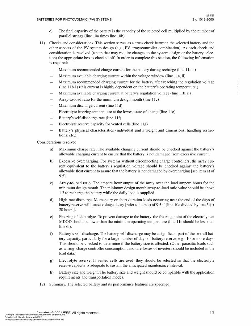
c) The final capacity of the battery is the capacity of the selected cell multiplied by the number ofparallel strings (line 10a times line 10b).
11) Checks and considerations. This section serves as a cross check between the selected battery and theother aspects of the PV system design (e.g., PV array/controller combination). As each check andconsideration is resolved (a step that may require changes to the system design or the battery selec-tion) the appropriate box is checked off. In order to complete this section, the following informationis required:
— Maximum recommended charge current for the battery during recharge (line 11a, i)
— Maximum available charging current within the voltage window (line 11a, ii)
— Maximum recommended charging current for the battery after reaching the regulation voltage(line 11b.1) (this current is highly dependent on the battery’s operating temperature.)
— Maximum available charging current at battery’s regulation voltage (line 11b, ii)
— Array-to-load ratio for the minimum design month (line 11c)
— Maximum discharge current (line 11d)
— Electrolyte freezing temperature at the lowest state of charge (line 11e)
— Battery’s self-discharge rate (line 11f)
— Electrolyte reserve capacity for vented cells (line 11g)
— Battery’s physical characteristics (individual unit’s weight and dimensions, handling restric-tions, etc.).
Considerations resolved
a) Maximum charge rate. The available charging current should be checked against the battery’sallowable charging current to ensure that the battery is not damaged from excessive current.
b) Excessive overcharging. For systems without disconnecting charge controllers, the array cur-rent equivalent to the battery’s regulation voltage should be checked against the battery’sallowable float current to assure that the battery is not damaged by overcharging [see item a) of9.5].
c) Array-to-load ratio. The ampere hour output of the array over the load ampere hours for theminimum design month. The minimum design month array-to-load ratio value should be above1.3 to recharge the battery while the daily load is supplied.
d) High-rate discharge. Momentary or short-duration loads occurring near the end of the days ofbattery reserve will cause voltage decay [refer to item c) of 9.5 if (line 10c divided by line 5i) <20 hours].
e) Freezing of electrolyte. To prevent damage to the battery, the freezing point of the electrolyte atMDOD should be lower than the minimum operating temperature (line 11e should be less thanline 6i).
f) Battery’s self-discharge. The battery self-discharge may be a significant part of the overall bat-tery capacity, particularly for a large number of days of battery reserve, e.g., 10 or more days.This should be checked to determine if the battery size is affected. (Other parasitic loads suchas wiring, charge controller consumption, and tare losses of inverters should be included in theload data.)
g) Electrolyte reserve. If vented cells are used, they should be selected so that the electrolytereserve capacity is adequate to sustain the anticipated maintenance interval.
h) Battery size and weight. The battery size and weight should be compatible with the applicationrequirements and transportation modes.
12) Summary. The selected battery and its performance features are specified.
Copyright © 2001 IEEE. All rights reserved. 15ical and Electronics Engineers, Inc. ith IEEE
Not for Resaleermitted without license from IHS
IEEEStd 1013-2000 IEEE RECOMMENDED PRACTICE FOR SIZING LEAD-ACID
Copyright The Institute of ElectrProvided by IHS under license wNo reproduction or networking p
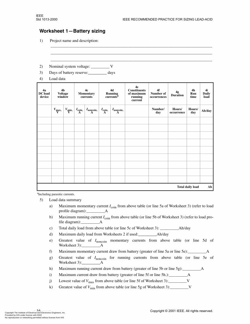
Worksheet 1—Battery sizing
1) Project name and description:_______________________________________________________________________________
_______________________________________________________________________________
_______________________________________________________________________________
2) Nominal system voltage: _________ V
3) Days of battery reserve:_________ days
4) Load data
5) Load data summary
a) Maximum momentary current Icoin from above table (or line 5a of Worksheet 3) (refer to loadprofile diagram):_________A
b) Maximum running current Icoin from above table (or line 5b of Worksheet 3) (refer to load pro-file diagram):_________A
c) Total daily load from above table (or line 5c of Worksheet 3): _________Ah/day
d) Maximum daily load from Worksheets 2 if used:_________Ah/day
e) Greatest value of Inoncoin momentary currents from above table (or line 5d ofWorksheet 3):_________A
f) Maximum momentary current draw from battery (greater of line 5a or line 5e):_________A
g) Greatest value of Inoncoin for running currents from above table (or line 5e ofWorksheet 3):_________A
h) Maximum running current draw from battery (greater of line 5b or line 5g):_________A
i) Maximum current draw from battery (greater of line 5f or line 5h.):_________A
j) Lowest value of Vmax from above table (or line 5f of Worksheet 3):_________V
k) Greatest value of Vmin from above table (or line 5g of Worksheet 3):_________V
4a DC load device
4b Voltagewindow
4cMomentary
currents
4dRunning currentsa
aIncluding parasitic currents.
4eConstituents of maximum
running current
4fNumber of occurrences
4gDuration
4hRun time
4iDaily load
Vmax,V
Vmin,V
Icoin,A
Inoncoin,A
Icoin,A
Inoncoin,A
Number/day
Hours/occurrence
Hours/day Ah/day
Total daily load Ah
16 Copyright © 2001 IEEE. All rights reserved.ical and Electronics Engineers, Inc. ith IEEE
Not for Resaleermitted without license from IHS
--``,-`-`,,`,,`,`,,`---
IEEEBATTERIES FOR PHOTOVOLTAIC (PV) SYSTEMS Std 1013-2000
Copyright The Institute of ElectrProvided by IHS under license wNo reproduction or networking p
--``,-`-`,,`,,`,`,,`---
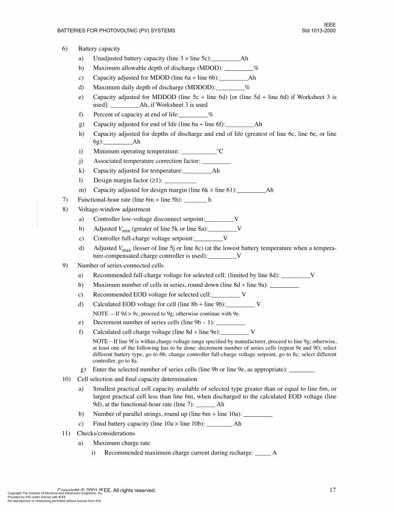
6) Battery capacity
a) Unadjusted battery capacity (line 3 × line 5c):_________Ah
b) Maximum allowable depth of discharge (MDOD): _________%
c) Capacity adjusted for MDOD (line 6a ÷ line 6b):_________Ah
d) Maximum daily depth of discharge (MDDOD):_________%
e) Capacity adjusted for MDDOD (line 5c ÷ line 6d) [or (line 5d ÷ line 6d) if Worksheet 3 isused]: _________Ah, if Worksheet 3 is used
f) Percent of capacity at end of life:_________%
g) Capacity adjusted for end of life (line 6a ÷ line 6f):_________Ah
h) Capacity adjusted for depths of discharge and end of life (greatest of line 6c, line 6e, or line6g):_________Ah
i) Minimum operating temperature: ___________°C
j) Associated temperature correction factor: _________
k) Capacity adjusted for temperature:_________Ah
l) Design margin factor (≥1): __________
m) Capacity adjusted for design margin (line 6k × line 61):_________Ah
7) Functional-hour rate (line 6m ÷ line 5h): _______ h
8) Voltage-window adjustment
a) Controller low-voltage disconnect setpoint:_________V
b) Adjusted Vmin (greater of line 5k or line 8a):_________V
c) Controller full-charge voltage setpoint:_________V
d) Adjusted Vmax (lesser of line 5j or line 8c) (at the lowest battery temperature when a tempera-ture-compensated charge controller is used):_________V
9) Number of series-connected cells
a) Recommended full-charge voltage for selected cell: (limited by line 8d): _________V
b) Maximum number of cells in series, round down (line 8d ÷ line 9a): _________
c) Recommended EOD voltage for selected cell:_________ V
d) Calculated EOD voltage for cell (line 8b ÷ line 9b):_________ V
NOTE —If 9d > 9c, proceed to 9g; otherwise continue with 9e.
e) Decrement number of series cells (line 9b – 1): _________
f) Calculated cell charge voltage (line 8d ÷ line 9e):_________ V
NOTE—If line 9f is within charge voltage range specified by manufacturer, proceed to line 9g; otherwise,at least one of the following has to be done: decrement number of series cells (repeat 9e and 9f); selectdifferent battery type, go to 6b; change controller full-charge voltage setpoint, go to 8c; select differentcontroller, go to 8a.
g) Enter the selected number of series cells (line 9b or line 9e, as appropriate): ________
10) Cell selection and final capacity determination
a) Smallest practical cell capacity available of selected type greater than or equal to line 6m, orlargest practical cell less than line 6m, when discharged to the calculated EOD voltage (line9d), at the functional-hour rate (line 7): ______ Ah
b) Number of parallel strings, round up (line 6m ÷ line 10a): _________
c) Final battery capacity (line 10a × line 10b): ________ Ah
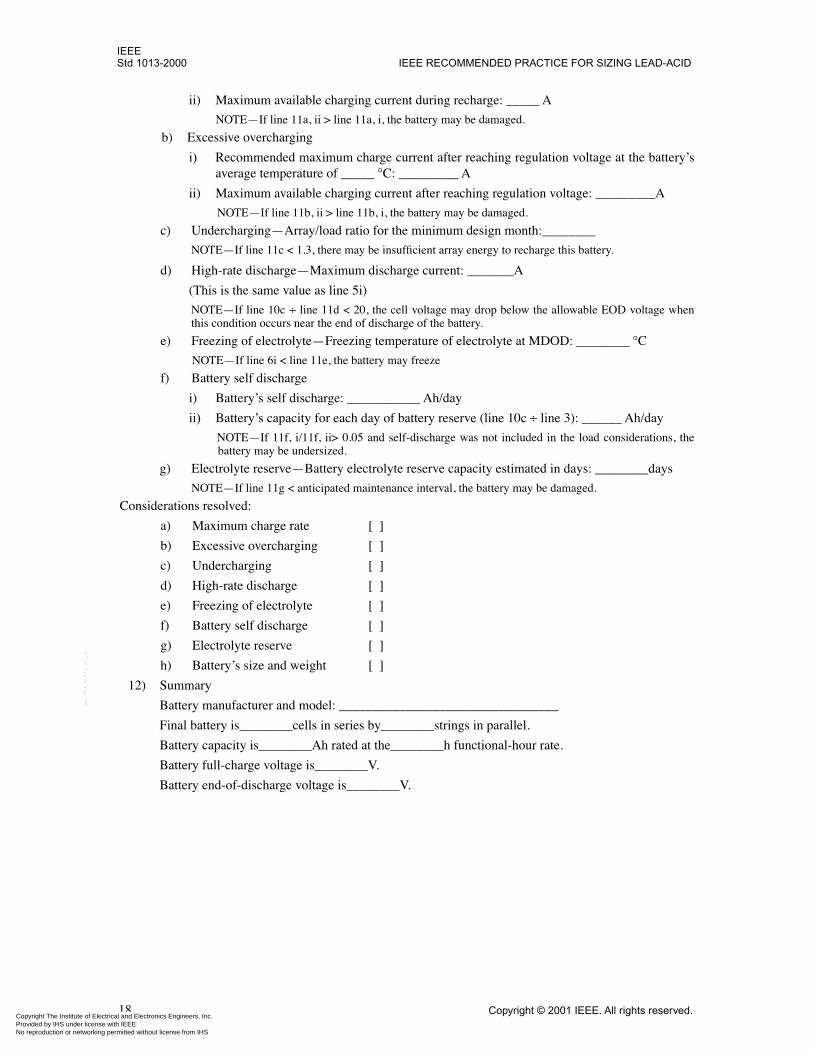
11) Checks/considerations
a) Maximum charge rate
i) Recommended maximum charge current during recharge: _____ A
Copyright © 2001 IEEE. All rights reserved. 17ical and Electronics Engineers, Inc. ith IEEE
Not for Resaleermitted without license from IHS
IEEEStd 1013-2000 IEEE RECOMMENDED PRACTICE FOR SIZING LEAD-ACID
Copyright The Institute of ElectrProvided by IHS under license wNo reproduction or networking p
--``,-`-`,,`,,`,`,,`---
ii) Maximum available charging current during recharge: _____ A
NOTE—If line 11a, ii > line 11a, i, the battery may be damaged.
b) Excessive overcharging
i) Recommended maximum charge current after reaching regulation voltage at the battery’saverage temperature of _____ °C: _________ A
ii) Maximum available charging current after reaching regulation voltage: _________A
NOTE—If line 11b, ii > line 11b, i, the battery may be damaged.
c) Undercharging—Array/load ratio for the minimum design month:________
NOTE—If line 11c < 1.3, there may be insufficient array energy to recharge this battery.
d) High-rate discharge—Maximum discharge current: _______A
(This is the same value as line 5i)
NOTE—If line 10c ÷ line 11d < 20, the cell voltage may drop below the allowable EOD voltage whenthis condition occurs near the end of discharge of the battery.
e) Freezing of electrolyte—Freezing temperature of electrolyte at MDOD: ________ °C
NOTE—If line 6i < line 11e, the battery may freeze
f) Battery self discharge
i) Battery’s self discharge: ___________ Ah/day
ii) Battery’s capacity for each day of battery reserve (line 10c ÷ line 3): ______ Ah/day
NOTE—If 11f, i/11f, ii> 0.05 and self-discharge was not included in the load considerations, thebattery may be undersized.
g) Electrolyte reserve—Battery electrolyte reserve capacity estimated in days: ________days
NOTE—If line 11g < anticipated maintenance interval, the battery may be damaged.
Considerations resolved:
a) Maximum charge rate [ ]b) Excessive overcharging [ ]c) Undercharging [ ]d) High-rate discharge [ ]e) Freezing of electrolyte [ ]f) Battery self discharge [ ]g) Electrolyte reserve [ ]h) Battery’s size and weight [ ]
12) Summary
Battery manufacturer and model: _________________________________
Final battery is________cells in series by________strings in parallel.
Battery capacity is________Ah rated at the________h functional-hour rate.
Battery full-charge voltage is________V.
Battery end-of-discharge voltage is________V.
18 Copyright © 2001 IEEE. All rights reserved.ical and Electronics Engineers, Inc. ith IEEE
Not for Resaleermitted without license from IHS
IEEEBATTERIES FOR PHOTOVOLTAIC (PV) SYSTEMS Std 1013-2000
Copyright The Institute of ElectrProvided by IHS under license wNo reproduction or networking p
--``,-`-`,,`,,`,`,,`---
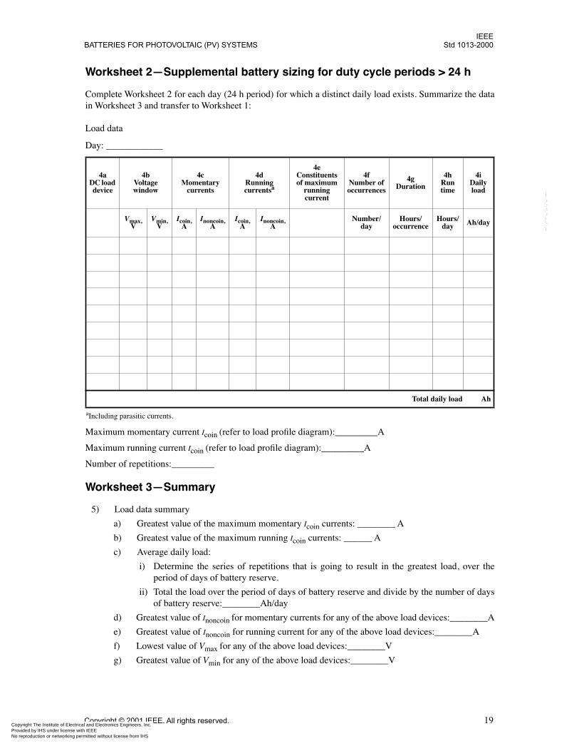
Worksheet 2—Supplemental battery sizing for duty cycle periods > 24 h
Complete Worksheet 2 for each day (24 h period) for which a distinct daily load exists. Summarize the datain Worksheet 3 and transfer to Worksheet 1:
Load data
Day: ____________
Maximum momentary current Icoin (refer to load profile diagram):_________A
Maximum running current Icoin (refer to load profile diagram):_________A
Number of repetitions:_________
Worksheet 3—Summary
5) Load data summary
a) Greatest value of the maximum momentary Icoin currents: ________ A
b) Greatest value of the maximum running Icoin currents: ______ A
c) Average daily load:
i) Determine the series of repetitions that is going to result in the greatest load, over theperiod of days of battery reserve.
ii) Total the load over the period of days of battery reserve and divide by the number of daysof battery reserve:________Ah/day
d) Greatest value of Inoncoin for momentary currents for any of the above load devices:________A
e) Greatest value of Inoncoin for running current for any of the above load devices:________A
f) Lowest value of Vmax for any of the above load devices:________V
g) Greatest value of Vmin for any of the above load devices:________V
4a DC load device
4b Voltagewindow
4cMomentary
currents
4dRunning currentsa
aIncluding parasitic currents.
4eConstituents of maximum
running current
4fNumber of occurrences
4gDuration
4hRun time
4iDaily load
Vmax,V
Vmin,V
Icoin,A
Inoncoin,A
Icoin,A
Inoncoin,A
Number/day
Hours/occurrence
Hours/day Ah/day
Total daily load Ah
Copyright © 2001 IEEE. All rights reserved. 19ical and Electronics Engineers, Inc. ith IEEE
Not for Resaleermitted without license from IHS
IEEEStd 1013-2000 IEEE RECOMMENDED PRACTICE FOR SIZING LEAD-ACID
Copyright The Institute of ElectrProvided by IHS under license wNo reproduction or networking p
Annex A
(informative)
Battery characteristics
This annex summarizes some factors that should be considered in selecting a battery design for a terrestrialphotovoltaic (PV) application.
A.1 Capacity
The ampere hour capacity of a battery depends on the size and number of plates of the cells, the amount andconcentration of electrolyte (particularly in valve-regulated cells), and the number of parallel strings of cellsused. The conditions under which a battery is used can change the available capacity of the battery, as illus-trated in the following examples:
a) Low temperatures reduce capacity.
b) High discharge rates reduce capacity.
c) High end-of-discharge voltages reduce capacity.
d) Limitations on the depth of discharge reduce capacity.
e) Failure to properly recharge a battery limits its capacity.
f) Excessive periods of high temperature and/or overcharge may result in the loss of electrolyte andlimit capacity of batteries.
A.2 Type
The two generic types of lead-acid batteries are:
a) Vented. Vented batteries are characterized by plates immersed in liquid electrolyte. The volume ofelectrolyte is sufficient to allow for a reasonable loss of water by evaporation and by the electrolysisassociated with overcharging. A vent in the cell’s cover allows a free exchange of the resulting gaseswith the atmosphere. Catalytic recombiners may be incorporated in each cell vent to reduce waterloss. In most of these types of batteries, the lost water can be replaced.
b) Valve-regulated. Valve-regulated level acid batteries (VRLA) are characterized by plates in contactwith a limited amount of immobilized electrolyte. Water loss is minimized during overcharge byoxygen recombination. As long as the cell’s recombination rate is not exceeded, the evolved oxygenis recombined at the cell’s negative plates to reform water. However, other mechanisms, such as gridcorrosion, consume oxygen and lead to water loss and hydrogen evolution. The cell or multi-cellcontainer is sealed with the exception of a pressure-relief valve (“valve-regulated”) that allowsexcess pressure (mostly hydrogen) resulting from overcharging to be released. In these types of bat-teries, the lost water generally cannot be replaced.
A.3 Cyclability
Lead-acid batteries for PV applications are generally categorized as deep-cycle and shallow-cycle.
20 Copyright © 2001 IEEE. All rights reserved.ical and Electronics Engineers, Inc. ith IEEE
Not for Resaleermitted without license from IHS
--``,-`-`,,`,,`,`,,`---
IEEEBATTERIES FOR PHOTOVOLTAIC (PV) SYSTEMS Std 1013-2000
Copyright The Institute of ElectrProvided by IHS under license wNo reproduction or networking p
--``,-`-`,,`,,`,`,,`---
A.3.1 Deep-cycle batteries
Deep-cycle batteries may be discharged up to 80% of their rated capacity on a daily basis. Typicaldeep-cycle-battery PV applications are those that have a low number of days of battery reserve, or are con-nected to a backup power source or a utility grid.
A.3.2 Shallow-cycle batteries
Usually, shallow-cycle batteries are discharged less than 25% of their rated capacity on a daily basis(MDDOD), and up to 80% over the period of battery reserve (MDOD). Manufacturers can supply the maxi-mum number of permissible 80% discharges per year. Typical shallow-cycle-battery PV applications arethose with larger numbers of days of battery reserve where neither a utility grid nor an emergency backuppower source is available.
A.4 Cycle life
The life of a battery can be measured by the number of times it can be cycled before it is no longer able todeliver sufficient energy to satisfy the load requirements of the system. The number of cycles of operation abattery will provide depends on the following three factors:
a) Cell design
b) Use
c) Operating temperature
A.4.1 Design factors
Some of the design factors that affect cycle life are:
a) Plate thickness
b) Grid alloy and construction
c) Active material density
d) Active material retention systems
e) Electrolyte density and amount
f) Type of separator
g) Pressure setting of valve (valve-regulated batteries)
A.4.2 Use factors
How a battery is used has an effect on its cycle life. Some of the considerations are listed below:
a) Depth of discharge
b) Stratification of electrolyte
c) Excessive overcharge (see A.4.3)
d) Insufficient recharge
e) End-of-discharge voltage
f) Higher-than-rated operating temperatures (>25 °C)
Copyright © 2001 IEEE. All rights reserved. 21ical and Electronics Engineers, Inc. ith IEEE
Not for Resaleermitted without license from IHS
IEEEStd 1013-2000 IEEE RECOMMENDED PRACTICE FOR SIZING LEAD-ACID
Copyright The Institute of ElectrProvided by IHS under license wNo reproduction or networking p
A.4.3 Operating temperature
High temperatures decrease cycle life, while low temperatures decrease available capacity. A battery shouldbe sized for operation at its coldest expected operating temperature, which, in effect, oversizes the batteryfor normal warmer operation, resulting in a reduced depth of discharge, which increases cycle life.
The VRLA battery’s oxygen recombination cycle is exothermic (generating heat on charging). Thus thistype of battery is more sensitive to conditions that can lead to thermal runaway, wherein the batterygenerates heat at a rate faster than it can be dissipated. Thermal runaway can result in deformation of thebattery case and significant emission of gases. When thermal runaway occurs, it is typically the result ofextended overcharging, which can be the result of shorted cells, coupled with an elevated temperature of thebattery environment and an inadequately ventilated battery enclosure. Thermal runaway can be prevented orarrested by appropriate charging control including temperature compensation, spacing of the individual cellsor units of the battery to allow for adequate air circulation, adequate ventilation of the battery enclosure, andappropriate periodic maintenance. To arrest thermal runaway, circuitry can be included to disconnect thebattery from its charging source should the battery temperature rise significantly above the ambienttemperature.
A.5 Economic considerations
The optimum battery will be the battery with lowest life-cycle cost. The life-cycle cost, expressed in dollarsper kilowatt hour ($/kWh) of energy delivered, is a function of a number of variables. These include thefollowing:
a) Initial cost
b) Cycle life
c) Maintenance costs
d) Battery/system reliability
e) Economic impact on PV system design including:
1) Charge controller
2) Structural design including battery support structure and enclosure
3) Heating, ventilation, and cooling
f) Replacement costs
g) Salvage value/disposal costs
h) Energy efficiency
i) Accessory systems such as those for electrolyte agitation and water addition
A.6 Physical characteristics
Physical characteristics that may be important are:
a) Size and weight of the smallest transportable unit
b) Cell access requirements for maintenance, such as addition of water
c) Strength of cell containers for safety and if electrolyte freezing is a possibility
d) Terminal connection configuration
e) Accessory requirements
22 Copyright © 2001 IEEE. All rights reserved.ical and Electronics Engineers, Inc. ith IEEE
Not for Resaleermitted without license from IHS
--``,-`-`,,`,,`,`,,`---
IEEEBATTERIES FOR PHOTOVOLTAIC (PV) SYSTEMS Std 1013-2000
Copyright The Institute of ElectrProvided by IHS under license wNo reproduction or networking p
--``,-`-`,,`,,`,`,,`---
f) Vent fittings to attach tubing for external venting
g) Available enclosure space
h) Container flammability
A.7 Maintenance
The required maintenance of batteries depends on the batteries’ design and use. Refer to IEEE Std 937-2000.
A.8 Safety
Batteries are potentially hazardous for a number of reasons, including generation and release of explosivegasses (see 9.5), stored electrical energy, and presence of corrosive liquids. Installation and maintenance per-sonnel should be qualified in battery operating and safety procedures. Refer to IEEE Std 937-2000 for safetydetails.
Copyright © 2001 IEEE. All rights reserved. 23ical and Electronics Engineers, Inc. ith IEEE
Not for Resaleermitted without license from IHS

IEEEStd 1013-2000 IEEE RECOMMENDED PRACTICE FOR SIZING LEAD-ACID
Copyright The Institute of ElectrProvided by IHS under license wNo reproduction or networking p
--``,-`-`,,`,,`,`,,`---
Annex B
(informative)
Examples
The following examples, including the parameters used, show the application of this sizing method. They areillustrative only and are not intended to cover all possible sizing features.
B.1 Refrigerator/freezer for vaccine storage
Example B.1 describes the battery sizing for a vaccine storage refrigerator intended for remote use. Therefrigerator is to be located near the equator in a tropical climate. Vaccines are delivered quarterly. At thesame time deliveries are made, a technician is available for system maintenance. There is a constraint on thephysical size of the battery that can be installed in the refrigerator’s battery box. Figure B.1 shows a typicalload profile diagram for this application.
Figure B.1—Simulated load-profile diagram for vaccine storage refrigerator/freezer
24 Copyright © 2001 IEEE. All rights reserved.ical and Electronics Engineers, Inc. ith IEEE
Not for Resaleermitted without license from IHS
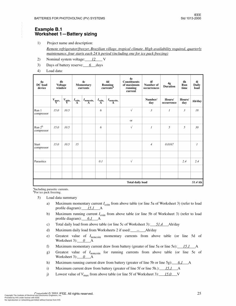
IEEEBATTERIES FOR PHOTOVOLTAIC (PV) SYSTEMS Std 1013-2000
Copyright The Institute of ElectrProvided by IHS under license wNo reproduction or networking p
--``,-`-`,,`,,`,`,,`---
Example B.1Worksheet 1—Battery sizing
1) Project name and description:
Remote refrigerator/freezer, Brazilian village, tropical climate. High availability required, quarterlymaintenance, four starts each 24 h period (including one for ice pack freezing)
2) Nominal system voltage: 12 V
3) Days of battery reserve: 6 days
4) Load data:
5) Load data summary
a) Maximum momentary current Icoin from above table (or line 5a of Worksheet 3) (refer to loadprofile diagram): 15.1 A
b) Maximum running current Icoin from above table (or line 5b of Worksheet 3) (refer to loadprofile diagram): 6.1 A
c) Total daily load from above table (or line 5c of Worksheet 3): 51.4 Ah/day
d) Maximum daily load from Worksheets 2 if used: — Ah/day
e) Greatest value of Inoncoin momentary currents from above table (or line 5d ofWorksheet 3): 0 A
f) Maximum momentary current draw from battery (greater of line 5a or line 5e): 15.1 A
g) Greatest value of Inoncoin for running currents from above table (or line 5e ofWorksheet 3): 0 A
h) Maximum running current draw from battery (greater of line 5b or line 5g): 6.1 A
i) Maximum current draw from battery (greater of line 5f or line 5h.): 15.1 A
j) Lowest value of Vmax from above table (or line 5f of Worksheet 3): 15.0 V
4a DC load device
4b Voltagewindow
4cMomentary
currents
4dRunning currentsa
aIncluding parasitic currents.
4eConstituents of maximum
running current
4fNumber of occurrences
4gDuration
4hRun time
4iDaily load
Vmax,V
Vmin,V
Icoin,A
Inoncoin,A
Icoin,A
Inoncoin,A
Number/day
Hours/occurrence
Hours/day Ah/day
Run 1compressor
15.0 10.5 6 √ 3 1 3 18
or
Run 2b compressor
bFor ice pack freezing.
15.0 10.5 6 √ 1 5 5 30
Startcompressor
15.0 10.5 15 4 0.0167 1
Parasitics 0.1 √ 2.4 2.4
Total daily load 51.4 Ah
Copyright © 2001 IEEE. All rights reserved. 25ical and Electronics Engineers, Inc. ith IEEE
Not for Resaleermitted without license from IHS
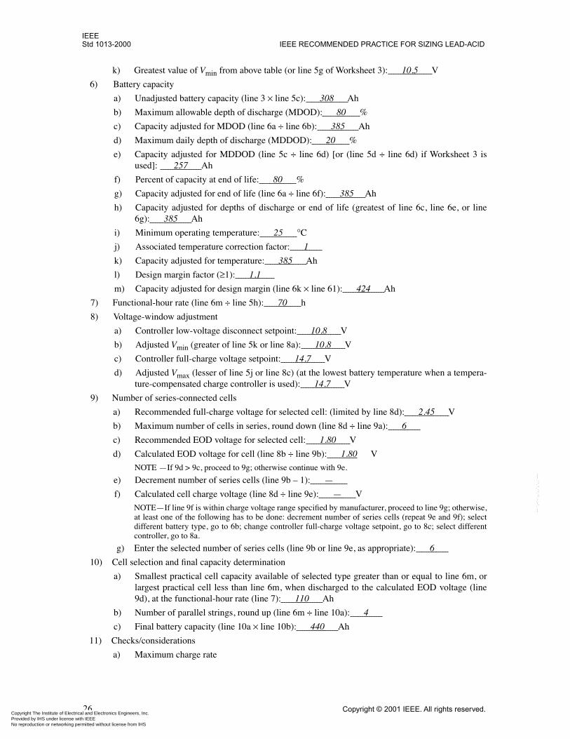
IEEEStd 1013-2000 IEEE RECOMMENDED PRACTICE FOR SIZING LEAD-ACID
Copyright The Institute of ElectrProvided by IHS under license wNo reproduction or networking p
--``,-`-`,,`,,`,`,,`---
k) Greatest value of Vmin from above table (or line 5g of Worksheet 3): 10.5 V
6) Battery capacity
a) Unadjusted battery capacity (line 3 × line 5c): 308 Ah
b) Maximum allowable depth of discharge (MDOD): 80 %
c) Capacity adjusted for MDOD (line 6a ÷ line 6b): 385 Ah
d) Maximum daily depth of discharge (MDDOD): 20 %
e) Capacity adjusted for MDDOD (line 5c ÷ line 6d) [or (line 5d ÷ line 6d) if Worksheet 3 isused]: 257 Ah
f) Percent of capacity at end of life: 80 %
g) Capacity adjusted for end of life (line 6a ÷ line 6f): 385 Ah
h) Capacity adjusted for depths of discharge or end of life (greatest of line 6c, line 6e, or line6g): 385 Ah
i) Minimum operating temperature: 25 °C
j) Associated temperature correction factor: 1
k) Capacity adjusted for temperature: 385 Ah
l) Design margin factor (≥1): 1.1
m) Capacity adjusted for design margin (line 6k × line 61): 424 Ah
7) Functional-hour rate (line 6m ÷ line 5h): 70 h
8) Voltage-window adjustment
a) Controller low-voltage disconnect setpoint: 10.8 V
b) Adjusted Vmin (greater of line 5k or line 8a): 10.8 V
c) Controller full-charge voltage setpoint: 14.7 V
d) Adjusted Vmax (lesser of line 5j or line 8c) (at the lowest battery temperature when a tempera-ture-compensated charge controller is used): 14.7 V
9) Number of series-connected cells
a) Recommended full-charge voltage for selected cell: (limited by line 8d): 2.45 V
b) Maximum number of cells in series, round down (line 8d ÷ line 9a): 6
c) Recommended EOD voltage for selected cell: 1.80 V
d) Calculated EOD voltage for cell (line 8b ÷ line 9b): 1.80 V
NOTE —If 9d > 9c, proceed to 9g; otherwise continue with 9e.
e) Decrement number of series cells (line 9b – 1): —
f) Calculated cell charge voltage (line 8d ÷ line 9e): — V
NOTE—If line 9f is within charge voltage range specified by manufacturer, proceed to line 9g; otherwise,at least one of the following has to be done: decrement number of series cells (repeat 9e and 9f); selectdifferent battery type, go to 6b; change controller full-charge voltage setpoint, go to 8c; select differentcontroller, go to 8a.
g) Enter the selected number of series cells (line 9b or line 9e, as appropriate): 6
10) Cell selection and final capacity determination
a) Smallest practical cell capacity available of selected type greater than or equal to line 6m, orlargest practical cell less than line 6m, when discharged to the calculated EOD voltage (line9d), at the functional-hour rate (line 7): 110 Ah
b) Number of parallel strings, round up (line 6m ÷ line 10a): 4
c) Final battery capacity (line 10a × line 10b): 440 Ah
11) Checks/considerations
a) Maximum charge rate
26 Copyright © 2001 IEEE. All rights reserved.ical and Electronics Engineers, Inc. ith IEEE
Not for Resaleermitted without license from IHS
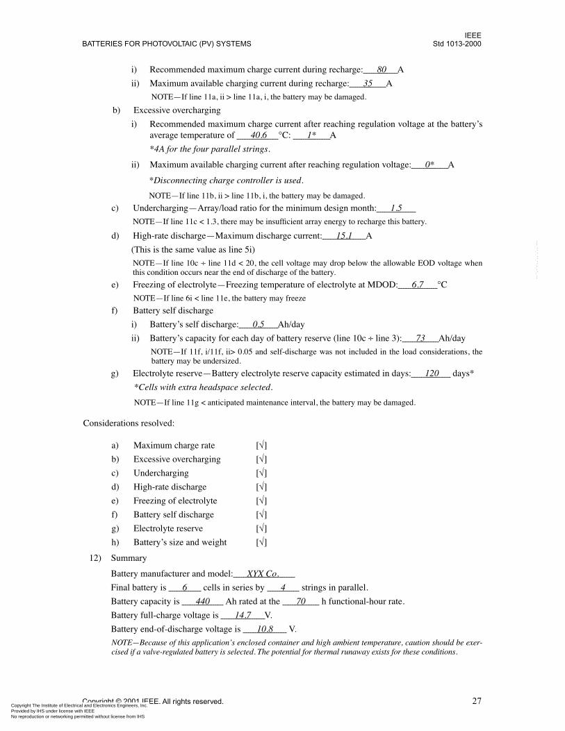
IEEEBATTERIES FOR PHOTOVOLTAIC (PV) SYSTEMS Std 1013-2000
Copyright The Institute of ElectrProvided by IHS under license wNo reproduction or networking p
--``,-`-`,,`,,`,`,,`---
i) Recommended maximum charge current during recharge: 80 A
ii) Maximum available charging current during recharge: 35 A
NOTE—If line 11a, ii > line 11a, i, the battery may be damaged.
b) Excessive overcharging
i) Recommended maximum charge current after reaching regulation voltage at the battery’saverage temperature of 40.6 °C: 1* A
*4A for the four parallel strings.
ii) Maximum available charging current after reaching regulation voltage: 0* A
*Disconnecting charge controller is used.
NOTE—If line 11b, ii > line 11b, i, the battery may be damaged.
c) Undercharging—Array/load ratio for the minimum design month: 1.5
NOTE—If line 11c < 1.3, there may be insufficient array energy to recharge this battery.
d) High-rate discharge—Maximum discharge current: 15.1 A
(This is the same value as line 5i)
NOTE—If line 10c ÷ line 11d < 20, the cell voltage may drop below the allowable EOD voltage whenthis condition occurs near the end of discharge of the battery.
e) Freezing of electrolyte—Freezing temperature of electrolyte at MDOD: 6.7 °C
NOTE—If line 6i < line 11e, the battery may freeze
f) Battery self discharge
i) Battery’s self discharge: 0.5 Ah/day
ii) Battery’s capacity for each day of battery reserve (line 10c ÷ line 3): 73 Ah/day
NOTE—If 11f, i/11f, ii> 0.05 and self-discharge was not included in the load considerations, thebattery may be undersized.
g) Electrolyte reserve—Battery electrolyte reserve capacity estimated in days: 120 days*
*Cells with extra headspace selected.
NOTE—If line 11g < anticipated maintenance interval, the battery may be damaged.
Considerations resolved:
a) Maximum charge rate [√]
b) Excessive overcharging [√]
c) Undercharging [√]
d) High-rate discharge [√]
e) Freezing of electrolyte [√]
f) Battery self discharge [√]
g) Electrolyte reserve [√]
h) Battery’s size and weight [√]
12) Summary
Battery manufacturer and model: XYX Co.
Final battery is 6 cells in series by 4 strings in parallel.
Battery capacity is 440 Ah rated at the 70 h functional-hour rate.
Battery full-charge voltage is 14.7 V.
Battery end-of-discharge voltage is 10.8 V.
NOTE—Because of this application’s enclosed container and high ambient temperature, caution should be exer-cised if a valve-regulated battery is selected. The potential for thermal runaway exists for these conditions.
Copyright © 2001 IEEE. All rights reserved. 27ical and Electronics Engineers, Inc. ith IEEE
Not for Resaleermitted without license from IHS
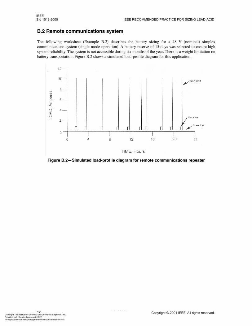
IEEEStd 1013-2000 IEEE RECOMMENDED PRACTICE FOR SIZING LEAD-ACID
Copyright The Institute of ElectrProvided by IHS under license wNo reproduction or networking p
B.2 Remote communications system
The following worksheet (Example B.2) describes the battery sizing for a 48 V (nominal) simplexcommunications system (single-mode operation). A battery reserve of 15 days was selected to ensure highsystem reliability. The system is not accessible during six months of the year. There is a weight limitation onbattery transportation. Figure B.2 shows a simulated load-profile diagram for this application.
Figure B.2—Simulated load-profile diagram for remote communications repeater
28 Copyright © 2001 IEEE. All rights reserved.ical and Electronics Engineers, Inc. ith IEEE
Not for Resaleermitted without license from IHS
--``,-`-`,,`,,`,`,,`---
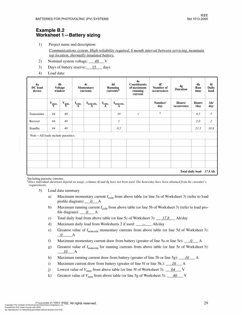
IEEEBATTERIES FOR PHOTOVOLTAIC (PV) SYSTEMS Std 1013-2000
D
aIncl
ly d
/y
Tra
bSinreq
Re
Sta 8
N
h
Copyright The Institute of ElectrProvided by IHS under license wNo reproduction or networking p
--``,-`-`,,`,,`,`,,`---
Example B.2Worksheet 1—Battery sizing
1) Project name and description:
Communications system. High reliability required, 6 month interval between servicing, mountain top location, thermally insulated battery.
2) Nominal system voltage: 48 V
3) Days of battery reserve: 15 days
4) Load data:
5) Load data summary
a) Maximum momentary current Icoin from above table (or line 5a of Worksheet 3) (refer to loadprofile diagram): 0 A
b) Maximum running current Icoin from above table (or line 5b of Worksheet 3) (refer to load pro-file diagram): 0 A
c) Total daily load from above table (or line 5c of Worksheet 3): 17.8 Ah/day
d) Maximum daily load from Worksheets 2 if used: — Ah/day
e) Greatest value of Inoncoin momentary currents from above table (or line 5d of Worksheet 3): 0 A
f) Maximum momentary current draw from battery (greater of line 5a or line 5e): 0 A
g) Greatest value of Inoncoin for running currents from above table (or line 5e of Worksheet 3): 10 A
h) Maximum running current draw from battery (greater of line 5b or line 5g): 10 A
i) Maximum current draw from battery (greater of line 5f or line 5h.): 10 A
j) Lowest value of Vmax from above table (or line 5f of Worksheet 3): 64 V
k) Greatest value of Vmin from above table (or line 5g of Worksheet 3): 40 V
4aC load
device
4bVoltage window
4cMomentary
currents
4dRunning currentsa
uding parasitic currents.
4eConstituents of maximum
running current
4fNumber of occurrences
4gDuration
4hRun time
4IDailoa
Vmax,V
Vmin,V
Icoin,A
Inoncoin,A
Icoin,A
Inoncoin,A
Number/day
Hours/occurrence
Hours/day
Ahda
nsmitter 64 40 10 √ b
ce individual durations depend on usage, columns 4f and 4g have not been used. The hours/day have been obtained from the customer’s uirements.
0.5 5
cover 64 40 1 2.0 2
ndby 64 40 0.5 21.5 10.
ote—All loads include parasitics.
Total daily load 17.8 A
Copyright © 2001 IEEE. All rights reserved. 29ical and Electronics Engineers, Inc. ith IEEE
Not for Resaleermitted without license from IHS
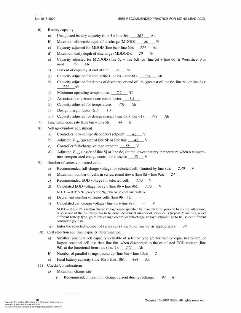
IEEEStd 1013-2000 IEEE RECOMMENDED PRACTICE FOR SIZING LEAD-ACID
Copyright The Institute of ElectrProvided by IHS under license wNo reproduction or networking p
6) Battery capacity
a) Unadjusted battery capacity (line 3 × line 5c): 267 Ah
b) Maximum allowable depth of discharge (MDOD): 80 %
c) Capacity adjusted for MDOD (line 6a ÷ line 6b): 334 Ah
d) Maximum daily depth of discharge (MDDOD): 20 %
e) Capacity adjusted for MDDOD (line 5c ÷ line 6d) [or (line 5d ÷ line 6d) if Worksheet 3 isused]: 89 Ah
f) Percent of capacity at end of life: 80 %
g) Capacity adjusted for end of life (line 6a ÷ line 6f): 334 Ah
h) Capacity adjusted for depths of discharge or end of life (greatest of line 6c, line 6e, or line 6g): 334 Ah
i) Minimum operating temperature: 7.2 °C
j) Associated temperature correction factor: 1.2
k) Capacity adjusted for temperature: 401 Ah
l) Design margin factor (≥1): 1.1
m) Capacity adjusted for design margin (line 6k × line 61): 441 Ah
7) Functional-hour rate (line 6m ÷ line 5h): 44 h
8) Voltage-window adjustment
a) Controller low-voltage disconnect setpoint: 42 V
b) Adjusted Vmin (greater of line 5k or line 8a): 42 V
c) Controller full-charge voltage setpoint: 58 V
d) Adjusted Vmax (lesser of line 5j or line 8c) (at the lowest battery temperature when a tempera-ture-compensated charge controller is used): 58 V
9) Number of series-connected cells
a) Recommended full-charge voltage for selected cell: (limited by line 8d): 2.40 V
b) Maximum number of cells in series, round down (line 8d ÷ line 9a): 24
c) Recommended EOD voltage for selected cell: 1.75 V
d) Calculated EOD voltage for cell (line 8b ÷ line 9b): 1.75 V
NOTE —If 9d > 9c, proceed to 9g; otherwise continue with 9e.
e) Decrement number of series cells (line 9b – 1): —
f) Calculated cell charge voltage (line 8d ÷ line 9e): — V
NOTE—If line 9f is within charge voltage range specified by manufacturer, proceed to line 9g; otherwise,at least one of the following has to be done: decrement number of series cells (repeat 9e and 9f); selectdifferent battery type, go to 6b; change controller full-charge voltage setpoint, go to 8c; select differentcontroller, go to 8a.
g) Enter the selected number of series cells (line 9b or line 9e, as appropriate): 24
10) Cell selection and final capacity determination
a) Smallest practical cell capacity available of selected type greater than or equal to line 6m, orlargest practical cell less than line 6m, when discharged to the calculated EOD voltage (line9d), at the functional-hour rate (line 7): 242 Ah
b) Number of parallel strings, round up (line 6m ÷ line 10a): 2
c) Final battery capacity (line 10a × line 10b): 484 Ah
11) Checks/considerations
a) Maximum charge rate
i) Recommended maximum charge current during recharge: 97 A
30 Copyright © 2001 IEEE. All rights reserved.ical and Electronics Engineers, Inc. ith IEEE
Not for Resaleermitted without license from IHS
--``,-`-`,,`,,`,`,,`---
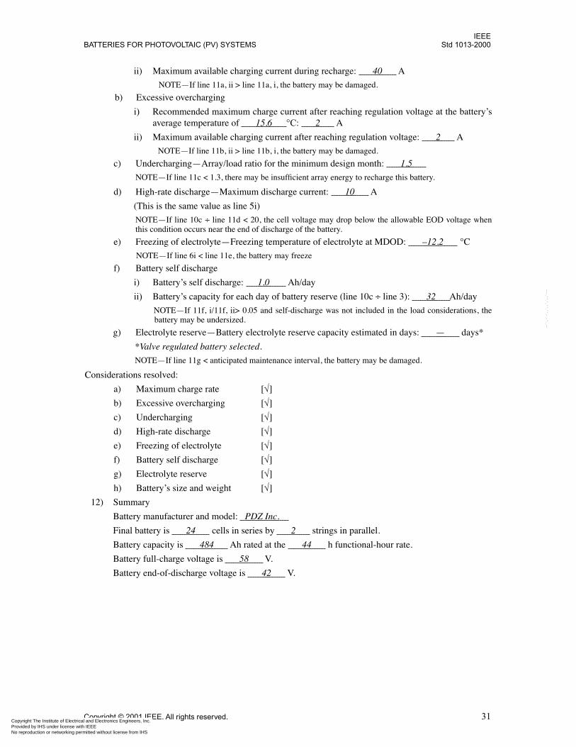
IEEEBATTERIES FOR PHOTOVOLTAIC (PV) SYSTEMS Std 1013-2000
Copyright The Institute of ElectrProvided by IHS under license wNo reproduction or networking p
--``,-`-`,,`,,`,`,,`---
ii) Maximum available charging current during recharge: 40 A
NOTE—If line 11a, ii > line 11a, i, the battery may be damaged.
b) Excessive overcharging
i) Recommended maximum charge current after reaching regulation voltage at the battery’saverage temperature of 15.6 °C: 2 A
ii) Maximum available charging current after reaching regulation voltage: 2 A
NOTE—If line 11b, ii > line 11b, i, the battery may be damaged.
c) Undercharging—Array/load ratio for the minimum design month: 1.5
NOTE—If line 11c < 1.3, there may be insufficient array energy to recharge this battery.
d) High-rate discharge—Maximum discharge current: 10 A
(This is the same value as line 5i)
NOTE—If line 10c ÷ line 11d < 20, the cell voltage may drop below the allowable EOD voltage whenthis condition occurs near the end of discharge of the battery.
e) Freezing of electrolyte—Freezing temperature of electrolyte at MDOD: –12.2 °C
NOTE—If line 6i < line 11e, the battery may freeze
f) Battery self discharge
i) Battery’s self discharge: 1.0 Ah/day
ii) Battery’s capacity for each day of battery reserve (line 10c ÷ line 3): 32 Ah/day
NOTE—If 11f, i/11f, ii> 0.05 and self-discharge was not included in the load considerations, thebattery may be undersized.
g) Electrolyte reserve—Battery electrolyte reserve capacity estimated in days: — days*
*Valve regulated battery selected.
NOTE—If line 11g < anticipated maintenance interval, the battery may be damaged.
Considerations resolved:
a) Maximum charge rate [√]
b) Excessive overcharging [√]
c) Undercharging [√]
d) High-rate discharge [√]
e) Freezing of electrolyte [√]
f) Battery self discharge [√]
g) Electrolyte reserve [√]
h) Battery’s size and weight [√]
12) Summary
Battery manufacturer and model: PDZ Inc.
Final battery is 24 cells in series by 2 strings in parallel.
Battery capacity is 484 Ah rated at the 44 h functional-hour rate.
Battery full-charge voltage is 58 V.
Battery end-of-discharge voltage is 42 V.
Copyright © 2001 IEEE. All rights reserved. 31ical and Electronics Engineers, Inc. ith IEEE
Not for Resaleermitted without license from IHS
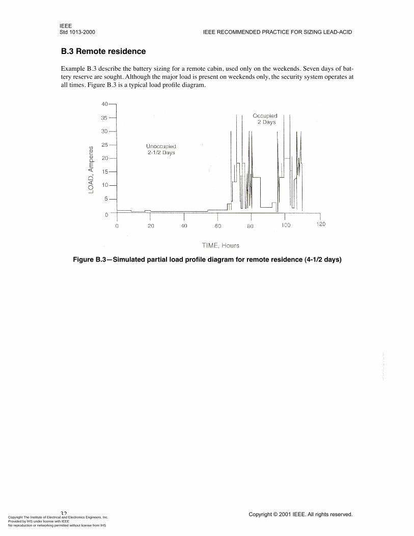
IEEEStd 1013-2000 IEEE RECOMMENDED PRACTICE FOR SIZING LEAD-ACID
Copyright The Institute of ElectrProvided by IHS under license wNo reproduction or networking p
--``,-`-`,,`,,`,`,,`---
B.3 Remote residence
Example B.3 describe the battery sizing for a remote cabin, used only on the weekends. Seven days of bat-tery reserve are sought. Although the major load is present on weekends only, the security system operates atall times. Figure B.3 is a typical load profile diagram.
Figure B.3—Simulated partial load profile diagram for remote residence (4-1/2 days)
32 Copyright © 2001 IEEE. All rights reserved.ical and Electronics Engineers, Inc. ith IEEE
Not for Resaleermitted without license from IHS
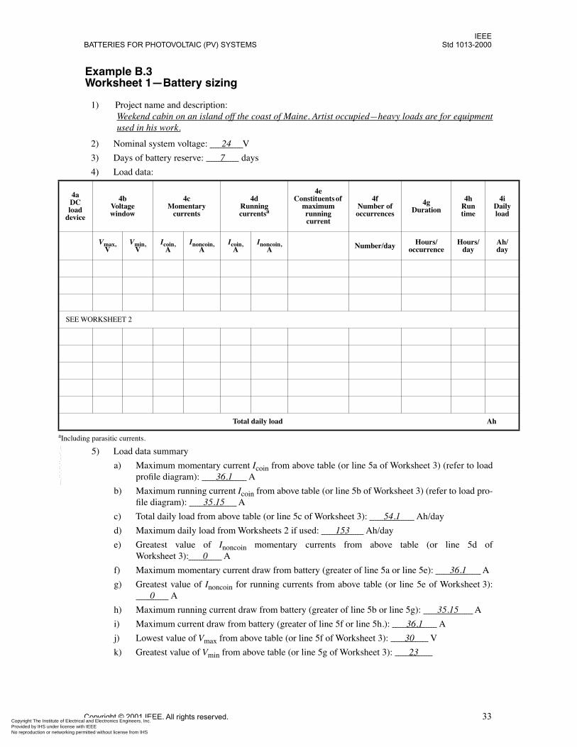
IEEEBATTERIES FOR PHOTOVOLTAIC (PV) SYSTEMS Std 1013-2000
4aDCloa
dev
aInclu
iily ad
h/y
SEE
Copyright The Institute of ElectrProvided by IHS under license wNo reproduction or networking p
--``,-`-`,,`,,`,`,,`---
Example B.3Worksheet 1—Battery sizing
1) Project name and description:Weekend cabin on an island off the coast of Maine. Artist occupied—heavy loads are for equipmentused in his work.
2) Nominal system voltage: 24 V
3) Days of battery reserve: 7 days
4) Load data:
5) Load data summary
a) Maximum momentary current Icoin from above table (or line 5a of Worksheet 3) (refer to loadprofile diagram): 36.1 A
b) Maximum running current Icoin from above table (or line 5b of Worksheet 3) (refer to load pro-file diagram): 35.15 A
c) Total daily load from above table (or line 5c of Worksheet 3): 54.1 Ah/day
d) Maximum daily load from Worksheets 2 if used: 153 Ah/day
e) Greatest value of Inoncoin momentary currents from above table (or line 5d ofWorksheet 3): 0 A
f) Maximum momentary current draw from battery (greater of line 5a or line 5e): 36.1 A
g) Greatest value of Inoncoin for running currents from above table (or line 5e of Worksheet 3): 0 A
h) Maximum running current draw from battery (greater of line 5b or line 5g): 35.15 A
i) Maximum current draw from battery (greater of line 5f or line 5h.): 36.1 A
j) Lowest value of Vmax from above table (or line 5f of Worksheet 3): 30 V
k) Greatest value of Vmin from above table (or line 5g of Worksheet 3): 23
d ice
4b Voltagewindow
4cMomentary
currents
4dRunning currentsa
ding parasitic currents.
4eConstituents of
maximum running current
4fNumber of occurrences
4gDuration
4hRun time
4Dalo
Vmax,V
Vmin,V
Icoin,A
Inoncoin,A
Icoin,A
Inoncoin,A Number/day Hours/
occurrenceHours/
dayAda
WORKSHEET 2
Total daily load Ah
Copyright © 2001 IEEE. All rights reserved. 33ical and Electronics Engineers, Inc. ith IEEE
Not for Resaleermitted without license from IHS

IEEEStd 1013-2000 IEEE RECOMMENDED PRACTICE FOR SIZING LEAD-ACID
Copyright The Institute of ElectrProvided by IHS under license wNo reproduction or networking p
--``,-`-`,,`,,`,`,,`---
6) Battery capacity
a) Unadjusted battery capacity (line 3 × line 5c): 417 Ah
b) Maximum allowable depth of discharge (MDOD): 50 %
c) Capacity adjusted for MDOD (line 6a ÷ line 6b): 834 Ah
d) Maximum daily depth of discharge (MDDOD): 20 %
e) Capacity adjusted for MDDOD (line 5c ÷ line 6d) [or (line 5d ÷ line 6d) if Worksheet 3 isused]: 772 Ah
f) Percent of capacity at end of life: 80 %
g) Capacity adjusted for end of life (line 6a ÷ line 6f): 521 Ah
h) Capacity adjusted for depths of discharge or end of life (greatest of line 6c, line 6e, or line 6g): 834 Ah
i) Minimum operating temperature: 0 °C
j) Associated temperature correction factor: 1.35
k) Capacity adjusted for temperature: 1126 Ah
l) Design margin factor (≥1): 1.1
m) Capacity adjusted for design margin (line 6k × line 61): 1239 Ah
7) Functional-hour rate (line 6m ÷ line 5h): 35 h
8) Voltage-window adjustment
a) Controller low-voltage disconnect setpoint: 24.5 V
b) Adjusted Vmin (greater of line 5k or line 8a): 24.5 V
c) Controller full-charge voltage setpoint: 28.8 V
d) Adjusted Vmax (lesser of line 5j or line 8c) (at the lowest battery temperature when a tempera-ture-compensated charge controller is used): 28.8 V
9) Number of series-connected cells
a) Recommended full-charge voltage for selected cell: (limited by line 8d): 2.40 V
b) Maximum number of cells in series, round down (line 8d ÷ line 9a): 12
c) Recommended EOD voltage for selected cell: 2.0 V
d) Calculated EOD voltage for cell (line 8b ÷ line 9b): 2.04 V
NOTE —If 9d > 9c, proceed to 9g; otherwise continue with 9e.
e) Decrement number of series cells (line 9b – 1): —
f) Calculated cell charge voltage (line 8d ÷ line 9e): — V
NOTE—If line 9f is within charge voltage range specified by manufacturer, proceed to line 9g; otherwise,at least one of the following has to be done: decrement number of series cells (repeat 9e and 9f); selectdifferent battery type, go to 6b; change controller full-charge voltage setpoint, go to 8c; select differentcontroller, go to 8a.
g) Enter the selected number of series cells (line 9b or line 9e, as appropriate): 12
10) Cell selection and final capacity determination
a) Smallest practical cell capacity available of selected type greater than or equal to line 6m, orlargest practical cell less than line 6m, when discharged to the calculated EOD voltage (line9d), at the functional-hour rate (line 7): 1240 Ah
b) Number of parallel strings, round up (line 6m ÷ line 10a): 1
c) Final battery capacity (line 10a × line 10b): 1240 Ah
11) Checks/considerations
a) Maximum charge rate
i) Recommended maximum charge current during recharge: 150 A
34 Copyright © 2001 IEEE. All rights reserved.ical and Electronics Engineers, Inc. ith IEEE
Not for Resaleermitted without license from IHS
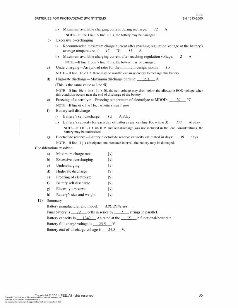
IEEEBATTERIES FOR PHOTOVOLTAIC (PV) SYSTEMS Std 1013-2000
Copyright The Institute of ElectrProvided by IHS under license wNo reproduction or networking p
--``,-`-`,,`,,`,`,,`---
ii) Maximum available charging current during recharge: 12 A
NOTE—If line 11a, ii > line 11a, i, the battery may be damaged.
b) Excessive overcharging
i) Recommended maximum charge current after reaching regulation voltage at the battery’saverage temperature of 15 °C: 11 A
ii) Maximum available charging current after reaching regulation voltage: 2 A
NOTE—If line 11b, ii > line 11b, i, the battery may be damaged.
c) Undercharging—Array/load ratio for the minimum design month: 1.3
NOTE—If line 11c < 1.3, there may be insufficient array energy to recharge this battery.
d) High-rate discharge—Maximum discharge current: 36.1 A
(This is the same value as line 5i)
NOTE—If line 10c ÷ line 11d < 20, the cell voltage may drop below the allowable EOD voltage whenthis condition occurs near the end of discharge of the battery.
e) Freezing of electrolyte—Freezing temperature of electrolyte at MDOD: –20 °C
NOTE—If line 6i < line 11e, the battery may freeze
f) Battery self discharge
i) Battery’s self discharge: 1.5 Ah/day
ii) Battery’s capacity for each day of battery reserve (line 10c ÷ line 3): 177 Ah/day
NOTE—If 11f, i/11f, ii> 0.05 and self-discharge was not included in the load considerations, thebattery may be undersized.
g) Electrolyte reserve—Battery electrolyte reserve capacity estimated in days: 30 days
NOTE—If line 11g < anticipated maintenance interval, the battery may be damaged.
Considerations resolved:
a) Maximum charge rate [√]
b) Excessive overcharging [√]
c) Undercharging [√]
d) High-rate discharge [√]
e) Freezing of electrolyte [√]
f) Battery self discharge [√]
g) Electrolyte reserve [√]
h) Battery’s size and weight [√]
12) Summary
Battery manufacturer and model: ABC Batteries .
Final battery is 12 cells in series by 1 strings in parallel.
Battery capacity is 1240 Ah rated at the 35 h functional-hour rate.
Battery full-charge voltage is 28.8 V.
Battery end-of-discharge voltage is 24.5 V.
Copyright © 2001 IEEE. All rights reserved. 35ical and Electronics Engineers, Inc. ith IEEE
Not for Resaleermitted without license from IHS
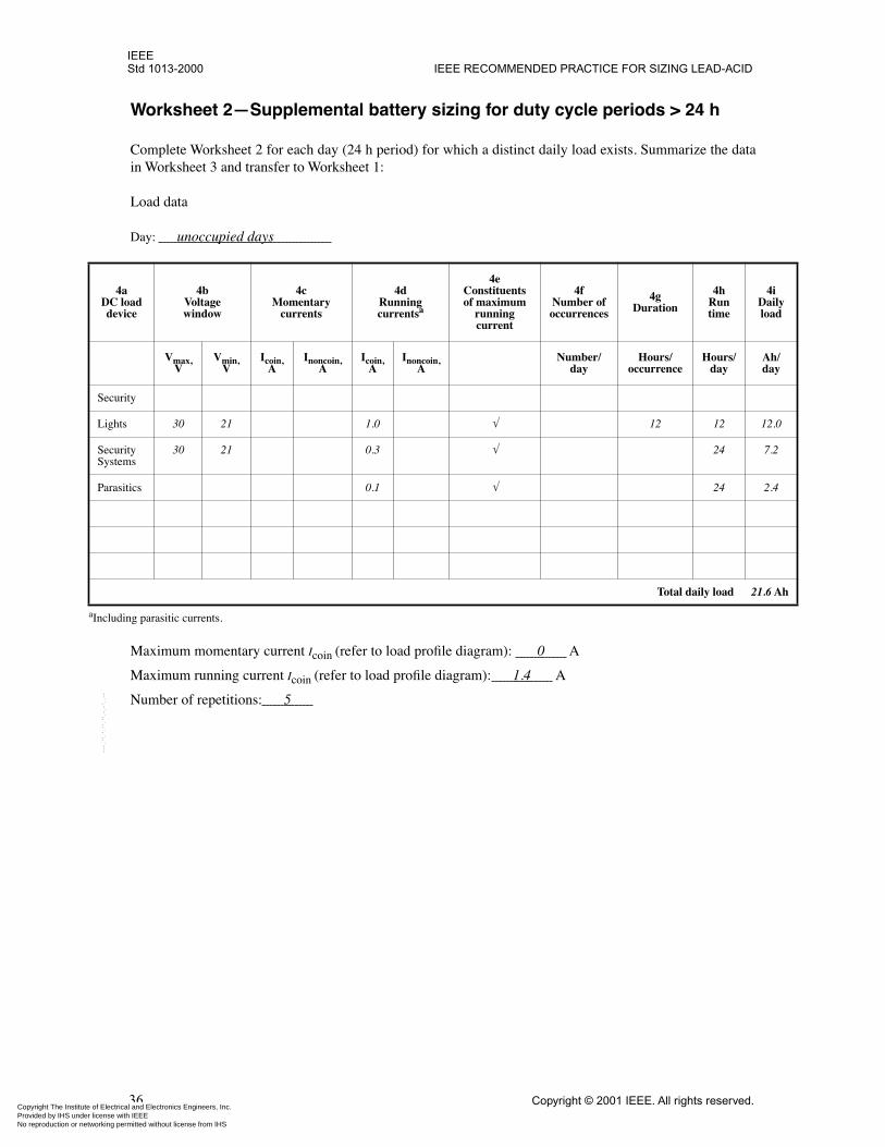
IEEEStd 1013-2000 IEEE RECOMMENDED PRACTICE FOR SIZING LEAD-ACID
4DCde
aInclud
iily ad
h/y
Secu
Ligh .0
SecuSyst
.2
Para .4
Ah
Copyright The Institute of ElectrProvided by IHS under license wNo reproduction or networking p
--``,-`-`,,`,,`,`,,`---
Worksheet 2—Supplemental battery sizing for duty cycle periods > 24 h
Complete Worksheet 2 for each day (24 h period) for which a distinct daily load exists. Summarize the datain Worksheet 3 and transfer to Worksheet 1:
Load data
Day: unoccupied days
Maximum momentary current Icoin (refer to load profile diagram): 0 A
Maximum running current Icoin (refer to load profile diagram): 1.4 A
Number of repetitions: 5
a load vice
4b Voltagewindow
4cMomentary
currents
4dRunning currentsa
ing parasitic currents.
4eConstituents of maximum
running current
4fNumber of occurrences
4gDuration
4hRun time
4Dalo
Vmax,V
Vmin,V
Icoin,A
Inoncoin,A
Icoin,A
Inoncoin,A
Number/day
Hours/occurrence
Hours/day
Ada
rity
ts 30 21 1.0 √ 12 12 12
rity ems
30 21 0.3 √ 24 7
sitics 0.1 √ 24 2
Total daily load 21.6
36 Copyright © 2001 IEEE. All rights reserved.ical and Electronics Engineers, Inc. ith IEEE
Not for Resaleermitted without license from IHS
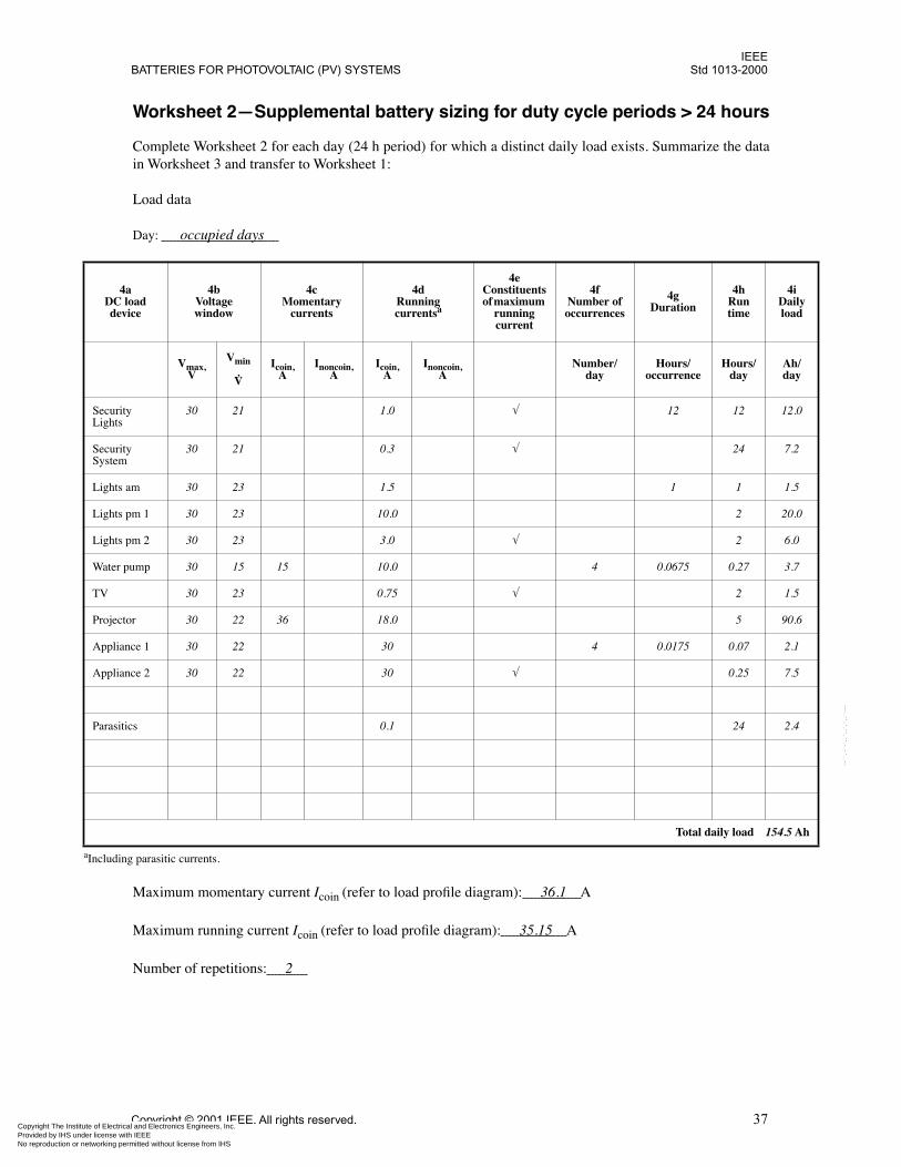
IEEEBATTERIES FOR PHOTOVOLTAIC (PV) SYSTEMS Std 1013-2000
DCde
aIncludi
4iaily oad
Ah/day
SecuriLights
2.0
SecuriSystem
7.2
Lights 1.5
Lights 0.0
Lights 6.0
Water 3.7
TV 1.5
Projec 0.6
Applia 2.1
Applia 7.5
Parasi 2.4
.5 Ah
Copyright The Institute of ElectrProvided by IHS under license wNo reproduction or networking p
--``,-`-`,,`,,`,`,,`---
Worksheet 2—Supplemental battery sizing for duty cycle periods > 24 hours
Complete Worksheet 2 for each day (24 h period) for which a distinct daily load exists. Summarize the datain Worksheet 3 and transfer to Worksheet 1:
Load data
Day: occupied days
Maximum momentary current Icoin (refer to load profile diagram): 36.1 A
Maximum running current Icoin (refer to load profile diagram): 35.15 A
Number of repetitions: 2
4a load vice
4b Voltagewindow
4cMomentary
currents
4dRunning currentsa
ng parasitic currents.
4eConstituents of maximum
running current
4fNumber of occurrences
4gDuration
4hRun time
Dl
Vmax,V
Vmin,
V
Icoin,A
Inoncoin,A
Icoin,A
Inoncoin,A
Number/day
Hours/occurrence
Hours/day
ty 30 21 1.0 √ 12 12 1
ty 30 21 0.3 √ 24
am 30 23 1.5 1 1
pm 1 30 23 10.0 2 2
pm 2 30 23 3.0 √ 2
pump 30 15 15 10.0 4 0.0675 0.27
30 23 0.75 √ 2
tor 30 22 36 18.0 5 9
nce 1 30 22 30 4 0.0175 0.07
nce 2 30 22 30 √ 0.25
tics 0.1 24
Total daily load 154
Copyright © 2001 IEEE. All rights reserved. 37ical and Electronics Engineers, Inc. ith IEEE
Not for Resaleermitted without license from IHS
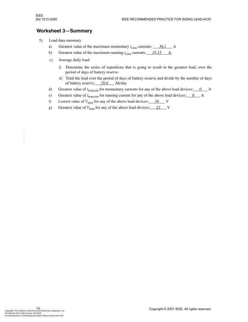
IEEEStd 1013-2000 IEEE RECOMMENDED PRACTICE FOR SIZING LEAD-ACID
Copyright The Institute of ElectrProvided by IHS under license wNo reproduction or networking p
--``,-`-`,,`,,`,`,,`---
Worksheet 3—Summary
5) Load data summary
a) Greatest value of the maximum momentary Icoin currents: 36.1 A
b) Greatest value of the maximum running Icoin currents: 35.15 A
c) Average daily load:
i) Determine the series of repetitions that is going to result in the greatest load, over theperiod of days of battery reserve.
ii) Total the load over the period of days of battery reserve and divide by the number of daysof battery reserve: 59.6 Ah/day
d) Greatest value of Inoncoin for momentary currents for any of the above load devices: 0 A
e) Greatest value of Inoncoin for running current for any of the above load devices: 0 A
f) Lowest value of Vmax for any of the above load devices: 30 V
g) Greatest value of Vmin for any of the above load devices: 23 V
38 Copyright © 2001 IEEE. All rights reserved.ical and Electronics Engineers, Inc. ith IEEE
Not for Resaleermitted without license from IHS
IEEEBATTERIES FOR PHOTOVOLTAIC (PV) SYSTEMS Std 1013-2000
Copyright The Institute of ElectrProvided by IHS under license wNo reproduction or networking p
Annex C
(informative)
Bibliography
[B1] IEEE 100, The Authoritative Dictionary of IEEE Standards Terms, Seventh Edition.
[B2] IEEE Std 928-1986 (Reaff 1991), IEEE Recommended Criteria for Terrestrial Photovoltaic PowerSystems.
[B3] IEEE Std 929-2000, IEEE Recommended Practice for Utility Interface of Residential and IntermediatePhotovoltaic (PV) Systems.
Copyright © 2001 IEEE. All rights reserved. 39ical and Electronics Engineers, Inc. ith IEEE
Not for Resaleermitted without license from IHS
--``,-`-`,,`,,`,`,,`---