identification guide gm 6l45, 6l50, 6l80, 6l90 · gm 6l45, 6l50, 6l80, 6l90 figure 1 figure 2...
TRANSCRIPT
©2017 Sonnax Industries, Inc. 6L45-6L90-Identify_D 01-24-17
800-843-2600 • 802-463-9722 • F: 802-463-4059 • www.sonnax.com Page 1
Identification Guide
GM 6L45, 6L50, 6L80, 6L90
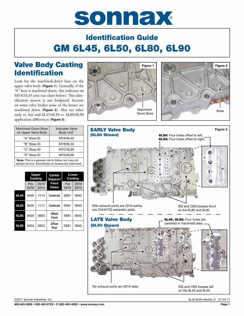
Figure 2Figure 1
Machined- Down Boss
Valve Body Casting IdentificationLook for the machined-down boss on the upper valve body (Figure 1). Generally, if the “A” boss is machined down, this indicates an MYA/6L45 unit (see chart below). This iden-tification system is not foolproof, because on some valve bodies none of the bosses are machined down (Figure 2). Also see other early vs. late and 6L45/6L50 vs. 6L80/6L90 application differences (Figure 3).
Machined-Down Boss on Upper Valve Body
Indicates Valve Body Unit*
“A” Boss ID MYA/6L45
“B” Boss ID MYB/6L50
“C” Boss ID MYC/6L80
“D” Boss ID MYD/6L90
*Note: This is a general rule to follow, but may not always be true. Sometimes no bosses are machined.
Boss
Upper Casting
Center Support
Feed Holes
Lower Casting
Pre 2010
2010 - 2015
Pre 2010
2010 - 2015
6L45 9405 7114 Centered 9581 0945
6L50 9405 7117 Centered 9581 0945
6L80 9404 0955Offset Front
9581 0945
6L90 9404 0955Offset Rear
9581 0945
With exhaust ports are 2010-earlier, use 24245720 separator plate.
ISS and OSS bosses short on the 6L80 and 6L90.
No exhaust ports are 2010–later. ISS and OSS bosses tall on the 6L45 and 6L50.
Figure 3
6L80: Four holes offset to left. 6L90: Four holes offset to right.
6L45, 6L50: Four holes are centered in machined area.
LATE Valve Body (6L50 Shown)
EARLY Valve Body (6L80 Shown)
GM 6L45, 6L50, 6L80, 6L90 Identification Guide
©2017 Sonnax Industries, Inc. 6L45-6L90-Identify_D 01-24-17
800-843-2600 • 802-463-9722 • F: 802-463-4059 • www.sonnax.com Page 2
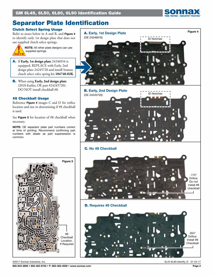
Clutch Select Spring UsageRefer to notes below in A and B, and Figure 4 to identify early 1st design plate that does not use supplied clutch select springs. NOTE: All other plate designs can use supplied springs.
A. If Early, 1st design plate 24246916 is equipped, REPLACE with Early, 2nd design plate 24245720 and install Sonnax clutch select valve spring kit 104740-02K.
B. When using Early, 2nd design plate (2010-Earlier, OE part #24245720): DO NOT install checkball #8.
#8 Checkball UsageReference Figure 4 images C and D for orifice location and size in determining if #8 checkball is used.
See Figure 5 for location of #8 checkball when necessary.NOTE: OE separator plate part numbers correct at time of printing. Recommend confirming part numbers with dealer as part supersession is common.
Figure 4A. Early, 1st Design Plate (OE 24246916)
B. Early, 2nd Design Plate (OE 24245720)
ID Notches
D. Requires #8 Checkball
.054"Orifice:
Install #8Checkball
C. No #8 Checkball
Figure 5
#8 Checkball Location,
If Required
ID Notches
.175"Orifice:Do not
install #8 checkball
Separator Plate Identification
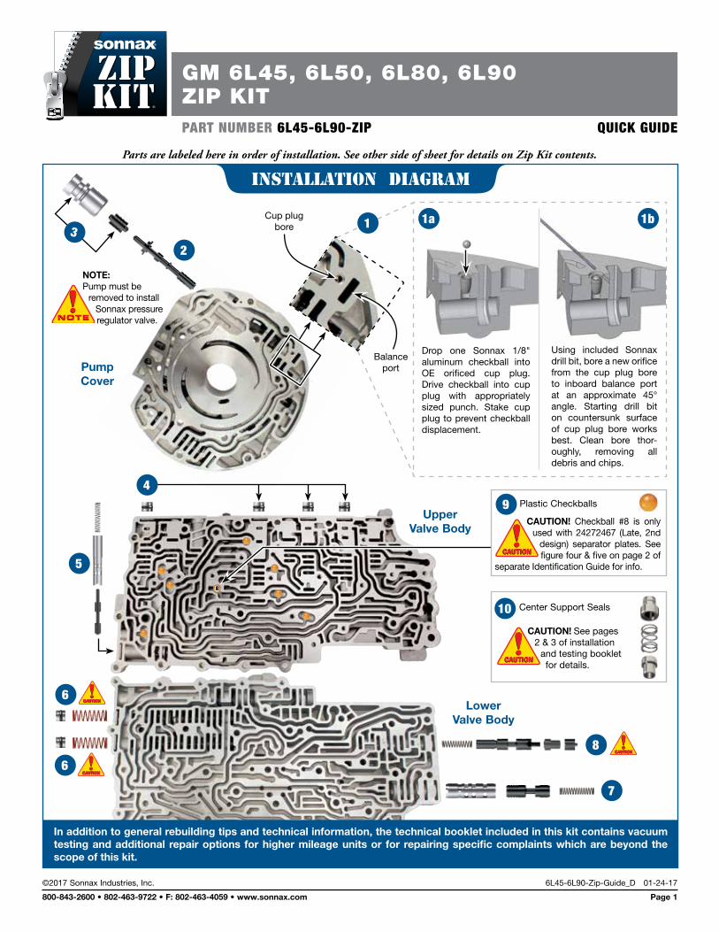
PART NUMBER 6L45-6L90-ZIP QUICK GUIDE
NOTE: Pump must be
removed to install Sonnax pressure regulator valve.
23
1a
Lower Valve Body
7
8CAUTIONCAUTIONCAUTIONCAUTION
10
CAUTION! See pages 2 & 3 of installation
and testing booklet for details.
CAUTIONCAUTIONCAUTIONCAUTION
Upper Valve Body
5
4
6CAUTIONCAUTIONCAUTIONCAUTION
6CAUTIONCAUTIONCAUTIONCAUTION
1b
Drop one Sonnax 1/8" aluminum checkball into OE orificed cup plug. Drive checkball into cup plug with appropriately sized punch. Stake cup plug to prevent checkball displacement.
1Cup plug
bore
Balance port
8
Center Support Seals
Pump Cover
Plastic Checkballs9CAUTION! Checkball #8 is only
used with 24272467 (Late, 2nd design) separator plates. See figure four & five on page 2 of
separate Identification Guide for info.
CAUTIONCAUTIONCAUTIONCAUTION
Using included Sonnax drill bit, bore a new orifice from the cup plug bore to inboard balance port at an approximate 45° angle. Starting drill bit on countersunk surface of cup plug bore works best. Clean bore thor-oughly, removing all debris and chips.
©2017 Sonnax Industries, Inc. 6L45-6L90-Zip-Guide_D 01-24-17
800-843-2600 • 802-463-9722 • F: 802-463-4059 • www.sonnax.com Page 1
GM 6L45, 6L50, 6L80, 6L90ZIP KIT
Parts are labeled here in order of installation. See other side of sheet for details on Zip Kit contents.
installation Diagram
In addition to general rebuilding tips and technical information, the technical booklet included in this kit contains vacuum testing and additional repair options for higher mileage units or for repairing specific complaints which are beyond the scope of this kit.
GM 6L45, 6L50, 6L80, 6L90 ZIP KIT Quick Guide
©2017 Sonnax Industries, Inc. 6L45-6L90-Zip-Guide_D 01-24-17
800-843-2600 • 802-463-9722 • F: 802-463-4059 • www.sonnax.com Page 2
Step Reroute Pressure Regulator Valve Balance Feed
NOTE: Pump must be removed to install Sonnax pressure regulator valve. Remove all components from bore prior to proceeding. Following steps required for use of Sonnax valve.
Drop one Sonnax 1/8" aluminum checkball into OE orificed cup plug. Drive checkball into cup plug with appropriately sized punch. Stake cup plug to prevent checkball displacement.
Using included Sonnax drill bit, bore a new orifice from the cup plug bore to inboard balance port at an approximate 45° angle. Starting drill bit on countersunk surface of cup plug bore works best. Clean bore thoroughly, removing all debris and chips.
Packaging Pocket 1
• Drill Bit, .039" dia. • Checkball, 1/8" (2) 1 Extra
Step Replace OE Pressure Regulator Valve
Re-use OE springs.
Packaging Pocket 2
Pressure Regulator Valve
Step Replace OE Boost Assembly
Packaging Pocket 3
• Boost Valve • Boost Sleeve
Step Replace Upper Valve Body OE End Plugs
Place O-ring in groove, lubricate with Sonnax Slippery Stick™ O-LUBE and roll on bench to size.
Packaging Pocket 4
• End Plugs (4) • O-Rings (6) 2 extra
Step Replace OE Actuator Feed Limit Valve
Sleeve installs with end grooves inboard. Valve installs with spring stem outboard.
Packaging Pocket 5
• Valve • Sleeve • Spring
1
1a
1b
2
3
4
5
Step Replace Clutch Select Valve #2 & #3 Springs & End Plugs
Sonnax clutch select valve springs can be used with all OE separator plates EXCEPT separator plate 24246916 (Early, 1st design). If sepa-
rator plate 24246916 is equipped, it must be upgraded with OE plate 24245720 (Early, 2nd design) to prevent code P0751, shift concerns and burnt/slipping 1-2-3-4 and/or 3-5-Reverse clutches. See Figures 3 and 4 on separate Identification Guide for information.
Packaging Pocket 6
• Springs (2) • End Plugs (2) • O-Rings (3) 1 extra
Step Replace Compensator Feed Regulator Valve
Sleeve installs with end grooves inboard. Valve installs with spring pocket outboard.
Packaging Pocket 7
• Valve • Sleeve • Spring
Step Replace TCC Regulator Valve Lineup
Clocking/Rotational alignment of components are critical. See page 2 of installation and testing booklet for details.
Packaging Pocket 8
• Spring • TCC Regulator Valve • Shuttle Valve • End Plug
Step Replace OE CheckballsPackaging Pocket 9
Checkballs, .250" dia. (8)NOTE: Not all checkballs used on all castings. See warning on page 1 of this Quick Guide.
Step Install Center Support Seals See pages 2 & 3 of installation and testing booklet for details.
Packaging Pocket 10
• Seal Inserts (8) • Springs (6)
Step Vacuum TestingUse nut for testing pump body pressure regulator valve. Block valve outboard as shown on page 5 of installation and testing booklet. Remove nut after testing.
Packaging Pocket 11
• Nut, .125"
6
CAUTIONCAUTIONCAUTIONCAUTION
7
8
CAUTIONCAUTIONCAUTIONCAUTION
9
10
CAUTIONCAUTIONCAUTIONCAUTION
11
Zip Kit Contents & Installation Steps
Cautions
Control Solenoid Valve AssemblyUse care when handling the control solenoid valve assembly (valve body and TCM or TEHCM). If dropped, roughly handled, or exposed to excessive dust and debris, damage could occur to the TEHCM. A thorough inspection and cleaning of the TEHCM should be included in any rebuild procedure, and is detailed on page 3.
The control solenoid valve assembly must be removed prior to removing the converter housing and pump assem-bly. Severe component damage will result if not followed.
Fast Learn Adapts Following installation of the Zip Kit, the Service Fast Learn Adapts procedure must be performed. Follow instruction on the scan tool or reference OE specifica-tions for details on the procedure.
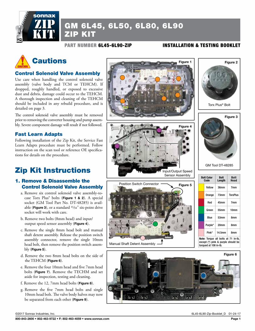
Zip Kit Instructions1. Remove & Disassemble the
Control Solenoid Valve Assemblya. Remove six control solenoid valve assembly-to-
case Torx Plus® bolts (Figure 1 & 2). A special socket (GM Tool Part No. DT-48285) is avail-able (Figure 3), or a standard 11/32" six-point drive socket will work with care.
b. Remove two bolts (8mm head) and input/output speed sensor assembly (Figure 4).
c. Remove the single 8mm head bolt and manual shaft detent assembly. Release the position switch assembly connector, remove the single 10mm head bolt, then remove the position switch assem-bly (Figure 5).
d. Remove the two 8mm head bolts on the side of the TEHCM (Figure 6).
e. Remove the four 10mm head and five 7mm head bolts (Figure 7). Remove the TECHM and set aside for inspection, testing and cleaning.
f. Remove the 12, 7mm head bolts (Figure 8).g. Remove the five 7mm head bolts and single
10mm head bolt. The valve body halves may now be separated from each other (Figure 9).
CAUTIONCAUTIONCAUTIONCAUTION
Figure 1
Figure 3
GM Tool DT-48285
Figure 2
Torx Plus® Bolt
Figure 4
Input/Output Speed Sensor Assembly
Figure 5Position Switch Connector
Manual Shaft Detent Assembly
Bolt Color Code
Bolt Length
Bolt Head
Yellow 36mm 7mm
Orange 73mm TorxPlus
Red 45mm 7mm
Green 55mm 10mm
Blue 53mm 8mm
Purple* 20mm 8mm
Pink* 14.5mm 8mm
Note: Torque all bolts at 71 in-lb, except (*) pink & purple should be torqued at 106 in-lb.
Figure 6
GM 6L45, 6L50, 6L80, 6L90ZIP KITPART NUMBER 6L45-6L90-ZIP INSTALLATION & TESTING BOOKLET
©2017 Sonnax Industries, Inc. 6L45-6L90-Zip-Booklet_D 01-24-17
800-843-2600 • 802-463-9722 • F: 802-463-4059 • www.sonnax.com Page 1
6L45, 6L50, 6L80, 6L90 ZIP KIT Installation & Testing Booklet
01-24-17 6L45-6L90-Zip-Booklet_D ©2017 Sonnax Industries, Inc.
Page 2 800-843-2600 • 802-463-9722 • F: 802-463-4059 • www.sonnax.com
TIME TESTED • INDUSTRY TRUSTED
Zip Kit Instructions (continued)
2. Pump Disassembly & AssemblyRemove 13 pump-cover-assembly-to-torque-converter-housing bolts. For reassem-bly, torque bolts in the sequence shown to 97 in-lb (Figure 10).
3. InstallationInstall Zip Kit parts as shown on diagram of separate quick guide sheet included in this Zip Kit. Sonnax recommends vacuum testing critical wear areas not covered by this kit to determine whether additional Sonnax parts are required (see pages 5–6).
Zip Kit Quick Guide Details1. Replace TCC Regulator Valve Lineup Clocking/rotational alignment of components from step 8 is critical, see diagram for proper alignment (Figure 11).
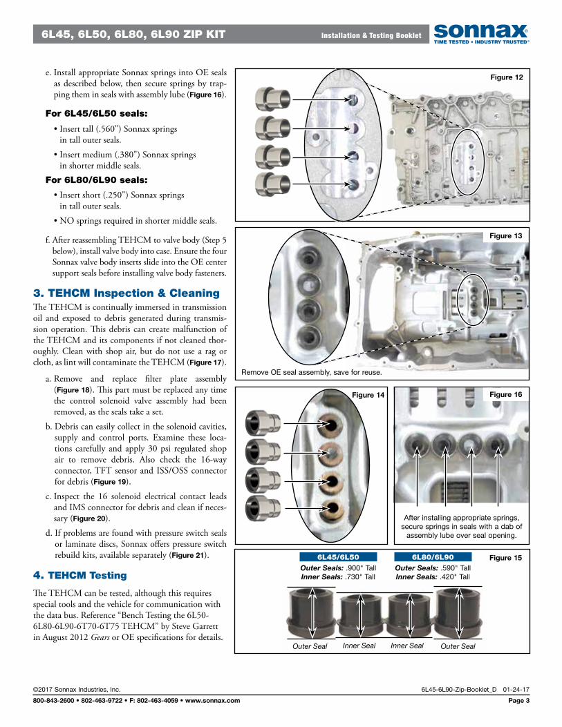
2. Center Support Seal Reinforcement Insert Installationa. Install four Sonnax valve body seal inserts (non-grooved, non-threaded) into
the back side of valve body. Use appropriately sized flat punch to lightly tap inserts into place. Shoulder on insert will seat flush against the finished valve body surface (Figure 12).
b. Remove OE center support seal assembly from case and set aside for reuse (Figure 13).
c. Install four Sonnax case seal inserts (grooved and threaded) into the case at the center support location (Figure 14). Use appropriately sized flat punch to lightly tap inserts into place. Shoulder on insert will seat flush.
TECH TIP: Threads are provided for removal of case inserts when necessary to allow center support removal.
d. Reinstall OE center support seals over Sonnax case seal inserts.
NOTE: 6L45 and 6L50 center support seals are approximately .900” tall (outer) and .730” tall (inner). 6L80 and 6L90 unit seals are shorter, approximately .590” tall (outer) and .420” tall (inner) (Figure 15).
TECHTIP!TECHTIP!
Figure 10
1
2
3
4
5
6
7
8
9
10
11
12
13
Figure 11
FLATS Face Upward
Critical TCC Regulator Valve Line-up Clocking/Rotational
Alignment
Retainer slot holds plug boss
VERTICAL.
Figure 7
Figure 9
Figure 812 8 6 4 2
1
10
11 97 3 5
6L45, 6L50, 6L80, 6L90 ZIP KIT Installation & Testing Booklet
©2017 Sonnax Industries, Inc. 6L45-6L90-Zip-Booklet_D 01-24-17
800-843-2600 • 802-463-9722 • F: 802-463-4059 • www.sonnax.com Page 3
TIME TESTED • INDUSTRY TRUSTED
e. Install appropriate Sonnax springs into OE seals as described below, then secure springs by trap-ping them in seals with assembly lube (Figure 16).
For 6L45/6L50 seals:
• Insert tall (.560") Sonnax springs in tall outer seals.
• Insert medium (.380") Sonnax springs in shorter middle seals.
For 6L80/6L90 seals:
• Insert short (.250") Sonnax springs in tall outer seals.
• NO springs required in shorter middle seals.
f. After reassembling TEHCM to valve body (Step 5 below), install valve body into case. Ensure the four Sonnax valve body inserts slide into the OE center support seals before installing valve body fasteners.
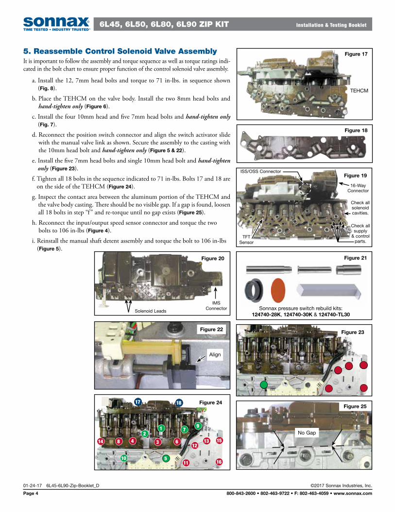
3. TEHCM Inspection & CleaningThe TEHCM is continually immersed in transmission oil and exposed to debris generated during transmis-sion operation. This debris can create malfunction of the TEHCM and its components if not cleaned thor-oughly. Clean with shop air, but do not use a rag or cloth, as lint will contaminate the TEHCM (Figure 17).
a. Remove and replace filter plate assembly (Figure 18). This part must be replaced any time the control solenoid valve assembly had been removed, as the seals take a set.
b. Debris can easily collect in the solenoid cavities, supply and control ports. Examine these loca-tions carefully and apply 30 psi regulated shop air to remove debris. Also check the 16-way connector, TFT sensor and ISS/OSS connector for debris (Figure 19).
c. Inspect the 16 solenoid electrical contact leads and IMS connector for debris and clean if neces-sary (Figure 20).
d. If problems are found with pressure switch seals or laminate discs, Sonnax offers pressure switch rebuild kits, available separately (Figure 21).
4. TEHCM Testing
The TEHCM can be tested, although this requires special tools and the vehicle for communication with the data bus. Reference “Bench Testing the 6L50-6L80-6L90-6T70-6T75 TEHCM” by Steve Garrett in August 2012 Gears or OE specifications for details.
Figure 13
Remove OE seal assembly, save for reuse.
Figure 12
Figure 14
After installing appropriate springs, secure springs in seals with a dab of
assembly lube over seal opening.
Figure 16
Figure 15
Outer Seal Inner Seal Inner Seal Outer Seal
6L80/6L90Outer Seals: .590" TallInner Seals: .420" Tall
6L45/6L50Outer Seals: .900" TallInner Seals: .730" Tall
6L45, 6L50, 6L80, 6L90 ZIP KIT Installation & Testing Booklet
01-24-17 6L45-6L90-Zip-Booklet_D ©2017 Sonnax Industries, Inc.
Page 4 800-843-2600 • 802-463-9722 • F: 802-463-4059 • www.sonnax.com
TIME TESTED • INDUSTRY TRUSTED
Figure 21
Sonnax pressure switch rebuild kits: 124740-28K, 124740-30K & 124740-TL30
TEHCM
Figure 17
Figure 18
Figure 25
No Gap
5. Reassemble Control Solenoid Valve AssemblyIt is important to follow the assembly and torque sequence as well as torque ratings indi-cated in the bolt chart to ensure proper function of the control solenoid valve assembly.
a. Install the 12, 7mm head bolts and torque to 71 in-lbs. in sequence shown (Fig. 8).
b. Place the TEHCM on the valve body. Install the two 8mm head bolts and hand-tighten only (Figure 6).
c. Install the four 10mm head and five 7mm head bolts and hand-tighten only (Fig. 7).
d. Reconnect the position switch connector and align the switch activator slide with the manual valve link as shown. Secure the assembly to the casting with the 10mm head bolt and hand-tighten only (Figure 5 & 22).
e. Install the five 7mm head bolts and single 10mm head bolt and hand-tighten only (Figure 23).
f. Tighten all 18 bolts in the sequence indicated to 71 in-lbs. Bolts 17 and 18 are on the side of the TEHCM (Figure 24).
g. Inspect the contact area between the aluminum portion of the TEHCM and the valve body casting. There should be no visible gap. If a gap is found, loosen all 18 bolts in step “f” and re-torque until no gap exists (Figure 25).
h. Reconnect the input/output speed sensor connector and torque the two bolts to 106 in-lbs (Figure 4).
i. Reinstall the manual shaft detent assembly and torque the bolt to 106 in-lbs (Figure 5).
Figure 22
Align
Figure 23
510
12
11 16
13 1514 8 4 3 6
21 7
9
17 18 Figure 24
Figure 19
Check all solenoid cavities.
TFT Sensor
ISS/OSS Connector
16-WayConnector
Check all supply
& control parts.
Figure 20
IMS ConnectorSolenoid Leads
6L45, 6L50, 6L80, 6L90 ZIP KIT Installation & Testing Booklet
©2017 Sonnax Industries, Inc. 6L45-6L90-Zip-Booklet_D 01-24-17
800-843-2600 • 802-463-9722 • F: 802-463-4059 • www.sonnax.com Page 5
TIME TESTED • INDUSTRY TRUSTED
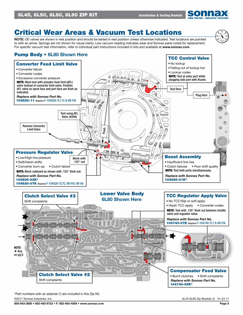
Critical Wear Areas & Vacuum Test Locations NOTE: OE valves are shown in rest position and should be tested in rest position unless otherwise indicated. Test locations are pointed to with an arrow. Springs are not shown for visual clarity. Low vacuum reading indicates wear and Sonnax parts noted for replacement. For specific vacuum test information, refer to individual part instructions included in kits and available at www.sonnax.com.
Pump Body • 6L80 Shown Here
20
25
15
0
10
5
30VACUUMTEST
Remove Converter Limit Valve
Test using AFL Valve (#209)
Plug Here
Test Here
TCC Control Valve• No lockup• Falling out of lockup hot• Lockup codesNOTE: Test at valve port while plugging side port with thumb.
Boost Assembly• Insufficient line rise• Clutch failures • Poor shift qualityNOTE: Test both ports simultaneously.
Replace with Sonnax Part No.104520-01K*
Pressure Regulator Valve• Low/High line pressure• Soft/Harsh shifts• Converter burn-up • Clutch failure
NOTE: Block outboard as shown with .125" thick nut.Replace with Sonnax Part No.104520-03K* 104520-07K Requires F-104520-TL7C, VB-FIX, VB-06
Block with .125" nut
Lower Valve Body 6L80 Shown Here
Clutch Select Valve #2Shift complaints
Clutch Select Valve #3Shift complaints
Compensater Feed Valve• Burnt clutches • Shift complaintsReplace with Sonnax Part No.104740-09K*
Flus
h
Converter Feed Limit Valve• Converter failure• Converter codes• Excessive converter pressureNOTE: Must test with actuator feed limit (AFL) valve instead of converter limit valve. Position AFL valve so spool face and port face are flush as indicated.Replace with Sonnax Part No.104520-11 Requires F-104520-TL11C & VB-FIX
TCC Regulator Apply Valve• No TCC/Slip or soft apply• Harsh TCC apply • Converter codes
NOTE: Test with .125" thick nut between shuttle valve and regulator valve.
Replace with Sonnax Part No.104740-07K Requires F-104740-TL7 & VB-FIX
NOTE: Key on pg 6
*Part numbers with an asterisk (*) are included in this Zip Kit.
6L45, 6L50, 6L80, 6L90 ZIP KIT Installation & Testing Booklet
01-24-17 6L45-6L90-Zip-Booklet_D ©2017 Sonnax Industries, Inc.
Page 6 800-843-2600 • 802-463-9722 • F: 802-463-4059 • www.sonnax.com
TIME TESTED • INDUSTRY TRUSTED
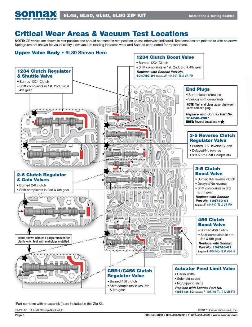
*Part numbers with an asterisk (*) are included in this Zip Kit.
Critical Wear Areas & Vacuum Test Locations NOTE: OE valves are shown in rest position and should be tested in rest position unless otherwise indicated. Test locations are pointed to with an arrow. Springs are not shown for visual clarity. Low vacuum reading indicates wear and Sonnax parts noted for replacement.
Upper Valve Body • 6L80 Shown Here
456 Clutch Boost Valve• Burned 456 clutch• Shift complaints in 4th,
5th & 6th gearReplace with Sonnax Part No. 104740-01
Requires F-104740-TL & VB-FIX
3-5 Clutch Boost Valve• Burned 3-5 reverse clutch• Delayed/No reverse• Shift complaints in 3rd
& 5th gearReplace with Sonnax Part No. 104740-01
Requires F-104740-TL & VB-FIX
Insets shown with end plugs removed for clarity only. Test with end plugs installed.
CBR1/C456 Clutch Regulator Valve• Burned 456 clutch• Shift complaints in 4th, 5th
& 6th gear
2-6 Clutch Regulator & Gain Valves• Burned 2-6 clutch• Shift complaints in 2nd & 6th gear
End Plugs• Burnt clutches/brakes• Various shift complaints
NOTE: Test end plugs at port between valve and end plug.
Replace with Sonnax Part No.104740-23K* NOTE: Several Locations =
1234 Clutch Regulator & Shuttle Valve• Burned 1234 Clutch• Shift complaints in 1st, 2nd, 3rd &
4th gear
1234 Clutch Boost Valve• Burned 1234 Clutch• Shift complaints in 1st, 2nd, 3rd & 4th gearReplace with Sonnax Part No.104740-01 Requires F-104740-TL & VB-FIX
3-5 Reverse Clutch Regulator Valve• Burned 3-5 Reverse Clutch• Delayed/No reverse• 3rd & 5th Shift Complaints
Actuator Feed Limit Valve• Harsh shifts• Solenoid codes• No/Slipping shiftsReplace with Sonnax Part No.104740-12 Requires F-104740-TL12 & VB-FIX
6L45, 6L50, 6L80, 6L90 ZIP KIT Installation & Testing Booklet
©2017 Sonnax Industries, Inc. 6L45-6L90-Zip-Booklet_D 01-24-17
800-843-2600 • 802-463-9722 • F: 802-463-4059 • www.sonnax.com Page 7
TIME TESTED • INDUSTRY TRUSTED
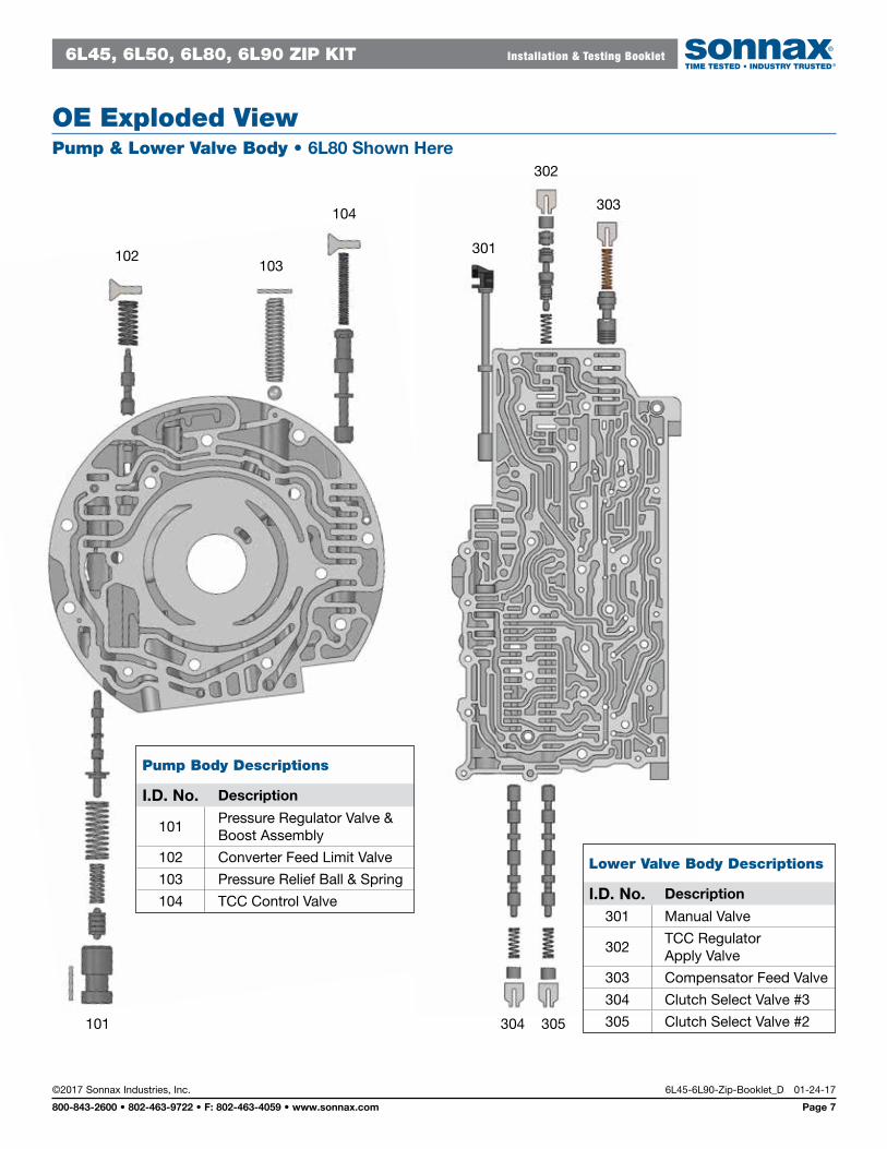
OE Exploded ViewPump & Lower Valve Body • 6L80 Shown Here
Pump Body Descriptions
I.D. No. Description
101Pressure Regulator Valve & Boost Assembly
102 Converter Feed Limit Valve
103 Pressure Relief Ball & Spring
104 TCC Control Valve
Lower Valve Body Descriptions
I.D. No. Description
301 Manual Valve
302TCC Regulator Apply Valve
303 Compensator Feed Valve
304 Clutch Select Valve #3
305 Clutch Select Valve #2
301
302
303
305304101
102103
104
6L45, 6L50, 6L80, 6L90 ZIP KIT Installation & Testing Booklet
01-24-17 6L45-6L90-Zip-Booklet_D ©2017 Sonnax Industries, Inc.
Page 8 800-843-2600 • 802-463-9722 • F: 802-463-4059 • www.sonnax.com
TIME TESTED • INDUSTRY TRUSTED
201
202
203
204
205
206
207
208
209
C AUTION! Do Not Remove! The plug is set at a precise depth at the factory.
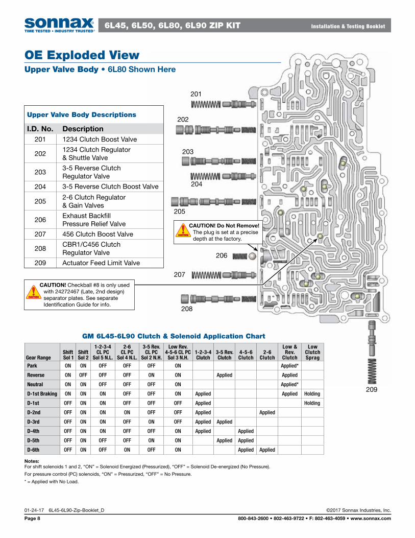
OE Exploded ViewUpper Valve Body • 6L80 Shown Here
Upper Valve Body Descriptions
I.D. No. Description201 1234 Clutch Boost Valve
2021234 Clutch Regulator & Shuttle Valve
2033-5 Reverse Clutch Regulator Valve
204 3-5 Reverse Clutch Boost Valve
2052-6 Clutch Regulator & Gain Valves
206Exhaust Backfill Pressure Relief Valve
207 456 Clutch Boost Valve
208CBR1/C456 Clutch Regulator Valve
209 Actuator Feed Limit Valve
GM 6L45-6L90 Clutch & Solenoid Application Chart
Gear RangeShift Sol 1
Shift Sol 2
1-2-3-4 CL PC
Sol 5 N.L.
2-6 CL PC
Sol 4 N.L.
3-5 Rev. CL PC
Sol 2 N.H.
Low Rev. 4-5-6 CL PC Sol 3 N.H.
1-2-3-4 Clutch
3-5 Rev. Clutch
4-5-6 Clutch
2-6 Clutch
Low & Rev.
Clutch
Low Clutch Sprag
Park ON ON OFF OFF OFF ON Applied*
Reverse ON OFF OFF OFF ON ON Applied Applied
Neutral ON ON OFF OFF OFF ON Applied*
D-1st Braking ON ON ON OFF OFF ON Applied Applied Holding
D-1st OFF ON ON OFF OFF OFF Applied Holding
D-2nd OFF ON ON ON OFF OFF Applied Applied
D-3rd OFF ON ON OFF ON OFF Applied Applied
D-4th OFF ON ON OFF OFF ON Applied Applied
D-5th OFF ON OFF OFF ON ON Applied Applied
D-6th OFF ON OFF ON OFF ON Applied Applied
Notes: For shift solenoids 1 and 2, “ON” = Solenoid Energized (Pressurized), “OFF” = Solenoid De-energized (No Pressure).
For pressure control (PC) solenoids, “ON” = Pressurized, “OFF” = No Pressure.
* = Applied with No Load.
CAUTIONCAUTIONCAUTIONCAUTION
C AUTION! Checkball #8 is only used with 24272467 (Late, 2nd design) separator plates. See separate Identification Guide for info.
CAUTIONCAUTIONCAUTIONCAUTION