ibm tivoli storage tape drive
DESCRIPTION
TRANSCRIPT
ibm.com/redbooks
Front cover
Implementing IBM Tape in UNIX Systems
Charlotte BrooksAlv Jon HovdaReena Master
Abbe Woodcock
How to set up tape drives and libraries in multiple UNIX environments
New: Ultrium3 and WORM features
Integration with popular backup products

International Technical Support Organization
Implementing IBM Tape in UNIX Systems
October 2005
SG24-6502-03
© Copyright International Business Machines Corporation 2002, 2003, 2004, 2005. All rights reserved.Note to U.S. Government Users Restricted Rights -- Use, duplication or disclosure restricted by GSA ADP ScheduleContract with IBM Corp.
Fourth Edition (October 2005)
This edition applies to IBM TotalStorage 3580 Tape Drive, IBM TotalStorage 3581 Tape Autoloader, IBM TotalStorage 3581 2U Tape Autoloader, IBM TotalStorage 3582 Tape Library, IBM TotalStorage 3583 Tape Library, IBM TotalStorage 3584 Tape Library, and IBM TotalStorage 3592 Tape Drive.
Note: Before using this information and the product it supports, read the information in “Notices” on page xiii.

Contents
Figures . . . . . . . . . . . . . . . . . . . . . . . . . . . . . . . . . . . . . . . . . . . . . . . . . . . . . . . . . . . . . . . . . ix
Notices . . . . . . . . . . . . . . . . . . . . . . . . . . . . . . . . . . . . . . . . . . . . . . . . . . . . . . . . . . . . . . . . xiiiTrademarks . . . . . . . . . . . . . . . . . . . . . . . . . . . . . . . . . . . . . . . . . . . . . . . . . . . . . . . . . . . . . xiv
Preface . . . . . . . . . . . . . . . . . . . . . . . . . . . . . . . . . . . . . . . . . . . . . . . . . . . . . . . . . . . . . . . . .xvThe team that wrote this redbook. . . . . . . . . . . . . . . . . . . . . . . . . . . . . . . . . . . . . . . . . . . . . .xvBecome a published author . . . . . . . . . . . . . . . . . . . . . . . . . . . . . . . . . . . . . . . . . . . . . . . . . xviComments welcome. . . . . . . . . . . . . . . . . . . . . . . . . . . . . . . . . . . . . . . . . . . . . . . . . . . . . . . xvii
Summary of changes . . . . . . . . . . . . . . . . . . . . . . . . . . . . . . . . . . . . . . . . . . . . . . . . . . . . . xixOctober 2005, Fourth Edition . . . . . . . . . . . . . . . . . . . . . . . . . . . . . . . . . . . . . . . . . . . . . . . . xixJuly 2004, Third Edition . . . . . . . . . . . . . . . . . . . . . . . . . . . . . . . . . . . . . . . . . . . . . . . . . . . . xix
Part 1. Setting up IBM tape in UNIX. . . . . . . . . . . . . . . . . . . . . . . . . . . . . . . . . . . . . . . . . . . . . . . . . . . . . . . 1
Chapter 1. Introduction to LTO Ultrium with UNIX . . . . . . . . . . . . . . . . . . . . . . . . . . . . . . 31.1 LTO overview . . . . . . . . . . . . . . . . . . . . . . . . . . . . . . . . . . . . . . . . . . . . . . . . . . . . . . . . . 4
1.1.1 IBM TotalStorage LTO Ultrium models . . . . . . . . . . . . . . . . . . . . . . . . . . . . . . . . . . 51.1.2 IBM TotalStorage 3580 Tape Drive. . . . . . . . . . . . . . . . . . . . . . . . . . . . . . . . . . . . . 71.1.3 IBM TotalStorage 3581 Tape Autoloader . . . . . . . . . . . . . . . . . . . . . . . . . . . . . . . . 91.1.4 IBM TotalStorage 3581 2U Tape Autoloader . . . . . . . . . . . . . . . . . . . . . . . . . . . . 101.1.5 IBM TotalStorage 3582 Tape Library . . . . . . . . . . . . . . . . . . . . . . . . . . . . . . . . . . 111.1.6 IBM TotalStorage 3583 Tape Library . . . . . . . . . . . . . . . . . . . . . . . . . . . . . . . . . . 131.1.7 IBM TotalStorage 3584 Tape Library . . . . . . . . . . . . . . . . . . . . . . . . . . . . . . . . . . 18
1.2 Hardware and operating system platforms . . . . . . . . . . . . . . . . . . . . . . . . . . . . . . . . . . 271.2.1 Hardware server platforms . . . . . . . . . . . . . . . . . . . . . . . . . . . . . . . . . . . . . . . . . . 271.2.2 ISV storage management software. . . . . . . . . . . . . . . . . . . . . . . . . . . . . . . . . . . . 28
1.3 Connectivity. . . . . . . . . . . . . . . . . . . . . . . . . . . . . . . . . . . . . . . . . . . . . . . . . . . . . . . . . . 281.3.1 SCSI direct attach . . . . . . . . . . . . . . . . . . . . . . . . . . . . . . . . . . . . . . . . . . . . . . . . . 281.3.2 SAN attach . . . . . . . . . . . . . . . . . . . . . . . . . . . . . . . . . . . . . . . . . . . . . . . . . . . . . . 291.3.3 Determining the number of drives on a SCSI bus. . . . . . . . . . . . . . . . . . . . . . . . . 30
1.4 Host Bus Adapters and device drivers . . . . . . . . . . . . . . . . . . . . . . . . . . . . . . . . . . . . . 311.5 LVD versus HVD . . . . . . . . . . . . . . . . . . . . . . . . . . . . . . . . . . . . . . . . . . . . . . . . . . . . . . 32
1.5.1 What are LVD and HVD? . . . . . . . . . . . . . . . . . . . . . . . . . . . . . . . . . . . . . . . . . . . 321.5.2 Why is this important?. . . . . . . . . . . . . . . . . . . . . . . . . . . . . . . . . . . . . . . . . . . . . . 33
1.6 SCSI HD68 and VHDCI cable connectors . . . . . . . . . . . . . . . . . . . . . . . . . . . . . . . . . . 33
Chapter 2. IBM LTO Tape Library sharing and partitioning. . . . . . . . . . . . . . . . . . . . . . 352.1 Definitions . . . . . . . . . . . . . . . . . . . . . . . . . . . . . . . . . . . . . . . . . . . . . . . . . . . . . . . . . . . 36
2.1.1 Library sharing . . . . . . . . . . . . . . . . . . . . . . . . . . . . . . . . . . . . . . . . . . . . . . . . . . . 362.1.2 Homogenous drive sharing . . . . . . . . . . . . . . . . . . . . . . . . . . . . . . . . . . . . . . . . . . 382.1.3 What should I use? . . . . . . . . . . . . . . . . . . . . . . . . . . . . . . . . . . . . . . . . . . . . . . . . 40
2.2 Partitioning multi-path tape libraries . . . . . . . . . . . . . . . . . . . . . . . . . . . . . . . . . . . . . . . 412.2.1 Partitioning the IBM 3582 . . . . . . . . . . . . . . . . . . . . . . . . . . . . . . . . . . . . . . . . . . . 412.2.2 Partitioning the IBM 3583 . . . . . . . . . . . . . . . . . . . . . . . . . . . . . . . . . . . . . . . . . . . 422.2.3 Partitioning the IBM 3584 (ALMS not enabled). . . . . . . . . . . . . . . . . . . . . . . . . . . 452.2.4 Partitioning the IBM 3584 using the wizard (ALMS not enabled) . . . . . . . . . . . . . 472.2.5 Partitioning the IBM 3584 with the operator panel (ALMS not enabled) . . . . . . . . 52
© Copyright IBM Corp. 2002, 2003, 2004, 2005. All rights reserved. iii
2.3 ALMS . . . . . . . . . . . . . . . . . . . . . . . . . . . . . . . . . . . . . . . . . . . . . . . . . . . . . . . . . . . . . . 552.3.1 Functional description . . . . . . . . . . . . . . . . . . . . . . . . . . . . . . . . . . . . . . . . . . . . . . 562.3.2 Configuring ALMS. . . . . . . . . . . . . . . . . . . . . . . . . . . . . . . . . . . . . . . . . . . . . . . . . 612.3.3 Using ALMS . . . . . . . . . . . . . . . . . . . . . . . . . . . . . . . . . . . . . . . . . . . . . . . . . . . . . 73
Chapter 3. SAN considerations . . . . . . . . . . . . . . . . . . . . . . . . . . . . . . . . . . . . . . . . . . . . 753.1 SAN design considerations for IBM tape libraries. . . . . . . . . . . . . . . . . . . . . . . . . . . . . 76
3.1.1 Bandwidth needed for FC tape . . . . . . . . . . . . . . . . . . . . . . . . . . . . . . . . . . . . . . . 763.1.2 Multiple paths to tape drives . . . . . . . . . . . . . . . . . . . . . . . . . . . . . . . . . . . . . . . . . 793.1.3 Tape and disk on the same HBA . . . . . . . . . . . . . . . . . . . . . . . . . . . . . . . . . . . . . 803.1.4 Different SAN fabrics for disk and tape. . . . . . . . . . . . . . . . . . . . . . . . . . . . . . . . . 82
3.2 Zoning . . . . . . . . . . . . . . . . . . . . . . . . . . . . . . . . . . . . . . . . . . . . . . . . . . . . . . . . . . . . . . 833.2.1 Some basic information on zoning . . . . . . . . . . . . . . . . . . . . . . . . . . . . . . . . . . . . 853.2.2 Types of zoning. . . . . . . . . . . . . . . . . . . . . . . . . . . . . . . . . . . . . . . . . . . . . . . . . . . 853.2.3 Suggestion on zoning for tapes . . . . . . . . . . . . . . . . . . . . . . . . . . . . . . . . . . . . . . 863.2.4 World Wide Names of FC Host Bus Adapter . . . . . . . . . . . . . . . . . . . . . . . . . . . . 86
3.3 Persistent binding . . . . . . . . . . . . . . . . . . . . . . . . . . . . . . . . . . . . . . . . . . . . . . . . . . . . . 883.3.1 The need for persistent binding . . . . . . . . . . . . . . . . . . . . . . . . . . . . . . . . . . . . . . 893.3.2 Persistent binding with QLogic HBA on Solaris . . . . . . . . . . . . . . . . . . . . . . . . . . 933.3.3 Persistent binding with Emulex HBA on Solaris . . . . . . . . . . . . . . . . . . . . . . . . . . 953.3.4 Persistent binding not applicable to AIX . . . . . . . . . . . . . . . . . . . . . . . . . . . . . . . . 97
3.4 Connection type of IBM tapes . . . . . . . . . . . . . . . . . . . . . . . . . . . . . . . . . . . . . . . . . . . . 99
Chapter 4. Basic IBM tape setup for UNIX systems. . . . . . . . . . . . . . . . . . . . . . . . . . . 1014.1 Installing library and device drivers . . . . . . . . . . . . . . . . . . . . . . . . . . . . . . . . . . . . . . . 1024.2 Installing IBM tape device driver for AIX . . . . . . . . . . . . . . . . . . . . . . . . . . . . . . . . . . . 103
4.2.1 Atape driver installation using the command line interface. . . . . . . . . . . . . . . . . 1044.2.2 Installation using SMIT . . . . . . . . . . . . . . . . . . . . . . . . . . . . . . . . . . . . . . . . . . . . 1064.2.3 Configuring tape and medium changer devices . . . . . . . . . . . . . . . . . . . . . . . . . 1074.2.4 Verifying the Atape driver installation . . . . . . . . . . . . . . . . . . . . . . . . . . . . . . . . . 1074.2.5 Configuring the IBM tape device parameters . . . . . . . . . . . . . . . . . . . . . . . . . . . 1114.2.6 Setting up control path failover for AIX . . . . . . . . . . . . . . . . . . . . . . . . . . . . . . . . 1124.2.7 Data path failover for LTO 2 and 3 FC and 3592 drives on AIX . . . . . . . . . . . . . 1174.2.8 Deleting tape devices . . . . . . . . . . . . . . . . . . . . . . . . . . . . . . . . . . . . . . . . . . . . . 1244.2.9 Removing Atape driver from the system. . . . . . . . . . . . . . . . . . . . . . . . . . . . . . . 125
4.3 Installing IBM tape device driver for Solaris . . . . . . . . . . . . . . . . . . . . . . . . . . . . . . . . 1264.3.1 IBMtape driver installation. . . . . . . . . . . . . . . . . . . . . . . . . . . . . . . . . . . . . . . . . . 1274.3.2 Configuring tape and medium changer devices . . . . . . . . . . . . . . . . . . . . . . . . . 1294.3.3 Verifying the IBMtape driver installation . . . . . . . . . . . . . . . . . . . . . . . . . . . . . . . 1334.3.4 Deleting tape devices . . . . . . . . . . . . . . . . . . . . . . . . . . . . . . . . . . . . . . . . . . . . . 1344.3.5 Removing IBMtape driver from the system. . . . . . . . . . . . . . . . . . . . . . . . . . . . . 1354.3.6 Setting up control path failover on Solaris. . . . . . . . . . . . . . . . . . . . . . . . . . . . . . 1364.3.7 Setting up data path failover on Solaris . . . . . . . . . . . . . . . . . . . . . . . . . . . . . . . 138
4.4 Installing IBM tape device driver for HP-UX . . . . . . . . . . . . . . . . . . . . . . . . . . . . . . . . 1404.4.1 Atdd driver installation. . . . . . . . . . . . . . . . . . . . . . . . . . . . . . . . . . . . . . . . . . . . . 1414.4.2 Verifying the atdd driver installation . . . . . . . . . . . . . . . . . . . . . . . . . . . . . . . . . . 1424.4.3 Setting up control path failover on HP-UX . . . . . . . . . . . . . . . . . . . . . . . . . . . . . 1444.4.4 Configuring tape devices . . . . . . . . . . . . . . . . . . . . . . . . . . . . . . . . . . . . . . . . . . 148
4.5 Testing the library with tapeutil . . . . . . . . . . . . . . . . . . . . . . . . . . . . . . . . . . . . . . . . . . 1494.6 Creating a library device table. . . . . . . . . . . . . . . . . . . . . . . . . . . . . . . . . . . . . . . . . . . 1504.7 Fibre Channel HBA driver installation . . . . . . . . . . . . . . . . . . . . . . . . . . . . . . . . . . . . . 1524.8 IBM pSeries or RS/6000 FC HBA installation . . . . . . . . . . . . . . . . . . . . . . . . . . . . . . . 153
4.8.1 IBM HBA microcode installation . . . . . . . . . . . . . . . . . . . . . . . . . . . . . . . . . . . . . 155
iv Implementing IBM Tape in UNIX Systems
4.8.2 HBA configuration . . . . . . . . . . . . . . . . . . . . . . . . . . . . . . . . . . . . . . . . . . . . . . . . 1564.9 Solaris Fibre Channel HBA driver installation . . . . . . . . . . . . . . . . . . . . . . . . . . . . . . . 157
4.9.1 QLogic QLA2310 HBA driver installation . . . . . . . . . . . . . . . . . . . . . . . . . . . . . . 1574.9.2 QLogic QLA2310 HBA driver configuration. . . . . . . . . . . . . . . . . . . . . . . . . . . . . 1594.9.3 QLogic HBA FCode . . . . . . . . . . . . . . . . . . . . . . . . . . . . . . . . . . . . . . . . . . . . . . 1604.9.4 Emulex LP8000 HBA driver installation . . . . . . . . . . . . . . . . . . . . . . . . . . . . . . . 1604.9.5 Emulex LP8000 HBA driver configuration. . . . . . . . . . . . . . . . . . . . . . . . . . . . . . 1634.9.6 Emulex HBA firmware . . . . . . . . . . . . . . . . . . . . . . . . . . . . . . . . . . . . . . . . . . . . . 1644.9.7 JNI driver configuration . . . . . . . . . . . . . . . . . . . . . . . . . . . . . . . . . . . . . . . . . . . . 164
4.10 IBM Tape Library Specialist . . . . . . . . . . . . . . . . . . . . . . . . . . . . . . . . . . . . . . . . . . . 1644.10.1 IBM 3581 2U Tape Library Specialist . . . . . . . . . . . . . . . . . . . . . . . . . . . . . . . . 1654.10.2 IBM 3582 Tape Library Specialist . . . . . . . . . . . . . . . . . . . . . . . . . . . . . . . . . . . 1684.10.3 IBM 3583 Tape Library Specialist . . . . . . . . . . . . . . . . . . . . . . . . . . . . . . . . . . . 1714.10.4 IBM 3584 Tape Library Specialist . . . . . . . . . . . . . . . . . . . . . . . . . . . . . . . . . . . 175
4.11 Updating library, drive, and RMU firmware . . . . . . . . . . . . . . . . . . . . . . . . . . . . . . . . 1834.11.1 Using My Support to stay up-to-date with your drivers and firmware . . . . . . . . 1834.11.2 Check the installed firmware. . . . . . . . . . . . . . . . . . . . . . . . . . . . . . . . . . . . . . . 1834.11.3 Upgrading drive firmware using the IBM Tape Library Specialist . . . . . . . . . . . 1884.11.4 Upgrading the drive firmware using LTO-TDX . . . . . . . . . . . . . . . . . . . . . . . . . 189
Part 2. LTO libraries and backup software . . . . . . . . . . . . . . . . . . . . . . . . . . . . . . . . . . . . . . . . . . . . . . . 195
Chapter 5. Implementing IBM Tivoli Storage Manager . . . . . . . . . . . . . . . . . . . . . . . . 1975.1 IBM Tivoli Storage Manager overview . . . . . . . . . . . . . . . . . . . . . . . . . . . . . . . . . . . . 198
5.1.1 Tivoli Storage Manager commonly used terms. . . . . . . . . . . . . . . . . . . . . . . . . . 1995.1.2 Tivoli Storage Manager and tape library sharing . . . . . . . . . . . . . . . . . . . . . . . . 200
5.2 Non-shared tape device with Tivoli Storage Manager . . . . . . . . . . . . . . . . . . . . . . . . 2025.2.1 Installing Tivoli Storage Manager . . . . . . . . . . . . . . . . . . . . . . . . . . . . . . . . . . . . 2025.2.2 Configure non-shared tape library and drives for AIX . . . . . . . . . . . . . . . . . . . . . 2035.2.3 Configure non-shared tape library and drives for Solaris . . . . . . . . . . . . . . . . . . 2065.2.4 Configure non-shared tape library and drives for HP-UX . . . . . . . . . . . . . . . . . . 2095.2.5 Define device class and storage pool . . . . . . . . . . . . . . . . . . . . . . . . . . . . . . . . . 2125.2.6 Inserting data and cleaning cartridges . . . . . . . . . . . . . . . . . . . . . . . . . . . . . . . . 2165.2.7 Performance hints for Tivoli Storage Manager with LTO or 3592. . . . . . . . . . . . 219
5.3 LTO WORM (Write Once Read Many) . . . . . . . . . . . . . . . . . . . . . . . . . . . . . . . . . . . . 2205.4 Various 3592 media types and Tivoli Storage Manager . . . . . . . . . . . . . . . . . . . . . . . 2215.5 Sharing LTO libraries with Tivoli Storage Manager. . . . . . . . . . . . . . . . . . . . . . . . . . . 223
5.5.1 Configuring the Library Manager to share libraries . . . . . . . . . . . . . . . . . . . . . . . 2235.5.2 Configuring the library client . . . . . . . . . . . . . . . . . . . . . . . . . . . . . . . . . . . . . . . . 2245.5.3 Define library and drives for library client . . . . . . . . . . . . . . . . . . . . . . . . . . . . . . 2245.5.4 Administering shared libraries. . . . . . . . . . . . . . . . . . . . . . . . . . . . . . . . . . . . . . . 225
5.6 LAN-free backup with Tivoli Storage Manager . . . . . . . . . . . . . . . . . . . . . . . . . . . . . . 2265.6.1 LAN-free configuration setup . . . . . . . . . . . . . . . . . . . . . . . . . . . . . . . . . . . . . . . 2275.6.2 Define path considerations . . . . . . . . . . . . . . . . . . . . . . . . . . . . . . . . . . . . . . . . . 228
5.7 NDMP backup with Tivoli Storage Manager . . . . . . . . . . . . . . . . . . . . . . . . . . . . . . . . 2295.7.1 Network Attached Storage . . . . . . . . . . . . . . . . . . . . . . . . . . . . . . . . . . . . . . . . . 2295.7.2 Overview of Tivoli Storage Manager NDMP backup. . . . . . . . . . . . . . . . . . . . . . 2305.7.3 Tivoli Storage Manager NDMP backup configurations . . . . . . . . . . . . . . . . . . . . 230
5.8 Tivoli Storage Manager and redundant library control paths . . . . . . . . . . . . . . . . . . . 2325.9 Tivoli Storage Manager and data path failover . . . . . . . . . . . . . . . . . . . . . . . . . . . . . . 2345.10 Tape alert support . . . . . . . . . . . . . . . . . . . . . . . . . . . . . . . . . . . . . . . . . . . . . . . . . . . 2355.11 Device migration and co-existence . . . . . . . . . . . . . . . . . . . . . . . . . . . . . . . . . . . . . . 237
5.11.1 Scenarios . . . . . . . . . . . . . . . . . . . . . . . . . . . . . . . . . . . . . . . . . . . . . . . . . . . . . 237
Contents v
5.12 Tivoli Storage Manager V5.2 SAN device mapping . . . . . . . . . . . . . . . . . . . . . . . . . 2445.12.1 SAN device mapping functions . . . . . . . . . . . . . . . . . . . . . . . . . . . . . . . . . . . . . 244
Chapter 6. Implementing EMC Legato NetWorker with LTO . . . . . . . . . . . . . . . . . . . . 2476.1 EMC Legato NetWorker overview. . . . . . . . . . . . . . . . . . . . . . . . . . . . . . . . . . . . . . . . 248
6.1.1 NetWorker and IBM LTO interoperability . . . . . . . . . . . . . . . . . . . . . . . . . . . . . . 2486.2 NetWorker installation . . . . . . . . . . . . . . . . . . . . . . . . . . . . . . . . . . . . . . . . . . . . . . . . . 249
6.2.1 Installation in an AIX environment . . . . . . . . . . . . . . . . . . . . . . . . . . . . . . . . . . . 2496.2.2 Installation in a Solaris environment . . . . . . . . . . . . . . . . . . . . . . . . . . . . . . . . . . 2516.2.3 Installation in an HP-UX environment . . . . . . . . . . . . . . . . . . . . . . . . . . . . . . . . . 255
6.3 NetWorker implementation . . . . . . . . . . . . . . . . . . . . . . . . . . . . . . . . . . . . . . . . . . . . . 2586.3.1 3583 autochanger configuration on NetWorker 6.1 . . . . . . . . . . . . . . . . . . . . . . 2586.3.2 IBM 3584 autochanger configuration on NetWorker 7.0 . . . . . . . . . . . . . . . . . . . 262
6.4 Installation verification. . . . . . . . . . . . . . . . . . . . . . . . . . . . . . . . . . . . . . . . . . . . . . . . . 2706.4.1 Inventorying and labeling volumes with barcodes. . . . . . . . . . . . . . . . . . . . . . . . 272
6.5 Adding a new LTO device to NetWorker . . . . . . . . . . . . . . . . . . . . . . . . . . . . . . . . . . . 2746.6 NetWorker exploitation . . . . . . . . . . . . . . . . . . . . . . . . . . . . . . . . . . . . . . . . . . . . . . . . 275
6.6.1 Dynamic drive sharing (DDS) . . . . . . . . . . . . . . . . . . . . . . . . . . . . . . . . . . . . . . . 2756.6.2 Sharing autochangers between NetWorker hosts. . . . . . . . . . . . . . . . . . . . . . . . 2766.6.3 Auto media management . . . . . . . . . . . . . . . . . . . . . . . . . . . . . . . . . . . . . . . . . . 277
Part 3. Appendixes . . . . . . . . . . . . . . . . . . . . . . . . . . . . . . . . . . . . . . . . . . . . . . . . . . . . . . . . . . . . . . . . . . 279
Appendix A. IBM SAN Data Gateway. . . . . . . . . . . . . . . . . . . . . . . . . . . . . . . . . . . . . . . 281Connecting tape drives to a SDG. . . . . . . . . . . . . . . . . . . . . . . . . . . . . . . . . . . . . . . . . . . . 282WWN of SDG . . . . . . . . . . . . . . . . . . . . . . . . . . . . . . . . . . . . . . . . . . . . . . . . . . . . . . . . . . . 282
Get WWN of the SDG . . . . . . . . . . . . . . . . . . . . . . . . . . . . . . . . . . . . . . . . . . . . . . . . . . 282SAN Data Gateway setup . . . . . . . . . . . . . . . . . . . . . . . . . . . . . . . . . . . . . . . . . . . . . . . . . 283
SAN Data Gateway basic setup . . . . . . . . . . . . . . . . . . . . . . . . . . . . . . . . . . . . . . . . . . 284Install and use the IBM SDG Specialist . . . . . . . . . . . . . . . . . . . . . . . . . . . . . . . . . . . . 286SDG LUN mapping . . . . . . . . . . . . . . . . . . . . . . . . . . . . . . . . . . . . . . . . . . . . . . . . . . . . 293Access control by channel zoning. . . . . . . . . . . . . . . . . . . . . . . . . . . . . . . . . . . . . . . . . 296Access control by Virtual Private SAN (VPS) . . . . . . . . . . . . . . . . . . . . . . . . . . . . . . . . 296
Appendix B. SNMP setup . . . . . . . . . . . . . . . . . . . . . . . . . . . . . . . . . . . . . . . . . . . . . . . . 299Simple Network Management Protocol (SNMP) alerts . . . . . . . . . . . . . . . . . . . . . . . . . . . 300Configuring SNMP for the IBM 3582 . . . . . . . . . . . . . . . . . . . . . . . . . . . . . . . . . . . . . . . . . 301Configuring SNMP for the IBM 3583 . . . . . . . . . . . . . . . . . . . . . . . . . . . . . . . . . . . . . . . . . 302Configuring SNMP for the IBM 3584 . . . . . . . . . . . . . . . . . . . . . . . . . . . . . . . . . . . . . . . . . 304
Enable SNMP traps using the Operator panel . . . . . . . . . . . . . . . . . . . . . . . . . . . . . . . 305Enable SNMP Traps using Tape Library Specialist . . . . . . . . . . . . . . . . . . . . . . . . . . . 307Enabling or disabling SNMP requests. . . . . . . . . . . . . . . . . . . . . . . . . . . . . . . . . . . . . . 311
Appendix C. LTO tips and troubleshooting . . . . . . . . . . . . . . . . . . . . . . . . . . . . . . . . . 317Guidelines for booting SAN Data Gateway and FC hosts . . . . . . . . . . . . . . . . . . . . . . . . . 318Performance considerations . . . . . . . . . . . . . . . . . . . . . . . . . . . . . . . . . . . . . . . . . . . . . . . 318AIX commands. . . . . . . . . . . . . . . . . . . . . . . . . . . . . . . . . . . . . . . . . . . . . . . . . . . . . . . . . . 321SUN Solaris commands . . . . . . . . . . . . . . . . . . . . . . . . . . . . . . . . . . . . . . . . . . . . . . . . . . . 321Tivoli Storage Manager tape and tape library commands . . . . . . . . . . . . . . . . . . . . . . . . . 322EMC Legato NetWorker autochanger maintenance commands . . . . . . . . . . . . . . . . . . . . 322Verifying proper device attachment with tapeutil . . . . . . . . . . . . . . . . . . . . . . . . . . . . . . . . 323
AIX tape and medium changer device attachment test. . . . . . . . . . . . . . . . . . . . . . . . . 323Solaris and HP tape and medium changer device attachment test . . . . . . . . . . . . . . . 324Using tapeutil element inventory . . . . . . . . . . . . . . . . . . . . . . . . . . . . . . . . . . . . . . . . . . 325
vi Implementing IBM Tape in UNIX Systems
Troubleshooting . . . . . . . . . . . . . . . . . . . . . . . . . . . . . . . . . . . . . . . . . . . . . . . . . . . . . . . . . 326Collect real-time failure information. . . . . . . . . . . . . . . . . . . . . . . . . . . . . . . . . . . . . . . . 327Hints . . . . . . . . . . . . . . . . . . . . . . . . . . . . . . . . . . . . . . . . . . . . . . . . . . . . . . . . . . . . . . . 330
Abbreviations and acronyms . . . . . . . . . . . . . . . . . . . . . . . . . . . . . . . . . . . . . . . . . . . . . 331
Related publications . . . . . . . . . . . . . . . . . . . . . . . . . . . . . . . . . . . . . . . . . . . . . . . . . . . . 333IBM Redbooks . . . . . . . . . . . . . . . . . . . . . . . . . . . . . . . . . . . . . . . . . . . . . . . . . . . . . . . . . . 333Other publications . . . . . . . . . . . . . . . . . . . . . . . . . . . . . . . . . . . . . . . . . . . . . . . . . . . . . . . 333Online resources . . . . . . . . . . . . . . . . . . . . . . . . . . . . . . . . . . . . . . . . . . . . . . . . . . . . . . . . 334How to get IBM Redbooks . . . . . . . . . . . . . . . . . . . . . . . . . . . . . . . . . . . . . . . . . . . . . . . . . 335Help from IBM . . . . . . . . . . . . . . . . . . . . . . . . . . . . . . . . . . . . . . . . . . . . . . . . . . . . . . . . . . 335
Index . . . . . . . . . . . . . . . . . . . . . . . . . . . . . . . . . . . . . . . . . . . . . . . . . . . . . . . . . . . . . . . . . 337
Contents vii

viii Implementing IBM Tape in UNIX Systems
Figures
1-1 LTO Ultrium road map . . . . . . . . . . . . . . . . . . . . . . . . . . . . . . . . . . . . . . . . . . . . . . . . . 51-2 Ultrium generation media compatibility . . . . . . . . . . . . . . . . . . . . . . . . . . . . . . . . . . . . 61-3 The LTO Ultrium product family . . . . . . . . . . . . . . . . . . . . . . . . . . . . . . . . . . . . . . . . . . 71-4 IBM TotalStorage 3580 Tape Drive L1x, H1X, L23 and H23. . . . . . . . . . . . . . . . . . . . 81-5 IBM TotalStorage 3580 Tape Drive L33/L3H. . . . . . . . . . . . . . . . . . . . . . . . . . . . . . . . 91-6 IBM TotalStorage 3581 Tape Autoloader . . . . . . . . . . . . . . . . . . . . . . . . . . . . . . . . . 101-7 IBM TotalStorage 3581 2U Tape Autoloader. . . . . . . . . . . . . . . . . . . . . . . . . . . . . . . 111-8 IBM TotalStorage 3582 Tape Library. . . . . . . . . . . . . . . . . . . . . . . . . . . . . . . . . . . . . 131-9 IBM TotalStorage 3583 Tape Library. . . . . . . . . . . . . . . . . . . . . . . . . . . . . . . . . . . . . 171-10 IBM TotalStorage 3584 Tape Library. . . . . . . . . . . . . . . . . . . . . . . . . . . . . . . . . . . . . 181-11 Example of a 16-frame 3584 . . . . . . . . . . . . . . . . . . . . . . . . . . . . . . . . . . . . . . . . . . . 221-12 Storage Products microcode Web site. . . . . . . . . . . . . . . . . . . . . . . . . . . . . . . . . . . . 301-13 Device data flow. . . . . . . . . . . . . . . . . . . . . . . . . . . . . . . . . . . . . . . . . . . . . . . . . . . . . 321-14 SCSI connectors . . . . . . . . . . . . . . . . . . . . . . . . . . . . . . . . . . . . . . . . . . . . . . . . . . . . 342-1 IBM 3494 tape library sharing . . . . . . . . . . . . . . . . . . . . . . . . . . . . . . . . . . . . . . . . . . 372-2 IBM multipath architecture and logical partitioning . . . . . . . . . . . . . . . . . . . . . . . . . . 382-3 Tivoli Storage Manager library sharing . . . . . . . . . . . . . . . . . . . . . . . . . . . . . . . . . . . 392-4 LAN-free backup . . . . . . . . . . . . . . . . . . . . . . . . . . . . . . . . . . . . . . . . . . . . . . . . . . . . 392-5 Library sharing done by TSM. . . . . . . . . . . . . . . . . . . . . . . . . . . . . . . . . . . . . . . . . . . 402-6 IBM 3582 partitioning . . . . . . . . . . . . . . . . . . . . . . . . . . . . . . . . . . . . . . . . . . . . . . . . . 422-7 IBM 3583 . . . . . . . . . . . . . . . . . . . . . . . . . . . . . . . . . . . . . . . . . . . . . . . . . . . . . . . . . . 432-8 IBM 3583 Tape Library Specialist Operator panel . . . . . . . . . . . . . . . . . . . . . . . . . . . 442-9 IBM 3583 setting up partitioning 1 . . . . . . . . . . . . . . . . . . . . . . . . . . . . . . . . . . . . . . . 442-10 IBM 3583 Setting up partitioning 2. . . . . . . . . . . . . . . . . . . . . . . . . . . . . . . . . . . . . . . 442-11 IBM 3583 setting up partitioning 3 . . . . . . . . . . . . . . . . . . . . . . . . . . . . . . . . . . . . . . . 452-12 IBM 3583 setting up partitioning 4 . . . . . . . . . . . . . . . . . . . . . . . . . . . . . . . . . . . . . . . 452-13 IBM 3584 partitioning example . . . . . . . . . . . . . . . . . . . . . . . . . . . . . . . . . . . . . . . . . 462-14 IBM 3584 Specialist main screen. . . . . . . . . . . . . . . . . . . . . . . . . . . . . . . . . . . . . . . . 482-15 IBM 3854 Tape Library Specialist Logical Libraries entry panel . . . . . . . . . . . . . . . . 482-16 IBM 3854 Tape Library Specialist configuration wizard . . . . . . . . . . . . . . . . . . . . . . . 492-17 Current physical configuration . . . . . . . . . . . . . . . . . . . . . . . . . . . . . . . . . . . . . . . . . . 492-18 IBM 3584 Tape Library Specialist Logical Libraries. . . . . . . . . . . . . . . . . . . . . . . . . . 502-19 IBM 3854 Tape Library Specialist drives and slots . . . . . . . . . . . . . . . . . . . . . . . . . . 512-20 Rename logical library . . . . . . . . . . . . . . . . . . . . . . . . . . . . . . . . . . . . . . . . . . . . . . . . 512-21 IBM 3584 operator panel: Main Menu . . . . . . . . . . . . . . . . . . . . . . . . . . . . . . . . . . . . 522-22 IBM 3584 operator panel: Configuration . . . . . . . . . . . . . . . . . . . . . . . . . . . . . . . . . . 522-23 IBM 3584 Configuration display . . . . . . . . . . . . . . . . . . . . . . . . . . . . . . . . . . . . . . . . . 532-24 IBM 3584 operator panel: Set Logical Libraries. . . . . . . . . . . . . . . . . . . . . . . . . . . . . 532-25 IBM 3584 operator panel: Set Storage Slots . . . . . . . . . . . . . . . . . . . . . . . . . . . . . . . 542-26 IBM 3584 operator panel: Set Drives. . . . . . . . . . . . . . . . . . . . . . . . . . . . . . . . . . . . . 542-27 IBM 3584 operator panel: Configuration Summary . . . . . . . . . . . . . . . . . . . . . . . . . . 552-28 IBM 3584 with ALMS . . . . . . . . . . . . . . . . . . . . . . . . . . . . . . . . . . . . . . . . . . . . . . . . . 572-29 Welcome screen before enabling ALMS . . . . . . . . . . . . . . . . . . . . . . . . . . . . . . . . . . 612-30 Enable ALMS. . . . . . . . . . . . . . . . . . . . . . . . . . . . . . . . . . . . . . . . . . . . . . . . . . . . . . . 622-31 Create Logical Library . . . . . . . . . . . . . . . . . . . . . . . . . . . . . . . . . . . . . . . . . . . . . . . . 632-32 Create Logical Library . . . . . . . . . . . . . . . . . . . . . . . . . . . . . . . . . . . . . . . . . . . . . . . . 632-33 Added new Logical Library. . . . . . . . . . . . . . . . . . . . . . . . . . . . . . . . . . . . . . . . . . . . . 642-34 Cartridge assignment policy main screen . . . . . . . . . . . . . . . . . . . . . . . . . . . . . . . . . 64
© Copyright IBM Corp. 2002, 2003, 2004, 2005. All rights reserved. ix
2-35 Cartridge Assignment Policy assignments. . . . . . . . . . . . . . . . . . . . . . . . . . . . . . . . . 652-36 assign Data Cartridge menu . . . . . . . . . . . . . . . . . . . . . . . . . . . . . . . . . . . . . . . . . . . 652-37 Assign cartridge to a logical library . . . . . . . . . . . . . . . . . . . . . . . . . . . . . . . . . . . . . . 662-38 Cartridge list. . . . . . . . . . . . . . . . . . . . . . . . . . . . . . . . . . . . . . . . . . . . . . . . . . . . . . . . 662-39 Drive Assignment. . . . . . . . . . . . . . . . . . . . . . . . . . . . . . . . . . . . . . . . . . . . . . . . . . . . 672-40 Drive with control path . . . . . . . . . . . . . . . . . . . . . . . . . . . . . . . . . . . . . . . . . . . . . . . . 682-41 Drive details . . . . . . . . . . . . . . . . . . . . . . . . . . . . . . . . . . . . . . . . . . . . . . . . . . . . . . . . 682-42 Display drive element number . . . . . . . . . . . . . . . . . . . . . . . . . . . . . . . . . . . . . . . . . . 692-43 Drive gap warning . . . . . . . . . . . . . . . . . . . . . . . . . . . . . . . . . . . . . . . . . . . . . . . . . . . 692-44 Change maximum number of cartridges . . . . . . . . . . . . . . . . . . . . . . . . . . . . . . . . . . 702-45 Logical Library details . . . . . . . . . . . . . . . . . . . . . . . . . . . . . . . . . . . . . . . . . . . . . . . . 712-46 Detailed information before ALMS is enabled . . . . . . . . . . . . . . . . . . . . . . . . . . . . . . 722-47 Detailed Information after ALMS enabled . . . . . . . . . . . . . . . . . . . . . . . . . . . . . . . . . 722-48 Inventory before move medium . . . . . . . . . . . . . . . . . . . . . . . . . . . . . . . . . . . . . . . . . 732-49 Inventory after moving cartridge . . . . . . . . . . . . . . . . . . . . . . . . . . . . . . . . . . . . . . . . 743-1 SAN Bandwidth for tape. . . . . . . . . . . . . . . . . . . . . . . . . . . . . . . . . . . . . . . . . . . . . . . 773-2 Switch Management window . . . . . . . . . . . . . . . . . . . . . . . . . . . . . . . . . . . . . . . . . . . 783-3 Port performance . . . . . . . . . . . . . . . . . . . . . . . . . . . . . . . . . . . . . . . . . . . . . . . . . . . . 783-4 Our lab configuration . . . . . . . . . . . . . . . . . . . . . . . . . . . . . . . . . . . . . . . . . . . . . . . . . 793-5 Tape and disk on the same HBA . . . . . . . . . . . . . . . . . . . . . . . . . . . . . . . . . . . . . . . . 803-6 SAN example for backup . . . . . . . . . . . . . . . . . . . . . . . . . . . . . . . . . . . . . . . . . . . . . . 813-7 Zoning . . . . . . . . . . . . . . . . . . . . . . . . . . . . . . . . . . . . . . . . . . . . . . . . . . . . . . . . . . . . 833-8 Zone to restrict the tapes to one HBA only . . . . . . . . . . . . . . . . . . . . . . . . . . . . . . . . 843-9 3584 with 8 FC LTO drives, one server with two HBA and two zones. . . . . . . . . . . . 843-10 Lab configuration with Sun server and 3584 . . . . . . . . . . . . . . . . . . . . . . . . . . . . . . . 893-11 Lab configuration with one 3583 and one 3570. . . . . . . . . . . . . . . . . . . . . . . . . . . . . 903-12 One Drive is missing during boot . . . . . . . . . . . . . . . . . . . . . . . . . . . . . . . . . . . . . . . . 923-13 Binding with QLogic . . . . . . . . . . . . . . . . . . . . . . . . . . . . . . . . . . . . . . . . . . . . . . . . . . 933-14 Binding with Emulex. . . . . . . . . . . . . . . . . . . . . . . . . . . . . . . . . . . . . . . . . . . . . . . . . . 963-15 N-Port login . . . . . . . . . . . . . . . . . . . . . . . . . . . . . . . . . . . . . . . . . . . . . . . . . . . . . . . 1004-1 IBM 3582: Enable control paths. . . . . . . . . . . . . . . . . . . . . . . . . . . . . . . . . . . . . . . . 1134-2 IBM 3583: Enable control path. . . . . . . . . . . . . . . . . . . . . . . . . . . . . . . . . . . . . . . . . 1144-3 IBM 3584: Enabling additional control paths without ALMS . . . . . . . . . . . . . . . . . . 1144-4 IBM 3584: Enabling additional control paths with ALMS enabled . . . . . . . . . . . . . . 1154-5 High availability control path configuration on an IBM 3584 . . . . . . . . . . . . . . . . . . 1174-6 Datapath failover with LTO 2 FC drive. . . . . . . . . . . . . . . . . . . . . . . . . . . . . . . . . . . 1194-7 Database failover with IBM 3592 . . . . . . . . . . . . . . . . . . . . . . . . . . . . . . . . . . . . . . . 1204-8 Dynamic load balancing. . . . . . . . . . . . . . . . . . . . . . . . . . . . . . . . . . . . . . . . . . . . . . 1214-9 Tapeutil main menu . . . . . . . . . . . . . . . . . . . . . . . . . . . . . . . . . . . . . . . . . . . . . . . . . 1504-10 Net Parameter command. . . . . . . . . . . . . . . . . . . . . . . . . . . . . . . . . . . . . . . . . . . . . 1664-11 IBM 3581 Tape Library Login screen. . . . . . . . . . . . . . . . . . . . . . . . . . . . . . . . . . . . 1664-12 Maintenance screen. . . . . . . . . . . . . . . . . . . . . . . . . . . . . . . . . . . . . . . . . . . . . . . . . 1674-13 Firmware update screen . . . . . . . . . . . . . . . . . . . . . . . . . . . . . . . . . . . . . . . . . . . . . 1684-14 3582 operator panel: Configuring RMU IP address . . . . . . . . . . . . . . . . . . . . . . . . . 1684-15 3582 Specialist welcome screen . . . . . . . . . . . . . . . . . . . . . . . . . . . . . . . . . . . . . . . 1694-16 IBM 3582 Specialist: Configuration panel . . . . . . . . . . . . . . . . . . . . . . . . . . . . . . . . 1704-17 3582 Specialist: Diagnostics file panel. . . . . . . . . . . . . . . . . . . . . . . . . . . . . . . . . . . 1714-18 IBM 3582 Specialist: Operator panel . . . . . . . . . . . . . . . . . . . . . . . . . . . . . . . . . . . . 1714-19 IBM 583 operator panel: Configuring RMU . . . . . . . . . . . . . . . . . . . . . . . . . . . . . . . 1724-20 IBM 3583 Specialist: Welcome panel . . . . . . . . . . . . . . . . . . . . . . . . . . . . . . . . . . . 1724-21 IBM 3583 Specialist: Configuration panel . . . . . . . . . . . . . . . . . . . . . . . . . . . . . . . . 1744-22 IBM 3583 Specialist: Diagnostics file panel . . . . . . . . . . . . . . . . . . . . . . . . . . . . . . . 1744-23 IBM 3583 Specialist: Operator panel . . . . . . . . . . . . . . . . . . . . . . . . . . . . . . . . . . . . 175
x Implementing IBM Tape in UNIX Systems
4-24 Change Ethernet parameters on IBM 3584 . . . . . . . . . . . . . . . . . . . . . . . . . . . . . . . 1754-25 IBM 3854 Specialist: Welcome page . . . . . . . . . . . . . . . . . . . . . . . . . . . . . . . . . . . . 1764-26 IBM 3584 Specialist: Physical Library drive panel . . . . . . . . . . . . . . . . . . . . . . . . . . 1774-27 IBM 3584 Specialist: Cartridges. . . . . . . . . . . . . . . . . . . . . . . . . . . . . . . . . . . . . . . . 1784-28 IBM 3584 Specialist - Drive summary . . . . . . . . . . . . . . . . . . . . . . . . . . . . . . . . . . . 1794-29 IBM 3584 Specialist: ID change warning . . . . . . . . . . . . . . . . . . . . . . . . . . . . . . . . . 1794-30 IBM 3584 Specialist: Drive Assignment Filter . . . . . . . . . . . . . . . . . . . . . . . . . . . . . 1804-31 IBM 3584 Specialist: Drive assignment . . . . . . . . . . . . . . . . . . . . . . . . . . . . . . . . . 1814-32 IBM 3584 Specialist: Assignment change warning . . . . . . . . . . . . . . . . . . . . . . . . . 1814-33 Change Password screen . . . . . . . . . . . . . . . . . . . . . . . . . . . . . . . . . . . . . . . . . . . . 1824-34 IBM 3584 Specialist: Check drive firmware version. . . . . . . . . . . . . . . . . . . . . . . . . 1854-35 Tapeutil inquiry on tape drive. . . . . . . . . . . . . . . . . . . . . . . . . . . . . . . . . . . . . . . . . . 1874-36 Tape Library Specialist: Updating RMU firmware . . . . . . . . . . . . . . . . . . . . . . . . . . 1884-37 LTO-TDX selection screen 1 . . . . . . . . . . . . . . . . . . . . . . . . . . . . . . . . . . . . . . . . . . 1904-38 LTO-TDX selection screen 2 . . . . . . . . . . . . . . . . . . . . . . . . . . . . . . . . . . . . . . . . . . 1914-39 LTO-TDX Selection screen 3 . . . . . . . . . . . . . . . . . . . . . . . . . . . . . . . . . . . . . . . . . . 1914-40 LTO-TDX selection screen 4 . . . . . . . . . . . . . . . . . . . . . . . . . . . . . . . . . . . . . . . . . . 1924-41 LTO-TDX selection screen 5 . . . . . . . . . . . . . . . . . . . . . . . . . . . . . . . . . . . . . . . . . . 1925-1 IBM Tivoli Storage Manager supported platforms . . . . . . . . . . . . . . . . . . . . . . . . . . 1985-2 Tivoli Storage Manager library sharing overview. . . . . . . . . . . . . . . . . . . . . . . . . . . 2005-3 Tivoli Storage Manager LAN-free data transfer overview . . . . . . . . . . . . . . . . . . . . 2015-4 How each of the SCALECAPACITY parameter initializes 3592 JA cartridges . . . . 2215-5 LAN-free backup lab example . . . . . . . . . . . . . . . . . . . . . . . . . . . . . . . . . . . . . . . . . 2275-6 Library connected to NAS system . . . . . . . . . . . . . . . . . . . . . . . . . . . . . . . . . . . . . . 2315-7 Library on Tivoli Storage Manager server; drives on NAS system . . . . . . . . . . . . . 2315-8 How version control works for NDMP backups . . . . . . . . . . . . . . . . . . . . . . . . . . . . 2325-9 IBM 3584 with multiple control paths enabled . . . . . . . . . . . . . . . . . . . . . . . . . . . . . 2335-10 3592 drive with multiple data paths configured . . . . . . . . . . . . . . . . . . . . . . . . . . . . 2355-11 Migration scenario 5. . . . . . . . . . . . . . . . . . . . . . . . . . . . . . . . . . . . . . . . . . . . . . . . . 2415-12 Migrating to LTO as sequential primary copy . . . . . . . . . . . . . . . . . . . . . . . . . . . . . 2435-13 Migrating to LTO through disk primary copy . . . . . . . . . . . . . . . . . . . . . . . . . . . . . . 2446-1 Specify source window of the software installation GUI interface . . . . . . . . . . . . . . 2566-2 Select NetWorker package . . . . . . . . . . . . . . . . . . . . . . . . . . . . . . . . . . . . . . . . . . . 2566-3 Subproducts selection window of the software install dialog . . . . . . . . . . . . . . . . . . 2576-4 Install window after the successful package installation . . . . . . . . . . . . . . . . . . . . . 2576-5 Library view . . . . . . . . . . . . . . . . . . . . . . . . . . . . . . . . . . . . . . . . . . . . . . . . . . . . . . . 2696-6 Device view . . . . . . . . . . . . . . . . . . . . . . . . . . . . . . . . . . . . . . . . . . . . . . . . . . . . . . . 2706-7 NetWorker administration GUI . . . . . . . . . . . . . . . . . . . . . . . . . . . . . . . . . . . . . . . . . 2716-8 Jukeboxes window for the LTO tape library. . . . . . . . . . . . . . . . . . . . . . . . . . . . . . . 2726-9 Jukebox labeling . . . . . . . . . . . . . . . . . . . . . . . . . . . . . . . . . . . . . . . . . . . . . . . . . . . 2736-10 Inventorying the library. . . . . . . . . . . . . . . . . . . . . . . . . . . . . . . . . . . . . . . . . . . . . . . 2736-11 Configuring a new tape device. . . . . . . . . . . . . . . . . . . . . . . . . . . . . . . . . . . . . . . . . 2746-12 NetWorker Dynamic Drive Sharing (DDS) example . . . . . . . . . . . . . . . . . . . . . . . . 2766-13 How NetWorker autochanger sharing works . . . . . . . . . . . . . . . . . . . . . . . . . . . . . . 277A-1 Example of a connection with SDG . . . . . . . . . . . . . . . . . . . . . . . . . . . . . . . . . . . . . 282A-2 WWN of the SDG. . . . . . . . . . . . . . . . . . . . . . . . . . . . . . . . . . . . . . . . . . . . . . . . . . . 283A-3 Connected to the SDG. . . . . . . . . . . . . . . . . . . . . . . . . . . . . . . . . . . . . . . . . . . . . . . 284A-4 Install of the SDG StorWatch Specialist. . . . . . . . . . . . . . . . . . . . . . . . . . . . . . . . . . 288A-5 SDG StorWatch connect to server. . . . . . . . . . . . . . . . . . . . . . . . . . . . . . . . . . . . . . 289A-6 SDG StorWatch logon . . . . . . . . . . . . . . . . . . . . . . . . . . . . . . . . . . . . . . . . . . . . . . . 289A-7 Connect to SDG. . . . . . . . . . . . . . . . . . . . . . . . . . . . . . . . . . . . . . . . . . . . . . . . . . . . 289A-8 Install firmware on the SDG. . . . . . . . . . . . . . . . . . . . . . . . . . . . . . . . . . . . . . . . . . . 290A-9 Select the SCSI option. . . . . . . . . . . . . . . . . . . . . . . . . . . . . . . . . . . . . . . . . . . . . . . 291
Figures xi
A-10 SCSI Channel parameters . . . . . . . . . . . . . . . . . . . . . . . . . . . . . . . . . . . . . . . . . . . . 291A-11 Select the Fibre Channel options. . . . . . . . . . . . . . . . . . . . . . . . . . . . . . . . . . . . . . . 292A-12 Fibre Channel parameters . . . . . . . . . . . . . . . . . . . . . . . . . . . . . . . . . . . . . . . . . . . . 293A-13 Basic SCSI connection to a system. . . . . . . . . . . . . . . . . . . . . . . . . . . . . . . . . . . . . 293A-14 SDG attached through Fibre Channel: Host view . . . . . . . . . . . . . . . . . . . . . . . . . . 294A-15 Select Device Mapping . . . . . . . . . . . . . . . . . . . . . . . . . . . . . . . . . . . . . . . . . . . . . . 295A-16 Device mapping . . . . . . . . . . . . . . . . . . . . . . . . . . . . . . . . . . . . . . . . . . . . . . . . . . . . 295A-17 Select channel zoning . . . . . . . . . . . . . . . . . . . . . . . . . . . . . . . . . . . . . . . . . . . . . . . 296A-18 Channel zoning settings. . . . . . . . . . . . . . . . . . . . . . . . . . . . . . . . . . . . . . . . . . . . . . 296B-1 IBM 3582 Tape Library Specialist: SNMP MIB download . . . . . . . . . . . . . . . . . . . . 301B-2 IBM 3582 Tape Library Specialist: configuring SNMP. . . . . . . . . . . . . . . . . . . . . . . 302B-3 IBM 3583 Tape Library Specialist: SNMP MIB download . . . . . . . . . . . . . . . . . . . . 303B-4 IBM 3583 Tape Library Specialist: Configuring SNMP . . . . . . . . . . . . . . . . . . . . . . 303B-5 Tivoli NetView SNMP monitoring . . . . . . . . . . . . . . . . . . . . . . . . . . . . . . . . . . . . . . . 304B-6 IBM 3584 operator panel: Enable/disable SNMP . . . . . . . . . . . . . . . . . . . . . . . . . . 305B-7 IBM 3584 operator panel: V1/V2 Traps . . . . . . . . . . . . . . . . . . . . . . . . . . . . . . . . . . 305B-8 IBM 3584 operator panel: Destination IP address . . . . . . . . . . . . . . . . . . . . . . . . . . 306B-9 IBM 3584 operator panel: Set destination IP address . . . . . . . . . . . . . . . . . . . . . . . 306B-10 IBM 3584 operator panel: Set community name . . . . . . . . . . . . . . . . . . . . . . . . . . . 306B-11 IBM 3584 Tape Library Specialist: Enabling SNMP. . . . . . . . . . . . . . . . . . . . . . . . . 307B-12 IBM 3584 Tape Library Specialist: SNMP destinations . . . . . . . . . . . . . . . . . . . . . . 308B-13 Tivoli NetView: Create new Object . . . . . . . . . . . . . . . . . . . . . . . . . . . . . . . . . . . . . 309B-14 NetView: Create new object. . . . . . . . . . . . . . . . . . . . . . . . . . . . . . . . . . . . . . . . . . . 309B-15 NetView - Browse network segment . . . . . . . . . . . . . . . . . . . . . . . . . . . . . . . . . . . . 310B-16 NetView - SNMP Traps . . . . . . . . . . . . . . . . . . . . . . . . . . . . . . . . . . . . . . . . . . . . . . 310B-17 NetView - Detailed description of 3584 SNMP Trap . . . . . . . . . . . . . . . . . . . . . . . . 311B-18 Enable SNMP Request with IBM 3584 Specialist . . . . . . . . . . . . . . . . . . . . . . . . . . 312B-19 SNMP Request: Drive status . . . . . . . . . . . . . . . . . . . . . . . . . . . . . . . . . . . . . . . . . . 313B-20 SNMP Request: Number of all physical cartridges . . . . . . . . . . . . . . . . . . . . . . . . . 314B-21 SNMP Request: List of all physical media . . . . . . . . . . . . . . . . . . . . . . . . . . . . . . . . 315C-1 IBM Specialist 3582 download logs . . . . . . . . . . . . . . . . . . . . . . . . . . . . . . . . . . . . . 327C-2 IBM Specialist Download 3584 logs. . . . . . . . . . . . . . . . . . . . . . . . . . . . . . . . . . . . . 328
xii Implementing IBM Tape in UNIX Systems
Notices
This information was developed for products and services offered in the U.S.A.
IBM may not offer the products, services, or features discussed in this document in other countries. Consult your local IBM representative for information on the products and services currently available in your area. Any reference to an IBM product, program, or service is not intended to state or imply that only that IBM product, program, or service may be used. Any functionally equivalent product, program, or service that does not infringe any IBM intellectual property right may be used instead. However, it is the user's responsibility to evaluate and verify the operation of any non-IBM product, program, or service.
IBM may have patents or pending patent applications covering subject matter described in this document. The furnishing of this document does not give you any license to these patents. You can send license inquiries, in writing, to: IBM Director of Licensing, IBM Corporation, North Castle Drive Armonk, NY 10504-1785 U.S.A.
The following paragraph does not apply to the United Kingdom or any other country where such provisions are inconsistent with local law: INTERNATIONAL BUSINESS MACHINES CORPORATION PROVIDES THIS PUBLICATION "AS IS" WITHOUT WARRANTY OF ANY KIND, EITHER EXPRESS OR IMPLIED, INCLUDING, BUT NOT LIMITED TO, THE IMPLIED WARRANTIES OF NON-INFRINGEMENT, MERCHANTABILITY OR FITNESS FOR A PARTICULAR PURPOSE. Some states do not allow disclaimer of express or implied warranties in certain transactions, therefore, this statement may not apply to you.
This information could include technical inaccuracies or typographical errors. Changes are periodically made to the information herein; these changes will be incorporated in new editions of the publication. IBM may make improvements and/or changes in the product(s) and/or the program(s) described in this publication at any time without notice.
Any references in this information to non-IBM Web sites are provided for convenience only and do not in any manner serve as an endorsement of those Web sites. The materials at those Web sites are not part of the materials for this IBM product and use of those Web sites is at your own risk.
IBM may use or distribute any of the information you supply in any way it believes appropriate without incurring any obligation to you.
Information concerning non-IBM products was obtained from the suppliers of those products, their published announcements or other publicly available sources. IBM has not tested those products and cannot confirm the accuracy of performance, compatibility or any other claims related to non-IBM products. Questions on the capabilities of non-IBM products should be addressed to the suppliers of those products.
This information contains examples of data and reports used in daily business operations. To illustrate them as completely as possible, the examples include the names of individuals, companies, brands, and products. All of these names are fictitious and any similarity to the names and addresses used by an actual business enterprise is entirely coincidental.
COPYRIGHT LICENSE: This information contains sample application programs in source language, which illustrates programming techniques on various operating platforms. You may copy, modify, and distribute these sample programs in any form without payment to IBM, for the purposes of developing, using, marketing or distributing application programs conforming to the application programming interface for the operating platform for which the sample programs are written. These examples have not been thoroughly tested under all conditions. IBM, therefore, cannot guarantee or imply reliability, serviceability, or function of these programs. You may copy, modify, and distribute these sample programs in any form without payment to IBM for the purposes of developing, using, marketing, or distributing application programs conforming to IBM's application programming interfaces.
© Copyright IBM Corp. 2002, 2003, 2004, 2005. All rights reserved. xiii
TrademarksThe following terms are trademarks of the International Business Machines Corporation in the United States, other countries, or both:
Eserver®Eserver®Redbooks (logo) ™iSeries™pSeries®xSeries®z/OS®zSeries®
AIX 5L™AIX®AS/400®ESCON®FICON®IBM®Netfinity®NetView®
OS/390®OS/400®Redbooks™RS/6000®SANergy®Tivoli®TotalStorage®
The following terms are trademarks of other companies:
Java, Solaris, StorageTek, Sun, Sun Fire, Sun Microsystems, Ultra, and all Java-based trademarks are trademarks of Sun Microsystems, Inc. in the United States, other countries, or both.
Microsoft, Windows NT, Windows, and the Windows logo are trademarks of Microsoft Corporation in the United States, other countries, or both.
Intel, Itanium, Intel logo, Intel Inside logo, and Intel Centrino logo are trademarks or registered trademarks of Intel Corporation or its subsidiaries in the United States, other countries, or both.
UNIX is a registered trademark of The Open Group in the United States and other countries.
Linux is a trademark of Linus Torvalds in the United States, other countries, or both.
Other company, product, and service names may be trademarks or service marks of others.
xiv Implementing IBM Tape in UNIX Systems
Preface
This IBM® Redbook follows The IBM TotalStorage Tape Libraries Guide for Open Systems, SG24-5946, and will help you plan, install, and configure IBM Ultrium LTO tape drives and libraries, as well as the IBM 3592 tape drive in UNIX® environments. This book focuses on the setup and customization of these drives and libraries in both direct-attached SCSI and SAN configurations for the AIX®, Solaris™, and HP-UX operating systems.
The first part of the book describes how to attach and configure the drives and libraries, and covers basic installation and administration. It also describes the sharing and partitioning of libraries, and explains the concept and usage of the Advanced Library Management System (ALMS) and virtual I/O with the IBM TotalStorage 3584 Tape Library.
Part two documents how to use these products with popular data backup applications such as IBM Tivoli® Storage Manager and EMC Legato NetWorker.
This redbook will help IBM personnel, Business Partners, and customers to better understand and implement the IBM Ultrium LTO product line as well as the 3592 Enterprise tape drive in UNIX environments.
We assume that the reader is familiar with tape drives and libraries, and understands basic SAN concepts and technologies.
The team that wrote this redbookThis redbook was produced by a team of specialists from around the world working at the International Technical Support Organization, San Jose Center.
Charlotte Brooks is a Certified IT Specialist and Project Leader for IBM TotalStorage® solutions at the International Technical Support Organization, San Jose Center. She has 15 years of experience with IBM in the fields of IBM TotalStorage hardware and software and IBM eserver servers. She has written 12 Redbooks™, and has developed and taught IBM classes in all areas of storage and storage management. Before joining the ITSO in 2000, she was the Technical Support Manager for Tivoli Storage Manager in the Asia Pacific Region.
Alv Jon Hovda is a Senior IT Specialist with IBM Global Services in Norway. He has 35 years of experience with IBM, the last 9 years working with Tivoli Storage Manager. He holds a Masters degree in Engineering Physics. He is Tivoli Storage Manager certified, and his areas of expertise include Tivoli Storage Manager and AIX. He has the author of two previous redbooks on Tivoli Storage Manager and IBM tape.
Reena Master is a Field Technical Support Specialist in Atlanta, Georgia, supporting the storage sales team in the Southeast for the past four years. She has extensive experience in both high-end mainframe and open systems tape. Her daily support activities include pre and post sales support, including developing and presenting technical solutions and proposals and positioning IBM capabilities versus competitive offerings. She holds a Bachelor's degree in Civil Engineering and a Master's degree in Industrial Engineering.
Abbe Woodcock is a Consulting IT Specialist with the Advanced Technical Support (ATS) tape team in the Americas. She joined IBM in 1974 as a Program Support Representative for DOS/VS systems, then moved to a CICS/VS Level 2 Support position. After positions in SPD
© Copyright IBM Corp. 2002, 2003, 2004, 2005. All rights reserved. xv
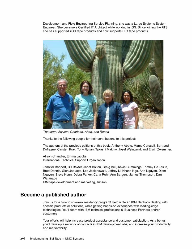
Development and Field Engineering Service Planning, she was a Large Systems System Engineer. She became a Certified IT Architect while working in IGS. Since joining the ATS, she has supported zOS tape products and now supports LTO tape products.
The team: Alv Jon, Charlotte, Abbe, and Reena
Thanks to the following people for their contributions to this project:
The authors of the previous editions of this book: Anthony Abete, Marco Ceresoli, Bertrand Dufrasne, Carsten Krax, Tony Rynan, Takashi Makino, Josef Weingand, and Erwin Zwemmer.
Alison Chandler, Emma JacobsInternational Technical Support Organization
Jennifer Bappert, Bill Baxter, Janet Bolton, Craig Bell, Kevin Cummings, Tommy De Jesus, Brett Dennis, Glen Jaquette, Lee Jesionowski, Jeffrey Li, Khanh Ngo, Anh Nguyen, Diem Nguyen, Steve Nunn, Debra Parker, Carla Ruhl, Ann Sargent, James Thompson, Dan WatanabeIBM tape development and marketing, Tucson
Become a published authorJoin us for a two- to six-week residency program! Help write an IBM Redbook dealing with specific products or solutions, while getting hands-on experience with leading-edge technologies. You'll team with IBM technical professionals, Business Partners and/or customers.
Your efforts will help increase product acceptance and customer satisfaction. As a bonus, you'll develop a network of contacts in IBM development labs, and increase your productivity and marketability.
xvi Implementing IBM Tape in UNIX Systems
Find out more about the residency program, browse the residency index, and apply online at:
ibm.com/redbooks/residencies.html
Comments welcomeYour comments are important to us!
We want our Redbooks to be as helpful as possible. Send us your comments about this or other Redbooks in one of the following ways:
� Use the online Contact us review redbook form found at:
ibm.com/redbooks
� Send your comments in an Internet note to:
� Mail your comments to:
IBM Corporation, International Technical Support OrganizationDept. QXXE Building 80-E2650 Harry RoadSan Jose, California 95120-6099
Preface xvii

xviii Implementing IBM Tape in UNIX Systems
Summary of changes
This section describes the technical changes made in this edition of the book and in previous editions. This edition may also include minor corrections and editorial changes that are not identified.
Summary of Changesfor SG24-6502-03for Implementing IBM Tape in UNIX Systemsas created or updated on October 18, 2005.
October 2005, Fourth EditionThis revision reflects the addition, deletion, or modification of new and changed information described below.
New information� WORM media for Ultrium 3 drives
� Ultrium 3 drives and libraries
� Virtual I/O for IBM TotalStorage 3584 Tape Library
July 2004, Third EditionThis revision reflects the addition, deletion, or modification of new and changed information described below.
New information� New models, IBM TotalStorage 3581 2U Tape Autoloader L28 and F28
� New frames and features for the IBM TotalStorage 3584 Tape Library, including support for IBM TotalStorage 3592 Tape Drive with WORM media
� Setup and implementation information for the IBM TotalStorage 3592 Tape Drive
� Advanced Library Management System (ALMS) for the IBM 3584
© Copyright IBM Corp. 2002, 2003, 2004, 2005. All rights reserved. xix

xx Implementing IBM Tape in UNIX Systems
Part 1 Setting up IBM tape in UNIX
In this part we introduce the IBM TotalStorage tape products (LTO Ultrium and 3592 Enterprise Tape Drive) and describe how to set them up in various UNIX environments. Both native SCSI and SAN (Fibre Channel) attachments are presented. We also show how to use the administration tools such as the IBM TotalStorage Tape Library Specialist.
Part 1
© Copyright IBM Corp. 2002, 2003, 2004, 2005. All rights reserved. 1

2 Implementing IBM Tape in UNIX Systems
Chapter 1. Introduction to LTO Ultrium with UNIX
This chapter provides an overview of the Linear Tape-Open (LTO) initiative and the corresponding IBM TotalStorage LTO Ultrium product line, including the IBM TotalStorage 3592 Tape Drive.
In addition, this chapter presents the following topics:
� Server and OS platforms explained� Storage Management software � Connectivity
– Direct SCSI attach– SCSI bus performance
� HBAs and drivers discussion� LVD versus HVD discussion� HD68 versus VHDCI discussion
1
© Copyright IBM Corp. 2002, 2003, 2004, 2005. All rights reserved. 3
1.1 LTO overviewThe Linear Tape-Open (LTO) program began as a joint initiative of Hewlett-Packard, IBM, and Seagate Technology. In 1997, the three companies set out to enable the development of best-of-breed tape storage products by consolidating state-of-the-art technologies from numerous sources. The three companies also took steps to protect customer investment by providing a four generation roadmap and establishing an infrastructure to enable compatibility between competitive products.
The LTO technology objective was to establish new open-format specifications for high capacity, high performance tape storage products for use in the midrange and network server computing environments, and to enable superior tape product options.
The current technology provider companies are IBM, HP, and Certance LLC (owned by Quantum), but LTO program cooperation goes beyond these three companies. LTO format specifications have been made available to all who want to participate through standard licensing provisions. LTO program technology has already attracted a number of other industry leaders, so LTO-specified products (tape drives and tape storage cartridges) will reach the market from multiple manufacturers, not just the technology provider companies. This is critical to meeting an open market objective, and is accomplished through open licensing of the technology.
Cooperation is also evident in the LTO program requirement that all products produced by licensees be technically certified annually. The primary objective of this certification is to help determine whether LTO format cartridges will be exchangeable across drives produced by different Ultrium manufacturers. Simply stated, this means “LTO-compliant media from any vendor can be read and written in LTO-compliant drives from any vendor.”
All three consortium members (IBM, HP, and Certance) are now shipping LTO Ultrium products, and numerous other licensees are shipping hardware and media.
The Linear Tape-Open organization homepage is:
http://www.lto.org
For more information on LTO technology, see The IBM TotalStorage Tape Libraries Guide for Open Systems, SG24-5946.
The IBM LTO homepage is:
http://www.ibm.com/storage/lto
The LTO Ultrium road map (Figure 1-1) shows the evolution of LTO technology. At the time of writing, IBM Ultrium generation 2 and 3 products are offered; however, there are many existing installations of now-withdrawn Ultrium 1 products, so they are included for your reference. The information in the road map is given as an indication of future developments by the three consortium members, and is subject to change.
Important: Hewlett-Packard, IBM, and Certance reserve the right to change the information in this migration path without notice.
4 Implementing IBM Tape in UNIX Systems
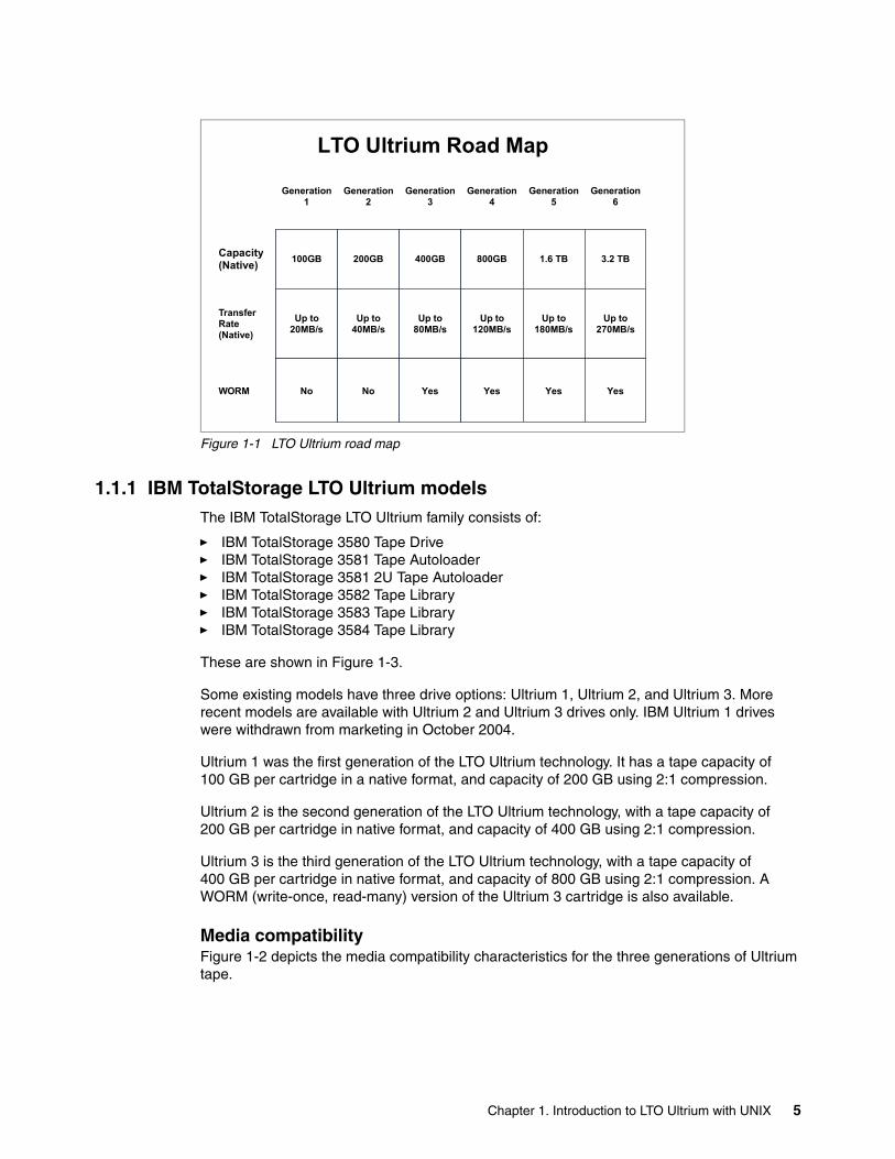
Figure 1-1 LTO Ultrium road map
1.1.1 IBM TotalStorage LTO Ultrium modelsThe IBM TotalStorage LTO Ultrium family consists of:
� IBM TotalStorage 3580 Tape Drive� IBM TotalStorage 3581 Tape Autoloader� IBM TotalStorage 3581 2U Tape Autoloader� IBM TotalStorage 3582 Tape Library� IBM TotalStorage 3583 Tape Library� IBM TotalStorage 3584 Tape Library
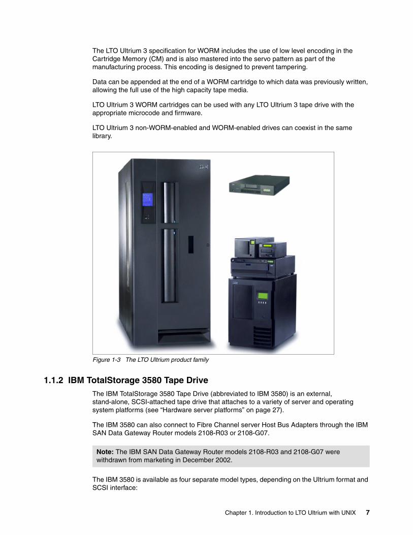
These are shown in Figure 1-3.
Some existing models have three drive options: Ultrium 1, Ultrium 2, and Ultrium 3. More recent models are available with Ultrium 2 and Ultrium 3 drives only. IBM Ultrium 1 drives were withdrawn from marketing in October 2004.
Ultrium 1 was the first generation of the LTO Ultrium technology. It has a tape capacity of 100 GB per cartridge in a native format, and capacity of 200 GB using 2:1 compression.
Ultrium 2 is the second generation of the LTO Ultrium technology, with a tape capacity of 200 GB per cartridge in native format, and capacity of 400 GB using 2:1 compression.
Ultrium 3 is the third generation of the LTO Ultrium technology, with a tape capacity of 400 GB per cartridge in native format, and capacity of 800 GB using 2:1 compression. A WORM (write-once, read-many) version of the Ultrium 3 cartridge is also available.
Media compatibilityFigure 1-2 depicts the media compatibility characteristics for the three generations of Ultrium tape.
Generation 1
Generation 2
Generation 3
Generation 4
Generation 5
Generation 6
Capacity (Native) 100GB 200GB 400GB 800GB 1.6 TB 3.2 TB
Transfer Rate (Native)
Up to 20MB/s
Up to 40MB/s
Up to 80MB/s
Up to 120MB/s
Up to 180MB/s
Up to 270MB/s
WORM No No Yes Yes Yes Yes
LTO Ultrium Road Map
Chapter 1. Introduction to LTO Ultrium with UNIX 5
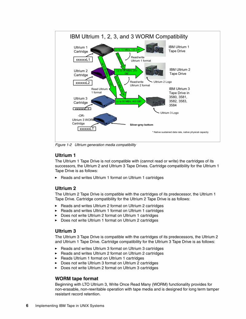
Figure 1-2 Ultrium generation media compatibility
Ultrium 1The Ultrium 1 Tape Drive is not compatible with (cannot read or write) the cartridges of its successors, the Ultrium 2 and Ultrium 3 Tape Drives. Cartridge compatibility for the Ultrium 1 Tape Drive is as follows:
� Reads and writes Ultrium 1 format on Ultrium 1 cartridges
Ultrium 2The Ultrium 2 Tape Drive is compatible with the cartridges of its predecessor, the Ultrium 1 Tape Drive. Cartridge compatibility for the Ultrium 2 Tape Drive is as follows:
� Reads and writes Ultrium 2 format on Ultrium 2 cartridges� Reads and writes Ultrium 1 format on Ultrium 1 cartridges� Does not write Ultrium 2 format on Ultrium 1 cartridges� Does not write Ultrium 1 format on Ultrium 2 cartridges
Ultrium 3The Ultrium 3 Tape Drive is compatible with the cartridges of its predecessors, the Ultrium 2 and Ultrium 1 Tape Drive. Cartridge compatibility for the Ultrium 3 Tape Drive is as follows:
� Reads and writes Ultrium 3 format on Ultrium 3 cartridges� Reads and writes Ultrium 2 format on Ultrium 2 cartridges� Reads Ultrium 1 format on Ultrium 1 cartridges� Does not write Ultrium 3 format on Ultrium 2 cartridges� Does not write Ultrium 2 format on Ultrium 3 cartridges
WORM tape formatBeginning with LTO Ultrium 3, Write Once Read Many (WORM) functionality provides for non-erasable, non-rewritable operation with tape media and is designed for long term tamper resistant record retention.
IBM Ultrium 1, 2, 3, and 3 WORM Compatibility
Ultrium 2 Cartridge
IBM Ultrium 2 Tape Drive
IBM Ultrium 1 Tape Drive
Ultrium 1 Cartridge Up to 15 MB/s, 100 GB*
Up to 35 MB/s, 200 GB*
Ultrium 2 LogoxxxxxxL2
xxxxxxL1
20 MB/s, 100 G
B*
* Native sustained data rate, native physical capacity
Read/write Ultrium 1 format
Ultrium 3 Cartridge
xxxxxxL3
Up to 80 MB/s, 400 GB*
Ultrium 3 Logo
IBM Ultrium 3 Tape Drive in 3580, 3581, 3582, 3583, 3584
Read Ultrium 1 format
Up to 35 MB/s, 200 G
B*
up to 20 MB/s, 100 G
B*
Read/write Ultrium 2 format
-OR-Ultrium 3 WORM Cartridge
xxxxxxLTSilver-grey bottom
6 Implementing IBM Tape in UNIX Systems
The LTO Ultrium 3 specification for WORM includes the use of low level encoding in the Cartridge Memory (CM) and is also mastered into the servo pattern as part of the manufacturing process. This encoding is designed to prevent tampering.
Data can be appended at the end of a WORM cartridge to which data was previously written, allowing the full use of the high capacity tape media.
LTO Ultrium 3 WORM cartridges can be used with any LTO Ultrium 3 tape drive with the appropriate microcode and firmware.
LTO Ultrium 3 non-WORM-enabled and WORM-enabled drives can coexist in the same library.
Figure 1-3 The LTO Ultrium product family
1.1.2 IBM TotalStorage 3580 Tape DriveThe IBM TotalStorage 3580 Tape Drive (abbreviated to IBM 3580) is an external, stand-alone, SCSI-attached tape drive that attaches to a variety of server and operating system platforms (see “Hardware server platforms” on page 27).
The IBM 3580 can also connect to Fibre Channel server Host Bus Adapters through the IBM SAN Data Gateway Router models 2108-R03 or 2108-G07.
The IBM 3580 is available as four separate model types, depending on the Ultrium format and SCSI interface:
Note: The IBM SAN Data Gateway Router models 2108-R03 and 2108-G07 were withdrawn from marketing in December 2002.
Chapter 1. Introduction to LTO Ultrium with UNIX 7
� IBM 3580-L23 has an Ultrium 2 drive and a Low-Voltage Differential (LVD) Ultra2 SCSI attachment that connects to LVD fast/wide adapters.
� IBM 3580-H23 has an Ultrium 2 drive and a High-Voltage Differential (HVD) Ultra™ SCSI attachment that connects to HVD fast/wide adapters.
� IBM 3580-L33 and IBM 3580-L3H have an Ultrium 3 drive and a Low-Voltage Differential (LVD) Ultra SCSI attachment that connects to LVD fast/wide adapters.
The IBM 3580-L33 and IBM 3580-L3H are functionally identical; the only difference is that the IBM 3580-L3H is an Express Model which is part of the On-Demand Express Portfolio.
The four previously available model types are:
� IBM 3580-L11 and IBM 3580-L13 have an Ultrium 1 drive and a Low-Voltage Differential (LVD) Ultra2 SCSI attachment that connects to LVD fast/wide adapters.
The IBM 3580-L11 and IBM 3580-L13 are functionally identical; the only difference is that the IBM 3580-L13 has a three-year Customer Element Exchange warranty.
� IBM 3580-H11 and IBM 3580-H13 have an Ultrium 1 drive and a High-Voltage Differential (HVD) Ultra SCSI attachment that connects to HVD fast/wide adapters.
The IBM 3580-H11 and IBM 3580-H13 are functionally identical; the only difference is that the IBM 3580-H13 has a three year Customer Element Exchange warranty.
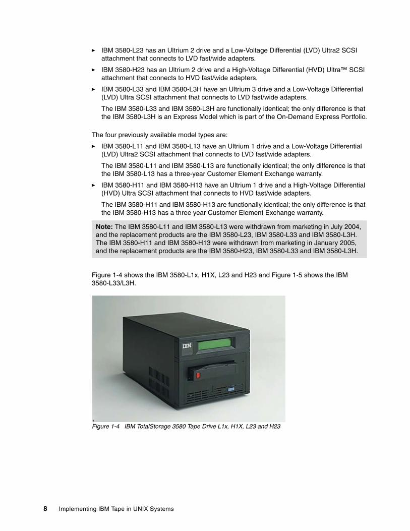
Figure 1-4 shows the IBM 3580-L1x, H1X, L23 and H23 and Figure 1-5 shows the IBM 3580-L33/L3H.
Figure 1-4 IBM TotalStorage 3580 Tape Drive L1x, H1X, L23 and H23
Note: The IBM 3580-L11 and IBM 3580-L13 were withdrawn from marketing in July 2004, and the replacement products are the IBM 3580-L23, IBM 3580-L33 and IBM 3580-L3H. The IBM 3580-H11 and IBM 3580-H13 were withdrawn from marketing in January 2005, and the replacement products are the IBM 3580-H23, IBM 3580-L33 and IBM 3580-L3H.
8 Implementing IBM Tape in UNIX Systems
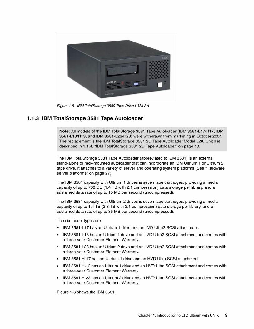
Figure 1-5 IBM TotalStorage 3580 Tape Drive L33/L3H
1.1.3 IBM TotalStorage 3581 Tape Autoloader
The IBM TotalStorage 3581 Tape Autoloader (abbreviated to IBM 3581) is an external, stand-alone or rack-mounted autoloader that can incorporate an IBM Ultrium 1 or Ultrium 2 tape drive. It attaches to a variety of server and operating system platforms (See “Hardware server platforms” on page 27).
The IBM 3581 capacity with Ultrium 1 drives is seven tape cartridges, providing a media capacity of up to 700 GB (1.4 TB with 2:1 compression) data storage per library, and a sustained data rate of up to 15 MB per second (uncompressed).
The IBM 3581 capacity with Ultrium 2 drives is seven tape cartridges, providing a media capacity of up to 1.4 TB (2.8 TB with 2:1 compression) data storage per library, and a sustained data rate of up to 35 MB per second (uncompressed).
The six model types are:
� IBM 3581-L17 has an Ultrium 1 drive and an LVD Ultra2 SCSI attachment.
� IBM 3581-L13 has an Ultrium 1 drive and an LVD Ultra2 SCSI attachment and comes with a three-year Customer Element Warranty.
� IBM 3581-L23 has an Ultrium 2 drive and an LVD Ultra2 SCSI attachment and comes with a three-year Customer Element Warranty.
� IBM 3581 H-17 has an Ultrium 1 drive and an HVD Ultra SCSI attachment.
� IBM 3581 H-13 has an Ultrium 1 drive and an HVD Ultra SCSI attachment and comes with a three-year Customer Element Warranty.
� IBM 3581 H-23 has an Ultrium 2 drive and an HVD Ultra SCSI attachment and comes with a three-year Customer Element Warranty.
Figure 1-6 shows the IBM 3581.
Note: All models of the IBM TotalStorage 3581 Tape Autoloader (IBM 3581-L17/H17, IBM 3581-L13/H13, and IBM 3581-L23/H23) were withdrawn from marketing in October 2004. The replacement is the IBM TotalStorage 3581 2U Tape Autoloader Model L28, which is described in 1.1.4, “IBM TotalStorage 3581 2U Tape Autoloader” on page 10.
Chapter 1. Introduction to LTO Ultrium with UNIX 9
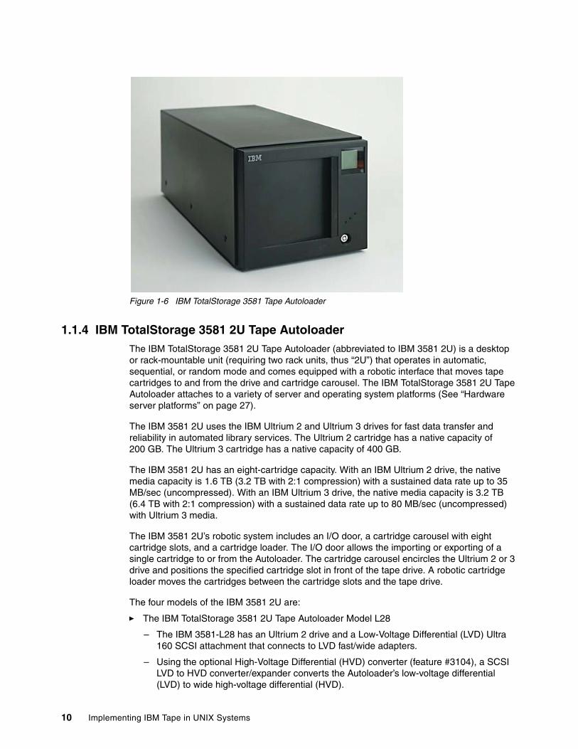
Figure 1-6 IBM TotalStorage 3581 Tape Autoloader
1.1.4 IBM TotalStorage 3581 2U Tape AutoloaderThe IBM TotalStorage 3581 2U Tape Autoloader (abbreviated to IBM 3581 2U) is a desktop or rack-mountable unit (requiring two rack units, thus “2U”) that operates in automatic, sequential, or random mode and comes equipped with a robotic interface that moves tape cartridges to and from the drive and cartridge carousel. The IBM TotalStorage 3581 2U Tape Autoloader attaches to a variety of server and operating system platforms (See “Hardware server platforms” on page 27).
The IBM 3581 2U uses the IBM Ultrium 2 and Ultrium 3 drives for fast data transfer and reliability in automated library services. The Ultrium 2 cartridge has a native capacity of 200 GB. The Ultrium 3 cartridge has a native capacity of 400 GB.
The IBM 3581 2U has an eight-cartridge capacity. With an IBM Ultrium 2 drive, the native media capacity is 1.6 TB (3.2 TB with 2:1 compression) with a sustained data rate up to 35 MB/sec (uncompressed). With an IBM Ultrium 3 drive, the native media capacity is 3.2 TB (6.4 TB with 2:1 compression) with a sustained data rate up to 80 MB/sec (uncompressed) with Ultrium 3 media.
The IBM 3581 2U’s robotic system includes an I/O door, a cartridge carousel with eight cartridge slots, and a cartridge loader. The I/O door allows the importing or exporting of a single cartridge to or from the Autoloader. The cartridge carousel encircles the Ultrium 2 or 3 drive and positions the specified cartridge slot in front of the tape drive. A robotic cartridge loader moves the cartridges between the cartridge slots and the tape drive.
The four models of the IBM 3581 2U are:
� The IBM TotalStorage 3581 2U Tape Autoloader Model L28
– The IBM 3581-L28 has an Ultrium 2 drive and a Low-Voltage Differential (LVD) Ultra 160 SCSI attachment that connects to LVD fast/wide adapters.
– Using the optional High-Voltage Differential (HVD) converter (feature #3104), a SCSI LVD to HVD converter/expander converts the Autoloader’s low-voltage differential (LVD) to wide high-voltage differential (HVD).
10 Implementing IBM Tape in UNIX Systems
� The IBM TotalStorage 3581 2U Tape Autoloader Model F28
The IBM 3581-F28 has an Ultrium 2 drive and a 2 Gbps native switched fabric Fibre Channel attachment.
� The IBM TotalStorage 3581 2U Tape Autoloader Model L38/L3H
The IBM 3581-L38 has an Ultrium 3 drive and a Low-Voltage Differential (LVD) Ultra 160 SCSI attachment that connects to LVD fast/wide adapters.
� The IBM TotalStorage 3581 2U Tape Autoloader Model F38/F3H
The IBM 3581-F38 has an Ultrium 3 drive and a 2 Gbps Native Switched Fabric Fibre Channel attachment.
The IBM 3581-L38 and IBM 3581-L3H are functionally identical. The IBM 3581-F38 and IBM 3581-F3H are functionally identical.The only difference is the IBM 3580-L3H and IBM 3581-F3H are Express Models and are part of the On-Demand Express Portfolio.
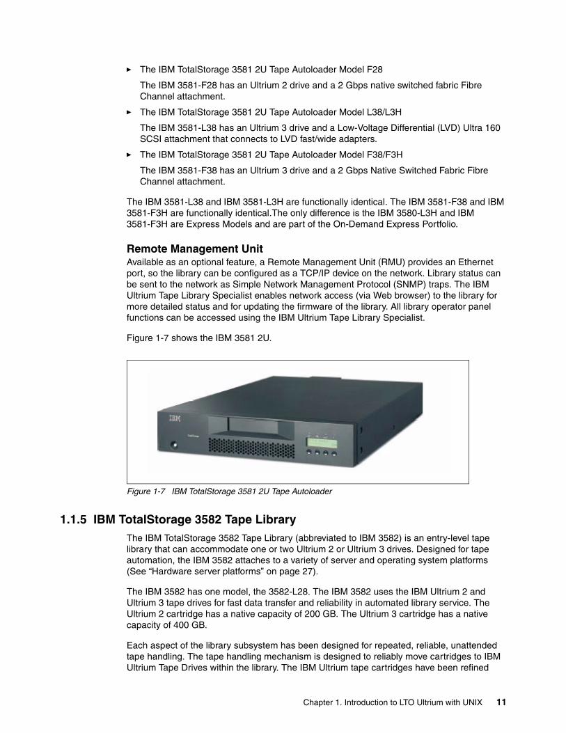
Remote Management UnitAvailable as an optional feature, a Remote Management Unit (RMU) provides an Ethernet port, so the library can be configured as a TCP/IP device on the network. Library status can be sent to the network as Simple Network Management Protocol (SNMP) traps. The IBM Ultrium Tape Library Specialist enables network access (via Web browser) to the library for more detailed status and for updating the firmware of the library. All library operator panel functions can be accessed using the IBM Ultrium Tape Library Specialist.
Figure 1-7 shows the IBM 3581 2U.
Figure 1-7 IBM TotalStorage 3581 2U Tape Autoloader
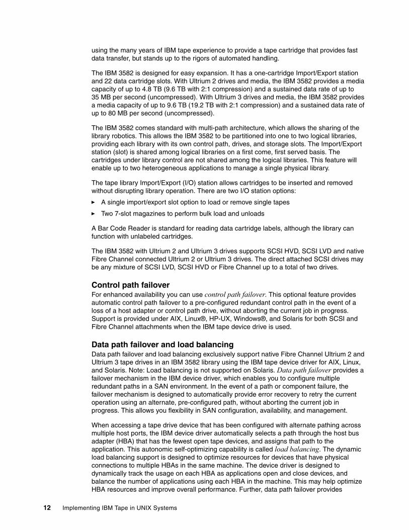
1.1.5 IBM TotalStorage 3582 Tape LibraryThe IBM TotalStorage 3582 Tape Library (abbreviated to IBM 3582) is an entry-level tape library that can accommodate one or two Ultrium 2 or Ultrium 3 drives. Designed for tape automation, the IBM 3582 attaches to a variety of server and operating system platforms (See “Hardware server platforms” on page 27).
The IBM 3582 has one model, the 3582-L28. The IBM 3582 uses the IBM Ultrium 2 and Ultrium 3 tape drives for fast data transfer and reliability in automated library service. The Ultrium 2 cartridge has a native capacity of 200 GB. The Ultrium 3 cartridge has a native capacity of 400 GB.
Each aspect of the library subsystem has been designed for repeated, reliable, unattended tape handling. The tape handling mechanism is designed to reliably move cartridges to IBM Ultrium Tape Drives within the library. The IBM Ultrium tape cartridges have been refined
Chapter 1. Introduction to LTO Ultrium with UNIX 11
using the many years of IBM tape experience to provide a tape cartridge that provides fast data transfer, but stands up to the rigors of automated handling.
The IBM 3582 is designed for easy expansion. It has a one-cartridge Import/Export station and 22 data cartridge slots. With Ultrium 2 drives and media, the IBM 3582 provides a media capacity of up to 4.8 TB (9.6 TB with 2:1 compression) and a sustained data rate of up to 35 MB per second (uncompressed). With Ultrium 3 drives and media, the IBM 3582 provides a media capacity of up to 9.6 TB (19.2 TB with 2:1 compression) and a sustained data rate of up to 80 MB per second (uncompressed).
The IBM 3582 comes standard with multi-path architecture, which allows the sharing of the library robotics. This allows the IBM 3582 to be partitioned into one to two logical libraries, providing each library with its own control path, drives, and storage slots. The Import/Export station (slot) is shared among logical libraries on a first come, first served basis. The cartridges under library control are not shared among the logical libraries. This feature will enable up to two heterogeneous applications to manage a single physical library.
The tape library Import/Export (I/O) station allows cartridges to be inserted and removed without disrupting library operation. There are two I/O station options:
� A single import/export slot option to load or remove single tapes
� Two 7-slot magazines to perform bulk load and unloads
A Bar Code Reader is standard for reading data cartridge labels, although the library can function with unlabeled cartridges.
The IBM 3582 with Ultrium 2 and Ultrium 3 drives supports SCSI HVD, SCSI LVD and native Fibre Channel connected Ultrium 2 or Ultrium 3 drives. The direct attached SCSI drives may be any mixture of SCSI LVD, SCSI HVD or Fibre Channel up to a total of two drives.
Control path failover For enhanced availability you can use control path failover. This optional feature provides automatic control path failover to a pre-configured redundant control path in the event of a loss of a host adapter or control path drive, without aborting the current job in progress. Support is provided under AIX, Linux®, HP-UX, Windows®, and Solaris for both SCSI and Fibre Channel attachments when the IBM tape device drive is used.
Data path failover and load balancing Data path failover and load balancing exclusively support native Fibre Channel Ultrium 2 and Ultrium 3 tape drives in an IBM 3582 library using the IBM tape device driver for AIX, Linux, and Solaris. Note: Load balancing is not supported on Solaris. Data path failover provides a failover mechanism in the IBM device driver, which enables you to configure multiple redundant paths in a SAN environment. In the event of a path or component failure, the failover mechanism is designed to automatically provide error recovery to retry the current operation using an alternate, pre-configured path, without aborting the current job in progress. This allows you flexibility in SAN configuration, availability, and management.
When accessing a tape drive device that has been configured with alternate pathing across multiple host ports, the IBM device driver automatically selects a path through the host bus adapter (HBA) that has the fewest open tape devices, and assigns that path to the application. This autonomic self-optimizing capability is called load balancing. The dynamic load balancing support is designed to optimize resources for devices that have physical connections to multiple HBAs in the same machine. The device driver is designed to dynamically track the usage on each HBA as applications open and close devices, and balance the number of applications using each HBA in the machine. This may help optimize HBA resources and improve overall performance. Further, data path failover provides
12 Implementing IBM Tape in UNIX Systems
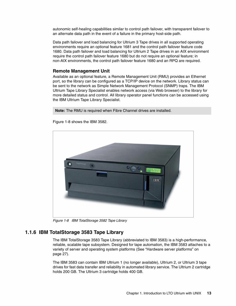
autonomic self-healing capabilities similar to control path failover, with transparent failover to an alternate data path in the event of a failure in the primary host-side path.
Data path failover and load balancing for Ultrium 3 Tape drives in all supported operating environments require an optional feature 1681 and the control path failover feature code 1680. Data path failover and load balancing for Ultrium 2 Tape drives in an AIX environment require the control path failover feature 1680 but do not require an optional feature; in non-AIX environments, the control path failover feature 1680 and an RPQ are required.
Remote Management UnitAvailable as an optional feature, a Remote Management Unit (RMU) provides an Ethernet port, so the library can be configured as a TCP/IP device on the network. Library status can be sent to the network as Simple Network Management Protocol (SNMP) traps. The IBM Ultrium Tape Library Specialist enables network access (via Web browser) to the library for more detailed status and control. All library operator panel functions can be accessed using the IBM Ultrium Tape Library Specialist.
Figure 1-8 shows the IBM 3582.
Figure 1-8 IBM TotalStorage 3582 Tape Library
1.1.6 IBM TotalStorage 3583 Tape LibraryThe IBM TotalStorage 3583 Tape Library (abbreviated to IBM 3583) is a high-performance, reliable, scalable tape subsystem. Designed for tape automation, the IBM 3583 attaches to a variety of server and operating system platforms (See “Hardware server platforms” on page 27).
The IBM 3583 can contain IBM Ultrium 1 (no longer available), Ultrium 2, or Ultrium 3 tape drives for fast data transfer and reliability in automated library service. The Ultrium 2 cartridge holds 200 GB. The Ultrium 3 cartridge holds 400 GB.
Note: The RMU is required when Fibre Channel drives are installed.
Chapter 1. Introduction to LTO Ultrium with UNIX 13
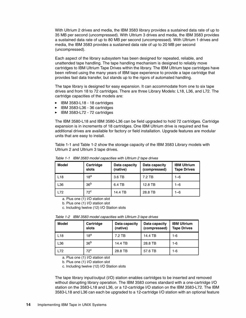
With Ultrium 2 drives and media, the IBM 3583 library provides a sustained data rate of up to 35 MB per second (uncompressed). With Ultrium 3 drives and media, the IBM 3583 provides a sustained data rate of up to 80 MB per second (uncompressed). With Ultrium 1 drives and media, the IBM 3583 provides a sustained data rate of up to 20 MB per second (uncompressed).
Each aspect of the library subsystem has been designed for repeated, reliable, and unattended tape handling. The tape handling mechanism is designed to reliably move cartridges to IBM Ultrium Tape Drives within the library. The IBM Ultrium tape cartridges have been refined using the many years of IBM tape experience to provide a tape cartridge that provides fast data transfer, but stands up to the rigors of automated handling.
The tape library is designed for easy expansion. It can accommodate from one to six tape drives and from 18 to 72 cartridges. There are three Library Models: L18, L36, and L72. The cartridge capacities of the models are:
� IBM 3583-L18 - 18 cartridges� IBM 3583-L36 - 36 cartridges� IBM 3583-L72 - 72 cartridges
The IBM 3580-L18 and IBM 3580-L36 can be field upgraded to hold 72 cartridges. Cartridge expansion is in increments of 18 cartridges. One IBM Ultrium drive is required and five additional drives are available for factory or field installation. Upgrade features are modular units that are easy to install.
Table 1-1 and Table 1-2 show the storage capacity of the IBM 3583 Library models with Ultrium 2 and Ultrium 3 tape drives.
Table 1-1 IBM 3583 model capacities with Ultrium 2 tape drives
Table 1-2 IBM 3583 model capacities with Ultrium 3 tape drives
The tape library input/output (I/O) station enables cartridges to be inserted and removed without disrupting library operation. The IBM 3583 comes standard with a one-cartridge I/O station on the 3583-L18 and L36, or a 12-cartridge I/O station on the IBM 3583-L72. The IBM 3583-L18 and L36 can each be upgraded to a 12-cartridge I/O station with an optional feature
Model Cartridge slots
Data capacity (native)
Data capacity (compressed)
IBM Ultrium Tape Drives
L18 18a
a. Plus one (1) I/O station slot
3.6 TB 7.2 TB 1–6
L36 36b
b. Plus one (1) I/O station slot
6.4 TB 12.8 TB 1–6
L72 72c
c. Including twelve (12) I/O Station slots
14.4 TB 28.8 TB 1–6
Model Cartridge slots
Data capacity (native)
Data capacity (compressed)
IBM Ultrium Tape Drives
L18 18a
a. Plus one (1) I/O station slot
7.2 TB 14.4 TB 1-6
L36 36b
b. Plus one (1) I/O station slot
14.4 TB 28.8 TB 1-6
L72 72c
c. Including twelve (12) I/O Station slots
28.8 TB 57.6 TB 1-6
14 Implementing IBM Tape in UNIX Systems
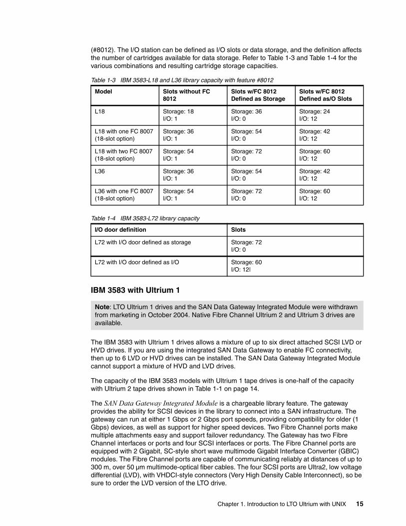
(#8012). The I/O station can be defined as I/O slots or data storage, and the definition affects the number of cartridges available for data storage. Refer to Table 1-3 and Table 1-4 for the various combinations and resulting cartridge storage capacities.
Table 1-3 IBM 3583-L18 and L36 library capacity with feature #8012
Table 1-4 IBM 3583-L72 library capacity
IBM 3583 with Ultrium 1
The IBM 3583 with Ultrium 1 drives allows a mixture of up to six direct attached SCSI LVD or HVD drives. If you are using the integrated SAN Data Gateway to enable FC connectivity, then up to 6 LVD or HVD drives can be installed. The SAN Data Gateway Integrated Module cannot support a mixture of HVD and LVD drives.
The capacity of the IBM 3583 models with Ultrium 1 tape drives is one-half of the capacity with Ultrium 2 tape drives shown in Table 1-1 on page 14.
The SAN Data Gateway Integrated Module is a chargeable library feature. The gateway provides the ability for SCSI devices in the library to connect into a SAN infrastructure. The gateway can run at either 1 Gbps or 2 Gbps port speeds, providing compatibility for older (1 Gbps) devices, as well as support for higher speed devices. Two Fibre Channel ports make multiple attachments easy and support failover redundancy. The Gateway has two Fibre Channel interfaces or ports and four SCSI interfaces or ports. The Fibre Channel ports are equipped with 2 Gigabit, SC-style short wave multimode Gigabit Interface Converter (GBIC) modules. The Fibre Channel ports are capable of communicating reliably at distances of up to 300 m, over 50 µm multimode-optical fiber cables. The four SCSI ports are Ultra2, low voltage differential (LVD), with VHDCI-style connectors (Very High Density Cable Interconnect), so be sure to order the LVD version of the LTO drive.
Model Slots without FC 8012
Slots w/FC 8012 Defined as Storage
Slots w/FC 8012 Defined as/O Slots
L18 Storage: 18I/O: 1
Storage: 36I/O: 0
Storage: 24I/O: 12
L18 with one FC 8007 (18-slot option)
Storage: 36I/O: 1
Storage: 54I/O: 0
Storage: 42I/O: 12
L18 with two FC 8007 (18-slot option)
Storage: 54I/O: 1
Storage: 72I/O: 0
Storage: 60I/O: 12
L36 Storage: 36I/O: 1
Storage: 54I/O: 0
Storage: 42I/O: 12
L36 with one FC 8007 (18-slot option)
Storage: 54I/O: 1
Storage: 72I/O: 0
Storage: 60I/O: 12
I/O door definition Slots
L72 with I/O door defined as storage Storage: 72 I/O: 0
L72 with I/O door defined as I/O Storage: 60I/O: 12|
Note: LTO Ultrium 1 drives and the SAN Data Gateway Integrated Module were withdrawn from marketing in October 2004. Native Fibre Channel Ultrium 2 and Ultrium 3 drives are available.
Chapter 1. Introduction to LTO Ultrium with UNIX 15
IBM 3583 with Ultrium 2The IBM 3583 with Ultrium 2 drives supports SCSI HVD, SCSI LVD, and native FC-connected Ultrium 2 drives. The drives may be any mixture of SCSI LVD, SCSI HVD, or FC, up to a total of six drives.
The FC drives are native switched fabric 2 Gbps Fibre Channel LTO Ultrium 2 Drives that can be directly attached to a host or a switch.
IBM 3583 with Ultrium 3The IBM 3583 with Ultrium 3 drives supports SCSI LVD and native FC-connected Ultrium 3 drives. The drives may be any mixture of SCSI LVD or FC up to a total of six drives.
The FC drives are native switched fabric 2-Gbps Fibre Channel LTO Ultrium 3 Drives that can be directly attached to a host or a switch.
Multi-path supportThe patented multi-path support feature of the IBM 3583 supports sharing of the library robotics. This is accomplished by partitioning the library into up to three multiple logical libraries and providing each logical library its own separate and distinct drives, storage slots, and control paths.
Logical libraries can also be used for separating different generations of Ultrium Tape Drives and cartridges for applications that do not support mixing the drives in the same logical library.
Support for multi-path architecture and partitioning may require an updated microcode level. Download the latest microcode from either of these Web sites:
http://www.ibm.com/servers/storage/support/lto/3583/downloading.htmlftp://ftp.software.ibm.com/storage/358x/3583/
Control path failoverFor enhanced availability you may use control path failover. This optional feature provides automatic control path failover to a preconfigured redundant control path in the event of a loss of a host adapter or control path drive, without aborting the current job in progress. Support is provided under AIX, Linux, HP-UX, Windows, and Solaris for both SCSI and Fibre Channel attachments when the IBM tape device driver is used.
Data path failover and load balancingData path failover exclusively supports native Fibre Channel Ultrium 3 or Ultrium 2 drives in the IBM 3583 using the IBM tape device driver for AIX, Linux, and Solaris. Load balancing exclusively supports native Fibre Channel Ultrium 3 or Ultrium 2 drives in the IBM 3583 using the IBM tape device driver for AIX and Linux; it is not supported for Solaris.
Data path failover provides a failover mechanism in the IBM device driver, so that you can configure multiple redundant paths in a SAN environment. If a path or component fails, the
Note: An 18-slot storage column needs to be dedicated to each logical partition. I/O slots are shared on a first-come, first-served basis. This type of partitioning allows heterogeneous applications to share the library robotics independent of each other. Cartridges under library control are not shared between logical libraries nor allowed to be moved between logical libraries. An example of heterogeneous sharing is a Microsoft® Windows 2000 application using the drive and storage slots of one logical library while a UNIX application uses the drive and slots of another logical library.
16 Implementing IBM Tape in UNIX Systems
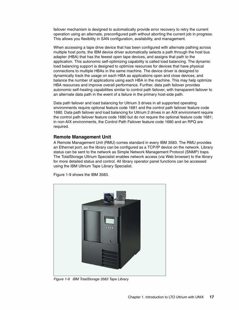
failover mechanism is designed to automatically provide error recovery to retry the current operation using an alternate, preconfigured path without aborting the current job in progress. This allows you flexibility in SAN configuration, availability, and management.
When accessing a tape drive device that has been configured with alternate pathing across multiple host ports, the IBM device driver automatically selects a path through the host bus adapter (HBA) that has the fewest open tape devices, and assigns that path to the application. This autonomic self-optimizing capability is called load balancing. The dynamic load balancing support is designed to optimize resources for devices that have physical connections to multiple HBAs in the same machine. The device driver is designed to dynamically track the usage on each HBA as applications open and close devices, and balance the number of applications using each HBA in the machine. This may help optimize HBA resources and improve overall performance. Further, data path failover provides autonomic self-healing capabilities similar to control path failover, with transparent failover to an alternate data path in the event of a failure in the primary host-side path.
Data path failover and load balancing for Ultrium 3 drives in all supported operating environments require optional feature code 1681 and the control path failover feature code 1680. Data path failover and load balancing for Ultrium 2 drives in an AIX environment require the control path failover feature code 1680 but do not require the optional feature code 1681; in non-AIX environments, the Control Path Failover feature code 1680 and an RPQ are required.
Remote Management UnitA Remote Management Unit (RMU) comes standard in every IBM 3583. The RMU provides an Ethernet port, so the library can be configured as a TCP/IP device on the network. Library status can be sent to the network as Simple Network Management Protocol (SNMP) traps. The TotalStorage Ultrium Specialist enables network access (via Web browser) to the library for more detailed status and control. All library operator panel functions can be accessed using the IBM Ultrium Tape Library Specialist.
Figure 1-9 shows the IBM 3583.
Figure 1-9 IBM TotalStorage 3583 Tape Library
Chapter 1. Introduction to LTO Ultrium with UNIX 17
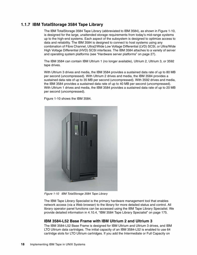
1.1.7 IBM TotalStorage 3584 Tape LibraryThe IBM TotalStorage 3584 Tape Library (abbreviated to IBM 3584), as shown in Figure 1-10, is designed for the large, unattended storage requirements from today's mid-range systems up to the high-end systems. Each aspect of the subsystem is designed to optimize access to data and reliability. The IBM 3584 is designed to connect to host systems using any combination of Fibre Channel, Ultra2/Wide Low Voltage Differential (LVD) SCSI, or Ultra/Wide High Voltage Differential (HVD) SCSI interfaces. The IBM 3584 attaches to a variety of server and operating system platforms (see “Hardware server platforms” on page 27).
The IBM 3584 can contain IBM Ultrium 1 (no longer available), Ultrium 2, Ultrium 3, or 3592 tape drives.
With Ultrium 3 drives and media, the IBM 3584 provides a sustained data rate of up to 80 MB per second (uncompressed). With Ultrium 2 drives and media, the IBM 3584 provides a sustained data rate of up to 35 MB per second (uncompressed). With 3592 drives and media, the IBM 3584 provides a sustained data rate of up to 40 MB per second (uncompressed). With Ultrium 1 drives and media, the IBM 3584 provides a sustained data rate of up to 20 MB per second (uncompressed).
Figure 1-10 shows the IBM 3584.
Figure 1-10 IBM TotalStorage 3584 Tape Library
The IBM Tape Library Specialist is the primary hardware management tool that enables network access (via a Web browser) to the library for more detailed status and control. All library operator panel functions can be accessed using the IBM Tape Library Specialist. We provide detailed information in 4.10.4, “IBM 3584 Tape Library Specialist” on page 175.
IBM 3584-L52 Base Frame with IBM Ultrium 2 and Ultrium 3The IBM 3584-L52 Base Frame is designed for IBM Ultrium and Ultrium 3 drives, and IBM LTO Ultrium data cartridges. The initial capacity of an IBM 3584-L52 is enabled to use 64 cartridge slots for LTO Ultrium cartridges. If you add the Intermediate or Full Capacity on
18 Implementing IBM Tape in UNIX Systems
Demand features, you can enable storage elements in the IBM 3584 L52 to increase the available capacity to 129 cartridge slots, or 219 to 287 cartridge slots (depending on the features you order).
The IBM 3584-L52 Base Frame has support for up to 12 tape drives with an incremental reduction of storage slots for more than four drives or with the additional I/O station installed. This model has a smaller footprint than the IBM 3584-L32. The IBM 3584-L52 is designed with an optimized gripper for use with IBM LTO or 3592 tape cartridges. Data capacity for the IBM 3584-L52 depends on the types of cartridges. Up to 12 logical libraries can be configured for each frame. Details of the capacity of the IBM 3584 with the various expansion options are in Table 1-5 on page 23 and Table 1-6 on page 23.
Each IBM 3584-L52 library has a standard 16-slot cartridge I/O station for importing or exporting LTO tape cartridges from the library without requiring a re-inventory. An additional 16-slot cartridge I/O station is optionally available for either IBM LTO or 3592 data cartridges. Libraries containing a mixture of IBM LTO and 3592 drive technologies must have one LTO I/O station and one 3592 I/O station. For bulk loading of tape cartridges the library door can be opened. Each time the library door is closed, a bar code reader mounted on the autochanger scans the cartridge labels, enabling a re-inventory of the cartridges in the library frame in typically less than 60 seconds. A door lock is included to restrict physical access to cartridges in the library.
IBM 3584-D52 Expansion Frame with IBM Ultrium 2 and Ultrium 3The IBM 3584-D52 Expansion Frame is designed for IBM Ultrium 2 and Ultrium 3 drives, and IBM LTO Ultrium data cartridges. Up to 15 IBM 3584-D52 Expansion Frames may be added to the IBM 3584-L22, L32, or L52 Base Frame to increase LTO cartridge storage or drive capacity. Each IBM 3584-D52 supports up to 440 LTO cartridge slots and up to 12 Ultrium 2 or Ultrium 3 drives, with an incremental reduction of storage slots for each set of four tape drives installed. Each frame can have up to 12 logical libraries or 12 control paths.
IBM 3584 High Availability Frame Model HA1 The IBM 3584 High Availability Frame Model HA1 is designed to improve the performance and availability of the IBM 3584. The 3584-HA1, in conjunction with service bay features on the IBM 3584-D22 and D52, provides for the installation of a second library accessor that is designed to operate simultaneously with the first accessor and service mount requests in the IBM 3584 at the same time. It is designed to non-disruptively fail over to a redundant accessor when any component of either accessor fails, which helps maintain availability and reliability. Additionally, this design includes the ability to add one or more IBM 3584-L52 or D22 Frames to a IBM 3584 that has an attached 3584-HA1 with minimal disruption.
Dual active accessor support is provided in a mixed media library. This includes any combination of IBM 3592 and LTO Ultrium media types. Advanced Library Management Systems (ALMS) will be required for support of dual accessors and two or more IBM 3584 frames are required in a high availability configuration.
A dual accessor library will have two garage areas called service bays. Service Bay A (the IBM 3584 High Availability Frame Model HA1) is to the left of and adjacent to the L-frame, when facing the front door. Service Bay B (a modified IBM 3584-D22 or D52) is to the right of the last active frame in the library. The service bays will be regular library frames, but they will not have any drives, power supplies, or node cards. Storage slots within the service bays will only be used to test service actions.
The actual performance of the IBM 3584 is determined by a number of factors, such as accessor capacity, number of library frames, number of tape drives, location of tape drives and tape cartridges, and tape cartridge residency.
Chapter 1. Introduction to LTO Ultrium with UNIX 19
IBM TotalStorage 3588 Tape Drive Model F3AThe IBM TotalStorage 3588 Tape Drive Model F3A is designed for installation in an IBM 3584 to offer high capacity, performance, and technology designed for the mid-range open systems environment. This model incorporates the Ultrium 3 drive, which more than doubles the maximum tape drive throughput data rate performance over the Ultrium 2 drive. It has a native data transfer of up to 80 MB/sec with Ultrium 3 media. In addition, with the use of the Ultrium 400 GB Data Cartridge, the IBM 3588 doubles the tape cartridge capacity up to 400 GB native physical capacity (800 GB with 2:1 compression), as compared to the Ultrium 2 drives and cartridges. Ultrium 3 drives can read and write Ultrium 2 cartridges and read Ultrium 1 cartridges. The IBM 3588 comes with a 2 Gbps Fibre Channel interface for connection to a wide spectrum of open system servers.
IBM 3584-L22 Base Frame with IBM 3592 The IBM 3584-L22 Base Frame is designed for 3592 Model J1A Tape Drives and 3592 data cartridges. The initial capacity of an IBM 3584-L22 is enabled to use 58 cartridge slots for 3592 cartridges. If you add the Intermediate or Full Capacity on Demand features, you can enable storage elements in the IBM 3584-L22 to increase the available capacity to 117 cartridge slots, or 199 to 260 cartridge slots (depending on the features you order).
The IBM 3584-L22 Base Frame has support for up to 12 tape drives with an incremental reduction of storage slots for more than four drives or with the additional I/O station installed. This model has a smaller footprint than the IBM 3584-L32. The IBM 3584-L22 is designed with an optimized gripper for use with IBM Ultrium or IBM 3592 tape cartridges. Up to 12 logical libraries can be configured for each frame.
Each IBM 3584-L22 has a standard 16-slot cartridge I/O station for importing or exporting 3592 tape cartridges from the library without requiring a re-inventory. An additional 16-slot cartridge I/O station is optionally available for either IBM Ultrium or IBM 3592 data cartridges. Libraries containing a mixture of IBM Ultrium and IBM 3592 drive technologies must have one LTO I/O station and one 3592 I/O station. For bulk loading of tape cartridges, the library door can be opened. Each time the library door is closed, a bar code reader mounted on the autochanger scans the cartridge labels, enabling a re-inventory of the cartridges in the library frame in typically less than 60 seconds. A door lock is included to restrict physical access to cartridges in the library.
IBM 3584-D22 Expansion Frame with IBM 3592The IBM 3584-D22 Expansion Frame is designed for the IBM 3592 Model J1A Tape Drives and 3592 data cartridges. Up to 15 Model D22 Expansion Frames can be added to an IBM 3584-L22, L32, or L52 Base Frame to increase the 3592 cartridge storage or drive capacity. Each Model D22 supports up to 400 3592 cartridge slots and up to twelve 3592 drives, with an incremental reduction of storage slots for each set of four tape drives installed. Each frame can have up to 12 logical libraries or 12 control paths.
IBM TotalStorage 3592 Tape Drive Model J1A As indicated, the IBM 3584-L22 and D22 frames support the IBM TotalStorage 3592 Tape Drive Model J1A (IBM 3592).
The IBM 3592 has a native data rate of up to 40 MB/sec. With the use of the IBM TotalStorage Enterprise Tape Cartridge 3592, it provides a native cartridge capacity of up to
Note: An IBM 3584 with IBM 3592 drives can be attached to zSeries® systems using the IBM TotalStorage 3953 Library Manager and Tape Frame. For more information on the IBM 3953, refer to the IBM TotalStorage 3953 Tape Frame Model F05 and Library Manager Model L05 Introduction and Planning Guide, GA32-0472.
20 Implementing IBM Tape in UNIX Systems
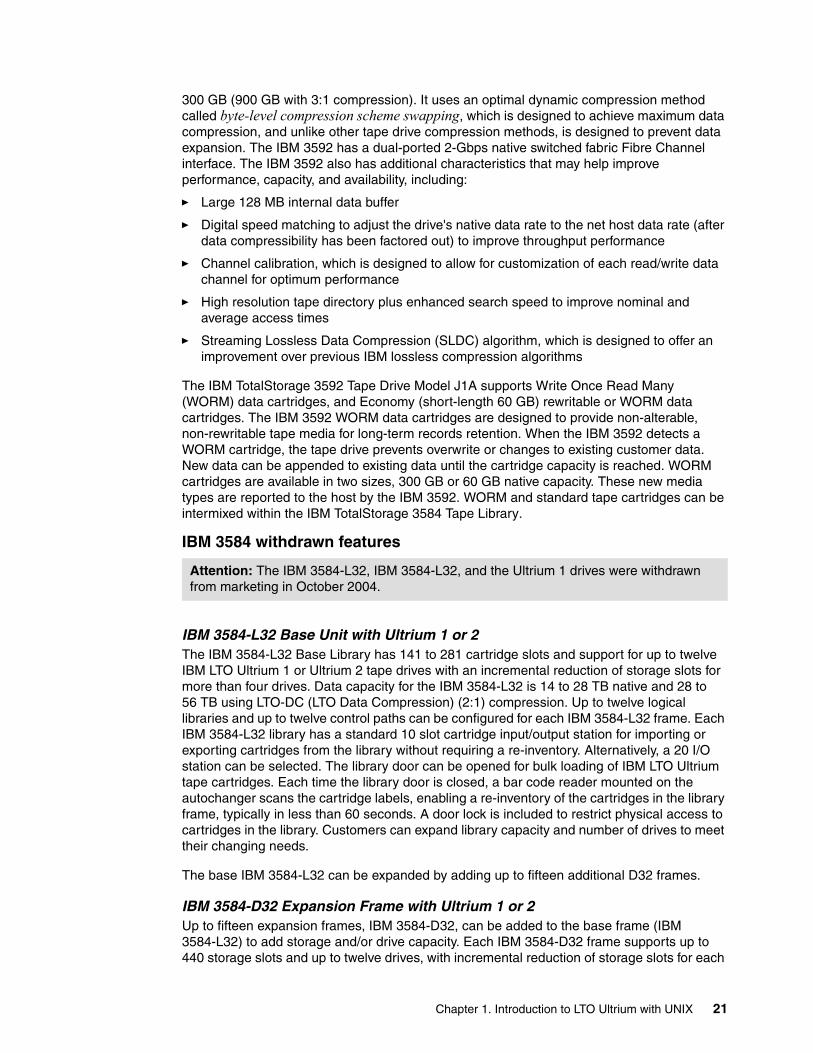
300 GB (900 GB with 3:1 compression). It uses an optimal dynamic compression method called byte-level compression scheme swapping, which is designed to achieve maximum data compression, and unlike other tape drive compression methods, is designed to prevent data expansion. The IBM 3592 has a dual-ported 2-Gbps native switched fabric Fibre Channel interface. The IBM 3592 also has additional characteristics that may help improve performance, capacity, and availability, including:
� Large 128 MB internal data buffer
� Digital speed matching to adjust the drive's native data rate to the net host data rate (after data compressibility has been factored out) to improve throughput performance
� Channel calibration, which is designed to allow for customization of each read/write data channel for optimum performance
� High resolution tape directory plus enhanced search speed to improve nominal and average access times
� Streaming Lossless Data Compression (SLDC) algorithm, which is designed to offer an improvement over previous IBM lossless compression algorithms
The IBM TotalStorage 3592 Tape Drive Model J1A supports Write Once Read Many (WORM) data cartridges, and Economy (short-length 60 GB) rewritable or WORM data cartridges. The IBM 3592 WORM data cartridges are designed to provide non-alterable, non-rewritable tape media for long-term records retention. When the IBM 3592 detects a WORM cartridge, the tape drive prevents overwrite or changes to existing customer data. New data can be appended to existing data until the cartridge capacity is reached. WORM cartridges are available in two sizes, 300 GB or 60 GB native capacity. These new media types are reported to the host by the IBM 3592. WORM and standard tape cartridges can be intermixed within the IBM TotalStorage 3584 Tape Library.
IBM 3584 withdrawn features
IBM 3584-L32 Base Unit with Ultrium 1 or 2The IBM 3584-L32 Base Library has 141 to 281 cartridge slots and support for up to twelve IBM LTO Ultrium 1 or Ultrium 2 tape drives with an incremental reduction of storage slots for more than four drives. Data capacity for the IBM 3584-L32 is 14 to 28 TB native and 28 to 56 TB using LTO-DC (LTO Data Compression) (2:1) compression. Up to twelve logical libraries and up to twelve control paths can be configured for each IBM 3584-L32 frame. Each IBM 3584-L32 library has a standard 10 slot cartridge input/output station for importing or exporting cartridges from the library without requiring a re-inventory. Alternatively, a 20 I/O station can be selected. The library door can be opened for bulk loading of IBM LTO Ultrium tape cartridges. Each time the library door is closed, a bar code reader mounted on the autochanger scans the cartridge labels, enabling a re-inventory of the cartridges in the library frame, typically in less than 60 seconds. A door lock is included to restrict physical access to cartridges in the library. Customers can expand library capacity and number of drives to meet their changing needs.
The base IBM 3584-L32 can be expanded by adding up to fifteen additional D32 frames.
IBM 3584-D32 Expansion Frame with Ultrium 1 or 2Up to fifteen expansion frames, IBM 3584-D32, can be added to the base frame (IBM 3584-L32) to add storage and/or drive capacity. Each IBM 3584-D32 frame supports up to 440 storage slots and up to twelve drives, with incremental reduction of storage slots for each
Attention: The IBM 3584-L32, IBM 3584-L32, and the Ultrium 1 drives were withdrawn from marketing in October 2004.
Chapter 1. Introduction to LTO Ultrium with UNIX 21
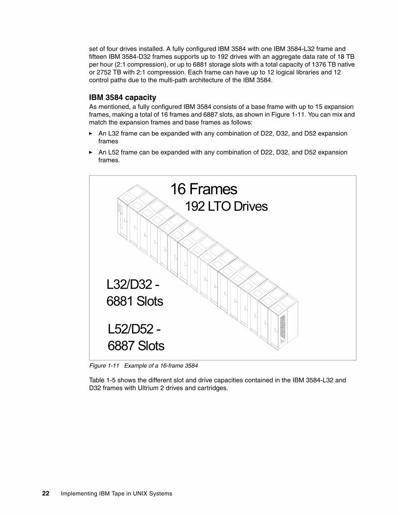
set of four drives installed. A fully configured IBM 3584 with one IBM 3584-L32 frame and fifteen IBM 3584-D32 frames supports up to 192 drives with an aggregate data rate of 18 TB per hour (2:1 compression), or up to 6881 storage slots with a total capacity of 1376 TB native or 2752 TB with 2:1 compression. Each frame can have up to 12 logical libraries and 12 control paths due to the multi-path architecture of the IBM 3584.
IBM 3584 capacityAs mentioned, a fully configured IBM 3584 consists of a base frame with up to 15 expansion frames, making a total of 16 frames and 6887 slots, as shown in Figure 1-11. You can mix and match the expansion frames and base frames as follows:
� An L32 frame can be expanded with any combination of D22, D32, and D52 expansion frames
� An L52 frame can be expanded with any combination of D22, D32, and D52 expansion frames.
Figure 1-11 Example of a 16-frame 3584
Table 1-5 shows the different slot and drive capacities contained in the IBM 3584-L32 and D32 frames with Ultrium 2 drives and cartridges.
16 Frames192 LTO Drives
L32/D32 - 6881 Slots
L52/D52 - 6887 Slots
22 Implementing IBM Tape in UNIX Systems
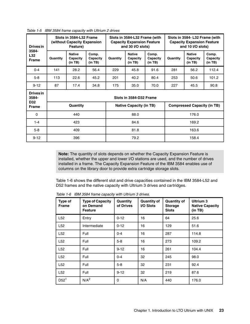
Table 1-5 IBM 3584 frame capacity with Ultrium 2 drives
Table 1-6 shows the different slot and drive capacities contained in the IBM 3584-L52 and D52 frames and the native capacity with Ultrium 3 drives and cartridges.
Table 1-6 IBM 3584 frame capacity with Ultrium 3 drives.
Drives in 3584- L32 Frame
Slots in 3584-L32 Frame (without Capacity Expansion
Feature)
Slots in 3584-L32 Frame (with Capacity Expansion Feature
and 30 I/O slots)
Slots in 3584- L32 Frame (with Capacity Expansion Feature
and 10 I/O slots)
QuantityNativeCapacity(in TB)
Comp.Capacity (in TB)
QuantityNativeCapacity(in TB)
Comp.Capacity (in TB)
QuantityNativeCapacity(in TB)
Comp.Capacity (in TB)
0-4 141 28.2 56.4 229 45.8 91.6 281 56.2 112.4
5-8 113 22.6 45.2 201 40.2 80.4 253 50.6 101.2
9-12 87 17.4 34.8 175 35.0 70.0 227 45.5 90.8
Drives in 3584- D32 Frame
Slots in 3584-D32 Frame
Quantity Native Capacity (in TB) Compressed Capacity (in TB)
0 440 88.0 176.0
1-4 423 84.6 169.2
5-8 409 81.8 163.6
9-12 396 79.2 158.4
Note: The quantity of slots depends on whether the Capacity Expansion Feature is installed, whether the upper and lower I/O stations are used, and the number of drives installed in a frame. The Capacity Expansion Feature of the IBM 3584 enables use of columns on the library door to provide extra cartridge storage slots.
Type of Frame
Type of Capacity on Demand Feature
Quantity of Drives
Quantity of I/O Slots
Quantity of Storage Slots
Ultrium 3Native Capacity (in TB)
L52 Entry 0-12 16 64 25.6
L52 Intermediate 0-12 16 129 51.6
L52 Full 0-4 16 287 114.8
L52 Full 5-8 16 273 109.2
L52 Full 9-12 16 261 104.4
L52 Full 0-4 32 245 98.0
L52 Full 5-8 32 231 92.4
L52 Full 9-12 32 219 87.6
D521 N/A2 0 N/A 440 176.0
Chapter 1. Introduction to LTO Ultrium with UNIX 23
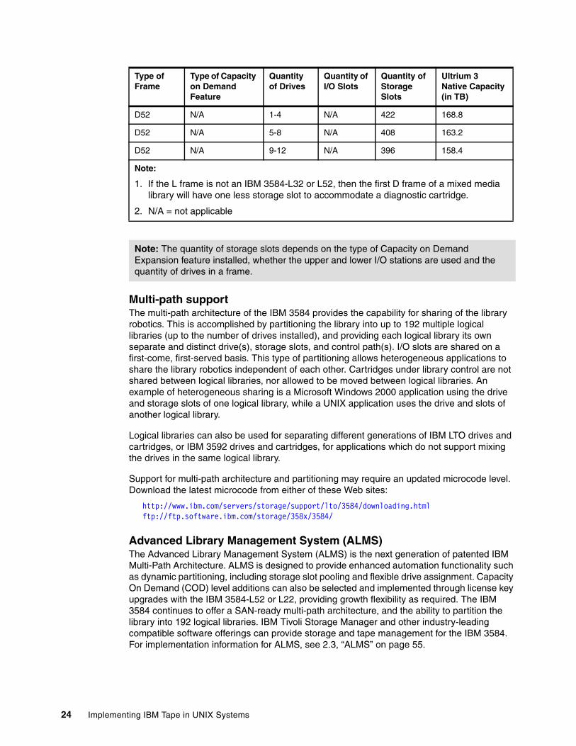
Multi-path support The multi-path architecture of the IBM 3584 provides the capability for sharing of the library robotics. This is accomplished by partitioning the library into up to 192 multiple logical libraries (up to the number of drives installed), and providing each logical library its own separate and distinct drive(s), storage slots, and control path(s). I/O slots are shared on a first-come, first-served basis. This type of partitioning allows heterogeneous applications to share the library robotics independent of each other. Cartridges under library control are not shared between logical libraries, nor allowed to be moved between logical libraries. An example of heterogeneous sharing is a Microsoft Windows 2000 application using the drive and storage slots of one logical library, while a UNIX application uses the drive and slots of another logical library.
Logical libraries can also be used for separating different generations of IBM LTO drives and cartridges, or IBM 3592 drives and cartridges, for applications which do not support mixing the drives in the same logical library.
Support for multi-path architecture and partitioning may require an updated microcode level. Download the latest microcode from either of these Web sites:
http://www.ibm.com/servers/storage/support/lto/3584/downloading.htmlftp://ftp.software.ibm.com/storage/358x/3584/
Advanced Library Management System (ALMS)The Advanced Library Management System (ALMS) is the next generation of patented IBM Multi-Path Architecture. ALMS is designed to provide enhanced automation functionality such as dynamic partitioning, including storage slot pooling and flexible drive assignment. Capacity On Demand (COD) level additions can also be selected and implemented through license key upgrades with the IBM 3584-L52 or L22, providing growth flexibility as required. The IBM 3584 continues to offer a SAN-ready multi-path architecture, and the ability to partition the library into 192 logical libraries. IBM Tivoli Storage Manager and other industry-leading compatible software offerings can provide storage and tape management for the IBM 3584. For implementation information for ALMS, see 2.3, “ALMS” on page 55.
D52 N/A 1-4 N/A 422 168.8
D52 N/A 5-8 N/A 408 163.2
D52 N/A 9-12 N/A 396 158.4
Note:
1. If the L frame is not an IBM 3584-L32 or L52, then the first D frame of a mixed media library will have one less storage slot to accommodate a diagnostic cartridge.
2. N/A = not applicable
Note: The quantity of storage slots depends on the type of Capacity on Demand Expansion feature installed, whether the upper and lower I/O stations are used and the quantity of drives in a frame.
Type of Frame
Type of Capacity on Demand Feature
Quantity of Drives
Quantity of I/O Slots
Quantity of Storage Slots
Ultrium 3Native Capacity (in TB)
24 Implementing IBM Tape in UNIX Systems
Control path failoverThis optional feature is designed to provide automatic control path failover to a pre-configured redundant control path in the event of a loss of a host adapter or control path drive, without aborting the current job in progress. Support is provided under AIX, Linux, Windows, HP-UX, and Solaris when the IBM device driver is used.
Data path failover and load balancingData path failover and load balancing exclusively support native Fibre Channel IBM LTO 2 and LTO 3 drives and IBM 3592 drives in the IBM 3584 using the IBM device driver for AIX, HP-UX, Windows, Linux and Solaris. Data path failover provides a failover mechanism in the IBM device driver, so you can configure multiple redundant paths in a SAN environment. If a path or component fails, the failover mechanism is designed to automatically provide error recovery to retry the current operation using an alternate, pre-configured path without aborting the current job in progress. This provides flexibility in SAN configuration, availability, and management.
When accessing a tape drive device that has been configured with alternate pathing across multiple host ports, the IBM device driver automatically selects a path through the host bus adapter (HBA) that has the fewest open tape devices, and assigns that path to the application. This autonomic self-optimizing capability is called load balancing. The dynamic load balancing support is designed to optimize resources for devices that have physical connections to multiple HBAs in the same machine. The device driver is designed to dynamically track the usage on each HBA as applications open and close devices, and balance the number of applications using each HBA in the machine. This may help optimize HBA resources and improve overall performance. Further, data path failover provides autonomic self-healing capabilities similar to control path failover, with transparent failover to an alternate data path in the event of a failure in the primary host-side path.
Data path failover and load balancing for Ultrium 3 drives in all supported operating environments requires optional feature code 1681 and the Control Path Failover feature code 1680. Data path failover and load balancing for Ultrium 2 drives in an AIX environment requires the Control Path Failover feature code 1680 but does not require the optional feature code 1681; in non-AIX environments, the Control Path Failover feature code 1680 and an RPQ are required.
Virtual I/O slotsThe configuration of virtual I/O slots in the IBM 3584 makes it appear to the host application that the library has more physical I/O slots than actually exist.
When the Advanced Library Management System (ALMS) is enabled, you can enable virtual I/O slots in the IBM 3584 so that the library automatically queues all cartridge moves between the I/O station and the storage slots. This makes the process of adding and removing cartridges easier and faster.
The IBM 3584 has input/output (I/O) stations and I/O slots that allow you to import and export up to 32 cartridges at any given time. The I/O slots are also known as import/export elements (IEEs). Virtual I/O slots increase the quantity of available I/O slots by allowing storage slots to
Note: If your library does not have virtual I/O slot capability and you want to enable it, you must first install the license key for the Advanced Library Management System (ALMS). With the ALMS license key installed, you have the option to enable ALMS and the virtual I/O slot feature through the Tape Library Specialist Web interface. ALMS must be enabled and the I/O station must be empty before you can enable or disable virtual I/O slots. For information about enabling or disabling ALMS, see 2.3, “ALMS” on page 55.
Chapter 1. Introduction to LTO Ultrium with UNIX 25
appear to the host as I/O slots. These storage slots are called virtual import/export elements (VIEEs). With virtual I/O slots, the library automatically moves cartridges from the I/O stations to the VIEEs. In this way, the library enhances its import and export capabilities.
The goal of virtual I/O slots is to reduce the dependencies between the system administrator and library operator so that each performs their import and export tasks without needing the other to perform any actions:
� In a typical import scenario without virtual I/O slots, a library operator needs to stand at the physical library and fill the I/O station with cartridges; a system administrator must trigger the applications to send commands for moving cartridges out of the I/O station and into library storage slots. After filling the I/O station with cartridges, the operator must wait for the I/O station to be cleared before inserting additional cartridges, which means the operator is waiting on the system administrator to clear the I/O station of each set of inserted cartridges. If the library is enabled with virtual I/O slots, the operator can continuously insert cartridges into the I/O station and the administrator does not need to issue commands to move each new set of inserted cartridges. Instead, the library automatically moves the cartridges and places them into virtual I/O slots until they are ready to be processed later as one composite set of inserted cartridges.
� In a typical export scenario without virtual I/O slots, the system administrator may need to export a large number of cartridges from the library. However, after the I/O station is filled, the system administrator must wait for the operator to physically remove cartridges from the entire I/O station before issuing another export command. This operation can be inconvenient. If the library is enabled with virtual I/O slots, the administrator does not have to wait to issue all export commands (up to 255 export commands can be issued at the same time for each logical library) and the operator can remove cartridges from the I/O stations as soon as the accessor automatically moves them from the storage slots.
After enabling virtual I/O slots, the library can use the Cartridge Assignment Policy and Insert Notification features to determine the best storage slot location for each inserted cartridge. This determination is designed to optimize the mount throughput for the logical library to which the inserted cartridge is assigned. For more information, see Cartridge assignment policy and “Virtual I/O” on page 60.
Using mtlib in the IBM 3584 The mtlib program facilitates communication between the IBM 3584 and the IBM 3494, as well as the IBM TotalStorage Virtual Tape Server (VTS).
The mtlib program is a command-line interface designed originally to control the IBM 3494. It is shipped with the 3494 device driver, similar to the way the tapeutil utility comes with the SCSI tape device driver. The mtlib program provides an interface from the server to a 3494 Tape Library, and also to the virtual tape drives and cartridges within an attached VTS.
The mtlib program has been enhanced to also work with SCSI tape libraries, such as the IBM 3584. Some customers have written mtlib scripts to work with the IBM 3494. If a customer with an IBM 3494 decides to migrate to the IBM 3584, this mtlib enhancement will ease the migration.
Existing customer scripts that use mtlib require no changes or minor changes, depending on the functions of the IBM 3494 that are used. For example, there is no category concept in SCSI tape libraries, so that any mtlib command that references categories might need to be changed.
For a complete description of the mtlib program and command syntax, see the IBM TotalStorage Tape Device Drivers Installation and User’s Guide, GC35-0154.
26 Implementing IBM Tape in UNIX Systems
SMI-S supportTo communicate with storage devices in a SAN, management software uses other software known as the Storage Management Initiative - Specification (SMI-S) Agent for Tape. You must install the SMI-S Agent for Tape on an Intel® machine that runs the SUSE Linux Enterprise Server 9 operating system. The SMI-S Agent for Tape communicates by using the Web-Based Enterprise Management (WBEM) protocol, which allows management software to communicate with the IBM 3584.
The SMI-S Agent for Tape is designed to be compliant with the Storage Management Initiative - Specification. The SMI-S is a design specification of the Storage Management Initiative (SMI), which that was launched by the Storage Networking Industry Association (SNIA). The SMI-S specifies a secure and reliable interface that allows storage management systems to identify, classify, monitor, and control physical and logical resources in a Storage Area Network (SAN). The interface is intended as a solution that integrates the various devices to be managed in a SAN and the tools used to manage them. The SMI-S was developed to address the problems that many vendors face in managing heterogeneous storage environments. It creates a management interface protocol for multi-vendor storage networking products. By enabling the integration of diverse multi-vendor storage networks, the initiative is able to expand the overall market for storage networking technology.
For detailed information about SMI-S, see the IBM TotalStorage SMI-S Agent for Tape Installation Guide, GC35-0512.
1.2 Hardware and operating system platformsThis section gives information on operating system support, SCSI and FC adapter vendors, and some applications that support the LTO family.
1.2.1 Hardware server platformsThe LTO products are supported on the following operating systems and servers:
� IBM iSeries™, AS/400® with OS/400®� IBM pSeries®, RS/6000®, SP with AIX and Linux� IBM xSeries® and other Intel Based (Windows NT®, 2000, 2003)� Sun™ SPARC with Solaris� Hewlett-Packard with HP-UX� Intel Linux (Red Hat and SUSE)� zSeries Linux � Tru64 (IBM 3584 only)� Other open systems using SCSI attachment or Fibre Channel attachment
Note that not all platforms and attachment methods are supported for all models; for current details for operating system and attachment support for each Ultrium model, see the following Web sites:
http://www.ibm.com/servers/storage/tape/3580/interop.htmlhttp://www.ibm.com/servers/storage/tape/3581/interop.htmlhttp://www.ibm.com/servers/storage/tape/3582/interop.htmlhttp://www.ibm.com/servers/storage/tape/3583/interop.htmlhttp://www.ibm.com/servers/storage/tape/3584/interop.html
Note: Always check the Web site for the most current, detailed, and accurate information.
Chapter 1. Introduction to LTO Ultrium with UNIX 27
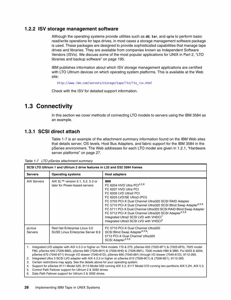
1.2.2 ISV storage management softwareAlthough the operating systems provide utilities such as dd, tar, and cpio to perform basic read/write operations for tape drives, in most cases a storage management software package is used. These packages are designed to provide sophisticated capabilities that manage tape drives and libraries. They are available from companies known as Independent Software Vendors (ISVs). We discuss some of the most popular applications for UNIX in Part 2, “LTO libraries and backup software” on page 195.
IBM publishes information about which ISV storage management applications are certified with LTO Ultrium devices on which operating system platforms. This is available at the Web site:
http://www.ibm.com/servers/storage/tape/lto/lto_isv.html
Check with the ISV for detailed support information.
1.3 ConnectivityIn this section we cover methods of connecting LTO models to servers using the IBM 3584 as an example.
1.3.1 SCSI direct attachTable 1-7 is an example of the attachment summary information found on the IBM Web sites that details server, OS levels, Host Bus Adapters, and fabric support for the IBM 3584 in the pSeries environment. The Web addresses for each LTO model are given in 1.2.1, “Hardware server platforms” on page 27.
Table 1-7 LTO pSeries attachment summary
SCSI LTO Ultrium 1 and Ultrium 2 drive features in L32 and D32 3584 frames
Servers Operating systems Host adapters
AIX Servers AIX 5L™ version 5.1, 5.2, 5.3 or later for Power-based servers
IBMFC 6204 HVD Ultra PCI4,5,6
FC 6207 HVD Ultra PCIFC 6205 LVD Ultra2 PCIFC 6203 LVD/SE Ultra3 (PCI)FC 5703 PCI-X Dual Channel Ultra320 SCSI RAID AdapterFC 5710 PCI-X Dual Channel Ultra320 SCSI Blind Swap Adapter4,5,6
FC 5711 PCI-X Dual Channel Ultra320 SCSI RAID Blind Swap AdapterFC 5712 PCI-X Dual Channel Ultra320 SCSI Adapter4,5,6
Integrated Ultra2 SCSI LVD with VHDCI1
Integrated Ultra3 SCSI LVD with VHDCI2
pLinux Servers
Red Hat Enterprise Linux 3.0SUSE Linux Enterprise Server 8,9
FC 5710 PCI-X Dual Channel Ultra320SCSI Blind Swap Adapter4,5,6;5712 PCI-X Dual Channel Ultra320SCSI Adapter4,5,6
1. Integrated LVD adapter with AIX 4.3.3 or higher on 7044 models 170 & 270, pSeries 620 (7025-6F1) & (7025-6F0), 7025 model F80, pSeries 640 (7026-B80), pSeries 660 (7026-6H1) & (7026-6H0) & (7026-6M1), 7026 models H80 & M80. For 6203 & 6204, pSeries 670 (7040-671) through I/O drawer (7040-61D), pSeries 690 (7040-681) through I/O drawer (7040-61D), 9112-265.
2. Integrated Ultra 3 SCSI LVD adapter with AIX 4.3.3 or higher on pSeries 610 (7028-6C1) & (7028-6E1), 9112-265.3. Certain restrictions may apply. See the details above for your operating system.4. Support for pSeries 9111 Model 520, 9113 Model 550 running AIX 5.3, 9117 Model 570 running two partitions AIX 5.2H, AIX 5.3.5. Control Path Failover support for Ultrium 2 & 3592 drives.6. Data Path Failover support for Ultrium 2 & 3592 drives.
28 Implementing IBM Tape in UNIX Systems
Using this table as an example, the following is true: In order to attach an IBM 3584 to a pSeries with AIX, you need to be running 5.1 or higher of the operating system. Let us assume for our example that you want attach the IBM 3584 to a pSeries 9119-590 (model 590) through SCSI. The matrix reflects that there is a choice of eight PCI SCSI HBAs that you can order through feature codes. Feature codes 6204 and 6207 are for the HVD interface, and feature codes 6205 and 6203 are the LVD versions. Feature codes 5703, 5710, 5711, and 5712 are PCI-X adapters. Also, note that some models of the pSeries have an integrated LVD adapter, which is also supported. Let us assume that you are considering a 5711 PCI-X adapter in your pSeries. The next step is to check if that adapter 5711 is actually supported on the pSeries model.
To determine if an adapter is supported on a particular pSeries, check the IBM announcement letters or the IBM Sales manual. You can find them at the following Web address:
http://www.ibm.com/common/ssi/
When visiting the site the first time, you may need to do the following:
1. Select your home country.
2. Select available home page language.
3. Select primary document language to be displayed in search results.
4. Select the maximum number of documents to be returned for a search.
When the Offering Information screen is displayed, in the Specific information search drop-down box, select HW & SW Desc (Salesmanual, RPQ) and press Go.
On the HW & SW Desc (Salesmanual, RPQ) screen, in the Product Number field, enter the following keyword:
9119-590
By looking in the 9119-590 Sales Manual, you will find that the 5711 PCI-X adapter is supported on this pSeries model. You also find the specifications of that adapter, and also some configuration rules for this adapter in model 9119-590.
1.3.2 SAN attachIf you want to use Fibre Channel attachment, you will use native FC drives. Refer to the following Web site to determine the supported adapters for the IBM 3584:
http://knowledge.storage.ibm.com/servers/storage/support/hbasearch/interop/hbaSearch.do
This site lists SAN HBA, switch, and SAN device interoperability among IBM and non-IBM devices.
Assuming that you have a Fibre Channel HBA feature 5716, and want to check if this card is supported on your pSeries, and if the latest firmware is installed for that adapter, the search results are returned as in Figure 1-12.
Chapter 1. Introduction to LTO Ultrium with UNIX 29
Figure 1-12 Storage Products microcode Web site
On the 5716 line, click View Details; from there you will be able to download the supported microcode level. More information on using SCSI and SAN adapters to attach the LTO drives and libraries is in Chapter 4, “Basic IBM tape setup for UNIX systems” on page 101, and Chapter 3, “SAN considerations” on page 75.
1.3.3 Determining the number of drives on a SCSI busHow do you determine how many SCSI drives to place on a host adapter? There are several factors to take into consideration, including:
� Tape drive speed capability
� Disk drive speed capability
� Application
– Application needs
– Application characteristics: Read/write mix, amount of data transferred, streaming or stop/start, data block size
� Adapter slot availability and capability
� Cost of more adapters
To ensure best performance, if possible, avoid daisy-chaining (connecting more than one drive to an adapter). If cost or slot availability considerations make daisy-chaining unavoidable, then connect no more than two drives per HVD (Ultrium 1 and 2), 2 to 4 drives per LVD adapter (Ultrium 1 and 2), or no more than two drives per LVD adapter for Ultrium 3.
When daisy chaining with Ultrium 3 drives, you must consider the data transfer rate of the drive and the capacity of the adapter. A single Ultrium 3 SCSI drive, which is capable of transferring over 200 MB/sec of compressible data, can saturate a SCSI-160 adapter. A SCSI-160 adapter can transfer 160 MB/sec but that does not include SCSI overhead. With overhead, the available bandwidth is approximately 140 to 150 MB/sec. Two Ultrium 3 drives cannot run at their native drive rate of 80 MB/sec on a single adapter. If performance is not a primary consideration, it may be possible to daisy chain two Ultrium 3 drives on one adapter.
30 Implementing IBM Tape in UNIX Systems
The type of application is also very significant. If you are mainly doing smaller volume reads or writes, then more drives can be attached without saturating the adapter. A more typical use of tape is in high-volume backup, usually writing large blocks of data (for example, backing up large database files). In this scenario, a single drive per adapter will give the best performance.
Another situation where daisy-chaining may be required is when connecting a multi-drive library through a SAN Data Gateway (SDG) (withdrawn from marketing). The SDG has a total of four ports and one is recommended for the SCSI medium changer. Therefore, if more than three drives are installed in the library, daisy-chaining will be required.
1.4 Host Bus Adapters and device driversThis section covers the following:
� What are HBAs?
� Why are they needed, and which one do you need?
� Are drivers needed for HBAs?
What are HBAs?HBA stands for Host Bus Adapter. An HBA is an I/O adapter (or card) that sits between the host computer's bus and the SCSI or Fibre Channel loop and manages the transfer of information between the two channels. In order to minimize the impact on host processor performance, the HBA performs many low-level interface functions automatically, or with minimal processor involvement.
What are device drivers?A device driver is a program that controls a device. Every device, whether it be a printer, disk drive, or keyboard, must have a driver program. Many drivers such as the keyboard driver, come with the operating system. For other devices, you may need to load a new driver either from the operating system CD or provided by the manufacturer when you first install the device on your computer.
A driver acts like a translator between the device and programs that use the device. Each device has its own set of specialized commands that only its driver knows. In contrast, most programs access devices by using generic commands, that is, Read, Write, Put, and Get. The driver, therefore, accepts generic commands from a program and then translates them into specialized commands for the device.
Figure 1-13 is an example of the data flow between an application program and a LTO tape device. Note the different pieces of code or microcode involved.
Note that the HBA device driver is not always a separate piece of software; sometimes it is part of the standard operating system. This is true for some SCSI adapters; you should check the documentation provided with the card to see if this applies. For Fibre Channel HBAs, extra software will almost always need to be installed.
Restriction: At this time, there are restrictions on attaching both disk and tape devices to the same HBA. See 3.1.3, “Tape and disk on the same HBA” on page 80 for more information.
Chapter 1. Introduction to LTO Ultrium with UNIX 31
Figure 1-13 Device data flow
Data flowThe simplified list below reflects the components involved in the data path for moving data at a file level between disk storage devices and tape.
Problem or performance analysis must be approached by determining which component of the data path impacts performance:
� Disk device� SCSI device adapter� Adapter device driver� Disk device driver� Logical Volume Manager� File system� Application program� Atape device driver - tape driver� HBA adapter device driver� HBA (SCSI or FC-AL) device adapter� Tape device
IBM device driver overviewThe IBM Ultrium tape and medium changer device drivers are designed specifically to take advantage of the features provided by the IBM Ultrium tape drives and medium changer devices. The goal is to give applications access to the functions required for basic tape functions (such as backup and restore) and medium changer operations (such as cartridge mount and dismount), as well as to the advanced functions needed by full tape management systems. Whenever possible, the driver will take advantage of the device features transparently to the application.
1.5 LVD versus HVDWhat is it? Why choose one over the other? Why should you care?
1.5.1 What are LVD and HVD? LTO tape drives have two types of SCSI attachment interfaces, low voltage differential (LVD), and high voltage differential (HVD). LVD and HVD, as the names imply, use different voltage levels while sending the signal down the SCSI bus. LVD uses 3.3 volts DC and HVD uses 5 volts DC. LTO tape drives are either LVD or HVD, and cannot be upgraded or converted from one to the other. To change from LVD to HVD, an LVD drive would need to be replaced with an HVD drive. Therefore, when configuring an LTO product, consider carefully whether you should choose HVD or LVD drives.
ApplicationProgram
(software)
HBA device driver
(software)
HBA device adapter
(hardware)
LTO tapedevice
LTO device driver
(software)
Note: Ultrium 3 drives attach only via SCSI LVD (or native Fibre Channel) interfaces.
32 Implementing IBM Tape in UNIX Systems
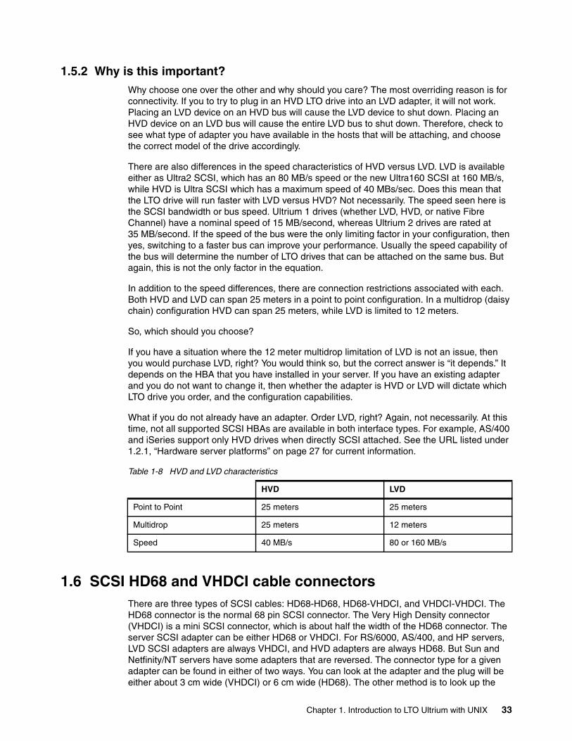
1.5.2 Why is this important?Why choose one over the other and why should you care? The most overriding reason is for connectivity. If you to try to plug in an HVD LTO drive into an LVD adapter, it will not work. Placing an LVD device on an HVD bus will cause the LVD device to shut down. Placing an HVD device on an LVD bus will cause the entire LVD bus to shut down. Therefore, check to see what type of adapter you have available in the hosts that will be attaching, and choose the correct model of the drive accordingly.
There are also differences in the speed characteristics of HVD versus LVD. LVD is available either as Ultra2 SCSI, which has an 80 MB/s speed or the new Ultra160 SCSI at 160 MB/s, while HVD is Ultra SCSI which has a maximum speed of 40 MBs/sec. Does this mean that the LTO drive will run faster with LVD versus HVD? Not necessarily. The speed seen here is the SCSI bandwidth or bus speed. Ultrium 1 drives (whether LVD, HVD, or native Fibre Channel) have a nominal speed of 15 MB/second, whereas Ultrium 2 drives are rated at 35 MB/second. If the speed of the bus were the only limiting factor in your configuration, then yes, switching to a faster bus can improve your performance. Usually the speed capability of the bus will determine the number of LTO drives that can be attached on the same bus. But again, this is not the only factor in the equation.
In addition to the speed differences, there are connection restrictions associated with each. Both HVD and LVD can span 25 meters in a point to point configuration. In a multidrop (daisy chain) configuration HVD can span 25 meters, while LVD is limited to 12 meters.
So, which should you choose?
If you have a situation where the 12 meter multidrop limitation of LVD is not an issue, then you would purchase LVD, right? You would think so, but the correct answer is “it depends.” It depends on the HBA that you have installed in your server. If you have an existing adapter and you do not want to change it, then whether the adapter is HVD or LVD will dictate which LTO drive you order, and the configuration capabilities.
What if you do not already have an adapter. Order LVD, right? Again, not necessarily. At this time, not all supported SCSI HBAs are available in both interface types. For example, AS/400 and iSeries support only HVD drives when directly SCSI attached. See the URL listed under 1.2.1, “Hardware server platforms” on page 27 for current information.
Table 1-8 HVD and LVD characteristics
1.6 SCSI HD68 and VHDCI cable connectorsThere are three types of SCSI cables: HD68-HD68, HD68-VHDCI, and VHDCI-VHDCI. The HD68 connector is the normal 68 pin SCSI connector. The Very High Density connector (VHDCI) is a mini SCSI connector, which is about half the width of the HD68 connector. The server SCSI adapter can be either HD68 or VHDCI. For RS/6000, AS/400, and HP servers, LVD SCSI adapters are always VHDCI, and HVD adapters are always HD68. But Sun and Netfinity/NT servers have some adapters that are reversed. The connector type for a given adapter can be found in either of two ways. You can look at the adapter and the plug will be either about 3 cm wide (VHDCI) or 6 cm wide (HD68). The other method is to look up the
HVD LVD
Point to Point 25 meters 25 meters
Multidrop 25 meters 12 meters
Speed 40 MB/s 80 or 160 MB/s
Chapter 1. Introduction to LTO Ultrium with UNIX 33
adapter characteristics to determine the plug type. One source of this information is the IBM TotalStorage 3584 Tape Library Operator Guide, GA32-0468 available online at:
http://www-03.ibm.com/servers/storage/tape/resource-library.html#publications
Before the June 12, 2001 IBM LTO announcement, all the LTO tape drives used HD68 connectors. The current IBM 3584 hot swappable canister LTO drive uses the VHDCI connectors. Check to make sure you order the correct cable with the right end plug to attach to your HBA.
Figure 1-14 SCSI connectors
VHDCI HD68
34 Implementing IBM Tape in UNIX Systems
Chapter 2. IBM LTO Tape Library sharing and partitioning
In this chapter we describe the sharing and partitioning of the IBM TotalStorage 3582 Tape Library, IBM TotalStorage 3583 Tape Library, and IBM TotalStorage 3584 Tape Library.
The topics are:
� Tape library sharing and partitioning definitions
� Sharing the IBM TotalStorage 3583 Tape Library
� Partitioning the IBM TotalStorage 3583 Tape Library using the Tape Library Specialist
� Sharing the IBM TotalStorage 3584 Tape Library
� Partitioning the IBM TotalStorage 3584 Tape Library using the Tape Library Specialist
� Partitioning the IBM TotalStorage 3584 Tape Library using the Operator panel
� Using and partitioning the IBM TotalStorage 3584 Tape Library with the Advanced Library Management System (ALMS)
For additional discussions on Tape Library Sharing, refer to the redbook:
� Get More Out of Your SAN with IBM Tivoli Storage Manager, SG24-6687
Details about the ALMS functionality and setup can be found in the 3584 manuals:
� IBM TotalStorage 3584 Tape Library Operator Guide, GA32-0468
� IBM TotalStorage 3584 Tape Library Installation and Planning Guide, GA32-0469
2
© Copyright IBM Corp. 2002, 2003, 2004, 2005. All rights reserved. 35
2.1 DefinitionsIn general the sharing of devices improves the utilization of the devices and can reduce the total cost of ownership. Sharing of disk devices is a common practice. Compared to disk devices, which allow random access from different clients, tape drives are sequential devices that do not allow access from different clients at the same time. Still sharing can improve the utilization of the tape drive; indeed, a tape drive is normally not used 100% of the time by a single client (host), and there are different possible ways to share either a tape library or tape drives among multiple host. The most basic requirement in sharing any library between backup applications and servers is the ability to control the medium changer. The tape drives and media may or may not be shared, but the medium changer must be available to be manipulated by all of the backup applications and servers.
2.1.1 Library sharingWe differentiate between outboard library management and the multipath approach.
Outboard library managementOne approach is to share the library but not the tape drives. Multiple servers attached to a tape library can share the library robotic. Drives and cartridges are pooled, and such a drive and cartridge pool belong to one set of servers (one server or multiple servers) and cannot be shared with another set of servers.
Some applications, like IBM Tivoli Storage Manager use the name “library sharing” if they share drives and library. We will explain drive sharing later.
Some technique is needed to share the library robotic. The most common way is to use an outboard library manager that controls the library. The library manager receives the commands from the attached servers, controls the resources inside the library, and executes the commands received from the servers. The communication between the library manager and attached servers normally takes place over the LAN using a proprietary command set.
The tape library manager controls access to and sequencing of the medium changer. The medium changer is physically available to all backup and application servers. The IBM 3494 tape library uses this type of library sharing. For communication with the IBM 3494, a command set called mtlib must be used (see Figure 2-1). Other examples are STK with ACSLS, or ADIC with Scalar DLC.
36 Implementing IBM Tape in UNIX Systems
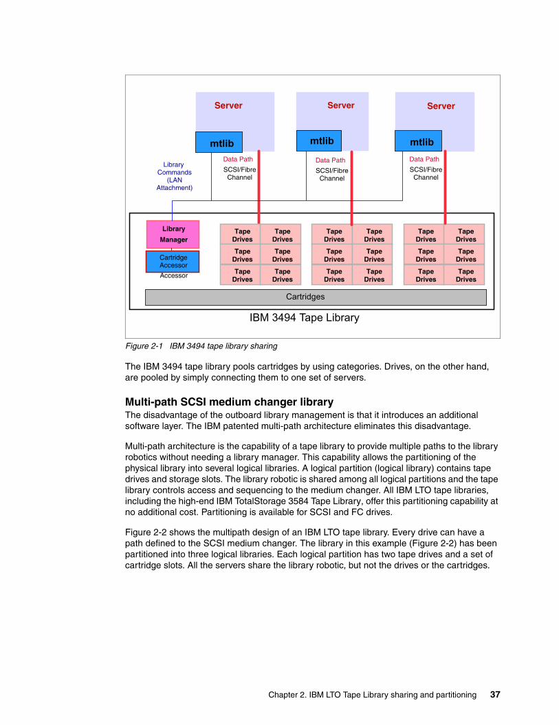
Figure 2-1 IBM 3494 tape library sharing
The IBM 3494 tape library pools cartridges by using categories. Drives, on the other hand, are pooled by simply connecting them to one set of servers.
Multi-path SCSI medium changer libraryThe disadvantage of the outboard library management is that it introduces an additional software layer. The IBM patented multi-path architecture eliminates this disadvantage.
Multi-path architecture is the capability of a tape library to provide multiple paths to the library robotics without needing a library manager. This capability allows the partitioning of the physical library into several logical libraries. A logical partition (logical library) contains tape drives and storage slots. The library robotic is shared among all logical partitions and the tape library controls access and sequencing to the medium changer. All IBM LTO tape libraries, including the high-end IBM TotalStorage 3584 Tape Library, offer this partitioning capability at no additional cost. Partitioning is available for SCSI and FC drives.
Figure 2-2 shows the multipath design of an IBM LTO tape library. Every drive can have a path defined to the SCSI medium changer. The library in this example (Figure 2-2) has been partitioned into three logical libraries. Each logical partition has two tape drives and a set of cartridge slots. All the servers share the library robotic, but not the drives or the cartridges.
Library Commands
(LANAttachment)
Library
Manager
Accessor
CartridgeAccessor
Server
Cartridges
SCSI/Fibre Channel
Data Path
Tape Drives
Tape Drives
Tape Drives
Tape Drives
Tape Drives
Tape Drives
mtlib
Tape Drives
Tape Drives
Tape Drives
Tape Drives
Tape Drives
Tape Drives
Tape Drives
Tape Drives
Tape Drives
Tape Drives
Tape Drives
Tape Drives
Server
mtlib
Server
mtlib
SCSI/Fibre Channel
Data PathSCSI/Fibre
Channel
Data Path
IBM 3494 Tape Library
Chapter 2. IBM LTO Tape Library sharing and partitioning 37
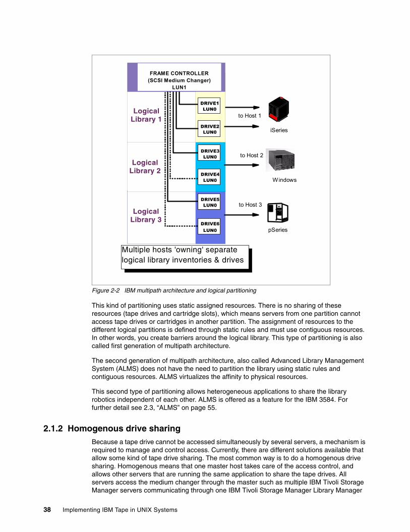
Figure 2-2 IBM multipath architecture and logical partitioning
This kind of partitioning uses static assigned resources. There is no sharing of these resources (tape drives and cartridge slots), which means servers from one partition cannot access tape drives or cartridges in another partition. The assignment of resources to the different logical partitions is defined through static rules and must use contiguous resources. In other words, you create barriers around the logical library. This type of partitioning is also called first generation of multipath architecture.
The second generation of multipath architecture, also called Advanced Library Management System (ALMS) does not have the need to partition the library using static rules and contiguous resources. ALMS virtualizes the affinity to physical resources.
This second type of partitioning allows heterogeneous applications to share the library robotics independent of each other. ALMS is offered as a feature for the IBM 3584. For further detail see 2.3, “ALMS” on page 55.
2.1.2 Homogenous drive sharingBecause a tape drive cannot be accessed simultaneously by several servers, a mechanism is required to manage and control access. Currently, there are different solutions available that allow some kind of tape drive sharing. The most common way is to do a homogenous drive sharing. Homogenous means that one master host takes care of the access control, and allows other servers that are running the same application to share the tape drives. All servers access the medium changer through the master such as multiple IBM Tivoli Storage Manager servers communicating through one IBM Tivoli Storage Manager Library Manager
DRIVE1 LUN0
DRIVE2 LUN0
Logical Library 1
Logical Library 2
Logical Library 3
FRAME CONTROLLER(SCSI Medium Changer)
LUN1
DRIVE3 LUN0
DRIVE4 LUN0
DRIVE5 LUN0
DRIVE6LUN0
to Host 1
to Host 2
to Host 3
iSeries
Windows
pSeries
Multiple hosts 'owning' separate logical library inventories & drives
38 Implementing IBM Tape in UNIX Systems
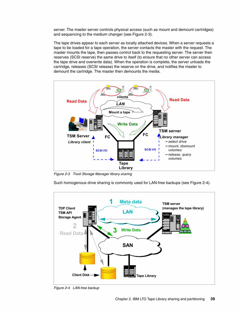
server. The master server controls physical access (such as mount and demount cartridges) and sequencing to the medium changer (see Figure 2-3).
The tape drives appear to each server as locally attached devices. When a server requests a tape to be loaded for a tape operation, the server contacts the master with the request. The master mounts the tape, then passes control back to the requesting server. The server then reserves (SCSI reserve) the same drive to itself (to ensure that no other server can access the tape drive and overwrite data). When the operation is complete, the server unloads the cartridge, releases (SCSI release) the reserve on the drive, and notifies the master to demount the cartridge. The master then demounts the media.
Figure 2-3 Tivoli Storage Manager library sharing
Such homogenous drive sharing is commonly used for LAN-free backups (see Figure 2-4).
Figure 2-4 LAN-free backup
TSM serverTSM Server FC FC
Mount a tape
Library managerselect drivemount, dismount volumesrelease, query volumes
Write Data
Library client
clients Read Data
SCSI I/O SCSI I/O
LAN Read Data
Tape Library
TSM server(manages the tape library)TDP Client
TSM APIStorage Agent
3 Write DataRead Data
2
Client Disk
SAN
Meta data1LAN
Tape Library
Chapter 2. IBM LTO Tape Library sharing and partitioning 39
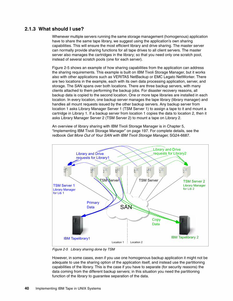
2.1.3 What should I use?Whenever multiple servers running the same storage management (homogenous) application have to share the same tape library, we suggest using the application’s own sharing capabilities. This will ensure the most efficient library and drive sharing. The master server can normally provide sharing functions for all tape drives to all client servers. The master server also manages the cartridges in the library; so that you need only one scratch pool, instead of several scratch pools (one for each server).
Figure 2-5 shows an example of how sharing capabilities from the application can address the sharing requirements. This example is built on IBM Tivoli Storage Manager, but it works also with other applications such as VERITAS NetBackup or EMC Legato NetWorker. There are two locations in the example, each with its own data processing application, server, and storage. The SAN spans over both locations. There are three backup servers, with many clients attached to them performing the backup jobs. For disaster recovery reasons, all backup data is copied to the second location. One or more tape libraries are installed in each location. In every location, one backup server manages the tape library (library manager) and handles all mount requests issued by the other backup servers. Any backup server from location 1 asks Library Manager Server 1 (TSM Server 1) to assign a tape to it and mount a cartridge in Library 1. If a backup server from location 1 copies the data to location 2, then it asks Library Manager Server 2 (TSM Server 2) to mount a tape on Library 2.
An overview of library sharing with IBM Tivoli Storage Manager is in Chapter 5, “Implementing IBM Tivoli Storage Manager” on page 197. For complete details, see the redbook Get More Out of Your SAN with IBM Tivoli Storage Manager, SG24-6687.
Figure 2-5 Library sharing done by TSM
However, in some cases, even if you use one homogenous backup application it might not be adequate to use the sharing option of the application itself, and instead use the partitioning capabilities of the library. This is the case if you have to separate (for security reasons) the data coming from the different backup servers; in this situation you need the partitioning function of the library to guarantee separation of the data.
TSM Server 1Library Manager for Lib 1
IBM Tapelibrary1 IBM Tapelibrary 2
TSM Server 2Library Manager for Lib 2
Location 1 Location 2
SAN
TSM Server TSM Server
Library and Drive requests for Library1
Library and Drive requests for Library2
Primary Data
CopyData
40 Implementing IBM Tape in UNIX Systems
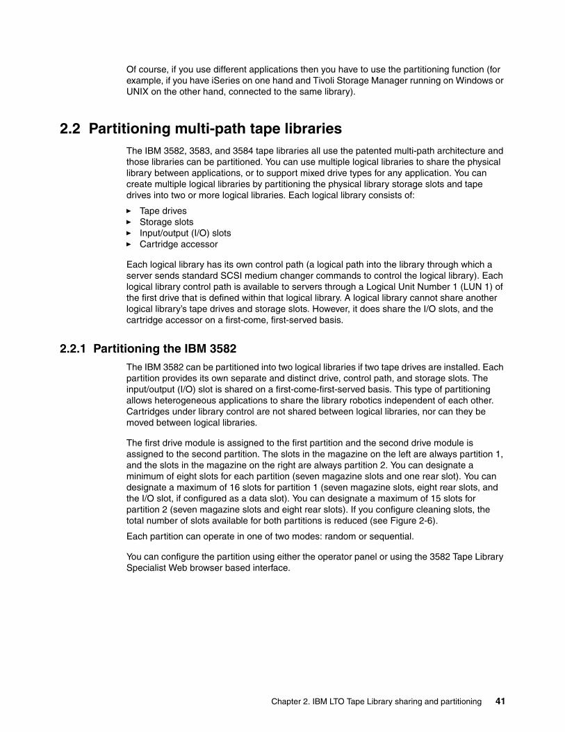
Of course, if you use different applications then you have to use the partitioning function (for example, if you have iSeries on one hand and Tivoli Storage Manager running on Windows or UNIX on the other hand, connected to the same library).
2.2 Partitioning multi-path tape librariesThe IBM 3582, 3583, and 3584 tape libraries all use the patented multi-path architecture and those libraries can be partitioned. You can use multiple logical libraries to share the physical library between applications, or to support mixed drive types for any application. You can create multiple logical libraries by partitioning the physical library storage slots and tape drives into two or more logical libraries. Each logical library consists of:
� Tape drives � Storage slots � Input/output (I/O) slots � Cartridge accessor
Each logical library has its own control path (a logical path into the library through which a server sends standard SCSI medium changer commands to control the logical library). Each logical library control path is available to servers through a Logical Unit Number 1 (LUN 1) of the first drive that is defined within that logical library. A logical library cannot share another logical library’s tape drives and storage slots. However, it does share the I/O slots, and the cartridge accessor on a first-come, first-served basis.
2.2.1 Partitioning the IBM 3582The IBM 3582 can be partitioned into two logical libraries if two tape drives are installed. Each partition provides its own separate and distinct drive, control path, and storage slots. The input/output (I/O) slot is shared on a first-come-first-served basis. This type of partitioning allows heterogeneous applications to share the library robotics independent of each other. Cartridges under library control are not shared between logical libraries, nor can they be moved between logical libraries.
The first drive module is assigned to the first partition and the second drive module is assigned to the second partition. The slots in the magazine on the left are always partition 1, and the slots in the magazine on the right are always partition 2. You can designate a minimum of eight slots for each partition (seven magazine slots and one rear slot). You can designate a maximum of 16 slots for partition 1 (seven magazine slots, eight rear slots, and the I/O slot, if configured as a data slot). You can designate a maximum of 15 slots for partition 2 (seven magazine slots and eight rear slots). If you configure cleaning slots, the total number of slots available for both partitions is reduced (see Figure 2-6).
Each partition can operate in one of two modes: random or sequential.
You can configure the partition using either the operator panel or using the 3582 Tape Library Specialist Web browser based interface.
Chapter 2. IBM LTO Tape Library sharing and partitioning 41
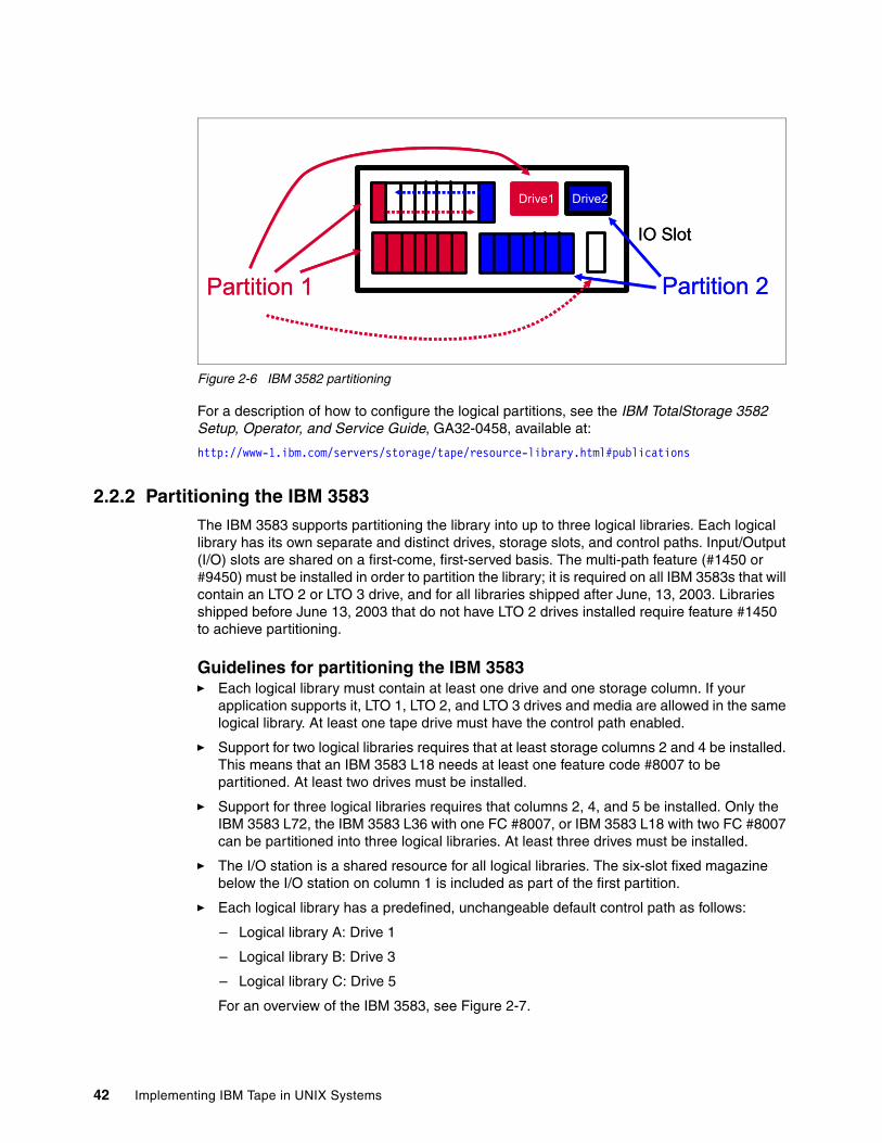
Figure 2-6 IBM 3582 partitioning
For a description of how to configure the logical partitions, see the IBM TotalStorage 3582 Setup, Operator, and Service Guide, GA32-0458, available at:
http://www-1.ibm.com/servers/storage/tape/resource-library.html#publications
2.2.2 Partitioning the IBM 3583The IBM 3583 supports partitioning the library into up to three logical libraries. Each logical library has its own separate and distinct drives, storage slots, and control paths. Input/Output (I/O) slots are shared on a first-come, first-served basis. The multi-path feature (#1450 or #9450) must be installed in order to partition the library; it is required on all IBM 3583s that will contain an LTO 2 or LTO 3 drive, and for all libraries shipped after June, 13, 2003. Libraries shipped before June 13, 2003 that do not have LTO 2 drives installed require feature #1450 to achieve partitioning.
Guidelines for partitioning the IBM 3583� Each logical library must contain at least one drive and one storage column. If your
application supports it, LTO 1, LTO 2, and LTO 3 drives and media are allowed in the same logical library. At least one tape drive must have the control path enabled.
� Support for two logical libraries requires that at least storage columns 2 and 4 be installed. This means that an IBM 3583 L18 needs at least one feature code #8007 to be partitioned. At least two drives must be installed.
� Support for three logical libraries requires that columns 2, 4, and 5 be installed. Only the IBM 3583 L72, the IBM 3583 L36 with one FC #8007, or IBM 3583 L18 with two FC #8007 can be partitioned into three logical libraries. At least three drives must be installed.
� The I/O station is a shared resource for all logical libraries. The six-slot fixed magazine below the I/O station on column 1 is included as part of the first partition.
� Each logical library has a predefined, unchangeable default control path as follows:
– Logical library A: Drive 1
– Logical library B: Drive 3
– Logical library C: Drive 5
For an overview of the IBM 3583, see Figure 2-7.
Drive1 Drive2
Partition 1 Partition 2
IO Slot
Drive1 Drive2
Partition 1 Partition 2
IO Slot
42 Implementing IBM Tape in UNIX Systems
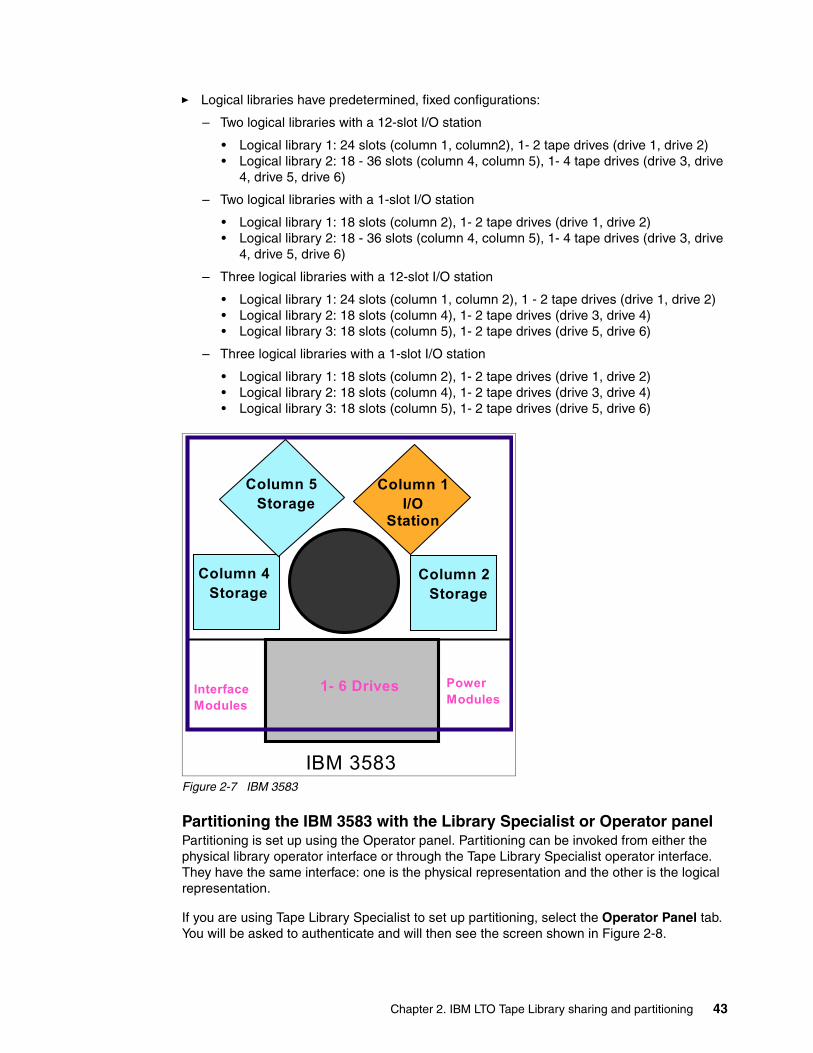
� Logical libraries have predetermined, fixed configurations:
– Two logical libraries with a 12-slot I/O station
• Logical library 1: 24 slots (column 1, column2), 1- 2 tape drives (drive 1, drive 2)• Logical library 2: 18 - 36 slots (column 4, column 5), 1- 4 tape drives (drive 3, drive
4, drive 5, drive 6)
– Two logical libraries with a 1-slot I/O station
• Logical library 1: 18 slots (column 2), 1- 2 tape drives (drive 1, drive 2)• Logical library 2: 18 - 36 slots (column 4, column 5), 1- 4 tape drives (drive 3, drive
4, drive 5, drive 6)
– Three logical libraries with a 12-slot I/O station
• Logical library 1: 24 slots (column 1, column 2), 1 - 2 tape drives (drive 1, drive 2)• Logical library 2: 18 slots (column 4), 1- 2 tape drives (drive 3, drive 4)• Logical library 3: 18 slots (column 5), 1- 2 tape drives (drive 5, drive 6)
– Three logical libraries with a 1-slot I/O station
• Logical library 1: 18 slots (column 2), 1- 2 tape drives (drive 1, drive 2)• Logical library 2: 18 slots (column 4), 1- 2 tape drives (drive 3, drive 4)• Logical library 3: 18 slots (column 5), 1- 2 tape drives (drive 5, drive 6)
Figure 2-7 IBM 3583
Partitioning the IBM 3583 with the Library Specialist or Operator panelPartitioning is set up using the Operator panel. Partitioning can be invoked from either the physical library operator interface or through the Tape Library Specialist operator interface. They have the same interface: one is the physical representation and the other is the logical representation.
If you are using Tape Library Specialist to set up partitioning, select the Operator Panel tab. You will be asked to authenticate and will then see the screen shown in Figure 2-8.
Power Modules
1- 6 Drives
Picker PickerAssemblyAssembly
Interface Modules
Column 1I/O
Station
Column 5 Storage
Column 4 Storage
Column 2 Storage
IBM 3583
Chapter 2. IBM LTO Tape Library sharing and partitioning 43
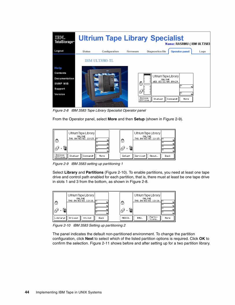
Figure 2-8 IBM 3583 Tape Library Specialist Operator panel
From the Operator panel, select More and then Setup (shown in Figure 2-9).
Figure 2-9 IBM 3583 setting up partitioning 1
Select Library and Partitions (Figure 2-10). To enable partitions, you need at least one tape drive and control path enabled for each partition, that is, there must at least be one tape drive in slots 1 and 3 from the bottom, as shown in Figure 2-8.
Figure 2-10 IBM 3583 Setting up partitioning 2
The panel indicates the default non-partitioned environment. To change the partition configuration, click Next to select which of the listed partition options is required. Click OK to confirm the selection. Figure 2-11 shows before and after setting up for a two partition library.
44 Implementing IBM Tape in UNIX Systems
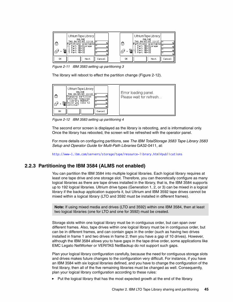
Figure 2-11 IBM 3583 setting up partitioning 3
The library will reboot to effect the partition change (Figure 2-12).
Figure 2-12 IBM 3583 setting up partitioning 4
The second error screen is displayed as the library is rebooting, and is informational only. Once the library has rebooted, the screen will be refreshed with the operator panel.
For more details on configuring partitions, see The IBM TotalStorage 3583 Tape Library 3583 Setup and Operator Guide for Multi-Path Libraries GA32-0411, at:
http://www-1.ibm.com/servers/storage/tape/resource-library.html#publications
2.2.3 Partitioning the IBM 3584 (ALMS not enabled)You can partition the IBM 3584 into multiple logical libraries. Each logical library requires at least one tape drive and one storage slot. Therefore, you can theoretically configure as many logical libraries as there are tape drives installed in the library, that is, the IBM 3584 supports up to 192 logical libraries. Ultrium drive types (Generation 1, 2, or 3) can be mixed in a logical library if the backup application supports it, but Ultrium and IBM 3592 tape drives cannot be mixed within a logical library (LTO and 3592 must be installed in different frames).
Storage slots within one logical library must be in contiguous order, but can span over different frames. Also, tape drives within one logical library must be in contiguous order, but can be in different frames, and can contain gaps in the order (such as having two drives installed in frame 1 and two drives in frame 2; then you have a gap of 10 drives). However, although the IBM 3584 allows you to have gaps in the tape drive order, some applications like EMC Legato NetWorker or VERITAS NetBackup do not support such gaps.
Plan your logical library configuration carefully, because the need for contiguous storage slots and drives makes future changes to the configuration very difficult. For instance, if you have an IBM 3584 with six logical libraries defined, and you have to change the configuration of the first library, then all of the five remaining libraries must be changed as well. Consequently, plan your logical library configuration according to these rules:
� Put the logical library that has the most expected growth at the end of the library.
Note: If using mixed media and drives (LTO and 3592) within one IBM 3584, then at least two logical libraries (one for LTO and one for 3592) must be created.
Chapter 2. IBM LTO Tape Library sharing and partitioning 45
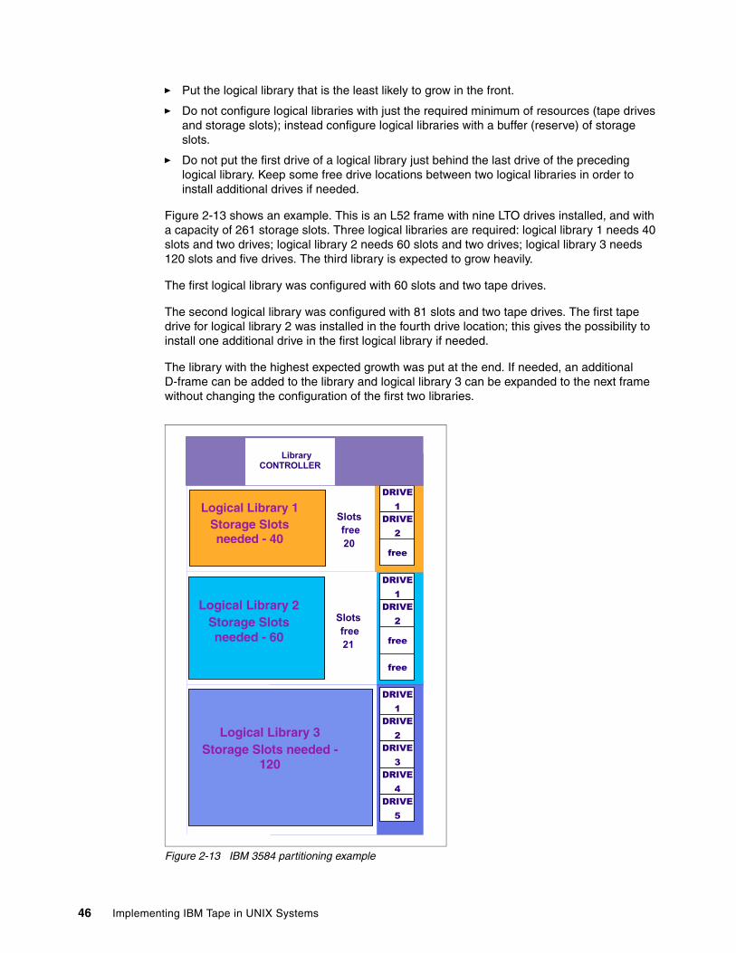
� Put the logical library that is the least likely to grow in the front.
� Do not configure logical libraries with just the required minimum of resources (tape drives and storage slots); instead configure logical libraries with a buffer (reserve) of storage slots.
� Do not put the first drive of a logical library just behind the last drive of the preceding logical library. Keep some free drive locations between two logical libraries in order to install additional drives if needed.
Figure 2-13 shows an example. This is an L52 frame with nine LTO drives installed, and with a capacity of 261 storage slots. Three logical libraries are required: logical library 1 needs 40 slots and two drives; logical library 2 needs 60 slots and two drives; logical library 3 needs 120 slots and five drives. The third library is expected to grow heavily.
The first logical library was configured with 60 slots and two tape drives.
The second logical library was configured with 81 slots and two tape drives. The first tape drive for logical library 2 was installed in the fourth drive location; this gives the possibility to install one additional drive in the first logical library if needed.
The library with the highest expected growth was put at the end. If needed, an additional D-frame can be added to the library and logical library 3 can be expanded to the next frame without changing the configuration of the first two libraries.
Figure 2-13 IBM 3584 partitioning example
Slots free20
DRIVE1Logical Library 1
Storage Slots needed - 40
Library CONTROLLER
DRIVE2
free
DRIVE1
DRIVE2
free
free
Slots free21
Logical Library 2Storage Slots needed - 60
DRIVE1
DRIVE2
DRIVE4
DRIVE3
DRIVE5
Logical Library 3Storage Slots needed -
120
46 Implementing IBM Tape in UNIX Systems
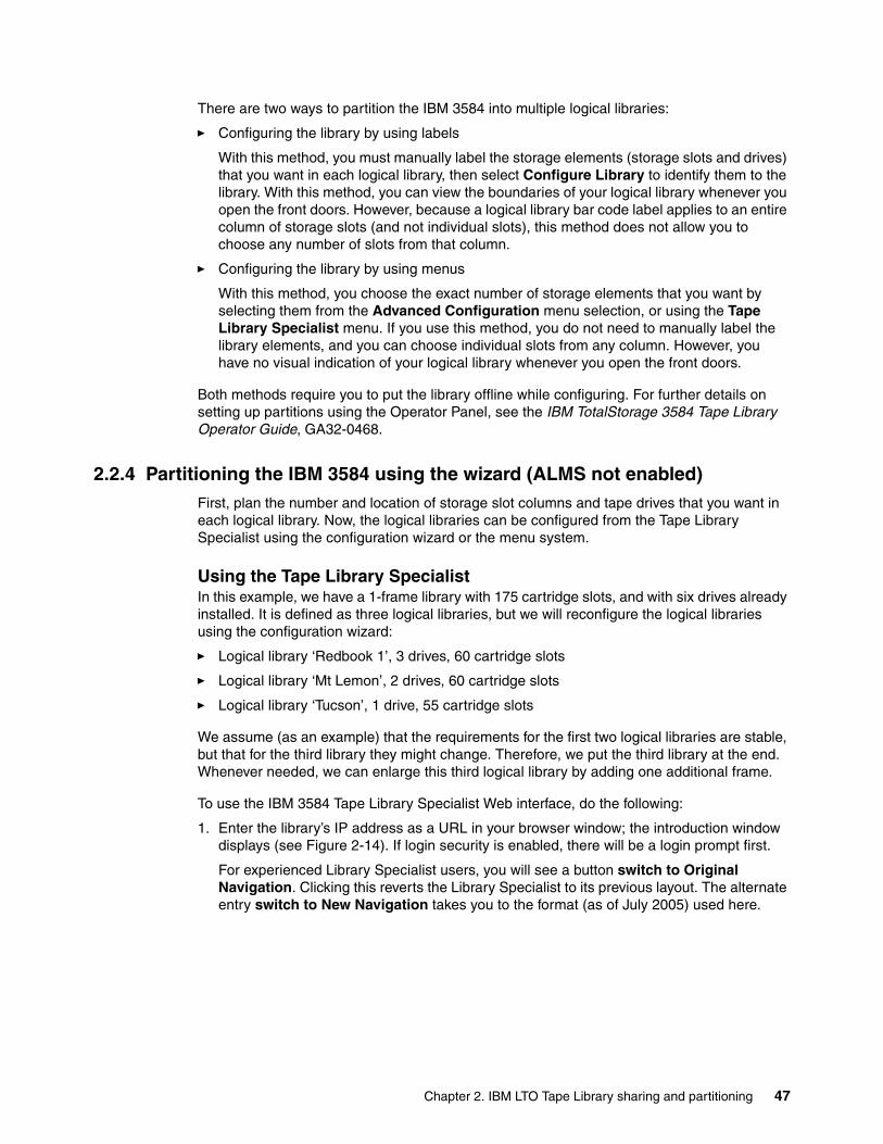
There are two ways to partition the IBM 3584 into multiple logical libraries:
� Configuring the library by using labels
With this method, you must manually label the storage elements (storage slots and drives) that you want in each logical library, then select Configure Library to identify them to the library. With this method, you can view the boundaries of your logical library whenever you open the front doors. However, because a logical library bar code label applies to an entire column of storage slots (and not individual slots), this method does not allow you to choose any number of slots from that column.
� Configuring the library by using menus
With this method, you choose the exact number of storage elements that you want by selecting them from the Advanced Configuration menu selection, or using the Tape Library Specialist menu. If you use this method, you do not need to manually label the library elements, and you can choose individual slots from any column. However, you have no visual indication of your logical library whenever you open the front doors.
Both methods require you to put the library offline while configuring. For further details on setting up partitions using the Operator Panel, see the IBM TotalStorage 3584 Tape Library Operator Guide, GA32-0468.
2.2.4 Partitioning the IBM 3584 using the wizard (ALMS not enabled)First, plan the number and location of storage slot columns and tape drives that you want in each logical library. Now, the logical libraries can be configured from the Tape Library Specialist using the configuration wizard or the menu system.
Using the Tape Library SpecialistIn this example, we have a 1-frame library with 175 cartridge slots, and with six drives already installed. It is defined as three logical libraries, but we will reconfigure the logical libraries using the configuration wizard:
� Logical library ‘Redbook 1’, 3 drives, 60 cartridge slots
� Logical library ‘Mt Lemon’, 2 drives, 60 cartridge slots
� Logical library ‘Tucson’, 1 drive, 55 cartridge slots
We assume (as an example) that the requirements for the first two logical libraries are stable, but that for the third library they might change. Therefore, we put the third library at the end. Whenever needed, we can enlarge this third logical library by adding one additional frame.
To use the IBM 3584 Tape Library Specialist Web interface, do the following:
1. Enter the library’s IP address as a URL in your browser window; the introduction window displays (see Figure 2-14). If login security is enabled, there will be a login prompt first.
For experienced Library Specialist users, you will see a button switch to Original Navigation. Clicking this reverts the Library Specialist to its previous layout. The alternate entry switch to New Navigation takes you to the format (as of July 2005) used here.
Chapter 2. IBM LTO Tape Library sharing and partitioning 47
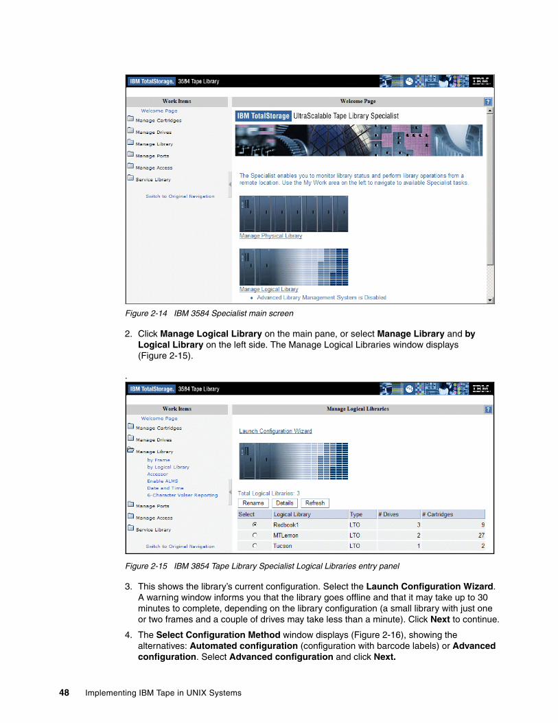
Figure 2-14 IBM 3584 Specialist main screen
2. Click Manage Logical Library on the main pane, or select Manage Library and by Logical Library on the left side. The Manage Logical Libraries window displays (Figure 2-15).
.
Figure 2-15 IBM 3854 Tape Library Specialist Logical Libraries entry panel
3. This shows the library’s current configuration. Select the Launch Configuration Wizard. A warning window informs you that the library goes offline and that it may take up to 30 minutes to complete, depending on the library configuration (a small library with just one or two frames and a couple of drives may take less than a minute). Click Next to continue.
4. The Select Configuration Method window displays (Figure 2-16), showing the alternatives: Automated configuration (configuration with barcode labels) or Advanced configuration. Select Advanced configuration and click Next.
48 Implementing IBM Tape in UNIX Systems
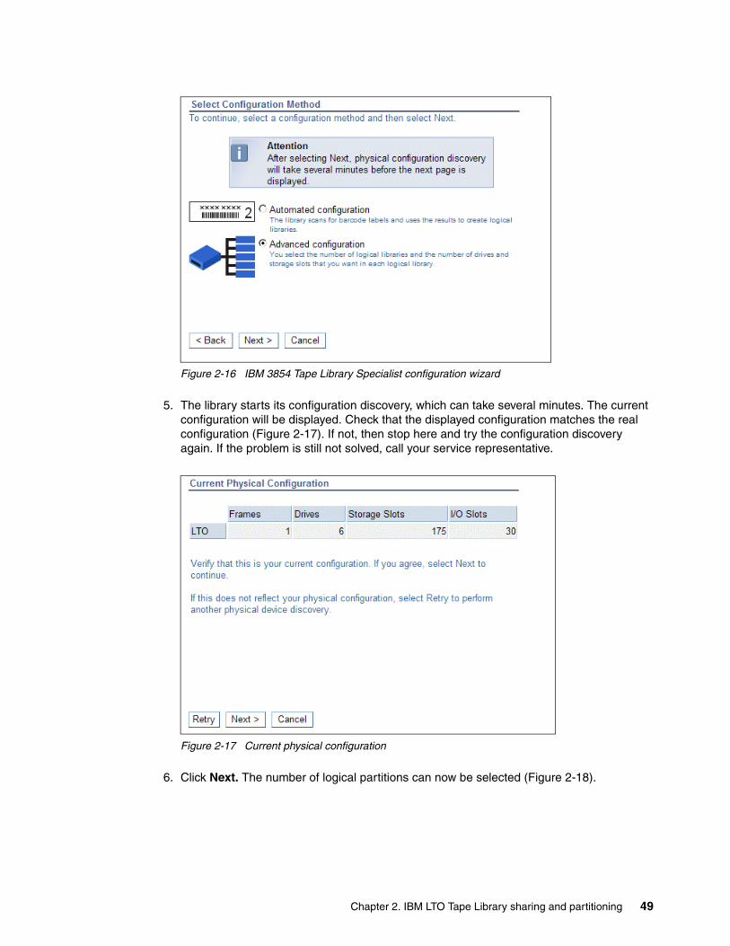
Figure 2-16 IBM 3854 Tape Library Specialist configuration wizard
5. The library starts its configuration discovery, which can take several minutes. The current configuration will be displayed. Check that the displayed configuration matches the real configuration (Figure 2-17). If not, then stop here and try the configuration discovery again. If the problem is still not solved, call your service representative.
Figure 2-17 Current physical configuration
6. Click Next. The number of logical partitions can now be selected (Figure 2-18).
Chapter 2. IBM LTO Tape Library sharing and partitioning 49
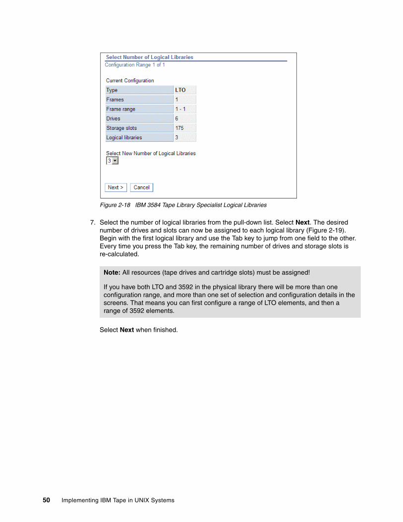
Figure 2-18 IBM 3584 Tape Library Specialist Logical Libraries
7. Select the number of logical libraries from the pull-down list. Select Next. The desired number of drives and slots can now be assigned to each logical library (Figure 2-19). Begin with the first logical library and use the Tab key to jump from one field to the other. Every time you press the Tab key, the remaining number of drives and storage slots is re-calculated.
Select Next when finished.
Note: All resources (tape drives and cartridge slots) must be assigned!
If you have both LTO and 3592 in the physical library there will be more than one configuration range, and more than one set of selection and configuration details in the screens. That means you can first configure a range of LTO elements, and then a range of 3592 elements.
50 Implementing IBM Tape in UNIX Systems
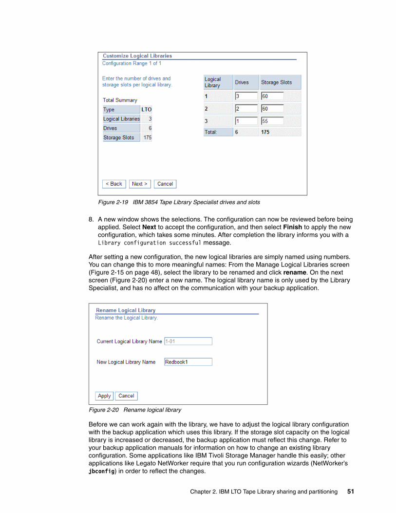
Figure 2-19 IBM 3854 Tape Library Specialist drives and slots
8. A new window shows the selections. The configuration can now be reviewed before being applied. Select Next to accept the configuration, and then select Finish to apply the new configuration, which takes some minutes. After completion the library informs you with a Library configuration successful message.
After setting a new configuration, the new logical libraries are simply named using numbers. You can change this to more meaningful names: From the Manage Logical Libraries screen (Figure 2-15 on page 48), select the library to be renamed and click rename. On the next screen (Figure 2-20) enter a new name. The logical library name is only used by the Library Specialist, and has no affect on the communication with your backup application.
Figure 2-20 Rename logical library
Before we can work again with the library, we have to adjust the logical library configuration with the backup application which uses this library. If the storage slot capacity on the logical library is increased or decreased, the backup application must reflect this change. Refer to your backup application manuals for information on how to change an existing library configuration. Some applications like IBM Tivoli Storage Manager handle this easily; other applications like Legato NetWorker require that you run configuration wizards (NetWorker’s jbconfig) in order to reflect the changes.
Chapter 2. IBM LTO Tape Library sharing and partitioning 51
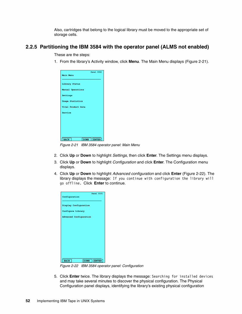
Also, cartridges that belong to the logical library must be moved to the appropriate set of storage cells.
2.2.5 Partitioning the IBM 3584 with the operator panel (ALMS not enabled)These are the steps:
1. From the library’s Activity window, click Menu. The Main Menu displays (Figure 2-21).
Figure 2-21 IBM 3584 operator panel: Main Menu
2. Click Up or Down to highlight Settings, then click Enter. The Settings menu displays.
3. Click Up or Down to highlight Configuration and click Enter. The Configuration menu displays.
4. Click Up or Down to highlight Advanced configuration and click Enter (Figure 2-22). The library displays the message: If you continue with configuration the library will go offline. Click Enter to continue.
Figure 2-22 IBM 3584 operator panel: Configuration
5. Click Enter twice. The library displays the message: Searching for installed devices and may take several minutes to discover the physical configuration. The Physical Configuration panel displays, identifying the library’s existing physical configuration
Panel 0002
Main Menu______________________________
Library Status
Manual Operations
Settings
Usage Statistics
Vital Product Data
Service
______________________________
BACK DOWN ENTER
Panel 0101
Configuration______________________________
Display Configuration
Configure Library
Advanced Configuration
______________________________
BACK DOWN ENTER
52 Implementing IBM Tape in UNIX Systems
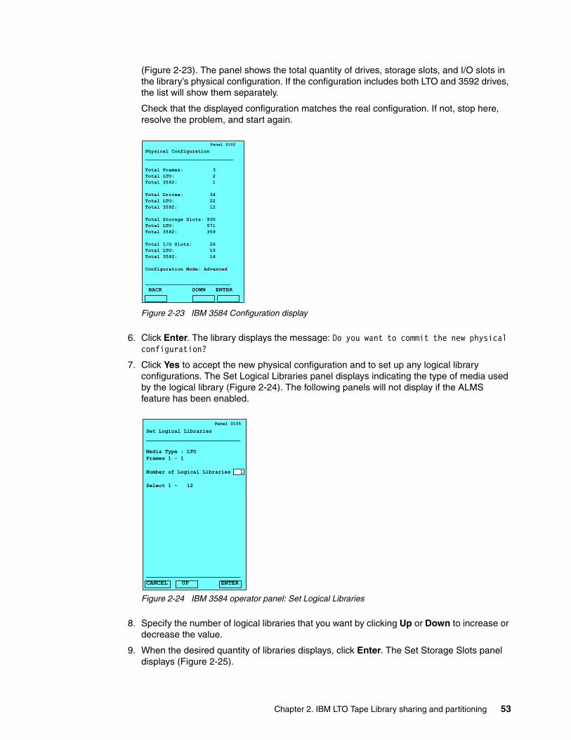
(Figure 2-23). The panel shows the total quantity of drives, storage slots, and I/O slots in the library’s physical configuration. If the configuration includes both LTO and 3592 drives, the list will show them separately.
Check that the displayed configuration matches the real configuration. If not, stop here, resolve the problem, and start again.
Figure 2-23 IBM 3584 Configuration display
6. Click Enter. The library displays the message: Do you want to commit the new physical configuration?
7. Click Yes to accept the new physical configuration and to set up any logical library configurations. The Set Logical Libraries panel displays indicating the type of media used by the logical library (Figure 2-24). The following panels will not display if the ALMS feature has been enabled.
Figure 2-24 IBM 3584 operator panel: Set Logical Libraries
8. Specify the number of logical libraries that you want by clicking Up or Down to increase or decrease the value.
9. When the desired quantity of libraries displays, click Enter. The Set Storage Slots panel displays (Figure 2-25).
Panel 0102
Physical Configuration______________________________
Total Frames: 3 Total LTO: 2 Total 3592: 1
Total Drives: 34 Total LTO: 22 Total 3592: 12 Total Storage Slots: 930 Total LTO: 571 Total 3592: 359
Total I/O Slots: 26 Total LTO: 10 Total 3592: 16
Configuration Mode: Advanced
_____________________________
BACK DOWN ENTER
Panel 0105
Set Logical Libraries______________________________
Media Type : LTOFrames 1 - 1
Number of Logical Libraries 1
Select 1 - 12
______________________________
CANCEL UP ENTER
Chapter 2. IBM LTO Tape Library sharing and partitioning 53
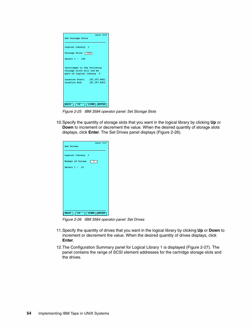
Figure 2-25 IBM 3584 operator panel: Set Storage Slots
10.Specify the quantity of storage slots that you want in the logical library by clicking Up or Down to increment or decrement the value. When the desired quantity of storage slots displays, click Enter. The Set Drives panel displays (Figure 2-26).
Figure 2-26 IBM 3584 operator panel: Set Drives
11.Specify the quantity of drives that you want in the logical library by clicking Up or Down to increment or decrement the value. When the desired quantity of drives displays, click Enter.
12.The Configuration Summary panel for Logical Library 1 is displayed (Figure 2-27). The panel contains the range of SCSI element addresses for the cartridge storage slots and the drives.
Panel 0106
Set Storage Slots______________________________
Logical Library 1
Storage Slots 139
Select 1 - 140
Cartridges in the followingstorage slots will now bepart of logical library 2 Location Start: [F1,C07,R42]Location End: [F1,C07,R43]
______________________________
BACK UP DOWN ENTER
Panel 0107
Set Drives______________________________
Logical Library 1
Nunber of Drives 1
Select 1 - 12
______________________________
BACK UP DOWN ENTER
54 Implementing IBM Tape in UNIX Systems
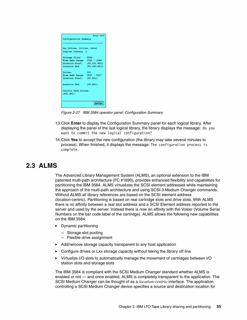
Figure 2-27 IBM 3584 operator panel: Configuration Summary
13.Click Enter to display the Configuration Summary panel for each logical library. After displaying the panel of the last logical library, the library displays the message: Do you want to commit the new logical configuration?
14.Click Yes to accept the new configuration (the library may take several minutes to process). When finished, it displays the message: The configuration process is complete.
2.3 ALMSThe Advanced Library Management System (ALMS), an optional extension to the IBM patented multi-path architecture (FC #1690), provides enhanced flexibility and capabilities for partitioning the IBM 3584. ALMS virtualizes the SCSI element addresses while maintaining the approach of the multi-path architecture and using SCSI-3 Medium Changer commands. Without ALMS all library references are based on the SCSI element address (location-centric). Partitioning is based on real cartridge slots and drive slots. With ALMS there is no affinity between a real slot address and a SCSI Element address reported to the server and used by the server. Instead there is now an affinity with the Volser (Volume Serial Numbers on the bar code label of the cartridge). ALMS allows the following new capabilities on the IBM 3584:
� Dynamic partitioning
– Storage slot pooling– Flexible drive assignment
� Add/remove storage capacity transparent to any host application
� Configure drives or Lxx storage capacity without taking the library off line
� Virtualize I/O slots to automatically manage the movement of cartridges between I/O station slots and storage slots
The IBM 3584 is compliant with the SCSI Medium Changer standard whether ALMS is enabled or not — and once enabled, ALMS is completely transparent to the application. The SCSI Medium Changer can be thought of as a location-centric interface. The application controlling a SCSI Medium Changer device specifies a source and destination location for
Panel 0103
Configuration Summary______________________________
Key:[F=Frame, C=Column, R=Row]
Logical Library 1
Storage Slots: 0064 Elem Addr Range: 1025 - 1088 Location Start: [F1,C01,R02]Location End: [F1,C03,R21]
Drives: 001Elem Addr Range: 0257 - 0257Location Start: [F1,R01]
Location End: [F1,R01]
Control Path Drives:[F01,R01]
______________________________
ENTER
Chapter 2. IBM LTO Tape Library sharing and partitioning 55
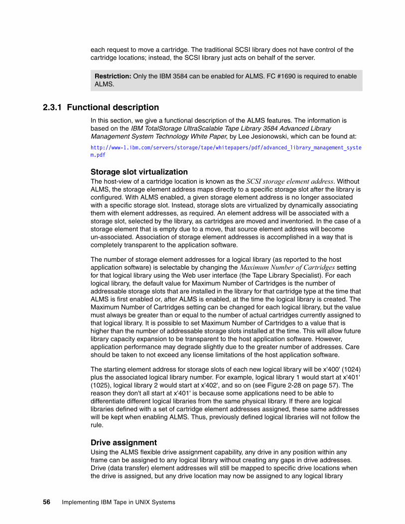
each request to move a cartridge. The traditional SCSI library does not have control of the cartridge locations; instead, the SCSI library just acts on behalf of the server.
2.3.1 Functional descriptionIn this section, we give a functional description of the ALMS features. The information is based on the IBM TotalStorage UltraScalable Tape Library 3584 Advanced Library Management System Technology White Paper, by Lee Jesionowski, which can be found at:
http://www-1.ibm.com/servers/storage/tape/whitepapers/pdf/advanced_library_management_system.pdf
Storage slot virtualizationThe host-view of a cartridge location is known as the SCSI storage element address. Without ALMS, the storage element address maps directly to a specific storage slot after the library is configured. With ALMS enabled, a given storage element address is no longer associated with a specific storage slot. Instead, storage slots are virtualized by dynamically associating them with element addresses, as required. An element address will be associated with a storage slot, selected by the library, as cartridges are moved and inventoried. In the case of a storage element that is empty due to a move, that source element address will become un-associated. Association of storage element addresses is accomplished in a way that is completely transparent to the application software.
The number of storage element addresses for a logical library (as reported to the host application software) is selectable by changing the Maximum Number of Cartridges setting for that logical library using the Web user interface (the Tape Library Specialist). For each logical library, the default value for Maximum Number of Cartridges is the number of addressable storage slots that are installed in the library for that cartridge type at the time that ALMS is first enabled or, after ALMS is enabled, at the time the logical library is created. The Maximum Number of Cartridges setting can be changed for each logical library, but the value must always be greater than or equal to the number of actual cartridges currently assigned to that logical library. It is possible to set Maximum Number of Cartridges to a value that is higher than the number of addressable storage slots installed at the time. This will allow future library capacity expansion to be transparent to the host application software. However, application performance may degrade slightly due to the greater number of addresses. Care should be taken to not exceed any license limitations of the host application software.
The starting element address for storage slots of each new logical library will be x'400' (1024) plus the associated logical library number. For example, logical library 1 would start at x'401' (1025), logical library 2 would start at x'402', and so on (see Figure 2-28 on page 57). The reason they don't all start at x'401' is because some applications need to be able to differentiate different logical libraries from the same physical library. If there are logical libraries defined with a set of cartridge element addresses assigned, these same addresses will be kept when enabling ALMS. Thus, previously defined logical libraries will not follow the rule.
Drive assignmentUsing the ALMS flexible drive assignment capability, any drive in any position within any frame can be assigned to any logical library without creating any gaps in drive addresses. Drive (data transfer) element addresses will still be mapped to specific drive locations when the drive is assigned, but any drive location may now be assigned to any logical library
Restriction: Only the IBM 3584 can be enabled for ALMS. FC #1690 is required to enable ALMS.
56 Implementing IBM Tape in UNIX Systems
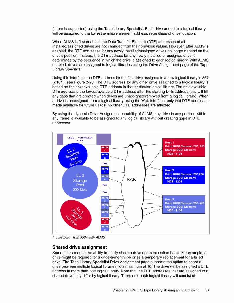
(intermix supported) using the Tape Library Specialist. Each drive added to a logical library will be assigned to the lowest available element address, regardless of drive location.
When ALMS is first enabled, the Data Transfer Element (DTE) addresses of all installed/assigned drives are not changed from their previous values. However, after ALMS is enabled, the DTE addresses for any newly installed/assigned drives no longer depend on the drive’s position. Instead, the DTE address for any newly installed or assigned drive is determined by the sequence in which the drive is assigned to each logical library. With ALMS enabled, drives are assigned to logical libraries using the Drive Assignment page of the Tape Library Specialist.
Using this interface, the DTE address for the first drive assigned to a new logical library is 257 (x'101'); see Figure 2-28. The DTE address for any other drive assigned to a logical library is based on the next available DTE address in that particular logical library. The next available DTE address is the lowest available DTE address after the starting DTE address (this will fill any gaps that are created when drives are unassigned/removed from a logical library). When a drive is unassigned from a logical library using the Web interface, only that DTE address is made available for future usage, no other DTE addresses are affected.
By using the dynamic Drive Assignment capability of ALMS, any drive in any position within any frame is available to be assigned to any logical library without creating gaps in DTE addresses.
Figure 2-28 IBM 3584 with ALMS
Shared drive assignmentSome users require the ability to easily share a drive on an exception basis. For example, a drive might be required for a once-a-month job or as a temporary replacement for a failed drive. The Tape Library Specialist Drive Assignment page supports the option to share a drive between multiple logical libraries, to a maximum of 10. The drive will be assigned a DTE address in more than one logical library. Note that the DTE addresses that are assigned to a shared drive may differ by logical library. Therefore, each logical library will consist of
DRIVE1
Library CONTROLLERALMS
DRIVE1
DRIVE1
DRIVE4
DRIVE2
DRIVE5
DRIVE3
DRIVE2
LL 1 Storage Pool
100 Slots
LL 2
Storage
Pool
80 Slots
LL 3Storage
Pool200 Slots
free
free
free
Host 1Drive SCSI Element: 257, 258Storage SCSI Element: 1025 - 1104
Host 2Drive SCSI Element: 257,258Storage SCSI Element: 1026 - 1225
Host 3Drive SCSI Element: 257..261Storage SCSI Element: 1027 - 1126
DRIVE2
SAN
Chapter 2. IBM LTO Tape Library sharing and partitioning 57
dedicated drives and shared drives. Each logical library will map a drive element address to the location of both dedicated and shared drives.
This option reduces the requirement to configure the tape drive every time it is needed and unconfigure it when it is not needed.
The Drive Assignment Web screen supports the following point-and-click capabilities, which are non-disruptive to other logical libraries:
� Assign the drive � Remove the drive assignment� Reassign the drive
When a cartridge is mounted in a shared drive, the library will only accept a de-mount command requested via the source logical library; any de-mount command requested via other logical libraries will be rejected.
However, the data path to the tape drive itself is not protected by the library. Therefore, the customer must make sure that shared drives are not accessed by the wrong application via the data path. To ensure this, one option is to use the SCSI reserve/release option on open and close. The device driver together with the application handles this. On opening a tape drive, the application initiates a SCSI reserve through the tape device driver. No other server can access the tape drive any more (except for commands such as Inquiry). This ensures that data is not overwritten by any other host or application. After the device is closed, the application must send a SCSI release to the tape drive. Most applications handle this, but it should be confirmed with the backup software provider.
SAN zoning can also be used to prevent access to the same tape drives by different servers.
When a tape drive is shared by applications, any application using the drive has no knowledge of the other applications sharing the tape drive. For example, if there is already a cartridge loaded and in use by application A, application B does not know it and tries also to mount a cartridge in the same drive. Application B would in that case get a failure, and the job application B was executing would fail. Some applications periodically scan all the tape drives and if they recognize that there is a cartridge mounted without initiation from the application itself, the application will consider this tape drive offline.
In any case we recommend to not allow multiple applications to use shared tape drives concurrently. In other words, set tape drives offline (or in service mode) from the application whenever it is not used by that application.
The sharing option is mainly intended for environments where some drives are just needed once in a while and must be pre-configured for the application.
Eliminate downtime for total capacity changesWith ALMS enabled, the total library capacity (number of addressable storage slots) can be changed transparent to each application as the Maximum Number of Cartridges value is not impacted by changes to the number of storage slots. The additional storage slots are simply more slots the cartridges can be moved to upon insertion.
Further, using the new Intermediate and Full Capacity on Demand capabilities of the 3584 Model L22 and L52, no downtime is required at all for the change to total L-frame capacity.
Attention: An application which occasionally leaves cartridges in drives or which periodically scans all configured drives will not be a good candidate for sharing drives between logical libraries.
58 Implementing IBM Tape in UNIX Systems
Storage slot poolingALMS allows logical libraries to be added or deleted non-disruptively. The minimum logical library simply has a name — it can be thought of as a file which initially has no contents.
Drives can be “placed in this file” using the Drive Assignment page of the Tape Library Specialist Web interface. Cartridges can also be placed in this file, based on their volume serial (VOLSER) numbers and by using one of the following methods (in priority order):
� Migration from static partitioning (UI enablement of ALMS)
� Cartridge assignment policy (automatic at time of insertion)
� Insert notification (operator panel selection at time of insertion)
� Software application move from I/O Station (based on source of command)
� Manual assignment using the Tape Library Specialist
The VOLSER assignment and physical location of cartridges are stored in non-volatile RAM (both primary and backup copies). All storage slots are first-come, first-served to each logical library based on cartridge insert operations. Therefore, storage slots are pooled as a shared resource so that changes to the capacity allocation for each logical library do not require any downtime or administrator involvement at all. Indications of a full or nearly full physical library will continue to be provided via the operator panel, Tape Library Specialist, and SNMP traps.
Cartridge assignment policyThe cartridge assignment policy (CAP) of the IBM 3584 allows you to assign ranges of cartridge volume serial (VOLSER) numbers to specific logical libraries through the Tape Library Specialist. When a cartridge is inserted into the I/O station, the cartridge assignment policy will be used to attempt to associate the cartridge with a logical library. If the cartridge is not in the CAP and insert notification (discussed in the next section) is enabled, you can assign the cartridge to a logical library by using the Insert Notification process on the library’s operator panel or keep the cartridge as unassigned and assign it later using the Tape Library Specialist. If the insert notification feature is not enabled, and the cartridge was not in the CAP, the cartridge will eventually be available to all hosts. Unassigned cartridges can also be assigned to a logical library by creating a new VOLSER range, then performing a manual inventory to assign those cartridges through the cartridge assignment policy.
The cartridge assignment policy is media-type specific. As such, it is based on the six most significant characters of the cartridge label, and the ranges of VOLSERs do not include the media-type indicator (L2, L3, JA, and so forth). This means that two identical labels (except for the media-type indicator) could be assigned to two different logical libraries; for example, libraries that contain Ultrium or 3592 drives.
Insert notificationInsert notification is an option that enables the IBM 3584 to monitor the I/O station for any new media which does not have a logical library assignment. This feature can be enabled through the Operator Panel or through the Tape Library Specialist. With Insert Notification enabled, when new media is detected the operator panel displays a message that asks to select a logical library. Any unassigned cartridges in the I/O station will be assigned to the logical library that you select (and all other logical libraries will not be able to access the cartridges). The library includes an option to defer any assignment and there is a time-out period when the deferral will automatically take effect.
Note: The cartridge assignment policy does not reassign an assigned tape cartridge. To reassign a cartridge, use the procedure for assigning cartridges to a logical library.
Chapter 2. IBM LTO Tape Library sharing and partitioning 59
Virtual I/OThe IBM 3584 has input/output (I/O) stations and I/O slots that allow you to import and export up to 32 cartridges at any given time. The I/O slots are also known as import/export elements (IEEs). Virtual I/O slots increase the quantity of available I/O slots by allowing storage slots to appear to the host as I/O slots. Storage slots appearing to the host as I/O slots are called virtual import/export elements (VIEEs). The goal of virtual I/O slots is to reduce the dependencies between the system administrator and library operator so that each performs their import and export tasks without needing the other to perform any actions. With virtual I/O slots, the library automatically moves cartridges from the I/O stations to physical storage slots and from physical storage slots to the I/O stations.
With Virtual I/O slots, you can configure up to 255 VIEEs per logical library. Each logical library will have a unique VIEE address space that is not accessible by other logical libraries. The number of VIO (virtual I/O) slots can be set using the Max VIO Slots button for the logical libraries (see Figure 2-33 on page 64). New logical libraries will by default be assigned the maximum number, while logical libraries defined before ALMS is enabled will initially have the number of physical I/O slots in the library.
Before virtual I/O slots, the IEE space consisted of physical I/O station slots (10, 30, 16, or 32, depending on the frame model type) which were shared by all logical libraries. If the application or system administrator did not explicitly import the cartridges from the I/O station into library storage the cartridges would remain in the I/O station. This reduced the number of IEEs available to process imports and exports.
With virtual I/O slots, when cartridges are inserted into the I/O station, the library will work with the cartridge assignment policy or insert notification to assign a cartridge to the correct logical library VIEE space, and cartridges will automatically be moved into library storage slots. If there is no cartridge assignment policy assigned, and insert notification is disabled for a particular cartridge, then that cartridge will be inserted into the VIEE space of all logical libraries and automatically be moved into a library storage slot. The VIEE temporarily takes on the attributes of an IEE until a host moves the cartridge into a storage element (StE).
If a cartridge cannot be assigned, this will be reported as Assignment Pending. This can occur if the assigned logical library has no available VIEE slots, or if all of the logical libraries do not have a common VIEE to share. To resolve this, either free up VIEE addresses so this is available in all libraries, or make a specific assignment of this cartridge to a logical library.
When the host move occurs, if the cartridge is in a storage slot, no physical move is needed and the element transitions from a VIEE to an StE. Similarly, when a host exports a cartridge from an StE, the physical storage slot will be reported as a VIEE without moving the cartridge to the I/O station. The library will monitor when free space is available in the I/O station and move exported cartridges at the library’s convenience.
As seen in Figure 2-33 on page 64, there is also a button for Hide/Show Exports. Show Exports is the default, and this will show a VIEE inventory of cartridges exported from the logical library. These cartridges will then fill one of the VIEE slots for that logical library. Export Complete will be shown when the exported cartridge is physically in an I/O station slot.
Selecting Hide Exports will move the exported cartridges to a library-maintained export queue, the VIEE is free immediately for other import/exports, and the exported cartridge will disappear from the host application’s inventory data. Exporting a cartridge will be reported as Export in Progress if there is no available VIEE, and will not complete until one is available. With Hide Exports this situation will not occur.
Support for virtual I/O slots is provided at the latest released level of library microcode (5360) and will be enabled by default when ALMS is enabled. For existing customers whose IBM
60 Implementing IBM Tape in UNIX Systems
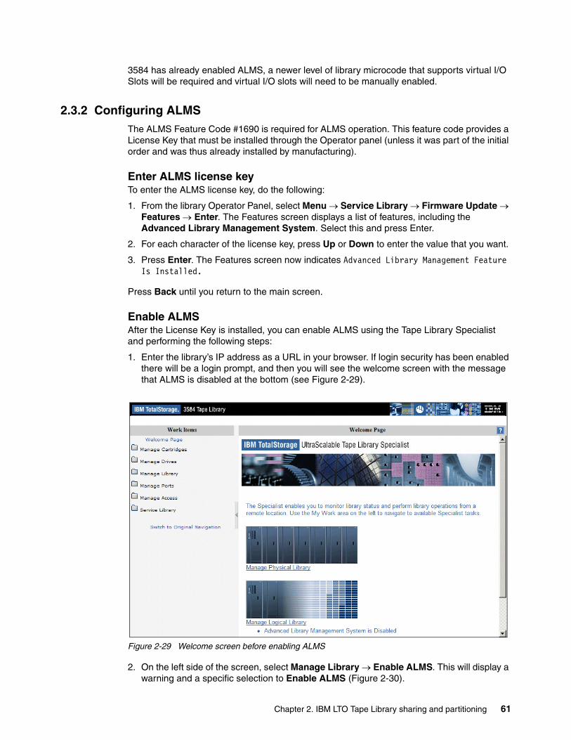
3584 has already enabled ALMS, a newer level of library microcode that supports virtual I/O Slots will be required and virtual I/O slots will need to be manually enabled.
2.3.2 Configuring ALMSThe ALMS Feature Code #1690 is required for ALMS operation. This feature code provides a License Key that must be installed through the Operator panel (unless it was part of the initial order and was thus already installed by manufacturing).
Enter ALMS license keyTo enter the ALMS license key, do the following:
1. From the library Operator Panel, select Menu → Service Library → Firmware Update → Features → Enter. The Features screen displays a list of features, including the Advanced Library Management System. Select this and press Enter.
2. For each character of the license key, press Up or Down to enter the value that you want.
3. Press Enter. The Features screen now indicates Advanced Library Management Feature Is Installed.
Press Back until you return to the main screen.
Enable ALMSAfter the License Key is installed, you can enable ALMS using the Tape Library Specialist and performing the following steps:
1. Enter the library’s IP address as a URL in your browser. If login security has been enabled there will be a login prompt, and then you will see the welcome screen with the message that ALMS is disabled at the bottom (see Figure 2-29).
Figure 2-29 Welcome screen before enabling ALMS
2. On the left side of the screen, select Manage Library → Enable ALMS. This will display a warning and a specific selection to Enable ALMS (Figure 2-30).
Chapter 2. IBM LTO Tape Library sharing and partitioning 61
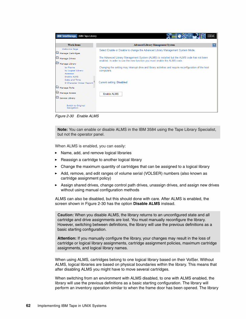
Figure 2-30 Enable ALMS
When ALMS is enabled, you can easily:
� Name, add, and remove logical libraries
� Reassign a cartridge to another logical library
� Change the maximum quantity of cartridges that can be assigned to a logical library
� Add, remove, and edit ranges of volume serial (VOLSER) numbers (also known as cartridge assignment policy)
� Assign shared drives, change control path drives, unassign drives, and assign new drives without using manual configuration methods
ALMS can also be disabled, but this should done with care. After ALMS is enabled, the screen shown in Figure 2-30 has the option Disable ALMS instead.
When using ALMS, cartridges belong to one logical library based on their VolSer. Without ALMS, logical libraries are based on physical boundaries within the library. This means that after disabling ALMS you might have to move several cartridges.
When switching from an environment with ALMS disabled, to one with ALMS enabled, the library will use the previous definitions as a basic starting configuration. The library will perform an inventory operation similar to when the frame door has been opened. The library
Note: You can enable or disable ALMS in the IBM 3584 using the Tape Library Specialist, but not the operator panel.
Caution: When you disable ALMS, the library returns to an unconfigured state and all cartridge and drive assignments are lost. You must manually reconfigure the library. However, switching between definitions, the library will use the previous definitions as a basic starting configuration.
Attention: If you manually configure the library, your changes may result in the loss of cartridge or logical library assignments, cartridge assignment policies, maximum cartridge assignments, and logical library names.
62 Implementing IBM Tape in UNIX Systems
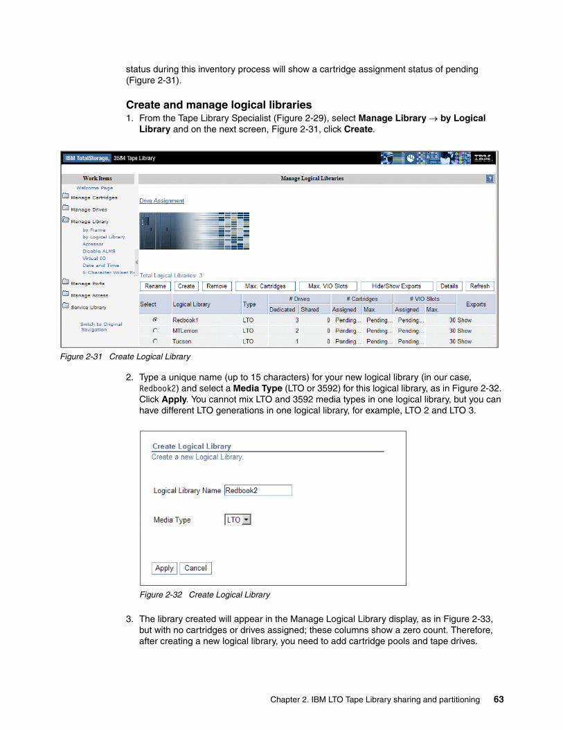
status during this inventory process will show a cartridge assignment status of pending (Figure 2-31).
Create and manage logical libraries1. From the Tape Library Specialist (Figure 2-29), select Manage Library → by Logical
Library and on the next screen, Figure 2-31, click Create.
Figure 2-31 Create Logical Library
2. Type a unique name (up to 15 characters) for your new logical library (in our case, Redbook2) and select a Media Type (LTO or 3592) for this logical library, as in Figure 2-32. Click Apply. You cannot mix LTO and 3592 media types in one logical library, but you can have different LTO generations in one logical library, for example, LTO 2 and LTO 3.
Figure 2-32 Create Logical Library
3. The library created will appear in the Manage Logical Library display, as in Figure 2-33, but with no cartridges or drives assigned; these columns show a zero count. Therefore, after creating a new logical library, you need to add cartridge pools and tape drives.
Chapter 2. IBM LTO Tape Library sharing and partitioning 63
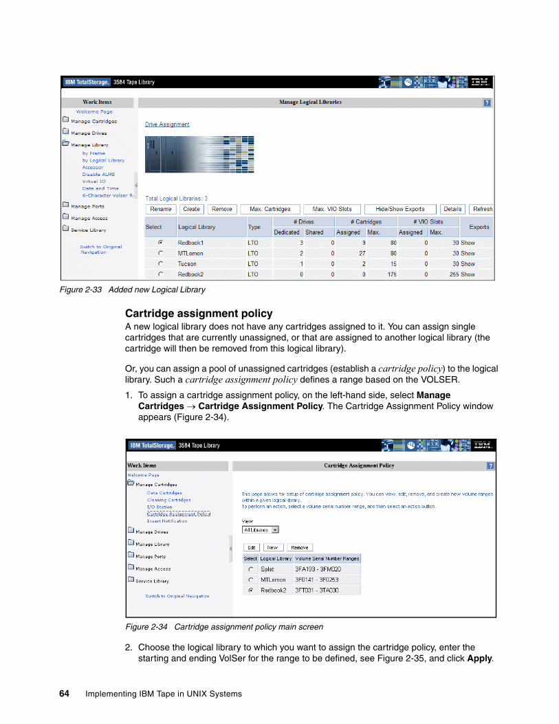
Figure 2-33 Added new Logical Library
Cartridge assignment policyA new logical library does not have any cartridges assigned to it. You can assign single cartridges that are currently unassigned, or that are assigned to another logical library (the cartridge will then be removed from this logical library).
Or, you can assign a pool of unassigned cartridges (establish a cartridge policy) to the logical library. Such a cartridge assignment policy defines a range based on the VOLSER.
1. To assign a cartridge assignment policy, on the left-hand side, select Manage Cartridges → Cartridge Assignment Policy. The Cartridge Assignment Policy window appears (Figure 2-34).
Figure 2-34 Cartridge assignment policy main screen
2. Choose the logical library to which you want to assign the cartridge policy, enter the starting and ending VolSer for the range to be defined, see Figure 2-35, and click Apply.
64 Implementing IBM Tape in UNIX Systems
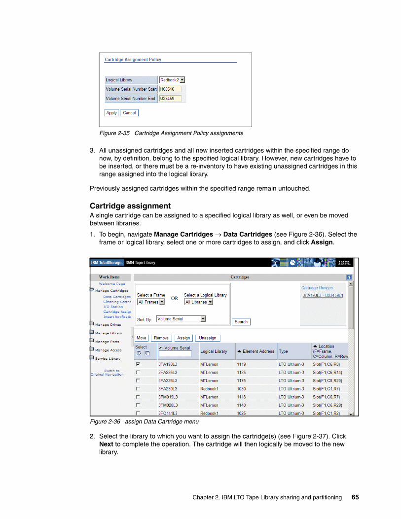
Figure 2-35 Cartridge Assignment Policy assignments
3. All unassigned cartridges and all new inserted cartridges within the specified range do now, by definition, belong to the specified logical library. However, new cartridges have to be inserted, or there must be a re-inventory to have existing unassigned cartridges in this range assigned into the logical library.
Previously assigned cartridges within the specified range remain untouched.
Cartridge assignmentA single cartridge can be assigned to a specified logical library as well, or even be moved between libraries.
1. To begin, navigate Manage Cartridges → Data Cartridges (see Figure 2-36). Select the frame or logical library, select one or more cartridges to assign, and click Assign.
Figure 2-36 assign Data Cartridge menu
2. Select the library to which you want to assign the cartridge(s) (see Figure 2-37). Click Next to complete the operation. The cartridge will then logically be moved to the new library.
Chapter 2. IBM LTO Tape Library sharing and partitioning 65
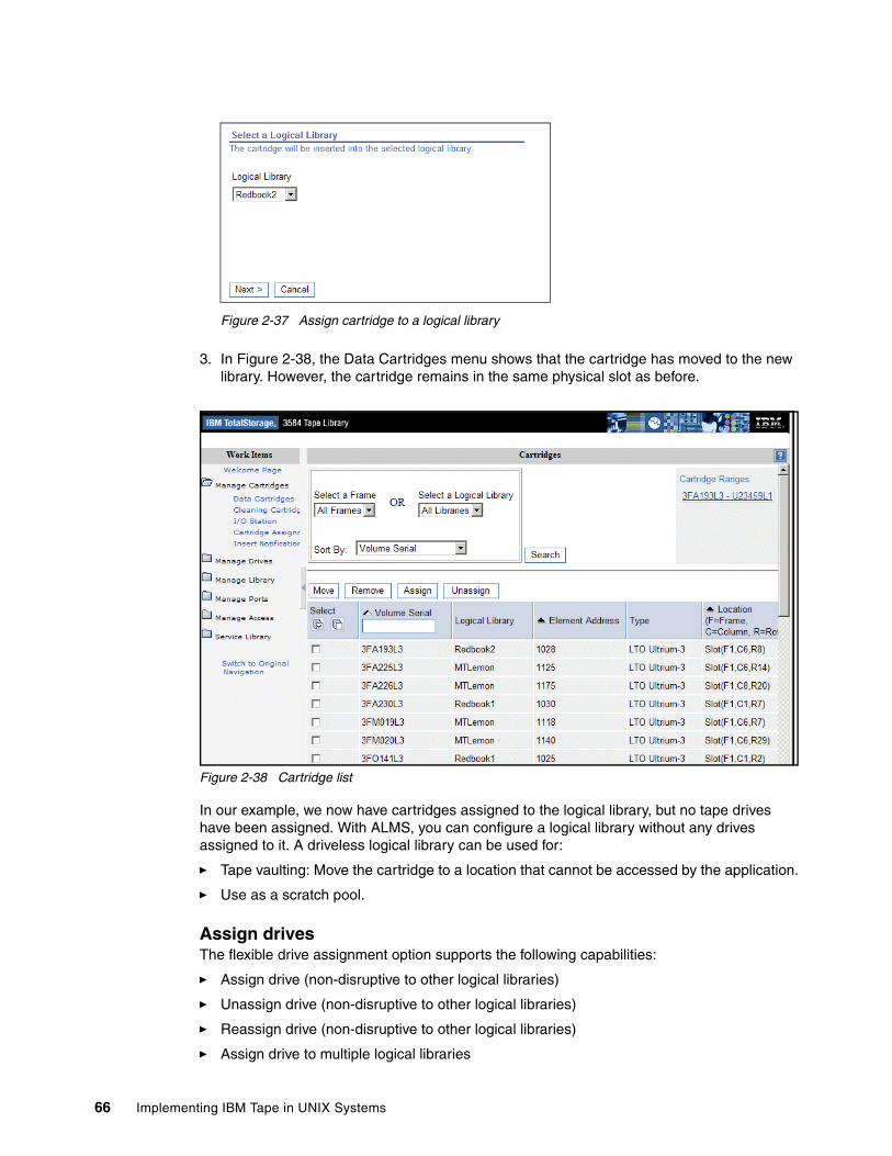
Figure 2-37 Assign cartridge to a logical library
3. In Figure 2-38, the Data Cartridges menu shows that the cartridge has moved to the new library. However, the cartridge remains in the same physical slot as before.
Figure 2-38 Cartridge list
In our example, we now have cartridges assigned to the logical library, but no tape drives have been assigned. With ALMS, you can configure a logical library without any drives assigned to it. A driveless logical library can be used for:
� Tape vaulting: Move the cartridge to a location that cannot be accessed by the application.
� Use as a scratch pool.
Assign drivesThe flexible drive assignment option supports the following capabilities:
� Assign drive (non-disruptive to other logical libraries)
� Unassign drive (non-disruptive to other logical libraries)
� Reassign drive (non-disruptive to other logical libraries)
� Assign drive to multiple logical libraries
66 Implementing IBM Tape in UNIX Systems
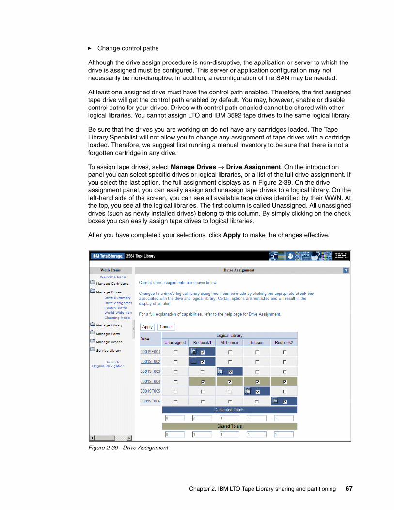
� Change control paths
Although the drive assign procedure is non-disruptive, the application or server to which the drive is assigned must be configured. This server or application configuration may not necessarily be non-disruptive. In addition, a reconfiguration of the SAN may be needed.
At least one assigned drive must have the control path enabled. Therefore, the first assigned tape drive will get the control path enabled by default. You may, however, enable or disable control paths for your drives. Drives with control path enabled cannot be shared with other logical libraries. You cannot assign LTO and IBM 3592 tape drives to the same logical library.
Be sure that the drives you are working on do not have any cartridges loaded. The Tape Library Specialist will not allow you to change any assignment of tape drives with a cartridge loaded. Therefore, we suggest first running a manual inventory to be sure that there is not a forgotten cartridge in any drive.
To assign tape drives, select Manage Drives → Drive Assignment. On the introduction panel you can select specific drives or logical libraries, or a list of the full drive assignment. If you select the last option, the full assignment displays as in Figure 2-39. On the drive assignment panel, you can easily assign and unassign tape drives to a logical library. On the left-hand side of the screen, you can see all available tape drives identified by their WWN. At the top, you see all the logical libraries. The first column is called Unassigned. All unassigned drives (such as newly installed drives) belong to this column. By simply clicking on the check boxes you can easily assign tape drives to logical libraries.
After you have completed your selections, click Apply to make the changes effective.
Figure 2-39 Drive Assignment
Chapter 2. IBM LTO Tape Library sharing and partitioning 67
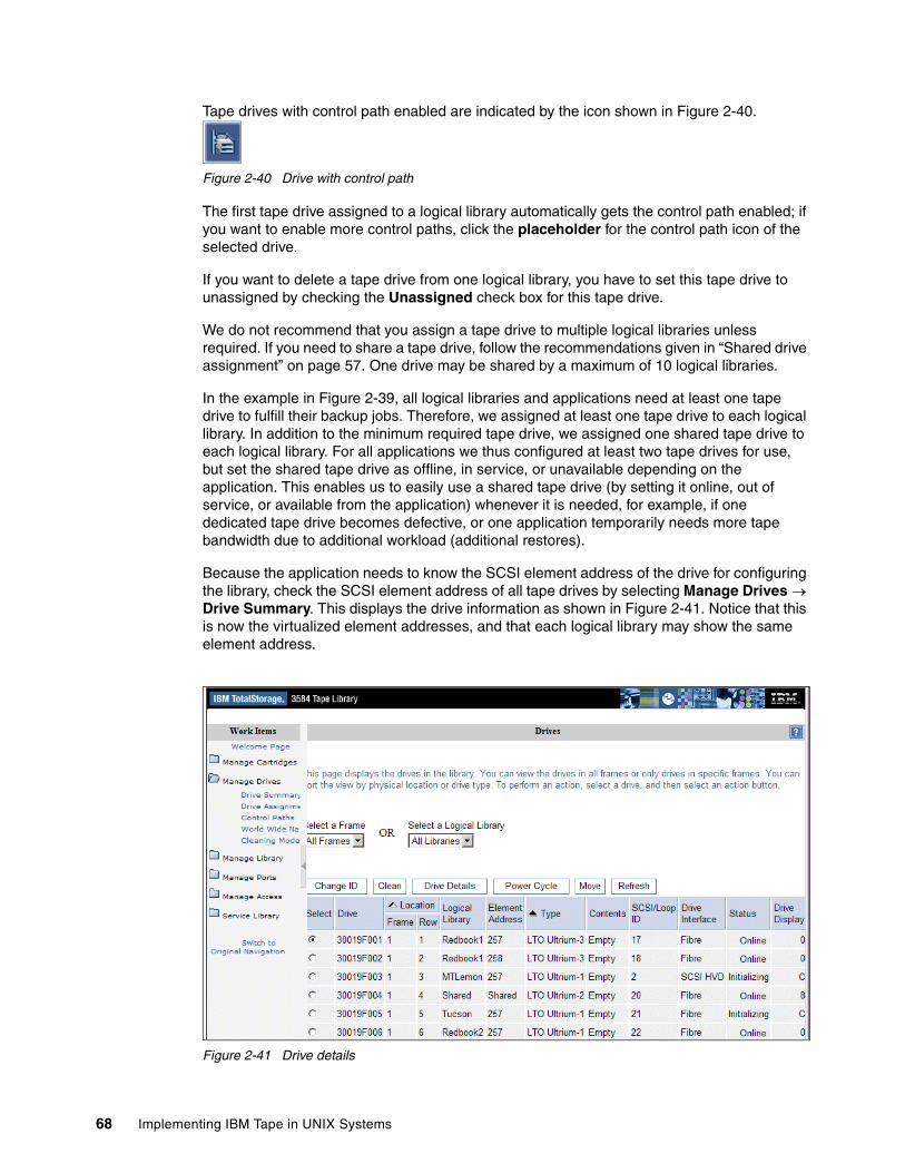
Tape drives with control path enabled are indicated by the icon shown in Figure 2-40.
Figure 2-40 Drive with control path
The first tape drive assigned to a logical library automatically gets the control path enabled; if you want to enable more control paths, click the placeholder for the control path icon of the selected drive.
If you want to delete a tape drive from one logical library, you have to set this tape drive to unassigned by checking the Unassigned check box for this tape drive.
We do not recommend that you assign a tape drive to multiple logical libraries unless required. If you need to share a tape drive, follow the recommendations given in “Shared drive assignment” on page 57. One drive may be shared by a maximum of 10 logical libraries.
In the example in Figure 2-39, all logical libraries and applications need at least one tape drive to fulfill their backup jobs. Therefore, we assigned at least one tape drive to each logical library. In addition to the minimum required tape drive, we assigned one shared tape drive to each logical library. For all applications we thus configured at least two tape drives for use, but set the shared tape drive as offline, in service, or unavailable depending on the application. This enables us to easily use a shared tape drive (by setting it online, out of service, or available from the application) whenever it is needed, for example, if one dedicated tape drive becomes defective, or one application temporarily needs more tape bandwidth due to additional workload (additional restores).
Because the application needs to know the SCSI element address of the drive for configuring the library, check the SCSI element address of all tape drives by selecting Manage Drives → Drive Summary. This displays the drive information as shown in Figure 2-41. Notice that this is now the virtualized element addresses, and that each logical library may show the same element address.
Figure 2-41 Drive details
68 Implementing IBM Tape in UNIX Systems
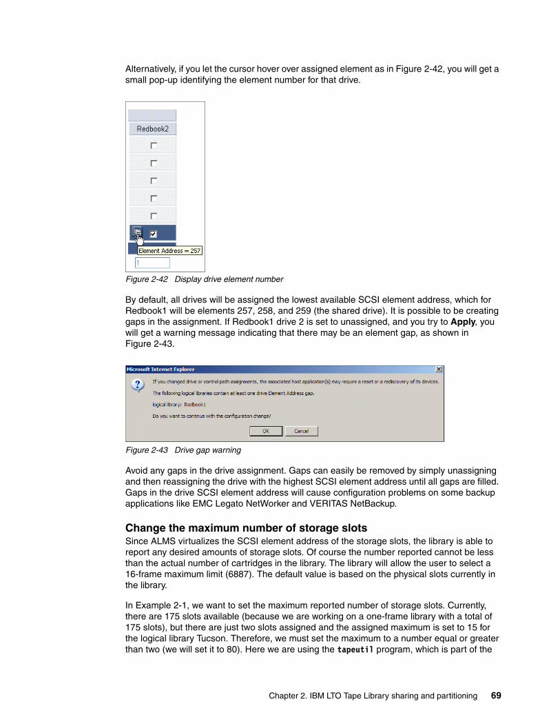
Alternatively, if you let the cursor hover over assigned element as in Figure 2-42, you will get a small pop-up identifying the element number for that drive.
Figure 2-42 Display drive element number
By default, all drives will be assigned the lowest available SCSI element address, which for Redbook1 will be elements 257, 258, and 259 (the shared drive). It is possible to be creating gaps in the assignment. If Redbook1 drive 2 is set to unassigned, and you try to Apply, you will get a warning message indicating that there may be an element gap, as shown in Figure 2-43.
Figure 2-43 Drive gap warning
Avoid any gaps in the drive assignment. Gaps can easily be removed by simply unassigning and then reassigning the drive with the highest SCSI element address until all gaps are filled. Gaps in the drive SCSI element address will cause configuration problems on some backup applications like EMC Legato NetWorker and VERITAS NetBackup.
Change the maximum number of storage slotsSince ALMS virtualizes the SCSI element address of the storage slots, the library is able to report any desired amounts of storage slots. Of course the number reported cannot be less than the actual number of cartridges in the library. The library will allow the user to select a 16-frame maximum limit (6887). The default value is based on the physical slots currently in the library.
In Example 2-1, we want to set the maximum reported number of storage slots. Currently, there are 175 slots available (because we are working on a one-frame library with a total of 175 slots), but there are just two slots assigned and the assigned maximum is set to 15 for the logical library Tucson. Therefore, we must set the maximum to a number equal or greater than two (we will set it to 80). Here we are using the tapeutil program, which is part of the
Chapter 2. IBM LTO Tape Library sharing and partitioning 69

IBM-supplied device driver. For more information on tapeutil, see 4.5, “Testing the library with tapeutil” on page 149.
Example 2-1 Reported storage slots
# tapeutil -f /dev/smc1 elementinfoGetting element information...
Number of Robots .............. 1 First Robot Address ........... 1 Number of Slots ............... 15 First Slot Address ............ 1185 Number of Import/Exports ...... 30 First Import/Export Address ... 769 Number of Drives .............. 1 First Drive Address ........... 257
To change the Maximum Number, select Manage Logical Library; select the logical library and click Maximum Cartridges (as in Figure 2-31 on page 63).
A window like Figure 2-44 appears. Enter the new maximum number of cartridges and click Apply.
Figure 2-44 Change maximum number of cartridges
Now, the library reports the new maximum storage slots as 80, as shown in Example 2-2.
Example 2-2 Reported storage slots
#tapeutil -f /dev/smc1 elementinfoGetting element information...
Number of Robots .............. 1 First Robot Address ........... 1 Number of Slots ............... 80 First Slot Address ............ 1185 Number of Import/Exports ...... 30 First Import/Export Address ... 769 Number of Drives .............. 1 First Drive Address ........... 257
Warning: Changing maximum settings for a logical library may interrupt drive and library activities and require reconfiguration of the host applications for the selected logical library.
70 Implementing IBM Tape in UNIX Systems
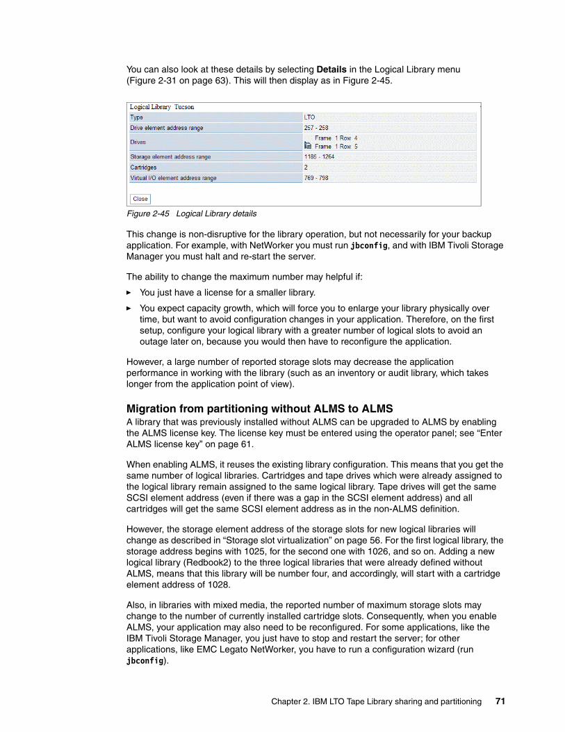
You can also look at these details by selecting Details in the Logical Library menu (Figure 2-31 on page 63). This will then display as in Figure 2-45.
Figure 2-45 Logical Library details
This change is non-disruptive for the library operation, but not necessarily for your backup application. For example, with NetWorker you must run jbconfig, and with IBM Tivoli Storage Manager you must halt and re-start the server.
The ability to change the maximum number may helpful if:
� You just have a license for a smaller library.
� You expect capacity growth, which will force you to enlarge your library physically over time, but want to avoid configuration changes in your application. Therefore, on the first setup, configure your logical library with a greater number of logical slots to avoid an outage later on, because you would then have to reconfigure the application.
However, a large number of reported storage slots may decrease the application performance in working with the library (such as an inventory or audit library, which takes longer from the application point of view).
Migration from partitioning without ALMS to ALMSA library that was previously installed without ALMS can be upgraded to ALMS by enabling the ALMS license key. The license key must be entered using the operator panel; see “Enter ALMS license key” on page 61.
When enabling ALMS, it reuses the existing library configuration. This means that you get the same number of logical libraries. Cartridges and tape drives which were already assigned to the logical library remain assigned to the same logical library. Tape drives will get the same SCSI element address (even if there was a gap in the SCSI element address) and all cartridges will get the same SCSI element address as in the non-ALMS definition.
However, the storage element address of the storage slots for new logical libraries will change as described in “Storage slot virtualization” on page 56. For the first logical library, the storage address begins with 1025, for the second one with 1026, and so on. Adding a new logical library (Redbook2) to the three logical libraries that were already defined without ALMS, means that this library will be number four, and accordingly, will start with a cartridge element address of 1028.
Also, in libraries with mixed media, the reported number of maximum storage slots may change to the number of currently installed cartridge slots. Consequently, when you enable ALMS, your application may also need to be reconfigured. For some applications, like the IBM Tivoli Storage Manager, you just have to stop and restart the server; for other applications, like EMC Legato NetWorker, you have to run a configuration wizard (run jbconfig).
Chapter 2. IBM LTO Tape Library sharing and partitioning 71
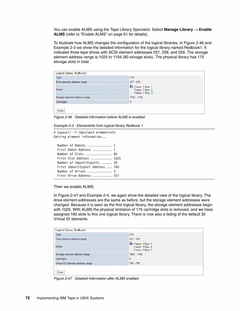
You can enable ALMS using the Tape Library Specialist. Select Manage Library → Enable ALMS (refer to “Enable ALMS” on page 61 for details).
To illustrate how ALMS changes the configuration of the logical libraries, in Figure 2-46 and Example 2-3 we show the detailed information for the logical library named Redbook1. It indicates three tape drives with SCSI element addresses 257, 258, and 259. The storage element address range is 1025 to 1104 (80 storage slots). The physical library has 175 storage slots in total.
Figure 2-46 Detailed information before ALMS is enabled
Example 2-3 Elementinfo from logical library Redbook 1
# tapeutil -f /dev/smc4 elementinfoGetting element information...
Number of Robots .............. 1 First Robot Address ........... 1 Number of Slots ............... 80 First Slot Address ............ 1025 Number of Import/Exports ...... 30 First Import/Export Address ... 769 Number of Drives .............. 3 First Drive Address ........... 257
Then we enable ALMS.
In Figure 2-47 and Example 2-4, we again show the detailed view of the logical library. The drive element addresses are the same as before, but the storage element addresses were changed. Because it is seen as the first logical library, the storage element addresses begin with 1025. With ALMS the physical limitation of 175 cartridge slots is removed, and we have assigned 160 slots to this one logical library. There is now also a listing of the default 30 Virtual IO elements.
Figure 2-47 Detailed Information after ALMS enabled
72 Implementing IBM Tape in UNIX Systems
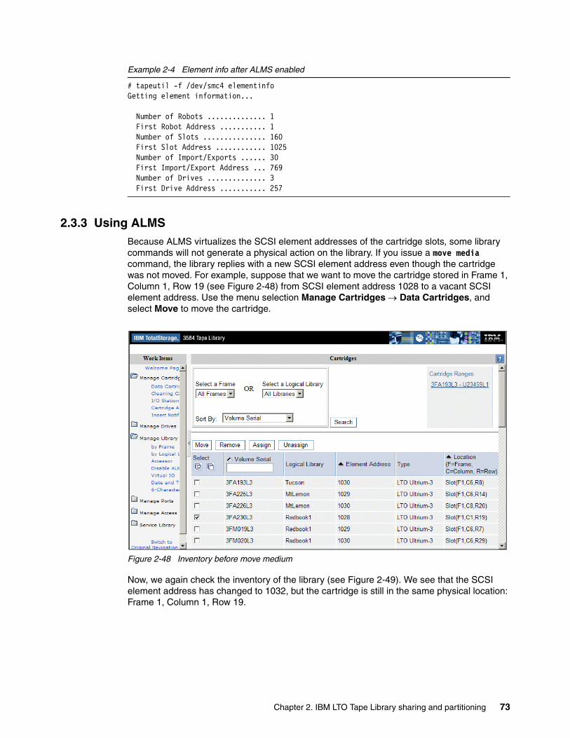
Example 2-4 Element info after ALMS enabled
# tapeutil -f /dev/smc4 elementinfoGetting element information...
Number of Robots .............. 1 First Robot Address ........... 1 Number of Slots ............... 160 First Slot Address ............ 1025 Number of Import/Exports ...... 30 First Import/Export Address ... 769 Number of Drives .............. 3 First Drive Address ........... 257
2.3.3 Using ALMSBecause ALMS virtualizes the SCSI element addresses of the cartridge slots, some library commands will not generate a physical action on the library. If you issue a move media command, the library replies with a new SCSI element address even though the cartridge was not moved. For example, suppose that we want to move the cartridge stored in Frame 1, Column 1, Row 19 (see Figure 2-48) from SCSI element address 1028 to a vacant SCSI element address. Use the menu selection Manage Cartridges → Data Cartridges, and select Move to move the cartridge.
Figure 2-48 Inventory before move medium
Now, we again check the inventory of the library (see Figure 2-49). We see that the SCSI element address has changed to 1032, but the cartridge is still in the same physical location: Frame 1, Column 1, Row 19.
Chapter 2. IBM LTO Tape Library sharing and partitioning 73
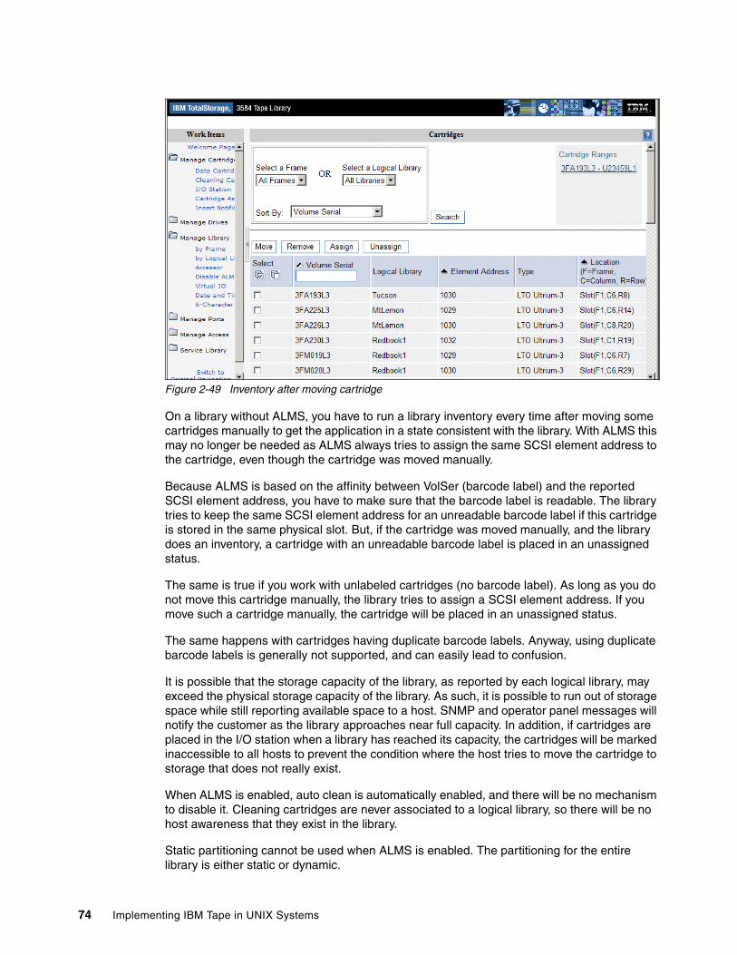
Figure 2-49 Inventory after moving cartridge
On a library without ALMS, you have to run a library inventory every time after moving some cartridges manually to get the application in a state consistent with the library. With ALMS this may no longer be needed as ALMS always tries to assign the same SCSI element address to the cartridge, even though the cartridge was moved manually.
Because ALMS is based on the affinity between VolSer (barcode label) and the reported SCSI element address, you have to make sure that the barcode label is readable. The library tries to keep the same SCSI element address for an unreadable barcode label if this cartridge is stored in the same physical slot. But, if the cartridge was moved manually, and the library does an inventory, a cartridge with an unreadable barcode label is placed in an unassigned status.
The same is true if you work with unlabeled cartridges (no barcode label). As long as you do not move this cartridge manually, the library tries to assign a SCSI element address. If you move such a cartridge manually, the cartridge will be placed in an unassigned status.
The same happens with cartridges having duplicate barcode labels. Anyway, using duplicate barcode labels is generally not supported, and can easily lead to confusion.
It is possible that the storage capacity of the library, as reported by each logical library, may exceed the physical storage capacity of the library. As such, it is possible to run out of storage space while still reporting available space to a host. SNMP and operator panel messages will notify the customer as the library approaches near full capacity. In addition, if cartridges are placed in the I/O station when a library has reached its capacity, the cartridges will be marked inaccessible to all hosts to prevent the condition where the host tries to move the cartridge to storage that does not really exist.
When ALMS is enabled, auto clean is automatically enabled, and there will be no mechanism to disable it. Cleaning cartridges are never associated to a logical library, so there will be no host awareness that they exist in the library.
Static partitioning cannot be used when ALMS is enabled. The partitioning for the entire library is either static or dynamic.
74 Implementing IBM Tape in UNIX Systems
Chapter 3. SAN considerations
In this chapter, we discuss considerations for SAN-attached tapes and libraries. We emphasize issues generally relevant to SAN tape attachment including:
� Design considerations for SAN-attached tape libraries� Switch fabric zoning� Persistent binding
We also provide additional information on SAN setup for the IBM TotalStorage 3583 Tape Library and IBM TotalStorage 3584 Tape Library where necessary.
We assume the reader is already familiar with basic SAN concepts. For more information about general SAN concepts and design, refer to these redbooks:
� Designing an IBM Storage Area Network, SG24-5758� Planning and Implementing an IBM SAN, SG24-6116� IBM SAN Survival Guide, SG24-6143� Implementing an Open IBM SAN, SG24-6116� Introduction to Storage Area Networks, SG24-5470� Designing and Optimizing an IBM Storage Area Network, SG24-6419
3
Note: The IBM SAN Data Gateway (SDG) Router models 2108-R03 and 2108-G07 were withdrawn from marketing in September 2002. The SAN Data Gateway Integrated Module is no longer available as a feature in new IBM 3583s. The SAN Data Gateway features were withdrawn from marketing in October 2004. For more information on the SDG, see Appendix A, “IBM SAN Data Gateway” on page 281.
© Copyright IBM Corp. 2002, 2003, 2004, 2005. All rights reserved. 75
3.1 SAN design considerations for IBM tape librariesIn this section we cover the following IBM tape SAN design considerations:
� Bandwidth needed for FC Tape� How to handle multiple paths to tape drives
The IBM LTO Ultrium 2 and 3 tape drives with Fibre Channel interface and the IBM 3592 tape drive support either point-to-point or Fibre Channel arbitrated loop attachment. The IBM Ultrium 1 Tape drives with Fibre Channel interface only support FC-AL protocol. If you connect an IBM LTO Ultrium 1 tape drive to a SAN, then the FC-AL protocol must be supported at that physical connection.
3.1.1 Bandwidth needed for FC tapeMany SANs are designed for disk I/O, which means they are optimized for high IOPS and not necessarily for the high bandwidth that is needed for tape and backup I/O. During backup sessions, high volumes of data are generally transferred from disk to tape media. High speed transfer is also a necessity to minimize backup time. Current tape drives, like the IBM LTO3 with 80 MB/sec, the IBM LTO2 with 35 MB/sec and the IBM 3592 with 40 MB/sec can easily saturate a single FC link if several drives operate concurrently.
Using a SAN fabric configuration, you can potentially attach and access many tape drives through one or more HBAs. But how will this affect performance if several tape drives run concurrently? The theoretical maximum data transfer rate for one FC connection in a 2 Gbit SAN is 200 MB/sec. In reality, we typically see an effective data transfer rate of about 160 MB/sec. In a 1 Gbit SAN we see an effective data transfer rate of just 80 MB/sec.
Ultrium 3 drives have a sustained data transfer rate of 80 MB/second uncompressed, and 160 MB/second using 2:1 compression. In theory, this means you should be able to run two uncompressed tape drives or one compressed tape drive concurrently on an HBA without performance degradation.
Ultrium 2 drives have a sustained data transfer rate of 35 MB/second uncompressed, and 70 MB/second using 2:1 compression. In theory, this means you should be able to run four uncompressed tape drives or two compressed tape drives concurrently on an HBA without performance degradation.
However, the actual data transfer rates achieved will depend heavily on the type of data.
Typically, most system environments have a mix of data types achieving very different compression rates. If writing very large files with a good compression ratio, you may get a transfer rate of up to 160MB/sec (Ultrium 3), or 70 MB/sec (Ultrium 2), or even more. In that case, you should only run one Ultrium 3 or two Ultrium 2 drives together on one HBA. On the other hand, if writing small files or uncompressible files, then you may see transfer rates of less than 80 MB/sec (Ultrium 3) or 35 MB/sec ((Ultrium 2). In this case, more than one Ultrium 3 drive or two Ultrium 2 drives can be run together on one HBA. Nevertheless, it is not recommended that you try to work concurrently with more than two Ultrium 3 drives or four Ultrium 2 drives using a single HBA.
Along with the number of devices per HBA, the overall SAN design must be capable of supporting the volume of data transferred during the backup process (see Figure 3-1). The SAN might be able to easily sustain the overall load and normal data traffic, but still have an insufficient bandwidth when backups take place. This is especially true in complex fabrics with multiple switches, where the inter-switch links (ISLs) can become saturated.
76 Implementing IBM Tape in UNIX Systems
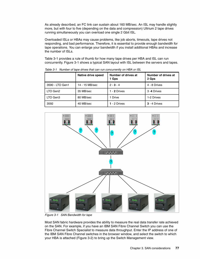
As already described, an FC link can sustain about 160 MB/sec. An ISL may handle slightly more, but with four to five (depending on the data and compression) Ultrium 2 tape drives running simultaneously you can overload one single 2 Gbit ISL.
Overloaded ISLs or HBAs may cause problems, like job aborts, timeouts, tape drives not responding, and bad performance. Therefore, it is essential to provide enough bandwidth for tape operations. You can enlarge your bandwidth if you install additional HBAs and increase the number of ISLs.
Table 3-1 provides a rule of thumb for how many tape drives per HBA and ISL can run concurrently. Figure 3-1 shows a typical SAN layout with ISL between the servers and tapes.
Table 3-1 Number of tape drives that can run concurrently on HBA or ISL
Figure 3-1 SAN Bandwidth for tape
Most SAN fabric hardware provides the ability to measure the real data transfer rate achieved on the SAN. For example, if you have an IBM SAN Fibre Channel Switch you can use the Fibre Channel Switch Specialist to measure data throughput. Enter the IP address of one of the IBM SAN Fibre Channel switches in the browser window, and select the switch to which your HBA is attached (Figure 3-2) to bring up the Switch Management view.
Native drive speed Number of drives at 1 Gps
Number of drives at 2 Gps
3590 - LTO Gen1 14 - 15 MB/sec 2 - 3 - 4 4 - 8 Drives
LTO Gen2 35 MB/sec 1 - 2 Drives 3 -4 Drives
LTO Gen3 80 MB/sec 1 Drive 1-2 Drives
3592 40 MB/sec 1 - 2 Drives 3 - 4 Drives
?
? ? ???
Chapter 3. SAN considerations 77
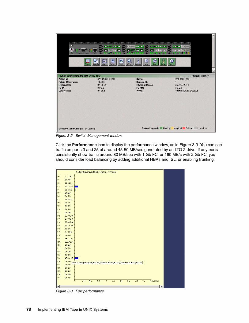
Figure 3-2 Switch Management window
Click the Performance icon to display the performance window, as in Figure 3-3. You can see traffic on ports 3 and 25 of around 45-50 MB/sec generated by an LTO 2 drive. If any ports consistently show traffic around 80 MB/sec with 1 Gb FC, or 160 MB/s with 2 Gb FC, you should consider load balancing by adding additional HBAs and ISL, or enabling trunking.
Figure 3-3 Port performance
78 Implementing IBM Tape in UNIX Systems
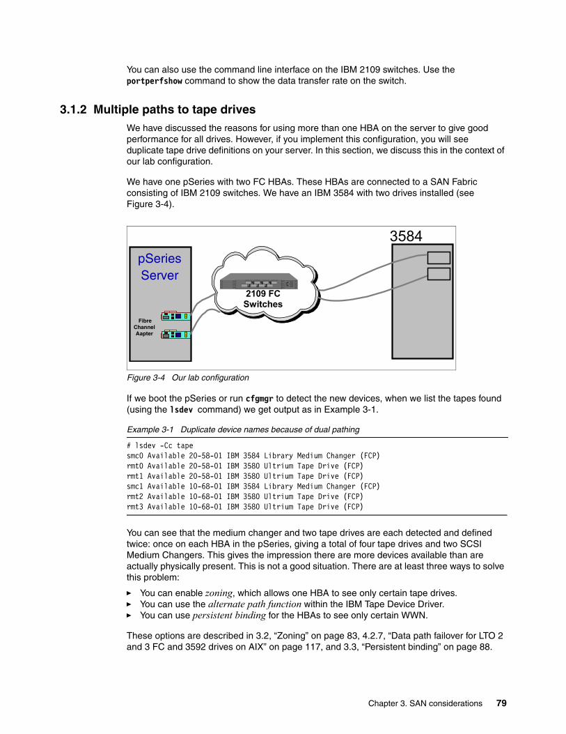
You can also use the command line interface on the IBM 2109 switches. Use the portperfshow command to show the data transfer rate on the switch.
3.1.2 Multiple paths to tape drivesWe have discussed the reasons for using more than one HBA on the server to give good performance for all drives. However, if you implement this configuration, you will see duplicate tape drive definitions on your server. In this section, we discuss this in the context of our lab configuration.
We have one pSeries with two FC HBAs. These HBAs are connected to a SAN Fabric consisting of IBM 2109 switches. We have an IBM 3584 with two drives installed (see Figure 3-4).
Figure 3-4 Our lab configuration
If we boot the pSeries or run cfgmgr to detect the new devices, when we list the tapes found (using the lsdev command) we get output as in Example 3-1.
Example 3-1 Duplicate device names because of dual pathing
# lsdev -Cc tapesmc0 Available 20-58-01 IBM 3584 Library Medium Changer (FCP)rmt0 Available 20-58-01 IBM 3580 Ultrium Tape Drive (FCP)rmt1 Available 20-58-01 IBM 3580 Ultrium Tape Drive (FCP)smc1 Available 10-68-01 IBM 3584 Library Medium Changer (FCP)rmt2 Available 10-68-01 IBM 3580 Ultrium Tape Drive (FCP)rmt3 Available 10-68-01 IBM 3580 Ultrium Tape Drive (FCP)
You can see that the medium changer and two tape drives are each detected and defined twice: once on each HBA in the pSeries, giving a total of four tape drives and two SCSI Medium Changers. This gives the impression there are more devices available than are actually physically present. This is not a good situation. There are at least three ways to solve this problem:
� You can enable zoning, which allows one HBA to see only certain tape drives.� You can use the alternate path function within the IBM Tape Device Driver.� You can use persistent binding for the HBAs to see only certain WWN.
These options are described in 3.2, “Zoning” on page 83, 4.2.7, “Data path failover for LTO 2 and 3 FC and 3592 drives on AIX” on page 117, and 3.3, “Persistent binding” on page 88.
3584
Fibre Channel Aapter
pSeriesServer
2109 FC Switches
Chapter 3. SAN considerations 79
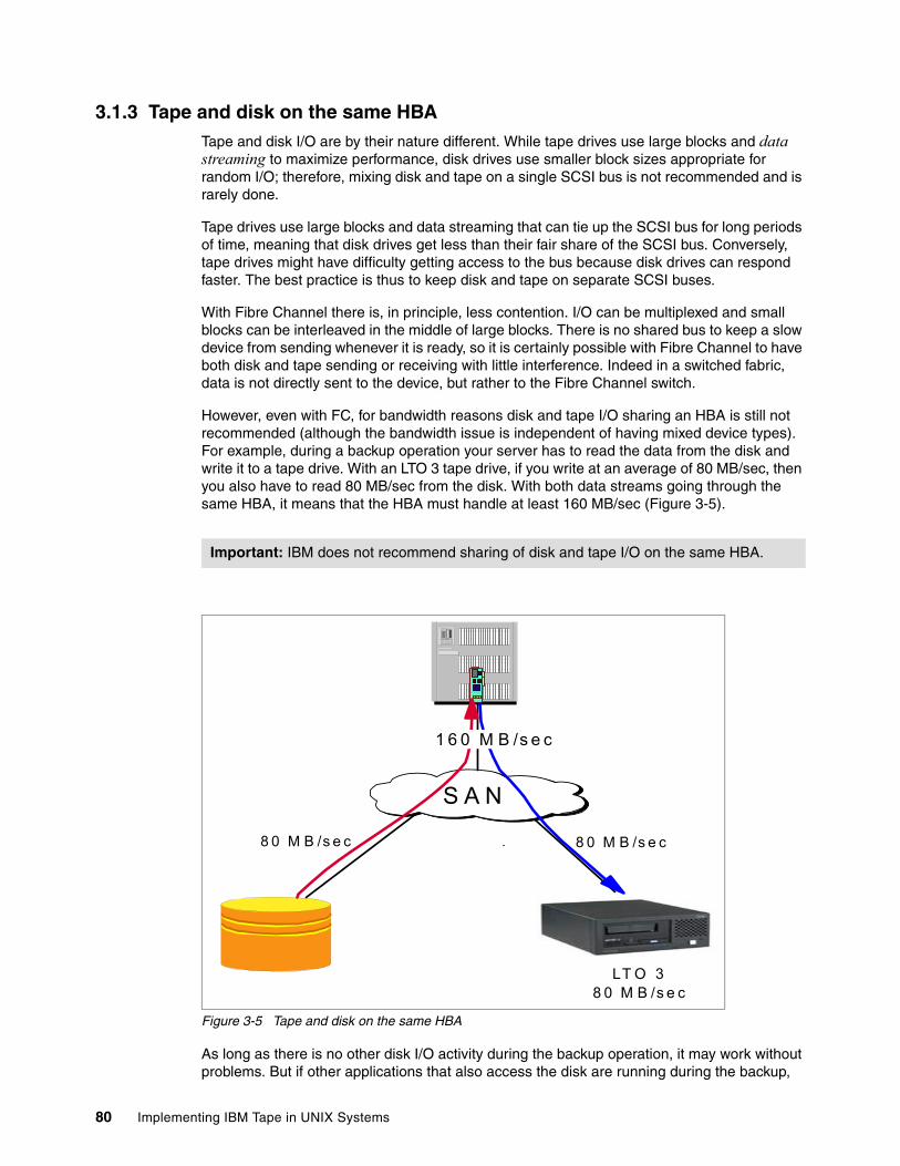
3.1.3 Tape and disk on the same HBATape and disk I/O are by their nature different. While tape drives use large blocks and data streaming to maximize performance, disk drives use smaller block sizes appropriate for random I/O; therefore, mixing disk and tape on a single SCSI bus is not recommended and is rarely done.
Tape drives use large blocks and data streaming that can tie up the SCSI bus for long periods of time, meaning that disk drives get less than their fair share of the SCSI bus. Conversely, tape drives might have difficulty getting access to the bus because disk drives can respond faster. The best practice is thus to keep disk and tape on separate SCSI buses.
With Fibre Channel there is, in principle, less contention. I/O can be multiplexed and small blocks can be interleaved in the middle of large blocks. There is no shared bus to keep a slow device from sending whenever it is ready, so it is certainly possible with Fibre Channel to have both disk and tape sending or receiving with little interference. Indeed in a switched fabric, data is not directly sent to the device, but rather to the Fibre Channel switch.
However, even with FC, for bandwidth reasons disk and tape I/O sharing an HBA is still not recommended (although the bandwidth issue is independent of having mixed device types). For example, during a backup operation your server has to read the data from the disk and write it to a tape drive. With an LTO 3 tape drive, if you write at an average of 80 MB/sec, then you also have to read 80 MB/sec from the disk. With both data streams going through the same HBA, it means that the HBA must handle at least 160 MB/sec (Figure 3-5).
Figure 3-5 Tape and disk on the same HBA
As long as there is no other disk I/O activity during the backup operation, it may work without problems. But if other applications that also access the disk are running during the backup,
Important: IBM does not recommend sharing of disk and tape I/O on the same HBA.
LT O 38 0 M B /s e c
S A N
8 0 M B /s e c8 0 M B /s e c
1 6 0 M B /s e c
80 Implementing IBM Tape in UNIX Systems

performance will be impacted. Because disk access uses smaller block size, and is quicker and more frequent, the disk I/O will occupy the FC link, and cause the tape to wait to get on the link, causing backhitches and thus affecting performance. Or even worse, the disk I/O will keep the command queue filled up so that no tape commands can go through.
For a backup server where a high I/O load exists, and for LAN-free clients, where during the backup some other disk I/O occurs, you should use multiple HBAs and separate the disk and tape I/O (see Figure 3-6). This is especially true for backup servers using a disk storage pool (such as with Tivoli Storage Manager) where the backup data is staged to disk and then migrated to tape. If the backup and migration run simultaneously, it will cause a high I/O load.
Keep in mind that your environment will evolve over time, and usually the data traffic will increase. Although it might have been justified (generally from a cost perspective) in a simple installation with low traffic to share the HBA, you must reevaluate the situation on a regular basis. In most cases you will reach a point where it becomes necessary to install additional HBAs.
Figure 3-6 SAN example for backup
If you cannot avoid combining disk and tape I/O (for example, when no more PCI slots are available on the host), you should at least implement your SAN in accordance with the following rules and configure your FC HBAs accordingly:
� Create different zones for disk and tape.
� Create a different zone for every server.
� Enable FCP-2 recovery (also called FC Tape Support) on the FC HBA.
Tip: Monitor your environment over time and when traffic grows, consider the installation of additional HBAs.
SANSAN
LAN-free Clientswith low bandwith Backup Server
Tape IO
Disk IO
Tape&Disk IO
LAN-free Clientswith high bandwith
Chapter 3. SAN considerations 81
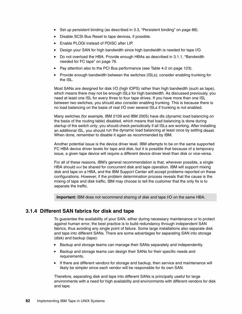
� Set up persistent binding (as described in 3.3, “Persistent binding” on page 88).
� Disable SCSI Bus Reset to tape devices, if possible.
� Enable PLOGI instead of PDISC after LIP.
� Design your SAN for high bandwidth since high bandwidth is needed for tape I/O.
� Do not overload the HBA. Provide enough HBAs as described in 3.1.1, “Bandwidth needed for FC tape” on page 76.
� Pay attention also to the PCI Bus performance (see Table 4-2 on page 123).
� Provide enough bandwidth between the switches (ISLs); consider enabling trunking for the ISL.
Most SANs are designed for disk I/O (high IOPS) rather than high bandwidth (such as tape), which means there may not be enough ISLs for high bandwidth. As discussed previously, you need at least one ISL for every three to four tape drives. If you have more than one ISL between two switches, you should also consider enabling trunking. This is because there is no load balancing on the basis of real I/O over several ISLs if trunking is not enabled.
Many switches (for example, IBM 2109 and IBM 2005) have dls (dynamic load balancing on the basis of the routing table) disabled, which means that load balancing is done during startup of the switch only; you should check periodically if all ISLs are working. After installing an additional ISL, you should run the dynamic load balancing at least once by setting dlsset. When done, remember to disable it again as recommended by IBM.
Another potential issue is the device driver level. IBM attempts to be on the same supported FC HBA device driver levels for tape and disk, but it is possible that because of a temporary issue, a given tape device will require a different device driver level than disk or vice-versa.
For all of these reasons, IBM’s general recommendation is that, wherever possible, a single HBA should not be shared for concurrent disk and tape operation. IBM will support mixing disk and tape on a HBA, and the IBM Support Center will accept problems reported on these configurations. However, if the problem determination process reveals that the cause is the mixing of tape and disk traffic, IBM may choose to tell the customer that the only fix is to separate the traffic.
3.1.4 Different SAN fabrics for disk and tapeTo guarantee the availability of your SAN, either during necessary maintenance or to protect against human error, the best practice is to build redundancy through independent SAN fabrics, thus avoiding any single point of failure. Some large installations also separate disk and tape into different SANs. There are some advantages for separating SAN into storage (disk) and backup (tape):
� Backup and storage teams can manage their SANs separately and independently.
� Backup and storage teams can design their SANs for their specific needs and requirements.
� If there are different vendors for storage and backup, then service and maintenance will likely be simpler since each vendor will be responsible for its own SAN.
Therefore, separating disk and tape into different SANs is principally useful for large environments with a need for high availability and environments with different vendors for disk and tape.
Important: IBM does not recommend sharing of disk and tape I/O on the same HBA.
82 Implementing IBM Tape in UNIX Systems
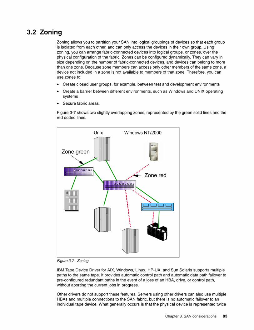
3.2 ZoningZoning allows you to partition your SAN into logical groupings of devices so that each group is isolated from each other, and can only access the devices in their own group. Using zoning, you can arrange fabric-connected devices into logical groups, or zones, over the physical configuration of the fabric. Zones can be configured dynamically. They can vary in size depending on the number of fabric-connected devices, and devices can belong to more than one zone. Because zone members can access only other members of the same zone, a device not included in a zone is not available to members of that zone. Therefore, you can use zones to:
� Create closed user groups, for example, between test and development environments
� Create a barrier between different environments, such as Windows and UNIX operating systems
� Secure fabric areas
Figure 3-7 shows two slightly overlapping zones, represented by the green solid lines and the red dotted lines.
Figure 3-7 Zoning
IBM Tape Device Driver for AIX, Windows, Linux, HP-UX, and Sun Solaris supports multiple paths to the same tape. It provides automatic control path and automatic data path failover to pre-configured redundant paths in the event of a loss of an HBA, drive, or control path, without aborting the current jobs in progress.
Other drivers do not support these features. Servers using other drivers can also use multiple HBAs and multiple connections to the SAN fabric, but there is no automatic failover to an individual tape device. What generally occurs is that the physical device is represented twice
Unix Windows NT/2000
Zone red
Zone green
Chapter 3. SAN considerations 83
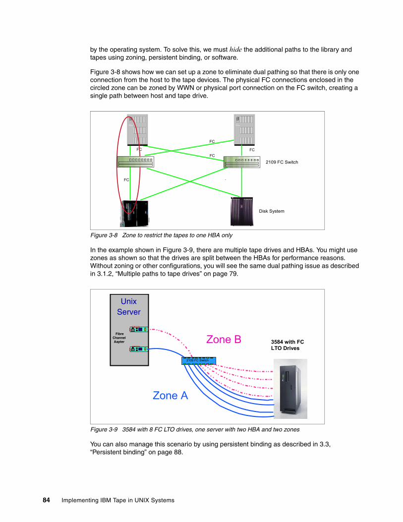
by the operating system. To solve this, we must hide the additional paths to the library and tapes using zoning, persistent binding, or software.
Figure 3-8 shows how we can set up a zone to eliminate dual pathing so that there is only one connection from the host to the tape devices. The physical FC connections enclosed in the circled zone can be zoned by WWN or physical port connection on the FC switch, creating a single path between host and tape drive.
Figure 3-8 Zone to restrict the tapes to one HBA only
In the example shown in Figure 3-9, there are multiple tape drives and HBAs. You might use zones as shown so that the drives are split between the HBAs for performance reasons. Without zoning or other configurations, you will see the same dual pathing issue as described in 3.1.2, “Multiple paths to tape drives” on page 79.
Figure 3-9 3584 with 8 FC LTO drives, one server with two HBA and two zones
You can also manage this scenario by using persistent binding as described in 3.3, “Persistent binding” on page 88.
FC
Host HostFC FC
2109 FC SwitchFC
FC
Disk System
3584 with FC LTO Drives
Fibre Channel Aapter
UnixServer
2109 FC Switch
Zone A
Zone B
84 Implementing IBM Tape in UNIX Systems
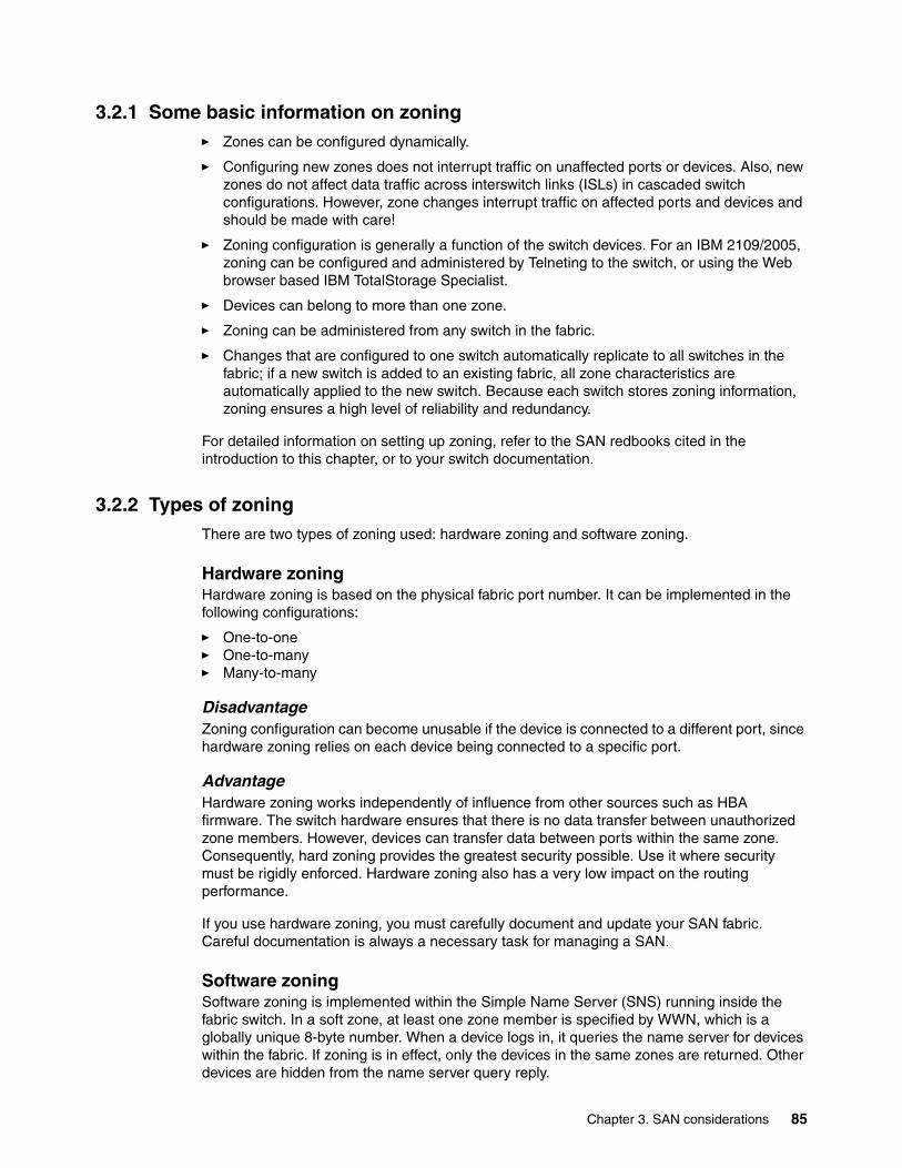
3.2.1 Some basic information on zoning� Zones can be configured dynamically.
� Configuring new zones does not interrupt traffic on unaffected ports or devices. Also, new zones do not affect data traffic across interswitch links (ISLs) in cascaded switch configurations. However, zone changes interrupt traffic on affected ports and devices and should be made with care!
� Zoning configuration is generally a function of the switch devices. For an IBM 2109/2005, zoning can be configured and administered by Telneting to the switch, or using the Web browser based IBM TotalStorage Specialist.
� Devices can belong to more than one zone.
� Zoning can be administered from any switch in the fabric.
� Changes that are configured to one switch automatically replicate to all switches in the fabric; if a new switch is added to an existing fabric, all zone characteristics are automatically applied to the new switch. Because each switch stores zoning information, zoning ensures a high level of reliability and redundancy.
For detailed information on setting up zoning, refer to the SAN redbooks cited in the introduction to this chapter, or to your switch documentation.
3.2.2 Types of zoningThere are two types of zoning used: hardware zoning and software zoning.
Hardware zoningHardware zoning is based on the physical fabric port number. It can be implemented in the following configurations:
� One-to-one� One-to-many� Many-to-many
DisadvantageZoning configuration can become unusable if the device is connected to a different port, since hardware zoning relies on each device being connected to a specific port.
AdvantageHardware zoning works independently of influence from other sources such as HBA firmware. The switch hardware ensures that there is no data transfer between unauthorized zone members. However, devices can transfer data between ports within the same zone. Consequently, hard zoning provides the greatest security possible. Use it where security must be rigidly enforced. Hardware zoning also has a very low impact on the routing performance.
If you use hardware zoning, you must carefully document and update your SAN fabric. Careful documentation is always a necessary task for managing a SAN.
Software zoningSoftware zoning is implemented within the Simple Name Server (SNS) running inside the fabric switch. In a soft zone, at least one zone member is specified by WWN, which is a globally unique 8-byte number. When a device logs in, it queries the name server for devices within the fabric. If zoning is in effect, only the devices in the same zones are returned. Other devices are hidden from the name server query reply.
Chapter 3. SAN considerations 85
The members of a zone can be defined with:
� Node WWN (WWNN)� Port WWN (WWPN)
AdvantageSoftware zoning is not affected by moving devices to different physical switch ports. If you use WWNs for the zone members, even if a device is connected to another physical port, it will still remain in the same zoning definition because the device’s WWN remains the same.
DisadvantageEach component of the SAN fabric must support soft zoning.
The switch does not control data transfer, so there is no guarantee against data transfer from unauthorized zone members. Example 3-2 shows the Emulex HBA device driver. You need to make sure the zone-rscn option is set to 1 in the lpfc.conf file. More information on configuring this device driver is in 4.9.5, “Emulex LP8000 HBA driver configuration” on page 163.
Example 3-2 Enabling software zoning with Emulex HBA
# Setting zone-rscn to 1 causes the driver to check with the# NameServer to see if an N_Port ID received from an RSCN applies.# If "Soft Zoning" is used, with Brocade Fabrics, this# should be set to 1.zone-rscn=1;
The switch does not control data transfer, so there is no guarantee against data transfer from unauthorized zone members.
You can intermix hardware and software zoning.
3.2.3 Suggestion on zoning for tapesConsider the following recommendations as you plan your zone configuration:
� Create different zones for disk and tape.
� Create a zone for every server or for every HBA.
� Adopt a meaningful naming convention for your zones, like ServerA_Tape1.
3.2.4 World Wide Names of FC Host Bus AdapterTo set up software zoning and eliminate the dual pathing issue, you need to know the World Wide Names of your installed FC HBAs. This section describes how to collect this information for different UNIX variants.
Get WWN of HBA on AIXLog in as root and type lsdev -Cc adapter|grep fcs (Example 3-3) to see the installed Fibre Channel cards. For each Fibre Channel card, there will be a device of type fcsx.
Example 3-3 FC HBA on AIX
# lsdev -Cc adapter|grep fcsfcs0 Available 30-68 FC Adapter
Type lscfg -vl fcsx, where x is the adapter number (Example 3-4).
86 Implementing IBM Tape in UNIX Systems
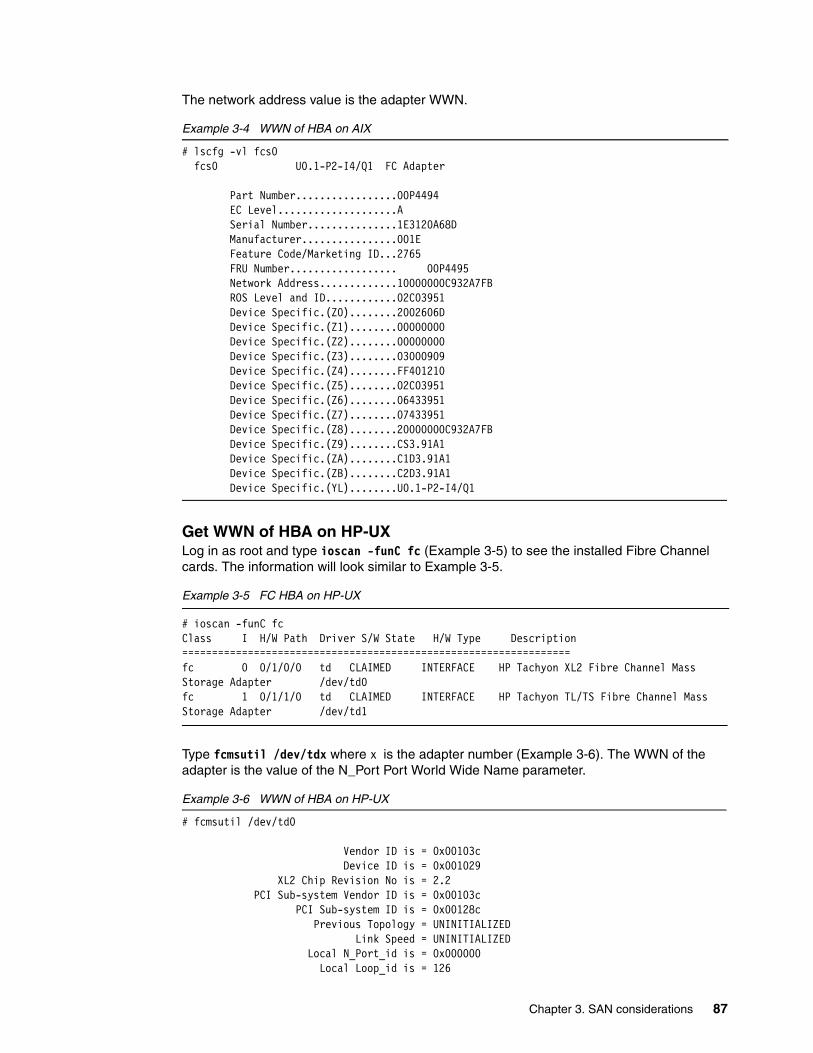
The network address value is the adapter WWN.
Example 3-4 WWN of HBA on AIX
# lscfg -vl fcs0 fcs0 U0.1-P2-I4/Q1 FC Adapter
Part Number.................00P4494 EC Level....................A Serial Number...............1E3120A68D Manufacturer................001E Feature Code/Marketing ID...2765 FRU Number.................. 00P4495 Network Address.............10000000C932A7FB ROS Level and ID............02C03951 Device Specific.(Z0)........2002606D Device Specific.(Z1)........00000000 Device Specific.(Z2)........00000000 Device Specific.(Z3)........03000909 Device Specific.(Z4)........FF401210 Device Specific.(Z5)........02C03951 Device Specific.(Z6)........06433951 Device Specific.(Z7)........07433951 Device Specific.(Z8)........20000000C932A7FB Device Specific.(Z9)........CS3.91A1 Device Specific.(ZA)........C1D3.91A1 Device Specific.(ZB)........C2D3.91A1 Device Specific.(YL)........U0.1-P2-I4/Q1
Get WWN of HBA on HP-UXLog in as root and type ioscan -funC fc (Example 3-5) to see the installed Fibre Channel cards. The information will look similar to Example 3-5.
Example 3-5 FC HBA on HP-UX
# ioscan -funC fcClass I H/W Path Driver S/W State H/W Type Description=================================================================fc 0 0/1/0/0 td CLAIMED INTERFACE HP Tachyon XL2 Fibre Channel MassStorage Adapter /dev/td0fc 1 0/1/1/0 td CLAIMED INTERFACE HP Tachyon TL/TS Fibre Channel MassStorage Adapter /dev/td1
Type fcmsutil /dev/tdx where x is the adapter number (Example 3-6). The WWN of the adapter is the value of the N_Port Port World Wide Name parameter.
Example 3-6 WWN of HBA on HP-UX
# fcmsutil /dev/td0
Vendor ID is = 0x00103c Device ID is = 0x001029 XL2 Chip Revision No is = 2.2 PCI Sub-system Vendor ID is = 0x00103c PCI Sub-system ID is = 0x00128c Previous Topology = UNINITIALIZED Link Speed = UNINITIALIZED Local N_Port_id is = 0x000000 Local Loop_id is = 126
Chapter 3. SAN considerations 87

N_Port Node World Wide Name = 0x50060b000010949d N_Port Port World Wide Name = 0x50060b000010949c Driver state = AWAITING_LINK_UP Hardware Path is = 0/1/0/0 Number of Assisted IOs = 0 Number of Active Login Sessions = 0 Dino Present on Card = NO Maximum Frame Size = 960 Driver Version = @(#) PATCH_11.11: libtd.a : Dec 12 2003,14:34:15, PHSS_28509
Get WWN of HBA on SolarisThe Solaris system here had both QLogic 2200 and Emulex LP8000 HBAs installed. Log in as root. Type dmesg and scan down until you find the entries related to the HBA. They will look similar to Example 3-7.
Example 3-7 WWN of HBA on Solaris
Aug 10 16:10:28 sol-e unix: QLogic qla2200 Fibre Channel Driver v3.07 Instance: 1. Firmware v2.1.31.Aug 10 16:10:36 sol-e unix: qla2200(1): Verification complete. Hardware initialized.Aug 10 16:10:37 sol-e unix: qla2200-hba1-adapter-node-name="200000e08b0190ef";Aug 10 16:10:37 sol-e unix: qla2200-hba1-adapter-port-name="210000e08b0190ef";Aug 10 16:10:37 sol-e unix: PCI-device: scsi@2, qla22001Aug 10 16:10:37 sol-e unix: qla22001 is /pci@1f,4000/scsi@2Aug 10 16:10:37 sol-e unix: NOTICE: Aug 10 16:10:37 sol-e Emulex LightPulse FC SCSI/IP 4.20kAug 10 16:10:37 sol-e unix: NOTICE: lpfc0:045:Vital Product Data Data: 82 23 0 36Aug 10 16:10:37 sol-e unix: NOTICE: lpfc0:031:Link Up Event received Data: 1 1 0 0Aug 10 16:10:39 sol-e unix: NOTICE: lpfc0: Firmware Rev 3.81A1 (D2D3.81A1)Aug 10 16:10:39 sol-e unix: NOTICE: lpfc0: WWPN:10:00:00:00:c9:23:c3:05 WWNN:20:00:00:00:c9:23:c3:05 DID 0x31700
The entries beginning with qla2200-hba1-adapter-node-name and qla2200-hba1-adapter-port-name give the WWN and WWPN of the QLogic 220 HBA. The entry beginning with lpfc0: WWPN gives the same information for the Emulex LP8000 HBA.
3.3 Persistent bindingThis function allows a subset of discovered targets to be bound to an HBA. Some operating systems do not guarantee that devices will always be allocated the same SCSI target and LUN IDs after a reboot. This can cause problems for application software that expects tape devices always to have the same SCSI target ID/LUN. Persistent binding allows a tape device’s WWN to be bound to a specific SCSI LUN.
Another reason to use persistent binding is to ensure that the operating system drive names are configured in their physically installed order. Many backup applications (for example, EMC Legato NetWorker and VERITAS NetBackup DataCenter) will assume that the devices have been assigned their drive names in the same order as the element numbers. If the drives were configured in a different order, then the application will not correctly access the
Note: You can use dmesg, or view the messages file in /var/adm, or use your HBA vendor's utility to display the WWN. The dmesg command displays the contents of a fixed-size buffer. Therefore, if the system has been up for an extended period, the initial boot messages may have been overwritten with other kernel log entries.
88 Implementing IBM Tape in UNIX Systems
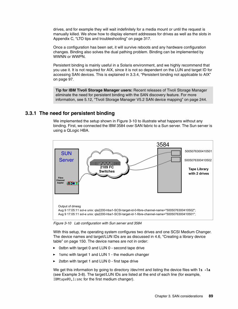
drives, and for example they will wait indefinitely for a media mount or until the request is manually killed. We show how to display element addresses for drives as well as the slots in Appendix C, “LTO tips and troubleshooting” on page 317.
Once a configuration has been set, it will survive reboots and any hardware configuration changes. Binding also solves the dual pathing problem. Binding can be implemented by WWNN or WWPN.
Persistent binding is mainly useful in a Solaris environment, and we highly recommend that you use it. It is not required for AIX, since it is not so dependent on the LUN and target ID for accessing SAN devices. This is explained in 3.3.4, “Persistent binding not applicable to AIX” on page 97.
3.3.1 The need for persistent bindingWe implemented the setup shown in Figure 3-10 to illustrate what happens without any binding. First, we connected the IBM 3584 over SAN fabric to a Sun server. The Sun server is using a QLogic HBA.
Figure 3-10 Lab configuration with Sun server and 3584
With this setup, the operating system configures two drives and one SCSI Medium Changer. The device names and target/LUN IDs are as discussed in 4.6, “Creating a library device table” on page 150. The device names are not in order:
� 0stbn with target 0 and LUN 0 - second tape drive
� 1smc with target 1 and LUN 1 - the medium changer
� 2stbn with target 1 and LUN 0 - first tape drive
We get this information by going to directory /dev/rmt and listing the device files with ls -la (see Example 3-8). The target/LUN IDs are listed at the end of each line (for example, IBMtape@0,1:smc for the first medium changer).
Tip for IBM Tivoli Storage Manager users: Recent releases of Tivoli Storage Manager eliminate the need for persistent binding with the SAN discovery feature. For more information, see 5.12, “Tivoli Storage Manager V5.2 SAN device mapping” on page 244.
Tape Librarywith 2 drives
3584
Fibre Channel Aapter
SUNServer
2109 FC Switches
5005076300410501
5005076300410502
Output of dmesgAug 9 17:05:11 sol-e unix: qla2200-hba1-SCSI-target-id-0-fibre-channel-name="5005076300410502";Aug 9 17:05:11 sol-e unix: qla2200-hba1-SCSI-target-id-1-fibre-channel-name="5005076300410501";
Chapter 3. SAN considerations 89
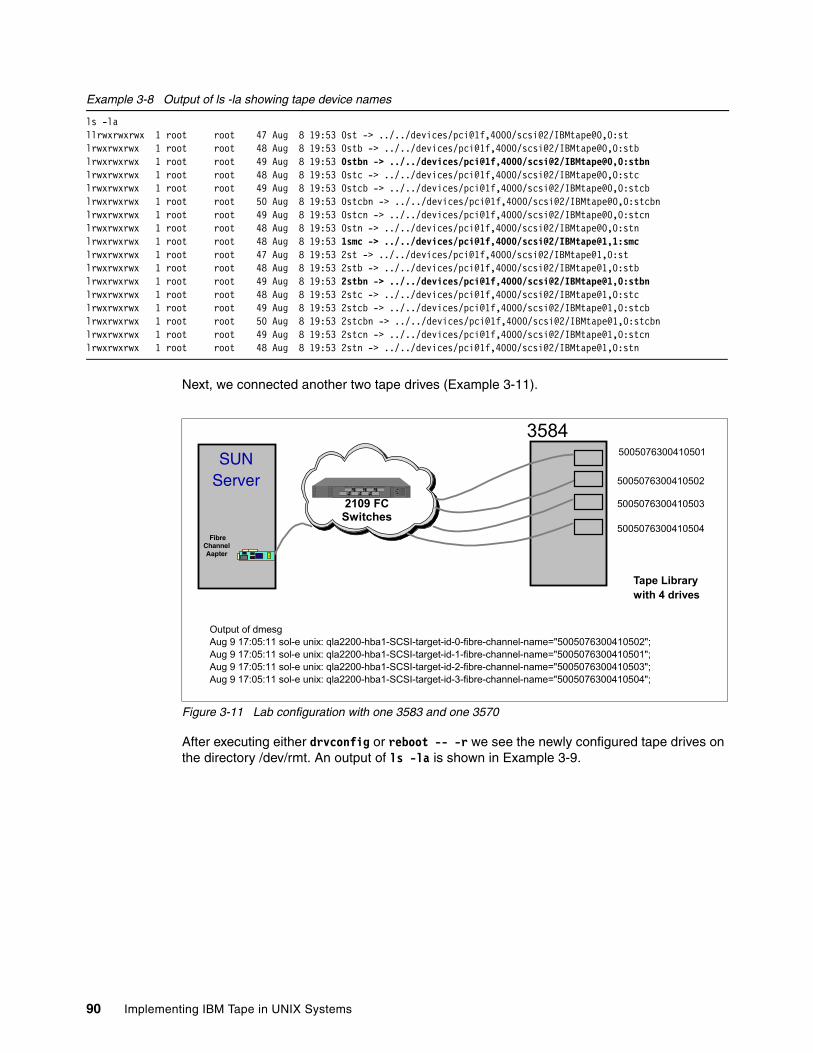
Example 3-8 Output of ls -la showing tape device names
ls -lallrwxrwxrwx 1 root root 47 Aug 8 19:53 0st -> ../../devices/pci@1f,4000/scsi@2/IBMtape@0,0:stlrwxrwxrwx 1 root root 48 Aug 8 19:53 0stb -> ../../devices/pci@1f,4000/scsi@2/IBMtape@0,0:stblrwxrwxrwx 1 root root 49 Aug 8 19:53 0stbn -> ../../devices/pci@1f,4000/scsi@2/IBMtape@0,0:stbnlrwxrwxrwx 1 root root 48 Aug 8 19:53 0stc -> ../../devices/pci@1f,4000/scsi@2/IBMtape@0,0:stclrwxrwxrwx 1 root root 49 Aug 8 19:53 0stcb -> ../../devices/pci@1f,4000/scsi@2/IBMtape@0,0:stcblrwxrwxrwx 1 root root 50 Aug 8 19:53 0stcbn -> ../../devices/pci@1f,4000/scsi@2/IBMtape@0,0:stcbnlrwxrwxrwx 1 root root 49 Aug 8 19:53 0stcn -> ../../devices/pci@1f,4000/scsi@2/IBMtape@0,0:stcnlrwxrwxrwx 1 root root 48 Aug 8 19:53 0stn -> ../../devices/pci@1f,4000/scsi@2/IBMtape@0,0:stnlrwxrwxrwx 1 root root 48 Aug 8 19:53 1smc -> ../../devices/pci@1f,4000/scsi@2/IBMtape@1,1:smclrwxrwxrwx 1 root root 47 Aug 8 19:53 2st -> ../../devices/pci@1f,4000/scsi@2/IBMtape@1,0:stlrwxrwxrwx 1 root root 48 Aug 8 19:53 2stb -> ../../devices/pci@1f,4000/scsi@2/IBMtape@1,0:stblrwxrwxrwx 1 root root 49 Aug 8 19:53 2stbn -> ../../devices/pci@1f,4000/scsi@2/IBMtape@1,0:stbnlrwxrwxrwx 1 root root 48 Aug 8 19:53 2stc -> ../../devices/pci@1f,4000/scsi@2/IBMtape@1,0:stclrwxrwxrwx 1 root root 49 Aug 8 19:53 2stcb -> ../../devices/pci@1f,4000/scsi@2/IBMtape@1,0:stcblrwxrwxrwx 1 root root 50 Aug 8 19:53 2stcbn -> ../../devices/pci@1f,4000/scsi@2/IBMtape@1,0:stcbnlrwxrwxrwx 1 root root 49 Aug 8 19:53 2stcn -> ../../devices/pci@1f,4000/scsi@2/IBMtape@1,0:stcnlrwxrwxrwx 1 root root 48 Aug 8 19:53 2stn -> ../../devices/pci@1f,4000/scsi@2/IBMtape@1,0:stn
Next, we connected another two tape drives (Example 3-11).
Figure 3-11 Lab configuration with one 3583 and one 3570
After executing either drvconfig or reboot -- -r we see the newly configured tape drives on the directory /dev/rmt. An output of ls -la is shown in Example 3-9.
Tape Librarywith 4 drives
3584
Fibre Channel Aapter
SUNServer
2109 FC Switches
5005076300410501
5005076300410502
Output of dmesgAug 9 17:05:11 sol-e unix: qla2200-hba1-SCSI-target-id-0-fibre-channel-name="5005076300410502";Aug 9 17:05:11 sol-e unix: qla2200-hba1-SCSI-target-id-1-fibre-channel-name="5005076300410501";Aug 9 17:05:11 sol-e unix: qla2200-hba1-SCSI-target-id-2-fibre-channel-name="5005076300410503";Aug 9 17:05:11 sol-e unix: qla2200-hba1-SCSI-target-id-3-fibre-channel-name="5005076300410504";
5005076300410503
5005076300410504
90 Implementing IBM Tape in UNIX Systems
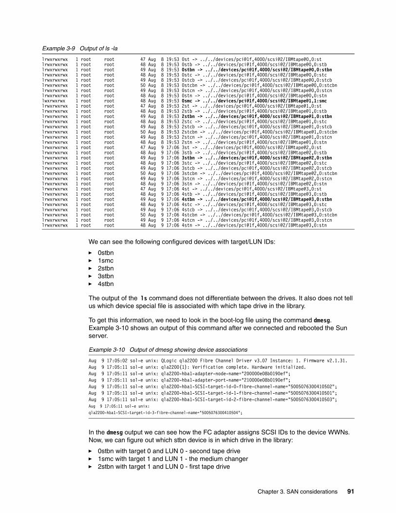
Example 3-9 Output of ls -la
lrwxrwxrwx 1 root root 47 Aug 8 19:53 0st -> ../../devices/pci@1f,4000/scsi@2/IBMtape@0,0:stlrwxrwxrwx 1 root root 48 Aug 8 19:53 0stb -> ../../devices/pci@1f,4000/scsi@2/IBMtape@0,0:stblrwxrwxrwx 1 root root 49 Aug 8 19:53 0stbn -> ../../devices/pci@1f,4000/scsi@2/IBMtape@0,0:stbnlrwxrwxrwx 1 root root 48 Aug 8 19:53 0stc -> ../../devices/pci@1f,4000/scsi@2/IBMtape@0,0:stclrwxrwxrwx 1 root root 49 Aug 8 19:53 0stcb -> ../../devices/pci@1f,4000/scsi@2/IBMtape@0,0:stcblrwxrwxrwx 1 root root 50 Aug 8 19:53 0stcbn -> ../../devices/pci@1f,4000/scsi@2/IBMtape@0,0:stcbnlrwxrwxrwx 1 root root 49 Aug 8 19:53 0stcn -> ../../devices/pci@1f,4000/scsi@2/IBMtape@0,0:stcnlrwxrwxrwx 1 root root 48 Aug 8 19:53 0stn -> ../../devices/pci@1f,4000/scsi@2/IBMtape@0,0:stnlwxrwxrwx 1 root root 48 Aug 8 19:53 0smc -> ../../devices/pci@1f,4000/scsi@2/IBMtape@1,1:smclrwxrwxrwx 1 root root 47 Aug 8 19:53 2st -> ../../devices/pci@1f,4000/scsi@2/IBMtape@1,0:stlrwxrwxrwx 1 root root 48 Aug 8 19:53 2stb -> ../../devices/pci@1f,4000/scsi@2/IBMtape@1,0:stblrwxrwxrwx 1 root root 49 Aug 8 19:53 2stbn -> ../../devices/pci@1f,4000/scsi@2/IBMtape@1,0:stbnlrwxrwxrwx 1 root root 48 Aug 8 19:53 2stc -> ../../devices/pci@1f,4000/scsi@2/IBMtape@1,0:stclrwxrwxrwx 1 root root 49 Aug 8 19:53 2stcb -> ../../devices/pci@1f,4000/scsi@2/IBMtape@1,0:stcblrwxrwxrwx 1 root root 50 Aug 8 19:53 2stcbn -> ../../devices/pci@1f,4000/scsi@2/IBMtape@1,0:stcbnlrwxrwxrwx 1 root root 49 Aug 8 19:53 2stcn -> ../../devices/pci@1f,4000/scsi@2/IBMtape@1,0:stcnlrwxrwxrwx 1 root root 48 Aug 8 19:53 2stn -> ../../devices/pci@1f,4000/scsi@2/IBMtape@1,0:stnlrwxrwxrwx 1 root root 47 Aug 9 17:06 3st -> ../../devices/pci@1f,4000/scsi@2/IBMtape@2,0:stlrwxrwxrwx 1 root root 48 Aug 9 17:06 3stb -> ../../devices/pci@1f,4000/scsi@2/IBMtape@2,0:stblrwxrwxrwx 1 root root 49 Aug 9 17:06 3stbn -> ../../devices/pci@1f,4000/scsi@2/IBMtape@2,0:stbnlrwxrwxrwx 1 root root 48 Aug 9 17:06 3stc -> ../../devices/pci@1f,4000/scsi@2/IBMtape@2,0:stclrwxrwxrwx 1 root root 49 Aug 9 17:06 3stcb -> ../../devices/pci@1f,4000/scsi@2/IBMtape@2,0:stcblrwxrwxrwx 1 root root 50 Aug 9 17:06 3stcbn -> ../../devices/pci@1f,4000/scsi@2/IBMtape@2,0:stcbnlrwxrwxrwx 1 root root 49 Aug 9 17:06 3stcn -> ../../devices/pci@1f,4000/scsi@2/IBMtape@2,0:stcnlrwxrwxrwx 1 root root 48 Aug 9 17:06 3stn -> ../../devices/pci@1f,4000/scsi@2/IBMtape@2,0:stnlrwxrwxrwx 1 root root 47 Aug 9 17:06 4st -> ../../devices/pci@1f,4000/scsi@2/IBMtape@3,0:stlrwxrwxrwx 1 root root 48 Aug 9 17:06 4stb -> ../../devices/pci@1f,4000/scsi@2/IBMtape@3,0:stblrwxrwxrwx 1 root root 49 Aug 9 17:06 4stbn -> ../../devices/pci@1f,4000/scsi@2/IBMtape@3,0:stbnlrwxrwxrwx 1 root root 48 Aug 9 17:06 4stc -> ../../devices/pci@1f,4000/scsi@2/IBMtape@3,0:stclrwxrwxrwx 1 root root 49 Aug 9 17:06 4stcb -> ../../devices/pci@1f,4000/scsi@2/IBMtape@3,0:stcblrwxrwxrwx 1 root root 50 Aug 9 17:06 4stcbn -> ../../devices/pci@1f,4000/scsi@2/IBMtape@3,0:stcbnlrwxrwxrwx 1 root root 49 Aug 9 17:06 4stcn -> ../../devices/pci@1f,4000/scsi@2/IBMtape@3,0:stcnlrwxrwxrwx 1 root root 48 Aug 9 17:06 4stn -> ../../devices/pci@1f,4000/scsi@2/IBMtape@3,0:stn
We can see the following configured devices with target/LUN IDs:
� 0stbn � 1smc � 2stbn � 3stbn � 4stbn
The output of the ls command does not differentiate between the drives. It also does not tell us which device special file is associated with which tape drive in the library.
To get this information, we need to look in the boot-log file using the command dmesg. Example 3-10 shows an output of this command after we connected and rebooted the Sun server.
Example 3-10 Output of dmesg showing device associations
Aug 9 17:05:02 sol-e unix: QLogic qla2200 Fibre Channel Driver v3.07 Instance: 1. Firmware v2.1.31.Aug 9 17:05:11 sol-e unix: qla2200(1): Verification complete. Hardware initialized.Aug 9 17:05:11 sol-e unix: qla2200-hba1-adapter-node-name="200000e08b0190ef";Aug 9 17:05:11 sol-e unix: qla2200-hba1-adapter-port-name="210000e08b0190ef";Aug 9 17:05:11 sol-e unix: qla2200-hba1-SCSI-target-id-0-fibre-channel-name="5005076300410502";Aug 9 17:05:11 sol-e unix: qla2200-hba1-SCSI-target-id-1-fibre-channel-name="5005076300410501";Aug 9 17:05:11 sol-e unix: qla2200-hba1-SCSI-target-id-2-fibre-channel-name="5005076300410503";Aug 9 17:05:11 sol-e unix: qla2200-hba1-SCSI-target-id-3-fibre-channel-name="5005076300410504";
In the dmesg output we can see how the FC adapter assigns SCSI IDs to the device WWNs. Now, we can figure out which stbn device is in which drive in the library:
� 0stbn with target 0 and LUN 0 - second tape drive� 1smc with target 1 and LUN 1 - the medium changer� 2stbn with target 1 and LUN 0 - first tape drive
Chapter 3. SAN considerations 91
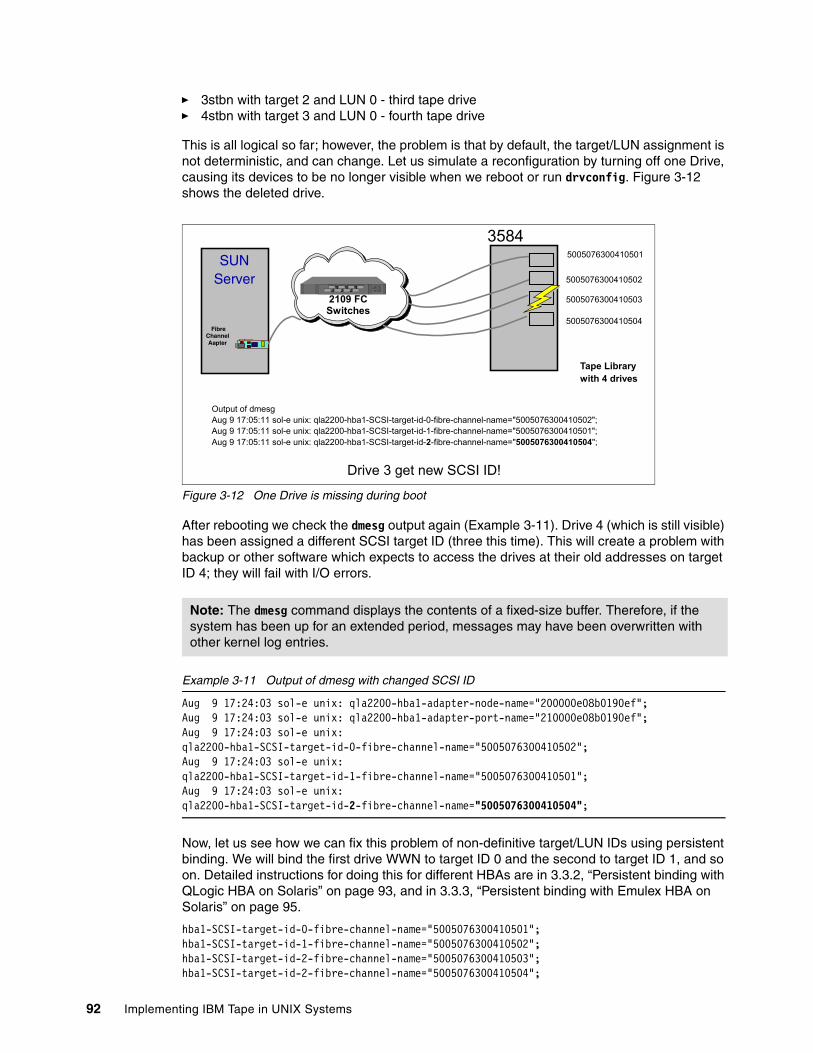
� 3stbn with target 2 and LUN 0 - third tape drive� 4stbn with target 3 and LUN 0 - fourth tape drive
This is all logical so far; however, the problem is that by default, the target/LUN assignment is not deterministic, and can change. Let us simulate a reconfiguration by turning off one Drive, causing its devices to be no longer visible when we reboot or run drvconfig. Figure 3-12 shows the deleted drive.
Figure 3-12 One Drive is missing during boot
After rebooting we check the dmesg output again (Example 3-11). Drive 4 (which is still visible) has been assigned a different SCSI target ID (three this time). This will create a problem with backup or other software which expects to access the drives at their old addresses on target ID 4; they will fail with I/O errors.
Example 3-11 Output of dmesg with changed SCSI ID
Aug 9 17:24:03 sol-e unix: qla2200-hba1-adapter-node-name="200000e08b0190ef";Aug 9 17:24:03 sol-e unix: qla2200-hba1-adapter-port-name="210000e08b0190ef";Aug 9 17:24:03 sol-e unix: qla2200-hba1-SCSI-target-id-0-fibre-channel-name="5005076300410502";Aug 9 17:24:03 sol-e unix: qla2200-hba1-SCSI-target-id-1-fibre-channel-name="5005076300410501";Aug 9 17:24:03 sol-e unix: qla2200-hba1-SCSI-target-id-2-fibre-channel-name="5005076300410504";
Now, let us see how we can fix this problem of non-definitive target/LUN IDs using persistent binding. We will bind the first drive WWN to target ID 0 and the second to target ID 1, and so on. Detailed instructions for doing this for different HBAs are in 3.3.2, “Persistent binding with QLogic HBA on Solaris” on page 93, and in 3.3.3, “Persistent binding with Emulex HBA on Solaris” on page 95.
hba1-SCSI-target-id-0-fibre-channel-name="5005076300410501";hba1-SCSI-target-id-1-fibre-channel-name="5005076300410502";hba1-SCSI-target-id-2-fibre-channel-name="5005076300410503";hba1-SCSI-target-id-2-fibre-channel-name="5005076300410504";
Note: The dmesg command displays the contents of a fixed-size buffer. Therefore, if the system has been up for an extended period, messages may have been overwritten with other kernel log entries.
Tape Librarywith 4 drives
3584
Fibre Channel Aapter
SUNServer
2109 FC Switches
5005076300410501
5005076300410502
Output of dmesgAug 9 17:05:11 sol-e unix: qla2200-hba1-SCSI-target-id-0-fibre-channel-name="5005076300410502";Aug 9 17:05:11 sol-e unix: qla2200-hba1-SCSI-target-id-1-fibre-channel-name="5005076300410501";Aug 9 17:05:11 sol-e unix: qla2200-hba1-SCSI-target-id-2-fibre-channel-name="5005076300410504";
5005076300410503
5005076300410504
Drive 3 get new SCSI ID!
92 Implementing IBM Tape in UNIX Systems
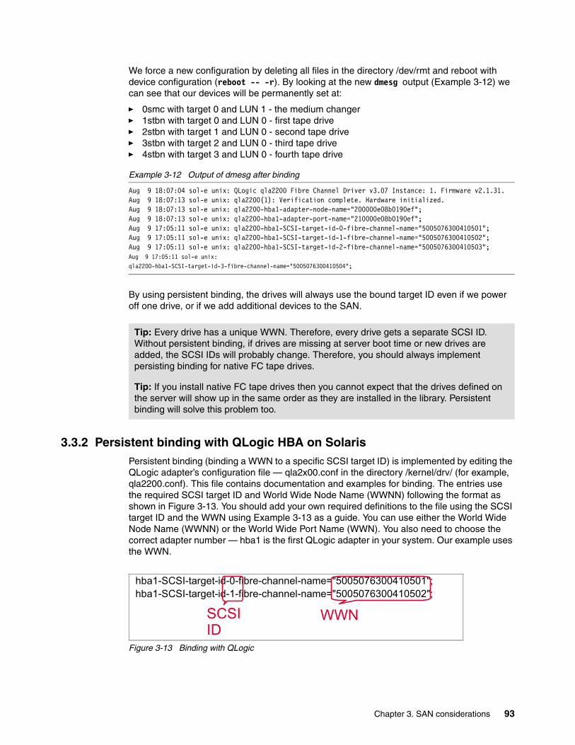
We force a new configuration by deleting all files in the directory /dev/rmt and reboot with device configuration (reboot -- -r). By looking at the new dmesg output (Example 3-12) we can see that our devices will be permanently set at:
� 0smc with target 0 and LUN 1 - the medium changer� 1stbn with target 0 and LUN 0 - first tape drive� 2stbn with target 1 and LUN 0 - second tape drive� 3stbn with target 2 and LUN 0 - third tape drive� 4stbn with target 3 and LUN 0 - fourth tape drive
Example 3-12 Output of dmesg after binding
Aug 9 18:07:04 sol-e unix: QLogic qla2200 Fibre Channel Driver v3.07 Instance: 1. Firmware v2.1.31.Aug 9 18:07:13 sol-e unix: qla2200(1): Verification complete. Hardware initialized.Aug 9 18:07:13 sol-e unix: qla2200-hba1-adapter-node-name="200000e08b0190ef";Aug 9 18:07:13 sol-e unix: qla2200-hba1-adapter-port-name="210000e08b0190ef";Aug 9 17:05:11 sol-e unix: qla2200-hba1-SCSI-target-id-0-fibre-channel-name="5005076300410501";Aug 9 17:05:11 sol-e unix: qla2200-hba1-SCSI-target-id-1-fibre-channel-name="5005076300410502";Aug 9 17:05:11 sol-e unix: qla2200-hba1-SCSI-target-id-2-fibre-channel-name="5005076300410503";Aug 9 17:05:11 sol-e unix: qla2200-hba1-SCSI-target-id-3-fibre-channel-name="5005076300410504";
By using persistent binding, the drives will always use the bound target ID even if we power off one drive, or if we add additional devices to the SAN.
3.3.2 Persistent binding with QLogic HBA on SolarisPersistent binding (binding a WWN to a specific SCSI target ID) is implemented by editing the QLogic adapter’s configuration file — qla2x00.conf in the directory /kernel/drv/ (for example, qla2200.conf). This file contains documentation and examples for binding. The entries use the required SCSI target ID and World Wide Node Name (WWNN) following the format as shown in Figure 3-13. You should add your own required definitions to the file using the SCSI target ID and the WWN using Example 3-13 as a guide. You can use either the World Wide Node Name (WWNN) or the World Wide Port Name (WWN). You also need to choose the correct adapter number — hba1 is the first QLogic adapter in your system. Our example uses the WWN.
Figure 3-13 Binding with QLogic
Tip: Every drive has a unique WWN. Therefore, every drive gets a separate SCSI ID. Without persistent binding, if drives are missing at server boot time or new drives are added, the SCSI IDs will probably change. Therefore, you should always implement persisting binding for native FC tape drives.
Tip: If you install native FC tape drives then you cannot expect that the drives defined on the server will show up in the same order as they are installed in the library. Persistent binding will solve this problem too.
hba1-SCSI-target-id-0-fibre-channel-name="5005076300410501";hba1-SCSI-target-id-1-fibre-channel-name="5005076300410502";
SCSI ID
WWN
Chapter 3. SAN considerations 93
The WWN 5005076300410501 was bound to SCSI target ID 0. This is the first drive in our example (see Figure 3-11 on page 90). WWN 5005076300410502, the second drive, was bound to SCSI target ID 0.
Example 3-13 Binding with QLogic 2200 adapter
# =======================# Persistent Name Binding# =======================## The Persistent Name Binding support for adapter devices associates a# user specified World Wide Node Name to a specified adapter instance.# In other words, this entry changes the node name of the specified# adapter instance to the node name specified in the entry.# To enable it, entries of the following format should be added in the# qla2200.conf file:# # hba<#>-adapter-node-name="<World Wide Node Name>";# # For example, to associate the following node name to adapter# instance 2, the entry will be:# # hba2-adapter-node-name="200000e08b023227";# # The Persistent Name Binding support for target devices associates a# SCSI target ID to a specified device World Wide Name. In other# words, this entry changes the target ID of the specified device# to the number specified in the entry. To enable it, lines of# the following format should be added in the qla2200.conf file:# # hba<#>-SCSI-target-id-<#>-fibre-channel-name="<device WWN>";# # For example, to associate the following WWN with target ID 2 on# adapter instance 1, the entry will be:# # hba1-SCSI-target-id-2-fibre-channel-name="2000002037004ac9";# # *********# IMPORTANT# *********# # - Unlike other parameter entries in the qla2200.conf file, values# indicated in persistent name binding entries for instance 0 does# not apply to other instances when there are no entries for the# other instances.# # - Persistent Name Binding entries are optional entries in the# qla2200.conf file. These entries do not dictate which devices# are scanned by the driver, and do not perform any device masking.# Absence of this entry for any given device name or SCSI ID does# not direct the driver to perform any type of device masking.## - For adapter devices, if no Persistent Name Binding entries are# specified, the default WWNN used by the adapters will be the ones# stored in the NVRAM.# # - For target devices, if no Persistent Name Binding entries are# specified, the default SCSI target IDs assigned will be the loop# ID of the devices. Please refer to the FAQ section for which# default SCSI target IDs are assigned to fabric devices.#
94 Implementing IBM Tape in UNIX Systems
# *******# CAUTION# *******# # When the Persistent Name Binding entries are used in combination with# the device entries in the /kernel/drv/sd.conf or /kernel/drv/st.conf# file, it is possible to purposely mask off certain devices of certain# adapter instances from the operating system, by purposely commenting# out/deleting entries in the sd.conf/st.conf file for those SCSI target# IDs/LUNs bound to those certain adapter instances. However, when the# devices are shared among multiple adapters, doing so requires extreme# caution, and it is strongly recommeded that all target devices be bound# with all adapter instances so that the devices will show up in a pre-# determinable way. A shared device which is bound on one adapter# instance but unbound on another adapter instance may show up at a SCSI# target ID which is unexpected by the user for the unbound adapter# instance, which may lead to possible data corruption on the device# if the user unknowingly writes to the unexpected device.## The QLogic Solaris SCSI HBA driver does not filter out the OS scanning# of SCSI devices. The target IDs/LUNs scanned by the OS is based on the# entries specified in the sd.conf and st.conf files. When the HBA# driver first initializes during the system boot process, it assigns a# target ID internally to all of the devices it detected. During the OS# device scan, the driver ignores the 'class' value indicated in the# sd.conf/st.conf file and processes the IOs addressed to a device whose# target ID/LUN matches that of a device previously detected by the# driver.
#Bindinghba1-SCSI-target-id-1-fibre-channel-name="5005076300410501";hba1-SCSI-target-id-0-fibre-channel-name="5005076300410502";
After you edit the configuration file, reboot the system to apply the changes.
Note that for a QLogic 2300 adapter, entries are of the format:
hbax-SCSI-target-id-x-fibre-channel-port-name="xxxxxxxxxxx";
3.3.3 Persistent binding with Emulex HBA on SolarisPersistent binding (binding a WWN to a specific SCSI target ID) is implemented by editing the Emulex adapter’s configuration file. The configuration files are located in the directory /kernel/drv/, and are called lpfc.conf (for LP8000) or lpfs.conf (for LP8000S). This file contains documentation and examples for binding. The entries use the required SCSI target ID and World Wide names. Follow the format as shown in Figure 3-14. You should add your own required definitions to the file, using the SCSI target ID and either the WWNN or WWPN, and also using Example 3-14 as a guide (in our example, we used WWNN). You also need to choose the correct adapter number — lpfc0 is the first adapter in your system and lpfc1 is the second one. For LP8000 you have to use device name lpfc, and for LP8000S you have to use lpfs.
Chapter 3. SAN considerations 95
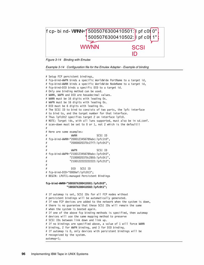
Figure 3-14 Binding with Emulex
Example 3-14 Configuration file for the Emulex Adapter - Example of binding
# Setup FCP persistent bindings,# fcp-bind-WWPN binds a specific WorldWide PortName to a target id,# fcp-bind-WWNN binds a specific WorldWide NodeName to a target id,# fcp-bind-DID binds a specific DID to a target id.# Only one binding method can be used.# WWNN, WWPN and DID are hexadecimal values.# WWNN must be 16 digits with leading 0s.# WWPN must be 16 digits with leading 0s.# DID must be 6 digits with leading 0s.# The SCSI ID to bind to consists of two parts, the lpfc interface# to bind to, and the target number for that interface.# Thus lpfc0t2 specifies target 2 on interface lpfc0.# NOTE: Target ids, with all luns supported, must also be in sd.conf.# scan-down must be set to 0 or 1, not 2 which is the default!!## Here are some examples:# WWNN SCSI ID# fcp-bind-WWNN="2000123456789abc:lpfc1t0",# "20000020370c27f7:lpfc0t2";# # WWPN SCSI ID# fcp-bind-WWPN="2100123456789abc:lpfc0t0",# "21000020370c2855:lpfc0t1",# "2100122222222222:lpfc2t2";# # DID SCSI ID# fcp-bind-DID="0000ef:lpfc0t3";# BEGIN: LPUTIL-managed Persistent Bindings
fcp-bind-WWNN="5005076300410501:lpfc0t0", "5005076300410502:lpfc0t1";
# If automap is set, SCSI IDs for all FCP nodes without# persistent bindings will be automatically generated.# If new FCP devices are added to the network when the system is down,# there is no guarantee that these SCSI IDs will remain the same# when the system is booted again. # If one of the above fcp binding methods is specified, then automap# devices will use the same mapping method to preserve # SCSI IDs between link down and link up.# If no bindings are specified above, a value of 1 will force WWNN# binding, 2 for WWPN binding, and 3 for DID binding.# If automap is 0, only devices with persistent bindings will be# recognized by the system.automap=1;
SCSI ID
WWNN
f cp- bi nd- WWNN=" 5005076300410501: l pf c0t 0" , " 5005076300410502: l pf c0t 1" ;
96 Implementing IBM Tape in UNIX Systems
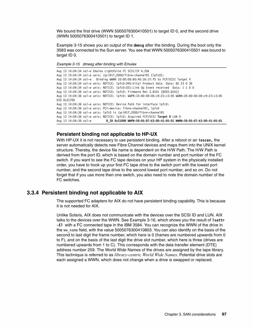
We bound the first drive (WWN 5005076300410501) to target ID 0, and the second drive (WWN 5005076300410501) to target ID 1.
Example 3-15 shows you an output of the dmesg after the binding. During the boot only the 3583 was connected to the Sun server. You see that WWN 5005076300410501 was bound to target ID 0.
Example 3-15 dmesg after binding with Emulex
Aug 13 14:04:34 sol-e Emulex LightPulse FC SCSI/IP 4.20kAug 13 14:04:34 sol-e unix: /pci@1f,2000/fibre-channel@1 (lpfc0):Aug 13 14:04:34 sol-e Binding WWNN 10:00:00:60:45:16:1f:f5 to FCP/SCSI Target 4Aug 13 14:04:34 sol-e unix: NOTICE: lpfc0:045:Vital Product Data Data: 82 23 0 36Aug 13 14:04:34 sol-e unix: NOTICE: lpfc0:031:Link Up Event received Data: 1 1 0 0Aug 13 14:04:36 sol-e unix: NOTICE: lpfc0: Firmware Rev 3.81A1 (D2D3.81A1)Aug 13 14:04:36 sol-e unix: NOTICE: lpfc0: WWPN:10:00:00:00:c9:23:c3:05 WWNN:20:00:00:00:c9:23:c3:05 DID 0x31700Aug 13 14:04:36 sol-e unix: NOTICE: Device Path for interface lpfc0:Aug 13 14:04:36 sol-e unix: PCI-device: fibre-channel@1, lpfc0Aug 13 14:04:36 sol-e unix: lpfc0 is /pci@1f,2000/fibre-channel@1Aug 13 14:04:36 sol-e unix: NOTICE: lpfc0: Acquired FCP/SCSI Target 0 LUN 0Aug 13 14:04:36 sol-e D_ID 0x31000 WWPN:50:05:07:63:00:41:05:01 WWNN:50:05:07:63:00:41:05:01
Persistent binding not applicable to HP-UXWith HP-UX it is not necessary to use persistent binding. After a reboot or an ioscan, the server automatically detects new Fibre Channel devices and maps them into the UNIX kernel structure. Thereby, the device file name is dependent on the H/W Path. The H/W Path is derived from the port ID, which is based on the domain number and port number of the FC switch. If you want to see the FC tape devices on your HP system in the physically installed order, you have to hook up your first FC tape drive to the switch port with the lowest port number, and the second tape drive to the second lowest port number, and so on. Do not forget that if you use more then one switch, you also need to note the domain number of the FC switches.
3.3.4 Persistent binding not applicable to AIXThe supported FC adapters for AIX do not have persistent binding capability. This is because it is not needed for AIX.
Unlike Solaris, AIX does not communicate with the devices over the SCSI ID and LUN. AIX talks to the devices over the WWN. See Example 3-16, which shows you the result of lsattr -El with a FC connected tape in the IBM 3584. You can recognize the WWN of the drive in the ww_name field, with the value 5005076300410803. You can also identify on the basis of the second to last digit the frame number, which here is 0 (frames are numbered upwards from 0 to F), and on the basis of the last digit the drive slot number, which here is three (drives are numbered upwards from 1 to C). This corresponds with the data transfer element (DTE) address number 259. The World Wide Names of the drives are assigned by the tape library. This technique is referred to as library-centric World Wide Names. Potential drive slots are each assigned a WWN, which does not change when a drive is swapped or replaced.
Chapter 3. SAN considerations 97
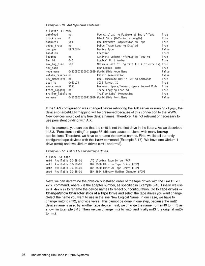
Example 3-16 AIX tape drive attributes
# lsattr -El rmt0autoload no Use Autoloading Feature at End-of-Tape Trueblock_size 0 Block Size (0=Variable Length) Truecompress yes Use Hardware Compression on Tape Truedebug_trace no Debug Trace Logging Enabled Truedevtype ULTRIUM- Device Type Falselocation Location Trueelogging no Activate volume information logging Truelun_id 0x0 Logical Unit Number Truemax_log_size 500 Maximum size of log file (in # of entries) Truenew_name New Logical Name Truenode_name 0x500507630001082b World Wide Node Name Falseretain_reserve no Retain Reservation Falserew_immediate no Use Immediate Bit in Rewind Commands Truescsi_id 0x60c79 SCSI Target ID Truespace_mode SCSI Backward Space/Forward Space Record Mode Truetrace_logging no Trace Logging Enabled Truetrailer_labels no Trailer Label Processing Trueww_name 0x500507630041082b World Wide Port Name False
If the SAN configuration was changed before rebooting the AIX server or running cfgmgr, the device-to-target/LUN mapping will be preserved because of this connection to the WWN. New devices would get any free device names. Therefore, it is not relevant or necessary to use persistent binding with AIX.
In this example, you can see that the rmt0 is not the first drive in the library. As we described in 3.3, “Persistent binding” on page 88, this can cause problems with many backup applications. Therefore, we have to rename the device names. First, we list all currently configured tape devices with the lsdev command (Example 3-17). We have one Ultrium 1 drive (rmt0) and two Ultrium drives (rmt1 and rmt2).
Example 3-17 List of FC attached tape drives
# lsdev -Cc tapermt0 Available 30-68-01 LTO Ultrium Tape Drive (FCP)rmt1 Available 30-68-01 IBM 3580 Ultrium Tape Drive (FCP)rmt2 Available 30-68-01 IBM 3580 Ultrium Tape Drive (FCP)smc0 Available 30-68-01 IBM 3584 Library Medium Changer (FCP)
Next, we can determine the physically installed order of the tape drives with the lsattr -El rmtx command, where x is the adapter number, as specified in Example 3-16. Finally, we use smit devices to rename the device names to reflect our configuration. Go to Tape drives → Change/Show Characteristics of a Tape Drive and select the tape drives you want change. Select the name you want to use in the line New Logical Name. In our case, we have to change rmt0 to rmt2, and vice versa. This cannot be done in one step, because the rmt2 device name is used by another tape device. First, we change the name from rmt0 to rmt3 as shown in Example 3-18. Then we can change rmt2 to rmt0, and finally rmt3 (the original rmt0) to rmt2.
98 Implementing IBM Tape in UNIX Systems
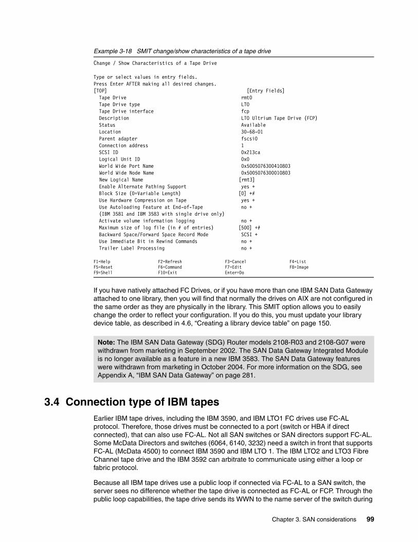
Example 3-18 SMIT change/show characteristics of a tape drive
Change / Show Characteristics of a Tape Drive
Type or select values in entry fields.Press Enter AFTER making all desired changes.[TOP] [Entry Fields] Tape Drive rmt0 Tape Drive type LTO Tape Drive interface fcp Description LTO Ultrium Tape Drive (FCP) Status Available Location 30-68-01 Parent adapter fscsi0 Connection address 1 SCSI ID 0x213ca Logical Unit ID 0x0 World Wide Port Name 0x5005076300410803
World Wide Node Name 0x5005076300010803New Logical Name [rmt3]
Enable Alternate Pathing Support yes + Block Size (0=Variable Length) [0] +# Use Hardware Compression on Tape yes + Use Autoloading Feature at End-of-Tape no + (IBM 3581 and IBM 3583 with single drive only) Activate volume information logging no + Maximum size of log file (in # of entries) [500] +# Backward Space/Forward Space Record Mode SCSI + Use Immediate Bit in Rewind Commands no + Trailer Label Processing no +
F1=Help F2=Refresh F3=Cancel F4=ListF5=Reset F6=Command F7=Edit F8=ImageF9=Shell F10=Exit Enter=Do
If you have natively attached FC Drives, or if you have more than one IBM SAN Data Gateway attached to one library, then you will find that normally the drives on AIX are not configured in the same order as they are physically in the library. This SMIT option allows you to easily change the order to reflect your configuration. If you do this, you must update your library device table, as described in 4.6, “Creating a library device table” on page 150.
3.4 Connection type of IBM tapesEarlier IBM tape drives, including the IBM 3590, and IBM LTO1 FC drives use FC-AL protocol. Therefore, those drives must be connected to a port (switch or HBA if direct connected), that can also use FC-AL. Not all SAN switches or SAN directors support FC-AL. Some McData Directors and switches (6064, 6140, 3232) need a switch in front that supports FC-AL (McData 4500) to connect IBM 3590 and IBM LTO 1. The IBM LTO2 and LTO3 Fibre Channel tape drive and the IBM 3592 can arbitrate to communicate using either a loop or fabric protocol.
Because all IBM tape drives use a public loop if connected via FC-AL to a SAN switch, the server sees no difference whether the tape drive is connected as FC-AL or FCP. Through the public loop capabilities, the tape drive sends its WWN to the name server of the switch during
Note: The IBM SAN Data Gateway (SDG) Router models 2108-R03 and 2108-G07 were withdrawn from marketing in September 2002. The SAN Data Gateway Integrated Module is no longer available as a feature in a new IBM 3583. The SAN Data Gateway features were withdrawn from marketing in October 2004. For more information on the SDG, see Appendix A, “IBM SAN Data Gateway” on page 281.
Chapter 3. SAN considerations 99
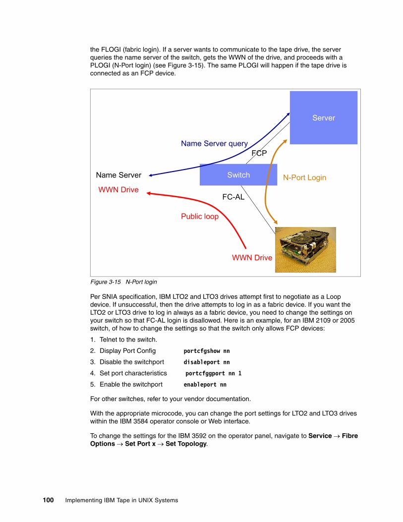
the FLOGI (fabric login). If a server wants to communicate to the tape drive, the server queries the name server of the switch, gets the WWN of the drive, and proceeds with a PLOGI (N-Port login) (see Figure 3-15). The same PLOGI will happen if the tape drive is connected as an FCP device.
Figure 3-15 N-Port login
Per SNIA specification, IBM LTO2 and LTO3 drives attempt first to negotiate as a Loop device. If unsuccessful, then the drive attempts to log in as a fabric device. If you want the LTO2 or LTO3 drive to log in always as a fabric device, you need to change the settings on your switch so that FC-AL login is disallowed. Here is an example, for an IBM 2109 or 2005 switch, of how to change the settings so that the switch only allows FCP devices:
1. Telnet to the switch.
2. Display Port Config portcfgshow nn
3. Disable the switchport disableport nn
4. Set port characteristics portcfggport nn 1
5. Enable the switchport enableport nn
For other switches, refer to your vendor documentation.
With the appropriate microcode, you can change the port settings for LTO2 and LTO3 drives within the IBM 3584 operator console or Web interface.
To change the settings for the IBM 3592 on the operator panel, navigate to Service → Fibre Options → Set Port x → Set Topology.
Switch
Server
Name Server
FCP
FC-AL
WWN Drive
WWN Drive
Public loop
Name Server query
N-Port Login
100 Implementing IBM Tape in UNIX Systems
Chapter 4. Basic IBM tape setup for UNIX systems
This chapter provides detailed information for the basic setup of IBM tape drives and libraries, including:
� Device and library drivers installation and update
– AIX environment– Solaris environment– HP-UX environment
� Host Bus Adapter drivers installation and update
– AIX environment– Sun Solaris environment
� IBM Ultrium Tape Library Specialist for the Ultrium Tape Libraries
– IBM 3581 2U Tape Library Specialist– IBM 3582 Tape Library Specialist– IBM 3583 Tape Library Specialist– IBM 3584 Tape Library Specialist
� Device, library, and RMU firmware upgrade
At the end of this chapter you should be able to understand and implement the tasks required to:
� Install the required device drivers for the platform you are using
� Install and configure the required Host Bus Adapter drivers
� Understand the functions and use of the TotalStorage Tape Specialist
� Upgrade the library and drive microcode
4
© Copyright IBM Corp. 2002, 2003, 2004, 2005. All rights reserved. 101
4.1 Installing library and device driversAfter physically installing and connecting an IBM tape drive or library to your environment, the next step in the basic implementation is to install the device driver.
The IBM tape and medium changer device drivers are designed specifically to take advantage of the features provided by the IBM tape drives and medium changer devices.
The objective is to give applications access to the functions required for basic tape operations (such as backup and restore) and medium changer operations (such as cartridge mount and dismount), as well as to the advanced functions needed by full tape management systems.
In Part 2, “LTO libraries and backup software” on page 195, we describe the implementation of IBM tape devices for some of the most common application software in UNIX environments.
For more information and specific installation instructions for every platform, refer to IBM Ultrium Device Drivers Installation and User’s Guide, GA32-0430 for LTO tape drives and libraries, and IBM TotalStorage Tape Device Drivers Installation and User’s Guide, GC35-0154 for the IBM 3592.
The device drivers allow the operating system and the application software to manage tape devices and medium changers to automate the use of the tape media. The tape devices and medium changer are managed using a special device file name, which is the name used to address each tape operation (mount, dismount, write, read) to the required device or robotic changer.
This special device file name is specific for each OS platform. Table 4-1 shows the most commonly used names for AIX, Solaris, and HP-UX.
Note: Installation and configuration of Fibre Channel Host Bus Adapters (HBAs) is described in 4.7, “Fibre Channel HBA driver installation” on page 152.
Note: IBM tape drives and libraries are most usually used with vendor-provided software applications. These may work with the IBM provided device drivers, their own provided device drivers, or even native OS device drivers for the tape drive and medium changer (or some combination of these, for example, the IBM drive device driver and application-provided medium changer driver). For correct operation, follow the specific implementation instructions for the software that you are installing to determine if the IBM-supplied device drivers are suitable for your installation.
Note: Manuals are separate for LTO and 3592 drives; however, the device driver and the setup procedures for both types of drives are basically the same for the platforms mentioned in this publication. Unless otherwise noted, follow the procedures for both LTO and 3592 drives.
102 Implementing IBM Tape in UNIX Systems
Table 4-1 Special device file names used with UNIX operating systems
In the following section, we give detailed examples of installing the drivers in AIX, SUN Solaris, and HP-UX environments.
4.2 Installing IBM tape device driver for AIXThe device driver used for IBM pSeries AIX platforms is called Atape.driver, and it includes both the tape drive and medium changer drivers.
To check if your environment has the correct OS level for your pSeries, consult the following link:
http://www.ibm.com/servers/storage/tape/resource-library.html#interoperability
Look for supported servers and operating systems, and then select the LTO model. Look for the section IBM pSeries, RS/6000, and SP Servers for information about operating systems and supported HBAs. For the supported HBA firmware level and SAN fabric components, see:
http://knowledge.storage.ibm.com/servers/storage/support/hbasearch/interop/hbaSearch.do
You must have AIX root authority to proceed with the installation of the driver.
Use lslpp to determine if the Atape.driver is installed and to determine the version, as shown in Example 4-1.
AIX Solaris HP-UX
Medium changer smc[0-255] [0-255]smc [0-255]chng
Tape device rmt[0-255]rmt[0-255].1a
a. Adding (.1) to the device name, means that it is a No Rewind on Close device. Some backupapplications write a file mark on the volume at the end of each backup. When the next backupoccurs, the backup application appends data to the volume based on the position of the filemark. If a device automatically rewinds the tape, the file mark position is lost and the next back-up overwrites the data! This option is used by some application software, such as EMC LegatoNetWorker: See “Software installation (AIX)” on page 249.
[0-255]st[0-255]stbb
[0-255]stcc
[0-255]stnd
[0-255]stbnb,d
[0-255]stcbb,c
[0-255]stcnc,d
[0-255]stcbnb,c,d
b. A (b) stands for Berkeley Software Distribution (BSD) compatibility. The BSD device specialfile modifies close behavior for non-rewind devices. If the device is opened for no rewind onclose, in non-BSD mode, if the last command before closing the device was a read, then thetape is positioned after the file mark immediately following the last block read. If the device isopened for no rewind on close, in BSD mode, if the last command before closing the device wasa read, the tape is left positioned exactly where it was following the last block read. If the deviceis opened for rewind on close, the BSD mode is not relevant.c. A (c) stands for compression. The compression device special file determines whether thetape device will use built-in hardware compression while storing data on the tape.d. An (n) stands for No rewind on close. The no rewind on close device special file does notrewind the tape during a close operation. Otherwise, the tape is rewound when the device isclosed.
[0-255]m[0-255]mbb
[0-255]mnd
[0-255]mnbb,d
[tTGTdLUNe]BEST[tTGTdLUNe]BESTbb
[tTGTdLUNe]BESTnd
[tTGTdLUNe]BESTnbb,d
e. The TGT is the SCSI target ID, and LUN is the Logical Unit Number associated with thedevice.
Chapter 4. Basic IBM tape setup for UNIX systems 103
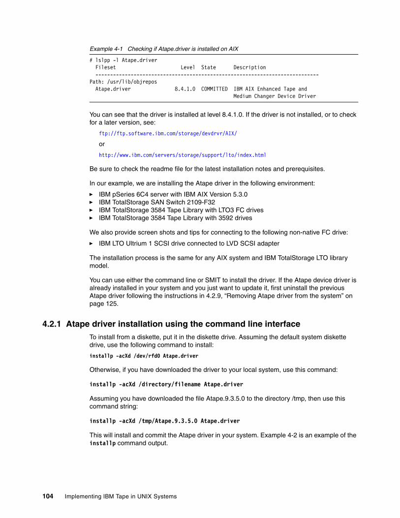
Example 4-1 Checking if Atape.driver is installed on AIX
# lslpp -l Atape.driver Fileset Level State Description ----------------------------------------------------------------------------Path: /usr/lib/objrepos Atape.driver 8.4.1.0 COMMITTED IBM AIX Enhanced Tape and Medium Changer Device Driver
You can see that the driver is installed at level 8.4.1.0. If the driver is not installed, or to check for a later version, see:
ftp://ftp.software.ibm.com/storage/devdrvr/AIX/
or
http://www.ibm.com/servers/storage/support/lto/index.html
Be sure to check the readme file for the latest installation notes and prerequisites.
In our example, we are installing the Atape driver in the following environment:
� IBM pSeries 6C4 server with IBM AIX Version 5.3.0� IBM TotalStorage SAN Switch 2109-F32� IBM TotalStorage 3584 Tape Library with LTO3 FC drives� IBM TotalStorage 3584 Tape Library with 3592 drives
We also provide screen shots and tips for connecting to the following non-native FC drive:
� IBM LTO Ultrium 1 SCSI drive connected to LVD SCSI adapter
The installation process is the same for any AIX system and IBM TotalStorage LTO library model.
You can use either the command line or SMIT to install the driver. If the Atape device driver is already installed in your system and you just want to update it, first uninstall the previous Atape driver following the instructions in 4.2.9, “Removing Atape driver from the system” on page 125.
4.2.1 Atape driver installation using the command line interfaceTo install from a diskette, put it in the diskette drive. Assuming the default system diskette drive, use the following command to install:
installp -acXd /dev/rfd0 Atape.driver
Otherwise, if you have downloaded the driver to your local system, use this command:
installp -acXd /directory/filename Atape.driver
Assuming you have downloaded the file Atape.9.3.5.0 to the directory /tmp, then use this command string:
installp -acXd /tmp/Atape.9.3.5.0 Atape.driver
This will install and commit the Atape driver in your system. Example 4-2 is an example of the installp command output.
104 Implementing IBM Tape in UNIX Systems
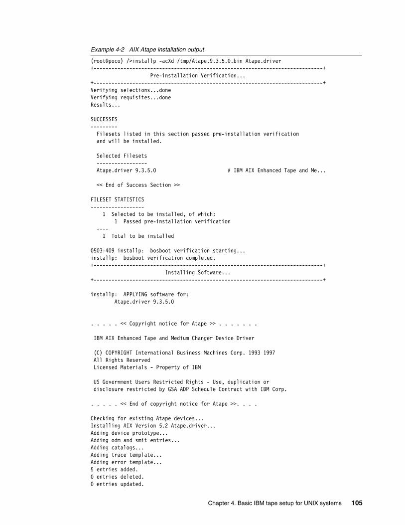
Example 4-2 AIX Atape installation output
(root@poco) />installp -acXd /tmp/Atape.9.3.5.0.bin Atape.driver+-----------------------------------------------------------------------------+ Pre-installation Verification...+-----------------------------------------------------------------------------+Verifying selections...doneVerifying requisites...doneResults...
SUCCESSES--------- Filesets listed in this section passed pre-installation verification and will be installed.
Selected Filesets ----------------- Atape.driver 9.3.5.0 # IBM AIX Enhanced Tape and Me...
<< End of Success Section >>
FILESET STATISTICS------------------ 1 Selected to be installed, of which: 1 Passed pre-installation verification ---- 1 Total to be installed
0503-409 installp: bosboot verification starting...installp: bosboot verification completed.+-----------------------------------------------------------------------------+ Installing Software...+-----------------------------------------------------------------------------+
installp: APPLYING software for: Atape.driver 9.3.5.0
. . . . . << Copyright notice for Atape >> . . . . . . .
IBM AIX Enhanced Tape and Medium Changer Device Driver
(C) COPYRIGHT International Business Machines Corp. 1993 1997 All Rights Reserved Licensed Materials - Property of IBM
US Government Users Restricted Rights - Use, duplication or disclosure restricted by GSA ADP Schedule Contract with IBM Corp.
. . . . . << End of copyright notice for Atape >>. . . .
Checking for existing Atape devices...Installing AIX Version 5.2 Atape.driver...Adding device prototype...Adding odm and smit entries...Adding catalogs...Adding trace template...Adding error template...5 entries added.0 entries deleted.0 entries updated.
Chapter 4. Basic IBM tape setup for UNIX systems 105
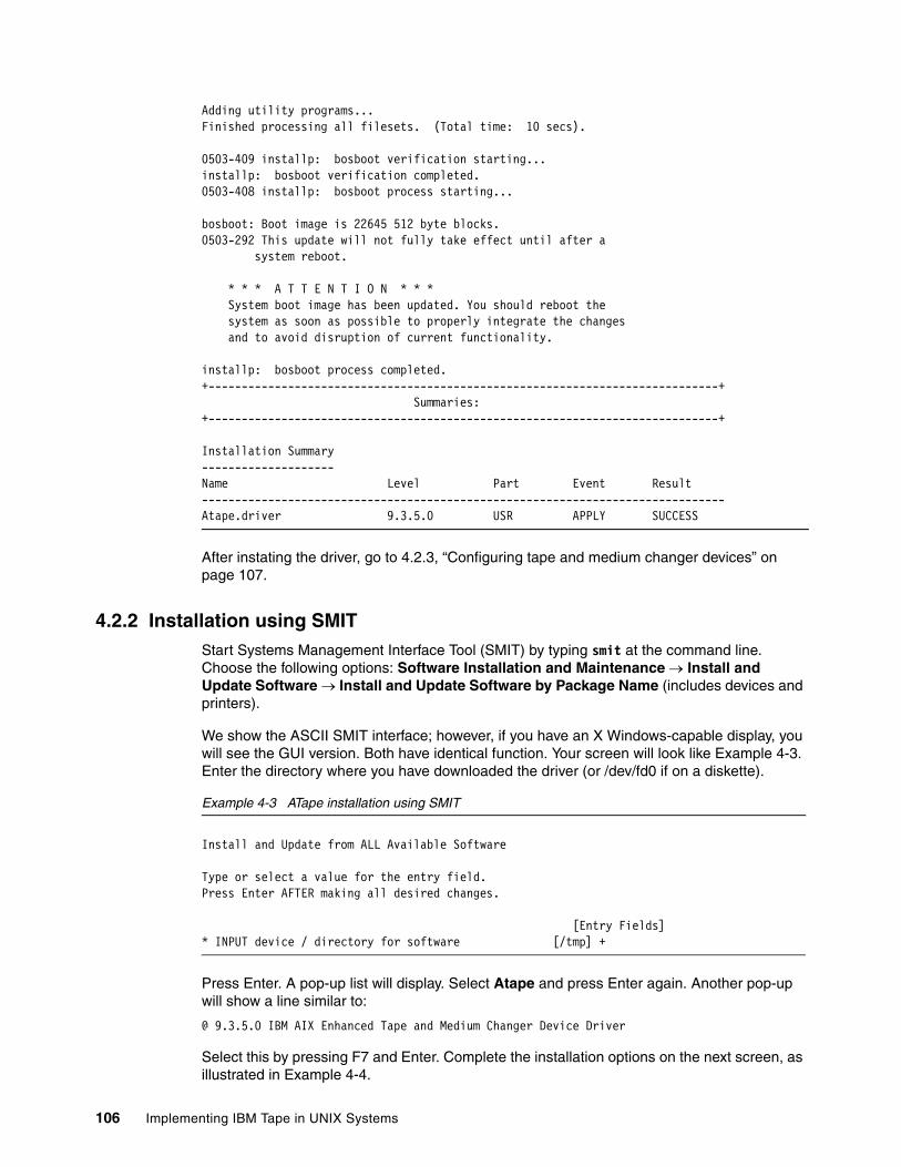
Adding utility programs...Finished processing all filesets. (Total time: 10 secs).
0503-409 installp: bosboot verification starting...installp: bosboot verification completed.0503-408 installp: bosboot process starting...
bosboot: Boot image is 22645 512 byte blocks.0503-292 This update will not fully take effect until after a system reboot.
* * * A T T E N T I O N * * * System boot image has been updated. You should reboot the system as soon as possible to properly integrate the changes and to avoid disruption of current functionality.
installp: bosboot process completed.+-----------------------------------------------------------------------------+ Summaries:+-----------------------------------------------------------------------------+
Installation Summary--------------------Name Level Part Event Result-------------------------------------------------------------------------------Atape.driver 9.3.5.0 USR APPLY SUCCESS
After instating the driver, go to 4.2.3, “Configuring tape and medium changer devices” on page 107.
4.2.2 Installation using SMIT Start Systems Management Interface Tool (SMIT) by typing smit at the command line. Choose the following options: Software Installation and Maintenance → Install and Update Software → Install and Update Software by Package Name (includes devices and printers).
We show the ASCII SMIT interface; however, if you have an X Windows-capable display, you will see the GUI version. Both have identical function. Your screen will look like Example 4-3. Enter the directory where you have downloaded the driver (or /dev/fd0 if on a diskette).
Example 4-3 ATape installation using SMIT
Install and Update from ALL Available Software
Type or select a value for the entry field.Press Enter AFTER making all desired changes.
[Entry Fields]* INPUT device / directory for software [/tmp] +
Press Enter. A pop-up list will display. Select Atape and press Enter again. Another pop-up will show a line similar to:
@ 9.3.5.0 IBM AIX Enhanced Tape and Medium Changer Device Driver
Select this by pressing F7 and Enter. Complete the installation options on the next screen, as illustrated in Example 4-4.
106 Implementing IBM Tape in UNIX Systems
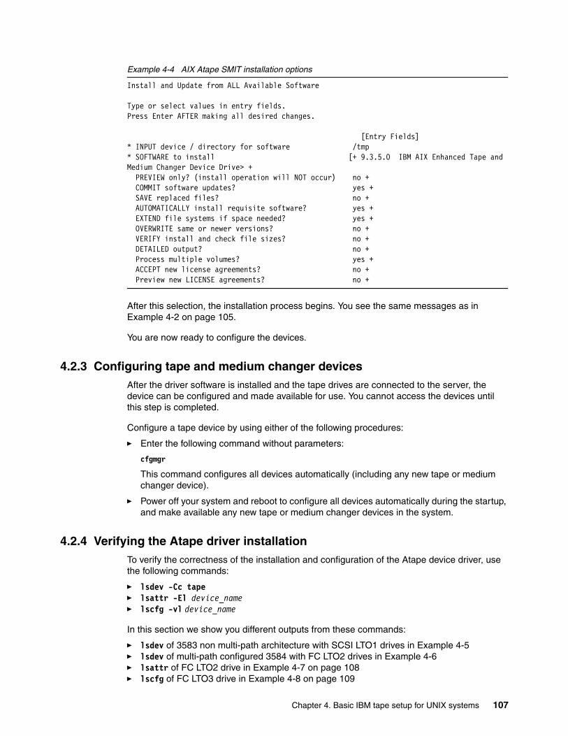
Example 4-4 AIX Atape SMIT installation options
Install and Update from ALL Available Software
Type or select values in entry fields.Press Enter AFTER making all desired changes.
[Entry Fields]* INPUT device / directory for software /tmp* SOFTWARE to install [+ 9.3.5.0 IBM AIX Enhanced Tape and Medium Changer Device Drive> + PREVIEW only? (install operation will NOT occur) no + COMMIT software updates? yes + SAVE replaced files? no + AUTOMATICALLY install requisite software? yes + EXTEND file systems if space needed? yes + OVERWRITE same or newer versions? no + VERIFY install and check file sizes? no + DETAILED output? no + Process multiple volumes? yes + ACCEPT new license agreements? no + Preview new LICENSE agreements? no +
After this selection, the installation process begins. You see the same messages as in Example 4-2 on page 105.
You are now ready to configure the devices.
4.2.3 Configuring tape and medium changer devicesAfter the driver software is installed and the tape drives are connected to the server, the device can be configured and made available for use. You cannot access the devices until this step is completed.
Configure a tape device by using either of the following procedures:
� Enter the following command without parameters:
cfgmgr
This command configures all devices automatically (including any new tape or medium changer device).
� Power off your system and reboot to configure all devices automatically during the startup, and make available any new tape or medium changer devices in the system.
4.2.4 Verifying the Atape driver installationTo verify the correctness of the installation and configuration of the Atape device driver, use the following commands:
� lsdev -Cc tape� lsattr -El device_name� lscfg -vl device_name
In this section we show you different outputs from these commands:
� lsdev of 3583 non multi-path architecture with SCSI LTO1 drives in Example 4-5� lsdev of multi-path configured 3584 with FC LTO2 drives in Example 4-6� lsattr of FC LTO2 drive in Example 4-7 on page 108� lscfg of FC LTO3 drive in Example 4-8 on page 109
Chapter 4. Basic IBM tape setup for UNIX systems 107
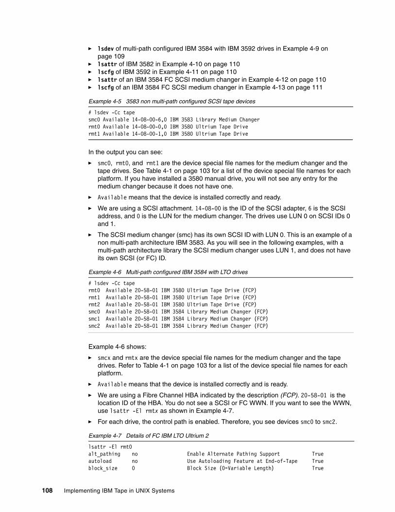
� lsdev of multi-path configured IBM 3584 with IBM 3592 drives in Example 4-9 on page 109
� lsattr of IBM 3582 in Example 4-10 on page 110� lscfg of IBM 3592 in Example 4-11 on page 110� lsattr of an IBM 3584 FC SCSI medium changer in Example 4-12 on page 110� lscfg of an IBM 3584 FC SCSI medium changer in Example 4-13 on page 111
Example 4-5 3583 non multi-path configured SCSI tape devices
# lsdev -Cc tapesmc0 Available 14-08-00-6,0 IBM 3583 Library Medium Changer rmt0 Available 14-08-00-0,0 IBM 3580 Ultrium Tape Drive rmt1 Available 14-08-00-1,0 IBM 3580 Ultrium Tape Drive
In the output you can see:
� smc0, rmt0, and rmt1 are the device special file names for the medium changer and the tape drives. See Table 4-1 on page 103 for a list of the device special file names for each platform. If you have installed a 3580 manual drive, you will not see any entry for the medium changer because it does not have one.
� Available means that the device is installed correctly and ready.
� We are using a SCSI attachment. 14-08-00 is the ID of the SCSI adapter, 6 is the SCSI address, and 0 is the LUN for the medium changer. The drives use LUN 0 on SCSI IDs 0 and 1.
� The SCSI medium changer (smc) has its own SCSI ID with LUN 0. This is an example of a non multi-path architecture IBM 3583. As you will see in the following examples, with a multi-path architecture library the SCSI medium changer uses LUN 1, and does not have its own SCSI (or FC) ID.
Example 4-6 Multi-path configured IBM 3584 with LTO drives
# lsdev -Cc tapermt0 Available 20-58-01 IBM 3580 Ultrium Tape Drive (FCP)rmt1 Available 20-58-01 IBM 3580 Ultrium Tape Drive (FCP)rmt2 Available 20-58-01 IBM 3580 Ultrium Tape Drive (FCP)smc0 Available 20-58-01 IBM 3584 Library Medium Changer (FCP)smc1 Available 20-58-01 IBM 3584 Library Medium Changer (FCP)smc2 Available 20-58-01 IBM 3584 Library Medium Changer (FCP)
Example 4-6 shows:
� smcx and rmtx are the device special file names for the medium changer and the tape drives. Refer to Table 4-1 on page 103 for a list of the device special file names for each platform.
� Available means that the device is installed correctly and is ready.
� We are using a Fibre Channel HBA indicated by the description (FCP). 20-58-01 is the location ID of the HBA. You do not see a SCSI or FC WWN. If you want to see the WWN, use lsattr -El rmtx as shown in Example 4-7.
� For each drive, the control path is enabled. Therefore, you see devices smc0 to smc2.
Example 4-7 Details of FC IBM LTO Ultrium 2
lsattr -El rmt0alt_pathing no Enable Alternate Pathing Support Trueautoload no Use Autoloading Feature at End-of-Tape Trueblock_size 0 Block Size (0=Variable Length) True
108 Implementing IBM Tape in UNIX Systems
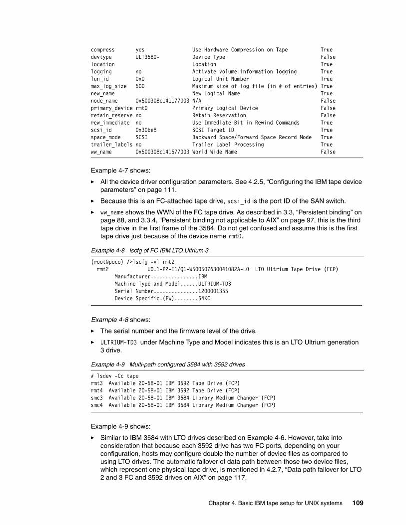
compress yes Use Hardware Compression on Tape Truedevtype ULT3580- Device Type Falselocation Location Truelogging no Activate volume information logging Truelun_id 0x0 Logical Unit Number Truemax_log_size 500 Maximum size of log file (in # of entries) Truenew_name New Logical Name Truenode_name 0x500308c141177003 N/A Falseprimary_device rmt0 Primary Logical Device Falseretain_reserve no Retain Reservation Falserew_immediate no Use Immediate Bit in Rewind Commands Truescsi_id 0x30be8 SCSI Target ID Truespace_mode SCSI Backward Space/Forward Space Record Mode Truetrailer_labels no Trailer Label Processing Trueww_name 0x500308c141577003 World Wide Name False
Example 4-7 shows:
� All the device driver configuration parameters. See 4.2.5, “Configuring the IBM tape device parameters” on page 111.
� Because this is an FC-attached tape drive, scsi_id is the port ID of the SAN switch.
� ww_name shows the WWN of the FC tape drive. As described in 3.3, “Persistent binding” on page 88, and 3.3.4, “Persistent binding not applicable to AIX” on page 97, this is the third tape drive in the first frame of the 3584. Do not get confused and assume this is the first tape drive just because of the device name rmt0.
Example 4-8 lscfg of FC IBM LTO Ultrium 3
(root@poco) />lscfg -vl rmt2 rmt2 U0.1-P2-I1/Q1-W500507630041082A-L0 LTO Ultrium Tape Drive (FCP) Manufacturer................IBM Machine Type and Model......ULTRIUM-TD3 Serial Number...............1200001355 Device Specific.(FW)........54KC
Example 4-8 shows:
� The serial number and the firmware level of the drive.
� ULTRIUM-TD3 under Machine Type and Model indicates this is an LTO Ultrium generation 3 drive.
Example 4-9 Multi-path configured 3584 with 3592 drives
# lsdev -Cc tapermt3 Available 20-58-01 IBM 3592 Tape Drive (FCP)rmt4 Available 20-58-01 IBM 3592 Tape Drive (FCP)smc3 Available 20-58-01 IBM 3584 Library Medium Changer (FCP)smc4 Available 20-58-01 IBM 3584 Library Medium Changer (FCP)
Example 4-9 shows:
� Similar to IBM 3584 with LTO drives described on Example 4-6. However, take into consideration that because each 3592 drive has two FC ports, depending on your configuration, hosts may configure double the number of device files as compared to using LTO drives. The automatic failover of data path between those two device files, which represent one physical tape drive, is mentioned in 4.2.7, “Data path failover for LTO 2 and 3 FC and 3592 drives on AIX” on page 117.
Chapter 4. Basic IBM tape setup for UNIX systems 109
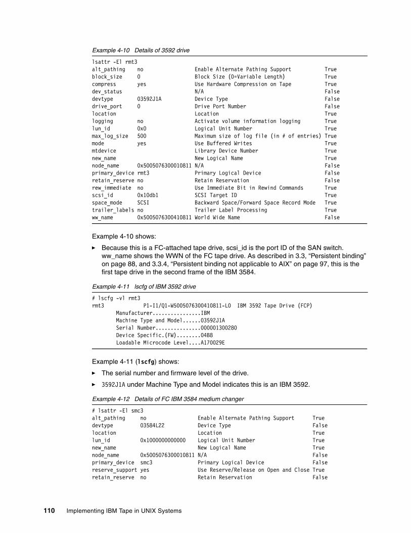
Example 4-10 Details of 3592 drive
lsattr -El rmt3alt_pathing no Enable Alternate Pathing Support Trueblock_size 0 Block Size (0=Variable Length) Truecompress yes Use Hardware Compression on Tape Truedev_status N/A Falsedevtype 03592J1A Device Type Falsedrive_port 0 Drive Port Number Falselocation Location Truelogging no Activate volume information logging Truelun_id 0x0 Logical Unit Number Truemax_log_size 500 Maximum size of log file (in # of entries) Truemode yes Use Buffered Writes Truemtdevice Library Device Number Truenew_name New Logical Name Truenode_name 0x5005076300010811 N/A Falseprimary_device rmt3 Primary Logical Device Falseretain_reserve no Retain Reservation Falserew_immediate no Use Immediate Bit in Rewind Commands Truescsi_id 0x10db1 SCSI Target ID Truespace_mode SCSI Backward Space/Forward Space Record Mode Truetrailer_labels no Trailer Label Processing Trueww_name 0x5005076300410811 World Wide Name False
Example 4-10 shows:
� Because this is a FC-attached tape drive, scsi_id is the port ID of the SAN switch. ww_name shows the WWN of the FC tape drive. As described in 3.3, “Persistent binding” on page 88, and 3.3.4, “Persistent binding not applicable to AIX” on page 97, this is the first tape drive in the second frame of the IBM 3584.
Example 4-11 lscfg of IBM 3592 drive
# lscfg -vl rmt3rmt3 P1-I1/Q1-W5005076300410811-L0 IBM 3592 Tape Drive (FCP) Manufacturer................IBM Machine Type and Model......03592J1A Serial Number...............000001300280 Device Specific.(FW)........04B8 Loadable Microcode Level....A170029E
Example 4-11 (lscfg) shows:
� The serial number and firmware level of the drive.
� 3592J1A under Machine Type and Model indicates this is an IBM 3592.
Example 4-12 Details of FC IBM 3584 medium changer
# lsattr -El smc3alt_pathing no Enable Alternate Pathing Support Truedevtype 03584L22 Device Type Falselocation Location Truelun_id 0x1000000000000 Logical Unit Number Truenew_name New Logical Name Truenode_name 0x5005076300010811 N/A Falseprimary_device smc3 Primary Logical Device Falsereserve_support yes Use Reserve/Release on Open and Close Trueretain_reserve no Retain Reservation False
110 Implementing IBM Tape in UNIX Systems
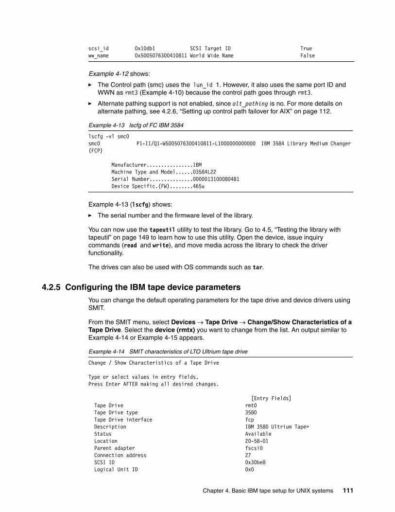
scsi_id 0x10db1 SCSI Target ID Trueww_name 0x5005076300410811 World Wide Name False
Example 4-12 shows:
� The Control path (smc) uses the lun_id 1. However, it also uses the same port ID and WWN as rmt3 (Example 4-10) because the control path goes through rmt3.
� Alternate pathing support is not enabled, since alt_pathing is no. For more details on alternate pathing, see 4.2.6, “Setting up control path failover for AIX” on page 112.
Example 4-13 lscfg of FC IBM 3584
lscfg -vl smc0smc0 P1-I1/Q1-W5005076300410811-L1000000000000 IBM 3584 Library Medium Changer (FCP)
Manufacturer................IBM Machine Type and Model......03584L22 Serial Number...............00000131000804B1 Device Specific.(FW)........465u
Example 4-13 (lscfg) shows:
� The serial number and the firmware level of the library.
You can now use the tapeutil utility to test the library. Go to 4.5, “Testing the library with tapeutil” on page 149 to learn how to use this utility. Open the device, issue inquiry commands (read and write), and move media across the library to check the driver functionality.
The drives can also be used with OS commands such as tar.
4.2.5 Configuring the IBM tape device parametersYou can change the default operating parameters for the tape drive and device drivers using SMIT.
From the SMIT menu, select Devices → Tape Drive → Change/Show Characteristics of a Tape Drive. Select the device (rmtx) you want to change from the list. An output similar to Example 4-14 or Example 4-15 appears.
Example 4-14 SMIT characteristics of LTO Ultrium tape drive
Change / Show Characteristics of a Tape Drive
Type or select values in entry fields.Press Enter AFTER making all desired changes.
[Entry Fields] Tape Drive rmt0 Tape Drive type 3580 Tape Drive interface fcp Description IBM 3580 Ultrium Tape> Status Available Location 20-58-01 Parent adapter fscsi0 Connection address 27 SCSI ID 0x30be8 Logical Unit ID 0x0
Chapter 4. Basic IBM tape setup for UNIX systems 111
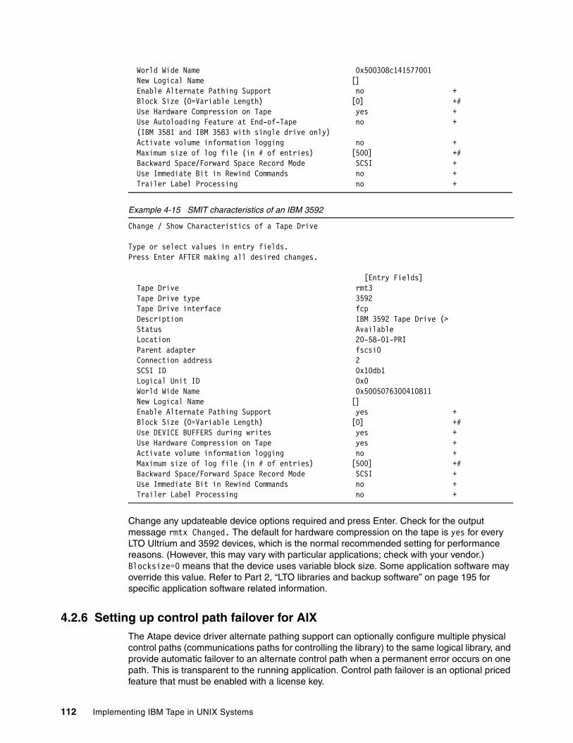
World Wide Name 0x500308c141577001 New Logical Name [] Enable Alternate Pathing Support no + Block Size (0=Variable Length) [0] +# Use Hardware Compression on Tape yes + Use Autoloading Feature at End-of-Tape no + (IBM 3581 and IBM 3583 with single drive only) Activate volume information logging no + Maximum size of log file (in # of entries) [500] +# Backward Space/Forward Space Record Mode SCSI + Use Immediate Bit in Rewind Commands no + Trailer Label Processing no +
Example 4-15 SMIT characteristics of an IBM 3592
Change / Show Characteristics of a Tape Drive
Type or select values in entry fields.Press Enter AFTER making all desired changes.
[Entry Fields] Tape Drive rmt3 Tape Drive type 3592 Tape Drive interface fcp Description IBM 3592 Tape Drive (> Status Available Location 20-58-01-PRI Parent adapter fscsi0 Connection address 2 SCSI ID 0x10db1 Logical Unit ID 0x0 World Wide Name 0x5005076300410811 New Logical Name [] Enable Alternate Pathing Support yes + Block Size (0=Variable Length) [0] +# Use DEVICE BUFFERS during writes yes + Use Hardware Compression on Tape yes + Activate volume information logging no + Maximum size of log file (in # of entries) [500] +# Backward Space/Forward Space Record Mode SCSI + Use Immediate Bit in Rewind Commands no + Trailer Label Processing no +
Change any updateable device options required and press Enter. Check for the output message rmtx Changed. The default for hardware compression on the tape is yes for every LTO Ultrium and 3592 devices, which is the normal recommended setting for performance reasons. (However, this may vary with particular applications; check with your vendor.) Blocksize=0 means that the device uses variable block size. Some application software may override this value. Refer to Part 2, “LTO libraries and backup software” on page 195 for specific application software related information.
4.2.6 Setting up control path failover for AIXThe Atape device driver alternate pathing support can optionally configure multiple physical control paths (communications paths for controlling the library) to the same logical library, and provide automatic failover to an alternate control path when a permanent error occurs on one path. This is transparent to the running application. Control path failover is an optional priced feature that must be enabled with a license key.
112 Implementing IBM Tape in UNIX Systems
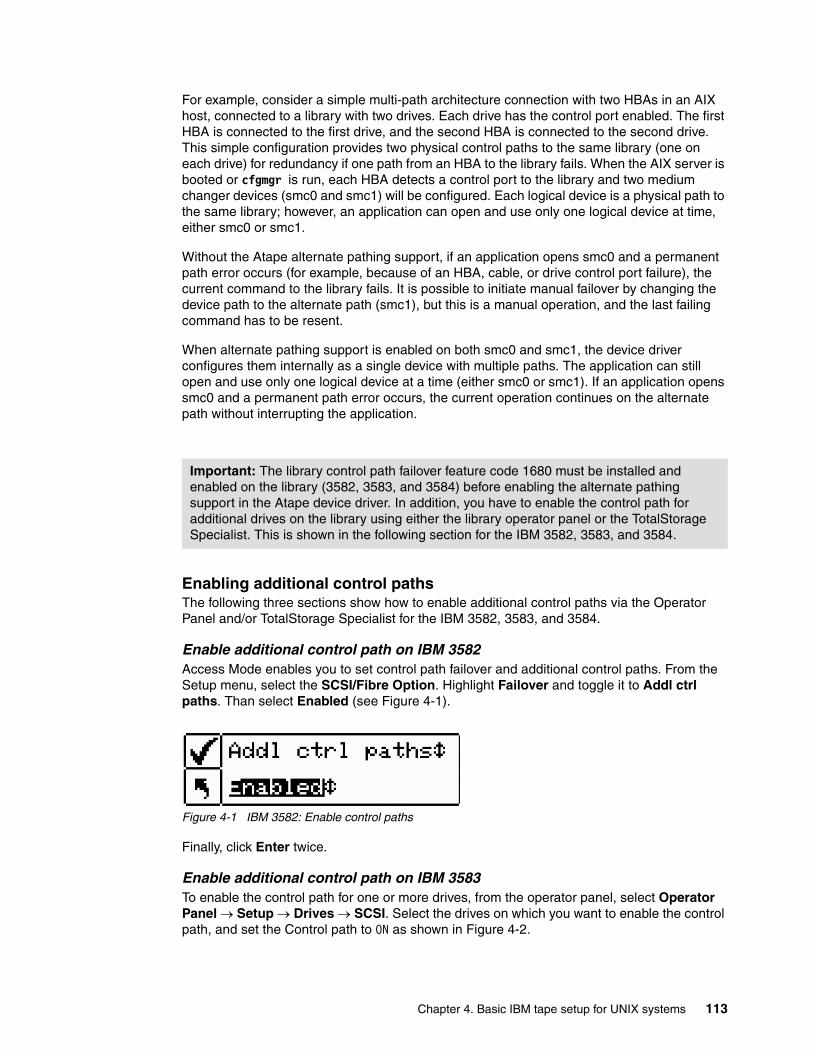
For example, consider a simple multi-path architecture connection with two HBAs in an AIX host, connected to a library with two drives. Each drive has the control port enabled. The first HBA is connected to the first drive, and the second HBA is connected to the second drive. This simple configuration provides two physical control paths to the same library (one on each drive) for redundancy if one path from an HBA to the library fails. When the AIX server is booted or cfgmgr is run, each HBA detects a control port to the library and two medium changer devices (smc0 and smc1) will be configured. Each logical device is a physical path to the same library; however, an application can open and use only one logical device at time, either smc0 or smc1.
Without the Atape alternate pathing support, if an application opens smc0 and a permanent path error occurs (for example, because of an HBA, cable, or drive control port failure), the current command to the library fails. It is possible to initiate manual failover by changing the device path to the alternate path (smc1), but this is a manual operation, and the last failing command has to be resent.
When alternate pathing support is enabled on both smc0 and smc1, the device driver configures them internally as a single device with multiple paths. The application can still open and use only one logical device at a time (either smc0 or smc1). If an application opens smc0 and a permanent path error occurs, the current operation continues on the alternate path without interrupting the application.
Enabling additional control pathsThe following three sections show how to enable additional control paths via the Operator Panel and/or TotalStorage Specialist for the IBM 3582, 3583, and 3584.
Enable additional control path on IBM 3582Access Mode enables you to set control path failover and additional control paths. From the Setup menu, select the SCSI/Fibre Option. Highlight Failover and toggle it to Addl ctrl paths. Than select Enabled (see Figure 4-1).
Figure 4-1 IBM 3582: Enable control paths
Finally, click Enter twice.
Enable additional control path on IBM 3583To enable the control path for one or more drives, from the operator panel, select Operator Panel → Setup → Drives → SCSI. Select the drives on which you want to enable the control path, and set the Control path to ON as shown in Figure 4-2.
Important: The library control path failover feature code 1680 must be installed and enabled on the library (3582, 3583, and 3584) before enabling the alternate pathing support in the Atape device driver. In addition, you have to enable the control path for additional drives on the library using either the library operator panel or the TotalStorage Specialist. This is shown in the following section for the IBM 3582, 3583, and 3584.
Chapter 4. Basic IBM tape setup for UNIX systems 113
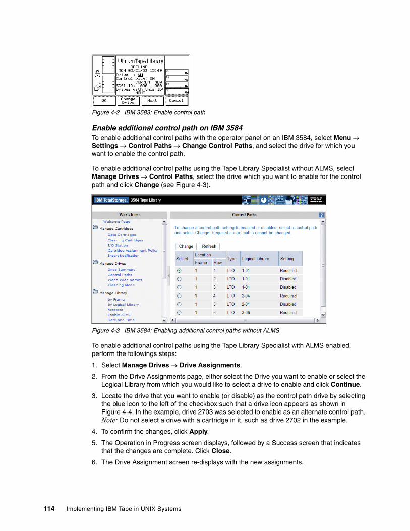
Figure 4-2 IBM 3583: Enable control path
Enable additional control path on IBM 3584To enable additional control paths with the operator panel on an IBM 3584, select Menu → Settings → Control Paths → Change Control Paths, and select the drive for which you want to enable the control path.
To enable additional control paths using the Tape Library Specialist without ALMS, select Manage Drives → Control Paths, select the drive which you want to enable for the control path and click Change (see Figure 4-3).
Figure 4-3 IBM 3584: Enabling additional control paths without ALMS
To enable additional control paths using the Tape Library Specialist with ALMS enabled, perform the followings steps:
1. Select Manage Drives → Drive Assignments.
2. From the Drive Assignments page, either select the Drive you want to enable or select the Logical Library from which you would like to select a drive to enable and click Continue.
3. Locate the drive that you want to enable (or disable) as the control path drive by selecting the blue icon to the left of the checkbox such that a drive icon appears as shown in Figure 4-4. In the example, drive 2703 was selected to enable as an alternate control path. Note: Do not select a drive with a cartridge in it, such as drive 2702 in the example.
4. To confirm the changes, click Apply.
5. The Operation in Progress screen displays, followed by a Success screen that indicates that the changes are complete. Click Close.
6. The Drive Assignment screen re-displays with the new assignments.
114 Implementing IBM Tape in UNIX Systems
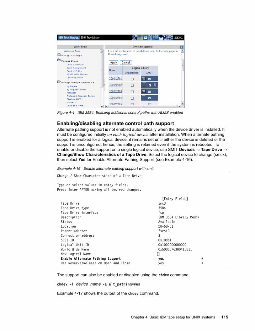
Figure 4-4 IBM 3584: Enabling additional control paths with ALMS enabled
Enabling/disabling alternate control path supportAlternate pathing support is not enabled automatically when the device driver is installed. It must be configured initially on each logical device after installation. When alternate pathing support is enabled for a logical device, it remains set until either the device is deleted or the support is unconfigured; hence, the setting is retained even if the system is rebooted. To enable or disable the support on a single logical device, use SMIT Devices → Tape Drive → Change/Show Characteristics of a Tape Drive. Select the logical device to change (smcx), then select Yes for Enable Alternate Pathing Support (see Example 4-16).
Example 4-16 Enable alternate pathing support with smit
Change / Show Characteristics of a Tape Drive
Type or select values in entry fields.Press Enter AFTER making all desired changes.
[Entry Fields] Tape Drive smc3 Tape Drive type 3584 Tape Drive interface fcp Description IBM 3584 Library Medi> Status Available Location 20-58-01 Parent adapter fscsi0 Connection address 3 SCSI ID 0x10db1 Logical Unit ID 0x1000000000000 World Wide Name 0x5005076300410811 New Logical Name [] Enable Alternate Pathing Support yes + Use Reserve/Release on Open and Close yes +
The support can also be enabled or disabled using the chdev command.
chdev -l device_name -a alt_pathing=yes
Example 4-17 shows the output of the chdev command.
Chapter 4. Basic IBM tape setup for UNIX systems 115
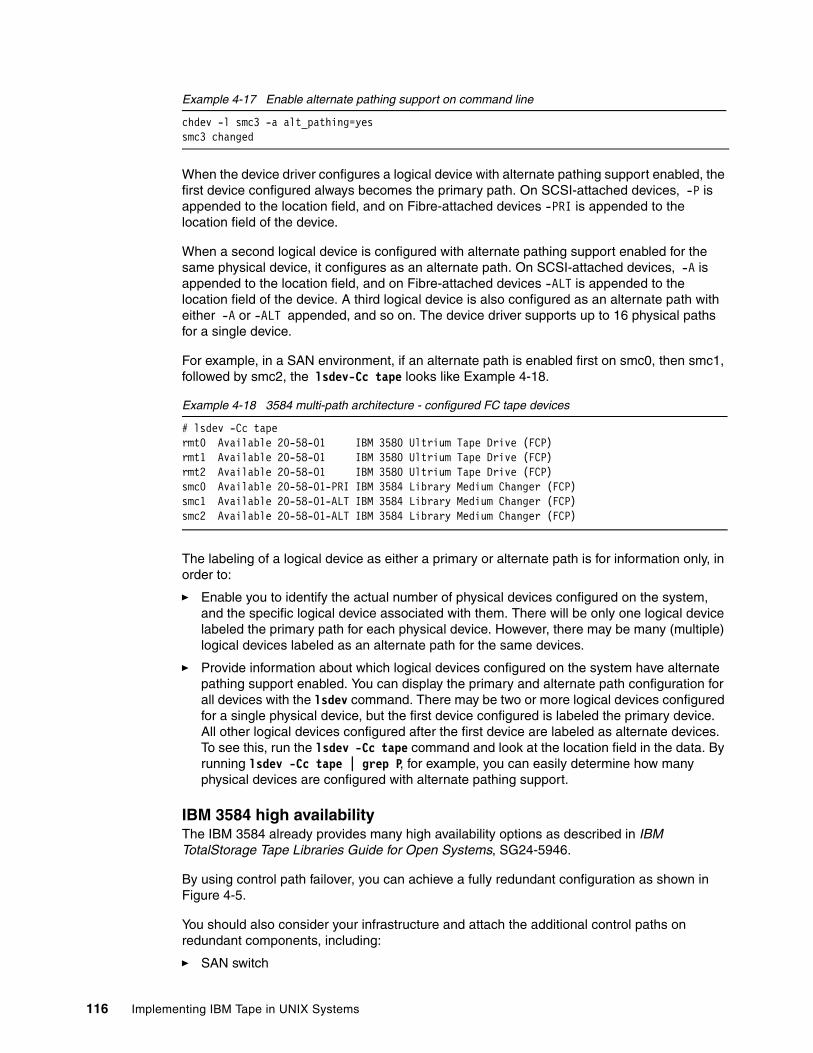
Example 4-17 Enable alternate pathing support on command line
chdev -l smc3 -a alt_pathing=yessmc3 changed
When the device driver configures a logical device with alternate pathing support enabled, the first device configured always becomes the primary path. On SCSI-attached devices, -P is appended to the location field, and on Fibre-attached devices -PRI is appended to the location field of the device.
When a second logical device is configured with alternate pathing support enabled for the same physical device, it configures as an alternate path. On SCSI-attached devices, -A is appended to the location field, and on Fibre-attached devices -ALT is appended to the location field of the device. A third logical device is also configured as an alternate path with either -A or -ALT appended, and so on. The device driver supports up to 16 physical paths for a single device.
For example, in a SAN environment, if an alternate path is enabled first on smc0, then smc1, followed by smc2, the lsdev-Cc tape looks like Example 4-18.
Example 4-18 3584 multi-path architecture - configured FC tape devices
# lsdev -Cc tapermt0 Available 20-58-01 IBM 3580 Ultrium Tape Drive (FCP)rmt1 Available 20-58-01 IBM 3580 Ultrium Tape Drive (FCP)rmt2 Available 20-58-01 IBM 3580 Ultrium Tape Drive (FCP)smc0 Available 20-58-01-PRI IBM 3584 Library Medium Changer (FCP)smc1 Available 20-58-01-ALT IBM 3584 Library Medium Changer (FCP)smc2 Available 20-58-01-ALT IBM 3584 Library Medium Changer (FCP)
The labeling of a logical device as either a primary or alternate path is for information only, in order to:
� Enable you to identify the actual number of physical devices configured on the system, and the specific logical device associated with them. There will be only one logical device labeled the primary path for each physical device. However, there may be many (multiple) logical devices labeled as an alternate path for the same devices.
� Provide information about which logical devices configured on the system have alternate pathing support enabled. You can display the primary and alternate path configuration for all devices with the lsdev command. There may be two or more logical devices configured for a single physical device, but the first device configured is labeled the primary device. All other logical devices configured after the first device are labeled as alternate devices. To see this, run the lsdev -Cc tape command and look at the location field in the data. By running lsdev -Cc tape | grep P, for example, you can easily determine how many physical devices are configured with alternate pathing support.
IBM 3584 high availabilityThe IBM 3584 already provides many high availability options as described in IBM TotalStorage Tape Libraries Guide for Open Systems, SG24-5946.
By using control path failover, you can achieve a fully redundant configuration as shown in Figure 4-5.
You should also consider your infrastructure and attach the additional control paths on redundant components, including:
� SAN switch
116 Implementing IBM Tape in UNIX Systems

� SAN fabric� Server HBA
If you have a multi-frame configuration, enable the additional control paths on a different frame, so that you can still use your library even if the AC power for the first frame is lost. In Figure 4-5, the second control path is enabled on the second frame, and goes over a separate SAN switch and fabric (there is no inter-switch link between these switches) to a second HBA. You can still work with the library if any one of these conditions occurs:
� AC power is lost on the first frame.
� Drive one in the first frame is down.
� The FC cable between the drive and switch, or switch and HBA is broken.
� One switch fails.
� One SAN fabric is down.
� One HBA is broken.
Figure 4-5 High availability control path configuration on an IBM 3584
4.2.7 Data path failover for LTO 2 and 3 FC and 3592 drives on AIXThe Atape.driver for AIX supports alternate drive pathing, which will configure multiple physical paths to the same drive within the device driver. It provides two basic functions:
� Automatic failover to an alternate physical drive path when a permanent error occurs on one path
� Dynamic load balancing for devices using multiple HBAs
LIBRARY CONTROLLER
DRIVE1
DRIVE2
DRIVE3
DRIVE4
FC ADAPTER
SERVER
smc0 smc1
AC
LIBRARY CONTROLLER
DRIVE1
DRIVE2
DRIVE3
DRIVE4
AC
Frame 1 Frame 2
Control path required for Drive 1
Control path enabled for Drive 4
Chapter 4. Basic IBM tape setup for UNIX systems 117
Automatic failoverThe automatic failover support provides error recovery on an alternate path when a permanent error occurs on one path. This is transparent to the running application.
For example, consider a simple multi-path connection with two HBAs in an AIX host, connected over a SAN to an LTO 2 drive (see Figure 4-6). This simple configuration provides two physical paths to the same LTO drive for redundancy if one path from an HBA to the drive fails. When the AIX server is booted or cfgmgr is run, each HBA detects an LTO drive and two logical devices will be configured (for example, rmt0 and rmt1). Each logical device is a physical path to the same drive. An application can open and use only one logical device at a time, either rmt0 or rmt1.
The IBM 3592 has two fibre ports available on the back of each drive for increased redundancy. With the IBM 3592, complete redundancy of the SAN components can be achieved (see Figure 4-7).
Without the Atape alternate pathing support, if an application opens rmt0, and a permanent path error occurs (for example, because of an HBA or cable failure), the application fails. It is possible to initiate manual failover by changing the device path to the alternate path (rmt1), but this is a manual operation, and the last failing job has to be resent. Sometimes manual failover may require operator intervention to reset the drive (like a power cycle through TotalStorage Specialist) because a SCSI reservation can still exist on the failing HBA path.
When the alternate pathing support is enabled on both rmt0 and rmt1, the device driver configures them internally as a single device with multiple paths. The application can still open and use only one logical device at a time (either rmt0 or rmt1). If an application opens rmt0 and a permanent path error occurs, the driver initiates failover error recovery automatically on the alternate path (rmt1), and the current operation continues on the alternate path without interrupting the application. Use of this function with TSM is described in 5.9, “Tivoli Storage Manager and data path failover” on page 234.
Note: This function is supported only on IBM Ultrium 2 and 3 native Fibre Channel drives and IBM 3592 Enterprise tape drives. It is not supported on IBM Ultrium 1 drives or for devices that are attached through an IBM San Data Gateway.
Important: The library data path failover feature code 1681 must be installed on the library (3582, 3583, and 3584) before enabling alternate data path support in the AIX device driver for IBM Ultrium 3 drives only. The feature code is not required for IBM Ultrium 2 FC drives or for IBM 3592 Enterprise drives.
118 Implementing IBM Tape in UNIX Systems
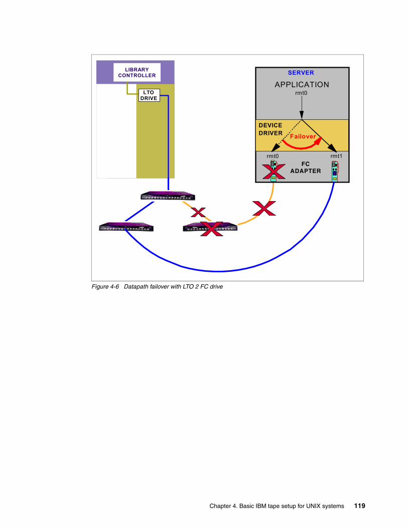
Figure 4-6 Datapath failover with LTO 2 FC drive
FC ADAPTER
SERVER
rmt0
rmt1
APPLICATION
rmt0
DEVICEDRIVER Failover
LIBRARY CONTROLLER
LTO DRIVE
Chapter 4. Basic IBM tape setup for UNIX systems 119
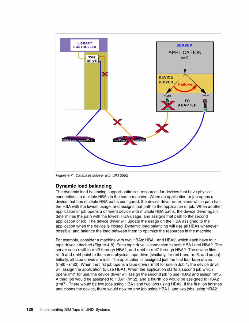
Figure 4-7 Database failover with IBM 3592
Dynamic load balancingThe dynamic load balancing support optimizes resources for devices that have physical connections to multiple HBAs in the same machine. When an application or job opens a device that has multiple HBA paths configured, the device driver determines which path has the HBA with the lowest usage, and assigns that path to the application or job. When another application or job opens a different device with multiple HBA paths, the device driver again determines the path with the lowest HBA usage, and assigns that path to the second application or job. The device driver will update the usage on the HBA assigned to the application when the device is closed. Dynamic load balancing will use all HBAs whenever possible, and balance the load between them to optimize the resources in the machine.
For example, consider a machine with two HBAs: HBA1 and HBA2, which each have four tape drives attached (Figure 4-8). Each tape drive is connected to both HBA1 and HBA2. The server sees rmt0 to rmt3 through HBA1, and rmt4 to rmt7 through HBA2. The device files rmt0 and rmt4 point to the same physical tape drive (similarly, for rmt1 and rmt5, and so on). Initially, all tape drives are idle. The application is assigned just the first four tape drives (rmt0 - rmt3). When the first job opens a tape drive (rmt0) for use in Job 1, the device driver will assign the application to use HBA1. When the application starts a second job which opens rmt1 for use, the device driver will assign the second job to use HBA2 and assign rmt5. A third job would be assigned to HBA1 (rmt2), and a fourth job would be assigned to HBA2 (rmt7). There would be two jobs using HBA1 and two jobs using HBA2. If the first job finishes and closes the device, there would now be one job using HBA1, and two jobs using HBA2.
FC ADAPTER
SERVER
rmt0
rmt1
APPLICATION
rmt0
DEVICEDRIVER Failover
LIBRARY CONTROLLER
3592 DRIVE
120 Implementing IBM Tape in UNIX Systems
When the next job opens a tape drive (rmt0), it would be assigned to HBA1, so again there would be two jobs using HBA1 and two jobs using HBA2. Likewise, if the second job finishes and closes the device, HBA2 would have one job using it, and the next job that opens a tape drive (rmt1) would be assigned to HBA2. The dynamic load balancing support is independent from the automatic failover support. Regardless of the path assigned initially for load balancing, if that path fails, the automatic failover support will attempt recovery on the next available path.
Figure 4-8 Dynamic load balancing
It should be noted that dynamic load balancing works when the tape drive is opened, not loaded. The device driver tries to balance the usage of drive opens over several HBAs, but it is not possible to precisely balance the workload or throughput of HBAs. This means it can still happen that the throughput of one HBA is significantly higher than that of other HBAs.
Also, if a failover happens, then all open devices will be switched to the next available HBA, regardless of dynamic load balancing. The next open will then try to balance. Thus, recovering from failover is more important than load balancing, and failover must happen fast to avoid application impact.
Note: If you are using alternate paths for tape drives, then you do not need to follow the instructions in 3.1.2, “Multiple paths to tape drives” on page 79.
Job 4
LIBRARY CONTROLLER
DRIVE1
DRIVE2
DRIVE3
DRIVE4
FC ADAPTER
SERVER
rmt0
rmt3rmt2rmt1
rmt4
rmt7rmt6rmt5
DEVICE DRIVER
rmt0rmt4
rmt1rmt5
rmt2rmt6
rmt3rmt7
rmt0 rmt1 rmt2 rmt3
APPLICATIONJob 1
Job 2Job 3
Chapter 4. Basic IBM tape setup for UNIX systems 121
Enabling/disabling alternate data pathing Alternate pathing support is not enabled automatically when the device driver is installed. It can be enabled on all configured devices at one time, or it can be enabled or disabled selectively by logical device. When alternate pathing support is enabled for a logical device, it remains set until the device is deleted or the support is unconfigured, and is preserved across reboots.
To enable the support globally on all currently configured devices, run this command:
/usr/lpp/Atape/instAtape -a
To enable or disable the support on a single logical device, run the following command:
chdev -l device_name -a alt_pathing=yes
Example 4-19 shows sample output of the chdev command.
Example 4-19 Enable alternate pathing support for rmt0 on command line
chdev -l rmt0 -a alt_pathing=yesrmt0 changed
The support can also be enabled or disabled through the SMIT interface, by selecting Devices → Tape Drive → Change/Show Characteristics of a Tape Drive. Select the logical device to change, such as rmt0, rmt1, and so on; then select Yes for Enable Alternate Pathing Support (see Example 4-20).
Example 4-20 Enable alternate pathing support for rmt 0 through SMIT
Change / Show Characteristics of a Tape Drive
Type or select values in entry fields.Press Enter AFTER making all desired changes.
[Entry Fields] Tape Drive rmt0 Tape Drive type 3580 Tape Drive interface fcp Description IBM 3580 Ultrium Tape> Status Available Location 20-58-01 Parent adapter fscsi0 Connection address 27 SCSI ID 0x30be8 Logical Unit ID 0x0 World Wide Name 0x500308c141577001 New Logical Name [] Enable Alternate Pathing Support yes Block Size (0=Variable Length) [0] Use Hardware Compression on Tape yes Use Autoloading Feature at End-of-Tape no (IBM 3581 and IBM 3583 with single drive only)
Note: Before enabling alternate pathing support for IBM 3580 Ultrium 3 tape drives, you must first install the DPF license key. To install the license key, use the following command (all letters should be entered in lowercase):
# dpf_keys -a key
122 Implementing IBM Tape in UNIX Systems
Activate volume information logging no Maximum size of log file (in # of entries) [500] Backward Space/Forward Space Record Mode SCSI Use Immediate Bit in Rewind Commands no Trailer Label Processing no
When the device driver configures a logical device with alternate pathing support enabled, the first device configured always becomes the primary path. On fibre-attached devices, -PRI is appended to the location field of the device.
When a second logical device is configured with alternate pathing support enabled for the same physical device, it configures as an alternate path. On fibre-attached devices, -ALT is appended to the location field of the device. A third logical device is also configured as an alternate path with -ALT appended, and so on. The device driver supports up to 16 physical paths for a single device.
For example, if an rmt0 is configured first, then an rmt1 and an rmt2, the lsdev -Cc tape command looks as shown in Example 4-21.
Example 4-21 Alternate data path - configured LTO2 FC tape devices
# lsdev -Cc tapermt0 Available 30-68-01-PRI IBM 3580 Ultrium Tape Drive (FCP)rmt1 Available 20-58-01-ALT IBM 3580 Ultrium Tape Drive (FCP)rmt2 Available 10-70-01-ALT IBM 3580 Ultrium Tape Drive (FCP)
You can see by the location code which HBA connection is associated with the primary and alternate paths. In Example 4-21, rmt0 is the primary device, connected to the HBA in location 30-68-01. (Also, the serial number or WWN shown with an lscfg -vl or lsattr -El command for each device file would indicate that each represents the same physical drive.) You also see that the three HBAs are on three separate PCI buses to split the I/O workload between them, which should improve performance.
Different types of PCI buses have different performance specifications as shown in Table 4-2. It does make sense to put one 2 Gbps HBA in a 32/33 PCI bus; however, it does not make sense to put more than one 2 Gbps HBA in a 64/33 PCI bus because the throughput will be saturated.
Table 4-2 PCI buses
The labeling of a logical device as either a primary or alternate path is for information only in order to:
� Enable you to identify the actual number of physical devices configured on the system and a specific logical device associated with them. There will be only one logical device
Note: Bandwidth throughputs in Table 4-2 are burst rates. Sustained throughput rates are typically around 50% of the burst rates.
Width Speed Bandwidth
32 bit 33 MHz 132 MB/sec
64 bit 33 MHz 264 MB/sec
64 bit 64 MHz 512 MB/sec
64 bit 132 MHz 1056 MB/sec
Chapter 4. Basic IBM tape setup for UNIX systems 123
labeled as the primary path for each physical device. However, there may be many (multiple) logical devices labeled as alternate paths for the same devices.
� Provide information about which logical devices configured on the system have alternate pathing support enabled. You can display the primary and alternate path configuration for all devices with the lsdev command. There may be two or more logical devices configured for a single physical device, but the first device configured is labeled the primary device. All other logical devices configured after the first device are labeled as alternate devices. To see this, run the lsdev -Cc tape command and look at the location field in the data. By running lsdev -Cc tape | grep P for example, you can easily determine how many physical devices are configured with alternate pathing support.
4.2.8 Deleting tape devices It can be necessary to remove the tape device or the medium changer from the AIX device configuration. This is a required step for some application software that provides its own device driver for a tape drive and medium changer. Refer to Part 2, “LTO libraries and backup software” on page 195 for more information on specific application software driver requirements.
Remove the devices from the configuration using either of the following procedures:
� The first method leaves the device defined in the configuration database. It is similar to bringing the device offline. Enter the following command to bring the /dev/rmtn device offline, but leave it defined in the device database:
rmdev -l rmtn
In this case, the removed device will appear as:
rmt0 Defined 14-08-00-0,0 IBM 3580 Ultrium Tape Drive
� The second method brings the device offline, and also removes its definition from the device database. Enter the following command:
rmdev -l rmtn -d
After this, the removed device will no longer appear in the device listing.
Use the actual device number (for example, /dev/rmt0), and repeat for each drive to be removed. If you are removing a medium changer as well, repeat with /dev/smcx.
Alternatively, you can use SMIT Devices → Tape Drive → Remove a Tape Drive. From the list of devices, select the device that you want to remove from the configuration as shown in Example 4-22.
Example 4-22 Select tape device to delete
+--------------------------------------------------------------------------+ | Tape Drive | | | | Move cursor to desired item and press Enter. | | | | rmt0 Available 1V-08-01 LTO Ultrium Tape Drive (FCP) | | rmt1 Available 1V-08-01 LTO Ultrium Tape Drive (FCP) | | rmt2 Available 1V-08-01 LTO Ultrium Tape Drive (FCP) | | smc0 Available 1V-08-01 IBM 3584 Library Medium Changer (FCP) | | |
Select No in the Keep definition in database field, then click OK. The device will then be deleted.
124 Implementing IBM Tape in UNIX Systems
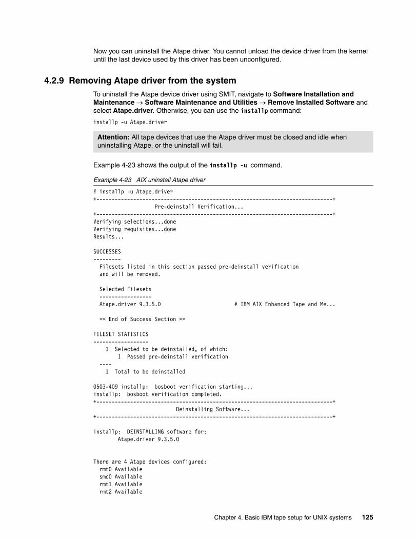
Now you can uninstall the Atape driver. You cannot unload the device driver from the kernel until the last device used by this driver has been unconfigured.
4.2.9 Removing Atape driver from the systemTo uninstall the Atape device driver using SMIT, navigate to Software Installation and Maintenance → Software Maintenance and Utilities → Remove Installed Software and select Atape.driver. Otherwise, you can use the installp command:
installp -u Atape.driver
Example 4-23 shows the output of the installp -u command.
Example 4-23 AIX uninstall Atape driver
# installp -u Atape.driver+-----------------------------------------------------------------------------+ Pre-deinstall Verification...+-----------------------------------------------------------------------------+Verifying selections...doneVerifying requisites...doneResults...
SUCCESSES--------- Filesets listed in this section passed pre-deinstall verification and will be removed.
Selected Filesets ----------------- Atape.driver 9.3.5.0 # IBM AIX Enhanced Tape and Me...
<< End of Success Section >>
FILESET STATISTICS------------------ 1 Selected to be deinstalled, of which: 1 Passed pre-deinstall verification ---- 1 Total to be deinstalled
0503-409 installp: bosboot verification starting...installp: bosboot verification completed.+-----------------------------------------------------------------------------+ Deinstalling Software...+-----------------------------------------------------------------------------+
installp: DEINSTALLING software for: Atape.driver 9.3.5.0
There are 4 Atape devices configured: rmt0 Available smc0 Available rmt1 Available rmt2 Available
Attention: All tape devices that use the Atape driver must be closed and idle when uninstalling Atape, or the uninstall will fail.
Chapter 4. Basic IBM tape setup for UNIX systems 125
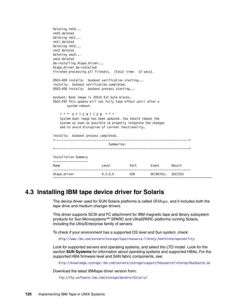
Deleting rmt0...rmt0 deletedDeleting rmt1...rmt1 deletedDeleting rmt2...rmt2 deletedDeleting smc0...smc0 deletedDe-installing Atape.driver...Atape.driver de-installedFinished processing all filesets. (Total time: 12 secs).
0503-409 installp: bosboot verification starting...installp: bosboot verification completed.0503-408 installp: bosboot process starting...
bosboot: Boot image is 22610 512 byte blocks.0503-292 This update will not fully take effect until after a system reboot.
* * * A T T E N T I O N * * * System boot image has been updated. You should reboot the system as soon as possible to properly integrate the changes and to avoid disruption of current functionality.
installp: bosboot process completed.+-----------------------------------------------------------------------------+ Summaries:+-----------------------------------------------------------------------------+
Installation Summary--------------------Name Level Part Event Result-------------------------------------------------------------------------------Atape.driver 9.3.5.0 USR DEINSTALL SUCCESS
4.3 Installing IBM tape device driver for SolarisThe device driver used for SUN Solaris platforms is called IBMtape, and it includes both the tape drive and medium changer drivers.
This driver supports SCSI and FC attachment for IBM magnetic tape and library subsystem products for Sun Microsystems™ SPARC and UltraSPARC platforms running Solaris, including the Ultra/Enterprise family of servers.
To check if your environment has a supported OS level and Sun system, check:
http://www.ibm.com/servers/storage/tape/resource-library.html#interoperability
Look for supported servers and operating systems, and select the LTO model. Look for the section SUN Systems for information about operating systems and supported HBAs. For the supported HBA firmware level and SAN fabric components, see:
http://knowledge.storage.ibm.com/servers/storage/support/hbasearch/interop/hbaSearch.do
Download the latest IBMtape driver version from:
ftp://ftp.software.ibm.com/storage/devdrvr/Solaris/
126 Implementing IBM Tape in UNIX Systems
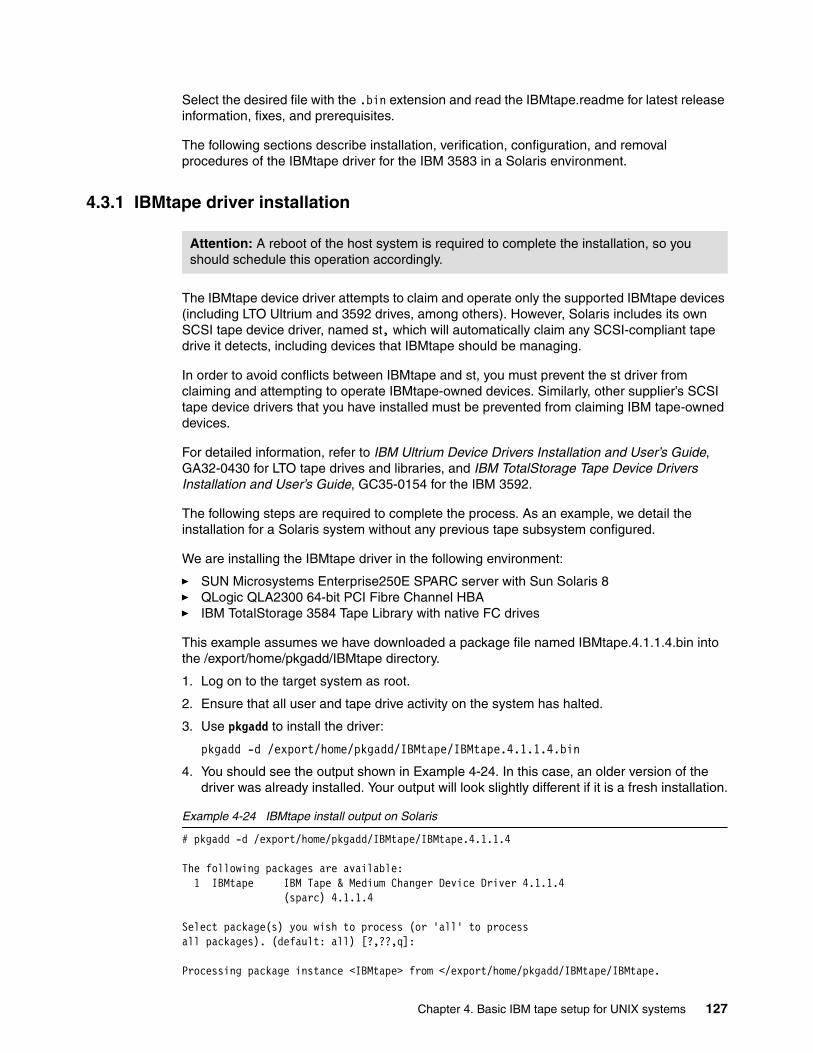
Select the desired file with the .bin extension and read the IBMtape.readme for latest release information, fixes, and prerequisites.
The following sections describe installation, verification, configuration, and removal procedures of the IBMtape driver for the IBM 3583 in a Solaris environment.
4.3.1 IBMtape driver installation
The IBMtape device driver attempts to claim and operate only the supported IBMtape devices (including LTO Ultrium and 3592 drives, among others). However, Solaris includes its own SCSI tape device driver, named st, which will automatically claim any SCSI-compliant tape drive it detects, including devices that IBMtape should be managing.
In order to avoid conflicts between IBMtape and st, you must prevent the st driver from claiming and attempting to operate IBMtape-owned devices. Similarly, other supplier’s SCSI tape device drivers that you have installed must be prevented from claiming IBM tape-owned devices.
For detailed information, refer to IBM Ultrium Device Drivers Installation and User’s Guide, GA32-0430 for LTO tape drives and libraries, and IBM TotalStorage Tape Device Drivers Installation and User’s Guide, GC35-0154 for the IBM 3592.
The following steps are required to complete the process. As an example, we detail the installation for a Solaris system without any previous tape subsystem configured.
We are installing the IBMtape driver in the following environment:
� SUN Microsystems Enterprise250E SPARC server with Sun Solaris 8� QLogic QLA2300 64-bit PCI Fibre Channel HBA� IBM TotalStorage 3584 Tape Library with native FC drives
This example assumes we have downloaded a package file named IBMtape.4.1.1.4.bin into the /export/home/pkgadd/IBMtape directory.
1. Log on to the target system as root.
2. Ensure that all user and tape drive activity on the system has halted.
3. Use pkgadd to install the driver:
pkgadd -d /export/home/pkgadd/IBMtape/IBMtape.4.1.1.4.bin
4. You should see the output shown in Example 4-24. In this case, an older version of the driver was already installed. Your output will look slightly different if it is a fresh installation.
Example 4-24 IBMtape install output on Solaris
# pkgadd -d /export/home/pkgadd/IBMtape/IBMtape.4.1.1.4
The following packages are available: 1 IBMtape IBM Tape & Medium Changer Device Driver 4.1.1.4 (sparc) 4.1.1.4
Select package(s) you wish to process (or 'all' to processall packages). (default: all) [?,??,q]:
Processing package instance <IBMtape> from </export/home/pkgadd/IBMtape/IBMtape.
Attention: A reboot of the host system is required to complete the installation, so you should schedule this operation accordingly.
Chapter 4. Basic IBM tape setup for UNIX systems 127
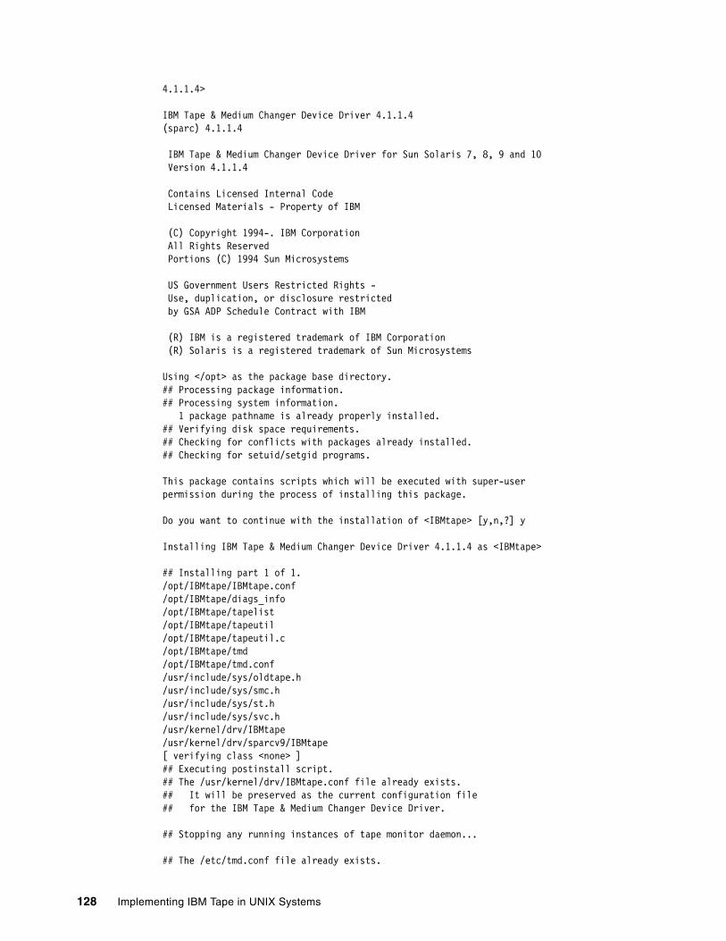
4.1.1.4>
IBM Tape & Medium Changer Device Driver 4.1.1.4(sparc) 4.1.1.4
IBM Tape & Medium Changer Device Driver for Sun Solaris 7, 8, 9 and 10 Version 4.1.1.4
Contains Licensed Internal Code Licensed Materials - Property of IBM
(C) Copyright 1994-. IBM Corporation All Rights Reserved Portions (C) 1994 Sun Microsystems
US Government Users Restricted Rights - Use, duplication, or disclosure restricted by GSA ADP Schedule Contract with IBM
(R) IBM is a registered trademark of IBM Corporation (R) Solaris is a registered trademark of Sun Microsystems
Using </opt> as the package base directory.## Processing package information.## Processing system information. 1 package pathname is already properly installed.## Verifying disk space requirements.## Checking for conflicts with packages already installed.## Checking for setuid/setgid programs.
This package contains scripts which will be executed with super-userpermission during the process of installing this package.
Do you want to continue with the installation of <IBMtape> [y,n,?] y
Installing IBM Tape & Medium Changer Device Driver 4.1.1.4 as <IBMtape>
## Installing part 1 of 1./opt/IBMtape/IBMtape.conf/opt/IBMtape/diags_info/opt/IBMtape/tapelist/opt/IBMtape/tapeutil/opt/IBMtape/tapeutil.c/opt/IBMtape/tmd/opt/IBMtape/tmd.conf/usr/include/sys/oldtape.h/usr/include/sys/smc.h/usr/include/sys/st.h/usr/include/sys/svc.h/usr/kernel/drv/IBMtape/usr/kernel/drv/sparcv9/IBMtape[ verifying class <none> ]## Executing postinstall script.## The /usr/kernel/drv/IBMtape.conf file already exists.## It will be preserved as the current configuration file## for the IBM Tape & Medium Changer Device Driver.
## Stopping any running instances of tape monitor daemon...
## The /etc/tmd.conf file already exists.
128 Implementing IBM Tape in UNIX Systems
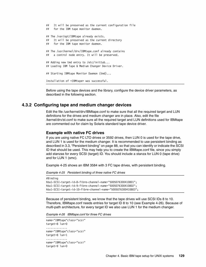
## It will be preserved as the current configuration file## for the IBM tape monitor daemon.
## The /var/opt/IBMtape already exists.## It will be preserved as the current directory## for the IBM tape monitor daemon.
## The /usr/kernel/drv/IBMtape.conf already contains## a control node entry. It will be preserved.
## Adding new tmd entry to /etc/inittab...## Loading IBM Tape & Medium Changer Device Driver.
## Starting IBMtape Monitor Daemon (tmd)...
Installation of <IBMtape> was successful.
Before using the tape devices and the library, configure the device driver parameters, as described in the following section.
4.3.2 Configuring tape and medium changer devicesEdit the file /usr/kernel/drv/IBMtape.conf to make sure that all the required target and LUN definitions for the drives and medium changer are in place. Also, edit the file /kernel/drv/st.conf to make sure all the required target and LUN definitions used for IBMtape are commented out for claim by Solaris standard tape device driver.
Example with native FC drivesIf you are using native FC LTO drives or 3592 drives, then LUN 0 is used for the tape drive, and LUN 1 is used for the medium changer. It is recommended to use persistent binding as described in 3.3, “Persistent binding” on page 88, so that you can identify or indicate the SCSI ID that should be used. This may help you to create the IBMtape.conf file, since you simply add stanzas for every SCSI (target) ID. You should include a stanza for LUN 0 (tape drive) and for LUN 1 (smc).
Example 4-25 shows an IBM 3584 with 3 FC tape drives, with persistent binding.
Example 4-25 Persistent binding of three native FC drives
#Bindinghba1-SCSI-target-id-8-fibre-channel-name="5005076300410801";hba1-SCSI-target-id-9-fibre-channel-name="5005076300410802";hba1-SCSI-target-id-10-fibre-channel-name="5005076300410803";
Because of persistent binding, we know that the tape drives will use SCSI IDs 8 to 10. Therefore, IBMtape.conf needs entries for target ID 8 to 10 (see Example 4-26). Because of multi-path architecture, for every target ID we also use LUN 1 for the medium changer.
Example 4-26 IBMtape.conf for three FC drives
name="IBMtape"class="scsi"target=8 lun=0..............name="IBMtape"class="scsi"target=8 lun=1..............name="IBMtape"class="scsi"target=9 lun=0
Chapter 4. Basic IBM tape setup for UNIX systems 129
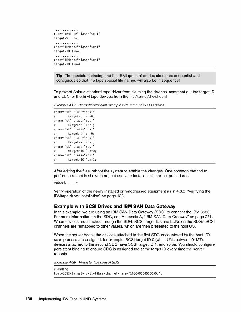
..............name="IBMtape"class="scsi"target=9 lun=1..............name="IBMtape"class="scsi"target=10 lun=0..............name="IBMtape"class="scsi"target=10 lun=1
To prevent Solaris standard tape driver from claiming the devices, comment out the target ID and LUN for the IBM tape devices from the file /kernel/drv/st.conf.
Example 4-27 /kernel/drv/st.conf example with three native FC drives
#name="st" class="scsi"# target=8 lun=0;#name="st" class="scsi"# target=8 lun=1;#name="st" class="scsi"# target=9 lun=0;#name="st" class="scsi"# target=9 lun=1;#name="st" class="scsi"# target=10 lun=0;#name="st" class="scsi"# target=10 lun=1;
After editing the files, reboot the system to enable the changes. One common method to perform a reboot is shown here, but use your installation’s normal procedures:
reboot -- -r
Verify operation of the newly installed or readdressed equipment as in 4.3.3, “Verifying the IBMtape driver installation” on page 133.
Example with SCSI Drives and IBM SAN Data GatewayIn this example, we are using an IBM SAN Data Gateway (SDG) to connect the IBM 3583. For more information on the SDG, see Appendix A, “IBM SAN Data Gateway” on page 281. When devices are attached through the SDG, SCSI target IDs and LUNs on the SDG’s SCSI channels are remapped to other values, which are then presented to the host OS.
When the server boots, the devices attached to the first SDG encountered by the boot I/O scan process are assigned, for example, SCSI target ID 0 (with LUNs between 0-127); devices attached to the second SDG have SCSI target ID 1, and so on. You should configure persistent binding to ensure SDG is assigned the same target ID every time the server reboots.
Example 4-28 Persistent binding of SDG
#Bindinghba1-SCSI-target-id-11-fibre-channel-name="100000604516050b";
Tip: The persistent binding and the IBMtape.conf entries should be sequential and contiguous so that the tape special file names will also be in sequence!
130 Implementing IBM Tape in UNIX Systems
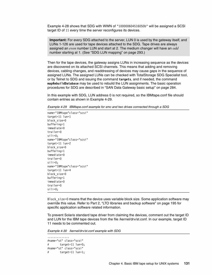
Example 4-28 shows that SDG with WWN of "100000604516050b" will be assigned a SCSI target ID of 11 every time the server reconfigures its devices.
Then for the tape devices, the gateway assigns LUNs in increasing sequence as the devices are discovered on its attached SCSI channels. This means that adding and removing devices, cabling changes, and readdressing of devices may cause gaps in the sequence of assigned LUNs. The assigned LUNs can be checked with TotalStorage SDG Specialist tool, or by Telnet to SDG and issuing the command targets, and if needed, the command mapRebuildDatabase may be used to rebuild the LUN assignments. The basic operation procedures for SDG are described in “SAN Data Gateway basic setup” on page 284.
In this example with SDG, LUN address 0 is not required, so the IBMtape.conf file should contain entries as shown in Example 4-29.
Example 4-29 IBMtape.conf example for smc and two drives connected through a SDG
name="IBMtape"class="scsi"target=11 lun=1block_size=0buffering=1immediate=0trailer=0sili=0;name="IBMtape"class="scsi"target=11 lun=2block_size=0buffering=1immediate=0trailer=0sili=0;name="IBMtape"class="scsi"target=11 lun=4block_size=0buffering=1immediate=0trailer=0sili=0;
Block_size=0 means that the device uses variable block size. Some application software may override this value. Refer to Part 2, “LTO libraries and backup software” on page 195 for specific application software related information.
To prevent Solaris standard tape driver from claiming the devices, comment out the target ID and LUN for the IBM tape devices from the file /kernel/drv/st.conf. In our example, target ID 11 needs to be commented out.
Example 4-30 /kernel/drv/st.conf example with SDG
..............#name="st" class="scsi"# target=11 lun=0;#name="st" class="scsi"# target=11 lun=1;
Important: For every SDG attached to the server, LUN 0 is used by the gateway itself, and LUNs 1-126 are used for tape devices attached to the SDG. Tape drives are always assigned an even number LUN and start at 2. The medium changer will have an odd number starting at 1. (See “SDG LUN mapping” on page 293.)
Chapter 4. Basic IBM tape setup for UNIX systems 131
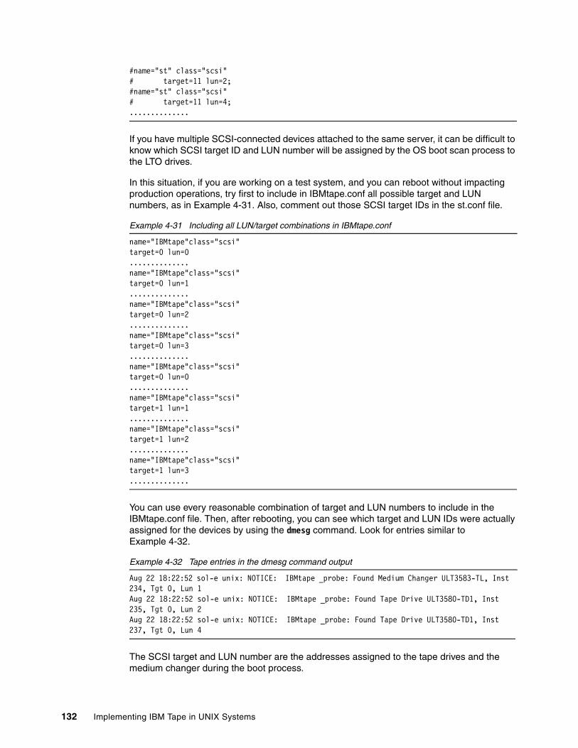
#name="st" class="scsi"# target=11 lun=2;#name="st" class="scsi"# target=11 lun=4;..............
If you have multiple SCSI-connected devices attached to the same server, it can be difficult to know which SCSI target ID and LUN number will be assigned by the OS boot scan process to the LTO drives.
In this situation, if you are working on a test system, and you can reboot without impacting production operations, try first to include in IBMtape.conf all possible target and LUN numbers, as in Example 4-31. Also, comment out those SCSI target IDs in the st.conf file.
Example 4-31 Including all LUN/target combinations in IBMtape.conf
name="IBMtape"class="scsi"target=0 lun=0..............name="IBMtape"class="scsi"target=0 lun=1..............name="IBMtape"class="scsi"target=0 lun=2..............name="IBMtape"class="scsi"target=0 lun=3..............name="IBMtape"class="scsi"target=0 lun=0..............name="IBMtape"class="scsi"target=1 lun=1..............name="IBMtape"class="scsi"target=1 lun=2..............name="IBMtape"class="scsi"target=1 lun=3..............
You can use every reasonable combination of target and LUN numbers to include in the IBMtape.conf file. Then, after rebooting, you can see which target and LUN IDs were actually assigned for the devices by using the dmesg command. Look for entries similar to Example 4-32.
Example 4-32 Tape entries in the dmesg command output
Aug 22 18:22:52 sol-e unix: NOTICE: IBMtape _probe: Found Medium Changer ULT3583-TL, Inst 234, Tgt 0, Lun 1Aug 22 18:22:52 sol-e unix: NOTICE: IBMtape _probe: Found Tape Drive ULT3580-TD1, Inst 235, Tgt 0, Lun 2Aug 22 18:22:52 sol-e unix: NOTICE: IBMtape _probe: Found Tape Drive ULT3580-TD1, Inst 237, Tgt 0, Lun 4
The SCSI target and LUN number are the addresses assigned to the tape drives and the medium changer during the boot process.
132 Implementing IBM Tape in UNIX Systems

Now you can re-edit IBMtape.conf to exclude the unused entries. Do not leave unused entries in the file, since superfluous entries can slow the boot process.
Reboot the system after removing the unused entries in IBMtape.conf. One common method to perform a reboot is shown here, but use your installation’s normal procedures:
reboot -- -r
Verify operation of the newly installed or readdressed equipment as in 4.3.3, “Verifying the IBMtape driver installation” on page 133.
4.3.3 Verifying the IBMtape driver installationTo verify the correctness of the installation and configuration of the IBMtape device driver, use the command in Example 4-33. This example relates to the IBM 3583 connected through SAN Data Gateway using the persistent binding setting used in Example 4-28 on page 130. (The letter b is actually a hexadecimal digit, and indicates that these devices have a SCSI ID of eleven.)
Example 4-33 Verifying Solaris device configuration
ls -l /dev/rmt/*stbn /dev/rmt/*smclrwxrwxrwx 1 root root 47 Aug 22 18:12 /dev/rmt/0smc -> ../../devices/pci@1f,4000/scsi@2/IBMtape@b,1:stlrwxrwxrwx 1 root root 47 Aug 22 18:12 /dev/rmt/1stcbn -> ../../devices/pci@1f,4000/scsi@2/IBMtape@b,2:stlrwxrwxrwx 1 root root 47 Aug 22 18:12 /dev/rmt/2stcbn -> ../../devices/pci@1f,4000/scsi@2/IBMtape@b,4:st
Example 4-33 shows:
0smc The device special file name for the medium changer
1stbn The device special file name for the first 3580 tape drive
2stbn The device special file name for the 2nd 3580 tape drive
Example 4-34 shows an IBM TotalStorage 3584 Tape Library with native FC drives connected using the persistent binding setting used in Example 4-25 on page 129.
Example 4-34 Verifying Solaris device configuration
ls -l /dev/rmt/*stbn /dev/rmt/*smclrwxrwxrwx 1 root root 58 Mar 24 17:33 /dev/rmt/0stbn -> ../../devices/pci@1f,4000/fibre-channel@2/IBMtape@8,0:stbnlrwxrwxrwx 1 root root 57 Mar 29 13:22 /dev/rmt/1smc -> ../../devices/pci@1f,4000/fibre-channel@2/IBMtape@8,1:smclrwxrwxrwx 1 root root 58 Mar 24 17:33 /dev/rmt/2stbn -> ../../devices/pci@1f,4000/fibre-channel@2/IBMtape@9,0:stbnlrwxrwxrwx 1 root root 57 Mar 29 13:22 /dev/rmt/3smc -> ../../devices/pci@1f,4000/fibre-channel@2/IBMtape@9,1:smclrwxrwxrwx 1 root root 58 Mar 24 17:33 /dev/rmt/4stbn -> ../../devices/pci@1f,4000/fibre-channel@2/IBMtape@a,0:stbnlrwxrwxrwx 1 root root 57 Mar 29 13:22 /dev/rmt/5smc -> ../../devices/pci@1f,4000/fibre-channel@2/IBMtape@a,1:smc
In this example, the fields are:
0stbn Since this device has a SCSI ID of 8 and LUN of 0 (8,0), it is most likely that this device special file represents the device with WWN of 5005076300410801 from
Chapter 4. Basic IBM tape setup for UNIX systems 133
the persistent binding setting in Example 4-25 on page 129, which is the first tape drive.
1smc 8,1 indicates that it is the device special file name for the medium changer recognized from the first tape drive.
2stbn Similarly, this is the device special file name for the second tape drive.
3smc The device special file name for the medium changer.
4stbn The device special file name for the third tape drive.
5smc The device special file name for the medium changer.
You can also use the tapelist tool for identifying the relationship between the device special file and which physical device it represents.
Example 4-35 Tape entries in the server using tapelist tool
# tapelist -lInst # Special File Device Serial No TGT/LUN Ucode World Wide NN World Wide PN Device Physical Path Path Type------ --------------- ------------- ------------ ------- ------ ---------------- ---------------- -------------------------------------------- ----------3682 /dev/rmt/10st 03592J1A 000001300280 8/0 04B8 5005076300010811 5005076300410811 /devices/pci@1f,4000/fibre-channel@2/IBMtape@8,0:st N/A3683 /dev/rmt/13smc 03584L22 000001310008 8/1 465u N/A N/A /devices/pci@1f,4000/fibre-channel@2/IBMtape@8,1:smc N/A3715 /dev/rmt/12st 03592J1A 000001300178 9/0 04B8 5005076300010812 5005076300410812 /devices/pci@1f,4000/fibre-channel@2/IBMtape@9,0:st N/A
Example 4-35 shows that device special file /dev/rmt/12st is representing an IBM 3592-J1A tape drive with assigned SCSI target ID of 9 and LUN of 0, serial number of 1300178, and WWNN of 5005076300010812.
IBMtape is listed correctly as the owner of these devices. Refer to Table 4-1 on page 103 for a list of the device special file names for each platform. For performance reasons, it is suggested to use a special device file name that has compression turned on. If you have installed an IBM 3580, you will not see any entry for the medium changer because it does not have one.
You can now use the tapeutil utility to test the library. See 4.5, “Testing the library with tapeutil” on page 149 to learn how to use this utility. Open the device, issue inquiry commands read and write, and move the media across the library to check the driver functionality.
The drives can also be used with OS commands such as tar.
4.3.4 Deleting tape devicesIt can be necessary to remove the tape device or the medium changer from the Solaris device configuration. This is a required step for some application software, which provides its own device driver for a tape drive and medium changer. Refer to Part 2, “LTO libraries and backup software” on page 195 for more information on specific application software driver requirements.
To remove the IBMtape driver support for a specific device, edit /usr/kernel/drv/IBMtape.conf, and remove (comment out) the stanza for the device that is no longer to be configured with this driver.
134 Implementing IBM Tape in UNIX Systems
Then reboot the system in order for the changes to take effect.
4.3.5 Removing IBMtape driver from the systemUse the pkgrm command to remove the IBMtape package from the system:
/usr/sbin/pkgrm IBMtape
All active processes using any IBM device supported by the IBMtape driver must be stopped in order for the removal procedure to complete successfully.
Example 4-36 shows sample output of the pkgrm command.
Example 4-36 Uninstall IBMtape drive on Solaris
# /usr/sbin/pkgrm IBMtape
The following package is currently installed: IBMtape IBM Tape & Medium Changer Device Driver 4.1.1.4 (sparc) 4.1.1.4
Do you want to remove this package? yes
## Removing installed package instance <IBMtape>
This package contains scripts which will be executed with super-userpermission during the process of removing this package.
Do you want to continue with the removal of this package [y,n,?,q] y## Verifying package dependencies.## Processing package information.## Executing preremove script.## Stopping any running instances of tape monitor daemon...## Unloading IBM Tape & Medium Changer Device Driver.## Deleting device special file nodes.## Removing old tmd entry from /etc/inittab...## The /usr/kernel/drv/IBMtape.conf file will not be removed## to preserve previously established configurations.## Removing pathnames in class <none>/usr/kernel/drv/sparcv9/IBMtape/usr/kernel/drv/IBMtape/usr/include/sys/svc.h/usr/include/sys/st.h/usr/include/sys/smc.h/usr/include/sys/oldtape.h/opt/IBMtape/tmd.conf/opt/IBMtape/tmd/opt/IBMtape/tapeutil.c/opt/IBMtape/tapeutil/opt/IBMtape/tapelist/opt/IBMtape/diags_info/opt/IBMtape/IBMtape.conf/opt/IBMtape <non-empty directory not removed>## Updating system information.
Removal of <IBMtape> was successful.
Chapter 4. Basic IBM tape setup for UNIX systems 135
4.3.6 Setting up control path failover on SolarisThe Solaris IBMtape device driver alternate pathing support for library control path is called Control Path Failover (CPF), and will configure multiple physical control paths to the same logical library within the device driver and provide automatic failover to an alternate control path when a permanent error occurs on one path. This is transparent to the running application.
For example, consider a simple multipath connection that consists of two Host Bus Adapters (HBAs) that are connected to a library with two drive control ports enabled as in Figure 4-5 on page 117. The first HBA is connected to the first control port drive (Drive 1 in Figure 4-5), and the second HBA is connected to the second control port drive (Drive 4 in Figure 4-5). This connection provides two physical control paths to the same library for redundancy if one path from an HBA to the library fails.
When the tape library is attached to the two HBAs on the Solaris system, each HBA detects a control port to the same library, and two logical devices will be configured with IBMtape driver (for example, /dev/rmt/0smc and 1smc). Each logical device is a physical path to the same library. An application can open and use only one logical device at a time, either smc0 or smc1, because these represent the same physical device.
Without the IBMtape alternate pathing support, if an application opens 0smc and a permanent path error occurs (because of an HBA, cable, or drive control port failure, for example), the application fails. It is possible to initiate manual failover by restarting the application on the alternate logical device (1smc), but the failing transaction has to be restarted from the beginning.
When the alternate pathing support is enabled, the device driver configures them internally as a single device with multiple paths. The application can still open and use only one logical device at a time (either 0smc or 1smc). If an application opens 0smc and a permanent path error occurs, the device driver initiates failover error recovery automatically on the alternate path (1smc). If successful, the current operation continues on the alternate path without interrupting the application.
Configuring alternate control pathAlternate pathing support is enabled automatically by default when the IBMtape device driver is installed on a Solaris system. The Solaris IBMtape device driver provides a driver configuration parameter failover for you to enable or disable the library control path failover (CPF) support. To enable the CPF support for all of the paths, no action is required.
When the device driver configures a logical device with alternate pathing support enabled, the first device configured always becomes the primary path. When a second or more logical device is configured with alternate pathing support enabled for the same physical device, it configures as an alternate path. The device driver supports up to 16 physical paths for a single device.
The primary and alternate path information is shown in the Path Type field from the output of the tapelist command. See Example 4-37.
Important: The library control path failover feature code 1680 must be installed and enabled on the library (IBM 3582, 3583, and 3584) in order for the device driver to detect alternate control paths. In addition, you have to enable the control path for additional drives on the library using either the library operator panel or the TotalStorage Specialist. To see how to do this go to “Enabling additional control paths” on page 113.
136 Implementing IBM Tape in UNIX Systems
Example 4-37 Output of Primary and Alternate Control Paths using tapelist command
#tapelist -1
Inst# Special File Device Serial No TGT/LUN Ucode WWNN WWPN Device Physical Path Path Type ----- ------------ ------ --------- ------- ----- ---- ---- -------------------- --------- 686 /dev/rmt/12smc 03584L32 0000000T0039 1/1 402j N/A N/A /devices/pci@If,2000/QLGC,qla@1/IBMtape@1,1 Primary 688 /dev/rmt/14smc 03584L32 0000000T0039 2/1 402j N/A N/A /devices/pci@If,2000/QLGC,qla@1/IBMtape@2,1 Alt_path_1 694 /dev/rmt/26smc 03584L32 0000000T0039 5/1 402j N/A N/A /devices/pci@If,2000/QLGC,qla@1/IBMtape@5,1 Alt_path_2
Another method for viewing the primary and alternate control paths is to run tapeutil and select option 54, Query Device Paths. See Example 4-38.
Example 4-38 Output of Primary and Alternate Control Paths using tapeutil
Path list in the device: Path 0 Path 1 Path 2 Current active path: Path 0
Enter path number or <enter> for all of the paths:
Instance Number ............. 201 SCSI Target ................. 4SCSI LUN .................... 1 Serial Number ............... 000001301084 Ucode Level ................. 227B Path World Wide NN .......... N/A Path World Wide PN .......... N/A Path Type ....................Primary Path .........................Enable Device Physical Path ........ /devices/pci@1f,2000/scsi@1/IBMtape@4,1
Instance Number ............. 231 SCSI Target ................. 3 SCSI LUN .................... 1 Serial Number ............... 000001301084 Ucode Level ................. 227B Path World Wide NN .......... N/A Path World Wide PN .......... N/A Path Type ................... Alt_path_1 Path ........................ Enable Device Physical Path ........ /devices/pci@4,2000/pci@1/fibre-channel@4/IBMtape@3,1
Instance Number ............. 293 SCSI Target ................. 2 SCSI LUN .................... 1 Serial Number ............... 000001301084 Ucode Level ................. 227BPath World Wide NN .......... N/A Path World Wide PN .......... N/A Path Type ................... Alt_path_2 Path ........................ Enable Device Physical Path ........ /devices/pci@6,4000/lpfc@4/IBMtape@2,1
Chapter 4. Basic IBM tape setup for UNIX systems 137
Disabling and enabling primary and alternate control pathsOnce you install the IBMtape device driver, by default, all the available paths for a physical device are enabled. If for some maintenance reason you need to disable a path and do not want to fail over to this path, run the following steps:
1. Turn the failover parameter to off in the path entry in the IBMtape.conf file. For example:
name="IBMtape" class="scsi" target=3 lun=1 failover=0;
2. Stop the TMD (tape monitor daemon) running on the system and unload the IBMtape driver module from the current kernel:
# /opt/IBMtape/tmd -s # /usr/sbin/rem_drv IBMtape
3. Reload the IBMtape driver module in the kernel and start the daemon:
# /usr/sbin/add_drv -m ' 0666 bin bin' IBMtape # /opt/IBMtape/tmd
To enable a path from a disabled state, run the following steps:
1. Remove the parameter failover=0 in the path entry in IBMtape.conf file. For example:
name="IBMtape" class="scsi" target=3 lun=1"
2. Stop the TMD (tape monitor daemon) running on the system and unload the IBMtape driver module from the current kernel:
# /opt/IBMtape/tmd -s # /usr/sbin/rem_drv IBMtape
3. Reload the IBMtape driver module in the kernel and start the daemon:
# /usr/sbin/add_drv -m ' 0666 bin bin' IBMtape # /opt/IBMtape/tmd
4.3.7 Setting up data path failover on SolarisThe Solaris IBMtape device driver alternate pathing support will configure multiple physical paths to the same device within the device driver to provide Data Path Failover (DPF) and dynamic load balancing for devices using multiple Host Bus Adapters (HBA). See Figure 4-6 on page 119, Figure 4-7 on page 120, and Figure 4-8 on page 121.
When the drive is attached on the Solaris system, each HBA detects a tape drive, and two logical devices will be configured (for example, 0st and 1st). Each logical device is a physical path to the same tape drive. A backup and restore application can open and use only one logical device at a time, either 0st or 1st, because they represent the same physical device.
Without the IBMtape alternate pathing support, if an application opens 0st and a permanent path error occurs (because of an HBA or cable failure, for example), the application fails. It is possible to initiate manual failover by restarting the application on the alternate logical device (1st), but the application has to be restarted from the beginning. A long backup or restore operation could have been in progress when the path error occurred. Sometimes manual failover can require operator intervention to reset the drive because a SCSI Reservation could still exist on the failing HBA path.
When the alternate pathing support is enabled on both 0st and 1st, the device driver configures them internally as a single device with multiple paths. The application can still open and use only one logical device at a time (either 0st or 1st). If an application opens 0st and a permanent path error occurs, the device driver initiates failover error recovery
Note: These functions are supported only on IBM Ultrium 2 and 3 native Fibre Channel drives and IBM 3592 Enterprise tape drives. They are not supported on IBM Ultrium 1 drives or for devices that are attached through an IBM San Data Gateway.
138 Implementing IBM Tape in UNIX Systems
automatically on the alternate path (1st). If successful, the current operation continues on the alternate path without interrupting the application. The failover error recovery first restores the previous device state, SCSI Reservation, and tape position, then retries the failing operation.
The dynamic load balancing support optimizes resources for devices that have physical connections to multiple Host Bus Adapters (HBA) in the same machine. When an application opens a device that has multiple HBA paths configured, the device driver determines which path has the HBA with the lowest usage, and assigns that path to the application. When another application opens a different device with multiple HBA paths, the device driver again determines the path with the lowest HBA usage and assigns that path to the second application. The device driver will update the usage on the HBA assigned to the application when the device is closed. Dynamic load balancing will use all Host Bus Adapters whenever possible and balance the load between them to optimize the resources in the machine.
Enabling/disabling alternate data path support
Alternate pathing support for tape drives is not enabled automatically when the device driver is installed. It must be configured initially on each logical device after installation. When alternate pathing support is enabled for a logical device, it remains set until the device is deleted or the support is deconfigured. The alternate pathing setting is retained even if the system is rebooted.
Alternate pathing support can be enabled on all configured devices at one time, or it can be enabled or disabled selectively by logical device. Perform the following steps to enable DPF support:
1. Enter the DPF feature key(s) in the parameter dpf_keys at the beginning of the IBMtape.conf file in the directory of /usr/kernel/drv. The feature key is required for Ultrium tape drives only. For example, dpf_keys="A729E60F7B119411, C7A0B9ef2c1a4360, a729e60f7b118460"
2. To enable the support globally on all currently configured devices, add the following to the beginning of IBMtape.conf:
dpf_support=1
3. To enable a particular path, add the flag dpf_support=1 in the path entry in IBMtape.conf. For example, name="IBMtape" class="scsi" target=3 lun=0 dpf_support=1
4. Stop the TMD (tape monitor daemon) running on the system and unload the IBMtape driver module from the current kernel:
# /opt/IBMtape/tmd -s # /usr/sbin/rem_drv IBMtape
5. Reload the IBMtape driver module in the kernel and start the daemon:
# /usr/sbin/add_drv -m ' 0666 bin bin' IBMtape # /opt/IBMtape/tmd
Important: The library data path failover feature code 1681 must be installed on the library (IBM 3582, 3583, and 3584) before enabling alternate data path support in the Solaris device driver for IBM Ultrium 2 and 3 drives. The feature code is not required for IBM 3592 drives.
Note: The parameter dpf_keys is in the format “key1, key2, key3,...". Each key is 16 characters long with a comma separator and a space. IBMtape driver supports up to 36 dpf keys.
Chapter 4. Basic IBM tape setup for UNIX systems 139

If for some reason you need to disable DPF support for all drives or for a particular path or drive, perform the following steps:
1. Specify what you want to disable.
a. To disable DPF support for all tape drives, set the dpf_support parameter in the IBMtape.conf file to 0.
b. To disable DPF support for a particular tape drive or path, do the following:
i. To disable a particular path, add the flag entry dpf_support=0 in the path entry in IBMtape.conf. For example: name="IBMtape" class="scsi" target=3 lun=0 dpf_support=0
ii. To disable DPF support for a physical tape drive, remove the key from the list of dpf_keys in IBMtape.conf
2. Stop the TMD (tape monitor daemon) running on the system and unload the IBMtape driver module from the current kernel:
# /opt/IBMtape/tmd -s # /usr/sbin/rem_drv IBMtape
3. Reload the IBMtape driver module in the kernel and start the daemon:
# /usr/sbin/add_drv -m ' 0666 bin bin' IBMtape # /opt/IBMtape/tmd
4.4 Installing IBM tape device driver for HP-UX The device driver used for HP-UX UNIX platforms is called atdd and it includes both the tape drive and medium changer drivers.
To check if your environment has the a supported OS level, see:
http://www.ibm.com/servers/storage/tape/resource-library.html#interoperability
Look for supported servers and operating systems, and then select the LTO model. Look for the section Hewlett-Packard Servers for information about operating systems and supported HBAs. For the supported HBA firmware level and SAN fabric components, see:
http://knowledge.storage.ibm.com/servers/storage/support/hbasearch/interop/hbaSearch.do
Download the latest atdd driver version from:
ftp://ftp.software.ibm.com/storage/devdrvr/HPUX/
To find the right driver, go to the subdirectory according to your HP-UX OS level and system architecture (either Precision or PCI) and OS. In our case, we have an HP PCI bus system with HP-UX V11i, therefore, we need to be in the 11i_PCI directory. The IBM tape device driver has the format atdd.3.5.x.x.bin. Note, other bus architectures like Itanium® and PA-RISC use different formats for the device driver file. See the README file in the ftp directory to make sure you download the correct package for your architecture.
We recommend that you also download the tapeutil utility from the same location. This file is called tapeutil.hpux.x.x.x.x.bin and is packaged separately, unlike for Solaris or AIX. You use tapeutil for tape and medium changer commands such as mount, dismount, move media, write, and read files.
Finally, download the InstallAtdd script in ASCII. This is a script provided to automatically install the device driver. You can either execute this script, or follow the manual steps in the next section.
140 Implementing IBM Tape in UNIX Systems
Be sure to check the readme for updated information on fixes and prerequisites.
The following sections describe installation, configuration, verification, and removal procedures for the atdd device driver for the IBM 3584 with 3592 drives with HP-UX V11i.
4.4.1 Atdd driver installation
By default, the atdd device driver automatically configures all supported IBM tape drives that are attached and powered on when the system starts. You have to decide whether to have the driver automatically configure IBM medium changer devices by default, because some backup applications use their own changer drivers or the native schgr or sctl drivers. In our case, we chose to have the medium changer device automatically configured (claimed).
For detailed installation instructions, refer to IBM Ultrium Device Drivers Installation and User’s Guide, GA32-0430 for LTO tape drives and libraries, and IBM TotalStorage Tape Device Drivers Installation and User’s Guide, GC35-0154 for the 3592 tape drive.
We are installing the atdd driver in the following environment:
� HP “L” class server with HP-UX operating system release 11i� Fibre Channel adapter HP A6826A� IBM TotalStorage 3584 Tape Library with two 3580 drives
You must have root authority to proceed with the installation of the driver. The following installation steps assume that the driver atdd.3.5.0.26.bin has been downloaded to the directory /bavaria/atdd.
1. Copy the installation file to the software depot using the command:
swcopy -p -s /bavaria/atdd.3.5.0.26.bin atddswcopy -s /bavaria/atdd.3.5.0.26.bin atdd
The first command performs a preview copy only. Repeat without the -p option to actually execute the copy.
Verify that the Atdd software has been copied in the depot:
swlist -d atdd
You should see these messages:
# atdd 3.5.0.26 GES IBM tape and changer device driver for TotalStorage atdd.driver IBM Advanced Tape Device Driver
2. Use the swlist command to view the product’s readme file:
swlist -d -a readme atdd | more
3. To install atdd from the depot to the default root file system, use the command:
swinstall -x ask=true atdd
The -ask option means that you will be prompted whether to allow the system to configure automatically (claim) any medium changer devices. You may have to use an alternative method to configure the medium changer; see the IBM Ultrium Device Drivers Installation and User’s Guide, GA32-0430 for information.
When the command runs, you will be prompted with the question,
Would you like to activate the Medium Changer support by ACDD (Y/N)
Enter Y to allow the ACDD module to configure all attached IBM medium changer devices, or answer N to allow the HP native changer driver to configure the devices.
Chapter 4. Basic IBM tape setup for UNIX systems 141
Depending on the version of HP-UX installed, the atdd driver may or may not require an automatic reboot of the system. The atdd package starting with version 3.5.x.x on HP-UX 11i and 1.15.x.x on HP-UX 11.0 is a Dynamically Loadable Kernel Module (DLKM) package without the system reboot requirement. The atdd DLKM package consists of two DLKM modules, atdd (Advanced Tape Device Driver) which controls tape drives and ACDD (Advanced Changer Device Driver) which controls media changers.
4. To verify correct installation of the package, use the command:
swverify atdd
You will see the output in Example 4-39.
Example 4-39 Verifying the correct install with swlist atdd
# swverify atdd
======= 07/07/05 14:56:43 MST BEGIN swverify SESSION (non-interactive) (jobid=patti-0429)
* Session started for user "root@patti".
* Beginning Selection * Target connection succeeded for "patti:/". * Software selections: atdd.driver,l=/opt/atdd,r=3.5.0.26 * Selection succeeded.
* Beginning Analysis * Session selections have been saved in the file "/home/root/.sw/sessions/swverify.last". * The analysis phase succeeded for "patti:/". * Verification succeeded.
NOTE: More information may be found in the agent logfile using the command "swjob -a log patti-0429 @ patti:/".
======= 07/07/05 14:56:53 MST END swverify SESSION (non-interactive) (jobid=patti-0429)
4.4.2 Verifying the atdd driver installationTo verify the atdd device driver has been installed correctly, use the commands:
� ioscan -fnkC tape shows detected (claimed) tape drives.� ioscan -fnkC autoch shows detected (claimed) autochangers.� ls -la /dev/rmt shows the special file name.
The output of ioscan -fnkC tape is shown in Example 4-40, and the output of ioscan -fnkC autoch is in Example 4-41; they were captured from an IBM 3584 with two FC LTO 2 drives.
Example 4-40 shows the device special files (l /dev/rmt/1m and /dev/rmt/2m) for each tape drive. Both are connected to the same FC HBA with the location code 0/0/12/0/0.121.
Note: If an earlier version of atdd is already installed, the existing version will be replaced. This is true even if the version already installed is more recent than the version being installed.
142 Implementing IBM Tape in UNIX Systems
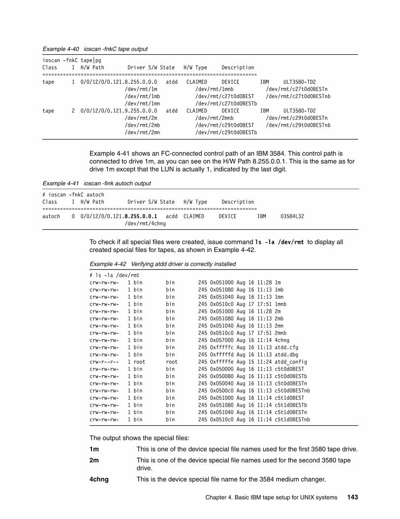
Example 4-40 ioscan -fnkC tape output
ioscan -fnkC tape|pgClass I H/W Path Driver S/W State H/W Type Description=========================================================================tape 1 0/0/12/0/0.121.8.255.0.0.0 atdd CLAIMED DEVICE IBM ULT3580-TD2 /dev/rmt/1m /dev/rmt/1mnb /dev/rmt/c27t0d0BESTn /dev/rmt/1mb /dev/rmt/c27t0d0BEST /dev/rmt/c27t0d0BESTnb /dev/rmt/1mn /dev/rmt/c27t0d0BESTbtape 2 0/0/12/0/0.121.9.255.0.0.0 atdd CLAIMED DEVICE IBM ULT3580-TD2 /dev/rmt/2m /dev/rmt/2mnb /dev/rmt/c29t0d0BESTn /dev/rmt/2mb /dev/rmt/c29t0d0BEST /dev/rmt/c29t0d0BESTnb /dev/rmt/2mn /dev/rmt/c29t0d0BESTb
Example 4-41 shows an FC-connected control path of an IBM 3584. This control path is connected to drive 1m, as you can see on the H/W Path 8.255.0.0.1. This is the same as for drive 1m except that the LUN is actually 1, indicated by the last digit.
Example 4-41 ioscan -fink autoch output
# ioscan -fnkC autochClass I H/W Path Driver S/W State H/W Type Description=========================================================================autoch 0 0/0/12/0/0.121.8.255.0.0.1 acdd CLAIMED DEVICE IBM 03584L32 /dev/rmt/4chng
To check if all special files were created, issue command ls -la /dev/rmt to display all created special files for tapes, as shown in Example 4-42.
Example 4-42 Verifying atdd driver is correctly installed
# ls -la /dev/rmtcrw-rw-rw- 1 bin bin 245 0x051000 Aug 16 11:28 1mcrw-rw-rw- 1 bin bin 245 0x051080 Aug 16 11:13 1mbcrw-rw-rw- 1 bin bin 245 0x051040 Aug 16 11:13 1mncrw-rw-rw- 1 bin bin 245 0x0510c0 Aug 17 17:51 1mnbcrw-rw-rw- 1 bin bin 245 0x051000 Aug 16 11:28 2mcrw-rw-rw- 1 bin bin 245 0x051080 Aug 16 11:13 2mbcrw-rw-rw- 1 bin bin 245 0x051040 Aug 16 11:13 2mncrw-rw-rw- 1 bin bin 245 0x0510c0 Aug 17 17:51 2mnbcrw-rw-rw- 1 bin bin 245 0x057000 Aug 16 11:14 4chngcrw-rw-rw- 1 bin bin 245 0xfffffc Aug 16 11:13 atdd.cfgcrw-rw-rw- 1 bin bin 245 0xfffffd Aug 16 11:13 atdd.dbgcrw-r--r-- 1 root root 245 0xfffffe Aug 15 11:24 atdd_configcrw-rw-rw- 1 bin bin 245 0x050000 Aug 16 11:13 c5t0d0BESTcrw-rw-rw- 1 bin bin 245 0x050080 Aug 16 11:13 c5t0d0BESTbcrw-rw-rw- 1 bin bin 245 0x050040 Aug 16 11:13 c5t0d0BESTncrw-rw-rw- 1 bin bin 245 0x0500c0 Aug 16 11:13 c5t0d0BESTnbcrw-rw-rw- 1 bin bin 245 0x051000 Aug 16 11:14 c5t1d0BESTcrw-rw-rw- 1 bin bin 245 0x051080 Aug 16 11:14 c5t1d0BESTbcrw-rw-rw- 1 bin bin 245 0x051040 Aug 16 11:14 c5t1d0BESTncrw-rw-rw- 1 bin bin 245 0x0510c0 Aug 16 11:14 c5t1d0BESTnb
The output shows the special files:
1m This is one of the device special file names used for the first 3580 tape drive.
2m This is one of the device special file names used for the second 3580 tape drive.
4chng This is the device special file name for the 3584 medium changer.
Chapter 4. Basic IBM tape setup for UNIX systems 143
See Table 4-1 on page 103 to interpret all the device names.
You can now use the tapeutil utility to test the library. If you downloaded the tapeutil installation file as described in 4.4, “Installing IBM tape device driver for HP-UX” on page 140, install the package with the following commands:
swcopy /bavaria/tapeutil.hpux.4.0.0.0.bin tapeutilswinstall tapeutil
Then go to 4.5, “Testing the library with tapeutil” on page 149 to learn how to use tapeutil.
Open the device, issue inquiry commands read and write, and move media across the library to check the driver functionality.
4.4.3 Setting up control path failover on HP-UXThe HP-UX atdd device driver alternate pathing support will configure multiple physical control paths to the same logical library within the device driver and provide automatic failover to an alternate control path when a permanent error occurs on one path. This is transparent to the running application.
For example, consider a simple multipath connection that consists of two Host Bus Adapters (HBAs) that are connected to a library with two drive control ports enabled as in Figure 4-5 on page 117. The first HBA is connected to the first control port drive (Drive 1 in Figure 4-5), and the second HBA is connected to the second control port drive (Drive 4 in Figure 4-5). This connection provides two physical control paths to the same library for redundancy if one path from an HBA to the library fails.
When the host bus adapter device drivers are loaded into the running system, each HBA detects a control port to the same library, and two logical devices can be created (for example, /dev/rmt/0chng and /dev/rmt/1chng) by the atdd driver or the atdd_claim script. Each logical device is a physical path to the same library. An application can open and use only one logical device at a time, either 0chng or 1chng, because they represent the same physical device. Without the atdd alternate pathing support, if an application opens 0chng and a permanent path error occurs (because of an HBA, cable, or drive control port failure, for example), the application fails. It is possible to initiate manual failover by restarting the application on the alternate logical device (1chng), but the failing transaction has to be restarted from the beginning. When the alternate pathing support is enabled, the device driver configures them internally as a single device with multiple paths. The driver also renames the alternate paths from 1chng to 1chng.altpath.
It is recommended that applications open the primary path (0chng). If an application opens 0chng and a permanent path error occurs, the device driver initiates failover error recovery automatically on the alternate path (1chng.altpath). If successful, the current operation continues on the alternate path without interrupting the application.
Note: This function is supported only on IBM Ultrium 2 and 3 drives with native Fibre Channel and IBM 3592 tape drives. It is not supported on IBM Ultrium 1 drives or for devices that are attached through an IBM SAN Data Gateway.
Important: The library control path failover feature code 1680 must be installed and enabled on the library (IBM 3582, 3583, and 3584) prior to enabling the alternate pathing support in the HP-UX atdd device drive. In addition, you have to enable the control path for additional drives on the library using either the library operator panel or the TotalStorage Specialist. To see how to do this go to “Enabling additional control paths” on page 113.
144 Implementing IBM Tape in UNIX Systems
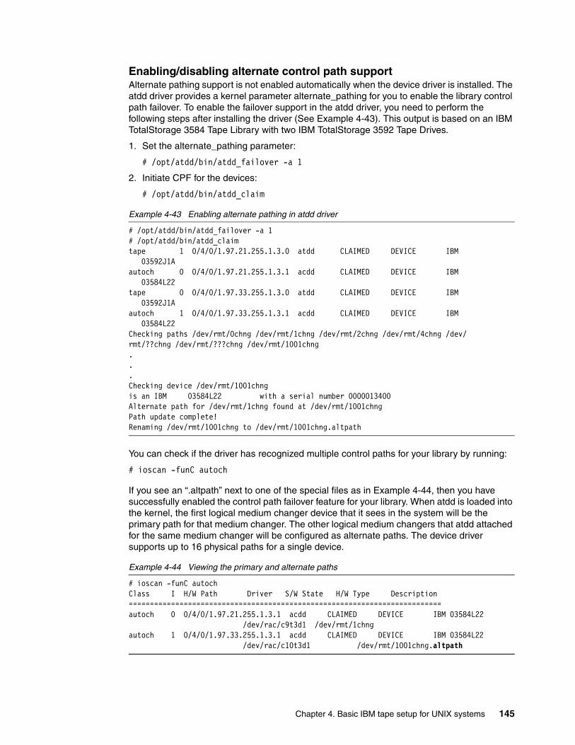
Enabling/disabling alternate control path supportAlternate pathing support is not enabled automatically when the device driver is installed. The atdd driver provides a kernel parameter alternate_pathing for you to enable the library control path failover. To enable the failover support in the atdd driver, you need to perform the following steps after installing the driver (See Example 4-43). This output is based on an IBM TotalStorage 3584 Tape Library with two IBM TotalStorage 3592 Tape Drives.
1. Set the alternate_pathing parameter:
# /opt/atdd/bin/atdd_failover -a 1
2. Initiate CPF for the devices:
# /opt/atdd/bin/atdd_claim
Example 4-43 Enabling alternate pathing in atdd driver
# /opt/atdd/bin/atdd_failover -a 1# /opt/atdd/bin/atdd_claimtape 1 0/4/0/1.97.21.255.1.3.0 atdd CLAIMED DEVICE IBM 03592J1Aautoch 0 0/4/0/1.97.21.255.1.3.1 acdd CLAIMED DEVICE IBM 03584L22tape 0 0/4/0/1.97.33.255.1.3.0 atdd CLAIMED DEVICE IBM 03592J1Aautoch 1 0/4/0/1.97.33.255.1.3.1 acdd CLAIMED DEVICE IBM 03584L22Checking paths /dev/rmt/0chng /dev/rmt/1chng /dev/rmt/2chng /dev/rmt/4chng /dev/rmt/??chng /dev/rmt/???chng /dev/rmt/1001chng...Checking device /dev/rmt/1001chngis an IBM 03584L22 with a serial number 0000013400Alternate path for /dev/rmt/1chng found at /dev/rmt/1001chngPath update complete!Renaming /dev/rmt/1001chng to /dev/rmt/1001chng.altpath
You can check if the driver has recognized multiple control paths for your library by running:
# ioscan -funC autoch
If you see an “.altpath” next to one of the special files as in Example 4-44, then you have successfully enabled the control path failover feature for your library. When atdd is loaded into the kernel, the first logical medium changer device that it sees in the system will be the primary path for that medium changer. The other logical medium changers that atdd attached for the same medium changer will be configured as alternate paths. The device driver supports up to 16 physical paths for a single device.
Example 4-44 Viewing the primary and alternate paths
# ioscan -funC autochClass I H/W Path Driver S/W State H/W Type Description==========================================================================autoch 0 0/4/0/1.97.21.255.1.3.1 acdd CLAIMED DEVICE IBM 03584L22 /dev/rac/c9t3d1 /dev/rmt/1chngautoch 1 0/4/0/1.97.33.255.1.3.1 acdd CLAIMED DEVICE IBM 03584L22 /dev/rac/c10t3d1 /dev/rmt/1001chng.altpath
Chapter 4. Basic IBM tape setup for UNIX systems 145
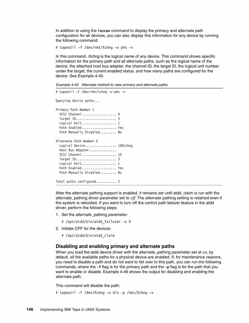
In addition to using the ioscan command to display the primary and alternate path configuration for all devices, you can also display this information for any device by running the following command:
# tapeutil -f /dev/rmt/Xchng -o phs -v
In this command, Xchng is the logical name of any device. This command shows specific information for the primary path and all alternate paths, such as the logical name of the device, the attached host bus adapter, the channel ID, the target ID, the logical unit number under the target, the current enabled status, and how many paths are configured for the device. See Example 4-45.
Example 4-45 Alternate method to view primary and alternate paths
# tapeutil -f /dev/rmt/1chng -o phs -v
Querying device paths...
Primary Path Number 1 SCSI Channel................... 9 Target ID...................... 3 Logical Unit................... 1 Path Enabled................... Yes Path Manually Disabled......... No
Alternate Path Number 2 Logical Device................. 1001chng Host Bus Adapter............... SCSI Channel................... 10 Target ID...................... 3 Logical Unit................... 1 Path Enabled................... Yes Path Manually Disabled......... No
Total paths configured........... 2
After the alternate pathing support is enabled, it remains set until atdd_claim is run with the alternate_pathing driver parameter set to off. The alternate pathing setting is retained even if the system is rebooted. If you want to turn off the control path failover feature in the atdd driver, perform the following steps:
1. Set the alternate_pathing parameter:
# /opt/atdd/bin/atdd_failover -a 0
2. Initiate CPF for the devices:
# /opt/atdd/bin/atdd_claim
Disabling and enabling primary and alternate pathsWhen you load the atdd device driver with the alternate_pathing parameter set at on, by default, all the available paths for a physical device are enabled. If, for maintenance reasons, you need to disable a path and do not want to fail over to this path, you can run the following commands, where the -f flag is for the primary path and the -p flag is for the path that you want to enable or disable. Example 4-46 shows the output for disabling and enabling the alternate path.
This command will disable the path:
# tapeutil -f /dev/Xchng -o dis -p /dev/Xchng -v
146 Implementing IBM Tape in UNIX Systems
To enable a path from a disabled state, run the following command:
# tapeutil -f /dev/Xchng -o ena -p /dev/Xchng -v
Example 4-46 Output for disabling and enabling the alternate path
***************************Disabling alternate path***************************
# tapeutil -f /dev/rmt/1chng -o dis -p /dev/rmt/1001chng.altpath -v
SCSI path disabled.
*********************************************Verifying alternate path has been disabled*********************************************
# tapeutil -f /dev/rmt/1chng -o phs -v
Querying device paths...
Primary Path Number 1 SCSI Channel................... 9 Target ID...................... 3 Logical Unit................... 1 Path Enabled................... Yes Path Manually Disabled......... No
Alternate Path Number 2 Logical Device................. 1001chng Host Bus Adapter............... SCSI Channel................... 10 Target ID...................... 3 Logical Unit................... 1 Path Enabled................... Yes Path Manually Disabled......... Yes
Total paths configured........... 2
***************************Enabling alternate path ***************************
# tapeutil -f /dev/rmt/1chng -o ena -p /dev/rmt/1001chng.altpath -v
SCSI path enabled.
********************************************Verifying alternate path has been enabled********************************************
# tapeutil -f /dev/rmt/1chng -o phs -v
Querying device paths...
Primary Path Number 1 SCSI Channel................... 9 Target ID...................... 3 Logical Unit................... 1 Path Enabled................... Yes
Chapter 4. Basic IBM tape setup for UNIX systems 147
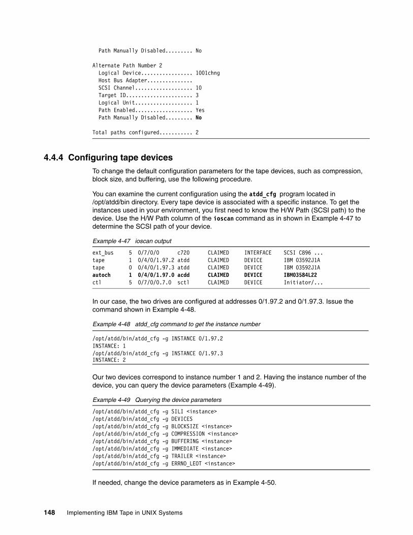
Path Manually Disabled......... No
Alternate Path Number 2 Logical Device................. 1001chng Host Bus Adapter............... SCSI Channel................... 10 Target ID...................... 3 Logical Unit................... 1 Path Enabled................... Yes Path Manually Disabled......... No
Total paths configured........... 2
4.4.4 Configuring tape devicesTo change the default configuration parameters for the tape devices, such as compression, block size, and buffering, use the following procedure.
You can examine the current configuration using the atdd_cfg program located in /opt/atdd/bin directory. Every tape device is associated with a specific instance. To get the instances used in your environment, you first need to know the H/W Path (SCSI path) to the device. Use the H/W Path column of the ioscan command as in shown in Example 4-47 to determine the SCSI path of your device.
Example 4-47 ioscan output
ext_bus 5 0/7/0/0 c720 CLAIMED INTERFACE SCSI C896 ...tape 1 0/4/0/1.97.2 atdd CLAIMED DEVICE IBM 03592J1Atape 0 0/4/0/1.97.3 atdd CLAIMED DEVICE IBM 03592J1Aautoch 1 0/4/0/1.97.0 acdd CLAIMED DEVICE IBM03584L22ctl 5 0/7/0/0.7.0 sctl CLAIMED DEVICE Initiator/...
In our case, the two drives are configured at addresses 0/1.97.2 and 0/1.97.3. Issue the command shown in Example 4-48.
Example 4-48 atdd_cfg command to get the instance number
/opt/atdd/bin/atdd_cfg -g INSTANCE 0/1.97.2INSTANCE: 1/opt/atdd/bin/atdd_cfg -g INSTANCE 0/1.97.3INSTANCE: 2
Our two devices correspond to instance number 1 and 2. Having the instance number of the device, you can query the device parameters (Example 4-49).
Example 4-49 Querying the device parameters
/opt/atdd/bin/atdd_cfg -g SILI <instance>/opt/atdd/bin/atdd_cfg -g DEVICES/opt/atdd/bin/atdd_cfg -g BLOCKSIZE <instance>/opt/atdd/bin/atdd_cfg -g COMPRESSION <instance>/opt/atdd/bin/atdd_cfg -g BUFFERING <instance>/opt/atdd/bin/atdd_cfg -g IMMEDIATE <instance>/opt/atdd/bin/atdd_cfg -g TRAILER <instance>/opt/atdd/bin/atdd_cfg -g ERRNO_LEOT <instance>
If needed, change the device parameters as in Example 4-50.
148 Implementing IBM Tape in UNIX Systems
Example 4-50 Changing the device parameters
/opt/atdd/bin/atdd_cfg -s SILI <sili> <instance>/opt/atdd/bin/atdd_cfg -s BLOCKSIZE <block size> <instance>/opt/atdd/bin/atdd_cfg -s COMPRESSION <compression> <instance>/opt/atdd/bin/atdd_cfg -s BUFFERING <buffering> <instance>/opt/atdd/bin/atdd_cfg -s IMMEDIATE <immediate> <instance>/opt/atdd/bin/atdd_cfg -s TRAILER <trailer> <instance>/opt/atdd/bin/atdd_cfg -s ERRNO_LEOT <errno_leot> <instance>
For example, to change COMPRESSION to 1 (On) for the device with instance 1:
/opt/atdd/bin/atdd_cfg -s COMPRESSION 1 1
Any changes made here will be lost when the server is rebooted. To make the changes permanent, add entries in the Configuring Parameters Section of the file /sbin/init.d/atdd, as shown in Example 4-51.
Example 4-51 Configuring Parameters Section of atdd configuration file
# Configuring Parameters Section # # modify the configuration parameters here, for example: # /opt/atdd/bin/atdd_cfg -s COMPRESSION 0 2
4.5 Testing the library with tapeutilThe tapeutil tape utility is installed with the IBM tape device drivers on Solaris and AIX, or as a separate package for HP-UX. This utility exercises or tests the functions of the tape device and the device driver. It also performs basic tape and medium changer operations. The tape utility program provides two user interfaces: the interactive menu and the UNIX command line.
Start the tapeutil interactive menu by typing tapeutil without any parameters. On AIX, this displays the menu shown in Figure 4-9. For Solaris and HP-UX, it is in a slightly different format.
Chapter 4. Basic IBM tape setup for UNIX systems 149
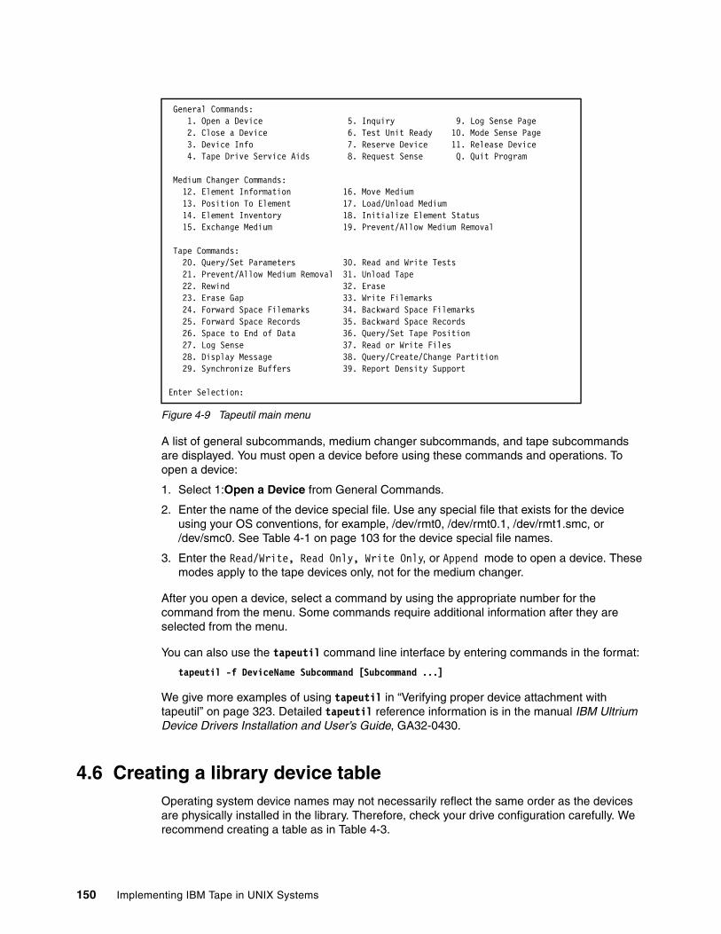
Figure 4-9 Tapeutil main menu
A list of general subcommands, medium changer subcommands, and tape subcommands are displayed. You must open a device before using these commands and operations. To open a device:
1. Select 1:Open a Device from General Commands.
2. Enter the name of the device special file. Use any special file that exists for the device using your OS conventions, for example, /dev/rmt0, /dev/rmt0.1, /dev/rmt1.smc, or /dev/smc0. See Table 4-1 on page 103 for the device special file names.
3. Enter the Read/Write, Read Only, Write Only, or Append mode to open a device. These modes apply to the tape devices only, not for the medium changer.
After you open a device, select a command by using the appropriate number for the command from the menu. Some commands require additional information after they are selected from the menu.
You can also use the tapeutil command line interface by entering commands in the format:
tapeutil -f DeviceName Subcommand [Subcommand ...]
We give more examples of using tapeutil in “Verifying proper device attachment with tapeutil” on page 323. Detailed tapeutil reference information is in the manual IBM Ultrium Device Drivers Installation and User’s Guide, GA32-0430.
4.6 Creating a library device tableOperating system device names may not necessarily reflect the same order as the devices are physically installed in the library. Therefore, check your drive configuration carefully. We recommend creating a table as in Table 4-3.
General Commands: 1. Open a Device 5. Inquiry 9. Log Sense Page 2. Close a Device 6. Test Unit Ready 10. Mode Sense Page 3. Device Info 7. Reserve Device 11. Release Device 4. Tape Drive Service Aids 8. Request Sense Q. Quit Program
Medium Changer Commands: 12. Element Information 16. Move Medium 13. Position To Element 17. Load/Unload Medium 14. Element Inventory 18. Initialize Element Status 15. Exchange Medium 19. Prevent/Allow Medium Removal
Tape Commands: 20. Query/Set Parameters 30. Read and Write Tests 21. Prevent/Allow Medium Removal 31. Unload Tape 22. Rewind 32. Erase 23. Erase Gap 33. Write Filemarks 24. Forward Space Filemarks 34. Backward Space Filemarks 25. Forward Space Records 35. Backward Space Records 26. Space to End of Data 36. Query/Set Tape Position 27. Log Sense 37. Read or Write Files 28. Display Message 38. Query/Create/Change Partition 29. Synchronize Buffers 39. Report Density Support
Enter Selection:
150 Implementing IBM Tape in UNIX Systems
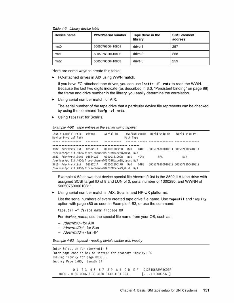
Table 4-3 Library device table
Here are some ways to create this table:
� FC-attached drives in AIX using WWN match.
If you have FC-attached tape drives, you can use lsattr -El rmtx to read the WWN. Because the last two digits indicate (as described in 3.3, “Persistent binding” on page 88) the frame and drive number in the library, you easily determine the correlation.
� Using serial number match for AIX.
The serial number of the tape drive that a particular device file represents can be checked by using the command lscfg -vl rmtx.
� Using tapelist for Solaris.
Example 4-52 Tape entries in the server using tapelist
Inst # Special File Device Serial No TGT/LUN Ucode World Wide NN World Wide PN Device Physical Path Path Type----- ------------- -------- ----------- ------- ------ ---------------- ---------------- ------------------------------------------------- -------3682 /dev/rmt/10st 03592J1A 000001300280 8/0 04B8 5005076300010811 5005076300410811 /devices/pci@1f,4000/fibre-channel@2/IBMtape@8,0:st N/A3683 /dev/rmt/13smc 03584L22 000001310008 8/1 404e N/A N/A /devices/pci@1f,4000/fibre-channel@2/IBMtape@8,1:smc N/A3715 /dev/rmt/12st 03592J1A 000001300178 9/0 04B8 5005076300010812 5005076300410812 /devices/pci@1f,4000/fibre-channel@2/IBMtape@9,0:st N/A
Example 4-52 shows that device special file /dev/rmt/10st is the 3592J1A tape drive with assigned SCSI target ID of 8 and LUN of 0, serial number of 1300280, and WWNN of 5005076300010811.
� Using serial number match in AIX, Solaris, and HP-UX platforms.
List the serial numbers of every created tape drive file name. Use tapeutil and inquiry option with page x80 as seen in Example 4-53, or use the command:
tapeutil -f device_name inqpage 80
For device_name, use the special file name from your OS, such as:
– /dev/rmt0 - for AIX– /dev/rmt/0st - for Sun– /dev/rmt/0m - for HP
Example 4-53 tapeutil - reading serial number with inquiry
Enter Selection for /dev/rmt1: 5Enter page code in hex or <enter> for standard inquiry: 80Issuing inquiry for page 0x80...Inquiry Page 0x80, Length 14
0 1 2 3 4 5 6 7 8 9 A B C D E F 0123456789ABCDEF 0000 - 0180 000A 3133 3130 3130 3131 3931 [. ..1110000237 ]
Device name WWN/serial number Tape drive in the library
SCSI element address
rmt0 5005076300410801 drive 1 257
rmt1 5005076300410802 drive 2 258
rmt2 5005076300410803 drive 3 259
Chapter 4. Basic IBM tape setup for UNIX systems 151

Compare this serial number to the number written on the drives in the library. You can also determine the serial by correlating the SCSI element address on the medium changer (Example 4-54) using the following commands:
For AIX and Solaris:
tapeutil -f device_name devids
For HP-UX:
tapeutil -f device_name -o dvc
For device_name, use the medium changer special file name from your OS, such as:
– /dev/smc0 - for AIX– /dev/rmt/0smc- for Sun– /dev/rmt/0chng - for HP
Example 4-54 tapeutil - reading serial number with inquiry
tapeutil -f /dev/smc2 devidsReading element device ids...
Drive Address 257 Drive State .................... Abnormal ASC/ASCQ ....................... 8100 (Drive Present) Media Present .................. No Robot Access Allowed ........... No Source Element Address Valid ... No Media Inverted ................. No Same Bus as Medium Changer ..... Yes SCSI Bus Address Vaild ......... No Logical Unit Number Valid ...... No Device ID ...................... IBM ULT3580-TD2 1110000237
Drive Address 258 Drive State .................... Abnormal ASC/ASCQ ....................... 8100 (Drive Present) Media Present .................. No Robot Access Allowed ........... No Source Element Address Valid ... No Media Inverted ................. No Same Bus as Medium Changer ..... Yes SCSI Bus Address Vaild ......... No Logical Unit Number Valid ...... No Device ID ...................... IBM ULT3580-TD1 1310102528
Using this output, we can complete Table 4-4.
Table 4-4 Library device table
4.7 Fibre Channel HBA driver installationUp to now, we have focused on direct SCSI attachment. You can also connect LTO Ultrium tape libraries and drives on a SAN using either direct Fibre Channel attach (using native FC
Device name Serial number Tape drive in the library
SCSI element address
rmt1 1110000237 drive 1 257
152 Implementing IBM Tape in UNIX Systems
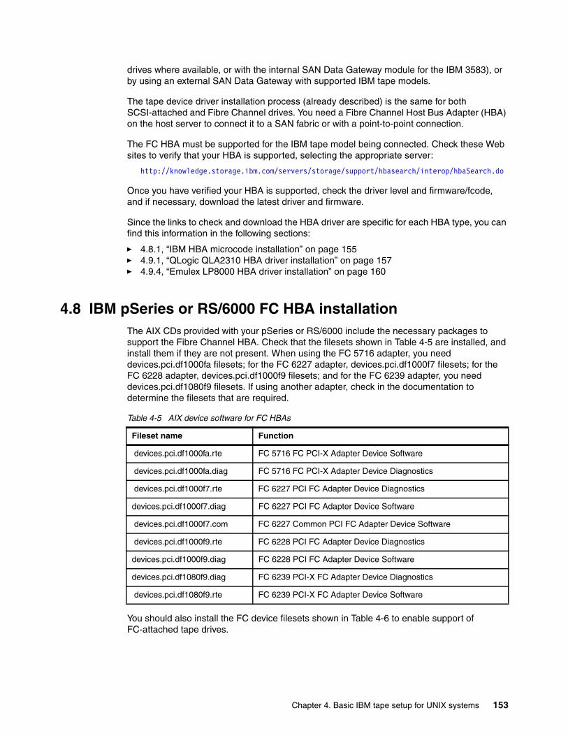
drives where available, or with the internal SAN Data Gateway module for the IBM 3583), or by using an external SAN Data Gateway with supported IBM tape models.
The tape device driver installation process (already described) is the same for both SCSI-attached and Fibre Channel drives. You need a Fibre Channel Host Bus Adapter (HBA) on the host server to connect it to a SAN fabric or with a point-to-point connection.
The FC HBA must be supported for the IBM tape model being connected. Check these Web sites to verify that your HBA is supported, selecting the appropriate server:
http://knowledge.storage.ibm.com/servers/storage/support/hbasearch/interop/hbaSearch.do
Once you have verified your HBA is supported, check the driver level and firmware/fcode, and if necessary, download the latest driver and firmware.
Since the links to check and download the HBA driver are specific for each HBA type, you can find this information in the following sections:
� 4.8.1, “IBM HBA microcode installation” on page 155� 4.9.1, “QLogic QLA2310 HBA driver installation” on page 157� 4.9.4, “Emulex LP8000 HBA driver installation” on page 160
4.8 IBM pSeries or RS/6000 FC HBA installationThe AIX CDs provided with your pSeries or RS/6000 include the necessary packages to support the Fibre Channel HBA. Check that the filesets shown in Table 4-5 are installed, and install them if they are not present. When using the FC 5716 adapter, you need devices.pci.df1000fa filesets; for the FC 6227 adapter, devices.pci.df1000f7 filesets; for the FC 6228 adapter, devices.pci.df1000f9 filesets; and for the FC 6239 adapter, you need devices.pci.df1080f9 filesets. If using another adapter, check in the documentation to determine the filesets that are required.
Table 4-5 AIX device software for FC HBAs
You should also install the FC device filesets shown in Table 4-6 to enable support of FC-attached tape drives.
Fileset name Function
devices.pci.df1000fa.rte FC 5716 FC PCI-X Adapter Device Software
devices.pci.df1000fa.diag FC 5716 FC PCI-X Adapter Device Diagnostics
devices.pci.df1000f7.rte FC 6227 PCI FC Adapter Device Diagnostics
devices.pci.df1000f7.diag FC 6227 PCI FC Adapter Device Software
devices.pci.df1000f7.com FC 6227 Common PCI FC Adapter Device Software
devices.pci.df1000f9.rte FC 6228 PCI FC Adapter Device Diagnostics
devices.pci.df1000f9.diag FC 6228 PCI FC Adapter Device Software
devices.pci.df1080f9.diag FC 6239 PCI-X FC Adapter Device Diagnostics
devices.pci.df1080f9.rte FC 6239 PCI-X FC Adapter Device Software
Chapter 4. Basic IBM tape setup for UNIX systems 153
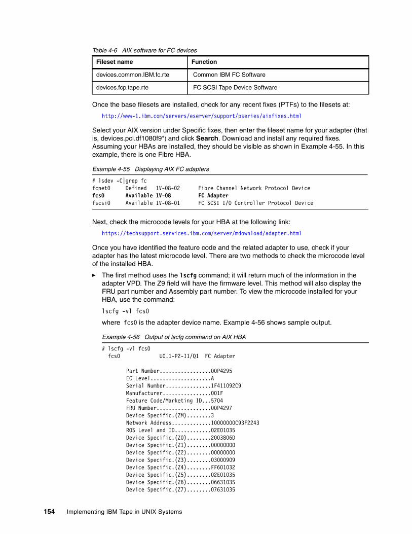
Table 4-6 AIX software for FC devices
Once the base filesets are installed, check for any recent fixes (PTFs) to the filesets at:
http://www-1.ibm.com/servers/eserver/support/pseries/aixfixes.html
Select your AIX version under Specific fixes, then enter the fileset name for your adapter (that is, devices.pci.df1080f9*) and click Search. Download and install any required fixes. Assuming your HBAs are installed, they should be visible as shown in Example 4-55. In this example, there is one Fibre HBA.
Example 4-55 Displaying AIX FC adapters
# lsdev -C|grep fcfcnet0 Defined 1V-08-02 Fibre Channel Network Protocol Devicefcs0 Available 1V-08 FC Adapterfscsi0 Available 1V-08-01 FC SCSI I/O Controller Protocol Device
Next, check the microcode levels for your HBA at the following link:
https://techsupport.services.ibm.com/server/mdownload/adapter.html
Once you have identified the feature code and the related adapter to use, check if your adapter has the latest microcode level. There are two methods to check the microcode level of the installed HBA.
� The first method uses the lscfg command; it will return much of the information in the adapter VPD. The Z9 field will have the firmware level. This method will also display the FRU part number and Assembly part number. To view the microcode installed for your HBA, use the command:
lscfg -vl fcs0
where fcs0 is the adapter device name. Example 4-56 shows sample output.
Example 4-56 Output of lscfg command on AIX HBA
# lscfg -vl fcs0 fcs0 U0.1-P2-I1/Q1 FC Adapter
Part Number.................00P4295 EC Level....................A Serial Number...............1F411092C9 Manufacturer................001F Feature Code/Marketing ID...5704 FRU Number..................00P4297 Device Specific.(ZM)........3 Network Address.............10000000C93F2243 ROS Level and ID............02E01035 Device Specific.(Z0)........2003806D Device Specific.(Z1)........00000000 Device Specific.(Z2)........00000000 Device Specific.(Z3)........03000909 Device Specific.(Z4)........FF601032 Device Specific.(Z5)........02E01035 Device Specific.(Z6)........06631035 Device Specific.(Z7)........07631035
Fileset name Function
devices.common.IBM.fc.rte Common IBM FC Software
devices.fcp.tape.rte FC SCSI Tape Device Software
154 Implementing IBM Tape in UNIX Systems
Device Specific.(Z8)........20000000C93F2243 Device Specific.(Z9)........HS1.00X5 Device Specific.(ZA)........H1D1.00X5 Device Specific.(ZB)........H2D1.00X5 Device Specific.(YL)........U0.1-P2-I1/Q1
In this example, the HBA microcode level is 1.00X5 as shown in the Z9 field.
� The second method uses the lsmcode command, which returns the extension of the firmware image file that is installed.
lsmcode -d fcs0
where fcs0 is the adapter device name. Example 4-57 shows sample output.
Example 4-57 Output of lsmcode command on AIX HBA
DISPLAY MICROCODE LEVELfcs0 FC Adapter
The current microcode level for fcs0 is 100305.
Use Enter to continue.
In this example, 100305 is the extension of the firmware image (df1080f9.100305) that was last loaded on the adapter.
If the adapter microcode is not at the level as listed on the Web site, download the file from the Web site with either the AIX (.bin file) or RPM format package, and follow the installation instructions. Next is an example of how to update the microcode installation.
4.8.1 IBM HBA microcode installationIn this example, we describe how to install the file pci.df1080f9-1-81X1.rpm, corresponding to the microcode level 1.41.A2 for an adapter FC6239.
Log in as root, and perform the following steps to install the FLASH code into your adapter:
1. Make a directory to receive the RPM format file.
mkdir /etc/microcode
2. Transfer the RPM format file to a temporary directory on the target server.
For our example the filename is pci.df1080f9-1-81X1.rpm
3. Be careful to follow the pSeries microcode download procedure. There is a link in the microcode Web site that points to:
https://techsupport.services.ibm.com/server/mdownload/downproc.html
This is where you can obtain the password needed to decompress the zip file.
4. Unpack the file by executing the following instructions:
rpm -ihv --ignoreos pci.df1080f9-1-81X1.rpm
The file size and checksum will be verified.
Filesize: 455308 bytes Checksum: 45802
5. Ensure there is no activity running on the adapter. Vary off all volume groups associated with the adapter.
Chapter 4. Basic IBM tape setup for UNIX systems 155
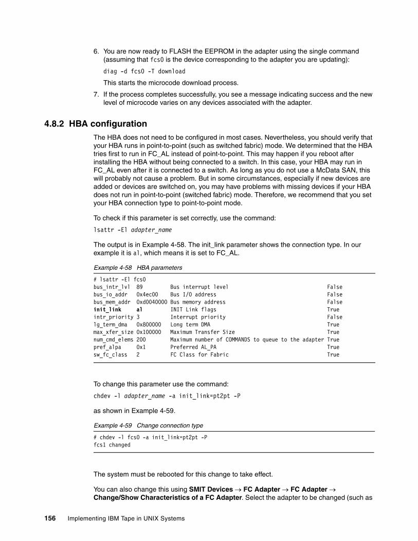
6. You are now ready to FLASH the EEPROM in the adapter using the single command (assuming that fcs0 is the device corresponding to the adapter you are updating):
diag -d fcs0 -T download
This starts the microcode download process.
7. If the process completes successfully, you see a message indicating success and the new level of microcode varies on any devices associated with the adapter.
4.8.2 HBA configurationThe HBA does not need to be configured in most cases. Nevertheless, you should verify that your HBA runs in point-to-point (such as switched fabric) mode. We determined that the HBA tries first to run in FC_AL instead of point-to-point. This may happen if you reboot after installing the HBA without being connected to a switch. In this case, your HBA may run in FC_AL even after it is connected to a switch. As long as you do not use a McData SAN, this will probably not cause a problem. But in some circumstances, especially if new devices are added or devices are switched on, you may have problems with missing devices if your HBA does not run in point-to-point (switched fabric) mode. Therefore, we recommend that you set your HBA connection type to point-to-point mode.
To check if this parameter is set correctly, use the command:
lsattr -El adapter_name
The output is in Example 4-58. The init_link parameter shows the connection type. In our example it is al, which means it is set to FC_AL.
Example 4-58 HBA parameters
# lsattr -El fcs0bus_intr_lvl 89 Bus interrupt level Falsebus_io_addr 0x4ec00 Bus I/O address Falsebus_mem_addr 0xd0040000 Bus memory address Falseinit_link al INIT Link flags Trueintr_priority 3 Interrupt priority Falselg_term_dma 0x800000 Long term DMA Truemax_xfer_size 0x100000 Maximum Transfer Size Truenum_cmd_elems 200 Maximum number of COMMANDS to queue to the adapter Truepref_alpa 0x1 Preferred AL_PA Truesw_fc_class 2 FC Class for Fabric True
To change this parameter use the command:
chdev -l adapter_name -a init_link=pt2pt -P
as shown in Example 4-59.
Example 4-59 Change connection type
# chdev -l fcs0 -a init_link=pt2pt -Pfcs1 changed
The system must be rebooted for this change to take effect.
You can also change this using SMIT Devices → FC Adapter → FC Adapter → Change/Show Characteristics of a FC Adapter. Select the adapter to be changed (such as
156 Implementing IBM Tape in UNIX Systems
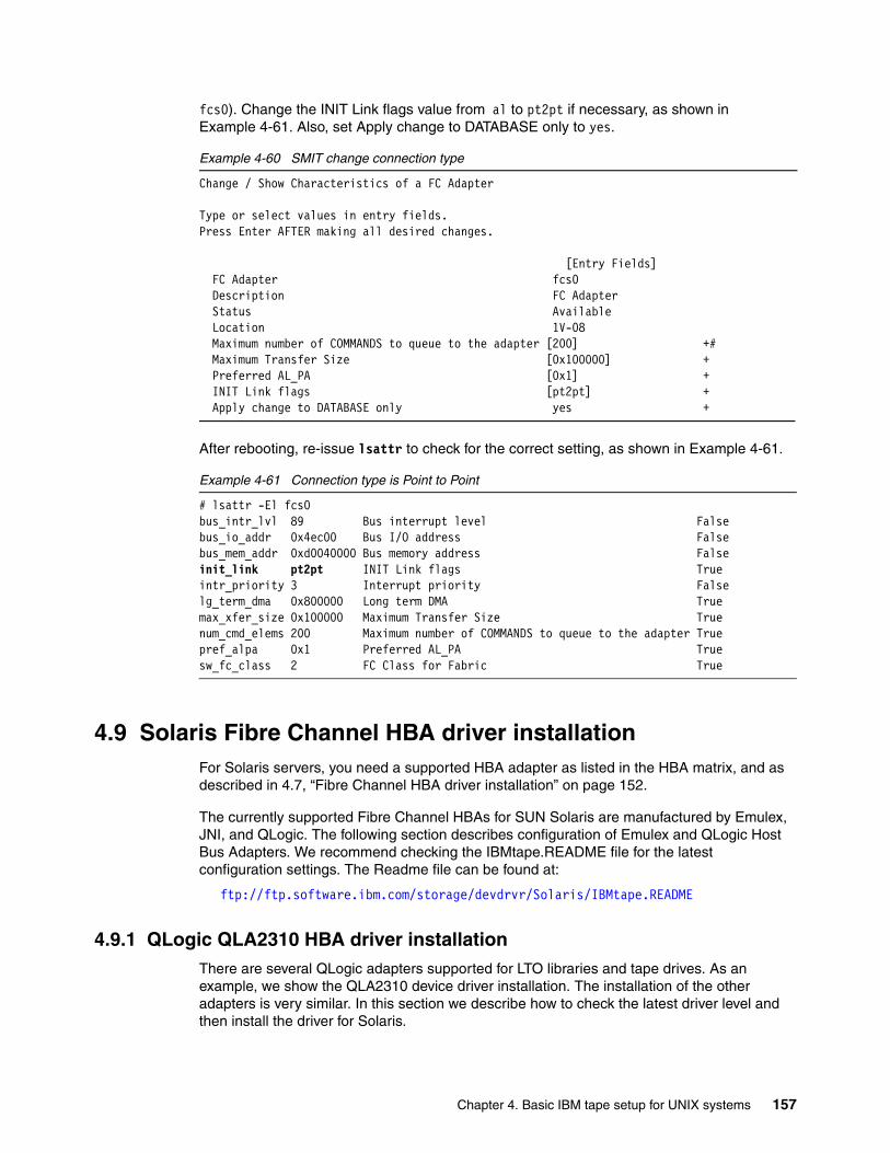
fcs0). Change the INIT Link flags value from al to pt2pt if necessary, as shown in Example 4-61. Also, set Apply change to DATABASE only to yes.
Example 4-60 SMIT change connection type
Change / Show Characteristics of a FC Adapter
Type or select values in entry fields.Press Enter AFTER making all desired changes.
[Entry Fields] FC Adapter fcs0 Description FC Adapter Status Available Location 1V-08 Maximum number of COMMANDS to queue to the adapter [200] +# Maximum Transfer Size [0x100000] + Preferred AL_PA [0x1] + INIT Link flags [pt2pt] + Apply change to DATABASE only yes +
After rebooting, re-issue lsattr to check for the correct setting, as shown in Example 4-61.
Example 4-61 Connection type is Point to Point
# lsattr -El fcs0bus_intr_lvl 89 Bus interrupt level Falsebus_io_addr 0x4ec00 Bus I/O address Falsebus_mem_addr 0xd0040000 Bus memory address Falseinit_link pt2pt INIT Link flags Trueintr_priority 3 Interrupt priority Falselg_term_dma 0x800000 Long term DMA Truemax_xfer_size 0x100000 Maximum Transfer Size Truenum_cmd_elems 200 Maximum number of COMMANDS to queue to the adapter Truepref_alpa 0x1 Preferred AL_PA Truesw_fc_class 2 FC Class for Fabric True
4.9 Solaris Fibre Channel HBA driver installationFor Solaris servers, you need a supported HBA adapter as listed in the HBA matrix, and as described in 4.7, “Fibre Channel HBA driver installation” on page 152.
The currently supported Fibre Channel HBAs for SUN Solaris are manufactured by Emulex, JNI, and QLogic. The following section describes configuration of Emulex and QLogic Host Bus Adapters. We recommend checking the IBMtape.README file for the latest configuration settings. The Readme file can be found at:
ftp://ftp.software.ibm.com/storage/devdrvr/Solaris/IBMtape.README
4.9.1 QLogic QLA2310 HBA driver installationThere are several QLogic adapters supported for LTO libraries and tape drives. As an example, we show the QLA2310 device driver installation. The installation of the other adapters is very similar. In this section we describe how to check the latest driver level and then install the driver for Solaris.
Chapter 4. Basic IBM tape setup for UNIX systems 157
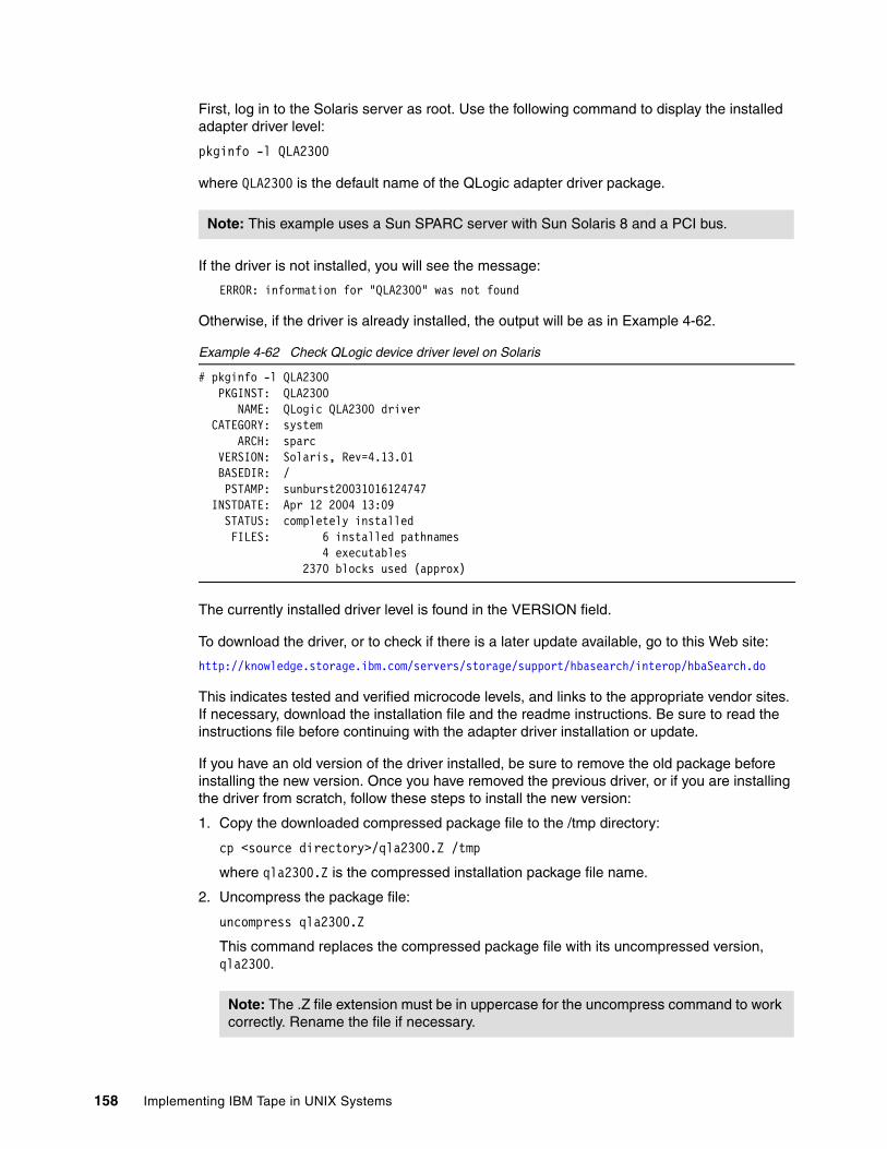
First, log in to the Solaris server as root. Use the following command to display the installed adapter driver level:
pkginfo -l QLA2300
where QLA2300 is the default name of the QLogic adapter driver package.
If the driver is not installed, you will see the message:
ERROR: information for "QLA2300" was not found
Otherwise, if the driver is already installed, the output will be as in Example 4-62.
Example 4-62 Check QLogic device driver level on Solaris
# pkginfo -l QLA2300 PKGINST: QLA2300 NAME: QLogic QLA2300 driver CATEGORY: system ARCH: sparc VERSION: Solaris, Rev=4.13.01 BASEDIR: / PSTAMP: sunburst20031016124747 INSTDATE: Apr 12 2004 13:09 STATUS: completely installed FILES: 6 installed pathnames 4 executables 2370 blocks used (approx)
The currently installed driver level is found in the VERSION field.
To download the driver, or to check if there is a later update available, go to this Web site:
http://knowledge.storage.ibm.com/servers/storage/support/hbasearch/interop/hbaSearch.do
This indicates tested and verified microcode levels, and links to the appropriate vendor sites. If necessary, download the installation file and the readme instructions. Be sure to read the instructions file before continuing with the adapter driver installation or update.
If you have an old version of the driver installed, be sure to remove the old package before installing the new version. Once you have removed the previous driver, or if you are installing the driver from scratch, follow these steps to install the new version:
1. Copy the downloaded compressed package file to the /tmp directory:
cp <source directory>/qla2300.Z /tmp
where qla2300.Z is the compressed installation package file name.
2. Uncompress the package file:
uncompress qla2300.Z
This command replaces the compressed package file with its uncompressed version, qla2300.
Note: This example uses a Sun SPARC server with Sun Solaris 8 and a PCI bus.
Note: The .Z file extension must be in uppercase for the uncompress command to work correctly. Rename the file if necessary.
158 Implementing IBM Tape in UNIX Systems
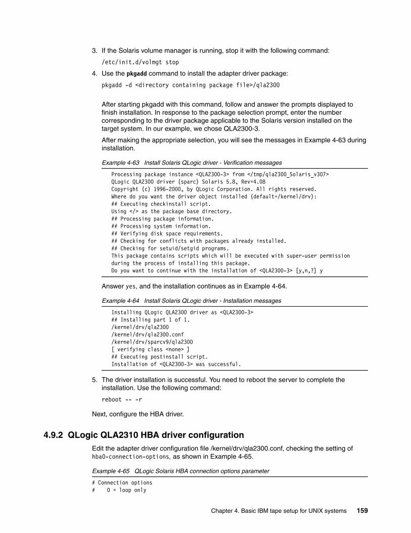
3. If the Solaris volume manager is running, stop it with the following command:
/etc/init.d/volmgt stop
4. Use the pkgadd command to install the adapter driver package:
pkgadd -d <directory containing package file>/qla2300
After starting pkgadd with this command, follow and answer the prompts displayed to finish installation. In response to the package selection prompt, enter the number corresponding to the driver package applicable to the Solaris version installed on the target system. In our example, we chose QLA2300-3.
After making the appropriate selection, you will see the messages in Example 4-63 during installation.
Example 4-63 Install Solaris QLogic driver - Verification messages
Processing package instance <QLA2300-3> from </tmp/qla2300_Solaris_v307>QLogic QLA2300 driver (sparc) Solaris 5.8, Rev=4.08Copyright (c) 1996-2000, by QLogic Corporation. All rights reserved.Where do you want the driver object installed (default=/kernel/drv): ## Executing checkinstall script.Using </> as the package base directory.## Processing package information.## Processing system information.## Verifying disk space requirements.## Checking for conflicts with packages already installed.## Checking for setuid/setgid programs.This package contains scripts which will be executed with super-user permission during the process of installing this package.Do you want to continue with the installation of <QLA2300-3> [y,n,?] y
Answer yes, and the installation continues as in Example 4-64.
Example 4-64 Install Solaris QLogic driver - Installation messages
Installing QLogic QLA2300 driver as <QLA2300-3>## Installing part 1 of 1./kernel/drv/qla2300/kernel/drv/qla2300.conf/kernel/drv/sparcv9/qla2300[ verifying class <none> ]## Executing postinstall script.Installation of <QLA2300-3> was successful.
5. The driver installation is successful. You need to reboot the server to complete the installation. Use the following command:
reboot -- -r
Next, configure the HBA driver.
4.9.2 QLogic QLA2310 HBA driver configurationEdit the adapter driver configuration file /kernel/drv/qla2300.conf, checking the setting of hba0-connection-options, as shown in Example 4-65.
Example 4-65 QLogic Solaris HBA connection options parameter
# Connection options# 0 = loop only
Chapter 4. Basic IBM tape setup for UNIX systems 159
# 1 = point-to-point only# 2 = loop preferred, otherwise point-to-pointhba0-connection-options=1;
We are connecting the LTO library to the Sun server through a SAN. Point-to-point (value 1) is the correct option, which means the HBA uses fabric login (N-Port) to the switch.
Next check that hba0-fc-tape is set to 1 (as in Example 4-66) to enable support of Fibre Channel tape drives.
Example 4-66 QLogic Solaris HBA FC tape support parameter
# Fibre Channel tape support enable/disable.# 0 = disable, 1 = enabledhba0-fc-tape=1;
If you are connecting the adapter to a SAN fabric switch, you may need to change other adapter configuration settings. See 3.3.2, “Persistent binding with QLogic HBA on Solaris” on page 93 for more information.
4.9.3 QLogic HBA FCodeQLogic HBAs (QLA2200 and higher) also have FCode (like microcode), which can be downloaded from the QLogic Web site, and installed into flash ROM from the Solaris operating system. You can find which firmware level was tested by IBM at this Web site:
http://knowledge.storage.ibm.com/servers/storage/support/hbasearch/interop/hbaSearch.do
Instructions and the FCode for the Qlogic HBAs are available at:
http://www.qlogic.com
4.9.4 Emulex LP8000 HBA driver installationThe are several Emulex adapters supported for LTO libraries and tape drives. We describe the LP8000 device driver installation in this section. The installation of the other adapters is similar.
First, log in to Solaris as root. Use the following command to display the installed adapter driver level:
pkginfo -l lpfc
where lpfc is the default name of the Emulex adapter driver package.
If the driver is not installed, you will see the message:
ERROR: information for "lpfc" was not found
Otherwise, if the driver is already installed, the output will be as in Example 4-67.
Example 4-67 Check Emulex device driver level on Solaris
PKGINST: lpfc NAME: Emulex LightPulse FC SCSI/IP Host Bus Adapter driver CATEGORY: system ARCH: sun4u
Note: This example uses a Sun SPARC server with Sun Solaris 7 and a PCI bus.
160 Implementing IBM Tape in UNIX Systems
VERSION: Release 4.20k BASEDIR: / PSTAMP: ultrapci20010531121050 INSTDATE: Aug 10 2001 10:37 STATUS: completely installed FILES: 44 installed pathnames 14 shared pathnames 12 directories 13 executables 8013 blocks used (approx)
The currently installed driver level is found in the VERSION field.
To download the driver, or to check if there is a later update available, go to this Web site:
http://knowledge.storage.ibm.com/servers/storage/support/hbasearch/interop/hbaSearch.do
This indicates tested and verified microcode levels, and provides links to the appropriate vendor sites. If an upgrade of the driver is required, or if you are installing the driver for the first time, download the installation file.
Detailed installation instructions for the LP8000 adapter (PCI) are at:
http://www.emulex.com/ts/fc/docs/frame8k.htm
Instructions for the LP8000S adapter (Sbus) are at:
http://www.emulex.com/ts/fc/docs/frame8ks.htm
Click the Drivers for Solaris link and you will find the installation information in the Documentation column. Be sure to read this information before continuing the driver installation.
If you have an old version of the driver installed, remove it before installing the newer version. Once you have removed the previous driver, or if you are installing the driver from scratch, follow these steps to install the new version:
1. Download the device driver file to a temporary directory, for example, /tmp, then untar it:
tar xvf lpfc-sparc.tar
where lpfc-sparc.tar is the compressed adapter driver package file. This command creates subdirectories and unpacks the installation files.
2. Install the package using the command:
pkgadd -d 'pwd'
You will be prompted to respond as in Example 4-68.
Example 4-68 Install Solaris Emulex driver - select package
The following packages are available: 1 lpfc.1 Emulex LightPulse FC SCSI/IP Host Bus Adapter driver (sun4u) Release 4.20kSelect package(s) you wish to process (or 'all' to process all packages). (default: all) [?,??,q]:
Press Enter; the messages in Example 4-69 follow.
Example 4-69 Install Solaris Emulex driver - install man pages
Processing package instance <lpfc.1> from </emlxtemp>
Chapter 4. Basic IBM tape setup for UNIX systems 161
Emulex LightPulse FC SCSI/IP Host Bus Adapter driver(sun4u) Release 4.20k lpfc (FCP) / lpfn (IP) combo driver Copyright (c) 1997, 1998, 1999, 2000 Emulex Corporation 3535 Harbor Boulevard, Costa Mesa, CA 92626All rights reserved. This product and related documentation is protected by copyright and distributed under licenses restricting its use, copying, distribution and decompilation. No part of this product or related documentation may be reproduced in any form by any means without prior written authorization of Emulex Corporation and its licensors, if any.CAUTION: The lpfc driver will not work with any release of Solaris/SunOS earlier than 2.6/5.6. However, even for later releases, lpfc may have to be compiled specifically for that release of Solaris. This version of lpfc has been built under Solaris/SunOS 5.7 for sun4u.Rebuild manual pages database for section 7d [y,n,?] y
Answer yes [y] if you want to include the driver information in the man pages.
Use IP networking over Fibre Channel [y,n,?] n
Answer no [n] if you do not need the IP protocol over Fibre Channel. This protocol is not used by LTO. Installation continues as in Example 4-70.
Example 4-70 Install Solaris Emulex driver - installation messages
Using </> as the package base directory.## Processing package information.## Processing system information. 6 package pathnames are already properly installed.## Verifying disk space requirements.## Checking for conflicts with packages already installed.## Checking for setuid/setgid programs.This package contains scripts which will be executed with super-user permission during the process of installing this package.Do you want to continue with the installation of <lpfc> [y,n,?] yInstalling Emulex LightPulse FC SCSI/IP Host Bus Adapter driver as <lpfc>## Installing part 1 of 1.[ verifying class <none> ]/usr/share/man/man7d/lpfc.7d/usr/share/man/man7d/lpfn.7d[ verifying class <manpage> ]/kernel/drv/lpfc/kernel/drv/lpfc.conf/kernel/drv/lpfc.hotplug/kernel/drv/sparcv9/lpfc/kernel/drv/sparcv9/lpfc.hotplug[ verifying class <driver> ]/usr/include/fcdiag.h/usr/lib/libHBAAPI.so/usr/lib/libHBAAPIV6.so/usr/lib/libdfc.a/usr/lib/libemulexhbaapi.so/usr/lib/libemulexhbaapiV6.so/usr/lib/sparcv9/libHBAAPI.so/usr/lib/sparcv9/libdfc.a/usr/lib/sparcv9/libemulexhbaapi.so/usr/sbin/lpfc/CT_fmw/usr/sbin/lpfc/DD_fmw/usr/sbin/lpfc/REV_fmw/usr/sbin/lpfc/SF_fmw/usr/sbin/lpfc/convert_path_lpfc/usr/sbin/lpfc/dfc/usr/sbin/lpfc/dfc32
162 Implementing IBM Tape in UNIX Systems
/usr/sbin/lpfc/dfc64/usr/sbin/lpfc/download_fmw_lpfc/usr/sbin/lpfc/lputil/usr/sbin/lpfc/lputil32/usr/sbin/lpfc/lputil64/usr/sbin/lpfc/resetqdepth[ verifying class <diagnostic> ]Modifying /etc/path_to_instModifying /etc/systemModifying /kernel/drv/sd.conf[ verifying class <sed> ]## Executing postinstall script.cat: cannot open //etc/hba.confUpdating /kernel/drv/lpfc.confUpdating /etc/system (moddir)catman -M //usr/share/man -w 7dThis may take a while ...Driver lpfc added to system.Adding emulexapilibrary from //etc/hba.conf************IMPORTANT: You must reboot the system to start this driver.SCSI: If you are using lpfc to access disks, be sure to check the configuration file of your SCSI target driver (presumably sd.conf) to ensure that the driver will probe for all of the targets/luns in your environment.HOTPLUG: If you wish to run with HOTPLUG enabled you must manually: cp //kernel/drv/sparcv9/lpfc.hotplug //kernel/drv/sparcv9/lpfcNOTE: lpfc supports FCP and IP but wasn't configured for networking.ALL: Examine the contents of /kernel/drv/lpfc.conf for driver-specific variables and behavior.************Installation of <lpfc> was successful.
3. The installation of the driver is successful. You need to reboot the server to complete the installation. Use the following command:
reboot -- -r
Next, you need to configure the driver.
4.9.5 Emulex LP8000 HBA driver configurationEdit the adapter driver configuration file /kernel/drv/lpfc.conf, and check the topology parameter as in Example 4-71.
Example 4-71 Emulex Solaris HBA topology parameter
# topology: link topology for initializing the Fibre Channel connection.# 0 = attempt loop mode, if it fails attempt point-to-point mode# 2 = attempt point-to-point mode only# 4 = attempt loop mode only# 6 = attempt point-to-point mode, if it fails attempt loop mode# Set point-to-point mode if you want to run as an N_Port.# Set loop mode if you want to run as an NL_Port.topology=2;
We are connecting the LTO library to the Sun server through a SAN. Point-to-point (2) is the correct option, which means the HBA will use fabric login (N-Port) to the switch.
If you are connecting the adapter to a SAN fabric switch, you may need to change other configuration settings. See 3.3.3, “Persistent binding with Emulex HBA on Solaris” on page 95 for more information.
Chapter 4. Basic IBM tape setup for UNIX systems 163
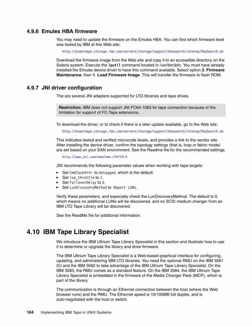
4.9.6 Emulex HBA firmware You may need to update the firmware on the Emulex HBA. You can find which firmware level was tested by IBM at this Web site:
http://knowledge.storage.ibm.com/servers/storage/support/hbasearch/interop/hbaSearch.do
Download the firmware image from the Web site and copy it to an accessible directory on the Solaris system. Execute the lputil command located in /usr/bin/lpfc. You must have already installed the Emulex device driver to have this command available. Select option 3. Firmware Maintenance, then 1. Load Firmware Image. This will transfer the firmware to flash ROM.
4.9.7 JNI driver configurationThe are several JNI adapters supported for LTO libraries and tape drives.
To download the driver, or to check if there is a later update available, go to the Web site:
http://knowledge.storage.ibm.com/servers/storage/support/hbasearch/interop/hbaSearch.do
This indicates tested and verified microcode levels, and provides a link to the vendor site. After installing the device driver, confirm the topology settings (that is, loop or fabric mode) are set based on your SAN environment. See the Readme file for the recommended settings.
http://www.jni.com/oem/oem.cfm?ID=4
JNI recommends the following parameter values when working with tape targets:
� Set CmdTaskAttr to Untagged, which is the default.� Set lun_throttle to 1. � Set FailoverDelay to 0.� Set LunDiscoveryMethod to Report LUNs.
Verify these parameters, and especially check the LunDiscoveryMethod. The default is 0, which means no additional LUNs will be discovered, and no SCSI medium changer from an IBM LTO Tape Library will be discovered.
See the ReadMe file for additional information.
4.10 IBM Tape Library SpecialistWe introduce the IBM Ultrium Tape Library Specialist in this section and illustrate how to use it to determine or upgrade the library and drive firmware.
The IBM Ultrium Tape Library Specialist is a Web-based graphical interface for configuring, updating, and administering IBM LTO libraries. You need the optional RMU on the IBM 3581 2U and the IBM 3582 to take advantage of the IBM Ultrium Tape Library Specialist. On the IBM 3583, the RMU comes as a standard feature. On the IBM 3584, the IBM Ultrium Tape Library Specialist is embedded in the firmware of the Media Changer Pack (MCP), which is part of the library.
The communication is through an Ethernet connection between the host (where the Web browser runs) and the RMU. The Ethernet speed is 10/100MB full duplex, and is auto-negotiated with the host or switch.
Restriction: IBM does not support JNI FC64-1063 for tape connection because of the limitation for support of FC-Tape extensions.
164 Implementing IBM Tape in UNIX Systems
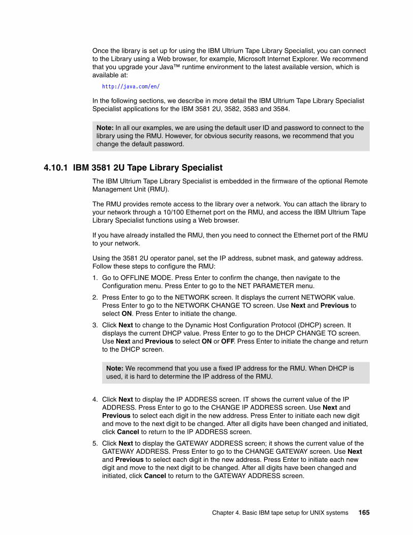
Once the library is set up for using the IBM Ultrium Tape Library Specialist, you can connect to the Library using a Web browser, for example, Microsoft Internet Explorer. We recommend that you upgrade your Java™ runtime environment to the latest available version, which is available at:
http://java.com/en/
In the following sections, we describe in more detail the IBM Ultrium Tape Library Specialist Specialist applications for the IBM 3581 2U, 3582, 3583 and 3584.
4.10.1 IBM 3581 2U Tape Library SpecialistThe IBM Ultrium Tape Library Specialist is embedded in the firmware of the optional Remote Management Unit (RMU).
The RMU provides remote access to the library over a network. You can attach the library to your network through a 10/100 Ethernet port on the RMU, and access the IBM Ultrium Tape Library Specialist functions using a Web browser.
If you have already installed the RMU, then you need to connect the Ethernet port of the RMU to your network.
Using the 3581 2U operator panel, set the IP address, subnet mask, and gateway address. Follow these steps to configure the RMU:
1. Go to OFFLINE MODE. Press Enter to confirm the change, then navigate to the Configuration menu. Press Enter to go to the NET PARAMETER menu.
2. Press Enter to go to the NETWORK screen. It displays the current NETWORK value. Press Enter to go to the NETWORK CHANGE TO screen. Use Next and Previous to select ON. Press Enter to initiate the change.
3. Click Next to change to the Dynamic Host Configuration Protocol (DHCP) screen. It displays the current DHCP value. Press Enter to go to the DHCP CHANGE TO screen. Use Next and Previous to select ON or OFF. Press Enter to initiate the change and return to the DHCP screen.
4. Click Next to display the IP ADDRESS screen. IT shows the current value of the IP ADDRESS. Press Enter to go to the CHANGE IP ADDRESS screen. Use Next and Previous to select each digit in the new address. Press Enter to initiate each new digit and move to the next digit to be changed. After all digits have been changed and initiated, click Cancel to return to the IP ADDRESS screen.
5. Click Next to display the GATEWAY ADDRESS screen; it shows the current value of the GATEWAY ADDRESS. Press Enter to go to the CHANGE GATEWAY screen. Use Next and Previous to select each digit in the new address. Press Enter to initiate each new digit and move to the next digit to be changed. After all digits have been changed and initiated, click Cancel to return to the GATEWAY ADDRESS screen.
Note: In all our examples, we are using the default user ID and password to connect to the library using the RMU. However, for obvious security reasons, we recommend that you change the default password.
Note: We recommend that you use a fixed IP address for the RMU. When DHCP is used, it is hard to determine the IP address of the RMU.
Chapter 4. Basic IBM tape setup for UNIX systems 165
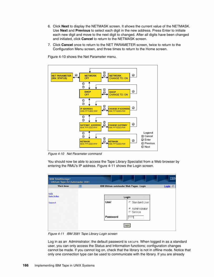
6. Click Next to display the NETMASK screen. It shows the current value of the NETMASK. Use Next and Previous to select each digit in the new address. Press Enter to initiate each new digit and move to the next digit to changed. After all digits have been changed and initiated, click Cancel to return to the NETMASK screen.
7. Click Cancel once to return to the NET PARAMETER screen, twice to return to the Configuration Menu screen, and three times to return to the Home screen.
Figure 4-10 shows the Net Parameter menu.
Figure 4-10 Net Parameter command
You should now be able to access the Tape Library Specialist from a Web browser by entering the RMU’s IP address. Figure 4-11 shows the Login screen.
Figure 4-11 IBM 3581 Tape Library Login screen
Log in as an Administrator; the default password is secure. When logged in as a standard user, you can only access the Status and Information functions; configuration changes cannot be made. If you cannot log on, check that the library is not in offline mode. Notice that only one connection type can be used to communicate with the library. If you are already
166 Implementing IBM Tape in UNIX Systems
logged on using the RMU, and then try to log on using the Operator Panel, a warning is displayed in the Operator Panel.
Click the Login button to log in. To operate and maintain the library, select Maintenance → Operations. This shows a quick status of the library and enables you to select the main operating tasks. See Figure 4-12.
Use the menu bar on the left of the panel to navigate between the menus. You can choose from the following options:
Information AutoloaderDrive
Status Autoloader MediaMedia
Configuration DeviceNetworkUserRTCLogEvent NotificationConfiguration Reset
Maintenance OperationsGeneral DiagnosticAdvanced DiagnosticFirmwareReset
Logs LoaderDrive
Figure 4-12 Maintenance screen
Chapter 4. Basic IBM tape setup for UNIX systems 167
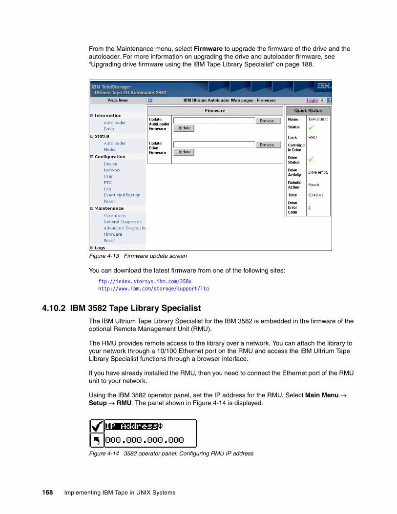
From the Maintenance menu, select Firmware to upgrade the firmware of the drive and the autoloader. For more information on upgrading the drive and autoloader firmware, see “Upgrading drive firmware using the IBM Tape Library Specialist” on page 188.
Figure 4-13 Firmware update screen
You can download the latest firmware from one of the following sites:
ftp://index.storsys.ibm.com/358xhttp://www.ibm.com/storage/support/lto
4.10.2 IBM 3582 Tape Library SpecialistThe IBM Ultrium Tape Library Specialist for the IBM 3582 is embedded in the firmware of the optional Remote Management Unit (RMU).
The RMU provides remote access to the library over a network. You can attach the library to your network through a 10/100 Ethernet port on the RMU and access the IBM Ultrium Tape Library Specialist functions through a browser interface.
If you have already installed the RMU, then you need to connect the Ethernet port of the RMU unit to your network.
Using the IBM 3582 operator panel, set the IP address for the RMU. Select Main Menu → Setup → RMU. The panel shown in Figure 4-14 is displayed.
Figure 4-14 3582 operator panel: Configuring RMU IP address
168 Implementing IBM Tape in UNIX Systems
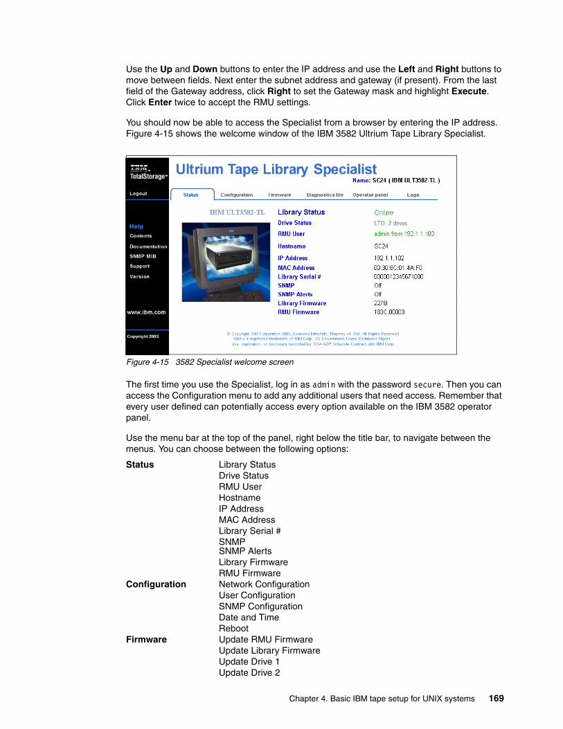
Use the Up and Down buttons to enter the IP address and use the Left and Right buttons to move between fields. Next enter the subnet address and gateway (if present). From the last field of the Gateway address, click Right to set the Gateway mask and highlight Execute. Click Enter twice to accept the RMU settings.
You should now be able to access the Specialist from a browser by entering the IP address. Figure 4-15 shows the welcome window of the IBM 3582 Ultrium Tape Library Specialist.
Figure 4-15 3582 Specialist welcome screen
The first time you use the Specialist, log in as admin with the password secure. Then you can access the Configuration menu to add any additional users that need access. Remember that every user defined can potentially access every option available on the IBM 3582 operator panel.
Use the menu bar at the top of the panel, right below the title bar, to navigate between the menus. You can choose between the following options:
Status Library StatusDrive StatusRMU UserHostnameIP AddressMAC AddressLibrary Serial #SNMPSNMP AlertsLibrary FirmwareRMU Firmware
Configuration Network ConfigurationUser ConfigurationSNMP ConfigurationDate and TimeReboot
Firmware Update RMU FirmwareUpdate Library FirmwareUpdate Drive 1Update Drive 2
Chapter 4. Basic IBM tape setup for UNIX systems 169
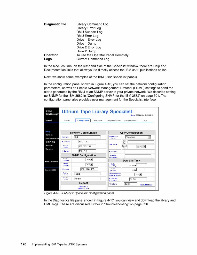
Diagnostic file Library Command LogLibrary Error LogRMU Support LogRMU Error LogDrive 1 Error LogDrive 1 DumpDrive 2 Error LogDrive 2 Dump
Operator To use the Operator Panel RemotelyLogs Current Command Log
In the black column, on the left-hand side of the Specialist window, there are Help and Documentation links that allow you to directly access the IBM 3582 publications online.
Next, we show some examples of the IBM 3582 Specialist panels.
In the configuration panel shown in Figure 4-16, you can set the network configuration parameters, as well as Simple Network Management Protocol (SNMP) settings to send the alerts generated by the RMU to an SNMP server in your private network. We describe setting up SNMP for the IBM 3582 in “Configuring SNMP for the IBM 3582” on page 301. The configuration panel also provides user management for the Specialist interface.
Figure 4-16 IBM 3582 Specialist: Configuration panel
In the Diagnostics file panel shown in Figure 4-17, you can view and download the library and RMU logs. These are discussed further in “Troubleshooting” on page 326.
170 Implementing IBM Tape in UNIX Systems
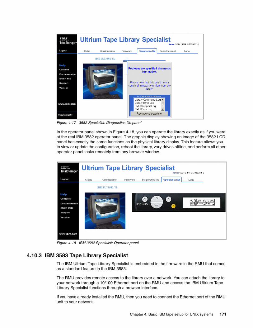
Figure 4-17 3582 Specialist: Diagnostics file panel
In the operator panel shown in Figure 4-18, you can operate the library exactly as if you were at the real IBM 3582 operator panel. The graphic display showing an image of the 3582 LCD panel has exactly the same functions as the physical library display. This feature allows you to view or update the configuration, reboot the library, vary drives offline, and perform all other operator panel tasks remotely from any browser window.
Figure 4-18 IBM 3582 Specialist: Operator panel
4.10.3 IBM 3583 Tape Library SpecialistThe IBM Ultrium Tape Library Specialist is embedded in the firmware in the RMU that comes as a standard feature in the IBM 3583.
The RMU provides remote access to the library over a network. You can attach the library to your network through a 10/100 Ethernet port on the RMU and access the IBM Ultrium Tape Library Specialist functions through a browser interface.
If you have already installed the RMU, then you need to connect the Ethernet port of the RMU unit to your network.
Chapter 4. Basic IBM tape setup for UNIX systems 171
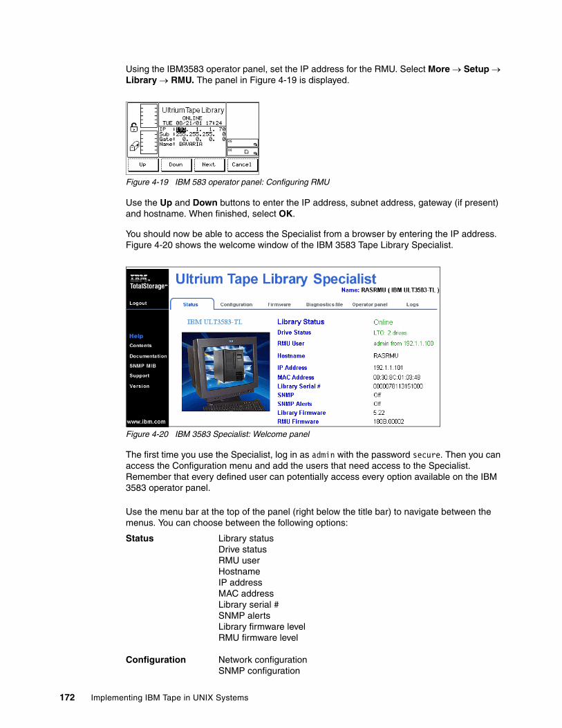
Using the IBM3583 operator panel, set the IP address for the RMU. Select More → Setup → Library → RMU. The panel in Figure 4-19 is displayed.
Figure 4-19 IBM 583 operator panel: Configuring RMU
Use the Up and Down buttons to enter the IP address, subnet address, gateway (if present) and hostname. When finished, select OK.
You should now be able to access the Specialist from a browser by entering the IP address. Figure 4-20 shows the welcome window of the IBM 3583 Tape Library Specialist.
Figure 4-20 IBM 3583 Specialist: Welcome panel
The first time you use the Specialist, log in as admin with the password secure. Then you can access the Configuration menu and add the users that need access to the Specialist. Remember that every defined user can potentially access every option available on the IBM 3583 operator panel.
Use the menu bar at the top of the panel (right below the title bar) to navigate between the menus. You can choose between the following options:
Status Library statusDrive statusRMU userHostnameIP addressMAC addressLibrary serial #SNMP alertsLibrary firmware levelRMU firmware level
Configuration Network configurationSNMP configuration
172 Implementing IBM Tape in UNIX Systems
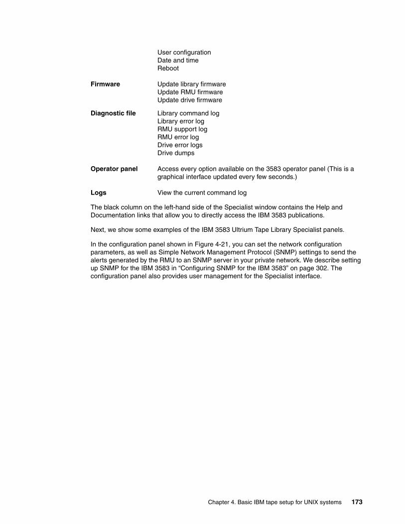
User configurationDate and timeReboot
Firmware Update library firmwareUpdate RMU firmwareUpdate drive firmware
Diagnostic file Library command logLibrary error logRMU support logRMU error logDrive error logsDrive dumps
Operator panel Access every option available on the 3583 operator panel (This is a graphical interface updated every few seconds.)
Logs View the current command log
The black column on the left-hand side of the Specialist window contains the Help and Documentation links that allow you to directly access the IBM 3583 publications.
Next, we show some examples of the IBM 3583 Ultrium Tape Library Specialist panels.
In the configuration panel shown in Figure 4-21, you can set the network configuration parameters, as well as Simple Network Management Protocol (SNMP) settings to send the alerts generated by the RMU to an SNMP server in your private network. We describe setting up SNMP for the IBM 3583 in “Configuring SNMP for the IBM 3583” on page 302. The configuration panel also provides user management for the Specialist interface.
Chapter 4. Basic IBM tape setup for UNIX systems 173
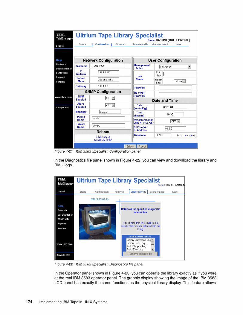
Figure 4-21 IBM 3583 Specialist: Configuration panel
In the Diagnostics file panel shown in Figure 4-22, you can view and download the library and RMU logs.
Figure 4-22 IBM 3583 Specialist: Diagnostics file panel
In the Operator panel shown in Figure 4-23, you can operate the library exactly as if you were at the real IBM 3583 operator panel. The graphic display showing the image of the IBM 3583 LCD panel has exactly the same functions as the physical library display. This feature allows
174 Implementing IBM Tape in UNIX Systems
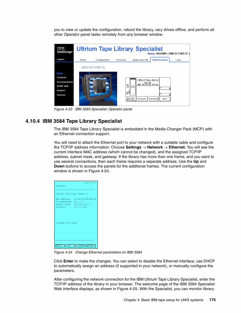
you to view or update the configuration, reboot the library, vary drives offline, and perform all other Operator panel tasks remotely from any browser window.
Figure 4-23 IBM 3583 Specialist: Operator panel
4.10.4 IBM 3584 Tape Library SpecialistThe IBM 3584 Tape Library Specialist is embedded in the Media Changer Pack (MCP) with an Ethernet connection support.
You will need to attach the Ethernet port to your network with a suitable cable and configure the TCP/IP address information. Choose Settings → Network → Ethernet. You will see the current interface MAC address (which cannot be changed), and the assigned TCP/IP address, subnet mask, and gateway. If the library has more than one frame, and you want to use several connections, then each frame requires a separate address. Use the Up and Down buttons to access the panels for the additional frames. The current configuration window is shown in Figure 4-24.
Figure 4-24 Change Ethernet parameters on IBM 3584
Click Enter to make the changes. You can select to disable the Ethernet interface, use DHCP to automatically assign an address (if supported in your network), or manually configure the parameters.
After configuring the network connection for the IBM Ultrium Tape Library Specialist, enter the TCP/IP address of the library in your browser. The welcome page of the IBM 3584 Specialist Web interface displays, as shown in Figure 4-25. With the Specialist, you can monitor library
Panel 0175
Ethernet______________________________
Current Settings Frame 1:
MAC Address: 18:36:F3:98:4F:9AIP Addresses: 10.1.1.1Subnet Mask: 255.255.255.0Gateway: 10.1.1.254
[Change Settings]
______________________________
BACK UP DOWN ENTER
Chapter 4. Basic IBM tape setup for UNIX systems 175
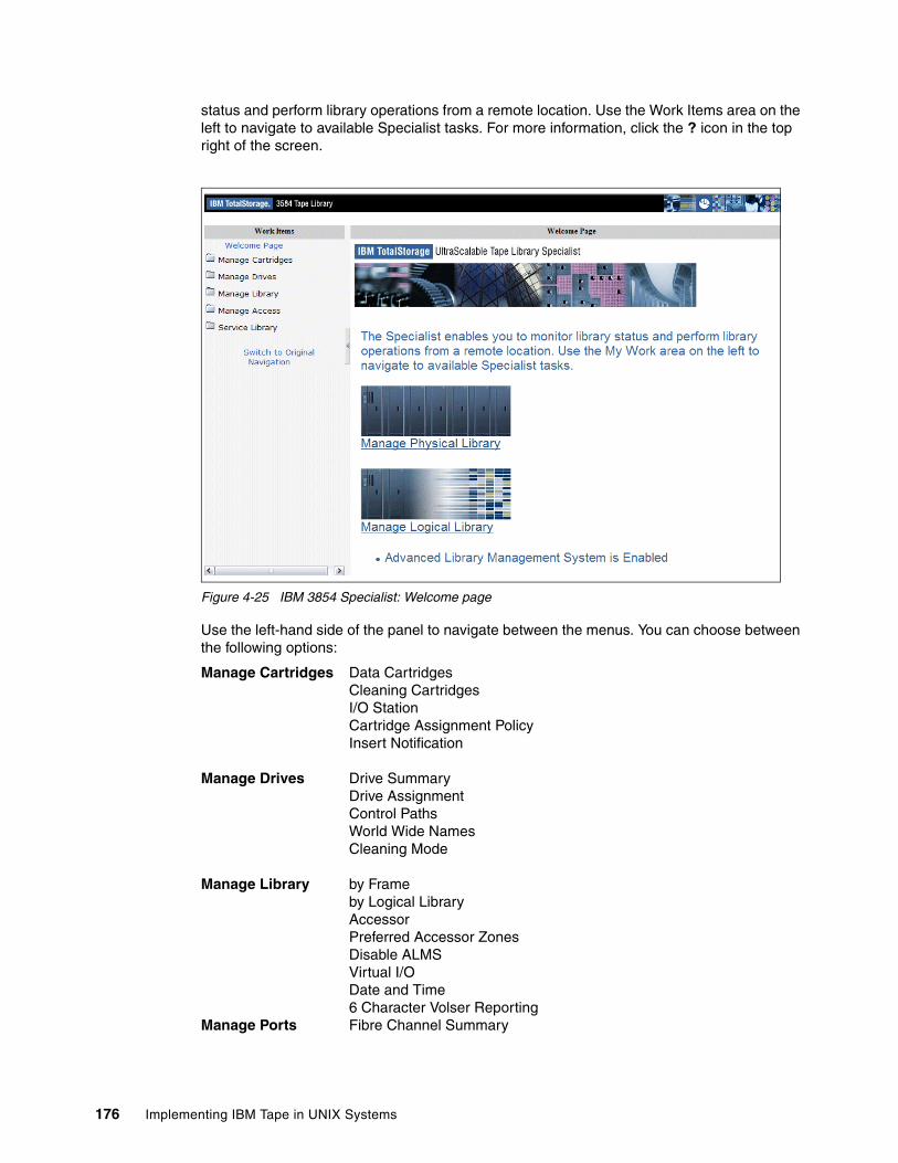
status and perform library operations from a remote location. Use the Work Items area on the left to navigate to available Specialist tasks. For more information, click the ? icon in the top right of the screen.
Figure 4-25 IBM 3854 Specialist: Welcome page
Use the left-hand side of the panel to navigate between the menus. You can choose between the following options:
Manage Cartridges Data CartridgesCleaning CartridgesI/O StationCartridge Assignment PolicyInsert Notification
Manage Drives Drive SummaryDrive AssignmentControl PathsWorld Wide NamesCleaning Mode
Manage Library by Frameby Logical LibraryAccessorPreferred Accessor ZonesDisable ALMSVirtual I/ODate and Time6 Character Volser Reporting
Manage Ports Fibre Channel Summary
176 Implementing IBM Tape in UNIX Systems
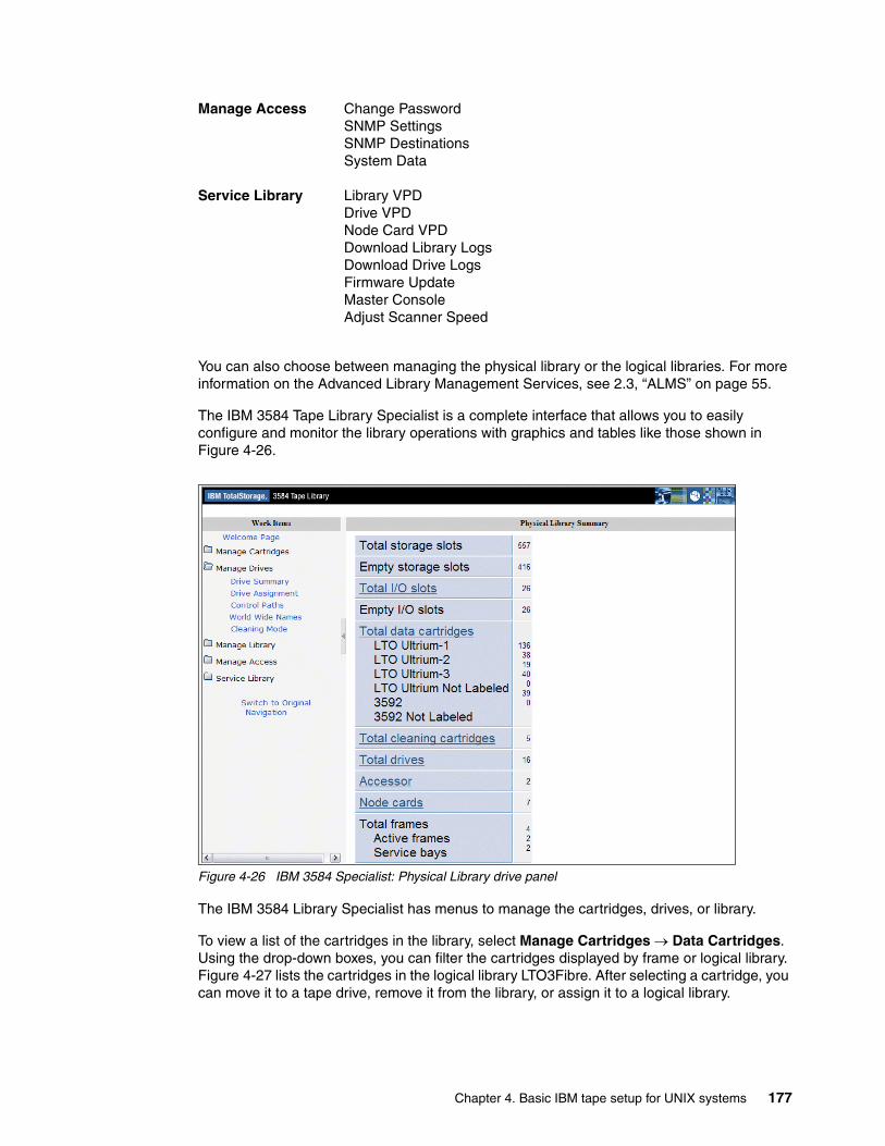
Manage Access Change PasswordSNMP SettingsSNMP DestinationsSystem Data
Service Library Library VPDDrive VPDNode Card VPDDownload Library LogsDownload Drive LogsFirmware UpdateMaster ConsoleAdjust Scanner Speed
You can also choose between managing the physical library or the logical libraries. For more information on the Advanced Library Management Services, see 2.3, “ALMS” on page 55.
The IBM 3584 Tape Library Specialist is a complete interface that allows you to easily configure and monitor the library operations with graphics and tables like those shown in Figure 4-26.
Figure 4-26 IBM 3584 Specialist: Physical Library drive panel
The IBM 3584 Library Specialist has menus to manage the cartridges, drives, or library.
To view a list of the cartridges in the library, select Manage Cartridges → Data Cartridges. Using the drop-down boxes, you can filter the cartridges displayed by frame or logical library. Figure 4-27 lists the cartridges in the logical library LTO3Fibre. After selecting a cartridge, you can move it to a tape drive, remove it from the library, or assign it to a logical library.
Chapter 4. Basic IBM tape setup for UNIX systems 177
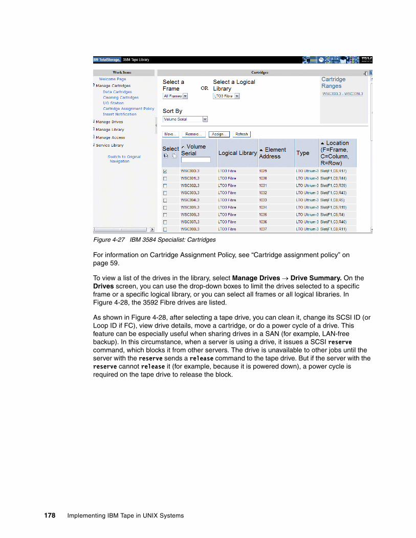
Figure 4-27 IBM 3584 Specialist: Cartridges
For information on Cartridge Assignment Policy, see “Cartridge assignment policy” on page 59.
To view a list of the drives in the library, select Manage Drives → Drive Summary. On the Drives screen, you can use the drop-down boxes to limit the drives selected to a specific frame or a specific logical library, or you can select all frames or all logical libraries. In Figure 4-28, the 3592 Fibre drives are listed.
As shown in Figure 4-28, after selecting a tape drive, you can clean it, change its SCSI ID (or Loop ID if FC), view drive details, move a cartridge, or do a power cycle of a drive. This feature can be especially useful when sharing drives in a SAN (for example, LAN-free backup). In this circumstance, when a server is using a drive, it issues a SCSI reserve command, which blocks it from other servers. The drive is unavailable to other jobs until the server with the reserve sends a release command to the tape drive. But if the server with the reserve cannot release it (for example, because it is powered down), a power cycle is required on the tape drive to release the block.
178 Implementing IBM Tape in UNIX Systems
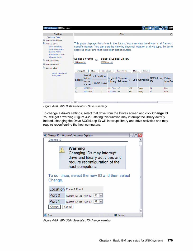
Figure 4-28 IBM 3584 Specialist - Drive summary
To change a drive’s settings, select that drive from the Drives screen and click Change ID. You will get a warning (Figure 4-29) stating this function may interrupt the library activity. Indeed, changing the Drive SCSI/Loop ID will interrupt library and drive activities and may require reconfiguring the host computers.
Figure 4-29 IBM 3584 Specialist: ID change warning
Chapter 4. Basic IBM tape setup for UNIX systems 179
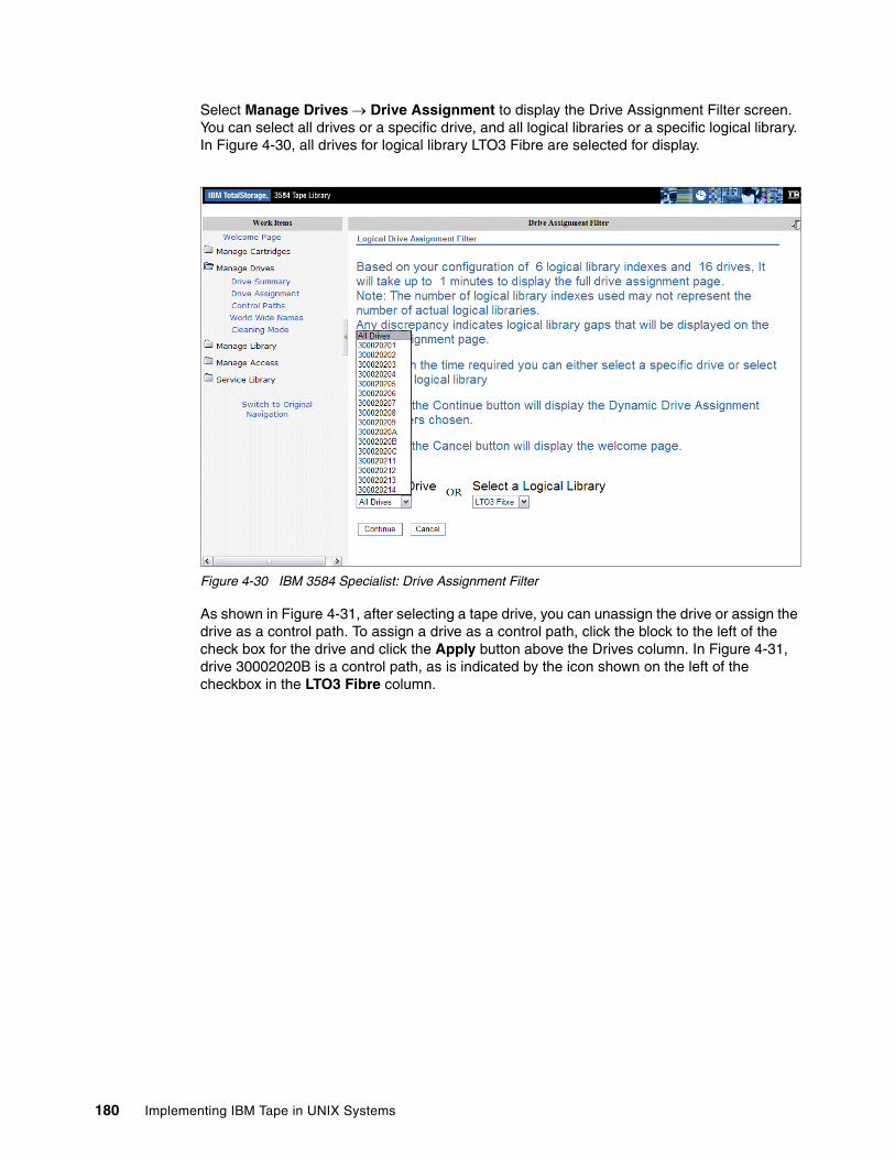
Select Manage Drives → Drive Assignment to display the Drive Assignment Filter screen. You can select all drives or a specific drive, and all logical libraries or a specific logical library. In Figure 4-30, all drives for logical library LTO3 Fibre are selected for display.
Figure 4-30 IBM 3584 Specialist: Drive Assignment Filter
As shown in Figure 4-31, after selecting a tape drive, you can unassign the drive or assign the drive as a control path. To assign a drive as a control path, click the block to the left of the check box for the drive and click the Apply button above the Drives column. In Figure 4-31, drive 30002020B is a control path, as is indicated by the icon shown on the left of the checkbox in the LTO3 Fibre column.
180 Implementing IBM Tape in UNIX Systems
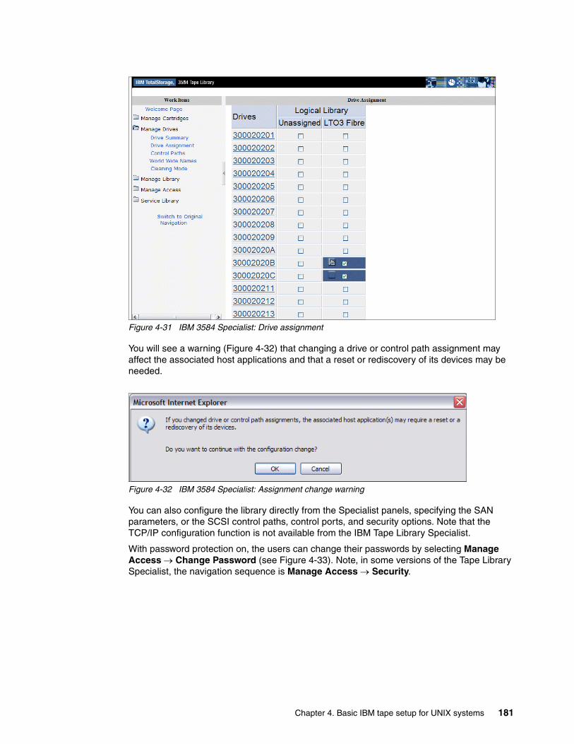
Figure 4-31 IBM 3584 Specialist: Drive assignment
You will see a warning (Figure 4-32) that changing a drive or control path assignment may affect the associated host applications and that a reset or rediscovery of its devices may be needed.
Figure 4-32 IBM 3584 Specialist: Assignment change warning
You can also configure the library directly from the Specialist panels, specifying the SAN parameters, or the SCSI control paths, control ports, and security options. Note that the TCP/IP configuration function is not available from the IBM Tape Library Specialist.
With password protection on, the users can change their passwords by selecting Manage Access → Change Password (see Figure 4-33). Note, in some versions of the Tape Library Specialist, the navigation sequence is Manage Access → Security.
Chapter 4. Basic IBM tape setup for UNIX systems 181
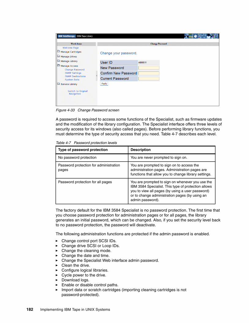
Figure 4-33 Change Password screen
A password is required to access some functions of the Specialist, such as firmware updates and the modification of the library configuration. The Specialist interface offers three levels of security access for its windows (also called pages). Before performing library functions, you must determine the type of security access that you need. Table 4-7 describes each level.
Table 4-7 Password protection levels
The factory default for the IBM 3584 Specialist is no password protection. The first time that you choose password protection for administration pages or for all pages, the library generates an initial password, which can be changed. Also, if you set the security level back to no password protection, the password will deactivate.
The following administration functions are protected if the admin password is enabled.
� Change control port SCSI IDs.� Change drive SCSI or Loop IDs.� Change the cleaning mode.� Change the date and time.� Change the Specialist Web interface admin password.� Clean the drive.� Configure logical libraries.� Cycle power to the drive.� Download logs.� Enable or disable control paths.� Import data or scratch cartridges (importing cleaning cartridges is not
password-protected).
Type of password protection Description
No password protection You are never prompted to sign on.
Password protection for administration pages
You are prompted to sign on to access the administration pages. Administration pages are functions that allow you to change library settings.
Password protection for all pages You are prompted to sign on whenever you use the IBM 3584 Specialist. This type of protection allows you to view all pages (by using a user password) or to change administration pages (by using an admin password).
182 Implementing IBM Tape in UNIX Systems
� Inventory the library.� Move cartridges.� Remove cartridges.� Update control port firmware.� Update library and drive firmware.
4.11 Updating library, drive, and RMU firmwareIt is a good habit to check periodically for available updates on the IBM Web site; newer code can provide additional support functions or fix problems. To upgrade the installed microcode level of the library, refer to the Operator Guide for your library or drive. In our example, we describe the procedures to check and update the library and drive microcode for various IBM LTO models.
4.11.1 Using My Support to stay up-to-date with your drivers and firmwareMy Support provides e-mail notification when firmware is updated and becomes available for download and installation. To register for My Support:
1. Visit the Web at:
http://www.ibm.com/support
2. Under Personalized support, click My support.
3. If this is your first access, under Sign in, click Register; otherwise, go to step 5.
4. Fill in the information required for registration. Items with an asterisk (*) are required fields.
5. Enter your user ID and password and click Submit to access My Support.
6. Enter the information required for your My personalized page.
a. Select Add products.
b. From the Products drop-down, select Storage.
c. In the next drop-down, select Computer Storage.
d. In the next drop-down, select Computer Tape Storage.
e. In the next drop-down, select either Computer tape autoloaders (IBM 3581) or Computer tape libraries (IBM 3582, IBM 3583 or IBM 3584).
f. Click the checkboxes for the appropriate products.
g. Click Add products at the bottom of the page.
h. Review your profile for correctness.
i. Under Subscribe to email, select Storage and then check the boxes labeled Flashes and Downloads and Drivers, and click Update.
j. Under Welcome, (your name), click Sign out to end your session.
You will be notified whenever there is new firmware available for the products you selected during registration.
4.11.2 Check the installed firmware To check for microcode updates, use any of the following links:
http://www-1.ibm.com/servers/storage/support/lto/ftp://ftp.software.ibm.com/storage/358x
Chapter 4. Basic IBM tape setup for UNIX systems 183
ftp://index.storsys.ibm.com/358x/
Here you can find the latest microcode releases for the LTO library, drives, and RMU (if installed).
For the library microcode, use the compressed file appcode.zip for Windows systems, or appcode.tar for UNIX systems. It contains the Vn_n_n.lif file that is the microcode image file to upload in the library. For the drive code, download the latest .ro file.
Check IBM 3580 installed firmware levelTo determine the current level of firmware on the IBM 3580, watch for the message Drive FW nnnn (where nnnn is the firmware level) to display while you power the drive off, then back on.
Check IBM 3581 installed firmware level
To check the installed firmware level from the IBM 3581 operator panel, make sure that LdR REAdY appears on the message display.
1. Click and hold the Next button and then the Mode button until dIAG MENU displays (approximately 5 seconds).
2. Click Mode until dSP FW displays.
3. Click Select. dSP LdR FW displays.
4. Click Select. Ld FW NNNN displays (where NNNN is the revision number of the autoloader firmware).
5. Click Next. dSP dRV FW displays.
At this point, you can select the firmware for the drive:
1. Click Select. dR FW NNNN displays (where NNNN is the revision number of the drive firmware).
2. Click Next. dSP MTN FW displays.
3. Click Select. LdR REAdY displays. Go back to the main menu.
Check IBM 3581 2U installed firmware levelTo check the installed firmware level from the IBM 3581 2U operator panel:
� Autoloader firmware: Click Previous or Next until Information is displayed. Press Enter. Click Next or Previous until you see LOADER INFO. Press Enter. Firmware REV. X.XX is displayed, where X.XX is the firmware level of the autoloader.
� Drive firmware: Click Next or Previous until Information is displayed. Press Enter. Click Next or Previous until Drive Info is displayed. Press Enter. Product REV. XXXX is displayed, where XXXX is the current firmware of the drive.
Check IBM 3582 installed firmware levelTo check the installed firmware level from the IBM 3582 operator panel:
1. Main menu → Status menu → display F/W.2. This shows the firmware levels of the following components: RMU, APPLICATION, DRIVE
1, DRIVE 2, PICKER.
Note: All models of the IBM TotalStorage 3581 Tape Autoloader (IBM 3581-L17/H17, IBM 3581-L13/H13 and IBM 3581-L23/H23) were withdrawn from marketing in October 2004.
184 Implementing IBM Tape in UNIX Systems
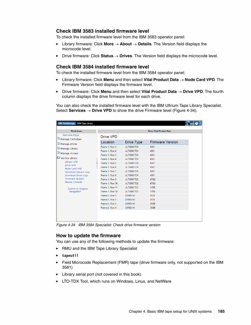
Check IBM 3583 installed firmware levelTo check the installed firmware level from the IBM 3583 operator panel:
� Library firmware: Click More → About → Details. The Version field displays the microcode level.
� Drive firmware: Click Status → Drives. The Version field displays the microcode level.
Check IBM 3584 installed firmware levelTo check the installed firmware level from the IBM 3584 operator panel:
� Library firmware: Click Menu and then select Vital Product Data → Node Card VPD. The Firmware Version field displays the firmware level.
� Drive firmware: Click Menu and then select Vital Product Data → Drive VPD. The fourth column displays the drive firmware level for each drive.
You can also check the installed firmware level with the IBM Ultrium Tape Library Specialist. Select Services → Drive VPD to show the drive Firmware level (Figure 4-34).
Figure 4-34 IBM 3584 Specialist: Check drive firmware version
How to update the firmwareYou can use any of the following methods to update the firmware:
� RMU and the IBM Tape Library Specialist
� tapeutil
� Field Microcode Replacement (FMR) tape (drive firmware only, not supported on the IBM 3581)
� Library serial port (not covered in this book)
� LTO-TDX Tool, which runs on Windows, Linux, and NetWare
Chapter 4. Basic IBM tape setup for UNIX systems 185
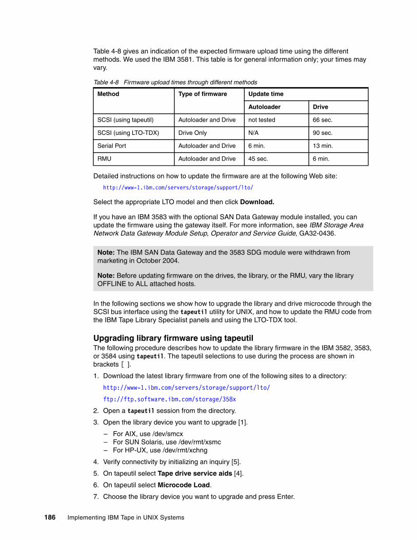
Table 4-8 gives an indication of the expected firmware upload time using the different methods. We used the IBM 3581. This table is for general information only; your times may vary.
Table 4-8 Firmware upload times through different methods
Detailed instructions on how to update the firmware are at the following Web site:
http://www-1.ibm.com/servers/storage/support/lto/
Select the appropriate LTO model and then click Download.
If you have an IBM 3583 with the optional SAN Data Gateway module installed, you can update the firmware using the gateway itself. For more information, see IBM Storage Area Network Data Gateway Module Setup, Operator and Service Guide, GA32-0436.
In the following sections we show how to upgrade the library and drive microcode through the SCSI bus interface using the tapeutil utility for UNIX, and how to update the RMU code from the IBM Tape Library Specialist panels and using the LTO-TDX tool.
Upgrading library firmware using tapeutil The following procedure describes how to update the library firmware in the IBM 3582, 3583, or 3584 using tapeutil. The tapeutil selections to use during the process are shown in brackets [ ].
1. Download the latest library firmware from one of the following sites to a directory:
http://www-1.ibm.com/servers/storage/support/lto/
ftp://ftp.software.ibm.com/storage/358x
2. Open a tapeutil session from the directory.
3. Open the library device you want to upgrade [1].
– For AIX, use /dev/smcx– For SUN Solaris, use /dev/rmt/xsmc– For HP-UX, use /dev/rmt/xchng
4. Verify connectivity by initializing an inquiry [5].
5. On tapeutil select Tape drive service aids [4].
6. On tapeutil select Microcode Load.
7. Choose the library device you want to upgrade and press Enter.
Method Type of firmware Update time
Autoloader Drive
SCSI (using tapeutil) Autoloader and Drive not tested 66 sec.
SCSI (using LTO-TDX) Drive Only N/A 90 sec.
Serial Port Autoloader and Drive 6 min. 13 min.
RMU Autoloader and Drive 45 sec. 6 min.
Note: The IBM SAN Data Gateway and the 3583 SDG module were withdrawn from marketing in October 2004.
Note: Before updating firmware on the drives, the library, or the RMU, vary the library OFFLINE to ALL attached hosts.
186 Implementing IBM Tape in UNIX Systems
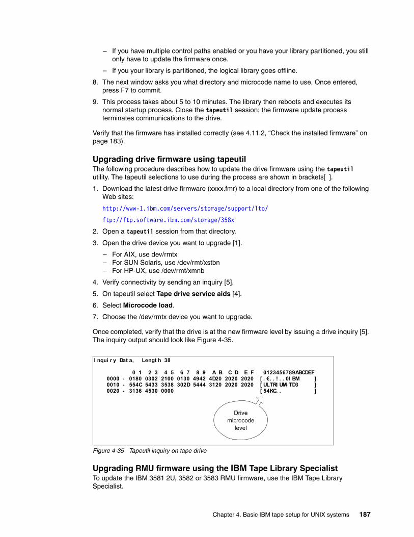
– If you have multiple control paths enabled or you have your library partitioned, you still only have to update the firmware once.
– If you your library is partitioned, the logical library goes offline.
8. The next window asks you what directory and microcode name to use. Once entered, press F7 to commit.
9. This process takes about 5 to 10 minutes. The library then reboots and executes its normal startup process. Close the tapeutil session; the firmware update process terminates communications to the drive.
Verify that the firmware has installed correctly (see 4.11.2, “Check the installed firmware” on page 183).
Upgrading drive firmware using tapeutilThe following procedure describes how to update the drive firmware using the tapeutil utility. The tapeutil selections to use during the process are shown in brackets[ ].
1. Download the latest drive firmware (xxxx.fmr) to a local directory from one of the following Web sites:
http://www-1.ibm.com/servers/storage/support/lto/
ftp://ftp.software.ibm.com/storage/358x
2. Open a tapeutil session from that directory.
3. Open the drive device you want to upgrade [1].
– For AIX, use dev/rmtx– For SUN Solaris, use /dev/rmt/xstbn– For HP-UX, use /dev/rmt/xmnb
4. Verify connectivity by sending an inquiry [5].
5. On tapeutil select Tape drive service aids [4].
6. Select Microcode load.
7. Choose the /dev/rmtx device you want to upgrade.
Once completed, verify that the drive is at the new firmware level by issuing a drive inquiry [5]. The inquiry output should look like Figure 4-35.
Figure 4-35 Tapeutil inquiry on tape drive
Upgrading RMU firmware using the IBM Tape Library SpecialistTo update the IBM 3581 2U, 3582 or 3583 RMU firmware, use the IBM Tape Library Specialist.
I nqui r y Dat a, Lengt h 38
0 1 2 3 4 5 6 7 8 9 A B C D E F 0123456789ABCDEF 0000 - 0180 0302 2100 0130 4942 4D20 2020 2020 [ . €. . ! . . 0I BM ] 0010 - 554C 5433 3538 302D 5444 3120 2020 2020 [ ULTRI UM- TD3 ] 0020 - 3136 4530 0000 [ 54KC. . ]
Drivemicrocode
level
Chapter 4. Basic IBM tape setup for UNIX systems 187
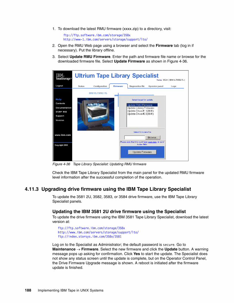
1. To download the latest RMU firmware (xxxx.zip) to a directory, visit:
ftp://ftp.software.ibm.com/storage/358xhttp://www-1.ibm.com/servers/storage/support/lto/
2. Open the RMU Web page using a browser and select the Firmware tab (log in if necessary). Put the library offline.
3. Select Update RMU Firmware. Enter the path and firmware file name or browse for the downloaded firmware file. Select Update Firmware as shown in Figure 4-36.
Figure 4-36 Tape Library Specialist: Updating RMU firmware
Check the IBM Tape Library Specialist from the main panel for the updated RMU firmware level information after the successful completion of the operation.
4.11.3 Upgrading drive firmware using the IBM Tape Library SpecialistTo update the 3581 2U, 3582, 3583, or 3584 drive firmware, use the IBM Tape Library Specialist panels.
Updating the IBM 3581 2U drive firmware using the Specialist To update the drive firmware using the IBM 3581 Tape Library Specialist, download the latest version at:
ftp://ftp.software.ibm.com/storage/358xhttp://www.ibm.com/servers/storage/support/lto/ftp://index.storsys.ibm.com/358x/3581
Log on to the Specialist as Administrator; the default password is secure. Go to Maintenance → Firmware. Select the new firmware and click the Update button. A warning message pops up asking for confirmation. Click Yes to start the update. The Specialist does not show any status screen until the update is complete, but on the Operator Control Panel, the Drive Firmware Upgrade message is shown. A reboot is initiated after the firmware update is finished.
188 Implementing IBM Tape in UNIX Systems
Updating the IBM 3582 drive firmware using the Specialist To update the drive firmware using the IBM Tape Library Specialist, the latest firmware for the Ultrium drives can be found at:
ftp://ftp.software.ibm.com/storage/358xhttp://www.ibm.com/servers/storage/support/lto/
From the Ultrium Tape Library Specialist Welcome screen select the Firmware tab. Enter the user name and password. The default settings are Admin for the user and secure for the password. Select the drive you want to update and select the new firmware. Click the Update Firmware button. Status of the drive update process is displayed. It can take more than one hour to update a single drive.
Updating the IBM 3583 drive firmware using the IBM Specialist The latest firmware for the Ultrium drives can be found at:
ftp://ftp.software.ibm.com/storage/358xhttp://www.ibm.com/servers/storage/support/lto/
From the Ultrium Tape Library Specialist Welcome screen select the Firmware tab. Enter the user name and password. The default settings are Admin for the user and secure for the password. Select the drive you want to update and click Browse to select the new firmware. Click the Update Firmware button. The status of the drive update process is displayed.
Updating the IBM 3584 drive firmware using the IBM Specialist To update the drive firmware using the IBM Tape Library Specialist, the latest firmware for the Ultrium drives can be found at:
ftp://ftp.software.ibm.com/storage/358xhttp://www.ibm.com/servers/storage/support/lto/
1. From the Service Library menu select Firmware Update. An attention screen pops up to verify that you have the firmware update that you want to apply. If not, select the link to the Ultrium support site and download the appropriate firmware update.
2. When you have the appropriate firmware downloaded, click the Launch Firmware Update Wizard icon. Select the model for the drive you want to update and click Next.
3. A warning will pop up indicating that the drive will be taken offline during update. If you wish to continue, click Next.
4. Select a specific drive in the drop-down list to be updated or select All drives.
5. Use the Browse button or enter the file name to load the firmware file you downloaded from the support page.
6. Click Update to finish the firmware update. The drive will be taken offline during the firmware update process. The library should then activate the new firmware automatically.
4.11.4 Upgrading the drive firmware using LTO-TDXLTO-TDX is a SCSI and Fibre Drive Firmware Download and LTO Dump Upload tool. LTO-TDX is an alternative method for downloading LTO drive firmware across the SCSI bus or Fibre Channel. In addition, this tool can be used to upload LTO drive error dumps, which can be sent to the Support Center for further analysis. LTO-TDX needs no additional drivers and it is the fastest and easiest way to update drive firmware.
Note: LTO-TDX is available for Windows, Linux, and NetWare Operating Systems.
Chapter 4. Basic IBM tape setup for UNIX systems 189
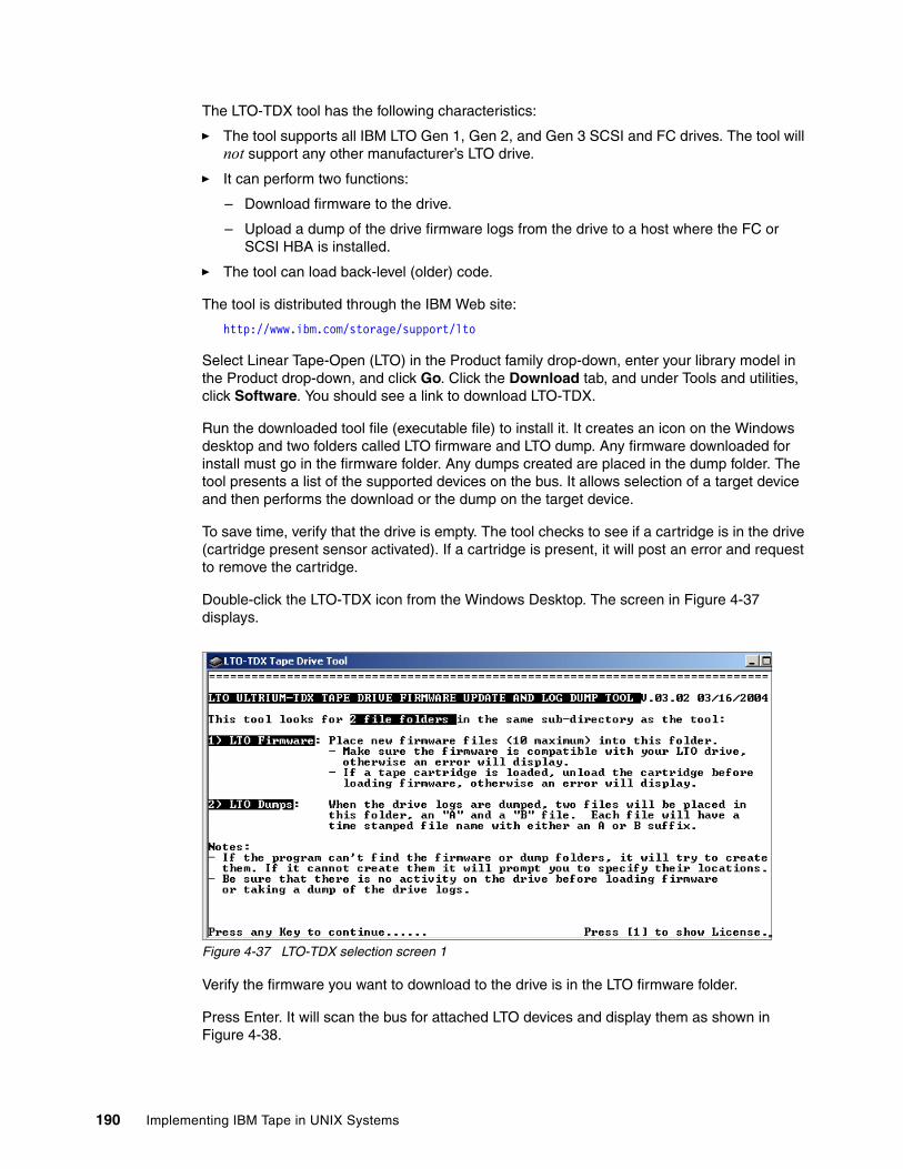
The LTO-TDX tool has the following characteristics:
� The tool supports all IBM LTO Gen 1, Gen 2, and Gen 3 SCSI and FC drives. The tool will not support any other manufacturer’s LTO drive.
� It can perform two functions:
– Download firmware to the drive.
– Upload a dump of the drive firmware logs from the drive to a host where the FC or SCSI HBA is installed.
� The tool can load back-level (older) code.
The tool is distributed through the IBM Web site:
http://www.ibm.com/storage/support/lto
Select Linear Tape-Open (LTO) in the Product family drop-down, enter your library model in the Product drop-down, and click Go. Click the Download tab, and under Tools and utilities, click Software. You should see a link to download LTO-TDX.
Run the downloaded tool file (executable file) to install it. It creates an icon on the Windows desktop and two folders called LTO firmware and LTO dump. Any firmware downloaded for install must go in the firmware folder. Any dumps created are placed in the dump folder. The tool presents a list of the supported devices on the bus. It allows selection of a target device and then performs the download or the dump on the target device.
To save time, verify that the drive is empty. The tool checks to see if a cartridge is in the drive (cartridge present sensor activated). If a cartridge is present, it will post an error and request to remove the cartridge.
Double-click the LTO-TDX icon from the Windows Desktop. The screen in Figure 4-37 displays.
Figure 4-37 LTO-TDX selection screen 1
Verify the firmware you want to download to the drive is in the LTO firmware folder.
Press Enter. It will scan the bus for attached LTO devices and display them as shown in Figure 4-38.
190 Implementing IBM Tape in UNIX Systems
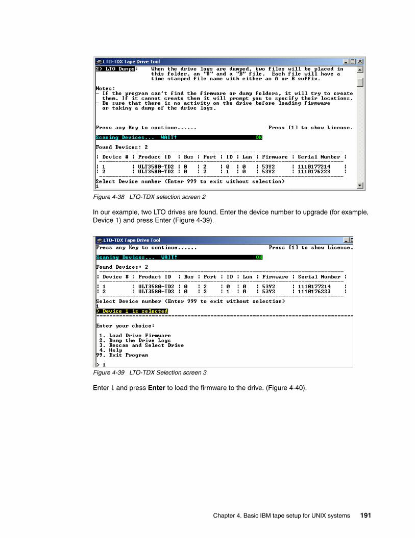
Figure 4-38 LTO-TDX selection screen 2
In our example, two LTO drives are found. Enter the device number to upgrade (for example, Device 1) and press Enter (Figure 4-39).
Figure 4-39 LTO-TDX Selection screen 3
Enter 1 and press Enter to load the firmware to the drive. (Figure 4-40).
Chapter 4. Basic IBM tape setup for UNIX systems 191
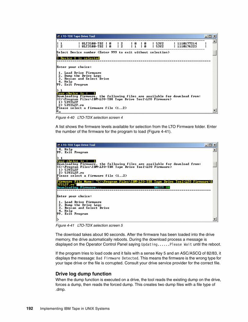
Figure 4-40 LTO-TDX selection screen 4
A list shows the firmware levels available for selection from the LTO Firmware folder. Enter the number of the firmware for the program to load (Figure 4-41).
Figure 4-41 LTO-TDX selection screen 5
The download takes about 90 seconds. After the firmware has been loaded into the drive memory, the drive automatically reboots. During the download process a message is displayed on the Operator Control Panel saying Updating......Please Wait until the reboot.
If the program tries to load code and it fails with a sense Key 5 and an ASC/ASCQ of 82/83, it displays the message: Bad Firmware Detected. This means the firmware is the wrong type for your tape drive or the file is corrupted. Consult your drive service provider for the correct file.
Drive log dump functionWhen the dump function is executed on a drive, the tool reads the existing dump on the drive, forces a dump, then reads the forced dump. This creates two dump files with a file type of .dmp.
192 Implementing IBM Tape in UNIX Systems

The two dump files created by the dump function are time stamped with year, month, day, and seconds, and contain the drive serial number. The first dump file read has an A suffix. The second file produced has a B suffix. The files that are created are placed in the LTO Dumps folder in the directory with the tool.
These files are now ready to be sent to the Support Center for further analysis.
Chapter 4. Basic IBM tape setup for UNIX systems 193

194 Implementing IBM Tape in UNIX Systems
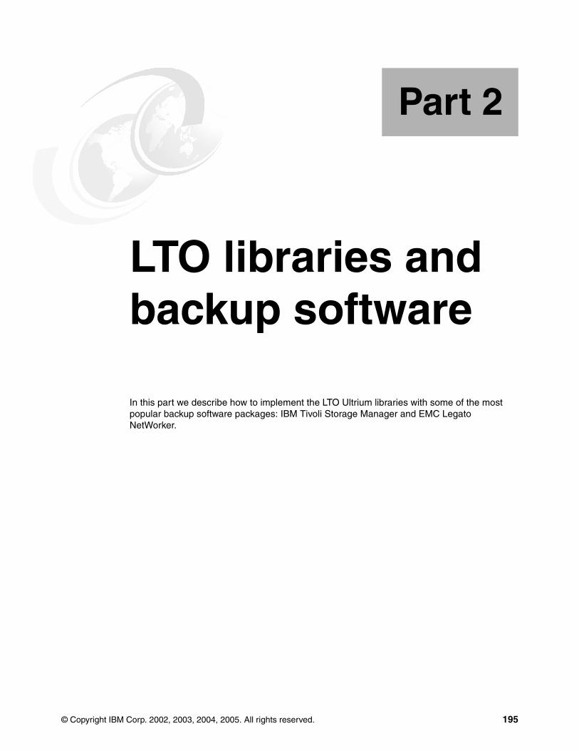
Part 2 LTO libraries and backup software
In this part we describe how to implement the LTO Ultrium libraries with some of the most popular backup software packages: IBM Tivoli Storage Manager and EMC Legato NetWorker.
Part 2
© Copyright IBM Corp. 2002, 2003, 2004, 2005. All rights reserved. 195

196 Implementing IBM Tape in UNIX Systems

Chapter 5. Implementing IBM Tivoli Storage Manager
This chapter describes the installation and implementation of IBM tape devices with IBM Tivoli Storage Manager in AIX, Sun Solaris, and HP-UX environments. In particular, we review Tivoli Storage Manager’s ability to:
� Be used for normal backup/restore processing
� Allow multiple servers to share the library
� Provide LAN-free backup services
We also provide information on migrating between the generations of LTO technology with IBM Tivoli Storage Manager, how to define various 3592 media types to Tivoli Storage Manager, and discuss some features available with Tivoli Storage Manager V5.2 and V5.3 that are useful for IBM tape devices.
We begin with a brief overview of Tivoli Storage Manager. For more in-depth information about this product, refer to these redbooks:
� IBM Tivoli Storage Management Concepts, SG24-4877
� IBM Tivoli Storage Manager Implementation Guide, SG24-5416
� Get More Out of Your SAN with IBM Tivoli Storage Manager, SG24-6687
� IBM Tivoli Storage Manager Version 5.3 Technical Guide, SG24-6638
5
© Copyright IBM Corp. 2002, 2003, 2004, 2005. All rights reserved. 197
5.1 IBM Tivoli Storage Manager overviewAs part of the IBM TotalStorage Open Software Family, IBM Tivoli Storage Manager protects data from hardware failures, errors, and unforeseen disasters by storing backup and archive copies on offline and off-site storage. It scales to protect hundreds to thousands of computers running more than a dozen operating systems, ranging from laptops to mainframes and connected together via the Internet, WANs, LANs or SANs. Tivoli Storage Manager Extended Edition's centralized Web-based management, intelligent data move and store techniques, and comprehensive policy-based automation all work together to minimize administration costs and the impact to both computers and networks.
Optional software modules allow business-critical applications that must run 24x365 to utilize Tivoli Storage Manager's centralized data protection with no interruption to their service. Optional software extensions also allow SAN-connected computers to use the SAN for data protection data movements, and provide Hierarchical Storage Management to automatically move unused data files from online disk storage to offline tape storage. Tivoli Storage Manager Extended Edition provides disaster planning capability, NDMP control for NAS files, and support for large tape libraries.
Tivoli Storage Manager is ideal for heterogeneous, data-intensive environments, supporting over 35 platforms and over 250 storage devices across LANs, WANs, and SANs, plus providing protection for leading databases and e-mail applications. See Figure 5-1.
Figure 5-1 IBM Tivoli Storage Manager supported platforms
Tivoli Storage Manager allows users to confidently protect and manage information; it integrates unattended network backup and archive capabilities with centralized storage management and powerful disaster recovery functions. Tivoli Storage Manager is intended for companies with homogeneous or heterogeneous platforms and complex environments that include traditional LANs as well as SANs. It is a best-of-breed, scalable storage management solution that helps provide consistent and reliable protection and management
LINUXRed Hat
SuSETurboLinuxSILICON
GRAPHICS IRIX
APPLE Macintosh
DIGITALTru64
HEWLETT-PACKARD
HP-UX
MICROSOFTWindows XPWindows NT Server/WSWindows 2000Windows 2003
NOVELL NETWARE
SUNSolarisSunOS
Tape
Disk
Storage Hierarchy
Optical
VMLinux
OS/400zOS
SolarisHP-UX
AIX
Windows W2K/2003
IBM Tivoli Storage Manager Servers
DB2
INFORMIX
LOTUS DOMINO
MICROSOFTExchange ServerSQL Server
ORACLE
mySAP SYBASE
NAS NDMP FUJITSU***
IBM Tivoli Storage Manager for MailLotus Notes on AIXLotus Notes on Windows NTDomino on AIXDomino on Windows NTMicrosoft Exchange Server
IBM Tivoli Storage Manager for DatabasesMicrosoft SQL ServerOracle Backup on AIXOracle Backup on HP-UXOracle Backup on Sun SolarisInformixIBM DB2 (included in DB2)
IBM Tivoli Storage Manager for Hardware
IBM Tivoli Storage Manager for ERPData Protection for mySAP on DB2 and Oracle
IBM Tivoli Storage Manager for Data Retention
AIXAS/400*** Linux zSeriesOpenEdition MVSzOS
IBM*
IBM Tivoli Storage Manager Client Platforms
Supported NetworksAPPCIPX/SPXNamed PipesShared MemoryTCP/IP3270 Emulation
IBM Tivoli Storage Manager for HardwareIBM ESS
IBM Tivoli Storage Manager for Application Servers
Data Protection for Websphere Application Server
WebSphereApplication
Server
IBM ESSLINUX
xSeriespSerieszSeriesiSeries
198 Implementing IBM Tape in UNIX Systems

of mission-critical data that is spread across your company's enterprise. Tivoli Storage Manager is an industrial-strength centralized storage management product for your enterprise.
Tivoli Storage Manager can protect almost any backup-archive client as exemplified in Figure 5-1. A Tivoli Storage Manager server is provided for OS/390®, z/OS®, Windows 2000/2003, AIX, Solaris, HP-UX, Linux, and OS/400. This breadth of platform coverage affords you the choice in selecting the storage management platform that suits your environment and leverages your hardware and software investments. Tivoli Storage Manager can help control the cost of distributed storage management by leveraging storage resources, helping to reduce the cost of downtime and lost data, and helping to increase the productivity of storage administrators and end users.
Tivoli Storage Manager exploits the numerous advantages of SANs with its LAN-free, server-free, and library sharing functions. These help to remove traffic from the LAN, allow for multiple Tivoli Storage Manager servers to share a library, and offload backup processing from mission-critical servers.
Tivoli Storage Manager includes LAN-free backup/restore functionality for many databases and applications, as well as the file-based backup/archive clients. It exploits Tivoli SANergy® to allow for LAN-free transfers to file-based storage pools on disk.
For more information about IBM Tivoli Storage Management, visit:
http://www-306.ibm.com/software/tivoli/products/storage-mgr/
For the list of currently available storage management products, and supported servers and clients, see:
http://www-306.ibm.com/software/tivoli/products/storage-mgr/product-links.html
5.1.1 Tivoli Storage Manager commonly used termsHere are a few basic Tivoli Storage Manager terms:
� Server A server is a computer system that provides services to one or more clients, or other devices over a network. A Tivoli Storage Manager server is the repository and manager of all the backed up client data. Administrative policies defined at the server control the types of backup performed and retention policies for the data. The server also manages the physical media and devices where the backed up data is stored.
� Client A client is a computer system that requests a service of another computer system that is typically referred to as a server. Multiple clients may share access to a common server. In Tivoli Storage Manager terms, a client is a computer system that has data assets requiring protection by the Tivoli Storage Manager server. The client decides what data will be backed up, and is subject to the server’s defined administrative policies for data retention. Typically, a client’s data is backed up automatically by a server-scheduled operation.
� Tape libraryA tape library consists of the physical robotics that move cartridges, one or more tape drives, and slots for tape storage. It must also have a mechanism for controlling the robotics (a library controller), and may also have a library manager that maintains inventory and mediates sharing. In most cases, a library does not have a built-in library manager, so server-based software has to provide the library management function. As an example, the IBM 3494 has a built-in library manager, whereas the IBM 3584 does not.
Chapter 5. Implementing IBM Tivoli Storage Manager 199
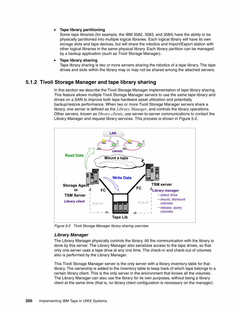
� Tape library partitioning Some tape libraries (for example, the IBM 3582, 3583, and 3584) have the ability to be physically partitioned into multiple logical libraries. Each logical library will have its own storage slots and tape devices, but will share the robotics and Import/Export station with other logical libraries in the same physical library. Each library partition can be managed by a backup application (such as Tivoli Storage Manager).
� Tape library sharingTape library sharing is two or more servers sharing the robotics of a tape library. The tape drives and slots within the library may or may not be shared among the attached servers.
5.1.2 Tivoli Storage Manager and tape library sharingIn this section we describe the Tivoli Storage Manager implementation of tape library sharing. This feature allows multiple Tivoli Storage Manager servers to use the same tape library and drives on a SAN to improve both tape hardware asset utilization and potentially backup/restore performance. When two or more Tivoli Storage Manager servers share a library, one server is defined as the Library Manager, and controls the library operations. Other servers, known as library clients, use server-to-server communications to contact the Library Manager and request library services. This process is shown in Figure 5-2.
Figure 5-2 Tivoli Storage Manager library sharing overview
Library ManagerThe Library Manager physically controls the library. All the communication with the library is done by this server. The Library Manager also serializes access to the tape drives, so that only one server uses a tape drive at any one time. The check-in and check-out of volumes also is performed by the Library Manager.
This Tivoli Storage Manager server is the only server with a library inventory table for that library. The ownership is added to the inventory table to keep track of which tape belongs to a certain library client. This is the only server in the environment that knows all the volumes. The Library Manager can also use the library for its own purposes, without being a library client at the same time (that is, no library client configuration is necessary on the manager).
Tape Lib
TSM serverStorage Agent or FC FC
Mount a tape
Library managerselect drivemount, dismount volumesrelease, query volumes
Write Data
Library client
clients
LAN
Read Data
SCSI I/O SCSI I/O
TSM Server
200 Implementing IBM Tape in UNIX Systems
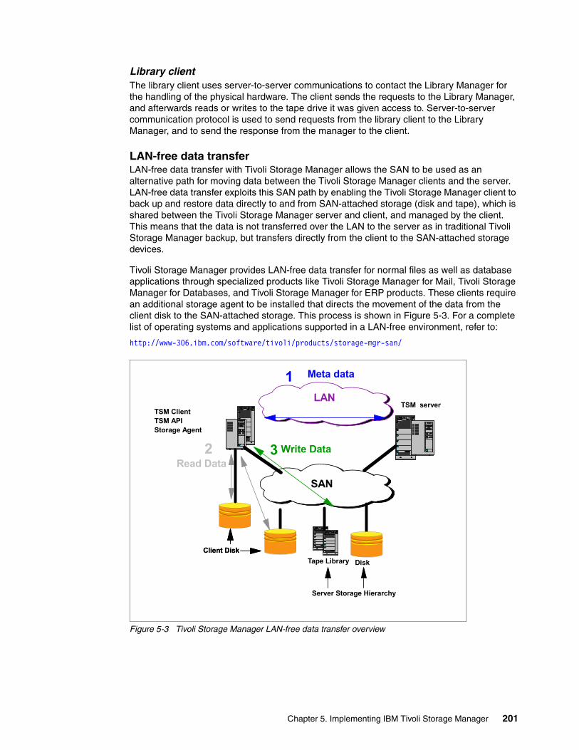
Library clientThe library client uses server-to-server communications to contact the Library Manager for the handling of the physical hardware. The client sends the requests to the Library Manager, and afterwards reads or writes to the tape drive it was given access to. Server-to-server communication protocol is used to send requests from the library client to the Library Manager, and to send the response from the manager to the client.
LAN-free data transferLAN-free data transfer with Tivoli Storage Manager allows the SAN to be used as an alternative path for moving data between the Tivoli Storage Manager clients and the server. LAN-free data transfer exploits this SAN path by enabling the Tivoli Storage Manager client to back up and restore data directly to and from SAN-attached storage (disk and tape), which is shared between the Tivoli Storage Manager server and client, and managed by the client. This means that the data is not transferred over the LAN to the server as in traditional Tivoli Storage Manager backup, but transfers directly from the client to the SAN-attached storage devices.
Tivoli Storage Manager provides LAN-free data transfer for normal files as well as database applications through specialized products like Tivoli Storage Manager for Mail, Tivoli Storage Manager for Databases, and Tivoli Storage Manager for ERP products. These clients require an additional storage agent to be installed that directs the movement of the data from the client disk to the SAN-attached storage. This process is shown in Figure 5-3. For a complete list of operating systems and applications supported in a LAN-free environment, refer to:
http://www-306.ibm.com/software/tivoli/products/storage-mgr-san/
Figure 5-3 Tivoli Storage Manager LAN-free data transfer overview
TSM serverTSM ClientTSM APIStorage Agent
3 Write Data
3
Read Data
Meta data1
2
Client Disk
LAN
SAN
Tape Library Disk Client Disk
Server Storage Hierarchy
Chapter 5. Implementing IBM Tivoli Storage Manager 201
5.2 Non-shared tape device with Tivoli Storage ManagerIn this section we discuss configuring the IBM LTO tape libraries with Tivoli Storage Manager in AIX, Solaris, and HP-UX environments. We used an FC-connected IBM LTO tape library with AIX and Solaris, and direct SCSI attach for HP-UX.
The lab environment for the Tivoli Storage Manager installation with an FC-connected tape device was:
� IBM pSeries 6E1 server, AIX Release 5.2.0, and FC adapter (FC 6228)� Sun Fire™ 280R SPARC server. Solaris 9 and QLogic QLA 2200 FC adapter� IBM 2109-F16 FC switch� IBM TotalStorage 3584 Tape Library with FC LTO drives� IBM TotalStorage 3584 Tape Library with IBM 3592 drives
For a direct SCSI-connected LTO, our environment was:
� HP9000 L1000 server, HP-UX V10 and SCSI Ultra-2 LVD PCI A5150A� IBM TotalStorage 3583 Tape Library with two LVD drives
The following discussion is valid for all generations of LTO. Some parameters may be specific for the different LTO generations (for example, device formats); they are clearly noted in the text. Similarly, the Tivoli Storage Manager Version 5.3 is only slightly different from Version 5.2 with respect to the Command Line Interface used throughout this discussion.
All discussions on setup of Tivoli Storage Manager, except what is specifically device dependent, is the same for all the general IBM LTO libraries, IBM 3582, IBM 3583, and IBM 3584.
5.2.1 Installing Tivoli Storage ManagerTo install Tivoli Storage Manager Version 5.2 use the Tivoli Storage Manager Quick Start manuals for the relevant operating system. For AIX this is IBM Tivoli Storage Manager for AIX Quick Start, GC32-0770. The manuals can be found at:
http://publib.boulder.ibm.com/tividd/td/tdprodlist.html
To install Tivoli Storage Manager Version 5.3 use the Tivoli Storage Manager Installation Guide manuals for the relevant operating system. For AIX this is IBM Tivoli Storage Manager for AIX Installation Guide, GC32-1597. The manuals can be found at:
http://publib.boulder.ibm.com/infocenter/tivihelp/index.jsp
Notice that there is now a new Web site for the Tivoli Storage Manager V5.3 publications.
Note:
� Tivoli Storage Manager V4.1.2 supports Ultrium 1 drives in the IBM 3580, 3581, 3583, and 3584.
� Tivoli Storage Manager V5.1.6 supports Ultrium 2 drives.� Tivoli Storage Manager V5.1.6.5 supports IBM 3582.� Tivoli Storage Manager V5.2 supports mixing Ultrium 1 and 2 in the same logical
library.� Tivoli Storage Manager V5.1.7.2, V5.2.1 or V5.3 support IBM 3592 tape drives.� Tivoli Storage Manager V5.2.3 supports the IBM 3581 2U.� Tivoli Storage Manager V5.2.4 or V5.3 supports Ultrium 3 tape drives, and a mix of
Ultrium 1, 2 and 3 in the same logical library.
202 Implementing IBM Tape in UNIX Systems
Installation summaryWhen installing Tivoli Storage Manager, the default configuration sets up a disk storage pool for storing backup data. Before you can begin using tape devices as a backup destination, you must do the following:
� Attach the devices to your system, which includes physically attaching the devices, configuring the device drivers, and determining the device names.
� Define the library and the drives in the library with their connection paths, a device class using the library, and a storage pool associated with the device class.
� Include the storage pool in your storage hierarchy.
To perform these tasks you can use either the administrative client command line or Web interface. Our examples use the command line interface. This interface is the same across all present Tivoli Storage Manager versions, while the Web-based administrative command interface has changed completely between Tivoli Storage Manager Versions 5.2 and 5.3, with the introduction of the Administrative Console in V5.3. Refer to the Tivoli Storage Manager manuals and Redbooks for details using the Web interface.
The next three sections show how to define IBM tape devices in each of the specific AIX, Solaris, and HP-UX standalone (non-shared) environments.
Refer to the following Web site for Tivoli product requirements, supported devices, and code levels:
http://www-306.ibm.com/software/sysmgmt/products/support/IBMTivoliStorageManager.html
5.2.2 Configure non-shared tape library and drives for AIX You should have already installed your tape drives and library (including the Atape device driver) according to Chapter 4, “Basic IBM tape setup for UNIX systems” on page 101, and Chapter 3, “SAN considerations” on page 75. Now determine the names of your devices (see Example 5-1).
Example 5-1 Installed and available drives and media changer on AIX
# lsdev -Cc tapermt0 Available 1V-08-01 LTO Ultrium Tape Drive (FCP)rmt1 Available 1V-08-01 LTO Ultrium Tape Drive (FCP)smc0 Available 1V-08-01 IBM 3584 Library Medium Changer (FCP)
For performance reasons, we suggest that you use a variable block size length and have hardware compression turned on.
To display or change this setting, use SMIT → Devices → Tape Drive → Change/Show Characteristics of a Tape Drive.
Example 5-2 reflects a tape drive configured with Block Size = 0, which means variable length blocks, and Hardware Compression on Tape = yes. The exact content of this example may change with different tape drives and AIX versions. Note that Tivoli Storage Manager can override the device settings for hardware compression by use of the FORMAT parameter in the DEFINE DEVCLASS command (see 5.2.5, “Define device class and storage pool” on page 212).
Chapter 5. Implementing IBM Tivoli Storage Manager 203
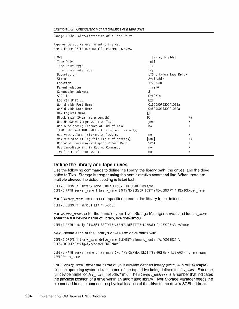
Example 5-2 Change/show characteristics of a tape drive
Change / Show Characteristics of a Tape Drive
Type or select values in entry fields.Press Enter AFTER making all desired changes.
[TOP] [Entry Fields] Tape Drive rmt1 Tape Drive type LTO Tape Drive interface fcp Description LTO Ultrium Tape Driv> Status Available Location 1V-08-01 Parent adapter fscsi0 Connection address 2 SCSI ID 0x60b7a Logical Unit ID 0x0 World Wide Port Name 0x500507630041082a World Wide Node Name 0x500507630001082a New Logical Name [] Block Size (0=Variable Length) [0] +# Use Hardware Compression on Tape yes + Use Autoloading Feature at End-of-Tape no + (IBM 3581 and IBM 3583 with single drive only) Activate volume information logging no + Maximum size of log file (in # of entries) [500] +# Backward Space/Forward Space Record Mode SCSI + Use Immediate Bit in Rewind Commands no + Trailer Label Processing no +
Define the library and tape drivesUse the following commands to define the library, the library path, the drives, and the drive paths to Tivoli Storage Manager using the administrative command line. When there are multiple choices the default setting is listed last.
DEFINE LIBRARY library_name LIBTYPE=SCSI AUTOLABEL=yes/noDEFINE PATH server_name library_name SRCTYPE=SERVER DESTTYPE=LIBRARY \ DEVICE=dev_name
For library_name, enter a user-specified name of the library to be defined:
DEFINE LIBRARY lib3584 LIBTYPE=SCSI
For server_name, enter the name of your Tivoli Storage Manager server, and for dev_name, enter the full device name of library, like /dev/smc0:
DEFINE PATH sicily lib3584 SRCTYPE=SERVER DESTTYPE=LIBRARY \ DEVICE=/dev/smc0
Next, define each of the library’s drives and drive paths with:
DEFINE DRIVE library_name drive_name ELEMENT=element_number/AUTODETECT \ CLEANFREQUENCY=Gigabytes/ASNEEDED/NONE
DEFINE PATH server_name drive_name SRCTYPE=SERVER DESTTYPE=DRIVE \ LIBRARY=library_name DEVICE=dev_name
For library_name, enter the name of your already defined library (lib3584 in our example). Use the operating system device name of the tape drive being defined for dev_name. Enter the full device name for dev_name, like /dev/rmt0. The element_address is a number that indicates the physical location of a drive within an automated library. Tivoli Storage Manager needs the element address to connect the physical location of the drive to the drive’s SCSI address.
204 Implementing IBM Tape in UNIX Systems
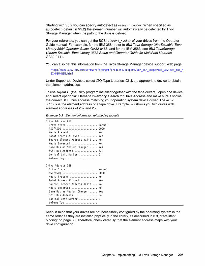
Starting with V5.2 you can specify autodetect as element_number. When specified as autodetect (default in V5.2) the element number will automatically be detected by Tivoli Storage Manager when the path to the drive is defined.
For your reference, you can get the SCSI element_number of your drives from the Operator Guide manual. For example, for the IBM 3584 refer to IBM Total Storage UltraScalable Tape Library 3584 Operator Guide, GA32-0468; and for the IBM 3583, see IBM TotalStorage Ultrium Scalable Tape Library 3583 Setup and Operator Guide for MultiPath Libraries, GA32-0411.
You can also get this information from the Tivoli Storage Manager device support Web page:
http://www-306.ibm.com/software/sysmgmt/products/support/IBM_TSM_Supported_Devices_for_AIXHPSUNWIN.html
Under Supported Devices, select LTO Tape Libraries. Click the appropriate device to obtain the element addresses.
To use tapeutil (the utility program installed together with the tape drivers), open one device and select option 14: Element Inventory. Search for Drive Address and make sure it shows the correct SCSI bus address matching your operating system device driver. The drive address is the element address of a tape drive. Example 5-3 shows you two drives with element addresses of 257 and 258.
Example 5-3 Element information returned by tapeutil
Drive Address 257 Drive State .................... Normal ASC/ASCQ ....................... 0000 Media Present .................. No Robot Access Allowed ........... Yes Source Element Address Valid ... No Media Inverted ................. No Same Bus as Medium Changer ..... Yes SCSI Bus Address ............... 33 Logical Unit Number ............ 0 Volume Tag .....................
Drive Address 258 Drive State .................... Normal ASC/ASCQ ....................... 0000 Media Present .................. No Robot Access Allowed ........... Yes Source Element Address Valid ... No Media Inverted ................. No Same Bus as Medium Changer ..... Yes SCSI Bus Address ............... 34 Logical Unit Number ............ 0 Volume Tag .....................
Keep in mind that your drives are not necessarily configured by the operating system in the same order as they are installed physically in the library, as described in 3.3, “Persistent binding” on page 88. Therefore, check carefully that the element address maps with your drive configuration.
Chapter 5. Implementing IBM Tivoli Storage Manager 205
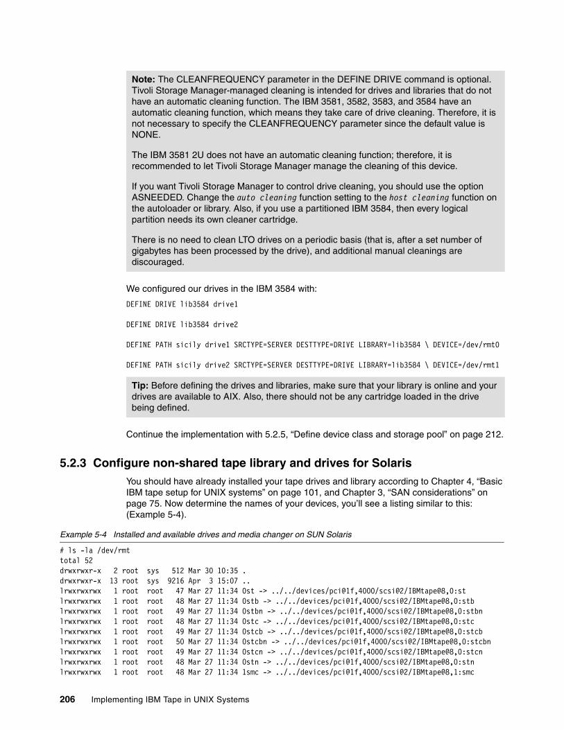
We configured our drives in the IBM 3584 with:
DEFINE DRIVE lib3584 drive1
DEFINE DRIVE lib3584 drive2
DEFINE PATH sicily drive1 SRCTYPE=SERVER DESTTYPE=DRIVE LIBRARY=lib3584 \ DEVICE=/dev/rmt0
DEFINE PATH sicily drive2 SRCTYPE=SERVER DESTTYPE=DRIVE LIBRARY=lib3584 \ DEVICE=/dev/rmt1
Continue the implementation with 5.2.5, “Define device class and storage pool” on page 212.
5.2.3 Configure non-shared tape library and drives for Solaris You should have already installed your tape drives and library according to Chapter 4, “Basic IBM tape setup for UNIX systems” on page 101, and Chapter 3, “SAN considerations” on page 75. Now determine the names of your devices, you’ll see a listing similar to this: (Example 5-4).
Example 5-4 Installed and available drives and media changer on SUN Solaris
# ls -la /dev/rmttotal 52drwxrwxr-x 2 root sys 512 Mar 30 10:35 .drwxrwxr-x 13 root sys 9216 Apr 3 15:07 ..lrwxrwxrwx 1 root root 47 Mar 27 11:34 0st -> ../../devices/pci@1f,4000/scsi@2/IBMtape@8,0:stlrwxrwxrwx 1 root root 48 Mar 27 11:34 0stb -> ../../devices/pci@1f,4000/scsi@2/IBMtape@8,0:stblrwxrwxrwx 1 root root 49 Mar 27 11:34 0stbn -> ../../devices/pci@1f,4000/scsi@2/IBMtape@8,0:stbnlrwxrwxrwx 1 root root 48 Mar 27 11:34 0stc -> ../../devices/pci@1f,4000/scsi@2/IBMtape@8,0:stclrwxrwxrwx 1 root root 49 Mar 27 11:34 0stcb -> ../../devices/pci@1f,4000/scsi@2/IBMtape@8,0:stcblrwxrwxrwx 1 root root 50 Mar 27 11:34 0stcbn -> ../../devices/pci@1f,4000/scsi@2/IBMtape@8,0:stcbnlrwxrwxrwx 1 root root 49 Mar 27 11:34 0stcn -> ../../devices/pci@1f,4000/scsi@2/IBMtape@8,0:stcnlrwxrwxrwx 1 root root 48 Mar 27 11:34 0stn -> ../../devices/pci@1f,4000/scsi@2/IBMtape@8,0:stnlrwxrwxrwx 1 root root 48 Mar 27 11:34 1smc -> ../../devices/pci@1f,4000/scsi@2/IBMtape@8,1:smc
Note: The CLEANFREQUENCY parameter in the DEFINE DRIVE command is optional. Tivoli Storage Manager-managed cleaning is intended for drives and libraries that do not have an automatic cleaning function. The IBM 3581, 3582, 3583, and 3584 have an automatic cleaning function, which means they take care of drive cleaning. Therefore, it is not necessary to specify the CLEANFREQUENCY parameter since the default value is NONE.
The IBM 3581 2U does not have an automatic cleaning function; therefore, it is recommended to let Tivoli Storage Manager manage the cleaning of this device.
If you want Tivoli Storage Manager to control drive cleaning, you should use the option ASNEEDED. Change the auto cleaning function setting to the host cleaning function on the autoloader or library. Also, if you use a partitioned IBM 3584, then every logical partition needs its own cleaner cartridge.
There is no need to clean LTO drives on a periodic basis (that is, after a set number of gigabytes has been processed by the drive), and additional manual cleanings are discouraged.
Tip: Before defining the drives and libraries, make sure that your library is online and your drives are available to AIX. Also, there should not be any cartridge loaded in the drive being defined.
206 Implementing IBM Tape in UNIX Systems
lrwxrwxrwx 1 root root 47 Mar 27 11:34 2st -> ../../devices/pci@1f,4000/scsi@2/IBMtape@9,0:stlrwxrwxrwx 1 root root 48 Mar 27 11:34 2stb -> ../../devices/pci@1f,4000/scsi@2/IBMtape@9,0:stblrwxrwxrwx 1 root root 49 Mar 27 11:34 2stbn -> ../../devices/pci@1f,4000/scsi@2/IBMtape@9,0:stbnlrwxrwxrwx 1 root root 48 Mar 27 11:34 2stc -> ../../devices/pci@1f,4000/scsi@2/IBMtape@9,0:stclrwxrwxrwx 1 root root 49 Mar 27 11:34 2stcb -> ../../devices/pci@1f,4000/scsi@2/IBMtape@9,0:stcblrwxrwxrwx 1 root root 50 Mar 27 11:34 2stcbn -> ../../devices/pci@1f,4000/scsi@2/IBMtape@9,0:stcbnlrwxrwxrwx 1 root root 49 Mar 27 11:34 2stcn -> ../../devices/pci@1f,4000/scsi@2/IBMtape@9,0:stcnlrwxrwxrwx 1 root root 48 Mar 27 11:34 2stn -> ../../devices/pci@1f,4000/scsi@2/IBMtape@9,0:stn
Refer to Table 4-1 on page 103 for the special device file names to be used with the Solaris operating system. The recommendation for Tivoli Storage Manager is to use xst or xstc, which is No BSD-compatibility and rewind on close. Therefore, we can use either /dev/rmt/xst or /dev/rmt/xstc (compression on).
For performance reasons we suggest that you use a variable length block and hardware compression from the LTO drives. The block size length is configured in the IBMtape.conf file, as described in 4.3.1, “IBMtape driver installation” on page 127. For variable block size, set the block_size=0, as shown in Example 5-5.
Example 5-5 IBMtape.conf excerpt
name="IBMtape"class="scsi"target=0 lun=2block_size=0buffering=1immediate=0trailer=0sili=0;
To enable hardware compression you can specify the /dev/rmt/xstc device file when defining the tape drive. Note that Tivoli Storage Manager can also override the device settings for hardware compression by use of the FORMAT parameter in the DEFINE DEVCLASS command (see 5.2.5, “Define device class and storage pool” on page 212).
Define the library and tape drivesUse the following commands to define the library, the library path, the drives, and the drive paths to Tivoli Storage Manager using the administrative command line. When there are multiple choices the default setting is listed last.
DEFINE LIBRARY library_name LIBTYPE=SCSI AUTOLABEL=yes/noDEFINE PATH server_name library_name SRCTYPE=SERVER DESTTYPE=LIBRARY \ DEVICE=dev_name
For library_name, enter a user-specified name of the library to be defined:
DEFINE LIBRARY lib3584 LIBTYPE=SCSI
For server_name, enter the name of your Tivoli Storage Manager server, and for dev_name, enter the full device name of library, like /dev/rmt/1smc:
DEFINE PATH sol-e lib3584 SRCTYPE=SERVER DESTTYPE=LIBRARY DEVICE=/dev/rmt/1smc
Next, define each of the library’s drives and drive paths with:
DEFINE DRIVE library_name drive_name ELEMENT=element_number/AUTODETECT \ CLEANFREQUENCY=Gigabytes/ASNEEDED/NONE
DEFINE PATH server_name drive_name SRCTYPE=SERVER DESTTYPE=DRIVE \ LIBRARY=library_name DEVICE=dev_name
Chapter 5. Implementing IBM Tivoli Storage Manager 207
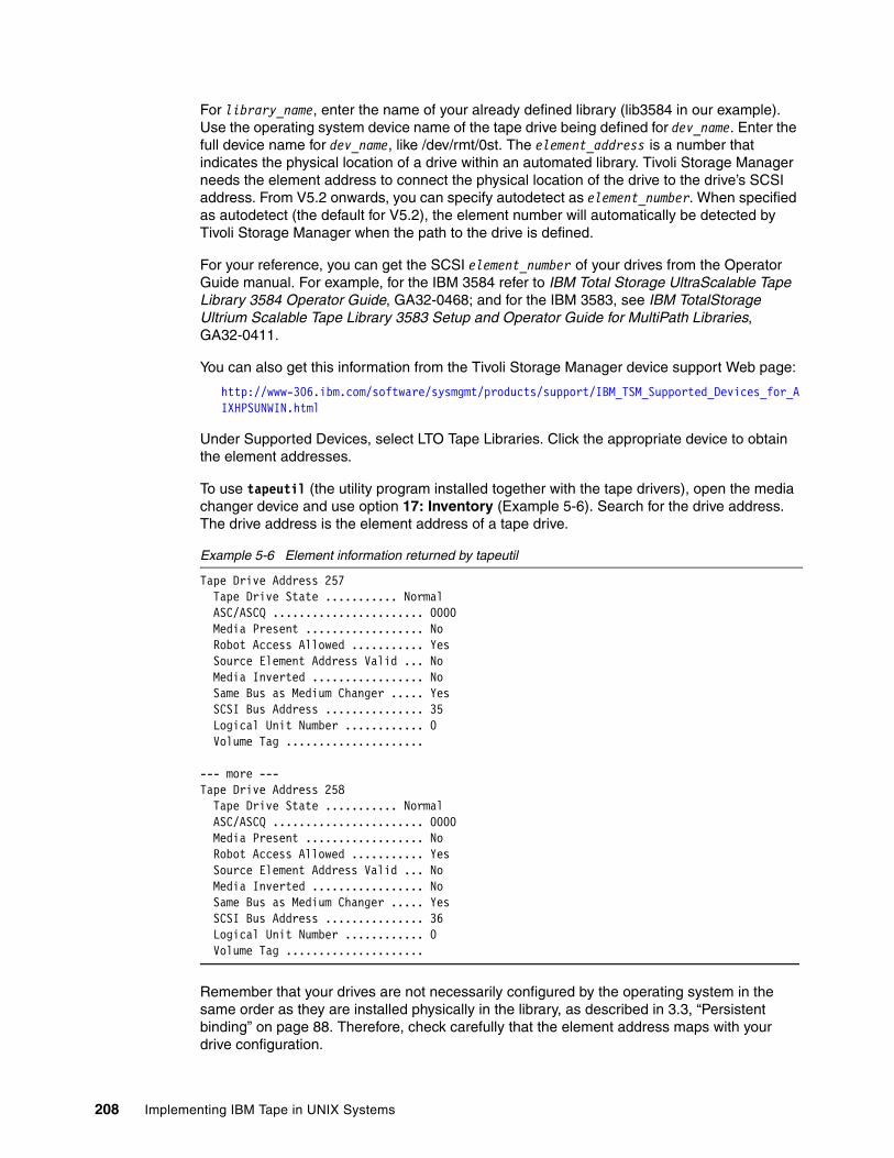
For library_name, enter the name of your already defined library (lib3584 in our example). Use the operating system device name of the tape drive being defined for dev_name. Enter the full device name for dev_name, like /dev/rmt/0st. The element_address is a number that indicates the physical location of a drive within an automated library. Tivoli Storage Manager needs the element address to connect the physical location of the drive to the drive’s SCSI address. From V5.2 onwards, you can specify autodetect as element_number. When specified as autodetect (the default for V5.2), the element number will automatically be detected by Tivoli Storage Manager when the path to the drive is defined.
For your reference, you can get the SCSI element_number of your drives from the Operator Guide manual. For example, for the IBM 3584 refer to IBM Total Storage UltraScalable Tape Library 3584 Operator Guide, GA32-0468; and for the IBM 3583, see IBM TotalStorage Ultrium Scalable Tape Library 3583 Setup and Operator Guide for MultiPath Libraries, GA32-0411.
You can also get this information from the Tivoli Storage Manager device support Web page:
http://www-306.ibm.com/software/sysmgmt/products/support/IBM_TSM_Supported_Devices_for_AIXHPSUNWIN.html
Under Supported Devices, select LTO Tape Libraries. Click the appropriate device to obtain the element addresses.
To use tapeutil (the utility program installed together with the tape drivers), open the media changer device and use option 17: Inventory (Example 5-6). Search for the drive address. The drive address is the element address of a tape drive.
Example 5-6 Element information returned by tapeutil
Tape Drive Address 257 Tape Drive State ........... Normal ASC/ASCQ ....................... 0000 Media Present .................. No Robot Access Allowed ........... Yes Source Element Address Valid ... No Media Inverted ................. No Same Bus as Medium Changer ..... Yes SCSI Bus Address ............... 35 Logical Unit Number ............ 0 Volume Tag .....................
--- more ---Tape Drive Address 258 Tape Drive State ........... Normal ASC/ASCQ ....................... 0000 Media Present .................. No Robot Access Allowed ........... Yes Source Element Address Valid ... No Media Inverted ................. No Same Bus as Medium Changer ..... Yes SCSI Bus Address ............... 36 Logical Unit Number ............ 0 Volume Tag .....................
Remember that your drives are not necessarily configured by the operating system in the same order as they are installed physically in the library, as described in 3.3, “Persistent binding” on page 88. Therefore, check carefully that the element address maps with your drive configuration.
208 Implementing IBM Tape in UNIX Systems
We configured our drives in the IBM 3584 with:
DEFINE DRIVE lib3584 drive1
DEFINE DRIVE lib3584 drive2
DEFINE PATH sol-e drive1 SRCTYPE=SERVER DESTTYPE=DRIVE LIBRARY=lib3584 \ DEVICE=/dev/rmt/0st
DEFINE PATH sol-e drive2 SRCTYPE=SERVER DESTTYPE=DRIVE LIBRARY=lib3584 \ DEVICE=/dev/rmt/2st
Continue the implementation with 5.2.5, “Define device class and storage pool” on page 212.
5.2.4 Configure non-shared tape library and drives for HP-UXYou should have already installed your tape drives and library according to Chapter 4, “Basic IBM tape setup for UNIX systems” on page 101, and Chapter 3, “SAN considerations” on page 75. Now determine the names of your devices; you should see a listing similar to Example 5-7.
Example 5-7 Installed and available drives and media changer on HP-UX
# ls -la /dev/rmtcrw-rw-rw- 1 bin bin 245 0x050000 Mar 16 11:13 0mcrw-rw-rw- 1 bin bin 245 0x050080 Mar 16 11:13 0mbcrw-rw-rw- 1 bin bin 245 0x050040 Mar 16 11:13 0mncrw-rw-rw- 1 bin bin 245 0x0500c0 Mar 17 17:14 0mnbcrw-rw-rw- 1 bin bin 245 0x051000 Mar 16 11:28 1mcrw-rw-rw- 1 bin bin 245 0x051080 Mar 16 11:13 1mbcrw-rw-rw- 1 bin bin 245 0x051040 Mar 16 11:13 1mncrw-rw-rw- 1 bin bin 245 0x0510c0 Mar 17 17:51 1mnbcrw-rw-rw- 1 bin bin 245 0x056000 Mar 16 11:14 2chngcrw-rw-rw- 1 bin bin 245 0xfffffc Mar 16 11:13 atdd.cfg
Note: The CLEANFREQUENCY parameter in the DEFINE DRIVE command is optional. Tivoli Storage Manager-managed cleaning is intended for drives and libraries that do not have an automatic cleaning function. The IBM 3581, 3582, 3583, and 3584 have an automatic cleaning function, which means they take care of drive cleaning. Therefore, it is not necessary to specify the CLEANFREQUENCY parameter since the default value is NONE.
The IBM 3581 2U does not have an automatic cleaning function; therefore, it is recommended to let Tivoli Storage Manager manage the cleaning of this device.
If you want Tivoli Storage Manager to control drive cleaning, you should use the option ASNEEDED. Change the auto cleaning function setting to the host cleaning function on the autoloader or library. Also, if you use a partitioned IBM 3584, then every logical partition needs its own cleaner cartridge.
There is no need to clean LTO drives on a periodic basis (that is, after a set number of gigabytes have been processed by the drive), and additional manual cleanings are discouraged.
Tip: Before defining the drives and libraries, make sure that your library is online and your drives are available to Solaris. Also, there should not be any cartridge loaded in the drive being defined.
Chapter 5. Implementing IBM Tivoli Storage Manager 209
crw-rw-rw- 1 bin bin 245 0xfffffd Mar 16 11:13 atdd.dbgcrw-r--r-- 1 root root 245 0xfffffe Mar 15 11:24 atdd_configcrw-rw-rw- 1 bin bin 245 0x050000 Mar 16 11:13 c5t0d0BESTcrw-rw-rw- 1 bin bin 245 0x050080 Mar 16 11:13 c5t0d0BESTbcrw-rw-rw- 1 bin bin 245 0x050040 Mar 16 11:13 c5t0d0BESTncrw-rw-rw- 1 bin bin 245 0x0500c0 Mar 16 11:13 c5t0d0BESTnbcrw-rw-rw- 1 bin bin 245 0x051000 Mar 16 11:14 c5t1d0BESTcrw-rw-rw- 1 bin bin 245 0x051080 Mar 16 11:14 c5t1d0BESTbcrw-rw-rw- 1 bin bin 245 0x051040 Mar 16 11:14 c5t1d0BESTncrw-rw-rw- 1 bin bin 245 0x0510c0 Mar 16 11:14 c5t1d0BESTnb
For performance reasons we suggest that you use hardware compression. Recording format ultriumc (Ultrium 1), ultrium2c (Ultrium 2), or ultrium3c (Ultrium 3), which are configured when the device class is defined, use hardware compression. More information on how to configure the device class is in 5.2.5, “Define device class and storage pool” on page 212.
Define the library and tape drivesUse the following commands to define the library, the library path, the drives, and the drive paths to Tivoli Storage Manager using the administrative command line. When there are multiple choices the default setting is listed last.
DEFINE LIBRARY library_name LIBTYPE=SCSI AUTOLABEL=yes/noEFINE PATH server_name library_name SRCTYPE=SERVER DESTTYPE=LIBRARY \ DEVICE=dev_name
For library_name, enter a user-specified name of the library to be defined:
DEFINE LIBRARY lto_3583 LIBTYPE=SCSI
For server_name, enter the name of your Tivoli Storage Manager server, and for dev_name, enter the full device name of the library, such as /dev/rmt/2chng.
DEFINE PATH easter lto_3583 SRCTYPE=SERVER DESTTYPE=LIBRARY DEVICE=/dev/rmt/2chng
Next, define each of the library’s drives and drive paths with:
DEFINE DRIVE library_name drive_name ELEMENT=element_number/AUTODETECT \ CLEANFREQUENCY=Gigabytes/ASNEEDED/NONE
DEFINE PATH server_name drive_name SRCTYPE=SERVER DESTTYPE=DRIVE \ LIBRARY=library_name DEVICE=dev_name
For library_name, enter the name of your already defined library (lto_3583 in our example). Use the operating system device name of the tape drive being defined for dev_name. Enter the full device name for dev_name such as /dev/rmt/0m. The element_address is a number that indicates the physical location of a drive within an automated library. Tivoli Storage Manager needs the element address to connect the physical location of the drive to the drive’s SCSI address. From V5.2 onwards, you can specify autodetect as the element_number. When specified as autodetect (default in V5.2) the element number will automatically be detected by Tivoli Storage Manager when the path to the drive is defined.
For your reference, you can get the SCSI element_number of your drives from the Operator Guide manual. For example, for the IBM 3584 refer to IBM Total Storage UltraScalable Tape Library 3584 Operator Guide, GA32-0468; for IBM 3583, see IBM TotalStorage Ultrium Scalable Tape Library 3583 Setup and Operator Guide for MultiPath Libraries, GA32-0411.
You can also get this information from the Tivoli Storage Manager device support Web page:
http://www-306.ibm.com/software/sysmgmt/products/support/IBM_TSM_Supported_Devices_for_AIXHPSUNWIN.html
210 Implementing IBM Tape in UNIX Systems
Under Supported Devices, select LTO Tape Libraries. Click the appropriate device to obtain the element addresses.
To use tapeutil (the utility program installed together with the tape drivers), open one device and use option 14: Element Inventory. Search for Drive Address. The drive address is the element address of a tape drive. Example 5-8 shows you two drives with the element addresses of 256 and 257.
Example 5-8 Element information returned by tapeutil
Drive Address 256 Drive State .................... Normal ASC/ASCQ ....................... 0000 Media Present .................. No Robot Access Allowed ........... Yes Source Element Address Valid ... No Media Inverted ................. No Same Bus as Medium Changer ..... Yes SCSI Bus Address ............... 0 Logical Unit Number Valid ...... No Volume Tag .....................
Hit <enter> to continue...
Drive Address 257 Drive State .................... Normal ASC/ASCQ ....................... 0000 Media Present .................. No Robot Access Allowed ........... Yes Source Element Address Valid ... No Media Inverted ................. No Same Bus as Medium Changer ..... Yes SCSI Bus Address ............... 1 Logical Unit Number Valid ...... No Volume Tag .....................
Keep in mind that your drives are not necessarily configured by the operating system in the same order as they are installed physically in the library, as described in 3.3, “Persistent binding” on page 88. Therefore, check carefully that the element address maps with your drive configuration.
Chapter 5. Implementing IBM Tivoli Storage Manager 211
We configured our drives in the IBM 3583 with:
DEFINE DRIVE lto_3583 drive1
DEFINE DRIVE lto_3583 drive2
DEFINE PATH easter drive1 SRCTYPE=SERVER DESTTYPE=DRIVE LIBRARY=lto_3583 \ DEVICE=/dev/rmt/0m
DEFINE PATH easter drive2 SRCTYPE=SERVER DESTTYPE=DRIVE LIBRARY=lto_3583 \ DEVICE=/dev/rmt/1m
Continue the implementation with the following section.
5.2.5 Define device class and storage poolConfiguring the device classes and storage pools is the same for the AIX, Solaris, and HP-UX environments. When there are multiple choices the default setting is listed last.
LTO 3 and LTO 2 definitions are similar, except for specifying format=ultrium3c or =ultrium2c.
Define device classConfigure the device class:
For LTO drives use LTO as DEVTYPE parameter.
DEFINE DEVCLASS devclass_name LIBRARY=library_name DEVTYPE=LTO \ FORMAT=Ultrium/UltriumC/Ultrium2/Ultium2C/Ultrium3/Ultrium3C/Drive \ MOUNTLIMIT=mount_limit/DRIVES
If using any 3592 drives use 3592 as DEVTYPE parameter.
DEFINE DEVCLASS devclass_name LIBRARY=library_name DEVTYPE=3592 \ FORMAT=3592/3592C/Drive MOUNTLIMIT=mount_limit/DRIVES
Note: The CLEANFREQUENCY parameter in the DEFINE DRIVE command is optional. Tivoli Storage Manager-managed cleaning is intended for drives and libraries that do not have an automatic cleaning function. The IBM 3581, 3582, 3583, and 3584 have an automatic cleaning function, which means they take care of drive cleaning. Therefore, it is not necessary to specify the CLEANFREQUENCY parameter since the default value is NONE.
The IBM 3581 2U does not have an automatic cleaning function; therefore, it is recommended to let Tivoli Storage Manager manage the cleaning of this device.
If you want Tivoli Storage Manager to control drive cleaning, you should use the option ASNEEDED. Change the auto cleaning function setting to the host cleaning function on the autoloader or library. Also, if you use a partitioned IBM 3584, then every logical partition needs its own cleaner cartridge.
There is no need to clean LTO drives on a periodic basis (that is, after a set number of gigabytes has been processed by the drive), and additional manual cleanings are discouraged.
Tip: Before defining the drives and libraries, make sure that your library is online and your drives are available to HP-UX. Also, there should not be any cartridges loaded in the drive being defined.
212 Implementing IBM Tape in UNIX Systems
The library_name will match the name of the library you previously defined.
The FORMAT parameter has the following valid options for LTO:
� drive
The server selects the highest format that can be supported by the drive on which a volume is mounted. This value will use the settings on the tape drive characteristics (device driver) for hardware compression. This is the default.
� ultrium
This specifies that Tivoli Storage Manager writes data using the ULTRIUM recording format. This format results in a cartridge capacity of 100 GB when using an Ultrium 100 GB data cartridge. This value overrides the settings on the tape drive characteristics for hardware compression.
� ultriumc
This specifies that Tivoli Storage Manager writes data using the ULTRIUM recording format with compression. This format results in a cartridge capacity of approximately 200 GB when using an Ultrium 100GB data cartridge. This value overrides the settings on the tape drive characteristics for hardware compression.
� ultrium2
Specifies that Tivoli Storage Manager writes data using the ULTRIUM2 recording format. This format results in a cartridge capacity of 200 GB when using Ultrium2 200 GB data cartridges. This value overrides the settings on the tape drive characteristics for hardware compression.
� ultrium2c
Specifies that Tivoli Storage Manager writes data using the ULTRIUM2 recording format with compression. This format results in a cartridge capacity of approximately 400 GB when using Ultrium2 200 GB data cartridges. This value overrides the settings on the tape drive characteristics for hardware compression.
� ultrium3
Specifies that Tivoli Storage Manager writes data using the ULTRIUM3 recording format. This format results in a cartridge capacity of 400 GB when using Ultrium3 400 GB data cartridges. This value overrides the settings on the tape drive characteristics for hardware compression.
� ultrium3c
Specifies that Tivoli Storage Manager writes data using the ULTRIUM3 recording format with compression. This format results in a cartridge capacity of approximately 800 GB when using Ultrium3 400 GB data cartridges. This value overrides the settings on the tape drive characteristics for hardware compression.
The FORMAT parameter has the following valid options for the 3592:
� 3592
Specifies that Tivoli Storage Manager writes data using the 3592 recording format. This format results in a cartridge capacity of 300 GB when using 3592 300GB data cartridges. This value overrides the settings on the tape drive characteristics for hardware compression.
� 3592c
Specifies that Tivoli Storage Manager writes data using the 3592 recording format with compression. This format results in a cartridge capacity of approximately 900 GB when
Chapter 5. Implementing IBM Tivoli Storage Manager 213
using 3592 300 GB data cartridges. This value overrides the settings on the tape drive characteristics for hardware compression.
Compression in general improves backup performance. Therefore, we recommend that you use compression either specifically with FORMAT=ultriumc/ultrium2c/ultrium3c/3592c; or with FORMAT= drive, which implies that the server selects the highest format that is supported by the drive on which a volume is mounted. (Do not use FORMAT= drive for a library containing a mix of Ultrium 1, 2, or 3 drives. Use the specific definitions, as described in detail in 5.11, “Device migration and co-existence” on page 237)
If you use recording FORMAT=ultriumc/ultrium2c/ultrium3c/3592c/drive, then your LAN-free clients also use compression regardless of whether hardware compression is enabled.
Note that Tivoli Storage Manager also provides optional client compression. If this is enabled, then clients compress their data before sending it to the storage device. This is particularly useful where the network connection between the client and server is slow and traffic needs to be minimized. With client compression on, using tape drive compression has little effect and is not recommended. You should evaluate your environment and requirements (probably by performing some appropriate testing) to determine if client compression is of benefit. If so, then enable it, and use the uncompressed (FORMAT=ultrium/ultrium2/ultrium3/3592) flag when defining the device class. If not, then tape drive compression should be used.
The option MOUNTLIMIT specifies the maximum number of sequential access volumes that can simultaneously be mounted for the device class. This parameter is optional. The default is drives, which means that the maximum is set to the number of drives installed and available in the library. There are two reasons why you might use a specific value rather than the default:
� If you are going to share the library among multiple servers, you may want to specify a number instead of the default drives to limit the number of drives each server has access to.
� If you have a mixture of LTO generation drives in the same library, see 5.11, “Device migration and co-existence” on page 237 for more information. It is then recommended that the default value of drives is not used for the older Ultrium x device classes. For example, when specifying MOUNTLIMIT=drives, the Tivoli Storage Manager server will load Ultrium 1 cartridges into Ultrium 1 drives in preference to Ultrium 2 or 3 drives, but there exists the possibility that all Ultrium 2 or 3 drives could be loaded with Ultrium 1 cartridges and therefore, an Ultrium 2 or 3 cartridge could not be loaded. It may be necessary to set the MOUNTLIMIT parameter to a value that is equal to the number of that version of drives, or certainly to a value less than the total number of drives in the library.
To define the IBM 3584 in our UNIX environment, we called the device class 3584ult_devclass, pointing to our previously defined library lib3584, specified ULTRIUM3C for the FORMAT parameter and set the MOUNTLIMIT to 2.
DEFINE DEVCLASS 3584ULT_devclass DEVTYPE=LTO LIBRARY=lib3584 FORMAT=ULTRIUM3C \ MOUNTLIMIT=2
Example 5-9 shows our device class definition.
Example 5-9 Query devclass 3584ult_devclass f=d
Device Class Name: 3584ULT_DEVCLASS Device Access Strategy: Sequential Storage Pool Count: 1 Device Type: LTO Format: ULTRIUM3C
214 Implementing IBM Tape in UNIX Systems
Est/Max Capacity (MB): Mount Limit: 2 Mount Wait (min): 60 Mount Retention (min): 60 Label Prefix: ADSM Library: LIB3584 Directory: Server Name: Retry Period: Retry Interval: Shared: High-level Address: Minimum Capacity: WORM: No Scaled Capacity: Last Update by (administrator): ADMIN Last Update Date/Time: 06/08/05 20:42:03
Define storage poolDefine the storage pool with:
DEFINE STGPOOL stgpool_name devclass_name MAXSCRATCH=number
This storage pool will be assigned (written) to the device class we just defined, so we specify the name, 3584ult_devclass. We used 3584ult_stgpool as the stgpool_name, and defined a maximum of 200 tapes belonging to this storage pool:
DEFINE STGPOOL 3584ult_stgpool 3584ult_devclass MAXSCRATCH=200
Example 5-10 shows you the storage pool we defined.
Example 5-10 q stgpool 3584ult_stgpool f=d
Storage Pool Name: 3584ULT_STGPOOL Storage Pool Type: Primary Device Class Name: 3584ULT_DEVCLASS Estimated Capacity (MB): 0.0 Pct Util: 0.0 Pct Migr: 0.0 Pct Logical: 100.0 High Mig Pct: 90 Low Mig Pct: 70 Migration Delay: 0 Migration Continue: Yes Migration Processes: Next Storage Pool: Reclaim Storage Pool: Maximum Size Threshold: No Limit Access: Read/Write Description: Overflow Location: Cache Migrated Files?: Collocate?: No Reclamation Threshold: 60 Maximum Scratch Volumes Allowed: 200 Delay Period for Volume Reuse: 0 Day(s) Migration in Progress?: No Amount Migrated (MB): 0.00Elapsed Migration Time (seconds): 0 Reclamation in Progress?: No
Chapter 5. Implementing IBM Tivoli Storage Manager 215
Volume Being Migrated/Reclaimed: Last Update by (administrator): ADMIN Last Update Date/Time: 10/06/03 18:01:50 Storage Pool Data Format: Native Copy Storage Pool(s): Continue Copy on Error?: CRC Data: No Last Update Date/Time: 06/09/05 20:50:18
Now you can use this storage pool in your management class copy groups, so that the device will be used for backups or archives.
5.2.6 Inserting data and cleaning cartridgesOnce we have set up our definitions, we need to identify the cartridges that Tivoli Storage Manager will use, either for storing data, or for cleaning the drives. LTO cartridges are identified as IBM machine type 3589. You can find information on how to buy LTO and 3592 cartridges from IBM, both data and cleaning, from the Web site:
http://www-1.ibm.com/servers/storage/media/
LTO and 3592 cartridges are also available from several other licensed manufacturers, which vary from country to country. Check your local sources for details.
Labeling data cartridgesTivoli Storage Manager requires each tape used to have a physical label written on it for identification. You can label volumes individually or process multiple volumes with variations of the label command. Here, we want to perform initial labeling of all the new tapes in our library. Since the IBM 3584 model has a barcode reader, and the tapes already have an external barcode label, this command will cause the matching label to be written onto the tape. It is not necessary that the magnetic label is the same as the barcode label; however, you will avoid a lot of confusion by making them identical. We put the new tapes directly into the library, then used the following command:
LABEL LIBVOLUME lib3584 SEARCH=yes LABELSOURCE=barcode CHECKIN=scratch
The parameter SEARCH=Yes means that Tivoli Storage Manager searches inside the library for any unlabeled volume with a readable barcode. It then mounts each cartridge in turn and writes the label onto the tape.
After issuing the LABEL LIBVOLUME command, you can check on the status of the inserted volumes with the QUERY LIBVOL command. Example 5-11 shows all the labeled cartridges with scratch status. The element address is also displayed, so we can tell which physical location contains each volume.
Attention: There should be no cleaning cartridges in the library inventory accessible from the host because Tivoli Storage Manager will try to label and mount them into a drive.
If you have enabled the tape library’s autoclean function, and cleaning cartridges were inserted as appropriate, then those cartridges are not accessible from the host, and no labeling operation will occur for them.
216 Implementing IBM Tape in UNIX Systems
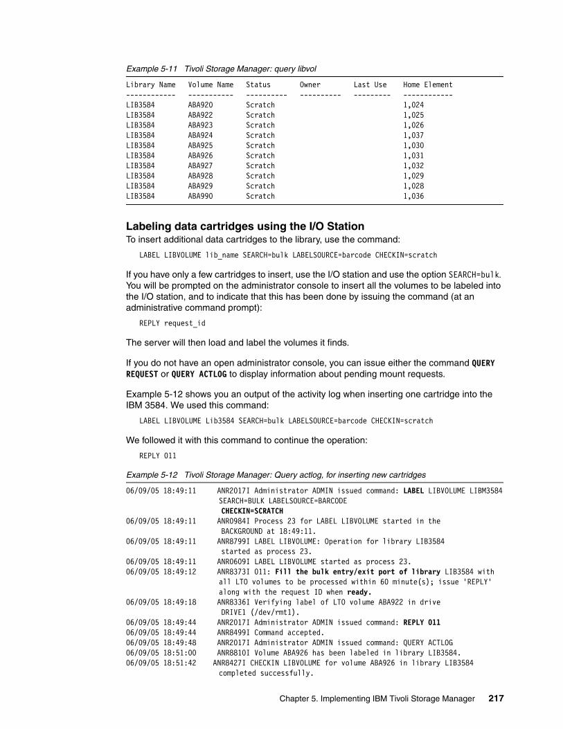
Example 5-11 Tivoli Storage Manager: query libvol
Library Name Volume Name Status Owner Last Use Home Element------------ ----------- ---------- ---------- --------- ------------LIB3584 ABA920 Scratch 1,024 LIB3584 ABA922 Scratch 1,025 LIB3584 ABA923 Scratch 1,026 LIB3584 ABA924 Scratch 1,037 LIB3584 ABA925 Scratch 1,030 LIB3584 ABA926 Scratch 1,031 LIB3584 ABA927 Scratch 1,032 LIB3584 ABA928 Scratch 1,029 LIB3584 ABA929 Scratch 1,028 LIB3584 ABA990 Scratch 1,036
Labeling data cartridges using the I/O StationTo insert additional data cartridges to the library, use the command:
LABEL LIBVOLUME lib_name SEARCH=bulk LABELSOURCE=barcode CHECKIN=scratch
If you have only a few cartridges to insert, use the I/O station and use the option SEARCH=bulk. You will be prompted on the administrator console to insert all the volumes to be labeled into the I/O station, and to indicate that this has been done by issuing the command (at an administrative command prompt):
REPLY request_id
The server will then load and label the volumes it finds.
If you do not have an open administrator console, you can issue either the command QUERY REQUEST or QUERY ACTLOG to display information about pending mount requests.
Example 5-12 shows you an output of the activity log when inserting one cartridge into the IBM 3584. We used this command:
LABEL LIBVOLUME Lib3584 SEARCH=bulk LABELSOURCE=barcode CHECKIN=scratch
We followed it with this command to continue the operation:
REPLY 011
Example 5-12 Tivoli Storage Manager: Query actlog, for inserting new cartridges
06/09/05 18:49:11 ANR2017I Administrator ADMIN issued command: LABEL LIBVOLUME LIBM3584SEARCH=BULK LABELSOURCE=BARCODE
CHECKIN=SCRATCH06/09/05 18:49:11 ANR0984I Process 23 for LABEL LIBVOLUME started in the BACKGROUND at 18:49:11.06/09/05 18:49:11 ANR8799I LABEL LIBVOLUME: Operation for library LIB3584 started as process 23.06/09/05 18:49:11 ANR0609I LABEL LIBVOLUME started as process 23.06/09/05 18:49:12 ANR8373I 011: Fill the bulk entry/exit port of library LIB3584 with
all LTO volumes to be processed within 60 minute(s); issue 'REPLY'along with the request ID when ready.
06/09/05 18:49:18 ANR8336I Verifying label of LTO volume ABA922 in drive DRIVE1 (/dev/rmt1). 06/09/05 18:49:44 ANR2017I Administrator ADMIN issued command: REPLY 011 06/09/05 18:49:44 ANR8499I Command accepted. 06/09/05 18:49:48 ANR2017I Administrator ADMIN issued command: QUERY ACTLOG 06/09/05 18:51:00 ANR8810I Volume ABA926 has been labeled in library LIB3584.06/09/05 18:51:42 ANR8427I CHECKIN LIBVOLUME for volume ABA926 in library LIB3584
completed successfully.
Chapter 5. Implementing IBM Tivoli Storage Manager 217
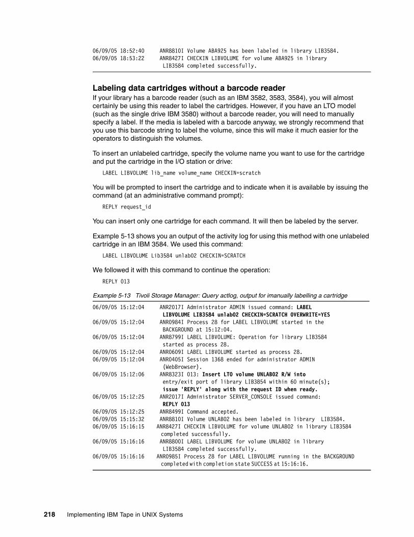
06/09/05 18:52:40 ANR8810I Volume ABA925 has been labeled in library LIB3584.06/09/05 18:53:22 ANR8427I CHECKIN LIBVOLUME for volume ABA925 in library LIB3584 completed successfully.
Labeling data cartridges without a barcode readerIf your library has a barcode reader (such as an IBM 3582, 3583, 3584), you will almost certainly be using this reader to label the cartridges. However, if you have an LTO model (such as the single drive IBM 3580) without a barcode reader, you will need to manually specify a label. If the media is labeled with a barcode anyway, we strongly recommend that you use this barcode string to label the volume, since this will make it much easier for the operators to distinguish the volumes.
To insert an unlabeled cartridge, specify the volume name you want to use for the cartridge and put the cartridge in the I/O station or drive:
LABEL LIBVOLUME lib_name volume_name CHECKIN=scratch
You will be prompted to insert the cartridge and to indicate when it is available by issuing the command (at an administrative command prompt):
REPLY request_id
You can insert only one cartridge for each command. It will then be labeled by the server.
Example 5-13 shows you an output of the activity log for using this method with one unlabeled cartridge in an IBM 3584. We used this command:
LABEL LIBVOLUME Lib3584 unlab02 CHECKIN=SCRATCH
We followed it with this command to continue the operation:
REPLY 013
Example 5-13 Tivoli Storage Manager: Query actlog, output for imanually labelling a cartridge
06/09/05 15:12:04 ANR2017I Administrator ADMIN issued command: LABEL LIBVOLUME LIB3584 unlab02 CHECKIN=SCRATCH OVERWRITE=YES 06/09/05 15:12:04 ANR0984I Process 28 for LABEL LIBVOLUME started in the BACKGROUND at 15:12:04.06/09/05 15:12:04 ANR8799I LABEL LIBVOLUME: Operation for library LIB3584 started as process 28.06/09/05 15:12:04 ANR0609I LABEL LIBVOLUME started as process 28.06/09/05 15:12:04 ANR0405I Session 1368 ended for administrator ADMIN (WebBrowser).06/09/05 15:12:06 ANR8323I 013: Insert LTO volume UNLAB02 R/W into entry/exit port of library LIB3854 within 60 minute(s); issue 'REPLY' along with the request ID when ready.06/09/05 15:12:25 ANR2017I Administrator SERVER_CONSOLE issued command: REPLY 01306/09/05 15:12:25 ANR8499I Command accepted.06/09/05 15:15:32 ANR8810I Volume UNLAB02 has been labeled in library LIB3584.06/09/05 15:16:15 ANR8427I CHECKIN LIBVOLUME for volume UNLAB02 in library LIB3584
completed successfully.06/09/05 15:16:16 ANR8800I LABEL LIBVOLUME for volume UNLAB02 in library LIB3584 completed successfully.06/09/05 15:16:16 ANR0985I Process 28 for LABEL LIBVOLUME running in the BACKGROUND
completed with completion state SUCCESS at 15:16:16.
218 Implementing IBM Tape in UNIX Systems
Inserting cleaner cartridgesIf you have chosen to have Tivoli Storage Manager manage library cleaning, you need to insert some cleaning cartridges. Use:
CHECKIN LIBVOLUME LIB3584 STATUS=cleaner CHECKLABEL=barcode SEARCH=bulk \ CLEANINGS=50
The parameter SEARCH=bulk means that Tivoli Storage Manager will search the library I/O station for usable volumes to check-in. Set the CLEANINGS parameter to the number of uses specified for your cartridge, for LTO this is 50. Insert one or more cleaner cartridges into the I/O station, and reply to the request issued by the server as shown in Example 5-14.
Example 5-14 Insert cleaner cartridge
06/09/05 20:02:56 ANR2017I Administrator ADMIN issued command: CHECKIN LIBVOLUME LIB3584 STATUS=CLEANER CHECKLABEL=BARCODE
MOUNTWAIT=60 SEARCH=BULK CLEANINGS=50 06/09/05 20:02:56 ANR0984I Process 4 for CHECKIN LIBVOLUME started in the BACKGROUND at 20:02:56.06/09/05 20:02:56 ANR8422I CHECKIN LIBVOLUME: Operation for library LIB3584 started as process 4.06/09/05 20:02:56 ANR0609I CHECKIN LIBVOLUME started as process 4.06/09/05 20:03:06 ANR8468I LTO volume ABA922 dismounted from drive DRIVE2 (/dev/rmt1) in library LIB3584.06/09/05 20:03:07 ANR8373I 001: Fill the bulk entry/exit port of library LIB3584
with all LTO volumes to be processed within 60 minute(s); issue'REPLY' along with the request ID when ready.
06/09/05 20:03:09 ANR2017I Administrator ADMIN issued command: QUERY ACTLOG06/09/05 20:03:21 ANR2017I Administrator ADMIN issued command: REPLY 001 06/09/05 20:03:21 ANR8499I Command accepted.06/09/05 20:03:26 ANR2017I Administrator ADMIN issued command: QUERY ACTLOG06/09/05 20:03:40 ANR2017I Administrator ADMIN issued command: QUERY ACTLOG06/09/05 20:03:46 ANR8430I Volume CLNI17 has been checked into library LIB3584.06/09/05 20:03:46 ANR1434W No files have been identified for automatically storing device configuration information.06/09/05 20:03:46 ANR8431I CHECKIN LIBVOLUME process completed for library LIB3584; 1 volume(s) found.06/09/05 20:03:46 ANR0985I Process 4 for CHECKIN LIBVOLUME running in the BACKGROUND completed with completion state SUCCESS at 20:03:46.
5.2.7 Performance hints for Tivoli Storage Manager with LTO or 3592Since Tivoli Storage Manager writes a record to its database of each file backed up, it will perform better with large file workloads than with small file workloads. This is because of the proportion of time spent doing database writes and updates as a fraction of the total backup time. Therefore, to get the best performance from Tivoli Storage Manager with LTO and IBM 3592 drives, be sure to update the parameter TXNGroupmax on the server to a higher value than the default 256. This parameter controls how many files are transferred as a group between the client and server. Note that the larger the txngroupmax value, the bigger the Tivoli Storage Manager database log area must be.
Tip: Tivoli Storage Manager V5.2 increased the maximum size for TXNGroupmax to 8192, and in V5.3 this is further increased to 65000. A value of 4096 or higher is recommended for environments that back up numerous small files such as 10 KB files. With Tivoli Storage Manager V5.3 this parameter may also be defined for the individual clients. Thus an intermediate value, say 2048, can be set for the server, and the high values should then be defined individually when registering the client.
Chapter 5. Implementing IBM Tivoli Storage Manager 219
In the client option file, also set the parameter TXNBytelimit to its maximum of 2097152 (2 GB). This parameter specifies the number of kilobytes the client program can buffer together in one transaction before it sends data to the server.
To set TXNGroupmax, edit the dsmserv.opt on the Tivoli Storage Manager server as shown in Example 5-15. If you are using the Storage Agent for LAN-free backup you should also set this parameter to the same value in the options file dsmsta.opt. The restart of the server process is required to enable this change (for Storage Agent, restart of the Storage Agent process is required).
Example 5-15 TXNGroupmax entry in dsmserv.opt and dsmsta.opt
*==============================================================================* TXNGROUPMAX** Specifies the maximum number of files transferred as a group between* the client and storage agent.** Syntax* +------------------+----------------------------------------------+* | TXNGroupmax | value |* +------------------+----------------------------------------------+** Parameters* value Specifies the maximum number of files that are* transferred as a group between the client and* storage agent. The minimum value is 4 and the maximum* value is 65000. The default value is 256.** Examples TXNGroupmax 4096
Alternatively, the parameter may be set online to the server by the command:
SETOPT TXNGROUPMAX 4096
To set the client parameter TXNBytelimit, edit dsm.sys (for UNIX clients) or dsm.opt (for all other clients). The entry should look like:
TXNBytelimit 2097152
In general, small file workloads will back up faster if they are staged initially to a disk storage pool, which then migrates to the tape pool. More suggestions on storage pool configuration are in IBM Tivoli Storage Manager Implementation Guide, SG24-5416. We also recommended the use of compression on the tape drives as previously discussed in this chapter.
5.3 LTO WORM (Write Once Read Many)The Ultrium 3 tape drive now has WORM functionality. Special LTO 3 WORM cartridges (identified as LT cartridges) are designed to provide non-alterable, non-rewritable tape media for long-term records retention.
Tivoli Storage Manager supports IBM LTO WORM devices and media at V5.2.4.5 and V.5.3.1.2. IBM LTO WORM devices are only available with Ultrium 3 devices and media. To use LTO WORM, an LTO WORM device class definition is required. This uses the WORM=YES parameter in the definition.
220 Implementing IBM Tape in UNIX Systems
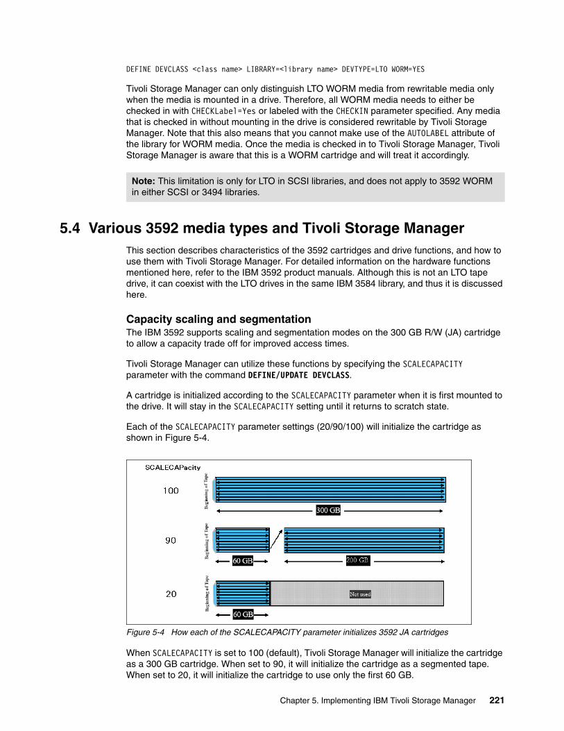
DEFINE DEVCLASS <class name> LIBRARY=<library name> DEVTYPE=LTO WORM=YES
Tivoli Storage Manager can only distinguish LTO WORM media from rewritable media only when the media is mounted in a drive. Therefore, all WORM media needs to either be checked in with CHECKLabel=Yes or labeled with the CHECKIN parameter specified. Any media that is checked in without mounting in the drive is considered rewritable by Tivoli Storage Manager. Note that this also means that you cannot make use of the AUTOLABEL attribute of the library for WORM media. Once the media is checked in to Tivoli Storage Manager, Tivoli Storage Manager is aware that this is a WORM cartridge and will treat it accordingly.
5.4 Various 3592 media types and Tivoli Storage ManagerThis section describes characteristics of the 3592 cartridges and drive functions, and how to use them with Tivoli Storage Manager. For detailed information on the hardware functions mentioned here, refer to the IBM 3592 product manuals. Although this is not an LTO tape drive, it can coexist with the LTO drives in the same IBM 3584 library, and thus it is discussed here.
Capacity scaling and segmentationThe IBM 3592 supports scaling and segmentation modes on the 300 GB R/W (JA) cartridge to allow a capacity trade off for improved access times.
Tivoli Storage Manager can utilize these functions by specifying the SCALECAPACITY parameter with the command DEFINE/UPDATE DEVCLASS.
A cartridge is initialized according to the SCALECAPACITY parameter when it is first mounted to the drive. It will stay in the SCALECAPACITY setting until it returns to scratch state.
Each of the SCALECAPACITY parameter settings (20/90/100) will initialize the cartridge as shown in Figure 5-4.
Figure 5-4 How each of the SCALECAPACITY parameter initializes 3592 JA cartridges
When SCALECAPACITY is set to 100 (default), Tivoli Storage Manager will initialize the cartridge as a 300 GB cartridge. When set to 90, it will initialize the cartridge as a segmented tape. When set to 20, it will initialize the cartridge to use only the first 60 GB.
Note: This limitation is only for LTO in SCSI libraries, and does not apply to 3592 WORM in either SCSI or 3494 libraries.
Chapter 5. Implementing IBM Tivoli Storage Manager 221

Depending on the customer requirements, in most cases you should use either the SCALECAPACITY=100 for capacity-oriented applications (for example, data backup) or SCALECAPACITY=20 for access-oriented applications such as HSM.
There is no practical reason for using SCALECAPACITY=90 because you cannot control where the data is written on the tape. After the first 60 GB segment is filled, the drive will proceed to write on the rest of the (slower access) tape. Each of the segmented parts must be defined to a different storage pool to fully utilize the segmented function, but with the current Tivoli Storage Manager architecture, it is not possible to define two storage pools for one volume.
WORM (Write Once Read Many)The IBM 3592 WORM data cartridges are designed to provide non-alterable, non-rewritable tape media for long-term records retention. The drive will automatically determine if the mounted volume is a WORM or R/W cartridge.
To use this function, specify the parameter WORM=yes in the command DEFINE/UPDATE DEVCLASS. Tivoli Storage Manager V5.2.3 or later is required.
Because Tivoli Storage Manager can distinguish between WORM and R/W cartridges (assigns “media type” of 412 for WORM cartridges and 411 for R/W cartridges at the time of check-in), you can have both WORM and R/W cartridges in a single logical library just by defining device classes, one with WORM=yes and the other with WORM=no.
Short length (economy) cartridgesBoth R/W and WORM cartridges are available with the standard length (300 GB) and the short length (60 GB) format.
The following cartridges formats are available for the 3592:
� JA (ETC) 609m 300 GB Standard R/W Tape� JJ (EETC) 246m 60 GB Short R/W Tape� JW (EWTC) 609m 300 GB Standard WORM Tape� JR (EEWTC) 246m 60 GB Short WORM Tape
For a JA cartridge, define the device class as follows; you have the option to specify the SCALECAPACITY parameter:
DEFINE DEVCLASS devclass_name DEVTYPE=3592 FORMAT=3592/3592c/drive \ LIBRARY=library_name SCALECAPACITY=20/90/100
For JJ cartridges, define the device class as follows:
DEFINE DEVCLASS devclass_name DEVTYPE=3592 FORMAT=3592/3592c/drive \ LIBRARY=library_name
For JW and JR cartridges, define device class as follows:
DEFINE DEVCLASS devclass_name DEVTYPE=3592 FORMAT=3592/3592c/drive \ LIBRARY=library_name WORM=yes
The SCALECAPACITY parameter with value other than 100 (default) can be specified only with the standard length R/W cartridge.
When the short length cartridges are initially defined to a storage pool, QUERY VOLUME and QUERY STGPOOL will show you 300 GB (or 900 GB for compressed) for each of the volumes
Note: For the IBM TotalStorage 3494 Tape Library, you would also need to specify WORMSCRATCHCATEGORY with the DEFINE/UPDATE LIBRARY command.
222 Implementing IBM Tape in UNIX Systems
defined. When the EOV (end-of-volume) is reached; query commands will show the actual data written for the volume.
Fast access storage pool with IBM 3592 in Tivoli Storage ManagerTo configure a fast access storage pool with 3592 drives, you have two options:
1. Define a device class with SCALECAPACITY=20 and use standard length R/W cartridges.
2. Use short length (economy) cartridges.
To set up both the fast access storage pool and the non-fast access (optimized for capacity) storage pool in a single logical library:
1. If using method (1) to configure the fast access storage pool:
Define a separate device class for each storage pool, one with SCALECAPACITY=100 and one with SCALECAPACITY=20. The scratch JA tape will automatically be initialized to the storage pool it is called for.
2. If using method (2) to configure the fast access storage pool:
Since Tivoli Storage Manager does not distinguish between the short length and the standard length cartridges, you would need to define each of the cartridges explicitly to the storage pool.
It is probably be a better idea to just logically partition the library into a short length cartridge only partition (fast access partition), and a standard length cartridge only partition (capacity partition).
5.5 Sharing LTO libraries with Tivoli Storage ManagerThe concepts of library sharing were discussed in Chapter 2, “IBM LTO Tape Library sharing and partitioning” on page 35. In this section we briefly discuss configuration parameters to consider; for in-depth discussion of Tivoli Storage Manager, library sharing, and the use of SAN, refer to the redbook Get More Out of Your SAN with IBM Tivoli Storage Manager, SG24-6687.
Several Tivoli Storage Manager servers can share the same tape library using the library sharing feature, as shown in Figure 5-2 on page 200. Tape library sharing is supported between any combination of Windows, AIX, Solaris, Linux, and HP-UX Tivoli Storage Manager servers. We recommend using the latest code level. You can find the link to download the latest code fixes at:
http://www-306.ibm.com/software/sysmgmt/products/support/IBMTivoliStorageManager.html
All servers that will share the library need to have an FC/SAN connection to the tape drives in the library. One server will control the library robotics and is designated the Library Manager. Other library users are designated Library Clients. Services are requested from the Library Manager, rather than the library itself as in non-shared library configurations. For instance, if a library client wants to write data to a tape, then the client has to ask the Library Manager to mount the tape volume. After the tape is mounted by the Library Manager, the library client can write the data directly over the physical SAN path to the tape drive.
5.5.1 Configuring the Library Manager to share librariesInstall and configure your tape library and drives on the Library Manager, as described in 5.2, “Non-shared tape device with Tivoli Storage Manager” on page 202. Register the license for library sharing, and define the library with the shared=yes parameter, such as:
Chapter 5. Implementing IBM Tivoli Storage Manager 223
REGISTER LICENSE FILE=libshare.lic NUMBER=1DEFINE LIBRARY lto_3584 LIBTYPE=SCSI SHARED=YES
Define drives and path information as for the non-shared environment.
Because library sharing uses server-to-server communication for sending and receiving requests, you need to configure server-to-server communications between the Library Manager and the library clients.
Set the following parameters on the Library Manager: servername, password, serverhladdress, serverlladdress, and set crossdefine to on.
SET SERVERNAME server_nameSET SERVERPASSWORD server_passwordSET CROSSDEFINE onSET SERVERHLADDRESS server_ip_addressSET SERVERLLADDRESS server_ip_portaddress
5.5.2 Configuring the library clientThe library client is similarly set up for crossdefine.Set the parameters: servername, password, serverhladdress, serverlladdress, and set crossdefine to on.
SET SERVERNAME server_nameSET SERVERPASSWORD server_passwordSET CROSSDEFINE onSET SERVERHLADDRESS server_ip_addressSET SERVERLLADDRESS server_ip_portaddress
Next, we define the Library Manager server on each of the library clients, so that they will know which system is managing the tape libraries. Use the DEFINE SERVER command and match the parameters to the server definitions on the Library Manager (server name, password, IP address, and port number).
DEFINE SERVER library_manager_servername SERVERPASSWORD=library_manager_password HLADDRESS=library_manager_ip_address LLADDRESS=library_manager_port_number COMM=tcpip
Since we have set crossdefine to on, these commands should automatically create library client definitions on the Library Manager. Check this with the QUERY SERVER command.
5.5.3 Define library and drives for library clientSee Chapter 4, “Basic IBM tape setup for UNIX systems” on page 101, and Chapter 3, “SAN considerations” on page 75 for basic tape drive installation on the library clients.
You will need to define the library definition at each library client. The drive paths must be defined for each library client drive, but this definition is done at the Library Manager.
DEFINE LIBRARY library_name LIBTYPE=shared PRIMARYLIBMANAGER=lib_manager_name
Note the use of the LIBTYPE=shared parameter. You must use the same library_name as was defined on the library server.
On the Library Manager define each of the tape drive paths for each library client as:
DEFINE PATH server_name drive_name SRCTYPE=SERVER DESTTYPE=DRIVE \ LIBRARY=library_name DEVICE=device_name
224 Implementing IBM Tape in UNIX Systems
For server_name, enter the name of the library client, and for device_name specify the name of the device special file on the library client machine.
You can check the result with the command Q PATH.
Now you can define the device class and the storage pool using the library definitions as described in 5.2.5, “Define device class and storage pool” on page 212.
5.5.4 Administering shared librariesWhen using a shared LTO library, it is important to remember that the library clients cannot directly access the library robotics (medium changer) themselves. Any requests for tape movement must be made through the Library Manager. While library clients do not directly access the library robotics, once a volume is mounted in a drive, the library clients can read or write data directly to the drive through the SAN data path. This means that certain commands give different output, or are not applicable in some circumstances.
QUERY LIBVOLUMEIf you use the QUERY LIBVOLUME on the Library Manager, the output will now also display which Tivoli Storage Manager server is the “owner” of each volume, as shown in Example 5-16.
Example 5-16 Q LIBVOL on a Library Manager
Library Name Volume Name Status Owner Last Use Home Element------------ ----------- ---------- ---------- --------- ------------LTO_3584 ABA920 Private SICILY Data 4,114 LTO_3584 ABA922 Private SICILY Data 4,104 LTO_3584 ABA923 Scratch 4,106 LTO_3584 ABA924 Scratch 4,107 LTO_3584 ABA925 Private SICILY 4,130 LTO_3584 ABA926 Private SICILY 4,098 LTO_3584 ABA927 Private BRAZIL Data 4,102 LTO_3584 ABA928 Private BRAZIL Data 4,111 LTO_3584 ABA929 Private BRAZIL Data 4,112 LTO_3584 ABA990 Private BRAZIL Data 4,133
The library client is only using the drives, and has no knowledge of the library contents. Example 5-17 shows executing QUERY LIBVOLUME on a library client.
Example 5-17 Q LIBVOL on a library client
tsm: BRAZIL> QUERY LIBVOLUMEANR2017I Administrator ADMIN issued command: QUERY LIBVANR2034E QUERY LIBVOLUME: No match found using this criteria.
QUERY VOLUMEQuerying the volumes (QUERY VOLUME) on any attached server will report only those volumes that belong to that server.
Important: Keep in mind that the drives are not necessarily configured by the operating system in the same order as they are installed physically in the library, as described in 3.3, “Persistent binding” on page 88. Therefore, check carefully that the element address matches your drive configuration.
Chapter 5. Implementing IBM Tivoli Storage Manager 225
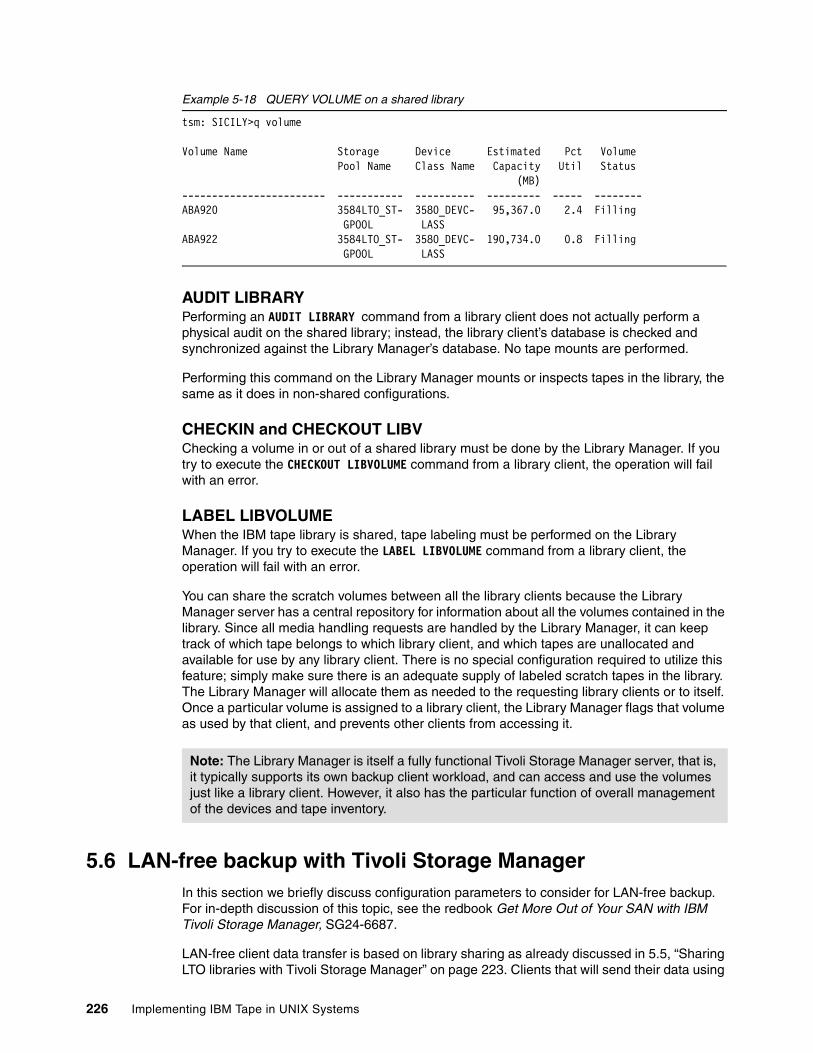
Example 5-18 QUERY VOLUME on a shared library
tsm: SICILY>q volume
Volume Name Storage Device Estimated Pct Volume Pool Name Class Name Capacity Util Status (MB)------------------------ ----------- ---------- --------- ----- --------ABA920 3584LTO_ST- 3580_DEVC- 95,367.0 2.4 Filling GPOOL LASSABA922 3584LTO_ST- 3580_DEVC- 190,734.0 0.8 Filling GPOOL LASS
AUDIT LIBRARYPerforming an AUDIT LIBRARY command from a library client does not actually perform a physical audit on the shared library; instead, the library client’s database is checked and synchronized against the Library Manager’s database. No tape mounts are performed.
Performing this command on the Library Manager mounts or inspects tapes in the library, the same as it does in non-shared configurations.
CHECKIN and CHECKOUT LIBVChecking a volume in or out of a shared library must be done by the Library Manager. If you try to execute the CHECKOUT LIBVOLUME command from a library client, the operation will fail with an error.
LABEL LIBVOLUMEWhen the IBM tape library is shared, tape labeling must be performed on the Library Manager. If you try to execute the LABEL LIBVOLUME command from a library client, the operation will fail with an error.
You can share the scratch volumes between all the library clients because the Library Manager server has a central repository for information about all the volumes contained in the library. Since all media handling requests are handled by the Library Manager, it can keep track of which tape belongs to which library client, and which tapes are unallocated and available for use by any library client. There is no special configuration required to utilize this feature; simply make sure there is an adequate supply of labeled scratch tapes in the library. The Library Manager will allocate them as needed to the requesting library clients or to itself. Once a particular volume is assigned to a library client, the Library Manager flags that volume as used by that client, and prevents other clients from accessing it.
5.6 LAN-free backup with Tivoli Storage ManagerIn this section we briefly discuss configuration parameters to consider for LAN-free backup. For in-depth discussion of this topic, see the redbook Get More Out of Your SAN with IBM Tivoli Storage Manager, SG24-6687.
LAN-free client data transfer is based on library sharing as already discussed in 5.5, “Sharing LTO libraries with Tivoli Storage Manager” on page 223. Clients that will send their data using
Note: The Library Manager is itself a fully functional Tivoli Storage Manager server, that is, it typically supports its own backup client workload, and can access and use the volumes just like a library client. However, it also has the particular function of overall management of the devices and tape inventory.
226 Implementing IBM Tape in UNIX Systems
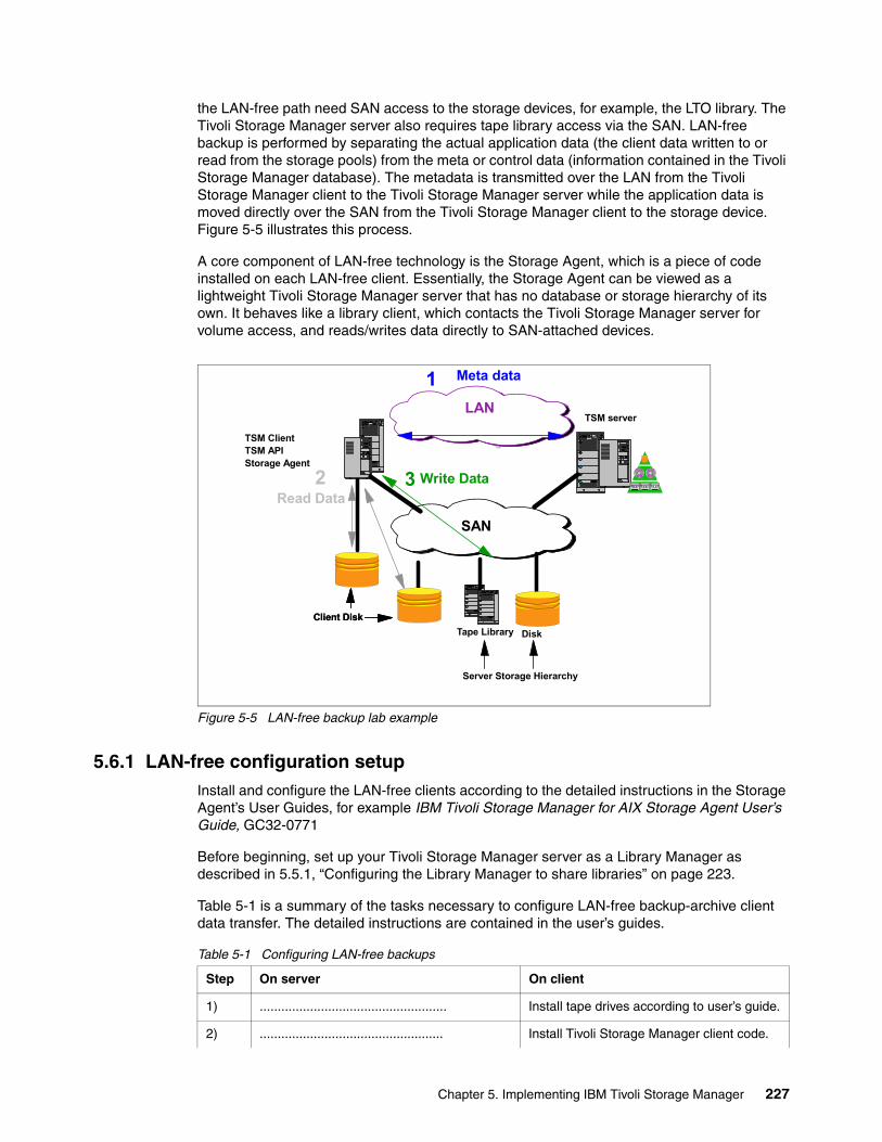
the LAN-free path need SAN access to the storage devices, for example, the LTO library. The Tivoli Storage Manager server also requires tape library access via the SAN. LAN-free backup is performed by separating the actual application data (the client data written to or read from the storage pools) from the meta or control data (information contained in the Tivoli Storage Manager database). The metadata is transmitted over the LAN from the Tivoli Storage Manager client to the Tivoli Storage Manager server while the application data is moved directly over the SAN from the Tivoli Storage Manager client to the storage device. Figure 5-5 illustrates this process.
A core component of LAN-free technology is the Storage Agent, which is a piece of code installed on each LAN-free client. Essentially, the Storage Agent can be viewed as a lightweight Tivoli Storage Manager server that has no database or storage hierarchy of its own. It behaves like a library client, which contacts the Tivoli Storage Manager server for volume access, and reads/writes data directly to SAN-attached devices.
Figure 5-5 LAN-free backup lab example
5.6.1 LAN-free configuration setupInstall and configure the LAN-free clients according to the detailed instructions in the Storage Agent’s User Guides, for example IBM Tivoli Storage Manager for AIX Storage Agent User’s Guide, GC32-0771
Before beginning, set up your Tivoli Storage Manager server as a Library Manager as described in 5.5.1, “Configuring the Library Manager to share libraries” on page 223.
Table 5-1 is a summary of the tasks necessary to configure LAN-free backup-archive client data transfer. The detailed instructions are contained in the user’s guides.
Table 5-1 Configuring LAN-free backups
TSM server
TSM ClientTSM APIStorage Agent
3 Write Data
3
Read Data
Meta data1
2
Client Disk
LAN
SAN
Tape Library Disk Client Disk
Server Storage Hierarchy
Step On server On client
1) .................................................... Install tape drives according to user’s guide.
2) ................................................... Install Tivoli Storage Manager client code.
Chapter 5. Implementing IBM Tivoli Storage Manager 227
5.6.2 Define path considerationsConsider the following guidelines for mapping your SAN drives:
� Define paths to all drives. Problems can occur if you do not define paths from the server to each drive in a library. For example, during backup operations, all drives that have paths can be used by the Storage Agent in backing up data. Backup operations will fail if you try to use other drives in a library that do not have defined paths. When paths are defined for each drive in a library, backup operations wait until the next drive is available for the transfer of data.
� If you want to limit the number of drives available to a node, you can use the MAXNUMMP parameter with the REGISTER NODE or UPDATE NODE command. This will limit the number of drives that are available for the Storage Agent to use on behalf of the client.
� Review tape device names. For the same tape device, the device name as known to the server will probably not match the device name as known to the Storage Agent, as described in 3.3, “Persistent binding” on page 88.
3) .................................................... Modify dsm.sys of backup-archive client with: ENABLELANFREE YESLANFREECommethod TCPIPLANFREETCPPort port_number
4) .................................................... Install the Storage Agent.
5) .................................................... Specify the DEVCONFIG option in the dsmsta.opt of Storage Agent:DEVCONFIG outputfile
6) Define each LAN-free client Storage Agent as if it was a server. Use the DEFINE SERVER command.
....................................................
7) .................................................... Set the installation data for the Storage Agent with:DSMSTA SETSTORAGESERVER
8) Register clients for LAN-free backup. If needed, define a separate domain. Also register license for LAN-free nodes.
...................................................
9) .................................................... Obtain Tape Device information (see 5.6.2 Define path considerations).
10) Use the DEFINE PATH command to define paths from the Storage Agent to the drives that are available to the Tivoli Storage Manager server (see 5.6.2 Define path considerations).
...................................................
11) .................................................... Test if data transfer goes over the SAN
Note: Make sure TXNGROUPMAX in dsmsta.opt is set at the same value as that in dsmserv.opt. When using LTO or 3592 drives, it is recommended to set this value to 256 or higher for performance reasons. Refer to 5.2.7, “Performance hints for Tivoli Storage Manager with LTO or 3592” on page 219.
Step On server On client
228 Implementing IBM Tape in UNIX Systems
Define paths on the server using the device names as seen by the Storage Agent on each client system. Use the DEFINE PATH command:
DEFINE PATH storageagent_name drive_name SRCTYPE=SERVER DESTTYPE=DRIVE \ LIBRARY=library_name DEVICE=dev_name_on_storageagent
Where:
� storageagent_name is the name of the storage agent.� drive_name is the tape drive name defined on the Tivoli Storage Manager server.� library_name is the tape library name defined on the server.� dev_name_on_storageagent is the device special file name of the tape drive on the storage
agent machine (for example, /dev/rmt0).
5.7 NDMP backup with Tivoli Storage ManagerNetwork Data Management Protocol (NDMP) is an open standard protocol developed to eliminate the issues associated with the decentralization of backup standards for file servers, and dedicated Network Attached Storage (NAS) file servers.
NDMP backup is provided with IBM Tivoli Storage Manager Enterprise Edition. This is well documented in the Administration Guide for your Tivoli Storage Manager platform, for example for Windows server:
� IBM Tivoli Storage Manager for Windows Administrators Guide, GC32-0782.
Also see the redbook:
� IBM Tivoli Storage Manager Implementation Guide, SG24-5416.
5.7.1 Network Attached StorageNetwork Attached Storage (NAS) is a way to make large amounts of disk storage available to many clients using standard file sharing protocols. A NAS box (sometimes also called a NAS appliance or file server) consists of a number of standard disks, one or more network adapters (NICs), and a controller that typically runs an embedded, specialized operating system used to configure and administer the box. The NAS appliance exists as an entity on the network. The disks are divided up into volumes, which can then be accessed by other servers or workstations using standard file sharing protocols like NFS and CIFS. Network Attached Storage is, therefore, easy and relatively cheap to implement, since standard file sharing methods and normal network adapters are used to access the data.
But the question arises, how do you back up the data in the NAS box? One way is to back up the mounted file systems from a client that is accessing it. However, this involves multiple network accesses and may or may not back up metadata, like access control lists, correctly. Or, you could write/modify a backup client to run directly on the NAS appliance itself. The issue here is that vendors use different operating systems (often specialized) for their appliances, which means multiple ports of the backup client would be necessary. A standard is really needed to make NAS backup easier.
Important: Remember also that the drives are not necessarily configured by the operating system in the same order as they are installed physically in the library, as described in 3.3, “Persistent binding” on page 88. Therefore, check carefully that the element address matches your drive configuration.
Chapter 5. Implementing IBM Tivoli Storage Manager 229
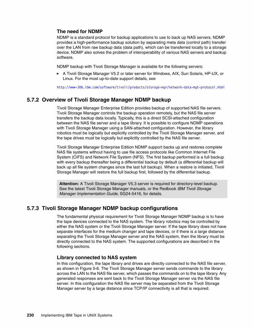
The need for NDMPNDMP is a standard protocol for backup applications to use to back up NAS servers. NDMP provides a high-performance backup solution by separating meta data (control path) transfer over the LAN from raw backup data (data path), which can be transferred locally to a storage device. NDMP also solves the problem of interoperability of various NAS servers and backup software.
NDMP backup with Tivoli Storage Manager is available for the following servers:
� A Tivoli Storage Manager V5.2 or later server for Windows, AIX, Sun Solaris, HP-UX, or Linux. For the most up-to-date support details, see
http://www-306.ibm.com/software/tivoli/products/storage-mgr/network-data-mgt-protocol.html
5.7.2 Overview of Tivoli Storage Manager NDMP backupTivoli Storage Manager Enterprise Edition provides backup of supported NAS file servers. Tivoli Storage Manager controls the backup operation remotely, but the NAS file server transfers the backup data locally. Typically, this is a direct SCSI-attached configuration between the NAS file server and a tape library. It is possible to configure NDMP operations with Tivoli Storage Manager using a SAN-attached configuration. However, the library robotics must be logically but explicitly controlled by the Tivoli Storage Manager server, and the tape drives must be logically but explicitly controlled by the NAS file server.
Tivoli Storage Manager Enterprise Edition NDMP support backs up and restores complete NAS file systems without having to use file access protocols like Common Internet File System (CIFS) and Network File System (NFS). The first backup performed is a full backup with every backup thereafter being a differential backup by default (a differential backup will back up all file system changes since the last full backup). When a restore is initiated, Tivoli Storage Manager will restore the full backup first, followed by the differential backup.
5.7.3 Tivoli Storage Manager NDMP backup configurationsThe fundamental physical requirement for Tivoli Storage Manager NDMP backup is to have the tape devices connected to the NAS system. The library robotics may be controlled by either the NAS system or the Tivoli Storage Manager server. If the tape library does not have separate interfaces for the medium changer and tape devices, or if there is a large distance separating the Tivoli Storage Manager server and the NAS system, then the library must be directly connected to the NAS system. The supported configurations are described in the following sections.
Library connected to NAS systemIn this configuration, the tape library and drives are directly connected to the NAS file server, as shown in Figure 5-6. The Tivoli Storage Manager server sends commands to the library across the LAN to the NAS file server, which passes the commands on to the tape library. Any generated responses are sent back to the Tivoli Storage Manager server via the NAS file server. In this configuration the NAS file server may be separated from the Tivoli Storage Manager server by a large distance since TCP/IP connectivity is all that is required.
Attention: A Tivoli Storage Manager V5.3 server is required for directory-level backup. See the latest Tivoli Storage Manager manuals, or the Redbook IBM Tivoli Storage Manager Implementation Guide, SG24-5416, for details.
230 Implementing IBM Tape in UNIX Systems
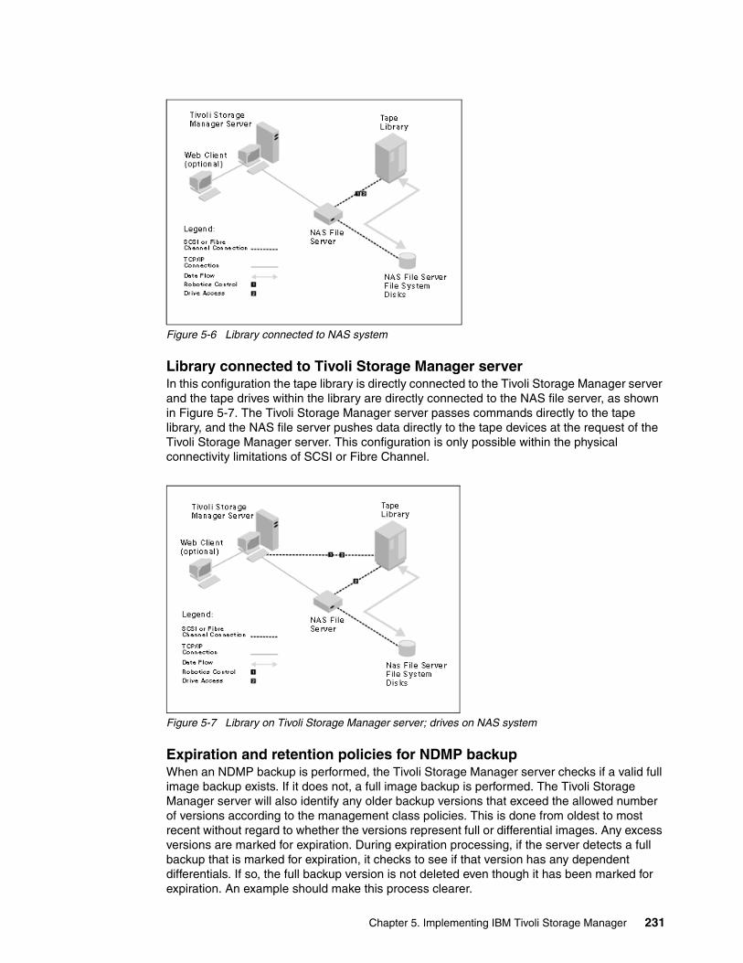
Figure 5-6 Library connected to NAS system
Library connected to Tivoli Storage Manager server In this configuration the tape library is directly connected to the Tivoli Storage Manager server and the tape drives within the library are directly connected to the NAS file server, as shown in Figure 5-7. The Tivoli Storage Manager server passes commands directly to the tape library, and the NAS file server pushes data directly to the tape devices at the request of the Tivoli Storage Manager server. This configuration is only possible within the physical connectivity limitations of SCSI or Fibre Channel.
Figure 5-7 Library on Tivoli Storage Manager server; drives on NAS system
Expiration and retention policies for NDMP backupWhen an NDMP backup is performed, the Tivoli Storage Manager server checks if a valid full image backup exists. If it does not, a full image backup is performed. The Tivoli Storage Manager server will also identify any older backup versions that exceed the allowed number of versions according to the management class policies. This is done from oldest to most recent without regard to whether the versions represent full or differential images. Any excess versions are marked for expiration. During expiration processing, if the server detects a full backup that is marked for expiration, it checks to see if that version has any dependent differentials. If so, the full backup version is not deleted even though it has been marked for expiration. An example should make this process clearer.
Chapter 5. Implementing IBM Tivoli Storage Manager 231
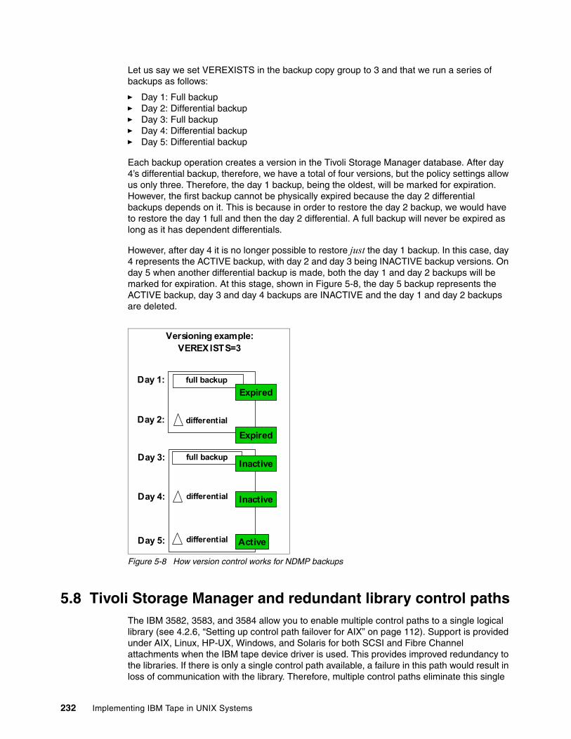
Let us say we set VEREXISTS in the backup copy group to 3 and that we run a series of backups as follows:
� Day 1: Full backup� Day 2: Differential backup� Day 3: Full backup� Day 4: Differential backup� Day 5: Differential backup
Each backup operation creates a version in the Tivoli Storage Manager database. After day 4’s differential backup, therefore, we have a total of four versions, but the policy settings allow us only three. Therefore, the day 1 backup, being the oldest, will be marked for expiration. However, the first backup cannot be physically expired because the day 2 differential backups depends on it. This is because in order to restore the day 2 backup, we would have to restore the day 1 full and then the day 2 differential. A full backup will never be expired as long as it has dependent differentials.
However, after day 4 it is no longer possible to restore just the day 1 backup. In this case, day 4 represents the ACTIVE backup, with day 2 and day 3 being INACTIVE backup versions. On day 5 when another differential backup is made, both the day 1 and day 2 backups will be marked for expiration. At this stage, shown in Figure 5-8, the day 5 backup represents the ACTIVE backup, day 3 and day 4 backups are INACTIVE and the day 1 and day 2 backups are deleted.
Figure 5-8 How version control works for NDMP backups
5.8 Tivoli Storage Manager and redundant library control pathsThe IBM 3582, 3583, and 3584 allow you to enable multiple control paths to a single logical library (see 4.2.6, “Setting up control path failover for AIX” on page 112). Support is provided under AIX, Linux, HP-UX, Windows, and Solaris for both SCSI and Fibre Channel attachments when the IBM tape device driver is used. This provides improved redundancy to the libraries. If there is only a single control path available, a failure in this path would result in loss of communication with the library. Therefore, multiple control paths eliminate this single
Versioning example:VEREXISTS=3
full backupDay 3:
Day 4:
Day 5:
Day 1: full backup
differential
differential
Day 2: differential
Expired
Inactive
Expired
Active
Inactive
232 Implementing IBM Tape in UNIX Systems
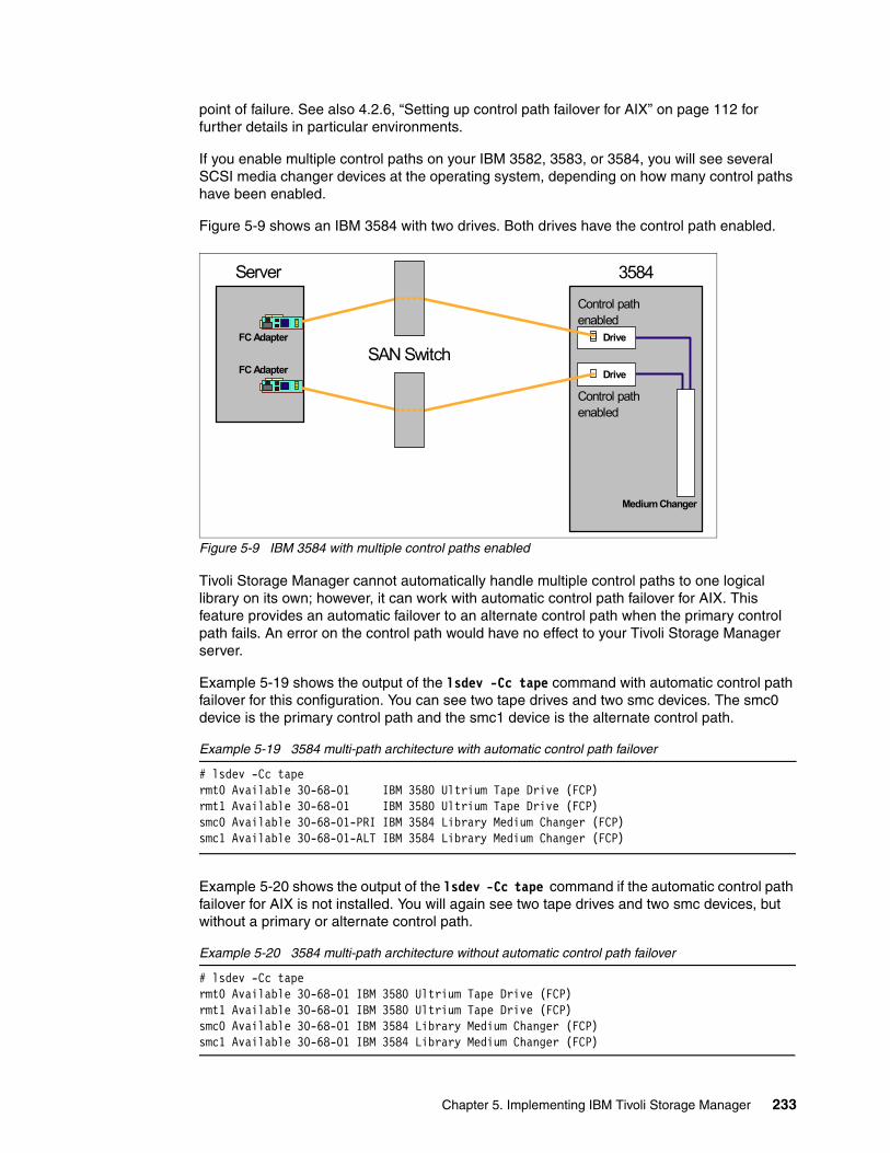
point of failure. See also 4.2.6, “Setting up control path failover for AIX” on page 112 for further details in particular environments.
If you enable multiple control paths on your IBM 3582, 3583, or 3584, you will see several SCSI media changer devices at the operating system, depending on how many control paths have been enabled.
Figure 5-9 shows an IBM 3584 with two drives. Both drives have the control path enabled.
Figure 5-9 IBM 3584 with multiple control paths enabled
Tivoli Storage Manager cannot automatically handle multiple control paths to one logical library on its own; however, it can work with automatic control path failover for AIX. This feature provides an automatic failover to an alternate control path when the primary control path fails. An error on the control path would have no effect to your Tivoli Storage Manager server.
Example 5-19 shows the output of the lsdev -Cc tape command with automatic control path failover for this configuration. You can see two tape drives and two smc devices. The smc0 device is the primary control path and the smc1 device is the alternate control path.
Example 5-19 3584 multi-path architecture with automatic control path failover
# lsdev -Cc tapermt0 Available 30-68-01 IBM 3580 Ultrium Tape Drive (FCP)rmt1 Available 30-68-01 IBM 3580 Ultrium Tape Drive (FCP)smc0 Available 30-68-01-PRI IBM 3584 Library Medium Changer (FCP)smc1 Available 30-68-01-ALT IBM 3584 Library Medium Changer (FCP)
Example 5-20 shows the output of the lsdev -Cc tape command if the automatic control path failover for AIX is not installed. You will again see two tape drives and two smc devices, but without a primary or alternate control path.
Example 5-20 3584 multi-path architecture without automatic control path failover
# lsdev -Cc tapermt0 Available 30-68-01 IBM 3580 Ultrium Tape Drive (FCP)rmt1 Available 30-68-01 IBM 3580 Ultrium Tape Drive (FCP)smc0 Available 30-68-01 IBM 3584 Library Medium Changer (FCP)smc1 Available 30-68-01 IBM 3584 Library Medium Changer (FCP)
3584
FC Adapter
Server
Control pathenabled
SAN Switch
Control pathenabled
Medium Changer
Drive
Drive
FC Adapter
Chapter 5. Implementing IBM Tivoli Storage Manager 233
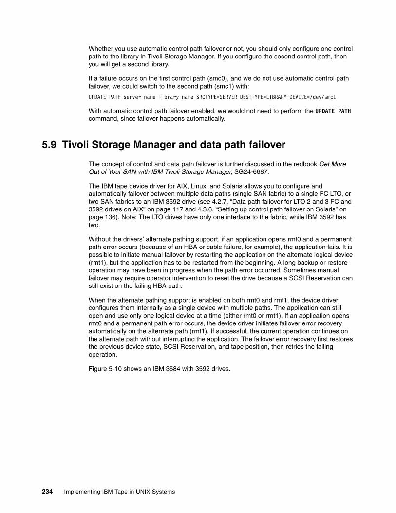
Whether you use automatic control path failover or not, you should only configure one control path to the library in Tivoli Storage Manager. If you configure the second control path, then you will get a second library.
If a failure occurs on the first control path (smc0), and we do not use automatic control path failover, we could switch to the second path (smc1) with:
UPDATE PATH server_name library_name SRCTYPE=SERVER DESTTYPE=LIBRARY DEVICE=/dev/smc1
With automatic control path failover enabled, we would not need to perform the UPDATE PATH command, since failover happens automatically.
5.9 Tivoli Storage Manager and data path failover
The concept of control and data path failover is further discussed in the redbook Get More Out of Your SAN with IBM Tivoli Storage Manager, SG24-6687.
The IBM tape device driver for AIX, Linux, and Solaris allows you to configure and automatically failover between multiple data paths (single SAN fabric) to a single FC LTO, or two SAN fabrics to an IBM 3592 drive (see 4.2.7, “Data path failover for LTO 2 and 3 FC and 3592 drives on AIX” on page 117 and 4.3.6, “Setting up control path failover on Solaris” on page 136). Note: The LTO drives have only one interface to the fabric, while IBM 3592 has two.
Without the drivers’ alternate pathing support, if an application opens rmt0 and a permanent path error occurs (because of an HBA or cable failure, for example), the application fails. It is possible to initiate manual failover by restarting the application on the alternate logical device (rmt1), but the application has to be restarted from the beginning. A long backup or restore operation may have been in progress when the path error occurred. Sometimes manual failover may require operator intervention to reset the drive because a SCSI Reservation can still exist on the failing HBA path.
When the alternate pathing support is enabled on both rmt0 and rmt1, the device driver configures them internally as a single device with multiple paths. The application can still open and use only one logical device at a time (either rmt0 or rmt1). If an application opens rmt0 and a permanent path error occurs, the device driver initiates failover error recovery automatically on the alternate path (rmt1). If successful, the current operation continues on the alternate path without interrupting the application. The failover error recovery first restores the previous device state, SCSI Reservation, and tape position, then retries the failing operation.
Figure 5-10 shows an IBM 3584 with 3592 drives.
234 Implementing IBM Tape in UNIX Systems
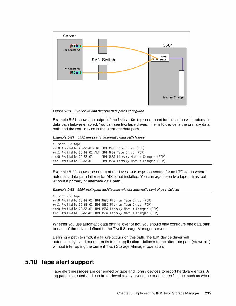
Figure 5-10 3592 drive with multiple data paths configured
Example 5-21 shows the output of the lsdev -Cc tape command for this setup with automatic data path failover enabled. You can see two tape drives. The rmt0 device is the primary data path and the rmt1 device is the alternate data path.
Example 5-21 3592 drives with automatic data path failover
# lsdev -Cc tapermt0 Available 20-58-01-PRI IBM 3592 Tape Drive (FCP)rmt1 Available 30-68-01-ALT IBM 3592 Tape Drive (FCP)smc0 Available 20-58-01 IBM 3584 Library Medium Changer (FCP)smc1 Available 30-68-01 IBM 3584 Library Medium Changer (FCP)
Example 5-22 shows the output of the lsdev -Cc tape command for an LTO setup where automatic data path failover for AIX is not installed. You can again see two tape drives, but without a primary or alternate data path.
Example 5-22 3584 multi-path architecture without automatic control path failover
# lsdev -Cc tapermt0 Available 20-58-01 IBM 3580 Ultrium Tape Drive (FCP)rmt1 Available 30-68-01 IBM 3580 Ultrium Tape Drive (FCP)smc0 Available 20-58-01 IBM 3584 Library Medium Changer (FCP)smc1 Available 30-68-01 IBM 3584 Library Medium Changer (FCP)
Whether you use automatic data path failover or not, you should only configure one data path to each of the drives defined to the Tivoli Storage Manager server.
Defining a path to rmt0, if a failure occurs on this path, the IBM device driver will automatically—and transparently to the application—failover to the alternate path (/dev/rmt1) without interrupting the current Tivoli Storage Manager operation.
5.10 Tape alert supportTape alert messages are generated by tape and library devices to report hardware errors. A log page is created and can be retrieved at any given time or at a specific time, such as when
3584
Server
SAN Switch
Medium Changer
3592Drive
FC Adapter A
FC Adapter B
Chapter 5. Implementing IBM Tivoli Storage Manager 235
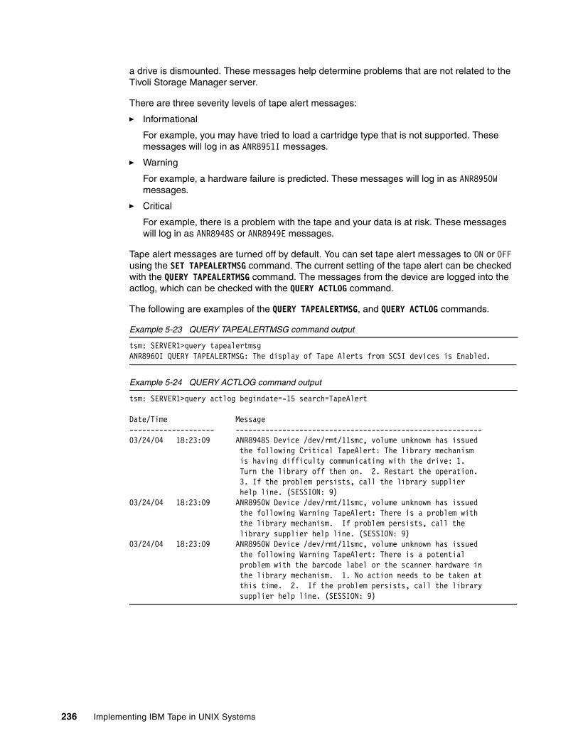
a drive is dismounted. These messages help determine problems that are not related to the Tivoli Storage Manager server.
There are three severity levels of tape alert messages:
� Informational
For example, you may have tried to load a cartridge type that is not supported. These messages will log in as ANR8951I messages.
� Warning
For example, a hardware failure is predicted. These messages will log in as ANR8950W messages.
� Critical
For example, there is a problem with the tape and your data is at risk. These messages will log in as ANR8948S or ANR8949E messages.
Tape alert messages are turned off by default. You can set tape alert messages to ON or OFF using the SET TAPEALERTMSG command. The current setting of the tape alert can be checked with the QUERY TAPEALERTMSG command. The messages from the device are logged into the actlog, which can be checked with the QUERY ACTLOG command.
The following are examples of the QUERY TAPEALERTMSG, and QUERY ACTLOG commands.
Example 5-23 QUERY TAPEALERTMSG command output
tsm: SERVER1>query tapealertmsgANR8960I QUERY TAPEALERTMSG: The display of Tape Alerts from SCSI devices is Enabled.
Example 5-24 QUERY ACTLOG command output
tsm: SERVER1>query actlog begindate=-15 search=TapeAlert
Date/Time Message -------------------- ----------------------------------------------------------03/24/04 18:23:09 ANR8948S Device /dev/rmt/11smc, volume unknown has issued the following Critical TapeAlert: The library mechanism is having difficulty communicating with the drive: 1. Turn the library off then on. 2. Restart the operation. 3. If the problem persists, call the library supplier help line. (SESSION: 9) 03/24/04 18:23:09 ANR8950W Device /dev/rmt/11smc, volume unknown has issued the following Warning TapeAlert: There is a problem with the library mechanism. If problem persists, call the library supplier help line. (SESSION: 9) 03/24/04 18:23:09 ANR8950W Device /dev/rmt/11smc, volume unknown has issued the following Warning TapeAlert: There is a potential problem with the barcode label or the scanner hardware in the library mechanism. 1. No action needs to be taken at this time. 2. If the problem persists, call the library supplier help line. (SESSION: 9)
236 Implementing IBM Tape in UNIX Systems
5.11 Device migration and co-existenceCareful planning is recommended when introducing and mixing new generations of media technology with Tivoli Storage Manager. This is because new format generations cannot be read by older drives, and conversely the old formats cannot necessarily be read and written by the new drives. Tivoli Storage Manager controls the media through the library changer by using SCSI commands, and cannot detect the internal format of a cartridge. Tivoli Storage Manager has always taken the position that all media must be at least readable by all the drives in a given library. With Tivoli Storage Manager V5.2 and higher, you can operate with mixed media types when the library is able to distinguish the different media.
This section provides information on migration and co-existence issues for LTO Ultrium 1, 2, and 3 drives in one library, and with Tivoli Storage Manager V5.1 and V5.2 or newer. First, we define a few terms.
Mixed media librariesMixed media in a Tivoli Storage Manager server describes devices using different device types (in the devclass) in the same logical library. LTO and 3592 are examples of two devices that need different device classes, but can co-exist in the same library. Mixed media is supported in Tivoli Storage Manager V5.2 and higher.
Mixed generation devicesA mixed generation device in a Tivoli Storage Manager server describes devices that use the same device types (from DEFINE DEVCLASS) despite capacity differences. In order to have mixed generation devices in the same device class, the media types must be distinguishable.
The design specifications for Ultrium devices are:
Ultrium 1 Can read and write Ultrium 1 cartridges
Ultrium 2 Can read and write Ultrium 1 and Ultrium 2 cartridges
Ultrium 3 Can read and write Ultrium 2 and 3 cartridges, and can read Ultrium 1 cartridges.
5.11.1 ScenariosIn the lifetime of a Tivoli Storage Manager server, there will be times when new technology or customer requirements will allow the expansion of storage capacity through new devices. This might occur through the addition of a new library to an existing Tivoli Storage Manager server, or through increased capacity of a new or upgraded tape drive in an existing library.
In both these instances you need to decide whether to install the new technology and retire the old technology, or operate both technologies in parallel.
For Ultrium 1, Ultrium 2, and Ultrium 3 drives, Table 5-2 describes some of the migration and co-existence possibilities in one physical library, and also the migration from an existing
Note: In mixed generation environments, the current generation device can generally read and write current and previous generation media. The previous generation device can only read and write previous generation media. LTO Ultrium devices are an example of mixed generation devices.
Note: Tivoli Storage Manager V5.2.4.0 or higher provides support for the Ultrium 3 drives, while support for Ultrium 2 is available as of V5.1.6.1.
Chapter 5. Implementing IBM Tivoli Storage Manager 237

library to a new LTO library, relative to the version of Tivoli Storage Manager used. You may need to upgrade the library firmware for Ultrium 2 or Ultrium 3 device support and library partitioning support. We discuss each scenario in more detail in the following sections.
The table and subsequent discussion do not attempt to show all migration possibilities, but cover the most obvious scenarios. For several of the configuration scenarios, there are 2 identical discussions. In general, whatever applies to coexistence and migration of Ultrium 2 and 3, is also valid for coexistence and migration of the older Ultrium 1and 2.
Table 5-2 LTO migration and co-existence examples
Scenario 1There are 2 similar scenarios. Install Ultrium 3 drives in addition to the current Ultrium 2 drives and media, or the equivalent scenario for the older generation: install Ultrium 2 drives in addition to the current Ultrium 1 drives and media.
We can install the new Ultrium 3 devices with existing Ultrium 2 devices into the same logical library and device class because of mixed generation support. The Ultrium 3 devices will be able to read and write the Ultrium 2 cartridges at the Ultrium 2 speed and capacity.
Similarly, we can install the Ultrium 2 devices with existing Ultrium 1 devices into the same logical library and device class because of mixed generation support. The Ultrium 2 devices will be able to read and write the Ultrium 1 cartridges at the Ultrium 1 speed and capacity.
Scenario Configuration TSM V5.1.6.1 TSM V5.2 TSM 5.2.4 or 5.3
1 a) Ultrium 2 + 3 drivesUltrium 2 Media-----------------
b) Ultrium 1 + 2 drives, Ultrium 1 Media
--------------------1 logical library1 devclass
--------------------1 logical library 1 devclass
1 logical library 1 devclass
2 a) Ultrium 2 + 3 drivesUltrium 2 + 3 Media-----------------
b) Ultrium 1 + 2 drives,Ultrium 1 + 2 Media
--------------------2 logical libraries2 devclass
--------------------1 logical library 2 devclass
1 logical library 2 devclass
3 Ultrium 1 + 2 + 3 drivesUltrium 1 + 2 + 3 Media
1 logical library 3 devclass
4 a) Migrate Ultrium 2 to 3 drivesUltrium 2 + 3 Media-----------------
b) Migrate Ultrium 1 to 2 drivesUltrium 1 + 2 Media
--------------------1 logical library1 devclass
--------------------1 logical library 1 devclass
1 logical library 1 devclass
5 a) Migrate Ultrium 2 to 3 drivesMigrate media Ultrium 2 to 3 -----------------
b) Migrate Ultrium 1 to 2 drivesMigrate Media Ultrium 1 to 2
--------------------1 logical library1 devclass
--------------------1 logical library1 devclass
1 logical library 1 devclass
6 Migrate Ultrium 1 to 3 drivesMigrate media Ultrium 1 to 3
1 logical library1 devclass
7 Migrate existing tape storage to LTO Ultrium
2 libraries 2 devclass
2 libraries 2 devclass
2 libraries 2 devclass
238 Implementing IBM Tape in UNIX Systems
Scenario 2Install Ultrium 3 drives and Ultrium 3 media in addition to existing Ultrium 2 drives and Ultrium 2 media.
As of Tivoli Storage Manager V5.2, mixed media types are supported in one library, and thus different generations of tape devices can co-exist in the same logical library. However, two device classes are required because of the two media types.
All of the tape devices are available to the Ultrium 2 device class, but only Ultrium 3 devices are available to the Ultrium 3 device class. Tivoli Storage Manager will ensure that Ultrium 3 media will only be loaded into Ultrium 3 devices for reading and writing. Ultrium 2 media will be read from or written to by all the Ultrium 2 and 3 devices.
In Tivoli Storage Manager V5.1, we would have to separate the physical Ultrium device types into separate logical libraries and device classes. Therefore, one Tivoli Storage Manager with both Ultrium 1 and 2 drives would have to define at least two logical libraries and the physical library would have to support library partitioning. Again, Tivoli Storage Manager will ensure that only Ultrium 2 media are loaded in the Ultrium 2 drives, while Ultrium 1 media can be read and written by both Ultrium 1 and 2 drives.
Scenario 3As of Tivoli Storage Manager V5.2.4, Ultrium 3 drives are supported, and any combination of Ultrium 1, 2, and 3 drives and media can be used in one library. As discussed in scenario 2, Ultrium 3 drives can read and write Ultrium 2 media. Similarly the Ultrium 2 drives can read and write Ultrium 1 media.
Although Ultrium 3 drives can read the Ultrium 1 media (but cannot write to it), care should be taken to avoid attempted writing. Set the MOUNTLIMIT option for the Ultrium 1 devclass to less than the sum of Ultrium 1 and 2 drives (see the previous tip), thereby preventing the Ultrium 1 media from being loaded in the Ultrium 3 drives. The Ultrium 1 media will still be available for normal use by the Ultrium 1 and 2 drives.
Alternatively, the migration path will be to have all Ultrium 1 media set to read-only for use by all drives, and the Ultrium 1 drives and media eventually phased out of the library.
Tip: MOUNTLIMIT
For read or write tape mounts, Tivoli Storage Manager will select Ultrium 2 drives for Ultrium 2 media first. If no Ultrium 2 devices are available, an available Ultrium 3 drive will be selected for the Ultrium 2 media. To prevent the case where all Ultrium 3 drives are loaded with Ultrium 2 media (leaving no drives available to read/write Ultrium 3 media, set the DEVCLASS parameter MOUNTLIMIT appropriately. For example:
� MOUNTLIMIT can be set to the number of Ultrium 2 drives in the library for the Ultrium 2 devclass, so it will not use Ultrium 3 drives at all.
� MOUNTLIMIT can be set to the number of Ultrium 2 drives plus half the number of Ultrium 3 drives. This is a compromise position to allow good drive utilization, but reserves some Ultrium 3 drives for Ultrium 3 media.
You should define a suitable MOUNTLIMIT, which works for your environment.
Chapter 5. Implementing IBM Tivoli Storage Manager 239
Scenario 4Replace all Ultrium 2 drives with Ultrium 3 drives, using the existing Ultrium 2 media and installing additional Ultrium 3 media:
1. Delete the existing Ultrium 2 device DRIVE and PATH entries and define new DRIVE and PATH entries for the Ultrium 3 devices.
2. The replacement of the Ultrium 2 drives with Ultrium 3 drives will also affect the Tivoli Storage Manager device class parameter format, which should now be set to ultrium3c.
The same discussion applies using the older generation Ultrium 1 and Ultrium 2 media and drives.
Scenario 5Replace all Ultrium 2 drives with Ultrium 3 drives, and choose to migrate the existing Ultrium 2 media to Ultrium 3 media:
1. Delete the existing Ultrium 2 device DRIVE and PATH entries, and define new DRIVE and PATH entries for the Ultrium 3 devices.
2. Remove empty Ultrium 2 media and install Ultrium 3 media (label 1 in Figure 5-11).
3. Over time, update the Ultrium 2 media ACCESS to READONLY. This ensures they will then not be written to any more by any Tivoli Storage Manager client or server operation (label 2 in Figure 5-11).
4. You can leave the existing utilized Ultrium 2 cartridges as they are, and over time, expiration of old backups and reclamation will reduce the usage of the old cartridges.
5. However, if you want to drain the existing Ultrium 2 cartridges more quickly, you can execute a MOVE DATA volume_name LTO_storage_pool_name command, selecting each individual Ultrium 2 volume and targeting the LTO storage pool.
6. Once the old Ultrium 2 cartridges are emptied, the cartridges can be checked out of the library and new Ultrium 3 cartridges can be checked in to replace them (label 3 in Figure 5-11).
7. The replacement of the Ultrium 2 drives and media with Ultrium 3 drives and media will also affect the device class parameter format, which should be set to DRIVE, ULTRIUM3, or ULTRIUM3C. If the format parameter is left at ULTRIUM2 or ULTRIUM2C, a write will still occur to the end of Ultrium 3 media, but the pre-determined capacity of the storage pool will only show Ultrium 2 capacity on the command query stgpool.
Tip: The devclass format parameter is used to pre-determine the capacity value of a storage pool. Because we now have media with varying amounts of capacity (200 GB and 400 GB native), the storage pool values will not be correct. If this is an issue, then use two device classes as described in Scenario 2.
240 Implementing IBM Tape in UNIX Systems
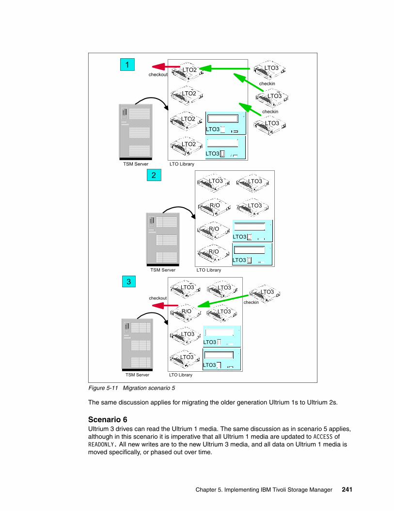
Figure 5-11 Migration scenario 5
The same discussion applies for migrating the older generation Ultrium 1s to Ultrium 2s.
Scenario 6Ultrium 3 drives can read the Ultrium 1 media. The same discussion as in scenario 5 applies, although in this scenario it is imperative that all Ultrium 1 media are updated to ACCESS of READONLY. All new writes are to the new Ultrium 3 media, and all data on Ultrium 1 media is moved specifically, or phased out over time.
LTO3
LTO3R/O
LTO3
LTO3 LTO32
R/O
R/O
TSM Server LTO Library
LTO3
LTO3R/O
LTO3
LTO3 LTO33
LTO3
LTO3
TSM Server LTO Library
checkoutLTO3
checkin
LTO3
LTO2
LTO3LTO2
LTO2
LTO2
LTO3
LTO3
LTO31
TSM Server LTO Library
checkout
checkin
checkin
Chapter 5. Implementing IBM Tivoli Storage Manager 241
Scenario 7Replace an existing tape library and migrate the client data to a new LTO tape library. The steps are the same whether migrating to Ultrium 2 or Ultrium 3 drives and media. You are, however, encouraged always to migrate to the newest generation library.
Various techniques can be used. We describe migrating the data by using an existing management class. This only requires modifying the currently used storage pool to cascade to the new LTO storage pool. This has the advantage of being less disruptive, and has no affect on the client option files.
We give two possibilities for storage pools, depending on whether the primary destination is a disk or tape (sequential) pool.
Sequential storage pool as primary copy destination Your modification affects the storage pools only.
1. Define the new LTO library, library path, drives, drive paths, and device classes.
2. Create an LTO sequential storage pool and/or copy storage pool using the new LTO device class (label 1 in Figure 5-12).
3. Modify the NEXTSTGPOOL parameter of the old storage pool to point to the new LTO storage pool (label 2 in Figure 5-12).
4. Update the old storage pool ACCESS to READONLY.
5. You can leave the old storage pool as it is, and over time, expiration of old backups will reduce the usage of the old storage pool.
However, if you want to drain the old storage pool more quickly, you can simply set HIGHMIG and LOWMIG to zero. This starts a migration process that moves data from the old storage pool to the new LTO storage pool. To speed up the migration, you can increase the MIGPROCESS limit for the old storage pool to use more drives (remember this is a drive-to-drive process).
6. Alternatively, you can execute a MOVE DATA volume_name LTO_storage_pool_name command, selecting each individual volume from the old storage pool, and targeting the new LTO storage pool.
7. Once the old storage pool is emptied, modify the BACKUP and ARCHIVE COPY GROUP of each management class to point the DESTINATION to the new LTO Storage pool (label 3 in Figure 5-12).
8. Delete the DRIVE and PATH, and also the LIBRARY and PATH entries for the old library and drives.
Note: This assumes that you want to move the entire storage pool content to the new LTO, since you cannot have the storage pool read-only for certain management classes, and read-write for others.
242 Implementing IBM Tape in UNIX Systems
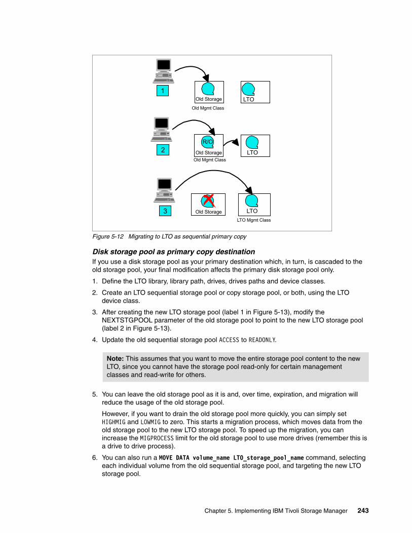
Figure 5-12 Migrating to LTO as sequential primary copy
Disk storage pool as primary copy destination If you use a disk storage pool as your primary destination which, in turn, is cascaded to the old storage pool, your final modification affects the primary disk storage pool only.
1. Define the LTO library, library path, drives, drives paths and device classes.
2. Create an LTO sequential storage pool or copy storage pool, or both, using the LTO device class.
3. After creating the new LTO storage pool (label 1 in Figure 5-13), modify the NEXTSTGPOOL parameter of the old storage pool to point to the new LTO storage pool (label 2 in Figure 5-13).
4. Update the old sequential storage pool ACCESS to READONLY.
5. You can leave the old storage pool as it is and, over time, expiration, and migration will reduce the usage of the old storage pool.
However, if you want to drain the old storage pool more quickly, you can simply set HIGHMIG and LOWMIG to zero. This starts a migration process, which moves data from the old storage pool to the new LTO storage pool. To speed up the migration, you can increase the MIGPROCESS limit for the old storage pool to use more drives (remember this is a drive to drive process).
6. You can also run a MOVE DATA volume_name LTO_storage_pool_name command, selecting each individual volume from the old sequential storage pool, and targeting the new LTO storage pool.
Note: This assumes that you want to move the entire storage pool content to the new LTO, since you cannot have the storage pool read-only for certain management classes and read-write for others.
Old Storage LTO
LTOOld Storage
LTOOld Storage
1
2
3
R/O
Old Mgmt Class
LTO Mgmt Class
Old Mgmt Class
Chapter 5. Implementing IBM Tivoli Storage Manager 243
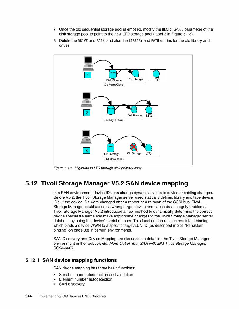
7. Once the old sequential storage pool is emptied, modify the NEXTSTGPOOL parameter of the disk storage pool to point to the new LTO storage pool (label 3 in Figure 5-13).
8. Delete the DRIVE and PATH, and also the LIBRARY and PATH entries for the old library and drives.
Figure 5-13 Migrating to LTO through disk primary copy
5.12 Tivoli Storage Manager V5.2 SAN device mappingIn a SAN environment, device IDs can change dynamically due to device or cabling changes. Before V5.2, the Tivoli Storage Manager server used statically defined library and tape device IDs. If the device IDs were changed after a reboot or a re-scan of the SCSI bus, Tivoli Storage Manager could access a wrong target device and cause data integrity problems. Tivoli Storage Manager V5.2 introduced a new method to dynamically determine the correct device special file name and make appropriate changes to the Tivoli Storage Manager server database by using the device’s serial number. This function can replace persistent binding, which binds a device WWN to a specific target/LUN ID (as described in 3.3, “Persistent binding” on page 88) in certain environments.
SAN Discovery and Device Mapping are discussed in detail for the Tivoli Storage Manager environment in the redbook Get More Out of Your SAN with IBM Tivoli Storage Manager, SG24-6687.
5.12.1 SAN device mapping functionsSAN device mapping has three basic functions:
� Serial number autodetection and validation� Element number autodetection� SAN discovery
Old Storage
R/O
2Old Storage
R/O
LTO
Old Storage1
Disk Storage
3LTODisk Storage
Old Mgmt Class
Old Mgmt Class
Old Mgmt Class
LTO
244 Implementing IBM Tape in UNIX Systems
To enable these functions, the DEFINE LIBRARY and DEFINE DRIVE commands have been enhanced to allow manual entry or automatic detection of the serial and element numbers. Also, the DEFINE PATH command is enhanced to automatically update the serial number. This new syntax is described in “Define the library and tape drives” on page 204. Refer to the Tivoli Storage Manager documentation for further details.
Serial number autodetection and validationSerial number autodetection enables Tivoli Storage Manager to automatically obtain a library or drive serial number by issuing a SCSI Inquiry command during the DEFINE PATH command.
Serial number validation automatically validates the serial number if the serial number is provided with the DEFINE/UPDATE LIBRARY and DEFINE/UPDATE DRIVE commands by issuing a SCSI Inquiry command during the DEFINE PATH command. Device serial numbers are also automatically validated during every library or tape drive access.
To avoid potential errors during device definitions or when SAN and device reconfiguration occurs, you can use the AUTODETECT function of the DEFINE PATH command. This function automatically updates the Tivoli Storage Manager server database with the correct device special file name by using the device’s serial number.
Element number autodetectionElement number autodetection enables Tivoli Storage Manager to automatically obtain the drive element address by using the drive’s serial number. This function automatically finds the matching element address in the serial number/element number map during the DEFINE PATH command.
SAN discoveryTo avoid the need for manual modification, there is an accurate SAN device mapping feature available in Tivoli Storage Manager V5.3. This mapping process involves two steps:
1. Detecting that the device has changed.
This detection is accomplished by recording the device’s serial number, manufacturer, and World Wide Node Name (WWNN), if it exists, in the Tivoli Storage Manager database. Whenever a device is opened, its identity is verified. This feature is now available on Windows, AIX, Sun, and Linux servers as well as Storage Agents, and was implemented in Tivoli Storage Manager V5.2 for Windows.
2. Reconciling the device definitions (paths) dynamically when changes are detected.
This reconciliation requires Tivoli Storage Manager to discover devices in the SAN environment.
New commands are available in Tivoli Storage Manager V5.3. To activate SAN device mapping, set the SANDISCOVERY option to ON in the dsmserv.opt file:
SANDISCOVERY ON
This setting is the default for Windows platforms. For all other platforms, you must set this option in the server options file. To activate SAN Discovery in a running Tivoli Storage Manager instance, use the following setting:
SETOPT SANDISCOVERY ON
Chapter 5. Implementing IBM Tivoli Storage Manager 245

246 Implementing IBM Tape in UNIX Systems
Chapter 6. Implementing EMC Legato NetWorker with LTO
In this chapter we give you detailed information on implementing EMC Legato NetWorker with LTO drives and libraries. This includes:
� Product overview
� Installation and library definition
– AIX environment– Solaris environment– HP-UX environment
� Implementation and use
� Product exploitation
– LTO library sharing– LAN-free backup
At the end of this chapter you should be able to understand and implement the tasks required to:
� Install the EMC Legato NetWorker product in a UNIX environment with LTO
� Implement and use the LTO library with EMC Legato NetWorker
� Exploit EMC Legato NetWorker capabilities with LTO
6
Note: Later versions of EMC Legato NetWorker are available, which support IBM LTO3 and IBM 3592 products. The panels and command outputs may have changed from what is shown in this chapter; however the information is included as a guide. Consult the product documentation and the compatibility Web sites listed in the following sections for the most up-to-date information.
© Copyright IBM Corp. 2002, 2003, 2004, 2005. All rights reserved. 247
6.1 EMC Legato NetWorker overviewEMC Legato NetWorker is a suite of storage management software that provides backup, recovery, and other services to computers with a wide variety of operating systems and data types. NetWorker products for different operating systems are interoperable, which provides you with flexibility in designing a storage management setup that works best with your current computing environment. For detailed product information, visit the NetWorker Web site:
http://www.legato.com/products/networker
The NetWorker product has four major components: the NetWorker server, client, storage node, and the License Manager:
� NetWorker server: The NetWorker server software provides control and scheduling for NetWorker operations. On the NetWorker server, you can enter the enabler licenses for the NetWorker server, and all the functions the NetWorker server controls such as autochanger modules, additional client connections, and ClientPak licenses. You can also define the clients, devices, and media that the NetWorker server controls, define the schedules for backups and other operations, and monitor all the NetWorker operations.
� NetWorker client: The NetWorker client software provides on-demand backup and recovery functionality, communicating with the NetWorker server. You install the NetWorker client software on all computers that need to back up to the NetWorker server.
� NetWorker storage node: You can back up data directly to devices attached to either a NetWorker server or to a NetWorker storage node. A storage node controls storage devices such as tape drivers, autochangers, and silos.
� License Manager: The License Manager provides a central place for managing the licenses of all your NetWorker clients and servers. Instead of managing licenses separately, you can maintain all your NetWorker licenses from a single computer. Installation of the License Manager is an option when installing the NetWorker software.
6.1.1 NetWorker and IBM LTO interoperabilityBe sure that NetWorker is supported in your specific environment. You should cross check on both the IBM and NetWorker Web sites to verify this:
http://www-1.ibm.com/servers/storage/tape/lto/lto_isv.htmlhttp://www.legato.com/support/websupport/compat_guides/
Special note: NetWorker and IBM 3584The IBM 3584 is a SCSI library with fixed SCSI element addresses for the tape drives. Because of the way NetWorker configures tape libraries, special handling is required when installing with a multiframe IBM 3584 where the drives are not installed in a contiguous sequence. Preferably, you should first install 12 drives in the first frame before installing additional drives in the second frame. If the IBM 3584 is not set up in this manner, the NetWorker commands sjirdtag, sjirelem, inquire and jbconfig will all return a list of drives that include tape devices where no physical devices are present. When configuring the tape library with jbconfig you will have to define some dummy devices, as described in “Configuring dummy devices (non-contiguous libraries only)” on page 264.
248 Implementing IBM Tape in UNIX Systems
6.2 NetWorker installationIn this section, we give you examples of NetWorker installation for the UNIX platforms, IBM AIX, SUN Solaris, and HP-UX. For more details, refer to the NetWorker product documentation that can be found at:
http://web1.legato.com/cgi-bin/catalog?sf=Releases
In these examples, we show the installation of NetWorker in a SAN environment with Solaris, and with a SCSI point-to-point connection for AIX and HP-UX environments.
In each installation example, we used an IBM 3583 with two SCSI-LVD drives, connected to an IBM 2108 SAN Data Gateway for the SAN environment.
You should have already installed and configured the tape drives as described in Chapter 4, “Basic IBM tape setup for UNIX systems” on page 101.
6.2.1 Installation in an AIX environmentFor a detailed explanation of the installation process, refer to the Legato NetWorker Installation Guide - AIX Version. This book can be downloaded in PDF format from the NetWorker Web site:
http://web1.legato.com/cgi-bin/catalog?sf=Releases
We used the following environment:
� IBM pSeries F50 server with IBM AIX Version 4.3.3 and LVD SCSI adapter� EMC Legato NetWorker 6.1 Build 186� IBM 3583 with LVD drives
Software installation (AIX)We assume that you are installing NetWorker from a directory on the AIX server. These are the required steps:
1. Expand the compressed file using the following command:
# gunzip -s networker_aix.tar.gz
This process replaces the original file with an uncompressed file of the same name, without the .gz last level qualifier.
2. Extract the uncompressed file to the same directory with the following command:
# tar -xvpf networker_aix.tar
This operation expands this file in many other files and directories that make up the installation package.
3. If not already logged in, log in as root, then change to the directory where the NetWorker installation files are, and enter the following command at the shell prompt:
# ./nsr_ize -i -s
You are prompted with the following messages:
NetWorker(TM) - Release 6.1.Build.186Copyright (c) 1990-2001, Legato Systems, Inc. All rights reserved.This product includes software developed by the University ofCalifornia, Berkeley and its contributors.nsr_ize is about to install NetWorker server software on machine 'brazil'.Install the NetWorker man pages [yes]? n
Chapter 6. Implementing EMC Legato NetWorker with LTO 249
4. Answer yes/no depending on whether you want the NetWorker manuals to be installed, then:
Install the aix43n NetWorker programs [yes]?Directory where aix43n NetWorker programs should be installed [/bin]?Directory to use for client, licensing and server information [/nsr]?
5. Press Enter to respond to each question. Then configure the tape devices, as in Example 6-1.
Example 6-1 AIX NetWorker configure devices
The following is a list of the tape devices available on your system:rmt0 Available 30-58-00-0,0 IBM 3580 Ultrium Tape Drivermt1 Available 30-58-00-1,0 IBM 3580 Ultrium Tape Drivesmc0 Available 30-58-00-6,0 IBM 3583 Library Medium Changer
The name needed by NetWorker is usually `/dev/' plus the name of the device as given the first column of the above table, followed by `.1'to indicate a no-rewind device name.Enter the tape or disk device(s) that are going to be used by the NetWorker server. Use the no-rewind name for each tape device (i.e., use /dev/rmt0.1 instead of /dev/rmt0). If you do not choose a device a default device will be created for you.Enter device name ([Return] if no more): /dev/rmt0.1
Answer exactly as indicated in the example (add .1 to the device name, to indicate a non rewinding device).
You should receive this message:
Device rmt0.1 is of NetWorker type: 3580
6. Repeat this operation for every LTO tape device that you want to configure to NetWorker. Press Enter when you have no more devices to add. Then the prompt asks:
Start NetWorker daemons at end of install [yes]?Install the NetWorker device drivers (required for storage nodes and servers) [yes]?
7. Press Enter to both questions, since you need to install the NetWorker device drivers to be able to use the SCSI medium changer. At the end of the installation, you should see the following message:
NetWorker successfully installed on 'brazil'!
8. Check whether the daemons are running with the command:
# ps -ef |grep -E "nsr|lgto"
The command output should look like Example 6-2, depending on the packages installed.
Important: You can only use non rewinding devices with the NetWorker server. If you use a rewinding device, the read/write head is repositioned at the beginning of the volume, and the previously backed-up data is overwritten.
250 Implementing IBM Tape in UNIX Systems
Example 6-2 AIX NetWorker daemons process listing
root 4484 11512 0 15:38:07 - 0:00 /usr/bin/nsrmmdbdroot 10902 11512 0 15:38:13 - 0:00 /usr/bin/nsrmmd -n 2root 11152 12044 0 15:37:57 - 0:00 /bin/nsrexecdroot 11512 1 0 15:38:01 - 0:01 /bin/nsrdroot 12044 1 0 15:37:57 - 0:00 /bin/nsrexecdroot 12586 11512 0 15:38:09 - 0:00 /usr/bin/nsrindexdroot 15524 18328 0 15:42:26 pts/1 0:00 grep -E nsr|lgtoroot 17202 11512 0 15:38:11 - 0:00 /usr/bin/nsrmmd -n 1root 19064 1 0 15:37:57 - 0:00 /bin/lgtolmd -p /nsr/lic -n 1
If you do not see the processes, start NetWorker manually with the command:
# /etc/rc.nsr start
Table 6-1 identifies the daemons required for each NetWorker component.
Table 6-1 NetWorker daemons for AIX
Before using NetWorker with an LTO library (such as an IBM 3583 or IBM 3584) see 6.3.1, “3583 autochanger configuration on NetWorker 6.1” on page 258, and 6.3.2, “IBM 3584 autochanger configuration on NetWorker 7.0” on page 262.
6.2.2 Installation in a Solaris environmentFor a detailed explanation of the installation process, refer to Legato NetWorker Installation Guide - Solaris Version. This book can be downloaded in PDF format from the NetWorker Web site at:
http://web1.legato.com/cgi-bin/catalog?sf=Releases
We used the following environment:
� SUN Microsystems Enterprise250 SPARC server with Solaris Version 2.7 and QLogic 2200 HBA
� EMC Legato NetWorker 6.1 Build 186
� IBM 3583 with LVD drives
Software installation (Solaris)We assume that you are installing NetWorker from a directory on the Solaris server. These are the required steps:
1. Expand the compressed file using the following command:
# gunzip networker_sol.tar.gz
This process replaces the original file with an uncompressed file of the same name, without the .gz last level qualifier.
2. Extract the uncompressed file to the same directory with the following command:
# tar -xvpBf networker_sol.tar
NetWorker installation packages NetWorker daemons
NetWorker server nsrd, nsrexecd, nsrindexd, nsrmmdbd, nsrmmd
NetWorker client nsrexecd
NetWorker storage node nsrexecd, nsrmmd
Chapter 6. Implementing EMC Legato NetWorker with LTO 251
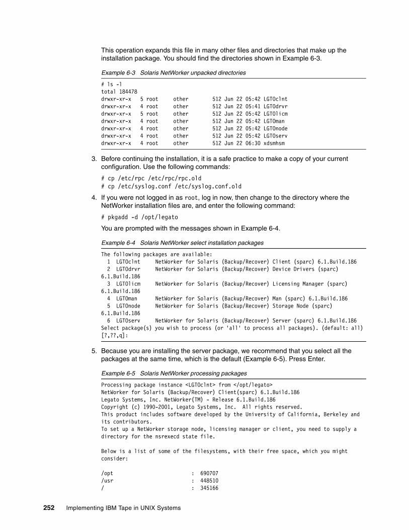
This operation expands this file in many other files and directories that make up the installation package. You should find the directories shown in Example 6-3.
Example 6-3 Solaris NetWorker unpacked directories
# ls -ltotal 184478drwxr-xr-x 5 root other 512 Jun 22 05:42 LGTOclntdrwxr-xr-x 4 root other 512 Jun 22 05:41 LGTOdrvrdrwxr-xr-x 5 root other 512 Jun 22 05:42 LGTOlicmdrwxr-xr-x 4 root other 512 Jun 22 05:42 LGTOmandrwxr-xr-x 4 root other 512 Jun 22 05:42 LGTOnodedrwxr-xr-x 4 root other 512 Jun 22 05:42 LGTOservdrwxr-xr-x 4 root other 512 Jun 22 06:30 xdsmhsm
3. Before continuing the installation, it is a safe practice to make a copy of your current configuration. Use the following commands:
# cp /etc/rpc /etc/rpc/rpc.old# cp /etc/syslog.conf /etc/syslog.conf.old
4. If you were not logged in as root, log in now, then change to the directory where the NetWorker installation files are, and enter the following command:
# pkgadd -d /opt/legato
You are prompted with the messages shown in Example 6-4.
Example 6-4 Solaris NetWorker select installation packages
The following packages are available: 1 LGTOclnt NetWorker for Solaris (Backup/Recover) Client (sparc) 6.1.Build.186 2 LGTOdrvr NetWorker for Solaris (Backup/Recover) Device Drivers (sparc) 6.1.Build.186 3 LGTOlicm NetWorker for Solaris (Backup/Recover) Licensing Manager (sparc) 6.1.Build.186 4 LGTOman NetWorker for Solaris (Backup/Recover) Man (sparc) 6.1.Build.186 5 LGTOnode NetWorker for Solaris (Backup/Recover) Storage Node (sparc) 6.1.Build.186 6 LGTOserv NetWorker for Solaris (Backup/Recover) Server (sparc) 6.1.Build.186Select package(s) you wish to process (or 'all' to process all packages). (default: all) [?,??,q]:
5. Because you are installing the server package, we recommend that you select all the packages at the same time, which is the default (Example 6-5). Press Enter.
Example 6-5 Solaris NetWorker processing packages
Processing package instance <LGTOclnt> from </opt/legato>NetWorker for Solaris (Backup/Recover) Client(sparc) 6.1.Build.186Legato Systems, Inc. NetWorker(TM) - Release 6.1.Build.186Copyright (c) 1990-2001, Legato Systems, Inc. All rights reserved.This product includes software developed by the University of California, Berkeley and its contributors.To set up a NetWorker storage node, licensing manager or client, you need to supply a directory for the nsrexecd state file.
Below is a list of some of the filesystems, with their free space, which you might consider:
/opt : 690707/usr : 448510/ : 345166
252 Implementing IBM Tape in UNIX Systems
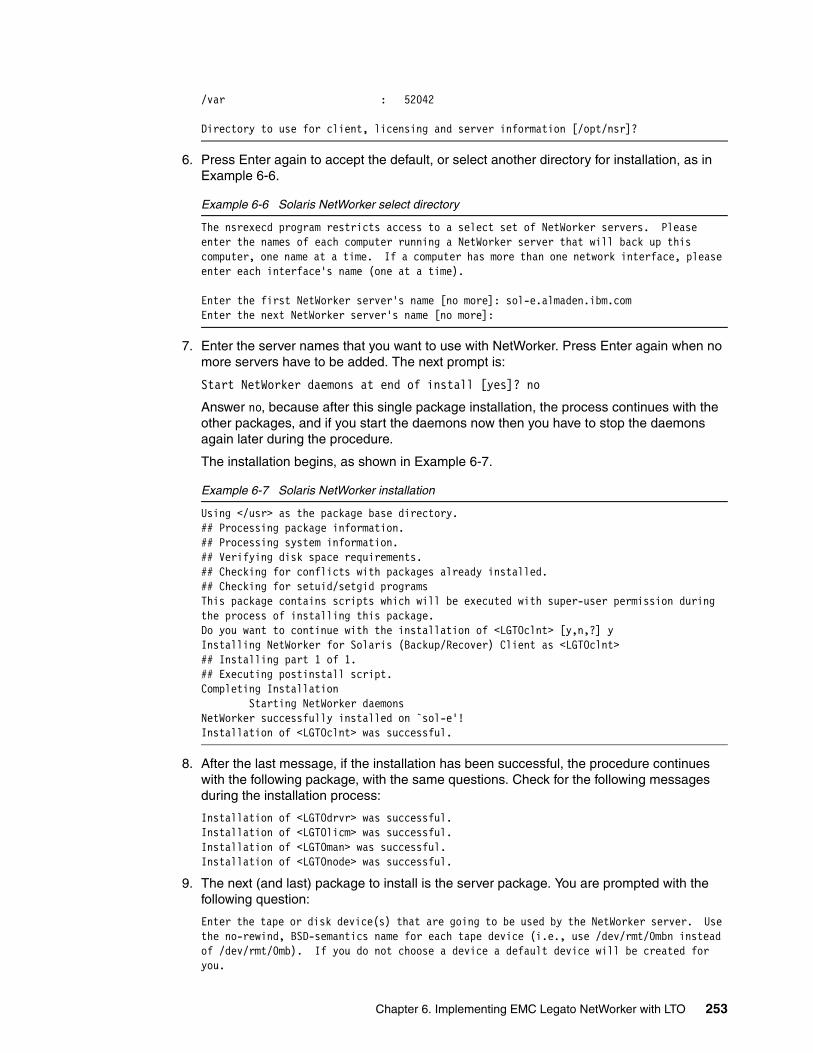
/var : 52042
Directory to use for client, licensing and server information [/opt/nsr]?
6. Press Enter again to accept the default, or select another directory for installation, as in Example 6-6.
Example 6-6 Solaris NetWorker select directory
The nsrexecd program restricts access to a select set of NetWorker servers. Please enter the names of each computer running a NetWorker server that will back up this computer, one name at a time. If a computer has more than one network interface, please enter each interface's name (one at a time).
Enter the first NetWorker server's name [no more]: sol-e.almaden.ibm.comEnter the next NetWorker server's name [no more]:
7. Enter the server names that you want to use with NetWorker. Press Enter again when no more servers have to be added. The next prompt is:
Start NetWorker daemons at end of install [yes]? no
Answer no, because after this single package installation, the process continues with the other packages, and if you start the daemons now then you have to stop the daemons again later during the procedure.
The installation begins, as shown in Example 6-7.
Example 6-7 Solaris NetWorker installation
Using </usr> as the package base directory.## Processing package information.## Processing system information.## Verifying disk space requirements.## Checking for conflicts with packages already installed.## Checking for setuid/setgid programsThis package contains scripts which will be executed with super-user permission during the process of installing this package.Do you want to continue with the installation of <LGTOclnt> [y,n,?] yInstalling NetWorker for Solaris (Backup/Recover) Client as <LGTOclnt>## Installing part 1 of 1.## Executing postinstall script.Completing Installation Starting NetWorker daemonsNetWorker successfully installed on `sol-e'!Installation of <LGTOclnt> was successful.
8. After the last message, if the installation has been successful, the procedure continues with the following package, with the same questions. Check for the following messages during the installation process:
Installation of <LGTOdrvr> was successful.Installation of <LGTOlicm> was successful.Installation of <LGTOman> was successful.Installation of <LGTOnode> was successful.
9. The next (and last) package to install is the server package. You are prompted with the following question:
Enter the tape or disk device(s) that are going to be used by the NetWorker server. Use the no-rewind, BSD-semantics name for each tape device (i.e., use /dev/rmt/0mbn instead of /dev/rmt/0mb). If you do not choose a device a default device will be created for you.
Chapter 6. Implementing EMC Legato NetWorker with LTO 253
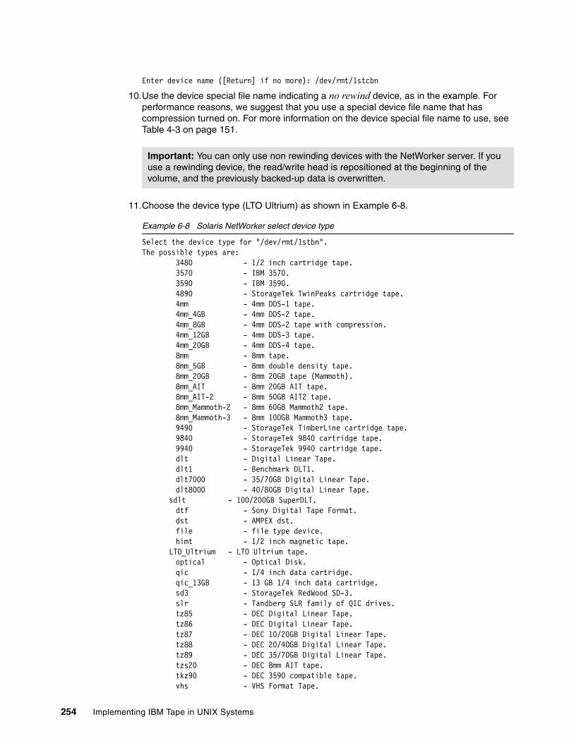
Enter device name ([Return] if no more): /dev/rmt/1stcbn
10.Use the device special file name indicating a no rewind device, as in the example. For performance reasons, we suggest that you use a special device file name that has compression turned on. For more information on the device special file name to use, see Table 4-3 on page 151.
11.Choose the device type (LTO Ultrium) as shown in Example 6-8.
Example 6-8 Solaris NetWorker select device type
Select the device type for "/dev/rmt/1stbn".The possible types are: 3480 - 1/2 inch cartridge tape. 3570 - IBM 3570. 3590 - IBM 3590. 4890 - StorageTek TwinPeaks cartridge tape. 4mm - 4mm DDS-1 tape. 4mm_4GB - 4mm DDS-2 tape. 4mm_8GB - 4mm DDS-2 tape with compression. 4mm_12GB - 4mm DDS-3 tape. 4mm_20GB - 4mm DDS-4 tape. 8mm - 8mm tape. 8mm_5GB - 8mm double density tape. 8mm_20GB - 8mm 20GB tape (Mammoth). 8mm_AIT - 8mm 20GB AIT tape. 8mm_AIT-2 - 8mm 50GB AIT2 tape. 8mm_Mammoth-2 - 8mm 60GB Mammoth2 tape. 8mm_Mammoth-3 - 8mm 100GB Mammoth3 tape. 9490 - StorageTek TimberLine cartridge tape. 9840 - StorageTek 9840 cartridge tape. 9940 - StorageTek 9940 cartridge tape. dlt - Digital Linear Tape. dlt1 - Benchmark DLT1. dlt7000 - 35/70GB Digital Linear Tape. dlt8000 - 40/80GB Digital Linear Tape. sdlt - 100/200GB SuperDLT. dtf - Sony Digital Tape Format. dst - AMPEX dst. file - file type device. himt - 1/2 inch magnetic tape. LTO_Ultrium - LTO Ultrium tape. optical - Optical Disk. qic - 1/4 inch data cartridge. qic_13GB - 13 GB 1/4 inch data cartridge. sd3 - StorageTek RedWood SD-3. slr - Tandberg SLR family of QIC drives. tz85 - DEC Digital Linear Tape. tz86 - DEC Digital Linear Tape. tz87 - DEC 10/20GB Digital Linear Tape. tz88 - DEC 20/40GB Digital Linear Tape. tz89 - DEC 35/70GB Digital Linear Tape. tzs20 - DEC 8mm AIT tape. tkz90 - DEC 3590 compatible tape. vhs - VHS Format Tape.
Important: You can only use non rewinding devices with the NetWorker server. If you use a rewinding device, the read/write head is repositioned at the beginning of the volume, and the previously backed-up data is overwritten.
254 Implementing IBM Tape in UNIX Systems
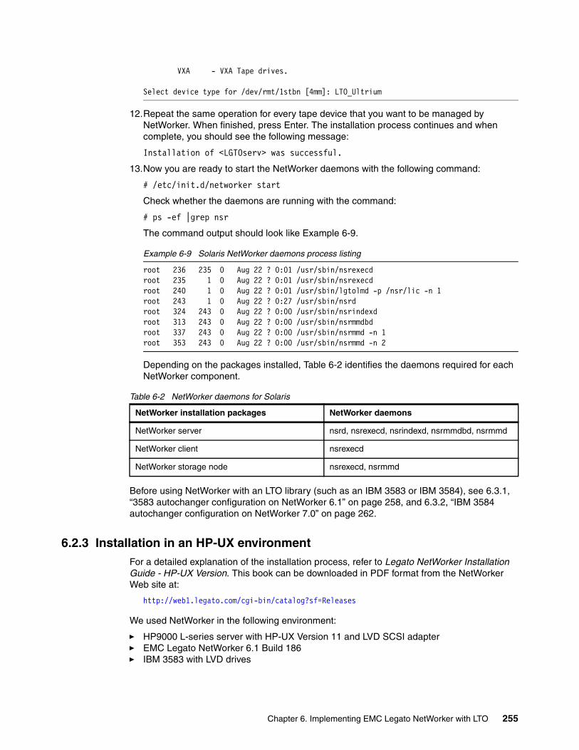
VXA - VXA Tape drives.
Select device type for /dev/rmt/1stbn [4mm]: LTO_Ultrium
12.Repeat the same operation for every tape device that you want to be managed by NetWorker. When finished, press Enter. The installation process continues and when complete, you should see the following message:
Installation of <LGTOserv> was successful.
13.Now you are ready to start the NetWorker daemons with the following command:
# /etc/init.d/networker start
Check whether the daemons are running with the command:
# ps -ef |grep nsr
The command output should look like Example 6-9.
Example 6-9 Solaris NetWorker daemons process listing
root 236 235 0 Aug 22 ? 0:01 /usr/sbin/nsrexecdroot 235 1 0 Aug 22 ? 0:01 /usr/sbin/nsrexecdroot 240 1 0 Aug 22 ? 0:01 /usr/sbin/lgtolmd -p /nsr/lic -n 1root 243 1 0 Aug 22 ? 0:27 /usr/sbin/nsrdroot 324 243 0 Aug 22 ? 0:00 /usr/sbin/nsrindexdroot 313 243 0 Aug 22 ? 0:00 /usr/sbin/nsrmmdbdroot 337 243 0 Aug 22 ? 0:00 /usr/sbin/nsrmmd -n 1root 353 243 0 Aug 22 ? 0:00 /usr/sbin/nsrmmd -n 2
Depending on the packages installed, Table 6-2 identifies the daemons required for each NetWorker component.
Table 6-2 NetWorker daemons for Solaris
Before using NetWorker with an LTO library (such as an IBM 3583 or IBM 3584), see 6.3.1, “3583 autochanger configuration on NetWorker 6.1” on page 258, and 6.3.2, “IBM 3584 autochanger configuration on NetWorker 7.0” on page 262.
6.2.3 Installation in an HP-UX environmentFor a detailed explanation of the installation process, refer to Legato NetWorker Installation Guide - HP-UX Version. This book can be downloaded in PDF format from the NetWorker Web site at:
http://web1.legato.com/cgi-bin/catalog?sf=Releases
We used NetWorker in the following environment:
� HP9000 L-series server with HP-UX Version 11 and LVD SCSI adapter� EMC Legato NetWorker 6.1 Build 186� IBM 3583 with LVD drives
NetWorker installation packages NetWorker daemons
NetWorker server nsrd, nsrexecd, nsrindexd, nsrmmdbd, nsrmmd
NetWorker client nsrexecd
NetWorker storage node nsrexecd, nsrmmd
Chapter 6. Implementing EMC Legato NetWorker with LTO 255
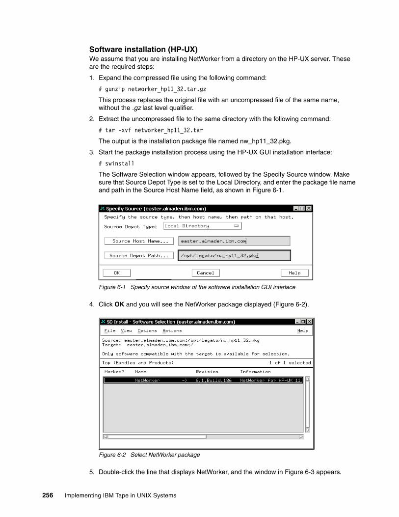
Software installation (HP-UX)We assume that you are installing NetWorker from a directory on the HP-UX server. These are the required steps:
1. Expand the compressed file using the following command:
# gunzip networker_hp11_32.tar.gz
This process replaces the original file with an uncompressed file of the same name, without the .gz last level qualifier.
2. Extract the uncompressed file to the same directory with the following command:
# tar -xvf networker_hp11_32.tar
The output is the installation package file named nw_hp11_32.pkg.
3. Start the package installation process using the HP-UX GUI installation interface:
# swinstall
The Software Selection window appears, followed by the Specify Source window. Make sure that Source Depot Type is set to the Local Directory, and enter the package file name and path in the Source Host Name field, as shown in Figure 6-1.
Figure 6-1 Specify source window of the software installation GUI interface
4. Click OK and you will see the NetWorker package displayed (Figure 6-2).
Figure 6-2 Select NetWorker package
5. Double-click the line that displays NetWorker, and the window in Figure 6-3 appears.
256 Implementing IBM Tape in UNIX Systems
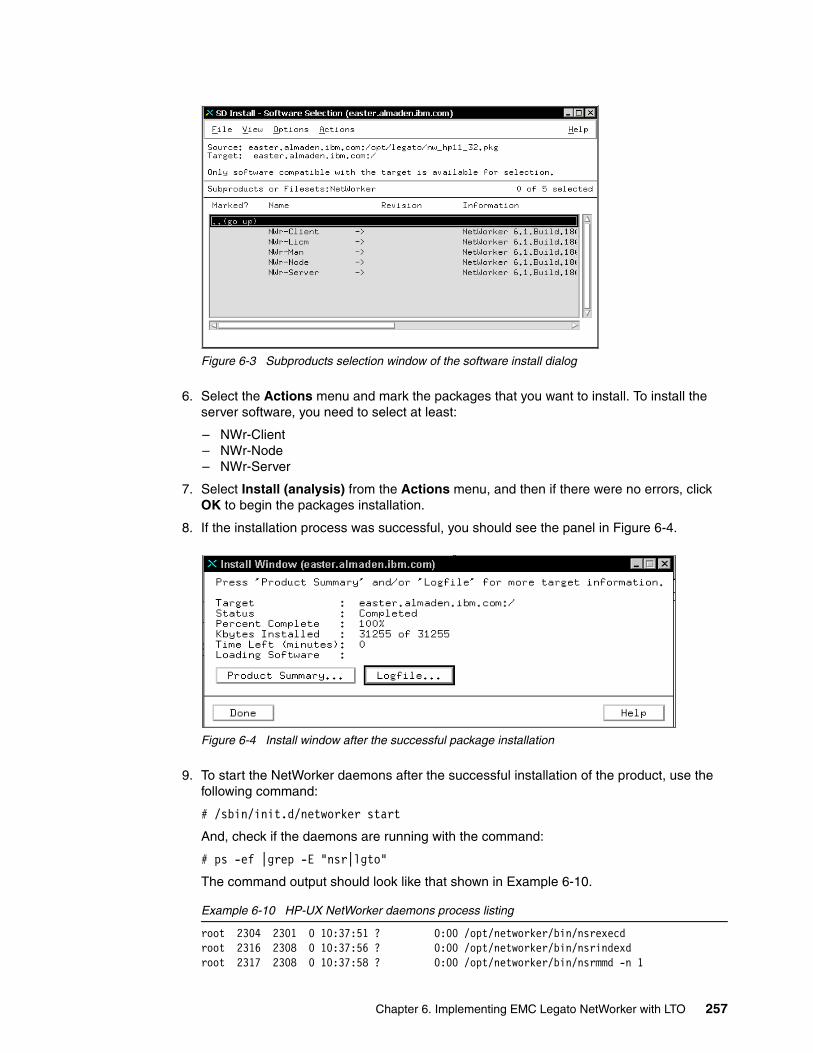
Figure 6-3 Subproducts selection window of the software install dialog
6. Select the Actions menu and mark the packages that you want to install. To install the server software, you need to select at least:
– NWr-Client– NWr-Node– NWr-Server
7. Select Install (analysis) from the Actions menu, and then if there were no errors, click OK to begin the packages installation.
8. If the installation process was successful, you should see the panel in Figure 6-4.
Figure 6-4 Install window after the successful package installation
9. To start the NetWorker daemons after the successful installation of the product, use the following command:
# /sbin/init.d/networker start
And, check if the daemons are running with the command:
# ps -ef |grep -E "nsr|lgto"
The command output should look like that shown in Example 6-10.
Example 6-10 HP-UX NetWorker daemons process listing
root 2304 2301 0 10:37:51 ? 0:00 /opt/networker/bin/nsrexecdroot 2316 2308 0 10:37:56 ? 0:00 /opt/networker/bin/nsrindexdroot 2317 2308 0 10:37:58 ? 0:00 /opt/networker/bin/nsrmmd -n 1
Chapter 6. Implementing EMC Legato NetWorker with LTO 257
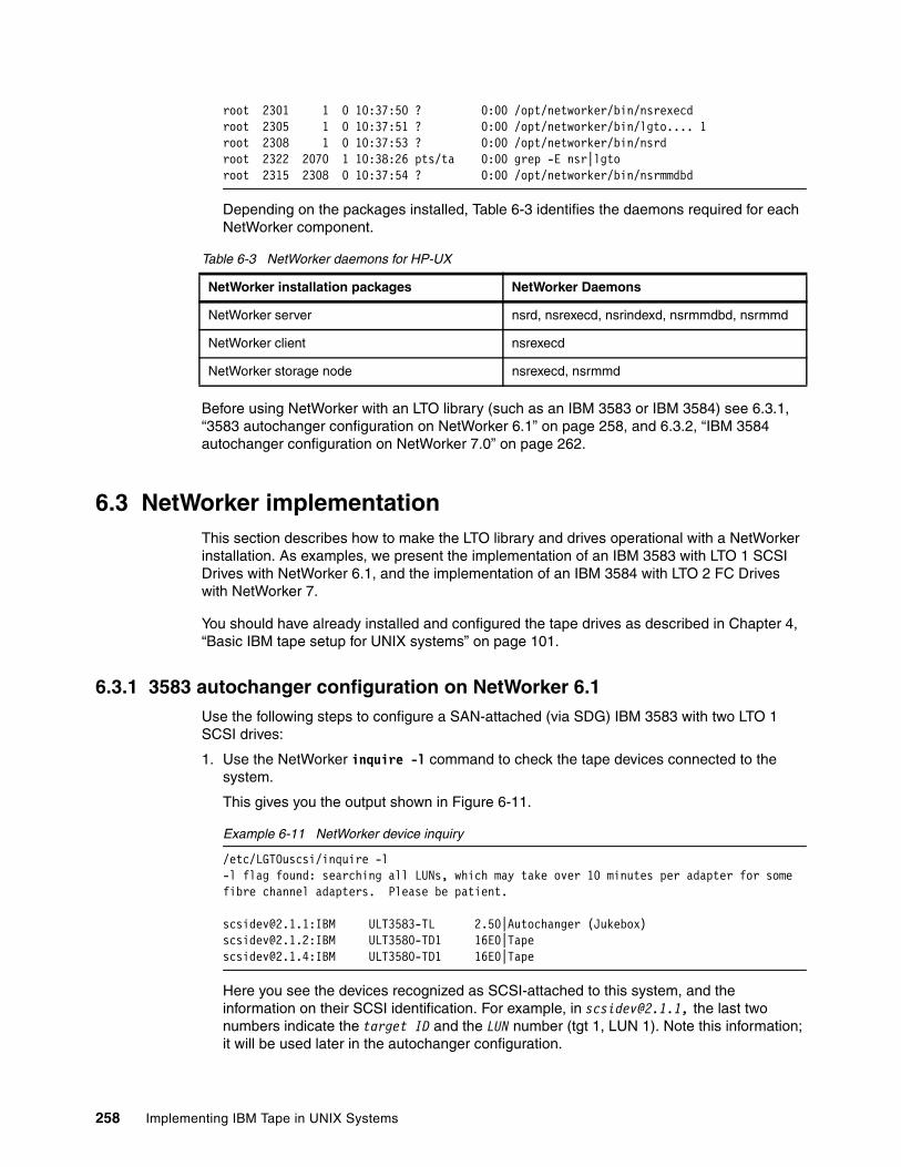
root 2301 1 0 10:37:50 ? 0:00 /opt/networker/bin/nsrexecdroot 2305 1 0 10:37:51 ? 0:00 /opt/networker/bin/lgto.... 1root 2308 1 0 10:37:53 ? 0:00 /opt/networker/bin/nsrdroot 2322 2070 1 10:38:26 pts/ta 0:00 grep -E nsr|lgtoroot 2315 2308 0 10:37:54 ? 0:00 /opt/networker/bin/nsrmmdbd
Depending on the packages installed, Table 6-3 identifies the daemons required for each NetWorker component.
Table 6-3 NetWorker daemons for HP-UX
Before using NetWorker with an LTO library (such as an IBM 3583 or IBM 3584) see 6.3.1, “3583 autochanger configuration on NetWorker 6.1” on page 258, and 6.3.2, “IBM 3584 autochanger configuration on NetWorker 7.0” on page 262.
6.3 NetWorker implementationThis section describes how to make the LTO library and drives operational with a NetWorker installation. As examples, we present the implementation of an IBM 3583 with LTO 1 SCSI Drives with NetWorker 6.1, and the implementation of an IBM 3584 with LTO 2 FC Drives with NetWorker 7.
You should have already installed and configured the tape drives as described in Chapter 4, “Basic IBM tape setup for UNIX systems” on page 101.
6.3.1 3583 autochanger configuration on NetWorker 6.1Use the following steps to configure a SAN-attached (via SDG) IBM 3583 with two LTO 1 SCSI drives:
1. Use the NetWorker inquire -l command to check the tape devices connected to the system.
This gives you the output shown in Figure 6-11.
Example 6-11 NetWorker device inquiry
/etc/LGTOuscsi/inquire -l-l flag found: searching all LUNs, which may take over 10 minutes per adapter for some fibre channel adapters. Please be patient.
[email protected]:IBM ULT3583-TL 2.50|Autochanger (Jukebox)[email protected]:IBM ULT3580-TD1 16E0|[email protected]:IBM ULT3580-TD1 16E0|Tape
Here you see the devices recognized as SCSI-attached to this system, and the information on their SCSI identification. For example, in [email protected], the last two numbers indicate the target ID and the LUN number (tgt 1, LUN 1). Note this information; it will be used later in the autochanger configuration.
NetWorker installation packages NetWorker Daemons
NetWorker server nsrd, nsrexecd, nsrindexd, nsrmmdbd, nsrmmd
NetWorker client nsrexecd
NetWorker storage node nsrexecd, nsrmmd
258 Implementing IBM Tape in UNIX Systems
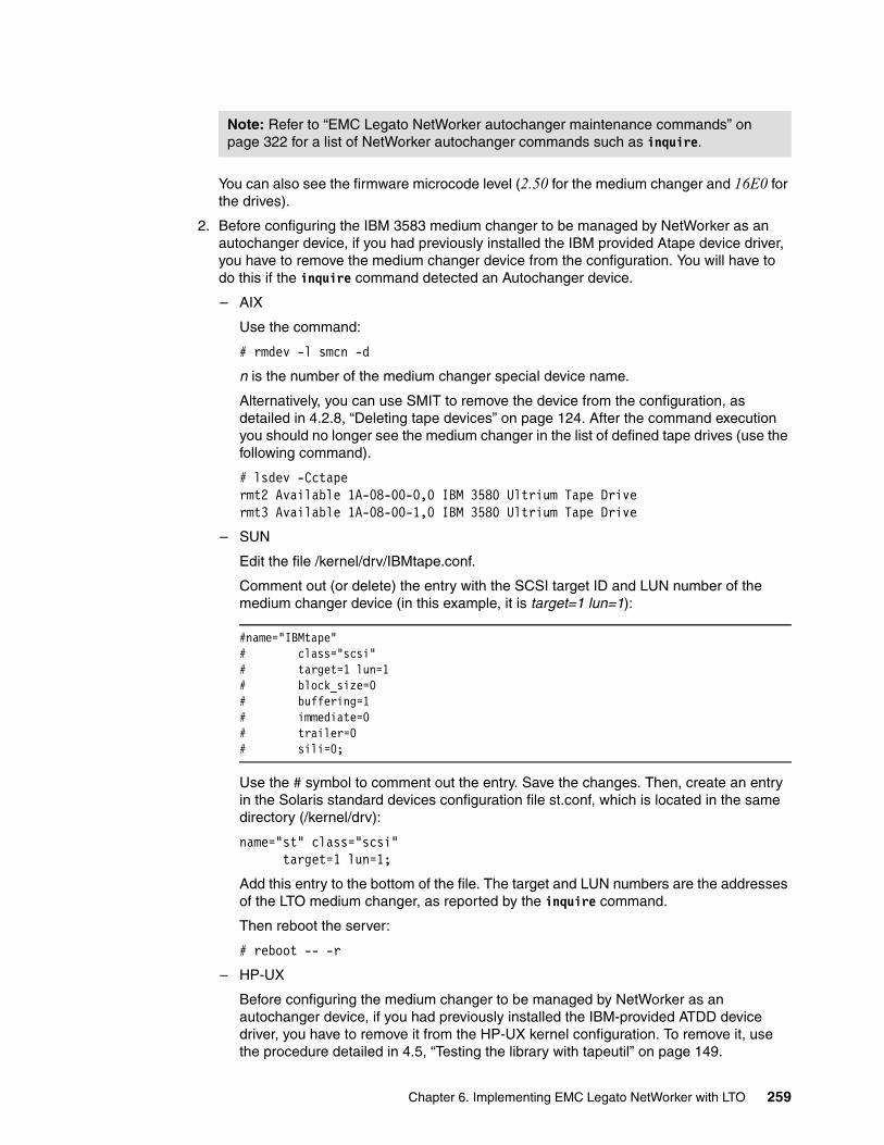
You can also see the firmware microcode level (2.50 for the medium changer and 16E0 for the drives).
2. Before configuring the IBM 3583 medium changer to be managed by NetWorker as an autochanger device, if you had previously installed the IBM provided Atape device driver, you have to remove the medium changer device from the configuration. You will have to do this if the inquire command detected an Autochanger device.
– AIX
Use the command:
# rmdev -l smcn -d
n is the number of the medium changer special device name.
Alternatively, you can use SMIT to remove the device from the configuration, as detailed in 4.2.8, “Deleting tape devices” on page 124. After the command execution you should no longer see the medium changer in the list of defined tape drives (use the following command).
# lsdev -Cctapermt2 Available 1A-08-00-0,0 IBM 3580 Ultrium Tape Drivermt3 Available 1A-08-00-1,0 IBM 3580 Ultrium Tape Drive
– SUN
Edit the file /kernel/drv/IBMtape.conf.
Comment out (or delete) the entry with the SCSI target ID and LUN number of the medium changer device (in this example, it is target=1 lun=1):
#name="IBMtape"# class="scsi"# target=1 lun=1# block_size=0# buffering=1# immediate=0# trailer=0# sili=0;
Use the # symbol to comment out the entry. Save the changes. Then, create an entry in the Solaris standard devices configuration file st.conf, which is located in the same directory (/kernel/drv):
name="st" class="scsi" target=1 lun=1;
Add this entry to the bottom of the file. The target and LUN numbers are the addresses of the LTO medium changer, as reported by the inquire command.
Then reboot the server:
# reboot -- -r
– HP-UX
Before configuring the medium changer to be managed by NetWorker as an autochanger device, if you had previously installed the IBM-provided ATDD device driver, you have to remove it from the HP-UX kernel configuration. To remove it, use the procedure detailed in 4.5, “Testing the library with tapeutil” on page 149.
Note: Refer to “EMC Legato NetWorker autochanger maintenance commands” on page 322 for a list of NetWorker autochanger commands such as inquire.
Chapter 6. Implementing EMC Legato NetWorker with LTO 259
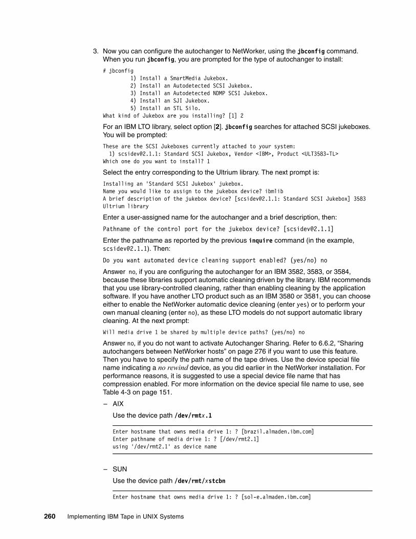
3. Now you can configure the autochanger to NetWorker, using the jbconfig command. When you run jbconfig, you are prompted for the type of autochanger to install:
# jbconfig 1) Install a SmartMedia Jukebox. 2) Install an Autodetected SCSI Jukebox. 3) Install an Autodetected NDMP SCSI Jukebox. 4) Install an SJI Jukebox. 5) Install an STL Silo.What kind of Jukebox are you installing? [1] 2
For an IBM LTO library, select option [2]. jbconfig searches for attached SCSI jukeboxes. You will be prompted:
These are the SCSI Jukeboxes currently attached to your system: 1) [email protected]: Standard SCSI Jukebox, Vendor <IBM>, Product <ULT3583-TL>Which one do you want to install? 1
Select the entry corresponding to the Ultrium library. The next prompt is:
Installing an 'Standard SCSI Jukebox' jukebox.Name you would like to assign to the jukebox device? ibmlibA brief description of the jukebox device? [[email protected]: Standard SCSI Jukebox] 3583 Ultrium library
Enter a user-assigned name for the autochanger and a brief description, then:
Pathname of the control port for the jukebox device? [[email protected]]
Enter the pathname as reported by the previous inquire command (in the example, [email protected]). Then:
Do you want automated device cleaning support enabled? (yes/no) no
Answer no, if you are configuring the autochanger for an IBM 3582, 3583, or 3584, because these libraries support automatic cleaning driven by the library. IBM recommends that you use library-controlled cleaning, rather than enabling cleaning by the application software. If you have another LTO product such as an IBM 3580 or 3581, you can choose either to enable the NetWorker automatic device cleaning (enter yes) or to perform your own manual cleaning (enter no), as these LTO models do not support automatic library cleaning. At the next prompt:
Will media drive 1 be shared by multiple device paths? (yes/no) no
Answer no, if you do not want to activate Autochanger Sharing. Refer to 6.6.2, “Sharing autochangers between NetWorker hosts” on page 276 if you want to use this feature. Then you have to specify the path name of the tape drives. Use the device special file name indicating a no rewind device, as you did earlier in the NetWorker installation. For performance reasons, it is suggested to use a special device file name that has compression enabled. For more information on the device special file name to use, see Table 4-3 on page 151.
– AIX
Use the device path /dev/rmtx.1
Enter hostname that owns media drive 1: ? [brazil.almaden.ibm.com]Enter pathname of media drive 1: ? [/dev/rmt2.1]using '/dev/rmt2.1' as device name
– SUN
Use the device path /dev/rmt/xstcbn
Enter hostname that owns media drive 1: ? [sol-e.almaden.ibm.com]
260 Implementing IBM Tape in UNIX Systems
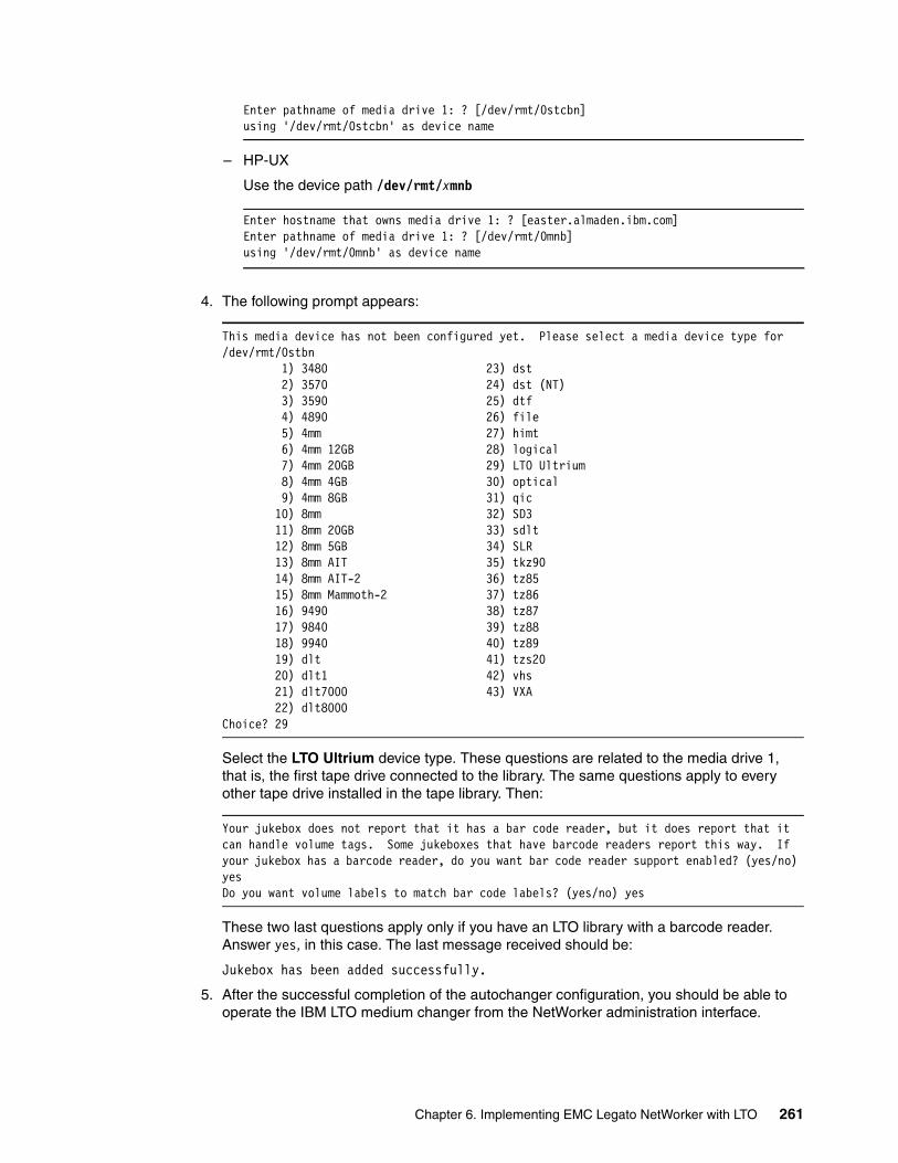
Enter pathname of media drive 1: ? [/dev/rmt/0stcbn]using '/dev/rmt/0stcbn' as device name
– HP-UX
Use the device path /dev/rmt/xmnb
Enter hostname that owns media drive 1: ? [easter.almaden.ibm.com]Enter pathname of media drive 1: ? [/dev/rmt/0mnb]using '/dev/rmt/0mnb' as device name
4. The following prompt appears:
This media device has not been configured yet. Please select a media device type for /dev/rmt/0stbn 1) 3480 23) dst 2) 3570 24) dst (NT) 3) 3590 25) dtf 4) 4890 26) file 5) 4mm 27) himt 6) 4mm 12GB 28) logical 7) 4mm 20GB 29) LTO Ultrium 8) 4mm 4GB 30) optical 9) 4mm 8GB 31) qic 10) 8mm 32) SD3 11) 8mm 20GB 33) sdlt 12) 8mm 5GB 34) SLR 13) 8mm AIT 35) tkz90 14) 8mm AIT-2 36) tz85 15) 8mm Mammoth-2 37) tz86 16) 9490 38) tz87 17) 9840 39) tz88 18) 9940 40) tz89 19) dlt 41) tzs20 20) dlt1 42) vhs 21) dlt7000 43) VXA 22) dlt8000Choice? 29
Select the LTO Ultrium device type. These questions are related to the media drive 1, that is, the first tape drive connected to the library. The same questions apply to every other tape drive installed in the tape library. Then:
Your jukebox does not report that it has a bar code reader, but it does report that it can handle volume tags. Some jukeboxes that have barcode readers report this way. If your jukebox has a barcode reader, do you want bar code reader support enabled? (yes/no) yesDo you want volume labels to match bar code labels? (yes/no) yes
These two last questions apply only if you have an LTO library with a barcode reader. Answer yes, in this case. The last message received should be:
Jukebox has been added successfully.
5. After the successful completion of the autochanger configuration, you should be able to operate the IBM LTO medium changer from the NetWorker administration interface.
Chapter 6. Implementing EMC Legato NetWorker with LTO 261
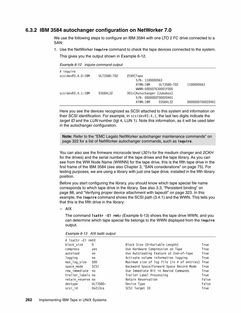
6.3.2 IBM 3584 autochanger configuration on NetWorker 7.0We use the following steps to configure an IBM 3584 with one LTO 2 FC drive connected to a SAN:
1. Use the NetWorker inquire command to check the tape devices connected to the system.
This gives you the output shown in Example 6-12.
Example 6-12 inquire command output
# [email protected]:IBM ULT3580-TD2 2CKH|Tape S/N: 1100000563 ATNN:IBM ULT3580-TD2 1100000563 WWNN:[email protected]:IBM 03584L32 301v|Autochanger (Jukebox) S/N: 0000000T00020401 ATNN:IBM 03584L32 0000000T00020401
Here you see the devices recognized as SCSI attached to this system and information on their SCSI identification. For example, in [email protected], the last two digits indicate the target ID and the LUN number (tgt 4, LUN 1). Note this information, as it will be used later in the autochanger configuration.
You can also see the firmware microcode level (301v for the medium changer and 2CKH for the drives) and the serial number of the tape drives and the tape library. As you can see from the WW Node Name (WWNN) for the tape drive, this is the fifth tape drive in the first frame of the IBM 3584 (see also Chapter 3, “SAN considerations” on page 75). For testing purposes, we are using a library with just one tape drive, installed in the fifth library position.
Before you start configuring the library, you should know which tape special file name corresponds to which tape drive in the library. See also 3.3, “Persistent binding” on page 88, and “Verifying proper device attachment with tapeutil” on page 323. In this example, the inquire command shows the SCSI path (3.4.1) and the WWN. This tells you that this is the fifth drive in the library:
– AIX
The command lsattr -El rmtx (Example 6-13) shows the tape drive WWN, and you can determine which tape special file belongs to the WWN displayed from the inquire output.
Example 6-13 AIX lsattr output
# lsattr -El rmt0block_size 0 Block Size (0=Variable Length) Truecompress yes Use Hardware Compression on Tape Trueautoload no Use Autoloading Feature at End-of-Tape Truelogging no Activate volume information logging Truemax_log_size 500 Maximum size of log file (in # of entries) Truespace_mode SCSI Backward Space/Forward Space Record Mode Truerew_immediate no Use Immediate Bit in Rewind Commands Truetrailer_labels no Trailer Label Processing Trueretain_reserve no Retain Reservation Falsedevtype ULT3580- Device Type Falsescsi_id 0x213ca SCSI Target ID True
Note: Refer to the “EMC Legato NetWorker autochanger maintenance commands” on page 322 for a list of NetWorker autochanger commands, such as inquire.
262 Implementing IBM Tape in UNIX Systems

lun_id 0x0 Logical Unit Number Truelocation Location Trueww_name 0x500507630001F005 World Wide Name Falsenew_name New Logical Name True
Now, we know that the tape special file rmt0 corresponds to the fifth tape drive in the library.
– SUN
With ls -l /dev/rmt/*stbn you see that the tape special file with the SCSI path 3.4.0 is /dev/rmt/0stbn.
# ls -l /dev/rmt/*stbn /dev/rmt/*smclrwxrwxrwx 1 root root 47 Aug 22 18:12 /dev/rmt/0smc -> ../../devices/pci@1f,4000/scsi@3/IBMtape@4,1:stlrwxrwxrwx 1 root root 47 Aug 22 18:12 /dev/rmt/0stbn -> ../../devices/pci@1f,4000/scsi@3/IBMtape@4,0:st
– HP-UX
On HP-UX use tapeutil (as shown in Example 6-14) to read the serial number from a tape drive (use 10: inquiry and specify page x80). You see /dev/rmt/0m has serial number 1100000563, and in conjunction with the inquire command can determine that this is the fifth tape drive (because of the WWN) in the library.
Example 6-14 HP-UX inquire to determine drive position
ENTER COMMAND ('M' for Menu) ==> 1
Enter device special file name (e.g., /dev/rmt/1mnb): /dev/rmt/0mSelect open mode (1=read-write, 2=read, 3=write, 4=append): 2
Device /dev/rmt/0m opened.
ENTER COMMAND ('M' for Menu) ==> 10
Enter Inquiry Page code in hex or <enter> for standard inquiry: 80
The IOC_INQUIRY_PAGE ioctl succeeded.Inquiry Data (Page 0x80):
0 1 2 3 4 5 6 7 8 9 A B C D E F 0123456789ABCDEF ----------------------------------------------- ---------------- 01 80 00 0A 36 38 31 31 30 30 37 30 33 30 ....1100000563
ENTER COMMAND ('M' for Menu) ==> 2
Device /dev/rmt/0m closed.
2. The sjirjc command provides more information about the tape library. Use sjirjc and specify the library with the SCSI address given from the inquire output, as shown in Example 6-15.
Example 6-15 sjirjc command output
# sjirjc 3.4.1
Device: 3.4.1
Chapter 6. Implementing EMC Legato NetWorker with LTO 263
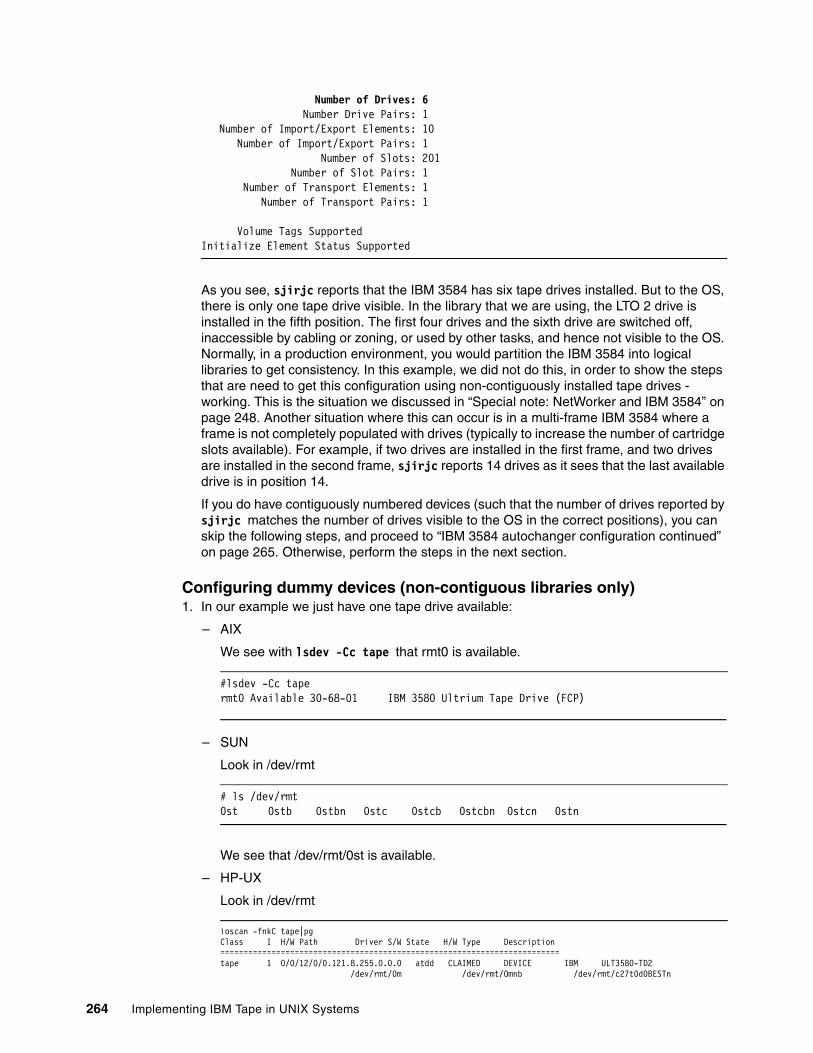
Number of Drives: 6 Number Drive Pairs: 1 Number of Import/Export Elements: 10 Number of Import/Export Pairs: 1 Number of Slots: 201 Number of Slot Pairs: 1 Number of Transport Elements: 1 Number of Transport Pairs: 1
Volume Tags SupportedInitialize Element Status Supported
As you see, sjirjc reports that the IBM 3584 has six tape drives installed. But to the OS, there is only one tape drive visible. In the library that we are using, the LTO 2 drive is installed in the fifth position. The first four drives and the sixth drive are switched off, inaccessible by cabling or zoning, or used by other tasks, and hence not visible to the OS. Normally, in a production environment, you would partition the IBM 3584 into logical libraries to get consistency. In this example, we did not do this, in order to show the steps that are need to get this configuration using non-contiguously installed tape drives - working. This is the situation we discussed in “Special note: NetWorker and IBM 3584” on page 248. Another situation where this can occur is in a multi-frame IBM 3584 where a frame is not completely populated with drives (typically to increase the number of cartridge slots available). For example, if two drives are installed in the first frame, and two drives are installed in the second frame, sjirjc reports 14 drives as it sees that the last available drive is in position 14.
If you do have contiguously numbered devices (such that the number of drives reported by sjirjc matches the number of drives visible to the OS in the correct positions), you can skip the following steps, and proceed to “IBM 3584 autochanger configuration continued” on page 265. Otherwise, perform the steps in the next section.
Configuring dummy devices (non-contiguous libraries only)1. In our example we just have one tape drive available:
– AIX
We see with lsdev -Cc tape that rmt0 is available.
#lsdev -Cc tapermt0 Available 30-68-01 IBM 3580 Ultrium Tape Drive (FCP)
– SUN
Look in /dev/rmt
# ls /dev/rmt0st 0stb 0stbn 0stc 0stcb 0stcbn 0stcn 0stn
We see that /dev/rmt/0st is available.
– HP-UX
Look in /dev/rmt
ioscan -fnkC tape|pgClass I H/W Path Driver S/W State H/W Type Description=========================================================================tape 1 0/0/12/0/0.121.8.255.0.0.0 atdd CLAIMED DEVICE IBM ULT3580-TD2 /dev/rmt/0m /dev/rmt/0mnb /dev/rmt/c27t0d0BESTn
264 Implementing IBM Tape in UNIX Systems
/dev/rmt/0mb /dev/rmt/c27t0d0BEST /dev/rmt/c27t0d0BESTnb /dev/rmt/0mn /dev/rmt/c27t0d0BESTb
We see that /dev/rmt/0mnb is available.
2. In order to get jbconfig reporting correctly, we need to create, in our case, five dummy devices to stand in for the missing five devices. For this we have to create five blank files. You can use touch to do this. The file names can be arbitrary, but for consistency we recommend the following system. Use file name /dev/rmt/logx for each device, where x represents the device position. So, in our case, because we have a tape drive at position 5, but none at 1-4, or 6, we create the files as shown in Example 6-16. We will use these dummy device files in step 2 on page 266.
Example 6-16 Creating dummy tape devices
# touch /dev/rmt/log1# touch /dev/rmt/log2# touch /dev/rmt/log3# touch /dev/rmt/log4# touch /dev/rmt/log6
IBM 3584 autochanger configuration continued1. Before configuring the IBM 3584 medium changer to be managed by NetWorker as an
autochanger device, if you had previously installed the IBM provided Atape device driver, you have to remove the medium changer device from the OS configuration. You will have to do this if the inquire command (Example 6-12 on page 262) detected an Autochanger device:
– AIX
To remove the medium changer, use the command:
# rmdev -l smcn -d
Where, n is the number associated with the medium changer special device name.
Alternatively, you can use SMIT to remove the device from the configuration, as in 4.2.8, “Deleting tape devices” on page 124. After this, you should no longer see the medium changer in the list of devices.
– SUN
To remove the medium changer, edit /kernel/drv/IBMtape.conf.
Comment out (or delete) the entry with the SCSI target ID and LUN number of the medium changer device (in this example, it is target=4 lun=1):
#name="IBMtape"# class="scsi"# target=4 lun=1# block_size=0# buffering=1# immediate=0# trailer=0# sili=0;
Use the # symbol to comment out the entry. Save the changes. If you have multiple control paths enabled on your LTO library, and you want to use these additional control paths for redundancy reasons in NetWorker, then you also have to remove or comment all entries for the control paths. In most cases this would be all stanzas with lun=1.
Chapter 6. Implementing EMC Legato NetWorker with LTO 265
Then, create an entry for the medium changer in the Solaris standard devices configuration file /kernel/drv/st.conf:
name="st" class="scsi" target=4 lun=1;
Add this entry to the bottom of the file. The target and LUN numbers are the addresses of the LTO medium changer, as reported by the inquire command.
Then reboot the server:
# reboot -- -r
– HP-UX
To remove the medium changer, use the procedure in 4.5, “Testing the library with tapeutil” on page 149.
2. After the server has successfully restarted (if necessary), you can configure the autochanger to NetWorker, using the jbconfig command. When you run jbconfig, you are prompted for the type of autochanger to install.
# jbconfig 1) Configure an AlphaStor/SmartMedia Jukebox. 2) Configure an Autodetected SCSI Jukebox. 3) Configure an Autodetected NDMP SCSI Jukebox. 4) Configure an SJI Jukebox. 5) Configure an STL Silo.
What kind of Jukebox are you configuring? [1] 2
For an IBM LTO library, select option [2]. Then jbconfig searches for attached SCSI jukeboxes. If jbconfig does not find the library, you have to enter the SCSI path, such as 3.4.1. If jbconfig detects the library you will see this:
Installing 'Standard SCSI Jukebox' jukebox - [email protected].
After that you have to assign a name to the library. For the auto-cleaning question, answer no if you are configuring the autochanger for an IBM 3582, 3583, or 3584, because these libraries support automatic cleaning driven by the library. IBM recommends that you use library-controlled cleaning, rather than enabling cleaning by the application software. If you have another LTO product such as an IBM 3580 or 3581, you can choose either to enable the NetWorker automatic device cleaning (enter yes) or to perform your own manual cleaning (enter no), since these LTO models do not support automatic library cleaning.
What name do you want to assign to this jukebox device? IBM3584fcTurn NetWorker auto-cleaning on (yes / no) [yes]? n
In our example our library is non-shared, and will not be set up for NDMP; therefore, we answered No to the next two questions.
The drives in this jukebox cannot be auto-configured with the available information. You will need to provide the path for the drives.
Is (any path of) any drive intended for NDMP use? (yes / no) [no] Is any drive going to have more than one path defined? (yes / no) [no]
266 Implementing IBM Tape in UNIX Systems
Now, you need to enter in the device names for each drive element number. If you have contiguously installed drives, enter the real device names. In our configuration, we have non-contiguous drives (only one drive installed in the 5th position). Therefore, we will use our “real” tape drive for the fifth position (element 261) and enter the dummy tape devices, which we created in “Configuring dummy devices (non-contiguous libraries only)” on page 264, for the other five positions. For actual tape drives, use the device special file name indicating a no rewind device. For performance reasons, it is suggested to use a device special file name that has compression enabled. For more information on the device special file name to use, see Table 4-3 on page 151.
– AIX
For AIX, use the device path /dev/rmtx.1
– SUN
For SUN, use the device path /dev/rmt/xstcbn
– HP-UX
For HP-UX, use the device path /dev/rmt/xmnb
Example 6-17 shows our Solaris example with one real drive and five dummy drives.
Example 6-17 Entering element device names
Please enter the device path information in one of the following formats:
/dev/rmt/1cbn --for local path or host:device-path --for remote node or host:drive-letter:directory path --for Windows disk file
Drive 1, element 257Drive path ? /dev/rmt/log1
Drive 2, element 258Drive path ? /dev/rmt/log2
Drive 3, element 259Drive path ? /dev/rmt/log3
Drive 4, element 260Drive path ? /dev/rmt/log4
Drive 5, element 261Drive path ? /dev/rmt/0stcbn
Drive 6, element 262Drive path ? /dev/rmt/log6
3. Now we have to define the drive types. For the real tape we use the option 34 LTO Ultrium-2, and for the dummy devices the option 32 logical.
Please select the appropriate drive type number: 1) 3480 18) 9840 35) optical 2) 3570 19) 9840b 36) qic 3) 3590 20) 9940 37) SD3 4) 4890 21) adv_file 38) sdlt 5) 4mm 22) dlt 39) sdlt320 6) 4mm 12GB 23) dlt1 40) SLR 7) 4mm 20GB 24) dlt7000 41) tkz90 8) 4mm 4GB 25) dlt8000 42) travan10 9) 4mm 8GB 26) dst 43) tz85
Chapter 6. Implementing EMC Legato NetWorker with LTO 267
10) 8mm 27) dst (NT) 44) tz86 11) 8mm 20GB 28) dtf 45) tz87 12) 8mm 5GB 29) dtf2 46) tz88 13) 8mm AIT 30) file 47) tz89 14) 8mm AIT-2 31) himt 48) tz90 15) 8mm AIT-3 32) logical 49) tzs20 16) 8mm Mammoth-2 33) LTO Ultrium 50) VXA 17) 9490 34) LTO Ultrium-2
Enter the drive type of drive 1? 32Are all the drives the same model? (yes / no) [yes] nEnter the drive type of drive 2? 32Enter the drive type of drive 3? 32Enter the drive type of drive 4? 32Enter the drive type of drive 5? 34Enter the drive type of drive 6? 32
Now, the library is configured successfully.
Jukebox has been added successfully
The following configuration options have been set:
> Jukebox description to the control port and model. > Autochanger control port to the port at which we found it. > Autocleaning off. > Barcode reading to on. Your jukebox does not report that it has a bar code reader, but it does report that it can handle volume tags. Some jukeboxes that have barcode readers report this way. > Volume labels that match the barcodes.
You can review and change the characteristics of the autochanger and itsassociated devices using nwadmin.
Disabling dummy devices The dummy devices (if required) are just needed to complete the jbconfig stage. After this, you should disable them using the following procedure before continuing. If you did not have to create dummy devices, then you can continue with the installation as described in 6.4, “Installation verification” on page 270:
1. To disable the configured dummy devices, start the NetWorker admin GUI.
2. To see more information about the drives and the library, set the options to see hidden attributes. Select Options → Customize and enable Display Hidden Attributes.
3. Use the Media pull-down menu to select the Jukeboxes window, and check if the LTO library is present (Figure 6-5).
268 Implementing IBM Tape in UNIX Systems
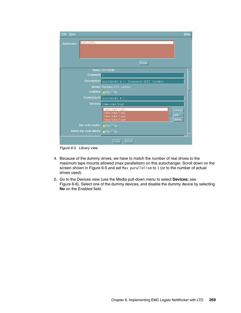
Figure 6-5 Library view
4. Because of the dummy drives, we have to match the number of real drives to the maximum tape mounts allowed (max parallelism) on this autochanger. Scroll down on the screen shown in Figure 6-5 and set Max parallelism to 1 (or to the number of actual drives used).
5. Go to the Devices view (use the Media pull-down menu to select Devices; see Figure 6-6). Select one of the dummy devices, and disable the dummy device by selecting No on the Enabled field.
Chapter 6. Implementing EMC Legato NetWorker with LTO 269
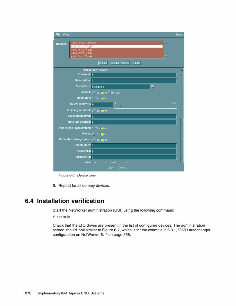
Figure 6-6 Device view
6. Repeat for all dummy devices.
6.4 Installation verificationStart the NetWorker administration (GUI) using the following command:
# nwadmin
Check that the LTO drives are present in the list of configured devices. The administration screen should look similar to Figure 6-7, which is for the example in 6.3.1, “3583 autochanger configuration on NetWorker 6.1” on page 258.
270 Implementing IBM Tape in UNIX Systems
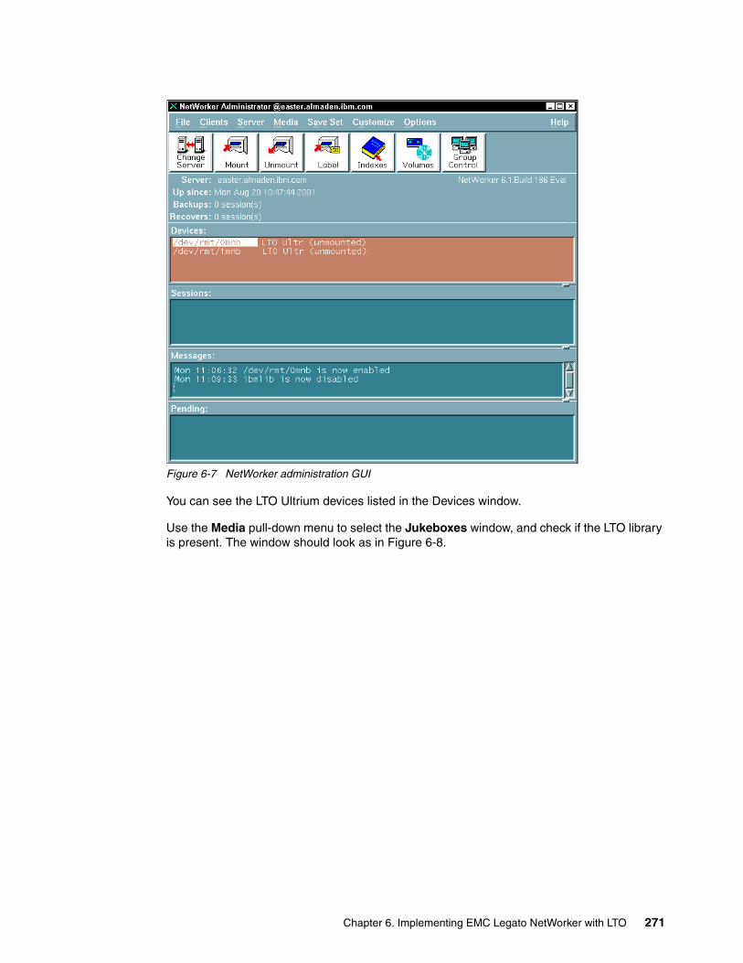
Figure 6-7 NetWorker administration GUI
You can see the LTO Ultrium devices listed in the Devices window.
Use the Media pull-down menu to select the Jukeboxes window, and check if the LTO library is present. The window should look as in Figure 6-8.
Chapter 6. Implementing EMC Legato NetWorker with LTO 271
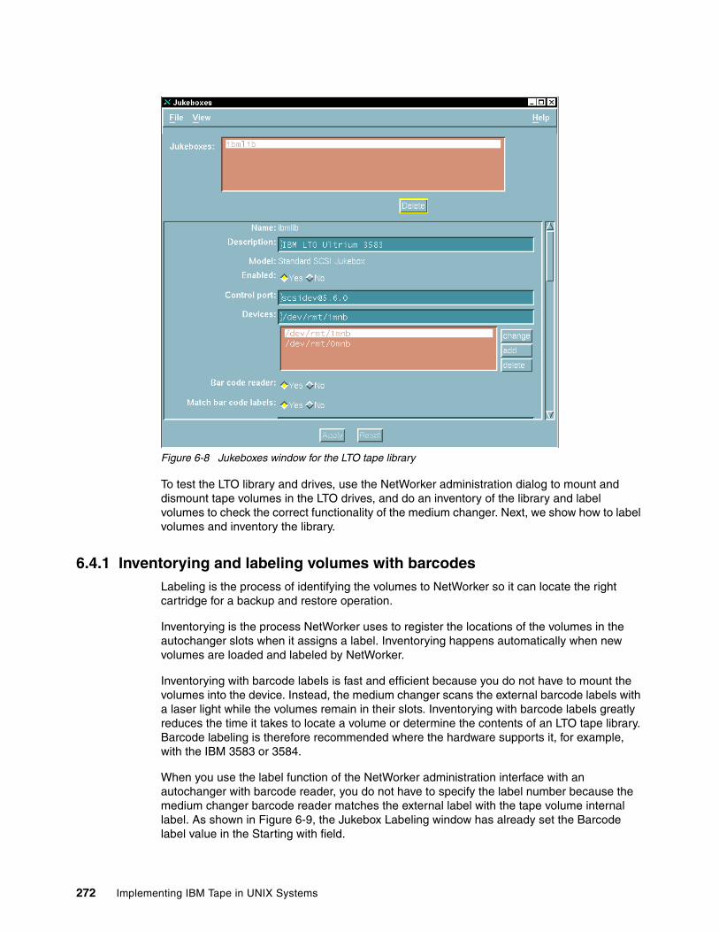
Figure 6-8 Jukeboxes window for the LTO tape library
To test the LTO library and drives, use the NetWorker administration dialog to mount and dismount tape volumes in the LTO drives, and do an inventory of the library and label volumes to check the correct functionality of the medium changer. Next, we show how to label volumes and inventory the library.
6.4.1 Inventorying and labeling volumes with barcodesLabeling is the process of identifying the volumes to NetWorker so it can locate the right cartridge for a backup and restore operation.
Inventorying is the process NetWorker uses to register the locations of the volumes in the autochanger slots when it assigns a label. Inventorying happens automatically when new volumes are loaded and labeled by NetWorker.
Inventorying with barcode labels is fast and efficient because you do not have to mount the volumes into the device. Instead, the medium changer scans the external barcode labels with a laser light while the volumes remain in their slots. Inventorying with barcode labels greatly reduces the time it takes to locate a volume or determine the contents of an LTO tape library. Barcode labeling is therefore recommended where the hardware supports it, for example, with the IBM 3583 or 3584.
When you use the label function of the NetWorker administration interface with an autochanger with barcode reader, you do not have to specify the label number because the medium changer barcode reader matches the external label with the tape volume internal label. As shown in Figure 6-9, the Jukebox Labeling window has already set the Barcode label value in the Starting with field.
272 Implementing IBM Tape in UNIX Systems
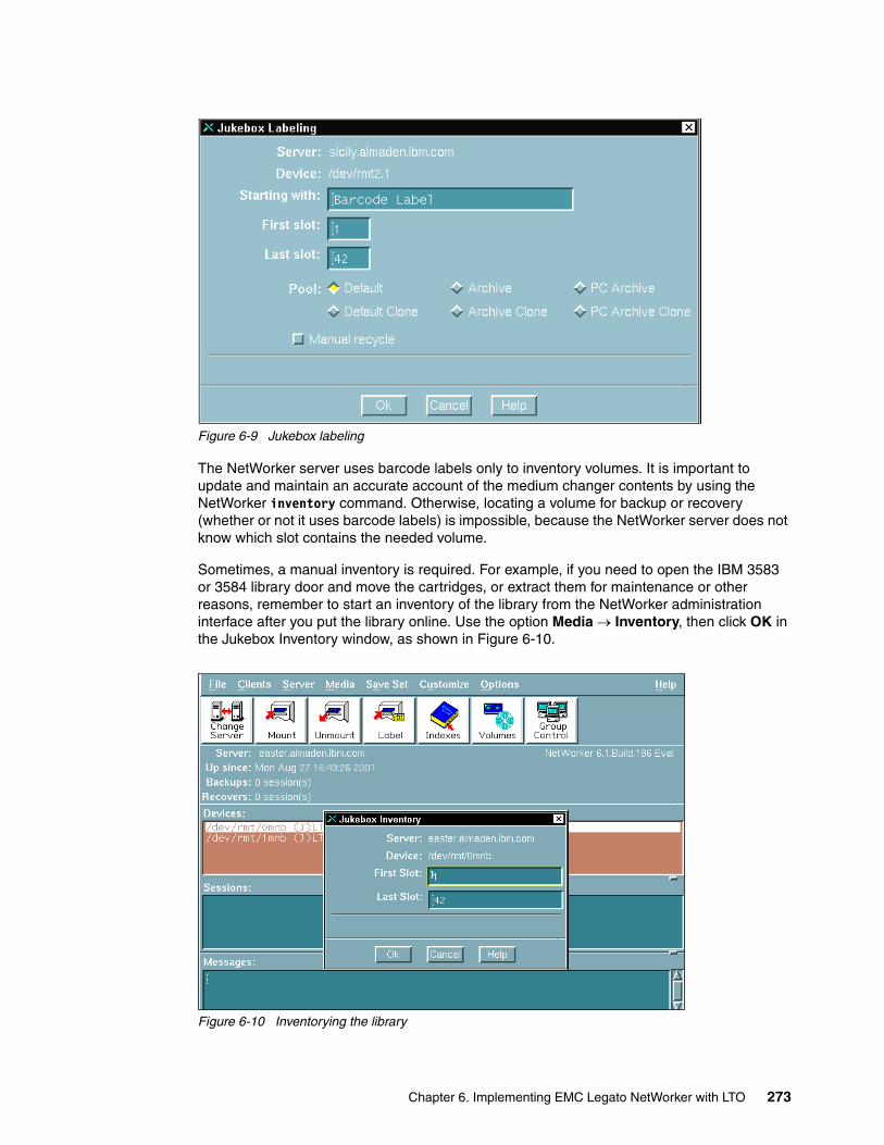
Figure 6-9 Jukebox labeling
The NetWorker server uses barcode labels only to inventory volumes. It is important to update and maintain an accurate account of the medium changer contents by using the NetWorker inventory command. Otherwise, locating a volume for backup or recovery (whether or not it uses barcode labels) is impossible, because the NetWorker server does not know which slot contains the needed volume.
Sometimes, a manual inventory is required. For example, if you need to open the IBM 3583 or 3584 library door and move the cartridges, or extract them for maintenance or other reasons, remember to start an inventory of the library from the NetWorker administration interface after you put the library online. Use the option Media → Inventory, then click OK in the Jukebox Inventory window, as shown in Figure 6-10.
Figure 6-10 Inventorying the library
Chapter 6. Implementing EMC Legato NetWorker with LTO 273
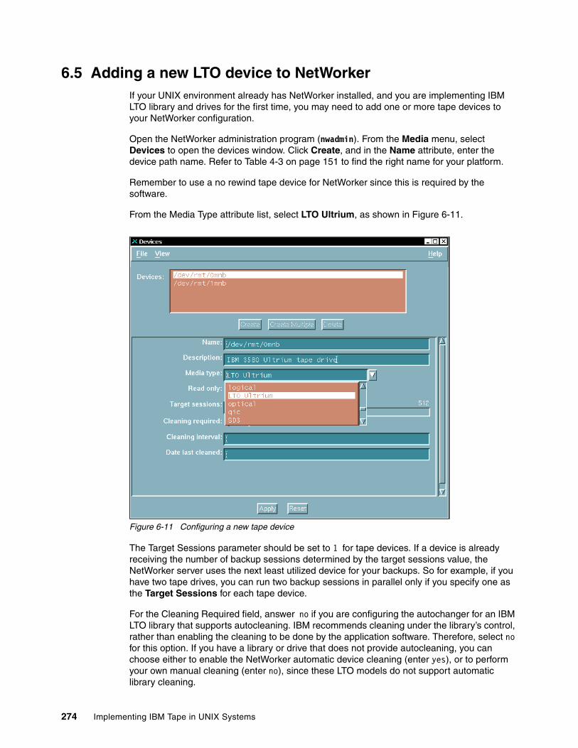
6.5 Adding a new LTO device to NetWorkerIf your UNIX environment already has NetWorker installed, and you are implementing IBM LTO library and drives for the first time, you may need to add one or more tape devices to your NetWorker configuration.
Open the NetWorker administration program (nwadmin). From the Media menu, select Devices to open the devices window. Click Create, and in the Name attribute, enter the device path name. Refer to Table 4-3 on page 151 to find the right name for your platform.
Remember to use a no rewind tape device for NetWorker since this is required by the software.
From the Media Type attribute list, select LTO Ultrium, as shown in Figure 6-11.
Figure 6-11 Configuring a new tape device
The Target Sessions parameter should be set to 1 for tape devices. If a device is already receiving the number of backup sessions determined by the target sessions value, the NetWorker server uses the next least utilized device for your backups. So for example, if you have two tape drives, you can run two backup sessions in parallel only if you specify one as the Target Sessions for each tape device.
For the Cleaning Required field, answer no if you are configuring the autochanger for an IBM LTO library that supports autocleaning. IBM recommends cleaning under the library’s control, rather than enabling the cleaning to be done by the application software. Therefore, select no for this option. If you have a library or drive that does not provide autocleaning, you can choose either to enable the NetWorker automatic device cleaning (enter yes), or to perform your own manual cleaning (enter no), since these LTO models do not support automatic library cleaning.
274 Implementing IBM Tape in UNIX Systems

The Automatic Media Management feature can be activated from this panel only if you are using a manual tape drive. This feature gives the NetWorker server automatic control over media loaded in the storage device. If you have an LTO library or autoloader, this feature can be enabled only from the Jukeboxes resources dialog. Further discussion is in 6.6.3, “Auto media management” on page 277.
6.6 NetWorker exploitationIn this section we give you further information on NetWorker capabilities related to tape processing. These are:
� Dynamic drive sharing (DDS)� Auto media management� Using the barcode reader with NetWorker
These are all functions that you can enable and configure to exploit the NetWorker product with the IBM LTO tape library and drives.
6.6.1 Dynamic drive sharing (DDS)The dynamic drive sharing (DDS) feature provides NetWorker software with the ability to recognize shared drives. Shared drives are drives that are available to more than one NetWorker server. DDS enables NetWorker software to be aware of all the servers with access to these drives. If a drive is required for an operation, it will skip any shared drives that are in use, and route the backups or recoveries to other available shared drives.
Enabling DDS on your system provides you with the following benefits:
� Reduced storage costs: A single tape drive can be shared among several storage nodes. In fact, since the NetWorker software uses the same open tape format for UNIX, Windows NT, NetWare, and Linux, you can actually share the same tape between different platforms (assuming that respective save sets belong to the same pool).
� Reduced LAN traffic: You can reconfigure clients as SAN storage nodes, which can send save sets over the SAN to shared drives.
In the example in Figure 6-12, we are using one NetWorker server, two NetWorker storage nodes (SN1 and SN2), and an IBM 3583 with two drives.
Important: Do not activate the Automatic Media Management feature unless you are using your LTO tape library exclusively with NetWorker. If this is activated, NetWorker assumes that all the volumes loaded in the autochanger will be handled exclusively as NetWorker media. This can lead to unwanted data overwrites if there are other, non-NetWorker volumes in the autochanger.
Note: DDS is only supported in a SAN Fibre Channel environment, not in a direct-connect, twin-tailed SCSI environment.
Chapter 6. Implementing EMC Legato NetWorker with LTO 275
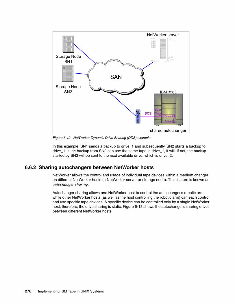
Figure 6-12 NetWorker Dynamic Drive Sharing (DDS) example
In this example, SN1 sends a backup to drive_1 and subsequently, SN2 starts a backup to drive_1. If the backup from SN2 can use the same tape in drive_1, it will. If not, the backup started by SN2 will be sent to the next available drive, which is drive_2.
6.6.2 Sharing autochangers between NetWorker hostsNetWorker allows the control and usage of individual tape devices within a medium changer on different NetWorker hosts (a NetWorker server or storage node). This feature is known as autochanger sharing.
Autochanger sharing allows one NetWorker host to control the autochanger’s robotic arm, while other NetWorker hosts (as well as the host controlling the robotic arm) can each control and use specific tape devices. A specific device can be controlled only by a single NetWorker host; therefore, the drive sharing is static. Figure 6-13 shows the autochangers sharing drives between different NetWorker hosts.
Drive 2
Drive 1
SCSII/Face
IBM 3583
SDG
Rou
ter
SCSI
SAN
NetWorker server
shared autochanger
Storage NodeSN1
Storage NodeSN2
276 Implementing IBM Tape in UNIX Systems
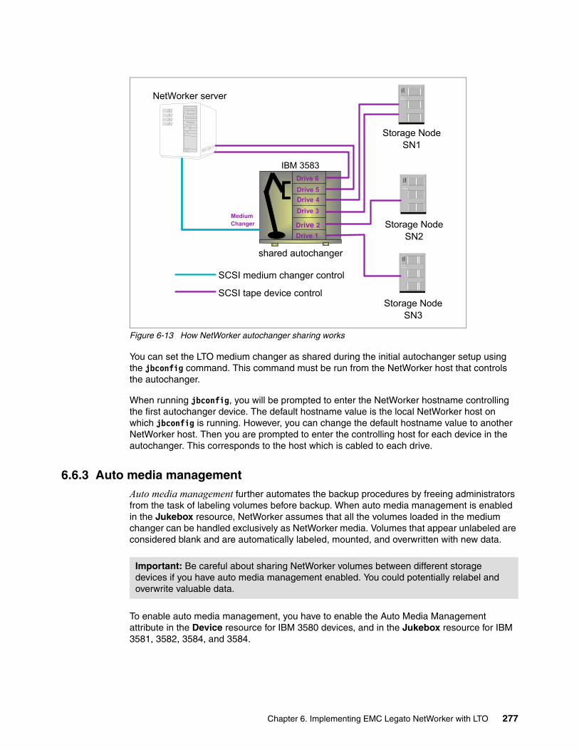
Figure 6-13 How NetWorker autochanger sharing works
You can set the LTO medium changer as shared during the initial autochanger setup using the jbconfig command. This command must be run from the NetWorker host that controls the autochanger.
When running jbconfig, you will be prompted to enter the NetWorker hostname controlling the first autochanger device. The default hostname value is the local NetWorker host on which jbconfig is running. However, you can change the default hostname value to another NetWorker host. Then you are prompted to enter the controlling host for each device in the autochanger. This corresponds to the host which is cabled to each drive.
6.6.3 Auto media managementAuto media management further automates the backup procedures by freeing administrators from the task of labeling volumes before backup. When auto media management is enabled in the Jukebox resource, NetWorker assumes that all the volumes loaded in the medium changer can be handled exclusively as NetWorker media. Volumes that appear unlabeled are considered blank and are automatically labeled, mounted, and overwritten with new data.
To enable auto media management, you have to enable the Auto Media Management attribute in the Device resource for IBM 3580 devices, and in the Jukebox resource for IBM 3581, 3582, 3584, and 3584.
NetWorker server
Storage NodeSN1
Storage NodeSN2Drive 1
Drive 2
IBM 3583
shared autochanger
Drive 3
Drive 4
Drive 5
Drive 6
MediumChanger
Storage NodeSN3
SCSI medium changer control
SCSI tape device control
Important: Be careful about sharing NetWorker volumes between different storage devices if you have auto media management enabled. You could potentially relabel and overwrite valuable data.
Chapter 6. Implementing EMC Legato NetWorker with LTO 277

278 Implementing IBM Tape in UNIX Systems

Part 3 Appendixes
Part 3
© Copyright IBM Corp. 2002, 2003, 2004, 2005. All rights reserved. 279

280 Implementing IBM Tape in UNIX Systems
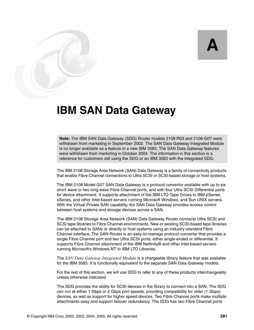
Appendix A. IBM SAN Data Gateway
The IBM 2108 Storage Area Network (SAN) Data Gateway is a family of connectivity products that enable Fibre Channel connections to Ultra SCSI or SCSI-based storage or host systems.
The IBM 2108 Model G07 SAN Data Gateway is a protocol convertor available with up to six short wave or two long wave Fibre Channel ports, and with four Ultra SCSI Differential ports for device attachment. It supports attachment of the IBM LTO Tape Drives to IBM pSeries, xSeries, and other Intel-based servers running Microsoft Windows, and Sun UNIX servers. With the Virtual Private SAN capability, the SAN Data Gateway provides access control between host systems and storage devices across a SAN.
The IBM 2108 Storage Area Network (SAN) Data Gateway Router connects Ultra SCSI and SCSI tape libraries to Fibre Channel environments. New or existing SCSI-based tape libraries can be attached to SANs or directly to host systems using an industry-standard Fibre Channel interface. The SAN Router is an easy-to-manage protocol converter that provides a single Fibre Channel port and two Ultra SCSI ports, either single-ended or differential. It supports Fibre Channel attachment of the IBM Netfinity® and other Intel-based servers running Microsoft's Windows NT to IBM LTO Libraries.
The SAN Data Gateway Integrated Module is a chargeable library feature that was available for the IBM 3583. It is functionally equivalent to the separate SAN Data Gateway models.
For the rest of this section, we will use SDG to refer to any of these products interchangeably unless otherwise indicated.
The SDG provides the ability for SCSI devices in the library to connect into a SAN. The SDG can run at either 1 Gbps or 2 Gbps port speeds, providing compatibility for older (1 Gbps) devices, as well as support for higher speed devices. Two Fibre Channel ports make multiple attachments easy and support failover redundancy. The SDG has two Fibre Channel ports
A
Note: The IBM SAN Data Gateway (SDG) Router models 2108-R03 and 2108-G07 were withdrawn from marketing in September 2002. The SAN Data Gateway Integrated Module is no longer available as a feature in a new IBM 3583. The SAN Data Gateway features were withdrawn from marketing in October 2004. The information in this section is a reference for customers still using the SDG or an IBM 3583 with the integrated SDG.
© Copyright IBM Corp. 2002, 2003, 2004, 2005. All rights reserved. 281
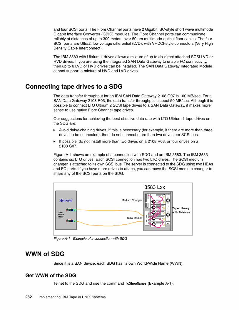
and four SCSI ports. The Fibre Channel ports have 2 Gigabit, SC-style short wave multimode Gigabit Interface Converter (GBIC) modules. The Fibre Channel ports can communicate reliably at distances of up to 300 meters over 50 µm multimode-optical fiber cables. The four SCSI ports are Ultra2, low voltage differential (LVD), with VHDCI-style connectors (Very High Density Cable Interconnect).
The IBM 3583 with Ultrium 1 drives allows a mixture of up to six direct attached SCSI LVD or HVD drives. If you are using the integrated SAN Data Gateway to enable FC connectivity, then up to 6 LVD or HVD drives can be installed. The SAN Data Gateway Integrated Module cannot support a mixture of HVD and LVD drives.
Connecting tape drives to a SDGThe data transfer throughput for an IBM SAN Data Gateway 2108 G07 is 100 MB/sec. For a SAN Data Gateway 2108 R03, the data transfer throughput is about 50 MB/sec. Although it is possible to connect LTO Ultrium 2 SCSI tape drives to a SAN Data Gateway, it makes more sense to use native Fibre Channel tape drives.
Our suggestions for achieving the best effective data rate with LTO Ultrium 1 tape drives on the SDG are:
� Avoid daisy-chaining drives. If this is necessary (for example, if there are more than three drives to be connected), then do not connect more than two drives per SCSI bus.
� If possible, do not install more than two drives on a 2108 R03, or four drives on a 2108 G07.
Figure A-1 shows an example of a connection with SDG and an IBM 3583. The IBM 3583 contains six LTO drives. Each SCSI connection has two LTO drives. The SCSI medium changer is attached to its own SCSI bus. The server is connected to the SDG using two HBAs and FC ports. If you have more drives to attach, you can move the SCSI medium changer to share any of the SCSI ports on the SDG.
Figure A-1 Example of a connection with SDG
WWN of SDGSince it is a SAN device, each SDG has its own World-Wide Name (WWN).
Get WWN of the SDGTelnet to the SDG and use the command fcShowNames (Example A-1).
Tape Librarywith 6 drives
3583 Lxx
Fibre Channel Aapter
Server
SDG Module
Medium ChangerF
E
D
C
B
A
282 Implementing IBM Tape in UNIX Systems
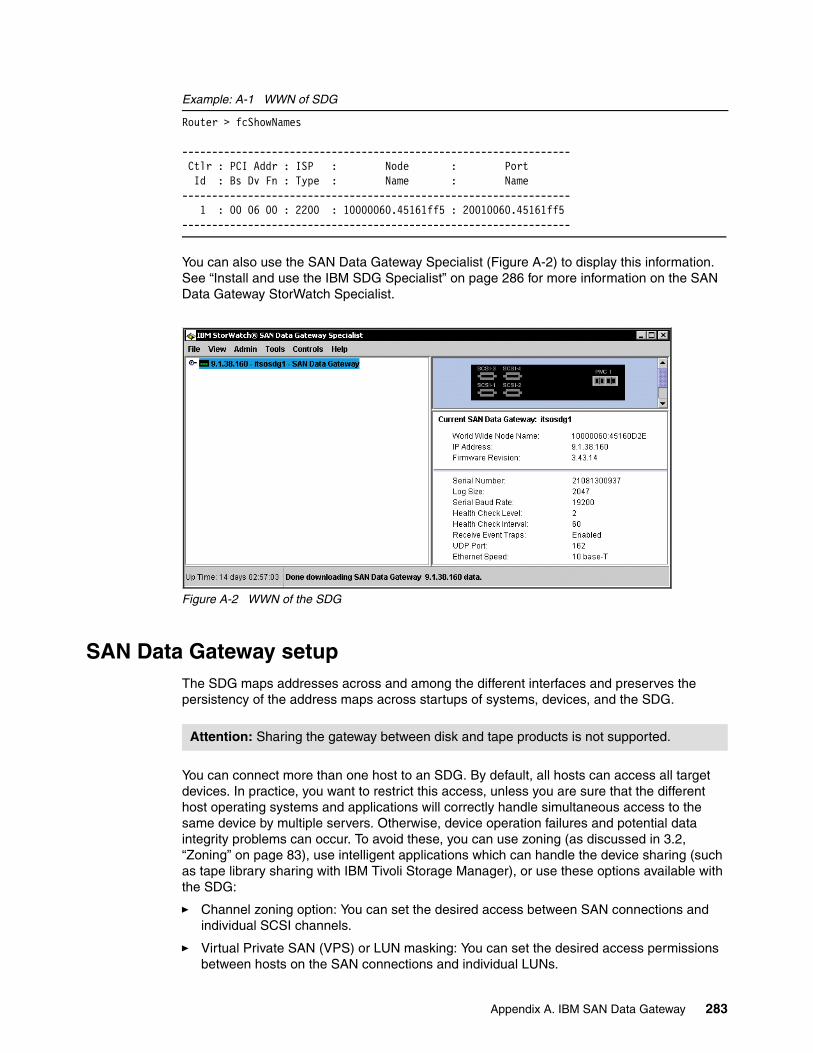
Example: A-1 WWN of SDG
Router > fcShowNames
----------------------------------------------------------------- Ctlr : PCI Addr : ISP : Node : Port Id : Bs Dv Fn : Type : Name : Name----------------------------------------------------------------- 1 : 00 06 00 : 2200 : 10000060.45161ff5 : 20010060.45161ff5-----------------------------------------------------------------
You can also use the SAN Data Gateway Specialist (Figure A-2) to display this information. See “Install and use the IBM SDG Specialist” on page 286 for more information on the SAN Data Gateway StorWatch Specialist.
Figure A-2 WWN of the SDG
SAN Data Gateway setupThe SDG maps addresses across and among the different interfaces and preserves the persistency of the address maps across startups of systems, devices, and the SDG.
You can connect more than one host to an SDG. By default, all hosts can access all target devices. In practice, you want to restrict this access, unless you are sure that the different host operating systems and applications will correctly handle simultaneous access to the same device by multiple servers. Otherwise, device operation failures and potential data integrity problems can occur. To avoid these, you can use zoning (as discussed in 3.2, “Zoning” on page 83), use intelligent applications which can handle the device sharing (such as tape library sharing with IBM Tivoli Storage Manager), or use these options available with the SDG:
� Channel zoning option: You can set the desired access between SAN connections and individual SCSI channels.
� Virtual Private SAN (VPS) or LUN masking: You can set the desired access permissions between hosts on the SAN connections and individual LUNs.
Attention: Sharing the gateway between disk and tape products is not supported.
Appendix A. IBM SAN Data Gateway 283
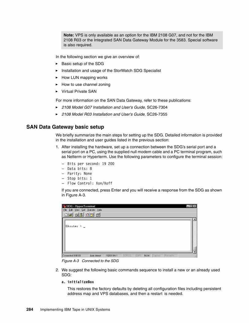
In the following section we give an overview of:
� Basic setup of the SDG
� Installation and usage of the StorWatch SDG Specialist
� How LUN mapping works
� How to use channel zoning
� Virtual Private SAN
For more information on the SAN Data Gateway, refer to these publications:
� 2108 Model G07 Installation and User's Guide, SC26-7304
� 2108 Model R03 Installation and User's Guide, SC26-7355
SAN Data Gateway basic setupWe briefly summarize the main steps for setting up the SDG. Detailed information is provided in the installation and user guides listed in the previous section:
1. After installing the hardware, set up a connection between the SDG’s serial port and a serial port on a PC, using the supplied null modem cable and a PC terminal program, such as Netterm or Hyperterm. Use the following parameters to configure the terminal session:
– Bits per second: 19 200– Data bits: 8– Parity: None– Stop bits: 1– Flow Control: Xon/Xoff
If you are connected, press Enter and you will receive a response from the SDG as shown in Figure A-3.
Figure A-3 Connected to the SDG
2. We suggest the following basic commands sequence to install a new or an already used SDG:
a. initializeBox
This restores the factory defaults by deleting all configuration files including persistent address map and VPS databases, and then a restart is needed.
Note: VPS is only available as an option for the IBM 2108 G07, and not for the IBM 2108 R03 or the Integrated SAN Data Gateway Module for the 3583. Special software is also required.
284 Implementing IBM Tape in UNIX Systems
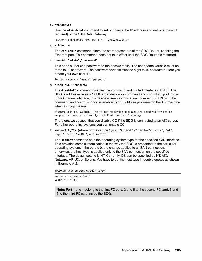
b. ethAddrSet
Use the ethAddrSet command to set or change the IP address and network mask (if required) of the SAN Data Gateway.
Router > ethAddrSet “192.168.1.54” “255.255.255.0”
c. ethEnable
The ethEnable command alters the start parameters of the SDG Router, enabling the Ethernet port. This command does not take effect until the SDG Router is restarted.
d. userAdd "admin","password"
This adds a user and password to the password file. The user name variable must be three to 80 characters. The password variable must be eight to 40 characters. Here you create your own user ID.
Router > userAdd "nancy","password"
e. disableCC or enableCC
The disableCC command disables the command and control interface (LUN 0). The SDG is addressable as a SCSI target device for command and control support. On a Fibre Channel interface, this device is seen as logical unit number 0, (LUN 0). If the command and control support is enabled, you might see problems on the AIX machine when a cfgmgr is run:
cfgmgr: 0514-621 WARNING: The following device packages are required for device support but are not currently installed. devices.fcp.array
Therefore, we suggest that you disable CC if the SDG is connected to an AIX server. For other operating systems you can enable CC.
f. setHost X,YYY (where port X can be 1,4,2,5,3,6 and YYY can be "solaris", "nt", "hpux", "aix", "as400", and so forth).
The setHost command sets the operating system type for the specified SAN interface. This provides some customization in the way the SDG is presented to the particular operating system. If the port is 0, the change applies to all SAN connections; otherwise, the host type is applied only to the SAN connection on the specified interface. The default setting is NT. Currently, OS can be specified as NT, AIX, Netware, HP-UX, or Solaris. You have to put the host type in double quotes as shown in Example A-2.
Example: A-2 setHost for FC 4 to AIX
Router > setHost 4,"aix"value = 0 = 0x0
Note: Port 1 and 4 belong to the first FC card; 2 and 5 to the second FC card; 3 and 6 to the third FC card inside the SDG.
Appendix A. IBM SAN Data Gateway 285
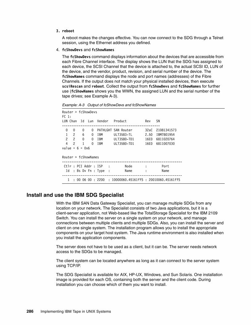
3. reboot
A reboot makes the changes effective. You can now connect to the SDG through a Telnet session, using the Ethernet address you defined.
4. fcShowDevs and fcShowNames
The fcShowDevs command displays information about the devices that are accessible from each Fibre Channel interface. The display shows the LUN that the SDG has assigned to each device, the SCSI Channel that the device is attached to, the actual SCSI ID, LUN of the device, and the vendor, product, revision, and serial number of the device. The fcShowNames command displays the node and port names (addresses) of the Fibre Channels. If the output does not match your physical installed devices, then execute scsiRescan and reboot. Collect the output from fcShowDevs and fcShowNames for further use (fcShowNames shows you the WWN, the assigned LUN and the serial number of the tape drives; see Example A-3).
Example: A-3 Output of fcShowDevs and fcShowNames
Router > fcShowDevsFC 1:LUN Chan Id Lun Vendor Product Rev SN----------------------------------------------------- 0 0 0 0 PATHLGHT SAN Router 32aC 21081341573 1 2 6 0 IBM ULT3583-TL 2.50 IBM7801954 2 2 0 0 IBM ULT3580-TD1 16E0 6811020764 4 2 1 0 IBM ULT3580-TD1 16E0 6811007030value = 6 = 0x6
Router > fcShowNames----------------------------------------------------------------- Ctlr : PCI Addr : ISP : Node : Port Id : Bs Dv Fn : Type : Name : Name----------------------------------------------------------------- 1 : 00 06 00 : 2200 : 10000060.45161ff5 : 20010060.45161ff5
Install and use the IBM SDG SpecialistWith the IBM SAN Data Gateway Specialist, you can manage multiple SDGs from any location on your network. The Specialist consists of two Java applications, but it is a client-server application, not Web-based like the TotalStorage Specialist for the IBM 2109 Switch. You can install the server on a single system on your network, and manage connections between multiple clients and multiple SDGs. Also, you can install the server and client on one single system. The installation program allows you to install the appropriate components on your target host system. The Java runtime environment is also installed when you install the application components.
The server does not have to be used as a client, but it can be. The server needs network access to the SDGs to be managed.
The client system can be located anywhere as long as it can connect to the server system using TCP/IP.
The SDG Specialist is available for AIX, HP-UX, Windows, and Sun Solaris. One installation image is provided for each OS, containing both the server and the client code. During installation you can choose which of them you want to install.
286 Implementing IBM Tape in UNIX Systems
Client and server do not need to be on the same operating system. This means you can install the server, for instance, on AIX, HP-UX, or Sun Solaris, and use the client on Windows 2000 or on Windows NT.
You can download the latest version of the SDG Specialist from:
ftp://ftp.software.ibm.com/storage/san/2108/
Install on AIXDownload the latest version and the readme file for AIX from the FTP site. If needed, decompress and untar the files. The install images will be called something similar to storwsdg_bff. Install the server and client code with:
installp -a -d storwsdg_bff all
If you want to install only the server code type:
installp -a -d storwsdg_bff storwsdg.server
Or, to install the client code only:
installp -a -d storwsdg_bff storwsdg.client
As always, check the readme file for the latest information on fixes and prerequisites.
Install on HP-UXDownload the latest version and the readme file for HP-UX from the FTP site. If needed, decompress and untar the files. The install images will be called something similar to SS272HPX.bin. You need to set execute permission for the file as follows:
chmod 777 SS272HPX.bin
At the prompt type:
SS272HPX.bin
In a few moments a window will be displayed that contains the text InstallAnywhere. As of Version 2.6, the IBM SAN Data Gateway Specialist uses this installation software program.
A few moments later, the StorWatch SAN Data Gateway Specialist splash screen will be displayed.
Follow the prompts during the installation. You have an option to install the server only or client only. If you accept the default settings, both the server and client components will be installed.
As always, check the readme file for the latest information on fixes and prerequisites.
Install on Sun SolarisDownload the latest version and the readme file for Sun Solaris from the FTP site above. If needed, decompress and/or untar the files. For installation of the files enter:
pkgadd -d . IBMswsdg
During the installation you are asked if you want to install the client, and if you want to install the server:
Install StorWatch SAN Data Gateway Specialist Client [y/n] ? yInstall StorWatch SAN Data Gateway Specialist Server [y/n] ? y
As always, check the readme file for the latest information on fixes and prerequisites.
Appendix A. IBM SAN Data Gateway 287

Install on WindowsDownload the latest version and the readme file for Windows from the FTP site. Execute the downloaded file to start the installation. During installation, you can choose to install the server and the client (see Figure A-4).
Figure A-4 Install of the SDG StorWatch Specialist
As always, check the readme file for the latest information.
Start the serverIn order to connect to an SDG, you must first start the server application. The server application can run in the background.
Start the server on AIX, HP-UX, and on Sun Solaris in the background with:
/usr/bin/ServerLaunch -background &
To start the server on Windows, go to Start → Programs → IBM StorWatch SAN Data Gateway Specialist → Server. This opens a DOS window (Example A-4). Note that when starting the Specialist for the first time, you will see additional messages to subsequent invocations.
Example: A-4 SDG Specialist - Server application
IBM StorWatch SAN Data Gateway SpecialistServer Version 2.7.02 Build 0003Server StartCopyright 2001 Advanced Digital Information Corporation All rights reserved.Centralized error handling initiatedLog Filename = SanmgrServerLog00002.txtSNMP InitializedNetSessionManager instantiatedTrying to start RMI Registry on Port in Range (1099,1109)RMI registry started from within server, Host 9.1.39.50 , Port 1099Checking for other applications bound with URL rmi://9.1.39.50:1099/starfishNo other Server URL bound in registry, OK to proceedTrap receiver started on UDP Port 162Server logging on
288 Implementing IBM Tape in UNIX Systems
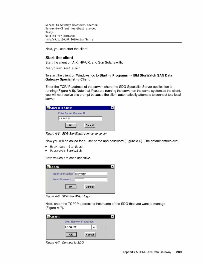
Server-to-Gateway heartbeat startedServer-to-Client heartbeat startedReady.Waiting for commandsrmi://9.1.150.57:1099/starfish :
Next, you can start the client.
Start the clientStart the client on AIX, HP-UX, and Sun Solaris with:
/usr/bin/ClientLaunch
To start the client on Windows, go to Start → Programs → IBM StorWatch SAN Data Gateway Specialist → Client.
Enter the TCP/IP address of the server where the SDG Specialist Server application is running (Figure A-5). Note that if you are running the server on the same system as the client, you will not receive this prompt because the client automatically attempts to connect to a local server.
Figure A-5 SDG StorWatch connect to server
Now you will be asked for a user name and password (Figure A-6). The default entries are:
� User name: StorWatch� Password: StorWatch
Both values are case sensitive.
Figure A-6 SDG StorWatch logon
Next, enter the TCP/IP address or hostname of the SDG that you want to manage (Figure A-7).
Figure A-7 Connect to SDG
Appendix A. IBM SAN Data Gateway 289
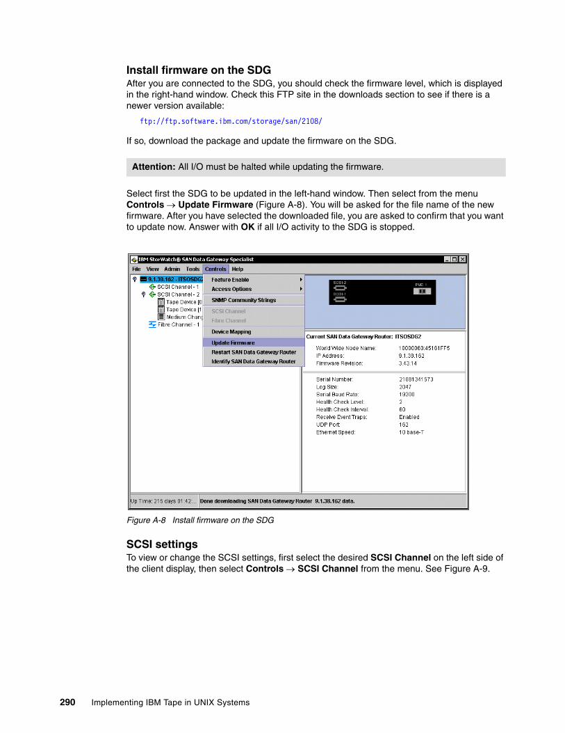
Install firmware on the SDGAfter you are connected to the SDG, you should check the firmware level, which is displayed in the right-hand window. Check this FTP site in the downloads section to see if there is a newer version available:
ftp://ftp.software.ibm.com/storage/san/2108/
If so, download the package and update the firmware on the SDG.
Select first the SDG to be updated in the left-hand window. Then select from the menu Controls → Update Firmware (Figure A-8). You will be asked for the file name of the new firmware. After you have selected the downloaded file, you are asked to confirm that you want to update now. Answer with OK if all I/O activity to the SDG is stopped.
Figure A-8 Install firmware on the SDG
SCSI settingsTo view or change the SCSI settings, first select the desired SCSI Channel on the left side of the client display, then select Controls → SCSI Channel from the menu. See Figure A-9.
Attention: All I/O must be halted while updating the firmware.
l
Firmware level
290 Implementing IBM Tape in UNIX Systems
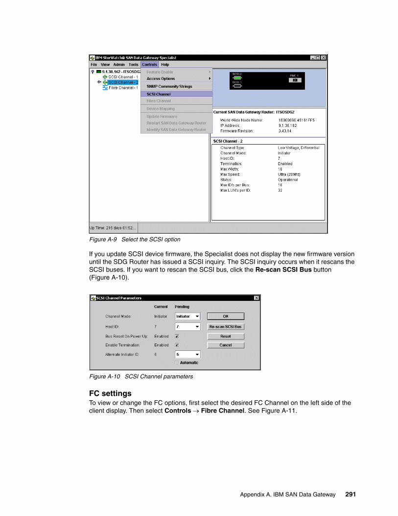
Figure A-9 Select the SCSI option
If you update SCSI device firmware, the Specialist does not display the new firmware version until the SDG Router has issued a SCSI inquiry. The SCSI inquiry occurs when it rescans the SCSI buses. If you want to rescan the SCSI bus, click the Re-scan SCSI Bus button (Figure A-10).
Figure A-10 SCSI Channel parameters
FC settingsTo view or change the FC options, first select the desired FC Channel on the left side of the client display. Then select Controls → Fibre Channel. See Figure A-11.
Appendix A. IBM SAN Data Gateway 291
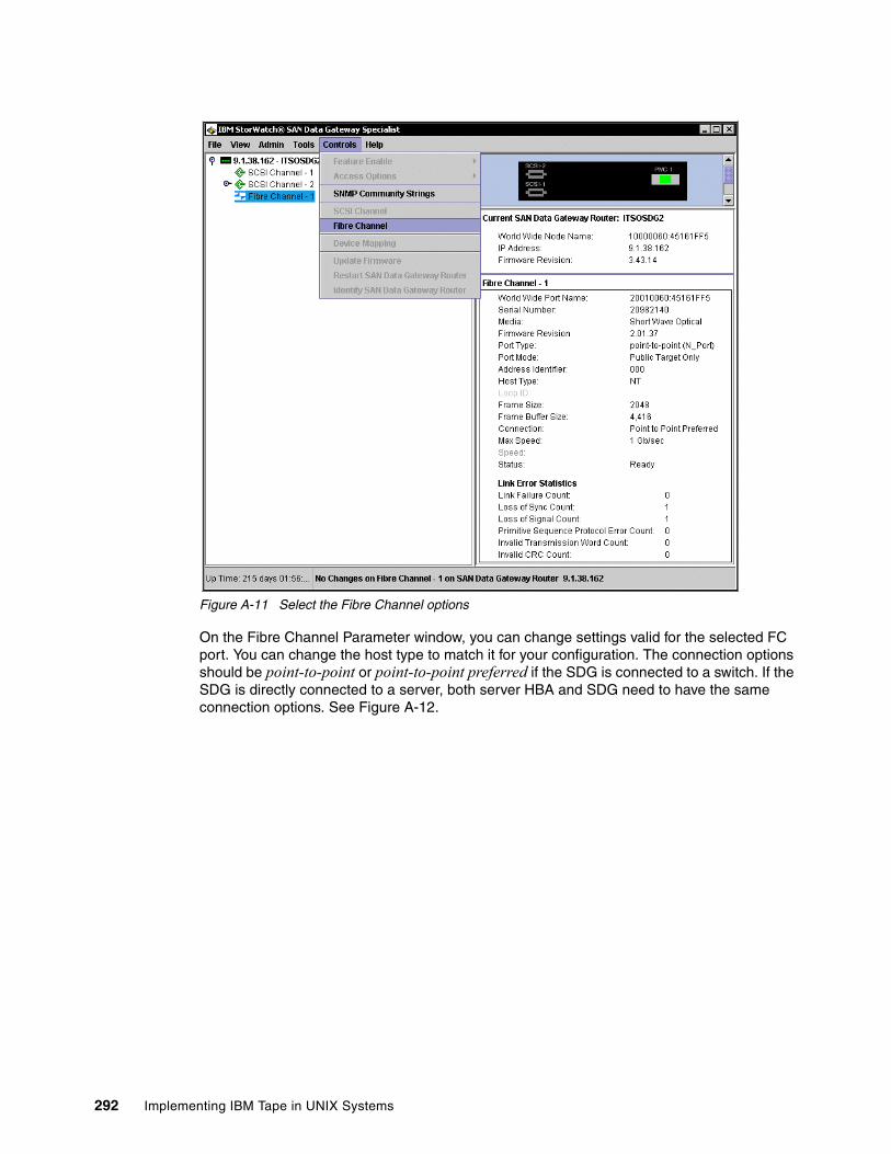
Figure A-11 Select the Fibre Channel options
On the Fibre Channel Parameter window, you can change settings valid for the selected FC port. You can change the host type to match it for your configuration. The connection options should be point-to-point or point-to-point preferred if the SDG is connected to a switch. If the SDG is directly connected to a server, both server HBA and SDG need to have the same connection options. See Figure A-12.
292 Implementing IBM Tape in UNIX Systems
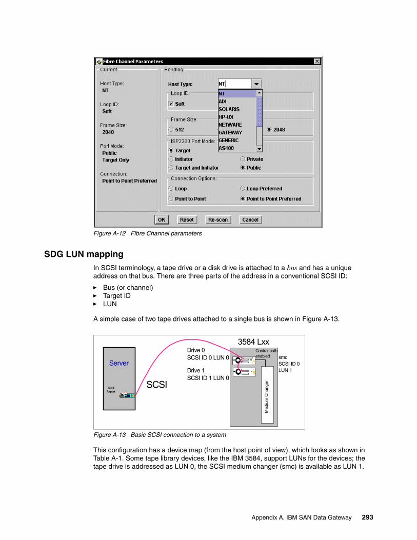
Figure A-12 Fibre Channel parameters
SDG LUN mapping In SCSI terminology, a tape drive or a disk drive is attached to a bus and has a unique address on that bus. There are three parts of the address in a conventional SCSI ID:
� Bus (or channel)� Target ID� LUN
A simple case of two tape drives attached to a single bus is shown in Figure A-13.
Figure A-13 Basic SCSI connection to a system
This configuration has a device map (from the host point of view), which looks as shown in Table A-1. Some tape library devices, like the IBM 3584, support LUNs for the devices; the tape drive is addressed as LUN 0, the SCSI medium changer (smc) is available as LUN 1.
3584 Lxx
SCSI Aapter
Server
Med
ium
Cha
nger
Control pathenabled
SCSI
Drive 0SCSI ID 0 LUN 0
Drive 1SCSI ID 1 LUN 0
smcSCSI ID 0 LUN 1B
A
Appendix A. IBM SAN Data Gateway 293
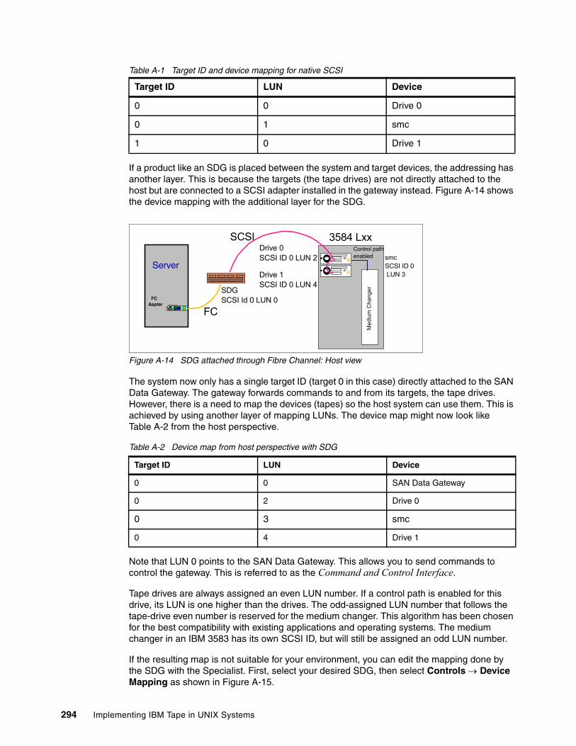
Table A-1 Target ID and device mapping for native SCSI
If a product like an SDG is placed between the system and target devices, the addressing has another layer. This is because the targets (the tape drives) are not directly attached to the host but are connected to a SCSI adapter installed in the gateway instead. Figure A-14 shows the device mapping with the additional layer for the SDG.
Figure A-14 SDG attached through Fibre Channel: Host view
The system now only has a single target ID (target 0 in this case) directly attached to the SAN Data Gateway. The gateway forwards commands to and from its targets, the tape drives. However, there is a need to map the devices (tapes) so the host system can use them. This is achieved by using another layer of mapping LUNs. The device map might now look like Table A-2 from the host perspective.
Table A-2 Device map from host perspective with SDG
Note that LUN 0 points to the SAN Data Gateway. This allows you to send commands to control the gateway. This is referred to as the Command and Control Interface.
Tape drives are always assigned an even LUN number. If a control path is enabled for this drive, its LUN is one higher than the drives. The odd-assigned LUN number that follows the tape-drive even number is reserved for the medium changer. This algorithm has been chosen for the best compatibility with existing applications and operating systems. The medium changer in an IBM 3583 has its own SCSI ID, but will still be assigned an odd LUN number.
If the resulting map is not suitable for your environment, you can edit the mapping done by the SDG with the Specialist. First, select your desired SDG, then select Controls → Device Mapping as shown in Figure A-15.
Target ID LUN Device
0 0 Drive 0
0 1 smc
1 0 Drive 1
3584 Lxx
FC Aapter
Server
Med
ium
Cha
nger
Control pathenabled
SCSIDrive 0SCSI ID 0 LUN 2
Drive 1SCSI ID 0 LUN 4
smcSCSI ID 0 LUN 3
FC
SDGSCSI Id 0 LUN 0
B
A
Target ID LUN Device
0 0 SAN Data Gateway
0 2 Drive 0
0 3 smc
0 4 Drive 1
294 Implementing IBM Tape in UNIX Systems
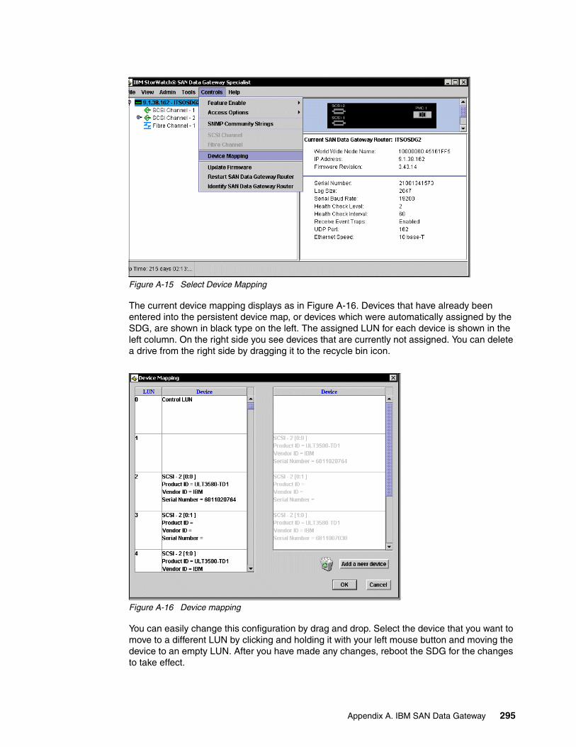
Figure A-15 Select Device Mapping
The current device mapping displays as in Figure A-16. Devices that have already been entered into the persistent device map, or devices which were automatically assigned by the SDG, are shown in black type on the left. The assigned LUN for each device is shown in the left column. On the right side you see devices that are currently not assigned. You can delete a drive from the right side by dragging it to the recycle bin icon.
Figure A-16 Device mapping
You can easily change this configuration by drag and drop. Select the device that you want to move to a different LUN by clicking and holding it with your left mouse button and moving the device to an empty LUN. After you have made any changes, reboot the SDG for the changes to take effect.
Appendix A. IBM SAN Data Gateway 295
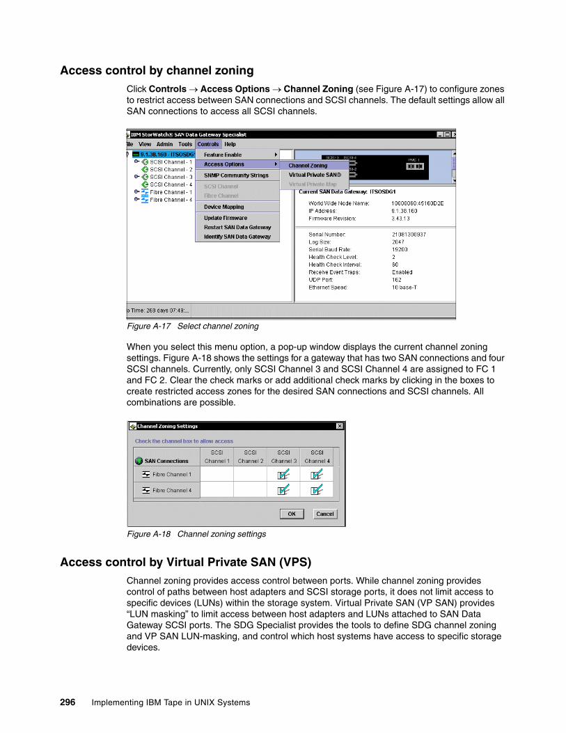
Access control by channel zoningClick Controls → Access Options → Channel Zoning (see Figure A-17) to configure zones to restrict access between SAN connections and SCSI channels. The default settings allow all SAN connections to access all SCSI channels.
Figure A-17 Select channel zoning
When you select this menu option, a pop-up window displays the current channel zoning settings. Figure A-18 shows the settings for a gateway that has two SAN connections and four SCSI channels. Currently, only SCSI Channel 3 and SCSI Channel 4 are assigned to FC 1 and FC 2. Clear the check marks or add additional check marks by clicking in the boxes to create restricted access zones for the desired SAN connections and SCSI channels. All combinations are possible.
Figure A-18 Channel zoning settings
Access control by Virtual Private SAN (VPS)Channel zoning provides access control between ports. While channel zoning provides control of paths between host adapters and SCSI storage ports, it does not limit access to specific devices (LUNs) within the storage system. Virtual Private SAN (VP SAN) provides “LUN masking” to limit access between host adapters and LUNs attached to SAN Data Gateway SCSI ports. The SDG Specialist provides the tools to define SDG channel zoning and VP SAN LUN-masking, and control which host systems have access to specific storage devices.
296 Implementing IBM Tape in UNIX Systems

VPS is applicable mainly in disk environments, so we do not discuss it further here. It is also not available for the integrated SAN Data Gateway Module for the IBM 3583. You can find more information on VPS in Planning and Implementing an IBM SAN, SG24-6116.
Appendix A. IBM SAN Data Gateway 297

298 Implementing IBM Tape in UNIX Systems
Appendix B. SNMP setup
This appendix describes setting up SNMP on the IBM TotalStorage 3582 Tape Library, IBM TotalStorage 3583 Tape Library, and IBM TotalStorage 3584 Tape Library.
B
© Copyright IBM Corp. 2002, 2003, 2004, 2005. All rights reserved. 299
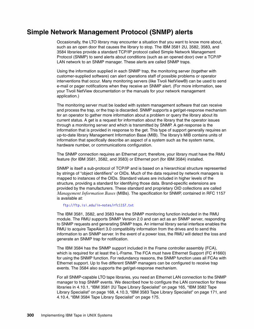
Simple Network Management Protocol (SNMP) alertsOccasionally, the LTO library may encounter a situation that you want to know more about, such as an open door that causes the library to stop. The IBM 3581 2U, 3582, 3583, and 3584 libraries provide a standard TCP/IP protocol called Simple Network Management Protocol (SNMP) to send alerts about conditions (such as an opened door) over a TCP/IP LAN network to an SNMP manager. These alerts are called SNMP traps.
Using the information supplied in each SNMP trap, the monitoring server (together with customer-supplied software) can alert operations staff of possible problems or operator interventions that occur. Many monitoring servers (like Tivoli NetView®) can be used to send e-mail or pager notifications when they receive an SNMP alert. (For more information, see your Tivoli NetView documentation or the manuals for your network management application.)
The monitoring server must be loaded with system management software that can receive and process the trap, or the trap is discarded. SNMP supports a get/get-response mechanism for an operator to gather more information about a problem or query the library about its current status. A get is a request for information about the library that the operator issues through a monitoring server and which is transmitted by SNMP. A get-response is the information that is provided in response to the get. This type of support generally requires an up-to-date library Management Information Base (MIB). The library’s MIB contains units of information that specifically describe an aspect of a system such as the system name, hardware number, or communications configuration.
The SNMP connection requires an Ethernet port; therefore, your library must have the RMU feature (for IBM 3581, 3582, and 3583) or Ethernet port (for IBM 3584) installed.
SNMP is itself a sub-protocol of TCP/IP and is based on a hierarchical structure represented by strings of “object identifiers” or OIDs. Much of the data required by network managers is mapped to instances of the OIDs. Standard values are included in higher levels of the structure, providing a standard for identifying those data. Brand-specific extensions are provided by the manufacturers. These standard and proprietary OID collections are called Management Information Bases (MIBs). The specification for SNMP, contained in RFC 1157 is available at:
ftp://ftp.isi.edu/in-notes/rfc1157.txt
The IBM 3581, 3582, and 3583 have the SNMP monitoring function included in the RMU module. The RMU supports SNMP Version 2.0 and can act as an SNMP server, responding to SNMP requests and generating SNMP traps. An internal library serial interface enables the RMU to acquire TapeAlert 3.0 compatibility information from the drives and to send this information to an SNMP server. In the event of a power loss, the RMU will detect the loss and generate an SNMP trap for notification.
The IBM 3584 has the SNMP support included in the Frame controller assembly (FCA), which is required for at least the L-Frame. The FCA must have Ethernet Support (FC #1660) for using the SNMP function. For redundancy reasons, the SNMP function uses all FCAs with Ethernet support. Up to five different SNMP managers can be configured to receive trap events. The 3584 also supports the get/get-response mechanism.
For all SNMP-capable LTO tape libraries, you need an Ethernet LAN connection to the SNMP manager to trap SNMP events. We described how to configure the LAN connection for these libraries in 4.10.1, “IBM 3581 2U Tape Library Specialist” on page 165, “IBM 3582 Tape Library Specialist” on page 168, 4.10.3, “IBM 3583 Tape Library Specialist” on page 171, and 4.10.4, “IBM 3584 Tape Library Specialist” on page 175.
300 Implementing IBM Tape in UNIX Systems
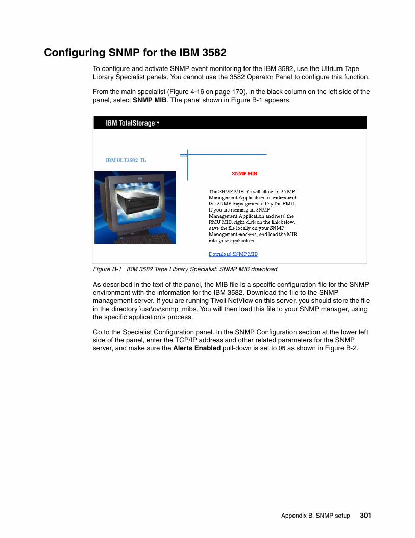
Configuring SNMP for the IBM 3582To configure and activate SNMP event monitoring for the IBM 3582, use the Ultrium Tape Library Specialist panels. You cannot use the 3582 Operator Panel to configure this function.
From the main specialist (Figure 4-16 on page 170), in the black column on the left side of the panel, select SNMP MIB. The panel shown in Figure B-1 appears.
Figure B-1 IBM 3582 Tape Library Specialist: SNMP MIB download
As described in the text of the panel, the MIB file is a specific configuration file for the SNMP environment with the information for the IBM 3582. Download the file to the SNMP management server. If you are running Tivoli NetView on this server, you should store the file in the directory \usr\ov\snmp_mibs. You will then load this file to your SNMP manager, using the specific application’s process.
Go to the Specialist Configuration panel. In the SNMP Configuration section at the lower left side of the panel, enter the TCP/IP address and other related parameters for the SNMP server, and make sure the Alerts Enabled pull-down is set to ON as shown in Figure B-2.
Appendix B. SNMP setup 301
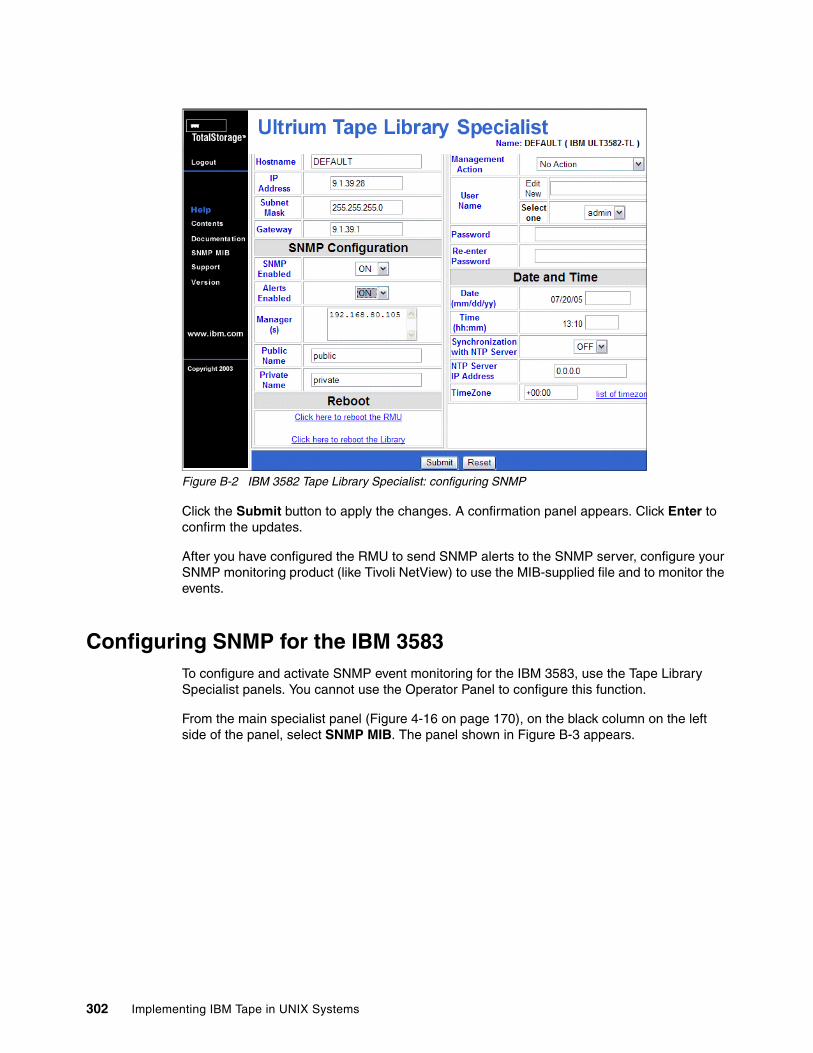
Figure B-2 IBM 3582 Tape Library Specialist: configuring SNMP
Click the Submit button to apply the changes. A confirmation panel appears. Click Enter to confirm the updates.
After you have configured the RMU to send SNMP alerts to the SNMP server, configure your SNMP monitoring product (like Tivoli NetView) to use the MIB-supplied file and to monitor the events.
Configuring SNMP for the IBM 3583To configure and activate SNMP event monitoring for the IBM 3583, use the Tape Library Specialist panels. You cannot use the Operator Panel to configure this function.
From the main specialist panel (Figure 4-16 on page 170), on the black column on the left side of the panel, select SNMP MIB. The panel shown in Figure B-3 appears.
302 Implementing IBM Tape in UNIX Systems
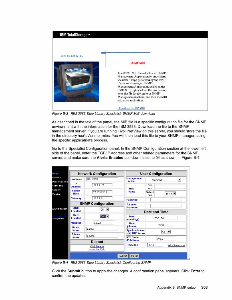
Figure B-3 IBM 3583 Tape Library Specialist: SNMP MIB download
As described in the text of the panel, the MIB file is a specific configuration file for the SNMP environment with the information for the IBM 3583. Download the file to the SNMP management server. If you are running Tivoli NetView on this server, you should store the file in the directory \usr\ov\snmp_mibs. You will then load this file to your SNMP manager, using the specific application’s process.
Go to the Specialist Configuration panel. In the SNMP Configuration section at the lower left side of the panel, enter the TCP/IP address and other related parameters for the SNMP server, and make sure the Alerts Enabled pull-down is set to ON as shown in Figure B-4.
Figure B-4 IBM 3583 Tape Library Specialist: Configuring SNMP
Click the Submit button to apply the changes. A confirmation panel appears. Click Enter to confirm the updates.
Appendix B. SNMP setup 303
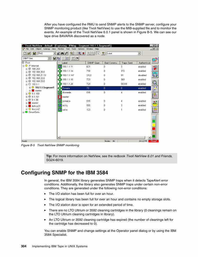
After you have configured the RMU to send SNMP alerts to the SNMP server, configure your SNMP monitoring product (like Tivoli NetView) to use the MIB-supplied file and to monitor the events. An example of the Tivoli NetView 6.0.1 panel is shown in Figure B-5. We can see our tape drive BAVARIA discovered as a node.
Figure B-5 Tivoli NetView SNMP monitoring
Configuring SNMP for the IBM 3584In general, the IBM 3584 library generates SNMP traps when it detects TapeAlert error conditions. Additionally, the library also generates SNMP traps under certain non-error conditions. They are generated under the following non-error conditions:
� The I/O station has been full for over an hour.
� The logical library has been full for over an hour and contains no empty storage slots.
� The I/O station door is open for an extended period of time.
� There are no LTO Ultrium or 3592 cleaning cartridges in the library (0 cleanings remain on the LTO Ultrium cleaning cartridges in library).
� An LTO Ultrium or 3592 cleaning cartridge has expired (the number of cleanings left for the cartridge has decreased to 0).
You can enable SNMP and change settings at the Operator panel dialog or by using the IBM 3584 Specialist.
Tip: For more information on NetView, see the redbook Tivoli NetView 6.01 and Friends, SG24-6019.
304 Implementing IBM Tape in UNIX Systems
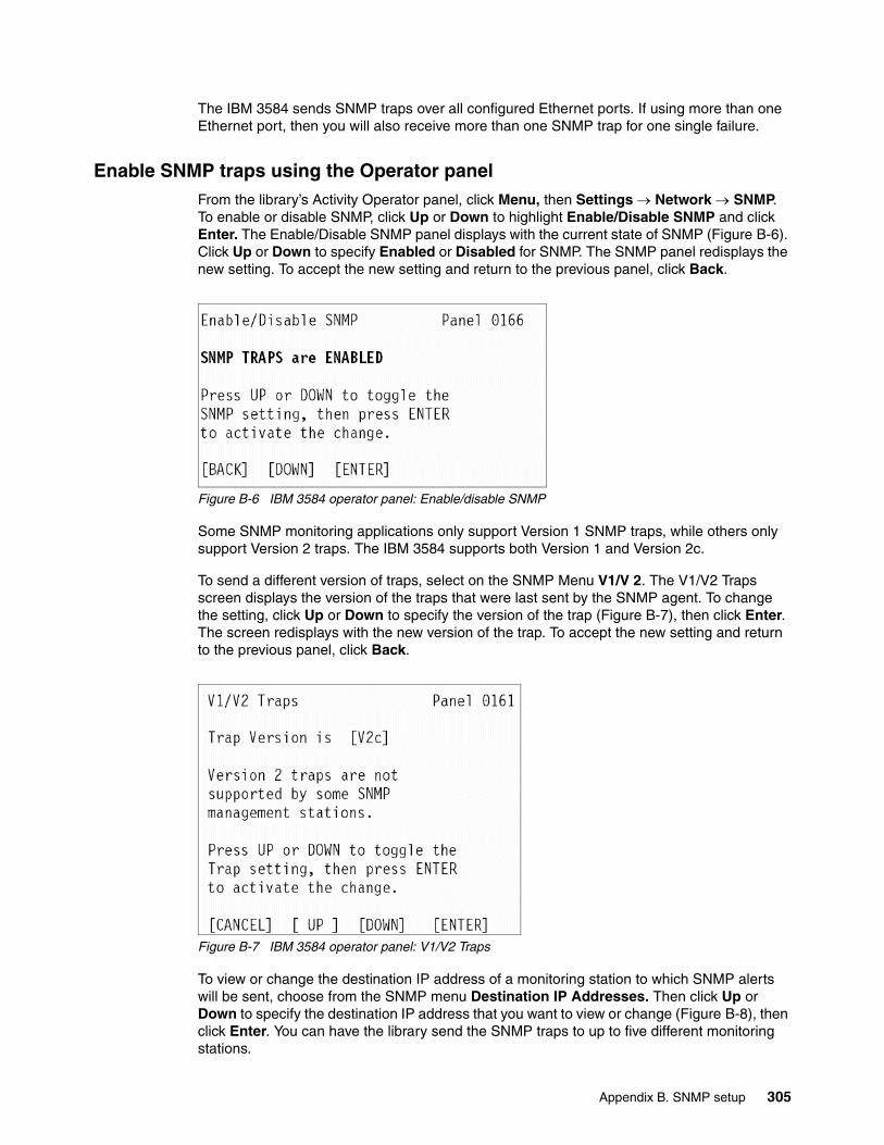
The IBM 3584 sends SNMP traps over all configured Ethernet ports. If using more than one Ethernet port, then you will also receive more than one SNMP trap for one single failure.
Enable SNMP traps using the Operator panelFrom the library’s Activity Operator panel, click Menu, then Settings → Network → SNMP. To enable or disable SNMP, click Up or Down to highlight Enable/Disable SNMP and click Enter. The Enable/Disable SNMP panel displays with the current state of SNMP (Figure B-6). Click Up or Down to specify Enabled or Disabled for SNMP. The SNMP panel redisplays the new setting. To accept the new setting and return to the previous panel, click Back.
Figure B-6 IBM 3584 operator panel: Enable/disable SNMP
Some SNMP monitoring applications only support Version 1 SNMP traps, while others only support Version 2 traps. The IBM 3584 supports both Version 1 and Version 2c.
To send a different version of traps, select on the SNMP Menu V1/V 2. The V1/V2 Traps screen displays the version of the traps that were last sent by the SNMP agent. To change the setting, click Up or Down to specify the version of the trap (Figure B-7), then click Enter. The screen redisplays with the new version of the trap. To accept the new setting and return to the previous panel, click Back.
Figure B-7 IBM 3584 operator panel: V1/V2 Traps
To view or change the destination IP address of a monitoring station to which SNMP alerts will be sent, choose from the SNMP menu Destination IP Addresses. Then click Up or Down to specify the destination IP address that you want to view or change (Figure B-8), then click Enter. You can have the library send the SNMP traps to up to five different monitoring stations.
Appendix B. SNMP setup 305
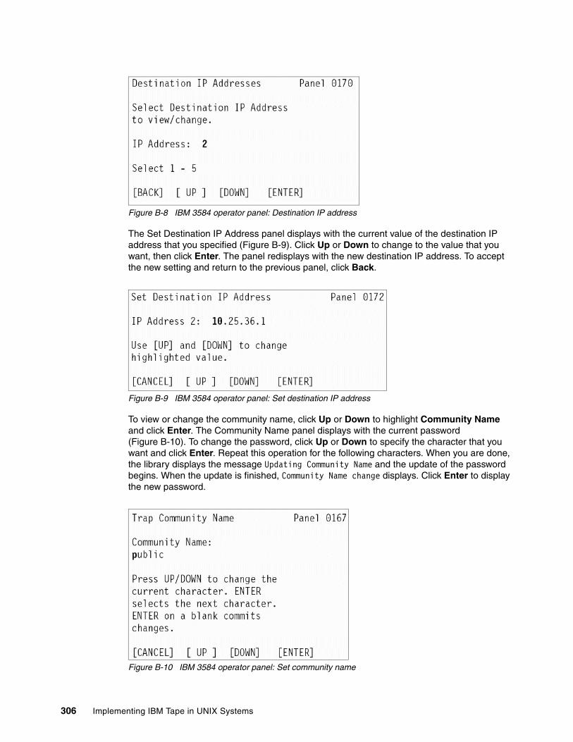
Figure B-8 IBM 3584 operator panel: Destination IP address
The Set Destination IP Address panel displays with the current value of the destination IP address that you specified (Figure B-9). Click Up or Down to change to the value that you want, then click Enter. The panel redisplays with the new destination IP address. To accept the new setting and return to the previous panel, click Back.
Figure B-9 IBM 3584 operator panel: Set destination IP address
To view or change the community name, click Up or Down to highlight Community Name and click Enter. The Community Name panel displays with the current password (Figure B-10). To change the password, click Up or Down to specify the character that you want and click Enter. Repeat this operation for the following characters. When you are done, the library displays the message Updating Community Name and the update of the password begins. When the update is finished, Community Name change displays. Click Enter to display the new password.
Figure B-10 IBM 3584 operator panel: Set community name
306 Implementing IBM Tape in UNIX Systems
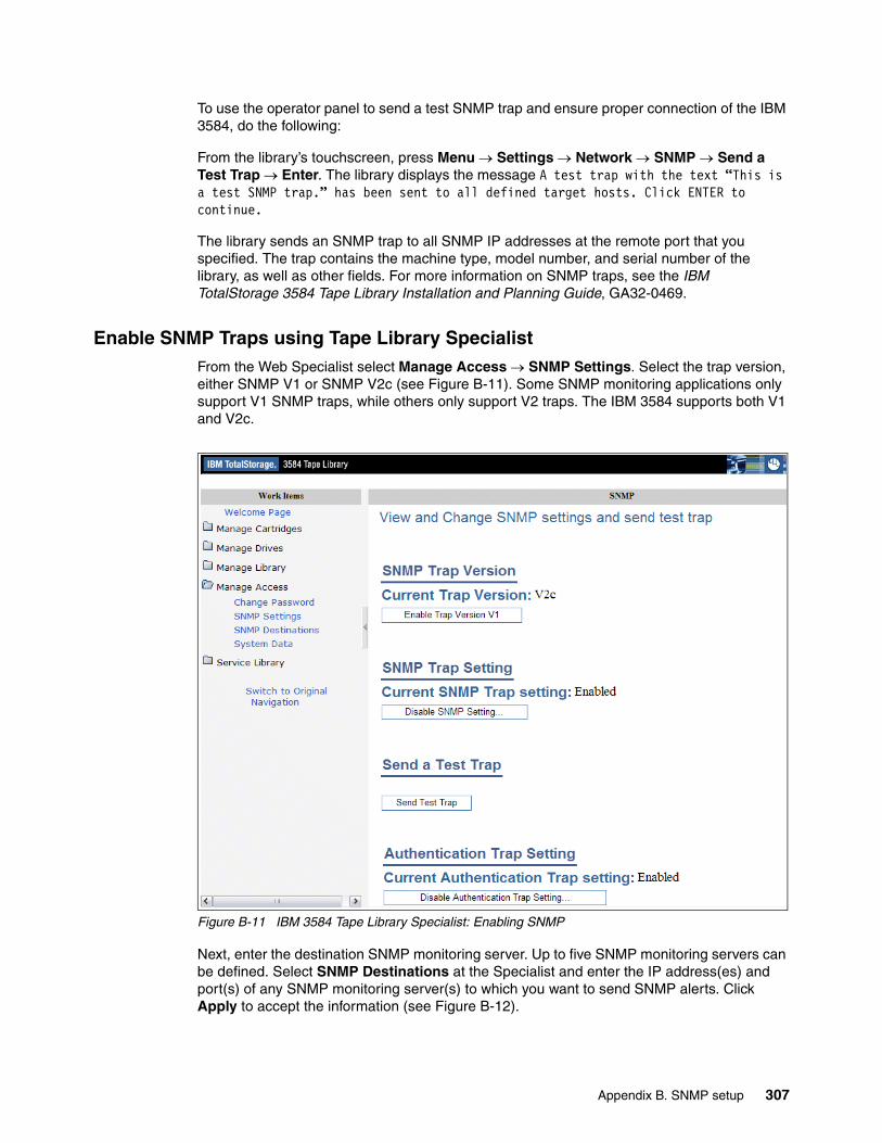
To use the operator panel to send a test SNMP trap and ensure proper connection of the IBM 3584, do the following:
From the library’s touchscreen, press Menu → Settings → Network → SNMP → Send a Test Trap → Enter. The library displays the message A test trap with the text “This is a test SNMP trap.” has been sent to all defined target hosts. Click ENTER to continue.
The library sends an SNMP trap to all SNMP IP addresses at the remote port that you specified. The trap contains the machine type, model number, and serial number of the library, as well as other fields. For more information on SNMP traps, see the IBM TotalStorage 3584 Tape Library Installation and Planning Guide, GA32-0469.
Enable SNMP Traps using Tape Library SpecialistFrom the Web Specialist select Manage Access → SNMP Settings. Select the trap version, either SNMP V1 or SNMP V2c (see Figure B-11). Some SNMP monitoring applications only support V1 SNMP traps, while others only support V2 traps. The IBM 3584 supports both V1 and V2c.
Figure B-11 IBM 3584 Tape Library Specialist: Enabling SNMP
Next, enter the destination SNMP monitoring server. Up to five SNMP monitoring servers can be defined. Select SNMP Destinations at the Specialist and enter the IP address(es) and port(s) of any SNMP monitoring server(s) to which you want to send SNMP alerts. Click Apply to accept the information (see Figure B-12).
Appendix B. SNMP setup 307
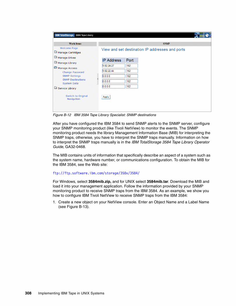
Figure B-12 IBM 3584 Tape Library Specialist: SNMP destinations
After you have configured the IBM 3584 to send SNMP alerts to the SNMP server, configure your SNMP monitoring product (like Tivoli NetView) to monitor the events. The SNMP monitoring product needs the library Management Information Base (MIB) for interpreting the SNMP traps, otherwise, you have to interpret the SNMP traps manually. Information on how to interpret the SNMP traps manually is in the IBM TotalStorage 3584 Tape Library Operator Guide, GA32-0468.
The MIB contains units of information that specifically describe an aspect of a system such as the system name, hardware number, or communications configuration. To obtain the MIB for the IBM 3584, see the Web site:
ftp://ftp.software.ibm.com/storage/358x/3584/
For Windows, select 3584mib.zip, and for UNIX select 3584mib.tar. Download the MIB and load it into your management application. Follow the information provided by your SNMP monitoring product to receive SNMP traps from the IBM 3584. As an example, we show you how to configure IBM Tivoli NetView to receive SNMP traps from the IBM 3584:
1. Create a new object on your NetView console. Enter an Object Name and a Label Name (see Figure B-13).
308 Implementing IBM Tape in UNIX Systems
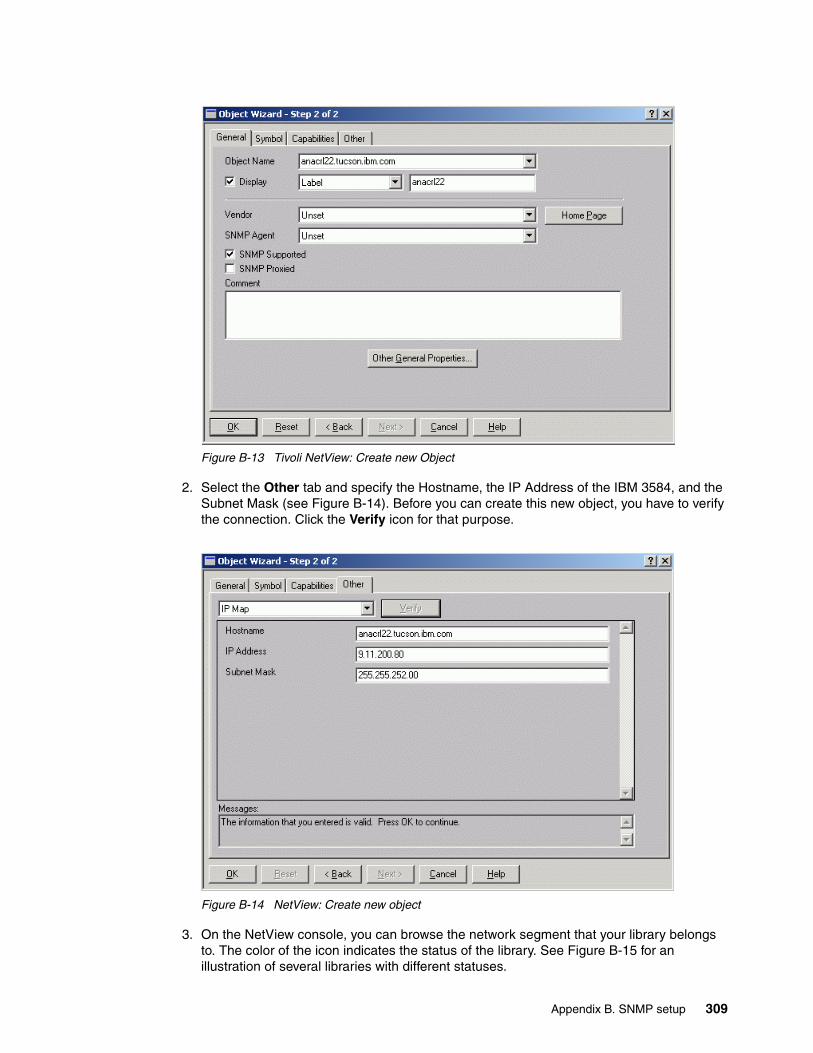
Figure B-13 Tivoli NetView: Create new Object
2. Select the Other tab and specify the Hostname, the IP Address of the IBM 3584, and the Subnet Mask (see Figure B-14). Before you can create this new object, you have to verify the connection. Click the Verify icon for that purpose.
Figure B-14 NetView: Create new object
3. On the NetView console, you can browse the network segment that your library belongs to. The color of the icon indicates the status of the library. See Figure B-15 for an illustration of several libraries with different statuses.
Appendix B. SNMP setup 309
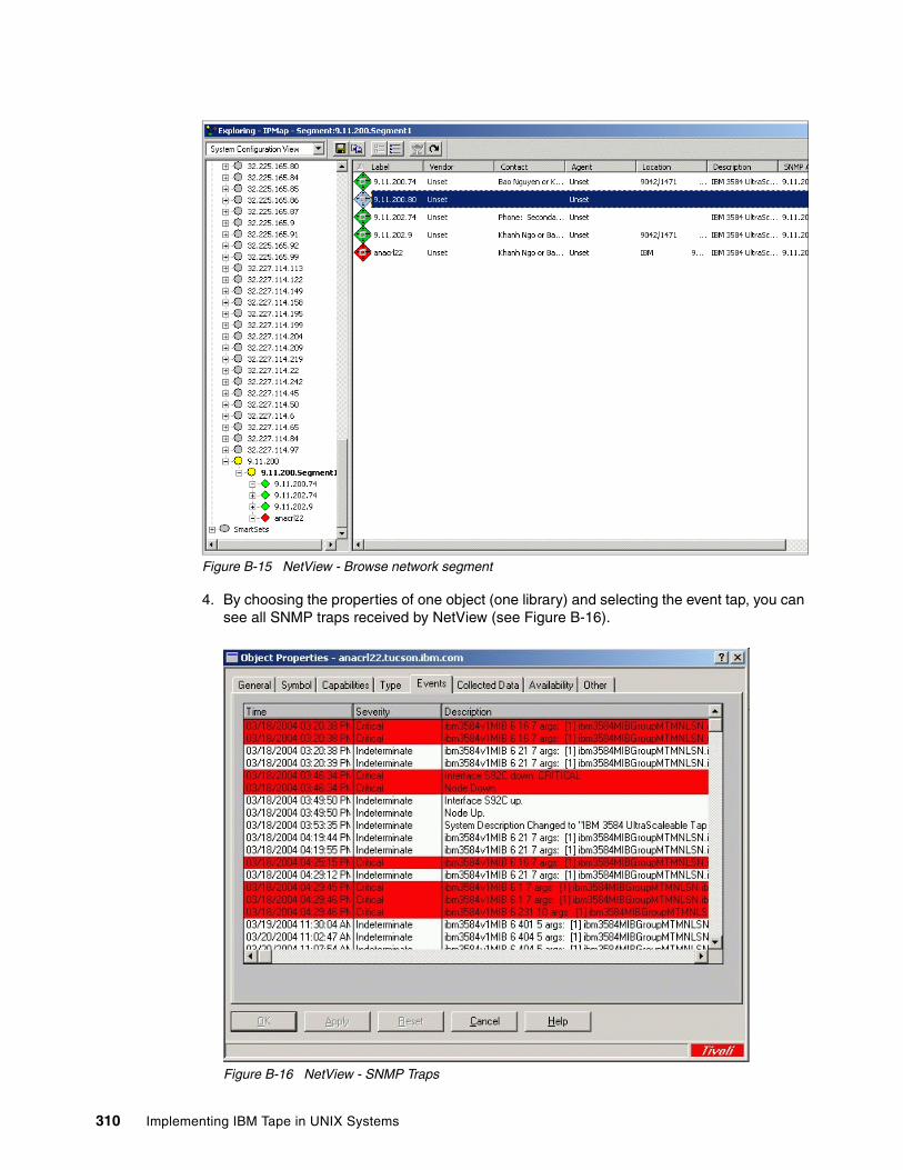
Figure B-15 NetView - Browse network segment
4. By choosing the properties of one object (one library) and selecting the event tap, you can see all SNMP traps received by NetView (see Figure B-16).
Figure B-16 NetView - SNMP Traps
310 Implementing IBM Tape in UNIX Systems
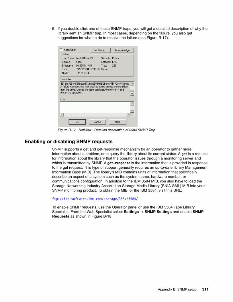
5. If you double click one of these SNMP traps, you will get a detailed description of why the library sent an SNMP trap. In most cases, depending on the failure, you also get suggestions for what to do to resolve the failure (see Figure B-17).
Figure B-17 NetView - Detailed description of 3584 SNMP Trap
Enabling or disabling SNMP requestsSNMP supports a get and get-response mechanism for an operator to gather more information about a problem, or to query the library about its current status. A get is a request for information about the library that the operator issues through a monitoring server and which is transmitted by SNMP. A get-response is the information that is provided in response to the get request. This type of support generally requires an up-to-date library Management Information Base (MIB). The library’s MIB contains units of information that specifically describe an aspect of a system such as the system name, hardware number, or communications configuration. In addition to the IBM 3584 MIB, you also have to load the Storage Networking Industry Association-Storage Media Library (SNIA-SML) MIB into your SNMP monitoring product. To obtain the MIB for the IBM 3584, visit this URL:
ftp://ftp.software.ibm.com/storage/358x/3584/
To enable SNMP requests, use the Operator panel or use the IBM 3584 Tape Library Specialist. From the Web Specialist select Settings → SNMP Settings and enable SNMP Requests as shown in Figure B-18.
Appendix B. SNMP setup 311
Figure B-18 Enable SNMP Request with IBM 3584 Specialist
You can now use SNMP to monitor your library. Here are some examples created with Tivoli NetView:
� To know how many drives are present in the library, use your monitoring server to issue an SNMP get request on the object numberOfMediaAccessDevices.0.
� For a list showing the status of all of the drives in the library ordered by element address, issue an SNMP get request on the objects mediaAccessDevice-Availability.1 through mediaAccessDevice-Availability.n where n is the number returned by numberOfMediaAccessDevices.0 (see Figure B-19).
312 Implementing IBM Tape in UNIX Systems
Figure B-19 SNMP Request: Drive status
� To obtain a list of all cartridges in the library, issue an SNMP get request on the object numberOfPhysicalMedias. This indicates how many cartridges are present in the library (see Figure B-20). Issue an SNMP get request on the object physicalMedia-PhysicalLabel.1 through physicalMedia-PhysicalLabel.n where n is the number returned by numberOfPhysicalMedias. This gives you a list of the physical label (volser) of all the cartridges in the library. You can also use (depending on your SNMP monitor product) the subtitle physicalMediaEntry (see Figure B-21) for the status and the volser of all the cartridges.
Appendix B. SNMP setup 313
Figure B-20 SNMP Request: Number of all physical cartridges
314 Implementing IBM Tape in UNIX Systems
Figure B-21 SNMP Request: List of all physical media
Note: As of the writing this redbook, just a few SNMP requests had been implemented. More SNMP requests will be implemented in the near future. Check for updates of IBM 3584 library firmware and MIB files at:
ftp://ftp.software.ibm.com/storage/358x/3584/
Appendix B. SNMP setup 315

316 Implementing IBM Tape in UNIX Systems
Appendix C. LTO tips and troubleshooting
This appendix provides some additional information that is useful when implementing IBM LTO tape drives and libraries.
The topics are:
� Guidelines for booting SAN Data Gateway and FC hosts
� Some performance considerations for tape devices
� Table of commonly used AIX commands
� Table of commonly used Solaris commands
� IBM Tivoli Storage Manager tape drive and library commonly used commands
� EMC Legato NetWorker autochanger maintenance commands
� Using tapeutil to verify correct device attachment
� Troubleshooting considerations
C
© Copyright IBM Corp. 2002, 2003, 2004, 2005. All rights reserved. 317
Guidelines for booting SAN Data Gateway and FC hostsDevice access problems sometimes occur when it is necessary to shut down the IBM SAN Data Gateway. To avoid losing access to your FC devices when a shutdown is required, the SAN Data Gateway and its attached devices must be booted in a specific order. Rebooting is required after updating firmware, and when adding or removing SCSI devices. The following procedure describes the recommended boot order, and is also applicable to the SAN Data Gateway router.
These are the steps:
1. SCSI devices
Turn on the SCSI devices first. All SCSI devices attached to the SAN Data Gateway (SDG) must be turned on before turning on or rebooting the SDG.
2. SAN Data Gateway
The SDG scans the SCSI buses when it is booting. If you add or remove SCSI devices after the SDG has booted, it will not automatically detect the changes. You can reboot the SDG using the StorWatch SAN Data Gateway Specialist client from a Telnet session or a serial terminal session. You can also use the scsiRescan command to scan the SCSI channels.
3. Fibre Channel hosts
Before turning on or restarting hosts that are connected through Fibre Channel to the SDG, you must wait until the SDG has finished booting as indicated by the ready light on the front panel blinking at a rate of about once per second.
� Although some operating systems may provide software methods that allow SCSI devices to be dynamically added or removed after the host has booted, we highly recommend that you reboot the host to ensure reliable operation.
� If you update SDG firmware, you must reboot the SDG to use the new firmware. We highly recommended that you also reboot the host to ensure compatibility with any new firmware features or functions.
� If you update SCSI device firmware, the SDG Explorer application will not display the new firmware version until the SDG has issued a SCSI inquiry, which occurs when it re-scans the SCSI buses. The same is true for the StorWatch SAN Data Gateway Specialist client application and the service terminal.
Performance considerationsPerformance analysis is approached by determining which component of the data path impacts performance. Typically, a performance problem can be isolated by looking at one aspect of the data path at a time. The data path mainly consists of:
� Client file system� Client server hardware� Network� Application server hardware� Application server file system� Application itself (for example, database)
Attention: You must stop all I/O between the host and SCSI devices before rebooting the SAN Data Gateway.
318 Implementing IBM Tape in UNIX Systems
� Connection to the tape drives– Type of HBAs: 1 GBit or 2 Gbit– What are the HBAs connected to? Which Type of PCI Bus? What else is on the same
PCI Bus?� Size of files which you backing up
If you think you have a performance problem, then you have to determine which link of your chain is causing the problem, that is, where does the bottleneck occur? Look at each link separately. The UNIX command dd can be used to get a baseline performance level. You can test the performance of your disk subsystem first by writing and reading from the disk to /dev/null or /dev/zero. Then you may want to test the performance from the server to the tape by writing and reading from tape to /dev/null or /dev/zero. And finally, you write files from the disk to the tape.
On some UNIX systems you can use /dev/null as the destination device, and on others you will use /dev/zero.
The dd command has the following syntax:
dd if=input_file/device of=output_file/device bs=blocksize count=amount_of block_reading/writing
You can use dd in conjunction with time to measure the time.
We suggest writing and reading at least 1 GB, hence, use bs=262144 count=4096.
We tested Ultrium 1 tape performance on two hosts: BRAZIL and SOL-E. We created a file of 256 MB called rbs01.dbf. First, we tested the file system performance with:
time dd if=filename of=/dev/null bs=128k
Then we tested the tape performance with:
time dd if=filename of=/dev/rmt0 bs=128k
Example C-1 shows the results obtained on BRAZIL. There is good file system performance (over 74 MB/s) and the tape performance is also in the expected range (nearly 11 MB/s for an Ultrium 1 drive).
Example: C-1 Performance on BRAZIL
# ls -l-rw-r--r-- 1 root sys 268439552 Sep 05 18:21 rbs01.dbf# time dd if=/software/lto/rbs01.dbf of=/dev/zero bs=128k2048+1 records in.2048+1 records out.
real 0m3.43suser 0m0.02ssys 0m3.42s# time dd if=/software/lto/rbs01.dbf of=/dev/rmt0 bs=128k2048+1 records in.2048+1 records out.real 0m23.68s
Attention: The numbers presented here are not intended to reflect any real performance that might be achieved. The tests were run without particular attention to optimizing performance, and are intended to be used for comparative purposes only.
Appendix C. LTO tips and troubleshooting 319
user 0m0.02ssys 0m3.95s
Example C-2 shows you the result on SOL-E. As you can see, the file system test takes longer than on BRAZIL, which can be attributed to less CPU, disk, or I/O capacity. Therefore, the tape performance is also relatively slower.
Example: C-2 Performance on sol-e
# time dd if=/usr/sepp/rbs01.dbf of=/dev/null bs=256k1024+1 records in1024+1 records out
real 0m17.43suser 0m0.02ssys 0m3.80s# time dd if=/usr/sepp/rbs01.dbf of=/dev/rmt/0st bs=256k1024+1 records in1024+1 records out
real 1m19.85suser 0m0.02ssys 0m3.77s# time dd if=/usr/sepp/rbs01.dbf of=/dev/rmt/0stc bs=256k1024+1 records in1024+1 records out
real 0m33.39suser 0m0.05ssys 0m3.53s
In addition, you can see in Example C-2 how the performance is different depending on whether hardware compression is used (dev/rmt/0st) or not (dev/rmt/0stc).
During the tests it may be helpful to monitor the real-time performance values on your SAN switch (if FC drives). You can use either the switch GUI or command line interfaces. For IBM 2109 (Brocade) switches you can use the command portperfshow to show the performance of the attached devices. Example C-3 shows the portperfshow output from an IBM 2109-F16 Switch. The tape is connected on port 7, and the HBA is connected on port 5. Performance varies between 35 and 36 MB/sec, with the values updated automatically every second.
Example: C-3 IBM 2109 SAN Switch: portperfshow
portPerfShow 0 1 2 3 4 5 6 7 8 9 10 11 12 13 14 15 -------------------------------------------------------------------------------- 0 0 0 0 0 35m 0 35m 0 0 0 0 0 0 0 0 0 0 0 0 0 36m 0 36m 0 0 0 0 0 0 0 0 0 0 0 0 0 36m 0 36m 0 0 0 0 0 0 0 0 0 0 0 0 0 36m 0 36m 0 0 0 0 0 0 0 0 0 0 0 0 0 35m 0 35m 0 0 0 0 0 0 0 0 0 0 0 0 0 36m 0 36m 0 0 0 0 0 0 0 0 112 0 0 0 0 35m 0 35m 0 0 0 0 0 0 0 0 0 0 0 0 0 36m 0 36m 0 0 0 0 0 0 0 0 0 0 0 0 0 36m 0 36m 0 0 0 0 0 0 0 0 0 0 0 0 0 36m 0 36m 0 0 0 0 0 0 0 0 0 0 0 0 0 36m 0 36m 0 0 0 0 0 0 0 0 0 0 0 0 0 36m 0 36m 0 0 0 0 0 0 0 0 0 0 0 0 0 35m 0 35m 0 0 0 0 0 0 0 0 0 0 0 0 0 36m 0 36m 0 0 0 0 0 0 0 0 112 0 0 0 0 36m 0 36m 0 0 0 0 0 0 0 0
320 Implementing IBM Tape in UNIX Systems
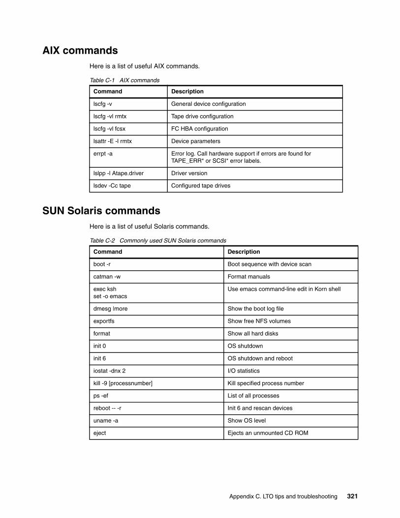
AIX commandsHere is a list of useful AIX commands.
Table C-1 AIX commands
SUN Solaris commandsHere is a list of useful Solaris commands.
Table C-2 Commonly used SUN Solaris commands
Command Description
lscfg -v General device configuration
lscfg -vl rmtx Tape drive configuration
lscfg -vl fcsx FC HBA configuration
lsattr -E -l rmtx Device parameters
errpt -a Error log. Call hardware support if errors are found for TAPE_ERR* or SCSI* error labels.
lslpp -l Atape.driver Driver version
lsdev -Cc tape Configured tape drives
Command Description
boot -r Boot sequence with device scan
catman -w Format manuals
exec kshset -o emacs
Use emacs command-line edit in Korn shell
dmesg |more Show the boot log file
exportfs Show free NFS volumes
format Show all hard disks
init 0 OS shutdown
init 6 OS shutdown and reboot
iostat -dnx 2 I/O statistics
kill -9 [processnumber] Kill specified process number
ps -ef List of all processes
reboot -- -r Init 6 and rescan devices
uname -a Show OS level
eject Ejects an unmounted CD ROM
Appendix C. LTO tips and troubleshooting 321
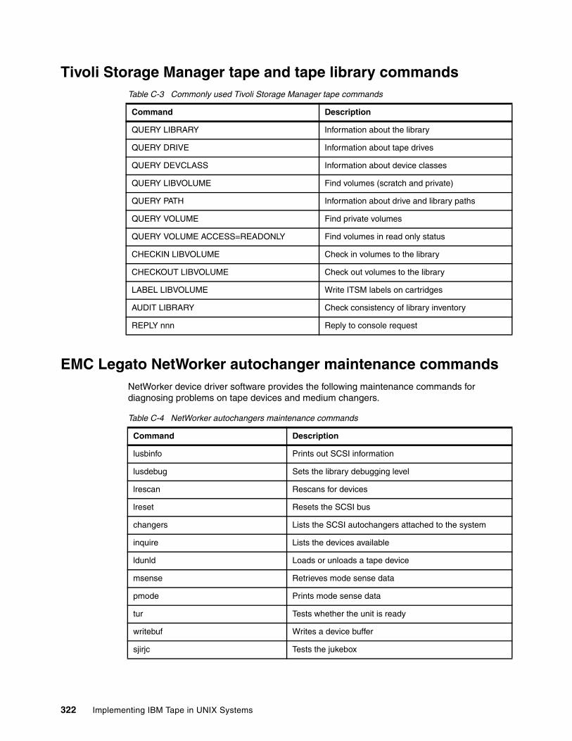
Tivoli Storage Manager tape and tape library commandsTable C-3 Commonly used Tivoli Storage Manager tape commands
EMC Legato NetWorker autochanger maintenance commandsNetWorker device driver software provides the following maintenance commands for diagnosing problems on tape devices and medium changers.
Table C-4 NetWorker autochangers maintenance commands
Command Description
QUERY LIBRARY Information about the library
QUERY DRIVE Information about tape drives
QUERY DEVCLASS Information about device classes
QUERY LIBVOLUME Find volumes (scratch and private)
QUERY PATH Information about drive and library paths
QUERY VOLUME Find private volumes
QUERY VOLUME ACCESS=READONLY Find volumes in read only status
CHECKIN LIBVOLUME Check in volumes to the library
CHECKOUT LIBVOLUME Check out volumes to the library
LABEL LIBVOLUME Write ITSM labels on cartridges
AUDIT LIBRARY Check consistency of library inventory
REPLY nnn Reply to console request
Command Description
lusbinfo Prints out SCSI information
lusdebug Sets the library debugging level
lrescan Rescans for devices
lreset Resets the SCSI bus
changers Lists the SCSI autochangers attached to the system
inquire Lists the devices available
ldunld Loads or unloads a tape device
msense Retrieves mode sense data
pmode Prints mode sense data
tur Tests whether the unit is ready
writebuf Writes a device buffer
sjirjc Tests the jukebox
322 Implementing IBM Tape in UNIX Systems
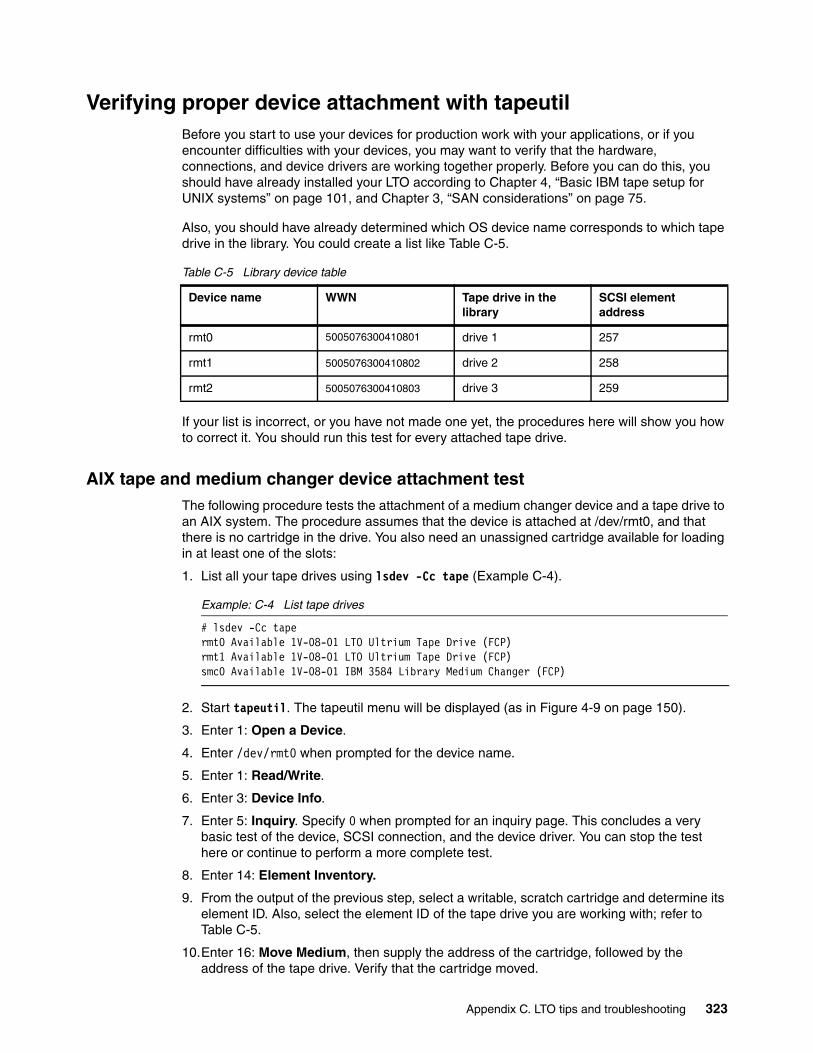
Verifying proper device attachment with tapeutilBefore you start to use your devices for production work with your applications, or if you encounter difficulties with your devices, you may want to verify that the hardware, connections, and device drivers are working together properly. Before you can do this, you should have already installed your LTO according to Chapter 4, “Basic IBM tape setup for UNIX systems” on page 101, and Chapter 3, “SAN considerations” on page 75.
Also, you should have already determined which OS device name corresponds to which tape drive in the library. You could create a list like Table C-5.
Table C-5 Library device table
If your list is incorrect, or you have not made one yet, the procedures here will show you how to correct it. You should run this test for every attached tape drive.
AIX tape and medium changer device attachment testThe following procedure tests the attachment of a medium changer device and a tape drive to an AIX system. The procedure assumes that the device is attached at /dev/rmt0, and that there is no cartridge in the drive. You also need an unassigned cartridge available for loading in at least one of the slots:
1. List all your tape drives using lsdev -Cc tape (Example C-4).
Example: C-4 List tape drives
# lsdev -Cc tapermt0 Available 1V-08-01 LTO Ultrium Tape Drive (FCP)rmt1 Available 1V-08-01 LTO Ultrium Tape Drive (FCP)smc0 Available 1V-08-01 IBM 3584 Library Medium Changer (FCP)
2. Start tapeutil. The tapeutil menu will be displayed (as in Figure 4-9 on page 150).
3. Enter 1: Open a Device.
4. Enter /dev/rmt0 when prompted for the device name.
5. Enter 1: Read/Write.
6. Enter 3: Device Info.
7. Enter 5: Inquiry. Specify 0 when prompted for an inquiry page. This concludes a very basic test of the device, SCSI connection, and the device driver. You can stop the test here or continue to perform a more complete test.
8. Enter 14: Element Inventory.
9. From the output of the previous step, select a writable, scratch cartridge and determine its element ID. Also, select the element ID of the tape drive you are working with; refer to Table C-5.
10.Enter 16: Move Medium, then supply the address of the cartridge, followed by the address of the tape drive. Verify that the cartridge moved.
Device name WWN Tape drive in the library
SCSI element address
rmt0 5005076300410801 drive 1 257
rmt1 5005076300410802 drive 2 258
rmt2 5005076300410803 drive 3 259
Appendix C. LTO tips and troubleshooting 323
11.Enter 6: Test Unit Ready until no error occurs.
If your drive is not ready after 1 minute, then do a visual check to see if the cartridge is loaded on the right drive. If not, your library device table (Table C-5) may be wrong and you will have to figure it out by iteration. Close your device by entering 2, try to open a different device name, and try it again with Test Unit Ready.
Repeat these steps until you find a device which is ready, then update your library device table.
12.Enter 30: Read and Write Tests.
13.Enter 1: Read/Write. Press Enter three times to accept the defaults and run the test.
14.Enter 31: Unload Tape. Wait until the Medium is unloaded.
15.Enter 16: Move Medium, then supply the address of the tape drive, followed by the address of the cartridge slot where it was before. Verify that the cartridge moved.
16.Enter 2: Close a Device.
17.Enter Q: Quit Program.
Solaris and HP tape and medium changer device attachment testThe following procedure tests the attachment of a medium changer device and a tape device to a Sun or HP system. The procedure assumes that your media changer is configured at:
� /dev/rmt/0smc - for Sun � /dev/rmt/0chng - for HP
And, the tape drive is attached at:
� /dev/rmt/1st - for Sun � /dev/rmt/1m - for HP
And, it assumes that there is no cartridge in any drive.
You also need an unassigned cartridge available for loading in at least one of the slots.
1. Open a terminal session and list all your tape drives with:
ls -l /dev/rmt/*stbn - for Sun
ioscan -fnkC tape - for HP
2. Enter:
/opt/IBMtapeutil/tapeutil - for Sun
tapeutil - for HP
The tapeutil menu will be displayed (similar to Figure 4-9 on page 150).
3. Enter 1:Open a Device. When prompted for the device name:
Enter /dev/rmt/0smc - for Sun System
Enter /dev/rmt/0chng - for HP System
4. Enter 3: Device Info.
5. Enter 14: Element Inventory.
6. From the output of the previous step, select a writable, scratch cartridge, and determine its element ID. Also, select the element ID of the tape drive that you are working with; refer to Table C-5 on page 323.
324 Implementing IBM Tape in UNIX Systems
7. Enter 16: Move Medium, then supply the address of the cartridge, followed by the address of the tape drive. Verify that the cartridge moved.
8. Enter 6: Test Unit Ready until no error occurs.
If your drive is not ready after 1 minute, check to see if the cartridge actually loaded in the right drive. If not, then your library device table (Table C-5 on page 323) may be wrong, and you will have to figure it out by iteration. Close your device by entering 2; try to open a different device name, and try it again with 6: Test Unit Ready.
Repeat these steps until you find a device which is ready, then update your library device table.
9. Enter 30: Read and Write Tests.
10.Enter 1: Read/Write. Press Enter three times to accept the defaults and run the test.
11.Enter 31: Unload Tape. Wait until the tape is unloaded.
12.Enter 16: Move Medium, then supply the address of the tape drive, followed by the address of the cartridge slot where it was before. Verify that the cartridge moved.
13.Enter 2: Close a Device.
14.Enter Q: Quit Program.
Using tapeutil element inventoryWhen you select option 14:Element Inventory in tapeutil, you will receive a list of each element in the library and its status. First, the robot itself is listed, followed by each of the slots in the Import/Export station, as shown in Example C-5.
Example: C-5 Tapeutil element inventory - robot and Import/export station
Reading element status...
Robot Address 1 Robot State .................... Normal ASC/ASCQ ....................... 0000 Media Present .................. No Source Element Address Valid ... No Media Inverted ................. No Volume Tag ................................................. Some addresses deleted for brevityImport/Export Station Address 16 Import/Export State ............ Normal ASC/ASCQ ....................... 0000 Media Present .................. No Import Enabled ................. Yes Export Enabled ................. Yes Robot Access Allowed ........... Yes Source Element Address Valid ... No Media Inverted ................. No Volume Tag .....................
Scroll down to continue the listing of the rest of the Import/Export slots. Next, the drives are listed (Example C-6).
Example: C-6 Tapeutil element inventory - drives
Drive Address 256 Drive State .................... Normal ASC/ASCQ ....................... 0000
Appendix C. LTO tips and troubleshooting 325
Media Present .................. No Robot Access Allowed ........... Yes Source Element Address Valid ... No Media Inverted ................. No Same Bus as Medium Changer ..... Yes SCSI Bus Address ............... 0 Logical Unit Number Valid ...... No Volume Tag .....................
Drive Address 257 Drive State .................... Normal ASC/ASCQ ....................... 0000 Media Present .................. No Robot Access Allowed ........... Yes Source Element Address Valid ... No Media Inverted ................. No Same Bus as Medium Changer ..... Yes SCSI Bus Address ............... 1 Logical Unit Number Valid ...... No Volume Tag......................
Finally, the individual storage slots are listed (Example C-7).
Example: C-7 Tapeutil element inventory - storage slots
Slot Address 4096 Slot State ..................... Normal ASC/ASCQ ....................... 0000 Media Present .................. Yes Robot Access Allowed ........... Yes Source Element Address ......... 4096 Media Inverted ................. No Volume Tag ..................... ABA920L1
Slot Address 4097 Slot State ..................... Normal ASC/ASCQ ....................... 0000 Media Present .................. No Robot Access Allowed ........... Yes Source Element Address Valid ... No Media Inverted ................. No Volume Tag .....................
You can see that slot 4096 is occupied since Media Present is set to Yes and the Volume Tag (Barcode label) contains ABA920L1, indicating this tape cartridge is located in this slot. Slot 4097 is empty, since Media Present is set to No. Therefore, when selecting option 16: Move Medium (assuming we knew the tape in slot 4096 was not already used by an application), we can specify source address of 4096 and destination address 256. This loads that tape into the tape drive. To unload the media (after selecting 31: Unload Tape) move the medium from 256 back to 4096.
TroubleshootingIn this section we present an approach to troubleshooting problems with LTO drives and libraries.
326 Implementing IBM Tape in UNIX Systems
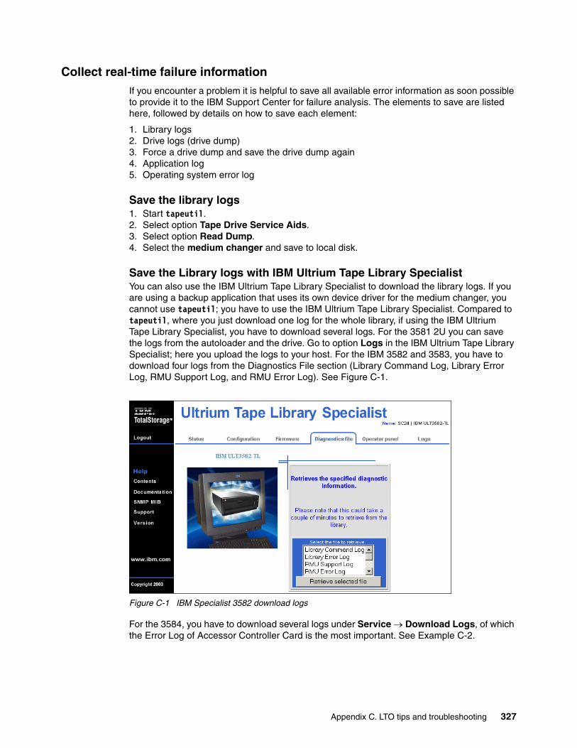
Collect real-time failure informationIf you encounter a problem it is helpful to save all available error information as soon possible to provide it to the IBM Support Center for failure analysis. The elements to save are listed here, followed by details on how to save each element:
1. Library logs2. Drive logs (drive dump)3. Force a drive dump and save the drive dump again 4. Application log5. Operating system error log
Save the library logs1. Start tapeutil.2. Select option Tape Drive Service Aids.3. Select option Read Dump.4. Select the medium changer and save to local disk.
Save the Library logs with IBM Ultrium Tape Library SpecialistYou can also use the IBM Ultrium Tape Library Specialist to download the library logs. If you are using a backup application that uses its own device driver for the medium changer, you cannot use tapeutil; you have to use the IBM Ultrium Tape Library Specialist. Compared to tapeutil, where you just download one log for the whole library, if using the IBM Ultrium Tape Library Specialist, you have to download several logs. For the 3581 2U you can save the logs from the autoloader and the drive. Go to option Logs in the IBM Ultrium Tape Library Specialist; here you upload the logs to your host. For the IBM 3582 and 3583, you have to download four logs from the Diagnostics File section (Library Command Log, Library Error Log, RMU Support Log, and RMU Error Log). See Figure C-1.
Figure C-1 IBM Specialist 3582 download logs
For the 3584, you have to download several logs under Service → Download Logs, of which the Error Log of Accessor Controller Card is the most important. See Example C-2.
Appendix C. LTO tips and troubleshooting 327
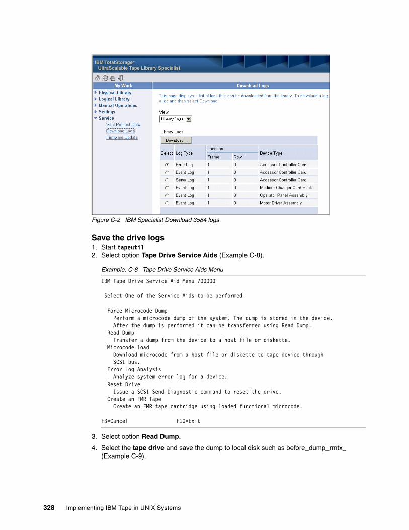
Figure C-2 IBM Specialist Download 3584 logs
Save the drive logs1. Start tapeutil2. Select option Tape Drive Service Aids (Example C-8).
Example: C-8 Tape Drive Service Aids Menu
IBM Tape Drive Service Aid Menu 700000
Select One of the Service Aids to be performed
Force Microcode Dump Perform a microcode dump of the system. The dump is stored in the device. After the dump is performed it can be transferred using Read Dump. Read Dump Transfer a dump from the device to a host file or diskette. Microcode load Download microcode from a host file or diskette to tape device through SCSI bus. Error Log Analysis Analyze system error log for a device. Reset Drive Issue a SCSI Send Diagnostic command to reset the drive. Create an FMR Tape Create an FMR tape cartridge using loaded functional microcode.
F3=Cancel F10=Exit
3. Select option Read Dump.
4. Select the tape drive and save the dump to local disk such as before_dump_rmtx_ (Example C-9).
328 Implementing IBM Tape in UNIX Systems
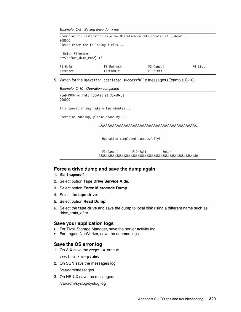
Example: C-9 Saving drive du → mp
Prompting for Destination File for Operation on rmt2 located at 30-68-01 B00000Please enter the following fields...
Enter Filename: <ev/before_dump_rmt2] +/
F1=Help F2=Refresh F3=Cancel F4=ListF5=Reset F7=Commit F10=Exit
5. Watch for the Operation completed successfully messages (Example C-10).
Example: C-10 Operation completed
READ DUMP on rmt2 located at 30-68-01 C00000 This operation may take a few minutes...
Operation running, please stand by....
ÚÄÄÄÄÄÄÄÄÄÄÄÄÄÄÄÄÄÄÄÄÄÄÄÄÄÄÄÄÄÄÄÄÄÄÄÄÄÄÄÄÄÄÄÄÄÄÄÄÄÄÄÄÄÄ¿ Operation completed successfully! F3=Cancel F10=Exit Enter ÀÄÄÄÄÄÄÄÄÄÄÄÄÄÄÄÄÄÄÄÄÄÄÄÄÄÄÄÄÄÄÄÄÄÄÄÄÄÄÄÄÄÄÄÄÄÄÄÄÄÄÄÄÄÄÙ
Force a drive dump and save the dump again1. Start tapeutil.
2. Select option Tape Drive Service Aids.
3. Select option Force Microcode Dump.
4. Select the tape drive.
5. Select option Read Dump.
6. Select the tape drive and save the dump to local disk using a different name such as drive_rmtx_after.
Save your application logs� For Tivoli Storage Manager, save the server activity log.� For Legato NetWorker, save the daemon logs.
Save the OS error log1. On AIX save the errpt -a output:
errpt –a > errpt.det
2. On SUN save the messages log:
/var/adm/messages
3. On HP-UX save the messages:
/var/adm/syslog/syslog.log
Appendix C. LTO tips and troubleshooting 329
Provide all the logs to the IBM Support Center. You should also provide general information about your system such as:
� Exact machine type (such as pSeries 7028-H80, HP N-Class Server)
� Exact OS version (such as AIX 5.1, HP-UX 11.00):
– For AIX, use oslevel– For SUN, use uname -r – For HP, use uname -r
� Installed adapter (SCSI/FC, FC6227/6228, Adaptec, Emulex, and so forth)
� Adapter microcode, firmware level, bios level, configuration
– For AIX, use lscfg –vp > lscfg-vp.out– For SUN, send the conf files, such as:
• /kernel/drv/fcaw.conf for JNI - FC adapter• /kernel/drv/qlx.conf for QLogic – FC adapter• /kernel/drv/lpx.conf for Emulex – FC adapter
– For HP, use • fcmsutil /dev/tdx
� Installed device driver version and device driver configuration:
– For AIX, use: • Device driver level: lslpp –l Atape.driver• Device parameters: lsattr –El rmtx
– For SUN, use • Device driver level: /usr/bin/pkginfo IBMtape• Device parameters: /kernel/drv/st.conf and /kernel/drv/IBMtape.conf
– For HP, use: • Device driver level: swverify atdd• Device parameter: ioscan -fnkC tape• ioscan -fnkC autoch
Hints Finally, here are some miscellaneous operational hints.
Library inventory and application inventoryIf you open the library door, the library will automatically update its inventory. But this does not mean that the backup application will also update inventory. If the library has been opened, it is possible that cartridges have been moved, added, or removed. Therefore, you should always have your application audit the library after it has been opened. Refer to your application documentation for details on how to do this. In Tivoli Storage Manager, use the command:
AUDIT LIBRARY library_name checklabel=barcode
The IBM Ultrium Tape Library SpecialistIf you have problems connecting to your library using the Specialist, try changing the library network settings to 10 Mbit Half duplex.
330 Implementing IBM Tape in UNIX Systems
ronyms
AC Alternating Current
AIM Automatic Identification Manufacturers
AIT Advanced Intelligent Tape
AIX Advanced Interactive Executive
ALDC Adaptive Lossless Data Compression
ALMS Advanced Library Management System
AME Advanced Metal Evaporative
AMP Advanced Metal Evaporative
ANSI American National Standards Institute
API Application Programming Interface
ATF Auto Tracking Following
BRMS Business Recovery and Management Services
CM Cartridge Memory
CRC Cyclic Redundancy Check
CVE Compliance Verification Entity
DAT Digital Audio Tape
DC Direct Current
DDS Digital Data Standard
DLT Digital Linear Tape
DTE Data Transfer Element
ECC Error checking and correction
ECMA European Computer Manufacturer’s Association
EEPROM Electrically Erasable Programmable Read-Only Memory
EOT End of tape
EOV End of volume
ESCON® Enterprise Systems Connection
FC Fibre channel/feature code
FC-AL Fibre channel arbitrated loop
FCP Fibre channel protocol
FICON® Fiber Connectivity
FRU Field replacable unit
HBA Host bus adapter
HSM Hierarchical storage management
HVD High voltage differential
IBM International Business Machines
Abbreviations and ac
© Copyright IBM Corp. 2002, 2003, 2004, 2005. All rights rese
IDRC Improved Data Recording Capability
IOP Input/output processor
ISV Industry solution provider
ITSO International Technical Support Organization
LAN Local area network
LGMR Laser Guided Magnetic Recording
LIP Loop initialization protocol
LPAR Logical partition
LPOS Longitudinal Positioning
LTO Linear Tape-Open
LTO-CM Linear Tape-Open-cartridge memory
LTO-DC Linear Tape-Open Data Cartridge
LUN Logical unit number
LVD Low voltage differential
MCC Medium changer controller
MES Machine equipment specification
MFM Modified Frequency Modulation
MIB Management information block
MRC Magneto-Resistive Cluster
MTBF Mean time between failures
OEM Original equipment manufacture
P/N Part number
PCBA Printed circuit board assembly
PCI PC Connect interface
POS Pivoting Optical Servo
PRML Partial Response Maximum Likelihood
PTF Program temporary fix
QIC Quarter inch cartridge
RF Radio frequency
RLL Run Length Limited
RMU Remote Management Unit
SAN Storage Area Network
SARS Statistical Analysis and Reporting System
SCSI Small computer systems interface
SDG SAN Data Gateway
SDLT SuperDLT
rved. 331
SLDC Streaming lossless data compression
SMIT Systems Management Interface Tool
SNIA Storage Networking Industry Association
SNMP Simple Network Management Protocol
TCP/IP Transmission Control Protocol/Internet Protocol
VHDCI Very High Density Cable Interconnect
VPD Vital Product Data
WWN World Wide Name
WORM Write Once Read Many
WWN World Wide Name
332 Implementing IBM Tape in UNIX Systems

Related publications
The publications listed in this section are considered particularly suitable for a more detailed discussion of the topics covered in this redbook.
IBM RedbooksFor information on ordering these publications, see “How to get IBM Redbooks” on page 335. Note that some of the documents referenced here may be available in softcopy only.
� The IBM TotalStorage Tape Libraries Guide for Open Systems, SG24-5946
� Implementing IBM tape in Linux and Windows, SG24-6268
� Designing an IBM Storage Area Network, SG24-5758
� IBM TotalStorage Enterprise Tape 3592: Presentation Guide, REDP-3749-00
� IBM Tivoli Storage Manager Version 5.3 Technical Guide, SG24-6638
� IBM Tivoli Storage Management Concepts, SG24-4877
� IBM Tivoli Storage Manager: Implementation Guide, SG24-5416
� Get More out of your SAN with IBM Tivoli Storage Manager, SG24-6687
Other publicationsThese publications are also relevant as further information sources:
� IBM TotalStorage Tape Device Drivers Installation and User’s Guide, GC35-0154
� IBM TotalStorage Tape Device Drivers Programming Reference, GC35-0346
� IBM Ultrium Device Drivers Installation and User’s Guide, GA32-0430
� IBM TotalStorage 3580 Tape Drive Setup, Operator, and Service Guide, GC26-7708
� IBM TotalStorage Ultrium Tape Autoloader 3581 Setup, Operator and Service Guide, GA32-0461
� IBM TotalStorage 3581 Tape Autoloader Setup, Operator and Service Guide, GA32-0470
� IBM TotalStorage 3582 Setup, Operator, and Service Guide, GA32-0458
� The IBM TotalStorage 3583 Tape Library 3583 Setup and Operator Guide for Multi-Path Libraries GA32-0411
� IBM TotalStorage 3584 Tape Library Installation and Planning Guide, GA32-0469
� IBM TotalStorage UltraScalable Tape Library 3584 SCSI Reference, GA32-0454
� IBM TotalStorage 3584 Tape Library Operator Guide, GA32-0468
� IBM TotalStorage Enterprise Tape System 3592 Introduction and Planning Guide, GA32-0464
� IBM Storage Area Network Data Gateway Module Setup,Operator,and Service Guide , GA32-0436
� IBM Storage Area Network Data Gateway Installation and User's Guide, SC26-7304
© Copyright IBM Corp. 2002, 2003, 2004, 2005. All rights reserved. 333
� IBM SAN Data Gateway Router 2108 Model R03 Installation and User's Guide, SC26-7355
� IBM Tivoli Storage Manager for AIX Storage Agent User's Guide, GC32-0771
� IBM Tivoli Storage Manager for Sun Solaris Storage Agent User's Guide, GC32-0781
� Tivoli Storage Manager for AIX Quick Start, GC32-0770
� Tivoli Storage Manager for Sun Solaris Quick Start, GC32-0780
� Tivoli Storage Manager for HP-UX Quick Start, GC32-0774
Online resourcesThese Web sites and URLs are also relevant as further information sources:
� This is the main Web site for information about IBM LTO products:
http://www.ibm.com/storage/lto
� The Linear Tape-Open Technology Organization Web site provides information about the technology, formats and licensing:
http://www.lto-technology.com/
� This Web site describes the media available from IBM:
http://www.ibm.com/storage/media
� IBM Tivoli Storage Manager SAN device support:
http://www-3.ibm.com/software/tivoli/products/storage-mgr-san/platforms.html
� Ultrium device driver downloads:
ftp://ftp.software.ibm.com/storage/devdrvr
� LTO devices update drive firmware:
http://www.ibm.com/servers/storage/support/lto/index.html
� ISV Support Matrix for LTO:
http://www.storage.ibm.com/hardsoft/tape/conntrix/pdf/lto_isv_matrix.pdf
� Ultrium 3580 Drive firmware information:
http://www-1.ibm.com/support/docview.wss?rs=543&org=ssg&doc=S4000055&loc=en-us
� IBM 3582 Interoperability Matrix:
http://www.storage.ibm.com/tape/lto/3582/3582opn.pdf
� IBM 3583 Interoperability Matrix:
http://www.storage.ibm.com/tape/lto/3583/3583opn.pdf
� IBM 3584 Interoperability Matrix:
http://www.storage.ibm.com/tape/lto/3584/3584opn.pdf
� IBM 3584 drive and library firmware:
ftp://ftp.software.ibm.com/storage/358x/3584
� IBM HBA and SAN Interoperability Matrix:
http://ssddom02.storage.ibm.com/hba/hba_support.pdf
� IBM ServerProven compatibility for hardware, applications, and middleware:
http://www.pc.ibm.com/us/compat
334 Implementing IBM Tape in UNIX Systems
� HP-UX documentation
http://docs.hp.com/
� EMC Legato homepage
http://www.legato.com/
� Solaris documentation
http://docs.sun.com/
� QLogic homepage
http://www.qlogic.com
� Emulex homepage
http://www.emulex.com
How to get IBM RedbooksYou can search for, view, or download Redbooks, Redpapers, Hints and Tips, draft publications and Additional materials, as well as order hardcopy Redbooks or CD-ROMs, at this Web site:
ibm.com/redbooks
Help from IBMIBM Support and downloads
ibm.com/support
IBM Global Services
ibm.com/services
Related publications 335

336 Implementing IBM Tape in UNIX Systems
Index
Numerics3592 18, 20
WORM 21, 222
AACDD 142ACSLS 36adding a new LTO device 274Advanced Library Management System. See ALMSAIX 102, 153
Atape device driver 103device attachment test 323drive blocksize 112drive compression 112drive configuration 111EEPROM 156error log 329FC adapter filesets 153FC device filesets 153HBA configuration 156HBA microcode 154HBA microcode installation 155install SDG Specialist 287installing HBA microcode 155library element inventory 325LTO with TSM 203multiple control path 112PTF 154remove device 124SMIT 106uninstall Atape device driver 125verifying Atape 107
AIX commands 321cfgmgr 79, 98, 118, 285chdev 115dd 319errpt 329lsattr 97, 156, 330lscfg 86, 154, 330lsdev 79, 203lslpp 103, 330oslevel 330rmdev 259time 319
ALMS 19, 24, 38, 55–56assign drives 66cartridge assignment policy 64configuration 61migration 71shared drive assignment 57storage slot pooling 59using 73
alternate control pathconfiguration 115
© Copyright IBM Corp. 2002, 2003, 2004, 2005. All rights rese
alternate drive pathing 111, 117configuring 122
Arbitrated Loop 76assign drives 66Atape
alternate pathing support 112control paths 112
Atape alternate pathing support 112Atape device driver 103
AIX uninstall 125installation 104
Atdd 140driver installation 141installation verification 142
auto media management 277autochanger configuration (SUN) 258, 262autochanger maintenance commands 322automatic control path failover 232automatic drive path failover 117automation 12
Bblock size 31booting FC hosts 318booting SAN Data Gateway 318
CCAP 59Capacity Expansion Feature 23Capacity On Demand 24cartridge 222cartridge assignment policy 59, 64cartridge I/O station 19cartridge labeling 216cartridge memory 7cartridge policy 64cfgmgr 79, 98, 285channel calibration 21channel zoning 283, 296cleaning tape drives 219compression 76, 103, 203, 207, 210, 254, 260, 267configuration discovery 49configure non-shared tape library 203configuring SNMP 302configuring tape and medium changer devices 107, 129configuring tape devices 148configuring the Library Client 224configuring the Library Manager 223connecting tape drives to a SDG 282control path 111control path failover 12, 16, 25control paths 112
rved. 337
Ddaisy-chaining 30–31, 282data expansion 21data flow 32data path failover 12, 16, 25data streaming 80Data Transfer Element 57define device class 212define storage pool 215deleting LTO devices 134device attachment with tapeutil 323device driver 31
Atape 103verifying 107
device drivers 102DHCP 165, 175diagnostics 170, 174disableCC 285discovery 49DLT expansion frame 3584-D42 22dmesg 88, 91, 97downtime 58drive
automatic failover 117check firmware 185compression 76, 103, 213daisy-chaining 30–31dynamic load balancing 117, 120element address 245firmware 109LUN assignment 293maximum number 30microcode download 183no rewind device 103update firmware 185
drive path failover 117drive sharing 38drives
blocksize 148, 203, 207configuring with AIX 111daisy-chaining 282device special names 102maximum connections 76medium changer 282multiple paths 79upgrade firmware 187
drvconfig 92dual pathing 84duplicate drive definitions 79dynamic drive sharing (DDS) 275dynamic load balancing 117, 120dynamic partitioning 24Dynamically Loadable Kernel Module 142
Eemacs 321EMC Legato NetWorker see Legato NetWorkerEmulex 160Emulex HBA
configuration 163driver configuration 163driver installation 160enabling software zoning 86firmware 164firmware and bootcode 164install driver 160persistent binding 95Solaris 95
ethAddrSet 285expansion frame 21
Ffailover 25FCA 300FC-AL 76FCode 160fcShowDevs 286fcShowNames 282, 286Fibre Channel
mix disk and tape 80Fibre Channel HBA installation 153filesize
and tape performance 76firmware 85, 164, 184–185, 290
drive 187IBM SAN Data Gateway 289library 186LTO-TDX 189RMU 187
FLOGI 100FMR 185
GGBIC 15, 282
Hhardware zoning 85HBA 31
EEPROM 156firmware 85microcode 155number of drives 30using multiple 79
HD68 33Hewlett-Packard 4high availability via control paths 116HP-UX
ACDD 142Atdd 140device attachment test 324device driver 140error log 329install SDG StorWatch Specialist 287library element inventory 325LTO with TSM 209persistent binding 97special file names 102
338 Implementing IBM Tape in UNIX Systems
tapeutil 140, 144, 149verify Atdd installation 142
HP-UX commandsdd 319fcmsutil 87ioscan 87, 97, 148, 330swcopy 144swinstall 144, 256swverify 142, 330time 319uname 330
HVD 18, 32HVD model 8
IIBM 2109
StorWatch Specialist 77IBM 3494 26
library sharing 36IBM 3580 7
check installed firmware 184firmware 184HVD model 8installed firmware 184LVD model 8
IBM 3581 9check firmware 184drive firmware 188firmware 184installed firmware 184set IP address 165update drive firmware 188
IBM 3581 2URMU 11SNMP 11Tape Library Specialist 11
IBM 3582 11access mode 113alternate control path 113check firmware 184configure SNMP 301control path failover 12, 113data path failover 12diagnostic logs 327drive firmware 189firmware 184general information 11I/O station 12Import/Export station 12installed firmware 184Library Specialist 165, 168Library Specialist diagnostics 170Library Specialist logs 170Library Specialist menus 169Library Specialist SNMP 170Library Specialist users 169load balancing 12logs 170multi-path architecture 12operator panel 171
partitioning 12RMU 13, 165, 168, 300set IP address 168SNMP 13Tape Library Specialist 13, 165update drive firmware 189
IBM 3583 13alternate control path 113check firmware 185configure SNMP 302control path failover 16, 113data path failover 16diagnostic logs 327drive firmware 189firmware 185installed firmware 185Library Specialist 43Library Specialist diagnostics 174Library Specialist logs 174Library Specialist menu 167, 172Library Specialist SNMP 173Library Specialist users 172load balancing 16logs 174multi-path support 16operator panel 174partitioning 42partitioning setup 43RMU 17, 300SAN Data Gateway Integrated Module 15, 281SNMP 17Tape Library Specialist 17Ultrium 1 15Ultrium 2 16Ultrium 3 16update drive firmware 189update firmware 186
IBM 3584 183592 drives 183592 expansion frame 20ALMS 19, 24, 55alternate control path 114and Legato NetWorker 248assign drives 66base frame 18, 20base library 21Capacity Expansion Feature 23Capacity On Demand 24cartridge assignment policy 64cartridge I/O station 19check firmware 185control path 111control path failover 25, 114data path failover 25diagnostic logs 327drive firmware 189dynamic partitioning 24Ethernet 300expansion frame 19, 21FCA 300
Index 339

firmware 185frame for 3592 20high availability 116high availability frame 19I/O station 21IEE 60insert notification 59installed firmware 185L32 21library accessor 19Library Specialist 47, 175Library Specialist menus 176Library Specialist password 182Linux zSeries 27load balancing 25logical libraries 45logical library 24logs 327MAC address 175MCP 164Model D22 20Model D32 21Model D52 19Model HA1 19Model L22 20Model L52 18multi-path architecture 24partition with labels 47partitioning 45, 47serial number 111service bays 19set IP address 175SMI-S agent 27storage slot pooling 24tape library specialist 18Ultrium 1 21update drive firmware 189VIEE 60virtual I/O 25, 60zSeries attach 20
IBM 3592 221scaling 221segmentation 221
IBM SAN Data Gateway 7, 29, 130data transfer rate 282fcShowNames 282get WWN 282install firmware 289install Specialist 287install StorWatch Specialist 287Library Specialist 285rebooting 318setup 284Specialist 283, 286
IBM SAN Data Gateway commandsdisableCC 285ethAddrSet 285fcShowDevs 286fcShowNames 286initializeBox 284
reboot 286, 318scsiRescan 286, 318setHost 285userAdd 285
IBM SAN Fibre Channel Switch 77IBM Tape Library Specialist 18IBM TotalStorage 3580 Tape Drivesee IBM 3580IBM TotalStorage 3581 2U Tape Autoloader see IBM 3581 2UIBM TotalStorage 3581 Tape Autoloader see IBM 3581IBM TotalStorage 3582 Tape Library see IBM 3582IBM TotalStorage 3583 Tape Library see IBM 3583IBM TotalStorage 3584 Tape Library see IBM 3584IBM TotalStorage 3588 Tape Drive Model F3A 20IBM TotalStorage UltraScalable Tape Library 3584 see IBM 3584IBM TotalStorage Virtual Tape Server 26IBM3581
firmware 184IBMtape
verification 133IBMtape device driver
Solaris installation 126IBMtape.conf 129, 134, 265IEE 25, 60Import/Export station 12initializeBox 284inquire 262Insert Notification 59inserting data and cleaner cartridges 216inserting unlabeled data cartridges 218install StorWatch SDG Specialist 286installation in a HP-UX environment 255installation in a Solaris environment 251installation in an AIX environment 249installation using the SMIT interface 106installation verification 270installing library and device drivers 102installing Tivoli Storage Manage 202Integrated SAN Data Gateway Module 15, 281Intermediate 58inventory 325inventorying volumes with barcode 272ISV software 28
JJava 165JNI 164
KKorn shell 321
Llabeling data cartridges 216labeling volumes with barcode 272LAN-free backup 39, 178, 201, 226LAN-free data transfer 201, 226LCD 171
340 Implementing IBM Tape in UNIX Systems

Legato NetWorker 248and IBM 3584 248auto media management 277autochanger sharing 276cleaning tape drives 260, 266client 248compression 254, 260, 267configure jukebox 260, 266daemons 251, 255, 258drive sharing 275dummy devices 248dynamic drive sharing 275element addresses 248installation 249inventorying libraries 272labeling cartridges 272License Manager 248server 248storage node 248
Legato NetWorker commands 262, 322inquire 248, 258, 262–263inventory 273jb_config 248jbconfig 260, 266, 277nsr_ize 249nwadmin 270sjirdtag 248sjirelem 248sjirjc 263
Legato NetWorker exploitation 275Legato NetWorker implementation 258Legato NetWorker use 258libraries 237library
check firmware 185device drivers 102firmware download 186serial number 111
library accessor 19library client 224library management 36Library Manager 224library sharing
definitions 36Legato NetWorker 275TSM 223
Library Specialist 165, 168, 1823584 175diagnostics 170, 174IBM 3582 168operator panel 171, 174users 169, 172
Linear Tape Open initiative 4Linux
Red Hat 27SUSE 27zSeries 27
Linux commandsdd 319
load balancing 12, 16, 25
logical library 16, 24, 37logs 327lpfc.conf 95, 163lpfs.conf 95lputil 164lsattr 97lscfg 86, 154lsdev 79, 203LTO 4
automation 12block size 31buying media 216cartridge memory 7compression 76duplicate drive definitions 79firmware 184HP-UX device driver 140logical library 16logs 327media compatibility 6mixed media with TSM 237multi-path architecture 41partitioning 37remove device 124, 134roadmap 4supported operating systems 27supported servers 27technology migration with TSM 237troubleshooting 327update firmware 185Vital Product Data selection 185WORM 6, 220
LTO 1tape capacity 5
LTO 2tape capacity 5
LTO driveblocksize 112compression 112
LTO driver 102installation for HP-UX 140installation for Solaris 126
LTO roadmap 5LTO Ultrium 4LTO-DC 21LTO-TDX 189LUN 103LUN mapping 293LUN masking 296LVD 18, 32LVD model 8
MMAC address 175magazine 42Management Information Base (MIB) 300, 308Maximum Number of Cartridges 56McData 156MCP 164, 175media compatibility 6
Index 341
media suppliers 216medium changer 37–38
device attachment test 323LUN mapping 293
migration of LTO 237mixed media 237mtlib 26, 36multi-path architecture 12, 24, 37, 41multi-path support 16multiple paths to tape drives 79multiple tape paths 79
NNAS 229NDMP
backup with Tivoli Storage Manager 230metadata 230
network 229Network Attached Storage see NASno rewind on close 103
OOn-Demand Express Portfolio 8, 11
Ppartitioning 12password protection 182performance
block size 31performance considerations 318performance hints for TSM and LTO 219persistent binding 75, 79, 88–89
Emulex HBA 95QLogic HBA 93
PLOGI 100point-to-point 76pSeries
Fibre Channel HBA installation 153HBA microcode installation 155
Qqla2200.conf 93, 159QLogic 157QLogic HBA
configuration 159driver installation 157FCode 160install driver 157on Solaris 93persistent binding 93
Rreboot 286Redbooks Web site 335
Contact us xviiredundant library control paths 232, 234Remote Management Unit (RMU) 11, 13, 17
removing Atape driver 125RMU 17, 164–165, 168, 300
firmware download 188update firmware 187
roadmap 4–5
SSAN
bandwidth 76channel zoning 296fabric 76performance 76performance statistics 78Simple Name Server 85switch 84tapes and libraries 75TSM device mapping 244WWN 85WWNN 86WWPN 86zoning 79, 83
SAN Data Gateway 15, 281SAN discovery 245SANergy 199SCALECAPACITY 221scratch pool 40SCSI
cable connectors 33mix disk and tape 80
SCSI commandsrelease 178reserve 178
SCSI direct attach 29SCSI element address 55SCSI Medium Changer 282SCSI storage element address 56SCSI target IDs 89, 95scsiRescan 286, 318SDG
install firmware 290SCSI LUN mapping 293setup 284WWN 282
SDLC 21Seagate 4service bays 19setHost 285sharing autochangers 276Simple Name Server 85slot pooling 55SMI-S 27SMIT 106SNIA 100SNMP 11, 13, 17, 74, 170, 173, 299–300, 307
Community Name 306Set Destination IP Address 306test trap 307traps 305, 307
SNMP alerts 300software installation
342 Implementing IBM Tape in UNIX Systems

AIX 249HP-UX 256Solaris 251
software zoning 85Solaris
device attachment test 324error log 329get HBA WWN 87–88HBA 157HBA configuration 159, 163IBMtape.conf 259, 265install IBMtape device driver 126install SDG StorWatch Specialist 287library element inventory 325LTO with TSM 206remove device 134special file names 102st.conf 266verifying IBMtape 133volume manager 159
Solaris commands 321dd 319dmesg 88, 91, 97, 132drvconfig 92lputil 164pkgadd 159, 161, 252pkginfo 160, 330time 319uname 330
special device file name 102special file names 102Srorwatch Specialist
IBM SAN Data Gateway 318st.conf 266storage slot pooling 24Streaming Lossless Data Compression (SLDC) 21switch commands
portperfshow 320
Ttape alert 235tape categories 37tape directory 21tape drive
device drivers 102tape library
partitioning 35, 200sharing 35
tape library commands 322Tape Library Specialist 11, 13, 17, 164, 168
IBM 3582 165update RMU firmware 187
TapeAlert 235tapeutil 111, 134, 140, 144, 149, 208, 263, 327
device attachment tests 323element inventory 325library element inventory 325upgrade drive firmware 187upgrade library firmware 186
Tivoli NetView 301, 303
troubleshooting 327TSM
automatic control path failover 232client 199client compression 214commonly used terms 199data migration 237define device class 212define storage pool 215device classes 212device co-existence 237device mapping 244device mapping - new functions 244dsm.opt 220dsm.sys 220dsmserv.opt 220element autodetection 244element number autodetection 244–245insert cleaner cartridge 219insert data cartridges 217labeling cartridges 216LAN-free backup 201, 226library client 201, 224Library Manager 200, 224Library Manager Server 223library sharing 200, 223LTO migration 237metadata 227migration and co-existence 237mixed generation device 237mixed media libraries 237MOUNTLIMIT 214mountlimit 239multiple control paths 232performance hints 219SAN device mapping 244SAN discovery 244–245SCALECAPACITY 221scratch volumes 226serial number autodetection 244–245server 199server-to-server communication 224server-to-server communications 201Storage Agent 227storage pools 215supported platforms 198tape alert 235tape cleaning 206, 209, 212tape library 199TXNBytelimit 220TXNGroupmax 220unlabeled cartridges 218
TSM commands 322AUDIT LIBRARY 330CHECKIN LIBVOLUME 219DEFINE DEVCLASS 212, 214DEFINE DRIVE 204, 206–207, 209–210, 212, 224, 245DEFINE LIBRARY 204, 207, 210, 224, 245DEFINE PATH 204, 207, 209–210, 212, 229, 245
Index 343
DEFINE STGPOOL 215LABEL LIBVOLUME 216–218QUERY ACTLOG 217QUERY LIBVOLUME 216, 225QUERY PATH 225QUERY REQUEST 217REPLY 217SET CROSSDEFINE 224SET SERVERHLADDRESS 224SET SERVERLLADDRESS 224SET SERVERNAME 224SET SERVERPASSWORD 224SET TAPEALERTMSG 236
TSM devclass3592 format 2133592c format 213Ultrium format 213Ultrium2 format 213Ultrium2c format 213Ultriumc format 213
TSM for NDMP 230configurations 230expiration and retention policies 231requirements 230
UUltrium 4
roadmap 4Ultrium 1 5Ultrium 2 5Ultrium device driver 83Ultrium Tape Library Specialist 165, 168UNIX
library element inventory 325use StorWatch SDG Specialist 286userAdd 285using the StorWatch Specialist 47
Vverifying the Atape driver installation 107verifying the atdd driver installation 142verifying the IBMtape driver installation 133VHDCI 15, 33, 282VHDCI cable connectors 33VIEE 26, 60virtual I/O 25, 60Virtual Private SAN 283, 296Vital Product Data selection 185Volser 55, 59, 74VTS 26
WWindows
install SDG StorWatch Specialist 288WORM 5–6, 21, 220, 222WWN 84–85, 88, 282
of HBA on Solaris 87–88of SDG 282
WWNN 86, 93, 95WWPN 86, 95
XXWindows 106
Zzoning 75, 79, 83
and dual pathing 84hardware 85SNS 85software 85
zSeriesand IBM 3584 20
344 Implementing IBM Tape in UNIX Systems

(0.5” spine)0.475”<
->0.873”
250 <->
459 pages
Implem
enting IBM Tape in UNIX System
s
Implem
enting IBM Tape in UNIX
Systems
Implem
enting IBM Tape in UNIX
Systems
Implem
enting IBM Tape in UNIX System
s

Implem
enting IBM Tape in UNIX
Systems
Implem
enting IBM Tape in UNIX
Systems

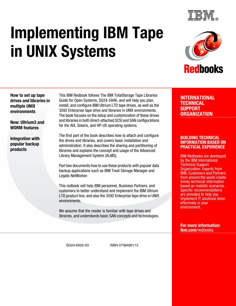
®
SG24-6502-03 ISBN 0738490113
INTERNATIONAL TECHNICALSUPPORTORGANIZATION
BUILDING TECHNICAL INFORMATION BASED ON PRACTICAL EXPERIENCE
IBM Redbooks are developed by the IBM International Technical Support Organization. Experts from IBM, Customers and Partners from around the world create timely technical information based on realistic scenarios. Specific recommendations are provided to help you implement IT solutions more effectively in your environment.
For more information:ibm.com/redbooks
Implementing IBM Tape in UNIX Systems
How to set up tape drives and libraries in multiple UNIX environments
New: Ultrium3 and WORM features
Integration with popular backup products
This IBM Redbook follows The IBM TotalStorage Tape Libraries Guide for Open Systems, SG24-5946, and will help you plan, install, and configure IBM Ultrium LTO tape drives, as well as the 3592 Enterprise tape drive and libraries in UNIX environments. The book focuses on the setup and customization of these drives and libraries in both direct-attached SCSI and SAN configurations for the AIX, Solaris, and HP-UX operating systems.
The first part of the book describes how to attach and configure the drives and libraries, and covers basic installation and administration. It also describes the sharing and partitioning of libraries and explains the concept and usage of the Advanced Library Management System (ALMS).
Part two documents how to use these products with popular data backup applications such as IBM Tivoli Storage Manager and Legato NetWorker.
This redbook will help IBM personnel, Business Partners, and customers to better understand and implement the IBM Ultrium LTO product line, and also the 3592 Enterprise tape drive in UNIX environments.
We assume that the reader is familiar with tape drives and libraries, and understands basic SAN concepts and technologies.
Back cover