ibm powerha systemmirror v7.2 for aix updates · · 2016-07-06international technical support...
TRANSCRIPT

Redbooks
Front cover
IBM PowerHASystemMirror V7.2 forIBM AIX Updates
Dino Quintero
Sergio Baeta
Shawn Bodily
Bernhard Buehler
Primitivo Cervantes
Bing He
Mihai Huica
Howard Knight


International Technical Support Organization
IBM PowerHA SystemMirror V7.2 for IBM AIX Updates
July 2016
SG24-8278-00

© Copyright International Business Machines Corporation 2016. All rights reserved.Note to U.S. Government Users Restricted Rights -- Use, duplication or disclosure restricted by GSA ADP ScheduleContract with IBM Corp.
First Edition (July 2016)
This edition applies to IBM AIX V7100-03-05-1524, IBM PowerHA SystemMirror V7.2.0, IBM AIX V7.1.3.4, IBM AIX V7.2.0, IBM AIX V7.1 TL3 SP5, IBM PowerHA SystemMirror V7.1.1 SP1, IBM PowerHA SystemMirror V7.1.2 SP1, IBM PowerHA SystemMirror V7.1.3 GA, IBM HTTP Server V7.0.0.0.
Note: Before using this information and the product it supports, read the information in “Notices” on page ix.

Contents
Notices . . . . . . . . . . . . . . . . . . . . . . . . . . . . . . . . . . . . . . . . . . . . . . . . . . . . . . . . . . . . . . . . . ixTrademarks . . . . . . . . . . . . . . . . . . . . . . . . . . . . . . . . . . . . . . . . . . . . . . . . . . . . . . . . . . . . . . .x
IBM Redbooks promotions . . . . . . . . . . . . . . . . . . . . . . . . . . . . . . . . . . . . . . . . . . . . . . . . . xi
Preface . . . . . . . . . . . . . . . . . . . . . . . . . . . . . . . . . . . . . . . . . . . . . . . . . . . . . . . . . . . . . . . . xiiiAuthors. . . . . . . . . . . . . . . . . . . . . . . . . . . . . . . . . . . . . . . . . . . . . . . . . . . . . . . . . . . . . . . . . xiiiNow you can become a published author, too . . . . . . . . . . . . . . . . . . . . . . . . . . . . . . . . . . . .xvComments welcome. . . . . . . . . . . . . . . . . . . . . . . . . . . . . . . . . . . . . . . . . . . . . . . . . . . . . . . .xvStay connected to IBM Redbooks . . . . . . . . . . . . . . . . . . . . . . . . . . . . . . . . . . . . . . . . . . . . .xv
Chapter 1. Introduction to IBM PowerHA SystemMirror for IBM AIX . . . . . . . . . . . . . . . 11.1 What IBM PowerHA SystemMirror for IBM AIX is . . . . . . . . . . . . . . . . . . . . . . . . . . . . . . 2
1.1.1 High availability . . . . . . . . . . . . . . . . . . . . . . . . . . . . . . . . . . . . . . . . . . . . . . . . . . . . 21.1.2 Cluster multiprocessing. . . . . . . . . . . . . . . . . . . . . . . . . . . . . . . . . . . . . . . . . . . . . . 2
1.2 Availability solutions: An overview . . . . . . . . . . . . . . . . . . . . . . . . . . . . . . . . . . . . . . . . . 31.2.1 Downtime . . . . . . . . . . . . . . . . . . . . . . . . . . . . . . . . . . . . . . . . . . . . . . . . . . . . . . . . 41.2.2 Single point of failure (SPOF) . . . . . . . . . . . . . . . . . . . . . . . . . . . . . . . . . . . . . . . . . 5
1.3 History and evolution. . . . . . . . . . . . . . . . . . . . . . . . . . . . . . . . . . . . . . . . . . . . . . . . . . . . 61.3.1 PowerHA SystemMirror version 7.1.1 . . . . . . . . . . . . . . . . . . . . . . . . . . . . . . . . . . . 61.3.2 PowerHA SystemMirror version 7.1.2 . . . . . . . . . . . . . . . . . . . . . . . . . . . . . . . . . . . 71.3.3 PowerHA SystemMirror version 7.1.3 . . . . . . . . . . . . . . . . . . . . . . . . . . . . . . . . . . . 81.3.4 PowerHA SystemMirror version 7.2.0 . . . . . . . . . . . . . . . . . . . . . . . . . . . . . . . . . . . 9
1.4 High availability terminology and concepts . . . . . . . . . . . . . . . . . . . . . . . . . . . . . . . . . . . 91.4.1 Terminology . . . . . . . . . . . . . . . . . . . . . . . . . . . . . . . . . . . . . . . . . . . . . . . . . . . . . . 9
1.5 Fault tolerance versus high availability . . . . . . . . . . . . . . . . . . . . . . . . . . . . . . . . . . . . . 111.5.1 Fault-tolerant systems. . . . . . . . . . . . . . . . . . . . . . . . . . . . . . . . . . . . . . . . . . . . . . 111.5.2 High availability systems. . . . . . . . . . . . . . . . . . . . . . . . . . . . . . . . . . . . . . . . . . . . 11
1.6 Additional PowerHA resources . . . . . . . . . . . . . . . . . . . . . . . . . . . . . . . . . . . . . . . . . . . 12
Chapter 2. IBM PowerHA SystemMirror V7.2 for IBM AIX new features. . . . . . . . . . . . 172.1 Resiliency enhancements . . . . . . . . . . . . . . . . . . . . . . . . . . . . . . . . . . . . . . . . . . . . . . . 18
2.1.1 Integrated support for AIX Live Kernel Update . . . . . . . . . . . . . . . . . . . . . . . . . . . 182.1.2 Automatic repository replacement. . . . . . . . . . . . . . . . . . . . . . . . . . . . . . . . . . . . . 202.1.3 Verification enhancements . . . . . . . . . . . . . . . . . . . . . . . . . . . . . . . . . . . . . . . . . . 202.1.4 Use of Logical Volume Manager rootvg failure monitoring . . . . . . . . . . . . . . . . . . 212.1.5 Live Partition Mobility automation . . . . . . . . . . . . . . . . . . . . . . . . . . . . . . . . . . . . . 23
2.2 Cluster Aware AIX (CAA) Enhancements . . . . . . . . . . . . . . . . . . . . . . . . . . . . . . . . . . . 252.2.1 Network Failure Detection Tunable. . . . . . . . . . . . . . . . . . . . . . . . . . . . . . . . . . . . 252.2.2 Built in NETMON logic . . . . . . . . . . . . . . . . . . . . . . . . . . . . . . . . . . . . . . . . . . . . . 252.2.3 Traffic stimulation for better interface failure detection . . . . . . . . . . . . . . . . . . . . . 25
2.3 Enhanced “split brain” handling. . . . . . . . . . . . . . . . . . . . . . . . . . . . . . . . . . . . . . . . . . . 262.4 Resource optimized high availability (ROHA) fallovers using Enterprise Pools . . . . . . 262.5 Non-disruptive upgrades . . . . . . . . . . . . . . . . . . . . . . . . . . . . . . . . . . . . . . . . . . . . . . . . 272.6 GLVM wizard. . . . . . . . . . . . . . . . . . . . . . . . . . . . . . . . . . . . . . . . . . . . . . . . . . . . . . . . . 27
© Copyright IBM Corp. 2016. All rights reserved. iii
Chapter 3. Planning considerations . . . . . . . . . . . . . . . . . . . . . . . . . . . . . . . . . . . . . . . . 293.1 Introduction . . . . . . . . . . . . . . . . . . . . . . . . . . . . . . . . . . . . . . . . . . . . . . . . . . . . . . . . . . 30
3.1.1 Mirrored architecture. . . . . . . . . . . . . . . . . . . . . . . . . . . . . . . . . . . . . . . . . . . . . . . 303.1.2 Single storage architecture . . . . . . . . . . . . . . . . . . . . . . . . . . . . . . . . . . . . . . . . . . 303.1.3 Stretched cluster . . . . . . . . . . . . . . . . . . . . . . . . . . . . . . . . . . . . . . . . . . . . . . . . . . 313.1.4 Linked cluster . . . . . . . . . . . . . . . . . . . . . . . . . . . . . . . . . . . . . . . . . . . . . . . . . . . . 32
3.2 Cluster Aware AIX repository disk. . . . . . . . . . . . . . . . . . . . . . . . . . . . . . . . . . . . . . . . . 333.2.1 Preparing for a CAA repository disk . . . . . . . . . . . . . . . . . . . . . . . . . . . . . . . . . . . 343.2.2 CAA with multiple storage devices . . . . . . . . . . . . . . . . . . . . . . . . . . . . . . . . . . . . 34
3.3 Important considerations for Virtual Input/Output Server . . . . . . . . . . . . . . . . . . . . . . . 393.3.1 Using poll_uplink. . . . . . . . . . . . . . . . . . . . . . . . . . . . . . . . . . . . . . . . . . . . . . . . . . 393.3.2 Advantages for PowerHA when poll_uplink is used . . . . . . . . . . . . . . . . . . . . . . . 41
3.4 Network considerations. . . . . . . . . . . . . . . . . . . . . . . . . . . . . . . . . . . . . . . . . . . . . . . . . 423.4.1 Dual adapter networks . . . . . . . . . . . . . . . . . . . . . . . . . . . . . . . . . . . . . . . . . . . . . 423.4.2 Single adapter network . . . . . . . . . . . . . . . . . . . . . . . . . . . . . . . . . . . . . . . . . . . . . 42
3.5 Network File System tie breaker . . . . . . . . . . . . . . . . . . . . . . . . . . . . . . . . . . . . . . . . . . 423.5.1 Introduction and concepts . . . . . . . . . . . . . . . . . . . . . . . . . . . . . . . . . . . . . . . . . . . 423.5.2 Test environment setup . . . . . . . . . . . . . . . . . . . . . . . . . . . . . . . . . . . . . . . . . . . . 443.5.3 NFS server and client configuration . . . . . . . . . . . . . . . . . . . . . . . . . . . . . . . . . . . 463.5.4 NFS tie breaker configuration . . . . . . . . . . . . . . . . . . . . . . . . . . . . . . . . . . . . . . . . 483.5.5 NFS tie breaker tests . . . . . . . . . . . . . . . . . . . . . . . . . . . . . . . . . . . . . . . . . . . . . . 533.5.6 Log entries for monitoring and debugging . . . . . . . . . . . . . . . . . . . . . . . . . . . . . . 58
Chapter 4. What’s new with IBM Cluster Aware AIX and Reliable Scalable Clustering Technology . . . . . . . . . . . . . . . . . . . . . . . . . . . . . . . . . . . . . . . . . . . . . . . . . . . 63
4.1 CAA. . . . . . . . . . . . . . . . . . . . . . . . . . . . . . . . . . . . . . . . . . . . . . . . . . . . . . . . . . . . . . . . 644.1.1 CAA tunables . . . . . . . . . . . . . . . . . . . . . . . . . . . . . . . . . . . . . . . . . . . . . . . . . . . . 644.1.2 What is new in CAA overview . . . . . . . . . . . . . . . . . . . . . . . . . . . . . . . . . . . . . . . . 644.1.3 Monitoring /var usage . . . . . . . . . . . . . . . . . . . . . . . . . . . . . . . . . . . . . . . . . . . . . . 654.1.4 New lscluster option -g . . . . . . . . . . . . . . . . . . . . . . . . . . . . . . . . . . . . . . . . . . . . . 674.1.5 Interface failure detection . . . . . . . . . . . . . . . . . . . . . . . . . . . . . . . . . . . . . . . . . . . 76
4.2 Automatic repository update for the repository disk . . . . . . . . . . . . . . . . . . . . . . . . . . . 774.2.1 Introduction to the automatic repository update . . . . . . . . . . . . . . . . . . . . . . . . . . 774.2.2 Requirements for Automatic Repository Update. . . . . . . . . . . . . . . . . . . . . . . . . . 784.2.3 Configuring Automatic Repository Update . . . . . . . . . . . . . . . . . . . . . . . . . . . . . . 784.2.4 Automatic Repository Update operations . . . . . . . . . . . . . . . . . . . . . . . . . . . . . . . 81
4.3 Reliable Scalable Cluster Technology overview . . . . . . . . . . . . . . . . . . . . . . . . . . . . . . 884.3.1 What Reliable Scalable Cluster Technology is . . . . . . . . . . . . . . . . . . . . . . . . . . . 884.3.2 Reliable Scalable Cluster Technology components . . . . . . . . . . . . . . . . . . . . . . . 88
4.4 IBM PowerHA, RSCT, and CAA . . . . . . . . . . . . . . . . . . . . . . . . . . . . . . . . . . . . . . . . . . 984.4.1 Configuring PowerHA, RSCT, and CAA . . . . . . . . . . . . . . . . . . . . . . . . . . . . . . . . 984.4.2 Relationship between PowerHA, RSCT, CAA . . . . . . . . . . . . . . . . . . . . . . . . . . . 994.4.3 How to start and stop CAA and RSCT . . . . . . . . . . . . . . . . . . . . . . . . . . . . . . . . 104
Chapter 5. Migration . . . . . . . . . . . . . . . . . . . . . . . . . . . . . . . . . . . . . . . . . . . . . . . . . . . . 1075.1 Migration planning. . . . . . . . . . . . . . . . . . . . . . . . . . . . . . . . . . . . . . . . . . . . . . . . . . . . 108
5.1.1 PowerHA SystemMirror V7.2.0 requirements . . . . . . . . . . . . . . . . . . . . . . . . . . . 1085.1.2 Deprecated features . . . . . . . . . . . . . . . . . . . . . . . . . . . . . . . . . . . . . . . . . . . . . . 1095.1.3 Migration options. . . . . . . . . . . . . . . . . . . . . . . . . . . . . . . . . . . . . . . . . . . . . . . . . 1105.1.4 Migration steps . . . . . . . . . . . . . . . . . . . . . . . . . . . . . . . . . . . . . . . . . . . . . . . . . . 1115.1.5 Clmigcheck . . . . . . . . . . . . . . . . . . . . . . . . . . . . . . . . . . . . . . . . . . . . . . . . . . . . . 1145.1.6 Clmigcheck enhancements . . . . . . . . . . . . . . . . . . . . . . . . . . . . . . . . . . . . . . . . . 1165.1.7 Migration matrix to PowerHA SystemMirror V7.2.0. . . . . . . . . . . . . . . . . . . . . . . 117
iv IBM PowerHA SystemMirror V7.2 for IBM AIX Updates

5.2 Migration scenarios from PowerHA V6.1 . . . . . . . . . . . . . . . . . . . . . . . . . . . . . . . . . . 1175.2.1 PowerHA V6.1 test environment overview . . . . . . . . . . . . . . . . . . . . . . . . . . . . . 1175.2.2 Rolling migration from PowerHA V6.1. . . . . . . . . . . . . . . . . . . . . . . . . . . . . . . . . 1185.2.3 Offline migration from PowerHA V6.1 . . . . . . . . . . . . . . . . . . . . . . . . . . . . . . . . . 1265.2.4 Snapshot migration from PowerHA V6.1 . . . . . . . . . . . . . . . . . . . . . . . . . . . . . . 128
5.3 Migration scenarios from PowerHA V7 . . . . . . . . . . . . . . . . . . . . . . . . . . . . . . . . . . . . 1315.3.1 PowerHA V7.1 test environment overview . . . . . . . . . . . . . . . . . . . . . . . . . . . . . 1315.3.2 Check and document initial stage . . . . . . . . . . . . . . . . . . . . . . . . . . . . . . . . . . . . 1325.3.3 Offline migration of PowerHA from 7.1.3 to 7.2.0 . . . . . . . . . . . . . . . . . . . . . . . . 1385.3.4 Rolling migration of PowerHA from 7.1.3 to 7.2.0 . . . . . . . . . . . . . . . . . . . . . . . . 1425.3.5 Snapshot migration from PowerHA 7.1.3 to 7.2.0. . . . . . . . . . . . . . . . . . . . . . . . 1475.3.6 Non-disruptive migration of PowerHA from 7.1.3 to 7.2.0. . . . . . . . . . . . . . . . . . 1535.3.7 Migrations of PowerHA from 7.1.1 and 7.1.2 to 7.2.0 . . . . . . . . . . . . . . . . . . . . . 158
Chapter 6. Resource Optimized High Availability (ROHA) . . . . . . . . . . . . . . . . . . . . . 1636.1 ROHA concept and terminology . . . . . . . . . . . . . . . . . . . . . . . . . . . . . . . . . . . . . . . . . 164
6.1.1 Environment requirement for ROHA . . . . . . . . . . . . . . . . . . . . . . . . . . . . . . . . . . 1656.2 New PowerHA SystemMirror SMIT configure panel for ROHA. . . . . . . . . . . . . . . . . . 165
6.2.1 Entry point to ROHA . . . . . . . . . . . . . . . . . . . . . . . . . . . . . . . . . . . . . . . . . . . . . . 1666.2.2 ROHA panel . . . . . . . . . . . . . . . . . . . . . . . . . . . . . . . . . . . . . . . . . . . . . . . . . . . . 1676.2.3 HMC configuration . . . . . . . . . . . . . . . . . . . . . . . . . . . . . . . . . . . . . . . . . . . . . . . 1686.2.4 Hardware resource provisioning for application controller . . . . . . . . . . . . . . . . . 1756.2.5 Change/Show Default Cluster Tunable. . . . . . . . . . . . . . . . . . . . . . . . . . . . . . . . 180
6.3 New PowerHA SystemMirror verification enhancement for ROHA. . . . . . . . . . . . . . . 1816.4 Planning for one ROHA cluster environment . . . . . . . . . . . . . . . . . . . . . . . . . . . . . . . 183
6.4.1 Consideration before ROHA configuration . . . . . . . . . . . . . . . . . . . . . . . . . . . . . 1836.4.2 Configuration steps for ROHA. . . . . . . . . . . . . . . . . . . . . . . . . . . . . . . . . . . . . . . 193
6.5 Resource acquisition and release process introduction . . . . . . . . . . . . . . . . . . . . . . . 1946.5.1 Steps for allocation and for release . . . . . . . . . . . . . . . . . . . . . . . . . . . . . . . . . . 194
6.6 Introduction to resource acquisition . . . . . . . . . . . . . . . . . . . . . . . . . . . . . . . . . . . . . . 1956.6.1 Query . . . . . . . . . . . . . . . . . . . . . . . . . . . . . . . . . . . . . . . . . . . . . . . . . . . . . . . . . 1966.6.2 Resource computation . . . . . . . . . . . . . . . . . . . . . . . . . . . . . . . . . . . . . . . . . . . . 1996.6.3 Identify the method of resource allocation . . . . . . . . . . . . . . . . . . . . . . . . . . . . . 2016.6.4 Acquire the resource. . . . . . . . . . . . . . . . . . . . . . . . . . . . . . . . . . . . . . . . . . . . . . 203
6.7 Introduction to release of resources . . . . . . . . . . . . . . . . . . . . . . . . . . . . . . . . . . . . . . 2046.7.1 Query . . . . . . . . . . . . . . . . . . . . . . . . . . . . . . . . . . . . . . . . . . . . . . . . . . . . . . . . . 2056.7.2 Synchronous and asynchronous mode. . . . . . . . . . . . . . . . . . . . . . . . . . . . . . . . 2096.7.3 Automatic resource release process after an operating system crash . . . . . . . . 210
6.8 Example 1: Setup one ROHA cluster (without On/Off CoD) . . . . . . . . . . . . . . . . . . . . 2106.8.1 Requirement . . . . . . . . . . . . . . . . . . . . . . . . . . . . . . . . . . . . . . . . . . . . . . . . . . . . 2106.8.2 Hardware topology . . . . . . . . . . . . . . . . . . . . . . . . . . . . . . . . . . . . . . . . . . . . . . . 2116.8.3 Cluster configuration . . . . . . . . . . . . . . . . . . . . . . . . . . . . . . . . . . . . . . . . . . . . . . 2126.8.4 Show the ROHA configuration . . . . . . . . . . . . . . . . . . . . . . . . . . . . . . . . . . . . . . 214
6.9 Test scenarios of Example 1 (without On/Off CoD) . . . . . . . . . . . . . . . . . . . . . . . . . . 2176.9.1 Bring two resource groups online . . . . . . . . . . . . . . . . . . . . . . . . . . . . . . . . . . . . 2176.9.2 Move one resource group to another node. . . . . . . . . . . . . . . . . . . . . . . . . . . . . 2236.9.3 Primary node crashes and reboots with current configuration . . . . . . . . . . . . . . 231
6.10 Example 2: Set up one ROHA cluster (with On/Off CoD) . . . . . . . . . . . . . . . . . . . . . 2326.10.1 Requirements . . . . . . . . . . . . . . . . . . . . . . . . . . . . . . . . . . . . . . . . . . . . . . . . . . 2336.10.2 Hardware topology . . . . . . . . . . . . . . . . . . . . . . . . . . . . . . . . . . . . . . . . . . . . . . 2336.10.3 Cluster configuration . . . . . . . . . . . . . . . . . . . . . . . . . . . . . . . . . . . . . . . . . . . . . 2346.10.4 Showing the ROHA configuration . . . . . . . . . . . . . . . . . . . . . . . . . . . . . . . . . . . 235
Contents v

6.11 Test scenarios for Example 2 (with On/Off CoD) . . . . . . . . . . . . . . . . . . . . . . . . . . . 2376.11.1 Bring two resource groups online . . . . . . . . . . . . . . . . . . . . . . . . . . . . . . . . . . . 2386.11.2 Bring one resource group offline. . . . . . . . . . . . . . . . . . . . . . . . . . . . . . . . . . . . 243
6.12 Hardware Management Console (HMC) high availability introduction . . . . . . . . . . . 2446.12.1 Switch to the backup HMC for the Power Enterprise Pool . . . . . . . . . . . . . . . . 246
6.13 Test scenario for HMC fallover . . . . . . . . . . . . . . . . . . . . . . . . . . . . . . . . . . . . . . . . . 2466.13.1 Hardware topology . . . . . . . . . . . . . . . . . . . . . . . . . . . . . . . . . . . . . . . . . . . . . . 2476.13.2 Bring one resource group offline when primary HMC fails . . . . . . . . . . . . . . . . 2506.13.3 Testing summary . . . . . . . . . . . . . . . . . . . . . . . . . . . . . . . . . . . . . . . . . . . . . . . 255
6.14 Manage, monitor and troubleshooting. . . . . . . . . . . . . . . . . . . . . . . . . . . . . . . . . . . . 2556.14.1 The clmgr interface to manage ROHA . . . . . . . . . . . . . . . . . . . . . . . . . . . . . . . 2556.14.2 Changing the DLPAR and CoD resources dynamically . . . . . . . . . . . . . . . . . . 2586.14.3 View the ROHA report . . . . . . . . . . . . . . . . . . . . . . . . . . . . . . . . . . . . . . . . . . . 2586.14.4 Troubleshooting DLPAR and CoD operations . . . . . . . . . . . . . . . . . . . . . . . . . 259
Chapter 7. Using the GLVM Configuration Assistant. . . . . . . . . . . . . . . . . . . . . . . . . . 2617.1 Choosing the data replication type . . . . . . . . . . . . . . . . . . . . . . . . . . . . . . . . . . . . . . . 262
7.1.1 Synchronous Mirroring . . . . . . . . . . . . . . . . . . . . . . . . . . . . . . . . . . . . . . . . . . . . 2627.1.2 Asynchronous Mirroring . . . . . . . . . . . . . . . . . . . . . . . . . . . . . . . . . . . . . . . . . . . 2627.1.3 GLVM Configuration Assistant . . . . . . . . . . . . . . . . . . . . . . . . . . . . . . . . . . . . . . 263
7.2 Configuration requirements. . . . . . . . . . . . . . . . . . . . . . . . . . . . . . . . . . . . . . . . . . . . . 2637.3 Test environment overview . . . . . . . . . . . . . . . . . . . . . . . . . . . . . . . . . . . . . . . . . . . . . 264
7.3.1 Test environment details . . . . . . . . . . . . . . . . . . . . . . . . . . . . . . . . . . . . . . . . . . . 2647.4 Creating a sample cluster environment. . . . . . . . . . . . . . . . . . . . . . . . . . . . . . . . . . . . 267
7.4.1 Configuring a multisite cluster . . . . . . . . . . . . . . . . . . . . . . . . . . . . . . . . . . . . . . . 2677.4.2 Configuring an asynchronous geographically mirrored volume group by using the
GLVM Configuration Assistant . . . . . . . . . . . . . . . . . . . . . . . . . . . . . . . . . . . . . . 2727.4.3 Creating a logical volume and a file system with the cluster online . . . . . . . . . . 2757.4.4 Creating a new logical volume and file system with cluster services stopped. . . 279
Chapter 8. Automation to adapt to the Live Partition Mobility (LPM) operation . . . . 2838.1 Concept. . . . . . . . . . . . . . . . . . . . . . . . . . . . . . . . . . . . . . . . . . . . . . . . . . . . . . . . . . . . 284
8.1.1 Prerequisites for PowerHA node support of LPM . . . . . . . . . . . . . . . . . . . . . . . . 2868.1.2 Reduce LPM freeze time as far as possible . . . . . . . . . . . . . . . . . . . . . . . . . . . . 2868.1.3 PowerHA fix requirement . . . . . . . . . . . . . . . . . . . . . . . . . . . . . . . . . . . . . . . . . . 286
8.2 Operation flow to support LPM on PowerHA node . . . . . . . . . . . . . . . . . . . . . . . . . . . 2868.2.1 Pre-migration operation flow . . . . . . . . . . . . . . . . . . . . . . . . . . . . . . . . . . . . . . . . 2878.2.2 Post-migration operation flow . . . . . . . . . . . . . . . . . . . . . . . . . . . . . . . . . . . . . . . 289
8.3 Example: LPM scenario for PowerHA node with version 7.1 . . . . . . . . . . . . . . . . . . . 2918.3.1 Topology introduction . . . . . . . . . . . . . . . . . . . . . . . . . . . . . . . . . . . . . . . . . . . . . 2918.3.2 Initial status . . . . . . . . . . . . . . . . . . . . . . . . . . . . . . . . . . . . . . . . . . . . . . . . . . . . . 2928.3.3 Manual operation before LPM. . . . . . . . . . . . . . . . . . . . . . . . . . . . . . . . . . . . . . . 2968.3.4 Perform LPM. . . . . . . . . . . . . . . . . . . . . . . . . . . . . . . . . . . . . . . . . . . . . . . . . . . . 3038.3.5 Manual operation after LPM . . . . . . . . . . . . . . . . . . . . . . . . . . . . . . . . . . . . . . . . 304
8.4 New panel to support LPM in PowerHA 7.2 . . . . . . . . . . . . . . . . . . . . . . . . . . . . . . . . 3088.5 PowerHA 7.2 scenario and troubleshooting . . . . . . . . . . . . . . . . . . . . . . . . . . . . . . . . 309
8.5.1 Troubleshooting . . . . . . . . . . . . . . . . . . . . . . . . . . . . . . . . . . . . . . . . . . . . . . . . . 310
vi IBM PowerHA SystemMirror V7.2 for IBM AIX Updates

Appendix A. SCSI reservations . . . . . . . . . . . . . . . . . . . . . . . . . . . . . . . . . . . . . . . . . . . 315SCSI reservations . . . . . . . . . . . . . . . . . . . . . . . . . . . . . . . . . . . . . . . . . . . . . . . . . . . . . . . 316
ODM reserve policy. . . . . . . . . . . . . . . . . . . . . . . . . . . . . . . . . . . . . . . . . . . . . . . . . . . . 317Persistent Reserve IN (PRIN) . . . . . . . . . . . . . . . . . . . . . . . . . . . . . . . . . . . . . . . . . . . . . . 319
Persistent Preserve OUT (PROUT) . . . . . . . . . . . . . . . . . . . . . . . . . . . . . . . . . . . . . . . 319Understanding register, reserve, and preempt . . . . . . . . . . . . . . . . . . . . . . . . . . . . . . . 320Unregister . . . . . . . . . . . . . . . . . . . . . . . . . . . . . . . . . . . . . . . . . . . . . . . . . . . . . . . . . . . 323Release. . . . . . . . . . . . . . . . . . . . . . . . . . . . . . . . . . . . . . . . . . . . . . . . . . . . . . . . . . . . . 323Clear . . . . . . . . . . . . . . . . . . . . . . . . . . . . . . . . . . . . . . . . . . . . . . . . . . . . . . . . . . . . . . . 323
Storage. . . . . . . . . . . . . . . . . . . . . . . . . . . . . . . . . . . . . . . . . . . . . . . . . . . . . . . . . . . . . . . . 324More about PR reservations . . . . . . . . . . . . . . . . . . . . . . . . . . . . . . . . . . . . . . . . . . . . . . . 324Persistent reservation commands . . . . . . . . . . . . . . . . . . . . . . . . . . . . . . . . . . . . . . . . . . . 325
Appendix B. PowerHA: Live kernel update support . . . . . . . . . . . . . . . . . . . . . . . . . . 327Live kernel update (LKU) support . . . . . . . . . . . . . . . . . . . . . . . . . . . . . . . . . . . . . . . . . . . 328Example of LKU patching a kernel interim fix in a PowerHA environment. . . . . . . . . . . . . 328
Related publications . . . . . . . . . . . . . . . . . . . . . . . . . . . . . . . . . . . . . . . . . . . . . . . . . . . . 337IBM Redbooks . . . . . . . . . . . . . . . . . . . . . . . . . . . . . . . . . . . . . . . . . . . . . . . . . . . . . . . . . . 337Other publications . . . . . . . . . . . . . . . . . . . . . . . . . . . . . . . . . . . . . . . . . . . . . . . . . . . . . . . 337Online resources . . . . . . . . . . . . . . . . . . . . . . . . . . . . . . . . . . . . . . . . . . . . . . . . . . . . . . . . 337Help from IBM . . . . . . . . . . . . . . . . . . . . . . . . . . . . . . . . . . . . . . . . . . . . . . . . . . . . . . . . . . 338
Contents vii

viii IBM PowerHA SystemMirror V7.2 for IBM AIX Updates

Notices
This information was developed for products and services offered in the US. This material might be available from IBM in other languages. However, you may be required to own a copy of the product or product version in that language in order to access it.
IBM may not offer the products, services, or features discussed in this document in other countries. Consult your local IBM representative for information on the products and services currently available in your area. Any reference to an IBM product, program, or service is not intended to state or imply that only that IBM product, program, or service may be used. Any functionally equivalent product, program, or service that does not infringe any IBM intellectual property right may be used instead. However, it is the user’s responsibility to evaluate and verify the operation of any non-IBM product, program, or service.
IBM may have patents or pending patent applications covering subject matter described in this document. The furnishing of this document does not grant you any license to these patents. You can send license inquiries, in writing, to:IBM Director of Licensing, IBM Corporation, North Castle Drive, MD-NC119, Armonk, NY 10504-1785, US
INTERNATIONAL BUSINESS MACHINES CORPORATION PROVIDES THIS PUBLICATION “AS IS” WITHOUT WARRANTY OF ANY KIND, EITHER EXPRESS OR IMPLIED, INCLUDING, BUT NOT LIMITED TO, THE IMPLIED WARRANTIES OF NON-INFRINGEMENT, MERCHANTABILITY OR FITNESS FOR A PARTICULAR PURPOSE. Some jurisdictions do not allow disclaimer of express or implied warranties in certain transactions, therefore, this statement may not apply to you.
This information could include technical inaccuracies or typographical errors. Changes are periodically made to the information herein; these changes will be incorporated in new editions of the publication. IBM may make improvements and/or changes in the product(s) and/or the program(s) described in this publication at any time without notice.
Any references in this information to non-IBM websites are provided for convenience only and do not in any manner serve as an endorsement of those websites. The materials at those websites are not part of the materials for this IBM product and use of those websites is at your own risk.
IBM may use or distribute any of the information you provide in any way it believes appropriate without incurring any obligation to you.
The performance data and client examples cited are presented for illustrative purposes only. Actual performance results may vary depending on specific configurations and operating conditions.
Information concerning non-IBM products was obtained from the suppliers of those products, their published announcements or other publicly available sources. IBM has not tested those products and cannot confirm the accuracy of performance, compatibility or any other claims related to non-IBM products. Questions on the capabilities of non-IBM products should be addressed to the suppliers of those products.
Statements regarding IBM’s future direction or intent are subject to change or withdrawal without notice, and represent goals and objectives only.
This information contains examples of data and reports used in daily business operations. To illustrate them as completely as possible, the examples include the names of individuals, companies, brands, and products. All of these names are fictitious and any similarity to actual people or business enterprises is entirely coincidental.
COPYRIGHT LICENSE:
This information contains sample application programs in source language, which illustrate programming techniques on various operating platforms. You may copy, modify, and distribute these sample programs in any form without payment to IBM, for the purposes of developing, using, marketing or distributing application programs conforming to the application programming interface for the operating platform for which the sample programs are written. These examples have not been thoroughly tested under all conditions. IBM, therefore, cannot guarantee or imply reliability, serviceability, or function of these programs. The sample programs are provided “AS IS”, without warranty of any kind. IBM shall not be liable for any damages arising out of your use of the sample programs.
© Copyright IBM Corp. 2016. All rights reserved. ix

Trademarks
IBM, the IBM logo, and ibm.com are trademarks or registered trademarks of International Business Machines Corporation, registered in many jurisdictions worldwide. Other product and service names might be trademarks of IBM or other companies. A current list of IBM trademarks is available on the web at “Copyright and trademark information” at http://www.ibm.com/legal/copytrade.shtml
The following terms are trademarks or registered trademarks of International Business Machines Corporation, and might also be trademarks or registered trademarks in other countries.
AIX®DS8000®GPFS™HACMP™HyperSwap®IBM®IBM Spectrum™
IBM Spectrum Scale™POWER®Power Systems™POWER6®POWER7®PowerHA®PowerVM®
Redbooks®Redpaper™Redbooks (logo) ®RS/6000®Storwize®SystemMirror®XIV®
The following terms are trademarks of other companies:
Linux is a trademark of Linus Torvalds in the United States, other countries, or both.
Windows, and the Windows logo are trademarks of Microsoft Corporation in the United States, other countries, or both.
UNIX is a registered trademark of The Open Group in the United States and other countries.
Other company, product, or service names may be trademarks or service marks of others.
x IBM PowerHA SystemMirror V7.2 for IBM AIX Updates

IBM REDBOOKS PROMOTIONS
Find and read thousands of IBM Redbooks publications
Search, bookmark, save and organize favorites
Get personalized notifications of new content
Link to the latest Redbooks blogs and videos
DownloadNow
Get the latest version of the Redbooks Mobile App
iOS
Android
Place a Sponsorship Promotion in an IBM Redbooks publication, featuring your business or solution with a link to your web site.
Qualified IBM Business Partners may place a full page promotion in the most popular Redbooks publications. Imagine the power of being seen by users who download millions of Redbooks publications each year!
®
®
Promote your business in an IBM Redbooks publication
ibm.com/RedbooksAbout Redbooks Business Partner Programs
IBM Redbooks promotions

THIS PAGE INTENTIONALLY LEFT BLANK

Preface
This IBM® Redbooks® publication addresses topics to help answer customers’ complex high availability requirements to help maximize systems availability and resources, and provide documentation to transfer the how-to-skills to the worldwide sales and support teams.
This publication helps strengthen the position of the IBM PowerHA® SystemMirror® solution with a well-defined and documented deployment models within an IBM Power Systems™ virtualized environment, providing customers a planned foundation for business resilient infrastructure solutions.
This book describes documentation, and other resources available to help the technical teams provide business resilience solutions and support with the IBM PowerHA SystemMirror Standard and Enterprise Editions on IBM Power Systems.
This publication targets technical professionals (consultants, technical support staff, IT Architects, and IT Specialists) responsible for providing high availability solutions and support with IBM PowerHA SystemMirror Standard and Enterprise Editions on IBM Power Systems.
Authors
This book was produced by a team of specialists from around the world, working at the International Technical Support Organization, Austin Center.
Dino Quintero is a Complex Solutions Project Leader and an IBM Level 3 Certified Senior IT Specialist with the Technical Content Services in Poughkeepsie, New York. His areas of knowledge include enterprise continuous availability, enterprise systems management, system virtualization, technical computing, and clustering solutions. He is an Open Group Distinguished IT Specialist. Dino holds a Master of Computing Information Systems degree and a Bachelor of Science degree in Computer Science from Marist College.
Sergio Baeta is a System Analyst at Banco do Brasil in Brazil. He has 10 years of experience with UNIX operating systems, including IBM AIX®, Solaris, and Linux. He holds a Bachelor degree in Computer Science from the Catholic University of Brasília (UCB). His areas of expertise include implementation, support, and performance analysis of IBM PowerVM®, IBM AIX, IBM PowerHA SystemMirror, and IBM Spectrum™ Scale.
Shawn Bodily is an IBM Champion for Power Systems known online as “PowerHAguy” and is a Senior IT Consultant for Clear Technologies in Dallas, Texas. He has 24 years of AIX experience and the last 20 years, specializing in high availability and disaster recovery solutions that are primarily focused around PowerHA. He is double AIX Advanced Technical Expert, and is certified in IBM POWER® Systems and IBM Storage. He has written and presented extensively about high availability and storage at technical conferences, webinars, and onsite to customers. He is an IBM Redbooks platinum author who has co-authored nine IBM Redbooks publications and three IBM Redpaper™ publications.
© Copyright IBM Corp. 2016. All rights reserved. xiii

Bernhard Buehler is an IT Specialist for availability solutions on IBM Power Systems in Germany. He works for IBM Systems Lab Services in Nice, France. He has worked at IBM for 34 years and has 25 years of experience in AIX and the availability field. His areas of expertise include AIX, Linux, IBM PowerHA, HA architecture, shell script programming, and AIX security. He is a co-author of several IBM Redbooks publications and of several courses in the IBM AIX curriculum.
Primitivo Cervantes is a certified I/T Specialist with a focus on high-availability and disaster recovery. He has been working in the I/T industry for over 28 years, starting in mid-range computer systems and workstations. For the last 23 years, he has focused on high-availability and disaster recovery solutions in the AIX platforms. He is now also focusing on Linux business continuity. He is a techie-nerd so, in his spare time, he also reads anything related to technology, from rockets to radios.
Bing He is a Consulting I/T Specialist of the IBM Advanced Technical Skills (ATS) team in China. He has 16 years of experience with IBM Power Systems. He has worked at IBM for over seven years. His areas of expertise include PowerHA, PowerVM, and performance tuning on AIX.
Mihai Huica is an IT Specialist who currently works for UTI Group in Bucharest, Romania. He has 12 years of experience in designing, implementing, and supporting IT&C solutions. He is an IBM Certified Systems Expert for Enterprise Technical Support for AIX and Linux, with 5 years of experience in IBM Power Systems. He holds a Bachelor degree in Engineering from Polytechnical Institute of Bucharest and a Master degree in Electronics Engineering and Telecommunications from Technical Military Academy in Bucharest. His areas of expertise include UNIX-like operating systems (AIX, Solaris, and Linux), and virtualization and HA technologies (IBM PowerVM, IBM PowerHA, VMware).
Howard Knight is a Software Advisory Specialist with the IBM GTS team in the United Kingdom. Howard provides technical support to customers with PowerHA related issues on IBM Power Systems clusters.
Thanks to the following people for their contributions to this project:
Richard Conway, David BenninInternational Technical Support Organization, Austin Center
Minh Pham, Alex Mcleod, Tom Weaver, and Teresa Pham, Michael Coffey, Paul Moyer, Ravi Shankar, PI Ganesh, Gary Lowther, Gary Domrow, Esdras E Cruz-Aguilar, Gilles QuillardIBM US
Maria-Katharina EsserIBM Germany
Fabio MartinsIBM Brazil
Octavian LascuIBM Romania
Jes Kiran, Srikanth Thanneeru, Madhusudhanan Duraisamy, Prabhanjan GururajIBM India
Victoria CervantesCalifornia, US
xiv IBM PowerHA SystemMirror V7.2 for IBM AIX Updates

Now you can become a published author, too
Here’s an opportunity to spotlight your skills, grow your career, and become a published author—all at the same time. Join an ITSO residency project and help write a book in your area of expertise, while honing your experience using leading-edge technologies. Your efforts will help to increase product acceptance and customer satisfaction, as you expand your network of technical contacts and relationships. Residencies run 2 - 6 weeks in length, and you can participate either in person or as a remote resident working from your home base.
Find out more about the residency program, browse the residency index, and apply online at:
ibm.com/redbooks/residencies.html
Comments welcome
Your comments are important to us.
We want our books to be as helpful as possible. Send us your comments about this book or other IBM Redbooks publications in one of the following ways:
� Use the online Contact us review Redbooks form:
ibm.com/redbooks
� Send your comments in an email:
� Mail your comments:
IBM Corporation, International Technical Support OrganizationDept. HYTD Mail Station P0992455 South RoadPoughkeepsie, NY 12601-5400
Stay connected to IBM Redbooks
� Find us on Facebook:
http://www.facebook.com/IBMRedbooks
� Follow us on Twitter:
http://twitter.com/ibmredbooks
� Look for us on LinkedIn:
http://www.linkedin.com/groups?home=&gid=2130806
� Explore new Redbooks publications, residencies, and workshops with the IBM Redbooks weekly newsletter:
https://www.redbooks.ibm.com/Redbooks.nsf/subscribe?OpenForm
� Stay current on recent Redbooks publications with RSS Feeds:
http://www.redbooks.ibm.com/rss.html
Preface xv

xvi IBM PowerHA SystemMirror V7.2 for IBM AIX Updates

Chapter 1. Introduction to IBM PowerHA SystemMirror for IBM AIX
This chapter provides an introduction to IBM PowerHA SystemMirror for newcomers into this solution as well as a refresher to those that have implemented PowerHA and have used it for many years.
This chapter contains the following topics:
� What IBM PowerHA SystemMirror for IBM AIX is� Availability solutions: An overview� History and evolution� High availability terminology and concepts� Fault tolerance versus high availability� Additional PowerHA resources
1
© Copyright IBM Corp. 2016. All rights reserved. 1

1.1 What IBM PowerHA SystemMirror for IBM AIX is
IBM PowerHA SystemMirror for IBM AIX (PowerHA) is the IBM Power Systems data center solution that helps protect critical business applications (apps) from outages, planned or unplanned. One of the major objectives of PowerHA is to offer automatically continued business services by providing redundancy despite different component failures.
PowerHA depends on Reliable Scalable Cluster Technology (RSCT). RSCT is a set of low-level operating system components that allow clustering technologies implementation, such as IBM Spectrum Scale™ (formerly IBM General Parallel File System, IBM GPFS™). RSCT is distributed with AIX. On the current AIX release, AIX V7.1, RSCT is on version 3.1.2.0. After installing PowerHA and Cluster Aware AIX (CAA) file sets, the RSCT’s topology services subsystem is deactivated and all its functionality is performed by CAA.
PowerHA version 7.1 and later rely heavily on the CAA infrastructure available in AIX V6.1 TL6 and AIX V7.1. CAA provides communication interfaces and monitoring provision for PowerHA and execution using CAA commands with clcmd.
PowerHA Enterprise Edition also provides disaster recovery functionality, such as cross site mirroring, IBM HyperSwap®, Geographical Logical Volume Mirroring and many storage-based replication methods. These cross-site clustering methods support PowerHA functionality between two geographic sites. For more information see the IBM PowerHA SystemMirror 7.1.2 Enterprise Edition for AIX, SG24-8106.
More information for features added in PowerHA V7.1.1 and above can be found at 1.3, “History and evolution” on page 6.
1.1.1 High availability
In today’s complex environments, providing continuous service for applications is a key component of a successful IT implementation. High availability (HA) is one of the components that contributes to providing continuous service for the application clients, by masking or eliminating both planned and unplanned systems and application downtime.
A high availability solution ensures that the failure of any component of the solution, either hardware, software, or system management, does not cause the application and its data to become permanently unavailable to the user. High availability solutions can help to eliminate single points of failure through appropriate design, planning, selection of hardware, configuration of software, control of applications, a carefully controlled environment, and change management discipline.
In short, we can define high availability as the process of ensuring, through the use of duplicated or shared hardware resources, managed by a specialized software component, that an application stays up and available for use.
1.1.2 Cluster multiprocessing
In addition to high availability, PowerHA also provides the multiprocessing component. The multiprocessing capability comes from the fact that in a cluster there are multiple hardware and software resources managed by PowerHA to provide complex application functionality and better resource use.
A short definition for cluster multiprocessing can be multiple applications that run over several nodes with shared or concurrent access to the data.
2 IBM PowerHA SystemMirror V7.2 for IBM AIX Updates

Although desirable, the cluster multiprocessing component depends on the application capabilities and system implementation to efficiently use all resources available in a multi-node (cluster) environment. This must be implemented starting with the cluster planning and design phase.
PowerHA is only one of the HA technologies and builds on the increasingly reliable operating systems, hot-swappable hardware, increasingly resilient applications, by offering monitoring and automated response. A high availability solution based on PowerHA provides automated failure detection, diagnosis, application recovery, and node reintegration. PowerHA can also provide excellent horizontal and vertical scalability by combining other advanced functionality, such as dynamic logical partition (DLPAR) and capacity on demand (CoD).
1.2 Availability solutions: An overview
Many solutions can provide a wide range of availability options. Table 1-1 lists various types of availability solutions and their characteristics.
Table 1-1 Types of availability solutions
High availability solutions, in general, offer the following benefits:
� Standard hardware and networking components (can be used with the existing hardware)
� Works with nearly all applications
� Works with a wide range of disks and network types
� Excellent availability at a reasonable cost
The highly available solution for IBM Power Systems offers distinct benefits:
� Proven solution with ~26 years of product development
� Using “off the shelf” hardware components
� Proven commitment for supporting our customers
� IP version 6 (IPv6) support for both internal and external cluster communication
� Smart Assist technology that enables high availability support for all prominent applications
� Flexibility (virtually any application that runs on a stand-alone AIX system can be protected with PowerHA)
Solution Downtime Data availability Observations
Stand-alone Days From last backup Basic hardware and software
Enhanced stand-alone Hours Until last transaction Double most hardware components
High availability clustering
Seconds Until last transaction Double hardware and additional software costs
Fault-tolerant Zero No loss of data Specialized hardware and software, veryexpensive
Chapter 1. Introduction to IBM PowerHA SystemMirror for IBM AIX 3

When you plan to implement a PowerHA solution, consider the following aspects:
� Thorough HA design and detailed planning from end to end� Elimination of single points of failure� Selection of appropriate hardware� Correct implementation (do not take “shortcuts”)� Disciplined system administration practices and change control� Documented operational procedures� Comprehensive test plan and thorough testing
A typical PowerHA environment is shown in Figure 1-1. Both IP heartbeat networks and non-IP heartbeat networks perform actions through the cluster repository disk.
Figure 1-1 PowerHA cluster example
1.2.1 Downtime
Downtime is the period when an application is not available to serve its clients. Downtime can be classified in two categories, planned and unplanned:
� Planned
– Hardware upgrades– Hardware or software repair or replacement– Software updates or upgrades– Backups (offline backups)– Testing (periodic testing is required for cluster validation)– Development
4 IBM PowerHA SystemMirror V7.2 for IBM AIX Updates

� Unplanned
– Administrator errors– Application failures– Hardware failures– Operating system errors– Environmental disasters
The role of PowerHA is to maintain application availability through the unplanned outages and normal day-to-day administrative requirements. PowerHA provides monitoring and automatic recovery of the resources on which your application depends.
1.2.2 Single point of failure (SPOF)
A single point of failure is any individual component that is integrated in a cluster and that, if there is a failure, renders the application unavailable for users.
Good design can remove single points of failure in the cluster: nodes, storage, and networks. PowerHA manages these, and also the resources required by the application (including the application start/stop scripts).
Ultimately, the goal of any IT solution in a critical environment is to provide continuous application availability and data protection. The high availability is just one building block in achieving the continuous operation goal. The high availability is based on the availability of the hardware, software (operating system and its components), application, and network components.
To avoid single points of failure, use the following items:
� Redundant servers� Redundant network paths� Redundant storage (data) paths� Redundant (mirrored, RAID) storage� Monitoring of components� Failure detection and diagnosis� Automated application fallover� Automated resource reintegration
As previously mentioned, a good design is able to avoid single points of failure, and PowerHA can manage the availability of the application through downtimes. Table 1-2 lists each cluster object, which, if it fails, can result in loss of availability of the application. Each cluster object can be a physical or logical component.
Table 1-2 Single points of failure
Cluster object SPOF eliminated by
Node (servers) Multiple nodes
Power/power supply Multiple circuits, power supplies, or uninterruptible power supply (UPS)
Network Multiple networks connected to each node, redundant network paths with independent hardware between each node and the clients
Network adapters Redundant adapters and use other HA type features, such as EtherChannel and shared Ethernet adapters (SEA) via Virtual input/output Server (VIOS)
Chapter 1. Introduction to IBM PowerHA SystemMirror for IBM AIX 5
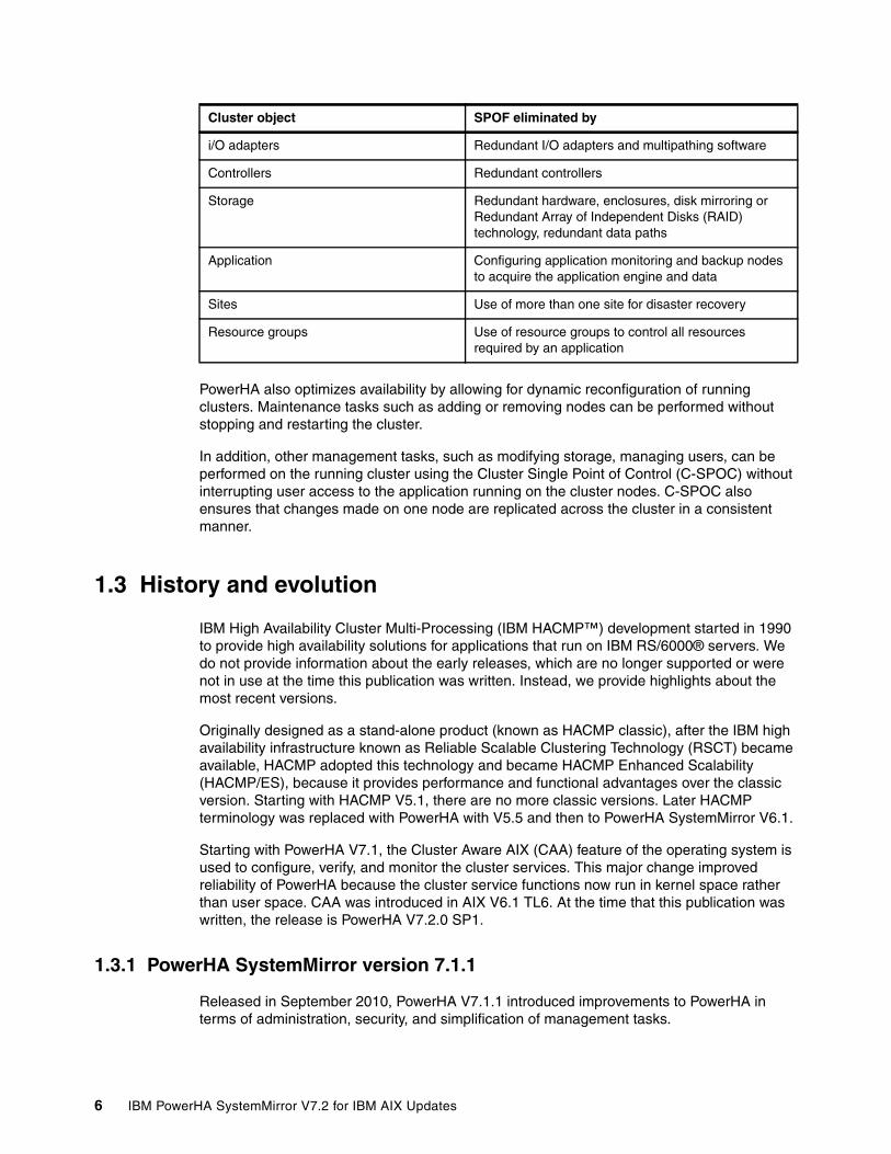
PowerHA also optimizes availability by allowing for dynamic reconfiguration of running clusters. Maintenance tasks such as adding or removing nodes can be performed without stopping and restarting the cluster.
In addition, other management tasks, such as modifying storage, managing users, can be performed on the running cluster using the Cluster Single Point of Control (C-SPOC) without interrupting user access to the application running on the cluster nodes. C-SPOC also ensures that changes made on one node are replicated across the cluster in a consistent manner.
1.3 History and evolution
IBM High Availability Cluster Multi-Processing (IBM HACMP™) development started in 1990 to provide high availability solutions for applications that run on IBM RS/6000® servers. We do not provide information about the early releases, which are no longer supported or were not in use at the time this publication was written. Instead, we provide highlights about the most recent versions.
Originally designed as a stand-alone product (known as HACMP classic), after the IBM high availability infrastructure known as Reliable Scalable Clustering Technology (RSCT) became available, HACMP adopted this technology and became HACMP Enhanced Scalability (HACMP/ES), because it provides performance and functional advantages over the classic version. Starting with HACMP V5.1, there are no more classic versions. Later HACMP terminology was replaced with PowerHA with V5.5 and then to PowerHA SystemMirror V6.1.
Starting with PowerHA V7.1, the Cluster Aware AIX (CAA) feature of the operating system is used to configure, verify, and monitor the cluster services. This major change improved reliability of PowerHA because the cluster service functions now run in kernel space rather than user space. CAA was introduced in AIX V6.1 TL6. At the time that this publication was written, the release is PowerHA V7.2.0 SP1.
1.3.1 PowerHA SystemMirror version 7.1.1
Released in September 2010, PowerHA V7.1.1 introduced improvements to PowerHA in terms of administration, security, and simplification of management tasks.
i/O adapters Redundant I/O adapters and multipathing software
Controllers Redundant controllers
Storage Redundant hardware, enclosures, disk mirroring or Redundant Array of Independent Disks (RAID) technology, redundant data paths
Application Configuring application monitoring and backup nodes to acquire the application engine and data
Sites Use of more than one site for disaster recovery
Resource groups Use of resource groups to control all resources required by an application
Cluster object SPOF eliminated by
6 IBM PowerHA SystemMirror V7.2 for IBM AIX Updates

The following list summarizes the improvements in PowerHA V7.1.1:
� Federated security allows cluster-wide single point of control, such as these:
– Encrypted file system (EFS) support– Role-based access control (RBAC) support– Authentication by using Lightweight Directory Access Protocol (LDAP) methods
� Logical Volume Manager (LVM) and C-SPOC enhancements, to name several:
– EFS management by C-SPOC
– Support for mirror pools
– Disk renaming inside the cluster
– Support for EMC, Hitachi, HP disk subsystems multipathing logical unit number (LUN) as a clustered repository disk
– Capability to display disk Universally Unique Identifier (UUID)
– File system mounting feature (journaled file system (JFS2) Mount Guard), which prevents simultaneous mounting of the same file system by two nodes, which can cause data corruption
� Repository resiliency
� Dynamic automatic reconfiguration (DARE) progress indicator
� Application management improvements such as new application startup option
When you add an application controller, you can choose the application startup mode. Now, you can choose background startup mode, which is the default and where the cluster activation moves forward with an application start script that runs in the background. Alternatively, you can choose foreground startup mode.
When you choose the application controller option, the cluster activation is sequential, which means that cluster events hold application-startup-script execution. If the application script ends with a failure (nonzero return code), the cluster activation is considered to failed, also.
� New network features, such as defining a network as private, use of netmon.cf file, and more network tunables.
1.3.2 PowerHA SystemMirror version 7.1.2
Released in October 2012, PowerHA V7.1.2 continued to add features and functionality:
� Two new cluster types (stretched and linked clusters):
– Stretched cluster refers to a cluster that has sites that are defined in the same geographic location. It uses a shared repository disk. Extended distance sites with only IP connectivity are not possible with this cluster.
– Linked cluster refers to a cluster with only internet protocol (IP) connectivity across sites, and is usually for PowerHA Enterprise Edition.
� IPv6 support reintroduced
� Backup repository disk
Note: More details and examples of implementing these features are found in IBM PowerHA SystemMirror Standard Edition 7.1.1 for AIX Update, SG24-8030, which is available at the following website:
http://www.redbooks.ibm.com/abstracts/sg248030.html
Chapter 1. Introduction to IBM PowerHA SystemMirror for IBM AIX 7

� Site support reintroduced with Standard Edition
� PowerHA Enterprise Edition reintroduced:
– New HyperSwap support added for DS88XX:
• All previous storage replication options supported in PowerHA V6.1 are supported• IBM DS8000® Metro Mirror and Global Mirror• SAN Volume Controller Metro Mirror and Global Mirror• IBM Storwize® V7000 Metro Mirror and Global Mirror• EMC Corporation SRDF synchronous and asynchronous replication• Hitachi TrueCopy and HUR replication• HP Continuous Access synchronous and asynchronous replication
– Geographic Logical Volume Manager (GLVM)
1.3.3 PowerHA SystemMirror version 7.1.3
Released in October 2013, PowerHA V7.1.3 continued the development of PowerHA SystemMirror, by adding further improvements in management, configuration simplification, automation, and performance areas. The following list summarizes the improvements in PowerHA V7.1.3:
� Unicast heartbeat
� Dynamic host name change
� Cluster split and merge handling policies
� clmgr command enhancements:
– Embedded hyphen and leading digit support in node labels– Native Hypertext Markup Language (HTML) report– Cluster copying through snapshots– Syntactical built-in help– Split and merge support
� CAA enhancements:
– Scalability up to 32 nodes– Support for unicast and multicast– Dynamic host name or IP address support
� HyperSwap enhancements:
– Active-active sites– One node HyperSwap– Auto resynchronization of mirroring– Node level unmanage mode support– Enhanced repository disk swap management
� PowerHA plug-in enhancements for IBM Systems Director:
– Restore snapshot wizard– Cluster simulator– Cluster split/merge support
� Smart Assist for SAP enhancements
Note: Additional details and examples of implementing some of these features are found in the IBM PowerHA SystemMirror 7.1.2 Enterprise Edition for AIX, SG24-8106, which is available at the following website:
http://www.redbooks.ibm.com/abstracts/sg248106.html
8 IBM PowerHA SystemMirror V7.2 for IBM AIX Updates

1.3.4 PowerHA SystemMirror version 7.2.0
Released in December 2015, PowerHA V7.2 continued the development of PowerHA SystemMirror, by adding further improvements in management, configuration simplification, automation, and performance areas.
The following list summarizes the improvements in PowerHA V7.2:
� Resiliency enhancements
– Integrated support for AIX Live Kernel Update (LKU)– Automatic repository replacement– Verification enhancements– Exploitation of LVM rootvg failure monitoring– Live Partition Mobility automation
� Cluster Aware AIX (CAA) Enhancements
– Network Failure Detection Tunable per interface– Built in NETMON logic– Traffic stimulation for better interface failure detection
� Enhanced split brain handling
– Quarantine protection against “sick but not dead” nodes– Network File System (NFS) Tie Breaker support for split and merge policies
� Resource optimized high availability (ROHA) fallovers using Enterprise Pools
� Non-disruptive upgrades
1.4 High availability terminology and concepts
To understand the functionality of PowerHA and to use it effectively, understanding several important terms and concepts can help.
1.4.1 Terminology
The terminology used to describe PowerHA configuration and operation continues to evolve. The following terms are used throughout this book:
Cluster Loosely-coupled collection of independent systems (nodes) or logical partitions (LPARs) organized into a network for sharing resources and communicating with each other.
PowerHA defines relationships among cooperating systems where peer cluster nodes provide the services offered by a cluster node if that node is unable to do so. These individual nodes are together responsible for maintaining the functionality of one or more applications in case of a failure of any cluster component.
Note: More details and examples of implementing some of these features are found in the IBM PowerHA SystemMirror 7.1.2 Enterprise Edition for AIX, SG24-8106, which is available at the following website:
http://www.redbooks.ibm.com/abstracts/sg248106.html
Chapter 1. Introduction to IBM PowerHA SystemMirror for IBM AIX 9

Node An IBM Power Systems (or LPAR) running AIX and PowerHA that is defined as part of a cluster. Each node has a collection of resources (disks, file systems, IP addresses, and applications) that can be transferred to another node in the cluster in case the node or a component fails.
Client A client is a system that can access the application that is running on the cluster nodes over a local area network (LAN). Clients run a client application that connects to the server (node) where the app runs.
Topology Contains basic cluster components nodes, networks, communication interfaces, and communication adapters.
Resources Logical components or entities that are being made highly available (for example, file systems, raw devices, service IP labels, and applications) by being moved from one node to another. All resources that together form a highly available application or service, are grouped together in resource groups (RG).
PowerHA keeps the RG highly available as a single entity that can be moved from node to node if a component or node fails. Resource groups can be available from a single node or, for concurrent applications, available simultaneously from multiple nodes. A cluster can host more than one resource group, thus allowing for efficient use of the cluster nodes.
Service IP label A label that matches to a service IP address and is used for communications between clients and the node. A service IP label is part of a resource group, which means that PowerHA can monitor it and keep it highly available.
IP address takeover (IPAT)
The process whereby an IP address is moved from one adapter to another adapter on the same logical network. This adapter can be on the same node, or another node in the cluster. If aliasing is used as the method of assigning addresses to adapters, then more than one address can exist on a single adapter.
Resource takeover This is the operation of transferring resources between nodes inside the cluster. If one component or node fails because of a hardware or operating system problem, its resource groups are moved to another node.
Fallover This represents the movement of a resource group from one active node to another node (backup node) in response to a failure on that active node.
Fallback This represents the movement of a resource group back from the backup node to the previous node, when it becomes available. This movement is typically in response to the reintegration of the previously failed node.
Heartbeat packet A packet that is sent between communication interfaces in the cluster, and is used by the various cluster daemons to monitor the state of the cluster components (nodes, networks, adapters).
RSCT daemons These consist of two types of processes, topology and group services. PowerHA uses group services but depends on CAA for topology services. The cluster manager receives event information generated by these daemons, and takes corresponding (response) actions in case of any failure.
10 IBM PowerHA SystemMirror V7.2 for IBM AIX Updates

1.5 Fault tolerance versus high availability
Based on the response time and response action to system detected failures, the clusters and systems can belong to one of the following classifications:
� Fault-tolerant systems� High availability systems
1.5.1 Fault-tolerant systems
The systems provided with fault tolerance are designed to operate virtually without interruption, regardless of the failure that can occur (except perhaps for a complete site down because of a natural disaster). In such systems, all components are at least duplicated for both software or hardware.
All components, processors (CPUs), memory, and disks have a special design and provide continuous service, even if one subcomponent fails. Only special software solutions can run on fault tolerant hardware.
Such systems are expensive and extremely specialized. Implementing a fault tolerant solution requires much effort and a high degree of customization for all system components.
For environments where no downtime is acceptable (life critical systems), fault-tolerant equipment and solutions are required.
1.5.2 High availability systems
The systems configured for high availability are a combination of hardware and software components that are configured to work together to ensure automated recovery in case of failure with a minimal acceptable downtime.
In such systems, the software that is involved detects problems in the environment, and manages application survivability by restarting it on the same or on another available machine (taking over the identity of the original machine: node).
Therefore, eliminating all single points of failure (SPOF) in the environment is important. For example, if the machine has only one network interface (connection), provide a second network interface (connection) in the same node to take over in case the primary interface that is providing the service fails.
Another important issue is to protect the data by mirroring and placing it on shared disk areas, accessible from any machine in the cluster.
The PowerHA software provides the framework and a set of tools for integrating applications in a highly available system. Applications to be integrated in a PowerHA cluster can require a fair amount of customization, possibly both at the application level and at the PowerHA and AIX platform level. PowerHA is a flexible platform that allows integration of generic applications that are running on the AIX platform, providing for highly available systems at a reasonable cost.
Remember, PowerHA is not a fault tolerant solution and should never be implemented as such.
Chapter 1. Introduction to IBM PowerHA SystemMirror for IBM AIX 11

1.6 Additional PowerHA resources
The following list describes more PowerHA resources:
� Entitled Software Support (download images)
https://www.ibm.com/servers/eserver/ess/ProtectedServlet.wss
� PowerHA, CAA, & RSCT ifixes
https://aix.software.ibm.com/aix/ifixes/PHA_Migration/ha_install_mig_fixes.htm
� PowerHA wiki
Probably the most comprehensive resource. The wiki contains links to all of the following references and much more. It can be found at the following website:
https://ibm.biz/Bd45qZ
� PowerHA LinkedIn Group
https://www.linkedin.com/grp/home?gid=8413388
� PowerHA V7.2 release notes
https://ibm.biz/BdHaRM
� Base publications
All of the following PowerHA V7 publications are available on the following website:
http://www.ibm.com/support/knowledgecenter/SSPHQG/welcome
– Administering PowerHA SystemMirror
– Developing Smart Assist applications for PowerHA SystemMirror
– Geographic Logical Volume Manager for PowerHA SystemMirror Enterprise Edition
– Installing PowerHA SystemMirror
– Planning PowerHA SystemMirror
– PowerHA SystemMirror concepts
– PowerHA SystemMirror for IBM Systems Director
– Programming client applications for PowerHA SystemMirror
– Quick reference: clmgr command
– Smart Assists for PowerHA SystemMirror
– Storage-based high availability and disaster recovery for PowerHA SystemMirror Enterprise Edition
– Troubleshooting PowerHA SystemMirror
� PowerHA and Capacity Backup
http://www.ibm.com/systems/power/hardware/cbu/
12 IBM PowerHA SystemMirror V7.2 for IBM AIX Updates

� Videos
Shawn Bodily has several PowerHA related videos on his YouTube channel:
https://www.youtube.com/user/PowerHAguy
� DeveloperWorks Discussion forum
https://ibm.biz/Bd45q2
� IBM Redbooks publications
The main focus of each IBM PowerHA Redbooks differs a bit but usually their main focus is covering what’s new in a particular release. They generally have more details and advanced tips than the base publications.
Each new IBM Redbooks publication is rarely a complete replacement for the last. The only exception to this is the IBM PowerHA SystemMirror for AIX Cookbook. It was updated to version 7.1.3 after replacing two previous cookbooks.
It is probably the most comprehensive of all of the current Redbooks publications with regard to PowerHA Standard Edition specifically. Although there is some overlap across them, with multiple versions supported, it is important to reference the version of the Redbooks publication that is relevant to the version you are using.
Chapter 1. Introduction to IBM PowerHA SystemMirror for IBM AIX 13

Figure 1-2 shows a list of relevant PowerHA Redbooks. Though it still includes PowerHA V6.1 Enterprise Edition, which is no longer supported, that exact Redbooks publication is still the best reference for configuring EMC SRDF and Hitachi TrueCopy.
Figure 1-2 PowerHA Redbooks cross reference
� White papers
– PowerHA V7.1 quick config guide
https://ibm.biz/Bd45qm
– Implementing PowerHA with Storwize V7000
https://ibm.biz/Bd45qG
14 IBM PowerHA SystemMirror V7.2 for IBM AIX Updates

– PowerHA with EMC V-Plex
http://hk.emc.com/collateral/hardware/white-papers/h8138-vplex-aix-wp.pdf
– Tips and Consideration with Oracle 11gR2 with PowerHA on AIX
http://www.ibm.com/support/docview.wss?uid=tss1wp101176&aid=1
– Tips and Consideration with Oracle 12cR1 with PowerHA on AIX
http://www.ibm.com/support/docview.wss?uid=tss1wp102425&aid=1
– Edison Group Report on the value of deep integration of PowerHA V7.1 and AIX
https://www14.software.ibm.com/webapp/iwm/web/signup.do?source=stg-web&S_PKG=us-en-po-ar-powerha&S_CMP=web-ibm-po-_-ws-powerhares
– PowerHA Case Study of Robert Wood Johnson University Hospital
http://www.ibm.com/software/success/cssdb.nsf/cs/ARBN-92XN94?OpenDocument&Site=corp&cty=en_us
– PowerHA V7 Rapid Deploy worksheets
https://www.ibm.com/developerworks/aix/tutorials/au-ibm-powerha-system-mirror
– Performance Implications of LVM Mirroring
https://ibm.biz/Bd45tU
– AIX Higher Availability using SAN services
http://www.ibm.com/developerworks/aix/library/au-AIX_HA_SAN/index.html#N10237
Chapter 1. Introduction to IBM PowerHA SystemMirror for IBM AIX 15

16 IBM PowerHA SystemMirror V7.2 for IBM AIX Updates

Chapter 2. IBM PowerHA SystemMirror V7.2 for IBM AIX new features
This chapter covers the specific features that are new to IBM PowerHA SystemMirror V7.2 for IBM AIX.
This chapter includes the following topics:
� Resiliency enhancements
– Integrated support for AIX Live Kernel Update– Automatic repository replacement– Verification enhancements– Use of Logical Volume Manager rootvg failure monitoring– Live Partition Mobility automation
� Cluster Aware AIX (CAA) Enhancements
– Network Failure Detection Tunable per interface– Built-in NETMON logic– Traffic stimulation for better interface failure detection
� Enhanced “split brain” handling
– Quarantine protection against “sick but not dead” nodes– NFS Tie Breaker support for split and merge policies
� Resource optimized high availability (ROHA) fallovers using Enterprise Pools
� Non-disruptive upgrades
2
© Copyright IBM Corp. 2016. All rights reserved. 17

2.1 Resiliency enhancements
Every release of PowerHA SystemMirror aims to make the product even more resilient than its predecessors. PowerHA SystemMirror for AIX V7.2 continues this tradition.
2.1.1 Integrated support for AIX Live Kernel Update
AIX V7.2 introduced a new capability to allow concurrent patching without interruption to the applications. This capability is known as AIX live kernel update (LKU). Initially this capability is only supported for interim fixes, but it is the foundation for broader patching of service packs and eventually technologies levels in the future.
Consider the following key points about PowerHA’s integrated support for live kernel updates:
� LKU can only be performed on one cluster node at a time
� Support includes all PowerHA SystemMirror Enterprise Edition Storage replication features including HyperSwap and Geographic Logical Volume Manager (GLVM).
For asynchronous GLVM, you must swap to sync mode before LKU is performed, and then swap back to async mode upon LKU completion.
� During LKU operation, enhanced concurrent volume groups cannot be changed.
� Workloads continue to run without interruption.
PowerHA scripts and checks during live kernel updatePowerHA provides scripts that are called during different phases of the AIX live kernel update notification mechanism. An overview of the PowerHA operations that are performed at which phase follows:
� Check phase
– Verifies that no other concurrent AIX Live Update is in progress in the cluster– Verifies that the cluster is in stable state– Verifies that there are no GLVM active asynchronous mirror pools
� Pre-phase
– Switches the active Enhanced Concurrent volume groups (VGs) in a “silent” mode– Stops the cluster services and SRC daemons– Stops GLVM traffic
� Post phase
– Restarts GLVM traffic– Restarts System Resource Controller (SRC) daemons and cluster services– Restores the state of the Enhanced Concurrent volume groups
Tip: More details about LKU can be found on the following website:
http://www.ibmsystemsmag.com/aix/administrator/systemsmanagement/aix-live-updates/
A demonstration of performing LKU is available on the following website:
https://youtu.be/Bm-JKIsCL44
18 IBM PowerHA SystemMirror V7.2 for IBM AIX Updates

Enabling and disabling AIX Live Kernel Update support of PowerHAAs is the case for most of the features and functionality of PowerHA, the feature can be enabled and disabled both using the System Management Interface Tool (SMIT), and using the command line using the clmgr command. In either case, it must be set on each node.
When enabling AIX LKU through SMIT, the option is set using either yes or no. However, when using the clmgr command, the settings are true or false. The default is for it to be enabled (yes/true).
To modify using SMIT, perform the following steps, as shown in Figure 2-1:
1. Go to smitty sysmirror → Cluster Nodes and Networks → Manage Nodes → Change/Show a Node.
2. Select the wanted node.
3. Set the Enable AIX Live Update operation field as wanted.
4. Press Enter.
Figure 2-1 Enabling AIX Live Update operation
An example of how to check the current value of this setting using clmgr follows:
[root@Jess] /# clmgr view node Jess |grep LIVEENABLE_LIVE_UPDATE="true"
An example of how to disable this setting using clmgr follows:
[root@Jess] /# clmgr modify node Jess ENABLE_LIVE_UPDATE=false
In order for the change to take effect. the cluster must be synchronized.
Logs generated during AIX Live Kernel Update operationThe two logs used during the operation of an AIX Live Kernel Update are both located in /var/hacmp/log directory:
lvupdate_orig.log This log file keeps information from the original source system logical partition (LPAR).
lvupdate_surr.log This log file keeps information from the target surrogate system LPAR
Change/Show a Node
Type or select values in entry fields.Press Enter AFTER making all wanted changes.
[Entry Fields]* Node Name Jess New Node Name [] Communication Path to Node [Jess] + Enable AIX Live Update operation Yes +
Tip: A demo of performing a Live Kernel Update, though on a stand-alone AIX system and not a PowerHA node, is available on the following website:
https://youtu.be/BJAnpN-6Sno
Chapter 2. IBM PowerHA SystemMirror V7.2 for IBM AIX new features 19

2.1.2 Automatic repository replacement
Cluster Aware AIX (CAA) detects when a repository disk failure occurs and generates a notification message. The notification messages continue until the failed repository disk is replaced. PowerHA V7.1.1 introduced the ability to define a backup repository disk. However the replacement procedure was a manual one. Beginning in PowerHA V7.2 and combined with AIX V7.1.4 or V7.2.0, Automatic Repository Update (ARU) provides the capability to automatically swap a failed repository disk with the backup repository disk.
A maximum of six repository disks per site can be defined in a cluster. The backup disks are polled once a minute by clconfd to verify that they are still viable for an ARU operation. The steps to define a backup repository disk are the same as in previous versions of PowerHA. These steps and examples of failure situations can be found in 4.2, “Automatic repository update for the repository disk” on page 77.
2.1.3 Verification enhancements
Cluster verification is the framework to check environmental conditions across all nodes in the cluster. Its purpose is to try to ensure proper operation of cluster events when they occur. Every new release of PowerHA provides more verification checks. In PowerHA V7.2, there are both new default additional checks, and a new option for detailed verification checks.
The following new additional checks are the default:
� Verify that the reserve_policy setting on shared disks is not set to single_path.� Verify that /etc/filesystems entries for shared file systems are consistent across nodes.
The new detailed verification checks, which only run when explicitly enabled, include the following steps:
� Physical volume identifier (PVID) checks between Logical Volume Manager (LVM) and Object Data Manager (ODM) on various nodes
� Use AIX Runtime Expert checks for LVM, and Network File System (NFS)
� Checks if network errors exceed a predefined 5% threshold
� GLVM buffer size
� Security configuration, such as password rules
� Kernel parameters, such as network, Virtual Memory Manager (VMM), and so on
Using the new detailed verification checks can add a significant amount of time to the verification process. To enable it, run smitty sysmirror → Custom Cluster Configuration → Verify and Synchronize Cluster Configuration (Advanced), and then set the option of Detailed Checks to Yes, as shown in Figure 2-2 on page 21. This must be set manually each time, because it will always default to No. This option is only available if cluster services are not running.
Tip: An overview of configuring and a demonstration of automatic repository replacement can be found on the following website:
https://youtu.be/HJZZDCXLwTk
20 IBM PowerHA SystemMirror V7.2 for IBM AIX Updates

Figure 2-2 Enabling detail verification checking
2.1.4 Use of Logical Volume Manager rootvg failure monitoring
AIX LVM has recently added the capability to change a volume group to be a known as critical volume group. Though PowerHA has allowed critical volume groups in the past, that only applied to non-operating system/data volume groups. PowerHA V7.2 now also takes advantage of this functionality specifically for rootvg.
If the volume group is set to the critical VG, any input/output (I/O) request failure starts the Logical Volume Manager (LVM) metadata write operation to check the state of the disk before returning the I/O failure. If the critical VG option is set to rootvg and if the volume group loses access to the quorum set of disks (or all disks if quorum is disabled), instead of moving the VG to an offline state, the node is failed and a message is displayed on the console.
You can set and validate rootvg as a critical volume group by running the commands shown in Figure 2-3. The command must run once because we are using the clcmd CAA distributed command.
Figure 2-3 Enabling rootvg as a critical volume group
PowerHA SystemMirror Verification and Synchronization
Type or select values in entry fields.Press Enter AFTER making all wanted changes.
[Entry Fields]* Verify, Synchronize or Both [Both] +* Include custom verification library checks [Yes] +* Automatically correct errors found during [No] + verification?
* Force synchronization if verification fails? [No] +* Verify changes only? [No] +* Logging [Standard] +* Detailed checks Yes +* Ignore errors if nodes are unreachable ? No +
F1=Help F2=Refresh F3=Cancel F4=ListF5=Reset F6=Command F7=Edit F8=ImageF9=Shell F10=Exit Enter=Do
# clcmd chvg -r y rootvg# clcmd lsvg rootvg |grep CRITDISK BLOCK SIZE: 512 CRITICAL VG: yesDISK BLOCK SIZE: 512 CRITICAL VG: yes
Chapter 2. IBM PowerHA SystemMirror V7.2 for IBM AIX new features 21

Testing rootvg failure detectionIn this environment, the rootvg is in a Storwize V7000 logical unit numbers (LUNs) presented to the PowerHA nodes via virtual Fibre Channel (FC) adapters. Simulating a loss of any disk can often be accomplished in multiple ways, but often one of the following methods is used:
� From within the storage management, simply unmap the volume(s) from the host� Unmap the virtual FC adapter from the real adapter on the Virtual I/O Server (VIOS)� Unzone the virtual worldwide port names (WWPNs) from the storage area network (SAN)
We prefer to use the first option of unmapping from the storage side. The other two options also usually affect all of the disks rather than just rootvg. However, usually that is fine too.
After the rootvg LUN is disconnected and detected, a kernel panic ensues. If the failure occurs on a PowerHA node that is hosting a resource group, then a resource group fallover occurs as it would with any unplanned outage.
If you check the error report after restarting the system successfully, it will have a kernel panic entry, as shown in Example 2-1.
Example 2-1 Kernel panic error report entry
---------------------------------------------------------------------------LABEL: KERNEL_PANICIDENTIFIER: 225E3B63
Date/Time: Mon Jan 25 21:23:14 CST 2016Sequence Number: 140Machine Id: 00F92DB14C00Node Id: PHA72aClass: SType: TEMPWPAR: GlobalResource Name: PANIC
DescriptionSOFTWARE PROGRAM ABNORMALLY TERMINATED
Recommended Actions PERFORM PROBLEM DETERMINATION PROCEDURES
Detail DataASSERT STRING
PANIC STRINGCritical VG Force off, halting.
Of course, the cluster would need to be restarted on the previously failed node. If it previously hosted a resource group, then a resource group move back might be desired as well.
22 IBM PowerHA SystemMirror V7.2 for IBM AIX Updates

2.1.5 Live Partition Mobility automation
Performing a Live Partition Mobility (LPM) operation of a PowerHA node has always been supported. However, it is not without risk. Because of the unique nature of LPM, certain events, such as network loss could be triggered during the operation. There have been some suggestions in the past, such as unmanage the node before performing LPM, but many users were unaware of them. As a result of this, the LPM automation integration feature was created.
PowerHA scripts and checks during Live Partition MobilityPowerHA provides scripts that are called during different phases of the Live Partition Mobility update notification mechanism. An overview of the PowerHA operations that are performed at which phase follows:
� Check phase
– Verifies that no other concurrent LPM is in progress in the cluster– Verifies the cluster is in stable state– Verifies network communications between cluster nodes
� Pre-phase
– If set, or if IBM HyperSwap is used, stop cluster services in unmanaged mode.
– On local node, and on peer node in two-node configuration:
• Stop the Reliable Scalable Cluster Technology (RSCT) Dead Man Switch.• If HEARTBEAT_FREQUENCY_FOR_LPM is set, change the CAA node timeout.• If CAA deadman_mode at per-node level is a, set it to e.
– Restrict SAN communications across nodes.
� Post phase
– Restart cluster services.
– On local node, and on peer node in two-node configuration:
• Restart the RSCT Dead Man Switch.• Restore the CAA node timeout.• Restore the CAA deadman_mode.
– Re-enable SAN communications across nodes.
The following new cluster heartbeat settings are associated with the auto handling of LPM:
� Node Failure Detection Timeout during LPM
If specified, this timeout value (in seconds) will be used during a Live Partition Mobility (LPM) instead of the Node Failure Detection Timeout value.
You can use this option to increase the Node Failure Detection Timeout during the LPM duration to ensure it will be greater than the LPM freeze duration in order to avoid any risk of unwanted cluster events. Enter a value 10 - 600.
� LPM Node Policy
This specifies the action to be taken on the node during a Live Partition Mobility operation.
If unmanage is selected, the cluster services are stopped with the Unmanage Resource Groups option during the duration of the LPM operation. Otherwise, PowerHA SystemMirror continues to monitor the resource groups and application availability.
Chapter 2. IBM PowerHA SystemMirror V7.2 for IBM AIX new features 23

As is common, these options can be set using both SMIT and the clmgr command line. To change these options using SMIT, run smitty sysmirror → Custom Cluster Configuration → Cluster Nodes and Networks → Manage the Cluster → Cluster Heartbeat Settings, as shown in Figure 2-4.
Figure 2-4 Enabling LPM integration
An example of using clmgr to check and change these settings is shown in Example 2-2.
Example 2-2 Using the clmgr command
[root@Jess] /# clmgr query cluster |grep LPMLPM_POLICY=""HEARTBEAT_FREQUENCY_DURING_LPM="0"
[root@Jess] /# clmgr modify cluster HEARTBEAT_FREQUENCY_DURING_LPM="120"[root@Jess] /# clmgr modify cluster LPM_POLICY=unmanage
[root@Jess] /# clmgr query cluster |grep LPMLPM_POLICY="120"HEARTBEAT_FREQUENCY_DURING_LPM="unmanage"
Even with these new automated steps, there are still a few manual steps when using SAN Communications:
� Before LPM
Verify that the tme attribute is set to yes on the target systems VIOS fibre adapters
� After LPM
Reestablish SAN communication between VIOS and the client LPAR through virtual local area network (VLAN) 3358 adapter configuration
No matter which method you chose to change these settings, the cluster needs to be synchronized for the change to take effect cluster-wide.
Cluster heartbeat settings
Type or select values in entry fields.Press Enter AFTER making all wanted changes.
[Entry Fields]
* Network Failure Detection Time [20] #* Node Failure Detection Timeout [30] #* Node Failure Detection Grace Period [10] #* Node Failure Detection Timeout during LPM [120] #* LPM Node Policy [unmanage] +
F1=Help F2=Refresh F3=Cancel F4=ListF5=Reset F6=Command F7=Edit F8=ImageF9=Shell F10=Exit Enter=Do
24 IBM PowerHA SystemMirror V7.2 for IBM AIX Updates

2.2 Cluster Aware AIX (CAA) Enhancements
In every new AIX level CAA is also updated. The CAA version typically references the year in which it was released. For example, the AIX V7.2 CAA level is referenced as the 2015 version, also known as release 4. Table 2-1 shows matching AIX and PowerHA levels to the CAA versions. This chapter continues with features that are new to CAA (2015/R4).
Table 2-1 IBM AIX and PowerHA levels to CAA versions
2.2.1 Network Failure Detection Tunable
PowerHA 7.1 had a fixed latency for network failure detection that was about 5 seconds. In PowerHA 7.2, the default is now 20 seconds. The tunable is named network_fdt.
The self-adjusting network heartbeat behavior (CAA), which got introduced with PowerHA 7.1.0, still exists and does still get used. It has no impact to the network failure detection time.
For more information, see 4.1.5, “Interface failure detection” on page 76.
2.2.2 Built in NETMON logic
NETMON logic was previously handled by RSCT. As it was getting hard to keep both CAA and RSCT layers synchronized about the adapter state, NETMON logic has been moved within the CAA layer.
The configuration file remains the same, namely /usr/es/sbin/cluster/netmon.cf. RSCT will eventually disable NETMON functionality in their code.
More information about netmon.cf file usage and formatting can be found on the following website:
http://www.ibm.com/support/knowledgecenter/SGVKBA_3.1.5/com.ibm.rsct315.admin/bl503_tophva.htm
2.2.3 Traffic stimulation for better interface failure detection
Multicast pings are sent to the all hosts multicast group just before marking an interface down. This ping gets distributed to the nodes within the subnet. Any node receiving this request replies (even the node is not a part of the cluster), and thus generates incoming traffic on the adapter. Multicast ping uses the address 224.0.0.1. All nodes register by default for this multicast group. Therefore, there is a good chance that some incoming traffic will be generated by this method.
Internal version External release AIX level PowerHA level
2011 R1 6.1.7/7.1.1 7.1.1
2012 R2 6.1.8/7.1.2 7.1.2
2013 R3 6.1.9/7.1.3 7.1.3
2015 R4 7.1.4/7.2.0 7.2
Note: The network_fdt tunable is also available for PowerHA 7.1.3. To get it for your PowerHA 7.1.3 version, you must open a PMR and request the “Tunable FDT IFix bundle”.
Chapter 2. IBM PowerHA SystemMirror V7.2 for IBM AIX new features 25

2.3 Enhanced “split brain” handling
Split brain, also known as a partitioned cluster, refers to when all communications are lost between cluster nodes, yet the nodes are still running. PowerHA 7.2 supports new policies to quarantine a sick or dead active node. These policies help handle the cluster split scenarios to ensure data protection during split scenarios. The following two new policies are supported:
� Disk fencing
Disk fencing uses Small Computer System Interface (SCSI-3) Persistent Reservation mechanism to fence out the sick or dead node to block future writes from the sick node.
� Hardware Management Console (HMC)-based Active node shoot down
In the case of HMC-based Active node shoot down policy, standby node works with HMC to kill the previously active (sick) node, and only then starts the workload on the standby.
2.4 Resource optimized high availability (ROHA) fallovers using Enterprise Pools
PowerHA offers integrated support for dynamic LPAR (DLPAR), including using capacity on demand resources (CoD) since IBM HACMP V5.3. However, the type of CoD support was limited. Now PowerHA V7.2 extends support to include Enterprise Pool CoD (EPCoD) and elastic capacity on demand resources. Using these types of resources makes the solution less expensive to acquire and less expensive to own.
This support has the following requirements:
� PowerHA SystemMirror V7.2, Standard Edition or Enterprise Edition
� One of the following AIX levels:
– AIX V6.1 TL09 SP5– AIX V7.1 TL03 SP5– AIX V7.1 TL4– AIX V7.2 or later
� HMC requirement
– HMC V7.8 or later– HMC must have a minimum of 2 gigabytes (GB) memory
� Hardware requirement for using Enterprise Pool CoD license
– IBM POWER7+: 9117-MMD, 9179-MHD with FW780.10 or later– IBM POWER8: 9119-MME, 9119-MHE with FW820 or later
Full details on using this integrated support can be found in Chapter 6, “Resource Optimized High Availability (ROHA)” on page 163.
26 IBM PowerHA SystemMirror V7.2 for IBM AIX Updates

2.5 Non-disruptive upgrades
PowerHA V7.2 enables non-disruptive cluster upgrades. It allows upgrades from PowerHA V7.1.3 to V7.2 without having to roll over the workload from one node to another as part of the migration. The key requirement is that the existing AIX/CAA levels must be either V6.1.9 or V7.1.3. More information on performing non-disruptive upgrades can be found in 5.3.6, “Non-disruptive migration of PowerHA from 7.1.3 to 7.2.0” on page 153.
2.6 GLVM wizard
PowerHA V6.1 introduced the first two-site GLVM configuration. However, it was limited to only synchronous implementations and still required a bit more manual steps. PowerHA V7.2 introduces an enhanced GLVM wizard that involves fewer steps but also includes support for asynchronous implementations. More details can be found in Chapter 7, “Using the GLVM Configuration Assistant” on page 261.
Tip: A demonstration of performing a non-disruptive upgrade can be found on the following website:
https://youtu.be/1Kzm7I2mRyE
Chapter 2. IBM PowerHA SystemMirror V7.2 for IBM AIX new features 27

28 IBM PowerHA SystemMirror V7.2 for IBM AIX Updates

Chapter 3. Planning considerations
This chapter provides information when planning to implement IBM PowerHA SystemMirror.
This chapter provides information about the following topics:
� Introduction� Cluster Aware AIX repository disk� Important considerations for Virtual Input/Output Server� Network considerations� Network File System tie breaker
3
© Copyright IBM Corp. 2016. All rights reserved. 29

3.1 Introduction
There are many different ways to build a high available environment. This chapter describes a small subset.
3.1.1 Mirrored architecture
In a mirrored architecture, you have identical or nearly identical physical components in each part of the data center. You can have this type of setup in a single room (not recommended), in different rooms in the same building, or in different buildings. The distance between each part can be between few meters and several kilometers (km) or miles.
Figure 3-1 shows a high-level diagram of such a cluster. In this example, there are two networks, two managed systems, two Virtual Input/Output Servers (VIOS) by managed system, and two storage subsystems. This example also uses Logical Volume Manager (LVM) mirroring for getting the data written to each storage subsystem.
This example also has a logical unit number (LUN) for the Cluster Aware AIX (CAA) repository disk on each storage subsystem. For details on how to set up the CAA repository disk see section 3.2, “Cluster Aware AIX repository disk” on page 33.
Figure 3-1 Cluster with multiple storage subsystems
3.1.2 Single storage architecture
In a single storage architecture, you have a single storage subsystem, which is used by both your primary and backup logical partition (LPAR). This solution can be used when you have lower availability requirements for your data or when it is combined in a geographic solution.
30 IBM PowerHA SystemMirror V7.2 for IBM AIX Updates

If you can use the mirror feature in IBM SAN Volume Controller (SVC) or an SVC stretched cluster, this can look from a physical point of view identical or nearly identical to the mirrored architecture described in 3.1.1, “Mirrored architecture” on page 30. However, from an AIX and Cluster point of view, it is a Single Storage Architecture. For more details about the layout in an SVC stretched cluster, see 3.1.3, “Stretched cluster” on page 31.
Figure 3-2 shows such a kind of layout from a logical point of view.
Figure 3-2 Cluster with single storage subsystem
3.1.3 Stretched cluster
A stretched cluster involves separating the cluster nodes into sites where a site can be in a different building within a campus or separated by a few miles in terms of distance. In this configuration, there is a storage area network (SAN) that spans the sites and a disk can be presented between sites.
As with any multi-site cluster, Transmission Control Protocol/Internet Protocol (TCP/IP) communications are essential, and multiple links and routes are suggested such that a single network component or path failure could be incurred and communications between sites still be maintained.
A main concern is having redundant storage and verifying that the data within the storage devices is synchronized across sites. The following section presents a method for synchronizing the shared data.
IBM SAN Volume Controller (SVC) in a stretched configurationThe IBM SAN Volume Controller can be configured in a stretched configuration. In the stretched configuration, the IBM SVC can make two storage devices that are separated by some distance look as if it is a single IBM SVC device. The IBM SVC itself keeps the data between the sites consistent through its disk mirroring technology.
Chapter 3. Planning considerations 31

The IBM SVC in a stretched configuration allows the PowerHA cluster continuous availability of the storage LUNs even if there is a single component failure anywhere on the storage environment. With this combination, the behavior of the cluster is similar in terms of functionality and failure scenarios as a local cluster (Figure 3-3).
Figure 3-3 IBM SVC stretched configuration
3.1.4 Linked cluster
A linked cluster is another type of cluster that involves multiple sites. In this case, there is no SAN network between sites, typically because the distance between sites is too large. In this configuration, the repository disk is mirrored across a network link such that each site has their own copy of the repository disk and PowerHA keeps those disks synchronized.
TCP/IP communications are essential, and multiple links and routes are suggested such that a single network component or path failure could be incurred and communications between sites still be maintained.
For more information, see IBM PowerHA SystemMirror 7.1.2 Enterprise Edition for AIX, SG24-8106 on the following website:
http://www.redbooks.ibm.com/abstracts/sg248106.html
IBM-supported storage using copy servicesThere are several IBM-supported storage devices with copy services capabilities and, for the following example, we use one of these devices, the IBM SVC, which can replicate data across long distances with the IBM SVC copy services functions. The data can be replicated in synchronous or asynchronous modes where synchronous provides the most up-to-date data redundancy.
32 IBM PowerHA SystemMirror V7.2 for IBM AIX Updates

Data replication in asynchronous modes is typically used for distances longer than 100 miles, or where the data replication in synchronous mode can affect application performance.
If there is a failure that requires moving the workload to the remaining site, PowerHA will interact directly with the storage to switch replication direction. PowerHA will then make the LUNs read/write capable and vary on the appropriate volume groups to activate the application on the remaining site.
An example of this concept is shown in Figure 3-4.
Figure 3-4 PowerHA and SVC storage replication
3.2 Cluster Aware AIX repository disk
Cluster Aware AIX (CAA) uses a shared disk to store its cluster configuration information. You must have at least 512 megabytes (MB) and no more than 460 gigabytes (GB) of disk space allocated for the cluster repository disk. This feature requires that a dedicated shared disk is available to all nodes that are part of the cluster. This disk cannot be used for application storage or any other purpose.
The amount of configuration information that is stored on this repository disk is directly dependent on the number of cluster entities, such as shared disks, number of nodes, and number of adapters in the environment. You must ensure that you have enough space for the following components when you determine the size of a repository disk:
� Node-to-node communication� Cluster topology management� All migration processes
The advised size for a two-node cluster is 1 GB.
Chapter 3. Planning considerations 33

3.2.1 Preparing for a CAA repository disk
The amount of work you have to do to prepare for a CAA Repository disk depends on your storage architecture. The easiest one is when you have an environment like the one described in 3.1.2, “Single storage architecture” on page 30. In this case, you need to make sure that the LUN for the CAA repository disk is visible on all cluster nodes, and that there is a PVID assigned to it.
If you have a multi-storage environment, such as the one described in 3.1.1, “Mirrored architecture” on page 30, then read 3.2.2, “CAA with multiple storage devices” on page 34.
3.2.2 CAA with multiple storage devices
The description here is related to the architecture described in 3.1.1, “Mirrored architecture” on page 30. This example uses one backup CAA repository disk. The maximum number of backup disks you can define is six.
If you plan to use one or more disks, which can potentially be used as backup disks for the CAA repository, it is advised to rename the disks, as described in “Rename the hdisk” on page 36. However, this cannot be possible in all cases.
The examples that are described in this section use mainly smitty sysmirror to show the interesting parts. Using the clmgr command can be faster, but it can be harder to understand for someone new in this area. Nevertheless, the examples use the clmgr command where it makes sense or where it is the only option.
Using the standard hdisk nameA current drawback of having multiple LUNs that can be used as a CAA Repository disk is that they are not visible by using normal AIX commands, such as lspv. In this example, hdisk3 and hdisk4 are the LUNs prepared for the primary and backup CAA repository disks. Therefore, hdisk1 and hdisk2 are for the application. Example 3-1 shows the output of the lspv command before starting the configuration.
Example 3-1 The lspv output before configuring CAA
# lspvhdisk0 00f71e6a059e7e1a rootvg activehdisk1 00c3f55e34ff43cc Nonehdisk2 00c3f55e34ff433d Nonehdisk3 00f747c9b40ebfa5 Nonehdisk4 00f747c9b476a148 Nonehdisk5 00f71e6a059e701b rootvg active#
Important: Note that third-party Microsoft Multipath I/O (MPIO) management software, such as EMC PowerPath, uses disk mapping to manage multi-paths. These software programs typically have a disk definition at a higher level, and path-specific disks underneath. Also, these software programs typically use special naming conventions.
Renaming these types of disks using the AIX rendev command can confuse the third-party MPIO software and can create disk-related issues. See your vendor documentation for any disk renaming tool available as part of the vendor’s software kit.
34 IBM PowerHA SystemMirror V7.2 for IBM AIX Updates

After creating a cluster, selecting hdisk3 as the CAA repository disk, synchronizing the cluster, and creating the application volume group, you get the output listed in Example 3-2. As you can see in this output, the problem there is that the lspv command does not show that hdisk4 is reserved as the backup disk for the CAA repository.
Example 3-2 The lspv output after configuring CAA
# lspvhdisk0 00f71e6a059e7e1a rootvg activehdisk1 00c3f55e34ff43cc testvghdisk2 00c3f55e34ff433d testvghdisk3 00f747c9b40ebfa5 caavg_private activehdisk4 00f747c9b476a148 Nonehdisk5 00f71e6a059e701b rootvg active#
To see which disk is reserved as a backup disk, you can use the clmgr -v query repository command or the odmget HACMPsircol command. Example 3-3 shows the output of the clmgr command, and Example 3-4 on page 36 shows the output of the odmget command.
Example 3-3 The clmgr -v query repository output
# clmgr -v query repositoryNAME="hdisk3"NODE="c2n1"PVID="00f747c9b40ebfa5"UUID="12d1d9a1-916a-ceb2-235d-8c2277f53d06"BACKUP="0"TYPE="mpioosdisk"DESCRIPTION="MPIO IBM 2076 FC Disk"SIZE="1024"AVAILABLE="512"CONCURRENT="true"ENHANCED_CONCURRENT_MODE="true"STATUS="UP"
NAME="hdisk4"NODE="c2n1"PVID="00f747c9b476a148"UUID="c961dda2-f5e6-58da-934e-7878cfbe199f"BACKUP="1"TYPE="mpioosdisk"DESCRIPTION="MPIO IBM 2076 FC Disk"SIZE="1024"AVAILABLE="95808"CONCURRENT="true"ENHANCED_CONCURRENT_MODE="true"STATUS="BACKUP"#
Chapter 3. Planning considerations 35

As you can see in the output of the clmgr command, you can directly see the hdisk name. The odmget command output (Example 3-4) lists the physical volume identifiers (PVIDs).
Example 3-4 The odmget HACMPsircol output
# odmget HACMPsircol
HACMPsircol: name = "c2n1_cluster_sircol" id = 0 uuid = "0" ip_address = "" repository = "00f747c9b40ebfa5" backup_repository = "00f747c9b476a148"#
Rename the hdiskTo get around the issues mentioned in “Using the standard hdisk name” on page 34, it is suggested to rename the hdisks. The advantage of doing this is that it will be a lot easier to see which disk is reserved as the CAA repository disk.
There are some points to consider:
� Generally you can use any name, but if it gets too long you can experience some administration issues.
� The name must be unique.
� It is advised not to have the string disk as part of the name. There might be some scripts or tools that can search for the string disk.
� You must manually rename the hdisks on all cluster nodes.
Using a long nameFirst, we tested using a longer and more descriptive name. Example 3-5 shows the output of the lspv command before we started.
Example 3-5 The lspv output before using rendev
# lspvhdisk0 00f71e6a059e7e1a rootvg activehdisk1 00c3f55e34ff43cc Nonehdisk2 00c3f55e34ff433d Nonehdisk3 00f747c9b40ebfa5 Nonehdisk4 00f747c9b476a148 Nonehdisk5 00f71e6a059e701b rootvg active#
Important: Note that third-party Microsoft Multipath I/O (MPIO) management software, such as EMC PowerPath, uses disk mapping to manage multi-paths. These software programs typically have a disk definition at a higher level, and path-specific disks underneath. Also, these software programs typically use special naming conventions.
Renaming these types of disks using the AIX rendev command can confuse the third-party MPIO software and can create disk-related issues. See your vendor documentation for any disk renaming tool available as part of the vendor’s software kit.
36 IBM PowerHA SystemMirror V7.2 for IBM AIX Updates

For the first try we decided to use a longer name (caa_reposX). Example 3-6 shows what we did and what the lspv command output looks like afterward.
Example 3-6 The lspv output after using rendev (using a long name)
#rendev -l hdisk3 -n caa_repos0#rendev -l hdisk4 -n caa_repos1# lspvhdisk0 00f71e6a059e7e1a rootvg activehdisk1 00c3f55e34ff43cc Nonehdisk2 00c3f55e34ff433d Nonecaa_repos0 00f747c9b40ebfa5 Nonecaa_repos1 00f747c9b476a148 Nonehdisk5 00f71e6a059e701b rootvg active#
Now we started to configure the cluster using the System Management Interface Tool (SMIT). Using F4 to select the CAA repository disk returns the screen shown in Figure 3-5. As you can see, only the first part of the name displayed. So the only way to find out which is the disk, is to check for the PVID.
Figure 3-5 SMIT screen using long names
Important: Remember to do the same on all cluster nodes.
Define Repository and Cluster IP Address
Type or select values in entry fields.Press Enter AFTER making all desired changes.
[Entry Fields]* Cluster Name c2n1_cluster* Heartbeat Mechanism Unicast +* Repository Disk [] + Cluster Multicast Address [] +--------------------------------------------------------------------------+ | Repository Disk | | | | Move cursor to desired item and press Enter. | | | | caa_rep (00f747c9b40ebfa5) on all cluster nodes | | caa_rep (00f747c9b476a148) on all cluster nodes | | hdisk1 (00c3f55e34ff43cc) on all cluster nodes | | hdisk2 (00c3f55e34ff433d) on all cluster nodes | | | | F1=Help F2=Refresh F3=Cancel |F1| F8=Image F10=Exit Enter=Do |F5| /=Find n=Find Next |F9+--------------------------------------------------------------------------+
Chapter 3. Planning considerations 37

Using a short nameIn this case, a short name means a name with a maximum of seven characters. We used the same starting point, as listed in Example 3-5 on page 36. This time, we decided to use a shorter name (caa_rX). Example 3-7 shows what we did and what the lspv command output looks like afterward.
Example 3-7 The lspv output after using rendev (using a short name)
#rendev -l hdisk3 -n caa_r0#rendev -l hdisk4 -n caa_r1# lspvhdisk0 00f71e6a059e7e1a rootvg activehdisk1 00c3f55e34ff43cc Nonehdisk2 00c3f55e34ff433d Nonecaa_r0 00f747c9b40ebfa5 Nonecaa_r1 00f747c9b476a148 Nonehdisk5 00f71e6a059e701b rootvg active#
Now we start to configure the cluster using SMIT. Using F4 to select the CAA repository disk returns the screen shown in Figure 3-6. As you can see, the full name now displays.
Figure 3-6 Smit screen using short names
Important: Remember to do the same on all cluster nodes.
Define Repository and Cluster IP Address
Type or select values in entry fields.Press Enter AFTER making all desired changes.
[Entry Fields]* Cluster Name c2n1_cluster* Heartbeat Mechanism Unicast +* Repository Disk [] + Cluster Multicast Address [] +--------------------------------------------------------------------------+ | Repository Disk | | | | Move cursor to desired item and press Enter. | | | | caa_r0 (00f747c9b40ebfa5) on all cluster nodes | | caa_r1 (00f747c9b476a148) on all cluster nodes | | hdisk1 (00c3f55e34ff43cc) on all cluster nodes | | hdisk2 (00c3f55e34ff433d) on all cluster nodes | | | | F1=Help F2=Refresh F3=Cancel |F1| F8=Image F10=Exit Enter=Do |F5| /=Find n=Find Next |F9+--------------------------------------------------------------------------+
38 IBM PowerHA SystemMirror V7.2 for IBM AIX Updates

3.3 Important considerations for Virtual Input/Output Server
This section lists some new features of AIX and Virtual I/O Server (VIOS) that help to increase overall availability, and are specially suggested to use for PowerHA environments.
3.3.1 Using poll_uplink
To use the poll_uplink option, you must have the following versions and settings:
� VIOS 2.2.3.4 or later installed in all related VIO servers.� The LPAR must be at AIX 7.1 TL3, or AIX 6.1 TL9 or later.� The option poll_uplink needs to be set on the LPAR, on the virtual entX interfaces.
The option poll_uplink can be defined directly on the virtual interface if you are using shared Ethernet adapter (SEA) fallover or the Etherchannel device that points to the virtual interfaces. To enable poll_uplink, use the following command:
chdev -l entX -a poll_uplink=yes –P
Figure 3-7 shows how the option works from a simplified point of view. In production environments, you normally have at least two physical interfaces on the VIOS, and you can also use a dual VIOS setup. In a multiple physical interface environment, the virtual link will be reported as down only when all physical connections on the VIOS for this SEA are down.
Figure 3-7 Using poll_uplink
The following settings are possible for poll_uplink:
� poll_uplink (yes, no)� poll_uplink_int (100 milliseconds (ms) - 5000 ms)
Important: You must restart the LPAR to get the poll_uplink activated.
Chapter 3. Planning considerations 39

To display the settings, use the lsattr –El entX command. Example 3-8 shows the default settings for poll_uplink.
Example 3-8 The lsattr details for poll_uplink
# lsdev –Cc Adapter | grep ^entent0 Available Virtual I/O Ethernet Adapter (l-lan)ent1 Available Virtual I/O Ethernet Adapter (l-lan)# lsattr –El ent0 | grep “poll_up”poll_uplink no Enable Uplink Polling Truepoll_uplink_int 1000 Time interval for Uplink Polling True#
There is another way to check whether poll_uplink is enabled, and what the current state is. However, this requires at least AIX 7.1 TL3 SP3 or AIX 6.1 TL9 SP3 or later. If your LPAR is at one of these levels or on later ones, you can use the entstat command to check for the poll_uplink status and if it is enabled.
Example 3-9 shows an excerpt of the entstat command output in an LPAR where poll_uplink is not enabled (set to no).
Example 3-9 Using poll_uplink=no
# entstat -d ent0--------------------------------------------------ETHERNET STATISTICS (en0) :Device Type: Virtual I/O Ethernet Adapter (l-lan)...General Statistics:-------------------No mbuf Errors: 0Adapter Reset Count: 0Adapter Data Rate: 20000Driver Flags: Up Broadcast Running Simplex 64BitSupport ChecksumOffload DataRateSet VIOENT...LAN State: Operational...#
Compared to Example 3-9, Example 3-10 on page 41 shows the entstat command output on a system where poll_uplink is enabled and where all physical links that are related to this virtual interface are up. The text in bold shows the additional content that you get:
� VIRTUAL_PORT� PHYS_LINK_UP� Bridge Status: Up
40 IBM PowerHA SystemMirror V7.2 for IBM AIX Updates

Example 3-10 Using poll_uplink=yes when physical link is up
# entstat -d ent0--------------------------------------------------ETHERNET STATISTICS (en0) :Device Type: Virtual I/O Ethernet Adapter (l-lan)...General Statistics:-------------------No mbuf Errors: 0Adapter Reset Count: 0Adapter Data Rate: 20000Driver Flags: Up Broadcast Running Simplex 64BitSupport ChecksumOffload DataRateSet VIOENT VIRTUAL_PORT PHYS_LINK_UP...LAN State: OperationalBridge Status: Up...#
When all of the physical links on the VIOS are down, then you get the output listed in Example 3-11. The text PHYS_LINK_UP no longer displays, and the Bridge Status changes from Up to Unknown.
Example 3-11 Using poll_uplink=yes when physical link is down
# entstat -d ent0--------------------------------------------------ETHERNET STATISTICS (en0) :Device Type: Virtual I/O Ethernet Adapter (l-lan)...General Statistics:-------------------No mbuf Errors: 0Adapter Reset Count: 0Adapter Data Rate: 20000Driver Flags: Up Broadcast Running Simplex 64BitSupport ChecksumOffload DataRateSet VIOENT VIRTUAL_PORT...LAN State: OperationalBridge Status: Unknown...#
3.3.2 Advantages for PowerHA when poll_uplink is used
In PowerHA V7, the network down detection is performed by CAA. CAA by default checks for IP traffic and for the link status of an interface. Therefore, using poll_uplink is advised for PowerHA LPARs. This helps the system to make a better decision whether a given interface is up or down.
Chapter 3. Planning considerations 41

3.4 Network considerations
This section focuses on the network considerations from a PowerHA point of view only. It means from this point of view it does not matter if you have virtual or physical network devices.
3.4.1 Dual adapter networks
This type of network was the most used one in the past. Starting with virtualization, this was replaced with the single adapter network solutions.
In PowerHA 7.1, this solution can still be used, but it is not recommended. The cross-adapter checking logic is not implemented in PowerHA V7. The advantage of not having this feature is that PowerHA 7.1 and later versions do not require that the IP Source route is enabled.
If you are using this kind of setup in PowerHA 7.1 or later, you must also use the netmon.cf file in a similar way as that for a single adapter layout. In this case, the netmon.cf file must have a path for all potential enX interfaces defined.
3.4.2 Single adapter network
When we describe a single adapter network, it is from a PowerHA point of view. In a highly available environment, you should always have a redundant way to access your network. This is nowadays done by using SEA fallover or Etherchannel, so Link Aggregation or node initialization block (NIB). The Etherchannel NIB-based solution can be used in both scenarios, using virtual adapters or physical adapters. The Etherchannel Link Aggregation-based solution can be used only if you have direct-attached adapters.
This setup eases the setup from a TCP/IP point of view, and it also reduces the content of the netmon.cf file.
3.5 Network File System tie breaker
This section describes the Network File System (NFS) tie breaker.
3.5.1 Introduction and concepts
NFS tie breaker functionality represents an extension of the previously introduced disk tie breaker feature that relied on a Small Computer System Interface (SCSI) disk accessible to all nodes in a PowerHA cluster. The differences between the protocols that are used for accessing the tie breaker (SCSI disk or NFS-mounted file) favor the NFS-based solution for linked clusters.
Note: Keep in mind that with a single adapter, you use the SEA fallover or the Etherchannel fallover.
42 IBM PowerHA SystemMirror V7.2 for IBM AIX Updates

Split-brain situationA cluster split event can occur when a group of nodes cannot communicate with the remaining nodes in a cluster. For example, in a two-site linked cluster, a split occurs if all communication links between the two sites fail. Depending on the communication network topology and the location of the interruption, a cluster split event will split the cluster into two (or more) partitions, each of them containing one ore more cluster nodes. The resulting situation is commonly referred to as a split-brain situation.
In a split-brain situation, as its name implies, the two partitions have no knowledge of each other’s status, each of them considering the other as being offline. As a consequence, each partition will try to bring online the other partition’s resource groups, thus generating a high risk of data corruption on all shared disks. To prevent that, split and merge policies are defined as a method to avoid data corruption on the shared cluster disks.
Tie breakerThe tie breaker feature uses a tie breaker resource to choose a surviving partition (that will be allowed to continue to operate) when a cluster split event occurs. This feature prevents data corruption on the shared cluster disks. The tie breaker is identified either as a SCSI disk or an NFS-mounted file that must be accessible (in normal conditions) to all nodes in the cluster.
Split policyWhen a split-brain situation occurs, each partition attempts to acquire the tie breaker by placing a lock on the tie breaker disk or on the NFS file. The partition that first locks the SCSI disk or reserves the NFS file “wins”, while the other “loses”.
All nodes in the winning partition continue to process cluster events, while all nodes in the other partition (the losing partition) attempt to recover according to the defined split and merge action plan. This plan most often implies either the restart of the cluster nodes, or merely the restart of cluster services on those nodes.
Merge policyThere are situations in which, depending on the cluster split policy, the cluster can have two partitions that run independently of each other. However, most often, the wanted option is to configure a merge policy that allows the partitions to operate together again after communications are restored between the partitions.
In this second approach, when partitions that were part of the cluster are brought back online after the communication failure, they must be able to communicate with the partition that owns the tie breaker disk or NFS file. If a partition that is brought back online cannot communicate with the tie breaker disk or the NFS file, it does not join the cluster. The tie breaker disk or NFS file is released when all nodes in the configuration rejoin the cluster.
The merge policy configuration (in this case, NFS-based tie breaker) must be of the same type as that for the split policy.
Chapter 3. Planning considerations 43

3.5.2 Test environment setup
The laboratory environment that we used to test the NFS tie breaker functionality consisted of a two-sites linked cluster (each site having a single node) with a common NFS-mounted resource, as shown in Figure 3-8.
Figure 3-8 NFS tie-breaker test environment
Because the goal was to test the NFS tie breaker functionality as a method for handling split-brain situations, the additional local nodes in a linked multisite cluster were considered irrelevant, and therefore not included in the test setup. Each node had its own cluster repository disk (clnode_1r and clnode_2r), while both nodes shared a common cluster disk (clnode_12, the one that needs to be protected from data corruption caused by a split-brain situation), as shown in Example 3-12.
Example 3-12 List of physical volumes on both cluster nodes
clnode_1:/# lspvclnode_1r 00f6f5d0f8c9fbf4 caavg_private activeclnode_12 00f6f5d0f8ca34ec datavg concurrenthdisk0 00f6f5d09570f170 rootvg activeclnode_1:/#
clnode_2:/# lspvclnode_2r 00f6f5d0f8ceed1a caavg_private activeclnode_12 00f6f5d0f8ca34ec datavg concurrenthdisk0 00f6f5d09570f31b rootvg activeclnode_2:/#
44 IBM PowerHA SystemMirror V7.2 for IBM AIX Updates

To allow greater flexibility for our test scenarios, we chose to use different network adapters for the production traffic or inter-site connectivity, and the connectivity to the shared NFS resource. The network setup of the two nodes is shown in Example 3-13.
Example 3-13 Network settings for both cluster nodes
clnode_1:/# netstat -in | egrep "Name|en"Name Mtu Network Address Ipkts Ierrs Opkts Oerrs Collen0 1500 link#2 ee.af.e.90.ca.2 533916 0 566524 0 0en0 1500 192.168.100 192.168.100.50 533916 0 566524 0 0en0 1500 192.168.100 192.168.100.51 533916 0 566524 0 0en1 1500 link#3 ee.af.e.90.ca.3 388778 0 457776 0 0en1 1500 10 10.0.0.1 388778 0 457776 0 0clnode_1:/#
clnode_2:/# netstat -in | egrep "Name|en"Name Mtu Network Address Ipkts Ierrs Opkts Oerrs Collen0 1500 link#2 ee.af.7.e3.9a.2 391379 0 278953 0 0en0 1500 192.168.100 192.168.100.52 391379 0 278953 0 0en1 1500 link#3 ee.af.7.e3.9a.3 385787 0 350121 0 0en1 1500 10 10.0.0.2 385787 0 350121 0 0clnode_2:/#
During the setup of the cluster, the NFS communication network (with the en1 network adapters in Example 3-13) was discovered and automatically added to the cluster configuration as a heartbeat network (as net_ether_02). However, we manually removed it afterward to prevent interference with the NFS tie breaker tests. Therefore, the cluster eventually had only one heartbeat network: net_ether_01.
The final cluster topology was reported, as shown in Example 3-14.
Example 3-14 Cluster topology information
clnode_1:/# cltopinfoCluster Name: nfs_tiebr_clusterCluster Type: LinkedHeartbeat Type: UnicastRepository Disks: Site 1 (site1@clnode_1): clnode_1r Site 2 (site2@clnode_2): clnode_2rCluster Nodes: Site 1 (site1): clnode_1 Site 2 (site2): clnode_2
There are 2 node(s) and 1 network(s) definedNODE clnode_1: Network net_ether_01 clst_svIP 192.168.100.50 clnode_1 192.168.100.51NODE clnode_2: Network net_ether_01 clst_svIP 192.168.100.50 clnode_2 192.168.100.52
Chapter 3. Planning considerations 45

Resource Group rg_IHS Startup Policy Online On Home Node Only Fallover Policy Fallover To Next Priority Node In The List Fallback Policy Never Fallback Participating Nodes clnode_1 clnode_2 Service IP Label clst_svIPclnode_1:/#
At the end of our environment preparation, the cluster was up and running. The resource group (IBM Hypertext Transfer Protocol (HTTP) Server, installed on the clnode_12 cluster disk, with the datavg volume group) was online, as shown in Example 3-15.
Example 3-15 Cluster nodes and resource groups status
clnode_1:/# clmgr -cv -a name,state,raw_state query node# NAME:STATE:RAW_STATEclnode_1:NORMAL:ST_STABLEclnode_2:NORMAL:ST_STABLE
clnode_1:/#clnode_1:/# clRGinfo-----------------------------------------------------------------------------Group Name Group State Node-----------------------------------------------------------------------------rg_IHS ONLINE clnode_1@site1 ONLINE SECONDARY clnode_2@site2
clnode_1:/#
3.5.3 NFS server and client configuration
An important prerequisite of the NFS tie breaker functionality deployment is the proper setup of the NFS resource. For that matter, note that the NFS tie breaker functionality does not work with (the more common) NFS version 3.
Our test environment used an NFS server configured for convenience on an AIX 7.1 TL3 SP5 LPAR. This, of course, is not a requirement for deploying an NFS version 4 server.
A number of services are required to be active in order to allow NFSv4 communication between clients and servers:
� On the NFS server:
– biod– nfsd– nfsgryd– portmap– rpc.lockd– rpc.mountd– rpc.statd– TCP
Important: NFS tie breaker functionality requires NFS version 4.
46 IBM PowerHA SystemMirror V7.2 for IBM AIX Updates

� On the NFS client (all cluster nodes):
– biod– nfsd– rpc.mountd– rpc.statd– TCP
While most of the previous services can (by default) already be active, particular attention is required for the setup of the nfsrgyd service. As mentioned previously, this daemon must be running on both the server and the clients (in our case, the two cluster nodes). This daemon provides a name conversion service for NFS servers and clients using NFS v4.
Starting the nfsrgyd daemon requires in turn that the local NFS domain is set. The local NFS domain is stored in the /etc/nfs/local_domain file and it can be set by using the chnfsdom command as shown in Example 3-16).
Example 3-16 Setting the local NFS domain
nfsserver:/# chnfsdom nfs_local_domainnfsserver:/# startsrc -g nfs[...]nfsserver:/# lssrc -g nfsSubsystem Group PID Status[...]nfsrgyd nfs 7077944 active[...]nfsserver:#
In addition, for the server, you need to specify the root node directory (what clients would mount as /) and the public node directory with the command-line interface (CLI), using the chnfs command, as shown in Example 3-17.
Example 3-17 Setting the root and public node directory
nfsserver:/# chnfs -r /nfs_root -p /nfs_rootnfsserver:/#
Alternatively, root, the public node directory, and the local NFS domain can be set with SMIT. Use the smit nfs command and follow the path Network File System (NFS) → Configure NFS on This System, then select the corresponding option:
� Change Version 4 Server Root Node� Change Version 4 Server Public Node� Configure NFS Local Domain → Change NFS Local Domain
Chapter 3. Planning considerations 47

As a final step for the NFS configuration, create the NFS resource (export). Example 3-18 shows the NFS resource, created using SMIT (smit mknfs command).
Example 3-18 Creating an NFS v4 export
Add a Directory to Exports List
Type or select values in entry fields.Press Enter AFTER making all desired changes.
[Entry Fields]* Pathname of directory to export [/nfs_root/nfs_tie_breaker] /[...] Public filesystem? no +[...] Allow access by NFS versions [4] +[...]* Security method 1 [sys,krb5p,krb5i,krb5,dh] +* Mode to export directory read-write +[...]
F1=Help F2=Refresh F3=Cancel F4=ListF5=Reset F6=Command F7=Edit F8=ImageF9=Shell F10=Exit Enter=Do
At this point, a good practice is to make sure that the NFS configuration is correct and test it by manually mounting the NFS export to the clients, as shown in Example 3-19 (date column removed for clarity).
Example 3-19 Mounting an NFS v4 export
clnode_1:/# mount -o vers=4 nfsserver:/nfs_tie_breaker /mntclnode_1:/# mount | egrep "node|---|tie"node mounted mounted over vfs options-------- ---------------- ------------ ---- -------------------------------nfsserver /nfs_tie_breaker /mnt nfs4 vers=4,fg,soft,retry=1,timeo=10clnode_1:/#clnode_1:/# umount /mntclnode_1:/#
3.5.4 NFS tie breaker configuration
NFS tie breaker functionality can be configured either with CLI commands or with SMIT.
To configure the NFS tie breaker using SMIT, complete the following steps:
1. The SMIT menu that enables the configuration of NFS Tie Breaker split policy can be accessed following the path Custom Cluster Configuration → Cluster Nodes and Networks → Initial Cluster Setup (Custom) → Configure Cluster Split and Merge Policy.
48 IBM PowerHA SystemMirror V7.2 for IBM AIX Updates

2. When there, first select the option of Split Management Policy, as shown in Example 3-20.
Example 3-20 Configuring split handling policy
Configure Cluster Split and Merge Policy
Move cursor to desired item and press Enter.
Split Management Policy Merge Management Policy Quarantine Policy
+-------------------------------------------------------------+ | Split Handling Policy | | | | Move cursor to desired item and press Enter. | | | | None | | TieBreaker | | Manual | | | | F1=Help F2=Refresh F3=Cancel | | F8=Image F10=Exit Enter=Do |F1=Help | /=Find n=Find Next |F9=Shell +-------------------------------------------------------------+
3. Selecting further on the option of TieBreaker leads us to the menu where we can choose the method to use for tie breaking, as shown in Example 3-21.
Example 3-21 Selecting the tie breaker type
Configure Cluster Split and Merge Policy
Move cursor to desired item and press Enter.
Split Management Policy Merge Management Policy Quarantine Policy
+-------------------------------------------------------------+ | Select TieBreaker Type | | | | Move cursor to desired item and press Enter. | | | | Disk | | NFS | | | | F1=Help F2=Refresh F3=Cancel | | F8=Image F10=Exit Enter=Do |F1=Help | /=Find n=Find Next |F9=Shell +-------------------------------------------------------------+
Chapter 3. Planning considerations 49

4. After selecting NFS as the method for tie breaking, we get to the last SMIT menu for our purpose, where we must specify the NFS export server and directory and the local mount point, as shown in Example 3-22.
Example 3-22 Configuring NFS tie breaker for split handling policy using SMIT
NFS TieBreaker Configuration
Type or select values in entry fields.Press Enter AFTER making all desired changes.
[Entry Fields] Split Handling Policy NFS* NFS Export Server [nfsserver_nfs]* Local Mount Directory [/nfs_tie_breaker]* NFS Export Directory [/nfs_tie_breaker]
F1=Help F2=Refresh F3=Cancel F4=ListF5=Reset F6=Command F7=Edit F8=ImageF9=Shell F10=Exit Enter=Do
Split and merge policies must be of the same type, and the same rule goes for the tie breaker type. Therefore, selecting the TieBreaker option for the Split Handling Policy field, and the NFS option for the TieBreaker type for that policy, implies also selecting those same options (TieBreaker and NFS) for the Merge Handling Policy:
1. In a similar manner to the one described previously, we configure the merge policy. From the same SMIT menu mentioned earlier (Custom Cluster Configuration → Cluster Nodes and Networks → Initial Cluster Setup (Custom) → Configure Cluster Split and Merge Policy), we select the Merge Management Policy option (Example 3-23).
Example 3-23 Configuring merge handling policy
Configure Cluster Split and Merge Policy
Move cursor to desired item and press Enter.
Split Management Policy Merge Management Policy Quarantine Policy
+-------------------------------------------------------------+ | Merge Handling Policy | | | | Move cursor to desired item and press Enter. | | | | Majority | | TieBreaker | | Manual | | Priority | | | | F1=Help F2=Refresh F3=Cancel | | F8=Image F10=Exit Enter=Do |F1=Help | /=Find n=Find Next |F9=Shell +-------------------------------------------------------------+
50 IBM PowerHA SystemMirror V7.2 for IBM AIX Updates

2. Selecting further on the option of TieBreaker leads us to the menu shown in Example 3-24, where we again choose NFS as the method to use for tie breaking.
Example 3-24 Configuring NFS tie breaker for merge handling policy with SMIT
NFS TieBreaker Configuration
Type or select values in entry fields.Press Enter AFTER making all desired changes.
[Entry Fields] Merge Handling Policy NFS* NFS Export Server [nfsserver_nfs]* Local Mount Directory [/nfs_tie_breaker]* NFS Export Directory [/nfs_tie_breaker]
F1=Help F2=Refresh F3=Cancel F4=ListF5=Reset F6=Command F7=Edit F8=ImageF9=Shell F10=Exit Enter=Do
Chapter 3. Planning considerations 51

Alternatively, both split and merge management policies can be configured by CLI using the clmgr modify cluster SPLIT_POLICY=tiebreaker MERGE_POLICY=tiebreaker command, followed by the cl_sm command, as shown in Example 3-25.
Example 3-25 Configuring NFS tie breaker for split and merge handling policy using the CLI
clnode_1:/# /usr/es/sbin/cluster/utilities/cl_sm -s 'NFS' -k'nfsserver_nfs' -g'/nfs_tie_breaker' -p'/nfs_tie_breaker'The PowerHA SystemMirror split and merge policies have been updated.Current policies are: Split Handling Policy : NFS Merge Handling Policy : NFSNFS Export Server :nfsserver_nfsLocal Mount Directory :/nfs_tie_breakerNFS Export Directory :/nfs_tie_breaker Split and Merge Action Plan : RestartThe configuration must be synchronized to make this change known across the cluster.clnode_1:/#
clnode_1:/# /usr/es/sbin/cluster/utilities/cl_sm -m 'NFS' -k'nfsserver_nfs' -g'/nfs_tie_breaker' -p'/nfs_tie_breaker'The PowerHA SystemMirror split and merge policies have been updated.Current policies are: Split Handling Policy : NFS Merge Handling Policy : NFSNFS Export Server :nfsserver_nfsLocal Mount Directory :/nfs_tie_breakerNFS Export Directory :/nfs_tie_breaker Split and Merge Action Plan : RestartThe configuration must be synchronized to make this change known across the cluster.clnode_1:/#
At this point, both a PowerHA cluster synchronization and restart, and a CAA cluster restart, are required. To complete these restarts, the following actions must be performed:
1. Verify and synchronize the changes across the cluster. This can be achieved either by the SMIT menu (select the smit sysmirror command, then follow the path: Cluster Applications and Resources → Resource Groups → Verify and Synchronize Cluster Configuration), or by the CLI, using the clmgr sync cluster command.
2. Stop cluster services for all nodes in the cluster by running the clmgr stop cluster command.
3. Stop the Cluster Aware AIX (CAA) daemon on all cluster nodes by running the stopsrc -s clconfd command.
4. Start the Cluster Aware AIX (CAA) daemon on all cluster nodes by running the startsrc -s clconfd command.
52 IBM PowerHA SystemMirror V7.2 for IBM AIX Updates

5. Start cluster services for all nodes in the cluster by running the clmgr start cluster command.
When all cluster nodes are synchronized and running, and the split and merge management policies are applied, the NFS resource is accessed by all nodes, as shown in Example 3-26 (date column removed for clarity).
Example 3-26 Checking for NFS export mounted on clients
clnode_1:/# mount | egrep "node|---|tie"node mounted mounted over vfs options------------- --------------- ---------------- ---- ----------------------nfsserver_nfs /nfs_tie_breaker /nfs_tie_breaker nfs4 vers=4,fg,soft,retry=1,timeo=10clnode_1:/#
clnode_2:/# mount | egrep "node|---|tie"node mounted mounted over vfs options------------- --------------- ---------------- ---- ----------------------nfsserver_nfs /nfs_tie_breaker /nfs_tie_breaker nfs4 vers=4,fg,soft,retry=1,timeo=10clnode_2:/#
3.5.5 NFS tie breaker tests
A number of tests have been carried out. As a general method to simulate network connectivity loss, we chose to use the ifconfig command to bring network interfaces down, especially because its effect was not persistent across restarts, so that the NFS tie breaker induced restart would have the expected recovery effect. The test scenarios that we used and the actual results that we got are presented in the following sections.
Loss of network communication to the NFS serverBecause the use of an NFS server resource was merely a secondary communication means (the primary one being the heartbeat network), the loss of communication between the cluster nodes and the NFS server did not actually have any visible results (other than the expected log entries).
Loss of production/heartbeat network communication on standby nodeThe loss of the production/heartbeat network communication on the standby node triggered no actual response, because no resource groups were online on that node at the time the simulated event occurred.
Loss of production/heartbeat network communication on active nodeThe loss of the production/heartbeat network communication on the active node triggered the expected fallover action. This occured because the network service IP and the underlying network (as resources essential to the resource group that was online until the simulated event) were no longer available.
Important: Verify all output messages generated by the synchronization and restart of the cluster, because if an error occurred when activating the NFS tie breaker policies, it might not necessarily produce an error on the overall result of a cluster synchronization action.
Chapter 3. Planning considerations 53
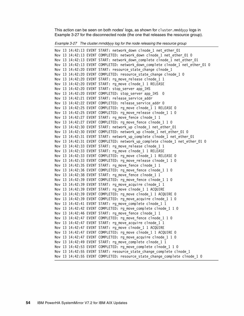
This action can be seen on both nodes’ logs, as shown for cluster.mmddyyy logs in Example 3-27 for the disconnected node (the one that releases the resource group).
Example 3-27 The cluster.mmddyyy log for the node releasing the resource group
Nov 13 14:42:13 EVENT START: network_down clnode_1 net_ether_01Nov 13 14:42:13 EVENT COMPLETED: network_down clnode_1 net_ether_01 0Nov 13 14:42:13 EVENT START: network_down_complete clnode_1 net_ether_01Nov 13 14:42:13 EVENT COMPLETED: network_down_complete clnode_1 net_ether_01 0Nov 13 14:42:20 EVENT START: resource_state_change clnode_1Nov 13 14:42:20 EVENT COMPLETED: resource_state_change clnode_1 0Nov 13 14:42:20 EVENT START: rg_move_release clnode_1 1Nov 13 14:42:20 EVENT START: rg_move clnode_1 1 RELEASENov 13 14:42:20 EVENT START: stop_server app_IHS Nov 13 14:42:20 EVENT COMPLETED: stop_server app_IHS 0Nov 13 14:42:21 EVENT START: release_service_addr Nov 13 14:42:22 EVENT COMPLETED: release_service_addr 0Nov 13 14:42:25 EVENT COMPLETED: rg_move clnode_1 1 RELEASE 0Nov 13 14:42:25 EVENT COMPLETED: rg_move_release clnode_1 1 0Nov 13 14:42:27 EVENT START: rg_move_fence clnode_1 1Nov 13 14:42:27 EVENT COMPLETED: rg_move_fence clnode_1 1 0Nov 13 14:42:30 EVENT START: network_up clnode_1 net_ether_01Nov 13 14:42:30 EVENT COMPLETED: network_up clnode_1 net_ether_01 0Nov 13 14:42:31 EVENT START: network_up_complete clnode_1 net_ether_01Nov 13 14:42:31 EVENT COMPLETED: network_up_complete clnode_1 net_ether_01 0Nov 13 14:42:33 EVENT START: rg_move_release clnode_1 1Nov 13 14:42:33 EVENT START: rg_move clnode_1 1 RELEASENov 13 14:42:33 EVENT COMPLETED: rg_move clnode_1 1 RELEASE 0Nov 13 14:42:33 EVENT COMPLETED: rg_move_release clnode_1 1 0Nov 13 14:42:35 EVENT START: rg_move_fence clnode_1 1Nov 13 14:42:36 EVENT COMPLETED: rg_move_fence clnode_1 1 0Nov 13 14:42:38 EVENT START: rg_move_fence clnode_1 1Nov 13 14:42:39 EVENT COMPLETED: rg_move_fence clnode_1 1 0Nov 13 14:42:39 EVENT START: rg_move_acquire clnode_1 1Nov 13 14:42:39 EVENT START: rg_move clnode_1 1 ACQUIRENov 13 14:42:39 EVENT COMPLETED: rg_move clnode_1 1 ACQUIRE 0Nov 13 14:42:39 EVENT COMPLETED: rg_move_acquire clnode_1 1 0Nov 13 14:42:41 EVENT START: rg_move_complete clnode_1 1Nov 13 14:42:42 EVENT COMPLETED: rg_move_complete clnode_1 1 0Nov 13 14:42:46 EVENT START: rg_move_fence clnode_1 1Nov 13 14:42:47 EVENT COMPLETED: rg_move_fence clnode_1 1 0Nov 13 14:42:47 EVENT START: rg_move_acquire clnode_1 1Nov 13 14:42:47 EVENT START: rg_move clnode_1 1 ACQUIRENov 13 14:42:47 EVENT COMPLETED: rg_move clnode_1 1 ACQUIRE 0Nov 13 14:42:47 EVENT COMPLETED: rg_move_acquire clnode_1 1 0Nov 13 14:42:49 EVENT START: rg_move_complete clnode_1 1Nov 13 14:42:53 EVENT COMPLETED: rg_move_complete clnode_1 1 0Nov 13 14:42:55 EVENT START: resource_state_change_complete clnode_1Nov 13 14:42:55 EVENT COMPLETED: resource_state_change_complete clnode_1 0
54 IBM PowerHA SystemMirror V7.2 for IBM AIX Updates

This action is also shown in Example 3-28 for the other node (the one that acquires the resource group).
Example 3-28 The cluster.mmddyyy log for the node acquiring the resource group
Nov 13 14:42:13 EVENT START: network_down clnode_1 net_ether_01Nov 13 14:42:13 EVENT COMPLETED: network_down clnode_1 net_ether_01 0Nov 13 14:42:14 EVENT START: network_down_complete clnode_1 net_ether_01Nov 13 14:42:14 EVENT COMPLETED: network_down_complete clnode_1 net_ether_01 0Nov 13 14:42:20 EVENT START: resource_state_change clnode_1Nov 13 14:42:20 EVENT COMPLETED: resource_state_change clnode_1 0Nov 13 14:42:20 EVENT START: rg_move_release clnode_1 1Nov 13 14:42:20 EVENT START: rg_move clnode_1 1 RELEASENov 13 14:42:20 EVENT COMPLETED: rg_move clnode_1 1 RELEASE 0Nov 13 14:42:20 EVENT COMPLETED: rg_move_release clnode_1 1 0Nov 13 14:42:27 EVENT START: rg_move_fence clnode_1 1Nov 13 14:42:29 EVENT COMPLETED: rg_move_fence clnode_1 1 0Nov 13 14:42:31 EVENT START: network_up clnode_1 net_ether_01Nov 13 14:42:31 EVENT COMPLETED: network_up clnode_1 net_ether_01 0Nov 13 14:42:31 EVENT START: network_up_complete clnode_1 net_ether_01Nov 13 14:42:31 EVENT COMPLETED: network_up_complete clnode_1 net_ether_01 0Nov 13 14:42:33 EVENT START: rg_move_release clnode_1 1Nov 13 14:42:33 EVENT START: rg_move clnode_1 1 RELEASENov 13 14:42:34 EVENT COMPLETED: rg_move clnode_1 1 RELEASE 0Nov 13 14:42:34 EVENT COMPLETED: rg_move_release clnode_1 1 0Nov 13 14:42:36 EVENT START: rg_move_fence clnode_1 1Nov 13 14:42:36 EVENT COMPLETED: rg_move_fence clnode_1 1 0Nov 13 14:42:39 EVENT START: rg_move_fence clnode_1 1Nov 13 14:42:39 EVENT COMPLETED: rg_move_fence clnode_1 1 0Nov 13 14:42:39 EVENT START: rg_move_acquire clnode_1 1Nov 13 14:42:39 EVENT START: rg_move clnode_1 1 ACQUIRENov 13 14:42:39 EVENT COMPLETED: rg_move clnode_1 1 ACQUIRE 0Nov 13 14:42:39 EVENT COMPLETED: rg_move_acquire clnode_1 1 0Nov 13 14:42:42 EVENT START: rg_move_complete clnode_1 1Nov 13 14:42:45 EVENT COMPLETED: rg_move_complete clnode_1 1 0Nov 13 14:42:47 EVENT START: rg_move_fence clnode_1 1Nov 13 14:42:47 EVENT COMPLETED: rg_move_fence clnode_1 1 0Nov 13 14:42:47 EVENT START: rg_move_acquire clnode_1 1Nov 13 14:42:47 EVENT START: rg_move clnode_1 1 ACQUIRENov 13 14:42:49 EVENT START: acquire_takeover_addr Nov 13 14:42:50 EVENT COMPLETED: acquire_takeover_addr 0Nov 13 14:42:50 EVENT COMPLETED: rg_move clnode_1 1 ACQUIRE 0Nov 13 14:42:50 EVENT COMPLETED: rg_move_acquire clnode_1 1 0Nov 13 14:42:50 EVENT START: rg_move_complete clnode_1 1Nov 13 14:42:50 EVENT START: start_server app_IHSNov 13 14:42:51 EVENT COMPLETED: start_server app_IHS 0Nov 13 14:42:52 EVENT COMPLETED: rg_move_complete clnode_1 1 0Nov 13 14:42:55 EVENT START: resource_state_change_complete clnode_1Nov 13 14:42:55 EVENT COMPLETED: resource_state_change_complete clnode_1 0
Note that neither log includes split_merge_prompt, site_down, or node_down events.
Chapter 3. Planning considerations 55

Loss of all network communication on standby nodeThe loss of all network communication (production/heartbeat and connectivity to NFS server) on the standby node (the node without any online resource groups) triggered the restart of that node, in accordance to the split and merge action plan defined earlier.
As a starting point, both nodes were operational and the resource group was online on node clnode_1 (Example 3-29).
Example 3-29 Cluster nodes and resource group status before simulated network down event
clnode_1:/# clmgr -cva name,state,raw_state query node# NAME:STATE:RAW_STATEclnode_1:NORMAL:ST_STABLEclnode_2:NORMAL:ST_STABLEclnode_1:/#
clnode_1:/# clRGinfo-----------------------------------------------------------------------------Group Name Group State Node-----------------------------------------------------------------------------rg_IHS ONLINE clnode_1@site1 ONLINE SECONDARY clnode_2@site2clnode_1:/#
We performed the following steps:
1. First, we temporarily (not persistent across restart) brought down the network interfaces on the standby node clnode_2, in a terminal console opened using the Hardware Management Console (HMC), as shown in Example 3-30.
Example 3-30 Simulating a network down event
clnode_2:/# ifconfig en0 down; ifconfig en1 downclnode_2:/#
2. Then (in about a minute or less), as a response to the split brain situation, the node clnode_2 (with no communication to the NFS server) rebooted itself. This can be seen on the virtual terminal console opened (using the HMC) on that node, and is also reflected by the status of the cluster nodes (Example 3-31).
Example 3-31 Cluster nodes status immediately after simulated network down event
clnode_1:/# clmgr -cva name,state,raw_state query node# NAME:STATE:RAW_STATEclnode_1:NORMAL:ST_STABLEclnode_2:UNKNOWN:UNKNOWNclnode_1:/#
3. After restart, the node clnode_2 was functional, but with cluster services stopped (Example 3-32).
Example 3-32 Cluster nodes and resource group status after node restart
clnode_1:/# clmgr -cva name,state,raw_state query node# NAME:STATE:RAW_STATEclnode_1:NORMAL:ST_STABLEclnode_2:OFFLINE:ST_INIT
56 IBM PowerHA SystemMirror V7.2 for IBM AIX Updates

clnode_1:/#
clnode_2:/# clRGinfo-----------------------------------------------------------------------------Group Name Group State Node-----------------------------------------------------------------------------rg_IHS ONLINE clnode_1@site1 OFFLINE clnode_2@site2clnode_2:/#
4. We then manually started the services on clnode_2 node (Example 3-33).
Example 3-33 Starting cluster services on the recently rebooted node
clnode_2:/# clmgr start node[...]clnode_2: Completed execution of /usr/es/sbin/cluster/etc/rc.clusterclnode_2: with parameters: -boot -N -A -b -P cl_rc_cluster.clnode_2: Exit status = 0clnode_2:/#
5. Finally, we arrived to the exact initial situation that we had before the simulated network loss event, that is with both nodes operational and the resource group online on node clnode_1 (Example 3-34).
Example 3-34 Cluster nodes and resource group status after cluster services start-up
clnode_2:/# clmgr -cva name,state,raw_state query node# NAME:STATE:RAW_STATEclnode_1:NORMAL:ST_STABLEclnode_2:NORMAL:ST_STABLEclnode_2:/#
clnode_2:/# clRGinfo-----------------------------------------------------------------------------Group Name Group State Node-----------------------------------------------------------------------------rg_IHS ONLINE clnode_1@site1 ONLINE SECONDARY clnode_2@site2clnode_2:/#
Loss of all network communication on active nodeThe loss of all network communication (production/heartbeat and connectivity to NFS server) on the active node (the node with the resource group online) triggered the restart of that node. At the same time, the resource group was independently brought online on the other node.
The test was performed just like the one on the standby node (see “Loss of all network communication on standby node” on page 56) and the process was similar. The only notable difference was that while the previously active node (now disconnected) was restarting, the other node (previously the standby node) was now bringing the resource group online, thus ensuring service availability.
Chapter 3. Planning considerations 57

3.5.6 Log entries for monitoring and debugging
As expected, the usual system and cluster log files contain also information related to the NFS tie breaker events and actions. However, the particular content of these logs varies significantly upon the node that is recording those logs and its role in such an event.
Error report (errpt)The surviving node included log entries as presented (in chronological order, older entries first) in Example 3-35.
Example 3-35 Error report events on the surviving node
LABEL: CONFIGRM_SITE_SPLITDescriptionConfigRM received Site Split event notification
LABEL: CONFIGRM_PENDINGQUODescriptionThe operational quorum state of the active peer domain has changed to PENDING_QUORUM. This state usually indicates that exactly half of the nodes that are defined in the peer domain are online. In this state cluster resources cannot be recovered although none will be stopped explicitly.
LABEL: LVM_GS_RLEAVEDescriptionRemote node Concurrent Volume Group failure detected
LABEL: CONFIGRM_HASQUORUM_DescriptionThe operational quorum state of the active peer domain has changed to HAS_QUORUM.In this state, cluster resources may be recovered and controlled as needed bymanagement applications.
While the disconnected or rebooted node included log entries as presented (again in chronological order, older entries first) in Example 3-36.
Example 3-36 Error report events on the rebooted node
LABEL: CONFIGRM_SITE_SPLITDescriptionConfigRM received Site Split event notification
LABEL: CONFIGRM_PENDINGQUODescriptionThe operational quorum state of the active peer domain has changed to PENDING_QUORUM. This state usually indicates that exactly half of the nodes that are defined in the peer domain are online. In this state cluster resources cannot be recovered although none will be stopped explicitly.
58 IBM PowerHA SystemMirror V7.2 for IBM AIX Updates

LABEL: LVM_GS_RLEAVEDescriptionRemote node Concurrent Volume Group failure detected
LABEL: CONFIGRM_NOQUORUM_EDescriptionThe operational quorum state of the active peer domain has changed to NO_QUORUM.This indicates that recovery of cluster resources can no longer occur and thatthe node may be rebooted or halted in order to ensure that critical resourcesare released so that they can be recovered by another sub-domain that may haveoperational quorum.
LABEL: CONFIGRM_REBOOTOS_EDescriptionThe operating system is being rebooted to ensure that critical resources arestopped so that another sub-domain that has operational quorum may recoverthese resources without causing corruption or conflict.
LABEL: REBOOT_IDDescriptionSYSTEM SHUTDOWN BY USER
LABEL: CONFIGRM_HASQUORUM_DescriptionThe operational quorum state of the active peer domain has changed to HAS_QUORUM.In this state, cluster resources may be recovered and controlled as needed bymanagement applications.
LABEL: CONFIGRM_ONLINE_STDescriptionThe node is online in the domain indicated in the detail data.
Note that the rebooted node’s log includes information relative to the surviving node’s log, and information on the restart event.
Chapter 3. Planning considerations 59

The cluster.mmddyyy log fileFor each split brain situation occurred, the content of cluster.mmddyyy log file was similar on the two nodes. The surviving node’s log entries are presented in Example 3-37.
Example 3-37 The cluster.mmddyyy log entries on the surviving node
Nov 13 13:40:03 EVENT START: split_merge_prompt splitNov 13 13:40:07 EVENT COMPLETED: split_merge_prompt split 0Nov 13 13:40:07 EVENT START: site_down site2Nov 13 13:40:09 EVENT START: site_down_remote site2Nov 13 13:40:09 EVENT COMPLETED: site_down_remote site2 0Nov 13 13:40:09 EVENT COMPLETED: site_down site2 0Nov 13 13:40:09 EVENT START: node_down clnode_2Nov 13 13:40:09 EVENT COMPLETED: node_down clnode_2 0Nov 13 13:40:11 EVENT START: rg_move_release clnode_1 1Nov 13 13:40:11 EVENT START: rg_move clnode_1 1 RELEASENov 13 13:40:11 EVENT COMPLETED: rg_move clnode_1 1 RELEASE 0Nov 13 13:40:11 EVENT COMPLETED: rg_move_release clnode_1 1 0Nov 13 13:40:11 EVENT START: rg_move_fence clnode_1 1Nov 13 13:40:12 EVENT COMPLETED: rg_move_fence clnode_1 1 0Nov 13 13:40:14 EVENT START: node_down_complete clnode_2Nov 13 13:40:14 EVENT COMPLETED: node_down_complete clnode_2 0
The log entries for the same event, but this time on the disconnected or rebooted node, are shown in Example 3-38.
Example 3-38 The cluster.mmddyyy log entries on the rebooted node
Nov 13 13:40:03 EVENT START: split_merge_prompt splitNov 13 13:40:03 EVENT COMPLETED: split_merge_prompt split 0Nov 13 13:40:12 EVENT START: site_down site1Nov 13 13:40:13 EVENT START: site_down_remote site1Nov 13 13:40:13 EVENT COMPLETED: site_down_remote site1 0Nov 13 13:40:13 EVENT COMPLETED: site_down site1 0Nov 13 13:40:13 EVENT START: node_down clnode_1Nov 13 13:40:13 EVENT COMPLETED: node_down clnode_1 0Nov 13 13:40:15 EVENT START: network_down clnode_2 net_ether_01Nov 13 13:40:15 EVENT COMPLETED: network_down clnode_2 net_ether_01 0Nov 13 13:40:15 EVENT START: network_down_complete clnode_2 net_ether_01Nov 13 13:40:15 EVENT COMPLETED: network_down_complete clnode_2 net_ether_01 0Nov 13 13:40:18 EVENT START: rg_move_release clnode_2 1Nov 13 13:40:18 EVENT START: rg_move clnode_2 1 RELEASENov 13 13:40:18 EVENT COMPLETED: rg_move clnode_2 1 RELEASE 0Nov 13 13:40:18 EVENT COMPLETED: rg_move_release clnode_2 1 0Nov 13 13:40:18 EVENT START: rg_move_fence clnode_2 1Nov 13 13:40:19 EVENT COMPLETED: rg_move_fence clnode_2 1 0Nov 13 13:40:21 EVENT START: node_down_complete clnode_1Nov 13 13:40:21 EVENT COMPLETED: node_down_complete clnode_1 0
Note that this log also includes the information about the network_down event.
60 IBM PowerHA SystemMirror V7.2 for IBM AIX Updates

The cluster.log fileThe cluster.log file included much of the information in the cluster.mmddyyy log file. The notable exception was that this one (cluster.log) also included information about the quorum status (losing and regaining quorum). For the disconnected or rebooted node only, the cluster.log file has information about the restart event, as shown in Example 3-39.
Example 3-39 The cluster.log entries on the rebooted node
Nov 13 13:40:03 clnode_2 [...] EVENT START: split_merge_prompt split Nov 13 13:40:03 clnode_2 [...] CONFIGRM_SITE_SPLIT_ST ConfigRM received Site Split event notificationNov 13 13:40:03 clnode_2 [...] EVENT COMPLETED: split_merge_prompt split 0 Nov 13 13:40:09 clnode_2 [...] CONFIGRM_PENDINGQUORUM_ER The operational quorum state of the active peer domain has changed to PENDING_QUORUM. This state usually indicates that exactly half of the nodes that are defined in the peer domain are online. In this state cluster resources cannot be recovered although none will be stopped explicitly.Nov 13 13:40:12 clnode_2 [...] EVENT START: site_down site1 Nov 13 13:40:13 clnode_2 [...] EVENT START: site_down_remote site1 Nov 13 13:40:13 clnode_2 [...] EVENT COMPLETED: site_down_remote site1 0 Nov 13 13:40:13 clnode_2 [...] EVENT COMPLETED: site_down site1 0 Nov 13 13:40:13 clnode_2 [...] EVENT START: node_down clnode_1 Nov 13 13:40:13 clnode_2 [...] EVENT COMPLETED: node_down clnode_1 0 Nov 13 13:40:15 clnode_2 [...] EVENT START: network_down clnode_2 net_ether_01 Nov 13 13:40:15 clnode_2 [...] EVENT COMPLETED: network_down clnode_2 net_ether_01 0 Nov 13 13:40:15 clnode_2 [...] EVENT START: network_down_complete clnode_2 net_ether_01 Nov 13 13:40:16 clnode_2 [...] EVENT COMPLETED: network_down_complete clnode_2 net_ether_01 0 Nov 13 13:40:18 clnode_2 [...] EVENT START: rg_move_release clnode_2 1 Nov 13 13:40:18 clnode_2 [...] EVENT START: rg_move clnode_2 1 RELEASE Nov 13 13:40:18 clnode_2 [...] EVENT COMPLETED: rg_move clnode_2 1 RELEASE 0 Nov 13 13:40:18 clnode_2 [...] EVENT COMPLETED: rg_move_release clnode_2 1 0 Nov 13 13:40:18 clnode_2 [...] EVENT START: rg_move_fence clnode_2 1 Nov 13 13:40:19 clnode_2 [...] EVENT COMPLETED: rg_move_fence clnode_2 1 0 Nov 13 13:40:21 clnode_2 [...] EVENT START: node_down_complete clnode_1 Nov 13 13:40:21 clnode_2 [...] EVENT COMPLETED: node_down_complete clnode_1 0 Nov 13 13:40:29 clnode_2 [...] CONFIGRM_NOQUORUM_ER The operational quorum state of the active peer domain has changed to NO_QUORUM. This indicates that recovery of cluster resources can no longer occur and that the node may be rebooted or halted in order to ensure that critical resources are released so that they can be recovered by another sub-domain that may have operational quorum.Nov 13 13:40:29 clnode_2 [...] CONFIGRM_REBOOTOS_ER The operating system is being rebooted to ensure that critical resources are stopped so that another sub-domain that has operational quorum may recover these resources without causing corruption or conflict.[...]Nov 13 13:41:32 clnode_2 [...] RMCD_INFO_0_ST The daemon is started.Nov 13 13:41:33 clnode_2 [...] CONFIGRM_STARTED_ST IBM.ConfigRM daemon has started. Nov 13 13:42:03 clnode_2 [...] GS_START_ST Group Services daemon started DIAGNOSTIC EXPLANATION HAGS daemon started by SRC. Log file is /var/ct/1Z4w8kYNeHvP2dxgyEaCe2/log/cthags/trace.Nov 13 13:42:36 clnode_2 [...] CONFIGRM_HASQUORUM_ST The operational quorum state of the active peer domain has changed to HAS_QUORUM. In this state, cluster resources may be recovered and controlled as needed by management applications.Nov 13 13:42:36 clnode_2 [...] CONFIGRM_ONLINE_ST The node is online in the domain indicated in the detail data. Peer Domain Name nfs_tiebr_clusterNov 13 13:42:38 clnode_2 [...] STORAGERM_STARTED_ST IBM.StorageRM daemon has started.
Chapter 3. Planning considerations 61

62 IBM PowerHA SystemMirror V7.2 for IBM AIX Updates

Chapter 4. What’s new with IBM Cluster Aware AIX and Reliable Scalable Clustering Technology
This chapter provides details on what is new with IBM Cluster Aware AIX (CAA) and with IBM Reliable Scalable Clustering Technology (RSCT).
This chapter describes the following topics:
� CAA� Automatic repository update for the repository disk� Reliable Scalable Cluster Technology overview� IBM PowerHA, RSCT, and CAA
4
© Copyright IBM Corp. 2016. All rights reserved. 63

4.1 CAA
This section describes in more detail some of the new CAA features.
4.1.1 CAA tunables
This section and other places in this book mention CAA tunables and how they behave. Example 4-1 shows the list of the CAA tunables with IBM AIX V7.2.0.0 and IBM PowerHA V7.2.0. Newer versions can have more tunables, different defaults, or both.
In general, you should never modify these values, because these values are modified and managed by PowerHA.
Example 4-1 List of CAA tunables
# clctrl -tune -aha72cluster(71a0d83c-e467-11e5-8022-4217e0ce7b02).communication_mode = u ha72cluster(71a0d83c-e467-11e5-8022-4217e0ce7b02).config_timeout = 240 ha72cluster(71a0d83c-e467-11e5-8022-4217e0ce7b02).deadman_mode = a ha72cluster(71a0d83c-e467-11e5-8022-4217e0ce7b02).link_timeout = 30000 ha72cluster(71a0d83c-e467-11e5-8022-4217e0ce7b02).local_merge_policy = m ha72cluster(71a0d83c-e467-11e5-8022-4217e0ce7b02).network_fdt = 20000ha72cluster(71a0d83c-e467-11e5-8022-4217e0ce7b02).no_if_traffic_monitor = 0 ha72cluster(71a0d83c-e467-11e5-8022-4217e0ce7b02).node_down_delay = 10000 ha72cluster(71a0d83c-e467-11e5-8022-4217e0ce7b02).node_timeout = 30000 ha72cluster(71a0d83c-e467-11e5-8022-4217e0ce7b02).packet_ttl = 32 ha72cluster(71a0d83c-e467-11e5-8022-4217e0ce7b02).remote_hb_factor = 1 ha72cluster(71a0d83c-e467-11e5-8022-4217e0ce7b02).repos_mode = e ha72cluster(71a0d83c-e467-11e5-8022-4217e0ce7b02).site_merge_policy = p#
4.1.2 What is new in CAA overview
The following new features are included in CAA:
� Automatic Repository Update (ARU)
Also known as Automatic Repository Replacement (ARR) See 4.2, “Automatic repository update for the repository disk” on page 77 for more details.
� Monitor /var usage
See 4.1.3, “Monitoring /var usage” on page 65 for more details.
� New -g option for the lscluster command
See 4.1.4, “New lscluster option -g” on page 67 for more details.
� Interface Failure Detection:
– Tuning for Interface Failure Detection – Send multicast packet to generate incoming traffic – Implementation of network monitor (NETMON) within CAA
See 4.1.5, “Interface failure detection” on page 76 for more Details.
Attention: Do not change any of these tunables without the explicit permission of IBM.
64 IBM PowerHA SystemMirror V7.2 for IBM AIX Updates

� Functional Enhancements
– Reduce dependency of CAA node name on hostname – Roll back on mkcluster failure or partial success
� Reliability, Availability, and Serviceability (RAS) Enhancements
– Message improvements – Several syslog.caa serviceability improvements – Enhanced Dead Man Switch (DMS) error logging
4.1.3 Monitoring /var usage
Starting with PowerHA 7.2 the /var file system is monitored by default. This monitoring is done by the clconfd subsystem. The following default values are used:
Threshold 75% (range 70 - 95)Interval 15 min (range 5 - 30)
To change the default values, use the chssys command. The -t option is used to specify the threshold in % and the -i option is used to specify the interval:
chssys -s clconfd -a "-t 80 -i 10"
To check what values are currently used, you have two options: You can use the ps -ef | grep clconfd or the odmget -q "subsysname='clconfd'" SRCsubsys command. Example 4-2 shows the output of the two commands mentioned before with default values. When using the odmget command, the cmdargs line has no arguments listed. The same happens if ps -ef is used, because there are no arguments displayed after clconfd.
Example 4-2 Check clconfd (when default values are used)
# ps -ef | grep clconfdroot 3713096 3604778 0 17:50:30 - 0:00 /usr/sbin/clconfd
## odmget -q "subsysname='clconfd'" SRCsubsysSRCsubsys:
subsysname = "clconfd" synonym = "" cmdargs = "" path = "/usr/sbin/clconfd" uid = 0 auditid = 0 standin = "/dev/null" standout = "/dev/null" standerr = "/dev/null" action = 1 multi = 0 contact = 2 svrkey = 0 svrmtype = 0 priority = 20 signorm = 2 sigforce = 9 display = 1 waittime = 20 grpname = "caa"
Chapter 4. What’s new with IBM Cluster Aware AIX and Reliable Scalable Clustering Technology 65

Example 4-3 shows what happens when you change the default values, and what the output of the odmget and ps -ef looks like after that change.
Example 4-3 Change monitoring for /var
# chssys -s clconfd -a "-t 80 -i 10" 0513-077 Subsystem has been changed ## stopsrc -s clconfd0513-044 The clconfd Subsystem was requested to stop.## startsrc -s clconfd0513-059 The clconfd Subsystem has been started. Subsystem PID is 13173096.# ps -ef | grep clconfd
root 13173096 3604778 0 17:50:30 - 0:00 /usr/sbin/clconfd -t 80 -i 10## odmget -q "subsysname='clconfd'" SRCsubsys
SRCsubsys: subsysname = "clconfd" synonym = "" cmdargs = "-t 80 -i 10" path = "/usr/sbin/clconfd" uid = 0 auditid = 0 standin = "/dev/null" standout = "/dev/null" standerr = "/dev/null" action = 1 multi = 0 contact = 2 svrkey = 0 svrmtype = 0 priority = 20 signorm = 2 sigforce = 9 display = 1 waittime = 20 grpname = "caa"
Important: You need to stop and start the subsystem to get your changes active.
66 IBM PowerHA SystemMirror V7.2 for IBM AIX Updates

If the threshold is exceeded, then you get an entry in the error log. Example 4-4 shows what such an error entry can look like.
Example 4-4 Error message of /var monitoring
LABEL: CL_VAR_FULLIDENTIFIER: E5899EEB
Date/Time: Fri Nov 13 17:47:15 2015Sequence Number: 1551Machine Id: 00F747C94C00Node Id: esp-c2n1Class: SType: PERMWPAR: GlobalResource Name: CAA (for RSCT)
Description/var filesystem is running low on space
Probable CausesUnknown
Failure CausesUnknown
Recommended Actions RSCT could malfunction if /var gets full Increase the filesystem size or delete unwanted files
Detail DataPercent full
81Percent threshold
80
4.1.4 New lscluster option -g
Starting with AIX V7.1 TL4 and AIX V7.2, there is an additional option for the CAA lscluster command.
The new option -g lists the used communication paths of CAA.
The lscluster -i command lists all of the seen communication paths by CAA but it does not show if all of them can potentially be used for heartbeating. This is particularly the case if you use a network that is set to private, or if you have removed a network from the PowerHA configuration.
Note: At the time this publication was written, this option was not available in AIX versions earlier than AIX V7.1.4.
Chapter 4. What’s new with IBM Cluster Aware AIX and Reliable Scalable Clustering Technology 67

Using all interfacesWhen using the standard way to configure a cluster, all configured networks in AIX are added to the PowerHA and CAA configuration. In our test cluster, we configured two IP interfaces in AIX. Example 4-5 shows the two networks in our PowerHA configuration, all set to public.
Example 4-5 The cllsif command with all interfaces on public
> cllsifAdapter Type Network Net Type Attribute Node IP Address Hardware Address Interface Name Global Name Netmask Alias for HB Prefix Length
n1adm boot adm_net ether public powerha-c2n1 10.17.1.100 en1 255.255.255.0 24powerha-c2n1 boot service_net ether public powerha-c2n1 172.16.150.121 en0 255.255.0.0 16c2svc service service_net ether public powerha-c2n1 172.16.150.125 255.255.0.0 16n2adm boot adm_net ether public powerha-c2n2 10.17.1.110 en1 255.255.255.0 24powerha-c2n2 boot service_net ether public powerha-c2n2 172.16.150.122 en0 255.255.0.0 16c2svc service service_net ether public powerha-c2n2 172.16.150.125 255.255.0.0 16#
In this case, the lscluster -i output looks like that shown in Example 4-6.
Example 4-6 The lscluster -i command (all interfaces on public)
> lscluster -iNetwork/Storage Interface Query
Cluster Name: ha72clusterCluster UUID: 63d12f4e-e61b-11e5-8016-4217e0ce7b02Number of nodes reporting = 2Number of nodes stale = 0Number of nodes expected = 2
Node powerha-c2n1.munich.de.ibm.comNode UUID = 63b68a36-e61b-11e5-8016-4217e0ce7b02Number of interfaces discovered = 3 Interface number 1, en0 IFNET type = 6 (IFT_ETHER) NDD type = 7 (NDD_ISO88023) MAC address length = 6 MAC address = 42:17:E0:CE:7B:02 Smoothed RTT across interface = 0 Mean deviation in network RTT across interface = 0 Probe interval for interface = 990 ms
68 IBM PowerHA SystemMirror V7.2 for IBM AIX Updates

IFNET flags for interface = 0x1E084863 NDD flags for interface = 0x0021081B Interface state = UP Number of regular addresses configured on interface = 1 IPv4 ADDRESS: 172.16.150.121 broadcast 172.16.255.255 netmask 255.255.0.0 Number of cluster multicast addresses configured on interface = 1 IPv4 MULTICAST ADDRESS: 228.16.150.121 Interface number 2, en1 IFNET type = 6 (IFT_ETHER) NDD type = 7 (NDD_ISO88023) MAC address length = 6 MAC address = 42:17:E0:CE:7B:05 Smoothed RTT across interface = 0 Mean deviation in network RTT across interface = 0 Probe interval for interface = 990 ms IFNET flags for interface = 0x1E084863 NDD flags for interface = 0x0021081B Interface state = UP Number of regular addresses configured on interface = 1 IPv4 ADDRESS: 10.17.1.100 broadcast 10.17.1.255 netmask 255.255.255.0 Number of cluster multicast addresses configured on interface = 1 IPv4 MULTICAST ADDRESS: 228.16.150.121 Interface number 3, dpcom IFNET type = 0 (none) NDD type = 305 (NDD_PINGCOMM) Smoothed RTT across interface = 750 Mean deviation in network RTT across interface = 1500 Probe interval for interface = 22500 ms IFNET flags for interface = 0x00000000 NDD flags for interface = 0x00000009 Interface state = UP RESTRICTED AIX_CONTROLLED
Node powerha-c2n2.munich.de.ibm.comNode UUID = 63b68a86-e61b-11e5-8016-4217e0ce7b02Number of interfaces discovered = 3 Interface number 1, en0 IFNET type = 6 (IFT_ETHER) NDD type = 7 (NDD_ISO88023) MAC address length = 6 MAC address = 42:17:E4:E6:1B:02 Smoothed RTT across interface = 0 Mean deviation in network RTT across interface = 0 Probe interval for interface = 990 ms IFNET flags for interface = 0x1E084863 NDD flags for interface = 0x0021081B Interface state = UP Number of regular addresses configured on interface = 1 IPv4 ADDRESS: 172.16.150.122 broadcast 172.16.255.255 netmask 255.255.0.0 Number of cluster multicast addresses configured on interface = 1 IPv4 MULTICAST ADDRESS: 228.16.150.121 Interface number 2, en1 IFNET type = 6 (IFT_ETHER)
Chapter 4. What’s new with IBM Cluster Aware AIX and Reliable Scalable Clustering Technology 69

NDD type = 7 (NDD_ISO88023) MAC address length = 6 MAC address = 42:17:E4:E6:1B:05 Smoothed RTT across interface = 0 Mean deviation in network RTT across interface = 0 Probe interval for interface = 990 ms IFNET flags for interface = 0x1E084863 NDD flags for interface = 0x0021081B Interface state = UP Number of regular addresses configured on interface = 1 IPv4 ADDRESS: 10.17.1.110 broadcast 10.17.1.255 netmask 255.255.255.0 Number of cluster multicast addresses configured on interface = 1 IPv4 MULTICAST ADDRESS: 228.16.150.121 Interface number 3, dpcom IFNET type = 0 (none) NDD type = 305 (NDD_PINGCOMM) Smoothed RTT across interface = 750 Mean deviation in network RTT across interface = 1500 Probe interval for interface = 22500 ms IFNET flags for interface = 0x00000000 NDD flags for interface = 0x00000009 Interface state = UP RESTRICTED AIX_CONTROLLEDroot@powerha-c2n1:/>
Example 4-7 shows the output of the lscluster -g command. When you compare the output of the lscluster -g command with the lscluster -i command, you should not find any differences. There are no differences because all of the networks are allowed to potentially be used for heartbeat in this example.
Example 4-7 The lscluster -g command output in relation to cllsif output
# > lscluster -gNetwork/Storage Interface Query
Cluster Name: ha72clusterCluster UUID: 63d12f4e-e61b-11e5-8016-4217e0ce7b02Number of nodes reporting = 2Number of nodes stale = 0Number of nodes expected = 2
Node powerha-c2n1.munich.de.ibm.comNode UUID = 63b68a36-e61b-11e5-8016-4217e0ce7b02Number of interfaces discovered = 3 Interface number 1, en0 IFNET type = 6 (IFT_ETHER) NDD type = 7 (NDD_ISO88023) MAC address length = 6 MAC address = 42:17:E0:CE:7B:02 Smoothed RTT across interface = 0 Mean deviation in network RTT across interface = 0 Probe interval for interface = 990 ms IFNET flags for interface = 0x1E084863 NDD flags for interface = 0x0021081B Interface state = UP Number of regular addresses configured on interface = 1 IPv4 ADDRESS: 172.16.150.121 broadcast 172.16.255.255 netmask 255.255.0.0 Number of cluster multicast addresses configured on interface = 1
70 IBM PowerHA SystemMirror V7.2 for IBM AIX Updates

IPv4 MULTICAST ADDRESS: 228.16.150.121 Interface number 2, en1 IFNET type = 6 (IFT_ETHER) NDD type = 7 (NDD_ISO88023) MAC address length = 6 MAC address = 42:17:E0:CE:7B:05 Smoothed RTT across interface = 0 Mean deviation in network RTT across interface = 0 Probe interval for interface = 990 ms IFNET flags for interface = 0x1E084863 NDD flags for interface = 0x0021081B Interface state = UP Number of regular addresses configured on interface = 1 IPv4 ADDRESS: 10.17.1.100 broadcast 10.17.1.255 netmask 255.255.255.0 Number of cluster multicast addresses configured on interface = 1 IPv4 MULTICAST ADDRESS: 228.16.150.121 Interface number 3, dpcom IFNET type = 0 (none) NDD type = 305 (NDD_PINGCOMM) Smoothed RTT across interface = 750 Mean deviation in network RTT across interface = 1500 Probe interval for interface = 22500 ms IFNET flags for interface = 0x00000000 NDD flags for interface = 0x00000009 Interface state = UP RESTRICTED AIX_CONTROLLED
Node powerha-c2n2.munich.de.ibm.comNode UUID = 63b68a86-e61b-11e5-8016-4217e0ce7b02Number of interfaces discovered = 3 Interface number 1, en0 IFNET type = 6 (IFT_ETHER) NDD type = 7 (NDD_ISO88023) MAC address length = 6 MAC address = 42:17:E4:E6:1B:02 Smoothed RTT across interface = 0 Mean deviation in network RTT across interface = 0 Probe interval for interface = 990 ms IFNET flags for interface = 0x1E084863 NDD flags for interface = 0x0021081B Interface state = UP Number of regular addresses configured on interface = 1 IPv4 ADDRESS: 172.16.150.122 broadcast 172.16.255.255 netmask 255.255.0.0 Number of cluster multicast addresses configured on interface = 1 IPv4 MULTICAST ADDRESS: 228.16.150.121 Interface number 2, en1 IFNET type = 6 (IFT_ETHER) NDD type = 7 (NDD_ISO88023) MAC address length = 6 MAC address = 42:17:E4:E6:1B:05 Smoothed RTT across interface = 0 Mean deviation in network RTT across interface = 0 Probe interval for interface = 990 ms IFNET flags for interface = 0x1E084863 NDD flags for interface = 0x0021081B Interface state = UP Number of regular addresses configured on interface = 1 IPv4 ADDRESS: 10.17.1.110 broadcast 10.17.1.255 netmask 255.255.255.0 Number of cluster multicast addresses configured on interface = 1 IPv4 MULTICAST ADDRESS: 228.16.150.121 Interface number 3, dpcom
Chapter 4. What’s new with IBM Cluster Aware AIX and Reliable Scalable Clustering Technology 71

IFNET type = 0 (none) NDD type = 305 (NDD_PINGCOMM) Smoothed RTT across interface = 750 Mean deviation in network RTT across interface = 1500 Probe interval for interface = 22500 ms IFNET flags for interface = 0x00000000 NDD flags for interface = 0x00000009 Interface state = UP RESTRICTED AIX_CONTROLLEDroot@powerha-c2n1:/>
One network set to privateThe following examples in this section describe the lscluster command output when you decided to change one or more networks to private. Example 4-8 shows the starting point for this example. In our testing environment, we changed one network to private.
Example 4-8 The clslif command (private)
# cllsifAdapter Type Network Net Type Attribute Node IP Address Hardware Address Interface Name Global Name Netmask Alias for HB Prefix Length
n1adm service adm_net ether private powerha-c2n1 10.17.1.100 en1 255.255.255.0 24powerha-c2n1 boot service_net ether public powerha-c2n1 172.16.150.121 en0 255.255.0.0 16c2svc service service_net ether public powerha-c2n1 172.16.150.125 255.255.0.0 16n2adm service adm_net ether private powerha-c2n2 10.17.1.110 en1 255.255.255.0 24powerha-c2n2 boot service_net ether public powerha-c2n2 172.16.150.122 en0 255.255.0.0 16c2svc service service_net ether public powerha-c2n2172.16.150.125 255.255.0.016#
Because we did not change the architecture of our cluster, the output of the lscluster -i command is still the same, as shown in Example 4-6 on page 68.
Note: Private networks cannot be used for any services. When you want to use a service IP address, the network must be public.
Remember: You must synchronize your cluster before the change to private is visible in CAA.
72 IBM PowerHA SystemMirror V7.2 for IBM AIX Updates

Example 4-9 shows the lscluster -g command output after the synchronization. If you now compare the output of the lscluster -g command with the lscluster -i command or with the lscluster -g output from the previous example, you see that the entries about en1 (in our example) do not appear any longer. In other words, the list of networks potentially allowed to be used for heartbeat is shorter.
Example 4-9 The lscluster -g command (one private network)
# lscluster -gNetwork/Storage Interface Query
Cluster Name: ha72clusterCluster UUID: 55430510-e6a7-11e5-8035-4217e0ce7b02Number of nodes reporting = 2Number of nodes stale = 0Number of nodes expected = 2
Node powerha-c2n1.munich.de.ibm.comNode UUID = 55284db0-e6a7-11e5-8035-4217e0ce7b02Number of interfaces discovered = 2 Interface number 1, en0 IFNET type = 6 (IFT_ETHER) NDD type = 7 (NDD_ISO88023) MAC address length = 6 MAC address = 42:17:E0:CE:7B:02 Smoothed RTT across interface = 0 Mean deviation in network RTT across interface = 0 Probe interval for interface = 990 ms IFNET flags for interface = 0x1E084863 NDD flags for interface = 0x0021081B Interface state = UP Number of regular addresses configured on interface = 1 IPv4 ADDRESS: 172.16.150.121 broadcast 172.16.255.255 netmask 255.255.0.0 Number of cluster multicast addresses configured on interface = 1 IPv4 MULTICAST ADDRESS: 228.16.150.121 Interface number 2, dpcom IFNET type = 0 (none) NDD type = 305 (NDD_PINGCOMM) Smoothed RTT across interface = 750 Mean deviation in network RTT across interface = 1500 Probe interval for interface = 22500 ms IFNET flags for interface = 0x00000000 NDD flags for interface = 0x00000009 Interface state = UP RESTRICTED AIX_CONTROLLED
Node powerha-c2n2.munich.de.ibm.comNode UUID = 55284df6-e6a7-11e5-8035-4217e0ce7b02Number of interfaces discovered = 2 Interface number 1, en0 IFNET type = 6 (IFT_ETHER) NDD type = 7 (NDD_ISO88023) MAC address length = 6 MAC address = 42:17:E4:E6:1B:02 Smoothed RTT across interface = 0 Mean deviation in network RTT across interface = 0
Chapter 4. What’s new with IBM Cluster Aware AIX and Reliable Scalable Clustering Technology 73

Probe interval for interface = 990 ms IFNET flags for interface = 0x1E084863 NDD flags for interface = 0x0021081B Interface state = UP Number of regular addresses configured on interface = 1 IPv4 ADDRESS: 172.16.150.122 broadcast 172.16.255.255 netmask 255.255.0.0 Number of cluster multicast addresses configured on interface = 1 IPv4 MULTICAST ADDRESS: 228.16.150.121 Interface number 2, dpcom IFNET type = 0 (none) NDD type = 305 (NDD_PINGCOMM) Smoothed RTT across interface = 750 Mean deviation in network RTT across interface = 1500 Probe interval for interface = 22500 ms IFNET flags for interface = 0x00000000 NDD flags for interface = 0x00000009 Interface state = UP RESTRICTED AIX_CONTROLLED#
Remove networks from PowerHA The examples in this section describe the lscluster command output when you remove one or more networks from the list of known networks in PowerHA. Example 4-10 shows the starting point for this example. In our test environment, we removed the adm_net network.
Example 4-10 The cllsif command (removed network)
# cllsifAdapter Type Network Net Type Attribute Node IP Address Hardware Address Interface Name Global Name Netmask Alias for HB Prefix Length
powerha-c2n1 boot service_net ether public powerha-c2n1 172.16.150.121 en0 255.255.0.0 16c2svc service service_net ether public powerha-c2n1 172.16.150.125 255.255.0.0 16powerha-c2n2 boot service_net ether public powerha-c2n2 172.16.150.122 en0 255.255.0.0 16c2svc service service_net ether public powerha-c2n2 172.16.150.125 255.255.0.0 16#
Because we did not change the architecture of our cluster, the output of the lscluster -i command is still the same as listed in Example 4-6 on page 68.
Remember that you must synchronize your cluster before the change to private is visible in CAA.
74 IBM PowerHA SystemMirror V7.2 for IBM AIX Updates

Example 4-11 shows the lscluster -g output after the synchronization. If you now compare the output of the lscluster -g command with the previous lscluster -i command, or with the lscluster -g output in “Using all interfaces” on page 68, you see that the entries about en1 (in our example) do not appear.
When you compare the content of Example 4-11 with the content of Example 4-9 on page 73 in “One network set to private” on page 72, you see that the output of the lscluster -g commands is identical.
Example 4-11 The lscluster -g command output (removed network)
# lscluster -gNetwork/Storage Interface Query
Cluster Name: ha72clusterCluster UUID: 63d12f4e-e61b-11e5-8016-4217e0ce7b02Number of nodes reporting = 2Number of nodes stale = 0Number of nodes expected = 2
Node powerha-c2n1.munich.de.ibm.comNode UUID = 63b68a36-e61b-11e5-8016-4217e0ce7b02Number of interfaces discovered = 2 Interface number 1, en0 IFNET type = 6 (IFT_ETHER) NDD type = 7 (NDD_ISO88023) MAC address length = 6 MAC address = 42:17:E0:CE:7B:02 Smoothed RTT across interface = 0 Mean deviation in network RTT across interface = 0 Probe interval for interface = 990 ms IFNET flags for interface = 0x1E084863 NDD flags for interface = 0x0021081B Interface state = UP Number of regular addresses configured on interface = 1 IPv4 ADDRESS: 172.16.150.121 broadcast 172.16.255.255 netmask 255.255.0.0 Number of cluster multicast addresses configured on interface = 1 IPv4 MULTICAST ADDRESS: 228.16.150.121 Interface number 2, dpcom IFNET type = 0 (none) NDD type = 305 (NDD_PINGCOMM) Smoothed RTT across interface = 750 Mean deviation in network RTT across interface = 1500 Probe interval for interface = 22500 ms IFNET flags for interface = 0x00000000 NDD flags for interface = 0x00000009 Interface state = UP RESTRICTED AIX_CONTROLLED
Node powerha-c2n2.munich.de.ibm.comNode UUID = 63b68a86-e61b-11e5-8016-4217e0ce7b02Number of interfaces discovered = 2 Interface number 1, en0 IFNET type = 6 (IFT_ETHER) NDD type = 7 (NDD_ISO88023) MAC address length = 6
Chapter 4. What’s new with IBM Cluster Aware AIX and Reliable Scalable Clustering Technology 75

MAC address = 42:17:E4:E6:1B:02 Smoothed RTT across interface = 0 Mean deviation in network RTT across interface = 0 Probe interval for interface = 990 ms IFNET flags for interface = 0x1E084863 NDD flags for interface = 0x0021081B Interface state = UP Number of regular addresses configured on interface = 1 IPv4 ADDRESS: 172.16.150.122 broadcast 172.16.255.255 netmask 255.255.0.0 Number of cluster multicast addresses configured on interface = 1 IPv4 MULTICAST ADDRESS: 228.16.150.121 Interface number 2, dpcom IFNET type = 0 (none) NDD type = 305 (NDD_PINGCOMM) Smoothed RTT across interface = 750 Mean deviation in network RTT across interface = 1500 Probe interval for interface = 22500 ms IFNET flags for interface = 0x00000000 NDD flags for interface = 0x00000009 Interface state = UP RESTRICTED AIX_CONTROLLEDroot@powerha-c2n1:/>#
4.1.5 Interface failure detection
PowerHA V7.1 had a fixed latency for network failure detection that was about 5 seconds. In PowerHA V7.2, the default is now 20 seconds. The tunable is named network_fdt.
The self-adjusting network heartbeating behavior (CAA) which was introduced with PowerHA V7.1.0 is still there and still gets used. It has no impact on the network failure detection time.
The network_fdt tunable can be set to zero to maintain the default behavior. The tunable can be set in a range of 5 - 10 seconds less than the node_timeout.
The default recognition time for a network problem is not affected by this tunable. It is 0 for hard failures and 5 seconds for soft failures (since PowerHA V7.1.0). CAA continues to check the network, but it waits until the end of the defined timeout to create a network down event.
For PowerHA nodes, when the effective level of CAA is 4, also known as the 2015 release, CAA automatically sets the network_fdt to 20 seconds and the node_timeout to 30 seconds.
Note: The network_fdt tunable is also available in PowerHA V7.1.3. To get it for your PowerHA V7.1.3 version, you must open a PMR and request the Tunable FDT IFix bundle.
76 IBM PowerHA SystemMirror V7.2 for IBM AIX Updates

Example 4-12 shows how to both check and change the CAA network tunable attribute using the CAA native clctrl command.
Example 4-12 Using clctrl to change CAA network tunable
# clctrl -tune -o network_fdt HA72a_cluster(641d80c2-bd87-11e5-8005-96d75a7c7f02).network_fdt = 20000
# clctrl -tune -o network_fdt=100001 tunable updated on cluster PHA72a_cluster
# clctrl -tune -o network_fdtPHA72a_cluster(641d80c2-bd87-11e5-8005-96d75a7c7f02).network_fdt = 10000
4.2 Automatic repository update for the repository disk
This section discusses the new PowerHA Automatic Repository Update (ARU) feature for the PowerHA repository disk.
4.2.1 Introduction to the automatic repository update
Starting with PowerHA V7.0.0, PowerHA uses a shared disk, called the PowerHA repository disk, for various purposes. The availability of this repository disk is critical to the operation of PowerHA clustering and its nodes. The initial implementation of the repository disk, at PowerHA V7.0.0, did not allow for the operation of PowerHA cluster services if the repository disk failed, making that a single point of failure.
With later versions of PowerHA, features have been added to make the cluster more resilient if there is a PowerHA repository disk failure. The ability to survive a repository disk failure, in addition to the ability to manually replace a repository disk without an outage has increased the resiliency of PowerHA. With PowerHA V7.2.0, a new feature to increase the resiliency further was introduced, and this is called Automatic Repository Update.
If there is an active repository disk failure, the purpose of ARU is to automate the replacement of a PowerHA repository disk, without intervention from a system administrator, and without affecting the active cluster services. All that is needed is to point PowerHA to the backup repository disks to use if there is an active repository disk failure.
If a repository disk fails, PowerHA detects the failure of the active repository disk. At that point, it verifies that the active repository disk is not usable. If the active repository disk is unusable, it attempts to switch to the backup repository disk. If it is successful, then the backup repository disk becomes the active repository disk.
Note: At the time that this publication was written, the only way to find out if CAA level 4 is installed is to use the lscluster -c command. In the output of lscluster -c, check if the AUTO_REPOS_REPLACE is listed for the effective cluster-wide capabilities.
For instance, use the following command:
# lscluster -c | grep "Effective cluster-wide capabilities"Effective cluster-wide capabilities: CAA_NETMON, AUTO_REPOS_REPLACE, HNAME_CHG, UNICAST, IPV6, SITE#
Chapter 4. What’s new with IBM Cluster Aware AIX and Reliable Scalable Clustering Technology 77

4.2.2 Requirements for Automatic Repository Update
The Automatic Repository Update has the following requirements:
� AIX V7.1.4 or AIX V7.2.0.� PowerHA V7.2.0.� The storage used for the backup repository disk has the same requirements as the
primary repository disk.
See the following website for the PowerHA repository disk requirements:
https://www.ibm.com/support/knowledgecenter/#!/SSPHQG_7.1.0/com.ibm.powerha.plangd/ha_plan_repos_disk.htm
4.2.3 Configuring Automatic Repository Update
The configuration of the ARU is automatic when you configure a backup repository disk for PowerHA. Essentially, all you have to do is configure a backup repository disk.
This section shows an example in a 2-site, 2-node cluster. The cluster configuration is similar to the diagram shown in Figure 4-1.
Figure 4-1 Storage example for PowerHA ARU showing linked and backup repository disks
For the purposes of this example, we configure a backup repository disk for each site of this 2-site cluster.
78 IBM PowerHA SystemMirror V7.2 for IBM AIX Updates

Configuring a backup repository diskThe following process details how to configure a backup repository disk. For our example, we perform this process for each site in our cluster:
1. Using AIX’s SMIT, run smitty sysmirror and select Cluster Nodes and Networks → Cluster Nodes and Networks → Add a Repository Disk. You are prompted for a site, due to the fact that our example is a 2-site cluster, and then given a selection of possible repository disks. The screen captures in the following sections provide more details.
When you select Add a Repository Disk, you are prompted to select a site, as shown in Example 4-13.
Example 4-13 Selecting “Add a Repository Disk” in multi-site cluster
Manage Repository Disks
Move cursor to desired item and press Enter.
Add a Repository Disk Remove a Repository Disk Show Repository Disks
Verify and Synchronize Cluster Configuration
+--------------------------------------------------------------------------+ | Select a Site | | | | Move cursor to desired item and press Enter. | | | | primary_site1 | | standby_site2 | | | | F1=Help F2=Refresh F3=Cancel | | F8=Image F10=Exit Enter=Do |F1| /=Find n=Find Next |F9+--------------------------------------------------------------------------+
2. After selecting primary_site1, we are shown the repository disk menu (Example 4-14).
Example 4-14 Add a repository disk screen
Add a Repository Disk
Type or select values in entry fields.Press Enter AFTER making all desired changes.
[Entry Fields] Site Name primary_site1* Repository Disk [] +
F1=Help F2=Refresh F3=Cancel F4=ListF5=Reset F6=Command F7=Edit F8=ImageF9=Shell F10=Exit Enter=Do
Chapter 4. What’s new with IBM Cluster Aware AIX and Reliable Scalable Clustering Technology 79

3. Next, press F4 on the Repository Disk field, and you are shown the repository disk selection list, as shown in Example 4-15.
Example 4-15 Backup repository disk selection
Add a Repository Disk
Type or select values in entry fields.Press Enter AFTER making all desired changes. [Entry Fields] Site Name primary_site1* Repository Disk [] +
+--------------------------------------------------------------------------+ | Repository Disk | | | | Move cursor to desired item and press F7. | | ONE OR MORE items can be selected. | | Press Enter AFTER making all selections. | | | | hdisk3 (00f61ab295112078) on all nodes at site primary_site1 | | hdisk4 (00f61ab2a61d5bc6) on all nodes at site primary_site1 | | hdisk5 (00f61ab2a61d5c7e) on all nodes at site primary_site1 | | | | F1=Help F2=Refresh F3=Cancel |F1| F7=Select F8=Image F10=Exit |F5| Enter=Do /=Find n=Find Next |F9+--------------------------------------------------------------------------+
4. After selecting the appropriate disk, the choice is shown in Example 4-16.
Example 4-16 Add a repository disk preview screen
Add a Repository Disk
Type or select values in entry fields.Press Enter AFTER making all desired changes.
[Entry Fields] Site Name primary_site1* Repository Disk [(00f61ab295112078)] +
F1=Help F2=Refresh F3=Cancel F4=ListF5=Reset F6=Command F7=Edit F8=ImageF9=Shell F10=Exit Enter=Do
80 IBM PowerHA SystemMirror V7.2 for IBM AIX Updates

5. Next, after pressing the Enter key to make the changes, the confirmation screen appears, as shown in Example 4-17.
Example 4-17 Backup repository disk addition confirmation screen
COMMAND STATUS
Command: OK stdout: yes stderr: no
Before command completion, additional instructions may appear below.
Successfully added one or more backup repository disks.To view the complete configuration of repository disks use:"clmgr query repository" or "clmgr view report repository"
F1=Help F2=Refresh F3=Cancel F6=CommandF8=Image F9=Shell F10=Exit /=Find
4.2.4 Automatic Repository Update operations
PowerHA ARU operations are automatic when a backup repository disk is configured.
Successful ARU operationAs previously mentioned, ARU operations are automatic when a backup repository disk is defined. Our scenario has a 2-site cluster and a backup repository disk per site.
In order to induce a failure of the primary repository disk, we logged in to the VIOS servers that present storage to the cluster LPARs and deallocate the disk LUN that corresponds to the primary repository disk on one site of our cluster. This disables the primary repository disk, and PowerHA ARU detects the failure and automatically activates the backup repository disk as the active repository disk.
This section presents the following examples used during this process:
1. Before disabling the primary repository disk, we look at the lspv command output and note that the active repository disk is hdisk1, as shown in Example 4-18.
Example 4-18 Output of the lspv command in an example cluster
hdisk0 00f6f5d09570f647 rootvg active hdisk1 00f6f5d0ba49cdcc caavg_private active hdisk2 00f6f5d0a621e9ff None hdisk3 00f61ab2a61d5c7e None hdisk4 00f61ab2a61d5d81 testvg01 concurrent hdisk5 00f61ab2a61d5e5b testvg01 concurrent hdisk6 00f61ab2a61d5f32 testvg01 concurrent
2. We then proceed to log in to the VIOS servers that present the repository disk to this logical partition (LPAR) and de-allocate that logical unit (LUN) so that the cluster LPAR no longer has access to that disk. This causes the primary repository disk to fail.
Chapter 4. What’s new with IBM Cluster Aware AIX and Reliable Scalable Clustering Technology 81

3. At this point, PowerHA ARU detects the failure and activates the backup repository disk as the active repository disk. You can verify this behavior in the syslog.caa log file. This log file logs the ARU activities and shows the detection of the primary repository disk failure, and the activation of the backup repository disk. See Example 4-19.
Example 4-19 The /var/adm/ras/syslog.caa file showing repository disk failure and recovery
Nov 12 09:13:29 primo_s2_n1 caa:info cluster[14025022]: caa_config.c run_list 1377 1 = = END REPLACE_REPOS Op = = POST Stage = =Nov 12 09:13:30 primo_s2_n1 caa:err|error cluster[14025022]: cluster_utils.c cluster_repository_read 5792 1 Could not open cluster repository device /dev/rhdisk1: 5Nov 12 09:13:30 primo_s2_n1 caa:info cluster[14025022]: cluster_utils.c cl_kern_repos_check 11769 1 Could not read the respository.Nov 12 09:13:30 primo_s2_n1 caa:info cluster[14025022]: cluster_utils.c cl_run_log_method 11862 1 START '/usr/sbin/importvg -y caavg_private_t -O hdisk1'Nov 12 09:13:32 primo_s2_n1 caa:info cluster[14025022]: cluster_utils.c cl_run_log_method 11893 1 FINISH return = 1Nov 12 09:13:32 primo_s2_n1 caa:info cluster[14025022]: cluster_utils.c cl_run_log_method 11862 1 START '/usr/sbin/reducevg -df caavg_private_t hdisk1'Nov 12 09:13:32 primo_s2_n1 caa:info cluster[14025022]: cluster_utils.c cl_run_log_method 11893 1 FINISH return = 1Nov 12 09:13:33 primo_s2_n1 caa:err|error cluster[14025022]: cluster_utils.c cluster_repository_read 5792 1 Could not open cluster repository device /dev/rhdisk1: 5Nov 12 09:13:33 primo_s2_n1 caa:info cluster[14025022]: cl_chrepos.c destroy_old_repository 344 1 Failed to read repository data.Nov 12 09:13:34 primo_s2_n1 caa:err|error cluster[14025022]: cluster_utils.c cluster_repository_write 5024 1 return = -1, Could not open cluster repository device /dev/rhdisk1: I/O errorNov 12 09:13:34 primo_s2_n1 caa:info cluster[14025022]: cl_chrepos.c destroy_old_repository 350 1 Failed to write repository data.Nov 12 09:13:34 primo_s2_n1 caa:warn|warning cluster[14025022]: cl_chrepos.c destroy_old_repository 358 1 Unable to destroy repository disk hdisk1. Manual intervention is required to clear the disk of cluster identifiers.Nov 12 09:13:34 primo_s2_n1 caa:info cluster[14025022]: cl_chrepos.c automatic_repository_update 2242 1 Replaced hdisk1 with hdisk2Nov 12 09:13:34 primo_s2_n1 caa:info cluster[14025022]: cl_chrepos.c automatic_repository_update 2255 1 FINISH rc = 0Nov 12 09:13:34 primo_s2_n1 caa:info cluster[14025022]: caa_protocols.c recv_protocol_slave 1542 1 Returning from Automatic Repository replacement rc = 0
4. As an extra verification, note that the AIX error log has an entry showing that a successful repository disk replacement has occurred, as shown in Example 4-20.
Example 4-20 AIX error log showing successful repository disk replacement message
LABEL: CL_ARU_PASSEDIDENTIFIER: 92EE81A5
Date/Time: Thu Nov 12 09:13:34 2015Sequence Number: 1344Machine Id: 00F6F5D04C00
82 IBM PowerHA SystemMirror V7.2 for IBM AIX Updates

Node Id: primo_s2_n1Class: HType: INFOWPAR: GlobalResource Name: CAA ARUResource Class: NONEResource Type: NONELocation:
DescriptionAutomatic Repository Update succeeded.
Probable CausesPrimary repository disk was replaced.
Failure CausesA hardware problem prevented local node from accessing primary repository disk.
Recommended Actions Primary repository disk was replaced using backup repository disk.
Detail DataPrimary Disk Infohdisk1 6c1b76e1-3e0a-ff3c-3c43-cb6c3881c3bfReplacement Disk Infohdisk2 5890b139-e987-1451-211e-24ba89e7d1df
At this point, it is safe to remove the failed repository disk and replace it. The replacement disk can become the new backup repository disk by following the steps in “Configuring a backup repository disk” on page 79.
Possible ARU failure situationsNote that some activities can affect the operation of ARU. Specifically, any administrative activity that uses the backup repository disk can affect ARU. If a volume group was previously created on a backup repository disk and this disk was not cleaned up, then ARU cannot operate properly.
In our sample scenario, we completed the following steps:
1. Configure a backup repository disk that previously had an AIX volume group (VG).
2. Export the AIX VG so that the disk did not display a volume group using the AIX command, lspv. However, we did not delete that volume group from the disk, so the disk itself still had that information.
Chapter 4. What’s new with IBM Cluster Aware AIX and Reliable Scalable Clustering Technology 83

3. For our example, we ran the AIX command, lspv. Our backup repository disk is hdisk2. The disk shows a PVID but no volume group, as shown in Example 4-21.
Example 4-21 Output of lspv command in an example cluster showing hdisk2
hdisk0 00f6f5d09570f647 rootvg active hdisk1 00f6f5d0ba49cdcc caavg_private active hdisk2 00f6f5d0a621e9ff None hdisk3 00f61ab2a61d5c7e None hdisk4 00f61ab2a61d5d81 testvg01 concurrent hdisk5 00f61ab2a61d5e5b testvg01 concurrent hdisk6 00f61ab2a61d5f32 testvg01 concurrent
4. At this point, we disconnected the primary repository disk from the LPAR by going to the VIOS and de-allocating the disk LUN from the cluster LPAR. This made the primary repository disk fail immediately.
At this point, ARU attempted to perform the following actions:
a. Check the primary repository disk that is not accessible.b. Switch to the backup repository disk (but this action failed).
5. We noted that ARU did leave an error message in the AIX error report, as shown in Example 4-22.
Example 4-22 Output of AIX errpt command showing failed repository disk replacement
LABEL: CL_ARU_FAILEDIDENTIFIER: F63D60A2
Date/Time: Wed Nov 11 17:15:17 2015Sequence Number: 1263Machine Id: 00F6F5D04C00Node Id: primo_s2_n1Class: HType: INFOWPAR: GlobalResource Name: CAA ARUResource Class: NONEResource Type: NONELocation:
DescriptionAutomatic Repository Update failed.
Probable CausesUnknown.
Failure CausesUnknown.
Recommended Actions Try manual replacement of cluster repository disk.
Detail DataPrimary Disk Infohdisk1 6c1b76e1-3e0a-ff3c-3c43-cb6c3881c3bf
84 IBM PowerHA SystemMirror V7.2 for IBM AIX Updates

6. In addition, we noted that ARU verified the primary repository disk and failed. This is shown in the CAA log /var/adm/ras/syslog.caa, as shown in Example 4-23.
Example 4-23 Selected messages from /var/adm/ras/syslog.caa log file
Nov 12 09:13:20 primo_s2_n1 caa:info unix: *base_kernext_services.c aha_thread_queue 614 The AHAFS event is EVENT_TYPE=REP_DOWN DISK_NAME=hdisk1 NODE_NUMBER=2 NODE_ID=0xD9DDB48A889411E580106E8DDB7B3702 SITE_NUMBER=2 SITE_ID=0xD9DE2028889411E580106E8DDB7B3702 CLUSTER_ID=0xD34E8658889411E580026E8DDBNov 12 09:13:20 primo_s2_n1 caa:info unix: caa_sock.c caa_kclient_tcp 231 entering caa_kclient_tcp ....Nov 12 09:13:20 primo_s2_n1 caa:info unix: *base_kernext_services.c aha_thread_queue 614 The AHAFS event is EVENT_TYPE=VG_DOWN DISK_NAME=hdisk1 VG_NAME=caavg_private NODE_NUMBER=2 NODE_ID=0xD9DDB48A889411E580106E8DDB7B3702 SITE_NUMBER=2 SITE_ID=0xD9DE2028889411E580106E8DDB7B3702 CLUSTER_ID=0xD34E8Nov 12 09:13:20 primo_s2_n1 caa:info cluster[14025022]: cluster_utils.c cl_run_log_method 11862 1 START '/usr/lib/cluster/caa_syslog 'Nov 12 09:13:20 primo_s2_n1 caa:info unix: kcluster_event.c find_event_disk 742 Find disk called for hdisk4Nov 12 09:13:20 primo_s2_n1 caa:info unix: kcluster_event.c ahafs_Disk_State_register 1504 diskState set opqId = 0xF1000A0150301A00Nov 12 09:13:20 primo_s2_n1 caa:info cluster[14025022]: cluster_utils.c cl_run_log_method 11893 1 FINISH return = 0Nov 12 09:13:20 primo_s2_n1 caa:info cluster[14025022]: caa_message.c inherit_socket_inetd 930 1 IPv6=::ffff:127.0.0.1Nov 12 09:13:20 primo_s2_n1 caa:info cluster[14025022]: cluster_utils.c cl_kern_repos_check 11769 1 Could not read the respository.Nov 12 09:13:20 primo_s2_n1 caa:info cluster[14025022]: caa_message.c cl_recv_req 172 1 recv successful, sock = 0, recv rc = 32, msgbytes = 32Nov 12 09:13:20 primo_s2_n1 caa:info cluster[14025022]: caa_protocols.c recv_protocol_slave 1518 1 Automatic Repository Replacement request being processed.
7. Then we noted that ARU attempted to activate the backup repository disk, but it failed due to the fact that an AIX VG previously existed in this disk, as shown Example 4-24.
Example 4-24 Messages from the /var/adm/ras/syslog.caa log file showing ARU failure
Nov 12 09:11:26 primo_s2_n1 caa:info unix: kcluster_lock.c xcluster_lock 659 xcluster_lock: nodes which responded: 1 0 0 0 0 0 0 0 0 0 0 0 0 0 0 0 0 0 0 0Nov 12 09:11:26 primo_s2_n1 caa:info cluster[8716742]: cluster_utils.c cl_run_log_method 11862 1 START '/usr/sbin/mkvg -y caavg_private_t hdisk2'Nov 12 09:11:26 primo_s2_n1 caa:info cluster[8716742]: cluster_utils.c cl_run_log_method 11893 1 FINISH return = 1Nov 12 09:11:26 primo_s2_n1 caa:err|error cluster[8716742]: cl_chrepos.c check_disk_add 2127 1 hdisk2 contains an existing vg.Nov 12 09:11:26 primo_s2_n1 caa:info cluster[8716742]: cl_chrepos.c automatic_repository_update 2235 1 Failure to move to hdisk2Nov 12 09:11:26 primo_s2_n1 caa:info cluster[8716742]: cl_chrepos.c automatic_repository_update 2255 1 FINISH rc = -1Nov 12 09:11:26 primo_s2_n1 caa:info cluster[8716742]: caa_protocols.c recv_protocol_slave 1542 1 Returning from Automatic Repository replacement rc = -1
Chapter 4. What’s new with IBM Cluster Aware AIX and Reliable Scalable Clustering Technology 85

Recovering from a failed ARU eventIn the previous section “Possible ARU failure situations” on page 83, an example was given on what can prevent a successful repository disk replacement using ARU. In order to recover from that failed event, we manually switched the repository disks using the PowerHA SMIT panels.
Complete the following steps:
1. Using AIX’s SMIT, run smitty sysmirror, and select Problem Determination Tools → Replace the Primary Repository Disk. In our sample cluster, we have multiple sites so that a menu is shown to select a site, as shown in Example 4-25.
Example 4-25 Site selection prompt after selecting “Replace the Primary Repository Disk”
Problem Determination Tools
Move cursor to desired item and press Enter.
[MORE...1] View Current State PowerHA SystemMirror Log Viewing and Management Recover From PowerHA SystemMirror Script Failure Recover Resource Group From SCSI Persistent Reserve Error Restore PowerHA SystemMirror Configuration Database from Active Configuration Release Locks Set By Dynamic Reconfiguration Cluster Test Tool +--------------------------------------------------------------------------+ | Select a Site | | | | Move cursor to desired item and press Enter. | | | | primary_site1 | | standby_site2 | | |[M| F1=Help F2=Refresh F3=Cancel | | F8=Image F10=Exit Enter=Do |F1| /=Find n=Find Next |F9+--------------------------------------------------------------------------+
2. In our example, we select standby_site2 and a screen is shown with an option to select the replacement repository disk, as shown in Example 4-26.
Example 4-26 Prompt to select a new repository disk
Select a new repository disk
Type or select values in entry fields.Press Enter AFTER making all desired changes. [Entry Fields] Site Name standby_site2* Repository Disk [] +
F1=Help F2=Refresh F3=Cancel F4=ListF5=Reset F6=Command F7=Edit F8=ImageF9=Shell F10=Exit Enter=Do
86 IBM PowerHA SystemMirror V7.2 for IBM AIX Updates

3. Pressing the F4 key displays the available backup repository disks, as shown in Example 4-27.
Example 4-27 SMIT menu prompting for replacement repository disk
Select a new repository disk
Type or select values in entry fields.Press Enter AFTER making all desired changes.
[Entry Fields] Site Name standby_site2* Repository Disk [] +
+--------------------------------------------------------------------------+ | Repository Disk | | | | Move cursor to desired item and press Enter. | | | | 00f6f5d0ba49cdcc | | | | F1=Help F2=Refresh F3=Cancel |F1| F8=Image F10=Exit Enter=Do |F5| /=Find n=Find Next |F9+--------------------------------------------------------------------------+
4. Selecting the backup repository disk leads to the SMIT panel showing the selected disk, as shown in Example 4-28.
Example 4-28 SMIT panel showing the selected repository disk
Select a new repository disk
Type or select values in entry fields.Press Enter AFTER making all desired changes.
[Entry Fields] Site Name standby_site2* Repository Disk [00f6f5d0ba49cdcc] +
F1=Help F2=Refresh F3=Cancel F4=ListF5=Reset F6=Command F7=Edit F8=ImageF9=Shell F10=Exit Enter=Do
Chapter 4. What’s new with IBM Cluster Aware AIX and Reliable Scalable Clustering Technology 87

5. Last, pressing the Enter key runs the repository disk replacement. After the repository disk has been replaced, the following screen displays, as shown in Example 4-29.
Example 4-29 SMIT panel showing success repository disk replacement
COMMAND STATUS
Command: OK stdout: yes stderr: no
Before command completion, additional instructions may appear below.
chrepos: Successfully modified repository disk or disks.
New repository "hdisk1" (00f6f5d0ba49cdcc) is now active.The configuration must be synchronized to make this change known across the cluster.
F1=Help F2=Refresh F3=Cancel F6=CommandF8=Image F9=Shell F10=Exit /=Findn=Find Next
At this point, it is safe to remove the failed repository disk and replace it. The replacement disk can become the new backup repository disk by following the steps described in “Configuring a backup repository disk” on page 79.
4.3 Reliable Scalable Cluster Technology overview
This section provides an overview of Reliable Scalable Cluster Technology (RSCT), its components, and the communication path between these components. This section also discusses what of it is used by PowerHA. The items described here are not new but are needed for a basic understanding of the PowerHA underlying infrastructure.
4.3.1 What Reliable Scalable Cluster Technology is
Reliable Scalable Cluster Technology (RSCT) is a set of software components that together provide a comprehensive clustering environment for AIX, Linux, Solaris, and Microsoft Windows operating systems. RSCT is the infrastructure used by various IBM products to provide clusters with improved system availability, scalability, and ease of use.
4.3.2 Reliable Scalable Cluster Technology components
This section describes the RSCT components and how they communicate with each other.
Reliable Scalable Cluster Technology components overviewFor a more detailed description of the RSCT components, see the IBM RSCT for AIX: Guide and Reference, SA22-7889 on the following website:
http://www.ibm.com/support/knowledgecenter/SGVKBA
88 IBM PowerHA SystemMirror V7.2 for IBM AIX Updates

The main RSCT components are explained in this section:
� Resource Monitoring and Control (RMC) subsystem
This is the scalable, and reliable backbone of RSCT. RMC runs on a single machine or on each node (operating system image) of a cluster, and provides a common abstraction for the resources of the individual system or the cluster of nodes. You can use RMC for a single system monitoring, or for monitoring nodes in a cluster. However, in a cluster, RMC provides global access to subsystems and resources throughout the cluster, thus providing a single monitoring and management infrastructure for clusters.
� RSCT core resource managers
A resource manager is a software layer between a resource (a hardware or software entity that provides services to some other component) and RMC. A resource manager maps programmatic abstractions in RMC into the actual calls and commands of a resource.
� RSCT cluster security services
This RSCT component provides the security infrastructure that enables RSCT components to authenticate the identity of other parties.
� Group Services subsystem
This RSCT component provides cross-node/process coordination on some cluster configurations.
� Topology Services subsystem
This RSCT component provides node and network failure detection on some cluster configurations.
Communication between RSCT componentsThe RMC subsystem and RSCT core resource managers (RM) are today the only ones that use the RSCT cluster security services. Since the availability of PowerHA V7, RSCT Group Services are able to use Topology Services or CAA. Figure 4-2 on page 90 shows the RSCT components and their relationships.
The RMC application programming interface (API) is the only interface that can be used by applications to exchange data with the RSCT components. RMC manages the RMs and receives data from them. Group Services is a client of RMC. Depending on if PowerHA V7 is installed, it connects to CAA. Otherwise, it connects to the RSCT Topology Services.
Chapter 4. What’s new with IBM Cluster Aware AIX and Reliable Scalable Clustering Technology 89

Figure 4-2 shows RSCT component relationships.
Figure 4-2 RSCT components
RSCT domainsA RSCT management domain is a set of nodes with resources that can be managed and monitored from one of the nodes, which is designated as the management control point (MCP). All other nodes are considered to be managed nodes. Topology Services and Group Services are not used in a management domain. Figure 4-3 shows the high-level architecture of an RSCT management domain.
Figure 4-3 RSCT managed domain (architecture)
90 IBM PowerHA SystemMirror V7.2 for IBM AIX Updates

A RSCT peer domain is a set of nodes that have a consistent knowledge of the existence of each other, and of the resources shared among them. On each node within the peer domain, RMC depends on a core set of cluster services, which include Topology Services, Group Services, and cluster security services. Figure 4-4 shows the high-level architecture of an RSCT peer domain.
Figure 4-4 RSCT peer domain (architecture)
Group Services are used in peer domains. If PowerHA V7 is installed, Topology Services are not used, and CAA is used instead. Otherwise, Topology Services are used too.
Combination of management and peer domainsYou can have a combination of both types of domains (management domain and peer domains).
Figure 4-5 on page 92 shows the high-level architecture for how an RSCT managed domain and RSCT peer domains can be combined. In this example, Node Y is an RSCT management server. You have three nodes as managed nodes (Node A, Node B, and Node C). Node B and Node C are part of an RSCT peer domain.
Chapter 4. What’s new with IBM Cluster Aware AIX and Reliable Scalable Clustering Technology 91

You can have multiple peer domains within a managed domain. A node can be part of a managed domain and a peer domain. A given node can only belong to a single peer domain, as shown in Figure 4-5.
Figure 4-5 Management and peer domain (architecture)
Important: A node can only belong to one RSCT peer domain.
92 IBM PowerHA SystemMirror V7.2 for IBM AIX Updates

Example of a management and a peer domain The example here is extremely simplified. It just shows one Hardware Management Console (HMC) that is managing three LPARS, where two of them are used for a 2-node PowerHA cluster.
In a Power Systems environment, the HMC is always the management server in the RSCT management domain. The LPARs are clients to this server from an RSCT point of view. For instance, this management domain is used to do dynamic LPAR (DLPAR) operations on the different LPARs.
Figure 4-6 shows this simplified setup.
Figure 4-6 Example management and peer domain
RSCT peer domain on Cluster Aware AIX (CAA)When RSCT operates on nodes in a CAA cluster, a peer domain is created that is equivalent to the CAA cluster. This RSCT peer domain presents largely the same set of function to users and software as other peer domains not based on CAA. Consider a peer domain, which is operating without CAA, and autonomously manages and monitors the configuration and liveness of the nodes and interfaces that it comprises.
The peer domain that represents a CAA cluster acquires configuration information and liveness results from CAA. It introduces some differences in the mechanics of peer domain operations, but very few in the view of the peer domain that is available to the users.
Only one CAA cluster can be defined on a set of nodes. Therefore, if a CAA cluster is defined, the peer domain that represents it is the only peer domain that can exist, and it exists and be online for the life of the CAA cluster.
Chapter 4. What’s new with IBM Cluster Aware AIX and Reliable Scalable Clustering Technology 93

Figure 4-7 illustrates the relationship discussed in this section.
Figure 4-7 RSCT peer domain and CAA
When your cluster is configured and synchronized, you can check the RSCT peer domain using the lsrpdomain command. To list the nodes in this peer domain, you can use the command lsrpnode. Example 4-30 shows a sample output of these commands.
The RSCTActiveVersion number of the lsrpdomain output can show a back-level version number. This is the lowest RSCT version that is required by a new joining node. In a PowerHA environment, there is no need to modify this.
The value of yes for MixedVersions just means that you have at least one node with a higher version than the displayed RSCT version. The lsrpdnode command lists the actually used RSCT version by node.
Example 4-30 List RSCT peer domain information
# lsrpdomain Name OpState RSCTActiveVersion MixedVersions TSPort GSPortc2n1_cluster Online 3.1.5.0 Yes 12347 12348# lsrpnode lsrpnodeName OpState RSCTVersionc2n2.munich.de.ibm.com Online 3.2.1.0c2n1.munich.de.ibm.com Online 3.2.1.0#
94 IBM PowerHA SystemMirror V7.2 for IBM AIX Updates

Update the RSCT peer domain versionIf you like, you can upgrade the RSCT version of the RSCT peer domain which is reported by the lsrpdomain command. To do this used the command listed in Example 4-31.
To be clear, doing such an update does not give you any advantages in a PowerHA environment. In fact, if you delete the cluster and then re-create it manually, or by using an existing snapshot of the RSCT peer domain version, you are back to the original version, which was 3.1.5.0 in our example.
Example 4-31 Update RSCT peer domain
# export CT_MANAGEMENT_SCOPE=2; runact -c IBM.PeerDomain \CompleteMigration Options=0#
Check for CAATo do a quick check on the CAA cluster, you can for instance use the lscluster -c command or use the lscluster -m command. Example 4-32 shows an example output of these two commands. For most situations, when you get an output of the lscluster command, CAA is up and running. To be on the safe side, you should use the lscluster -m command.
Example 4-32 shows that in our case CAA is up and running on the local node where we used the lscluster command. But on the remote node CAA was stopped.
To stop CAA, we used the clmgr off node powerha-c2n2 STOP_CAA=yes command.
Example 4-32 The lscluster -c and lscluster -m commands
# lscluster -cCluster Name: c2n1_clusterCluster UUID: d19995ae-8246-11e5-806f-fa37c4c10c20Number of nodes in cluster = 2 Cluster ID for node c2n1.munich.de.ibm.com: 1 Primary IP address for node c2n1.munich.de.ibm.com: 172.16.150.121 Cluster ID for node c2n2.munich.de.ibm.com: 2 Primary IP address for node c2n2.munich.de.ibm.com: 172.16.150.122Number of disks in cluster = 1 Disk = caa_r0 UUID = 12d1d9a1-916a-ceb2-235d-8c2277f53d06 cluster_major = 0 cluster_minor = 1Multicast for site LOCAL: IPv4 228.16.150.121 IPv6 ff05::e410:9679Communication Mode: unicastLocal node maximum capabilities: AUTO_REPOS_REPLACE, HNAME_CHG, UNICAST, IPV6, SITEEffective cluster-wide capabilities: AUTO_REPOS_REPLACE, HNAME_CHG, UNICAST, IPV6, SITE# # lscluster -m | egrep "Node name|State of node" Node name: powerha-c2n1.munich.de.ibm.com State of node: DOWN Node name: powerha-c2n2.munich.de.ibm.com State of node: UP NODE_LOCAL#
Chapter 4. What’s new with IBM Cluster Aware AIX and Reliable Scalable Clustering Technology 95

Peer domain on CAA linked clustersStarting with PowerHA V7.1.2, linked clusters can be used. An RSCT peer domain that operates on linked clusters encompasses all nodes at each site. The nodes that comprise each site cluster are all members of the same peer domain.
Figure 4-8 shows how this looks from an architecture point of view.
Figure 4-8 RSCT peer domain and CAA linked cluster
Example 4-33 shows what the RSCT looks like in our 2-node cluster.
Example 4-33 Output of the lsrpdomain command
# lsrpdomainName OpState RSCTActiveVersion MixedVersions TSPort GSPort primo_s1_n1_cluster Online 3.1.5.0 Yes 12347 12348 # lsrpnodeName OpState RSCTVersion primo_s2_n1 Online 3.2.1.0 primo_s1_n1 Online 3.2.1.0#
Because we have defined each of our nodes to a different site, the lscluster -c command only lists one node. Example 4-34 shows an example output from node 1.
Example 4-34 Output of the lscluster command (node 1)
# lscluster -cCluster Name: primo_s1_n1_clusterCluster UUID: d34e8658-8894-11e5-8002-6e8ddb7b3702Number of nodes in cluster = 2 Cluster ID for node primo_s1_n1: 1 Primary IP address for node primo_s1_n1: 192.168.100.20 Cluster ID for node primo_s2_n1: 2 Primary IP address for node primo_s2_n1: 192.168.100.21Number of disks in cluster = 4 Disk = hdisk2 UUID = 2f1b2492-46ca-eb3b-faf9-87fa7d8274f7 cluster_major = 0 cluster_minor = 1 Disk = UUID = 6c1b76e1-3e0a-ff3c-3c43-cb6c3881c3bf cluster_major = 0 cluster_minor = 2 Disk = hdisk3 UUID = 20d93b0c-97e8-85ee-8b71-b880ccf848b7 cluster_major = 0 cluster_minor = 3
96 IBM PowerHA SystemMirror V7.2 for IBM AIX Updates

Disk = UUID = 5890b139-e987-1451-211e-24ba89e7d1df cluster_major = 0 cluster_minor = 4Multicast for site primary_site1: IPv4 228.168.100.20 IPv6 ff05::e4a8:6414Multicast for site standby_site2: IPv4 228.168.100.21 IPv6 ff05::e4a8:6415Communication Mode: unicastLocal node maximum capabilities: CAA_NETMON, AUTO_REPOS_REPLACE, HNAME_CHG, UNICAST, IPV6, SITEEffective cluster-wide capabilities: CAA_NETMON, AUTO_REPOS_REPLACE, HNAME_CHG, UNICAST, IPV6, SITE#
Example 4-35 shows the output from node 2.
Example 4-35 Output of the lscluster command (node 2)
# lscluster -cCluster Name: primo_s1_n1_clusterCluster UUID: d34e8658-8894-11e5-8002-6e8ddb7b3702Number of nodes in cluster = 2 Cluster ID for node primo_s1_n1: 1 Primary IP address for node primo_s1_n1: 192.168.100.20 Cluster ID for node primo_s2_n1: 2 Primary IP address for node primo_s2_n1: 192.168.100.21Number of disks in cluster = 4 Disk = UUID = 2f1b2492-46ca-eb3b-faf9-87fa7d8274f7 cluster_major = 0 cluster_minor = 1 Disk = UUID = 20d93b0c-97e8-85ee-8b71-b880ccf848b7 cluster_major = 0 cluster_minor = 3 Disk = hdisk2 UUID = 5890b139-e987-1451-211e-24ba89e7d1df cluster_major = 0 cluster_minor = 4 Disk = hdisk1 UUID = 6c1b76e1-3e0a-ff3c-3c43-cb6c3881c3bf cluster_major = 0 cluster_minor = 2Multicast for site standby_site2: IPv4 228.168.100.21 IPv6 ff05::e4a8:6415Multicast for site primary_site1: IPv4 228.168.100.20 IPv6 ff05::e4a8:6414Communication Mode: unicastLocal node maximum capabilities: CAA_NETMON, AUTO_REPOS_REPLACE, HNAME_CHG, UNICAST, IPV6, SITEEffective cluster-wide capabilities: CAA_NETMON, AUTO_REPOS_REPLACE, HNAME_CHG, UNICAST, IPV6, SITE#
Chapter 4. What’s new with IBM Cluster Aware AIX and Reliable Scalable Clustering Technology 97

4.4 IBM PowerHA, RSCT, and CAA
Starting with PowerHA V7.1, instead of the RSCT Topology Service, the CAA component is used in a PowerHA V7 setup. Figure 4-9 shows the connections between PowerHA V7, RSCT, and CAA (mainly the connection from PowerHA to RSCT Group services, and from there to CAA and back, are used). The potential communication to RMC is rarely used.
Figure 4-9 PowerHA, RSCT, CAA overview
4.4.1 Configuring PowerHA, RSCT, and CAA
There is no need to make any configuration RSCT or CAA. You just need to configure or migrate PowerHA, as shown in Figure 4-10 on page 99. To set it up, just use the smitty sysmirror screens or the clmgr command. The different migration processes operate in a similar way.
98 IBM PowerHA SystemMirror V7.2 for IBM AIX Updates

Figure 4-10 Set up PowerHA, RSCT, and CAA
4.4.2 Relationship between PowerHA, RSCT, CAA
This section describes, from a high-level point of view, the relationship between PowerHA, RSCT, and CAA. The intention of this section is to give you a general understanding of what is running in the background. The examples use in this section are based on a 2-node cluster.
In traditional situations, there is no need to use CAA or RSCT commands, because these are all managed by PowerHA.
All PowerHA components are upIn a cluster where the state of PowerHA is up on all nodes, you also have all of the RSCT and CAA services up and running, as shown in Figure 4-11.
Figure 4-11 All cluster services are up
Chapter 4. What’s new with IBM Cluster Aware AIX and Reliable Scalable Clustering Technology 99

To check if the services are up, you can use different commands. In the following examples, we use the clmgr, clRGinfo, lsrpdomain, and lscluster commands. Example 4-36 shows the output of the clmgr and clRGinfo PowerHA commands.
Example 4-36 Check PowerHA when all is up
# clmgr -a state query clusterSTATE="STABLE“# clRGinfo-----------------------------------------------------------------------------Group Name Group State Node-----------------------------------------------------------------------------Test_RG ONLINE CL1_N1 OFFLINE CL1_N2#
To check if RSCT is up and running, use the lsrpdomain command. Example 4-37 shows the output of the command.
Example 4-37 Check for RSCT when all components are running
# lsrpdomainName OpState RSCTActiveVersion MixedVersions TSPort GSPortCL1_N1_cluster Online 3.1.5.0 Yes 12347 12348#
To check if CAA is properly running, we use the lscluster command. You must specify an option when using the lscluster command. We used the option -m in our Example 4-38. In most cases, any other valid option can be used as well. However, to be absolutely sure, you should use the option -m.
In most cases the general behavior is that, when you get a valid output, CAA is running. Otherwise, you get an error message telling you that the Cluster services are not active.
Example 4-38 Check for CAA when all is up
# lscluster -m | egrep "Node name|State of node" Node name: powerha-c2n1 State of node: UP Node name: powerha-c2n2 State of node: UP NODE_LOCAL#
100 IBM PowerHA SystemMirror V7.2 for IBM AIX Updates

One node stopped with UnmanageIn a cluster where the state of PowerHA is up on all Nodes, you also have all of the RSCT and CAA services running, as shown in Figure 3-10 on page 24.
In a cluster where one node is stopped with an Unmanage state, all of the underlying components (RSCT and CAA) need to stay running. Figure 4-12 illustrates what happens when LPAR A is stopped with an Unmanage state.
Figure 4-12 One node where all RGs are unmanaged
The following examples use the same commands as in “All PowerHA components are up” on page 99 to check the status of the different components. Example 4-39 shows the output of the clmgr and clRGinfo PowerHA commands.
Example 4-39 Check PowerHA, one node in state unmanaged
# clmgr -a state query clusterSTATE="WARNING“# clRGinfo-----------------------------------------------------------------------------Group Name Group State Node-----------------------------------------------------------------------------Test_RG UNMANAGED CL1_N1 UNMANAGED CL1_N2#
As expected, the output of the lsrpdomain RSCT command shows that RSCT is still online (see Example 4-40).
Example 4-40 Check RSCT, one node in state unmanaged
# lsrpdomainName OpState RSCTActiveVersion MixedVersions TSPort GSPortCL1_N1_cluster Online 3.1.5.0 Yes 12347 12348#
Chapter 4. What’s new with IBM Cluster Aware AIX and Reliable Scalable Clustering Technology 101

Also as expected, checking for CAA shows that it is up and running, as shown in Example 4-41.
Example 4-41 Check CAA, one node in state unmanaged
# lscluster -m | egrep "Node name|State of node" Node name: powerha-c2n1 State of node: UP Node name: powerha-c2n2 State of node: UP NODE_LOCAL#
PowerHA stopped on all nodesWhen you stop PowerHA on all cluster nodes, then you get a situation as illustrated in Figure 4-13. In this case, PowerHA is stopped on all cluster nodes but RSCT and CAA are still up and running. You have the same situation after a system reboot of all your cluster nodes (assuming that you do not use the automatic startup of PowerHA).
Figure 4-13 PowerHA stopped on all cluster nodes
Again, we use the same commands as in “All PowerHA components are up” on page 99 to check the status of the different components. Example 4-42 shows the output of the PowerHA commands clmgr and clRGinfo.
As expected, the clmgr command shows that PowerHA is offline, and clRGinfo returns an error message.
Example 4-42 Check PowerHA, PowerHA stopped on all cluster nodes
# clmgr -a state query clusterSTATE="OFFLINE“# clRGinfoCluster IPC error: The cluster manager on node CL1_N1 is in ST_INIT or NOT_CONFIGURED state and cannot process the IPC request.#
102 IBM PowerHA SystemMirror V7.2 for IBM AIX Updates

As mentioned previously, the output of the RSCT lsrpdomain command shows that RSCT is still online (Example 4-43).
Example 4-43 Check RSCT, PowerHA stopped on all cluster nodes
# lsrpdomainName OpState RSCTActiveVersion MixedVersions TSPort GSPortCL1_N1_cluster Online 3.1.5.0 Yes 12347 12348#
And as expected, the check for CAA shows that it is running, as shown in Example 4-44.
When RSCT is running, CAA needs to be up as well. Keep in mind that this statement is only true for a PowerHA cluster.
Example 4-44 Check CAA, PowerHA stopped on all cluster nodes
# lscluster -m | egrep "Node name|State of node" Node name: powerha-c2n1 State of node: UP Node name: powerha-c2n2 State of node: UP NODE_LOCAL#
All cluster components are stoppedRemember, by default CAA and RSCT are automatically started as part of an operating system restart (if it is configured by PowerHA).
There are situations when you need to stop all three cluster components, for instance when you need to change the RSCT or CAA code, as shown in Figure 4-14.
For example, to stop all cluster components, use clmgr off cluster STOP_CAA=yes. For more details about starting and stopping CAA, see 4.4.3, “How to start and stop CAA and RSCT” on page 104.
Figure 4-14 All cluster services stopped
Chapter 4. What’s new with IBM Cluster Aware AIX and Reliable Scalable Clustering Technology 103

Example 4-45 shows the status of the cluster with all services stopped. As in the previous examples, we used the clmgr and clRGinfo commands.
Example 4-45 Check PowerHA, all cluster services stopped
# clmgr -a state query clusterSTATE="OFFLINE“root@CL1_N1:/home/root# clRGinfoCluster IPC error: The cluster manager on node CL1_N1 is in ST_INIT or NOT_CONFIGURED state and cannot process the IPC request.#
The lsrpdomain command shows that the RSCT cluster is offline, as shown in Example 4-46.
Example 4-46 Check RSCT, all cluster services stopped
# lsrpdomainName OpState RSCTActiveVersion MixedVersions TSPort GSPortCL1_N1_cluster Offline 3.1.5.0 Yes 12347 12348#
As mentioned in the previous examples, the output of the lscluster command creates an error message in this case, as shown in Example 4-47.
Example 4-47 Check CAA, all cluster services stopped
# lscluster -m lscluster: Cluster services are not active on this node because it has been stopped.#
4.4.3 How to start and stop CAA and RSCT
CAA and RSCT are stopped and started together. As mentioned in the previous section, CAA and RSCT are automatically started as part of an operating system boot (if it is configured by PowerHA).
If you want to stop CAA and RSCT, you must use the clmgr command (at the time this publication was written, SMIT does not support this operation). To stop it, you must use the STOP_CAA=yes argument. This argument can be used for both CAA and RSCT, and the complete cluster or a set of nodes.
Remember that the information when you stopped CAA manually is preserved across an operating system reboot. So if you want to start PowerHA on a node where CAA and RSCT has been stopped deliberately, you must use the START_CAA argument.
To start CAA and RSCT, you can use the clmgr command with the argument START_CAA=yes. Remember that this command also starts PowerHA.
104 IBM PowerHA SystemMirror V7.2 for IBM AIX Updates

Example 4-48 shows how to stop or start CAA and RSCT. Remember that all of these examples stop all three components or start all three components.
Example 4-48 Using clmgr to start and stop CAA, RSCT
To Stop CAA and RSCT:- clmgr off cluster STOP_CAA=yes- clmgr off node system-a STOP_CAA=yes
To Start CAA and RSCT: - clmgr on cluster START_CAA=yes- clmgr on node system-a START_CAA=yes
Starting with AIX V7.1 TL4 or AIX V7.2, you can use the clctrl command to stop or start CAA and RSCT. To stop it, use the -stop option for the clctrl command. Remember that this also stops PowerHA. To start CAA and RSCT, you can use the -start option. If -start is used, only CAA and RSCT are started. To start PowerHA, you must use the clmgr command, or use SMIT afterward.
Chapter 4. What’s new with IBM Cluster Aware AIX and Reliable Scalable Clustering Technology 105

106 IBM PowerHA SystemMirror V7.2 for IBM AIX Updates

Chapter 5. Migration
This chapter covers the most common migration scenarios from IBM PowerHA V6.1 and PowerHA V7.1.x to PowerHA V7.2.
This chapter contains the following topics:
� Migration planning
– PowerHA SystemMirror V7.2.0 requirements– Deprecated features– Migration options– Clmigcheck– Migration matrix to PowerHA SystemMirror V7.2.0
� Migration scenarios from PowerHA V6.1
– PowerHA V6.1 test environment overview– Rolling migration from PowerHA V6.1– Offline migration from PowerHA V6.1– Snapshot migration from PowerHA 7.1.3 to 7.2.0
� Migration scenarios from PowerHA V7
– PowerHA V7.1 test environment overview– Check and document initial stage– Offline migration of PowerHA from 7.1.3 to 7.2.0– Rolling migration of PowerHA from 7.1.3 to 7.2.0– Snapshot migration from PowerHA 7.1.3 to 7.2.0– Non-disruptive migration of PowerHA from 7.1.3 to 7.2.0
5
© Copyright IBM Corp. 2016. All rights reserved. 107

5.1 Migration planning
Proper planning of the migration procedure of existing clusters to IBM PowerHA SystemMirror V7.2.0 is important, in order to minimise both the risk of unexpected turns during migration and the duration of the process itself. The following section describes a set of actions that should be considered when planning the migration of existing PowerHA clusters.
Additional specifics when migrating from PowerHA V6.1, including crucial interim fixes, can be found on the following website:
https://aix.software.ibm.com/aix/ifixes/PHA_Migration/ha_install_mig_fixes.htm
Before beginning the actual migration procedure, always have a contingency plan in case any problems occur. Some general suggestions are as follows:
� Create a backup of rootvg.
In some cases of upgrading PowerHA, depending on the starting point, updating or upgrading the IBM AIX base operating system is also required. Therefore, a good practice is to save your existing rootvg. One method is to create a clone by using alt_disk_copy to another free disk on the system. That way, a simple change to the bootlist and a reboot can easily return the system to the beginning state.
Other options are available, such as mksysb, alt_disk_install, and multibos.
� Save the existing cluster configuration.
Create a cluster snapshot before the migration. By default it is stored in the following directory; make a copy of it and also save a copy from the cluster nodes for extra safety:
/usr/es/sbin/cluster/snapshots
� Save any user-provided scripts.
This most commonly refers to custom events, pre-events and post-events, application controller, and application monitoring scripts.
� Verify, by using the lslpp -h cluster.* command, that the current version of PowerHA is in the COMMIT state and not in the APPLY state. If not, run smit install_commit before you install the most recent software version.
5.1.1 PowerHA SystemMirror V7.2.0 requirements
The following sections list the software and hardware requirements that must be met for migrating to PowerHA SystemMirror V7.2.0.
Software requirementsEnsure that you meet the following software requirements:
� IBM AIX V6 with Technology Level 9 with Service Pack 5, or later� IBM AIX V7 with Technology Level 3 with Service Pack 5, or later� IBM AIX V7 with Technology Level 4 with Service Pack 1, or later� IBM AIX version 7.2 with Service Pack 1, or later
Migrating from PowerHA SystemMirror V6.1 or earlier requires installing these AIX file sets:
� bos.cluster.rte� bos.ahafs� bos.clvm.enh� devices.commom.IBM.storfwork.rte� clic.rte (for secured encryption communication options of clcomd)
108 IBM PowerHA SystemMirror V7.2 for IBM AIX Updates

HardwareThe hardware characteristics are as follows:
� Support is available only for IBM POWER5 technologies and later.� Shared disks for the cluster repository.
Choose an appropriate size. Usually 1 gigabyte (GB) is sufficient for a two-node cluster. Ensure that the storage subsystem that hosts the repository disk is supported. Also, make sure that the adapters and the multipath driver that are used for the connection to the repository disk are supported. The only requirement is for it to be accessible within each site and not across sites.
It is possible to repurpose an existing disk heartbeat device as the cluster repository disk. However, the disk must be clear of any contents other than a PVID.
If you decide to use multicast heartbeating, it must be enabled, and you must ensure that the multicast traffic generated by any of the cluster nodes is properly forwarded by the network infrastructure between all cluster nodes.
HBA/SAN level heartbeatingThough it is a good practice to use as many different heartbeating lines of communication as possible, this is optional. It is only used within a site and not across sites. If wanted, you must have an adapter that has the tme attribute to enable. This typically applies to most 4 gigabit (Gb) and newer FC adapters. However, most converged adapters cannot offer this ability.
5.1.2 Deprecated features
Although this applies to PowerHA V7.1 and later, this list is mostly important when migrating from PowerHA V6.1. If your existing cluster contains any of these features in point 1 - 4, your cluster cannot be migrated until they are removed from the cluster configuration.
1. Internet Protocol address takeover (IPAT) with IP replacement
2. Locally administered address (LAA) for Media Access Control (MAC) hardware address takeover (HWAT)
3. Heartbeat over IP aliases
4. The following IP network types:
– Asynchronous transfer mode (ATM)– Fiber Distributed Data Interface (FDDI)– Token Ring
5. The following point-to-point (non-IP) network types:
– Recommended Standard 232 (RS232)– Target Mode Small Computer Serial Interface (TMSCSI)– Target Mode Serial Storage Architecture (TMSSA)
6. Disk heartbeat (diskhb)
7. Multinode disk heartbeat (mndhb)
8. Two-node configuration assistant
9. Web System Management Interface Tool (WebSMIT), replacing the IBM Systems Director plug-in
Important: PowerHA V7.2 no longer provides IBM Systems Director plug-in.
Chapter 5. Migration 109

5.1.3 Migration options
There are four methods of performing a migration of a PowerHA cluster. Each of them is briefly described in the following list, and in more detail for the corresponding migration scenarios included in this chapter:
Offline A migration method where PowerHA is brought offline on all nodes before performing the software upgrade. During this time, the cluster resource groups are not available.
Rolling A migration method from one PowerHA version to another during which cluster services are stopped one node at a time. That node is upgraded and reintegrated into the cluster before the next node is upgraded. It requires little downtime, mostly for moving the resource groups between nodes to allow each node to be upgraded.
Snapshot A migration method from one PowerHA version to another, during which you take a snapshot of the current cluster configuration, stop cluster services on all nodes, and uninstall the current version of PowerHA. After this, you install the preferred version of SystemMirror, convert the snapshot by running the clconvert_snapshot utility, and finally restore the cluster configuration from the converted snapshot.
Non-disruptive This method is by far the most advised method of migration, whenever possible. As its name implies, the cluster resource groups remain available, and the applications remain functional, during the cluster migration. All cluster nodes are sequentially (one node at a time) brought to an unmanaged state, allowing all resource groups (RGs) on that node to remain operational while cluster services are stopped.
However, this method can generally be used only when applying service packs to the cluster, and not doing major upgrades. This option does not apply when the upgrade of the base operating system is also required, such as when migrating PowerHA to a version later than 7.1.x from an earlier version.
Important: When there are nodes in a cluster running two separate versions of PowerHA, this configuration is considered to be a mixed cluster state. A cluster in this state does not support any configuration changes or synchronization until all of the nodes have been migrated. Be sure to complete either the rolling or non-disruptive migration as soon as possible to ensure stable cluster functionality.
Tip: After Cluster Aware AIX (CAA) is installed, the following line is added to the /etc/syslog.conf file:
*.info /var/adm/ras/syslog.caa rotate size 1m files 10
Be sure to enable verbose logging by adding the following line:
*.debug /tmp/syslog.out rotate size 10m files 10
Then, issue a refresh -s syslogd command. This command provides valuable information if troubleshooting is required.
110 IBM PowerHA SystemMirror V7.2 for IBM AIX Updates
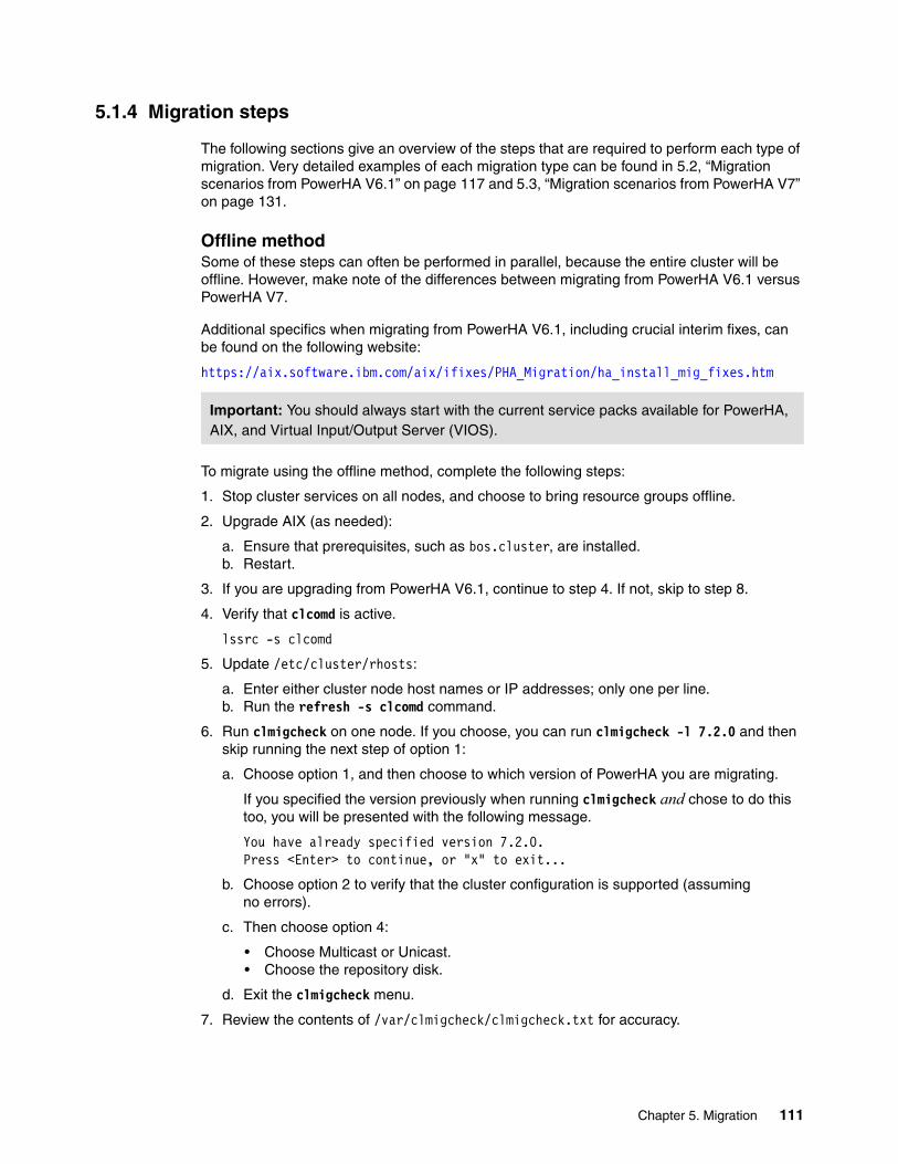
5.1.4 Migration steps
The following sections give an overview of the steps that are required to perform each type of migration. Very detailed examples of each migration type can be found in 5.2, “Migration scenarios from PowerHA V6.1” on page 117 and 5.3, “Migration scenarios from PowerHA V7” on page 131.
Offline methodSome of these steps can often be performed in parallel, because the entire cluster will be offline. However, make note of the differences between migrating from PowerHA V6.1 versus PowerHA V7.
Additional specifics when migrating from PowerHA V6.1, including crucial interim fixes, can be found on the following website:
https://aix.software.ibm.com/aix/ifixes/PHA_Migration/ha_install_mig_fixes.htm
To migrate using the offline method, complete the following steps:
1. Stop cluster services on all nodes, and choose to bring resource groups offline.
2. Upgrade AIX (as needed):
a. Ensure that prerequisites, such as bos.cluster, are installed.b. Restart.
3. If you are upgrading from PowerHA V6.1, continue to step 4. If not, skip to step 8.
4. Verify that clcomd is active.
lssrc -s clcomd
5. Update /etc/cluster/rhosts:
a. Enter either cluster node host names or IP addresses; only one per line.b. Run the refresh -s clcomd command.
6. Run clmigcheck on one node. If you choose, you can run clmigcheck -l 7.2.0 and then skip running the next step of option 1:
a. Choose option 1, and then choose to which version of PowerHA you are migrating.
If you specified the version previously when running clmigcheck and chose to do this too, you will be presented with the following message.
You have already specified version 7.2.0.Press <Enter> to continue, or "x" to exit...
b. Choose option 2 to verify that the cluster configuration is supported (assuming no errors).
c. Then choose option 4:
• Choose Multicast or Unicast.• Choose the repository disk.
d. Exit the clmigcheck menu.
7. Review the contents of /var/clmigcheck/clmigcheck.txt for accuracy.
Important: You should always start with the current service packs available for PowerHA, AIX, and Virtual Input/Output Server (VIOS).
Chapter 5. Migration 111

8. Upgrade PowerHA:
a. If migrating from PowerHA V6.1, perform this action on only one node.b. If migrating from PowerHA V7.1, you can perform this action on both nodes in parallel
and skip to step 11.
9. Review the /tmp/clconvert.log file.
10.Run clmigcheck and upgrade PowerHA on the remaining node.
When running clmigcheck on each additional node, the menu does not appear, and no further actions are needed. On the last node, it creates the CAA cluster.
11.Restart cluster services.
Rolling methodA rolling migration provides the least amount of downtime by upgrading one node at a time.
Additional specifics when migrating from PowerHA V6.1, including crucial interim fixes, can be found on the following website:
https://aix.software.ibm.com/aix/ifixes/PHA_Migration/ha_install_mig_fixes.htm
To migrate using the rolling method, complete the following steps:
1. Stop cluster services on one node (move resource group as needed).
2. Upgrade AIX (as needed):
a. Ensure that prerequisites, such as bos.cluster, are installed.b. Reboot.
3. If upgrading from PowerHA V6.1, continue to step 4. If not, skip to step 8.
4. Verify that clcomd is active on the downed node:
lssrc -s clcomd
5. Update /etc/cluster/rhosts.
Enter either cluster node host names or IP addresses; only one per line.
6. Run the refresh -s clcomd command.
7. Run clmigcheck on the downed node. If you choose, you can run clmigcheck -l 7.2.0 and then skip running the next step of option 1:
a. Choose option 1, and then choose to which version of PowerHA you are migrating.
If you specified the version previously when running clmigcheck and choose to do this too, you will be presented with the following message.
You have already specified version 7.2.0.Press <Enter> to continue, or "x" to exit...
b. Choose option 2 to verify that the cluster configuration is supported (assuming no errors).
Important: You should always start with the current service packs available for PowerHA, AIX, and VIOS.
112 IBM PowerHA SystemMirror V7.2 for IBM AIX Updates

c. Then choose option 4.
• Choose the repository disk device to be used for each site.• Choose Multicast or Unicast.
d. Exit the clmigcheck menu.
8. Review contents of /var/clmigcheck/clmigcheck.txt for accuracy.
9. Upgrade PowerHA on the cluster node where clmigcheck was run.
10.Review the /tmp/clconvert.log file.
11.Restart cluster services.
12.Repeat these steps for each node.
When running clmigcheck on each additional node, a menu does not appear, and no further actions are needed. On the last node, it automatically creates the CAA cluster.
Snapshot methodSome of these steps can often be performed in parallel, because the entire cluster will be offline. However, make note of the differences between migrating from PowerHA V6.1 versus PowerHA V7.1.
Additional specifics when migrating from PowerHA V6.1, including crucial interim fixes, can be found on the following website:
https://aix.software.ibm.com/aix/ifixes/PHA_Migration/ha_install_mig_fixes.htm
To migrate using the snapshot method, complete the following steps:
1. Stop cluster services on all nodes, and choose to bring resource groups offline.
2. Create a cluster snapshot.
This step assumes that you have not previously created one. Save copies of it from the cluster.
3. Upgrade AIX (as needed):
a. Ensure that prerequisites are installed, such as bos.cluster.b. Reboot.
4. If upgrading from PowerHA V6.1, continue to step 4. If not, skip to step 9.
5. Verify that clcomd is active:
lssrc -s clcomd
6. Update /etc/cluster/rhosts:
a. Enter either cluster node host names or IP addresses; only one per line.b. Run the refresh -s clcomd command.
7. Run clmigcheck on one node. If you choose, you can run clmigcheck -l 7.2.0 and then skip running the next step of option 1:
a. Choose option 1 and then choose to which version of PowerHA you are migrating.
If you specified the version previously when running clmigcheck and choose to do this too, you will be presented with the following message.
You have already specified version 7.2.0.Press <Enter> to continue, or "x" to exit...
Important: You should always start with the current service packs available for PowerHA, AIX, and VIOS.
Chapter 5. Migration 113

b. Choose option 3.
Select a specific snapshot (from /usr/es/sbin/cluster/snapshots) to verify that the cluster configuration in the snapshot is supported (assuming no errors).
c. Then, choose option 4:
• Choose Multicast or Unicast.• Choose the repository disk.
d. Exit the clmigcheck menu.
Review contents of /var/clmigcheck/clmigcheck.txt for accuracy.
8. Upgrade PowerHA:
a. If you are migrating from PowerHA V6.1, perform this action on only one node.b. If you are migrating from PowerHA V7.1, you can perform the upgrade on both nodes in
parallel and skip to step 12.
9. Review the /tmp/clconvert.log file.
10.Run clmigcheck and upgrade PowerHA on the remaining node.
When running clmigcheck on each additional node, the menu does not appear, and no further actions are needed. On the last node, it creates the CAA cluster.
11.Restart cluster services.
Non-disruptive upgradeThis method applies only when the AIX level is already at appropriate levels to support PowerHA V7.2 (or later). The following steps are to be performed fully on one node:
1. Stop cluster services with unmanage of the resource groups.2. Upgrade PowerHA (update_all).3. Start cluster services with automatic manage of the resource groups.
5.1.5 Clmigcheck
Before migrating to PowerHA version 7, run the clmigcheck program to prepare the cluster for migration.
The program has two functions:
� It validates the current cluster configuration (Object Data Manager (ODM) with option 2 or snapshot with option 3) for migration. If the configuration is not valid, the program notifies you of any unsupported elements. If an error is encountered, it must be corrected or you cannot migrate. If a warning is displayed, such as for disk heartbeat, you can continue.
Important: When you restart cluster services with the Automatic option for managing resource groups, this action invokes one or more application start scripts. Make sure that the application scripts can detect that the application is already running. If they cannot detect this, copy them somewhere for backup, put a dummy blank executable script in their place, and then copy them back after startup.
Important: Make sure that you have the current version of clmigcheck. Consult the technical bulleting and contact support as needed to obtain an interim fix from the following website:
https://ibm.biz/BdXwEc
114 IBM PowerHA SystemMirror V7.2 for IBM AIX Updates

� It prepares for the new cluster by obtaining the disks to be used for the repository disks and multicast address (if chosen).
The clmigcheck program goes through the following stages:
1. Performing the first initial run
When the clmigcheck program runs, it checks whether it has been run before by looking for a /var/clmigcheck/clmigcheck.txt file. If it does exist from a previous run, it displays the message shown in Figure 5-1.
Figure 5-1 The clmigcheck.txt file exists warning
It then checks if the last fix pack, SP15, is installed. Next, it makes a cluster snapshot for recovery purposes. If not, it will display the warning message shown in Figure 5-2.
Figure 5-2 The clmigcheck latest fixes warning
2. Verifying that the cluster configuration is suitable for migration
From the clmigcheck menu, you can select options 2 or 3 to check your existing ODM or snapshot configuration to verify whether the environment is valid for migration. This checks many things, including all of the options in 5.1.2, “Deprecated features” on page 109.
3. Creating the CAA required configuration
After performing option 2 or 3, choose option 4. Option 4 creates the /var/clmigcheck/clmigcheck.txt file with the information entered, and is copied to all nodes in the cluster.
When run on the last node of the cluster to be migrated, the clmigcheck program uses the mkcluster command and passes the cluster parameters from the existing PowerHA cluster, along with the repository disk and multicast address (if applicable).
This appears to be the first node in the cluster to begin the migrationprocess. However, a migration data file from a previous invocation of"clmigcheck" already exists. This file will be overwritten if youcontinue.
Do you want to continue (y/n)? (y)
Warning: PowerHA version 6.1 has been detected, but the current fixlevel is 12. IBM strongly advises that service pack 15 or laterbe installed prior to performing this migration.
Do you want to attempt the migration anyway (n/y)? (n)
Chapter 5. Migration 115

5.1.6 Clmigcheck enhancements
The most recent version of clmigcheck has been enhanced to include additional checks to further maximize the likelihood for a successful migration. These include, but are not limited to, the following enhancements:
� Adds a new verification only flag, -v, to perform most checks without actually getting into the menu and creating a clmigcheck.txt file. This is useful to run well in advance of performing a migration (for example, run the clmigcheck -v).
� Adds a new flag, -l, to specify the target version for migration (for example, clmigcheck -l 7.2.0).
� Adds a new flag, -g, to skip version checking (for example, clmigcheck -g). It is rare that you would ever run this option.
� Verifies that the cluster is in sync.
� Ensures that /etc/cluster/rhosts is properly created.
� Checks if the last PowerHA V6.1 service pack, SP15, is installed.
� Automatically creates a cluster snapshot upon first time/node run.
� Performs additional log and trace capturing by appending clmigcheck.log into clutils.log.
� Changes the backup strategy of existing clmigcheck files to be time and date specific.
� Ensures that CAA logging is enabled in syslog.conf by changing the previous default setting in syslog.conf from info to debug.
� Ensures that the -v flag is not used in the mkcluster command.
� Adds an attribute to specify which version is being migrated to. This is required because it affects which restrictions apply based on the target version. It also shows only the latest version of PowerHA supported based on the AIX level detected.
� Ensures that inetd is active.
� Verifies that both /etc/cluster/locks and cluster0 exist.
� Checks that all critical CAA services exist in the following locations:
– /etc/inetd.conf– /etc/services– /etc/syslog.conf
� Ensures that a CAA cluster does not already exist.
� Includes additional checks for the following IBM High Availability Cluster Multiprocessing (IBM HACMP) deprecated components:
– HACMPsp2 – HACMPx25 – HACMPsna – HACMPcommadapter – HACMPcommlink
� Checks for consistency in persistent host name and communication paths.
� Checks that name resolution in /etc/netsvc.conf is configured to resolve locally first.
� Ensures that no service or persistent address is set to the host name.
116 IBM PowerHA SystemMirror V7.2 for IBM AIX Updates

� Makes the following additions specifically for the repository disk:
– Shows only valid repository candidate disks that are 512 megabytes (MB) in size or more. It will also display their size.
– Also verifies that repository disk candidates are not Oracle Real Application Clusters (RAC) or Oracle Automatic Storage Management (ASM) disks.
– When a repository disk is chosen, it checks to make sure that the no_reserve attribute for reservation_policy is set.
– Attempts to verify that the disk chosen for repository does not have any leftover repository contents on it from being used previously.
� When performing a snapshot migration, the clmigcheck menu now generates a list of available snapshots to choose from, instead of making the user type in a snapshot.
� When performing a snapshot migration, because clmigcheck is run only once, it automatically propagates /etc/cluster/rhosts on all other remote nodes.
� Adds messaging and further clarifies existing messages.
5.1.7 Migration matrix to PowerHA SystemMirror V7.2.0
Table 5-1 shows the migration options between versions of PowerHA.
Table 5-1 Migration matrix table
5.2 Migration scenarios from PowerHA V6.1
This section further details test scenarios used in each of these migrations methods:
� Rolling migration� Snapshot migration� Offline migration
5.2.1 PowerHA V6.1 test environment overview
For the following scenarios we are using a two-node cluster with nodes Jess and Cass. It consists of a single resource group configured in a typical hot-standby configuration.
PowerHA To V6.1 To V7.1.1 To V7.1.2 To V7.1.3 To V7.2.0
From V5.5 R, S, O, Na
a. R=Rolling, S=Snapshot, O=Offline, N=Nondisruptive
Upgrade to PowerHA V6.1 SP15 First
From V6.1 Update to SP15 first then R,S,O are all viable options to V7.x.x
From V7.1.0 Rb,S, O
b. This option is available only if the beginning AIX level is high enough to support the newer version.
Rb,S, O Rb,S, O Rb,S, O
From V7.1.1 R, S, O, Nb R, S, O, Nb R, S, O, Nb
From V7.1.2 R, S, O, Nb R, S, O, Nb
From V7.1.3 R, S, O, Nb
Chapter 5. Migration 117

Our test configuration consisted of the following hardware and software (see Figure 5-3):
� IBM POWER8 S814 with firmware 840� Hardware Management Console (HMC) 840� AIX V7.1.4� PowerHA V6.1 SP15� IBM Storwize V7000
Figure 5-3 PowerHA V6.1 test migration cluster
5.2.2 Rolling migration from PowerHA V6.1
For the rolling migration, we begin with the standby node, Cass.
We performed the following steps:
1. Stop cluster services on node Cass.
This was accomplished by running smitty clstop and choosing the options shown in Figure 5-4 on page 119. After running, the OK response appears quickly. Make sure that the cluster node is in the ST_INIT state. This can be found from the lssrc -ls clstrmgrES|grep state output.
2. Upgrade AIX.
In our scenario we already have supported AIX levels for PowerHA V7.2, and do not need to perform this step. But if you do, a restart will be required before continuing.
Tip: A demonstration of performing a rolling migration from PowerHA V6.1 to PowerHA V7.2 is available at the following website:
https://youtu.be/oaOwZySTIls
118 IBM PowerHA SystemMirror V7.2 for IBM AIX Updates

Figure 5-4 Stopping cluster services
3. Verify that the clcomd daemon is active, as shown in Figure 5-5.
Figure 5-5 Verify that clcomd is active
4. Next, edit the CAA-specific communication file, /etc/cluster/rhosts. You can enter either the host name for each node, or the IP address that resolves to the host name. However, there must be only one entry per line. We entered host names as shown in Figure 5-6.
Figure 5-6 The /etc/cluster/rhosts contents
5. Refresh clcomd by running refresh -s clcomd.
6. Run /usr/sbin/clmigcheck and the menu shown in Figure 5-7 on page 120 displays.
If you choose, you can run clmigcheck -l 7.2.0 and then skip running the next step of option 1.
Important: If you are upgrading to AIX V7.2, ensure that you have PowerHA V7.2 SP1 (or later). Otherwise, at least get interim fix for IV79386 from support, because there is a known issue that will prevent a rolling migration from succeeding.
Also, see the AIX V7.2 release notes regarding IBM Reliable Scalable Cluster Technology (RSCT) file sets when upgrading:
http://www.ibm.com/support/knowledgecenter/ssw_aix_72/com.ibm.aix.rnbase720/rnbase720.htm
Stop Cluster Services
Type or select values in entry fields.Press Enter AFTER making all wanted changes.
[Entry Fields]* Stop now, on system restart or both now + Stop Cluster Services on these nodes [Cass] + BROADCAST cluster shutdown? true +* Select an Action on Resource Groups Bring Resource Groups> +
F1=Help F2=Refresh F3=Cancel F4=ListF5=Reset F6=Command F7=Edit F8=ImageF9=Shell F10=Exit Enter=Do
[root@Cass] /# lssrc -s clcomdSubsystem Group PID Status clcomd caa 3670016 active
[root@Cass] /# vi /etc/cluster/rhostsJessCass
Chapter 5. Migration 119

Figure 5-7 shows the main menu.
Figure 5-7 Clmigcheck main menu
7. First, we choose Option 1 and then choose Option 5, as shown in Figure 5-8. After specifying the PowerHA version level to which we are migrating (7.2.0) and pressing Enter, we are returned back to the main menu.
Figure 5-8 Clmigcheck choosing PowerHA version
8. Because this was a rolling migration, we choose Option 2 and press Enter. In most environments, it is common to have a disk heartbeat network configured. If that is the case, a warning appears.
Attention: During our testing of running clmigcheck, we encountered an error about our /etc/netsvc.conf file containing more than one line, as shown in the following paragraph. We had to remove all of the comment lines from the file on each node for successful execution. This was reported to development as a defect:
## One or more possible problems have been detectedERROR: exactly one “hosts” entry is required in /etc/netsvc.conf on node “Cass”. A value such as the following should be
the only line in /etc/netsvc.conf: hosts = local4,bind4
Or for IPv6 environments: hosts = local6,bind6
------------[ PowerHA SystemMirror Migration Check ]-------------
Please select one of the following options:
1 -> Enter the version you are migrating to.
2 -> Check ODM configuration.
3 -> Check snapshot configuration.
4 -> Enter repository disk and IP addresses.
Select one of the above, "x" to exit, or "h" for help: 1
------------[ PowerHA SystemMirror Migration Check ]-------------
Which version of IBM PowerHA SystemMirror for AIX are you migrating to?
1 -> 7.1.0 2 -> 7.1.1 3 -> 7.1.2 4 -> 7.1.3 5 -> 7.2.0
Select one of the above or "h" for help or "x" to exit: 5
120 IBM PowerHA SystemMirror V7.2 for IBM AIX Updates

This is normal, because it is removed during the last phase of the migration. In our case, because there were no unsupported elements, when you press Enter a message displays to that effect, as shown in Figure 5-9.
Figure 5-9 The clmigcheck disk heartbeat warning
9. After pressing Enter to continue, the panel returns to the main clmigcheck menu shown in Figure 5-7 on page 120. This time, we choose Option 4 and press Enter. We were presented with the options for either Multicast or Unicast. We chose Option 3 for Unicast, as shown in Figure 5-10.
Figure 5-10 The clmigcheck option for Multicast or Unicast
10.Afterward, the menu to select a repository disk displays. In our case, we choose the only 1 GB disk, hdisk2, by choosing Option 4, as shown in Figure 5-11.
Figure 5-11 Clmigcheck choosing repository disk
------------[ PowerHA SystemMirror v7.2.0 Migration Check ]-------------
CONFIG-WARNING: The configuration contains unsupported hardware: Disk Heartbeat network. The PowerHA network name is net_diskhb_01. This will be removed from the configuration during the migration to PowerHA SystemMirror 7.
Press <Enter> to continue...
------------[ PowerHA SystemMirror v7.2.0 Migration Check ]-------------
The ODM has no unsupported elements.
Press <Enter> to continue...
------------[ PowerHA SystemMirror v7.2.0 Migration Check ]-------------
Your cluster can use multicast or unicast messaging for heartbeat.Multicast addresses can be user specified or default (i.e. generated by AIX).Select the message protocol for cluster communications:
1 -> DEFAULT_MULTICAST 2 -> USER_MULTICAST 3 -> UNICAST
Select one of the above or "h" for help or "x" to exit:3
------------[ PowerHA SystemMirror v7.2.0 Migration Check ]-------------
Select the disk to use for the repository:
1 -> 00f92db1df804285 (hdisk5 on Cass), 2 GB 2 -> 00f92db1df804342 (hdisk4 on Cass), 2 GB 3 -> 00f92db1df804414 (hdisk3 on Cass), 2 GB 4 -> 00f92db1df8044d8 (hdisk2 on Cass), 1 GB
Select one of the above or "h" for help or "x" to exit: 4
Chapter 5. Migration 121

After choosing the repository disk, the clmigcheck menu displays the final message that the new version of PowerHA can now be installed, as shown in Figure 5-12.
Figure 5-12 Clmigcheck last message
11.Upgrade PowerHA on node Cass. To upgrade PowerHA, we simply run smitty update_all, as shown in Figure 5-13.
Figure 5-13 Smitty update_all
12.Ensure that the file /usr/es/sbin/cluster/netmon.cf exists, and that it contains at least one pingable IP address, because installation or upgrade of PowerHA file sets can overwrite this file with an empty one. An illustration is shown in Example 5-21 on page 140.
13.Start cluster services on node Cass by running smitty clstart. During the startup, a message displays about cluster verification being skipped because of mixed versions, as shown in Figure 5-14 on page 123.
No further checking is required on this node.You can install the new version of PowerHA SystemMirror.
Update Installed Software to Latest Level (Update All)
Type or select values in entry fields.Press Enter AFTER making all wanted changes.
[TOP] [Entry Fields]* INPUT device / directory for software .* SOFTWARE to update _update_all PREVIEW only? (update operation will NOT occur) no + COMMIT software updates? yes + SAVE replaced files? no + AUTOMATICALLY install requisite software? yes + EXTEND file systems if space needed? yes + VERIFY install and check file sizes? no + DETAILED output? no + Process multiple volumes? yes + ACCEPT new license agreements? yes + Preview new LICENSE agreements? no +
[MORE...6]
F1=Help F2=Refresh F3=Cancel F4=ListF5=Reset F6=Command F7=Edit F8=ImageF9=Shell F10=Exit Enter=Do
Important: Always remember to set ACCEPT new license agreements? to yes.
Important: While in this mixed cluster state, do not make any cluster changes or attempt to synchronize the cluster.
122 IBM PowerHA SystemMirror V7.2 for IBM AIX Updates

Figure 5-14 Verification skipped
14.After starting, validate that the cluster is stable before continuing by running the lssrc -ls clstrmgrES |grep -i state command.
15.Now we repeat the previous steps for node Jess. However, when stopping cluster services, we choose the Move Resource Groups option, as shown in Figure 5-15.
Figure 5-15 Run clstop and move the resource group
16.Upgrade AIX.
In our scenario we already have supported AIX levels for PowerHA V7.2 and do not need to perform this step. But if you do, a restart will be required before continuing.
17.Verify that the clcomd daemon is active, as shown in Figure 5-16.
Figure 5-16 Verify clcomd is active
18.Next, edit the CAA-specific communication file, /etc/cluster/rhosts. You can enter either the host name for each node, or the IP address that resolves to the host name. However, there must be only one entry per line. We entered host names, as shown in Figure 5-17.
Figure 5-17 /etc/cluster/rhosts contents
19.Refresh clcomd by running the refresh -s clcomd command.
Cluster services are running at different levels acrossthe cluster. Verification will not be invoked in this environment.
Starting Cluster Services on node: PHA72bThis may take a few minutes. Please wait...Cass: Nov 25 2015 15:08:33 Starting execution of /usr/es/sbin/cluster/etc/rc.clusterCass: with parameters: -boot -N -A -C interactive -P cl_rc_cluster
Stop Cluster Services
Type or select values in entry fields.Press Enter AFTER making all wanted changes.
[Entry Fields]* Stop now, on system restart or both now + Stop Cluster Services on these nodes [Jess] + BROADCAST cluster shutdown? true +* Select an Action on Resource Groups Move Resource Groups +
[root@Jess] /# lssrc -s clcomdSubsystem Group PID Status clcomd caa 50467008 active
[root@Jess] /# vi /etc/cluster/rhostsJessCass
Chapter 5. Migration 123

20.Run the /usr/sbin/clmigcheck command.
Unlike the first execution, it will not be displayed this time. Rather, the message shown in Figure 5-18 displays.
Figure 5-18 Clmigcheck to create CAA cluster
21.Upon pressing Enter, a confirmation about creating a CAA cluster displays, as shown in Figure 5-19.
Figure 5-19 CAA cluster creation notification
22.Press Enter again and, after successful completion, a message displays to remind you to upgrade PowerHA now, as shown in Figure 5-20.
Figure 5-20 Clmigcheck upgrade PowerHA notification
23.Check for a CAA cluster on both nodes, and that cluster communication mode is Unicast, as shown in Example 5-1.
Example 5-1 Checking the CAA cluster configuration
Cluster Name: Jess_clusterCluster UUID: 6563d404-9479-11e5-8002-96d75a7c7f02Number of nodes in cluster = 2 Cluster ID for node Jess: 1 Primary IP address for node Jess: 10.2.30.91 Cluster ID for node Cass: 2 Primary IP address for node Cass: 10.2.30.92Number of disks in cluster = 1 Disk = hdisk2 UUID = ef446503-eb46-8174-9bdd-15563273ad21 cluster_major = 0 cluster_minor = 1
It appears that this is the last node in this cluster that still needs tobe migrated. All the other nodes have already completed their migration toPowerHA SystemMirror version 7. Please confirm that this is correct, andthen the migration process will be completed by creating an appropriateCAA cluster on the cluster nodes.
** After the successful creation of the CAA cluster, you _MUST_ install SystemMirror version 7 on this node as soon as possible. Until version 7 is installed, communication with remote nodes will not be possible.
Press <Enter> to continue, or "x" to exit...
------------[ PowerHA SystemMirror Migration Check ]-------------
About to configure a 2 node standard CAA cluster, which can take up to 2minutes.
Press <Enter> to continue...
You _MUST_ install the new version of PowerHA SystemMirror now. This nodewill not be able to communicate with the other nodes in the cluster untilSystemMirror v7 is installed on it.
124 IBM PowerHA SystemMirror V7.2 for IBM AIX Updates

Multicast for site LOCAL: IPv4 228.2.30.91 IPv6 ff05::e402:1e5bCommunication Mode: unicastLocal node maximum capabilities: CAA_NETMON, AUTO_REPOS_REPLACE, HNAME_CHG, UNICAST, IPV6, SITEEffective cluster-wide capabilities: CAA_NETMON, AUTO_REPOS_REPLACE, HNAME_CHG, UNICAST, IPV6, SITE
24.Upgrade PowerHA on node Jess. To upgrade PowerHA, run smitty update_all, as shown in Figure 5-13 on page 122.
25.Ensure that the file /usr/es/sbin/cluster/netmon.cf exists, and that is contains at least one pingable IP address, because installation or upgrade of PowerHA file sets can overwrite this file with an empty one. An illustration is shown in Example 5-21 on page 140.
26.Start cluster services on node Jess by running the smitty clstart command.
27.Verify that the cluster has completed the migration on both nodes by checking that cluster_version = 16, as shown in Example 5-2.
Example 5-2 Verifying the migration has completed on both nodes
# clcmd odmget HACMPcluster |grep version cluster_version = 16 cluster_version = 16
#clcmd odmget HACMPnode |grep version |sort -u version = 16
28.Though the migration is completed at this point, remember that the resource is currently running on node Cass. If wanted, move the resource group back to node Jess, as shown in Example 5-3.
Example 5-3 Move resource group back to node Jess
# clmgr move rg demorg node=JessAttempting to move resource group demorg to node Cass.
Waiting for the cluster to process the resource group movement request....
Waiting for the cluster to stabilize.....
Resource group movement successful.Resource group demorg is online on node Cass.
Cluster Name: Jess_cluster
Resource Group Name: demorgNode Group State---------------------------- ---------------Jess ONLINECass OFFLINE
Important: Both nodes must show version=16, or the migration did not complete successfully. If the migration did not complete, call IBM support.
Important: Always test the cluster thoroughly after migrating.
Chapter 5. Migration 125

5.2.3 Offline migration from PowerHA V6.1
For an offline migration, we can perform many of the steps in parallel on all (both) nodes in the cluster. However, this means that a full cluster outage must be planned.
To perform and offline migration, complete the following steps:
1. Stop cluster services on both nodes Jess and Cass.
This was accomplished by running smitty clstop and choosing the options shown in Figure 5-21. After running, the OK response displays quickly. Make sure that the cluster node is in the ST_INIT state. This can be found from the lssrc -ls clstrmgrES|grep state output.
Figure 5-21 Stopping cluster services
2. Upgrade AIX on both nodes.
In our scenario, we already have the supported AIX levels for PowerHA V7.2, and do not need to perform this step. But if you do, a restart will be required before continuing.
Tip: A demo of performing an offline migration from PowerHA V6.1 to PowerHV 7.2 is available on the following website:
https://youtu.be/krX3epDCsPI
Stop Cluster Services
Type or select values in entry fields.Press Enter AFTER making all wanted changes.
[Entry Fields]* Stop now, on system restart or both now + Stop Cluster Services on these nodes [Jess,Cass] + BROADCAST cluster shutdown? true +* Select an Action on Resource Groups Bring Resource Groups> +
F1=Help F2=Refresh F3=Cancel F4=ListF5=Reset F6=Command F7=Edit F8=ImageF9=Shell F10=Exit Enter=Do
Important: If upgrading to AIX 7.2, see the AIX 7.2 release notes regarding RSCT file sets at the following website:
http://www.ibm.com/support/knowledgecenter/ssw_aix_72/com.ibm.aix.rnbase720/rnbase720.htm
126 IBM PowerHA SystemMirror V7.2 for IBM AIX Updates

3. Verify that the clcomd daemon is active on both nodes, as shown in Figure 5-22.
Figure 5-22 Verify clcomd is active
4. Next, edit the CAA-specific communication file, /etc/cluster/rhosts, on both nodes. You can enter either the host name for each node, or the IP address that resolves to the host name. But there must be only one entry per line. We entered host names, as shown in Figure 5-23.
Figure 5-23 The /etc/cluster/rhosts contents
5. Refresh clcomd by running refresh -s clcomd on both nodes.
6. Run clmigcheck on one node. In our case, we ran the command on node Jess.
a. Choose Option 1, as shown in Figure 5-7 on page 120.
b. Choose Option 5 to specify version 7.2.0, as shown in Figure 5-8 on page 120.
c. Choose Option 2 back on the main menu to have the cluster configuration validated.
d. Assuming no errors, Choose Option 4:
i. We then choose Unicast, as shown in Figure 5-10 on page 121.
ii. Next, we choose the repository disk, as shown in Figure 5-11 on page 121.
e. Then, we get the last message, as shown in Figure 5-12 on page 122.
[root@Cass] /# lssrc -s clcomdSubsystem Group PID Status clcomd caa 3670016 active
[root@Jess] /# lssrc -s clcomdSubsystem Group PID Status clcomd caa 50467008 active
[root@Jess] /# vi /etc/cluster/rhostsJessCass
[root@Cass] /# vi /etc/cluster/rhostsJessCass
Attention: During our testing of running clmigcheck, we encountered an error about our /etc/netsvc.conf file containing more than one line, as shown in the following paragraph. We had to remove all of the comment lines from the file on each node for successful execution. This was reported to development as a defect:
## One or more possible problems have been detectedERROR: exactly one “hosts” entry is required in /etc/netsvc.conf on node “Jess”. A value such as the following should be
the only line in /etc/netsvc.conf: hosts = local4,bind4
Or for IPv6 environments: hosts = local6,bind6
Chapter 5. Migration 127

7. Now we upgrade to PowerHA V7.2.0 by running smitty update_all on node Jess.
8. Perform clmigcheck on node Cass.
This will create the CAA cluster after pressing Enter at the message displayed in both Figure 5-18 on page 124 and Figure 5-19 on page 124.
9. Now we upgrade to PowerHA V7.2.0 by running smitty update_all on node Cass.
10.Verify that version numbers show correctly, as shown in Example 5-2 on page 125.
11.Ensure that the file /usr/es/sbin/cluster/netmon.cf exists on all nodes, and that it contains at least one pingable IP address, because installation or upgrade of PowerHA file sets can overwrite this file with an empty one. An illustration is shown in Example 5-21 on page 140.
12.Restart the cluster on both nodes by running the clmgr start cluster command.
5.2.4 Snapshot migration from PowerHA V6.1
For an a snapshot migration we can perform many of the steps in parallel on all (both) nodes in the cluster. However this means that a full cluster outage must be planned.
To perform a snapshot migration, complete the following steps:
1. Stop cluster services on both nodes Jess and Cass.
This was accomplished by running smitty clstop and choosing the options shown in Figure 5-24. After running, the OK response appears quickly. Make sure that the cluster node is in the ST_INIT state.
This can be found from the lssrc -ls clstrmgrES|grep state output.
Figure 5-24 Stopping cluster services
Important: Always test the cluster thoroughly after migrating.
Tip: A demo of performing a snapshot migration from PowerHA V6.1 to PowerHA V7.2 is available at:
https://youtu.be/4tpKBBBlkls
Stop Cluster Services
Type or select values in entry fields.Press Enter AFTER making all wanted changes.
[Entry Fields]* Stop now, on system restart or both now + Stop Cluster Services on these nodes [Jess,Cass] + BROADCAST cluster shutdown? true +* Select an Action on Resource Groups Bring Resource Groups> +
F1=Help F2=Refresh F3=Cancel F4=ListF5=Reset F6=Command F7=Edit F8=ImageF9=Shell F10=Exit Enter=Do
128 IBM PowerHA SystemMirror V7.2 for IBM AIX Updates

2. Create a cluster snapshot. Although clmigcheck creates a snapshot too, we created our own by running smitty cm_add_snap.dialog and completing the options, as shown in Figure 5-25.
Figure 5-25 Creating cluster snapshot
3. Upgrade AIX on both nodes.
In our scenario, we already have the supported AIX levels for PowerHA V7.2, and do not need to perform this step. But if you do, a restart will be required before continuing.
4. Verify that the clcomd daemon is active on both nodes, as shown in Figure 5-26.
Figure 5-26 Verify that clcomd is active
5. Next, edit the CAA-specific communication file, /etc/cluster/rhosts, on both nodes. You can enter either the host name for each node, or the IP address that resolves to the host name. But there must be only one entry per line. We entered host names, as shown in Figure 5-27.
Figure 5-27 The /etc/cluster/rhosts contents
Create a Snapshot of the Cluster Configuration
Type or select values in entry fields.Press Enter AFTER making all wanted changes.
[Entry Fields]* Cluster Snapshot Name [pre72migration] / Custom-Defined Snapshot Methods [] +* Cluster Snapshot Description [61 SP15 cluster]
Important: If upgrading to AIX 7.2, see the AIX 7.2 release notes regarding RSCT file sets on the following website:
http://www.ibm.com/support/knowledgecenter/ssw_aix_72/com.ibm.aix.rnbase720/rnbase720.htm
[root@Cass] /# lssrc -s clcomdSubsystem Group PID Status clcomd caa 3670016 active
[root@Jess] /# lssrc -s clcomdSubsystem Group PID Status clcomd caa 50467008 active
[root@Jess] /# vi /etc/cluster/rhostsJessCass
[root@Cass] /# vi /etc/cluster/rhostsJessCass
Chapter 5. Migration 129

6. Refresh clcomd by running refresh -s clcomd on both nodes.
7. Run clmigcheck on one node. In this case, we ran the command on node Jess.
a. Choose Option 1, as shown in Figure 5-7 on page 120.
b. Choose Option 5 to specify version 7.2.0, as shown in Figure 5-8 on page 120.
c. Choose Option 3 on the main menu to have the cluster snapshot configuration validated. In our case, we choose option 8 for the snapshot that we created, as shown in Figure 5-28.
Figure 5-28 Clmigcheck snapshot selection
d. Assuming no errors, choose Option 4:
i. We then chose Unicast, as shown in Figure 5-10 on page 121.ii. Next, we choose our repository disk, as shown in Figure 5-11 on page 121.
e. Then, we get the last message, as shown in Figure 5-12 on page 122.
8. Next, we uninstall PowerHA 6.1 on both nodes Jess and Cass by running smitty remove on the cluster.*
9. Install PowerHA V7.2.0 by running smitty install_all on node Jess.
10.Perform clmigcheck on node Cass.
This creates the CAA cluster after pressing Enter at the message displayed in both Figure 5-18 on page 124 and Figure 5-19 on page 124.
Attention: During our testing of running clmigcheck we encountered an error about our /etc/netsvc.conf file containing more than one line, as shown below. We had to remove all of the comment lines from the file on each node for successful execution. This was reported to development as a defect:
## One or more possible problems have been detectedERROR: exactly one “hosts” entry is required in /etc/netsvc.conf on node “Jess”. A value such as the following should be
the only line in /etc/netsvc.conf: hosts = local4,bind4
Or for IPv6 environments: hosts = local6,bind6
------------[ PowerHA SystemMirror v7.2.0 Migration Check ]-------------
Select a snapshot:
1 -> 07_30_2014_ClearHA61democluster_autosnap 2 -> 61SP14pre71upgrade 3 -> 713SP2cluster 4 -> HAdb2.1.030800.snapshot 5 -> HAdb2.snapshot 6 -> active.0 7 -> active.1 8 -> pre72migration
Select one of the above or "h" for help or "x" to exit: 8
130 IBM PowerHA SystemMirror V7.2 for IBM AIX Updates

11.Install PowerHA V7.2.0 by running smitty install_all on node Cass.
12.Convert the previously created snapshot:
/usr/es/sbin/cluster/conversion/clconvert_snapshot -v 6.1 -s pre72migration
13.Restore the cluster configuration from the converted snapshot by running smitty cm_apply_snap.select and choosing the snapshot from the pop-up menu. It auto completes the last menu, as shown in Figure 5-29.
Figure 5-29 Restoring the cluster configuration from a snapshot
The restore process automatically synchronizes the cluster.
14.Ensure that the file /usr/es/sbin/cluster/netmon.cf exists on all nodes, and that is contains at least one pingable IP address, because installation or upgrade of the PowerHA file sets can overwrite this file with an empty one. An illustration is shown in Example 5-21 on page 140.
15.Restart the cluster on both nodes by running clmgr start cluster.
5.3 Migration scenarios from PowerHA V7
This section further details test scenarios used in each of these migration methods:
� Rolling migration� Snapshot migration� Offline migration� Non-disruptive migration
5.3.1 PowerHA V7.1 test environment overview
The cluster environment used for our migration scenarios presented the following features:
� Two cluster nodes both with AIX 7.1.3 SP5� PowerHA installed in the following versions as starting point for migrations:
– PowerHA 7.1.1 SP1– PowerHA 7.1.2 SP1– PowerHA 7.1.3 GA
� One network common to both nodes� One cluster disk, for the resource group
Restore the Cluster Snapshot
Type or select values in entry fields.Press Enter AFTER making all wanted changes.
[Entry Fields] Cluster Snapshot Name pre72migration> Cluster Snapshot Description 61 SP15 cluster> Un/Configure Cluster Resources? [Yes] + Force apply if verify fails? [No] +
Important: Always test the cluster thoroughly after migrating.
Chapter 5. Migration 131

� One repository disk� One resource group, built upon IBM HTTP Server
The diagram for the migration test environment is presented in Figure 5-30.
Figure 5-30 Migration test environment
5.3.2 Check and document initial stage
Before starting the actual migration, we need to make sure that the cluster nodes are synchronized in terms of PowerHA committed file sets and cluster configuration. The following actions are common to all migration scenarios, and therefore generally advised. Many of these actions are not mandatory, but they can help you repair or debug your cluster if things go wrong.
Complete the following initial steps:
1. Get the version of the operating system using the oslevel -s command (node-specific), as shown in Example 5-4.
Example 5-4 Get the AIX version
clnode_1:/# oslevel -s7100-03-05-1524clnode_1:/#
2. Get the version of PowerHA using the halevel -s command (node specific, Example 5-5).
Example 5-5 Get the PowerHA version
clnode_1:/# halevel -s7.1.3 GAclnode_1:/#
132 IBM PowerHA SystemMirror V7.2 for IBM AIX Updates

3. Get the network configuration using the netstat -in command (Example 5-6 limits the query to the en0 network interface).
Example 5-6 Get the network settings
clnode_1:/# netstat -inI en0Name Mtu Network Address Ipkts Ierrs Opkts Oerrs Collen0 1500 link#2 ee.af.e.90.ca.2 44292 0 30506 0 0en0 1500 192.168.100 192.168.100.51 44292 0 30506 0 0clnode_1:/#
4. Get a list of all PowerHA file sets and their current state using the lslpp -l cluster.* command (node specific, Example 5-7).
Example 5-7 Get a list of PowerHA installed fileset and their status
clnode_1:/# lslpp -l cluster.* Fileset Level State Description ----------------------------------------------------------------------------Path: /usr/lib/objrepos cluster.adt.es.client.include 7.1.3.0 COMMITTED PowerHA SystemMirror Client Include Files
[...]cluster.man.en_US.es.data 7.1.3.0 COMMITTED Man Pages - U.S. English
clnode_1:/#
5. Get the general configuration of the CAA cluster using the lscluster -c command (CAA cluster specific, Example 5-8).
Example 5-8 Get the general cluster configuration
clnode_1:/# lscluster -cCluster Name: migration_clusterCluster UUID: 8478eec0-83f2-11e5-98f5-eeaf0e90ca02Number of nodes in cluster = 2 Cluster ID for node clnode_1: 1 Primary IP address for node clnode_1: 192.168.100.51 Cluster ID for node clnode_2: 2 Primary IP address for node clnode_2: 192.168.100.52Number of disks in cluster = 1 Disk = hdisk2 UUID = 89efbf4d-ef62-cc65-c0c3-fca88281da6f cluster_major = 0 cluster_minor = 1Multicast for site LOCAL: IPv4 228.168.100.51 IPv6 ff05::e4a8:6433Communication Mode: unicast[...]clnode_1:/#
Chapter 5. Migration 133

6. Get the list of the CAA cluster storage interfaces using the lscluster -d command (CAA cluster specific, Example 5-9).
Example 5-9 Get the storage cluster configuration
clnode_1:/# lscluster -dStorage Interface Query
Cluster Name: migration_clusterCluster UUID: 8478eec0-83f2-11e5-98f5-eeaf0e90ca02Number of nodes reporting = 2Number of nodes expected = 2
Node clnode_1Node UUID = 8474b378-83f2-11e5-98f5-eeaf0e90ca02Number of disks discovered = 1 hdisk2: State : UP [...] Type : REPDISK
Node clnode_2Node UUID = 8474b3be-83f2-11e5-98f5-eeaf0e90ca02Number of disks discovered = 1 hdisk2: State : UP [...] Type : REPDISKclnode_1:/#
7. Get the list of the CAA cluster network interfaces using the lscluster -i command (CAA cluster specific, Example 5-10).
Example 5-10 Get the network cluster configuration
clnode_1:/# lscluster -iNetwork/Storage Interface Query
Cluster Name: migration_clusterCluster UUID: 8478eec0-83f2-11e5-98f5-eeaf0e90ca02Number of nodes reporting = 2Number of nodes stale = 0Number of nodes expected = 2
Node clnode_1Node UUID = 8474b378-83f2-11e5-98f5-eeaf0e90ca02Number of interfaces discovered = 2 Interface number 1, en0 [...] Interface state = UP Number of regular addresses configured on interface = 1 IPv4 ADDRESS: 192.168.100.51 broadcast 192.168.100.255 netmask 255.255.255.0 Number of cluster multicast addresses configured on interface = 1 IPv4 MULTICAST ADDRESS: 228.168.100.51[...]
134 IBM PowerHA SystemMirror V7.2 for IBM AIX Updates

Node clnode_2Node UUID = 8474b3be-83f2-11e5-98f5-eeaf0e90ca02Number of interfaces discovered = 2 Interface number 1, en0 [...] Interface state = UP Number of regular addresses configured on interface = 2 IPv4 ADDRESS: 192.168.100.50 broadcast 192.168.103.255 netmask 255.255.252.0 IPv4 ADDRESS: 192.168.100.52 broadcast 192.168.100.255 netmask 255.255.255.0 Number of cluster multicast addresses configured on interface = 1[...]clnode_1:/#
8. Get the cluster node configuration for the CAA cluster using the lscluster -m command (CAA cluster specific, Example 5-11).
Example 5-11 Get the node cluster configuration
clnode_1:/# lscluster -mCalling node query for all nodes...Node query number of nodes examined: 2
Node name: clnode_1 Cluster shorthand id for node: 1 UUID for node: 8474b378-83f2-11e5-98f5-eeaf0e90ca02 State of node: UP NODE_LOCAL [...] Points of contact for node: 0
----------------------------------------------------------------------------
Node name: clnode_2 Cluster shorthand id for node: 2 UUID for node: 8474b3be-83f2-11e5-98f5-eeaf0e90ca02 State of node: UP [...] Points of contact for node: 1 ----------------------------------------------------------------------- Interface State Protocol Status SRC_IP->DST_IP ----------------------------------------------------------------------- tcpsock->02 UP IPv4 none 192.168.100.51->192.168.100.52clnode_1:/#
Chapter 5. Migration 135
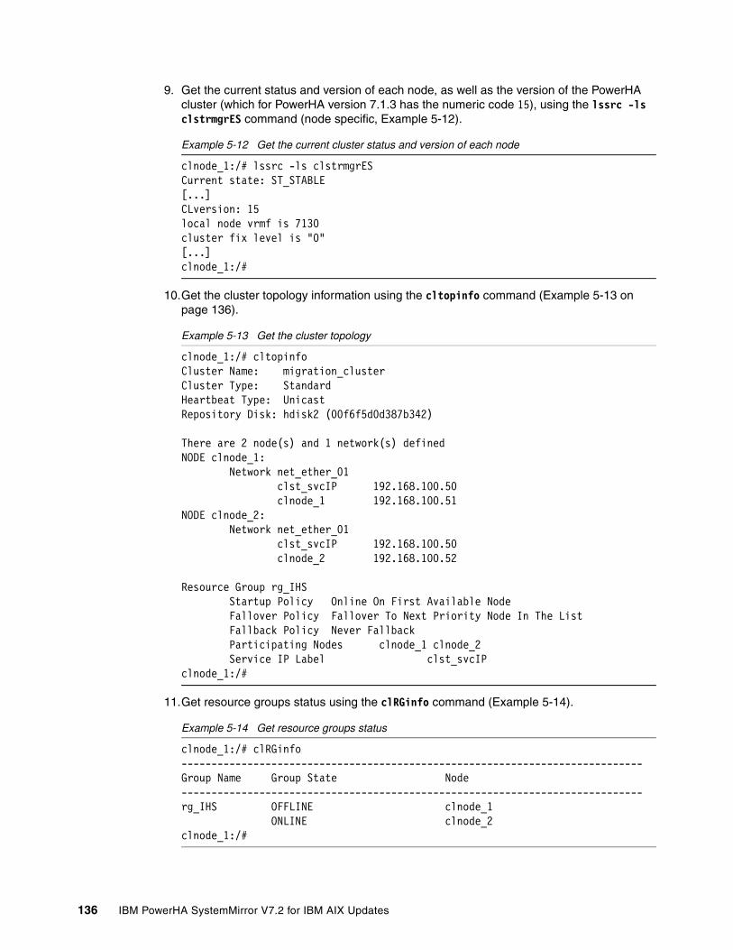
9. Get the current status and version of each node, as well as the version of the PowerHA cluster (which for PowerHA version 7.1.3 has the numeric code 15), using the lssrc -ls clstrmgrES command (node specific, Example 5-12).
Example 5-12 Get the current cluster status and version of each node
clnode_1:/# lssrc -ls clstrmgrESCurrent state: ST_STABLE[...]CLversion: 15local node vrmf is 7130cluster fix level is "0"[...]clnode_1:/#
10.Get the cluster topology information using the cltopinfo command (Example 5-13 on page 136).
Example 5-13 Get the cluster topology
clnode_1:/# cltopinfoCluster Name: migration_clusterCluster Type: StandardHeartbeat Type: UnicastRepository Disk: hdisk2 (00f6f5d0d387b342)
There are 2 node(s) and 1 network(s) definedNODE clnode_1: Network net_ether_01 clst_svcIP 192.168.100.50 clnode_1 192.168.100.51NODE clnode_2: Network net_ether_01 clst_svcIP 192.168.100.50 clnode_2 192.168.100.52
Resource Group rg_IHS Startup Policy Online On First Available Node Fallover Policy Fallover To Next Priority Node In The List Fallback Policy Never Fallback Participating Nodes clnode_1 clnode_2 Service IP Label clst_svcIPclnode_1:/#
11.Get resource groups status using the clRGinfo command (Example 5-14).
Example 5-14 Get resource groups status
clnode_1:/# clRGinfo-----------------------------------------------------------------------------Group Name Group State Node-----------------------------------------------------------------------------rg_IHS OFFLINE clnode_1 ONLINE clnode_2clnode_1:/#
136 IBM PowerHA SystemMirror V7.2 for IBM AIX Updates

12.List (or make a copy of) some configuration files (Example 5-15) that PowerHA needs for proper functioning, such as the following files:
– /etc/hosts– /etc/cluster/rhosts– /usr/es/sbin/cluster/netmon.cf
Example 5-15 List configuration files relevant to PowerHA
clnode_1:/# cat /etc/hosts[...]192.168.100.50 clst_svcIP192.168.100.51 clnode_1192.168.100.52 clnode_2192.168.100.40 nimres1
clnode_1:/#clnode_1:/# cat /etc/cluster/rhosts192.168.100.50192.168.100.51192.168.100.52
clnode_1:/#clnode_1:/# cat /usr/es/sbin/cluster/netmon.cf!REQD en0 192.168.100.1clnode_1:/#
13.Perhaps most important, take a snapshot of the current cluster configuration using the clmgr add snapshot command (Example 5-16).
Example 5-16 Take a snapshot of the current cluster configuration
clnode_1:/# clmgr add snapshot snapshot_before_migration
clsnapshot: Creating file /usr/es/sbin/cluster/snapshots/snapshot_before_migration.odm.
clsnapshot: Creating file /usr/es/sbin/cluster/snapshots/snapshot_before_migration.info.
clsnapshot: Running clsnapshotinfo command on node: clnode_2...
clsnapshot: Running clsnapshotinfo command on node: clnode_1...
clsnapshot: Succeeded creating Cluster Snapshot: snapshot_before_migrationclnode_1:/#
14.Copy the snapshot files to a safe location. The default location for creation of snapshot files is the /usr/es/sbin/cluster/snapshots directory.
Chapter 5. Migration 137

5.3.3 Offline migration of PowerHA from 7.1.3 to 7.2.0
Complete the following major steps to perform an offline migration of PowerHA from version 7.1.3 to version 7.2.0:
1. Check and document initial stage2. Stop cluster on all nodes, bringing the resources offline3. Upgrade PowerHA file sets4. Start cluster on all nodes, bring the resources online5. Check for proper function of the cluster
Check and document initial stageThis step is described in 5.3.2, “Check and document initial stage” on page 132 and applies to all migration scenarios and methods.
Stop cluster on all nodes, bringing the resources offlineThe next step is to stop the cluster and bring the resources offline:
1. Issue the clmgr stop cluster command with the corresponding resource managing option, as shown in Example 5-17.
Example 5-17 Stop the cluster and bring the resources offline
clnode_2:/# clmgr stop cluster manage=offline when=now[...]PowerHA SystemMirror on clnode_2 shutting down. Please exit any cluster applications...[...]The cluster is now offline.clnode_2:/#
2. Now you can check that all cluster nodes are offline, using the clmgr query node command with appropriate command switches, as shown in Example 5-18.
Example 5-18 Check that all cluster nodes are offline
clnode_2:/# clmgr -cv -a name,state,raw_state query node# NAME:STATE:RAW_STATEclnode_1:OFFLINE:ST_INITclnode_2:OFFLINE:ST_INITclnode_2:/#
Upgrade PowerHA file setsSince we now have the cluster stopped we can proceed to upgrading the PowerHA file sets:
1. This can be done from the command line, using the installp -acgNYX command as shown in Example 5-19. This also can be performed using SMIT via the smitty update_all fastpath.
Example 5-19 Upgrade PowerHA file sets via CLI
clnode_1:/mnt/powerha_720_1545A/inst.images# installp -acgNYX -d . all+-----------------------------------------------------------------------------+ Pre-installation Verification...+-----------------------------------------------------------------------------+Verifying selections...doneVerifying requisites...done
138 IBM PowerHA SystemMirror V7.2 for IBM AIX Updates

Results...[...]+-----------------------------------------------------------------------------+ Summaries:+-----------------------------------------------------------------------------+
Installation Summary--------------------Name Level Part Event Result-------------------------------------------------------------------------------glvm.rpv.man.en_US 7.2.0.0 USR APPLY SUCCESSglvm.rpv.util 7.2.0.0 USR APPLY SUCCESS[...]cluster.es.spprc.rte 7.2.0.0 USR APPLY SUCCESScluster.es.spprc.rte 7.2.0.0 ROOT APPLY SUCCESSclnode_1:/mnt/powerha_720_1545A/inst.images#
2. Alternatively, the upgrade of PowerHA can also be made with SMIT. If using the NIM server, use the smit nim → Install and Update Software → Install and Update from ALL Available Software:
a. At this point you have to select the lpp source for the new PowerHA file sets.b. Then, select all file sets to install.c. Select to accept new licenses, as shown in Example 5-20.
Example 5-20 Upgrade PowerHA file sets with SMIT
Install and Update from ALL Available Software
Type or select values in entry fields.Press Enter AFTER making all wanted changes.
[Entry Fields]* LPP_SOURCE powerha_720_1545A* Software to Install [all] +
Customization SCRIPT to run after installation [] +
installp Flags PREVIEW only? [no] + Preview new LICENSE agreements? [no] + ACCEPT new license agreements? [yes] + COMMIT software updates? [yes] + SAVE replaced files? [no] + AUTOMATICALLY install requisite software? [yes] + EXTEND filesystems if space needed? [yes] + OVERWRITE same or newer versions? [no] + VERIFY install and check file sizes? [no] +
F1=Help F2=Refresh F3=Cancel F4=ListF5=Reset F6=Command F7=Edit F8=ImageF9=Shell F10=Exit Enter=Do
Chapter 5. Migration 139

3. Before starting the cluster services on any recently installed or upgraded node, also check that the file /usr/es/sbin/cluster/netmon.cf exists and contains at least one pingable IP address, as shown in Example 5-21. This step is necessary because the installation or upgrade of the PowerHA file sets can (depending on the particular PowerHA version) overwrite this file with an empty one. This is particularly important in clusters with only a single network interface card per logical network configured.
Example 5-21 Check content of netmon.cf file
clnode_1:/# cat /usr/es/sbin/cluster/netmon.cf!REQD en0 192.168.100.1clnode_1:/#
Start cluster on all nodes and bring the resources onlineNow we can start the cluster on both nodes:
1. Use either the clmgr start cluster command (as shown in Example 5-22), or smitty clstart in SMIT.
Example 5-22 Start cluster on all nodes and bring the resources online
clnode_1:/# clmgr start cluster
[...]clnode_2: start_cluster: Starting PowerHA SystemMirror[...]clnode_1: start_cluster: Starting PowerHA SystemMirror[...]The cluster is now online.
Cluster services are running at different levels acrossthe cluster. Verification will not be invoked in this environment.
Starting Cluster Services on node: clnode_2[...]clnode_2: Exit status = 0
Starting Cluster Services on node: clnode_1[...]clnode_1: Exit status = 0clnode_1:/#
2. The cluster nodes status can be checked, as shown in Example 5-23.
Example 5-23 Check cluster nodes status
clnode_1:/# clmgr -cv -a name,state,raw_state query node# NAME:STATE:RAW_STATEclnode_1:NORMAL:ST_STABLEclnode_2:NORMAL:ST_STABLEclnode_1:/#
3. We also check the version of PowerHA running on each node, as shown in Example 5-24.
Example 5-24 Check PowerHA version on each node
clnode_1:/# lssrc -ls clstrmgrES | egrep "state|CLversion|vrmf|fix"Current state: ST_STABLE
140 IBM PowerHA SystemMirror V7.2 for IBM AIX Updates

CLversion: 16local node vrmf is 7200cluster fix level is "0"clnode_1:/#
clnode_2:/# lssrc -ls clstrmgrES | egrep "state|CLversion|vrmf|fix"Current state: ST_STABLECLversion: 16local node vrmf is 7200cluster fix level is "0"clnode_2:/#
4. Finally, we check the status of the resource groups using the clRGinfo command, as shown in Example 5-25.
Example 5-25 Check the resource groups status
clnode_2:/# clRGinfo-----------------------------------------------------------------------------Group Name Group State Node-----------------------------------------------------------------------------rg_IHS OFFLINE clnode_1 ONLINE clnode_2clnode_2:/#
Check for proper function of the clusterChecking the functionality of the cluster can be done in several ways. The most basic actions include synchronizing the cluster and moving resource groups between cluster nodes. Verifying the cluster is shown in Example 5-26.
Example 5-26 Verify and synchronize cluster configuration
clnode_1:/# clmgr sync cluster
Verifying additional prerequisites for Dynamic Reconfiguration...
[...]Verification to be performed on the following: Cluster Topology Cluster Resources
Retrieving data from available cluster nodes. This could take a few minutes.
Start data collection on node clnode_1 Start data collection on node clnode_2 Collector on node clnode_1 completed Collector on node clnode_2 completed Data collection complete[...] Completed 100 percent of the verification checks
Verification has completed normally.clnode_1:/#
Chapter 5. Migration 141

Move a resource group from one node to another (Example 5-27).
Example 5-27 Move a resource group from one node to another
clnode_1:/# clRGinfo-----------------------------------------------------------------------------Group Name Group State Node-----------------------------------------------------------------------------rg_IHS OFFLINE clnode_1 ONLINE clnode_2clnode_1:/#
clnode_1:/# clmgr move resource_group rg_IHS node=clnode_1Attempting to move resource group rg_IHS to node clnode_1.[...]Resource group movement successful.Resource group rg_IHS is online on node clnode_1.[...]Resource Group Name: rg_IHSNode Group State---------------------------- ---------------clnode_1 ONLINEclnode_2 OFFLINEclnode_1:/#
clnode_1:/# clRGinfo-----------------------------------------------------------------------------Group Name Group State Node-----------------------------------------------------------------------------rg_IHS ONLINE clnode_1 OFFLINE clnode_2clnode_1:/#
5.3.4 Rolling migration of PowerHA from 7.1.3 to 7.2.0
The major steps for an offline migration of PowerHA from version 7.1.3 to version 7.2.0 are as follows:
1. Check and document initial stage2. Stop cluster services on one node, moving resource groups to other nodes3. Upgrade PowerHA file sets on the offline node4. Start cluster on the recently upgraded node5. Repeat steps 2 - 4 for all other cluster nodes, one node at a time6. Check for proper function of the cluster
Check and document initial stageThis step is described in 5.3.2, “Check and document initial stage” on page 132 and applies to all migration scenarios and methods.
142 IBM PowerHA SystemMirror V7.2 for IBM AIX Updates

Stop cluster on one node, moving resources to other nodesTo stop cluster services and move resources, complete the following steps:
1. First we make a note of the distribution of resource groups across the cluster, using the clRGinfo command, so that we can track the migration process (Example 5-28).
Example 5-28 Check the resource groups distribution across the cluster
clnode_2:/# clRGinfo-----------------------------------------------------------------------------Group Name Group State Node-----------------------------------------------------------------------------rg_IHS OFFLINE clnode_1 ONLINE clnode_2clnode_2:/#
2. Next, we stop the cluster with the option of moving the resource groups to another node that is still online. This will cause a short interruption to the application by stopping it first on the current node, and then restarting it on the target node. For that, we use the clmgr stop node command on clnode_1, with the option to move the resource group, as shown in Example 5-29.
Example 5-29 Stop the cluster and move the resource group
clnode_1:/# clmgr stop node clnode_1 manage=move when=now[...]PowerHA SystemMirror on clnode_1 shutting down. Please exit any cluster applications...[...]"clnode_1" is now offline.clnode_1:/#
3. We can check now the status of cluster nodes and that of the resource groups across the cluster, using the clmgr query node and the clRGinfo commands. In our case, because we took a node offline that had no online resource groups, the output of the second command is just the same as before stopping the node (Example 5-30).
Example 5-30 Check the cluster nodes status
clnode_1:/# clmgr -cv -a name,state,raw_state query node# NAME:STATE:RAW_STATEclnode_1:OFFLINE:ST_INITclnode_2:NORMAL:ST_STABLEclnode_1:/#
clnode_1:/# clRGinfo-----------------------------------------------------------------------------Group Name Group State Node-----------------------------------------------------------------------------rg_IHS OFFLINE clnode_1 ONLINE clnode_2clnode_1:/#
Chapter 5. Migration 143

Upgrade PowerHA file sets on the offline nodeWe now can proceed to upgrade the PowerHA file sets on the node that we just brought offline. This can be performed at the command line, using the installp -acgNYX command as shown in Example 5-19 on page 138. The same action can also be performed with SMIT, as shown in Example 5-20 on page 139.
Before starting the cluster services on the recently upgraded node, we also check that the file /usr/es/sbin/cluster/netmon.cf exists and has the right content (Example 5-21 on page 140, see chapter “Upgrade PowerHA file sets” on page 138 for details).
Start cluster on the recently upgraded nodeAfter the PowerHA file sets are upgraded, we can proceed to start the cluster services on the current node:
1. This can be done at the command line using the clmgr start node command, as shown in Example 5-31.
Example 5-31 Start cluster on upgraded node through CLI
clnode_1:/# clmgr start node
[...]clnode_1: start_cluster: Starting PowerHA SystemMirror[...]"clnode_1" is now online.
Cluster services are running at different levels acrossthe cluster. Verification will not be invoked in this environment.
Starting Cluster Services on node: clnode_1[...]clnode_1: Exit status = 0clnode_1:/#
Alternatively, the node can be started also using the SMIT by running smitty clstart command, as shown in Example 5-32.
Example 5-32 Start cluster on upgraded node through SMIT
Start Cluster Services
Type or select values in entry fields.Press Enter AFTER making all wanted changes. [Entry Fields]* Start now, on system restart or both now + Start Cluster Services on these nodes [clnode_1] +* Manage Resource Groups Automatically + BROADCAST message at startup? true + Startup Cluster Information Daemon? false + Ignore verification errors? false + Automatically correct errors found during Interactively + cluster start?
F1=Help F2=Refresh F3=Cancel F4=ListF5=Reset F6=Command F7=Edit F8=ImageF9=Shell F10=Exit Enter=Do
144 IBM PowerHA SystemMirror V7.2 for IBM AIX Updates

2. Check the status of the newly upgraded node, as shown in Example 5-33.
Example 5-33 Check the status of upgraded node
clnode_1:/# clmgr -cv -a name,state,raw_state query node# NAME:STATE:RAW_STATEclnode_1:NORMAL:ST_STABLEclnode_2:NORMAL:ST_STABLEclnode_1:/#
3. When the node is reported as stable, check the version of the node by using the lssrc -ls clstrmgrES command, as shown in Example 5-34.
Example 5-34 Check the PowerHA version of the upgraded node
clnode_1:/# lssrc -ls clstrmgrES | egrep "state|CLversion|vrmf|fix"Current state: ST_STABLECLversion: 15local node vrmf is 7200cluster fix level is "0"clnode_1:/#
Note that although the node itself has been upgraded to PowerHA 7.2.0, the cluster version code is still 15, because not all cluster nodes have yet been upgraded.
Repeat these steps for each node, one node at a timeNow we can proceed in the same manner to upgrade all of the remaining nodes:
� Stop cluster services moving resources to another nodes� Upgrade PowerHA file sets� Restart cluster services
Complete the following steps:
1. Proceed in the same way for each node that has not yet been upgraded, one node at a time. When finished, all nodes should be upgraded and stable across the cluster.
2. After all nodes are stable, issue an lssrc -ls clstrmgrES command to verify that the cluster version is 16, as shown in Example 5-35.
Example 5-35 Check the PowerHA version on all nodes
clnode_1:/# clmgr -cv -a name,state,raw_state query node# NAME:STATE:RAW_STATEclnode_1:NORMAL:ST_STABLEclnode_2:NORMAL:ST_STABLEclnode_1:/#
clnode_1:/# lssrc -ls clstrmgrES | egrep "state|version|vrmf|fix"Current state: ST_STABLECLversion: 16
Note: With the migration process started, moving resources groups using C-SPOC or rg_move to another is not permitted. This is a precautionary measure to minimize the user-originated activity, and therefore the chances of service unavailability across the cluster during the mixed version environment. Movement of resources across the cluster is only permitted by stopping cluster services on specific nodes with the option of moving resources.
Chapter 5. Migration 145

local node vrmf is 7200cluster fix level is "0"clnode_1:/#
clnode_2:/# lssrc -ls clstrmgrES | egrep "state|version|vrmf|fix"Current state: ST_STABLECLversion: 16local node vrmf is 7200cluster fix level is "0"clnode_2:/#
3. Finally, we also need to check the status of the resource groups using the clRGinfo command, as shown in Example 5-36.
Example 5-36 Check the resource groups’ status
clnode_1:/# clRGinfo-----------------------------------------------------------------------------Group Name Group State Node-----------------------------------------------------------------------------rg_IHS OFFLINE clnode_1 ONLINE clnode_2clnode_1:/#
Check for proper function of the clusterChecking the functionality of the cluster can be done in several ways. The most basic actions include synchronizing the cluster and moving resource groups across cluster nodes. Both of these actions are shown in Example 5-37.
Example 5-37 Verify and synchronize cluster configuration
clnode_1:/# clmgr sync cluster
Verifying additional prerequisites for Dynamic Reconfiguration...
[...]
Verification to be performed on the following: Cluster Topology Cluster Resources
Retrieving data from available cluster nodes. This could take a few minutes.
Start data collection on node clnode_1 Start data collection on node clnode_2 Collector on node clnode_1 completed Collector on node clnode_2 completed Data collection complete[...] Completed 100 percent of the verification checks
Verification has completed normally.clnode_1:/#
146 IBM PowerHA SystemMirror V7.2 for IBM AIX Updates

Moving a resource group from one node to another is shown in Example 5-38.
Example 5-38 Move a resource group from one node to another
clnode_1:/# clRGinfo-----------------------------------------------------------------------------Group Name Group State Node-----------------------------------------------------------------------------rg_IHS ONLINE clnode_1 OFFLINE clnode_2clnode_1:/#
clnode_1:/# clmgr move rg rg_IHS node=clnode_2Attempting to move resource group rg_IHS to node clnode_2.[...]Resource group movement successful.Resource group rg_IHS is online on node clnode_2.[...]Resource Group Name: rg_IHSNode Group State---------------------------- ---------------clnode_1 OFFLINEclnode_2 ONLINEclnode_1:/#
5.3.5 Snapshot migration from PowerHA 7.1.3 to 7.2.0
The following steps are the major stages for a snapshot migration of PowerHA from version 7.1.3 to version 7.2.0:
1. Check and document the initial stage.2. Create a cluster snapshot.3. Stop cluster services on all nodes, bringing the resources offline.4. Uninstall PowerHA file sets on all nodes.5. Install the new version of PowerHA on all nodes.6. Convert the snapshot file from the old version to the new one.7. Restore the snapshot to re-create the cluster.8. Start cluster services on all nodes, bring resources online.9. Check for proper functionality of the cluster.
Check and document initial stage and create a cluster snapshotThis step is described in 5.3.2, “Check and document initial stage” on page 132, and applies to all migration scenarios and methods. Although for other types of migrations, creating a cluster snapshot before starting the migration is only a recommended step, for this type of migration this is, as the name implies, a mandatory action. This is shown in Example 5-16 on page 137.
Chapter 5. Migration 147

Stop cluster services on all nodes, bring the resource groups offlineThe next step is to stop the cluster services and bring the resource groups offline. For that purpose, you can use the clmgr stop cluster command with the option of bringing the resource groups offline (Example 5-39).
Example 5-39 Stop cluster on all nodes and bring the resource groups offline
clnode_1:/# clmgr stop cluster manage=offline when=now[...]PowerHA SystemMirror on clnode_1 shutting down. Please exit any cluster applications...[...]The cluster is now offline.[...]clnode_1:/#
We now check the status of cluster nodes using the clmgr query node command, as shown in Example 5-40.
Example 5-40 Check cluster nodes status
clnode_1:/# clmgr -cv -a name,state,raw_state query node# NAME:STATE:RAW_STATEclnode_1:OFFLINE:ST_INITclnode_2:OFFLINE:ST_INITclnode_1:/#
Uninstall PowerHA file sets on all nodesBecause we now have the resource groups offline, we can proceed to uninstall the PowerHA file sets. This can be done from the command line using the installp -ug command, as shown in Example 5-41.
Example 5-41 Uninstall PowerHA file sets via CLI
clnode_1:/# installp -ug cluster.*+-----------------------------------------------------------------------------+ Pre-deinstall Verification...+-----------------------------------------------------------------------------+Verifying selections...doneVerifying requisites...doneResults...[...]FILESET STATISTICS------------------ 79 Selected to be deinstalled, of which: 79 Passed pre-deinstall verification ---- 79 Total to be deinstalled[...]cluster.es.migcheck 7.1.3.0 ROOT DEINSTALL SUCCESScluster.es.migcheck 7.1.3.0 USR DEINSTALL SUCCESSclnode_1:/#
148 IBM PowerHA SystemMirror V7.2 for IBM AIX Updates
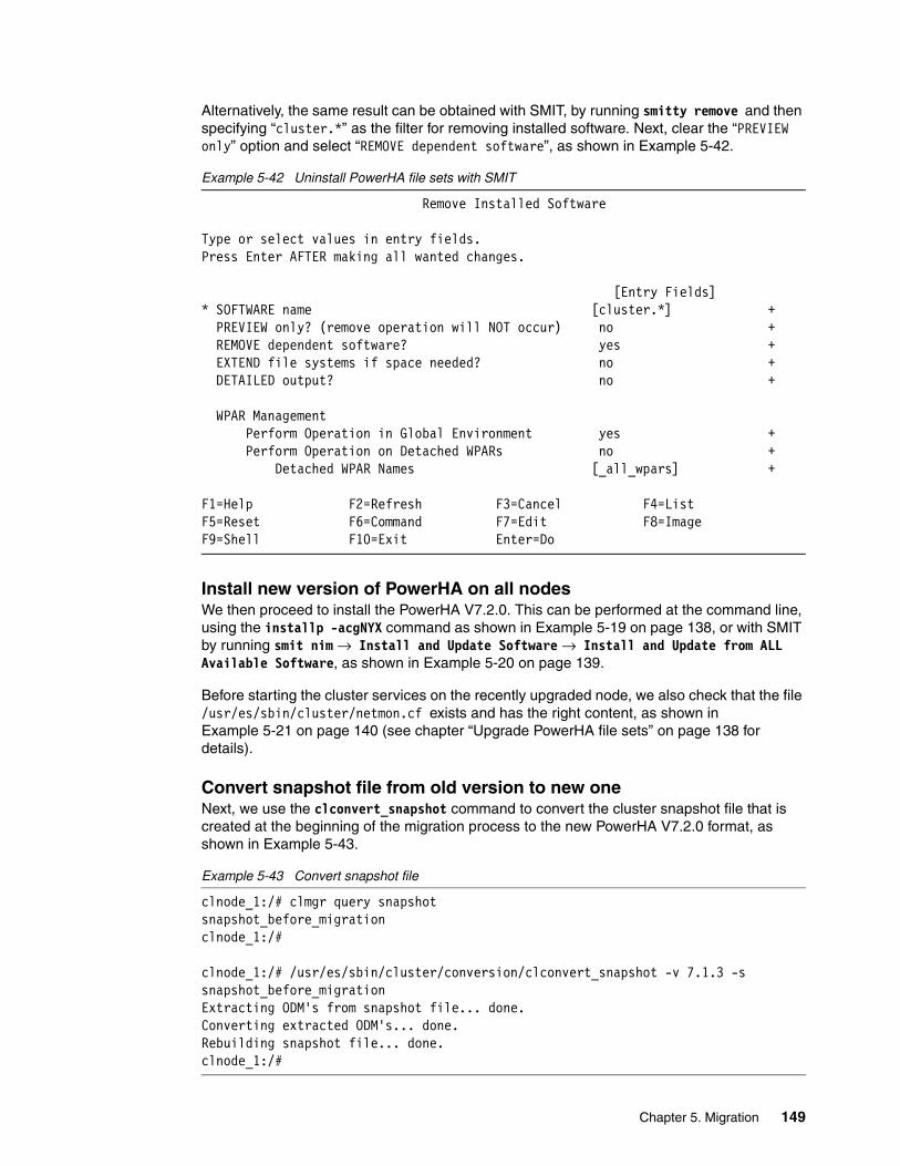
Alternatively, the same result can be obtained with SMIT, by running smitty remove and then specifying “cluster.*” as the filter for removing installed software. Next, clear the “PREVIEW only” option and select “REMOVE dependent software”, as shown in Example 5-42.
Example 5-42 Uninstall PowerHA file sets with SMIT
Remove Installed Software
Type or select values in entry fields.Press Enter AFTER making all wanted changes.
[Entry Fields]* SOFTWARE name [cluster.*] + PREVIEW only? (remove operation will NOT occur) no + REMOVE dependent software? yes + EXTEND file systems if space needed? no + DETAILED output? no +
WPAR Management Perform Operation in Global Environment yes + Perform Operation on Detached WPARs no + Detached WPAR Names [_all_wpars] +
F1=Help F2=Refresh F3=Cancel F4=ListF5=Reset F6=Command F7=Edit F8=ImageF9=Shell F10=Exit Enter=Do
Install new version of PowerHA on all nodesWe then proceed to install the PowerHA V7.2.0. This can be performed at the command line, using the installp -acgNYX command as shown in Example 5-19 on page 138, or with SMIT by running smit nim → Install and Update Software → Install and Update from ALL Available Software, as shown in Example 5-20 on page 139.
Before starting the cluster services on the recently upgraded node, we also check that the file /usr/es/sbin/cluster/netmon.cf exists and has the right content, as shown in Example 5-21 on page 140 (see chapter “Upgrade PowerHA file sets” on page 138 for details).
Convert snapshot file from old version to new oneNext, we use the clconvert_snapshot command to convert the cluster snapshot file that is created at the beginning of the migration process to the new PowerHA V7.2.0 format, as shown in Example 5-43.
Example 5-43 Convert snapshot file
clnode_1:/# clmgr query snapshotsnapshot_before_migrationclnode_1:/#
clnode_1:/# /usr/es/sbin/cluster/conversion/clconvert_snapshot -v 7.1.3 -s snapshot_before_migrationExtracting ODM's from snapshot file... done.Converting extracted ODM's... done.Rebuilding snapshot file... done.clnode_1:/#
Chapter 5. Migration 149

The file newly created can be found in the same location as the old one, with the same name, while the old one gets renamed, as shown in Example 5-44.
Example 5-44 Location of new snapshot file
clnode_1:/# ls -al /usr/es/sbin/cluster/snapshots/total 680drwxr-xr-x 2 root system 4096 Nov 5 17:44 .drwxr-xr-x 28 root system 4096 Nov 5 17:34 ..-rw------- 1 root system 0 Nov 3 17:43 clsnapshot.log-rw------- 1 root system 74552 Nov 5 17:12 snapshot_before_migration.info-rw-r--r-- 1 root system 58045 Nov 5 17:44 snapshot_before_migration.odm-rw------- 1 root system 57722 Nov 5 17:12 snapshot_before_migration.odm.oldclnode_1:/#
Restore the snapshot to re-create the clusterWe will use now the converted file to restore the cluster configuration:
1. Use the clmgr manage snapshot restore command (Example 5-45). This process will also re-create the CAA cluster.
Example 5-45 Restore the snapshot to re-create the cluster
clnode_1:/# clmgr manage snapshot restore snapshot_before_migration
clsnapshot: Removing any existing temporary PowerHA SystemMirror ODM entries...
clsnapshot: Creating temporary PowerHA SystemMirror ODM object classes...clsnapshot: Adding PowerHA SystemMirror ODM entries to a temporary directory..clsnapshot: Verifying configuration using temporary PowerHA SystemMirror ODM entries...Verification to be performed on the following: Cluster Topology Cluster Resources
Retrieving data from available cluster nodes. This could take a few minutes.
Start data collection on node clnode_1 Start data collection on node clnode_2 Collector on node clnode_2 completed Waiting on node clnode_1 data collection, 15 seconds elapsed Collector on node clnode_1 completed Data collection complete[...] Completed 100 percent of the verification checks
Verification has completed normally.
clsnapshot: Removing current PowerHA SystemMirror cluster information...Ensuring that the following nodes are offline: clnode_2, clnode_1[...]Attempting to delete node "clnode_2" from the cluster...Attempting to remove the CAA cluster from "clnode_1"...Attempting to delete node "clnode_1" from the cluster...
clsnapshot: Adding new PowerHA SystemMirror ODM entries...
150 IBM PowerHA SystemMirror V7.2 for IBM AIX Updates

clsnapshot: Synchronizing cluster configuration to all cluster nodes...[...]Committing any changes, as required, to all available nodes...[...]cldare: Configuring a 2 node cluster in AIX may take up to 2 minutes. Please wait.[...]Verification has completed normally.
clsnapshot: Succeeded applying Cluster Snapshot: snapshot_before_migration
lscluster: Cluster services are not active.[...]clnode_1:/#
2. When the snapshot restoration is finished, we are able to check the topology of the newly restored cluster, as shown Example 5-46.
Example 5-46 Check cluster topology
clnode_1:/# cltopinfoCluster Name: migration_clusterCluster Type: StandardHeartbeat Type: UnicastRepository Disk: hdisk2 (00f6f5d0d387b342)
There are 2 node(s) and 1 network(s) definedNODE clnode_1: Network net_ether_01 clst_svcIP 192.168.100.50 clnode_1 192.168.100.51NODE clnode_2: Network net_ether_01 clst_svcIP 192.168.100.50 clnode_2 192.168.100.52
Resource Group rg_IHS Startup Policy Online On First Available Node Fallover Policy Fallover To Next Priority Node In The List Fallback Policy Never Fallback Participating Nodes clnode_1 clnode_2 Service IP Label clst_svcIPclnode_1:/#
Chapter 5. Migration 151

Start cluster services on all nodes, bring resource groups onlineNow we can start the cluster services on both nodes using the clmgr start cluster command, as shown in Example 5-47. We could also use SMIT by running smitty clstart, as shown in Example 5-32 on page 144.
Example 5-47 Start the cluster services on all nodes and bring resource groups online
clnode_1:/# clmgr start cluster
clnode_2: start_cluster: Starting PowerHA SystemMirror[...]clnode_1: start_cluster: Starting PowerHA SystemMirror[...]The cluster is now online.
Starting Cluster Services on node: clnode_2[...]clnode_2: Exit status = 0clnode_2:
Starting Cluster Services on node: clnode_1[...]clnode_1: Exit status = 0clnode_1:/#
Check for proper function of the cluster
Checking the functionality of the cluster can be done in several ways. The most basic actions include synchronizing the cluster and moving resource groups between cluster nodes. Both of these actions are shown in Example 5-48.
Example 5-48 Verify and synchronize cluster configuration
clnode_2:/# clmgr sync cluster
Verifying additional prerequisites for Dynamic Reconfiguration......completed.
Committing any changes, as required, to all available nodes...[..]Verification has completed normally.
cldare: No changes detected in Cluster Topology or Resources....completed.
Committing any changes, as required, to all available nodes...[...]Verification has completed normally.
clsnapshot: Creating file /usr/es/sbin/cluster/snapshots/active.0.odm.
clsnapshot: Succeeded creating Cluster Snapshot: active.0
152 IBM PowerHA SystemMirror V7.2 for IBM AIX Updates

PowerHA SystemMirror Cluster Manager current state is: ST_RP_RUNNINGPowerHA SystemMirror Cluster Manager current state is: ST_BARRIERPowerHA SystemMirror Cluster Manager current state is: ST_UNSTABLE.PowerHA SystemMirror Cluster Manager current state is: ST_RP_RUNNING.PowerHA SystemMirror Cluster Manager current state is: ST_UNSTABLE.PowerHA SystemMirror Cluster Manager current state is: ST_CBARRIERPowerHA SystemMirror Cluster Manager current state is: ST_STABLE.....completed.clnode_2:/#
Moving a resource group from one node to another is shown in Example 5-49.
Example 5-49 Move a resource group from one node to another
clnode_2:/# clRGinfo-----------------------------------------------------------------------------Group Name Group State Node-----------------------------------------------------------------------------rg_IHS OFFLINE clnode_1 ONLINE clnode_2clnode_2:/#clnode_2:/# clmgr move resource_group rg_IHS node=clnode_1Attempting to move resource group rg_IHS to node clnode_1.[...]Resource group movement successful.Resource group rg_IHS is online on node clnode_1.[...]Resource Group Name: rg_IHSNode Group State---------------------------- ---------------clnode_1 ONLINEclnode_2 OFFLINEclnode_2:/#
5.3.6 Non-disruptive migration of PowerHA from 7.1.3 to 7.2.0
The major steps in a non-disruptive migration of PowerHA are described in the following list:
1. Check and document the initial stage.2. Stop cluster services on one node, leaving the resource groups unmanaged.3. Upgrade PowerHA file sets on the offline node.4. Start the cluster on the recently upgraded node.5. Repeat steps 2 through 4 for all of the other cluster nodes, one node at a time.6. Check for proper function of the cluster.
Check and document initial stageThis step is described in 5.3.2, “Check and document initial stage” on page 132 as being common to all migration scenarios and methods.
Tip: A demo of performing a non-disruptive migration to PowerHA 7.2 is available on the following website:
https://youtu.be/1Kzm7I2mRyE
Chapter 5. Migration 153

Stop cluster services on one node, leaving resource groups unmanagedTo stop cluster services, complete the following steps:
1. First, we make a note of the distribution of resource group across the cluster (using the clRGinfo command), so that we can track the migration process (Example 5-50).
Example 5-50 Check the resource groups distribution across the cluster
clnode_1 /> clRGinfo-----------------------------------------------------------------------------Group Name State Node-----------------------------------------------------------------------------rg_IHS OFFLINE clnode_1 ONLINE clnode_2clnode_1 />
2. Next, we stop the cluster services on one node and leave the resource groups unmanaged, so that the applications remain functional. For that purpose, you can use the clmgr stop node command with the option of unmanaging resources (Example 5-51).
Example 5-51 Stop the cluster services on all nodes and unmanage the resource groups
clnode_1 /> clmgr stop node manage=unmanage[...]PowerHA SystemMirror on clnode_1 shutting down. Please exit any cluster applications...[...]"clnode_1" is now unmanaged.[...]clnode_1 />
3. We can now check the status of the cluster nodes and that of the resource groups across the cluster, using the clmgr query node and the clRGinfo commands. In our case, because we first took a node offline that had no online resource groups, the output of the second command is just the same as before stopping the node (Example 5-52).
Example 5-52 Check the cluster nodes and resource groups status
clnode_1 /> clmgr -cv -a name,state,raw_state query node# NAME:STATE:RAW_STATEclnode_1:UNMANAGED:UNMANAGEDclnode_2:NORMAL:ST_STABLEclnode_1 />
clnode_1 /> clRGinfo-----------------------------------------------------------------------------Group Name State Node-----------------------------------------------------------------------------rg_IHS OFFLINE clnode_1 ONLINE clnode_2clnode_1 />
Upgrade PowerHA file sets on the offline nodeBecause we now have the cluster services stopped on one node, we can proceed to upgrading the PowerHA file sets on that node. This can be performed at the command line using the installp -acgNYX command. as shown in Example 5-19 on page 138, as well as with SMIT, as shown in Example 5-20 on page 139.
154 IBM PowerHA SystemMirror V7.2 for IBM AIX Updates

Before starting the cluster services on the recently upgraded node, we also verify that the file /usr/es/sbin/cluster/netmon.cf exists and has the right content, as shown in Example 5-21 on page 140 (see chapter “Upgrade PowerHA file sets” on page 138 for details).
After the upgrade finishes, we can check the version of PowerHA installed on the current node using the halevel -s command, as shown in Example 5-53.
Example 5-53 Checking the version of PowerHA installed in the node
clnode_1 /> halevel -s7.2.0 GAclnode_1 />
Start cluster services on the recently upgraded nodeNow we can start the cluster services on the recently upgraded node:
1. Use the clmgr start node command (or with SMIT, use the smit sysmirror command and then follow the System Management (C-SPOC) → PowerHA SystemMirror Services → Start Cluster Services path), as shown in Example 5-54.
Example 5-54 Start cluster services on one node
clnode_1 /> clmgr start node[...]clnode_1: start_cluster: Starting PowerHA SystemMirror..."clnode_1" is now online.
Cluster services are running at different levels acrossthe cluster. Verification will not be invoked in this environment.
Starting Cluster Services on node: clnode_1[...]clnode_1: Dec 11 2015 19:28:07 complete.clnode_1 />
2. The cluster nodes status can be checked using the clmgr query node command, as shown in Example 5-55.
Example 5-55 Check cluster nodes status
clnode_1:/# clmgr -cv -a name,state,raw_state query node# NAME:STATE:RAW_STATEclnode_1:NORMAL:ST_STABLEclnode_2:NORMAL:ST_STABLEclnode_1:/#
Important: When restarting cluster services with the Automatic option for managing resource groups, this invokes one or more application start scripts. Make sure that the application scripts can either detect that the application is already running, or copy the scripts and put a dummy blank executable script in their place and then copy them back after startup.
Chapter 5. Migration 155

3. We also verify the version and status of PowerHA running on the recently upgraded node, as well as the version of the cluster, using the lssrc -ls clstrmgrES command, as shown in Example 5-56.
Example 5-56 Check PowerHA version on current node
clnode_1 /> lssrc -ls clstrmgrES | egrep "state|CLversion|vrmf|fix"Current state: ST_STABLECLversion: 15local node vrmf is 7200cluster fix level is "0"clnode_1 />
Note that although the node itself has been upgraded to PowerHA 7.2.0, the cluster version is still 15, because not all cluster nodes have yet been upgraded.
Repeat steps 2-4 for each node, one node at a timeNow we can proceed in the same manner to upgrade all the remaining nodes, only one node at a time, following the same steps:
1. Stop cluster services on a particular node, leaving the resource groups unmanaged2. Upgrade PowerHA file sets on that node3. Restart cluster services on that node
Complete the following steps:
1. Proceed in this way for each node that has not yet been upgraded, one node at a time. When finished, all nodes should be upgraded and stable within the cluster.
2. When all nodes are stable (use the clmgr query node command), issue a lssrc -ls clstrmgrES command to verify that the cluster version is 16, as shown in Example 5-57.
Example 5-57 Check the nodes version, nodes status and cluster version
clnode_1 /> clmgr -cv -a name,state,raw_state query node# NAME:STATE:RAW_STATEclnode_1:NORMAL:ST_STABLEclnode_2:NORMAL:ST_STABLEclnode_1 />
clnode_1 /> lssrc -ls clstrmgrES | egrep "state|CLversion|vrmf|fix"Current state: ST_STABLECLversion: 16local node vrmf is 7200cluster fix level is "0"clnode_1 />
clnode_2 /> lssrc -ls clstrmgrES | egrep "state|CLversion|vrmf|fix"Current state: ST_STABLECLversion: 16
Note: With the migration process started, moving resources groups using C-SPOC or rg_move to another node is not permitted. This is a precautionary measure to minimize the user-originated activity, and therefore the chances of service unavailability across the cluster during the mixed version environment. Movement of resources across the cluster is only permitted by stopping cluster services on specific nodes with the option of moving resources.
156 IBM PowerHA SystemMirror V7.2 for IBM AIX Updates

local node vrmf is 7200cluster fix level is "0"clnode_2 />
3. Finally we also need to check the status of the resource groups, using the clRGinfo command, as shown in Example 5-58.
Example 5-58 Check the resource groups status
clnode_1:/# clRGinfo-----------------------------------------------------------------------------Group Name Group State Node-----------------------------------------------------------------------------rg_IHS OFFLINE clnode_1 ONLINE clnode_2clnode_1:/#
Check for proper function of the cluster
Checking the functionality of the cluster can be done in several ways. The most basic actions include synchronizing the cluster and moving resource groups between cluster nodes. Both of these actions are shown in Example 5-59.
Example 5-59 Verify and synchronize cluster configuration
clnode_2:/# clmgr sync clusterVerifying additional prerequisites for Dynamic Reconfiguration......completed.
Committing any changes, as required, to all available nodes...[...]Verification has completed normally.
clsnapshot: Creating file /usr/es/sbin/cluster/snapshots/active.0.odm.
clsnapshot: Succeeded creating Cluster Snapshot: active.0[...]PowerHA SystemMirror Cluster Manager current state is: ST_RP_RUNNINGPowerHA SystemMirror Cluster Manager current state is: ST_BARRIER...PowerHA SystemMirror Cluster Manager current state is: ST_UNSTABLE.PowerHA SystemMirror Cluster Manager current state is: ST_RP_RUNNING...PowerHA SystemMirror Cluster Manager current state is: ST_BARRIERPowerHA SystemMirror Cluster Manager current state is: ST_CBARRIERPowerHA SystemMirror Cluster Manager current state is: ST_UNSTABLE.PowerHA SystemMirror Cluster Manager current state is: ST_STABLE.....completed.clnode_2:/#
Chapter 5. Migration 157

Moving a resource group from one node to another is shown in Example 5-60.
Example 5-60 Move a resource group from one node to another
clnode_1:/# clRGinfo-----------------------------------------------------------------------------Group Name Group State Node-----------------------------------------------------------------------------rg_IHS OFFLINE clnode_1 ONLINE clnode_2
clnode_1:/# clmgr move resource_group rg_IHS node=clnode_1Attempting to move resource group rg_IHS to node clnode_1.[...]Resource group movement successful.Resource group rg_IHS is online on node clnode_1.[...]Resource Group Name: rg_IHSNode Group State---------------------------- ---------------clnode_1 ONLINEclnode_2 OFFLINEclnode_1:/#
5.3.7 Migrations of PowerHA from 7.1.1 and 7.1.2 to 7.2.0
Migrations of PowerHA from versions 7.1.1 and 7.1.2 to version 7.2.0 are possible as depicted in Table 5-1 on page 117. Because the migrations from these versions of PowerHA go in a very similar manner to that described in the previous sections, we chose to present this only briefly, with some emphasis on the few particularities encountered.
Offline migrationThe offline migration of PowerHA from versions 7.1.1 or 7.1.2 to 7.2.0 goes in a similar manner to the one from 7.1.3 described earlier, following the same major steps:
1. Check and document initial stage2. Stop cluster on all nodes, bringing the resources offline3. Upgrade PowerHA file sets4. Start cluster on all nodes, bring the resources online5. Check for proper function of the cluster
The output that the user gets while running the individual commands for these migration cases is also similar to the one received during a migration from 7.1.3 version (see chapter 5.3.3, “Offline migration of PowerHA from 7.1.3 to 7.2.0” on page 138).
Rolling migrationThe rolling migration of PowerHA from versions 7.1.1 or 7.1.2 to 7.2.0 goes in a similar manner to the one from 7.1.3 described earlier, following the same major steps:
1. Check and document initial stage2. Stop cluster on all nodes, bringing the resources offline3. Upgrade PowerHA file sets4. Start cluster on all nodes, bring the resources online5. Check for proper function of the cluster
158 IBM PowerHA SystemMirror V7.2 for IBM AIX Updates

The output that the user gets while running the individual commands for these migration cases is also similar to the one received during a migration from 7.1.3 version (see chapter 5.3.4, “Rolling migration of PowerHA from 7.1.3 to 7.2.0” on page 142).
The only notable differences (some obvious or self-explanatory and some not) in the command output are related to the version of PowerHA used as starting point and the corresponding numeric code for the PowerHA cluster, which is 13 for PowerHA version 7.1.1 and 14 for PowerHA 7.1.2, as shown in Table 5-2.
Table 5-2 Cluster and node before, during, and after upgrade from PowerHA 7.1.1 or 7.1.2
Snapshot migrationThe snapshot migration of PowerHA from versions 7.1.1 or 7.1.2 to 7.2.0 goes in a similar manner to the one from 7.1.3 described earlier, following the same major steps:
1. Check and document initial stage2. Stop cluster on all nodes, bringing the resources offline3. Upgrade PowerHA file sets4. Start cluster on all nodes, bring the resources online5. Check for proper function of the cluster
The output that the user gets while running the individual commands for these migration cases is also similar to the one received during a migration from 7.1.3 version (see chapter 5.3.5, “Snapshot migration from PowerHA 7.1.3 to 7.2.0” on page 147).
PowerHA starting point
version
Migration stageCommand output
halevel -s lssrc -ls clstrmgrES | egrep "CLversion|vrmf|fix"
PowerHA 7.1.1
Before upgrade 7.1.1 SP1 CLversion: 13local node vrmf is 7112cluster fix level is "2"
During upgrade(mixed cluster state)
7.2.0 GA CLversion: 13local node vrmf is 7200cluster fix level is "0"
After upgrade 7.2.0 GA CLversion: 16local node vrmf is 7200cluster fix level is "0"
PowerHA 7.1.2
Before upgrade 7.1.2 SP1 CLversion: 14local node vrmf is 7121cluster fix level is "1"
During upgrade(mixed cluster state)
7.2.0 GA CLversion: 13local node vrmf is 7200cluster fix level is "0"
After upgrade 7.2.0 GA CLversion: 16local node vrmf is 7200cluster fix level is "0"
Chapter 5. Migration 159

The only notable difference is related to the parameters specified for the clconvert_snapshot command, which will obviously need to reflect the version of PowerHA used as the starting point for migration (in our case, those were 7.1.1 and 7.1.2, as shown in Example 5-61).
Example 5-61 Convert snapshot file from PowerHA 7.1.1 or 7.1.2
clnode_1 /> /usr/es/sbin/cluster/conversion/clconvert_snapshot -v 7.1.1 -s snapshot_7.1.1_before_migration.odmExtracting ODMs from snapshot file... done.Converting extracted ODMs... done.Rebuilding snapshot file... done.clnode_1 />
clnode_1 /> /usr/es/sbin/cluster/conversion/clconvert_snapshot -v 7.1.2 -s snapshot_7.1.2_before_migration.odmExtracting ODMs from snapshot file... done.Converting extracted ODMs... done.Rebuilding snapshot file... done.clnode_1 />
Non-disruptive migration
We attempted non-disruptive migrations of PowerHA from versions 7.1.1 or 7.1.2 to 7.2.0 on our test environment in a manner similar to the one from 7.1.3 described earlier, following the same major steps:
1. Check and document initial stage2. Stop cluster services on one node, leaving the resource groups unmanaged3. Upgrade PowerHA file sets on the offline node4. Start cluster on the recently upgraded node5. Repeat steps 2 through 4 for all other cluster nodes, one node at a time6. Check for proper function of the cluster
Non-disruptive migration from 7.1.1Complete migration of PowerHA from 7.1.1 to 7.2.0 did not work. The process went in a similar manner to the migration from PowerHA 7.1.3 until the last step, that of cluster verification and synchronization test. The nodes themselves were successfully upgraded and the cluster services started on each of them. The resource groups remained online (available) throughout the whole process.
In the last step, however, the verification and synchronization action failed, rendering the communication between the two nodes not functional. The situation reverted to normal as soon as an offline/online cycle was performed upon the resource groups (as such or by movement to other nodes). However, the result of that action was that the migration was no longer non-disruptive.
Important: Non-disruptive migrations from versions older than 7.1.3 are not supported. Therefore, such migrations should not be attempted in production environments.
For more detailed information on supported configurations, requirements and limitations, see the following website:
http://www.ibm.com/support/knowledgecenter/SSPHQG_7.2.0/com.ibm.powerha.insgd/ha_install_rolling_migration_ndu.htm
160 IBM PowerHA SystemMirror V7.2 for IBM AIX Updates

Non-disruptive migration from 7.1.2Although unsupported, our attempt to migrate PowerHA 7.1.2 to 7.2.0, on our test environment and with our cluster setup, was successful and went the same way as the migration from PowerHA 7.1.3. However, this does not mean in any way that it will work in any other conditions, different from those of our test environment and cluster setup.
That being said, the output that we got while running the individual commands for this migration case was similar to the one received during a migration from 7.1.3 version (see chapter 5.3.6, “Non-disruptive migration of PowerHA from 7.1.3 to 7.2.0” on page 153).
The same remarks relative to the cluster and cluster nodes versions apply as in the case of rolling migrations. The stages through which a node goes are shown in Table 5-2 on page 159.
Chapter 5. Migration 161

162 IBM PowerHA SystemMirror V7.2 for IBM AIX Updates

Chapter 6. Resource Optimized High Availability (ROHA)
This chapter describes one feature: Resource Optimized High Availability (ROHA). This feature is one new feature of PowerHA SystemMirror Standard and Enterprise Edition, version 7.2.
In this chapter, we introduce the following topics:
� ROHA concept and terminology
� New PowerHA SystemMirror SMIT configure panel for ROHA
� New PowerHA SystemMirror verification enhancement for ROHA
� Planning for one ROHA cluster environment
� Resource acquisition and release process introduction
� Introduction to resource acquisition
� Introduction to release of resources
� Example 1: Setup one ROHA cluster (without On/Off CoD)
� Test scenarios of Example 1 (without On/Off CoD)
� Example 2: Set up one ROHA cluster (with On/Off CoD)
� Test scenarios for Example 2 (with On/Off CoD)
� Hardware Management Console (HMC) high availability introduction
� Test scenario for HMC fallover
� Manage, monitor and troubleshooting
6
© Copyright IBM Corp. 2016. All rights reserved. 163

6.1 ROHA concept and terminology
With this feature, PowerHA SystemMirror can manage dynamic LPAR (DLPAR) and Capacity of Demand (CoD) resources. CoD resources are mainly composed of Enterprise Pool CoD resources and On/Off CoD resources.
Enterprise Pool CoD (EPCoD) resourceEPCoD resources are resources that can be freely moved among servers in the same pool where the resources are best used. Physical resources (like CPU or memory) are not really moved between servers, what is moved, in fact, is the privilege to use them. You can grant this privilege to any server of the pool. This enables you to flexibly manage the pool of resources and allocate the resources where they are most needed.
On/Off CoD resourceOn/Off CoD resources are preinstalled and inactive (and unpaid for) physical resources for a given server: Processors or memory capacity. On/Off CoD is a type of CoD license enabling temporary activation of processors and memory. PowerHA SystemMirror can dynamically activate these resources and can make them available to the system, so that they are allocated when needed to the LPAR through a DLPAR operation.
Dynamic Logical Partitioning (DLPAR)DLPAR represents the facilities in some IBM Power Systems that provide the ability to logically attach and detach a managed system’s resources to and from a logical partition’s operating system without restarting.
By integrating with DLPAR and CoD resources, PowerHA SystemMirror ensures that each node can support the application with reasonable performance at a minimum cost. This way, you can tune the capacity of the logical partition flexibly when your application requires more resources, without having to pay for idle capacity until you actually need it (for On/Off CoD), or without keeping allocated resources if you don’t use them (for Enterprise Pool CoD).
You can configure cluster resources so that the logical partition with minimally allocated resources serves as a standby node, and the application is on another LPAR node that has more resources than the standby node. This way, you do not use any additional resources that the frames have until the resources are required by the application.
PowerHA SystemMirror uses the system-connected HMC to perform DLPAR operation and manage CoD resources.
Table 6-1 displays all available types of CoD offering. Only two of them are dynamically managed and controlled by PowerHA SystemMirror: EPCoD and On/Off CoD.
Table 6-1 CoD offering and PowerHA
CoD offering PowerHA SystemMirror 6.1 Standard and Enterprise Edition
PowerHA SystemMirror 7.1or 7.2Standard and Enterprise Edition
Enterprise PoolMemory and Processor
No Yes, from version 7.2
On/Off CoD (temporary)Memory
No Yes, from version 7.1.3SP2
On/Off CoD (temporary)Processor
Yes Yes
164 IBM PowerHA SystemMirror V7.2 for IBM AIX Updates

Trial CoDTrial CoD are temporary resources, but they are not put On or Off to follow dynamic needs. When Trial CoD standard or exception code is entered into HMC, these resources are On at once, and elapsed time starts immediately. The amount of resources granted by Trial CoD directly enters into the available DLPAR resources. It is as if they were configured DLPAR resources.
Therefore, PowerHA SystemMirror can dynamically control the Trial CoD resource after customer manually enter code to activate the resource through HMC.
6.1.1 Environment requirement for ROHA
The following are the requirements to implement ROHA:
� PowerHA SystemMirror 7.2, Standard Edition or Enterprise Edition
� AIX 6.1 TL09 SP5, or AIX 7.1 TL03 SP5, or AIX 7.1 TL4 or AIX 7.2 or later
� HMC requirement
– To use the Enterprise Pool CoD license, your system must be using HMC 7.8 firmware or later
– To configure backup HMC for EPCoD as far as possible for high availability requirement
– For EPCoD User Interface (UI) in HMC, HMC must have a minimum of 2 GB memory
� Hardware requirement for using Enterprise Pool CoD license
– Power 7+: 9117-MMD(770 D model), 9179-MHD(780 D model), using FW780.10 or later
– Power 8: 9119-MME (E870), 9119-MHE (E880), using FW820 or later
6.2 New PowerHA SystemMirror SMIT configure panel for ROHA
In order to support the ROHA feature, PowerHA SystemMirror provides some new SMIT menu and clmgr command options. These options include the following functions:
� HMC configuration� Hardware Resource Provisioning for Application Controller� Cluster tunables configuration
Utility CoD (temporary)Memory and Processor
Utility CoD automatically is performed at PHYP/System level. PowerHA cannot play a role in the same
Trial CoDMemory and Processor
Trial CoD are used if available through DLPAR operation(At the bottom of this table, describe detail relationship between PowerHA and Trial CoD)
CuoD (permanent)Memory & Processor
CuoD are used if available through DLPAR operation. PowerHA will not handle this kind of resource directly.
CoD offering PowerHA SystemMirror 6.1 Standard and Enterprise Edition
PowerHA SystemMirror 7.1or 7.2Standard and Enterprise Edition
Chapter 6. Resource Optimized High Availability (ROHA) 165

Figure 6-1 shows the summary of SMIT menu navigation for all new ROHA panels. For the new options of clmgr command, see 6.14.1, “The clmgr interface to manage ROHA” on page 255 for detailed information.
Figure 6-1 All new ROHA panels
6.2.1 Entry point to ROHA
Start smit sysmirror. Select Cluster Applications and Resources → Resources → Configure User Applications (Scripts and Monitors). This panel is a menu screen with a title menu option and four item menu options. Only the third item is the entry point to ROHA configuration (Figure 6-2).
Figure 6-2 Entry point to ROHA menu
Configure User Applications (Scripts and Monitors)
Move cursor to desired item and press Enter.
Application Controller Scripts Application Monitors Resource Optimized High Availability Show Cluster Applications
166 IBM PowerHA SystemMirror V7.2 for IBM AIX Updates

Table 6-2 shows the context-sensitive help for the ROHA entry point.
Table 6-2 Context-sensitive help for entry point of ROHA
6.2.2 ROHA panel
Start smit sysmirror. Select Cluster Applications and Resources → Resources → Configure User Applications (Scripts and Monitors) → Resource Optimized High Availability. The next panel is a menu screen with a title menu option and three item menu options. Its fast path is cm_cfg_roha (Figure 6-3).
Figure 6-3 ROHA panel
Table 6-3 shows the help information for the ROHA panel.
Table 6-3 Context-sensitive help for ROHA panel
Name and fast path context-sensitive help (F1)
Resource Optimized High Availability# smitty cm_cfg_roha
Choose this option to configure Resource Optimized High Availability (ROHA). ROHA performs dynamic management of hardware resources (memory, cpu) for the account of PowerHA SystemMirror. This dynamic management of resources uses three types of mechanism: DLPAR mechanism, On/Off CoD mechanism, Enterprise Pool CoD mechanism. If resources available on the CEC are not sufficient, and cannot be got through a DLPAR operation, it is possible to fetch into external pools of resources provided by CoD: Either On/Off or Enterprise Pool. On/Off CoD can result in extra costs, and formal agreement from the user is required. The user must configure Hardware Management Consoles (HMC) to contact for actual acquisition/release of resources.
Resource Optimized High Availability
Move cursor to desired item and press Enter.
HMC Configuration Hardware Resource Provisioning for Application Controller Change/Show Default Cluster Tunables
Name and fast path context-sensitive help (F1)
HMC Configuration# smitty cm_cfg_hmc
Choose this option to configure Hardware Management Console (HMC) used by your cluster configuration, and to optionally associate HMC to your cluster’s nodes. If no HMC associated with a node, PowerHA SystemMirror will use the default cluster configuration.
Change/Show Hardware Resource Provisioning for Application Controller # smitty cm_cfg_hr_prov
Choose this option to change or show CPU and memory resource requirements for any Application Controller that runs in a cluster that uses DLPAR, CoD, or Enterprise Pool CoD capable nodes, or a combination.
Change/Show Default Cluster Tunables# smitty cm_cfg_def_cl_tun
Choose this option to modify or view the DLPAR, CoD, and Enterprise Pool CoD configuration parameters.
Chapter 6. Resource Optimized High Availability (ROHA) 167
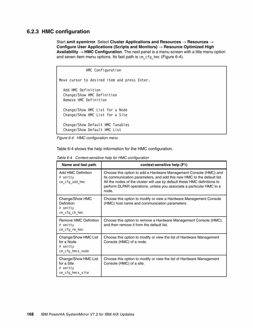
6.2.3 HMC configuration
Start smit sysmirror. Select Cluster Applications and Resources → Resources → Configure User Applications (Scripts and Monitors) → Resource Optimized High Availability → HMC Configuration. The next panel is a menu screen with a title menu option and seven item menu options. Its fast path is cm_cfg_hmc (Figure 6-4).
Figure 6-4 HMC configuration menu
Table 6-4 shows the help information for the HMC configuration.
Table 6-4 Context-sensitive help for HMC configuration
HMC Configuration
Move cursor to desired item and press Enter.
Add HMC Definition Change/Show HMC Definition Remove HMC Definition Change/Show HMC List for a Node Change/Show HMC List for a Site Change/Show Default HMC Tunables Change/Show Default HMC List
Name and fast path context-sensitive help (F1)
Add HMC Definition# smitty cm_cfg_add_hmc
Choose this option to add a Hardware Management Console (HMC) and its communication parameters, and add this new HMC to the default list. All the nodes of the cluster will use by default these HMC definitions to perform DLPAR operations, unless you associate a particular HMC to a node.
Change/Show HMC Definition# smitty cm_cfg_ch_hmc
Choose this option to modify or view a Hardware Management Console (HMC) host name and communication parameters.
Remove HMC Definition# smitty cm_cfg_rm_hmc
Choose this option to remove a Hardware Management Console (HMC), and then remove it from the default list.
Change/Show HMC List for a Node# smitty cm_cfg_hmcs_node
Choose this option to modify or view the list of Hardware Management Console (HMC) of a node.
Change/Show HMC List for a Site# smitty cm_cfg_hmcs_site
Choose this option to modify or view the list of Hardware Management Console (HMC) of a site.
168 IBM PowerHA SystemMirror V7.2 for IBM AIX Updates

HMC Add/Change/Remove Definition
To add HMC, select Add HMC Definition. The next panel is a dialog screen with a title dialog header and several dialog command options. Its fast path is cm_cfg_add_hmc. Each item has a context-sensitive help screen that you access by pressing F1, and can have an associated list (press F4).
Figure 6-5 shows the menu to add the HMC definition and its entry fields.
Figure 6-5 Add HMC Definition menu
Table 6-5 shows the help and information list for adding the HMC definition.
Table 6-5 Context-sensitive help and Associated List for Add HMC Definition
Change/Show Default HMC Tunables# smitty cm_cfg_def_hmc_tun
Choose this option to modify or view the HMC default communication tunables.
Change/Show Default HMC List# smitty cm_cfg_def_hmcs
Choose this option to modify or view the default HMC list that is used by default by all nodes of the cluster. Nodes that define their own HMC list will not use this default HMC list.
Note: Before you add HMC, you need to build password-less communication from AIX nodes to the HMC. See 6.4.1, “Consideration before ROHA configuration” on page 183 for detailed steps.
Add HMC Definition
Type or select values in entry fields.Press Enter AFTER making all desired changes. [Entry Fields]* HMC name [] + DLPAR operations timeout (in minutes) [] # Number of retries [] # Delay between retries (in seconds) [] # Nodes [] + Sites [] + Check connectivity between HMC and nodes Yes
Name context-sensitive help (F1) Associated list (F4)
HMC name Enter the host name for the Hardware Management Console (HMC). An IP address is also accepted here. Both IPv4 and IPv6 addresses are supported.
Yes (single-selection).The list is obtained with the following command: /usr/sbin/rsct/bin/rmcdomainstatus -s ctrmc -a IP
Name and fast path context-sensitive help (F1)
Chapter 6. Resource Optimized High Availability (ROHA) 169

If DNS (Domain Name Service) is configured in your environment and DNS can do resolution for HMC IP and host name, then you can use F4 to select one HMC to perform the add operation.
DLPAR operations timeout (in minutes)
Enter a timeout in minutes on DLPAR commands run on an HMC (-w parameter). This -w parameter only exists on the chhwres command, when allocating or releasing resources. It is adjusted according to the type of resources (for memory, 1 minute per gigabyte is added to this timeout. Setting no value means that you use the default value, which is defined in the Change/Show Default HMC Tunables panel. When -1 is displayed in this field, it indicates that the default value is used.
None
Number of retries Enter a number of times one HMC command is retried before the HMC is considered as non-responding. The next HMC in the list will be used after this number of retries has failed. Setting no value means that you use the default value, which is defined in the Change/Show Default HMC Tunables panel. When -1 is displayed in this field, it indicates that the default value is used.
None
Delay between retries (in seconds)
Enter a delay in seconds between two successive retries. Setting no value means that you use the default value, which is defined in the Change/Show Default HMC Tunables panel. When -1 is displayed in this field, it indicates that the default value is used.
None
Nodes Enter the list of nodes that use this HMC. Yes (multiple-selection).A list of nodes to be proposed can be obtained through the following command: odmget HACMPnode
Sites Enter the sites that use this HMC. All nodes of the sites will then use this HMC by default, unless the node defines an HMC as its own level.
Yes (multiple-selection).A list of sites to be proposed can be obtained through the following command: odmget HACMPsite
Check connectivity between HMC and nodes
Select Yes to check communication links between nodes and HMC.
<Yes>|<No>. The default is Yes.
Name context-sensitive help (F1) Associated list (F4)
170 IBM PowerHA SystemMirror V7.2 for IBM AIX Updates

Figure 6-6 shows an example of selecting one HMC from the list to perform the add operation.
Figure 6-6 Select one HMC from HMC list to do add HMC operation
PowerHA SystemMirror also supports entering the HMC IP address to add the HMC. Figure 6-7 shows an example of entering one HMC IP address to add the HMC.
Figure 6-7 Enter one HMC IP address to add HMC
Change/Show HMC DefinitionTo show or modify an HMC, select Change/Show HMC Definition. The next panel is a selector screen with a selector header that lists all existing HMC names. Its fast path is cm_cfg_ch_hmc (Figure 6-8).
Figure 6-8 Select HMC from list during change or show HMC configuration
HMC name Move cursor to desired item and press Enter. e16hmc1 is 9.3.207.130 e16hmc3 is 9.3.207.133 F1=Help F2=Refresh F3=Cancel Esc+8=Image Esc+0=Exit Enter=Do /=Find n=Find Next
Add HMC Definition
Type or select values in entry fields.Press Enter AFTER making all desired changes. [Entry Fields]* HMC name [9.3.207.130] + DLPAR operations timeout (in minutes) [] Number of retries [] Delay between retries (in seconds) [] Nodes []+ Sites []+ Check connectivity between HMC and nodes Yes
| HMC name | | Move cursor to desired item and press Enter. | | e16hmc1 | e16hmc3 | | F1=Help F2=Refresh F3=Cancel | Esc+8=Image Esc+0=Exit Enter=Do | /=Find n=Find Next
Chapter 6. Resource Optimized High Availability (ROHA) 171
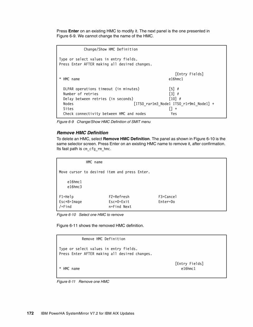
Press Enter on an existing HMC to modify it. The next panel is the one presented in Figure 6-9. We cannot change the name of the HMC.
Figure 6-9 Change/Show HMC Definition of SMIT menu
Remove HMC DefinitionTo delete an HMC, select Remove HMC Definition. The panel as shown in Figure 6-10 is the same selector screen. Press Enter on an existing HMC name to remove it, after confirmation. Its fast path is cm_cfg_rm_hmc.
Figure 6-10 Select one HMC to remove
Figure 6-11 shows the removed HMC definition.
Figure 6-11 Remove one HMC
Change/Show HMC Definition
Type or select values in entry fields.Press Enter AFTER making all desired changes. [Entry Fields]* HMC name e16hmc1 DLPAR operations timeout (in minutes) [5] # Number of retries [3] # Delay between retries (in seconds) [10] # Nodes [ITSO_rar1m3_Node1 ITSO_r1r9m1_Node1] + Sites [] + Check connectivity between HMC and nodes Yes
HMC name
Move cursor to desired item and press Enter.
e16hmc1 e16hmc3
F1=Help F2=Refresh F3=Cancel Esc+8=Image Esc+0=Exit Enter=Do /=Find n=Find Next
Remove HMC Definition
Type or select values in entry fields.Press Enter AFTER making all desired changes. [Entry Fields]* HMC name e16hmc1
172 IBM PowerHA SystemMirror V7.2 for IBM AIX Updates

Change/Show HMC List for a NodeTo show or modify the HMC list for a node, select Change/Show HMC List for a Node. The next panel (Figure 6-12) is a selector screen with a selector header that lists all existing nodes. Its fast path is cm_cfg_hmcs_node.
Figure 6-12 Select a Node to change
Press Enter on an existing node to modify it. The next panel (Figure 6-13) is a dialog screen with a title dialog header and two dialog command options.
Note that you cannot add or remove an HMC from this list. You can only reorder (set in the right precedence order) the HMCs used by the node.
Figure 6-13 Change/Show HMC list for a Node
Table 6-6 shows the help information to change or show the HMC list for a node.
Table 6-6 Context-sensitive help for Change or Show HMC list for a Node
Select a Node
Move cursor to desired item and press Enter.
ITSO_rar1m3_Node1 ITSO_r1r9m1_Node1
F1=Help F2=Refresh F3=Cancel Esc+8=Image Esc+0=Exit Enter=Do /=Find n=Find Next Esc+8=Image
Change/Show HMC List for a Node
Type or select values in entry fields.Press Enter AFTER making all desired changes. [Entry Fields]* Node name ITSO_rar1m3_Node1 HMC list [e16hmc1 e16hmc3]
Name and fast path context-sensitive help (F1)
Node name This is the node name to associate with one or more Hardware Management Consoles (HMCs).
HMC list Precedence order of the HMCs used by this node. The first in the list is tried first then the second, and so on. You cannot add or remove any HMC. You are only able to modify the order of the already set HMCs.
Chapter 6. Resource Optimized High Availability (ROHA) 173

Change/Show HMC List for a SiteTo show or modify the HMC list for a node, select Change/Show HMC List for a Site. The next panel (Figure 6-14) is a selector screen with a selector header that lists all existing sites. Its fast path is cm_cfg_hmcs_site.
Figure 6-14 Select a Site menu when Change/Show HMC List for as Site
Press Enter on an existing site to modify it. The next panel (Figure 6-15) is a dialog screen with a title dialog header and two dialog command options.
Figure 6-15 Change/Show HMC List for a Site menu
Note that you cannot add or remove an HMC from the list. You can only reorder (set in the right precedence order) the HMCs used by the site. See Table 6-7.
Table 6-7 Site and HMC usage list
Select a Site
Move cursor to desired item and press Enter.
site1 site2
F1=Help F2=Refresh F3=Cancel Esc+8=Image Esc+0=Exit Enter=Do /=Find n=Find Next
Change/Show HMC List for a Site
Type or select values in entry fields.Press Enter AFTER making all desired changes. [Entry Fields]* Site Name site1 HMC list [e16hmc1 e16hmc3]
Name and fast path context-sensitive help (F1)
Site name This is the site name to associate with one or more Hardware Management Consoles (HMCs).
HMC list Precedence order of the HMCs used by this site. The first in the list is tried first, then the second, and so on. You cannot add or remove any HMC. You are only able to modify the order of the already set HMCs.
174 IBM PowerHA SystemMirror V7.2 for IBM AIX Updates

Change/Show Default HMC TunablesTo show or modify default HMC communication tunables, select Change/Show Default HMC Tunables. The next panel (Figure 6-16) is a dialog screen with a title dialog header and three dialog command options. Its fast path is cm_cfg_def_hmc_tun. Each item has a context-sensitive help screen (press F1) and can have an associated list (press F4).
Figure 6-16 Change/Show Default HMC Tunables menu
Change/Show Default HMC ListTo show or modify the default HMC list, select Change/Show Default HMC List. The next panel (Figure 6-17) is a dialog screen with a title dialog header and one dialog command option. Its fast path is cm_cfg_def_hmcs. Each item has a context-sensitive help screen (press F1) and can have an associated list (press F4).
Figure 6-17 Change/Show Default HMC list menu
6.2.4 Hardware resource provisioning for application controller
To provision hardware, complete the following steps:
1. Start smit sysmirror. Select Cluster Applications and Resources → Resources → Configure User Applications (Scripts and Monitors) → Resource Optimized High Availability → Hardware Resource Provisioning for Application Controller. The next panel (Figure 6-18) is a menu screen with a title menu option and three item menu options.
Figure 6-18 Hardware Resource Provisioning for Application Controller menu
Change/Show Default HMC Tunables
Type or select values in entry fields.Press Enter AFTER making all desired changes.
[Entry Fields] DLPAR operations timeout (in minutes) [10] # Number of retries [5] # Delay between retries (in seconds) [10]
Change/Show Default HMC List
Type or select values in entry fields.Press Enter AFTER making all desired changes. [Entry Fields] HMC list [e16hmc1 e16hmc3]
Hardware Resource Provisioning for Application Controller
Move cursor to desired item and press Enter.
Add Hardware Resource Provisioning to an Application Controller Change/Show Hardware Resource Provisioning of an Application Controller Remove Hardware Resource Provisioning from an Application Controller
Chapter 6. Resource Optimized High Availability (ROHA) 175

2. Choose one of the following actions:
– To add an application controller configuration, select Add. – To change or show an application controller configuration, select Change/Show. – To remove an application controller configuration, select Remove.
In case you choose Add or Change/Show, the following On/Off CoD Agreement is displayed as shown in Figure 6-19. However, this is displayed only if the user has not yet agreed to it. If the user has already agreed to it, it is not displayed.
On/Off CoD AgreementFigure 6-19 is a dialog screen with a dialog header and one dialog command option.
Figure 6-19 On/Off CoD Agreement menu
To accept the On/Off CoD Agreement, complete the following steps:
1. Enter Yes to have PowerHA SystemMirror use On/Off Capacity On Demand (On/Off CoD) resources to perform DLPAR operations on your nodes.
2. If you agree to use On/Off CoD, you must ensure that you have entered the On/Off CoD activation code. The On/Off CoD license key needs to be entered into HMC before PowerHA SystemMirror can activate this type of resources.
3. In the following cases, keep the default value:
– If there is only half Enterprise Pool CoD, keep the default value of No.– If there is not Enterprise Pool CoD or On/Off CoD, PowerHA manages only the server’s
permanent resources through DLPAR, so also keep the default value.
This option can be modified later in the Change/Show Default Cluster Tunables panel, as shown in Figure 6-22 on page 180.
On/Off CoD Agreement Type or select a value for the entry field. Press Enter AFTER making all desired changes. [Entry Fields] Resources Optimized High Availability management No + can take advantage of On/Off CoD resources. On/Off CoD use would incur additional costs. Do you agree to use On/Off CoD and be billed for extra costs?
176 IBM PowerHA SystemMirror V7.2 for IBM AIX Updates

Add Hardware Resource Provisioning to an Application ControllerThe panel shown in Figure 6-20 is a selector screen with a selector header that lists all existing application controllers.
Figure 6-20 Select Application Controller menu
To create a Hardware Resource Provisioning for an Application Controller, the list displays only application controllers that do not already have hardware resource provisioning. See Figure 6-21.
To modify or remove a Hardware Resource Provisioning for an Application Controller, the list displays application controllers that already have hardware resource provisioning.
Press Enter on an existing application controller to modify it. The next panel is a dialog screen with a title dialog header and three dialog command options. Each item has a context-sensitive help screen (press F1) and can have an associated list (press F4).
Figure 6-21 Add Hardware Resource Provisioning to an Application Controller menu
Select Application Controller
Move cursor to desired item and press Enter.
App1 App2
F1=Help F2=Refresh F3=Cancel Esc+8=Image Esc+0=Exit Enter=Do /=Find n=Find Next
Add Hardware Resource Provisioning to an Application Controller
Type or select values in entry fields.Press Enter AFTER making all desired changes. [Entry Fields]* Application Controller Name App1 Use desired level from the LPAR profile No + Optimal amount of gigabytes of memory [] Optimal number of dedicated processors [] #
Optimal number of processing units [] Optimal number of virtual processors []
Chapter 6. Resource Optimized High Availability (ROHA) 177

Table 6-8 shows the help for adding hardware resources.
Table 6-8 Context-sensitive help for add hardware resource provisioning
Name and fast path context-sensitive help (F1)
Application Controller Name
This is the application controller for which you will configure DLPAR and CoD resource provisioning.
Use desired level from the LPAR profile
There is no default value. You must make one of the following choices:� Enter Yes if you want the LPAR hosting your node to reach only the
level of resources indicated by the desired level of the LPAR’s profile. By choosing Yes, you trust the desired level of LPAR profile to fit the needs of your application controller.
� Enter No if you prefer to enter exact optimal values for memory, processor (CPU), or both. These optimal values should match the needs of your application controller, and enable you to better control the level of resources to be allocated to your application controller.
� Enter nothing if you do not need to provision any resource for your application controller.
For all application controllers having this tunable set to Yes, the allocation performed lets the LPAR reach the LPAR desired value of the profile. Suppose you have a mixed configuration, in which some application controllers have this tunable set to Yes, and other application controllers have this tunable set to No with some optimal level of resources specified. In this case, the allocation performed lets the LPAR reach the desired value of the profile added to the optimal values.
Optimal amount of gigabytes of memory
Enter the amount of memory that PowerHA SystemMirror will attempt to acquire to the node before starting this application controller. This Optimal amount of gigabytes of memory value can be set only if the Used desired level from the LPAR profile value is set to No. Enter the value in multiples of ¼, ½, ¾, or 1 GB. For example, 1 would represent 1 GB or 1024 MB, 1.25 would represent 1.25 GB or 1280 MB, 1.50 would represent 1.50 GB or 1536 MB, and 1.75 would represent 1.75 GB or 1792 MB.If this amount of memory is not satisfied, PowerHA SystemMirror takes resource group recovery actions to move the resource group with this application to another node. Alternatively, PowerHA SystemMirror can allocate less memory depending on the Start RG even if resources are insufficient cluster tunable.
Optimal number of dedicated processors
Enter the number of processors that PowerHA SystemMirror will attempt to allocate to the node before starting this application controller. This attribute is only for nodes running on LPAR with Dedicated Processing Mode.This Optimal number of dedicated processors value can be set only if the Used desired level from the LPAR profile value is set to No. If this number of CPUs is not satisfied, PowerHA SystemMirror takes resource group recovery actions to move the resource group with this application to another node. Alternatively, PowerHA SystemMirror can allocate fewer CPUs depending on the Start RG even if resources are insufficient cluster tunable.For more information about how to acquire mobile resources at the resource group onlining stage, see 6.6, “Introduction to resource acquisition” on page 195.For more information about how to release mobile resources at the resource group offlining stage, see 6.7, “Introduction to release of resources” on page 204.
178 IBM PowerHA SystemMirror V7.2 for IBM AIX Updates

To modify an application controller configuration, select Change/Show. The next panel is the same selector screen as shown in Figure 6-21 on page 177. Press Enter on an existing application controller to modify it. The next panel is the same dialog screen (Figure 6-21 on page 177) as shown previously, (except the title, which is different).
To delete an application controller configuration, select Remove. The next panel is the same selector screen shown previously. Press Enter on an existing application controller to remove it.
If Use desired level from the LPAR profile is set to No, then at least the memory (Optimal amount of gigabytes of memory) or CPU (Optimal number of dedicated or virtual processors) setting is mandatory.
Optimal number of processing units
Enter the number of processing units that PowerHA SystemMirror will attempt to allocate to the node before starting this application controller. This attribute is only for nodes running on LPAR with Shared Processing Mode.This Optimal number of processing units value can be set only if the Used desired level from the LPAR profile value is set to No. Processing units are specified as a decimal number with two decimal places, ranging 0.01 - 255.99. This value is only used on nodes that support allocation of processing units. If this amount of CPUs is not satisfied, PowerHA SystemMirror takes resource group recovery actions to move the resource group with this application to another node. Alternatively, PowerHA SystemMirror can allocate fewer CPUs depending on the Start RG even if resources are insufficient cluster tunable.For more information about how to acquire mobile resources at the resource group onlining stage, see 6.6, “Introduction to resource acquisition” on page 195.For more information about how to release mobile resources at the resource group offlining stage, see 6.7, “Introduction to release of resources” on page 204.
Optimal number of virtual processors
Enter the number of virtual processors that PowerHA SystemMirror will attempt to allocate to the node before starting this application controller. This attribute is only for nodes running on LPAR with Shared Processing Mode.This Optimal number of dedicated or virtual processors value can be set only if the Used desired level from the LPAR profile value is set to No. If this number of virtual processors is not satisfied, PowerHA SystemMirror takes resource group recovery actions to move the resource group with this application to another node. Alternatively, PowerHA SystemMirror can allocate fewer CPUs depending on the Start RG even if resources are insufficient cluster tunable.
Name and fast path context-sensitive help (F1)
Chapter 6. Resource Optimized High Availability (ROHA) 179

6.2.5 Change/Show Default Cluster Tunable
Start smit sysmirror. Select Cluster Applications and Resources → Resources → Configure User Applications (Scripts and Monitors) → Resource Optimized High Availability → Change/Show Default Cluster Tunables. The next panel (Figure 6-22) is a dialog screen with a title dialog header and seven dialog command options. Each item has a context-sensitive help screen (press F1) and can have an associated list (press F4). Its fast path is cm_cfg_def_cl_tun.
Figure 6-22 Change/Show Default Cluster Tunables menu
Table 6-9 shows the help for the cluster tunables.
Table 6-9 Context-sensitive help for Change/Show Default Cluster Tunables
Change/Show Default Cluster Tunables
Type or select values in entry fields.Press Enter AFTER making all desired changes. [Entry Fields] Dynamic LPAR Start Resource Groups even if resources are No + insufficient Adjust Shared Processor Pool size if required No + Force synchronous release of DLPAR resources No + On/Off CoD I agree to use On/Off CoD and be billed for Yes + extra costs Number of activating days for On/Off CoD requests [30]
Name and fast path context-sensitive help (F1)
Start Resource Groups even if resources are insufficient
Enter Yes to have PowerHA SystemMirror start Resource Groups even if resources are insufficient. This can occur when the total requested resources exceed the LPAR profile’s maximum or the combined available resources. Thus the best-can-do allocation is performed. Enter No to prevent starting Resources Groups with insufficient resources. Resource Groups can end in an error state if resources are insufficient. The default is No.
Adjust Shared Processor Pool size if required
Enter Yes to authorize PowerHA SystemMirror to dynamically change the user-defined Shared-Processors Pool boundaries, if necessary. This change can occur only at takeover, and only if CoD resources have been activated for the CEC, so that changing the maximum size of a particular Shared-Processors Pool is not done to the detriment of other Shared-Processors Pools.The default is No.
Force synchronous release of DLPAR resources
Enter Yes to have PowerHA SystemMirror release CPU and memory resources synchronously. For example, if the client needs to free resources on one side before they can be used on the other side. By default, PowerHA SystemMirror automatically detects the resource release mode by looking if Active and Backup nodes are on the same or different CECs. A leading practice is to have asynchronous release in order not to delay the takeover.The default is No.
180 IBM PowerHA SystemMirror V7.2 for IBM AIX Updates

6.3 New PowerHA SystemMirror verification enhancement for ROHA
The ROHA function allows PowerHA SystemMirror to automatically or manually check environment discrepancies. The clverify tool has been improved to check ROHA-related configuration integrity.
Customers will be able to use the verification tool to ensure that their environment is correct with regard to their ROHA setup. Discrepancies will be called out by PowerHA SystemMirror, and the tool assists customers to correct the configuration if possible.
The results will appear in the following files:
� The /var/hacmp/log/clverify.log file� The /var/hacmp/log/autoverify.log file
The user is actively notified of critical errors. Distinction can be made between errors that are raised during configuration and errors that are raised during cluster synchronization.
As a general principal, any problems that are detected at configuration time should be presented as warnings instead of errors.
Another general principle is that PowerHA SystemMirror checks only what is being configured at configuration time and not the whole configuration. PowerHA SystemMirror checks whole configuration at verification time.
For example, when adding a new HMC, you check only the new HMC (verify that it is pingable, at an appropriate software level, and so on) and not all of the HMCs. Checking the whole configuration can take some time and is done at verify and sync time rather than each individual configuration step.
I agree to use On/Off CoD and be billed for extra costs
Enter Yes to have PowerHA SystemMirror use On/Off Capacity On Demand (On/Off CoD) to obtain enough resources to fulfill the optimal amount requested. Using On/Off CoD requires an activation code to be entered on the Hardware Management Console (HMC) and can result in extra costs due to the usage of the On/Off CoD license.The default is No.
Number of activating days for On/Off CoD requests
Enter a number of activating days for On/Off CoD requests. If the requested available resources are insufficient for this duration, then the longest-can-do allocation is performed. We try to allocate the amount of resources requested for the longest duration. To do that we consider the overall resources available: This number is the sum of the On/Off CoD resources already activated but not yet used, and the On/Off CoD resources not yet activated. The default is 30.
Name and fast path context-sensitive help (F1)
Chapter 6. Resource Optimized High Availability (ROHA) 181

General verificationTable 6-10 shows the general verification list.
Table 6-10 General verification list
HMC communication verificationTable 6-11 shows the HMC communication verification list.
Table 6-11 HMC communication verification list
Capacity on demand verificationTable 6-12 shows the capacity on demand verification.
Table 6-12 Capacity on demand verification
Item Configuration time
Synchronizationtime
Check that all RG active and standby nodes are on different CECs. This enables the asynchronous mode of releasing resources.
Info Warning
This code cannot run on an IBM Power4. Error Error
Item Configuration time
Synchronizationtime
Only one HMC is configured per node. None Warning
Two HMCs are configured per node. None OK
One node is without HMC (if ROHA only). None Error
Only one HMC per node can be pinged. Warning Warning
Two HMCs per node can be pinged. OK OK
One node has a non-pingable HMC. Warning Error
Only one HMC with password-less SSH communication exists per node.
Warning Warning
Two HMCs with password-less SSH communication exist per node.
OK OK
One node exists with non-SSH accessible HMC. Warning Error
Check that all HMCs share the same level (the same version of HMC).
Warning Warning
Check that all HMCs administer the CEC hosting the current node. It is suggested to configure two HMCs administering the CEC hosting the current node. If not, PowerHA gives a warning message.
Warning Warning
Check if the HMC level supports FSP Lock Queuing. Info Info
Item Configuration Time
SynchronizationTime
Check that all CECs are CoD capable. Info Warning
Check if CoD is enabled. Info Warning
182 IBM PowerHA SystemMirror V7.2 for IBM AIX Updates

Power enterprise pool verificationTable 6-13 shows the enterprise pool verification list.
Table 6-13 Power enterprise pool verification
Resource provisioning verificationTable 6-14 shows the resource provisioning verification information.
Table 6-14 Resource provisioning verification
6.4 Planning for one ROHA cluster environment
Before completing the ROHA configuration, read the following considerations.
6.4.1 Consideration before ROHA configuration
This section describes a few considerations to know before a ROHA configuration.
Tips for Enterprise PoolIf you have ordered IBM Power Systems Enterprise Pool license for your servers, and you want to use the resource with your PowerHA SystemMirror cluster, then you must create the Enterprise Pool manually.
Before you create the Enterprise Pool, get the configuration extensible markup language (XML) file from the IBM CoD, and the deactivation code from the IBM CoD project office on the following website:
http://www-912.ibm.com/pod/pod
Item @info @Sync
Check that all CECs are Enterprise Pool capable. Info Info
Determine which HMC is the master, and which HMC is non-master. Info Info
Check that the nodes of the cluster are on different pools. This enables the asynchronous mode of releasing resources.
Info Info
Check that all HMCs have level 7.8 or later. Info Warning
Check that the CEC has unlicensed resources. Info Warning
Item @info @Sync
Check that for one given node the total of optimal memory (of RG on this node) added to the profile’s minimum does not exceed the profile’s maximum.
Warning Error
Check that for one given node the total of optimal CPU (of RG on this node) added to the profile’s minimum does not exceed the profile’s maximum.
Warning Error
Check that for one given node the total of optimal PU (of RG on this node) added to the profile’s minimum does not exceed the profile’s maximum.
Warning Error
Check that the total processing units do not break the minimum processing units per virtual processor ratio.
Error Error
Chapter 6. Resource Optimized High Availability (ROHA) 183

The configuration XML file is used to enable and generate mobile resources.
The deactivation code is used to deactivate some of the permanent resources to inactive mode. The number is the same independent of how many mobile resources are on the server’s order.
For example, in one order, there are two Power Servers. Each one has 16 static CPUs, 8 mobile CPUs, and 8 inactive CPUs, for a total of 32 CPUs. When you power them on the first time, you can see that each server has 24 permanent CPUs, 16 static CPUs plus 8 mobile CPUs.
After you create the Enterprise Pool with the XML configuration file, you see that there are 16 mobile CPUs generated in the Enterprise Pool, but the previous 8 mobile CPUs are still in permanent status in each server. This results in the server’s status being different from its original order. This will bring some issues in future post-sales activities.
There are two steps to complete the Enterprise Pool implementation:
1. Create the Enterprise Pool with the XML configuration file.
2. Deactivate some permanent resources (the number is the same with mobile resources) to inactive with the deactivation code.
After you finish these two steps, each server has 16 static CPUs and 16 inactive CPUs, and the Enterprise Pool has 16 mobile CPUs. Then the mobile CPUs can be assigned to each of the two servers through the HMC graphical user interface or the command-line interface.
How to get the deactivation code and use itThe following steps explain how to get the deactivation code and how to use it:
1. Send an email to the IBM CoD project office ([email protected]). You need to provide the following information or attach the servers order:
– Customer name– Each server’s system type and serial number– Configuration XML file
2. In reply to this note, you will receive from the Capacity on Demand project office a de-activation code for the servers. The de-activation code will lower the number of activated resources to align it with your server order.
Note: These two steps will be combined into one step in the future. As of the time of writing, you need to perform each step separately.
Note: This de-activation code updates the IBM CoD website after you receive the note. This de-activation code has RPROC and RMEM. RPROC is for reducing processor resources, RMEM is for reducing memory resources.
184 IBM PowerHA SystemMirror V7.2 for IBM AIX Updates

3. Enter this de-activation code in the corresponding servers through the HMC as shown in Figure 6-23 (shows the menu to Enter CoD Code).
Figure 6-23 Menu to Enter CoD Code
4. After entering the de-activation code, you need to send a listing of the updated VPD (Vital Product Data) output to the Capacity on Demand Project office at [email protected].
Collect the VPD using the HMC command line instruction, as shown in Example 6-1.
Example 6-1 Collecting the VPD information case
Collect the VPD using the HMC command line instruction for every server:Processor:lscod -m your_system_name -t code -r proc -c mobileMemory:lscod -m your_system_name -t code -r mem -c mobile
5. With the receipt of the lscod profile, the Project Office will update the CoD database records and close out your request.
For more information about how to use the configuration XML file to create Power Enterprise Pool and some management concept, see the publication Power Enterprise Pools on IBM Power Systems, REDP-5101 on the following website:
http://www.redbooks.ibm.com/abstracts/redp5101.html
Configure redundant HMCs or add EP’s master and backup HMCIn 6.12, “Hardware Management Console (HMC) high availability introduction” on page 244, we introduce HMC high availability design in PowerHA SystemMirror. For the ROHA solution, the HMC is critical, so configuring redundant HMCs is advised.
If there is a Power Enterprise Pool configured, we suggest configuring backup HMC for Enterprise Pool and adding both of them into PowerHA SystemMirror with clmgr add hmc <hmc>’ command or through the SMIT menu. Thus, PowerHA SystemMirror can provide the fallover function if the master HMC fails. 6.12.1, “Switch to the backup HMC for the Power Enterprise Pool” on page 246 introduces some prerequisites when you set up the Power Enterprise Pool.
Note: At the time of writing this publication, Power Systems Firmware supports a pair of HMCs to manage one Power Enterprise Pool: One is in master mode, and the other one is in backup mode.
Chapter 6. Resource Optimized High Availability (ROHA) 185

Verify communication between Enterprise Pool’s HMC IP and AIX LPARsIf you want PowerHA SystemMirror to control Power Systems Enterprise Pool’s mobile resource for resource group automatically, you must be able to ping the HMC’s host name from AIX environment. For example, in our testing environment, the master HMC and backup HMC of Power Enterprise Pool is: e16hmc1 and e16hmc3. You can get the information using the clmgr view report roha command in AIX or using the lscodpool in the HMC command line, as shown in Example 6-2 and Example 6-3.
Example 6-2 Show HMC information with clmgr view report roha through AIX
...Enterprise pool 'DEC_2CEC' State: 'In compliance' Master HMC: 'e16hmc1' --> Master HMC name of EPCoD Backup HMC: 'e16hmc3' --> Backup HMC name of EPCoD Enterprise pool memory Activated memory: '100' GB Available memory: '100' GB Unreturned memory: '0' GB Enterprise pool processor Activated CPU(s): '4' Available CPU(s): '4' Unreturned CPU(s): '0' Used by: 'rar1m3-9117-MMD-1016AAP' Activated memory: '0' GB Unreturned memory: '0' GB Activated CPU(s): '0' CPU(s) Unreturned CPU(s): '0' CPU(s) Used by: 'r1r9m1-9117-MMD-1038B9P' Activated memory: '0' GB Unreturned memory: '0' GB Activated CPU(s): '0' CPU(s) Unreturned CPU(s): '0' CPU(s)
Example 6-3 Show EPCoD HMC information with lscodpool through HMC
hscroot@e16hmc1:~> lscodpool -p DEC_2CEC --level pool name=DEC_2CEC,id=026F,state=In compliance,sequence_num=41,master_mc_name=e16hmc1,master_mc_mtms=7042-CR5*06K0040,backup_master_mc_name=e16hmc3,backup_master_mc_mtms=7042-CR5*06K0036,mobile_procs=4,avail_mobile_procs=1,unreturned_mobile_procs=0,mobile_mem=102400,avail_mobile_mem=60416,unreturned_mobile_mem=0
Before PowerHA SystemMirror acquires the resource from EPCoD or releases the resource back to EPCoD, PowerHA tries to check if the HMC is accessible with the ping command. So it is required that AIX can perform the resolution between the IP address and the host name. You can use /etc/hosts or Domain Name System (DNS) or other technology to achieve it. For example, on AIX, run ping e16hmc1 and ping e16hmc3 to check if the resolution works.
If the HMCs are in the DNS configuration, we suggest configuring these HMCs into PowerHA SystemMirror using their names, and not their IPs.
Note: At the time of writing this publication, for one Power Systems server, IBM only supports at most two HMCs to manage it.
186 IBM PowerHA SystemMirror V7.2 for IBM AIX Updates

Enter the On/Off CoD code before using the resourceIf you purchased the On/Off CoD code and want to use it with PowerHA SystemMirror, you need to enter the code to active it before use it. The menu is shown in Figure 6-23 on page 185.
No restriction about deployment combination with Enterprise PoolIn one PowerHA SystemMirror cluster, there is no restriction for its nodes deployment with Enterprise Pool CoD (EPCoD):
� It supports all the nodes in one server and share mobile resource from one EPCoD.� It supports the nodes in different servers and share one EPCoD.� It supports the nodes in different servers and in different EPCoD.� It supports the nodes in different servers and some of them in EPCoD, and others has no
EPCoD.
No restriction about LPAR’s CPU type combination in one clusterOne PowerHA SystemMirror cluster supports:
� All nodes are dedicated processor mode.� All nodes are shared processor mode.� Some of them are dedicated processor mode and others are shared.
In Figure 6-24, before the application starts, PowerHA SystemMirror check current LPAR’s processor mode, if it is dedicated, then 2 available CPU is its target, if it is shared mode, then 1.5 available CPUs and 3 available VPs is its target.
Figure 6-24 Mixed CPU type in one PowerHA SystemMirror cluster
Recommendation after changing partition’s LPAR nameIf you change one partition’s LPAR name, the profile is changed, but AIX does not recognize this change automatically. You need to shut down the partition and activate it with its profile (AIX IPL process, Initial Program Load), then after restart, the LPAR name information can be changed.
PowerHA SystemMirror gets the LPAR name from the uname -L command’s output and take this name to do DLPAR operations through the HMC.
Add Hardware Resource Provisioning to an Application Controller
Type or select values in entry fields. Press Enter AFTER making all desired changes.
[Entry Fields]* Application Controller Name AppController1
Use desired level from the LPAR profile No + Optimal amount of gigabytes of memory [30]
Optimal number of dedicated processors [2] #
Optimal number of processing units [1.5] Optimal number of virtual processors [3]
Chapter 6. Resource Optimized High Availability (ROHA) 187

Build password-less communication from AIX nodes to HMCsIn order for LPARs to communicate with the HMC, they must use SSH. All the LPAR nodes must have SSH correctly set up.
Setting up SSH for password-less communication with the HMC requires that the user run ssh-keygen on each LPAR node to generate a public and private key pair. The public key must then be copied to the HMC’s public authorized keys file. This will allow ssh from the LPAR to contact the HMC without the need for typing in a password. Example 6-4 is one example to set up HMC password-less communication.
Example 6-4 Setting up the HMC password-less communication
# ssh-keygen -t rsaGenerating public/private rsa key pair.Enter file in which to save the key (//.ssh/id_rsa): Created directory '//.ssh'.Enter passphrase (empty for no passphrase): Enter same passphrase again: Your identification has been saved in //.ssh/id_rsa.Your public key has been saved in //.ssh/id_rsa.pub.The key fingerprint is:70:0d:22:c0:28:e9:71:64:81:0f:79:52:53:5a:52:06 root@epvioc3The key's randomart image is:…
# cd /.ssh/# lsid_rsa id_rsa.pub# export MYKEY='cat /.ssh/id_rsa.pub'# ssh [email protected] mkauthkeys -a \"$MYKEY\"The authenticity of host '172.16.15.42 (172.16.15.42)' can't be established.RSA key fingerprint is b1:47:c8:ef:f1:82:84:cd:33:c2:57:a1:a0:b2:14:f0.Are you sure you want to continue connecting (yes/no)? yesWarning: Permanently added '172.16.15.42' (RSA) to the list of known hosts.
Keep Sync turned OFF for the Sync current configuration Capability settingThere is one option in the LPAR if it needs to enable sync of the current configuration. With the ROHA solution, one LPAR’s running CPU and memory size would be resized, if this feature is enabled, the wanted value of profile would be resized too. This will bring confusion to the system administrator. So we suggest disabling this feature in a ROHA environment (Figure 6-25 on page 189).
Note: There is one enhancement to support DLPAR name update for AIX commands such as uname -L or lparstat -i. The requirements are as follows:
� Hardware firmware level SC840 or later (for E870 and E880)
� AIX 7.1 TL4 or 7.2 or later
� HMC V8 R8.4.0 (PTF MH01559) with mandatory efix (PTF MH01560)
188 IBM PowerHA SystemMirror V7.2 for IBM AIX Updates

Figure 6-25 Sync current configuration Capability
Consideration of setting LPAR’s Minimum and Maximum parametersWhen you configure an LPAR on the HMC (outside of PowerHA SystemMirror), you provide LPAR minimum and LPAR maximum values for the number of CPUs and amount of memory.
The stated minimum values of the resources must be available when an LPAR node starts. If more resources are available in the free pool on the frame, an LPAR can allocate up to the stated wanted values. During dynamic allocation operations, the system does not allow the values for CPU and memory to go below the minimum or above the maximum amounts specified for the LPAR.
PowerHA SystemMirror obtains the LPAR minimums and LPAR maximums amounts and uses them to allocate and release CPU and memory when application controllers are started and stopped on the LPAR node.
In planning stage, we need to consider how many resources are needed to satisfy all the resource groups online carefully and set LPAR’s minimal and maximum parameter correctly.
Using pre-event and post-event scriptsExisting pre-event and post-event scripts that you maybe using in a cluster with LPARs (before using the CoD integration with PowerHA SystemMirror) might need to be modified or rewritten, if you plan to configure CoD and DLPAR requirements in PowerHA SystemMirror.
Chapter 6. Resource Optimized High Availability (ROHA) 189

Keep in mind the following considerations:
� PowerHA SystemMirror performs all the DLPAR operations before the application controllers are started, and after they are stopped. You might need to rewrite the scripts to account for this.
� Because PowerHA SystemMirror takes care of the resource calculations, requests additional resources from the DLPAR operations and, if allowed, from CUoD, you can get rid of the portions of your scripts that do that.
� PowerHA SystemMirror considers only the free pool on a single frame. If your cluster is configured within one frame, then modifying the scripts as stated above is sufficient.
� However, if a cluster is configured with LPAR nodes that are on two frames, you might still require the portions of the existing pre-event and post-event scripts that deal with dynamically allocating resources from the free pool on one frame to the node on another frame, should the application requires these resources.
About elapsed time of DLPAR operationWhen you plan a PowerHA SystemMirror cluster with ROHA feature, DLPAR release time needs to be considered.
While initially bringing up the Resource Group online, PowerHA SystemMirror must wait for all the resources acquisition before it, then can start up user’s application.
While performing a takeover (Fallover to next priority node, for example), PowerHA SystemMirror tries to perform some operations (DLPAR or adjust CoD and EPCoD resource) in parallel the release of resources on source node and the acquisition of resources on target node if user allows it in tunables (the value of Force synchronous release of DLPAR resources is No).
Table 6-15 shows testing result of DLPAR operation, the result maybe different in other environment.
There is one LPAR, its current running CPU resource size is 2C, and the running memory resource size is 8 GB. The DLPAR operation includes add and remove.
Table 6-15 Elapsed time of DLPAR operation
Incremental Value By DLPAR
Add CPU(in seconds)
Add Memory(in seconds)
Remove CPU(in seconds)
Remove Memory(in minutes and
seconds)
2C and 8 GB 5.5 s 8 s 6 s 88 s (1 m 28 s)
4C and 16 GB 7 s 12 s 9.8 s 149 s (2 m 29 s)
8C and 32 GB 13 s 27 s 23 s 275 s (4 m 35 s)
16C and 64 GB 18 s 34 s 33 s 526 s (8 m 46 s)
32C and 128 GB 24 s 75 s 52 s 1010 s (16 m 50 s)
48C and 192 GB 41 s 179 s 87 s 1480 s (24 m 40 s)
190 IBM PowerHA SystemMirror V7.2 for IBM AIX Updates

AIX ProbeVue maximum pinned memory settingProbeVue is one dynamic tracing facility of AIX. You can use it for both performance analysis and problem debugging. ProbeVue uses the Vue programming language to dynamically specify trace points and provide the actions to run at the specified trace points. This feature is enabled by default. There is one restriction between ProbeVue’s maximum pinned memory and DLPAR remove memory operation:
Max Pinned Memory For ProbeVue tunable would cross the 40% limit of system running memory.
For example, you configured one profile for LPAR with 8 GB (minimum) and 40 GB (wanted), at the first you activate this LPAR, the maximum pinned memory of ProbVue is set to 4 GB (10% of system running memory) as shown in Example 6-5.
From AIX 7.1 TL4 onwards, the tunables are derived based on the available system memory. MAX pinned memory is set to 10% of the system memory. It cannot be adjusted itself when you restart the operating system or adjusting the memory size with the DLPAR operation.
Example 6-5 Current maximum pinned memory for ProbeVue
# probevctrl -lProbevue Features: on --> ProbeVue is enable at this timeMAX pinned memory for Probevue framework(in MB): 4096 --> this is the value we are discussing...
Now if you want to remove memory from 40 GB to 8 GB use the following command:
chhwres -r mem -m r1r9m1-9117-MMD-1038B9P -o r -p ITSO_S2Node1 -q 32768
The command fails with the error shown in Example 6-6.
Example 6-6 Error information when you remove memory through DLPAR
hscroot@e16hmc3:~> chhwres -r mem -m r1r9m1-9117-MMD-1038B9P -o r -p ITSO_S2Node1 -q 32768HSCL2932 The dynamic removal of memory resources failed: The operating system prevented all of the requested memory from being removed. Amount of memory removed: 0 MB of 32768 MB. The detailed output of the OS operation follows:
0930-050 The following kernel errors occured during the DLPAR operation.
0930-023 The DR operation could not be supported by one or more kernel extensions.
Consult the system error log for more information....Please issue the lshwres command to list the memory resources of the partition and to determine whether or not its pending and runtime memory values match. If they do not match, problems with future memory-related operations on the managed system may occur, and it is recommended that the rsthwres command to restore memory resources be issued on the partition to synchronize its pending memory value with its runtime memory value.
Chapter 6. Resource Optimized High Availability (ROHA) 191

From AIX, the error report also generates some error information, as shown in Example 6-7 and Example 6-8.
Example 6-7 AIX error information when remove memory through DLPAR
47DCD753 1109140415 T S PROBEVUE DR: memory remove failed by ProbeVue rec252D3145 1109140415 T S mem DR failed by reconfig handler
Example 6-8 Detailed information about DR_PVUE_MEM_REM_ERR error
LABEL: DR_PVUE_MEM_REM_ERRIDENTIFIER: 47DCD753
Date/Time: Mon Nov 9 14:04:56 CST 2015Sequence Number: 676Machine Id: 00F638B94C00Node Id: ITSO_S2Node1Class: SType: TEMPWPAR: GlobalResource Name: PROBEVUE
DescriptionDR: memory remove failed by ProbeVue reconfig handler
Probable CausesExceeded one or more ProbeVue Configuration Limits or other
Failure CausesMax Pinned Memory For Probevue tunable would cross 40% limit
Recommended Actions Reduce the Max Pinned Memory For Probevue tunable
Detail DataDR Phase NamePRECurrent System Physical Memory
42949672960 -->> this is 40GB which is current running memory sizeMemory requested to remove
34359738368 -->> this is 32GB which want to removeProbeVue Max Pinned Memory tunable value 4294967296 -->> this is 4GB which is current maximum pinned memory for ProbeVue.
In the ROHA solution, it is possible that PowerHA SystemMirror will remove memory to a low value, like in the procedure of automatic resource release after OS failure, so we have the following comment to avoid this situation:
1. If you want to enable the ProbeVue component, set the maximum pinned memory less or equal to (40% *minimum memory value of one LPAR’s profile). For example, in this case, the minimum memory size is 8 GB, so 40% is 3276.8 MB.
192 IBM PowerHA SystemMirror V7.2 for IBM AIX Updates

Therefore, we can set the maximum pinned memory size with the command, as shown in Table 6-9.
Example 6-9 Change max_total_mem_siize
# probevctrl -c max_total_mem_size=3276Attention: The command "/usr/sbin/bosboot -a" must be run for the change to take effect in the next boot.
This means to set it to 3276 MB, which is less than 3276.8 (8 GB*40%). This change will take effect immediately. But if you want this change to take effect after the next boot, you need to run /usr/sbin/bosboot -a before the reboot.
2. If you do not want the ProbeVue component online, you can turn off it with the command shown in Example 6-10.
Example 6-10 Turn off ProveVue
# probevctrl -c trace=offAttention: The command "/usr/sbin/bosboot -a" must be run for the change to take effect in the next boot.
This change will take effect immediately. But if you want this change to take effect after the next boot, you need to run /usr/sbin/bosboot -a before the reboot.
6.4.2 Configuration steps for ROHA
After finishing all of the preparations and considerations outside of PowerHA SystemMirror, then we do the configuration with PowerHA SystemMirror.
First, you need to configure generic elements for PowerHA SystemMirror cluster:
� Cluster name� Nodes in Cluster� CAA repository disk� Shared VG� Application Controller� Service IP� Resource Group� Other user-defined contents such as pre-event or post-event
Then start to configure the ROHA-related elements:
� HMC configuration (see 6.2.3, “HMC configuration” on page 168)– At least one HMC, two HMC is better– Optionally change cluster hmc tunables– Optionally change HMC at node or site level
� Optimal resources for each application controller (see 6.2.4, “Hardware resource provisioning for application controller” on page 175)
� Change cluster ROHA tunables optionally (see 6.2.5, “Change/Show Default Cluster Tunable” on page 180)
� Run Verify and Synchronize, review the warning or error message and fix them� Show ROHA report with the clmgr view report roha command to review
Chapter 6. Resource Optimized High Availability (ROHA) 193

6.5 Resource acquisition and release process introduction
This section introduces the steps of the resource acquisition and release in a ROHA solution.
6.5.1 Steps for allocation and for release
Figure 6-26 shows the steps of allocation and release. During fallover, resources are released on the active node (same as stopping resource groups – in red on the diagram) and resources are acquired on the backup node (same as starting resource groups – in green on the diagram). Figure 6-26 shows the process when CoD Pool and Enterprise Pool are used. On some CECs, none or only one or both of those reservoirs can be used.
Figure 6-26 Allocations and releases steps
For the resource releasing process, in some cases, PowerHA SystemMirror tries to return EPCoD resource before doing the DLPAR remove operation from the LPAR, and this generates unreturned resource on this server. This is an asynchronous process and is helpful to speed up resource group takeover. The unreturned resource will be reclaimed after the DLPAR remove operation is completed.
194 IBM PowerHA SystemMirror V7.2 for IBM AIX Updates

6.6 Introduction to resource acquisition
Figure 6-27 shows the process of acquisition for memory and processor. Resources are acquired together for a list of applications. It is a four steps process:
1. Query (yellow boxes): Required resources are computed based on the LPAR configuration, and the information provided by PowerHA SystemMirror state (if applications are currently running) and applications. Then, the script reaches out the HMC to get information about available ROHA resources.
2. Compute (purple box): Based on this information, PowerHA SystemMirror figures out the total amount of required resources that are needed on the node, for the list of resource groups that are to be started on the node.
3. Identify (green box): Figures out how to perform this allocation for the node, by looking at each kind of allocations to be made: Which part must come from Enterprise Pool CoD resources, and which part must come from On/Off CoD resources to allocate some supplementary resources to the CEC, and which amount of resources must be allocated from the CEC to the LPAR through a DLPAR operation.
4. Apply (orange boxes): After these decisions are made, the script reaches out the HMC to acquire resources. First, allocate Enterprise Pool CoD resources and activate On/Off CoD resources, and then allocate all DLPAR resources. Each amount of resources is persisted in the HACMPdynresop ODM object for release purposes.
Figure 6-27 Four steps to acquire resource
There are many reasons for success. The script immediately returns if the applications are not configured with optimal resources. The script also exits if there are already enough resources allocated. Finally, the script exits when the entire process of acquisition succeeds.
Chapter 6. Resource Optimized High Availability (ROHA) 195

However, the script can fail and return an error if one of the following situations occurs:
� Maximum LPAR size as indicated in the LPAR profile is exceeded and Start RGs even if resources are insufficient tunable is set to No.
� Shared processor pool size is exceeded and Adjust SPP size if the required tunable is set to No.
� There are not enough free resources on the CEC, or on the Enterprise Pool CoD, or on the On/Off CoD, and the Start RGs even if resources are insufficient tunable is set to No.
� Any one step of the acquisition fails (see the previous four steps). Thus, successful actions previously performed are rolled back, and the node is reset to its initial allocation state as read in the HACMPdynresop ODM object.
In a shared processor partition, more operations must be done. For example, take into account both virtual CPUs and processing units instead of only a number of processors. To activate On/Off CoD resources or allocate Enterprise Pool CoD resources, decimal processing units should be converted to integers and decimal gigabytes of memory should be converted to integers.
On shared processor pool partitions, the maximum pool size can be automatically adjusted, if necessary and if authorized by the user.
6.6.1 Query
In the query step, PowerHA SystemMirror gets the following information:
Getting information from onlining appsOnlining applications see the ones being brought online. It is achieved by summing values returned by an ODM request to the HACMPserver object containing the applications resources provisioning.
Getting information from running appsRunning applications see the ones currently running on the node. It is achieved by calling the clRGinfo command to obtain all the running applications and summing values returned by an ODM request on all those applications.
Getting LPAR information from HMCThe minimum, maximum, and currently allocated resources for the partition are listed through the HMC command-line interface lshwres.
Getting the DLPAR resource information from HMCSome people think only the available resource (the query method is shown in Table 6-16) can be used for the DLPAR operation.
Table 6-16 Get server’s available resource from HMC
Memory lshwres -m <cec> --level sys -r mem -F curr_avail_sys_mem
CPU lshwres -m <cec> --level sys -r proc -F curr_avail_sys_proc_units
196 IBM PowerHA SystemMirror V7.2 for IBM AIX Updates

Strictly speaking, it is not correct. Two kinds of cases need to be considered:
� There are stopped partitions on the CEC
A stopped partition still keep its resources because the resources do not appear in the Available of the CEC. As a matter of fact, the resources are available for other LPARs. Therefore, if you have stopped a partition on the CEC, the resource that stopped the partition needs to be available for the DLPAR operation.
Figure 6-28 shows that there is no available CPU resource using the lshwres command to query. But in fact, there is 0.5 CPU which LPAR rar1m34 is holding, and this LPAR is in Not Activated status. The free CPU resource should be 0.5 CPU (0+0.5).
Figure 6-28 Describe the difference between available resource and free resource
� There are uncapped mode partitions in the CEC
In an uncapped shared processor partition, considering only the maximum processor unit is not correct.
Consider the following case (Example 6-11), where one LPAR’s profile includes the following configuration:
Example 6-11 Uncapped mode partition example
Min processor unit: 0.5Assigned processor unit: 1.5 Maximum processor unit: 3Min virtual processor: 1Assigned virtual processor: 6Maximum virtual processor: 8
Chapter 6. Resource Optimized High Availability (ROHA) 197

This LPAR could get up to six processor units if the workload increases, and if these resources are available in the CEC. Also, this value is above the limit set by the Maximum processor unit, which has a value of 3.
But in any case, allocation beyond the limit of the maximum processor unit is something that is performed at the CEC level, and that cannot be controlled at the PowerHA SystemMirror level.
But it is true that the calculation of available resources could consider what is really being used in the CEC, and should not consider the Maximum processor unit as an intangible maximum. The real maximum comes from the number of Assigned Virtual Processor.
PowerHA SystemMirror supports the uncapped mode, but does not play a direct role in this support, because it is performed at the CEC level. There is no difference in uncapped mode as compared with the capped mode for PowerHA SystemMirror.
Based on the previous considerations, the formula to calculate free resources (memory and processor) for the DLAR operation is shown in Figure 6-29.
Figure 6-29 Formula to calculate free resource of one CEC
Getting On/Off CoD resource information from the HMCThe available On/Off CoD resources for the CEC is listed through the HMC command-line interface with the lscod command. The state should be Available or Running (a request is ongoing). Table 6-17 shows the commands that PowerHA SystemMirror uses to get On/Off resource information. You do not need to run these commands.
Table 6-17 Get On/Off CoD resources’ status from HMC
Note: You read the level of configured resources (configurable_sys_mem in the formula), and you remove from that the level of reserved resources (sys_firmware_mem in the formula), then you end up with the level of resources needed to run one started partition.
Moreover, when computing the free processing units of a CEC, you consider the reserved processing units of any used Shared Processor Pool (the reserved in the formula).
Memory lscod -m <cec> -t cap -c onoff -r mem -F mem_onoff_state:avail_mem_for_onoff
CPU lscod -m <cec> -t cap -c onoff -r proc -F proc_onoff_state:avail_proc_for_onoff
198 IBM PowerHA SystemMirror V7.2 for IBM AIX Updates

Getting Power Enterprise Pool resource information from the HMCThe available Enterprise Pool CoD resources for the pool is listed through the HMC command-line interface with the lscodpool command. Table 6-18 shows the commands that PowerHA SystemMirror uses to get the EPCoD information. You do not need to run these commands.
Table 6-18 Get the EPCoD available resource from the HMC
6.6.2 Resource computation
After the query step, PowerHA SystemMirror starts performing computations in order to satisfy PowerHA SystemMirror application controller’s needs. It is likely that some resources have to be allocated from the CEC to the LPAR. The diagram Figure 6-30 on page 200 shows the computation of the amount of resources to be allocated to the partition. This computation is performed for all types of resources, and it takes into account the following:
� The configuration of the partition (minimum, current and maximum amount of resources).
� The optimal resources that are configured for the applications currently running on the partition.
� The optimal resources that are configured for the applications that are being brought online.
In Figure 6-30 on page 200, case 2b is the normal case. The currently allocated resources level matches the blue level, which is the level of resources for the application controllers currently running. PowerHA SystemMirror will add the yellow amount to the blue amount.
But in some cases, where these two levels do not match, we consider having a “start afresh” policy. This policy performs a readjustment of the allocation to the exact needs of the currently running application controllers added to the application controllers that are being brought online (always provides an optimal amount of resources to application controllers). Those alternative cases can occur when the user has manually released (case 2a) or acquired (case 2c) resources.
Memory lscodpool -p <pool> --level pool -F avail_mobile_mem
CPU lscodpool -p <pool> --level pool -F avail_mobile_procs
Note: If the execution of this command fails (either because the link is down or other errors), after the last retry but before trying another HMC, PowerHA SystemMirror changes the master HMC for its Enterprise Pool.
Chapter 6. Resource Optimized High Availability (ROHA) 199

Figure 6-30 shows the computation policy in the resource acquisition process.
Figure 6-30 Computation policy in the resource acquisition process
� In case 1, PowerHA SystemMirror just keeps current the allocated level to satisfy the needs. This can occur when a partition is at its profile’s wanted level, which is greater than its profile’s minimum.
� In case 2a, the readjustment consists in allocating only the missing part of the application controllers that are being brought online.
� In case 2c, the readjustment consists in allocating the missing part of the application controllers currently running added to the application controllers that are being brought online.
� In case 3, the needed resources cannot be satisfied by this partition. It exceeds the partition profile’s maximum. In that particular case, two behaviors can happen here depending on the Start RGs even if resources are insufficient tunable. If enabled, PowerHA SystemMirror tries to allocate all that can be allocated, raises a warning, and goes on. If disabled, PowerHA SystemMirror stops and returns an error.
In shared processor partitions, both virtual CPUs and processing units are computed. In shared processor partitions that are part of a Shared Processor Pool, computation need is checked against the Shared Processor Pool size. If it is lesser, everything is fine, and the process continues. If it is greater, an Adjust SPP size if required tunable is set to No, and the process stops and return an error. Otherwise, it raises a warning, changes the pools size to the new size, and goes on.
200 IBM PowerHA SystemMirror V7.2 for IBM AIX Updates

6.6.3 Identify the method of resource allocation
In the resource compute step, the amount of resources that are needed by the LPAR has been computed, so now you need to identify how to achieve the wanted amount. PowerHA SystemMirror considers multiple strategies in the following order:
1. Consider the CEC current free pool for DLPAR operations. This section explains how these available resources are computed.
2. If resources are still insufficient, consider the Enterprise Pool of resources if any.
3. If resources are still insufficient, consider the CoD pool of resources if a license has been activated, and if any On/Off CoD resources are available.
When the right strategy has been chosen, there are two types of resource allocations to be done:
1. Allocation to the CEC: Resources can come from the Enterprise Pool CoD or the On/Off CoD pools.
2. Allocation to the partition: Resources come from the CEC.
Figure 6-31 on page 202 shows the computation for the DLPAR, CoD and Enterprise Pool CoD amount of resources to acquire. The computation is performed for all types of resources. In shared processor partitions, only processing units are computed this way, and takes into account the following:
� The total amount of resources to acquire for the node (computed previously).� The available amount of DLPAR resources on the CEC.� The available amount of On/Off CoD resources on the CEC.� The available amount of Enterprise Pool CoD resources in the pool the CEC belongs to.
Chapter 6. Resource Optimized High Availability (ROHA) 201

Figure 6-31 shows the identified policy in the resource acquisition process.
Figure 6-31 Identify the policy in resource acquisition process
There are four possible cases:
1. There are sufficient DLPAR resources to fulfill the optimal configuration. No EPCoD resources, nor On/Off CoD resources will be allocated to the CEC. A portion of the available DLPAR resources will be allocated to the node.
2. A portion of available Enterprise Pool CoD resources will be allocated to the CEC, and then all DLPAR resources will be allocated. No On/Off CoD resources will be activated.
Alternative case: If there are no available EPCoD resources, a portion of available On/Off CoD resources will be activated instead, and then all DLPAR resources will be allocated.
3. All available Enterprise Pool CoD resources will be allocated to the CEC, then a portion of On/Off CoD resources will be activated, and then all DLPAR resources will be allocated.
Alternative case: If there are no available EPCoD resources, a portion of available On/Off CoD resources will be activated instead, and then all DLPAR resources will be allocated (as in case 2).
202 IBM PowerHA SystemMirror V7.2 for IBM AIX Updates

4. All available Enterprise Pool CoD resources will be allocated to the CEC, then all On/Off CoD resources will be activated, and then all DLPAR resources will be allocated.
Alternative case: If the cluster has not been configured to automatically start the resource groups even if resources are insufficient, do not allocate nor acquire any resources since it exceeds the available resources for this CEC and exit on error instead.
In shared processor partitions, PowerHA SystemMirror takes into account the minimum ratio of assigned processing units to assigned virtual processors for the partition that is supported by the CEC. In an IBM POWER6® server, the ratio is 0.1 and in an IBM POWER7® server, the ratio is 0.05.
For example, if the current assigned processing unit in the partition is 0.6 and the current assigned virtual processor is 6, and PowerHA SystemMirror acquires virtual processors, it raises an error because it breaks the minimum ratio rule. The same occurs when PowerHA SystemMirror releases the processing units. PowerHA SystemMirror must compare the expected ratio to the configured ratio.
6.6.4 Acquire the resource
After finishing step 6.6.3, “Identify the method of resource allocation” on page 201, PowerHA SystemMirror performs the acquire operation.
Acquire the Power Enterprise Pool resourceThe Enterprise Pool CoD resources are allocated through the HMC command-line interface with the chcodpool command. Table 6-19 shows the commands that PowerHA SystemMirror uses to assign EPCoD resource to one server. You do not need to run these commands.
Table 6-19 Acquire the EPCoD mobile resources
Acquire the On/Off CoD resourceOn/Off CoD resources are activated through the HMC command-line interface with the chcod command. Table 6-20 shows the commands that PowerHA SystemMirror uses to assign the On/Off CoD resource to one server. You do not need to run these commands.
Table 6-20 Acquire On/Off available resources
Memory chcodpool -p <pool> -m <system> -o add -r mem -q <mb_of_memory>
CPU chcodpool -p <pool> -m <system> -o add -r proc -q <cpu>
Memory chcod -m <cec> -o a -c onoff -r mem -q <mb_of_memory> -d <days>
CPU chcod -m <cec> -o a -c onoff -r proc -q <cpu> -d <days>
Note: For acquiring the Power Enterprise Pool and the On/Off CoD resources, every amount of memory resources are expressed in MB but aligned in GB of memory (for example 1024 or 4096), and every number of processing units is aligned on the whole upper integer.
All Power Enterprise Pool and On/Off CoD resources that are acquired will be located in CEC’s free pool, and these will be added to the target LPAR using DLPAR automatically.
Chapter 6. Resource Optimized High Availability (ROHA) 203

Acquire the DLPAR resourceDLPAR resources are allocated through the HMC command-line interface with the chhwres command. Table 6-21 shows the commands that PowerHA SystemMirror uses to assign resource from the server’s free pool to one LPAR. You do not need to run these commands.
Table 6-21 Assign resource from server’s free pool to target LPAR
For shared processor partitions in a Shared-Processors Pool that is not the default pool, it might be necessary to adjust the maximum processing units of the Shared Processor Pool. It is performed by the operation, as shown in Example 6-12 through the HMC command-line interface by using the chhwres command. The enablement of this adjustment is authorized or not by a tunable.
Example 6-12 shows the command that PowerHA SystemMirror uses to change Shared-Processor Pool’s maximum processing units. You do not need to run this command.
Example 6-12 DLPAR command line from HMC
chhwres -m <cec> -o s -r procpool --poolname <pool> -a max_pool_proc_units=<pu>
6.7 Introduction to release of resources
When the resource groups are stopped, PowerHA SystemMirror computes the amount of resources to be released and is responsible for performing the release of ROHA resources. There are four steps when releasing resources. These steps are also shown in Figure 6-32 on page 205:
1. Query step, appears in yellow. In this step, PowerHA SystemMirror queries all the information that is needed for following the compute, identify, and release steps.
2. Computes step, appears in purple. In this step, PowerHA SystemMirror computes how many resource need to release through DLPAR. In this step, PowerHA SystemMirror uses a “fit to remaining RGs” policy, which consists in computing amounts of resources to be released by taking into account currently allocated resources and total optimal resources that are needed by resource groups remaining on the node. In any case, and as it was done before, PowerHA SystemMirror does not release more than optimal resources for the RGs being released.
3. Identify step, appears in green. In this step, PowerHA SystemMirror identifies how many resources need to be removed from the LPAR, and identify how many resources need to be released to the On/Off CoD and to the Power Enterprise Pool.
4. Remove resources from the LPAR and release resource from CEC to On/Off CoD and Power Enterprise Pool, appears in orange. In this step, PowerHA SystemMirror performs the DLPAR remove operation and after that, releases On/Off CoD resources and EPCoD resources.
Dedicate Memory chhwres -m <cec> -p <lpar> -o a -r mem -q <mb_of_memory>
Dedicate CPU chhwres -m <cec> -p <lpar> -o a -r proc --procs <cpu>
Shared CPU chhwres -m <cec> -p <lpar> -o a -r proc --procs <vp> --proc_units <pu>
204 IBM PowerHA SystemMirror V7.2 for IBM AIX Updates

Figure 6-32 Four steps to release resources
6.7.1 Query
In the query step, PowerHA SystemMirror gets the information in the following sections for compute.
Getting information from offlining appsOfflining applications see the one being brought offline. At this step, check that the release of resources is needed. It means that at least one application has been configured with optimal resources.
Getting information from running appsRunning applications see the ones currently running on the node. It is achieved by calling the clRGinfo binary to obtain all the running applications and summing values that are returned by an ODM request on all those applications.
Getting LPAR information from the HMCThe minimum, maximum and currently allocated resources for the partition are listed through the HMC lshwres command.
Get On/Off CoD resource information from the HMCThe active On/Off CoD resources for the CEC is listed through the HMC command-line interface lscod. Table 6-22 shows the commands that PowerHA SystemMirror uses to get On/Off CoD information. You do not need to run these commands.
Table 6-22 Get On/Off active resources in this server from the HMC
Memory lscod -m <cec> -t cap -c onoff -r mem -F activated_onoff_mem
CPU lscod -m <cec> -t cap -c onoff -r proc -F activated_onoff_proc
Chapter 6. Resource Optimized High Availability (ROHA) 205

Getting Power Enterprise Pool resource information from the HMCThe allocated Enterprise Pool CoD resources for the pool is listed through the HMC command-line interface lscodpool. Table 6-23 shows the commands that PowerHA SystemMirror uses to get EPCoD information. You do not need to run these commands.
Table 6-23 Get EPCoD resource information
Resource computationThe level of resources to be left on the LPAR is computed using the fit to remaining RGs policy. What is above this level will be released, and it takes into account the following information:
1. The configuration of the LPAR (minimum, current and maximum amount of resources).
2. The optimal resources that are configured for the applications currently running on the LPAR. PowerHA SystemMirror tries to fit to the level of remaining RGs running on the node.
3. The optimal amount of resources of the stopping RGs as you do not de-allocate more than this.
Two cases can happen, as shown in Figure 6-33 on page 207:
1. Release resources to a level that enables the remaining applications to run at optimal level. PowerHA SystemMirror applies the fit to remaining RGs policy here to compute and provide the optimal amount of resources to the remaining applications.
2. Do not release any since the level of currently allocated resources is already under the level that is computed by the fit to remaining RGs policy.
Memory lscodpool -p <pool> --level pool -F mobile_memlscodpool -p <cec> --level sys --filter "names=server name" -F mobile_mem
CPU lscodpool -p <pool> --level pool -F mobile_procslscodpool -p <cec> --level sys --filter "names=server name" -F mobile_procs
206 IBM PowerHA SystemMirror V7.2 for IBM AIX Updates

Figure 6-33 Resource computation in releasing process
Release resources from LPAR to CECDLPAR resources are released through the HMC command-line interface chhwres. Table 6-24 shows the commands that PowerHA SystemMirror uses to release resources from the LPAR. You do not need to run these commands.
Table 6-24 Release resources from LPAR to CEC through the HMC
A timeout is given with the -w option and this timeout is set to the configured value at the cluster level (DLPAR operations timeout) added with 1 minute per GB. So for example to release 100 GB, if default timeout value is set to 10 minutes, the timeout will be set to 110 minutes (10 + 100).
For large memory releases, for example instead of making one 100 GB release request, make rather 10 requests of 10 GB release. You can see the logs in the hacmp.out log file.
Dedicate memory chhwres -m <cec> -p <lpar> -o r -r mem -q <mb_of_memory>
Dedicate CPU chhwres -m <cec> -p <lpar> -o r -r proc --procs <cpu>
Shared CPU chhwres -m <cec> -p <lpar> -o r -r proc --procs <vp> --proc_units <pu>
Chapter 6. Resource Optimized High Availability (ROHA) 207

Identify the resource to releaseThe diagram as shown in Figure 6-34 shows three cases of DLPAR, CoD, and Enterprise Pool CoD release for memory and processors.
At release, the de-allocation order is reversed, On/Off CoD resources are preferably released, preventing the user from paying for extra costs. Figure 6-34 shows the process.
Figure 6-34 Identifying the source to release
There are three cases in the identify step:
1. There are no On/Off CoD or Enterprise Pool resources used by the CEC. Therefore, no resources need to be released to On/Off CoD or Enterprise Pool.
2. There are On/Off resources allocated to the CEC. Some of the On/Off CoD resources will be deactivated to the limit of what has been previously activated. In this way, some On/Off CoD resources can be left activated on the CEC if they have been activated outside of PowerHA SystemMirror.
3. There are both On/Off CoD resources and Enterprise Pool resources allocated to the CEC. Then, On/Off CoD resources will be deactivated to the limit of what has been previously allocated to the CEC for the node. And then, Enterprise Pool CoD resources will be returned back to the pool to the limit of what has been previously allocated for the CEC by the node. In this way, some On/Off CoD or Enterprise Pool CoD resources can be left activated/allocated if used outside of PowerHA SystemMirror.
Alternative case: If there are no On/Off CoD resources activated on the CEC, only return back Enterprise Pool resources to the pool.
208 IBM PowerHA SystemMirror V7.2 for IBM AIX Updates

Generate an “unreturned” resourceIn this step, if some EPCoD resource is identified, it is possible for PowerHA SystemMirror to release them to EPCoD immediately, and before the DLPAR remove operation even starts.
PowerHA SystemMirror raises an asynchronous process to do the DLPAR remove operation. PowerHA SystemMirror does not need to wait for the DLPAR operation to complete. So PowerHA SystemMirror on standby mode can bring the online resource groups quickly.
This asynchronous process happens only under the following two conditions:
1. If there are only two nodes in the cluster and those two nodes are on different managed systems, or if there are more than two nodes in the cluster and that the operation is a move to target node and that the source node is on another managed system.
2. If you set the Force synchronous release of DLPAR resources as the default, which is No, see 6.2.5, “Change/Show Default Cluster Tunable” on page 180.
About the “unreturned” resourceThe unreturned resource is one function of EPCoD. This function enables you to remove Mobile CoD resources from a server that the server cannot reclaim because they are still in use, hence these resources become unreturned resources. From the EPCoD pool point of view, the resource is back and can be assigned to other nodes. This function can allow the standby node to acquire the resource and application to use them while the resource is being released by the primary node.
When an unreturned resource is generated, a grace period timer starts for the unreturned Mobile CoD resources on that server, and EPCoD will be in Approaching out of compliance (within server grace period) status. After the releasing operation completes physically on the primary node, the unreturned resource is reclaimed automatically, and the EPCoD’s status is changed back to In compliance.
ReleaseThis section describes the release resource concept.
Deactivate the On/Off CoD resourceCoD resources are deactivated through the HMC command-line interface chcod. PowerHA SystemMirror runs the command automatically.
De-allocate the Enterprise Pool CoD resourceEnterprise Pool CoD resources are returned back to the pool through the HMC command line interface chcodpool. PowerHA SystemMirror runs the command automatically.
6.7.2 Synchronous and asynchronous mode
As release requests take times, PowerHA SystemMirror tries to release DLPAR resources asynchronously. In asynchronous mode, the process of release is run in the background and gives priority back to other tasks.
By default, the release is asynchronous. This default behavior can be changed with a cluster tunable.
Note: For detailed information about Enterprise Pool’s status, see the following website:
https://www.ibm.com/support/knowledgecenter/POWER8/p8ha2/entpool_cod_compliance.htm?lang=en
Chapter 6. Resource Optimized High Availability (ROHA) 209

But synchronous mode is automatically computed if necessary as follows:
� All nodes of a cluster are on same CEC.� Otherwise, the backup LPARs of the given list of RGs are on the same CEC.
In following case, if one PowerHA SystemMirror cluster includes two nodes, the two nodes are deployed on different servers and the two servers share one Power Enterprise Pool. In this case, if you are keeping asynchronous mode, you can benefit from the resource group move scenarios because EPCoD’s unreturned resource feature and asynchronous release mode can reduce takeover time.
During resource group offline, operations to release resources to EPCoD pool can be done even if physical resources are not free on the server at that time. The freed resources are added back to the EPCoD pool as available resources immediately, so the backup partition can use these resources to bring the resource group online at once.
6.7.3 Automatic resource release process after an operating system crash
Sometimes, the ROHA resources have not been released by one node before the node failed or crashed. In this kind of cases, an automatic mechanism is implemented to release these resources when the node restarts.
A history of what was allocated for the partition is kept in the AIX ODM object database, and PowerHA SystemMirror uses it to release the same amount of resources at boot time.
6.8 Example 1: Setup one ROHA cluster (without On/Off CoD)
This section describes how to set up a ROHA cluster without On/Off CoD.
6.8.1 Requirement
We have two IBM Power 770 D model servers, and these are in one Power Enterprise Pool. We want to deploy one PowerHA SystemMirror cluster with two nodes that are located in different servers. We want the PowerHA SystemMirror cluster to manage the server’s free resources and EPCoD mobile resource to automatically satisfy the application’s hardware requirements before start it.
Note: You do not need to start PowerHA SystemMirror service to activate this process after an operating system reboot as this operation is triggered by the /usr/es/sbin/cluster/etc/rc.init script, which is in the /etc/inittab file.
210 IBM PowerHA SystemMirror V7.2 for IBM AIX Updates

6.8.2 Hardware topology
Figure 6-35 shows the hardware topology.
Figure 6-35 Hardware topology for example 1
The topology includes the following components for configuration:
� Two Power 770 D model servers, named P770D-01 and P770D-02.
� One Power Enterprise Pool with 4 mobile processor and 100 GB mobile memory resources.
� The PowerHA SystemMirror cluster includes two nodes, ITSO_S1Node1 and ITSO_S2Node1.
� P770D-01 has 4 inactive CPUs, 140 GB inactive memory, 4 free CPUs, and 5 GB free memory.
� P770D-02 has 16 inactive CPUs, 225 GB inactive memory, 4 free CPUs, and 10 GB free memory.
� This topology also includes the profile configuration for each LPAR.
There are two HMCs to manage the EPCoD named e16hmc1 and e16hmc3. Here, e16hmc1 is the master and e16hmc3 is the backup. There are two applications in this cluster and related resource requirement.
Chapter 6. Resource Optimized High Availability (ROHA) 211

6.8.3 Cluster configuration
This section describes the cluster configuration.
Topology and resource group configurationTable 6-25 shows the cluster’s attributes.
Table 6-25 Cluster’s attributes
ROHA configurationThe ROHA configuration includes the HMC, hardware resource provisioning, and the cluster-wide tunable configuration.
HMC configurationThere are two HMCs to add as shown in Table 6-26 and Table 6-27 on page 213.
Table 6-26 Configuration of HMC1
ITSO_S1Node1 ITSO_S2Node2
Cluster name ITSO_ROHA_clusterCluster type: NSC (No Site Cluster)
Network interface en0:10.40.1.218netmask:255.255.254.0Gateway:10.40.1.1
en0:10.40.0.11netmask:255.255.254.0Gateway:10.40.1.1
Network net_ether_01 (10.40.0.0/23)
CAA Unicastprimary disk: repdisk1backup disk: repdisk2
Shared VG shareVG1:hdisk18shareVG2:hdisk19
shareVG1:hdisk8shareVG2:hdisk9
Application controller App1Controller:/home/bing/app1start.sh/home/bing/app1stop.shApp2Controller:/home/bing/app2start.sh/home/bing/app2stop.sh
Service IP 10.40.1.61 ITSO_ROHA_service110.40.1.62 ITSO_ROHA_service2
Resource Group RG1 includes shareVG1, ITSO_ROHA_service1 and App1ControllerRG2 includes shareVG2, ITSO_ROHA_service2 and App2ControllerThe node order is:ITSO_S1Node1 ITSO_S2Node1Startup Policy: Online On Home Node Only Fallover Policy: Fallover To Next Priority Node In The List Fallback Policy: Never Fallback
Items Value
HMC name 9.3.207.130a
DLPAR operations timeout (in minutes) 3
Number of retries 2
212 IBM PowerHA SystemMirror V7.2 for IBM AIX Updates

Table 6-27 Configure of HMC2
Additionally, in /etc/hosts, there are resolution details between the HMC IP and the HMC host name, as shown in Example 6-13.
Example 6-13 /etc/hosts for example 1 and example 2
10.40.1.218 ITSO_S1Node110.40.0.11 ITSO_S2Node110.40.1.61 ITSO_ROHA_service110.40.1.62 ITSO_ROHA_service29.3.207.130 e16hmc19.3.207.133 e16hmc3
Hardware Resource Provisioning for Application ControllerThere are two application controllers to add as shown in Table 6-28 and Table 6-29 on page 214.
Table 6-28 Configuration for HMC1
Delay between retries (in seconds) 5
Nodes ITSO_S1Node1 ITSO_S2Node1
Sites
Check connectivity between HMC and nodes Yes (default)
a. We suggest entering this item with one HMC name, not IP address. Or select one HMC after press F4 to show HMC list. PowerHA SystemMirror also supports enter an HMC IP address.
Items Value
HMC name 9.3.207.133a
a. We suggest entering one HMC name, not an IP address. Or select one HMC after press F4 to show the HMC list. PowerHA SystemMirror also supports an HMC IP address.
DLPAR operations timeout (in minutes) 3
Number of retries 2
Delay between retries (in seconds) 5
Nodes ITSO_S1Node1 ITSO_S2Node1
Sites
Check connectivity between HMC and nodes Yes (default)
Items Value
I agree to use On/Off CoD and be billed for extra costs No (default)
Application Controller Name AppController1
Use wanted level from the LPAR profile No
Optimal number of gigabytes of memory 30
Optimal number of dedicated processors 2
Items Value
Chapter 6. Resource Optimized High Availability (ROHA) 213

Table 6-29 Configuration for HMC2
Cluster-wide tunablesAll the tunables are in default value as shown in Table 6-30.
Table 6-30 Configuration for HMC1
Perform the PowerHA SystemMirror Verify and Synchronize Cluster Configuration process after finishing the above configuration.
6.8.4 Show the ROHA configuration
Example 6-14 shows the output of the clmgr view report roha command line.
Example 6-14 Output of the clmgr view report roha command
Cluster: ITSO_ROHA_cluster of NSC type <---NSC means No Site Cluster Cluster tunables Dynamic LPAR Start Resource Groups even if resources are insufficient: '0' Adjust Shared Processor Pool size if required: '0' Force synchronous release of DLPAR resources: '0' On/Off CoD I agree to use On/Off CoD and be billed for extra costs: '0'--> don’t use On/Off CoD resource in this case Number of activating days for On/Off CoD requests: '30' Node: ITSO_S1Node1 HMC(s): 9.3.207.130 9.3.207.133 Managed system: rar1m3-9117-MMD-1016AAP <--this server is P770D-01 LPAR: ITSO_S1Node1 Current profile: 'ITSO_profile' Memory (GB): minimum '8' desired '32' current '32' maximum '96' Processing mode: Dedicated Processors: minimum '1' desired '2' current '2' maximum '12'
Items Value
I agree to use On/Off CoD and be billed for extra costs No (default)
Application Controller Name AppController2
Use wanted level from the LPAR profile No
Optimal number of gigabytes of memory 40
Optimal number of dedicated processors 6
Items Value
DLPAR Start Resource Groups even if resources are insufficient
No (default)
Adjust Shared Processor Pool size if required No (default)
Force synchronous release of DLPAR resources No (default)
I agree to use On/Off CoD and be billed for extra costs No (default)
214 IBM PowerHA SystemMirror V7.2 for IBM AIX Updates

ROHA provisioning for resource groups No ROHA provisioning. Node: ITSO_S2Node1 HMC(s): 9.3.207.130 9.3.207.133 Managed system: r1r9m1-9117-MMD-1038B9P <--this server is P770D-02 LPAR: ITSO_S2Node1 Current profile: 'ITSO_profile' Memory (GB): minimum '8' desired '32' current '32' maximum '96' Processing mode: Dedicated Processors: minimum '1' desired '2' current '2' maximum '12' ROHA provisioning for resource groups No ROHA provisioning.
Hardware Management Console '9.3.207.130' <--this HMC is master Version: 'V8R8.3.0.1'
Hardware Management Console '9.3.207.133' <--this HMC is backup Version: 'V8R8.3.0.1'
Managed System 'rar1m3-9117-MMD-1016AAP' Hardware resources of managed system Installed: memory '192' GB processing units '12.00' Configurable: memory '52' GB processing units '8.00' Inactive: memory '140' GB processing units '4.00' Available: memory '5' GB processing units '4.00' On/Off CoD--> this server has enabled On/Off CoD, but we don’t use them during resource group bring online or offline scenarios, because we only want to simulate ONLY Enterprise Pool scenarios. Please ignore the On/Off CoD information. On/Off CoD memory State: 'Available' Available: '9927' GB.days On/Off CoD processor State: 'Running' Available: '9944' CPU.days Activated: '4' CPU(s) <-- this 4CPU is assigned to P770D-01 manually to simulate 4 free processor resource Left: '20' CPU.days Yes: 'DEC_2CEC' Enterprise pool Yes: 'DEC_2CEC' <-- this is enterprise pool name Hardware Management Console 9.3.207.130 9.3.207.133 Logical partition 'ITSO_S1Node1'
Managed System 'r1r9m1-9117-MMD-1038B9P' Hardware resources of managed system Installed: memory '320' GB processing units '32.00' Configurable: memory '95' GB processing units '16.00' Inactive: memory '225' GB processing units '16.00' Available: memory '10' GB processing units '4.00' On/Off CoD
Chapter 6. Resource Optimized High Availability (ROHA) 215

--> this server has enabled On/Off CoD, but we don’t use them during resource group bring online or offline, because we want to simulate ONLY Enterprise Pool exist scenarios. On/Off CoD memory State: 'Available' Available: '9889' GB.days On/Off CoD processor State: 'Available' Available: '9976' CPU.days Yes: 'DEC_2CEC' Enterprise pool Yes: 'DEC_2CEC' Hardware Management Console 9.3.207.130 9.3.207.133 Logical partition 'ITSO_S2Node1' This 'ITSO_S2Node1' partition hosts 'ITSO_S2Node1' node of the NSC cluster 'ITSO_ROHA_cluster'
Enterprise pool 'DEC_2CEC'--> shows that there is no EPCoD mobile resource is assigned to any of server State: 'In compliance' Master HMC: 'e16hmc1' Backup HMC: 'e16hmc3' Enterprise pool memory Activated memory: '100' GB Available memory: '100' GB Unreturned memory: '0' GB Enterprise pool processor Activated CPU(s): '4' Available CPU(s): '4' Unreturned CPU(s): '0' Used by: 'rar1m3-9117-MMD-1016AAP' Activated memory: '0' GB Unreturned memory: '0' GB Activated CPU(s): '0' CPU(s) Unreturned CPU(s): '0' CPU(s) Used by: 'r1r9m1-9117-MMD-1038B9P' Activated memory: '0' GB Unreturned memory: '0' GB Activated CPU(s): '0' CPU(s) Unreturned CPU(s): '0' CPU(s)
216 IBM PowerHA SystemMirror V7.2 for IBM AIX Updates

6.9 Test scenarios of Example 1 (without On/Off CoD)
Based on the cluster configuration in 6.5, “Resource acquisition and release process introduction” on page 194, this section introduces several testing scenarios as follows:
� Bring two resource groups online� Move one resource group to another node� Primary node crashes and reboots with current configuration
6.9.1 Bring two resource groups online
When PowerHA SystemMirror starts cluster service on the primary node (ITSO_S1Node1), the two resource groups will be online. The procedure that is related with ROHA is described in Figure 6-36.
Figure 6-36 Resource acquire procedure to bring two resource groups online
Section 6.6, “Introduction to resource acquisition” on page 195 introduced four steps for PowerHA SystemMirror to acquire resources. In this case, the following section provides the detailed description for the four steps.
Query stepPowerHA SystemMirror queries the server, the EPCoD, the LPARs, and the current resource group information. The data is shown in yellow in Figure 6-36.
Chapter 6. Resource Optimized High Availability (ROHA) 217

Compute stepIn this step, PowerHA SystemMirror computes how many resources to be added through DLPAR. It needs 7C and 46 GB. The purple table shows the process in Figure 6-36. We take the CPU resource for example:
� The expected total CPU number is as follows: 1 (Min) + 2 (RG1 require) + 6 (RG2 require) + 0 (running RG require, there is no running RG) = 9C.
� Take this value to compare with LPAR’s profile needs less than or equal to the Maximum and more than or equal to the Minimum value.
� If the requirement is satisfied, and takes this value minus the current running CPU, 9 - 2 = 7, we get the CPU number to add through the DLPAR.
Identify and acquire stepAfter the compute step, PowerHA SystemMirror identifies how to satisfy the requirement. For CPU, it gets the remaining 4C of this server and 3C from EPCoD. For memory, it gets remaining 5 GB of this server and 41 GB from EPCoD. The process is shown in the green table in Figure 6-36 on page 217. We take the CPU resource for example:
� There are 4 CPUs available in the server’s free pool, so PowerHA SystemMirror reserves them, then needs another 3 CPUs (7-4).
� There are 4 mobile CPUs in the EPCoD pool, so PowerHA SystemMirror assigns the 3 CPUs from EPCoD to this server through the HMC (chcodpool command). At this time, there are 7 CPUs in the free pool, then PowerHA SystemMirror assigns all of them to LPAR (ITSO_S1Node1) through the DLPAR operation (chhwres command).
The orange table (Figure 6-36 on page 217) shows the result after the resource acquisition, and includes the LPAR’s running resource, EPCoD and the server’s resource status.
Track hacmp.out log to know what is happeningFrom hacmp.out, we know all the resources (7 CPU and 41 memory) cost 53 seconds, as shown in Example 6-15.
09:11:39 -> 09:12:32
Example 6-15 The hacmp.out log shows the resource acquisition process for example 1
# egrep "ROHALOG|Close session|Open session" /var/hacmp/log/hacmp.out+RG1 RG2:clmanageroha[roha_session_open:162] roha_session_log 'Open session Open session 22937664 at Sun Nov 8 09:11:39 CST 2015INFO: acquisition is always synchronous.=== HACMProhaparam ODM ====--> Cluster wide tunables displayALWAYS_START_RG = 0ADJUST_SPP_SIZE = 0FORCE_SYNC_RELEASE = 0AGREE_TO_COD_COSTS = 0ONOFF_DAYS = 30===========================------------------+----------------+ HMC | Version |
Note: During this process, PowerHA SystemMirror adds mobile resources from EPCoD to the server’s free pool first, then adds all the free pool’s resources to the LPAR through DLPAR. In order to describe the process clearly, the free pool only means the available resources of one server before adding the EPCoD’s resources to it.
218 IBM PowerHA SystemMirror V7.2 for IBM AIX Updates

------------------+----------------+ 9.3.207.130 | V8R8.3.0.1 | 9.3.207.133 | V8R8.3.0.1 |------------------+----------------+------------------+----------------+----------------+ MANAGED SYSTEM | Memory (GB) | Proc Unit(s) |------------------+----------------+----------------+ Name | rar1m3-9117-MMD-1016AAP | --> Server name State | Operating | Region Size | 0.25 | / | VP/PU Ratio | / | 0.05 | Installed | 192.00 | 12.00 | Configurable | 52.00 | 8.00 | Reserved | 5.00 | / | Available | 5.00 | 4.00 | Free (computed) | 5.00 | 4.00 | --> Free pool resource------------------+----------------+----------------+------------------+----------------+----------------+ LPAR (dedicated) | Memory (GB) | CPU(s) |------------------+----------------+----------------+ Name | ITSO_S1Node1 | State | Running | Minimum | 8.00 | 1 | Desired | 32.00 | 2 | Assigned | 32.00 | 2 | Maximum | 96.00 | 12 |------------------+----------------+----------------++------------------+----------------+----------------+| ENTERPRISE POOL | Memory (GB) | CPU(s) |+------------------+----------------+----------------+| Name | DEC_2CEC | --> Enterprise Pool Name| State | In compliance || Master HMC | e16hmc1 || Backup HMC | e16hmc3 || Available | 100.00 | 4 | --> Available resource| Unreturned (MS) | 0.00 | 0 || Mobile (MS) | 0.00 | 0 || Inactive (MS) | 140.00 | 4 | --> Maximum number to add+------------------+----------------+----------------++------------------+----------------+----------------+| TRIAL COD | Memory (GB) | CPU(s) |+------------------+----------------+----------------+| State | Not Running | Not Running || Activated | 0.00 | 0 || Days left | 0 | 0 || Hours left | 0 | 0 |+------------------+----------------+----------------++------------------+----------------+----------------+| ONOFF COD | Memory (GB) | CPU(s) |+------------------+----------------+----------------+| State | Available | Running || Activated | 0.00 | 4 | --> just ignore it| Unreturned | 0.00 | 0 || Available | 140.00 | 4 || Days available | 9927 | 9944 |
Chapter 6. Resource Optimized High Availability (ROHA) 219

| Days left | 0 | 20 || Hours left | 0 | 2 |+------------------+----------------+----------------++------------------+----------------+----------------+| OTHER | Memory (GB) | CPU(s) |+------------------+----------------+----------------+| LPAR (dedicated) | ITSO_S2Node1 || State | Running || Id | 13 || Uuid | 78E8427B-B157-494A-8711-7B8 || Minimum | 8.00 | 1 || Assigned | 32.00 | 2 |+------------------+----------------+----------------+| MANAGED SYSTEM | r1r9m1-9117-MMD-1038B9P || State | Operating |+------------------+----------------+----------------+| ENTERPRISE POOL | DEC_2CEC || Mobile (MS) | 0.00 | 0 |+------------------+----------------+----------------++------------------+----------------+----------------+----------------+---------+| OPTIMAL APPS | Use Desired | Memory (GB) | CPU(s) |PU(s)/VP(s)+------------------+----------------+----------------+----------------+---------+| App1Controller | 0 | 30.00 | 2 | 0.00/0 | App2Controller | 0 | 40.00 | 6 | 0.00/0+------------------+----------------+----------------+----------------+---------+| Total | 0 | 70.00 | 8 | 0.00/0+------------------+----------------+----------------+----------------+---------+===== HACMPdynresop ODM ====TIMESTAMP = Sun Nov 8 09:11:43 CST 2015STATE = start_acquireMODE = syncAPPLICATIONS = App1Controller App2ControllerRUNNING_APPS = 0PARTITION = ITSO_S1Node1MANAGED_SYSTEM = rar1m3-9117-MMD-1016AAPENTERPRISE_POOL = DEC_2CECPREFERRED_HMC_LIST = 9.3.207.130 9.3.207.133OTHER_LPAR = ITSO_S2Node1INIT_SPP_SIZE_MAX = 0INIT_DLPAR_MEM = 32.00INIT_DLPAR_PROCS = 2INIT_DLPAR_PROC_UNITS = 0INIT_CODPOOL_MEM = 0.00INIT_CODPOOL_CPU = 0INIT_ONOFF_MEM = 0.00INIT_ONOFF_MEM_DAYS = 0INIT_ONOFF_CPU = 4INIT_ONOFF_CPU_DAYS = 20SPP_SIZE_MAX = 0DLPAR_MEM = 0DLPAR_PROCS = 0DLPAR_PROC_UNITS = 0CODPOOL_MEM = 0CODPOOL_CPU = 0ONOFF_MEM = 0
220 IBM PowerHA SystemMirror V7.2 for IBM AIX Updates

ONOFF_MEM_DAYS = 0ONOFF_CPU = 0ONOFF_CPU_DAYS = 0
===== Compute ROHA Memory =====--> compute memory processminimal + optimal + running = total <=> current <=> maximum8.00 + 70.00 + 0.00 = 78.00 <=> 32.00 <=> 96.00 : => 46.00 GB============ End =================== Compute ROHA CPU(s) =====--> compute CPU processminimal + optimal + running = total <=> current <=> maximum1 + 8 + 0 = 9 <=> 2 <=> 12 : => 7 CPU(s)============ End =================== Identify ROHA Memory ====--> identify memory processRemaining available memory for partition: 5.00 GBTotal Enterprise Pool memory to allocate: 41.00 GBTotal Enterprise Pool memory to yank: 0.00 GBTotal On/Off CoD memory to activate: 0.00 GB for 0 daysTotal DLPAR memory to acquire: 46.00 GB============ End ================= Identify ROHA Processor ===--> identify CPU processRemaining available PU(s) for partition: 4.00 Processing Unit(s)Total Enterprise Pool CPU(s) to allocate: 3.00 CPU(s)Total Enterprise Pool CPU(s) to yank: 0.00 CPU(s)Total On/Off CoD CPU(s) to activate: 0.00 CPU(s) for 0 daysTotal DLPAR CPU(s) to acquire: 7.00 CPU(s)============ End ==============--> assign EPCoD resource to serverclhmccmd: 41.00 GB of Enterprise Pool CoD have been allocated.clhmccmd: 3 CPU(s) of Enterprise Pool CoD have been allocated.--> assign all resource to LPARclhmccmd: 46.00 GB of DLPAR resources have been acquired.clhmccmd: 7 VP(s) or CPU(s) and 0.00 PU(s) of DLPAR resources have been acquired.The following resources were acquired for application controllers App1Controller App2Controller.DLPAR memory: 46.00 GB On/Off CoD memory: 0.00 GB Enterprise Pool memory: 41.00 GB.DLPAR processor: 7.00 CPU(s) On/Off CoD processor: 0.00 CPU(s) Enterprise Pool processor: 3.00 CPU(s)INFO: received rc=0.Success on 1 attempt(s).===== HACMPdynresop ODM ====TIMESTAMP = Sun Nov 8 09:12:31 CST 2015STATE = end_acquireMODE = 0APPLICATIONS = 0RUNNING_APPS = 0PARTITION = 0MANAGED_SYSTEM = 0ENTERPRISE_POOL = 0PREFERRED_HMC_LIST = 0OTHER_LPAR = 0
Chapter 6. Resource Optimized High Availability (ROHA) 221

INIT_SPP_SIZE_MAX = 0INIT_DLPAR_MEM = 0INIT_DLPAR_PROCS = 0INIT_DLPAR_PROC_UNITS = 0INIT_CODPOOL_MEM = 0INIT_CODPOOL_CPU = 0INIT_ONOFF_MEM = 0INIT_ONOFF_MEM_DAYS = 0INIT_ONOFF_CPU = 0INIT_ONOFF_CPU_DAYS = 0SPP_SIZE_MAX = 0DLPAR_MEM = 46DLPAR_PROCS = 7DLPAR_PROC_UNITS = 0CODPOOL_MEM = 41CODPOOL_CPU = 3ONOFF_MEM = 0ONOFF_MEM_DAYS = 0ONOFF_CPU = 0ONOFF_CPU_DAYS = 0============================Session_close:313] roha_session_log 'Close session 22937664 at Sun Nov 8 09:12:32 CST 2015'
ROHA report updateThe clmgr view report roha command output (Example 6-16) shows updates on the resources of P770D-01 and the Enterprise Pool.
Example 6-16 The update in the ROHA report shows resource acquisition process for example 1
# clmgr view report roha...Managed System 'rar1m3-9117-MMD-1016AAP' --> this is P770D-01 server Hardware resources of managed system Installed: memory '192' GB processing units '12.00' Configurable: memory '93' GB processing units '11.00' Inactive: memory '99' GB processing units '1.00' Available: memory '0' GB processing units '0.00'...
Enterprise pool 'DEC_2CEC' State: 'In compliance' Master HMC: 'e16hmc1' Backup HMC: 'e16hmc3' Enterprise pool memory Activated memory: '100' GB Available memory: '59' GB Unreturned memory: '0' GB Enterprise pool processor Activated CPU(s): '4' Available CPU(s): '1' Unreturned CPU(s): '0' Used by: 'rar1m3-9117-MMD-1016AAP' Activated memory: '41' GB Unreturned memory: '0' GB
222 IBM PowerHA SystemMirror V7.2 for IBM AIX Updates

Activated CPU(s): '3' CPU(s) Unreturned CPU(s): '0' CPU(s) Used by: 'r1r9m1-9117-MMD-1038B9P' Activated memory: '0' GB Unreturned memory: '0' GB Activated CPU(s): '0' CPU(s) Unreturned CPU(s): '0' CPU(s)
Testing summaryThe total time to bring the two resource groups online is 68 s (from 09:11:27 to 9.12:35), and it includes the resource acquisition time, as shown in Example 6-17.
Example 6-17 The hacmp.out log shows the total time
Nov 8 09:11:27 EVENT START: node_up ITSO_S1Node1Nov 8 09:11:31 EVENT COMPLETED: node_up ITSO_S1Node1 0Nov 8 09:11:33 EVENT START: rg_move_fence ITSO_S1Node1 2Nov 8 09:11:33 EVENT COMPLETED: rg_move_fence ITSO_S1Node1 2 0Nov 8 09:11:33 EVENT START: rg_move_acquire ITSO_S1Node1 2Nov 8 09:11:33 EVENT START: rg_move ITSO_S1Node1 2 ACQUIRENov 8 09:11:34 EVENT START: acquire_service_addr Nov 8 09:11:34 EVENT START: acquire_aconn_service en0 net_ether_01Nov 8 09:11:34 EVENT COMPLETED: acquire_aconn_service en0 net_ether_01 0Nov 8 09:11:35 EVENT START: acquire_aconn_service en0 net_ether_01Nov 8 09:11:35 EVENT COMPLETED: acquire_aconn_service en0 net_ether_01 0Nov 8 09:11:35 EVENT COMPLETED: acquire_service_addr 0Nov 8 09:11:39 EVENT COMPLETED: rg_move ITSO_S1Node1 2 ACQUIRE 0Nov 8 09:11:39 EVENT COMPLETED: rg_move_acquire ITSO_S1Node1 2 0Nov 8 09:11:39 EVENT START: rg_move_complete ITSO_S1Node1 2Nov 8 09:12:32 EVENT START: start_server App1ControllerNov 8 09:12:32 EVENT START: start_server App2ControllerNov 8 09:12:32 EVENT COMPLETED: start_server App1Controller 0Nov 8 09:12:32 EVENT COMPLETED: start_server App2Controller 0Nov 8 09:12:33 EVENT COMPLETED: rg_move_complete ITSO_S1Node1 2 0Nov 8 09:12:35 EVENT START: node_up_complete ITSO_S1Node1Nov 8 09:12:35 EVENT COMPLETED: node_up_complete ITSO_S1Node1 0
6.9.2 Move one resource group to another node
There are two resource groups that are running on the primary node (ITSO_S1Node1). Now we want to move one resource group from this node to the standby node (ITSO_S2Node1).
In this case, we split this move into two parts: One is the resource group offline at the primary node, and the other is the resource group online at the standby node.
Chapter 6. Resource Optimized High Availability (ROHA) 223

Resource group offline at primary node (ITSO_S1Node1)Figure 6-37 describes the offline procedure at the primary node.
Figure 6-37 Resource group offline procedure at the primary node during the resource group move
The following is the description of the offline procedure:
Query stepPowerHA SystemMirror queries the server, EPCoD, the LPARs, and the current resource group information. The data is shown in the yellow table in Figure 6-37.
Compute stepIn this step, PowerHA SystemMirror computes how many resources need to remove through the DLPAR. PowerHA SystemMirror needs 2C and 30 GB, purple tables show the process as shown in Figure 6-37:
� In this case, RG1 will be released and RG2 is still running. PowerHA calculates how many resources it can release based on whether RG2 has enough resource to run. So the formula is: 9 (current running) - 1 (Min) - 6 (RG2 still running) = 2C. This means 2 CPUs can be released.
� PowerHA takes into account that sometimes you would adjust your current running resources through a DLPAR operation manually. For example, you added some resources to satisfy another application that was not started with PowerHA. To avoid removing this kind of resource, PowerHA needs to check how many resources it allocated before.
224 IBM PowerHA SystemMirror V7.2 for IBM AIX Updates

The total number is those that PowerHA will freeze, such that the number is not greater than what was allocated before.
So in this case, PowerHA takes the value in the previous step to compare with the real resources this LPAR allocated before. This value is stored in one ODM object database (HACMPdryresop), and the value is 7. PowerHA SystemMirror select the small one.
Identify and releasePowerHA SystemMirror identifies how many resources need to be released to EPCoD and then releases them to EPCoD asynchronously, although the resources are still in use. This process generates an unreturned resource temporarily. Figure 6-38 displays the box shown on the HMC.
Figure 6-38 HMC message shows that there are unreturned resources generated
Chapter 6. Resource Optimized High Availability (ROHA) 225

We can get the unreturned resources using the clmgr view report roha command from the AIX command line, as shown in Example 6-18.
Example 6-18 Display unreturned resources from the AIX command line
# clmgr view report roha...Enterprise pool 'DEC_2CEC' State: 'Approaching out of compliance (within server grace period)' Master HMC: 'e16hmc1' Backup HMC: 'e16hmc3' Enterprise pool memory Activated memory: '100' GB Available memory: '89' GB -->the 30GB has been changed to EPCoD available status Unreturned memory: '30' GB -->the 30GB is marked 'unreturned' Enterprise pool processor Activated CPU(s): '4' Available CPU(s): '3' --> the 2CPU has been changed to EPCoD available status Unreturned CPU(s): '2' --> the 2CPU is marked 'unreturned' Used by: 'rar1m3-9117-MMD-1016AAP' -->show unreturned resource from server’s view Activated memory: '11' GB Unreturned memory: '30' GB Activated CPU(s): '1' CPU(s) Unreturned CPU(s): '2' CPU(s) Used by: 'r1r9m1-9117-MMD-1038B9P' Activated memory: '0' GB Unreturned memory: '0' GB Activated CPU(s): '0' CPU(s) Unreturned CPU(s): '0' CPU(s)
From the HMC command line, you can see the unreturned resource generated, as shown in Example 6-19.
Example 6-19 Show the unreturned resources and the status from the HMC command line
hscroot@e16hmc1:~> lscodpool -p DEC_2CEC --level sys name=rar1m3-9117-MMD-1016AAP,mtms=9117-MMD*1016AAP,mobile_procs=1,non_mobile_procs=8,unreturned_mobile_procs=2,inactive_procs=1,installed_procs=12,mobile_mem=11264,non_mobile_mem=53248,unreturned_mobile_mem=30720,inactive_mem=101376,installed_mem=196608name=r1r9m1-9117-MMD-1038B9P,mtms=9117-MMD*1038B9P,mobile_procs=0,non_mobile_procs=16,unreturned_mobile_procs=0,inactive_procs=16,installed_procs=32,mobile_mem=0,non_mobile_mem=97280,unreturned_mobile_mem=0,inactive_mem=230400,installed_mem=327680hscroot@e16hmc1:~> lscodpool -p DEC_2CEC --level poolname=DEC_2CEC,id=026F,state=Approaching out of compliance (within server grace period),sequence_num=41,master_mc_name=e16hmc1,master_mc_mtms=7042-CR5*06K0040,backup_master_mc_name=e16hmc3,backup_master_mc_mtms=7042-CR5*06K0036,mobile_procs=4,avail_mobile_procs=3,unreturned_mobile_procs=2,mobile_mem=102400,avail_mobile_mem=91136,unreturned_mobile_mem=30720
226 IBM PowerHA SystemMirror V7.2 for IBM AIX Updates

Meanwhile, PowerHA SystemMirror triggers one asynchronous process to do the DLPAR remove operation, and it removes 2C and 30 GB resources from the LPAR into the server’s free pool. The log is written in the /var/hacmp/log/async_release.log file.
When the DLPAR operation completes, the unreturned resource is reclaimed immediately, and some messages are shown on the HMC (Figure 6-39). The Enterprise Pool’s status is changed back to In compliance.
Figure 6-39 The unreturned resource is reclaimed after the DLPAR operation
You can see the changes from HMC command line, as shown in Example 6-20.
Example 6-20 Show the unreturned resource reclaimed from the HMC command line
hscroot@e16hmc1:~> lscodpool -p DEC_2CEC --level sys name=rar1m3-9117-MMD-1016AAP,mtms=9117-MMD*1016AAP,mobile_procs=1,non_mobile_procs=8,unreturned_mobile_procs=0,inactive_procs=3,installed_procs=12,mobile_mem=11264,non_mobile_mem=53248,unreturned_mobile_mem=0,inactive_mem=132096,installed_mem=196608name=r1r9m1-9117-MMD-1038B9P,mtms=9117-MMD*1038B9P,mobile_procs=0,non_mobile_procs=16,unreturned_mobile_procs=0,inactive_procs=16,installed_procs=32,mobile_mem=0,non_mobile_mem=97280,unreturned_mobile_mem=0,inactive_mem=230400,installed_mem=327680hscroot@e16hmc1:~> lscodpool -p DEC_2CEC --level poolname=DEC_2CEC,id=026F,state=In compliance,sequence_num=41,master_mc_name=e16hmc1,master_mc_mtms=7042-CR5*06K0040,backup_master_mc_name=e16hmc3,backup_master_mc_mtms=7042-CR5*06K0036,mobile_procs=4,avail_mobile_procs=3,unreturned_mobile_procs=0,mobile_mem=102400,avail_mobile_mem=91136,unreturned_mobile_mem=0
Chapter 6. Resource Optimized High Availability (ROHA) 227

Log information in hacmp.outThe hacmp.out log file records the process of the resource group offlining, as shown in Example 6-21.
Example 6-21 The hacmp.out log file information about the resource group offline process
#egrep "ROHALOG|Close session|Open session" /var/hacmp/log/hacmp.out...===== Compute ROHA Memory =====minimum + running = total <=> current <=> optimal <=> saved8.00 + 40.00 = 48.00 <=> 78.00 <=> 30.00 <=> 46.00 : => 30.00 GB============ End =================== Compute ROHA CPU(s) =====minimal + running = total <=> current <=> optimal <=> saved1 + 6 = 7 <=> 9 <=> 2 <=> 7 : => 2 CPU(s)============ End =================== Identify ROHA Memory ====Total Enterprise Pool memory to return back: 30.00 GBTotal On/Off CoD memory to de-activate: 0.00 GBTotal DLPAR memory to release: 30.00 GB============ End ================= Identify ROHA Processor ===Total Enterprise Pool CPU(s) to return back: 2.00 CPU(s)Total On/Off CoD CPU(s) to de-activate: 0.00 CPU(s)Total DLPAR CPU(s) to release: 2.00 CPU(s)============ End ==============clhmccmd: 30.00 GB of Enterprise Pool CoD have been returned.clhmccmd: 2 CPU(s) of Enterprise Pool CoD have been returned.The following resources were released for application controllers App1Controller.DLPAR memory: 30.00 GB On/Off CoD memory: 0.00 GB Enterprise Pool memory: 30.00 GB.DLPAR processor: 2.00 CPU(s) On/Off CoD processor: 0.00 CPU(s) Enterprise Pool processor: 2.00 CPU(s)Close session 22937664 at Sun Nov 8 09:12:32 CST 2015..
During the releasing process, the de-allocation order is EPCoD and then local server’s free pool. Because EPCoD is shared between different servers, the standby node on other server always needs this resource to bring the resource group online in a takeover scenario.
Resource online at standby node (ITSO_S2Node1)In this case, the resource group online on standby node doesn’t need to wait for DLPAR complete on primary node, it is an asynchronous process. In this process, PowerHA SystemMirror will acquire a corresponding resource for the onlining resource group.
Note: The Approaching out of compliance status is a normal status in the Enterprise Pool, and it is useful when you need extra resources temporarily. PowerHA SystemMirror’s resource group takeover scenario is one of the cases.
Note: Before acquiring process start, the 2C and 30 GB resource was available in the Enterprise Pool, so this kind of resource can also be used by standby node.
228 IBM PowerHA SystemMirror V7.2 for IBM AIX Updates

Figure 6-40 describes the resource acquire process on standby node (ITSO_S2Node1).
Figure 6-40 The acquisition process on standby node
This acquisition process differs from item 6.9.1, “Bring two resource groups online” on page 217:
The expected resource to add to the LPAR is 1C and 6 GB, the system’s free pool can satisfy it, so it doesn’t need to acquire resource from EPCoD.
Testing scenario summaryThe total time of this resource group moving costs 80 seconds, from 10:53:15 to 10:53:43.
The removing resource (2C and 30 GB) from LPAR to a free pool on the primary node costs 257 seconds, from 10:52:51 to 10:57:08, but are not concerned with this time because it is an asynchronous process.
Chapter 6. Resource Optimized High Availability (ROHA) 229

Example 6-22 shows the hacmp.out information on ITSO_S1Node1.
Example 6-22 The key timestamp in hacmp.out on primary node (ITSO_S1Node1)
# egrep "EVENT START|EVENT COMPLETED" hacmp.outNov 8 10:52:27 EVENT START: external_resource_state_change ITSO_S2Node1Nov 8 10:52:27 EVENT COMPLETED: external_resource_state_change ITSO_S2Node1 0Nov 8 10:52:27 EVENT START: rg_move_release ITSO_S1Node1 1Nov 8 10:52:27 EVENT START: rg_move ITSO_S1Node1 1 RELEASENov 8 10:52:27 EVENT START: stop_server App1Controller Nov 8 10:52:28 EVENT COMPLETED: stop_server App1Controller 0Nov 8 10:52:53 EVENT START: release_service_addr Nov 8 10:52:54 EVENT COMPLETED: release_service_addr 0Nov 8 10:52:56 EVENT COMPLETED: rg_move ITSO_S1Node1 1 RELEASE 0Nov 8 10:52:56 EVENT COMPLETED: rg_move_release ITSO_S1Node1 1 0Nov 8 10:52:58 EVENT START: rg_move_fence ITSO_S1Node1 1Nov 8 10:52:58 EVENT COMPLETED: rg_move_fence ITSO_S1Node1 1 0Nov 8 10:53:00 EVENT START: rg_move_fence ITSO_S1Node1 1Nov 8 10:53:00 EVENT COMPLETED: rg_move_fence ITSO_S1Node1 1 0Nov 8 10:53:00 EVENT START: rg_move_acquire ITSO_S1Node1 1Nov 8 10:53:00 EVENT START: rg_move ITSO_S1Node1 1 ACQUIRENov 8 10:53:00 EVENT COMPLETED: rg_move ITSO_S1Node1 1 ACQUIRE 0Nov 8 10:53:00 EVENT COMPLETED: rg_move_acquire ITSO_S1Node1 1 0Nov 8 10:53:18 EVENT START: rg_move_complete ITSO_S1Node1 1Nov 8 10:53:19 EVENT COMPLETED: rg_move_complete ITSO_S1Node1 1 0Nov 8 10:53:50 EVENT START: external_resource_state_change_complete ITSO_S2Node1Nov 8 10:53:50 EVENT COMPLETED: external_resource_state_change_complete ITSO_S2Node1 0
Example 6-23 shows the async_release.log on ITSO_S2Node1.
Example 6-23 asyn_release.log records the DLPAR operation
# egrep "Sun Nov| eval LC_ALL=C ssh " async_release.logSun Nov 8 10:52:51 CST 2015+RG1:clhmccmd[clhmcexec:3624] : Start ssh command at Sun Nov 8 10:52:56 CST 2015+RG1:clhmccmd[clhmcexec:3625] eval LC_ALL=C ssh -o StrictHostKeyChecking=no -o LogLevel=quiet -o AddressFamily=any -o BatchMode=yes -o ConnectTimeout=3 -o ConnectionAttempts=3 -o TCPKeepAlive=no $'[email protected] \'lssyscfg -r sys -m 9117-MMD*1016AAP -F name 2>&1\''+RG1:clhmccmd[clhmcexec:3627] : Return from ssh command at Sun Nov 8 10:52:56 CST 2015+RG1:clhmccmd[clhmcexec:3624] : Start ssh command at Sun Nov 8 10:52:56 CST 2015+RG1:clhmccmd[clhmcexec:3625] eval LC_ALL=C ssh -o StrictHostKeyChecking=no -o LogLevel=quiet -o AddressFamily=any -o BatchMode=yes -o ConnectTimeout=3 -o ConnectionAttempts=3 -o TCPKeepAlive=no $'[email protected] \'chhwres -m rar1m3-9117-MMD-1016AAP -p ITSO_S1Node1 -r mem -o r -q 10240 -w 30 2>&1\''+RG1:clhmccmd[clhmcexec:3627] : Return from ssh command at Sun Nov 8 10:54:19 CST 2015+RG1:clhmccmd[clhmcexec:3624] : Start ssh command at Sun Nov 8 10:54:19 CST 2015+RG1:clhmccmd[clhmcexec:3625] eval LC_ALL=C ssh -o StrictHostKeyChecking=no -o LogLevel=quiet -o AddressFamily=any -o BatchMode=yes -o ConnectTimeout=3 -o ConnectionAttempts=3 -o TCPKeepAlive=no $'[email protected] \'chhwres -m rar1m3-9117-MMD-1016AAP -p ITSO_S1Node1 -r mem -o r -q 10240 -w 30 2>&1\''+RG1:clhmccmd[clhmcexec:3627] : Return from ssh command at Sun Nov 8 10:55:32 CST 2015
230 IBM PowerHA SystemMirror V7.2 for IBM AIX Updates

+RG1:clhmccmd[clhmcexec:3624] : Start ssh command at Sun Nov 8 10:55:32 CST 2015+RG1:clhmccmd[clhmcexec:3625] eval LC_ALL=C ssh -o StrictHostKeyChecking=no -o LogLevel=quiet -o AddressFamily=any -o BatchMode=yes -o ConnectTimeout=3 -o ConnectionAttempts=3 -o TCPKeepAlive=no $'[email protected] \'chhwres -m rar1m3-9117-MMD-1016AAP -p ITSO_S1Node1 -r mem -o r -q 10240 -w 30 2>&1\''+RG1:clhmccmd[clhmcexec:3627] : Return from ssh command at Sun Nov 8 10:56:40 CST 2015+RG1:clhmccmd[clhmcexec:3624] : Start ssh command at Sun Nov 8 10:56:40 CST 2015+RG1:clhmccmd[clhmcexec:3625] eval LC_ALL=C ssh -o StrictHostKeyChecking=no -o LogLevel=quiet -o AddressFamily=any -o BatchMode=yes -o ConnectTimeout=3 -o ConnectionAttempts=3 -o TCPKeepAlive=no $'[email protected] \'chhwres -m rar1m3-9117-MMD-1016AAP -p ITSO_S1Node1 -r proc -o r --procs 2 -w 30 2>&1\''+RG1:clhmccmd[clhmcexec:3627] : Return from ssh command at Sun Nov 8 10:57:08 CST 2015Sun Nov 8 10:57:08 CST 2015
Example 6-24 shows the hacmp.out information on ITSO_S2Node1.
Example 6-24 The key timestamp in hacmp.out on standby node (ITSO_S1Node1)
#egrep "EVENT START|EVENT COMPLETED" hacmp.outNov 8 10:52:24 EVENT START: rg_move_release ITSO_S1Node1 1Nov 8 10:52:24 EVENT START: rg_move ITSO_S1Node1 1 RELEASENov 8 10:52:25 EVENT COMPLETED: rg_move ITSO_S1Node1 1 RELEASE 0Nov 8 10:52:25 EVENT COMPLETED: rg_move_release ITSO_S1Node1 1 0Nov 8 10:52:55 EVENT START: rg_move_fence ITSO_S1Node1 1Nov 8 10:52:55 EVENT COMPLETED: rg_move_fence ITSO_S1Node1 1 0Nov 8 10:52:57 EVENT START: rg_move_fence ITSO_S1Node1 1Nov 8 10:52:57 EVENT COMPLETED: rg_move_fence ITSO_S1Node1 1 0Nov 8 10:52:57 EVENT START: rg_move_acquire ITSO_S1Node1 1Nov 8 10:52:57 EVENT START: rg_move ITSO_S1Node1 1 ACQUIRENov 8 10:52:57 EVENT START: acquire_takeover_addr Nov 8 10:52:58 EVENT COMPLETED: acquire_takeover_addr 0Nov 8 10:53:15 EVENT COMPLETED: rg_move ITSO_S1Node1 1 ACQUIRE 0Nov 8 10:53:15 EVENT COMPLETED: rg_move_acquire ITSO_S1Node1 1 0Nov 8 10:53:15 EVENT START: rg_move_complete ITSO_S1Node1 1Nov 8 10:53:43 EVENT START: start_server App1ControllerNov 8 10:53:43 EVENT COMPLETED: start_server App1Controller 0Nov 8 10:53:45 EVENT COMPLETED: rg_move_complete ITSO_S1Node1 1 0Nov 8 10:53:47 EVENT START: external_resource_state_change_complete ITSO_S2Node1Nov 8 10:53:47 EVENT COMPLETED: external_resource_state_change_complete ITSO_S2Node1 0
6.9.3 Primary node crashes and reboots with current configuration
This case introduces Automatic Release After a Failure (ARAF) process. We simulated that the primary node is crashed immediately, and we don’t introduce how resource group is online on standby node. We only describe how PowerHA SystemMirror does after the primary node reboots. We assume that we activate this node with current configuration, that means this LPAR still can hold the same amount of resource as before crash.
As described in 6.7.3, “Automatic resource release process after an operating system crash” on page 210, after the primary node reboot completes, /usr/es/sbin/cluster/etc/rc.init script is triggered by /etc/inittab and will do the resource releasing operation.
Chapter 6. Resource Optimized High Availability (ROHA) 231

The process is shown in Figure 6-41.
Figure 6-41 Resource release process in ARAF process
The process is similar to the “Resource group offline at primary node (ITSO_S1Node1)” on page 224. In this process, PowerHA SystemMirror tries to release all the resources that were held by the two resource groups before.
Testing summaryIf some resource was not released because of PowerHA SystemMirror service crash or an AIX operating system crash, PowerHA SystemMirror can do the release operation automatically after this node comes up again. This operation occurs before you start the PowerHA SystemMirror service with the smitty clstart or the clmgr start cluster commands.
6.10 Example 2: Set up one ROHA cluster (with On/Off CoD)
This section describes the setup of one ROHA cluster example.
232 IBM PowerHA SystemMirror V7.2 for IBM AIX Updates

6.10.1 Requirements
We have two Power 770 D model servers, these are in one Power Enterprise Pool, and each server has an On/Off CoD license. We want to deploy one PowerHA SystemMirror cluster, include two nodes, and these are located in different servers. We want the PowerHA SystemMirror cluster to manage the server’s free resources, EPCoD mobile resources, and On/Off CoD resources automatically to satisfy the application’s hardware requirement before starting it.
6.10.2 Hardware topology
Figure 6-42 shows the server and LPAR information of example 2.
Figure 6-42 Server and LPAR information
The topology includes the following components for configuration:
� Two Power 770 D model servers, named P770D-01 and P770D-02.
� One Power Enterprise Pool, it has 4 mobile processor and 100 GB mobile memory resource.
� Each server has enabled the On/Off CoD feature.
� PowerHA SystemMirror cluster includes two nodes, ITSO_S1Node1 and ITSO_S2Node1.
� P770D-01 has 8 inactive CPUs, 140 GB inactive memory, 0.5 free CPUs, and 5 GB free memory.
Chapter 6. Resource Optimized High Availability (ROHA) 233

� P770D-02 has 16 inactive CPUs, 225 GB inactive memory, 2.5 free CPUs, and 10 GB free memory.
� This also includes the profile configuration for each LPAR.
There are two HMCs to manage the EPCoD, named e16hmc1 and e16hmc3. Here, e16hmc1 is the master and e16hmc3 is the backup. There are two applications in this cluster and related resource requirements.
Available resource in On/Off CoDIn the examples, we must keep in mind that the resources we have at the On/Off CoD level are GB.Days or Processor.Days. For example, we can have in On/Off CoD pool: 600 GB.Days, or 120 Processors.Days. The time scope of the activation is determined through a tunable variable: Number of activating days for On/Off CoD requests (6.2.5, “Change/Show Default Cluster Tunable” on page 180).
If set to 30, for example, it means that we want to activate for 30 days, so it can allocate 20 GB of memory only, and we would say that we have 20 GB On/Off CoD only, even if we have 600 GB.Days available.
6.10.3 Cluster configuration
The Topology and resource group configuration and HMC configuration is the same as 6.8.3, “Cluster configuration” on page 212.
Hardware Resource Provisioning for Application ControllerThere are two application controllers to be added, as shown in Table 6-31 and Table 6-32.
Table 6-31 Configure HMC1
Table 6-32 Configure HMC1
Items Value
I agree to use On/Off CoD and be billed for extra costs Yes
Application Controller Name AppController1
Use wanted level from the LPAR profile No
Optimal number of gigabytes of memory 70
Optimal number of processing units 3.5
Optimal number of virtual processors 7
Items Value
I agree to use On/Off CoD and be billed for extra costs Yes
Application Controller Name AppController2
Use wanted level from the LPAR profile No
Optimal number of gigabytes of memory 80
Optimal number of processing units 4.5
Optimal number of virtual processors 9
234 IBM PowerHA SystemMirror V7.2 for IBM AIX Updates

Cluster-wide tunablesAll the tunables are at default value, as shown in Table 6-33.
Table 6-33 Configure of HMC1
This requires that you perform a Verify and Synchronize Cluster Configuration after changing the previous configuration.
6.10.4 Showing the ROHA configuration
The clmgr view report roha command shows the current ROHA data, as shown in Example 6-25.
Example 6-25 Shows ROHA data with the clmgr view report roha command
# clmgr view report rohaCluster: ITSO_ROHA_cluster of NSC type --> NSC means No Site Cluster Cluster tunables --> Following is the cluster tunalbes Dynamic LPAR Start Resource Groups even if resources are insufficient: '0' Adjust Shared Processor Pool size if required: '0' Force synchronous release of DLPAR resources: '0' On/Off CoD I agree to use On/Off CoD and be billed for extra costs: '1' Number of activating days for On/Off CoD requests: '30' Node: ITSO_S1Node1 --> Information of ITSO_S1Node1 node HMC(s): 9.3.207.130 9.3.207.133 Managed system: rar1m3-9117-MMD-1016AAP LPAR: ITSO_S1Node1 Current profile: 'ITSO_profile' Memory (GB): minimum '8' desired '32' current '32' maximum '160' Processing mode: Shared Shared processor pool: 'DefaultPool' Processing units: minimum '0.5' desired '1.5' current '1.5' maximum '9.0' Virtual processors: minimum '1' desired '3' current '3' maximum '18' ROHA provisioning for resource groups No ROHA provisioning. Node: ITSO_S2Node1 --> Information of ITSO_S2Node1 node HMC(s): 9.3.207.130 9.3.207.133 Managed system: r1r9m1-9117-MMD-1038B9P LPAR: ITSO_S2Node1
Items Value
DLPAR Start Resource Groups even if resources are insufficient
No (default)
Adjust Shared Processor Pool size if required No (default)
Force synchronous release of DLPAR resources No (default)
I agree to use On/Off CoD and be billed for extra costs Yes
Number of activating days for On/Off CoD requests 30 (default)
Chapter 6. Resource Optimized High Availability (ROHA) 235

Current profile: 'ITSO_profile' Memory (GB): minimum '8' desired '32' current '32' maximum '160' Processing mode: Shared Shared processor pool: 'DefaultPool' Processing units: minimum '0.5' desired '1.5' current '1.5' maximum '9.0' Virtual processors: minimum '1' desired '3' current '3' maximum '18' ROHA provisioning for resource groups No ROHA provisioning.
Hardware Management Console '9.3.207.130' --> Information of HMCs Version: 'V8R8.3.0.1'
Hardware Management Console '9.3.207.133' Version: 'V8R8.3.0.1'
Managed System 'rar1m3-9117-MMD-1016AAP' --> Information of P770D-01 Hardware resources of managed system Installed: memory '192' GB processing units '12.00' Configurable: memory '52' GB processing units '4.00' Inactive: memory '140' GB processing units '8.00' Available: memory '5' GB processing units '0.50' On/Off CoD --> Information of On/Off CoD on P770D-01 server On/Off CoD memory State: 'Available' Available: '9907' GB.days On/Off CoD processor State: 'Available' Available: '9959' CPU.days Yes: 'DEC_2CEC' Enterprise pool Yes: 'DEC_2CEC' Hardware Management Console 9.3.207.130 9.3.207.133 Shared processor pool 'DefaultPool' Logical partition 'ITSO_S1Node1' This 'ITSO_S1Node1' partition hosts 'ITSO_S2Node1' node of the NSC cluster 'ITSO_ROHA_cluster'
Managed System 'r1r9m1-9117-MMD-1038B9P' --> Information of P770D-02 Hardware resources of managed system Installed: memory '320' GB processing units '32.00' Configurable: memory '95' GB processing units '16.00' Inactive: memory '225' GB processing units '16.00' Available: memory '10' GB processing units '2.50' On/Off CoD --> Information of On/Off CoD on P770D-02 server On/Off CoD memory State: 'Available' Available: '9889' GB.days On/Off CoD processor State: 'Available' Available: '9976' CPU.days
236 IBM PowerHA SystemMirror V7.2 for IBM AIX Updates

Yes: 'DEC_2CEC' Enterprise pool Yes: 'DEC_2CEC' Hardware Management Console 9.3.207.130 9.3.207.133 Shared processor pool 'DefaultPool' Logical partition 'ITSO_S2Node1' This 'ITSO_S2Node1' partition hosts 'ITSO_S2Node1' node of the NSC cluster 'ITSO_ROHA_cluster'
Enterprise pool 'DEC_2CEC' --> Information of Enterprise Pool State: 'In compliance' Master HMC: 'e16hmc1' Backup HMC: 'e16hmc3' Enterprise pool memory Activated memory: '100' GB -->Total mobile resource of Pool, not change during resource moving Available memory: '100' GB -->Available for assign, will change during resource moving Unreturned memory: '0' GB Enterprise pool processor Activated CPU(s): '4' Available CPU(s): '4' Unreturned CPU(s): '0' Used by: 'rar1m3-9117-MMD-1016AAP' Activated memory: '0' GB --> the number assigned from EPCoD to server Unreturned memory: '0' GB --> the number has been released to EPCoD but not reclaimed actually, need to reclaimed within a period time Activated CPU(s): '0' CPU(s) Unreturned CPU(s): '0' CPU(s) Used by: 'r1r9m1-9117-MMD-1038B9P' Activated memory: '0' GB Unreturned memory: '0' GB Activated CPU(s): '0' CPU(s) Unreturned CPU(s): '0' CPU(s)
6.11 Test scenarios for Example 2 (with On/Off CoD)
Based on the configuration in 6.10, “Example 2: Set up one ROHA cluster (with On/Off CoD)” on page 232, we will introduce several testing scenarios in this section:
� Bring two resource groups online
� Bring one resource group offline
Chapter 6. Resource Optimized High Availability (ROHA) 237
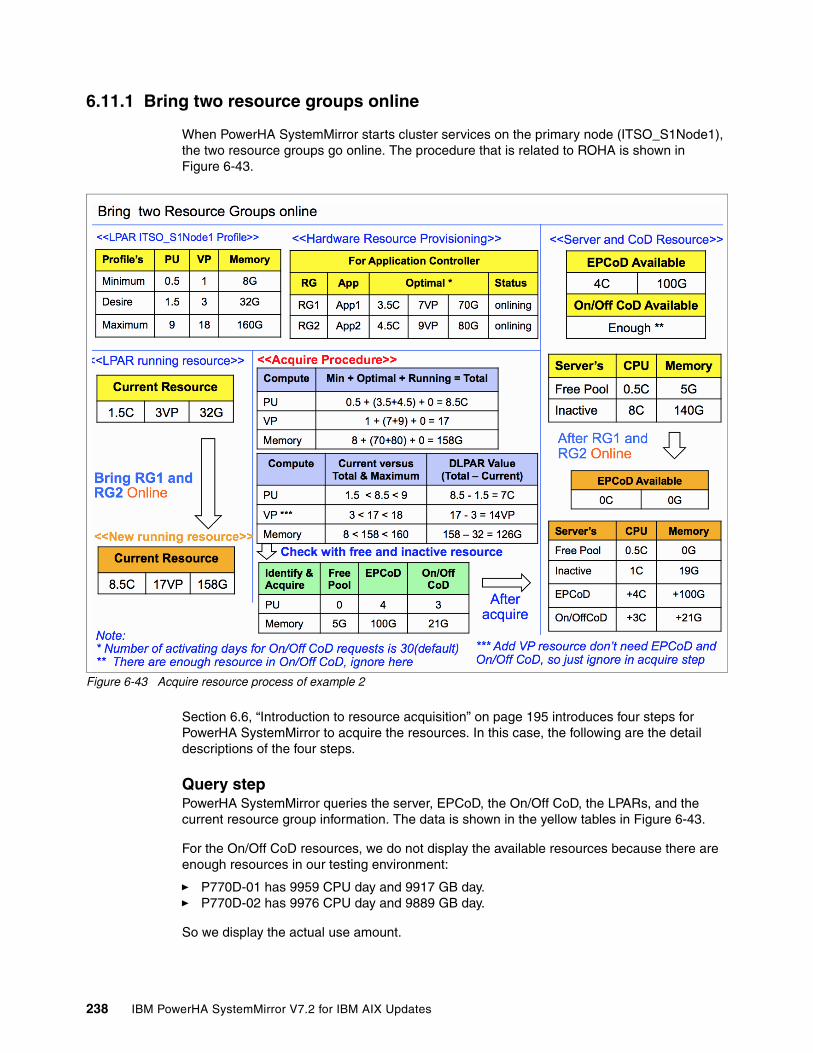
6.11.1 Bring two resource groups online
When PowerHA SystemMirror starts cluster services on the primary node (ITSO_S1Node1), the two resource groups go online. The procedure that is related to ROHA is shown in Figure 6-43.
Figure 6-43 Acquire resource process of example 2
Section 6.6, “Introduction to resource acquisition” on page 195 introduces four steps for PowerHA SystemMirror to acquire the resources. In this case, the following are the detail descriptions of the four steps.
Query stepPowerHA SystemMirror queries the server, EPCoD, the On/Off CoD, the LPARs, and the current resource group information. The data is shown in the yellow tables in Figure 6-43.
For the On/Off CoD resources, we do not display the available resources because there are enough resources in our testing environment:
� P770D-01 has 9959 CPU day and 9917 GB day.� P770D-02 has 9976 CPU day and 9889 GB day.
So we display the actual use amount.
238 IBM PowerHA SystemMirror V7.2 for IBM AIX Updates

Compute stepIn this step, PowerHA SystemMirror computes how many resources need to add through the DLPAR. PowerHA SystemMirror needs 7C and 126 GB, purple tables show this process (Figure 6-43). We take the CPU resources for example:
� The expected total processor unit number is: 0.5 (Min) + 3.5 (RG1 require) + 4.5 (RG2 require) +0 (running RG require, there is no running RG) = 8.5C.
� Take this value to compare with the LPAR’s profile, which needs to be less than or equal to the Maximum and more than or equal to the Minimum value.
� If this satisfies the requirement, then take this value minus the current running CPU (meaning 8.5 - 1.5 = 7), and this is the number that we want to add to the LPAR through DLPAR.
Identify and acquire the stepAfter the compute step, PowerHA SystemMirror identifies how to satisfy the requirement. For CPU, it gets 4C from EPCoD and 3C from the On/Off CoD. Because for EPCoD and On/Off CoD, the minimum operation unit is 1, so even if there is 0.5 CPU in the server’s free pool, but because the requirement is 7, you leave it in the free pool.
PowerHA SystemMirror gets the remaining 5 GB of this server, all 100 GB from EPCoD and 21 GB from the On/Off CoD. The process is shown in the green table in Figure 6-43 on page 238.
The orange table shows (Figure 6-43 on page 238) the result of this scenario, including the LPAR’s running resources, EPCoD, On/Off CoD and the server’s resource status.
Track the hacmp.out log to know what is happeningFrom hacmp.out, we know that all the resources (7 CPU and 126 memory) costs 117 seconds as a synchronous process as shown in Example 6-26.
22:44:40 → 22:46:37
Example 6-26 The hacmp.out log shows the resource acquisition of example 2
===== Compute ROHA Memory =====minimal + optimal + running = total <=> current <=> maximum8.00 + 150.00 + 0.00 = 158.00 <=> 32.00 <=> 160.00 : => 126.00 GB============ End ================= Compute ROHA PU(s)/VP(s) ==minimal + optimal + running = total <=> current <=> maximum1 + 16 + 0 = 17 <=> 3 <=> 18 : => 14 Virtual Processor(s)minimal + optimal + running = total <=> current <=> maximum0.50 + 8.00 + 0.00 = 8.50 <=> 1.50 <=> 9.00 : => 7.00 Processing Unit(s)============ End =================== Identify ROHA Memory ====Remaining available memory for partition: 5.00 GBTotal Enterprise Pool memory to allocate: 100.00 GBTotal Enterprise Pool memory to yank: 0.00 GB
Note: During this process, PowerHA SystemMirror adds mobile resources from EPCoD to the server’s free pool first, then adds all the free pool’s resources to the LPAR through DLPAR. In order to describe this clearly, the free pool only means the available resources of one server before adding EPCoD’s resources to it.
Chapter 6. Resource Optimized High Availability (ROHA) 239

Total On/Off CoD memory to activate: 21.00 GB for 30 daysTotal DLPAR memory to acquire: 126.00 GB============ End ================= Identify ROHA Processor ===Remaining available PU(s) for partition: 0.50 Processing Unit(s)Total Enterprise Pool CPU(s) to allocate: 4.00 CPU(s)Total Enterprise Pool CPU(s) to yank: 0.00 CPU(s)Total On/Off CoD CPU(s) to activate: 3.00 CPU(s) for 30 daysTotal DLPAR PU(s)/VP(s) to acquire: 7.00 Processing Unit(s) and 14.00 Virtual Processor(s)============ End ==============clhmccmd: 100.00 GB of Enterprise Pool CoD have been allocated.clhmccmd: 4 CPU(s) of Enterprise Pool CoD have been allocated.clhmccmd: 21.00 GB of On/Off CoD resources have been activated for 30 days.clhmccmd: 3 CPU(s) of On/Off CoD resources have been activated for 30 days. clhmccmd: 126.00 GB of DLPAR resources have been acquired. clhmccmd: 14 VP(s) or CPU(s) and 7.00 PU(s) of DLPAR resources have been acquired. The following resources were acquired for application controllers App1Controller App2Controller. DLPAR memory: 126.00 GB On/Off CoD memory: 21.00 GB Enterprise Pool memory: 100.00 GB. DLPAR processor: 7.00 PU/14.00 VP On/Off CoD processor: 3.00 CPU(s) Enterprise Pool processor: 4.00 CPU(s)
ROHA report updateThe clmgr view report roha command reports the ROHA data, as shown in Example 6-27.
Example 6-27 ROHA data after acquire resource in example 2
# clmgr view report rohaCluster: ITSO_ROHA_cluster of NSC type Cluster tunables Dynamic LPAR Start Resource Groups even if resources are insufficient: '0' Adjust Shared Processor Pool size if required: '0' Force synchronous release of DLPAR resources: '0' On/Off CoD I agree to use On/Off CoD and be billed for extra costs: '1' Number of activating days for On/Off CoD requests: '30' Node: ITSO_S1Node1 HMC(s): 9.3.207.130 9.3.207.133 Managed system: rar1m3-9117-MMD-1016AAP LPAR: ITSO_S1Node1 Current profile: 'ITSO_profile' Memory (GB): minimum '8' desired '32' current '158' maximum '160' Processing mode: Shared Shared processor pool: 'DefaultPool' Processing units: minimum '0.5' desired '1.5' current '8.5' maximum '9.0' Virtual processors: minimum '1' desired '3' current '17' maximum '18' ROHA provisioning for 'ONLINE' resource groups No ROHA provisioning.
240 IBM PowerHA SystemMirror V7.2 for IBM AIX Updates

ROHA provisioning for 'OFFLINE' resource groups No 'OFFLINE' resource group. Node: ITSO_S2Node1 HMC(s): 9.3.207.130 9.3.207.133 Managed system: r1r9m1-9117-MMD-1038B9P LPAR: ITSO_S2Node1 Current profile: 'ITSO_profile' Memory (GB): minimum '8' desired '32' current '32' maximum '160' Processing mode: Shared Shared processor pool: 'DefaultPool' Processing units: minimum '0.5' desired '1.5' current '1.5' maximum '9.0' Virtual processors: minimum '1' desired '3' current '3' maximum '18' ROHA provisioning for 'ONLINE' resource groups No 'ONLINE' resource group. ROHA provisioning for 'OFFLINE' resource groups No ROHA provisioning.
Hardware Management Console '9.3.207.130' Version: 'V8R8.3.0.1'
Hardware Management Console '9.3.207.133' Version: 'V8R8.3.0.1'
Managed System 'rar1m3-9117-MMD-1016AAP' Hardware resources of managed system Installed: memory '192' GB processing units '12.00' Configurable: memory '173' GB processing units '11.00' Inactive: memory '19' GB processing units '1.00' Available: memory '0' GB processing units '0.50' On/Off CoD On/Off CoD memory State: 'Running' Available: '9277' GB.days Activated: '21' GB Left: '630' GB.days On/Off CoD processor State: 'Running' Available: '9869' CPU.days Activated: '3' CPU(s) Left: '90' CPU.days Yes: 'DEC_2CEC' Enterprise pool Yes: 'DEC_2CEC' Hardware Management Console 9.3.207.130 9.3.207.133 Shared processor pool 'DefaultPool' Logical partition 'ITSO_S1Node1' This 'ITSO_S1Node1' partition hosts 'ITSO_S2Node1' node of the NSC cluster 'ITSO_ROHA_cluster'
...
Chapter 6. Resource Optimized High Availability (ROHA) 241

Enterprise pool 'DEC_2CEC' State: 'In compliance' Master HMC: 'e16hmc1' Backup HMC: 'e16hmc3' Enterprise pool memory Activated memory: '100' GB Available memory: '0' GB Unreturned memory: '0' GB Enterprise pool processor Activated CPU(s): '4' Available CPU(s): '0' Unreturned CPU(s): '0' Used by: 'rar1m3-9117-MMD-1016AAP' Activated memory: '100' GB Unreturned memory: '0' GB Activated CPU(s): '4' CPU(s) Unreturned CPU(s): '0' CPU(s) Used by: 'r1r9m1-9117-MMD-1038B9P' Activated memory: '0' GB Unreturned memory: '0' GB Activated CPU(s): '0' CPU(s) Unreturned CPU(s): '0' CPU(s)
The clmgr view report roha command output (Example 5-8) has some updates about the resources of P770D-01, Enterprise Pool and On/Off CoD.
How to calculate the On/Off CoD consumptionIn this case, before bringing the two resource groups online, the remaining resources in On/Off CoD are shown in Example 6-28.
Example 6-28 Remaining resources in On/Off CoD before resource acquisition
On/Off CoD memory State: 'Available' Available: '9907' GB.daysOn/Off CoD processor State: 'Available' Available: '9959' CPU.days
After the resource group is online, the status of the On/Off CoD resource is shown in Example 6-29.
Example 6-29 Status of the memory resources
On/Off CoD memory State: 'Running' Available: '9277' GB.days Activated: '21' GB Left: '630' GB.days On/Off CoD processor State: 'Running' Available: '9869' CPU.days Activated: '3' CPU(s) Left: '90' CPU.days
242 IBM PowerHA SystemMirror V7.2 for IBM AIX Updates

For processor, PowerHA SystemMirror assigns 3 processors and activate day is 30 days, so the total is 90 CPU.Day. (3*30=90), then the remaining available CPU.Day in the On/Off CoD is 9869 (9959 - 90 = 9869).
For memory, PowerHA SystemMirror assigns 21 GB and activate day is 30 days, so the total is 630 GB.Day. (21*30=630), then the remaining available GB.Day in On/Off CoD is 9277 (9907 - 630 = 9277).
6.11.2 Bring one resource group offline
This section introduces the process of resource group offline. Figure 6-44 shows the overall process.
Figure 6-44 Overall releasing process of example 2
The process is similar to the one shown in 6.9.2, “Move one resource group to another node” on page 223.
In the releasing process, the de-allocation order is On/Off CoD, then EPCoD, and last is the server’s free pool because you always need to pay extra cost for the On/Off CoD.
Chapter 6. Resource Optimized High Availability (ROHA) 243

After the releasing process completes, in the hacmp.out file, you can find the detailed information about compute, identify, and release processes, as shown in Example 6-30.
Example 6-30 The hacmp.out log information in the releasing process of example 2
===== Compute ROHA Memory =====minimum + running = total <=> current <=> optimal <=> saved8.00 + 80.00 = 88.00 <=> 158.00 <=> 70.00 <=> 126.00 : => 70.00 GB============ End ================= Compute ROHA PU(s)/VP(s) ==minimal + running = total <=> current <=> optimal <=> saved1 + 9 = 10 <=> 17 <=> 7 <=> 14 : => 7 Virtual Processor(s)minimal + running = total <=> current <=> optimal <=> saved0.50 + 4.50 = 5.00 <=> 8.50 <=> 3.50 <=> 7.00 : => 3.50 Processing Unit(s)============ End =================== Identify ROHA Memory ====Total Enterprise Pool memory to return back: 49.00 GBTotal On/Off CoD memory to de-activate: 21.00 GBTotal DLPAR memory to release: 70.00 GB============ End ================= Identify ROHA Processor ===Total Enterprise Pool CPU(s) to return back: 1.00 CPU(s)Total On/Off CoD CPU(s) to de-activate: 3.00 CPU(s)Total DLPAR PU(s)/VP(s) to release: 7.00 Virtual Processor(s) and 3.50 Processing Unit(s)============ End ==============clhmccmd: 49.00 GB of Enterprise Pool CoD have been returned.clhmccmd: 1 CPU(s) of Enterprise Pool CoD have been returned.The following resources were released for application controllers App1Controller.DLPAR memory: 70.00 GB On/Off CoD memory: 21.00 GB Enterprise Pool memory: 49.00 GB.DLPAR processor: 3.50 PU/7.00 VP On/Off CoD processor: 3.00 CPU(s) Enterprise Pool processor: 1.00 CPU(s)
6.12 Hardware Management Console (HMC) high availability introduction
More than one HMC can be configured for a node, so that if one HMC fails to respond, the ROHA functionality can switch to the other HMC.
This section describes the mechanism that enables the HMC to switch from one HMC to another HMC.
Suppose that you have, for a given node, three HMCs in the following order: HMC1, HMC2, and HMC3. (These HMCs can be set either at the node level, at the site level or at the cluster level, as it is explained later in this document. What counts at the end is that you have for a given node an ordered list of HMCs).
All of this means that a given node will use the first HMC in its list, for example HMC1, and use it for as long as it works.
244 IBM PowerHA SystemMirror V7.2 for IBM AIX Updates

HMC1 could fail for different reasons, for example in the following situations:
1. HMC1 is not reachable via the ping command:
One parameter controls the ping command in the HMC: Timeout on ping (which is set by default to 3 seconds, and you cannot adjust it). If an HMC cannot be pinged after this timeout, you cannot use it through ssh, so switch immediately to another HMC, in this case the HMC following the current one in the list (for example, HMC2).
2. HMC1 is not reachable through SSH:
– SSH is not properly configured between the node and HMC1, and you can consider that it is not worth trying to use HMC1, and it is best to switch to another HMC. In this case, the HMC following the current one in the list, for example, HMC2.
– SSH has temporary conditions that prevent it from responding.
Two parameters controls the ssh command on the HMC:
– Connect Attempts (which is set by default to 5)– Connect Timeout (which is set by default to 5), meaning that after a 25-second delay,
the HMC can be considered as not reachable through ssh
If the HMC is not reachable through ssh, it is not worth trying to perform an hmc command through ssh on it, and the best is to switch at to another HMC. In this case, the HMC following the current one in the list, for example HMC2.
3. The HMC is repeatedly busy:
When the HMC is processing a command, it cannot perform another command at the same time. The command fails with RC=-1 and with the HSCL3205 message indicating that the HMC is busy.
PowerHA SystemMirror ROHA functionality has a retry mechanism that is controlled with two parameters:
– RETRY_COUNT, indicating how many retries must be done– RETRY_DELAY, indicating how long to wait between retries.
This means that when the HMC is busy, the retry mechanism is used until declaring that the HMC is flooded.
When the HMC is considered flooded, it is not worth using it again, and the best is to switch immediately to another HMC, the HMC following the current one in the list, for example HMC2.
4. The HMC returns an application error. Several cases can occur:
– One case is for example when you request for an amount of resources which is not available, and the same request is attempted with another smaller amount.
– A second case is when the command is not understandable by the HMC which is more like a programming bug, and in these cases should be debugged at test time. In any case, this is not a reason to switch to another HMC.
If you decide to switch to another HMC, consider the next HMC of the list, and use it.
Remember to note that the first HMC is not usable (HMC1), and that you are currently using the second HMC in the list (HMC2). This helps to prevent the ROHA functionality from trying again and failing again using the first HMC (HMC1). You can add (persistence) into the ODM which HMC is being used (for example, HMC2).
This mechanism enables the ROHA functionality to skip the failing HMCs, and to use the HMC that works (in this case, HMC2). At the end of the session, the persistence into the ODM is cleared, meaning that the first HMC in the list is restored to its role of HMC1 or the first in the list.
Chapter 6. Resource Optimized High Availability (ROHA) 245

6.12.1 Switch to the backup HMC for the Power Enterprise Pool
For Enterprise Pool operations, querying operations can be run on the master or backup HMC, but changing operations must run on the master HMC. If the master HMC fails, PowerHA SystemMirror’s actions are as follows:
� For querying operations, PowerHA SystemMirror tries to switch to the backup HMC to continue the operation, but does not set the backup HMC as the master.
� For changing operations, PowerHA SystemMirror tries to set the backup HMC as the master, and then continues the operation. Example 6-31 shows the command that PowerHA SystemMirror performs to set the backup HMC as the master. This command is triggered by PowerHA SystemMirror automatically.
Example 6-31 Setting the backup HMC as the master
chcodpool -o setmaster -p <pool> --mc backup
There are some prerequisites in PowerHA SystemMirror before switching to the backup HMC when the master HMC fails:
� Configure the master HMC and the backup HMC for your Power Enterprise Pool.
For more information about how to configure the backup HMC for the Power Enterprise Pool, read the following two references:
https://www.ibm.com/support/knowledgecenter/P8DEA/p8ha2/entpool_cod_use.htmhttp://www.redbooks.ibm.com/redpapers/pdfs/redp5101.pdf
� Both HMCs are configured in PowerHA SystemMirror.
� Establish password-less communication between the PowerHA SystemMirror nodes to the two HMCs.
� Ensure reachability (pingable) from PowerHA SystemMirror nodes to the master and backup HMCs.
� Ensure that all of the servers that participate in the pool are connected to the two HMCs.
� Ensure that the participating servers are in either Standby state or the Operating state.
6.13 Test scenario for HMC fallover
This section shows how PowerHA SystemMirror switches the HMC automatically when the primary HMC fails.
246 IBM PowerHA SystemMirror V7.2 for IBM AIX Updates

6.13.1 Hardware topology
Figure 6-45 shows the initial status of the hardware topology.
Figure 6-45 Initial status of the hardware topology
The topology includes the following components:
� Two Power 780 D model servers, named P780D_09 and P780D_10.
� One Power Enterprise Pool, which has 64 mobile processors and 2 TB of mobile memory resources.
� There are 64 CPUs and 2 TB of memory installed in P780D_09, 32 CPUs, and 1 TB of memory are configured, and another 32 CPUs and 1 TB of memory are in inactive status. At this time, there are 5 CPUs and 10 GB of memory available for the DLPAR.
� The PowerHA SystemMirror cluster includes two nodes:
– P780_09_Lpar1– P780_10_Lpar2
� The PowerHA SystemMirror cluster includes one resource group (RG2), this resource group has one application controller (app2) configured hardware resource provisioning.
� This application needs 20 C and 40 G when it runs.
� There is no On/Off CoD in this testing.
There are two HMCs to manage the EPCoD, named HMCEP1 and HMCEP2.
Chapter 6. Resource Optimized High Availability (ROHA) 247

HMCEP1 is the master and HMCEP2 is the backup, as shown in Example 6-32.
Example 6-32 HMCs available
hscroot@HMCEP1:~> lscodpool -p 0019 --level poolname=0019,id=0019,state=In compliance,sequence_num=5,master_mc_name=HMCEP1,master_mc_mtms=V017-ffe*d33e8a1,backup_master_mc_name=HMCEP2,backup_master_mc_mtms=V017-f93*ba3e3aa,mobile_procs=64,avail_mobile_procs=64,unreturned_mobile_procs=0,mobile_mem=2048000,avail_mobile_mem=2048000,unreturned_mobile_mem=0
In the AIX /etc/hosts file, define the resolution between the HMC IP address, and the HMC’s host name, as shown in Example 6-33.
Example 6-33 Define resolution between HMC IP and HMC name in the /etc/hosts
172.16.50.129 P780_09_Lpar1172.16.50.130 P780_10_Lpar1172.16.51.129 testservice1172.16.51.130 testservice2172.16.50.253 HMCEP1172.16.50.254 HMCEP2
Then start the PowerHA SystemMirror service on P780_09_Lpar1. During the start, PowerHA SystemMirror will acquire resources from the server’s free pool and EPCoD (Figure 6-46).
Figure 6-46 Resource Acquisition process during the start of PowerHA SystemMirror service
248 IBM PowerHA SystemMirror V7.2 for IBM AIX Updates

In this process, HMCEP1 acts as the primary HMC and does all the query and resource acquisition operations. Example 6-34 and Example 6-35 show the detailed commands used in the acquisition step.
Example 6-34 EPCoD operation during resource acquisition (hacmp.out)
+testRG2:clhmccmd[clhmcexec:1] ssh -o StrictHostKeyChecking=no -o LogLevel=quiet -o AddressFamily=any -o BatchMode=yes -o ConnectTimeout=3 -o ConnectionAttempts=3 -o TCPKeepAlive=no hscroot@HMCEP1 'chcodpool -p 0019 -m SVRP7780-09-SN060C0AT -r mem -o add -q 23552 2>&1' -->23552 means 23GB...+testRG2:clhmccmd[clhmcexec:1] ssh -o StrictHostKeyChecking=no -o LogLevel=quiet -o AddressFamily=any -o BatchMode=yes -o ConnectTimeout=3 -o ConnectionAttempts=3 -o TCPKeepAlive=no hscroot@HMCEP1 'chcodpool -p 0019 -m SVRP7780-09-SN060C0AT -r proc -o add -q 14 2>&1'
Example 6-35 DLPAR add operation in the acquire step
+testRG2:clhmccmd[clhmcexec:1] ssh -o StrictHostKeyChecking=no -o LogLevel=quiet -o AddressFamily=any -o BatchMode=yes -o ConnectTimeout=3 -o ConnectionAttempts=3 -o TCPKeepAlive=no [email protected] 'chhwres -m SVRP7780-09-SN060C0AT -p P780_09_Lpar1 -r mem -o a -q 33024 -w 32 2>&1' -->33024 means 32.25GB...+testRG2:clhmccmd[clhmcexec:1] ssh -o StrictHostKeyChecking=no -o LogLevel=quiet -o AddressFamily=any -o BatchMode=yes -o ConnectTimeout=3 -o ConnectionAttempts=3 -o TCPKeepAlive=no [email protected] 'chhwres -m SVRP7780-09-SN060C0AT -p P780_09_Lpar1 -r proc -o a --procs 19 -w 32 2>&1 -->172.16.50.253 is HMCEP1
Note: We do not display the DLPAR and EPCoD operations in the query step in the previous examples.
Chapter 6. Resource Optimized High Availability (ROHA) 249

6.13.2 Bring one resource group offline when primary HMC fails
After the resource group is online, we bring the resource group offline. During this process, we shut down HMCEP1 to see how PowerHA SystemMirror handles this situation.
The resource releasing process is shown in Figure 6-47.
Figure 6-47 Bring the resource group offline process
Section 6.6, “Introduction to resource acquisition” on page 195 introduces the four steps for PowerHA SystemMirror to acquire the resources. In this case, the following is the detailed description of the four steps.
Query stepIn this step, PowerHA SystemMirror needs to query the server’s data and the EPCoD’s data.
For getting the server’s information, PowerHA SystemMirror uses the default primary HMC (172.16.50.253, HMCEP1). At first, HMCEP1 is alive, the operation succeeds. But after HMCEP1 shutdown, the operation fails and PowerHA SystemMirror uses 172.16.50.254 as the primary HMC to continue. Example 6-36 on page 251 shows the takeover process.
250 IBM PowerHA SystemMirror V7.2 for IBM AIX Updates

Example 6-36 HMC takeover process
+testRG2:clhmccmd[get_local_hmc_list:815] g_hmc_list='172.16.50.253 172.16.50.254'--> default, the global HMC list is:172.16.50.253 is first, then 172.16.50.254...+testRG2:clhmccmd[clhmcexec:3512] ping -c 1 -w 3 172.16.50.253+testRG2:clhmccmd[clhmcexec:3512] 1> /dev/null 2>& 1+testRG2:clhmccmd[clhmcexec:3512] ping_output=''+testRG2:clhmccmd[clhmcexec:3513] ping_rc=1+testRG2:clhmccmd[clhmcexec:3514] (( 1 > 0 ))+testRG2:clhmccmd[clhmcexec:3516] : Cannot contact this HMC. Ask following HMC in list.--> after checking, confirm that 172.16.50.253 is unaccessible, then to find next HMC in the list...+testRG2:clhmccmd[clhmcexec:3510] : Try to ping the HMC at address 172.16.50.254.+testRG2:clhmccmd[clhmcexec:3512] ping -c 1 -w 3 172.16.50.254+testRG2:clhmccmd[clhmcexec:3512] 1> /dev/null 2>& 1+testRG2:clhmccmd[clhmcexec:3512] ping_output=''+testRG2:clhmccmd[clhmcexec:3513] ping_rc=0+testRG2:clhmccmd[clhmcexec:3514] (( 0 > 0 ))--> 172.16.50.254 is the next, so PowerHA SystemMirror check it...+testRG2:clhmccmd[update_hmc_list:3312] g_hmc_list='172.16.50.254 172.16.50.253'--> it is accessable, change it as first HMC in globale HMC list...+testRG2:clhmccmd[clhmcexec:3456] loop_hmc_list='172.16.50.254 172.16.50.253'--> global HMC list has been changed, following operation will use 172.16.50.254...+testRG2:clhmccmd[clhmcexec:1] ssh -o StrictHostKeyChecking=no -o LogLevel=quiet -o AddressFamily=any -o BatchMode=yes -o ConnectTimeout=3 -o ConnectionAttempts=3 -o TCPKeepAlive=no [email protected] 'lshmc -v 2>&1'--> start with 172.16.50.254 to do query operation...+testRG2:clhmccmd[clhmcexec:3618] eval LC_ALL=C ssh -o StrictHostKeyChecking=no -o LogLevel=quiet -o AddressFamily=any -o BatchMode=yes -o ConnectTimeout=3 -o ConnectionAttempts=3 -o TCPKeepAlive=no $'[email protected] \'lscodpool -p 0019 --level sys --filter names=SVRP7780-09-SN060C0AT -F inactive_mem:mobile_mem:unreturned_mobile_mem:inactive_procs:mobile_procs:unreturned_mobile_procs 2>&1\''+t--> using 172.16.50.254 to query EPCoD information
Compute stepThis step does not need to do an HMC operation. See Figure 6-47 on page 250 for the detailed process.
Identify and acquire stepAfter the identify step, there are some resources that are needed to release to EPCoD. Therefore, PowerHA SystemMirror returns the resource back to EPCoD immediately before the resource is removed from the LPAR. This generates an unreturned resource temporarily.
Important: The process enables you to query EPCoD information from the backup HMC. However, any change operations need to be done on the master HMC.
Chapter 6. Resource Optimized High Availability (ROHA) 251

At this time, PowerHA SystemMirror checks if the master HMC is available. If not, switches to the backup HMC automatically. Example 6-37 shows the detailed process.
Example 6-37 The EPCoD master and backup HMC switch process
+testRG2:clhmccmd[clhmcexec:3388] cmd='chcodpool -p 0019 -m SVRP7780-09-SN060C0AT -r mem -o remove -q 23552 --force'-->PowerHA SystemMirror try to do chcodpool operation...+testRG2:clhmccmd[clhmcexec:3401] : If working on an EPCoD Operation, we need master-->PowerHA SystemMirror want to check if master HMC is accessiable...ctionAttempts=3 -o TCPKeepAlive=no $'[email protected] \'lscodpool -p 0019 --level pool -F master_mc_name:backup_master_mc_name 2>&1\''+testRG2:clhmccmd[clhmcexec:1] ssh -o StrictHostKeyChecking=no -o LogLevel=quiet -o AddressFamily=any -o BatchMode=yes -o ConnectTimeout=3 -o ConnectionAttempts=3 -o TCPKeepAlive=no [email protected] 'lscodpool -p 0019 --level pool -F master_mc_name:backup_master_mc_name 2>&1'+testRG2:clhmccmd[clhmcexec:1] LC_ALL=C+testRG2:clhmccmd[clhmcexec:3415] res=HMCEP1:HMCEP2-->Current HMC is 172.16.50.254, so PowerHA SystemMirror query current master and backup HMC name from it. At this time, HMCEP1 is master and HMCEP2 is backup....+testRG2:clhmccmd[clhmcexec:3512] ping -c 1 -w 3 HMCEP1+testRG2:clhmccmd[clhmcexec:3512] 1> /dev/null 2>& 1+testRG2:clhmccmd[clhmcexec:3512] ping_output=''+testRG2:clhmccmd[clhmcexec:3513] ping_rc=1+testRG2:clhmccmd[clhmcexec:3514] (( 1 > 0 ))+testRG2:clhmccmd[clhmcexec:3516] : Cannot contact this HMC. Ask following HMC in list.+testRG2:clhmccmd[clhmcexec:3518] dspmsg scripts.cat -s 38 500 '%1$s: WARNING: unable to ping HMC at address %2$s.\n' clhmccmd HMCEP1-->PowerHA SystemMirror try to ping HMCEP1, but fails...+testRG2:clhmccmd[clhmcexec:3510] : Try to ping the HMC at address HMCEP2.+testRG2:clhmccmd[clhmcexec:3512] ping -c 1 -w 3 HMCEP2+testRG2:clhmccmd[clhmcexec:3512] 1> /dev/null 2>& 1+testRG2:clhmccmd[clhmcexec:3512] ping_output=''+testRG2:clhmccmd[clhmcexec:3513] ping_rc=0+testRG2:clhmccmd[clhmcexec:3514] (( 0 > 0 ))-->PowerHA SystemMirror try to verify HMCEP2 and it is available...+testRG2:clhmccmd[clhmcexec:3527] : the hmc is the master_hmc+testRG2:clhmccmd[clhmcexec:3529] (( g_epcod_modify_operation == 1 && loop_hmc_counter != 1 ))+testRG2:clhmccmd[clhmcexec:3531] : If not, we need to change master_hmc, we also try to+testRG2:clhmccmd[clhmcexec:3532] : set a backup_master_hmc
+testRG2:clhmccmd[clhmcexec:3536] eval LC_ALL=C ssh -o StrictHostKeyChecking=no -o LogLevel=quiet -o AddressFamily=any -o BatchMode=yes -o ConnectTimeout=3 -o ConnectionAttempts=3 -o TCPKeepAlive=no $'hscroot@HMCEP2 \'chcodpool -p 0019 -o setmaster --mc this 2>&1\''
252 IBM PowerHA SystemMirror V7.2 for IBM AIX Updates

+testRG2:clhmccmd[clhmcexec:1] ssh -o StrictHostKeyChecking=no -o LogLevel=quiet -o AddressFamily=any -o BatchMode=yes -o ConnectTimeout=3 -o ConnectionAttempts=3 -o TCPKeepAlive=no hscroot@HMCEP2 'chcodpool -p 0019 -o setmaster --mc this 2>&1'+testRG2:clhmccmd[clhmcexec:1] LC_ALL=C+testRG2:clhmccmd[clhmcexec:3536] out_str=''+testRG2:clhmccmd[clhmcexec:3537] ssh_rc=0-->PowerHA SystemMirror set backup HMC(HMCEP2) as master...+testRG2:clhmccmd[clhmcexec:1] ssh -o StrictHostKeyChecking=no -o LogLevel=quiet -o AddressFamily=any -o BatchMode=yes -o ConnectTimeout=3 -o ConnectionAttempts=3 -o TCPKeepAlive=no hscroot@HMCEP2 'chcodpool -p 0019 -o update -a "backup_master_mc_name=HMCEP1" 2>&1'+testRG2:clhmccmd[clhmcexec:1] LC_ALL=C+testRG2:clhmccmd[clhmcexec:3722] out_str='HSCL90E9 Management console HMCEP1was not found.'-->PowerHA SystemMirror also try to set HMCEP1 as backup, but it fails because HMCEP1 is shutdown at this time...+testRG2:clhmccmd[clhmcexec:1] ssh -o StrictHostKeyChecking=no -o LogLevel=quiet -o AddressFamily=any -o BatchMode=yes -o ConnectTimeout=3 -o ConnectionAttempts=3 -o TCPKeepAlive=no hscroot@HMCEP2 'chcodpool -p 0019 -m SVRP7780-09-SN060C0AT -r mem -o remove -q 23552 --force 2>&1'+testRG2:clhmccmd[clhmcexec:1] LC_ALL=C-->PowerHA SystemMirror do the force release for memory resource...+testRG2:clhmccmd[clhmcexec:1] ssh -o StrictHostKeyChecking=no -o LogLevel=quiet -o AddressFamily=any -o BatchMode=yes -o ConnectTimeout=3 -o ConnectionAttempts=3 -o TCPKeepAlive=no hscroot@HMCEP2 'chcodpool -p 0019 -m SVRP7780-09-SN060C0AT -r proc -o remove -q 14 --force 2>&1'-->PowerHA SystemMirror do the force release for CPU resource
Example 6-38 shows the update that is performed from EPCoD’s view.
Example 6-38 EPCoD status change during the takeover operation
hscroot@HMCEP2:~> lscodpool -p 0019 --level poolname=0019,id=0019,state=In compliance,sequence_num=5,master_mc_name=HMCEP1,master_mc_mtms=V017-ffe*d33e8a1,backup_master_mc_name=HMCEP2,backup_master_mc_mtms=V017-f93*ba3e3aa,mobile_procs=64,avail_mobile_procs=50,unreturned_mobile_procs=0,mobile_mem=2048000,avail_mobile_mem=2024448,unreturned_mobile_mem=0--> There are 14CPU(64-50) and 23GB((2048000-2024448)/1024) has assigned to P780D_09.hscroot@HMCEP2:~> lscodpool -p 0019 --level sys name=SVRP7780-10-SN061949T,mtms=9179-MHD*061949T,mobile_procs=0,non_mobile_procs=32,unreturned_mobile_procs=0,inactive_procs=32,installed_procs=64,mobile_mem=0,non_mobile_mem=1073152,unreturned_mobile_mem=0,inactive_mem=1024000,installed_mem=2097152name=SVRP7780-09-SN060C0AT,mtms=9179-MHD*060C0AT,mobile_procs=14,non_mobile_procs=32,unreturned_mobile_procs=0,inactive_procs=18,installed_procs=64,mobile_mem=23552,non_mobile_mem=1073152,unreturned_mobile_mem=0,inactive_mem=1000448,installed_mem=2097152
Chapter 6. Resource Optimized High Availability (ROHA) 253

--> Show the information from server level report...hscroot@HMCEP2:~> lscodpool -p 0019 --level poolname=0019,id=0019,state=unavailable,sequence_num=5,master_mc_name=HMCEP1,master_mc_mtms=V017-ffe*d33e8a1,backup_master_mc_name=HMCEP2,backup_master_mc_mtms=V017-f93*ba3e3aa,mobile_procs=unavailable,avail_mobile_procs=unavailable,unreturned_mobile_procs=unavailable,mobile_mem=unavailable,avail_mobile_mem=unavailable,unreturned_mobile_mem=unavailable--> After HMCEP1 shutdown, the EPCoD’s status is changed to 'unavailable'...hscroot@HMCEP2:~> lscodpool -p 0019 --level poolname=0019,id=0019,state=In compliance,sequence_num=5,master_mc_name=HMCEP2,master_mc_mtms=V017-f93*ba3e3aa,backup_master_mc_mtms=none,mobile_procs=64,avail_mobile_procs=50,unreturned_mobile_procs=0,mobile_mem=2048000,avail_mobile_mem=2024448,unreturned_mobile_mem=0--> After PowerHA SystemMirror run 'chcodpool -p 0019 -o setmaster --mc this' on HMCEP2, the master HMC is changed and status is changed to 'In compliance'....hscroot@HMCEP2:~> lscodpool -p 0019 --level sys name=SVRP7780-10-SN061949T,mtms=9179-MHD*061949T,mobile_procs=0,non_mobile_procs=32,unreturned_mobile_procs=0,inactive_procs=32,installed_procs=64,mobile_mem=0,non_mobile_mem=1073152,unreturned_mobile_mem=0,inactive_mem=1024000,installed_mem=2097152name=SVRP7780-09-SN060C0AT,mtms=9179-MHD*060C0AT,mobile_procs=0,non_mobile_procs=32,unreturned_mobile_procs=14,inactive_procs=18,installed_procs=64,mobile_mem=0,non_mobile_mem=1073152,unreturned_mobile_mem=23552,inactive_mem=1000448,installed_mem=2097152--> After PowerHA SystemMirror forcely release resource, ureturned resource is generated...hscroot@HMCEP2:~> lscodpool -p 0019 --level poolname=0019,id=0019,state=Approaching out of compliance (within server grace period),sequence_num=5,master_mc_name=HMCEP2,master_mc_mtms=V017-f93*ba3e3aa,backup_master_mc_mtms=none,mobile_procs=64,avail_mobile_procs=64,unreturned_mobile_procs=14,mobile_mem=2048000,avail_mobile_mem=2048000,unreturned_mobile_mem=23553--> At this time, the resource has returned to EPCoD and can be used by other servers...
When PowerHA SystemMirror completes the above steps, it raises an asynchronous process to remove the resources from P780_09_Lpar1 using DLPAR. The resources include 19 CPUs and 32.25 GB of memory.
After the DLPAR operation, the unreturned resource is reclaimed automatically, and EPCoD’s status is changed to In compliance, as shown in Example 6-39.
Example 6-39 EPCoD’s status restored after DLPAR operation complete
hscroot@HMCEP1:~> lscodpool -p 0019 --level pool name=0019,id=0019,state=In compliance,sequence_num=5,master_mc_name=HMCEP1,master_mc_mtms=V017-ffe*d33e8a1,backup_master_mc_name=HMCEP2,backup_master_mc_mtms=V017-f93*ba3e3aa,mobile_procs=64,avail_mobile_procs=64,unreturned_mobile_procs=0,mobile_mem=2048000,avail_mobile_mem=2048000,unreturned_mobile_mem=0
254 IBM PowerHA SystemMirror V7.2 for IBM AIX Updates

6.13.3 Testing summary
This scenario introduced how PowerHA SystemMirror performs HMC takeovers when the primary HMC fails. This is an automatic process and has no impact to your environment.
6.14 Manage, monitor and troubleshooting
This section introduces some tools to manage, monitor, and troubleshoot a ROHA cluster.
6.14.1 The clmgr interface to manage ROHA
SMIT relies on the clmgr command to perform configuration that is related with ROHA.
HMC configurationThe following examples show how to configure HMC with the clmgr command.
Query/Add/Modify/DeleteExample 6-40 shows how to query, add, modify, and delete HMC with the clmgr command.
Example 6-40 query/add/modify/delete HMC with clmgr command
# clmgr query hmc -hclmgr query hmc [<HMC>[,<HMC#2>,...]]
# clmgr –v query hmcNAME="r1r9sdmc.austin.ibm.com"TIMEOUT="-1"RETRY_COUNT="8"RETRY_DELAY="-1"NODES=clio1,clio2SITES=site1
# clmgr add hmc -hclmgr add hmc <HMC> \ [ TIMEOUT={<#>} ] \ [ RETRY_COUNT={<#>} ] \ [ RETRY_DELAY={<#>} ] \ [ NODES=<node>[,<node#2>,...]> ] \ [ SITES=<site>[,<site#2>,...]> ] \ [ CHECK_HMC={<yes>|<no>} ]
# clmgr modify hmc -hclmgr modify hmc <HMC> \ [ TIMEOUT={<#>} ] \ [ RETRY_COUNT={<#>} ] \ [ RETRY_DELAY={<#>} ] [ NODES=<node>[,<node#2>,...]> ] \ [ SITES=<site>[,<site#2>,...]> ] \ [ CHECK_HMC={<yes>|<no>} ]
# clmgr delete hmc -hclmgr delete hmc {<HMC>[,<HMC#2>,...] | ALL}
Chapter 6. Resource Optimized High Availability (ROHA) 255

Query/Modify a node with the list of associated HMCExample 6-41 shows how to query and modify a node with the list of associated HMCs.
Example 6-41 query/modify node with a list of associated HMC with the clmgr command
# clmgr query node -hclmgr query node {<node>|LOCAL}[,<node#2>,...]
# clmgr –v query nodeNAME="rar1m31"…HMCS="r1r9sdmc.austin.ibm.com cuodhmc.austin.ibm.com"
# clmgr modify node -hclmgr modify node <NODE> \ … \ [ HMCS=<sorted_hmc_list> ]
Query/Modify a site with the list of associated HMCExample 6-42 shows how to query and modify the site with a list of associated HMCs with the clmgr command.
Example 6-42 query/modify site with a list of associated HMCs with clmgr command
# clmgr query site -hclmgr query site [<site> [,<site#2>,...]]
# clmgr –v query siteNAME="site1"…HMCS="r1r9sdmc.austin.ibm.com cuodhmc.austin.ibm.com"
# clmgr modify site -hclmgr modify site <SITE> \ … \ [ HMCS =<sorted_hmc_list> ]
Query/Modify cluster with default HMC tunablesExample 6-43 shows how to query and modify the cluster with the default HMC tunables.
Example 6-43 query/modify cluser with default HMC tunables with clmgr command
# clmgr query cluster -hclmgr query cluster [ ALL | {CORE,SECURITY,SPLIT-MERGE,HMC,ROHA} ]
# clmgr query cluster hmcDEFAULT_HMC_TIMEOUT="10"DEFAULT_HMC_RETRY_COUNT="5"DEFAULT_HMC_RETRY_DELAY="10"DEFAULT_HMCS_LIST="r1r9sdmc.austin.ibm.com cuodhmc.austin.ibm.com"
# clmgr manage cluster hmc -hclmgr manage cluster hmc \ [ DEFAULT_HMC_TIMEOUT=# ] \ [ DEFAULT_HMC_RETRY_COUNT=# ] \
256 IBM PowerHA SystemMirror V7.2 for IBM AIX Updates

[ DEFAULT_HMC_RETRY_DELAY=# ] \ [ DEFAULT_HMCS_LIST=<new_hmcs_list> ]
Hardware resource provisioningSMIT relies on the clmgr command to List or Query current values of the hardware resource provisioning and to Add/Modify/Delete the HACMPserver ODM data structure, as shown in Example 6-44.
Example 6-44 Hardware resource provisioning configuration with the clmgr command
# clmgr query cod -hclmgr query cod [<APP>[,<APP#2>,...]]
# clmgr –v query codNAME="appli1_APPCON_A"USE_DESIRED=NoOPTIMAL_MEM="4"OPTIMAL_CPU="3"OPTIMAL_PU="2.5"OPTIMAL_PV="3.0"
# clmgr add cod -hclmgr add cod <APPCTRL> \ [ USE_DESIRED =<Yes|No> ] \ [ OPTIMAL_MEM=# ] \ [ OPTIMAL_CPU=# ] \ [ OPTIMAL_PU=#.# ] \ [ OPTIMAL_PV=#.# ]
# clmgr modify cod -hclmgr modify cod <APPCTRL> \ [ USE_DESIRED =<Yes|No> ] \ [ OPTIMAL_MEM=# ] \ [ OPTIMAL_CPU=# ] \ [ OPTIMAL_PU=#.# ] \ [ OPTIMAL_PV=# ]
# clmgr delete cod -hclmgr delete cod {<APPCTRL> | ALL}
Cluster tunablesSMIT relies on the clmgr command to query or modify cluster CoD tunables, as shown in Example 6-45.
Example 6-45 Cluster wide tunables configuration with clmgr command
# clmgr query cluster -hclmgr query cluster [ ALL | {CORE,SECURITY,SPLIT-MERGE,HMC,ROHA} ]
# clmgr query cluster rohaALWAYS_START_RG="no"ADJUST_SPP_SIZE="yes"FORCE_SYNC_RELEASE="no"AGREE_TO_COD_COSTS="no"
Chapter 6. Resource Optimized High Availability (ROHA) 257

COD_ONOFF_DAYS="30"SECONDARY_LPARS_ENABLE="no"SECONDARY_LPARS_POLICY=""SECONDARY_LPARS_THRESHOLD=""
# clmgr manage cluster roha –hclmgr manage cluster roha \ [ ALWAYS_START_RG={yes|no} ] \ [ ADJUST_SPP_SIZE={yes|no} ] \ [ FORCE_SYNC_RELEASE={yes|no} ] \ [ AGREE_TO_COD_COSTS={yes|no} ] \ [ COD_ONOFF_DAYS=<new_number_of_days> ] \ [ SECONDARY_LPARS_ENABLE={yes|no} ] [ SECONDARY_LPARS_POLICY={minimize|shutdown} ] [ SECONDARY_LPARS_THRESHOLD=<priority> ]
6.14.2 Changing the DLPAR and CoD resources dynamically
You can change the DLPAR and CoD resource requirements for application controllers without stopping the cluster services. Remember to synchronize the cluster after making the changes.
The new configuration is not reflected until the next event that causes the application (hence the resource group) to be released and reacquired on another node. In other words, a change in the resource requirements for CPUs, memory or both does not cause the recalculation of the DLPAR resources. PowerHA SystemMirror does not stop and restarts the application controllers solely for the purpose of making the application provisioning changes.
If another dynamic reconfiguration change causes the resource groups to be released and reacquired, the new resource requirements for DLPAR and CoD are used at the end of this dynamic reconfiguration event.
6.14.3 View the ROHA report
The clmgr view report roha command is intended to query all the Resource Optimized High Availability data, so that a report and a summary can be presented to the user.
The output of this command includes the following sections:
� CEC name� LPAR name� LPAR profile (min, desired, max)� LPAR processing mode� If shared (capped or uncapped, SPP name, SPP size)� LPAR current level of resources (mem, cpu, pu)� Number and names of AC and optimal level of resources, and the sum of them� Release mode (sync/async) which would be computed at release time� All On/Off CoD information of the CECs� All EPCoD information of the CECs
There is an example of the report in 6.10.4, “Showing the ROHA configuration” on page 235.
258 IBM PowerHA SystemMirror V7.2 for IBM AIX Updates

6.14.4 Troubleshooting DLPAR and CoD operations
This section provides a brief troubleshooting of the DLPAR and CoD operations.
Log filesThere are several log files use to track ROHA operation process.
Logs for verificationIn the process of Verify and Synchronize Cluster Configuration, there are some log files generated in the /var/hacmp/clverify directory. The clverify.log and the ver_collect_dlpar.log files are useful for debugging if the process fails. For example, after performing the process, there is some error information appearing in the console output(/smit.log), as shown in Example 6-46.
Example 6-46 Error information on console or /smit.log
WARNING: At the time of verification, node ITSO_S2Node1 would not have been able to acquire sufficient resources to run Resource Group(s) RG1 (multiple Resource Groups in case of node collocation). Please note that the amount of resources and CoD resources available at the time of verification may be different from the amount available at the time of an actual acquisition of resources. Reason : 708.00 GB of memory needed will exceed LPAR maximum of 160.00 GB. 12.50 Processing Unit(s) needed will exceed LPAR maximum of 9.00 Processing Unit(s).ERROR: At the time of verification, no node (out of 2) was able to acquire sufficient resources to run Resource Group(s) RG1
You can get detailed information to help you identify errors’ root causes from the clverify.log and the ver_collect_dlpar.log files, as shown in Example 6-47.
Example 6-47 Detailed information in ver_collect_dlpar.log
[ROHALOG:2490918:(19.127)] clmanageroha: ERROR: 708.00 GB of memory needed will exceed LPAR maximum of 160.00 GB.[ROHALOG:2490918:(19.130)] ===== Compute ROHA Memory =====[ROHALOG:2490918:(19.133)] minimal + optimal + running = total <=> current <=> maximum[ROHALOG:2490918:(19.137)] 8.00 + 700.00 + 0.00 = 708.00 <=> 32.00 <=> 160.00 : => 0.00 GB[ROHALOG:2490918:(19.140)] ============ End ==============[ROHALOG:2490918:(19.207)] clmanageroha: ERROR: 12.50 Processing Unit(s) needed will exceed LPAR maximum of 9.00 Processing Unit(s).[ROHALOG:2490918:(19.212)] === Compute ROHA PU(s)/VP(s) ==[ROHALOG:2490918:(19.214)] minimal + optimal + running = total <=> current <=> maximum[ROHALOG:2490918:(19.217)] 1 + 12 + 0 = 13 <=> 3 <=> 18 : => 0 Virtual Processor(s)[ROHALOG:2490918:(19.220)] minimal + optimal + running = total <=> current <=> maximum[ROHALOG:2490918:(19.223)] 0.50 + 12.00 + 0.00 = 12.50 <=> 1.50 <=> 9.00 : => 0.00 Processing Unit(s)[ROHALOG:2490918:(19.227)] ============ End ==============[ROHALOG:2490918:(19.231)] INFO: received error code 21.[ROHALOG:2490918:(19.233)] No or no more reassessment.[ROHALOG:2490918:(19.241)] An error occurred while performing acquire operation.
PowerHA SystemMirror simulates the resource acquisition process based on the current configuration and generate the log in the ver_collect_dlpar.log file.
Chapter 6. Resource Optimized High Availability (ROHA) 259

Logs for resource group online and offlineDuring the process of resource online or offline, the hacmp.out and the async_release.log logs are useful for monitoring or debugging. In some resource group offline scenarios, the DLPAR remove operation is a synchronous process. In this case, PowerHA SystemMirror generates the DLPAR operation logs into the async_release.log file. In a synchronous process, only the hacmp.out is used.
AIX errpt outputSometimes, the DLPAR operation fails, and AIX generates some errors that are found in the errpt output, as shown in Example 6-48.
Example 6-48 The errpt error report
252D3145 1109140415 T S mem DR failed by reconfig handler47DCD753 1109140415 T S PROBEVUE DR: memory remove failed by ProbeVue rec
You can identify the root cause of the failure using this information.
HMC commandsYou can use the following commands on the HMC to do some monitor or maintenance. See the HMC man manual for a detailed description about the commands.
The lshwres commandThis command shows the LPAR minimum, LPAR maximum, the total amount of memory, and the number of CPUs that are currently allocated to the LPAR.
The lssyscfg commandThis command verifies that the LPAR node is DLPAR capable.
The chhwres commandThis command runs the DLPAR operations on the HMC outside of PowerHA SystemMirror to manually change the LPAR minimum, LPAR minimum and LPAR required values for the LPAR. This might be necessary if PowerHA SystemMirror issues an error or a warning, during the verification process, if you requested to use DLPAR and CoD resources in SystemMirror.
The lscod commandThis command views the system CoD of the current configuration.
The chcod commandThis command runs the CoD operations on the HMC outside of PowerHA SystemMirror and to manually change the Trial CoD, On/Off CoD, and so on, of the activated resources. This is necessary if PowerHA SystemMirror issues an error or a warning during the verification process, or if you requested to use DLPAR and On/Off CoD resources in PowerHA SystemMirror.
The lscodpool commandThis command views the system Enterprise Pool current configuration.
The chcodpool commandThis command runs the Enterprise Pool CoD operations on the HMC outside of PowerHA SystemMirror and to manually change the Enterprise pool capacity resources. This is necessary if PowerHA SystemMirror issues an error or a warning during the verification process, or if you requested to use DLPAR, On/Off CoD, or EPCoD resources in PowerHA SystemMirror.
260 IBM PowerHA SystemMirror V7.2 for IBM AIX Updates

Chapter 7. Using the GLVM Configuration Assistant
This chapter describes how to configure GLVM for PowerHA SystemMirror Enterprise Edition with the GLVM Cluster Configuration Assistant
SystemMirror with GLVM allows mission critical data to be replicated across different geographical sites. Geographic Logical Volume Manager (GLVM) provides the data replication over the IP networks for use in disaster recovery solutions and protects the data against total site failure by remote mirroring between the participating sites.
This chapter describes the following topics:
� Choosing the data replication type
� Configuration requirements
� Test environment overview
� Creating a sample cluster environment
7
© Copyright IBM Corp. 2016. All rights reserved. 261

7.1 Choosing the data replication type
The Geographic Logical Volume Manager (GLVM) is based on the AIX Logical Volume Manager (LVM) and allows mirroring of data at geographically distant locations. There are two supported modes of mirroring with GLVM:
� Synchronous� Asynchronous
7.1.1 Synchronous Mirroring
Synchronous mirroring writes to both the local and remote sites simultaneously, the downside of implementing this solution is that writes to the remote physical volumes can have an impact on the application response time. A possible Synchronous GLVM configuration is shown in Figure 7-1.
Figure 7-1 Synchronous GLVM
7.1.2 Asynchronous Mirroring
Asynchronous mirroring allows the local site to be updated immediately and the remote site to be updated as network bandwidth allows. Information is cached and sent later, as network resources become available. This can greatly increase application response time, but there is some risk of data loss.
Figure 7-2 on page 263 shows a configuration example for asynchronous GLVM.
262 IBM PowerHA SystemMirror V7.2 for IBM AIX Updates

Figure 7-2 Asynchronous GLVM using mirror pools
7.1.3 GLVM Configuration Assistant
With the GLVM Configuration Assistant you can create a Geographically Mirrored Volume Group (GMVG) with the following characteristics:
� The GMVG exists on all nodes in the cluster.
� All available persistent labels on XD_data networks are used.
� A resource group is created with the following attributes:
– Prefer Primary Site– On Home Node Only – Fallover To Next Priority Node In The List– Never Fallback
7.2 Configuration requirements
Ensure that you meet the following requirements before configuring a GLVM environment using the GLVM Cluster Configuration Assistant:
� A cluster is configured with sites.
� A repository disk is defined in the cluster configuration.
� The verification and synchronization process completes successfully on the cluster.
� XD_data networks with persistent IP labels are defined on the cluster.
� The network communication between the local site and remote site is working.
� All PowerHA SystemMirror services are active on both nodes in the cluster.
� The /etc/hosts file on both sites contains all of the host IP, service IP, and persistent IP labels that you want to use in the GLVM configuration.
� PowerHA SystemMirror 7.2.0, or later, and Reliable Scalable Cluster Technology (RSCT) 3.2.0, or later, are installed on all nodes in the cluster.
Chapter 7. Using the GLVM Configuration Assistant 263

� Verify that the remote site has enough free disks and enough free space on those disks to support all of the local site volume groups that are created for geographical mirroring.
� The following file sets must be installed on your system:
– cluster.xd.glvm
– glvm.rpv.client
– glvm.rpv.server
� Ensure that for all logical volumes that are planned to be geographically mirrored, the inter-disk allocation policy is set to Super Strict.
For more information, see the Geographic Logic Volume Manager Manual on the following website:
http://ibm.co/1PbiS9V
7.3 Test environment overview
In this example the following environment was used for testing:
� Two Power 750 servers, model 8233-E8B, simulating two different site locations: Houston and Boston.
� One LPAR on each site to simulate a 2-node linked cluster that running AIX version 7100-03-05-1524.
� Three separate disks for each LPAR as follows:
– 10 GB LUN for rootvg– 10 GB LUN for data– 1 GB LUN for repository disk
� The disks are presented to the clients through VIO with the vscsi command.
7.3.1 Test environment details
The LPARs CPU and memory configuration are described in Example 7-1.
Example 7-1 CPU and memory configuration
...Type : Shared-SMT-4Mode : UncappedEntitled Capacity : 0.20Online Virtual CPUs : 2Maximum Virtual CPUs : 10Minimum Virtual CPUs : 1Online Memory : 2048 MBMaximum Memory : 16384 MBMinimum Memory : 1024 MBVariable Capacity Weight : 128Minimum Capacity : 0.10Maximum Capacity : 5.00Capacity Increment : 0.01...
264 IBM PowerHA SystemMirror V7.2 for IBM AIX Updates

Example 7-2 lists the file sets that were installed on the AIX servers.
Example 7-2 PowerHA and GLVM filesets installed
Fileset Level State Type Description (Uninstaller) ---------------------------------------------------------------------------- cluster.adt.es.client.include 7.2.0.0 C F PowerHA SystemMirror Client Include Files cluster.adt.es.client.samples.clinfo 7.2.0.0 C F PowerHA SystemMirror Client CLINFO Samples cluster.adt.es.client.samples.clstat 7.2.0.0 C F PowerHA SystemMirror Client Clstat Samples cluster.adt.es.client.samples.libcl 7.2.0.0 C F PowerHA SystemMirror Client LIBCL Samples cluster.doc.en_US.es.pdf 7.2.0.0 C F PowerHA SystemMirror PDF Documentation - U.S. English cluster.doc.en_US.glvm.pdf 7.2.0.0 C F PowerHA SystemMirror GLVM PDF Documentation - U.S. English cluster.es.client.clcomd 7.2.0.0 C F Cluster Communication Infrastructure cluster.es.client.lib 7.2.0.0 C F PowerHA SystemMirror Client Libraries cluster.es.client.rte 7.2.0.0 C F PowerHA SystemMirror Client Runtime cluster.es.client.utils 7.2.0.0 C F PowerHA SystemMirror Client Utilities cluster.es.cspoc.cmds 7.2.0.0 C F CSPOC Commands cluster.es.cspoc.rte 7.2.0.0 C F CSPOC Runtime Commands cluster.es.migcheck 7.2.0.0 C F PowerHA SystemMirror Migration support cluster.es.server.diag 7.2.0.0 C F Server Diags cluster.es.server.events 7.2.0.0 C F Server Events cluster.es.server.rte 7.2.0.0 C F Base Server Runtime cluster.es.server.testtool 7.2.0.0 C F Cluster Test Tool cluster.es.server.utils 7.2.0.0 C F Server Utilities cluster.license 7.2.0.0 C F PowerHA SystemMirror Electronic License cluster.man.en_US.es.data 7.2.0.0 C F SystemMirror manual commands - U.S. English cluster.msg.en_US.es.client 7.2.0.0 C F PowerHA SystemMirror Client Messages - U.S. English cluster.msg.en_US.es.server 7.2.0.0 C F Recovery Driver Messages - U.S. English cluster.msg.en_US.glvm 7.2.0.0 C F PowerHA SystemMirror GLVM Messages - U.S. English
Note: Some of the output in Example 7-1 on page 264 was omitted for brevity.
Chapter 7. Using the GLVM Configuration Assistant 265

cluster.xd.base 7.2.0.0 C F PowerHA SystemMirror Enterprise Edition - Base Support. cluster.xd.glvm 7.2.0.0 C F PowerHA SystemMirror Enterprise Edition GLVM RPV Support cluster.xd.license 7.2.0.0 C F PowerHA SystemMirror Enterprise Edition License Agreement Files glvm.rpv.client 7.2.0.0 C F Remote Physical Volume Client glvm.rpv.man.en_US 7.2.0.0 C F Geographic LVM Man Pages - U.S. English glvm.rpv.server 7.2.0.0 C F Remote Physical Volume Server glvm.rpv.util 7.2.0.0 C F Geographic LVM Utilities
Example 7-3 shows the lines that were added to /etc/hosts, /etc/cluster/rhosts, and /usr/es/sbin/cluster/netmon.cf files.
Example 7-3 Configuration file changes before cluster creation
/etc/hosts on both nodes:#PowerHA - GLVM#net_ether_01192.168.100.26 Houston192.168.100.27 Boston#XD_data192.168.150.26 Houston-xd192.168.150.27 Boston-xd#Service Address192.168.100.28 Service1
/etc/cluster/rhosts on both nodes:192.168.100.26 192.168.100.27 192.168.150.26 192.168.150.27 192.168.100.28
root@Houston(/)# cat /usr/es/sbin/cluster/netmon.cf!REQD 192.168.100.26 192.168.100.1
root@Boston(/)# cat /usr/es/sbin/cluster/netmon.cf!REQD 192.168.100.27 192.168.100.1
Note: If changes are made to the /etc/cluster/rhosts file, it becomes necessary to restart the clcomd service by issuing the following commands on both nodes:
stopsrc -s clcomd; sleep 2; startsrc -s clcomd
266 IBM PowerHA SystemMirror V7.2 for IBM AIX Updates
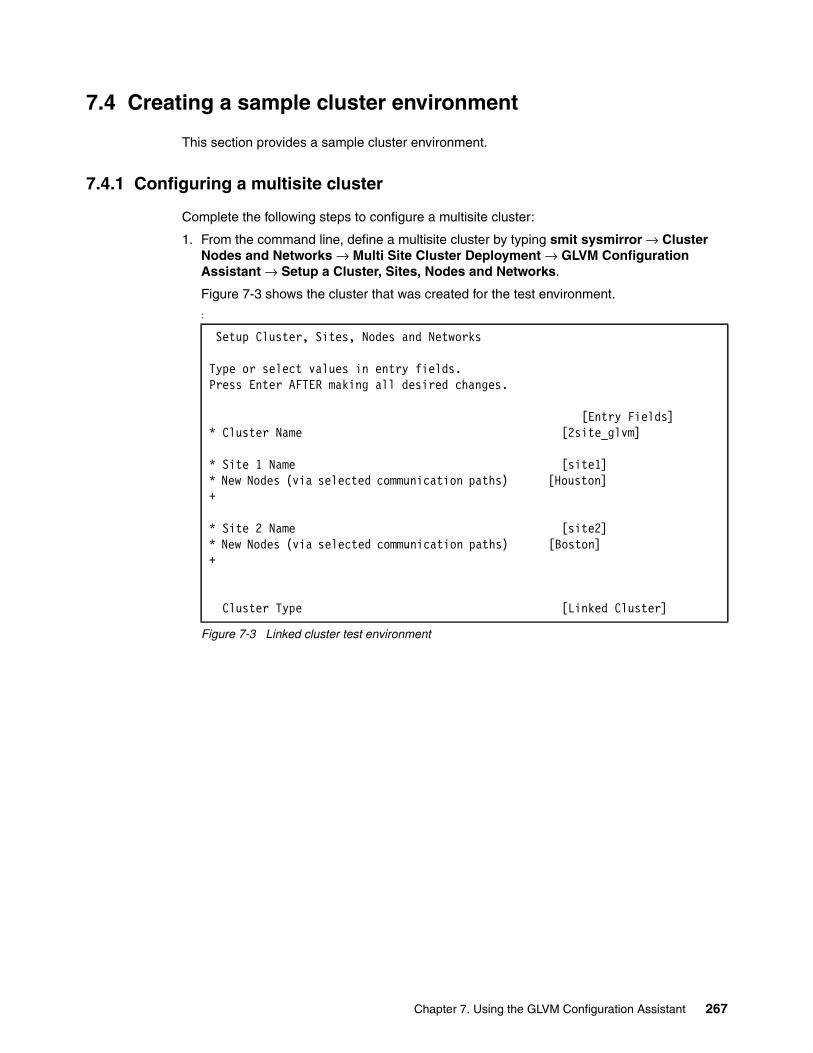
7.4 Creating a sample cluster environment
This section provides a sample cluster environment.
7.4.1 Configuring a multisite cluster
Complete the following steps to configure a multisite cluster:
1. From the command line, define a multisite cluster by typing smit sysmirror → Cluster Nodes and Networks → Multi Site Cluster Deployment → GLVM Configuration Assistant → Setup a Cluster, Sites, Nodes and Networks.
Figure 7-3 shows the cluster that was created for the test environment.
:
Figure 7-3 Linked cluster test environment
Setup Cluster, Sites, Nodes and Networks
Type or select values in entry fields.Press Enter AFTER making all desired changes.
[Entry Fields]* Cluster Name [2site_glvm]
* Site 1 Name [site1]* New Nodes (via selected communication paths) [Houston] +
* Site 2 Name [site2]* New Nodes (via selected communication paths) [Boston] +
Cluster Type [Linked Cluster]
Chapter 7. Using the GLVM Configuration Assistant 267

2. Define the repository disks for each site by following the path smit sysmirror → Cluster Nodes and Networks → Multi Site Cluster Deployment → Define Repository Disk and Cluster IP Address, as shown in Figure 7-4.
Figure 7-4 Repository disk definition
3. Define a XD_data type network (Figure 7-5) by typing smit sysmirror → Cluster Nodes and Networks → Manage Networks and Network Interfaces → Networks → Add a Network.
4. Select XD_data from the list and press Enter.
5. Type the field values and press Enter.
Figure 7-5 Adding a XD_data type network
6. Add a persistent IP address for each node for the XD_data network by following the path smit sysmirror → Cluster Nodes and Networks → Manage Nodes → Configure Persistent Node IP Label/Addresses → Add a Persistent Node IP Label/Address.
Multi Site with Linked Clusters Configuration
Type or select values in entry fields.Press Enter AFTER making all desired changes.
[Entry Fields]* Cluster Name 2site_glvm* Heartbeat Mechanism Unicast +
* Site Name site1* Repository Disk [(00f6f5d09570fcb3)] + Site Multicast Address [] (used only for multicast heart beating)
* Site Name site2* Repository Disk [(00f61ab2a617140b)] + Site Multicast Address [] (used only for multicast heart beating)
Add a Network
Type or select values in entry fields.Press Enter AFTER making all desired changes.
[Entry Fields]* Network Name [net_XD_data_01]* Network Type XD_data* Netmask(IPv4)/Prefix Length(IPv6) [255.255.255.0]* Network attribute public +
268 IBM PowerHA SystemMirror V7.2 for IBM AIX Updates

7. Select one of the nodes and press Enter. Repeat the same steps for all other nodes. Figure 7-6 shows the configuration that was used in our test environment.
Figure 7-6 Adding a persistent IP address for the XD_data network for each node of the cluster
8. Verify and synchronize the cluster by following the path smit sysmirror → Cluster Nodes and Networks → Verify and Synchronize Cluster Configuration. Press Enter to start.
Add a Persistent Node IP Label/Address
Type or select values in entry fields.Press Enter AFTER making all desired changes.
[Entry Fields]* Node Name Boston* Network Name [net_XD_data_01] +* Node IP Label/Address [Boston-xd] + Netmask(IPv4)/Prefix Length(IPv6) [255.255.255.0]
----------------------------------------------------------------------------
Add a Persistent Node IP Label/Address
Type or select values in entry fields.Press Enter AFTER making all desired changes.
[Entry Fields]* Node Name Houston* Network Name [net_XD_data_01] +* Node IP Label/Address [Houston-xd] + Netmask(IPv4)/Prefix Length(IPv6) [255.255.255.0]
Chapter 7. Using the GLVM Configuration Assistant 269

Make sure that the synchronization completes successfully. An OK command status is displayed by the SMIT, as shown in Figure 7-7.
Figure 7-7 Successful cluster synchronization
9. From the command line, start cluster services on all nodes with the fast path smit cspoc → PowerHA SystemMirror Services → Start Cluster Services. Select the Start Cluster Services on these nodes and press “F4” to select all cluster nodes. Press Enter. Figure 7-8 displays the Start Cluster Services Menu used for our testing.
:
Figure 7-8 Start the cluster services on all nodes
COMMAND STATUS
Command: OK stdout: yes stderr: no
Before command completion, additional instructions may appear below.
[MORE...53]Adding any necessary PowerHA SystemMirror for AIX entries to /etc/inittab and /etc/rc.net for IP Address Takeover on node Houston.Checking for any added or removed nodes
cldare: Current Cluster Aware AIX version (bos.cluster.rte is 7.1.3.46) does not support Automatic Repository Replacement.1 tunable updated on cluster 2site_glvm.Adding any necessary PowerHA SystemMirror for AIX entries to /etc/inittab and /etc/rc.net for IP Address Takeover on node Boston.
Verification has completed normally.
[BOTTOM]
F1=Help F2=Refresh F3=Cancel F6=CommandF8=Image F9=Shell F10=Exit /=Findn=Find Next
Start Cluster Services
Type or select values in entry fields.Press Enter AFTER making all desired changes.
[Entry Fields]* Start now, on system restart or both now + Start Cluster Services on these nodes [Boston,Houston] +* Manage Resource Groups Automatically + BROADCAST message at startup? false + Startup Cluster Information Daemon? false + Ignore verification errors? false + Automatically correct errors found during Yes + cluster start?
270 IBM PowerHA SystemMirror V7.2 for IBM AIX Updates

Example 7-4 shows the current cluster state and configuration after performing the steps described in this chapter.
Example 7-4 Cluster status and configuration
COMMAND STATUS
Command: OK stdout: yes stderr: no
Before command completion, additional instructions may appear below.
Local node: "Houston" ("Houston", "Houston") Cluster services status: "NORMAL" ("ST_STABLE") Remote communications: "UP" Cluster-Aware AIX status: "UP"
Remote node: "Boston" ("Boston", "Boston") Cluster services status: "NORMAL" ("ST_STABLE") Remote communications: "UP" Cluster-Aware AIX status: "UP"
Status of the RSCT subsystems used by PowerHA SystemMirror:Subsystem Group PID Status cthags cthags 13369550 active ctrmc rsct 9043998 active
Status of the PowerHA SystemMirror subsystems:Subsystem Group PID Status clstrmgrES cluster 7864536 active clevmgrdES cluster 18088036 active
Status of the CAA subsystems:Subsystem Group PID Status clconfd caa 15859896 active clcomd caa 15925386 active
root@Houston(/)# cltopinfoCluster Name: 2site_glvmCluster Type: LinkedHeartbeat Type: UnicastRepository Disks: Site 1 (site1@Houston): hdisk2 Site 2 (site2@Boston): hdisk2Cluster Nodes: Site 1 (site1): Houston Site 2 (site2): Boston
There are 2 node(s) and 2 network(s) definedNODE Boston: Network net_XD_data_01 Network net_ether_01 Boston 192.168.100.27
Chapter 7. Using the GLVM Configuration Assistant 271

NODE Houston: Network net_XD_data_01 Network net_ether_01 Houston 192.168.100.26
No resource groups defined
7.4.2 Configuring an asynchronous geographically mirrored volume group by using the GLVM Configuration Assistant
To configure an asynchronous geographically mirrored volume group (GMVG) with the GLVM Configuration Assistant, complete the following steps:
1. From the command line, type smit sysmirror → Applications and Resources → Make Applications Highly Available (Use Smart Assist) → GLVM Configuration Assistant → Configure Asynchronous GMVG and press Enter.
2. As shown in Figure 7-9, enter the name of the VG, select the disks to be mirrored from both sites, and enter the size of the ASYNC cache and press Enter.
Figure 7-9 Creating a asynchronous gmvg
The ASYNC cache size is represented in physical partitions (PPs). The number of PPs allocated for the cache will depend on the load of the applications and bandwidth available on the network. You will sometimes need to adjust the number for peak workloads.
3. You can monitor the cache usage with the rpvstat -C command, as shown in Example 7-5.
Example 7-5 ASYNC cache monitoring
root@Houston(/)# rpvstat -C
Remote Physical Volume Statistics:
Max Pending Total Max Total Async Cache Cache Cache Cache Cache FreeGMVG Name ax Writes Util % Writes Wait % Wait Space KB---------------- -- -------------- ------ ---------- ------ ------- ----------datamvg A 0 0.00 0 0.00 0 261119
Create GMVG with Asynchronous Mirror Pools
Type or select values in entry fields.Press Enter AFTER making all desired changes.
[Entry Fields]* Enter the name of the VG [datamvg]* Select disks to be mirrored from the local site (00f6f5d09570efe1) +* Select disks to be mirrored from the remote site (00f61ab2951123c1) +* Enter the size of the ASYNC cache [20] #
272 IBM PowerHA SystemMirror V7.2 for IBM AIX Updates

The current state and topology of the cluster is shown in Example 7-6.
Example 7-6 Displaying the current configuration of the volume group and the resource group
root@Houston(/)# lsvg -odatamvgcaavg_privaterootvgroot@Houston(/)# clshowres
Resource Group Name datamvg_RGParticipating Node Name(s) Houston BostonStartup Policy Online On Home Node OnlyFallover Policy Fallover To Next Priority Node In The ListFallback Policy Never FallbackSite Relationship Prefer Primary SiteNode PriorityService IP LabelFilesystems ALLFilesystems Consistency Check fsckFilesystems Recovery Method sequentialFilesystems/Directories to be exported (NFSv3)Filesystems/Directories to be exported (NFSv4)Filesystems to be NFS mountedNetwork For NFS MountFilesystem/Directory for NFSv4 Stable StorageVolume Groups datamvgConcurrent Volume GroupsUse forced varyon for volume groups, if necessary trueDisksRaw DisksDisk Error Management? noGMVG Replicated Resources datamvgGMD Replicated ResourcesPPRC Replicated ResourcesSVC PPRC Replicated ResourcesEMC SRDF? Replicated ResourcesHitachi TrueCopy? Replicated ResourcesGeneric XD Replicated ResourcesAIX Connections ServicesAIX Fast Connect ServicesShared Tape ResourcesApplication ServersHighly Available Communication LinksPrimary Workload Manager ClassSecondary Workload Manager ClassDelayed Fallback TimerMiscellaneous DataAutomatically Import Volume Groups falseInactive TakeoverSSA Disk Fencing falseFilesystems mounted before IP configured falseWPAR Name
Chapter 7. Using the GLVM Configuration Assistant 273

Run Time Parameters:
Node Name HoustonDebug Level highFormat for hacmp.out Standard
Node Name BostonDebug Level highFormat for hacmp.out Standard
root@Houston(/)# clRGinfo-----------------------------------------------------------------------------Group Name Group State Node-----------------------------------------------------------------------------datamvg_RG ONLINE Houston@site1 ONLINE SECONDARY Boston@site2
4. You can monitor the geographically mirrored volume groups with the gmvgstat command, as shown in Example 7-7.
Example 7-7 Sample usage of the gmvgstat command
root@Houston(/)# gmvgstatGMVG Name PVs RPVs Tot Vols St Vols Total PPs Stale PPs Sync--------------- ---- ---- -------- -------- ---------- ---------- ----datamvg 1 1 2 0 2542 0 100%
The GLVM Configuration Assistant automatically creates two mirror pools for the volume group, as shown in Example 7-8.
Example 7-8 Listing the mirror pools of a volume group
root@Houston(/)# lsmp -A datamvgVOLUME GROUP: datamvg Mirror Pool Super Strict: yes
MIRROR POOL: glvmMP01 Mirroring Mode: ASYNCASYNC MIRROR STATE: inactive ASYNC CACHE LV: glvm_cache_LV02ASYNC CACHE VALID: yes ASYNC CACHE EMPTY: yesASYNC CACHE HWM: 80 ASYNC DATA DIVERGED: no
MIRROR POOL: glvmMP02 Mirroring Mode: ASYNCASYNC MIRROR STATE: active ASYNC CACHE LV: glvm_cache_LV01ASYNC CACHE VALID: yes ASYNC CACHE EMPTY: noASYNC CACHE HWM: 80 ASYNC DATA DIVERGED: no
Note: GLVM requires that volume groups use super strict mirror pools. A mirror pool is a collection of disks that are used by the LVM. A mirror pool can contain only one copy of each of the logical volumes of the volume group.
274 IBM PowerHA SystemMirror V7.2 for IBM AIX Updates

7.4.3 Creating a logical volume and a file system with the cluster online
To create a logical volume and file system within a GMVG when both nodes and resource groups are online can be accomplished by making all the physical disks that belong to the volume group available on both nodes in the cluster and then use the C-SPOC menus to create the new logical volumes and file systems.
To achieve this, all of the remote physical volume (RPV) client and server devices must be changed to the Available state. The following steps describe a way to achieve this:
1. From the command line on either node, use the clRGinfo command (Example 7-9) to display the current state of the resource groups.
Example 7-9 Showing current state of the resource groups
root@Houston(/)# clRGinfo-----------------------------------------------------------------------------Group Name Group State Node-----------------------------------------------------------------------------datamvg_RG ONLINE Houston@site1 ONLINE SECONDARY Boston@site2
2. In our scenario, site 1 node (Houston), currently the Primary node, has the datamvg_RG resource group in the ONLINE status. The GMVG datamvg is composed of the following disks, hdisk1 (00f6f5d09570efe1) and hdisk3 (00f61ab2951123c1), and is currently active on this node, as displayed in Example 7-10.
Example 7-10 Current composition of the datamvg resource group
root@Houston(/)# lspvhdisk0 00f6f5d09570ee14 rootvg activehdisk1 00f6f5d09570efe1 datamvg activehdisk2 00f6f5d09570fcb3 caavg_private activehdisk3 00f61ab2951123c1 datamvg activeroot@Houston(/)# lsvg -p datamvgdatamvg:PV_NAME PV STATE TOTAL PPs FREE PPs FREE DISTRIBUTIONhdisk1 active 1271 1181 255..164..254..254..254hdisk3 active 1271 1181 255..164..254..254..254
3. Site 2 node (Boston) currently has the datamvg_RG resource group with the ONLINE SECONDARY status, and the GMVG datamvg is varied off. The disk with the PVID 00f6f5d09570efe1 is not listed in the output of the lspv command. This is shown in Example 7-11.
Example 7-11 The datamvg resource group and list of physical volumes on site 2 node
root@Boston(/)# lspvhdisk0 00f61ab295112213 rootvg activehdisk1 00f61ab2951123c1 datamvghdisk2 00f61ab2a617140b caavg_private activeroot@Boston(/)# lsvg -ocaavg_privaterootvg
Chapter 7. Using the GLVM Configuration Assistant 275

4. List the state of the remote physical volume devices on all nodes (Example 7-12).
Example 7-12 State of the rpv devices on both nodes
root@Houston(/)# lsdev |grep "Remote Physical Volume"hdisk3 Available Remote Physical Volume Clientrpvserver0 Defined Remote Physical Volume Server
root@Boston(/)# lsdev |grep "Remote Physical Volume"hdisk3 Defined Remote Physical Volume Clientrpvserver0 Available Remote Physical Volume Server
5. Example 7-13 makes the rpv server device available using the mkdev command on node Houston.
Example 7-13 Make the rpv server device available on site
root@Houston(/)# mkdev -l rpvserver0rpvserver0 Available
6. In Example 7-14, the rpv client (hdisk3) has now been brought to the Available state with the mkdev command. It is now possible to see all of the disks that belong to the datamvg on both nodes.
Example 7-14 Make the rpv client device available on site 2
root@Boston(/)# mkdev -l hdisk3hdisk3 Availableroot@Boston(/)# lspvhdisk0 00f61ab295112213 rootvg activehdisk1 00f61ab2951123c1 datamvghdisk2 00f61ab2a617140b caavg_private activehdisk3 00f6f5d09570efe1 datamvg
7. Create a logical volume. Access the fast path smit cspoc → Storage → Logical Volumes → Add a Logical Volume and press Enter.
8. Select the volume group (datamvg in our example) and press Enter again.
9. Select all the disks that will be part of the new logical volume and press enter. In our test scenario we selected both hdisk1 and hdisk3. Example 7-15 shows the logical volume creation window inside C-SPOC.
Example 7-15 Creating a new logical volume from C-SPOC
Add a Logical Volume
Type or select values in entry fields.Press Enter AFTER making all desired changes.
[Entry Fields] Resource Group Name datamvg_RG VOLUME GROUP name datamvg Node List Boston,Houston Reference node Houston* Number of LOGICAL PARTITIONS [20] # PHYSICAL VOLUME names hdisk1 hdisk3 Logical volume NAME [datamlv]
276 IBM PowerHA SystemMirror V7.2 for IBM AIX Updates

Logical volume TYPE [jfs2] + POSITION on physical volume outer_middle + RANGE of physical volumes minimum + MAXIMUM NUMBER of PHYSICAL VOLUMES [] # to use for allocation Number of COPIES of each logical 2 + partition Mirror Write Consistency? active + Allocate each logical partition copy superstrict + on a SEPARATE physical volume? RELOCATE the logical volume during reorganization? yes + Logical volume LABEL [] MAXIMUM NUMBER of LOGICAL PARTITIONS [512] # Enable BAD BLOCK relocation? yes + SCHEDULING POLICY for reading/writing parallel + logical partition copies Enable WRITE VERIFY? no + File containing ALLOCATION MAP [] / Stripe Size? [Not Striped] + Serialize I/O? no + Make first block available for applications? no + Mirror Pool for First Copy glvmMP01 + Mirror Pool for Second Copy glvmMP02 + Mirror Pool for Third Copy + User ID + Group ID + Permissions [] X
Note: The LV must be created with the super strict allocation policy. This is the required setting for GLVM for PowerHA SystemMirror Enterprise Edition. The Super Strict inter-disk allocation policy enables GLVM to properly mirror the logical volume at the remote site. Also, each logical partition copy needs to be placed in a separate mirror pool.
Chapter 7. Using the GLVM Configuration Assistant 277

10.Create a file system (Figure 7-10) using the previously created logical volume as a backing device. Access the fast path smit cspoc → Storage → File Systems → Add a File System and press Enter. In this example we selected the datamvg volume group, the Enhanced Journaled File System type, and the datamlv logical volume when prompted.
Figure 7-10 Creating a file system in C-SPOC
11.Return the rpv client and server devices to their original Defined state and mount the file system, as shown in Example 7-16.
Example 7-16 Returning the rpv devices to the Defined state and mounting the file system
root@Boston(/)# rmdev -l hdisk3hdisk3 Defined
root@Houston(/)# rmdev -l rpvserver0rpvserver0 Definedroot@Houston(/)# mount /datamfs
Add an Enhanced Journaled File System
Type or select values in entry fields.Press Enter AFTER making all desired changes.
[Entry Fields] Resource Group datamvg_RG* Node Names Boston,Houston Volume group name datamvg
SIZE of file system Unit Size G +* Number of units [10] #* MOUNT POINT [/datamfs] / PERMISSIONS read/write + Mount OPTIONS [] + Block Size (bytes) 4096 + Inline Log? yes + Inline Log size (MBytes) [] # Logical Volume for Log + Extended Attribute Format Version 1 + Enable Quota Management? no + Enable EFS? no +
278 IBM PowerHA SystemMirror V7.2 for IBM AIX Updates

7.4.4 Creating a new logical volume and file system with cluster services stopped.
Create a logical volume and a file system in the GMVG when cluster services have been stopped on both nodes and the resource groups are offline. Complete the sequence of steps as follows:
1. Make sure to stop the cluster on all nodes and bring the resource groups offline by using the fast path smit clstop from the command line, as shown in Figure 7-11.
Figure 7-11 Stopping the cluster on both nodes
2. Make the Remote Physical Volume Server device available on one of the nodes using the mkdev command. Example 7-17 shows an operation performed on the node Boston.
Example 7-17 Changing the rpvserver0 device to available status
root@Boston(/)# lsdev|grep "Remote Physical Volume Server"rpvserver0 Defined Remote Physical Volume Serverroot@Boston(/)# mkdev -l rpvserver0rpvserver0 Available
3. On the other node make the Remote Physical Volume Client available and vary on the recently created volume group with the mkdev and varyonvg commands. Example 7-18 shows the output of the commands that were performed on the node named Houston.
Example 7-18 Making the remote physical volume client device available and varying on the vg
root@Houston(/var/hacmp/log)# lsdev |grep "Remote Physical Volume Client"hdisk3 Defined Remote Physical Volume Clientroot@Houston(/var/hacmp/log)# mkdev -l hdisk3hdisk3 Availableroot@Houston(/var/hacmp/log)# varyonvg datamvg
Stop Cluster Services
Type or select values in entry fields.Press Enter AFTER making all desired changes.
[Entry Fields]* Stop now, on system restart or both now + Stop Cluster Services on these nodes [Boston,Houston] + BROADCAST cluster shutdown? true +* Select an Action on Resource Groups Bring Resource Groups Offline +
Chapter 7. Using the GLVM Configuration Assistant 279

4. Create a new logical volume on the node that has the VG varied on, as shown in Example 7-19. In this example, the new LV will be created with two copies, each of them in a different mirrorpool on node (Houston).
Example 7-19 Creating a mirrored logical volume across mirror pools
root@Houston(/)# mklv -y datamlv -t jfs2 -c 2 -s s -p copy1=glvmMP01 \-p copy2=glvmMP02 datamvg 30 hdisk1 hdisk3
5. Example 7-20 shows how to create a new file system using the new recently created logical volume datamlv as a backing device.
Example 7-20 Creating a new file system
root@Houston(/)# crfs -v jfs2 -A no -m /datamfs -d datamlv -a logname=INLINEFile system created successfully.243500 kilobytes total disk space.New File System size is 491520
6. The volume group datamvg now needs to be imported on site 2 node (Boston). The following steps need to be performed:
a. On site 1 node (Example 7-21) bring the Remote Physical Volume Server device to the Available state.
Example 7-21 Site 1 steps before importing volume group on site 2
root@Houston(/)# mkdev -l rpvserver0rpvserver0 Available
b. On site 2 node (Example 7-22) perform the following actions:
i. List the Remote Physical Volume Client type device and make note of the device name.
ii. Bring the Remote Physical Volume Client device to the Available state.
iii. Import the volume group datamvg with the -L flag.
Example 7-22 Site 2 steps to import the volume group
root@Boston(/)# lsdev|grep "Remote Physical Volume Client"hdisk3 Defined Remote Physical Volume Clientroot@Boston(/)# mkdev -l hdisk3hdisk3 Availableroot@Boston(/)# lspvhdisk0 00f61ab295112213 rootvg activehdisk1 00f61ab2951123c1 datamvghdisk2 00f61ab2a617140b caavg_private activehdisk3 00f6f5d09570efe1 datamvgroot@Boston(/)# importvg -L datamvg hdisk1datamvg
Note: Notice the -s s flag on the previous command for setting the Super Strict inter-disk allocation policy.
280 IBM PowerHA SystemMirror V7.2 for IBM AIX Updates

c. On both sites (Example 7-23) return the Remote Physical Volume Client and the Remote Physical Volume Server to the Defined state.
Example 7-23 Returning the remote physical volumes to the defined state
root@Houston(/)# varyoffvg datamvgroot@Houston(/)# rmdev -l hdisk3hdisk3 Definedroot@Houston(/)# rmdev -l rpvserver0rpvserver0 Defined
root@Boston(/)# rmdev -l hdisk3hdisk3 Definedroot@Boston(/)# rmdev -l rpvserver0rpvserver0 Defined
After completing the previous steps on site 2 node (Boston) the ODM will be updated with the new logical volume and file system information.
7. Perform a new cluster synchronization by following the path smit sysmirror → Cluster Nodes and Networks → Verify and Synchronize Cluster Configuration.
8. Press Enter to start. An OK command status will be displayed by SMIT for a successful synchronization as shown in Figure 7-7 on page 270.
9. From the command line, start the cluster services again on all nodes with the fast path smit cspoc → PowerHA SystemMirror Services → Start Cluster Services.
10.Select the Start Cluster Services on these nodes and press F4 to select all cluster nodes. Press Enter.
Example 7-24 shows the configuration of the cluster after creating the file system and bringing the resource group online.
Example 7-24 Cluster configuration with the resource group and file system created
root@Houston(/var/hacmp/log)# cltopinfoCluster Name: 2site_glvmCluster Type: LinkedHeartbeat Type: UnicastRepository Disks: Site 1 (site1@Houston): hdisk2 Site 2 (site2@Boston): hdisk2Cluster Nodes: Site 1 (site1): Houston Site 2 (site2): Boston
There are 2 node(s) and 2 network(s) definedNODE Boston: Network net_XD_data_01 Network net_ether_01 Boston 192.168.100.27NODE Houston: Network net_XD_data_01 Network net_ether_01 Houston 192.168.100.26
Chapter 7. Using the GLVM Configuration Assistant 281

Resource Group datamvg_RG Startup Policy Online On Home Node Only Fallover Policy Fallover To Next Priority Node In The List Fallback Policy Never Fallback Participating Nodes Houston Boston
root@Houston(/var/hacmp/log)# clRGinfo-----------------------------------------------------------------------------Group Name Group State Node-----------------------------------------------------------------------------datamvg_RG ONLINE Houston@site1 ONLINE SECONDARY Boston@site2
root@Houston(/var/hacmp/log)# mount node mounted mounted over vfs date options-------- --------------- --------------- ------ ------------ --------------- /dev/hd4 / jfs2 Nov 03 12:39 rw,log=/dev/hd8 /dev/hd2 /usr jfs2 Nov 03 12:39 rw,log=/dev/hd8 /dev/hd9var /var jfs2 Nov 03 12:39 rw,log=/dev/hd8 /dev/hd3 /tmp jfs2 Nov 03 12:39 rw,log=/dev/hd8 /dev/hd1 /home jfs2 Nov 03 12:39 rw,log=/dev/hd8 /dev/hd11admin /admin jfs2 Nov 03 12:39 rw,log=/dev/hd8 /proc /proc procfs Nov 03 12:39 rw /dev/hd10opt /opt jfs2 Nov 03 12:39 rw,log=/dev/hd8 /dev/livedump /var/adm/ras/livedump jfs2 Nov 03 12:39 rw,log=/dev/hd8 /aha /aha ahafs Nov 03 12:40 rw /dev/datamlv /datamfs jfs2 Nov 03 16:08 rw,log=INLINE
282 IBM PowerHA SystemMirror V7.2 for IBM AIX Updates

Chapter 8. Automation to adapt to the Live Partition Mobility (LPM) operation
This chapter introduces one new feature of PowerHA SystemMirror 7.2 edition: Automation to adapt to the Live Partition Mobility (LPM) operation.
Before PowerHA SystemMirror 7.2 edition, if customers wanted to implement the LPM operation for one AIX LPAR that is running PowerHA service, they had to perform a manual operation, which is illustrated on the following website:
https://www.ibm.com/support/knowledgecenter/SSPHQG_7.1.0/com.ibm.powerha.admngd/ha_admin_live_partition.htm?lang=en
The PowerHA SystemMirror 7.2 edition plugs into the LPM infrastructure to listen to LPM events and adjusts the clustering related monitoring as needed for the LPM operation to succeed without disruption. This reduces the burden on the administrator to perform manual operations on the cluster node during LPM operations. See the following website for more information about this feature:
https://www.ibm.com/support/knowledgecenter/SSPHQG_7.2.0/com.ibm.powerha.admngd/ha_admin_live_partition.htm?lang=en
This chapter introduces what operations are necessary to ensure that the LPM operation for the PowerHA node completes successfully. This chapter used both PowerHA 7.1 and PowerHA 7.2 cluster environments to illustrate the scenarios.
This chapter contains the following sections:
� Concept� Prerequisites for PowerHA node support of LPM� Operation flow to support LPM on PowerHA node� Example: LPM scenario for PowerHA node with version 7.1� New panel to support LPM in PowerHA 7.2� PowerHA 7.2 scenario and troubleshooting
8
© Copyright IBM Corp. 2016. All rights reserved. 283

8.1 Concept
This section provides an introduction to the Live Partition Mobility concepts.
Live Partition MobilityLive Partition Mobility (LPM) enables you to migrate LPARs running the AIX operating system and their hosted applications from one physical server to another without disrupting the infrastructure services. The migration operation maintains system transactional integrity and transfers the entire system environment, including processor state, memory, attached virtual devices, and connected users.
LPM provides the facility for no down time for planned hardware maintenance. However, LPM does not offer the same for software maintenance or unplanned downtime. You can use PowerHA SystemMirror within a partition that is capable of LPM. This does not mean that PowerHA SystemMirror uses LPM in anyway, and it is treated as another application within the partition.
LPM operation time and freeze timeThe amount of operational time that an LPM migration requires on an LPAR is determined by multiple factors, such as LPAR’s memory size, workload activity (more memory pages require more memory updates across the system), and network performance.
LPAR freeze time is a part of LPM operational time, and it occurs when the LPM tries to reestablish the memory state. During this time, no other processes can operate in the LPAR. As part of this memory reestablishment process, memory pages from the source system can be copied to the target system over the network connection. If the network connection is congested, this process of copying over the memory pages can increase the overall LPAR freeze time.
Cluster software in a PowerHA cluster environmentIn a PowerHA solution, although PowerHA is one cluster software, there are two other kinds of cluster software running behind the PowerHA cluster:
� RSCT� CAA
See section 4.4, “IBM PowerHA, RSCT, and CAA” on page 98, which describes their relationship.
PowerHA cluster heartbeating and the Dead Man Switch (DMS)PowerHA SystemMirror uses constant communication between the nodes to keep track of the health of the cluster, nodes, and so on. One of the key components of communication is the heartbeating between the nodes. Lack of heartbeats forms a critical part of the decision-making process to declare a node to be dead.
PowerHA 7.2 default node failure detection time is 40 seconds. 30 seconds for node communication timeout plus 10 seconds grace period. Note that these values could be higher if a customer requires it.
Node A would declare partner Node B to be dead if Node A did not receive any communication or heartbeats for more than 40 seconds. This works great when Node B is actually dead (crashed, powered off, and so on). However, there could be scenarios where Node B is not dead, but is not able to communicate for long periods.
284 IBM PowerHA SystemMirror V7.2 for IBM AIX Updates

Some examples of such scenarios are as follows:
1. There is one communication link between the nodes and it is broken (it is highly recommended that multiple communication links be deployed between the nodes to avoid this scenario).
2. Due to a rare situation, the operating system froze the cluster processes and kernel threads such that the node could not send any I/O (disk or network) for more than 40 seconds. This would result in the same situation that Node A is not able to receive any communication from Node B for more than 40 seconds, and therefore would declare Node B to be dead, even though it is alive. This leads to a “split brain” condition, which could result in data corruption if the disks are shared across nodes.
Some of these scenarios can be handled in the cluster. For example, in scenario #2, when Node B is allowed to run after the unfreeze, it recognizes the fact that it has not been able to communicate to other nodes for a long time and takes evasive action. Those types of actions are called Dead Man Switch (DMS) protection.
DMS involves timers monitoring various activities, such as I/O traffic and process health, to recognize stray cases where there is potential for it (Node B) to be considered dead by its peers in the cluster. In these cases, the DMS timers trigger just before the node failure detection time and evasive action is initiated. A typical evasive action involves fencing the node.
PowerHA SystemMirror consists of different DMS protections:
� Cluster Aware AIX (CAA) DMS protection
When CAA detects that a node is isolated in a multiple node environment, a DMS is triggered. This timeout occurs when the node cannot communicate with other nodes during the delay specified by the node_timeout cluster tunable. The system crashes with an errlog Deadman timer triggered if the deadman_mode cluster tunable (clctrl -tune) is set to a (assert mode, which is the default), or only log an event if deadman_mode is set to e (event mode).
This can occur on the node performing LPM, or on both nodes in a two-node cluster. To prevent a system crash due to this timeout, it is suggested to increase node_timeout to its maximum value, which is 600 seconds before LPM and restore it after LPM.
� Group Services DMS
Group services is a critical component that allows for cluster-wide membership and group management. This daemon’s health is monitored continuously. If this process exits or becomes inactive for long periods of time, then the node is brought down.
� RSCT RMC, ConfigRMC, clstrmgr, and IBM.StorageRM daemons
Group Services monitors the health of these daemons. If they are inactive for a long time or exit, then the node is brought down.
Note: This operation is done manually with a PowerHA SystemMirror 7.1 node. 8.3, “Example: LPM scenario for PowerHA node with version 7.1” on page 291 introduces the operation. This operation is done automatically with a PowerHA System 7.2 node, as described in 8.4, “New panel to support LPM in PowerHA 7.2” on page 308.
Note: The Group Service (cthags) DMS timeout, at the time this publication was written, is 30 seconds. For now, it is hardcoded, and cannot be changed.
Chapter 8. Automation to adapt to the Live Partition Mobility (LPM) operation 285

Therefore, if the LPM freeze time is longer than the Group Service DMS timeout, Group Service (cthags) reacts and halts the node.
Because we cannot tune the parameter to increase its timeout, it is required to disable RSCT critical process monitoring before LPM, and enable it after LPM, with the following commands:
– Disable RSCT critical process monitoring
To disable RSCT monitoring process, use the following commands:
/usr/sbin/rsct/bin/hags_disable_client_kill -s cthags/usr/sbin/rsct/bin/dms/stopdms -s cthags
– Enable RSCT critical process monitoring
To enable RSCT monitoring process, use the following commands:
/usr/sbin/rsct/bin/dms/startdms -s cthags/usr/sbin/rsct/bin/hags_enable_client_kill -s cthags
8.1.1 Prerequisites for PowerHA node support of LPM
This section describes the prerequisites for PowerHA node support for LPM.
8.1.2 Reduce LPM freeze time as far as possible
To reduce the freeze time during LPM operation, it is suggested to use 10 Gb network adapters and a dedicated network with enough bandwidth available, and reduce memory activity during LPM.
8.1.3 PowerHA fix requirement
For PowerHA SystemMirror version 7.1 to support changing CAA’s node_time variable online through the PowerHA clmgr command, the following APARs are required:
� PowerHA SystemMirror Version 7.1.2 - IV79502 (in SP8)� PowerHA SystemMirror Version 7.1.3 - IV79497 (in SP5)
Without these APARs or in PowerHA version 7.1.1, the change requires two steps to change the CAA node_timeout variable. See “Increase the CAA node_timeout” on page 298 for more information.
8.2 Operation flow to support LPM on PowerHA node
The operation flow includes pre-migration and post-migration.
If the PowerHA version is earlier than 7.2, then you have to do the operations manually. If PowerHA version is 7.2 or later, the PowerHA performs the operations automatically.
This section introduces pre-migration and post-migration operation flow during LPM.
Note: This operation is done manually in a PowerHA SystemMirror 7.1 node, as described in 8.3, “Example: LPM scenario for PowerHA node with version 7.1” on page 291. This operation is done automatically in a PowerHA System 7.2 node, as described in 8.4, “New panel to support LPM in PowerHA 7.2” on page 308.
286 IBM PowerHA SystemMirror V7.2 for IBM AIX Updates

8.2.1 Pre-migration operation flow
Figure 8-1 describes the operation flow in a pre-migration stage.
Figure 8-1 Pre-migration operation flow
Chapter 8. Automation to adapt to the Live Partition Mobility (LPM) operation 287

Table 8-1 shows the detailed information for each step in the pre-migration stage.
Table 8-1 Description of the pre-migration operation flow
Step Description
1 Check if HyperSwap is used. If YES, go to 2; otherwise, go to 1.1
1.1 Check if LPM_POLICY=unmanage is set. If YES, go to 2; otherwise, go to 4:clodmget -n -f lpm_policy HACMPcluster
2 Change the node to unmanage resource group status:clmgr stop node <node_name> WHEN=now MANAGE=unmanage
3 Add an entry in the /etc/inittab file, which is useful in case of a node crash before restoring the managed state:mkitab hacmp_lpm:2:once:/usr/es/sbin/cluster/utilities/cl_dr undopremigrate > /dev/null 2>&1
4 Check if RSCT DMS critical resource monitoring is enabled:/usr/sbin/rsct/bin/dms/listdms -s cthags | grep -qw Enabled
5 Disable RSCT DMS critical resource monitoring:/usr/sbin/rsct/bin/hags_disable_client_kill -s cthags/usr/sbin/rsct/bin/dms/stopdms -s cthags
6 Check if th ecurrent node_timeout value is equal to the value that you set:clodmget -n -f lpm_node_timeout HACMPclusterclctrl -tune -x node_timeout
7 Change the CAA node_timeout value:clmgr -f modify cluster HEARTBEAT_FREQUENCY="600"
8 If SAN-based heartbeating is enabled, then disable this function:echo 'sfwcom' >> /etc/cluster/ifrestrictclusterconf
288 IBM PowerHA SystemMirror V7.2 for IBM AIX Updates

8.2.2 Post-migration operation flow
Figure 8-2 describes the operation flow in the post-migration stage.
Figure 8-2 Post-migration operation flow
Chapter 8. Automation to adapt to the Live Partition Mobility (LPM) operation 289

Table 8-2 shows the detailed information for each step in the post-migration stage.
Table 8-2 Description of post-migration operation flow
Step Description
1 Check if the current resource group status is unmanaged. If YES, go to 2; otherwise, go to 4.
2 Change the node back to manage resource group status:clmgr start node <node_name> WHEN=now MANAGE=auto
3 Remove the entry from the /etc/inittab file that was added in the pre-migration process:rmitab hacmp_lpm
4 Check if the RSCT DMS critical resource monitoring function is enabled before LPM operation.
5 Enable RSCT DMS critical resource monitoring:/usr/sbin/rsct/bin/dms/startdms -s cthags/usr/sbin/rsct/bin/hags_enable_client_kill -s cthags
6 Check if the current node_timeout value is equal to the value that you set before:clctrl -tune -x node_timeoutclodmget -n -f lpm_node_timeout HACMPcluster
7 Restore the CAA node_timeout value:clmgr -f modify cluster HEARTBEAT_FREQUENCY="30"
8 If SAN based heartbeating is enabled, then enable this function:rm -f /etc/cluster/ifrestrictclusterconfrmdev -l sfwcomm*mkdev -l sfwcomm*
290 IBM PowerHA SystemMirror V7.2 for IBM AIX Updates

8.3 Example: LPM scenario for PowerHA node with version 7.1
This section introduces detailed operations for performing LPM for one node with PowerHA SystemMirror version 7.1.
8.3.1 Topology introduction
Figure 8-3 describes the topology of the testing environment.
Figure 8-3 Testing environment topology
There are two Power Systems 780 servers. The first server is P780_09 and its serial number is 060C0AT, and the second server is P780_10 and its machine serial number is 061949T. The following list provides additional details about the testing environment:
� Each server has one VIOS partition and one AIX partition.� The P780_09 server has VIOSA and AIX720_LPM1 partitions.� The P780_10 server has VIOSB and AIX720_LPM2 partitions.� There is one storage that can be accessed by the two VIO servers.� The two AIX partitions access storage via the NPIV protocol.� The heartbeating method includes IP, SAN, and dpcom.� The AIX version is AIX 7.2 SP1.� The PowerHA SystemMirror version is 7.1.3 SP4.
Chapter 8. Automation to adapt to the Live Partition Mobility (LPM) operation 291

8.3.2 Initial status
This section describes the initial cluster status.
PowerHA and AIX versionExample 8-1 shows the PowerHA and the AIX version information.
Example 8-1 PowerHA and AIX version information
AIX720_LPM1:/usr/es/sbin/cluster # clhaverNode AIX720_LPM2 has HACMP version 7134 installedNode AIX720_LPM1 has HACMP version 7134 installed
AIX720_LPM1:/usr/es/sbin/cluster # clcmd oslevel -s-------------------------------NODE AIX720_LPM2-------------------------------7200-00-01-1543
-------------------------------NODE AIX720_LPM1-------------------------------7200-00-01-1543
PowerHA configurationTable 8-3 shows the cluster’s configuration.
Table 8-3 Cluster’s configuration
AIX720_LPM1 AIX720_LPM2
Cluster name LPMClusterCluster type: NSC (No Site Cluster)
Network interface en1:172.16.50.21netmask:255.255.255.0Gateway:172.16.50.1
en0:172.16.50.22netmask:255.255.255.0Gateway:172.16.50.1
Network net_ether_01 (172.16.50.0/24)
CAA Unicastprimary disk: hdisk1
shared VG testVG:hdisk2
Service IP 172.16.50.23 AIX720_LPM_Service
Resource Group testRG includes testVG, AIX720_LPM_ServiceThe node order is: AIX720_LPM1, AIX720_LPM2Startup Policy: Online On Home Node Only Fallover Policy: Fallover To Next Priority Node In The List Fallback Policy: Never Fallback
292 IBM PowerHA SystemMirror V7.2 for IBM AIX Updates

PowerHA and Resource Group statusExample 8-2 shows the current status of PowerHA and the Resource Group.
Example 8-2 PowerHA and Resource Group status
AIX720_LPM1:/ # clcmd -n LPMCluster lssrc -ls clstrmgrES|egrep "NODE|state"|grep -v "Last" NODE AIX720_LPM2Current state: ST_STABLENODE AIX720_LPM1Current state: ST_STABLE
AIX720_LPM1:/ # clcmd -n LPMCluster clRGinfo-------------------------------NODE AIX720_LPM2------------------------------------------------------------------------------------------------------------Group Name State Node -----------------------------------------------------------------------------testRG ONLINE AIX720_LPM1 OFFLINE AIX720_LPM2
-------------------------------NODE AIX720_LPM1------------------------------------------------------------------------------------------------------------Group Name State Node -----------------------------------------------------------------------------testRG ONLINE AIX720_LPM1 OFFLINE AIX720_LPM2
CAA heartbeating statusExample 8-3 shows the current CAA heartbeating status and node_timeout parameter.
Example 8-3 CAA heartbeating status and value of node_timeout parameter
AIX720_LPM1:/ # clcmd lscluster -m
-------------------------------NODE AIX720_LPM2-------------------------------Calling node query for all nodes...Node query number of nodes examined: 2
Node name: AIX720_LPM1 Cluster shorthand id for node: 1 UUID for node: 112552f0-c4b7-11e5-8014-56c6a3855d04 State of node: UP Smoothed rtt to node: 7 Mean Deviation in network rtt to node: 3 Number of clusters node is a member in: 1 CLUSTER NAME SHID UUID LPMCluster 0 11403f34-c4b7-11e5-8014-56c6a3855d04 SITE NAME SHID UUID
Chapter 8. Automation to adapt to the Live Partition Mobility (LPM) operation 293

LOCAL 1 51735173-5173-5173-5173-517351735173
Points of contact for node: 2 ----------------------------------------------------------------------- Interface State Protocol Status SRC_IP->DST_IP ----------------------------------------------------------------------- sfwcom UP none none none tcpsock->01 UP IPv4 none 172.16.50.22->172.16.50.21
----------------------------------------------------------------------------
Node name: AIX720_LPM2 Cluster shorthand id for node: 2 UUID for node: 11255336-c4b7-11e5-8014-56c6a3855d04 State of node: UP NODE_LOCAL Smoothed rtt to node: 0 Mean Deviation in network rtt to node: 0 Number of clusters node is a member in: 1 CLUSTER NAME SHID UUID LPMCluster 0 11403f34-c4b7-11e5-8014-56c6a3855d04 SITE NAME SHID UUID LOCAL 1 51735173-5173-5173-5173-517351735173
Points of contact for node: 0
-------------------------------NODE AIX720_LPM1-------------------------------Calling node query for all nodes...Node query number of nodes examined: 2
Node name: AIX720_LPM1 Cluster shorthand id for node: 1 UUID for node: 112552f0-c4b7-11e5-8014-56c6a3855d04 State of node: UP NODE_LOCAL Smoothed rtt to node: 0 Mean Deviation in network rtt to node: 0 Number of clusters node is a member in: 1 CLUSTER NAME SHID UUID LPMCluster 0 11403f34-c4b7-11e5-8014-56c6a3855d04 SITE NAME SHID UUID LOCAL 1 51735173-5173-5173-5173-517351735173
Points of contact for node: 0
----------------------------------------------------------------------------
Node name: AIX720_LPM2 Cluster shorthand id for node: 2 UUID for node: 11255336-c4b7-11e5-8014-56c6a3855d04 State of node: UP Smoothed rtt to node: 17 Mean Deviation in network rtt to node: 13 Number of clusters node is a member in: 1 CLUSTER NAME SHID UUID
294 IBM PowerHA SystemMirror V7.2 for IBM AIX Updates

LPMCluster 0 11403f34-c4b7-11e5-8014-56c6a3855d04 SITE NAME SHID UUID LOCAL 1 51735173-5173-5173-5173-517351735173
Points of contact for node: 2 ----------------------------------------------------------------------- Interface State Protocol Status SRC_IP->DST_IP ----------------------------------------------------------------------- sfwcom UP none none none tcpsock->02 UP IPv4 none 172.16.50.21->172.16.50.22
AIX720_LPM2:/ # clctrl -tune -LNAME DEF MIN MAX UNIT SCOPE...node_timeout 20000 10000 600000 milliseconds c n LPMCluster(11403f34-c4b7-11e5-8014-56c6a3855d04) 30000 ...--> Current node_timeout is 30s
RSCT cthags statusExample 8-4 shows the current RSCT cthags service’s status.
Example 8-4 RSCT cthags service’s status
AIX720_LPM1:/ # lssrc -ls cthagsSubsystem Group PID Status cthags cthags 13173166 active5 locally-connected clients. Their PIDs:9175342(IBM.ConfigRMd) 6619600(rmcd) 14549496(IBM.StorageRMd) 7995658(clstrmgr) 10355040(gsclvmd) HA Group Services domain information:Domain established by node 1Number of groups known locally: 8 Number of Number of localGroup name providers providers/subscribersrmc_peers 2 1 0s00V0CKI0009G000001A9UHPVQ4 2 1 0IBM.ConfigRM 2 1 0IBM.StorageRM.v1 2 1 0CLRESMGRD_1495882547 2 1 0CLRESMGRDNPD_1495882547 2 1 0CLSTRMGR_1495882547 2 1 0d00V0CKI0009G000001A9UHPVQ4 2 1 0Critical clients will be terminated if unresponsive
Dead Man Switch Enabled
AIX720_LPM1:/usr/sbin/rsct/bin/dms # ./listdms -s cthags Dead Man Switch Enabled: reset interval = 3 seconds trip interval = 30 seconds
Chapter 8. Automation to adapt to the Live Partition Mobility (LPM) operation 295

LPAR and server location informationExample 8-5 shows the current LPAR’s location information.
Example 8-5 LPAR and server location information
AIX720_LPM1:/ # prtconfSystem Model: IBM,9179-MHDMachine Serial Number: 060C0AT --> this server is P780_09
AIX720_LPM2:/ # prtconfSystem Model: IBM,9179-MHDMachine Serial Number: 061949T --> this server is P780_10
8.3.3 Manual operation before LPM
Before performing the LPM operation, there are several manual operations that are required.
Change the PowerHA service to unmanage Resource Group statusThere are two methods to change the PowerHA service to Unmanage Resource Group status. The first method is through the SMIT menu, as shown in Example 8-6.
Start smit clstop.
Example 8-6 Change the cluster service to unmanage Resource Groups through the SMIT menu
Stop Cluster Services
Type or select values in entry fields.Press Enter AFTER making all desired changes.
[Entry Fields]* Stop now, on system restart or both now Stop Cluster Services on these nodes [AIX720_LPM1] BROADCAST cluster shutdown? true * Select an Action on Resource Groups Unmanage Resource Groups
The second method is through the clmgr command, as shown in Example 8-7.
Example 8-7 Change cluster service to unmanage Resource Group through the clmgr command
AIX720_LPM1:/ # clmgr stop node AIX720_LPM1 WHEN=now MANAGE=unmanageBroadcast message from root@AIX720_LPM1 (tty) at 23:52:44 ... PowerHA SystemMirror on AIX720_LPM1 shutting down. Please exit any cluster applications...AIX720_LPM1: 0513-044 The clevmgrdES Subsystem was requested to stop.."AIX720_LPM1" is now unmanaged.AIX720_LPM1: Jan 26 2016 23:52:43 /usr/es/sbin/cluster/utilities/clstop: called with flags -N -f
AIX720_LPM1:/ # clcmd -n LPMCluster clRGinfo -------------------------------NODE AIX720_LPM2------------------------------------------------------------------------------------------------------------
296 IBM PowerHA SystemMirror V7.2 for IBM AIX Updates

Group Name State Node -----------------------------------------------------------------------------testRG UNMANAGED AIX720_LPM1 UNMANAGED AIX720_LPM2
-------------------------------NODE AIX720_LPM1------------------------------------------------------------------------------------------------------------Group Name State Node -----------------------------------------------------------------------------testRG UNMANAGED AIX720_LPM1 UNMANAGED AIX720_LPM2
Disable RSCT cthags critical resource monitoring functionExample 8-8 shows how to disable the RSCT cthags critical resource monitoring function to prevent a DMS trigger if the LPM freeze time is longer than its timeout.
Example 8-8 Disable RSCT cthgs critical resource monitoring function
AIX720_LPM1:/ # /usr/sbin/rsct/bin/hags_disable_client_kill -s cthagsAIX720_LPM1:/ # /usr/sbin/rsct/bin/dms/stopdms -s cthags
Dead Man Switch DisabledDMS Re-arming Thread cancelled
AIX720_LPM1:/ # lssrc -ls cthagsSubsystem Group PID Status cthags cthags 13173166 active5 locally-connected clients. Their PIDs:9175342(IBM.ConfigRMd) 6619600(rmcd) 14549496(IBM.StorageRMd) 19792370(clstrmgr) 19268008(gsclvmd) HA Group Services domain information:Domain established by node 1Number of groups known locally: 8 Number of Number of localGroup name providers providers/subscribersrmc_peers 2 1 0s00V0CKI0009G000001A9UHPVQ4 2 1 0IBM.ConfigRM 2 1 0IBM.StorageRM.v1 2 1 0CLRESMGRD_1495882547 2 1 0CLRESMGRDNPD_1495882547 2 1 0CLSTRMGR_1495882547 2 1 0d00V0CKI0009G000001A9UHPVQ4 2 1 0
Critical clients will not be terminated even if unresponsive
Dead Man Switch Disabled
Note: In this case, there are only two nodes in this cluster, so you need to disable this function on both nodes. Only one node is shown in the example, but the command is run on both nodes.
Chapter 8. Automation to adapt to the Live Partition Mobility (LPM) operation 297

AIX720_LPM1:/usr/sbin/rsct/bin/dms # ./listdms -s cthags
Dead Man Switch Disabled
Increase the CAA node_timeoutExample 8-9 shows how to increase the CAA node_timeout to prevent a CAA DMS trigger if the LPM freeze time is longer than its timeout. You need to run this command on only one node, because it is cluster aware.
Example 8-9 Increase the CAA node_timeout
AIX720_LPM1:/ # clmgr -f modify cluster HEARTBEAT_FREQUENCY="600"1 tunable updated on cluster LPMCluster.
AIX720_LPM1:/ # clctrl -tune -LNAME DEF MIN MAX UNIT SCOPE ENTITY_NAME(UUID) CUR ...node_timeout 20000 10000 600000 milliseconds c n LPMCluster(11403f34-c4b7-11e5-8014-56c6a3855d04) 600000
Example 8-10 Detailed steps to change CAA node_timeout variable without PowerHA interim fix
--> Step 1AIX720_LPM1:/ # clmgr start node AIX720_LPM1 WHEN=now MANAGE=autoAdding any necessary PowerHA SystemMirror entries to /etc/inittab and /etc/rc.net for IPAT on node AIX720_LPM1.AIX720_LPM1: start_cluster: Starting PowerHA SystemMirror..."AIX720_LPM1" is now online.Starting Cluster Services on node: AIX720_LPM1This may take a few minutes. Please wait...AIX720_LPM1: Jan 27 2016 06:17:04 Starting execution of /usr/es/sbin/cluster/etc/rc.clusterAIX720_LPM1: with parameters: -boot -N -A -b -P cl_rc_clusterAIX720_LPM1:
Note: With the previous configuration, if LPM’s freeze time is longer than 600 seconds, CAA DMS is triggered because of the CAA’s deadman_mode=a (assert) parameter. The node crashes and its resource group is moved to another node.
Note: The -f option of the clmgr command means not to update the HACMPcluster ODM, because it will update the CAA variable (node_timeout) directly with the clctrl command. This function is included with the following interim fixes:
� PowerHA SystemMirror Version 7.1.2 - IV79502 (SP8)� PowerHA SystemMirror Version 7.1.3 - IV79497 (SP5)
If you do not apply one of these interim fixes, then you must perform four steps to increase the CAA node_timeout variable (Example 8-10):
� Change the PowerHA service to online status (because cluster sync needs this status)� Change the HACMPcluster ODM� Perform cluster verification and synchronization
Change the PowerHA service to unmanage resource group status
298 IBM PowerHA SystemMirror V7.2 for IBM AIX Updates

AIX720_LPM1: Jan 27 2016 06:17:04 Checking for srcmstr active...AIX720_LPM1: Jan 27 2016 06:17:04 complete.
--> Step 2AIX720_LPM1:/ # clmgr modify cluster HEARTBEAT_FREQUENCY="600"
--> Step 3AIX720_LPM1:/ # clmgr sync cluster Verifying additional pre-requisites for Dynamic Reconfiguration......completed.
Committing any changes, as required, to all available nodes...Adding any necessary PowerHA SystemMirror entries to /etc/inittab and /etc/rc.net for IPAT on node AIX720_LPM1.Checking for added nodesUpdating Split Merge Policies1 tunable updated on cluster LPMCluster.Adding any necessary PowerHA SystemMirror entries to /etc/inittab and /etc/rc.net for IPAT on node AIX720_LPM2.
Verification has completed normally.
--> Step 4AIX720_LPM1:/ # clmgr stop node AIX720_LPM1 WHEN=now MANAGE=unmanageBroadcast message from root@AIX720_LPM1 (tty) at 06:15:02 ... PowerHA SystemMirror on AIX720_LPM1 shutting down. Please exit any cluster applications...AIX720_LPM1: 0513-044 The clevmgrdES Subsystem was requested to stop.."AIX720_LPM1" is now unmanaged.
--> Check the resultAIX720_LPM1:/ # clctrl -tune -LNAME DEF MIN MAX UNIT SCOPE ENTITY_NAME(UUID) CUR ...node_timeout 20000 10000 600000 milliseconds c n LPMCluster(11403f34-c4b7-11e5-8014-56c6a3855d04) 600000
Note: When you stop the cluster with unmanage and when you start it with auto, it will try to bring the resource group online, which does not cause any problem with the VGs, file systems, and IPs. However, it runs the application controller one more time. If you do not predict the appropriate checks in its application controller before running the commands, it can cause problems with the application. Therefore, the application controller start script should check if the application is already online before starting it.
Chapter 8. Automation to adapt to the Live Partition Mobility (LPM) operation 299

Disable SAN heartbeating function
Example 8-11 shows how to disable SAN heartbeating function.
Example 8-11 Disable SAN heartbeating function
AIX720_LPM1:/ # echo "sfwcom" >> /etc/cluster/ifrestrict AIX720_LPM1:/ # clusterconf
AIX720_LPM2:/ # echo "sfwcom" >> /etc/cluster/ifrestrict AIX720_LPM2:/ # clusterconf
AIX720_LPM1:/ # clcmd lscluster -m
-------------------------------NODE AIX720_LPM2-------------------------------Calling node query for all nodes...Node query number of nodes examined: 2
Node name: AIX720_LPM1 Cluster shorthand id for node: 1 UUID for node: 112552f0-c4b7-11e5-8014-56c6a3855d04 State of node: UP Smoothed rtt to node: 7 Mean Deviation in network rtt to node: 3 Number of clusters node is a member in: 1 CLUSTER NAME SHID UUID LPMCluster 0 11403f34-c4b7-11e5-8014-56c6a3855d04 SITE NAME SHID UUID LOCAL 1 51735173-5173-5173-5173-517351735173
Points of contact for node: 1 ----------------------------------------------------------------------- Interface State Protocol Status SRC_IP->DST_IP ----------------------------------------------------------------------- tcpsock->01 UP IPv4 none 172.16.50.22->172.16.50.21----------------------------------------------------------------------------
Node name: AIX720_LPM2 Cluster shorthand id for node: 2 UUID for node: 11255336-c4b7-11e5-8014-56c6a3855d04 State of node: UP NODE_LOCAL Smoothed rtt to node: 0 Mean Deviation in network rtt to node: 0 Number of clusters node is a member in: 1 CLUSTER NAME SHID UUID LPMCluster 0 11403f34-c4b7-11e5-8014-56c6a3855d04 SITE NAME SHID UUID LOCAL 1 51735173-5173-5173-5173-517351735173
Points of contact for node: 0
Note: In our scenario, SAN-based heartbeating has been configured, so this step is required. You do not need to do this step if SAN-based heartbeating is not configured.
300 IBM PowerHA SystemMirror V7.2 for IBM AIX Updates

-------------------------------NODE AIX720_LPM1-------------------------------Calling node query for all nodes...Node query number of nodes examined: 2
Node name: AIX720_LPM1 Cluster shorthand id for node: 1 UUID for node: 112552f0-c4b7-11e5-8014-56c6a3855d04 State of node: UP NODE_LOCAL Smoothed rtt to node: 0 Mean Deviation in network rtt to node: 0 Number of clusters node is a member in: 1 CLUSTER NAME SHID UUID LPMCluster 0 11403f34-c4b7-11e5-8014-56c6a3855d04 SITE NAME SHID UUID LOCAL 1 51735173-5173-5173-5173-517351735173
Points of contact for node: 0
----------------------------------------------------------------------------
Node name: AIX720_LPM2 Cluster shorthand id for node: 2 UUID for node: 11255336-c4b7-11e5-8014-56c6a3855d04 State of node: UP Smoothed rtt to node: 18 Mean Deviation in network rtt to node: 14 Number of clusters node is a member in: 1 CLUSTER NAME SHID UUID LPMCluster 0 11403f34-c4b7-11e5-8014-56c6a3855d04 SITE NAME SHID UUID LOCAL 1 51735173-5173-5173-5173-517351735173
Points of contact for node: 1 ----------------------------------------------------------------------- Interface State Protocol Status SRC_IP->DST_IP ----------------------------------------------------------------------- tcpsock->02 UP IPv4 none 172.16.50.21->172.16.50.22
AIX720_LPM1:/ # lscluster -iNetwork/Storage Interface Query
Cluster Name: LPMClusterCluster UUID: 11403f34-c4b7-11e5-8014-56c6a3855d04Number of nodes reporting = 2Number of nodes stale = 0Number of nodes expected = 2
Node AIX720_LPM1Node UUID = 112552f0-c4b7-11e5-8014-56c6a3855d04Number of interfaces discovered = 3 Interface number 1, en1 IFNET type = 6 (IFT_ETHER)
Chapter 8. Automation to adapt to the Live Partition Mobility (LPM) operation 301

NDD type = 7 (NDD_ISO88023) MAC address length = 6 MAC address = FA:97:6D:97:2A:20 Smoothed RTT across interface = 0 Mean deviation in network RTT across interface = 0 Probe interval for interface = 990 ms IFNET flags for interface = 0x1E084863 NDD flags for interface = 0x0021081B Interface state = UP Number of regular addresses configured on interface = 2 IPv4 ADDRESS: 172.16.50.21 broadcast 172.16.50.255 netmask 255.255.255.0 IPv4 ADDRESS: 172.16.50.23 broadcast 172.16.50.255 netmask 255.255.255.0 Number of cluster multicast addresses configured on interface = 1 IPv4 MULTICAST ADDRESS: 228.16.50.21 Interface number 2, sfwcom IFNET type = 0 (none) NDD type = 304 (NDD_SANCOMM) Smoothed RTT across interface = 7 Mean deviation in network RTT across interface = 3 Probe interval for interface = 990 ms IFNET flags for interface = 0x00000000 NDD flags for interface = 0x00000009 Interface state = DOWN RESTRICTED SOURCE HARDWARE RECEIVE SOURCE HARDWARE TRANSMIT Interface number 3, dpcom IFNET type = 0 (none) NDD type = 305 (NDD_PINGCOMM) Smoothed RTT across interface = 750 Mean deviation in network RTT across interface = 1500 Probe interval for interface = 22500 ms IFNET flags for interface = 0x00000000 NDD flags for interface = 0x00000009 Interface state = UP RESTRICTED AIX_CONTROLLED
Node AIX720_LPM2Node UUID = 11255336-c4b7-11e5-8014-56c6a3855d04Number of interfaces discovered = 3 Interface number 1, en1 IFNET type = 6 (IFT_ETHER) NDD type = 7 (NDD_ISO88023) MAC address length = 6 MAC address = FA:F2:D3:29:50:20 Smoothed RTT across interface = 0 Mean deviation in network RTT across interface = 0 Probe interval for interface = 990 ms IFNET flags for interface = 0x1E084863 NDD flags for interface = 0x0021081B Interface state = UP Number of regular addresses configured on interface = 1 IPv4 ADDRESS: 172.16.50.22 broadcast 172.16.50.255 netmask 255.255.255.0 Number of cluster multicast addresses configured on interface = 1 IPv4 MULTICAST ADDRESS: 228.16.50.21
302 IBM PowerHA SystemMirror V7.2 for IBM AIX Updates

Interface number 2, sfwcom IFNET type = 0 (none) NDD type = 304 (NDD_SANCOMM) Smoothed RTT across interface = 7 Mean deviation in network RTT across interface = 3 Probe interval for interface = 990 ms IFNET flags for interface = 0x00000000 NDD flags for interface = 0x00000009 Interface state = DOWN RESTRICTED SOURCE HARDWARE RECEIVE SOURCE HARDWARE TRANSMIT Interface number 3, dpcom IFNET type = 0 (none) NDD type = 305 (NDD_PINGCOMM) Smoothed RTT across interface = 750 Mean deviation in network RTT across interface = 1500 Probe interval for interface = 22500 ms IFNET flags for interface = 0x00000000 NDD flags for interface = 0x00000009 Interface state = UP RESTRICTED AIX_CONTROLLED
8.3.4 Perform LPM
Example 8-12 shows how to perform the LPM operation for the AIX720_LPM1 node. This operation migrates this LPAR from P780_09 to P780_10.
Example 8-12 Performing the LPM operation
hscroot@hmc55:~> time migrlpar -o m -m SVRP7780-09-SN060C0AT -t SVRP7780-10-SN061949T -p AIX720_LPM1
real 1m6.269suser 0m0.001ssys 0m0.000s
PowerHA service and resource group statusAfter LPM completes, Example 8-13 shows that the PowerHA services are still stable, and AIX720_LPM1 has been moved to the P780_10 server.
Example 8-13 PowerHA services stable
AIX720_LPM1:/ # clcmd -n LPMCluster lssrc -ls clstrmgrES|egrep "NODE|state"|grep -v "Last"NODE AIX720_LPM2Current state: ST_STABLENODE AIX720_LPM1Current state: ST_STABLE
AIX720_LPM1:/ # prtconfSystem Model: IBM,9179-MHDMachine Serial Number: 061949T --> this server is P780_10
AIX720_LPM2:/ # prtconf|moreSystem Model: IBM,9179-MHDMachine Serial Number: 061949T --> this server is P780_10
Chapter 8. Automation to adapt to the Live Partition Mobility (LPM) operation 303

8.3.5 Manual operation after LPM
After LPM completes, there are several manual operations required.
Enable SAN heartbeating functionExample 8-14 shows how to enable the SAN heartbeating function.
Example 8-14 Enable SAN heartbeating function
AIX720_LPM1:/ # rm /etc/cluster/ifrestrictAIX720_LPM1:/ # clusterconf
AIX720_LPM2:/ # rm /etc/cluster/ifrestrictAIX720_LPM2:/ # clusterconf
AIX720_LPM1:/ # clcmd lscluster -m
-------------------------------NODE AIX720_LPM2-------------------------------Calling node query for all nodes...Node query number of nodes examined: 2
Node name: AIX720_LPM1 Cluster shorthand id for node: 1 UUID for node: 112552f0-c4b7-11e5-8014-56c6a3855d04 State of node: UP Smoothed rtt to node: 7 Mean Deviation in network rtt to node: 3 Number of clusters node is a member in: 1 CLUSTER NAME SHID UUID LPMCluster 0 11403f34-c4b7-11e5-8014-56c6a3855d04 SITE NAME SHID UUID LOCAL 1 51735173-5173-5173-5173-517351735173
Points of contact for node: 2 ----------------------------------------------------------------------- Interface State Protocol Status SRC_IP->DST_IP ----------------------------------------------------------------------- sfwcom UP none none none tcpsock->01 UP IPv4 none 172.16.50.22->172.16.50.21
----------------------------------------------------------------------------
Node name: AIX720_LPM2 Cluster shorthand id for node: 2 UUID for node: 11255336-c4b7-11e5-8014-56c6a3855d04 State of node: UP NODE_LOCAL Smoothed rtt to node: 0 Mean Deviation in network rtt to node: 0 Number of clusters node is a member in: 1 CLUSTER NAME SHID UUID LPMCluster 0 11403f34-c4b7-11e5-8014-56c6a3855d04 SITE NAME SHID UUID LOCAL 1 51735173-5173-5173-5173-517351735173
304 IBM PowerHA SystemMirror V7.2 for IBM AIX Updates

Points of contact for node: 0
-------------------------------NODE AIX720_LPM1-------------------------------Calling node query for all nodes...Node query number of nodes examined: 2
Node name: AIX720_LPM1 Cluster shorthand id for node: 1 UUID for node: 112552f0-c4b7-11e5-8014-56c6a3855d04 State of node: UP NODE_LOCAL Smoothed rtt to node: 0 Mean Deviation in network rtt to node: 0 Number of clusters node is a member in: 1 CLUSTER NAME SHID UUID LPMCluster 0 11403f34-c4b7-11e5-8014-56c6a3855d04 SITE NAME SHID UUID LOCAL 1 51735173-5173-5173-5173-517351735173
Points of contact for node: 0
----------------------------------------------------------------------------
Node name: AIX720_LPM2 Cluster shorthand id for node: 2 UUID for node: 11255336-c4b7-11e5-8014-56c6a3855d04 State of node: UP Smoothed rtt to node: 16 Mean Deviation in network rtt to node: 14 Number of clusters node is a member in: 1 CLUSTER NAME SHID UUID LPMCluster 0 11403f34-c4b7-11e5-8014-56c6a3855d04 SITE NAME SHID UUID LOCAL 1 51735173-5173-5173-5173-517351735173
Points of contact for node: 2 ----------------------------------------------------------------------- Interface State Protocol Status SRC_IP->DST_IP ----------------------------------------------------------------------- sfwcom UP none none none tcpsock->02 UP IPv4 none 172.16.50.21->172.16.50.22
Note: After this step, if the sfwcom interface is still not UP, check the VLAN storage framework communication device’s status. If it is in defined status, you need to reconfigure it with the following command:
AIX720_LPM1:/ # lsdev -C|grep vLANsfwcomm1 Defined vLAN Storage Framework CommAIX720_LPM1:/ # rmdev -l sfwcomm1; sleep 2; mkdev -l sfwcomm1sfwcomm1 Definedsfwcomm1 Available
Then you can check the sfwcom interface’s status again with the lscluster command.
Chapter 8. Automation to adapt to the Live Partition Mobility (LPM) operation 305

Restore CAA node_timeoutExample 8-15 shows how to restore the CAA node_timeout.
Example 8-15 Restore the CAA node_timeout parameter
AIX720_LPM1:/ # clmgr -f modify cluster HEARTBEAT_FREQUENCY="30"1 tunable updated on cluster LPMCluster.
AIX720_LPM1:/ # clctrl -tune -LNAME DEF MIN MAX UNIT SCOPE ENTITY_NAME(UUID) CUR ...node_timeout 20000 10000 600000 milliseconds c n LPMCluster(11403f34-c4b7-11e5-8014-56c6a3855d04) 30000
Enable RSCT cthags critical resouce monitoring functionExample 8-16 shows how to enable the RSCT cthags critical resource monitoring function.
Example 8-16 Enable RSCT cthags resource monitoring
AIX720_LPM1:/ # /usr/sbin/rsct/bin/dms/startdms -s cthags
Dead Man Switch EnabledDMS Re-arming Thread created
AIX720_LPM1:/ # /usr/sbin/rsct/bin/hags_enable_client_kill -s cthagsAIX720_LPM1:/ # lssrc -ls cthagsSubsystem Group PID Status cthags cthags 13173166 active5 locally-connected clients. Their PIDs:9175342(IBM.ConfigRMd) 6619600(rmcd) 14549496(IBM.StorageRMd) 19792370(clstrmgr) 19268008(gsclvmd) HA Group Services domain information:Domain established by node 1Number of groups known locally: 8 Number of Number of localGroup name providers providers/subscribersrmc_peers 2 1 0s00V0CKI0009G000001A9UHPVQ4 2 1 0IBM.ConfigRM 2 1 0IBM.StorageRM.v1 2 1 0CLRESMGRD_1495882547 2 1 0CLRESMGRDNPD_1495882547 2 1 0CLSTRMGR_1495882547 2 1 0d00V0CKI0009G000001A9UHPVQ4 2 1 0
Critical clients will be terminated if unresponsive
Note: In a PowerHA cluster environment, the default value of node_timeout is 30 seconds.
Note: In this case, there are only two nodes in this cluster, so you disabled the function on both nodes before LPM. Only one node is shown in this example, but the command is run on both nodes.
306 IBM PowerHA SystemMirror V7.2 for IBM AIX Updates

Dead Man Switch EnabledAIX720_LPM1:/ # /usr/sbin/rsct/bin/dms/listdms -s cthags Dead Man Switch Enabled: reset interval = 3 seconds trip interval = 30 seconds
Change PowerHA service back to normal statusExample 8-17 shows how to change the PowerHA service back to normal status. There are two methods to achieve it. One is through the SMIT menu:
Start smit clstart.
Example 8-17 Change PowerHA service back to normal status
Start Cluster Services
Type or select values in entry fields.Press Enter AFTER making all desired changes.
[Entry Fields]* Start now, on system restart or both now Start Cluster Services on these nodes [AIX720_LPM1] * Manage Resource Groups Automatically BROADCAST message at startup? true Startup Cluster Information Daemon? false Ignore verification errors? false Automatically correct errors found during Interactively cluster start?
Another is through 'clmgr' command:AIX720_LPM1:/ # clmgr start node AIX720_LPM1 WHEN=now MANAGE=autoAIX720_LPM1: start_cluster: Starting PowerHA SystemMirror..."AIX720_LPM1" is now online.
Starting Cluster Services on node: AIX720_LPM1This may take a few minutes. Please wait...AIX720_LPM1: Jan 27 2016 01:04:43 Starting execution of /usr/es/sbin/cluster/etc/rc.clusterAIX720_LPM1: with parameters: -boot -N -A -b -P cl_rc_clusterAIX720_LPM1: AIX720_LPM1: Jan 27 2016 01:04:43 Checking for srcmstr active...AIX720_LPM1: Jan 27 2016 01:04:43 complete.
Note: When you stop the cluster with unmanage and when you start it with auto, it will try to bring the resource group online, which does not cause any problem with the VGs, file systems, and IPs. However, it runs the application controller one more time. If you do not predict the appropriate checks in its application controller before running the commands, it can cause problems with the application. Therefore, the application controller start script should check if the application is already online before starting it.
Chapter 8. Automation to adapt to the Live Partition Mobility (LPM) operation 307

Example 8-18 shows that the resource group’s status has been changed to normal.
Example 8-18 Resource Group’s status
AIX720_LPM1:/ # clcmd clRGinfo
-------------------------------NODE AIX720_LPM2------------------------------------------------------------------------------------------------------------Group Name State Node -----------------------------------------------------------------------------testRG ONLINE AIX720_LPM1 OFFLINE AIX720_LPM2
-------------------------------NODE AIX720_LPM1------------------------------------------------------------------------------------------------------------Group Name State Node -----------------------------------------------------------------------------testRG ONLINE AIX720_LPM1 OFFLINE AIX720_LPM2
8.4 New panel to support LPM in PowerHA 7.2
From version 7.2, PowerHA SystemMirror automates some of the Live Partition Mobility (LPM) steps by registering a script with the LPM framework.
PowerHA SystemMirror listens to LPM events and automates steps in PowerHA SystemMirror to handle the LPAR freeze that can occur during the LPM process. As part of the automation, PowerHA SystemMirror provides a few variables that can be changed based on the requirements for your environment.
You can change the following LPM variables in PowerHA SystemMirror that provide LPM automation:
� Node Failure Detection Timeout during LPM� LPM Node Policy
Start smit sysmirror. Select Custom Cluster Configuration → Cluster Nodes and Networks → Manage the Cluster → Cluster heartbeat settings. The next panel is a menu screen with a title menu option and seven item menu options.
308 IBM PowerHA SystemMirror V7.2 for IBM AIX Updates

Its fast path is cm_chng_tunables (Figure 8-4). This menu is not new, but two items have been added to it to make LPM easier in a PowerHA environment (the last two items are new).
Figure 8-4 Cluster heartbeat setting
Table 8-4 describes the context-sensitive help information for the cluster heartbeating setting.
Table 8-4 Context-sensitive help for the Cluster heartbeat setting
8.5 PowerHA 7.2 scenario and troubleshooting
This scenario keeps the same hardware and operating system as 8.3, “Example: LPM scenario for PowerHA node with version 7.1” on page 291. This scenario replaces only the PowerHA software with the 7.2 edition.
Example 8-19 shows the PowerHA version.
Example 8-19 PowerHA version
AIX720_LPM1:/ #clhaverNode AIX720_LPM1 has HACMP version 7200 installedNode AIX720_LPM2 has HACMP version 7200 installed
Cluster heartbeat settings
Type or select values in entry fields. Press Enter AFTER making all desired changes. [Entry Fields]
* Network Failure Detection Time [20] * Node Failure Detection Timeout [30] * Node Failure Detection Grace Period [10] * Node Failure Detection Timeout during LPM [600] * LPM Node Policy [manage]
Name and fast path context-sensitive help (F1)
Node Failure Detection Timeout during LPM
If specified, this timeout value (in seconds) will be used during a Live Partition Mobility (LPM) instead of the Node Failure Detection Timeout value.You can use this option to increase the Node Failure Detection Timeout during the LPM duration to ensure it will be greater than the LPM freeze duration in order to avoid any risk of unwanted cluster events. The unit is second.For PowerHA 7.2 GA Edition, the customer can enter a value 10 - 600.For PowerHA 7.2 SP1 or later, the default is 600 and is unchangeable.
LPM Node Policy Specifies the action to be taken on the node during a Live Partition Mobility operation. If unmanage is selected, the cluster services are stopped with the Unmanage Resource Groups option during the duration of the LPM operation. Otherwise, PowerHA SystemMirror will continue to monitor the Resource Groups and application availability.The default is manage.
Chapter 8. Automation to adapt to the Live Partition Mobility (LPM) operation 309

Table 8-5 shows the variables of LPM.
Table 8-5 Cluster heartbeating setting
8.5.1 Troubleshooting
The PowerHA log related with LPM operation is in /var/hacmp/log/clutils.log. Example 8-20 and Example 8-21 on page 311 show the information in this log file, and include pre-migration and post-migration.
Example 8-20 Log file of pre-migration operation
...--> Check if need to change PowerHA service to 'unmanage resource group' statusTue Jan 26 10:57:08 UTC 2016 cl_dr: clodmget -n -f lpm_policy HACMPclusterTue Jan 26 10:57:08 UTC 2016 cl_dr: lpm_policy='UNMANAGE'...Tue Jan 26 10:57:09 UTC 2016 cl_dr: Node = AIX720_LPM1, state = NORMALTue Jan 26 10:57:09 UTC 2016 cl_dr: Stop cluster servicesTue Jan 26 10:57:09 UTC 2016 cl_dr: LC_ALL=C clmgr stop node AIX720_LPM1 WHEN=now MANAGE=unmanage..."AIX720_LPM1" is now unmanaged....--> Add an entry in /etc/inittab to ensure PowerHA to be in 'manage resource group' status after crash unexpectedlyTue Jan 26 10:57:23 UTC 2016 cl_dr: Adding a temporary entry in /etc/inittabTue Jan 26 10:57:23 UTC 2016 cl_dr: lsitab hacmp_lpmTue Jan 26 10:57:23 UTC 2016 cl_dr: mkitab hacmp_lpm:2:once:/usr/es/sbin/cluster/utilities/cl_dr undopremigrate > /dev/null 2>&1Tue Jan 26 10:57:23 UTC 2016 cl_dr: mkitab RC: 0...--> Stop RSCT cthags critical resource monitoring function (for two nodes)Tue Jan 26 10:57:30 UTC 2016 cl_dr: Stopping RSCT Dead Man Switch on node 'AIX720_LPM1'Tue Jan 26 10:57:30 UTC 2016 cl_dr: /usr/sbin/rsct/bin/dms/stopdms -s cthags
Dead Man Switch DisabledDMS Re-arming Thread cancelled
Items Value
Node Failure Detection Timeout during LPM 600
LPM Node Policy unmanage
Note: During the operation, PowerHA SystemMirror stops the cluster with the unmanage option in the pre-migration stage, and starts it with the auto option in the post-migration stage automatically. PowerHA SystemMirror tries to bring the resource group online in the post-migration stage, which does not cause any problem with the VGs, file systems, and IPs. However, it runs the application controller one more time.
If you do not predict the appropriate checks in its application controller before running the commands, it can cause problems with the application. Therefore, the application controller start script should check if the application is already online before starting it.
310 IBM PowerHA SystemMirror V7.2 for IBM AIX Updates

Tue Jan 26 10:57:30 UTC 2016 cl_dr: stopdms RC: 0Tue Jan 26 10:57:30 UTC 2016 cl_dr: Stopping RSCT Dead Man Switch on node 'AIX720_LPM2'Tue Jan 26 10:57:30 UTC 2016 cl_dr: cl_rsh AIX720_LPM2 "LC_ALL=C lssrc -s cthags | grep -qw active"Tue Jan 26 10:57:31 UTC 2016 cl_dr: cl_rsh AIX720_LPM2 lssrc RC: 0Tue Jan 26 10:57:31 UTC 2016 cl_dr: cl_rsh AIX720_LPM2 "LC_ALL=C /usr/sbin/rsct/bin/dms/listdms -s cthags | grep -qw Enabled"Tue Jan 26 10:57:31 UTC 2016 cl_dr: cl_rsh AIX720_LPM2 listdms RC: 0Tue Jan 26 10:57:31 UTC 2016 cl_dr: cl_rsh AIX720_LPM2 "/usr/sbin/rsct/bin/dms/stopdms -s cthags"
Dead Man Switch DisabledDMS Re-arming Thread cancelled...--> Change CAA node_time parameter to 600sTue Jan 26 10:57:31 UTC 2016 cl_dr: clodmget -n -f lpm_node_timeout HACMPclusterTue Jan 26 10:57:31 UTC 2016 cl_dr: clodmget LPM node_timeout: 600Tue Jan 26 10:57:31 UTC 2016 cl_dr: clctrl -tune -x node_timeoutTue Jan 26 10:57:31 UTC 2016 cl_dr: clctrl CAA node_timeout: 30000Tue Jan 26 10:57:31 UTC 2016 cl_dr: Changing CAA node_timeout to '600000'Tue Jan 26 10:57:31 UTC 2016 cl_dr: clctrl -tune -o node_timeout=600000...--> Disable CAA SAN heartbeating (for two nodes)Tue Jan 26 10:57:32 UTC 2016 cl_dr: cl_rsh AIX720_LPM1 "LC_ALL=C echo sfwcom >> /etc/cluster/ifrestrict"Tue Jan 26 10:57:32 UTC 2016 cl_dr: cl_rsh to node AIX720_LPM1 completed, RC: 0Tue Jan 26 10:57:32 UTC 2016 cl_dr: clusterconfTue Jan 26 10:57:32 UTC 2016 cl_dr: clusterconf completed, RC: 0...Tue Jan 26 10:57:32 UTC 2016 cl_dr: cl_rsh AIX720_LPM2 "LC_ALL=C echo sfwcom >> /etc/cluster/ifrestrict"Tue Jan 26 10:57:33 UTC 2016 cl_dr: cl_rsh to node AIX720_LPM2 completed, RC: 0Tue Jan 26 10:57:33 UTC 2016 cl_dr: clusterconfTue Jan 26 10:57:33 UTC 2016 cl_dr: clusterconf completed, RC: 0...
Example 8-21 shows information in the post-migration operation.
Example 8-21 Log file of post-migration operation
--> Change PowerHA service back to normal statusTue Jan 26 10:57:52 UTC 2016 cl_2dr: POST_MIGRATE enteredTue Jan 26 10:57:52 UTC 2016 cl_2dr: clodmget -n -f lpm_policy HACMPclusterTue Jan 26 10:57:52 UTC 2016 cl_2dr: lpm_policy='UNMANAGE'Tue Jan 26 10:57:52 UTC 2016 cl_2dr: grep -w node_state /var/hacmp/cl_dr.state | cut -d'=' -f2Tue Jan 26 10:57:52 UTC 2016 cl_2dr: Previous state = NORMALTue Jan 26 10:57:52 UTC 2016 cl_2dr: Restarting cluster servicesTue Jan 26 10:57:52 UTC 2016 cl_2dr: LC_ALL=C clmgr start node AIX720_LPM1 WHEN=now MANAGE=autoAIX720_LPM1: start_cluster: Starting PowerHA SystemMirror..."AIX720_LPM1" is now online....
Chapter 8. Automation to adapt to the Live Partition Mobility (LPM) operation 311

--> Remove the entry from /etc/inittab, this entry was written in pre-migration operationTue Jan 26 11:00:27 UTC 2016 cl_2dr: lsitab hacmp_lpmTue Jan 26 11:00:27 UTC 2016 cl_2dr: Removing the temporary entry from /etc/inittabTue Jan 26 11:00:27 UTC 2016 cl_2dr: rmitab hacmp_lpm...--> Enable RSCT cthags critical resource monitoring function (for two nodes)Tue Jan 26 10:58:21 UTC 2016 cl_2dr: LC_ALL=C lssrc -s cthags | grep -qw activeTue Jan 26 10:58:21 UTC 2016 cl_2dr: lssrc RC: 0Tue Jan 26 10:58:21 UTC 2016 cl_2dr: grep -w RSCT_local_DMS_state /var/hacmp/cl_dr.state | cut -d'=' -f2Tue Jan 26 10:58:22 UTC 2016 cl_2dr: previous RSCT DMS state = EnabledTue Jan 26 10:58:22 UTC 2016 cl_2dr: Restarting RSCT Dead Man Switch on node 'AIX720_LPM1'Tue Jan 26 10:58:22 UTC 2016 cl_2dr: /usr/sbin/rsct/bin/dms/startdms -s cthags
Dead Man Switch EnabledDMS Re-arming Thread createdTue Jan 26 10:58:22 UTC 2016 cl_2dr: startdms RC: 0Tue Jan 26 10:58:22 UTC 2016 cl_2dr: cl_rsh AIX720_LPM2 lssrc RC: 0Tue Jan 26 10:58:22 UTC 2016 cl_2dr: grep -w RSCT_peer_DMS_state /var/hacmp/cl_dr.state | cut -d'=' -f2Tue Jan 26 10:58:22 UTC 2016 cl_2dr: previous RSCT Dead Man Switch on node 'AIX720_LPM2' = EnabledTue Jan 26 10:58:22 UTC 2016 cl_2dr: Restarting RSCT Dead Man Switch on node 'AIX720_LPM2'Tue Jan 26 10:58:22 UTC 2016 cl_2dr: cl_rsh AIX720_LPM2 "/usr/sbin/rsct/bin/dms/startdms -s cthags"
Dead Man Switch EnabledDMS Re-arming Thread created...--> Restore CAA node_timeout valueTue Jan 26 10:58:22 UTC 2016 cl_2dr: previous CAA node timeout = 30000Tue Jan 26 10:58:22 UTC 2016 cl_2dr: Restoring CAA node_timeout to '30000'Tue Jan 26 10:58:22 UTC 2016 cl_2dr: clctrl -tune -o node_timeout=30000smcaactrl:0:[182](0.009): Running smcaactrl at Tue Jan 26 10:58:22 UTC 2016 with the following parameters: -O MOD_TUNE -P CHECK -T 2 -c 7ae36082-c418-11e5-8039-fa976d972a20 -t 7ae36082-c418-11e5-8039-fa976d972a20,LPMCluster,0 -i -v node_timeout,600000...
312 IBM PowerHA SystemMirror V7.2 for IBM AIX Updates

--> Enable SAN heartbeating (for two nodes)Tue Jan 26 11:00:26 UTC 2016 cl_2dr: cl_rsh AIX720_LPM1 "if [ -s /var/hacmp/ifrestrict ]; then mv /var/hacmp/ifrestrict /etc/cluster/ifrestrict; else rm -f /etc/cluster/ifrestrict; fi"Tue Jan 26 11:00:26 UTC 2016 cl_2dr: cl_rsh to node AIX720_LPM1 completed, RC: 0Tue Jan 26 11:00:26 UTC 2016 cl_2dr: cl_rsh AIX720_LPM2 "if [ -s /var/hacmp/ifrestrict ]; then mv /var/hacmp/ifrestrict /etc/cluster/ifrestrict; else rm -f /etc/cluster/ifrestrict; fi"Tue Jan 26 11:00:26 UTC 2016 cl_2dr: cl_rsh to node AIX720_LPM2 completed, RC: 0Tue Jan 26 11:00:26 UTC 2016 cl_2dr: clusterconfTue Jan 26 11:00:27 UTC 2016 cl_2dr: clusterconf completed, RC: 0Tue Jan 26 11:00:27 UTC 2016 cl_2dr: Launch the SAN communication reconfiguration in background....
Chapter 8. Automation to adapt to the Live Partition Mobility (LPM) operation 313

314 IBM PowerHA SystemMirror V7.2 for IBM AIX Updates

Appendix A. SCSI reservations
This appendix describes SCSI reservation, and how it can be used to provide faster disk fallover times when the underlaying storage supports this feature. For example, SCSI 3 Persistent Reservation allows the stripe group manager (also known as file system manager) to “fence” disks during node fallover by removing the reservation keys for that node. In contrast, non-PR disk fallover causes the system to wait until the disk lease expires.
This appendix discusses SCSI reservations, and contains the following:
� SCSI reservations� Persistent Reserve IN (PRIN)� Storage� More about PR reservations� Persistent reservation commands
A
Attention: You should not run these commands in your systems. By running these commands, this section shows you how disk reservations work, especially in a clustered environment, which demands more care while managing disk reservations.
© Copyright IBM Corp. 2016. All rights reserved. 315

SCSI reservations
SCSI 2 reservations gives us a mechanism to reserve and control access to a SCSI device from a node. An initiator obtains ownership of the device by using the reserve system call and works as a lock against any I/O attempt from other imitators. Another initiator trying to access this reserved disk would get a reservation conflict error code. Only the original initiator can release this reservation by issuing a release or reset system call.
SCSI 3 Persistent Reservations provides us the mechanism to control access to a shared device from multiple nodes. The reservation persists even if the bus is reset for error recovery. This is not the case with SCSI 2 command, where device reservations do not survive after node reboots. Also SCSI 3 PR supports multiple paths to a host, where SCSI 2 works only with one path from host to a disk. The scope of a persistent reservation is the entire logical unit.
SCSI 3 Persistent Reservations uses the concept of register and reserve. Multiple nodes can register their reservation keys (also known as PR_Key) with the shared device and establish a reservation in any of the following modes, as shown in Table A-1.
Table A-1 Types of SCSI reservations
In All Registrants type of reservations (WEAR and EAAR), each registered node is a Persistent Reservation (PR) Holder. The PR Holder value would be set to zero. The All registrants type is an optimization that makes all cluster members equal, so if any member fails, the others continue.
In all other types of reservation, there is a single reservation holder, which is one of the following I_T nexus examples:
� The nexus for which the reservation was established with a PERSISTENT RESERVE OUT command with the RESERVE service action, the PREEMPT service action, the PREEMPT AND ABORT service action, or the REPLACE LOST RESERVATION service action
� The nexus to which the reservation was moved by a PERSISTENT RESERVE OUT command with the REGISTER AND MOVE service action
An I_T nexus refers to the combination of the initiator port on the host with the target port on the server:
� 1h Write Exclusive (WE)
Only the Persistent reservation holder shall be permitted to perform write operations to the device. Only one persistent reservation holder at a time.
� 3h Exclusive Access (EA)
Only the Persistent reservation holder shall be permitted to access (includes read/write operations) the device. Only one persistent reservation holder at a time.
Types Code
Write exclusive 1h
Exclusive access 3h
Write exclusive - Registrants only 5h
Exclusive Access - Registrants only 6h
Write Exclusive - All registrants 7h
Exclusive Access - All registrants 8h
316 IBM PowerHA SystemMirror V7.2 for IBM AIX Updates

� 5h Write Exclusive Registrants only (WERO)
Write access commands are permitted only to registered nodes. A cluster designed around this type must declare one cluster owner (the persistent reservation holder) at a time. If the owner fails, another must be elected. The PR_key_Holder value would be pointing to the PR_Key of the I_T nexus that holds the reservation of the disk. Only one persistent reservation holder at a time, but all registered I_T nexuses are allowed to do write operations on the disk.
� 6h Exclusive Access Registrants only (EARO)
Access to the device is limited only to the registered nodes and like in WERO, if the current owner fails, the reservation must be established again to gain access to the device. Only one persistent reservation holder at a time, but all registered I_T nexuses are allowed to do read/write operation on the disk.
� 7h Write exclusive All Registrants (WEAR)
While this reservation is active, only the registered initiators shall be permitted write operations to the indicated extent. This reservation shall not inhibit read operations from any initiator or conflict with a read exclusive reservation from any initiator. Each registered I_T nexus is a reservation holder, and is allowed to write to the disk.
� 8h Exclusive access All Registrant (EAAR)
While this reservation is active, no other initiator shall be permitted any access to the indicated extent apart from registered nodes. Each registered I_T nexus is a reservation holder, and is allowed to read/write to the disk.
Table A-2 shows the read/write operations with the type of All Registrants.
Table A-2 Read and write operations with All Registrants type
In Registrants Only (RO) type, reservation is exclusive to one of the registrants. The reservation of the device is lost if the current PR holder removes his PR Key from the device. In order to avoid losing the reservation, any other registrant can replace himself (known as preempt) as the Persistent Reservation Holder. Alternatively, in All Registrants (AR) type, the reservation is shared among all registrants.
ODM reserve policy
Accordingly, the AIX ODM device reserve_policy attribute needs to be set to open the device in any of the previous reservation types. The following values are the current valid values of the reserve_policy attribute, which can be seen using lsattr with the -R option, as shown in Example A-1.
Example A-1 Current valid values of the reserve_policy attribute
#lsattr -Rl <hdisk#> -a reserve_policyno_reservesingle_pathPR_exclusivePR_shared
Type WEAR (7h)/WERO (5h) EAAR (8h)/EARO (6h)
Not registered Registered Not registered Registered
WRITE Not allowed Allowed Not allowed Allowed
READ Allowed Allowed Not allowed Allowed
Appendix A. SCSI reservations 317

The following attribute values are valid:
� no_reserve does not apply a reservation methodology for the device. The device can be accessed by any initiators.
� single_path applies a SCSI 2 reserve methodology.
� PR_exclusive applies SCSI 3 persistent reserve, exclusive host methodology. Write Exclusive Registrants Only type of reservations would require reserve_policy attribute to be set to PR_exclusive.
� PR_shared applied SCSI 3 persistent reserve, shared host methodology. Write Exclusive All Registrants type of reservations would require reserve_policy attribute to be set to PR_shared.
This attribute can be set and read as shown in Example A-2.
Example A-2 Setting the disk attribute to PR_shared
# chdev -l hdisk1 -a reserve_policy=PR_sharedhdisk1 changed
# lsattr -El hdisk1 -a reserve_policyreserve_policy PR_shared Reserve Policy True+
The command lsattr with the -E option displays the effective policy for the disk in the AIX ODM. The -P option displays the policy when the device was last configured. This is the reservation information on the AIX kernel that is used to enforce the reservation during disk opens.
Setting these attributes using the chdev command can fail if the resource is busy, as shown in Example A-3.
Example A-3 Setting the disk attribute with the chdev command
# chdev -l hdisk1 -a reserve_policy=PR_sharedMethod error (/usr/lib/methods/chgdisk):0514-062 Cannot perform the requested function because the specified device is busy.
When the device is in use, we can use the -P flag to chdev to change the effective policy only. The change is made to the database and the changes will be applied to the device when the system is restarted. Another method is to use the -U flag where the reservation information is updated with the AIX ODM and the AIX kernel. However, not all devices support the -U flag. One of the ways to determine this support is to look for the True+ value in the lsattr output, as shown in Example A-4.
Example A-4 Checking if the device supports the U flag using the lsattr command output
# lsattr -Pl hdisk1 -a reserve_policyreserve_policy PR_shared Reserve Policy True+
Note: The values shown in Example A-1 on page 317 can change according to the ODM definitions or host attachment scripts provided by the disk or storage vendors.
318 IBM PowerHA SystemMirror V7.2 for IBM AIX Updates

Persistent Reserve IN (PRIN)
PRIN commands are used to obtain information about active reservations and registrations on a device. The following PRIN service actions are commonly used:
Read keys To read PR Keys of all registrants of the device.
Read reservation To obtain information of Persistent Reservation Holder. PR Holder value would be zero if All Registrants type of reservation exists on the device. Else it would be the PR Key of the node holding the reservation of the device exclusively.
Report capabilities To read the capability information of the device. The capability bits indicate whether the device supports persistent reservations and the types of reservation supported by the device. A devrsrv implementation of this service action is shown in Example A-5.
Example A-5 Output of the devrsrv implementation
# devrsrv -c prin -s 2 -l hdisk1PR Capabilities Byte[2] : 0x1 PTPL_CPR Capabilities Byte[3] : 0x81 PTPL_APR Types Supported : PR_WE_AR PR_EA_RO PR_WE_RO PR_EA PR_WE PR_EA_AR
Persistent Preserve OUT (PROUT)
PROUT commands are used to reserve, register and remove the reservations and reservation keys. The following PROUT service actions are commonly used:
Register To register and unregister a PR key with device.
Reserve To create a persistent reservation for the device.
Release To release the selected persistent reservation and not remove any registrations.
Clear To release any persistent reservation and remove all registrations on the device.
Preempt To replace the persistent reservation or remove registrations.
Preempt and abort Along with preempting, to abort all tasks for one or more preempted nodes.
The value of the service action key and the reservation type matters when Preempt or Preempt and Abort actions are performed. Therefore, a little more detail about these service actions is necessary.
Attention: You should not run these commands in your systems. By running these commands, this section shows you how disk reservations work, especially in a clustered environment, which demands more care while managing disk reservations.
Attention: You should not run these commands in your systems. By running these commands, this section shows you how disk reservations work, especially in a clustered environment, which demands more care while managing disk reservations.
Appendix A. SCSI reservations 319

A PROUT command with PREEMPT or PREEMPT AND ABORT is used to perform one of the following actions:
� Preempt (for example, replace) the persistent reservation and remove registrations� Remove registrations
The PREEMPT AND ABORT service action is identical to the responses to a PREEMPT service action except that all tasks from the device associated with the persistent reservations or registrations being preempted (but not the task containing the PROUT command itself) shall be aborted. See Table A-3.
Table A-3 Effects of preempt and abort under different reservation types
Understanding register, reserve, and preempt
We have a cluster of four systems with shared access to disk, as shown in Figure A-1. Assign PR_key_value from each node, and also set the reserve_policy of the target disk to PR_shared or PR_exclusive. The unique PR_key of each device is registered with the disk and the reserved disk with SCSIPR reservation, which gives access to registered devices only.
Figure A-1 Four node cluster setup with shared disk
We performed the register action from each system (1 - 4) to register its reservation key with the disk and reserve action to establish the reservation. The PR_Holder_key value represents the current reservation holder of the disk. As shown in Table A-4 on page 321, in the RO type only one system can hold the reservation of the disk at a time (key 0x1 in our example). However, all of the four registrant systems hold the reservation of the disk under the AR type, so you see that the PR_Holder_key value is Zero.
Reservation type Service action reservation key
Action
All registrants Zero Preempt the persistent reservation and remove registrations.
Not zero Remove registrations.
All other types Zero Illegal request.
Reservation holder’s reservation key
Preempt the persistent reservation and remove registrations.
Any other, non-zero reservation key
Remove registrations.
320 IBM PowerHA SystemMirror V7.2 for IBM AIX Updates

Table A-4 Differences with RO and AR
A read key command displays all of the reservation keys that are registered with the disk (0x1, 0x2, 0x3, and 0x4). The read reservation command gives the value of PR_Holder_Key, which varies per reservation type. If there is a network or any other failure such that system 1 and the rest of the systems are unable to communicate with each other for a certain period, results in a split brain or split cluster situation as shown in Figure A-2.
Figure A-2 Split cluster situation
Suppose that your cluster manager decides on system 2 to take ownership (or the sub cluster with system 2), then the system can issue a PROUT command preempt or preempt and abort and remove the PR_Key 0x1 registration from the disk. The result is that the reservation is moved away from system 1, as shown in Table A-5 and is denied access to the shared disk.
Table A-5 Differences with RO and AR
Preempt or preempt_and_abort functions can take the following arguments:
Current_key PR_key of nodes issuing command, for example 0x2.Disk The shared disk in discussion.Action_key PR_key on which the action needs to be taken.
The action_key is 0x1 with the RO type of reservation. The action_key can be either 0 or 0x1 with the AR type of reservation. The two methods of preempting in case of an AR type are explained as follows:
� Method 1: Zero action key
If the action key is zero, the following action takes place:
– Registration of systems 1,3 and 4 are removed.– Release persistent reservation– Create new reservation from system 2.
Type All registrant (Types 7h/8h)
Registrant only (Types 5h/6h)
Registrants 0x1 0x2 0x3 0x4 0x1 0x2 0x3 0x4
PR_Holder_Key 0 0x1
Type All registrant (Types 7h/8h)
Registrants only (Types 5h/6h)
PR_Holder_Key 0 0x2
Appendix A. SCSI reservations 321

This results in access only to system 2, as shown in Figure A-3.
Figure A-3 Result of preempt with action key zero
If the access to the rest of the system in active sub clusters needs to regained, we need to drive an event to re-register keys of systems of the active cluster (systems 3 and 4).
� Method 2: Non-zero action key
If the action key is Non-Zero (Key of system1 in our case), there is no release of persistent reservation, but registration of the PR_Key 0x1 is removed. This achieves fencing, as shown in Figure A-4.
Figure A-4 Disk fencing
Table A-6 shows the result of prin commands after preempting system 1.
Table A-6 Difference with RO and AR
scsipr command All registrants (Types 7h/8h) Registrants only (Types 5h/6h)
Method 1 Method 2
Read key 0x2 0x2 0x3 0x4 0x2 0x3 0x4
Read reservation 0 0 0x2
322 IBM PowerHA SystemMirror V7.2 for IBM AIX Updates

Unregister
A registered PR_key can be removed by issuing a register or register and ignore command through that node. The service action key needs to be set to zero to unregister a reservation key. The list of registrants and PR_key_holder are shown in Table A-7.
Table A-7 Differences with RO and AR
If the unregistered key is the PR_Holder_key (0x2) in RO type of reservation, along with the PR_key, the reservation to the disk is also lost. Removing Key 0x2 has no impact on reservation in the case of AR reservation type. The same is true when other keys are removed.
Any preempt attempt by system 1 fails with a conflict because its key is not registered with the disk.
Release
A release request from persistent reservation holder node would release the reservation of the disk only, and the pr_keys would remain registered. Referring to Table A-7 on page 323, with AR type of reservation, a release command from any of the registrants (0x2 0x3 0x4) results in the reservation being removed. In the case of RO type, a release command from non pr_holders (0x3 0x4) would return good but with no impact on the reservation or registration. Release request should come from PR_holder (0x2) in this case.
Clear
Referring again to Table A-7 on page 323, if a clear request is made to the target device from any of the nodes, the persistent reservation of the disk is lost, and all of the pr_keys registered with the disk (0x2 0x3 0x4) are removed. Note that as T10 document rightly suggests, the clear action must be restricted to recovery operations, because it defeats the persistent reservation feature that protects data integrity.
Type All registrants (Types 7h/8h) Registrants only (Types 5h/6h)
Registrants 0x2 0x3 0x4 0x2 0x3 0x4
PR_Holder_Key 0 0x2
Note: When a node opens the disk or a register action is performed, it would register with the PR_key value through each path to the disk. Therefore, we can see multiple registrations (I_T nexuses) with the same key. The number of registrations would be equal to the number of active paths from the host to the target, because each path represents an I_T nexus.
Appendix A. SCSI reservations 323

Storage
Contact your storage vendor to understand if the your device or Multipathing driver is capable of SCSI Persistent Reservation, and the types of reservations it supports. Your storage vendor can also provide you the minimum firmware level, driver version that is needed, and the flags required to enable support for persistent reservations.
The following configurations provide examples of support for persistent reservations:
� IBM XIV®, Ds8k, SVC storages with native AIX MPIO supports1 SCSI PR Exclusive and Shared reservations by default as shown in Example A-6.
Example A-6 IBM storage support with native AIX MPIO of the SCSI PR Exclusive
# lsattr -Rl hdiskx -a reserve_policy | grep PRPR_exclusivePR_shared
The devrsrv utility enables you to verify the capability of your disks.
� Hitachi disks with native AIX MPIO support2 all SCSI PR reservation types, provided that Host Mode Options (HMOs) 2 and 72 are set. The minimum code to support HMO72 is 70-04-31-00/00.
� EMC disks support3* PR Shared reservations and not Exclusive reservation with powerpath v6.0, as shown in Example A-7.
Example A-7 EMC disk reservation support with powerpath v6.0
# lsattr -Rl hdiskpowerX -a reserve_policy | grep PRPR_shared
Director bits SCSI3 Interface (SC3) and SCSI Primary Commands (SC2) must be enabled. Flag SCSI3_persist_reserv must also be enabled in order to use persistent reservation on powerpath devices.
More about PR reservations
During the reset sequence of the disk through a path, we send a PR IN command with service action READ RESERVATION(01h). This returns the current reserved key on the disk, if any Persistent reservation exists. If an All Registrant type reservation is on the disk, the reserved key would be zero.
In the case of a PR_exclusive type of reservation, the following actions occur:
� If the current reservation key is same as the node’s key as in ODM, we register the key using PR OUT command with Register and Ignore Existing Key service action.
� If the current reservation key is zero and that TYPE field (persistent reservation type as shown in Table A-1 on page 316) is also 0, which means no persistent reservation on the disk, we complete the following steps:
a. Register the key on to the disk using a PR OUT command Register and Ignore Existing Key service action.
1 Confirm with the storage and driver vendors.2 Confirm with the storage and driver vendors.3 Confirm with the storage and driver vendors.
324 IBM PowerHA SystemMirror V7.2 for IBM AIX Updates

b. If not reserved already by this host, we reserve it using a PR OUT command with Reserve service action and a type of Write Exclusive Registrants Only (5h).
� If the current reservation key is different from the current host’s key, then it means that some other host holds the reservation. If we are not trying to open the disk with the -force flag, the open call fails. If we are trying to open the disk with the -force flag, complete the following steps:
a. Register the disk with our key using a PR OUT command with Register and Ignore Existing Key service action.
b. Preempt the current reservation with a PR OUT command with Preempt and Abort service action to remove the registration and reservation of the current reservation holder. The key of the current reservation holder is given in the Service Action Reservation Key field.
In the case of a PR_shared reservation, the following actions occur:
� If the current reservation key is zero and the TYPE field (persistent reservation type as shown in Table A-1 on page 316) is also 0, this means that there is no persistent reservation on the disk. If the TYPE field is Write Exclusive All Registrants(7h), then some other host is already registered for shared access. In either case, complete the following actions:
a. Register our key on to the disk using a PR OUT command with the Register and Ignore Existing Key service action.
b. Reserve the disk using a PR OUT command with the RESERVE service action and the type of Write Exclusive All Registrants (7h).
While closing the disk, for PR_exclusive reservations alone, we send a PR OUT command with the Clear service action to the disk to clear all of the existing reservations and registration. This command is sent through any one of the good paths of the disk (the I_T nexus where registration has been done successfully).
While changing the reserve_policy using chdev from PR_shared to PR_exclusive, from PR_shared or PR_exclusive to single_path (or no_reserve if the key in ODM is one of the registered keys on the disk), we send a PR OUT command with Clear service action to the disk to clear all of the existing reservations and registration.
Persistent reservation commands
The devrsrv command of AIX queries, and can even break, persistent reservations on the device. The following IBM Knowledge Center explains the usage of the devrsrv command:
http://ibm.co/1Yl2s1m
Use the following syntax for the devrsrv command:
devrsrv -c query | release | prin -s sa | (prout -s sa -r rkey -k sa_key -t prtype) -l devicename
The clrsrvmgr command of PowerHA 7.2 lists and clears the reservation of a disk or a group of disks in a Volume Group.
Use the following syntax for the clrsrvmgr command:
clrsrvmgr -r {[-l DiskName]|[-g VGname]} [-v]clrsrvmgr -c {[-l DiskName]|[-g VGname]} [-v]clrsrvmgr -h
Appendix A. SCSI reservations 325

This command lists or Clears the reservation status of a disk or a volume group. The command will display the following key attributes related to disk reservations:
� Configured Reserve Policy. This is the reservation information in the AIX kernel used to enforce the reservation during disk opens etc.
� Effective Reserve Policy. Reservation policy for the disk in the AIX ODM.
� Reservation Status. This is the status of the actual reservation on the storage disk itself.
The options are mostly self explanatory:
-r read-c clear-h help-v verbose-l expects diskname-g expects a volume group name
The manager does not guarantee the operation because disk operations depend on the accessibility of the device. However, it tries to show the reason for failure when used with the -v option. The utility does not support operation at both the disk and volume group levels together. Therefore, the -l and -g options cannot co-exist. At the volume group level, the number of disks in the VG, and each target disk name, are displayed as shown in the following code:
# clrsrvmgr -rg PRABVGNumber of disks in PRABVG: 2
hdisk1011
Configured Reserve Policy : no_reserveEffective Reserve Policy : no_reserveReservation Status : No reservation
hdisk1012
Configured Reserve Policy : no_reserveEffective Reserve Policy : no_reserveReservation Status : No reservation
At disk level, the disk name is not mentioned because the target device is known well:
# clrsrvmgr -rl hdisk1015 -vConfigured Reserve Policy : PR_sharedEffective Reserve Policy : PR_sharedReservation Status : No reservation
326 IBM PowerHA SystemMirror V7.2 for IBM AIX Updates

Appendix B. PowerHA: Live kernel update support
This appendix provides details about the PowerHA live kernel update support.
This appendix contains the following topics:
� Live kernel update (LKU) support
� Example of LKU patching a kernel interim fix in a PowerHA environment
B
© Copyright IBM Corp. 2016. All rights reserved. 327

Live kernel update (LKU) support
Starting with AIX Version 7.2, the AIX operating system provides the AIX Live Update function, which eliminates the downtime that is associated with patching the AIX operating system.
PowerHA V7.2 recognizes and supports Live Update of cluster member nodes:
� PowerHA is switched to an unmanage mode during the operation.
� It allows workload and storage activities continue to be run without interruption.
� Live update can be performed on one node in the cluster at a time.
The hardware requirement is as follows:
� All devices in node should be virtual.
� Each disk should have multi-path.
� Four spare disks for LKU (Disks for mirrorvg, new rootvg, temporary paging space, and temporary dump device).
Example of LKU patching a kernel interim fix in a PowerHA environment
The test environment used has the following configuration:
� Two nodes cluster environment
� AIX 7.2.0.0
– bos.mp64 7.2.0.0
– bos.cluster.rte 7.2.0.0
– bos.liveupdate.rte 7.2.0.0
� PowerHA 7.2 SP1
– cluster.es.server.rte 7.2.1.0
First, check the environment using the following steps:
1. Check that the PowerHA cluster service is UP and in a stable state on both nodes:
# clcmd lssrc -ls clstrmgrES | egrep "Current state"Current state: ST_STABLECurrent state: ST_STABLE
2. Check that the CAA cluster is up and active:
# lscluster -c | grep Cluster Cluster Name: CL102_103Cluster UUID: 8e1409c6-a407-11e5-8002-c6d7ab283702Number of nodes in cluster = 2
Cluster ID for node kern102.aus.stglabs.ibm.com: 1Cluster ID for node kern103.aus.stglabs.ibm.com: 2
328 IBM PowerHA SystemMirror V7.2 for IBM AIX Updates

3. Check that the PowerHA RGs are online and available:
# clcmd clRGinfo -m------------------------------------------------------------------------NODE kern103.aus.stglabs.ibm.com------------------------------------------------------------------------Group Name Group State Application state Node------------------------------------------------------------------------RG1 ONLINE kern102 montest ONLINE MONITORED---------------------------------------------------------------------------NODE kern102.aus.stglabs.ibm.com---------------------------------------------------------------------------Group Name Group State Application state Node---------------------------------------------------------------------------RG1 ONLINE kern102 montest ONLINE MONITORED
Then, to perform the Live Kernel Update, complete the following steps:
1. The HMC authentication is required to perform a live kernel update.
The hmcauth command is used to authenticate with a Hardware Management Console (HMC). For example, issue the following command:
# hmcauthEnter HMC URI: dsolab134Enter HMC user name: hscrootEnter HMC password:
To list all the known HMC authentication tokens, use the following command:
# hmcauth -lAddress : 9.3.4.134User name: hscrootport : 12443TTL : 23:59:55 left
2. The geninstall command is used to install this kernel interim fix. For more information about the command, see the following website:
https://www.ibm.com/support/knowledgecenter/ssw_aix_72/com.ibm.aix.cmds2/geninstall.htm
The flags used in the geninstall command are explained as follows:
-p Performs a preview of an action by running all preinstallation checks for the specified action.
-d Device or directory specifies the device or directory containing the images to install.
-k Specifies that the AIX Live Update operation is to be performed. This is a new flag and for LKU.
Appendix B. PowerHA: Live kernel update support 329

3. Use the -p flag to preview first, the output will show if any action needs to be corrected before installing this interim fix package. For example, issue the following command:
# geninstall -p -k -d /home/ dummy.150813.epkg.Z
Validating live update input data. Computing the estimated time for the live update operation:-------------------------------------------------------LPAR: kern102Blackout_time(s): 37Global_time(s): 939
Checking mirror vg device size:------------------------------------------Required device size: 15104 MBGiven device size: 32767 MBPASSED: device size is sufficient.
Checking new root vg device size:------------------------------------------Required device size: 15104 MBGiven device size: 32767 MBPASSED: device size is sufficient.
Checking temporary storage size for original LPAR:------------------------------------------Required device size: 1024 MBGiven device size: 32767 MBPASSED: device size is sufficient.
Checking temporary storage size for surrogate LPAR:------------------------------------------Required device size: 1024 MBGiven device size: 20479 MBPASSED: device size is sufficient.
Validating the adapters and their paths:------------------------------------------PASSED: adapters can be divided into two sets so that each has paths to all disks.
Checking lpar minimal memory size:------------------------------------------Required memory size: 2048 MBCurrent memory size: 8192 MBPASSED: memory size is sufficient.
Checking other requirements:------------------------------------------PASSED: sufficient space available in /var.PASSED: sufficient space available in /.PASSED: sufficient space available in /home.PASSED: no existing altinst_rootvg.PASSED: rootvg is not part of a snapshot.PASSED: pkcs11 is not installed.PASSED: DoD/DoDv2 profile is not applied.
330 IBM PowerHA SystemMirror V7.2 for IBM AIX Updates

PASSED: Advanced Accounting is not on.PASSED: Virtual Trusted Platform Module is not on.PASSED: multiple semid lists is not on.PASSED: The trustchk Trusted Execution Policy is not on.PASSED: The trustchk Trusted Library Policy is not on.PASSED: The trustchk TSD_FILES_LOCK policy is not on.PASSED: the boot disk is set to the current rootvg.PASSED: the mirrorvg name is available.PASSED: the rootvg is uniformly mirrored.PASSED: the rootvg does not have the maximum number of mirror copies.PASSED: the rootvg does not have stale logical volumes.PASSED: all of the mounted file systems are of a supported type.PASSED: this AIX instance is not diskless.PASSED: no Kerberos configured for NFS mounts.PASSED: multibos environment not present.PASSED: Trusted Computing Base not defined.PASSED: no local tape devices found.PASSED: live update not executed from console.PASSED: the execution environment is valid.PASSED: enough available space for /var to dump Component Trace buffers.PASSED: enough available space for /var to dump Light weight memory Trace buffers.PASSED: all devices are virtual devices.PASSED: No active workload partition found.PASSED: nfs configuration supported.PASSED: HMC token is present.PASSED: HMC token is valid.PASSED: HMC requests successful.PASSED: A virtual slot is available.PASSED: RSCT daemons are active.PASSED: no Kerberos configuration.PASSED: lpar is not remote restart capable.PASSED: no virtual log device configured.PASSED: lpar is using dedicated memory.PASSED: the disk configuration is supported.PASSED: no Generic Routing Encapsulation (GRE) tunnel configured.PASSED: Firmware level is supported.PASSED: vNIC resources available.PASSED: Consolidated system trace buffers size is within the limit of 64 MB.PASSED: SMT number is valid.INFO: Any system dumps present in the current dump logical volumes will not be available after live update is complete.
4. Update the /var/adm/ras/liveupdate/lvupdate.data file:
# cat /var/adm/ras/liveupdate/lvupdate.data --- start --- software:
single = /home/dummy.150813.epkg.Z --- EOF ---
Appendix B. PowerHA: Live kernel update support 331

5. Edit this file and add the following fields:
general:kext_check =
disks:nhdisk = <hdisk#>mhdisk = <hdisk#>tohdisk = <hdisk#>tshdisk = <hdisk#>
hmc:lpar_id =management_console = dsolab134user = hscroot
Note: For the disks description, the /var/adm/ras/liveupdate/lvupdate.template file has provided the following information:
https://www.ibm.com/support/knowledgecenter/ssw_aix_72/com.ibm.aix.install/lvupdate_configuration.htm disks: nhdisk = mhdisk = tohdisk = tshdisk = # disk:# nhdisk = <disk1,disk2,...> The disk names to be used to make a copy# of the original rootvg which will be used to boot disk the
Surrogate# (surr-boot-rootvg). The capacity needs to match the capacity of# the “required” file systems (/, /var, /opt, /usr, /etc) from the# orig-rootvg. (If preview mode, size checking will be performed)# mhdisk = <disk1,disk2,...> The disk names to be used for the mirrored# rootvg (surr-mir-rootvg) on the Surrogate. The capacity needs to# match the capacity of orig-rootvg. (If preview mode, size checking# will be performed.)# tohdisk = <disk1,disk2,...> The name of disks to be used as temporary# storage for the Original. This is only required if paging space is # present on a non-rootvg disk, or if a dump device is present
(either # on rootvg or non-rootvg). The capacity needs to match the total
capacity# of paging devices and dump devices defined for the original
partition.# (If preview mode, size checking will be performed.)# tshdisk = <disk1,disk2,...> The name of disks to be used as temporary# storage for the Surrogate. This is only required if paging space
is # present on a non-rootvg disk, or if a dump device is present
(either # on rootvg or non-rootvg). It must have the same capacity as
tohdisk.# (If preview mode, size checking will be performed.)
332 IBM PowerHA SystemMirror V7.2 for IBM AIX Updates

For example, you might receive the following information:
general:kext_check =
disks:nhdisk = hdisk1mhdisk = hdisk2tohdisk = hdisk3tshdisk = hdisk7
hmc:lpar_id =management_console = dsolab134user = hscroot
software:single = /home/dummy.150813.epkg.Z
6. Install the interim fix.
The flags used in the commands are described as follows:
-d Device or DirectorySpecifies the device or directory containing the images to install.
-k Specifies that the AIX Live Update operation is to be performed. This is a new flag and for LKU.
# geninstall -k -d /home/ dummy.150813.epkg.ZValidating live update input data.Computing the estimated time for the liveupdate operation:-------------------------------------------------------LPAR: kern102Blackout_time(s): 82Global_time(s): 415
Checking mirror vg device size:------------------------------------------Required device size: 7808 MBGiven device size: 32767 MBPASSED: device size is sufficient.
Checking new root vg device size:------------------------------------------Required device size: 7808 MBGiven device size: 32767 MBPASSED: device size is sufficient.
Checking temporary storage size for the original LPAR:------------------------------------------Required device size: 1024 MBGiven device size: 32767 MBPASSED: device size is sufficient.
Checking temporary storage size for the surrogate LPAR:------------------------------------------Required device size: 1024 MBGiven device size: 20479 MBPASSED: device size is sufficient.
Appendix B. PowerHA: Live kernel update support 333

Validating the adapters and their paths:------------------------------------------PASSED: adapters can be divided into two sets so that each has paths to all disks.Checking lpar minimal memory size:------------------------------------------Required memory size: 2048 MBCurrent memory size: 8192 MBPASSED: memory size is sufficient.
Checking other requirements:------------------------------------------PASSED: sufficient space available in /var.PASSED: sufficient space available in /.PASSED: sufficient space available in /home.PASSED: no existing altinst_rootvg.PASSED: rootvg is not part of a snapshot.PASSED: pkcs11 is not installed.PASSED: DoD/DoDv2 profile is not applied.PASSED: Advanced Accounting is not on.PASSED: Virtual Trusted Platform Module is not on.PASSED: The trustchk Trusted Execution Policy is not on.PASSED: The trustchk Trusted Library Policy is not on.PASSED: The trustchk TSD_FILES_LOCK policy is not on.PASSED: the boot disk is set to the current rootvg.PASSED: the mirrorvg name is available.PASSED: the rootvg is uniformly mirrored.PASSED: the rootvg does not have the maximum number of mirror copies.PASSED: the rootvg does not have stale logical volumes.PASSED: all of the mounted file systems are of a supported type.PASSED: this AIX instance is not diskless.PASSED: no Kerberos configured for NFS mounts.PASSED: multibos environment not present.PASSED: Trusted Computing Base not defined.PASSED: no local tape devices found.PASSED: live update not executed from console.PASSED: the execution environment is valid.PASSED: enough available space for /var to dump Component Trace buffers.PASSED: enough available space for /var to dump Light weight memory Trace buffers.PASSED: all devices are virtual devices.PASSED: No active workload partition found.PASSED: nfs configuration supported.PASSED: HMC token is present.PASSED: HMC token is valid.PASSED: HMC requests successful.PASSED: A virtual slot is available.PASSED: RSCT services are active.PASSED: no Kerberos configuration.PASSED: lpar is not remote restart capable.PASSED: no virtual log device configured.PASSED: lpar is using dedicated memory.PASSED: the disk configuration is supported.PASSED: no Generic Routing Encapsulation (GRE) tunnel configured.PASSED: Firmware level is supported.
334 IBM PowerHA SystemMirror V7.2 for IBM AIX Updates

PASSED: vNIC resources available.PASSED: Consolidated system trace buffers size is within the limit of 64 MB.PASSED: SMT number is valid.INFO: Any system dumps present in the current dump logical volumes will not be available after live update is complete.
Non-interruptable live update operation begins in 10 seconds.Broadcast message from root@kern102 (pts/3) at 22:20:18 ...
Live AIX update in progress.
....................................Initializing live update on original LPAR.
Validating original LPAR environment.
Beginning live update operation on original LPAR.
Requesting resources required for live update.............Notifying applications of impending live update.....Creating rootvg for boot of surrogate.....................................................Starting the surrogate LPAR.............................................
Broadcast message from root@kern102 (tty) at 22:26:02 ...
PowerHA SystemMirror on kern102 shutting down. Please exit any cluster applications...
Creating mirror of original LPAR's rootvg.................................................Moving workload to surrogate LPAR............. Blackout Time started................................................................................................................................. Blackout Time end.
Workload is running on surrogate LPAR.....................................................Shutting down the Original LPAR.....................The live update operation succeeded.
Broadcast message from root@kern102 (pts/3) at 22:33:05 ...
Live AIX update completed.
File /etc/inittab has been modified.
One or more of the files listed in /etc/check_config.files have changed. See /var/adm/ras/config.diff for details.
Appendix B. PowerHA: Live kernel update support 335

During Live Kernel Update, the PowerHA switches into an unmanaged mode:
# lssrc -ls clstrmgrESCurrent state: ST_STABLEsccsid = "@(#)36 1.135.1.125 src/43haes/usr/sbin/cluster/hacmprd/main.C,hacmp.pe,71haes_r721,1532A_hacmp721 7/31/15"build = "Dec 2 2015 04:17:07 1549A_hacmp721"i_local_nodeid 1, i_local_siteid -1, my_handle 2ml_idx[1]=0 ml_idx[2]=1Forced down node list: kern102AIX Live Update operation in progress on node list: kern102...
# clRGinfo -m------------------------------------------------------------Group Name Group State Application state Node------------------------------------------------------------RG1 UNMANAGED kern102 montest OFFLINE
RG1 UNMANAGED kern103 montest OFFLINE
AIX Live Update is automatically enabled at PowerHA 7.2.0 and AIX 7.2.0 and later versions. The AIX live update is not supported on any AIX 7.1.X with PowerHA 7.2.0 installed. However, if you are upgrading the AIX to V7.2.0 or later, you must enable the AIX Live Update function in PowerHA in order to use the Live update support of AIX:
� AIX live Update activation / deactivation
# smitty sysmirror Cluster Nodes and Networks Manage Nodes Change/Show a Node
A new field “Enable AIX Live Update operation” can be set to Yes or No (to enable or disable the AIX Live update operation). This needs to be performed on each node in the cluster, one node at a time.
� AIX Live Update and PowerHA tips and logs:
– lssrc -ls clstrmgrES shows the list of nodes in the cluster that are processing a Live Update operation.
– Logs generates by cluster script during AIX Live Update operation:
/var/hacmp/log/lvupdate_orig.log/var/hacmp/log/lvupdate_surr.log
336 IBM PowerHA SystemMirror V7.2 for IBM AIX Updates

Related publications
The publications listed in this section are considered particularly suitable for a more detailed discussion of the topics covered in this book.
IBM Redbooks
The following IBM Redbooks publications provide additional information about the topic in this document. Note that some publications referenced in this list might be available in softcopy only.
� IBM PowerHA SystemMirror 7.1.2 Enterprise Edition for AIX, SG24-8106
� IBM PowerHA SystemMirror Standard Edition 7.1.1 for AIX Update, SG24-8030
� Power Enterprise Pools on IBM Power Systems, REDP-5101
You can search for, view, download or order these documents and other Redbooks, Redpapers, Web Docs, draft and additional materials, at the following website:
ibm.com/redbooks
Other publications
These publications are also relevant as further information sources:
� IBM RSCT for AIX: Guide and Reference, SA22-7889
Online resources
These websites are also relevant as further information sources:
� IBM PowerHA based publications
http://www.ibm.com/support/knowledgecenter/SSPHQG/welcome
� IBM PowerHA discussion forum
https://ibm.biz/Bd45q2
� IBM PowerHA wiki
https://ibm.biz/Bd45qZ
� Entitled Software Support (download images)
https://www.ibm.com/servers/eserver/ess/ProtectedServlet.wss
� PowerHA, CAA, & RSCT ifixes
https://aix.software.ibm.com/aix/ifixes/PHA_Migration/ha_install_mig_fixes.htm
� PowerHA LinkedIn Group
https://www.linkedin.com/grp/home?gid=8413388
© Copyright IBM Corp. 2016. All rights reserved. 337

� PowerHA V7.2 release notes
https://ibm.biz/BdHaRM
� PowerHA and Capacity Backup
http://www.ibm.com/systems/power/hardware/cbu/
� Videos
https://www.youtube.com/user/PowerHAguy
� DeveloperWorks Discussion forum
https://ibm.biz/Bd45q2
Help from IBM
IBM Support and downloads
ibm.com/support
IBM Global Services
ibm.com/services
338 IBM PowerHA SystemMirror V7.2 for IBM AIX Updates

ISB
N 0738441759
SG
24-8278-00
(0.5” spine)0.475”<
->0.873”
250 <->
459 pages
IBM Pow
erHA SystemM
irror V7.2 for IBM AIX Updates


ibm.com/redbooks
Printed in U.S.A.
Back cover
ISBN 0738441759
SG24-8278-00
®