ibm power 595 and 570 servers cec concurrent · pdf fileibm power 595 and 570 servers cec...
TRANSCRIPT
IBM Power 595 and 570 ServersCEC Concurrent Maintenance
Technical Overview
April 14, 2009
Authors:Curtis Eide Al Kitamorn Dave Larson Erlander Lo Naresh Nayar Jayesh Patel Adam Stallman
Table of Contents 1 Executive Overview...............................................................................................................................3 2 Introduction............................................................................................................................................4
2.1 Terminology...................................................................................................................................4 2.2 Function Overview.........................................................................................................................5 2.3 System Hardware Overview...........................................................................................................7
3 CEC Concurrent Maintenance Functions ..............................................................................................8 3.1 Concurrent Node Add.....................................................................................................................8 3.2 Concurrent Memory Add/Upgrade...............................................................................................11 3.3 Concurrent GX Adapter Add........................................................................................................13 3.4 Concurrent Hot Node Repair........................................................................................................16 3.5 Concurrent Cold Node Repair......................................................................................................18 3.6 Concurrent Cold GX Adapter Repair...........................................................................................20 3.7 Performing the Concurrent Maintenance Operation....................................................................21
4 Planning Guides for CEC Concurrent Maintenance............................................................................22 4.1 System Hardware Configurations................................................................................................22 4.2 Partition Configuration Considerations........................................................................................23 4.3 Supported Firmware Level...........................................................................................................24 4.4 IBM i Planning Considerations....................................................................................................24 4.5 Guidelines for All Concurrent Maintenance Operations..............................................................25 4.6 Guidelines for Concurrent Add/Upgrade Operations...................................................................26 4.7 Guidelines for Concurrent Repair Operations..............................................................................26 4.8 Planning Checklist........................................................................................................................27
5 User Interfaces.....................................................................................................................................28 5.1 Reserving TCE Memory for Concurrent GX Adapter Add..........................................................28 5.2 Initiating a Concurrent Maintenance Procedure ..........................................................................28 5.3 Display Service Effect Utility......................................................................................................31
6 Appendix..............................................................................................................................................44 6.1 Expanded Node Gard Policy........................................................................................................44 6.2 Manual Node Gard Option ..........................................................................................................44 6.3 FRU Type and Location Code Reference.....................................................................................45
POW03023USEN01.pdf Page 2
1 Executive Overview
IBM continues to introduce new and advanced RAS functions in the IBM PowerTM Systems to improve the overall system availability. The IBM Power 595 and 570 servers now feature advanced concurrent maintenance functions for the Central Electronics Complex (CEC), the heart of the computer system, in order to continue to provide higher availability and reduce system outages.
With advance planning, the new CEC concurrent add and upgrade function allows the expansion of the system processor, memory, and I/O hub capability concurrently with system operation (i.e. with no system down time). These new functions, with the proper planning, also allow the repair of the system processor, memory, I/O hub, and other CEC hardware concurrently with system operation.
This paper provides a technical overview and description of these new CEC concurrent maintenance functions. It also includes planning guides to help the system administrator obtain the maximum system availability benefits from these new functions.
POW03023USEN01.pdf Page 3
2 IntroductionThis section introduces a set of terminology used in this document and provides a brief overview of the CEC concurrent maintenance functions. Section 3 provides additional functional details. Section 4 provides an overview of the planning guides for the system administrator to obtain the maximum availability benefits from these functions.
2.1 TerminologyConcurrent Maintenance (CM): performs an add, upgrade or repair operation to the computer system while the system is running, i.e. concurrently with system operation.
Concurrent Add: adds new hardware to the system while the system is running.
Concurrent Upgrade: adds new hardware to the system or exchanges hardware to increase system capacity while the system is running.
Concurrent Repair: repairs the hardware in the system while the system is running.
Concurrent Cold Repair: repairs the hardware that has been “electrically isolated” from the running system and has no resources that are currently in use by the system firmware and software when the repair is initiated.
Concurrent Hot Repair: repairs the hardware that is “electrically connected” to the system and may have resources that are currently in use by the system firmware and software when the repair is initiated.
Non-Concurrent Repair: repairs the hardware in the system while the system is powered off.
Node: a physical group of processor, memory, and I/O hub in the system.
GX Adapter: an I/O hub which connects I/O adapters to the processor and memory in the system.
CEC: Central Electronic Complex, the heart of a large computer system, i.e. processor, memory, I/O hub, and associated controlling and supporting hardware (e.g. system clock, service processor, etc). CEC does not include I/O drawers, I/O adapters, I/O devices, power or cooling hardware.
CCM: CEC Concurrent Maintenance, concurrent add/repair of CEC hardware.
HMC: Hardware Management Console, an appliance with platform management software which manages one or multiple large computers.
RV: Repair and Verify, a serviceability application that runs on HMC.
FRU: Field Replaceable Unit, a computer hardware part that can be replaced in a client environment (e.g. data center) by a trained service representative.
DIMM: Dual Inline Memory Module, a hardware part for computer memory.
DLPAR: Dynamic Logical Partitioning allows the flexibility to change the assignment of processor, memory, and I/O hardware resources dynamically, without restarting the operating system partition.
CuoD: Capacity Upgrade on Demand.
SAN: Storage Area Network, a network designed to connect systems and storage.
POW03023USEN01.pdf Page 4
TCE: Translation Control Entry, an I/O address translation table in system memory.
IPL: System power on, initial program load to start the computer system.
reIPL: System restart after failure or restart initiated by the system administrator.
SSR: System Service Representative
PE: Product Engineer, a highly trained product support person that has direct access to development for product design information.
Service Processor: an embedded controller which controls the system power on/off, hardware initialization, and other internal system hardware operations, e.g. CEC concurrent maintenance, CEC runtime diagnostics, service network, etc.
2.2 Function Overview
2.2.1 Concurrent Add or UpgradeConcurrent node add: This function allows an SSR to add a node to a system to increase the processor, memory, and I/O expansion capability of the system. The new processor and memory resources are available for the creation of new partitions or to be dynamically added to existing partitions. Additional GX adapters (I/O hubs) can be physically added to the node and activated as part of the concurrent node add operation. After the completion of the node add operation, additional I/O expansion units can be attached to the new GX adapter(s) in the new node in a separate concurrent I/O expansion unit add operation.
Concurrent memory add/upgrade: This function allows an SSR to increase the memory capacity in a system (with 2 or more nodes) by adding additional memory DIMMs into a node or upgrading (exchanging) existing memory with higher capacity memory DIMMs. The function is a hot add, since the node that is being upgraded is running software applications prior to starting the concurrent add/upgrade operation. System administrator planning is required to free up the memory, processor, and I/O resources prior to the concurrent add/upgrade. As part of the reintegration of resources following the add/upgrade, the I/O resources are automatically restored to the partitions as part of the concurrent operation. After the completion of the concurrent operation, processor and memory resources can be assigned to the partitions by the system administrator using DLPAR operations.
Concurrent GX adapter add: This function allows an SSR to add a GX adapter to increase the I/O expansion capability of the system. For Power 570 server, it can also be performed by a system administrator. One GX adapter can be added concurrently to a Power 570 system, and up to two GX adapters can be added to a Power 595 system with 2 or more nodes without planning for GX memory reservation. To concurrently add additional GX adapters, additional planning is required (refer to sections 3 and 4 for more details). After the completion of the concurrent GX adapter add operation, an additional I/O expansion unit can be attached to the new GX adapter as a separate concurrent I/O expansion unit add operation.
2.2.2 Concurrent RepairConcurrent hot node repair: This function allows an SSR to repair defective hardware in a node of a system (with 2 or more nodes). The function is a hot repair since the node with the defective hardware
POW03023USEN01.pdf Page 5
is running software applications prior to starting the concurrent repair operation. System administrator planning is required to free up the processor, memory, and I/O resources prior to the concurrent repair. As part of the reintegration of resources following the repair, the I/O resources are automatically restored to the partitions as part of the concurrent operation. After the completion of the concurrent operation, processor and memory resources can be assigned to the partitions by the system administrator using DLPAR operations.
Concurrent cold node repair: This function allows an SSR to concurrently repair defective hardware in a node that has been electrically isolated from the system during a previous system IPL or reIPL. As part of the reintegration of resources following the repair, the I/O resources are automatically restored to the partitions as part of the concurrent operation. After the completion of the concurrent operation, processor and memory resources can be assigned to the partitions by the system administrator using DLPAR operations.
Concurrent cold GX adapter repair: This function allows an SSR to concurrently repair a GX adapter that has been electrically isolated from the system during a previous system IPL or reIPL. As part of the reintegration of resources following the repair, the I/O resources are automatically restored to the partitions as part of the concurrent operation.
POW03023USEN01.pdf Page 6
2.3 System Hardware OverviewThis section provides a brief overview of the Power 595 and Power 570 system hardware that is supported by CEC concurrent maintenance functions.
2.3.1 Power 595 serverThe IBM Power 595 System consists of 1 to 8 nodes (also known as processor books). Each node contains four dual-core Multi-Chip Modules (MCMs), 32 memory DIMM slots, four I/O slots (for GX adapter), and two node controllers (node-level service processor).
For additional details, please visit http://www-03.ibm.com/systems/power/hardware/595/index.html .
2.3.2 Power 570 serverThe Power 570 System consists of 1 to 4 nodes (also known as building blocks or drawers). Each node contains 2 processor/memory cards, an integrated I/O hub, 2 slots for GX adapters (the second slot shares space with one PCI adapter slot), and one service processor card. Each processor/memory card contains two processor cores and 12 memory DIMM slots. Each Power 570 building block also contains 6 PCI adapter slots, 6 disk drive slots, and 1 media bay.
For a multiple-node server configuration, a processor fabric cable or cables and a service interface cable are required. Cable features are available for connecting pairs of nodes, three-node stacks, and four-node stacks. With this modular approach, cables are required to connect nodes in a multi-enclosure stack.
For additional details, please visit http://www-03.ibm.com/systems/power/hardware/570/index.html.
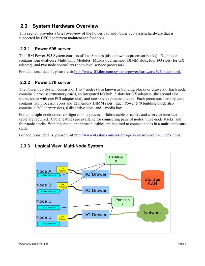
2.3.3 Logical View: Multi-Node System
POW03023USEN01.pdf Page 7
Node A
Node B
Node C
Node D
I/O Drawer
I/O Drawer
I/O Drawer
StorageSAN
Network
GX Adapter
GXAdapter
GX Adapter
CPUs Memory
CPUs Memory
CPUs ,Memory
CPUs, Memory
PartitionX
PartitionY
3 CEC Concurrent Maintenance Functions Each of the CEC concurrent maintenance functions available on the Power 595 and Power 570 systems is described in more detail within this section.
All of the concurrent maintenance procedures are performed through guided procedures on a Hardware Management Console (HMC). Most of the service procedures, including physical hardware installation, removal, and replacement, must be performed by a trained System Service Representative (SSR). The concurrent GX adapter add may be performed by a system administrator.
3.1 Concurrent Node AddThis function allows an SSR to add a node to a system to increase the processor, memory, and I/O expansion capability of the system. The new processor and memory resources are available for the creation of new partitions or to be dynamically added to existing partitions. Additional GX adapters (I/O hubs) can be physically added to the node and activated as part of the concurrent node add operation. After the completion of the node add operation, additional I/O expansion units can be attached to the new GX adapter(s) in the new node in a separate concurrent I/O expansion unit add operation.
POW03023USEN01.pdf Page 8
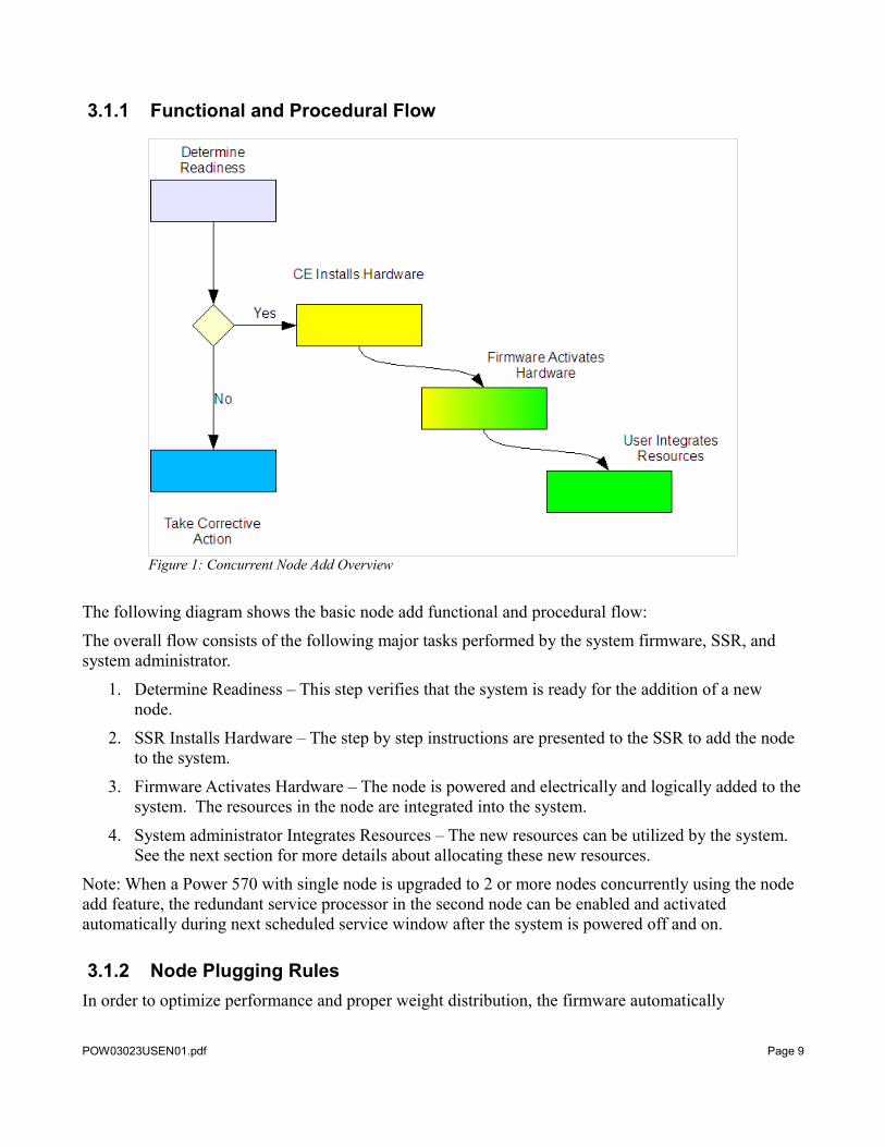
3.1.1 Functional and Procedural Flow
The following diagram shows the basic node add functional and procedural flow:
The overall flow consists of the following major tasks performed by the system firmware, SSR, and system administrator.
1. Determine Readiness – This step verifies that the system is ready for the addition of a new node.
2. SSR Installs Hardware – The step by step instructions are presented to the SSR to add the node to the system.
3. Firmware Activates Hardware – The node is powered and electrically and logically added to the system. The resources in the node are integrated into the system.
4. System administrator Integrates Resources – The new resources can be utilized by the system. See the next section for more details about allocating these new resources.
Note: When a Power 570 with single node is upgraded to 2 or more nodes concurrently using the node add feature, the redundant service processor in the second node can be enabled and activated automatically during next scheduled service window after the system is powered off and on.
3.1.2 Node Plugging RulesIn order to optimize performance and proper weight distribution, the firmware automatically
POW03023USEN01.pdf Page 9
Figure 1: Concurrent Node Add Overview
determines where the next node can be added into the system. The guided procedure on the HMC will direct the SSR to place the node into the correct location.
3.1.3 Allocation of ResourcesWith proper planning, the newly added processor and memory resources can be assigned to logical partitions without a partition reboot or entering CUoD activation codes.
If the system administrator wants to dynamically add the new processor and memory resources to activated partitions after concurrent maintenance, the profiles that were used to activate the partitions must have the maximums for processors, processing capacity and memory set to the appropriate values. When concurrent maintenance is complete, the processor and memory resources can be added to the partitions using dynamic logical partitioning (DLPAR).
POW03023USEN01.pdf Page 10
3.2 Concurrent Memory Add/UpgradeThis function allows a SSR to increase the memory capacity in a system (with 2 or more nodes) by adding additional memory DIMMs or upgrading (exchanging) existing memory with higher capacity memory cards in a node. The function is a hot add because the node that is being upgraded is running software applications prior to starting the concurrent add/upgrade. System administrator planning is required to free up the memory, processor, and I/O resources prior to the concurrent operation.
The upgrade process will deactivate the node to allow the upgrade to take place. In order for the node to be deactivated, the target node must be evacuated.
As part of the reintegration of resources following the add/upgrade, the I/O resources are automatically restored to the partitions as part of the concurrent operation. After the completion of the concurrent operation, processor and memory resources can be assigned to the partitions by the system administrator using DLPAR operations.
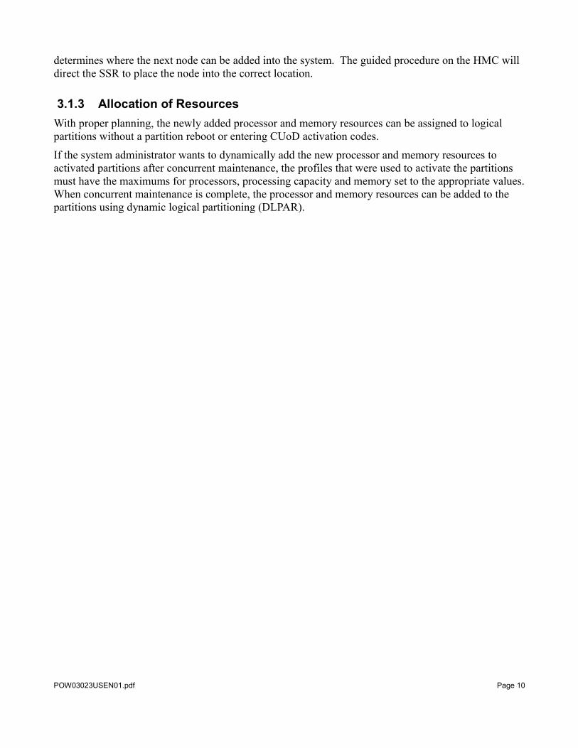
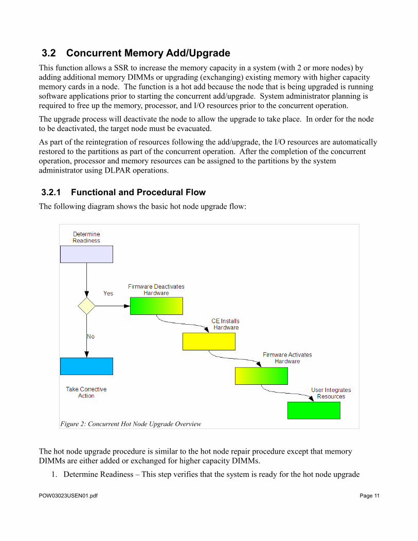
3.2.1 Functional and Procedural FlowThe following diagram shows the basic hot node upgrade flow:
Figure 2: Concurrent Hot Node Upgrade Overview
The hot node upgrade procedure is similar to the hot node repair procedure except that memory DIMMs are either added or exchanged for higher capacity DIMMs.
1. Determine Readiness – This step verifies that the system is ready for the hot node upgrade
POW03023USEN01.pdf Page 11
procedure. Various redundancy checks are made to ensure that the system will remain functional with the removal of the node being upgraded. Then the system firmware determine how much processor, memory (after taking the unlicensed processor and memory into account) and the I/O resources that need to be freed up to allow the node to be deactivated for upgrade. This phase also involves the system administrator making additional processor and memory resources available to accommodate the node upgrade if necessary, and placing I/O resources associated with the node in an inactive state to ensure that system firmware and software are not using them. See the “Display Service Effect Utility” in the “User Interface” section of this document for more information on preparing the system for a hot node upgrade procedure.
2. Firmware Deactivates Hardware – During this step of the upgrade procedure, the system will automatically offload the processor and memory resources used in the node being repaired to alternate nodes. Additionally, I/O resources associated with the node that are owned by active partitions will be released by those partitions or varied off. The node is electrically isolated from the system (powered off).
3. SSR Installs Hardware – The step by step instructions are presented to the SSR to add new DIMMs or replace existing DIMMs with higher capacity DIMMs.
4. Firmware Activates Hardware – The node is powered and electrically and logically added back to the system. The resources within the node are re-integrated into the system.
5. System administrator Integrates Resources – I/O resources associated with the node that were varied off during the deactivation step are re-acquired by active partitions, or varied on, automatically. The steps taken by the system administrator during the check system readiness step to make additional processor or memory resources available or to put I/O resources in an inactive state must be reversed manually by the system administrator.
3.2.2 Allocation of ResourcesAs part of the concurrent upgrade operation, I/O resources are added back to partitions automatically. The rest of the newly activated resources become available. Unassigned processors will be used for uncapped work in the shared processor pool, and these resources may be assigned to a partition by the system administrator.
POW03023USEN01.pdf Page 12
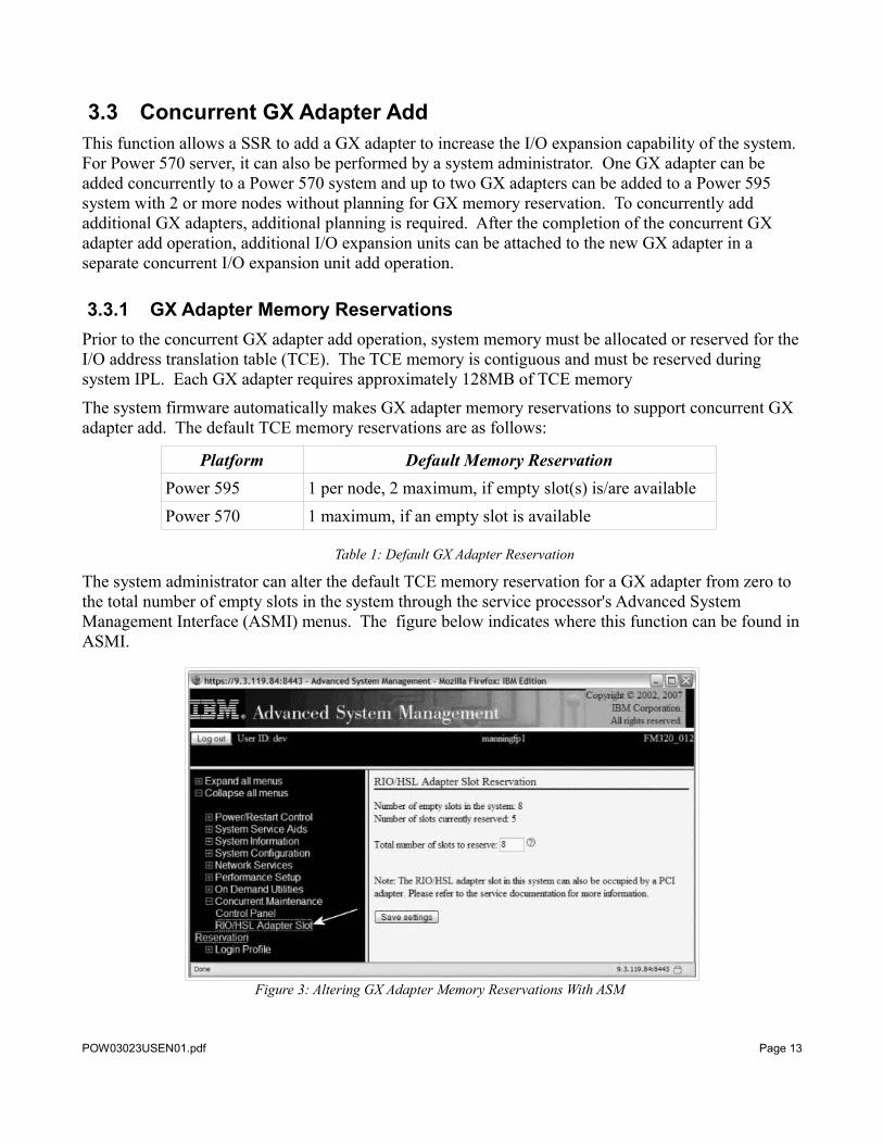
3.3 Concurrent GX Adapter AddThis function allows a SSR to add a GX adapter to increase the I/O expansion capability of the system. For Power 570 server, it can also be performed by a system administrator. One GX adapter can be added concurrently to a Power 570 system and up to two GX adapters can be added to a Power 595 system with 2 or more nodes without planning for GX memory reservation. To concurrently add additional GX adapters, additional planning is required. After the completion of the concurrent GX adapter add operation, additional I/O expansion units can be attached to the new GX adapter in a separate concurrent I/O expansion unit add operation.
3.3.1 GX Adapter Memory ReservationsPrior to the concurrent GX adapter add operation, system memory must be allocated or reserved for the I/O address translation table (TCE). The TCE memory is contiguous and must be reserved during system IPL. Each GX adapter requires approximately 128MB of TCE memory
The system firmware automatically makes GX adapter memory reservations to support concurrent GX adapter add. The default TCE memory reservations are as follows:
Platform Default Memory ReservationPower 595 1 per node, 2 maximum, if empty slot(s) is/are availablePower 570 1 maximum, if an empty slot is available
Table 1: Default GX Adapter Reservation
The system administrator can alter the default TCE memory reservation for a GX adapter from zero to the total number of empty slots in the system through the service processor's Advanced System Management Interface (ASMI) menus. The figure below indicates where this function can be found in ASMI.
POW03023USEN01.pdf Page 13
Figure 3: Altering GX Adapter Memory Reservations With ASM
These default reservations can be adjusted to the system administrator's discretion by changing the value in the “Total number of slots to reserver” field.
Once the system administrator saves the settings they become active on the next system IPL. The firmware attempts to allocate the memory to the desired number of slots to reserve, but may not be able to due to the system memory configuration. The more configured memory that is available, the higher probability all the desired requests will be fulfilled. Once the system reaches the runtime state, the menu can be refreshed to show exactly how many reservation requests were satisfied.
Because reservation requests are fulfilled during a system IPL, reservation requests while the system is powered on do not take effect until the next system IPL. A reservation request made while the system is powered off is fulfilled during the next system IPL.
3.3.2 Fulfilling a GX Adapter Memory ReservationOnce a GX adapter is successfully added through a concurrent GX adapter add operation, the reservation request is fulfilled, and the firmware decrements the total number of reservations. For example, if a System administrator requests three slots and then performs a concurrent GX adapter add operation, the total number of reservations decreases to two.
3.3.3 Plugging RulesIn order to optimize performance the firmware automatically determines where a GX adapter can be added into the system. A system administrator only needs to specify how many GX adapters are desired, and the firmware enforces the rules.
POW03023USEN01.pdf Page 14
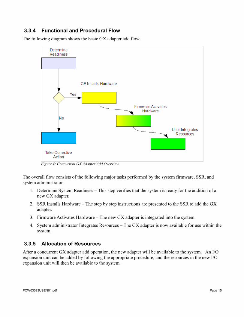
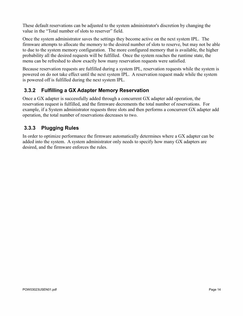
3.3.4 Functional and Procedural FlowThe following diagram shows the basic GX adapter add flow.
The overall flow consists of the following major tasks performed by the system firmware, SSR, and system administrator.
1. Determine System Readiness – This step verifies that the system is ready for the addition of a new GX adapter.
2. SSR Installs Hardware – The step by step instructions are presented to the SSR to add the GX adapter.
3. Firmware Activates Hardware – The new GX adapter is integrated into the system.
4. System administrator Integrates Resources – The GX adapter is now available for use within the system.
3.3.5 Allocation of ResourcesAfter a concurrent GX adapter add operation, the new adapter will be available to the system. An I/O expansion unit can be added by following the appropriate procedure, and the resources in the new I/O expansion unit will then be available to the system.
POW03023USEN01.pdf Page 15
Figure 4: Concurrent GX Adapter Add Overview
3.4 Concurrent Hot Node RepairThis function allows an SSR to repair defective hardware in a node in a system (with 2 or more nodes ). The function is a hot repair, since the node with the defective hardware is running software applications prior to starting the concurrent repair operation. System administrator planning is required to free up the processor, memory, and I/O resources prior to the concurrent repair.
The hot node repair procedure will deactivate and electrically isolate the node to allow safe removal and insertion. In order for the node to be deactivated, the target node must be evacuated.
As part of the reintegration of resources following the repair, the I/O resources are automatically restored to the partitions as part of the concurrent operation. After the completion of the concurrent operation, processor and memory resources can be assigned to the partitions by the system administrator using DLPAR operations.
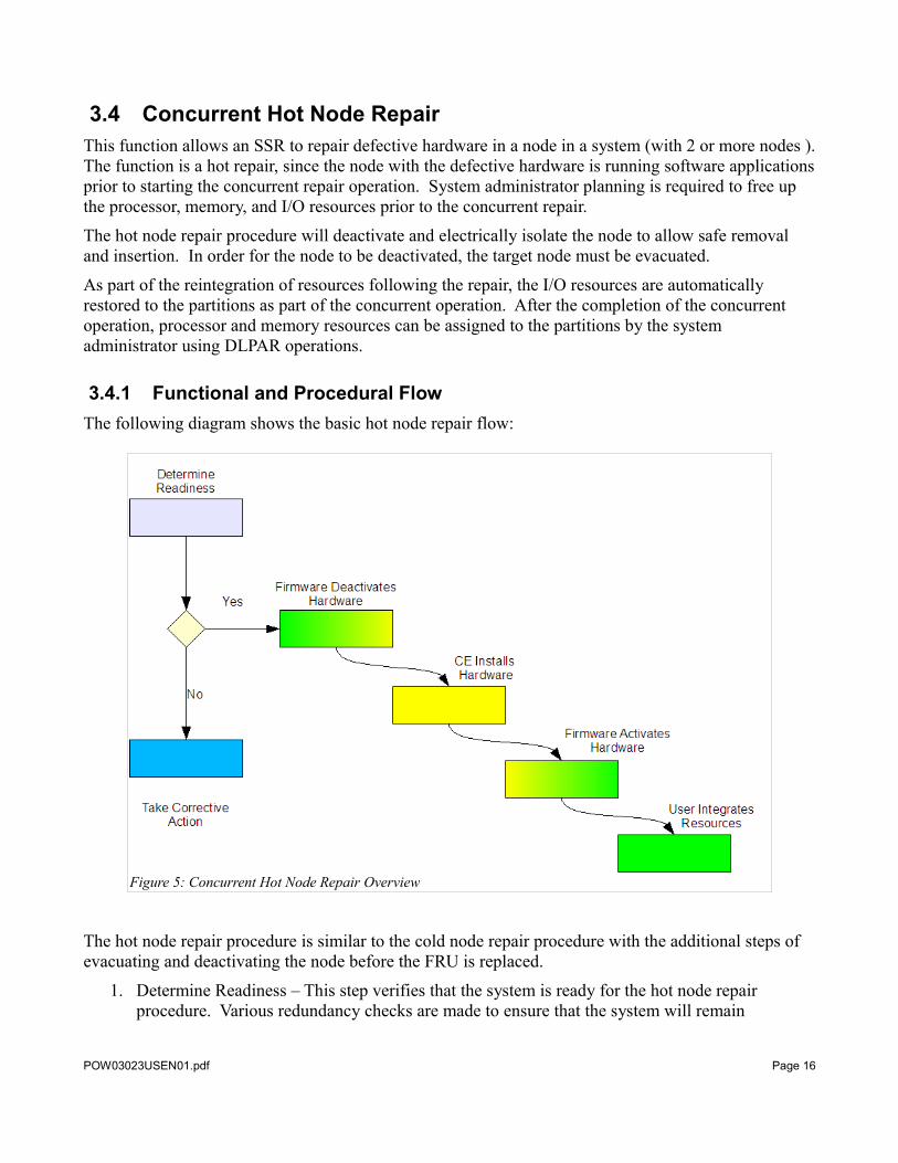
3.4.1 Functional and Procedural FlowThe following diagram shows the basic hot node repair flow:
Figure 5: Concurrent Hot Node Repair Overview
The hot node repair procedure is similar to the cold node repair procedure with the additional steps of evacuating and deactivating the node before the FRU is replaced.
1. Determine Readiness – This step verifies that the system is ready for the hot node repair procedure. Various redundancy checks are made to ensure that the system will remain
POW03023USEN01.pdf Page 16
functional with the removal of the target node. Then the system firmware determine how much processor, memory (after taking the unlicensed processor and memory into account) and the I/O resources that need to be freed up to allow the node to be deactivated for upgrade. This phase also involves the system administrator making additional processor and memory resources available to accommodate the node repair if necessary, and placing I/O resources associated with the node in an inactive state so system firmware and software are not using them. See the “Display Service Effect Utility” in the “User Interface” section of this document for more information on preparing the system for a hot node repair procedure.
2. Firmware Deactivates Hardware – During this step of the repair procedure, the system will automatically offload the processor and memory resources used in the node being repaired to alternate nodes. Additionally, I/O resources associated with the node that are owned by active partitions will be released by those partitions, or varied off. The node is electrically isolated from the system (powered off).
3. SSR Installs Hardware – The step by step instructions are presented to the SSR to replace the failing FRU.
4. Firmware Activates Hardware – The node is powered and electrically and logically added back to the system. The resources within the node are reintegrated into the system.
5. System administrator Integrates Resources – I/O resources associated with the node that were varied off during the deactivation step are re-acquired by active partitions, or varied on, automatically. The steps taken by the system administrator during the check system readiness step to make additional processor or memory resources available or to put I/O resources in an inactive state must be reversed manually by the system administrator.
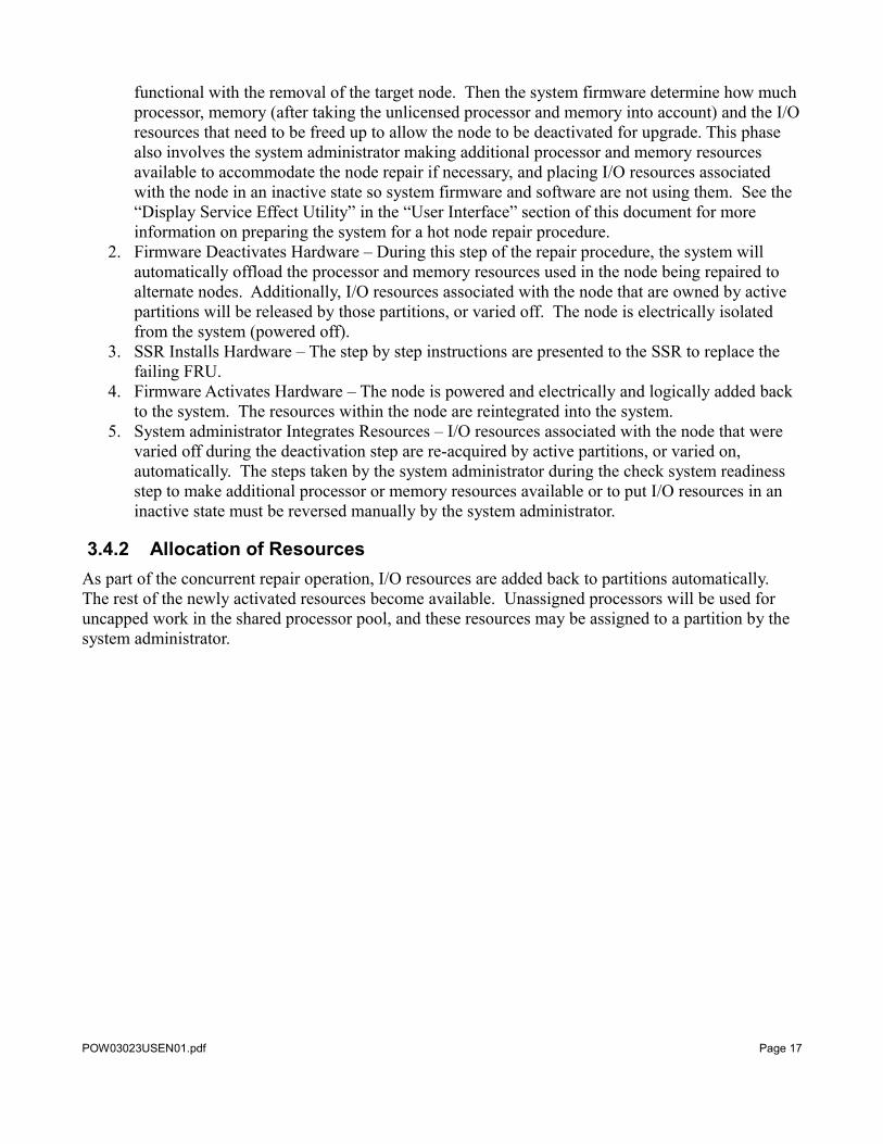
3.4.2 Allocation of ResourcesAs part of the concurrent repair operation, I/O resources are added back to partitions automatically. The rest of the newly activated resources become available. Unassigned processors will be used for uncapped work in the shared processor pool, and these resources may be assigned to a partition by the system administrator.
POW03023USEN01.pdf Page 17
3.5 Concurrent Cold Node RepairThis function allows an SSR to concurrently repair defective hardware in a node that has been electrically isolated from the system during a previous system IPL or reIPL. As part of the reintegration of resources following the repair, the I/O resources are automatically restored to the partitions as part of the concurrent operation. After the completion of the concurrent operation, processor and memory resources can be assigned to the partitions by the system administrator using DLPAR operations.
3.5.1 Restoring Service Processor RedundancyIf the backup service processor lost its connectivity to the system because of a node was electrically isolated (deconfigured) from the system, during the concurrent cold node repair, the backup service processor connectivity will be restored using available I/O paths in the repaired node. When the primary service processor detects that a Power 595 node has been repaired, it restores and activates its sibling service processor to full functionality. This restores the client's environment to full system availability. In the Power 570 system, when a node containing a backup service processor is repaired, the primary service processor will activate the backup and restore redundancy.
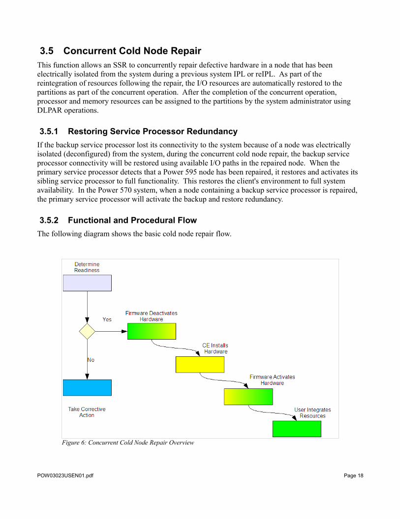
3.5.2 Functional and Procedural FlowThe following diagram shows the basic cold node repair flow.
POW03023USEN01.pdf Page 18
Figure 6: Concurrent Cold Node Repair Overview
The overall flow consists of the following major tasks performed by the system firmware, SSR, and system administrator. The shades of blue represent actions initiated by the SSR. The shades of green and yellow indicate the hardware functionality of the target FRU.
1. Determine Readiness – This step verifies that the system is ready for the repair of a CEC node.
2. Firmware Deactivates Hardware – Because the node is electrically isolated from the system, this step only needs to to prepare and notify the firmware that the FRU is being repaired.
3. SSR Installs Hardware – The step by step instructions are presented to the SSR to replace the failing FRU.
4. Firmware Activates Hardware – The node and the resources within the node are reintegrated into the system.
5. Restoring Resources – The resources within the CEC node are reintegrated into the system.
3.5.3 Allocation of ResourcesAs part of the cold node repair operation, I/O resources are added back to partitions automatically.
The rest of the newly activated resources become available. Unassigned processors will be used for uncapped work in the shared processor pool, and these resources may be assigned to a partition by the system administrator.
3.5.4 Expanded Node Gard PolicyFor Power 570 systems running firmware level EM322_xxx (Service Pack 5), the expanded node Gard policy is intended to prepare a system for concurrent cold node repair. See Apendix for more details.
POW03023USEN01.pdf Page 19
3.6 Concurrent Cold GX Adapter RepairThis function allows an SSR to concurrently repair a GX adapter that has been electrically isolated from the system during a previous system IPL or reIPL. As part of the reintegration of resources following the repair, the I/O resources are automatically restored to the partitions as part of the concurrent operation.
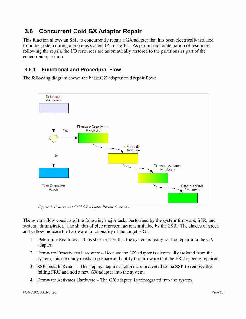
3.6.1 Functional and Procedural FlowThe following diagram shows the basic GX adapter cold repair flow:
The overall flow consists of the following major tasks performed by the system firmware, SSR, and system administrator. The shades of blue represent actions initiated by the SSR. The shades of green and yellow indicate the hardware functionality of the target FRU.
1. Determine Readiness – This step verifies that the system is ready for the repair of a the GX adapter.
2. Firmware Deactivates Hardware – Because the GX adapter is electrically isolated from the system, this step only needs to prepare and notify the firmware that the FRU is being repaired.
3. SSR Installs Repair – The step by step instructions are presented to the SSR to remove the failing FRU and add a new GX adapter into the system.
4. Firmware Activates Hardware – The GX adapter is reintegrated into the system.
POW03023USEN01.pdf Page 20
Figure 7: Concurrent Cold GX adapter Repair Overview
5. Restoring resources – Previously failed resources are now made available.
3.6.2 Allocation of ResourcesWhen the concurrent repair action is complete, all previously disabled resources are available. These resources would appear to be “missing” from the profiles without the resources being re-allocated to the partitions on the system.
When resources are added back to the system as a result of the concurrent maintenance action, the recovery action varies depending on the types of partitions that own the resources in question. Active i partitions will automatically discover and start utilizing the previously “missing” but currently available resources. For active AIX and Linux partitions, RV will initiate DLPAR flows to add back the currently available resources, without the intervention of the system administrator.
Partitions that previously failed to reboot because of missing critical resources will have to be restarted by the system administrator. The resources will be available following the repair and will remain assigned to the partition.
3.7 Performing the Concurrent Maintenance OperationEach of the CEC concurrent maintenance functions is carried out by using the guided procedures on the HMC. The procedures provide the step-by-step instructions necessary to complete the repair, add, or upgrade. Each of the operations described in section 3 will be done by an SSR with the exception of the Power 570 GX add operation, which can be performed by a system administrator.
The guided procedures provided by the HMC must be precisely followed. Additional hardware should not be added, moved, or removed during the operation. For repair operations, the same FRU type must be used to replace the failing FRU. Each of the CEC concurrent maintenance operations must be completed individually. Add multiple nodes or adding a GX adapter and I/O expansion unit at the same time is not supported. Each of these procedures must be done separately.
For the node and GX add operations, the HMC procedures provide guidance as to where to add the new FRU based on the plugging order rules. These plugging rules must be followed to ensure optimal system functionality following the CEC concurrent maintenance operation.
POW03023USEN01.pdf Page 21
4 Planning Guides for CEC Concurrent Maintenance
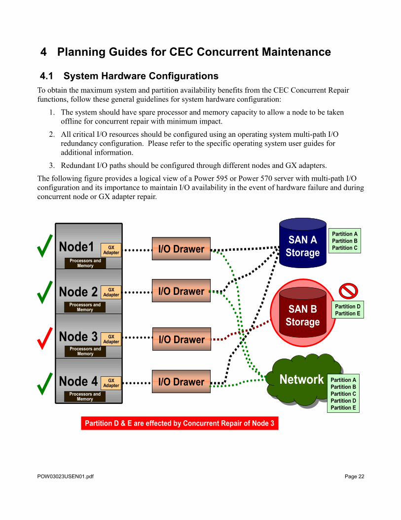
4.1 System Hardware ConfigurationsTo obtain the maximum system and partition availability benefits from the CEC Concurrent Repair functions, follow these general guidelines for system hardware configuration:
1. The system should have spare processor and memory capacity to allow a node to be taken offline for concurrent repair with minimum impact.
2. All critical I/O resources should be configured using an operating system multi-path I/O redundancy configuration. Please refer to the specific operating system user guides for additional information.
3. Redundant I/O paths should be configured through different nodes and GX adapters.
The following figure provides a logical view of a Power 595 or Power 570 server with multi-path I/O configuration and its importance to maintain I/O availability in the event of hardware failure and during concurrent node or GX adapter repair.
POW03023USEN01.pdf Page 22
I/O Drawer
SAN AStorage
NetworkNetworkNode 4
Node 3
Node 2
Node1
Node 4
Node 3
Node 2
Node1
SAN BStorage
I/O Drawer
I/O DrawerGXAdapter
GXAdapter
GXAdapter
Partition APartition BPartition C
Partition DPartition E
Partition APartition BPartition CPartition DPartition E
Processors and Memory
Processors and Memory
Processors and Memory
Processors and Memory
GXAdapter
I/O Drawer
Partition D & E are effected by Concurrent Repair of Node 3
4.2 Partition Configuration ConsiderationsMaintaining the availability of partitions during a hot node repair or upgrade requires planning ahead of time to ensure that the impacts are minimized. It is important to realize that the operation is concurrent from the system point of view and is not completely transparent to the logical partitions on the system. Since an action of this type temporarily reduces the memory, processing, and I/O capacity of the system it very likely will impact individual partitions without the proper planning.
Memory and processor capacity are the easiest types of resources to plan for since PowerVMTM can transparently change processor and memory assignments to accommodate the removal of a node. The only requirement that the system administrator must plan for is that there be enough free memory and processor capacity available in other nodes on the system to accommodate processor and memory resources that are in use in the node being evacuated.
The following considerations should be taken into account when planning to free sufficient processor and memory capacity:
1. Capacity upgrade On Demand (CuOD) resources can be used to meet the free memory and processor requirements. For example, a 16 CPU Power 570 system consisting of 4 nodes/drawers with 12 licensed and 4 unlicensed processors would not be required to free any processor resources to perform a hot node repair/upgrade on any of the nodes since there are already 4 unlicensed processors available to be used during the procedure.
2. Processor and memory resources currently assigned to logical partitions that are powered off will be considered available resources to be used during the hot node repair/upgrade procedure while performing the deactivation of the node.
3. Partitions can either be powered off or have processor and/or memory resources removed from them via dynamic logical partitioning (DLPAR) to free the resources needed to perform the hot node repair or upgrade. If DLPAR is being used, the minimum processor and memory settings for each logical partition should be planned for appropriately such that an entire node's worth of processor and memory resources could be removed from the partitions that will be running during the CCM operation.
I/O resource planning is more complex. During a hot node repair or upgrade procedure, the I/O expansion units attached to the GX adapters in that node will be unavailable. If a partition needs to continue running during the procedure and is using I/O resources attached to the GX adapters in the target node, careful planning must be done to ensure that access to critical I/O resources can be maintained.
To maintain access to the I/O attached through the target node, multi-path I/O solutions must be utilized so there are multiple I/O adapter (IOA) paths to the physical I/O resource such as network or SAN attached storage. Care must be taken to ensure that the redundant IOAs for each resource are located in different I/O expansion units that are attached to different GX adapters located in different nodes.
These redundant paths to the I/O resources could be assigned to the same partition and use the multi-path physical I/O solutions that have been implemented by each OS. Another example would be having each of the redundant paths assigned to a different Virtual I/O Server (VIOS) partition, with the VIOS partitions being redundant VIOS servers for VIOS clients that need to remain available during the node repair/upgrade.
POW03023USEN01.pdf Page 23
An additional logical partition configuration consideration is related to the system setting to "Power off the system after all the logical partitions are powered off." This setting can be displayed and modified by selecting the "Properties" for your server on the HMC and viewing the "General" tab. Preparation for a hot node repair or upgrade may impact resources on the system and may require logical partitions to be powered-off. If the last logical partition is powered off as a part of preparing for the hot node repair or upgrade, the system will also power off if this option is selected. In order for the system to successfully complete a concurrent operation involving, this setting should not be selected if logical partitions are being deactivated. If this option is selected and the last logical partition is powered off, the system will attempt to power off in the middle of the concurrent repair operation.
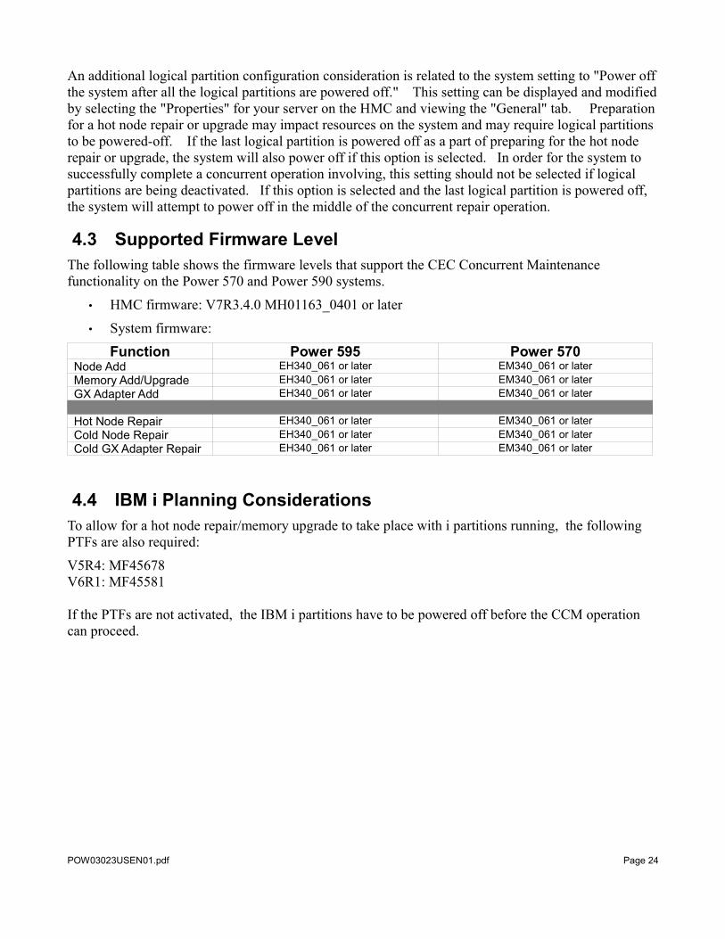
4.3 Supported Firmware LevelThe following table shows the firmware levels that support the CEC Concurrent Maintenance functionality on the Power 570 and Power 590 systems.
• HMC firmware: V7R3.4.0 MH01163_0401 or later
• System firmware:
Function Power 595 Power 570Node Add EH340_061 or later EM340_061 or laterMemory Add/Upgrade EH340_061 or later EM340_061 or laterGX Adapter Add EH340_061 or later EM340_061 or later
Hot Node Repair EH340_061 or later EM340_061 or laterCold Node Repair EH340_061 or later EM340_061 or laterCold GX Adapter Repair EH340_061 or later EM340_061 or later
4.4 IBM i Planning ConsiderationsTo allow for a hot node repair/memory upgrade to take place with i partitions running, the following PTFs are also required:
V5R4: MF45678V6R1: MF45581
If the PTFs are not activated, the IBM i partitions have to be powered off before the CCM operation can proceed.
POW03023USEN01.pdf Page 24
4.5 Guidelines for All Concurrent Maintenance Operations1. Only one concurrent maintenance operation can be performed at a time from one HMC.2. A second concurrent maintenance operation cannot be started until the first one has been
completed successfully.3. Multiple concurrent maintenance operations must be completed by doing a series of single
concurrent maintenance operations.4. All of the concurrent maintenance activities, with the exception of the Power 570 GX adapter
add, must be performed by a service representative. Power 570 concurrent GX adapter add can be performed by a system administrator.
5. Enable service processor redundancy before a CCM operation, except Power 570 with single node.
6. For concurrent memory upgrade and concurrent hot node repair:a) the Display Service Effect Utility must be run by the system administrator to determine the
processor, memory and I/O resources that must be freed up prior to the start of concurrent operation.
b) both service processors (system controllers) in Power 595 must be in functional state.c) Power 570 node must not contain an active system clock.
7. Ensure that the system is not in energy savings mode prior to concurrent node add, memory upgrade or concurrent node repair operation. Energy savings mode and energy capping enable the server to use less energy by decreasing the processor frequency.
8. Resource relocation: There are certain system features and capabilities that do not support the functionality needed to relocate their resources transparently to an executing partition to another node. In some cases the usage of these features or capabilities will prevent any CEC concurrent maintenance on the system. In other cases the partition to which a resource that is associated with such a feature or capability is assigned will have to be powered off during the CEC concurrent maintenance action. The following features and capabilities are not supported in conjunction with hot node repair or upgrade:• If the system is clustered to another system using RIO-SAN technology, CCM is not
supported. This technology is used only by i users that are using clustering, switchable towers, and virtual opticonnect technologies.
• If the system is clustered to another system using Infiniband technology, CCM is not supported. This capability is typically used by High Performance Computing type clients that have several systems clustered together using an Infiniband switch.
• I/O Processors (IOPs) used by i partitions do not support CCM. Any i partitions that have IOPs assigned to them must either have the IOPs assigned to them powered off, or the partition must be powered off to allow the CCM action.
• 16 GB memory pages, also known as huge pages, do not support memory relocation. Any partitions that have 16 GB pages assigned to them must be powered off to allow the CCM action. Furthermore, due to memory layout changes that take place during the memory relocation phase of a node deactivation, the number of huge pages after a hot node repair may be reduced.
9. As previously described, with proper planning and configuration, enterprise-class Power Servers are designed for concurrent upgrade (add) or repair. However, changing the hardware configuration or the operational state of electronic equipment may cause unforeseen impacts to
POW03023USEN01.pdf Page 25
the system status or applications that are running. Clients should therefore consider taking proactive measures to insure minimal impact to their operations. Some highly recommended precautions to consider:• Schedule concurrent upgrades or repairs during "non-peak" operational hours.• Move business-critical applications to another server using the Live Partition Mobility
feature or quiesce them.• Back up critical application and system state information.• Checkpoint data bases
4.6 Guidelines for Concurrent Add/Upgrade Operations1. All serviceable hardware events must be repaired and closed before starting a concurrent add or
upgrade operation. This eliminates the possibility that an existing hardware failure will cause the concurrent add operation to fail. Prior to a node add operation, the existing nodes in the system must be in a functional state.
2. System firmware enforces the node and GX adapter plugging order. Only the next GX adapter slot or node position based on the plugging order is available.
3. For Power 570, ensure that system cable with connections for additional node is added with system powered off during a scheduled upgrade window in advance, prior to concurrent node add.
4. When multiple concurrent adds are planned that include node and GX adapter adds, the GX adapter(s) can be installed in the node before the node is installed in the system. If this order is observed, the memory in the new node will be used for the 128 MB of memory that is required for the GX adapter. (The node must have approximately 128 MB of memory per GX adapter to support the adapter’s translation control entry (TCE) table) The GX adapter in the new node will be activated during the node add (if the 128 MB memory requirement is met). If the GX adapter is installed after the new node is installed and activated, the plugging rules for GX adapters will be enforced. In this case, the GX adapter must be installed in another node with another concurrent add operation.
5. For multiple upgrades that include node or GX adapter adds, as well as I/O drawer adds, the concurrent node or GX adapter add must be completed first. The I/O drawer can then be added later as a separate concurrent I/O drawer add.
4.7 Guidelines for Concurrent Repair Operations1. Repair with same FRU type: The node repair procedure does not allow for changes to the
hardware beyond the repair of the target FRU. The same FRU type must be used to replace the failing FRU and no additional hardware can be added or removed during the procedure. For example, if a 4GB DIMM fails, it must be replaced with a 4GB DIMM – not a 2GB or 8GB DIMM, a RIO GX adapter, it must be replaced with a RIO GX adapter, not an Infiniban GX adapter..
2. Hardware upgrades and downgrades are not supported during a repair operation.
POW03023USEN01.pdf Page 26

4.8 Planning ChecklistPlease refer to the “Central electronics complex concurrent maintenance” topic in the Information Center for additional information. http://publib.boulder.ibm.com/infocenter/systems/scope/hw/index.jsp?topic=/ared3/ared3kickoff.htm
POW03023USEN01.pdf Page 27
5 User InterfacesThe HMC and service processor provide the user interface for the activities related to CEC concurrent maintenance actions. The SSR who is executing the procedure will use the HMC to initiate the concurrent maintenance procedure and use the guided procedure to complete the service action.
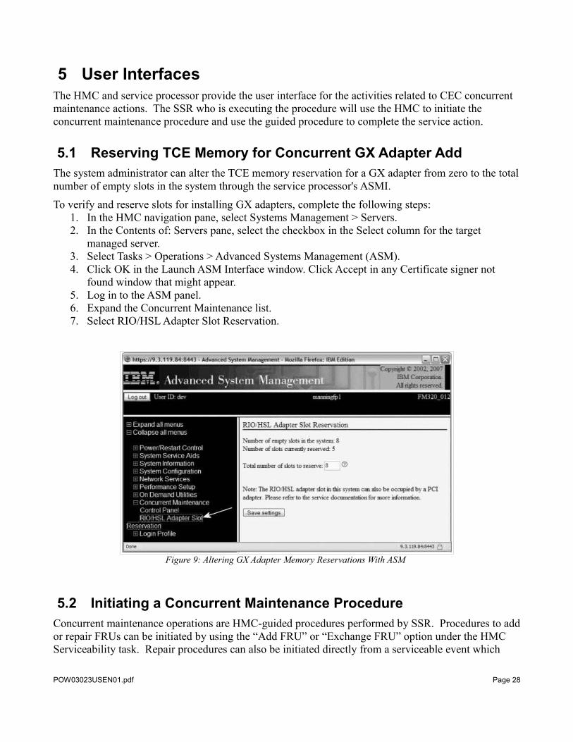
5.1 Reserving TCE Memory for Concurrent GX Adapter AddThe system administrator can alter the TCE memory reservation for a GX adapter from zero to the total number of empty slots in the system through the service processor's ASMI.
To verify and reserve slots for installing GX adapters, complete the following steps:1. In the HMC navigation pane, select Systems Management > Servers.2. In the Contents of: Servers pane, select the checkbox in the Select column for the target
managed server.3. Select Tasks > Operations > Advanced Systems Management (ASM).4. Click OK in the Launch ASM Interface window. Click Accept in any Certificate signer not
found window that might appear.5. Log in to the ASM panel.6. Expand the Concurrent Maintenance list.7. Select RIO/HSL Adapter Slot Reservation.
5.2 Initiating a Concurrent Maintenance Procedure Concurrent maintenance operations are HMC-guided procedures performed by SSR. Procedures to add or repair FRUs can be initiated by using the “Add FRU” or “Exchange FRU” option under the HMC Serviceability task. Repair procedures can also be initiated directly from a serviceable event which
POW03023USEN01.pdf Page 28
Figure 9: Altering GX Adapter Memory Reservations With ASM
calls out the FRU(s) to be repaired.
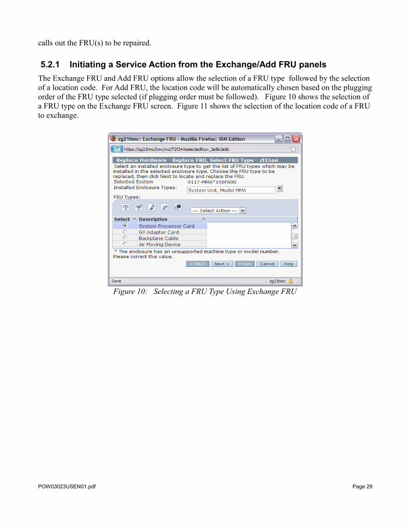
5.2.1 Initiating a Service Action from the Exchange/Add FRU panelsThe Exchange FRU and Add FRU options allow the selection of a FRU type followed by the selection of a location code. For Add FRU, the location code will be automatically chosen based on the plugging order of the FRU type selected (if plugging order must be followed). Figure 10 shows the selection of a FRU type on the Exchange FRU screen. Figure 11 shows the selection of the location code of a FRU to exchange.
Figure 10: Selecting a FRU Type Using Exchange FRU
POW03023USEN01.pdf Page 29
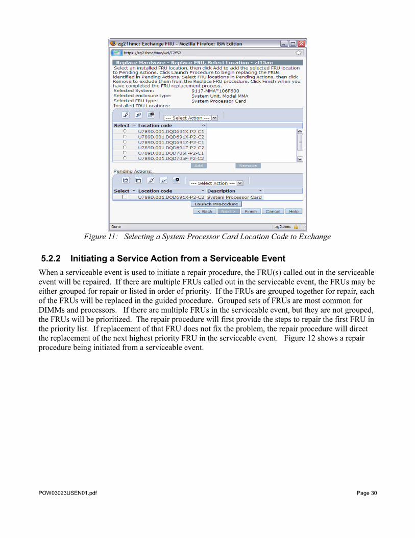
Figure 11: Selecting a System Processor Card Location Code to Exchange
5.2.2 Initiating a Service Action from a Serviceable EventWhen a serviceable event is used to initiate a repair procedure, the FRU(s) called out in the serviceable event will be repaired. If there are multiple FRUs called out in the serviceable event, the FRUs may be either grouped for repair or listed in order of priority. If the FRUs are grouped together for repair, each of the FRUs will be replaced in the guided procedure. Grouped sets of FRUs are most common for DIMMs and processors. If there are multiple FRUs in the serviceable event, but they are not grouped, the FRUs will be prioritized. The repair procedure will first provide the steps to repair the first FRU in the priority list. If replacement of that FRU does not fix the problem, the repair procedure will direct the replacement of the next highest priority FRU in the serviceable event. Figure 12 shows a repair procedure being initiated from a serviceable event.
POW03023USEN01.pdf Page 30
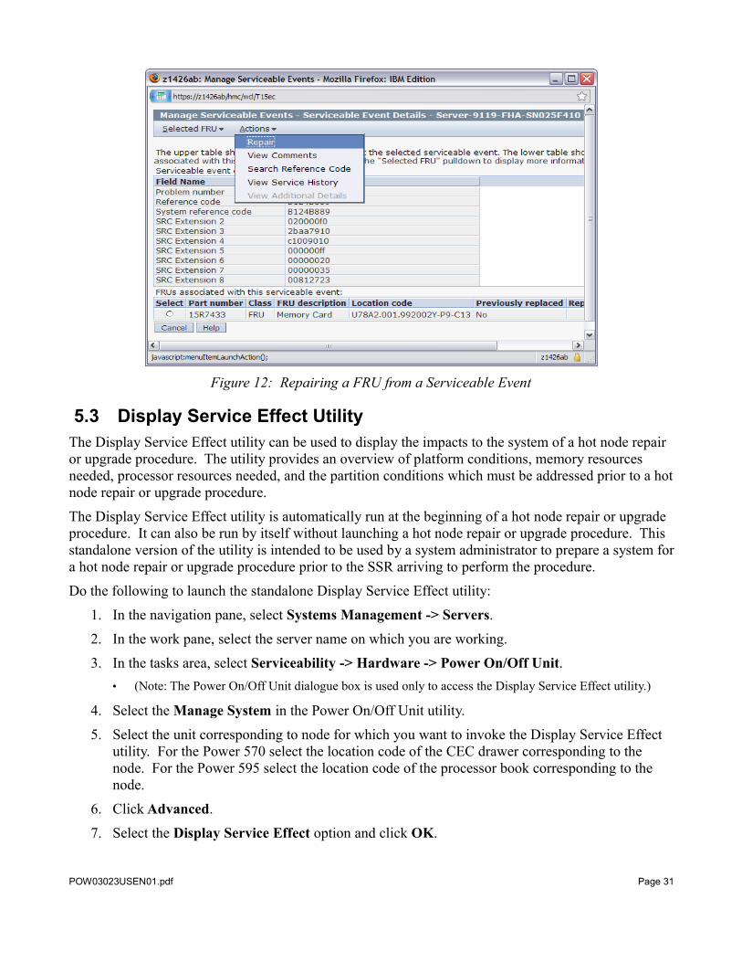
Figure 12: Repairing a FRU from a Serviceable Event
5.3 Display Service Effect UtilityThe Display Service Effect utility can be used to display the impacts to the system of a hot node repair or upgrade procedure. The utility provides an overview of platform conditions, memory resources needed, processor resources needed, and the partition conditions which must be addressed prior to a hot node repair or upgrade procedure.
The Display Service Effect utility is automatically run at the beginning of a hot node repair or upgrade procedure. It can also be run by itself without launching a hot node repair or upgrade procedure. This standalone version of the utility is intended to be used by a system administrator to prepare a system for a hot node repair or upgrade procedure prior to the SSR arriving to perform the procedure.
Do the following to launch the standalone Display Service Effect utility:
1. In the navigation pane, select Systems Management -> Servers.
2. In the work pane, select the server name on which you are working.
3. In the tasks area, select Serviceability -> Hardware -> Power On/Off Unit. • (Note: The Power On/Off Unit dialogue box is used only to access the Display Service Effect utility.)
4. Select the Manage System in the Power On/Off Unit utility.
5. Select the unit corresponding to node for which you want to invoke the Display Service Effect utility. For the Power 570 select the location code of the CEC drawer corresponding to the node. For the Power 595 select the location code of the processor book corresponding to the node.
6. Click Advanced.
7. Select the Display Service Effect option and click OK.
POW03023USEN01.pdf Page 31

8. Select Yes when prompted to continue with the advanced power control command.
The Display Service Effect utility displays either a message indicating why a hot node repair or upgrade of the selected node is not allowed, or displays the Node Evacuation Summary Status panel. The Node Evacuation Summary Status panel displays a summary of any conditions which must be corrected or should be noted before starting a hot node repair or upgrade procedure. The four buttons across the top of the utility (Platform, Memory, Processors, and Partitions) can be used to display details about these conditions. Conditions that are displayed when the Errors button is selected on any of the details screens must be corrected or resolved before the hot repair or upgrade procedure can proceed. Conditions that are displayed when the Informational Messages button is selected on any of the details screens are things that might affect the system or partitions and thus should be of interest to the system administrator, but do not prevent the repair or upgrade procedure from continuing.
10. Click Recheck to reevaluate the system readiness for hot node repair or upgrade without relaunching the utility. Once the Overall Summary statement at the top of the Node Evacuation Summary Status panel indicates that there are no error conditions, the system is ready for a hot node repair or upgrade procedure.
11. Click Cancel to exit the Display Service Effect utility.
When working with the information and error messages shown on the Node Evacuation Summary Status panel, work with the Platform and Partition messages first. The impacts to the platform and partitions indicated in these messages may lead to the shutdown of partitions on the system for reasons such as I/O resources being used by the partition in the target node. The shutdown of a partition will free up memory and processor resources. If a partition must be shutdown, use the Recheck button to re-evaluate the memory and processor resources. Working with the information and error messages in this order will avoid the situation where memory and processor resources are DLPARed away from partitions only to later discover that additional partitions must be shutdown prior to the node evacuation.
Examples of the Node Evacuation Summary Status panels can be found in Figures 13 and 14. These figures show some of the common information and error messages which are seen with this utility.
POW03023USEN01.pdf Page 32
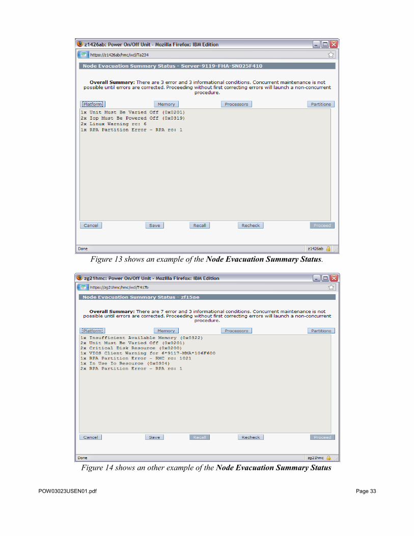
Figure 13 shows an example of the Node Evacuation Summary Status.
Figure 14 shows an other example of the Node Evacuation Summary Status
POW03023USEN01.pdf Page 33
The following are some common conditions that are displayed by the Display Service Effect utility. Each of the conditions displayed on the Node Evacuation Summary Status panel is described in greater detail under one of the buttons across the top of the panel.
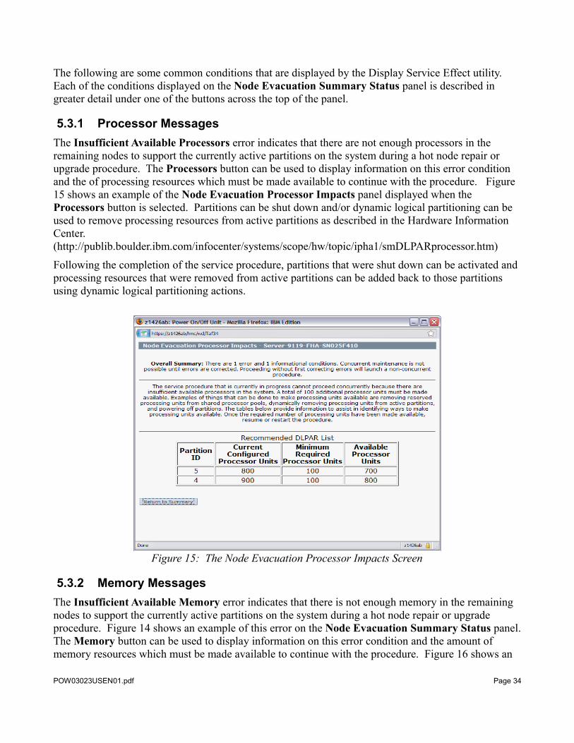
5.3.1 Processor MessagesThe Insufficient Available Processors error indicates that there are not enough processors in the remaining nodes to support the currently active partitions on the system during a hot node repair or upgrade procedure. The Processors button can be used to display information on this error condition and the of processing resources which must be made available to continue with the procedure. Figure 15 shows an example of the Node Evacuation Processor Impacts panel displayed when the Processors button is selected. Partitions can be shut down and/or dynamic logical partitioning can be used to remove processing resources from active partitions as described in the Hardware Information Center. (http://publib.boulder.ibm.com/infocenter/systems/scope/hw/topic/ipha1/smDLPARprocessor.htm)
Following the completion of the service procedure, partitions that were shut down can be activated and processing resources that were removed from active partitions can be added back to those partitions using dynamic logical partitioning actions.
Figure 15: The Node Evacuation Processor Impacts Screen
5.3.2 Memory MessagesThe Insufficient Available Memory error indicates that there is not enough memory in the remaining nodes to support the currently active partitions on the system during a hot node repair or upgrade procedure. Figure 14 shows an example of this error on the Node Evacuation Summary Status panel. The Memory button can be used to display information on this error condition and the amount of memory resources which must be made available to continue with the procedure. Figure 16 shows an
POW03023USEN01.pdf Page 34
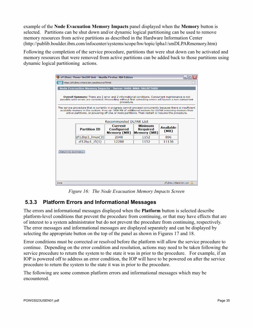
example of the Node Evacuation Memory Impacts panel displayed when the Memory button is selected. Partitions can be shut down and/or dynamic logical partitioning can be used to remove memory resources from active partitions as described in the Hardware Information Center (http://publib.boulder.ibm.com/infocenter/systems/scope/hw/topic/ipha1/smDLPARmemory.htm)
Following the completion of the service procedure, partitions that were shut down can be activated and memory resources that were removed from active partitions can be added back to those partitions using dynamic logical partitioning actions.
Figure 16: The Node Evacuation Memory Impacts Screen
5.3.3 Platform Errors and Informational MessagesThe errors and informational messages displayed when the Platform button is selected describe platform-level conditions that prevent the procedure from continuing, or that may have effects that are of interest to a system administrator but do not prevent the procedure from continuing, respectively. The error messages and informational messages are displayed separately and can be displayed by selecting the appropriate button on the top of the panel as shown in Figures 17 and 18.
Error conditions must be corrected or resolved before the platform will allow the service procedure to continue. Depending on the error condition and resolution, actions may need to be taken following the service procedure to return the system to the state it was in prior to the procedure. For example, if an IOP is powered off to address an error condition, the IOP will have to be powered on after the service procedure to return the system to the state it was in prior to the procedure.
The following are some common platform errors and informational messages which may be encountered.
POW03023USEN01.pdf Page 35
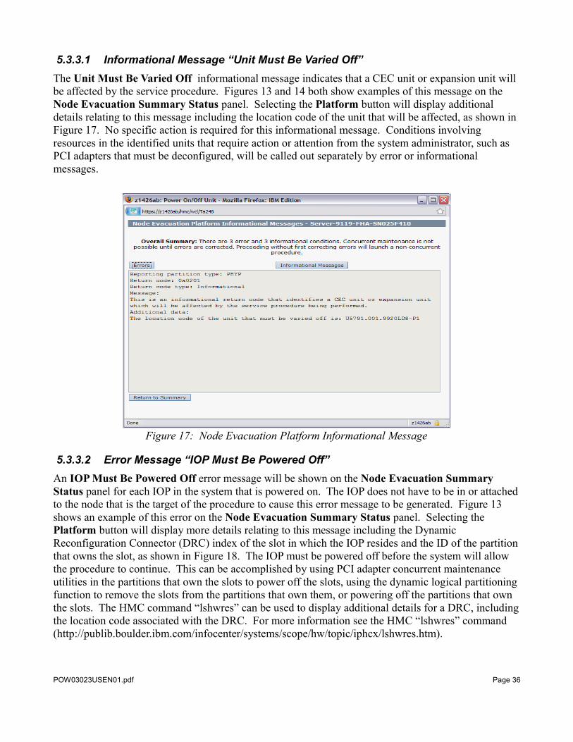
5.3.3.1 Informational Message “Unit Must Be Varied Off”The Unit Must Be Varied Off informational message indicates that a CEC unit or expansion unit will be affected by the service procedure. Figures 13 and 14 both show examples of this message on the Node Evacuation Summary Status panel. Selecting the Platform button will display additional details relating to this message including the location code of the unit that will be affected, as shown in Figure 17. No specific action is required for this informational message. Conditions involving resources in the identified units that require action or attention from the system administrator, such as PCI adapters that must be deconfigured, will be called out separately by error or informational messages.
Figure 17: Node Evacuation Platform Informational Message
5.3.3.2 Error Message “IOP Must Be Powered Off”An IOP Must Be Powered Off error message will be shown on the Node Evacuation Summary Status panel for each IOP in the system that is powered on. The IOP does not have to be in or attached to the node that is the target of the procedure to cause this error message to be generated. Figure 13 shows an example of this error on the Node Evacuation Summary Status panel. Selecting the Platform button will display more details relating to this message including the Dynamic Reconfiguration Connector (DRC) index of the slot in which the IOP resides and the ID of the partition that owns the slot, as shown in Figure 18. The IOP must be powered off before the system will allow the procedure to continue. This can be accomplished by using PCI adapter concurrent maintenance utilities in the partitions that own the slots to power off the slots, using the dynamic logical partitioning function to remove the slots from the partitions that own them, or powering off the partitions that own the slots. The HMC command “lshwres” can be used to display additional details for a DRC, including the location code associated with the DRC. For more information see the HMC “lshwres” command (http://publib.boulder.ibm.com/infocenter/systems/scope/hw/topic/iphcx/lshwres.htm).
POW03023USEN01.pdf Page 36
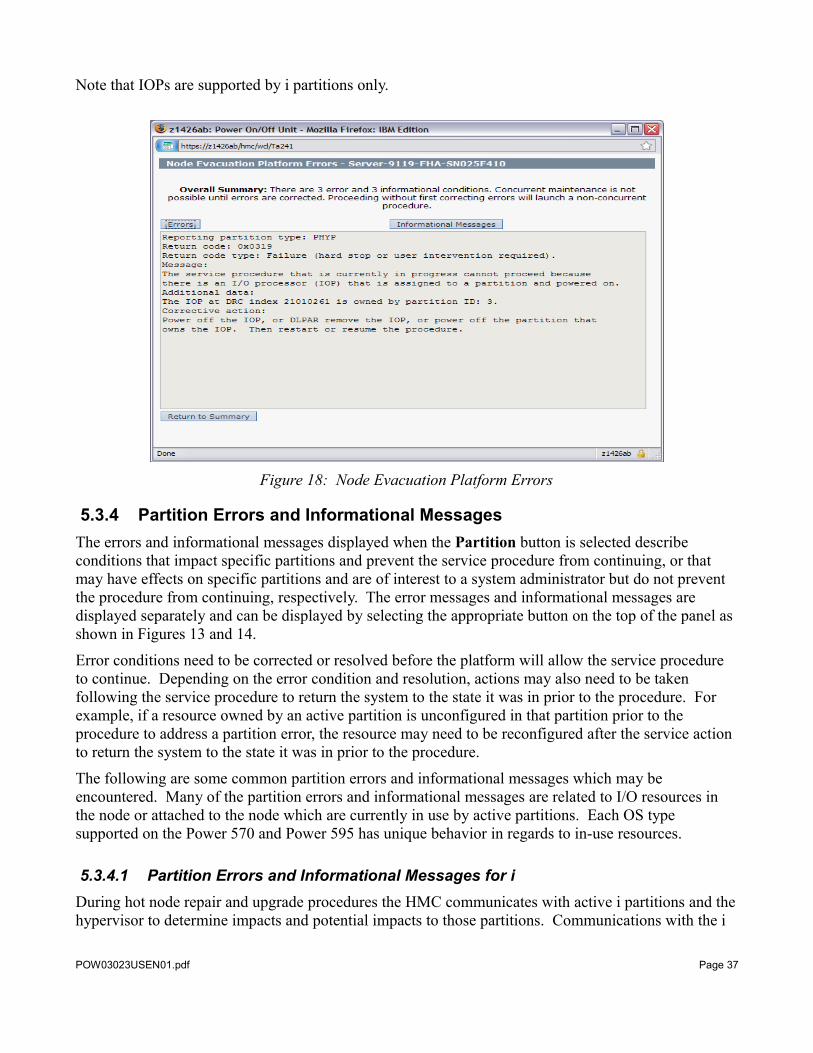
Note that IOPs are supported by i partitions only.
Figure 18: Node Evacuation Platform Errors
5.3.4 Partition Errors and Informational MessagesThe errors and informational messages displayed when the Partition button is selected describe conditions that impact specific partitions and prevent the service procedure from continuing, or that may have effects on specific partitions and are of interest to a system administrator but do not prevent the procedure from continuing, respectively. The error messages and informational messages are displayed separately and can be displayed by selecting the appropriate button on the top of the panel as shown in Figures 13 and 14.
Error conditions need to be corrected or resolved before the platform will allow the service procedure to continue. Depending on the error condition and resolution, actions may also need to be taken following the service procedure to return the system to the state it was in prior to the procedure. For example, if a resource owned by an active partition is unconfigured in that partition prior to the procedure to address a partition error, the resource may need to be reconfigured after the service action to return the system to the state it was in prior to the procedure.
The following are some common partition errors and informational messages which may be encountered. Many of the partition errors and informational messages are related to I/O resources in the node or attached to the node which are currently in use by active partitions. Each OS type supported on the Power 570 and Power 595 has unique behavior in regards to in-use resources.
5.3.4.1 Partition Errors and Informational Messages for i During hot node repair and upgrade procedures the HMC communicates with active i partitions and the hypervisor to determine impacts and potential impacts to those partitions. Communications with the i
POW03023USEN01.pdf Page 37
partitions is through a hypervisor-based communications facility.
The following sections contain some common partition errors and informational messages related to i partitions.
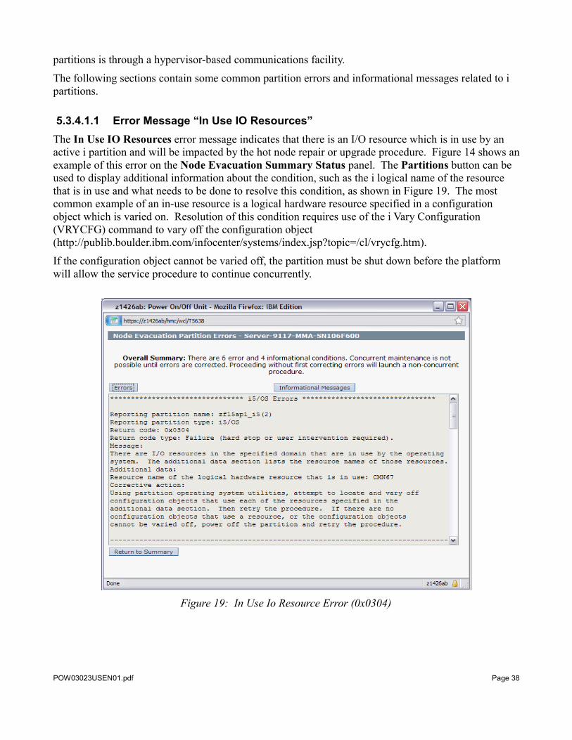
5.3.4.1.1 Error Message “In Use IO Resources”The In Use IO Resources error message indicates that there is an I/O resource which is in use by an active i partition and will be impacted by the hot node repair or upgrade procedure. Figure 14 shows an example of this error on the Node Evacuation Summary Status panel. The Partitions button can be used to display additional information about the condition, such as the i logical name of the resource that is in use and what needs to be done to resolve this condition, as shown in Figure 19. The most common example of an in-use resource is a logical hardware resource specified in a configuration object which is varied on. Resolution of this condition requires use of the i Vary Configuration (VRYCFG) command to vary off the configuration object (http://publib.boulder.ibm.com/infocenter/systems/index.jsp?topic=/cl/vrycfg.htm).
If the configuration object cannot be varied off, the partition must be shut down before the platform will allow the service procedure to continue concurrently.
Figure 19: In Use Io Resource Error (0x0304)
POW03023USEN01.pdf Page 38
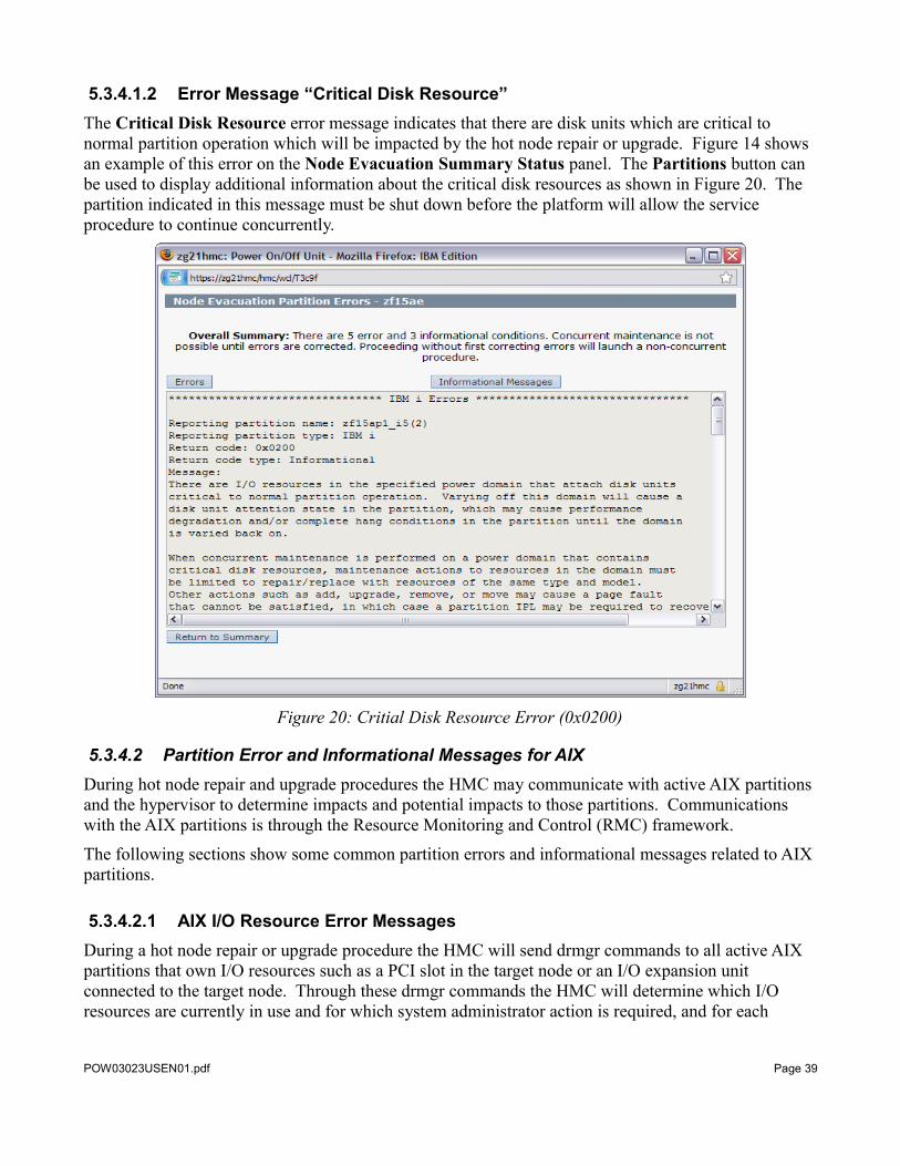
5.3.4.1.2 Error Message “Critical Disk Resource”The Critical Disk Resource error message indicates that there are disk units which are critical to normal partition operation which will be impacted by the hot node repair or upgrade. Figure 14 shows an example of this error on the Node Evacuation Summary Status panel. The Partitions button can be used to display additional information about the critical disk resources as shown in Figure 20. The partition indicated in this message must be shut down before the platform will allow the service procedure to continue concurrently.
Figure 20: Critial Disk Resource Error (0x0200)
5.3.4.2 Partition Error and Informational Messages for AIXDuring hot node repair and upgrade procedures the HMC may communicate with active AIX partitions and the hypervisor to determine impacts and potential impacts to those partitions. Communications with the AIX partitions is through the Resource Monitoring and Control (RMC) framework.
The following sections show some common partition errors and informational messages related to AIX partitions.
5.3.4.2.1 AIX I/O Resource Error MessagesDuring a hot node repair or upgrade procedure the HMC will send drmgr commands to all active AIX partitions that own I/O resources such as a PCI slot in the target node or an I/O expansion unit connected to the target node. Through these drmgr commands the HMC will determine which I/O resources are currently in use and for which system administrator action is required, and for each
POW03023USEN01.pdf Page 39
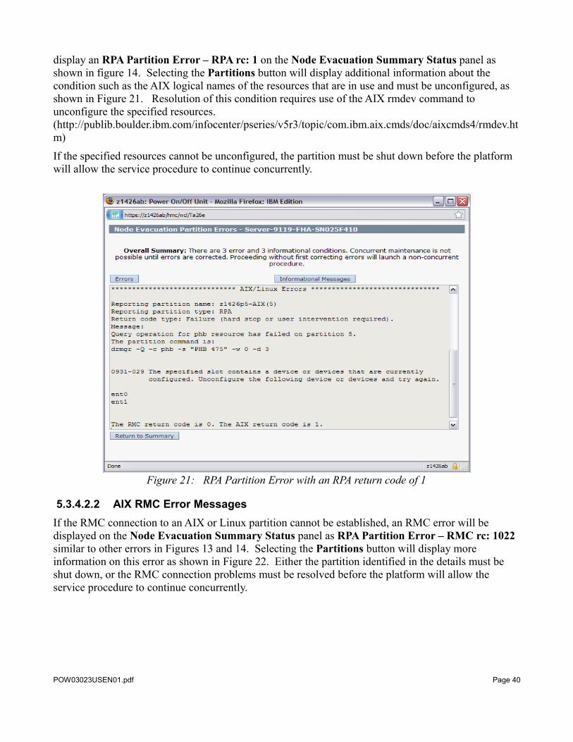
display an RPA Partition Error – RPA rc: 1 on the Node Evacuation Summary Status panel as shown in figure 14. Selecting the Partitions button will display additional information about the condition such as the AIX logical names of the resources that are in use and must be unconfigured, as shown in Figure 21. Resolution of this condition requires use of the AIX rmdev command to unconfigure the specified resources. (http://publib.boulder.ibm.com/infocenter/pseries/v5r3/topic/com.ibm.aix.cmds/doc/aixcmds4/rmdev.htm)
If the specified resources cannot be unconfigured, the partition must be shut down before the platform will allow the service procedure to continue concurrently.
Figure 21: RPA Partition Error with an RPA return code of 1
5.3.4.2.2 AIX RMC Error MessagesIf the RMC connection to an AIX or Linux partition cannot be established, an RMC error will be displayed on the Node Evacuation Summary Status panel as RPA Partition Error – RMC rc: 1022 similar to other errors in Figures 13 and 14. Selecting the Partitions button will display more information on this error as shown in Figure 22. Either the partition identified in the details must be shut down, or the RMC connection problems must be resolved before the platform will allow the service procedure to continue concurrently.
POW03023USEN01.pdf Page 40
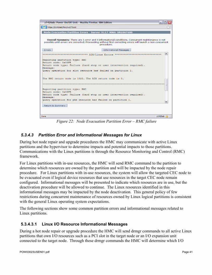
Figure 22: Node Evacuation Partition Error – RMC failure
5.3.4.3 Partition Error and Informational Messages for LinuxDuring hot node repair and upgrade procedures the HMC may communicate with active Linux partitions and the hypervisor to determine impacts and potential impacts to those partitions. Communications with the Linux partitions is through the Resource Monitoring and Control (RMC) framework.
For Linux partitions with in-use resources, the HMC will send RMC command to the partition to determine which resources are owned by the partition and will be impacted by the node repair procedure. For Linux partitions with in-use resources, the system will allow the targeted CEC node to be evacuated even if logical device resources that use resources in the target CEC node remain configured. Informational messages will be presented to indicate which resources are in use, but the deactivation procedure will be allowed to continue. The Linux resources identified in this informational messages may be impacted by the node deactivation. This general policy of few restrictions during concurrent maintenance of resources owned by Linux logical partitions is consistent with the general Linux operating system expectations.
The following sections show some common partition errors and informational messages related to Linux partitions.
5.3.4.3.1 Linux I/O Resource Informational MessagesDuring a hot node repair or upgrade procedure the HMC will send drmgr commands to all active Linux partitions that own I/O resources such as a PCI slot in the target node or an I/O expansion unit connected to the target node. Through these drmgr commands the HMC will determine which I/O
POW03023USEN01.pdf Page 41
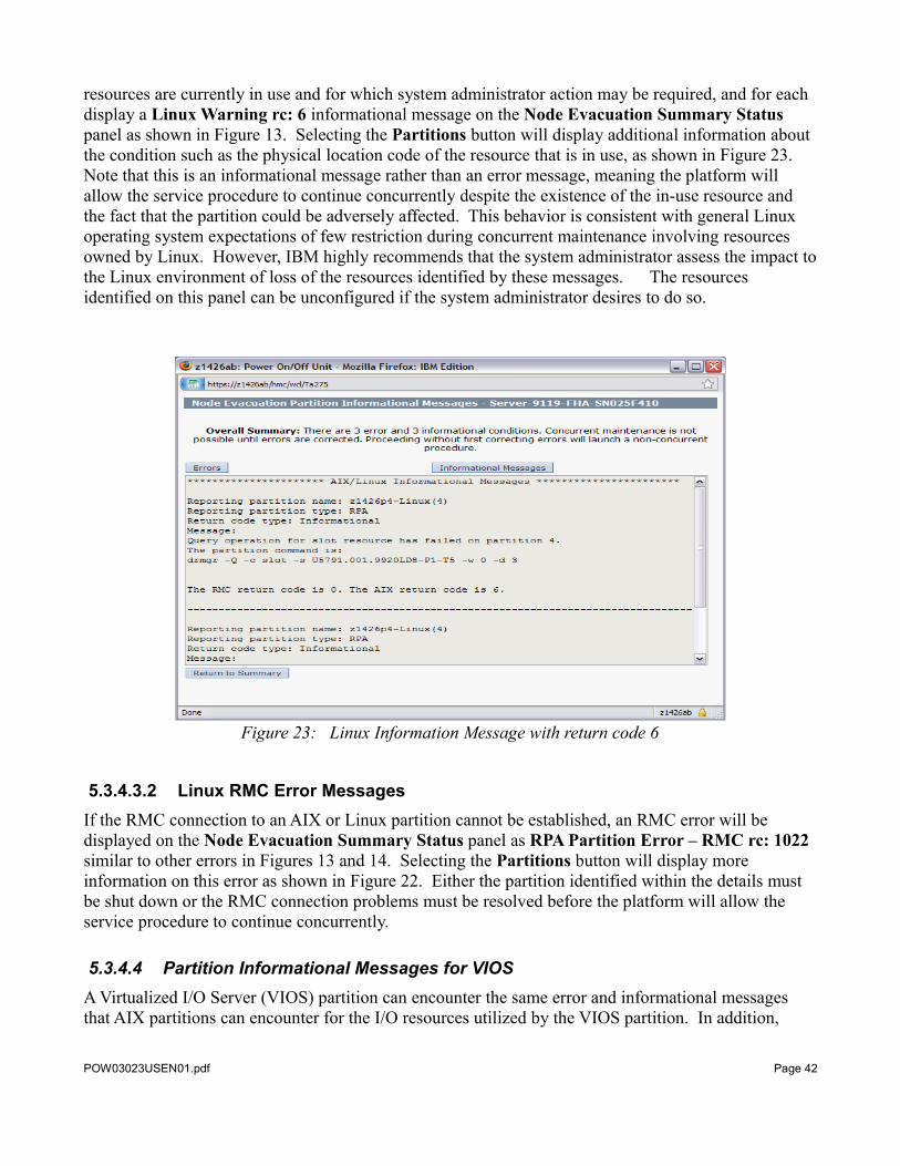
resources are currently in use and for which system administrator action may be required, and for each display a Linux Warning rc: 6 informational message on the Node Evacuation Summary Status panel as shown in Figure 13. Selecting the Partitions button will display additional information about the condition such as the physical location code of the resource that is in use, as shown in Figure 23. Note that this is an informational message rather than an error message, meaning the platform will allow the service procedure to continue concurrently despite the existence of the in-use resource and the fact that the partition could be adversely affected. This behavior is consistent with general Linux operating system expectations of few restriction during concurrent maintenance involving resources owned by Linux. However, IBM highly recommends that the system administrator assess the impact to the Linux environment of loss of the resources identified by these messages. The resources identified on this panel can be unconfigured if the system administrator desires to do so.
Figure 23: Linux Information Message with return code 6
5.3.4.3.2 Linux RMC Error MessagesIf the RMC connection to an AIX or Linux partition cannot be established, an RMC error will be displayed on the Node Evacuation Summary Status panel as RPA Partition Error – RMC rc: 1022 similar to other errors in Figures 13 and 14. Selecting the Partitions button will display more information on this error as shown in Figure 22. Either the partition identified within the details must be shut down or the RMC connection problems must be resolved before the platform will allow the service procedure to continue concurrently.
5.3.4.4 Partition Informational Messages for VIOSA Virtualized I/O Server (VIOS) partition can encounter the same error and informational messages that AIX partitions can encounter for the I/O resources utilized by the VIOS partition. In addition,
POW03023USEN01.pdf Page 42
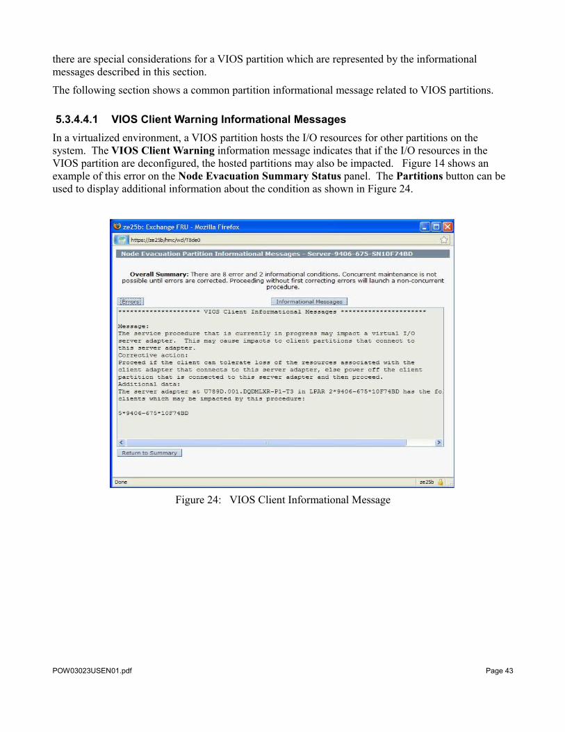
there are special considerations for a VIOS partition which are represented by the informational messages described in this section.
The following section shows a common partition informational message related to VIOS partitions.
5.3.4.4.1 VIOS Client Warning Informational MessagesIn a virtualized environment, a VIOS partition hosts the I/O resources for other partitions on the system. The VIOS Client Warning information message indicates that if the I/O resources in the VIOS partition are deconfigured, the hosted partitions may also be impacted. Figure 14 shows an example of this error on the Node Evacuation Summary Status panel. The Partitions button can be used to display additional information about the condition as shown in Figure 24.
Figure 24: VIOS Client Informational Message
POW03023USEN01.pdf Page 43
6 Appendix
6.1 FRU Type and Location Code Reference
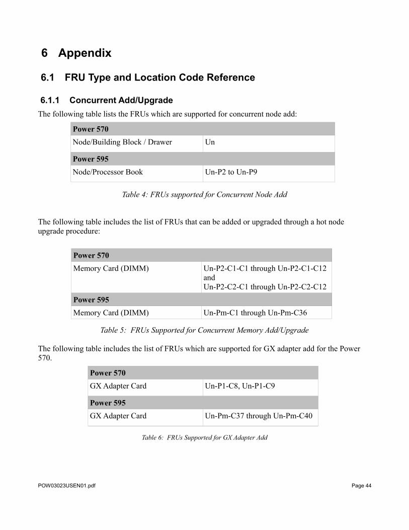
6.1.1 Concurrent Add/UpgradeThe following table lists the FRUs which are supported for concurrent node add:
Power 570Node/Building Block / Drawer Un
Power 595Node/Processor Book Un-P2 to Un-P9
Table 4: FRUs supported for Concurrent Node Add
The following table includes the list of FRUs that can be added or upgraded through a hot node upgrade procedure:
Power 570Memory Card (DIMM) Un-P2-C1-C1 through Un-P2-C1-C12
andUn-P2-C2-C1 through Un-P2-C2-C12
Power 595Memory Card (DIMM) Un-Pm-C1 through Un-Pm-C36
Table 5: FRUs Supported for Concurrent Memory Add/Upgrade
The following table includes the list of FRUs which are supported for GX adapter add for the Power 570.
Power 570GX Adapter Card Un-P1-C8, Un-P1-C9
Power 595GX Adapter Card Un-Pm-C37 through Un-Pm-C40
Table 6: FRUs Supported for GX Adapter Add
POW03023USEN01.pdf Page 44

6.1.2 Concurrent RepairThe following table includes the list of FRUs and corresponding location codes which can be replaced through a node repair procedure:
Power 570System Backplane Un-P1Memory Card DIMM Un-P2-C1-C1 through Un-P2-C1-C12
andUn-P2-C2-C1 through Un-P2-C2-C12
Battery Un-P1-C11-E1System Processor Card Un-P2-C1, Un-P2-C2GX Adapter Card Un-P1-C8, Un-P1-C9I/O Backplane Un-P2Service Processor card Un-P1-C11Power 595GX Adapter Card Un-Pm-C37 through Un-Pm-C40Node backplane Un-P2 through Un-P9Memory DIMM Un-Pm-C1 through Un-Pm-C36Multi Chip Module (MCM) Un-Pm-C25 through Un-Pm-C28Node Controller Service processor Card Un-Pm-C41, Un-Pm-C42Distributed Converter Assembly (DCA)* Un-Pm-E2, Un-Pm-E1 (Hot node repair
only)
Table 7: FRUs Supported for Node Repair
* Only requires the hot repair procedure if power redundancy checks do not allow a concurrent repair.
The following table lists the FRUs which are supported for cold GX adapter repair for Power servers:
Power 570GX adapter Un-P1-C8 & Un-P1-C9
Power 595GX Adapter Un-Pm-C37 through Un-Pm-C40
Table 8: FRUs Supported for Concurrent Cold GX Adapter Repair
POW03023USEN01.pdf Page 45
© IBM Corporation 2009IBM CorporationSystems and Technology GroupRoute 100Somers, New York 10589
Produced in the United States of AmericaApril 2009All Rights Reserved
This document was developed for products and/or services offered in the United States. IBM may not offer the products, features, or services discussed in this document in other countries.The information may be subject to change without notice. Consult your local IBM business contact for information on the products, features and services available in your area.All statements regarding IBM future directions and intent are subject to change or withdrawal without notice and represent goals and objectives only.IBM, the IBM logo, ibm.com, Power, PowerVM and AIX are trademarks or registered trademarks of International Business Machines Corporation in the United States, other countries, or both. If these and other IBM trademarked terms are marked on their first occurrence in this information with a trademark symbol (® or ™), these symbols indicate U.S. registered or common law trademarks owned by IBM at the time this information was published. Such trademarks may also be registered or common law trademarks in other countries. A current list of IBM trademarks is available on the Web at "Copyright and trademark information" at www.ibm.com/legal/copytrade.shtml The Power Architecture and Power.org wordmarks and the Power and Power.org logos and related marks are trademarks and service marks licensed by Power.org. UNIX is a registered trademark of The Open Group in the United States, other countries or both. Linux is a trademark of Linus Torvalds in the United States, other countries or both. Java and all Java-based trademarks and logos are trademarks of Sun Microsystems, Inc. In the United States and/or other countries. InfiniBand, InfiniBand Trade Association and the InfiniBand design marks are trademarks and/or service marks of the InfiniBand Trade Association. Other company, product, and service names may be trademarks or service marks of others.IBM hardware products are manufactured from new parts, or new and used parts. In some cases, the hardware product may not be new and may have been previously installed. Regardless, our warranty terms apply. Photographs show engineering and design models. Changes may be incorporated in production models. Copying or downloading the images contained in this document is expressly prohibited without the written consent of IBM.This equipment is subject to FCC rules. It will comply with the appropriate FCC rules before final delivery to the buyer. Information concerning non-IBM products was obtained from the suppliers of these products or other public sources. Questions on the capabilities of the non-IBM products should be addressed with those suppliers.All performance information was determined in a controlled environment. Actual results may vary. Performance information is provided “AS IS” and no warranties or guarantees are expressed or implied by IBM. Buyers should consult other sources of information, including system benchmarks, to evaluate the performance of a system they are considering buying. When referring to storage capacity, 1 TB equals total GB divided by 1000; accessible capacity may be less.The IBM home page on the Internet can be found at: http://www.ibm.co m .The IBM Power Systems home page on the Internet can be found at: http://www.ibm.com/systems/power/POW03023-USEN-01
POW03023USEN01.pdf Page 46