“i spy something round" - manuscript
DESCRIPTION
Rudy, M., Wolfsgruber, J., & Jaksch, S. (2007). „I Spy Something Round: On the Commitment to Cognitive and Physical Design Form in an Experimental Sphere Structure“. IASDR 2007 – Emerging Trends in Design Research, Hong Kong, China: International Association of Design Research Societies (IASDR), The Hong Kong Polytechnic University, Paper-Nr. 730 (21 S.). ISBN 988-99101-4-4TRANSCRIPT

1
I SPY SOMETHING ROUND: ON COMMITTING TO COGNITIVE AND PHYSICAL DESIGN FORM IN AN EXPERIMENTAL SPHERE STRUCTURE
Margit Rudy¹, Josef Wolfsgruber¹, and Stefan Jaksch¹
¹Institute of Architectural Sciences, Vienna University of Technology, Vienna, Austria. rudy, wolfsgruber, [email protected]
ABSTRACT:
Architecture and structural engineering design are closely related in their common focus on the
built environment, but employ fundamentally different working methods in practice to address
differing sets of design issues. With an aim to better bridge the problematic design-concern gap
between these domains, a compact design challenge was conceived in an academic setting to
focus the collaborative process on design criteria that hinge on the construction field as their inter-
face: to build a large-scale object that is perceived as a spherical volume using a simple, yet
innovative assembly method in wood. Given the stringency of the prescribed constraints, the
commitment to physical and social viability is what created the real challenge of the design experi-
ment, during which a trans-disciplinary team designed and manufactured a “recognizably round”
response. This paper traces multiple intertwining threads of design decisions in a narrative about
the essential creative emergences leading to the final artifact.

2
PROLOGUE
The three professional fields comprising the “AEC domain” – architecture, engineering, and
construction – are closely related in practice by virtue of their common focus on the built environ-
ment. Yet there are fundamental differences in the respective working methods and immediate
design concerns of each field, which are also reflected in distinct styles of academic training (or
lack thereof in the vocational sense of construction). Spatial thinking skills are central to the
qualification of architects, whose education traditionally revolves around simulating the building
design process in design studio courses. These engage students in the three-dimensional model-
ing of physical relationships – tangible patterns – as a means of developing complex solutions to
building design tasks. In contrast, classic training of civil engineers focuses on describing the
quantitative relationships between mechanical and material properties; qualitative geometric and
perceptual relationships are of secondary concern in reaching a design solution.
All of these “angles on the building” are, of course, interdependent subject views on facets of the
same physical construct in space and time (Fig. 1). With an aim to better bridge the design-con-
cern gap between architecture and engineering, an experimental design task was conceived to
focus the core issues on a maximally compact set of design criteria that hinge on the construction
field as their interface. The objective stems naturally from the authors’ experiences (and frustra-
tions) with design education in the trans-disciplinary department of structural design and timber
engineering at the Vienna University of Technology, where the difficulty of translating between
disparate “universes of discourse” about buildings is a running theme common to all research and
teaching activities (c.f., Rudy and Hauck 2007).
The design task and notions declared in the next sections have their roots not only in the specific
mix of qualifications and personal histories of those involved in its conception, but also in a shared
awareness of knowledge passed on by others from the past into the present by various means. It
was in this case a design artifact, in particular, a relatively large model of a wood sphere, which
had been left behind by a guest professor from Japan and was lying around the department as a
sort of conversation piece (for some: an eye sore) ever since his departure, that provoked the kind
of communication by which it became clear to a few of us that we could and wanted to develop a
“better sphere” and, more importantly, actually build it. In other words, the design challenge was
quite literally “languaged into being” (c.f., Krippendorf 2006) and its existence was inspired purely
by the shared desire to make something wonderful and to make it at fully perceivable scale.

3
Figure 1: Segmental view of the many semantic layers comprising a building design, arranged in relation to time and design
cognition across the building object (Pfeiffer-Rudy, 2006; based on a scheme proposed by W. Winter, professor of structural
design at the authors’ university).
The lack of extrinsic motivation, that is, the fact that none of us had a rational answer to the oft
asked question, “What’s it for?” was liberating in many respects, but also made us keenly aware
of a common dilemma all designers face to some degree in practice: rationalizing the value and
meaning of intrinsically motivated design work to others in defensibly quantifiable terms of func-
tion and economy (“fitness” for someone else’s purposes). Such justification problems are also
more influential in academia than commonly assumed, although a university setting is by defini-

4
tion more amenable to doing something “for its own sake” than professional practice – as long as
it serves the generation of new knowledge in a recognized academic field. Even if it is obvious
that solid procedural knowledge of construction methods is needed for building designers to
competently bring their proposals to fruition in practice, this field is considered especially
“unscientific” and does not lend itself well to curricular integration in higher education (c.f.,
Bouchlaghem et al., 2006). The commitment of the authors and a small group of students as aca-
demic stakeholders in the endeavor of developing a “workably round answer” to the stated design
challenge made it an experiment of construction design research in both architectural and
engineering terms, with the aspiration that more such experiments would follow.
In light of the research objective, this paper presents an attempt to systematically reflect upon
how a specific design proposal came to be what it is by telling its story of intertwining design
threads in a loosely structured narrative. The following sections relate part of what we learned
about what it means to simply build a life-size sphere, in the hope that this particular tale will also
provide the reader with some generally applicable insights into communicative patterns of creative
emergence with the “building blocks” of collaborative design work (Fig. 2).
Figure 2: Successful design synthesis means bringing about a dialogical convergence of visions between the different cognitive views
of collaborating sub-domains, here represented as windows on distinct design vocabularies to be brought together through
effective communication in the course of design development.

5
1. STAKING OUT AND EXPLORING THE DESIGN SPACE
An initiating expression for the heart of the design challenge could be reduced to the following
mission statement:
Erect a temporary physical object that is fully perceived as spherically round –
from inside and out – using “do-it-yourself” construction methods and wood as
the primary construction material.
Before proceeding with explanations of what this declaration means in detail, we want to empha-
size that throughout the design process it was emotionally felt as a clear challenge and not as an
ill-defined “problem” to be solved, “task” to be executed, or “assignment” to be dutifully taken care
of – all rather uninspiring expressions of extrinsically motivated work that do not capture the
nature of what makes people really want to design anything in the first place (c.f., Krippendorf,
2006; Cross, 2006; Simon, 1996; Alexander, 1964). Of course, the drive to meet a design chal-
lenge always creates plenty of consequent problems that then need to be meaningfully framed for
solution by way of expressed and performed tasks, which constitute the only outwardly visible and
audible design activity that can be directly recorded for analysis by outside observers (e.g., with
video protocols as related in Cross et al., 1996, or in the more recent work of Cardella, Atman,
and Adams, 2006).
The meanings of the design challenge which bounded the “playing field” for our construction
design experiment are summarized in the following basic rules for the design process (in order of
appearance in the statement, but not ordered by importance, contingency, or causality):
“Erect a temporary physical object …”
It shall be constructed such that it can be rapidly erected and dismantled on site, with minimal
auxiliary structures (scaffolding, etc.) and without permanent anchoring. Its material components
must also be economically transportable to and from potential construction sites.
“… that is fully perceived as spherically round – from inside and out …”
While being small enough to obey the rules above, it must still be large enough to form an interior
space such that people of average size can enter and experience it from within (Ø ≈ 6m). As a
simplified physical approximation, it shall manifest the essence of “sphereness” in as many mean-
ings as possible such that the final object deserves an appropriate nickname, ideally the German

6
word “Kugel” (a word which connotes this essence more succinctly than either “sphere” or “ball” in
English).
“… using ‘do-it-yourself’ construction methods …”
It shall be built by means and with tools that are accessible to anyone with average construction
skills and knowledge, without resorting to technologies that require either industrial manufacturing
capabilities (e.g., glue-laminating presses) or overly time-consuming craftsmanship (as for furni-
ture or boat building). The essential aspect of this rule: The consequences for design decisions
must be carried by the designers themselves.
“… and wood as the primary construction material.”
It shall be built of wood in such a way that this typically flat, linear construction material (beams,
posts, planks …) is curved in mechanically joined members. The design should furthermore focus
on finding an innovative application for a partially pre-engineered method to eliminate the need for
extensive material testing. We tentatively introduced the curved construction method of “timber
ribbed shells” (Gliniorz, Natterer, and Kreuzinger, 2001; Pirazzi and Weinand, 2006). Bending and
joining thin wood boards in such a lamellar buildup imposed further rules: (a) the lamellas should
be curved geodesically, i.e. bent only across their thickness but not across their width, and (b) the
axis lines of only two lamellas may meet in the same plane at each construction joint.
Aside from such concrete meanings for the construction design, conversations about the project
between ourselves and others invariably evoked the abundant use of metaphors revolving around
the words “Kugel,” “ball,” “sphere,” and the notion of “something round” in all its spontaneous
connotations, from high-minded associations (e.g., symbolically transferring mathematical defini-
tions or referring to analogies used by the philosopher Sloterdijk, 1998, etc.) to common expres-
sions of everyday speech (often as surprisingly enlightening puns or, on a sillier level, associa-
tions with well-known products such as the Austrian chocolate specialty “Mozart balls”). The
verbalization of metaphors was especially influential during the project’s incubation phase, fueling
the drive to do whatever it takes – meaning: solve whatever problems crop up – to make it
actually happen.
The basic issue of “what to call it,” i.e. of finding a practical moniker that would not prematurely
brand the project in a counterproductive direction, both haunted and inspired us throughout the
entire process of design (and construction; see also Epilogue), and we decided to maintain a mini-
mally suggestive code label (“eine runde Sache” / “something round”) for the duration of the

7
experiment. The particular challenge posed by this issue was to find a metaphorical association
that would be meaningful enough to other potential stakeholders to gain their needed support for
realization, yet not compromise the intrinsically motivating nature of the overall design challenge
(c.f., Krippendorf, 2006: 139) by overtly commercializing its intent or falsifying its perceptual
criteria.
The first stage of design involved getting a grasp of the form by studying an array of formal rules
governing spherical geometry. Though even young children naturally understand the principle of
balls, gaining an applicable understanding of this subject matter in terms of the design challenge
turned out to be much more difficult than anyone had expected. From then on, the most effective
paths of exploration through the “uncharted territory” of the design space formed an intuitive, but
not undisciplined network of both breadth-first and depth-first routes (c.f., Cross 2006), referred to
here as threads. Major design threads can be roughly codified as an informal sort of “information
game” in the sense postulated by information theory (Jaynes, 1957: 180-182; c.f., Shannon, 1948),
but adapted here to schematically map the active evolution of design knowledge from tentatively
formulated notions to convergence on a promising concept (Fig. 3). As it developed, the design
proposal was embodied in an exchange network of communication about design artifacts.
The emerging thread that clearly proved most promising for continued development (Fig. 3, C) did
not stem directly from the palette of ideas generated in the initial breadth phase, but rather was a
spin-off born in reaction to frustration that had set in while pursuing a concept that was progres-
sively felt to be “causing too many problems.” This state provoked a fundamental realignment of
intermediate assumptions in order to break free from an apparently unproductive fixation by open-
ing up the design space again to include more possibilities. Still, we did not yet entirely give up the
original concept, but instead revisited it as a competing option later on in the process (only to dis-
cover that it had even more serious flaws than originally suspected).
The concept finally agreed upon for the sphere structure delineates its surface with ten great cir-
cles such that the requirements given by the construction method are met with a maximally uni-
form distribution of design dimensions in the resulting surface figures (Fig. 4). Two arc dimensions
are configured to form 12 regular pentagons, 60 isosceles triangles, and 20 equilateral hexagons
with two different interior angles (semi-regular). In each lamellar construction layer, one circle
passes through a node continuously and the other is interrupted in an alternating, tri-axial weave
pattern that yields basic structural arc units between every second node.

8
Figure 3: Sequential design evolution driven through interactive spaces of communication in time, with examples of intermediary
artifacts produced and used along the design threads.

9
Figure 4: Sphere volume articulation with ten great circles translated into tri-axial weave pattern (left) or resultant surface figures
(right).
Building up an even number of layers such that the continuous lamellas cover the interrupted
lamellas (and vice versa) produces a structurally sound sphere of interlaced rings with uniform
node conditions, that is, an object that is as “evenly round” as possible in all directions. The logical
principle can be also illustrated by charting the intersection of ten great circles in a topology of
vertices (nodes) and edges (rings) for a reference layer (Fig. 5). Several features of this graph, in
particular the “dialogical nature” of its vertices, bear an undeniable resemblance to the diagram of
design threads (Fig. 3) – yet another of the many metaphorical levels discovered along the way.
Figure 5: Diagram of the node topology for ten great circles (spherically straight lines) that intersect in a triaxial weave pattern.

10
2. PROJECTING MORE MEANINGS ALONG A PROMISING THREAD
Though the described treatment of spherical geometry with intersecting rings constitutes a for-
mally consistent structural principle, it would be highly impractical (if not impossible) to apply this
ideal principle when actually building a physical sphere of substantial diameter with the available
means of construction. The next stage of the challenge, therefore, was to find a uniform
segmentation of the sphere surface into reasonably compact sub-components that would allow
multiple use of as few different unit templates for manufacturing the curvature as possible, while
maintaining the overall “do-it-yourself” character of the construction objective.
After working through the logical consequences of several different, ultimately unsuccessful sub-
division strategies in sketches and with sketch models (Fig.3, C2a), a satisfying double-shell solu-
tion with three lamella layers per shell finally emerged. Hereby the sphere surface is segmented in
such a way that each shell is structurally a complement of the other, meaning that all the stronger
joints within the components of one shell overlap and compensate for the weaker edge joints
between components of the other shell (Fig.3, C4a). The components individually would be of
manageable size and format at full-scale, whereby the inner shell is sub-divided into 12 identical
pentagrams (~3 meters across), while the outer shell is composed of 30 double triangles (~2.2
meters long). Adjustable tension members spanning as construction chords between the edge
joints would be needed to stabilize the curvature of the prefabricated components, at least until
final assembly of the double shell. An additional lamella layer of alternating arcs applied to the
exterior in a ten-ring weave pattern should both visually simplify the sphere’s outward “face” and
provide a protective finish to the underlying component structure.
To verify and further investigate the concept in detail, the entire construction was modeled as
analogously as possible at a scale of 1:10. In such scale models, mainly the fastening methods
are what necessarily diverge from techniques that would be applied at full scale (e.g., glue-lami-
nated rather than screw-fastened components, simple strings as construction chords rather than
cables with turnbuckles). Once the set of model components was finished, it immediately called
forth an urge to put these design artifacts together and have some fun with them (Fig. 6).

11
Figure 6: Sketch assembly of model components with office clips and playful “abuse,” for example, as an enigmatic hanging object.
Up to this point, the design process had focused entirely on developing a satisfactory concept for
building a wooden ribbed sphere of six meters diameter, with only cursory consideration of any
supplementary structures needed to keep such a sphere safely in place and carry people into and
out of the object. In other words, we now needed to devote explicit attention to an extended scope
of considerations, spelled out in three contingent parts, which effectively drove the next stages of
design development: (1) committed design dimensions of the sphere structure, which established
architectural and mechanical constraints for (2) a supporting structure, which – together with the
sphere – bounded the development of (3) an accessing structure, by which the spherical space
could be experienced (and cognitively understood) from within.
The physical modeling work was accompanied by the analytical development of digital simulation
models to investigate principle structural behavior in engineering terms and to do preliminary
assessments of the sphere’s structurally critical points. Different load-bearing configurations were
explored in the simulation model (Fig. 7) before discovering the simple figure of a spherical
square around the central base node. A simple analogue of this geometry was then prepared to
support assembly of the scale model (Fig. 8).

12
Figure 7: Alternative concepts for a supporting structure for the simulation of structural behavior: left, elevation of sphere
geometry with bearing nodes along horizontal ring (“egg cup”); right, bottom view of simulation model with bearing nodes along
base figure of sphere.
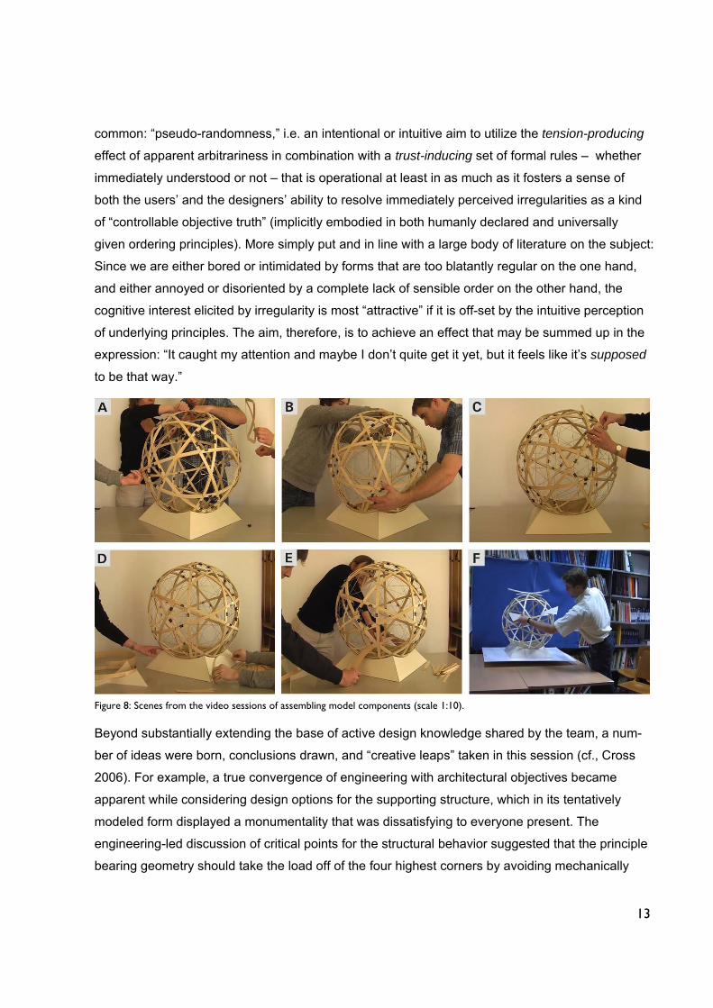
The activity of assembling the model components into a full sphere was recorded on video tape in
two sessions (Fig. 8): a rapid preliminary assembly of shell components was done with temporary
fasteners to verify that the geometric principle basically “worked” (session 1, ~1.5 h) before
permanently gluing together the complete component assembly and applying the finishing layer
(session 2, ~2 h). The greater part of design communication and creativity with respect to further
development clearly happened during the first session, which was marked by a series of relatively
long discussions that were stimulated directly through “hands on” interactions with the model,
especially once it was largely assembled (Fig. 8, C). More essential design knowledge about the
concept’s consequential meanings was created through this highly interactive design artifact than
could have been gained by any other cognitive means or learning activity at this stage of the
design process (e.g., grasping the assembly logistics by fastening the shell components, or the
underlying tri-axial “weave logic” by positioning parts of the finishing layer, Fig. 8, A).
An example of the type of realizations that emerged in this process is the definitive discovery of
the regularity underlying the largest and most interesting surface figures, the apparently “dis-
torted” hexagons. In the full sphere assembly, the construction chords tying the outer component
joints land in the span of these shapes, forming simple equilateral triangles of different size and
opposite orientation in each shell. The drawn triangles turn out to be an effective way of “explain-
ing” the regularity of resultant figures that, at first glance, appear more arbitrary than they actually
are (Fig. 8, B). This realization may be expanded upon at greater length to illustrate a form-giving
principle that many successful (but of course much more complex) architectural designs have in
13
common: “pseudo-randomness,” i.e. an intentional or intuitive aim to utilize the tension-producing
effect of apparent arbitrariness in combination with a trust-inducing set of formal rules – whether
immediately understood or not – that is operational at least in as much as it fosters a sense of
both the users’ and the designers’ ability to resolve immediately perceived irregularities as a kind
of “controllable objective truth” (implicitly embodied in both humanly declared and universally
given ordering principles). More simply put and in line with a large body of literature on the subject:
Since we are either bored or intimidated by forms that are too blatantly regular on the one hand,
and either annoyed or disoriented by a complete lack of sensible order on the other hand, the
cognitive interest elicited by irregularity is most “attractive” if it is off-set by the intuitive perception
of underlying principles. The aim, therefore, is to achieve an effect that may be summed up in the
expression: “It caught my attention and maybe I don’t quite get it yet, but it feels like it’s supposed
to be that way.”
Figure 8: Scenes from the video sessions of assembling model components (scale 1:10).
Beyond substantially extending the base of active design knowledge shared by the team, a num-
ber of ideas were born, conclusions drawn, and “creative leaps” taken in this session (cf., Cross
2006). For example, a true convergence of engineering with architectural objectives became
apparent while considering design options for the supporting structure, which in its tentatively
modeled form displayed a monumentality that was dissatisfying to everyone present. The
engineering-led discussion of critical points for the structural behavior suggested that the principle
bearing geometry should take the load off of the four highest corners by avoiding mechanically

14
active members at the outer edges of the base construction. This structurally meaningful redirec-
tion away from the corners of the base volume conveniently coincided with the general desire for
a much lighter and “more elegant” appearance architecturally. It led to the idea of a double arch
construction to carry each of the four bearing edges (sides of the spherical square directly sup-
ported by the base geometry; Fig. 8, D), analogous in principle to the shock-absorbing suspension
springs historically used in horse-drawn carriages.
The model’s orientation on the supports had been adopted from another design thread (with six
rings; Fig. 3, B), where the pentagons were the largest surface figures, and we had concluded
that a sphere with this orientation could best be accessed through two of these figures opposite
each other below the equator. In the ten-ring design, pentagrams are inscribed in these fields,
leaving an inner pentagon that would be too small for human access. Before putting the model
together completely, we had been working on the assumption that we would have to leave out two
curved members to create larger openings at these positions. However upon completion of
preliminary assembly, we realized that it would be much better in several respects to envision
access via a reverse-mirrored pair of the more interesting semi-regular hexagons. These lie
slightly displaced from the center of the supporting edges, where a ramp or arch could nicely
transition into a bridge to carry visitors at a height that brings the heads of average adults into the
sphere’s mathematical center (Fig. 8, E).
It also became obvious that the construction chords, which would be necessary to maintain the
curvature of components prior to on-site assembly, could easily be removed once the entire object
is put together. The need for such chords had originally been considered a drawback in construc-
tion terms, especially if they were to prove superfluous in the finished structure from an engineer-
ing perspective. Once it was determined that the largest openings between sphere ribs seriously
impaired the architectural “roundness” of the object, however, the construction chords came into
play again, this time positively since they could serve well to support air cushions or other means
of secondary construction for rounding out the overall form, thereby indirectly enriching the
architectural design without contradicting the goals of structural efficiency. Further architectural
considerations emerged while handling the finished model (Fig. 9, F) and producing subsequent
design artifacts: a means of filling the spaces between the structural ribs may be needed not only
to achieve a more spherical shape, but also to close the outward form visually and make it more
selectively comprehensible from the exterior.

15
3. CONSTRUCTING TANGIBLE DESIGN ARGUMENTS
The simulation-based assessments of mechanical behavior could only provide us with qualitative
hints, but not quantitative proof of the design’s structural soundness, since reliable values for
modeling the structural properties of its lamellar joints and curved members in cross-section could
not be found in the literature. It was clear that in the next stage of design we would ourselves
need to build comparable prototypes for mechanical testing at full-scale. Even more importantly,
many questions regarding details and concrete fabrication procedures still needed to be answered.
We explored a very different – and for many academics unfamiliar – kind of design space in
component prototyping, one that is characterized by the kinesthetic experience of manual labor,
power tools, and everything else that comes with this territory. Also characteristic is the large
proportion of tacit, procedural knowledge (c.f., Niedderer 2007), which usually remains out of the
range of design knowledge explicitly shared between architects and engineers. For this very
strenuous phase of construction design, we spent a total of seven days working in nearby labora-
tory workshops that are located in a historically preserved building complex of the university,
amidst a rather bizarre mix of modern and antique machinery (Fig. 9, D), enormous test beds and
piles of leftover construction materials. Key stages of work progress and mechanical testing were
recorded in more than six hours of video footage. The material clearly documents the emergence
of several characteristic patterns of behavior, communication, and decision-making, which distin-
guished this particular stage of design activity from the others and are summarized in the
following.
The better part of construction design activity and cognition is expressed non-verbally.
A good deal of communication and reflective understanding happened through the use of hands
(touching, holding, pointing, stroking, signaling …) and other parts of the body. All manners of
“talking and listening” to each other with our hands, especially while interacting with artifacts while
and after they were produced, had already played an eminent role in previous design stages, but
were more evidently pronounced in the construction workshop (Fig. 9, E). Given the tactile quality
of wood, it was no great surprise that literally no one could keep their hands off this pleasant
construction material for long, even during the less physically active stretches of video taping
where people were mainly thinking aloud or paying direct attention to each other in conversation
(Fig. 9, A). More distinctively, the life-size character of this specific type of design artifact invited a
variety of spontaneous, full-body interactions to informally test “how it feels,” with little concern for
damaging the specimens before formally testing them. More was learned by simply sitting on (Fig.

16
9, F), hanging from (Fig. 9, J), or just joking around with the objects (Fig. 9, C), than by disciplined
tests of mechanical behavior. Nonetheless, in all fairness to the merits of responsible engineering,
we did gain a very important degree of faith by having some quasi-certified numbers about the
(surprisingly) sound qualities of what was being designed in terms of elasticity, bending and buck-
ling strength after the tests had been performed (Fig. 9, K and L).
Figure 9: Scenes from the video documentation of construction prototyping and testing.

17
As a brief corollary to the above:
The taciturn construction domain is typically averse to “discourse” for a good reason.
The most meaningful procedural knowledge was not created in endless, theoretically conjunctive
discussions of how and why some things in a design could work. The more efficient – and often
only – way to figure these things out definitively was to “just do it” and see how it really works
(then do it again, but differently, and so on). The mental concentration that this type of
experimentation and learning demanded left little cognitive capacity for extensive verbalizing
activity, as reflected in the long stretches of video recording where conversations were reduced to
minimalist exchanges of only the most immediately relevant information. Overall, there was a
clear pattern that alternated between prolonged making and brief talking about (verbally
exchanged awareness of) design decisions.
Effective prototyping means trying things you do not already know will work.
We had originally set out to test a well-defined set of hypotheses about the construction method
and its mechanical properties by building a carefully planned set of test specimens according to
tight specifications (during an originally projected time in the workshop of only two to three days).
However, the experimentally built components were, in end effect, not “prototypes” in the usual
sense of the word in as much as they digressed substantially from the intentions underlying the
quantities and types of materials purchased beforehand (aside from seriously extending workshop
time). What was actually done instead served to “prototypically” try out techniques that could not
adequately be modeled by analogy at a scale of 1:10, especially the fastening methods and eco-
nomic properties of materials. Any meaningful alternatives that we could think of were spontane-
ously built and tested, for instance, to determine if we could use basic lumber “as is” instead of
having to plane boards down to a non-standard thickness (we can’t – unless we employ too much
manpower and time-consuming techniques in order to make the boards more pliable; Fig. 9, B) or
to see if we could spare ourselves the work of manufacturing a second shell by finding a way to
join the twelve pentagram components directly (we could – but only by potentially sacrificing the
sphere’s even roundness, due to the fact that a parabolic, not truly spherical curvature results
from bending wood, and simple component joints may not fully compensate for this; Fig. 9, I).
Construction drawings are essential, but not sacrosanct, working artifacts of design.
Clean printouts of carefully spelled out construction details and dimensions are important to have
for reference at the start, but in the course of actually building something, such drawings (any
pieces of paper lying around the workspace, for that matter) serve a much more important pur-
pose as a communicative medium for interactive sketching. The reality of unexpected material

18
properties creates a need to continually improvise, which invariably provokes an essential design
activity to bring the process forward: “dialogical scribbling,” that is, spontaneous sketching and
marking between and over the marks left by others (Fig. 3, C).
After all was said and done, we arrived at the conclusion that, in essence, the design concept that
had been worked out at a scale of 1:10 best represented a synthesis that meets the challenge
successfully at all the levels we had worried about every step of the way (aesthetics, weight,
economy, mechanical workability, durability in different assembly states, etc.). Even if this interim
conclusion could be interpreted as coming “full circle” to a previous starting point, it by no means
meant that the work invested in prototyping had been wasted. Substantial improvements in proce-
dure were found for some of the more tedious aspects of constructing the scale model, for exam-
ple, the process of building up each component layer by layer: At full scale, the lamellas can be
bent, clamped, and screwed together on the component template in packages of up to six layers
at once (Fig. 9, H), which allows rapid pre-assembly of inner component joints in a more manage-
able state using secondary templates to align lamella packets in cross form (some ideas were
promptly checked at the scale of 1:10 before trying them out 1:1; Fig. 3, C). We gained the proce-
dural knowledge needed to confidently pursue the concrete realization of our design proposal –
and it was also a relief to know that we had developed a satisfactory “backup plan” for the event
that time and/or money should run out and perhaps force a radical simplification of the preferred
double-shell concept.
Prior to actual construction, however, we had to switch modes once again and open up the lines
of explicit communication well beyond the immediate design team in order to involve vastly
extended spheres of potential stakeholders (e.g., administrative officials of the university and the
city of Vienna, sponsor and volunteer candidates, public interest groups, etc.). Direct verbal
communication became crucial at this point, accompanied by easily distributable, broadly informa-
tive types of design artifacts (compact digital and printout compilations of brief texts and images;
e.g., Fig. 10).
Since the project had effectively no budget and was limited to the use of sparse university
resources, this last, critical stage of design meant walking a fine line between taking on an exces-
sive burden of personal risk and compromising altruistic participation (e.g., by building nothing
more interesting than a spherical billboard for a “generous” sponsor). Our “case” could thus only
be argued on its idealistic merits as a compelling experiment (some call it art) that, having fasci-
nated us for so long, must be worth sharing with others.

19
Figure 10: Preliminary visualizations projecting the sphere structure into potential contexts in and around the university: left, set in
campus plaza; center, suspended between buildings; left, placed in nearby park (church of St. Carl in background).
EPILOGUE
In the meanwhile (summer of 2007), the design proposal has been “built into reality” by a dedi-
cated group of volunteers working with the principle design team to prefabricate the shell compo-
nents and assemble the sphere prototype on its first site (Fig. 11). The initial version included a
simple supporting cradle and access bridge out of surplus wood.
Figure 11: Construction scenes: left, component prefabrication in university workshop; center/right, on-site assembly in Viennese
park adjacent to university and church of St. Carl.
As the sphere structure was erected and became a publicly accessible artifact, the “transmission
channel” of social communication between designers and users became complete (cf., Crilly,
Moultrie, and Clarkson, 2007). This opened the door for a host of thoroughly unexpected percep-
tions, such as the discovery that, although the ribbed shell is entirely open, its geometric center
constitutes not just a visual, but also an acoustical “sweet spot,” at which the experience inside is
enhanced by a distinct aural sense of space (Fig. 12).1
1 Further information (construction photos, discoveries, background details, etc.) available at http://twoday.tuwien.ac.at/kugel/.

20
Figure 12: Experimental sphere interactions: left, access bridge construction (with pavement markings showing hourly shadow
outlines mid-July); right, workshop participation during children’s university week at VUT (www.kinderuni.at).
The experimental design process additionally highlighted some lessons learned (once again)
about a larger, contextual sphere of reference: design research at a university. Space, time, and
other physical resources are needed for building design educators to maintain and develop their
“street credibility” in relevant, stimulating projects while maintaining the integrity of educational
and scientific goals. The fact that thus far this project has been an enlightening experience in so
many different ways proves that taking the real risk of striving for such a balance – science by
design – is purposeful, motivating, and ultimately worth the investment in theory and practice.
In conclusion, we may draw one last analogy to the structural principle of spherically interlaced
rings: It takes at least three concurrent spheres of meaning to encircle a complete design vision;
the more circles, the better and more richly “round” this co-realized vision becomes. As both the
invention and discovery of meanings, functions may then follow form.
REFERENCES
Alexander (1964). Notes on the Synthesis of Form. Cambridge (MA), USA: Harvard University Press.
Bouchlaghem (Ed.) et al. (2006) Architectural Engineering and Design Management: Teaching and Learning Building Design and Construction. London, UK: James & James Ltd.
Cardella, Atman, and Adams (2006) “Mapping between design activities and external representations for engineering student designers.” Design Studies 27, Great Britain: Elsevier Ltd., 5-24.
Crilly, Moultrie, and Clarkson (2007) “Seeing things: consumer response to the visual domain in product design,” Design Studies 25, UK: Elsevier Ltd., 547-577.

21
Cross (2006) Designerly Ways of Knowing. London: Springer Verlag.
Cross, Christiaans, and Dorst (eds.) (1996) Analysing Design Activity. Chichester, UK: John Wiley & Sons Ltd.
Gliniorz, Natterer, and Kreuzinger (2001) “Tonnenschalen aus Holz in Kreuzrippenbauweise.” Bautechnik 8/7. Lausanne, Switzerland: EPFL – IBOIS.
Jaynes (1957) “Information Theory and Statistical Mechanics. II.“ Physical Review, Vol. 108, Issue 2, 171-190.
Krippendorf (2006) The Semantic Turn: A New Foundation for Design. Boca Raton (FL), USA: Taylor and Francis CRC Press.
Niedderer (2007) “Mapping the Meaning of Knowledge in Design Research.” Design Research Quarterly, Vol. 2:2, April 2007.
Pfeiffer-Rudy (2006) “Case Study Guide.” Web publication: archistructura – lehrmedien / study aids. Vienna: Institute of Architectural Sciences, Dept. of Structural Design & Timber Engineering, Vienna University of Technology. [http://www.archistructura.net/study/index_en.htm]
Pirazzi and Weinand (2006) “Geodesic Lines on Free-Form Surfaces: Optimized Grids for Timber Rib Shells.” Proceedings: WCTE 2006 – World Conference on Timber Engineering. Portland (OR), USA, August 7-10.
Rudy and Hauck (2007) “Spatial Cognition Support for Exploring the Design Mechanics of Building Structures.” Manuscript accepted for publication: Journal of Interactive Learning Research. Norfolk (VA), USA: Association for the Advancement of Computing in Education.
Shannon (1948) “A Mathematical Theory of Communication.” The Bell System Technical Journal, Vol. 27, 379-423, 623-656.
Simon (1996) The Sciences of the Artificial, 3rd edition. Cambridge (MA), USA: MIT Press.
Sloterdijk (1998) Sphären: Microsphärologie. Frankfurt: Suhrkamp Verlag.
AKNOWLEDGEMENTS
Special thanks to the faculty members, students and friends who invested their motivation, time and energy in making this risky endeavor happen, as well as to Karl Deix and the laboratory staff of VUT (TVFA), the facility management department (GUT, also VUT), the Viennese department of municipal parks (MA 42), Roland Zemla (hardware donations) and Rainer Handl (support from the Association of Austrian Wood Industries).