i nasa technical note nasa tn d-7886
TRANSCRIPT
I
I
I
NASA TECHNICAL NOTE NASA TN D-7886
*o 00
I 00
APOLLO EXPERIENCE REPORT - THE ANIARD-17 DIRECTION-FINDING SYSTEM
Lyndon B. Johnson Space Center Houston, Texus 77058
N A T I O N A L A E R O N A U T I C S A N D SPACE A D M I N I S T R A T I O N W A S H I N G T O N , D. C. M A R C H 1975
https://ntrs.nasa.gov/search.jsp?R=19750010201 2019-01-02T19:38:00+00:00Z
1. Report No. 2. Government Accession No.
NASA TN D-7886 4. Title and Subtitle
APOLLOEXPERIENCEREPORT THE AN/ARD-17 DIRECTION-FINDING SYSTEM
7. Author(s)
William R. Chase and William A. Middleton ,
9. Performing Organization Name and Address
Lyndon B. Johnson Space Center Houston, Texas 77058
3. Recipient's Catalog No.
5. Report Date March 1975
6. Performing Organization Code
JSC-06026 8. Performing Organization Report No.
JSC S-416 10. Work Unit No.
076-00-00-00-72 L
11. Contract or Grant No.
12. Sponsoring Agency Name and Address
Washington, D. C. 20546 National Aeronautics and Space Administration
16. A b m m
This report contains a statement of the operational philosophy and requirements leading to the development of the AN/ARD-17 direction-finding system. and the solutions devised in the AN/ARD-17 development a r e discussed. An evaluation of the system under actual operational conditions is included.
The technical problems encountered
13; Type of Report and Period Covered
Technical Note 14. Sponsoring Agency Code
17. Key Words (Suggested by Authork) ) I 18. Distribution Statement
19. Security Classif. (of this report) 20. Security Classif. (of this page) 21. NO. of Pages
Unclassified Unclassified 10
* Radio Direction Finders * Spacecraft Recovery a Recovery Zones * Command Modules
22. Price'
$3.25
STAR Subject Category: 12 (Astronautics, General)
*For sale by the National Technical Information Service, Springfield, Virginia 22151
!
APOLLO EXPERIENCE REPORT
EDITORIAL COMMITTEE
The material submitted for the Apollo Experience Reports (a series of NASA Technical Notes) was reviewed and ap- proved by a NASA Editorial Review Board a t the Lyndon B. Johnson Space Center consisting of the following members : Scott H. Simpkinson (Chairman), Richard R. Baldwin, James R. Bates, William M. Bland, Jr . , Aleck C. Bond, Robert P. Burt, Chris C. Critzos, John M. Eggleston, E. M. Fields, Donald T . Gregory, Edward B. Hamblett, Jr. , Kenneth F. Hecht, David N. Holman (Editor/Secretary), and Carl R. Huss. The prime reviewer for this report w a s Kenneth F. Hecht.
I

APOLLO EXPERIENCE REPORT
THE ANIARD-17 D I RECTI ON-FI ND I NG SYSTEM
By W i l l i a m R. Chase a n d W i l l i a m A. M i d d l e t o n Lyndon B. Johnson Space C e n t e r
SUMMARY
Because of the relatively large landing footprint predicted for an Apollo command module returning from a lunar mission, i t was determined that rescue aircraft should be equipped with an entry direction-finding system to minimize the search a rea if a non- nominal landing occurred. In effect, such a system would reduce the size of the recov- ery force required for rapid location of the command module. Because no system was available at the time, the AN/ARD- 17 direction-finding system was developed for this purpose. The system operated by obtaining bearings on signals transmitted from the command module in the S-band frequency range (2200 to 2300 megahertz) and the very- high-frequency range (225 to 300 megahertz) during nonblackout entry periods and dur- ing parachute descent and postlanding periods. The landing point then was established by means of triangulation techniques. Although the system performed well during operational testing, several problems that required the incorporation of engineering changes developed during i t s initial use in the field. These changes have proved to be successful. Nevertheless, a problem that has not been resolved completely is the train- ing of field maintenance personnel to keep the equipment in peak operating condition.
I NTRODUCTI ON
During the latter part of Project Mercury, it became obvious to flight planners and recovery engineers that the possible occurrence of large landing dispersions in the projected Apollo entry and landing profile would prevent timely location and recovery of the command module and crewmembers. These guidance dispersions could cause land- ing footprints of approximately 9260 kilometers (5000 nautical miles) in length and 1852 kilometers (1000 nautical miles) in width. To locate and recover the Apollo crew- members and command module within such a landing footprint, many aircraft (more than 10) and several ships would be required in the terminal area. To reduce the cost and number of supporting aircraft and ships, a capability to predict the landing area and to locate the command module without performing an extensive search was required. To minimize the required support, the aircraft normally deployed to provide pararescue support had to be equipped with a direction-finding system that was compatible with signals radiating f rom the Apollo command module during the entry period. The hard- ware developed for this purpose was the AN/ARD-17 direction-finding system (ARD-17).
The system procurement, testing, and modification resulting from problems arising during initial operation a r e discussed in this report.
A s an aid to the reader, where necessary the original units of measure have been converted to the equivalent value in the SystGme International d'Unit6s (SI). The SI units a r e written first , and the original units a r e written parenthetically thereafter.
i %'
APPLl CAB I LlTY OF ARD-17
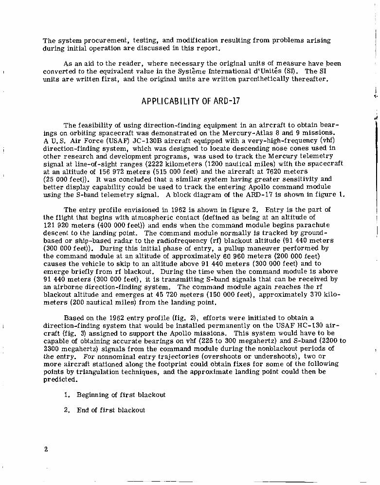
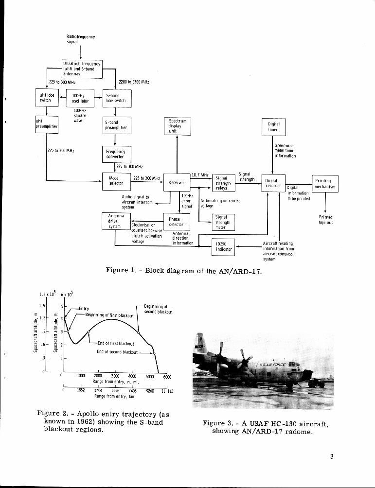
The feasibility of using direction-finding equipment in an aircraft t o obtain bear- ings on orbiting spacecraft was demonstrated on the Mercury-Atlas 8 and 9 missions. A U. S. Air Force (USAF) JC-130B aircraft equipped with a very-high-frequency (vhf) direction-f inding system, which was designed to locate descending nose cones used in other research and development programs, was used to track the Mercury telemetry signal at line-of -sight ranges (2222 kilometers (1200 nautical miles) with the spacecraft at an altitude of 156 972 meters (515 000 feet) and the aircraft at 7620 meters (25 000 feet)). It was concluded that a similar system having greater sensitivity and better display capability could be used to track the entering Apollo command module using the S-band telemetry signal. A block diagram of the ARD-17 is shown in figure 1.
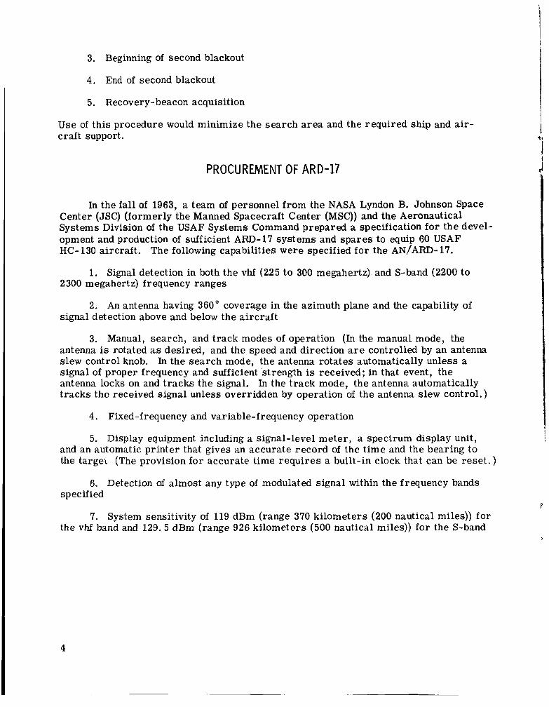
The entry profile envisioned in 1962 is shown in figure 2. Entry is the part of the flight that begins with atmospheric contact (defined as being at an altitude of 121 920 meters (400 000 feet)) and ends when the command module begins parachute descent to the landing point. The command module normally is tracked by ground- based or ship-based radar to the radiofrequency (rf) blackout altitude (91 440 meters (300 000 feet)). During this initial phase of entry, a pullup maneuver performed by the command module at an altitude of approximately 60 960 meters (200 000 feet) causes the vehicle to skip to an altitude above 91 440 meters (300 000 feet) and to emerge briefly from rf blackout. During the t ime when the command module is above 91 440 meters (300 000 feet), it is transmitting S-band signals that can be received by an airborne direction-finding system. The command module again reaches the rf blackout altitude and emerges at 45 720 meters (150 000 feet), approximately 370 kilo- meters (200 nautical miles) from the landing point.
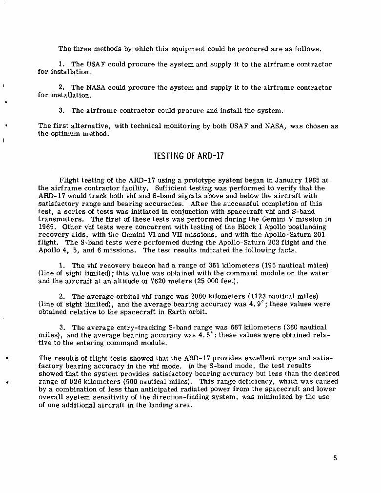
Based on the 1962 entry profile (fig. 2), efforts were initiated to obtain a direction-finding system that would be installed permanently on the USAF HC-130 air- craft (fig. 3) assigned to support the Apollo missions. This system would have to be capable of obtaining accurate bearings on vhf (225 to 300 megahertz) and S-band (2200 to 2300 megahertz) signals f rom the command module during the nonblackout periods of the entry. For nonnominal entry trajectories (overshoots or undershoots), two or more aircraft stationed along the footprint could obtain fixes for some of the following points by triangulation techniques, and the approximate landing point could then be predicted.
I
1. Beginning of f i rs t blackout
2. End of f i rs t blackout
2
Radio frequency signal
- I
Ultrahigh frequency (uhfJ and S-band - antennas
225 to 300 MHz 2200 to 2300 MHz
Figure 1. - Block diagram of the AN/AFtD-1'7.
u h f lobe 100-Hz switch oscillator
1 . 8 x l d 6 x 1 3
S-band lobe switch
Beginning of € 1 1'5t 1 ~ r b E n t r y /Beginning of f i rst blackout second blackout
u h f preamplifier
End of f i rst blackout
End of second blackout
wave S-band Spectrum preamplifier display
un i t
0 1000 2000 3000 4ooo 5000 6Mx) Range from entry, n. mi.
1 I I I I 1 0 1852 3704 55% 7408 9260 11 112
Range from entry, km
1
r
225 to 300 MHz Frequency converter
225 to 300 MHz
Figure 2. - Apollo entry trajectory (as known in 1962) showing the S-band blackout regions.
Greenwich mean time information
Printed tape out
Mode selector
Figure 3. - A USAF HC-130 aircraf t , showing AN/ARD-17 radome.
- -
225 to 300 MHz Signal Strength t Receiver strength Digital
relays
3
Audio signal to aircraft intercom system
A information to be printed 100-Hz
error Automa!ic gain control signal wltage
Antenna drive system
4 Phase
meter Clockwise o r detector
3. Beginning of second blackout
4. End of second blackout
5. Recovery-beacon acquisition
Use of this procedure would minimize the search area and the required ship and air- craft support.
PROCUREMENT OF ARD-17
In the fall of 1963, a team of personnel from the NASA Lyndon B. Johnson Space Center (JSC) (formerly the Manned Spacecraft Center (MSC)) and the Aeronautical Systems Division of the USAF Systems Command prepared a specification for the devel- opment and production of sufficient A m - 1 7 systems and spares to equip 60 USAF HC- 130 aircraft. The following capabilities were specified for the AN/ARD- 17.
1. Signal detection in both the vhf (225 to 300 megahertz) and S-band (2200 to 2300 megahertz) frequency ranges
2. An antenna having 360" coverage in the azimuth plane and the capability of signal detection above and below the aircraft
3. Manual, search, and track modes of operation (In the manual mode, the antenna is rotated as desired, and the speed and direction are controlled by an antenna slew control knob. In the search mode, the antenna rotates automatically unless a signal of proper frequency and sufficient strength is received; in that event, the antenna locks on and tracks the signal. In the t rack mode, the antenna automatically tracks the received signal unless overridden by operation of the antenna slew control.)
4. Fixed-frequency and variable-frequency operation
5. Display equipment including a signal-level meter, a spectrum display unit, and an automatic printer that gives an accurate record of the t ime and the bearing to the targel (The provision for accurate time requires a built-in clock that can be reset . )
6. Detection of almost any type of modulated signal within the frequency bands specified
7. System sensitivity of 119 dBm (range 370 kilometers (200 nautical miles)) for the vhf band and 129.5 dBm (range 926 kilometers (500 nautical miles)) fo r the S-band
4
The three methods by which this equipment could be procured a r e as follows.
1. The USAF could procure the system and supply it to the airframe contractor for installation.
I
I
2. The NASA could procure the system and supply it to the airframe contractor for installation.
* 3. The airframe contractor could procure and install the system.
e The f i rs t alternative, with technical monitoring by both USAF and NASA, was chosen as the optimum method.
TEST1 NG OF ARD-17
Flight testing of the A m - 1 7 using a prototype system' began in January 1965 at the air f rame contractor facility. Sufficient testing was performed to verify that the ARD-17 would track both vhf and S-band signals above and below the aircraft with satisfactory range and bearing accuracies. After the successful completion of this test, a ser ies of tes ts was initiated in conjunction with spacecraft vhf and S-band transmitters. The f i rs t of these tes ts was performed during the Gemini V mission in 1965. Other vhf tes ts were concurrent with testing of the Block I Apollo postlanding recovery aids, with the Gemini VI and VI1 missions, and with the Apollo-Saturn 201 flight. The S-band tes ts were performed during the Apollo-Saturn 202 flight and the Apollo 4, 5, and 6 missions. The test results indicated the following facts.
1. The vhf recovery beacon had a range of 361 kilometers (195 nautical miles) (line of sight limited); this value was obtained with the command module on the water and the aircraft at an altitude of 7620 meters (25 000 feet).
2. The average orbital vhf range was 2080 kilometers (1123 nautical miles) (line of sight limited), and the average bearing accuracy was 4 . 9 " ; these values were obtained relative to the spacecraft in Earth orbit.
3. The average entry-tracking S-band range was 667 kilometers (360 nautical miles), and the average bearing accuracy was 4 . 5 " ; these values were obtained rela- tive to the entering command module.
The resul ts of flight tes t s showed that the ARD- 17 provides excellent range and satis-
range of 926 kilometers (500 nautical miles), This range deficiency, which was caused
factory bearing accuracy in the vhf mode. showed that the system provides satisfactory bearing accuracy but less than the desired
by a combination of less than anticipated radiated power from the spacecraft and lower overall system sensitivity of the direction-finding system, was minimized by the use of one additional aircraft in the landing area.
In the S-band mode, the test results
4
5
MOD I FI CAT1 ON OF ARD-17
After a f ew months of A m - 1 7 operational use, several problems developed. 1
I Recurrent failures of the two clutches located in the antenna actuator were encountered. Excessive antenna drift occurred, slew switches stuck, and operators had trouble identifying the direction of the signal in the vhf mode because of the presence of two antenna side lobes. made.
i To solve these problems, the following engineering changes were
1. The antenna actuator clutch seals were wearing out after approximately
It was determined that the manufacturer could not correct the defect. 20 hours of use, although a minimum requirement of 100 hours of use had been assessed for them. reliable unit modified at reasonable cost could not be obtained; therefore, a survey Of clutch manufacturers was conducted to obtain replacement clutches having longer life- times. Two candidate clutches that passed a 500-hour life test were selected to replace the original clutches. The manufacturer of the new clutches also certified the units for 1000 hours of operation.
A
2. A newly designed printed circuit board was installed in the control set to eliminate antenna drift. Basically, this modification permitted an accurate balancing of the clutches that eliminated the antenna drift.
3. The wiring to the s l ew switches had interfered with the s l e w switch rotation and caused sticking when the switch was deflected in one direction. solved the slew switch problem.
Rerouting the wire
4. The presence of the antenna side lobes when operating in the vhf mode was caused by a radome restriction imposed on the antenna size. Because of this restric- tion, the side lobes could not be eliminated, but the addition of a manual gain control to the receiver simplified identification of the major lobe. When the manual gain con- t rol was switched on, the existing automatic gain control was overridden and the gain of the receiver could be set manually. This change resulted in a greater difference in signal strength between the major lobe and the side lobes and simplified identification of the major lobe.
The four preceding engineering changes were incorporated into the system by use of field modification kits. The changes have proved to be quite successful.
OPERATI ONAL-CONCEPT CHANGES
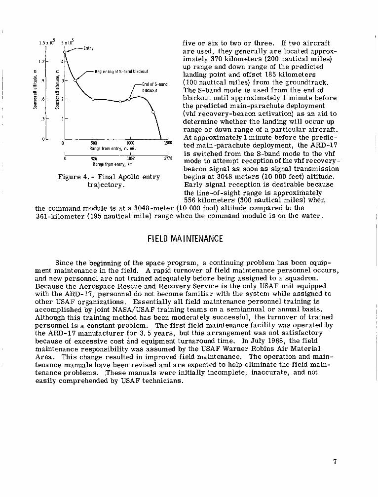
After the procurement of the ARD-17, the Apollo entry profile changed signifi- cantly; that is, reduction of the range fron, 9260 kilometers (5000 nautical miles) to approximately 4630 kilometers (2500 nautical miles) reduced the number of S-band blackouts to one (fig. 4). Because of the reduced footprint s ize and the single blackout period, the original requirement fo r airborne S-band tracking was eliminated. There- fore, the number of HC-130 aircraf t required to support a landing was reduced f rom
6
1 . 5 ~ 1 2 5 x 1 2
1.2 -
E
m m 2 .9 - c - m
m L
.- - L - P .6 - m n. VI
rtry e m v
c c ._
Range from entry, n. mi. I I I I 0 926 1852 2778
Range frpm entry, km
Figure 4. - Final Apollo entry trajectory.
five o r six to two o r three. If two aircraft a r e used, they generally a r e located approx- imately 370 kilometers (200 nautical miles) up range and down range of the predicted landing point and offset 185 kilometers (100 nautical miles) from the groundtrack. The S-band mode is used from the end of blackout until approximately 1 minute before the predicted main-parachute deployment (vhf recovery-beacon activation) as an aid to determine whether the landing will occur up range or down range of a particular aircraft. At approximately 1 minute before the predic- ted main-parachute deployment, the ARD-1'7 is switched from the S-band mode to the vhf mode to attempt reception of the vhf recovery - beacon signal as soon as signal transmission begins at 3048 meters (10 000 feet) altitude. Early signal reception is desirable because the line -of -sight range is approximately 556 kilometers (300 nautical miles) when
the command module is at a 3048-meter (10 000 foot) altitude compared to the 361-kilometer (195 nautical mile) range when the command module is on the water.
FIELD MAINTENANCE
Since the beginning of the space program, a continuing problem has been equip- ment maintenance in the field. and new personnel a r e not trained adequately before being assigned to a squadron. Because the Aerospace Rescue and Recovery Service is the only USAF unit equipped with the Am-17 , personnel do not become familiar with the system while assigned to other USAF organizations. accomplished by joint NASA/USAF training teams on a semiannual or annual basis. Although this training method has been moderately successful, the turnover of trained personnel is a constant problem. The f i rs t field maintenance facility was operated by the A m - 1 7 manufacturer for 3.5 years, but this arrangement was not satisfactory because of excessive cost and equipment turnaround time. In July 1968, the field maintenance responsibility was assumed by the USAF Warner Robins Air Material Area. This change resulted in improved field maintenance. The operation and main- tenance manuals have been revised and a r e expected to help eliminate the field main- tenance problems. These manuals were initially incomplete, inaccurate, and not easily comprehended by USAF technicians.
A rapid turnover of field maintenance personnel occurs,
Essentially all field maintenance personnel training is
I
7
CONCLUDING REMARKS
The AN/ARD- 17 direction-finding system has operated satisfactorily since the incorporation of four engineering changes. The only disappointment in performance has been the range obtained on the S-band mode. This deficiency was caused partly by insufficient spacecraft transmitter power, which actually was approximately half the originally stated value for which the AN/ARD- 17 performance specifications had been written. Because of the elimination of the S-band entry-tracking requirement, the range deficiency has not impaired the capability of the equipment as currently used. In the very-high-frequency mode, the AN/ARD-17 is the best long-range direction- finding equipment in existence and would have enabled location of the command module if a nonnominal landing had occurred.
Lyndon B. Johnson Space Center National Aeronautics and Space Administration
Houston, Texas, October 4, 1974 076-00-00-00-72
8
NATIONAL AERONAUTICS AND SPACE ADMINISTRATION WASHINGTON, D.C. 20546
OFFICIAL BUSINESS
POSTAGE AND FEES P A I D N A T I O N A L AERONAUTICS A N D
SPACE ADMINISTRATION PENALTY FOR PRIVATE USE $300 SPECIAL FOURTHXLASS RATE 451
BOOK
[S) U % W L
FOSTMA8T~R : If Undellvernhlr (Section 168 Postal nfnnunl) Do Not Return
“The aevonautical and space activities of the United States shall be conducted so as to contribute . . . to the expansion of human knowl- edge of phenomena in, the atmosphere and space. The Administration shall provide for the widest practicable and appropriate dissemination of information concerning its activities and the results thereof.”
-NATIONAL AERONAUTICS AND SPACE ACT OF 1958
NASA SCIENTIFIC AND TECHNICAL PUBLICATIONS TECHNICAL REPORTS: Scientific and technical information considered important, complete, and a lasting contribution to existing knowledge.
TECHNICAL NOTES: Information less broad in scope but nevertheless of importance as a contribution to existing knowledge.
TECHNICAL MEMORANDUMS: Information receiving limited distribution because of preliminary data, security classifica- tion, or other reasons, Also includes conference proceedings with either limited or unlimited distribution.
CONTRACTOR REPORTS: Scientific and technical information generated under a NASA contract or grant and considered an important contribution to existing knowledge.
TECHNICAL TRANSLATIONS : Information published in a foreign language considered to merit NASA distribution in English.
PUBLICAT1oNS: Information derived from or of value to NASA activities. Publications include final reports of major projects, monographs, data compilations, handbooks, sourcebooks, and special bibliographies.
TECHNOLOGY PUBLICATIONS: Information on technology used by NASA that may be of particular interest in commercial and other- non-aerospace applications. Publications include Tech Briefs, Technology Utilization Reports and Technology Surveys.
-
Details on the availability of these publications may be obtained from:
SCIENTIFIC AND TECHNICAL INFORMATION OFFICE
N A T I O N A L A E R O N A U T I C S A N D SPACE A D M I N I S T R A T I O N Washington, D.C. 20546
c