i j i 1 lonworks’” host application programmer’s guide · lonworks’” host application...
TRANSCRIPT
I I J
1
LONWORKS’” Host Application
Programmer’s Guide
Revision 2
EtHELOk Corporation
I
I 1 1
078-0016-01 B

No part of this publication may be reproduced, stored in a retrieval system, or transmitted, in any form or by any means, electronic, mechanical. photocopying, recording, or otherwise, without the prior written permission of Echelon Corporation.
Echelon, LON, and NEURON are registered trademarks of Echelon Corporation. LONBUILDER, LONMANAGER, LONTALK, LONWORKS, 3120, and 3150 are trademarks of Echelon Corporation. Other names may be trademarks of their respective companies,
Document No. 29400
Printed in the United States of America. Copyright 01992,1993 by Echelon Corporation
Echelon Corporation 4015 Miranda Avenue Palo Alto, California 94304
Preface
This guide describes how to create LONWORKS~~ host applications. Host applications are application programs running on hosts other than NEURON@ CHIPS that use the LONTALKTM protocol to communicate with nodes on a LONWORKS network. The availability of host applications makes the LONTALK protocol available to any host processor by using the NEURON CHIP as a communications processor.
Host Application Programmer’s Guide i
Audience The Host Application Programmer’s Guide is intended for developers creating host applications for any host. Examples are shown in ANSI C, however, host applications may be written in any language that can implement the LONTALK network interface protocol.
Developers creating host applications using the LONMANAGERm API do not need to read this guide. The LONMANAGER API implements the network interface protocol and provides a higher level of services to the host application programmer.
Readers of this guide should have C programming experience and be familiar with LONWORKS concepts and LONWORKS application node development. See Related Manuals later in the preface for a list of LONWORKS documentation.
For a complete description of ANSI C consult the following references:
l American National Standard X3.159-1989, Programming Language C, D-F. Prosser, American National Standards Institute, 1989.
l Standard C: Programmer’s Quick Reference, P.J. Plauger and Jim Brodie, Microsoft Press, 1989.
l C: A Reference Manual, Samuel P. Harbison and Guy L. Steele, Jr., 3rd edition, Prentice-Hall, Inc., 1991.
l The C Programming Language, Brian W. Kemighan and Dennis M. Ritchie, 2nd edition, Prentice-Hall, Inc., 1988.
Content The Host Application Programmer’s Guide has five chapters and four appendices as follows:
l Chapter 1, Host Application Overview, provides an introduction to the host application architecture.
l Chapter 2, Host Application Architecture, discusses the protocol used by host applications to communicate with a network interface.
l Chapter 3, Sending and Receiving Messages, discusses the steps used in sending and receiving LONTALK messages from a host application.
l Chapter 4, Using a Network Driver, describes specifications for using a LONWORKS network driver.
l Chapter 5, Error Conditions, discusses errors detected by host applications.
l Appendix A, Sample Host Application, provides source code for a sample host application.
l Appendix B, Creating an External Interface File, describes the procedure for modifying an external interface file to include network variables and message tags used by a host application.
ii Preface
l Appendix C, Network Interface Messages, defines the message structures exchanged by a host application and the network interface.
l Appendix D, Network Interface Commands, describes the network interface commands specified in a data transfer from a host application to the network interface.
Related Manuals The following manuals and engineering bulletins are referenced in this guide:
The LONTALK Protocol engineering bulletin describes the LONTALK Protocol.
The How to Use SNVTs in LONWORKS Applications engineering bulletin describes how standard network variable types (SNVTs) can be used by any application, including host applications, to increase interoperability between LONWORKS nodes.
The NEURON 3120TM CHIP and NEURON 3150TM CHIP Data Book Appendix B defines the network management and network diagnostic message formats that can be used by all application nodes, including host application nodes.
The LONBUILDERTM User’s Guide lists and describes all tasks related to LONWORKS application development using the LONBUILDER Developer’s Workbench. Refer to that guide for detailed information on the LONBUILDER user interface.
The LONMANAGER API Programmer’s Guide and the LONMANAGER API Programmer’s Guide for Windows describe network management in a LONWORKS network. They outline the components of a LONWORKS network management tool, list the library functions of the LONMANAGER API, and provide examples for building a host application using the LONMANAGER API. In addition to the programmer’s guide, there is also a LONMANAGER API Reference Guide for Windows, Volumes I and II.
The NEURON C Programmer’s Guide outlines a recommended general approach to developing a NEURON C application, explains key concepts of programming in NEURON C through the use of code fragments and examples, and provides a complete reference section for NEURON C.
The Parallel II0 Inte$ace to the NEURON CHIP engineering bulletin describes hardware and software to interface the NEURON CHIP to a host processor using the parallel I/O port.
The Custom Node DeueEopment engineering bulletin describes the steps for building an example LONWORKS application node.
The LONWORKS Installation Overview engineering bulletin describes LONWORKS network installation and outlines several scenarios that may be used to install LONWORKS networks.
Host Application Programmer’s Guide iii
The NEURON CHIP-based Installation of LONWORKS Networks engineering bulletin describes network management from NEURON C applications.
The Serial LONTALK Adapter User’s Guide describes how to use the Serial LONTALK Adapter, a network interface that can be used with any host with a serial interface.
The LONBUILDER Microprocessor Interface Program (MIP) User’s Guide describes how to create a network interface using the LONBUILDER Microprocessor Interface Program (MIP).
iv Preface
Contents
Pn?face Audience Content Related Materials
chapter1 overview of the Host Application Architecture
Overview of the Host Application Architecture Intended Uses of Host Applications
Examples Network Management, Network Control,
and Network Monitoring Network Management Network Control Network Monitoring
Definitions
CM-57 Host Application Architecture Host Application Architecture
Application Layer Link-Layer Physical Layer
Plush State
chapter3 Sending and Receiving Messages Communicating With Other Nodes Network Interface Configuration Options
Network Variable Processing Option Network Variable Configuration Table Size Option Explicit Addressing Option Buffer Options
Sending Messages Receiving Messages Local Control of the Network Interface Local Network Management/Diagnostics
With the Network Interface Binding to a Host Node
i ii ii
iii
1-1 1-2 1-3 1-3
1-4 1-4 1-5 1-5 1-5
2-1 2-2 2-2 2-2 2-2 2-3
3-1 3-1 3-4 3-4 3-5 3-5 3-6 3-7 3-8
3-10
3-10 3-11
Host Application Programmer’s Guide V
chapter4 Using a Network Driver 4-1 The Network Driver 4-2 Standard Network Driver Services 4-2 DOS Network Driver Services 4-3
Driver Direct Functions 4-4
-P-5 Error Conditions Errors Detected by the Host Application
Driver Not Installed Wrong Driver Invoked Network Interface Not Installed Power Lost to Network Interface ARer Start-Up Destination Node Not Available Network Management Request Failed
Errors Detected By a Network Driver Downlink Timeouts Host Detection of Hardware Failures Error Codes Returned to the Driver Direct Functions
Errors Detected By a Network Interface
Appendix A Sample Host Application A-1 Host Application Overview A-2 Host Application Requirements A-2 Host Application Data Structures A-3 Host Application Architecture A-6 Network Interface Transaction Handler A-8
ni-init A-8 ni-reset0 A-9 NI-send-msg-wait0 A-9
Input Parameters A-9 Output Parameters A-11 Error Codes A-12
ni,get-next-response0 A-12 ni-receive-msg0 A-12 ni-send-response0 A-13 ni,sendjmmediate() A-13 handle-error0 A-14
Application Message Handler A-14 handle-updatepv-config A-15 handle-query-nv-config A-15 handle-set-mode0 A-15 handle-query-SNVT() A-16 handle-NV-fetch0 A-16 handle-netvar-msg() A-16 handle-explicit-msg() A-16
Outgoing Network Variable Messages A-16 NV-update0 A-16 NV-poll0 A-17
Running the Sample Host Application A-19
5-1 5-2 5-2 5-2 5-3 5-3 5-3 5-3 5-4 5-4 5-4 5-4 5-5
vi Preface
AppendixB Creating an External Interface File How to Add Network Variables to the External
Interface File External Interface File Network Variables and Message Tags
Adding Network Variables and Message Tags to the Network Interface External Interface File
AppendixC Network Interface Messages NI-MSG.H NI-MGMT.H Bit Field Diagrams
AppendixD Network Interface Commands Network Interface Commands Buffer Queue Values
Host Application Programmer’s Guide
B-1
B-2 B-3 B-5
B-9
C-1 C-2
C-15 C-19
D-1 D-2 D-4
vii

Host Application Overview
This chapter provides an introduction to the host applications. Basic concepts are defined and the host application’s intended uses are outlined.
Host Application Programmer’s Guide 1-1
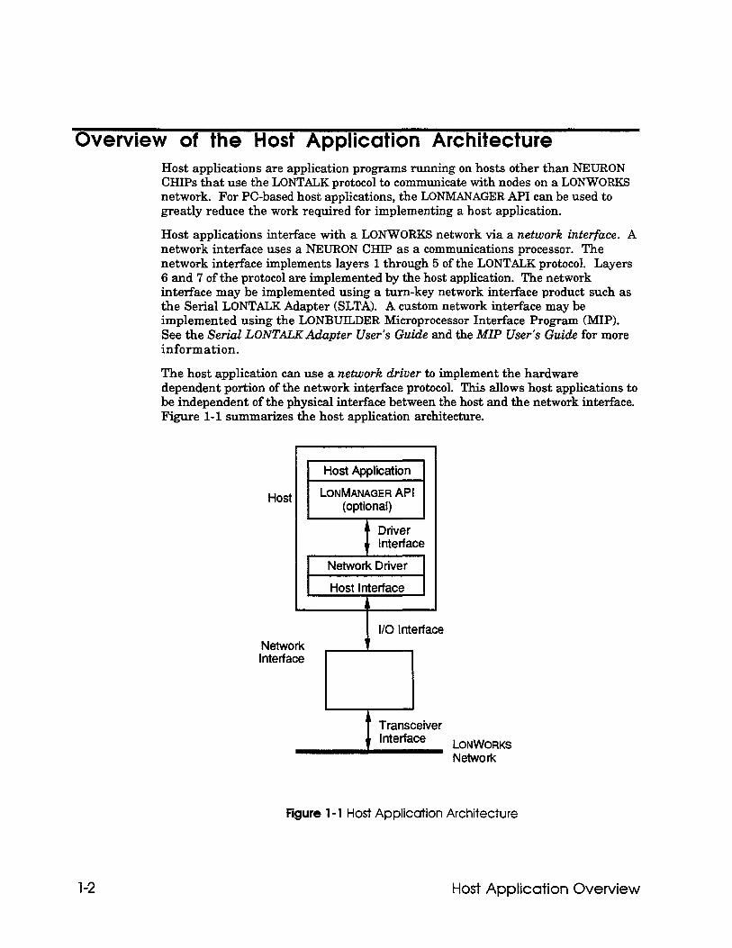
Overview of the Host Application Architecture Host applications are application programs running on hosts other than NEURON CHIPS that use the LONTALK protocol to communicate with nodes on a LONWORKS network. For PC-based host applications, the LONMANAGER API can be used to greatly reduce the work required for implementing a host application.
Host applications interface with a LONWORKS network via a network interface. A network interface uses a NEURON CHIP as a communications processor. The network interface implements layers 1 through 5 of the LONTALK protocol. Layers 6 and 7 of the protocol are implemented by the host application. The network interface may be implemented using a turn-key network interface product such as the Serial LONTALK Adapter (SLTA). A custom network interface may be implemented using the LONBUILDER Microprocessor Interface Program (MIP). See the Serial LONTtiKAdapter User’s Guide and the MIP User’s Guide for more information.
The host application can use a network driver to implement the hardware dependent portion of the network interface protocol. This allows host applications to be independent of the physical interface between the host and the network interface. Figure l-l summarizes the host application architecture.
Host
Driver Interface
1 Network Driver 1
I I Host interface
I l/O Interface Network Interface
rl
Figure l- 1 Host Applicdion Architecture
1-2 Host Application Overview
Intended Uses of Host Applications Several types of nodes can be attached to a LONWORKS network. The lowest cost node, based on the NEURON 3120” CHIP, provides a complete system-on-a-chip, including memory for the application code and data, and protocol firmware. For applications that require more code or data space, the NEURON 3150TM CHIP supports up to 42 Kbytes of off-chip user memory. Nodes using the NEURON CHIP as the applications processor are called NEURON CHIP-hosted nodes.
Host applications can be used for nodes that require more processing power, memory, or input/output capability than provided by the NEURON CHIP family. Host applications use the NEURON CHIP as a communications processor. The applications processing occurs on an external host processor. Host applications can also be used to interface an existing application to a LONWORKS network. These nodes are called host-based nodes.
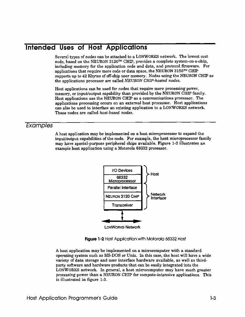
Examples A host application may be implemented on a host microprocessor to expand the input/output capabilities of the node. For example, the host microprocessor family may have special-purpose peripheral chips available. Figure l-2 illustrates an example host application using a Motorola 68332 processor.
Parallel Interface
I Transceiver
Host
Network Interface
LONWORKS Network
Figure l-2 Host Application with Motorola 68332 Host
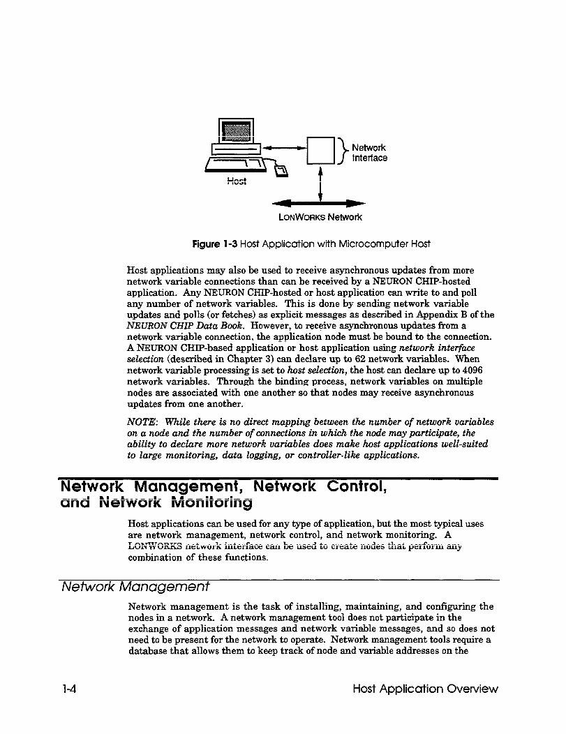
A host application may be implemented on a microcomputer with a standard operating system such as MS-DOS or Unix. In this case, the host will have a wide variety of data storage and user interface hardware available, as well as third- party software and hardware products that can be easily integrated into the LONWORKS network. In general, a host microcomputer may have much greater processing power than a NEURON CHIP for compute-intensive applications. This is illustrated in figure l-3.
Host Application Programmer’s Guide 1-3
>
Network Interface
LONWORKS Network
Figure 1-3 Host Application with Microcomputer Host
Host applications may also be used to receive asynchronous updates from more network variable connections than can be received by a NEURON CHIP-hosted application. Any NEURON CHIP-hosted or host application can write to and poll any number of network variables. This is done by sending network variable updates and polls (or fetches) as explicit messages as described in Appendix B of the NEURON CHIP Data Book. However, to receive asynchronous updates from a network variable connection, the application node must be bound to the connection. A NEURON CHIP-based application or host application using network interface selection (described in Chapter 3) can declare up to 62 network variables. When network variable processing is set to host selection, the host can declare up to 4096 network variables. Through the binding process, network variables on multiple nodes are associated with one another so that nodes may receive asynchronous updates from one another.
NOTE: While there is no direct mapping between the number of network variables on a node and the number of connections in which the node may participate, the ability to declare more network variables does make host applications well-suited to large monitoring, data logging, or controller-like applications.
Network Management, Network Control, and Network Monitoring
Host applications can be used for any type of application, but the most typical uses are network management, network control, and network monitoring. A LONWORKS network interface can be used to create nodes that perform any combination of these functions.
Network Management Network management is the task of installing, maintaining, and configuring the nodes in a network. A network management tool does not participate in the exchange of application messages and network variable messages, and so does not need to be present for the network to operate. Network management tools require a database that allows them to keep track of node and variable addresses on the
1-4 Host Application Overview
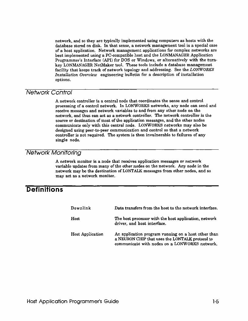
network, and so they are typically implemented using computers as hosts with the database stored on disk. In that sense, a network management tool is a special case of a host application. Network management applications for complex networks are best implemented using a PC-compatible host and the LONMANAGER Application Programmer’s Interface (API) for DOS or Windows, or alternatively with the turn- key LONMANAGER NetMaker tool. These tools include a database management facility that keeps track of network topology and addressing. See the LONWORKS Installation Overview engineering bulletin for a description of installation options.
Network Control A network controller is a central node that coordinates the sense and control processing of a control network. In LONWORKS networks, any node can send and receive messages and network variables to and from any other node on the network, and thus can act as a network controller. The network controller is the source or destination of most of the application messages, and the other nodes communicate only with this central node. LONWORKS networks may also be designed using peer-to-peer communication and control so that a network controller is not required. The system is then invulnerable to failures of any single node.
Network Monitoring A network monitor is a node that receives application messages or network variable updates from many of the other nodes on the network. Any node in the network may be the destination of LONTALK messages from other nodes, and so may act as a network monitor.
Definitions
Downlink Data transfers from the host to the network interface.
Host The host processor with the host application, network driver, and host interface.
Host Application An application program running on a host other than a NEURON CHIP that uses the LONTALK protocol to communicate with nodes on a LONWORKS network.
Host Application Programmer’s Guide 1-5
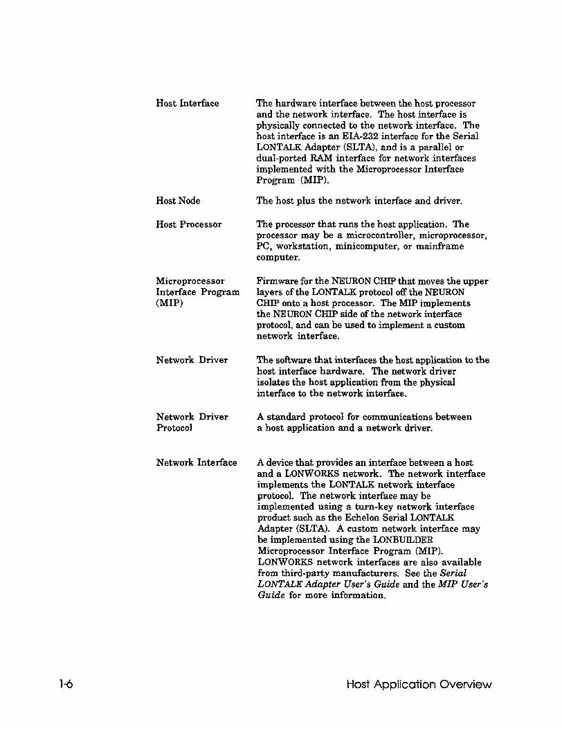
Host Interface The hardware interface between the host processor and the network interface. The host interface is physically connected to the network interface. The host interface is an EIA-232 interface for the Serial LONTALK Adapter (SLTA), and is a parallel or dual-ported RAM interface for network interfaces implemented with the Microprocessor Interface Program (MIP).
Host Node The host plus the network interface and driver.
Host Processor The processor that runs the host application. The processor may be a microcontroller, microprocessor, PC, workstation, minicomputer, or mainframe computer.
Microprocessor Firmware for the NEURON CHIP that moves the upper Interface Program layers of the LONTALK protocol off the NEURON NIP) CHIP onto a host processor. The MIP implements
the NEURON CHIP side of the network interface protocol, and can be used to implement a custom network interface.
Network Driver The software that interfaces the host application to the host interface hardware. The network driver isolates the host application from the physical interface to the network interface.
Network Driver Protocol
A standard protocol for communications between a host application and a network driver.
Network Interface A device that provides an interface between a host and a LONWORKS network. The network interface implements the LONTALK network interface protocol. The network interface may be implemented using a turn-key network interface product such as the Echelon Serial LONTALK Adapter (SLTA). A custom network interface may be implemented using the LONBUILDER Microprocessor Interface Program (MIP). LONWORKS network interfaces are also available from third-party manufacturers. See the Serial LONTALX Adapter User’s Guide and the MIP User’s Guide for more information.
1-6 Host Application Overview
Network Interface Protocol
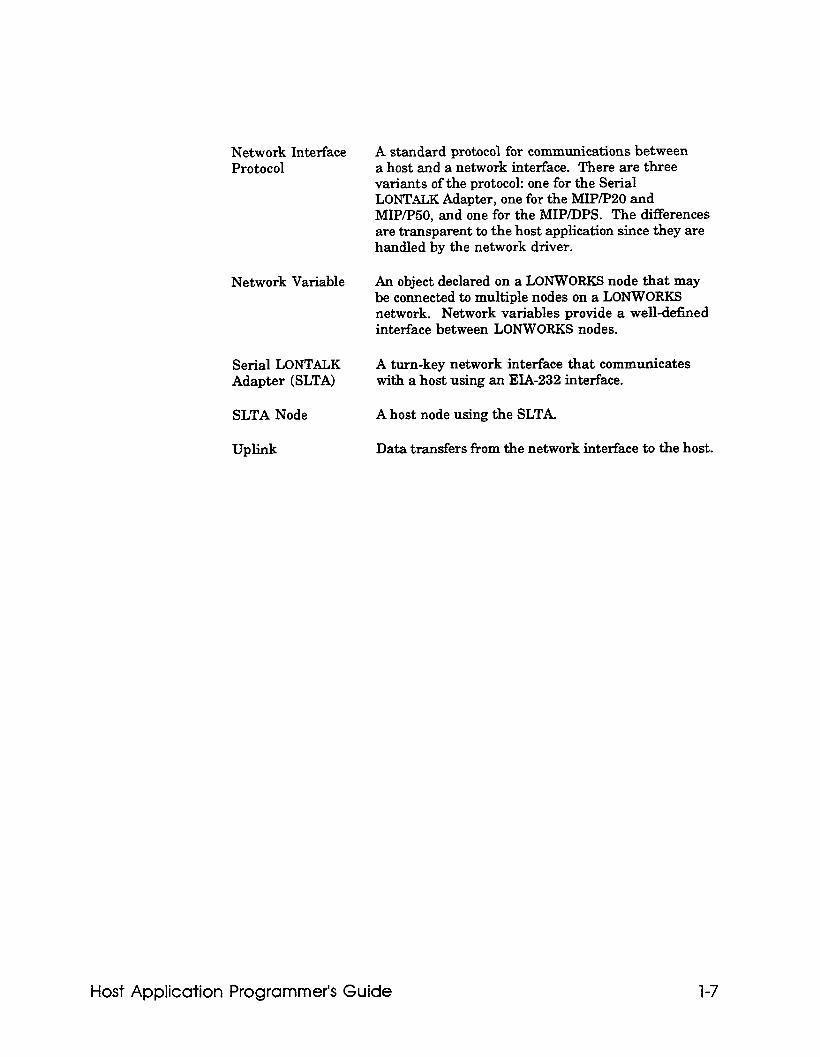
A standard protocol for communications between a host and a network interface. There are three variants of the protocol: one for the Serial LONTALK Adapter, one for the MIP/PBO and MIP/P50, and one for the MIP/DPS. The differences are transparent to the host application since they are handled by the network driver.
Network Variable An object declared on a LONWORKS node that may be connected to multiple nodes on a LONWORKS network. Network variables provide a well-defined interface between LONWORKS nodes.
Serial LONTALK A turn-key network interface that communicates Adapter (SLTA) with a host using an EIA-232 interface.
SLTA Node A host node using the SLTA
Uplink Data transfers from the network interface to the host.
Host Application Programmer’s Guide 1-7

2 Host Application
Architecture
This chapter discusses the protocol used by host applications to communicate with a network interface.
Host Application Programmer’s Guide 2-1
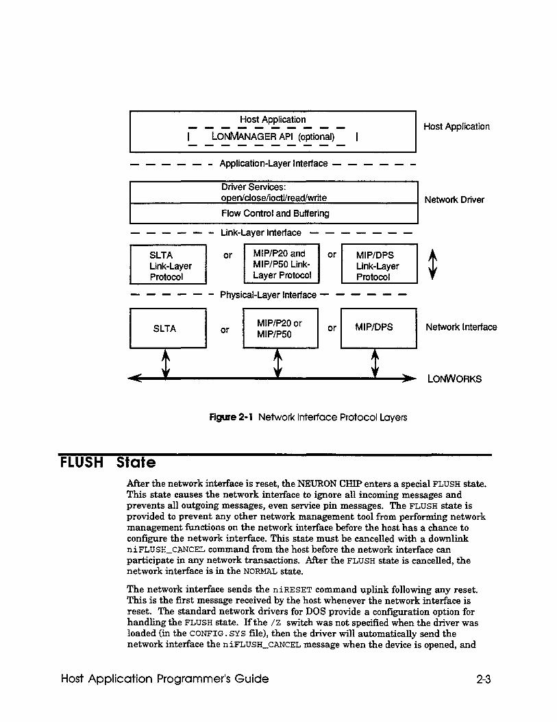
Host Application Architecture The host application architecture defines standard protocols for communications between a host and a network interface. The architecture has three layers; application, link, and physical. Figure 2-l illustrates the host application architecture layers.
Application layer The application layer, also known as the LONTALK Network Driver Protocol, is used by the host application to send and receive LONT&K messages. Chapter 3, Sending and Receiving Messages, describes how the host application can send and receive LONTALK messages using the network driver protocol. The network driver protocol is identical for all network interfaces, including the Serial LONTALK Adapter (SLTA) and network interfaces using any version of the Microprocessor Interface Program (MIP).
link layer The link layer, also known as the LONTXLK Network Interface Protocol is used by the network driver to ensure reliable delivery of packets between the host and the network interface. The link layer is also used by the host to control the network interface. The link layer is different for the SLTA, the MIP/P20 and MIPBO, and the MIP/DPS. The differences in the link layer protocols are managed by the network driver, and are transparent to the host application. The link layer protocol for the SLTA is based on a serial data transfer protocol between the host and network interface. For details of the SLTA link layer protocol, see the SLTA User’s Guide. The link layer protocol for a MIP/P20 or MIP/PBO-based network interface is based on tbe NEURON CHIP parallel I/O protocol. The link layer protocol for a MIP/DPS-based network interface is based on a dual-ported HAM witb semaphores that is mapped into the address space of a NEURON 3150 CHIP and also of the host microprocessor. For details of the link layer protocols used by the MIPS, see the LONBUILDER Microprocessor Interface Program (MIP) User’s Guide. Appendix D, Network Interface Commands, describes the commands that the host can use to control the network interface.
Physical layer The physical layer is the physical interface between the host interface and the network interface. The physical layer for the SLTA is an EIA-232 interface as described in the Serial L0NTAL.K Adapter User’s Guide. The physical layer for a network interface based on the MIPIPBO or MIP/PBO is a parallel interface. The physical layer for a network interface based on the MIP/DPS is a dual-ported RAM with hardware semaphores. This interface should be described in documentation provided with a third-party network interface, and is described in the Microprocessor Interface Program (MIP) User’s Guide for custom network interfaces.
2-2 Host Application Architecture
Host Application
r -Lo~M&A<E~A~ (o$&& - I ---m---m--
Host Application
---me- Application-Layer Interface - - - - - -
Driier Services: open/close/ioctl/read/write
Flow Control and Buffering . Network Driver
------ Link-Layer Interface - - - - - - -
pi&-j Or /lO”‘~l$
------ Physical-Layer Interface - - - - - -
El SLTA or MIP/P20 or or MIP/P50
MIP/DPS Network Interface
< * LONWORKS
Figure 2- 1 Network Interface Protocol Layers
FLUSH State After the network interface is reset, the NFJJRON CHIP enters a special FLUSH state. This state causes the network interface to ignore all incoming messages and prevents all outgoing messages, even service pin messages. The FLUSH state is provided to prevent any other network management tool from performing network management functions on the network interface before the host has a chance to configure the network interface. This state must be cancelled with a downlink niFLUSH_CANCEL command from the host before the network interface can participate in any network transactions. After the FLUSH state is cancelled, the network interface is in the NORM&L state.
The network interface sends the niRESET command uplink following any reset. This is the first message received by the host whenever the network interface is reset. The standard network drivers for DOS provide a configuration option for handling the FLUSH state. If the /Z switch was not specified when the driver was loaded (in the CONFIG. SYS file), then the driver will automatically send the network interface the niFLUSH_CANCEL message when the device is opened, and
Host Application Programmer’s Guide 2-3
2-4
also when it receives an uplink niRESET command. If the /Z switch was specified, then the application is responsible for sending niFLUSH_CANCEL when the device is opened, and when it receives an uplink niRESET.
For the SLTA, another possibility is provided with a jumper option. This jumper specifies that the SLTA not enter the special FLUSH state after reset, so that the host application or the host driver need not send the niFLUSH_CANCEL. See Configuration Jumpers in Chapter 2 of the Serial LONTALK Adapter (SLTA) User’s Guide.
Host Application Architecture
3 Sending and Receiving
Messages
This chapter discusses the steps used in sending and receiving LONTALK messages fi-om a host application. Network interface configuration options are also described.
Host Application Programmer’s Guide 3-1
Communicating With Other Nodes The host application communicates with other nodes by sending and receiving LONTALK messages. These messages may be application, network management, or network diagnostic messages. Application messages may be network variable messages or explicit messages.
The host application sends a LONTALK message by building the message in an application buffer and passing the buffer downlink to the network interface via the network driver. The host application receives LONTALK messages by decoding application buffers received uplink from the network interface via the network driver. The format of the application buffer is defined in this section and is contained in the ExpAppBuf f er and ImpAppBuf f er structures in Appendix C.
The network driver translates the application-layer header to a link-layer header, and manages buffer allocation as described in the Serial LONTALK Adapter User’s Guide and the LONBUILDER Microprocessor Interface Program User’s Guide. Application buffers exchanged by the host application and the network driver contain one or more of the following fields:
l Network Interface Command. The network interface command specifies the type and size of the application buffer. The network interface command is contained in the NI-Hdr structure defined in Appendix C, and in the file NI-MGMT . H supplied with the sample host application. Network interface commands are defined in Appendix D. This field is always present, and is the only field specified for local network interface commands, such as the reset command, niRESET. Local network interface commands are network management or network diagnostic commands that are sent from the host to the network interface.
l Message Header. The message header describes the type of LONTALK message contained in the data field. The message header is contained in the MsgHdr union in Appendix C. This field is included if the application buffer is a data transfer or a completion event. The format of this field depends on the type of transfer and is defined by one of the following structures defined in Appendix c:
NetVarHdr Network variable update or completion code when network interface selection is enabled as described under Network Variable Processing Option later in this chapter.
ExpMsgHdr All other data transfers and completion codes.
l Network Address. The network address specifies the destination address for downlink explicitly addressed application buffers, or the source address for uplink application buffers. The network address is contained in the Explicit-Addr union in Appendix C. This field is included if the application buffer is a data transfer or a completion event and explicit addressing on is enabled as described under Explicit Addressing On later in this chapter. The format of this field depends on the type of transfer, and is defined by one of the following structures defined in Appendix C:
3-2 Sending and Receiving Messages
SendAddrDtl Outgoing explicit messages or network variable updates.
RcvAddrDtl Incoming explicit messages or unsolicited network variable updates.
RespAddrDtl Incoming responses or network variable updates solicited by a poll.
l Data. The data field defines the data to be transferred. The data field is contained in the MsgData union in Appendix C. This field is included if the application buffer is a data transfer or a completion event. The format of this field depends on the type of transfer, and is defined by one of the following structures defined in Appendix C:
UnprocessedNV Network variable update or completion event when host selection is enabled as described under Network Variable Processing Option later in this chapter. This field addresses the network variable using the network variable selector; the host application translates the network variable index to and from a network variable selector. Completion events include only the network variable selector contained in the first two bytes.
ProcessedNV Network variable update or completion event when network interface selection is enabled as described under Network Variable Processing Option later in this chapter. This field addresses the network variable using the network variable index; the network interface translates the network variable index to and from a network variable selector. Completion events include only the network variable index contained in the first byte.
FxplicitMsg Explicit message or completion code. Completion events include only the message code contained in the first byte. Explicit message formats are defined in Appendix B of the NEURON CH.?F Data Book.
When working with application buffers, note the following:
l The structure for the application buffer is different depending on whether explicit addressing on or explicit addressing off is selected as described under Explicit Addressing Option later in this chapter. When explicit addressing off is selected, the application buffer does not include the I1 byte explicit address field. When explicit addressing on is selected, an additional 11 bytes are included to accommodate the explicit address.
l The length field in the application buffer header describes the length of the message only, not the message plus the explicit addressing field.
Host Application Programmer’s Guide 3-3
l All downlink LONTALK messages that are not local network management or network diagnostic messages will eventually result in an uplink completion event message. The completion event message can be used to determine if an acknowledged message is received by all addresses. It is the responsibility of the host application to process these events appropriately.
l The command type of completion event messages is niCOMM+niRESPONSE. The cmpl-code field of the application buffer should be checked for pass/fail status. This field is zero for incoming LONTALK messages.
l Application buffers must be large enough to hold the largest network variable, explicit message, or response used by the application. Typically, the largest network management message is 17 bytes.
Network Interface Configuration Options The types of messages passed between the host and the network interface are determined by configuration options specified for the network interface. Defaults for these options specify the type of network variable processing performed by the network interface, the size of the network variable configuration table, use of explicit addressing, and the amount of buffering within the network interface. These options are selected when the network interface is built. If you are building a network interface based on the MIP, specify these options as described in the Microprocessor Interface Program (MIP) UserS Guide. The settings for these options for the SLTA are described in the Serial LOIVTU Adapter User’s Guide. The settings of these options for third-party network interfaces should be specified in the third-party network interface documentation.
Network Variable Processing Option There are two values for the network variable processing option: host selection and network interface selection. These values determine whether the host processor or the network interface perform network variable selection. Network variable selection is one of the three steps a node performs when a network variable update occurs. These three steps are:
1 Target address decoding. This step verifies that a network variable update is addressed to the target node and is always performed by the network interface.
2 Network uariable selection. This step determines which network variable on the node is to be updated. This step is performed by the network interface if network interface selection is specified; it is performed by the host application if host selection is specified.
3 Network variable modification. This step modifies the selected network variable and is always performed by the host application.
When network interface selection is specified, the host can declare up to 62 network variables. When host selection is specified, the host can declare up to 4096 network variables. To use host selection, the host application should process the Update Net Variable Conf& and Query Net Variable Config network management commands as described under Receiving Messages later in this chapter. If the host itself is the network manager and will not be receiving network variable binding messages from other nodes, this need not be done. Network interface selection is easier since
3-4 Sending and Receiving Messages
the network interface handles all network variable selection. Also, network interface selection provides non-volatile storage of network variable configuration. Host selection supports more connections, and the host application must provide network variable configuration storage.
The SLTA uses host selection. Network interfaces used with the LONMANAGER API must use host selection.
Network Variable Configuration Table Size Option When network interface selection is specified, this option defines the size of the network variable configuration table on the network interface. The size may be any value from 0 to 62 entries. This option is not used when host selection is specified.
Explicit Addressing Option This option determines whether space is set aside in the application buffer for explicit addressing information. Specifying explicit addressing on adds an 11 byte explicit address field to every application buffer. The host application can use this field to specify an explicit address for any message, bypassing the address table in the network interface. This allows the host application to send LONTALK messages to an unlimited number of nodes. When explicit addressing ofiis specified, the host application can only send messages to the addresses stored in the network interface address table, which has a maximum of 15 entries; this form of addressing is called implicit addressing.
When explicit addressing on is specified, the host application may still send implicitly addressed messages by clearing the addr-mode bit in the message header. Responses to incoming requests must be sent with implicit addressing, since the destination address of the respo’nse is implicitly taken from the source address of the request. If the host application has network variables which have been bound by some other network management tool, then these should also be sent with implicit addressing, since the network management tool will have created address table entries in the network interface for the destinations. Otherwise, network variable updates and polls may be sent with explicit addressing.
Specifying explicit addressing on can also be used to get the source address of a message received from the network interface. Every LONTALK packet has a source and destination address. The destination address ensures that the packet is delivered to the correct node(s). The source address is used for generating the acknowledgement or response and also for assisting learning routers in learning the network topology. Destination nodes can also use the source address to determine which member of a group sent a network variable update. See Monitoring Network Variables in Chapter 3 of the NEURON C Programmer’s Guide for more information.
The SLTA specifies explicit addressing on. Network interfaces used with the LONMANAGER API must specify explicit addressing on.
Host Application Programmer’s Guide 3-5
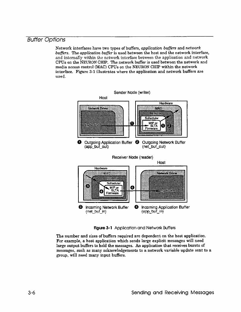
Buffer Options Network interfaces have two types of buffers, application buffers and network buffers. The application buffer is used between the host and the network interface, and internally within the network interface between the application and network CPUs on the NEURON CHIP. The network buffer is used between the network and media access control (MAC) CPUs on the NEURON CHIP within the network interface. Figure 3-l illustrates where the application and network buffers are used.
Sender Node (writer) Host
0 Outgoing Application Buffer @ Outgoing Network Buffer (app-tWW (net-buf-out)
Receiver Node (reader) Host
0
@ incoming Network Buffer 0 incoming Application Buffer (net-buf-in) (wp_bWn)
Figure 3- 1 Application and Network Buffers
The number and sizes of buffers required are dependent on the host application. For example, a host application which sends large explicit messages will need large output bu.fFers to hold the messages. An application that receives bursts of messages, such as many acknowledgements to a network variable update sent to a group, will need many input buffers.
3-6 Sending and Receiving Messages
The buffer configuration for any network interface, including the SLTA, can be changed at any time by sending network management write memory messages to it, either from the host (local network management) or over the network from some other network management tool. See the NEURON CHIP Data Book, section Al, for details of the data structures within the NEURON CHIP that control the partitioning of RAM for buffers. Although the NEURON 3150 CHIP used in a network interface has 2,048 bytes of on-chip RAM, do not attempt to configure a network interface to use more than its available buffer memory, as it will most likely crash or behave erratically, since the remaining on-chip RAM is used by the system image and SLTA or MIP firmware.
For network interfaces based on the MIP, the default allocation of RAM to buffers is controlled by pragmas in the NEURON C source file, and the hardware properties used when the MIP image was created. See the Microprocessor Interface Program (MIP) User’s Guide for details. If you have purchased a network interface from a third party, consult your vendor for details on the default buffer allocation specified when that device was manufactured.
Sending Messages Host applications send LONTALK messages using the following steps:
1 Build the message within the application bufFer data structures. See Appendix C of this document for the definition of the application buffer data structures.
2 Write the application buffer to the network driver.
3 Repeat step 2 if the driver returns the LDV_NO_BUFF_AVAIL or LDV-DEVICE-BUSY error codes.
4 If necessary, process (read) any response messages from the network interface. These appear as niRESPONSE+niCOMM commands.
5 Process the completion event messages from the network interface.
Downlink buffers (from host to network interface) can contain either outgoing messages or outgoing responses to a previous incoming request. Uplink buffers (from network interface to host) can contain incoming messages, incoming responses to a previous request, or completion events. Completion events are generated whenever an outgoing message has completed processing, and indicates whether the message succeeded or failed, indicated by the value of the cmpl-code field in the buffer. Buffers that are not completion events have zero in this field. For request/response service, the completion event occurs after all the responses have arrived.
For network management messages delivered to the network interface (command niNETMGMT), there are no completion events returned. Responses, however, are returned as usual.
The tag fields of an outgoing message, its completion event, and any responses are all the same. This allows the host application to correlate the responses and completion events with the original message. Similarly, a response generated by
Host Application Programmer’s Guide 3-7
the host must use the same tag as that in the incoming request message or network variable poll. To further aid in correlating completion events with the original message, the first two bytes of the data field are included. This contains either the network variable selector (host selection enabled network variables), the network variable index (network interface selection enabled network variables), or the message code (explicit messaging).
The LONTALK protocol supports two paths for special purpose transceivers, and the path field in an incoming message or response indicates how it was received. By default, the alternate path is used for the last two transmission attempts when using Acknowledged, Request/Response, or Unacknowledged/Repeated service. For an outgoing message, the host may override this selection by setting the path-spec bit. In this case, the message is delivered on the channel specified by the path bit.
The trnarnd bit of an outgoing response to a network variable poll must be the same as the trnarnd bit of the incoming request when using network interface selection. This allows any node to correctly poll its own output network variables.
For outgoing network variables, the message is delivered with priority service only if the priority bit in the message is set. Even if network interface selection is enabled, the priority bit in the network variable configuration table is ignored. Outgoing messages with the priority bit set must be delivered to the priority queue, and if the priority bit is clear, they must be delivered to the non-priority queue. The host application should read the priority bit from the network variable configuration table so that it can use priority or non-priority service as appropriate for delivering the network variable.
See the sample host application in Appendix A for an example of sending network variable updates from a host application. In the example, the NV-update ( 1 function updates an output network variable by calling ni-send-msg-wait ( 1 to send out the update message and wait for the completion event. Similarly, the NV_PO~~ ( ) function polls an input network variable by calling ni-send-msg-wait ( ) to send the poll request, and then wait for the response(s) and the completion event.
Receiving Messages When a network interface receives an application message it is passed uplink to the host in a link-layer buffer. The application message may be a network variable update, response to a poll, poll request, or an explicit message.
When a network interface receives a network management or network diagnostic message, it is processed entirely by the NEURON CBIP within the network interface with the following exceptions (these messages are passed uplink as explicit messages):
l Set Node MO& (online and offline only)
l Wink l Update Net Variable Config (only if host selection enabled)
l Query Net Variable Config (only if host selection enabled)
3-8 Sending and Receiving Messages
l Query SNVT
l Network Variable Fetch
See Appendix B of the NEURON CHIP Data Book for a description of these commands.
Messages passed to the host appear as application buffer data structures with the niCOkiM+niINCOMING commandor niCOMM+niRESPONSE value.
The form of network variable update messages depends on whether host selection or network interface selection is enabled.
When network variable selection is performed by the host application (host selection), the host application must maintain the network variable configuration table. Depending on the availability of host memory, this table may be as large as the maximum number of network variables on a node, which is 4096 entries. The network variable configuration table is updated with the Update Net Variable Config network management command, which is passed to the host application by the network interface and must be processed by the host application. The network variable configuration table is queried with the Query Net Variable Config network management command, which is also passed to the host application by the network interface and must also be processed by the host application. See the sample host application in Appendix A for an example of handling these incoming network management messages in a host application (routines handle-update-nv-cnfg() andhandle-query,nv-cnfg0 ).
Network variable updates and polls are passed to the host application as explicit messages using the UnprocessedNV structure defined in Appendix C (msg-type=O). The host application determines the network variable to be updated or polled by decoding the network variable selector. See the sample host application in Appendix A for an example of receiving network variable updates and polls in a host application (routine handlegetvar-msg()).
In a typical host application which is not itself a network installation tool, the network manager initially configures the network variable configuration table when the network image is downloaded to the node. If the host application manages its own configuration, then it must initialize its own network variable configuration table, whether it is on the network interface or on the host.
A host application that may be queried by a network manager to retrieve its program information must have an initialized network variable configuration table, so that the direction, priority, and authentication attributes of each network variable may be determined.
The following table summarizes the key differences in network variable messages when host selection or network interface selection is enabled.
Host Application Programmer’s Guide 3-9
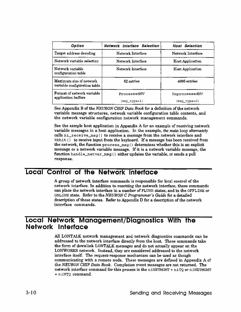
Option I Network interface Selection Host Selection I
Target address decoding Network Interface I Network Interface I
Network variable selection
Network variable configuration table
Network Interface
Network Interface
Host Application
Host Application
Maximum size of network variable cotiguration table
62 entries 4096entries
Format of network variable application buffers
ProcessedNV
(msg-tyPe=l)
UnprocessedNV
(msg-type=01
See Appendix B of the NEURON CHIP Data Book for a definition of the network variable message structures, network variable configuration table contents, and the network variable configuration network management commands.
See the sample host application in Appendix A for an example of receiving network variable messages in a host application. In the example, the main loop alternately calls ni-receive-msg ( ) to receive a message from the network interface and kbhit ( ) to receive input from the keyboard. If a message has been received from the network, the function process-msg ( ) determines whether this is an explicit message or a network variable message. If it is a network variable message, the function handle-netvar-msg ( ) either updates the variable, or sends a poll response.
local Control of the Network Interface A group of network interface commands is responsible for local control of the network interface. In addition to resetting the network interface, these commands can place the network interface iri a number of FLUSH states, and in the OFFLINE or ONLINE state. Refer to the NEURON C Programmefs Guide for a detailed description of these states. Refer to Appendix D for a description of the network interface commands.
Local Network Management/Diagnostics With the Network Interface
All LONTALK network management and network diagnostics commands can be addressed to the network interface directly from the host. These commands take the form of downlink LONTALK messages and do not actually appear on the LONWOFES network. Instead, they are considered addressed to the network interface itself. The request-response mechanism can be used as though communicating with a remote node. These messages are defined in Appendix A of the NEURON CHIP Data Book. Completion event messages are not returned. The network interface command for this process is the niNETMGMT. + niTQ or niNETMGMT + niNTQ command.
3-10 Sending and Receiving Messages
However, if the host application wishes to send network management messages to some other node on the network (not the network interface itselfi, these are not considered to be network management messages from the point of view of the network interface, and should therefore be sent using the niCOMM + niTQ or niCOMM + niNTQ commands. Responses and completion events are returned in the same way as for any application message.
When building the application buffer portion of a locally addressed network management message, the entire network address field must still be present if explicit addressing on is enabled. Explicit addressing is always on for the SLTA. The contents of the network address field are ignored for locally addressed network management messages.
Local network management commands can be used by the host application to do self-installation of the host node. For example, the Update Address network management message can be used to update the network interface’s address table. See the NEURON CHIP-based Installation of LONWORKS Networks engineering bulletin for more information on self-installation.
See the sample host application in Appendix A for an example of sending a local network management command. In the example, the main ( ) function calls install-prog-ID ( ) which creates a local network management message to write the application program ID into the EEPROM memory of the network interface, and thencalls ni-send-msg-wait0 to sendit.
Binding to a Host Node Host-based nodes can be bound to network variable and explicit message tag connections using procedures similar to NEURON CHIP-hosted nodes. Connections can be created using self-installation as described in the previous section, or connections can be created by a network management tool sending network management messages to host-based and NEURON CHIP-hosted nodes. To perform binding, a network management tool requires a description of the network variables on the nodes to be connected. The network management tool can get these descriptions for a host-based node using one of the following methods:
l SNVT Import. Anetwork management tool can import the network variable descriptions over the network using the Query SNVT network management command described in Appendix B of the NEURON CHIP Data Book, even if the network variables are not all of standard types. To support this, the host application must maintain the SNVT structure defined in Appendix A of the NEURON CHIP Data Book and return its contents in response to the Query SNVZ’ message. See the sample host application routine handle-query_SNVT ( ) for an example of handling this message. Also, the network variable configuration table of the host application must be initialized with the appropriate direction, priority, and authentication attributes for each network variable. The SNVT structure contains the following:
SNVT Header Defines the length of the SNVT structure, the number of network variables and bindable message tags, and the format of the SNVT structure.
Host Application Programmer’s Guide 3-11
SNVT Descriptor Defines each network variable for every network Table variable declared in the host application.
Node Self- A null-terminated text string containing an optional Documentation description of the node.
Extension Records Optional fields describing update rate estimates, the network variable name, and a text description of the network variable.
l External Interface File Import. An external interface file can be used with any type of LONWORKS node. The external interface file provides a text description of the node, its network variables, and its message tags. Network management tools can import external interface files to get all the information needed to create network variable and message tag connections.
Follow these steps to create and import an external interface file:
If you are using an SLTA, copy the external interface file provided with the SLTA as described in the Serial LONTALX Adapter User’s Guide.
OF
If you are using a third-party network interface, copy the external interface file provided with the network interface.
OF
If you have built your own network interface, create an external interface file as described in Exporting a Network Interface in the Microprocessor Interface Program (MIP) User’s Guide.
Modify the external interface file. Add the network variable and message tag entries as described in Appendix B. Import this new external interface file to the network management tool. If you are importing the host node into a development network, import the external interface file as described under Importing External Interface Files in Chapter 7 of the LONBULLLlER User’s Guide. If you are using the LONMANAGER API for DOS or Windows, use the ldb-import-xi f ( 1 function.
3-12 Sending and Receiving Messages
Using a Network Driver
This chapter describes specifications for using a LONWORKS network driver. Network interfaces for DOS should come with a DOS network driver. If you are using the Serial LONTALK Adapter, refer to the Serial LONTALK Adapter User’s Guide for instructions on how to install the SLTA driver. If you are using a different network interface, see their specific documentation on how to install the associated driver. Network driver services and functions are described.
Host Application Programmer’s Guide 4-1
The Network Driver The network driver provides a device-independent interface between the host application and the network interface.
The LONTALK network driver protocol defines four functions that should be provided by every network driver. These functions are ldv-open ( ) , ldv-close(),ldv-read(), and ldv-write(). Theldv-open0 function initializes the network driver and network interface. The ldv-close ( ) function deallocates any resources assigned by the ldv-open ( ) function. The ldv-read ( ) and ldv-write ( ) functions transfer application buffers uplink from the network interface and downlink to the network interface. The syntax for these functions may be operating system dependent. For example, the DOS network driver function calls are described under DOS Network Driver Services later in this chapter.
Standard Network Driver Services The functions and services defined by the LONTALK network driver protocol are:
typdef int LNI;
LNI handle = ldv-open(char *device-name);
Initialize the network interface and return a handle for accessing the network interface. If the network interface is held in a reset state after power-up, cancel the reset state.
Initialization includes cancelling the network interface Flush state. Hoer a network interface is reset, the network interface enters the Flush state. While in the Flush state, the network interface ignores all incoming messages and will not send any outgoing messages, even service pin messages. The Flush state is provided to prevent a network management tool from performing network management functions on the network interface before the host has configured the network interface. This state is cancelled with the niFLUSH_CANCEL command from the host. After the Flush state is cancelled, the network interface is in the Normal state.
The network interface sends a niRESET command uplink following any reset. This will be the first message received by the host whenever the network interface is reset.
LDVCode error = ldv-read(LN1 handle, void *msg_p, unsigned length);
Read an application buffer from the network interface. The msg_p argument is a pointer to an application buffer. Application buffers are defined in Chapter 3. If a buffer is not available, return the LDV-NO-MSG-AVAIL error code.
4-2 Using a Network Driver
LDVCode error = ldv-write(LN1 handle, void *msg_p, unsigned length);
Write an application buffer to the network interface. The msg_p argument is a pointer to an application buffer. Application buffers are defined in Chapter 3. If a buffer is not available, return the LDV-NO-BUFF-AVAIL error code.
LDVCode error = ldv-close(LN1 handle);
Free any resources assigned to the network interface identified by handle, and free the handle. Optionally hold the network interface in a reset condition.
DOS Network Driver Services A standard LONWORKS network driver interface has been defined for MS-DOS. This standard allows DOS applications, such as a host application incorporating the LONMANAGER API for DOS or Windows, to transparently interface with different network interfaces. The host application can initially be debugged with the network driver for the LONBUILDER Development Station. Later, that same host application program can be used with a network driver for a Serial LONTALK Adapter or with the network driver for a custom network interface based on the MIP.
Installation of the network driver for the SLTA is described in the Serial LONTALK Adapter User’s Guide. Installation of a network driver for a third-party network interface should be provided by the manufacturer of the network interface. Development and installation of the network driver for a custom network interface based on the MIP is described in the Microprocessor Interface Program CMIP) User’s Guide.
The network driver and installation instructions for the LONBUILDER development station are included in the LONLINK- Sampler diskette included ~4th LONBUILDER.
Following are the services provided by a standard DOS network driver:
OPEN To open the network interface use the DOS device/file open function with the device name LON (n) . In an ANSI C application the open ( ) function can be used with the access bits OJDWR and O-BINARY set. This function returns a handle value which is then used in subsequent device operations:
int handle = open(char * "LONl", int 0~RDWRIO-BINARY);
The open command invokes the autobaud sequence for the SLTA driver if autobaud is enabled on the driver and the SLTA The autobaud sequence causes the SLTA to synchronize with the host baud rate.
Host Application Programmer’s Guide 4-3
IOCTL Once the network driver is opened, it is ready to act as the connection between tire LONWORKS network and the host application. Messages are passed between the host application and the network interface via write or read DOS function calls. There are other paths to these services within the network driver if the user chooses to use them. The DOS ioct 1( ) function is used to fill in a data structure passed to it with function pointers to three functions within the driver:
ldv-read-direct0 ldv-write-direct0 ldv-register0
The ANSI C usage is:
int ioctl(int handle, int function, far struct adapter-info-s *argdx, int size);
The ioct 1 ( ) function is provided as part of the Borland C standard runtime library. Microsoft C does not provide this function, and so the source code for ioct 1( ) is provided with the sample host application for use with the Microsoft compiler.
The value of function is 2, for ‘read from device’. The usage of the pointers returned in the adapter-info-s structure is described in the next section.
struct adapter-info-s (
unsigned char ioctl-stat; //returned status
LDVCode (far *read-fn) (void * msg_p, unsigned length); //pointer to ldv-read-direct0
LDVCode (far *write-fn) (void * msgg, unsigned length); //pointer to ldv-write-direct0
void (far *register-fn) (int handle, void (interrupt far *callback) (void));
//pointer to ldv-register0 1;
The error codes returned by the driver direct functions are defined in Chapter 5.
WRITE The standard DOS write function can be used by the host application to transfer either network interface local commands or LONTALK messages to the network interface from the application via the driver. The ANSI C usage is:
4-4 Using a Network Driver
int length = write(int handle, void far *msg_p, unsigned length);
The msg_p argument is a pointer to an application buffer. Application buffers are discussed in Chapter 3. The first thing in an application buffer will always be the network interface command; i.e., the NI-Hdr structure defined in Appendix C. The length argument is the number of bytes in the application buffer. The return value is the number of bytes written, or -1 if an error occurred. If there are no output buffers available in the network driver, the return value is zero. L/O blocking does not occur, that is, the function will not wait for an output buffer if none is available.
READ The standard DOS read function can be used by the host application to transfer either responses to network interface local commands or LONTALK messages from the network interface to the host application via the driver. The ANSI C usage is:
int read(int handle, void far *msgg, unsigned length);
The msg_p argument is a pointer to an application bufFer. Application buffers are discussed in Chapter 3. The first thing in an application buffer will always be the network interface command, i.e., the NI-Hdr structure defined in Appendix C. The length argument is the number of bytes in the application buffer. The return value is the number of bytes read, or zero if no input buffers were ready, or -1 if an error occurred. I/O blocking does not occur, that is, the function will not wait for a full input buffer.
CLOSE To close the network interface, use the DOS device/file close function with the handle returned by the open function:
int error = close(int handle);
This function call closes the network interface, and the network interface is reset. The device’s callback function pointer (see below) is cleared and the callback is disabled.
Driver Direct Funcfions There are three driver direct functions available to the user. The ioct 1 ( ) function call returns pointers to these functions once the network interface has been opened. These functions are required by the LONMANAGER API. The driver direct functions are preferable to DOS read and write calls because error conditions can be handled better. Error conditions within the DOS functions will result in a DOS error prompt unless a DOS critical error handler is installed. The three functions are:
Host Application Programmer’s Guide 4-5
1 LDVCode error = ldv-write-direct(void far *msg_p, unsigned length);
This function is similar to the DOS write function, except that it is a direct call to the network driver rather than a call via DOS. Note that a handle is not required since this is a direct function call. The msg_p and length arguments are the same as those described for the DOS WRITE function. This function will return the error code LDV-NO-BUFF-AVAIL if no output buffers are available, whereas the DOS write function will return zero.
2 LDVCode error = ldv-read-direct(void far *msg_p, unsigned length);
This function provides the read complement of ldv-wr it e-direct ( 1. The msg_p and length arguments are the same as those described for the DOS READ function. While the DOS read function returns a zero value if no input messages are available to be read, this function returns the error code LDV-NO-MSG-AVAIL.
3 void ldv-register(int handle, void (interrupt far *callback)(void));
This function registers the handle value and the callback function pointer within the driver. The callback function is a function within the user application called by the driver whenever a network driver input buffer is filled by the network interface under interrupt control. The handle value will be included in the call to the callback function in the CPU’s AX register. The user’s callback function may then flag this event or call the ldv-read-direct 0 function.
NOTE: This callback function occurs under interrupt control, so the callback function must not o?o much more than the single read from the device. It should not make any DOS calls, or call any runtime library routines that make DOS calls, since DOS is not reentrant. It should also be careful when accessing static data that may simultaneously be accessed by the main application. The callback function must also behave like an interrupt function by loading its DS register with the application’s data segment since the DS register will be set to the driver’s data segment. An IRET instruction should terminate this function. This is handled automatically by the compiler when the interrupt keyword is used in the cleclaration of the callback routine.
4-6 Using a Network Driver
Error Conditions
This chapter describes error conditions that may be encountered by host applications. Errors detected by the network interface and network driver also are described.
Host Application Programmer’s Guide 5-1
Errors Detected By the Host Application There are several basic types of error detection in a host application. Host applications interact with a network driver, and detect errors based on return codes from I/O calls to the network driver. These errors are typically due to problems accessing the network interface, for example, incorrect jumper assignments, incorrect driver option settings, or hardware problems in the network interface. The network driver error responses are operating system dependent; this section describes the error responses from a DOS network driver.
The second type of error is due to transmission errors on the network, or temporary buffer congestion problems in either the sending or receiving nodes. These are normally handled transparently by the network protocol, which retries the transactions up to the configured retry count. The application is unaware of any retries if the transaction is ultimately successful.
The third type of error occurs when a network transaction fails to complete successfully, and the host application is informed by a failure completion code. This is most often due to the destination nodes not being accessible across the network because the message was misaddressed, the nodes were powered down, the network was disconnected or extremely busy or noisy.
For host applications that perform network management operations on other nodes on the network, a fourth type of error can occur when the receiving node rejects the network management request. It does this by returning a corresponding error code in the response.
The function ni-handle-error0 in the sample host application handles all types of errors after a call has been made to send a message and wait for the completion event. The arguments to this function are the function return value from the driver, the completion code for the transaction, and the returned message code if the message was a network management message.
Driver Not Ins tulle d If the network driver is not installed, or if the device name in the open ( ) function call does not match the device name used to install the driver, DOS returns a No such file or directory error when open ( 1 is called. The network driver is installed with a device statement in the DOS CONFIG. SYS file as described in Chapter 4. The device name is also specified in the same device statement, and defaults to LONG for the SLTA, MIP, and LONBUILDER network drivers.
Wrong Driver Invoked If a driver is opened that is not a LONWORKS network driver, DOS may return an Invalid argument error. If this error is not returned, the error symptoms will be the same as if the network interface is not installed.
5-2 Error Conditions
Network Interface Not Installed If a network driver is installed, but the network interface is not installed, the host application will not receive any responses to messages. The same error will occur if the network interface is installed, but is configured incorrectly, e.g. the wrong baud rate is selected on an SLTA The first message sent by a host application should be a niRESET command to the network interface. If installed and correctly configured, the network interface will respond with an uplink niRESET message upon completion of the reset. By waiting for this message with an appropriate timeout (e.g., 2 seconds), the host application can determine if a network interface is installed and operating correctly. See the ni-init ( ) function in Appendix A for an example.
Power lost to Network Interface After Starf-Up Network drivers that use polling will generally detect a power loss while transferring an application buffer to or from the network interface, and will return theism-DEVICE-ERR errorcode.
Network drivers that are fully interrupt driven will generally not detect an error during a transfer since all the bytes in a packet may be stored in an interrupt buffer on the host. In this case, loss of power will be detected by lack of response to a network message, which must be detected by a timeout in the host application. Since all network messages result in a completion code from the network interface upon successful completion or failure of the message, lack of a completion code within a long period of time (e.g., 10 seconds) can be used to flag loss of the network interface.
In either case, the host application should close, reopen, and reset the network driver. Doing this will restart the autobaud sequence if the network interface is an SLTA with autobaud enabled. If there is still no response from the reset, the network interface cannot be restarted. See the ni-init ( ) function in Appendix A for an example of closing and reinitializing a network interface.
Destination Node Not Available If the network driver and network interface are installed and operating correctly, but the destination of an acknowledged message or request message is not available, the driver will return the MSG-FAILS completion code. The MSG-FAILS completion code is returned after all retries have been attempted for a message. This completion code is the equivalent of the msg-f ails event in NEURON C.
Network Management Request Failed If a network management request is received by a node, the response contains a code which indicates whether the request was acted on. Failures are typically due to
Host Application Programmer’s Guide 5-3
parameters of the request being out of range, for example, a request to query a non- existent entry in a table. See the NEURON CZZP Data Book Appendix B for more details.
Errors Detected By a Network Driver
Down/ink Timeouts Downlink timeouts can occur as a result of the network interface’s inability to transmit messages on the network at the desired rate. This condition can be seen as the absence of the niACK from the network interface within a user selected period. This error detection scheme can be built into the host’s network driver, and is built into the SLTA network driver.
Host Detection of Hardware Failures Host detection of hardware failures is performed by various parts of the network driver. A hardware failure is a timeout condition on the handshake signal from the network interface. If a message transfer starts but is not completed due to this timeout, a device failure error will be returned to the host application. When this occurs, the host should perform a hardware reset of the network interface.
For network interfaces based on the MIPIPBO or MIP/P50, if the host driver has given up the write token, and the network interface has not returned it for some period, such as 500 ms, a hardware error state may be flagged.
For the SLTA, error conditions are typically a result of lost data bytes due to transmission errors between the SLTA and the host. Lost ALERT bytes are handled by both the SLTA and the driver by virtue of a timeout/retry feature. Lost downlink buffer requests are handled by the driver through a timeout/retry feature. If the command or data portion of any other type of transfer is corrupted, it will be the responsibility of the host sofiware to deal with this condition. Corrupted uplink transfers are flagged with an error status which results in an error code (LDV-DEVICE-ERR) when the driver read service is used. The driver has no method of detecting if a downlink transfer has been corrupted. It is up to the host application to determine that these transactions have failed by implementing some form of a timeout at that level.
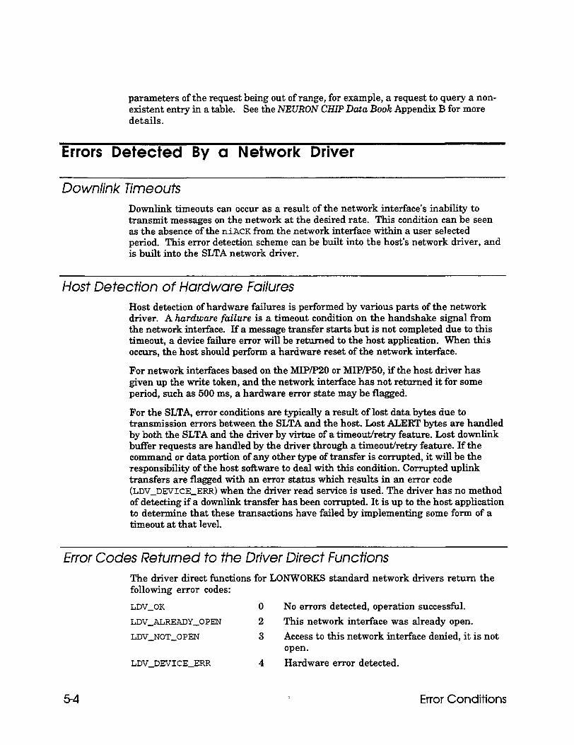
Error Codes Returned to the Driver Direct Functions The driver direct functions for LONWORKS standard network drivers return the following error codes:
LDV-OK 0 No errors detected, operation successful.
LDV-ALREADY-OPEN 2 This network interface was already open.
LDV-NOT-OPEN 3 Access to this network interface denied, it is not open.
LDV-DEVICE-ERR 4 Hardware error detected.
5-4 Error Conditions
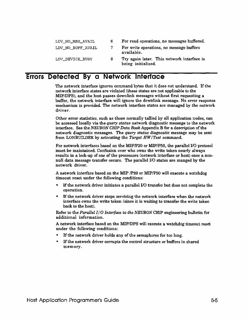
LDV-NO-MSG-AVAIL
LDV-NO-BUFF-AVAIL
6 For read operations, no messages buffered.
7 For write operations, no message buffers available.
LDV-DEVICE-BUSY 8 Try again later. This network interface is being initialized.
Errors Detected By a Network Interface The network interface ignores command bytes that it does not understand. If the network interface states are violated (these states are not applicable to the MIP/DPS), and the host passes downlink messages without first requesting a buffer, the network interface will ignore the downlink message. No error response mechanism is provided. The network interface states are managed by the network driver.
Other error statistics, such as those normally tallied by all application nodes, can be accessed locally via the query status network diagnostic message to the network interface. See the NEURON CHIP Data Book Appendix B for a description of the network diagnostic messages. The query status diagnostic message may be sent from LONBUILDER by activating the Target HWITest command.
For network interfaces based on the MIP/p20 or MIP/P50, the parallel I/O protocol must be maintained. Confusion over who owns the write token nearly always results in a lock-up of one of the processors (network interface or host) once a non- null data message transfer occurs. The parallel I/O states are manged by the network driver.
A network interface based on the MIP /p20 or MIP/PBO will execute a watchdog timeout reset under the following conditions:
l If the network driver initiates a parallel I/O transfer but does not complete the operation.
l If the network driver stops servicing the network interface when the network interface owns the write token (since it is waiting to transfer the write token back to the host).
Refer to the Parallel I/ 0 Interface to the NEURON CHIP engineering bulletin for additional information.
A network interface based on the MIP/DPS will execute a watchdog timeout reset under the following conditions:
l If the network driver holds any of the semaphores for too long.
l If the network driver corrupts the control structure or buffers in shared memory.
Host Application Programmer’s Guide 5-5

Appendix A Sample Host Application
This appendix contains source code for an example DOS host application that can both send and receive polls and updates to network variables, and whose network variables may be bound by an installation tool that sends it network management messages. This host application does not itself do any network management of other nodes. A PC-based host application that performs network management is best implemented using the LONMANAGER API, rather than the host application framework.
Host Application Programmer’s Guide A-1
Sample Host Application Overview The example is included in the host application example directory and consists of five C source files, three C header files, and a LONWORKS node external interface fileHA_V2.XIF. The sourcefilesareHA.C, APPLMSG.C, HAUIF.C, NI-MSG.C, and IOCTL . C. The HA. c file contains the main program for the example; the APPLMSG. c file contains the functions for handling network management and network variable messages; tRe HAUIF . c file contains the functions for a primitive command-line user interface, and the NI-MSG . C file contains general purpose functions for calling the network driver. The file IOCTL . c is required only when using the Microsoft C compiler. The header files are HAUIF . H, N1,MS.G . H and NI-MGMT. H . The file HAUIF . H contains prototype declarations for the user interface functions; the file NI-MSG . H contains complete data structure declarations for the message buffers that are passed to or received from the network interface driver, as well as prototype declarations for the functions in NI-MSG . C; the file NI-MGMT . H contains data structure and message code declarations for the network management messages and for the application-layer data structures for the host application. The files NI-MSG . H and NI-MGMT . H are reproduced in Appendix C.
These files may be compiled and linked with any ANSI C compiler and linker. The file makef ile is a make file for Borland C, and the file msof t .mak is a make file for Microsoft C. To make the example, copy the example source files, header files, and makefile to a working directory. For Borland C, type MAKE. The Borland C bin directory must be in your path. The default path for the Borland C lib directory must be specified in t link. cf g, as described in the Borland C documentation. For Microsoft C, type NMAKE /F MSOFT .MA.K. The Microsoft C, the bin directory must be in your path. The DOS environment variables INCLUDE and LIB must be set up to point to the Microsoft include and library directories respectively as described in the Microsoft documentation.
An executable version of the example is also included in the host application example directory. The file name is HA. EXE.
Sample Host Application Requirements The example host application is structured in a top down way that may easily be modified. The example was designed for the following requirements, but for specific applications, code will most likely need to be added or removed.
l The application supports any network interface that has a LONWORKS standard network driver for DOS. The network interface is configured with host network variable selection, and with explicit addressing on. This is the way that the SLTA is configured.
l Network variables on the node may be bound by a network management tool such as the LONBUILDER network manager, NetMaker, or a network management tool based on LONMANAGER API. This means that the host application must support incoming network management messages to query and update its network variable configuration table, as well as messages to go on-line and off-line.
A-2 Sample Host Application
.
Note. Two PCs are required to bind this example host application into a network. One PC runs the network management tool (for example, the LONBUILDER network manager or NetMaker). The other PC runs the host application. The host application must be running when the network image is loaded into the host node because it must process incoming network management messages during the loading process. It is not possible to run a DOS-based network management tool and this example host application in different DOS sessions under Microsoft Windows, because Windows cannot switch contexts fast enough between the two DOS applications. This host application is not able to return responses soon enough to the network management tool to avoid transaction timeouts. However, if both the network management tool and the host application are native Windows applications, multi-tasking may be achieved because the applications can relinquish the CPU when waiting for network events.
The node may be queried by a network management tool to retrieve self- identification and self-documentation information so that an external interface definition for the node may be created. The LONBUILDER Query command uses this capability, as does the LONMANAGER API function lxt-install-node ( 1 in the case that there is no program record for the node defined in the database. This function is not a requirement for all nodes, since the external interface definition may be supplied separately as an external interface file (. XIF extension) to the network management tool.
l The network variables of the node may be polled using the Nvfetch network management message. The node therefore responds appropriately to a network variable browser, such as the one in LONBUILDER and the Data function in NetMaker.
l The network variables of the node may be updated on receipt of a user command from the keyboard. Output network variables that are updated are propagated over the network to whatever nodes they are bound to. The application also has input network variables that are polled on receipt of a user command from the keyboard. The poll command sends the appropriate request message to the destination address that the network variable is bound to, and handles poll responses from single nodes as well as groups of nodes.
l The input network variables of the node are updated when the node receives the relevant update message from the network. Network variables may also be polled when the node receives a request message over the network, and the application will return the correct poll response. This means that the application has to support network variable selection appropriately.
Sample Host Application Data Structures The host application does not directly use the C native data types char, int , and long for any of its data declarations that need to be compatible with the NEURON CHIP data or message structures. This is because these types differ depending on the host architecture and the compiler used. Instead, the application uses the typedef names byte, word, and bits for unsigned 8-bit, unsigned 16-bit, and bit- field data objects respectively. These typedef s are defined in the file NI-MSG .H. For bitfields, most C compilers for the 80x86 little-end&n architecture assign bits from right to 1eR within a byte, whereas the NEURON C compiler and compilers for other big-endian architectures assign bits from left to right. Note that the Microsoft C compiler always assigns biffields to an even number of bytes, whereas the Borland C compiler allows bitlields to occupy any number of bytes. In most cases
Host Application Programmer’s Guide A-3
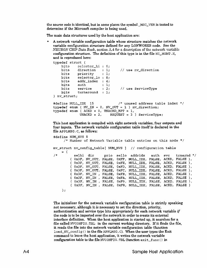
the source code is identical, but in some places the symbol -MSC-VER is tested to determine if the Microsoft compiler is being used.
The main data structures used by the host application are:
l A network variable configuration table whose structure matches the network variable configuration structure defined for any LONWORKS node. See the NEURON CHIP Data Book, section A4 for a description of the network variable configuration structure. The definition of this type is in the file NI-MGMT . H, and is reproduced here: typedef struct C
bits selector-hi bits direction bits priority bits selector-lo bits addr-index bits auth bits service bits turnaround
> nv-struct;
: 6; : 1; // use nv-direction : 1; : 8; : 4; : 1; : 2; // use ServiceType : 1;
#define NULL-IDX 15 /* unused address table index */ typedef enum { NV-IN = 0, NV-OUT = 1 ) nv-direction; typedef enum { ACKD = 0, UNACKD-RPT = 1,
UNACKD = 2, REQUEST = 3 1 ServiceType;
This host application is compiled with eight network variables, four outputs and four inputs. The network variable configuration table itself is declared in the file APPLMSG.C, as follows:
#define NUMJVS 8 /* Number of Network Variable table entries on this node */
nv-struct nv-config-table[ NUMJVS ] // configuration table = {
/* selhi dir prio sell0 addridx auth svc trnarnd */ { Ox3F, NV-OUT, FALSE, OxFF, NULLJDX, FALSE, ACKD, FALSE }, { Ox3F, NV-OUT, FALSE, OxFE, NULL-IDX, FALSE, ACKD, FALSE }, { Ox3F, NV-OUT, FALSE, OxFD, NULL-IDX, FALSE, ACKD, FALSE 1, ( Ox3F, NV-OUT, FALSE, OxFC, NULL-IDX, FALSE, ACKD, FALSE 1, { Ox3F, NV-IN , FALSE, OxFB, NULL-IDX, FALSE, ACKD, FALSE }, { Ox3F, NV-IN , FALSE, OxFA, NULL-IDX, FALSE, ACKD, FALSE ), { Ox3F, NV-IN , FALSE, OxF9, NULL-IDX, FALSE, ACKD, FALSE ), { Ox3F, NV-IN , FALSE, OxF8, NULL-IDX, FALSE, ACKD, FALSE )
I;
The initializer for the network variable configuration table is strictly speaking not necessary, although it is necessary to set the direction, priority, authentication and service type bits appropriately for each network variable if the node is to be imported over the network in order to create its external interface definition. When the host application is started up, it searches for a file called NVCONFIG .TBL in the current working directory. If it finds the file, it reads the file into the network variable configuration table (function load_NV_conf ig ( ) in the file APPLMSG . c). When the user types the Exit command to leave the host application, it writes the network variable configuration table to the file NVCONFIG. TBL (function exit-f unc ( ) in
A-4 Sample Host Application
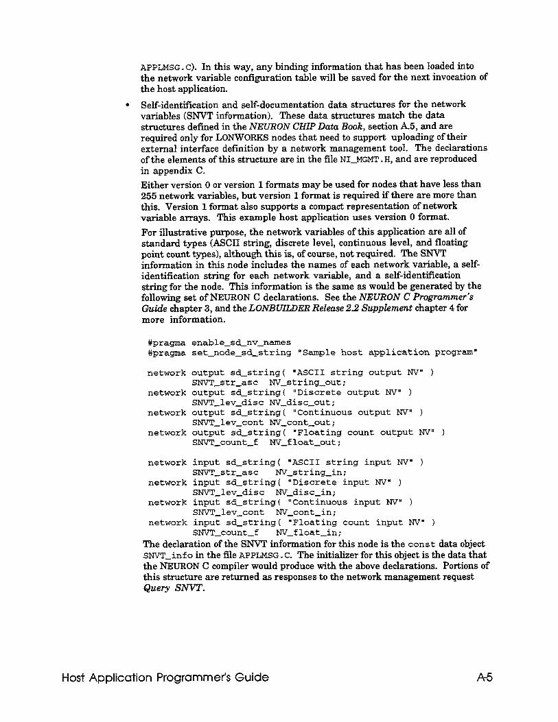
APPLNSG . c). In this way, any binding information that has been loaded into the network variable configuration table will be saved for the next invocation of the host application.
l Self-identification and self-documentation data structures for the network variables (SNVT information). These data structures match the data structures defined in the NEURON CHIP Data Book, section A.5, and are required only for LONWOFtKS nodes that need to support uploading of their external interface definition by a network management tool. The declarations of the elements of this structure are in the file NI-MGMT . H, and are reproduced in appendix C. Either version 0 or version 1 formats may be used for nodes that have less than 255 network variables, but version 1 format is required if there are more than this. Version 1 format also supports a compact representation of network variable arrays. This example host application uses version 0 format.
For illustrative purpose, the network variables of this application are all of standard types (ASCII string, discrete level, continuous level, and floating point count types), although this is, of course, not required. The SNVT information in this node includes the names of each network variable, a self- identification string for each network variable, and a self-identification string for the node. This information is the same as would be generated by the following set of NEURON C declarations. See the NEURON C Programmer’s Guide chapter 3, and the LONBUILDER Release 2.2 Supplement chapter 4 for more information.
#pragma enable-sd-nv-names #prag-ma set-node-sd-string "Sample host application program"
network output sd-string( "ASCII string output NV" 1 SNVT-str-asc NV-string-out;
network output sd-string( "Discrete output NV" ) SNVTJev-disc NV-disc-out;
network output sd-string( "Continuous output NV" ) SNVT-lev-cant NV-cant-out;
network output sd-string( "Floating count output NV" ) SNVT-count-f NV-float-out;
network input sd-string( "ASCII string input NV" ) SNVT-styasc NV-string-in;
network input sd-string( "Discrete input NV" ) SNVl~lev-disc NV-disc-in;
network input sd-string( "Continuous input NV" ) SNVT-lev-cant NV-cant-in;
network input sd-string( "Floating count input NV" ) SNVT-count-f NV-float-in;
The declaration of the SNVT information for this node is the const data object SNv'l?-info in the file APPLMSG . C. The initializer for this object is the data that the NEURON C compiler would produce with the above declarations. Portions of this structure are returned as responses to the network management request Query SNVT.
Host Application Programmer’s Guide A-5
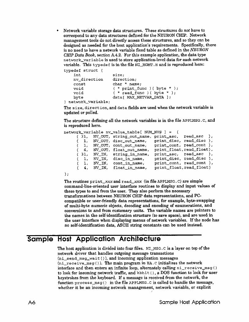
. Network variable storage data structures. These structures do not have to correspond to any data structures defined for the NEURON CHIP. Network management tools do not directly access these structures, and so they can be designed as needed for the host application’s requirements. Specifically, there is no need to have a network variable fixed table as defined in the NEURON CHIP Data Book, section A4.2. For this example application, the data type network-variable is used to store application-level data for each network variable. This typede f is in the file NI-MGMT . H and is reproduced here: typedef struct {
int size; nv-direction direction; const char * name; void ( * print-func ) ( byte * 1; void ( * read-func ) ( byte * ); byte data[ MAXJEI'VAFLDATA I;
] network-variable; The size, direction, and data fields are used when the network variable is updated or polled.
‘I’he structure defining all the network variables is in the file APPLMSG . C, and is reproduced here.
network-variable nv-value-table[ NUMJVS I = { t 31, NV-OUT, string-out-name, print-asc, read-asc 3, t 1, NV-OUT, disc-out-name, print-disc, read-disc 1, 1 1, NV-OUT, cant-out-name, print-cant, read-cant I, 1 4, NV-OUT, float-out-name, print-float,read-float), t 31, W-IN, string-in-name, print-asc, read-asc I,
I :: NV-IN r disc-in-name, print-disc, read-disc 1, NV-IN, cant-in-name, print-cant, read-cant I,
{ 4, W-IN, float-in-name, print-float,read&float)
The routines print-xxx and read-xxx (in file APPLXSG. C) are simple command-line-oriented user interface routines to display and input values of these types to and from the user. They also perform the necessary transformations between NEURON CHIP data representations, and PC- compatible or user-friendly data representations, for example, byte-swapping of multi-byte numeric objects, decoding and encoding of enumerations, and conversions to and from customary units. The variable names are pointers to the names in the self-identification structure (to save space), and are used in the user interface when displaying menus of network variables. If the node has no self-identification data, ASCII string constants can be used instead.
Sample Host Application Architecture The host application is divided into four files. NI-MSG . c is a layer on top of the network driver that handles outgoing message transactions (ni-send-msg-wait ( ) >, and incoming application messages (ni-receive-msg ( ) 1. The main program in HA. c initializes the network interface and then enters an infinite loop, alternately calling ni-receive-msg ( ) to look for incoming network traffic, and kbhit ( ) , a DOS function to look for user keystrokes from the keyboard. If a message is received from the network, the function process-msg ( ) in the file APPLMSG . c is called to handle the message, whether it be an incoming network management, network variable, or explicit
A-6 Sample Host Application
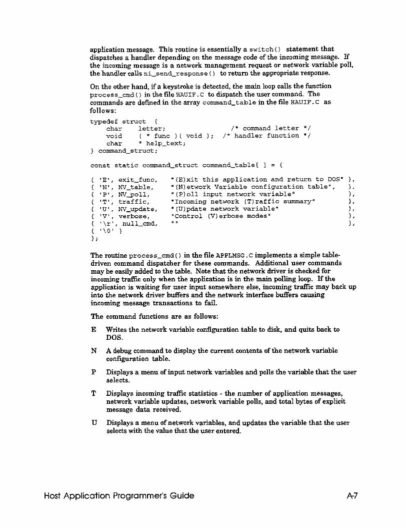
application message. This routine is essentially a switch ( ) statement that dispatches a handler depending on the message code of the incoming message. If the incoming message is a network management request or network variable poll, the handler calls ni-send-response ( ) to return the appropriate response.
On the other hand, if a keystroke is detected, the main loop calls the function process-cmd ( ) in the file HAUIF . C to dispatch the user command. The commands are defined in the array command-table in the file HAUIF. C as follows:
typedef struct ( char letter; /* command letter */ void ( * func )( void ); /* handler function */ char * help-text;
> command-struct;
const static command-struct command-table[ ] = {
{ ‘E’, exit-func, "(E)xit this application and return to DOS" >, E 'N's NV-table, "(N)etwork Variable configuration table", 1, t 'P', Nv_poll, "(P)oll input network variable" ( 'T', traffic, "Incoming network (T)raffic summary" ;:
NV update, i :t: : verbose
"(U)pdate network variable" I, "Control (V)erbose modes"
{ '\r', null-&d, In t '\O' 3 1;
The routine process-cmd ( ) in the file APPLMSG . c implements a simple table- driven command dispatcher for these commands. Additional user commands may be easily added to the table. Note that the network driver is checked for incoming traffic only when the application is in the main polling loop. If the application is waiting for user input somewhere else, incoming traffic may back up into the network driver buffers and the network interface buffers causing incoming message transactions to fail.
The command functions are as follows:
E Writes the network variable configuration table to disk, and quits back to DOS.
N A debug command to display the current contents of the network variable configuration table.
P Displays a menu of input network variables and polls the variable that the user selects.
T Displays incoming traffic statistics - the number of application messages, network variable updates, network variable polls, and total bytes of explicit message data received.
U Displays a menu of network variables, and updates the variable that the user selects with the value that the user entered.
Host Application Programmer’s Guide A-7
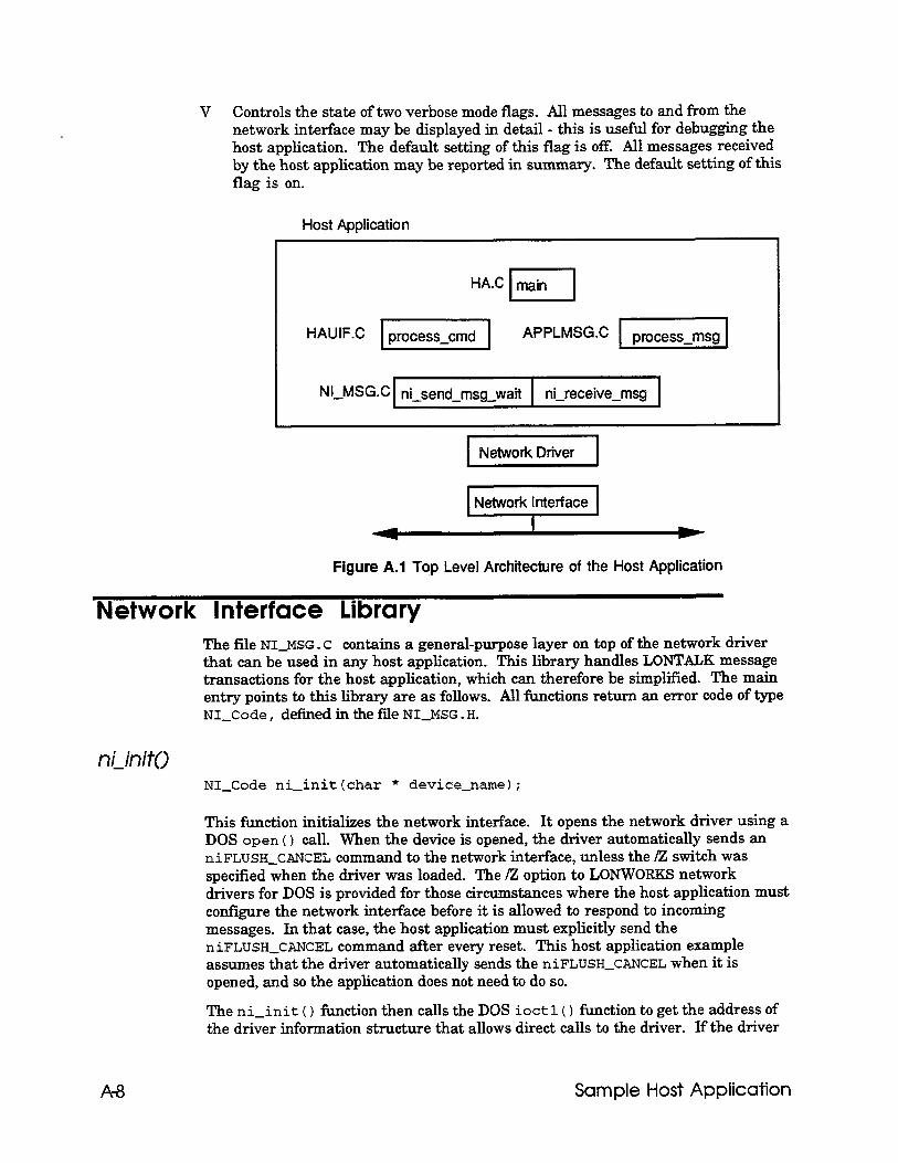
V Controls the state of two verbose mode flags. All messages to and from the network interface may be displayed in detail - this is useful for debugging the host application. The default setting of this flag is off. All messages received by the host application may be reported in summary. The default setting of this flag is on.
Host Application
HAUIF.C APPLMSG.C
1 NetworkDriver 1
Network Interface
Figure A.1 Top Level Architecture of the Host Application
Network Interface Library The file NI-MSG . c contains a general-purpose layer on top of the network driver that can be used in any host application. This library handles LONTALK message transactions for the host application, which can therefore be simplified. The main entry points to this library are as follows. All functions return an error code of type NI-Code, definedinthefile NI-MSG.H.
niinit() NI-Code ni-initlchar * device-name);
This function initializes the network interface. It opens the network driver using a DOS open ( ) call. When the device is opened, the driver automatically sends an niFLUSH_CANCEL command to the network interface, unless the /Z switch was specified when the driver was loaded. The /Z option to LONWORKS network drivers for DOS is provided for those circumstances where the host application must configure the network interface before it is allowed to respond to incoming messages. In that case, the host application must explicitly send the niFLUSH_CANCEL command after every reset. This host application example assumes that the driver automatically sends the niFLUSH_CANCEL when it is opened, and so the application does not need to do so.
The ni-init ( ) function then calls the DOS ioctl ( ) function to get the address of the driver information structure that allows direct calls to the driver. If the driver
A-8 Sample Host Application
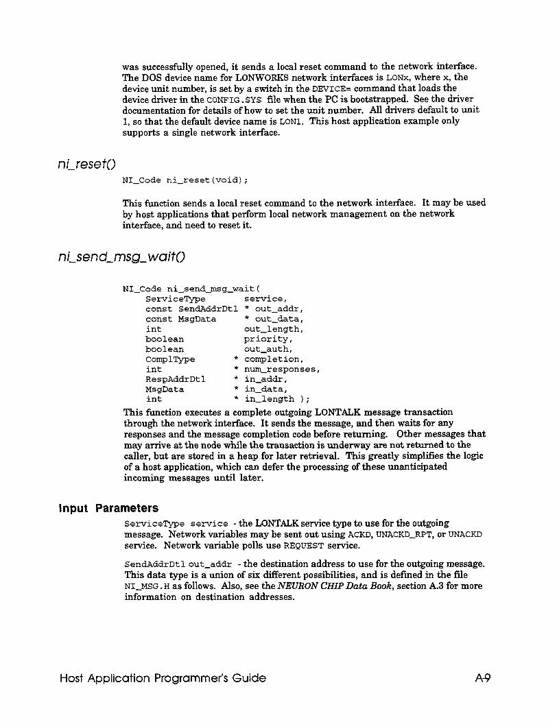
was successfully opened, it sends a local reset command to the network interface. The DOS device name for LONWORKS network interfaces is LONx, where x, the device unit number, is set by a switch in the DEVICE= command that loads the device driver in the CONFIG. SYS file when the PC is bootstrapped. See the driver documentation for details of how to set the unit number. All drivers default to unit 1, so that the default device name is LONl. This host application example only supports a single network interface.
ni-reset0 NI-Code ni-resetlvoid);
This function sends a local reset command to the network interface. It may be used by host applications that perform local network management on the network interface, and need to reset it.
ni-send-msg- waif0
NI-Code ni-send-msg-wait( ServiceType service, const SendAddrDtl * out-addr, const MsgData * out-data, int out-length, boolean priority, boolean out-auth, ComplType * completion, int * num-responses, RespAddrDtl * in-addr, MsgData * in-data, int * in-length );
This function executes a complete outgoing LONTALK message transaction through the network interface. It sends the message, and then waits for any responses and the message completion code before returning. Other messages that may arrive at the node while the transaction is underway are not returned to the caller, but are stored in a heap for later retrieval. This greatly simplifies the logic of a host application, which can defer the processing of these unanticipated incoming messages until later.
Input Parameters Serviceme service - the DONTALK service type to use for the outgoing message. Network variables may be sent out using ACKD, DNACKD-RPT, or UNACKD service. Network variable polls use REQUEST service.
SendAddrDt 1 out-addr - the destination address to use for the outgoing message. This data type is a union of six different possibilities, and is defined in the file NI-MSG . H as follows. Also, see the NEURON CHIP Data Book, section A.3 for more information on destination addresses.
Host Application Programmer’s Guide A-9
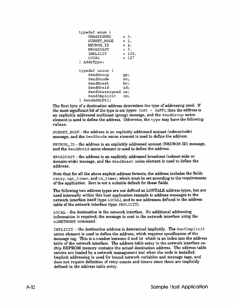
typedef enum I UNASSIGNED = 0, SUBNET-NODE = 1, NEURON-ID = 2, BROADCAST = 3, IMPLICIT = 126, LOCAL = 127
} AddrType;
typedef union ( SendGroup gp; SendSnode SendBcast ;zj SendNrnid id; SendUnassigned ua; SendImplicit im;
) SendAddrDtl; The first byte of a destination address determines the type of addressing used. If the most significant bit of the type is set (types 0x80 - OxFF), then the address is an explicitly addressed multicast (group) message, and the SendGroup union element is used to define the address. Otherwise, the type may have the following values:
SUBNET-NODE - the address is an explicitly addressed unicast (subnet/node) message, and the SendSnode union element is used to define the address.
NEURON-ID - the address is an explicitly addressed unicast (NEURON ID) message, and the SeridNrnid union element is used to define the address.
BROADCAST - the address is an explicitly addressed broadcast (subnet-wide or domain-wide) message, and the SendBcast union element is used to define the address.
Note that for all the above explicit address formats, the address includes the fields retry, rpt-t imer, and tx-t imer, which must be set according to the requirements of the application. Zero is not a suitable default for these fields.
The following two address types are not defined as LONTALK address types, but are used internally within this host application example to address messages to the network interface itself (type LOCAL), and to use addresses defined in the address table of the network interface (type IMPLICIT).
LOCAL - the destination is the network interface. No additional addressing information is required; the message is sent to the network interface using the niNETMGMT command.
IMPLICIT - the destination address is determined implicitly. The SendImplicit union element is used to define the address, which requires specification of the message tag. This is a number between 0 and 14 which is an index into the address table of the network interface. The address table entry in the network interface on- chip EEPROM memory contains the actual destination address. The address table entries are loaded by a network management tool when the node is installed. Implicit addressing is used for bound network variables and message tags, and does not require definition of retry counts and timers since these are implicitly defined in the address table entry.
A-10 Sample Host Application
MsgData out-data - the actual data to be sent in the outgoing message. This data type is a union of three possibilities, defined in the file NI-MSG . H .
typedef union { UnprocessedNV unv; ProcessedNV pm; JIxplicitMsg exp r'
} MsgData;
Since this host application is designed to work with network interfaces that are configured with host selection enabled, the ProcessedNV union element cannot be used. The UnprocessedNV union element is used for outgoing network variable updates and polls, and the ~xplicitMsg union element is used for outgoing explicit application and network management messages.
int out-length - the length of the outgoing message data in bytes (including the code byte for messages, and the selector bytes for network variables).
boolean priority - set to TRUE if the message should be delivered with priority service, FALSE otherwise.
boolean out-auth - set to TRUE if the message should be authenticated, FALSE otherwise. Only acknowledged and request messages may be authenticated.
Output Parameters All output parameters are returned via pointers passed to the function. If any pointer is NULL, the corresponding parameter is simply not returned.
ComplType *completion - the completion code for the transaction, either MSG-SUCCEEDS or MSG-FAILS. An acknowledged or request/response transaction is successful if all the acknowledgments or responses are received. An implicitly addressed transaction will also succeed ifit is sent to an unbound message tag or network variable. A network variable poll sent with network interface selection enabled is successful if at least one response contains network variable data. An unacknowledged or unacknowledged/repeated transaction is successful if all the packets were sent on to the network.
int *num-responses - the number of responses received (for request/response service only). If the message was sent with a unicast or a broadcast address and the transaction succeeded, this will be one. If the message was sent with a multicast address, this will be the number of actual responses received. The first response is returned in the call to ni-send-msg-wait ( ) , and subsequent responses with a call to ni-get-next-responseo.
RespAddrDtl * in-addr - the address of the first response. See the declaration in NI-MSG . H for details of the fields in this structure. It can be used to determine which node sent the response.
MsgData *in-data - the data in the first response. If this is a response to an explicit message, the union element ExplicitMsg is used. If this is a response to a network variable poll, the union element UnprocessedNV is used.
int *in-length - the length of the incoming response data in bytes (including the code for messages, and the selector for network variables).
Host Application Programmer’s Guide A-11
Error Codes NI-OK - returned when the transaction completed normally
NI-DRIVER-ERROR - returned if the network driver reported an error when the driver was called
NI-TIMEOUT - returned if the transaction did not complete within 5 seconds (the constant niWAIT-TIME in N1JISG.C)
NI-UPLINK-CMD - returned if the network interface sent a local uplink command (typically if it has been reset)
NI-INTERNAL-ERR - something unexpected happened
ni-get-next-response0
NI-Code ni-get-next-response( RespAddrDtl * in-addr, MsgData * in-data, int * in-length 1;
The output parameters of this function are the same as the output parameters of ni-send-msg-wait ( 1, which returns the first response for a request/response message. The ni-get-next-response ( ) function is used to return subsequent responses, if any. Note that the heap used to store the subsequent responses is cleared when a new call is made to ni-send-msg-wait ( ) . The error code NI-NO-RESPONSES is returned if the subsequent response heap is empty.
ni-receive-msg()
NI-Code ni-receive-msg( ServiceType * service, RcvAddrDtl * in-addr, MsgData * in-data, int * in-length, boolean * in-auth 1;
This function checks to see if an incoming message has been received. If so, it returns NI-OK and the message is passed to the caller using the output parameters of the function call. If there is no message waiting, the function returns NI-TIMEOUT. If an unexpected event is received (for example, a response, a completion event, or a reset from the network interface), then the function returns NI-UPLINK-CMD.
All output parameters are returned via pointers passed to the function. If any pointer is NULL, the corresponding parameter is simply not returned. The output parameters of this function are:
ServiceType *service - the LONTALK service type for the incoming message. Network variable updates are received using ACKD, UNACKD-RPT, or UNACKD service. Network variable polls use REQUEST service. If the incoming message uses REQUEST service, the response should be returned with the function ni-send-responseo.
A-12 Sample Host Application
RcvAddrDtl *in-addr - the source address in the received message. See the declaration in NI-MSG . H for details of the fields in this structure. It can be used to determine which node sent the message and how it was addressed to the network interface.
MsgData *in-data - the data in the received message. If this is an explicit message, the union element ExplicitMsg is used. If this is a network variable update or poll, the union element UnprocessedNV is used. The most significant bit of the message code is one for a network variable message, and zero for an explicit message.
int *in-length - tthe length of the incoming message data in bytes (including the code byte for messages, and the selector bytes for network variables).
boolean * in-auth - TRUE if the incoming message is authentic, FALSE otherwise. A message is authentic when authenticated service was specified and the sender successfully replied to the challenge from the network interface.
ni-send-response0
NI-Code ni-send-response( MsgData * out-data, int out-length 1;
This function is used by the host application to send a response to the last incoming message that specified request service. It is used to respond to incoming network management requests, incoming network variable polls, and other incoming request messages. Responses to requests should always be returned, otherwise the requestor will receive a transaction failure, and the received transaction record in the responder will remain locked. Also, the host application should return responses promptly; if lengthy processing is required to prepare a response, the transaction timer of the sending node and the appropriate receive timer of the host application node should be increased to compensate.
The input parameters of this function are:
MsgData out-data - the actual data to be sent in the outgoing response. Since this host application is designed to work with network interfaces that are configured with host selection enabled, the ProcessedNv union element cannot be used. The UnprocessedNV union element is used for outgoing network variable poll responses, and the Explici tMsg union element is used for outgoing application and network management responses.
int out-length - the length of the outgoing response data in bytes (including the code byte for explicit message responses, and the selector bytes for network variable poll responses).
nigend-immediafe()
NI-Code ni-send-immediate( NI-NoQueueCmd command );
Host Application Programmer’s Guide A-13
This function is used to send an immediate command to the network interface. These commands are defined in Appendix D. Any downlink command other than niCOMM or niNETMGMT may be sent with this function. The host application uses this to inform the network interface that is has received a mode on-line or mode off-line network management message. The output parameter is a command code of type NI-NoQueueCmd (definedin NI-MSG.H).
han de- error0 boolean handle-error( NI-Code ni-error,
ComplType completion, byte response-code, const char * msg-name );
This function (in file NI-MSG . C) should be used to check the return status of any call to the ni-xxx ( ) functions. It will print an appropriate message if any error has occurred, and return TRUE. If there was no error, it returns FALSE. The input parameters are:
NI-Code ni-error - an error code returned from a call to one of the ni-xxx ( ) functions
ComplType completion - a completion code returned from a call to ni-send-msg-wait 0. Ifthe callbeingcheckedwasnot ni-send-msg-wait0, MSGSUCCEEDS should be passed in for this parameter.
byte response-code - if the call being checked was a network management message sent with ni-send-msg-wait ( ) , this should be the message code from the response. Otherwise NO-CHECK should be used.
char * msg-name- a text string printed as part of the error message.
Application Message Handler The file APPLMSG . c contains all the functions that deal with incoming messages, including network management messages passed to the application, and incoming network variable updates and polls. The function process-msg ( ) is called by the main dispatch loop whenever it detects that an incoming message has been received with ni-receive-msg ( ) . It dispatches control to different functions depending on the message code of the incoming message. boolean process-msg( ServiceType service,
RcvAddrDtl * address, MsgData * in-data, int in-length, boolean in-auth ) (
/* handle incoming messages addressed to this node */ /* return TRUE if prompt should be redisplayed */
last-rev-addr = * address; // save for debug purposes
A-14
switch( in-data->exp.code ) ( // dispatch on message code
Sample Host Application
case NM-update-nv-cnfg: return handle-update-nv-cnfg( in-data, service );
case NM_query_nv-cnfg: return handle-query-nv-cnfg( in-data, service );
case NM-set-node-mode: return handle-set-mode( in-data );
case NM-quexy_SNVT: return handle-query-SNVT( in-data, service );
case N&-wink: if( report-flag )printf( "Received Wink msg\n" ); printf( I(\a" ); // Ding! return report-flag;
case m-NV-fetch: return handle-NV-fetch( in-data, service );
default: /* handle all other messages here */
if( in-data->unv.must-be-one ) // This is a network variable
return handle-netvar-msg( in-data, service, in-length, in-auth );
// This is an explicit msg else return handle-explicit-msg( in-data, service,
in-length, in-auth ); 1 // end switch
handle-update-nv-config This function is invoked when a network management tool wishes to bind a network variable. It extracts the network variable index from the incoming message, validates it, and then copies the network variable configuration table entry from the message to the appropriate element of the array nv-conf ig-table.
This function is invoked when a network management tool wishes to retrieve the binding information for a network variable. It extracts the network variable index from the incoming message, validates it, and then sends a response with a copy of the requested network variable configuration table entry from the array nv-config-table.
handle-set-mode0 This function is invoked when a network management tool sends a network management message to the node telling it to go on-line or off-line. It saves the requested mode in the variable on1 ine-f lag, and sends a local message to the network interface to inform it of the change. If the host application is off-line, it
Host Application Programmer’s Guide A-15
will not send out network variable updates and poll message. If it receives a network variable poll, it will respond with no data. If it receives a network variable update, the value will be updated, even if the node is off-line. If the node is on-line, of course, it will behave normally.
handle-query-SNVT() This function is invoked when a network management tool wishes to import the self-identification and self-documentation information -from the node. It extracts the offset and byte count from the request message, validates them, and sends a response containing the requested data from the sNv'l?-info data structure.
handle-NV-fetch0 This function is invoked when a network management tool wishes to retrieve the value of a network variable by index. It extracts the network variable index from the incoming message, validates it, and then sends a response with a copy of the requested network variable data from the array nv-value-table.
handle-ne tvar-msg() This function is invoked when an application node updates or polls one of the network variables of this node. It searches through the network variable configuration table for an entry whose selector and direction match the selector and direction in the incoming message. If a match is found, the corresponding entry in the network variable value table is updated (for non-request messages), or returned in a poll response (for request messages). The example host application uses linear searching for simplicity since there are only eight network variables on the node. For large numbers of network variables, a more efficient search algorithm could be used.
This function is invoked when the node receives an explicit message which is not one of the defined network management messages. It simply reports the arrival of the message. Note that service pin messages are received as ordinary unacknowledged explicit messages; they are not processed by this application.
Outgoing Network Variable Messages The file APPLMSG . c also contains two functions that handle user commands to update and poll network variables.
NV-update0 This function displays a menu of the defined network variables with their current values, and asks the user to identify which one should be updated. It then reads the new value for the network variable from the keyboard, and updates the value in the array nv-value-table. If the specified network variable is an output variable, it
A-16 Sample Host Application
then sends a network variable update message to the network interface. It uses the selector, service class, authentication, and priority attributes that are configured for this network variable in the network variable configuration table. It also uses an implicit address, with the message tag obtained from the addr-index field of the network variable configuration table entry. Finally, if this is a turnaround network variable bound to an input on the same node, it updates that input network variable.
This function displays a menu of the defined input network variables with their current values, and asks the user to identify which one should be polled. It then sends a network variable poll request message to the network interface. It uses the selector, authentication, and priority attributes that are configured for this network variable in the network variable configuration table. It also uses an implicit address, with the message tag obtained from the addr-index field of the network variable configuration table entry. For each valid response that is received, it updates the value in the array nv-value-table. Finally, if this is a turnaround network variable bound to an output on the same node, it uses the value of that output variable to update the value in the array nv-value-table.
Running the Sample Host Application The sample host application requires a PC to execute. It does not do any network management, and does not bind itself to other nodes. A network manager, such as NetMaker or the LONBUILDER Network Manager, may be used to install and bind the host application to other nodes. See the section Host Application Requirements in this chapter for more details.
To run the host application, type
HA [-VI [-DLONnl
at the DOS prompt. The optional argument -V turns on verbose mode. This mode may also be turned on with the v command to the application’s command interpreter. The optional argument -DLONn specifies the DOS network driver name for the network interface to use for the application, where n is the device number. The default is ~0~1. The device number is specified in the CONFIG. SYS file when the network driver is loaded.
Once the host application is running, it will respond to network events as well as keyboard commands as described below. A NEURON C test program HA-TEST. NC is provided that may be installed on a NEURON CHIP-hosted node such as a LONBUILDER NEURON Emulator. This test program has network variables that may be bound to the host application node in order to test its functionality. This test program also has four input and four output network variables with the same names and types as the host application’s network variables, and it may be bound to the host application node as shown below.
Host Application Programmer’s Guide A-17
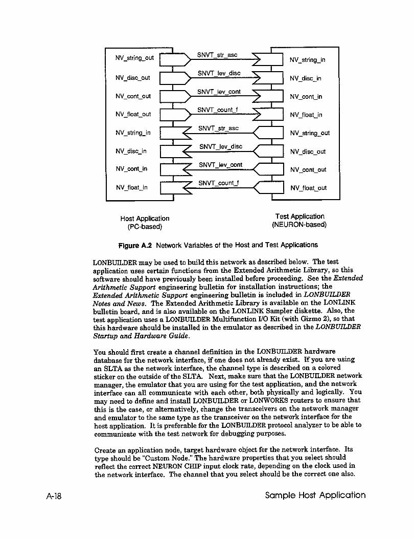
Host Application Test Application (PC-based) (NEURON-based)
Figure A.2 Network Variables of the Host and Test Applications
LONBTJILDER may be used to build this network as described below. The test application uses certain functions from the Extended Arithmetic Library, so this software should have previously been installed before proceeding. See the Extended Arithmetic Support engineering bulletin for installation instructions; the Extended Arithmetic Support engineering bulletin is included in LONBUILDER Notes and News. The Extended Arithmetic Library is available on the LONLINK bulletin board, and is also available on the LONLINK Sampler diskette. Also, the test application uses a LONBUILDER Multifunction I/O Kit (with Gizmo 21, so that this hardware should be installed in the emulator as described in the LONBUIL,DER Startup and Hardware Guide.
You should first create a channel definition in the LONBUILDER hardware database for the network interface, if one does not already exist. If you are using an SLTA as the network interface, the channel type is described on a colored sticker on the outside of the SLTA Next, make sure that the LONBTJILDER network manager, the emulator that you are using for the test application, and the network interface can all communicate with each other, both physically and logically. You may need to define and install LONBUILDER or LONWORKS routers to ensure that this is the case, or alternatively, change the transceivers on the network manager and emulator to the same type as the transceiver on the network interface for the host application. It is preferable for the LONBUILDER protocol analyzer to be able to communicate with the test network for debugging purposes.
Create an application node, target hardware object for the network interface. Its type should be “Custom Node.” The hardware properties that you select should reflect the correct NEURON CHIP input clock rate, depending on the clock used in the network interface. The channel that you select should be the correct one also.
A-18 Sample Host Application
Now install the network interface - you will be asked to press the service pin on the network interface. Do not install corn&cation parameters.
Create an application image of origin “Interface File”, with the name HA-V2 . XIF. Create a node specification for the host application that specifies HA-V2 as the application image, and the network interface object as the target hardware.
Create a node specification for the test application, and specify the application image name as HA-TEST, and the target hardware as the emulator you are using. ‘I!his will cause the NEURON C program HA-TEST. NC to be compiled to produce the application image for the emulator. The NEURON C include file DISPLAY. H is required; it contains the display driver for the Gizmo 2 used by the test application.
You can now build and load the emulator and the host application node using the LONBUILDER Project Manager. The host application must be running during the load operation, since it will be required to respond to certain network management messages. You can bind the network variables of the test application and the host application together as in the above diagram.
The test application uses the Gizmo 2 as the user interface device when connected to an emulator or other NEURON C-based node. When the node receives a network variable update from the network, it will display the value using the seven segment display. For the network variable of type SNVT-str-asc, it will display the first four characters if possible to do so using the seven segment display of the Gizmo 2. If there is no reasonable representation in seven segments, a blank will be displayed. For the network variable of type SNVT-count-f, it will display the number using two decimal places and a sign. For the network variable of type SNVT-lev-disc, it will display the value in percent using one decimal place. For the network variable of type SNV‘I-lev-disc, it will display one of the strings “OFF”, “LO”, “=Ed”, “HI” or “On”, corresponding to the ST-OFF, ST-LO, ST-MED, ST-HI and ST-ON values.
You can also use the Gizmo 2 to transmit network variables to the host application. Pressing the right (10-3) button will cycle the display through the discrete level, continuous level, floating point, and the four first characters of the string output network variables. The quadrature input dial may be used to change the values transmitted to the network, and these will then be displayed by the host application when it receives the network variable updates.
The left (IO-71 button of the Gizmo 2 toggles the node between display of the input and output network variable of a given type. The red LED will be on if the input variable is being displayed, and off if the output variable is being displayed.
Host Application Programmer‘s Guide A-19

Appendix B Creating an External Interface File
This appendix describes the procedure for modifying an external interface file ( . XIF extension) to include network variables and message tags used by a host application.
Host Application Programmer’s Guide B-1
How to Add Network Variables to the External Interface File
As described under Binding to a Host Node in Chapter 3, an external interface file (.XIF extension) can be used by a network management tool to determine the external interface of a node. The external interface file describes the network variables and message tags for a node. External interface files may be generated in several different ways.
The LONBUILDER sofiware will create external interface files for nodes created with the NEURON C compiler. After the node image has been built, invoke the Export command in the App Node / Node Specs screen, and specify the Intel)eace File option. See the LONBUILDER User’s Guide Chapter 7 for more information. LONBUILDER 2.1 exports an interface file with versions 1 and 2 formats, and LONBUILDER 2.2 exports an interface file with version 3 format. This appendix describes version 2 and version 3 formats. A utility XIF3T02 is included with LONBUILDER 2.2 to convert version 3 format interface files to version 2.
A variant of this technique may be used to create an external interface file for a host application node. Create a NEURON C program with the appropriate network variable and message tag declarations. There need be no actual code in this program. Compile and build this application using the appropriate hardware properties and channel definitions for the custom node. Then use LONBUILDER to export the external interface file for this node. Afterwards, use a text editor such as the LONBUILDER editor to modify the values in the sixth line appropriately. This technique will work for nodes with 62 network variables or less. Nodes with more than this will require further modifications to the external interface file as described below.
LONBUILDER may also be used to create an external interface file from an existing custom node by querying it over the network. Invoke the Query command in the App Node / Node Specs screen. If the node was built with network variable names in its SNVT information, those names will automatically be uploaded, otherwise default names will be used for the network variables. These names may be edited if desired. See the LONBUILDER User’s Guicle Chapter 6 for more information.
An external interface file without network variables or message tag definitions is included with the SLTA, and can be generated for network interfaces based on the MIP as described in the Microprocessor Interface Program (MIP) User’s Guiok. This appendix describes how to modify this external interface file to add network variables and message tag definitions to a basic header.
External interface files are used by several LONWORKS tools. All current releases of these tools can read version 2 interface files.
B-2 Creating an External interface File
LONBUILDER can read an external interface file for an existing custom node so that its network variables and message tags may be bound. In the App Node / App Images screen, create an application image whose origin is Interface File, and whose name is the base name of the external interface file which should be in the working directory. Then in the App Node / Node Specs screen, create a node specification with that App Image Name. Afer that node is built, the network variables and message tags imported from the external interface file will be available to the binder. See the LONBCULDER User$ Guide Chapter 7 for more information.
External interface files may be read by the function ldb-import-xif ( 1 in the LONMANAGER API in order to create program records. These program records may then be used to define the network variables of node records in the database. See the LONMANAGER Reference Guide for Windows Chapter 2, or the LONMANAGER API Programmer$ Guide for DOS Appendix C for details.
External interface files may also be read by the LONMANAGER NetProfiler as part of the process of creating an Application Type. These Application Types form part of the parts catalog that the LONMANAGER NetMaker uses for network installation. See the LONMANAGER NetProfiler User’s Guide Chapter 5 for details.
External Interface File Format The external interface file is a text file that describes critical logical (e.g., network variables) and physical (e.g., transceiver) interface characteristics of a node.
Before any modifications, the external interface file for a network interface will look very similar to the following: 1: File: PMIP-78K.XIF generated by APC Revision 1.73, XIF Version 2 2: Copyright (c) 1990, 1992 by Echelon Corporation 3: All Rights Reserved. Run on Wed Apr 15 10:18:08 1992 4: 5: 40:49:43:52:4F:5F:50:49 6:215100333444llllllll108 7: 0 4 4 5 3 13 18 1402 0 15 5 3 106 8: * The values in this file header depend upon transceiver type, buffer configuration, and other configuration characteristics of the application. Adding network variables or message tags to an external interface file requires only limited changes to the original contents of the external interface file header. Network variables and message tags are added to an external interface file by adding additional lines of information to the original file. Most of the entries in the header of the file must not be changed, except as noted below, otherwise many of the LONWORKS tools will fail to import the file. The other entries are documented here for reference only. Note that blank lines are significant. The fourth line must be blank, and there must be no blank lines at the end of the file.
Host Application Programmer’s Guide B-3
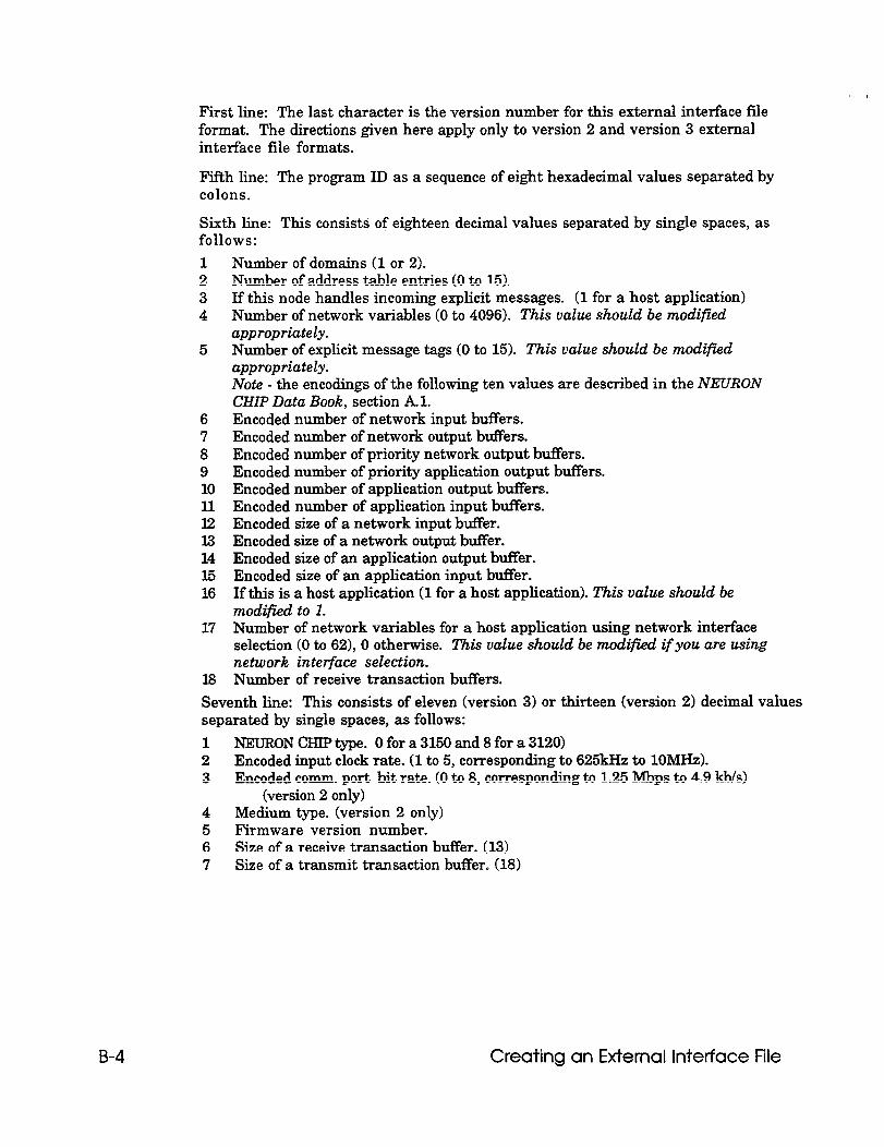
First line: The last character is the version number for this external interface file format. The directions given here apply only to version 2 and version 3 external interface file formats.
Fifth line: The program ID as a sequence of eight hexadecimal values separated by colons.
Sixth line: This consists of eighteen decimal values separated by single spaces, as follows: 1 2 3 4
5
6 7 8 9 10 11 12 I.3 14 15 16
17
18
Number of domains (1 or 2). Number of address table entries (0 to 15). If this node handles incoming explicit messages. (1 for a host application) Number of network variables (0 to 4096). This value should be modified appropriately. Number of explicit message tags (0 to 15). This value should be modified appropriately. Note - the encodings of the following ten values are described in the NEURON CHIP Data Book, section Al. Encoded number of network input buffers. Encoded number of network output buffers. Encoded number of priority network output buffers. Encoded number of priority application output buffers. Encoded number of application output buffers. Encoded number of application input buffers. Encoded size of a network input buffer. Encoded size of a network output buffer. Encoded size of an application output buffer. Encoded size of an application input buffer. If this is a host application (1 for a host application). This value should be modifid to 1. Number of network variables for a host application using network interface selection (0 to 621, 0 otherwise. This value should be modified if you are using network interface selection. Number of receive transaction buffers.
Seventh line: This consists of eleven (version 3) or thirteen (version 2) decimal values separated by single spaces, as follows:
1 NEURON CHIP type. 0 for a 3150 and 8 for a 3120) 2 Encoded input clock rate. (1 to 5, corresponding to 625kHz to 10MHz). 3 Encoded comm. port bit rate. (0 to 8, corresponding to 1.25 Mbps to 4.9 kb/s)
(version 2 only) 4 Medium type. (version 2 only) 5 Firmware version number. 6 Size of a receive transaction buffer. (13) 7 Size of a transmit transaction buffer, (18)
B-4 Creating an External interface File
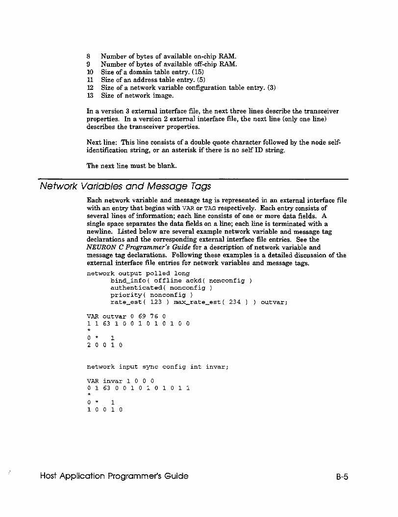
8 Number of bytes of available on-chip RAM. 9 Number of bytes of available off-chip RAM. 10 Size of a domain table entry. (15) 11 Size of an address table entry. (5) 12 Size of a network variable configuration table entry. (3) I3 Size of network image.
In a version 3 external interface file, the next three lines describe the transceiver properties. In a version 2 external interface file, the next line (only one line) describes the transceiver properties.
Next line: This line consists of a double quote character followed by the node self- identification string, or an asterisk if there is no self ID string.
The next line must be blank.
Network Variables and Message Tags Each network variable and message tag is represented in an external interface file with an entry that begins with VAR or TAG respectively. Each entry consists of several lines of information; each line consists of one or more data fields. A single space separates the data fields on a line; each line is terminated with a newline. Listed below are several example network variable and message tag declarations and the corresponding external interface file entries. See the NEURON C Programmer’s Guide for a description of network variable and message tag declarations. Following these examples is a detailed discussion of the external interface file entries for network variables and message tags. network output polled long
bind-info( offline ackd( nonconfig ) authenticatedc nonconfig ) priority( nonconfig ) rate-est( 123 ) max-rate-est( 234 ) ) outvar;
VAR outvar 0 69 76 0 116310 0101010 0 * o* 1 20010
network input sync config int invar;
VAR invar 1 0 0 0 0163 0010101011 * o* 1 10 010
Host Application Programmer’s Guide B-5
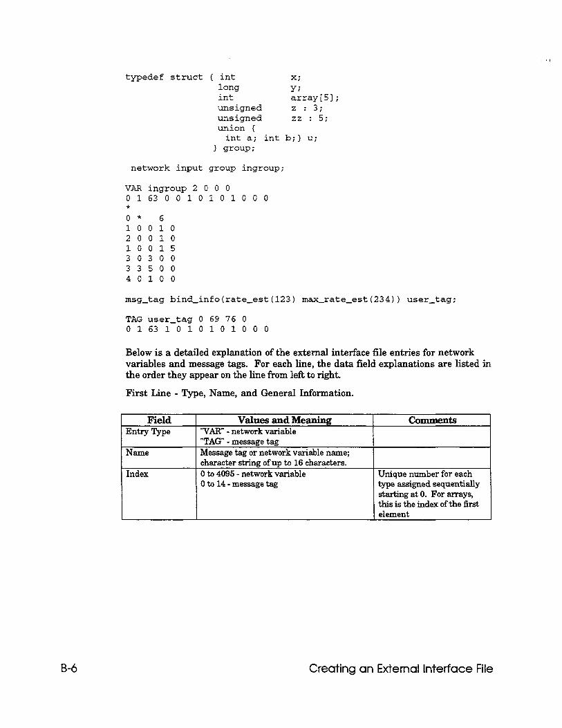
typedef struct ( int x; long YJ int arrayE51; unsigned z : 3; unsigned zz : 5; union (
int a; int b;) u; 3 group;
network input group ingroup;
VAR ingroup 2 0 0 0 0163 0 0101010 0 0 * 0* 6 10 0 10 2 0 0 10 10015 30300 33500 40100
msg-tag bind-info(rate-est(l23) max-rate-est(234)) user-tag;
TAG user-tag 0 69 76 0 016310101010 0 0
Below is a detailed explanation of the external interface file entries for network variables and message tags. For each line, the data field explanations are listed in the order they appear on the line from lefi to right.
First Line - Type, Name, and General Information.
Field Entry 5Pe
Name
Index
Values and Meaning “VAR” - network variable “TAG” - message tag Message tag or network variable name; character string of up to 16 characters. 0 to 4095 - network variable Oto 14-messagetag
cauments
Unique number for each type assigned sequentially starting at 0. For arrays, this is the index of the first element
B-6 Creating an External Interface File
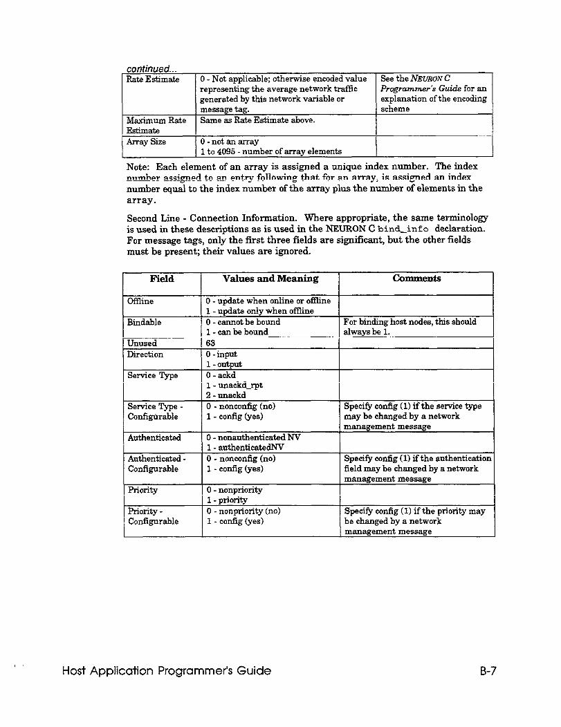
Rate Estimate 0 - Not applicable; otherwise encoded value See the NEURON C representing the average network traffic Programmer’s Guide for an generated by this network variable or explanation of the encoding message tag. scheme
Maximum Rate Same as Rate Estimate above. Estimate Array Size 0-notanarray
1 to 4095 - number of array elements
Note: Each element of an array is assigned a unique index number. The index number assigned to an entry following that for an array, is assigned an index number equal to the index number of the array plus the number of elements in the array.
Second Line - Connection Information. Where appropriate, the same terminology is used in these descriptions as is used in the NEURON C bind-info declaration. For message tags, only the first three fields are significant, but the other fields must be present; their values are ignored.
Field Values and Meaning Comments
Offline
Bindable
Unused
0 - update when online or offline 1 - update only when offline 0 - cannot be bound For binding host nodes, this should l-canbebound always be 1. 63
Direction
Service Type
0 - input 1 - output 0 - ackd
1 1 - unackd-rpt 1 - unackd-rpt 2 - unackd 2 - unackd 0 - nonconlig (no) 0 - nonconlig (no) 1 - config (yes) 1 - config (yes)
Service Type - Service Type - Configurable Configurable
Specify config (1) if the service type Specify config (1) if the service type may be changed by a network may be changed by a network
Authenticated
Authenticated - Configurable
priority
Priority - Configurable
0 - nonauthenticated NV 1 - authenticatedNV 0 - nonconfig (no) 1 - cofig (yes)
0 - nonpriority 1 - priority 0 - nonpriority (no) 1 - config (yes)
management message
Specify config (1) if the authentication field may be changed by a network management message
Specify conlig ( 1) if the priority may be changed by a network management message
Host Application Programmer’s Guide B-7
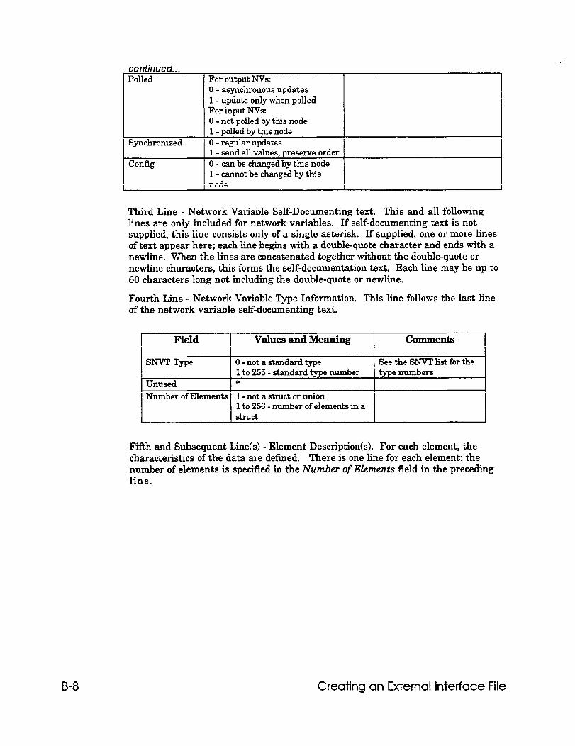
Polled For output NVs: 0 - asynchronous updates 1 - update only when polled For input NVs:
Synchronized
Config
0 - not polled by this node 1 - polled by this node 0 - regular updates 1 - send all values, preserve order 0 - can be changed by this node 1 - cannot be changed by this node
Third Line - Network Variable Self-Documenting text. This and all following lines are only included for network variables. If self-documenting text is not supplied, this line consists only of a single asterisk. If supplied, one or more lines of text appear here; each line begins with a double-quote character and ends with a newline. When the lines are concatenated together without the double-quote or newline characters, this forms the self-documentation text. Each line may be up to 60 characters long not including the double-quote or newline.
Fourth Line - Network Variable Type Information. This line follows the last line of the network variable self-documenting text.
Field Values and Meaning Comments
Smr Type 0 - not a standard type See the SNVT list for the 1 to 255 - standard type number type numbers
Unused *
Number of Elements 1 - not a struct or union 1 to 256 - number of elements in a
Fifth and Subsequent Line(s) - Element Description(s). For each element, the characteristics of the data are defined. There is one line for each element; the number of elements is specified in the Number of Elements field in the preceding line.
B-8 Creating an External Interface File
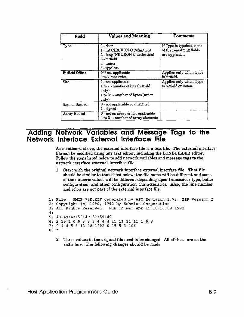
Field Values and Meaning Comments
Type
Bitfield Of&et
size
O-char 1 - int (NEURON C definition) 2 - long (NEURON C definition) 3 - biffield 4-union 5 - typeless 0 if not applicable Oto 7 otherwise 0 - not applicable 1 to 7 - number of bits (bitfield only) 1 to 31- number of bytes (union only) 0 - not applicable or unsigned 1 - signed 0 - not an array or not applicable
If Type is typeless, none of the remaining fields are applicable.
Applies only when Type is biUield. Applies only when Qpe is bitfield or union.
Sign or Signed
Array Bound 1 1 to 31- number of array elements 1
Adding Network Variables and Message Tags to the Network Interface External Interface File
As mentioned above, the external interface file is a text file. The external interface file can be modified using any text editor, including the LONBUILDER editor. Follow the steps listed below to add network variables and message tags to the network interface external interface file.
1 Start with the original network interface external interface file. That file should be similar to that listed below; the file name will be different and some of the numeric values will be different depending upon transceiver type, buffer configuration, and other configuration characteristics. Also, the line number and colon are not part of the external interface file.
1: File: PMIP-78K.XIF generated by APC Revision 1.73, XIF Version 2 2: Copyright (c) 1990, 1992 by Echelon Corporation 3: All Rights Reserved. Run on Wed Apr 15 10:18:08 1992 4: 5: 40:49:43:52:4F:5F:50:49 6:21510 03 3 3 444llllllll.108 7: 0 4 4 5 3 13 18 1402 0 15 5 3 106 8: *
2 Three values in the original file need to be changed. All of these are on the sixth line. The following changes should be made:
Host Application Programmer’s Guide B-9
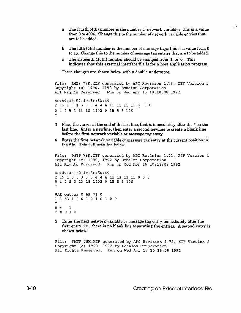
a The fourth (4th) number is the number of network variables; this is a value from 0 to 4096. Change this to the number of network variable entries that are to be added.
b The fifth (5th) number is the number of message tags; this is a value from 0 to 15. Change this to the number of message tag entries that are to be added.
c The sixteenth (16th) number should be changed from ‘1’ to ‘0’. This indicates that this external interface file is for a host application program.
These changes are shown below with a double underscore.
File: PMIP-78K.XIF generated by APC Revision 1.73, XIF Version 2 Copyright (c) 1990, 1992 by Echelon Corporation All Rights Reserved. Run on Wed Apr 15 10:18:08 1992
4D:49:43:52:4F:SF:50:49 2151~~333444llllllll~ 08 0 4 4 5 3-13 18 1402 0 15 5 3 106 *
3 Place the cursor at the end of the last line, that is immediately after the * on the last line. Enter a newline, then enter a second newline to create a blank line before the first network variable or message tag entry.
4 Enter the first network variable or message tag entry at the current position in the file. This is illustrated below.
File: PMIP-78K.XIF generated by APC Revision 1.73, XIF Version 2 Copyright (c) 1990, 1992 by Echelon Corporation All Rights Reserved. Run on Wed Apr 15 10:18:08 1992
40:49:43:52:4F:SF:50:49 21510 033344411111111008 0 4 4 5 3 13 18 1402 0 15 5 3 106 *
VAR outvar 0 69 76 0 1163100101010 0 * o* 1 20010
5 Enter the next network variable or message tag entry immediately after the first entry, i.e., there is no blank line separating the entries. A second entry is shown below.
File: PMIP-78K.XIF generated by APC Revision 1.73, XIF Version 2 Copyright (c) 1990, 1992 by Echelon Corporation All Rights Reserved. Run on Wed Apr 15 10:18:08 1992
B-10 Creating an External Interface File
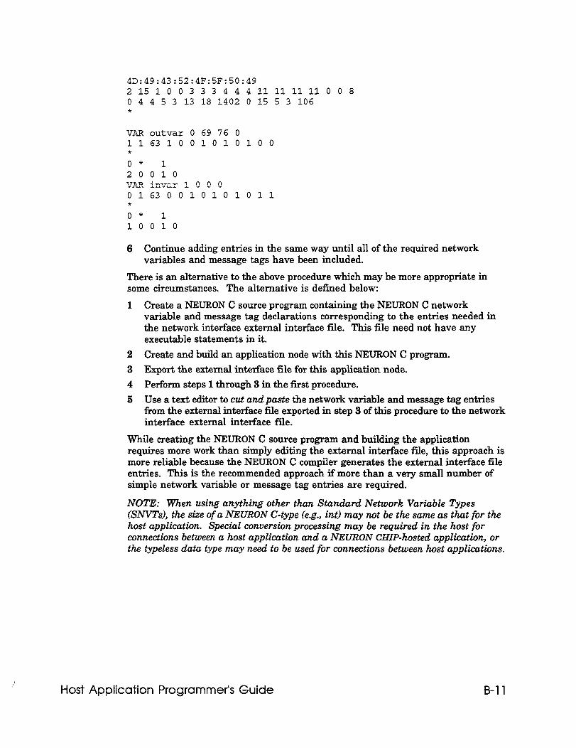
40:49:43:52:4F:SF:50:49 21510 0333444lllillllO 0 8 0 4 4 5 3 13 18 1402 0 15 5 3 106 *
VAR outvar 0 69 76 0 116310 0101010 0 * o* 1 20010 VAR invar 1 0 0 0 0163 0 010101011 * o* 1 10 0 10
6 Continue adding entries in the same way until all of the required network variables and message tags have been included.
There is an alternative to the above procedure which may be more appropriate in some circumstances. The alternative is defined below:
Create a NEURON C source program containing the NEURON C network variable and message tag declarations corresponding to the entries needed in the network interface external interface file. This file need not have any executable statements in it.
Create and build an application node with this NEURON C program. Export the external interface file for this application node.
Perform steps 1 through 3 in the first procedure.
Use a text editor to cut and paste the network variable and message tag entries from the external interface file exported in step 3 of this procedure to the network interface external interface file.
While creating the NEURON C source program and building the application requires more work than simply editing the external interface file, this approach is more reliable because the NEURON C compiler generates the external interface file entries. This is the recommended approach if more than a very small number of simple network variable or message tag entries are required.
NOTE: When using anything other than Standard Network Variable Types (SNVTs), the size of a NEURON C-type (e.g., int) may not be the same as that for the host application. Special conversion processing may be required in the host for connections between a host application and a NEURON CHIP-hosted application, or the typeless data type may need to be used for connections between host applications.
Host Application Programmer’s Guide B-11

Appendix C Network Interface Messages
This appendix defines the message structures exchanged by a host application and the network driver. These messages will consist of network variable updates, explicit messages, or local commands to the network interface. Explicit messages may be application, network management, or network diagnostic messages as defined in Appendix B of the NEURON CHIP Data Book.
The message structures are defined using ANSI C structure definitions, and also using bit-field diagrams. The ANSI C structure definitions are contained in two ANSI C header files that are included in the host application example directory. These files are NI-MSG . H and NI-MGMT e H. The NI-MSG . H header file defines the network interface message structures and also defines other structures and variables used by the NI-MSG . c functions listed in Appendix A. The NI-MGMT . H header file defines the subset of network management messages used by the example host application in Appendix A.
The bit-field diagrams can be used by host application developer’s using a language other than ANSI C. The bit-field diagrams also illustrate the difference between the application-layer header and the link-layer headers.
Host Application Programmer’s Guide C-l
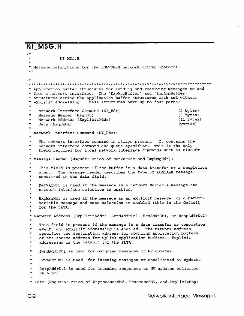
NIBMSG.H /*
* NI-MSG.H * * Message definitions for the LONWORKS network driver protocol. */
/* **********************************************************~~****************
* Application buffer structures for sending and receiving messages to and * from a network interface. The "ExpAppBuffer' and 'ImpAppBuffer' * structures define the application buffer structures with and without * explicit addressing. These structures have up to four parts: * * Network Interface Command (NI-Hdr) (2 bytes) * Message Header (MsgHdr) (3 bytes) * Network Address (ExplicitAddr) (11 bytes) * Data (MsgData) (varies) * * Network Interface Command (NI-Hdr): * * The network interface command is always present. It contains the * network interface command and queue specifier. This is the only * field required for local network interface commands such as niRESET. * * Message Header (MsgHdr: union of NetVarHdr and ExpMsgHdr): * * This field is present if the buffer is a data transfer or a completion * event. The message header describes the type of LONTALK message * contained in the data field. * * NetVarHdr is used if the message is a network variable message and * network interface selection is enabled. * * ExpMsgHdr is used if the message is an explicit message, or a network * variable message and host selection is enabled (this is the default * for the SLTA). * * Network Address (ExplicitAddr: SendAddrDtl, RcvAddrDtl, or RespAddrDtl) * * This field is present if the message is a data transfer or completion * event, and explicit addressing is enabled. The network address * specifies the destination address for downlink application buffers, * or the source address for uplink application buffers. Explicit * addressing is the default for the SLTA. * * SendAddrDtl is used for outgoing messages or NV updates. * * RcvAddrDtl is used for incoming messages or unsolicited NV updates. * * RespAddrDtl is used for incoming responses or NV updates solicited * by a poll. * * Data (MsgData: union of UnprocessedNV, ProcessedNV, and ExplicitMsg)
C-2 Network Interface Messages
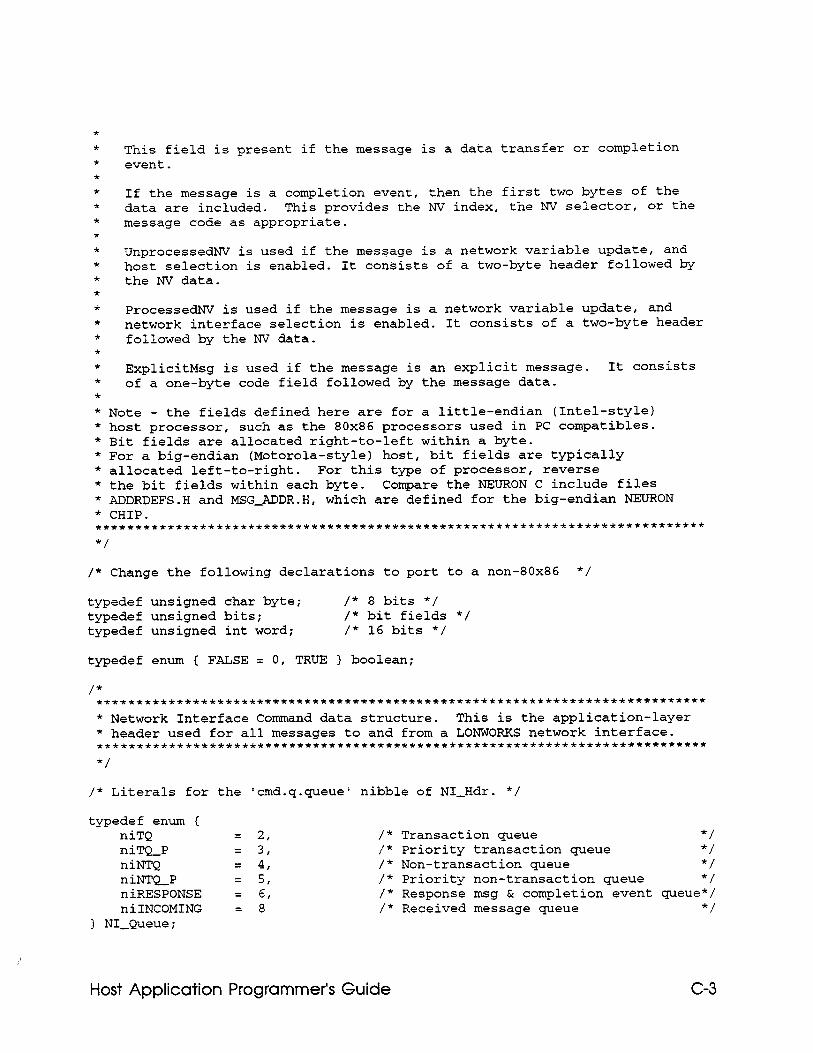
* * * * * * * * * * * * * * * * * * *
This field is present if the message is a data transfer or completion event.
If the message is a completion event, then the first two bytes of the data are included. This provides the NV index, the NV selector, or the message code as appropriate.
UnprocessedNV is used if the message is a network variable update, and host selection is enabled. It consists of a two-byte header followed by the NV data.
ProcessedNV is used if the message is a network variable update, and network interface selection is enabled. It consists of a two-byte header followed by the NV data.
ExplicitMsg is used if the message is an explicit message. It consists of a one-byte code field followed by the message data.
* Note - the fields defined here are for a little-endian (Intel-style) * host processor, such as the 80x86 processors used in PC compatibles. * Bit fields are allocated right-to-left within a byte. * For a big-endian (Motorola-style) host, bit fields are typically * allocated left-to-right. For this type of processor, reverse * the bit fields within each byte. Compare the NEURON C include files * ADDRDEFS.H and MSGJDDR.H, which are defined for the big-endian NEURON * CHIP. ******************************************************************~********* */
/* Change the following declarations to port to a non-80x86 */
typedef unsigned char byte; /* 8 bits */ typedef unsigned bits; /* bit fields */ typedef unsigned int word; /* 16 bits */
typedef enum { FALSE = 0, TRUE 1 boolean;
/* ********************~~~~~~~~~~~~~***~~~~~~~~~~~~~~~~~~~~~~~~~~*~~**~~~~~ * Network Interface Command data structure. This is the application-layer * header used for all messages to and from a LONWORKS network interface. **************************************************************************** */
/* Literals for the 'cmd.q.queue' nibble of NI-Hdr. */
typedef enum { niTQ = 2, niTQ-P = 3, niNTQ = 4, ni.NTQ-P = 5, niRESPONSE = 6, niINCOMING = 8
) NI-Queue;
/* Transaction queue */ /* Priority transaction queue */ /* Non-transaction queue */ /* Priority non-transaction queue */ /* Response msg & completion event queue*/ /* Received message queue */
Host Application Programmer’s Guide C-3
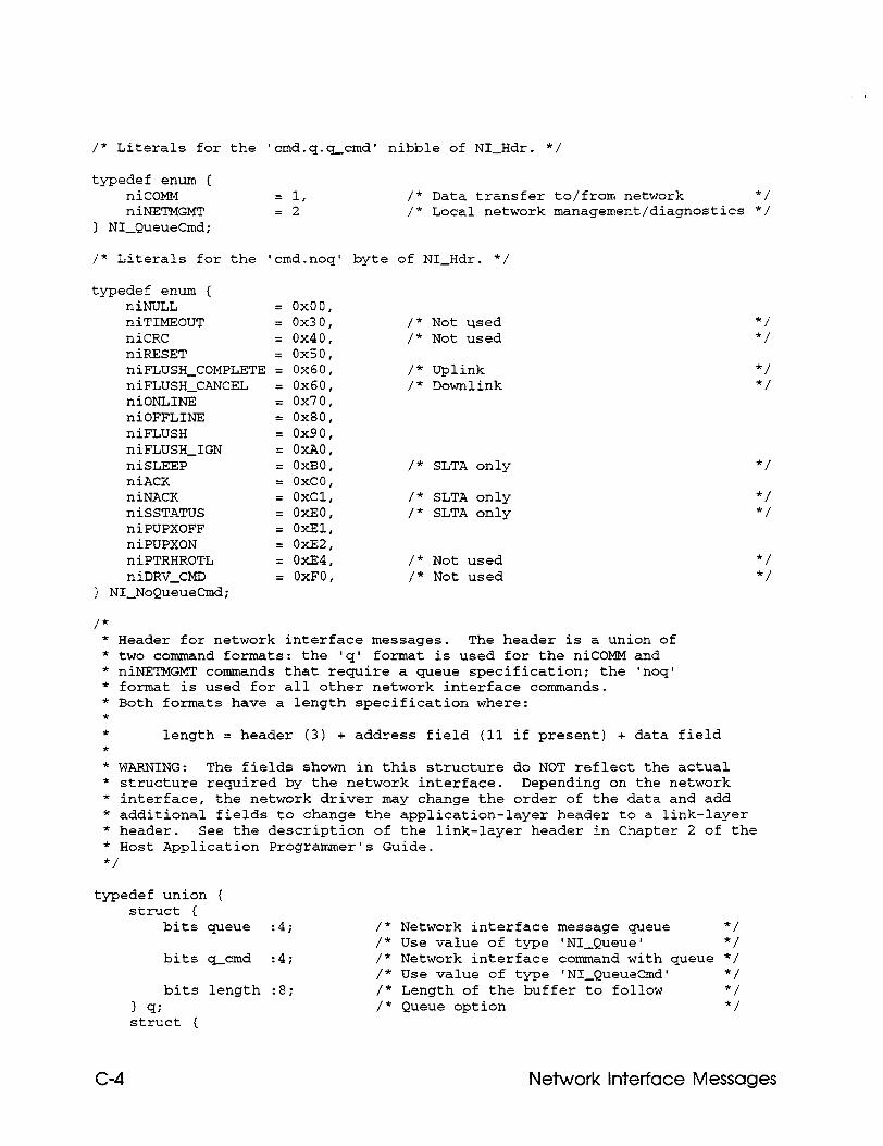
/* Literals for the 'cmd.q.q_cmd' nibble of NI-Hdr. */
typedef enum ( niCOMM = 1, /* Data transfer to/from network */ niNETMGMT = 2 /* Local network management/diagnostics */
) NI-QueueCmd;
/* Literals for the 'cmd.noq' byte of NI-Hdr. */
/* Not used /* Not used
/* Uplink /* Downlink
/* SLTA only
/* SLTA only /* SLTA only
/* Not used /* Not used
typedef enum { niNULL = 0x00, niTIMEOUT = 0x30, niCRC = 0x40, niRESET = 0x50, niFLUSH_COMPLETE = 0x60, niFLUSH_CANCEL = 0x60, niONLINE = 0x70, niOFFLINE = 0x80, niFLUSH = 0x90, niFLUSH_IGN = OXAO, niSLEEP = OxBO, niACK = oxco, niNACK = OxCl, niSSTATUS = OxEO, niPUPXOFF = OxEl, niPUPXON = oxE2, niPTRHROTL = oxE4, niDRV_CMD = OxFO,
3 NI-NoQueueCmd;
/* * Header for network interface messages. The header is a union of * two command formats: the 'q' format is used for the niCOMM and * niNETMGMT commands that require a queue specification; the 'noq' * format is used for all other network interface commands. * Both formats have a length specification where: * * length = header (3) + address field (11 if present) + data field * * WARNING: The fields shown in this structure do NOT reflect the actual * structure required by the network interface. Depending on the network * interface, the network driver may change the order of the data and add * additional fields to change the application-layer header to a link-layer * header. See the description of the link-layer header in Chapter 2 of the * Host Application Programmer's Guide. */
typedef union { struct (
bits queue :4;
bits q-cmd :4;
bits length :8; 1 9; struct {
/* Network interface message queue */ /* Use value of type 'NI-Queue' */ /* Network interface command with queue */ /* Use value of type 'NI-QueueCmd' */ /* Length of the buffer to follow */ /* Queue option */
*/ */
*/ */
*/
*/ */
*/ */
C-4 Network interface Messages
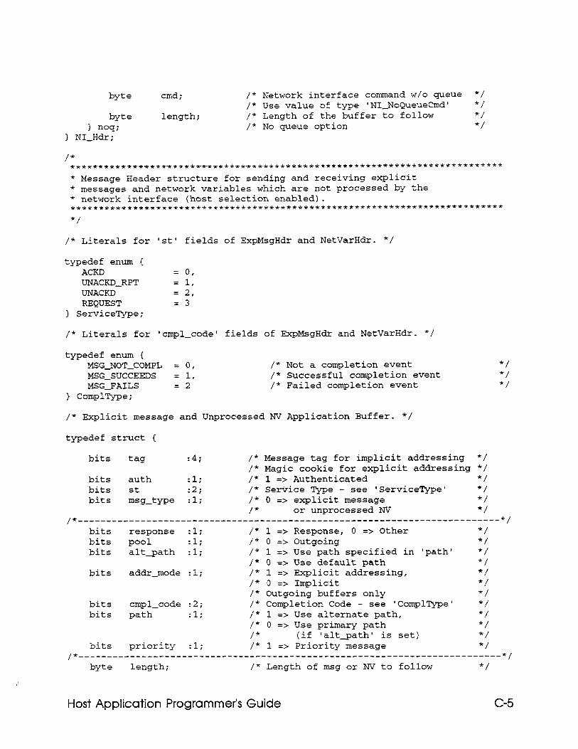
byte
byte I noq;
> NI-Hdr;
cmd;
length;
/* Network interface command w/o queue */ /* Use value of type 'NI-NoQueueCmd' */ /* Length of the buffer to follow */ /* No queue option */
/* ************t****t**~~~~~~*~~~~*~~~~~~~~~~~~~~~~~*~~~~~~~~~~~~*~~~*~~~~~~~~~ * Message Header structure for sending and receiving explicit * messages and network variables which are not processed by the * network interface (host selection enabled). ************************************************~***************************** */
/* Literals for 'St' fields of ExpMsgHdr and NetVarHdr. */
typedef enum C ACKD = 0, UNACKD-RPT = 1, UNACKD = 2, REQUEST = 3
} ServiceType;
/* Literals for 'cmpl-code' fields of ExpMsgHdr and NetVarHdr. */
typedef enum { MSG-NOT-COMPL = 0, MSG-SUCCEEDS = 1, MSG-FAILS = 2
} ComplType;
/* Not a completion event “1 /* Successful completion event */ /* Failed completion event */
/* Explicit message and Unprocessed NV Application Buffer. */
typedef struct {
bits tag :4; /* Message tag for implicit addressing */ /* Magic cookie for explicit addressing */
bits auth :l; /* 1 => Authenticated */ bits st :2; /* Service Type - see 'ServiceType' */ bits msg-type :l; /* 0 => explicit message *i
/* or unprocessed NV */ /*-------------------- ---------__---___-__---------------------------------- */
bits response :l; /* 1 => Response, 0 => Other */ bits pool :l; /* 0 => Outgoing */ bits alt_path :l; /* 1 => Use path specified in 'path' */
/* 0 => Use default path */ bits addr-mode :l; /* 1 => Explicit addressing, */
/* 0 => Implicit */ /* Outgoing buffers only */
bits cmpl-code :2; /* Completion Code - see 'ComplType' */ bits path :l; /* 1 => Use alternate path, */
/* 0 => Use primary path */ /* (if 'alt-path' is set) */
bits priority :l; /* 1 => Priority message */ /*--------------------------------------------------------------------------~~
byte length; /* Length of msg or NV to follow */
Host Application Programmer’s Guide C-5
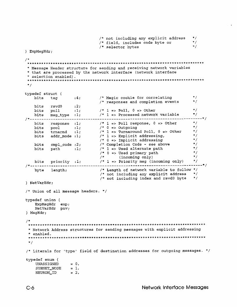
1 ExpMsgHdr;
/* not including any explicit address */ /* field, includes code byte or */ /* selector bytes */
* Message Header structure for sending and receiving network variables * that are processed by the network interface (network interface * selection enabled).
*/
typedef struct ( bits tag :4; /* Magic cookie for correlating */
/* responses and completion events */ bits rsvd0 :2; bits poll :l; /* 1 => Poll, 0 => Other */ bits msg-type :l; /* 1 => Processed network variable */
/*--------------------------------------------------------------------------*/ bits response :l; /* 1 => Poll response, 0 => Other */ bits pool :l; /* 0 => Outgoing */ bits trnarnd :l; /* 1 => Turnaround Poll, 0 => Other */ bits addr-mode :l; /* 1 => Explicit addressing, */
/* 0 => Implicit addressing */ bits cmpl-code :2; /* Completion Code - see above */ bits path :l; /* 1 => Used alternate path */
/* 0 => Used primary path */ /* (incoming only) */
bits priority :l; /* 1 => Priority msg (incoming only) */ /*--------------------------------------------------------------------------*/
byte length; /* Length of network variable to follow */ /* not including any explicit address */ /* not including index and rsvd0 byte */
> NetVarHdr;
/* Union of all message headers. */
typedef union { HxpMsgHdr exp; NetVarHdr pnv;
> MsgHdr;
*/
/* Literals for 'type' field of destination addresses for outgoing messages. */
typedef enum { UNASSIGNED = 0, SUBNET-NODE = 1, NEURON-ID = 2,
C-6 Network interface Messages
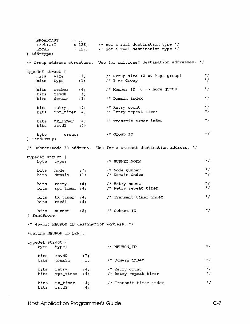
BROADCAST = 3, IMPLICIT = 126, /* not a real destination type *! LOCAL = 127, /* not a real destination type */
) AddrType;
/* Group address structure. Use for multicast destination addresses. */
typedef struct ( bits size :7; bits type :l;
bits member :6; bits rsvd0 :l; bits domain :l;
bits retry :4; bits rpt-timer :4;
bits tx-timer :4; bits rsvdl :4;
byte group i > SendGroup;
/* Subnet/node ID address.
typedef struct ( byte tme i
bits node :7; bits domain :l;
bits retry :4; bits rpt-timer :4;
bits tx_timer :4; bits rsvdl Z4i
bits subnet :8; } SendSnode;
/* Group size (0 => huge group) "1 /* 1 => Group */
/* Member ID (0 => huge group) */
/* Domain index */
/* Retry count */ /* Retry repeat timer "1
/* Transmit timer index */
/* Group ID */
Use for a unicast destination address. */
,'* SUBNET-NODE
/* Node number /* Domain index
/* Retry count /* Retry repeat timer
/* Transmit timer index
*/
*/ */
*/ */
*/
/* Subnet ID */
/* 48-bit NEURON ID destination address. */
#define NEURON-ID-LEN 6
typedef struct ( byte type i /* NEURON-ID */
bits rsvd0 :7; bits domain :li /* Domain index
bits retry :4i /* Retry count bits rpt-timer :4i /* Retry repeat timer
bits tx-timer :4i /* Transmit timer index bits rsvd2 :4;
*/
*/ */
*/
Host Application Programmer’s Guide C-7
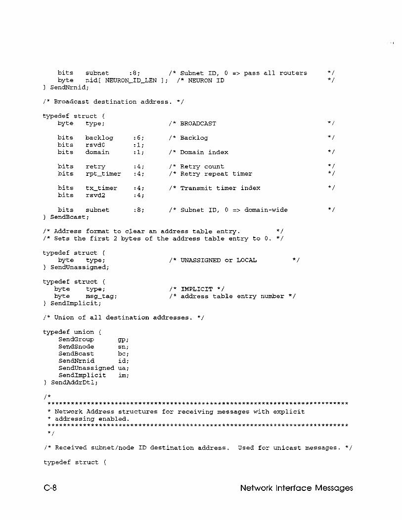
bits subnet :8; /* Subnet ID, 0 => pass all routers */ byte nid[ NEURON-ID-LEN 1; /* NEURON ID */
) SendNrnid;
/* Broadcast destination address. */
typedef struct ( byte type ; /* BROADCAST
bits backlog :6; /* Backlog bits rsvd0 :I.; bits domain :l; /* Domain index
bits retry :4i /* Retry count bits rpt-timer :4i /* Retry repeat timer
bits tx-timer :4i /* Transmit timer index bits rsvd2 :4;
bits subnet } SendBcast;
:8; /* Subnet ID, 0 => domain-wide
*/
*/
*/
*/ */
*/
*/
/* Address format to clear an address table entry. */ /* Sets the first 2 bytes of the address table entry to 0. */
typedef struct ( byte type i
> SendUnassigned; /* UNASSIGNED or LOCAL */
typedef struct { byte type i
byte -g-tag ; ) SendImplicit;
/* IMPLICIT */ /* address table entry number */
/* Union of all destination addresses. */
typedef union { SendGroup m?; SendSnode Sn;
SendBcast bc; SendNrnid id; SendUnassigned ua; SendImplicit im;
) SendAddrDtl;
/* Received subnet/node ID destination address. Used for unicast messages. */
typedef struct (
C-8 Network Interface Messages
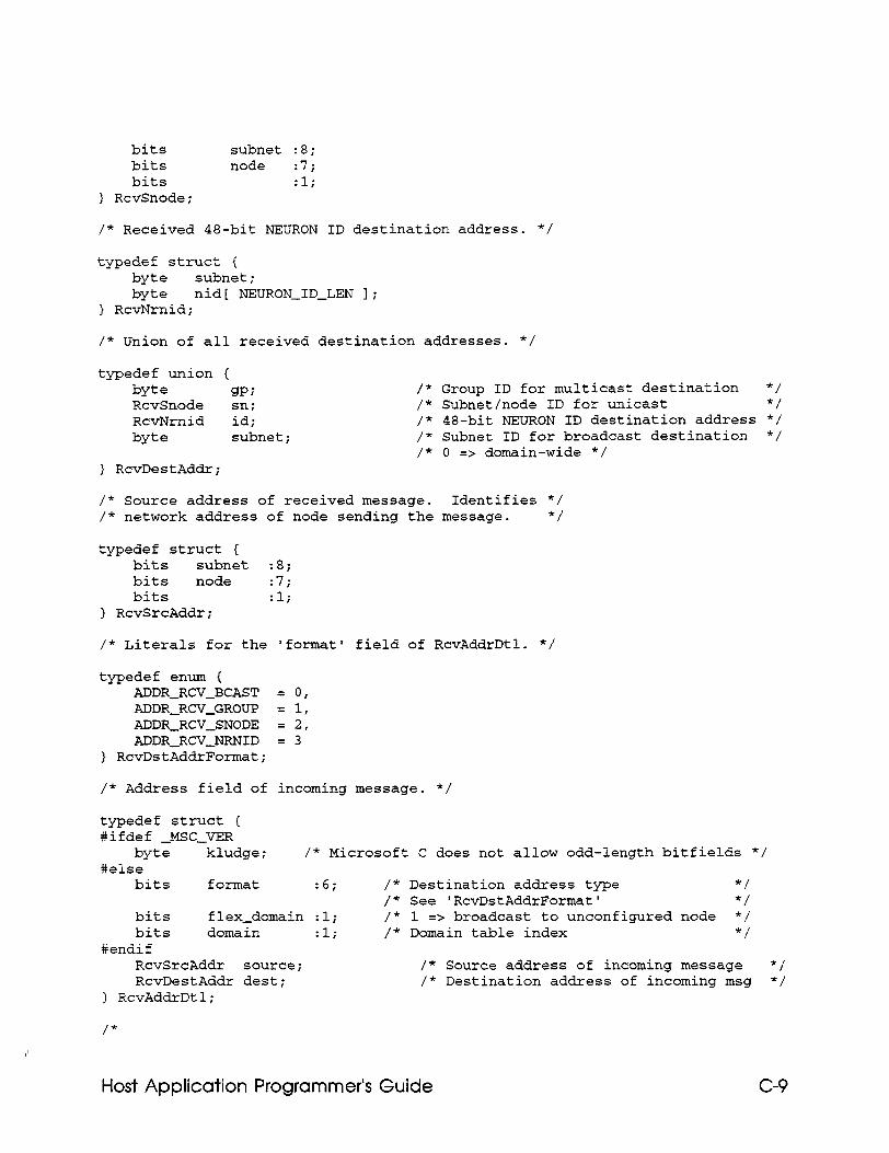
bits subnet :8; bits node :7; bits :li
) RcvSnode;
/* Received 48-bit NEURON ID destination address. */
typedef struct ( byte subnet; byte nid[ NEURON-ID-LEN I;
) RcvNrnid;
/* Union of all received destination addresses. */
typedef union ( byte gPi RcvSnode sn; RcvNrnid id; byte subnet;
> RcvDestAddr;
/* Group ID for multicast destination */ /* Subnet/node ID for unicast */ /* 48-bit NEURON ID destination address */ /* Subnet ID for broadcast destination */ /* 0 => domain-wide */
/* Source address of received message. Identifies */ /* network address of node sending the message. */
typedef struct { bits subnet :8; bits node :7i bits :I.;
) RcvSrcAddr;
/* Literals for the 'format' field of RcvAddrDtl. */
typedef enum { ADDR-RCV-BCAST = 0, ADDR-RCV-GROUP = 1, ADDR-RCV-SNODE = 2, ADDR-RCVJJRNID = 3
} RcvDstAddrFormat;
/* Address field of incoming message. */
typedef struct ( #ifdef &SC-VER
byte kludge; /* Microsoft C does not allow odd-length bitfields */ #else
bits format :6; /* Destination address type */ /* See 'RcvDstAddrFormat' */
bits flex-domain :l; /* 1 => broadcast to unconfigured node */ bits domain :li /* Domain table index */
#endif RcvSrcAddr source; /* Source address of incoming message */ RcvDestAddr dest; /* Destination address of incoming msg */
1 RcvAddrDtl;
/*
Host Application Programmer’s Guide C-9
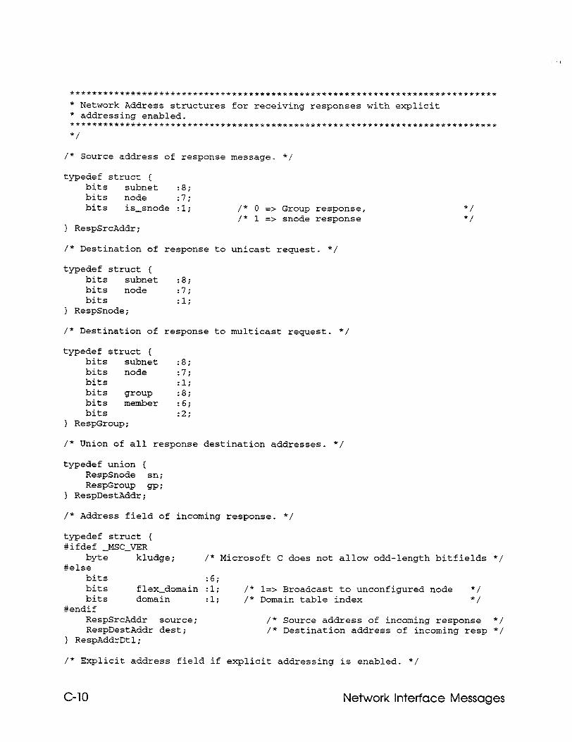
**********************~~*~**********~*******~***************~*************~* * Network Address structures for receiving responses with explicit * addressing enabled. *********fff*f**t********************+**~~~~~*~~~~~*~~~~**********~~******** */
/* Source address of response message. */
typedef struct ( bits subnet :8; bits node Z7i bits is-snode :l;
) RespSrcAddr;
/* 0 => Group response, */ /* 1 => snode response */
/* Destination of response to unicast request. */
typedef struct ( bits subnet :8; bits node :7i bits Eli
} RespSnode;
/* Destination of response to multicast request. */
typedef struct { bits subnet :8i bits node :7i bits :l; bits group :8; bits member :6; bits :2;
) RespGroup;
/* Union of all response destination addresses. */
typedef union ( RespSnode sn; RespGroup gPi
3 RespDestAddr;
/* Address field of incoming response. */
typedef struct { #ifdef &SC-VER
byte kludge; /* Microsoft C does not allow odd-length bitfields */ #else
bits :6; bits flex-domain :li /* l=> Broadcast to unconfigured node */ bits domain Eli /* Domain table index */
#endif RespSrcAddr source; /* Source address of incoming response */ RespDestAddr dest; /* Destination address of incoming resp */
) RespAddrDtl;
/* Explicit address field if explicit addressing is enabled. */
C-10 Network Interface Messages
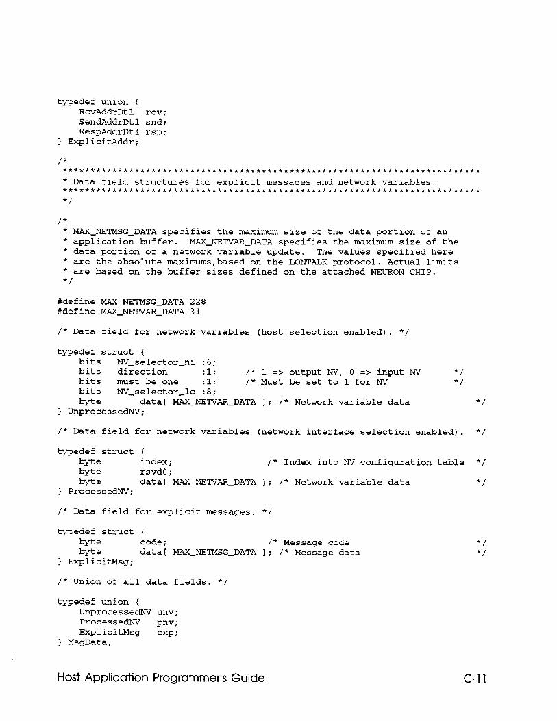
typedef union ( RcvAddrDtl rev i SendAddrDtl snd; RespAddrDtl rsp;
] ExplicitAddr;
/* * MAXJETMSG-DATA specifies the maximum size of the data portion of an * application buffer. MAXJETVAR-DATA specifies the maximum size of the * data portion of a network variable update. The values specified here * are the absolute maximums,based on the LONTALK protocol. Actual limits * are based on the buffer sizes defined on the attached NEURON CHIP. */
#define MAXJ'ETMSG~DATA 228 ##define MAXJETVAR_DATA 31
/* Data field for network variables (host selection enabled). */
typedef struct ( bits NV-selector-hi :6; bits direction :l; /* 1 => output NV, 0 => input NV bits must-be-one :li /* Must be set to 1 for NV bits NV-selector-lo :8; byte data[ MAXJETVAR~DATA 1; /* Network variable data
] UnprocessedNV;
*/ */
*/
/* Data field for network variables (network interface selection enabled). */
typedef struct { byte index; /* Index into NV configuration table */ byte rsvd0; byte data1 MAXJETVAR~DATA I; /* Network variable data */
} PrOCeSSdNVi
/* Data field for explicit messages. */
typedef struct ( byte code; /* Message code byte data[ MAXJETMSG-DATA 1; /* Message data
} ExplicitMsg;
/* Union of all data fields. */
typedef union { UnprocessedNV UIIV;
ProcessedNV PnVi
ExplicitMsg exp i
} MsgData;
*/ */
Host Application Programmer’s Guide C-11
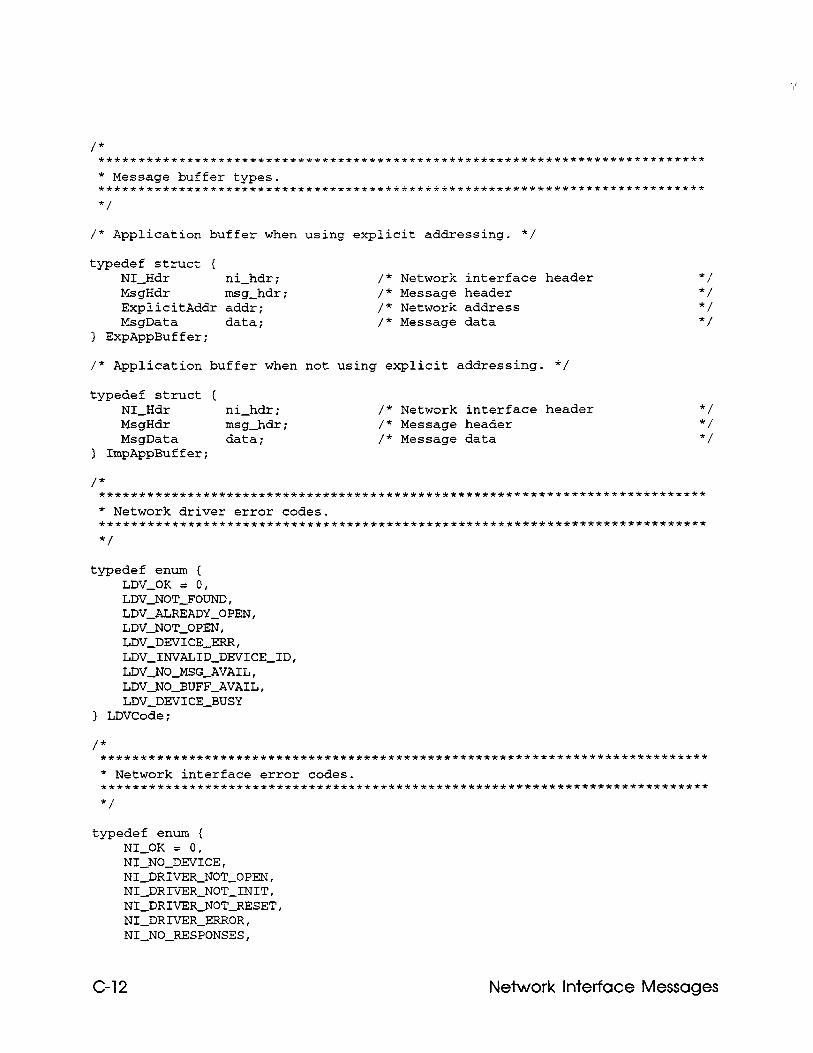
/* Application buffer when using explicit addressing. */
typedef struct { NI-Hdr ni-hdr; MsgHdr msg-hdr; ExplicitAddr addr; MsgData data;
1 ExpAppBuffer;
/* Network interface header /* Message header /* Network address /* Message data
/* Application buffer when not using explicit addressing. */
typedef struct ( NI-Hdr ni-hdr; /* Network interface header MsgHdr msg-hdr; /* Message header MsgData data; /* Message data
) ImpAppBuffer;
*/ */ */
/* ******+*************~~~~~~~******f*~~~~~~~~~~~*~~~~***********~******** * Network driver error codes. *****************************************~********************************** */
typedef enum { LDV-OK = 0, LDV-NOT-FOUND, LDV-ALREADY-OPEN, LDV-NOT-OPEN, LDV-DEVICE-ERR, LDV~INVALID~DEVICE~ID, LDV-NO-MSG-AVAIL, LDV-NO-BUFF-AVAIL, LDV-DEVICE-BUSY
> LDVCode;
typedef enum { NI-OK = 0, NI-NO-DEVICE, NI-DRIVER-NOT-OPEN, NI-DRIVER-NOT-INIT, NI-DRIVER-NOT-RESET, NI-DRIVER-ERROR, NI-NO-RESPONSES,
C-12 Network Interface Messages
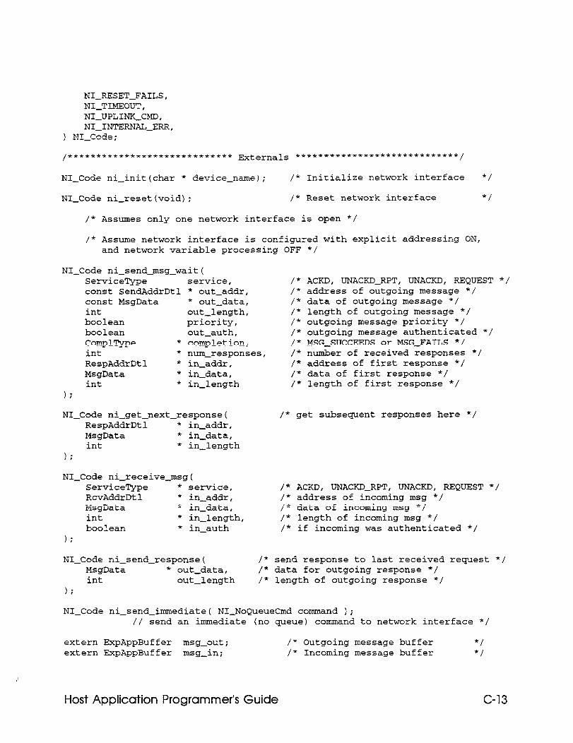
NI-RESET-FAILS, NI-TIMEOUT, NI-UPLINK-CMD, NI-INTERNAL-ERR,
) NI-Code;
,f********X+**f********++tf*** Externals ~*****t***i+********~~~~~**~~,
NI-Code ni-init(char * device-name); /* Initialize network interface */
NI-Code ni-reset(void); /* Reset network interface */
/* Assumes only one network interface is open */
/* Assume network interface is configured with explicit addressing ON, and network variable processing OFF */
NI-Code ni-send-msg-wait( ServiceType const SendAddrDtl const MsgData int boolean boolean ComplType * int * RespAddrDtl * MsgData * int *
1;
service, * out-addr, * out-data, out-length, priority, out-auth, completion, num-responses, in-addr, in-data, in-length
/* /* /* /* /* /* /* /* /* /* /*
ACKD, UNACKD-RPT, UNACKD, REQUEST */ address of outgoing message */ data of outgoing message */ length of outgoing message */ outgoing message priority */ outgoing message authenticated */ MSG-SUCCEEDS or MSG-FAILS */ number of received responses */ address of first response */ data of first response */ length of first response */
NI-Code ni-get-next-response( RespAddrDtl * in-addr, MsgData * in-data, int * in-length
\ .
NI-Code ni-receive-msg( ServiceType * service, RcvAddrDtl * in-addr, MsgData * in-data, int * in-length, boolean * in-auth
);
NI-Code ni-send-response( MsgData * out-data, int out-length
);
/* get subsequent responses here */
/* ACKD, UNACKD-RPT, UNACKD, REQUEST */ /* address of incoming msg */ /* data of incoming msg */ /* length of incoming msg */ /* if incoming was authenticated */
/* send response to last received request */ /* data for outgoing response */ /* length of outgoing response */
NI-Code ni-send-immediate( NI-NoQueueCmd command ); // send an immediate (no queue) command to network interface */
extern ExpAppBuffer msg-out; /" Outgoing message buffer */ extern ExpAppBuffer msg-in; /* Incoming message buffer */
Host Application Programmer’s Guide C-13
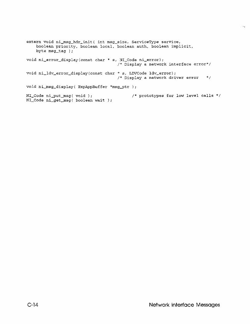
extern void ni-msg-hdr-init( int msg-size, ServiceType service, boolean priority, boolean local, boolean auth, boolean implicit, byte msg-tag );
void ni-error-display(const char * s, NI-Code ni-error); /* Disolay a network interface error*/
void ni-ldv-error-display(const char * s, LDVCode ldv-error); /* Display a network driver error */
void ni-msg-display( ExpAppBuffer *msg_ptr );
NI-Code ni_put-msg( void ); NI-Code ni-get-msg( boolean wait );
/* prototypes for low level calls */
C-14 Network interface Messages
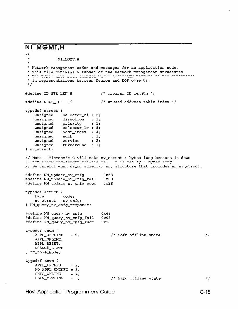
NI-MGMT.H /*
* NI-MGMT.H * * Network management codes and messages for an application node. * This file contains a subset of the network management structures * The types have been changed where necessary because of the difference * in representations between Neuron and DOS objects. */
#define ID-STR-LEN 8 /* program ID length */
#define NULL-IDX 15 /* unused address table index */
typedef struct unsigned unsigned unsigned unsigned unsigned unsigned unsigned unsigned
1 nv-struct;
1 selector-hi direction priority selector-lo addr-index auth service turnaround
: 6; : 1; : 1; : 8; : 4; : 1; : 2; : 1;
// Note - Microsoft C will make nv-struct 4 bytes long because it does // not allow odd-length bit-fields. It is really 3 bytes long. // Be careful when using sizeof() any structure that includes an nv-struct.
#define NM-update-nv-cnfg Ox6B #define NM-update-nv-cnfg-fail OxOB #define NM-update-nv-cnfg-succ Ox2B
typedef struct { byte code; nv-struct nv-cnfg;
1 NM-query-nv-cnfg-response;
#define NM-query-nv-cnfg 0x68 #define NM-querypv-cnfg-fail 0x08 #define NM-querypv-cnfg-succ 0x28
typedef enum ( APPL-OFFLINE = 0, APPL-ONLINE, APPL-RESET, CHANGE-STATE
) nm-node-mode;
/* Soft offline state
typedef enum { APPL-UNCNFG 2, NO-APPL-UNCNFG : 3, CNFG-ONLINE = 4, CNFG-OFFLINE = 6, /* Hard offline state
*/
*/
C-15 Host Application Programmer’s Guide
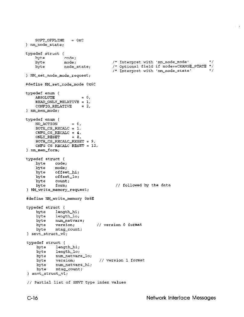
SOFT-OFFLINE = oxc ) r-m-node-state;
typedef struct { byte code: byte mode; byte node-state;
> NM~set~node~mode~request;
#define m-set-node-mode Ox@
typedef enum { ABSOLUTE 0, REA-ONLY-RELATIVE 1 1, CONFIGJELATIVE = 2,
I nm-mam-mode;
typedef enum { NO-ACTION 0, BOTH-CS-RECALC 1 1, CNFG-CSJECALC = 4, ONLY-RESET 8, BOTH-CS-RECALC-;ESET = 9, CNFG-CS-RECALC-RESET = 12,
1 nm-mem-form;
typedef struct ( byte code; byte mode; byte offset-hi; byte offset-lo; byte count; byte form;
1 NM-write-memory-request;
/* Interpret with 'run-node-mode' */ /* Optional field if mode==CHANGE-STATE */ /* Interpret with 'nm-node-state' */
// followed by the data
#define NM-write-memory Ox6E
typedef struct { byte length-hi; byte length-lo; byte nun--netvars; byte version; byte mtag-count;
> snvt-struct_vO;
// version 0 format
typedef struct { byte length-hi; byte length-lo; byte num-netvars-lo; byte version; // version 1 format byte num-netvars-hi; byte mtag-count;
) snvt-struct-vl;
// Partial list of SNVT type index values
C-16 Network Interface Messages
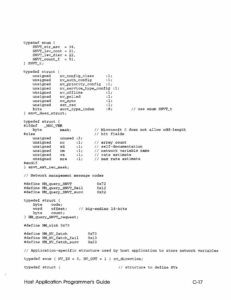
typedef enum { SNVT-str-asc = 36, SNVI-lev-cant = 21, SNVT-lev-disc = 22, SNVT-count-f = 51,
> SNVT_ti
typedef struct { unsigned nv-config-class :I.; unsigned nv-auth-config Zli unsigned nv-priority-config :l; unsigned nv-service-type-config ~1; unsigned nv-offline :l; unsigned nv_polled :l; unsigned nv-sync :l; unsigned ext-ret :l; bits snvt-type-index ~8;
) snvt-desc-struct; // use enum SNVl-t
typedef struct { #ifdef -MSC-VER
byte mask; #else
unsigned unused unsigned nc unsigned sd unsigned nm unsigned re unsigned mre
#endif > snvt-ext-ret-mask;
:3; :l; :li :l; :l; :l;
// Microsoft C does not allow odd-length // bit fields
// array count // self-documentation // network variable name // rate estimate // max rate estimate
// Network management message codes
#define NM-query-SNVT 0x72 #define NM-query-SNVT-fail 0x12 #define NM-query_SMrI-succ 0x32
typedef struct { byte code; word Offset; // big-endian 16-bits byte count;
1 NM_gue?Zy-SNV!-request;
#define NM-wink 0x70
#define NM-NV-fetch 0x73 #define NM_NV_fetch-fail 0x13 #define NM-NV-fetch-succ 0x33
// Application-specific structure used by host application to store network variables
typedef enum { NV-IN = 0, NV-OUT = 1 ] nv-direction;
typedef struct { // structure to define NVs
Host Application Programmer’s Guide C-17
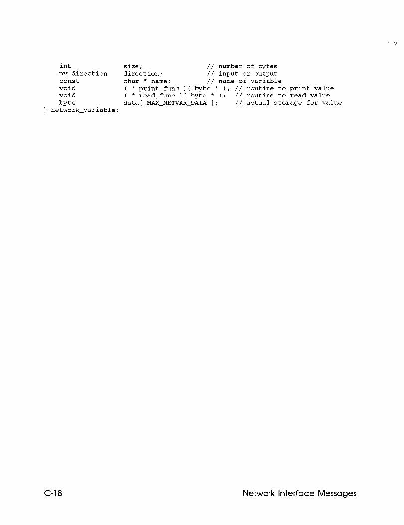
int Size; // number of bytes nv-direction direction; // input or output const char * name; // name of variable void void I
* print-func I( byte * ); // routine to print value * read-func )( byte * ); // routine to read value
byte data[ MAXJEI'V~~DATA 1; // actual storage for value ] network-variable;
C-18 Network Interface Messages
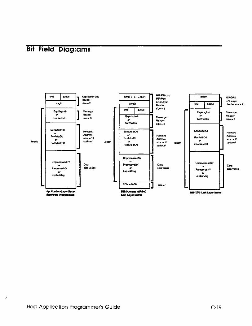
Bit Field Diagrams
Length
EqMsgHdr w
NetVarHdr
SendAddrDtl
Rc.~ddlDtl
Flsddr MI
UnprocessedNV
ProoikdN”
ApplicatiOll-by Header size-2
N&WOfk Address size - 11 qofional
Data size varies
length
CMDXFER-0x01
length
ExpMsgHdr Q
NetVarHdr
SendAddrDtl
R:LdrDtl
Re$ddrDtI
Unp-s.sdNV or
P-s&NV
Exp&sg
EOM -O&l
Host Application Programmer’s Guide
MIPmO and MIPlP50 Link-Layer Header she-3
Message Header sire-3
1 Network Address size -11 optional
Data size varies
length
length
T
ExpMsgHdr 0
NetVarHdr
UnprocessedNv w
ProcessedNV
EXPliLg
2 .
.
MP/DPS Link-layer Bulfer
C-19
MIPIDPS Link-layer Header size - 2
Message Header size-3
Network Address she - 11 optional
Data size varies
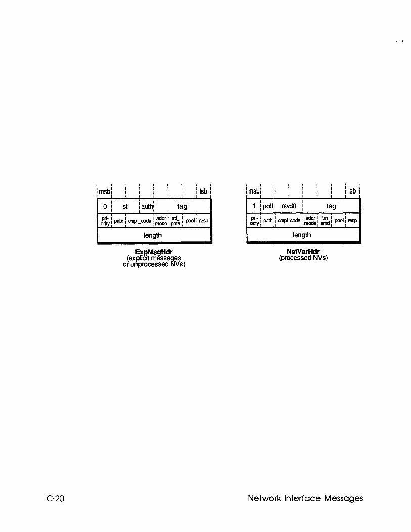
length length
ExpMsgHdr (explicit messa es
or unprocessed 14 Vs)
C-20
NetVarHdr (processed NVs)
Network Interface Messages
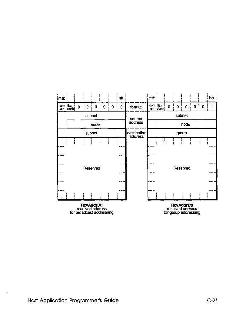
1 source address
I I node I
address
Reserved
--- m-e
---
---
Reserved ---
em-
_-- ---
_-- ---
I I
I I !
I I I I I I I
RcvAddrDtl RcvAddrDtl received address received address
for broadcast addressing for group addressing
Host Application Programmer’s Guide C-21
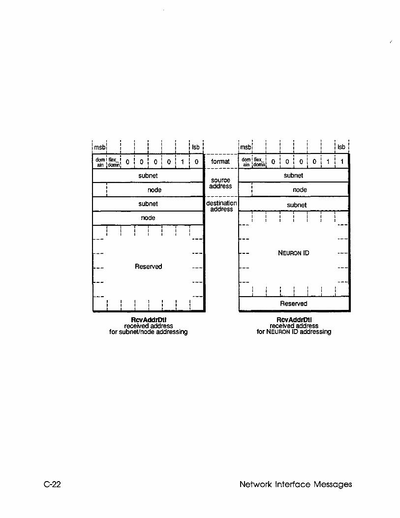
krisb; ; 1 I I f i Isb 1 I I I I I I I dfy$=.=-i 0 i 0 i 0 i 0 i 1 i 0
I I I I I I I subnet
1 I I node I subnet
node I I I I I I I I
I f I I I I
I I I I I m-v ---
subnet source
address 1 I node 1 --------
destip&n subnet I I I I I I I
i f I I I I I !
--- ---
--- ---
--- --- -mm NEURON ID -we
-me Resewed s-m --- me-
--- ---
--- ---
I I I I
I I ! ; I
--- m-w
i i i i i i i I 1 I I I I I
Resewed
RcvAddrDtl RcvAddrDtl received address received address
for subnethode addressing for NEURON ID addressing
C-22 Network Interface Messages
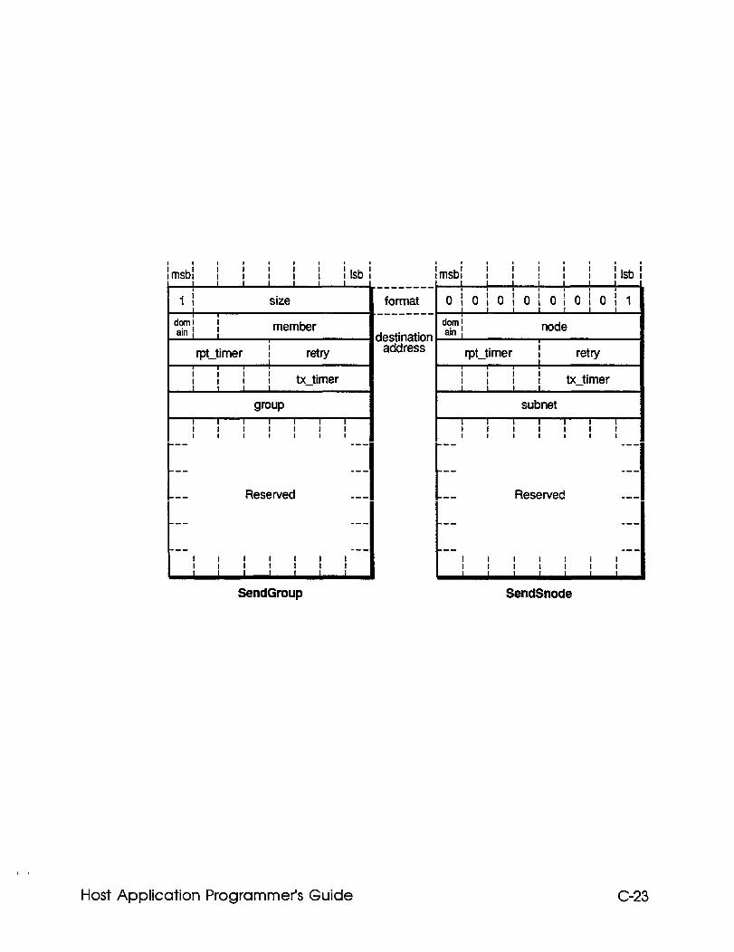
i i 1 msbl i i i i i I I I I I Isb I
I I I : i
1 I size I I
doml ; -...rLrr ain f I
fpt-timer I
’ -:--~~,
retr ! I i I I I I I I
I I 1 I I I I 1 I I I tx-timer I
W-timer I I
WuP subnet I I I I I I I I I I I I I I I I
f I I I I I
I I I I I 1 I I I I I I I I I
--- m-w --- _--
S-D _-- --- ---
--- Reserved _-- Reserved ---
--- me- --- _--
--- m-w
I I 1 I 1 I f
I I I I 1 I
SendGroup SendSnode
Host Application Programmer’s Guide C-23
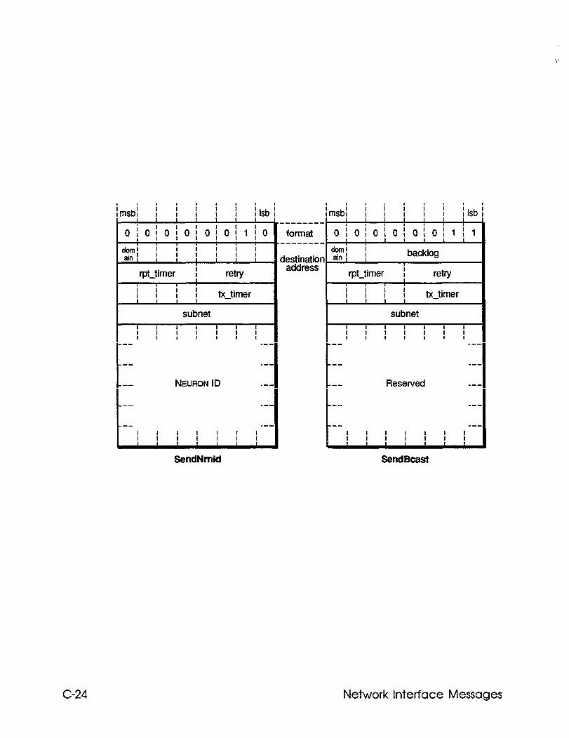
I I I I I
I I I i I ! I t i -- --
r -- -- --
NEURON ID
I 1 I I ! I I I
i i i i i i i I I lmsbl I I I I I I
I 1 I
i 0,0,0~0~0~0~1~ I
I I I-
hi I I I I f 1 ain , I I
tpt-timer I retry I I I I ! I I : &-timer
I I
subnet
SendNrnid Sendscast
isb i
0
.--
_--
se-
_--
.--
-
I I i i i I I I I I t Isb I I I .a------
format oioioioioioii~l I I I I I I I -w--w---
--a Reserved --.
--- --.
--- _-.
--- _-.
I I I I I I I
I I I t
C-24 Network Interface Messages
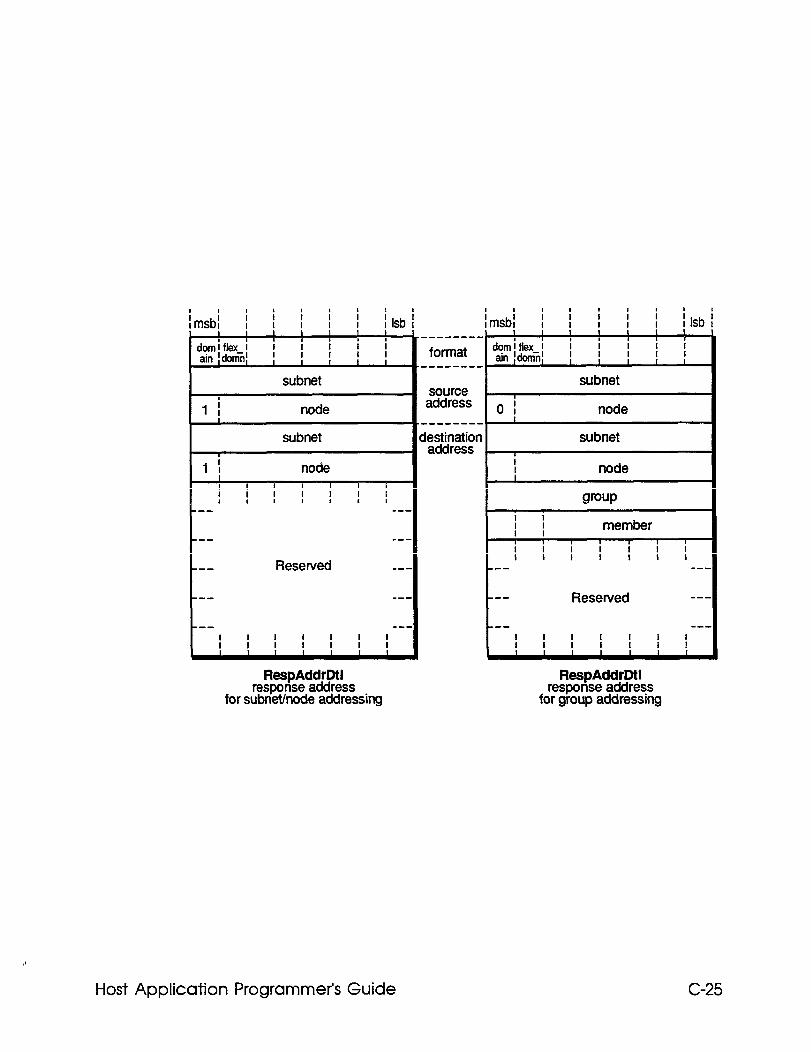
i i lmsbl i i i i i i i I Isb I
i i lmsbl i i i
i i i I I I I I I I I I I
I I I I I I l----,--,, I I I I I I 1
dmifkx i i i i i i 1
ain ldornni format domiflex i 1 i 1 i i I I 1 I I ain #onii~ I I I I 1 v-------e. 1
subnet subnet source
i 1 I node address 0 1 node
I 1 .-------- subnet d&&M& subnet
1 I node I I node
I I
I i
I I I I I I 8 i i WUP --- em-
I I
I I member --- V-B I I I I , I 1
i i I I
I I I
I I I --- Reserved m-s ---
--- Reserved
Rf?%pAddrDtl response address
for subnethode addressing
RespAddrDtl response address
for group addressing
Host Application Programmer’s Guide C-25
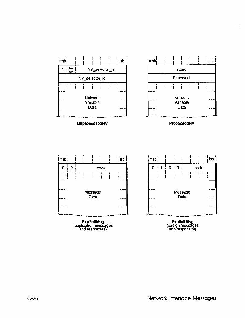
i i i I I I I i i lmsbl I I I I B
i i I Isb 1 I I I 1 I I 1 ;djrecI
c
, bon I NV-selector-h
NV~selector~lo
1 msbl i i i ) j I j i I j ~ Isb i
Reserved I
I I I I
I ! . . . ! . I i 1 I . 1 . I . ! f --- -- --- ---
Network Network --- _- --- --- Variable Variable
--- Data _-
e------w___ --____------- ----
UnprocessedNV
--- Data ---
c-------____ -_____----- __-----
ProcessedNV
i Ir
0 0
i
t
t I I
i i i i i I I I I I Isb I I
code
i I i i I I I f --.
Message Data
--.
--.
_-.
C- ------___ -_______e----- -s-.
Ex IlcltMsg (applica ion messages r
ExpllcltMsg
and responses) (foreign messages
and responses)
; ir nst
0
--
--
--
Message Data
C- -----__ ---________------
Isb 1
C-26 Network Interface Messages
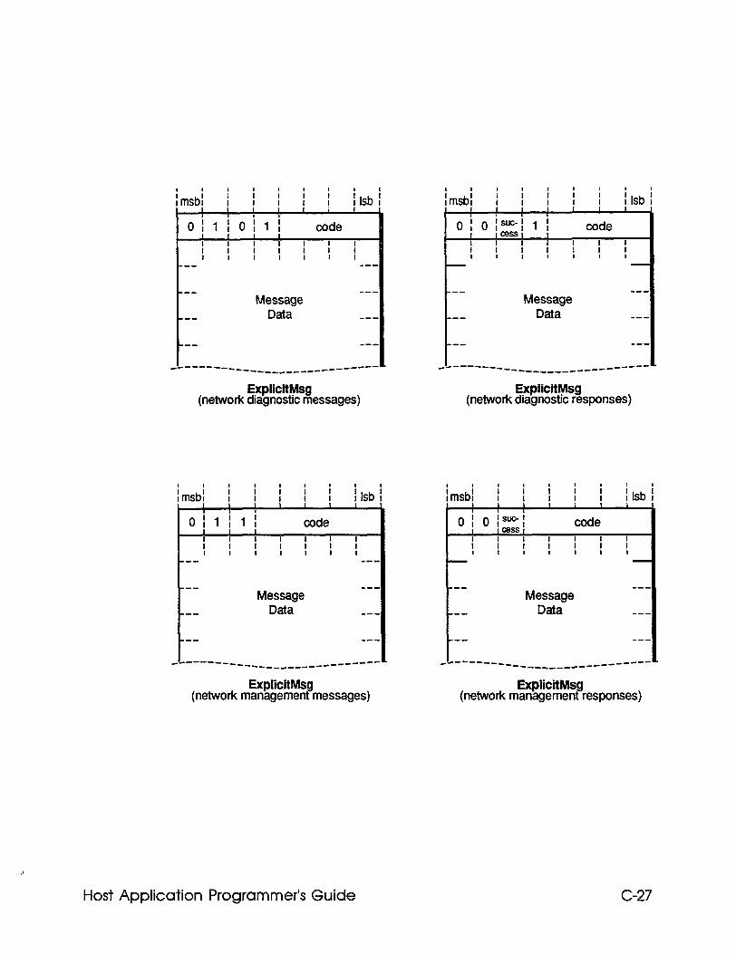
i i lmsbl i I I I i I i i i
I I I I I I Isb I
I I I I
I 1
1 IOil i
Message -- Data e--
-- ---
_a-----__ ---___c_____c------- I
ExpllcltMsg (network diagnostic messages)
ExplicitMsg (network diagnostic responses)
i i i lmsbl I i i I i
i i i I I Isb I
I I I I I I I I
Olllii code I I I
I I I I I I I I
I I I I I I I m-v m-s
---
Message ---
Data -em
--- ---
_----a-__ ---_________---------
ExplicitMsg (network management messages)
ExplicitMsg (network management responses)
i I I I I i i i i lmsbl I I I I I
i i I Isb I
I I I I I I / I 8
0; 0 1 WC- I 1 ; code
I ICeSSl I
I I I f I I
i I
I I I I I I
e-v
Message ---
--- Data ---
--- _--
_c-----__ -----____---- ---e---c
i i i i i i
i i i i i i
i i I I
I msbl I msbl I I i i I I I I I Isb I I Isb I
1 1 I I I I I I I I I I I I 1 1
0 I 0 F&1 0 I 0 F&1 code code
i i I I I I I I i i I I I I
I I I I
I I I I I I I I I I I 1 I 1
--- ---
--- --- Message Message
Data Data
--- ---
_-- _--
--- --- _-- _--
I _a-----___ _a-----___ ----___------ ----___------ __---- 1 __-----
Host Application Programmer’s Guide C-27

Appendix D Network interface Commands
This appendix defines the network interface commands specified in a data transfer from a host application to the network interface. All data transfers (non-NULL transfers) to the network interface include a length byte and a command byte.
Host Application Programmer’s Guide D-1
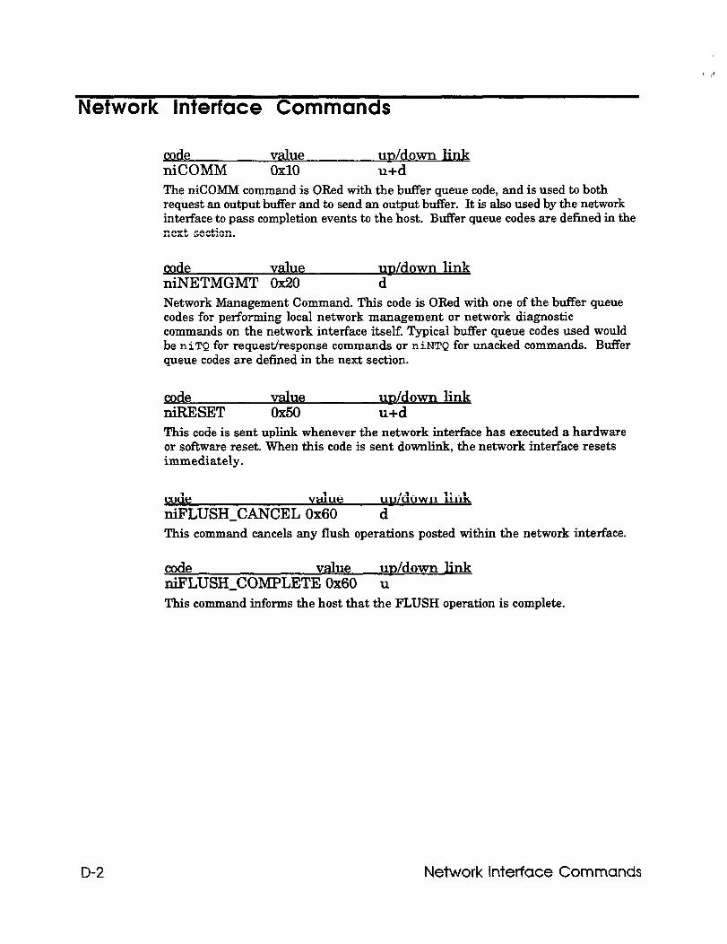
,,
Network Interface Commands
code value m/down link niCOMM 0x10 u+d The niCOMM command is ORed with the buffer queue code, and is used to both request an output buffer and to send an output buffer. It is also used by the network interface to pass completion events to the host. Buffer queue codes are defined in the next section.
cod value ni;ETMGMT 0x20
m/down link d
Network Management Command. This code is ORed with one of the buffer queue codes for performing local network management or network diagnostic commands on the network interface itself. Typical buffer queue codes used would be niTQ for request/response commands or niNTQ for unacked commands. Buffer queue codes are defined in the next section.
d Z&SET
value m/down link 0x50 u+d
This code is sent uplink whenever the network interface has executed a hardware or software reset. When this code is sent downlink, the network interface resets immediately.
code value m/down link niFLUSHJXNCEL 0x60 d This command cancels any flush operations posted within the network interface.
code value m/down hk niFLUSH_COMPLETE 0x60 u This command informs the host that the FLUSH operation is complete.
D-2 Network Interface Commands
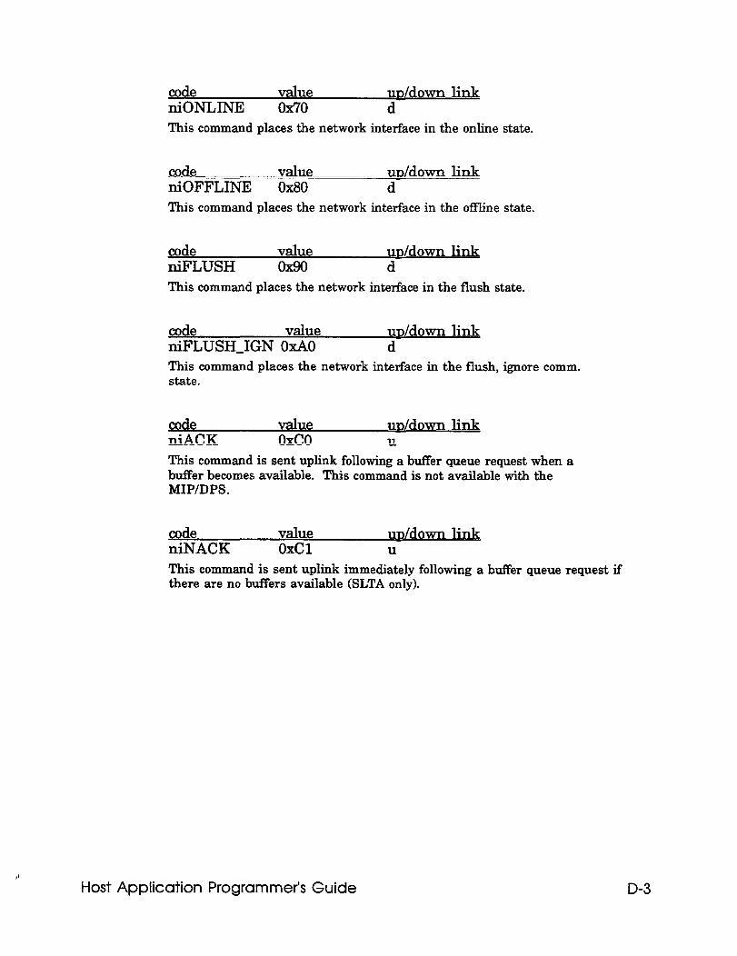
code value m/down link niONLINE 0x70 d This command places the network interface in the online state.
code value m/down link niOFFLINE OX80 d This command places the network interface in the offline state.
code value u&down link niFLUSH Ox!30 d This command places the network interface in the flush state.
code value m/down link niFLUSH_IGN OXAO d This command places the network interface in the flush, ignore comm. state.
code value m/down link niACK oxco U
This command is sent uplink following a buffer queue request when a buffer becomes available. This command is not available with the MIP/DPS.
9 de link niNACK OxCl U
This command is sent uplink immediately following a buffer queue request if there are no buffers available (SLTA only).
Host Application Programmer’s Guide D-3
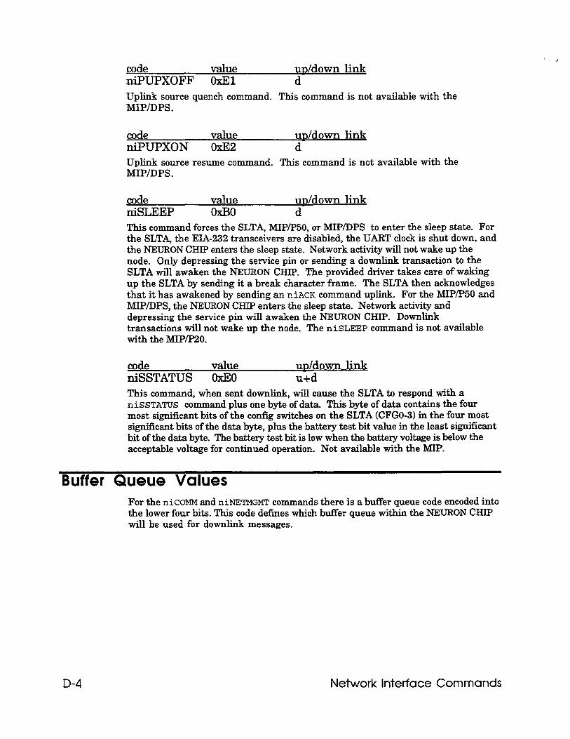
code value m/down hk niPUPXOFF OxEl d Uplink source quench command. This command is not available with the MIP/DPS.
code value u&down link niPUPXON OxE2 d Uplink source resume command. This command is not available with the MIP/DPS.
_cod niSemEP
value m/down hk OXBO d
This command forces the SLTA, MIP/P50, or MIP/DPS to enter the sleep state. For the SLTA, the EIA-232 transceivers are disabled, the UART clock is shut down, and the NEURON CHIP enters the sleep state. Network activity will not wake up the node. Only depressing the service pin or sending a downlink transaction to the SLTA will awaken the NEURON CHIP. The provided driver takes care of waking up the SLTA by sending it a break character frame. The SLTA then acknowledges that it has awakened by sending an niACK command uplink. For the MIP/P50 and MIP/DPS, the NEURON CHIP enters the sleep state. Network activity and depressing the service pin will awaken the NEURON CHIP. Downlink transactions will not wake up the node. The niSLEEP command is not available with the MIP/P20.
code value m/down link niSSTATUS OxEO u+d This command, when sent downlink, will cause the SLTA to respond with a niSSTATUS command plus one byte of data. This byte of data contains the four most significant bits of the config switches on the SLTA (CFGO-3) in the four most significant bits of the data byte, plus the battery test bit value in the least signit%ant bit of the data byte. The battery test bit is low when the battery voltage is below the acceptable voltage for continued operation. Not available with the MIP.
Buffer Queue Values For the niCOMM and niNETMGMT commands there is a buffer queue code encoded into the lower four bits. This code defines which buffer queue within the NEURON CHIP will be used for downlink messages.
D-4 Network interface Commands
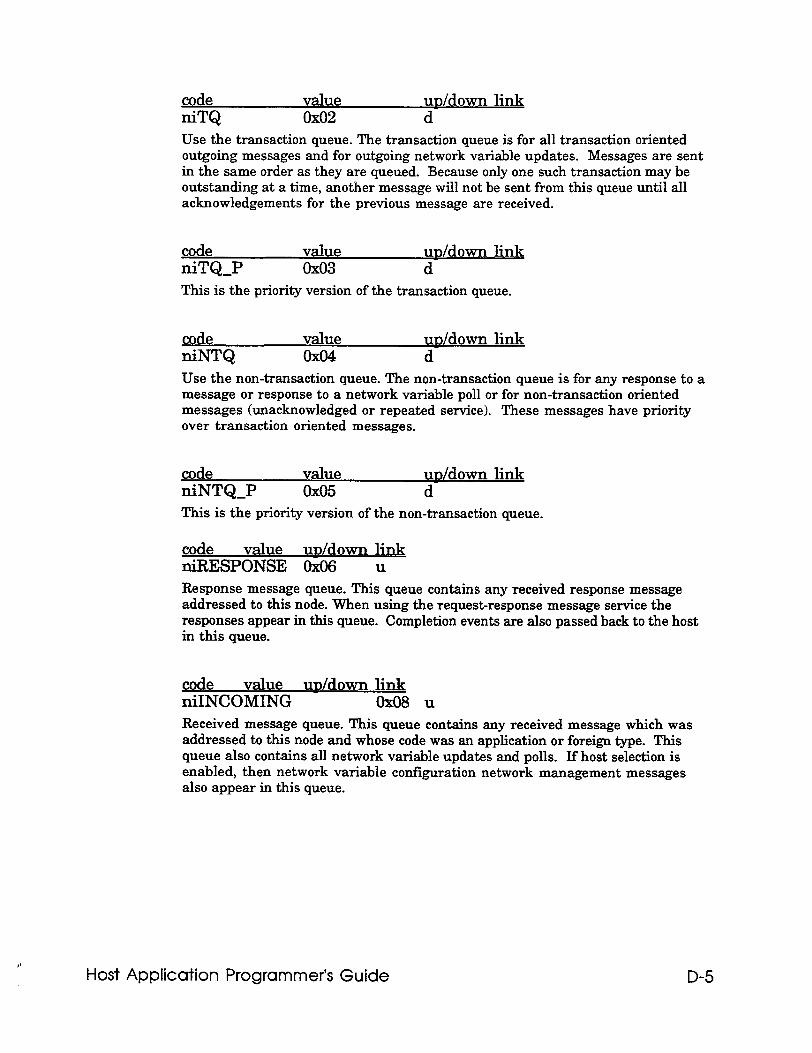
code value uD/down link niTQ 0x02 d Use the transaction queue. The transaction queue is for all transaction oriented outgoing messages and for outgoing network variable updates. Messages are sent in the same order as they are queued. Because only one such transaction may be outstanding at a time, another message will not be sent from this queue until all acknowledgements for the previous message are received.
code value niTQ_P 0x03
u&down link d
This is the priority version of the transaction queue.
code value &down link niNTQ 0x04 d Use the non-transaction queue. The non-transaction queue is for any response to a message or response to a network variable poll or for non-transaction oriented messages (unacknowledged or repeated service). These messages have priority over transaction oriented messages.
gode niNTQ_P
value 0x05
uD/down link d
This is the priority version of the non-transaction queue.
code value uD/down link niRESPONSE 0x06 u
Response message queue. This queue contains any received response message addressed to this node. When using the request-response message service the responses appear in this queue. Completion events are also passed back to the host in this queue.
code value uD/down link niINCOMING OXO8U
Received message queue. This queue contains any received message which was addressed to this node and whose code was an application or foreign type. This queue also contains all network variable updates and polls. If host selection is enabled, then network variable configuration network management messages also appear in this queue.
Host Application Programmer’s Guide D-5

Index
A acknowledged 3-8
acknowledgement 3-5
adapter-info-s 4-4
address table 3-5
AddrType C-7
&ERT byte 5-4
application-layer header 3-2
application buffer 3-2,3-3,3-4,3-6,3-g, 3-10,3-11,42,4-3,45,46 layer 2-2 message 3-2,3-8
asynchronous update l-4
authenticated B-7
autobaud 5-3
AX register 4-6
Host Application Programmer’s Guide I-1
B baud rate 5-3
bind-info 3-5
bindable B-7
binding l-4,3-11, B-7
bit-field diagrams C-l, C-19
buffer options 3-6
buf’Ter queue values D-4
building the application buffer 3-11
C callback 4-6
function 4-6
CLOSE 45
close0 4-2
cmpl-code 3-4,3-7, C-5
command-table A-7
communications processor l-2, l-3
completion code 5-3 event 3-2,3-3,3-4,3-7,3-10
ComplType C-5
config B-8
CONFIG.SYS 5-2
configuration options 3-4
connection information 3-5
connections l-4, 3-11
I-2 index
control network l-5
controller-like applications l-4
custom network interfaces 2-2
D data C-3
field 3-3,3-8 logging l-4 transfer 3-2,3-3
default message buffers A-28
destination node 5-2,5-3 address 3-2,3-5
diagnostic messages 3-8,5-5
direct function call 4-6
DOS 43 driver 43
downlink l-5,3-2,3-4,5-4 buffers 3-7 timeouts 5-4 application buffers 3-2
driver direct functions 4-5 not installed 5-2
DS register 4-6
E EIA-232 interface l-6,2-2
error codes 54 conditions 4-5 handler 45
errors 5-2,5-3,54,5-5
Host Application Programmer’s Guide I-3
existing application l-3
ExpAppBuffer 3-2, C-12
explicit addressing 3-5 Of-T 3-3,3-5 on 3-2,3-3,3-5,3-11
explicit messages 1-4, 3-2, 3-8
ExpMsgHdr 3-2, C-2, C-5, C-6
exporting 3-12
extension records 3-12
external interface file 3-12, B-2, B-5, B-9
F flow control 2-7
FLUSH state 2-7,3-10
H HA.C A-2
handle value 45 handle-error A-14 handle-explicit-msg A-16 handlepetvar-msg A-16 handle-NV-fetch A-16 handle-query-nv-config A-15 handle-query_SNVT A-16 handle-set-mode A-15 handle-update-nv-config A-15
handshake 5-4
hardware failure 5-4
host 1-5 application architecture l-2,2-2 applications l-2, 1-3, l-4, l-5,3-6,3-7,3-9,3-10,5-2
I-4 Index
hardware failure 5-4 interface 1-6 node l-6 processor 1-6 interface 2-2 selection l-4,3-3,3-4,3-8,3-9
ID-STR-LEN C-15
ImpAppBuffer 3-2, C-13
import 3-12
installgrogID() 3-11
int error 45
int read 45
initializing the network interface 5-3
input buffer 45
interrupt 46 driven 5-3
invalid argument 5-2
IOCTL 44
ioctl() 44, 45
IRET 46
L layers l-2,2-2,2-3
ldbjmport-xifo 3-12
LDV-ALREADY-OPEN 5-4
LDV-DEVICE-BUSY 3-7,5-5
LDV-DEVICE-ERR 5-3, 5-4
Host Application Programmer’s Guide I-5
LDV-NO-BUFF-AVAIL 3-7, 4-6, 5-5
LDV-NO-BUFF-AVAIL 5-4
LDV-NO-MSG-AVAIL 4-6, 5-5
LDV-NOT-OPEN 5-4
LDV-OK 5-4
ldv-read-direct0 4-3, 4-6
ldv-register0 4-4, 4-6
LDVCode C-12, C-14
ldv-write-direct0 4-4, 46
link-layer 2-2,2-3, 3-2 header 3-2
local network diagnostic commands 3-10
local network management commands 3-11
lock-up 5-5
LON database A-3
LONBUILDER 4-3, B-2, B-9
LONMANAGER API l-2,3-5,3-12,43,4-5,
LONTALK messages 3-2
loss of power 5-3
M main0 3-11
MAX-NETMSG-DATA C-12
MAXJETVAR-DATA C-12
media access control 3-6
I-6 index
message code 3-8 header 3-2, C-2 tag 3-8,3-11,3-E& B-2, B-5, B-10
messages receiving 3-2, 3-9 sending 3-2, 3-7
Microprocessor Interface Program see MIP
ME’ l-2, l-6,2-2,2-3,3-4,43,5-2,5-4, B-2 link-layer protocol 2-3 external interface file B-2 P/20 or PI50 2-2,5-4
monitoring l-4 network variables 3-5
Motorola 68332 processor l-3
MS-DOS l-3,42
MSG-FAILS 5-3
ms&p 5-4
MsgData 3-3, C-2, C-10, C-11, C-12, C-13
MsgHdr 3-2, C-2, C-5, C-6, C-12
N NetVarHdr 3-2, C-2, C-5, C-6
network address 3-2, C-2, C-12
network buffer 3-6
network control l-5
network diagnostic 3-4,3-10 message 3-2
network driver l-2, l-7,3-2,4-3,5-2,5-3 device driver 2-6 error strings A-29 interface structure A-28 services 4-1,4-2,43,4-4
Host Application Programmer’s Guide l-7
network interface l-2, l-4,1-5,1-6, l-7,2-2,3-4,3-10 command 2-2,3-2,3-10, C-2, D-2 configuration options 3-4 link-layer protocol 2-3 not installed 5-3 protocol l-7,2-2 selection l-4,3-2,3-4,3-8,3-9
network management l-4,3-4,3-8,3-10 messages 3-2,3-7,3-11 tool l-4,2-3,3-11, B-2
network monitor l-5
network variable l-7,3-11,3-12, A-6, B-2, B-5, B-10 62 14,3-4 4096 lJq3-4 configuration table 3-5,3-g fetch 3-9 index 3-3,3-g messages l-4,3-2 modification 3-4, 3-9 processing option 3-2 selection 3-4,3-g selector 3-3,3-g update 3-8
NEURON 3120TM CHIP 1-3
NEXRON 3150=“’ CHIP l-3
ni,get-next-response A-2
ni-handle-error0 5-2
ni,error-display0 A-37
ni_getsO A-37
NI-Hdr 3-2,4-5, C-5
ni-init 5-3, A-8
ni,receive-msg A-12
ni-reset A-9
ni-send 3-8
ni,send-immediate A-13
I-8 Index
ni-send-msgwait A-9
ni-send-response A-13
niACK 5-4, D-3
niCOMM + niNTQ 3-11
niCOMM D-2
niCOMM+niINCOMING 3-9
niCOMM+niRESPONSE 3-4,3-g
niFLUSH D-3
niFLUSH_CANCEL 2-3, 2-4, D-2
niFLUSH_COMPLETE D-2
niFLUSHJGN D-3
niINCOMING D-5
niNACK D-3
niNETMGMT + niNTQ 3-10
niNETMGMT + niTQ 3-10
niNETMGMT 3-7, D-2
niNTQ D-5
niNT&P D-5
niOFFLINE D-3
niONLINE D-3
niPUPXOFF D-4
Host Application Programmer’s Guide l-9
niPUPXON D-4
niRESET2-3,3-2,5-3,D-2
niRESPONSE D-5
niRESPONSE+niCOMM 3-7
niSLEEP D-4
niSSTATUS D-4
niTQ D-5
niT&P D-5
nm-node-state C-16
node self-documentation 3-12
NORMAL state 2-3
nv-config-table A-4
NV-poll A-17
nv-struct A-4
NV-update 3-8, A-16
nv-value-table A-6
0 off-chip memory l-3
OFFLINE 3-8,3-10, B-5, B-7
ONJJNE 3-8,3-10, B-7
OPEN 4-2
I-10
open0 4-2,5-2
output buffer 4-3
Index
P
parallel interface 2-2
path-spec 3-8
peer-to-peer l-5
physical layer 2-2
poll l-4,3-8 , B-8 request 3-8
power loss 5-3
priority 3-8, B-4
process_cmdO A-7
process-msg A-14
ProcessedNV 3-3,3-10, C-13
protocol layers l-2,2-2,2-3
a query 3-11
Query Net Variable Co&g 3-4,3-S
Query SNVT 3-9,3-11
query-received0 A-16
query&atusO 5-5, A-14
R RcvAddrDtl 3-3, C-2, C-9, C-11, C-13
RcvDestAddr C-9
RcvNrnid C-9
/* Host Application Programmer’s Guide l-11
RcvSnode C-9
RcvSrcAddr C-9
READ 4-5
read DOS function calls 4-4
receiving messages 3-4, 3-8
recursion 4-5
request/response 3-7,3-S
resetting the network interface 3-10
RespAddrDtl 3-3, C-2, C-10, C-11, C-13
RespDestAddr C-10
RespGroup C- 10
response 3-8
RespSnode C-10
RespSrcAddr C-10
S self-documenting 3-12, B-8
self-installation 3-11
SendAddrDtl 3-3, C-10
SendBcast C-8
SendGroup C-8
sending messages 3-7
SendNmid C-8
SendSnode C-8
Serial LONTALK Adapter See SLTA
Service Type B-7, C-5
l-12 Index
service pin 2-3
Set Node Mode 3-8
SLTA 1-2, l-6, l-7,2-2,2-3,2-4,3-4,3-5,3-7,3-12,43,5-2,5-3,5-4, B-2 link-layer protocol 2-2 node 1-7, host 24
SNVT 3-11,3-12, B-11 description table 3-12 header 3-11 import 3-11 structure 3-11
source address 3-2,3-5
special FLUSH state 2-3
special purpose transceiver 3-8
Standard Network Variable Type see SNVT
statistics 5-5
synchronized B-8
TAG B-5
tag field 3-7
target address decoding 3-4
timeout 5-4 reset 5-5
timers A-10, A-13
trnamd (turnaround) 3-8
type B-8
Host Application Programmer’s Guide l-13
U Unix 1-3
Unacknowledged/Repeated 3-8
UnprocessedNV 3-3,3-g, 3-10, C-11
Update Address 3-11
Update Net Variable Config 3-8
uplink l-7,3-9 buffers 3-7 application buffers 3-2
v VAR B-5
W
watchdog timeout 5-5
wink 3-8
WRITE 4-4
write DOS function calls 4-4
write token 54
l-14 Index