i ill11 ll111111 ill ill11 ill11 11111 11111 11111 11111 ... · microspheres with diameters from...
TRANSCRIPT
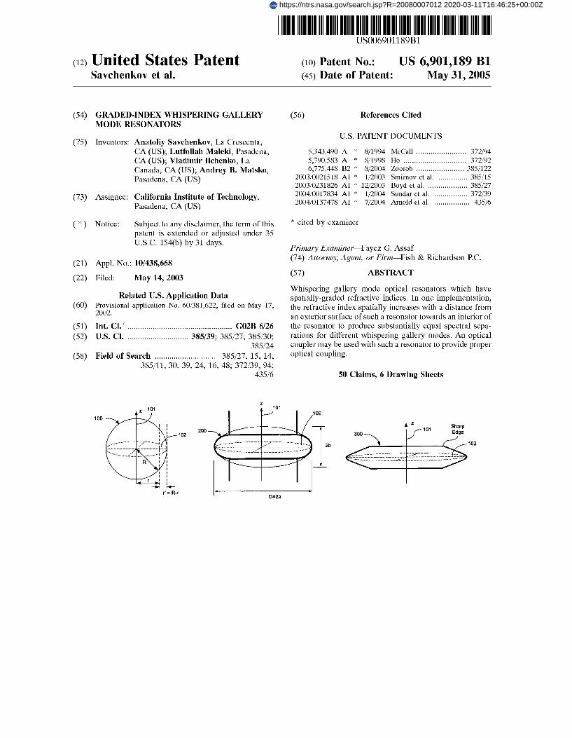
I Ill11 ll111111 Ill Ill11 Ill11 US006901189Bl IIIII 11111 11111 11111 11111 11111 llllll Ill1 1111 Ill1 (12) United States Patent (io) Patent No.: US 6,901,189 B1
Savchenkov et al. (45) Date of Patent: May 31,2005
(54) GRADED-INDEX WHISPERING GALLERY (56) References Cited MODE RESONATORS
Inventors: Anatoliy Savchenkov, La Crescenta, U.S. PATENT DOCUMENTS
(75) CA (US); Lutfollah Maleki, Pasadena, CA (US); Vladimir Ilchenko, La Canada, CA (US); Andrey B. Matsko, Pasadena, CA (US)
(73) Assignee: California Institute of Technology, Pasadena, CA (US)
Subject to any disclaimer, the term of this patent is extended or adjusted under 35 U.S.C. 154(b) by 31 days.
( * ) Notice:
(21) Appl. No.: 10/438,668
(22) Filed: May 14, 2003
Related U.S. Application Data (60) Provisional application No. 601381,622, filed on May 17,
2002.
(51) Int. C1.7 .................................................. G02B 6/26 (52) U.S. C1. ............................. 385/39; 385127; 385130;
385124 (58) Field of Search .............................. 385127, 15, 14,
385111, 30, 39, 24, 16, 48; 372139, 94; 43516
.....
- - k +
5,343,490 A * 811994 McCall ........................ 372194 5,790,583 A * 811998 Ho .............................. 372192 6,775,448 B2 * 812004 Zoorob ....................... 3851122
200310021518 A1 * 112003 Smirnov et al. .............. 385115 200310231826 A1 * 1212003 Boyd et al. ................... 385127 200410017834 A1 * 112004 Sundar et al. ................ 372139 200410137478 A1 * 712004 Arnold et al. ................. 43516
* cited by examiner
Primary ExaminerCayez G. Assaf (74) Attorney, Agent, or F i r m C i s h & Richardson P.C.
(57) ABSTRACT
Whispering gallery mode optical resonators which have spatially-graded refractive indices. In one implementation, the refractive index spatially increases with a distance from an exterior surface of such a resonator towards an interior of the resonator to produce substantially equal spectral sepa- rations for different whispering gallery modes. An optical coupler may be used with such a resonator to provide proper optical coupling.
50 Claims, 6 Drawing Sheets
102
r' = R-r I D=2a
https://ntrs.nasa.gov/search.jsp?R=20080007012 2020-03-11T16:46:25+00:00Z

U S . Patent May 31,2005 Sheet 1 of 6
100
- 4 -
r' = R-r
FIG. 2
US 6,901,189 B1
102
102
200 h
2b
D=2a I -
t
U S . Patent May 31,2005 Sheet 2 of 6
FIG. 3
US 6,901,189 B1
FIG. 4A
r' 400 Sharp 401A Edge
40
402
401B
FIG. 5A
Fiber
102
FIG. 46 Sharp
401 B
FIG. 56
Physical Contact
Prism
U S . Patent May 31,2005 Sheet 3 of 6 US 6,901,189 B1
0.5
0
-1 -8
-2.4
I I I I 1 I 0.5 I I .5 2
G ' R i f o
FIG. 7
U S . Patent
# \
'c. *' L
May 31,2005 Sheet 4 of 6 US 6,901,189 B1
I 0
I
7 rlR
FJO. 8
U S . Patent May 31,2005 Sheet 5 of 6 US 6,901,189 B1
- 1
r=0.9R F R
FIG. 9
U S . Patent May 31,2005 Sheet 6 of 6 US 6,901,189 B1
RE'I~EO
FIG. 10
US 6,901,189 B1 1 2
GRADED-INDEX WHISPERING GALLERY MODE RESONATORS
These and other implementations are now described in greater details as follows.
BRIEF DESCRIPTION OF THE DRAWINGS This application claims the benefit of U.S. Provisional
entire disclosure of which is incorporated herein by refer- ence as part of this application.
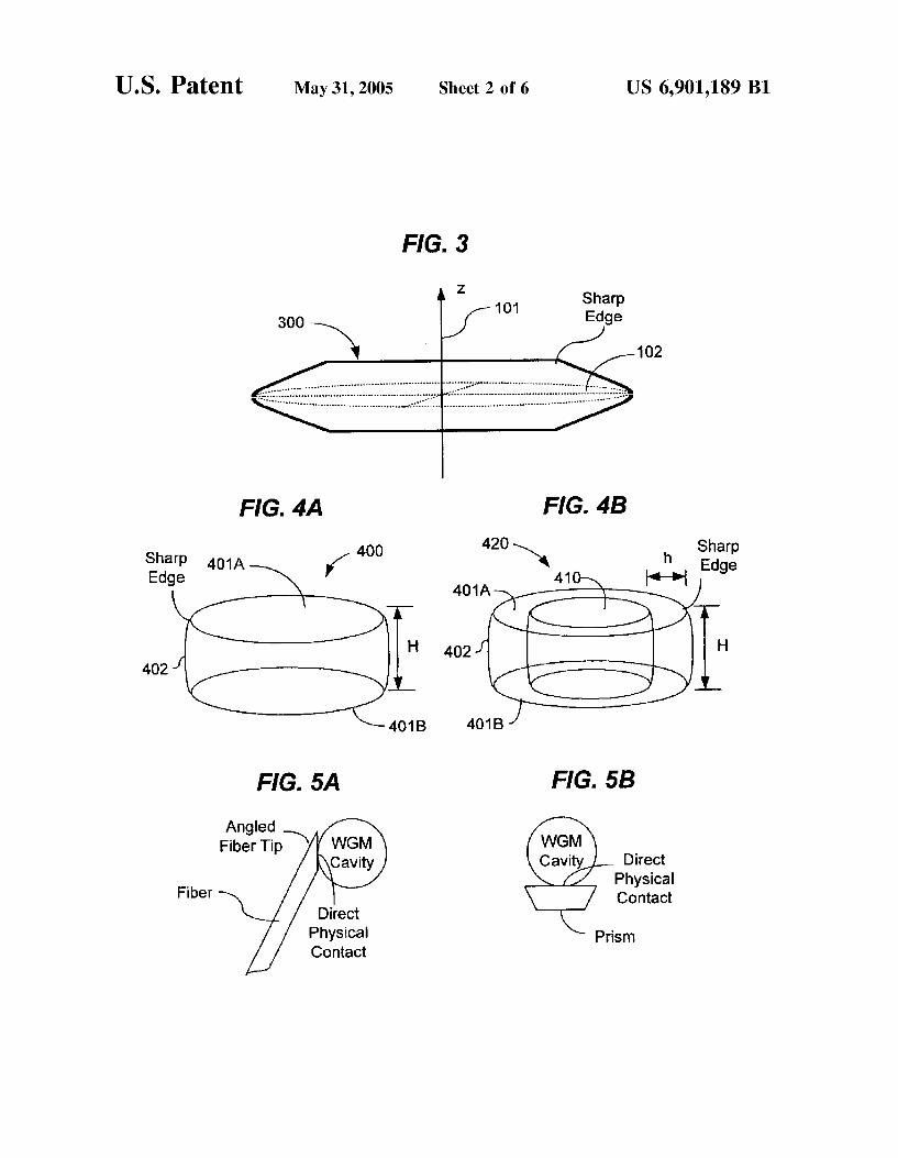
No. 60/381,622 On May 17, 2o02, the FIGS, 1, 2, 3, 4A, and 4B illustrate various exemplary resonator configurations with graded refractive indices that support whispering gallery modes.
STATEMENT REGARDING FEDERALLY FIGS. 5A and 5B illustrate two direct-contact evanescent
Of
SPONSORED RESEARCH coupling examples.
The systems and techniques described herein were made
subject to the provisions of Public Law 96-517 (35 USC 202) in which the Contractor has elected to retain title.
6 2 ’, 8 2 9 2 and lo show in the performance of work under a NASA contract, and are gallery mode resonators with graded refractive
DETAILED DESCRIPTION 15
WGM resonators are usually formed of dielectric mate- This application relates to optical resonators, and more rials with a spatially uniform refractive index. Microsphere
specifically, to optical whispering-gallery-mode (“WGM’) resonators with uniform refractive indices have been dem- resonators. onstrated to have a high Q factor greater than 1000 and up
A dielectric material may be shaped to form an optical 2o to lo9. Such high Q values are generally difficult and whispering-ga~~ery-mode (“WGM’) resonator which sup- expensive to obtain in conventional Fabry-Perot optical ports a special set of resonator modes known as whispering resonators formed with mirrors. The capability of producing gallery (“WG’) modes. These modes represent optical fields high Q values makes the WGM resonators useful for many confined in an interior region close to the surface of the optical aPPlications, including optical filtering, optical delay, resonator due to the total internal reflection at the boundary. 25 optical sensing, lasers, and oPto-electronic oscillators. Microspheres with diameters from few tens to several bun- However, WGM resonators with uniform refractive indices dred microns have been used to form compact optical WGM have complex spectral Pattern with unequal mode spacings resonators. Such spherical resonators include at least a and a high spectral density. Hence, in comparison with portion of the sphere that comprises the sphere’s equator, conventional Fabry-Perot resonators, these spectral charac- The resonator dimension is generally much larger than the 30 teristics of the WGM resonators with uniform refractive wavelength of light so that the optical loss due to the finite indices may Potentially limit the Performance Or the range of curvature of the resonators is small. As a result, a high applications using such WGM resonators. quality factor, Q, may be achieved in such resonators. Some Spherical WGM microcavities (microspheres) with uni- microspheres with sub-millimeter dimensions have been 35 form refractive indices, for example, are overmoded with demonstrated to exhibit very high quality factors for light complex quasi-periodic spectra and unequal mode spacings waves, exceeding lo9 for quartz microspheres. Hence, opti- caused by, e.g., the material dispersion and the resonator cal energy, once coupled into a whispering gallery mode, can dispersion. A highly oblate spheroidal microresonator circulate within the WGM resonator with a long photon life (microtorus) may be used to significantly reduce the mode time. spectral density but it is technically difficult, if not
impossible, to achieve equal mode spacings for different WG modes in spheroidal cavities with uniform refractive
This application includes implementations of optical indices. WGM resonators which have a spatially graded refractive In WGM resonators with uniform resonator materials, the index. In one implementation, the refractive index may have 45 resonator dispersion increases as the resonator size a spatially graded profile to extend the confinement area of decreases. This increased resonator dispersion in turn causes the whispering gallery modes deeper inside the volume from the unequal spectral separation between adjacent modes to the exterior surface of such a resonator than a WGM increase. This undesired feature is rooted in the fact that the resonator with a spatially uniform index profile. The graded radial distribution of whispering-gallery resonant modes is refractive index may spatially increase with a distance from dependent on the frequency of light in the WG modes. an exterior surface of the resonator towards an interior of the Higher frequency modes propagate on paths that are slightly resonator to produce substantially equal spectral separations closer to the surface than those of lower-frequency modes. for different whispering gallery modes. The spatially graded Thus higher-frequency modes travel in trajectories of a index profile may be, for example, a linear or nonlinear slightly larger radius and slightly longer optical path lengths. spatial function. Optical path length of a mode by definition is a function
Such a spatially graded index profile allows for an optical of both the physical distance and the refractive index in the coupler to be placed in direct contact with the exterior physical path of light. The designs of the WGM resonators surface of the resonator without a gap to evanescently in this application use a graded refractive index to modify couple light into a whispering gallery mode of the resonator. both the refractive index and the physical location of a WG Such a direct contact may be a full contact between the 60 mode to produce optical spectra of WG modes that are coupling surface of the optical coupler and the exterior different from the optical spectra produced by WGM reso- surface of the resonator and may provide efficient coupling nators with uniform refractive indices. The graded refractive without strong loading of the initial Q factor. index is specially designed in order to produce mode spac-
In another implementation, the refractive index may spa- ings that are equal or substantially equal for different WG tially decrease with a distance from an exterior surface of the 65 modes. In addition, the graded refractive index of such a resonator towards an interior of the resonator to for certain WGM resonator may be designed to change the spatial applications such as optical sensing. confinement of the WG modes by shifting the spatial dis-
BACKGROUND
40 . SUMMARY
ss
US 6,901,189 B1 3 4
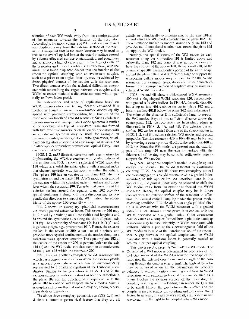
tribution of each WG mode away from the exterior surface axially or cylindrically symmetric around the axis 101(z) of the resonator towards the interior of the resonator. around which the WG modes circulate in the plane 102. The Accordingly, the mode volumes of WG modes are increased curved exterior surface is smooth around the plane 102 and and displaced away from the exterior surface of the reso- provides two-dimensional confinement around the plane 102 nator. This spatial shift in the mode location may be used to 5 to support the WG modes. reduce the overall optical loss at the exterior surface caused Notably, the spatial extent of the WG modes in each by adverse effects of surface contamination and roughness resonator along the z direction 101 is limited above and and to achieve a high Q value closer to the high Q value of below the plane 102 and hence it may not be necessary to the resonator under ideal conditions. Furthermore, with the have the entirety of the sphere 100, the spheroid 200, or the modal field being displaced deeper into the interior of the conical shape 300. Instead, only a portion of the entire shape resonator, optimal coupling with an evanescent coupler, around the plane 102 that is sufficiently large to support the such as a Prism Or an angled-fiber tip, may be achieved by whispering gallery modes may be used to for the WGM direct Physical contact of the coupler with the resonator. resonator. For example, rings, disks and other geometries This direct contact avoids the technical difficulties associ- formed from a proper section of a sphere may be used as a ated with maintaining the airgap between the coupler and a 15 spherical WGM resonator, WGM resonator made of a dielectric material with a spa- FIGS, 4A and 4B show a disk-shaped WGM resonator tially uniform index profile. 400 and a ring-shaped WGM resonator 420, respectively,
The Performance and range of applications based on with graded refractive indices. In FIG. 4A, the solid disk 400 WGM microcavities Can be significantly expanded if a has a top surface 401A above the center plane 102 and a method is found to make microresonator modes equally 2o bottom surface 401B below the plane 102 with a distance H. spaced with Precision corresponding to a fraction of the The value of the distance H is sufficiently large to support resonance bandwidth of a WGM resonator. Such a dielectric the WG modes, Beyond this sufficient distance above the microresonator with an equidistant mode spectrum is similar center plane 102, the resonator may have sharp edges as to the spectrum of a typical FabrY-Perot resonator formed illustrated in FIGS. 3, 4A, and 4B. The exterior curved with two reflective mirrors. Such dielectric resonators with 25 surface 402 can be selected from any of the shapes shown in an equidistant spectrum may be used, for example, in FIGS. 1,2, and 3 to achieve desired WG modes and spectral frequency comb generators, optical Pulse generators, broad- properties. The ring resonator 420 in FIG. 4B may be formed band energy-storage circuits of electro-optical devices, and by removing a center portion 410 from the solid disk 400 in in other applications where conventional optical Fabry-Perot FIG, 4 ~ . since the WG modes are present near the exterior cavities are utilized. 30 part of the ring 420 near the exterior surface 402, the
FIGS. 1,2, and 3 illustrate three exemplary geometries for thickness h of the ring may be set to be sufficiently large to implementing the WGM resonators with graded indices of support the WG modes. this application. FIG. 1 shows a spherical WGM resonator In general, an optical coupler is needed to couple optical 100 which is a solid dielectric sphere with a graded index energy into or out of the WGM resonator by evanescent that changes spatially with the location within the sphere. 35 coupling, FIGS, SA and 5~ show two exemplary optical The sphere 100 has an equator in the Plane 102 which is couplers engaged to a WGM resonator with a graded index symmetric around the z axis 101. AWG mode exists around according to this application, described later in this the equator within the spherical exterior surface and circu- application, the graded index may be selected to shift the lates within the resonator 100. The spherical curvature of the wc modes away from the exterior surface of the WGM exterior surface around the equator Plane 102 Provides 40 resonator. Hence, the optical coupler may be in direct spatial confinement along both the z direction and its Per- contact with the exterior surface of the resonator to effec- Pendicular direction to support the WG modes. The eccen- tuate the desired critical coupling under the proper mode- tricity of the sphere 100 generally is low. matching condition. FIG. 5A shows an angle-polished fiber
FIG. 2 shows an exemplary spheriodal microresonator tip is in contact with the WGM resonator with a graded 200 with a graded refractive index. This resonator 200 may 45 index. FIG. 5B shows a micro prism is in contact with the be formed by revolving an ellipse (with axial lengths a and WGM resonator with a graded index. Other evanescent b) around the symmetric axis along the short elliptical axis couplers such as a coupler formed from a photonic bandgap 101 (z). The eccentricity of resonator 100 is (l-b2/a2)1’2 and is material may be used. Notably, in WGM resonators with is generally high, e.g., greater than lo-’. Hence, the exterior uniform indices, a part of the electromagnetic field of the surface is the resonator 200 is not part of a sphere and 50 WG modes is located at the exterior surface of the resona- provides more spatial confinement on the modes along the z tors. A gap between the optical coupler and the WGM direction than a spherical exterior. The equator plane 102 at resonator with a uniform index is generally needed to the center of the resonator 200 is perpendicular to the axis achieve a proper optical coupling. 101 (z) and the WG modes circulate near the circumference This gap is used to properly ‘‘unload” the WG mode, The of the plane 102 within the resonator 200. ss Q-factor of a WG mode is determined by properties of the
FIG. 3 shows another exemplary WGM resonator 300 dielectric material of the WGM resonator, the shape of the which has a non-spherical exterior where the exterior profile resonator, the external conditions, and strength of the cou- is a general conic shape which can be mathematically pling through the coupler (e.g. prism). The highest Q-factor represented by a quadratic equation of the Cartesian coor- may be achieved when all the parameters are properly dinates. Similar to the geometries in FIGS. 1 and 2, the 60 balanced to achieve a critical coupling condition. In WGM exterior surface provides curvatures in both the direction in resonators with uniform indices, if the coupler such as a the plane 102 and the direction of z perpendicular to the prism touches the exterior surface of the resonator, the plane 102 to confine and support the WG modes. Such a coupling is strong and this loading can render the Q factor non-spherical, non-elliptical surface may be, among others, to be small. Hence, the gap between the surface and the a parabola or hyperbola. 65 coupler is used to reduce the coupling and to increase the Q
The above three exemplary geometries in FIGS. 1,2, and factor. In general, this gap is very small, e.g., less than one 3 share a common geometrical feature that they are all wavelength of the light to be coupled into a WG mode.
US 6,901,189 B1 5
This requirement of a gap can be problematic in device design and manufacture because the gap must be maintained at a critical angle and with a critical distance. The WGM resonators with graded indices may be designed with a spatial gradient profile for the refractive index to shift the WG modes away from the exterior surface towards the interior of the resonator so that the optical coupler in direct contact with the exterior surface can be used to achieve the critical coupling condition without the airgap. In addition, this shift of the WG modes can also reduce optical loss caused by the scattering and absorption by the imperfections and contaminants on the exterior surface of the resonator. This reduced loss leads to high values in the Q factor.
Referring back to FIGS. 1, 2, 3, 4A, and 4B, the graded index profile for the WGM resonators, like the geometrical shapes of the resonators, may also have axially or cylindri- cally symmetric spatial profiles with respect to the same axis 101(z). According to one implementation, the graded index profile of such a WGM resonator should at least vary along the radial direction, i.e., n=n(r) where r=(x2+y2)1/2. This radial profile n(r) may have different configurations. In one configuration, for example, the index changes with r throughout the entire resonator from the most inner part where r is at its minimum to the exterior surface where r is at its maximum at each given z within the resonator. The graded index is used here to modify the WG modes and thus it may suffice to have the graded profile only at the outer portion of the resonator because the WG modes are centered near the exterior surface of the resonator. Therefore, in another exemplary configuration, the index may be set at a predetermined constant no along the is radial direction at the inner part of the resonator but have a radial variation at the outer part of the resonator: n=n,+n,(r), where n,(r)=O when rer, and varies with r when r 3 , . The r, and the gradient function q(r) are selected to place the center of each WG mode where the mode strength is maximum at a desired location away from the exterior surface.
In general, the graded index n(r) or the gradient portion nr(r) decreases as r increases in order to place the center of each WG mode away from the exterior surface of the resonator. In other applications such as sensing based on WGM resonators, the graded index n(r) or the gradient portion n,(r) increases as r increases.
The following sections describe graded index profiles for WGM resonators with a spherical exterior surface to illus- trate the effects of the graded index along the radial direc- tion. The detailed analysis based on the Maxwell wave equation is included in “Dispersion Compensation in Whipering-Gallery Modes,” Ilchenko et al., Journal of Opti- cal Society of America, Volume 20(1), pages 157-162 (2003). It is understood that specific graded index profiles may be designed for the spheroid and other conic resonators to achieve desired spatial profile for each WG mode. In general, the graded index may be a spatial linear or nonlinear function.
For simplicity of the analysis, it is assumed in the fol- lowing sections that the dielectric constant of the graded resonator material is
t(r)=t,+t’(R-r),
where R is the radius of the sphere from which the spherical WGM resonator is formed. Referring to FIG. 1, r’=R-r. The ratio between E, and E’ may be chosen in an appropriate way to suppress the mode dispersion significantly. It is further assumed that R is much greater than the wavelength h of light for the WG modes. This assumption is applicable in
6 most practical micro resonators. For the angular momentum number v much greater than 1, almost all energy of a WG mode is spatially confined within a layer with a thickness of about Rv-”~. Under the above conditions, the approximate
5 number of equidistant modes for the resonator is
10 Hence, if E’ approaches ~ E J R , the resonator has equidis-
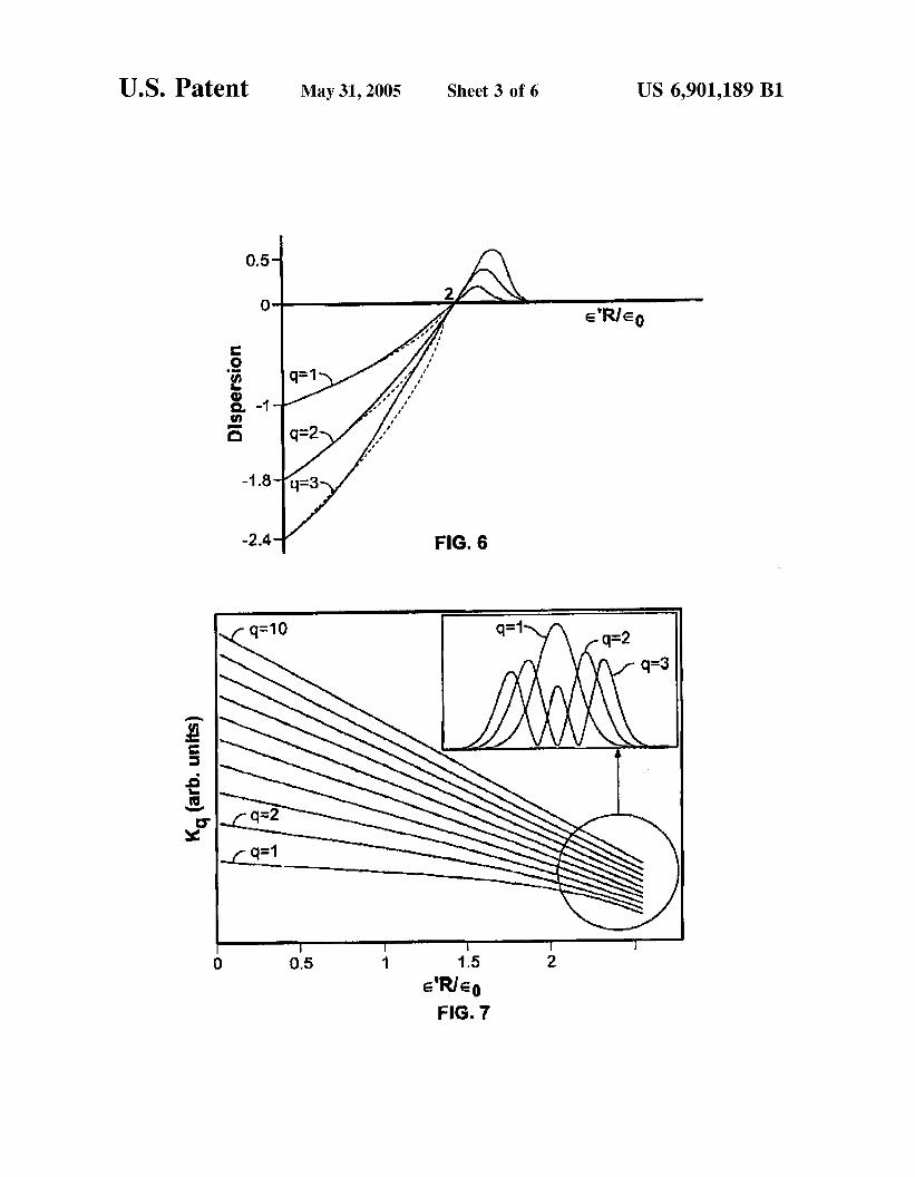
tant mode spacings for all modes. FIG. 6 shows the resonator dispersions of three adjacent WG modes as a function of E’R/E, based on numerical computations. The numerical
1~ analysis confirms that the resonator dispersions for different WG modes are is substantially eliminated and thus an equidistance spectrum can be achieved for different WG modes.
In one implementation, the gradient profile E(r) may be a 2o linear function of r’=R-r. This is described in the U.S.
Provisional Application No. 601381,622 filed on May 17, 2002. Under the first-order approximation, the linear gradi- ent profile for the a micro sphere cavity to have equidistant frequency spectrum may be:
2s &(R) ( R )
& ( T I ) = &(R) + 2-r‘.
This linear gradient index corresponds to evenly-spaced 30 resonator frequencies represented by the following:
1 k, =m-
R M ’
3s where m is an integer.
Notably, a graded material WGM resonator also demon- strates radial dispersion compensation except for v-dispersion compensation. This may be because modes do
40 not encounter the resonator boundaries for large refractive- index gradients but only the potential dip created owing to the gradient. As a consequence, radial profiles of cavity modes are nearly symmetrical, much in the same way as harmonic-oscillator wave functions. FIG. 7 shows depen-
4s dence of wave-vector eigen values kq,y on a normalized gradient of the dielectric constant for v=600. WG modes with different q become closer as the gradient increases. The WC modes pushed far away from the resonator boundary at the exterior surface are nearly equidistant in frequency. The
SO insert figure in FIG. 7 shows amplitude profiles for the fields for large index gradients where the mode wave functions are shown to be nearly symmetric.
The above result may be understood from a complex- angular momentum theory described in “Theory of Mie
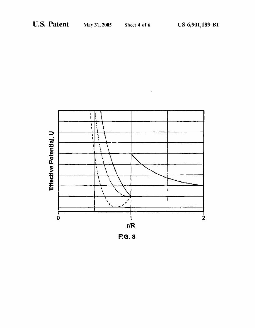
ss resonances and ripple fluctuations,” by Guimaraes et al., Opt. Communications, Volume 89, pages 363-369 (1992) where an analogy between optics and mechanics is utilized and the cavity modes are described as eigen values of an effective potential U. This effective potential for the WGM
60 resonators is asymmetric when E does not depend on radius r inside the sphere. FIG. 8 illustrates this by the curve in solid line. In spheres possessing gradient dielectric suscep- tibilities increasing to the sphere center, the potential pocket broadens, shifts into the cavity, and becomes more symmet-
65 ric as illustrated by the curves in dashed lines. The minimum of the effective potential is still on the sphere surface. For the critical value of the susceptibility gradient, the potential
US 6,901,189 B1 7 8
resembles one half of the oscillatory potential U-(r-R)’lr. In the above equations, the factor a is a geometrical factor >R-O (short-dashed curve in FIG. 8). For the gradients beyond that depends on the shape and the dielectric constants of a the critical value, the minimum of the potential moves coupler and a thin surface layer within the WGM resonator towards the interior of the resonator, The deeper the mini- in which the WGM is localized and on the distance between mum of the potential is, the better it can be described by the s the coupler and the cavity surface. The factor fl depends on oscillatory potential (FIG. 8, long-dashed curve). the geometry of the surface inhomogeneities and their ne gradient in the index of refraction can affect the field optical parameters. E(r=R) is the amplitude of the electric
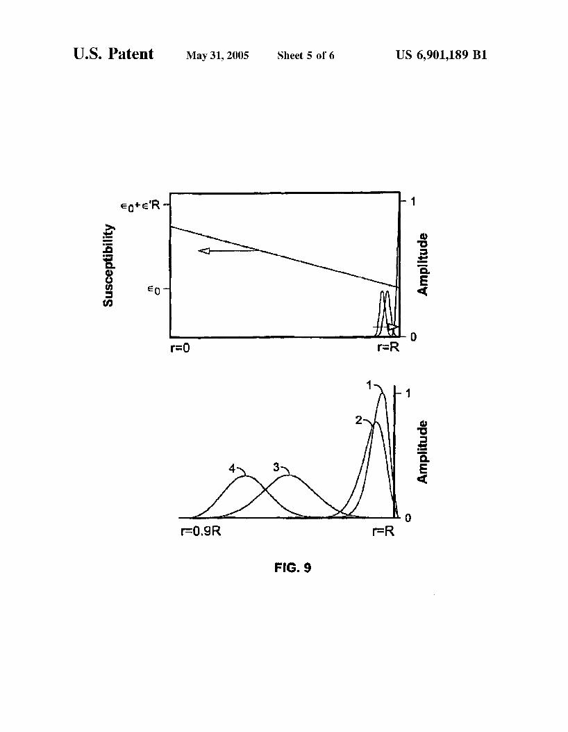
distribution in the WGM resonator. FIG. 9 shows the radial dependencies of the susceptibility of a cavity material as Based On the above, the quality factor Of the WGM well as of the amplitude profiles of the field (q=l) inside a IO resonator may be determined as Qi,ss=W/(Pi,ssT), where w is spherical WGM resonator with a graded index represented the energy stored in the WG mode and T is the oscillation by E’. The top chart in FIG. 9 shows the real scale for the field Period. BY changing the Profile of the index of refraction distributions in the case of v=600. The amplitude distribu- E(r), the ratio WB(r=R)2 can be changed. The ratio Of
tion as a function of r shows that the fields are localized close Qi/Qss, however, stays unchanged. Therefore, by choosing to the cavity surface (r=R). The bottom chart shows more 1s QdQSs=% and -reducing the absorption that is due to the detailed amplitude distributions under four different condi- surface scattering via engineering a cavity index of refrac- tions. Curve (1) of the bottom plot corresponds to E’R/E,=O, tion such that Qss=Qm, it is Possible to achieve both the curve (2) to Ei~/E,=l , curve (3) to Ei~/E,=2, and curve (4) to critical coupling and the maximum index of refraction. It can Ei~/E,=2,4, the value of € 1 increases, the WG modes are be shown that the maximum achievable quality factors for shifted deeper into the resonator and away from the exterior 20 surface. It is convenient to use a simple ratio to estimate the
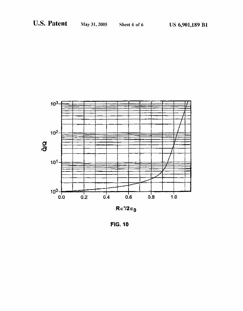
mis effect of the graded index may be used to greatly increase of the quality factors with the index gradient. reduce the losses caused by surface defects such as dust or Consider two identical spherical microcavities where the scratches, The change of the mode geometry may also susceptibility of one cavity is constant E, and the suscepti- change cavity radiative losses which may be much smaller 2s bility ofthe other cavity has a spatial gradient E(r)[E(R)=E,I. than the losses due to surface scattering. The ratio of the quality factors of the two cavities is:
Moreover, an efficient coupling with WGMs under the QI Q, = R) REO - 1) critical coupling condition to obtain high Q factors may be
achieved by a prism or fiber coupler that is in physical Ql - Q, hRe2(r)dr k o ’ contact with the dielectric cavity. This may significantly 30 simplify usage of WGM cavities in various applications. When improperly implemented, such a contact may over- where Q, and Q, (Q, and a,,) are the quality factors that are load the modes of the WGM dielectric cavity and thus may due to loading and surface scattering for the cavity with lead to a significant broadening of the resonances. Such constant (graded) susceptibility and Q(r)-E(r) is the field undesired effects may be avoided or significantly reduced by 35 distribution of a TE WG mode of the cavity with the graded properly engineering the profile of the dielectric suscepti- index. The less that the field is on the surface of the dielectric bility gradient so that the evanescent field of the cavity may cavity Q(r=R) (the deeper is the mode localization), the less be reduced to allow for the desired mode-matching evanes- are the absorption and coupling and the higher the quality cent coupling while greatly suppressing the influence of the factors. surface contamination. FIG. 10 is a chart showing the dependence of the ratio as
In general, the quality factor Q of a WG mode in the a function of the normalized gradient dielectric susceptibil- WGM resonator is primarily determined by three effects: ity. The radius of the sphere cavities is R=4 mm, the constant absorption in the dielectric material (Q,), surface scattering susceptibility ~,=2.1, and the mode wavelength is h=1.55 losses (Q,) and loading by the external coupler (Q,). The micron. load quality factor Q, can be regulated from the coupler 45 When a coupling prism is in full contact with the dielec- outside the WGM resonator. In the example of a prism tric cavity (d=O) as shown in FIG. 5B, the coupling losses coupler as shown in FIG. 5B, the load quality factor Q, exceed the surface scattering losses in this case. The value depends on the distance, d, from the coupling prism to the of Q, may be increased by changing the gradient c(r) until sphere surface as follows: the bulk optical losses become equal to the coupling losses.
SO At this point, the critical coupling can be achieved at a much
It is worth noting here that in some cases it may be desirable to increase the evanescent field of a dielectric cavity at the exterior surface. One example is if the cavity is
where h is the wavelength of a WG mode. The critical ss intended to be used as an optical sensor where the exterior (optimum) coupling with the WG mode is achieved if d is surface is the sensing surface to detect a change in its chosen such that Q,=(l/QsS+l/QJ1. Because usually surroundings. Such a WGM resonator sensor may also be Qm>>Qss, the effects of the absorption of the material can be optimized via manipulation of E(r) dependence. It has been neglected in most cases. shown that WGMs tend to be closer to the cavity exterior
Both Q,, and Q, are proportional to the ratio of the field 60 surface if the index of refraction of the cavity close to its power on the surface of the cavity and the total energy of the exterior surface exceeds the internal index of refraction. mode. The lost power caused by the surface scattering is Such dependence of the refractive index may increase the given by: surface absorption, but it can also increase the coupling to
the external space. Hence, for sensing applications, the 65 graded index should increase, rather than decrease, with the
radius r. This spatial profile pushes the WG modes outward in order to increase the detection sensitivity for sensing
On the surface.
microspheres are aPProximatelY Q,=1012.
---=--
40
4 7 r v G T higher Q-factor level. el -ev(
P,,=fiEE(r=R)Z,
and the lost power caused by the evanescent coupler is PFCrE(r=R)Z.
US 6,901,189 B1 9 10
applications. The optical losses at the surface may be mitigated by reducing the surface imperfections.
Graded index materials have been widely used in lenses and fibers. Such materials may be used to fabricate WGM resonators by, e,g,, using mechanical and flame polishing 5
techniques. Other suitable techniques may also be used to produce the desired gradient indices in WGM resonators.
However, it is understood that variations and enhancements may be made.
19. A device, comprising: an optical resonator formed of a dielectric material to
support whispering gallery modes and configured to have a spatially graded refractive index,
wherein said refractive index has a spatially graded profile to substantially equalize optical path lengths of differ- ent whispering gallery modes in said resonator.
In summary, only a few implementations are disclosed, 20. The device as in 19, wherein said Optical resonator includes at least a portion of a sphere.
resonator has a non-spherical shape.
resonator has a spheriodal shape.
21. The device as in claim 19, wherein said optical
22. The device as in claim 21, wherein said optical
23. The device as in claim 19, wherein said optical
What is claimed is: 1. A device, comprising: an optical resonator formed of a dielectric material to
support whispering gallery modes and configured to 15 resonator has a disk shape.
resonator is cylindrically symmetric in shape, and said resonator has a ring shape. refractive index spatially increases along a radial direc- 25. A device tion. an optical resonator formed of a dielectric material to
2. The device as in claim 1, wherein said optical resonator 2o support whispering gallery modes and configured to have a spatially graded refractive index,
3, The device as in claim 1, wherein said optical resonator wherein said spatially graded refractive index includes a constant index portion in an interior of said optical resonator and a spatial-varying portion near the exterior 4. The device as in claim 3, wherein said optical resonator surface of said optical resonator.
26. The device as in claim 25, wherein said spatially- 5. The device as in claim 1, wherein said optical resonator varying portion has a linear spatial profile. 27. The device as in claim 25, wherein said spatially-
6. The device as in claim 1, wherein said optical resonator varying portion has a nonlinear spatial profile, 28. The device as in claim 25, wherein said resonator is
7. The device as in claim 1, wherein said spatially graded 3o cylindrically symmetric in shape, and a value of said spatially-varying portion decreases along a radial direction.
8. The device as in claim 1, further comprising an optical 29. The device as in claim 25, wherein a value of said
couple light into at least one of said whispering gallery 30. The device as in claim 25, wherein a value of said modes. 35 spatially-varying portion spatially decreases with a distance
9. The device as in claim 1, further comprising an optical from an exterior surface of said resonator towards an interior coupler in contact with an exterior surface of said resonator of said resonator. to evanescently couple light into at least one of said whis- 31. The device as in claim 25, wherein a value of said pering gallery modes. spatially-varying portion spatially increases with a distance
10, The device as in claim 1, wherein said spatially graded from an exterior surface of said resonator towards an interior refractive index has a linear spatial profile. 40 of said resonator, and the device further comprising an
11. A device, comprising; optical coupler in contact with an exterior surface of said resonator to evanescently couple light into at least one of
an optical resonator formed of a dielectric material to said whispering gallery modes,
have a spatially graded refractive index, wherein said 24. The device as in claim 19, wherein said optical
includes at least a portion of a sphere.
has a non-spherical shape.
has a spheriodal shape.
has a disk shape.
has a ring shape.
refractive index has a nonlinear spatial profile.
25
coupler positioned relative to said resonator to evanescently spatially-varying portion decreases along a radial direction,
gallery modes and ‘Onfigured to 32, The device as in claim 25, wherein said optical have a spatially graded refractive index,
wherein said refractive index spatially decreases with a distance from an exterior surface of said resonator towards an interior of said resonator.
12. The device as in claim 11, wherein said refractive index has a spatially graded profile to substantially confine SO said whispering gallery modes within said exterior surface.
13, The device as in claim 11, further comprising an optical coupler in contact with said exterior surface to evanescently couple light into at least one of said whispering gallery modes.
14. The device as in claim 11, wherein said spatially graded refractive index has a linear spatial profile.
15. The device as in claim 11, wherein said spatially graded refractive index has a nonlinear spatial profile.
16. The device as in claim 11, further comprising an 60 optical coupler positioned relative to said resonator to eva- nescently couple light into at least one of said whispering gallery modes. resonator.
17. The device as in claim 11, wherein said optical resonator includes at least a portion of a sphere.
18. The device as in claim 11, wherein said optical resonator has a non-spherical shape.
45 resonator includes at least a portion of a sphere. 33. The device as in claim 25, wherein said optical
34. The device as in claim 33, wherein said optical
35. The device as in claim 25, wherein said optical
36. The device as in claim 25, wherein said optical
37. A device, ComPrising: an optical resonator foamed of a dielectric material to
support whispering gallery modes and configured to have a spatially graded refractive index,
wherein said spatially graded refractive index has a linear spatial profile.
38. The device as in claim 37, wherein said spatially graded refractive index decreases with a distance from an exterior surface of said resonator towards an interior of said
39. The device as in claim 37, wherein said spatially 65 graded refractive index increases with a distance from an
exterior surface of said resonator towards an interior of said resonator.
resonator has a non-spherical shape.
resonator has a spheriodal shape.
resonator has a disk shape.
resonator has a ring shape.
5s
US 6,901,189 B1 11
40. The device as in claim 37, wherein said optical
41. The device as in claim 37, wherein said optical
42. The device as in claim 37, wherein said optical
43. The device as in claim 37, wherein said optical
44. A device, comprising: an optical resonator formed of a dielectric material in a
cylindrically symmetric shape to support whispering gallery modes, said resonator having a refractive index with a spatial-varying profile along a radial direction of said resonator,
wherein said spatial-varying profile is configured to pro- duce substantially equal optical path lengths for differ- ent whispering gallery modes in said resonator.
45. The device as in claim 44, further comprising an optical coupler in contact with said resonator to evanes- cently couple light into at least one of said whispering gallery modes.
resonator includes at least a portion of a sphere.
resonator has a non-spherical shape.
resonator has a disk shape.
resonator has a ring shape.
12 46. The device as in claim 44, wherein said refractive
index spatially increases with a distance from an exterior surface of said resonator towards an interior of said reso- nator.
47. The device as in claim 44, wherein said spatial- varying profile is configured to substantially confine said whispering gallery modes within an exterior surface of said resonator.
48. The device as in claim 44, wherein said optical resonator includes at least a portion of a sphere.
49. The device as in claim 44, wherein said optical resonator has a non-spherical shape.
50. The device as in claim 44, wherein said spatially graded refractive index includes a constant index portion in an interior of said optical resonator and a spatial-varying portion near the exterior surface of said optical resonator.
’
* * * * *