i fly 747 400 operations manual
TRANSCRIPT

iFly 747-400 Operations Manual
Revision Number: 9 Revision Date: Jul 20, 2007

iFly Developer Team iFly 747-400 Operation Manual
WARNING
This manual is only used for understanding the functionalities of iFly 747-400 which runs
on Microsoft® Flight Simulator X™. User must not use iFly 747-400 and its associated
components for real aviation training or other correlative activities!
——————————————————————————————————— I The iFly Developer Team

iFly Developer Team iFly 747-400 Operation Manual
Introduction Introduction to iFly 747-400 Thanks for using iFly 747-400! We have taken three years of development for iFly 747-400. It is an add-on software for Microsoft® Flight simulator X™ (FSX). With our core developer Mr.Jiangwei’s hard work, iFly 747-400 is now able to simulate most of system components that are on real Boeing 747-400 airplane. They included Air Systems, EICAS, Automatic Flight Control System, Communication System, Electrical Systems, Fire Protection System, Flight Controls Systems, Flight Instruments, Flight Management Systems, Fuel Systems, Hydraulics Systems, spear gear and FLAP systems, TCAS, GPWS, CMC and many more. Due to the limitation of FSX, some system functionalities couldn’t be realized completely. For example, there’s no weather radar implementation on iFly 747-400. Since the overwhelming complexity of 3D 747-400 models, only the first class and business class have modeled in virtual cabin. But don’t be upset; in reality the airline companies usually arrange the business class seats into economy class cabin too☺. Additionally on a real plane, the positions of kitchen and lavatories are placed according to different cabin class layout. Therefore these facilities in iFly 747-400 virtual cabin may seen differently by comparing to various cabin layout on real airplanes.
Because we took this development seriously and tried to be hardcore enough just like very other fans of Boeing 747, this simulator should deserves a comprehensive manual that can fully describe each part of system components. Thus during the time of manual and documents writing, we have referenced the real Boeing 747-400 flight manuals in order to provide rich-content documents to the end users. And this is our yet another purpose that while users can fully simulate the cockpit of Boeing 747-400 on PCs, they also find commons from flight manuals between real ones and ours.
——————————————————————————————————— II The iFly Developer Team

iFly Developer Team iFly 747-400 Operation Manual
Introduction of the project team and team members
The iFly developer team currently has four members. As an individual, we got to know each other in a virtual aviation community. With the same interests in flight simulation, we were all very active on the simulation forum and shared every little thing about aviation, and finally we became very close friends. Therefore, this team was established under great friendship.
Jiangwei Shen Founder, gauge developer & 3D modeling He founded this developer team in 2003. He loves Boeing series airplanes and has great understanding of major Boeing series airplane systems. He has received his Master degree of Science in late 2004 with specialized in computing graphic and Geographic Information
System (GIS). Currently working in Zhejiang Institute of Media and Communications, Zhejiang, China (ICAO: ZSHC).
Bo Yuan 2D painting & optimiztion Born 1978 in Shan’xi, China. He is a painting artist with specialized in 2D image creation and has great understanding of image optimization. Further more he is very familiar by using various graphical editing
tools. Currently working in an electricity company and unmarried.
Miao Luo Documentation & manual writing He is currently pursuing for his Master degree of Science specialized in software engineering in University of Oulu, Oulu, Finland. Born 1981
in Chongqing, China. He is a big fan of Airbus fleets and has good understanding of Airbus A320-series airplane systems. He plans to graduate from university next year 2006.
Qinzhong Yao Technical mentor Born 1968 in Taipei, Taiwan. He has received his Master degree of Laws (LLM). He’s been an active airline and flight simulation add-on commentator since 2000. He has worked for an airliner magazine as
——————————————————————————————————— III The iFly Developer Team

iFly Developer Team iFly 747-400 Operation Manual
executive editor, and currently working as vice-director and lecturer in University of General Education Center in Taoyuan, Taipei. Single.
Credits
In the end, we should give most credits to Mr.Jiangwei’s hard work on gauge programming and 3D model development. Back in 2002 he has contributed his first add-on airport scenery ZSHC GMAX for FS2002 (Still available on AVSIM). Ever since then, he started to develop airplane gauges. Therefore without his enthusiasm, there will never be iFly 747-400. We should also thank to Mr.Yuan’s hard work on 2D painting. He is the one who has given us the visual enjoyed on iFly 747-400 cockpit panels and liveries. Last but not least, we should thank Mr.Yao (not that NBA player), with his inspiration to the development and rich knowledge on airplane system, we finally have been able to delivery this package to the virtual aviation community.
Credits: Gauge developer, 3D modeling and manual revisions: Shen Jiangwei (nick: szm99) 2D painting & image optimization: Yuan Bo (nick: agings) Documentation & manual writing: Luo Miao (nick: mluo) Technical mentor: Yao Qinzhong (nick: Adolf)
Bug Reports & suggestions Contact: [email protected] or [email protected]
——————————————————————————————————— IV The iFly Developer Team

iFly Developer Team iFly 747-400 Operation Manual
Intentionally Blank
——————————————————————————————————— V The iFly Developer Team

iFly Developer Team iFly 747-400 Operation Manual
TABLE OF CONTENTS
LIMITATIONS............................................................................. 2
NORMAL PROCEDURES.......................................................... 6
SUPPLEMENTARY PROCEDURES...................................... 19
AIRPLANE GENERAL............................................................. 28
AIR SYSTEMS ........................................................................... 42
ANTI-ICE.................................................................................... 56
AUTOMATIC FLIGHT ............................................................ 60
COMMUNICATIONS ............................................................... 76
ELECTRICAL............................................................................ 82
ENGINES, APU.......................................................................... 93
FIRE PROTECTION............................................................... 111
FLIGHT CONTROLS ............................................................. 118
FLIGHT INSTRUMENTS, DISPLAYS................................. 132
CONTROLS AND INDICATORS.......................................... 132
FLIGHT MANAGEMENT, NAVIGATION ......................... 178
FUEL ......................................................................................... 261
HYDRAULICS ......................................................................... 273
LANDING GEAR..................................................................... 279
WARNING SYSTEMS ............................................................ 288
CENTRAL MAINTENANCE COMPUTER SYSTEM........ 309
——————————————————————————————————— VI The iFly Developer Team

iFly Developer Team iFly 747-400 Operation Manual
Intentionally Blank
——————————————————————————————————— VII The iFly Developer Team

iFly Developer Team iFly 747-400 Operation Manual Limitations Chapter L
OPERATING LIMITATIONS.................................................... 2
MAXIMUM ALTITUDES................................................................ 2
OPERATING LIMITATIONS ......................................................... 2
WEIGHT LIMITATIONS ............................................................... 2
AUTOPILOT/FLIGHT DIRECTOR SYSTEM.................................. 2
AUTOMATIC LANDING................................................................ 3
FLAP PLACARD SPEEDS.............................................................. 3
——————————————————————————————————— Page 1 The iFly Developer Team

iFly Developer Team iFly 747-400 Operation Manual Limitations Chapter L
Operating Limitations Maximum altitudes Clean 45,000 ft Flaps 20,000 ft APU 20,000 ft APU Bleed Air 15,000 ft Take off 10,000 ft Landing 10,000 ft
Operating Limitations Runway slope +/- 2% Maximum Takeoff and Landing Tailwind Component
15 knots
Maximum speed operating in Reduced Vertical Separation Minimum (RVSM) Airspace
0.90 Mach
Weight Limitations Weights Kilograms
Maximum Taxi Weight 397,800 Maximum Takeoff Weight 396,893 Maximum Landing Weight 285,763 Maximum Zero Fuel Weight 246,073
Autopilot/Flight Director System The autopilot must not be engaged below a minimum engage altitude of 250 feet after takeoff. The autopilot must be disengaged before the airplane descends more than 50 feet below the MDA unless it is coupled to an ILS glideslope and localizer or in the go–around mode. For single channel ILS approaches, the autopilot must be disengaged before the airplane descends below 100 feet AGL. Use of aileron trim with the autopilot engaged is prohibited. Use of aileron with the autopilot engaged is prohibited. Disengage autopilot when G (gravity) force is larger than 1.4G
——————————————————————————————————— Page 2 The iFly Developer Team

iFly Developer Team iFly 747-400 Operation Manual Limitations Chapter L
Automatic Landing Maximum allowable wind speeds when landing weather minima are predicated on autoland operations: Headwind 25 knots Tailwind 15 knots Crosswind 25 knots Crosswind with One Engine Out 5 knots
Flap Placard Speeds
Flaps 1 280 KIAS Flaps 5 260 KIAS Flaps 10 240 KIAS Flaps 20 230 KIAS Flaps 25 205 KIAS Flaps 30 180 KIAS
——————————————————————————————————— Page 3 The iFly Developer Team

iFly Developer Team iFly 747-400 Operation Manual
Intentionally Blank
——————————————————————————————————— Page 4 The iFly Developer Team

iFly Developer Team iFly 747-400 Operation Manual Normal Procedures Chapter NP
NORMAL PROCEDURES.......................................................... 6
GENERAL..................................................................................... 6 Controls and Indicators – Nomenclature ................................................................... 6 How to read the checklists? ........................................................................................ 6
PREFLIGHT PROCEDURE............................................................ 7
BEFORE START PROCEDURE.................................................... 11
ENGINE START PROCEDURE .................................................... 12
AFTER START PROCEDURE...................................................... 12
BEFORE TAKEOFF PROCEDURE............................................... 13
TAKEOFF PROCEDURE ............................................................. 13
CLIMB AND CRUISE PROCEDURE............................................. 13
APPROACH AND LANDING PROCEDURE .................................. 14
GO–AROUND PROCEDURE ....................................................... 14
LANDING ROLL PROCEDURE ................................................... 15
AFTER LANDING PROCEDURE ................................................. 15
SHUTDOWN PROCEDURE.......................................................... 15
——————————————————————————————————— Page 5 The iFly Developer Team

iFly Developer Team iFly 747-400 Operation Manual Normal Procedures Chapter NP
Normal Procedures General Normal Checklists are organized by phase of flight to ensure airplane condition is acceptable and the flight deck is correctly configured for each phase of flight. These procedures assume all systems are operating normally and automated features are fully used. Normal Checklists are used to verify that certain critical procedural steps have been accomplished. These normal procedures are divided by major flight phase and should provide a basic guideline for accomplishing the major procedures required during flight. The flight crew uses the Normal Checklist after accomplishing all applicable procedural items. The First Officer on the ground and the pilot not flying in flight reads the checklist. Each crewmember responds for systems and controls in that crewmember’s area of responsibility. Controls and Indicators – Nomenclature Controls and indications appear in all UPPERCASE type to correspond to the words on the control panel or display. For example, the following item has UPPERCASE words to match what is found on the panel:
PASSENGER OXYGEN switch ....................NORM (guarded position) The word PASSENGER is spelled out, even though it is abbreviated on the panel. The following appears in all lower case because there are no words identifying the panel name:
Fuel panel............................................................................................ Set How to read the checklists? The checklist has some indented lines. The main points start on the left, with the actions on the right of the column (with dots in between). Whenever a comment or a conditional action is required, this is shown with an indentation (shifted to the right).
——————————————————————————————————— Page 6 The iFly Developer Team

iFly Developer Team iFly 747-400 Operation Manual Normal Procedures Chapter NP Preflight Procedure The following procedures are accomplished to permit safe application of electrical power.
Battery Switch…………………………………………………….…………….ON Standby Power Selector……………………………………………………..AUTO Hydraulic Electric Pump Switches………………………………………...…..OFF Hydraulic Demand Pump Selectors……………………………………...…….OFF Alternate Flaps Selector……………………………………………..……...NORM EXT PWR SWITCHES 1 & 2 (If Available)…………………………………..ON APU (If DESIRED)....…………………………………………….………..START
Rotate APU selector to START and release to ON, push APU GEN switch when AVAIL Light illuminated and verify ON light illuminated.
(Electrical Power Established) After electrical power is established, the following procedures are accomplished in their entirety on each originating trip or crew change.
IRS selectors………………………………………………………OFF, then NAV For all flights, a full alignment is recommended.
ELECTRONIC ENGINE CONTROL switch……………………….…..…NORM Verify ALTN lights extinguished.
Electrical panel…………………………………………………………………..Set STANDBY POWER selector -AUTO UTILITY power switches - ON BATTERY switch – ON
Verify OFF light extinguished. BUS TIE switches - AUTO
Verify ISLN lights extinguished. GENERATOR CONTROL switches - ON
HYDRAULIC panel……………………………………………………...……..Set Hydraulic SYS FAULT and demand pump PRESS lights - Illuminated DEMAND pump selectors - OFF ENGINE pump switches - ON
Verify engine pump PRESS lights illuminated. Fire Panel……………………………………………………………….……….Set
Engine fire switches - In BTL A DISCH and BTL B DISCH lights - Extinguished APU BTL DISCH light - Extinguished APU fire switch - In CARGO FIRE DISCH light - Extinguished CARGO FIRE ARM switches - OFF
Verify FWD and AFT lights extinguished. Engine START panel………………………………………………………...….Set
START switches - In, extinguished STANDBY IGNITION selector - NORM CONTINUOUS IGNITION switch - Off
——————————————————————————————————— Page 7 The iFly Developer Team

iFly Developer Team iFly 747-400 Operation Manual Normal Procedures Chapter NP
AUTO IGNITION selector - SINGLE AUTOSTART switch - ON
FUEL JETTISON panel………………………………………...……………….Set Fuel jettison selector - OFF Fuel jettison NOZZLE valve switches - Off
Verify VALVE light extinguished. Fuel panel…………………………………………………………...…………...Set
All X FEED valve switches - On Verify VALVE lights extinguished.
All fuel pump switches - Off Anti-ice panel…………………………………………………………...……….Set
NACELLE ANTI-ICE switches - As desired WING ANTI-ICE switch - As desired
PASSENGER OXYGEN switch……………………………NORM (guard closed) YAW DAMPER switches…………………………………………..…………..ON CABIN ALTITUDE panel…………………………………………...………….Set
OUTFLOW VALVES - OPEN Verify outflow valves OPEN.
LANDING ALTITUDE switch - AUTO Outflow valve manual switches - Off Cabin Altitude AUTO SELECTOR - NORM
ECS panel…………………………………………………………….…………Set PASSENGER TEMPERATURE selector - AUTO FLIGHT DECK TEMPERATURE selector - AUTO TRIM AIR switch - ON ZONE SYS FAULT light - Extinguished UPPER and LOWER RECIRCULATION fan switches - ON AFT CARGO HEAT switch - Off EQUIPMENT COOLING selector - NORM HIGH FLOW switch - Off Pack control selectors - NORM LEFT and RIGHT ISOLATION valve switches - On
Verify VALVE lights extinguished. Engine bleed air SYS FAULT lights - Extinguished APU bleed air switch - ON
Verify VALVE light extinguished. ENGINE BLEED air switches - ON
Lighting panel………………………………………………………...…………Set Mode control panel………………………………..…………………………….Set
FLIGHT DIRECTOR switch – ON AUTOTHROTTLE ARM switch – ARM BANK LIMIT selector -AUTO Autopilot DISENGAGE bar – Up
STATUS display switch……………………………………………………….Push Verify status display appears.
EFIS control panel……………………………………………………..………..Set CDU………………………………………………………………….Check and set
——————————————————————————————————— Page 8 The iFly Developer Team

iFly Developer Team iFly 747-400 Operation Manual Normal Procedures Chapter NP
IDENT page - Check Verify airplane model number and engine number displayed. Verify ACTIVE navigation data date current.
POS INIT line select key - Push Present position - Enter
Enter present position on SET IRS POS line using most accurate latitude and longitude.
UTC - Check NEXT PAGE key - Push
Verify L, C, and R IRS positions correct. PREVIOUS PAGE key - Push ROUTE line select key - Push
Enter route. ACTIVATE line select key - Push EXEC key - push DEP/ARR key - Push
Select runway and SID. ROUTE line select key - Push
Verify SID and route correct. EXEC key -Push NAV/RAD key - Push
Verify navigation radios set. INIT REF key - Push INDEX line select key - Push APPROACH line select key - Push
Verify FLAP/SPEED line blank. INIT REF key – Push
PARKING BRAKE………………………………………………………..……Set SPEEDBRAKE lever……………………………………………………..…….DN Reverse thrust levers……………………..…………………………………..Down Thrust levers………………………………………...………………………Closed FUEL CONTROL switches………………………………………………CUTOFF STABILIZER TRIM cutout switches………………………AUTO (guards closed) Radio tuning panel……………………………………………………..………..Set
OFF light - Extinguished Set panel - As desired
Audio panel…………………………………………………………..………….Set Set panel - As desired
Transponder panel…………………………………………………………..…...Set Transponder switch - As required Transponder mode selector - STBY
AUTOBRAKES Selector…………………………………………...…………RTO Passenger signs……………………………………………………….…………Set
NO SMOKING selector - AUTO or ON SEATBELTS selector - AUTO
Crew oxygen panel……………………………………………………………..Set Crew oxygen pressure - Check EICAS
Note oxygen pressure.
——————————————————————————————————— Page 9 The iFly Developer Team

iFly Developer Team iFly 747-400 Operation Manual Normal Procedures Chapter NP
Clock……………………………………………………………………………Set CRT select panel………………………………………………………………..Set
LOWER CRT selector - NORM INBOARD CRT selector - NORM
PFD…………………………………………………………………...……...Check Flight mode annunciation - Check
Verify autothrottle mode blank. Verify roll mode TO/GA. Verify pitch mode TO/GA. Verify AFDS status FD.
Displays - Normal Verify no flags displayed. Verify NO V SPD flag displayed until V-speeds selected.
Heading - Check Altimeter - Set
ND……………………………………………………………………………Check Heading/Track - Displayed, correct Route - Displayed, correct Displays - Normal
Verify no flags displayed. GROUND PROXIMITY panel…………………………………………………Set
Ground PROX light - Extinguished Ground proximity FLAP OVERIDE switch - Off Ground proximity CONFIGURATION GEAR OVERRIDE switch - Off
Alternate flaps and gear…………………………………………………………Set Landing gear lever - Down ALTERNATE FLAPS selector - Off Alternate flaps ARM switch - Off ALTERNATE GEAR EXTEND switches - Off
EIU selector…………………………………………………..……………..AUTO HEADING reference switch………………………………………..………NORM FMC master selector………………………………………………………………L Status display………………………………………………...………………Check
Hydraulic quantity - RF not displayed Oxygen pressure - Sufficient for flight
Standby attitude indicator…………………………………………...……….Check Caging control - Pull and release Attitude - Correct
Verify no gyro flag. APPROACH selector - OFF
Standby airspeed indicator……………………………………...……………Check Standby altimeter……………………………………………………..……...Check
——————————————————————————————————— Page 10 The iFly Developer Team

iFly Developer Team iFly 747-400 Operation Manual Normal Procedures Chapter NP
Before Start Procedure Accomplish this procedure after papers are on board and flight crew is ready for push back and/or engine start. CDU……………………………………………………………………………………..Set
Airplane zero fuel weight or gross weight - Enter Fuel reserves - Enter Cost index - Enter Cruise altitude - Enter THRUST LIM line select key – Push
Select desired takeoff and climb derate. TAKEOFF line select key - Push Takeoff flap setting - Enter Takeoff data - Review Takeoff speeds - Select
MCP……………………………………………………………………………………..Set IAS/MACH selector – Rotate Set V2 speed in IAS/MACH window. LNAV switch – As required VNAV switch – Push
Arm VNAV. Initial heading – Set Initial altitude – Set
Start clearance…………………………………………………………..…………...Obtain Obtain clearance to pressurize hydraulic systems and start engines.
Hydraulic demand pump 4 selector………………………………………….………..AUX Verify SYS FAULT light extinguished.
PRESS light remains illuminated. HYDRAULIC panel…………………………………………………………………….Set
Hydraulic demand pump 1, 2, and 3 selectors - AUTO Verify demand pump PRESS and SYS FAULT lights extinguished.
Fuel tank quantities………………………………………………………...………...Check Fuel panel………………………………………………………………………………..Set
Fuel pump switches – ON Push fuel pump switches for tanks containing fuel to ON. Verify pump PRESS lights extinguished.
Pack control selectors……………………………………………………………...……Set All packs MUST be off for engine start.
BEACON light switch…………………………………………………………………. ON RECALL switch……………………………………………………………………….Push
Verify only appropriate alert messages displayed. If FUEL TANK/ENG message displayed:
Verify fuel quantity in tank 2 less than or equal to tank 1, or tank 3 less than or equal to tank 4 (fuel tank-to-engine); or fuel quantity in tank 2 less than or equal to tank 1 plus 500 kgs. And tank 3 less than or equal to tank 4 plus 500 kgs.
OVERRIDE pumps 2 and 3 switches - Off
——————————————————————————————————— Page 11 The iFly Developer Team

iFly Developer Team iFly 747-400 Operation Manual Normal Procedures Chapter NP
CROSSFEED valve 1 and 4 switches - Off Cancel when review completed.
Status Display………………………………..………………………………………Select Trim…………………………………………………………………………………….Sets
Stabilizer trim –Set for takeoff. Check in illuminated greenband.
Aileron trim – ZERO Rudder trim – ZERO
Flight controls……………………………….………………………………….……Check Displace rudder, control wheel, and control column full travel in both directions. Verify freedom of movement, controls return to center, and proper flight control movement on secondary EICAS display.
Secondary ENGINE display switch……….………………………………….….……Push Verify secondary engine display appears.
EICAS displays…………………………..…………………………………………..Check Engine indications – Normal
Engine Start Procedure Normal start sequence is 4, 3, 2, 1. Two engines may be started simultaneously. Engine START switches……………………………………………………………………...…………Pull FUEL CONTROL SWITCH……………………………………………...…………..RUN Verify Engine START lights illuminated.
Monitor engine displays for start parameters listed below until engine(s) are stabilized at idle: • N1 rotation must be indicated by idle N2. Verify Engine START lights extinguished at approximately 50% N2. After engine(s) stabilized at idle, repeat procedure to start remaining engines.
EICAS ENGINE INDICATIONS………………………………………….…..MONITOR
After Start Procedure APU selector…………………………………………………………….……………..OFF Hydraulic demand pump selectors…………………………………………………..AUTO NACELLE ANTI–ICE switches……………………………………….………As required AFT CARGO HEAT switch………………………………………….………..As required Pack control selectors…………………………………………………………...….NORM GENERATOR CONTROL switches…………………………………………………...ON OVERRIDE pumps 2 and 3 switches…………………………………...………………Off
——————————————————————————————————— Page 12 The iFly Developer Team

iFly Developer Team iFly 747-400 Operation Manual Normal Procedures Chapter NP Before Takeoff Procedure RECALL switch……………………………………………………………………….Push
Verify only appropriate alert messages displayed. Cancel when review completed.
CDU…………………………………………………………………………….……Check Takeoff data – Review
Verify takeoff speeds selected. VNAV CLB PAGE - DISPLAY
When Obtain taxi clearance: Parking brake………………………………………………………...……..Release Flap lever………………………………………………………………………SET
Takeoff Procedure Landing Lights switches………………………………….…………………….………ON Transponder Mode selector………………………………….…………...…………TA/RA TAKEOFF THRUST……………………………………………………………….….SET
Advance Thrust levers to approximately 70% N1 and allow engines to stabilize. Push TO/GA switch to advance Thrust levers to takeoff thrust, or manually advance Thrust levers to takeoff thrust. Verify correct takeoff thrust set. Adjust takeoff thrust prior to 80 knots if required.
ENGINE INDICATIONS………………………………………….…………..MONITOR AIRSPEED 80 KNOTS……………………………………………...….Call “80 KNOTS” AIRSPEED V1……………………………………………………….…….……Call “V1” AIRSPEED Vr……………………………………………………….….. Call “ROTATE” Verify positive rate of climb Landing Gear lever………………………………………………………………..…….UP Verify A/P engaged when above minimum altitude for autopilot engagement.
Verify LNAV, VNAV engaged. Flap lever…………………………...………………………………………………….SET Landing Gear lever…………………………………………………………………….OFF Climb thrust………………………...………………………………….………………SET
Climb and Cruise Procedure NACELLE ANTI-ICE switches………...……………………………...……….As desired When above 10,000 feet: Landing Light switches………………………………………………………….…….OFF
——————————————————————————————————— Page 13 The iFly Developer Team

iFly Developer Team iFly 747-400 Operation Manual Normal Procedures Chapter NP When at transition altitude: Barometric Standard Switch…………………………………………………….……..STD When FUEL PMP STAB L and R messages are displayed and tank quantity is zero: Stabilizer tank L and R Pump switches……………………………………………..…OFF When FUEL OVRD CTR L and R messages are displayed and tank quantity is zero: Center L and R Pump switches……………………………………………………...…OFF When FUEL TANK/ENG message is displayed and fuel quantity in tank 2 is less than or equal to tank 1 or tank 3 is less than or equal to tank 4: Override Forward and Aft Pump switches 2 and 3…………………..…….…………..OFF Crossfeed valve switches 1 and 4………………..……………..…………………...…OFF Prior to top of descent, modify active route as required for arrival and approach. When cleared to descend, set clearance limit altitude on MCP. Approach and Landing Procedure VREF speed………………………………………………………………………....…SET RECALL switch……………………………………………………………………….Push
Review all messages. Arrival and approach procedures……………………………………………….…CHECK DH or MDA……………………………………………………..…………………..…SET When t transition level, set all altimeters: Altimeters…………………………………………………………………………..…SET Autobrakes selector…………………………….…………………………………..…SET Flap lever……………….…………………………………………………………..…SET Transponder selector…….……………………………………..……………….As desired When on localizer intercept heading: ILS tuned and identified…………………………………………..…...…………..CHECK
Verify LOC and G/S pointers displayed APP mode……………………………………………………………......…….……..ARM Landing Gear lever…………………………………………...……………...…….……DN Flap lever………………………………………………….……..…….…Landing Position Speedbrake lever……………………………………...……………….…………...…ARM
Go–Around Procedure TO/GA switch…………………………………………………………………………Push Verify rotation to go–around attitude and thrust increase. Verify thrust adequate for go–around; adjust if necessary. Flap lever……………………………………………………….…………….……….…20
——————————————————————————————————— Page 14 The iFly Developer Team

iFly Developer Team iFly 747-400 Operation Manual Normal Procedures Chapter NP Positive rate of climb………………………………………..………………….Established Landing Gear lever………………………………………….…...………..……….……UP When above 400 feet radio altitude: LNAV………………………………………………………………….....……. As desired When above1000 feet radio altitude: VNAV or FLCH..………………………..…………………………….....……. As desired Flap lever………………………………………………….……….………….…….…SET Landing Gear lever…………………………………………...……………….….……OFF Landing Roll Procedure Thrust levers………………………………………...………………….……..…….Closed Speedbrake lever…………………………………………………………...……………UP Verify Speedbrake lever UP and call “SPEEDBRAKES UP.” If Speedbrake lever not UP, call “SPEEDBRAKES NOT UP.” Reverse Thrust levers……..……………………………………………....……. As desired 60 knots…………………………………………………………………Call “60 KNOTS” Reverse Thrust levers……………………………………………………...…………Down AUTOBRAKES selector…..………………………………………….………….DISARM Manual braking……………………………………………………….......……. As desired Autopilot……………………………………..……………………….......……. Disengage WARNING: After reverse thrust is initiated, a full stop landing must be made. After Landing Procedure STROBE lights switch…………………..…………………………………….……….OFF Landing lights switches……………………………………...…………………..…….OFF APU selector……………………………………..…………………START, release to ON Speedbrake lever……………………………………..……………………...………….DN Flap lever……………………………………..…………………………...…………….UP AUTOBRAKES selector……………………………………..………….…………….OFF Transponder mode selector…………………………………………………………..STBY Shutdown Procedure Parking brake……………………..………………………………………...……..…….Set Electrical power…..……………………………………..……………..………….Establish
If external power desired: External power 1 and/or external power 2
——————————————————————————————————— Page 15 The iFly Developer Team

iFly Developer Team iFly 747-400 Operation Manual Normal Procedures Chapter NP
AVAIL lights - Illuminated EXTERNAL POWER 1 switches - Push
Verify ON light(s) illuminated. EXTERNAL POWER 2 switches - Push
Verify ON light(s) illuminated. If APU power desired:
APU generator 1 and APU generator 2 AVAIL lights -Illuminated APU GENERATOR 1 switch - Push
Verify ON light illuminated. APU GENERATOR 2 switch - Push
Verify ON light illuminated. Hydraulic demand pump 1, 2, and 3 selectors…..………………………….………….OFF Hydraulic demand pump 4 selector…..……………………………………………….AUX FUEL CONTROL switches…..……………………………………..……….…...CUTOFF SEATBELTS signs selector…..……………………………………..………………...OFF Fuel pump switches…..……………………………………..…………………………OFF NACELLE and WING ANTI-ICE switches…..………………………………………OFF BEACON lights switch…..……………………………………..……………..………OFF FLIGHT DIRECTOR switches…..……………………………………..……………..OFF Status messages…..……………………………………..…………………………...Check Hydraulic demand pump 4 selector……………………..…………………………….OFF IRS mode selectors…………………………..………………………………………..OFF AFT CARGO HEAT switch…………………………..………………………………OFF Pack control selectors……………………..…………………………………………..OFF APU selector and/or EXTERNAL POWER switch(es)………………………………OFF STANDBY POWER selector……………………..…………………………………..OFF When APU has completed shutdown cycle: BATTERY switch……………………..………………………………………………OFF
——————————————————————————————————— Page 16 The iFly Developer Team

iFly Developer Team iFly 747-400 Operation Manual
Intentionally Blank
——————————————————————————————————— Page 17 The iFly Developer Team

iFly Developer Team iFly 747-400 Operation Manual Supplementary Procedures Chapter SP
SUPPLEMENTARY PROCEDURES...................................... 19
GENERAL................................................................................... 19
AUTOMATIC FLIGHT ................................................................ 19 AFDS Operation ....................................................................................................... 19 Heading Hold............................................................................................................ 19 Heading Select .......................................................................................................... 19 Altitude Hold............................................................................................................. 19 Flight Level Change, Climb or Descent ................................................................... 20 Vertical Speed, Climb or Descent............................................................................. 20 Autothrottle Operation.............................................................................................. 20 Localizer Approach................................................................................................... 21 Localizer Back Course Approach ............................................................................. 22 VOR Approach .......................................................................................................... 23
ELECTRICAL ............................................................................. 24 Electrical Power Up ................................................................................................. 24 Standby Power Test................................................................................................... 24
ENGINES, APU.......................................................................... 24 Engine Continuous Ignition ...................................................................................... 24 Engine Crossbleed Start ........................................................................................... 24 Engine Manual Start ................................................................................................. 25
FIRE PROTECTION .................................................................... 25 Engine/APU/ Cargo/Fire/Overheat Test .................................................................. 25
FLIGHT MANAGEMENT, NAVIGATION .................................... 25 IRS Fast Realignment ............................................................................................... 25
——————————————————————————————————— Page 18 The iFly Developer Team

iFly Developer Team iFly 747-400 Operation Manual Supplementary Procedures Chapter SP
Supplementary Procedures General This chapter contains procedures (adverse weather operation, engine crossbleed start, and so on) accomplished as required rather than routinely performed on each flight.
Procedures accomplished in flight, or those that are an alternate means of accomplishing normal procedures (such as manual engine start), are usually accomplished by recall. Infrequently used procedures, not normally accomplished (such as engine crossbleed start) are usually accomplished by reference. Automatic Flight AFDS Operation FLIGHT DIRECTOR switches…………………………………………………………ON
Verify FD pitch and roll bars display. If autopilot desired: AUTOPILOT engage switch…………………………………………………………..Push
Verify CMD displays on AFDS status. Heading Hold If airplane position north of 82° N latitude (or north of 70° N between 80° W and 130° W) or south of 82° S latitude (or south of 60° S between 120° E and 160° E): HEADING reference switch…………………………………………………………TRUE HEADING HOLD switch……………………………………………………………..Push
Verify HDG HOLD displays on flight mode annunciation. Heading Select If airplane position north of 82° N latitude (or north of 70° N between 80° W and 130° W) or south of 82° S latitude (or south of 60° S between 120° E and 160° E): HEADING reference switch…………………………………………………………TRUE HEADING SELECT switch…………………………………………………………..Push
Verify HDG SEL displays on flight mode annunciation. HEADING selector…………………………………………………………………..Rotate Set desired heading in HDG window. Altitude Hold ALTITUDE HOLD switch……………………………………………………………Push
Verify ALT displays on flight mode annunciation.
——————————————————————————————————— Page 19 The iFly Developer Team

iFly Developer Team iFly 747-400 Operation Manual Supplementary Procedures Chapter SP Flight Level Change, Climb or Descent ALTITUDE selector…………………………………………………………………Rotate Set desired altitude in ALT window. FLCH switch…………………………………………………………………………Push
Verify FLCH SPD displays on flight mode annunciation. IAS/MACH selector…………………………………………………………………Rotate Set desired speed in IAS/MACH window. Vertical Speed, Climb or Descent ALTITUDE selector…………………………………………………………………Rotate Set desired altitude in ALT window. VERTICAL SPEED switch…………………………………………………………...Push
Verify V/S displays on PFD. VERTICAL SPEED selector………………………………………………………...Rotate Set desired vertical speed in VERT SPD window. If climb desired:
Select climb thrust limit on CDU THRUST LIM page. Autothrottle Operation To activate or reactivate an autothrottle mode: AUTOTHROTTLE ARM switch…………………………………………………….ARM If pitch mode TO/GA:
TO/GA switch……………...………………………………………………….Push Verify THR REF displays on flight mode annunciation.
If pitch mode ALT, V/S, G/S, or no pitch mode: SPEED switch…………………………………………………………………Push
Verify SPD displays on flight mode annunciation. To set desired airspeed:
IAS/MACH selector…………………………………………………………Rotate Set desired speed in IAS/MACH window.
If FLCH desired: FLCH switch…………………………………………..………………………Push
Pitch mode changes unless G/S and LOC captured. Verify THR, IDLE, or HOLD displays on flight mode annunciation.
If VNAV desired: VNAV switch……………….…………………………………………………Push
Pitch mode changes when in V/S or ALT. Verify THR REF, THR, SPD, IDLE, or HOLD displays on flight mode annunciation.
If TO/GA is desired: TO/GA switch…………………………………………………………………Push
Pitch and roll modes change to TO/GA. Verify THR or THR REF displays on flight mode annunciation.
If pitch mode is VNAV PTH, VNAV ALT, VNAV SPD, or FLCH SPD: AUTOTHROTTLE ARM switch…………………………………OFF, then ARM
Verify THR REF, THR, SPD, IDLE, or HOLD displays on flight mode annunciation.
——————————————————————————————————— Page 20 The iFly Developer Team

iFly Developer Team iFly 747-400 Operation Manual Supplementary Procedures Chapter SP Localizer Approach Pitch mode may be VNAV or V/S. If using VNAV, verify proper approach and altitudes have been entered in the CDU and use speed intervention for airspeed control. LOCALIZER switch…………………………………………………………………..Push
When on an intercept heading to the localizer course with PFD localizer pointer displayed, push LOC switch. Verify the armed roll flight mode annunciation is LOC. Verify the engaged roll flight mode annunciation is LOC upon localizer capture.
Prior to descent to minimum descent altitude (MDA): ALTITUDE window – Set
Set intermediate altitude constraint or MDA if no intermediate altitude constraint exists. In descent, set each intermediate altitude constraint and MDA. If constraints or MDA do not end in 00 (for example, 1820), set ALT window to closest 100-foot increment below.
If using VNAV: Prior to minimum descent altitude:
Missed approach altitude – Set Set in ALT window.
At minimum descent altitude and landing: Autopilot disengage switch – Push Disengage autopilot before descending below MDA. Autothrottle disconnect switch - Push Disconnect autothrottle before descending below MDA.
At minimum descent altitude and circling to land: ALTITUDE HOLD switch – Push
If landing: Autopilot disengage switch - Push
Disengage autopilot before descending below MDA. Autothrottle disconnect switch - Push
Disconnect autothrottle before descending below MDA. If using V/S:
At descent point: VERTICAL SPEED switch – Push
Verify V/S displays in flight mode annunciation. Desired vertical speed – Set
Set desired vertical speed to descend to MDA. At minimum descent altitude, straight-in or circle-to-land:
ALTITUDE HOLD switch - Push Missed approach altitude – Set
Set in ALT window. If landing:
Autopilot disengage switch – Push Disengage autopilot before descending below MDA.
Autothrottle disconnect switch - Push Disconnect autothrottle before descending below MDA.
——————————————————————————————————— Page 21 The iFly Developer Team

iFly Developer Team iFly 747-400 Operation Manual Supplementary Procedures Chapter SP Localizer Back Course Approach Pitch mode may be VNAV or V/S. When using VNAV, verify proper approach and altitudes have been entered in the CDU and use speed intervention for airspeed control. Roll mode may be LNAV or HDG SEL. If LNAV does not track correct course, use HDG SEL. Observe PFD localizer pointer. Prior to descent to minimum descent altitude:
ALTITUDE window – Set Set intermediate altitude constraint or MDA if no intermediate altitude constraint exists. In descent, set each intermediate altitude constraint and MDA. If constraints or MDA do not end in 00 (for example, 1820), set ALT window to closest 100-foot increment below.
If using VNAV: Prior to minimum descent altitude:
Missed approach altitude – Set Set in ALT window.
At minimum descent altitude and landing: Autopilot disengage switch – Push
Disengage autopilot before descending below MDA. Autothrottle disconnect switch - Push
Disconnect autothrottle before descending below MDA. At minimum descent altitude and circling to land:
ALTITUDE HOLD switch – Push If landing:
Autopilot disengage switch - Push Disengage autopilot before descending below MDA.
Autothrottle disconnect switch - Push Disconnect autothrottle before descending below MDA.
If using V/S: At descent point:
VERTICAL SPEED switch – Push Verify V/S displays in flight mode annunciation.
Desired vertical speed – Set Set desired vertical speed to descend to MDA.
At minimum descent altitude, straight-in or circle-to-land: ALTITUDE HOLD switch - Push Missed approach altitude – Set
Set in ALT window. If landing:
Autopilot disengage switch – Push Disengage autopilot before descending below MDA.
Autothrottle disconnect switch - Push Disconnect autothrottle before descending below MDA.
——————————————————————————————————— Page 22 The iFly Developer Team

iFly Developer Team iFly 747-400 Operation Manual Supplementary Procedures Chapter SP
VOR Approach Pitch mode may be VNAV or V/S. If using VNAV, verify proper approach and altitudes have been entered in the CDU and use speed intervention for airspeed control. Roll mode may be LNAV or HDG SEL. If LNAV does not track correct course, use HDG SEL. Prior to intercepting final approach course:
VOR/ADF switch (es) – VOR Observe ND VOR pointers.
Prior to descent to minimum descent altitude: ALTITUDE window – Set
Set intermediate altitude constraint or MDA if no intermediate altitude constraint exists. In descent, set each intermediate altitude constraint and MDA. If constraints or MDA do not end in 00 (for example, 1820), set ALT window to closest 100 foot increment below.
If using VNAV: Prior to minimum descent altitude:
Missed approach altitude – Set Set in ALT window.
At minimum descent altitude and landing: Autopilot disengage switch – Push
Disengage autopilot before descending below MDA. Autothrottle disconnect switch - Push
Disconnect autothrottle before descending below MDA. At minimum descent altitude and circling to land:
ALTITUDE HOLD switch – Push If landing:
Autopilot disengage switch - Push Disengage autopilot before descending below MDA.
Autothrottle disconnect switch - Push Disconnect autothrottle before descending below MDA.
If using V/S: At descent point:
VERTICAL SPEED switch – Push Verify V/S displays in flight mode annunciation.
Desired vertical speed – Set Set desired vertical speed to descend to MDA.
At minimum descent altitude, straight-in or circle-to-land: ALTITUDE HOLD switch - Push Missed approach altitude – Set
Set in ALT window. If landing:
Autopilot disengage switch – Push Disengage autopilot before descending below MDA.
Autothrottle disconnect switch - Push
——————————————————————————————————— Page 23 The iFly Developer Team

iFly Developer Team iFly 747-400 Operation Manual Supplementary Procedures Chapter SP
Disconnect autothrottle before descending below MDA. Electrical Electrical Power Up BATTERY switch………………………………………………………………………ON
Verify OFF light extinguished. STANDBY POWER selector……………………………………………………….AUTO Hydraulic DEMAND pump selectors………….………………………………………OFF ALTERNATE FLAPS selector………………………………………………………..OFF Landing gear lever………………………………………………………………………DN Flap position indication and flap lever……………………………………………….Agree Electrical power…………………………………………………………………...Establish
BUS TIE switches – AUTO If external power desired:
External power 1 and/or external power 2 AVAIL lights– Illuminated EXTERNAL POWER 1 and/or EXTERNAL POWER 2 switches – Push
Verify ON light(s) illuminated. If APU power desired:
APU selector – START, RELEASE TO ON APU generator 1 and APU generator 2 AVAIL lights - Illuminated APU GENERATOR 1 switch - Push
Verify ON light illuminated. APU GENERATOR 2 switch - Push
Verify ON light illuminated.
Standby Power Test Airplane must be on ground with all busses powered. STANDBY POWER selector…………………………………………………………BAT
Verify EICAS advisory messages BAT DISCH MAIN and BAT DISCH APU display. STANDBY POWER selector………………………………………….……………AUTO
Verify BAT DISCH MAIN and BAT DISCH APU messages no longer display. Engines, APU Engine Continuous Ignition CONTINUOUS IGNITION switch…………………………………………………….ON
Confirm CON IGNITION ON memo message is displayed. Engine Crossbleed Start Thrust lever (operating engine) .............................................................................. Advance Advance Thrust lever to approximately 70% N2. Accomplish normal engine start.
——————————————————————————————————— Page 24 The iFly Developer Team

iFly Developer Team iFly 747-400 Operation Manual Supplementary Procedures Chapter SP Engine Manual Start Normal start sequence is 4, 3, 2, 1. EICAS displays…………………………..…………………………………………..Check Secondary ENGINE display switch……….………………………………….….……Push Autostart switch………………………………………………………………………..OFF Engine Start switch……………………………………………………………………..Pull
Verify N2% RPM has reached Fuel-On line. Engine Fuel Control switch………………………………………...…………………RUN
Verify EGT rise and EGT within limits. Verify Engine START lights extinguished at approximately 50% N2. After engine(s) stabilized at idle, repeat procedure to start remaining engines.
Fire Protection Engine/APU/ Cargo/Fire/Overheat Test FIRE/OVERHEAT TEST switch…………………………………………………..…Push
Observe: Fire bell sounds. Master WARNING lights illuminate. Engine Fire switches illuminate. APU Fire switch illuminates. Fuel Control switches fire lights illuminate. Cargo fire FWD and AFT lights illuminate. ALL EICAS message no longer display.
Flight Management, Navigation IRS Fast Realignment A fast realignment may be accomplished when the combined operating time from the last full IRS alignment to the expected next destination arrival time does not exceed 18 hours. IRS Mode selectors…………………………………………………………………ALIGN CDU……………………………………………………………………………………..Set Enter present position on SET IRS POSITION line of position initialization page. IRS mode selectors……………………………………………………………………NAV
——————————————————————————————————— Page 25 The iFly Developer Team

iFly Developer Team iFly 747-400 Operation Manual
Intentionally Blank
——————————————————————————————————— Page 26 The iFly Developer Team

iFly Developer Team iFly 747-400 Operation Manual Airplane General Chapter 1 ——————————————————————————————
IFLY 747-400 OPTION MENU ................................................ 28
SIM MENU .............................................................................. 28
SAVE ROUTE ............................................................................. 29
SELECT NEXT STARTUP STATE...................................... 29
PANEL STYLE........................................................................ 30
PANEL STYLE SELECTION PAGE............................................... 31
FLIGHT DECK PANELS ......................................................... 32
OVERHEAD PANEL.................................................................... 32
LEFT FORWARD PANEL............................................................ 33
RIGHT FORWARD PANEL ......................................................... 34
CONTROL STAND ...................................................................... 35
AFT AISLE STAND PANELS....................................................... 36
LIGHTING.................................................................................. 37
PASSENGER SIGNS .................................................................... 37
OXYGEN SYSTEMS .................................................................... 38 Oxygen Indications ................................................................................................... 38 Passenger Oxygen Switch ......................................................................................... 38
AIRPLANE GENERAL EICAS MESSAGES......................... 39
EICAS ALERT MESSAGES ....................................................... 39
EICAS MEMO MESSAGES ....................................................... 39
——————————————————————————————————— Page 27 The iFly Developer Team

iFly Developer Team iFly 747-400 Operation Manual Airplane General Chapter 1 ——————————————————————————————
iFly 747-400 OPTION MENU iFly 747-400 OPTION MENU SIM MENU SIM MENU On CDU there is an extra page for user to set options. User can save route plans into files; create failure scenarios; select different startup plane configurations and select panel layout style.
On CDU there is an extra page for user to set options. User can save route plans into files; create failure scenarios; select different startup plane configurations and select panel layout style.
1 2 3 4
5
CDU 1 <FAILURE Push – Access to FAILURE page. Refer to chapter 16. 2 <SAVE Push – Access to SAVE page. It is used to save route plans. 3 <SELECT NEXT STARTUP STATE
Push – Access to SELECT NEXT STARTUP page. It is used for selecting the state of next startup.
4 <PANEL STYLE
Push – Access to PANEL STYLE page. It is used to select the panel style. 5 <RETURN
——————————————————————————————————— Page 28 The iFly Developer Team

iFly Developer Team iFly 747-400 Operation Manual Airplane General Chapter 1 ——————————————————————————————
Push – Return to SIMS page. Push – Return to SIMS page. Save Route Save Route
CDU Type preferred name for the RTE file (maximum 10 letters). Push left 2 key, the file that you created will be saved after pushing either SAVE RTE 1 or SAVE RTE 2 button, which they separately save the route 1 and route 2. When pushing RETURN, return to MENU page.
SELECT NEXT STARTUP STATE
1
4
2 3
CDU
1 <COLD AND DARK
——————————————————————————————————— Page 29 The iFly Developer Team

iFly Developer Team iFly 747-400 Operation Manual Airplane General Chapter 1 ——————————————————————————————
Push – Cold and dark cockpit state on next gauge startup. Push – Cold and dark cockpit state on next gauge startup. 2 <NORMAL STATE 2 <NORMAL STATE
Push – Normal cockpit state on next gauge startup Push – Normal cockpit state on next gauge startup 3 < STATE OF LAST EXIT 3 < STATE OF LAST EXIT
Push – Load up the last cockpit state to the next gauge startup. Push – Load up the last cockpit state to the next gauge startup. 4 <RETURN 4 <RETURN
Push – Return to SIMS page. Push – Return to SIMS page. PANEL STYLE PANEL STYLE
1
2
CDU 1 Selection list
Push – Access to the page with specified panel style selection. 2 <RETURN
Push – Return to SIMS page.
——————————————————————————————————— Page 30 The iFly Developer Team

iFly Developer Team iFly 747-400 Operation Manual Airplane General Chapter 1 ——————————————————————————————
Panel style selection page Panel style selection page
3
1
2
CDU 1 Selection list
Push – Select particular panel style. 2 <RETURN
Push – Return to SIMS page. 2 <SEL>
Selecting an option displays <SEL> inboard of the option.
——————————————————————————————————— Page 31 The iFly Developer Team

iFly Developer Team iFly 747-400 Operation Manual Airplane General Chapter 1 ——————————————————————————————
Flight Deck Panels Flight Deck Panels
On the following pages, circled numbers refer to chapters where information on the item may be found. On the following pages, circled numbers refer to chapters where information on the item may be found. The panels, controls, and indicators shown in this chapter are representative of installed units and may not exactly match the latest configuration. Refer to the appropriate chapter system descriptions for current information.
The panels, controls, and indicators shown in this chapter are representative of installed units and may not exactly match the latest configuration. Refer to the appropriate chapter system descriptions for current information. Overhead Panel Overhead Panel
13 1
6
3 12 1 12 1
11 7
8 8 1 9 2
——————————————————————————————————— Page 32 The iFly Developer Team

iFly Developer Team iFly 747-400 Operation Manual Airplane General Chapter 1 ——————————————————————————————
Left Forward Panel Left Forward Panel
10
1415
15 10 4 11 9
14
——————————————————————————————————— Page 33 The iFly Developer Team

iFly Developer Team iFly 747-400 Operation Manual Airplane General Chapter 1 ——————————————————————————————
Right Forward Panel 10
10 4 15
15
10
14
——————————————————————————————————— Page 34 The iFly Developer Team

iFly Developer Team iFly 747-400 Operation Manual Airplane General Chapter 1 ——————————————————————————————
Control Stand Control Stand
10
9
14 7 9 9
——————————————————————————————————— Page 35 The iFly Developer Team

iFly Developer Team iFly 747-400 Operation Manual Airplane General Chapter 1 ——————————————————————————————
Aft Aisle Stand Panels Aft Aisle Stand Panels
5 5
11 151 11 9 14
——————————————————————————————————— Page 36 The iFly Developer Team

iFly Developer Team iFly 747-400 Operation Manual Airplane General Chapter 1 ——————————————————————————————
Lighting Lighting
41 3 6 2 5 7 8
OVERHEAD PANEL 1 Flight Deck Lights Switch
ON - illuminates the Flight Deck Lights 2 Landing Light Switches
ON - illuminates wing landing light 3 Taxi Lights Switch
ON - illuminates taxi light on nose landing gear 4 Navigation (NAV) Lights Switch
ON - illuminates both wing and tail navigation lights. 5 BEACON Lights Switch
ON - activates lower red anti-collision beacon light. 6 STROBE Lights Switch
ON - activates strobe lights. 7 WING Lights Switch
ON - illuminates wing leading edge illumination lights. 8 LOGO Lights Switch
ON - illuminates logo lights.
Passenger Signs
3
1 2
AFT AISLE STAND
——————————————————————————————————— Page 37 The iFly Developer Team

iFly Developer Team iFly 747-400 Operation Manual Airplane General Chapter 1 ——————————————————————————————
1 NO SMOKING Selector 1 NO SMOKING Selector OFF – NO SMOKING signs are not illuminated. OFF – NO SMOKING signs are not illuminated.
AUTO – NO SMOKING signs illuminate or extinguish with reference to airplane altitude and system configuration. AUTO – NO SMOKING signs illuminate or extinguish with reference to airplane altitude and system configuration.
ON – NO SMOKING signs illuminate. ON – NO SMOKING signs illuminate. 2 SEAT BELTS Selector 2 SEAT BELTS Selector
OFF – FASTEN SEAT BELTS signs are not illuminated. OFF – FASTEN SEAT BELTS signs are not illuminated.
AUTO – FASTEN SEAT BELTS signs illuminate or extinguish with reference to airplane altitude and system configuration. AUTO – FASTEN SEAT BELTS signs illuminate or extinguish with reference to airplane altitude and system configuration.
ON – FASTEN SEAT BELTS signs illuminate. ON – FASTEN SEAT BELTS signs illuminate. 3 Flight Deck Door Switch 3 Flight Deck Door Switch Locks or unlocks flight deck door Locks or unlocks flight deck door
Oxygen Systems Oxygen Systems Oxygen Indications Oxygen Indications
1
SECONDARY EICAS DISPLAY 1 Oxygen Pressure (OXY PR) Display
Displays crew and passenger oxygen cylinder pressure (PSI).
Note: Access is through display select panel STAT switch. Passenger Oxygen Switch
1
SECONDARY EICAS DISPLAY
1 PASSENGER (PASS) OXYGEN Switch
——————————————————————————————————— Page 38 The iFly Developer Team

iFly Developer Team iFly 747-400 Operation Manual Airplane General Chapter 1 ——————————————————————————————
RESET – flow control units closed electrically
NORM – system activates if cabin altitude reaches approximately 14,000 feet
ON – passenger cabin oxygen masks drop.
Airplane General EICAS Messages The following EICAS messages can be displayed.
EICAS Alert Messages Message Level Aural Condition
DOORENTRY1L, 2L
Advisory Entry door not closed and latched.
PASS OXYGEN ON
Advisory Passenger oxygen system has activated.
>CREW OXY LOW
Advisory Crew oxygen pressure low.
EICAS Memo Messages Message Condition
NO SMOKING ON No Smoking switches in ON position. PASS SIGNS ON No Smoking and Seat Belts switches in
ON position. SEATBELTS ON Seat Belts switch in ON position. PASS OXYGEN ON Passenger oxygen system activated.
——————————————————————————————————— Page 39 The iFly Developer Team

iFly Developer Team iFly 747-400 Operation Manual ——————————————————————————————
Intentionally Blank
——————————————————————————————————— Page 40 The iFly Developer Team

iFly Developer Team iFly 747-400 Operation Manual Air Systems Chapter 2 ——————————————————————————————
AIR CONDITIONING SYSTEM ............................................. 42
ECS CONTROL.......................................................................... 42 Passenger and Flight Deck Temperature Selectors.................................................. 42 Zone Reset Switch and Zone System Fault Light ...................................................... 43 Trim Air Switch ......................................................................................................... 43 Recirculation Fans Switch ........................................................................................ 44 Aft Cargo Heat Switch .............................................................................................. 44 Equipment Cooling Selector ..................................................................................... 44 Pack High Flow Switch............................................................................................. 45 Pack Control ............................................................................................................. 45
PRESSURIZATION SYSTEM ....................................................... 46 Cabin Altitude Control.............................................................................................. 46 Bleed Air Control ...................................................................................................... 47
ECS DISPLAYS AND INDICATIONS ........................................... 48 ECS Synoptic Display ............................................................................................... 48 Duct Pressure and Cabin Altitude Indications ......................................................... 50
AIR CONDITIONING SYSTEM INTRODUCTION............. 51
INTRODUCTION ......................................................................... 51
AIR CONDITIONING PACKS ...................................................... 51
ZONE TARGET TEMPERATURES .............................................. 51
EQUIPMENT COOLING.............................................................. 51
PRESSURIZATION SYSTEM INTRODUCTION................. 51
INTRODUCTION ......................................................................... 51
PRESSURIZATION SYSTEM AUTOMATIC OPERATION............. 52
PRESSURIZATION SYSTEM MANUAL OPERATION .................. 52
BLEED AIR SYSTEM INTRODUCTION .............................. 52
INTRODUCTION ......................................................................... 52
ENGINE BLEED AIR SUPPLY..................................................... 52
APU BLEED AIR SUPPLY ......................................................... 52
GROUND BLEED AIR SUPPLY................................................... 52
AIR SYSTEMS EICAS MESSAGES ....................................... 53
EICAS ALERT MESSAGES ....................................................... 53
EICAS MEMO MESSAGES ....................................................... 53
——————————————————————————————————— Page 41 The iFly Developer Team

iFly Developer Team iFly 747-400 Operation Manual Air Systems Chapter 2 ——————————————————————————————
Air Conditioning System ECS Control
OVERHEAD PANEL Passenger and Flight Deck Temperature Selectors
1 2
ECS PANEL
1 Passenger Temperature (PASS TEMP) Selector There are four clickable regions that user can rotate the knob for specified function, when you
Click on top area: AUTO – provides automatic control of passenger zone temperatures
Click on lower area:
——————————————————————————————————— Page 42 The iFly Developer Team
iFly Developer Team iFly 747-400 Operation Manual Air Systems Chapter 2 ——————————————————————————————
ALTN - zone trim air valves remain in last position and master trim air valve remains open
Click on left area: C (cool) - valve moves toward closed to provide cooler air
Click on right area: W (warm) - valve moves toward open to provide warmer air
2 Flight (FLT) DECK Temperature (TEMP) Selector
There are four clickable regions that user can rotate the knob for specified function, when you
Click on top area: AUTO - provides automatic control of flight deck temperature
Click on lower area: MAN - flight deck trim air valve controlled manually
Click on left area: C (cool) - valve moves toward closed to provide cooler air
Click on right area: W (warm) - valve moves toward open to provide warmer air
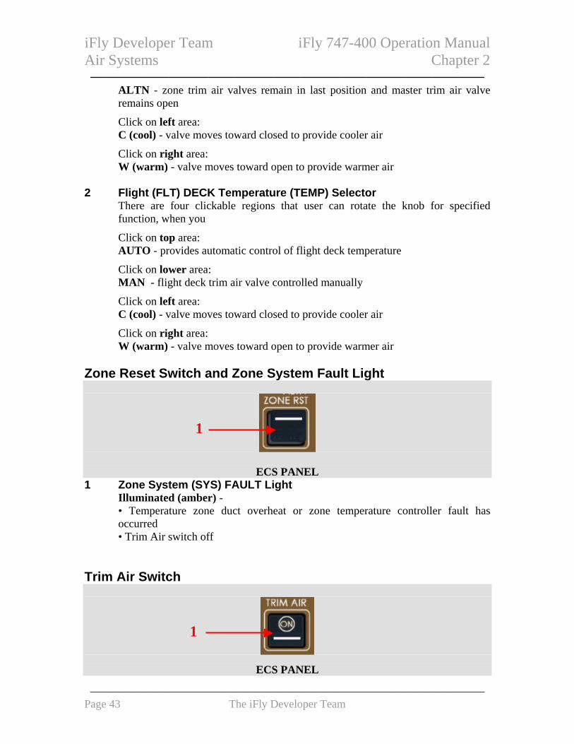
Zone Reset Switch and Zone System Fault Light
1
ECS PANEL
1 Zone System (SYS) FAULT Light Illuminated (amber) - • Temperature zone duct overheat or zone temperature controller fault has occurred • Trim Air switch off
Trim Air Switch
1
ECS PANEL
——————————————————————————————————— Page 43 The iFly Developer Team

iFly Developer Team iFly 747-400 Operation Manual Air Systems Chapter 2 ——————————————————————————————
1 TRIM AIR Switch Controls master trim air valve
Recirculation Fans Switch
1
ECS PANEL
1 Recirculation (RECIRC) Fans Switch Click ON - recirculation fans controlled automatically.
Off - recirculation fans off. Aft Cargo Heat Switch
1
ECS PANEL
1 AFT CARGO Heat (HT) Switch Provides bleed air heat to aft and bulk cargo compartments
Equipment Cooling Selector
1
ECS PANEL
1 Equipment (EQUIP) COOLING Selector Controls equipment cooling system.
——————————————————————————————————— Page 44 The iFly Developer Team

iFly Developer Team iFly 747-400 Operation Manual Air Systems Chapter 2 ——————————————————————————————
Pack High Flow Switch
1
ECS PANEL
1 Pack High (HI) FLOW Switch Click ON – • all operating packs provide high air flow • memo message PACKS HIGH FLOW displayed on EICAS
Off - pack air flow controlled automatically. Pack Control
1
2
ECS PANEL 1 Pack System (SYS) FAULT Light
Illuminated (amber) – • pack off or system fault has occurred
2 PACK Control Selector
Rotate the knob to: OFF – • pack valve closed • extinguishes SYS FAULT light for pack selected off
Normal (NORM) - pack controller A or B selected automatically on alternate flights
A - selects pack controller A as primary controller.
B - selects pack controller B as primary controller.
——————————————————————————————————— Page 45 The iFly Developer Team

iFly Developer Team iFly 747-400 Operation Manual Air Systems Chapter 2 ——————————————————————————————
Pressurization System Cabin Altitude Control
41
5
OVERHEAD PANEL 32
6
1 Landing Altitude (LDG ALT) Switch Click on it to alternately changes landing altitude control between Automatic and Manual. Manual - • landing altitude set by rotating Landing Altitude selector • landing altitude information displays on primary EICAS followed by MAN
Automatic - • landing altitude set automatically from FMS • landing altitude information displays on primary EICAS followed by AUTO
2 Landing Altitude (LDG ALT) Selector
Rotate to set landing altitude when MAN displayed on primary EICAS. 3 Outflow Valve Manual (MAN) Switch
Click: ON - outflow valve in manual mode
Off - outflow valve controlled automatically. 4 OUTFLOW VALVES Position Indicator
OP (Open) - outflow valve open.
CL (Closed) - outflow valve closed. 5 Cabin Altitude AUTO Selector (SELECT)
Rotate to: NORM - • cabin altitude controller A or B selected automatically on alternate flights
——————————————————————————————————— Page 46 The iFly Developer Team

iFly Developer Team iFly 747-400 Operation Manual Air Systems Chapter 2 ——————————————————————————————
• selected controller is the primary controller.
A - selects cabin altitude controller A as primary controller.
B - selects cabin altitude controller B as primary controller. 6 Outflow Valves Manual Control
Click: OPEN - valve moves toward open in manual mode.
CLOSE - valve moves toward closed in manual mode. Bleed Air Control
1
2 4
3
OVERHEAD PANEL
7 6
5
1 Isolation (ISLN) VALVE Light Illuminated (amber) – isolation valve position
2 Isolation (ISLN) Valve Switch
Click: ON (bar in view) – valve open.
Off - valve closed. 3 APU Bleed Air Switch
Click: ON - valve commanded open when EICAS memo message APU RUNNING displayed.
Off - valve closed. 4 Engine Bleed Air System (SYS) FAULT Light
——————————————————————————————————— Page 47 The iFly Developer Team

iFly Developer Team iFly 747-400 Operation Manual Air Systems Chapter 2 ——————————————————————————————
Illuminated (amber) - bleed air failed 5 ENGINE BLEED Air Switch
Click: ON - engine bleed air valve opens
Off - engine bleed air valve closed 6 ENGINE BLEED Air OFF Light
Illuminated (amber) - engine bleed air valve closed. 7 APU Bleed Air VALVE Light
Illuminated (amber) - APU bleed air isolation valve position. ECS Displays and Indications ECS Synoptic Display The ECS synoptic is displayed after clicking the ECS switch on the display select panel. Display select panel operation is described in Chapter 10, Flight Instruments, Displays.
4
2
1
567
8
9
1011
3
12LOWER EICAS DISPLAY
1 Zone Temperatures F/D, U/D, A, B, C, D, and E - zone target temperatures on left with pink strings
——————————————————————————————————— Page 48 The iFly Developer Team

iFly Developer Team iFly 747-400 Operation Manual Air Systems Chapter 2 ——————————————————————————————
and actual temperatures on right with white strings.
MASTER - Passenger Temperature selector.
FWD, AFT, BULK - actual temperature of cargo compartment. 2 Pack Control
OFF - pack valve closed.
A - pack controller A in use.
B - pack controller B in use. 3 APU Bleed Air Isolation Valve
Indicates open or closed position of isolation valve. 4 External Air Indication
Displayed if external air source is available 5 Outflow Valves Position
Indicates position of outflow valves. 6 Outflow Valve Control Source
MAN - indicates manual control of outflow valves.
AUTO - indicates FMS control of outflow valves. 7 High Flow Indication
HI FLOW - • pack operating in high flow mode • indication removed in normal flow or when pack OFF
8 Bleed Air Duct Pressure
White - 12 psi and above.
Amber - 11 psi and below. 9 Wing Anti-ice Indication
Indicates wing anti-ice on. 10 Isolation Valve
Indicates open or closed position of isolation valve. 11 Engine Bleed Air Valve
Indicates open or closed position of engine bleed air valve. 12 Nacelle Anti-ice Indication
Indicates nacelle anti-ice on.
——————————————————————————————————— Page 49 The iFly Developer Team

iFly Developer Team iFly 747-400 Operation Manual Air Systems Chapter 2 ——————————————————————————————
Duct Pressure and Cabin Altitude Indications
1
5 2
6 3
4
LOWER EICAS DISPLAY
1 Bleed Air Duct Pressure When it displays: White - 12 psi and above.
Amber - 11 psi and below. 2 Cabin Altitude
Indicates cabin altitude. 3 Landing Altitude
Indicates landing altitude 4 Landing Altitude Selection
AUTO (white) - altitude set automatically from FMC.
MAN (amber) - altitude set by Landing Altitude selector. 5 Cabin Rate of Climb
Indicates cabin altitude rate of climb. 6 Cabin Differential Pressure
Indicates cabin differential pressure.
——————————————————————————————————— Page 50 The iFly Developer Team

iFly Developer Team iFly 747-400 Operation Manual Air Systems Chapter 2 ——————————————————————————————
Air Conditioning System Introduction Introduction The air conditioning system can provide conditioned bleed and recirculated cabin air throughout the airplane at a specified temperature. On a normal operating airplane, the pack control, zone temperature control, cabin air recirculation, fault detection, and overhear protection are all automatic. In case of system failures, the backup system control modes can operate for it. There are seven temperature zones: • flight deck • upper deck • five main deck cabin zones A through E Air Conditioning Packs There are three identical air conditioning packs, they are used to cool down the bleed air from the engines, APU, or high pressure air from ground sources. Two identical pack controller are in charge of packs controlling, called A and B. Each pack valve has normal and high flow settings. During cruise, normal flow minimizes bleed air demand on the engine in order to reduce fuel consumption. Pilot can set it to high flow by clicking the High Flow switch ON. Zone Target Temperatures The Passenger Temperature selector sets the master passenger cabin temperature to between 18°C and 29°C on real airplane. Equipment Cooling The equipment cooling system can provide cooling air for the electrical and electronic (E & E) compartment equipments and flight deck equipment.
Pressurization System Introduction Introduction Cabin pressurization is controlled by the discharge of conditioned cabin air through the outflow valves at regulation. There are two cabin altitude controllers, A and B. Each controller controls both outflow valves. The pressurization system has automatic and manual operating modes.
——————————————————————————————————— Page 51 The iFly Developer Team

iFly Developer Team iFly 747-400 Operation Manual Air Systems Chapter 2 ——————————————————————————————
Pressurization System Automatic Operation The cabin pressure controllers use ambient pressure and flight plan data from the FMC to calculate a cabin pressurization schedule Pressurization System Manual Operation If both Outflow Manual switches are ON, all automatic cabin altitude control functions are bypassed.
Bleed Air System Introduction Introduction Bleed air can be supplied by the engines, APU, or ground air source. Bleed air is used for: • air conditioning • pressurization • wing and engine anti–ice • engine start • leading edge flaps • aft cargo heat • thrust reversers • hydraulic reservoir pressurization • potable water tank pressurization • air driven hydraulic demand pumps Engine Bleed Air Supply Engine bleed air is supplied from either intermediate pressure (IP) or high pressure (HP) engine sections. IP air is used during high power setting operations, and HP air is used during descent and other low power setting operations. APU Bleed Air Supply APU bleed air is used primarily during ground operations for pack operation and engine starting. APU bleed air is available in flight. With the APU bleed air switch ON, the APU bleed valve opens when the APU can supply bleed air. The EICAS memo message APU RUNNING is displayed when APU N1 is 95% and higher. Ground Bleed Air Supply External connectors are provided to connect a ground source of high pressure air directly to the bleed air duct.
——————————————————————————————————— Page 52 The iFly Developer Team

iFly Developer Team iFly 747-400 Operation Manual Air Systems Chapter 2 ——————————————————————————————
Air Systems EICAS Messages The following EICAS messages can be displayed.
EICAS Alert Messages Message Level Aural Condition
BLD OVHT/PRV 1, 2, 3, 4
Advisory Engine bleed air overheat or PRV failed closed.
BLEED 1, 2, 3, 4 Advisory Engine bleed air overpressure, or HP bleed valve or PRV failed to close when commanded.
>BLEED 1, 2, 3, 4 OFF
Advisory Engine Bleed Air switch OFF, engine operating, and engine bleed air valve closed.
BLEED ISLN L, R
Advisory Isolation Valve switch position and valve position disagree.
>BLEED ISLN APU
Advisory APU bleed isolation valve position disagrees with commanded position.
CABIN ALT AUTO
Caution Beeper Either cabin altitude controllers inoperative or both Outflow Valve Manual switches ON.
CABIN ALT AUTO
Caution Beeper Either cabin altitude controllers inoperative or both Outflow Valve Manual switches ON.
CABIN ALTITUDE
Warning Siren Cabin altitude exceeds 10,000 feet
LANDING ALT Advisory Disagreement between controller landing altitude and FMC landing altitude.
OUTLFOW VLV L, R
Advisory Automatic control of outflow valve is inoperative, or respective Outflow Valve Manual switch is ON.
>TRIM AIR OFF Advisory Master trim air valve closed. Flight deck and passenger cabin temperature control in backup mode.
EICAS Memo Messages
Message Condition PACK 1, 2, 3 OFF Pack has been selected off. PACKS 1 + 2, 1 + 3, 2 + 3 OFF Packs have been selected off. PACKS HIGH FLOW High flow switch ON. Pack flow setting
not controlled automatically. PACKS OFF All packs have been selected off.
——————————————————————————————————— Page 53 The iFly Developer Team

iFly Developer Team iFly 747-400 Operation Manual ——————————————————————————————
Intentionally Blank
——————————————————————————————————— Page 54 The iFly Developer Team

iFly Developer Team iFly 747-400 Operation Manual Anti-Ice Chapter 3 ——————————————————————————————
NACELLE AND WING ANTI-ICE ......................................... 56
NACELLE AND WING ANTI-ICE PANEL ................................... 56
ANTI-ICE SYSTEMS INTRODUCTION ............................... 56
NACELLE ANTI–ICE SYSTEM ................................................... 57 Nacelle Anti–Ice System Operation .......................................................................... 57
WING ANTI–ICE SYSTEM ......................................................... 57 Wing Anti–Ice System Operation .............................................................................. 57
ANTI–ICE, RAIN EICAS MESSAGES ................................... 57
EICAS ALERT MESSAGES ....................................................... 57
——————————————————————————————————— Page 55 The iFly Developer Team

iFly Developer Team iFly 747-400 Operation Manual Anti-Ice Chapter 3 ——————————————————————————————
——————————————————————————————
——————————————————————————————————— Page 56 The iFly Developer Team
Nacelle and Wing Anti-Ice Nacelle and Wing Anti-Ice Nacelle and Wing Anti-Ice Panel Nacelle and Wing Anti-Ice Panel
1 2
3
4
OVERHEAD PANEL
1 NACELLE ANTI–ICE Switches Click: ON – nacelle anti-ice on
OFF –nacelle anti-ice off 2 WING ANTI–ICE Switch
Click: ON –wing anti-ice on
OFF –wing anti-ice off 3 NACELLE ANTI-ICE VALVE Lights
Illuminated (amber) – Nacelle anti-ice valve position disagrees with switch position
4 WING ANTI-ICE VALVE Light
Illuminated (amber) – Wing anti-ice valve position disagrees with switch position
Anti-Ice Systems Introduction The anti–ice and rain systems contains: • engine anti–ice • wing anti–ice
——————————————————————————————————— Page 56 The iFly Developer Team

iFly Developer Team iFly 747-400 Operation Manual Anti-Ice Chapter 3 ——————————————————————————————
Nacelle Anti–Ice System The nacelle anti–ice system provides engine cowl inlet ice protection by using engine bleed air to. Nacelle Anti–Ice System Operation On the ground and in flight, with NACELLE ANTI-ICE switch is ON, the bleed air is supplied to the engine inlet cowl. Wing Anti–Ice System The wing anti–ice system provides bleed air to each wing. When anti-ice is commanded on, the bleed air flows from the engines to a spray tube in the leading edge. When the wing anti–ice valve is open, the wing anti–ice indication WAI is displayed beside the each wing EICAS N1 indication Wing Anti–Ice System Operation During flight, when the WING ANTI-ICE is ON, the wing anti–ice valve in each wing opens.
Anti–Ice, Rain EICAS Messages The following EICAS messages can be displayed. EICAS Alert Messages Message Level Aural Condition >ANTI-ICE NAC Advisory Any nacelle anti-ice system on, TAT
greater than 12°C >ANTI-ICE WING
Advisory Either wing anti-ice system on, TAT greater than 12°C
——————————————————————————————————— Page 57 The iFly Developer Team

iFly Developer Team iFly 747-400 Operation Manual ——————————————————————————————
Intentionally Blank
——————————————————————————————————— Page 58 The iFly Developer Team

iFly Developer Team iFly 747-400 Operation Manual Automatic Flight Chapter 4 ——————————————————————————————
CONTROLS AND INDICATORS............................................ 60
MODE CONTROL PANEL (MCP).............................................. 60 Autopilot Flight Director System (AFDS) Controls.................................................. 60 Autothrottle (A/T) System Controls........................................................................... 61 Autopilot Flight Director IAS/Mach Controls .......................................................... 62 Autopilot Flight Director Roll and Pitch Controls ................................................... 63 Autopilot Flight Director Heading and Bank Angle Controls.................................. 64 Autopilot Flight Director Vertical Speed (V/S) Controls ......................................... 65 Autopilot Flight Director Altitude Controls ............................................................. 66 Autopilot Flight Director Approach Mode Controls ................................................ 67
PFD FLIGHT MODE ANNUNCIATIONS (FMAS) ...................... 68
AUTOPILOT DISENGAGE SWITCH............................................ 69
TO/GA SWITCHES.................................................................... 69
SYSTEM DESCRIPTION ......................................................... 70
INTRODUCTION ......................................................................... 70
AUTOPILOT FLIGHT DIRECTOR SYSTEM ................................ 70 MCP Switches ........................................................................................................... 70 Autopilot Engagement............................................................................................... 70 Autopilot Disengagement.......................................................................................... 70 Flight Director Display............................................................................................. 71 AFDS Status Annunciation ....................................................................................... 71 AFDS Flight Mode Annunciations............................................................................ 71
Autothrottle Modes ............................................................................................... 71 Roll Modes............................................................................................................ 71 Pitch Modes .......................................................................................................... 72
AUTOTHROTTLE SYSTEM......................................................... 73 Autothrottle Disconnect ............................................................................................ 73
AUTOMATIC FLIGHT EICAS MESSAGES......................... 73
EICAS ALERT MESSAGES ....................................................... 73
——————————————————————————————————— Page 59 The iFly Developer Team

iFly Developer Team iFly 747-400 Operation Manual Automatic Flight Chapter 4 ——————————————————————————————
Controls and Indicators Mode Control Panel (MCP)
GLARESHIELD PANEL Autopilot Flight Director System (AFDS) Controls
1
2
3
Mode Control Panel (MCP)
1 Flight Director (F/D) Switches The F/D switch activates F/D, the steering indications are shown on the primary flight display (PFD).
Click: ON – • On the ground, positioning the F/D switches ON arms the F/D in the takeoff go–
around (TO/GA) roll and pitch modes, and also displays the flight direction steering indications on the PFD
• in flight, with the A/P disengaged and F/D switches OFF, the F/D switches positioned to ON activates the F/D in: • vertical speed (V/S) as the pitch mode, and • heading hold (HDG HOLD) as the roll mode, or if bank angle greater than five degrees, attitude hold (ATT)
• in flight, with the A/P engaged and both F/D switches OFF, the first F/D switch
——————————————————————————————————— Page 60 The iFly Developer Team

iFly Developer Team iFly 747-400 Operation Manual Automatic Flight Chapter 4 ——————————————————————————————
positioned to ON activates the F/D in the selected A/P mode(s)
OFF – • F/D steering indications do not display.
2 Autopilot (A/P) ENGAGE Switches
Click (any switch engages the autopilot) – • when either F/D switch is ON, the A/P engages in the selected F/D mode(s) • when both F/D switches are OFF, the A/P engages in:
• vertical speed (V/S) as the pitch mode and • heading hold (HDG HOLD) or attitude hold (ATT) as the roll mode
3 Autopilot DISENGAGE Bar
Click down– • disengages all three A/Ps • prevents A/P engagement • exposes amber stripe
Click to lift up position - • enables A/P engagement • conceals amber stripe
Autothrottle (A/T) System Controls
1
3
2
Mode Control Panel (MCP)
1 Autothrottle (A/T) ARM Switch ARM (Click) - • arms A/T system for mode selection, and A/T will operate when SPD, VNAV, FLCH, or TO/GA switch pushed
Click OFF – • disconnects A/T
——————————————————————————————————— Page 61 The iFly Developer Team

iFly Developer Team iFly 747-400 Operation Manual Automatic Flight Chapter 4 ——————————————————————————————
2 Thrust (THR) Switch Click: Light extinguished - • after takeoff and during climb, changes reference thrust limit to armed climb
thrust limit • changes reference thrust limit to CLB, unless engine inoperative or CON
selected, then reference thrust limit is CON
Light illuminated (A/T mode function) - Changes A/T mode to THR REF.
3 Speed (SPD) Switch Operative from 400 feet after takeoff until landing.
Click (light illuminates) – • selects A/T SPD mode • displays SPD on PFD • A/T controls thrust to maintain IAS or Mach displayed in IAS/MACH window • inactive in VNAV XXX, FLCH SPD, or TO/GA pitch modes
Autopilot Flight Director IAS/Mach Controls
1
3
2
Mode Control Panel (MCP)
1 IAS/MACH Window Displays selected speed when IAS/MACH selector controls command speed, and the selected speed will also display on PFD. Its display range is 100-399KIAS or .400-.950 Mach. When power first applied, IAS/Mach window and PFD speeds will set to 200knots.
Blank when FMC controls command speed. 2 IAS/MACH Select (SEL) Switch
Click – • Changes the IAS/MACH window between IAS and Mach displays alternativly.
——————————————————————————————————— Page 62 The iFly Developer Team

iFly Developer Team iFly 747-400 Operation Manual Automatic Flight Chapter 4 ——————————————————————————————
• inoperative when the IAS/MACH window is blank 3 IAS/MACH Selector
Rotate(by mouse) – • sets speed in IAS/MACH window and command speed on PFD • inoperative when IAS/MACH window blank Click – with VNAV active, alternately opens or closes the IAS/MACH window: • when window closed, FMC computed target speed is active and displays on
PFDs • when window open, FMC speed–intervention is active and IAS/MACH selector
may be used to set command speed. Autopilot Flight Director Roll and Pitch Controls
1 2
3 4
5 6
Mode Control Panel (MCP)
1 Lateral Navigation (LNAV) Switch Click – • arms, selects, or disarms LNAV as roll mode • displays LNAV in white (armed) on both PFD roll flight mode annunciations
when armed. The previous roll mode remains active • when active, displays LNAV in green on PFD roll flight mode annunciation
LNAV can deactivated either by selecting heading hold (HDG HOLD), or by selecting heading select (HDG SEL)
To disarm the LNAV, give LNAV switch a second time click.
2 LNAV Light
Illuminated when LNAV roll mode armed or active. 3 Vertical Navigation (VNAV) Switch
Click –
——————————————————————————————————— Page 63 The iFly Developer Team

iFly Developer Team iFly 747-400 Operation Manual Automatic Flight Chapter 4 ——————————————————————————————
• arms, selects, or disarms VNAV as pitch mode • displays VNAV in white (armed) on both PFD pitch flight mode annunciations
below 400 feet • VNAV activates 400 feet above runway elevation
VNAV can be deactivated by selecting TO/GA, FLCH SPD, V/S, ALT, or G/S pitch mode
To disarm VNAV, give VNAV switch a second time click. 4 VNAV Light
Illuminated when VNAV pitch mode armed or active. 5 Flight Level Change (FLCH) Switch
Click – • selects FLCH SPD pitch mode • FLCH SPD pitch mode displays in green (active) on PFD flight mode
annunciation 6 Flight Level Change Light
Illuminated when flight level changes and pitch mode is active. Autopilot Flight Director Heading and Bank Angle Controls
1
3
2
4 4
5
6
Mode Control Panel (MCP) 1 Heading Window
Displays selected heading. 2 Heading Select (HDG SEL) Switch
——————————————————————————————————— Page 64 The iFly Developer Team

iFly Developer Team iFly 747-400 Operation Manual Automatic Flight Chapter 4 ——————————————————————————————
Click - • selects HDG SEL roll mode • HDG SEL roll mode displays in green (active) on PFD roll flight mode
annunciation
3 Heading (HDG) Selector (inner) Rotate (by mouse) – sets heading in HDG window and selected heading on PFD and ND.
4 BANK LIMIT Selector (outer)
Rotate (by mouse) – sets AFDS commanded bank limit, the heading select (HDG SEL) roll mode is available as: • AUTO – varies between 15 – 25 degrees, depending on TAS, flap position • 5, 10, 15, 20, or 25 – selected value is maximum, regardless of airspeed
5 Heading (HDG) HOLD Switch
Click - • selects HDG HOLD roll mode, and • HDG HOLD roll mode displays in green (active) on PFD roll flight mode
annunciation 6 Heading Hold Light
Illuminated when HDG HOLD roll mode active. Autopilot Flight Director Vertical Speed (V/S) Controls
1
3 2
4 Mode Control Panel (MCP)
1 Vertical Speed (VERT SPD) Window Blank when vertical speed (V/S) pitch mode not selected. It can display current /S when V/S pitch mode selected; Displays selected V/S in 100 fpm increments;
——————————————————————————————————— Page 65 The iFly Developer Team

iFly Developer Team iFly 747-400 Operation Manual Automatic Flight Chapter 4 ——————————————————————————————
Display range is -8000 to +6000 fpm; And vertical speed displays on the PFD V/S indication.
2 Vertical Speed (V/S) Selector
Scroll UP or Down (DN), it sets V/S in VERT SPD window and on PFD. 3 Vertical Speed (V/S) Switch
Click – • selects V/S pitch mode, and • V/S pitch mode displays in green (active) on PFD pitch flight mode
annunciation.
4 Vertical Speed (V/S) Light Illuminated when vertical speed pitch mode is active.
Autopilot Flight Director Altitude Controls
1
2
3
Mode Control Panel (MCP) 1 Altitude Window
It can displays selected altitude in 100 feet increments. Display range is 0 to 50000 feet; Displays selected altitude on PFD; and displayed altitude is reference altitude for altitude alerting and level off.
2 Altitude Selector
Rotate(by mouse) – set altitude in ALT window and selected altitude on PFD.
Click – • during climb or descent with altitude constraints, each push deletes the next
waypoint constraint between the airplane altitude and the altitude window setting
• during climb with no altitude constraints, and the altitude window set above the FMC cruise altitude, changes cruise altitude to the altitude window value
——————————————————————————————————— Page 66 The iFly Developer Team

iFly Developer Team iFly 747-400 Operation Manual Automatic Flight Chapter 4 ——————————————————————————————
• during cruise: • with the altitude window set above or below FMC cruise altitude, resets the
FMC cruise altitude to the altitude window altitude • when in VNAV PTH or VNAV ALT pitch mode, initiates a climb or descent
toward the altitude window altitude • within 50 NM of the top–of–descent (T/D) point, with the altitude window set
below cruise altitude, initiates a reduced rate descent 3 Altitude HOLD Switch
Click – • selects altitude (ALT) pitch mode • ALT pitch mode displays in green (active) on PFD pitch mode annunciation
4 Altitude Hold Light Illuminated when altitude hold mode active.
Autopilot Flight Director Approach Mode Controls
1
2 34
Mode Control Panel (MCP)
1 Localizer (LOC) Switch Click – • arms, disarms, captures localizer (LOC) as roll mode • displays LOC in white (armed) on both PFD roll flight mode annunciations
before localizer capture; active HDG HOLD roll mode until LOC capture
Localizer mode can be disarmed before localizer capture by clicking localizer switch a second time, or selecting another roll mode Localizer mode can be deactivated after localizer capture by selecting a roll mode other than LNAV, or pushing a TO/GA switch
2 Localizer Light
Illuminated when localizer roll mode armed or active.
——————————————————————————————————— Page 67 The iFly Developer Team

iFly Developer Team iFly 747-400 Operation Manual Automatic Flight Chapter 4 ——————————————————————————————
3 Approach (APP) Switch
Click – • AFDS captures and tracks localizer and captures glideslope mode upon
interception
Approach mode can be disarmed before localizer or glideslope capture by clicking approach switch a second time, or selecting LOC, LNAV, or VNAV. Approach mode deselects with localizer captured and glideslope armed, by selecting another roll mode; with glideslope captured and localizer armed, by selecting another pitch mode; after localizer and/or glideslope are captured, by selecting TO/GA mode
4 Approach Light
Illuminated when approach modes (LOC and G/S) armed or active. PFD Flight Mode Annunciations (FMAs)
1
3
42
5
6
PFD
1 Autothrottle Modes (Active) THR, THRREF, HOLD, IDLE and SPD can be displayed in green color.
2 AFDS Roll Modes (Active)
ATT, HDG HOLD, HDG SEL, LNAV, LOC, ROLLOUT, TO/GA can be displayed here in green color.
3 AFDS Roll Modes (Armed)
LOC, ROLLOUT and LNAV can be displayed here in white color. 4 AFDS Pitch Modes (Active)
Displayed (green) –TO/GA, ALT, V/S, VNAVPTH, VNAV SPD, VNAVALT, G/S, FLARE and FLCH SPD can be displayed here in green color.
——————————————————————————————————— Page 68 The iFly Developer Team

iFly Developer Team iFly 747-400 Operation Manual Automatic Flight Chapter 4 ——————————————————————————————
5 AFDS Pitch Modes (Armed)
G/S, FLARE and VNAV can be displayed here in white color. 6 AFDS (Active)
FD, CMD, LAND 2, LAND 3 and TEST can be displayed here in green color.
NO AUTOLAND can be displayed here in amber color. Autopilot Disengage Switch
1
CONTROL WHEELS
1 Autopilot Disengage Switches Click to disengage all autopilots
TO/GA Switches
1
PFD
——————————————————————————————————— Page 69 The iFly Developer Team

iFly Developer Team iFly 747-400 Operation Manual Automatic Flight Chapter 4 ——————————————————————————————
1 Takeoff/Go-around (TO/GA) Switch On the ground: Click – • below 50 knots, activates autothrottle in THR REF mode at reference thrust limit
selected on THRUST LIMIT page
In flight (flaps out of up or glideslope captured): Click - • removes takeoff derates. • selects TO/GA roll and pitch modes. If A/T armed, activates autothrottle in THR
REF mode
System Description Introduction The automatic flight control system consists of the autopilot flight director system (AFDS) and the autothrottle system (A/T). The mode control panel (MCP) and flight management computer (FMC) control the AFDS and the autothrottle system to perform climb, cruise, descent, and approach. Autopilot Flight Director System On a real Boeing 747-400 airplane, the AFDS consists of three flight control computers (FCC) and the MCP. The MCP provides control of the autopilot, flight director, altitude alert, and autothrottle systems. The MCP selects and activates AFDS modes, and establishes altitudes, speeds, and climb/descent profiles. The FCCs also provide inputs for AFDS operating mode displays and FD commands on the PFD. MCP Switches MCP switches select automatic flight control and flight director modes. A light in the lower half of the switch illuminates PFD roll and pitch flight mode annunciations to indicate the mode is armed or active. Autopilot Engagement The autopilot is engaged by clicking one of the MCP autopilot engage switches. Autopilot Disengagement Normal autopilot disengagement is through either control wheel autopilot disengage switch. The autopilots can also be disengaged by the MCP autopilot disengage bar.
——————————————————————————————————— Page 70 The iFly Developer Team

iFly Developer Team iFly 747-400 Operation Manual Automatic Flight Chapter 4 ——————————————————————————————
Flight Director Display The flight director steering indications displays, when Flight Director switch is ON. AFDS Status Annunciation The following AFDS status annunciations display above the attitude display: • FD - flight director ON and autopilots not engaged • CMD - autopilot engaged • LAND 3 - three autopilots engaged and operating normally for an automatic landing • LAND 2 - AFDS redundancy reduced; in some cases, only two autopilots available • NO AUTOLAND - AFDS unable to make an automatic landing AFDS Flight Mode Annunciations Flight mode annunciations display above AFDS status annunciations. Mode annunciations, from left to right, are autothrottle, roll and pitch Autothrottle Modes Autothrottle annunciations are: THR - autothrottle applies thrust to maintain the climb/descent rate required by the pitch mode. THR REF – thrust set to the reference thrust limit displayed on EICAS. IDLE – displays while the autothrottle moves thrust levers to idle; IDLE mode is followed by HOLD mode. HOLD – thrust lever autothrottle servos are inhibited. The pilot can set the thrust levers manually. SPD – autothrottle maintains command speed. Command speed can be set using the MCP IAS/Mach selector or, by the FMC, as displayed on the CDU VNAV page. Roll Modes Roll annunciations are: LNAV – Arm LNAV by clicking the LNAV switch • LNAV (armed) – LNAV is armed to activate when parameters are met • LNAV (active) – LNAV activates
HDG – • HDG SEL (active) – airplane turns to or maintains the heading set in the MCP heading
window • HDG HOLD (active) – AFDS holds present heading.
ATT (active) – when the autopilot is first engaged and the flight director is OFF in flight, AFDS holds a bank angle between 5 and 30 degrees and will not roll to wings level. When the bank angle is less than 5 degrees, AFDS rolls to wings level (HDG HOLD). When the bank angle is greater than 30 degrees, AFDS rolls to 30 degrees of bank.
LOC –
——————————————————————————————————— Page 71 The iFly Developer Team

iFly Developer Team iFly 747-400 Operation Manual Automatic Flight Chapter 4 ——————————————————————————————
• LOC (armed) – AFDS captures the localizer • LOC (active) – AFDS follows the localizer course
TO/GA – • On the ground, TO/GA annunciates by positioning the flight director switch ON. • In flight, there is no flight mode annunciation for TO/GA armed in flight; although the
reference thrust limit changes to GA. TO/GA is activated in flight by pushing a TO/GA switch. The roll steering indication provides guidance to maintain the ground track present at mode engagement
ROLLOUT – • ROLLOUT (armed) – displays below 1,500 feet radio altitude and activates below 5
feet • ROLLOUT (active) – after touchdown, AFDS uses rudder and nose wheel steering to
steer the airplane on the localizer centerline Pitch Modes Pitch annunciations are: TO/GA – On the ground, TO/GA annunciates by positioning the flight director switch ON. The flight director pitch bar indicates an initial pitch of eight degrees up. After takeoff, the AFDS commands a pitch attitude to maintain a target speed of V2 plus 10 knots
When a go–around is initiated, the command speed is the MCP IAS/Mach window
VNAV – Arm VNAV by clicking the VNAV switch. VNAV activates at 400 feet and provides pitch commands to maintain the FMC computed airspeed/path: • VNAV SPD (active) – AFDS maintains the FMC speed displayed on the PFD and/or
the CDU CLIMB or DESCENT pages. • when a VNAV descent is initiated before the top of descent (T/D) and the airplane
subsequently intercepts the VNAV descent path, the pitch annunciation may change from VNAV SPD to VNAV PTH
• VNAV PTH (active) – AFDS maintains FMC altitude or descent path with pitch commands.
• VNAV ALT (active) - If a conflict occurs between the VNAV profile and the MCP altitude, the airplane levels and the pitch flight mode annunciation becomes VNAV ALT.
V/S – Clicking the V/S switch opens the vertical speed window and displays the current vertical speed. It also opens the IAS/MACH window (if blanked).
FLCH SPD – Clicking the FLCH switch opens the IAS/MACH window (if blanked).
ALT – Altitude hold mode is activated by pushing the MCP altitude HOLD switch, or capturing the selected altitude from a V/S or FLCH climb or descent
——————————————————————————————————— Page 72 The iFly Developer Team

iFly Developer Team iFly 747-400 Operation Manual Automatic Flight Chapter 4 ——————————————————————————————
G/S - AFDS follows the ILS glideslope.
FLARE – • FLARE (armed) - during autoland, FLARE displays below 1,500 feet RA • FLARE (active) - during autoland, flare activates between 60 and 40 feet RA. FLARE
deactivates at touchdown and the nose wheel smoothly lowers to the runway Autothrottle System The autothrottle system provides thrust control from takeoff through landing. Autothrottle operation is controlled from the MCP and the CDU. Refer to Chapter 11.
The autothrottle can be operated without using the flight director or the autopilot. Autothrottle Disconnect The autothrottle system can be disconnected manually by positioning the Autothrottle Arm switch to OFF.
Automatic Flight EICAS Messages The following EICAS messages can be displayed. EICAS Alert Messages Message Level Aural Condition >AUTOPILOT DISC
Warning Siren Autopilot has disengaged.
>AUTOTHROT DISC
Caution Beeper Autothrottle has disconnected.
>NO AUTOLAND
Caution Advisory
Beeper Autoland is not available. Message is a caution if fault occurs after LAND 3 or LAND 2 annunciates. Message is an advisory if fault occurs before LAND 3 or LAND 2 annunciates.
>NO LAND 3 Caution Advisory
Beeper Autoland system does not have redundancy for triple channel autoland. Message is a caution if fault occurs after LAND 3 or LAND 2 annunciates. Message is an advisory if fault occurs before LAND 3 or LAND 2 annunciates.
——————————————————————————————————— Page 73 The iFly Developer Team

iFly Developer Team iFly 747-400 Operation Manual ——————————————————————————————
Intentionally Blank
——————————————————————————————————— Page 74 The iFly Developer Team

iFly Developer Team iFly 747-400 Operation Manual Communications Chapter 5 ——————————————————————————————
CONTROLS AND INDICATORS............................................ 76
AUDIO PANEL............................................................................ 76
RADIO SYSTEM ......................................................................... 77 Radio Tuning Panel .................................................................................................. 77
SYSTEM DESCRIPTION ......................................................... 78
INTRODUCTION ......................................................................... 78
AUDIO PANELS.......................................................................... 78
RADIO TUNING PANELS............................................................ 78
AIR TRAFFIC CONTROL DATALINK......................................... 79
——————————————————————————————————— Page 75 The iFly Developer Team
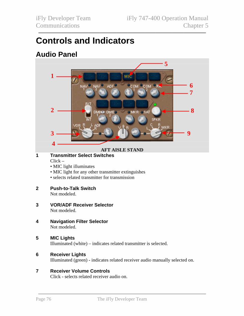
iFly Developer Team iFly 747-400 Operation Manual Communications Chapter 5 ——————————————————————————————
Controls and Indicators
Audio Panel
5
1
6 7
2 8
AFT AISLE STAND
3
4
9
1 Transmitter Select Switches Click – • MIC light illuminates • MIC light for any other transmitter extinguishes • selects related transmitter for transmission
2 Push-to-Talk Switch
Not modeled. 3 VOR/ADF Receiver Selector
Not modeled. 4 Navigation Filter Selector
Not modeled. 5 MIC Lights
Illuminated (white) – indicates related transmitter is selected. 6 Receiver Lights
Illuminated (green) - indicates related receiver audio manually selected on. 7 Receiver Volume Controls
Click - selects related receiver audio on.
——————————————————————————————————— Page 76 The iFly Developer Team

iFly Developer Team iFly 747-400 Operation Manual Communications Chapter 5 ——————————————————————————————
8 Speaker (SPKR) Volume Control Not modeled.
9 Approach (APP) Receiver Selector
Not modeled. Radio System Radio Tuning Panel
AFT AISLE STAND
1 6
7 2
3
4 8
9
105
1 Offside Tuning Light Illuminated – indicates one of the following conditions: • the radio tuning panel is being used to tune a radio not normally associated with
this radio tuning panel • the radio normally associated with this panel is being tuned by another radio
tuning panel • another radio tuning panel is off
2 ACTIVE Frequency Window Displays tuned frequency of selected radio.
3 HF Sensitivity Control
Not modeled. 4 Radio Tuning Panel (PNL) OFF Switch
Click – disconnects panel from communication radios. 5 Radio Tuning Panel OFF Light
Illuminated (white) – radio tuning panel is disconnected from communication radios.
——————————————————————————————————— Page 77 The iFly Developer Team

iFly Developer Team iFly 747-400 Operation Manual Communications Chapter 5 ——————————————————————————————
6 Frequency Transfer Switch
Click – • transfers frequency from STANDBY window to ACTIVE window while tunes
selected radio to new active frequency, or transfers ACTIVE window frequency to STANDBY window.
7 STANDBY Frequency Window
Displays preselected or previously tuned frequency of selected radio. 8 Frequency Selector
Set frequency in the STANDBY window: 9 Radio Tuning Switches
Click – • selects radio to be tuned • tuned frequency displays in ACTIVE frequency window, or standby frequency displays in STANDBY frequency window.
10 Radio Tuning Lights
Illuminated (white) – indicates selected radio.
System Description Introduction The communication system includes: • radio communication system • cockpit voice recorder system • interphone communication system The cockpit voice recorder system and interphone communication system are not modeled in this version. The radio tuning and audio panels control the communications systems. Audio Panels The audio panels control radio and interphone communication systems. Navigation receiver audio can also be monitored. Radio Tuning Panels The radio tuning panels tune the radios. The panels are designated left, center, and right, and are normally associated with the related radios.
——————————————————————————————————— Page 78 The iFly Developer Team

iFly Developer Team iFly 747-400 Operation Manual Communications Chapter 5 ——————————————————————————————
If a radio-tuning panel fails, the panel can be disconnected from the communication radios using the OFF switch. Air Traffic Control Datalink Due to the limitation of flight simulator, the functionalities of ATC on CDU are unable to be realized, meaning that they are not actually functional. Nevertheless, all the pages related to ATC on CDU are available in this version, but their specification descriptions won’t be provided here, pilots can take time to dig in while you are cruising. ☺ The ATC INDEX CDU page provides access to pages used for ATC datalink functions.
CDU
——————————————————————————————————— Page 79 The iFly Developer Team

iFly Developer Team iFly 747-400 Operation Manual ——————————————————————————————
Intentionally Blank
——————————————————————————————————— Page 80 The iFly Developer Team

iFly Developer Team iFly 747-400 Operation Manual ——————————————————————————————
CONTROLS AND INDICATORS............................................ 82
ELECTRICAL PANEL ................................................................. 82 OVERHEAD PANEL........................................................................................... 82
Standby Power, Battery, and Utility Bus Controls ................................................... 83 AC Bus and Generator Controls............................................................................... 84
ELECTRICAL SYNOPTIC DISPLAY............................................ 85 LOWER EICAS DISPLAY.................................................................................. 85
BATTERY CONDITION............................................................... 86 LOWER EICAS DISPLAY.................................................................................. 86
SYSTEM DESCRIPTION ......................................................... 87
INTRODUCTION ......................................................................... 87
AC ELECTRICAL SYSTEM ........................................................ 87 AC Electrical System Power Sources ....................................................................... 87 Integrated Drive Generators (IDGs) ........................................................................ 87 Auxiliary Power (External and APU) ....................................................................... 87 AC Electrical Power Distribution............................................................................. 87 AC Main Busses ........................................................................................................ 87 Ground Service Bus .................................................................................................. 88 Ground Handling Bus ............................................................................................... 88 Captain’s Transfer Bus ............................................................................................. 88 First Officer’s Transfer Bus...................................................................................... 88 Utility and Galley Busses.......................................................................................... 88 Electrical bus Isolation during Autoland.................................................................. 88 AC Standby Power System ........................................................................................ 88 Main Standby Bus ..................................................................................................... 88 APU Standby Bus...................................................................................................... 88 Standby Power Selector - BAT Position ................................................................... 88
DC ELECTRICAL SYSTEM ........................................................ 88 Main DC Electrical System....................................................................................... 89
ELECTRICAL FLIGHT EICAS MESSAGES ....................... 89
EICAS ALERT MESSAGES ....................................................... 89
——————————————————————————————————— Page 81 The iFly Developer Team

iFly Developer Team iFly 747-400 Operation Manual ——————————————————————————————
Controls and Indicators Electrical Panel
OVERHEAD PANEL
1
2
3
1 Standby Power and Utility Bus Controls 2 External Power, APU Generator, and Battery Controls 3 AC Bus and Generator Controls
——————————————————————————————————— Page 82 The iFly Developer Team

iFly Developer Team iFly 747-400 Operation Manual ——————————————————————————————
Standby Power, Battery, and Utility Bus Controls
41
52
3
OVERHEAD PANEL
1 STANDBY POWER Selector When switch to: OFF - The standby power is not available, the main and APU standby busses are disconnected from all power sources
AUTO - The main and APU standby busses are being powered by all available sources.
BAT - Gives powers to main battery bus and APU battery, and powers main and APU standby busses
2 BATTERY Switch Right click on mouse button to unveil protection box, then left click: ON - The main battery and APU battery are available
OFF - Disconnects main and APU batteries. 3 BATTERY Switch OFF Light
Illuminated (amber) - Battery switch off. 4 UTILITY Power Switches
ON - Powers utility ELCUs (electrical load control units) and galley ELCUs.
OFF - Removes power from related ELCUs and resets fault logic circuitry 5 UTILITY Power OFF Lights
Illuminated (amber) - Power removed from related ELCUs by fault protection logic, or related Utility Power switch OFF, or at least one Galley Emergency Power Off switch OFF
——————————————————————————————————— Page 83 The iFly Developer Team

iFly Developer Team iFly 747-400 Operation Manual ——————————————————————————————
AC Bus and Generator Controls
3 4
1 2
5
6
OVERHEAD PANEL
1 BUS TIE Switches
AUTO - Arms automatic AC bus tie circuit, or closes related DC isolation relay
OFF - Opens AC bus tie breaker and related DC isolation relay, or Resets fault logic circuitry
2 Bus Isolation (ISLN) Lights
Illuminated (amber) - AC bus tie breaker open, or AC bus isolated from synchronous bus
3 Generator Drive Disconnect (DRIVE DISC) Switches
Right click on mouse button to unveil protection box, then left click: • Disconnects integrated drive generator (IDG) from engine • Opens related generator control breaker
4 Generator DRIVE Lights Illuminated (amber) - IDG oil pressure low, or IDG oil temperature high
5 Generator Control (GEN CONT) Switches
ON - Arms generator control breaker to close when generator power quality acceptable.
OFF - Opens field and generator control breakers, or reset fault control logic circuit, or isolates generator from its related AC bus
6 Generator OFF Lights
Illuminated (amber) - Opens generator control breaker
——————————————————————————————————— Page 84 The iFly Developer Team

iFly Developer Team iFly 747-400 Operation Manual ——————————————————————————————
Electrical Synoptic Display The electrical synoptic displays will be brought up when clicking on the ELEC Synoptic switch. The synoptic displays the configuration of the AC power system schematically, and the DC power flow is not displayed. All the depiction is generated by the status of various system breakers and conductors (on real airplane, of course those data do not REALLY exist on SIMS). This display may not be an accurate representation of system operation, and it’s only for simplified display matters. Symbols display in lower intensity white when source data is invalid or unavailable.
During autoland, the message “ELECTRICAL SYNOPTIC INHIBITED FOR AUTOLAND” appears on the synoptic display.
1
23 5
4
6
7
LOWER EICAS DISPLAY 1 Split System Breaker (SSB)
Closed - Connected both sides of synchronous bus.
Open - Split synchronous bus. 2 Bus Tie (ISLN)
• Power flow bar present - Bus tie breaker closed • ISLN (amber) - Bus tie breaker open
——————————————————————————————————— Page 85 The iFly Developer Team

iFly Developer Team iFly 747-400 Operation Manual ——————————————————————————————
3 UTILITY Bus UTILITY - • Green - Utility bus is powered • Amber - Utility bus is not powered
4 AC BUS
BUS 1, 2, 3, 4 - • Green - AC bus is powered • Amber - AC bus is not powered
5 Generator Control Breaker (GEN CONT)
• Power flow bar present - Generator control breaker is closed • OFF (amber) - Generator control breaker is open
6 Generator Drive (DRIVE)
• Blank - Normal operation • DRIVE TEMP/PRESS (amber) - Drive has high oil temperature or low oil
pressure 7 GALLEY Bus
GALLEY - • Green - Galley bus is powered • Amber - Galley bus is unpowered
Battery Condition Battery condition can be displayed on the status page, when pilot clicks on STAT Display switch which is located on the display select panel..
2
31
LOWER EICAS DISPLAY 1 Battery Voltage (V-DC)
It shows main and APU battery voltage. 2 Battery Current (A-DC)
It shows main and APU battery amperage. 3 Battery Charge Status
DIS (Discharge) - Discharging the battery.
——————————————————————————————————— Page 86 The iFly Developer Team

iFly Developer Team iFly 747-400 Operation Manual ——————————————————————————————
CHG (Charge) - Charging battery, and if battery current is zero, the charge status is blank
System Description Introduction The electrical system can generate the AC and DC power to the airplane systems, it is comprised by main AC power, DC power, and standby power components. This system operation is fully automatic, any electrical faults are automatically detected and isolated. AC Electrical System The AC electrical system is the main source to supply the airplane electrical power. AC Electrical System Power Sources The main AC electrical power sources are four integrated drive generators (IDGs), two APU generators, and two external power sources. The IDG power is synchronically out-sending to the AC busses, it distributes electrical power and allows individual AC busses to remain on powered while other related generators are not available (inoperative). Integrated Drive Generators (IDGs) One IDG is mounted on each engine. Each IDG is associated with drive unit with self-contained lubrication system, an AC generator, and automatic protection and control components. Each IDG can be disconnected by clicking on the Generator Control switch (to OFF). If low oil pressure or high oil temperature is sensed in an IDG, the EICAS message ELEC DRIVE displays and the related generator drive light illuminates. To manually disconnect the IDG from its engine, click the Generator Drive Disconnect switch, and it will open the related GCB if it is not open. During flight, the IDG cannot be reconnected. Auxiliary Power (External and APU) Auxiliary power is available when external power sources or generators mounted on the APU. External power and APU generators can power up the main AC busses only when the airplane is on the ground. AC Electrical Power Distribution Four main busses distribute AC power, two transfer busses, ground service and ground handling busses, four galley busses, four utility busses, and two standby busses AC Main Busses Each IDG normally powers its related AC bus through a generator control breaker (GCB). Each AC bus is connected to the synchronous bus by a bus tie breaker (BTB). With the
——————————————————————————————————— Page 87 The iFly Developer Team

iFly Developer Team iFly 747-400 Operation Manual ——————————————————————————————
Bus Tie switch in AUTO, the related BTB controls the AC bus connection to the synchronous bus. Ground Service Bus The ground service bus is powered on the ground and in flight whenever AC bus 1 is powered. Ground Handling Bus The ground handling bus is powered on the ground when APU generator 1 or external power 1 is available. Captain’s Transfer Bus The Captain’s transfer bus is normally powered by AC bus 3. First Officer’s Transfer Bus The First Officer’s transfer bus is normally powered by AC bus 2. Utility and Galley Busses Each main AC bus powers one utility bus and one galley bus. Electrical bus Isolation during Autoland During automatic precision approach below 1,500 feet radio altitude, the message “ELECTRICAL SYNOPTIC NHIBITED FOR AUTOLAND” displays on the electrical synoptic. AC Standby Power System The AC standby power system provides electrical power for the critical flight equipment. Main Standby Bus The main standby bus is normally powered by AC bus 3. APU Standby Bus The APU standby bus is normally powered by the Captain’s transfer bus. Standby Power Selector - BAT Position The main and APU battery chargers are disabled when the battery switch is ON and Standby Power selector in BAT.
DC Electrical System The main DC electrical system and the battery busses are included in DC electrical system
——————————————————————————————————— Page 88 The iFly Developer Team

iFly Developer Team iFly 747-400 Operation Manual ——————————————————————————————
Main DC Electrical System The main DC electrical system uses four transformer-rectifier units (TRUs) to produce DC power.
Electrical Flight EICAS Messages The following EICAS messages can be displayed. EICAS Alert Messages
Message Level Aural Condition >BAT DISCH APU Advisory APU battery discharging. >BAT DISCH MAIN Advisory Main battery discharging. >BATTERY OFF Advisory Battery switch OFF. >DRIVE DISC 1, 2, 3, 4
Advisory Generator Drive Disconnect switch pushed, IDG manually disconnected.
ELEC AC BUS 1, 2, 3, 4
Beeper
AC bus unpowered. Additional related messages displayed for unpowered equipment items.
ELEC BUS ISLN 1, 2, 3, 4
Advisory Bus tie breaker open. Inhibited when ELEC AC BUS message displayed.
ELEC DRIVE 1, 2, 3, 4
Advisory IDG oil pressure low or oil temperature high. Inhibited when IDG manually disconnected.
ELEC GEN OFF 1, 2, 3, 4
Advisory Generator control breaker open and related engine running. Inhibited when ELEC AC BUS message displayed.
ELEC UTIL BUS L, R
Advisory One or more utility or galley busses not powered due to electrical fault, or related Utility Power switch OFF, or one or more Galley Emergency Power switches OFF. Inhibited during load shedding.
>STBY BUS APU Advisory APU standby bus not powered. >STBY BUS MAIN Advisory Main standby bus not powered.
——————————————————————————————————— Page 89 The iFly Developer Team

iFly Developer Team iFly 747-400 Operation Manual ——————————————————————————————
Intentionally Blank
——————————————————————————————————— Page 90 The iFly Developer Team

iFly Developer Team iFly 747-400 Operation Manual Engines, APU Chapter 7 ——————————————————————————————
PRIMARY ENGINE INDICATIONS ...................................... 93
PRIMARY ENGINE INDICATIONS .............................................. 93 Primary Engine Display ........................................................................................... 93 Mode Indications ...................................................................................................... 93 N1 Indications........................................................................................................... 94
EGT INDICATIONS.................................................................... 95 Anti–Ice Indications .................................................................................................. 96 Secondary Exceedance Cue ...................................................................................... 96
SECONDARY ENGINE INDICATIONS ................................ 97
SECONDARY ENGINE INDICATIONS ......................................... 97 Secondary Engine Display........................................................................................ 97 N2 Indications........................................................................................................... 97 Fuel Flow Indications ............................................................................................... 98 Oil Pressure Indications ........................................................................................... 98 Oil Temperature Indications..................................................................................... 99 Oil Quantity Indications ........................................................................................... 99 Engine Vibration Indications.................................................................................. 100
COMPACT ENGINE INDICATIONS................................... 100
ENGINE CONTROLS ............................................................. 101
ENGINE CONTROLS ................................................................ 101 Thrust Levers .......................................................................................................... 101 Fuel Control Switches............................................................................................. 102 Engine Start Panel .................................................................................................. 102
ELECTRONIC ENGINE CONTROL PANEL............................... 103
APU CONTROLS AND INDICATIONS............................... 104
APU CONTROLS AND INDICATIONS ...................................... 104 APU Selector........................................................................................................... 104 APU Indications...................................................................................................... 104
ENGINE SYSTEM DESCRIPTION ...................................... 105
INTRODUCTION ....................................................................... 105
ENGINE INDICATIONS............................................................. 105 Primary Engine Indications.................................................................................... 105 Secondary Engine Indications ................................................................................ 105 Normal Display Format.......................................................................................... 105 Compact Display Format........................................................................................ 106
——————————————————————————————————— Page 91 The iFly Developer Team

iFly Developer Team iFly 747-400 Operation Manual Engines, APU Chapter 7 —————————————————————————————— ELECTRONIC ENGINE CONTROL (EEC)................................ 106
EEC Normal Mode.................................................................................................. 106 EEC Alternate Mode ............................................................................................... 106
ENGINE START AND IGNITION SYSTEM................................. 106 Start Indications...................................................................................................... 107 Autostart.................................................................................................................. 107 Manual Start ........................................................................................................... 107
APU SYSTEM DESCRIPTION.............................................. 107
INTRODUCTION ....................................................................... 107
APU OPERATION.................................................................... 107 APU Start ................................................................................................................ 107 APU Run ................................................................................................................. 107 APU Shutdown ........................................................................................................ 107
ENGINES, APU EICAS MESSAGES .................................... 108
ENGINE ALERT MESSAGES .................................................... 108
CONDITION............................................................................. 108
ENGINE MEMO MESSAGES..................................................... 108
APU MEMO MESSAGES ......................................................... 108
——————————————————————————————————— Page 92 The iFly Developer Team

iFly Developer Team iFly 747-400 Operation Manual Engines, APU Chapter 7 ——————————————————————————————
Primary Engine Indications Primary Engine Indications Primary Engine Display
PRIMARY EICAS DISPLAY 1 Primary Engine Indications
Displayed real time on EICAS display: • N1 • EGT
Mode Indications
1
1
2
3
PRIMARY EICAS DISPLAY 1 Total Air Temperature (TAT)
Displayed (white) in TAT (degrees C). 2 Thrust Reference Mode
Displayed (green)
The selected FMS thrust reference modes are: • TO - maximum rated takeoff thrust • TO 1 – derate one takeoff thrust
——————————————————————————————————— Page 93 The iFly Developer Team

iFly Developer Team iFly 747-400 Operation Manual Engines, APU Chapter 7 ——————————————————————————————
• TO 2 – derate two takeoff thrust • D–TO - assumed temperature derated takeoff thrust • D–TO 1 – derate one assumed temperature derated takeoff thrust • D–TO 2 – derate two assumed temperature derated takeoff thrust • CLB - maximum rated climb thrust • CLB 1 - derate one climb thrust • CLB 2 - derate two climb thrust • CON - maximum rated continuous thrust • CRZ - maximum rated cruise thrust • GA - maximum rated go-around thrust
3 Assumed Temperature
Displayed (green) – selected assumed temperature (degrees C) for reduced thrust takeoff.
N1 Indications
1 5
2
6 3
7 4
8
PRIMARY EICAS DISPLAY 1 Thrust Reverser Indication
Displayed REV (amber) – reverser in transit. Displayed REV (green) – reverser fully deployed.
2 N1
N1% RPM with digital format is displayed: • (white) – normal operating range • (red) – operating limit reached
3 Maximum N1 Line
Displayed (amber). 4 N1 Indication
N1 RPM, displayed: • (white) – normal operating range • (red) – operating limit reached
——————————————————————————————————— Page 94 The iFly Developer Team

iFly Developer Team iFly 747-400 Operation Manual Engines, APU Chapter 7 ——————————————————————————————
5 Reference N1
Displayed (digital, green) - reference thrust selected by FMC. 6 N1 Red Line
Displayed (red) – N1 RPM operating limit. 7 Reference N1 Indicator
Displayed (green) – reference N1. Displayed (magenta) – target N1 commanded by FMC.
8 Command N1 Indicator
Displayed (white) – N1 RPM commanded by thrust lever position. EGT Indications
1 2
4
5 3
PRIMARY EICAS DISPLAY
1 EGT EGT (degrees C), displayed: • (white) – normal operating range • (amber) – continuous limit reached • (red) – start or takeoff limit reached
2 EGT Red Line
Displayed (red) – takeoff EGT limit. 3 EGT Start Limit Line
Displayed (red): • with Fuel Control switch in CUTOFF • until engine reaches idle
4 EGT Amber Band
Displayed (amber) – continuous EGT limit. 5 EGT Indication
Displayed:
——————————————————————————————————— Page 95 The iFly Developer Team

iFly Developer Team iFly 747-400 Operation Manual Engines, APU Chapter 7 ——————————————————————————————
• (white) – normal operating range • (amber) – continuous limit reached • (red) – start or takeoff limit reached
Anti–Ice Indications
1
2
PRIMARY EICAS DISPLAY 1 Nacelle Anti-ice Indication
Displayed (green) – nacelle anti-ice on. 2 Wing Anti-Ice Indication
Displayed (green) – wing anti-ice on. Secondary Exceedance Cue
1
PRIMARY EICAS DISPLAY
1 Secondary Engine Exceedance Cue Displayed (cyan) - • when a secondary engine parameter exceedance occurs • until exceeding parameter returns to normal operating range
——————————————————————————————————— Page 96 The iFly Developer Team

iFly Developer Team iFly 747-400 Operation Manual Engines, APU Chapter 7 ——————————————————————————————
Secondary Engine Indications Secondary Engine Indications Secondary Engine Display
1
SECONDARY EICAS DISPLAY
1 Secondary Engine Display Displays: • N2RPM • fuel flow(FF) • oil pressure • oil temperature • oil quantity • vibration
N2 Indications
1
2
3
4 SECONDARY EICAS DISPLAY
——————————————————————————————————— Page 97 The iFly Developer Team

iFly Developer Team iFly 747-400 Operation Manual Engines, APU Chapter 7 ——————————————————————————————
1 N2 N2 RPM (%), displayed: • (white) – normal operating range • (red) – operating limit reached
2 N2 Indication
N2 RPM (%), displayed: • (white) – normal operating range • (red) – operating limit reached
3 N2 Red Line
N2 RPM operating limit, displayed (red). 4 Fuel-On Indicator
Displayed - minimum N2 RPM at which Fuel Control switch should be moved to RUN during start. Displayed when Fuel Control switch in CUTOFF.
Fuel Flow Indications
1
SECONDARY EICAS DISPLAY 1 Fuel Flow
Displayed (white) – fuel flow to the engine (kilograms per hour x 1000). Oil Pressure Indications
1
2 4
SECONDARY EICAS DISPLAY 3
1 Oil Pressure Indicator Engine oil pressure, displayed: • (white) – normal operating range • (amber) – caution range reached • (red) – operating limit reached
2 Oil Pressure
Engine oil pressure (psi), displayed:
——————————————————————————————————— Page 98 The iFly Developer Team

iFly Developer Team iFly 747-400 Operation Manual Engines, APU Chapter 7 ——————————————————————————————
• (white) – normal operating range • (amber) – caution range reached • (red) – operating limit reached • indication remains white when engine shutdown and during start
3 Oil Pressure Red Line
Displayed (red) – oil pressure operating limit. 4 Oil Pressure Amber Band
Displayed (amber) – oil pressure caution range. Oil Temperature Indications
4
3
SECONDARY EICAS DISPLAY
1
2
1 Oil Temperature Engine oil temperature (degrees C), displayed: • (white) – normal operating range • (amber) – caution range reached • (red) – operating limit reached
2 Oil Temperature Indicator
Engine oil temperature, displayed: • (white) – normal operating range • (amber) – caution range reached • (red) – operating limit reached
3 Oil Temperature Red Line
Displayed (red) – oil temperature operating limit. 4 Oil Temperature Amber Band
Displayed (amber) – oil temperature caution range. Oil Quantity Indications
1
SECONDARY EICAS DISPLAY
——————————————————————————————————— Page 99 The iFly Developer Team

iFly Developer Team iFly 747-400 Operation Manual Engines, APU Chapter 7 ——————————————————————————————
1 Oil Quantity Usable oil quantity (liters). Displayed: • (white) – normal quantity • (magenta) – low quantity, or oil differential reached
Engine Vibration Indications
1
2
3
SECONDARY EICAS DISPLAY
1 Engine Vibration High Band Displayed (white) – vibration level at which automatic display of vibration indications occurs.
2 Engine Vibration
Displayed (white) - engine vibration. 4 Engine Vibration Indicator
Displayed (white) – engine vibration.
Compact Engine Indications
1
PRIMARY EICAS DISPLAY
——————————————————————————————————— Page 100 The iFly Developer Team

iFly Developer Team iFly 747-400 Operation Manual Engines, APU Chapter 7 ——————————————————————————————
1 Primary Engine Indications Displayed full time on EICAS display: • N1 • EGT • N2 • FF • OILP • OILT • OILQ • VIB
Engine Controls Engine Controls Thrust Levers
1
2
CONTROL STAND
1 Reverse Thrust Levers Control engine reverse thrust..
2 Forward Thrust Levers
Controls engine forward thrust.
——————————————————————————————————— Page 101 The iFly Developer Team

iFly Developer Team iFly 747-400 Operation Manual Engines, APU Chapter 7 ——————————————————————————————
Fuel Control Switches
1
CONTROL STAND
1 FUEL CONTROL Switches RUN (Autostart switch ON) – • opens spar fuel valve • opens engine fuel valve • sequences start valve, fuel metering valve, and igniter operation
RUN (Autostart switch OFF) – • opens spar fuel valve • opens engine fuel valve • energizes igniter(s)
CUTOFF – • closes fuel valves • removes igniter power • commands related hydraulic demand pump to operate when Demand Pump
selector in AUTO • unlocks Engine Fire switch
Engine Start Panel
1 5
OVERHEAD PANEL
2
3 4
6
1 Engine START Switches Right click on mouse button to unveil protection box, then left click:
——————————————————————————————————— Page 102 The iFly Developer Team

iFly Developer Team iFly 747-400 Operation Manual Engines, APU Chapter 7 ——————————————————————————————
Pull (Autostart switch ON) – • arms start valve • opens engine bleed air valve
Pull (Autostart switch OFF)– • opens start valve • opens engine bleed air valve
Releases at 50% N2 RPM - • start valve closes • engine bleed air valve closes
2 Standby (STBY) IGNITION Selector
NORM - AC power system supplies power to selected igniter 1 or 2 - standby power system supplies power continuously to related igniter.
3 Continuous (CONT) IGNITION Switch
ON – • selected igniter operates continuously
4 AUTO IGNITION Selector
SINGLE - - selects igniter 1 or igniter 2 BOTH - selects both igniters.
5 Engine Start Lights
Illuminated (white) – start valve is open. 6 AUTOSTART Switch
ON – arms the autostart system. OFF – • autostart system is disabled • start is manually controlled
Electronic Engine Control Panel
1
2
OVERHEAD PANEL
1 Electronic (ELEC) Engine (ENG) CONTROL Switches
——————————————————————————————————— Page 103 The iFly Developer Team

iFly Developer Team iFly 747-400 Operation Manual Engines, APU Chapter 7 ——————————————————————————————
NORM (Normal) – • selects normal engine control mode
Alternate - • selects alternate engine control mode
2 EEC Alternate (ALTN) Lights
Illuminated (amber) - alternate engine control mode selected.
APU Controls and Indications APU Controls and Indications APU Selector
1
OVERHEAD PANEL
1 APU Selector OFF –APU off
ON (APU operating position) – APU is running
START – initiates automatic start sequence. APU Indications
1 2
3
OVERHEAD PANEL 1 EGT
APU exhaust gas temperature. 2 RPM
APU rotation speeds in percent.
——————————————————————————————————— Page 104 The iFly Developer Team

iFly Developer Team iFly 747-400 Operation Manual Engines, APU Chapter 7 ——————————————————————————————
3 APU OIL Quantity APU oil quantity (1.00 indicates full).
Engine System Description
Introduction The airplane is powered by four General Electric CF6-80C2-B1F engines. The engines give at 57,900 pounds takeoff thrust each. The engines are dual rotor axial flow turbofans of high compression and bypass ratio. The N1 rotor consists of a fan, a low-pressure compressor section, and a low-pressure turbine section. The N2 rotor consists of a high-pressure compressor section and a high-pressure turbine section. The N1 and N2 rotors are mechanically independent. The N2 rotor drives the engine accessory gearbox. Each engine has individual flight deck controls and an electronic engine controller (EEC). The Thrust levers are positioned by the autothrottle system or by the flight crew. See Chapter 11 for a description of FMC thrust management functions. Engine Indications Engine indications are displayed on the Engine Indication and Crew Alerting System (EICAS) display. Primary Engine Indications The N1 and EGT are primary engine indications and they are displayed on primary EICAS. Secondary Engine Indications N2, fuel flow, oil pressure, oil temperature, oil quantity, and engine vibration are secondary engine indications and normally displayed on secondary EICAS. The secondary engine indications display when: • selected using the Secondary Engine Display switch from the ENG switch on the
Display Select panel. • the displays initially receive electrical power • a Fuel Control switch is moved to CUTOFF in flight Normal Display Format Each engine indication consists of a digital indicator and, except for fuel flow and oil quantity, a moving vertical indicator. The digital readouts display numerical values while the moving indicators display relative value. The vertical indicator can display the normal operating range, caution range, and operating limit. Which the normal operating range display on the vertical indicator is white.
——————————————————————————————————— Page 105 The iFly Developer Team

iFly Developer Team iFly 747-400 Operation Manual Engines, APU Chapter 7 ——————————————————————————————
Oil pressure and oil temperature indicators have caution ranges displayed by amber bands. When the parameter reaches the caution range the indication changes color to amber. The EGT indicator has a continuous limit displayed by an amber band. The indication changes color to amber if EGT reaches the continuous limit. The EGT indicator has a takeoff limit displayed by a red line. The indication changes color to red if EGT reaches the takeoff limit. N1, N2, oil pressure, and oil temperature indicators have operating limits displayed by red lines. The indication changes color to red if the parameter reaches the operating limits. The oil quantity indication changes color to magenta when low oil quantity is detected or the oil quantity differential is exceeded. An amber line displays maximum N1. Compact Display Format When in flight any engine failed, and when secondary EICAS display is not shown on ENG page, the Compact Engine Display will be displayed. In compact format, N1 displays by digital and vertical indicators while all other engine indications display by digital indicators. Pushing the switch again removes the secondary engine indications and returns the primary engine indications to normal format. Electronic Engine Control (EEC) The EEC uses Thrust lever inputs to control forward and reverse thrust. The EEC has two control modes: normal and alternate. The EEC uses N1 RPM as the controlling parameter for setting thrust. EEC Normal Mode In normal mode, EEC sets thrust by controlling N1 based on Thrust lever position. N1 is commanded by positioning the thrust levers either with the autothrottles, or by the flight crew. EEC Alternate Mode The EEC uses alternate mode as a backup to normal mode. Engine Start and Ignition System The engines can be started using the autostart system or manually. Autostart is the normal starting mode. During autostart, the EEC sequences start valve, engine fuel valve, and igniter operation. Selecting OFF on the Autostart switch disables autostart and allows
——————————————————————————————————— Page 106 The iFly Developer Team

iFly Developer Team iFly 747-400 Operation Manual Engines, APU Chapter 7 ——————————————————————————————
manual, pilot–monitored, starting. During manual start, the flight crew sequences the operation of the start valve, engine fuel valve, and the selected igniter. Start Indications Start indicators display with engine indications when an engine is shutdown. Autostart Autostart allows the EEC to control fuel and ignition and automatically abort the start for certain malfunctions. Manual Start The Autostart switch must be OFF to accomplish a manual start. The start is accomplished in accordance with the Manual Engine Start procedure (refer to Chapter SP, Engine Manual Start).
APU System Description Introduction The auxiliary power unit (APU) is a self–contained gas turbine engine located in the airplane tail cone. The APU can be started on the ground and when left running for takeoff can be operated in flight up to 20,000 feet. Refer to the following chapters for additional information: • Chapter 2, Air Systems, for a description of APU bleed air operation • Chapter 6, Electrical, for a description of APU electrical operation • Chapter 8, Fire Protection, for a description of the APU fire protection system APU Operation APU Start Rotating the APU selector momentarily to START begins the start sequence. APU Run The EICAS memo message APU RUNNING is displayed when the APU selector is ON and APU N1 RPM exceeds 95% N1. APU Shutdown Rotating the APU selector to OFF begin the shutdown cycle The APU continues running unloaded for a sixty second cool down period. When the cool down period finishes, the
——————————————————————————————————— Page 107 The iFly Developer Team

iFly Developer Team iFly 747-400 Operation Manual Engines, APU Chapter 7 ——————————————————————————————
APU shuts down.
Engines, APU EICAS Messages The following EICAS messages can be displayed.
Engine Alert Messages Message Level Aural Condition >AUTOSTART OFF Advisory Autostart switch OFF. ENG 1, 2, 3, 4 AUTOSTART
Caution Beeper Autostart system has failed to start the engine, or fault detected in autostart system.
>ENG 1, 2, 3, 4 CONTROL
Advisory EEC system fault present. Inhibited in flight.
>ENG CONTROLS Advisory Three or four EEC systems operating in a degraded condition and lack completeredundancy. Inhibited in flight.
ENG1, 2, 3, 4 EEC MODE
Advisory Engine EEC in alternate control mode.
ENG 1, 2, 3, 4 FAIL Caution Beeper Engine failure in flight. ENG 1, 2, 3, 4 OIL PRESS
Advisory Oil pressure reaches red line limit.
ENG 1, 2, 3, 4 OIL TEMP
Advisory Oil temperature reaches amber band.
Engine Memo Messages
Message Level Aural Condition CON IGNITION ON Memo Continuous Ignition switch ON.
Inhibited if ENG IGNITION message displayed.
STBY IGNITION Memo Standby Ignition selector is in 1 or 2. APU Memo Messages
Message Level Aural Condition APU RUNNING Memo APU selector in ON and APU N1 RPM
exceeds 95%.
——————————————————————————————————— Page 108 The iFly Developer Team

iFly Developer Team iFly 747-400 Operation Manual ——————————————————————————————
Intentionally Blank
——————————————————————————————————— Page 109 The iFly Developer Team

iFly Developer Team iFly 747-400 Operation Manual Fire Protection Chapter 8 ——————————————————————————————
CONTROLS AND INDICATORS.......................................... 111
ENGINE FIRE PROTECTION.................................................... 111 Engine Fire Panel ................................................................................................... 111 Fuel Control Switches............................................................................................. 112
APU FIRE PANEL.................................................................... 112
CARGO FIRE PANEL ............................................................... 113
FIRE/OVERHEAT TEST SWITCH............................................. 113
SYSTEM DESCRIPTION ....................................................... 114
FIRE WARNINGS ..................................................................... 114
FIRE AND OVERHEAT DETECTION SYSTEM MANUAL FAULT TEST ........................................................................................ 114
FIRE PROTECTION EICAS MESSAGES........................... 114
ALERT MESSAGES .................................................................. 115
——————————————————————————————————— Page 110 The iFly Developer Team
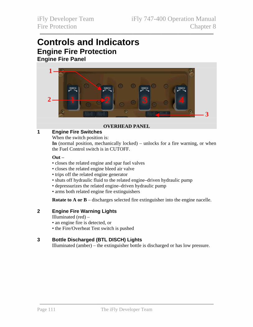
iFly Developer Team iFly 747-400 Operation Manual Fire Protection Chapter 8 ——————————————————————————————
Controls and Indicators
Engine Fire Protection Engine Fire Panel
1
2
3
OVERHEAD PANEL 1 Engine Fire Switches
When the switch position is: In (normal position, mechanically locked) – unlocks for a fire warning, or when the Fuel Control switch is in CUTOFF.
Out – • closes the related engine and spar fuel valves • closes the related engine bleed air valve • trips off the related engine generator • shuts off hydraulic fluid to the related engine–driven hydraulic pump • depressurizes the related engine–driven hydraulic pump • arms both related engine fire extinguishers
Rotate to A or B – discharges selected fire extinguisher into the engine nacelle. 2 Engine Fire Warning Lights
Illuminated (red) – • an engine fire is detected, or • the Fire/Overheat Test switch is pushed
3 Bottle Discharged (BTL DISCH) Lights
Illuminated (amber) – the extinguisher bottle is discharged or has low pressure.
——————————————————————————————————— Page 111 The iFly Developer Team

iFly Developer Team iFly 747-400 Operation Manual Fire Protection Chapter 8 ——————————————————————————————
Fuel Control Switches
1
CONTROL STAND
1 FUEL CONTROL Switch Fire Warning Lights Illuminated (red) – • a related engine fire is detected, or • the Fire/Overheat Test switch is pushed
APU Fire Panel
1
2
3
OVERHEAD PANEL
1 APU Fire Switch When the switch position is: In – normal position mechanically locked; unlocks for a fire warning.
Out – • arms APU fire extinguisher bottle • closes APU fuel valve • closes APU bleed air valve • trips APU generator field and generator breaker • shuts down APU (if automatic shutdown does not occur)
Rotate - discharges APU fire extinguisher into APU compartment. 2 APU Fire Warning Light
Illuminated (red) – • an APU fire is detected, or • the Fire/Overheat Test switch is pushed
——————————————————————————————————— Page 112 The iFly Developer Team

iFly Developer Team iFly 747-400 Operation Manual Fire Protection Chapter 8 ——————————————————————————————
APU automatically shuts down for a detected fire. 3 APU Bottle Discharged (BTL DISCH) Light
Illuminated (amber) – extinguisher bottle is discharged or has low pressure. Cargo Fire Panel
OVERHEAD PANEL
1
3
42
5
1 CARGO FIRE ARMED Light Illuminated (white) – cargo fire extinguishers armed
2 CARGO FIRE ARM Switch
FWD – arms cargo fire extinguishers AFT – arms cargo fire extinguishers
3 CARGO FIRE Warning Light
Illuminated (red) - • fire in related cargo compartment, or • the Fire/Overheat Test switch is pushed
4 CARGO FIRE Discharge (DISCH) Switch
Right click on mouse button to unveil protection box, then left click: Push - initiates extinguisher discharge sequence.
5 CARGO FIRE Discharged (DISCH) Light
Illuminated (amber) - cargo fire extinguishers discharged. Fire/Overheat Test Switch
1
OVERHEAD PANEL
1 FIRE/Overheat (OVHT) TEST Switch
——————————————————————————————————— Page 113 The iFly Developer Team

iFly Developer Team iFly 747-400 Operation Manual Fire Protection Chapter 8 ——————————————————————————————
Push and hold - • tests flight deck fire and overheat indications. And sends fire/overheat test
signals to the engine, APU, wheel well, cargo, and bleed duct leak detectors
System Description
Fire Warnings If a fire is detected, the flight deck warning bell rings on. Extinguishing the fire or pushing either Master Warning/Caution Reset switch can silence the fire bell. In addition to the aural warning, an EICAS FIRE message is displayed as long as the fire condition exists. The following lights illuminate if a fire is detected and remain illuminated as long as the fire signal exists: • both Master Warning lights (may be reset while fire signal exists) • related Engine, APU, or Cargo Fire Warning lights • for an engine fire, related Fuel Control switch Fire light. Fire and Overheat Detection System Manual Fault Test The fire and overheat detection systems can be tested manually by pushing the Fire/Overheat Test switch. The indications for a manual fire and overheat detection system test are: • the fire bell rings • the APU fire warning horn sounds (on the ground) • the EICAS message FIRE TEST IN PROG is displayed • these lights illuminate:
• the master WARNING lights • the engine fire warning lights • the APU fire warning light • the FWD and AFT cargo fire warning lights • the Fuel Control switch fire warning lights
Fire Protection EICAS Messages The following EICAS messages can be displayed.
——————————————————————————————————— Page 114 The iFly Developer Team

iFly Developer Team iFly 747-400 Operation Manual Fire Protection Chapter 8 ——————————————————————————————
Alert Messages Message Level Aural Condition
>BOTTLE LOW APU Advisory APU fire extinguisher bottle pressure low.
>BTL LO L, R ENG A, B
Advisory Left or right wing engine fire extinguisher bottle A or bottle B pressure low.
>CGO BTL DISCH Advisory On the ground, a cargo fire extinguisher bottle pressure low. In flight, bottles A and B discharged.
FIRE APU Warning Fire Bell Fire detected in the APU. FIRE CARGO AFT, FWD
Warning Fire Bell Smoke detected in the affected lower cargo compartment.
FIRE ENG 1, 2, 3, 4 Warning Fire Bell Fire detected in the engine.
——————————————————————————————————— Page 115 The iFly Developer Team

iFly Developer Team iFly 747-400 Operation Manual ——————————————————————————————
Intentionally Blank
——————————————————————————————————— Page 116 The iFly Developer Team

iFly Developer Team iFly 747-400 Operation Manual Flight Controls Chapter 9 ——————————————————————————————
CONTROLS AND INDICATORS.......................................... 118
PITCH AND STABILIZER TRIM SYSTEMS ............................... 118 Control Wheel and Column .................................................................................... 118 Stabilizer Trim Controls ......................................................................................... 118
AILERON AND RUDDER TRIM CONTROLS............................. 119
YAW DAMPER CONTROLS...................................................... 120
SPEEDBRAKE LEVER .............................................................. 120
FLAP SYSTEM.......................................................................... 121 Flap Controls .......................................................................................................... 121 Flap Limit Placard.................................................................................................. 122 Normal Flap Position Indication ............................................................................ 122 Secondary Mode Expanded Flap Position Indication ............................................ 123 Alternate Mode Expanded Flap Position Indication .............................................. 124
SURFACE POSITION INDICATION ........................................... 124 Surface Position Indication..................................................................................... 124
SYSTEM DESCRIPTION ....................................................... 125
INTRODUCTION ....................................................................... 125
PITCH CONTROL..................................................................... 125 Elevator Control ..................................................................................................... 125 Stabilizer Trim ........................................................................................................ 125 Trim Control ........................................................................................................... 125
Stabilizer Trim Position Indication and Greenband............................................ 125 Trimming with Autopilots Engaged ................................................................... 126
ROLL CONTROL...................................................................... 126 Aileron and Spoiler Roll Control ............................................................................ 126 Aileron Trim............................................................................................................ 126
YAW CONTROL ....................................................................... 126 Rudder Control and Trim........................................................................................ 126 Yaw Dampers .......................................................................................................... 126
SPOILERS................................................................................. 126 Speedbrakes ............................................................................................................ 127
FLAPS ...................................................................................... 127 Flap Control............................................................................................................ 127 Flap Load Relief ..................................................................................................... 127 Flap Indications ...................................................................................................... 127
FLIGHT CONTROLS EICAS MESSAGES ......................... 128
FLIGHT CONTROLS EICAS MESSAGES ................................ 128
——————————————————————————————————— Page 117 The iFly Developer Team
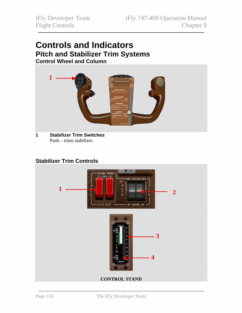
iFly Developer Team iFly 747-400 Operation Manual Flight Controls Chapter 9 ——————————————————————————————
Controls and Indicators
Pitch and Stabilizer Trim Systems Control Wheel and Column
1
1 Stabilizer Trim Switches
Push – trims stabilizer. Stabilizer Trim Controls
1 2
3
4
CONTROL STAND
——————————————————————————————————— Page 118 The iFly Developer Team

iFly Developer Team iFly 747-400 Operation Manual Flight Controls Chapter 9 ——————————————————————————————
1 Stabilizer (STAB) Trim Cut Out Switches When the switch is: ON - supplies hydraulic power for stabilizer trim. AUTO –supplies hydraulic power automatically CUT OUT - shuts off related hydraulic power to stabilizer trim.
2 Alternate (ALTN) Stabilizer Trim Switches
Push - trims stabilizer using alternate control channel. 3 Stabilizer Trim Indicator
• Indicates stabilizer positions in trim units. • Illuminated greenband which indicates allowable range for takeoff
4 Stabilizer Trim Indicator Off Flag
In View - trim indicator inoperative. Aileron and Rudder Trim Controls
1
3 2
4 5
AFT AISLE STAND 1 RUDDER TRIM Indicator
Indicate units of rudder trim. 2 AILERON Trim Switches
Push – trims ailerons. 3 RUDDER Trim Selector
Rotate - • Trims rudder. • Cancels rudder trim
4 Rudder Trim Centering (CTR) Light
Illuminated - Rudder Trim Centering switch has been pushed and trim is moving to zero.
——————————————————————————————————— Page 119 The iFly Developer Team

iFly Developer Team iFly 747-400 Operation Manual Flight Controls Chapter 9 ——————————————————————————————
5 Rudder Trim Center Switch
Push – rudder trim moves to zero units. Yaw Damper Controls
1
2
OVERHEAD PANEL
1 Yaw Damper Switches ON – yaw damper powered.
2 Yaw Damper Inoperative Light
Illuminated – • Yaw damper switch OFF, or • Yaw damper inoperative.
Speedbrake Lever
1
CONTROL STAND
1 Speedbrake Lever DN (down) (detent) – all spoiler panels retracted
——————————————————————————————————— Page 120 The iFly Developer Team

iFly Developer Team iFly 747-400 Operation Manual Flight Controls Chapter 9 ——————————————————————————————
ARM (armed) – • Automatic speedbrake system armed • After landing, speedbrake lever moves to UP and spoiler panels extend if engine
1 and engine 3 thrust levers retarded
FLIGHT DETENT - • Spoiler panels extend to their maximum in-flight positions • During flight, aft movement of speed brake lever limited to FLIGHT DETENT
by an automatic stop
UP – all spoiler panels extend to their maximum in–flight or on–ground position. Intermediate positions between them can also be selected.
Flap System Flap Controls
1
CONTROL STAND
2
3
CENTER PANEL
——————————————————————————————————— Page 121 The iFly Developer Team

iFly Developer Team iFly 747-400 Operation Manual Flight Controls Chapter 9 ——————————————————————————————
1 Flap Lever Primary mode - positions leading edge flaps pneumatically and trailing edge flaps hydraulically.
Secondary Mode - positions leading and/or trailing edge flaps electrically if flaps fail to drive pneumatically or hydraulically.
2 Alternate (ALTN) Flaps Selector
RET (retract) – leading and trailing edge flaps electrically retracted.
OFF – alternate flaps deactivated.
EXT (extend) – leading and trailing edge flaps electrically extend or maximum extension is flaps 25
3 Alternate (ALTN) Flaps Arm Switch
ALTN – • Arms flap alternate control mode • Arms Alternate Flaps selector • Shuts off primary and secondary mode operation • Asymmetry protection not available • Flap lever inoperative
Flap Limit Placard
1
CENTER PANEL
1 Flap Limit Placard Flaps extended speed limits.
Normal Flap Position Indication Displays combined leading and trailing edge flap positions when control is in the primary (hydraulic) mode and all surfaces are operating normally. The indicator shows continuous motion. Indication is no longer displayed 10 seconds after flap retraction.
——————————————————————————————————— Page 122 The iFly Developer Team

iFly Developer Team iFly 747-400 Operation Manual Flight Controls Chapter 9 ——————————————————————————————
1 2
EICAS DISPLAY
1 Flap Position (white) UP – all leading and trailing edge flaps retracted
Between UP and 1 - • inboard or midspan leading edge flap groups in transit • all trailing edge flaps retracted
1 – • inboard and midspan leading edge flap groups extended • all trailing edge flaps retracted
Between 1 and 30 – actual position of slowest trailing edge flap group. 2 Flap Lever Position (line and number)
Magenta – flaps in transit to position selected by Flap lever. Green – flaps in selected position.
Secondary Mode Expanded Flap Position Indication All flap positions are displayed, if flap control is in secondary mode or if any flap position is non–normal. Indicator motion is continuous between flap detents.
1 2
3
EICAS DISPLAY 1 Leading Edge Flap Indication
White - leading edge flap group up. Amber - leading edge flap group disagrees with Flap lever position. Green - leading edge flap group down.
2 Trailing Edge Flaps Indication
White - position of inboard and outboard trailing edge flaps.
——————————————————————————————————— Page 123 The iFly Developer Team

iFly Developer Team iFly 747-400 Operation Manual Flight Controls Chapter 9 ——————————————————————————————
Amber - asymmetry or drive failure has occurred in related group. 3 Flap Lever Position (line and number)
Magenta – flaps in transit to position selected by Flap lever. Alternate Mode Expanded Flap Position Indication If alternate flaps armed, expands to display all flap positions. Indicator motion is continuous between flap detents.
1 23
EICAS DISPLAY
1 Leading Edge Flap Indication Position of leading edge flap groups.
2 Trailing Edge Flap Indication
Position of inboard and outboard trailing flaps. 3 Flap Position Index Marks
Reference flaps 5 and 25 positions. Surface Position Indication The surface position indication is displayed when pushing the STAT synoptic display switch on the display select panel. More display select panel operation is described in Chapter 10. Full pointer deflection indicates full control surface displacement. Surface Position Indication
1
3
2 4
SECONDARY EICAS DISPLAY
1 Rudder Position
——————————————————————————————————— Page 124 The iFly Developer Team
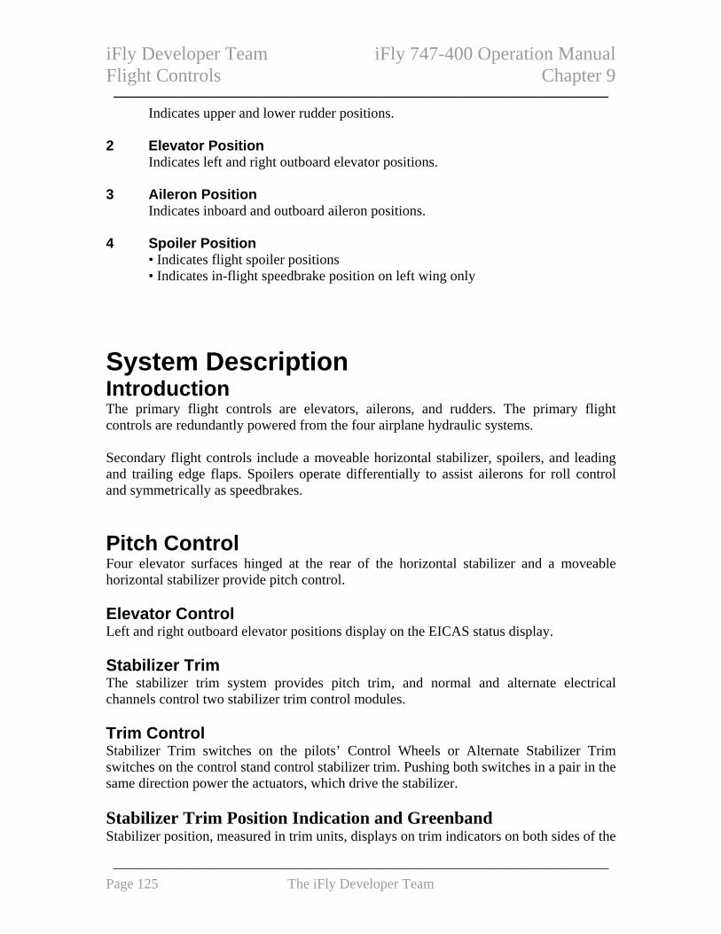
iFly Developer Team iFly 747-400 Operation Manual Flight Controls Chapter 9 ——————————————————————————————
Indicates upper and lower rudder positions. 2 Elevator Position
Indicates left and right outboard elevator positions. 3 Aileron Position
Indicates inboard and outboard aileron positions. 4 Spoiler Position
• Indicates flight spoiler positions • Indicates in-flight speedbrake position on left wing only
System Description
Introduction The primary flight controls are elevators, ailerons, and rudders. The primary flight controls are redundantly powered from the four airplane hydraulic systems. Secondary flight controls include a moveable horizontal stabilizer, spoilers, and leading and trailing edge flaps. Spoilers operate differentially to assist ailerons for roll control and symmetrically as speedbrakes. Pitch Control Four elevator surfaces hinged at the rear of the horizontal stabilizer and a moveable horizontal stabilizer provide pitch control. Elevator Control Left and right outboard elevator positions display on the EICAS status display. Stabilizer Trim The stabilizer trim system provides pitch trim, and normal and alternate electrical channels control two stabilizer trim control modules. Trim Control Stabilizer Trim switches on the pilots’ Control Wheels or Alternate Stabilizer Trim switches on the control stand control stabilizer trim. Pushing both switches in a pair in the same direction power the actuators, which drive the stabilizer. Stabilizer Trim Position Indication and Greenband Stabilizer position, measured in trim units, displays on trim indicators on both sides of the
——————————————————————————————————— Page 125 The iFly Developer Team

iFly Developer Team iFly 747-400 Operation Manual Flight Controls Chapter 9 ——————————————————————————————
control stand. The stabilizer trim indicators incorporate a multiple greenband, which indicates the acceptable range of trim settings for takeoff. The FMCs use entered center of gravity, gross weight, and takeoff thrust setting to calculate the correct greenband. Trimming with Autopilots Engaged If multiple autopilots are engaged, the Control Wheel Stabilizer Trim switches are inhibited. If a single autopilot is engaged, using the control wheel stabilizer trim switches causes the autopilot to disengage. Roll Control Hydraulically powered inboard and outboard ailerons and spoilers provide roll control. Aileron and Spoiler Roll Control Aileron positions display on the EICAS status display. Separate pointers indicate the inboard and outboard aileron positions on each wing.. Aileron Trim Pushing both Aileron Trim switches in the desired direction causes the feel and trim mechanism to reposition the aileron neutral point. If a single autopilot is engaged, using the Aileron Trim switches will cause the autopilot to be disengaged. If multiple autopilots are engaged, the Aileron Trim switches are inhibited. Yaw Control The rudder control system provides yaw control. Rudder Control and Trim Rudder positions display on the EICAS status display. Pushing the Rudder Trim Centering switch causes rudder trim to move to the zero units’ position. Yaw Dampers Two independent yaw damper systems operate continuously in flight to improve airplane directional stability and provide turn coordination. Spoilers There are six spoiler panels on each upper wing surface just forward of the trailing edge flaps. The four inboard panels on each wing function as speedbrakes in flight. On the
——————————————————————————————————— Page 126 The iFly Developer Team

iFly Developer Team iFly 747-400 Operation Manual Flight Controls Chapter 9 ——————————————————————————————
ground, all six-spoiler panels on each wing function as ground spoilers. The speedbrake and ground spoiler functions are controlled with the Speedbrake lever. Speedbrakes Speedbrake lever in-flight input is limited to mid-travel position by an automatic stop. With the Speedbrake lever in flight detent position, the two inboard spoiler panels on each wing extend to mid-travel position and the two middle spoiler panels on each wing extend to full travel position. Flaps Increased lift and decreased stall speed for takeoff and landing are provided by leading and trailing edge flaps. Flap Control Flap lever position is transmitted to three identical flap control units (FCUs) which sequence and monitor flap operation. The FCUs operate in two control modes, primary and secondary. In primary mode, the FCUs drive the leading edge flaps pneumatically and the trailing edge flaps hydraulically to the selected position. If a primary control failure occurs, the FCUs switch to secondary mode. If a trailing edge flap group is driven in secondary mode due to a lack of hydraulic system pressure, the FCUs switch back to primary mode operation once hydraulic pressure is restored. An alternate control mode, which bypasses the FCUs, can be manually selected. All flaps are extended or retracted by a simplified control system and electric motors. Flap Load Relief The flap load relief function of the FCUs operates if flap airspeed limits are exceeded with flaps 25 or 30. Automatic retraction protects the flaps from excessive airloads. If the airspeed limit is exceeded with flaps 30 selected, the flaps retract to flaps 25. If airspeed is still excessive at flaps 25, the flaps retract to 20. Similarly, if the airspeed limit is exceeded with flaps 25 selected, the flaps retract to 20. Flap Indications Flap position indications are displayed on the primary EICAS display. A single vertical indicator displays combined leading and trailing edge flap position. The position commanded by the flap lever is also displayed. Ten seconds after all flaps are up; the entire indication is no longer displayed.
——————————————————————————————————— Page 127 The iFly Developer Team

iFly Developer Team iFly 747-400 Operation Manual Flight Controls Chapter 9 ——————————————————————————————
Flight Controls EICAS Messages Note: Configuration (CONFIG) warning messages are described in Chapter 15, Warning Systems. Flight Controls EICAS Messages The following EICAS messages can be displayed.
Message Level Aural Condition >FLAP RELIEF Advisory Flap load relief system is active. FLAPS CONTROL Caution Beeper All three FCUs have failed in their control
function, or the Alternate Flaps Arm switch is in ALTN.
FLAPS PRIMARY Caution Beeper A flap group is in secondary mode. >SPEEDBRAKES EXT
Caution Beeper Speedbrake lever is aft of ARMED detent, and radio altitude is between 800 feet and 15 feet, or flaps are in a landing position, or two or more Thrust levers are forward of closed position.
>STAB TRIM 2, 3 Advisory Automatic cutout has occurred, or a Stabilizer Trim Cutout switch is in CUT OUT
>YAW DAMPER LWR, UPR
Advisory A yaw damper fault has occurred, or related Yaw Damper switch is OFF.
——————————————————————————————————— Page 128 The iFly Developer Team

iFly Developer Team iFly 747-400 Operation Manual ——————————————————————————————
Intentionally Blank
——————————————————————————————————— Page 129 The iFly Developer Team

iFly Developer Team iFly 747-400 Operation Manual Flight Instruments, Displays Chapter 10 ——————————————————————————————
CONTROLS AND INDICATORS.......................................... 132
PRIMARY FLIGHT DISPLAY (PFD)......................................... 132 Airspeed Displays ................................................................................................... 133 Airspeed Displays ................................................................................................... 134 Attitude Indications................................................................................................. 135 Flight Director ........................................................................................................ 136 Radio Altitude Indications ...................................................................................... 136 Instrument Landing System Indications.................................................................. 138 Expanded Localizer Indications ............................................................................. 139 Rising Runway Indications ..................................................................................... 139 Altitude Indications................................................................................................. 139 Landing Altitude/Minimums Indications................................................................. 140 Barometric Indications ........................................................................................... 141 Vertical Speed Indications ...................................................................................... 142 Heading/Track Displays ......................................................................................... 142
NAVIGATION DISPLAY (ND)................................................... 143 Map Mode ............................................................................................................... 143
Expanded Map Mode.......................................................................................... 143 Centered Map Mode ........................................................................................... 144
Approach Mode....................................................................................................... 145 Expanded Approach Mode ................................................................................. 145 Centered Approach Mode ................................................................................... 145
VOR Mode............................................................................................................... 146 Expanded VOR Mode......................................................................................... 146 Centered Approach Mode ................................................................................... 146
Plan Mode............................................................................................................... 147 TCAS Messages....................................................................................................... 148
EFIS CONTROL PANELS ........................................................ 149 Control Panel PFD Controls .................................................................................. 149
HEADING REFERENCE AND CRT DISPLAYS ......................... 152 CRT Display Controls............................................................................................. 152 Heading Reference Switch ...................................................................................... 152
DISPLAY SELECT PANEL ........................................................ 153
DISPLAY BRIGHTNESS CONTROLS......................................... 154 Upper/Lower CRT Brightness Controls.................................................................. 154
STANDBY FLIGHT INSTRUMENTS........................................... 154 Standby Magnetic Compass.................................................................................... 154 Standby Attitude Indicator ...................................................................................... 154 Standby Airspeed Indicator..................................................................................... 155 Standby Altimeter.................................................................................................... 156
CLOCK..................................................................................... 156
——————————————————————————————————— Page 130 The iFly Developer Team

iFly Developer Team iFly 747-400 Operation Manual Flight Instruments, Displays Chapter 10 —————————————————————————————— EFIS CONTROL PANEL AND DISPLAY SELECT PANEL (DSP) – CDU ALTERNATE CONTROL ................................................. 158
CDU EFIS/DSP Control Selection ......................................................................... 158 EFIS Control Page.................................................................................................. 158 EFIS Options Page ................................................................................................. 159 EICAS Modes Page................................................................................................. 160 EICAS Synoptics Page ............................................................................................ 161
SYSTEM DESCRIPTION ....................................................... 161
INTRODUCTION ....................................................................... 161
DISPLAY SELECTION AND CONTROL..................................... 161
STANDBY FLIGHT INSTRUMENTS........................................... 162 Standby Magnetic Compass.................................................................................... 162 Standby Attitude Indicator ...................................................................................... 162 Standby Airspeed Indicator..................................................................................... 162 Standby Altimeter.................................................................................................... 162
CLOCKS ................................................................................... 162
PRIMARY FLIGHT DISPLAYS (PFDS) .............................. 162
NAVIGATION DISPLAYS (ND)............................................ 163
INTRODUCTION ....................................................................... 163
MAP MODE.............................................................................. 163 Navigation Data Points........................................................................................... 163
VOR AND APPROACH MODES ............................................... 163
PLAN MODE ............................................................................ 163 ND Symbology ........................................................................................................ 163
Heading, Track, and Speed ................................................................................. 164 Radio Navigation ................................................................................................ 165 Map ..................................................................................................................... 167 TCAS .................................................................................................................. 171
——————————————————————————————————— Page 131 The iFly Developer Team
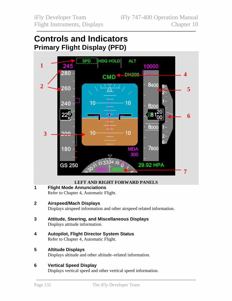
iFly Developer Team iFly 747-400 Operation Manual Flight Instruments, Displays Chapter 10 ——————————————————————————————
Controls and Indicators
Primary Flight Display (PFD)
1 4
2 5
6
3
7
LEFT AND RIGHT FORWARD PANELS 1 Flight Mode Annunciations
Refer to Chapter 4, Automatic Flight. 2 Airspeed/Mach Displays
Displays airspeed information and other airspeed related information. 3 Attitude, Steering, and Miscellaneous Displays Displays attitude information. 4 Autopilot, Flight Director System Status Refer to Chapter 4, Automatic Flight. 5 Altitude Displays Displays altitude and other altitude–related information. 6 Vertical Speed Display
Displays vertical speed and other vertical speed information.
——————————————————————————————————— Page 132 The iFly Developer Team

iFly Developer Team iFly 747-400 Operation Manual Flight Instruments, Displays Chapter 10 ——————————————————————————————
7 Heading and Track Displays
Displays current heading, track, and other heading information. Airspeed Displays
1 5
6
7 2
3
4
1 Command Speed
Displays airspeed/Mach set in the MCP IAS/MACH window (refer to Chapter 4, Automatic Flight).
Displays FMC–computed airspeed/Mach when the IAS/MACH window is blank.
2 Trend Indication Indicates predicted airspeed in ten seconds based on current acceleration or deceleration.
3 Current Airspeed
Displays current airspeed.
Displays 30 knots with no computed information.
Airspeed box changes to amber if current airspeed less than minimum maneuvering speed.
——————————————————————————————————— Page 133 The iFly Developer Team

iFly Developer Team iFly 747-400 Operation Manual Flight Instruments, Displays Chapter 10 ——————————————————————————————
4 Current Mach
Displays current Mach. 5 Maximum Speed
Indicates maximum airspeed limited 6 Maximum Maneuvering Speed
When displayed, indicates maneuver margin to buffet. 7 Command Speed
Points to airspeed/Mach set in MCP IAS/MACH window.
Indicates FMC–computed airspeed when MCP IAS/MACH window blank.
When selected speed off scale, pointer parked at the top or bottom of the tape, with half the pointer visible.
Airspeed Displays
1
3
2
54
1 Takeoff Reference Speeds
Displays takeoff reference speeds V1 and VR selected on the CDU. (refer to Chapter 11, Flight Management, Navigation): • Displayed for takeoff • NO V SPD displays when V speeds are not selected on the CDU • V1 displays at the top of the airspeed indication when selected and if the value is
off the scale • V1 and VR are removed at lift–off
——————————————————————————————————— Page 134 The iFly Developer Team

iFly Developer Team iFly 747-400 Operation Manual Flight Instruments, Displays Chapter 10 ——————————————————————————————
2 Flap Maneuvering Speeds Displays flap maneuvering speed for flap retraction or extension for current flap setting and next lesser flap setting. Not displayed above approximately 20,000 feet altitude.
3 Landing Reference Speed
Displays VREF speed selected on the CDU (refer to Chapter 11, Flight Management, Navigation).
4 Minimum Maneuvering Speed
Indicates maneuver speed margin to low speed buffet. 5 Minimum Speed
Indicates airspeed where low speed buffet occurs. Attitude Indications
1
23
4
5
SPLIT CUE F/D INTEGRATED CUE F/D
1 Bank Pointer Indicates bank in reference to bank scale.
2 Pitch Limit Indication
Indicates pitch limit.
Displayed when flaps are not up. 3 Horizon Line and Pitch Scale
Indicates horizon relative to the airplane symbol.
Pitch scale is in 2.5-degree increments.
——————————————————————————————————— Page 135 The iFly Developer Team

iFly Developer Team iFly 747-400 Operation Manual Flight Instruments, Displays Chapter 10 ——————————————————————————————
4 Bank Scale Fixed reference for the bank pointer.
Scale marks are at 0, 10, 20, 30, and 45 degrees. 5 Airplane Symbol
Indicates airplane attitude with reference to the horizon. Flight Director
SPLIT CUE F/D INTEGRATED CUE F/D 1 Flight Director Command Bars
Indicates flight director pitch and roll steering commands. Refer to Chapter 4, Automatic Flight.
Radio Altitude Indications
1
1
1
2
3
Digital RA Indications
1 3
Digital and Analog RA Indications 1 Radio Altitude
——————————————————————————————————— Page 136 The iFly Developer Team

iFly Developer Team iFly 747-400 Operation Manual Flight Instruments, Displays Chapter 10 ——————————————————————————————
Digital RA Indications Displays airplane radio altitude below 2,500 feet AGL. Digital and Analog RA Indications Digital - displays radio altitude: • on the ground, when speed less than 50 knots • in flight, between 1,000 feet and 2,500 feet AGL
Analog - • displays radio altitude between 50 knots ground speed and 1,000 feet AGL. • index marks located at 100 foot intervals • 0 foot and 1,000 feet index mark at 12 o’clock • length of arc indicates radio altitude • digital radio altitude displays in the center
2 Height Alert Displays between 1,000 feet and 500 feet AGL during descent.
Does not display when DH reset switch pushed. 3 Decision Height
Digital RA Indications Displays radio altitude set on EFIS control panel.
DH not displayed when set below 0 feet. Digital and Analog RA Indications
Digital - displays selected radio altitude: • on the ground, when speed less than 50 knots • in flight, between 1,000 feet and 2,500 feet AGL
Analog - • displays radio altitude between 50 knots ground speed and 1,000 feet AGL, pointer indicates RADIO altitude set on the EFIS control panel
RADIO not displayed when set below 0 feet.
——————————————————————————————————— Page 137 The iFly Developer Team

iFly Developer Team iFly 747-400 Operation Manual Flight Instruments, Displays Chapter 10 ——————————————————————————————
Instrument Landing System Indications
1
3
4
5
1 Approach Reference 2
Displays the selected ILS identifier or frequency and ILS DME distance. Refer to Chapter 11, Flight Management, Navigation.
2 Approach Course
Displays the selected ILS approach course. 3 Marker Beacon Annunciation
The marker beacon annunciation appears flashing when over one of the marker beacon transmitters: • IM – an airway or inner marker beacon • MM – a middle marker beacon • OM – an outer marker beacon
4 Glideslope Pointer and Scale
Glideslope pointer indicates glideslope position relative to the airplane and is in view when receiving the glideslope signal.
At low radio altitudes, with the autopilot or flight director engaged, scale turns amber to indicate excessive glideslope deviation.
5 Localizer Pointer and Scale
Localizer pointer: • indicates localizer position relative to the airplane • is in view when the localizer signal is received
At low radio altitudes, with the autopilot or flight director engaged, scale turns amber to indicate excessive localizer deviation.
——————————————————————————————————— Page 138 The iFly Developer Team

iFly Developer Team iFly 747-400 Operation Manual Flight Instruments, Displays Chapter 10 ——————————————————————————————
Expanded Localizer Indications
1 Expanded Localizer Deviation Scale
1
Displays when the airplane is close to the localizer centerline.
A rectangle equals 1/2 dot deviation. Rising Runway Indications
1
1 Rising Runway Displays below 2,500 feet radio altitude when the localizer pointer is in view.
Moves toward the airplane symbol below 200 feet radio altitude. Altitude Indications
2 3
4
5
6 1
1 Selected Altitude Pointer Indicates altitude set in the MCP altitude window.
When selected altitude is off scale, pointer displays at the top or bottom of the tape with half the pointer visible.
——————————————————————————————————— Page 139 The iFly Developer Team

iFly Developer Team iFly 747-400 Operation Manual Flight Instruments, Displays Chapter 10 ——————————————————————————————
2 Selected Altitude – Meters
Displays when MTRS selected on EFIS control panel MTRS switch.
Indicates selected altitude in meters (selected in feet in MCP altitude window).
Displays in 10-meter increments. 3 Selected Altitude
Displays altitude set in altitude window on MCP. 4 Current Altitude – Meters
Displays when MTRS selected on EFIS control panel MTRS switch.
Displays altitude in meters. 5 Current Altitude
Displays barometric altitude.
Altitude box is highlighted in white between 900 feet and 300 feet when approaching selected altitude.
6 Ten Thousand Digit Display
Crosshatch displays when altitude is below 10,000 feet. Landing Altitude/Minimums Indications
1
3 2
1 MDA Pointer Indicates barometric altitude set on EFIS control panel.
2 MDA Display
Displays barometric altitude set on EFIS control panel.
——————————————————————————————————— Page 140 The iFly Developer Team

iFly Developer Team iFly 747-400 Operation Manual Flight Instruments, Displays Chapter 10 ——————————————————————————————
Not displayed when MDA set below -100 feet. 3 Touchdown Zone Indicator
Upper edge of crosshatched area indicates FMC landing altitude for destination runway or airport.
Barometric Indications
1 2 3
1 Barometric Setting
Displays barometric setting set on EFIS control panel barometric control.
STD displays when STD selected on EFIS control panel barometric standard switch.
Display is boxed and changes to amber if a barometric setting is set and altitude climbs 300 feet above transition altitude, or if STD is selected and altitude descends 300 feet below transition flight level.
2 Barometric Reference
Displays barometric units selected on EFIS control panel barometric reference selector: • IN - inches of mercury • HPA - Hectopascals
3 Preset Barometric Setting
When STD is displayed, a preset barometric setting can be set using the barometric selector on EFIS control panel.
——————————————————————————————————— Page 141 The iFly Developer Team

iFly Developer Team iFly 747-400 Operation Manual Flight Instruments, Displays Chapter 10 ——————————————————————————————
Vertical Speed Indications 2
31
1 Vertical Speed Pointer Indicates vertical speed.
2 Vertical Speed
Displays vertical speed when greater than 400 feet per minute.
Display is above the vertical speed display when climbing and below when descending.
3 Selected Vertical Speed Pointer
Indicates vertical speed set in MCP vertical speed window with V/S pitch mode active.
Heading/Track Displays
1 4
2
3 5
1 Heading Pointer Indicates heading.
2 Track Indicator
Indicates airplane track. 3 Selected Heading
Displays heading set in heading window.
——————————————————————————————————— Page 142 The iFly Developer Team

iFly Developer Team iFly 747-400 Operation Manual Flight Instruments, Displays Chapter 10 ——————————————————————————————
4 Selected Heading Indicator Indicates heading set in heading window.
5 Heading Reference
Displays selected heading reference: • MAG - magnetic north • TRU - true north
Navigation Display (ND) Note: Refer to Navigation Display section of this chapter for a detailed explanation of
ND symbology shown on the following pages. Map Mode Expanded Map Mode
Heading Pointer
Magnetic/TrueReference
Track Line and Range Scale
FMC Position Update Status
Airplane Symbol
Trend Vector
SelectedHeading
Active RouteCurrent Track
ND
——————————————————————————————————— Page 143 The iFly Developer Team

iFly Developer Team iFly 747-400 Operation Manual Flight Instruments, Displays Chapter 10 ——————————————————————————————
Centered Map Mode
Selected Heading
VOR/ADF Ident or Frequency
VOR DME
VOR/ADF Selection
Right VOR/ADFPointer Tail
Groundspeed
True Airspeed
Wind Arrow Left VOR/ADF Pointer Tail
Right VOR/ADF Pointer Head
Wind Direction/Speed
Left VOR/ADFPointer Head
Active Waypoint Distance–To–Go
Active Waypoint ETA
Active Waypoint
ND
——————————————————————————————————— Page 144 The iFly Developer Team

iFly Developer Team iFly 747-400 Operation Manual Flight Instruments, Displays Chapter 10 ——————————————————————————————
Approach Mode Expanded Approach Mode
Glide Slope Pointer and Scale
Localizer Deviation Indication and Scale
Selected Course Pointer
Centered Approach Mode
Selected Course Pointer
Airplane Symbol
Track Line
Localizer Deviation Indication and Scale
ND
——————————————————————————————————— Page 145 The iFly Developer Team

iFly Developer Team iFly 747-400 Operation Manual Flight Instruments, Displays Chapter 10 ——————————————————————————————
VOR Mode Expanded VOR Mode
Selected Course Pointer
TO/FROM Indication
Centered Approach Mode
Course Deviation Indication and Scale
Course Deviation Indication and Scale
Selected Course Pointer
TO/FROM Indication
ND
——————————————————————————————————— Page 146 The iFly Developer Team

iFly Developer Team iFly 747-400 Operation Manual Flight Instruments, Displays Chapter 10 ——————————————————————————————
Plan Mode
True North Up Arrow
True north up depiction of the route.
ND
——————————————————————————————————— Page 147 The iFly Developer Team

iFly Developer Team iFly 747-400 Operation Manual Flight Instruments, Displays Chapter 10 ——————————————————————————————
TCAS Messages
2
3
4
1
1 TCAS Mode Display TCAS modes displayed - • TFC (blue) - traffic selected for display on ND from EFIS control panel in MAP,
MAP CTR, VOR, and APP ND modes. • TCAS FAIL (amber) - TCAS failed and displayed in MAP, MAP CTR, VOR,
and APP ND modes with TFC selected. • TA ONLY (blue) - TCASTA ONLY mode selected; displayed in all ND modes. • TCAS OFF (amber) - TCAS selected off and displayed in MAP, MAP CTR,
VOR, and APP ND modes with TFC selected. 2 Offscale
TA (amber) or RA (red) traffic beyond ND display range. Displayed in MAP, MAP CTR, VOR, and APP ND modes with TFC selected.
3 Traffic
Displayed during a TA (amber) or RA (red) condition. Displayed in all ND modes.
4 Traffic Messages
Displayed when information is available for traffic. Displayed in MAP, MAP CTR, VOR, and APP ND modes with TFC selected.
——————————————————————————————————— Page 148 The iFly Developer Team

iFly Developer Team iFly 747-400 Operation Manual Flight Instruments, Displays Chapter 10 ——————————————————————————————
EFIS Control Panels The EFIS control panel controls the PFD and ND. Displays can also be controlled through the related CDU. Control Panel PFD Controls
6
5 47
1 2
3
GLARESHIELD PANEL
1 Decision Height/Minimum Descent Altitude Selector DH – selects radio altitude as PFD minimums reference.
MDA – selects barometric altitude as PFD minimums reference. 2 Decision Height (DH)/Minimum Descent Altitude (MDA) Control
Rotate – • when DH selected, sets a radio altitude reference in DH display • when MDA selected, sets a barometric altitude reference in MDA display.
MDA pointer indicates the same altitude on the altitude display 3 Decision Height Reset (RST) Switch
Clears HEIGHT ALERT display on related PFD. 4 Meters (MTRS) Switch
Push – displays PFD altitude meters indications. 5 Barometric Standard (BARO STD) Switch
Push – • selects standard barometric setting (29.92 inches Hg/1013HPA) for PFD
barometric reference • when STD displayed, selects preselected barometric setting • if no preselected barometric setting displayed, displays the last value before
STD was selected
——————————————————————————————————— Page 149 The iFly Developer Team

iFly Developer Team iFly 747-400 Operation Manual Flight Instruments, Displays Chapter 10 ——————————————————————————————
6 Barometric (BARO) Selector
Rotate – adjusts PFD barometric reference. 7 Barometric (BARO) Reference Selector
IN – selects inches of mercury as PFD barometric reference. HPA – selects Hectopascals as PFD barometric reference.
1 2
3
4
5
6
GLARESHIELD PANEL
1 ND Mode Selector (outer) Selects desired ND display. APP – • displays localizer and glideslope information in heading–up format • TCAS are not displayed in APP CTR mode
VOR – • displays VOR navigation information in heading–up format • TCAS are not displayed in VOR CTR mode
MAP – • displays track up, full compass rose, FMC–generated route and map information, airplane position, heading, and track • displays active waypoint data
PLN – • displays a non-moving, true north–up, route depiction • allows route step–through using CDU legs page • TCAS are not displayed in PLN mode
2 ND Center (CTR) Switch (inner)
Push –
——————————————————————————————————— Page 150 The iFly Developer Team

iFly Developer Team iFly 747-400 Operation Manual Flight Instruments, Displays Chapter 10 ——————————————————————————————
• displays full compass rose (centered) for APP, VOR, and MAP modes • subsequent pushes alternate between expanded and centered displays
3 VOR/ADF Switches
Display VOR or ADF information on the respective ND.
VOR – displays VOR pointer and associated DME information in all modes except PLAN.
OFF – removes VOR and ADF displays.
ADF – displays ADF pointer and frequency or identification in all modes except PLAN.
4 WXR, STA, WPT, ARPT, DATA, POS, Switches
The switches: • select detailed ND information displays • displays can be selected simultaneously • second push removes information
STA (station) – in MAP and MAP CTR modes: • displays high and low altitude navigation aids when ND Range selector is in 10,
20, or 40 NM range • displays high altitude navigation aids when ND Range selector is in 80, 160, 320,
or 640 NM range.
WPT (waypoint) – in MAP and MAP CTR modes, displays waypoints when ND Range selector is in the 10, 20, or 40 NM range.
APRT (airport) – in MAP and MAP CTR modes, displays airports on all ranges.
DATA – in PLAN, MAP, and MAP CTR modes, displays FMC estimated time of arrival, altitude at each waypoint, and altitude constraints at each waypoint.
POS (position) – in MAP and MAP CTR modes: • displays IRU and GPS positions • displays VOR raw data radials extended from the nose of the airplane to the
VOR stations displayed on the CDU NAV RAD page. When co-located DME data received, tick mark displayed at DME distance; radial extends to edge of display if no valid DME data received
5 ND Range Selector (outer)
Selects desired ND nautical mile range scale. 6 ND Traffic (TFC) Switch (inner)
Push – in VOR, APP, MAP, and MAP CTR modes: • enables TCAS traffic display (Refer to Chapter 15, Warning Systems)
——————————————————————————————————— Page 151 The iFly Developer Team

iFly Developer Team iFly 747-400 Operation Manual Flight Instruments, Displays Chapter 10 ——————————————————————————————
Heading Reference and CRT Displays CRT Display Controls
FORWARD PANELS 1 Inboard (INBD) CRT Selector
EICAS - displays secondary or primary EICAS display on inboard CRT.
NORM - displays ND on inboard CRT. Displays PFD if outboard CRT fails.
PFD – displays PFD on inboard CRT. 2 Lower (LWR) CRT Selector
EICAS PRI - displays primary EICAS on lower CRT.
NORM - displays on lower CRT as selected on EICAS display select panel. Displays primary EICAS if upper CRT fails.
ND - displays ND on lower CRT. Heading Reference Switch
1 2
1
FORWARD PANELS
1 Heading (HDG) Reference Switch Selects heading reference for PFDs, NDs, AFDS, FMCs.
TRUE – references true north.
NORM - • references magnetic north • references true north when north of 82°N latitude (or north of 70°N between
——————————————————————————————————— Page 152 The iFly Developer Team
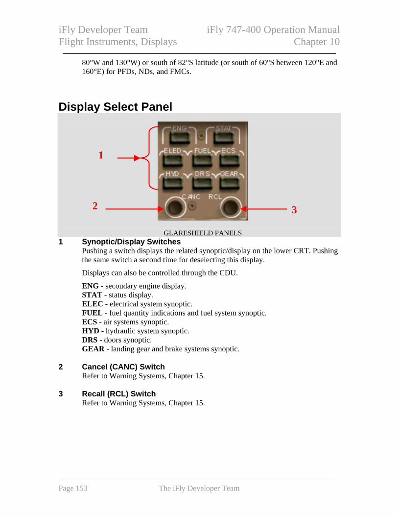
iFly Developer Team iFly 747-400 Operation Manual Flight Instruments, Displays Chapter 10 ——————————————————————————————
80°W and 130°W) or south of 82°S latitude (or south of 60°S between 120°E and 160°E) for PFDs, NDs, and FMCs.
Display Select Panel
1
2 3
GLARESHIELD PANELS 1 Synoptic/Display Switches
Pushing a switch displays the related synoptic/display on the lower CRT. Pushing the same switch a second time for deselecting this display.
Displays can also be controlled through the CDU.
ENG - secondary engine display. STAT - status display. ELEC - electrical system synoptic. FUEL - fuel quantity indications and fuel system synoptic. ECS - air systems synoptic. HYD - hydraulic system synoptic. DRS - doors synoptic. GEAR - landing gear and brake systems synoptic.
2 Cancel (CANC) Switch
Refer to Warning Systems, Chapter 15. 3 Recall (RCL) Switch
Refer to Warning Systems, Chapter 15.
——————————————————————————————————— Page 153 The iFly Developer Team

iFly Developer Team iFly 747-400 Operation Manual Flight Instruments, Displays Chapter 10 ——————————————————————————————
Display Brightness Controls Upper/Lower CRT Brightness Controls
1 2
GLARESHIELD PANELS 1 Upper (UPR) CRT Brightness Control
Rotate – adjusts brightness of upper CRT. 2 Lower (LWR) CRT Brightness Control (outer)
Rotate – adjusts brightness of lower CRT. Standby Flight Instruments Standby Magnetic Compass
1
CENTER POST ABOVE GLARESHIELD
1 Standby Magnetic Compass Displays magnetic heading.
Standby Attitude Indicator Standby attitude indicator displays airplane attitude.
1 3 5 6
CENTER PANEL
2 4
8 7
——————————————————————————————————— Page 154 The iFly Developer Team

iFly Developer Team iFly 747-400 Operation Manual Flight Instruments, Displays Chapter 10 ——————————————————————————————
1 Bank Indicator and Scale Indicates airplane bank.
2 Airplane Symbol
Indicates airplane position. 3 Attitude (GYRO) Flag
Displays when attitude information unreliable. 4 Localizer Indicator
Indicates localizer position relative to the airplane. 5 Glide Slope Indicator
Indicates glide slope position relative to the airplane. 6 Horizon Line and Pitch Scale
Indicates position of horizon relative to the airplane.
Scale marks in five-degree increments. 7 Caging Control
Pull - levels horizon with airplane symbol. 8 Approach Selector
OFF - glide slope and localizer indicators and flags retracted from view. APP (Approach) - glide slope and localizer information displayed. B/CRS (Back Course) - reverses sensing for localizer information.
Standby Airspeed Indicator Standby airspeed indicator displays airspeed.
1
CENTER PANEL
1 Airspeed Pointer Indicates airspeed.
———————————————————————————————————
Page 155 The iFly Developer Team

iFly Developer Team iFly 747-400 Operation Manual Flight Instruments, Displays Chapter 10 ——————————————————————————————
Standby Altimeter Standby altimeter displays barometric altitude.
1 2
4 3
CENTER PANEL 1 Altitude Display
Displays barometric altitude. 2 Altitude Pointer
Indicates barometric altitude. One full rotation of pointer is 1,000 feet.
3 Barometric Setting Control
Rotate – sets altimeter barometric setting. 4 Barometric Setting Display
Displays selected barometric reference in Hectopascals (MB/HPA) and inches (IN. HG).
Clock
4 1 2 5
6
3 7
FORWARD PANELS
——————————————————————————————————— Page 156 The iFly Developer Team

iFly Developer Team iFly 747-400 Operation Manual Flight Instruments, Displays Chapter 10 ——————————————————————————————
1 Chronograph (CHR or CLOCK) Switch Push – subsequent pushing starts, stops, resets the chronograph.
2 Chronograph Pointer
Indicates chronograph seconds. 3 Elapsed Time (ET) Selector
Controls elapsed time function.
RESET – returns elapsed time display to zero (spring loaded to HLD). HLD (Hold) – stops elapsed time display. RUN – starts elapsed time display.
4 DATE Switch
Push - • displays date (alternates day and month, then year) on GMT display • subsequent push returns display to time (hours, minutes) on GMT display.
5 GMT Display
Displays time (hours, minutes). Displays date when date switch pushed.
6 Elapsed Time (ET)/Chronograph (CHR) Display
Displays elapsed time (hours, minutes) or chronograph minutes.
Chronograph display replaces elapsed time display.
Elapsed time continues to run in the background and will be displayed after chronograph is reset.
7 Clock Set Selector
Sets time and date. Hours Slew, Day (HS D) –
• advances hours when time selected on time/date selector • advances days when date selected on time/date selector Minutes Slew,
Month (MS M) – • advances minutes when time selected on time/date selector • advances months when date selected on time/date selector
Hold, Year (HLD Y) – • stops time indicator and sets seconds to zero when time selected on time/date selector • advances years when date selected on time/date selector
RUN – starts time indicator.
——————————————————————————————————— Page 157 The iFly Developer Team

iFly Developer Team iFly 747-400 Operation Manual Flight Instruments, Displays Chapter 10 ——————————————————————————————
EFIS Control Panel and Display Select Panel (DSP) – CDU Alternate Control The CDU controls the functions of the EFIS control panel and the display select panel. CDU EFIS/DSP Control Selection
1
2
CDU
1 Alternate EFIS Control Push - • displays alternate EFIS control page
2 Alternate EICAS Control
Push - • displays alternate EICAS control page
EFIS Control Page
1 2 3 4 5 6
7
89
CDU
1 Barometric (BARO SET) Reference Valid entry is reference barometric setting.
——————————————————————————————————— Page 158 The iFly Developer Team

iFly Developer Team iFly 747-400 Operation Manual Flight Instruments, Displays Chapter 10 ——————————————————————————————
• Entry of S or STD displays 29.92 IN or 1013 HPA on BARO SET line and displays STD on the PFD. • Entry of "I" to change the displayed value to inches Hg • Entry of "H" to change the displayed value to hPa
2 Decision Height (DH SET)
Valid entry is decision height. 3 Decision Height Reset (DH RESET)
Push - resets PFD amber DH. 4 Minimum Descent Altitude
Valid entry is minimum descent altitude. 5 ND Range Increase (RANGE INCR)
Push - increases ND nautical mile range scale. 6 ND Range Decrease (RANGE DECR)
Push - decreases ND nautical mile range scale. 7 ND Mode
Push - selects desired ND display. 8 ND Center (CTR)
Push - alternately displays centered and expanded APP, VOR, and MAP modes. 9 EFIS OPTIONS
Push - displays EFIS OPTIONS page. EFIS Options Page
11
2 34
CDU
——————————————————————————————————— Page 159 The iFly Developer Team

iFly Developer Team iFly 747-400 Operation Manual Flight Instruments, Displays Chapter 10 ——————————————————————————————
1 WXR, POS, MTRS, WPT, STA, ARPT, DATA Push - select related PFD/ND options.
2 VOR
Push - selects left and right VORs for display on ND and deletes ADFs when previously selected.
3 ADF
Push - selects left and right ADFs for display on ND and deletes VORs when previously selected.
4 EFIS CONTROL
Push - selects EFIS CONTROL CDU page. EICAS Modes Page
11
2 34
CDU 1 Synoptic/Display
Push - displays related synoptics/displays. 2 Cancel (CANC)
Refer to Warning Systems, Chapter 15. 3 Recall (RCL)
Refer to Warning Systems, Chapter 15. 4 EICAS SYNOPTICS
Push - selects EICAS SYNOPTICS page.
——————————————————————————————————— Page 160 The iFly Developer Team

iFly Developer Team iFly 747-400 Operation Manual Flight Instruments, Displays Chapter 10 ——————————————————————————————
EICAS Synoptics Page
11
2
CDU 1 Synoptic/Display
Push - displays related synoptic/display. 2 EICAS MODES
Push - selects EICAS MODES page. System Description
Introduction The CRTs display three primary groups of information: • primary flight display (PFD) • navigation display (ND) • engine indication and crew alerting system (EICAS) The Electronic Flight Instrument System (EFIS) consists of the PFD and ND. Display Selection and Control During normal operations: • inboard and lower CRT selectors are set to NORM • PFDs display on two outboard CRTs • NDs display on two inboard CRTs • EICAS displays on upper and lower CRTs
——————————————————————————————————— Page 161 The iFly Developer Team

iFly Developer Team iFly 747-400 Operation Manual Flight Instruments, Displays Chapter 10 ——————————————————————————————
Standby Flight Instruments The standby flight instruments include: • standby magnetic compass • standby attitude indicator • standby airspeed indicator • standby altimeter Standby Magnetic Compass A standard liquid–damped magnetic standby compass is located on the center post above the glareshield. Standby Attitude Indicator The standby attitude indicator on the center instrument panel. Standby Airspeed Indicator The standby airspeed indicator on the center instrument panel. Standby Altimeter The standby altimeter on the center instrument panel. The pointer completes one revolution every 1,000 feet. Clocks The clock provides time and date. In addition to time, the clocks provide alternating day and month–year, elapsed time, and chronograph functions.
Primary Flight Displays (PFDs) PFDs present a dynamic color display of parameters necessary for flight path control. PFDs provide the following information: • flight mode annunciation • airspeed • altitude • vertical speed • attitude • steering information • radio altitude • time critical warnings • instrument landing • approach minimums
system display • heading/track indications
——————————————————————————————————— Page 162 The iFly Developer Team

iFly Developer Team iFly 747-400 Operation Manual Flight Instruments, Displays Chapter 10 ——————————————————————————————
Navigation Displays (ND) Introduction The NDs provide a mode–selectable color flight progress display. The modes are: • MAP • VOR • APP (approach) • PLN (plan) MAP, VOR, and APP modes can be switched between an expanded mode with a partial compass rose and a centered mode with a full compass rose. Map Mode MAP mode is recommended for most phases of flight. Presented track up, this mode shows airplane position relative to the route of flight against a moving map background. Displayed information can include: • track • heading • route • position trend vector • range to selected altitude • map range scale • ground speed • true airspeed • wind direction and speed • next waypoint distance • waypoint estimated • selected navigation data points
time of arrival • TCAS Traffic Display Navigation Data Points Additional navigation facility (STA), waypoint (WPT), airport (ARPT), route progress (DATA), and position (POS) data may be displayed on the ND in both the expanded and center map modes. VOR and Approach Modes VOR and APP modes display heading up. VOR and APP modes display track, heading, and wind speed and direction with VOR navigation or ILS approach information. Plan Mode PLN mode displays true north up. Position DATA is available for display in plan mode ND Symbology The following symbols display on each ND, depending on EFIS control panel switch selections. Colors indicate the following: • W (white) – present or modified status, range scales, armed flight mode annunciations • G (green) – dynamic conditions, active flight mode annunciations
——————————————————————————————————— Page 163 The iFly Developer Team

iFly Developer Team iFly 747-400 Operation Manual Flight Instruments, Displays Chapter 10 ——————————————————————————————
• M (magenta or pink) – active waypoint and route, command information, pointers, symbols, fly–to condition • B (blue) – inactive or background information, ADF symbols • A (amber) – cautions, faults, flags • R (red) – warnings Heading, Track, and Speed
Symbol Name ND Mode Remarks
Track orientation (G), current heading (W), heading reference (G), and heading pointer (W)
MAP, MAP CTR, PLAN
Displays TRK as display orientation, current heading, MAG or TRU as heading reference, and points to the heading on the compass rose.
Heading orientation (G), current heading (W), heading reference (G), and heading pointer (W)
VOR, VOR CTR, APP, APP CTR
Displays HDG as display orientation, current heading, MAG or TRU as heading reference, and points to the heading on the compass rose.
True airspeed (W) All Displays true airspeed
above 100 knots.
IRU time to align (W)
All Indicates time remaining for IRU alignment. Replaces wind direction/speed and wind arrow, on the ground, during alignment.
Groundspeed (W) All Displays ground speed
Wind direction/ speed and wind arrow (W)
All Indicates wind bearing, speed, and direction, with respect to display orientation and heading/track reference. Arrow not displayed in PLAN map mode.
Expanded compass (W)
MAP, APP, VOR, PLAN
Displays 90 degrees of compass rose.
Current heading pointer (W)
MAP, MAP CTR, PLAN
Points to current heading on the compass rose.
——————————————————————————————————— Page 164 The iFly Developer Team

iFly Developer Team iFly 747-400 Operation Manual Flight Instruments, Displays Chapter 10 ——————————————————————————————
Track indicator (W) VOR, VOR CTR, APP, APP CTR
Indicates airplane track when selected mode has heading orientation.
Selected heading (M)
All except PLAN
Displays MCP–selected heading. A dashed line (M) may extend from the marker to the airplane symbol.
Track line and range scale (W)
MAP, MAP CTR, VOR, APP
Indicates current track. Number indicates range. Displays in VOR or APP mode when WXR on
Radio Navigation
Left VOR (G) or ADF (B) pointer head and tail
Right VOR (G) or ADF (B) pointer head and tail
MAP, MAP CTR, VOR, VOR CTR, PLAN
Indicates bearing to (head) or from (tail) the tuned station, if selected on related EFIS control panel.
ILS localizer or VOR course deviation indication (M) and scale (W)
VOR, VOR CTR, APP, APP CTR
Displays LOC or VOR course deviation. Deviation indicator points in direction of VOR or ILS selected course.
Selected course pointer (W) and line (M)
VOR, VOR CTR, APP, APP CTR
Indicates CDU–selected course.
——————————————————————————————————— Page 165 The iFly Developer Team

iFly Developer Team iFly 747-400 Operation Manual Flight Instruments, Displays Chapter 10 ——————————————————————————————
Glide slope pointer (M) and scale (W)
APP, APP CTR
Displays glideslope position and deviation. .
To/from indication (W)
VOR CTR Located near airplane symbol. Displays VOR TO/FROM indication.
To/from indication (W)
VOR, VOR CTR
Displays VOR to/from indication.
VOR (B, G), Displays appropriate navaids (B) when EFIS control panel STA switch selected on. Tuned navaids display in green, regardless of switch selection. When a navaid is manually tuned, the selected course and reciprocal display.
VOR/DME raw data radial and distance (G)
MAP, MAP CTR
Extends the station radial from the airplane to the CDU-tuned VOR when EFIS control panel POS switch selected on. If co-located DME data received, tick mark displays at DME distance from airplane; extends to edge of display if no valid DME data displayed.
VOR (G) or ADF (B) selection
MAP, MAP CTR, VOR, VOR CTR, APP, APP CTR
Located lower left or right corner. Represents positions of VOR/ADF switches
VOR frequency or identifier (G),
MAP, MAP CTR,
Displays frequency before identifier is
——————————————————————————————————— Page 166 The iFly Developer Team

iFly Developer Team iFly 747-400 Operation Manual Flight Instruments, Displays Chapter 10 ——————————————————————————————
ADF frequency or identifier (B)
VOR, VOR CTR, APP, APP CTR
decoded. Decoded identifier replaces the frequency.
DME distance (G)
MAP, MAP CTR, VOR, VOR CTR, APP, APP CTR
Displays DME distance to the referenced navaid
Map
Symbol Name ND Mode Remarks
Airplane symbol (W)
MAP, MAP CTR, VOR, APP
Current airplane position is at the apex of the triangle.
Airplane symbol (W)
VOR CTR, APP CTR
Current airplane position is at the center of the symbol
Position trend vector (W) (dashed line)
MAP, MAP CTR
Predicts position at the end of 30, 60, and 90-second intervals. Each segment represents 30 seconds. Based on bank angle and ground speed. Selected range determines the number of segments displayed. For range:• greater than 20 NM, 3 segments • =20NM, 2 segments• =10NM, 1 segment
Active waypoint identifier (M)
MAP, MAP CTR, PLAN
Displays active flight plan waypoint, the next waypoint on the route of flight.
Active waypoint
MAP, MAP
Distance to active waypoint.
——————————————————————————————————— Page 167 The iFly Developer Team

iFly Developer Team iFly 747-400 Operation Manual Flight Instruments, Displays Chapter 10 ——————————————————————————————
distance (W) CTR, PLAN
Active waypoint ETA (W)
MAP, MAP CTR, PLAN
Displays FMS–calculated ETA at the active waypoint.
Waypoint: active (M), inactive (W)
MAP, MAP CTR, PLAN
Active – represents the waypoint the airplane is currently navigating to. Inactive – represents the waypoints on the active route.
Off route waypoint (B)
MAP, MAP CTR
Displays waypoints not on selected route displayed in ND ranges of 10, 20, or 40 when WPT switch selected on.
Flight plan route: active (M), modified (W), inactive (B)
MAP, MAP CTR, PLAN
Displays active route with a continuous line (M) between waypoints. Active route modifications display with short dashes (W) between waypoints. Inactive routes display with long dashes (B) between waypoints.
Offset path and identifier: active route (M), modified route (W)
MAP, MAP CTR, PLAN
Presents a dashed line parallel to and offset from the active or modified route.
——————————————————————————————————— Page 168 The iFly Developer Team

iFly Developer Team iFly 747-400 Operation Manual Flight Instruments, Displays Chapter 10 ——————————————————————————————
Route data: active waypoint (M), inactive waypoint (W)
MAP, MAP CTR
Displays entered or procedural altitude and ETAs for applicable route waypoints when DATA switch selected on.
Holding pattern: active route (M), modified route (W), inactive route (B)
MAP, MAP CTR, PLAN
Displays a holding pattern when in flight plan. Pattern increases to correct size when entering holding.
Altitude range arc (G)
MAP, MAP CTR
Displays position where MCP altitude will be reached based on vertical speed and groundspeed.
Altitude profile point and identifier (G)
MAP, MAP CTR
Displays position of FMC–calculated T/C (top–of–climb), S/C (step climb), T/D (top–of–descent), and E/D (end of descent) points. Predicted altitude/ETA points entered on the FIX page display the altitude/ETA along with the profile point.
Airport (B) MAP, MAP CTR, PLAN
Displays when ARPT switch selected on. Origin and destination airports always display, regardless of map switch selection.
Airport and runway (W)
MAP, MAP CTR, PLAN
Display when selected as the origin or destination and ND range is 10, 20, or 40 NM. Dashed
——————————————————————————————————— Page 169 The iFly Developer Team

iFly Developer Team iFly 747-400 Operation Manual Flight Instruments, Displays Chapter 10 ——————————————————————————————
runway centerlines extend 14.2 NM.
Energy management circles (B, W)
MAP, MAP CTR
Displays clean (B) and drag (W) energy management circles as defined on CDU OFFPATH DES page.
Selected reference point and bearing distance information (G)
MAP, MAP CTR, PLAN
Displays reference point selected on CDU FIX page. Bearing and/or distance from the fix are displayed with dashes (G).
FMC-IRS position update status (G)
MAP, MAP CTR
Displays FMC-IRS status based on IRUs. Transition from IRS (3) to any other annunciation highlighted by a green box for 10 seconds.
FMC-radio position update status (G)
MAP, MAP CTR
Displays FMC-radio update mode. DD: DME DME; VD: VOR DME; LOC: localizer; LOC DD: localizer and DME DME; LOC VD: localizer and VOR DME.
FMC-GPS position update status (G)
MAP, MAP CTR
Displays FMC-GPS update mode. LOCGPS: localizer and GPS; GPS: GPS, GPS.
GPS position (W)
MAP, MAP CTR
Displays GPS position relative to FMC position when POS switch selected
——————————————————————————————————— Page 170 The iFly Developer Team

iFly Developer Team iFly 747-400 Operation Manual Flight Instruments, Displays Chapter 10 ——————————————————————————————
on.
IRU positions (W)
MAP, MAP CTR
Displays IRU positions relative to FMC position when POS switch selected on.
North up arrow (G)
PLAN Indicates map background is oriented and referenced to true north.
Selected map options (B)
MAP, MAP CTR
Indicates STA, WPT, ARPT, and WXR switches selected on.
TCAS
Symbol Name ND Mode Remarks
TCAS resolution advisory (RA), relative altitude (R)
TCAS traffic advisory (TA), relative altitude (A)
TCAS proximate traffic, relative altitude (W)
MAP, MAP CTR, APP, VOR
These symbols display only when TFC switch selected on. Refer to Chapter 15, Warning Systems. Proximate traffic is traffic within 1,200 feet vertical and 6 miles lateral of present position. Other traffic is greater than 1,200 feet vertical or 6 miles lateral from present position. Arrow indicates traffic climbing or descending at a rate greater than or equal to 500 fpm At rates less than
——————————————————————————————————— Page 171 The iFly Developer Team

iFly Developer Team iFly 747-400 Operation Manual Flight Instruments, Displays Chapter 10 ——————————————————————————————
TCAS other traffic, relative altitude (W)
500 fpm. At rates less than 500 fpm, arrow is not displayed. Number and associated signs indicate altitude of traffic in hundreds of feet relative to the airplane. Number is below the traffic symbol when the traffic is below, and above the traffic symbol when the traffic is above the airplane.
TCAS message (RA–R, TA–A)
MAP, MAP CTR, APP, VOR
Message provides traffic type, range in NM, altitude and vertical direction.
TCAS traffic alert message (RA–R, TA–A)
All Displays when TCAS RA or TA is active. TFC switch does not have to be selected on.
TCAS off scale message (RA–R, TA–A)
MAP, MAP CTR, APP, VOR
Displays whenever RA or TA traffic is outside the traffic area covered by the ND range. Displays only when TFC switch selected on
TCAS mode (B) MAP, MAP
CTR, APP, VOR
Indicates ND TCAS display is active; TFC switch selected on.
——————————————————————————————————— Page 172 The iFly Developer Team

iFly Developer Team iFly 747-400 Operation Manual ——————————————————————————————
Intentionally Blank
——————————————————————————————————— Page 173 The iFly Developer Team

iFly Developer Team iFly 747-400 Operation Manual Flight Management, Navigation Chapter 11 ——————————————————————————————
CONTROLS AND INDICATORS.......................................... 178
CONTROL DISPLAY UNIT (CDU) ........................................... 178 Function and Execute Keys..................................................................................... 179 Alpha/Numeric and Miscellaneous Keys ................................................................ 180 CDU Page Components .......................................................................................... 181 FMC Selector .......................................................................................................... 182
INERTIAL REFERENCE SYSTEM (IRS) ................................... 183 Inertial Reference Unit (IRU) Selectors ................................................................. 183
TRANSPONDER ........................................................................ 183 Transponder Panel.................................................................................................. 183
NAVIGATION SYSTEMS DESCRIPTION.......................... 184
INTRODUCTION ....................................................................... 184
NAVIGATION SYSTEMS FLIGHT INSTRUMENT DISPLAYS..... 184
GLOBAL POSITIONING SYSTEM (GPS).................................. 184 GPS Displays .......................................................................................................... 184 GPS Data ................................................................................................................ 184
INERTIAL REFERENCE SYSTEM ............................................. 184 IRS Alignment ......................................................................................................... 185
Full Alignment .................................................................................................... 185 Fast Alignment.................................................................................................... 185 IRS Attitude ........................................................................................................ 185
IRS Power ............................................................................................................... 185
RADIO NAVIGATION SYSTEMS............................................... 185 Automatic Direction Finding (ADF)....................................................................... 185
ADF Tuning ........................................................................................................ 185 ADF Displays...................................................................................................... 185
Instrument Landing System (ILS)............................................................................ 186 ILS Tuning .......................................................................................................... 186 ILS Displays........................................................................................................ 186
VOR......................................................................................................................... 186 VOR Tuning........................................................................................................ 186 VOR Displays ..................................................................................................... 186
TRANSPONDER ........................................................................ 186
FLIGHT MANAGEMENT SYSTEM DESCRIPTION........ 187
INTRODUCTION ....................................................................... 187
FLIGHT MANAGEMENT COMPUTER...................................... 187
FLIGHT MANAGEMENT SYSTEM OPERATION ........... 187
——————————————————————————————————— Page 174 The iFly Developer Team

iFly Developer Team iFly 747-400 Operation Manual Flight Management, Navigation Chapter 11 —————————————————————————————— INTRODUCTION ....................................................................... 187
Preflight .................................................................................................................. 188 Takeoff..................................................................................................................... 188 Climb....................................................................................................................... 188 Cruise...................................................................................................................... 188 Descent.................................................................................................................... 189 Approach................................................................................................................. 189 Flight Complete ...................................................................................................... 189
MAINTENANCE PAGE ............................................................. 189 Maintenance Index.................................................................................................. 189 CROSS LOAD ......................................................................................................... 190 PERF FACTORS..................................................................................................... 190 IRS MONITOR........................................................................................................ 192
NAVIGATION POSITION .......................................................... 193 FMC Position Update ............................................................................................. 193
HIGH LATITUDE OPERATIONS............................................... 193
LATERAL NAVIGATION (LNAV)............................................ 193 Waypoints................................................................................................................ 193
Conditional Waypoints ....................................................................................... 193 Manually Entered Latitude/Longitude Waypoints.............................................. 194 Manually Entered Place/Bearing/Distance or ..................................................... 194 Place Bearing/Place Bearing Waypoints ............................................................ 194 Manually Entered Airway Crossing Waypoints ................................................. 194
ND Map Displays.................................................................................................... 194
VERTICAL NAVIGATION (VNAV).......................................... 195 Speed/Altitude Constraints...................................................................................... 195 Data Entry Rules..................................................................................................... 195
Altitude Entry...................................................................................................... 195 Airspeed Entry .................................................................................................... 195 Data Pairs ............................................................................................................ 195
FLIGHT MANAGEMENT COMPUTER ............................. 195
FMC DATABASES ................................................................... 195
THRUST MANAGEMENT ......................................................... 196 Reduced Thrust Takeoff .......................................................................................... 196
Derate/Variable Takeoff Rating.......................................................................... 196 Assumed Temperature Thrust Reduction Takeoff.............................................. 196
Derated Thrust Climb ............................................................................................. 196
FMC PREFLIGHT................................................................... 197
INTRODUCTION ....................................................................... 197
——————————————————————————————————— Page 175 The iFly Developer Team

iFly Developer Team iFly 747-400 Operation Manual Flight Management, Navigation Chapter 11 —————————————————————————————— PREFLIGHT PAGE SEQUENCE ................................................ 197
PREFLIGHT PAGES – PART 1A............................................... 197 Initialization/Reference Index Page........................................................................ 197 Identification Page.................................................................................................. 199 Position Initialization Page 1/3 .............................................................................. 200
PREFLIGHT PAGES – PART 1B ............................................... 201 Route Page 1/X ....................................................................................................... 201 Route Page 2/X ....................................................................................................... 202 Route Offset............................................................................................................. 203
PREFLIGHT PAGES - PART 1C................................................ 204 Departure/Arrival Index Page ................................................................................ 204 Departures Page ..................................................................................................... 205 Navigation Radio Page ........................................................................................... 206
PREFLIGHT PAGES – PART 2A............................................... 207 Performance Initialization Page............................................................................. 207
PREFLIGHT PAGES – PART 2B ............................................... 209 Thrust Limit Page ................................................................................................... 209 Takeoff Reference Page 1 ....................................................................................... 211 Menu Page .............................................................................................................. 213
FMC TAKEOFF AND CLIMB............................................... 214
INTRODUCTION ....................................................................... 214
TAKEOFF PHASE ..................................................................... 215
CLIMB PHASE.......................................................................... 215
CLIMB PAGE ........................................................................... 215 Climb Page.............................................................................................................. 216 RTE X LEGS Page .................................................................................................. 218
Direct/Intercept Course....................................................................................... 220 Select Desired Waypoint Page................................................................................ 222 Thrust Limit Page ................................................................................................... 223 Engine Out Climb ................................................................................................... 223 E/O CLB Page......................................................................................................... 224
AIR TURNBACK....................................................................... 225 Arrivals Page .......................................................................................................... 225
FMC CRUISE........................................................................... 225
INTRODUCTION ....................................................................... 225
CRUISE PAGE .......................................................................... 226 All Engine Cruise.................................................................................................... 226 Engine Out Cruise................................................................................................... 228
——————————————————————————————————— Page 176 The iFly Developer Team

iFly Developer Team iFly 747-400 Operation Manual Flight Management, Navigation Chapter 11 ——————————————————————————————
EO Cruise Page ................................................................................................... 228
NAVIGATION DATA................................................................. 230 Reference Navigation Data Page............................................................................ 230 Fix Information Page.............................................................................................. 232
ROUTE AND WAYPOINT DATA ............................................... 233 Route Data Page ..................................................................................................... 233 Wind Page............................................................................................................... 234 Position Reference Page 2/3................................................................................... 236 Position Reference Page 3/3................................................................................... 237
PROGRESS PAGES ................................................................... 238 Progress Page 1/3................................................................................................... 238 Progress Page 2/3................................................................................................... 240
FMC DESCENT AND APPROACH ...................................... 241
INTRODUCTION ....................................................................... 241 Early Descent.......................................................................................................... 241
DESCENT ................................................................................. 241 Descent Page .......................................................................................................... 242 Descent Forecast Page ........................................................................................... 244 Offpath Descent Page ............................................................................................. 245 Engine Out Descent ................................................................................................ 246
APPROACH .............................................................................. 246 Arrivals Page – IFR Approaches............................................................................ 247
Arrivals Page With STAR Selected.................................................................... 248 Arrivals Page With STAR, STAR Transition, and Approach Selected.............. 249
Arrivals Page – VFR Approaches........................................................................... 249 Arrivals Page With Runway Selected................................................................. 250 Arrivals Page With VFR Approach Selected...................................................... 251
Approach Reference Page....................................................................................... 251
HOLDING................................................................................. 252 Route Hold Page With No Holding Fix in Route.................................................... 252 Route Hold Page After Pushing PPOS And Executing........................................... 253 Route Hold Page With Holding Fix in Route.......................................................... 254
EICAS MESSAGES ................................................................. 256
FLIGHT MANAGEMENT, NAVIGATION EICAS MESSAGES .. 256 EICAS Alert Messages ............................................................................................ 256 EICAS Memo Messages .......................................................................................... 256
FMC MESSAGES..................................................................... 257 FMC Alert Messages............................................................................................... 257 FMC Advisory Messages ........................................................................................ 257
——————————————————————————————————— Page 177 The iFly Developer Team

iFly Developer Team iFly 747-400 Operation Manual Flight Management, Navigation Chapter 11 ——————————————————————————————
Controls and Indicators
Control Display Unit (CDU)
7
1
22
4
536
FORWARD AISLE STAND PANEL
1 Control Display Unit (CDU) Display It displays the FMS data pages.
2 Line Select Keys
When you push – • it moves data from scratchpad to selected line • it moves data from selected line to scratchpad • it selects page, procedure, or performance mode when applicable • it deletes data from selected line when DELETE is displayed in scratchpad
Conventions that you must know – • scratch pad must be blank for line select transfer • data cannot be transferred to a blank line
——————————————————————————————————— Page 178 The iFly Developer Team

iFly Developer Team iFly 747-400 Operation Manual Flight Management, Navigation Chapter 11 ——————————————————————————————
• a blank scratchpad cannot be transferred to a line • not all data can be modified • message displays if inappropriate entries attempted
3 Display (DSPY) Light
Illuminated (white) – It indicates that the current display is not related to the active leg.
4 Brightness (BRT) Control
Rotate – controls display brightness. 5 Message (MSG) Light
Illuminated (white) – • scratchpad displays message • pushing clear key extinguishes light and clears message
6 Offset (OFST) Light
Illuminated (white) – LNAV gives guidance for lateral route offset.
7 Keyboard Illuminated (white) – Enable directly input character via keyboard.
Function and Execute Keys
1 4
2 5 3 1 CDU Function Keys
When you push – • INIT REF – it displays page for data initialization or for reference data • RTE – it displays page to input or change origin, destination, or route • DEP ARR – it displays page to input or change departure and arrival procedures • ATC – it displays ATC/ADS STATUS page • VNAV – it displays page to view or change vertical navigation path data
——————————————————————————————————— Page 179 The iFly Developer Team

iFly Developer Team iFly 747-400 Operation Manual Flight Management, Navigation Chapter 11 ——————————————————————————————
• FIX – it displays page to create reference points on ND map • LEGS - • it displays page to evaluate or modify lateral and vertical route data • it displays page to correlate route waypoints on ND • HOLD – it displays page to create holding patterns and holding pattern data, or
to exit holding pattern • FMC COMM – it displays pages that access datalink, provides datalink status • PROG – it displays page to view dynamic flight and navigation data, including
waypoint and destination ETAs, fuel remaining, and arrival estimates • MENU – it displays page to choose subsystems controlled by CDU • NAV RAD – it displays page to view or control navigation radio tuning
2 Previous (PREV) PAGE Key When you push – It displays previous page in multiple page displays.
3 NEXT PAGE Key
When you push – It displays next page in multiple page displays.
4 Execute (EXEC) Key When you push –
• It makes data modification(s) active • It extinguishes execute light
5 Execute Light
Illuminated (white) – Active data modified but not executed.
Alpha/Numeric and Miscellaneous Keys
1
3 2 4 1 Alpha/Numeric Keys
——————————————————————————————————— Page 180 The iFly Developer Team

iFly Developer Team iFly 747-400 Operation Manual Flight Management, Navigation Chapter 11 ——————————————————————————————
When you push – • It enters selected character in scratchpad • Slash (/) key – enters “/” in scratchpad • Plus Minus (+/-) key – first push enters “-” in scratchpad.
Subsequent pushes alternate between “+” and “-”
2 Space (SP) Key When you push –
It enters a space in scratchpad. 3 Clear (CLR) Key Push –
• it clears last scratchpad character • it clears scratchpad message
Push and hold – clears all scratchpad data. 4 Delete (DEL) Key Push –
It enters “DELETE” in scratchpad. CDU Page Components 1 6
23 7
4
51 Page Title Subject or name of data displays on page.
ACT (active) or MOD (modified) indicates whether page contains active or modified data.
2 Line Title Title of data on line below.
——————————————————————————————————— Page 181 The iFly Developer Team

iFly Developer Team iFly 747-400 Operation Manual Flight Management, Navigation Chapter 11 ——————————————————————————————
3 Line It displays –
• Prompts • Data associated with line title
Large font indicates crew entered or verified data. Small font indicates FMC computed data.
4 Dashes
Data input is optional. 5 Scratchpad It displays messages, alphanumeric entries, or line selected data. 6 Page Number Left number is page number.
Right number is total number of related pages.
Page number is blank when only one page exists. 7 Boxes Data input is compulsive. 8 Prompts Display pages and control displays. Caret “<” or “>” is before or after prompt. FMC Selector
1
1 FMC Master Selector
L – selects left FMC to provide guidance commands R – selects right FMC to provide guidance commands.
Note: Due to one installation of FMC, the selector only simulates when switching between FMCs with autothrottle active causes autothrottle to disconnect.
——————————————————————————————————— Page 182 The iFly Developer Team

iFly Developer Team iFly 747-400 Operation Manual Flight Management, Navigation Chapter 11 ——————————————————————————————
Inertial Reference System (IRS) Inertial Reference Unit (IRU) Selectors
OVERHEAD PANEL 1
1 IRU Mode Selectors OFF - alignment lost. ALIGN (alignment)- when parked and momentarily selected: • initiates alignment NAV (navigation) - • system enters navigation mode after completing alignment • provides IRS information to airplane systems for normal operations ATT (attitude) - • system enters attitude move • position and velocity information lost until system realigned on ground • requires magnetic heading input from CDU
Transponder Transponder Panel
34
AFT AISLE STAND
1
2
1 Transponder (XPNDR) Switch 1 or 2 – You can select desired transponder.
2 Transponder Code Selectors
Rotate – You can set transponder code. As the image shown, click upper area will result Transponder code indicator incrementing digits, while click lower area result vice versa.
3 Transponder Mode Selector
Only available Test, TA and TA/RA mode.
——————————————————————————————————— Page 183 The iFly Developer Team

iFly Developer Team iFly 747-400 Operation Manual Flight Management, Navigation Chapter 11 ——————————————————————————————
TA ONLY (traffic avoidance) and TA/RA (traffic avoidance/resolution advisory) – Refer to Chapter 15, Warning Systems.
4 Transponder Code Indicator
It displays transponder code. It displays operating transponder (L or R).
Navigation Systems Description Introduction The navigation systems comprised the global positioning system (GPS), inertial reference system (IRS), VOR, DME, ILS, ADF, ATC transponder, and the flight management system (FMS). The FMS is described in the Flight Management System section in this chapter. Navigation Systems Flight Instrument Displays Refer to Chapter 10, Flight Instruments, Displays for flight instrument display system operations and typical instrument displays. Global Positioning System (GPS) Left and right GPS receivers independently supply geographical data to the FMC, and GPS tuning is automatic. GPS Displays POS REF 3/3 page displays the left and right GPS position. The ND annunciates GPS when the FMC uses GPS position updates. Pushing the POS (position) switch on the EFIS control panel displays left and right GPS positions on the ND. GPS Data The FMC uses GPS position data to estimate errors in the inertial reference system (IRS) position and velocity. The flight crew can manually inhibit GPS updating. This is accomplished on the CDU POS REF 2/3 page. Inertial Reference System The inertial reference system (IRS) calculates airplane position, acceleration, track, vertical speed, ground speed, true and magnetic heading, wind speed and direction, and attitude data for the displays, flight management system, flight controls, engine controls, and other systems. The IRS consists of three inertial reference units (IRUs) and the IRS mode selector panel.
——————————————————————————————————— Page 184 The iFly Developer Team

iFly Developer Team iFly 747-400 Operation Manual Flight Management, Navigation Chapter 11 ——————————————————————————————
IRS Alignment Full Alignment Rotating the IRS mode selector from OFF to NAV, which begins IRS alignment. Alignment requires approximately ten minutes. Present position (latitude and longitude) must be entered on the CDU position initialization page to complete alignment. Alignment can be accomplished only when the airplane is parked. Alignment stops immediately if an IRU detects motion during alignment. Alignment continues and completes in approximately ten minutes after motion stops. The IRS is aligned when all IRUs enter the navigation mode. Latitude and longitude entries then blank on the SET IRS POS line on the CDU position initialization page. Alignment is lost if the selector is moved out of the NAV position. A full alignment, accomplished by rotating the IRS mode selector to OFF and back to NAV, must be accomplished when the time from the last full alignment to the next expected arrival time exceeds 18 hours. Fast Alignment Following operation in the navigation mode and with the airplane parked, performing a fast alignment removes accumulated track, ground speed, and attitude errors, relevels the system, and updates present position. This is accomplished by positioning selectors to ALIGN, entering present position, and repositioning selectors to NAV. Fast alignment completes in approximately 30 seconds. IRS Attitude If alignment is lost in flight, the navigation mode is inoperative for the remainder of the flight. Attitude information can be obtained by moving the selector to ATT. IRS Power The IRS can operate on AC or DC power. If an IRU loses both AC and DC power, the alignment is lost. Radio Navigation Systems Automatic Direction Finding (ADF) ADF Tuning ADF receiver can be manually tuned from the CDU on the NAV RADIO page. ADF Displays ADF bearings display on the ND when the VOR/ADF switch is in the ADF position. ADF data is cyan.
——————————————————————————————————— Page 185 The iFly Developer Team

iFly Developer Team iFly 747-400 Operation Manual Flight Management, Navigation Chapter 11 ——————————————————————————————
Instrument Landing System (ILS) ILS Tuning Receivers tune and frequency/course display when destination ILS data information is available in navigation database and the airplane is within 150 nm of the destination airport, 50 nm of T/D, or in FMC descent. ILS receiver can be manually tuned from the NAV RADIO page.
ILS Displays The tuned ILS frequency displays on the PFD; and, on the ND in the approach mode. When receiving the identification signal, the decoded identifier displays. Localizer and glideslope deviation display on the PFD. Localizer and glide slope deviation, and selected course display on the ND when the related ND is in the approach mode. VOR The FMC usually tunes the two VOR receivers. The receivers can be tuned manually on the NAV RADIO page. VOR Tuning The FMC tunes a VOR for position updating automatically. VOR Displays Left and right VOR bearings display on the ND, when the VOR/ADF switch is in VOR position. The NAV RADIO page displays FMC–tuned or manually–tuned VOR data. POS REF page 2 displays identifiers of the VOR stations used for FMC position updating. Transponder The transponder panel controls two ATC transponders and the traffic alert and collision avoidance system (TCAS). In flight, traffic displays if the transponder mode selector is in TA ONLY or TA/RA. Refer to Chapter 15, Warning Systems, for a description of TCAS.
——————————————————————————————————— Page 186 The iFly Developer Team

iFly Developer Team iFly 747-400 Operation Manual Flight Management, Navigation Chapter 11 ——————————————————————————————
Flight Management System Description Introduction The flight management system (FMS) helps the flight crew with navigation, in–flight performance optimization, fuel monitoring, and flight deck displays using Flight Management Computer (FMC). Automatic flight functions manage the airplane lateral flight path (LNAV) and vertical flight path (VNAV). The displays include a map for airplane orientation and command markers on the airspeed, altitude, and thrust indicators to help fly efficient profiles. The flight crew enters the applicable route and flight data into the CDU. The FMS then uses the navigation database, airplane position, and supporting system data to calculate commands for manual and automatic flight path control. The FMS tunes the navigation radios and sets courses. The FMS navigation database supplies the necessary data to fly routes, SIDs, STARs, holding patterns, and procedure turns. Cruise altitudes and crossing altitude restrictions are used to calculate VNAV commands. Lateral offsets from the programmed route can be calculated and commanded. Flight Management Computer The FMC uses flight crew–entered flight plan data, airplane systems data, and data from the FMC navigation database to calculate airplane present position and pitch, roll, and thrust commands necessary to fly an optimum flight profile. The FMC sends these commands to the autothrottle, autopilot, and flight director. Map and route data are sent to the NDs. The EFIS control panels select the necessary data for the ND. The mode control panel selects the autothrottle, autopilot, and flight director operating modes. Refer to the following chapters for operation of these other systems: • Chapter 4, Automatic Flight • Chapter 10, Flight Instruments, Displays
Flight Management System Operation Introduction When first powered, the FMS is in preflight phase. When completing a phase, the FMS changes to the next phase in this order:
——————————————————————————————————— Page 187 The iFly Developer Team

iFly Developer Team iFly 747-400 Operation Manual Flight Management, Navigation Chapter 11 ——————————————————————————————
Preflight During preflight, the flight crew enters flight plan and load sheet data into the CDU. The flight plan defines the route of flight from the origin to the destination and initializes LNAV. Flight plan and load sheet data provide performance data to initialize VNAV. Optional preflight data includes: • navigation database selection • standard terminal arrival route(STAR) • route 2 • thrust limits • alternate airport • wind • standard instrument departure(SID) Preflight starts with the IDENT page. If the IDENT page is not displayed, it can be selected with the IDENT prompt on the INIT/REF INDEX page. Visual prompts help the flight crew select CDU preflight pages. Preflight pages can be manually selected in any order. After the data on each preflight page is entered and checked, pushing the lower right line select key selects the next preflight page. After selecting ACTIVATE on the ROUTE page, the execute (EXEC) light illuminates. Pushing the EXEC key activates the route. The departure/arrival (DEP/ARR) page can be used to select a SID. Selection of the SID may cause a route discontinuity. Resolution of the discontinuity and execution of the modification should be accomplished on the ROUTE or LEGS page. When all required preflight entries are complete, the PRE–FLT line title on the TAKEOFF REF page is replaced by dashes and the THRUST LIM prompt displays at the next page select line location. Takeoff Takeoff phase starts with selection of TO/GA and terminates with thrust reduction for climb. LNAV and VNAV can be armed before takeoff to activate at the applicable altitude (refer to Chapter 4, Automatic Flight). Climb Climb phase starts at thrust reduction for climb and terminates at the top of climb (T/C) point. The T/C point is where the airplane reaches the cruise altitude entered on the PERF INIT page. Cruise Cruise phase starts at the T/C point and terminates at top of descent (T/D) point. Cruise can include step climbs and en route descents.
——————————————————————————————————— Page 188 The iFly Developer Team

iFly Developer Team iFly 747-400 Operation Manual Flight Management, Navigation Chapter 11 ——————————————————————————————
Descent Descent phase starts at the T/D point or when the VNAV descent page becomes active and terminates at the start of approach phase. Approach Approach phase starts when the first waypoint of the procedure sequences or when the runway is the active waypoint and the distance to go is less than 25 nm. Flight Complete Thirty seconds after engine shutdown, flight complete phase clears the active flight plan and load data. Some preflight data fields initialize to default values in preparation for the next flight. Maintenance Page Maintenance Index MAINTENANCE INDEX page prompts are only used on the ground. These pages allow navigation database cross load, performance factor changes and IRS drift error checking.
1
2
1 Maintenance Prompts All prompts on this page are maintenance functions.
——————————————————————————————————— Page 189 The iFly Developer Team

iFly Developer Team iFly 747-400 Operation Manual Flight Management, Navigation Chapter 11 ——————————————————————————————
2 INDEX When you push –
Displays the INIT/REF INDEX page. CROSS LOAD
No implementation. PERF FACTORS The Performance (PERF) FACTOR page is accessed by pressing line select key next to the <PERF FACTORS prompt on the Maintenance index page. The PERF FACTORS page provides for display and entry of performance factors to tailor performance optimization and takeoff performance/guidance to individual airline policy or aircraft characteristics.
1
2
3 4 5 6
789101112
1 PERF CODE This field cannot be deleted or changed. 2 DRAG/F-F
This field displays the correction factor applied to drag and fuel flow computations, expressed as percentages.
——————————————————————————————————— Page 190 The iFly Developer Team

iFly Developer Team iFly 747-400 Operation Manual Flight Management, Navigation Chapter 11 ——————————————————————————————
Valid entry range is in from –9.9 to 9.9. Default value is the last entered value. If no value has been previously entered +0.0/+0.0 is displays. Fuel flow only entries require a leading slash (/), whereas drag factor has a optional slash entry.
3 TO 1/TO 2
Takeoff Derates (TO 1/TO 2) are displays in this field. Valid entries are one- to nine-character entries, and may consist of Takeoff Derate 1 and/or Takeoff Derate 2 within the range contained in the performance database. Entry of only Takeoff Derate 2 must be preceded by a slash (/). Entry of both derate are separated by a slash (/). The field is in LARGE font and any deletion to this field is non-operational.
4 MNVR MARGIN
The Maneuver (MNVR) Margin is used for flight envelope and bank angle limit computations. The default value is the last entered value..
5 MIN CRZ TIME
The Minimum Cruise Time (MIN CRZ) (in minutes) is used as a lower limit to the minimum cruise time extracted form the performance database for optimum altitude calculations. It is used only in the computation of the optimum altitude for short trips. The entry force the displayed optimum altitude to be lower, if required, to provide the entered minimum cruise time. Valid entry is 1 to 20 minutes.
6 INDEX Push – displays MAINTENANCE INDEX page. 7. OPTION CODE This field displays the current option configuration code. 8. R/C CLB
The Minimum Rate of Clime for Clime (R/C CLB) is displayed in this field. This is the residual rate of climb capability desired by the airline in a CLB mode at the thrust limited maximum altitude based on climb speed and climb thrust limits. The default value is 100 feet per minute, and may be changed by entering from 0 to 500. Default value is the last entry value. If no value has been previously entered 100 is displayed.
9 THR/CRZ
No implementation. 10 THR RED
The Thrust Reduction (THR RED) altitude (AGL) or flap setting corresponding to the point at which the thrust limit is automatically reduced from takeoff thrust to the selected climb thrust, when VNAV and A/T are engaged, is displayed in this
——————————————————————————————————— Page 191 The iFly Developer Team

iFly Developer Team iFly 747-400 Operation Manual Flight Management, Navigation Chapter 11 ——————————————————————————————
field. The default value for thrust reduction height is 1500 and field is in LARGE font. This value is propagated to the TAKEOFF REF page. Valid entries are three- or four character values greater than 399 and up to 9,999.
The only valid flap setting entry is “5” resulting in the display showing “FLAPS 5”.
11 ACCEL HT
Acceleration Height (ACCEL HT) displays engine out and all engine flap retraction heights (AGL) where acceleration begins in VNAV for flap retraction.
The ACC HT value is propagated to the TAKEOFF REF page. The engine out value is displays in the inner field. The two values are separated by s slash (/). Entry of an engine out or an all engine flap retraction height only is not allowed. Valid entries are from 400 to 9,999. The default value 1500/1500.
12 (---)
Selection of the typed in code is required to enable data entry on this page. A valid entry is “ARM”. Leaving the page deletes the code word.
IRS MONITOR
1
2
1 IRS L, C, R Displays position error rate, in nautical miles per hour, for each IRS Position error rate for flight computed by dividing the computed distance from FMC position to the IRS position occurring during the flight, by the total flight time. This value is computed upon flight completion. Display is clearing when Aircraft is airborne.
2 INDEX Push – displays MAINTENANCE INDEX page.
——————————————————————————————————— Page 192 The iFly Developer Team

iFly Developer Team iFly 747-400 Operation Manual Flight Management, Navigation Chapter 11 ——————————————————————————————
Navigation Position The FMC determines present position from these navigation systems: GPS, navigation radios, and IRS. When receiving reliable GPS data, the primary mode of navigation is from a GPS updated FMC position. If GPS data is not available or is inhibited, the FMC position is updated using navigation radios. When navigation radios are not available or reliable, the FMC position comes from the IRS. In the case of IRS-only navigation, at least one IRU is required. The FMC requires position data from the IRS. All other position sources are validated against the IRS position. FMC Position Update In flight, the FMC position is continually updated from the GPS, navigation radios, and IRS. Updating priority is based on the availability of valid data from the supporting systems. High Latitude Operations The heading reference for PFDs, NDs, changes to true north at 82°N (or north of 70°N between 80°W and 130°W) or at 82°S (or south of 60°S between 120°E and 160°E). At latitudes between 82°N (or south of 70°N between 80°W and 130°W) and 82°S (or north of 60°S between 120°E and 160°E), the FMC and IRU reference is determined by Heading Reference switch position. Outside this region, the FMC and IRUs reference true north regardless of Heading Reference switch position. Lateral Navigation (LNAV) LNAV normally provides great circle courses between waypoints making up the active route. When an FMC database procedure is entered in the active route, the FMC commands a heading, or a track arc to comply with the procedure. Waypoints Waypoint identifiers display on the CDU and navigation display. Conditional Waypoints Conditional waypoints may display in the route when selecting a DEPARTURES or ARRIVALS page procedure. The types of conditions are: • climb/descent through an Altitude • intercepting a course • flying a heading to a radial or DME distance • heading vectors to a course or fix
——————————————————————————————————— Page 193 The iFly Developer Team

iFly Developer Team iFly 747-400 Operation Manual Flight Management, Navigation Chapter 11 ——————————————————————————————
Altitude and course intercept conditional waypoints display on the CDU inside (parenthesis) marks. Manually Entered Latitude/Longitude Waypoints Pilot defined waypoints entered as a latitude and longitude display in a seven–character format. Latitude and longitude waypoints are entered with no space or slash between the latitude and longitude entries. Leading zeroes must be entered. All digits and decimal points (to 1/10 minute) must be entered unless the latitude or longitude are full degrees. An entry example: • N22° W009° is entered as N22W009 and displayed as N22W009 • N22° 10.4’ W009° 5.4’ is entered as N2210.4W00905.4 and displayed as N22W009 Manually Entered Place/Bearing/Distance or Place Bearing/Place Bearing Waypoints The first three characters of the entry followed by a two–digit sequence number, identify waypoints entered as a place/bearing/distance or place bearing/place bearing. Examples: • SAS330/10 becomes SAS01 • SAS240/OMG320 becomes SAS02 Manually Entered Airway Crossing Waypoints Airway crossing fixes are entered or by entering consecutive airways on the ROUTE page. Example: entering J70 on the VIA line of the ROUTE page causes box prompts to display opposite on the same line. Leaving the box prompts empty and entering J52 on the next VIA line, directly below J70, causes the FMC to calculate the intersection of the two airways and replace the boxes with the waypoint identifier XJ52. ND Map Displays The route displays on the ND in map, map center, and plan modes. The display color and format represent the following status: • an inactive route displays as a cyan dashed line • an activated, but not yet executed route, displays as an alternating cyan/white dashed line • the active route displays in magenta • modifications to an active route display as dashed white lines • modified waypoints display in white • executed route offsets display as a dashed magenta line The ND displays the FMC position at the apex of the airplane symbol. All ND map data displays relative to this apex.
——————————————————————————————————— Page 194 The iFly Developer Team

iFly Developer Team iFly 747-400 Operation Manual Flight Management, Navigation Chapter 11 ——————————————————————————————
When adequate radio (or GPS) updating is not available, the ND map may display a shift error. This error results in the displayed position of the airplane, route, waypoints, and navigation aids being shifted from their actual position. Vertical Navigation (VNAV) VNAV provides vertical profile guidance through the climb, cruise, and descent phases of flight. Speed/Altitude Constraints VNAV controls the path and speed to comply with waypoint crossing constraints. Waypoint crossing constraints are entered on the LEGS page waypoint line by pushing the applicable key on the right side of the CDU. Data Entry Rules Altitude Entry Altitudes can be entered into the FMC as three digit (XXX), four digit (XXXX), five digit (XXXXX), or flight level (FLXXX) numbers. The FMC displays altitude or flight level entries in the proper form based on the transition altitude. Airspeed Entry Airspeeds can be entered into the FMC as calibrated airspeed, CAS, or Mach number, M. Calibrated airspeeds are entered as three digits (XXX) in knots. Mach numbers are entered as one, two, or three digits following a decimal point. Data Pairs Many CDU pages display data in pairs separated by a slash “/”. Examples of these pairs include wind direction/speed and waypoint airspeed/altitude constraints.
Flight Management Computer FMC Databases The FMC contains two databases: • performance • navigation The performance database supplies performance data to the flight crew. It supplies to FMC with data for calculating pitch and thrust commands. The database includes airplane drag - engine characteristics, maximum - optimum altitudes, and maximum - minimum speeds
——————————————————————————————————— Page 195 The iFly Developer Team

iFly Developer Team iFly 747-400 Operation Manual Flight Management, Navigation Chapter 11 ——————————————————————————————
The crew can enter correction factors for drag and fuel flow to refine the database. The navigation database includes most data found on navigation charts. This data can be displayed on the CDU or ND. The database contains location of navigation aids, airports, runways, waypoint data and fix point data. Thrust Management Thrust limits are expressed as N1 limits. Thrust equalization references N1. Thrust management calculates a reference thrust for the following thrust settings: • TO–takeoff • CLB–climb • TO 1 – takeoff one • CLB 1 – climb one • TO 2 – takeoff two • CLB 2 – climb two • D–TO – assumed temperature takeoff • CRZ–cruise
• CON – continuous • D–TO 1 – derate one assumed • GA – go–around
temperature takeoff • D–TO 2 – derate two assumed
temperature takeoff With VNAV active, the reference thrust limit changes for the phase of flight. Thrust settings can be selected on the THRUST LIM page. The reference thrust limit displays at the top of the EICAS display. The flight crew can specify the thrust reduction height by making an entry on the CDU TAKEOFF REF page where the change from takeoff to climb thrust takes place. Reduced Thrust Takeoff Reduced thrust takeoffs lower EGT and extend engine life. Derate/Variable Takeoff Rating Two fixed derates, TO1 and TO2, can be selected on the THRUST LIM page. Assumed Temperature Thrust Reduction Takeoff Entering an assumed temperature higher than the actual temperature reduces takeoff thrust. Derated Thrust Climb During climb, CLB 1 and CLB 2 derates are gradually removed. In cruise, the thrust reference defaults to CLB or CRZ as set by maintenance.
——————————————————————————————————— Page 196 The iFly Developer Team

iFly Developer Team iFly 747-400 Operation Manual Flight Management, Navigation Chapter 11 ——————————————————————————————
Two fixed climb thrust derates can be selected on the THRUST LIM page. CLB 1 uses a 10% derate of CLB thrust to 10,000 feet, then increases thrust linearly with altitude to CLB thrust at 15,000 feet. CLB 2 uses a 20% derate of CLB thrust to 10,000 feet, then increases thrust linearly with altitude to CLB thrust at 15,000 feet.
FMC Preflight Introduction Completion of the FMC preflight requires data entry in all minimum required data locations..
Preflight Page Sequence The usual FMC power–up page is the identification page. Preflight flow continues in this sequence: • identification (IDENT) page • position initialization (POS INIT) page • route (RTE) page • DEPARTURES page (no prompt) • navigation radios (NAV RAD) page (no prompt) • performance initialization (PERF INIT) page • thrust limit (THRUST LIM) page • takeoff reference (TAKEOFF REF) page Some of these pages are also used in flight. Preflight Pages – Part 1A Preflight pages are presented in the sequence used during a typical preflight. Initialization/Reference Index Page Initialization/reference index page allows manual selection of FMC pages. It gives access to pages used during preflight and not usually used in flight.
——————————————————————————————————— Page 197 The iFly Developer Team

iFly Developer Team iFly 747-400 Operation Manual Flight Management, Navigation Chapter 11 ——————————————————————————————
7123456
1 Identification (IDENT) IDENT page is used to verify basic airplane data and currency of the navigation database.
2 Position (POS)
POS INIT page is used for IRU initialization. 3 Performance (PERF)
PERF INIT page is used for initialization of data required for VNAV operations and performance predictions.
4 Thrust Limit (THRUST LIM)
THRUST LIM page is used to select thrust limits and derates. 5 TAKEOFF
TAKEOFF REF page is used to enter takeoff reference data and V speeds. 6 APPROACH
APPROACH REF page is used for entry of the approach VREF speed. 7 Navigation Data (NAV DATA)
REF NAV DATA page is used for data on waypoints, navaids, airports, and runways. NAV DATA pages are accessible only from this page.
——————————————————————————————————— Page 198 The iFly Developer Team

iFly Developer Team iFly 747-400 Operation Manual Flight Management, Navigation Chapter 11 ——————————————————————————————
Identification Page
12
6 7
345
8
9
1 MODEL Displays airplane model from FMC performance database.
2 Navigation Data (NAV DATA)
Displays navigation database identifier. 3 Operating (OP) PROGRAM
Displays systems operating program identifier. 4 DRAG/Fuel Flow (FF)
Displays airplane drag and fuel flow correction factors. To avoid unauthorized changed to these factors, new values may not be entered on this page. New values may be entered on the PERF FACTORS page, which is accessible through the MAINTENANCE INDEX page and only when the aircraft is not airborne.
5 INDEX
Push – displays INIT/REF INDEX page. 6 ENGINES
Displays engine model from the FMC performance database. 7 ACTIVE
Displays the effectively date range for the active navigation database. 8 Company (CO) DATA
Displays airline policy file identifier. 9 Position Initialization (POS INIT)
Push – displays POS INIT page.
——————————————————————————————————— Page 199 The iFly Developer Team

iFly Developer Team iFly 747-400 Operation Manual Flight Management, Navigation Chapter 11 ——————————————————————————————
Position Initialization Page 1/3 Position initialization page allows entry of airplane present position for IRU alignment. The same page is used to enter the heading for IRUs in attitude mode.
789
612345
1 Reference (REF) AIRPORT Entry of the reference airport displays airport latitude/longitude. Valid entries are ICAO four letter airport identifiers.
2 GATE
Only displays ‘ANY’. 3 UTC Displays the Coordinated Universal Time. 4 SET Heading (HDG)
Dashes display if an IRU is in attitude mode.
Entering heading updates IRS magnetic heading signal for all IRUs in attitude mode.
Valid entry is 0 to 360 (0 or 360 is shown as 360°). Dashes display two seconds after entry to allow another entry.
5 INDEX
Push – displays INIT/REF INDEX page. 6 LAST Position (POS)
Displays the last FMC calculated position. 7 GPS Position (POS)
Displays GPS position.
——————————————————————————————————— Page 200 The iFly Developer Team

iFly Developer Team iFly 747-400 Operation Manual Flight Management, Navigation Chapter 11 ——————————————————————————————
8 SET IRS Position (POS) IRS position entry is required to initialize the IRUs. Enter airplane position latitude and longitude. Select the most accurate latitude/longitude from LAST POS, REF AIRPORT, GPS POS, or make a manual entry. If an entry is not made before the IRUs finish initial alignment, the scratchpad message ENTER IRS POSITION displays. If an entry has been made and the message displays, check the accuracy of the entered position for each IRU on the POS REF page and enter again even if positions are correct. Boxes display when any IRU in align mode and present position not entered. Blank except when an IRU in align mode.
9 ROUTE
Push – displays the ROUTE page.
Preflight Pages – Part 1B Route Page 1/X Two routes (RTE 1 and RTE 2) can be displayed in air traffic control format. All routes have two or more pages.
1 4 5 6
2
7 3
1 ORIGIN Valid entries are ICAO airport identifiers in the navigation database.
On the ground, entry of a new origin erases the previous route. In flight, entries are valid on the inactive route.
Enables selection of departure and arrival procedures for the origin airport.
Automatically entered as part of a company route.
2 RUNWAY Valid entries are origin airport runways in the navigation database.
——————————————————————————————————— Page 201 The iFly Developer Team

iFly Developer Team iFly 747-400 Operation Manual Flight Management, Navigation Chapter 11 ——————————————————————————————
Automatically entered when part of a company route.
Can be selected on DEPARTURES page. 3 RTE 2
Push – • displays RTE 2 page 1/x • data line displays RTE 1
4 Destination (DEST)
Valid entries are ICAO airport identifiers in the navigation database.
Enables selection of arrival procedures for the destination airport.
Automatically entered as part of a company route.
5 Flight Number (FLT NO) Valid entry is any flight crew entered.
6 Company (CO) ROUTE
Valid entry is to type the pre-planned route file name into CDU console, the maximum length of the file name is 10 letters.
7 ACTIVATE Displays on inactive route pages.
Activation of a route is required for completion of the preflight.
Push – arms the selected route for execution as the active route.
When the EXECUTE key is pushed, the route becomes the active route and the ACTIVATE prompt is replaced with the next required preflight page prompt.
After route activation, the ACTIVATE prompt is replaced by: • PERF INIT, when the required performance data is incomplete, or • TAKEOFF when the required performance data is complete
Route Page 2/X Subsequent route pages 2/X through X/X show the route segments in air traffic control format. Route segments are defined as direct routing, airways, or procedures with start and end points such as waypoints, fixes, navaids, airports, or runways.
——————————————————————————————————— Page 202 The iFly Developer Team

iFly Developer Team iFly 747-400 Operation Manual Flight Management, Navigation Chapter 11 ——————————————————————————————
1 2
1 VIA VIA column displays the route segment to the waypoint or termination in the TO column.
Entry of an airway in the VIA column displays boxes in the TO column.
Valid entries can also include procedures or DIRECT. Procedures are usually entered through selections on DEPARTURES and ARRIVALS pages. DIRECT usually results from entering a TO waypoint first.
2 TO
TO column displays the selected end waypoint or termination of the route segment in the VIA column
Route Offset Select route offsets on the route page. OFFSET prompt displays when the airplane is in flight and not on a SID, STAR, or transition. Offset displays as a white dashed line on the ND until the offset modification is executed or erased. After execution, the offset route displays as a dashed magenta line. The original route continues to display as a solid magenta line. When executing the offset modification with LNAV active, the airplane turns to capture the offset course.
1 1 Route Offset
Valid entry is L (left) or R (right) XX (XX is any number between 1 and 99).
Offset removed by deleting, entering zero.
——————————————————————————————————— Page 203 The iFly Developer Team

iFly Developer Team iFly 747-400 Operation Manual Flight Management, Navigation Chapter 11 ——————————————————————————————
Preflight Pages - Part 1C Departure/Arrival Index Page Departure and arrival index page is used to select the departure or arrival page for the origin and destination airports for each route.
1 4 5 6 7
2
3 8
1 Departure (DEP) – Route 1 Push – displays departure page for route 1 origin airport.
2 Departure (DEP) – Route 2
Push – displays departure page for route 2 origin airport. 3 Departure (DEP) –– Other
Displays departure page for the entered airport. Data can be viewed, but not selected because the airport is not in the route. Valid entry is four character ICAO airport identifier in the database.
4 Arrival (ARR) – Route 1 Origin
Push – displays arrival page for route 1 origin airport. 5 Arrival (ARR) – Route 1 Destination
Push – displays arrival page for route 1 destination airport. 6 Arrival (ARR) – Route 2 Origin
Push – displays arrival page for route 2 origin airport.
7 Arrival (ARR) – Route 2 Destination Push – displays arrival page for route 2 destination airport.
8 Arrival (ARR) – Other
Displays arrival page for the entered airport. Valid entry is four character ICAO airport identifier in the database.
——————————————————————————————————— Page 204 The iFly Developer Team

iFly Developer Team iFly 747-400 Operation Manual Flight Management, Navigation Chapter 11 ——————————————————————————————
Departures Page The departures page is used to select the departure runway, SID, and transition for the route origin airport.
1 2
4
5
3 6
1 Standard Instrument Departures (SIDs) Displays a list of SIDs for the airport.
Push - • selects SID for use in the route • other SIDs no longer display and transitions for the selected SID display • runways for selected SID remain and others no longer display
2 Transitions (TRANS)
Displays transitions compatible with the selected SID.
Push - • selects transition for entry into the route • other transitions no longer display
3 ERASE, INDEX ERASE displays when a route modification is pending.
ERASE - Push – removes route modifications not executed and displays the original route.
INDEX - Push – displays DEP/ARR INDEX page.
4 RUNWAYS
Displays a list of runways for the selected airport.
A runway selected on the RTE 1/X page displays as <SEL> or <ACT>.
Push - • selects runway for use in the route. All other runways no longer display • SIDs associated with selected runway remain, all others no longer display • subsequent change of a runway deletes departure procedures previously selected
——————————————————————————————————— Page 205 The iFly Developer Team

iFly Developer Team iFly 747-400 Operation Manual Flight Management, Navigation Chapter 11 ——————————————————————————————
5 <SEL>, <ACT> Selecting an option displays <SEL> inboard of the option and creates a route modification. After executing the modification, <SEL> becomes <ACT>. Executing a modification or leaving the page and returning displays all options and <SEL> or <ACT> prompts.
6 ROUTE
Push – displays the related RTE page.
Navigation Radio Page VOR and ILS navigation radios are normally auto-tuned by the FMC. ADF radios are manually tuned.
1 2 3 4
6
5
1 VOR Frequency and Tune Status Tuning status displays adjacent to left and right VOR frequencies. Entry of a frequency or identifier manual-tunes a VOR. FMC auto-tunes VORs for procedure flying and route operations. Tuning status displays are:
• A (autotuning) - FMC selects a navaid for best position orientation • M (manual) - VOR is manual-tuned
Manual tuning takes priority over FMC autotuning. Deletion of a manual-tuned frequency returns system to autotuning.
Valid entries: • VOR or non–ILS DME identifier or VOR frequency (XXX.X or XXX.XX) • VOR identifier or frequency/course; the course displays on the CRS line
2 Course (CRS) Blank when in autotune.
Valid entry is a three–digit course. Data can be entered when dashes or a course display.
——————————————————————————————————— Page 206 The iFly Developer Team

iFly Developer Team iFly 747-400 Operation Manual Flight Management, Navigation Chapter 11 ——————————————————————————————
3 ADF Frequency
Displays adjacent to left and right ADF frequencies. Tuning status
Valid entries are XXX.X or XXXX.X 4 ILS Frequency and Course
Tuning status displays adjacent to ILS frequency and course. The ILS receivers operate in FMC autotune or manual-tuning modes. The FMC auto-tunes ILS frequency and course. When the ILS is not necessary, the FMC sets the ILS to PARK. This removes the displays from the PFD.
Valid entries: • ILS frequency and front course (XXX.XX/YYY) • front course, with a frequency and course already entered (/YYY)
ILS Tuning Status: Display initializes to PARK. Tuning status displays are: • XXX.XX/YYY PARK – ILS autotuned for selected approach but not being used • A (autotune) - ILS autotuned for approach guidance • M (manual) - ILS manual-tuned
5 PRESELECT
Any valid page data may be entered. 6 RADIAL
Displays radial from left and right VOR stations to the airplane.
Preflight Pages – Part 2A Performance Initialization Page The performance initialization page allows entry of airplane and route data to initialize performance calculations. This data is required for VNAV calculations. Entered values clear with loss of electrical power or at engine shutdown after flight.
——————————————————————————————————— Page 207 The iFly Developer Team

iFly Developer Team iFly 747-400 Operation Manual Flight Management, Navigation Chapter 11 ——————————————————————————————
1 2 3 4 5 6
7
8910
1 Gross Weight (GR WT) Airplane gross weight can be entered by the flight crew or calculated by the FMC after entry of zero fuel weight.
Valid entries are XXX or XXX.X.
Entry of a value after takeoff speeds are selected deletes V speeds and displays the scratchpad message TAKEOFF SPEEDS DELETED.
The FMC gross weight calculated displays in small font with a caret. Line selection or pilot entry of gross weight changes display to large font with FMC computed gross weight displayed in small font.
2 FUEL
Fuel on board displays. The source for the display is included in the line: • CALC (calculated) - fuel quantity is from FMC calculations. Manual entry is
possible
• MANUAL - fuel quantity has been manually entered.
Valid entry is XXX or XXX.X.
Only manual entries can be deleted. 3 Zero Fuel Weight (ZFW)
Valid entry is XXX or XXX.X.
Calculated zero fuel weight displays when airplane gross weight is entered first and fuel on board is valid.
Entry of a value after takeoff speeds are selected deletes V speeds and displays the scratchpad message TAKEOFF SPEEDS DELETED.
4 RESERVES
Valid entry is XXX or XXX.X.
5 COST INDEX
——————————————————————————————————— Page 208 The iFly Developer Team

iFly Developer Team iFly 747-400 Operation Manual Flight Management, Navigation Chapter 11 ——————————————————————————————
Cost index is used to calculate ECON climb, cruise, and descent speeds. Larger values increase ECON speeds. Entering zero results in maximum range airspeed and minimum trip fuel. Cost index can be entered by the flight crew or from a company route.
Valid entries are 0 to 9999. 6 INDEX
Push – displays the INIT/REF INDEX page. 7 Cruise Altitude (CRZ ALT)
Cruise altitude can be entered by the flight crew or from a company route.
Valid entry is XXX, XXXX, XXXXX, or FLXXX.
Altitude displays in feet or flight level depending on transition altitude.
Entry displays this cruise altitude on the CLB and CRZ pages. 8 Cruise Center of Gravity (CRZ CG)
Displays default center of gravity.
Default value displays in small font.
A flight crew entered value displays in large font.
Valid entry is XX.X.
9 STEP SIZE Displays climb altitude increment used for planning the optimum climb profile.
Default display is ICAO.
Valid entries are 0 to 9000 in 1000 feet increments.
For a non–zero entry or ICAO, performance predictions are based on step climbs at calculated step climb points. For a zero entry, performance predictions are based on a constant CRZ ALT.
10 Thrust Limit (THRUST LIM)
Push – displays THRUST LIM page.
Preflight Pages – Part 2B Thrust Limit Page The thrust limit page allows selection and display of reference thrust for takeoff. Derating takeoff thrust by use of assumed temperature is also accomplished on this page.
——————————————————————————————————— Page 209 The iFly Developer Team

iFly Developer Team iFly 747-400 Operation Manual Flight Management, Navigation Chapter 11 ——————————————————————————————
6
1 7 2 8 3 9 4 10
5 11
12 1 Assumed Temperature (SEL), Outside Air Temperature (OAT)
Initially blank. Displays entered assumed temperature up to the maximum thrust reduction limits.
Entry of an assumed temperature warmer than OAT reduces takeoff thrust and displays D as part of thrust mode.
Valid entries are 0 to 99 degrees Celsius (C)
Entry of a value after takeoff speeds are selected deletes V speeds and displays the scratchpad message TAKEOFF SPEEDS DELETED.
OAT displays outside air temperature in degrees C. 2 Takeoff (TO)
Push – selects full rated (TO) takeoff thrust limit.
Selection of a new rating after takeoff speeds are selected deletes V speeds and displays the scratchpad message TAKEOFF SPEEDS DELETED.
3 Takeoff 1 (TO 1) Push – selects percentage derate (TO 1) takeoff thrust limit.
Selecting TO 1 arms CLB 1. 4 Takeoff 2 (TO 2)
Push – selects percentage derate (TO 2) takeoff thrust limit.
Selecting TO 2 arms CLB 2. 5 INDEX
Push – displays INIT/REF INDEX page. 6 Thrust Reference Mode
——————————————————————————————————— Page 210 The iFly Developer Team

iFly Developer Team iFly 747-400 Operation Manual Flight Management, Navigation Chapter 11 ——————————————————————————————
Displays selected takeoff thrust mode. 7 Takeoff N1 Limit
Displays takeoff N1 calculated by the thrust management system. 8 Climb (CLB)
Push – selects the full rated (CLB) climb thrust limit.
Pushing any climb line select key overrides an automatic selection. 9 Climb 1 (CLB 1)
Push – selects a percentage derate (CLB 1) climb thrust limit. 10 Climb 2 (CLB 2)
Push – selects a percentage derate (CLB 2) climb thrust limit. 11 TAKEOFF
Push – displays TAKEOFF REF page. 12 <SEL>, <ACT>
<SEL> - identifies selected takeoff thrust reference mode. <ARM> - identifies armed climb thrust reference mode. <ARM> changes to <SEL> when armed climb mode become active.
Note: Reference thrust limit remains GA when flaps in landing position or pitch mode are G/S.
Note: When Thrust (THR) Switch Pushed, changes reference thrust limit to CLB, unless engine inoperative or CON selected, then reference thrust limit is CON Takeoff Reference Page 1 Takeoff reference page allows the flight crew to manage takeoff performance. Takeoff flap setting and V speeds are entered and verified. Thrust limits, takeoff position, and takeoff gross weight can be verified or changed. Preflight completion status is annunciated until complete. Takeoff reference page entries finish the normal preflight. Takeoff flap setting must be entered and V speeds should be set before completion. Note: Acceleration/thrust reduction heights are added to runway elevation causing acceleration/thrust reduction at the desired MSL altitude. For example, for a runway elevation of 980 feet, an entry of 2020 acceleration height causes acceleration at 3,000 feet MSL.
——————————————————————————————————— Page 211 The iFly Developer Team
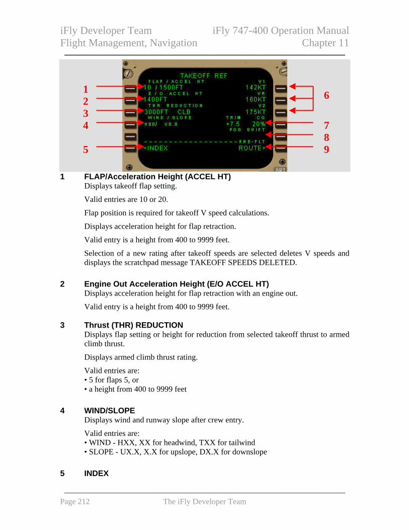
iFly Developer Team iFly 747-400 Operation Manual Flight Management, Navigation Chapter 11 ——————————————————————————————
1
1 FLAP/Acceleration Height (ACCEL HT) Displays takeoff flap setting.
Valid entries are 10 or 20.
Flap position is required for takeoff V speed calculations.
Displays acceleration height for flap retraction.
Valid entry is a height from 400 to 9999 feet.
Selection of a new rating after takeoff speeds are selected deletes V speeds and displays the scratchpad message TAKEOFF SPEEDS DELETED.
2 Engine Out Acceleration Height (E/O ACCEL HT)
Displays acceleration height for flap retraction with an engine out.
Valid entry is a height from 400 to 9999 feet.
3 Thrust (THR) REDUCTION Displays flap setting or height for reduction from selected takeoff thrust to armed climb thrust.
Displays armed climb thrust rating.
Valid entries are: • 5 for flaps 5, or • a height from 400 to 9999 feet
4 WIND/SLOPE
Displays wind and runway slope after crew entry.
Valid entries are: • WIND - HXX, XX for headwind, TXX for tailwind • SLOPE - UX.X, X.X for upslope, DX.X for downslope
5 INDEX
62 3 4 7
85 9
——————————————————————————————————— Page 212 The iFly Developer Team

iFly Developer Team iFly 747-400 Operation Manual Flight Management, Navigation Chapter 11 ——————————————————————————————
Push - displays INIT/REF INDEX page. 6 V Speeds (V1, VR, V2)
If performance data changes: • FMC replaces existing speeds with FMC calculated speeds in small font • V speeds are deleted from the PFD • PFD speed tape message NO V SPD displays • scratchpad message TAKEOFF SPEEDS DELETED displays
7 TRIM, Center of Gravity (CG) CG displays in small font with caret.
8 Position (POS) SHIFT
Displays the selected takeoff runway and TO/GA “push” distance from the runway threshold.
9 PRE-FLIGHT
Displays PRE-FLIGHT and title (XXXXX) of incomplete page when preflight is not complete.
Displays dashes and THRUST LIM when preflight is complete.
Push - • displays THRUST LIM page when THRUST LIM displayed • displays incomplete page (XXXXX) when PRE-FLIGHT displayed
Menu Page Provides access to other systems that use CDU.
1 FMC
Push – • connects FMC to the CDU • displays last page used
1 3 4
2 5
——————————————————————————————————— Page 213 The iFly Developer Team

iFly Developer Team iFly 747-400 Operation Manual Flight Management, Navigation Chapter 11 ——————————————————————————————
• displays INITIALIZATION page on initial application of AC power 2 Central Maintenance Computer (CMC)
Operational on ground and in flight above 10,000 feet.
Push - • displays CMC menu page • activates CMC control of the CDU for maintenance use
3 Alternate EFIS Control (CP)
See Chapter 10, Flight Instruments, Displays 4 Alternate EICAS Control (CP)
See Chapter 10, Flight Instruments, Displays 5 SIMU
Push – Shows the iFly 747-400 menu page. Refer to chapter 1.
FMC Takeoff and Climb Introduction FMC takeoff phase starts with selection of takeoff/go–around (TO/GA). Preparation for this phase starts in preflight phase and includes entry of TAKEOFF REF page data. Takeoff phase changes to climb phase when the FMC commands climb thrust. Climb phase continues to the top of climb point, where cruise phase starts. During takeoff and climb, the specific page listed below is used to: • TAKEOFF REF page – make last minute changes to the departure runway • DEPARTURES page – make last minute SID selections • CLIMB page – modify climb parameters and monitor airplane climb performance • RTE X LEGS page – modify the route and monitor route progress • PROGRESS page – monitor the overall progress of the flight • THRUST LIM page – select alternate climb thrust limits • DEP/ARR INDEX page – select an approach during a turn–back
——————————————————————————————————— Page 214 The iFly Developer Team

iFly Developer Team iFly 747-400 Operation Manual Flight Management, Navigation Chapter 11 ——————————————————————————————
Takeoff Phase When changes are made to the departure runway and SID, TAKEOFF REF and DEPARTURES pages must be modified to agree. The modified data are entered the same as during preflight. With correct takeoff parameters, the FMC commands the selected takeoff thrust when the TO/GA switch is pushed. During takeoff roll, autothrottle commands thrust and the FMC commands acceleration to between V2+10 and V2+25 knots, based on rate of rotation. Usually, VNAV is armed before takeoff. VNAV activates at 400 feet above runway elevation and commands pitch to fly the climb profile. Climb Phase At acceleration height or the first movement of the flap handle during flap retraction, VNAV commands acceleration to: • 250 knots, • VREF+100 knots, or • speed transition associated with the origin airport, whichever is greater VNAV commanded speed is limited by airplane configuration. At the climb thrust reduction point, the FMC commands a reduction to the armed climb thrust. Passing 10,000 feet, VNAV commands an acceleration to economy climb speed, which is maintained until entering the cruise phase. Waypoint speed constraints take priority, provided they are greater than VREF+100 or 250 knots. During climb, VNAV complies with LEGS page waypoint altitude and speed constraints. A temporary level–off for a crossing altitude restriction is accomplished at the commanded speed. When the climb profile fails to reach a waypoint altitude constraint, the FMC displays the CDU scratchpad message UNABLE NEXT ALTITUDE. Deleting climb derates or selecting a reduced climb speed thus giving a steeper climb angle, may enable the airplane to reach the altitude constraint. Climb Page The climb page is used to evaluate, monitor, and modify the climb path. Data on climb page comes from preflight entries made on the route and performance pages.
——————————————————————————————————— Page 215 The iFly Developer Team

iFly Developer Team iFly 747-400 Operation Manual Flight Management, Navigation Chapter 11 ——————————————————————————————
Climb Page The climb page is the first of the three pages selected with the VNAV function key. FMC climb can be economy, fixed speed, or engine out.
1 2 7
1 Page Title The page title displays active (ACT) or modified (MOD) climb. Usually, the title contains ECON for economy climb. Fixed speed and engine out modify the title. • ECON – speed based on a cost index • LIM SPD – speed based on airplane configuration limiting speed • MCP SPD – MCP speed intervention selected • XXXKT – fixed CAS climb speed profile • M.XXX – fixed Mach climb speed profile • E/O – engine out mode selected
Fixed climb speeds are for: • takeoff/climb acceleration segment constraints • a flight crew selected speed (SEL SPD) • a speed transition • a speed restriction associated with an altitude • waypoint speed constraints
2 Cruise Altitude (CRZ ALT)
Displays cruise altitude entered on PERF INIT page.
Valid entries are: XXX, XXXX, XXXXX, or FLXXX. Altitude displays in feet or flight level depending on transition altitude.
3 Economy Speed (ECON SPD), Selected Speed (SEL SPD)
ECON SPD - • speed based on cost index in CAS or Mach • used by the FMC at altitudes above all waypoint speed constraints, speed
restrictions, and speed transition altitudes
Valid entries are CAS or Mach. SEL SPD - displays when flight crew enters speed.
3 4 8 5 9 6 10
11
——————————————————————————————————— Page 216 The iFly Developer Team

iFly Developer Team iFly 747-400 Operation Manual Flight Management, Navigation Chapter 11 ——————————————————————————————
4 Speed Transition (SPD TRANS)
Speed transition line displays the transition speed/altitude from the greater of a default speed of 250 knots or VREF+100 knots and 10,000 feet (example 272/10000)
Not displayed above transition.
Can be deleted. 5 Speed Restriction (SPD RESTR)
Speed restrictions at an altitude less than the cruise altitude and not associated with a waypoint are manually entered on this line.
Displays dashes before entry by flight crew.
Valid entry is a CAS and altitude (example 240/8000). 6 Economy (ECON)
Push – changes climb speed to ECON.
Displays when the climb speed is not ECON. 7 Waypoint Constraint (AT XXXXX)
Displays next airspeed and/or altitude constraint at waypoint XXXXX.
Can also display HOLDAT XXXXX followed by a speed/altitude constraint.
FMC commands the slower of constraint speed or performance speed.
Constraints entered on RTE LEGS page.
Delete here or on RTE LEGS page.
Blank if no constraint exists. 8 Transition Altitude (TRANS ALT)
Manually change transition altitude here or on DESCENT FORECAST page.
Valid entries are: XXX, XXXX, XXXXX, or FLXXX.
CDU altitude data changes from altitudes to flight levels above the transition altitude.
9 Maximum Angle (MAX ANGLE)
Displays maximum angle climb speed.
Entry not allowed. 10 Engine Out (ENG OUT)
——————————————————————————————————— Page 217 The iFly Developer Team

iFly Developer Team iFly 747-400 Operation Manual Flight Management, Navigation Chapter 11 ——————————————————————————————
Push – displays E/O CLB page. 11 Climb Direct (CLB DIR)
Displays when climb altitude constraint exists between current altitude and FMC cruise altitude.
Push – deletes all waypoint altitude constraints between the airplane altitude and the MCP altitude or FMC cruise altitude, whichever is lower. FMC cruise altitude is not affected.
RTE X LEGS Page Route legs page provides means of entering and displaying details of each leg of the route. Valid entries same as on route pages TO line.
1 5 2
6 3
7 4 8
9 10
1 Page Title Title format displays route status: • RTE X LEGS – inactive route • ACT RTE X LEGS – active route • MOD RTE X LEGS – modified active route
2 Leg Direction
Leg segment data in line title: • computed course to waypoint - XXX° • heading leg segments – XXX° HDG • special procedural instructions - HOLD AT
Calculated great circle route leg directions may be different than chart values.
——————————————————————————————————— Page 218 The iFly Developer Team

iFly Developer Team iFly 747-400 Operation Manual Flight Management, Navigation Chapter 11 ——————————————————————————————
Dashes display for an undefined course. 3 Waypoint Identifier
Active leg is the first line of the first active RTE X LEGS page.
Active waypoint is on active leg.
All route waypoints display in flight sequence. Airway waypoints display on the route legs page.
Waypoints can be modified. Examples: • add waypoints • delete waypoints • change waypoint sequence • connect route discontinuities
Displays the waypoint by name or condition.
Boxes display for route discontinuities.
Dashes display after the end of the route. 4 Route 2 Legs (RTE 2 LEGS)
Push – • displays RTE 2 LEGS page • when RTE 2 LEGS page displayed, changes to RTE 1 LEGS
5 Waypoint Speed/Altitude Constraints
Waypoint speed or altitude constraints display in large font.
Manual entry allowed in climb or descent phase. Entered by FMC when constraints are part of a procedure.
Speed constraint is assumed to be at or below the displayed speed.
Valid entries are: • speed entry can be airspeed or Mach • altitude entry can be feet or flight level • XXX/XXXXX – airspeed/altitude entered simultaneously • XXX, XXXX, XXXXX or /XXX, /XXXX, /XXXXX – altitude only, less than cruise altitude
Altitude constraint suffixes: • blank – cross at altitude • A – cross at or above altitude • B – cross at or below altitude • both – altitude block. If constraint is to cross between two altitudes, enter lower altitude followed by “A”; then, enter higher altitude followed by “B”. Example: 220A240B.
——————————————————————————————————— Page 219 The iFly Developer Team

iFly Developer Team iFly 747-400 Operation Manual Flight Management, Navigation Chapter 11 ——————————————————————————————
6 Distance to Waypoint
Distance (decreasing) from airplane to active waypoint or distance from waypoint to waypoint. Blank for some leg types (e.g. HDG or VECTORS).
7 Waypoint Speed/Altitude Predictions
Waypoint speed and altitude predictions display in small font.
Dashes display in predicted descent region prior to descent path calculation.
Descent path calculation requires altitude constraint below cruise altitude. 8 ACTIVATE, Route (RTE) DATA
Push – • ACTIVATE – activates inactive flight plan; ready for execution • RTE DATA – displays route data page
ACTIVATE displays when RTE and RTE LEGS flight plan is inactive.
RTE DATA displays after pushing ACTIVATE prompt. 9 Center (<CTR>)
Displays when PLAN mode selected.
Displays adjacent to the waypoint around which ND plan mode is centered. 10 MAP Center (CTR) STEP
Replaces ACTIVATE or RTE DATA when PLAN mode selected.
Push - steps <CTR> to next waypoint. ND plan mode recenters.
Direct/Intercept Course Used to fly direct to or intercept a course to a waypoint. Entering a waypoint over the active waypoint displays direct/intercept prompts.
——————————————————————————————————— Page 220 The iFly Developer Team

iFly Developer Team iFly 747-400 Operation Manual Flight Management, Navigation Chapter 11 ——————————————————————————————
1
2 345
1 Course to Active Waypoint Prior to execution, displays direct-to inbound course at waypoint; changed by entry in INTC CRS line or by selecting intercept course.
After execution, displays current required track to fly inbound course to waypoint. 2 Active Waypoint
Displays crew entered direct/intercept waypoint. 3 ABEAM Points (PTS)
Push - • line title displays ABEAM PTS, line data displays SELECTED • creates abeam points on new route to indicate waypoints bypassed by direct to
function • abeam points are perpendicular to the waypoints bypassed • subsequent route modifications remove ABEAM PTS prompt
4 Route (RTE) COPY
Push - • copies active unmodified route into inactive route • erases previous inactive route • line title displays RTE COPY, line data displays COMPLETE • subsequent route modifications remove RTE COPY prompt
5 Intercept Course
Displays boxes if entered waypoint not in the active route; valid entry is intercept course from 000° to 360°.
Displays current route course and prompt caret if entered waypoint in the active route.
Push - • when current route course displayed, selects it as intercept course to active
waypoint
——————————————————————————————————— Page 221 The iFly Developer Team

iFly Developer Team iFly 747-400 Operation Manual Flight Management, Navigation Chapter 11 ——————————————————————————————
• displays entry or current route course as course to active waypoint • removes ABEAM PTS and RTE COPY prompts
Select Desired Waypoint Page The SELECT DESIRED WPT page displays after a waypoint entry when the FMC encounters more than one location for the same waypoint name. Selection of a waypoint returns the display to the previous page.
1 4
2
3
5
1 Identifier Displays the identifier for the duplicate named waypoints.
2 Waypoint Lines
Display a sorted list of waypoints with identifier, navaid type, frequency, and coordinates; • when page is accessed as a result of a flight plan modification, sort is based on
proximity to the waypoint preceding the entered waypoint • when page is accessed as a result of a DIR/INTC or REFNAVDATA entry, sort
is based on proximity to current aircraft position
Push - selects waypoint location for use and returns display to page previously in use.
Pushing any CDU function key exits page without selecting a waypoint. 3 Frequency
Displays the frequency of the navaid.
Blank if the waypoint is not a navaid. 2 4 Type
Displays the type of navaid for each duplicate name.
Blank if the waypoint is not a navaid.
——————————————————————————————————— Page 222 The iFly Developer Team

iFly Developer Team iFly 747-400 Operation Manual Flight Management, Navigation Chapter 11 ——————————————————————————————
5 Latitude/Longitude Displays the latitude/longitude for each duplicate name.
Thrust Limit Page Thrust limits are selected on the thrust limit page. In flight, this display replaces the takeoff thrust limits with applicable thrust limits for climb. The selected limits display here and on the EICAS Display. Fixed thrust derates can be selected for climb. Go-around, continuous, and cruise thrust limits are available also.
1 2 3
4
1 Go–Around (GA) Push – selects go–around thrust limit.
2 Continuous (CON)
Push – selects maximum continuous thrust limit. 3 Cruise (CRZ)
Push – selects cruise thrust limit. 4 APPROACH
Push – displays APPROACH REF page.
Engine Out Climb Engine out (E/O) VNAV climb guidance displays on the E/O CLB page. The E/O CLB page must be selected and executed by the flight crew. Engine out data is available with all engines operating. Engine out climb changes to engine out cruise at the top of climb.
——————————————————————————————————— Page 223 The iFly Developer Team

iFly Developer Team iFly 747-400 Operation Manual Flight Management, Navigation Chapter 11 ——————————————————————————————
E/O CLB Page The modified page displays engine out performance limitations based on one or two engines out. Manual entries are allowed. After execution, VNAV gives E/O guidance in the climb and reference thrust limit changes to CON.
1 2
34
1 Cruise Altitude (CRZ ALT) Displays cruise altitude.
Manual entry is allowed.
2 Engine Out Speed (E/O SPD) Displays engine out climb speed.
Valid entry is XXX for CAS.
Valid entry is 0.XXX for Mach. Trailing zeros can be omitted. 3 Maximum Altitude (MAX ALT)
Displays lower of maximum altitude at engine out climb speed or cruise speed.
Entry not allowed. 4 ALL ENG
Push – modifies page to display all engine (ALL ENG) performance data.
——————————————————————————————————— Page 224 The iFly Developer Team

iFly Developer Team iFly 747-400 Operation Manual Flight Management, Navigation Chapter 11 ——————————————————————————————
Air Turnback Arrivals Page
1 32
4
1 Standard Terminal Arrival Routes/Profile Descents (STARS) Displays STARS for origin airport.
2 Transitions (TRANS)
Displays transitions for the selected arrival procedure.
3 APPROACHES Displays approaches for origin airport.
4 RUNWAYS
Displays runways for origin airport. FMC Cruise Introduction Cruise phase starts at top of climb. During cruise, the primary FMC pages are: • RTE X LEGS • CRZ • PROGRESS VNAV related data. PROGRESS pages display flight progress data. During cruise, the
specific page listed below is used to: • POS REF page – verify the FMC position • RTE DATA page – display progress data for each waypoint on the RTE LEGS page • WINDS page – enter forecast wind and temperature
——————————————————————————————————— Page 225 The iFly Developer Team

iFly Developer Team iFly 747-400 Operation Manual Flight Management, Navigation Chapter 11 —————————————————————————————— • REF NAV DATA page – display data about waypoints, navaids, airports, or runways,
and can be used to inhibit navaids • FIX INFO page – display data about waypoints. Page data can be transferred to other
pages to create new waypoints and fixes • POS REPORT page –display data for a position report CLB page changes to CRZ at top of climb. CRZ CLB and CRZ DES pages change to CRZ at the new cruise altitude. CRZ page changes to DES at top of descent. Cruise Page All Engine Cruise The cruise page monitors and changes cruise altitude and speed. Speed changes can be manually entered or selected using speed intervention while in VNAV modes. Cruise climbs, cruise descents, and step climbs can be accomplished from the cruise page.
1 2 7 3 8 4 9 5 10 6 11
12
1 Page Title Page title displays active (ACT) or modified (MOD) cruise. Usually, the title contains ECON for economy cruise. Fixed speed, engine out, and long range cruise modify the title.
Page titles include: • ECON – speed based on cost index • LIM SPD – speed based on an airplane configuration limiting speed • MCP SPD – MCP speed intervention selected
• XXXKT – fixed CAS cruise speed • M.XXX – fixed Mach cruise speed • CRZ CLB or CRZ DES – cruise climb or descent • LRC – long range cruise selected • E/O – engine out mode selected • E/O LRC D/D – long range cruise drift down displays when EO selected and the airplane altitude is above the maximum altitude for engine out performance
Fixed cruise speeds are for: • a flight crew selected speed (SEL SPD)
——————————————————————————————————— Page 226 The iFly Developer Team

iFly Developer Team iFly 747-400 Operation Manual Flight Management, Navigation Chapter 11 ——————————————————————————————
• a speed restriction associated with an altitude • waypoint speed constraints
2 Cruise Altitude (CRZ ALT)
Displays cruise altitude entered on the PERF INIT page.
Valid entries are: XXX, XXXX, XXXXX, or FLXXX. Altitude displays in feet or flight level depending on the transition altitude.
A new entry changes the page title to CRZ CLB or CRZ DES.
Changing the MCP altitude and pushing the Altitude selector enters the MCP altitude as the active cruise altitude, without creating a modification.
3 Economy Speed (ECON SPD), Selected Speed (SEL SPD)
Displays the command speed or Mach.
Valid entries are CAS or Mach.
SEL SPD - displays when flight crew enters speed.
LRC - displays when LRC selected. 4 N1
Displays N1 to maintain level flight at command airspeed. 5 STEP SIZE
Displays climb altitude increment used by FMC to calculate optimum step climb.
Defaults to ICAO.
Valid entries are 0 to 9000 feet in increments of 1000 feet. 6 Economy (ECON)
Push – selects economy cruise speed.
Displays when speed or Mach entered manually; or, when LRC selected. 7 STEP TO Altitude
Displays calculated step climb altitude based on STEP SIZE. 8 AT
Displays ETA and distance to go to the optimum step point where a climb to the STEP TO altitude minimizes either trip cost.
Displays NOW passing the optimum step climb point.
Line title changes to TO T/D within 200 miles of T/D. ETA and distance are to T/D.
——————————————————————————————————— Page 227 The iFly Developer Team

iFly Developer Team iFly 747-400 Operation Manual Flight Management, Navigation Chapter 11 ——————————————————————————————
9 Destination ETA/FUEL
Estimated time of arrival and calculated fuel remaining at the destination assuming step climbs are made at optimum points to the STEP TO altitude.
Calculations are based on optimum and planned step climbs and cruise altitudes.
10 Optimum Altitude and Maximum Altitude (OPT, MAX) OPT – displays maximum cruise optimized altitude
MAX – displays the maximum cruise altitude. 11 Engine Out (ENG OUT)
Push – • displays E/O CRZ page • commands engine out performance calculations • changes CRZ ALT if above maximum engine out altitude • changes command speed to engine out LRC speed • upon execution, reference thrust limit changes to CON
12 Long Range Cruise (LRC)
Push – displays LRC CRZ page. Engine Out Cruise Engine out (E/O) VNAV cruise guidance displays on E/O CRZ page. E/O CRZ page must be selected and executed by the flight crew. Engine out data is also available with all engines operating. EO Cruise Page The modified page displays engine out performance limitations. Manual entries are allowed. When above the maximum engine out cruise altitude, VNAV calculates engine out guidance for drift down (D/D). The E/O LRC (long range cruise) D/D page changes to the E/O LRC CRZ page when reaching the engine out cruise altitude. As the airplane gross weight decreases, maximum altitude increases. A step climb may be possible under these conditions.
——————————————————————————————————— Page 228 The iFly Developer Team

iFly Developer Team iFly 747-400 Operation Manual Flight Management, Navigation Chapter 11 ——————————————————————————————
1
2 3
5
6
1 Page Title The page title displays active (ACT) and modified (MOD) cruise. Page titles include: • E/O - minimum drag speed • E/O LIM SPD - speed based on airplane configuration limiting speed • E/O MCP SPD - MCP speed intervention selected • E/O XXXKT - fixed CAS descent speed • E/O M.XXX - fixed Mach descent speed • E/O LRC D/D - airplane is above MAX altitude • E/O LRC - airplane is level at CRZ ALT; less than MAX • E/O CRZ CLB/DES - cruise climbs or descents when the CRZ ALT is below MAX altitude
2 Cruise Altitude (CRZ ALT) Displays CRZ ALT from all engine cruise page.
Valid entries are the same as all engine cruise page. 3 Long Range Cruise Speed (LRC SPD)
Displays computed engine out LRC speed.
Valid entries are the same as all engine cruise page.
SEL SPD - displays when flight crew enters speed.
E/O SPD - displays when E/O SPD prompt selected.
Manual entries may change MAX altitude. 4 Engine Out (EO SPD)
Push – enables execution of engine out minimum drag speed profile.
Displays when LRC or SEL SPD is the active speed mode.
7 4 8
——————————————————————————————————— Page 229 The iFly Developer Team

iFly Developer Team iFly 747-400 Operation Manual Flight Management, Navigation Chapter 11 ——————————————————————————————
5 AT Same as all engine display.
6 Optimum Altitude and Maximum Altitude (OPT, MAX)
OPT - displays optimum altitude at speed displayed on speed line. MAX - displays the maximum cruise altitude as MAX for all engines.
7 ALL Engine (ENG)
Push – displays and enables execution of MOD XXX CRZ page with performance based on all engines operating.
8 Long Range Cruise (LRC)
Push – enables execution of engine out long range cruise.
Displays when EO or SEL SPD is the active mode. Navigation Data Reference Navigation Data Page Reference navigation data page displays data about waypoints, navaids, airports, and runways. This page is used to inhibit FMC position updates from radio navaids. The navaids are available for manual, route, and procedure tuning.
7 1 2 8 3 9 4 4 5
1 Identification (IDENT) Valid entries are any waypoint, navaid, airport, or runway from the navigation database.
Entry changes to dashes when page is exited and then reselected. 2 LATITUDE
6 10 5
——————————————————————————————————— Page 230 The iFly Developer Team

iFly Developer Team iFly 747-400 Operation Manual Flight Management, Navigation Chapter 11 ——————————————————————————————
Displays latitude of entered identifier. 3 Magnetic Variation (MAG VAR), LENGTH
MAG VAR - displays magnetic variation when entered identifier is a navaid.
LENGTH - displays runway length when entered identifier is a runway. 4 NAVAID INHIBIT
Due to lack of VORTAC in FS, this part and the next section VOR ONLY INHIBIT own the same property, which is just for inhibiting VOR.
5 VOR ONLY INHIBIT Valid entries are VOR identifiers from the navigation database.
Inhibits use of only the VOR portion of entered navaid for updating by FMC.
Entries blank at flight completion.
Deleting or overwriting removes a previous inhibit. 6 INDEX
Push – displays INIT/REF INDEX page. 7 Frequency (FREQ)
Displays frequency of entered identifier when it is a navaid. 8 LONGITUDE
Displays longitude of entered identifier. 9 ELEVATION
Displays elevation of entered identifier when it is a navaid, airport, or runway. 10 VOR/DME NAV INHIBIT, ENABLE
INHIBIT - Push - • inhibits FMC from using VOR/DME radio position updating • displays ENABLE • does not affect DME/DME radio position updating • overwrites VOR ONLY INHIBIT entries and displays ALL • entries clear at flight completion and INHIBIT displays
ENABLE - Push - • allows VOR/DME radio position updating • displays INHIBIT
——————————————————————————————————— Page 231 The iFly Developer Team

iFly Developer Team iFly 747-400 Operation Manual Flight Management, Navigation Chapter 11 ——————————————————————————————
Fix Information Page Two identical fix information pages are used to create waypoint fixes and waypoints for the ND. Some of the created waypoints can be copied into the route.
1 FIX
Valid entries are airports, navaids, and waypoints from the navigation database.
Selected fix displays on the ND. 2 Bearing/Distance (BRG/DIS), ETA, DTG, ALT
Distance Entry: • valid entry is /YYY • leading zeros can be omitted for distance entries
Distances from the fix display on the ND as a circle around the fix.
When the distance intersects the active route, the ETA, DTG, and altitude at the intersection display for the closest of the two intersections.
Bearing Entry: • valid entry is a bearing from the fix, XXX • slash (/) not required
Bearings from the fix display on the ND as radial lines from the fix.
When the bearing intersects the active route, the ETA, DTG, and altitude at the intersection display.
ETA – displays the estimated time of arrival to the intersection point.
DTG – displays the distance to go to the intersection point.
ALT – displays the predicted altitude at the intersection point. Bearing/distance entries do not display ETA, DTG, or predicted altitude.
Line selection copies the fix place/bearing/distance into the scratchpad. Distance displays to the nearest tenth of a nautical mile. This fix can be placed in the route on a LEGS or RTE page as a waypoint.
1 52
3 4 6
——————————————————————————————————— Page 232 The iFly Developer Team

iFly Developer Team iFly 747-400 Operation Manual Flight Management, Navigation Chapter 11 ——————————————————————————————
3 ABEAM
Displays ABEAM prompt.
Push - displays bearing and distance from the fix perpendicular to the nearest segment of the flight plan path, and ETA, DTG, and altitude at the intersection point.
Second push - copies the fix place/bearing/distance definition into the scratchpad.
This fix can be placed in the route on a LEGS or RTE page as a waypoint. 4 ERASE FIX
Push – removes all fix data from the page and the ND. 5 Bearing/Distance From (BRG/DIS FR)
Displays the bearing and distance of the airplane from the fix. 6 Predicted Distance to ETA or Altitude (PRED ETA-ALT)
Valid entry is altitude, flight level, or time. “Z” must follow time entry.
Entering an altitude or flight level displays the predicted along track distance and altitude or flight level on this line. The predicted airplane position displays on the ND route line as a green circle with the entered altitude/flight level.
Entering a time displays the predicted along track distance and the time on this line. The predicted airplane position displays on the ND route line as a green circle with the entered ETA.
Route and Waypoint Data Route Data Page The route data page displays data for each waypoint on ACT RTE X LEGS page. This page also allows access to the WIND page. This page is available only for the active route.
——————————————————————————————————— Page 233 The iFly Developer Team

iFly Developer Team iFly 747-400 Operation Manual Flight Management, Navigation Chapter 11 ——————————————————————————————
1 4
2
5
3
1 ETA Displays ETA for waypoint.
2 Waypoint (WPT)
Displays identifier for waypoint. 3 LEGS, ERASE
LEGS - Push – displays RTE LEGS page.
4 FUEL Displays the FMC calculated fuel remaining at the waypoint.
Note: ETA and estimated fuel calculations assume a direct flight across route discontinuities.
5 WIND (W>/>)
W> - indicates waypoint winds have been entered.
> - winds not entered.
Push – displays WIND page for the selected waypoint. Wind Page The wind page is used to enter forecast winds and temperatures at waypoints for up to four altitudes to enhance VNAV performance. Wind speed and direction are entered for the specific altitudes. OAT can be entered for any altitude. The FMC calculates the temperature for the entered altitudes using the standard lapse rate.
——————————————————————————————————— Page 234 The iFly Developer Team

iFly Developer Team iFly 747-400 Operation Manual Flight Management, Navigation Chapter 11 ——————————————————————————————
1 2
3 4 5 6
1 Page Title Displays XXXXX, where XXXXX is the waypoint for which winds display.
2 Altitude (ALT)
Valid entry is altitude or flight level on line 1L.
After entry, data are sorted by altitude and display in lines 1 through 4. Dashes display on right side of line for wind direction and speed entry.
When all four lines have data, one must be deleted before new altitude can be entered.
3 OAT
OAT displays the outside air temperature. Data entry not possible. 4 Direction and Speed (DIR/SPD)
Displays wind direction and speed for related altitude. Displays dashes after altitude/flight level entered in the ALT line. Manual entries display in large font. Valid entries are wind direction and speed.
5 Altitude/Outside Air Temperature (ALT/OAT) Valid entries are altitude or flight level/and OAT.
OATs display in OAT column.
The altitude for OAT does not have to be one of the wind altitudes. The FMC uses standard lapse rate to calculate and display the temperature at the other altitudes.
6 Route Data (RTE DATA) Push – displays RTE DATA page.
——————————————————————————————————— Page 235 The iFly Developer Team

iFly Developer Team iFly 747-400 Operation Manual Flight Management, Navigation Chapter 11 ——————————————————————————————
Position Reference Page 2/3 Position reference page 2 displays the position and ground speed calculated by the FMC and IRS. GPS position updating can be enabled and inhibited and radio and GPS updates to the FMC position can be purged on this page. The IRS position can be changed to bearing/distance.
1 6
1 FMC Position (POS) Displays the FMC calculated latitude/longitude position.
Line title identifies the source for calculating the FMC position. 2 IRS
Displays the IRS latitude/longitude position.
Blank when FMC receiving no valid IRU data. 3 Required Navigation Performance and Actual Navigation
Performance (RNP /ACTUAL) No implementation.
4 PURGE
No implementation.
5 INDEX Push – displays INIT/REF INDEX page.
6 Ground Speed (GS)
Displays ground speed associated with FMC POS and IRS (X).
Blank from power application until IRU enters navigation mode.
Value frozen at engine shutdown following a flight until power removed, any IRU in ALIGN mode, or engine start.
2 73
4 85 9
——————————————————————————————————— Page 236 The iFly Developer Team

iFly Developer Team iFly 747-400 Operation Manual Flight Management, Navigation Chapter 11 ——————————————————————————————
7 Navigation Station
Displays identifiers of navigation stations in use by FMC for radio position computation.
Title line displays type of radio station, DME-DME or VOR-DME.
Title line displays NAV STA and data line blanks when no radio position computation occurring.
8 GPS Navigation (NAV)
Initially displays INHIBIT. GPS data enabled for FMC position updating.
Push - • inhibits GPS data for FMC position updating and displays ENABLE.
Inhibiting retained through power interruption • selection when ENABLE displayed enables GPS data for FMC position
updating and displays INHIBIT. Defaults to INHIBIT following flight completion
9 Bearing/Distance (BRG/DIST) or Latitude/Longitude (LAT/LON)
Initially displays BRG/DIST.
Push – • displays bearing/distance in IRS (X) line relative to FMC position and
displays LAT/LON • if distance is zero, bearing displays 000 • selection when LAT/LON displayed or leaving the POS REF pages on CDU
returns displays to latitude/longitude and BRG/DIST
The page illustration is shown in the latitude/longitude display format. Position Reference Page 3/3 On position reference page 3, the flight crew can observe the positions and ground speed from the GPS receivers and the IRUs. This page can be displayed in the bearing/distance or latitude/longitude format. The bearing/distance format displays the bearing and distance of the position sources relative to the active FMC position on POS REF 2/3 page.
——————————————————————————————————— Page 237 The iFly Developer Team

iFly Developer Team iFly 747-400 Operation Manual Flight Management, Navigation Chapter 11 ——————————————————————————————
1 IRU, GPS Position
Displays position computed by related system.
GPS data blanks if GPS unavailable or inhibited. 2 Ground Speed (GS)
Displays ground speed associated with IRS (X) or GPS (X).
GPS data blanks if GPS unavailable or inhibited. Progress Pages Progress Page 1/3 Progress page displays general flight progress data.. The page title displays the company flight number entered on the RTE page. Page one of the progress pages displays general data about: • waypoints (last, active, and next) • destination data • top of descent
1 LAST
1 2
1 72 83
4 9105
6 11
——————————————————————————————————— Page 238 The iFly Developer Team

iFly Developer Team iFly 747-400 Operation Manual Flight Management, Navigation Chapter 11 ——————————————————————————————
Displays last waypoint identifier and altitude (ALT), actual time of arrival (ATA), and fuel (FUEL) remaining at that waypoint.
2 TO
Displays active waypoint identifier. • waypoints (last, active, and next) • destination data
3 NEXT
Displays waypoint identifier of waypoint after the active waypoint. 4 Destination (DEST)
Displays destination identifier. 5 Selected Speed (SEL SPD)
Displays active command speed and mode.
The active speed mode is the same as displayed on the performance page, unless changed by the MCP or a limit. Speed modes are:
• LRC SPD – long range cruise speed • ECON SPD – economy speed • SEL SPD – selected speed manually entered on the CDU • LIM SPD – speed is limited by VMO, MMO, flap limit, or alpha limit • MCP SPD – MCP speed entered on the MCP IAS/MACH indicator • EO SPD – engine out speed • VREF +100 - engine out during takeoff, engine out not selected, and speed not
restricted by limit speed (e.g., flap placard)
6 Position Report (POS REPORT) Push – displays the POS REPORT page.
7 ETA
Displays estimated time of arrival at waypoint or destination. 8 Distance To Go (DTG)
Displays distance to go to waypoint or destination. 9 FUEL
Displays estimated fuel remaining at waypoint or destination. 10 TO
Displays ETA and DTG to various points as flight progresses. The line title and data change to display data for phases of flight. Line titles are:
——————————————————————————————————— Page 239 The iFly Developer Team

iFly Developer Team iFly 747-400 Operation Manual Flight Management, Navigation Chapter 11 ——————————————————————————————
• T/C - top of climb data • STEP CLB – step climb data • T/D - top of descent data • E/D – end of descent data
11 Position Reference (POS REF)
Push – displays position reference page 2/3. Progress Page 2/3 Progress page two contains: • wind data • fuel data • static air temperature • true airspeed • track error data
71
1 WIND Displays current wind direction and speed referenced to true north.
2 Headwind (H/WIND), Tailwind (T/WIND)
Displays headwind (H/WIND) or tailwind (T/WIND) component.
Wind component data is relative to airplane heading. 3 Crosstrack Error (XTK ERROR)
Displays crosstrack (XTK) error in nautical miles left or right of the active route. 4 TAS
Displays airplane true airspeed. 5 FUEL USED 1, 2, 3, 4
Displays fuel used by engines 1, 2, 3, 4.
2 83 94 105
6 11
——————————————————————————————————— Page 240 The iFly Developer Team

iFly Developer Team iFly 747-400 Operation Manual Flight Management, Navigation Chapter 11 ——————————————————————————————
6 USE TOTALIZER Displays fuel quantity
7 FUEL USED Total (TOT) Displays total fuel used as calculated from fuel flow.
8 Crosswind (X/WIND) Displays left (L) or right (R) crosswind component relative to airplane heading.
9 Vertical Track Error (VTK ERROR)
No implementation 10 Static Air Temperature (SAT)
Displays outside static air temperature.
11 FUEL Quantity (QTY) CALCULATED Displays fuel quantity.
FMC Descent and Approach Introduction The descent phase starts at the top of descent point and continues to the end of descent point. Planning for descent phase starts during cruise. The approach phase starts at the end of descent point and continues to touchdown or missed approach. Early Descent An early descent is a descent started prior to the T/D. The VNAV descent page becomes active. During cruise, setting an altitude below the current cruise altitude in the MCP altitude window and pushing the altitude selector activates the DES NOW function when the aircraft is within 50 nm of the T/D. Descent During descent, the RTE LEGS and PROGRESS pages are used to control the lateral route. The DES page is used to control the vertical descent profile. The additional descent pages listed below are used to: • DESCENT FORECAST page – enter forecast wind data to aid descent planning • OFFPATH DES page – analyze descent performance with and without the use of speedbrakes
——————————————————————————————————— Page 241 The iFly Developer Team

iFly Developer Team iFly 747-400 Operation Manual Flight Management, Navigation Chapter 11 ——————————————————————————————
Descent Page The DES page is used to monitor and revise the descent path. Descent speeds are economy (ECON) and selected speed (SEL). The default VNAV descent speed is ECON. A selected speed descent is flown when speed intervention is used or a speed is entered on the DES page.
1 72
3
4 5 86 9
1 Page Title The page title displays active (ACT) or modified (MOD) descent. Usually, the title contains ECON for economy descent. Other fixed or selected speeds modify the title.
The page title displays the type of descent: • ECON – speed based on a cost index • LIM SPD – speed based on airplane configuration limiting speed • MCP SPD – MCP speed intervention is selected • XXXKT – fixed CAS descent speed profile • M.XXX – fixed Mach descent speed profile
Fixed or selected descent speeds are for: • a flight crew selected speed (SEL SPD) • a speed transition • a speed restriction associated with an altitude constraint • waypoint speed constraints.
2 End Of Descent At (E/D AT)
Displays end of descent altitude and waypoint.
End of descent point is a point in descent phase with the lowest altitude constraint.
Page is blank if no E/D point exists. 3 Economy Speed (ECON SPD), Selected Speed (SEL SPD)
Both CAS and Mach values display.
——————————————————————————————————— Page 242 The iFly Developer Team

iFly Developer Team iFly 747-400 Operation Manual Flight Management, Navigation Chapter 11 ——————————————————————————————
ECON SPD – • economy speed based on cost index • displays CAS and Mach values
SEL SPD – • displays when flight crew enters speed • valid entries are CAS or Mach value
4 Speed Transition (SPD TRANS)
The default transition speed is 240 knots. Transition altitude is the point transition speed is active for the destination airport. The default transition altitude is 10,000 feet.
Blanks below SPD TRANS altitude.
Deleting causes the airplane to fly economy or selected speed if not limited by a waypoint constraint or speed restriction.
5 Speed Restriction (SPD RESTR)
Speed restrictions and not associated with specific waypoints are manually entered on this line.
Displays dashes before entry by flight crew.
Valid entry is a CAS and altitude (example: 240/8000). 6 Off Path Descent (OFFPATH DES)
Push – displays OFFPATH DES page. 7 AT XXXXX
Displays the next waypoint constraint from RTE LEGS page.
8 FORECAST Push – displays DESCENT FORECAST page.
9 Descend Direct (DES DIR), Descend Now (DES NOW)
DES DIR - Displays in descent phase with altitude constraint between airplane and E/D.
Push – deletes all waypoint altitude constraints between the airplane altitude and the MCP altitude. FMC cruise altitude is not affected.
DES NOW - Displays when T/D created and the descent phase is not active.
Push – • provides guidance to descend at approximately 1,250 feet per minute using the
active descent speed schedule. Thrust levers may be manually repositioned to
——————————————————————————————————— Page 243 The iFly Developer Team

iFly Developer Team iFly 747-400 Operation Manual Flight Management, Navigation Chapter 11 ——————————————————————————————
adjust vertical speed. Upon intercepting the planned descent path, the airplane transitions to the planned descent path
• activates FMC descent phase.
Descent Forecast Page Descent forecast page is used to enter wind data for descent, and the altitude at which anti–ice use is anticipated for more accurate descent path calculation. Primary entries are wind direction and speed for up to four descent altitudes, and the altitude anti–ice is to be turned on. Entries can be manual.
41 2 5
1 Transition Level (TRANS LVL) Transition level can be specified by the arrival procedure. The default transition level is FL180.
Valid entry is an altitude or flight level.
The FMC uses transition level to change displays between FL and feet. 2 Altitude (ALT)
Valid entries are altitudes and flight levels.
Altitudes and flight levels can be entered in any order. Entries are not sorted. 3 Off Path Descent (OFFPATH DES)
Push – displays OFFPATH DES page. 4 Thermal Anti–Ice On Altitude (TAI/ON ALT)
Valid entry is altitude or flight level where anti–ice is to be first turned on during the descent.
5 Wind Direction/Speed (WIND DIR/SPD)
Valid entry is wind direction/speed for the specified altitude.
63
——————————————————————————————————— Page 244 The iFly Developer Team

iFly Developer Team iFly 747-400 Operation Manual Flight Management, Navigation Chapter 11 ——————————————————————————————
6 Descent (DES)
Push – displays DES page.
Offpath Descent Page Offpath descent page allows the analysis of descent performance direct to a selected waypoint. Data entered displays clean and drag descent ranges on the page and on the ND. Ranges are based on an entered waypoint and altitude constraint. Range can be used to determine if the altitude constraint can be met in a direct descent to the waypoint. The FMC displays the last descent waypoint with an altitude constraint in DES TO. The ECON SPD, SPD TRANS, SPD RESTR, and DES data are the same as the DES page.
2
1 Descend To (DES TO) The waypoint for a direct–to descent. Usually, this is the E/D waypoint from the DES page. DTG calculations are for a descent direct to the DES TO waypoint.
Valid entry is any navigation data base waypoint. 2 Distance To Go (DTG)
Displays straight-line distance to the entered waypoint. 3 Speed/Altitude (SPD/ALT)
Displays the speed/altitude constraint from the E/D waypoint on the DES page or from an entered active waypoint, which has a speed/altitude constraint. Other entries cause prompt boxes to display.
4 CLEAN CIRCLE Displays distance to the clean descent circle. Distance is negative when a clean descent is no longer possible.
1
43
5
67
——————————————————————————————————— Page 245 The iFly Developer Team

iFly Developer Team iFly 747-400 Operation Manual Flight Management, Navigation Chapter 11 ——————————————————————————————
A clean circle assumes no drag devices are used for descent.
A direct descent to the DES TO waypoint at a SPD/ALT constraint is possible when the airplane is outside the clean circle.
5 DRAG CIRCLE
Displays distance to the drag descent circle. Distance is negative when a drag descent is no longer possible.
A drag circle assumes speedbrakes are UP for descent.
A direct descent to the DES TO waypoint at a SPD/ALT constraint is possible when the airplane is outside the drag circle.
6 FORECAST
PUSH - displays DESCENT FORECAST page. 7 DISPLAY SELECT ON, SELECT OFF
SELECT ON - Push – • displays CLEAN CIRCLE on ND • displays DRAG CIRCLE on ND after aircraft inside CLEAN CIRCLE
SELECT OFF - Push – removes clean and drag circles from the ND.
Engine Out Descent There is no specific engine out pages for descent. Use the all-engine descent planning features and pages. Approach During an ILS or LOC approach, roll and pitch modes change to approach guidance supplied by navigation radios. The FMC continues to calculate and display present position and can supply LNAV and VNAV approach guidance for certain types of approaches RTE LEGS and PROGRESS pages are used to manage the airplane until other approach guidance becomes active. During approach, the specific page listed below is used to: • APPROACH REF page – specify approach flap settings and set the approach VREF • ARRIVALS page – select arrival and approach procedures • HOLD page – manage holding patterns
——————————————————————————————————— Page 246 The iFly Developer Team

iFly Developer Team iFly 747-400 Operation Manual Flight Management, Navigation Chapter 11 ——————————————————————————————
Arrivals Page – IFR Approaches The arrivals page allows selection of an approach, standard terminal arrival route (STAR), and an arrival transition to the destination airport. This page can also be used to view data about a selected airport that is not the destination. Route 1 and route 2 have separate arrival pages. The approaches, STARS/profile descents, and transitions are displayed and selected on this page. Selecting Options Selecting a runway, approach, approach transition, STAR/profile descent, or descent transition option shows <SEL> inboard of the selection, and makes a route modification. The other options within the same category are removed from the list. When executing the modification, <SEL> changes to <ACT>. Selecting another page and returning to ARRIVALS displays all options; the applicable <SEL> or <ACT> prompts are displayed.
1 42
53
1 Page Title The destination airport identifier displays in the title.
Second line displays route number.
Airports with more than 5 runways or STARs produce multiple arrivals pages. 2 Standard Terminal Arrivals (STARS), Profile Descents (PROF DES)
STARS display in a list under the STAR line title. Profile descents display below
STARS under the PROF DES line title.
NONE displays when no STARS in the database.
Push - • selects STAR or PROF DES for entry into the route, <SEL> displays
——————————————————————————————————— Page 247 The iFly Developer Team

iFly Developer Team iFly 747-400 Operation Manual Flight Management, Navigation Chapter 11 ——————————————————————————————
display and transitions for the selected
• deletes a previously selected procedure s ERASE prompt
INDEX
DEP/ARR INDEX page. 4 ACHES
• selects approach for entry into the route, <SEL> displays d runways no longer display; transitions and profile
descents for the selected approach display ERASE prompt
5
displays route page for related route • displayed only on ground or for inactive route
Arrivals Page With STAR Selected
• all other arrival procedures no longer procedure display
• display
3Push – displays the
APPRODisplays the destination airport approaches. Push -
• all other approaches an
• displays
ROUTE Push - •
1
2
1 Transitions (TRANS) arrival procedure.
• selects transition for entry into the route itions no longer display
2 ERASE
STAR Displays list of transitions for the selected
Push -
• all other trans
——————————————————————————————————— Page 248 The iFly Developer Team

iFly Developer Team iFly 747-400 Operation Manual Flight Management, Navigation Chapter 11 ——————————————————————————————
PPROACH selected.
Push - • deletes selections made to active route
Arrivals Page With STAR, STAR Transition, and Approach Selected
Displayed when STAR, PROF DES, or A
1
1 ach Transitions (TRANS) approach procedure.
• selects transition for entry into the route • all other transitions no longer display
Arrivals Page – VFR Approaches
ApproDisplays list of transitions for the selected
Push -
1
1 AYS RUNW
——————————————————————————————————— Page 249 The iFly Developer Team

iFly Developer Team iFly 747-400 Operation Manual Flight Management, Navigation Chapter 11 ——————————————————————————————
ys
• all other runways and approaches no longer display d runway
Arrivals Page With Runway Selected
Displays list of runways for destination airport.
Push - • selects runway for entry into the route; <SEL> displa• deletes previously selected approach • displays VFR APP and runway extension
• displays approach intercept fix for selecte
12
1 ) continuity, enters straight-in VFR approach.
Displays RWY EXT 8.0 NM.
2
et for VNAV guidance.
g runway centerline for LNAV guidance.
Valid entry is 1.0 nm to 25.0 nm.
Entry deletes VFR APPR prompt.
VFR Approach (VFR APPRPush - following dis
Displays FPA 3.0°.
Runway Extension (RWY EXT) Allows entry of end of descent targ
Creates a runway extension fix alon
——————————————————————————————————— Page 250 The iFly Developer Team

iFly Developer Team iFly 747-400 Operation Manual Flight Management, Navigation Chapter 11 ——————————————————————————————
Arrivals Page With VFR Approach Selected
12
1 Runway Extension (RWY EXT) Displays RWY EXT 8.0.
2 Flight Path Angle (FPA)
Displays descent path angle to 50 foot runway waypoint. Default is 3.0°.
Valid entry is 2.4° to 3.7°. Approach Reference Page The approach reference page displays approach planning data and the approach reference speed (VREF) selection.
41
52
1 Gross Weight (GROSS WT) Displays FMC calculated airplane gross weight.
Displays boxes when gross weight is not available from FMC.
63
——————————————————————————————————— Page 251 The iFly Developer Team

iFly Developer Team iFly 747-400 Operation Manual Flight Management, Navigation Chapter 11 ——————————————————————————————
Valid entry is XXX.X. Leaving this page and returning displays the FMC calculated gross weight.
2 Runway Length
Displays length of departure runway in feet and meters. 3 INDEX
Push – displays INT/REF INDEX page. 4 FLAPS VREF
Displays computed VREF for the indicated landing flap settings at displayed gross weight.
Push - displays flaps/VREF in scratchpad for entry in 4R. 5 FLAP/SPEED
Valid entries are: XX/YYY, /YYY, or YYY. XX is flap setting; YYY is airspeed.
Entry displays VREF speed on PFD.
Deletion of data removes VREF from PFD. 6 Thrust Limit (THRUST LIM)
Push – displays THRUST LIM page. Holding The route hold page is used to enter holding information in the route or to view or modify an existing holding pattern. Modifications made to a holding pattern while active in the hold become effective on the next crossing of the holding fix. Route Hold Page With No Holding Fix in Route When no hold exists in route, pushing the HOLD key displays RTE LEGS page. RTE LEGS page displays prompts to enter the holding fix as a route waypoint or at present position.
——————————————————————————————————— Page 252 The iFly Developer Team

iFly Developer Team iFly 747-400 Operation Manual Flight Management, Navigation Chapter 11 ——————————————————————————————
1 HOLD AT Boxes
Boxes can be displayed on any RTE LEGS page.
Valid entry is any RTE LEGS waypoint, database waypoint, or pilot-defined waypoint.
AT XXXX to desired line displays RTE HOLD page; cannot be selected as the active waypoint.
2 HOLD AT PPOS
Push - • creates holding pattern at present position • execution establishes the holding fix at the position when EXEC is pushed and displays RTE HOLD page
Route Hold Page After Pushing PPOS And Executing
1 2
——————————————————————————————————— Page 253 The iFly Developer Team

iFly Developer Team iFly 747-400 Operation Manual Flight Management, Navigation Chapter 11 ——————————————————————————————
Route Hold Page With Holding Fix in Route When a hold(s) exists in the route, hold page 1/X displays first existing hold. When more than one hold exists, pushing NEXT PAGE displays succeeding holds. Most holding patterns remain active until the flight crew executes an exit from holding. This may be accomplished in one of two ways: • on the ACT RTE LEGS page, deleting or bypassing the HOLD AT waypoint causes
LNAV to command a direct to the next waypoint • on the ACT RTE HOLD page, selecting and executing EXIT HOLD> causes LNAV to
command the airplane to continue in the holding pattern until arriving at the holding fix, at which time the airplane exits the holding pattern
1 Holding FIX
Displays the holding fix. 2 Quadrant/Radial (QUAD/RADIAL)
Normally displays dashes.
Valid entry is X/XXX OR XX/XXX, or /XXX. Example: NW/330.
Entry changes INBD CRS/DIR to agree. 3 Inbound Course/Direction (INBD CRS/DIR)
Displays inbound course and direction of turn.
Valid entry is XXX (course), XXX/X, /X, or X (turn direction).
Entry changes QUAD/RADIAL to agree. 4 LEG TIME
Displays 1.0 MIN (minute) at or below 14,000 feet. Displays 1.5 MIN above 14,000 feet.
123456
101112
987
——————————————————————————————————— Page 254 The iFly Developer Team

iFly Developer Team iFly 747-400 Operation Manual Flight Management, Navigation Chapter 11 ——————————————————————————————
Displays dashes when entry made on LEG DIST line.
Valid entry is XXX.X.
Entry displays dashes on LEG DIST line. 5 LEG Distance (DIST)
Normally displays dashes. Allows entry of leg distance for hold.
Valid entry is XX.X or X.X.
Entry displays dashes on LEG TIME line. 6 NEXT HOLD, ERASE
NEXT HOLD - Push – displays prompts for entering another hold in route.
ERASE - Displayed when hold modified.
Push - • erases modification to hold • displays NEXT HOLD prompt
7 Speed/Target Altitude (SPD/TGT ALT)
Displays dashes or fix target speed/altitude from RTE LEGS page. 8 FIX ETA
With no EFC TIME entry, displays time the fix will be passed. With EFC TIME entry, displays the first time the fix will be passed after the EFC time.
9 Expect Further Clearance Time (EFC TIME)
Normally displays dashes.
Valid entry is XXXX (time). 10 HOLD Available (HOLD)
Displays holding time available before requiring reserve fuel to reach the destination.
11 BEST SPEED
Displays best holding speed for airplane gross weight, altitude, and flap setting.
12 EXIT HOLD, EXIT ARMED EXIT HOLD - Push -
——————————————————————————————————— Page 255 The iFly Developer Team

iFly Developer Team iFly 747-400 Operation Manual Flight Management, Navigation Chapter 11 ——————————————————————————————
• arms a holding pattern exit • displays EXIT ARMED prompt
EXIT ARMED - When executed, airplane returns to the fix via the inbound course and exits holding pattern.
EICAS Messages Flight Management, Navigation EICAS Messages The following EICAS messages can display. EICAS Alert Messages Message Level Aural Condition >FMC MESSAGE Advisory High priority FMC message exists. >IRS CENTER, LEFT, RIGHT
Advisory IRU fault detected.
>IRS AC CENTER, LEFT, RIGHT
Advisory IRU AC power failure.
>IRS DC CENTER, LEFT, RIGHT
Advisory IRU backup DC power failure.
>IRS MOTION Advisory Excessive airplane motion detected during alignment.
UNABLE RNP Advisory Navigation performance does not meet required accuracy during navigation phases other than approach.
UNABLE RNP Caution Beeper Navigation performance does not meet required accuracy during navigation approach phase.
EICAS Memo Messages Message Condition IRS ALIGN MODE C, L, R
IRS in align mode. Message no longer displayed when all IRUs enter navigation mode.
——————————————————————————————————— Page 256 The iFly Developer Team

iFly Developer Team iFly 747-400 Operation Manual Flight Management, Navigation Chapter 11 ——————————————————————————————
FMC Messages FMC messages indicate degraded system operation or data input errors. FMC alert messages display the EICAS message FMC MESSAGE. All FMC messages illuminate the CDU message (MSG) light. Pushing the CLEAR key or correcting the condition cancels the message. FMC Alert Messages CHECK ALT TGT - VNAV activates when airplane between MCP and FMC target altitudes. VNAV maintains level flight. DISCONTINUITY - LNAV active and airplane enters route discontinuity. AFDS maintains last heading. NO ACTIVE ROUTE - LNAV selected, but no active route activated. END OF ROUTE - LNAV active and end of active route over flown. AFDS maintains last heading. ENTER IRS POSITION - the flight crew-entered present position did not pass an IRS comparison check or the IRS is ready to enter the navigation mode and a present position has not been entered. INSUFFICIENT FUEL - estimated fuel at destination less than entered RESERVES value. RESET MCP ALT - two minutes prior to T/D point with VNAV active and MCP not set to altitude below cruise altitude. TAKEOFF SPEEDS DELETED - selected V speeds are invalid. PERF/VNAV UNAVAILABLE - VNAV selected without gross weight, cost index, or cruise altitude entered. FMC Advisory Messages DELETE - DELETE key pushed. INVALID DELETE - deletion of data displayed in selected field not allowed. INVALID ENTRY - entry format or range is incorrect for the selected field or, the entered airway or TO waypoint does not coincide with the navigation database.
——————————————————————————————————— Page 257 The iFly Developer Team

iFly Developer Team iFly 747-400 Operation Manual Flight Management, Navigation Chapter 11 ——————————————————————————————
MAX ALT FLNNN - entered cruise altitude greater than performance maximum altitude. NOT IN DATA BASE - data not in system. UNABLE CRZ ALT - entered cruise altitude results in climb intersecting the descent path or the time in cruise prior to top of descent less than minimum allowable.
——————————————————————————————————— Page 258 The iFly Developer Team

iFly Developer Team iFly 747-400 Operation Manual ——————————————————————————————
Intentionally Blank
——————————————————————————————————— Page 259 The iFly Developer Team

iFly Developer Team iFly 747-400 Operation Manual Fuel Chapter 12 ——————————————————————————————
CONTROLS AND INDICATORS.......................................... 261
FUEL SYSTEM.......................................................................... 261
FUEL JETTISON SYSTEM ........................................................ 262
FUEL INDICATIONS AND DISPLAYS........................................ 263 Fuel Synoptic Display ............................................................................................. 263
FUEL JETTISON INDICATIONS................................................ 264 Fuel Jettison Indications, Primary EICAS.............................................................. 264 Fuel Jettison Indications, Fuel Synoptic................................................................. 265
SYSTEM DESCRIPTION ....................................................... 266
INTRODUCTION ....................................................................... 266
FUEL QUANTITY ..................................................................... 266
FUEL PUMPS............................................................................ 266
FUEL CROSSFEED ................................................................... 266
FUEL TANK CAPACITIES ........................................................ 266
FUEL SYSTEM OPERATION..................................................... 267 Preflight .................................................................................................................. 267 Operation With Fuel in Center Wing Tank............................................................. 267 Operation With No Fuel in Center Wing Tank ....................................................... 268
FUEL JETTISON....................................................................... 268
FUEL SYSTEM EICAS MESSAGES .................................... 269
FUEL SYSTEM EICAS MESSAGES ......................................... 269
——————————————————————————————————— Page 260 The iFly Developer Team

iFly Developer Team iFly 747-400 Operation Manual Fuel Chapter 12 ——————————————————————————————
——————————————————————————————
——————————————————————————————————— Page 261 The iFly Developer Team
Controls and Indicators Controls and Indicators
Fuel System Fuel System 4
OVERHEAD PANEL 1 Crossfeed (X FEED) Valve Switches 2 and 3
Right click on mouse button to unveil protection box, then left click: ON (bar visible) - crossfeed valve opens when commanded by system logic.
2 Crossfeed VALVE Lights 2 and 3
Illuminated (amber) – crossfeed valve not in system logic commanded position. 3 Crossfeed (X FEED) Valve Switches 1 and 4
ON (bar visible) - crossfeed valve opens. 4 Crossfeed VALVE Lights 1 and 4
Illuminated (amber) - crossfeed valve position does not agree with switch position. 5 Center (CTR) Wing Tank Pump Switches
ON - fuel pump selected ON. Off (ON not visible) - fuel pump selected OFF.
6 MAIN Pump Switches
ON – fuel pump selected ON. Off (ON not visible) – fuel pump selected off.
7 Forward (FWD) and AFT Fuel Pump Pressure (PRESS) Lights
Illuminated (amber) – fuel pump output pressure low.
1 23 5 6
9 8 7
——————————————————————————————————— Page 261 The iFly Developer Team

iFly Developer Team iFly 747-400 Operation Manual Fuel Chapter 12 ——————————————————————————————
——————————————————————————————
——————————————————————————————————— Page 262 The iFly Developer Team
8 Override (OVRD) Fuel Pump Switches 8 Override (OVRD) Fuel Pump Switches ON - fuel pump operates when commanded by system logic. ON - fuel pump operates when commanded by system logic. Off (ON not visible) - fuel pump selected off. Off (ON not visible) - fuel pump selected off.
9 Stabilizer (STAB) Tank Pump Switches 9 Stabilizer (STAB) Tank Pump Switches
ON - fuel pump operates when commanded by system logic. ON - fuel pump operates when commanded by system logic. Fuel Jettison System Fuel Jettison System
1 4
2
3 OVERHEAD PANEL
1 FUEL TO REMAIN Selector Rotate – • selects fuel to remain after jettison • displays value on EICAS
2 Fuel Jettison NOZZLE Valve Switches
Right click on mouse button to unveil protection box, then left click: ON - • jettison nozzle valve selected open • when jettison system armed, activates override/jettison and transfer/ jettison
pumps in tanks containing fuel (pump switches must be ON)
Off - jettison nozzle valve selected closed. 3 Fuel Jettison Nozzle VALVE Lights
Illuminated (amber) – jettison nozzle valve not in selected position. 4 Fuel Jettison Selector
OFF – • disarms jettison system • removes EICAS fuel to remain indication
A or B –
——————————————————————————————————— Page 262 The iFly Developer Team

iFly Developer Team iFly 747-400 Operation Manual Fuel Chapter 12 ——————————————————————————————
——————————————————————————————
——————————————————————————————————— Page 263 The iFly Developer Team
• arms jettison system • arms jettison system • displays preselected fuel to remain on EICAS • displays preselected fuel to remain on EICAS
Fuel Indications and Displays Fuel Indications and Displays
1
EICAS DISPLAY
1 Fuel Indications Total fuel quantity (kilograms x 1000).
Fuel temperature (degrees Celsius).
Amber - fuel temperature is -37°C and below. Fuel Synoptic Display The fuel synoptic is displayed by pushing the Fuel Synoptic Display switch on the display select panel. Display select panel operation is described in Chapter 10, Flight Instruments, Displays.
4
1 5
6
2
73
8
SECONDARY EICAS DISPLAY
——————————————————————————————————— Page 263 The iFly Developer Team

iFly Developer Team iFly 747-400 Operation Manual Fuel Chapter 12 ——————————————————————————————
——————————————————————————————
——————————————————————————————————— Page 264 The iFly Developer Team
1 Center Wing Tank Pump 1 Center Wing Tank Pump White - pump switch off. White - pump switch off. Green - pump on. Green - pump on. Amber - pump pressure low. Amber - pump pressure low.
2 Main Pump 2 Main Pump
White - pump switch off. White - pump switch off. Green - pump on. Green - pump on. Amber - pump pressure low. Amber - pump pressure low.
3 Tank Quantity 3 Tank Quantity
White - indicates fuel quantity in tank. White - indicates fuel quantity in tank. Amber (main tank only) - imbalance condition or quantity less than 900 kg. Amber (main tank only) - imbalance condition or quantity less than 900 kg.
4 Total Fuel Quantity 4 Total Fuel Quantity
White - indicates total fuel quantity. White - indicates total fuel quantity. 5 Crossfeed Valve 5 Crossfeed Valve
Indicates open or closed position of crossfeed valve. Indicates open or closed position of crossfeed valve. 6 Override Pump 6 Override Pump
White - pump switch off. White - pump switch off. Cyan - armed for system logic operation. Cyan - armed for system logic operation. Green - pump on. Green - pump on. Amber - pump pressure low. Amber - pump pressure low.
7 Scavenge Pump Transfer 7 Scavenge Pump Transfer
Green - fuel pressure. Green - fuel pressure. 8 Stabilizer Tank Pump 8 Stabilizer Tank Pump
White - pump switch off. White - pump switch off. Cyan - armed for system logic operation. Cyan - armed for system logic operation. Green - pump on. Green - pump on. Amber - pump pressure low. Amber - pump pressure low.
Fuel Jettison Indications Fuel Jettison Indications Fuel Jettison Indications, Primary EICAS Fuel Jettison Indications, Primary EICAS
1
EICAS DISPLAY
1 Fuel Jettison Indications
——————————————————————————————————— Page 264 The iFly Developer Team

iFly Developer Team iFly 747-400 Operation Manual Fuel Chapter 12 ——————————————————————————————
——————————————————————————————
——————————————————————————————————— Page 265 The iFly Developer Team
Fuel to remain replaces fuel temperature during jettison operation. Fuel to remain replaces fuel temperature during jettison operation.
Magenta - indicates fuel to remain at completion of jettison. Magenta - indicates fuel to remain at completion of jettison. White (flashes for five seconds) - indicates jettison has completed. White (flashes for five seconds) - indicates jettison has completed.
Fuel Jettison Indications, Fuel Synoptic Fuel Jettison Indications, Fuel Synoptic
2
1
SECONDARY EICAS DISPLAY
1 Jettison Nozzle Magenta - fuel jettison system operating.
2 Time To Complete Jettison
White - time remaining to complete jettison.
——————————————————————————————————— Page 265 The iFly Developer Team

iFly Developer Team iFly 747-400 Operation Manual Fuel Chapter 12 ——————————————————————————————
System Description
Introduction The fuel system supplies fuel to the engines and the APU. The fuel is contained in a center wing tank, main tanks 1, 2, 3, 4, reserve tanks 2 and 3, and the horizontal stabilizer tank. Fuel Quantity Sensors in each tank measure fuel quantity. Total fuel quantity displays on primary EICAS. Tank quantities and total fuel quantity display on the fuel synoptic. Fuel Pumps Each main tank contains two AC–powered fuel pumps. A single pump supplies sufficient fuel to operate one engine at takeoff thrust conditions or two engines at cruise thrust. Main tank 2 and main tank 3 also contain two AC-powered override/jettison pumps. Each override/jettison pump supplies sufficient fuel to operate two engines during takeoff and cruise conditions. The two center wing tank (CWT) fuel pumps are override/jettison pumps. These pumps have a higher output pressure than the left and right main tank fuel pumps. The CWT pumps override the main tank pumps so CWT fuel is used before wing tank fuel. One CWT pump does not override 2 and 3 override/jettison pumps or the outboard main pumps. The horizontal stabilizer tank contains two AC-powered transfer/jettison pumps. Each pump can transfer all fuel in the horizontal stabilizer tank to the CWT. Fuel Crossfeed A common fuel manifold connects all main tanks and the CWT. There are four crossfeed valves in the fuel manifold. In flight, the combination of active pumps and automatically or manually controlled crossfeed valves direct the flow of fuel from tanks to engines. Fuel Tank Capacities
Tank Kilograms 1 and 4 Main 26,576 2 and 3 Main 76,263
Center 52,167 Reserves 8,036 Stabilizer 10,030
Total 173,072
——————————————————————————————————— Page 266 The iFly Developer Team

iFly Developer Team iFly 747-400 Operation Manual Fuel Chapter 12 ——————————————————————————————
Fuel System Operation Fuel system management cards (FSMCs) command fuel valves open or closed and fuel pumps on or off according to fuel management logic. Preflight When fuel pump switches are off before engine start, low pressure lights are illuminated on the main pump switches and extinguished on the override, CWT, and stabilizer tank pump switches. Operation With Fuel in Center Wing Tank The FSMCs close crossfeed valves 2 and 3 when flaps extend to takeoff position on the ground. Override/jettison pumps 2 and 3 are inhibited from operating when pressure is detected from both CWT override/jettison pumps. The CWT override/jettison pumps provide fuel to engines 1 and 4 and main pumps 2 and 3 provide fuel to their related engine. The FSMCs open crossfeed valves 2 and 3 when the flaps are retracted. The CWT override/jettison pumps provide fuel to all engines. When CWT fuel quantity decreases to 36,470 kilograms, the FSMCs open the appropriate valves and activate the transfer/jettison pumps to transfer fuel from the stabilizer tank to the CWT. The Stabilizer Tank Pump switches are pushed off when both FUEL PMP STAB messages are displayed and fuel quantity indications show the stabilizer tank empty. The CWT pump switches are pushed off when either FUEL OVRD CTR message displays or CWT fuel quantity is less than 900 kilograms. The FSMCs activate override/jettison pumps 2 and 3 when low pressure is detected from either CWT override/jettison pump. Override/jettison pumps 2 provide fuel to engines 1 and 2 and override/jettison pumps 3 provide fuel to engines 3 and 4. The FSMCs open the reserve transfer valves when main tank 2 or 3 fuel quantity decreases to 18,140 kilograms. Fuel transfers from reserve tanks 2 and 3 to the related main tank. The EICAS message FUEL TANK/ENG displays when main tank 2 quantity is equal to or less than main tank 1 quantity, or when main tank 3 quantity is equal or less than main tank 4 quantity. The override pump switches and crossfeed valve switches 1 and 4 are pushed off after confirming tank quantities. Main pumps provide fuel to their related engine until engine shutdown.
——————————————————————————————————— Page 267 The iFly Developer Team

iFly Developer Team iFly 747-400 Operation Manual Fuel Chapter 12 ——————————————————————————————
Operation With No Fuel in Center Wing Tank With no fuel in center wing tank, the FSMCs activate override/jettison pumps 2 and 3. The FSMCs close crossfeed valves 2 and 3 when the flaps extend to takeoff position on the ground. Override/jettisons pumps 2 provide fuel to engine 1 and override/jettison pumps 3 provide fuel to engine 4. Main pumps 2 and 3 provide fuel to their related engine. The FSMCs open crossfeed valves 2 and 3 when the flaps are retracted. Override/jettison pumps 2 provide fuel to engines 1 and 2 and override/jettison pumps 3 provide fuel to engines 3 and 4. Fuel Jettison The fuel jettison system allows jettison from all fuel tanks. Override/jettison pumps in main tanks 2 and 3 and the center wing tank pump fuel overboard through the jettison nozzle valves. Fuel jettison is initiated by rotating the fuel jettison selector to A or B. When a jettison control system is selected, the fuel temperature indication on EICAS is replaced with the fuel to remain quantity indication. The jettison manifold and jettison time display on the fuel synoptic. Rotating the Fuel To Remain selector decreases or increases the fuel to remain quantity. Pushing either fuel jettison nozzle valve switch ON activates all override/jettison and transfer/jettison pumps in the tanks containing fuel (pump switches must be ON) and opens the required jettison and transfer/jettison valves. The related jettison nozzle valve also opens.. The FSMCs open the reserve transfer valves when main tank 2 or 3 fuel quantity decreases to 18,140 kilograms. Fuel transfers from reserve tanks 2 and 3 to the related main tank. When either main tank 2 or 3 fuel quantity decreases to 9,072 kilograms during jettison, both main tank 1 and 4 transfer valves open. Jettison terminates when total fuel quantity decreases to the fuel to remain quantity. The fuel to remain quantity indication changes color from magenta to white and flashes. The jettison control system deactivates all operating override/jettison and transfer/jettison pumps. The related FUEL OVRD pump EICAS messages display until the Fuel Jettison selector is OFF.
——————————————————————————————————— Page 268 The iFly Developer Team

iFly Developer Team iFly 747-400 Operation Manual Fuel Chapter 12 ——————————————————————————————
Fuel System EICAS Messages The following EICAS messages can be displayed. Fuel System EICAS Messages
Message Level Aural Condition FUEL IMBAL 1-4 Advisory Fuel difference of 1,360 kilograms
between main tanks 1 and 4. Message no longer displayed when difference less than 450 kilograms.
FUEL IMBAL 2-3 Advisory Fuel difference of 2,720 kilograms between main tanks 2 and 3. Message no longer displayed when difference less than 450 kilograms.
FUEL IMBALANCE Advisory Fuel difference of 2,720 kilograms between inboard main tanks (2 and 3) and outboard main tanks (1 and 4) after reaching FUEL TANK/ENG condition. Message no longer displayed when difference less than 450 kilograms.
>FUEL JETT A, B Advisory Jettison control system has failed. Inhibited when FUEL JETT SYS message displayed.
FUEL JETT SYS Caution Beeper Fuel total less than fuel to remain and one nozzle valve open or both jettison cards fail.
FUEL OVRD 2, 3 AFT, FWD
Advisory Override Pump switch OFF before tank-to-engine configuration, or low pump pressure detected with Override Pump switch ON and pump activated by system logic.
FUEL OVRD CTR L, R
Advisory Center wing tank low pump pressure detected with the Center Wing Tank Pump switch ON, or Center Wing Tank Pump switch OFF and center wing tank fuel quantity more than 2,700 kilograms.
FUEL PMP STAB L, R
Advisory Stabilizer tank low pump pressure detected, or low pump pressure detected with Stabilizer Tank Pump switch ON and pump activated by system logic, or Stabilizer Tank Pump switch OFF and stabilizer tank fuel
——————————————————————————————————— Page 269 The iFly Developer Team

iFly Developer Team iFly 747-400 Operation Manual Fuel Chapter 12 ——————————————————————————————
quantity more than 1,100 kilograms. Inhibited when FUEL STAB XFER message displayed.
FUEL PRESS ENG 1, 2, 3, 4
Caution Beeper Both main pumps in a tank fail with the related crossfeed valve closed.
FUEL PUMP 1, 2, 3, 4 AFT, FWD
Advisory Main pump has failed. Inhibited when FUEL PRESS ENG message displayed.
FUEL QTY LOW Caution Beeper Fuel quantity in any main tank less than 900 kilograms.
FUEL STAB XFR Caution Beeper Horizontal stabilizer fuel fails to transfer.
>FUEL TANK/ENG Advisory Main tank 2 quantity equal to or less than main tank 1 quantity, or main tank 3 quantity equal to or less than main tank 4 quantity and crossfeed valve 1 or 4 open,
>FUEL TEMP LOW Advisory Fuel temperature -37°C or less. FUEL X FEED 1, 2, 3, 4
Advisory Fuel crossfeed valve position disagrees with commanded position.
>JETT NOZ ON Advisory Both fuel jettison nozzle valves open. >JETT NOZ ON L, R Advisory Fuel jettison nozzle valve open.
Inhibited when JETT NOZ ON message displayed.
>JETT NOZZLE L, R Advisory Jettison nozzle valve position disagrees with commanded position.
>SCAV PUMP ON Advisory Center wing tank scavenge pump operating while airplane on the ground.
>X FEED CONFIG Advisory Crossfeed valve 1 or 4 closed and main tanks not equal, or crossfeed valve 2 or 3 closed and flaps not in takeoff position.
——————————————————————————————————— Page 270 The iFly Developer Team

iFly Developer Team iFly 747-400 Operation Manual ——————————————————————————————
Intentionally Blank
——————————————————————————————————— Page 271 The iFly Developer Team

iFly Developer Team iFly 747-400 Operation Manual Hydraulics Chapter 13 ——————————————————————————————
CONTROLS AND INDICATORS.......................................... 273
HYDRAULIC PANEL ................................................................ 273
HYDRAULIC SYSTEM INDICATIONS ....................................... 274 Status Display ......................................................................................................... 274 Hydraulic Synoptic Display .................................................................................... 274
SYSTEM DESCRIPTION ....................................................... 276
INTRODUCTION ....................................................................... 276
HYDRAULIC SYSTEMS ............................................................ 276 Engine Driven Pumps ............................................................................................. 276 Demand Pumps ....................................................................................................... 276 Auxiliary Pump ....................................................................................................... 276
HYDRAULICS EICAS MESSAGES ..................................... 276
HYDRAULICS EICAS MESSAGES........................................... 276
——————————————————————————————————— Page 272 The iFly Developer Team

iFly Developer Team iFly 747-400 Operation Manual Hydraulics Chapter 13 ——————————————————————————————
Controls and Indicators
Hydraulic Panel
3
4
1
2 5
OVERHEAD PANEL
1 Hydraulic DEMAND Pump Selector OFF – demand pump off. AUTO - • demand pump operates when related engine pump output pressure is low, or when related fuel control switch is in CUTOFF • demand pumps 1 & 4 also operate when flaps are in transit, or flaps out of up in flight ON - demand pump operates Auxiliary (AUX) (System 4) - • auxiliary pump operates on ground until related engine pump pressurizes • related demand pump off
2 ENGINE Hydraulic Pump Switch
ON – engine hydraulic pump pressurizes system when engine rotates. 3 Hydraulic System (SYS) Light
Illuminated (amber) – • low hydraulic system pressure • low hydraulic reservoir quantity • excessive hydraulic fluid temperature
4 Demand Pump Low PRESS Light
Illuminated (amber) – • demand pump selector positioned to OFF or AUX • demand pump operates and output pressure is low • demand pump fails to operate
——————————————————————————————————— Page 273 The iFly Developer Team

iFly Developer Team iFly 747-400 Operation Manual Hydraulics Chapter 13 ——————————————————————————————
5 ENGINE Hydraulic Pump Low PRESS Light Illuminated (amber) – low engine hydraulic pump pressure.
Hydraulic System Indications To view the status display, push the STAT display switch on the display select panel. To view the hydraulic synoptic, push the HYD synoptic display switch on the display select panel. Display select panel operation is described in Chapter 10. Status Display
4
1
2 5
3 SECONDARY EICAS DISPLAY 1 Hydraulic Fluid Quantity (HYD QTY)
Hydraulic reservoir quantity of each system displays as a percentage of the normal service level (1.00).
2 Hydraulic System Pressure (HYD PR)
Hydraulic pressure of each system displays in psi. 3 Hydraulic System Temperature (HYD TEMP)
Hydraulic fluid temperature of each system displays in degrees C. 4 Reservoir Refill
RF (Refill) (magenta) - displays on ground when reservoir requires refill. 5 Low Reservoir Quantity
LO (magenta) - displays when a reservoir quantity is low. Hydraulic Synoptic Display The hydraulic power flow displayed is generated by the displayed valve positions, pump status, and fluid levels. It does not display actual hydraulic power flow, therefore the display may not represent actual system operation.
——————————————————————————————————— Page 274 The iFly Developer Team

iFly Developer Team iFly 747-400 Operation Manual Hydraulics Chapter 13 ——————————————————————————————
1
42
5
3
SECONDARY EICAS DISPLAY
1 Engine Driven Pump OFF - engine driven pump is not operating.
2 Demand Pump
OFF - demand pump is not operating. 3 Hydraulic Reservoir
Fluid Level - displays relative fluid level in the hydraulic reservoir. 4 Auxiliary Pump
OFF - auxiliary pump is not operating. 5 Shut Off Valve
Indicates open or closed position of shut off valve.
——————————————————————————————————— Page 275 The iFly Developer Team

iFly Developer Team iFly 747-400 Operation Manual Hydraulics Chapter 13 ——————————————————————————————
System Description
Introduction The airplane has four independent hydraulic systems, numbered by the engine, which powers it. The hydraulic systems power the: • primary flight controls • autopilot servos • spoilers • stabilizer trim • steering • landing gear • flaps • brakes Hydraulic Systems An engine driven pump and a demand pump installed in parallel powers each system. Engine Driven Pumps Each system has an engine driven pump (EDP). The EDP is pressurized when the engine is running and the engine pump switch is ON. Demand Pumps The demand pumps supply normal system demands if an engine or EDP fails. Auxiliary Pump System 4 has an electric auxiliary pump for ground handling operations.
Hydraulics EICAS Messages The following EICAS messages can be displayed.
Hydraulics EICAS Messages Message Level Aural Condition
HYD PRESS DEM 1, 2, 3, 4
Advisory Demand pump selector OFF, or demand pump commanded to run and demand pump output pressure low, or system 4 demand pump selector is in AUX. Inhibited by HYD PRESS SYS message in a system low pressure condition.
HYD PRESS ENG 1, 2, 3, 4
Advisory Engine drive pump output pressure low. Inhibited by HYD PRESS SYS message in a system low pressure condition.
HYD PRESS SYS 1, 2, 3, 4
Caution Beeper Hydraulic system pressure low.
>HYD QTY LOW 1, 2, 3, 4
Advisory Hydraulic system fluid quantity low
——————————————————————————————————— Page 276 The iFly Developer Team

iFly Developer Team iFly 747-400 Operation Manual ——————————————————————————————
Intentionally Blank
——————————————————————————————————— Page 277 The iFly Developer Team

iFly Developer Team iFly 747-400 Operation Manual Landing Gear Chapter 14 ——————————————————————————————
CONTROLS AND INDICATORS.......................................... 279
LANDING GEAR PANEL .......................................................... 279
BRAKE SYSTEM....................................................................... 280 Autobrakes Selector ................................................................................................ 280 Parking Brake Lever ............................................................................................... 280 Brake Accumulator Pressure Indicator .................................................................. 281
LANDING GEAR SYSTEM INDICATIONS ................................. 281 Landing Gear Position Indications......................................................................... 281 Gear Synoptic Display ............................................................................................ 282
SYSTEM DESCRIPTION ....................................................... 283
INTRODUCTION ....................................................................... 283
LANDING GEAR ALTERNATE EXTENSION............................. 283
BRAKE ACCUMULATOR.......................................................... 283
AUTOBRAKE SYSTEM ............................................................. 283 Rejected Takeoff...................................................................................................... 283 Landing ................................................................................................................... 283 Autobrake – Disarm................................................................................................ 284
BRAKE TEMPERATURE INDICATION ..................................... 284
EICAS MESSAGES ................................................................. 284
EICAS ALERT MESSAGES ..................................................... 284
EICAS MEMO MESSAGES ..................................................... 284
——————————————————————————————————— Page 278 The iFly Developer Team

iFly Developer Team iFly 747-400 Operation Manual Landing Gear Chapter 14 ——————————————————————————————
Controls and Indicators
Landing Gear Panel
1
2
3
CENTER PANEL
1 Landing Gear Lever UP – landing gear retracts. OFF - landing gear hydraulic system depressurized. DN – landing gear extends.
2 NOSE/BODY Alternate (ALTN) GEAR EXTEND switch
Right click on mouse button to unveil protection box, then left click: ALTN – nose/body landing gear extends by alternate extension system.
3 WING Alternate (ALTN) GEAR EXTEND switch
Right click on mouse button to unveil protection box, then left click: ALTN – wing landing gear extends by alternate extension system.
——————————————————————————————————— Page 279 The iFly Developer Team

iFly Developer Team iFly 747-400 Operation Manual Landing Gear Chapter 14 ——————————————————————————————
Brake System Autobrakes Selector
1
AISLE STAND
1 AUTOBRAKE Selector OFF - deactivates and resets system.
DISARM - • disengages autobrakes • releases brake pressure
1, 2, 3, 4, MAX AUTO - • increasing autobrakes deceleration rates • brakes apply at touchdown
RTO - • rejected takeoff braking • applies maximum brake pressure when thrust levers retarded to idle above 85
knots Parking Brake Lever
1
CONTROL STAND
1 Parking Brake Lever Pull – sets parking brake when both brake pedals simultaneously depressed.
——————————————————————————————————— Page 280 The iFly Developer Team

iFly Developer Team iFly 747-400 Operation Manual Landing Gear Chapter 14 ——————————————————————————————
Brake Accumulator Pressure Indicator
1
AISLE STAND
1 BRAKE SOURCE Light Illuminated (amber) – active brake hydraulic sources (hydraulic systems 4, 1, and 2) have low pressure.
2 BRAKE ACCUMULATOR PRESSURE Indicator
Indicates brake accumulator pressure. Landing Gear System Indications Landing Gear Position Indications
EICAS DISPLAY 1 Gear Position Indication (Normal Display)
DOWN (green) – all landing gear down and locked. Crosshatched (white) – one or more landing gear in transit. UP (white) – all landing gear up and locked (blanks after 10 seconds).
2 Expanded Gear Position Indication (Non–Normal Display)
DN (green) – related landing gear down and locked. Crosshatched (white) – related landing gear in transit. UP (white) – related landing gear up and locked.
2
1
2
——————————————————————————————————— Page 281 The iFly Developer Team

iFly Developer Team iFly 747-400 Operation Manual Landing Gear Chapter 14 ——————————————————————————————
Gear Synoptic Display The landing gear synoptic is displayed by pushing the GEAR synoptic display switch on the display select panel. Display select panel operation is described in Chapter 10, Flight Instruments, Displays.
1
2
SECONDARY EICAS DISPLAY
1 Brake Temperature Indicates a relative value of wheel brake temperature: • values range from 0 to 9 • white – normal range • amber – high range
2 Gear Door Status
Crosshatched – door not closed. CLOSED (white) – door closed. Empty box (es) (white) – related landing gear door position indicators inoperative.
——————————————————————————————————— Page 282 The iFly Developer Team
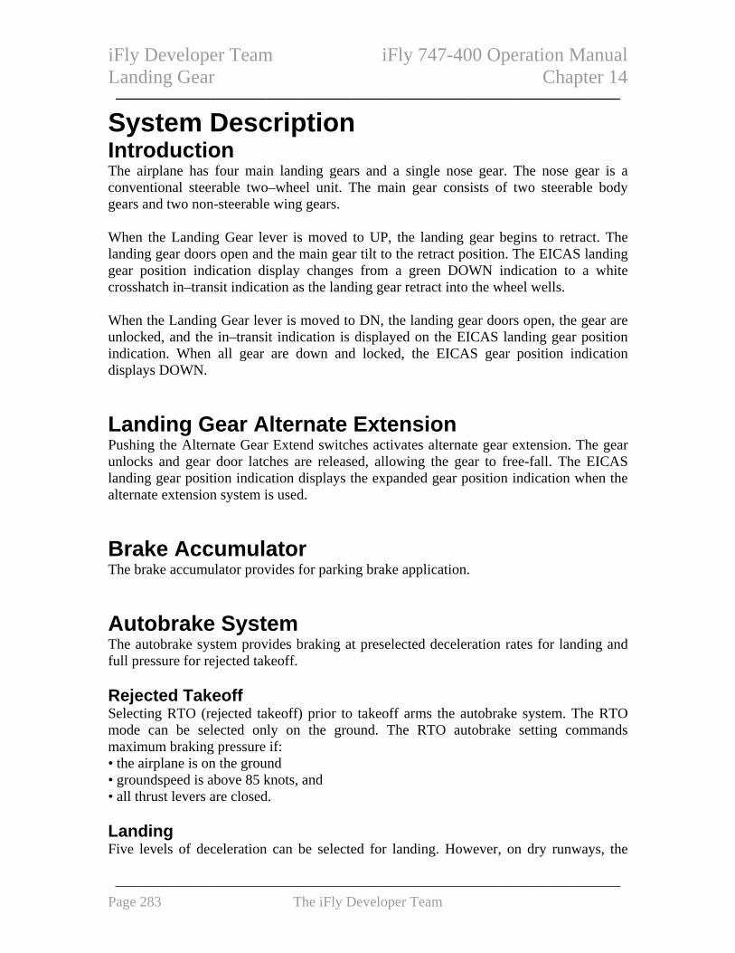
iFly Developer Team iFly 747-400 Operation Manual Landing Gear Chapter 14 ——————————————————————————————
System Description
Introduction The airplane has four main landing gears and a single nose gear. The nose gear is a conventional steerable two–wheel unit. The main gear consists of two steerable body gears and two non-steerable wing gears. When the Landing Gear lever is moved to UP, the landing gear begins to retract. The landing gear doors open and the main gear tilt to the retract position. The EICAS landing gear position indication display changes from a green DOWN indication to a white crosshatch in–transit indication as the landing gear retract into the wheel wells. When the Landing Gear lever is moved to DN, the landing gear doors open, the gear are unlocked, and the in–transit indication is displayed on the EICAS landing gear position indication. When all gear are down and locked, the EICAS gear position indication displays DOWN. Landing Gear Alternate Extension Pushing the Alternate Gear Extend switches activates alternate gear extension. The gear unlocks and gear door latches are released, allowing the gear to free-fall. The EICAS landing gear position indication displays the expanded gear position indication when the alternate extension system is used. Brake Accumulator The brake accumulator provides for parking brake application. Autobrake System The autobrake system provides braking at preselected deceleration rates for landing and full pressure for rejected takeoff. Rejected Takeoff Selecting RTO (rejected takeoff) prior to takeoff arms the autobrake system. The RTO mode can be selected only on the ground. The RTO autobrake setting commands maximum braking pressure if: • the airplane is on the ground • groundspeed is above 85 knots, and • all thrust levers are closed. Landing Five levels of deceleration can be selected for landing. However, on dry runways, the
——————————————————————————————————— Page 283 The iFly Developer Team

iFly Developer Team iFly 747-400 Operation Manual Landing Gear Chapter 14 ——————————————————————————————
maximum autobrake deceleration rate in the landing mode is less than that produced by full pedal braking. Autobrake – Disarm The system disarms immediately if any of the following occur: • DISARM or OFF position selected on Autobrake selector • autobrake fault
Brake Temperature Indication Wheel brake temperatures displayed on the GEAR synoptic display. Numerical values related to wheel brake temperature display inside each wheel/brake symbol.
EICAS Messages The following EICAS messages can be displayed. EICAS Alert Messages
Message Level Aural Condition ANTISKID OFF Advisory Antiskid power off on all wheels, or a brake
system control unit power loss occurs. AUTOBRAKES Advisory Autobrake system disarmed or inoperative, or
Autobrake selector OFF and system armed, or RTO initiated above 85 knots and brakes have not been applied.
>BRAKE SOURCE
Caution Beeper Hydraulic systems 4, 1, and 2 have low pressure.
BRAKE TEMP Advisory Any brake temperature equal to or greater than 5 units.
GEAR DISAGREE
Caution Beeper Gear position disagrees with Landing Gear lever position after normal gear extension time.
EICAS Memo Messages
Message Condition AUTOBRAKES 1, 2, 3, 4
Autobrake level selected
AUTOBRAKES MAX
Autobrakes MAX selected.
AUTOBRAKES RTO Autobrakes RTO selected. PARK BRAKE SET Parking brake valve closed.
——————————————————————————————————— Page 284 The iFly Developer Team

iFly Developer Team iFly 747-400 Operation Manual ——————————————————————————————
Intentionally Blank
——————————————————————————————————— Page 285 The iFly Developer Team

iFly Developer Team iFly 747-400 Operation Manual Warning Systems Chapter 15 ——————————————————————————————
CONTROLS AND INDICATORS.......................................... 288
ENGINE INDICATION AND CREW ALERTING SYSTEM (EICAS)................................................................................................. 288
EICAS Messages ..................................................................................................... 288
DISPLAY SELECT PANEL ........................................................ 289
GPWS ALERTS ON PFD......................................................... 290
MASTER WARNING/CAUTION RESET SWITCHES AND LIGHTS .................................................................................... 290
TRAFFIC ALERT AND COLLISION AVOIDANCE SYSTEM (TCAS)................................................................................................. 291
TCAS Controls (Transponder Panel)...................................................................... 291 TCAS PFD Vertical Guidance ................................................................................ 291 TCAS Traffic Displays ............................................................................................ 292
GROUND PROXIMITY WARNING SYSTEM (GPWS) CONTROLS................................................................................................. 293
Ground Proximity Panels ....................................................................................... 293
SYSTEM DESCRIPTION ....................................................... 294
INTRODUCTION ....................................................................... 294
ENGINE INDICATION AND CREW ALERTING SYSTEM (EICAS)................................................................................................. 294
EICAS Messages ..................................................................................................... 295 EICAS Alert messages........................................................................................ 295 EICAS Memo Messages ..................................................................................... 295 Display and Manipulation of EICAS Messages ................................................. 295
AURAL ALERTS, MASTER WARNING/CAUTION SWITCHES AND LIGHTS, AND GND PROX LIGHT ................................. 296
OVERSPEED WARNING........................................................... 297
TAKEOFF AND LANDING CONFIGURATION WARNING SYSTEM................................................................................................. 297
Takeoff Configuration Warnings ............................................................................ 297 Landing Configuration Warning............................................................................. 297
MCP SELECTED ALTITUDE ALERTS..................................... 297 Approaching MCP Selected Altitude ...................................................................... 297 Deviating From MCP Selected Altitude ................................................................. 298 MCP Selected Altitude Alert Inhibits ...................................................................... 298
——————————————————————————————————— Page 286 The iFly Developer Team

iFly Developer Team iFly 747-400 Operation Manual Warning Systems Chapter 15 —————————————————————————————— TRAFFIC ALERT AND COLLISION AVOIDANCE SYSTEM (TCAS)................................................................................................. 298
Resolution Advisories (RA) and Display................................................................. 298 Traffic Advisories (TA) and Display ....................................................................... 299 Proximate Traffic Display....................................................................................... 299 Other Traffic Display.............................................................................................. 299 TCAS PFD Vertical Guidance ................................................................................ 300 TCAS ND Messages ................................................................................................ 300 TCAS Voice Annunciations ..................................................................................... 300
GROUND PROXIMITY WARNING SYSTEM (GPWS) ALERTS 301 Introduction............................................................................................................. 301 GPWS Alerts ........................................................................................................... 302 Altitude Voice Annunciations During Approach .................................................... 303 GPWS Windshear Alert........................................................................................... 303 Immediate Windshear Warning .............................................................................. 303
ALERT INHIBITS...................................................................... 303 Alert Messages Inhibited By Other Alert Messages ............................................... 303 Alerts Inhibited Before Engine Start and After Shutdown ...................................... 304 Alerts Inhibited During Engine Start ...................................................................... 304 Alerts Inhibited During Takeoff .............................................................................. 304 TCAS Inhibits .......................................................................................................... 305 Alerts Inhibited During Landing............................................................................. 305
EICAS MESSAGES ................................................................. 305
WARNING SYSTEMS EICAS MESSAGES ............................... 305
——————————————————————————————————— Page 287 The iFly Developer Team

iFly Developer Team iFly 747-400 Operation Manual Warning Systems Chapter 15 ——————————————————————————————
Controls and Indicators
Engine Indication and Crew Alerting System (EICAS) EICAS Messages
1
EICAS DISPLAY
EICAS DISPLAY 1 Warning Messages
Displayed (red) – • highest priority alert messages • red alert messages remain displayed and cannot be canceled by pushing the
CANC switch. 2 Caution Messages
Displayed (amber) – • next highest priority alert messages after warning messages • amber alert messages can be canceled by pushing the CANC switch or recalled
by pushing the RCL switch 3 Advisory Messages
Displayed (amber) – • lowest priority alert messages; indented one space • indented one space • amber alert messages can be canceled by pushing the CANC switch or recalled
by pushing the RCL switch
4
2 3
5 6
7
——————————————————————————————————— Page 288 The iFly Developer Team

iFly Developer Team iFly 747-400 Operation Manual Warning Systems Chapter 15 ——————————————————————————————
4 Memo Messages
Displayed (white) – • reminder of selected state of controls or systems • cannot be canceled by pushing the CANC switch • EICAS alert messages have display priority over memo messages; some or all
memo messages not displayed on current EICAS message page if insufficient message lines are available below alert messages
5 Page (PG) Number
Displayed (white) – • more than one page of alert or memo messages exists • indicates the number of page selected
6 RECALL Indication
Displayed (white) – • when RCL switch pushed • remains displayed for one second after switch released
7 Secondary Engine Exceedance Cue
Displayed (cyan) – • engine parameter on secondary display is exceedanced • displayed until displayed parameter returns to normal operating range
Display Select Panel
2
GLARESHIELD
1 Cancel (CANC) Switch Push – • displays next page of caution and advisory messages when additional pages exist • cancels caution and advisory messages when last page displayed; warning and
memo messages remain displayed 2 Status (STAT) Display Switch
1 3
——————————————————————————————————— Page 289 The iFly Developer Team

iFly Developer Team iFly 747-400 Operation Manual Warning Systems Chapter 15 ——————————————————————————————
Push – displays status display on secondary EICAS. 3 Recall (RCL) Switch
Push – • redisplays all caution and advisory EICAS messages, when respective non-
normal condition exists • displays first page of messages when multiple pages exist • displays RECALL indication for one second after switch released
GPWS Alerts on PFD
1
PFD
1 Alert on PFD PULL UP (red) – GPWS PULL UP alert is occurring. WINDSHEAR (red) – • GPWS WINDSHEAR alert is occurring • all other GPWS alerts inhibited
Master WARNING/CAUTION Reset Switches and Lights
21
3
GLARESHIELD PANEL
1 Master WARNING/CAUTION Reset Switch Push – • extinguishes master WARNING lights • extinguishes master CAUTION lights • silences the aural alert that accompany the EICAS warning messages
2 Master WARNING Light
Illuminated (red) –
——————————————————————————————————— Page 290 The iFly Developer Team

iFly Developer Team iFly 747-400 Operation Manual Warning Systems Chapter 15 ——————————————————————————————
• new EICAS warning message displayed, or • red PULL UP or WINDSHEAR message displayed on PFD
3 Master CAUTION Light
Illuminated (amber) – new EICAS caution message displayed Traffic Alert and Collision Avoidance System (TCAS) TCAS Controls (Transponder Panel)
1
AFT AISLE STAND
1 Transponder Mode Selector Traffic Advisory (TA) ONLY – transponder and TCAS TA modes enabled. Provides TA data for TCAS. Traffic Advisory/Resolution Advisory (TA/RA) – transponder and TCAS TA and RA modes enabled. Provides TA and RA data for TCAS.
TCAS PFD Vertical Guidance
1
1
PFD
——————————————————————————————————— Page 291 The iFly Developer Team

iFly Developer Team iFly 747-400 Operation Manual Warning Systems Chapter 15 ——————————————————————————————
1 RA Pitch Region To Avoid Traffic (red outlined) To ensure vertical separation, the center of the airplane symbol must be outside the red outlined RA pitch regions to avoid traffic.
TCAS Traffic Displays
31
4
52
1
ND
1 Traffic Display Indicates relative position of traffic. Displayed when TCAS enabled: • filled red square indicates a resolution advisory (RA) • filled amber circle indicates a traffic advisory (TA) • filled white diamond indicates proximate traffic • unfilled white diamond indicates other traffic • number is relative altitude of traffic in hundreds of feet; not displayed when
altitude unknown • vertical motion arrow indicates traffic climbing or descending at 500 feet per
minute or greater; not displayed for vertical motion less than 500 feet per minute
——————————————————————————————————— Page 292 The iFly Developer Team

iFly Developer Team iFly 747-400 Operation Manual Warning Systems Chapter 15 ——————————————————————————————
Displayed automatically when: • a RA or TA occurs, and • TFC is not selected on either ND, and • respective ND is in MAP, MAP CTR, VOR, or APP mode
2 TCAS Mode Annunciations
TFC (cyan) – • TCAS traffic display enabled • TCAS traffic displayed in MAP, MAP CTR, APP, and VOR modes TA ONLY (cyan) – • TCAS cannot provide RAs • all traffic that would have been RAs are predicted as TAs
3 OFFSCALE Message
Displayed (red): • RA is beyond selected map range • only when TCAS enabled Displayed (amber): • TA is beyond selected map range • only when TCAS enabled
4 TRAFFIC Alert Message
Displayed: (red) – RA is occurring. Displayed: (amber) – TA is occurring, and RA is not occurring. Displayed whether TCAS traffic is displayed or not. Displayed in all ND modes and ranges.
5 TCAS No-Bearing Messages
RA (red) – data tag displayed for no-bearing RA. TA (amber) – data tag displayed for no-bearing TA. Data tag contains distance, altitude, and vertical motion arrow.
Ground Proximity Warning System (GPWS) Controls Ground Proximity Panels
3
FORWARD PANELS
1
2 4
——————————————————————————————————— Page 293 The iFly Developer Team

iFly Developer Team iFly 747-400 Operation Manual Warning Systems Chapter 15 ——————————————————————————————
1 Ground Proximity (GND PROX) Glideslope (G/S) Inhibit Switch Push – inhibits GPWS GLIDESLOPE alert when pushed below 1,000 feet radio altitude.
2 Ground Proximity (GND PROX) Light
Illuminated (amber) – • GPWS alert is occurring • Inhibited for GLIDESLOPE, or TOO LOW FLAPS, or TOO LOW GEAR alerts when respective inhibit or override switch is pushed
3 Ground Proximity (GND PROX) Flap Override (OVRD) Switch
Right click on mouse button to unveil protection box, then left click: Push (OVRD illuminated) – inhibits TOO LOW FLAPS alert.
4 Ground Proximity (GND PROX) Configuration (CONFIG)Gear (GR)
Override (OVRD) Switch Right click on mouse button to unveil protection box, then left click: Push (OVRD illuminated) – • inhibits TOO LOW GEAR alert • inhibits CONFIG GEAR alert
System Description
Introduction Warning systems consist of: • engine indication and crew alerting system (EICAS) • airspeed alerts • takeoff and landing configuration warning system • MCP selected altitude alerts • traffic collision avoidance system (TCAS) • windshear alerts • ground proximity warning system (GPWS) Engine Indication and Crew Alerting System (EICAS) EICAS consolidates engine and airplane system indications and is the primary means of displaying system indications and alerts to the flight crew.
——————————————————————————————————— Page 294 The iFly Developer Team

iFly Developer Team iFly 747-400 Operation Manual Warning Systems Chapter 15 ——————————————————————————————
EICAS Messages Systems conditions and configuration information is provided to the crew by three types of EICAS messages: • EICAS alert messages are the primary method to alert the crew to non-normal
conditions • EICAS memo messages are crew reminders of certain flight crew selected normal
conditions • EICAS status messages indicate equipment faults. EICAS Alert messages EICAS alert messages are the primary means to alert the crew to non-normal conditions, which may impact other operations during the flight. EICAS alert messages are grouped into three priority levels: warning, caution, and advisory. Prioritization is an aid to flight crew decision making when more than one EICAS alert message is displayed. EICAS warning messages are displayed red and EICAS caution and advisory messages are displayed amber. Red EICAS alert messages remain displayed and cannot be canceled by pushing the CANC switch. Amber EICAS alert messages can be canceled by pushing the CANC switch and recalled by pushing the RCL switch. EICAS Memo Messages EICAS memo messages are crew reminders of certain flight crew selected normal conditions. They display in white at the bottom of the last page of EICAS alert messages on the primary EICAS display. Display and Manipulation of EICAS Messages If more than one EICAS alert message is displayed, the messages are displayed in a list, which is grouped by priority level. EICAS warning messages are displayed in red at the top of the message list. EICAS caution messages are displayed in amber below the lowest warning message. EICAS advisory messages are displayed in amber below the lowest caution message and are indented one character so they may be distinguished from EICAS caution messages. The most recent EICAS alert message is displayed at the top of its priority group and all messages move down one display line. If a message is no longer displayed because the respective system non-normal condition no longer exists, all messages previously displayed move up one display line. If there are more messages in the list than can be displayed on one page, multiple pages are created and numbered sequentially. The page number is normally displayed at the bottom of each list. Multiple pages of EICAS caution and advisory messages can be
——————————————————————————————————— Page 295 The iFly Developer Team

iFly Developer Team iFly 747-400 Operation Manual Warning Systems Chapter 15 ——————————————————————————————
displayed one page at a time by pushing the CANC switch. If there are more EICAS warning messages in the list than can be displayed on one page, no page number is displayed and it is not possible to display other pages. In all other cases, pushing the CANC switch displays the next page of EICAS caution and advisory messages. EICAS warning messages are displayed at the top of each page. Pushing the CANC switch when the last page of the list is displayed causes all EICAS caution and advisory messages to be no longer displayed. When no EICAS caution or advisory messages are displayed, pushing the RCL switch redisplays page one of the EICAS caution and advisory messages for all system non-normal conditions and the RECALL message is displayed briefly. The most recent EICAS memo message is displayed at the bottom of the memo messages. Aural Alerts, Master WARNING/CAUTION Switches and Lights, and GND PROX Light Aural alerts, two master WARNING and CAUTION lights, and the GND PROX light call attention to the following alerts: • in the following table, params () describe crew action to silence the aural alert or
extinguish the light while the alert is occurring. Aural Alert Light Alert Calls Attention To:
Bell (Silence by pushing Master WARNING/CAUTION Reset switch.)
Master WARNING lights (Extinguish by pushing Master WARNING/CAUTION Reset switch.)
EICAS warning message: APU FIRE FIRE CARGO AFT, FWD FIRE ENG FIRE WHEEL WELL
Siren (Silence by pushing Master WARNING/CAUTION Reset switch.)
Master WARNING lights (Extinguish by pushing Master WARNING/CAUTION Reset switch.)
EICAS warning message: CABIN ALTITUDE CONFIG FLAPS CONFIG GEAR CONFIG PARK BRK CONFIG SPOILERS CONFIG STAB PILOT RESPONSE
Siren Master WARNING lights (Extinguish by pushing Master WARNING/CAUTION Reset switch.)
EICAS warning message OVERSPEED
Beeper Master CAUTION lights (Extinguish by pushing
New EICAS caution message, except:
——————————————————————————————————— Page 296 The iFly Developer Team

iFly Developer Team iFly 747-400 Operation Manual Warning Systems Chapter 15 ——————————————————————————————
Master WARNING/CAUTION Reset switch.)
ENG SHUTDOWN
Overspeed Warning The EICAS alert message OVERSPEED is displayed if VMO/MMO is exceeded. The message remains displayed until airspeed is reduced below VMO/MMO. Takeoff And Landing Configuration Warning System The takeoff and landing configuration warning system alerts that the airplane is not configured for a normal takeoff or a normal landing. The warning system also provides takeoff and landing configuration and stall warnings. Takeoff Configuration Warnings The respective EICAS alert message CONFIG is displayed if: • airplane is on the ground, and • FUEL CONTROL switches are in RUN position, and • engine two or three thrust is in takeoff range, and • any of the following configurations exist;
• flaps not in a takeoff position, or • parking brake is set, or • Speedbrake lever not in DN detent, or • stabilizer trim not in takeoff range
Landing Configuration Warning The landing configuration warning system alerts the crew the landing gear is not extended for landing. The EICAS warning message CONFIG GEAR is displayed if: • the airplane is in flight, and • any landing gear is not down and locked, and • any of the following configurations exist;
• any Thrust lever is closed and radio altitude is less than 800 ft, or • Flap lever in a landing position (Flaps 25 or Flaps 30)
MCP Selected Altitude Alerts Altitude alerting occurs when approaching or deviating from altitude selected on the MCP. Approaching MCP Selected Altitude Between 900 feet and 300 feet prior to reaching the selected altitude.
——————————————————————————————————— Page 297 The iFly Developer Team

iFly Developer Team iFly 747-400 Operation Manual Warning Systems Chapter 15 ——————————————————————————————
Deviating From MCP Selected Altitude When departing the selected altitude by 300 feet, the EICAS alert message ALTITUDE ALERT is displayed. The message no longer displayed when: • subsequently re-approaching to within 300 feet of the selected altitude, or • departing more than 900 feet from the selected altitude. MCP Selected Altitude Alert Inhibits MCP selected altitude alerts are inhibited when: • glideslope captured, or • landing flaps selected and landing gear down and locked. Traffic Alert and Collision Avoidance System (TCAS) TCAS alerts the crew to possible conflicting traffic. TCAS provides advisory, flight path guidance, and traffic displays of the other aircraft to the flight crew. TCAS operation is independent of ground–based air traffic control. TCAS provides advisories and traffic displays: • resolution advisory (RA) and display • traffic advisory (TA) and display • proximate traffic display • other traffic display TCAS messages and TCAS traffic symbols can be displayed on the ND in the map, map centered, VOR, and approach modes. TCAS messages and TCAS traffic symbols cannot be displayed on the ND in the VOR–centered, approach–centered, or plan modes. Resolution Advisories (RA) and Display A RA is a prediction another aircraft will enter TCAS conflict airspace within approximately 15 to 35 seconds. When TCAS predicts an RA: • a TCAS voice annunciation sounds • TCAS PFD vertical guidance is displayed • the TCAS red message TRAFFIC is displayed on the ND. When the TCAS cyan message TFC is displayed on the ND, and the RA is within the display range of the ND, the TCAS RA traffic symbol and its accompanying data tag are displayed on the ND. The TCAS RA traffic symbol is a filled red square. The RA data tag contains the altitude and the vertical motion arrow.
——————————————————————————————————— Page 298 The iFly Developer Team

iFly Developer Team iFly 747-400 Operation Manual Warning Systems Chapter 15 ——————————————————————————————
The red RA label is displayed below the red message, TRAFFIC, and the RA data tag information is displayed to the right of the label. The RA data tag contains the distance, altitude, and the vertical motion arrow. When the RA is further from the airplane than the ND range currently displayed, the TCAS red message OFFSCALE is displayed on the ND. Traffic Advisories (TA) and Display A TA is a prediction another aircraft will enter the conflict airspace in 15 to 45 seconds. TAs assist the flight crew in establishing visual contact with the other aircraft. When TCAS predicts a TA: • the TCAS voice annunciation TRAFFIC, TRAFFIC sounds once • the TCAS amber message TRAFFIC is displayed on the ND. When the TCAS cyan message TFC is displayed on the ND and the TA is within the display range of the ND, the TCAS TA traffic symbol and its accompanying data tag are displayed on the ND. The TA traffic symbol is a filled amber circle. The TA data tag contains the altitude and vertical motion arrow. The amber TA label is displayed below the TRAFFIC message, and the TA data tag information is displayed to the right of the label. The TA labels are displayed below the RA labels. The TA data tag contains the distance, altitude, and vertical motion arrow. When the TA is further from the airplane than the ND range currently displayed, the TCAS amber message OFFSCALE is displayed on the ND. Proximate Traffic Display Proximate traffic is another aircraft that is neither an RA nor a TA but is within: • six miles • 1,200 feet vertically When the TCAS cyan message TFC is displayed on the ND, and the proximate traffic is within the ND display range, the TCAS proximate traffic symbol is displayed on the ND. The TCAS proximate traffic symbol is a filled white diamond. Other Traffic Display Other traffic is another aircraft that is within the ND display limits but is not an RA, a TA, or proximate traffic. When the TCAS cyan message TFC is displayed on the ND and the other traffic is within
——————————————————————————————————— Page 299 The iFly Developer Team

iFly Developer Team iFly 747-400 Operation Manual Warning Systems Chapter 15 ——————————————————————————————
the ND display range, then the TCAS other traffic symbol is displayed on the ND. The TCAS other traffic symbol is a hollow white diamond. TCAS PFD Vertical Guidance When TCAS predicts an RA, TCAS PFD vertical guidance is displayed for a traffic avoidance maneuver to ensure vertical separation. Adjusting or maintaining a pitch attitude outside the red outlined RA pitch region ensures traffic avoidance. TCAS ND Messages ND Message Color Description
TFC Cyan TCAS traffic display enabled. Inhibited if following TCAS messages are displayed: TCAS FAIL, TCAS OFF,
TRAFFIC Amber TA is occurring. OFFSCALE Amber TA is occurring at range greater than current
ND range. Replaced by red OFFSCALE when RA is also occurring at range greater than current ND range.
TRAFFIC Red RA is occurring. OFFSCALE Red RA is occurring at range greater than current
ND range. TA ONLY Cyan TCAS can not provide RAs. All traffic that
would have been RAs are predicted as TAs. TCAS FAIL Amber TCAS failed. TCAS OFF Amber TFC switch pushed to display traffic but TCAS
not selected on transponder panel. TCAS Voice Annunciations
Voice Annunciation Condition TRAFFIC, TRAFFIC New TA, initial voice annunciation. MONITOR VERTICAL SPEED, MONITOR VERTICAL SPEED
New RA, initial voice annunciation. Present pitch attitude is outside the red RA regions.
CLIMB, CLIMB, CLIMB
New RA, initial voice annunciation. Present pitch attitude is within the red RA regions.
CLIMB, CROSSING CLIMB, CLIMB, CROSSING CLIMB
New RA, initial voice annunciation. Present pitch attitude is within the red RA regions. Airplane will climb through the altitude of the traffic.
DESCEND, DESCEND, DESCEND
New RA, initial voice annunciation. Present pitch attitude is within the red RA regions.
——————————————————————————————————— Page 300 The iFly Developer Team

iFly Developer Team iFly 747-400 Operation Manual Warning Systems Chapter 15 ——————————————————————————————
DESCEND, CROSSING DESCEND DESCEND, CROSSING DESCEND
New RA, initial voice annunciation. Present pitch attitude is within the red RA regions. Airplane will descend through the altitude of the traffic.
INCREASE CLIMB, INCREASE CLIMB,
INCREASE DESCENT, INCREASE DESCENT,
Existing RA, TCAS requires change in vertical rate. Present pitch attitude is within the red RA regions.
DESCEND, DESCEND NOW, DESCEND, DESCEND NOW
Existing RA, previous TCAS vertical guidance was to climb. Present pitch attitude is within the red RA regions.
CLIMB, CLIMB NOW, CLIMB, CLIMB NOW
Existing RA, previous TCAS vertical guidance was to descend. Present pitch attitude is within the red RA regions.
CLEAR OF CONFLICT TCAS PFD vertical guidance is no longer displayed and traffic changes to a TA symbol. Separation is increasing and the RA will not occur. However, the voice annunciation will not sound if TCAS can no longer predict the track of the RA aircraft.
Ground Proximity Warning System (GPWS) Alerts Introduction GPWS provides alerts for potentially hazardous flight conditions involving imminent impact with the ground. GPWS alerts are based on radio altitude, barometric altitude, IRS, airspeed, glide slope deviation, and airplane configuration. GPWS alerts are provided for the following: • altitude loss after takeoff or go-around • excessive and severe descent rate • excessive terrain closing rate • unsafe terrain clearance when not in the landing configuration • excessive deviation below an ILS glide slope • altitude advisories • windshear. GPWS warning alerts are accompanied by the Master WARNING light illuminating and voice aural alerts. GPWS caution alerts are accompanied by the ground proximity light illuminating and voice aural alerts. If illuminated, pushing a Master WARNING/CAUTION Reset switch resets the Master WARNING lights but does not inhibit the GPWS warning.
——————————————————————————————————— Page 301 The iFly Developer Team

iFly Developer Team iFly 747-400 Operation Manual Warning Systems Chapter 15 ——————————————————————————————
The ground proximity light illuminating accompanies GPWS caution alerts. The master CAUTION lights do not illuminate for GPWS caution alerts. GPWS alerts are prioritized based on the level of hazard and the required flight crew response. A windshear warning alert inhibits all other GPWS alerts. GPWS Alerts Aural Alert Visual Alert Description DON’T SINK GND PROX light Altitude loss with flaps and/or gear up after
takeoff or go-around. GLIDE SLOPE GND PROX light Excessive deviation below glide slope.
Volume and repetition rate increase as deviation increases. Pushing the GND PROX G/S INHIB switch inhibits the alert when pushed below 1,000 feet radio altitude.
PULL UP Red PULL UP message on both PFDs Master WARNING lights GND PROX light
Follows SINK RATE alert when descent rate becomes severe, or follows TERRAIN alert with flaps and/or gear not in landing configuration when excessive terrain closing rate continues.
SINK RATE GND PROX light Excessive descent rate. TERRAIN GND PROX light Excessive terrain closing rate. TOO LOW, FLAPS
GND PROX light Unsafe terrain clearance with flaps not in landing configuration at low altitude and airspeed. Pushing the GRND PROX FLAP OVRD switch to OVRD inhibits the alert.
TOO LOW, GEAR
GND PROX light Unsafe terrain clearance with gear not in landing configuration at low altitude and airspeed with gear not down. Pushing the GRND PROX GEAR OVRD switch to OVRD inhibits the alert.
TOO LOW, TERRAIN
GND PROX light Follows DON’T SINK alert with gear and/or flaps up after takeoff or go-around for altitude loss at low altitude, or unsafe terrain clearance with gear and/or flaps not in landing configuration at low altitude and airspeed.
——————————————————————————————————— Page 302 The iFly Developer Team

iFly Developer Team iFly 747-400 Operation Manual Warning Systems Chapter 15 ——————————————————————————————
Pushing the GRND PROX FLAP OVRD switch to OVRD inhibits the alert, when the alert is due to flaps not in landing position. Pushing the GRND PROX GEAR OVRD switch to OVRD inhibits the alert, when the alert is due to gear not down.
Altitude Voice Annunciations During Approach GPWS provides the following altitude voice annunciations during approach: • 100 feet – ONE HUNDRED • 50 feet–FIFTY • 30 feet – THIRTY • 10 feet – TEN GPWS Windshear Alert Windshear alerts are enabled during takeoff, approach, and landing: • GPWS provides an immediate windshear alert when an excessive downdraft or tailwind
is occurring The master WARNING light illuminating accompanies Windshear warning alerts. Immediate Windshear Warning Aural Alert Visual Alert Description Two–tone siren followed by WINDSHEAR, WINDSHEAR, WINDSHEAR
Red WINDSHEAR on PFD Red WINDSHEAR message on ND Master WARNING lights
Excessive windshear detected by GPWS. Enabled below 1,500 feet radio altitude. GPWS windshear detection begins at rotation.
Alert Inhibits Alerts are inhibited when they are operationally unnecessary or inappropriate. Alerts are also inhibited during part of the takeoff to prevent distracting the crew. Alert Messages Inhibited By Other Alert Messages Some EICAS alert messages are inhibited if another related alert message is displayed. For example, individual fuel or hydraulic pump pressure messages are inhibited if a hydraulic system pressure message is displayed.
——————————————————————————————————— Page 303 The iFly Developer Team

iFly Developer Team iFly 747-400 Operation Manual Warning Systems Chapter 15 ——————————————————————————————
Alerts Inhibited Before Engine Start and After Shutdown Alert Inhibited For Message Inhibit Occurs
Master CAUTION lights Beeper
For all EICAS caution messages
On the ground, and all FUEL CONTROL switches CUTOFF.
Respective EICAS messages: ELEC GEN OFF ENG CONTROL, ENG EEC MODE ENG FAIL ENG OIL PRESS
For EICAS caution messages: ENG SHUTDOWN
On the ground, and respective FUEL CONTROL switch in CUTOFF or Engine Fire switch out.
Alerts Inhibited During Engine Start
Alert Inhibited Inhibit Begins Inhibit Ends All new EICAS caution and advisory messages, except: ENG AUTOSTART ENG SHUTDOWN
Engine START switch pulled.
Engine reaches idle RPM,
Alerts Inhibited During Takeoff
Alert Inhibited For Message Inhibit Begins Inhibit Ends
Master CAUTION lights Beeper
All EICAS caution messages
80 knots airspeed
400 feet radio altitude
All EICAS advisory messages
(Messages are inhibited)
80 knots airspeed
400 feet radio altitude
Master WARNING lights Bell
FIRE V1 400 feet radio altitude
Master WARNING lights Siren
CABIN ALTITUDE OVERSPEED
V1 400 feet radio altitude
Master WARNING lights Siren
EICAS warning message CONFIG GEAR
Lift-off 800 feet radio altitude
If the Master WARNING lights are illuminated and the siren or fire bell sound before reaching V1, they continue to be illuminated and to sound when V1 is exceeded. If the Master CAUTION lights are illuminated before reaching V1, they continue to be illuminated when V1 is exceeded If an EICAS warning or caution message continues to be displayed when the inhibit ends, the respective Master WARNING or CAUTION lights illuminate and aural alert sounds.
——————————————————————————————————— Page 304 The iFly Developer Team

iFly Developer Team iFly 747-400 Operation Manual Warning Systems Chapter 15 ——————————————————————————————
TCAS Inhibits
Alert Inhibited Inhibited INCREASE DESCENT RAs Below approximately 1,500 feet radio altitude. DESCENT RAs Below approximately 1,100 feet radio altitude. All RAs Below approximately 1,000 feet radio altitude.
When RA selected on panel, TCAS switches automatically to TA only mode. And TCAS message TA ONLY is displayed on ND.
All TCAS voice alerts Below approximately 1,000 feet radio altitude. All TCAS alerts. GPWS and windshear warnings. Alerts Inhibited During Landing
Alert Inhibited For Message Inhibit Begins Inhibit Ends
EICAS alert message WINDSHEAR SYS
(Message is inhibited)
400 feet radio altitude Airspeed less than 80 knots
Master CAUTION lights Beeper
All EICAS caution messages, except: AUTOPILOT AUTOTHROTTLE DISC NO AUTOLAND SPEEDBRAKES EXT
LAND 2 or LAND 3 displayed on PFD, and 200 feet radio attitude
Airspeed less than 75 knots,
EICAS Messages The following EICAS messages can be displayed. Warning Systems EICAS Messages
Message Level Aural Condition >CONFIG FLAPS Warning Siren Flaps are not in a takeoff position
when airplane is on the ground, airspeed is less than V1, three or more Fuel Control switches are in RUN, and engine 2 or 3 thrust is in takeoff range.
>CONFIG GEAR Warning Siren Any landing gear is not down and
——————————————————————————————————— Page 305 The iFly Developer Team

iFly Developer Team iFly 747-400 Operation Manual Warning Systems Chapter 15 ——————————————————————————————
locked when any Thrust lever is closed below 800 feet radio altitude or when flaps are in a landing position.
>CONFIG PARK BRK Warning Siren Parking brake is set when airplane is on the ground, airspeed is less than V1, three or more Fuel Control switches are in RUN, and engine 2 or 3 thrust is in takeoff range.
>CONFIG SPOILERS Warning Siren Speedbrake lever is not DOWN when airplane is on the ground, airspeed is less than V1, three or more Fuel Control switches are in RUN, and engine 2 or 3 thrust is in takeoff range.
>CONFIG STAB Warning Siren Stabilizer is not within the greenband when airplane is on the ground, airspeed is less than V1, three or more Fuel Control switches are in RUN, and engine 2 or 3 thrust is in takeoff range.
>TCAS OFF Advisory TCAS mode (TA or TA/RA) not selected.
>TCAS SYSTEM Advisory TCAS has failed. >ALTITUDE ALERT Caution Beeper Airplane has deviated more than
300 feet from MCP selected altitude.
>OVERSPEED Warning Siren Airspeed exceeds Vmo/Mmo.
——————————————————————————————————— Page 306 The iFly Developer Team

iFly Developer Team iFly 747-400 Operation Manual ——————————————————————————————
Intentionally Blank
——————————————————————————————————— Page 307 The iFly Developer Team

iFly Developer Team iFly 747-400 Operation Manual Central Maintenance Computer System Chapter 16 ——————————————————————————————
CENTRAL MAINTENANCE COMPUTER SYSTEM........ 309
CONTROLS AND INDICATORS................................................. 309 Access to CMC page ............................................................................................... 309 CMC MENU............................................................................................................ 309 PRESENT LEG FAULTS ........................................................................................ 310 Detailed failure information page .......................................................................... 311 EICAS MAINT PAGES ........................................................................................... 312 EICAS PAGES CONTROL ..................................................................................... 313 SNAPSHOT LIST .................................................................................................... 314
EICAS MAINTENANCE PAGE ......................................... 314 Typical EICAS MAINTENANCE PAGE ................................................................. 315 ECS EICAS Maintenance Page .............................................................................. 316 ELECTRICAL EICAS Maintenance Page .............................................................. 316 Flight Control EICAS Maintenance Page .............................................................. 317 Fuel EICAS Maintenance Page .............................................................................. 317 Hydraulic EICAS Maintenance Page ..................................................................... 318 Config EICAS Maintenance Page........................................................................... 318 Gear EICAS Maintenance Page ............................................................................. 319 APU EICAS Maintenance Page.............................................................................. 319 EPCS EICAS Maintenance Page ............................................................................ 320 Performance EICAS Maintenance Page................................................................. 320
FAILURE SYSTEM.................................................................... 321 FAILURE MENU.................................................................................................... 321 ADD/CLEAR FAILURES........................................................................................ 322 FAILURE PAGES ................................................................................................... 322 Failure setting page ................................................................................................ 323
SYSTEM DESCRIPTION ....................................................... 324
INTRODUCTION ....................................................................... 324
——————————————————————————————————— Page 308 The iFly Developer Team

iFly Developer Team iFly 747-400 Operation Manual Central Maintenance Computer System Chapter 16 ——————————————————————————————
Central Maintenance Computer System Controls and Indicators Access to CMC page
1
CDU
1 <CMC It will display when – • airplane is on the ground or • fly higher than 10000ft
Push – Access into CMC control system CMC MENU The CDU MENU provides access to the page displays of each system that uses the CDU for crew control and display interface. Pushing the MENU key on the CDU accesses the CDU MENU.
1
2
CDU
——————————————————————————————————— Page 309 The iFly Developer Team

iFly Developer Team iFly 747-400 Operation Manual Central Maintenance Computer System Chapter 16 ——————————————————————————————
1 PRESENT LEG FAULTS Push – Access into PRESENT LEG FAULTS page. PRESENT LEG FAULTS PRESENT LEG FAULTS page is used to store records from all non-functional devices
1
2
3 4 5
CDU
1 EICAS message level Display the warning level associated with this failure message on EICAS 2 Name of failure device
Display the name of failure device.
Push – display the failure information in detail. 3 Code of failure device
Display the name of failure device. 4 ERASE ALL
Delete all malfunction log. 5 RETURN
Go back to CMC MENU.
——————————————————————————————————— Page 310 The iFly Developer Team

iFly Developer Team iFly 747-400 Operation Manual Central Maintenance Computer System Chapter 16 ——————————————————————————————
Detailed failure information page
1 8
CDU
1 CMCS MESSAGE Display current CMCS message
2 CMCS MESSAGE NUMBER
Display current CMCS message number. 3 EICAS MESSAGE
Display the warning message for the current failure device from EICAS. 4 READ SNAPSHOT
Push - Display the snapshot of failure system on SECONDARY EICAS DISPLAY
5 RETURN
Go back to PRESENT LEG FAULTS page. 6 LEVEL OF EICAS MESSAGE Display the warning level associated with this failure message on EICAS. 7 FAULT CODE Display the fault code of this failure. 8 FLIGHT PHASE
Flight phase during which the fault occurred 9 LEVEL OF FAULT
This indication shows (HRD), intermittent (INT).
2 3 4 5
6 9
7
——————————————————————————————————— Page 311 The iFly Developer Team

iFly Developer Team iFly 747-400 Operation Manual Central Maintenance Computer System Chapter 16 ——————————————————————————————
EICAS MAINT PAGES The EICAS MAINT PAGES menu shows all systems that have EICAS maintenance pages.
1
2 4 3
1
2 4 3
1
2 4 3
——————————————————————————————————— Page 312 The iFly Developer Team

iFly Developer Team iFly 747-400 Operation Manual Central Maintenance Computer System Chapter 16 ——————————————————————————————
1 EICAS MAINT PAGE list Display device list which are connected to EICAS MAINT PAGE
Push – Access to EICAS PAGES CONTROL page 2 ERASE ALL
Delete snapshots of all systems. 3 RETURN
Push – Return back to CMC MENU 4 RECORD ALL
Record snapshot of all systems. EICAS PAGES CONTROL
1
2 3 4 5 6 7
CDU
1 SYSTEM NAME Display the name of current system.
2 DISPLAY
Push this key to show the real-time maintenance page on the secondary EICAS. 3 RECORD
Push this key to make a manual snapshot of the maintenance page. 4 MANUAL SNAPSHOTS Push this key to show a list of available manual snapshots of the maintenance page. 5 AUTO SNAPSHOTS
Push this key to show a list of available auto snapshots of the maintenance page.
——————————————————————————————————— Page 313 The iFly Developer Team

iFly Developer Team iFly 747-400 Operation Manual Central Maintenance Computer System Chapter 16 ——————————————————————————————
6 ERASE SYSTEM
Push this key to erase a list of manual and auto snapshots for this system. 7 RETURN
Push – Return back CMC MENU SNAPSHOT LIST
1
2
3
CDU 1 type of SNAPSHOT
Display current the type of snapshots list. 2 SNAPSHOT list
Snapshots are shown in flight leg sequence with the date and time of the snapshot. The last snapshot is shown first.
Push – display snapshot on secondary EICAS. 3 RETURN
Push – Return to EICAS PAGES CONTROL. EICAS MAINTENANCE PAGE Due to limitation of flight simulator, parts of data shown on EICAS MAINTENANCE PAGE are only for simulation matter.
——————————————————————————————————— Page 314 The iFly Developer Team

iFly Developer Team iFly 747-400 Operation Manual Central Maintenance Computer System Chapter 16 ——————————————————————————————
Typical EICAS MAINTENANCE PAGE
1
2
3
4
SECONDARY EICAS DISPLAY
1 NAME OF MAINTENANCE PAGE Display the name of current MAINTENANCE PAGE
2 MAINTENANCE page types MAN – current data display is manual snapshot.
AUTO – current data display is auto snapshot
BLANK – current data display is in real-time. 3 Page data Display current system data in detail. 4 Time
Display current GMT time or the time when snapshot occurs.
——————————————————————————————————— Page 315 The iFly Developer Team

iFly Developer Team iFly 747-400 Operation Manual Central Maintenance Computer System Chapter 16 ——————————————————————————————
ECS EICAS Maintenance Page
SECONDARY EICAS DISPLAY
ELECTRICAL EICAS Maintenance Page
SECONDARY EICAS DISPLAY
——————————————————————————————————— Page 316 The iFly Developer Team

iFly Developer Team iFly 747-400 Operation Manual Central Maintenance Computer System Chapter 16 ——————————————————————————————
Flight Control EICAS Maintenance Page
SECONDARY EICAS DISPLAY
Fuel EICAS Maintenance Page
SECONDARY EICAS DISPLAY
——————————————————————————————————— Page 317 The iFly Developer Team

iFly Developer Team iFly 747-400 Operation Manual Central Maintenance Computer System Chapter 16 ——————————————————————————————
Hydraulic EICAS Maintenance Page
SECONDARY EICAS DISPLAY
Config EICAS Maintenance Page
SECONDARY EICAS DISPLAY
——————————————————————————————————— Page 318 The iFly Developer Team

iFly Developer Team iFly 747-400 Operation Manual Central Maintenance Computer System Chapter 16 ——————————————————————————————
Gear EICAS Maintenance Page
SECONDARY EICAS DISPLAY
APU EICAS Maintenance Page
SECONDARY EICAS DISPLAY
——————————————————————————————————— Page 319 The iFly Developer Team

iFly Developer Team iFly 747-400 Operation Manual Central Maintenance Computer System Chapter 16 ——————————————————————————————
EPCS EICAS Maintenance Page
SECONDARY EICAS DISPLAY
Performance EICAS Maintenance Page
SECONDARY EICAS DISPLAY
——————————————————————————————————— Page 320 The iFly Developer Team
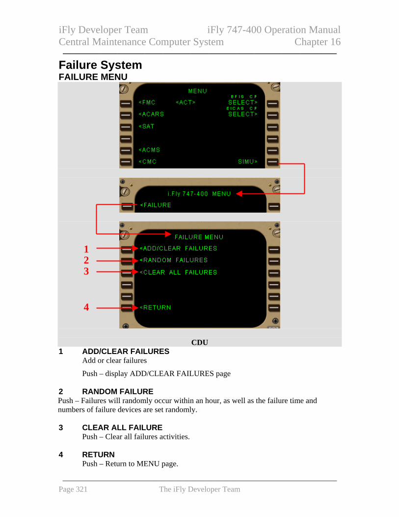
iFly Developer Team iFly 747-400 Operation Manual Central Maintenance Computer System Chapter 16 ——————————————————————————————
Failure System FAILURE MENU
1 2 3
4
CDU
1 ADD/CLEAR FAILURES Add or clear failures
Push – display ADD/CLEAR FAILURES page 2 RANDOM FAILURE Push – Failures will randomly occur within an hour, as well as the failure time and numbers of failure devices are set randomly. 3 CLEAR ALL FAILURE Push – Clear all failures activities. 4 RETURN Push – Return to MENU page.
——————————————————————————————————— Page 321 The iFly Developer Team

iFly Developer Team iFly 747-400 Operation Manual Central Maintenance Computer System Chapter 16 ——————————————————————————————
ADD/CLEAR FAILURES
1 1
2
CDU
1 SYSTEM LIST Display system list.
Push – Access to particular page associated with one system device. 2 RETURN Push – Return to FAILURE MENU page. FAILURE PAGES
1
CDU
1 FAILURE LIST Display failure list
2 3
——————————————————————————————————— Page 322 The iFly Developer Team

iFly Developer Team iFly 747-400 Operation Manual Central Maintenance Computer System Chapter 16 ——————————————————————————————
Push – Access to failure setting page. 2 RETURN Push – Return to FAILURE MENU page. 3 CLEAR SYSTEM
Clear all failure system activities. Failure setting page
CDU 1 OFF Push – Turn off current failure. 2 IN XXX MINS Set the time counter for a failure which will occur. The effective time rang is between 0 and 999. 0 means the failure will occur immediately. 3 <SEL> Display current status of failure. 4 RETURN Push – Return to FAILURE MENU page.
1 3 2
4
——————————————————————————————————— Page 323 The iFly Developer Team

iFly Developer Team iFly 747-400 Operation Manual Central Maintenance Computer System Chapter 16 ——————————————————————————————
System Description Introduction The CMCS collects, stores, and displays maintenance information. The Central Maintenance Computer System (CMCS) interfaces with all major avionics, electrical, and mechanical systems installed on the airplane. The CMCS provides fault consolidation to combine multiple fault indications when a single fault is reported by multiple subsystems. Approximately 500 of CMCS fault messages can be stored in CMCS memory. The primary crew interface with the CMCS is through the control display units (CDUs) which are part of the Flight Management Computer System (FMCS). The EICAS maintenance pages function provides the way to show an EICAS maintenance page on the secondary EICAS display. The EICAS PAGE CONTROL menu provides control over the display of EICAS maintenance pages.
——————————————————————————————————— Page 324 The iFly Developer Team