hyundai terracan - owner's manual uk (2/11)
DESCRIPTION
Hyundai Terracan - Owner's Manual UK (2/11)TRANSCRIPT
Fuel Recommendations ............................................... 1-2Running In Your Hyundai .............................................. 1-4Immobiliser System ...................................................... 1-5Door Locks ................................................................... 1-9Theft-Alarm System .....................................................1-11Power Windows...........................................................1-14Seats ...........................................................................1-16Seat Belts ....................................................................1-25Child Restraint System ................................................1-31Supplemental Restraint (AIRBAG) System .................1-40Instrument Cluster and Indicator Lights .......................1-46Warning and Indicator Lights .......................................1-50Multi-Function Switch ..................................................1-60Windscreen Wiper/Washer Switch ..............................1-63Sunroof ........................................................................1-70Mirror ...........................................................................1-75Bonnet Release ...........................................................1-83Cruise Control ..............................................................1-86Heating and Cooling Control ........................................1-89Stereo Sound System ...............................................1-105Antenna .....................................................................1-107
CONTROLS AND EQUIPMENT
11
1CONTROLS AND EQUIPMENT
2
CAUTION:The vehicle warranty will not extendto damage arising from the use ofincorrect fuels.
DIESEL ENGINES
Diesel fuel of 52 to 54 cetane is thecorrect rating to use in your HyundaiTerracan. If two types of diesel fuel areavailable, use summer or winter fuelproperly according to the following tem-perature conditions.o Above 23°F (-5°C) ... Summer type
diesel fuel.o Below 23°F (-5°C) ... Winter type
diesel fuel.
The use of leaded fuel in this vehicle willresult in irreversible pollution of thecatalyst element. Such pollution willprevent correct operation of the cata-lyst and give rise to increased operatingtemperatures leading to the catalystelement melting and restricting the ex-haust flow along with an increase inexhaust emission levels.
Watch the fuel level in the tank verycarefully : If the engine stops due to fuelfailure, the circuits must be completelypurged to permit restarting.
CAUTION:Do not let any petrol or water enterthe tank. If this happens, the tankshould be completely drained andthe fuel lines should all be cleanedout. This will stop the fuel pumpfrom becoming contaminated.
ZB010C1-E
"Alternative fuels"
Fuels which contain methanol or etha-nol must not be used.
FUEL RECOMMENDATIONS
B010A01HP-EAT
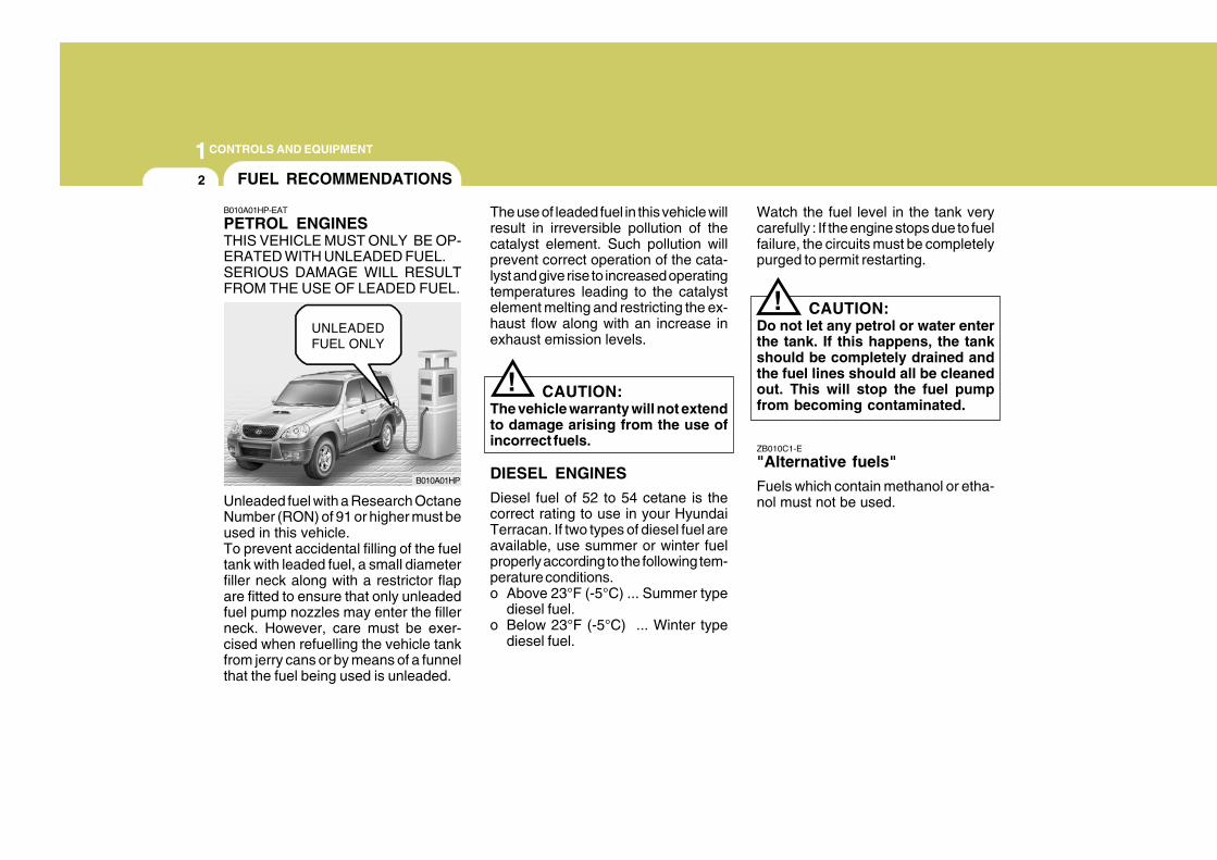
PETROL ENGINESTHIS VEHICLE MUST ONLY BE OP-ERATED WITH UNLEADED FUEL.SERIOUS DAMAGE WILL RESULTFROM THE USE OF LEADED FUEL.
Unleaded fuel with a Research OctaneNumber (RON) of 91 or higher must beused in this vehicle.To prevent accidental filling of the fueltank with leaded fuel, a small diameterfiller neck along with a restrictor flapare fitted to ensure that only unleadedfuel pump nozzles may enter the fillerneck. However, care must be exer-cised when refuelling the vehicle tankfrom jerry cans or by means of a funnelthat the fuel being used is unleaded.
B010A01HP
!
!UNLEADEDFUEL ONLY
1CONTROLS AND EQUIPMENT
3
ZB010D1-E
Operation in Foreign Countries
Drivers of vehicles which are to beoperated in foreign countries mustsatisfy themselves that:
o The vehicle meets all local regula-tions with respect to insurance, speci-fications etc..
o The correct types and grades of fuelare available for satisfactory opera-tion of the vehicle.
ZB010F2-A
FUELS FOR CLEANER AIR
To help contribute to cleaner air,Hyundai recommends that you usefuels treated with detergent additives,which help to prevent deposit forma-tion in the engine. These fuels will helpthe engines run cleaner and the Emis-sion Control System performance.
BEFORE ENTERING THE VE-HICLE
YB020A1-E
o Ensure that all windows, mirrorsand lamps are clean.
o Check condition of all tyres.o Ensure that no fluid leaks are evi-
dent.o Ensure that the area around the
vehicle is clear before driving off.
AFTER ENTERING THE VE-HICLE
YB020B1-E
o Ensure that all occupants fastenand correctly adjust seat belts.
o Ensure that seat and headrestraintpositions are adjusted for optimumsafety, control and comfort.
o Adjust interior and exterior rear viewmirrors.
o Verify correct operation of lamps,horn and other electrical equipment.
o Ensure that warning lamps illumi-nate when ignition is turned on.
NOTE:Fluid levels such as engine oil, en-gine coolant, brake and windscreenwasher fluid should be checkeddaily or at each refuelling, whicheveroccurs sooner.
1CONTROLS AND EQUIPMENT
4 RUNNING IN YOUR NEW HYUNDAI
B020A01FC-EAT
PETROL ENGINE
The longevity and performance of thevehicle are greatly affected by the careexercised during the first 1000 miles ofmotoring. Because of modern manu-facturing techniques, rigid guidelinesregarding maximum road speeds havebecome unnecessary. However, cer-tain precautions should be observed inorder to obtain the best possible per-formance and useful life from the ve-hicle.
1) Do not race the engine without aload (i.e revving the engine in neu-tral).
2) During the first 500 miles the maxi-mum engine speed should be re-stricted to 3000 rpm and graduallyincreased thereafter.
3) Avoid prolonged constant speedoperation. The internal componentsof the engine will become morequickly run in if the operation speedis varied during the running in pe-riod.
4) Never allow the engine to labour. Usethe gearbox freely and avoid largethrottle openings when the enginespeed is below 1500 rpm.
5) Avoid rapid acceleration and maxi-mum throttle openings.
6) Avoid harsh braking during the first100 miles of urban motoring or 1000miles of motorway driving to allowthe friction facings of the brake padsand shoes to bed against the discsand drums properly.
7) No trailer towing should be under-taken during the running-in period.
1) Do not race the engine without aload (i.e revving the engine in neu-tral).
2) During the first 600 miles the maxi-mum engine speed should be re-stricted to 3000 rpm and graduallyincreased thereafter. And while driv-ing, keep under three quarters ofmaximum vehicle speed.
3) Avoid prolonged constant speedoperation. The internal componentsof the engine will become morequickly run in if the operation speedis varied during the running in pe-riod.
4) Never allow the engine to labour.Use the gearbox freely and avoidlarge throttle openings when theengine speed is below 1500 rpm.
5) Avoid rapid acceleration and maxi-mum throttle openings.
6) Avoid harsh braking during the first100 miles of urban motoring or 1000miles of motorway driving to allowthe friction facings of the brake padsand shoes to bed against the discsand drums properly.
7) No trailer towing should be under-taken during the running-in period.
B020B01FC-EAT
DIESEL ENGINE
The longevity and performance of thevehicle are greatly affected by the careexercised during the first 1000 miles ofmotoring. Because of modern manu-facturing techniques, rigid guidelinesregarding maximum road speeds havebecome unnecessary. However, cer-tain precautions should be observed inorder to obtain the best possible per-formance and useful life from the ve-hicle.
1CONTROLS AND EQUIPMENT
5
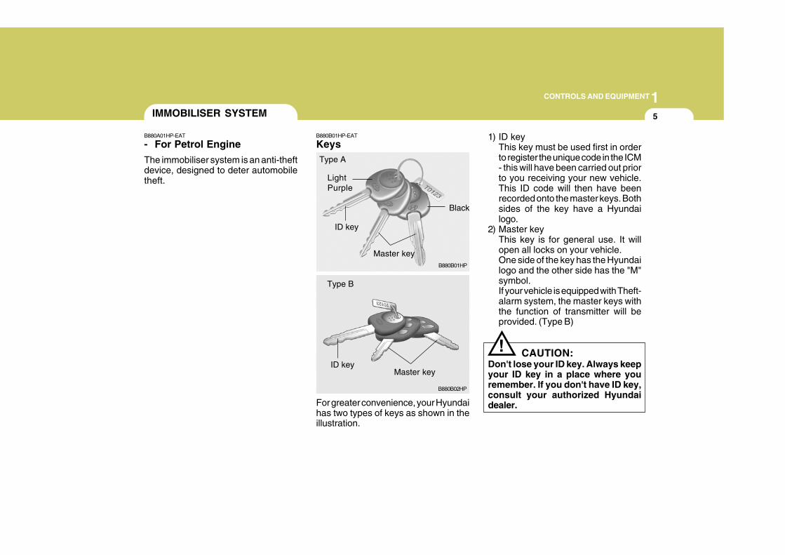
B880B01HP-EAT
Keys
For greater convenience, your Hyundaihas two types of keys as shown in theillustration.
1) ID keyThis key must be used first in orderto register the unique code in the ICM- this will have been carried out priorto you receiving your new vehicle.This ID code will then have beenrecorded onto the master keys. Bothsides of the key have a Hyundailogo.
2) Master keyThis key is for general use. It willopen all locks on your vehicle.One side of the key has the Hyundailogo and the other side has the "M"symbol.If your vehicle is equipped with Theft-alarm system, the master keys withthe function of transmitter will beprovided. (Type B)
CAUTION:Don't lose your ID key. Always keepyour ID key in a place where youremember. If you don't have ID key,consult your authorized Hyundaidealer.
IMMOBILISER SYSTEM
B880B01HP
LightPurple
ID key
Master key
Black
Type A
B880B02HP
ID keyMaster key
Type B
!
B880A01HP-EAT
- For Petrol Engine
The immobiliser system is an anti-theftdevice, designed to deter automobiletheft.
1CONTROLS AND EQUIPMENT
6
B885C01A-EAT
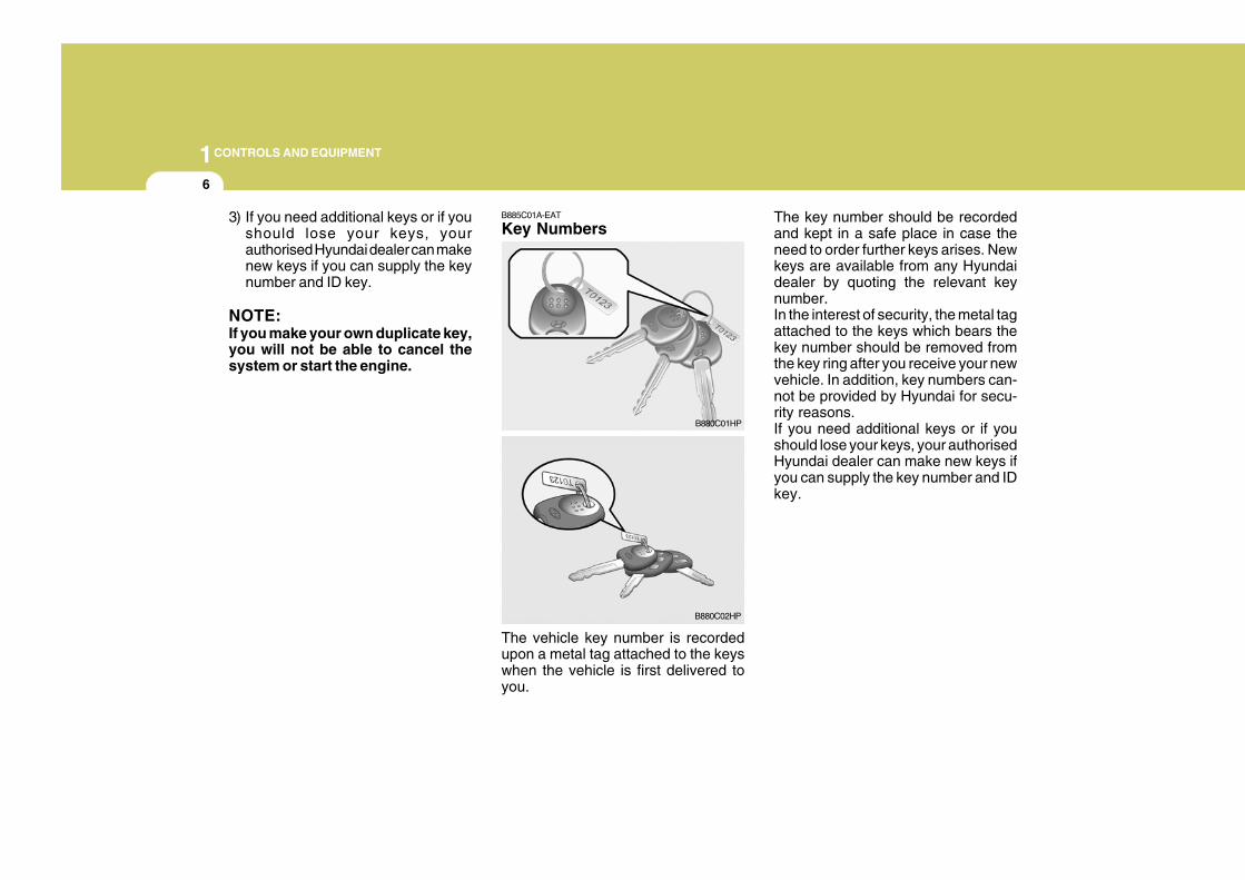
Key Numbers
The vehicle key number is recordedupon a metal tag attached to the keyswhen the vehicle is first delivered toyou.
The key number should be recordedand kept in a safe place in case theneed to order further keys arises. Newkeys are available from any Hyundaidealer by quoting the relevant keynumber.In the interest of security, the metal tagattached to the keys which bears thekey number should be removed fromthe key ring after you receive your newvehicle. In addition, key numbers can-not be provided by Hyundai for secu-rity reasons.If you need additional keys or if youshould lose your keys, your authorisedHyundai dealer can make new keys ifyou can supply the key number and IDkey.
B880C01HP
B880C02HP
3) If you need additional keys or if youshould lose your keys, yourauthorised Hyundai dealer can makenew keys if you can supply the keynumber and ID key.
NOTE:If you make your own duplicate key,you will not be able to cancel thesystem or start the engine.
1CONTROLS AND EQUIPMENT
7
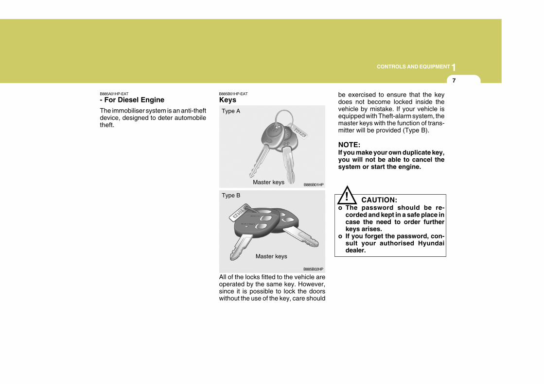
B885A01HP-EAT
- For Diesel Engine
The immobiliser system is an anti-theftdevice, designed to deter automobiletheft.
B885B01HP-EAT
Keys
All of the locks fitted to the vehicle areoperated by the same key. However,since it is possible to lock the doorswithout the use of the key, care should
be exercised to ensure that the keydoes not become locked inside thevehicle by mistake. If your vehicle isequipped with Theft-alarm system, themaster keys with the function of trans-mitter will be provided (Type B).
NOTE:If you make your own duplicate key,you will not be able to cancel thesystem or start the engine.
CAUTION:o The password should be re-
corded and kept in a safe place incase the need to order furtherkeys arises.
o If you forget the password, con-sult your authorised Hyundaidealer.
B885B01HP
Type A
Master keys
Master keys
B885B02HP
Type B !
1CONTROLS AND EQUIPMENT
8
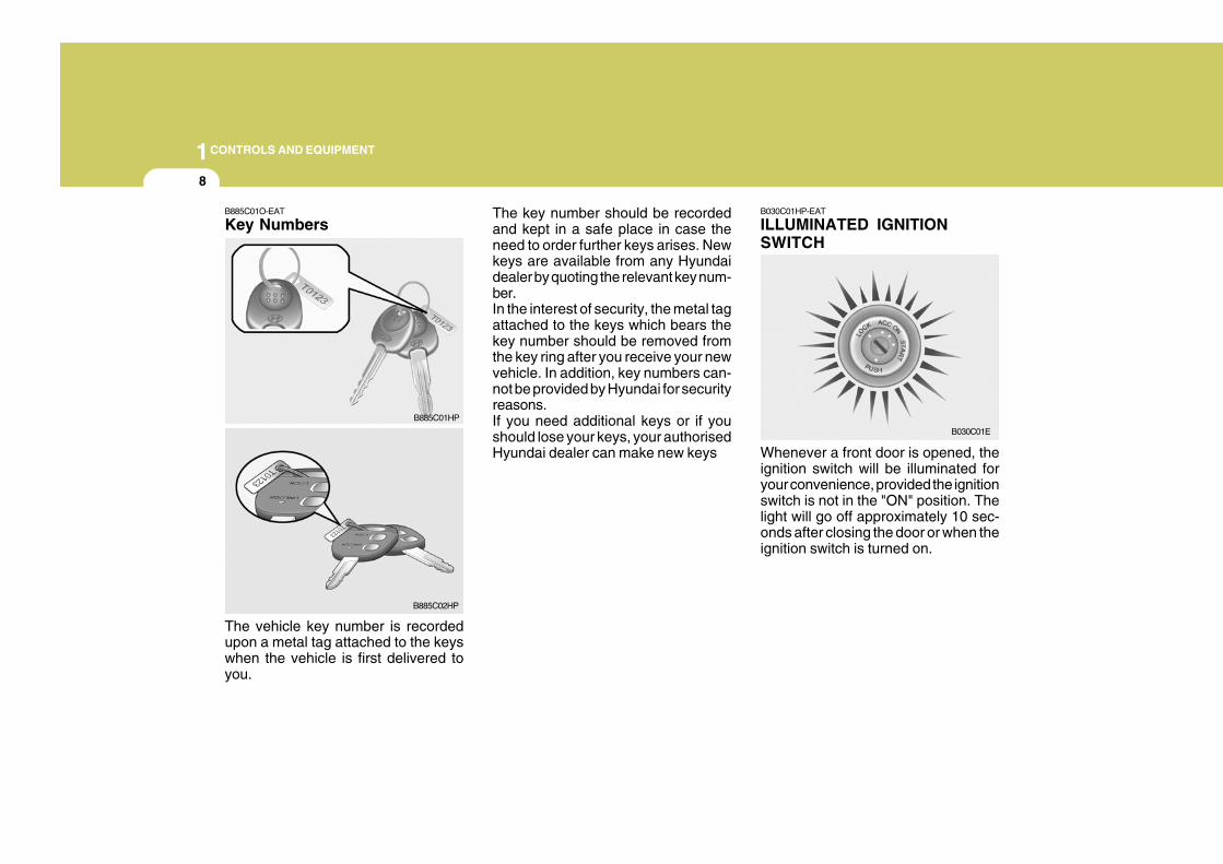
B030C01HP-EAT
ILLUMINATED IGNITIONSWITCH
Whenever a front door is opened, theignition switch will be illuminated foryour convenience, provided the ignitionswitch is not in the "ON" position. Thelight will go off approximately 10 sec-onds after closing the door or when theignition switch is turned on.
B030C01E
The key number should be recordedand kept in a safe place in case theneed to order further keys arises. Newkeys are available from any Hyundaidealer by quoting the relevant key num-ber.In the interest of security, the metal tagattached to the keys which bears thekey number should be removed fromthe key ring after you receive your newvehicle. In addition, key numbers can-not be provided by Hyundai for securityreasons.If you need additional keys or if youshould lose your keys, your authorisedHyundai dealer can make new keys
B885C01O-EAT
Key Numbers
The vehicle key number is recordedupon a metal tag attached to the keyswhen the vehicle is first delivered toyou.
B885C01HP
B885C02HP
1CONTROLS AND EQUIPMENT
9
!WARNING:
o Before you drive away, be surethat all the doors are securelyclosed. It is also recommendedthat the child-protector rear doorlocks are in the 'lock' position sothat children cannot open therear doors from inside the ve-hicle accidentally.
o Before opening the door, alwayslook for and avoid oncoming traf-fic.
o In case of accident, the door isunlocked automatically(Not allmodels).
DOOR LOCKS
B040A02Y-EAT B040B01A-AAT
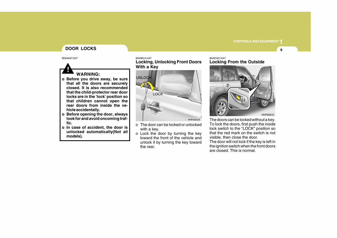
Locking, Unlocking Front DoorsWith a Key
o The door can be locked or unlockedwith a key.
o Lock the door by turning the keytoward the front of the vehicle andunlock it by turning the key towardthe rear.
B040C02Y-EAT
Locking From the Outside
The doors can be locked without a key.To lock the doors, first push the insidelock switch to the "LOCK" position sothat the red mark on the switch is notvisible, then close the door.The door will not lock if the key is left inthe ignition switch when the front doorsare closed. This is normal.
LOCK
UNLOCK
HHP2003-E
HHP2005-E
1CONTROLS AND EQUIPMENT
10
B040D01S-AAT
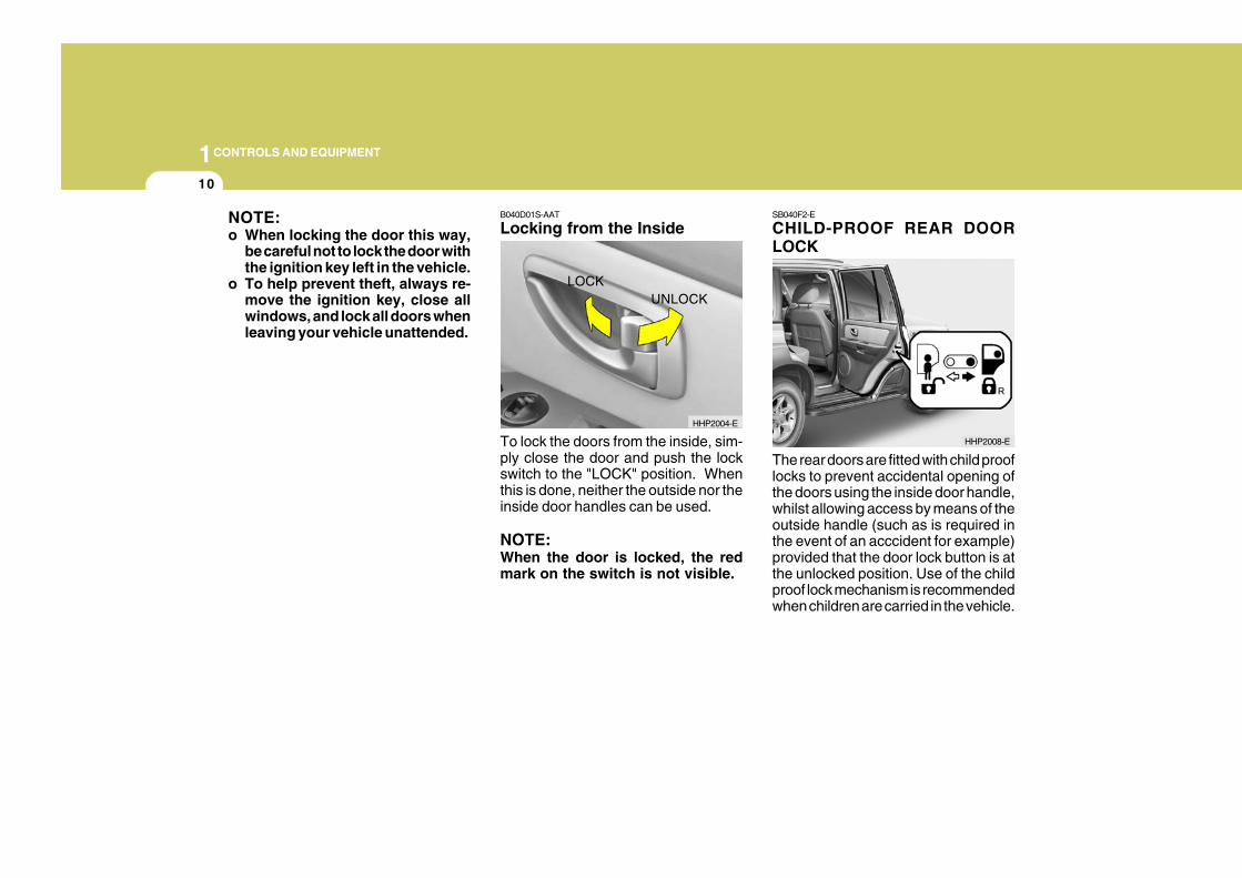
Locking from the Inside
To lock the doors from the inside, sim-ply close the door and push the lockswitch to the "LOCK" position. Whenthis is done, neither the outside nor theinside door handles can be used.
NOTE:When the door is locked, the redmark on the switch is not visible.
SB040F2-E
CHILD-PROOF REAR DOORLOCK
The rear doors are fitted with child prooflocks to prevent accidental opening ofthe doors using the inside door handle,whilst allowing access by means of theoutside handle (such as is required inthe event of an acccident for example)provided that the door lock button is atthe unlocked position. Use of the childproof lock mechanism is recommendedwhen children are carried in the vehicle.
LOCKUNLOCK
HHP2008-E
HHP2004-E
NOTE:o When locking the door this way,
be careful not to lock the door withthe ignition key left in the vehicle.
o To help prevent theft, always re-move the ignition key, close allwindows, and lock all doors whenleaving your vehicle unattended.
1CONTROLS AND EQUIPMENT
11
The child proof lock mechanism maybe activated by opening the door andmoving the lever located by the doorlatch to the " " position. Move thelever to the " " position when normaldoor operation is desired.
B040G01HP-AAT
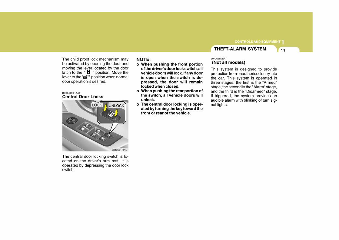
Central Door Locks
The central door locking switch is lo-cated on the driver's arm rest. It isoperated by depressing the door lockswitch.
B040G01HP-E
LOCK UNLOCK
NOTE:o When pushing the front portion
of the driver's door lock switch, allvehicle doors will lock. If any dooris open when the switch is de-pressed, the door will remainlocked when closed.
o When pushing the rear portion ofthe switch, all vehicle doors willunlock.
o The central door locking is oper-ated by turning the key toward thefront or rear of the vehicle.
THEFT-ALARM SYSTEM
B070A01A-EAT
(Not all models)
This system is designed to provideprotection from unauthorised entry intothe car. This system is operated inthree stages: the first is the "Armed"stage, the second is the "Alarm" stage,and the third is the "Disarmed" stage.If triggered, the system provides anaudible alarm with blinking of turn sig-nal lights.
1CONTROLS AND EQUIPMENT
12
!
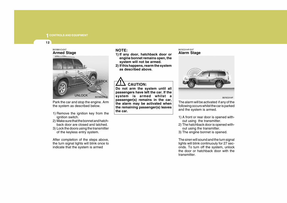
B070B01O-EAT
Armed StageNOTE:1) If any door, hatchback door or
engine bonnet remains open, thesystem will not be armed.
2) If this happens, rearm the systemas described above.
Park the car and stop the engine. Armthe system as described below.
1) Remove the ignition key from theignition switch.
2) Make sure that the bonnet and hatch-back door are closed and latched.
3) Lock the doors using the transmitterof the keyless entry system.
After completion of the steps above,the turn signal lights will blink once toindicate that the system is armed
CAUTION:Do not arm the system until allpassengers have left the car. If thesystem is armed whilst apassenger(s) remains in the car,the alarm may be activated whenthe remaining passenger(s) leavesthe car.
LOCK
UNLOCKB070B02HP-E
B070C01HP-EAT
Alarm Stage
The alarm will be activated if any of thefollowing occurs whilst the car is parkedand the system is armed.
1) A front or rear door is opened with-out using the transmitter.
2) The hatchback door is opened with-out using the transmitter.
3) The engine bonnet is opened.
The siren will sound and the turn signallights will blink continuouly for 27 sec-onds. To turn off the system, unlockthe door or hatchback door with thetransmitter.
B070C01HP
1CONTROLS AND EQUIPMENT
13
! CAUTION:Avoid trying to start the enginewhilst the system is armed.
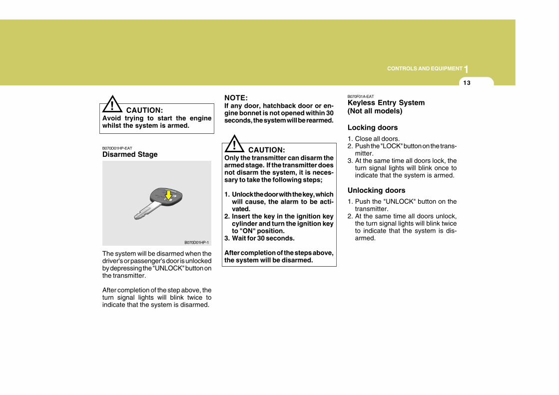
B070D01HP-EAT
Disarmed Stage
The system will be disarmed when thedriver's or passenger's door is unlockedby depressing the "UNLOCK" button onthe transmitter.
After completion of the step above, theturn signal lights will blink twice toindicate that the system is disarmed.
!
NOTE:If any door, hatchback door or en-gine bonnet is not opened within 30seconds, the system will be rearmed.
CAUTION:Only the transmitter can disarm thearmed stage. If the transmitter doesnot disarm the system, it is neces-sary to take the following steps;
1. Unlock the door with the key, whichwill cause, the alarm to be acti-vated.
2. Insert the key in the ignition keycylinder and turn the ignition keyto "ON" position.
3. Wait for 30 seconds.
After completion of the steps above,the system will be disarmed.
B070D01HP-1
B070F01A-EAT
Keyless Entry System(Not all models)
Locking doors
1. Close all doors.2. Push the "LOCK" button on the trans-
mitter.3. At the same time all doors lock, the
turn signal lights will blink once toindicate that the system is armed.
Unlocking doors
1. Push the "UNLOCK" button on thetransmitter.
2. At the same time all doors unlock,the turn signal lights will blink twiceto indicate that the system is dis-armed.
1CONTROLS AND EQUIPMENT
14
B070E02HP-EAT
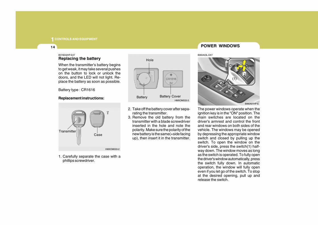
Replacing the battery
When the transmitter's battery beginsto get weak, it may take several pusheson the button to lock or unlock thedoors, and the LED will not light. Re-place the battery as soon as possible.
Battery type : CR1616
Replacement instructions:
1. Carefully separate the case with aphillips screwdriver.
HMXOM033-2
CaseTransmitter
HMXOM033-3
Hole
Battery Battery Cover
The power windows operate when theignition key is in the "ON" position. Themain switches are located on thedriver's armrest and control the frontand rear windows on both sides of thevehicle. The windows may be openedby depressing the appropriate windowswitch and closed by pulling up theswitch. To open the window on thedriver's side, press the switch(1) half-way down. The window moves as longas the switch is operated. To fully openthe driver's window automatically, pressthe switch fully down. In automaticoperation, the window will fully openeven if you let go of the switch. To stopat the desired opening, pull up andrelease the switch.
POWER WINDOWS
B060A03L-DAT
B060A01HP-E
(1)
Close Open
2. Take off the battery cover after sepa-rating the transmitter.
3. Remove the old battery from thetransmitter with a blade screwdriverinserted in the hole and note thepolarity. Make sure the polarity of thenew battery is the same(+side facingup), then insert it in the transmitter.
1CONTROLS AND EQUIPMENT
15
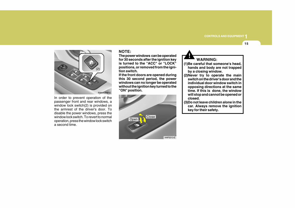
In order to prevent operation of thepassenger front and rear windows, awindow lock switch(2) is provided onthe armrest of the driver's door. Todisable the power windows, press thewindow lock switch. To revert to normaloperation, press the window lock switcha second time.
B060A02HP-E
(2)
NOTE:The power windows can be operatedfor 30 seconds after the ignition keyis turned to the "ACC" or "LOCK"positions, or removed from the igni-tion switch.If the front doors are opened duringthis 30 second period, the powerwindows can no longer be operatedwithout the ignition key turned to the"ON" position.
HHP2013-E
CloseOpen
!WARNING:
(1)Be careful that someone's head,hands and body are not trappedby a closing window.
(2)Never try to operate the mainswitch on the driver's door and theindividual door window switch inopposing directions at the sametime. If this is done, the windowwill stop and cannot be opened orclosed.
(3)Do not leave children alone in thecar. Always remove the ignitionkey for their safety.
1CONTROLS AND EQUIPMENT
16
! WARNING:Front seat adjustments must not beundertaken whilst the vehicle is inmotion. Loss of control of the ve-hicle may result if seat adjustmentsare made whilst the vehicle is inmotion.
ZB060A8-E
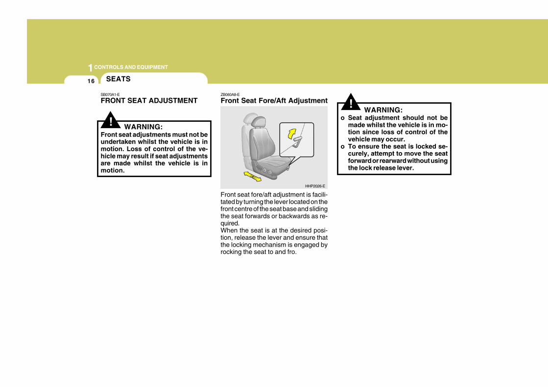
Front Seat Fore/Aft Adjustment
SEATS
SB070A1-E
FRONT SEAT ADJUSTMENT
HHP2026-E
!WARNING:
o Seat adjustment should not bemade whilst the vehicle is in mo-tion since loss of control of thevehicle may occur.
o To ensure the seat is locked se-curely, attempt to move the seatforward or rearward without usingthe lock release lever.
Front seat fore/aft adjustment is facili-tated by turning the lever located on thefront centre of the seat base and slidingthe seat forwards or backwards as re-quired.When the seat is at the desired posi-tion, release the lever and ensure thatthe locking mechanism is engaged byrocking the seat to and fro.
1CONTROLS AND EQUIPMENT
17
!ZB060C1-E
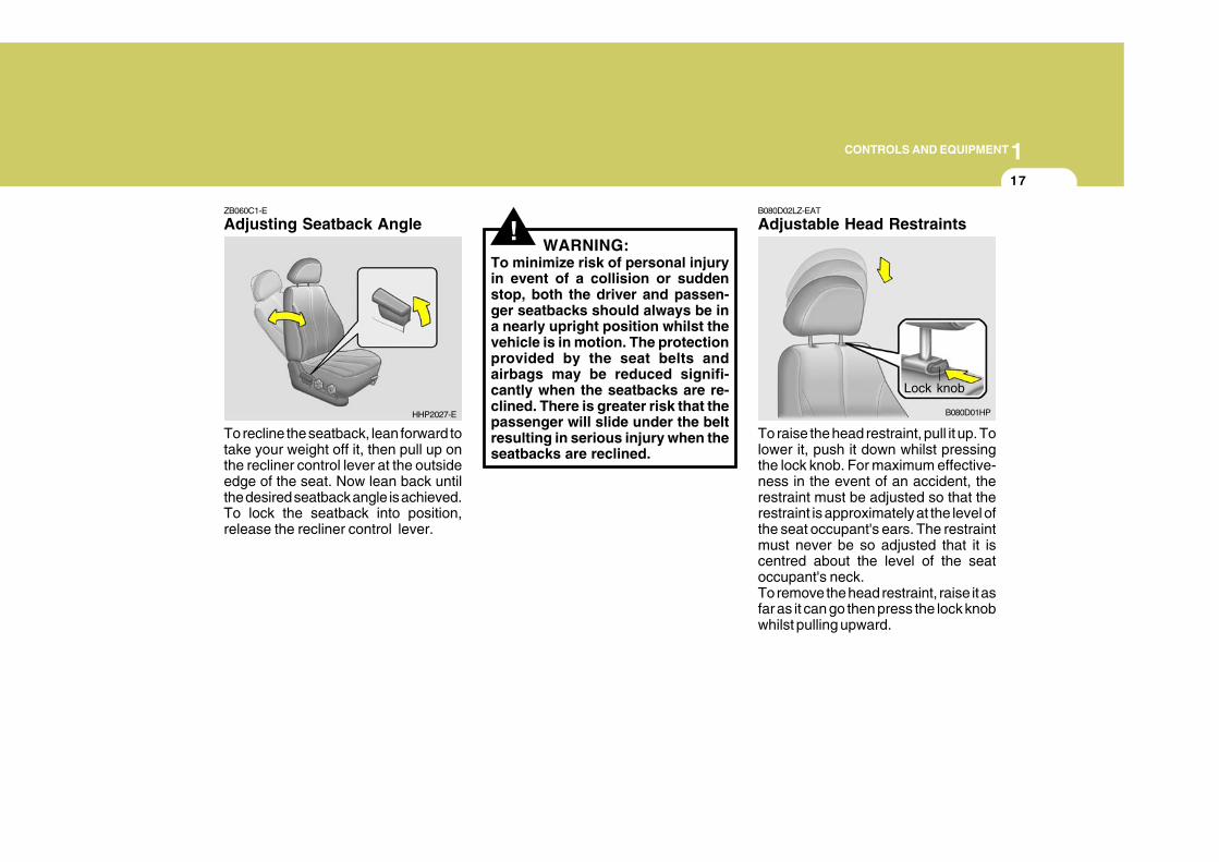
Adjusting Seatback Angle
To recline the seatback, lean forward totake your weight off it, then pull up onthe recliner control lever at the outsideedge of the seat. Now lean back untilthe desired seatback angle is achieved.To lock the seatback into position,release the recliner control lever.
WARNING:To minimize risk of personal injuryin event of a collision or suddenstop, both the driver and passen-ger seatbacks should always be ina nearly upright position whilst thevehicle is in motion. The protectionprovided by the seat belts andairbags may be reduced signifi-cantly when the seatbacks are re-clined. There is greater risk that thepassenger will slide under the beltresulting in serious injury when theseatbacks are reclined.
HHP2027-E
Lock knob
B080D01HP
B080D02LZ-EAT
Adjustable Head Restraints
To raise the head restraint, pull it up. Tolower it, push it down whilst pressingthe lock knob. For maximum effective-ness in the event of an accident, therestraint must be adjusted so that therestraint is approximately at the level ofthe seat occupant's ears. The restraintmust never be so adjusted that it iscentred about the level of the seatoccupant's neck.To remove the head restraint, raise it asfar as it can go then press the lock knobwhilst pulling upward.
1CONTROLS AND EQUIPMENT
18
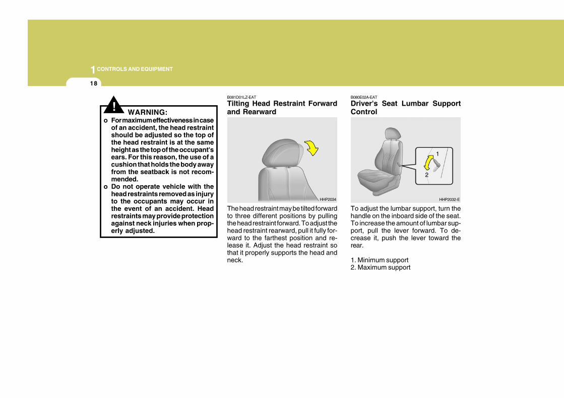
B080E02A-EAT
Driver's Seat Lumbar SupportControl
To adjust the lumbar support, turn thehandle on the inboard side of the seat.To increase the amount of lumbar sup-port, pull the lever forward. To de-crease it, push the lever toward therear.
1. Minimum support2. Maximum support
HHP2032-EHHP2034
! WARNING:o For maximum effectiveness in case
of an accident, the head restraintshould be adjusted so the top ofthe head restraint is at the sameheight as the top of the occupant'sears. For this reason, the use of acushion that holds the body awayfrom the seatback is not recom-mended.
o Do not operate vehicle with thehead restraints removed as injuryto the occupants may occur inthe event of an accident. Headrestraints may provide protectionagainst neck injuries when prop-erly adjusted.
B081D01LZ-EAT
Tilting Head Restraint Forwardand Rearward
The head restraint may be tilted forwardto three different positions by pullingthe head restraint forward. To adjust thehead restraint rearward, pull it fully for-ward to the farthest position and re-lease it. Adjust the head restraint sothat it properly supports the head andneck.
1
2
1CONTROLS AND EQUIPMENT
19
!
!
B080F01S-EAT
Seat Cushion Height Adjustment(Driver's Seat Only)
To raise or lower the front part of theseat cushion, turn the front knob for-ward or rearward.To raise or lower the rear part of the seatcushion, turn the rear knob forward orrearward.
B090A02Y-EAT
POWER DRIVER'S SEAT(Not all models)The driver's seat can be adjusted ap-propriately by using the control knobon the right side of the seat. Beforedriving, adjust the seat to the properposition so as to easily control thesteering wheel, pedals and switcheson the instrument panel.
CAUTION:Do not operate two knobs at thesame time.
WARNING:o Never attempt to adjust the seat
whilst the vehicle is moving. Thiscould result in loss of control oran accident causing death, seri-ous injury, or property damage.
o Do not sit or lean unnecessarilyclose to the airbag.
HHP2028-E
B090B01L-AAT
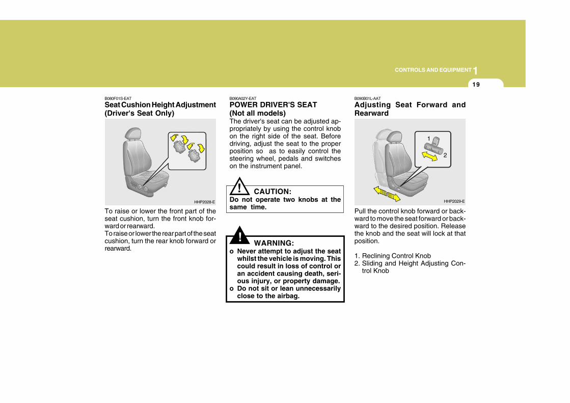
Adjusting Seat Forward andRearward
Pull the control knob forward or back-ward to move the seat forward or back-ward to the desired position. Releasethe knob and the seat will lock at thatposition.
1. Reclining Control Knob2. Sliding and Height Adjusting Con-
trol Knob
HHP2029-E
2
1
1CONTROLS AND EQUIPMENT
20
!B090C01Y-AAT
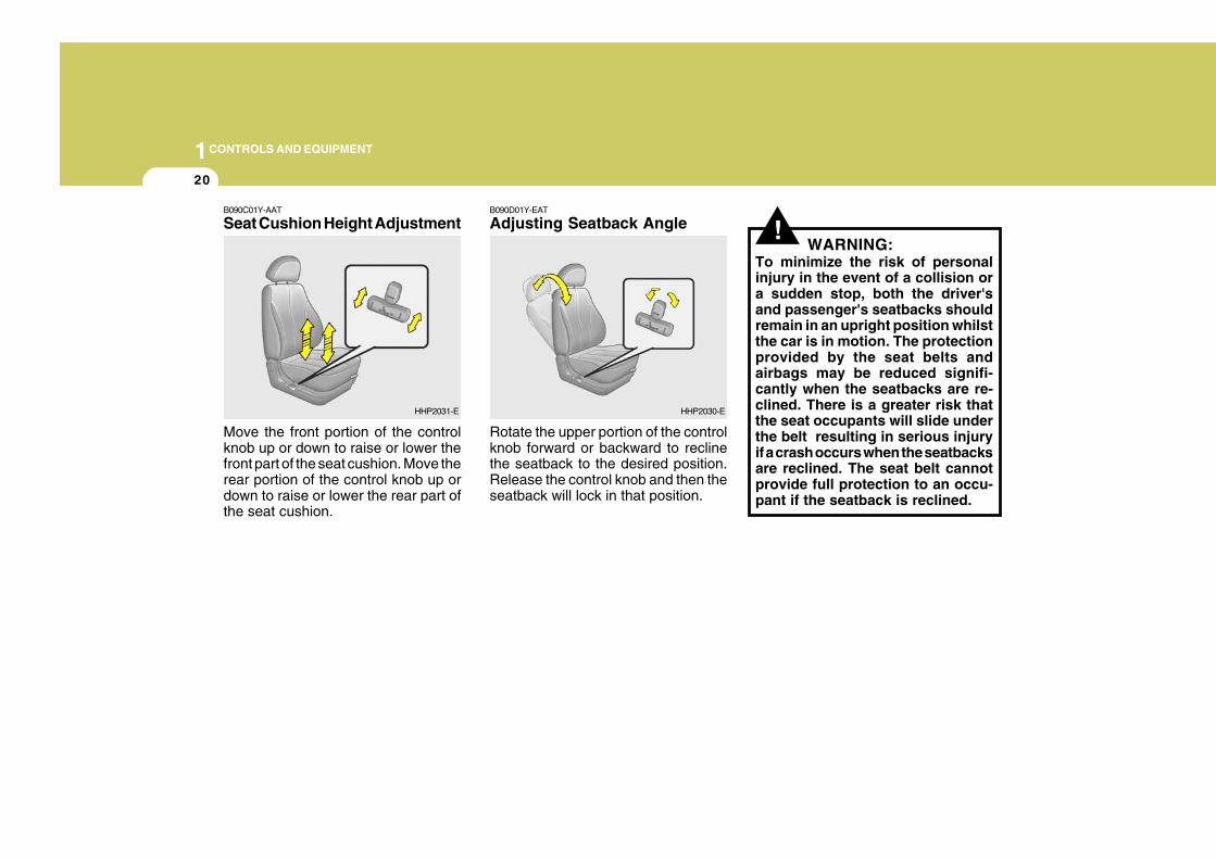
Seat Cushion Height Adjustment
Move the front portion of the controlknob up or down to raise or lower thefront part of the seat cushion. Move therear portion of the control knob up ordown to raise or lower the rear part ofthe seat cushion.
B090D01Y-EAT
Adjusting Seatback Angle
Rotate the upper portion of the controlknob forward or backward to reclinethe seatback to the desired position.Release the control knob and then theseatback will lock in that position.
WARNING:To minimize the risk of personalinjury in the event of a collision ora sudden stop, both the driver'sand passenger's seatbacks shouldremain in an upright position whilstthe car is in motion. The protectionprovided by the seat belts andairbags may be reduced signifi-cantly when the seatbacks are re-clined. There is a greater risk thatthe seat occupants will slide underthe belt resulting in serious injuryif a crash occurs when the seatbacksare reclined. The seat belt cannotprovide full protection to an occu-pant if the seatback is reclined.
HHP2031-E HHP2030-E
1CONTROLS AND EQUIPMENT
21
!
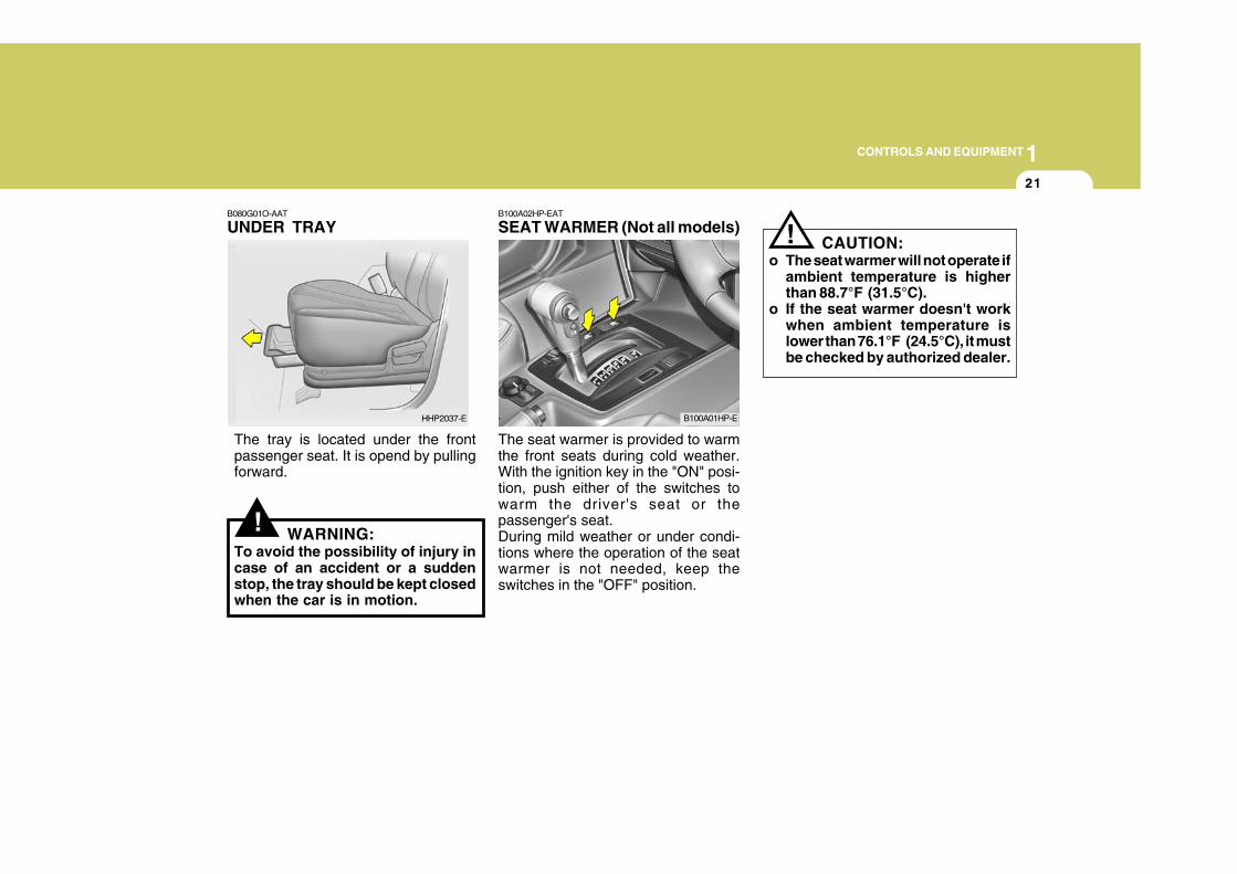
B080G01O-AAT
UNDER TRAY
The tray is located under the frontpassenger seat. It is opend by pullingforward.
WARNING:To avoid the possibility of injury incase of an accident or a suddenstop, the tray should be kept closedwhen the car is in motion.
B100A02HP-EAT
SEAT WARMER (Not all models)
The seat warmer is provided to warmthe front seats during cold weather.With the ignition key in the "ON" posi-tion, push either of the switches towarm the driver's seat or thepassenger's seat.During mild weather or under condi-tions where the operation of the seatwarmer is not needed, keep theswitches in the "OFF" position.
HHP2037-E B100A01HP-E
! CAUTION:o The seat warmer will not operate if
ambient temperature is higherthan 88.7°F (31.5°C).
o If the seat warmer doesn't workwhen ambient temperature islower than 76.1°F (24.5°C), it mustbe checked by authorized dealer.
1CONTROLS AND EQUIPMENT
22
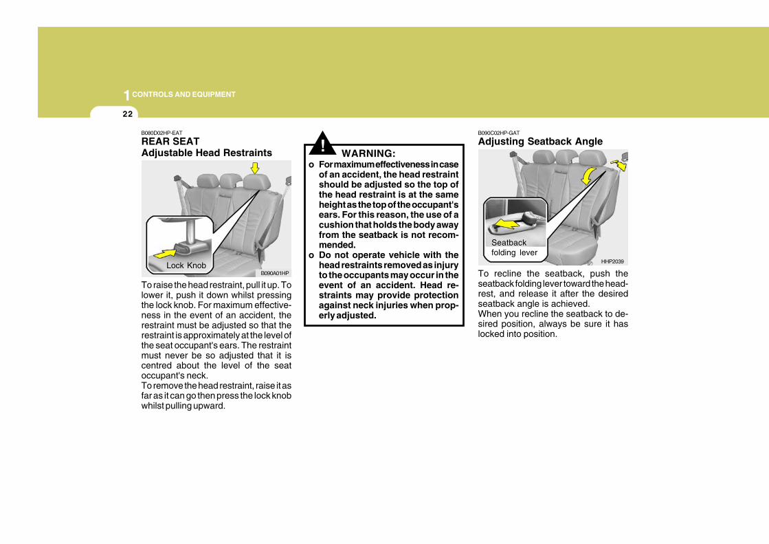
!B080D02HP-EAT
REAR SEATAdjustable Head Restraints
To raise the head restraint, pull it up. Tolower it, push it down whilst pressingthe lock knob. For maximum effective-ness in the event of an accident, therestraint must be adjusted so that therestraint is approximately at the level ofthe seat occupant's ears. The restraintmust never be so adjusted that it iscentred about the level of the seatoccupant's neck.To remove the head restraint, raise it asfar as it can go then press the lock knobwhilst pulling upward.
WARNING:o For maximum effectiveness in case
of an accident, the head restraintshould be adjusted so the top ofthe head restraint is at the sameheight as the top of the occupant'sears. For this reason, the use of acushion that holds the body awayfrom the seatback is not recom-mended.
o Do not operate vehicle with thehead restraints removed as injuryto the occupants may occur in theevent of an accident. Head re-straints may provide protectionagainst neck injuries when prop-erly adjusted.
Lock KnobB090A01HP
B090C02HP-GAT
Adjusting Seatback Angle
To recline the seatback, push theseatback folding lever toward the head-rest, and release it after the desiredseatback angle is achieved.When you recline the seatback to de-sired position, always be sure it haslocked into position.
Seatbackfolding lever
HHP2039
1CONTROLS AND EQUIPMENT
23
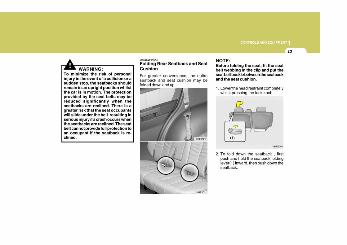
!B090B02HP-EAT
Folding Rear Seatback and SeatCushion
For greater convenience, the entireseatback and seat cushion may befolded down and up.
HHP2041
HHP2057
WARNING:To minimize the risk of personalinjury in the event of a collision or asudden stop, the seatbacks shouldremain in an upright position whilstthe car is in motion. The protectionprovided by the seat belts may bereduced significantly when theseatbacks are reclined. There is agreater risk that the seat occupantswill slide under the belt resulting inserious injury if a crash occurs whenthe seatbacks are reclined. The seatbelt cannot provide full protection toan occupant if the seatback is re-clined.
HHP2040
(1)
NOTE:Before folding the seat, fit the seatbelt webbing in the clip and put theseat belt buckle between the seatbackand the seat cushion.
1. Lower the head restraint completelywhilst pressing the lock knob.
2. To fold down the seatback , firstpush and hold the seatback foldinglever(1) inward, then push down theseatback.
1CONTROLS AND EQUIPMENT
24
!
HHP2042
HHP2043
(3)
HHP2043-1
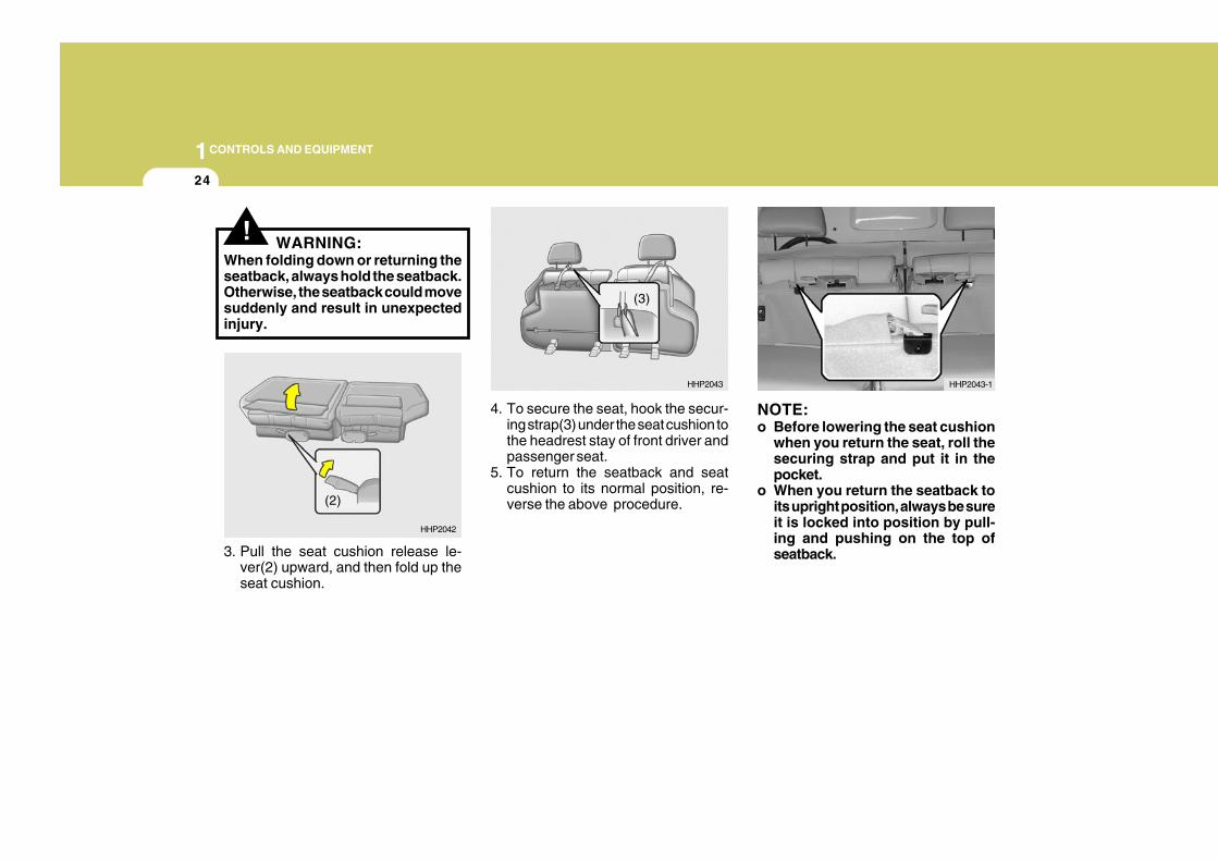
WARNING:When folding down or returning theseatback, always hold the seatback.Otherwise, the seatback could movesuddenly and result in unexpectedinjury.
4. To secure the seat, hook the secur-ing strap(3) under the seat cushion tothe headrest stay of front driver andpassenger seat.
5. To return the seatback and seatcushion to its normal position, re-verse the above procedure.
NOTE:o Before lowering the seat cushion
when you return the seat, roll thesecuring strap and put it in thepocket.
o When you return the seatback toits upright position, always be sureit is locked into position by pull-ing and pushing on the top ofseatback.
(2)
3. Pull the seat cushion release le-ver(2) upward, and then fold up theseat cushion.
1CONTROLS AND EQUIPMENT
25
!
B140A01B-GAT
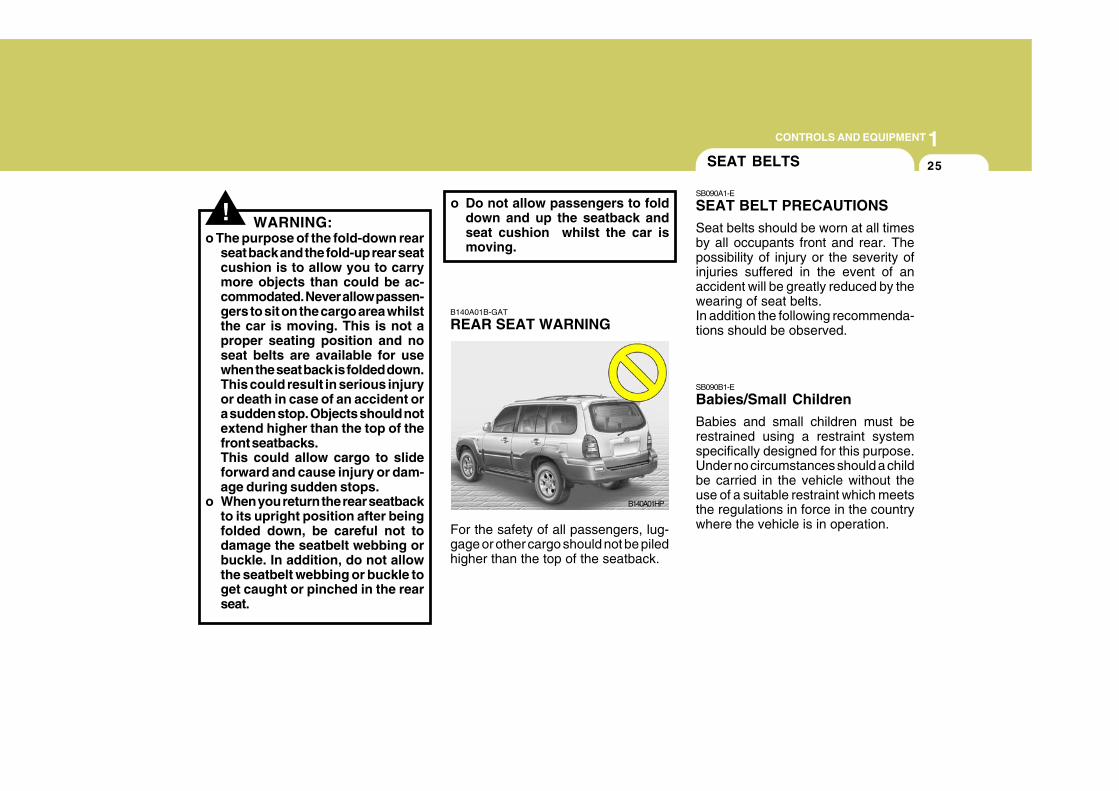
REAR SEAT WARNING
For the safety of all passengers, lug-gage or other cargo should not be piledhigher than the top of the seatback.
B140A01HP
WARNING:o The purpose of the fold-down rear
seat back and the fold-up rear seatcushion is to allow you to carrymore objects than could be ac-commodated. Never allow passen-gers to sit on the cargo area whilstthe car is moving. This is not aproper seating position and noseat belts are available for usewhen the seat back is folded down.This could result in serious injuryor death in case of an accident ora sudden stop. Objects should notextend higher than the top of thefront seatbacks.This could allow cargo to slideforward and cause injury or dam-age during sudden stops.
o When you return the rear seatbackto its upright position after beingfolded down, be careful not todamage the seatbelt webbing orbuckle. In addition, do not allowthe seatbelt webbing or buckle toget caught or pinched in the rearseat.
o Do not allow passengers to folddown and up the seatback andseat cushion whilst the car ismoving.
SB090B1-E
Babies/Small Children
Babies and small children must berestrained using a restraint systemspecifically designed for this purpose.Under no circumstances should a childbe carried in the vehicle without theuse of a suitable restraint which meetsthe regulations in force in the countrywhere the vehicle is in operation.
SEAT BELTS
SB090A1-E
SEAT BELT PRECAUTIONS
Seat belts should be worn at all timesby all occupants front and rear. Thepossibility of injury or the severity ofinjuries suffered in the event of anaccident will be greatly reduced by thewearing of seat belts.In addition the following recommenda-tions should be observed.
1CONTROLS AND EQUIPMENT
26
SB090C1-E
Larger Children
Larger children should occupy the rearseat and be restrained at all times. Therestraint may take the form of a specialsafety belt or the original factory fittedseat belt used in conjunction with anapproved booster cushion dependingupon the size and weight of the child.Under no circumstances should chil-dren be allowed to travel standing,kneeling or lying on the seat.Never allow childen to ride in the frontpassenger seat.
SB090O1-E
Pregnant Women
The use of a seat belt is recommendedfor pregnant women. The seat beltshould be worn as low and snugly aspossible across the hips, not acrossthe abdomen. A qualified Medical Prac-titioner should be consulted for furtherinformation.
SB090E1-E
Injured Persons
A seat belt should be used when aninjured person is being transported.For specific recommendations, theadvice of a qualified Medical Practionershould be sought.
SB090F1-E
Seat Belt Occupancy
The seat belts are designed to be usedby one seat occupant only. The use ofa seat belt by more than one personincreases the levels of injury whichmay be sustained in the event of anaccident.
SE090G1-E
Do Not Lie Down
To ensure that the maximum level ofprotection may be afforded by the seatbelt system, all passengers should besitting in an upright position throughoutthe journey. The seat belt will be un-able to afford maximum protection ifthe front seats are at or near the fullyreclined position.
SB090H1-E
CARE OF SEAT BELTS
Seat belt assemblies must never bedisassembled or modified in any way.In addition, care should be exercisedto ensure that the belt assemblies donot become damaged by being trappedin seat mechanisms, door shuts etc.
SB090I-E
Periodic Inspection
It is recommended that all seat beltsbe inspected periodically for wear ordamage of any kind. Parts of the sys-tem that are damaged should be re-placed as soon as possible. Under nocircumstances must any part of theseat belt assemblies be dismantled orrepaired.
1CONTROLS AND EQUIPMENT
27
SB090J1-E
Keep Belts Clean and Dry
Seat belts should be kept clean anddry. If belts become dirty, they can becleaned using a mild soap solution andwarm water. Bleach, dye, strong de-tergents or abrasives should not beused since the fabric may becomedamaged and weakened.
SB090K1-E
Replacement of Seat Belts
The entire seat belt assembly or as-semblies should be replaced if thevehicle has been involved in an acci-dent even if no damage is evident.Additional questions concerning seatbelt operation should be directed to aHyundai Dealer.
B170A04A-EAT
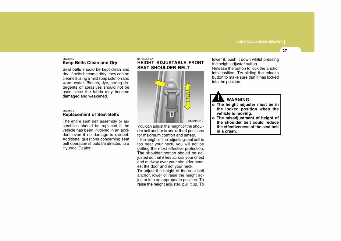
HEIGHT ADJUSTABLE FRONTSEAT SHOULDER BELT
You can adjust the height of the shoul-der belt anchor to one of the 4 positionsfor maximum comfort and safety.If the height of the adjusting seat belt istoo near your neck, you will not begetting the most effective protection.The shoulder portion should be ad-justed so that it lies across your chestand midway over your shoulder near-est the door and not your neck.To adjust the height of the seat beltanchor, lower or raise the height ad-juster into an appropriate position. Toraise the height adjuster, pull it up. To
B170A01HP-E
!
lower it, push it down whilst pressingthe height adjuster button.Release the button to lock the anchorinto position. Try sliding the releasebutton to make sure that it has lockedinto the position.
WARNING:o The height adjuster must be in
the locked position when thevehicle is moving.
o The misadjustment of height ofthe shoulder belt could reducethe effectiveness of the seat beltin a crash.
1CONTROLS AND EQUIPMENT
28
SB090P1-E
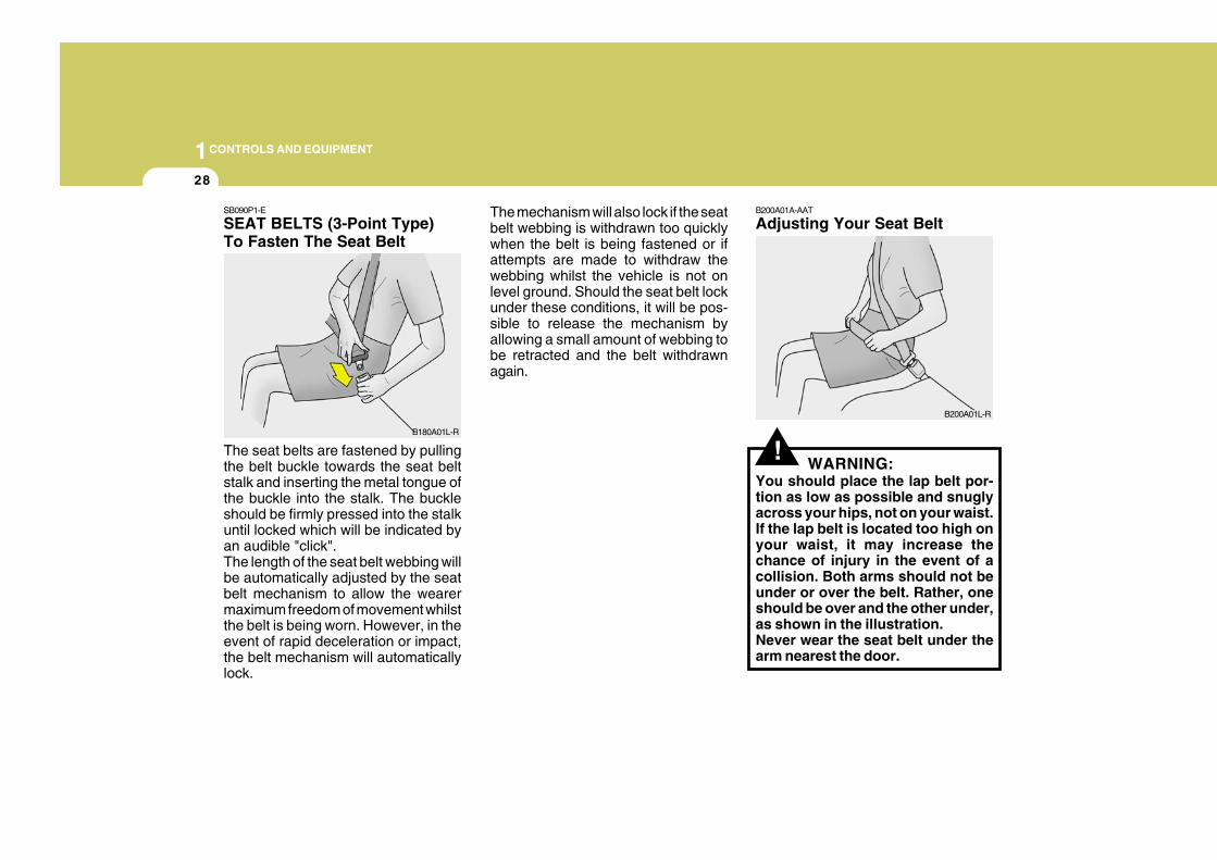
SEAT BELTS (3-Point Type)To Fasten The Seat Belt
The seat belts are fastened by pullingthe belt buckle towards the seat beltstalk and inserting the metal tongue ofthe buckle into the stalk. The buckleshould be firmly pressed into the stalkuntil locked which will be indicated byan audible "click".The length of the seat belt webbing willbe automatically adjusted by the seatbelt mechanism to allow the wearermaximum freedom of movement whilstthe belt is being worn. However, in theevent of rapid deceleration or impact,the belt mechanism will automaticallylock.
The mechanism will also lock if the seatbelt webbing is withdrawn too quicklywhen the belt is being fastened or ifattempts are made to withdraw thewebbing whilst the vehicle is not onlevel ground. Should the seat belt lockunder these conditions, it will be pos-sible to release the mechanism byallowing a small amount of webbing tobe retracted and the belt withdrawnagain.
B180A01L-R
!
B200A01A-AAT
Adjusting Your Seat Belt
WARNING:You should place the lap belt por-tion as low as possible and snuglyacross your hips, not on your waist.If the lap belt is located too high onyour waist, it may increase thechance of injury in the event of acollision. Both arms should not beunder or over the belt. Rather, oneshould be over and the other under,as shown in the illustration.Never wear the seat belt under thearm nearest the door.
B200A01L-R
1CONTROLS AND EQUIPMENT
29
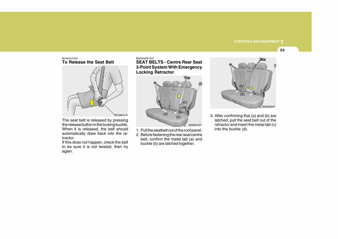
B210A01A-AAT
To Release the Seat Belt
The seat belt is released by pressingthe release button in the locking buckle.When it is released, the belt shouldautomatically draw back into the re-tractor.If this does not happen, check the beltto be sure it is not twisted, then tryagain.
B210A01L-R
B220D02HP-EAT
SEAT BELTS - Centre Rear Seat3-Point System With EmergencyLocking Retractor
1. Pull the seatbelt out of the roof panel.2. Before fastening the rear seat centre
belt, confirm the metal tab (a) andbuckle (b) are latched together.
B220D01HP
(a)
(b)
(c)
(d)
B220D02HP
(c)
(d)
3. After confirming that (a) and (b) arelatched, pull the seat belt out of theretractor and insert the metal tab (c)into the buckle (d).
1CONTROLS AND EQUIPMENT
30
!
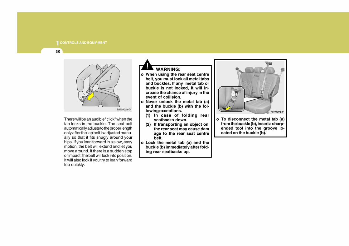
There will be an audible "click" when thetab locks in the buckle. The seat beltautomatically adjusts to the proper lengthonly after the lap belt is adjusted manu-ally so that it fits snugly around yourhips. If you lean forward in a slow, easymotion, the belt will extend and let youmove around. If there is a sudden stopor impact, the belt will lock into position.It will also lock if you try to lean forwardtoo quickly.
WARNING:o When using the rear seat centre
belt, you must lock all metal tabsand buckles. If any metal tab orbuckle is not locked, it will in-crease the chance of injury in theevent of collision.
o Never unlock the metal tab (a)and the buckle (b) with the fol-lowing exceptions.(1) In case of folding rear
seatbacks down.(2) If transporting an object on
the rear seat may cause damage to the rear seat centrebelt.
o Lock the metal tab (a) and thebuckle (b) immediately after fold-ing rear seatbacks up.
B220A02Y-DB220D03HP
o To disconnect the metal tab (a)from the buckle (b), insert a sharp-ended tool into the groove lo-cated on the buckle (b).
1CONTROLS AND EQUIPMENT
31
!
B220D04HP
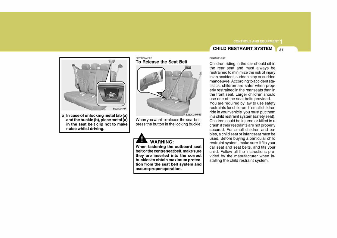
o In case of unlocking metal tab (a)and the buckle (b), place metal (a)in the seat belt clip not to makenoise whilst driving.
B220C02A-EAT
To Release the Seat Belt
When you want to release the seat belt,press the button in the locking buckle.
WARNING:When fastening the outboard seatbelt or the centre seat belt, make surethey are inserted into the correctbuckles to obtain maximum protec-tion from the seat belt system andassure proper operation.
B220C01HP-E
CHILD RESTRAINT SYSTEM
B230A03P-EAT
Children riding in the car should sit inthe rear seat and must always berestrained to minimize the risk of injuryin an accident, sudden stop or suddenmanoeuvre. According to accident sta-tistics, children are safer when prop-erly restrained in the rear seats than inthe front seat. Larger children shoulduse one of the seat belts provided.You are required by law to use safetyrestraints for children. If small childrenride in your vehicle you must put themin a child restraint system (safety seat).Children could be injured or killed in acrash if their restraints are not properlysecured. For small children and ba-bies, a child seat or infant seat must beused. Before buying a particular childrestraint system, make sure it fits yourcar seat and seat belts, and fits yourchild. Follow all the instructions pro-vided by the manufacturer when in-stalling the child restraint system.
1CONTROLS AND EQUIPMENT
32
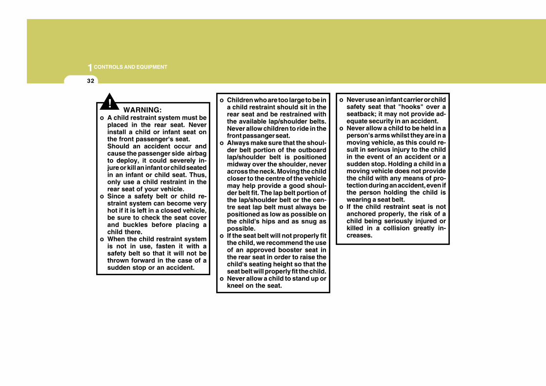
!WARNING:
o A child restraint system must beplaced in the rear seat. Neverinstall a child or infant seat onthe front passenger's seat.Should an accident occur andcause the passenger side airbagto deploy, it could severely in-jure or kill an infant or child seatedin an infant or child seat. Thus,only use a child restraint in therear seat of your vehicle.
o Since a safety belt or child re-straint system can become veryhot if it is left in a closed vehicle,be sure to check the seat coverand buckles before placing achild there.
o When the child restraint systemis not in use, fasten it with asafety belt so that it will not bethrown forward in the case of asudden stop or an accident.
o Children who are too large to be ina child restraint should sit in therear seat and be restrained withthe available lap/shoulder belts.Never allow children to ride in thefront passanger seat.
o Always make sure that the shoul-der belt portion of the outboardlap/shoulder belt is positionedmidway over the shoulder, neveracross the neck. Moving the childcloser to the centre of the vehiclemay help provide a good shoul-der belt fit. The lap belt portion ofthe lap/shoulder belt or the cen-tre seat lap belt must always bepositioned as low as possible onthe child's hips and as snug aspossible.
o If the seat belt will not properly fitthe child, we recommend the useof an approved booster seat inthe rear seat in order to raise thechild's seating height so that theseat belt will properly fit the child.
o Never allow a child to stand up orkneel on the seat.
o Never use an infant carrier or childsafety seat that "hooks" over aseatback; it may not provide ad-equate security in an accident.
o Never allow a child to be held in aperson's arms whilst they are in amoving vehicle, as this could re-sult in serious injury to the childin the event of an accident or asudden stop. Holding a child in amoving vehicle does not providethe child with any means of pro-tection during an accident, even ifthe person holding the child iswearing a seat belt.
o If the child restraint seat is notanchored properly, the risk of achild being seriously injured orkilled in a collision greatly in-creases.
1CONTROLS AND EQUIPMENT
33
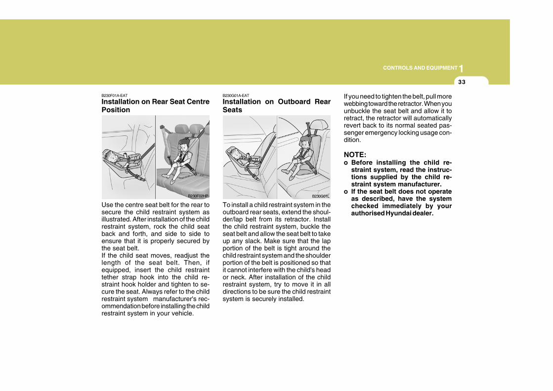
B230F01A-EAT
Installation on Rear Seat CentrePosition
Use the centre seat belt for the rear tosecure the child restraint system asillustrated. After installation of the childrestraint system, rock the child seatback and forth, and side to side toensure that it is properly secured bythe seat belt.If the child seat moves, readjust thelength of the seat belt. Then, ifequipped, insert the child restrainttether strap hook into the child re-straint hook holder and tighten to se-cure the seat. Always refer to the childrestraint system manufacturer's rec-ommendation before installing the childrestraint system in your vehicle.
B230F02HP
B230G01A-EAT
Installation on Outboard RearSeats
To install a child restraint system in theoutboard rear seats, extend the shoul-der/lap belt from its retractor. Installthe child restraint system, buckle theseat belt and allow the seat belt to takeup any slack. Make sure that the lapportion of the belt is tight around thechild restraint system and the shoulderportion of the belt is positioned so thatit cannot interfere with the child's heador neck. After installation of the childrestraint system, try to move it in alldirections to be sure the child restraintsystem is securely installed.
If you need to tighten the belt, pull morewebbing toward the retractor. When youunbuckle the seat belt and allow it toretract, the retractor will automaticallyrevert back to its normal seated pas-senger emergency locking usage con-dition.
NOTE:o Before installing the child re-
straint system, read the instruc-tions supplied by the child re-straint system manufacturer.
o If the seat belt does not operateas described, have the systemchecked immediately by yourauthorised Hyundai dealer.
B230G01L
1CONTROLS AND EQUIPMENT
34
! WARNING:Do not install any child restraintsystem in the front passenger seat.Should an accident occur and causethe passenger side airbag to de-ploy, it could severely injure or killan infant or child seated in an infantor child seat. Therefore, only use achild restraint system in the rearseat of your vehicle.
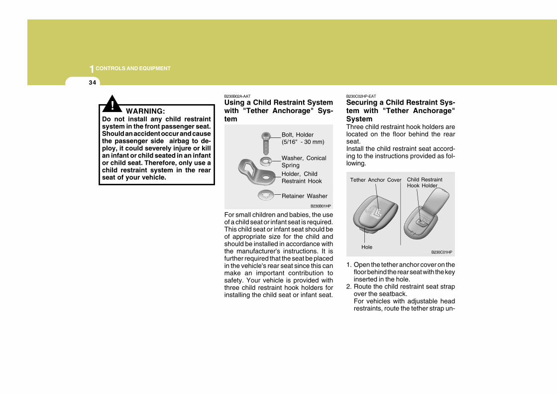
B230B02A-AAT
Using a Child Restraint Systemwith "Tether Anchorage" Sys-tem
For small children and babies, the useof a child seat or infant seat is required.This child seat or infant seat should beof appropriate size for the child andshould be installed in accordance withthe manufacturer's instructions. It isfurther required that the seat be placedin the vehicle's rear seat since this canmake an important contribution tosafety. Your vehicle is provided withthree child restraint hook holders forinstalling the child seat or infant seat.
B230C02HP-EAT
Securing a Child Restraint Sys-tem with "Tether Anchorage"SystemThree child restraint hook holders arelocated on the floor behind the rearseat.Install the child restraint seat accord-ing to the instructions provided as fol-lowing.
1. Open the tether anchor cover on thefloor behind the rear seat with the keyinserted in the hole.
2. Route the child restraint seat strapover the seatback.For vehicles with adjustable headrestraints, route the tether strap un-
B230B01HP
Bolt, Holder(5/16" - 30 mm)
Washer, ConicalSpring
Holder, ChildRestraint Hook
Retainer Washer
B230C01HP
Tether Anchor Cover Child RestraintHook Holder
Hole
1CONTROLS AND EQUIPMENT
35
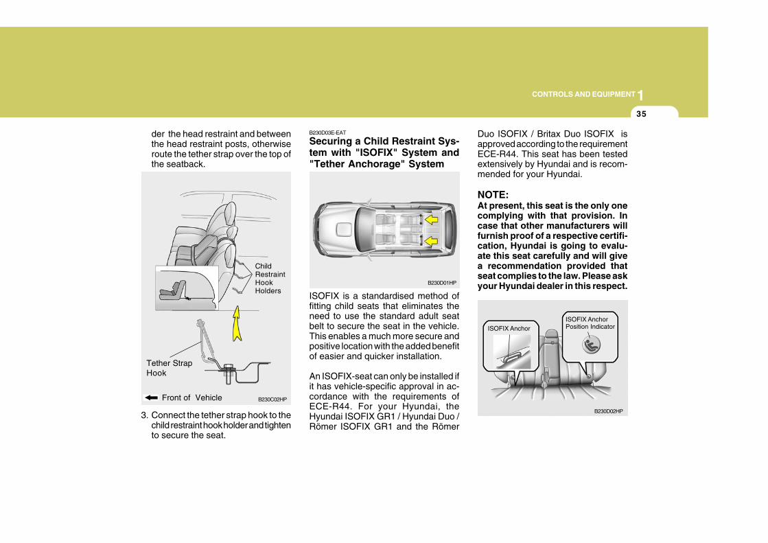
B230C02HPFront of Vehicle
der the head restraint and betweenthe head restraint posts, otherwiseroute the tether strap over the top ofthe seatback.
3. Connect the tether strap hook to thechild restraint hook holder and tightento secure the seat.
ChildRestraintHookHolders
Tether StrapHook
B230D03E-EAT
Securing a Child Restraint Sys-tem with "ISOFIX" System and"Tether Anchorage" System
ISOFIX is a standardised method offitting child seats that eliminates theneed to use the standard adult seatbelt to secure the seat in the vehicle.This enables a much more secure andpositive location with the added benefitof easier and quicker installation.
An ISOFIX-seat can only be installed ifit has vehicle-specific approval in ac-cordance with the requirements ofECE-R44. For your Hyundai, theHyundai ISOFIX GR1 / Hyundai Duo /Römer ISOFIX GR1 and the Römer
Duo ISOFIX / Britax Duo ISOFIX isapproved according to the requirementECE-R44. This seat has been testedextensively by Hyundai and is recom-mended for your Hyundai.
NOTE:At present, this seat is the only onecomplying with that provision. Incase that other manufacturers willfurnish proof of a respective certifi-cation, Hyundai is going to evalu-ate this seat carefully and will givea recommendation provided thatseat complies to the law. Please askyour Hyundai dealer in this respect.B230D01HP
ISOFIX Anchor
B230D02HP
ISOFIX AnchorPosition Indicator
1CONTROLS AND EQUIPMENT
36
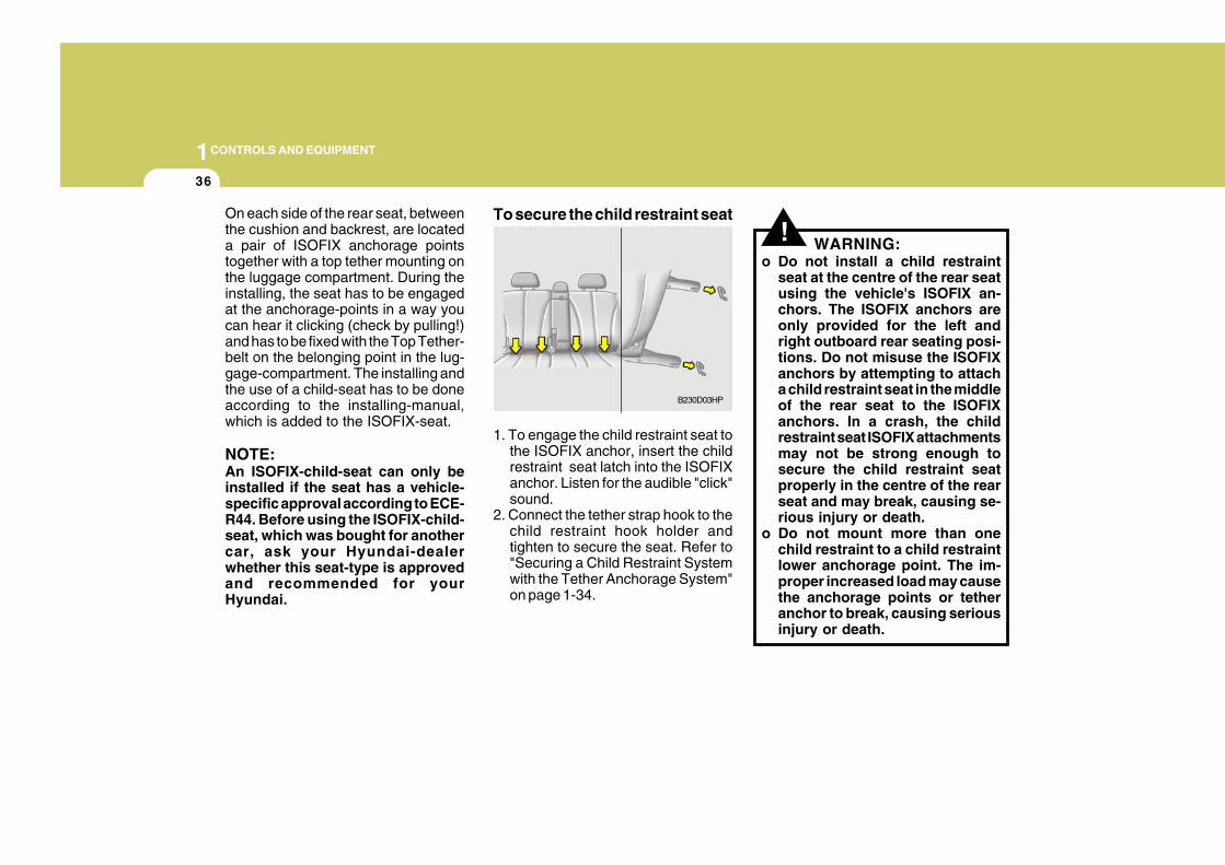
!On each side of the rear seat, betweenthe cushion and backrest, are locateda pair of ISOFIX anchorage pointstogether with a top tether mounting onthe luggage compartment. During theinstalling, the seat has to be engagedat the anchorage-points in a way youcan hear it clicking (check by pulling!)and has to be fixed with the Top Tether-belt on the belonging point in the lug-gage-compartment. The installing andthe use of a child-seat has to be doneaccording to the installing-manual,which is added to the ISOFIX-seat.
NOTE:An ISOFIX-child-seat can only beinstalled if the seat has a vehicle-specific approval according to ECE-R44. Before using the ISOFIX-child-seat, which was bought for anothercar, ask your Hyundai-dealerwhether this seat-type is approvedand recommended for yourHyundai.
To secure the child restraint seat
1. To engage the child restraint seat tothe ISOFIX anchor, insert the childrestraint seat latch into the ISOFIXanchor. Listen for the audible "click"sound.
2. Connect the tether strap hook to thechild restraint hook holder andtighten to secure the seat. Refer to"Securing a Child Restraint Systemwith the Tether Anchorage System"on page 1-34.
WARNING:o Do not install a child restraint
seat at the centre of the rear seatusing the vehicle's ISOFIX an-chors. The ISOFIX anchors areonly provided for the left andright outboard rear seating posi-tions. Do not misuse the ISOFIXanchors by attempting to attacha child restraint seat in the middleof the rear seat to the ISOFIXanchors. In a crash, the childrestraint seat ISOFIX attachmentsmay not be strong enough tosecure the child restraint seatproperly in the centre of the rearseat and may break, causing se-rious injury or death.
o Do not mount more than onechild restraint to a child restraintlower anchorage point. The im-proper increased load may causethe anchorage points or tetheranchor to break, causing seriousinjury or death.
B230D03HP
1CONTROLS AND EQUIPMENT
37
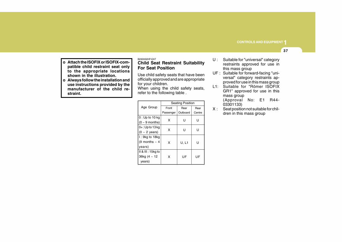
o Attach the ISOFIX or ISOFIX-com-patible child restraint seat onlyto the appropriate locationsshown in the illustration.
o Always follow the installation anduse instructions provided by themanufacturer of the child re-straint.
B230H02HP-EAT
Child Seat Restraint SuitabilityFor Seat Position
Use child safety seats that have beenofficially approved and are appropriatefor your children.When using the child safety seats,refer to the following table .
U : Suitable for "universal" categoryrestraints approved for use inthis mass group
UF : Suitable for forward-facing "uni-versal" category restraints ap-proved for use in this mass group
L1: Suitable for "Römer ISOFIXGR1" approved for use in thismass group(Approval No: E1 R44-03301133)
X : Seat position not suitable for chil-dren in this mass group
Rear
Centre
Age GroupSeating Position
U U
X U U
Rear
Outboard
Front
Passenger
0 : Up to 10 kg
(0 ~ 9 months)
0+ : Up to 13 kg
(0 ~ 2 years)
I : 9kg to 18kg
(9 months ~ 4
years)
II & III : 15kg to
36kg (4 ~ 12
years)
X
X U, L1 U
X UF UF
1CONTROLS AND EQUIPMENT
38
!
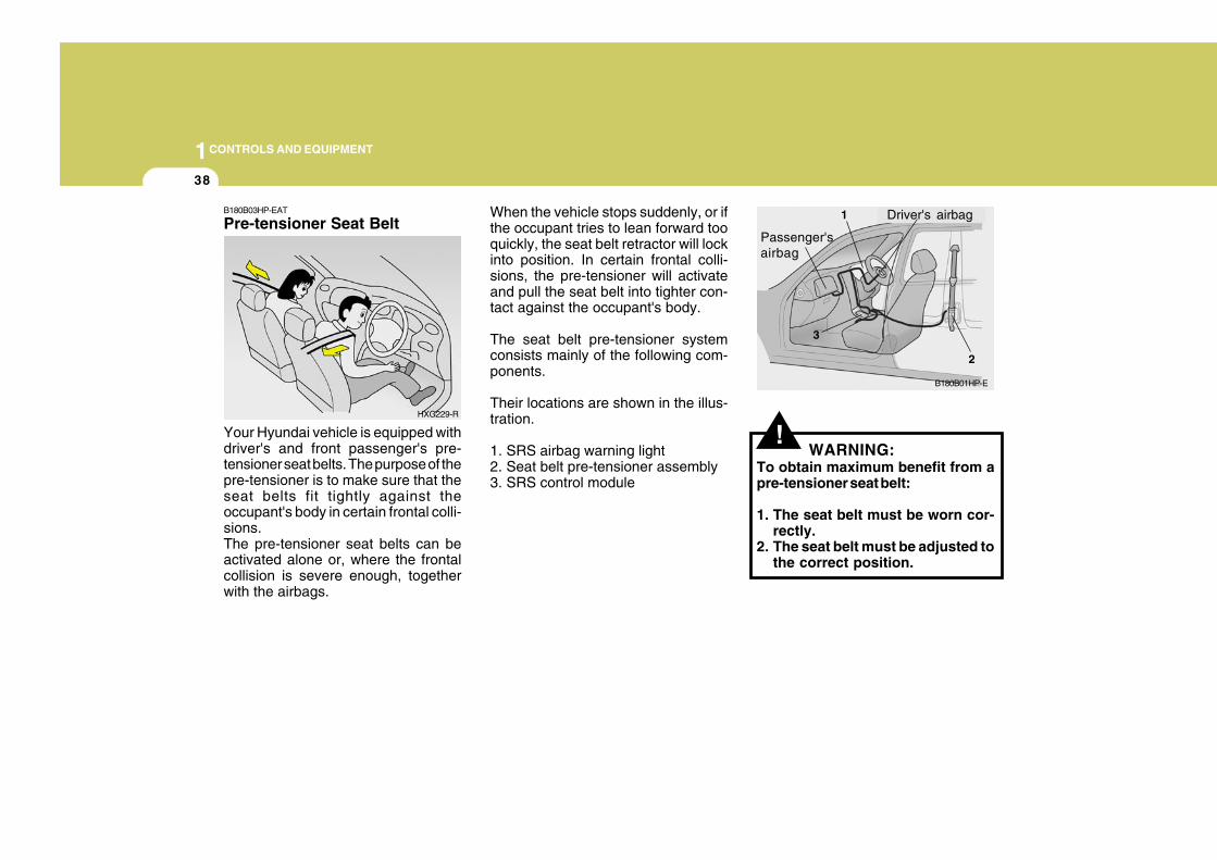
B180B03HP-EAT
Pre-tensioner Seat Belt
Your Hyundai vehicle is equipped withdriver's and front passenger's pre-tensioner seat belts. The purpose of thepre-tensioner is to make sure that theseat belts fit tightly against theoccupant's body in certain frontal colli-sions.The pre-tensioner seat belts can beactivated alone or, where the frontalcollision is severe enough, togetherwith the airbags.
When the vehicle stops suddenly, or ifthe occupant tries to lean forward tooquickly, the seat belt retractor will lockinto position. In certain frontal colli-sions, the pre-tensioner will activateand pull the seat belt into tighter con-tact against the occupant's body.
The seat belt pre-tensioner systemconsists mainly of the following com-ponents.
Their locations are shown in the illus-tration.
1. SRS airbag warning light2. Seat belt pre-tensioner assembly3. SRS control module
WARNING:To obtain maximum benefit from apre-tensioner seat belt:
1. The seat belt must be worn cor-rectly.
2. The seat belt must be adjusted tothe correct position.
HXG229-R
B180B01HP-E
Driver's airbag1
2
3
Passenger'sairbag
1CONTROLS AND EQUIPMENT
39
NOTE:o Both the driver's and front
passenger's pre-tensioner seatbelts will be activated in certainfrontal collisions. The pre-tensioner seat belts can be acti-vated alone or, where the frontalcollision is severe enough, to-gether with the airbags.
o When the pre-tensioner seat beltsare activated, a loud noise may beheard and fine dust, which mayappear to be smoke, may be vis-ible in the passenger compart-ment. These are normal operatingconditions and are not hazard-ous.
o Although it is harmless, the finedust may cause skin irritation andshould not be breathed for pro-longed periods. Wash your handsand face thoroughly after an acci-dent in which the pre-tensionerseat belts were activated.
! !CAUTION:o Because the sensor that activates
the SRS airbag is connected withpre-tensioner seat belt, the SRSairbag warning light on theinstrument panel will blink for ap-proximately 6 seconds after theignition key has been turned to the"ON" position or after the engineis started, and then it should turnoff.
o If pre-tensioner seat belt is notworking properly, this warninglight will illuminate even if there isno malfunction of the SRS airbag.If the SRS airbag warning lightdoes not blink for about 6 secondswhen the ignition key is turned to"ON" or the engine is started, or ifit remains illuminated after blink-ing for approximately 6 seconds,or if it illuminates whilst the ve-hicle is being driven, please havean authorised Hyundai dealer in-spect the pre-tensioner seat beltsand SRS airbag system as soon aspossible.
WARNING:o Pre-tensioners are designed to
operate only one time. After acti-vation, pre-tensioner seat beltsmust be replaced. All seat belts,of any type, should always bereplaced after they have beenworn during a collision.
o The pre-tensioner seat belt as-sembly mechanisms become hotduring activation. Do not touchthe pre-tensioner seat belt as-semblies for several minutes af-ter they have been activated.
o Do not attempt to inspect or re-place the pre-tensioner seat beltsyourself. This must be done byan authorised Hyundai dealer.
o Do not strike the pre-tensionerseat belt assemblies.
o Do not attempt to service or re-pair the pre-tensioner seat beltsystem in any manner.
AIRBAG
1CONTROLS AND EQUIPMENT
40
o Improper handling of the pre-tensioner seat belt assemblies, andfailure to heed the warnings to notstrike, modify, inspect, replace,service or repair the pretensionerseat belt assemblies may lead toimproper operation or inadvertentactivation and serious injury.
o Always wear seat belts when driv-ing or riding in a motor vehicle.
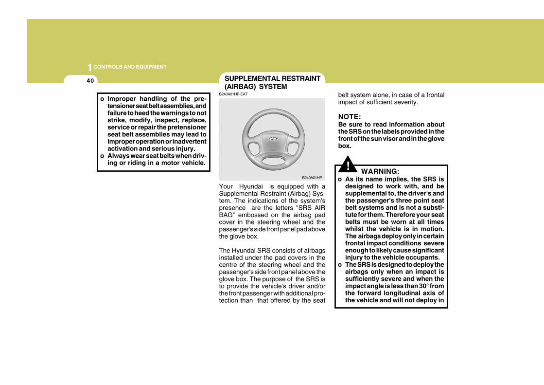
belt system alone, in case of a frontalimpact of sufficient severity.
NOTE:Be sure to read information aboutthe SRS on the labels provided in thefront of the sun visor and in the glovebox.
SUPPLEMENTAL RESTRAINT(AIRBAG) SYSTEM
B240A01HP-EAT
B240A01HP
Your Hyundai is equipped with aSupplemental Restraint (Airbag) Sys-tem. The indications of the system'spresence are the letters "SRS AIRBAG" embossed on the airbag padcover in the steering wheel and thepassenger's side front panel pad abovethe glove box.
The Hyundai SRS consists of airbagsinstalled under the pad covers in thecentre of the steering wheel and thepassenger's side front panel above theglove box. The purpose of the SRS isto provide the vehicle's driver and/orthe front passenger with additional pro-tection than that offered by the seat
! WARNING:o As its name implies, the SRS is
designed to work with, and besupplemental to, the driver's andthe passenger's three point seatbelt systems and is not a substi-tute for them. Therefore your seatbelts must be worn at all timeswhilst the vehicle is in motion.The airbags deploy only in certainfrontal impact conditions severeenough to likely cause significantinjury to the vehicle occupants.
o The SRS is designed to deploy theairbags only when an impact issufficiently severe and when theimpact angle is less than 30° fromthe forward longitudinal axis ofthe vehicle and will not deploy in
1CONTROLS AND EQUIPMENT
41
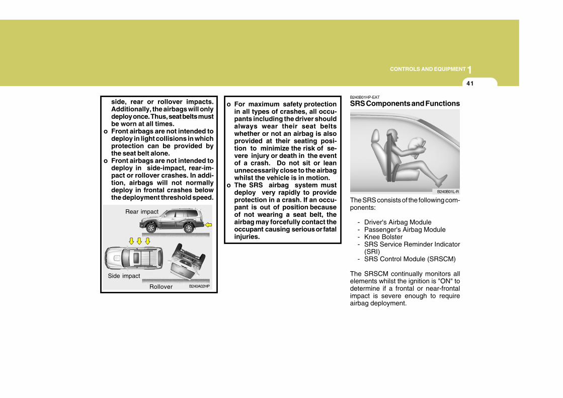
side, rear or rollover impacts.Additionally, the airbags will onlydeploy once. Thus, seat belts mustbe worn at all times.
o Front airbags are not intended todeploy in light collisions in whichprotection can be provided bythe seat belt alone.
o Front airbags are not intended todeploy in side-impact, rear-im-pact or rollover crashes. In addi-tion, airbags will not normallydeploy in frontal crashes belowthe deployment threshold speed.
o For maximum safety protectionin all types of crashes, all occu-pants including the driver shouldalways wear their seat beltswhether or not an airbag is alsoprovided at their seating posi-tion to minimize the risk of se-vere injury or death in the eventof a crash. Do not sit or leanunnecessarily close to the airbagwhilst the vehicle is in motion.
o The SRS airbag system mustdeploy very rapidly to provideprotection in a crash. If an occu-pant is out of position becauseof not wearing a seat belt, theairbag may forcefully contact theoccupant causing serious or fatalinjuries.
Rear impact
B240A02HP
Side impact
Rollover
B240B01HP-EAT
SRS Components and Functions
The SRS consists of the following com-ponents:
- Driver's Airbag Module- Passenger's Airbag Module- Knee Bolster- SRS Service Reminder Indicator
(SRI)- SRS Control Module (SRSCM)
The SRSCM continually monitors allelements whilst the ignition is "ON" todetermine if a frontal or near-frontalimpact is severe enough to requireairbag deployment.
B240B01L-R
1CONTROLS AND EQUIPMENT
42
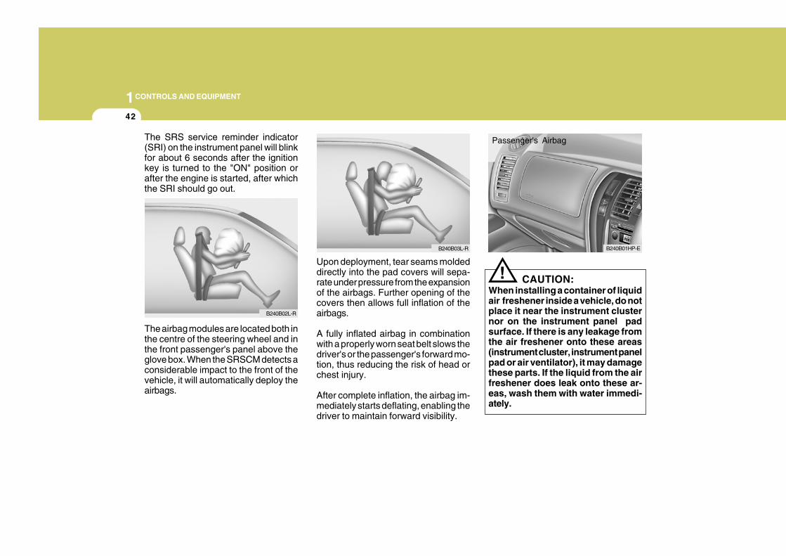
The SRS service reminder indicator(SRI) on the instrument panel will blinkfor about 6 seconds after the ignitionkey is turned to the "ON" position orafter the engine is started, after whichthe SRI should go out.
Upon deployment, tear seams moldeddirectly into the pad covers will sepa-rate under pressure from the expansionof the airbags. Further opening of thecovers then allows full inflation of theairbags.
A fully inflated airbag in combinationwith a properly worn seat belt slows thedriver's or the passenger's forward mo-tion, thus reducing the risk of head orchest injury.
After complete inflation, the airbag im-mediately starts deflating, enabling thedriver to maintain forward visibility.
The airbag modules are located both inthe centre of the steering wheel and inthe front passenger's panel above theglove box. When the SRSCM detects aconsiderable impact to the front of thevehicle, it will automatically deploy theairbags.
B240B02L-R
B240B03L-R
! CAUTION:When installing a container of liquidair freshener inside a vehicle, do notplace it near the instrument clusternor on the instrument panel padsurface. If there is any leakage fromthe air freshener onto these areas(instrument cluster, instrument panelpad or air ventilator), it may damagethese parts. If the liquid from the airfreshener does leak onto these ar-eas, wash them with water immedi-ately.
B240B01HP-E
Passenger's Airbag
1CONTROLS AND EQUIPMENT
43
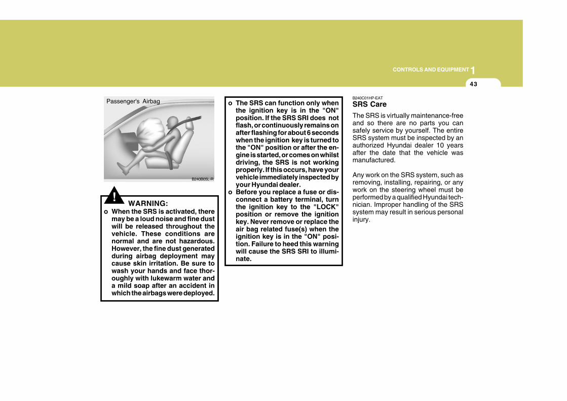
!WARNING:
o When the SRS is activated, theremay be a loud noise and fine dustwill be released throughout thevehicle. These conditions arenormal and are not hazardous.However, the fine dust generatedduring airbag deployment maycause skin irritation. Be sure towash your hands and face thor-oughly with lukewarm water anda mild soap after an accident inwhich the airbags were deployed.
o The SRS can function only whenthe ignition key is in the "ON"position. If the SRS SRI does notflash, or continuously remains onafter flashing for about 6 secondswhen the ignition key is turned tothe "ON" position or after the en-gine is started, or comes on whilstdriving, the SRS is not workingproperly. If this occurs, have yourvehicle immediately inspected byyour Hyundai dealer.
o Before you replace a fuse or dis-connect a battery terminal, turnthe ignition key to the "LOCK"position or remove the ignitionkey. Never remove or replace theair bag related fuse(s) when theignition key is in the "ON" posi-tion. Failure to heed this warningwill cause the SRS SRI to illumi-nate.
B240C01HP-EAT
SRS Care
The SRS is virtually maintenance-freeand so there are no parts you cansafely service by yourself. The entireSRS system must be inspected by anauthorized Hyundai dealer 10 yearsafter the date that the vehicle wasmanufactured.
Any work on the SRS system, such asremoving, installing, repairing, or anywork on the steering wheel must beperformed by a qualified Hyundai tech-nician. Improper handling of the SRSsystem may result in serious personalinjury.
B240B05L-R
Passenger's Airbag
1CONTROLS AND EQUIPMENT
44
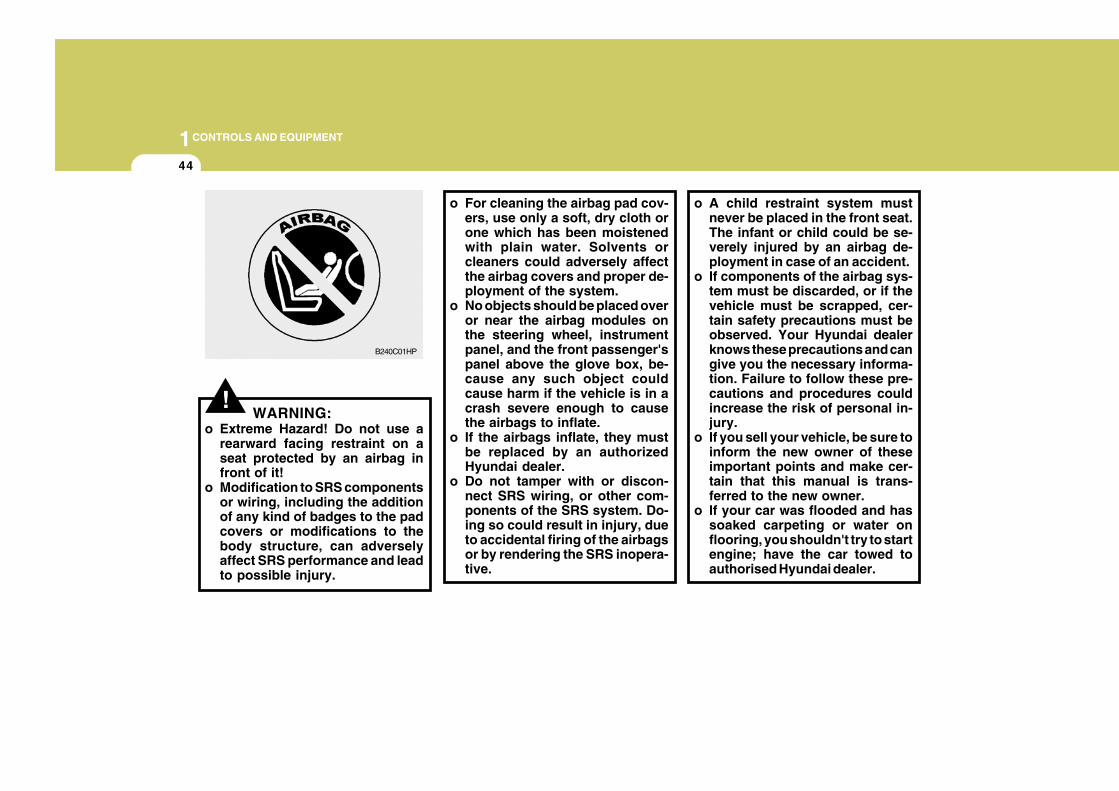
!WARNING:
o Extreme Hazard! Do not use arearward facing restraint on aseat protected by an airbag infront of it!
o Modification to SRS componentsor wiring, including the additionof any kind of badges to the padcovers or modifications to thebody structure, can adverselyaffect SRS performance and leadto possible injury.
o For cleaning the airbag pad cov-ers, use only a soft, dry cloth orone which has been moistenedwith plain water. Solvents orcleaners could adversely affectthe airbag covers and proper de-ployment of the system.
o No objects should be placed overor near the airbag modules onthe steering wheel, instrumentpanel, and the front passenger'spanel above the glove box, be-cause any such object couldcause harm if the vehicle is in acrash severe enough to causethe airbags to inflate.
o If the airbags inflate, they mustbe replaced by an authorizedHyundai dealer.
o Do not tamper with or discon-nect SRS wiring, or other com-ponents of the SRS system. Do-ing so could result in injury, dueto accidental firing of the airbagsor by rendering the SRS inopera-tive.
B240C01HP
o A child restraint system mustnever be placed in the front seat.The infant or child could be se-verely injured by an airbag de-ployment in case of an accident.
o If components of the airbag sys-tem must be discarded, or if thevehicle must be scrapped, cer-tain safety precautions must beobserved. Your Hyundai dealerknows these precautions and cangive you the necessary informa-tion. Failure to follow these pre-cautions and procedures couldincrease the risk of personal in-jury.
o If you sell your vehicle, be sure toinform the new owner of theseimportant points and make cer-tain that this manual is trans-ferred to the new owner.
o If your car was flooded and hassoaked carpeting or water onflooring, you shouldn't try to startengine; have the car towed toauthorised Hyundai dealer.
1CONTROLS AND EQUIPMENT
45
o Do not replace the bumper or thebumper guard with the one otherthan the Hyundai genuine parts.Otherwise, it can adversely af-fect SRS performance and leadto unexpected injury.
1CONTROLS AND EQUIPMENT
46 INSTRUMENT CLUSTER AND INDICATOR LIGHTS
B260A03HP-EAT
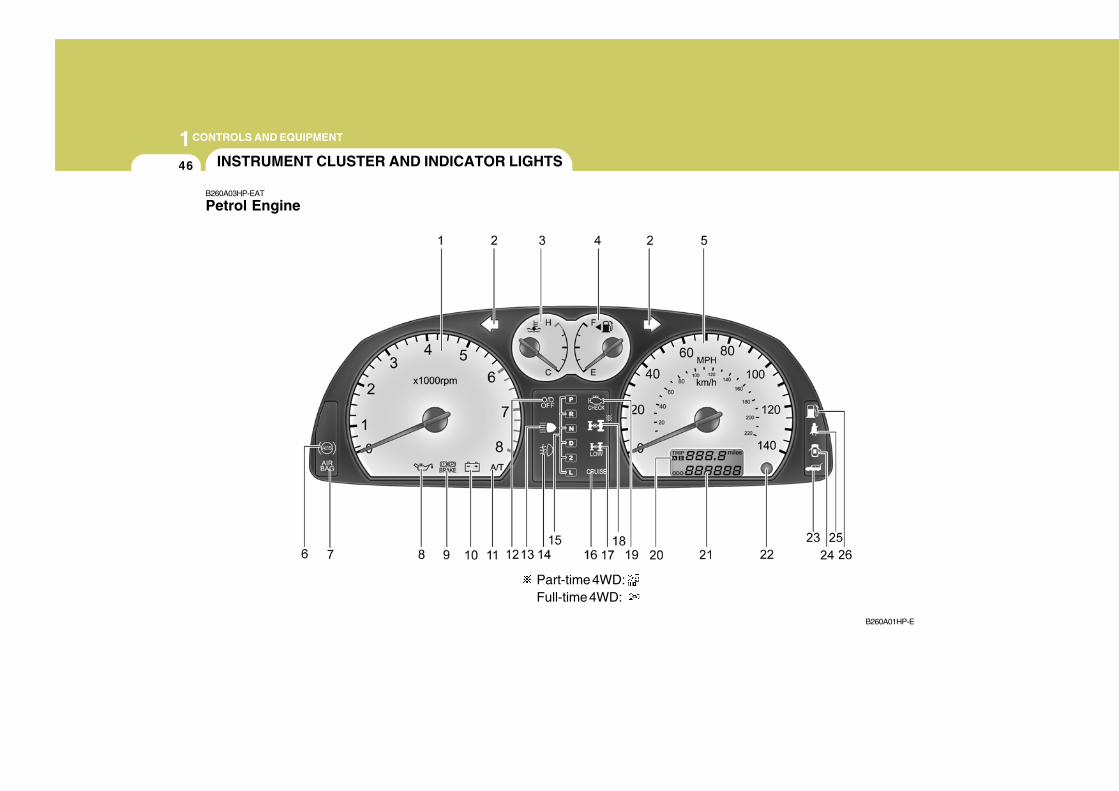
Petrol Engine
B260A01HP-E
Part-time 4WD:Full-time 4WD:
1CONTROLS AND EQUIPMENT
47
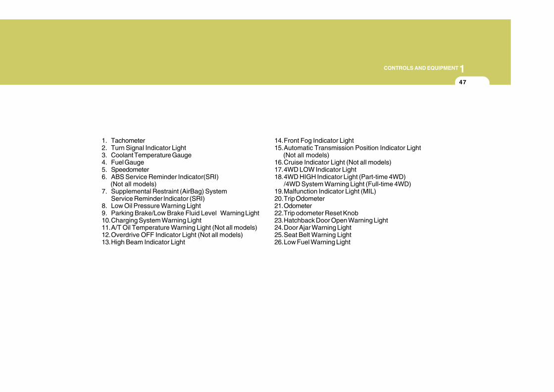
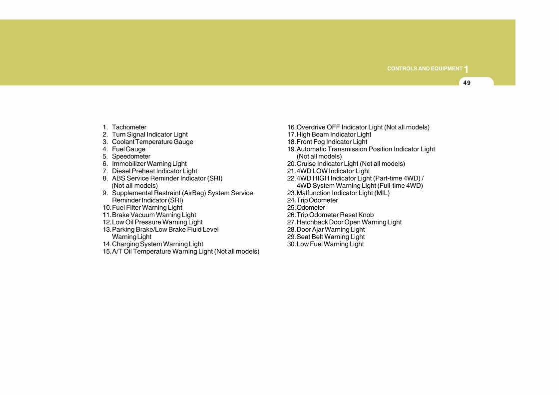
1. Tachometer2. Turn Signal Indicator Light3. Coolant Temperature Gauge4. Fuel Gauge5. Speedometer6. ABS Service Reminder Indicator(SRI) (Not all models)7. Supplemental Restraint (AirBag) System
Service Reminder lndicator (SRI)8. Low Oil Pressure Warning Light9. Parking Brake/Low Brake Fluid Level Warning Light10.Charging System Warning Light11.A/T Oil Temperature Warning Light (Not all models)12.Overdrive OFF Indicator Light (Not all models)13.High Beam Indicator Light
14.Front Fog Indicator Light15.Automatic Transmission Position Indicator Light (Not all models)16.Cruise Indicator Light (Not all models)17.4WD LOW Indicator Light18.4WD HIGH Indicator Light (Part-time 4WD)
/4WD System Warning Light (Full-time 4WD)19.Malfunction Indicator Light (MIL)20.Trip Odometer21.Odometer22.Trip odometer Reset Knob23.Hatchback Door Open Warning Light24.Door Ajar Warning Light25.Seat Belt Warning Light26.Low Fuel Warning Light
1CONTROLS AND EQUIPMENT
48
B262A03HP-GAT
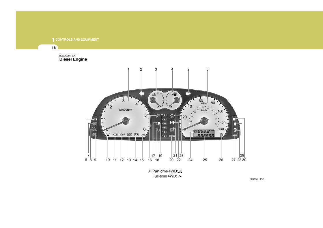
Diesel Engine
B260B01HP-E
Part-time 4WD:Full-time 4WD:
1CONTROLS AND EQUIPMENT
49
1. Tachometer2. Turn Signal Indicator Light3. Coolant Temperature Gauge4. Fuel Gauge5. Speedometer6. Immobilizer Warning Light7. Diesel Preheat Indicator Light8. ABS Service Reminder Indicator (SRI) (Not all models)9. Supplemental Restraint (AirBag) System Service
Reminder Indicator (SRI)10.Fuel Filter Warning Light11.Brake Vacuum Warning Light12.Low Oil Pressure Warning Light13.Parking Brake/Low Brake Fluid Level
Warning Light14.Charging System Warning Light15.A/T Oil Temperature Warning Light (Not all models)
16.Overdrive OFF Indicator Light (Not all models)17.High Beam Indicator Light18.Front Fog Indicator Light19.Automatic Transmission Position Indicator Light
(Not all models)20.Cruise Indicator Light (Not all models)21.4WD LOW Indicator Light22.4WD HIGH Indicator Light (Part-time 4WD) /
4WD System Warning Light (Full-time 4WD)23.Malfunction Indicator Light (MIL)24.Trip Odometer25.Odometer26.Trip Odometer Reset Knob27.Hatchback Door Open Warning Light28.Door Ajar Warning Light29.Seat Belt Warning Light30.Low Fuel Warning Light
1CONTROLS AND EQUIPMENT
50
! !
!
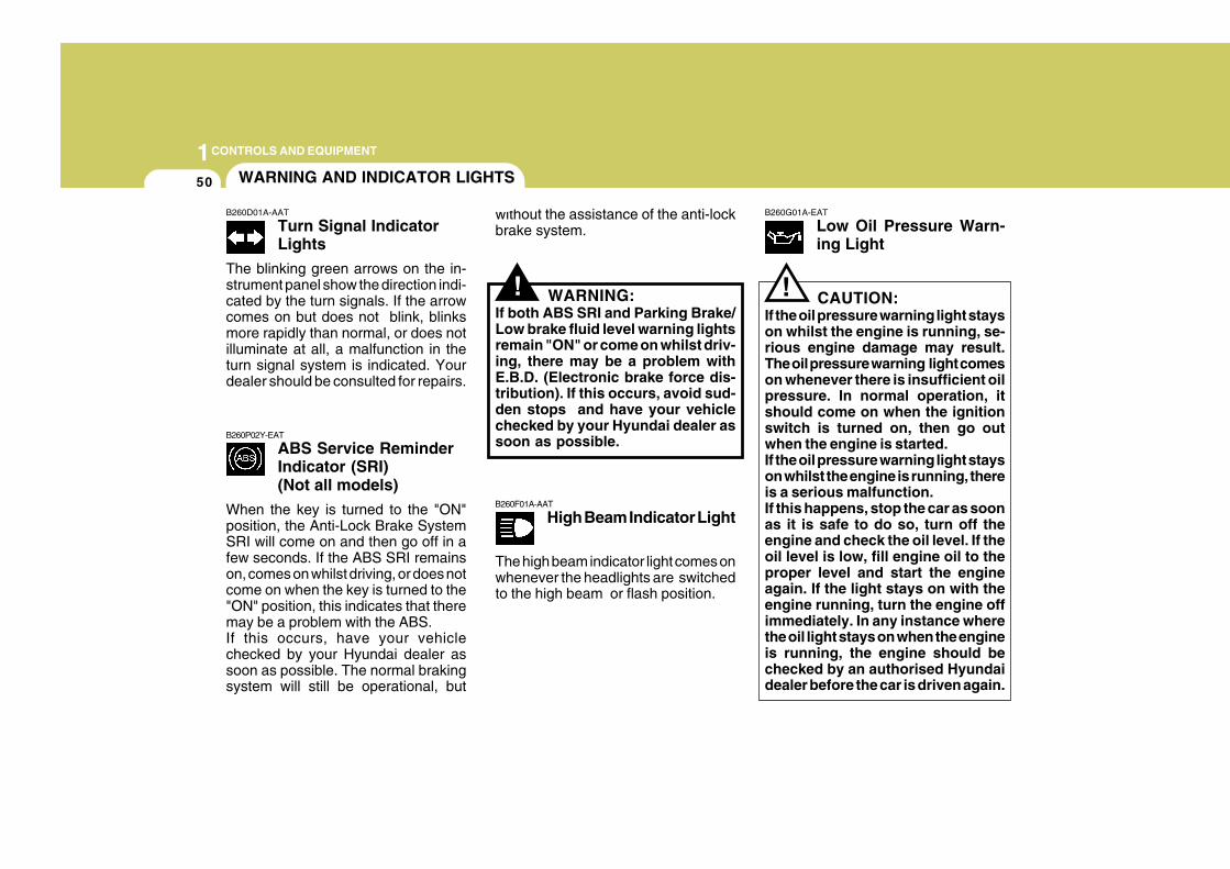
B260P02Y-EAT
ABS Service ReminderIndicator (SRI)(Not all models)
When the key is turned to the "ON"position, the Anti-Lock Brake SystemSRI will come on and then go off in afew seconds. If the ABS SRI remainson, comes on whilst driving, or does notcome on when the key is turned to the"ON" position, this indicates that theremay be a problem with the ABS.If this occurs, have your vehiclechecked by your Hyundai dealer assoon as possible. The normal brakingsystem will still be operational, but
without the assistance of the anti-lockbrake system.
WARNING:If both ABS SRI and Parking Brake/Low brake fluid level warning lightsremain "ON" or come on whilst driv-ing, there may be a problem withE.B.D. (Electronic brake force dis-tribution). If this occurs, avoid sud-den stops and have your vehiclechecked by your Hyundai dealer assoon as possible.
B260F01A-AAT
High Beam Indicator Light
B260G01A-EAT
Low Oil Pressure Warn-ing Light
CAUTION:If the oil pressure warning light stayson whilst the engine is running, se-rious engine damage may result.The oil pressure warning light comeson whenever there is insufficient oilpressure. In normal operation, itshould come on when the ignitionswitch is turned on, then go outwhen the engine is started.If the oil pressure warning light stayson whilst the engine is running, thereis a serious malfunction.If this happens, stop the car as soonas it is safe to do so, turn off theengine and check the oil level. If theoil level is low, fill engine oil to theproper level and start the engineagain. If the light stays on with theengine running, turn the engine offimmediately. In any instance wherethe oil light stays on when the engineis running, the engine should bechecked by an authorised Hyundaidealer before the car is driven again.
WARNING AND INDICATOR LIGHTS
B260D01A-AAT
Turn Signal IndicatorLights
The blinking green arrows on the in-strument panel show the direction indi-cated by the turn signals. If the arrowcomes on but does not blink, blinksmore rapidly than normal, or does notilluminate at all, a malfunction in theturn signal system is indicated. Yourdealer should be consulted for repairs.
The high beam indicator light comes onwhenever the headlights are switchedto the high beam or flash position.
1CONTROLS AND EQUIPMENT
51
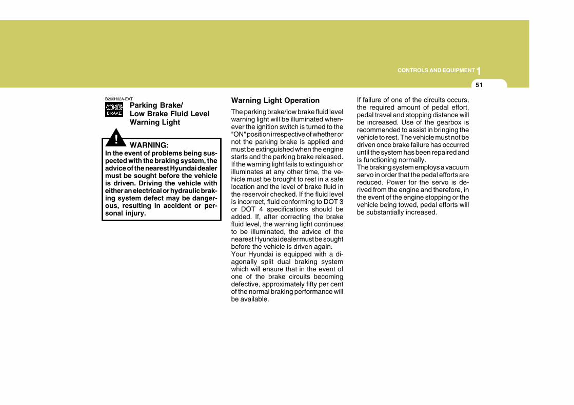
B260H02A-EAT
Parking Brake/Low Brake Fluid LevelWarning Light
WARNING:In the event of problems being sus-pected with the braking system, theadvice of the nearest Hyundai dealermust be sought before the vehicleis driven. Driving the vehicle witheither an electrical or hydraulic brak-ing system defect may be danger-ous, resulting in accident or per-sonal injury.
Warning Light Operation
The parking brake/low brake fluid levelwarning light will be illuminated when-ever the ignition switch is turned to the"ON" position irrespective of whether ornot the parking brake is applied andmust be extinguished when the enginestarts and the parking brake released.If the warning light fails to extinguish orilluminates at any other time, the ve-hicle must be brought to rest in a safelocation and the level of brake fluid inthe reservoir checked. If the fluid levelis incorrect, fluid conforming to DOT 3or DOT 4 specifications should beadded. If, after correcting the brakefluid level, the warning light continuesto be illuminated, the advice of thenearest Hyundai dealer must be soughtbefore the vehicle is driven again.Your Hyundai is equipped with a di-agonally split dual braking systemwhich will ensure that in the event ofone of the brake circuits becomingdefective, approximately fifty per centof the normal braking performance willbe available.
If failure of one of the circuits occurs,the required amount of pedal effort,pedal travel and stopping distance willbe increased. Use of the gearbox isrecommended to assist in bringing thevehicle to rest. The vehicle must not bedriven once brake failure has occurreduntil the system has been repaired andis functioning normally.The braking system employs a vacuumservo in order that the pedal efforts arereduced. Power for the servo is de-rived from the engine and therefore, inthe event of the engine stopping or thevehicle being towed, pedal efforts willbe substantially increased.
!
1CONTROLS AND EQUIPMENT
52
SB2100I-E
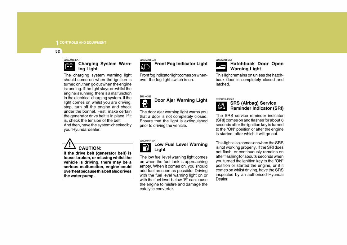
Door Ajar Warning Light
B260M01A-AAT
Low Fuel Level WarningLight
B260A01B-GAT
Front Fog Indicator LightB260K01B-EAT
Hatchback Door OpenWarning Light
B260B01HP-EAT
SRS (Airbag) ServiceReminder Indicator (SRI)
!
B260J01S-EAT
Charging System Warn-ing Light
CAUTION:If the drive belt (generator belt) isloose, broken, or missing whilst thevehicle is driving, there may be aserious malfunction, engine couldoverheat because this belt also drivesthe water pump.
The charging system warning lightshould come on when the ignition isturned on, then go out when the engineis running. If the light stays on whilst theengine is running, there is a malfunctionin the electrical charging system. If thelight comes on whilst you are driving,stop, turn off the engine and checkunder the bonnet. First, make certainthe generator drive belt is in place. If itis, check the tension of the belt.And then, have the system checked byyour Hyundai dealer.
Front fog indicator light comes on when-ever the fog light switch is on.
The door ajar warning light warns youthat a door is not completely closed.Ensure that the light is extinguishedprior to driving the vehicle.
The low fuel level warning light comeson when the fuel tank is approachingempty. When it comes on, you shouldadd fuel as soon as possible. Drivingwith the fuel level warning light on orwith the fuel level below "E" can causethe engine to misfire and damage thecatalytic converter.
This light remains on unless the hatch-back door is completely closed andlatched.
The SRS service reminder indicator(SRI) comes on and flashes for about 6seconds after the ignition key is turnedto the "ON" position or after the engineis started, after which it will go out.
This light also comes on when the SRSis not working properly. If the SRI doesnot flash, or continuously remains onafter flashing for about 6 seconds whenyou turned the ignition key to the "ON"position or started the engine, or if itcomes on whilst driving, have the SRSinspected by an authorised HyundaiDealer.
1CONTROLS AND EQUIPMENT
53
B260N02A-EAT
Malfunction IndicatorLight
B260Q01HP-EAT
Cruise Indicator Light(For Petrol Engine)(Not all models)
The cruise indicator light in the instru-ment cluster is illuminated only whenthe vehicle cruising speed has been setusing the control switch on the steeringwheel.The indicator light does not illuminatewhen the main cruise control switch isactivated.Information on the use of cruise controlmay be found on page 1-86.
B265Q01HP-EAT
Cruise Indicator Light(For Diesel Engine)(Not all models)
The cruise indicator light in the instru-ment cluster is illuminated when thecruise control main switch is activated.Information about the use of cruisecontrol may be found on page 1-86.
B260E01HP-GAT
Seat Belt Warning Light
HP210E1-E
Overdrive OFF IndicatorLight (Automatic Trans-mission only)
When the overdrive (4th gear) switchis turned off and the operation of over-drive (4th gear) is cancelled, the over-drive warning light (O/D OFF) will beilluminated. When the switch is at theon position, the gearbox will operate inthe normal fully automatic mode andthe warning light will be extinguished.
This light illuminates when there is amalfunction of an exhaust gas relatedcomponent, and the system is notfunctioning properly so that the ex-haust gas regulation values are notsatisfied. This light will also illuminatewhen the ignition key is turned to the"ON" position, and will go out in a fewseconds after the engine is started. If itilluminates whilst driving, or does notilluminate when the ignition key is turnedto the "ON" position, take your car toyour nearest authorised Hyundai dealerand have the system checked.
The seat belt warning light blinks forabout 6 seconds when the ignition keyis turned from the "OFF" position to"ON" or "START".
1CONTROLS AND EQUIPMENT
54
!
B260U01HP-EAT
A/T(Automatic Transmis-sion) Oil TemperatureWarning Light (Not allmodels)
CAUTION:If the warning light doesn't go off orblinks, this indicates that there is amalfunction in the automatic trans-mission or T.C.U (TransmissionControl Unit). If this occurs, haveyour vehicle checked by anauthorised Hyundai dealer.
B260U01TB-EAT
Immobiliser WarningLight (Diesel Engine)
This warning light comes on for someseconds after the ignition key is turnedto the "ON" position. At this time, youcan start the engine. The light goes outafter the engine is running. In case thislight goes out before you start theengine, you must turn to the "LOCK"position and restart the engine. In casethis light blinks for five seconds whenthe ignition key is turned to "ON" posi-tion, this indicates that the immobilisersystem is out of order. At this time,consult to the Hyundai dealer.
B260R01HP-GAT
4WD LOW Indicator Light
The A/T oil temperature warning lightcomes on when the automatic trans-mission oil temperature goes up to thetemperature that may result in seriousdamage of automatic transmission.If the A/T oil temperature warning lightcomes on whilst driving, park yourvehicle in at a safe place as soon aspossible. With the selector lever shiftedinto "P" position, allow the engine toidle until the warning light goes off.When the warning light goes off, thevehicle can be driven normally.
When the key is turned to the "ON"position, the 4WD(Four Wheel Drive)LOW indicator light will come on andthen go off in a few seconds.The 4WD LOW indicator light comes onwhen the transfer shift knob is set tolow position (Part-time 4WD type : 4Lposition, Full-time 4WD type : Lowposition).
1CONTROLS AND EQUIPMENT
55
!
B265T01HP-EAT
4WD System WarningLight (Full-time 4WD only)
CAUTION:If the 4WD system warning light( ) blinks whilst driving, thisindicates that there is a malfunctionin the 4WD system. If this occurs,have your vehicle checked by anauthorised Hyundai dealer as soonas possible.
!
B260T02HP-EAT
4WD HIGH Indicator Light(Part-time 4WD only)
CAUTION:If the 4WD HIGH indicator light ( )illuminates with the 4WD low indica-tor light ( ) whilst driving, thisindicates that there is a malfunc-tion in the 4WD system. If this oc-curs, have your vehicle checked byan authorised Hyundai dealer as soonas possible.
B265A01HP-EAT
Fuel Filter WarningLight (Diesel Engine)
! CAUTIONWhen the fuel filter warning light isilluminated, the engine power de-creases. If the fuel filter warning lightcomes on whilst driving, park yourvehicle in at a safe place and removethe water as soon as possible. If thelight remains on after removing thewater, have the system checked byan authorised Hyundai dealer.
When the key is turned to the "ON"position, the 4WD(Four Wheel Drive)HIGH indicator light will come on andthen go off in a few seconds.The 4WD HIGH indicator light will illu-minate when the transfer shift knob isset to 4H position .
When the key is turned to the "ON"position, the 4WD (Four wheel drive)system warning light will come on andthen go off in a few seconds.
This light illuminates when the ignitionswitch is set to the "ON" position andgoes off after the engine has started. Ifit lights up whilst the engine is running,it indicates that water has accumu-lated inside the fuel filter. If this hap-pens, remove the water from the fuelfilter. (Refer to "Owner Maintenance")
1CONTROLS AND EQUIPMENT
56
!
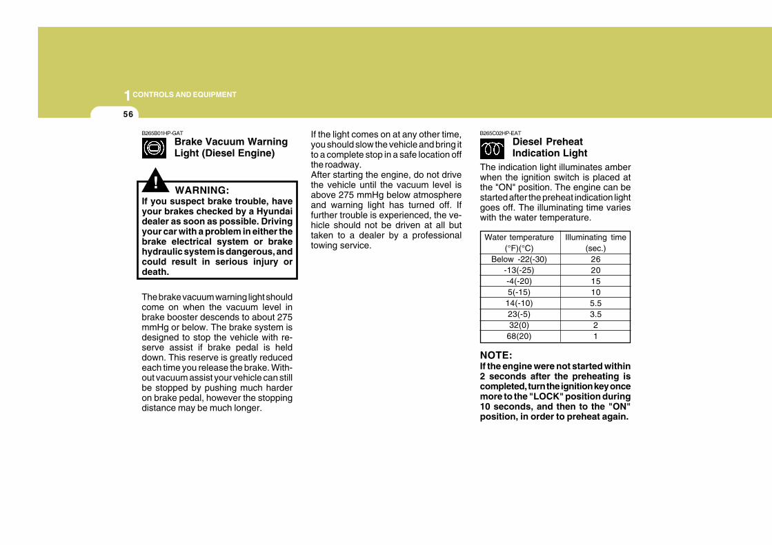
B265B01HP-GAT
Brake Vacuum WarningLight (Diesel Engine)
The brake vacuum warning light shouldcome on when the vacuum level inbrake booster descends to about 275mmHg or below. The brake system isdesigned to stop the vehicle with re-serve assist if brake pedal is helddown. This reserve is greatly reducedeach time you release the brake. With-out vacuum assist your vehicle can stillbe stopped by pushing much harderon brake pedal, however the stoppingdistance may be much longer.
WARNING:If you suspect brake trouble, haveyour brakes checked by a Hyundaidealer as soon as possible. Drivingyour car with a problem in either thebrake electrical system or brakehydraulic system is dangerous, andcould result in serious injury ordeath.
If the light comes on at any other time,you should slow the vehicle and bring itto a complete stop in a safe location offthe roadway.After starting the engine, do not drivethe vehicle until the vacuum level isabove 275 mmHg below atmosphereand warning light has turned off. Iffurther trouble is experienced, the ve-hicle should not be driven at all buttaken to a dealer by a professionaltowing service.
B265C02HP-EAT
Diesel PreheatIndication Light
Water temperature(°F)(°C)
Below -22(-30)-13(-25)-4(-20)5(-15)
14(-10)23(-5)32(0)
68(20)
Illuminating time(sec.)
262015105.53.521
NOTE:If the engine were not started within2 seconds after the preheating iscompleted, turn the ignition key oncemore to the "LOCK" position during10 seconds, and then to the "ON"position, in order to preheat again.
The indication light illuminates amberwhen the ignition switch is placed atthe "ON" position. The engine can bestarted after the preheat indication lightgoes off. The illuminating time varieswith the water temperature.
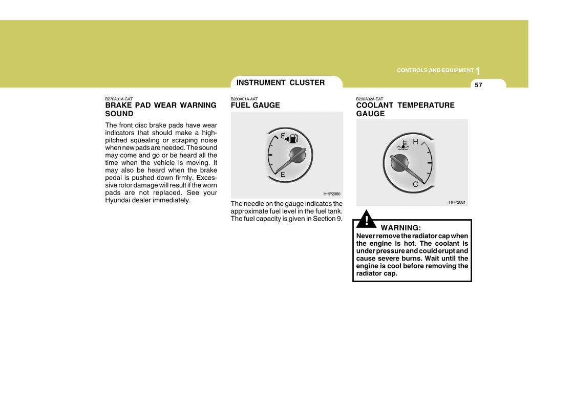
1CONTROLS AND EQUIPMENT
57
!
B270A01A-GAT
BRAKE PAD WEAR WARNINGSOUND
The front disc brake pads have wearindicators that should make a high-pitched squealing or scraping noisewhen new pads are needed. The soundmay come and go or be heard all thetime when the vehicle is moving. Itmay also be heard when the brakepedal is pushed down firmly. Exces-sive rotor damage will result if the wornpads are not replaced. See yourHyundai dealer immediately.
B290A02A-EAT
COOLANT TEMPERATUREGAUGE
The needle on the gauge indicates theapproximate fuel level in the fuel tank.The fuel capacity is given in Section 9.
WARNING:Never remove the radiator cap whenthe engine is hot. The coolant isunder pressure and could erupt andcause severe burns. Wait until theengine is cool before removing theradiator cap.
INSTRUMENT CLUSTER
B280A01A-AAT
FUEL GAUGE
HHP2080
HHP2081
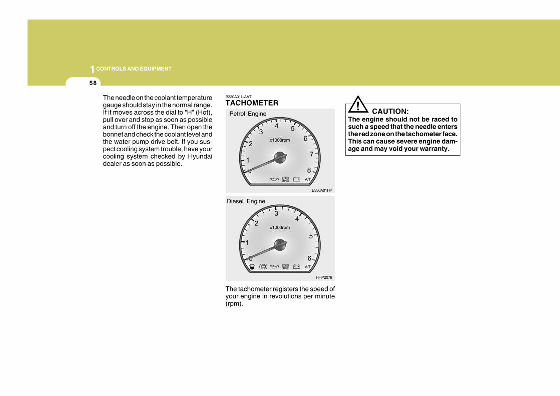
1CONTROLS AND EQUIPMENT
58
The needle on the coolant temperaturegauge should stay in the normal range.If it moves across the dial to "H" (Hot),pull over and stop as soon as possibleand turn off the engine. Then open thebonnet and check the coolant level andthe water pump drive belt. If you sus-pect cooling system trouble, have yourcooling system checked by Hyundaidealer as soon as possible.
! CAUTION:The engine should not be raced tosuch a speed that the needle entersthe red zone on the tachometer face.This can cause severe engine dam-age and may void your warranty.
B330A01L-AAT
TACHOMETER
The tachometer registers the speed ofyour engine in revolutions per minute(rpm).
Petrol Engine
B330A01HP
HHP2078
Diesel Engine
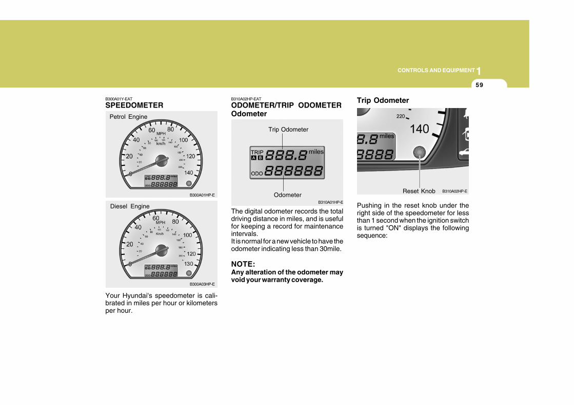
1CONTROLS AND EQUIPMENT
59
B300A01Y-EAT
SPEEDOMETER
Your Hyundai's speedometer is cali-brated in miles per hour or kilometersper hour.
Petrol Engine
B300A01HP-E
B300A03HP-E
Diesel Engine
B310A02HP-EAT
ODOMETER/TRIP ODOMETEROdometer
The digital odometer records the totaldriving distance in miles, and is usefulfor keeping a record for maintenanceintervals.It is normal for a new vehicle to have theodometer indicating less than 30mile.
NOTE:Any alteration of the odometer mayvoid your warranty coverage.
B310A01HP-E
Trip Odometer
OdometerB310A02HP-EReset Knob
Trip Odometer
Pushing in the reset knob under theright side of the speedometer for lessthan 1 second when the ignition switchis turned "ON" displays the followingsequence:
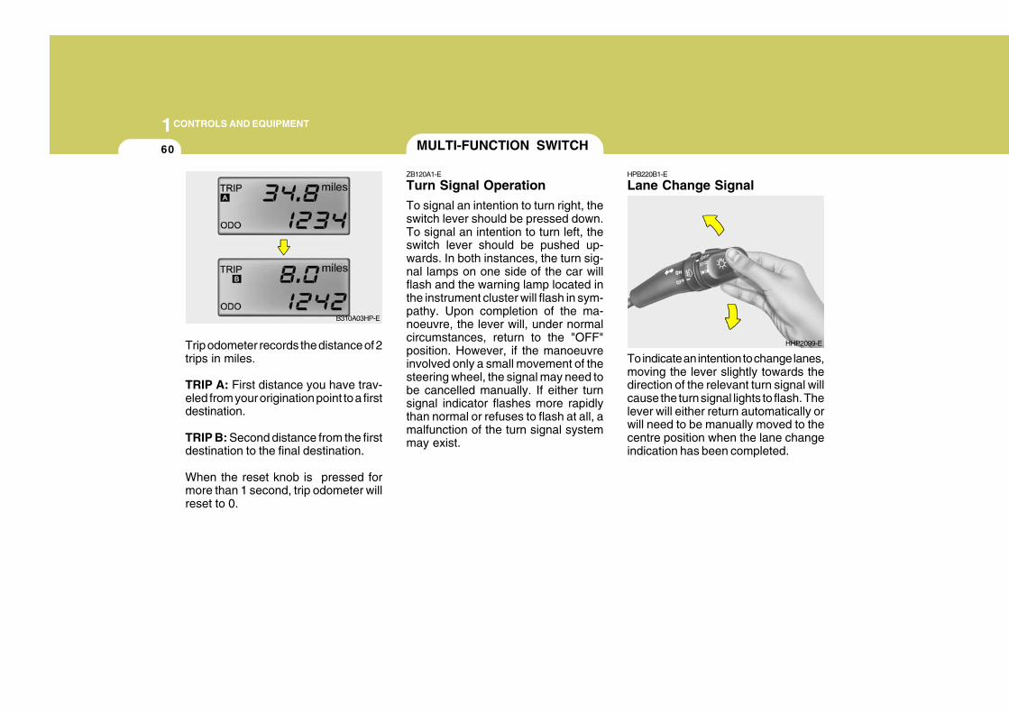
1CONTROLS AND EQUIPMENT
60
HPB220B1-E
Lane Change Signal
To indicate an intention to change lanes,moving the lever slightly towards thedirection of the relevant turn signal willcause the turn signal lights to flash. Thelever will either return automatically orwill need to be manually moved to thecentre position when the lane changeindication has been completed.
MULTI-FUNCTION SWITCH
ZB120A1-E
Turn Signal Operation
To signal an intention to turn right, theswitch lever should be pressed down.To signal an intention to turn left, theswitch lever should be pushed up-wards. In both instances, the turn sig-nal lamps on one side of the car willflash and the warning lamp located inthe instrument cluster will flash in sym-pathy. Upon completion of the ma-noeuvre, the lever will, under normalcircumstances, return to the "OFF"position. However, if the manoeuvreinvolved only a small movement of thesteering wheel, the signal may need tobe cancelled manually. If either turnsignal indicator flashes more rapidlythan normal or refuses to flash at all, amalfunction of the turn signal systemmay exist.
HHP2099-E
B310A03HP-E
Trip odometer records the distance of 2trips in miles.
TRIP A: First distance you have trav-eled from your origination point to a firstdestination.
TRIP B: Second distance from the firstdestination to the final destination.
When the reset knob is pressed formore than 1 second, trip odometer willreset to 0.
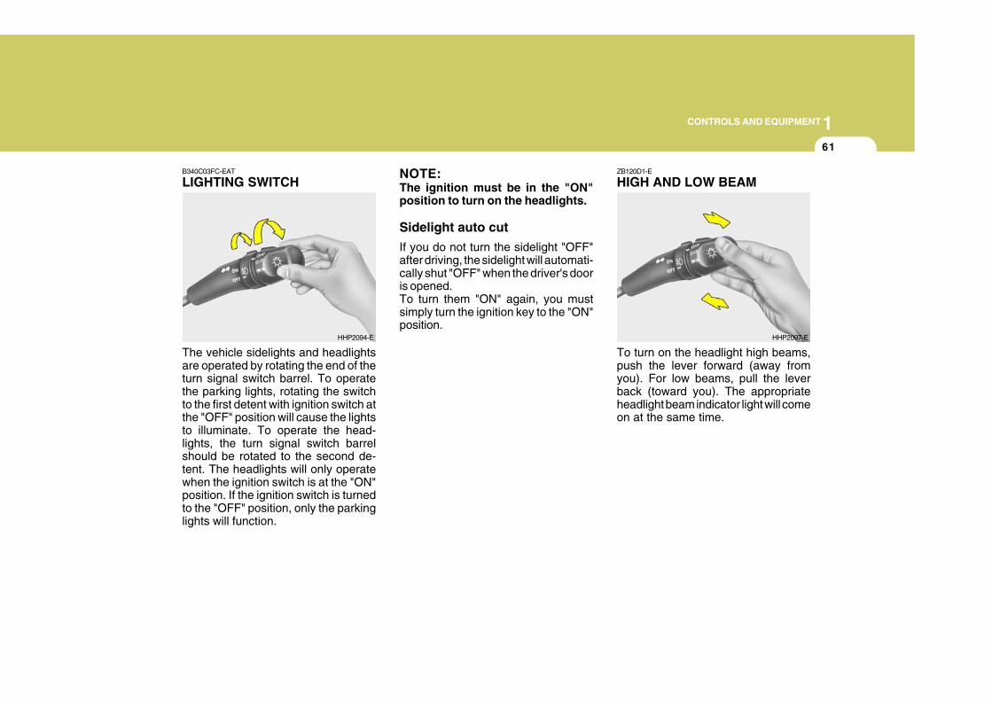
1CONTROLS AND EQUIPMENT
61
ZB120D1-E
HIGH AND LOW BEAMB340C03FC-EAT
LIGHTING SWITCH
The vehicle sidelights and headlightsare operated by rotating the end of theturn signal switch barrel. To operatethe parking lights, rotating the switchto the first detent with ignition switch atthe "OFF" position will cause the lightsto illuminate. To operate the head-lights, the turn signal switch barrelshould be rotated to the second de-tent. The headlights will only operatewhen the ignition switch is at the "ON"position. If the ignition switch is turnedto the "OFF" position, only the parkinglights will function.
HHP2094-E
NOTE:The ignition must be in the "ON"position to turn on the headlights.
Sidelight auto cut
If you do not turn the sidelight "OFF"after driving, the sidelight will automati-cally shut "OFF" when the driver's dooris opened.To turn them "ON" again, you mustsimply turn the ignition key to the "ON"position.
HHP2097-E
To turn on the headlight high beams,push the lever forward (away fromyou). For low beams, pull the leverback (toward you). The appropriateheadlight beam indicator light will comeon at the same time.
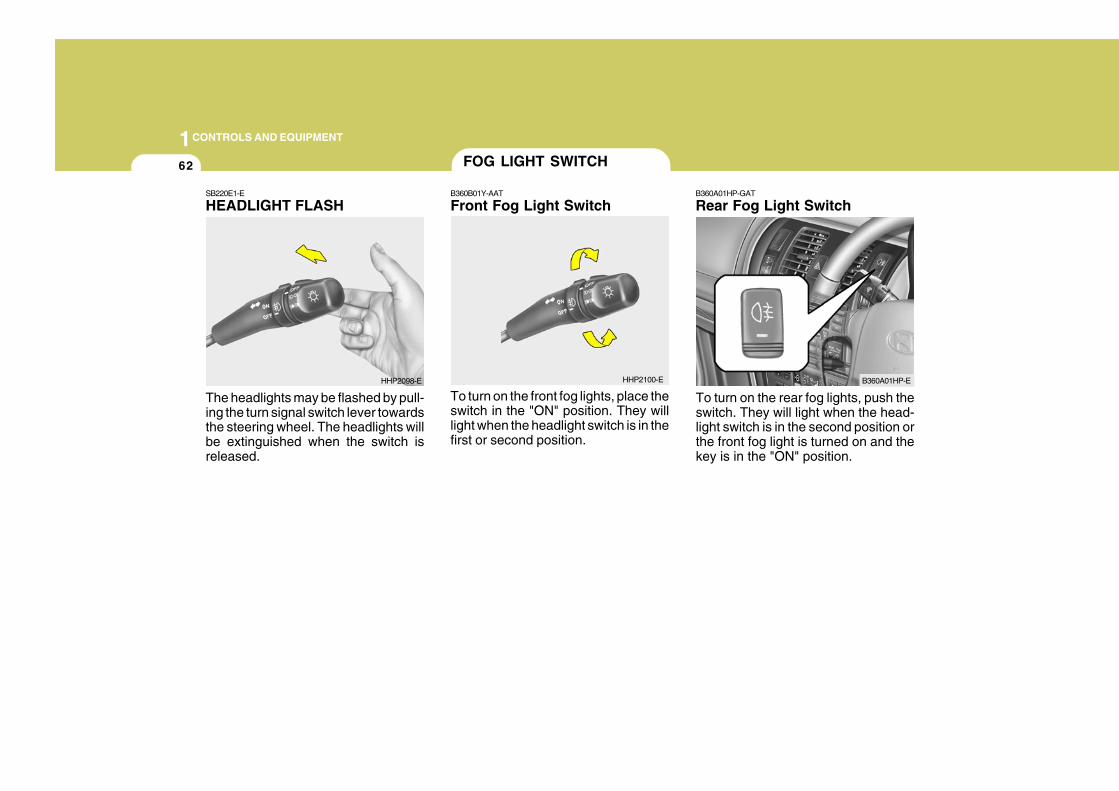
1CONTROLS AND EQUIPMENT
62 FOG LIGHT SWITCH
B360B01Y-AAT
Front Fog Light Switch
To turn on the front fog lights, place theswitch in the "ON" position. They willlight when the headlight switch is in thefirst or second position.
B360A01HP-GAT
Rear Fog Light Switch
HHP2100-E B360A01HP-E
SB220E1-E
HEADLIGHT FLASH
The headlights may be flashed by pull-ing the turn signal switch lever towardsthe steering wheel. The headlights willbe extinguished when the switch isreleased.
HHP2098-E
To turn on the rear fog lights, push theswitch. They will light when the head-light switch is in the second position orthe front fog light is turned on and thekey is in the "ON" position.
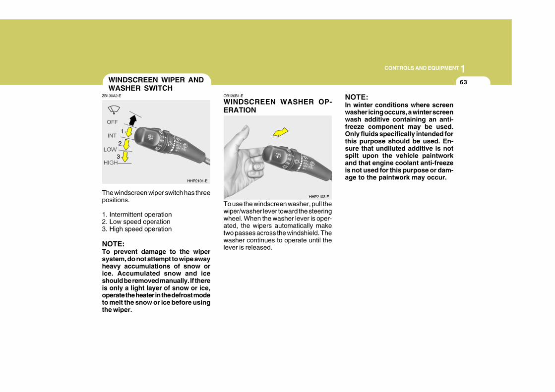
1CONTROLS AND EQUIPMENT
63
The windscreen wiper switch has threepositions.
1. Intermittent operation2. Low speed operation3. High speed operation
NOTE:To prevent damage to the wipersystem, do not attempt to wipe awayheavy accumulations of snow orice. Accumulated snow and iceshould be removed manually. If thereis only a light layer of snow or ice,operate the heater in the defrost modeto melt the snow or ice before usingthe wiper.
WINDSCREEN WIPER ANDWASHER SWITCH
ZB130A2-E
HHP2101-E
1
OB130B1-E
WINDSCREEN WASHER OP-ERATION
To use the windscreen washer, pull thewiper/washer lever toward the steeringwheel. When the washer lever is oper-ated, the wipers automatically maketwo passes across the windshield. Thewasher continues to operate until thelever is released.
NOTE:In winter conditions where screenwasher icing occurs, a winter screenwash additive containing an anti-freeze component may be used.Only fluids specifically intended forthis purpose should be used. En-sure that undiluted additive is notspilt upon the vehicle paintworkand that engine coolant anti-freezeis not used for this purpose or dam-age to the paintwork may occur.
HHP2103-E
2
3
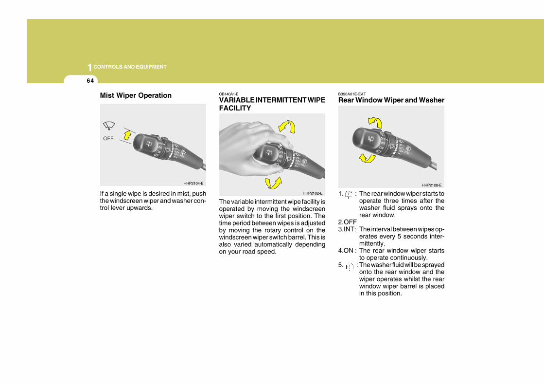
1CONTROLS AND EQUIPMENT
64
OB140A1-E
VARIABLE INTERMITTENT WIPEFACILITY
The variable intermittent wipe facility isoperated by moving the windscreenwiper switch to the first position. Thetime period between wipes is adjustedby moving the rotary control on thewindscreen wiper switch barrel. This isalso varied automatically dependingon your road speed.
HHP2102-E
HHP2108-E
Mist Wiper Operation
If a single wipe is desired in mist, pushthe windscreen wiper and washer con-trol lever upwards.
HHP2104-E
B390A01E-EAT
Rear Window Wiper and Washer
1. : The rear window wiper starts tooperate three times after thewasher fluid sprays onto therear window.
2.OFF3.INT: The interval between wipes op-
erates every 5 seconds inter-mittently.
4.ON : The rear window wiper startsto operate continuously.
5. :The washer fluid will be sprayedonto the rear window and thewiper operates whilst the rearwindow wiper barrel is placedin this position.
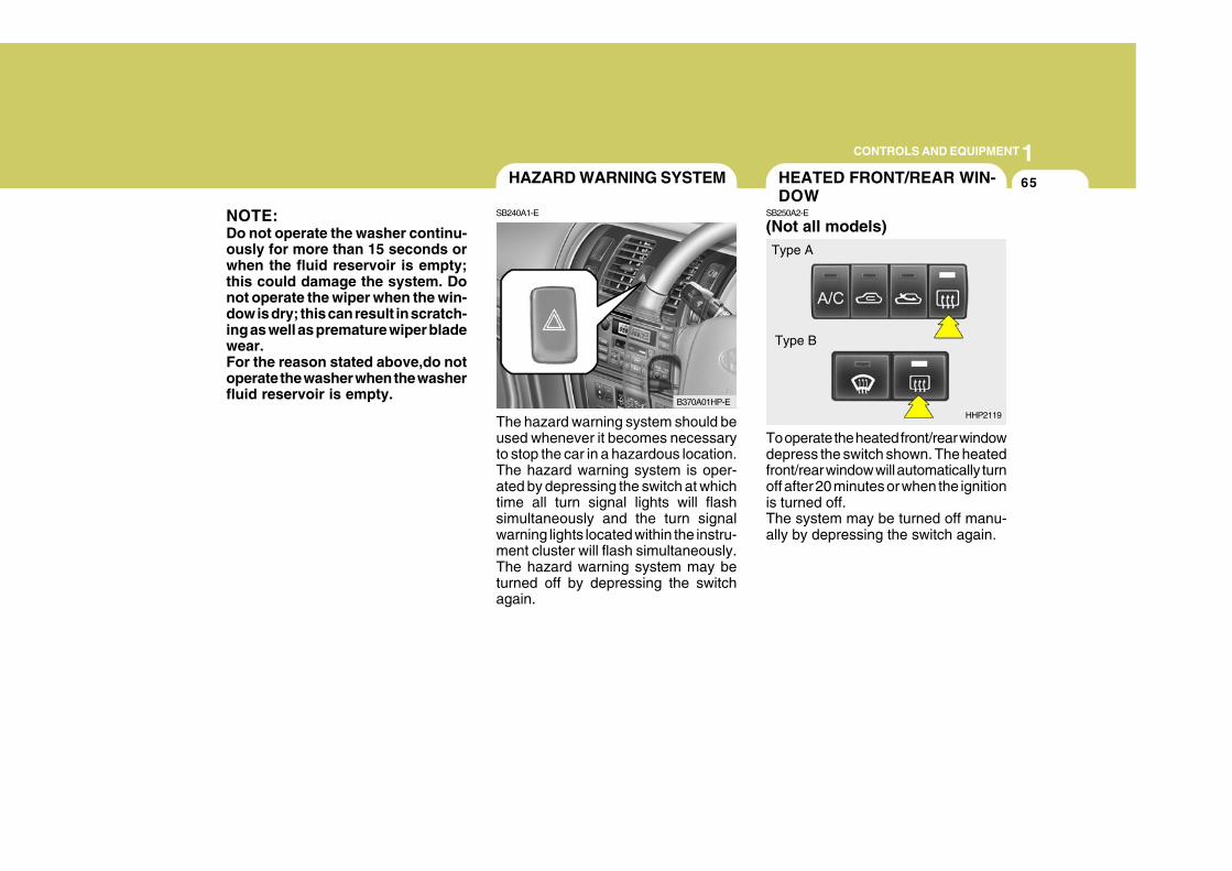
1CONTROLS AND EQUIPMENT
65
The hazard warning system should beused whenever it becomes necessaryto stop the car in a hazardous location.The hazard warning system is oper-ated by depressing the switch at whichtime all turn signal lights will flashsimultaneously and the turn signalwarning lights located within the instru-ment cluster will flash simultaneously.The hazard warning system may beturned off by depressing the switchagain.
HAZARD WARNING SYSTEM
SB240A1-E
B370A01HP-E
NOTE:Do not operate the washer continu-ously for more than 15 seconds orwhen the fluid reservoir is empty;this could damage the system. Donot operate the wiper when the win-dow is dry; this can result in scratch-ing as well as premature wiper bladewear.For the reason stated above,do notoperate the washer when the washerfluid reservoir is empty.
To operate the heated front/rear windowdepress the switch shown. The heatedfront/rear window will automatically turnoff after 20 minutes or when the ignitionis turned off.The system may be turned off manu-ally by depressing the switch again.
HEATED FRONT/REAR WIN-DOW
SB250A2-E
(Not all models)
HHP2119
Type A
Type B
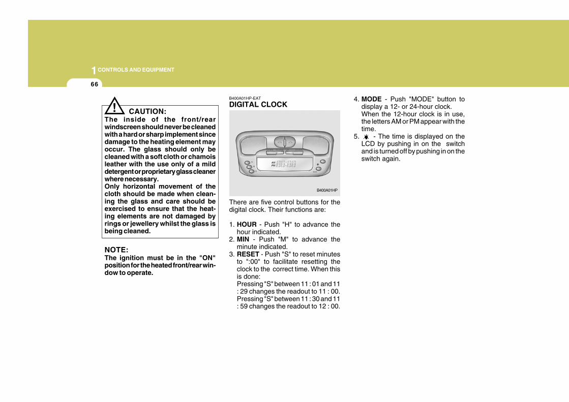
1CONTROLS AND EQUIPMENT
66
4. MODE - Push "MODE" button todisplay a 12- or 24-hour clock.When the 12-hour clock is in use,the letters AM or PM appear with thetime.
5. - The time is displayed on theLCD by pushing in on the switchand is turned off by pushing in on theswitch again.
! CAUTION:The inside of the front/rearwindscreen should never be cleanedwith a hard or sharp implement sincedamage to the heating element mayoccur. The glass should only becleaned with a soft cloth or chamoisleather with the use only of a milddetergent or proprietary glass cleanerwhere necessary.Only horizontal movement of thecloth should be made when clean-ing the glass and care should beexercised to ensure that the heat-ing elements are not damaged byrings or jewellery whilst the glass isbeing cleaned.
NOTE:The ignition must be in the "ON"position for the heated front/rear win-dow to operate.
B400A01HP-EAT
DIGITAL CLOCK
There are five control buttons for thedigital clock. Their functions are:
1. HOUR - Push "H" to advance thehour indicated.
2. MIN - Push "M" to advance theminute indicated.
3. RESET - Push "S" to reset minutesto ":00" to facilitate resetting theclock to the correct time. When thisis done:Pressing "S" between 11 : 01 and 11: 29 changes the readout to 11 : 00.Pressing "S" between 11 : 30 and 11: 59 changes the readout to 12 : 00.
B400A01HP
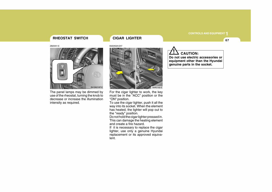
1CONTROLS AND EQUIPMENT
67
The panel lamps may be dimmed byuse of the rheostat, turning the knob todecrease or increase the illuminationintensity as required.
For the cigar lighter to work, the keymust be in the "ACC" position or the"ON" position.To use the cigar lighter, push it all theway into its socket. When the elementhas heated, the lighter will pop out tothe "ready" position.Do not hold the cigar lighter pressed in.This can damage the heating elementand create a fire hazard.If it is necessary to replace the cigarlighter, use only a genuine Hyundaireplacement or its approved equiva-lent.
RHEOSTAT SWITCH
ZB200A1-E
B410A01HP-E
CIGAR LIGHTER
B420A02A-EAT
HHP2160-E
CAUTION:Do not use electric accessories orequipment other than the Hyundaigenuine parts in the socket.
!
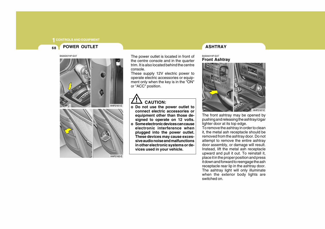
1CONTROLS AND EQUIPMENT
68
The front ashtray may be opened bypushing and releasing the ashtray/cigarlighter door at its top edge.To remove the ashtray in order to cleanit, the metal ash receptacle should beremoved from the ashtray door. Do notattempt to remove the entire ashtraydoor assembly, or damage will result.Instead, lift the metal ash receptacleupward and pull it out. To reinstall it,place it in the proper position and pressit down and forward to reengage the ashreceptacle rear lip in the ashtray door.The ashtray light will only illuminatewhen the exterior body lights areswitched on.
ASHTRAY
B430A01HP-EAT
Front Ashtray
HHP2167-E
!
The power outlet is located in front ofthe centre console and in the quartertrim. It is also located behind the centreconsole.These supply 12V electric power tooperate electric accessories or equip-ment only when the key is in the "ON"or "ACC" position.
CAUTION:o Do not use the power outlet to
connect electric accessories orequipment other than those de-signed to operate on 12 volts.
o Some electronic devices can causeelectronic interference whenplugged into the power outlet.These devices may cause exces-sive audio noise and malfunctionsin other electronic systems or de-vices used in your vehicle.
POWER OUTLET
B500D07HP-EAT
HHP2162-E
HHP2161-E
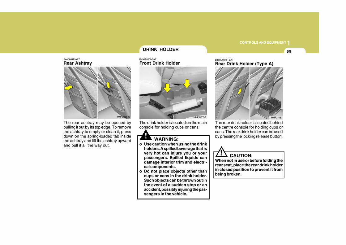
1CONTROLS AND EQUIPMENT
69
!
B440A01E-AAT
Rear Ashtray
The rear ashtray may be opened bypulling it out by its top edge. To removethe ashtray to empty or clean it, pressdown on the spring-loaded tab insidethe ashtray and lift the ashtray upwardand pull it all the way out.
The drink holder is located on the mainconsole for holding cups or cans.
WARNING:o Use caution when using the drink
holders. A spilled beverage that isvery hot can injure you or yourpassengers. Spilled liquids candamage interior trim and electri-cal components.
o Do not place objects other thancups or cans in the drink holder.Such objects can be thrown out inthe event of a sudden stop or anaccident, possibly injuring the pas-sengers in the vehicle.
HHP2168-E
DRINK HOLDER
B450A02O-GAT
Front Drink Holder
HHP2177-E
B450C01HP-EAT
Rear Drink Holder (Type A)
The rear drink holder is located behindthe centre console for holding cups orcans. The rear drink holder can be usedby pressing the locking release button.
HHP2178
CAUTION:When not in use or before folding therear seat, place the rear drink holderin closed position to prevent it frombeing broken.
!
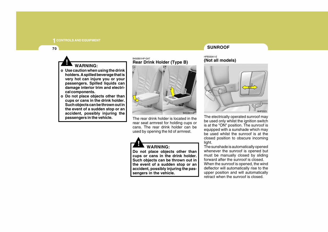
1CONTROLS AND EQUIPMENT
70
The electrically operated sunroof maybe used only whilst the ignition switchis at the "ON" position. The sunroof isequipped with a sunshade which maybe used whilst the sunroof is at theclosed position to obscure incominglight.The sunshade is automatically openedwhenever the sunroof is opened butmust be manually closed by slidingforward after the sunroof is closed.When the sunroof is opened, the winddeflector will automatically rise to theupper position and will automaticallyretract when the sunroof is closed.
SUNROOF
HPB330A1-E
(Not all models)
HHP2023
!
B450B01HP-GAT
Rear Drink Holder (Type B)
The rear drink holder is located in therear seat armrest for holding cups orcans. The rear drink holder can beused by opening the lid of armrest.
WARNING:Do not place objects other thancups or cans in the drink holder.Such objects can be thrown out inthe event of a sudden stop or anaccident, possibly injuring the pas-sengers in the vehicle.
!WARNING:
o Use caution when using the drinkholders. A spilled beverage that isvery hot can injure you or yourpassengers. Spilled liquids candamage interior trim and electri-cal components.
o Do not place objects other thancups or cans in the drink holder.Such objects can be thrown out inthe event of a sudden stop or anaccident, possibly injuring thepassengers in the vehicle.
B450B01HP
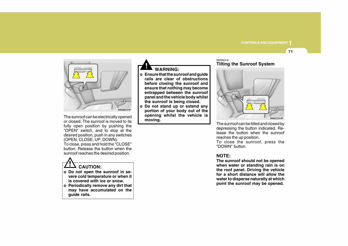
1CONTROLS AND EQUIPMENT
71
!
!
The sunroof can be electrically openedor closed. The sunroof is moved to itsfully open position by pushing the"OPEN" switch, and to stop at thedesired position, push in any switches(OPEN, CLOSE, UP, DOWN).To close, press and hold the "CLOSE"button. Release the button when thesunroof reaches the desired position.
CAUTION:o Do not open the sunroof in se-
vere cold temperature or when itis covered with ice or snow.
o Periodically remove any dirt thatmay have accumulated on theguide rails.
WARNING:o Ensure that the sunroof and guide
rails are clear of obstructionsbefore closing the sunroof andensure that nothing may becomeentrapped between the sunroofpanel and the vehicle body whilstthe sunroof is being closed.
o Do not stand up or extend anyportion of your body out of theopening whilst the vehicle ismoving.
B460B01HP
SB330C2-E
Tilting the Sunroof System
The sunroof can be tilted and closed bydepressing the button indicated. Re-lease the button when the sunroofreaches the up position.To close the sunroof, press the"DOWN" button.
NOTE:The sunroof should not be openedwhen water or standing rain is onthe roof panel. Driving the vehiclefor a short distance will allow thewater to disperse naturally at whichpoint the sunroof may be opened.
B460C01HP
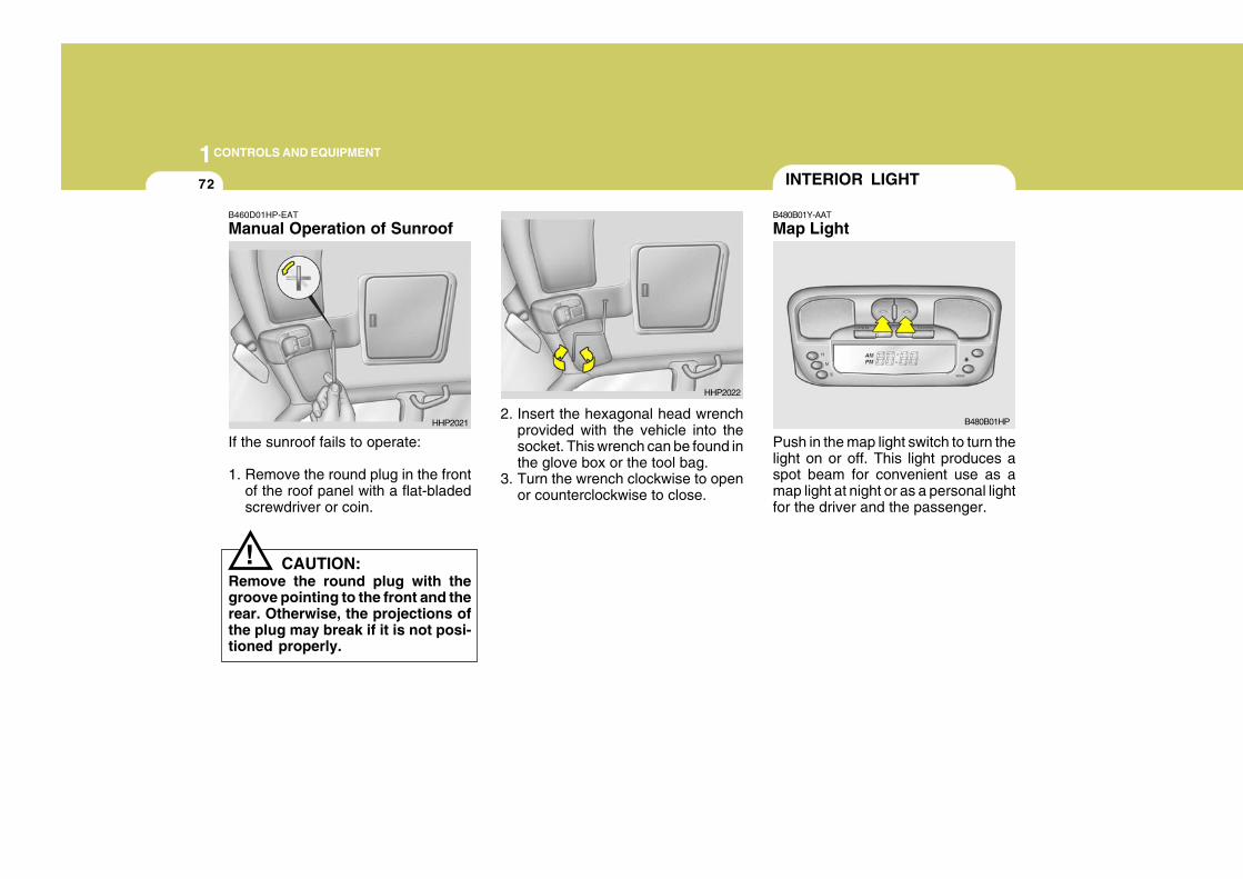
1CONTROLS AND EQUIPMENT
72
Push in the map light switch to turn thelight on or off. This light produces aspot beam for convenient use as amap light at night or as a personal lightfor the driver and the passenger.
INTERIOR LIGHT
B480B01Y-AAT
Map Light
B480B01HP
!
B460D01HP-EAT
Manual Operation of Sunroof
If the sunroof fails to operate:
1. Remove the round plug in the frontof the roof panel with a flat-bladedscrewdriver or coin.
2. Insert the hexagonal head wrenchprovided with the vehicle into thesocket. This wrench can be found inthe glove box or the tool bag.
3. Turn the wrench clockwise to openor counterclockwise to close.
CAUTION:Remove the round plug with thegroove pointing to the front and therear. Otherwise, the projections ofthe plug may break if it is not posi-tioned properly.
HHP2021
HHP2022
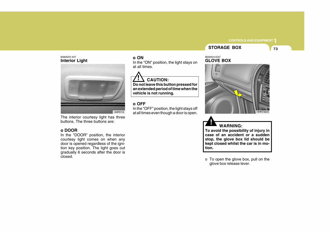
1CONTROLS AND EQUIPMENT
73
B490A03Y-AAT
Interior Light
The interior courtesy light has threebuttons. The three buttons are:
o DOORIn the "DOOR" position, the interiorcourtesy light comes on when anydoor is opened regardless of the igni-tion key position. The light goes outgradually 6 seconds after the door isclosed.
o ONIn the "ON" position, the light stays onat all times.
CAUTION:Do not leave this button pressed foran extended period of time when thevehicle is not running.
HHP2115
!
!WARNING:
To avoid the possibility of injury incase of an accident or a suddenstop, the glove box lid should bekept closed whilst the car is in mo-tion.
o To open the glove box, pull on theglove box release lever.
STORAGE BOX
B500A01A-EAT
GLOVE BOX
HHP2169-E
o OFFIn the "OFF" position, the light stays offat all times even though a door is open.
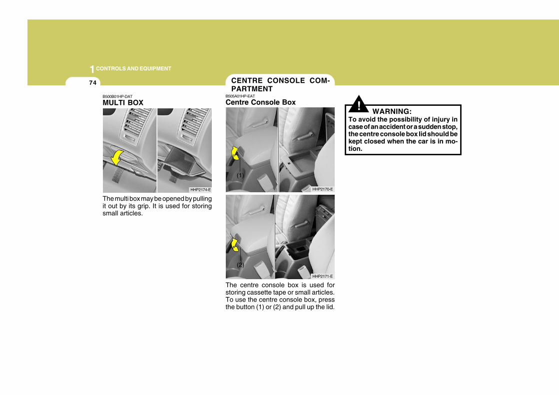
1CONTROLS AND EQUIPMENT
74
! WARNING:To avoid the possibility of injury incase of an accident or a sudden stop,the centre console box lid should bekept closed when the car is in mo-tion.
B500B01HP-DAT
MULTI BOX
The multi box may be opened by pullingit out by its grip. It is used for storingsmall articles.
HHP2174-E
CENTRE CONSOLE COM-PARTMENT
B505A01HP-EAT
Centre Console Box
The centre console box is used forstoring cassette tape or small articles.To use the centre console box, pressthe button (1) or (2) and pull up the lid.
HHP2170-E
HHP2171-E
(2)
(1)
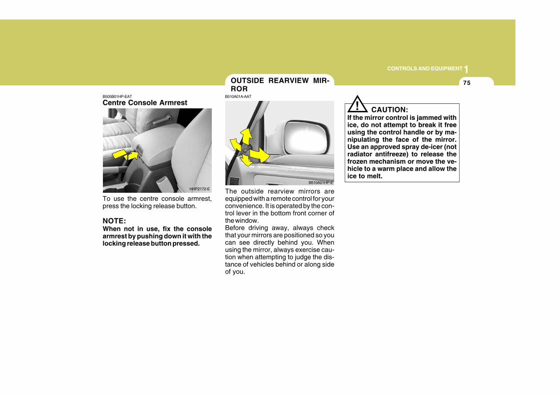
1CONTROLS AND EQUIPMENT
75
The outside rearview mirrors areequipped with a remote control for yourconvenience. It is operated by the con-trol lever in the bottom front corner ofthe window.Before driving away, always checkthat your mirrors are positioned so youcan see directly behind you. Whenusing the mirror, always exercise cau-tion when attempting to judge the dis-tance of vehicles behind or along sideof you.
B505B01HP-EAT
Centre Console Armrest
To use the centre console armrest,press the locking release button.
NOTE:When not in use, fix the consolearmrest by pushing down it with thelocking release button pressed.
HHP2172-E
B510A01HP-E
OUTSIDE REARVIEW MIR-ROR
B510A01A-AAT
! CAUTION:If the mirror control is jammed withice, do not attempt to break it freeusing the control handle or by ma-nipulating the face of the mirror.Use an approved spray de-icer (notradiator antifreeze) to release thefrozen mechanism or move the ve-hicle to a warm place and allow theice to melt.
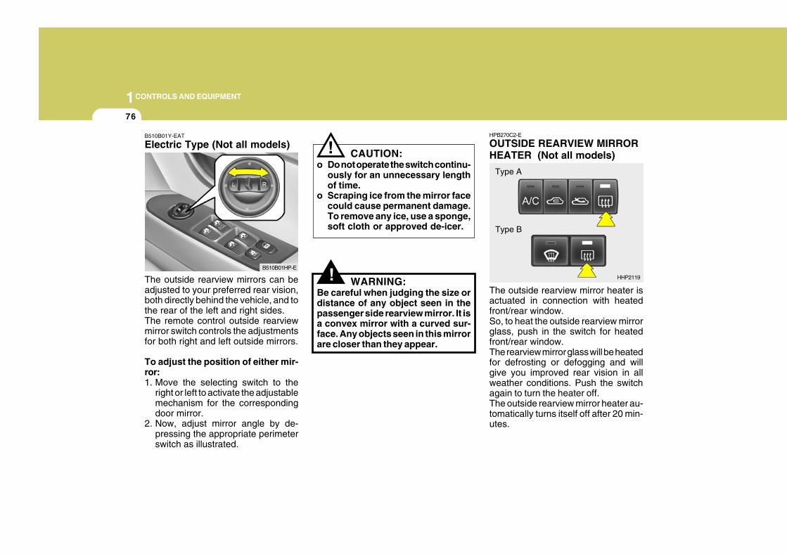
1CONTROLS AND EQUIPMENT
76
HPB270C2-E
OUTSIDE REARVIEW MIRRORHEATER (Not all models)
The outside rearview mirror heater isactuated in connection with heatedfront/rear window.So, to heat the outside rearview mirrorglass, push in the switch for heatedfront/rear window.The rearview mirror glass will be heatedfor defrosting or defogging and willgive you improved rear vision in allweather conditions. Push the switchagain to turn the heater off.The outside rearview mirror heater au-tomatically turns itself off after 20 min-utes.
HHP2119
Type A
Type B
!
B510B01Y-EAT
Electric Type (Not all models)
The outside rearview mirrors can beadjusted to your preferred rear vision,both directly behind the vehicle, and tothe rear of the left and right sides.The remote control outside rearviewmirror switch controls the adjustmentsfor both right and left outside mirrors.
To adjust the position of either mir-ror:1. Move the selecting switch to the
right or left to activate the adjustablemechanism for the correspondingdoor mirror.
2. Now, adjust mirror angle by de-pressing the appropriate perimeterswitch as illustrated.
CAUTION:o Do not operate the switch continu-
ously for an unnecessary lengthof time.
o Scraping ice from the mirror facecould cause permanent damage.To remove any ice, use a sponge,soft cloth or approved de-icer.
WARNING:Be careful when judging the size ordistance of any object seen in thepassenger side rearview mirror. It isa convex mirror with a curved sur-face. Any objects seen in this mirrorare closer than they appear.
!
B510B01HP-E
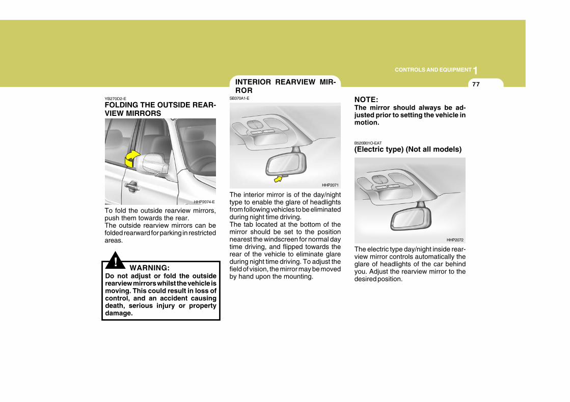
1CONTROLS AND EQUIPMENT
77
!
YB270D2-E
FOLDING THE OUTSIDE REAR-VIEW MIRRORS
To fold the outside rearview mirrors,push them towards the rear.The outside rearview mirrors can befolded rearward for parking in restrictedareas.
WARNING:Do not adjust or fold the outsiderearview mirrors whilst the vehicle ismoving. This could result in loss ofcontrol, and an accident causingdeath, serious injury or propertydamage.
The interior mirror is of the day/nighttype to enable the glare of headlightsfrom following vehicles to be eliminatedduring night time driving.The tab located at the bottom of themirror should be set to the positionnearest the windscreen for normal daytime driving, and flipped towards therear of the vehicle to eliminate glareduring night time driving. To adjust thefield of vision, the mirror may be movedby hand upon the mounting.
HHP2074-E
HHP2071
INTERIOR REARVIEW MIR-ROR
SB370A1-E NOTE:The mirror should always be ad-justed prior to setting the vehicle inmotion.
B520B01O-EAT
(Electric type) (Not all models)
The electric type day/night inside rear-view mirror controls automatically theglare of headlights of the car behindyou. Adjust the rearview mirror to thedesired position.
HHP2072
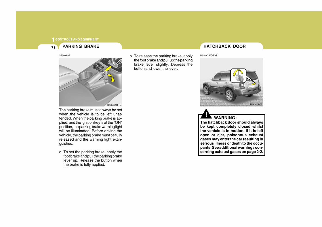
1CONTROLS AND EQUIPMENT
78
o To release the parking brake, applythe foot brake and pull up the parkingbrake lever slightly. Depress thebutton and lower the lever.
The parking brake must always be setwhen the vehicle is to be left unat-tended. When the parking brake is ap-plied, and the ignition key is at the "ON"position, the parking brake warning lightwill be illuminated. Before driving thevehicle, the parking brake must be fullyreleased and the warning light extin-guished.
o To set the parking brake, apply thefoot brake and pull the parking brakelever up. Release the button whenthe brake is fully applied.
PARKING BRAKE
SB380A1-E
B530A01HP-E
!
B540A01HP
HATCHBACK DOOR
B540A01FC-EAT
WARNING:The hatchback door should alwaysbe kept completely closed whilstthe vehicle is in motion. If it is leftopen or ajar, poisonous exhaustgases may enter the car resulting inserious illness or death to the occu-pants. See additional warnings con-cerning exhaust gases on page 2-2.
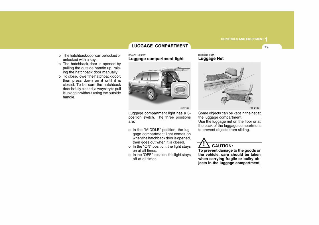
1CONTROLS AND EQUIPMENT
79
o The hatchback door can be locked orunlocked with a key.
o The hatchback door is opened bypulling the outside handle up, rais-ing the hatchback door manually.
o To close, lower the hatchback door,then press down on it until it isclosed. To be sure the hatchbackdoor is fully closed, always try to pullit up again without using the outsidehandle.
!
Luggage compartment light has a 3-position switch. The three positionsare:
o In the "MIDDLE" position, the lug-gage compartment light comes onwhen the hatchback door is opened,then goes out when it is closed.
o In the "ON" position, the light stayson at all times.
o In the "OFF" position, the light staysoff at all times.
B540D02HP-DAT
Luggage Net
Some objects can be kept in the net atthe luggage compartment.Use the luggage net on the floor or atthe back of the luggage compartmentto prevent objects from sliding.
CAUTION:To prevent damage to the goods orthe vehicle, care should be takenwhen carrying fragile or bulky ob-jects in the luggage compartment.
LUGGAGE COMPARTMENT
B540C01HP-EAT
Luggage compartment light
HHP2117 HHP2180
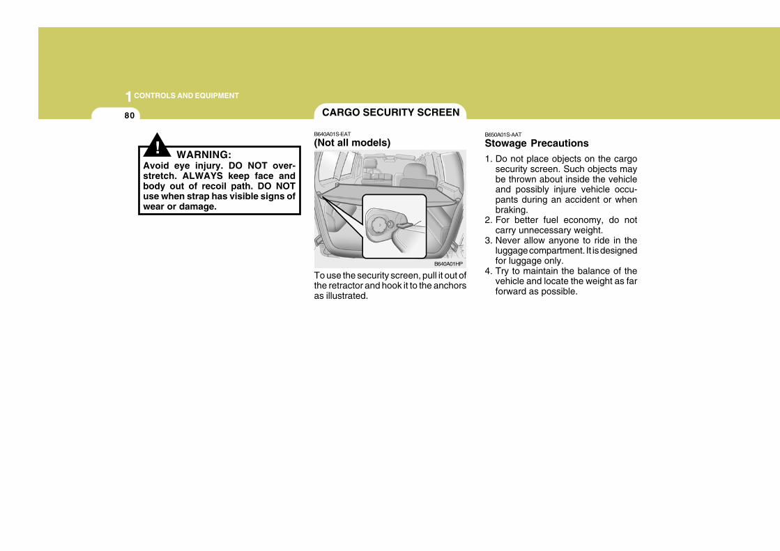
1CONTROLS AND EQUIPMENT
80
B650A01S-AAT
Stowage Precautions
1. Do not place objects on the cargosecurity screen. Such objects maybe thrown about inside the vehicleand possibly injure vehicle occu-pants during an accident or whenbraking.
2. For better fuel economy, do notcarry unnecessary weight.
3. Never allow anyone to ride in theluggage compartment. It is designedfor luggage only.
4. Try to maintain the balance of thevehicle and locate the weight as farforward as possible.
CARGO SECURITY SCREEN
B640A01S-EAT
(Not all models)
To use the security screen, pull it out ofthe retractor and hook it to the anchorsas illustrated.
B640A01HP
! WARNING:Avoid eye injury. DO NOT over-stretch. ALWAYS keep face andbody out of recoil path. DO NOTuse when strap has visible signs ofwear or damage.
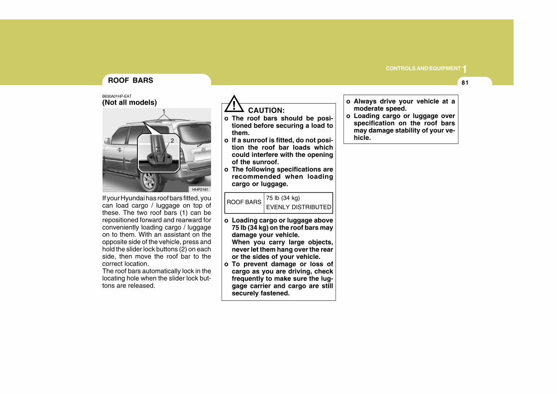
1CONTROLS AND EQUIPMENT
81
If your Hyundai has roof bars fitted, youcan load cargo / luggage on top ofthese. The two roof bars (1) can berepositioned forward and rearward forconveniently loading cargo / luggageon to them. With an assistant on theopposite side of the vehicle, press andhold the slider lock buttons (2) on eachside, then move the roof bar to thecorrect location.The roof bars automatically lock in thelocating hole when the slider lock but-tons are released.
ROOF BARS
B630A01HP-EAT
(Not all models)
HHP2181
1
2
o Always drive your vehicle at amoderate speed.
o Loading cargo or luggage overspecification on the roof barsmay damage stability of your ve-hicle.
! CAUTION:o The roof bars should be posi-
tioned before securing a load tothem.
o If a sunroof is fitted, do not posi-tion the roof bar loads whichcould interfere with the openingof the sunroof.
o The following specifications arerecommended when loadingcargo or luggage.
o Loading cargo or luggage above75 lb (34 kg) on the roof bars maydamage your vehicle.When you carry large objects,never let them hang over the rearor the sides of your vehicle.
o To prevent damage or loss ofcargo as you are driving, checkfrequently to make sure the lug-gage carrier and cargo are stillsecurely fastened.
ROOF BARS75 lb (34 kg)
EVENLY DISTRIBUTED
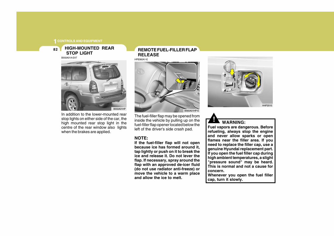
1CONTROLS AND EQUIPMENT
82
!The fuel-filler flap may be opened frominside the vehicle by pulling up on thefuel-filler flap opener located below theleft of the driver's side crash pad.
NOTE:If the fuel-filler flap will not openbecause ice has formed around it,tap lightly or push on it to break theice and release it. Do not lever theflap. If necessary, spray around theflap with an approved de-icer fluid(do not use radiator anti-freeze) ormove the vehicle to a warm placeand allow the ice to melt.
WARNING:Fuel vapors are dangerous. Beforerefueling, always stop the engineand never allow sparks or openflames near the filler area. If youneed to replace the filler cap, use agenuine Hyundai replacement part.If you open the fuel filler cap duringhigh ambient temperatures, a slight"pressure sound" may be heard.This is normal and not a cause forconcern.Whenever you open the fuel fillercap, turn it slowly.
REMOTE FUEL-FILLER FLAPRELEASE
HPB360A1-E
B560A01HP-E
HHP2015
In addition to the lower-mounted rearstop lights on either side of the car, thehigh mounted rear stop light in thecentre of the rear window also lightswhen the brakes are applied.
HIGH-MOUNTED REAR STOP LIGHT
B550A01A-EAT
B550A01HP
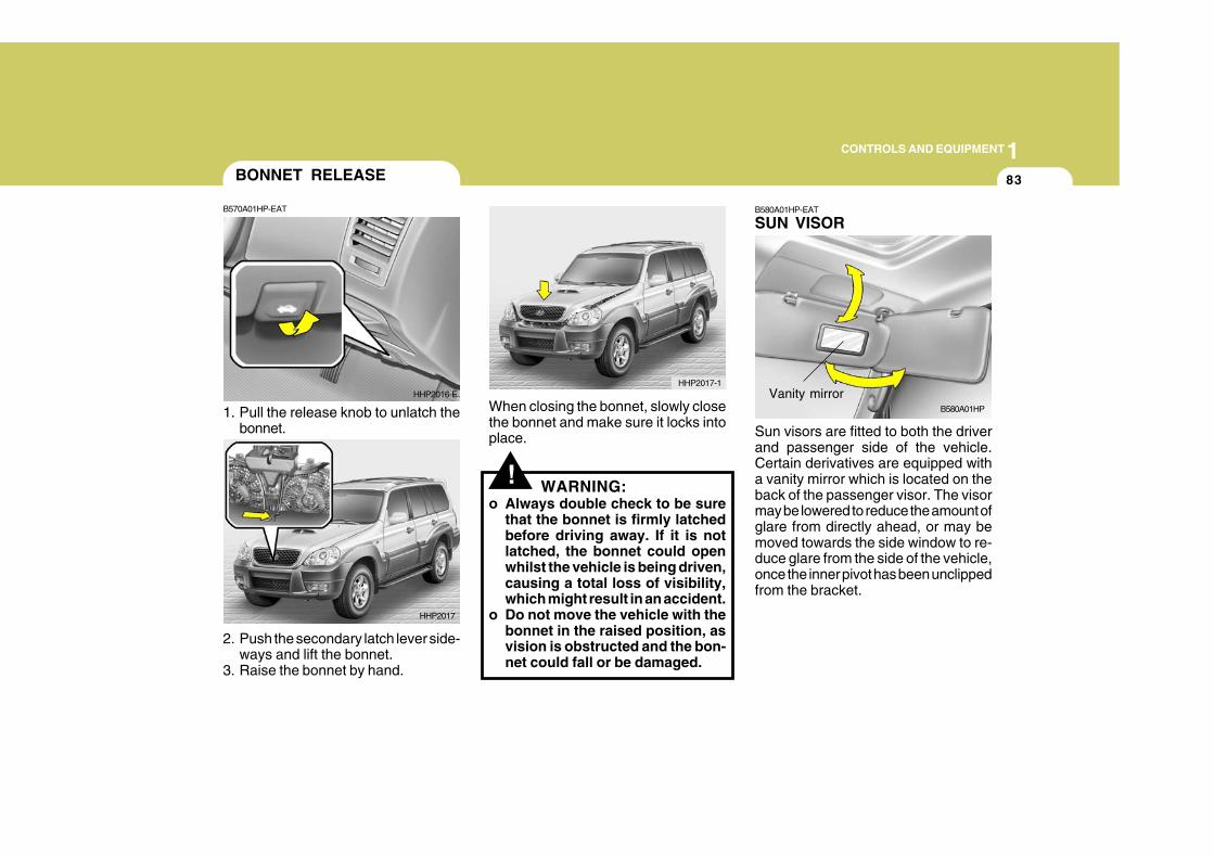
1CONTROLS AND EQUIPMENT
83
HHP2017-1
BONNET RELEASE
2. Push the secondary latch lever side-ways and lift the bonnet.
3. Raise the bonnet by hand.
B570A01HP-EAT
1. Pull the release knob to unlatch thebonnet.
HHP2016-E
HHP2017
!
When closing the bonnet, slowly closethe bonnet and make sure it locks intoplace.
WARNING:o Always double check to be sure
that the bonnet is firmly latchedbefore driving away. If it is notlatched, the bonnet could openwhilst the vehicle is being driven,causing a total loss of visibility,which might result in an accident.
o Do not move the vehicle with thebonnet in the raised position, asvision is obstructed and the bon-net could fall or be damaged.
B580A01HP-EAT
SUN VISOR
Sun visors are fitted to both the driverand passenger side of the vehicle.Certain derivatives are equipped witha vanity mirror which is located on theback of the passenger visor. The visormay be lowered to reduce the amount ofglare from directly ahead, or may bemoved towards the side window to re-duce glare from the side of the vehicle,once the inner pivot has been unclippedfrom the bracket.
B580A01HP
Vanity mirror
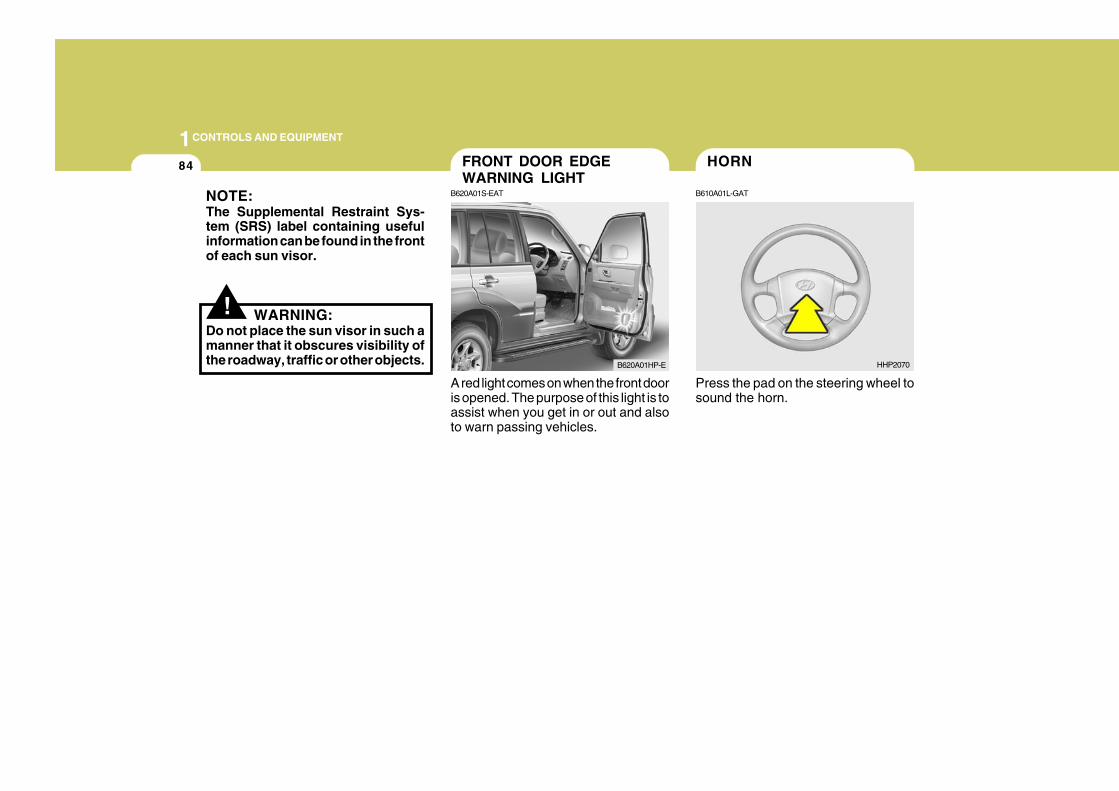
1CONTROLS AND EQUIPMENT
84
A red light comes on when the front dooris opened. The purpose of this light is toassist when you get in or out and alsoto warn passing vehicles.
Press the pad on the steering wheel tosound the horn.
FRONT DOOR EDGEWARNING LIGHT
B620A01S-EAT
B620A01HP-E HHP2070
!
NOTE:The Supplemental Restraint Sys-tem (SRS) label containing usefulinformation can be found in the frontof each sun visor.
WARNING:Do not place the sun visor in such amanner that it obscures visibility ofthe roadway, traffic or other objects.
HORN
B610A01L-GAT
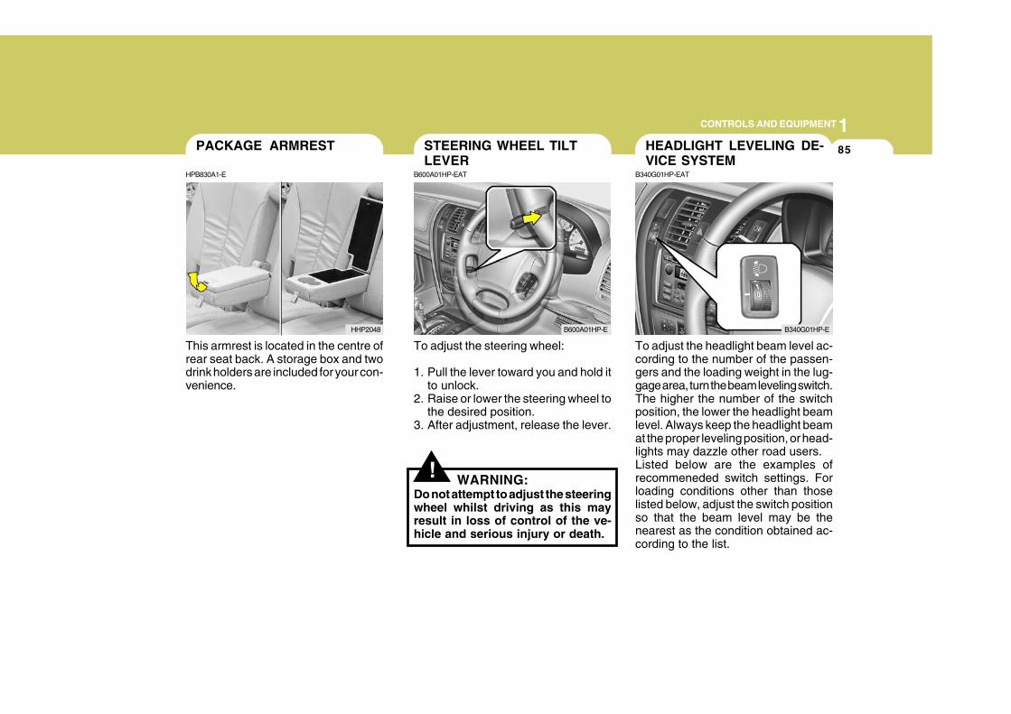
1CONTROLS AND EQUIPMENT
85
This armrest is located in the centre ofrear seat back. A storage box and twodrink holders are included for your con-venience.
PACKAGE ARMREST
HPB830A1-E
HHP2048
!
To adjust the steering wheel:
1. Pull the lever toward you and hold itto unlock.
2. Raise or lower the steering wheel tothe desired position.
3. After adjustment, release the lever.
WARNING:Do not attempt to adjust the steeringwheel whilst driving as this mayresult in loss of control of the ve-hicle and serious injury or death.
To adjust the headlight beam level ac-cording to the number of the passen-gers and the loading weight in the lug-gage area, turn the beam leveling switch.The higher the number of the switchposition, the lower the headlight beamlevel. Always keep the headlight beamat the proper leveling position, or head-lights may dazzle other road users.Listed below are the examples ofrecommeneded switch settings. Forloading conditions other than thoselisted below, adjust the switch positionso that the beam level may be thenearest as the condition obtained ac-cording to the list.
STEERING WHEEL TILTLEVER
B600A01HP-EAT
B600A01HP-E
HEADLIGHT LEVELING DE-VICE SYSTEM
B340G01HP-EAT
B340G01HP-E
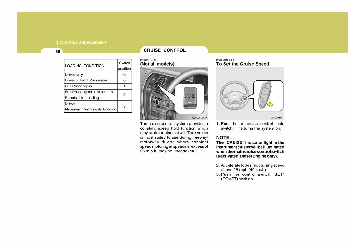
1CONTROLS AND EQUIPMENT
86
B660B001HP-EAT
To Set the Cruise Speed
The cruise control system provides aconstant speed hold function whichmay be determined at will. The systemis most suited to use during freeway/motorway driving where constantspeed motoring at speeds in excess of25 m.p.h. may be undertaken.
1. Push in the cruise control mainswitch. This turns the system on.
NOTE:The "CRUISE" indicator light in theinstrument cluster will be illuminatedwhen the main cruise control switchis activated(Diesel Engine only).
2. Accelerate to desired cruising speedabove 25 mph (40 km/h).
3. Push the control switch "SET"(COAST) position.
CRUISE CONTROL
B660A01S-EAT
(Not all models)
B660A01HP-E B660B01HP
LOADING CONDITION
Driver only
Driver + Front Passenger
Full Passengers
Full Passengers + Maximum
Permissible Loading
Driver +
Maximum Permissible Loading
Switch
position
0
0
1
2
3
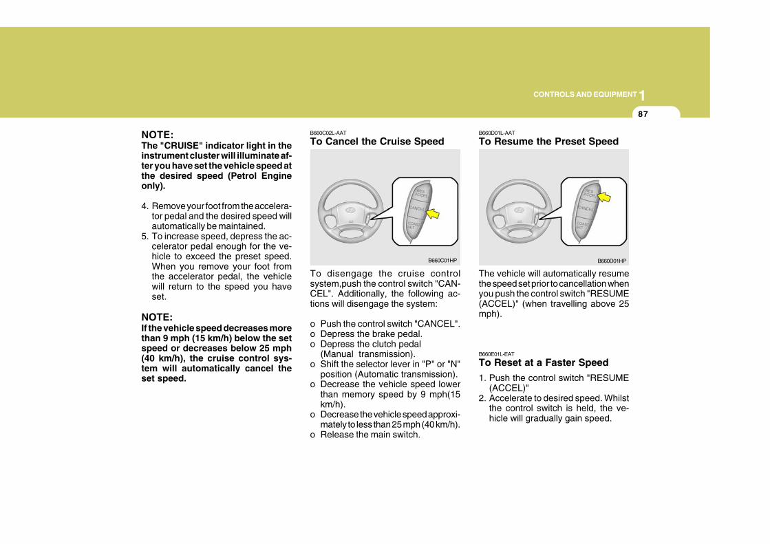
1CONTROLS AND EQUIPMENT
87
NOTE:The "CRUISE" indicator light in theinstrument cluster will illuminate af-ter you have set the vehicle speed atthe desired speed (Petrol Engineonly).
4. Remove your foot from the accelera-tor pedal and the desired speed willautomatically be maintained.
5. To increase speed, depress the ac-celerator pedal enough for the ve-hicle to exceed the preset speed.When you remove your foot fromthe accelerator pedal, the vehiclewill return to the speed you haveset.
NOTE:If the vehicle speed decreases morethan 9 mph (15 km/h) below the setspeed or decreases below 25 mph(40 km/h), the cruise control sys-tem will automatically cancel theset speed.
B660C02L-AAT
To Cancel the Cruise Speed
To disengage the cruise controlsystem,push the control switch "CAN-CEL". Additionally, the following ac-tions will disengage the system:
o Push the control switch "CANCEL".o Depress the brake pedal.o Depress the clutch pedal
(Manual transmission).o Shift the selector lever in "P" or "N"
position (Automatic transmission).o Decrease the vehicle speed lower
than memory speed by 9 mph(15km/h).
o Decrease the vehicle speed approxi-mately to less than 25 mph (40 km/h).
o Release the main switch.
B660C01HP
B660D01L-AAT
To Resume the Preset Speed
The vehicle will automatically resumethe speed set prior to cancellation whenyou push the control switch "RESUME(ACCEL)" (when travelling above 25mph).
B660E01L-EAT
To Reset at a Faster Speed
1. Push the control switch "RESUME(ACCEL)"
2. Accelerate to desired speed. Whilstthe control switch is held, the ve-hicle will gradually gain speed.
B660D01HP
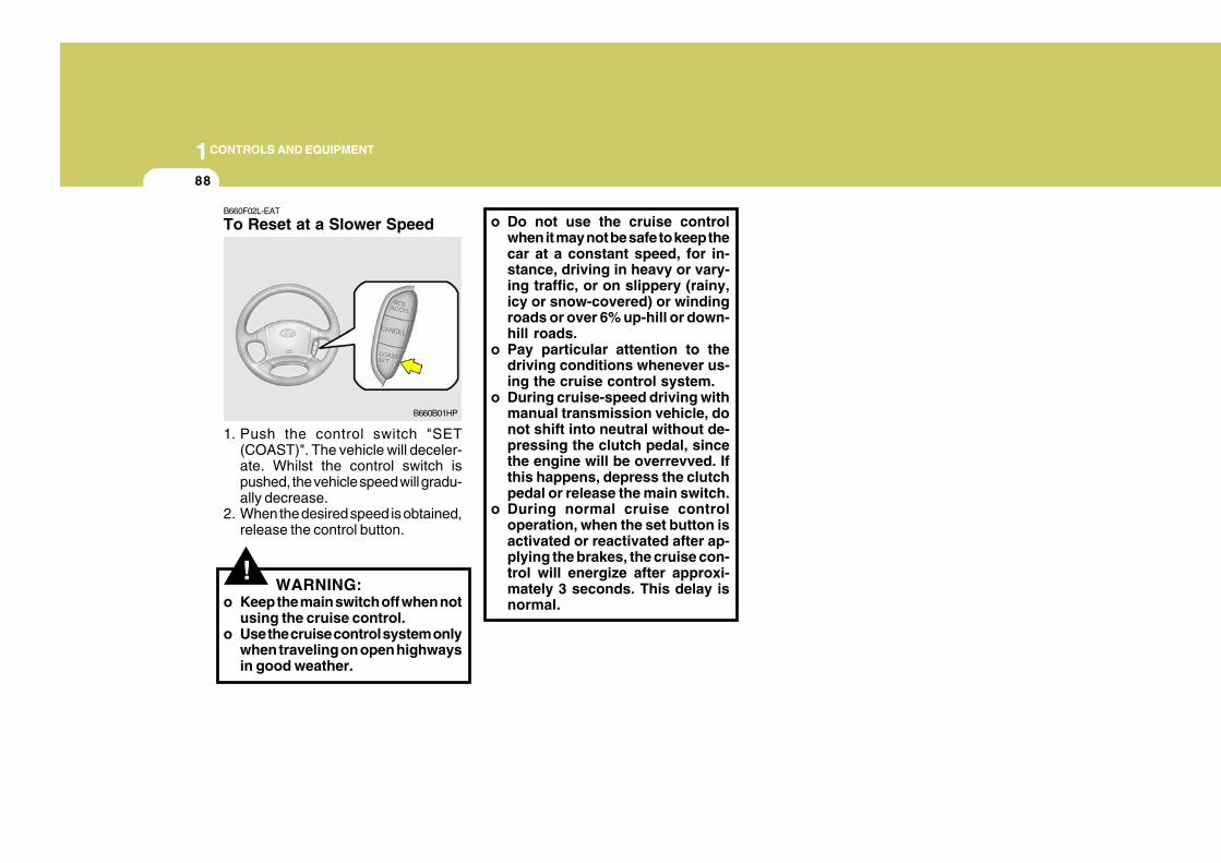
1CONTROLS AND EQUIPMENT
88
!
B660F02L-EAT
To Reset at a Slower Speed
1. Push the control switch "SET(COAST)". The vehicle will deceler-ate. Whilst the control switch ispushed, the vehicle speed will gradu-ally decrease.
2. When the desired speed is obtained,release the control button.
o Do not use the cruise controlwhen it may not be safe to keep thecar at a constant speed, for in-stance, driving in heavy or vary-ing traffic, or on slippery (rainy,icy or snow-covered) or windingroads or over 6% up-hill or down-hill roads.
o Pay particular attention to thedriving conditions whenever us-ing the cruise control system.
o During cruise-speed driving withmanual transmission vehicle, donot shift into neutral without de-pressing the clutch pedal, sincethe engine will be overrevved. Ifthis happens, depress the clutchpedal or release the main switch.
o During normal cruise controloperation, when the set button isactivated or reactivated after ap-plying the brakes, the cruise con-trol will energize after approxi-mately 3 seconds. This delay isnormal.
WARNING:o Keep the main switch off when not
using the cruise control.o Use the cruise control system only
when traveling on open highwaysin good weather.
B660B01HP
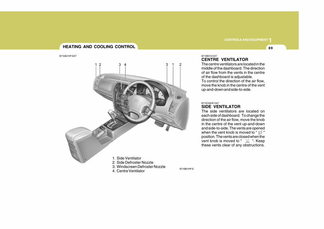
1CONTROLS AND EQUIPMENT
89
B710B01S-DAT
CENTRE VENTILATORThe centre ventilators are located in themiddle of the dashboard. The directionof air flow from the vents in the centreof the dashboard is adjustable.To control the direction of the air flow,move the knob in the centre of the ventup-and-down and side-to-side.
B710C02HP-DAT
SIDE VENTILATORThe side ventilators are located oneach side of dashboard. To change thedirection of the air flow, move the knobin the centre of the vent up-and-downand side-to-side. The vents are openedwhen the vent knob is moved to " "position. The vents are closed when thevent knob is moved to " ". Keepthese vents clear of any obstructions.
HEATING AND COOLING CONTROL
B710A01HP-EAT
1. Side Ventilator2. Side Defroster Nozzle3. Windscreen Defroster Nozzle4. Centre Ventilator
B710B01HP-E
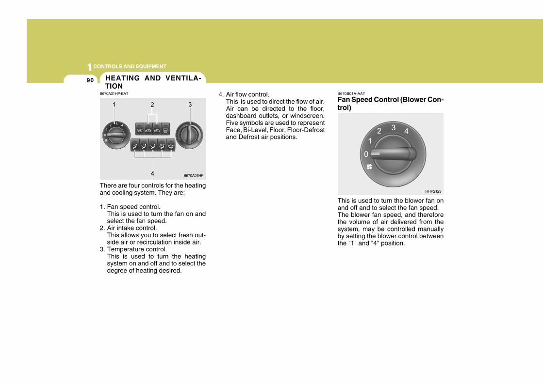
1CONTROLS AND EQUIPMENT
90
B670B01A-AAT
Fan Speed Control (Blower Con-trol)
There are four controls for the heatingand cooling system. They are:
1. Fan speed control.This is used to turn the fan on andselect the fan speed.
2. Air intake control.This allows you to select fresh out-side air or recirculation inside air.
3. Temperature control.This is used to turn the heatingsystem on and off and to select thedegree of heating desired.
4. Air flow control.This is used to direct the flow of air.Air can be directed to the floor,dashboard outlets, or windscreen.Five symbols are used to representFace, Bi-Level, Floor, Floor-Defrostand Defrost air positions.
This is used to turn the blower fan onand off and to select the fan speed.The blower fan speed, and thereforethe volume of air delivered from thesystem, may be controlled manuallyby setting the blower control betweenthe "1" and "4" position.
B670A01HP
HHP2123
HEATING AND VENTILA-TION
B670A01HP-EAT
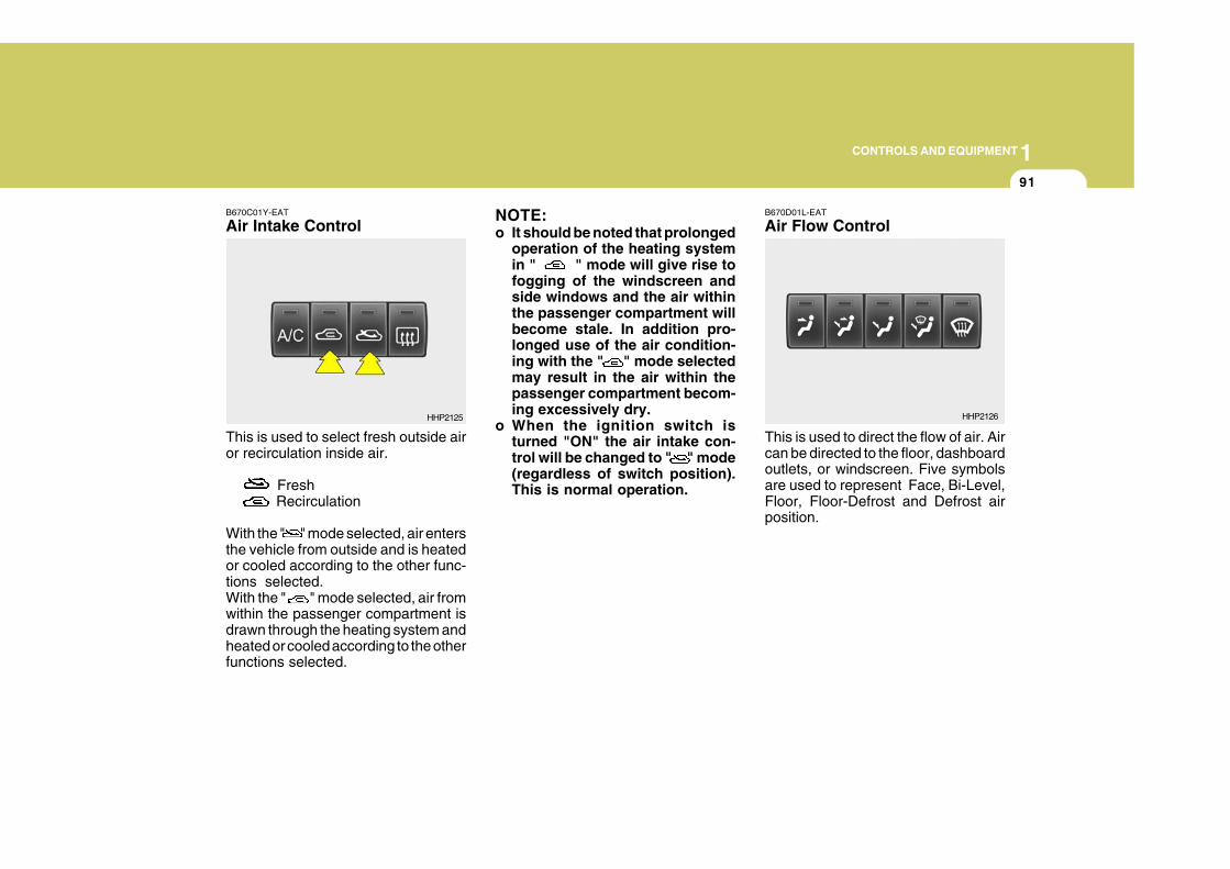
1CONTROLS AND EQUIPMENT
91
B670C01Y-EAT
Air Intake Control
This is used to select fresh outside airor recirculation inside air.
Fresh Recirculation
With the " " mode selected, air entersthe vehicle from outside and is heatedor cooled according to the other func-tions selected.With the " " mode selected, air fromwithin the passenger compartment isdrawn through the heating system andheated or cooled according to the otherfunctions selected.
NOTE:o It should be noted that prolonged
operation of the heating systemin " " mode will give rise tofogging of the windscreen andside windows and the air withinthe passenger compartment willbecome stale. In addition pro-longed use of the air condition-ing with the " " mode selectedmay result in the air within thepassenger compartment becom-ing excessively dry.
o When the ignition switch isturned "ON" the air intake con-trol will be changed to " " mode(regardless of switch position).This is normal operation.
B670D01L-EAT
Air Flow Control
This is used to direct the flow of air. Aircan be directed to the floor, dashboardoutlets, or windscreen. Five symbolsare used to represent Face, Bi-Level,Floor, Floor-Defrost and Defrost airposition.
HHP2125 HHP2126
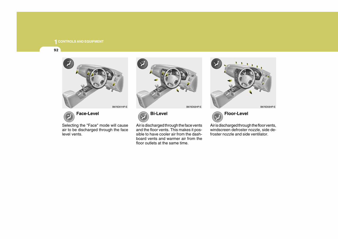
1CONTROLS AND EQUIPMENT
92
Face-Level
Selecting the "Face" mode will causeair to be discharged through the facelevel vents.
Bi-Level
Air is discharged through the face ventsand the floor vents. This makes it pos-sible to have cooler air from the dash-board vents and warmer air from thefloor outlets at the same time.
Floor-Level
Air is discharged through the floor vents,windscreen defroster nozzle, side de-froster nozzle and side ventilator.
B670D01HP-E B670D02HP-E B670D03HP-E
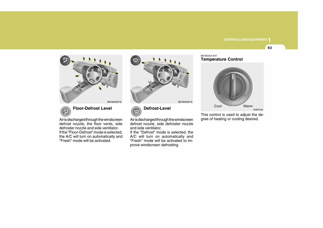
1CONTROLS AND EQUIPMENT
93
Floor-Defrost Level
Air is discharged through the windscreendefrost nozzle, the floor vents, sidedefroster nozzle and side ventilator.If the "Floor-Defrost" mode is selected,the A/C will turn on automatically and"Fresh" mode will be activated.
Defrost-Level
Air is discharged through the windscreendefrost nozzle, side defroster nozzleand side ventilator.If the "Defrost" mode is selected, theA/C will turn on automatically and"Fresh" mode will be activated to im-prove windscreen defrosting.
B670E02A-AAT
Temperature Control
This control is used to adjust the de-gree of heating or cooling desired.
B670D04HP-E B670D05HP-E
CoolHHP2124
Warm
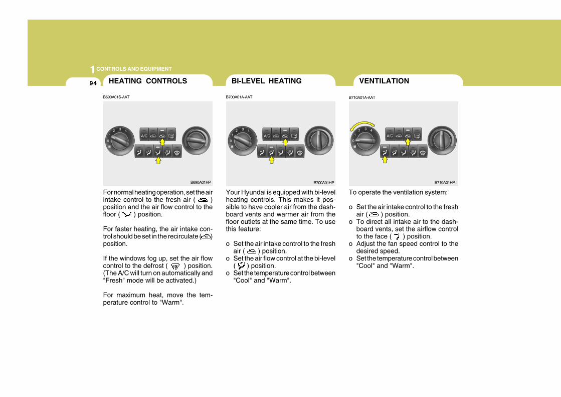
1CONTROLS AND EQUIPMENT
94
For normal heating operation, set the airintake control to the fresh air ( )position and the air flow control to thefloor ( ) position.
For faster heating, the air intake con-trol should be set in the recirculate ( )position.
If the windows fog up, set the air flowcontrol to the defrost ( ) position.(The A/C will turn on automatically and"Fresh" mode will be activated.)
For maximum heat, move the tem-perature control to "Warm".
Your Hyundai is equipped with bi-levelheating controls. This makes it pos-sible to have cooler air from the dash-board vents and warmer air from thefloor outlets at the same time. To usethis feature:
o Set the air intake control to the freshair ( ) position.
o Set the air flow control at the bi-level( ) position.
o Set the temperature control between"Cool" and "Warm".
To operate the ventilation system:
o Set the air intake control to the freshair ( ) position.
o To direct all intake air to the dash-board vents, set the airflow controlto the face ( ) position.
o Adjust the fan speed control to thedesired speed.
o Set the temperature control between"Cool" and "Warm".
VENTILATIONHEATING CONTROLS BI-LEVEL HEATING
B690A01S-AAT B710A01A-AATB700A01A-AAT
B690A01HP B700A01HP B710A01HP
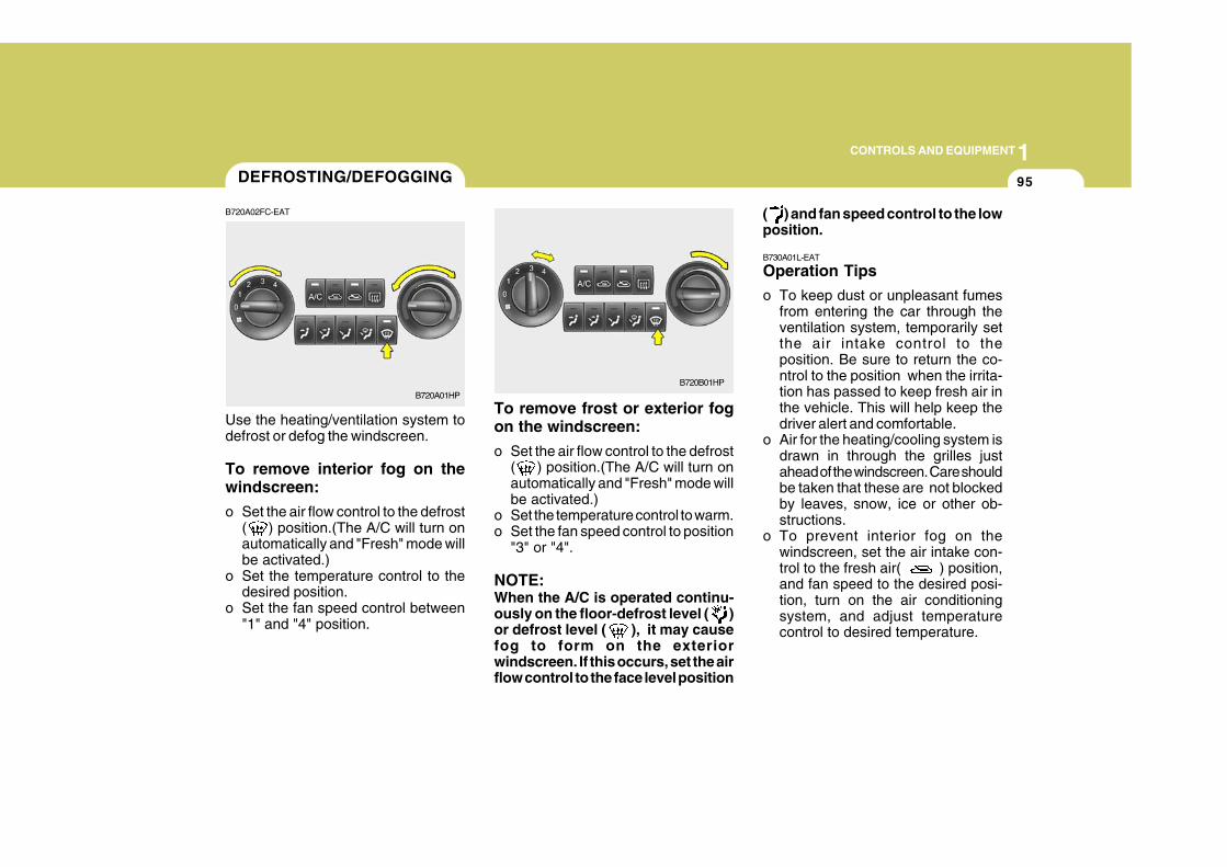
1CONTROLS AND EQUIPMENT
95
To remove frost or exterior fogon the windscreen:
o Set the air flow control to the defrost( ) position.(The A/C will turn onautomatically and "Fresh" mode willbe activated.)
o Set the temperature control to warm.o Set the fan speed control to position
"3" or "4".
NOTE:When the A/C is operated continu-ously on the floor-defrost level ( )or defrost level ( ), it may causefog to form on the exteriorwindscreen. If this occurs, set the airflow control to the face level position
( ) and fan speed control to the lowposition.
B730A01L-EAT
Operation Tips
o To keep dust or unpleasant fumesfrom entering the car through theventilation system, temporarily setthe air intake control to theposition. Be sure to return the co-ntrol to the position when the irrita-tion has passed to keep fresh air inthe vehicle. This will help keep thedriver alert and comfortable.
o Air for the heating/cooling system isdrawn in through the grilles justahead of the windscreen. Care shouldbe taken that these are not blockedby leaves, snow, ice or other ob-structions.
o To prevent interior fog on thewindscreen, set the air intake con-trol to the fresh air( ) position,and fan speed to the desired posi-tion, turn on the air conditioningsystem, and adjust temperaturecontrol to desired temperature.
Use the heating/ventilation system todefrost or defog the windscreen.
To remove interior fog on thewindscreen:
o Set the air flow control to the defrost( ) position.(The A/C will turn onautomatically and "Fresh" mode willbe activated.)
o Set the temperature control to thedesired position.
o Set the fan speed control between"1" and "4" position.
DEFROSTING/DEFOGGING
B720A01HP
B720A02FC-EAT
B720B01HP
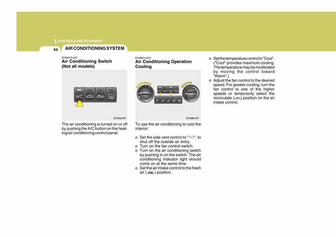
1CONTROLS AND EQUIPMENT
96
The air conditioning is turned on or offby pushing the A/C button on the heat-ing/air conditioning control panel.
AIR CONDITIONING SYSTEM
B740A01S-AAT
Air Conditioning Switch(Not all models)
B740A01HP
B740B01A-EAT
Air Conditioning OperationCooling
To use the air conditioning to cool theinterior:
o Set the side vent control to " ", toshut off the outside air entry.
o Turn on the fan control switch.o Turn on the air conditioning switch
by pushing in on the switch. The airconditioning indicator light shouldcome on at the same time.
o Set the air intake control to the freshair ( ) position.
o Set the temperature control to "Cool".("Cool" provides maximum cooling.The temperature may be moderatedby moving the control toward"Warm".)
o Adjust the fan control to the desiredspeed. For greater cooling, turn thefan control to one of the higherspeeds or temporarily select therecirculate ( ) position on the airintake control.
B740B01HP
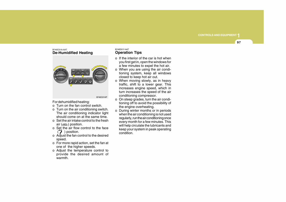
1CONTROLS AND EQUIPMENT
97
B740C01A-AAT
De-Humidified Heating
For dehumidified heating:o Turn on the fan control switch.o Turn on the air conditioning switch.
The air conditioning indicator lightshould come on at the same time.
o Set the air intake control to the freshair ( ) position.
o Set the air flow control to the face ( ) position.
o Adjust the fan control to the desiredspeed.
o For more rapid action, set the fan atone of the higher speeds.
o Adjust the temperature control toprovide the desired amount ofwarmth.
B740C01HP
B740D01Y-AAT
Operation Tips
o If the interior of the car is hot whenyou first get in, open the windows fora few minutes to expel the hot air.
o When you are using the air condi-tioning system, keep all windowsclosed to keep hot air out.
o When moving slowly, as in heavytraffic, shift to a lower gear. Thisincreases engine speed, which inturn increases the speed of the airconditioning compressor.
o On steep grades, turn the air condi-tioning off to avoid the possibility ofthe engine overheating.
o During winter months or in periodswhen the air conditioning is not usedregularly, run the air conditioning onceevery month for a few minutes. Thiswill help circulate the lubricants andkeep your system in peak operatingcondition.
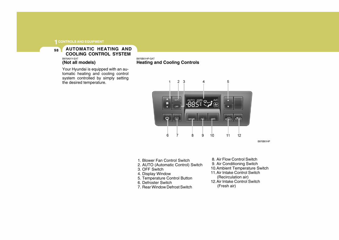
1CONTROLS AND EQUIPMENT
98
B970B01HP-GAT
Heating and Cooling Controls
1. Blower Fan Control Switch 2. AUTO (Automatic Control) Switch 3. OFF Switch 4. Display Window 5. Temperature Control Button 6. Defroster Switch 7. Rear Window Defrost Switch
8. Air Flow Control Switch 9. Air Conditioning Switch10.Ambient Temperature Switch11.Air Intake Control Switch (Recirculation air)12.Air Intake Control Switch (Fresh air)
B970B01HP
AUTOMATIC HEATING ANDCOOLING CONTROL SYSTEM
B970A01Y-EAT
(Not aII models)
Your Hyundai is equipped with an au-tomatic heating and cooling controlsystem controlled by simply settingthe desired temperature.
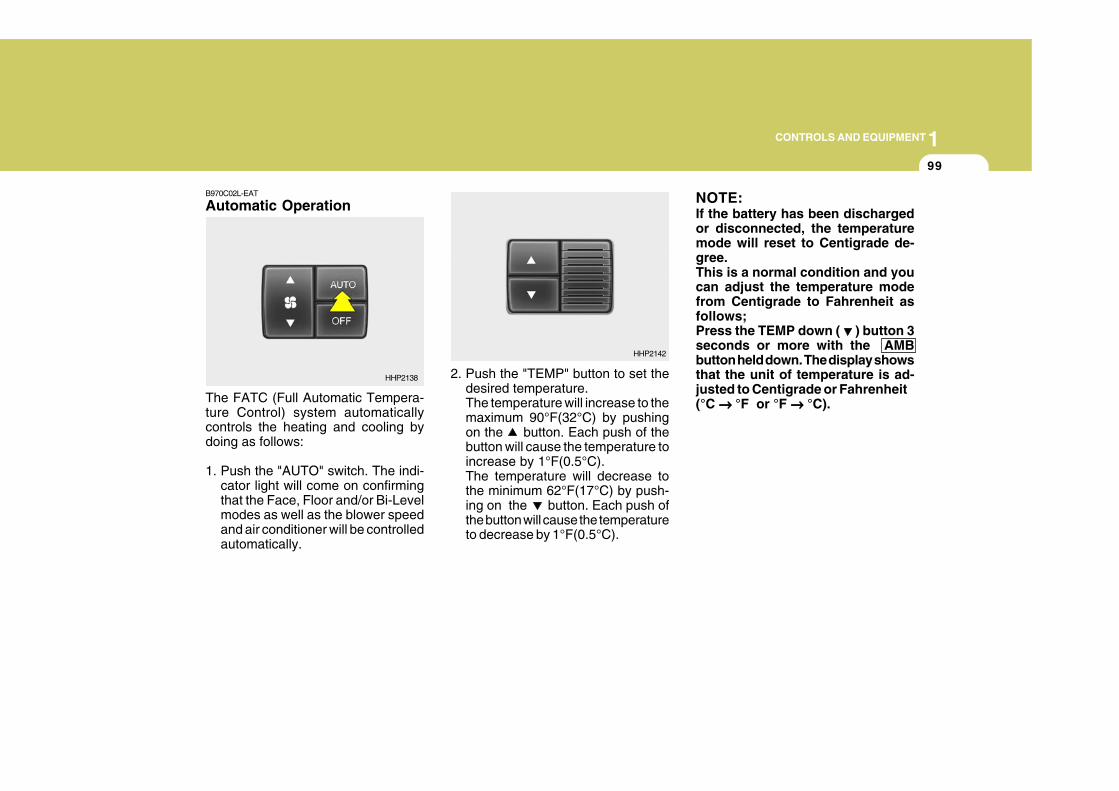
1CONTROLS AND EQUIPMENT
99
2. Push the "TEMP" button to set thedesired temperature.The temperature will increase to themaximum 90°F(32°C) by pushingon the button. Each push of thebutton will cause the temperature toincrease by 1°F(0.5°C).The temperature will decrease tothe minimum 62°F(17°C) by push-ing on the button. Each push ofthe button will cause the temperatureto decrease by 1°F(0.5°C).
NOTE:If the battery has been dischargedor disconnected, the temperaturemode will reset to Centigrade de-gree.This is a normal condition and youcan adjust the temperature modefrom Centigrade to Fahrenheit asfollows;Press the TEMP down ( ) button 3seconds or more with the AMBbutton held down. The display showsthat the unit of temperature is ad-justed to Centigrade or Fahrenheit(°C → → → → → °F or °F → → → → → °C).
HHP2142
B970C02L-EAT
Automatic Operation
The FATC (Full Automatic Tempera-ture Control) system automaticallycontrols the heating and cooling bydoing as follows:
1. Push the "AUTO" switch. The indi-cator light will come on confirmingthat the Face, Floor and/or Bi-Levelmodes as well as the blower speedand air conditioner will be controlledautomatically.
HHP2138
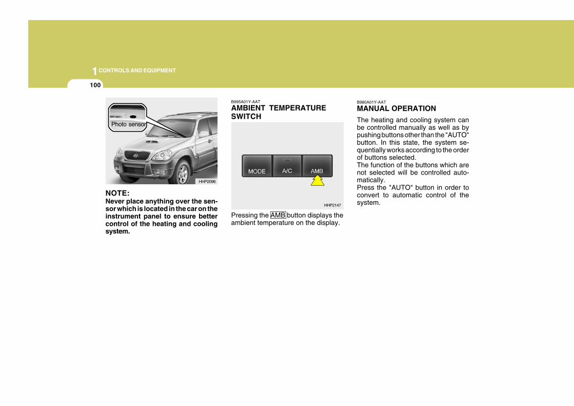
1CONTROLS AND EQUIPMENT
100
B995A01Y-AAT
AMBIENT TEMPERATURESWITCH
Pressing the AMB button displays theambient temperature on the display.
B980A01Y-AAT
MANUAL OPERATION
The heating and cooling system canbe controlled manually as well as bypushing buttons other than the "AUTO"button. In this state, the system se-quentially works according to the orderof buttons selected.The function of the buttons which arenot selected will be controlled auto-matically.Press the "AUTO" button in order toconvert to automatic control of thesystem.HHP2147
NOTE:Never place anything over the sen-sor which is located in the car on theinstrument panel to ensure bettercontrol of the heating and coolingsystem.
HHP2096
Photo sensor
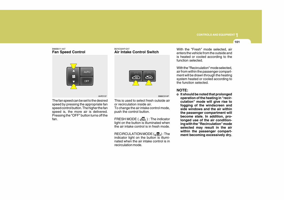
1CONTROLS AND EQUIPMENT
101
B670C02HP-EAT
Air Intake Control Switch
This is used to select fresh outside airor recirculation inside air.To change the air intake control mode,push the control button.
FRESH MODE ( ) : The indicatorlight on the button is illuminated whenthe air intake control is in fresh mode.
RECIRCULATION MODE ( ) : Theindicator light on the button is illumi-nated when the air intake control is inrecirculation mode.
With the "Fresh" mode selected, airenters the vehicle from the outside andis heated or cooled according to thefunction selected.
With the "Recirculation" mode selected,air from within the passenger compart-ment will be drawn through the heatingsystem heated or cooled according tothe function selected.
NOTE:o It should be noted that prolonged
operation of the heating in "recir-culation" mode will give rise tofogging of the windscreen andside windows and the air withinthe passenger compartment willbecome stale. In addition, pro-longed use of the air condition-ing with the "Recirculation" modeselected may result in the airwithin the passenger compart-ment becoming excessively dry.
B980C01HP
B980B01Y-AAT
Fan Speed Control
The fan speed can be set to the desiredspeed by pressing the appropriate fanspeed control button. The higher the fanspeed is, the more air is delivered.Pressing the "OFF" button turns off thefan.
HHP2137
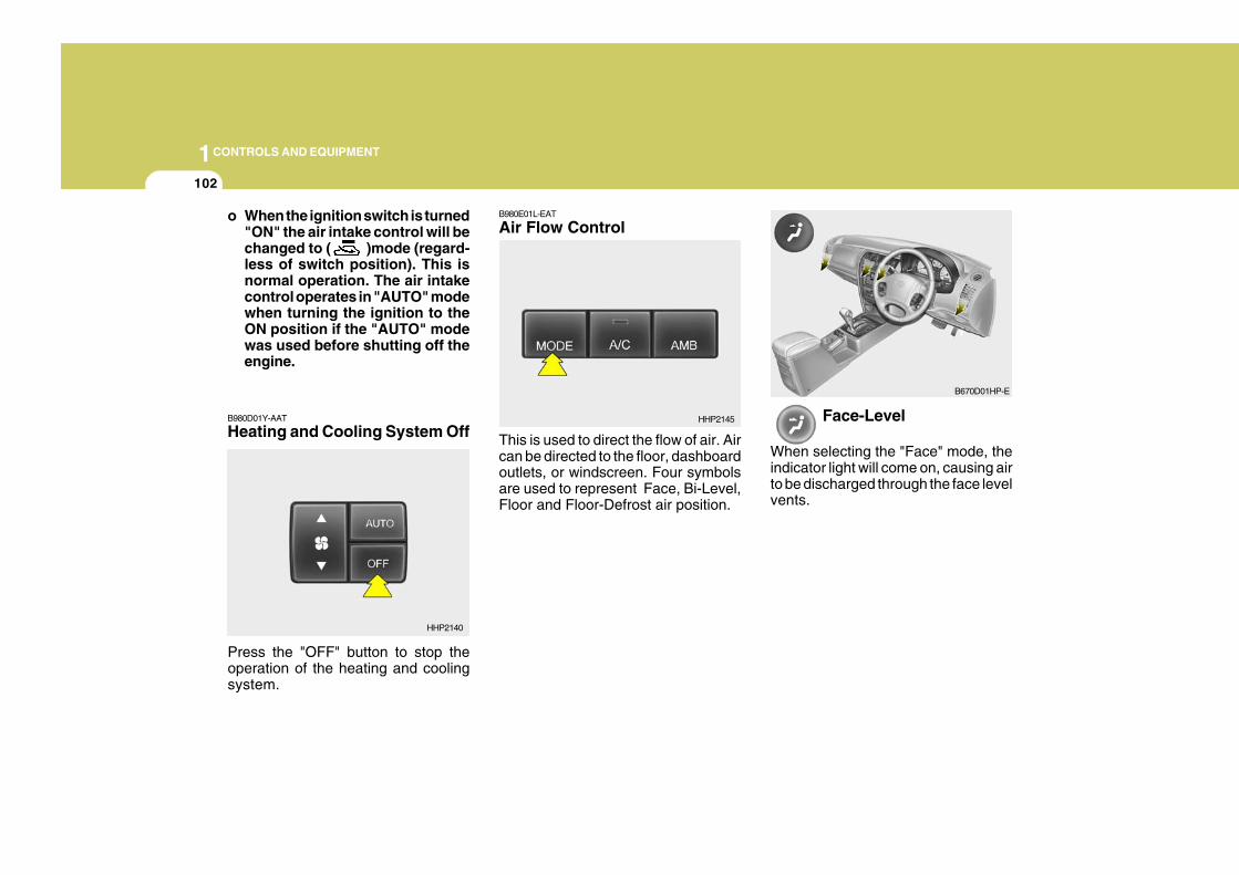
1CONTROLS AND EQUIPMENT
102
B980E01L-EAT
Air Flow Control
This is used to direct the flow of air. Aircan be directed to the floor, dashboardoutlets, or windscreen. Four symbolsare used to represent Face, Bi-Level,Floor and Floor-Defrost air position.
Face-Level
When selecting the "Face" mode, theindicator light will come on, causing airto be discharged through the face levelvents.
HHP2145
B670D01HP-E
o When the ignition switch is turned"ON" the air intake control will bechanged to ( )mode (regard-less of switch position). This isnormal operation. The air intakecontrol operates in "AUTO" modewhen turning the ignition to theON position if the "AUTO" modewas used before shutting off theengine.
B980D01Y-AAT
Heating and Cooling System Off
HHP2140
Press the "OFF" button to stop theoperation of the heating and coolingsystem.
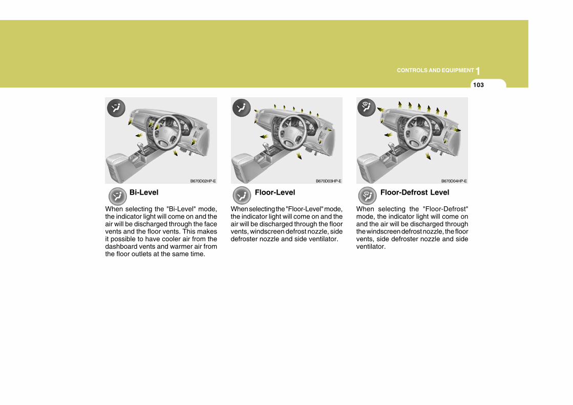
1CONTROLS AND EQUIPMENT
103
Floor-Level
When selecting the "Floor-Level" mode,the indicator light will come on and theair will be discharged through the floorvents, windscreen defrost nozzle, sidedefroster nozzle and side ventilator.
Floor-Defrost Level
When selecting the "Floor-Defrost"mode, the indicator light will come onand the air will be discharged throughthe windscreen defrost nozzle, the floorvents, side defroster nozzle and sideventilator.
B670D03HP-E B670D04HP-EB670D02HP-E
Bi-Level
When selecting the "Bi-Level" mode,the indicator light will come on and theair will be discharged through the facevents and the floor vents. This makesit possible to have cooler air from thedashboard vents and warmer air fromthe floor outlets at the same time.
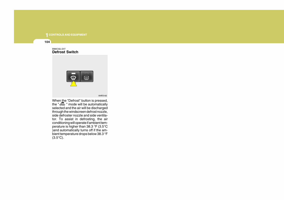
1CONTROLS AND EQUIPMENT
104
B980C02L-EAT
Defrost Switch
When the "Defrost" button is pressed,the " " mode will be automaticallyselected and the air will be dischargedthrough the windscreen defrost nozzle,side defroster nozzle and side ventila-tor. To assist in defrosting, the airconditioning will operate if ambient tem-perature is higher than 38.3 °F (3.5°C)and automatically turns off if the am-bient temperature drops below 38.3 °F(3.5°C).
HHP2143
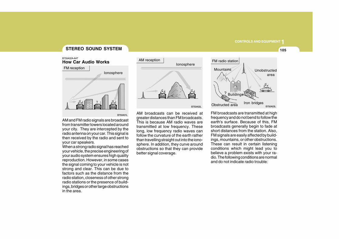
1CONTROLS AND EQUIPMENT
105STEREO SOUND SYSTEM
B750A02A-AAT
How Car Audio Works
Ionosphere FM reception
B750A01L
AM and FM radio signals are broadcastfrom transmitter towers located aroundyour city. They are intercepted by theradio antenna on your car. This signal isthen received by the radio and sent toyour car speakers.When a strong radio signal has reachedyour vehicle, the precise engineering ofyour audio system ensures high qualityreproduction. However, in some casesthe signal coming to your vehicle is notstrong and clear. This can be due tofactors such as the distance from theradio station, closeness of other strongradio stations or the presence of build-ings, bridges or other large obstructionsin the area.
AM broadcasts can be received atgreater distances than FM broadcasts.This is because AM radio waves aretransmitted at low frequency. Theselong, low frequency radio waves canfollow the curvature of the earth ratherthan travelling straight out into the iono-sphere. In addition, they curve aroundobstructions so that they can providebetter signal coverage.
AM receptionIonosphere
B750A02L
Mountains
Buildings
Unobstructedarea
FM radio station
B750A03LObstructed area Iron bridges
FM broadcasts are transmitted at highfrequency and do not bend to follow theearth's surface. Because of this, FMbroadcasts generally begin to fade atshort distances from the station. Also,FM signals are easily affected by build-ings, mountains, or other obstructions.These can result in certain listeningconditions which might lead you tobelieve a problem exists with your ra-dio. The following conditions are normaland do not indicate radio trouble:
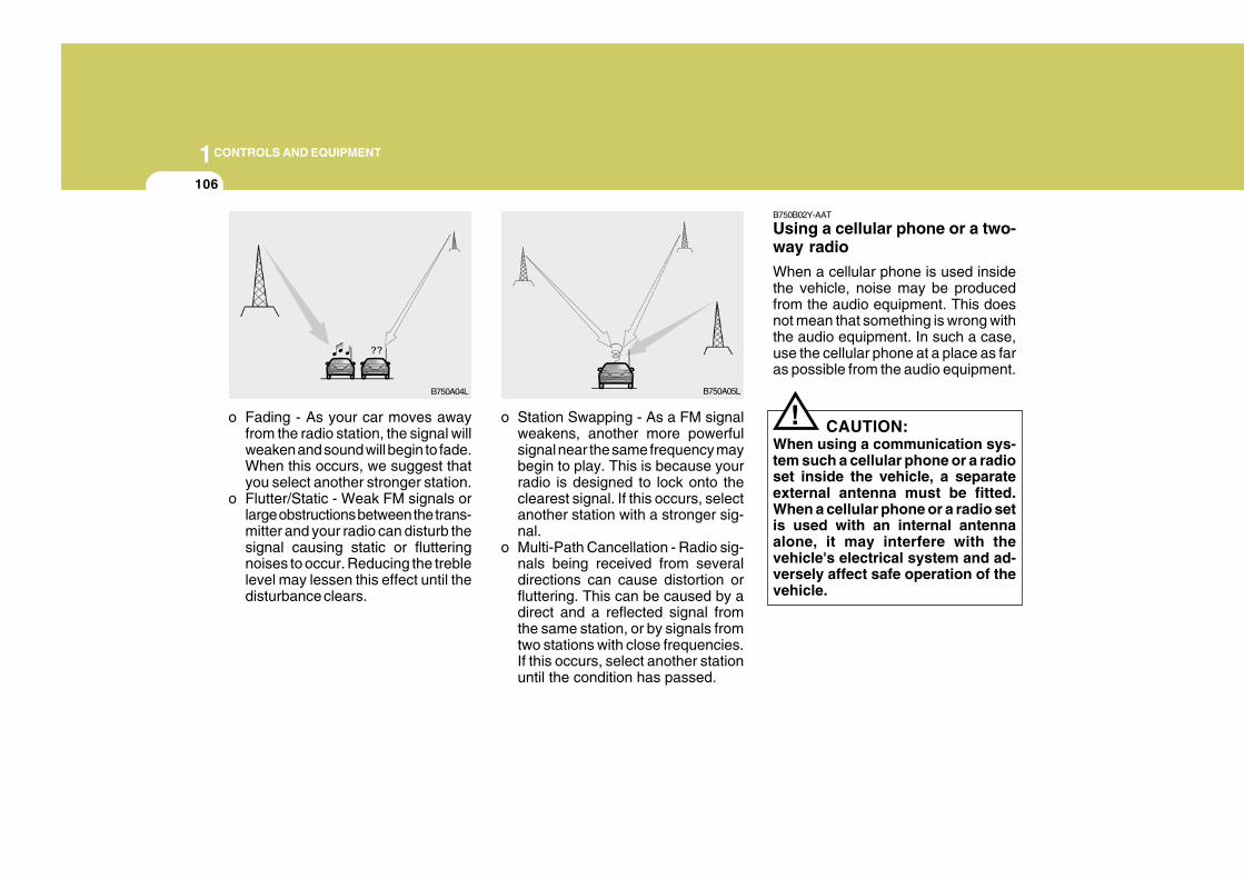
1CONTROLS AND EQUIPMENT
106
!
B750B02Y-AAT
Using a cellular phone or a two-way radio
When a cellular phone is used insidethe vehicle, noise may be producedfrom the audio equipment. This doesnot mean that something is wrong withthe audio equipment. In such a case,use the cellular phone at a place as faras possible from the audio equipment.
CAUTION:When using a communication sys-tem such a cellular phone or a radioset inside the vehicle, a separateexternal antenna must be fitted.When a cellular phone or a radio setis used with an internal antennaalone, it may interfere with thevehicle's electrical system and ad-versely affect safe operation of thevehicle.
o Fading - As your car moves awayfrom the radio station, the signal willweaken and sound will begin to fade.When this occurs, we suggest thatyou select another stronger station.
o Flutter/Static - Weak FM signals orlarge obstructions between the trans-mitter and your radio can disturb thesignal causing static or flutteringnoises to occur. Reducing the treblelevel may lessen this effect until thedisturbance clears.
o Station Swapping - As a FM signalweakens, another more powerfulsignal near the same frequency maybegin to play. This is because yourradio is designed to lock onto theclearest signal. If this occurs, selectanother station with a stronger sig-nal.
o Multi-Path Cancellation - Radio sig-nals being received from severaldirections can cause distortion orfluttering. This can be caused by adirect and a reflected signal fromthe same station, or by signals fromtwo stations with close frequencies.If this occurs, select another stationuntil the condition has passed.
B750A04L B750A05L
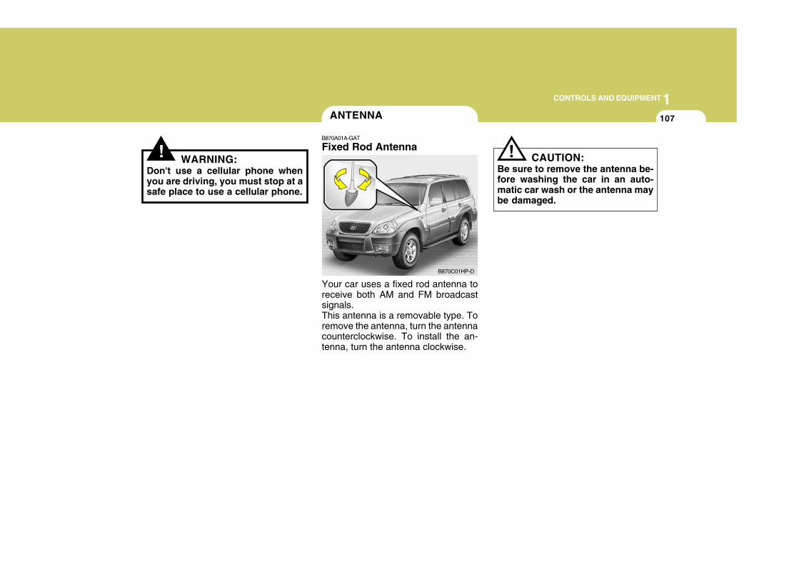
1CONTROLS AND EQUIPMENT
107
! WARNING:Don't use a cellular phone whenyou are driving, you must stop at asafe place to use a cellular phone.
ANTENNA
!B870A01A-GAT
Fixed Rod Antenna
Your car uses a fixed rod antenna toreceive both AM and FM broadcastsignals.This antenna is a removable type. Toremove the antenna, turn the antennacounterclockwise. To install the an-tenna, turn the antenna clockwise.
CAUTION:Be sure to remove the antenna be-fore washing the car in an auto-matic car wash or the antenna maybe damaged.
B870C01HP-D
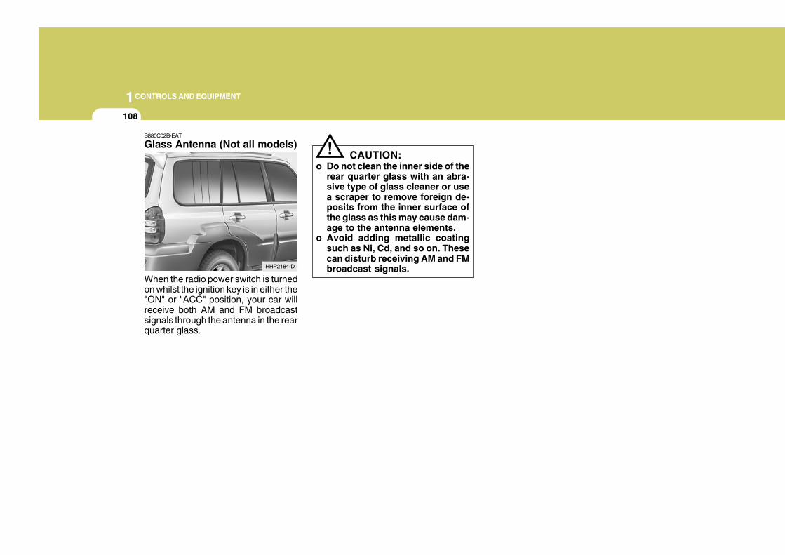
1CONTROLS AND EQUIPMENT
108
!B880C02B-EAT
Glass Antenna (Not all models)
When the radio power switch is turnedon whilst the ignition key is in either the"ON" or "ACC" position, your car willreceive both AM and FM broadcastsignals through the antenna in the rearquarter glass.
CAUTION:o Do not clean the inner side of the
rear quarter glass with an abra-sive type of glass cleaner or usea scraper to remove foreign de-posits from the inner surface ofthe glass as this may cause dam-age to the antenna elements.
o Avoid adding metallic coatingsuch as Ni, Cd, and so on. Thesecan disturb receiving AM and FMbroadcast signals.HHP2184-D