hydraulic-style squeeze off tool - broughton plant hire operating instructions and specifications...
TRANSCRIPT

1
Operating instructions and specifications for
Hydraulic-Style Squeeze Off Tool
Products by innovation not imitation
Models covered by this manual: Squeeze 63 90 125 180 SDR 11 and 17
Helping you make the right connections™

2
INDEX.
Pictorial representation .............................. 3
Schematic parts drawing ............................ 4
Parts list and product codes ....................... 5
Specifications ............................................ 6
General description ................................... 7
Safety instructions ..................................... 8
Instructions for use .................................. 9
Certificate of conformity ............................ 13
Certificate of calibration ............................. 14
Warranty information ................................ 15
3
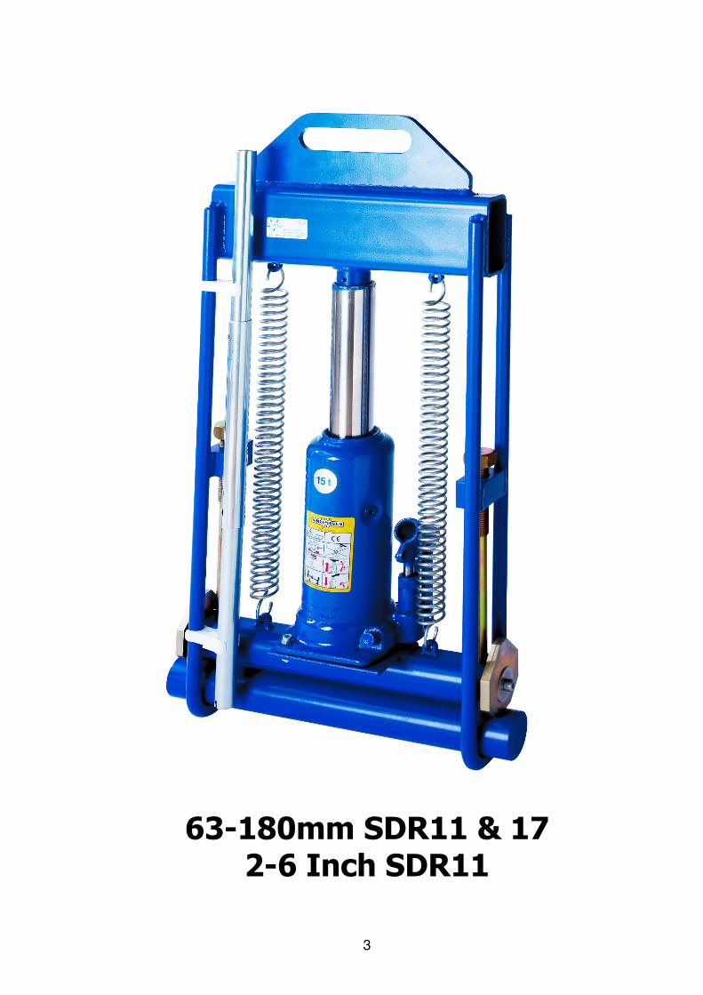
63-180mm SDR11 & 17 2-6 Inch SDR11

4
17
2
15
7
4
14
3
12
11
16
9
1 18-20-
21
6
5
10
13
19
8

5
Product description Product code Quantity 1. Squeeze tool frame 02-31-610 1 2. Check screw (1 OFF) 02-31-611 2 3. Bottom bar 02-31-612 1 4. Squeeze bar 02-31-613 1
5. Limit stop plate location spring/6mm steel ball (1 OFF) 02-31-614 2 6. Limit stop plate retaining boss/ M8 x 25 Socket Cap 02-31-615 1 7. Hydraulic jack 15 Ton 02-31-616 1 8. Jack relief valve 02-31-617 1 9. Jack pressure pump 02-31-618 1 10. M8 washer x 37 OD (1 OFF) Z183-T006-177 2
11. M6 x 25 socket Cap (1 OFF) Z183-T006-143 3 12. M6 washer (1 OFF) Z183-T006-144 6 13. M8 x 16 Socket Cap (1 OFF) Z183-T006-209 2 14. M6 nut (1 OFF) Z183-T006-172 3 15. Return spring (1 OFF) 02-31-624 2 16. Jack handle (3 part tubular) 02-31-625 1 17. Jack handle clip (1 OFF) 02-31-626 2 18. Limit stop plates SDR 17.6 (Export) 1 OFF 02-31-627 2 19. Limit stop plates SDR 11 (Export) 1 OFF 02-31-628 2 20. Limit stop plates SDR11/17 (UK only) 1 OFF 02-31-629 2 21. Limit stop plates 2, 3, 4&6 inch (IPS) 1 OFF 02-31-630 2
Product code: 02-31-601 UK 02-31-602 Export 02-31-603 IPS
6
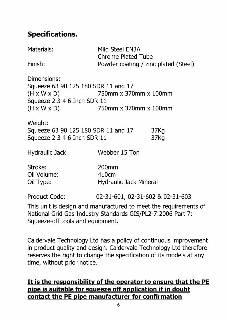
Specifications. Materials: Mild Steel EN3A Chrome Plated Tube Finish: Powder coating / zinc plated (Steel) Dimensions: Squeeze 63 90 125 180 SDR 11 and 17 (H x W x D) 750mm x 370mm x 100mm Squeeze 2 3 4 6 Inch SDR 11 (H x W x D) 750mm x 370mm x 100mm Weight: Squeeze 63 90 125 180 SDR 11 and 17 37Kg Squeeze 2 3 4 6 Inch SDR 11 37Kg Hydraulic Jack Webber 15 Ton Stroke: 200mm Oil Volume: 410cm Oil Type: Hydraulic Jack Mineral Product Code: 02-31-601, 02-31-602 & 02-31-603
This unit is design and manufactured to meet the requirements of National Grid Gas Industry Standards GIS/PL2-7:2006 Part 7: Squeeze-off tools and equipment.
Caldervale Technology Ltd has a policy of continuous improvement in product quality and design. Caldervale Technology Ltd therefore reserves the right to change the specification of its models at any time, without prior notice.
It is the responsibility of the operator to ensure that the PE pipe is suitable for squeeze off application if in doubt contact the PE pipe manufacturer for confirmation
7
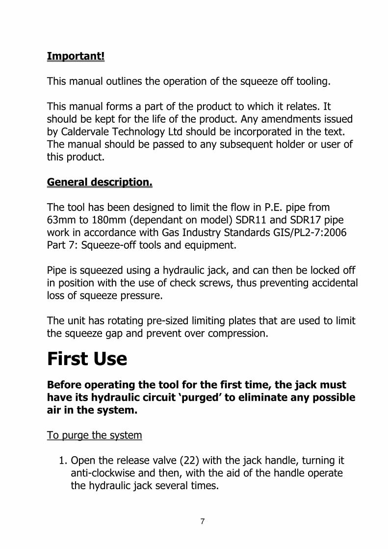
Important! This manual outlines the operation of the squeeze off tooling. This manual forms a part of the product to which it relates. It should be kept for the life of the product. Any amendments issued by Caldervale Technology Ltd should be incorporated in the text. The manual should be passed to any subsequent holder or user of this product. General description. The tool has been designed to limit the flow in P.E. pipe from 63mm to 180mm (dependant on model) SDR11 and SDR17 pipe work in accordance with Gas Industry Standards GIS/PL2-7:2006 Part 7: Squeeze-off tools and equipment. Pipe is squeezed using a hydraulic jack, and can then be locked off in position with the use of check screws, thus preventing accidental loss of squeeze pressure. The unit has rotating pre-sized limiting plates that are used to limit the squeeze gap and prevent over compression.
First Use
Before operating the tool for the first time, the jack must have its hydraulic circuit ‘purged’ to eliminate any possible air in the system. To purge the system
1. Open the release valve (22) with the jack handle, turning it anti-clockwise and then, with the aid of the handle operate the hydraulic jack several times.

8
2. Close the release valve fully using the jack handle. The tool is now ready for use
Before using
It is important to ensure all component parts are present and in serviceable condition. In addition, the setting of the limit stop (buffer) plates should be checked before every operation to ensure they are correct for the pipe size and wall thickness rating. Wrongly set buffer plates may cause insufficient or excessive pipe compression leading to pipe-wall damage, leakage or injury.
Safety Instructions
1. Read FIRST USE procedure before using the tool.
2. It is imperative that all possible precautions are made to avoid unexpected movement of the tool during use.
3. Never operate the jack beyond its maximum stroke.
4. The jack is fitted with a safety valve to stop overloading. This
is factory set and MUST NOT be tampered with.
5. The tool is heavy (37Kg) care should be taken when in use.
6. To avoid injury the bottom bars should be removed or locked in position with the jack extended for transportation, lifting must be by 2 persons.
7. Operatives should wear eye protection, gloves, safety
headwear & footwear when using the equipment.
9
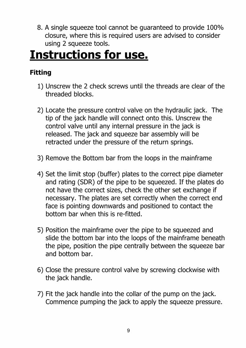
8. A single squeeze tool cannot be guaranteed to provide 100% closure, where this is required users are advised to consider using 2 squeeze tools.
Instructions for use.
Fitting
1) Unscrew the 2 check screws until the threads are clear of the threaded blocks.
2) Locate the pressure control valve on the hydraulic jack. The
tip of the jack handle will connect onto this. Unscrew the control valve until any internal pressure in the jack is released. The jack and squeeze bar assembly will be retracted under the pressure of the return springs.
3) Remove the Bottom bar from the loops in the mainframe
4) Set the limit stop (buffer) plates to the correct pipe diameter
and rating (SDR) of the pipe to be squeezed. If the plates do not have the correct sizes, check the other set exchange if necessary. The plates are set correctly when the correct end face is pointing downwards and positioned to contact the bottom bar when this is re-fitted.
5) Position the mainframe over the pipe to be squeezed and
slide the bottom bar into the loops of the mainframe beneath the pipe, position the pipe centrally between the squeeze bar and bottom bar.
6) Close the pressure control valve by screwing clockwise with
the jack handle.
7) Fit the jack handle into the collar of the pump on the jack. Commence pumping the jack to apply the squeeze pressure.

10
8) Continue the pumping action until the squeeze bar has fully closed the pipe, and the limit stop plates prevent further compression.
9) Screw down both check screws until they are in contact with
the upper edge of the squeeze bar. This will prevent any loss of squeeze pressure in the event of hydraulic pressure leakage in the jack.
Safety check screws 2
Hydraulic jack control valve
Squeeze tool frame
loops 2
Bottom bar
Safety check screw blocks 2
Limit stop plates 2
Jack handle
Hydraulic jack control pump
Return springs 2
Hydraulic jack
Squeeze tool frame

11
Instructions for removal after squeeze off.
1) On completion of the squeeze off operation, remove the tool as follows.
2) Unscrew the check screws until their threads are once again clear of the safety check screws threaded blocks. (If it is difficult to release the check screws, pump the jack handle 2 or 3 times to replace any loss of hydraulic pressure)
3) Gently release the hydraulic jack pressure by unscrewing the pressure control valve anti clockwise with the jack handle. This may require carrying out in controlled stages to prevent flow surges and excessive pressure drops in the pipe-work as the system fill up.
4) Allow the jack and squeeze bar to retract fully in the main frame under the force of the return springs, remove the bottom bar and lift the main frame clear of the pipe.
5) Allow the section of squeezed pipe to reform to its original shape, this may take several hours.
Transport and Storage
1. Replace the BOTTOM BARS into the FRAME. Turn the RELEASE VALVE fully clockwise using the jacking handle. The jack is now ready for storage preparation. Fit the jacking handle into the handle socket and ‘pump’ up the jack.
2. Continue jacking until the LIMIT PLATES just come into contact with the BOTTOM BAR. Refit both check screws and tighten against the SQUEEZE BARS.
3. Using the JACKING HANDLE turn the RELEASE VALVE on the HYDRAULIC JACK in an anticlockwise direction. This will release the oil pressure in the jack
12
Storage IMPORTANT: When not in use always – 1. Store the tool in an upright position. 2. Ensure the pressure in the jack is released. Maintenance Hydraulic Jack Lubricate all moving parts at regular intervals. NOTE: AN EXCESS OF OIL WILL RENDER THE JACK INOPERATIVE Use only hydraulic oil type HL or HM (30cSt at 40°C)
Tool Grease check screw threads at regular intervals.
13
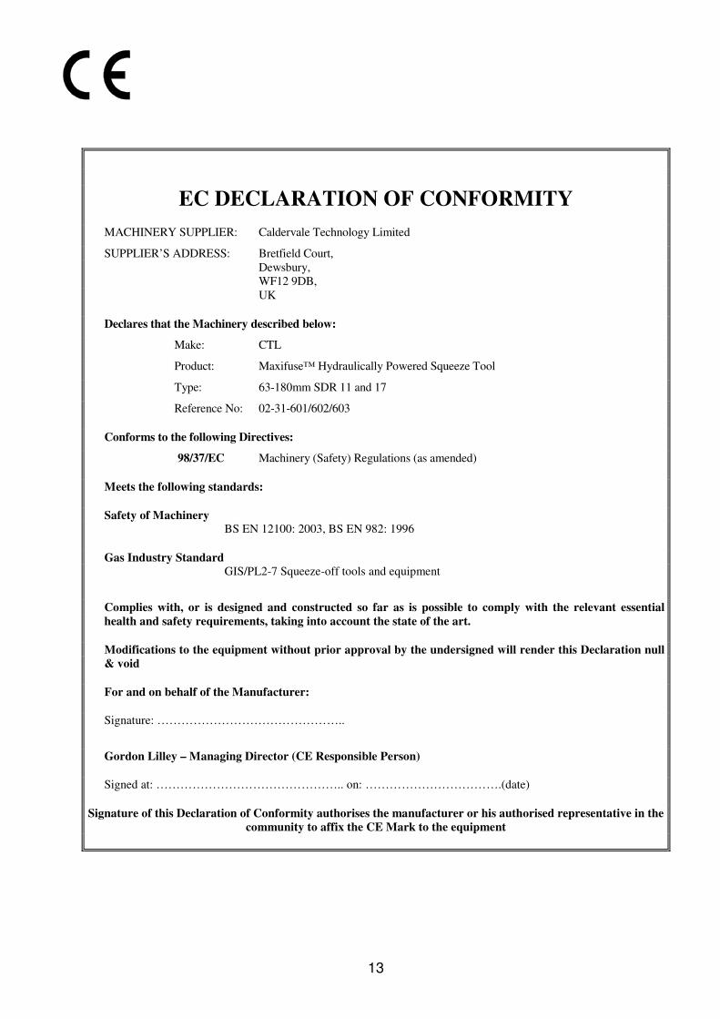
EC DECLARATION OF CONFORMITY
MACHINERY SUPPLIER: Caldervale Technology Limited
SUPPLIER’S ADDRESS: Bretfield Court,
Dewsbury,
WF12 9DB,
UK
Declares that the Machinery described below:
Make: CTL
Product: Maxifuse™ Hydraulically Powered Squeeze Tool
Type: 63-180mm SDR 11 and 17
Reference No: 02-31-601/602/603
Conforms to the following Directives:
98/37/EC Machinery (Safety) Regulations (as amended)
Meets the following standards:
Safety of Machinery BS EN 12100: 2003, BS EN 982: 1996
Gas Industry Standard
GIS/PL2-7 Squeeze-off tools and equipment
Complies with, or is designed and constructed so far as is possible to comply with the relevant essential
health and safety requirements, taking into account the state of the art.
Modifications to the equipment without prior approval by the undersigned will render this Declaration null
& void
For and on behalf of the Manufacturer:
Signature: ………………………………………..
Gordon Lilley – Managing Director (CE Responsible Person)
Signed at: ……………………………………….. on: …………………………….(date)
Signature of this Declaration of Conformity authorises the manufacturer or his authorised representative in the
community to affix the CE Mark to the equipment

14
Certificate of calibration.
• This product has been inspected and tested in accordance with the ISO9001 quality control systems and procedures in place at Caldervale Technology Ltd, Dewsbury.
• This product has no calibration period, periodic, safety inspections should be carried out by the operator if in any doubt please contact the manufacturer for further information
Decommissioning & Disposal Instructions
These give the instructions for decommissioning and disposal of the equipment
and confirm how it is to be taken out of service safely, in respect of the
Essential Health and Safety Requirements.
• If a Maxifuse™ Hydraulically Powered Squeeze Tool 63-180mm has reached the end of its useful working life and cannot be refurbished it must be disposed of through a licensed scrap or waste disposal facility. Alternatively, a reverse engineering company could be used to strip the equipment for recycling purposes.
• Waste hydraulic oil, similarly, must be disposed of via a licensed waste disposal route.
• Disposal is the responsibility of the Customer this can also be achieved by returning the product back to the manufacturer
15
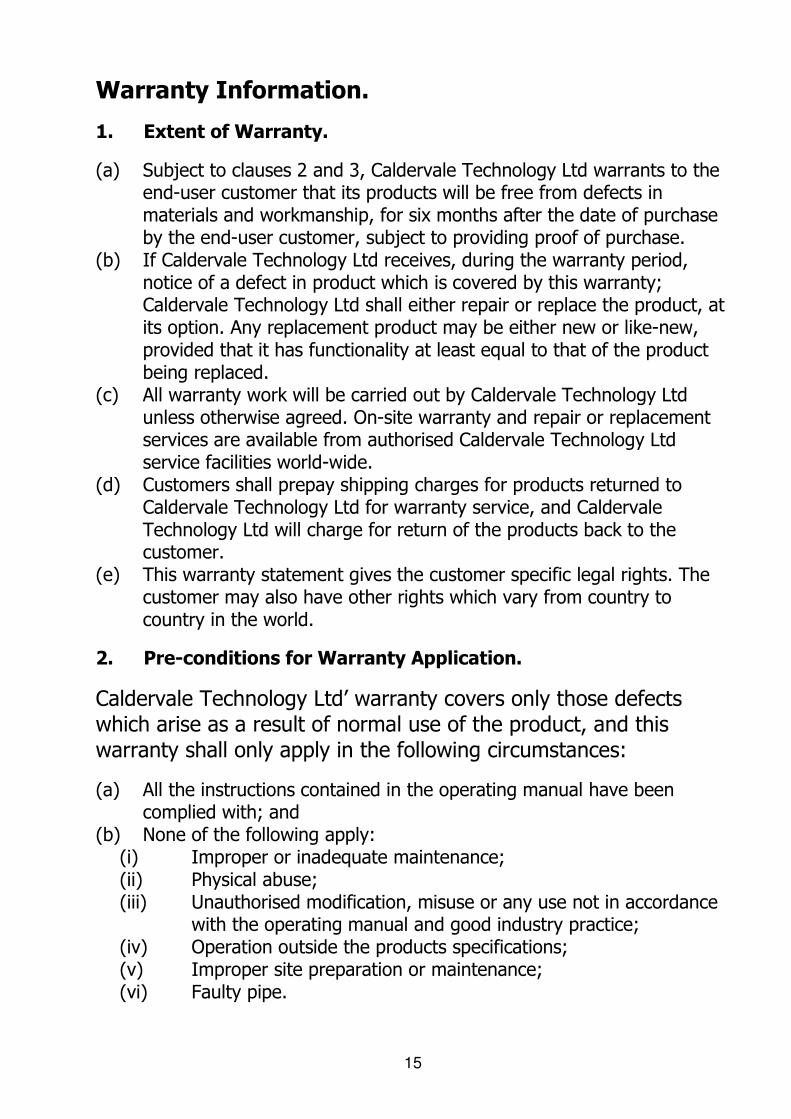
Warranty Information.
1. Extent of Warranty.
(a) Subject to clauses 2 and 3, Caldervale Technology Ltd warrants to the end-user customer that its products will be free from defects in materials and workmanship, for six months after the date of purchase by the end-user customer, subject to providing proof of purchase.
(b) If Caldervale Technology Ltd receives, during the warranty period, notice of a defect in product which is covered by this warranty; Caldervale Technology Ltd shall either repair or replace the product, at its option. Any replacement product may be either new or like-new, provided that it has functionality at least equal to that of the product being replaced.
(c) All warranty work will be carried out by Caldervale Technology Ltd unless otherwise agreed. On-site warranty and repair or replacement services are available from authorised Caldervale Technology Ltd service facilities world-wide.
(d) Customers shall prepay shipping charges for products returned to Caldervale Technology Ltd for warranty service, and Caldervale Technology Ltd will charge for return of the products back to the customer.
(e) This warranty statement gives the customer specific legal rights. The customer may also have other rights which vary from country to country in the world.
2. Pre-conditions for Warranty Application.
Caldervale Technology Ltd’ warranty covers only those defects which arise as a result of normal use of the product, and this warranty shall only apply in the following circumstances:
(a) All the instructions contained in the operating manual have been complied with; and
(b) None of the following apply: (i) Improper or inadequate maintenance; (ii) Physical abuse; (iii) Unauthorised modification, misuse or any use not in accordance
with the operating manual and good industry practice; (iv) Operation outside the products specifications; (v) Improper site preparation or maintenance; (vi) Faulty pipe.

16
3. Limitations of Warranty.
(a) Caldervale Technology Ltd does not warrant the operation of any product to be uninterrupted or error free.
(b) Caldervale Technology Ltd makes no other warranty of any kind, whether express or implied, with respect to its products. Caldervale Technology Ltd specifically disclaims the implied warranties of satisfactory quality and fitness for a particular purpose.
(c) To the extent that this warranty statement is inconsistent with the law of the locality where the customer uses the product, this warranty statement shall be deemed modified by the minimum necessary to be consistent with such local law.
(d) To the extent allowed by local law, the remedies provided in this warranty statement are the customer’s sole and exclusive remedies.
(e) This tool has been designed for the range of fittings available at the time of its design and development. Caldervale Technology Ltd can accept NO liability for the unit’s ability or otherwise to work with new or different fittings that subsequently appear in the market place.
17
Please complete this information and keep it safely with your proof of purchase receipt. You will require it for any warranty claim. Where purchased ............................................................... Date of purchase ............................................................... Name & address ............................................................... of purchaser ............................................................... ............................................................... ............................................................... ............................................................... ............................................................... Type of tool ............................................................... Serial number ...............................................................

18
For Service and repair please contact: Caldervale Technology Ltd Bretfield Court Dewsbury West Yorkshire WF12 9DB United Kingdom Tel: +44 (0)1924 469571 Fax: +44 (0)1924 460951 [email protected] http://www.caldertech.com
© 2007 Revision G