hybrid vrf systems - climacomclimacom.com/files/documents/2016_cm_hybrid_hvrf... · page 4 hybrid...
TRANSCRIPT
Hybrid VRF Systems
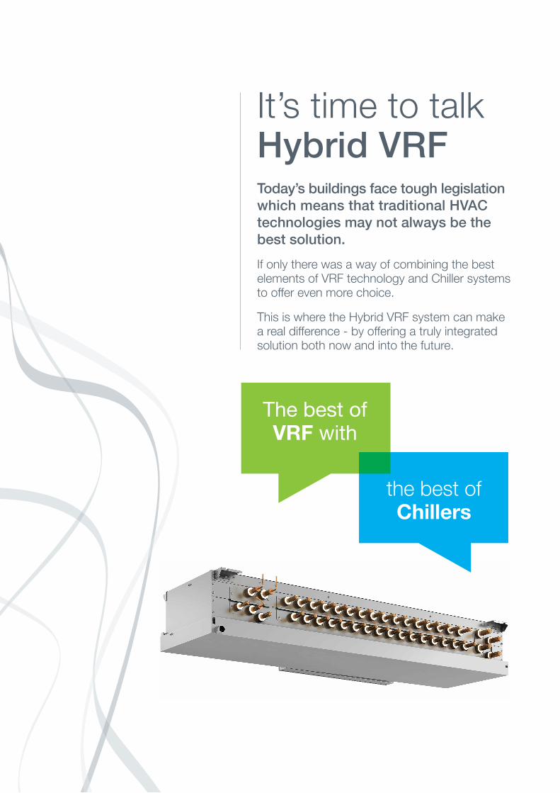
It’s time to talk Hybrid VRFToday’s buildings face tough legislation
which means that traditional HVAC
technologies may not always be the
best solution.
If only there was a way of combining the bestelements of VRF technology and Chiller systemsto offer even more choice.
This is where the Hybrid VRF system can makea real difference - by offering a truly integratedsolution both now and into the future.
the best of Chillers
The best ofVRF with
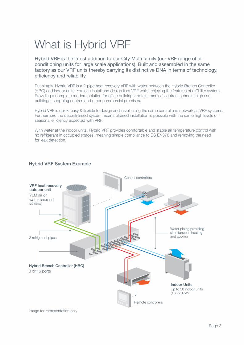
Hybrid VRF is the latest addition to our City Multi family (our VRF range of airconditioning units for large scale applications). Built and assembled in the same factory as our VRF units thereby carrying its distinctive DNA in terms of technology,efficiency and reliability.
Put simply, Hybrid VRF is a 2-pipe heat recovery VRF with water between the Hybrid Branch Controller (HBC) and indoor units. You can install and design it as VRF whilst enjoying the features of a Chiller system.Providing a complete modern solution for office buildings, hotels, medical centres, schools, high rise buildings, shopping centres and other commercial premises.
Hybrid VRF is quick, easy & flexible to design and install using the same control and network as VRF systems.Furthermore the decentralised system means phased installation is possible with the same high levels ofseasonal efficiency expected with VRF.
With water at the indoor units, Hybrid VRF provides comfortable and stable air temperature control withno refrigerant in occupied spaces, meaning simple compliance to BS EN378 and removing the needfor leak detection.
What is Hybrid VRF
Hybrid Branch Controller (HBC)
2 refrigerant pipes
VRF heat recoveryoutdoor unit
Water piping providingsimultaneous heating and cooling
Up to 50 indoor units (1.7-5.0kW)
Remote controllers
8 or 16 ports
YLM air orwater sourced(22-56kW)
Central controllers
Indoor Units
Hybrid VRF System Example
Page 3
Image for representation only
Page 4
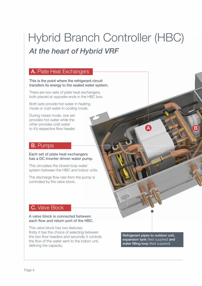
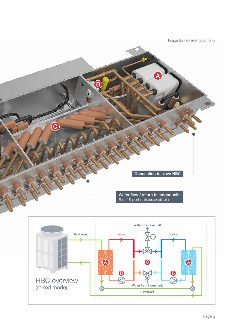
Hybrid Branch Controller (HBC)At the heart of Hybrid VRF
This is the point where the refrigerant circuit transfers its energy to the sealed water system.
There are two sets of plate heat exchangers, both placed at opposite ends in the HBC box.
Both sets provide hot water in heating mode or cold water in cooling mode.
During mixed mode, one setprovides hot water while the other provides cold water to it’s respective flow header.
Each set of plate heat exchangers has a DC inverter driven water pump.
This circulates the closed loop water system between the HBC and indoor units.
The discharge flow rate from the pump iscontrolled by the valve block.
A valve block is connected between each flow and return port of the HBC.
This valve block has two features; firstly it has the choice of selecting between the two flow headers and secondly it controls the flow of the water sent to the indoor unit,defining the capacity.
A. Plate Heat Exchangers
B. Pumps
C. Valve Block
A B
Refrigerant pipes to outdoor unit,
expansion tank (field supplied) and
water filling loop (field supplied)
Page 5
Image for representation only
Connection to slave HBC
8 or 16 port options availableWater flow / return to indoor units
C
A
B
Water to indoor unit
HeatingRefrigerant Cooling
Water from indoor unit
Refrigerant
HBC overview(mixed mode)
A AC
B B

Hybrid VRFFeatures and Benefits
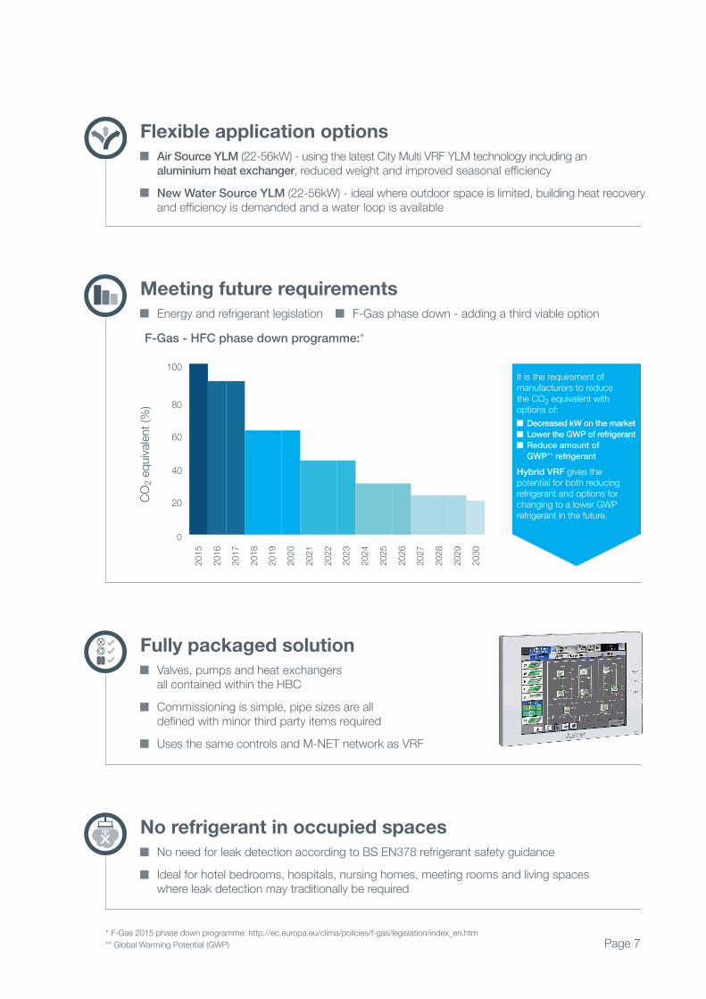
F-Gas - HFC phase down programme:*
2030
2029
2028
2027
2026
2025
2024
2023
2022
2021
2020
2019
2018
2017
2016
2015
100
CO2 e
quiva
lent (
%) 80
60
40
20
0
Flexible application options
Air Source YLM (22-56kW) - using the latest City Multi VRF YLM technology including an aluminium heat exchanger, reduced weight and improved seasonal efficiency
New Water Source YLM (22-56kW) - ideal where outdoor space is limited, building heat recovery and efficiency is demanded and a water loop is available
Meeting future requirements
Energy and refrigerant legislation F-Gas phase down - adding a third viable option
It is the requirement ofmanufacturers to reduce the CO2 equivalent with options of:
Decreased kW on the market
Lower the GWP of refrigerant
Reduce amount of
GWP** refrigerant
Hybrid VRF gives the potential for both reducingrefrigerant and options forchanging to a lower GWPrefrigerant in the future.
Fully packaged solution
Valves, pumps and heat exchangers all contained within the HBC
Commissioning is simple, pipe sizes are all defined with minor third party items required
Uses the same controls and M-NET network as VRF
No refrigerant in occupied spaces
No need for leak detection according to BS EN378 refrigerant safety guidance
Ideal for hotel bedrooms, hospitals, nursing homes, meeting rooms and living spaces where leak detection may traditionally be required
Page 7* F-Gas 2015 phase down programme: http://ec.europa.eu/clima/policies/f-gas/legislation/index_en.htm
** Global Warming Potential (GWP)
Page 8
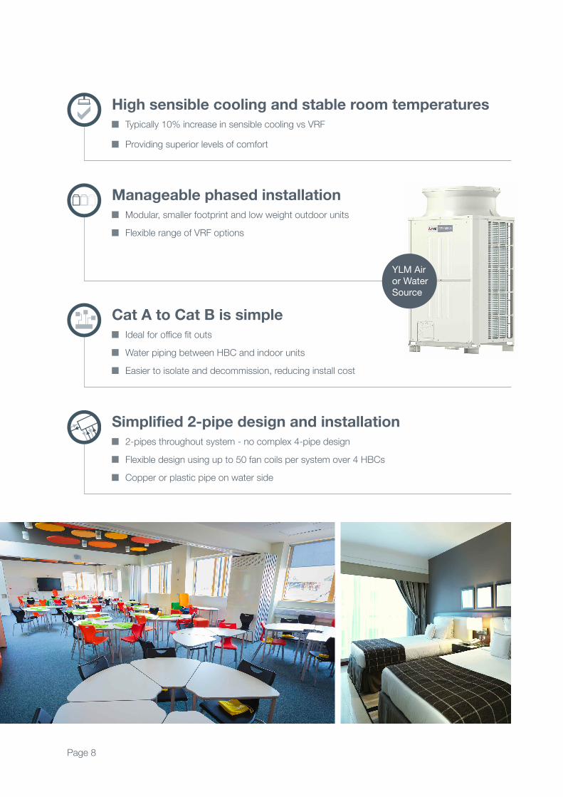
High sensible cooling and stable room temperatures
Typically 10% increase in sensible cooling vs VRF Providing superior levels of comfort
Manageable phased installation
Modular, smaller footprint and low weight outdoor units Flexible range of VRF options
Cat A to Cat B is simple
Ideal for office fit outs
Water piping between HBC and indoor units
Easier to isolate and decommission, reducing install cost
Simplified 2-pipe design and installation
2-pipes throughout system - no complex 4-pipe design
Flexible design using up to 50 fan coils per system over 4 HBCs
Copper or plastic pipe on water side
YLM Air or Water Source
Page 9
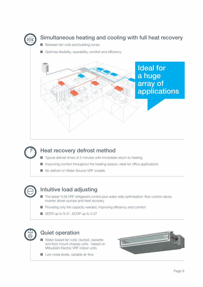
Simultaneous heating and cooling with full heat recovery Between fan coils and building zones Optimise flexibility, operability, comfort and efficiency
Heat recovery defrost method Typical defrost times of 5 minutes with immediate return to heating
Improving comfort throughout the heating season, ideal for office applications
No defrost on Water Source VRF models
Intuitive load adjusting The latest YLM VRF refrigerant control plus water side optimisation: flow control valves, inverter driven pumps and heat recovery
Providing only the capacity needed, improving efficiency and comfort
SEER up to 9.47, SCOP up to 5.37
Quiet operation Water based fan coils: ducted, cassette and floor mount chassis units - based on Mitsubishi Electric VRF indoor units
Low noise levels, variable air flow
Ideal for a huge array ofapplications
Page 10
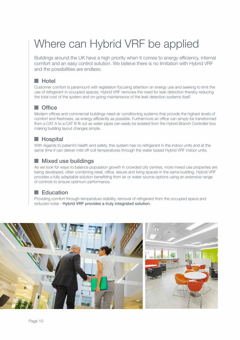
Buildings around the UK have a high priority when it comes to energy efficiency, internalcomfort and an easy control solution. We believe there is no limitation with Hybrid VRFand the possibilities are endless.
HotelCustomer comfort is paramount with legislation focusing attention on energy use and seeking to limit theuse of refrigerant in occupied spaces. Hybrid VRF removes the need for leak detection thereby reducingthe total cost of the system and on-going maintenance of the leak detection systems itself.
OfficeModern offices and commercial buildings need air conditioning systems that provide the highest levels ofcomfort and freshness, as energy efficiently as possible. Furthermore an office can simply be transformedfrom a CAT A to a CAT B fit out as water pipes can easily be isolated from the Hybrid Branch Controller boxmaking building layout changes simple.
HospitalWith regards to patient’s health and safety, this system has no refrigerant in the indoor units and at thesame time it can deliver mild off-coil temperatures through the water based Hybrid VRF indoor units.
Mixed use buildingsAs we look for ways to balance population growth in crowded city centres, more mixed use properties arebeing developed, often combining retail, office, leisure and living spaces in the same building. Hybrid VRFprovides a fully adaptable solution benefitting from air or water source options using an extensive rangeof controls to ensure optimum performance.
EducationProviding comfort through temperature stability, removal of refrigerant from the occupied space andreduced noise - Hybrid VRF provides a truly integrated solution.
Where can Hybrid VRF be applied
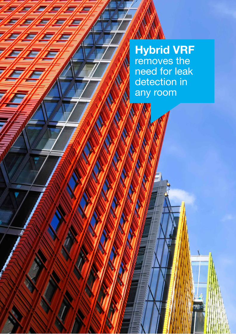
Hybrid VRFremoves the need for leakdetection inany room
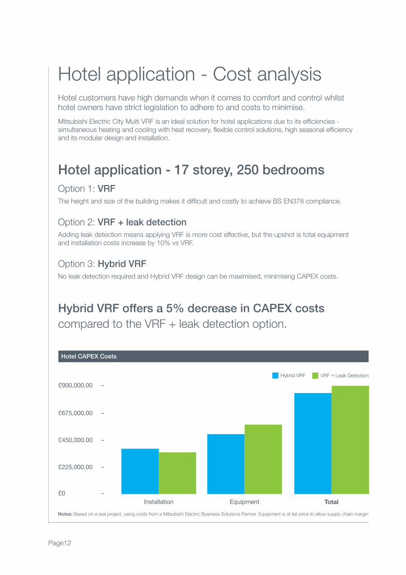
Hotel CAPEX Costs
Hybrid VRF VRF + Leak Detection
Hotel customers have high demands when it comes to comfort and control whilsthotel owners have strict legislation to adhere to and costs to minimise.
Mitsubishi Electric City Multi VRF is an ideal solution for hotel applications due to its efficiencies -simultaneous heating and cooling with heat recovery, flexible control solutions, high seasonal efficiency and its modular design and installation.
Hotel application - 17 storey, 250 bedrooms
Hotel application - Cost analysis
Option 1: VRF
The height and size of the building makes it difficult and costly to achieve BS EN378 compliance.
Option 2: VRF + leak detection
Adding leak detection means applying VRF is more cost effective, but the upshot is total equipment and installation costs increase by 10% vs VRF.
Option 3: Hybrid VRF
No leak detection required and Hybrid VRF design can be maximised, minimising CAPEX costs.
Hybrid VRF offers a 5% decrease in CAPEX costs
compared to the VRF + leak detection option.
£900,000.00 –
£675,000.00 –
£450,000.00 –
£225,000.00 –
£0 –
Installation Equipment Total
Page12
Notes: Based on a real project, using costs from a Mitsubishi Electric Business Solutions Partner. Equipment is at list price to allow supply chain margin
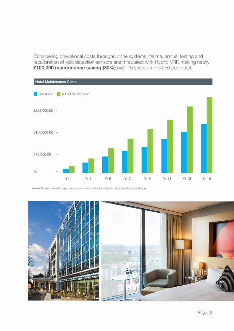
Considering operational costs throughout the systems lifetime, annual testing andrecalibration of leak detection sensors aren’t required with Hybrid VRF, making nearly£100,000 maintenance saving (30%) over 15 years on this 250 bed hotel.
Hotel Maintenance Costs
Notes: Based on a real project, using costs from a Mitsubishi Electric Business Solutions Partner
£225,000.00 –
£150,000.00 –
£75,000.00 –
£0 –
Yr 1 Yr 3 Yr 5 Yr 7 Yr 9 Yr 11 Yr 13 Yr 15
Hybrid VRF VRF + Leak Detection
Page 13
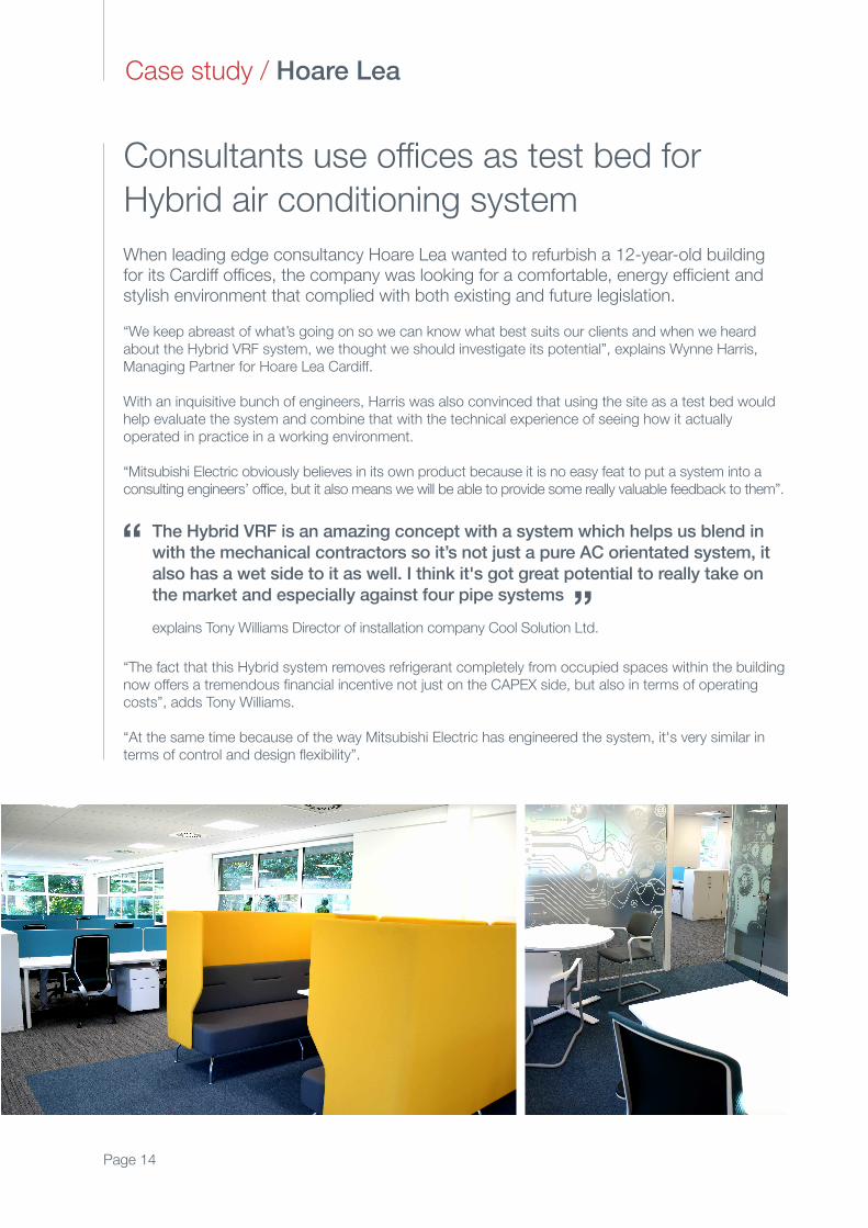
When leading edge consultancy Hoare Lea wanted to refurbish a 12-year-old buildingfor its Cardiff offices, the company was looking for a comfortable, energy efficient andstylish environment that complied with both existing and future legislation.
“We keep abreast of what’s going on so we can know what best suits our clients and when we heardabout the Hybrid VRF system, we thought we should investigate its potential”, explains Wynne Harris,Managing Partner for Hoare Lea Cardiff.
With an inquisitive bunch of engineers, Harris was also convinced that using the site as a test bed wouldhelp evaluate the system and combine that with the technical experience of seeing how it actuallyoperated in practice in a working environment.
“Mitsubishi Electric obviously believes in its own product because it is no easy feat to put a system into aconsulting engineers’ office, but it also means we will be able to provide some really valuable feedback to them”.
The Hybrid VRF is an amazing concept with a system which helps us blend in
with the mechanical contractors so it’s not just a pure AC orientated system, it
also has a wet side to it as well. I think it's got great potential to really take on
the market and especially against four pipe systems
explains Tony Williams Director of installation company Cool Solution Ltd.
“The fact that this Hybrid system removes refrigerant completely from occupied spaces within the buildingnow offers a tremendous financial incentive not just on the CAPEX side, but also in terms of operatingcosts”, adds Tony Williams.
“At the same time because of the way Mitsubishi Electric has engineered the system, it's very similar interms of control and design flexibility”.
Consultants use offices as test bed for
Hybrid air conditioning system
Case study / Hoare Lea
“ “
Page 14
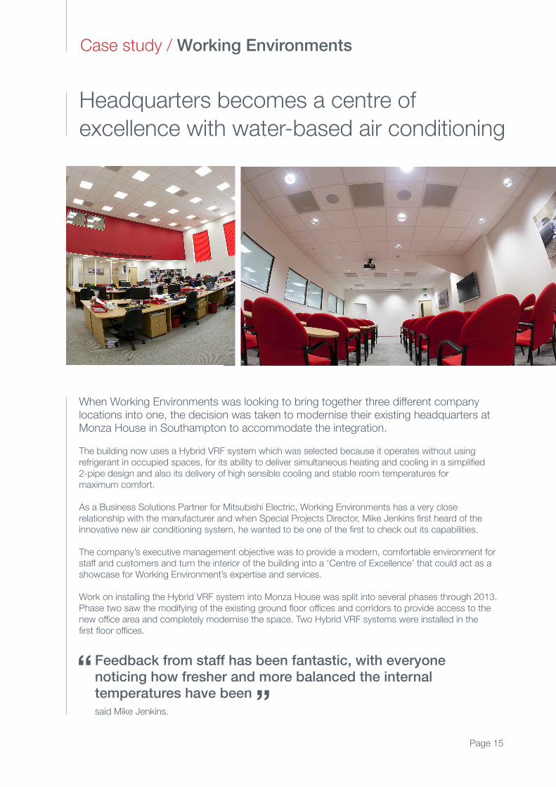
When Working Environments was looking to bring together three different companylocations into one, the decision was taken to modernise their existing headquarters atMonza House in Southampton to accommodate the integration.
The building now uses a Hybrid VRF system which was selected because it operates without usingrefrigerant in occupied spaces, for its ability to deliver simultaneous heating and cooling in a simplified2-pipe design and also its delivery of high sensible cooling and stable room temperatures formaximum comfort.
As a Business Solutions Partner for Mitsubishi Electric, Working Environments has a very closerelationship with the manufacturer and when Special Projects Director, Mike Jenkins first heard of theinnovative new air conditioning system, he wanted to be one of the first to check out its capabilities.
The company’s executive management objective was to provide a modern, comfortable environment forstaff and customers and turn the interior of the building into a ‘Centre of Excellence’ that could act as ashowcase for Working Environment’s expertise and services.
Work on installing the Hybrid VRF system into Monza House was split into several phases through 2013.Phase two saw the modifying of the existing ground floor offices and corridors to provide access to thenew office area and completely modernise the space. Two Hybrid VRF systems were installed in the first floor offices.
Feedback from staff has been fantastic, with everyone noticing how fresher and more balanced the internal temperatures have been
said Mike Jenkins.
Headquarters becomes a centre of
excellence with water-based air conditioning
Case study / Working Environments
“ “
Page 15
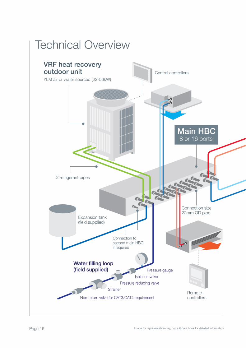
Main HBC
2 refrigerant pipes
Water filling loop(field supplied)
Expansion tank(field supplied)
Pressure gaugeIsolation valve
Pressure reducing valveStrainer
Non-return valve for CAT3/CAT4 requirement
Central controllers
Connection to second main HBCif required
Connection size22mm OD pipe
Remotecontrollers
VRF heat recoveryoutdoor unitYLM air or water sourced (22-56kW)
8 or 16 ports
Technical Overview
Page 16 Image for representation only, consult data book for detailed information
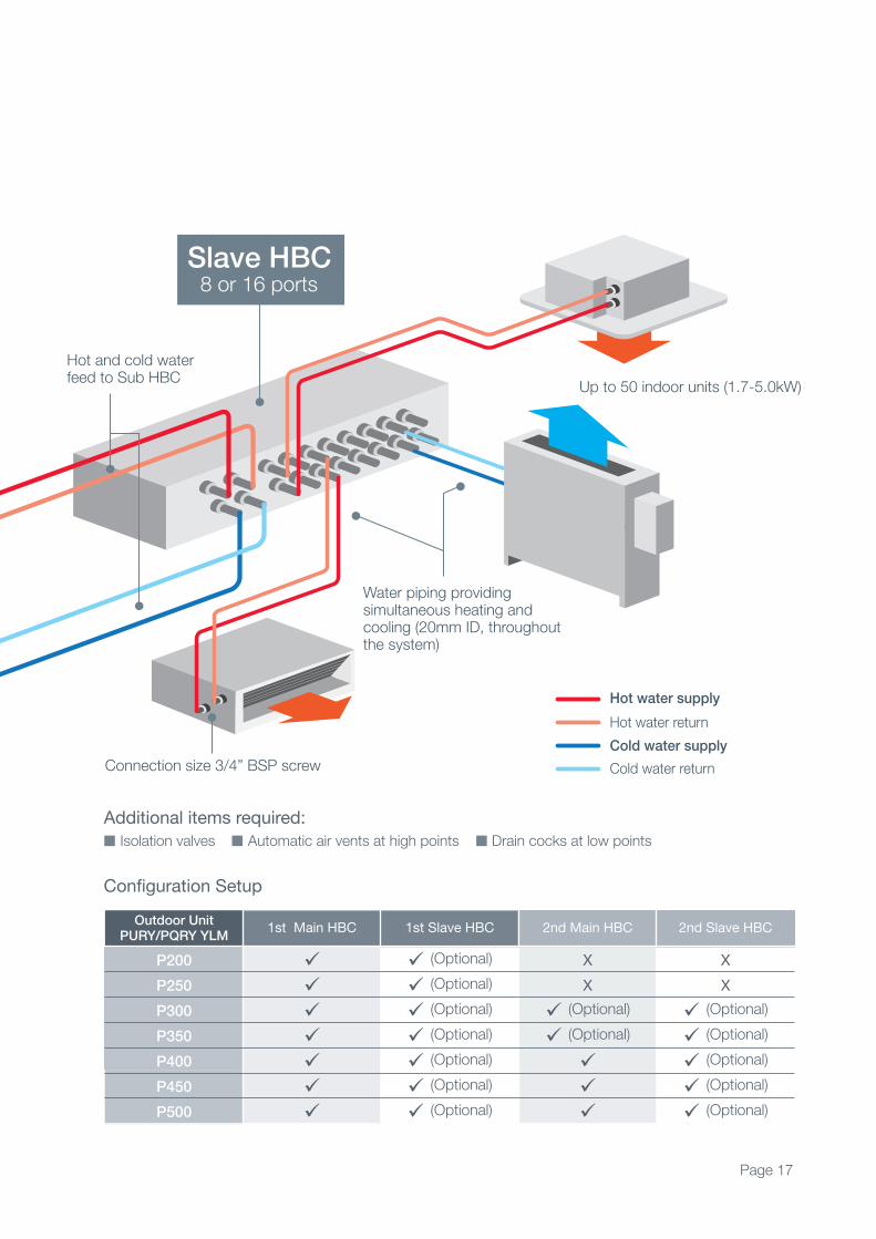
Water piping providing simultaneous heating and cooling (20mm ID, throughout the system)
Hot water supplyHot water returnCold water supplyCold water return
Hot and cold water feed to Sub HBC Up to 50 indoor units (1.7-5.0kW)
Connection size 3/4” BSP screw
Slave HBC8 or 16 ports
Outdoor UnitPURY/PQRY YLM
1st Main HBC 1st Slave HBC 2nd Main HBC 2nd Slave HBC
P200 (Optional) X X
P250 (Optional) X X
P300 (Optional) (Optional) (Optional)
P350 (Optional) (Optional) (Optional)
P400 (Optional) (Optional)
P450 (Optional) (Optional)
P500 (Optional) (Optional)
Configuration Setup
Page 17
Additional items required:
Isolation valves Automatic air vents at high points Drain cocks at low points
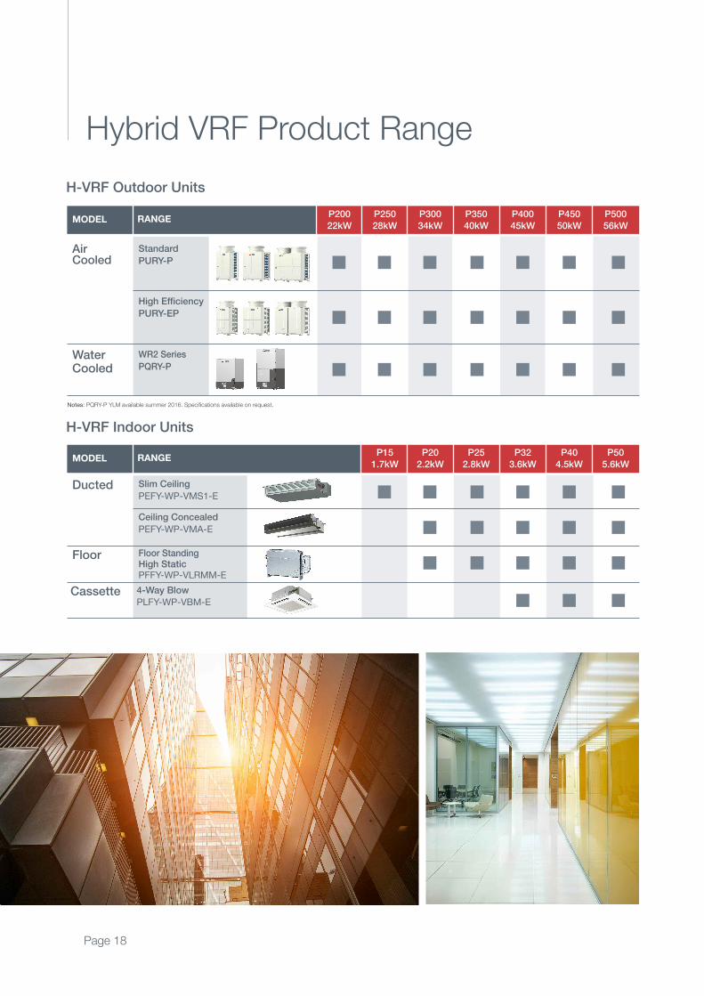
Hybrid VRF Product Range
H-VRF Outdoor Units
H-VRF Indoor Units
RANGE1.7kW 2.2kW 2.8kW 3.6kW 4.5kW 5.6kW
P15 P20 P25 P32 P40 P50
Ducted Slim Ceiling
PEFY-WP-VMS1-E
Floor Floor StandingHigh StaticPFFY-WP-VLRMM-E
Cassette 4-Way Blow
PLFY-WP-VBM-E
Ceiling Concealed
PEFY-WP-VMA-E
MODEL
RANGE28kW 34kW 40kW 45kW 50kW 56kW
P250
22kW
P200 P300 P350 P400 P450 P500
AirCooled
Standard
PURY-P
WaterCooled
WR2 Series
PQRY-P
High Efficiency
PURY-EP
MODEL
Page 18
Notes: PQRY-P YLM available summer 2016. Specifications available on request.
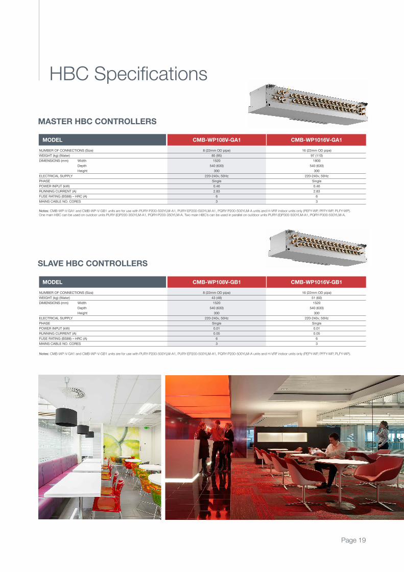
HBC Specifications
Notes: CMB-WP-V-GA1 and CMB-WP-V-GB1 units are for use with PURY-P200-500YLM-A1, PURY-EP200-500YLM-A1, PQRY-P200-500YLM-A units and H-VRF indoor units only (PEFY-WP, PFFY-WP, PLFY-WP). One main HBC can be used on outdoor units PURY-(E)P200-350YLM-A1, PQRY-P200-350YLM-A. Two main HBC’s can be used in parallel on outdoor units PURY-(E)P300-500YLM-A1, PQRY-P300-500YLM-A.
8 (22mm OD pipe)
85 (95)
1520
540 (630)
300
220-240v, 50Hz
Single
0.46
2.83
6
3
16 (22mm OD pipe)
97 (110)
1800
540 (630)
300
220-240v, 50Hz
Single
0.46
2.83
6
3
NUMBER OF CONNECTIONS (Size)
WEIgHT (kg) (Water)
DIMENSIONS (mm) Width
Depth
Height
ELECTRICAL SUPPLY
PHASE
POWER INPUT (kW)
RUNNINg CURRENT (A)
FUSE RATINg (BS88) – HRC (A)
MAINS CABLE NO. CORES
MODEL CMB-WP108V-GA1 CMB-WP1016V-GA1
Notes: CMB-WP-V-GA1 and CMB-WP-V-GB1 units are for use with PURY-P200-500YLM-A1, PURY-EP200-500YLM-A1, PQRY-P200-500YLM-A units and H-VRF indoor units only (PEFY-WP, PFFY-WP, PLFY-WP).
8 (22mm OD pipe)
43 (48)
1520
540 (630)
300
220-240v, 50Hz
Single
0.01
0.05
6
3
16 (22mm OD pipe)
51 (60)
1520
540 (630)
300
220-240v, 50Hz
Single
0.01
0.05
6
3
NUMBER OF CONNECTIONS (Size)
WEIgHT (kg) (Water)
DIMENSIONS (mm) Width
Depth
Height
ELECTRICAL SUPPLY
PHASE
POWER INPUT (kW)
RUNNINg CURRENT (A)
FUSE RATINg (BS88) – HRC (A)
MAINS CABLE NO. CORES
MODEL CMB-WP108V-GB1 CMB-WP1016V-GB1
MASTER HBC CONTROLLERS
SLAVE HBC CONTROLLERS
Page 19
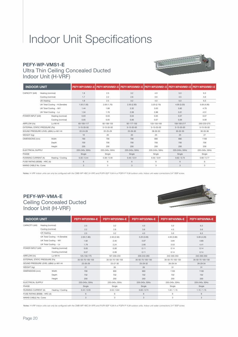
Indoor Unit Specifications
INDOOR UNIT PEFY-WP20VMA-E PEFY-WP25VMA-E PEFY-WP32VMA-E PEFY-WP40VMA-E PEFY-WP50VMA-E
2.5
2.2
2.5
2.00 (1.80)
1.92
1.79
0.05
0.07
125-150-175
35-50-70-100-150
23-26-29
21
700
732
250
220-240v, 50Hz
Single
0.44 / 0.55
6
3
3.2
2.8
3.2
2.50 (2.50)
2.40
2.24
0.09
0.09
167-200-233
35-50-70-100-150
23-27-30
26
900
732
250
220-240v, 50Hz
Single
0.53 / 0.64
6
3
4.0
3.6
4.0
3.20 (3.00)
3.07
2.85
0.11
0.11
200-242-283
35-50-70-100-150
25-29-32
26
900
732
250
220-240v, 50Hz
Single
0.63 / 0.74
6
3
5.0
4.5
5.0
4.00 (3.80)
3.84
3.53
0.14
0.14
242-300-350
35-50-70-100-150
26-29-34
31
1100
732
250
220-240v, 50Hz
Single
1.04 / 1.15
6
3
6.3
5.6
6.3
5.00 (4.20)
4.80
4.41
0.14
0.14
242-300-350
35-50-70-100-150
26-29-34
31
1100
732
250
220-240v, 50Hz
Single
1.15 / 1.15
6
3
CAPACITY (kW) Heating (nominal)
Cooling (nominal)
UK Heating
UK Total Cooling - Hi (Sensible)
UK Total Cooling - Mi1
UK Total Cooling - Lo
POWER INPUT (kW) Heating (nominal)
Cooling (nominal)
AIRFLOW (l/s) Lo-Mi-Hi
EXTERNAL STATIC PRESSURE (Pa)
SOUND PRESSURE LEVEL (dBA) Lo-Mi1-Hi
WEIgHT (kg)
DIMENSIONS (mm) Width
Depth
Height
ELECTRICAL SUPPLY
PHASE
RUNNINg CURRENT (A) Heating / Cooling
FUSE RATINg (BS88) - HRC (A)
MAINS CABLE No. Cores
Notes: H-VRF indoor units can only be configured with the CMB-WP HBC (H-VRF) and PURY-(E)P YLM-A or PQRY-P YLM outdoor units. Indoor unit water connections 3/4” BSP screw.
PEFY-WP-VMA-E
Ceiling Concealed DuctedIndoor Unit (H-VRF)
Notes: H-VRF indoor units can only be configured with the CMB-WP HBC (H-VRF) and PURY-(E)P YLM-A or PQRY-P YLM outdoor units. Indoor unit water connections 3/4” BSP screw.
INDOOR UNIT PEFY-WP15VMS1-E PEFY-WP20VMS1-E PEFY-WP25VMS1-E PEFY-WP32VMS1-E PEFY-WP40VMS1-E PEFY-WP50VMS1-E
CAPACITY (kW) Heating (nominal)
Cooling (nominal)
UK Heating
UK Total Cooling - Hi (Sensible)
UK Total Cooling - Mi1
UK Total Cooling - Lo
POWER INPUT (kW) Heating (nominal)
Cooling (nominal)
AIRFLOW (l/s) Lo-Mi-Hi
EXTERNAL STATIC PRESSURE (Pa)
SOUND PRESSURE LEVEL (dBA) Lo-Mi1-Hi
WEIgHT (kg)
DIMENSIONS (mm) Width
Depth
Height
ELECTRICAL SUPPLY
PHASE
RUNNINg CURRENT (A) Heating / Cooling
FUSE RATINg (BS88) - HRC (A)
MAINS CABLE No. Cores
1.9
1.7
1.9
1.50 (1.50)
1.44
1.34
0.03
0.05
83-100-117
5-15-35-50
22-24-28
19
790
700
200
220-240v, 50Hz
Single
0.33 / 0.44
6
3
2.5
2.2
2.5
2.00 (1.70)
1.89
1.76
0.03
0.05
92-108-133
5-15-35-50
22-25-29
20
790
700
200
220-240v, 50Hz
Single
0.38 / 0.49
6
3
3.2
2.8
3.2
2.50 (2.00)
2.32
2.08
0.04
0.06
92-117-150
5-15-35-50
23-26-30
20
790
700
200
220-240v, 50Hz
Single
0.40 / 0.51
6
3
4.0
3.6
4.0
3.20 (2.70)
3.03
2.88
0.05
0.07
133-150-183
5-15-35-50
28-30-33
25
990
700
200
220-240v, 50Hz
Single
0.50 / 0.61
6
3
5.0
4.5
5.0
4.00 (3.20)
3.82
3.61
0.07
0.09
158-183-217
5-15-35-50
30-32-35
25
990
700
200
220-240v, 50Hz
Single
0.62 / 0.73
6
3
6.3
5.6
6.3
5.00 (4.00)
4.79
4.51
0.07
0.09
200-233-275
5-15-35-50
30-33-36
27
1190
700
200
220-240v, 50Hz
Single
0.66 / 0.77
6
3
PEFY-WP-VMS1-E
Ultra Thin Ceiling Concealed Ducted Indoor Unit (H-VRF)
Page 20
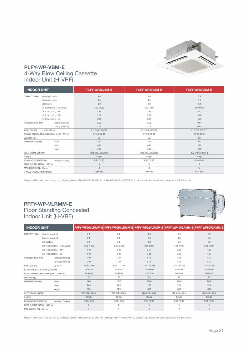
Page 21
Notes: H-VRF indoor units can only be configured with the CMB-WP HBC (H-VRF) and PURY-(E)P YLM-A or PQRY-P YLM outdoor units. Indoor unit water connections 3/4” BSP screw.
INDOOR UNIT PLFY-WP32VBM-E PLFY-WP40VBM-E PLFY-WP50VBM-E
PLFY-WP-VBM-E
4-Way Blow Ceiling Cassetteindoor Unit (H-VRf)
4.0
3.6
4.0
3.20 (3.20)
3.16
3.09
3.02
0.03
0.04
217-233-250-267
27-29-30-31
22
840
840
258
220-240v, 50/60Hz
Single
0.28 / 0.35
6
3
pLp-6Ba
5.0
4.5
5.0
4.00 (3.60)
3.95
3.87
3.77
0.03
0.04
217-233-250-267
27-29-30-31
22
840
840
258
220-240v, 50/60Hz
Single
0.28 / 0.35
6
3
pLp-6Ba
6.3
5.6
6.3
5.00 (4.20)
4.87
4.66
4.39
0.04
0.05
217-250-283-317
27-30-32-34
22
840
840
258
220-240v, 50/60Hz
Single
0.38 / 0.45
6
3
pLp-6Ba
CapaCity (kW) Heating (nominal)
Cooling (nominal)
UK Heating
UK Total cooling - Hi (Sensible)
UK Total cooling - Mi2
UK Total cooling - Mi1
UK Total cooling - Lo
pOWER iNpUt (kW) Heating (nominal)
Cooling (nominal)
aiRfLOW (l/s) Lo-Mi1-Mi2-Hi
SOUND pRESSURE LEVEL (dBa) Lo-Mi1-Mi2-Hi
WEigHt (kg)
DiMENSiONS (mm) Width
Depth
Height
ELECtRiCaL SUppLy
pHaSE
RUNNiNg CURRENt (a) Heating / Cooling
fUSE RatiNg (BS88) - HRC (a)
MaiNS CaBLE No. Cores
gRiLLE MODEL REfERENCE
INDOOR UNIT PFFY-WP20VLRMM-E PFFY-WP25VLRMM-E PFFY-WP32VLRMM-E PFFY-WP40VLRMM-E
Notes: H-VRF indoor units can only be configured with the CMB-WP HBC (H-VRF) and PURY-(E)P YLM-A or PQRY-P YLM outdoor units. Indoor unit water connections 3/4” BSP screw.
PFFY-WP-VLRMM-E
floor Standing Concealed indoor Unit (H-VRf)
CapaCity (kW) Heating (nominal)
Cooling (nominal)
UK Heating
UK total Cooling - Hi (Sensible)
UK total Cooling - Mi1
UK total Cooling - Lo
pOWER iNpUt (kW) Heating (nominal)
Cooling (nominal)
aiRfLOW (l/s) Lo-Mi-Hi
EXtERNaL StatiC pRESSURE (pa)
SOUND pRESSURE LEVEL (dBa) Lo-Mi1-Hi
WEigHt (kg)
DiMENSiONS (mm) Width
Depth
Height
ELECtRiCaL SUppLy
pHaSE
RUNNiNg CURRENt (a) Heating / Cooling
fUSE RatiNg (BS88) - HRC (a)
MaiNS CaBLE No. Cores
2.5
2.2
2.5
2.00 (1.50)
1.96
1.83
0.04
0.04
75-83-100
20-40-60
31-33-38
22
886
220
639
220-240v, 50Hz
Single
0.35 / 0.35
6
3
3.2
2.8
3.2
2.50 (2.00)
2.42
2.29
0.04
0.04
100-117-133
20-40-60
31-33-38
25
1006
220
639
220-240v, 50Hz
Single
0.35 / 0.35
6
3
4.0
3.6
4.0
3.20 (2.50)
3.07
2.86
0.05
0.05
125-150-175
20-40-60
31-35-38
25
1006
220
639
220-240v, 50Hz
Single
0.47 / 0.47
6
3
5.0
4.5
5.0
4.00 (3.10)
3.86
3.53
0.05
0.05
133-167-192
20-40-60
34-37-40
29
1246
220
639
220-240v, 50Hz
Single
0.47 / 0.47
6
3
PFFY-WP50VLRMM-E
6.3
5.6
6.3
5.00 (3.90)
4.82
4.43
0.07
0.07
175-217-250
20-40-60
37-42-45
29
1246
220
639
220-240v, 50Hz
Single
0.65 / 0.65
6
3

Page 22
CAPACITY (kW) Heating (nominal)
Cooling (nominal)
High Performance Heating (UK)
COP Priority Heating (UK)
Cooling (UK)
POWER INPUT (kW) Heating (nominal)
Cooling (nominal)
High Performance Heating (UK)
COP Priority Heating (UK)
Cooling (UK)
COP / EER (nominal)
SCOP / SEER
MAX No. OF CONNECTABLE INDOOR UNITS
MAX CONNECTABLE CAPACITY
AIRFLOW (m3/min) High
PIPE SIZE mm (in) Gas
Liquid
SOUND PRESSURE LEVEL (dBA)
SOUND POWER LEVEL (dBA)
WEIgHT (kg)
DIMENSIONS (mm) Width
Depth
(1650mm without legs) Height
ELECTRICAL SUPPLY
PHASE
STARTINg CURRENT (A)
NOMINAL SYSTEM RUNNINg CURRENT (A) Heating /Cooling [MAX]
gUARANTEED OPERATINg RANgE (ºC) Heating / Cooling
FUSE RATINg (MCB sizes BS EN 60947-2) - (A)
MAINS CABLE No. Cores
25.0
22.4
25.0
22.8
20.0
7.08
7.00
8.92
7.04
4.06
3.53 / 3.20
5.08 / 8.50
20
50~150% OU Capacity
185
19.05 (3/4”)
15.88 (5/8”)
59
82.5
205
920
740
1710
380-415v, 50Hz
Three
8
10.9 / 10.8 [16.1]
-20~15.5 / -5~46
1 x 20
4 + earth
31.5
28.0
31.5
28.7
25.0
10.06
9.90
12.67
10.01
5.74
3.13 / 2.82
4.51 / 7.53
25
50~150% OU Capacity
185
22.2 (7/8”)
19.05 (3/4”)
60
83.5
205
920
740
1710
380-415v, 50Hz
Three
8
15.5 / 15.3 [17.3]
-20~15.5 / -5~46
1 x 20
4 + earth
37.5
33.5
35.6
32.3
29.8
12.71
13.34
16.97
12.40
8.61
3.14 / 2.96
4.70 / 6.90
30
50~150% OU Capacity
230
22.2 (7/8”)
19.05 (3/4”)
62.5
86
248
1220
740
1710
380-415v, 50Hz
Three
8
19.6 / 20.6 [22.2]
-20~15.5 / -5~46
1 x 25
4 + earth
37.5
33.5
35.6
32.3
29.8
11.94
11.31
15.94
11.65
7.30
3.14 / 2.96
5.00 / 8.13
30
50~150% OU Capacity
230
22.2 (7/8”)
19.05 (3/4”)
62.5
86
248
1220
740
1710
380-415v, 50Hz
Three
8
18.4 / 17.4 [22.2]
-20~15.5 / -5~46
1 x 25
4 + earth
45.0
40.0
42.8
38.7
35.6
15.51
17.93
20.70
15.12
11.57
3.13 / 2.74
4.67 / 6.14
35
50~150% OU Capacity
230
28.58 (1-1/8”)
19.05 (3/4”)
62.5
86
248
1220
740
1710
380-415v, 50Hz
Three
8
23.9 / 27.7 [27.8]
-20~15.5 / -5~46
1 x 32
4 + earth
45.0
40.0
42.8
38.7
35.6
14.35
14.59
19.15
13.99
9.42
3.13 / 2.74
5.04 / 7.54
35
50~150% OU Capacity
230
28.58 (1-1/8”)
19.05 (3/4”)
62.5
86
248
1220
740
1710
380-415v, 50Hz
Three
8
22.2 / 22.5 [27.8]
-20~15.5 / -5~46
1 x 32
4 + earth
Outdoor Unit Specifications
OUTDOOR UNIT PURY-P200YLM-A1 PURY-P250YLM-A1 PURY-P300YLM-A1 PURY-P300YLM-A1X2 HBC
PURY-P350YLM-A1 PURY-P350YLM-A1X2 HBC
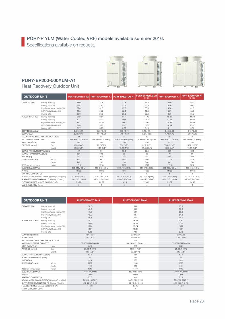
PURY-P200-500YLM-A1
Heat Recovery Outdoor Unit
CAPACITY (kW) Heating (nominal)
Cooling (nominal)
High Performance Heating (UK)
COP Priority Heating (UK)
Cooling (UK)
POWER INPUT (kW) Heating (nominal)
Cooling (nominal)
High Performance Heating (UK)
COP Priority Heating (UK)
Cooling (UK)
COP / EER (nominal)
SCOP / SEER
MAX No. OF CONNECTABLE INDOOR UNITS
MAX CONNECTABLE CAPACITY
AIRFLOW (m3/min) High
PIPE SIZE mm (in) Gas
Liquid
SOUND PRESSURE LEVEL (dBA)
SOUND POWER LEVEL (dBA)
WEIgHT (kg)
DIMENSIONS (mm) Width
Depth
(1650mm without legs) Height
ELECTRICAL SUPPLY
PHASE
STARTINg CURRENT (A)
NOMINAL SYSTEM RUNNINg CURRENT (A) Heating /Cooling [MAX]
gUARANTEED OPERATINg RANgE (ºC) Heating / Cooling
FUSE RATINg (MCB sizes BS EN 60947-2) - (A)
MAINS CABLE No. Cores
45.0
45.0
47.5
43.0
40.1
13.39
16.65
17.88
13.05
10.74
3.36 / 2.70
4.66 / 6.08
40
50~150% OU Capacity
230
28.58 (1-1/8”)
22.2 (7/8”)
62.5
86
246
1220
740
1710
380-415v, 50Hz
Three
8
20.6 / 25.7 [32.4]
-20~15.5 / -5~46
1 x 40
4 + earth
56.0
50.0
50.7
48.7
44.4
17.39
17.92
19.91
16.00
11.29
3.22 / 2.79
4.50 / 6.34
45
50~150% OU Capacity
320
28.58 (1-1/8”)
22.2 (7/8”)
62.5
86
321
1750
740
1710
380-415v, 50Hz
Three
8
26.8 / 27.7 [35.9]
-20~15.5 / -5~46
1 x 40
4 + earth
58.0
56.0
57.0
54.8
49.7
17.53
22.67
20.07
16.13
14.29
3.30 / 2.47
4.63 / 5.62
50
50~150% OU Capacity
380
28.58 (1-1/8”)
22.2 (7/8”)
63.5
87
321
1750
740
1710
380-415v, 50Hz
Three
8 / 8
27.0 / 35.0 [41.9]
-20~15.5 / -5~46
1 x 50
4 + earth
OUTDOOR UNIT PURY-P400YLM-A1 PURY-P450YLM-A1 PURY-P500YLM-A1
CAPACITY (kW) Heating (nominal)
Cooling (nominal)
High Performance Heating (UK)
COP Priority Heating (UK)
Cooling (UK)
POWER INPUT (kW) Heating (nominal)
Cooling (nominal)
High Performance Heating (UK)
COP Priority Heating (UK)
Cooling (UK)
COP / EER (nominal)
SCOP / SEER
MAX No. OF CONNECTABLE INDOOR UNITS
MAX CONNECTABLE CAPACITY
AIRFLOW (m3/min) High
PIPE SIZE mm (in) Gas
Liquid
SOUND PRESSURE LEVEL (dBA)
SOUND POWER LEVEL (dBA)
WEIgHT (kg)
DIMENSIONS (mm) Width
Depth
(1650mm without legs) Height
ELECTRICAL SUPPLY
PHASE
STARTINg CURRENT (A)
NOMINAL SYSTEM RUNNINg CURRENT (A) Heating /Cooling [MAX]
gUARANTEED OPERATINg RANgE (ºC) Heating / Cooling
FUSE RATINg (MCB sizes BS EN 60947-2) - (A)
MAINS CABLE No. Cores
25.0
22.4
25.0
22.8
20.0
6.92
6.27
8.67
6.88
2.77
3.61 / 3.57
5.19 / 9.47
20
50~150% OU Capacity
185
19.05 (3/4”)
15.88 (5/8”)
59
82.5
202
920
740
1710
380-415v, 50Hz
Three
8
10.6 / 9.6 [16.1]
-20~15.5 / -5~46
1 x 20
4
31.5
28.0
31.5
28.7
25.0
9.84
8.77
12.32
9.78
3.76
3.20 / 3.19
4.61 / 8.51
25
50~150% OU Capacity
185
22.2 (7/8”)
19.05 (3/4”)
60
83.5
202
920
740
1710
380-415v, 50Hz
Three
8
15.2 / 13.5 [19.9]
-20~15.5 / -5~46
1 x 20
4
37.5
33.5
35.6
32.3
29.8
11.71
12.05
15.62
11.37
6.06
3.76 / 3.74
5.10 / 7.63
30
50~150% OU Capacity
230
22.2 (7/8”)
19.05 (3/4”)
62.5
86
244
1220
740
1710
380-415v, 50Hz
Three
8
18.1 / 18.6 [23.6]
-20~15.5 / -5~46
1 x 25
4
37.5
33.5
35.6
32.3
29.8
11.12
10.24
14.83
10.80
5.15
3.76 / 3.74
5.37 / 8.96
30
50~150% OU Capacity
230
22.2 (7/8”)
19.05 (3/4”)
62.5
86
244
1220
740
1710
380-415v, 50Hz
Three
8
17.1 / 15.8 [23.6]
-20~15.5 / -5~46
1 x 25
4
45.0
40.0
42.8
38.7
35.6
15.38
17.16
20.52
14.94
8.11
3.15 / 2.86
4.70 / 6.42
35
50~150% OU Capacity
230
28.58 (1-1/8”)
19.05 (3/4”)
62.5
86
244
1220
740
1710
380-415v, 50Hz
Three
8
23.7 / 26.5 [30.6]
-20~15.5 / -5~46
1 x 32
4
45.0
40.0
42.8
38.7
35.6
14.28
13.98
19.05
13.87
6.61
3.15 / 2.86
5.06 / 7.86
35
50~150% OU Capacity
230
28.58 (1-1/8”)
19.05 (3/4”)
62.5
86
244
1220
740
1710
380-415v, 50Hz
Three
8
22.0 / 21.6 [30.6]
-20~15.5 / -5~46
1 x 32
4
OUTDOOR UNIT PURY-EP200YLM-A1 PURY-EP250YLM-A1 PURY-EP300YLM-A1 PURY-EP300YLM-A1X2 HBC
PURY-EP350YLM-A1 PURY-EP350YLM-A1X2 HBC
PURY-EP200-500YLM-A1
Heat Recovery Outdoor Unit
CAPACITY (kW) Heating (nominal)
Cooling (nominal)
High Performance Heating (UK)
COP Priority Heating (UK)
Cooling (UK)
POWER INPUT (kW) Heating (nominal)
Cooling (nominal)
High Performance Heating (UK)
COP Priority Heating (UK)
Cooling (UK)
COP / EER (nominal)
SCOP / SEER
MAX No. OF CONNECTABLE INDOOR UNITS
MAX CONNECTABLE CAPACITY
AIRFLOW (m3/min) High
PIPE SIZE mm (in) Gas
Liquid
SOUND PRESSURE LEVEL (dBA)
SOUND POWER LEVEL (dBA)
WEIgHT (kg)
DIMENSIONS (mm) Width
Depth
(1650mm without legs) Height
ELECTRICAL SUPPLY
PHASE
STARTINg CURRENT (A)
NOMINAL SYSTEM RUNNINg CURRENT (A) Heating /Cooling [MAX]
gUARANTEED OPERATINg RANgE (ºC) Heating / Cooling
FUSE RATINg (MCB sizes BS EN 60947-2) - (A)
MAINS CABLE No. Cores
50.0
45.0
47.5
43.0
40.1
14.12
13.88
18.84
13.71
6.82
3.54 / 3.24
4.92 / 7.34
40
50~150% OU Capacity
320
28.58 (1-1/8”)
22.2 (7/8”)
62.5
86
315
1750
740
1710
380-415v, 50Hz
Three
8 / 8
21.8 / 21.4 [31.7]
-20~15.5 / -5~46
1 x 32
4
56.0
50.0
50.7
48.7
44.4
16.86
16.83
19.24
15.41
7.88
3.32 / 2.97
4.64 / 6.75
45
50~150% OU Capacity
320
28.58 (1-1/8”)
22.2 (7/8”)
62.5
86
336
1750
740
1710
380-415v, 50Hz
Three
8 / 8
26.0 / 26.0 [37.4]
-20~15.5 / -5~46
1 x 40
4
63.0
56.0
57.0
54.8
49.7
21.67
21.22
24.73
19.81
9.10
2.9 / 2.63
4.77 / 6.00
50
50~150% OU Capacity
380
28.58 (1-1/8”)
22.2 (7/8”)
63.5
87
349
1750
740
1710
380-415v, 50Hz
Three
8 / 8
33.4 / 32.8 [46.1]
-20~15.5 / -5~46
1 x 50
4
OUTDOOR UNIT PURY-EP400YLM-A1 PURY-EP450YLM-A1 PURY-EP500YLM-A1
PQRY-P YLM (Water Cooled VRF) models available summer 2016.
Specifications available on request.
Page 23
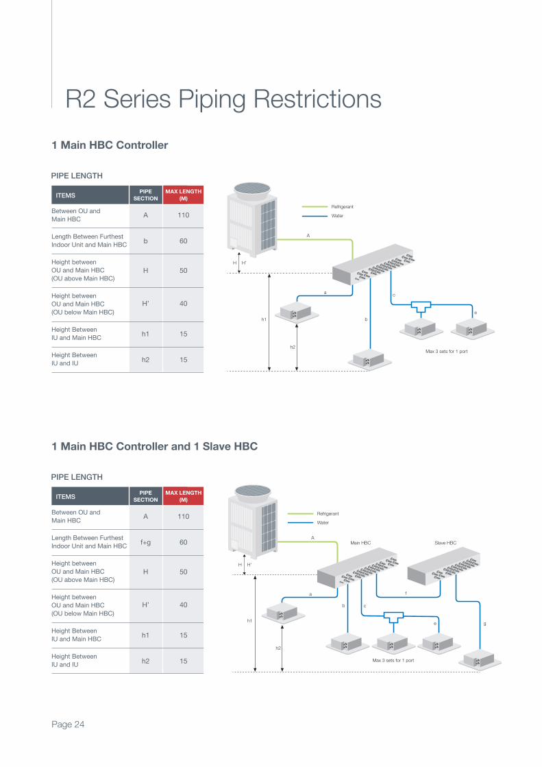
R2 Series Piping Restrictions
Page 24
ITEMS
Between OU and
Main HBC
Length Between Furthest
Indoor Unit and Main HBC
Height between
OU and Main HBC
(OU above Main HBC)
Height between
OU and Main HBC
(OU below Main HBC)
Height Between
IU and Main HBC
Height Between
IU and IU
A 110
b 60
H 50
H’ 40
h1 15
h2 15
PIPE
SECTION
MAX LENGTH
(M)
PIPE LENGTH
Main HBC
Max 3 sets for 1 port
A
H H’
a c
ebh1
h2
Refrigerant
Water
1 Main HBC Controller
1 Main HBC Controller and 1 Slave HBC
ITEMS
Between OU and
Main HBC
Length Between Furthest
Indoor Unit and Main HBC
Height between
OU and Main HBC
(OU above Main HBC)
Height between
OU and Main HBC
(OU below Main HBC)
Height Between
IU and Main HBC
Height Between
IU and IU
A 110
f+g 60
H 50
H’ 40
h1 15
h2 15
PIPE
SECTION
MAX LENGTH
(M)
PIPE LENGTH
Main HBC Slave HBC
Max 3 sets for 1 port
A
H H’
a
c
e
f
g
b
h1
h2
Refrigerant
Water
Page 25
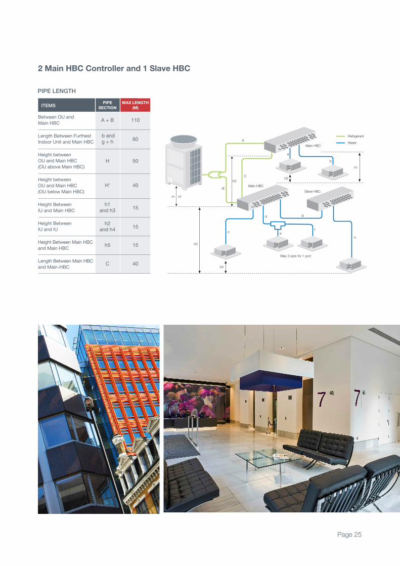
ITEMS
Between OU and
Main HBC
Length Between Furthest
Indoor Unit and Main HBC
Height between
OU and Main HBC
(OU above Main HBC)
Height between
OU and Main HBC
(OU below Main HBC)
Height Between
IU and Main HBC
Height Between
IU and IU
Height Between Main HBC
and Main HBC
Length Between Main HBC
and Main-HBC
A + B 110
b and g + h
60
H 50
H’ 40
h1 and h3
15
h2 and h4
15
h5 15
C 40
PIPE
SECTION
MAX LENGTH
(M)
PIPE LENGTH
Main HBC
Max 3 sets for 1 port
A
B
C
H H’
c
d
fe
g
h
h3
h4
h5h2
h1
a
b
Main HBC
Refrigerant
Water
Slave HBC
2 Main HBC Controller and 1 Slave HBC

Founded in 1921, we have led the way in airconditioning and the use of innovative, energyefficient, heat pump technology.
The company has manufactured both air conditioning and chillers
for more than 40 years and has now taken this extensive experience
to produce the new Hybrid VRF range.
Through our technical expertise, long experience and innovative
product range, we enable building operators everywhere to
significantly improve energy efficiency, reduce running costs
and adhere to increasingly tough legislation.
We believe that global climate challenges need local solutions.
Our aim is to help individuals and businesses reduce the energy
consumption of their buildings and their running costs.
Mitsubishi Electric offers advanced technology that really can make a world of difference.
Page 26
The name Mitsubishi issynonymous with excellence

Hybrid VRF offersan integrated solution both now and into the future
Telephone: 01707 282880
MELSmart Technical Services: 0161 866 6089Technical Help - option 1
Warranty - option 3
Training - option 6 followed by option 1
email: [email protected]
website: airconditioning.mitsubishielectric.co.uk
website: hybridvrf.co.uk
website: recycling.mitsubishielectric.co.uk
UNITED KINGDOM Mitsubishi Electric Europe Living Environmental Systems Division
Travellers Lane, Hatfield, Hertfordshire, AL10 8XB, England
General Enquiries Telephone: 01707 282880 Fax: 01707 278881
IRELAND Mitsubishi Electric Europe Westgate Business Park, Ballymount, Dublin 24, Ireland
Telephone: Dublin (01) 419 8800 Fax: Dublin (01) 419 8890 International code: (003531)
Country of origin: United Kingdom – Japan – Thailand – Malaysia. ©Mitsubishi Electric Europe 2016. Mitsubishi and Mitsubishi Electric
are trademarks of Mitsubishi Electric Europe B.V. The company reserves the right to make any variation in technical specification to the
equipment described, or to withdraw or replace products without prior notification or public announcement. Mitsubishi Electric is constantly
developing and improving its products. All descriptions, illustrations, drawings and specifications in this publication present only general
particulars and shall not form part of any contract. All goods are supplied subject to the Company’s General Conditions of Sale, a copy of
which is available on request. Third-party product and brand names may be trademarks or registered trademarks of their respective owners.
Effective as of January 2016