hybrid power system guardian hybrid ms32 | manual · 2019-08-04 · power supply system guardian...
TRANSCRIPT

Power Supply SystemGuardian Hybrid Cabinet
GDN.S.48.MS32Instruction Manual
Document Number: MS0032HC-MAN rev. 2
UNIPOWER, LLC65 Industrial Park RdDunlap, TN 37327Phone: +1-954-346-2442Toll Free: 1-800-440-3504Web site: www.unipowerco.com
© 2019 UNIPOWER LLCAll Rights Reserved
P O W E R I N G T E C H N O L O G Y

Page 2
P O W E R I N G T E C H N O L O G Y
Document Number: MS0032HC-MAN rev. 2 guardian_hybrid_ms32_cab-man-rev2-0719.indd
Copyright © 1999-2019 UNIPOWER LLC
All Rights Reserved
Restricted Rights Legend:
Use, duplication, or disclosure by the Government is subject to restrictions as set forth in subparagraph © (1)(ii) of the Rights in Technical Data and Computer Software clause at DFARS 252.227-7013 or subparagraphs © (1) and (2) of Commercial Computer Software - Restricted Rights at 48 CFR 52.227-19, as applicable.
For Contact Information, please go to https://www.unipowerco.com/contact/
Refer to the UNIPOWER License Agreement in this package before installing or using this product.
Unless specifically noted, all addresses, data characters and persons referenced herein, and all examples involving names of companies and products, are fictitious examples and are designed solely to illustrate the use of UNIPOWER products.
Product names, logos, brands, and other trademarks featured or referred to within this product manual are the property of their respective trademark holders. These trademark holders are not affiliated with UNIPOWER LLC or our products. They do not sponsor or endorse our products.
LIMITATIONS AND AUTHORIZATIONS FOR USE AND PERMITTED APPLICATIONS
UNIPOWER’s products are not designed, intended for use in, or authorized for use as critical components in, human life support systems/equipment, equipment used in hazardous environments, or equipment used in nuclear control equipment or systems. Any such use requires the prior express written consent of an authorized executive officer of UNIPOWER LLC, which consent may be withheld by UNIPOWER LLC in its sole discretion. Users assume all risk and liability for, and agree to indemnify and defend UNIPOWER from and against any claims for personal injury (including death) or property damage resulting from any such use or application which is made in the absence of such prior express written consent.
If you find errors or problems with this documentation, please notify UNIPOWER. UNIPOWER does not guarantee that this document is error-free. The information in this document is subject to change without notice.
REV DESCRIPTION CHK’d & APPR’d / DATE2 PCO# 45398 MM / 07-31-19

Page 3
P O W E R I N G T E C H N O L O G Y
Document Number: MS0032HC-MAN rev. 2 guardian_hybrid_ms32_cab-man-rev2-0719.indd
ContentsChapter 1 About This Manual .....................................................................................................................................61.1 Objectives ..............................................................................................................................................................61.2 Audience ................................................................................................................................................................61.3 Document Key .......................................................................................................................................................61.4 Feedback & Support ..............................................................................................................................................7Chapter 2 System Description .....................................................................................................................................82.1 Overview ...............................................................................................................................................................82.2 System Components ............................................................................................................................................10 2.2.1 Rectifier Module .....................................................................................................................................11 2.2.2 Solar Converter Module .........................................................................................................................12 2.2.3 System Controller ...................................................................................................................................13 2.2.4 Distribution Unit ....................................................................................................................................14 2.2.5 Extended 3U PDU (Optional) ................................................................................................................15 2.2.6 DC Input Distribution Unit ....................................................................................................................15 2.2.7 PV String Combiner ...............................................................................................................................17 2.2.8 Genset Kit (Optional) .............................................................................................................................18Chapter 3 System Safety.............................................................................................................................................193.1 Safety Warnings and Guidelines ..........................................................................................................................19 3.1.1 System Markings ....................................................................................................................................19 3.1.2 Safety Recommendations .......................................................................................................................19 3.1.3 Installation Warning ...............................................................................................................................20 3.1.4 Restricted Access Area Warnings ...........................................................................................................20 3.1.5 System Enclosure ...................................................................................................................................20 3.1.6 Operating Temperature Warnings ...........................................................................................................20 3.1.7 Recommended Power Ratings ...............................................................................................................20 3.1.8 Electrical Safety Warnings .....................................................................................................................21 3.1.9 Grounding ...............................................................................................................................................22 3.1.10 Batteries ..................................................................................................................................................22 3.1.10.1 Lead Acid Batteries .................................................................................................................22 3.1.11 PV Modules and Arrays .........................................................................................................................23 3.1.12 Generator ................................................................................................................................................23 3.1.13 In Case of an Accident............................................................................................................................233.2 Caution 24 3.2.1 Storage and Transportation .....................................................................................................................24 3.2.2 Disposal ..................................................................................................................................................24 3.2.3 Handling Electrostatic Sensitive Devices...............................................................................................24 3.2.4 Traceability .............................................................................................................................................24 3.2.5 Breakers ..................................................................................................................................................24 3.2.6 Hot Surfaces ...........................................................................................................................................25Chapter 4 Installation Guide .....................................................................................................................................264.1 Site Requirements ................................................................................................................................................264.2 Unpacking ............................................................................................................................................................264.3 Tools 264.4 Cable Size ............................................................................................................................................................274.5 Mounting Power Cabinet .....................................................................................................................................284.6 Mounting the 3U PDU (if not already installed) .................................................................................................304.7 Connecting the System Unit to the 3U PDU (if not already installed)................................................................314.8 Connecting PV Cables to the PV String Combiner .............................................................................................324.9 Connecting PV String Combiner Grounding Cable ............................................................................................334.10 Connecting PV String Combiner Alarm Cable ....................................................................................................34 4.10.1 Alarm Cable Connection for Single PV Combiner ................................................................................35 4.10.2 Alarm Cable Connection for Multiple PV Combiners ...........................................................................354.11 Connecting the DC Input Distribution Unit ........................................................................................................37
Page 4
P O W E R I N G T E C H N O L O G Y
Document Number: MS0032HC-MAN rev. 2 guardian_hybrid_ms32_cab-man-rev2-0719.indd
TABLESTable 4-1 Recommended Electrical Cable Sizes ........................................................................................................27Table 5-1 Commissioning Record ..............................................................................................................................57Table 6-1 Connection Torque Setting Check ..............................................................................................................58Table B-1 Fuel Sensor Input Connections ..................................................................................................................67Table B-2 Fuel Sensor Input Connections ..................................................................................................................67Table B-3 Jumper Settings ..........................................................................................................................................67Table B-4 Alarm Input Connections ...........................................................................................................................67Table B-4 Alarm Output Connections ........................................................................................................................68Table B-5 Genset Control and Battery Monitor Output Connections .........................................................................68Table B-5 Genset Control and Battery Monitor Input Connections ...........................................................................68
4.12 AC Input Connection ...........................................................................................................................................394.13 DC Load Connection ...........................................................................................................................................404.14 Battery Cable and Connection .............................................................................................................................414.15 DC Load Connection to 3U PDU (optional) .......................................................................................................424.16 Battery Installation ..............................................................................................................................................434.17 Alarm and Signal Connections ............................................................................................................................444.18 Symmetry Connection .........................................................................................................................................464.19 Temperature Sensor Connection ..........................................................................................................................474.20 Genset Signal and Control Cable Connection .....................................................................................................484.21 Rectifier/Solar Converter Installation ..................................................................................................................49Chapter 5 Commissioning ..........................................................................................................................................515.1 Commissioning Overview ...................................................................................................................................515.3 Preparation ...........................................................................................................................................................515.4 Commissioning procedure ...................................................................................................................................52Chapter 6 Maintenance & Troubleshooting .............................................................................................................586.1 Maintenance.........................................................................................................................................................58 6.1.1 Checking Terminal Connection ..............................................................................................................58 6.1.2 Other Requirements ................................................................................................................................586.2 Troubleshooting ...................................................................................................................................................59Chapter 7 Replacing Modules ....................................................................................................................................617.1 Controller Replacement .......................................................................................................................................617.2 Rectifier/Solar Converter Replacement ...............................................................................................................617.3 Battery and Load Breaker Replacement ..............................................................................................................617.4 Surge Protection Device Replacement ................................................................................................................62Appendix A.1 - System Unit Layout ..........................................................................................................................63Appendix A.2 - System Diagram - ACX External Board (4-relays) .......................................................................64Appendix A.3 - System Diagram - ACX Alarm Relay Board (10-relays) ..............................................................65Appendix B - Genset Kit.............................................................................................................................................66
Page 5
P O W E R I N G T E C H N O L O G Y
Document Number: MS0032HC-MAN rev. 2 guardian_hybrid_ms32_cab-man-rev2-0719.indd
FIGURESFigure 2-1 Main System Module Overview (6U configuration shown) .....................................................................8Figure 2-2 Cabinet Overview (5U system unit shown) ..............................................................................................9Figure 2-3 Principal of Operation .............................................................................................................................10Figure 2-4 Guardian Rectifier ...................................................................................................................................11Figure 2-5 Solar Converter........................................................................................................................................12Figure 2-6 Extended 3U PDU ...................................................................................................................................15Figure 2-7 DC Input Distribution Unit .....................................................................................................................16Figure 2-8 PV String Combiner ................................................................................................................................17Figure 2-9 PV String Combiner - Internal View .......................................................................................................17Figure 4-1 Cabinet Drilling Pattern...........................................................................................................................28Figure 4-2 Cabinet Levelling ....................................................................................................................................29Figure 4-3 Cabinet Grounding Connection ...............................................................................................................29Figure 4-4 Cable Entry (Top View) ...........................................................................................................................30Figure 4-5 Removing the Top Cover.........................................................................................................................30Figure 4-6 3U PDU Bus Bar Connections ................................................................................................................31Figure 4-7 3U PDU Alarm Connections ...................................................................................................................31Figure 4-8 Connecting PV Cables .............................................................................................................................32Figure 4-9 Removing PV Connectors .......................................................................................................................33Figure 4-10 PV String Combiner Earth Grounding Connection .................................................................................34Figure 4-11 PV String Combiner Alarm Connections ................................................................................................34Figure 4-12 Alarm Cable Connection for Single PV String Combiner ......................................................................35Figure 4-13 Alarm Cable Routing Between Multiple PV String Combiners .............................................................35Figure 4-14 Connecting the Alarm Cable to PV String Combiner #1 ........................................................................36Figure 4-15 Connecting the Alarm Cable to PV String Combiner #2 ........................................................................36Figure 4-16 Extended Alarm Cable Connection between PV String Combiners .......................................................37Figure 4-13 Direct Connection from the PV Array .....................................................................................................38Figure 4-14 Connection from the PV String Combiner ..............................................................................................38Figure 4-15 AC Input Terminal Block (1-phase) ........................................................................................................39Figure 4-16 AC Input Terminal Block (2-phase) ........................................................................................................40Figure 4-17 AC Input Terminal Block (3-phase) ........................................................................................................40Figure 4-18 DC Load Connection ...............................................................................................................................41Figure 4-19 Battery Cable Connection .......................................................................................................................42Figure 4-20 DC Load Connection to 3U PDU ............................................................................................................42Figure 4-21 Battery Installation (Example only) ........................................................................................................43Figure 4-22 Alarm Interface........................................................................................................................................44Figure 4-23 ACX External Connection Board ............................................................................................................45Figure 4-24 ACX Alarm Relay Board ........................................................................................................................46Figure 4-25 2-block Symmetry Measurement (for illustration only)..........................................................................47Figure 4-26 4-Block Symmetry Measurement (for illustration only) .........................................................................47Figure 4-27 Temperature Sensor Connection .............................................................................................................48Figure 4-28 Genset Kit Overview ...............................................................................................................................49Figure 4-29 Genset Kit Connections ...........................................................................................................................49Figure 4-23 Rectifier/solar converter Installation .......................................................................................................50Figure 5-1 General Settings ......................................................................................................................................53Figure 5-1 Battery Settings .......................................................................................................................................54Figure 5-3 Genset Setup ............................................................................................................................................55Figure 5-3 Load Settings ...........................................................................................................................................56Figure B-1 Genset Module ........................................................................................................................................66Figure B-2 Genset Connections .................................................................................................................................66Figure B-6 Genset Bypass .........................................................................................................................................69
Page 6
P O W E R I N G T E C H N O L O G Y
Document Number: MS0032HC-MAN rev. 2 guardian_hybrid_ms32_cab-man-rev2-0719.indd
1. About This ManualThis chapter contains an overview of the information that is presented in this Power System Manual. This includes information on objectives, the intended audience, and the organization of this manual. In addition, this chapter also defines the conventions used to indicate warnings, cautions and noteworthy information.
1.1 Objectives
This manual describes the Power System, explains how to unpack and install the system, how to perform the initial power-up and operational system check.
The information presented in this document is current as of the publication date.
1.2 Audience
This manual is to be used by installers and technicians who are preparing the site for a new installation and installing the power system. This manual assumes that the technician has an understanding of power systems in general and understands safety procedures for working around AC and DC voltage.
The user of this document should be familiar with electronic circuitry and wiring practices and have some expertise as an electronic, power, or electromechanical technician.
1.3 Document Key
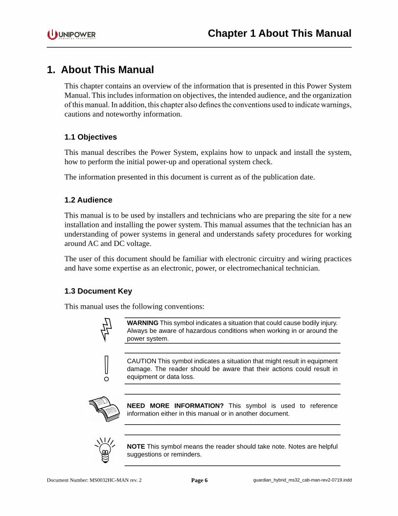
This manual uses the following conventions:
WARNING This symbol indicates a situation that could cause bodily injury. Always be aware of hazardous conditions when working in or around the power system.
CAUTION This symbol indicates a situation that might result in equipment damage. The reader should be aware that their actions could result in equipment or data loss.
NEED MORE INFORMATION? This symbol is used to reference information either in this manual or in another document.
NOTE This symbol means the reader should take note. Notes are helpful suggestions or reminders.
Chapter 1 About This Manual
Page 7
P O W E R I N G T E C H N O L O G Y
Document Number: MS0032HC-MAN rev. 2 guardian_hybrid_ms32_cab-man-rev2-0719.indd
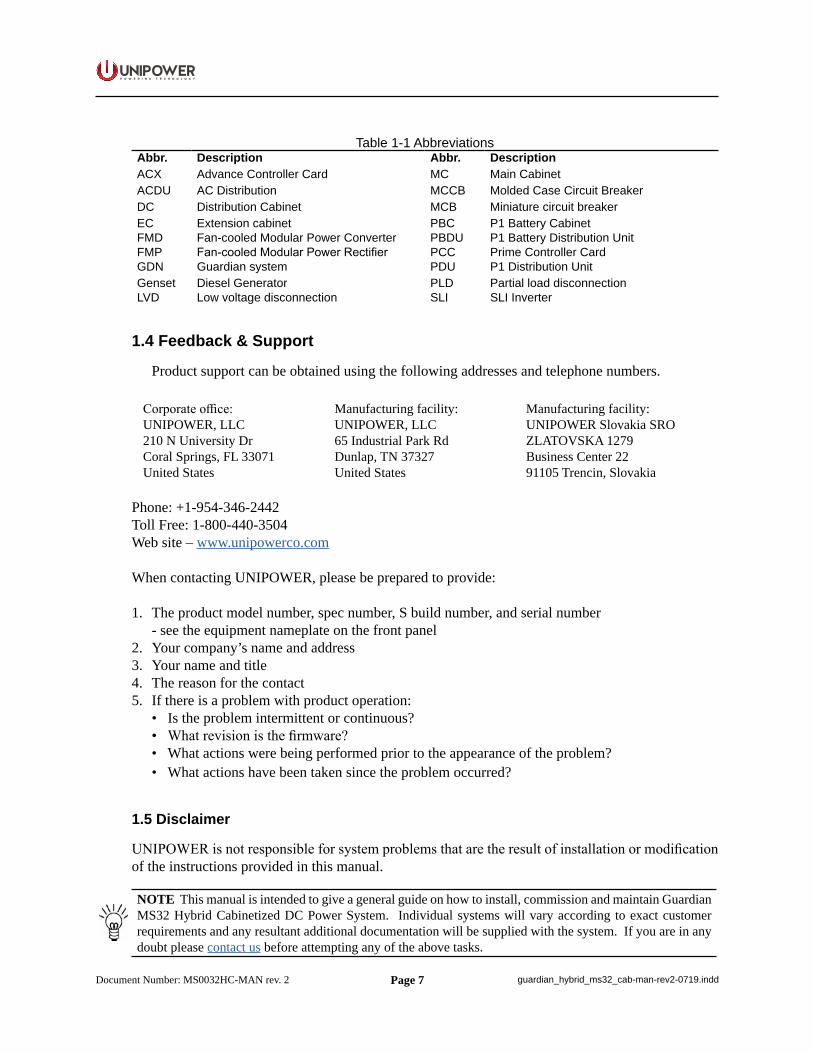
Table 1-1 AbbreviationsAbbr. Description Abbr. DescriptionACX Advance Controller Card MC Main CabinetACDU AC Distribution MCCB Molded Case Circuit BreakerDC Distribution Cabinet MCB Miniature circuit breakerEC Extension cabinet PBC P1 Battery CabinetFMD Fan-cooled Modular Power Converter PBDU P1 Battery Distribution UnitFMP Fan-cooled Modular Power Rectifier PCC Prime Controller CardGDN Guardian system PDU P1 Distribution UnitGenset Diesel Generator PLD Partial load disconnectionLVD Low voltage disconnection SLI SLI Inverter
1.4 Feedback & Support
Product support can be obtained using the following addresses and telephone numbers.
Corporate office: UNIPOWER, LLC210 N University DrCoral Springs, FL 33071 United States
Manufacturing facility:UNIPOWER, LLC65 Industrial Park RdDunlap, TN 37327United States
Manufacturing facility:UNIPOWER Slovakia SRO ZLATOVSKA 1279 Business Center 2291105 Trencin, Slovakia
Phone: +1-954-346-2442Toll Free: 1-800-440-3504Web site – www.unipowerco.com
When contacting UNIPOWER, please be prepared to provide:
1. The product model number, spec number, S build number, and serial number - see the equipment nameplate on the front panel2. Your company’s name and address3. Your name and title4. The reason for the contact5. If there is a problem with product operation: • Is the problem intermittent or continuous? • What revision is the firmware? • What actions were being performed prior to the appearance of the problem? • What actions have been taken since the problem occurred?
1.5 Disclaimer
UNIPOWER is not responsible for system problems that are the result of installation or modification of the instructions provided in this manual.
NOTE This manual is intended to give a general guide on how to install, commission and maintain Guardian MS32 Hybrid Cabinetized DC Power System. Individual systems will vary according to exact customer requirements and any resultant additional documentation will be supplied with the system. If you are in any doubt please contact us before attempting any of the above tasks.
Page 8
P O W E R I N G T E C H N O L O G Y
Document Number: MS0032HC-MAN rev. 2 guardian_hybrid_ms32_cab-man-rev2-0719.indd
2.1 Overview
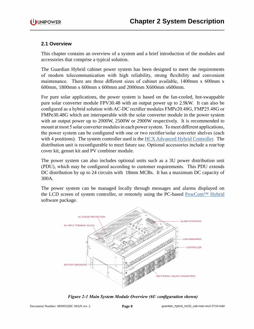
This chapter contains an overview of a system and a brief introduction of the modules and accessories that comprise a typical solution.
The Guardian Hybrid cabinet power system has been designed to meet the requirements of modern telecommunication with high reliability, strong flexibility and convenient maintenance. There are three different sizes of cabinet available, 1400mm x 600mm x 600mm, 1800mm x 600mm x 600mm and 2000mm X600mm x600mm.
For pure solar applications, the power system is based on the fan-cooled, hot-swappable pure solar converter module FPV30.48 with an output power up to 2.9kW. It can also be configured as a hybrid solution with AC-DC rectifier modules FMPe20.48G, FMP25.48G or FMPe30.48G which are interoperable with the solar converter module in the power system with an output power up to 2000W, 2500W or 2900W respectively. It is recommended to mount at most 5 solar converter modules in each power system. To meet different applications, the power system can be configured with one or two rectifier/solar converter shelves (each with 4 positions). The system controller used is the HCX Advanced Hybrid Controller. The distribution unit is reconfigurable to meet future use. Optional accessories include a rear/top cover kit, genset kit and PV combiner module.
The power system can also includes optional units such as a 3U power distribution unit (PDU), which may be configured according to customer requirements. This PDU extends DC distribution by up to 24 circuits with 18mm MCBs. It has a maximum DC capacity of 300A.
The power system can be managed locally through messages and alarms displayed on the LCD screen of system controller, or remotely using the PC-based PowCom™ Hybrid software package.
RECTIFIERS / SOLAR CONVERTERS
CONTROLLER
BATTERY BREAKERS
ALARM INTERFACE
LOAD BREAKERS
AC INPUT TERMINAL BLOCK
AC SURGE PROTECTION
Figure 2-1 Main System Module Overview (6U configuration shown)
Chapter 2 System Description
Page 9
P O W E R I N G T E C H N O L O G Y
Document Number: MS0032HC-MAN rev. 2 guardian_hybrid_ms32_cab-man-rev2-0719.indd
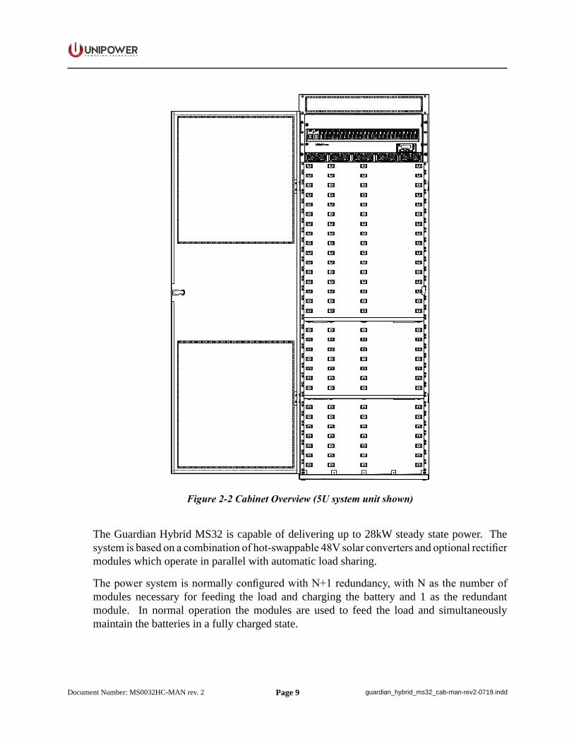
Figure 2-2 Cabinet Overview (5U system unit shown)
The Guardian Hybrid MS32 is capable of delivering up to 28kW steady state power. The system is based on a combination of hot-swappable 48V solar converters and optional rectifier modules which operate in parallel with automatic load sharing.
The power system is normally configured with N+1 redundancy, with N as the number of modules necessary for feeding the load and charging the battery and 1 as the redundant module. In normal operation the modules are used to feed the load and simultaneously maintain the batteries in a fully charged state.
Page 10
P O W E R I N G T E C H N O L O G Y
Document Number: MS0032HC-MAN rev. 2 guardian_hybrid_ms32_cab-man-rev2-0719.indd
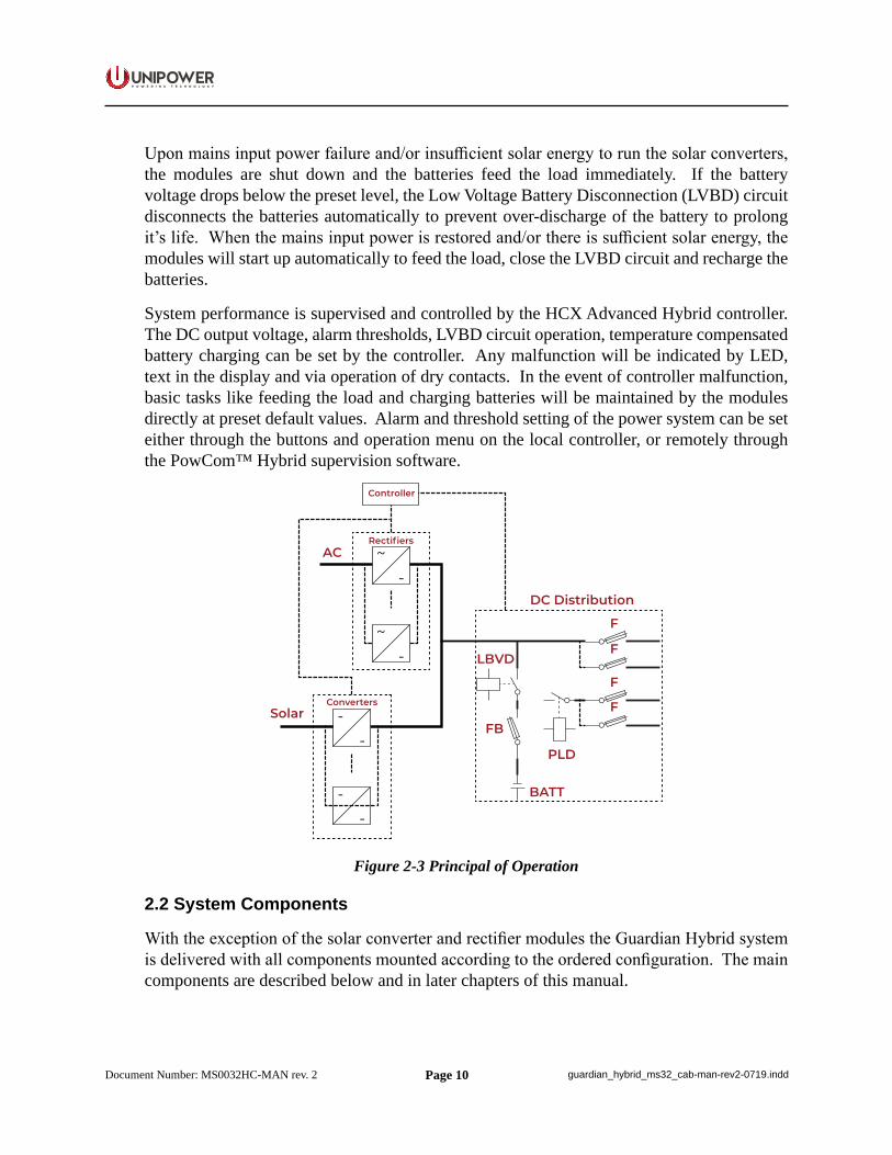
Upon mains input power failure and/or insufficient solar energy to run the solar converters, the modules are shut down and the batteries feed the load immediately. If the battery voltage drops below the preset level, the Low Voltage Battery Disconnection (LVBD) circuit disconnects the batteries automatically to prevent over-discharge of the battery to prolong it’s life. When the mains input power is restored and/or there is sufficient solar energy, the modules will start up automatically to feed the load, close the LVBD circuit and recharge the batteries.
System performance is supervised and controlled by the HCX Advanced Hybrid controller. The DC output voltage, alarm thresholds, LVBD circuit operation, temperature compensated battery charging can be set by the controller. Any malfunction will be indicated by LED, text in the display and via operation of dry contacts. In the event of controller malfunction, basic tasks like feeding the load and charging batteries will be maintained by the modules directly at preset default values. Alarm and threshold setting of the power system can be set either through the buttons and operation menu on the local controller, or remotely through the PowCom™ Hybrid supervision software.
~-
~-
Rectifiers
--
--
Converters
AC
Solar
DC Distribution
Controller
LBVD
PLD
BATT
FB
F
F
F
F
Figure 2-3 Principal of Operation
2.2 System Components
With the exception of the solar converter and rectifier modules the Guardian Hybrid system is delivered with all components mounted according to the ordered configuration. The main components are described below and in later chapters of this manual.
Page 11
P O W E R I N G T E C H N O L O G Y
Document Number: MS0032HC-MAN rev. 2 guardian_hybrid_ms32_cab-man-rev2-0719.indd
2.2.1 Rectifier Module
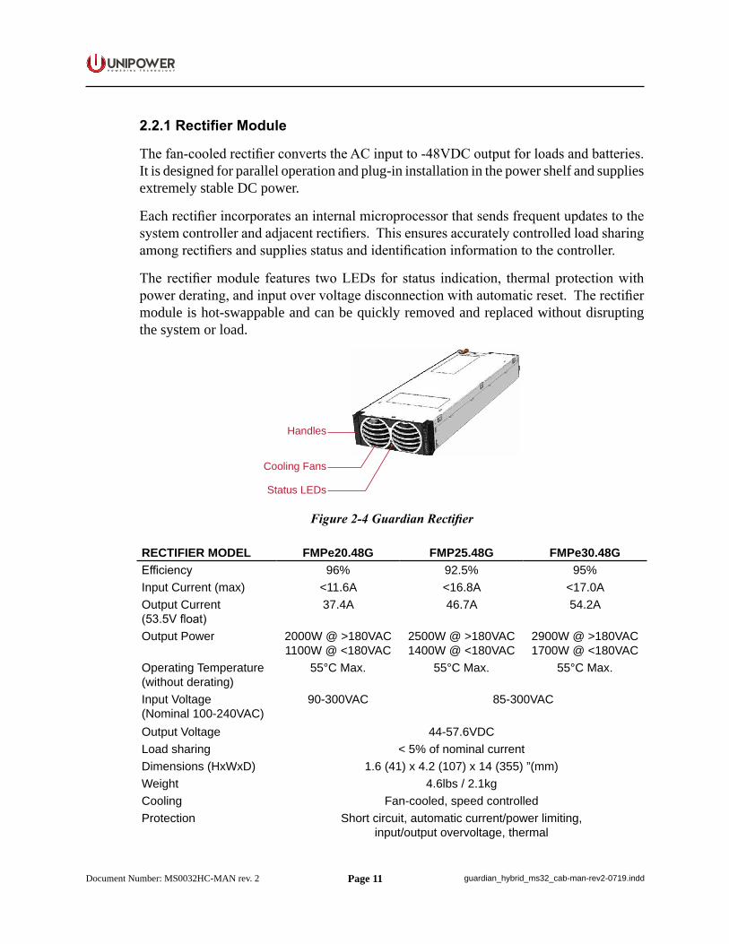
The fan-cooled rectifier converts the AC input to -48VDC output for loads and batteries. It is designed for parallel operation and plug-in installation in the power shelf and supplies extremely stable DC power.
Each rectifier incorporates an internal microprocessor that sends frequent updates to the system controller and adjacent rectifiers. This ensures accurately controlled load sharing among rectifiers and supplies status and identification information to the controller.
The rectifier module features two LEDs for status indication, thermal protection with power derating, and input over voltage disconnection with automatic reset. The rectifier module is hot-swappable and can be quickly removed and replaced without disrupting the system or load.
Handles
Cooling Fans
Status LEDs
Figure 2-4 Guardian Rectifier
RECTIFIER MODEL FMPe20.48G FMP25.48G FMPe30.48GEfficiency 96% 92.5% 95%Input Current (max) <11.6A <16.8A <17.0AOutput Current(53.5V float)
37.4A 46.7A 54.2A
Output Power 2000W @ >180VAC1100W @ <180VAC
2500W @ >180VAC1400W @ <180VAC
2900W @ >180VAC1700W @ <180VAC
Operating Temperature (without derating)
55°C Max. 55°C Max. 55°C Max.
Input Voltage(Nominal 100-240VAC)
90-300VAC 85-300VAC
Output Voltage 44-57.6VDCLoad sharing < 5% of nominal currentDimensions (HxWxD) 1.6 (41) x 4.2 (107) x 14 (355) ”(mm)Weight 4.6lbs / 2.1kgCooling Fan-cooled, speed controlledProtection Short circuit, automatic current/power limiting,
input/output overvoltage, thermal
Page 12
P O W E R I N G T E C H N O L O G Y
Document Number: MS0032HC-MAN rev. 2 guardian_hybrid_ms32_cab-man-rev2-0719.indd
Alarms Fan failure, Short circuit/arcing protection,High temperature/output voltage Low output voltage,Input voltage out of range Low fan speed (warning)
Internal communication failureLED Indication Green: AC normal operation
Yellow: Steady - Low fan speed, High temperature Flashing - Communications failureRed: Module alarm / shutdown
Audible noise <45dBA @ ≤25°C (50% load) | <60dBA (100% load)
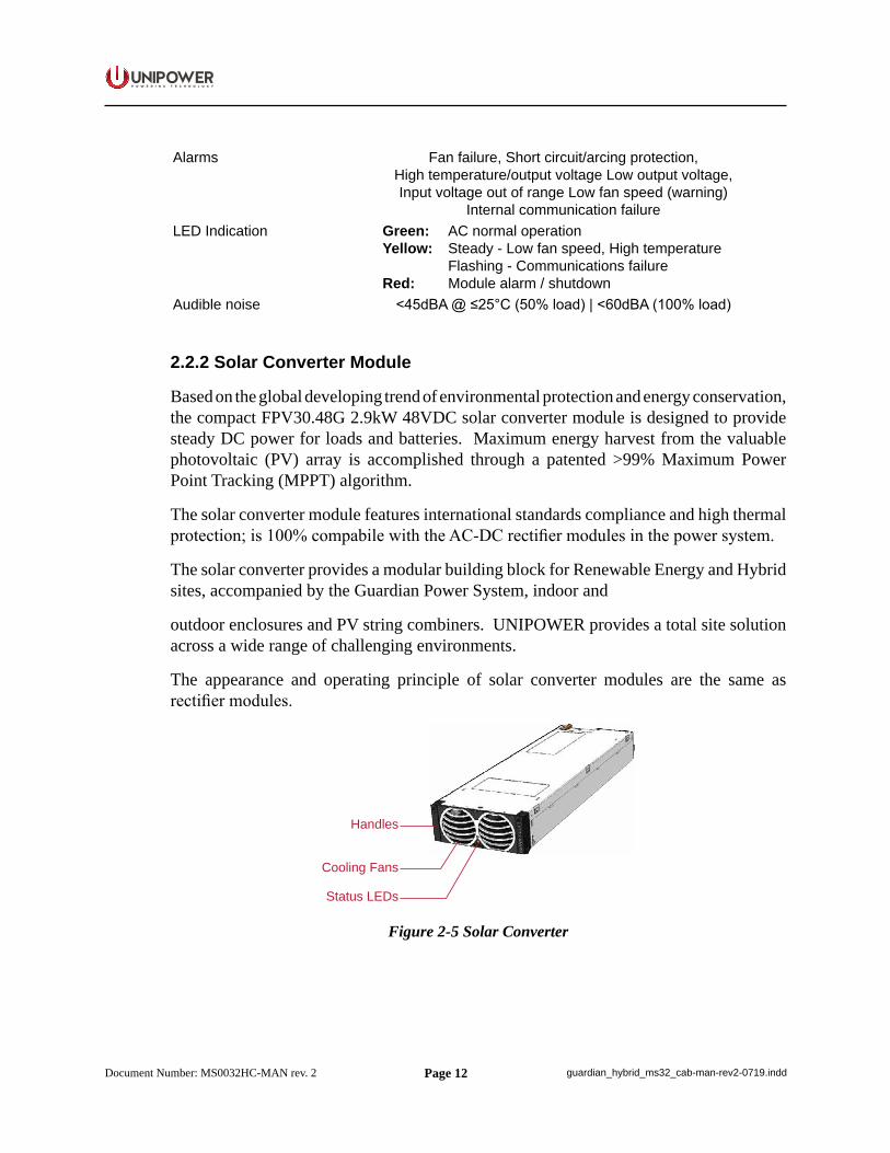
2.2.2 Solar Converter Module
Based on the global developing trend of environmental protection and energy conservation, the compact FPV30.48G 2.9kW 48VDC solar converter module is designed to provide steady DC power for loads and batteries. Maximum energy harvest from the valuable photovoltaic (PV) array is accomplished through a patented >99% Maximum Power Point Tracking (MPPT) algorithm.
The solar converter module features international standards compliance and high thermal protection; is 100% compabile with the AC-DC rectifier modules in the power system.
The solar converter provides a modular building block for Renewable Energy and Hybrid sites, accompanied by the Guardian Power System, indoor and
outdoor enclosures and PV string combiners. UNIPOWER provides a total site solution across a wide range of challenging environments.
The appearance and operating principle of solar converter modules are the same as rectifier modules.
Handles
Cooling Fans
Status LEDs
Figure 2-5 Solar Converter
Page 13
P O W E R I N G T E C H N O L O G Y
Document Number: MS0032HC-MAN rev. 2 guardian_hybrid_ms32_cab-man-rev2-0719.indd
CONVERTER MODEL FPV30.48GEfficiency 95% peakInput Current (max) <17.6AOutput Current(53.5V float)
54.2A
Output Power 2900WOperating Temperature (without derating)
65°C Max.
Input Voltage Nominal MPPT: 160-300 V DCMinimum: 130 V DCMaximum: 360 V DC
Output Voltage 46-57.6VDCLoad sharing < 5% of nominal currentDimensions (HxWxD) 1.6 (41) x 4.2 (107) x 14 (355) ”(mm)Weight 4.6lbs / 2.1kgCooling Fan-cooled, speed controlledProtection Short circuit, automatic current/power limiting,
input/output overvoltage, thermalAlarms Fan failure, Short circuit/arcing protection,
High temperature/output voltage Low output voltage,Input voltage out of range Low fan speed (warning)
Internal communication failureLED Indication Green: AC normal operation
Yellow: Steady - Low fan speed, High temperature Flashing - Communications failureRed: Module alarm / shutdown
Audible noise <45dBA @ ≤25°C (50% load) | <60dBA (100% load)
2.2.3 System Controller
The Guardian Hybrid system can be controlled by the HCX Advanced hybrid controller.
The system controller is a supervisory system with onboard software for monitoring and operation of power supply systems based on UNIPOWER modules. The design is based on the philosophy of having one main controller supervising the entire power supply system, and the use of distributed intelligence by local microcontrollers. An RS485 data bus takes care of internal communication between the various units.
USB and Web interfaces are used for remote control from a PC with PowCom™ Hybrid software, either through a direct connection of the Local Area Network (LAN) or a dial-up modem.
The description and operation of this controller is covered in a separate manual which is available at https://www.unipowerco.com/pdf/hcx-man.pdf.
Page 14
P O W E R I N G T E C H N O L O G Y
Document Number: MS0032HC-MAN rev. 2 guardian_hybrid_ms32_cab-man-rev2-0719.indd
2.2.4 Distribution Unit
The distribution unit includes configurable load breakers, battery breakers, a shunt for battery current measurement and fuse alarms for load and battery breakers.
The distribution unit has no special operation other than switching the load and battery breakers on and off. All trip states of breakers are supervised by measuring the voltage drop across each breaker.
Breakers that are not connected to any load will not cause a breaker alarm even if they are left open.
A battery fuse alarm may not be triggered instantly when a battery breaker is off. The alarm is triggered only when the voltage drop between the system voltage and the battery voltage is more than 1.5V. The interval that the voltage drop increases to 1.5V depends on the battery status.
Due to a small leakage current (2.5-3mA) through the alarm circuit, the voltage measured with a Digital Volt Meter (DVM) on an open breaker output will be nearly equal to the rectifier output voltage.
The distribution module has common “+Ve” with load breakers in “-Ve” leg. For more information see schematic drawing in Appendix A - Drawings.
2.2.4.1 Low Voltage Battery Disconnect (LVBD)
Generally, the system is equipped with low voltage battery disconnection, which prevents the batteries from deep discharging, thus prolonging the battery life. A disconnection requires a detected mains failure at the supervision unit.
If disconnection occurs, the batteries will not supply power to the load until they have been recharged to set voltage level, which can be adjusted by the user.
If disconnection occurs, the batteries will be reconnected when mains supply returns.
2.2.4.2 Partial Load Disconnection / Load Shedding (PLD)
Partial load disconnection can be configured to be voltage or time dependent, this is selected when ordering the power system.
At a mains outage the controller will open the PLD contactor when the batteries have discharged to a certain voltage or if the battery voltage has been under a certain voltage for a predetermined time. The disconnection has to be set according to the present load and battery manufacturer’s discharge tables or requirements.
Page 15
P O W E R I N G T E C H N O L O G Y
Document Number: MS0032HC-MAN rev. 2 guardian_hybrid_ms32_cab-man-rev2-0719.indd
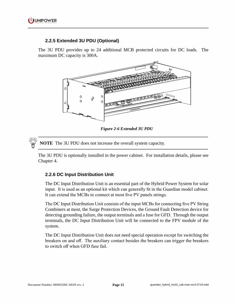
2.2.5 Extended 3U PDU (Optional)
The 3U PDU provides up to 24 additional MCB protected circuits for DC loads. The maximum DC capacity is 300A.
Figure 2-6 Extended 3U PDU
NOTE The 3U PDU does not increase the overall system capacity.
The 3U PDU is optionally installed in the power cabinet. For installation details, please see Chapter 4.
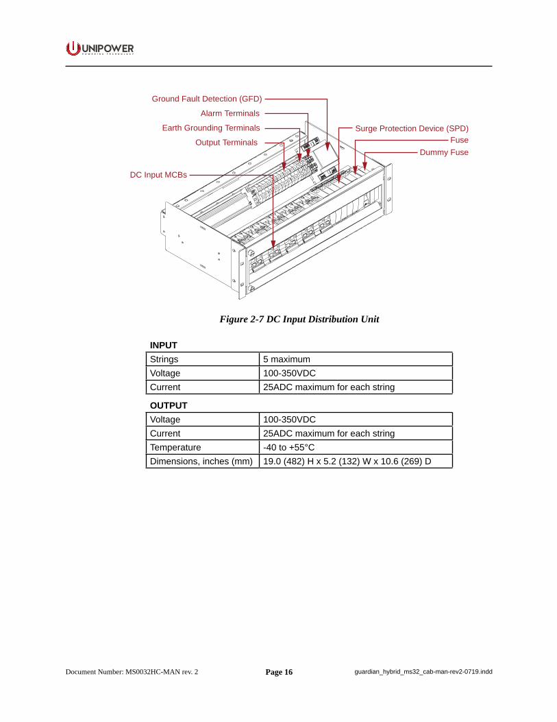
2.2.6 DC Input Distribution Unit
The DC Input Distribution Unit is an essential part of the Hybrid Power System for solar input. It is used as an optional kit which can generally fit in the Guardian model cabinet. It can extend the MCBs to connect at most five PV panels strings.
The DC Input Distribution Unit consists of the input MCBs for connecting five PV String Combiners at most, the Surge Protection Devices, the Ground Fault Detection device for detecting grounding failure, the output terminals and a fuse for GFD. Through the output terminals, the DC Input Distribution Unit will be connected to the FPV module of the system.
The DC Input Distribution Unit does not need special operation except for switching the breakers on and off. The auxiliary contact besides the breakers can trigger the breakers to switch off when GFD fuse fail.
Page 16
P O W E R I N G T E C H N O L O G Y
Document Number: MS0032HC-MAN rev. 2 guardian_hybrid_ms32_cab-man-rev2-0719.indd
Ground Fault Detection (GFD)
Alarm Terminals
Earth Grounding Terminals
Output Terminals
DC Input MCBs
Surge Protection Device (SPD)Fuse
Dummy Fuse
Figure 2-7 DC Input Distribution Unit
INPUTStrings 5 maximumVoltage 100-350VDCCurrent 25ADC maximum for each string
OUTPUTVoltage 100-350VDCCurrent 25ADC maximum for each stringTemperature -40 to +55°CDimensions, inches (mm) 19.0 (482) H x 5.2 (132) W x 10.6 (269) D
Page 17
P O W E R I N G T E C H N O L O G Y
Document Number: MS0032HC-MAN rev. 2 guardian_hybrid_ms32_cab-man-rev2-0719.indd
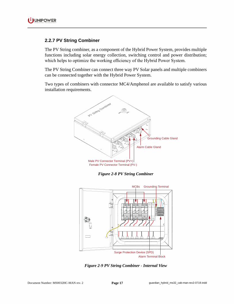
2.2.7 PV String Combiner
The PV String combiner, as a component of the Hybrid Power System, provides multiple functions including solar energy collection, switching control and power distribution; which helps to optimize the working efficiency of the Hybrid Power System.
The PV String Combiner can connect three way PV Solar panels and multiple combiners can be connected together with the Hybrid Power System.
Two types of combiners with connector MC4/Amphenol are available to satisfy various installation requirements.
Grounding Cable Gland
Alarm Cable Gland
Male PV Connector Terminal (PV+)Female PV Connector Terminal (PV-)
Figure 2-8 PV String Combiner
MCBs
Surge Protection Device (SPD)
Grounding Terminal
Alarm Terminal Block
Figure 2-9 PV String Combiner - Internal View
Page 18
P O W E R I N G T E C H N O L O G Y
Document Number: MS0032HC-MAN rev. 2 guardian_hybrid_ms32_cab-man-rev2-0719.indd
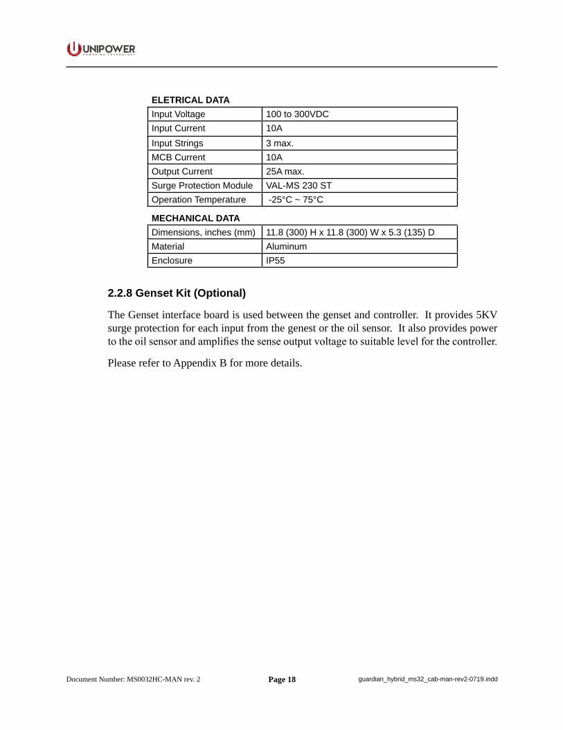
ELETRICAL DATAInput Voltage 100 to 300VDCInput Current 10AInput Strings 3 max.MCB Current 10AOutput Current 25A max.Surge Protection Module VAL-MS 230 STOperation Temperature -25°C ~ 75°C
MECHANICAL DATADimensions, inches (mm) 11.8 (300) H x 11.8 (300) W x 5.3 (135) DMaterial AluminumEnclosure IP55
2.2.8 Genset Kit (Optional)
The Genset interface board is used between the genset and controller. It provides 5KV surge protection for each input from the genest or the oil sensor. It also provides power to the oil sensor and amplifies the sense output voltage to suitable level for the controller.
Please refer to Appendix B for more details.
Page 19
P O W E R I N G T E C H N O L O G Y
Document Number: MS0032HC-MAN rev. 2 guardian_hybrid_ms32_cab-man-rev2-0719.indd
Chapter 3 System Safety
3.1 Safety Warnings and Guidelines
The following warnings and guidelines should be followed by properly trained and authorized personnel when installing, operating, commissioning or maintaining this equipment. Neglecting the instructions may be dangerous to personnel and equipment.
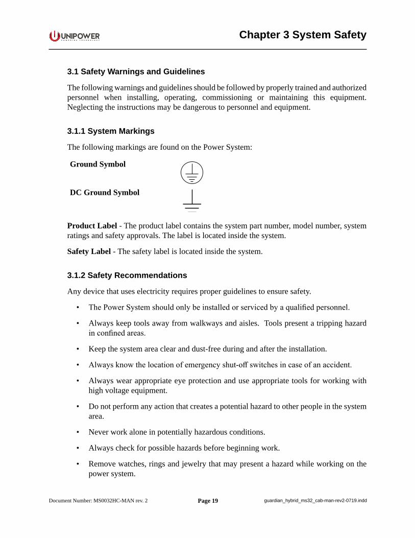
3.1.1 System Markings
The following markings are found on the Power System:
Ground Symbol
DC Ground Symbol
Product Label - The product label contains the system part number, model number, system ratings and safety approvals. The label is located inside the system.
Safety Label - The safety label is located inside the system.
3.1.2 Safety Recommendations
Any device that uses electricity requires proper guidelines to ensure safety.
• The Power System should only be installed or serviced by a qualified personnel.
• Always keep tools away from walkways and aisles. Tools present a tripping hazard in confined areas.
• Keep the system area clear and dust-free during and after the installation.
• Always know the location of emergency shut-off switches in case of an accident.
• Always wear appropriate eye protection and use appropriate tools for working with high voltage equipment.
• Do not perform any action that creates a potential hazard to other people in the system area.
• Never work alone in potentially hazardous conditions.
• Always check for possible hazards before beginning work.
• Remove watches, rings and jewelry that may present a hazard while working on the power system.
Page 20
P O W E R I N G T E C H N O L O G Y
Document Number: MS0032HC-MAN rev. 2 guardian_hybrid_ms32_cab-man-rev2-0719.indd
3.1.3 Installation Warning
The following safety guidelines should be observed when transporting or moving the system:
• Before moving the Power System, read the system specifications sheet to determine whether the install site meets all the size, environmental, and power requirements.
• The system should only be moved by qualified personnel and equipment.
• The Power System should be properly mounted to the building structure at the install location to prevent bodily injury.
3.1.4 Restricted Access Area Warnings
The Power System is designed for installation in locations with restricted access often secured by a locking mechanism. It can therefore be accessed only by a trained service person, who is fully aware of the restrictions applied to the location, or by an authority responsible for the location.
NOTE This may be disregarded for systems delivered in a UNIPOWER Outdoor enclosure.
3.1.5 System Enclosure
Appropriate measures need to be taken to avoid intrusion of any unwanted objects or insects into conductive areas of the power system as there is a potential risk of system damage.
Disclaimer: UNIPOWER LLC assumes no liability or responsibility for system failures resulting from inappropriate enclosure around the system.
3.1.6 Operating Temperature Warnings
To prevent the Power System from overheating, an automatic shutdown mechanism has been installed. It is not recommended to continually operate the Power System in an area that exceeds the maximum recommended operating temperature.
3.1.7 Recommended Power Ratings
Exceeding the following recommended power ratings may result in the system overheating.
• 46-57VDC, 500A at 45°C ambient• 46-57VDC, 435A at 55°C ambient• 46-57VDC, 350A at 65°C ambient
Page 21
P O W E R I N G T E C H N O L O G Y
Document Number: MS0032HC-MAN rev. 2 guardian_hybrid_ms32_cab-man-rev2-0719.indd
3.1.8 Electrical Safety Warnings
The following are electrical safety recommendations for working near the Power System:
WARNING Observe low voltage safety precautions before attempting to work on the system when power is connected. Potentially lethal voltages are present within the system.
WARNING Caution must be exercised when handling system power cables. Damage to the insulation or contact points of cables can cause contact with lethal voltages. For safety reasons, cables should be connected to the power system before power is applied.
• Remove all metallic jewelry like watches or rings that may present a hazard while working on the power system.
• Before connecting the AC input source to the power system, always verify voltage.
• Verify the AC source capacity. See system specifications for AC information.
• All AC connections must conform to local codes and regulations, e.g. ANSI, CEC, NEC, etc.
• When making AC connections, all AC power and DC load distribution breakers should be in the OFF position.
• All circuit breakers should meet the original design specifications of the system. In addition, equipment connected to the system should not overload the circuit breakers as this may have a negative effect on overcurrent protection and supply wiring, causing system or user harm.
• Verify the DC capacity before making connections. See system specifications for DC information.
• Potentially lethal voltages are present within the system. Ensure that all power supplies are completely isolated by turning all power switches OFF, disconnecting all relevant connectors and removing all relevant breakers before attempting any maintenance work. Do not rely on switches alone to isolate the power supply. Batteries should also be disconnected.
• Potentially lethal voltages are present within this system. Ensure that low voltage safety requirements are implemented before attempting to work on the system with power connected.
• Potentially lethal voltages can be induced if the equipment is not grounded (earthed) correctly. Ensure that all ground connections are secure.
Page 22
P O W E R I N G T E C H N O L O G Y
Document Number: MS0032HC-MAN rev. 2 guardian_hybrid_ms32_cab-man-rev2-0719.indd
3.1.9 Grounding
WARNING Grounding connection must be performed before operating the system. Refer to local codes, e.g. ANSI, CEC, NEC, T1-333, ETSI 300-386-TC specifying the connection of power system to building ground. In case of any doubt regarding the grounding connection, please contact a person responsible for the system.
WARNING The system should be hard-wired to the incoming earth ground. A solid high current ground connection capable of sinking the maximum system current is required.
CAUTION A conductor is connected between the ground point and the 0 VDC bus bar on the PBDU distribution. This conductor is connected to its own earth bar and not shared with other safety conductors.
3.1.10 Batteries
WARNING When installing or replacing batteries, there is risk of explosion if an incorrect battery type is used.
3.1.10.1 Lead Acid Batteries
WARNING This equipment may use Lead Acid Batteries. When handling batteries, follow the instructions included with the battery set, as the fluids contained within these batteries are known to be a health hazard. The disposal of lead acid batteries is subject to legal requirements for hazardous waste disposal. Local guidelines should be followed for disposal.
Ensure the following guidelines are observed when dealing with equipment that may contain lead acid batteries:
• Any attempt to burn these batteries may result in an explosion and the generation of toxic fumes.
• Should a lead acid battery suffer damage, it must be moved into a well-ventilated area. Contact with the corrosive fluid must be avoided.
• Neutralize any acid corrosion with copious amounts of a solution of baking soda and water, and then wipe off all traces of soda.
• If the lead acid battery is removed from the equipment, any exposed contact must be insulated prior to disposal.
• Ensure that protective full-face shields, rubber gloves and aprons are worn and insulated tools are used when working with the batteries. It is advised also to have water available in case acid gets in contact with the eyes.
Page 23
P O W E R I N G T E C H N O L O G Y
Document Number: MS0032HC-MAN rev. 2 guardian_hybrid_ms32_cab-man-rev2-0719.indd
3.1.11 PV Modules and Arrays
The following safety precautions should be taken into consideration when installing PV modules:
• All electrical installations must be done in accordance with the local and national electrical codes.
• Solar modules produce electrical energy when exposed to sunlight.
WARNING There is a risk of electric shock since the voltage generated by PV modules is higher than the system nominal voltage. Module installation should be performed only by a qualified person.
• It is required that PV arrays installed on the roof must incorporate aground-fault protection device to detect an electrical short circuit which could result in fire.
WARNING The GFD does not ensure personal safety, it is a device for system protection only.
• It is essential that PV installer is familiar with fall protection regulations. Any work done at more than six feet above the ground must be done with fall protection considerations.
3.1.12 Generator
Generator connections must be csarries out by a trained electrician in accordance with applicable codes.
• To eliminate unexpected startup and possible electric shock, ensure that Automatic Genset Starting is disabled before servicing the Genset.
• Keep hands away from moving parts.• Do not operate a diesel operated generator where there can be flammable vapours created
by fuel spills or gas leaks.• Do not smoke or turn electrical switches ON/OFF when fuel fumes are present - diesel
fuel is combustible.• Do not store fuel containers in the same enclosure as other spark-producing equipment
(e.g. Batteries).
3.1.13 In Case of an Accident
In the event of an accident resulting in injury:
1. Use caution and check for hazards in the area.2. Disconnect power to the system.
Page 24
P O W E R I N G T E C H N O L O G Y
Document Number: MS0032HC-MAN rev. 2 guardian_hybrid_ms32_cab-man-rev2-0719.indd
3. If possible, send someone to get medical aid. If not, check the condition of the victim and call for help.
3.2 Caution
3.2.1 Storage and Transportation
CAUTION During storage and transportation, the units must remain in their original packages in order to avoid mechanical damage, maintain tracability, and protect the units against electrostatic discharge.
3.2.2 Disposal
CAUTION The product should not be disposed with other wastes at the end of its working life so as to prevent possible harm to the environment or human health from uncontrolled waste disposal.
3.2.3 Handling Electrostatic Sensitive Devices
CAUTION An electrostatic sensitive device is an electronic component that may be permanently damaged by the discharge of electrostatic charges encountered in routine handling, testing and transportation.
3.2.4 Traceability
CAUTION Units are labeled with permanently attached product identification labels. The labels are designed to be indelible throughout the life span of the equipment, unless mistreated. Make sure that the product identification labels are present on the equipment and are not subjected to unusual wear or mistreatment.
3.2.5 Breakers
Maximum 45°C operating ambient: 1. Up to 32A CB maximum load must not exceed 80% of it’s rating.2. 40A CB maximum load shall not exceed 30A.3. 50-63A CB maximum load shall not exceed 35A.
Maximum 55°C operating ambient:1. Up to 20A CB maximum load must not exceed 80% of it’s rating2. 25A to 63A CB maximum load must not exceed 60% of it’s rating.
Page 25
P O W E R I N G T E C H N O L O G Y
Document Number: MS0032HC-MAN rev. 2 guardian_hybrid_ms32_cab-man-rev2-0719.indd
Maximum 65°C operating ambient:1. Up to 20A CB maximum load must not exceed 80% of it’s rating2. 25A to 63A CB maximum load must not exceed 50% of it’s rating.
CAUTION Breakers should always be replaced with the same type and rating in order to avoid damage to system components.
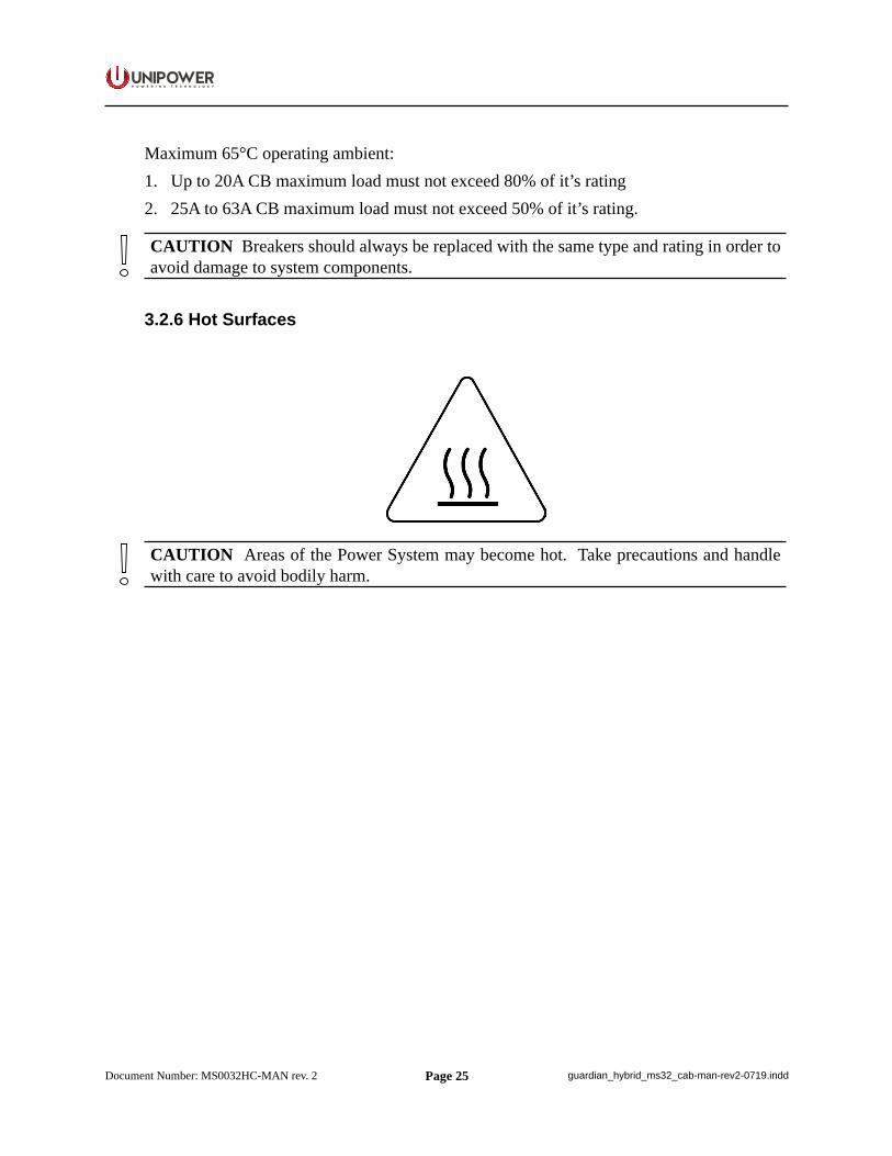
3.2.6 Hot Surfaces
CAUTION Areas of the Power System may become hot. Take precautions and handle with care to avoid bodily harm.

Page 26
P O W E R I N G T E C H N O L O G Y
Document Number: MS0032HC-MAN rev. 2 guardian_hybrid_ms32_cab-man-rev2-0719.indd
Chapter 4 Installation Guide
WARNING There are potential hazards related to installing this power system. It is important to carefully read and understand the contents of the Safety chapter before performing system installation.
CAUTION Make sure sufficient room is left around the system to enable optimal air circulation and thus prevent the system from overheating. Keep vent openings from blocking.
The following information should be read before attempting to install the Power System.
4.1 Site Requirements
The site should be suitable and ready for the Power supply. If it is not or you are unsure about this, contact your supervisor before continuing. Check, using a spirit level, that the site is level. Adjustment is provided in the cabinet to cater for floors that are not flat or smooth.
4.2 Unpacking
Check that the received equipment is in accordance with the packing list. Ensure that the cabinet and the equipment have not been damaged during transportation.
Report any parts that are damaged, missing or incorrect. If possible, correct the problem before continuing.
4.3 Tools
The following tools are required for a safe installation of the system:
• Anti-static hand strap.• Socket wrench, insulated.• Screwdriver set, flat, insulated.• Screwdriver set, torx, insulated.• Screwdrivers, pozidrive (cross head), sizes 1, 2, and 3, insulated.• Torque spanner (for battery connection), insulated.
WARNING Use only single-ended, fully insulated tools. Shafts of screwdrivers etc. should be insulated.
CAUTION Installation in USA / Canada must conform with the requirements in NEC/CEC.
Page 27
P O W E R I N G T E C H N O L O G Y
Document Number: MS0032HC-MAN rev. 2 guardian_hybrid_ms32_cab-man-rev2-0719.indd
CAUTION Care must be taken when installing this system. The units can be damaged and can cause damage if not handled with care. Pay particular attention to the order in which units are installed.
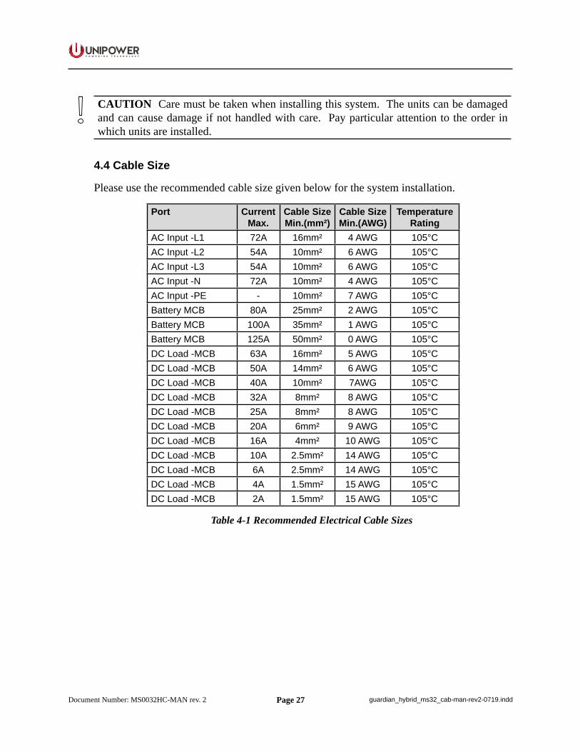
4.4 Cable Size
Please use the recommended cable size given below for the system installation.
Port Current Max.
Cable Size Min.(mm²)
Cable Size Min.(AWG)
Temperature Rating
AC Input -L1 72A 16mm² 4 AWG 105°C AC Input -L2 54A 10mm² 6 AWG 105°C AC Input -L3 54A 10mm² 6 AWG 105°C AC Input -N 72A 10mm² 4 AWG 105°C AC Input -PE - 10mm² 7 AWG 105°C Battery MCB 80A 25mm² 2 AWG 105°C Battery MCB 100A 35mm² 1 AWG 105°C Battery MCB 125A 50mm² 0 AWG 105°C DC Load -MCB 63A 16mm² 5 AWG 105°C DC Load -MCB 50A 14mm² 6 AWG 105°C DC Load -MCB 40A 10mm² 7AWG 105°C DC Load -MCB 32A 8mm² 8 AWG 105°C DC Load -MCB 25A 8mm² 8 AWG 105°C DC Load -MCB 20A 6mm² 9 AWG 105°C DC Load -MCB 16A 4mm² 10 AWG 105°C DC Load -MCB 10A 2.5mm² 14 AWG 105°C DC Load -MCB 6A 2.5mm² 14 AWG 105°C DC Load -MCB 4A 1.5mm² 15 AWG 105°C DC Load -MCB 2A 1.5mm² 15 AWG 105°C
Table 4-1 Recommended Electrical Cable Sizes
Page 28
P O W E R I N G T E C H N O L O G Y
Document Number: MS0032HC-MAN rev. 2 guardian_hybrid_ms32_cab-man-rev2-0719.indd
4.5 Mounting Power Cabinet
1. The site should be suitable and ready for the Power system.2. Move the cabinet to the right place and lift into an upright position.3. If necessary the cabinet can be mounted to the concrete slab and existing structures to
properly support the floor loading. In addition, the mounting site needs to be designed and installed in accordance with local building codes and regulations.
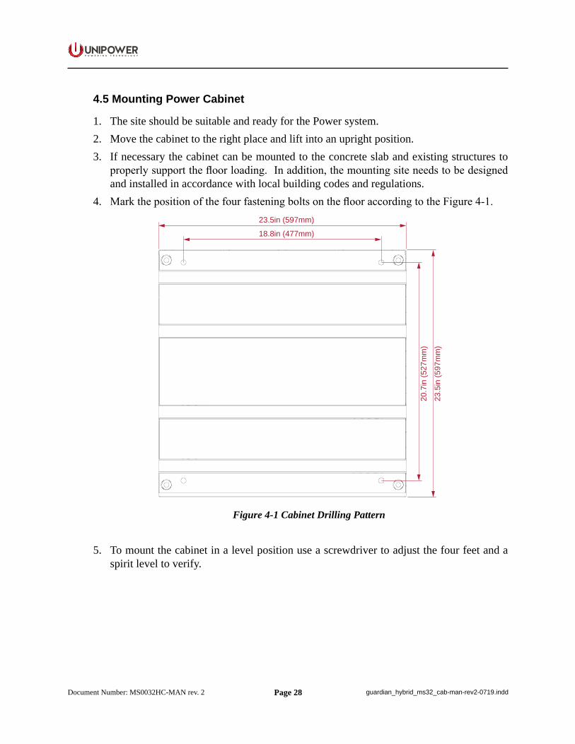
4. Mark the position of the four fastening bolts on the floor according to the Figure 4-1.
18.8in (477mm)
23.5in (597mm)
23.5
in (5
97m
m)
20.7
in (5
27m
m)
Figure 4-1 Cabinet Drilling Pattern
5. To mount the cabinet in a level position use a screwdriver to adjust the four feet and a spirit level to verify.
Page 29
P O W E R I N G T E C H N O L O G Y
Document Number: MS0032HC-MAN rev. 2 guardian_hybrid_ms32_cab-man-rev2-0719.indd
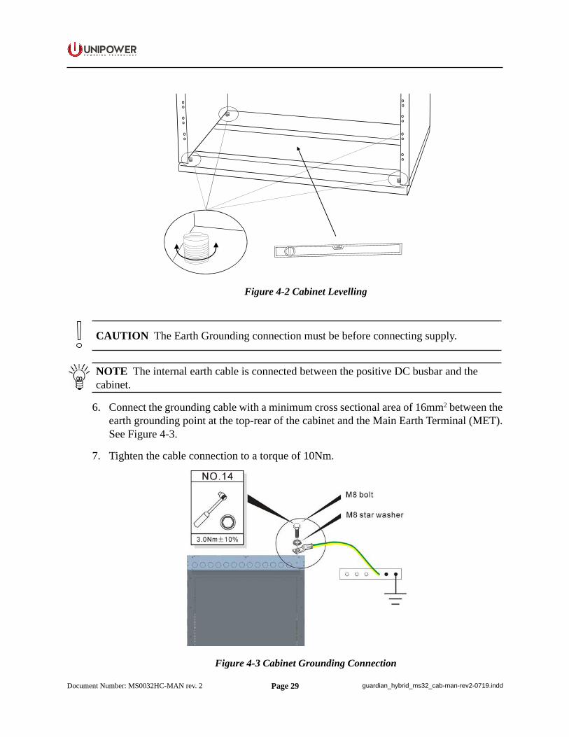
Figure 4-2 Cabinet Levelling
CAUTION The Earth Grounding connection must be before connecting supply.
NOTE The internal earth cable is connected between the positive DC busbar and the cabinet.
6. Connect the grounding cable with a minimum cross sectional area of 16mm2 between the earth grounding point at the top-rear of the cabinet and the Main Earth Terminal (MET). See Figure 4-3.
7. Tighten the cable connection to a torque of 10Nm.
Figure 4-3 Cabinet Grounding Connection
Page 30
P O W E R I N G T E C H N O L O G Y
Document Number: MS0032HC-MAN rev. 2 guardian_hybrid_ms32_cab-man-rev2-0719.indd
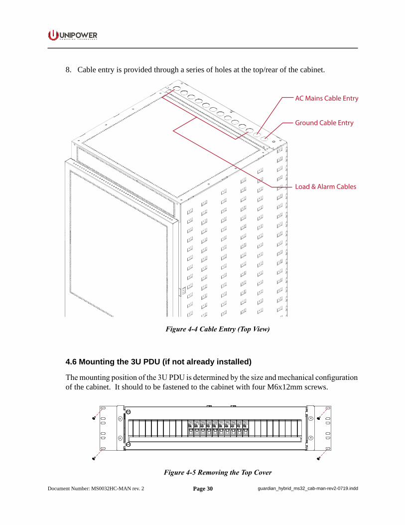
8. Cable entry is provided through a series of holes at the top/rear of the cabinet.
AC Mains Cable Entry
Ground Cable Entry
Load & Alarm Cables
Figure 4-4 Cable Entry (Top View)
4.6 Mounting the 3U PDU (if not already installed)
The mounting position of the 3U PDU is determined by the size and mechanical configuration of the cabinet. It should to be fastened to the cabinet with four M6x12mm screws.
Figure 4-5 Removing the Top Cover
Page 31
P O W E R I N G T E C H N O L O G Y
Document Number: MS0032HC-MAN rev. 2 guardian_hybrid_ms32_cab-man-rev2-0719.indd
NOTE The 19”/23” adaptor bracket actually used may differ from the one shown.
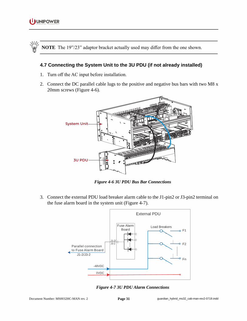
4.7 Connecting the System Unit to the 3U PDU (if not already installed)
1. Turn off the AC input before installation.
2. Connect the DC parallel cable lugs to the positive and negative bus bars with two M8 x 20mm screws (Figure 4-6).
System Unit
3U PDU
Figure 4-6 3U PDU Bus Bar Connections
3. Connect the external PDU load breaker alarm cable to the J1-pin2 or J3-pin2 terminal on the fuse alarm board in the system unit (Figure 4-7).
-48VDC
F1
Fn
F2
External PDU
Fuse AlarmBoard
Load Breakers
0VDC
Parallel connectionto Fuse Alarm Board
J1-2/J3-2
J1-2/J3-2
Figure 4-7 3U PDU Alarm Connections
Page 32
P O W E R I N G T E C H N O L O G Y
Document Number: MS0032HC-MAN rev. 2 guardian_hybrid_ms32_cab-man-rev2-0719.indd
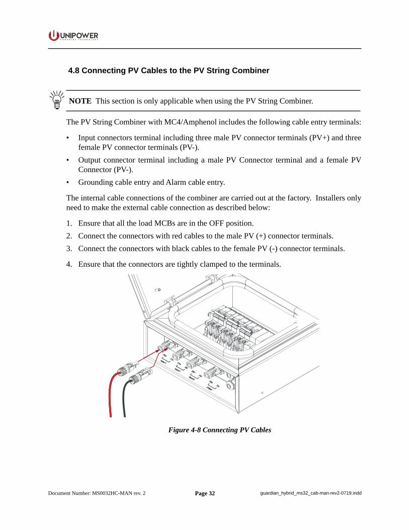
4.8 Connecting PV Cables to the PV String Combiner
NOTE This section is only applicable when using the PV String Combiner.
The PV String Combiner with MC4/Amphenol includes the following cable entry terminals:
• Input connectors terminal including three male PV connector terminals (PV+) and three female PV connector terminals (PV-).
• Output connector terminal including a male PV Connector terminal and a female PV Connector (PV-).
• Grounding cable entry and Alarm cable entry.
The internal cable connections of the combiner are carried out at the factory. Installers only need to make the external cable connection as described below:
1. Ensure that all the load MCBs are in the OFF position.2. Connect the connectors with red cables to the male PV (+) connector terminals.3. Connect the connectors with black cables to the female PV (-) connector terminals.
4. Ensure that the connectors are tightly clamped to the terminals.
Figure 4-8 Connecting PV Cables
Page 33
P O W E R I N G T E C H N O L O G Y
Document Number: MS0032HC-MAN rev. 2 guardian_hybrid_ms32_cab-man-rev2-0719.indd
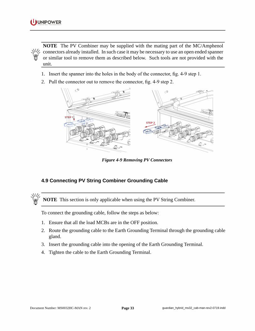
NOTE The PV Combiner may be supplied with the mating part of the MC/Amphenol connectors already installed. In such case it may be necessary to use an open ended spanner or similar tool to remove them as described below. Such tools are not provided with the unit.
1. Insert the spanner into the holes in the body of the connector, fig. 4-9 step 1.2. Pull the connector out to remove the connector, fig. 4-9 step 2.
STEP 1
STEP 2
Figure 4-9 Removing PV Connectors
4.9 Connecting PV String Combiner Grounding Cable
NOTE This section is only applicable when using the PV String Combiner.
To connect the grounding cable, follow the steps as below:
1. Ensure that all the load MCBs are in the OFF position.2. Route the grounding cable to the Earth Grounding Terminal through the grounding cable
gland.3. Insert the grounding cable into the opening of the Earth Grounding Terminal.4. Tighten the cable to the Earth Grounding Terminal.
Page 34
P O W E R I N G T E C H N O L O G Y
Document Number: MS0032HC-MAN rev. 2 guardian_hybrid_ms32_cab-man-rev2-0719.indd
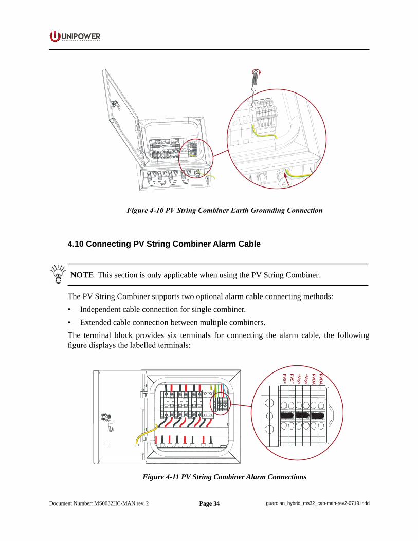
Figure 4-10 PV String Combiner Earth Grounding Connection
4.10 Connecting PV String Combiner Alarm Cable
NOTE This section is only applicable when using the PV String Combiner.
The PV String Combiner supports two optional alarm cable connecting methods:• Independent cable connection for single combiner.• Extended cable connection between multiple combiners.The terminal block provides six terminals for connecting the alarm cable, the following figure displays the labelled terminals:
PVDA
PVDA
+Vsys
+Vsys
PVSF
PVSF
Figure 4-11 PV String Combiner Alarm Connections
Page 35
P O W E R I N G T E C H N O L O G Y
Document Number: MS0032HC-MAN rev. 2 guardian_hybrid_ms32_cab-man-rev2-0719.indd
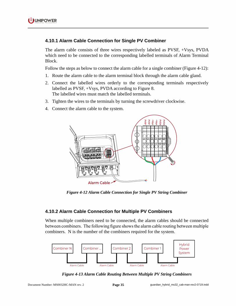
4.10.1 Alarm Cable Connection for Single PV Combiner
The alarm cable consists of three wires respectively labeled as PVSF, +Vsys, PVDA which need to be connected to the corresponding labelled terminals of Alarm Terminal Block.Follow the steps as below to connect the alarm cable for a single combiner (Figure 4-12):1. Route the alarm cable to the alarm terminal block through the alarm cable gland.2. Connect the labelled wires orderly to the corresponding terminals respectively
labelled as PVSF, +Vsys, PVDA according to Figure 8. The labelled wires must match the labelled terminals.
3. Tighten the wires to the terminals by turning the screwdriver clockwise.4. Connect the alarm cable to the system.
Alarm Cable
PVDA
PVDA
+Vsys
+Vsys
PVSF
PVSF
Figure 4-12 Alarm Cable Connection for Single PV String Combiner
4.10.2 Alarm Cable Connection for Multiple PV Combiners
When multiple combiners need to be connected, the alarm cables should be connected between combiners. The following figure shows the alarm cable routing between multiple combiners. N is the number of the combiners required for the system.
Combiner NHybridPowerSystem
Combiner 2Combiner ... Combiner 1
Alarm Cable Alarm Cable Alarm Cable Alarm Cable
Figure 4-13 Alarm Cable Routing Between Multiple PV String Combiners
Page 36
P O W E R I N G T E C H N O L O G Y
Document Number: MS0032HC-MAN rev. 2 guardian_hybrid_ms32_cab-man-rev2-0719.indd
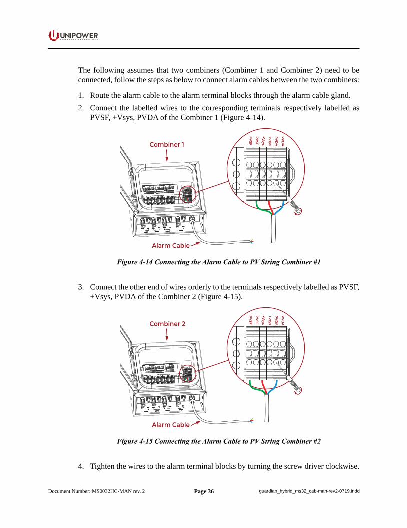
The following assumes that two combiners (Combiner 1 and Combiner 2) need to be connected, follow the steps as below to connect alarm cables between the two combiners:
1. Route the alarm cable to the alarm terminal blocks through the alarm cable gland.2. Connect the labelled wires to the corresponding terminals respectively labelled as
PVSF, +Vsys, PVDA of the Combiner 1 (Figure 4-14).
Alarm Cable
PVDA
PVDA
+Vsys
+Vsys
PVSF
PVSFCombiner 1
Figure 4-14 Connecting the Alarm Cable to PV String Combiner #1
3. Connect the other end of wires orderly to the terminals respectively labelled as PVSF, +Vsys, PVDA of the Combiner 2 (Figure 4-15).
Alarm Cable
PVDA
PVDA
+Vsys
+Vsys
PVSF
PVSFCombiner 2
Figure 4-15 Connecting the Alarm Cable to PV String Combiner #2
4. Tighten the wires to the alarm terminal blocks by turning the screw driver clockwise.
Page 37
P O W E R I N G T E C H N O L O G Y
Document Number: MS0032HC-MAN rev. 2 guardian_hybrid_ms32_cab-man-rev2-0719.indd
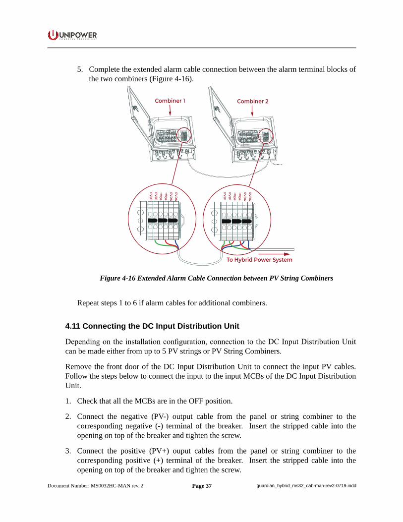
5. Complete the extended alarm cable connection between the alarm terminal blocks of the two combiners (Figure 4-16).
Combiner 2Combiner 1
PVDA
PVDA
+Vsys+VsysPVSFPVSF
PVDA
PVDA
+Vsys+VsysPVSFPVSF
To Hybrid Power System
Figure 4-16 Extended Alarm Cable Connection between PV String Combiners
Repeat steps 1 to 6 if alarm cables for additional combiners.
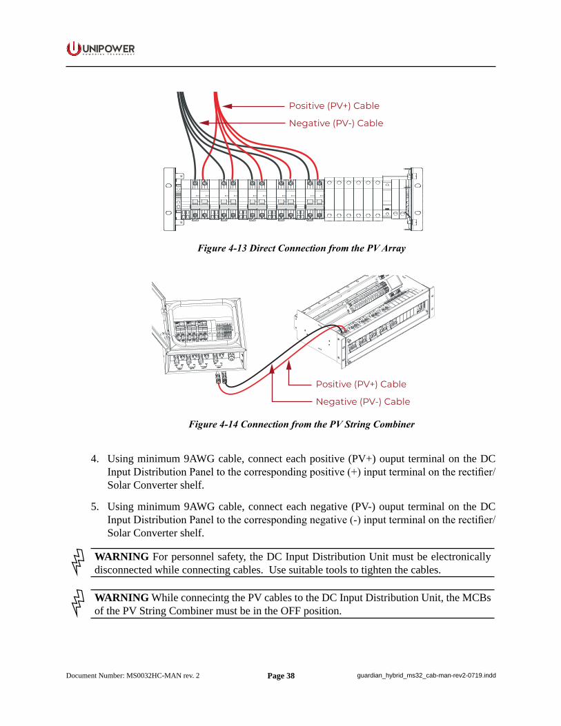
4.11 Connecting the DC Input Distribution Unit
Depending on the installation configuration, connection to the DC Input Distribution Unit can be made either from up to 5 PV strings or PV String Combiners.
Remove the front door of the DC Input Distribution Unit to connect the input PV cables. Follow the steps below to connect the input to the input MCBs of the DC Input Distribution Unit.
1. Check that all the MCBs are in the OFF position.
2. Connect the negative (PV-) output cable from the panel or string combiner to the corresponding negative (-) terminal of the breaker. Insert the stripped cable into the opening on top of the breaker and tighten the screw.
3. Connect the positive (PV+) ouput cables from the panel or string combiner to the corresponding positive (+) terminal of the breaker. Insert the stripped cable into the opening on top of the breaker and tighten the screw.
Page 38
P O W E R I N G T E C H N O L O G Y
Document Number: MS0032HC-MAN rev. 2 guardian_hybrid_ms32_cab-man-rev2-0719.indd
Positive (PV+) Cable
Negative (PV-) Cable
Figure 4-13 Direct Connection from the PV Array
Positive (PV+) Cable
Negative (PV-) Cable
Figure 4-14 Connection from the PV String Combiner
4. Using minimum 9AWG cable, connect each positive (PV+) ouput terminal on the DC Input Distribution Panel to the corresponding positive (+) input terminal on the rectifier/Solar Converter shelf.
5. Using minimum 9AWG cable, connect each negative (PV-) ouput terminal on the DC Input Distribution Panel to the corresponding negative (-) input terminal on the rectifier/Solar Converter shelf.
WARNING For personnel safety, the DC Input Distribution Unit must be electronically disconnected while connecting cables. Use suitable tools to tighten the cables.
WARNING While connecintg the PV cables to the DC Input Distribution Unit, the MCBs of the PV String Combiner must be in the OFF position.
Page 39
P O W E R I N G T E C H N O L O G Y
Document Number: MS0032HC-MAN rev. 2 guardian_hybrid_ms32_cab-man-rev2-0719.indd
4.12 AC Input Connection
NOTE This section is only applicable when using a Genset or utility supply and connecting AC power.
WARNING Ensure that mains input is turned off before connecting. The grounding must be connected to PE terminal as first.
WARNING High leakage current. Ensure earth is connected before connecting mains supply.
WARNING Only a qualified electrician may carry out the mains installation.
CAUTION Depending on deployment region with regards to lightning strikes and heavy inductive energy, it is highly recommended to install AC Surge Protection Class C, if not delivered with the system..
WARNING Used cable must be inserted into the terminal with as little insulation removed as possible, so as to prevents any stranded conductor coming loose and touching any other conductive parts. Tighten terminals securely with torque 1.5-1.8Nm.
Mains input terminal blocks are located on the rear left side of distribution unit. Mains cable size is max. 16mm².
The mains input terminal blocks can be connected to:
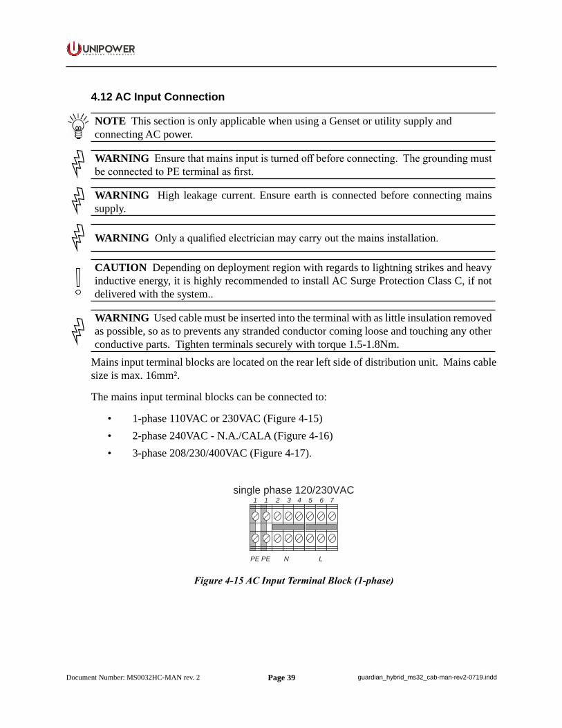
• 1-phase 110VAC or 230VAC (Figure 4-15)• 2-phase 240VAC - N.A./CALA (Figure 4-16)• 3-phase 208/230/400VAC (Figure 4-17).
1 2 3 4 5 6 7
N LPE
1
PE
single phase 120/230VAC
Figure 4-15 AC Input Terminal Block (1-phase)
Page 40
P O W E R I N G T E C H N O L O G Y
Document Number: MS0032HC-MAN rev. 2 guardian_hybrid_ms32_cab-man-rev2-0719.indd
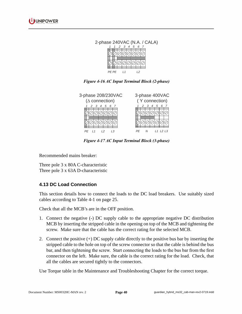
2-phase 240VAC (N.A. / CALA)1 2 3 4 5 6 7
L1PE
1
PE L2
Figure 4-16 AC Input Terminal Block (2-phase)
3-phase 208/230VAC(∆ connection) 1 2 3 4 5 6 7
L1PE L2 L3
3-phase 400VAC( Y connection)1 2 3 4 5 6 7
N L1 L2 L3PE
Figure 4-17 AC Input Terminal Block (3-phase)
Recommended mains breaker:
Three pole 3 x 80A C-characteristicThree pole 3 x 63A D-characteristic
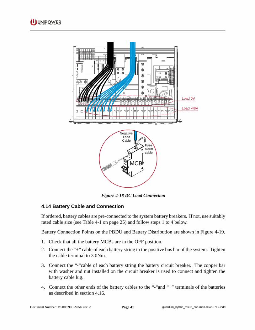
4.13 DC Load Connection
This section details how to connect the loads to the DC load breakers. Use suitably sized cables according to Table 4-1 on page 25.
Check that all the MCB’s are in the OFF position.
1. Connect the negative (-) DC supply cable to the appropriate negative DC distribution MCB by inserting the stripped cable in the opening on top of the MCB and tightening the screw. Make sure that the cable has the correct rating for the selected MCB.
2. Connect the positive (+) DC supply cable directly to the positive bus bar by inserting the stripped cable to the hole on top of the screw connector so that the cable is behind the bus bar, and then tightening the screw. Start connecting the loads to the bus bar from the first connector on the left. Make sure, the cable is the correct rating for the load. Check, that all the cables are secured tightly to the connectors.
Use Torque table in the Maintenance and Troubleshooting Chapter for the correct torque.
Page 41
P O W E R I N G T E C H N O L O G Y
Document Number: MS0032HC-MAN rev. 2 guardian_hybrid_ms32_cab-man-rev2-0719.indd
MCB
Fusealarm cable
Negative LoadCable
Load 0V
Load -48V
Figure 4-18 DC Load Connection
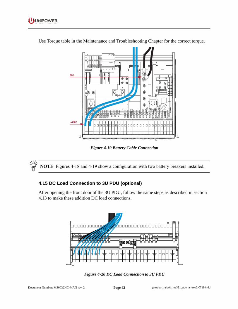
4.14 Battery Cable and Connection
If ordered, battery cables are pre-connected to the system battery breakers. If not, use suitably rated cable size (see Table 4-1 on page 25) and follow steps 1 to 4 below.
Battery Connection Points on the PBDU and Battery Distribution are shown in Figure 4-19.
1. Check that all the battery MCBs are in the OFF position.2. Connect the “+” cable of each battery string to the positive bus bar of the system. Tighten
the cable terminal to 3.0Nm.
3. Connect the “-“cable of each battery string the battery circuit breaker. The copper bar with washer and nut installed on the circuit breaker is used to connect and tighten the battery cable lug.
4. Connect the other ends of the battery cables to the “-“and “+” terminals of the batteries as described in section 4.16.
Page 42
P O W E R I N G T E C H N O L O G Y
Document Number: MS0032HC-MAN rev. 2 guardian_hybrid_ms32_cab-man-rev2-0719.indd
Use Torque table in the Maintenance and Troubleshooting Chapter for the correct torque.
0V
-48V
Figure 4-19 Battery Cable Connection
NOTE Figures 4-18 and 4-19 show a configuration with two battery breakers installed.
4.15 DC Load Connection to 3U PDU (optional)
After opening the front door of the 3U PDU, follow the same steps as described in section 4.13 to make these addition DC load connections.
Figure 4-20 DC Load Connection to 3U PDU
Page 43
P O W E R I N G T E C H N O L O G Y
Document Number: MS0032HC-MAN rev. 2 guardian_hybrid_ms32_cab-man-rev2-0719.indd
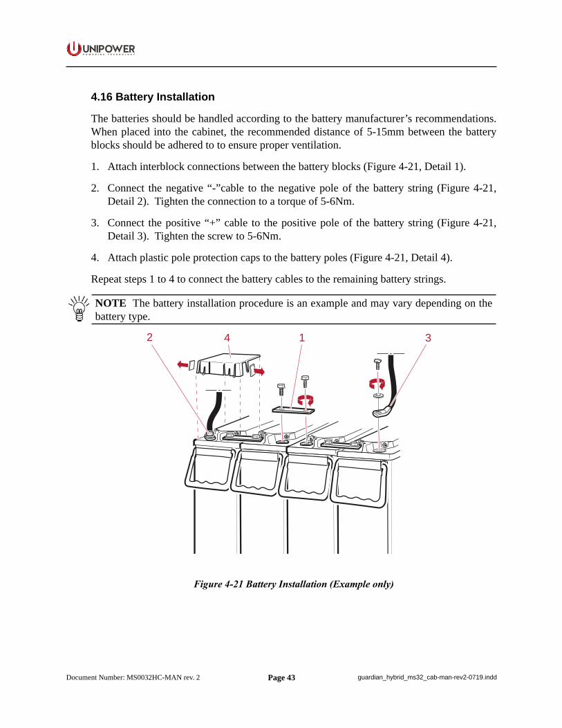
4.16 Battery Installation
The batteries should be handled according to the battery manufacturer’s recommendations. When placed into the cabinet, the recommended distance of 5-15mm between the battery blocks should be adhered to to ensure proper ventilation.
1. Attach interblock connections between the battery blocks (Figure 4-21, Detail 1).
2. Connect the negative “-”cable to the negative pole of the battery string (Figure 4-21, Detail 2). Tighten the connection to a torque of 5-6Nm.
3. Connect the positive “+” cable to the positive pole of the battery string (Figure 4-21, Detail 3). Tighten the screw to 5-6Nm.
4. Attach plastic pole protection caps to the battery poles (Figure 4-21, Detail 4).
Repeat steps 1 to 4 to connect the battery cables to the remaining battery strings.
NOTE The battery installation procedure is an example and may vary depending on the battery type.
2 1 34
Figure 4-21 Battery Installation (Example only)
Page 44
P O W E R I N G T E C H N O L O G Y
Document Number: MS0032HC-MAN rev. 2 guardian_hybrid_ms32_cab-man-rev2-0719.indd
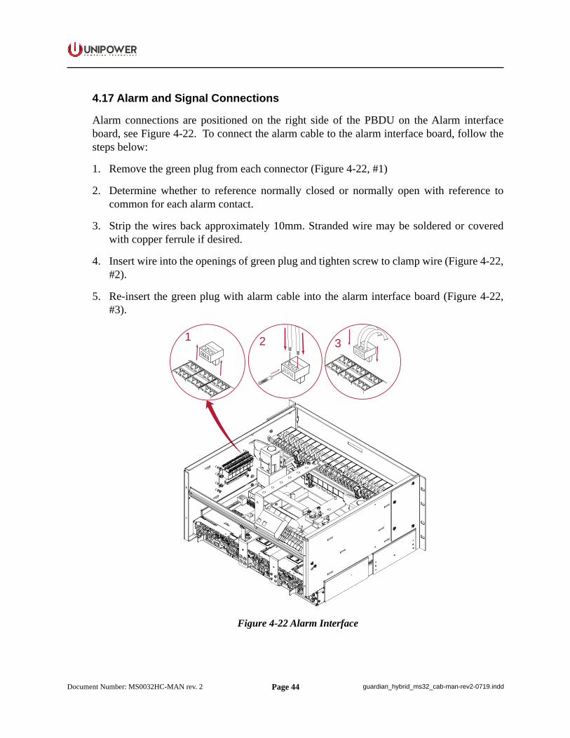
4.17 Alarm and Signal Connections
Alarm connections are positioned on the right side of the PBDU on the Alarm interface board, see Figure 4-22. To connect the alarm cable to the alarm interface board, follow the steps below:
1. Remove the green plug from each connector (Figure 4-22, #1)
2. Determine whether to reference normally closed or normally open with reference to common for each alarm contact.
3. Strip the wires back approximately 10mm. Stranded wire may be soldered or covered with copper ferrule if desired.
4. Insert wire into the openings of green plug and tighten screw to clamp wire (Figure 4-22, #2).
5. Re-insert the green plug with alarm cable into the alarm interface board (Figure 4-22, #3).
1 2 3
Figure 4-22 Alarm Interface
Page 45
P O W E R I N G T E C H N O L O G Y
Document Number: MS0032HC-MAN rev. 2 guardian_hybrid_ms32_cab-man-rev2-0719.indd
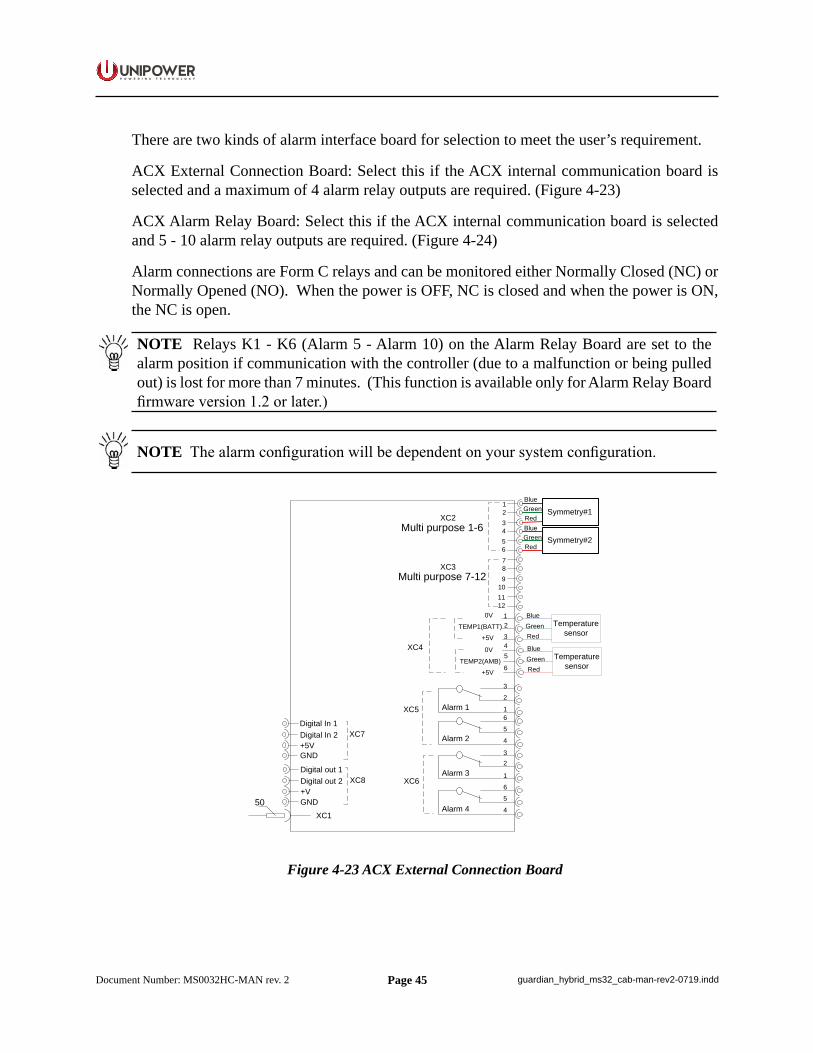
There are two kinds of alarm interface board for selection to meet the user’s requirement.
ACX External Connection Board: Select this if the ACX internal communication board is selected and a maximum of 4 alarm relay outputs are required. (Figure 4-23)
ACX Alarm Relay Board: Select this if the ACX internal communication board is selected and 5 - 10 alarm relay outputs are required. (Figure 4-24)
Alarm connections are Form C relays and can be monitored either Normally Closed (NC) or Normally Opened (NO). When the power is OFF, NC is closed and when the power is ON, the NC is open.
NOTE Relays K1 - K6 (Alarm 5 - Alarm 10) on the Alarm Relay Board are set to the alarm position if communication with the controller (due to a malfunction or being pulled out) is lost for more than 7 minutes. (This function is available only for Alarm Relay Board firmware version 1.2 or later.)
NOTE The alarm configuration will be dependent on your system configuration.
XC3
3
2
1Alarm 16
5
4Alarm 2
XC6
32
1Alarm 3
6
5
4Alarm 4
XC5
21
Multi purpose 7-12
Multi purpose 1-6XC2
+5V
0V
TEMP1(BATT)3
21
XC4
50XC1
Digital In 2+5V
Digital In 1XC7
Digital out 2+V
Digital out 1XC8
+5V
0V
TEMP2(AMB)6
54
43
65
87
109
1211
GND
GND
Symmetry#1
Symmetry#2
Temperature sensor
RedGreenBlueRedGreenBlue
RedGreenBlue
Temperature sensorRed
GreenBlue
Figure 4-23 ACX External Connection Board
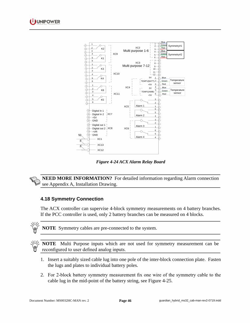
Page 46
P O W E R I N G T E C H N O L O G Y
Document Number: MS0032HC-MAN rev. 2 guardian_hybrid_ms32_cab-man-rev2-0719.indd
XC3
3
2
1Alarm 16
5
4Alarm 2
XC6
32
1Alarm 3
65
4Alarm 4
XC5
21
Multi purpose 7-12
Multi purpose 1-6XC2
+5V
0V
TEMP1(BATT)321
XC4
50XC1
Digital In 2+5V
Digital In 1XC7
Digital out 2+VR
Digital out 1XC8
+5V
0V
TEMP2(AMB)6
54
43
65
87
109
1211
1
234
56
123
4
56
123
4
56
K1
K2
K4
K3
K5
K6
XC10
XC9
XC11
GND
GND
Symmetry#1
Symmetry#2
Temperature sensor
RedGreenBlueRedGreenBlue
RedGreenBlue
8
8 XC13
XC12
Temperature sensorRed
GreenBlue
Figure 4-24 ACX Alarm Relay Board
NEED MORE INFORMATION? For detailed information regarding Alarm connection see Appendix A, Installation Drawing.
4.18 Symmetry Connection
The ACX controller can supervise 4-block symmetry measurements on 4 battery branches. If the PCC controller is used, only 2 battery branches can be measured on 4 blocks.
NOTE Symmetry cables are pre-connected to the system.
NOTE Multi Purpose inputs which are not used for symmetry measurement can be reconfigured to user defined analog inputs.
1. Insert a suitably sized cable lug into one pole of the inter-block connection plate. Fasten the lugs and plates to individual battery poles.
2. For 2-block battery symmetry measurement fix one wire of the symmetry cable to the cable lug in the mid-point of the battery string, see Figure 4-25.
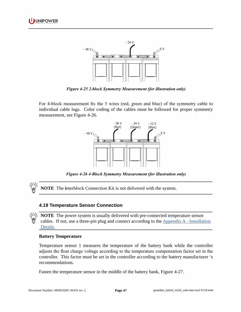
Page 47
P O W E R I N G T E C H N O L O G Y
Document Number: MS0032HC-MAN rev. 2 guardian_hybrid_ms32_cab-man-rev2-0719.indd
Figure 4-25 2-block Symmetry Measurement (for illustration only)
For 4-block measurement fix the 3 wires (red, green and blue) of the symmetry cable to individual cable lugs. Color coding of the cables must be followed for proper symmetry measurement, see Figure 4-26.
Figure 4-26 4-Block Symmetry Measurement (for illustration only)
NOTE The interblock Connection Kit is not delivered with the system.
4.19 Temperature Sensor Connection
NOTE The power system is usually delivered with pre-connected temperature sensor cables. If not, use a three-pin plug and connect according to the Appendix A - Installation Details.
Battery Temperature
Temperature sensor 1 measures the temperature of the battery bank while the controller adjusts the float charge voltage according to the temperature compensation factor set in the controller. This factor must be set in the controller according to the battery manufacturer ‘s recommendations.
Fasten the temperature sensor in the middle of the battery bank, Figure 4-27.
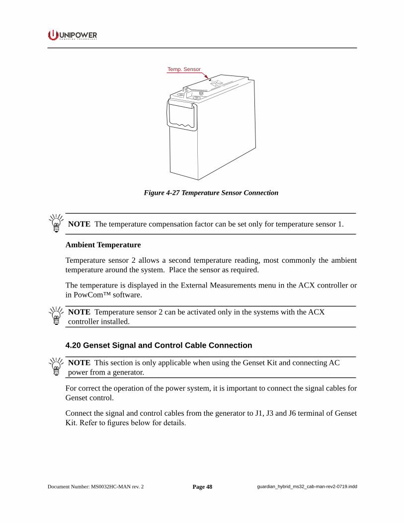
Page 48
P O W E R I N G T E C H N O L O G Y
Document Number: MS0032HC-MAN rev. 2 guardian_hybrid_ms32_cab-man-rev2-0719.indd
Temp. Sensor
Figure 4-27 Temperature Sensor Connection
NOTE The temperature compensation factor can be set only for temperature sensor 1.
Ambient Temperature
Temperature sensor 2 allows a second temperature reading, most commonly the ambient temperature around the system. Place the sensor as required.
The temperature is displayed in the External Measurements menu in the ACX controller or in PowCom™ software.
NOTE Temperature sensor 2 can be activated only in the systems with the ACX controller installed.
4.20 Genset Signal and Control Cable Connection
NOTE This section is only applicable when using the Genset Kit and connecting AC power from a generator.
For correct the operation of the power system, it is important to connect the signal cables for Genset control.
Connect the signal and control cables from the generator to J1, J3 and J6 terminal of Genset Kit. Refer to figures below for details.
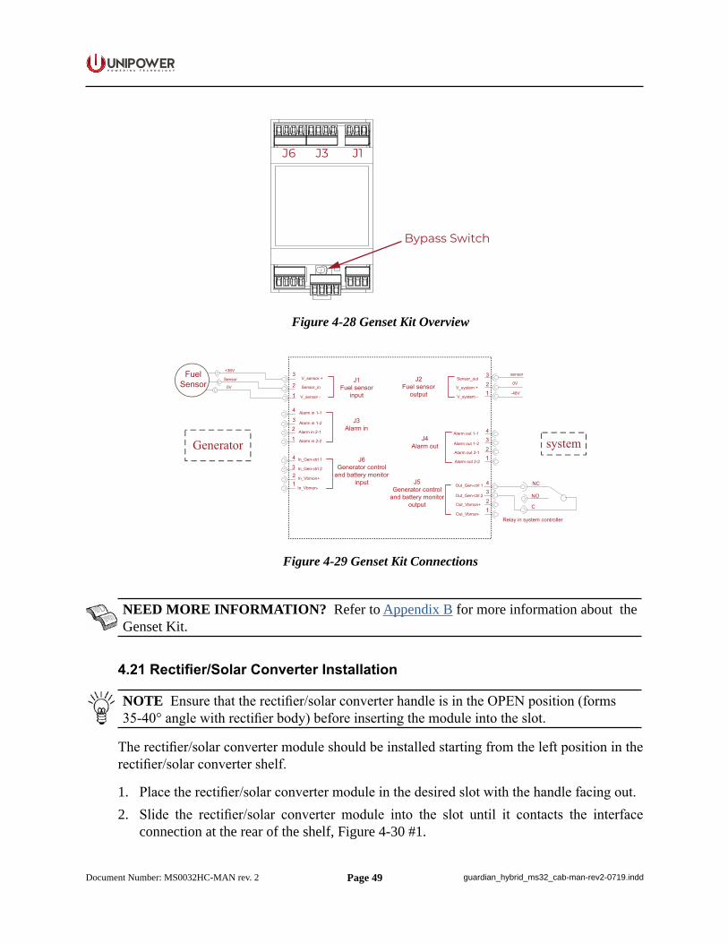
Page 49
P O W E R I N G T E C H N O L O G Y
Document Number: MS0032HC-MAN rev. 2 guardian_hybrid_ms32_cab-man-rev2-0719.indd
J6 J3 J1
Bypass Switch
Figure 4-28 Genset Kit Overview
Figure 4-29 Genset Kit Connections
NEED MORE INFORMATION? Refer to Appendix B for more information about the Genset Kit.
4.21 Rectifier/Solar Converter Installation
NOTE Ensure that the rectifier/solar converter handle is in the OPEN position (forms 35-40° angle with rectifier body) before inserting the module into the slot.
The rectifier/solar converter module should be installed starting from the left position in the rectifier/solar converter shelf.
1. Place the rectifier/solar converter module in the desired slot with the handle facing out.2. Slide the rectifier/solar converter module into the slot until it contacts the interface
connection at the rear of the shelf, Figure 4-30 #1.
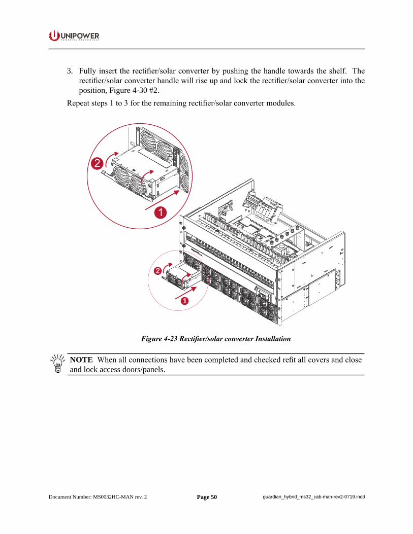
Page 50
P O W E R I N G T E C H N O L O G Y
Document Number: MS0032HC-MAN rev. 2 guardian_hybrid_ms32_cab-man-rev2-0719.indd
3. Fully insert the rectifier/solar converter by pushing the handle towards the shelf. The rectifier/solar converter handle will rise up and lock the rectifier/solar converter into the position, Figure 4-30 #2.
Repeat steps 1 to 3 for the remaining rectifier/solar converter modules.
2
1
Figure 4-23 Rectifier/solar converter Installation
NOTE When all connections have been completed and checked refit all covers and close and lock access doors/panels.
Page 51
P O W E R I N G T E C H N O L O G Y
Document Number: MS0032HC-MAN rev. 2 guardian_hybrid_ms32_cab-man-rev2-0719.indd
Chapter 5 Commissioning
5.1 Commissioning Overview
This chapter is a step-by-step guide to initial set-up and operation of the Hybrid Power System (Genset + Solar) with HCX Advanced controller.
Some commissioning steps are not applicable with the following applications:
Off-Grid or Unreliable Grid with Battery cycling management:
• Cyclic (Genset only with HCC Lite controller supervision)• Pure Solar
On-Grid with Battery in Standby mode:
• Solar Enhanced
For details refer to the final Commissioning checklist record.
CAUTION Before starting the system commissioning read the Instruction Manual carefully.
WARNING Only experienced electrician with necessary experience, knowledge and understanding of Hybrid Power Systems may perform the system commissioning. It is important to follow all local and national electrical codes, safety regulations and instructions in this manual.
5.2 Essential Tools and Test Equipment
• Laptop with PowCom™ Hybrid software installed• Multimeter (3½ Digit, 0–1%DC)• Screwdrivers (Torx 30, Flat 5.5)
NOTE The PowCom™ Hybrid software installer and manual can be donwloaded from the UNIPOWER web site: PowCom™ Hybrid installer | PowCom™ Hybrid Manual
5.3 Preparation
Check the installation to ensure the following:
• Grounding: The equipment is correctly grounded. The grounding cable size, color and routing conform to the requirements.
• Power: The incoming mains AC power is available for this site. The site power switch and circuit breakers are clearly labeled. The power cables are correctly terminated.
• The site is clean and safe. Check that the system/cabinet is free of any unwanted objects or insects that may have got in during the installation.
Page 52
P O W E R I N G T E C H N O L O G Y
Document Number: MS0032HC-MAN rev. 2 guardian_hybrid_ms32_cab-man-rev2-0719.indd
5.4 Commissioning procedure
The checkpoints are to be considered as a minimum for commissioning of the system.
WARNING Do not continue if any faults occur during the commissioning process. In such circumstances contact UNIPOWER for assistance if you cannot locate the problem yourself.
1. Ensure that all system components have been properly connected according to the Installation Guide, section 4, and manufacturers’ instructions. Check that all wiring connections have been made properly and that all required parts are properly grounded.
2. Ensure that load, battery, AC Input and PV breakers are in the OFF position and all modules (rectifiers/solar converters) are removed.
3. Switch the Generator (Genset) to Remote Operation and turn the AC Input breaker ON. (Consult Genset manufacturer documentation for details.)
4. Switch ON the Battery breakers. The HCX controller starts up from the batteries (the green LED on the HCX front panel is blinking).
5. The Generator starts operating after the HCX controller closes the Genset control relay. Check if the HCX controller displays the message “Genset ON”.
6. Measure the AC voltage on the AC Input terminal block, between phases and neutral. The correct value is approximately 230V. If the value is different, check the AC connection and/or Generator settings (voltage and frequency).
7. Switch ON the breakers in the PV String Combiner (if installed). Measure the DC voltage on input of PV breakers (130-360VDC), the voltage depends on the solar irradiance.
8. Insert all the modules (rectifiers/solar converters) into the correct positions. Switch the PV breakers ON.
The modules will turn ON automatically. It will take a minute to step up the correct voltage value.
9. Switch all Load breakers ON. Measure the DC voltage on the breakers, refer to U2.
NOTE The system is now operating according to the factory configuration settings.
10. Connect the PC with PowCom™ Hybrid software to the system using a USB cable. PowCom™ Hybrid software is a mandatory tool for correct setting of all system parameters.
11. Check if the HCX controller settings correspond with the installed configuration. If different settings are needed follow the steps below to setup the required configuration.
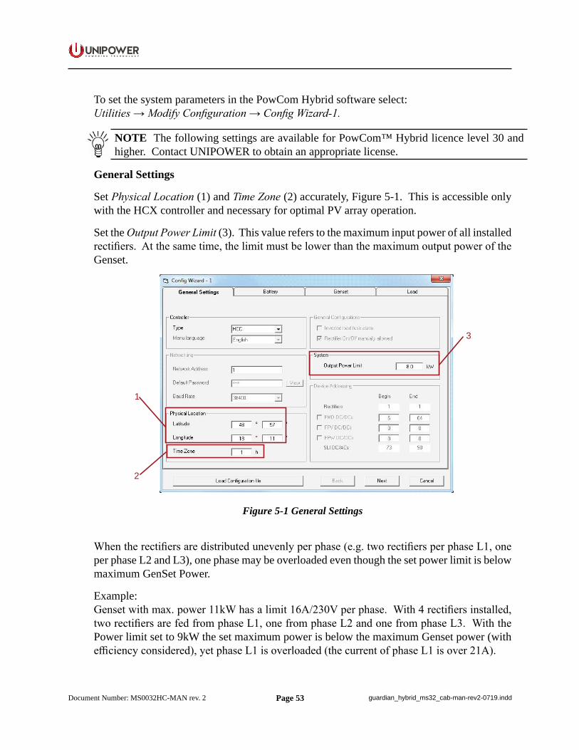
Page 53
P O W E R I N G T E C H N O L O G Y
Document Number: MS0032HC-MAN rev. 2 guardian_hybrid_ms32_cab-man-rev2-0719.indd
To set the system parameters in the PowCom Hybrid software select:Utilities → Modify Configuration → Config Wizard-1.
NOTE The following settings are available for PowCom™ Hybrid licence level 30 and higher. Contact UNIPOWER to obtain an appropriate license.
General Settings
Set Physical Location (1) and Time Zone (2) accurately, Figure 5-1. This is accessible only with the HCX controller and necessary for optimal PV array operation.
Set the Output Power Limit (3). This value refers to the maximum input power of all installed rectifiers. At the same time, the limit must be lower than the maximum output power of the Genset.
1
2
3
Figure 5-1 General Settings
When the rectifiers are distributed unevenly per phase (e.g. two rectifiers per phase L1, one per phase L2 and L3), one phase may be overloaded even though the set power limit is below maximum GenSet Power.
Example:Genset with max. power 11kW has a limit 16A/230V per phase. With 4 rectifiers installed, two rectifiers are fed from phase L1, one from phase L2 and one from phase L3. With the Power limit set to 9kW the set maximum power is below the maximum Genset power (with efficiency considered), yet phase L1 is overloaded (the current of phase L1 is over 21A).
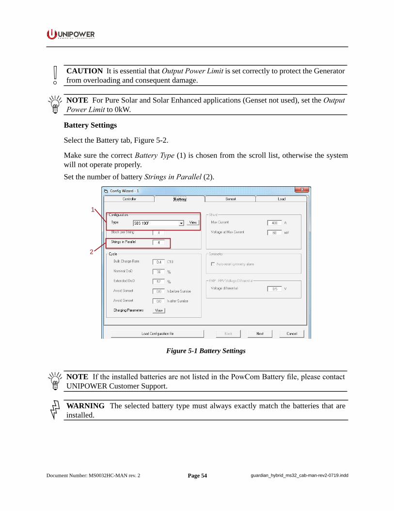
Page 54
P O W E R I N G T E C H N O L O G Y
Document Number: MS0032HC-MAN rev. 2 guardian_hybrid_ms32_cab-man-rev2-0719.indd
CAUTION It is essential that Output Power Limit is set correctly to protect the Generator from overloading and consequent damage.
NOTE For Pure Solar and Solar Enhanced applications (Genset not used), set the Output Power Limit to 0kW.
Battery Settings
Select the Battery tab, Figure 5-2.
Make sure the correct Battery Type (1) is chosen from the scroll list, otherwise the system will not operate properly.Set the number of battery Strings in Parallel (2).
1
2
Figure 5-1 Battery Settings
NOTE If the installed batteries are not listed in the PowCom Battery file, please contact UNIPOWER Customer Support.
WARNING The selected battery type must always exactly match the batteries that are installed.
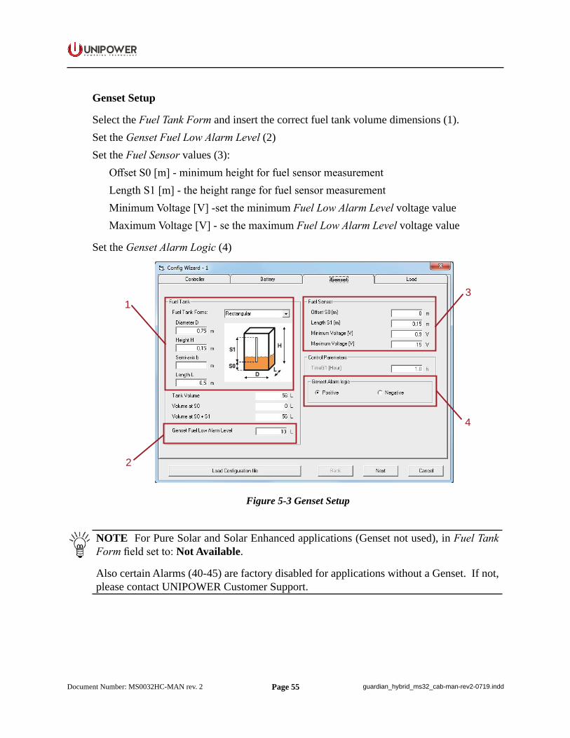
Page 55
P O W E R I N G T E C H N O L O G Y
Document Number: MS0032HC-MAN rev. 2 guardian_hybrid_ms32_cab-man-rev2-0719.indd
Genset Setup
Select the Fuel Tank Form and insert the correct fuel tank volume dimensions (1).Set the Genset Fuel Low Alarm Level (2)Set the Fuel Sensor values (3):
Offset S0 [m] - minimum height for fuel sensor measurementLength S1 [m] - the height range for fuel sensor measurementMinimum Voltage [V] -set the minimum Fuel Low Alarm Level voltage valueMaximum Voltage [V] - se the maximum Fuel Low Alarm Level voltage value
Set the Genset Alarm Logic (4)
1
2
3
4
Figure 5-3 Genset Setup
NOTE For Pure Solar and Solar Enhanced applications (Genset not used), in Fuel Tank Form field set to: Not Available.
Also certain Alarms (40-45) are factory disabled for applications without a Genset. If not, please contact UNIPOWER Customer Support.
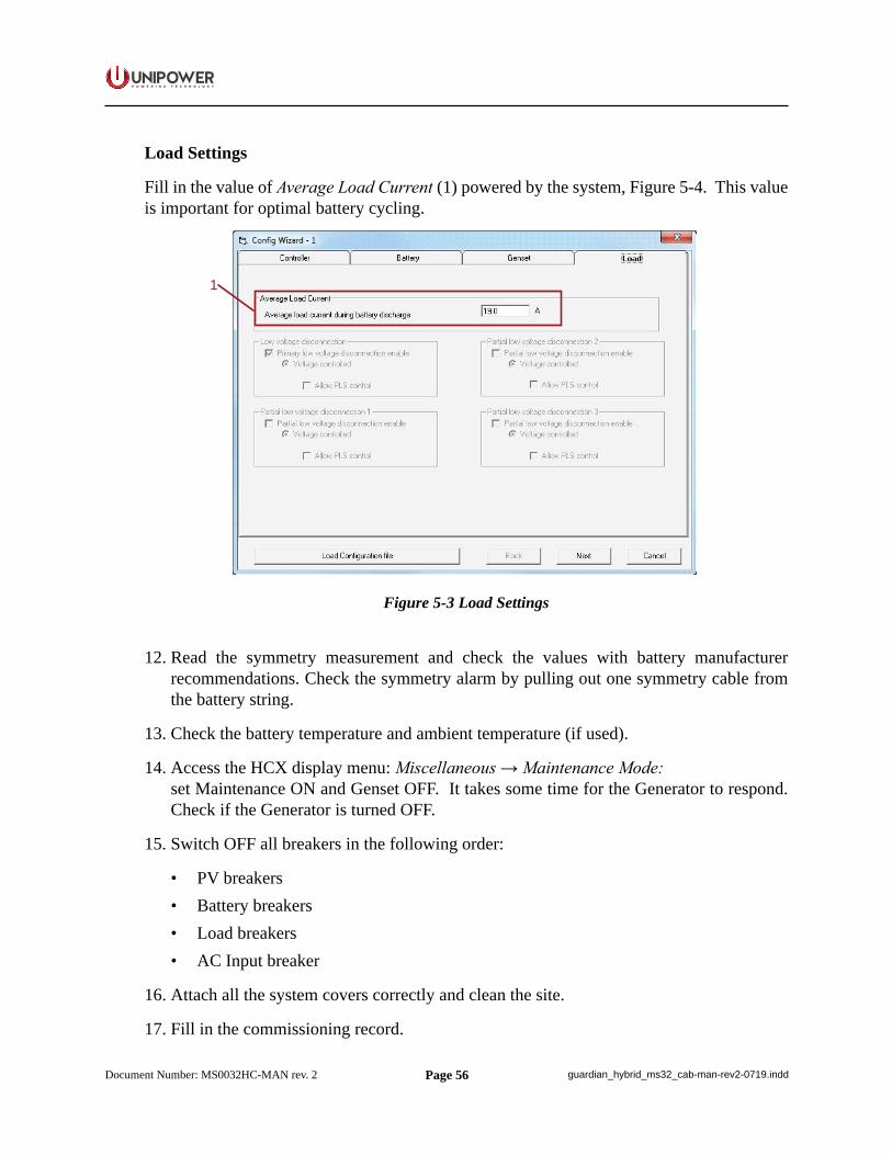
Page 56
P O W E R I N G T E C H N O L O G Y
Document Number: MS0032HC-MAN rev. 2 guardian_hybrid_ms32_cab-man-rev2-0719.indd
Load Settings
Fill in the value of Average Load Current (1) powered by the system, Figure 5-4. This value is important for optimal battery cycling.
1
Figure 5-3 Load Settings
12. Read the symmetry measurement and check the values with battery manufacturer recommendations. Check the symmetry alarm by pulling out one symmetry cable from the battery string.
13. Check the battery temperature and ambient temperature (if used).
14. Access the HCX display menu: Miscellaneous → Maintenance Mode:set Maintenance ON and Genset OFF. It takes some time for the Generator to respond. Check if the Generator is turned OFF.
15. Switch OFF all breakers in the following order:
• PV breakers• Battery breakers• Load breakers• AC Input breaker
16. Attach all the system covers correctly and clean the site.
17. Fill in the commissioning record.
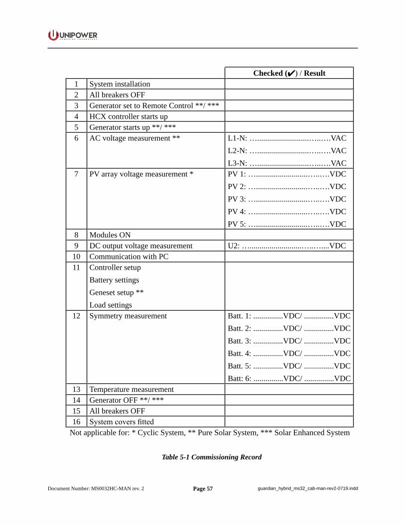
Page 57
P O W E R I N G T E C H N O L O G Y
Document Number: MS0032HC-MAN rev. 2 guardian_hybrid_ms32_cab-man-rev2-0719.indd
Checked () / Result1 System installation2 All breakers OFF3 Generator set to Remote Control **/ *** 4 HCX controller starts up5 Generator starts up **/ ***6 AC voltage measurement ** L1-N: …..........................…..….VAC
L2-N: …..........................…..….VACL3-N: …..........................…..….VAC
7 PV array voltage measurement * PV 1: …..........................…..….VDCPV 2: …..........................…..….VDCPV 3: …..........................…..….VDCPV 4: …..........................…..….VDCPV 5: …..........................…..….VDC
8 Modules ON9 DC output voltage measurement U2: …..........................…..…....VDC10 Communication with PC11 Controller setup
Battery settingsGeneset setup **Load settings
12 Symmetry measurement Batt. 1: ...............VDC/ ...............VDCBatt. 2: ...............VDC/ ...............VDCBatt. 3: ...............VDC/ ...............VDCBatt. 4: ...............VDC/ ...............VDCBatt. 5: ...............VDC/ ...............VDCBatt: 6: ...............VDC/ ...............VDC
13 Temperature measurement14 Generator OFF **/ ***15 All breakers OFF16 System covers fitted
Not applicable for: * Cyclic System, ** Pure Solar System, *** Solar Enhanced System
Table 5-1 Commissioning Record
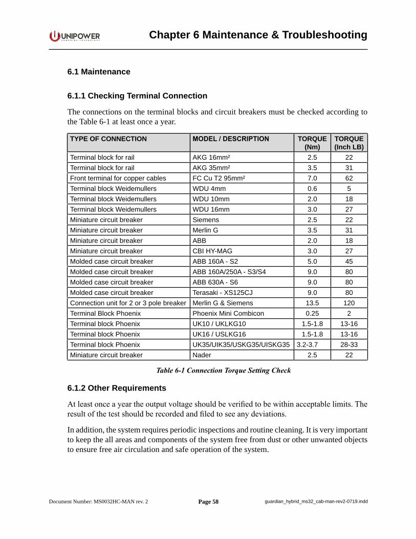
Page 58
P O W E R I N G T E C H N O L O G Y
Document Number: MS0032HC-MAN rev. 2 guardian_hybrid_ms32_cab-man-rev2-0719.indd
Chapter 6 Maintenance & Troubleshooting
6.1 Maintenance
6.1.1 Checking Terminal Connection
The connections on the terminal blocks and circuit breakers must be checked according to the Table 6-1 at least once a year.
TYPE OF CONNECTION MODEL / DESCRIPTION TORQUE (Nm)
TORQUE (Inch LB)
Terminal block for rail AKG 16mm² 2.5 22Terminal block for rail AKG 35mm² 3.5 31Front terminal for copper cables FC Cu T2 95mm² 7.0 62Terminal block Weidemullers WDU 4mm 0.6 5Terminal block Weidemullers WDU 10mm 2.0 18Terminal block Weidemullers WDU 16mm 3.0 27Miniature circuit breaker Siemens 2.5 22Miniature circuit breaker Merlin G 3.5 31Miniature circuit breaker ABB 2.0 18Miniature circuit breaker CBI HY-MAG 3.0 27Molded case circuit breaker ABB 160A - S2 5.0 45Molded case circuit breaker ABB 160A/250A - S3/S4 9.0 80Molded case circuit breaker ABB 630A - S6 9.0 80Molded case circuit breaker Terasaki - XS125CJ 9.0 80Connection unit for 2 or 3 pole breaker Merlin G & Siemens 13.5 120Terminal Block Phoenix Phoenix Mini Combicon 0.25 2Terminal block Phoenix UK10 / UKLKG10 1.5-1.8 13-16Terminal block Phoenix UK16 / USLKG16 1.5-1.8 13-16Terminal block Phoenix UK35/UIK35/USKG35/UISKG35 3.2-3.7 28-33Miniature circuit breaker Nader 2.5 22
Table 6-1 Connection Torque Setting Check
6.1.2 Other Requirements
At least once a year the output voltage should be verified to be within acceptable limits. The result of the test should be recorded and filed to see any deviations.
In addition, the system requires periodic inspections and routine cleaning. It is very important to keep the all areas and components of the system free from dust or other unwanted objects to ensure free air circulation and safe operation of the system.
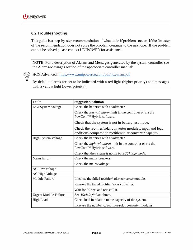
Page 59
P O W E R I N G T E C H N O L O G Y
Document Number: MS0032HC-MAN rev. 2 guardian_hybrid_ms32_cab-man-rev2-0719.indd
6.2 Troubleshooting
This guide is a step-by-step recommendation of what to do if problems occur. If the first step of the recommendation does not solve the problem continue to the next one. If the problem cannot be solved please contact UNIPOWER for assistance.
NOTE For a description of Alarms and Messages generated by the system controller see the Alarms/Messages section of the appropriate controller manual:
HCX Advanced: https://www.unipowerco.com/pdf/hcx-man.pdf
By default, alarms are set to be indicated with a red light (higher priority) and messages with a yellow light (lower priority).
Fault Suggestion/SolutionLow System Voltage Check the batteries with a voltmeter.
Check the low volt alarm limit in the controller or via the PowCom™ Hybrid software.
Check that the system is not in battery test mode.Check the rectifier/solar converter modules, input and load onditions compared to rectifier/solar converter capacity.
High System Voltage Check the batteries with a voltmeter.Check the high volt alarm limit in the controller or via the PowCom™ Hybrid software.Check that the system is not in boost/Charge mode.
Mains Error Check the mains breakers.Check the mains voltage.
AC Low VoltageAC High VoltageModule Failure Localise the failed rectifier/solar converter module.
Remove the failed rectifier/solar converter.Wait for 30 sec. and reinstall it.
Urgent Module Failure See Module failure above.High Load Check load in relation to the capacity of the system.
Increase the number of rectifier/solar converter modules.
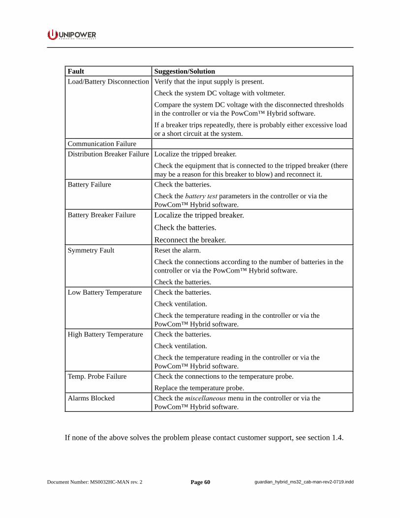
Page 60
P O W E R I N G T E C H N O L O G Y
Document Number: MS0032HC-MAN rev. 2 guardian_hybrid_ms32_cab-man-rev2-0719.indd
Fault Suggestion/SolutionLoad/Battery Disconnection Verify that the input supply is present.
Check the system DC voltage with voltmeter.Compare the system DC voltage with the disconnected thresholds in the controller or via the PowCom™ Hybrid software.If a breaker trips repeatedly, there is probably either excessive load or a short circuit at the system.
Communication FailureDistribution Breaker Failure Localize the tripped breaker.
Check the equipment that is connected to the tripped breaker (there may be a reason for this breaker to blow) and reconnect it.
Battery Failure Check the batteries.Check the battery test parameters in the controller or via the PowCom™ Hybrid software.
Battery Breaker Failure Localize the tripped breaker.Check the batteries.Reconnect the breaker.
Symmetry Fault Reset the alarm.Check the connections according to the number of batteries in the controller or via the PowCom™ Hybrid software.Check the batteries.
Low Battery Temperature Check the batteries.Check ventilation.Check the temperature reading in the controller or via the PowCom™ Hybrid software.
High Battery Temperature Check the batteries.Check ventilation.Check the temperature reading in the controller or via the PowCom™ Hybrid software.
Temp. Probe Failure Check the connections to the temperature probe.Replace the temperature probe.
Alarms Blocked Check the miscellaneous menu in the controller or via the PowCom™ Hybrid software.
If none of the above solves the problem please contact customer support, see section 1.4.
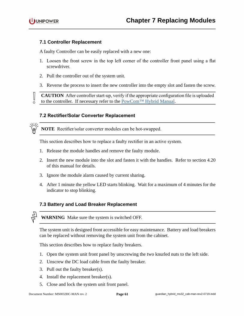
Page 61
P O W E R I N G T E C H N O L O G Y
Document Number: MS0032HC-MAN rev. 2 guardian_hybrid_ms32_cab-man-rev2-0719.indd
Chapter 7 Replacing Modules
7.1 Controller Replacement
A faulty Controller can be easily replaced with a new one:
1. Loosen the front screw in the top left corner of the controller front panel using a flat screwdriver.
2. Pull the controller out of the system unit.
3. Reverse the process to insert the new controller into the empty slot and fasten the screw.
CAUTION After controller start-up, verify if the appropriate configuration file is uploaded to the controller. If necessary refer to the PowCom™ Hybrid Manual.
7.2 Rectifier/Solar Converter Replacement
NOTE Rectifier/solar converter modules can be hot-swapped.
This section describes how to replace a faulty rectifier in an active system.
1. Release the module handles and remove the faulty module.
2. Insert the new module into the slot and fasten it with the handles. Refer to section 4.20 of this manual for details.
3. Ignore the module alarm caused by current sharing.
4. After 1 minute the yellow LED starts blinking. Wait for a maximum of 4 minutes for the indicator to stop blinking.
7.3 Battery and Load Breaker Replacement
WARNING Make sure the system is switched OFF.
The system unit is designed front accessible for easy maintenance. Battery and load breakers can be replaced without removing the system unit from the cabinet.
This section describes how to replace faulty breakers.
1. Open the system unit front panel by unscrewing the two knurled nuts to the left side.2. Unscrew the DC load cable from the faulty breaker.3. Pull out the faulty breaker(s).4. Install the replacement breaker(s).5. Close and lock the system unit front panel.
Page 62
P O W E R I N G T E C H N O L O G Y
Document Number: MS0032HC-MAN rev. 2 guardian_hybrid_ms32_cab-man-rev2-0719.indd
This document is believed to be correct at time of publication and UNIPOWER LLC accepts no responsibility for consequences from printing errors or inaccuracies. Specifications are subject to change without notice.
7.4 Surge Protection Device Replacement
This section describes how to replace a faulty surge protection module.
1. Switch off AC input power.
2. Remove the top cover.
3. Pull out the failed surge protection module.
4. Insert a new surge protection module into the corresponding position.
5. Reinstall the top cover.
6. Switch on AC input power.
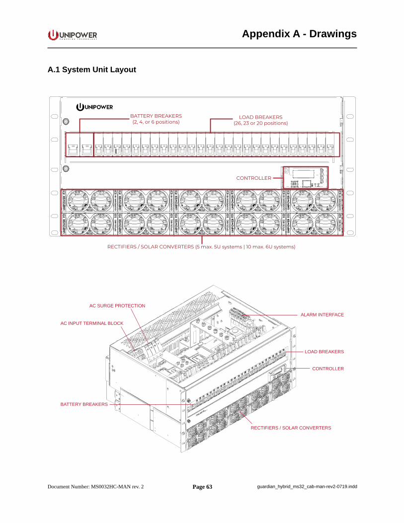
Page 63
P O W E R I N G T E C H N O L O G Y
Document Number: MS0032HC-MAN rev. 2 guardian_hybrid_ms32_cab-man-rev2-0719.indd
Appendix A - Drawings
A.1 System Unit Layout
GU
AR
DIA
N 4
8FP
V30.
48G
GU
AR
DIA
N 4
8FP
V30.
48G
GU
AR
DIA
N 4
8FP
V30.
48G
GU
AR
DIA
N 4
8FP
V30.
48G
GU
AR
DIA
N 4
8FP
V30.
48G
RECTIFIERS / SOLAR CONVERTERS (5 max. 5U systems | 10 max. 6U systems)
BATTERY BREAKERS(2, 4, or 6 positions)
CONTROLLER
LOAD BREAKERS(26, 23 or 20 positions)
RECTIFIERS / SOLAR CONVERTERS
CONTROLLER
BATTERY BREAKERS
ALARM INTERFACE
LOAD BREAKERS
AC INPUT TERMINAL BLOCK
AC SURGE PROTECTION
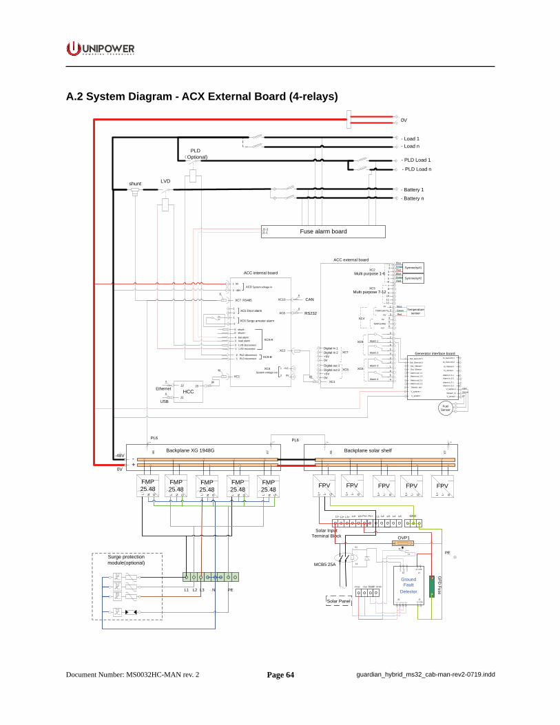
Page 64
P O W E R I N G T E C H N O L O G Y
Document Number: MS0032HC-MAN rev. 2 guardian_hybrid_ms32_cab-man-rev2-0719.indd
A.2 System Diagram - ACX External Board (4-relays)
- Battery 1
- Battery n
0V
- Load 1- Load n
LVD
- PLD Load 1
- PLD Load n
PLDOptional)
USB
96
J39
J1
J2Ethernet
96
XC1
ACC internal board
1 0V
2 -48V
XC9-A
XC9-B
XC7 RS485
8
XC8
System voltage out
RS232
XC2
XC3 System voltage in
XC5 Door alarm
XC6 Surge arrestor alarm
1
1
2
2
HCC
Fuse alarm board
shunt
8
J1-1J1-2
XC4
8
XC10 CAN
6 shunt-5 shunt+
4 bat alarm3 load alarm
2 LVD disconnect1 LVD reconnect
2 PLD disconnect1 PLD reconnect
XC3
32
1Alarm 165
4Alarm 2
XC6
32
1Alarm 3
65
4Alarm 4
XC5
21
Multi purpose 7-12
Multi purpose 1-6XC2
+5V
0V
TEMP1(BATT)
321
XC4
50
XC1
ACC external board
Digital In 2+5V
Digital In 1XC7
Digital out 2+5V
Digital out 1XC8
+5V
0V
TEMP2(AMB)6
54
43
65
87
109
1211
8
X6
8
0V
-48V -+
Backplane XG 1948G
FMP25.48
L N G
PL6
FMP25.48
L N G
FMP25.48
L N G
FMP25.48
L N G
Surge protection module(optional)
L1 NL2 L3 PE
8
X7 X6
8
Backplane solar shelf
PL6 8
X7
NO
NC
1 +V2
2 0V
0V
0V
Symmetry#1
Symmetry#2
Temperature senser
RedGreenBlueRedGreenBlue
RedGreenBlue
Generator interface board
Out_Gen-ctrl 2
Out_Gen-ctrl 1
V_system -
V_system +
Sensor_out
V_sensor -
V_sensor +
Sensor_in
+36V
0V
Sensor
In_Gen-ctrl 2
In_Gen-ctrl 1
Fuel Sensor
Alarm out 1-1Alarm out 1-2
Alarm out 2-1Alarm out 2-2
Out_Vbmon-Out_Vbmon+
Alarm in 1-1Alarm in 1-2
Alarm in 2-1Alarm in 2-2
In_Vbmon-
In_Vbmon+
FPV
MCB5 25A C1
C2
Ground Fault
Detector
GF+/GRD
J1
1212 3
1 21 2GF-/GRD
J2
J4
Com
NO
NC
J3-Vsys+Vsys
GFD
Fuse
3 4Alarm+Vsys
Solar Input Terminal Block
PV+ GND
+Vsys -Vsys GFDSDSAF
L1- L4-L4+ L5+ L2- L3- L5-L1+ L2+ L3+ PV+
OVP1
11
12 PE
Solar Panel
L+ GL-
FPV
L+ GL-
FPV
L+ GL-
FPV
L+ GL-
FMP25.48
L N G
FPV
L+ GL-
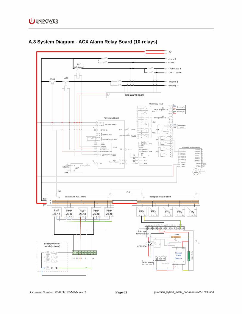
Page 65
P O W E R I N G T E C H N O L O G Y
Document Number: MS0032HC-MAN rev. 2 guardian_hybrid_ms32_cab-man-rev2-0719.indd
A.3 System Diagram - ACX Alarm Relay Board (10-relays)
- Battery 1
- Battery n
0V
- Load 1- Load n
LVD
- PLD Load 1
- PLD Load n
PLDOptional)
USB
96
J39
J1
J2Ethernet
96
XC1
ACC internal board
1 0V
2 -48V
XC9-A
XC9-B
XC7 RS485
XC8
System voltage out
RS232
XC2
XC3 System voltage in
XC5 Door alarm
XC6 Surge arrestor alarm
1
1
2
2
HCC
Fuse alarm board
shunt
8
J1-1J1-2
XC4
8
XC10 CAN
6 shunt-5 shunt+
4 bat alarm3 load alarm2 LVD disconnect1 LVD reconnect
2 PLD disconnect1 PLD reconnect
XC3
32
1Alarm 165
4Alarm 2
XC6
32
1Alarm 3
65
4Alarm 4
XC5
21
Multi purpose 7-12
Multi purpose 1-6XC2
+5V
0V
TEMP1(BATT)
321
XC4
50
XC1
Digital In 2+5V
Digital In 1XC7
Digital out 2+5V
Digital out 1XC8
+5V
0V
TEMP2(AMB)6
54
43
65
87
109
1211
1
234
56
123
4
56
123
4
56
K1
K2
K4
K3
K5
K6
XC10
XC9
XC118
X6
8
0V
-48V -+
Backplane XG 1948G
FMP25.48
L N G
PL6
FMP25.48
L N G
FMP25.48
L N G
FMP25.48
L N G
Surge protection module(optional)
L1 NL2 L3 PE
8
X7 X6
8
Backplane Solar shelf
PL6 8
X7
NO
NC
Alarm relay board
1 +V2
2 0V
0V
0V
Symmetry#1
Symmetry#2
Temperature senser
RedGreenBlueRedGreenBlue
RedGreenBlue
50
50 XC13
XC12
8
Generator interface board
Out_Gen-ctrl 2
Out_Gen-ctrl 1
V_system -
V_system +
Sensor_out
V_sensor -
V_sensor +
Sensor_in
+36V
0V
Sensor
In_Gen-ctrl 2
In_Gen-ctrl 1
FuelSensor
Alarm out 1-1Alarm out 1-2
Alarm out 2-1Alarm out 2-2
Out_Vbmon-Out_Vbmon+
Alarm in 1-1Alarm in 1-2
Alarm in 2-1Alarm in 2-2
In_Vbmon-
In_Vbmon+
FPV
MCB5 25A C1
C2
Ground Fault
Detector
GF+/GRD
J1
1212 3
1 21 2GF-/GRD
J2
J4
Com
NO
NC
J3-Vsys+Vsys
GFD
Fuse
3 4Alarm+Vsys
Solar Input Terminal Block
PV+ GND
+Vsys -Vsys GFDSDSAF
L1- L4-L4+ L5+ L2- L3- L5-L1+ L2+ L3+ PV+
OVP1
11
12 PE
Solar Panel
L+ GL-
FPV
L+ GL-
FPV
L+ GL-
FPV
L+ GL-
FMP25.48
L N G
FPV
L+ GL-
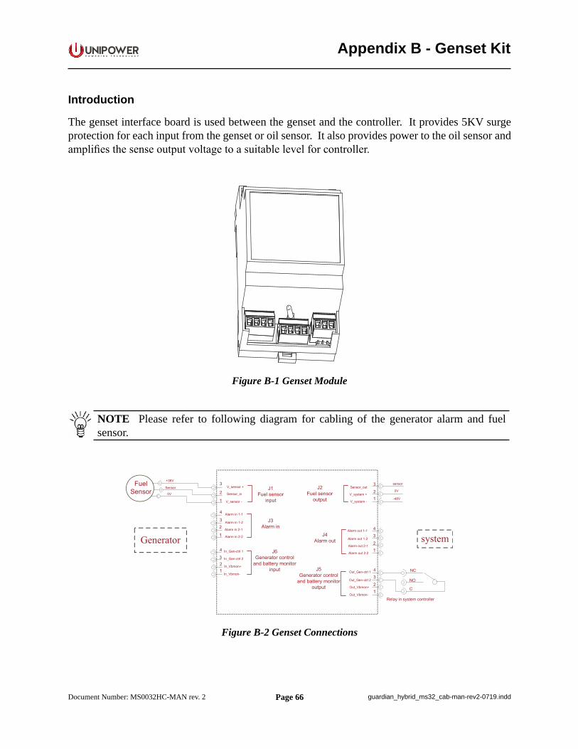
Page 66
P O W E R I N G T E C H N O L O G Y
Document Number: MS0032HC-MAN rev. 2 guardian_hybrid_ms32_cab-man-rev2-0719.indd
Appendix B - Genset Kit
Introduction
The genset interface board is used between the genset and the controller. It provides 5KV surge protection for each input from the genset or oil sensor. It also provides power to the oil sensor and amplifies the sense output voltage to a suitable level for controller.
Figure B-1 Genset Module
NOTE Please refer to following diagram for cabling of the generator alarm and fuel sensor.
Figure B-2 Genset Connections
Page 67
P O W E R I N G T E C H N O L O G Y
Document Number: MS0032HC-MAN rev. 2 guardian_hybrid_ms32_cab-man-rev2-0719.indd
J1 Fuel Sensor Input
Pin Function Note1 Vsensor+ 33VDC, 10mA max.2 Vsensor_in fuel sensor signal3 Vsensor- 0V
Table B-1 Fuel Sensor Input Connections
The fuel sensor should operate at 33VDC with a current consumption of less than 10mA.
Three alternative output voltages are available from the sensor; 5VDC, 10VDC and 15VDC. This is selected by using different jumper settings, see table B-3.
J2 Fuel Sensor Output
Pin Function Note1 Vsystem+
Connected to system2 Vsystem-3 Vsensor_out Output 0~30VDC
Table B-2 Fuel Sensor Input Connections
There are 3 pin-selectors beside this connector. Set jumpers according to following table based on fuel sensor.
Jumper Setting Max. Sensor OuputAll pins open 5VDC
Pins 2 and 3 shorted 10VDCPins 2 and 3 shorted 15VDC
Table B-3 Jumper Settings
J3 Alarm Input Interface
Pin Function1 Alarm in 1-12 Alarm in 1-23 Alarm in 2-14 Alarm in 2-2
Table B-4 Alarm Input Connections
Page 68
P O W E R I N G T E C H N O L O G Y
Document Number: MS0032HC-MAN rev. 2 guardian_hybrid_ms32_cab-man-rev2-0719.indd
NOTE The voltage of alarm signal should not exceed 60VDC. AC voltage is not allowed.
J4 Alarm Output Interface
Pin Function1 Alarm out 1-12 Alarm out 1-23 Alarm out 2-14 Alarm out 2-2
Table B-4 Alarm Output Connections
NOTE The alarm output interface matches the input interface. For example, Alarm in 1-1 is connected to Alarm out 1-1.
J5 Genset Control and Battery Monitor Output
Pin Function Note1 Out_Gen-ctrl1 60VDC max. on
both terminals2 Out_Gen-ctrl23 Out_Vbmon+ Battery voltage inside
genset, 12VDC or 24VDC4 Out_Vbmon-
Table B-5 Genset Control and Battery Monitor Output Connections
Out_Gen-ctrl1 and Out_Gen-crtl2 are used for remote genset ON/OFF.
The Out_Vbmon+ and Out_Vbmon- are used for detecting the voltage of the battery in the Genset. 24V or 12V is supported.
J6 Genset Control and Battery Monitor Input
Pin Function Note1 In_Gen-ctrl1 60VDC max. on
both terminals2 In_Gen-ctrl23 In_Vbmon+ Battery voltage inside
genset, 12VDC or 24VDC4 In_Vbmon-
Table B-5 Genset Control and Battery Monitor Input Connections
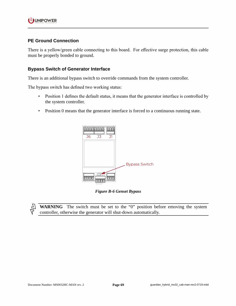
Page 69
P O W E R I N G T E C H N O L O G Y
Document Number: MS0032HC-MAN rev. 2 guardian_hybrid_ms32_cab-man-rev2-0719.indd
PE Ground Connection
There is a yellow/green cable connecting to this board. For effective surge protection, this cable must be properly bonded to ground.
Bypass Switch of Generator Interface
There is an additional bypass switch to override commands from the system controller.
The bypass switch has defined two working status:
• Position 1 defines the default status, it means that the generator interface is controlled by the system controller.
• Position 0 means that the generator interface is forced to a continuous running state.
J6 J3 J1
Bypass Switch
Figure B-6 Genset Bypass
WARNING The switch must be set to the “0” position before emoving the system controller, otherwise the generator will shut-down automatically.