hybrid and electric vehicle solutions guide · different types of hybrid and electric vehicle...
TRANSCRIPT
System Solutions for Hybrid and Electric Vehicles
2Q 2010www.ti.com/hev

System Solutions for Hybrid and Electric Vehicles TexasInstruments2Q2010
System Solutions for Hybrid and Electric Vehicles
Texas Instruments Automotive Commitment
2
➔
2
➔
TexasInstruments(TI)iscommittedtoprovidingsuperiorcost-efficientsolutionstothetransportationmarket,alongwithexcellentproductdocumentation,on-timedeliveryandconformancetospecifications.
TIsupportstransportationindustryrequirementsandcontinuestoaddtoourtransportationportfolio.Withmorethan30yearsofexperienceservingcustomerswithdemandingrequirements,TIcanhelpyouachievethequality,reliabilityandcostgoalstosucceedintoday’smarketplace.
TIisfullycommittedtoautomotivequality;wehaveadedicatedqualityorganizationandazero-defectstrategyinplace.WeareTS16949certifiedandapreferredsuppliertomajorcarmanufacturers.
Introduction to Electric TransportationElectrictransportationisnotanewphenomena;infact,theconcepthasbeenaroundformorethan100years.However,givengrowingenvironmentalsensitivities,long-termsupplyconcerns,fossilfuelpricesandimprovedtechnology,thereisastrongmotivationtofurtheracceleratethismarketsegment.
Governmentregulationslikethe130-g/km(andfutureplanned95-g/km)CO2averageemissionlimitsforcarmanufacturersinEuropearealsocatalystsbehindnewelectrifiedtransportationalternatives.Withtheadoptionofmoreelectronics,vehiclesbecomesafer,exhibithigherperformance,andaremoreefficient.
Electrictransportationisakeyelementwithintheoverallrenewableenergylandscape.Energyforchargingisexpectedtocomefromrenewablesourceslikewind-,solar-orwater-poweredplants.Homeandpublicchargingstationswillalsobecomemoreprevalentandcantakeadvantageofoff-peakcharging(nighttime)andothergreenenergysourcessuchaswind.
Withafullrangeofanalogandembeddedprocessingproducts,TIisattheforefrontofhelpingtobringsafer,affordableandmoreefficientelectrictransportationsolutionstomarket.TI’ssolutionsforthisindustryrangefromoptimizedanddedicatedintegrated
circuitstofullsystem-levelsolutionstohelpourcustomersoptimizeandaccelerateproductdevelopment.
TI’sexperienceindiversemarketssuchasindustrialcontrol,industrialmotordrives,digitalpowersupplies,smartmeteringandgrids,wiredandwireless
communications,consumerelectronics,andenergyefficiencyenablesengineerstomeetincreasingneedsforhigherspeeds,higherprecision,lowerpowerandmorerobustequipment–allwhilemaintainingthehighstandardsofqualityandreliabilitythattheautomotiveandtransportationmarketdemands.
System Solutions for Hybrid and Electric VehiclesTexasInstrumentsAutomotiveCommitment . . . . . . . . . . . . . . . . . . . . . . . . . . . . . . . . . 2IntroductiontoElectricTransportation . . . . . . . . . . . . . . . . . . . . . . . . . . . . . . . . . . . . . . 3WhyTI? . . . . . . . . . . . . . . . . . . . . . . . . . . . . . . . . . . . . . . . . . . . . . . . . . . . . . . . . . . . . . 3SystemArchitectureofHEV/EV . . . . . . . . . . . . . . . . . . . . . . . . . . . . . . . . . . . . . . . . . . . 3
Start/Stop Function (Micro Hybrid)Start/StopFunction . . . . . . . . . . . . . . . . . . . . . . . . . . . . . . . . . . . . . . . . . . . . . . . . . . . . 4PowerManagementforStart/StopFunction . . . . . . . . . . . . . . . . . . . . . . . . . . . . . . . . . 4Start/StopFunctionApplications . . . . . . . . . . . . . . . . . . . . . . . . . . . . . . . . . . . . . . . . . . 5TPS40210:BoostConverter . . . . . . . . . . . . . . . . . . . . . . . . . . . . . . . . . . . . . . . . . . . . . 5TPIC74100:Buck-Boost-ConverterIntegratedSwitches . . . . . . . . . . . . . . . . . . . . . . . 5TPS40090:Four-ChannelMultiphaseBuckDC/DCController(orBoost) . . . . . . . . . . . 5Start/StopFunctionUsingtheC2000™DSPPiccolo™MCU. . . . . . . . . . . . . . . . . . . . 6
Battery Management, Power Conversion (DC/DC) and Charging (AC/DC)IntroductiontoBatteryManagement . . . . . . . . . . . . . . . . . . . . . . . . . . . . . . . . . . . . . . . 7BatteryManagementSystem. . . . . . . . . . . . . . . . . . . . . . . . . . . . . . . . . . . . . . . . . . . . . 8BatteryManagement:bq76PL536andbq76PL537. . . . . . . . . . . . . . . . . . . . . . . . . . . . 9BatteryManagement:Applications . . . . . . . . . . . . . . . . . . . . . . . . . . . . . . . . . . . . . . . 10bq76PL536:BatteryManagement . . . . . . . . . . . . . . . . . . . . . . . . . . . . . . . . . . . . . . . . 10bq76PL536:EvaluationModule . . . . . . . . . . . . . . . . . . . . . . . . . . . . . . . . . . . . . . . . . . 10IntroductiontoDC/DCConverterModule. . . . . . . . . . . . . . . . . . . . . . . . . . . . . . . . . . 11DC/DCConverter:Applications . . . . . . . . . . . . . . . . . . . . . . . . . . . . . . . . . . . . . . . . . . 12UCC2895:AdvancedPhase-ShiftResonantController. . . . . . . . . . . . . . . . . . . . . . . . 12DC/DCConverterUsingC2000™DSOPiccolo™MCUs. . . . . . . . . . . . . . . . . . . . . . 12C2000™DSP’sPiccolo™TMS320F280xFamily . . . . . . . . . . . . . . . . . . . . . . . . . . . . 13C2000DSPDigitalPowerDC/DCDeveloperKits............................ 13On-BoardCharger–AC/DCwithPFC . . . . . . . . . . . . . . . . . . . . . . . . . . . . . . . . . . . . . 14AC/DCDeveloper’sKitwithTMS320F280x . . . . . . . . . . . . . . . . . . . . . . . . . . . . . . . . . 14AC/DCApplications . . . . . . . . . . . . . . . . . . . . . . . . . . . . . . . . . . . . . . . . . . . . . . . . . . . 15PiccoloMCUsF2802xvs.F2803x . . . . . . . . . . . . . . . . . . . . . . . . . . . . . . . . . . . . . . . . 15UCC28070:Two-PhaseInterleavedConstantCurrentMode(CCM)PowerFactorCorrection(PFC)Controller.................................. 16
Motor ControlIntroductiontoDC/ACforInverterMotorControl . . . . . . . . . . . . . . . . . . . . . . . . . . . . 17TMS570:TheSafeTIMicrocontroller. . . . . . . . . . . . . . . . . . . . . . . . . . . . . . . . . . . . . . 18TMS570:EvaluationKit . . . . . . . . . . . . . . . . . . . . . . . . . . . . . . . . . . . . . . . . . . . . . . . . 18
The Analog FoundationAnalogOverview . . . . . . . . . . . . . . . . . . . . . . . . . . . . . . . . . . . . . . . . . . . . . . . . . . . . . 19ISO1050:IsolatedCANTransceiver . . . . . . . . . . . . . . . . . . . . . . . . . . . . . . . . . . . . . . . 20ISO72x–Isolation . . . . . . . . . . . . . . . . . . . . . . . . . . . . . . . . . . . . . . . . . . . . . . . . . . . . 20ISO7221Cxx:Dual-Channel,1/1,25-MbpsDigitalIsolator..................... 21ISO55xx:IsolatedGateDriverFamily . . . . . . . . . . . . . . . . . . . . . . . . . . . . . . . . . . . . . 22AMC1203 . . . . . . . . . . . . . . . . . . . . . . . . . . . . . . . . . . . . . . . . . . . . . . . . . . . . . . . . . . . 22
Charging Infrastructure . . . . . . . . . . . . . . . . . . . . . . . . . . . . . . . . . . . . . . . . . . . 23ChargingInfrastructure–ConnectingtheCartotheSmartPowerGrid . . . . . . . . . . . 23PLCKitUsingtheTMS320F28335 . . . . . . . . . . . . . . . . . . . . . . . . . . . . . . . . . . . . . . . 24ZigBee®RFUsingtheCC2530System-on-Chip . . . . . . . . . . . . . . . . . . . . . . . . . . . . 24
E-Bike, Scooter and Small Task-Oriented Vehicles (STOVs) . . . . . . . . 25bq78PL114:IntegratedGasGauge,ProtectionandActiveCellBalancing. . . . . . . . . 26bq77PL900:StandaloneandHost-ControlledBatteryProtection. . . . . . . . . . . . . . . . 26DigitalMotorControlforE-Bikes,ScootersandSTOVs. . . . . . . . . . . . . . . . . . . . . . . 27High-VoltagePFCandMotorControlDeveloper’sKit . . . . . . . . . . . . . . . . . . . . . . . . . 27controlSuite™Software . . . . . . . . . . . . . . . . . . . . . . . . . . . . . . . . . . . . . . . . . . . . . . . . 27
TI Worldwide Technical Support . . . . . . . . . . . . . . . . . . . . . . . . . . . . . .28
TexasInstruments2Q2010 System Solutions for Hybrid and Electric Vehicles
System Solutions for Hybrid and Electric Vehicles
Introduction to Electric Transportation
3
➔
Why TI?Innovated semiconductor solutions• Makingadvancedautomotive andtransportationdevices moreflexible,affordableand accessible.• Addressinggrowingneedsin energyefficiency,powerand batterymanagement,wiredand wirelessconnectivity,and performanceandprecision.
Complete portfolio• Amplifiers,dataconverters,interfaces, powermanagement,isolation,logic, DSPs,MCUs,wirelessconnectivity.• Catalog,application-specific, enhancedandcustomICoptions.• Experiencedautomotiveand transportationsectorsupplierwitha fullrangeofAECQ-100-certified analogandembeddedprocessing technologiesandproducts.
Quality and reliability• Experienceinservingtheautomotive marketformorethan30years.• Abilitytoservecustomersofallsizes withavarietyofsupplierchainsand needs.• Longproductlifetimesandflexible productobsolescencepolicy,ensuring continuityofsupply.• WorldwidemanufacturingandR&D capabilities.• Memberofindustry-standard organizationsandalliances.
Commitment• Designsupport• Tools• Training• Distribution
ThisHybridandElectricVehicleSolutionsGuideisintendedtohelpyouexploreTI’sICsolutionsasthevarioustransportationsectorsbecomeincreasinglyelectrifiedonapathtowardenergyefficiencyandsustainability.Thisguidefeaturesseveralsystemblockdiagrams,followedbydetailsaboutkeydevicesandsupportfunctions.
Different types of hybrid and electric vehicles
FeatureStart/Stop
Micro Hybrid
Mild Hybrid
FullHybrid
(Parallel)
FullHybrid(Serial)
FullElectric
Start/stop alternator a a a a
Regenerative breaking a a a a a
Electric torque assist a a
Electric and combustion drive a
Only electric drive possible a a
Plug-in capability a a a
Differenttypesofhybridandelectricvehicleconceptsexistinthemarket.TexasInstrumentsoffersleading-edgesolutionsforallsystems,fromabasicstart/stopfunctiontoafullyintegratedplug-inelectricvehicle.Thisguidewillgiveanoverviewofthevariousfunctionsandalsocoverproducthighlightsfromvariousareas.Forthelatestinformation,seeTI’sWebsite,www.ti.com.
DC/DCConverter
(Reversible)
12-V BoardNet
DC/ACInverter
BatteryMonitoring
BatteryManagement
ElectricalMotor/
Generator
AC/DCConverter
(PFC + PLC)
DC/DCConverter
(Full Bridge)
High-VoltageLi-Ion
Battery
Low-Voltage
12-VBattery
ChargerEnergy Conversion
Infrastructure/Charging Spot
Motor Control
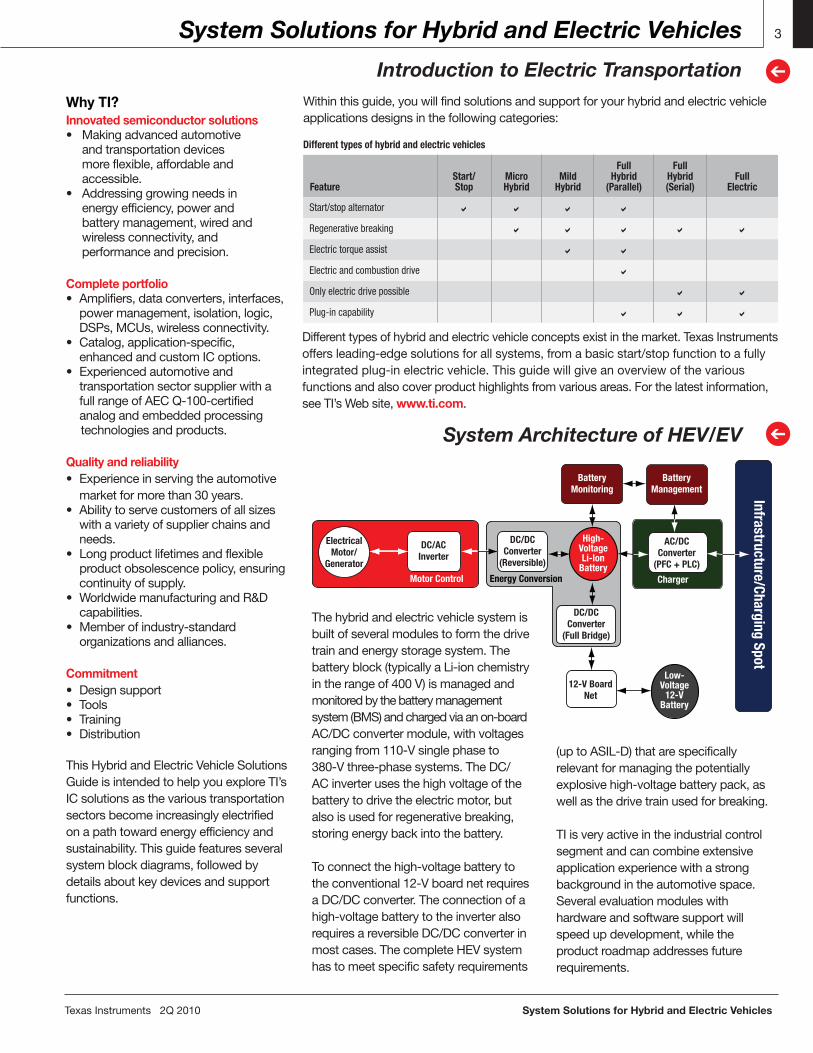
System Architecture of HEV/EV
➔Thehybridandelectricvehiclesystemisbuiltofseveralmodulestoformthedrivetrainandenergystoragesystem.Thebatteryblock(typicallyaLi-ionchemistryintherangeof400V)ismanagedandmonitoredbythebatterymanagementsystem(BMS)andchargedviaanon-boardAC/DCconvertermodule,withvoltagesrangingfrom110-Vsinglephaseto380-Vthree-phasesystems.TheDC/ACinverterusesthehighvoltageofthebatterytodrivetheelectricmotor,butalsoisusedforregenerativebreaking,storingenergybackintothebattery.
Toconnectthehigh-voltagebatterytotheconventional12-VboardnetrequiresaDC/DCconverter.Theconnectionofahigh-voltagebatterytotheinverteralsorequiresareversibleDC/DCconverterinmostcases.ThecompleteHEVsystemhastomeetspecificsafetyrequirements
(uptoASIL-D)thatarespecificallyrelevantformanagingthepotentiallyexplosivehigh-voltagebatterypack,aswellasthedrivetrainusedforbreaking.
TIisveryactiveintheindustrialcontrolsegmentandcancombineextensiveapplicationexperiencewithastrongbackgroundintheautomotivespace.Severalevaluationmoduleswithhardwareandsoftwaresupportwillspeedupdevelopment,whiletheproductroadmapaddressesfuturerequirements.
Withinthisguide,youwillfindsolutionsandsupportforyourhybridandelectricvehicleapplicationsdesignsinthefollowingcategories:

System Solutions for Hybrid and Electric Vehicles TexasInstruments2Q2010
Start/Stop Function (Micro Hybrid)
Start/Stop Function
4
➔Hi
gh-P
ower
Boo
ster
Gate Driver
Vdriver Cboot1L1
L2
Cboot2VOUT
PGND
5Vg
AOUT
RESETREST
Vlogic
Rmod
GND
Enable
5Vg_Enable
CLP
AIN
PWMController
Gate Driver
Pow
er M
anag
emen
t Buc
k/Bo
ost
VBAT
VBAT
Supply
Constant 5-Voutput at supplyvoltage from1.5 V to 40 V
Aux 5-VOutput
VOUT
VOUT
Phase 1
Phase n +1
VOUT
Cold crank, crank down to 2 V-4 V
Start-stop crank, crank down to 6 V-7 V
VS
2 V-4 V
6 V-7 V
VS
Astart/stopsystemautomaticallyshutsdownandrestartsanautomobile’sinternalcombustionenginetoreducetheamountoftimetheenginespendsidling,therebyimprovingfueleconomy.Thisismostadvantageousforvehiclesthatspendsignificantamountsoftimewaitingattrafficlightsorthatfrequentlycometoastopintrafficjams.
Thisfeatureispresentinhybridelectricvehicles,buthasalsoappearedinvehiclesthatlackahybridelectricpowertrain.Fornon-electricvehicles(calledmicrohybrids),fueleconomygainsfromthistechnologyaretypicallyintherangeof5to10percent.Butbecauseautomobileaccessorieslikeairconditionersandwaterpumps
havetypicallybeendesignedtorunoffaserpentinebeltontheengine,thesesystemsmustberedesignedtofunctionproperlywhentheengineisturnedoff.Typically,anelectricmotorisusedtopowerthesedevicesinstead.
Power Management for Start/Stop Function➔
Moreandmoremodulesinsideacarhavetobedefendedfromvoltagedropduringcranking.Thisproblemhasincreasedwiththeimplementationof
TI’s solution
start/stop(microhybrid)systems,atrendseenintheautomotiveindustrytoimprovefuelefficiency.
TIoffersavarietyofproductsinthepowermanagementareathatcansolvethissystem/customerproblem.
Buck-Boost-Converter Integrated SwitchesTPIC74100-Q1
Getsamples,datasheets,EVMsandappreportsat:www.ti.com/sc/device/TPIC74100-Q1
Key Features• Wide-inputvoltagerange:1.5Vto40V• Max.loadcurrent:1A(TPIC74100-Q1) 500mA(TPS55065-Q1)• Max.loadcurrent:200mA@VIN=2.0V• Max.loadcurrent:120mA@VIN=1.5V• Fixedoutputvoltage:5V• Enablefunction,shutdown current<20µA• Switchingfrequency440kHz(nom)• Slewratecontrolandfrequency modulationforEMIreduction• Alarmfunctionforundervoltagedetection• Switched5-Voutputwithcurrentlimit
• Thermallyenhanced20-pin PowerPAD™package
Benefits• Stable5-Vline,alsoduringcranking pulse• Wideinputvoltagerange,noexternal protectionrequired• Resetintegrated,additionalalarm thresholdintegrated• Outputvoltageswitchedtosecondpin (auxiliary5-Voutput)• Designedforharshautomotive environments(protectionsforover temperature,overvoltage)
2 CS2 CS3
CSCN
CS1
VIN
PWM1
PWM2
PWM4
PWM3
TPS40090
CS4
PGQOD
BP5
ILIM
GND
SS
RT
DROOP
REF
EN/SYNC
COMP
FB
DIFFO
GNDS
VOUT
4
14
22
6
17
15
16
7
8
24
9
10
11
13
12
18
18
20
21
23
1
5
3
RILIM2
CBP5
CCS3
CCS1
RCS3
RCS1
L2
L1CIN
COUT
BP5
VIN (4.5 V to 15 V)
VOUT(0.7 V to 3.5 V)
TISynchronous
BuckDriver
TISynchronous
BuckDriver
CSS
RRT
RDROOP
RILIM1
CREF
CFB1
RFB1
RFB3
RFB2
Four-Channel Multiphase Buck DC/DC Controller (or Boost)TPS40090
Getsamples,datasheets,EVMsandappreportsat:www.ti.com/sc/device/TPS40090
Key Features• Qualifiedforautomotiveapplications• Two-,three-orfour-phaseoperation• 5-Vto15-Voperatingrange• Programmableswitchingfrequency upto1MHz/phase• Current-modecontrolwithforced currentsharing(1)• 1%internal0.7-Vreference• Resistivedividersetoutputvoltage• Trueremotesensingdifferentialamp
• ResistiveorDCRcurrentsensing• Current-sensefaultprotection• Programmableloadline• CompatiblewithTI’sUCC37222 PredictiveGateDrive™ technologydrivers• 24-pinspace-saving TSSOPpackage• Binaryoutputs
TexasInstruments2Q2010 System Solutions for Hybrid and Electric Vehicles
Start/Stop Function (Micro Hybrid)
Start/Stop Function Applications
5
➔
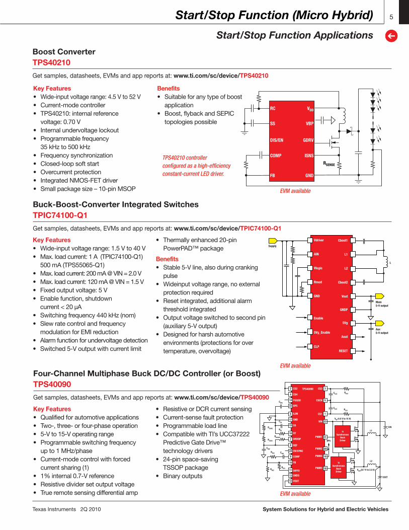
Boost ConverterTPS40210
Getsamples,datasheets,EVMsandappreportsat:www.ti.com/sc/device/TPS40210
Key Features• Wide-inputvoltagerange:4.5Vto52V• Current-modecontroller• TPS40210:internalreference voltage:0.70V• Internalundervoltagelockout• Programmablefrequency 35kHzto500kHz• Frequencysynchronization• Closed-loopsoftstart• Overcurrentprotection• IntegratedNMOS-FETdriver• Smallpackagesize–10-pinMSOP
Benefits• Suitableforanytypeofboost application• Boost,flybackandSEPIC topologiespossible
RC
SS
DIS/EN
COMP
FB
VDD
RSENSE
VBP
GDRV
ISNS
GND
5
➔
5
➔
TPS40210 controller configured as a high-efficiency constant-current LED driver.
EVM available
EVM available
EVM available
Supply
L
Main 5-V output
Aux 5-V output
Vdriver
AIN
Vlogic
Rmod
GND
Enable
5Vg_Enable
CLP
Cboot1
L1
L2
Cboot2
Vout
5Vg
GNDP
Aout
RESET
Start/Stop Function (Micro Hybrid)
Start/Stop Function Using the C2000™ DSP Piccolo™ MCU
6
➔
System Solutions for Hybrid and Electric Vehicles TexasInstruments2Q2010
6
➔
Battery Management, Power Conversion (DC/DC) and Charging (AC/DC)
Introduction to Battery Management
CSGain
1-phx44A
3A
2A
1A
CSGain
1-phx3
CSGain
1-phx2
CSGain
1-phx1
VOUTVIN
VIN-12 VV-BOOST
Piccolo
CANbus
+ + +
+
+
+
CPU
32-bitDSP
60 MHz
ADC
12-bit4.6 MSPS
LSDRV
PWM 1 (HR)
PWM 3 (HR)
PWM 4 (HR)
VREF
I2CSPI
UARTCAN
1A
2A
3A
4A
1-phs 11-phs 21-phs 31-phs 4
V-boostV-INTempSense
PWM 2 (HR)
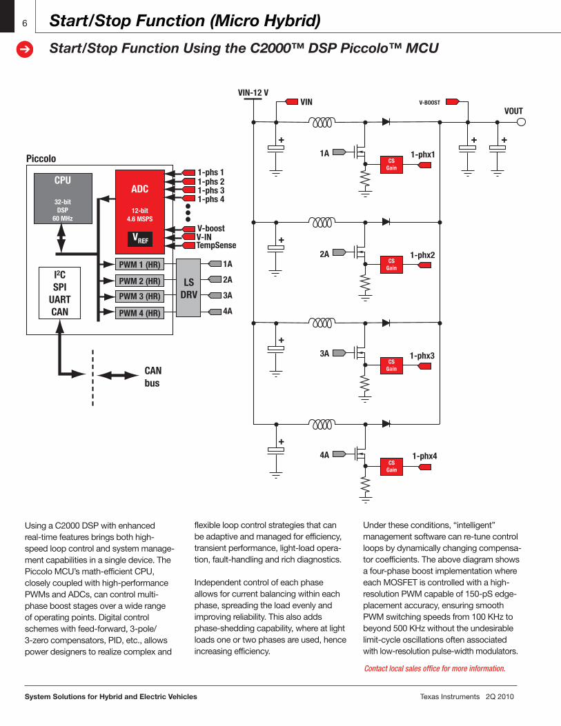
UsingaC2000DSPwithenhancedreal-timefeaturesbringsbothhigh-speedloopcontrolandsystemmanage-mentcapabilitiesinasingledevice.ThePiccoloMCU’smath-efficientCPU,closelycoupledwithhigh-performancePWMsandADCs,cancontrolmulti-phasebooststagesoverawiderangeofoperatingpoints.Digitalcontrolschemeswithfeed-forward,3-pole/3-zerocompensators,PID,etc.,allowspowerdesignerstorealizecomplexand
flexibleloopcontrolstrategiesthatcanbeadaptiveandmanagedforefficiency,transientperformance,light-loadopera-tion,fault-handlingandrichdiagnostics.Independentcontrolofeachphaseallowsforcurrentbalancingwithineachphase,spreadingtheloadevenlyandimprovingreliability.Thisalsoaddsphase-sheddingcapability,whereatlightloadsoneortwophasesareused,henceincreasingefficiency.
Undertheseconditions,“intelligent”managementsoftwarecanre-tunecontrolloopsbydynamicallychangingcompensa-torcoefficients.Theabovediagramshowsafour-phaseboostimplementationwhereeachMOSFETiscontrolledwithahigh-resolutionPWMcapableof150-pSedge-placementaccuracy,ensuringsmoothPWMswitchingspeedsfrom100KHztobeyond500KHzwithouttheundesirablelimit-cycleoscillationsoftenassociatedwithlow-resolutionpulse-widthmodulators.
Contact local sales office for more information.
TexasInstruments2Q2010 System Solutions for Hybrid and Electric Vehicles
Battery Management, Power Conversion (DC/DC) and Charging (AC/DC)
Introduction to Battery Management
7
➔
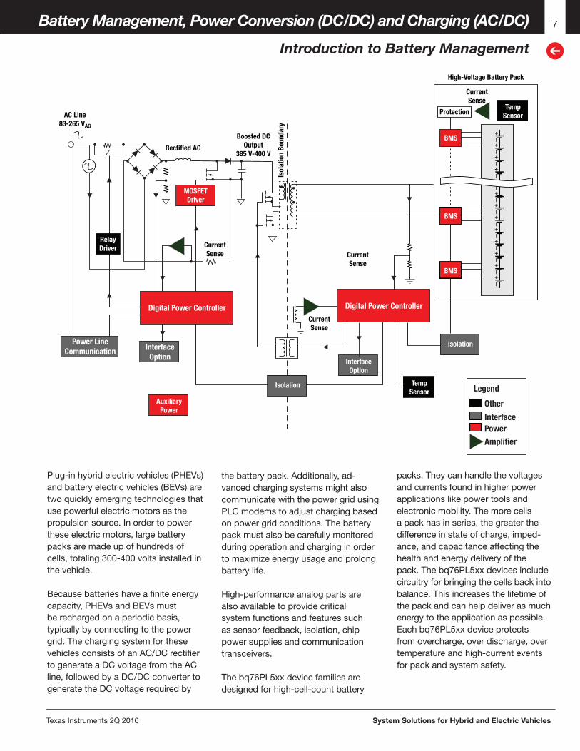
Plug-inhybridelectricvehicles(PHEVs)andbatteryelectricvehicles(BEVs)aretwoquicklyemergingtechnologiesthatusepowerfulelectricmotorsasthepropulsionsource.Inordertopowertheseelectricmotors,largebatterypacksaremadeupofhundredsofcells,totaling300-400voltsinstalledinthevehicle.
Becausebatterieshaveafiniteenergycapacity,PHEVsandBEVsmustberechargedonaperiodicbasis,typicallybyconnectingtothepowergrid.ThechargingsystemforthesevehiclesconsistsofanAC/DCrectifiertogenerateaDCvoltagefromtheACline,followedbyaDC/DCconvertertogeneratetheDCvoltagerequiredby
Isolation
TempSensor
TempSensor
InterfaceOption
InterfaceOption
Power LineCommunication
AuxiliaryPower
RelayDriver
Digital Power Controller
MOSFETDriver
Digital Power Controller
Isolation
BMS
Protection
CurrentSense
CurrentSense
CurrentSense
AC Line83-265 VAC
Rectified AC
Boosted DCOutput
385 V-400 V
Isol
atio
n Bo
unda
ry
CurrentSense
High-Voltage Battery Pack
BMS
BMS
+I+I+I+I+I+I+I+I+I+I+I+I+I
Legend
Other
InterfacePowerAmplifier
thebatterypack.Additionally,ad-vancedchargingsystemsmightalsocommunicatewiththepowergridusingPLCmodemstoadjustchargingbasedonpowergridconditions.Thebatterypackmustalsobecarefullymonitoredduringoperationandcharginginordertomaximizeenergyusageandprolongbatterylife.
High-performanceanalogpartsarealsoavailabletoprovidecriticalsystemfunctionsandfeaturessuchassensorfeedback,isolation,chippowersuppliesandcommunicationtransceivers.
Thebq76PL5xxdevicefamiliesaredesignedforhigh-cell-countbattery
packs.Theycanhandlethevoltagesandcurrentsfoundinhigherpowerapplicationslikepowertoolsandelectronicmobility.Themorecellsapackhasinseries,thegreaterthedifferenceinstateofcharge,imped-ance,andcapacitanceaffectingthehealthandenergydeliveryofthepack.Thebq76PL5xxdevicesincludecircuitryforbringingthecellsbackintobalance.Thisincreasesthelifetimeofthepackandcanhelpdeliverasmuchenergytotheapplicationaspossible.Eachbq76PL5xxdeviceprotectsfromovercharge,overdischarge,overtemperatureandhigh-currenteventsforpackandsystemsafety.
System Solutions for Hybrid and Electric Vehicles TexasInstruments2Q2010
Battery Management, Power Conversion (DC/DC) and Charging (AC/DC)
Battery Management System
8
➔
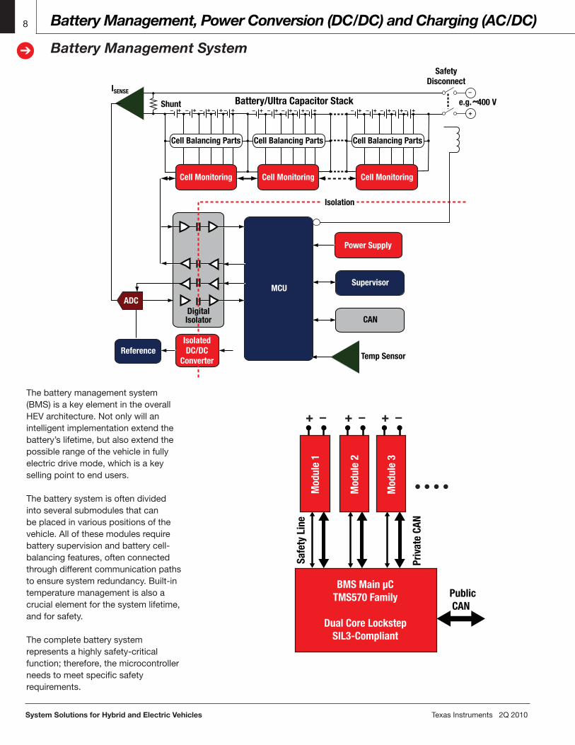
Thebatterymanagementsystem(BMS)isakeyelementintheoverallHEVarchitecture.Notonlywillanintelligentimplementationextendthebattery’slifetime,butalsoextendthepossiblerangeofthevehicleinfullyelectricdrivemode,whichisakeysellingpointtoendusers.Thebatterysystemisoftendividedintoseveralsubmodulesthatcanbeplacedinvariouspositionsofthevehicle.Allofthesemodulesrequirebatterysupervisionandbatterycell-balancingfeatures,oftenconnectedthroughdifferentcommunicationpathstoensuresystemredundancy.Built-intemperaturemanagementisalsoacrucialelementforthesystemlifetime,andforsafety.Thecompletebatterysystemrepresentsahighlysafety-criticalfunction;therefore,themicrocontrollerneedstomeetspecificsafetyrequirements.
Power Supply
MCUSupervisor
CAN
Temp SensorReference
ADC
Isolation
Shunt
ISENSE
+
–
Cell Balancing Parts
Cell Monitoring
– +– + – + – + – + – +– + – + – + – + – +– + – + – + – +
Cell Balancing Parts
Battery/Ultra Capacitor Stack
Cell Monitoring
Cell Balancing Parts
Safety Disconnect
e.g. ˜400 V
Cell Monitoring
Digital Isolator
IsolatedDC/DC
Converter
+ – + – + –
Mod
ule
1
Mod
ule
2
Mod
ule
3
BMS Main µCTMS570 Family
Dual Core LockstepSIL3-Compliant
Priv
ate
CAN
Public CAN
Safe
ty L
ine
Monitor
PassiveBalancing
bq76PL536
2nd Protector
Monitor
ActiveBalancing
bq76PL537
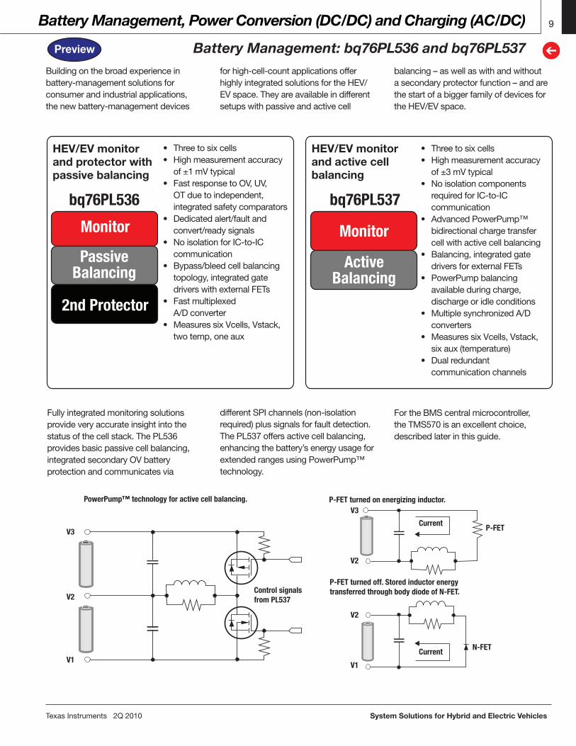
• Threetosixcells• Highmeasurementaccuracy of±3mVtypical• Noisolationcomponents requiredforIC-to-IC communication• AdvancedPowerPump™ bidirectionalchargetransfer cellwithactivecellbalancing• Balancing,integratedgate driversforexternalFETs• PowerPumpbalancing availableduringcharge, dischargeoridleconditions• MultiplesynchronizedA/D converters• MeasuressixVcells,Vstack, sixaux(temperature)• Dualredundant communicationchannels
TexasInstruments2Q2010 System Solutions for Hybrid and Electric Vehicles
Battery Management, Power Conversion (DC/DC) and Charging (AC/DC)
Battery Management: bq76PL536 and bq76PL537
9
➔➔
HEV/EV monitorand protector with passive balancing
HEV/EV monitor and active cell balancing
• Threetosixcells• Highmeasurementaccuracy of±1mVtypical• FastresponsetoOV,UV, OTduetoindependent, integratedsafetycomparators• Dedicatedalert/faultand convert/readysignals• NoisolationforIC-to-IC communication• Bypass/bleedcellbalancing topology,integratedgate driverswithexternalFETs• Fastmultiplexed A/Dconverter• MeasuressixVcells,Vstack, twotemp,oneaux
Fullyintegratedmonitoringsolutionsprovideveryaccurateinsightintothestatusofthecellstack.ThePL536providesbasicpassivecellbalancing,integratedsecondaryOVbatteryprotectionandcommunicatesvia
PowerPump™ technology for active cell balancing. P-FET turned on energizing inductor.
P-FET turned off. Stored inductor energy transferred through body diode of N-FET.Control signals
from PL537
Current
Current
P-FET
N-FET
V1V1
V2
V2
V2
V3
V3
Buildingonthebroadexperienceinbattery-managementsolutionsforconsumerandindustrialapplications,thenewbattery-managementdevices
forhigh-cell-countapplicationsofferhighlyintegratedsolutionsfortheHEV/EVspace.Theyareavailableindifferentsetupswithpassiveandactivecell
balancing–aswellaswithandwithoutasecondaryprotectorfunction–andarethestartofabiggerfamilyofdevicesfortheHEV/EVspace.
differentSPIchannels(non-isolationrequired)plussignalsforfaultdetection.ThePL537offersactivecellbalancing,enhancingthebattery’senergyusageforextendedrangesusingPowerPump™technology.
FortheBMScentralmicrocontroller,theTMS570isanexcellentchoice,describedlaterinthisguide.
Preview
Battery Managementbq76PL536
Getsamples,datasheets,EVMsandappreportsat:www.ti.com/sc/device/BQ76PL536
System Solutions for Hybrid and Electric Vehicles TexasInstruments2Q2010
Battery Management, Power Conversion (DC/DC) and Charging (AC/DC)
Battery Management: Applications
10
➔
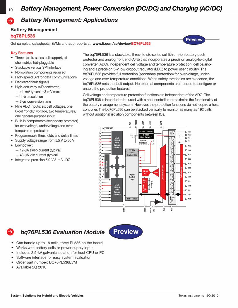
Key Features• Three-tosix-seriescellsupport,all chemistrieshot-pluggable• StackableverticalSPIinterface• Noisolationcomponentsrequired• High-speedSPIfordatacommunications• Dedicatedfaultsignals• High-accuracyA/Dconverter: —±1-mVtypical,±3-mVmax —14-bitresolution —3-µsconversiontime• NineADCinputs:sixcellvoltages,one 6-cell“brick,”voltage,twotemperatures, onegeneral-purposeinput• Built-incomparators(secondaryprotector) forovervoltage,undervoltageandover- temperatureprotection• Programmablethresholdsanddelaytimes• Supplyvoltagerangefrom5.5Vto30V• Lowpower: —12-µAsleepcurrent(typical) —48-µAidlecurrent(typical)• Integratedprecision5.0-V3-mALDO
Thebq76PL536isastackable,three-tosix-seriescelllithium-ionbatterypackprotectorandanalogfrontend(AFE)thatincorporatesaprecisionanalog-to-digitalconverter(ADC),independentcellvoltageandtemperatureprotection,cellbalanc-ingandaprecision5-Vlowdropoutregulator(LDO)topowerusercircuitry.Thebq76PL536providesfullprotection(secondaryprotection)forovervoltage,under-voltageandover-temperatureconditions.Whensafetythresholdsareexceeded,thebq76PL536setsthefaultoutput.Noexternalcomponentsareneededtoconfigureorenabletheprotectionfeatures.
CellvoltageandtemperatureprotectionfunctionsareindependentoftheADC.Thebq76PL536isintendedtobeusedwithahostcontrollertomaximizethefunctionalityofthebatterymanagementsystem.However,theprotectionfunctionsdonotrequireahostcontroller.Thebq76PL536canbestackedverticallytomonitorasmanyas192cellswithoutadditionalisolationcomponentsbetweenICs.
Start/Stop Function (Micro Hybrid)
bq76PL536 Evaluation Module➔
• Canhandleupto18cells,threePL536ontheboard• Workswithbatterycellsorpowersupplyinput• Includes2.5-kVgalvanicisolationforhostCPUorPC• Softwareinterfaceforeasysystemevaluation• Orderpartnumber:BQ76PL536EVM• Available2Q2010
TS2+
TS2–
TS1+
TS1–
VC6
AUX
GPIO
REG5
0
LDOA
LDOD
VBAT
VREF
GPAI
+
GPAI
–
VSS
VSS
CB6
VC5
CB5
VC4
CB4
VC3
CB3
VC2
CB2
VC1
CB1
VC0
OT1
OT2
UV
OV
OV
OV
OV
OV
OV
UV
UV
UV
UV
UV
EEPROM
REF2
ThermalShutdown
bq76PL536LDO-A LDO-D
5-V LDO(User Circuitry)
14-BitADCDigital
ControlLogic
OSC WDT
Level-ShiftedNorth
CommsInterface
Level-ShiftedSouth
CommsInterface
Host
Inte
rfac
e
Shadow RAM
VREF2.5 V
AMP
+–
Cell
Bala
ncin
g
Leve
l Shi
ft an
d M
UX
Ultr
a-Pr
ecis
ion
Band
gap
Preview
Preview
TexasInstruments2Q2010 System Solutions for Hybrid and Electric Vehicles
Battery Management, Power Conversion (DC/DC) and Charging (AC/DC)
Introduction to DC/DC Converter Module
11
➔
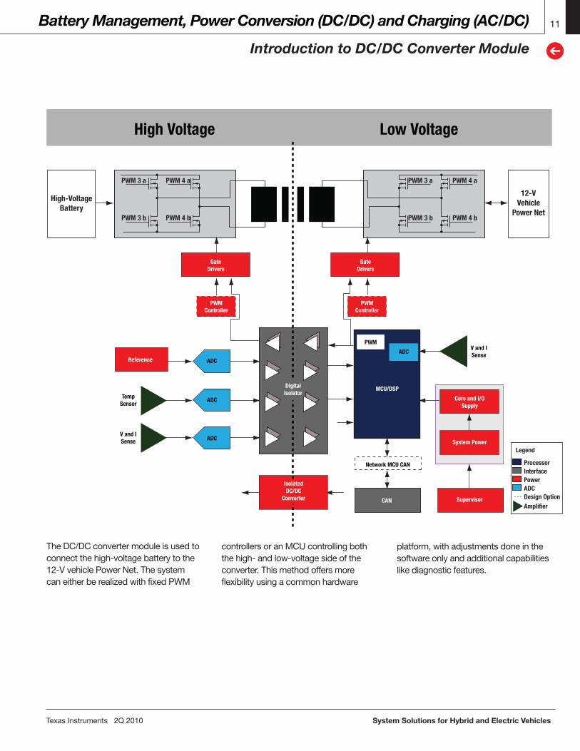
TheDC/DCconvertermoduleisusedtoconnectthehigh-voltagebatterytothe12-VvehiclePowerNet.ThesystemcaneitherberealizedwithfixedPWM
Core and I/OSupply
PWMController
PWMController
GateDrivers
GateDrivers
V and ISense
V and ISense
TempSensor
System Power
IsolatedDC/DC
Converter
DigitalIsolator
Supervisor
Reference
CAN
MCU/DSP
PWM
Network MCU CAN
ADC
Legend
InterfaceProcessor
Power
Amplifier
ADCDesign Option
ADC
ADC
ADC
High Voltage Low Voltage
PWM 3 a
PWM 3 b
PWM 4 a
PWM 4 b
PWM 3 a
PWM 3 b
PWM 4 a
PWM 4 b
High-Voltage Battery
12-VVehicle
Power Net
controllersoranMCUcontrollingboththehigh-andlow-voltagesideoftheconverter.Thismethodoffersmoreflexibilityusingacommonhardware
platform,withadjustmentsdoneinthesoftwareonlyandadditionalcapabilitieslikediagnosticfeatures.
System Solutions for Hybrid and Electric Vehicles TexasInstruments2Q2010
Battery Management, Power Conversion (DC/DC) and Charging (AC/DC)
DC/DC Converter: Applications
12
➔
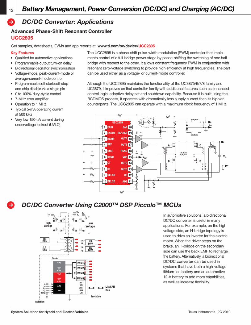
Advanced Phase-Shift Resonant ControllerUCC2895
Getsamples,datasheets,EVMsandappreportsat:www.ti.com/sc/device/UCC2895
DC/DC Converter Using C2000™ DSP Piccolo™ MCUs➔
Key Features• Qualifiedforautomotiveapplications• Programmableoutputturn-ondelay• Bidirectionaloscillatorsynchronization• Voltage-mode,peak-current-modeor average-current-modecontrol• Programmablesoftstart/softstop andchipdisableviaasinglepin• 0to100%duty-cyclecontrol• 7-MHzerroramplifier• Operationto1MHz• Typical5-mAoperatingcurrent at500kHz• Verylow150-µAcurrentduring undervoltagelockout(UVLO)
TheUCC2895isaphase-shiftpulse-widthmodulation(PWM)controllerthatimple-mentscontrolofafull-bridgepowerstagebyphase-shiftingtheswitchingofonehalf-bridgewithrespecttotheother.ItallowsconstantfrequencyPWMinconjunctionwithresonantzero-voltageswitchingtoprovidehighefficiencyathighfrequencies.Thepartcanbeusedeitherasavoltage-orcurrent-modecontroller.
AlthoughtheUCC2895maintainsthefunctionalityoftheUC3875/6/7/8familyandUC3879,itimprovesonthatcontrollerfamilywithadditionalfeaturessuchasenhancedcontrollogic,adaptivedelaysetandshutdowncapability.BecauseitisbuiltusingtheBCDMOSprocess,itoperateswithdramaticallylesssupplycurrentthanitsbipolarcounterparts.TheUCC2895canoperatewithamaximumclockfrequencyof1MHz.
Inautomotivesolutions,abidirectionalDC/DCconverterisusefulinmanyapplications.Forexample,onthehighvoltageside,anH-bridgetopologyisusedtodriveaninverterfortheelectricmotor.Whenthedriverstepsonthebrake,anH-bridgeonthesecondarysidecanusethebackEMFtorechargethebattery.Alternatively,abidirectionalDC/DCconvertercanbeusedinsystemsthathavebothahigh-voltagelithium-ionbatteryandanautomotive12-Vbatterytoaddmorecapabilities,aswellasincreaseflexibility.
Piccolo
ILV
IHVILV
VHV
VLV
CT4A
4B
3A
3B
2A
2B
1A
1B
CT
3A4A
3B
4B
IHV
VHV
VLV
Temp
CPU
32-bitDSP
60 MHz
CLA
32-bitFPU
60 MHz
ADC
12 bit
I2CSPI
UARTCANLIN
PWM1
LIN/CANBus
AB
PWM2 AB
PWM3 AB
PWM4 AB
HSDRVLS
DRV
HSDRV
HighVoltage
Isolation
Isolation
LowVoltage
LSDRV
20EAP
SS/DISB
OUTA
PGND
OUTB
VCC
OUTC
OUTD
CS
ADS
EAIN
EAOUT
RAMP
REF
GND
SYNC
CT
RT
DELAB
DELCD
UCC2895
B
A
VIN1
VINVOUT
Q1
D
C
19
18
17
16
15
14
13
12
11
1
3
4
7
8
10
2
5
6
9
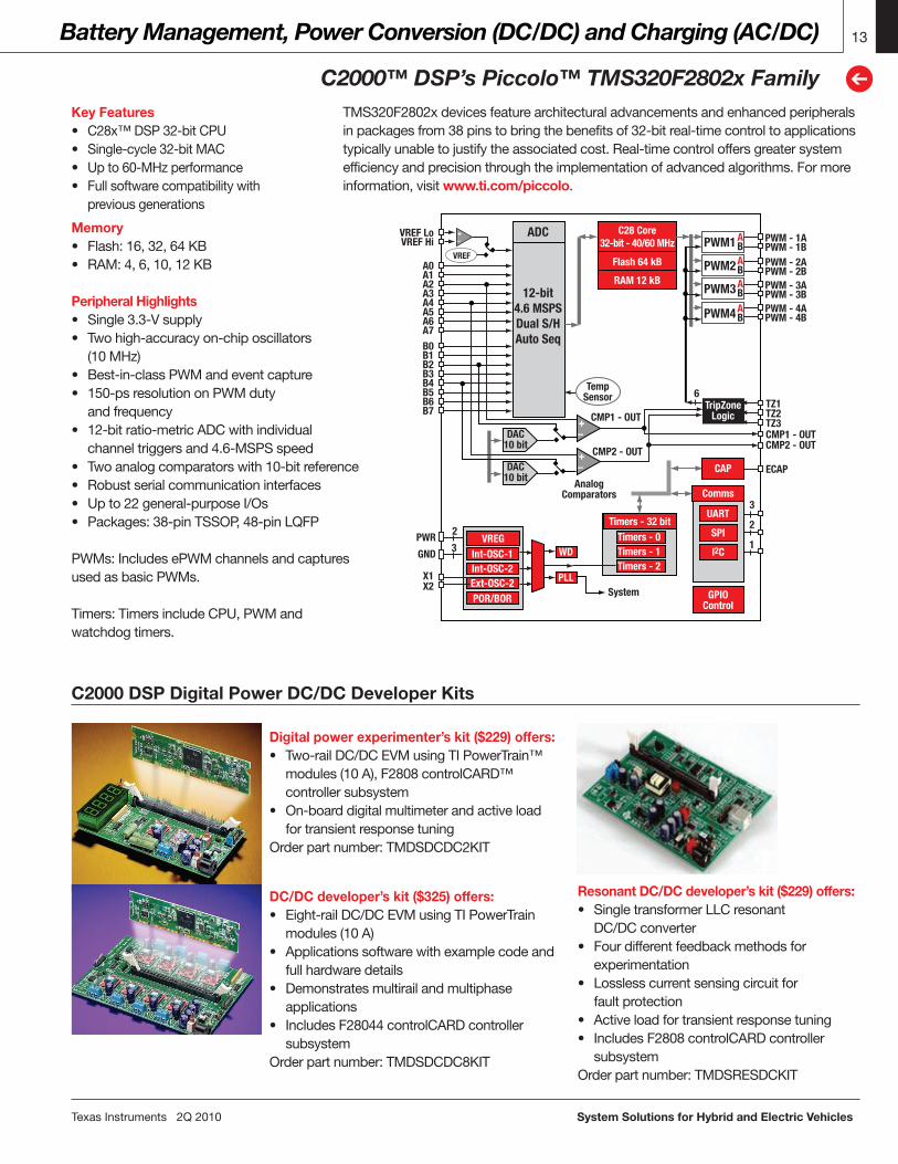
Key Features• C28x™DSP32-bitCPU• Single-cycle32-bitMAC• Upto60-MHzperformance• Fullsoftwarecompatibilitywith previousgenerations
Memory• Flash:16,32,64KB• RAM:4,6,10,12KB
Peripheral Highlights• Single3.3-Vsupply• Twohigh-accuracyon-chiposcillators (10MHz)• Best-in-classPWMandeventcapture• 150-psresolutiononPWMduty andfrequency• 12-bitratio-metricADCwithindividual channeltriggersand4.6-MSPSspeed• Twoanalogcomparatorswith10-bitreference• Robustserialcommunicationinterfaces• Upto22general-purposeI/Os• Packages:38-pinTSSOP,48-pinLQFP
PWMs:IncludesePWMchannelsandcapturesusedasbasicPWMs.
Timers:TimersincludeCPU,PWMandwatchdogtimers.
Digital power experimenter’s kit ($229) offers:• Two-railDC/DCEVMusingTIPowerTrain™ modules(10A),F2808controlCARD™ controllersubsystem• On-boarddigitalmultimeterandactiveload fortransientresponsetuningOrderpartnumber:TMDSDCDC2KIT
DC/DC developer’s kit ($325) offers:• Eight-railDC/DCEVMusingTIPowerTrain modules(10A)• Applicationssoftwarewithexamplecodeand fullhardwaredetails• Demonstratesmultirailandmultiphase applications• IncludesF28044controlCARDcontroller subsystemOrderpartnumber:TMDSDCDC8KIT
Resonant DC/DC developer’s kit ($229) offers:• SingletransformerLLCresonant DC/DCconverter• Fourdifferentfeedbackmethodsfor experimentation• Losslesscurrentsensingcircuitfor faultprotection• Activeloadfortransientresponsetuning• IncludesF2808controlCARDcontroller subsystemOrderpartnumber:TMDSRESDCKIT
TexasInstruments2Q2010 System Solutions for Hybrid and Electric Vehicles
Battery Management, Power Conversion (DC/DC) and Charging (AC/DC)
C2000™ DSP’s Piccolo™ TMS320F2802x Family
13
➔
TMS320F2802xdevicesfeaturearchitecturaladvancementsandenhancedperipheralsinpackagesfrom38pinstobringthebenefitsof32-bitreal-timecontroltoapplicationstypicallyunabletojustifytheassociatedcost.Real-timecontroloffersgreatersystemefficiencyandprecisionthroughtheimplementationofadvancedalgorithms.Formoreinformation,visitwww.ti.com/piccolo.
C2000 DSP Digital Power DC/DC Developer Kits
PWM1 PWM - 1A
TZ1
A0
AB
PWM2 AB
PWM3 AB
PWM4
12-bit4.6 MSPSDual S/HAuto Seq
C28 Core32-bit - 40/60 MHz
TempSensor
Flash 64 kB
RAM 12 kB
ADC
AB
TZ2TZ3CMP1 - OUTCMP2 - OUT
CMP1 - OUT
System
CMP2 - OUT
AnalogComparators
ECAP
A1
VREF LoVREF Hi
A2A3A4A5A6A7B0B1B2B3B4B5B6B7
X1X2
PWM - 1BPWM - 2APWM - 2BPWM - 3APWM - 3BPWM - 4APWM - 4B
3
2
1
TripZoneLogic
CAP
WD
PLL
GPIOControl
Comms
3
2
6
UART
SPI
I2C
+–
+–
+–
Timers - 32 bitTimers - 0Timers - 1Timers - 2
VREGInt-OSC-1Int-OSC-2Ext-OSC-2POR/BOR
VREF
DAC10 bit
DAC10 bit
PWR
GND
System Solutions for Hybrid and Electric Vehicles TexasInstruments2Q2010
Battery Management, Power Conversion (DC/DC) and Charging (AC/DC)
On-Board Charger – AC/DC with PFC
14
➔
AC/DC Developer’s Kit with TMS320F280x➔
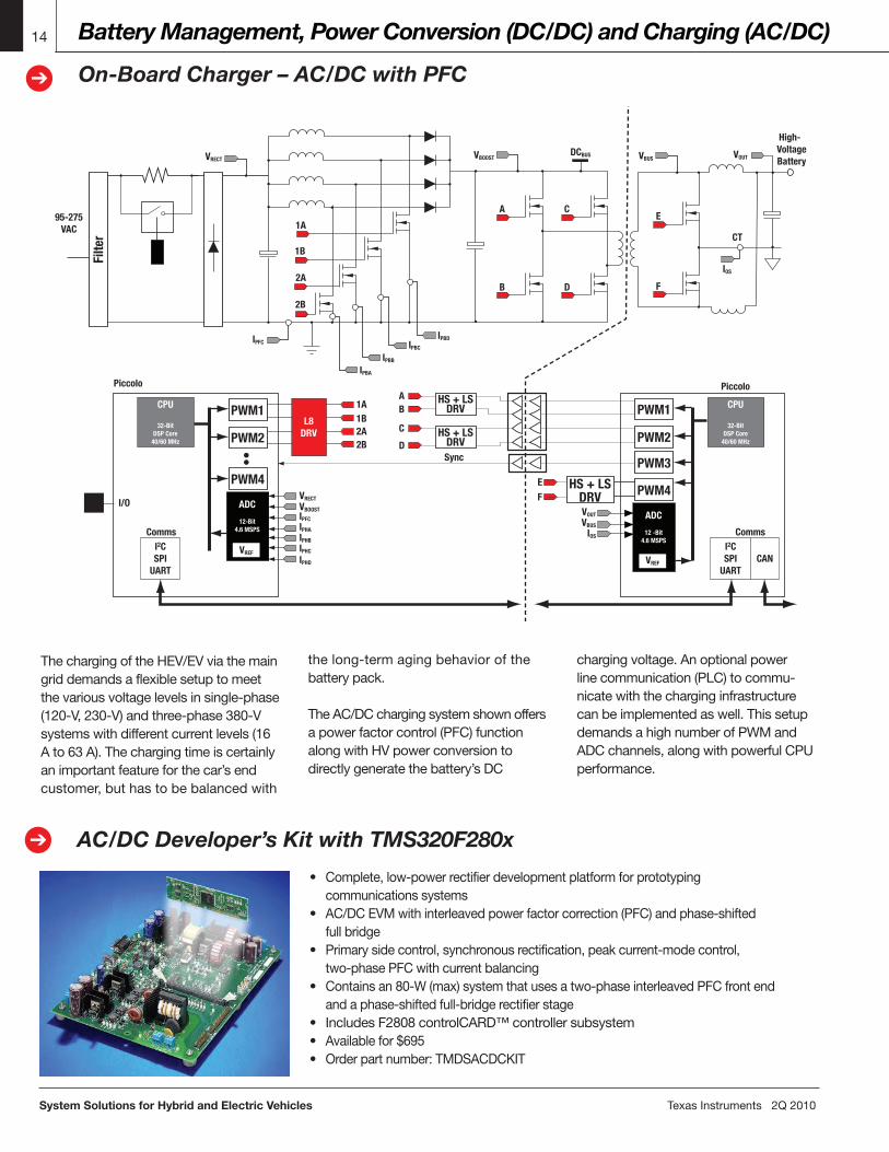
ThechargingoftheHEV/EVviathemaingriddemandsaflexiblesetuptomeetthevariousvoltagelevelsinsingle-phase(120-V,230-V)andthree-phase380-Vsystemswithdifferentcurrentlevels(16Ato63A).Thechargingtimeiscertainlyanimportantfeatureforthecar’sendcustomer,buthastobebalancedwith
thelong-termagingbehaviorofthebatterypack.
TheAC/DCchargingsystemshownoffersapowerfactorcontrol(PFC)functionalongwithHVpowerconversiontodirectlygeneratethebattery’sDC
chargingvoltage.Anoptionalpowerlinecommunication(PLC)tocommu-nicatewiththecharginginfrastructurecanbeimplementedaswell.ThissetupdemandsahighnumberofPWMandADCchannels,alongwithpowerfulCPUperformance.
Piccolo
High-Voltage Battery
CT
Sync
A1A1B2A2B
B
C
D
Piccolo
VOUT
VBUS
IOS
CPU
32-BitDSP Core
40/60 MHz
ADC
12 -Bit4.6 MSPS
I2CSPI
UARTCAN
Comms
CPU
32-BitDSP Core
40/60 MHz
I2CSPI
UART
Comms
I/OIPFC
VBOOST
VRECT
IOS
VOUTVBUSDCBUS
E
F
IPHA
IPHB
IPHC
IPHD
EF
HS + LSDRV
HS + LSDRV
VREF
HS + LSDRV
PWM1
PWM2
PWM3
PWM4ADC
12-Bit4.6 MSPS
PWM1
PWM2
PWM4
VREF
L8DRV
C
D
1A
1B
2A
2B
A
B
VRECT VBOOST
95-275 VAC
IPFC
IPBA
IPBB
IPBC
IPBD
Filte
r
• Complete,low-powerrectifierdevelopmentplatformforprototyping communicationssystems• AC/DCEVMwithinterleavedpowerfactorcorrection(PFC)andphase-shifted fullbridge• Primarysidecontrol,synchronousrectification,peakcurrent-modecontrol, two-phasePFCwithcurrentbalancing• Containsan80-W(max)systemthatusesatwo-phaseinterleavedPFCfrontend andaphase-shiftedfull-bridgerectifierstage• IncludesF2808controlCARD™controllersubsystem• Availablefor$695• Orderpartnumber:TMDSACDCKIT

Key Features• Upto128-KBflash,20-KBRAM• AllnewCLA:independent,floating- pointprocessingunitwithdirectaccess toADCandPWMsenablesparallel controlloopexecution• AdditionalthreeePWMmodules (sixPWMoutputs)• Quadratureencoderinterface(eQEP)• Threeon-chipcomparators
• Addedcommunication ports–CAN2.0Bwith upto16mailboxes,LIN/ UARTandadditionalSPI• Packages:64-pinTQFP, 80-pinLQFP
TexasInstruments2Q2010 System Solutions for Hybrid and Electric Vehicles
Battery Management, Power Conversion (DC/DC) and Charging (AC/DC)
AC/DC Applications
15
➔
Piccolo MCU family overview
Start/Stop Function (Micro Hybrid)
Why Piccolo™ MCUs?ThePiccoloF2802x/F2803xfamilyofC2000™MCUsprovidesalow-cost,high-integrationsolutiontohelpdriveprocessor-intensivereal-timecontrolintocost-sensitiveapplications.Withahostofindustry-leadingintegratedmodules,
suchasapowerfulADC,dedicatedhigh-resolutionPWMsandtheuniquecontrollawaccelerator(CLA),PiccoloMCUsareidealforpowerconversioninelectricvehicles.Formorecomplexsystems,likethosewithintegratedpower
Piccolo MCUsF2802x vs. F2803xTMS320F2803xincludesthesameC28x™DSPcore,enhancedhigh-resolutionPWMtechnologyandhigh-speedADC,butcombinesmorefeaturesandadditionalmemory.Getsamples,datasheets,EVMsandappreportsat:www.ti.com/piccolo.
PWM1 PWM - 1A
TZ1
A0
AB
PWM2 AB
PWM3 AB
PWM4
12-bit4.6 MSPSDual S/HAuto Seq
C28 Core32 bit - 60 MHz
TempSensor
Flash 128 KB
RAM 14 KB
-
RAM 6 KB(Dual Access)
CLA Core60-MHz F1tPt(Accelerator)
ADC
AB
TZ2TZ3CMP1 - OUTCMP2 - OUT
CMP1 - OUT
System
CMP2 - OUT
AnalogComparators
QEP
CMP3 - OUT
A1
VREF LoVREF Hi
A2A3A4A5A6A7B0B1B2B3B4B5B6B7
X1X2
PWR
GND
PWM - 1BPWM - 2APWM - 2BPWM - 3APWM - 3BPWM - 4APWM - 4B
4
6
2
ECAP
PWM5 AB
PWM6 AB
PWM7 AB
PWM - 2APWM - 2BPWM - 3APWM - 3BPWM - 4APWM - 4B
TripZoneLogic
QEP
CAP
WD
PLLGPIO
Control
Comms
4
5
4
6
CMP3 - OUT
UART x2
SPI x2
I2C2
CAN
Ch 1
1A1B
2A2B
3A3B
Ch 2
Ch 16
Piccolo
CLA60-MHz F1tPtAccelerator
ADC12-Bit
4-6 MSPS
C2832-Bit Core
60 MHz
PWM1
PWM2
PWM3+–
+–
+–
Timers - 32-bitTimers - 0Timers - 1Timers - 2
VREGInt-OSC-1Int-OSC-2Ext-OSC-2POR/BOR
VREF
DAC10 bit
DAC10 bit
–DAC10 bit
Benefit Enabling Feature
Improved system efficiency/accuracy • High-performance C28xTM DSP core supports adaptive control algorithms for efficiency across load curve• High-resolution 150-ps PWM modules and high-speed on-chip ADC
Added functions/features • Communication with outside systems: CAN, LIN, I2C, UART, SPI• Multiple PWMs allow multiple DC output rails
Better R&D efficiency • Software control adaptable to multiple topologies and power ratingsIncreased reliability • Digital control can adapt to environmental conditions and be recalibrated in software
• Software can implement failure prediction
linecommunication,severaladditionalfamilymembersoftheC2000familyareavailable,offeringfloating-pointperformanceupto300MHzandhigh-performanceperipheralslikea12.5-MSPS12-bitADC.Formoreinformation,visit www.ti.com/c2000.
DeviceSpeed (MHz) DMA CLA
RAM (KB)
Flash (KB)
ROM (KB)
PWM
ChannelsHiRes PWM
Quadrature Encoder
Event Captures Timers*
12-Bit ADC Channels/ Conversion Time (ns) McBSP I2C
UART/SCI SPI Lin CAN
External Memory
Bus (Bit)
Core Supply (Volts)
GPIO Pins
On-Chip Oscillator/Regulator Package
Piccolo™ MCUsTMS320F28022DAQ 50 — — 12 32 Boot 9 4 — 1 9 7/ 325 — 1 1 1 — — — 3.3 20 Yes / Yes 38TSSOPTMS320F28022PTQ 50 — — 12 32 Boot 9 4 — 1 9 13/ 325 — 1 1 1 — — — 3.3 22 Yes / Yes 48LQFP
TMS320F28023DAQ 50 — — 12 64 Boot 9 4 — 1 9 7/ 325 — 1 1 1 — — — 3.3 20 Yes / Yes 38TSSOPTMS320F28023PTQ 50 — — 12 64 Boot 9 4 — 1 9 13/ 325 — 1 1 1 — — — 3.3 22 Yes / Yes 48LQFPTMS320F28026DAQ 60 — — 12 32 Boot 9 4 — 1 9 7/ 217 — 1 1 1 — — — 3.3 20 Yes / Yes 38TSSOPTMS320F28026PTQ 60 — — 12 32 Boot 9 4 — 1 9 13/ 217 — 1 1 1 — — — 3.3 22 Yes / Yes 48LQFPTMS320F28027DAQ 60 — — 12 64 Boot 9 4 — 1 9 7/ 217 — 1 1 1 — — — 3.3 20 Yes / Yes 38TSSOPTMS320F28027PTQ 60 — — 12 64 Boot 9 4 — 1 9 13/ 217 — 1 1 1 — — — 3.3 22 Yes / Yes 48LQFPTMS320F28030PAGQ 60 — — 12 32 Boot 13 — 1 1 11 14/ 500 — 1 1 1 1 1 — 3.3 33 Yes / Yes 64TQFPTMS320F28030PNQ 60 — — 12 32 Boot 15 — 1 1 12 16/ 500 — 1 1 2 1 1 — 3.3 45 Yes / Yes 80LQFPTMS320F28031PAGQ 60 — — 16 64 Boot 13 — 1 1 11 14/ 500 — 1 1 1 1 1 — 3.3 33 Yes / Yes 64TQFPTMS320F28031PNQ 60 — — 16 64 Boot 15 — 1 1 12 16/ 500 — 1 1 2 1 1 — 3.3 45 Yes / Yes 80LQFPTMS320F28032PAGQ 60 — — 20 64 Boot 13 6 1 1 11 14/ 217 — 1 1 1 1 1 — 3.3 33 Yes / Yes 64TQFPTMS320F28032PNQ 60 — — 20 64 Boot 15 7 1 1 12 16/ 217 — 1 1 2 1 1 — 3.3 45 Yes / Yes 80LQFPTMS320F28034PAGQ 60 — — 20 128 Boot 13 6 1 1 11 14/ 217 — 1 1 1 1 1 — 3.3 33 Yes / Yes 64TQFPTMS320F28034PNQ 60 — — 20 128 Boot 15 7 1 1 12 16/ 217 — 1 1 2 1 1 — 3.3 45 Yes / Yes 80LQFPTMS320F28033PAGQ 60 — Yes 20 64 Boot 13 6 1 1 11 14/ 217 — 1 1 1 1 1 — 3.3 33 Yes / Yes 64TQFPTMS320F28033PNQ 60 — Yes 20 64 Boot 15 7 1 1 12 16/ 217 — 1 1 2 1 1 — 3.3 45 Yes / Yes 80LQFPTMS320F28035PAGQ 60 — Yes 20 128 Boot 13 6 1 1 11 14/ 217 — 1 1 1 1 1 — 3.3 33 Yes / Yes 64TQFPTMS320F28035PNQ 60 — Yes 20 128 Boot 15 7 1 1 12 16/ 217 — 1 1 2 1 1 — 3.3 45 Yes / Yes 80LQFP
System Solutions for Hybrid and Electric Vehicles TexasInstruments2Q2010
Battery Management, Power Conversion (DC/DC) and Charging (AC/DC)
Two-Phase Interleaved Constant Current Mode (CCM) Power Factor Correction (PFC) Controller
16
➔
20DMAX
RT
SS
GND
GDB
VCC
GDA
VREF
CAOA
CAOB
CDRCCDR
12 V to 21 V
To CSB
To CSA
RRDM
RDMX
RRT
CSS
From Ixfirms
RIMO
CZV
CPV
RZV
RPK1 CREF
CPC CPC
CZC CZC
VOUT
RA
RB
RS
RS
COUT
D1
T1
T2
M2
M1
D2
L1
L2
RPK2 RZC RZC
RSYNRB
RA
RDM
VAO
VSENSE
VINAC
IMO
RSYNTH
CSB
CSA
PKLMT
UCC28070
19
18
17
16
15
14
13
12
11
1
3
4
7
8
10
2
5
6
9
+
–
UCC28070
Getsamples,datasheets,EVMsandappreportsat:www.ti.com/sc/device/UCC28070
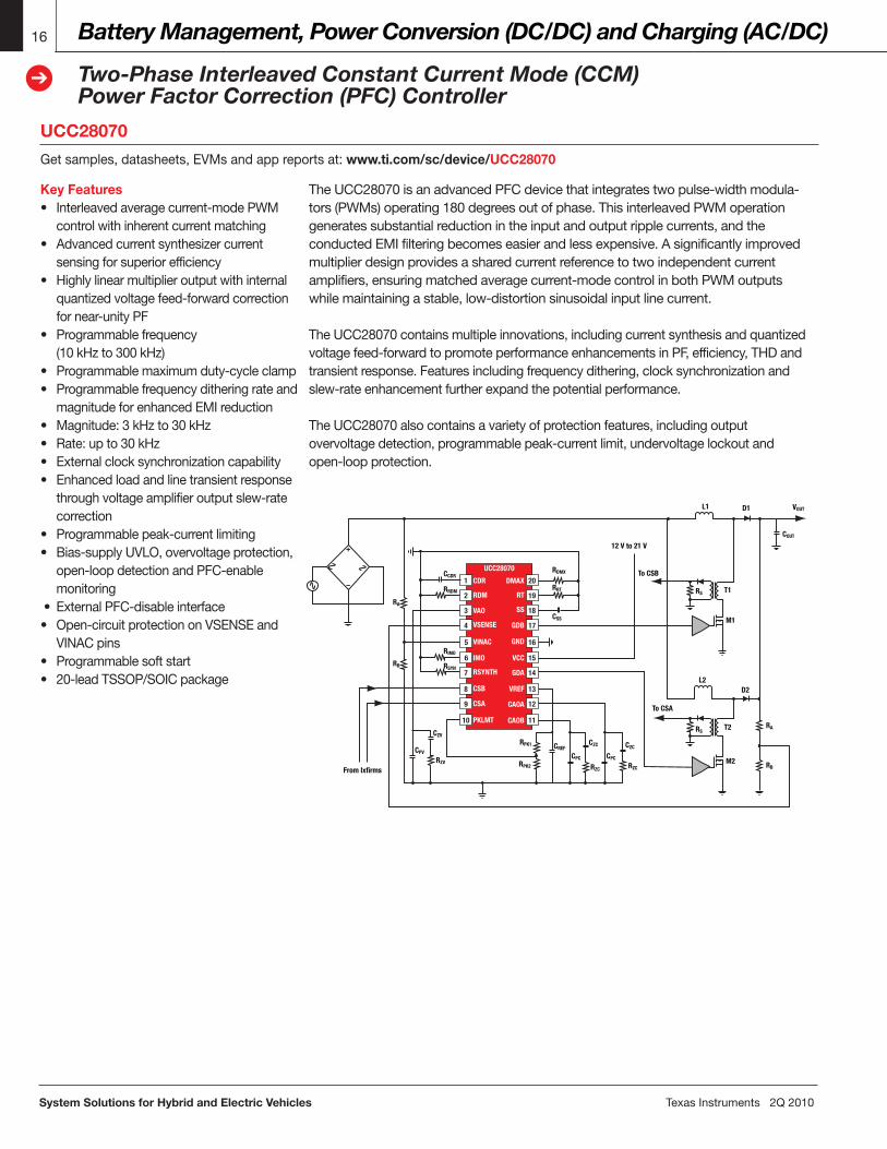
TheUCC28070isanadvancedPFCdevicethatintegratestwopulse-widthmodula-tors(PWMs)operating180degreesoutofphase.ThisinterleavedPWMoperationgeneratessubstantialreductionintheinputandoutputripplecurrents,andtheconductedEMIfilteringbecomeseasierandlessexpensive.Asignificantlyimprovedmultiplierdesignprovidesasharedcurrentreferencetotwoindependentcurrentamplifiers,ensuringmatchedaveragecurrent-modecontrolinbothPWMoutputswhilemaintainingastable,low-distortionsinusoidalinputlinecurrent.
TheUCC28070containsmultipleinnovations,includingcurrentsynthesisandquantizedvoltagefeed-forwardtopromoteperformanceenhancementsinPF,efficiency,THDandtransientresponse.Featuresincludingfrequencydithering,clocksynchronizationandslew-rateenhancementfurtherexpandthepotentialperformance.
TheUCC28070alsocontainsavarietyofprotectionfeatures,includingoutputovervoltagedetection,programmablepeak-currentlimit,undervoltagelockoutandopen-loopprotection.
Key Features• Interleavedaveragecurrent-modePWM controlwithinherentcurrentmatching• Advancedcurrentsynthesizercurrent sensingforsuperiorefficiency• Highlylinearmultiplieroutputwithinternal quantizedvoltagefeed-forwardcorrection fornear-unityPF• Programmablefrequency (10kHzto300kHz)• Programmablemaximumduty-cycleclamp• Programmablefrequencyditheringrateand magnitudeforenhancedEMIreduction• Magnitude:3kHzto30kHz• Rate:upto30kHz• Externalclocksynchronizationcapability• Enhancedloadandlinetransientresponse throughvoltageamplifieroutputslew-rate correction• Programmablepeak-currentlimiting• Bias-supplyUVLO,overvoltageprotection, open-loopdetectionandPFC-enable monitoring• ExternalPFC-disableinterface• Open-circuitprotectiononVSENSEand VINACpins• Programmablesoftstart• 20-leadTSSOP/SOICpackage
TexasInstruments2Q2010 System Solutions for Hybrid and Electric Vehicles
Motor Control
Introduction to DC/AC for Inverter Motor Control
17
➔
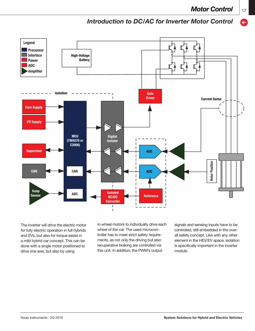
TheinverterwilldrivetheelectricmotorforfullyelectricoperationinfullhybridsandEVs,butalsofortorqueassistinamildhybridcarconcept.Thiscanbedonewithasinglemotorpositionedtodriveoneaxis,butalsobyusing
in-wheelmotorstoindividuallydriveeachwheelofthecar.Theusedmicrocon-trollerhastomeetstrictsafetyrequire-ments,asnotonlythedrivingbutalsorecuperativebrakingarecontrolledviathisunit.Inaddition,thePWM’soutput
signalsandsensinginputshavetobecontrolled,stillembeddedintheover-allsafetyconcept.LikewithanyotherelementintheHEV/EVspace,isolationisspecificallyimportantintheinvertermodule.
Legend
InterfaceProcessor
Power
AmplifierADC
ADC
Current Sense
ADC
DigitalIsolator
MCU(TMS570 or
C2000)
CAN
ADC IsolatedDC/DC
Converter
GateDriver
Core Supply
I/O Supply
CAN
Supervisor
Reference
Isolation
TempSensor
High-VoltageBattery
Roto
r Pos
ition
System Solutions for Hybrid and Electric Vehicles TexasInstruments2Q2010
Motor Control18
➔
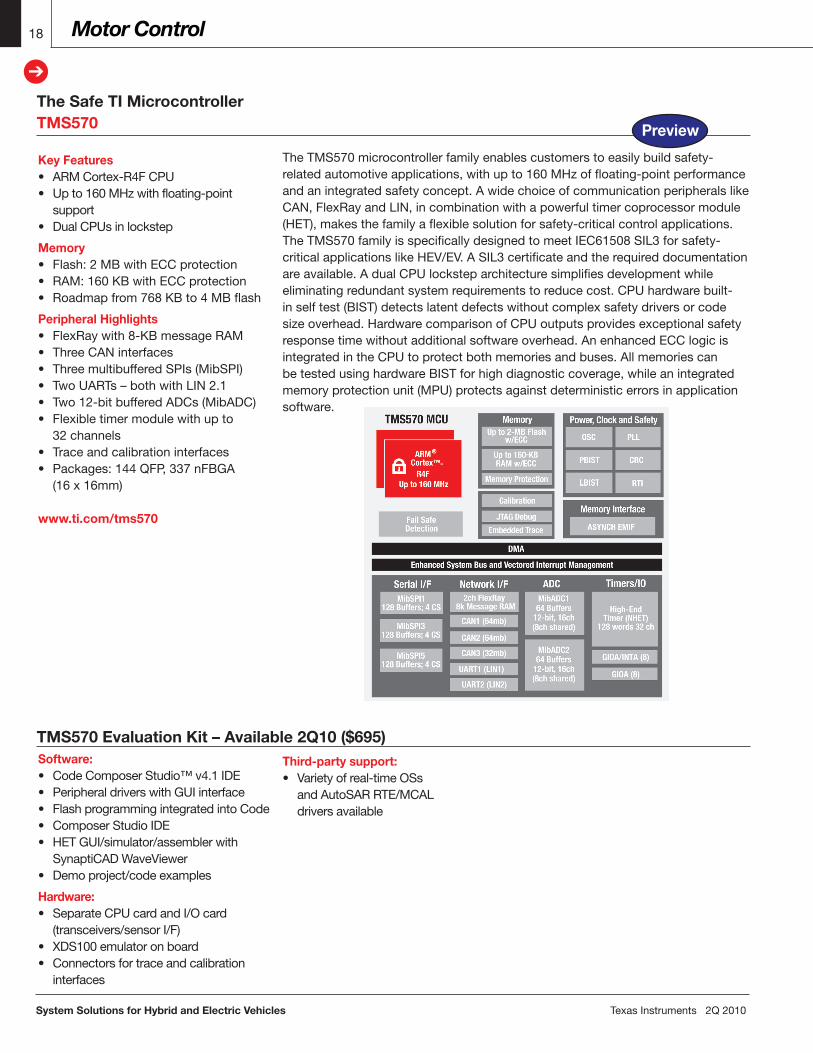
TheTMS570microcontrollerfamilyenablescustomerstoeasilybuildsafety-relatedautomotiveapplications,withupto160MHzoffloating-pointperformanceandanintegratedsafetyconcept.AwidechoiceofcommunicationperipheralslikeCAN,FlexRayandLIN,incombinationwithapowerfultimercoprocessormodule(HET),makesthefamilyaflexiblesolutionforsafety-criticalcontrolapplications.TheTMS570familyisspecificallydesignedtomeetIEC61508SIL3forsafety-criticalapplicationslikeHEV/EV.ASIL3certificateandtherequireddocumentationareavailable.AdualCPUlocksteparchitecturesimplifiesdevelopmentwhileeliminatingredundantsystemrequirementstoreducecost.CPUhardwarebuilt-inselftest(BIST)detectslatentdefectswithoutcomplexsafetydriversorcodesizeoverhead.HardwarecomparisonofCPUoutputsprovidesexceptionalsafetyresponsetimewithoutadditionalsoftwareoverhead.AnenhancedECClogicisintegratedintheCPUtoprotectbothmemoriesandbuses.AllmemoriescanbetestedusinghardwareBISTforhighdiagnosticcoverage,whileanintegratedmemoryprotectionunit(MPU)protectsagainstdeterministicerrorsinapplicationsoftware.
The Safe TI MicrocontrollerTMS570
Key Features• ARMCortex-R4FCPU• Upto160MHzwithfloating-point support• DualCPUsinlockstep
Memory• Flash:2MBwithECCprotection• RAM:160KBwithECCprotection• Roadmapfrom768KBto4MBflash
Peripheral Highlights• FlexRaywith8-KBmessageRAM• ThreeCANinterfaces• ThreemultibufferedSPIs(MibSPI)• TwoUARTs–bothwithLIN2.1• Two12-bitbufferedADCs(MibADC)• Flexibletimermodulewithupto 32channels• Traceandcalibrationinterfaces• Packages:144QFP,337nFBGA (16x16mm)
www.ti.com/tms570
TMS570 Evaluation Kit – Available 2Q10 ($695)Software:• CodeComposerStudio™v4.1IDE• PeripheraldriverswithGUIinterface• FlashprogrammingintegratedintoCode• ComposerStudioIDE• HETGUI/simulator/assemblerwith SynaptiCADWaveViewer• Demoproject/codeexamples
Hardware:• SeparateCPUcardandI/Ocard (transceivers/sensorI/F)• XDS100emulatoronboard• Connectorsfortraceandcalibration interfaces
Third-party support:• Varietyofreal-timeOSs andAutoSARRTE/MCAL driversavailable
Preview
TexasInstruments2Q2010 System Solutions for Hybrid and Electric Vehicles
The Analog Foundation 19
➔
19
➔
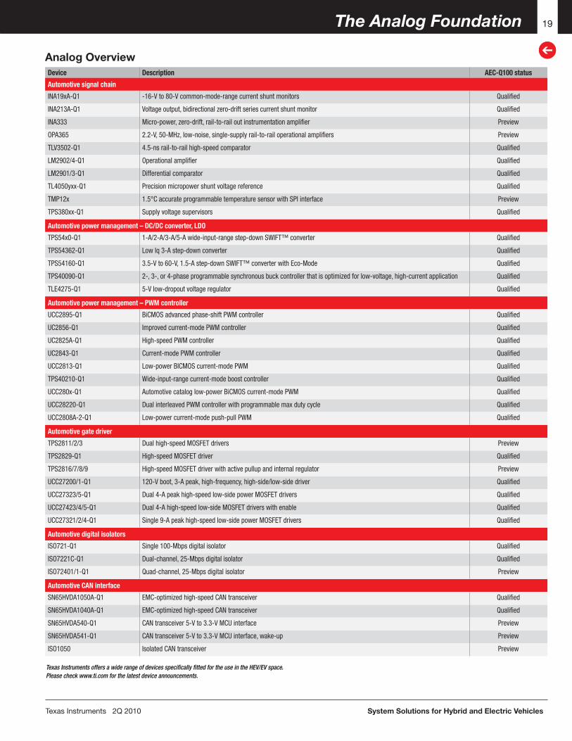
Device Description AEC-Q100 status
Automotive signal chain
INA19xA-Q1 -16-V to 80-V common-mode-range current shunt monitors Qualified
INA213A-Q1 Voltage output, bidirectional zero-drift series current shunt monitor Qualified
INA333 Micro-power, zero-drift, rail-to-rail out instrumentation amplifier Preview
OPA365 2.2-V, 50-MHz, low-noise, single-supply rail-to-rail operational amplifiers Preview
TLV3502-Q1 4.5-ns rail-to-rail high-speed comparator Qualified
LM2902/4-Q1 Operational amplifier Qualified
LM2901/3-Q1 Differential comparator Qualified
TL4050yxx-Q1 Precision micropower shunt voltage reference Qualified
TMP12x 1.5°C accurate programmable temperature sensor with SPI interface Preview
TPS380xx-Q1 Supply voltage supervisors Qualified
Automotive power management – DC/DC converter, LDO
TPS54x0-Q1 1-A/2-A/3-A/5-A wide-input-range step-down SWIFT™ converter Qualified
TPS54362-Q1 Low Iq 3-A step-down converter Qualified
TPS54160-Q1 3.5-V to 60-V, 1.5-A step-down SWIFT™ converter with Eco-Mode Qualified
TPS40090-Q1 2-, 3-, or 4-phase programmable synchronous buck controller that is optimized for low-voltage, high-current application Qualified
TLE4275-Q1 5-V low-dropout voltage regulator Qualified
Automotive power management – PWM controller
UCC2895-Q1 BiCMOS advanced phase-shift PWM controller Qualified
UC2856-Q1 Improved current-mode PWM controller Qualified
UC2825A-Q1 High-speed PWM controller Qualified
UC2843-Q1 Current-mode PWM controller Qualified
UCC2813-Q1 Low-power BICMOS current-mode PWM Qualified
TPS40210-Q1 Wide-input-range current-mode boost controller Qualified
UCC280x-Q1 Automotive catalog low-power BiCMOS current-mode PWM Qualified
UCC28220-Q1 Dual interleaved PWM controller with programmable max duty cycle Qualified
UCC2808A-2-Q1 Low-power current-mode push-pull PWM Qualified
Automotive gate driver
TPS2811/2/3 Dual high-speed MOSFET drivers Preview
TPS2829-Q1 High-speed MOSFET driver Qualified
TPS2816/7/8/9 High-speed MOSFET driver with active pullup and internal regulator Preview
UCC27200/1-Q1 120-V boot, 3-A peak, high-frequency, high-side/low-side driver Qualified
UCC27323/5-Q1 Dual 4-A peak high-speed low-side power MOSFET drivers Qualified
UCC27423/4/5-Q1 Dual 4-A high-speed low-side MOSFET drivers with enable Qualified
UCC27321/2/4-Q1 Single 9-A peak high-speed low-side power MOSFET drivers Qualified
Automotive digital isolators
ISO721-Q1 Single 100-Mbps digital isolator Qualified
ISO7221C-Q1 Dual-channel, 25-Mbps digital isolator Qualified
ISO72401/1-Q1 Quad-channel, 25-Mbps digital isolator Preview
Automotive CAN interface
SN65HVDA1050A-Q1 EMC-optimized high-speed CAN transceiver Qualified
SN65HVDA1040A-Q1 EMC-optimized high-speed CAN transceiver Qualified
SN65HVDA540-Q1 CAN transceiver 5-V to 3.3-V MCU interface Preview
SN65HVDA541-Q1 CAN transceiver 5-V to 3.3-V MCU interface, wake-up Preview
ISO1050 Isolated CAN transceiver Preview
Texas Instruments offers a wide range of devices specifically fitted for the use in the HEV/EV space. Please check www.ti.com for the latest device announcements.
Analog Overview
System Solutions for Hybrid and Electric Vehicles TexasInstruments2Q2010
The Analog Foundation20
➔
Isolated CAN TransceiverISO1050
Getsamples,datasheets,EVMsandappreportsat:www.ti.com/sc/device/ISO1050
Key Features• 4,000-VPEAKisolation• Failsafeoutputs• Lowloopdelay:150-ns(typical)• 50-kV/µs(typical)transientimmunity meetsorexceedsISO11898 requirements• Bus-faultprotectionof-27Vto40V• Dominanttimeoutfunction• UL1577,IEC60747-5-2(VDE0884, Rev.2),IEC61010-1,IEC60950-1and CSAapprovalpending• 3.3-Vinputsare5-Vtolerant• Typical25-yearlifeatratedworking voltage
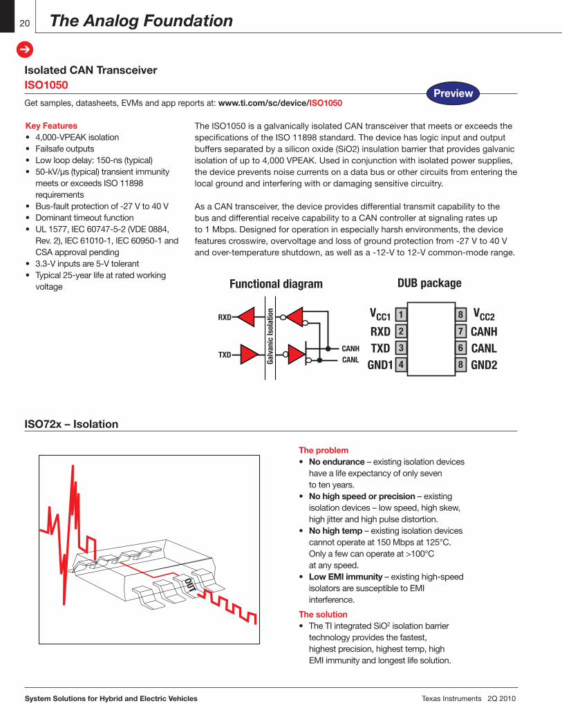
TheISO1050isagalvanicallyisolatedCANtransceiverthatmeetsorexceedsthespecificationsoftheISO11898standard.Thedevicehaslogicinputandoutputbuffersseparatedbyasiliconoxide(SiO2)insulationbarrierthatprovidesgalvanicisolationofupto4,000VPEAK.Usedinconjunctionwithisolatedpowersupplies,thedevicepreventsnoisecurrentsonadatabusorothercircuitsfromenteringthelocalgroundandinterferingwithordamagingsensitivecircuitry.
AsaCANtransceiver,thedeviceprovidesdifferentialtransmitcapabilitytothebusanddifferentialreceivecapabilitytoaCANcontrolleratsignalingratesupto1Mbps.Designedforoperationinespeciallyharshenvironments,thedevicefeaturescrosswire,overvoltageandlossofgroundprotectionfrom-27Vto40Vandover-temperatureshutdown,aswellasa-12-Vto12-Vcommon-moderange.
VCC1
RXDTXD
GND1
VCC2
CANHCANLGND2
DUB packageFunctional diagram
1
2
3
4
8
7
6
8Galv
anic
Isol
atio
n
RXD
CANHCANL
TXD
ISO72x – Isolation
The problem• No endurance–existingisolationdevices havealifeexpectancyofonlyseven totenyears.• No high speed or precision–existing isolationdevices–lowspeed,highskew, highjitterandhighpulsedistortion.• No high temp–existingisolationdevices cannotoperateat150Mbpsat125°C. Onlyafewcanoperateat>100°C atanyspeed.• Low EMI immunity –existinghigh-speed isolatorsaresusceptibletoEMI interference.
The solution• TheTIintegratedSiO2isolationbarrier technologyprovidesthefastest, highestprecision,highesttemp,high EMIimmunityandlongestlifesolution.
OUT
Preview
The Analog Foundation 21
➔
TexasInstruments2Q2010 System Solutions for Hybrid and Electric Vehicles
21
➔
Dual-Channel, 1/1, 25-Mbps Digital IsolatorISO7221Cxx
Getsamples,datasheets,EVMsandappreportsat:www.ti.com/sc/device/ISO7221Cxx
Key Features• Qualifiedforautomotiveapplications• 1-Mbpsand25-Mbpssignalingrateoptions• Lowchannel-to-channeloutputskew 1 ns (max)• Lowpulse-widthdistortion(PWD) 1 ns (max)• Lowjittercontent:1ns(typical)at 150Mbps• 25-year(typical)lifeatratedvoltage (seeapplicationreportSLLA197and Figure14)• 4,000-VPEAKisolation,560-VPEAKVIORM• UL1577,IEC60747-5-2(VDE0884, Rev2),IEC61010-1,IEC60950-1and CSAapproved• 50-kV/µstypicaltransientimmunity• Operateswith3.3-Vor5-Vsupplies• 4-kVESDprotection• Highelectromagneticimmunity• -40°Cto125°Coperatingfree-air temperaturerange
IN
VCC1
INAINB
GND1
VCC2
OUTAOUTBGND2
FIlter
Pulse Width Demodulation
OSC+
PWM
Galvanic IsolationBarrier
Single-Channel Functional Diagram
DC Channel
ISO7220
OUT
Data MUXAC Detect
Output Buffer
Input+
Filter
VREF
VREF
1
2
3
4
8
7
6
8
Isol
atio
n
VCC1
OUTAINB
GND1
VCC2
INAOUTBGND2
ISO7221
1
2
3
4
8
7
6
8
Isol
atio
n
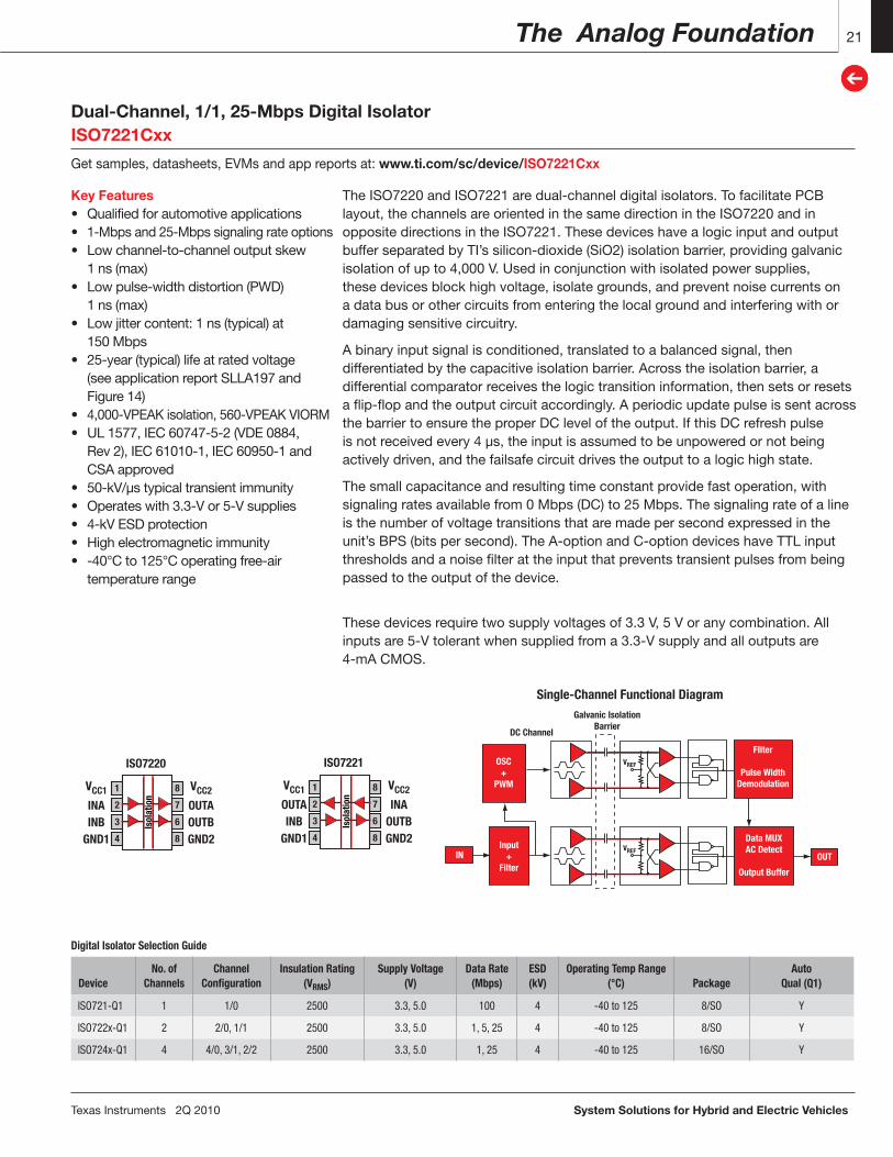
TheISO7220andISO7221aredual-channeldigitalisolators.TofacilitatePCBlayout,thechannelsareorientedinthesamedirectionintheISO7220andinoppositedirectionsintheISO7221.ThesedeviceshavealogicinputandoutputbufferseparatedbyTI’ssilicon-dioxide(SiO2)isolationbarrier,providinggalvanicisolationofupto4,000V.Usedinconjunctionwithisolatedpowersupplies,thesedevicesblockhighvoltage,isolategrounds,andpreventnoisecurrentsonadatabusorothercircuitsfromenteringthelocalgroundandinterferingwithordamagingsensitivecircuitry.
Abinaryinputsignalisconditioned,translatedtoabalancedsignal,thendifferentiatedbythecapacitiveisolationbarrier.Acrosstheisolationbarrier,adifferentialcomparatorreceivesthelogictransitioninformation,thensetsorresetsaflip-flopandtheoutputcircuitaccordingly.AperiodicupdatepulseissentacrossthebarriertoensuretheproperDCleveloftheoutput.IfthisDCrefreshpulseisnotreceivedevery4 µs,theinputisassumedtobeunpoweredornotbeingactivelydriven,andthefailsafecircuitdrivestheoutputtoalogichighstate.
Thesmallcapacitanceandresultingtimeconstantprovidefastoperation,withsignalingratesavailablefrom0Mbps(DC)to25Mbps.Thesignalingrateofalineisthenumberofvoltagetransitionsthataremadepersecondexpressedintheunit’sBPS(bitspersecond).TheA-optionandC-optiondeviceshaveTTLinputthresholdsandanoisefilterattheinputthatpreventstransientpulsesfrombeingpassedtotheoutputofthedevice.
Thesedevicesrequiretwosupplyvoltagesof3.3V,5Voranycombination.Allinputsare5-Vtolerantwhensuppliedfroma3.3-Vsupplyandalloutputsare4-mACMOS.
Digital Isolator Selection Guide
DeviceNo. of
ChannelsChannel
ConfigurationInsulation Rating
(VRMS)Supply Voltage
(V)Data Rate
(Mbps)ESD(kV)
Operating Temp Range (°C) Package
AutoQual (Q1)
ISO721-Q1 1 1/0 2500 3.3, 5.0 100 4 -40 to 125 8/SO Y
ISO722x-Q1 2 2/0, 1/1 2500 3.3, 5.0 1, 5, 25 4 -40 to 125 8/SO Y
ISO724x-Q1 4 4/0, 3/1, 2/2 2500 3.3, 5.0 1, 25 4 -40 to 125 16/SO Y
System Solutions for Hybrid and Electric Vehicles TexasInstruments2Q2010
The Analog Foundation22
➔
Isolated ADC (1-Bit, 10-MHz, Second-Order, Isolated Delta-Sigma Modulator)AMC1203Getsamples,datasheets,EVMsandappreportsat:www.ti.com/sc/device/AMC1203
MDAT
VIN+
VIN-
POR
2.5VVREF
BIASPOR
OutputBuffer
2nd OrderΑΣ Modulator
Isolation Barrier
MCLKOutputBuffer
20-MHzRC
Oscillator
Inte
rfac
e Ci
rcui
t
VREF
VREF
Buffer
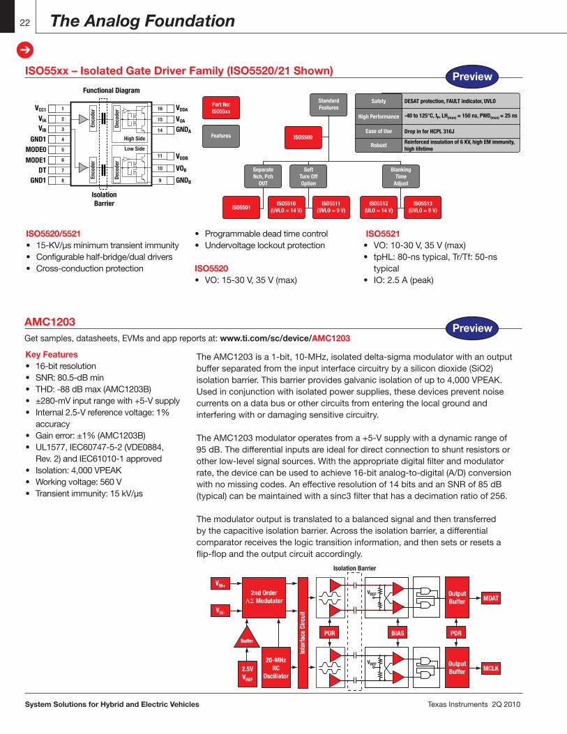
TheAMC1203isa1-bit,10-MHz,isolateddelta-sigmamodulatorwithanoutputbufferseparatedfromtheinputinterfacecircuitrybyasilicondioxide(SiO2)isolationbarrier.Thisbarrierprovidesgalvanicisolationofupto4,000VPEAK.Usedinconjunctionwithisolatedpowersupplies,thesedevicespreventnoisecurrentsonadatabusorothercircuitsfromenteringthelocalgroundandinterferingwithordamagingsensitivecircuitry.
TheAMC1203modulatoroperatesfroma+5-Vsupplywithadynamicrangeof95dB.Thedifferentialinputsareidealfordirectconnectiontoshuntresistorsorotherlow-levelsignalsources.Withtheappropriatedigitalfilterandmodulatorrate,thedevicecanbeusedtoachieve16-bitanalog-to-digital(A/D)conversionwithnomissingcodes.Aneffectiveresolutionof14bitsandanSNRof85dB(typical)canbemaintainedwithasinc3filterthathasadecimationratioof256.
Themodulatoroutputistranslatedtoabalancedsignalandthentransferredbythecapacitiveisolationbarrier.Acrosstheisolationbarrier,adifferentialcomparatorreceivesthelogictransitioninformation,andthensetsorresetsaflip-flopandtheoutputcircuitaccordingly.
Key Features• 16-bitresolution• SNR:80.5-dBmin• THD:-88dBmax(AMC1203B)• ±280-mVinputrangewith+5-Vsupply• Internal2.5-Vreferencevoltage:1% accuracy• Gainerror:±1%(AMC1203B)• UL1577,IEC60747-5-2(VDE0884, Rev.2)andIEC61010-1approved• Isolation:4,000VPEAK• Workingvoltage:560V• Transientimmunity:15kV/µs
1VCC1
2VIA
3VIB
4GND15MODE06MODE17DT8GND1
16
15
14
11
10
9
VDDA
Functional Diagram
IsolationBarrier
VOA
GNDA
VOB
VDDB
GNDB
Enco
der
Deco
der
High Side
Enco
der
Deco
der
Low Side
ISO55xx – Isolated Gate Driver Family (ISO5520/21 Shown)
ISO5520/5521• 15-KV/µsminimumtransientimmunity• Configurablehalf-bridge/dualdrivers• Cross-conductionprotection
• Programmabledeadtimecontrol• Undervoltagelockoutprotection
ISO5520• VO:15-30V,35V(max)
ISO5521• VO:10-30V,35V(max)• tpHL:80-nstypical,Tr/Tf:50-ns typical• IO:2.5A(peak)
ISO5513(UVLO = 9 V)
ISO5512(ULO = 14 V)
ISO5511(UVLO = 9 V)
ISO5510(UVLO = 14 V)
SeparateNch, Pch
OUT
ISO5501
ISO5500
Part No:ISO55xx
SoftTurn OffOption
BlankingTime
Adjust
StandardFeatures
Features
Safety DESAT protection, FAULT indicator, UVLO
-40 to 125°C, tP, LH(max) = 150 ns, PWD(max) = 25 ns
Reinforced insulation of 6 KV, high EM immunity,high lifetime
Drop in for HCPL 316J
High Performance
Ease of Use
Robust
Preview
Preview
TexasInstruments2Q2010 System Solutions for Hybrid and Electric Vehicles
Charging Infrastructure
Charging Infrastructure – Connecting the Car to the Smart Power Grid
23
➔
23
➔
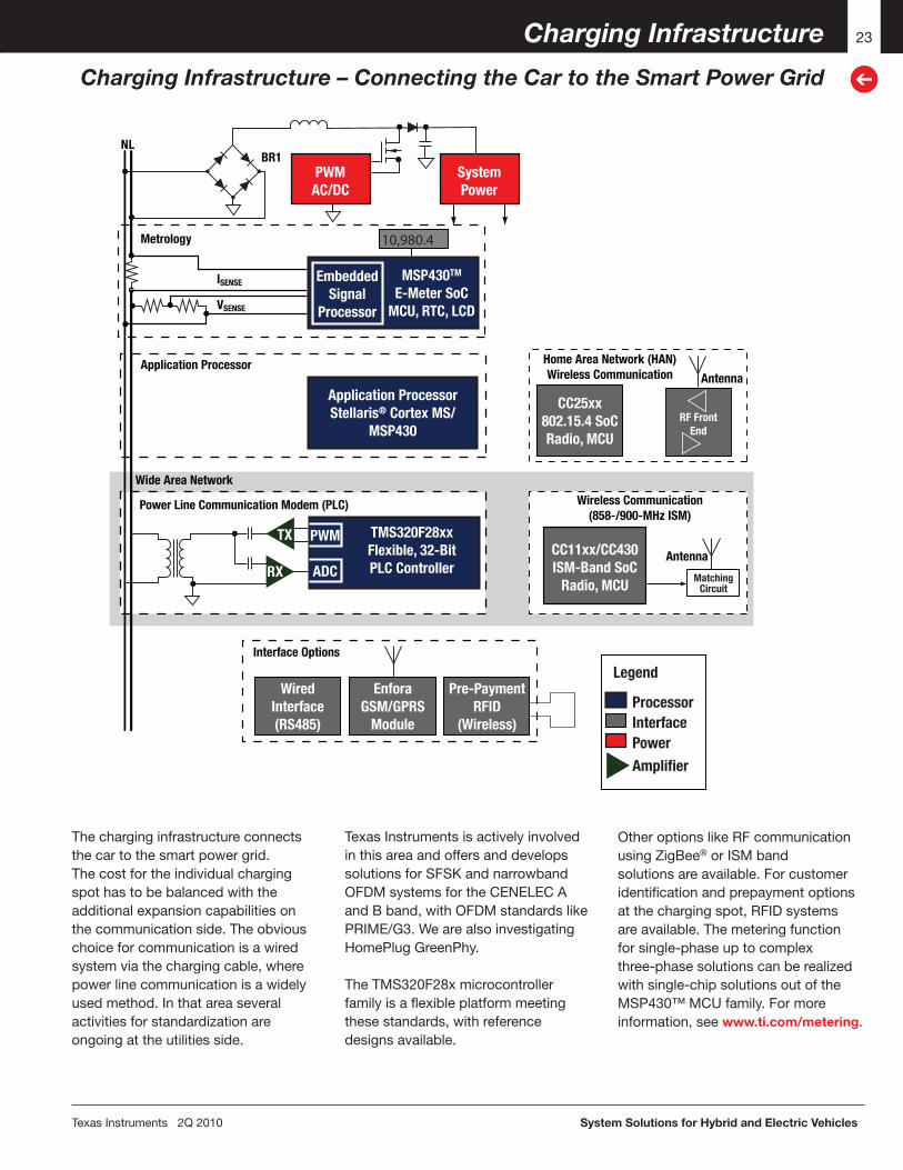
Thecharginginfrastructureconnectsthecartothesmartpowergrid.Thecostfortheindividualchargingspothastobebalancedwiththeadditionalexpansioncapabilitiesonthecommunicationside.Theobviouschoiceforcommunicationisawiredsystemviathechargingcable,wherepowerlinecommunicationisawidelyusedmethod.Inthatareaseveralactivitiesforstandardizationareongoingattheutilitiesside.
Application ProcessorStellaris® Cortex MS/
MSP430
TMS320F28xxFlexible, 32-BitPLC Controller
Power Line Communication Modem (PLC)
Wide Area Network
Application Processor
Wireless Communication(858-/900-MHz ISM)
Home Area Network (HAN)Wireless Communication
Interface Options
Antenna
Antenna
CC25xx802.15.4 SoCRadio, MCU
WiredInterface(RS485)
EnforaGSM/GPRS
Module
Pre-PaymentRFID
(Wireless)
RF FrontEnd
CC11xx/CC430ISM-Band SoC
Radio, MCU Matching Circuit
MSP430TM
E-Meter SoCMCU, RTC, LCD
Legend
InterfaceProcessor
PowerAmplifier
EmbeddedSignal
Processor
PWMAC/DC
SystemPower
PWMTX
ADCRX
Metrology
NBR1
L
ISENSE
VSENSE
10,980.4
TexasInstrumentsisactivelyinvolvedinthisareaandoffersanddevelopssolutionsforSFSKandnarrowbandOFDMsystemsfortheCENELECAandBband,withOFDMstandardslikePRIME/G3.WearealsoinvestigatingHomePlugGreenPhy.
TheTMS320F28xmicrocontrollerfamilyisaflexibleplatformmeetingthesestandards,withreferencedesignsavailable.
OtheroptionslikeRFcommunicationusingZigBee®orISMbandsolutionsareavailable.Forcustomeridentificationandprepaymentoptionsatthechargingspot,RFIDsystemsareavailable.Themeteringfunctionforsingle-phaseuptocomplexthree-phasesolutionscanberealizedwithsingle-chipsolutionsoutoftheMSP430™MCUfamily.Formoreinformation,seewww.ti.com/metering.
System Solutions for Hybrid and Electric Vehicles TexasInstruments2Q2010
Charging Infrastructure
PLC Kit Using the TMS320F28335
24
➔
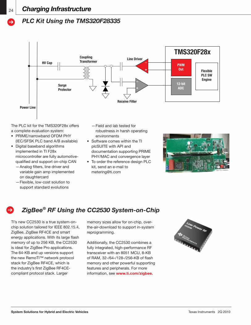
ThePLCkitfortheTMS320F28xoffersacompleteevaluationsystem:• PRIME/narrowbandOFDMPHY (IEC/SFSKPLCbandA/Bavailable)• Digitalbasebandalgorithms implementedinTIF28x microcontrollerarefullyautomotive- qualifiedandsupporton-chipCAN —Analogfilters,linedriverand variablegainampimplemented ondaughtercard —Flexible,low-costsolutionto supportstandardevolutions
Power Line
SurgeProtector
HV Cap
CouplingTransformer
PWMOut
–
+
–
+
FlexiblePLC SWEngine
12-bitADC
Line Driver
TMS320F28x
Receive Filter
TI’snewCC2530isatruesystem-on-chipsolutiontailoredforIEEE802.15.4,ZigBee,ZigBeeRF4CEandsmartenergyapplications.Withitslargeflashmemoryofupto256KB,theCC2530isidealforZigBeeProapplications.The64-KBandupversionssupportthenewRemoTI™networkprotocolstackforZigBeeRF4CE,whichistheindustry’sfirstZigBeeRF4CE-compliantprotocolstack.Larger
ZigBee® RF Using the CC2530 System-on-Chip➔
memorysizesallowforon-chip,over-the-air-downloadtosupportin-systemreprogramming.
Additionally,theCC2530combinesafullyintegrated,high-performanceRFtransceiverwithan8051MCU,8-KBofRAM,32-/64-/128-/256-KBofflashmemoryandotherpowerfulsupportingfeaturesandperipherals.Formoreinformation,seewww.ti.com/zigbee.
—Fieldandlabtestedfor robustnessinharshoperating environments• SoftwarecomeswithintheTI plcSUITEwithAPIand documentationsupportingPRIME PHY/MACandconvergencelayer• ToorderthereferencedesignPLC kit,sendane-mailto [email protected]
TexasInstruments2Q2010 System Solutions for Hybrid and Electric Vehicles
E-Bike, Scooter and Small Task-Oriented Vehicles (STOVs) 25
➔
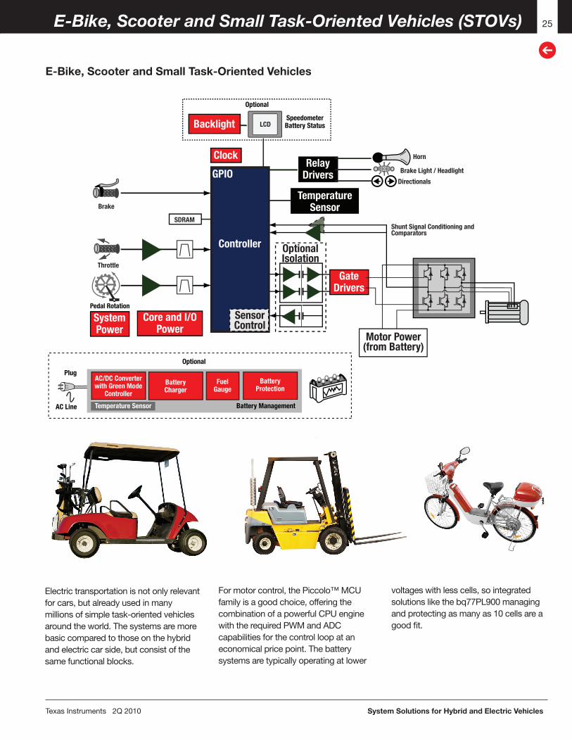
Electrictransportationisnotonlyrelevantforcars,butalreadyusedinmanymillionsofsimpletask-orientedvehiclesaroundtheworld.Thesystemsaremorebasiccomparedtothoseonthehybridandelectriccarside,butconsistofthesamefunctionalblocks.
OptionalIsolation
Motor Power(from Battery)
SystemPower
GateDrivers
ClockRelay
Drivers
TemperatureSensor
Backlight
AC/DC Converterwith Green Mode
Controller
BatteryCharger
Optional
Optional
SpeedometerBattery Status
Plug
AC Line
BatteryProtection
FuelGauge
Core and I/OPower
Temperature Sensor Battery Management
Controller
GPIO
SensorControl
LCD
SDRAM
Horn
Brake
Throttle
Brake Light / Headlight
Directionals
Shunt Signal Conditioning and Comparators
Pedal Rotation
Formotorcontrol,thePiccolo™MCUfamilyisagoodchoice,offeringthecombinationofapowerfulCPUenginewiththerequiredPWMandADCcapabilitiesforthecontrolloopataneconomicalpricepoint.Thebatterysystemsaretypicallyoperatingatlower
voltageswithlesscells,sointegratedsolutionslikethebq77PL900managingandprotectingasmanyas10cellsareagoodfit.
E-Bike, Scooter and Small Task-Oriented Vehicles

System Solutions for Hybrid and Electric Vehicles TexasInstruments2Q2010
E-Bike, Scooter and Small Task-Oriented Vehicles (STOVs)26
➔
Key Features• Five-,six-,seven-,eight-,nine-or 10-seriescellprimaryprotection• PMOSFETdriveforchargeand dischargeFETs• Capableofoperationwith1-mΩ senseresistor• Supplyvoltagerangefrom7Vto50V• Lowsupplycurrentof450µAtypical• Integrated5-V,25-mALDO• Standalonemode —Packprotectioncontrolandrecovery —Individualcellmonitoring —Integratedcellbalancing —Programmablethresholdanddelay timefor: —Overvoltage —Undervoltage —Overcurrentindischarge —Shortcircuitindischarge —Fixedovertemperatureprotection
Key Features• Three-to12-seriescellsystems• PowerPump™technologycellbalancing forlongerruntimeandcelllife• Supportsdischargecurrentlevelsof 10A,35Aand110A• Gauges65-650Ahrcapacitybatteries• Highresolution18-bitintegratingdelta- sigmaCoulombcounterforprecise charge-flowmeasurementsandgas gauging• Multipleindependentdelta-sigmaA/Ds: one-per-cellvoltage,plusseparate temperature,currentandsafety• Fullyprogrammablevoltage,current, balanceandtemperatureprotection• Remainingcapacityindicators:LCD, LED,EPD
ChargeFuse
Pack + Discharge
Pack –
PCH FET Drive
LDO, Thermal Output Drive
Overvoltage/Undervoltage Protection
Cell-Balance Drive
Overload Protection
Short-Circuit Protection
Serial Interface RAM Registers
bq77PL900
Sense Resistor
Integrated Gas Gauge, Protection and Active Cell Balancingbq78PL114
Getsamples,datasheets,EVMsandappreportsat:www.ti.com/sc/device/bq78PL114
RPRE
SD11
DSG
CHG
PRE
6
SDO0VLD01
RSTN
SPROT
GPIOEFCID
VLDO2
V2
V3
V4
P-LAN
SD02
SO13
V1
XTTemperatureSensor (typ.)
EFCID
SPI-CLKSPI-DOSPI-DI
SELECTSMBCLKSMBDAT
TAB
VSS
CBBA
TCC
BAT
CCPA
CK
CSPA
CK
RSENSE
CRA
PACK+
PACK–
Aux FETControl
SPI
SMBus
ESD
Prot
ectio
n
bq76
PL10
2
Cell-
Bala
ncin
gCi
rcui
tsCe
ll-Ba
lanc
ing
Circ
uits
Cell-
Bala
ncin
gCi
rcui
ts
bq76
PL10
2
bq78PL114
Level Shift Circuits
–
+
Standalone and Host-Controlled Battery Protectionbq77PL900Getsamples,datasheets,EVMsandappreportsat:www.ti.com/sc/device/bq77PL900
• Hostcontrolmode —I2Cinterfacetohost controller —Analoginterfacefor hostcellmeasure- mentandsystem charge/discharge current —Host-controlled protectionrecovery —Host-controlledcell balancing
TexasInstruments2Q2010 System Solutions for Hybrid and Electric Vehicles
E-Bike, Scooter and Small Task-Oriented Vehicles (STOVs)
Digital Motor Control for E-Bikes, Scooters and STOVs
27
➔
TheC2000™DSPplatformofreal-timecontrollershasbeentheindustryleaderindigitalmotorcontrolsincetheinceptionoftheTMS320F24xgenerationin1996.In2002wedebutedtheF281xseries,basedon
theC28x™DSPengine,becomingthefirst32-bitarchitecturespecificallybuiltforhigh-performance,math-intensivepowerelectronicscontrol.BasedontheC28xDSP,wehavecreatedafamilyofcode-compatible
devicestomeetapplicationneedsacrossperformance,price,pin-outandperipherals.Tofindoutmore,visit:www.ti.com/c2000dmc.
High-Voltage PFC and Motor Control Developer’s Kit
➔
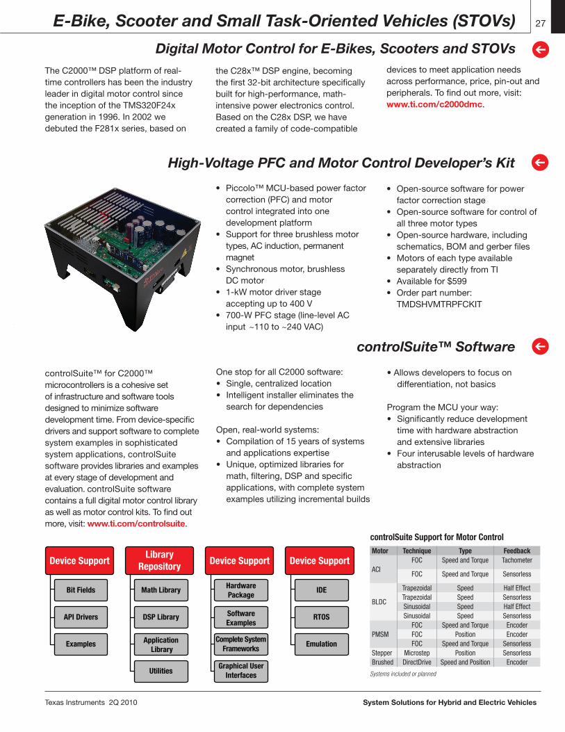
• Piccolo™MCU-basedpowerfactor correction(PFC)andmotor controlintegratedintoone developmentplatform• Supportforthreebrushlessmotor types,ACinduction,permanent magnet• Synchronousmotor,brushless DCmotor• 1-kWmotordriverstage acceptingupto400V• 700-WPFCstage(line-levelAC input~110to~240VAC)
• Open-sourcesoftwareforpower factorcorrectionstage• Open-sourcesoftwareforcontrolof allthreemotortypes• Open-sourcehardware,including schematics,BOMandgerberfiles• Motorsofeachtypeavailable separatelydirectlyfromTI• Availablefor$599• Orderpartnumber: TMDSHVMTRPFCKIT
controlSuite™ Software
➔
OnestopforallC2000software:• Single,centralizedlocation• Intelligentinstallereliminatesthe searchfordependencies
Open,real-worldsystems:• Compilationof15yearsofsystems andapplicationsexpertise• Unique,optimizedlibrariesfor math,filtering,DSPandspecific applications,withcompletesystem examplesutilizingincrementalbuilds
•Allowsdeveloperstofocuson differentiation,notbasics
ProgramtheMCUyourway:•Significantlyreducedevelopment timewithhardwareabstraction andextensivelibraries•Fourinterusablelevelsofhardware abstraction
controlSuite™forC2000™microcontrollersisacohesivesetofinfrastructureandsoftwaretoolsdesignedtominimizesoftwaredevelopmenttime.Fromdevice-specificdriversandsupportsoftwaretocompletesystemexamplesinsophisticatedsystemapplications,controlSuitesoftwareprovideslibrariesandexamplesateverystageofdevelopmentandevaluation.controlSuitesoftwarecontainsafulldigitalmotorcontrollibraryaswellasmotorcontrolkits.Tofindoutmore,visit:www.ti.com/controlsuite.
Math Library
DSP Library
Application Library
Utilities
HardwarePackage
Bit Fields
API Drivers
Examples
IDE
RTOS
Emulation
SoftwareExamples
Complete SystemFrameworks
Graphical UserInterfaces
Device SupportLibrary
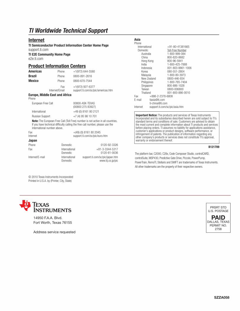
Repository Device Support Device SupportMotor Technique Type Feedback
ACIFOC Speed and Torque Tachometer
FOC Speed and Torque Sensorless
BLDC
Trapezoidal Speed Half EffectTrapezoidal Speed SensorlessSinusoidal Speed Half EffectSinusoidal Speed Sensorless
PMSMFOC Speed and Torque EncoderFOC Position EncoderFOC Speed and Torque Sensorless
Stepper Microstep Position SensorlessBrushed DirectDrive Speed and Position Encoder
Systems included or planned
controlSuite Support for Motor Control
PRSRTSTDU.S.POSTAGE
PAIDDALLAS,TEXAS
PERMITNO.2758
14950F.A.A.Blvd.FortWorth,Texas76155
Addressservicerequested
SZZA058
TI Worldwide Technical SupportInternetTI Semiconductor Product Information Center Home Pagesupport.ti.comTI E2E Community Home Pagee2e.ti.com
Product Information CentersAmericas Phone +1(972)644-5580
Brazil Phone 0800-891-2616
Mexico Phone 0800-670-7544
Fax +1(972)927-6377 Internet/Email support.ti.com/sc/pic/americas.htm
Europe, Middle East and AfricaPhone
EuropeanFreeCall 00800-ASK-TEXAS (0080027583927)
International +49(0)8161802121
RussianSupport +7(4)959810701
Note:TheEuropeanFreeCall(TollFree)numberisnotactiveinallcountries.Ifyouhavetechnicaldifficultycallingthefreecallnumber,pleaseusetheinternationalnumberabove.
Fax +(49)(0)8161802045Internet support.ti.com/sc/pic/euro.htm
JapanPhone Domestic 0120-92-3326Fax International +81-3-3344-5317 Domestic 0120-81-0036Internet/E-mail International support.ti.com/sc/pic/japan.htm Domestic www.tij.co.jp/pic
AsiaPhone International +91-80-41381665 Domestic Toll-FreeNumber Australia 1-800-999-084 China 800-820-8682 HongKong 800-96-5941 India 1-800-425-7888 Indonesia 001-803-8861-1006 Korea 080-551-2804 Malaysia 1-800-80-3973 NewZealand 0800-446-934 Philippines 1-800-765-7404 Singapore 800-886-1028 Taiwan 0800-006800 Thailand 001-800-886-0010Fax +886-2-2378-6808E-mail [email protected]
[email protected] support.ti.com/sc/pic/asia.htm
B121709
Important Notice:TheproductsandservicesofTexasInstrumentsIncorporatedanditssubsidiariesdescribedhereinaresoldsubjecttoTI’sstandardtermsandconditionsofsale.CustomersareadvisedtoobtainthemostcurrentandcompleteinformationaboutTIproductsandservicesbeforeplacingorders.TIassumesnoliabilityforapplicationsassistance,customer’sapplicationsorproductdesigns,softwareperformance,orinfringementofpatents.Thepublicationofinformationregardinganyothercompany’sproductsorservicesdoesnotconstituteTI’sapproval,warrantyorendorsementthereof.
©2010TexasInstrumentsIncorporatedPrintedinU.S.A.by(Printer,City,State)
Theplatformbar,C2000,C28x,CodeComposerStudio,controlCARD,controlSuite,MSP430,PredictiveGateDrive,Piccolo,PowerPump,PowerTrain,RemoTI,StellarisandSWIFTaretrademarksofTexasInstruments.Allothertrademarksarethepropertyoftheirrespectiveowners.
IMPORTANT NOTICE
Texas Instruments Incorporated and its subsidiaries (TI) reserve the right to make corrections, modifications, enhancements, improvements,and other changes to its products and services at any time and to discontinue any product or service without notice. Customers shouldobtain the latest relevant information before placing orders and should verify that such information is current and complete. All products aresold subject to TI’s terms and conditions of sale supplied at the time of order acknowledgment.
TI warrants performance of its hardware products to the specifications applicable at the time of sale in accordance with TI’s standardwarranty. Testing and other quality control techniques are used to the extent TI deems necessary to support this warranty. Except wheremandated by government requirements, testing of all parameters of each product is not necessarily performed.
TI assumes no liability for applications assistance or customer product design. Customers are responsible for their products andapplications using TI components. To minimize the risks associated with customer products and applications, customers should provideadequate design and operating safeguards.
TI does not warrant or represent that any license, either express or implied, is granted under any TI patent right, copyright, mask work right,or other TI intellectual property right relating to any combination, machine, or process in which TI products or services are used. Informationpublished by TI regarding third-party products or services does not constitute a license from TI to use such products or services or awarranty or endorsement thereof. Use of such information may require a license from a third party under the patents or other intellectualproperty of the third party, or a license from TI under the patents or other intellectual property of TI.
Reproduction of TI information in TI data books or data sheets is permissible only if reproduction is without alteration and is accompaniedby all associated warranties, conditions, limitations, and notices. Reproduction of this information with alteration is an unfair and deceptivebusiness practice. TI is not responsible or liable for such altered documentation. Information of third parties may be subject to additionalrestrictions.
Resale of TI products or services with statements different from or beyond the parameters stated by TI for that product or service voids allexpress and any implied warranties for the associated TI product or service and is an unfair and deceptive business practice. TI is notresponsible or liable for any such statements.
TI products are not authorized for use in safety-critical applications (such as life support) where a failure of the TI product would reasonablybe expected to cause severe personal injury or death, unless officers of the parties have executed an agreement specifically governingsuch use. Buyers represent that they have all necessary expertise in the safety and regulatory ramifications of their applications, andacknowledge and agree that they are solely responsible for all legal, regulatory and safety-related requirements concerning their productsand any use of TI products in such safety-critical applications, notwithstanding any applications-related information or support that may beprovided by TI. Further, Buyers must fully indemnify TI and its representatives against any damages arising out of the use of TI products insuch safety-critical applications.
TI products are neither designed nor intended for use in military/aerospace applications or environments unless the TI products arespecifically designated by TI as military-grade or "enhanced plastic." Only products designated by TI as military-grade meet militaryspecifications. Buyers acknowledge and agree that any such use of TI products which TI has not designated as military-grade is solely atthe Buyer's risk, and that they are solely responsible for compliance with all legal and regulatory requirements in connection with such use.
TI products are neither designed nor intended for use in automotive applications or environments unless the specific TI products aredesignated by TI as compliant with ISO/TS 16949 requirements. Buyers acknowledge and agree that, if they use any non-designatedproducts in automotive applications, TI will not be responsible for any failure to meet such requirements.
Following are URLs where you can obtain information on other Texas Instruments products and application solutions:
Products Applications
Amplifiers amplifier.ti.com Audio www.ti.com/audio
Data Converters dataconverter.ti.com Automotive www.ti.com/automotive
DLP® Products www.dlp.com Communications and www.ti.com/communicationsTelecom
DSP dsp.ti.com Computers and www.ti.com/computersPeripherals
Clocks and Timers www.ti.com/clocks Consumer Electronics www.ti.com/consumer-apps
Interface interface.ti.com Energy www.ti.com/energy
Logic logic.ti.com Industrial www.ti.com/industrial
Power Mgmt power.ti.com Medical www.ti.com/medical
Microcontrollers microcontroller.ti.com Security www.ti.com/security
RFID www.ti-rfid.com Space, Avionics & www.ti.com/space-avionics-defenseDefense
RF/IF and ZigBee® Solutions www.ti.com/lprf Video and Imaging www.ti.com/video
Wireless www.ti.com/wireless-apps
Mailing Address: Texas Instruments, Post Office Box 655303, Dallas, Texas 75265Copyright © 2010, Texas Instruments Incorporated