huawei antenna & antenna line products catalogue 2012
TRANSCRIPT

Huawei Antenna & Antenna Line Products Catalogue
Catalogue 2012
HUAWEI TECHNOLOGIES CO., LTD.


Huawei: MBB Era Network Antenna ExpertHuawei has been involved in mobile communications for more than 20 years. For 17 years, Huawei has designed base station (BTS)
antennas with some 300 experts and engineers in five R&D centers based in China, Germany, Canada and the US. Huawei has
been awarded more than 100 BTS antenna patents and has membership in more than 50 standardization organizations. Thanks to
Huawei's experience as well as its industry-leading network designs, performance simulation platforms, and precise 3D spherical
antenna near-field testing system, Huawei is capable of providing network antennas with optimal network performance.
Industry-Leading Antenna SolutionsAntennas for Optimal Network Performance•
Huawei is a pioneer in designing antenna for better network performance. All antennas are analyzed and optimized using
network simulation systems. This makes it possible for Huawei antennas to provide enhanced network performance (10% better
than traditional antennas).
Supporting Full Range of Frequency Bands and Reducing TCO•
Huawei provides more than 100 types of mainstream antennas covering frequency ranges from 790 MHz to 2690 MHz, with
support from single band to penta-band. Huawei's antennas lead the industry in terms of width, weight, wind load and "green
upgrade" support to minimize tower modernization costs and rental fees.
Easy Maintenance for Reducing OPEX•
Huawei's EasyRET solution (internal RCU ) for antennas eliminates extra sites visit due to incorrect installation and shortens
installation time by 95%. Internal RCU improves reliability while reducing RCU maintenance costs by 80%. Imbedded RCU
software requires no configuration, and improves service provisioning efficiency by approximately 95%.
Flexible MIMO Configurations•
Flexible configurations are available for multi-band (1800 MHz/2100 MHz/2600 MHz) for LTE in 2T2R\2T4R\4T4R. One-time
deployment supports long term evolution.
Supporting Evolution to AAS•
Integrating antennas with RF components, Huawei provides an industry-leading active antenna system (AAS) to handle dynamic
capacity requirements.
High-Performing TMA and Easy O&M•
Huawei TMA has many advantages, like low insertion loss, low PIM and small noise figure. Huawei is
also the only vendor in the world to provide remote gain control as well as
electrical labeling (essential to TMA asset management).
Huawei is committed to improving its customers'
communications capacities over the long-term. We look
forward to cooperating with you in delivering optimal
network performance using our antenna solutions.
Huawei Network Antenna
Huawei Antenna & Antenna Line Products Catalogue >>

Huawei Antenna & Antenna Line Products Catalogue >>
Huawei's SG128 spherical near field testing system - the world's most
advanced antenna testing system:High-performing ultra-broadband dual-polarization probes•
Five-axis precision turret for military use (can be rotated with 0.01 degree precision)•
Albatross high-performing shielded room from Germany•
AEMI radar absorbing materials from the US•
Precise and stable equipment imported from industry-leading countries•
Infrared laser for calibration and dedicated installation support•
Full series of installation poles•
Industry-leading temperature control technology•
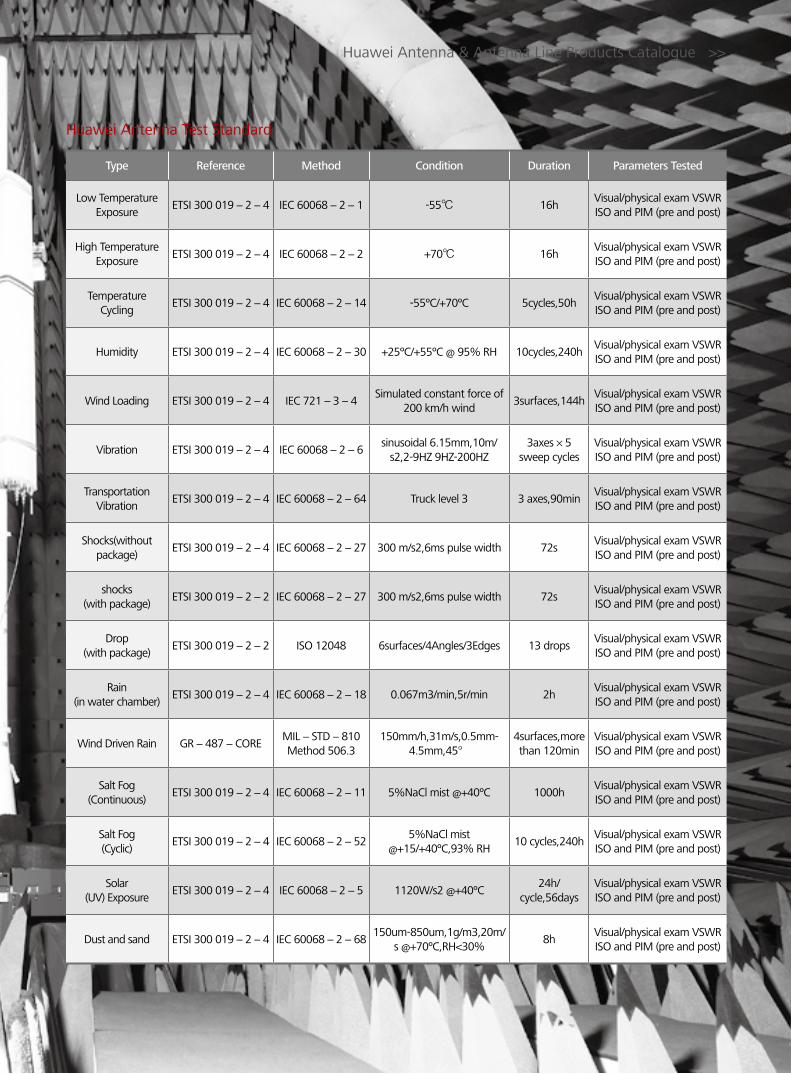
Type Reference Method Condition Duration Parameters Tested
Low Temperature Exposure
ETSI 300 019-2-4 IEC 60068-2-1 -55 16hVisual/physical exam VSWR ISO and PIM (pre and post)
High Temperature Exposure
ETSI 300 019-2-4 IEC 60068-2-2 +70 16hVisual/physical exam VSWR ISO and PIM (pre and post)
Temperature Cycling
ETSI 300 019-2-4 IEC 60068-2-14 -55ºC/+70ºC 5cycles,50hVisual/physical exam VSWR ISO and PIM (pre and post)
Humidity ETSI 300 019-2-4 IEC 60068-2-30 +25ºC/+55ºC @ 95% RH 10cycles,240hVisual/physical exam VSWR ISO and PIM (pre and post)
Wind Loading ETSI 300 019-2-4 IEC 721-3-4Simulated constant force of
200 km/h wind3surfaces,144h
Visual/physical exam VSWR ISO and PIM (pre and post)
Vibration ETSI 300 019-2-4 IEC 60068-2-6sinusoidal 6.15mm,10m/
s2,2-9HZ 9HZ-200HZ 3axes×5
sweep cyclesVisual/physical exam VSWR ISO and PIM (pre and post)
Transportation Vibration
ETSI 300 019-2-4 IEC 60068-2-64 Truck level 3 3 axes,90minVisual/physical exam VSWR ISO and PIM (pre and post)
Shocks(without package)
ETSI 300 019-2-4 IEC 60068-2-27 300 m/s2,6ms pulse width 72sVisual/physical exam VSWR ISO and PIM (pre and post)
shocks(with package)
ETSI 300 019-2-2 IEC 60068-2-27 300 m/s2,6ms pulse width 72sVisual/physical exam VSWR ISO and PIM (pre and post)
Drop(with package)
ETSI 300 019-2-2 ISO 12048 6surfaces/4Angles/3Edges 13 dropsVisual/physical exam VSWR ISO and PIM (pre and post)
Rain(in water chamber)
ETSI 300 019-2-4 IEC 60068-2-18 0.067m3/min,5r/min 2hVisual/physical exam VSWR ISO and PIM (pre and post)
Wind Driven Rain GR-487-COREMIL-STD-810 Method 506.3
150mm/h,31m/s,0.5mm-4.5mm,45°
4surfaces,more than 120min
Visual/physical exam VSWR ISO and PIM (pre and post)
Salt Fog(Continuous)
ETSI 300 019-2-4 IEC 60068-2-11 5%NaCl mist @+40ºC 1000hVisual/physical exam VSWR ISO and PIM (pre and post)
Salt Fog(Cyclic)
ETSI 300 019-2-4 IEC 60068-2-525%NaCl mist
@+15/+40ºC,93% RH 10 cycles,240h
Visual/physical exam VSWR ISO and PIM (pre and post)
Solar(UV) Exposure
ETSI 300 019-2-4 IEC 60068-2-5 1120W/s2 @+40ºC24h/
cycle,56daysVisual/physical exam VSWR ISO and PIM (pre and post)
Dust and sand ETSI 300 019-2-4 IEC 60068-2-68150um-850um,1g/m3,20m/
s @+70ºC,RH<30%8h
Visual/physical exam VSWR ISO and PIM (pre and post)
Huawei Antenna & Antenna Line Products Catalogue >>
Huawei Antenna Test Standard

ContentsProduct Portfolio
A. Huawei Network Antennas C. Accessories for RET Systems
B. Antenna Line Products D. Mounting Instructions
B-1. Dual Tower Mounted Amplifiers (DTMA)
B-2. Combiners
D-1. Antenna Installation Guide
D-2. DTMA Installation Guide
D-3. Combiner Installation Guide
D-4. RCU Installation Guide
D-5. BT Installation Guide
D-6. SBT Installation Guide
A-1. Single Band Antennas
A-2. Dual-band Antennas
A-3. Triple-band Antennas
A-4. Quad-band Antenna
A-5. WIMAX, LTE Antennas
A-6. Cluster Antenna
C-1. Remote Control Unit (RCU)
C-2. Bias Tee (BT)
C-3. Smart Bias Tee (SBT)
C-4. AISG Connecting Cables
Huawei Antenna & Antenna Line Products Catalogue >>
ⅰ
Contents

IndexA. Huawei Network Antennas
Huawei Antenna & Antenna Line Products Catalogue >>
A-1. Single Band Antennas
Frequency Range (MHz)
Polarization 3dB Horizontal beam width (°)
Gain (dBi) Electrical
downtilt (°) Tilt
MethodConnector Dimension (mm) Model Page
450-470 x 360 9 0 FET1 x 7/16
DIN Female Φ52 x 3316 A45VP0900 2
450-470 x 65 15 0 FET2 x 7/16
DIN Female 2042 x 486 x 98 A45451500 3
790-960 x 65 15 0-14 MET2 x 7/16
DIN Female 1356 x 259 x 135 **A79451500v01 4
790-960 x 65 16.5 0-12 MET2 x 7/16
DIN Female 1936 x 259 x 135 A79451600v01 5
790-960 x 65 17 0 FET2 x 7/16
DIN Female 1936 x 260 x 135 A90451702v01 7
790-960 x 65 17 3 FET2 x 7/16
DIN Female 1936 x 260 x 135 A90451705v01 9
790-960 x 65 17 6 FET2 x 7/16
DIN Female 1936 x 260 x 135 A90451709 11
790-960 x 65 17.5 0-10 MET2 x 7/16
DIN Female2535 x 259 x 135 A79451700v01 13
790-960 x 65 18 0 FET2 x 7/16
DIN Female 2535 x 259 x 135 A90451802v01 15
790-960 x 65 18 3 FET2 x 7/16
DIN Female 2535 x 259 x 135 A90451805v01 17
806-960 x 65 15 0 FET2 x 7/16
DIN Female 1322 x 289 x 85 A90451500 19
806-960 x 65 15 6 FET2 x 7/16
DIN Female 1322 x 289 x 85 A90451501 20
806-960 x 65 15 3 FET2 x 7/16
DIN Female 1322 x 289 x 85 A90451505 21
806-960 x 65 15.3 0 FET2 x 7/16
DIN Female 1312 x 295 x 126 A90451502 22
806-960 x 65 15.3 6 FET2 x 7/16
DIN Female 1312 x 295 x 126 A90451503 23
806-960 x 65 17 0 FET2 x 7/16
DIN Female 1932 x 289 x 85 A90451700 24
806-960 x 65 17 3 FET2 x 7/16
DIN Female 1932 x 289 x 85 A90451705 25
806-960 x 65 17 3 FET2 x 7/16
DIN Female 2526 x 268 x 125 A90451706 26
806-960 x 90 17 0 FET2 x 7/16
DIN Female 2526 x 268 x 125 A90451600 28
806-960 x 90 17 2-9.5 MET2 x 7/16
DIN Female 2526 x 268 x 125 A90451704 29
806-960 x 65 17.5 2-9.5 MET2 x 7/16
DIN Female 2515 x 289 x 85 A90451701 30
806-960 x 65 18 0 FET2 x 7/16
DIN Female 2572 x 289 x 85 A90451800 31
806-960 x 65 18 3 FET2 x 7/16
DIN Female 2572 x 289 x 85 A90451805 32
806-960 x 65 18 6 FET2 x 7/16
DIN Female 2572 x 289 x 85 A90451801 33
ⅱIn
dex
** Preliminary Issue

Huawei Antenna & Antenna Line Products Catalogue >>
Frequency Range (MHz)
Polarization 3dB Horizontal beam width (°)
Gain (dBi) Electrical
downtilt (°) Tilt
MethodConnector Dimension (mm) Model Page
806-960 x 65 18.2 6 FET2 x 7/16
DIN Female 2532 x 295 x 126 A90451804 34
1710-2170 x 90 17 2-10 MET2 x 7/16
DIN Female 1306 x 155 x 79 A19451703 35
1710-2170 x 90 17 0 FET2 x 7/16
DIN Female 1306 x 155 x 79 A19451704 36
1710-2170 x 90 17 3 FET2 x 7/16
DIN Female 1306 x 155 x 79 A19451705 38
1710-2170 x 65 18 2 FET2 x 7/16
DIN Female 1306 x 155 x 79 A19451801 40
1710-2170 x 33 21 2-10 MET2 x 7/16
DIN Female 1318 x 289 x 85 A19452101 41
1710-2170 x 33 21 0 FET2 x 7/16
DIN Female 1318 x 289 x 85 A19452102 42
1710-2170 x 65 21 0 FET2 x 7/16
DIN Female 2170 x 155 x 79 A19452100 43
1710-2170 x 65 21 2 FET2 x 7/16
DIN Female 2170 x 155 x 79 A19452103 44
1710-2200 x 65 15.5 0-12 MET2 x 7/16
DIN Female730 x 155 x 89 **A19451505 45
1710-2200 x 65 15.5 3 FET2 x 7/16
DIN Female 702 x 155 x 89 A19451601 46
1710-2200 x 65 15.5 6 FET2 x 7/16
DIN Female 702 x 155 x 89 A19451602 48
1710-2200 x 65 18 0-10 MET2 x 7/16
DIN Female1315 x 155 x 89 A19451811 50
1710-2200 x 65 18 0-10 IRET2 x 7/16
DIN Female 1315 x 155 x 89 **A194518R0 52
1710-2200 x 65 18 0 FET2 x 7/16
DIN Female 1311 x 155 x 89 A19451800v01 54
1710--2200 x 65 18 3 FET2 x 7/16
DIN Female 1311 x 155 x 89 A19451810v01 56
1710-2200 x 65 18 6 FET2 x 7/16
DIN Female 1311 x 155 x 89 A19451802v01 58
1710-2200 x 65 19.5 0-6 MET2 x 7/16
DIN Female1954 x 155 x 89 A19451902 60
1710-2690 x 65 18 0-10 MET2 x 7/16
DIN Female 1410 x 155 x 89 A26451800 62
1710-2690 x 65 18 0-12 IRET2 x 7/16
DIN Female 1425 x 155 x 89 **A264518R0 64
1710-2690 x 65 19.5 0-6 MET2 x 7/16
DIN Female1932 x155 x 89 A26451900 66
ⅲ
Index
** Preliminary Issue
Frequency Range (MHz)
Polarization 3dB Horizontal beam width (°)
Gain (dBi) Electrical
downtilt (°) Tilt
MethodConnector Dimension (mm) Model Page
790-862/880-960
xx 65/65 16/16.50-12/0-12
IRET4 x 7/16
DIN Female1990 x 259 x 135 **ADU4516R0 68
790-862/880-960
xx 65/65 17/17.50-10/0-10
IRET4 x 7/16
DIN Female 2565 x 259 x 135 **ADU4517R0 70
790-960/1710-2180
xx 65/65 14/17 0-14/0-10
MET4 x 7/16
DIN Female1360 x 259 x 135 ADU451503 72
A-2. Dual-band Antennas
** Preliminary Issue

Huawei Antenna & Antenna Line Products Catalogue >>
Frequency Range (MHz)
Polarization 3dB Horizontal beam width (°)
Gain (dBi) Electrical
downtilt (°) Tilt
MethodConnector Dimension (mm) Model Page
790-960/1710-2180
xx 65/65 16/18.5 0-12/0-8
MET4 x 7/16
DIN Female1936 x 259 x 135 ADU451602v01 74
790-960/1710-2180
xx 65/65 16/18.5 0-12/0-8
IRET4 x 7/16
DIN Female 1940 x 259 x 135 **ADU4518R3 76
790-960/1710-2180
xx 65/65 17/18.5 0-10/0-8
MET4 x 7/16
DIN Female2535 x 259 x 135 ADU451807v01 78
790-960/1710-2180
xx 65/65 17/18.5 0-10/0-8
IRET4 x 7/16
DIN Female 2535 x 259 x 135 **ADU4518R0 80
790-960/1710-2180
xx 65/65 17/18.50-10/0-8
MET2 x 7/16
DIN Female 2535 x 259 x 135 **ADU4518C0 82
790-960/1710-2690
xx 65/65 16/18.50-10/0-8
MET4 x 7/16
DIN Female1995 x 298 x 148 **ADU451604 83
790-960/1710-2690
xx 65/65 17/18.50-10/0-8
MET4 x 7/16
DIN Female2598 x 298 x 148 **ADU451712 84
824-960/1710-2170
xx 65/65 15/180-14/0-8
MET4 x 7/16
DIN Female1390 x 368 x 99 ADU451815 85
824-960/1710-2170
xx 65/65 15/17.50-14/0-8
MET2 x 7/16
DIN Female1390 x 368 x 99 ADU451707 87
824-960/1710-2170
xx 65/65 16/17.50-8/0-8
MET2 x 7/16
DIN Female1925 x 368 x 99 ADU451811 89
824-960/1710-2170
xx 65/65 16/180-8/0-8
MET4 x 7/16
DIN Female1925 x 368 x 99 ADU451806 91
824-960/1710-2170
xx 65/65 17/17.50-8/0-8
MET2 x 7/16
DIN Female2449 x 368 x 99 ADU451700 93
824-960/1710-2170
xx 65/65 17.5/180-10/0-8
MET4 x 7/16
DIN Female2449 x 368 x 99 ADU451801 95
1710-2200/1710-2200
xx 65/65 18/18 0-10/0-10
MET4 x 7/16
DIN Female1315 x 323 x 89 ADU451819 97
1710-2200/1710-2200
xx 65/65 18/18 0-10/0-10
IRET4 x 7/16
DIN Female 1315 x 323 x 89 **ADU4518R1 99
1710-2200/1710-2200
xx 65/65 19.5/19.5 0-6/0-6
MET4 x 7/16
DIN Female1954 x 323 x 89 ADU451902 101
1710-2690/1710-2690
xx 65/65 18/18 0-10/0-10
MET4 x 7/16
DIN Female1410 x 299 x 89 ADU451816 103
1710-2690/1710-2690
xx 65/65 16/16.50-12/0-12
IRET4 x 7/16
DIN Female1425 x 323 x 89 **ADU4518R6 105
1710-2690/1710-2690
xx 65/65 19.5/19.5 0-6/0-6
MET4 x 7/16
DIN Female 1930 x 299 x 89 ADU451901 107
ⅳIn
dex
** Preliminary Issue
Frequency Range (MHz)
Polarization 3dB Horizontal beam width (°)
Gain (dBi) Electrical
downtilt (°) Tilt
MethodConnector Dimension (mm) Model Page
790-862/880-960/
1710-2690xxx 65/65/65 15.5/16/18.5
0-10/0-10/0-8
IRET6 x 7/16
DIN Female 2065 x 298 x 148 **ATR4518R2 109
790-960/1710-2180/1710-2180
xxx 65/65/65 15/15/15 0-14/0-14/0-14
MET6 x 7/16 DIN
Female 1454 x 259 x 135 ATR451500 111
790-960/1710-2180/1710-2180
xxx 65/65/65 16/16/16 0-12/0-12/0-12
MET6 x 7/16 DIN
Female 2098 x 259 x 135 ATR451602v01 113
A-3. Triple-band Antennas
** Preliminary Issue

Huawei Antenna & Antenna Line Products Catalogue >>
A-5. WIMAX, LTE Antennas
Frequency Range (MHz)
Polarization 3dB Horizontal beam width (°)
Gain (dBi) Electrical
downtilt (°) Tilt
MethodConnector Dimension (mm) Model Page
2300-2700 x 60 18 2-10 MET 2 x N-50KF 1060 x 155 x 79 A25451804 131
2300-2700/2300-2700
xx 65/65 18/18 2-10 MET 4 x N-50KF 1060 x 289 x 85 A25451803 132
ⅴ
Index
Frequency Range (MHz)
Polarization 3dB Horizontal beam width (°)
Gain (dBi) Electrical
downtilt (°) Tilt
MethodConnector Dimension (mm) Model Page
790-960/1710-2180/1710-2180
xxx 65/65/65 16/16/16 0-12/0-12/0-12
IRET6 x 7/16 DIN
Female 2100 x 259 x 135 **ATR4516R0 115
790-960/1710-2180/1710-2180
xxx 65/65/65 17/17/17 0-10/0-10/0-10
MET6 x 7/16 DIN
Female2685 x 259 x 135 ATR451704v01 117
790-960/1710-2180/1710-2180
xxx 65/65/65 17/17/17 0-10/0-10/0-10
IRET6 x 7/16 DIN
Female 2685 x 259 x 135 **ATR4517R0 119
790-960/1710-2690/1710-2690
xxx 65/65/65 16/18.5/18.5 0-10/0-8/0-8
IRET6 x 7/16 DIN
Female 1950 x 349 x 148 **ATR4518R4 121
824-960/ 1710-2170/ 1710-2170
xxx 65/65/65 16.5/16.5/160-8/0-8/0-8
MET6 x 7/16 DIN
Female 1925 x 368 x 99 ATR451601 123
824-960/ 1710-2170/ 1710-2170
xxx 65/65/65 17.5/17.5/170-8/0-8/0-8
MET6 x 7/16 DIN
Female 2449 x 368 x 99 ATR451703 125
1710-2690/1710-2170/ 2490-2690
xxx 65/65/65 18/18/180-10/0-10/0-10
IRET6 x 7/16 DIN
Female 1410 x 323 x 89 **ATR4518R3 127
** Preliminary Issue
A-4. Quad-band Antenna
Frequency Range (MHz)
Polarization 3dB Horizontal beam width (°)
Gain (dBi) Electrical
downtilt (°) Tilt
MethodConnector Dimension (mm) Model Page
790-960/1710-2690/ 1710-2170/2490-2690
xxxx 65/65/65/6516/18.5/
18/18
0-10/0-8/0-8/0-8
IRET8 x 7/16 DIN
Female 1990 x 349 x 148 **AQU4518R0 129
** Preliminary Issue
A-6. Cluster Antenna
Frequency Range (MHz)
Polarization 3dB Horizontal beam width (°)
Gain (dBi) Electrical
downtilt (°) Tilt
MethodConnector Dimension(mm) Model Page
1710-2690 x 65 18 0-10 MET6 x 7/16
DIN Female1425 x Φ 236 **A264518S0 133
** Preliminary Issue

B. Antenna Line Products
B-1. Dual Tower Mounted Amplifiers (DTMA)
DescriptionFrequency Range
(MHz) AISG type Gain (dB) Dimension (mm) Model Page
DD800 8-16dB AISG1.1DD800 8-16dB AISG2.0
RX : 832-862 AISG v1.1 8-16 (0.5 dB Step) 190 x 240 x 120
ATA801100 ATA802000 135
TX : 791-821 AISG v2.0 8-16 (0.5 dB Step)
E900 SUBBAND 8-16dB AISG1.1E900 SUBBAND 8-16dB AISG2.0
RX : 880-905 AISG v1.1 8-16 (0.5 dB Step)198 x 308 x 70.5
ATA901102ATA902002 138
TX : 925-950 AISG v2.0 8-16 (0.5 dB Step)
E900 8-16dB AISG1.1E900 8-16dB AISG2.0
RX : 880-915 AISG v1.1 8-16 (0.5 dB Step) 248 x 324 x 75.5
ATA901101 ATA902001 141
TX : 925-960 AISG v2.0 8-16 (0.5 dB Step)
P900 12dB 8-16dB AISG1.1P900 12dB 8-16dB AISG2.0
RX: 890-915 AISG v1.1 8-16 (0.5 dB Step)198 x 308 x 70.5
ATA901103ATA902003 144
TX: 935-960 AISG v2.0 8-16 (0.5 dB Step)
1800 12dB AISG1.11800 12dB AISG2.0
RX: 1710-1785 AISG v1.1 12160 x 220 x 100
ATA181101ATA182001 147
TX: 1805-1880 AISG v2.0 12
2100 12dB AISG1.12100 12dB AISG2.0
RX : 1920-1980 AISG v1.1 12160 x 205 x 54.5
ATA211101 ATA212001 150
TX : 2110-2170 AISG v2.0 12
2600 12dB AISG1.12600 12dB AISG2.0
RX : 2500-2570 AISG v1.1 12160 x 210 x 54.5
ATA261100 ATA262000 153
TX : 2620-2690 AISG v2.0 12
Huawei Antenna & Antenna Line Products Catalogue >>
B-2. Combiners
Pass Band (MHz)Max. Input power (W)
DC-BypassIntermodulation
(dBm)Dimension (mm) Model Page
Band 1 : 698-960 300 300
1710-2700MHz DC-bypass
< -117 Double Unit: 130 x 190 x 105 ACOMD2H00 156Band 2 : 1710-2700
Band 1 : 790-1880 300 300
1710-2700MHz DC-bypass
< -110 Double Unit: 190 x 154 x 105 **ACOMD2H02 159Band 2 : 1920-2200
Band 1 : 790-862 200 200
880-960MHzDC-bypass
< -117 Double Unit: 180 x 210 x 107 ACOMD2H04 162Band 2 : 880-960
Band 1 : 1710-1880 300300
1920-2200MHzDC-bypass
< -117 Double Unit: 160 x 154 x 103 ACOMD2H05 165Band 2 : 1920-2200
Band 1 : 1710 - 1880 300300
1710-1880MHz DC-bypass
< -117 Double Unit: 160 x 154 x 103 ACOMD2H07 165Band 2 : 1920-2200
1920-2200MHz DC-bypass
Band 1 : 1710-1880 300300
1920-2200MHz DC-bypass
< -110 Double Unit: 160 x 154 x 103 ACOMD2H06 168Band 2 : 1920-2200
ⅵIn
dex
** Preliminary Issue

Huawei Antenna & Antenna Line Products Catalogue >>
Pass Band (MHz)Max. Input power (W)
DC-BypassIntermodulation
(dBm)Dimension (mm) Model Page
Band 1 : 1710-1880 300300
1710-1880MHz DC-bypass
< -110 Double Unit: 160 x 154 x 103 ACOMD2H08 168Band 2 : 1920-2200
1920-2200MHz DC-bypass
Band 1 : 790-862 200200
880-960MHz DC-bypass
< -110 Double Unit: 180 x 210 x 107 ACOMD2H09 171Band 2 : 880-960
Band 1 : 698-960 300300
1710-2200MHz DC-bypass
< -117 Double Unit: 130 x 190 x 105 ACOMD2H10 174Band 2 : 1710-2200
Band 1 : 698-960 300300
1710-2200MHz DC-bypass
< -110 Double Unit: 130 x 190 x 105 ACOMD2H11 177Band 2 : 1710-2200
Band 1 : 698-960 300300
2490-2700MHz DC-bypass
< -117 Double Unit: 130 x 190 x 105 ACOMD2H12 180Band 2 : 2490-2700
Band 1 : 698-960 300300
2490-2700MHz DC-bypass
< -110 Double Unit: 130 x 190 x 105 ACOMD2H13 183Band 2 : 2490-2700
Band 1 : 1710-2200 300300
1710-2200MHz DC-bypass
< -117 Double Unit: 126 x 102 x 103 ACOMD2L03 186Band 2 : 2490-2700
Band 1 : 1710-2200 300300
1710-2200MHz DC-bypass
< -110 Double Unit: 126 x 102 x 103 ACOMD2L04 189Band 2 : 2490-2700
Band 1 : 790-960 300300300
1920-2200MHz DC-bypass
< -117 Double Unit: 190 x 154 x 105 ACOMT2H00 192Band 2 : 1710-1880
Band 3 : 1920-2200
Band 1 : 790-960 300300300
1710-1880MHz DC-bypass
< -117 Double Unit: 190 x 154 x 105 ACOMT2H02 192Band 2 : 1710-1880 1920-2200MHz
DC-bypassBand 3 : 1920-2200
Band 1 : 790-960 300300300
1920-2200MHz DC-bypass
< -110 Double Unit: 190 x 154 x 105 ACOMT2H01 195Band 2 : 1710-1880
Band 3 : 1920-2200
Band 1 : 790-960 300300300
1710-1880MHz DC-bypass
< -110 Double Unit: 190 x 154 x 105 ACOMT2H03 195Band 2 : 1710-1880 1920-2200MHz
DC-bypassBand 3 : 1920-2200
Band 1 : 790-1880 300300300
1920-2200MHz DC-bypass
< -110 Double Unit: 215 x 200 x 105 **ACOMT2M00 198Band 2 : 1920-2200
Band 1 : 2490-2700
Band 1 : 790-960 300300300300
1920-2200MHz DC-bypass
< -110 Double Unit: 215 x 200 x 105 **ACOMQ2M00 201Band 2 : 1710-1880
Band 3 : 1920-2200
Band 4 : 2490-2700
ⅶ
Index
** Preliminary Issue

C. Accessories for RET Systems
C-2. Bias Tee (BT)
Frequency Range(MHz)
AISG type Insertion loss (dB) Dimension (mm) Model Page
690-2700 AISG v1.1AISG v2.0
≤ 0.1 (690-960 MHz / 1710-2690 MHz) ≤ 0.15 (960-1710 MHz)
48.5 x 151 x 45 ABT000001 209
C-3. Smart Bias Tee (SBT)
Frequency Range(MHz)
AISG type Insertion loss (dB) Dimension (mm) Model Page
690-2700 AISG v1.1AISG v2.0
≤ 0.1 (690-960 MHz / 1710-2690 MHz) ≤ 0.15 (960-1710 MHz)
75 x 160 x 45ASBT00001
212ASBT00002
Huawei Antenna & Antenna Line Products Catalogue >>
C-1. Remote Control Unit (RCU)
Input voltage range (V)
AISG typeAdjustment time (full
range) (min) Calibration time
(min) Dimension (mm) Model Page
DC 10-30 AISG v1.1
< 2 < 4 205 x 65.5 x 56
ARCU01100(AISG 1.1) ARCU01101(AISG 1.1)ARCU01102(AISG 1.1) ARCU01103(AISG 1.1)
206
AISG v2.0 ARCU02000(AISG 2.0)
DC 10-30 AISG v1.1
< 2 < 4 200 x 56 x 47 ARCU01104(AISG 1.1)
207AISG v2.0 ARCU02001(AISG 2.0)
DC 10-30AISG v1.1 < 1.5 (typically,
depending on antenna type)
< 3 (typically, depending on antenna type)
180 x 65 x 54 ARCU01109 (AISG 1.1)
208AISG v2.0 ARCU02004 (AISG 2.0)
C-4. AISG Connecting Cables
AISG Connecting Cables For Remote Electrical Tilt(RET) System 215
AISG Connecting Cables For RRU AISG Output 216
ⅷIn
dex
Antenna and RCU configuration list 205

D. Mounting Instructions
D-1. Antenna Installation Guide
Antenna (C1) Installation Guide 218
Antenna (D1) Installation Guide 220
D-6. SBT Installation Guide
SBT (A) Installation Guide (01) 239
SBT (B) Installation Guide (01) 241
D-2. DTMA Installation Guide
DTMA (A) Installation Guide 222
D-5. BT Installation Guide
BT (A) Installation Guide (01) 237
D-3. Combiner Installation Guide
Combiner (A) Installation Guide 224
D-4. RCU Installation Guide
RCU (A) Installation Guide 228
RCU (B) Installation Guide 231
RCU (C) Installation Guide 234
Huawei Antenna & Antenna Line Products Catalogue >>
ⅸ
Index

ⅹ
Huawei Network AntennasA
Accessories for RET SystemsC
Mounting InstructionsD
Antenna Line ProductsB

Huawei Network AntennasA

Electrical Properties
Frequency range (MHz) 450-470
Polarization Vertical
VSWR ≤1.4
Gain (dBi) 9.0
Horizontal 3dB beam width (°) 360
Vertical 3dB beam width (°) 11
Antenna pattern roundness (dB) ±1
Electrical downtilt(°) 0
Intermodulation IM3 (dBc) ≤-150
Max. CW input power (W) 150
Impedance (Ω) 50
Grounding DC Ground
Mechanical Properties
Dimensions (mm) Φ52 x 3316
Packing dimensions (mm) Φ164 x 3470
Net weight (kg) 5.0
Bracket weight (kg) 2.0
Packing weight (kg) 13.5
Mast diameter (mm) 50-85
Radome material Fiberglass
Operating temperature () -55-+65
Max. wind velocity (km/h) 200
Connector 1 x 7/16 DIN Female
OV-450-470-360-9i-0F
Model: A45VP0900
Any previous catalogue issues become invalid.
Issue: 2012-06-01
HUAWEI TECHNOLOGIES CO., LTD.
Huawei Industrial BaseBantian Longgang
Shenzhen 518129, P.R. ChinaTel: +86-755-28780808
Email: [email protected]
www.huawei.com
Copyright © Huawei Technologies Co., Ltd. 2012. All rights reserved.
THIS DOCUMENT IS FOR INFORMATION PURPOSE ONLY, AND DOSE NOT CONSTITUTE ANY KIND OF WARRANTIES.
450-460 MHz 455-465 MHz 460-470 MHz
245
0-47
0MHz
DX

450-460 MHz 455-465 MHz 460-470 MHz
Any previous catalogue issues become invalid.
Issue: 2012-06-01
HUAWEI TECHNOLOGIES CO., LTD.
Huawei Industrial BaseBantian Longgang
Shenzhen 518129, P.R. ChinaTel: +86-755-28780808
Email: [email protected]
www.huawei.com
Copyright © Huawei Technologies Co., Ltd. 2012. All rights reserved.
THIS DOCUMENT IS FOR INFORMATION PURPOSE ONLY, AND DOSE NOT CONSTITUTE ANY KIND OF WARRANTIES.
DX-450-470-65-15i-0F
Model: A45451500
Electrical Properties
Frequency range (MHz) 450-470
Polarization +45°, -45°VSWR ≤1.5Gain (dBi) 15Horizontal 3dB beam width (°) 65Vertical 3dB beam width (°) 16Isolation between ports (dB) ≥ 30Front to back ratio, copolar (dB) ≥ 25Cross polar ratio (dB) ≥ 15Electrical downtilt (°) 0
Intermodulation IM5 (dBc) ≤-160 (2 x 43 dBm carrier)
Max. CW input power (W) 500Impedance (Ω) 50Grounding DC Ground
Mechanical Properties
Dimensions (H x W x D) (mm) 2042 x 486 x 98Packing dimensions (H x W x D) (mm) 2267 x 598 x 269Net weight (kg) 28.3Bracket weight (kg) 6.5
Packing weight (kg) 41.6
Mechanical downtilt (°) 0-16Mast diameter (mm) 50-115Radome material Fiberglass Operating temperature () -55-+65
Wind load (N)Frontal: 740 (v=150 km/h)Lateral: 220 (v=150 km/h)
Rear side: 1100 (v=150 km/h)Max. wind velocity (km/h) 200Connector 2 x 7/16 DIN Female
450-470X
+45°
7/16 (F) 7/16 (F)
-45°
3
450-470M
Hz
DX

Electrical Properties
Frequency range (MHz)790-960
790-862 824-894 880-960
Polarization +45° , -45°
Electrical downtilt (°) 0-14 , continuously adjustable
Gain (dBi)0° 7° 14° 0° 7° 14° 0° 7° 14°
14.6 14.5 14.2 14.9 14.8 14.6 15.1 14.8 14.7
Side lobe suppression for first side lobe above horizon (Typ.) (dB)
0° 7° 14° 0° 7° 14° 0° 7° 14°
18 17 16 18 17 16 18 17 16
Horizontal 3dB beam width (°) 67 65 63
Vertical 3dB beam width (°) 15.2 14.5 13.6
VSWR < 1.4
Isolation between ports (dB) ≥ 30
Front to back ratio, copolar (dB) Typ. 28
Cross polar ratio (dB)0° Typ. 25
±60° ≥ 10
Max. power per input (W) 500 (at 50 ambient temperature)
Intermodulation IM3 (dBc) ≤ -153 (2 x 43 dBm carrier)
Squint (°) ≤ 3
Tracking (dB) Avg. 1 (within 10dB HBW)
Impedance (Ω) 50
Grounding DC Ground
Mechanical Properties
Antenna dimensions (H x W x D) (mm) 1356 x 259 x 135
Packing dimensions (H x W x D) (mm) 1784 x 392 x 230
Antenna net weight (kg) 11.2
Bracket weight (kg) 4.6
Packing weight (kg) 20
Mechanical downtilt (°) 0-16
Mast diameter (mm) 50-115
Radome material Fiberglass
Radome colour Light grey
Operational temperature () -55 .. +65
Wind load (N)Frontal: 440 (at 150 km/h) Lateral: 230 (at 150 km/h)
Rear side: 585 (at 150 km/h)
Max. operational wind speed (km/h) 150
Survival wind speed (km/h) 200
Connector 2 x 7/16 DIN Female
Connector position Bottom
DX-790-960-65-15i-M
Model: A79451500v01
Preliminary Issue
Any previous catalogue issues become invalid.
Issue: 2012-06-01
HUAWEI TECHNOLOGIES CO., LTD.
Huawei Industrial BaseBantian Longgang
Shenzhen 518129, P.R. ChinaTel: +86-755-28780808
Email: [email protected]
www.huawei.com
Copyright © Huawei Technologies Co., Ltd. 2012. All rights reserved.
THIS DOCUMENT IS FOR INFORMATION PURPOSE ONLY, AND DOSE NOT CONSTITUTE ANY KIND OF WARRANTIES.
479
0-96
0MHz
DX

Electrical Properties
Frequency range (MHz)790-960
790-862 824-894 880-960
Polarization +45° , -45°
Electrical downtilt (°) 0-12 , continuously adjustable
Gain (dBi)0° 6° 12° 0° 6° 12° 0° 6° 12°
16.2 16.3 16.0 16.3 16.5 16.3 16.6 16.8 16.4
Side lobe suppression for first side lobe above horizon (Typ.) (dB)
0° 6° 12° 0° 6° 12° 0° 6° 12°
20 20 16 20 18 16 20 17 16
Horizontal 3dB beam width (°) 67 65 63
Vertical 3dB beam width (°) 10.5 10.1 9.5
VSWR < 1.5
Isolation between ports (dB) ≥ 30
Front to back ratio, copolar (dB) Typ. 28
Cross polar ratio (dB)0° Typ. 25
±60° ≥ 10
Max. power per input (W) 500 (at 50 ambient temperature)
Intermodulation IM3 (dBc) ≤ -153 (2 x 43 dBm carrier)
Squint (°) Avg. 1.5
Tracking (dB) Avg. 1 (within 10dB HBW)
Impedance (Ω) 50
Grounding DC Ground
Mechanical Properties
Antenna dimensions (H x W x D) (mm) 1936 x 259 x 135
Packing dimensions (H x W x D) (mm) 2357 x 392 x 230
Antenna net weight (kg) 14.2
Bracket weight (kg) 4.6
Packing weight (kg) 25
Mechanical downtilt (°) 0-12
Mast diameter (mm) 50-115
Radome material Fiberglass
Radome colour Light grey
Operational temperature () -55 .. +65
Wind load (N)Frontal: 665 (at 150 km/h) Lateral: 345 (at 150 km/h)
Rear side: 880 (at 150 km/h)
Max. operational wind speed (km/h) 150
Survival wind speed (km/h) 200
Connector 2 x 7/16 DIN Female
Connector position Bottom
DX-790-960-65-16.5i-M
Model: A79451600v01
5
790-960M
Hz
DX

790-960 MHz
790-960X
+45°
7/16 (F) 7/16 (F)
-45°
DX-790-960-65-16.5i-M
Model: A79451600v01
Unit: mm70
56
HINT
Extraordinary operating conditions, such as heavy icing or storm wind, may result in the breakage of an antenna. These facts must be considered during the site planning process.
The installation team must be properly qualified and also be familiar with the relevant national safety regulations.
Any previous catalogue issues become invalid.
Issue: 2012-06-01
HUAWEI TECHNOLOGIES CO., LTD.
Huawei Industrial BaseBantian Longgang
Shenzhen 518129, P.R. ChinaTel: +86-755-28780808
Email: [email protected]
www.huawei.com
Copyright © Huawei Technologies Co., Ltd. 2012. All rights reserved.
THIS DOCUMENT IS FOR INFORMATION PURPOSE ONLY, AND DOSE NOT CONSTITUTE ANY KIND OF WARRANTIES.
679
0-96
0MHz
DX

DX-790-960-65-17i-0F
Model: A90451702v01
Electrical Properties
Frequency range (MHz)790-960
790-862 824-894 880-960
Polarization +45°, -45°
Electrical downtilt (°) 0, Fixed
Gain (dBi) 16.5 16.7 17.1
Side lobe suppression for first side lobe above horizon (Typ.) (dB)
20 20 20
Horizontal 3dB beam width (°) 67 65 63
Vertical 3dB beam width (°) 9.8 9.4 8.9
VSWR < 1.4
Isolation between ports (dB) ≥ 30
Front to back ratio, copolar (dB) Typ. 32
Cross polar ratio (dB)0° Typ. 25
±60° ≥ 10
Max. power per input (W) 500
Intermodulation IM3 (dBc) ≤ -153 (2 x 43 dBm carrier)
Squint (°) Avg. 0.6
Tracking (dB) Avg. 0.6 (within 10dB HBW)
Impedance (Ω) 50
Grounding DC Ground
Mechanical Properties
Antenna dimensions (H x W x D) (mm) 1936 x 260 x 135
Packing dimensions (H x W x D) (mm) 2357 x 392 x 230
Antenna net weight (kg) 12.9
Bracket weight (kg) 4.6
Packing weight (kg) 22.3
Mechanical downtilt (°) 0-12
Mast diameter (mm) 50-115
Radome material Fiberglass
Radome colour Light grey
Operational temperature () -55 .. +65
Wind load (N)Frontal: 665 (at 150 km/h) Lateral: 345 (at 150 km/h)
Rear side: 880 (at 150 km/h)
Max. operational wind speed (km/h) 150
Survival wind speed (km/h) 200
Connector 2 x 7/16 DIN Female
Connector position Bottom
7
790-960M
Hz
DX

790-960 MHz
790-960X
+45°
7/16 (F) 7/16 (F)
-45°
DX-790-960-65-17i-0F
Model: A90451702v01
Unit: mm70
HINT
Extraordinary operating conditions, such as heavy icing or storm wind, may result in the breakage of an antenna. These facts must be considered during the site planning process.
The installation team must be properly qualified and also be familiar with the relevant national safety regulations.
Any previous catalogue issues become invalid.
Issue: 2012-06-01
HUAWEI TECHNOLOGIES CO., LTD.
Huawei Industrial BaseBantian Longgang
Shenzhen 518129, P.R. ChinaTel: +86-755-28780808
Email: [email protected]
www.huawei.com
Copyright © Huawei Technologies Co., Ltd. 2012. All rights reserved.
THIS DOCUMENT IS FOR INFORMATION PURPOSE ONLY, AND DOSE NOT CONSTITUTE ANY KIND OF WARRANTIES.
879
0-96
0MHz
DX
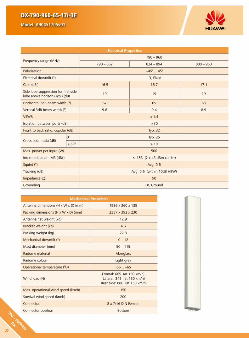
DX-790-960-65-17i-3F
Model: A90451705v01
Electrical Properties
Frequency range (MHz)790-960
790-862 824-894 880-960
Polarization +45° , -45°
Electrical downtilt (°) 3, Fixed
Gain (dBi) 16.5 16.7 17.1
Side lobe suppression for first side lobe above horizon (Typ.) (dB)
19 19 19
Horizontal 3dB beam width (°) 67 65 63
Vertical 3dB beam width (°) 9.8 9.4 8.9
VSWR < 1.4
Isolation between ports (dB) ≥ 30
Front to back ratio, copolar (dB) Typ. 32
Cross polar ratio (dB)0° Typ. 25
±60° ≥ 10
Max. power per input (W) 500
Intermodulation IM3 (dBc) ≤ -153 (2 x 43 dBm carrier)
Squint (°) Avg. 0.6
Tracking (dB) Avg. 0.6 (within 10dB HBW)
Impedance (Ω) 50
Grounding DC Ground
Mechanical Properties
Antenna dimensions (H x W x D) (mm) 1936 x 260 x 135
Packing dimensions (H x W x D) (mm) 2357 x 392 x 230
Antenna net weight (kg) 12.9
Bracket weight (kg) 4.6
Packing weight (kg) 22.3
Mechanical downtilt (°) 0-12
Mast diameter (mm) 50-115
Radome material Fiberglass
Radome colour Light grey
Operational temperature () -55 .. +65
Wind load (N)Frontal: 665 (at 150 km/h) Lateral: 345 (at 150 km/h)
Rear side: 880 (at 150 km/h)
Max. operational wind speed (km/h) 150
Survival wind speed (km/h) 200
Connector 2 x 7/16 DIN Female
Connector position Bottom
9
790-960M
Hz
DX
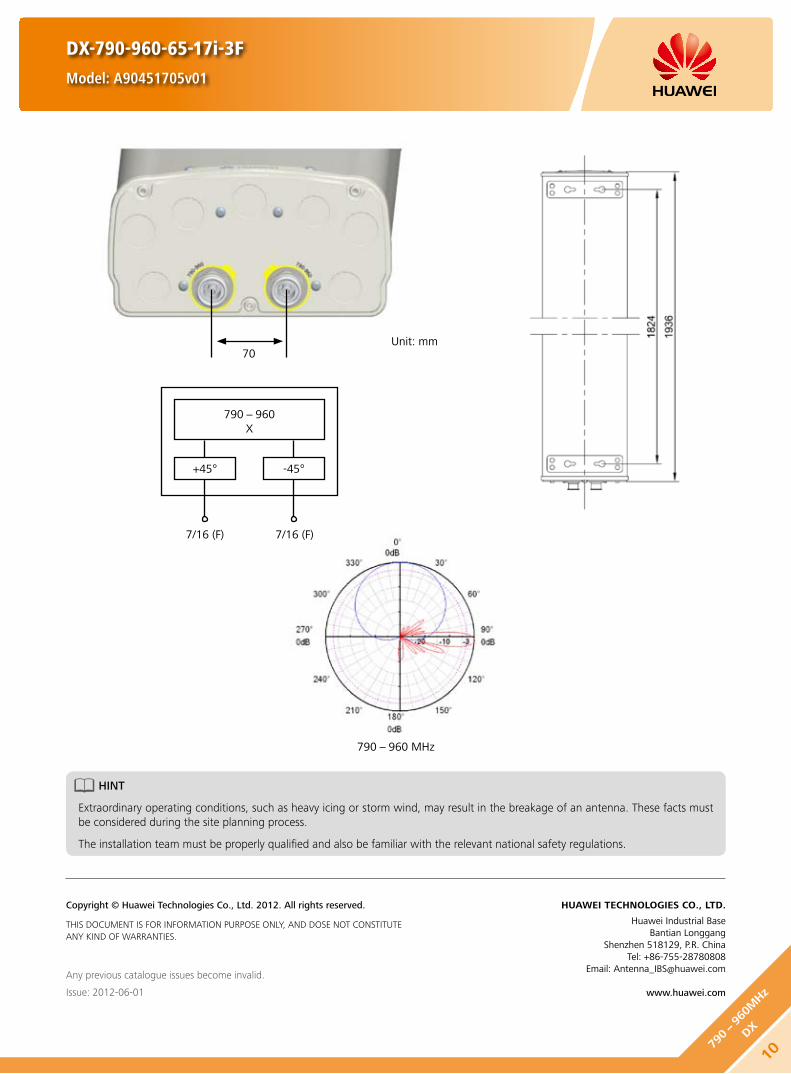
DX-790-960-65-17i-3F
Model: A90451705v01
790-960 MHz
790-960X
+45°
7/16 (F) 7/16 (F)
-45°
Unit: mm70
HINT
Extraordinary operating conditions, such as heavy icing or storm wind, may result in the breakage of an antenna. These facts must be considered during the site planning process.
The installation team must be properly qualified and also be familiar with the relevant national safety regulations.
Any previous catalogue issues become invalid.
Issue: 2012-06-01
HUAWEI TECHNOLOGIES CO., LTD.
Huawei Industrial BaseBantian Longgang
Shenzhen 518129, P.R. ChinaTel: +86-755-28780808
Email: [email protected]
www.huawei.com
Copyright © Huawei Technologies Co., Ltd. 2012. All rights reserved.
THIS DOCUMENT IS FOR INFORMATION PURPOSE ONLY, AND DOSE NOT CONSTITUTE ANY KIND OF WARRANTIES.
1079
0-96
0MHz
DX

DX-790-960-65-17i-6F
Model: A90451709
Electrical Properties
Frequency range (MHz)790-960
790-862 824-894 880-960
Polarization +45° , -45°
Electrical downtilt (°) 6, Fixed
Gain (dBi) 16.5 16.7 17.1
Side lobe suppression for first side lobe above horizon (Typ.) (dB)
19 19 18
Horizontal 3dB beam width (°) 67 65 63
Vertical 3dB beam width (°) 9.8 9.4 8.9
VSWR < 1.4
Isolation between ports (dB) ≥ 30
Front to back ratio, copolar (dB) Typ. 30
Cross polar ratio (dB)0° Typ. 25
±60° ≥ 10
Max. power per input (W) 500
Intermodulation IM3 (dBc) ≤ -153 (2 x 43 dBm carrier)
Max. power per input (W) Avg. 0.6
Intermodulation IM3 (dBc) Avg. 0.8 (within 10dB HBW)
Impedance (Ω) 50
Grounding DC Ground
Mechanical Properties
Antenna dimensions (H x W x D) (mm) 1936 x 260 x 135
Packing dimensions (H x W x D) (mm) 2357 x 392 x 230
Antenna net weight (kg) 12.9
Bracket weight (kg) 4.6
Packing weight (kg) 22.3
Mechanical downtilt (°) 0-12
Mast diameter (mm) 50-115
Radome material Fiberglass
Radome colour Light grey
Operational temperature () -55 .. +65
Wind load (N)Frontal: 665 (at 150 km/h) Lateral: 345 (at 150 km/h)
Rear side: 880 (at 150 km/h)
Max. operational wind speed (km/h) 150
Survival wind speed (km/h) 200
Connector 2 x 7/16 DIN Female
Connector position Bottom
11
790-960M
Hz
DX
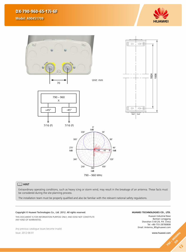
DX-790-960-65-17i-6F
Model: A90451709
790-960 MHz
790-960X
+45°
7/16 (F) 7/16 (F)
-45°
Unit: mm70
HINT
Extraordinary operating conditions, such as heavy icing or storm wind, may result in the breakage of an antenna. These facts must be considered during the site planning process.
The installation team must be properly qualified and also be familiar with the relevant national safety regulations.
Any previous catalogue issues become invalid.
Issue: 2012-06-01
HUAWEI TECHNOLOGIES CO., LTD.
Huawei Industrial BaseBantian Longgang
Shenzhen 518129, P.R. ChinaTel: +86-755-28780808
Email: [email protected]
www.huawei.com
Copyright © Huawei Technologies Co., Ltd. 2012. All rights reserved.
THIS DOCUMENT IS FOR INFORMATION PURPOSE ONLY, AND DOSE NOT CONSTITUTE ANY KIND OF WARRANTIES.
1279
0-96
0MHz
DX

DX-790-960-65-17.5i-M
Model: A79451700v01
Electrical Properties
Frequency range (MHz)790-960
790-862 824-894 880-960
Polarization +45°, -45°
Electrical downtilt (°) 0-10, continuously adjustable
Gain (dBi)0° 5° 10° 0° 5° 10° 0° 5° 10°
17.0 17.1 16.7 17.1 17.3 17.0 17.3 17.6 17.1
Side lobe suppression for first side lobe above horizon (Typ.) (dB)
0° 5° 10° 0° 5° 10° 0° 5° 10°
20 18 18 20 20 18 20 18 18
Horizontal 3dB beam width (°) 66 66 64
Vertical 3dB beam width (°) 8.3 7.9 7.3
VSWR < 1.5
Isolation between ports (dB) ≥ 30
Front to back ratio, copolar (dB) Typ. 30
Cross polar ratio (dB)0° Typ. 25
±60° ≥ 10
Max. power per input (W) 500 (at 50 ambient temperature)
Intermodulation IM3 (dBc) ≤ -153 (2 x 43 dBm carrier)
Squint (°) Avg. 1
Tracking (dB) Avg. 1 (within 10dB HBW)
Impedance (Ω) 50
Grounding DC Ground
Mechanical Properties
Antenna dimensions (H x W x D) (mm) 2535 x 259 x 135
Packing dimensions (H x W x D) (mm) 2952 x 392 x 230
Antenna net weight (kg) 17.5
Bracket weight (kg) 5.6
Packing weight (kg) 29
Mechanical downtilt (°) 0-8
Mast diameter (mm) 50-115
Radome material Fiberglass
Radome colour Light grey
Operational temperature () -55 .. +65
Wind load (N)Frontal: 910 (at 150 km/h)Lateral: 470 (at 150 km/h)
Rear side: 1200 (at 150 km/h)
Max. operational wind speed (km/h) 150
Survival wind speed (km/h) 200
Connector 2 x 7/16 DIN Female
Connector position Bottom
13
790-960M
Hz
DX

790-960 MHz
790-960X
+45°
7/16 (F) 7/16 (F)
-45°
DX-790-960-65-17.5i-M
Model: A79451700v01
HINT
Extraordinary operating conditions, such as heavy icing or storm wind, may result in the breakage of an antenna. These facts must be considered during the site planning process.
The installation team must be properly qualified and also be familiar with the relevant national safety regulations.
Any previous catalogue issues become invalid.
Issue: 2012-06-01
HUAWEI TECHNOLOGIES CO., LTD.
Huawei Industrial BaseBantian Longgang
Shenzhen 518129, P.R. ChinaTel: +86-755-28780808
Email: [email protected]
www.huawei.com
Copyright © Huawei Technologies Co., Ltd. 2012. All rights reserved.
THIS DOCUMENT IS FOR INFORMATION PURPOSE ONLY, AND DOSE NOT CONSTITUTE ANY KIND OF WARRANTIES.
Unit: mm
56
70
1479
0-96
0MHz
DX

DX-790-960-65-18i-0F
Model: A90451802v01
Electrical Properties
Frequency range (MHz)790-960
790-862 824-894 880-960
Polarization +45° , -45°
Electrical downtilt (°) 0, Fixed
Gain (dBi) 17.5 17.7 18.0
Side lobe suppression for first side lobe above horizon (Typ.) (dB)
21 21 21
Horizontal 3dB beam width (°) 67 65 63
Vertical 3dB beam width (°) 7.8 7.5 7.1
VSWR < 1.4
Isolation between ports (dB) ≥ 30
Front to back ratio, copolar (dB) Typ. 32
Cross polar ratio (dB)0° Typ. 25
±60° ≥ 10
Max. power per input (W) 500
Intermodulation IM3 (dBc) ≤ -153 (2 x 43 dBm carrier)
Squint (°) Avg. 0.5
Tracking (dB) Avg. 0.5 (within 10dB HBW)
Impedance (Ω) 50
Grounding DC Ground
Mechanical Properties
Antenna dimensions (H x W x D) (mm) 2535 x 259 x 135
Packing dimensions (H x W x D) (mm) 2952 x 392 x 230
Antenna net weight (kg) 16.3
Bracket weight (kg) 5.6
Packing weight (kg) 27.5
Mechanical downtilt (°) 0-8
Mast diameter (mm) 50-115
Radome material Fiberglass
Radome colour Light grey
Operational temperature () -55 .. +65
Wind load (N)Frontal: 910 (at 150 km/h)Lateral: 470 (at 150 km/h)
Rear side: 1200 (at 150 km/h)
Max. operational wind speed (km/h) 150
Survival wind speed (km/h) 200
Connector 2 x 7/16 DIN Female
Connector position Bottom
15
790-960M
Hz
DX

DX-790-960-65-18i-0F
Model: A90451802v01
790-960 MHz
790-960X
+45°
7/16 (F) 7/16 (F)
-45°
Unit: mm70
HINT
Extraordinary operating conditions, such as heavy icing or storm wind, may result in the breakage of an antenna. These facts must be considered during the site planning process.
The installation team must be properly qualified and also be familiar with the relevant national safety regulations.
Any previous catalogue issues become invalid.
Issue: 2012-06-01
HUAWEI TECHNOLOGIES CO., LTD.
Huawei Industrial BaseBantian Longgang
Shenzhen 518129, P.R. ChinaTel: +86-755-28780808
Email: [email protected]
www.huawei.com
Copyright © Huawei Technologies Co., Ltd. 2012. All rights reserved.
THIS DOCUMENT IS FOR INFORMATION PURPOSE ONLY, AND DOSE NOT CONSTITUTE ANY KIND OF WARRANTIES.
1679
0-96
0MHz
DX

DX-790-960-65-18i-3F
Model: A90451805v01
Electrical Properties
Frequency range (MHz)790-960
790-862 824-894 880-960
Polarization +45° , -45°
Electrical downtilt (°) 3, Fixed
Gain (dBi) 17.5 17.7 18.0
Side lobe suppression for first side lobe above horizon (Typ.) (dB)
20 20 20
Horizontal 3dB beam width (°) 67 65 63
Vertical 3dB beam width (°) 7.8 7.5 7.1
VSWR < 1.4
Isolation between ports (dB) ≥ 30
Front to back ratio, copolar (dB) Typ. 32
Cross polar ratio (dB)0° Typ. 25
±60° ≥ 10
Max. power per input (W) 500
Intermodulation IM3 (dBc) ≤ -153 (2 x 43 dBm carrier)
Squint (°) Avg. 0.5
Tracking (dB) Avg. 0.5 (within 10dB HBW)
Impedance (Ω) 50
Grounding DC Ground
Mechanical Properties
Antenna dimensions (H x W x D) (mm) 2535 x 259 x 135
Packing dimensions (H x W x D) (mm) 2952 x 392 x 230
Antenna net weight (kg) 16.3
Bracket weight (kg) 5.6
Packing weight (kg) 27.5
Mechanical downtilt (°) 0-8
Mast diameter (mm) 50-115
Radome material Fiberglass
Radome colour Light grey
Operational temperature () -55 .. +65
Wind load (N)Frontal: 910 (at 150 km/h)Lateral: 470 (at 150 km/h)
Rear side: 1200 (at 150 km/h)
Max. operational wind speed (km/h) 150
Survival wind speed (km/h) 200
Connector 2 x 7/16 DIN Female
Connector position Bottom
17
790-960M
Hz
DX

DX-790-960-65-18i-3F
Model: A90451805v01
790-960 MHz
790-960X
+45°
7/16 (F) 7/16 (F)
-45°
Unit: mm70
HINT
Extraordinary operating conditions, such as heavy icing or storm wind, may result in the breakage of an antenna. These facts must be considered during the site planning process.
The installation team must be properly qualified and also be familiar with the relevant national safety regulations.
Any previous catalogue issues become invalid.
Issue: 2012-06-01
HUAWEI TECHNOLOGIES CO., LTD.
Huawei Industrial BaseBantian Longgang
Shenzhen 518129, P.R. ChinaTel: +86-755-28780808
Email: [email protected]
www.huawei.com
Copyright © Huawei Technologies Co., Ltd. 2012. All rights reserved.
THIS DOCUMENT IS FOR INFORMATION PURPOSE ONLY, AND DOSE NOT CONSTITUTE ANY KIND OF WARRANTIES.
1879
0-96
0MHz
DX

806-866 MHz 824-894 MHz 880-960 MHz
DX-806-960-65-15i-0F
Model: A90451500
Electrical Properties
Frequency range (MHz) 806-866 824-894 880-960Polarization +45° , -45°
VSWR ≤1.4
Gain (dBi) 14.6 14.8 15.0Side lobe suppression for first side lobe above horizon (dB)
Typ. 17 Typ. 17 Typ. 17
Horizontal 3dB beam width (°) 67 65 62
Vertical 3dB beam width (°) 15.5 14.6 14.0Isolation between ports (dB) ≥30Front to back ratio, copolar (dB) ≥25Cross polar ratio (dB) ≥15Electrical downtilt (°) 0Intermodulation IM3 (dBc) ≤-150 (2 x 43 dBm carrier)Max. CW input power (W) 500Impedance (Ω) 50Grounding DC Ground
Mechanical Properties
Dimensions (H x W x D) (mm) 1322 x 289 x 85Packing dimensions (H x W x D) (mm) 1662 x 405 x 175Net weight (kg) 9.5Bracket weight (kg) 4.6Packing weight (kg) 18
Mechanical downtilt (°) 0-16
Mast diameter (mm) 50-115Radomematerial FiberglassOperating temperature () -55 .. +65
Wind load (N)Frontal: 290 (v=150 km/h)Lateral: 120 (v=150 km/h)
Rear side: 425 (v=150 km/h)Max. wind velocity (km/h) 200Connector 2 x 7/16 DIN Female
Any previous catalogue issues become invalid.
Issue: 2012-06-01
HUAWEI TECHNOLOGIES CO., LTD.
Huawei Industrial BaseBantian Longgang
Shenzhen 518129, P.R. ChinaTel: +86-755-28780808
Email: [email protected]
www.huawei.com
Copyright © Huawei Technologies Co., Ltd. 2012. All rights reserved.
THIS DOCUMENT IS FOR INFORMATION PURPOSE ONLY, AND DOSE NOT CONSTITUTE ANY KIND OF WARRANTIES.
806-960X
+45°
7/16 (F) 7/16 (F)
-45°
19
806-960M
Hz
DX

806-866 MHz 824-894 MHz 880-960 MHz
DX-806-960-65-15i-6F
Model: A90451501
Electrical Properties
Frequency range (MHz) 806-866 824-894 880-960Polarization +45° , -45°
VSWR ≤1.4
Gain (dBi) 14.5 14.7 14.9Side lobe suppression for first side lobe above horizon (dB)
Typ. 17 Typ. 17 Typ. 17
Horizontal 3dB beam width (°) 67 65 62
Vertical 3dB beam width (°) 15.5 14.9 14.0Isolation between ports (dB) ≥30Front to back ratio, copolar (dB) ≥25Cross polar ratio (dB) ≥15Electrical downtilt (°) 6Intermodulation IM3 (dBc) ≤-150 (2 x 43 dBm carrier)Max. CW input power (W) 500Impedance (Ω) 50Grounding DC Ground
Mechanical Properties
Dimensions (H x W x D) (mm) 1322 x 289 x 85Packing dimensions (H x W x D) (mm) 1662 x 405 x 175Net weight (kg) 9.5Bracket weight (kg) 4.6Packing weight (kg) 18
Mechanical downtilt (°) 0-16
Mast diameter (mm) 50-115Radomematerial FiberglassOperating temperature () -55 .. +65
Wind load (N)Frontal: 290 (v=150 km/h)Lateral: 120 (v=150 km/h)
Rear side: 425 (v=150 km/h)Max. wind velocity (km/h) 200Connector 2 x 7/16 DIN Female
Any previous catalogue issues become invalid.
Issue: 2012-06-01
HUAWEI TECHNOLOGIES CO., LTD.
Huawei Industrial BaseBantian Longgang
Shenzhen 518129, P.R. ChinaTel: +86-755-28780808
Email: [email protected]
www.huawei.com
Copyright © Huawei Technologies Co., Ltd. 2012. All rights reserved.
THIS DOCUMENT IS FOR INFORMATION PURPOSE ONLY, AND DOSE NOT CONSTITUTE ANY KIND OF WARRANTIES.
806-960X
+45°
7/16 (F) 7/16 (F)
-45°
2080
6-96
0MHz
DX

806-866 MHz 824-894 MHz 880-960 MHz
DX-806-960-65-15i-3F
Model: A90451505
Electrical Properties
Frequency range (MHz) 806-866 824-894 880-960Polarization +45° , -45°
VSWR ≤1.5
Gain (dBi) 14.7 15.0 15.3Side lobe suppression for first side lobe above horizon (dB)
Typ. 17 Typ. 17 Typ. 17
Horizontal 3dB beam width (°) 67 65 62
Vertical 3dB beam width (°) 15.5 14.6 14.0Isolation between ports (dB) ≥28Front to back ratio, copolar (dB) ≥25Cross polar ratio (dB) ≥15Electrical downtilt (°) 3Intermodulation IM3 (dBc) ≤-150 (2 x 43 dBm carrier)Max. CW input power (W) 500Impedance (Ω) 50Grounding DC Ground
Mechanical Properties
Dimensions (H x W x D) (mm) 1322 x 289 x 85Packing dimensions (H x W x D) (mm) 1662 x 405 x 175Net weight (kg) 9.5Bracket weight (kg) 4.6Packing weight (kg) 18
Mechanical downtilt (°) 0-16
Mast diameter (mm) 50-115Radomematerial FiberglassOperating temperature () -55 .. +65
Wind load (N)Frontal: 290 (v=150 km/h)Lateral: 120 (v=150 km/h)
Rear side: 425 (v=150 km/h)Max. wind velocity (km/h) 200Connector 2 x 7/16 DIN Female
Any previous catalogue issues become invalid.
Issue: 2012-06-01
HUAWEI TECHNOLOGIES CO., LTD.
Huawei Industrial BaseBantian Longgang
Shenzhen 518129, P.R. ChinaTel: +86-755-28780808
Email: [email protected]
www.huawei.com
Copyright © Huawei Technologies Co., Ltd. 2012. All rights reserved.
THIS DOCUMENT IS FOR INFORMATION PURPOSE ONLY, AND DOSE NOT CONSTITUTE ANY KIND OF WARRANTIES.
806-960X
+45°
7/16 (F) 7/16 (F)
-45°
21
806-960M
Hz
DX

DX-806-960-65-15.3i-0F
Model: A90451502
Any previous catalogue issues become invalid.
Issue: 2012-06-01
HUAWEI TECHNOLOGIES CO., LTD.
Huawei Industrial BaseBantian Longgang
Shenzhen 518129, P.R. ChinaTel: +86-755-28780808
Email: [email protected]
www.huawei.com
Copyright © Huawei Technologies Co., Ltd. 2012. All rights reserved.
THIS DOCUMENT IS FOR INFORMATION PURPOSE ONLY, AND DOSE NOT CONSTITUTE ANY KIND OF WARRANTIES.
806-866 MHz 824-894 MHz 880-960 MHz
Electrical Properties
Frequency range (MHz) 806-866 824-894 880-960Polarization +45° , -45°
VSWR ≤1.4 ≤1.4 ≤1.3
Gain (dBi) 14.8 15.0 15.3Side lobe suppression for first side lobe above horizon (dB)
≥19 ≥19 ≥19
Horizontal 3dB beam width (°) 68 66 64
Vertical 3dB beam width (°) 15.9 15.4 14.3Isolation between ports (dB) ≥30Front to back ratio, copolar (dB) ≥30
Cross polar ratio (dB)0° ≥20±60° ≥10
Electrical downtilt (°) 0Intermodulation IM3 (dBc) ≤-150 (2 x 43 dBm carrier)Max. CW input power (W) 500Impedance (Ω) 50Grounding DC Ground
Mechanical Properties
Dimensions (H x W x D) (mm) 1312 x 295 x 126Packing dimensions (H x W x D) (mm) 1622 x 405 x 205Net weight (kg) 10.5Bracket weight (kg) 4.6Packing weight (kg) 18
Mechanical downtilt (°) 0-16
Mast diameter (mm) 50-115Radomematerial FiberglassOperating temperature () -55 .. +65
Wind load (N)Frontal: 290 (v=150 km/h)Lateral: 180 (v=150 km/h)
Rear side: 430 (v=150 km/h)Max. wind velocity (km/h) 200Connector 2 x 7/16 DIN Female
806-960X
+45°
7/16 (F) 7/16 (F)
-45°
2280
6-96
0MHz
DX

806-866 MHz 824-894 MHz 880-960 MHz
806-960X
+45°
7/16 (F) 7/16 (F)
-45°
DX-806-960-65-15.3i-6F
Model: A90451503
Electrical Properties
Frequency range (MHz) 806-866 824-894 880-960Polarization +45° , -45°
VSWR ≤1.35 ≤1.35 ≤1.3
Gain (dBi) 14.7 14.9 15.2Side lobe suppression for first side lobe above horizon (dB)
≥19 ≥19 ≥19
Horizontal 3dB beam width (°) 68 66 64
Vertical 3dB beam width (°) 15.9 15.4 14.3Isolation between ports (dB) ≥30Front to back ratio, copolar (dB) ≥30
Cross polar ratio (dB)0° ≥20±60° ≥10
Electrical downtilt (°) 6Intermodulation IM3 (dBc) ≤-150 (2 x 43 dBm carrier)Max. CW input power (W) 500Impedance (Ω) 50Grounding DC Ground
Any previous catalogue issues become invalid.
Issue: 2012-06-01
HUAWEI TECHNOLOGIES CO., LTD.
Huawei Industrial BaseBantian Longgang
Shenzhen 518129, P.R. ChinaTel: +86-755-28780808
Email: [email protected]
www.huawei.com
Copyright © Huawei Technologies Co., Ltd. 2012. All rights reserved.
THIS DOCUMENT IS FOR INFORMATION PURPOSE ONLY, AND DOSE NOT CONSTITUTE ANY KIND OF WARRANTIES.
Mechanical Properties
Dimensions (H x W x D) (mm) 1312 x 295 x 126Packing dimensions (H x W x D) (mm) 1622 x 405 x 205Net weight (kg) 10.5Bracket weight (kg) 4.6Packing weight (kg) 18
Mechanical downtilt (°) 0-16
Mast diameter (mm) 50-115Radomematerial FiberglassOperating temperature () -55 .. +65
Wind load (N)Frontal: 290 (v=150 km/h)Lateral: 180 (v=150 km/h)
Rear side: 430 (v=150 km/h)Max. wind velocity (km/h) 200Connector 2 x 7/16 DIN Female
23
806-960M
Hz
DX

Electrical Properties
Frequency range (MHz) 806-866 824-894 880-960Polarization +45° , -45°
VSWR ≤1.37
Gain (dBi) 16.6 16.8 17.0Side lobe suppression for first side lobe above horizon (dB)
Typ. 17 Typ. 17 Typ. 17
Horizontal 3dB beam width (°) 67 64 63
Vertical 3dB beam width (°) 11.0 10.5 10.0Isolation between ports (dB) ≥28Front to back ratio, copolar (dB) ≥25Cross polar ratio (dB) ≥15Electrical downtilt (°) 0Intermodulation IM3 (dBc) ≤-150 (2 x 43 dBm carrier)Max. CW input power (W) 500Impedance (Ω) 50Grounding DC Ground
Mechanical Properties
Dimensions (H x W x D) (mm) 1932 x 289 x 85Packing dimensions (H x W x D) (mm) 2272 x 405 x 175Net weight (kg) 13.5Bracket weight (kg) 4.6Packing weight (kg) 20.8
Mechanical downtilt (°) 0-12
Mast diameter (mm) 50-115Radomematerial FiberglassOperating temperature () -55 .. +65
Wind load (N)Frontal: 420 (v=150 km/h)Lateral: 175 (v=150 km/h)
Rear side: 620 (v=150 km/h)Max. wind velocity (km/h) 200Connector 2 x 7/16 DIN Female
806-866 MHz 824-894 MHz 880-960 MHz
DX-806-960-65-17i-0F
Model: A90451700
Any previous catalogue issues become invalid.
Issue: 2012-06-01
HUAWEI TECHNOLOGIES CO., LTD.
Huawei Industrial BaseBantian Longgang
Shenzhen 518129, P.R. ChinaTel: +86-755-28780808
Email: [email protected]
www.huawei.com
Copyright © Huawei Technologies Co., Ltd. 2012. All rights reserved.
THIS DOCUMENT IS FOR INFORMATION PURPOSE ONLY, AND DOSE NOT CONSTITUTE ANY KIND OF WARRANTIES.
806-960X
+45°
7/16 (F) 7/16 (F)
-45°
2480
6-96
0MHz
DX

DX-806-960-65-17i-3F
Model: A90451705
Electrical Properties
Frequency range (MHz) 806-866 824-894 880-960Polarization +45° , -45°
VSWR ≤1.5
Gain (dBi) 16.7 17.0 17.2Side lobe suppression for first side lobe above horizon (dB)
Typ. 17 Typ. 17 Typ. 17
Horizontal 3dB beam width (°) 67 64 63
Vertical 3dB beam width (°) 11.0 10.5 10.0Isolation between ports (dB) ≥28Front to back ratio, copolar (dB) ≥25Cross polar ratio (dB) ≥15Electrical downtilt (°) 3Intermodulation IM3 (dBc) ≤-150 (2 x 43 dBm carrier)Max. CW input power (W) 500Impedance (Ω) 50Grounding DC Ground
Mechanical Properties
Dimensions (H x W x D) (mm) 1932 x 289 x 85Packing dimensions (H x W x D) (mm) 2272 x 405 x 175Net weight (kg) 13.5Bracket weight (kg) 4.6Packing weight (kg) 21.6
Mechanical downtilt (°) 0-12
Mast diameter (mm) 50-115Radomematerial FiberglassOperating temperature () -55 .. +65
Wind load (N)Frontal: 420 (v=150 km/h)Lateral: 175 (v=150 km/h)
Rear side: 620 (v=150 km/h)Max. wind velocity (km/h) 200Connector 2 x 7/16 DIN Female
Any previous catalogue issues become invalid.
Issue: 2012-06-01
HUAWEI TECHNOLOGIES CO., LTD.
Huawei Industrial BaseBantian Longgang
Shenzhen 518129, P.R. ChinaTel: +86-755-28780808
Email: [email protected]
www.huawei.com
Copyright © Huawei Technologies Co., Ltd. 2012. All rights reserved.
THIS DOCUMENT IS FOR INFORMATION PURPOSE ONLY, AND DOSE NOT CONSTITUTE ANY KIND OF WARRANTIES.
806-960X
+45°
7/16 (F) 7/16 (F)
-45°
806-866 MHz 824-894 MHz 880-960 MHz
25
806-960M
Hz
DX

DX-806-960-90-17i-3F
Model: A90451706
Electrical Properties
Frequency range (MHz)806-960
806-866 824-894 880-960
Polarization +45° , -45°
Electrical downtilt (°) 3, Fixed
Gain (dBi) 16.4 16.7 16.9
Side lobe suppression for first side lobe above horizon (Typ.) (dB)
19 19 19
Horizontal 3dB beam width (°) 88 86 84
Vertical 3dB beam width (°) 7.9 7.6 7.1
VSWR < 1.4
Isolation between ports (dB) ≥ 30
Front to back ratio, copolar (dB) ≥ 25
Cross polar ratio (dB)0° Typ. 20
±60° ≥ 10
Max. power per input (W) 500
Intermodulation IM3 (dBc) ≤ -153 (2 x 43 dBm carrier)
Squint (°) Avg. 1.0
Tracking (dB) Avg. 0.6 (within 10dB HBW)
Impedance (Ω) 50
Grounding DC Ground
Mechanical Properties
Antenna dimensions (H x W x D) (mm) 2526 x 268 x 125
Packing dimensions (H x W x D) (mm) 2842 x 405 x 205
Antenna net weight (kg) 17.4
Bracket weight (kg) 4.6
Packing weight (kg) 28.8
Mechanical downtilt (°) 0-8
Mast diameter (mm) 50-115
Radome material Fiberglass
Radome colour Light grey
Operational temperature () -55 .. +65
Wind load (N)Frontal: 510 (at 150 km/h) Lateral: 340 (at 150 km/h)
Rear side: 750 (at 150 km/h)
Max. operational wind speed (km/h) 150
Survival wind speed (km/h) 200
Connector 2 x 7/16 DIN Female
Connector position Bottom
2680
6-96
0MHz
DX

DX-806-960-90-17i-3F
Model: A90451706
806-960 MHz
806-960X
+45°
7/16 (F) 7/16 (F)
-45°
Unit: mm
120
HINT
Extraordinary operating conditions, such as heavy icing or storm wind, may result in the breakage of an antenna. These facts must be considered during the site planning process.
The installation team must be properly qualified and also be familiar with the relevant national safety regulations.
Any previous catalogue issues become invalid.
Issue: 2012-06-01
HUAWEI TECHNOLOGIES CO., LTD.
Huawei Industrial BaseBantian Longgang
Shenzhen 518129, P.R. ChinaTel: +86-755-28780808
Email: [email protected]
www.huawei.com
Copyright © Huawei Technologies Co., Ltd. 2012. All rights reserved.
THIS DOCUMENT IS FOR INFORMATION PURPOSE ONLY, AND DOSE NOT CONSTITUTE ANY KIND OF WARRANTIES.
27
806-960M
Hz
DX

806-866 MHz 824-894 MHz 880-960 MHz
DX-806-960-90-17i-0F
Model: A90451600
Electrical Properties
Frequency range (MHz) 806-866 824-894 880-960Polarization +45° , -45°
VSWR ≤ 1.4
Gain (dBi) 16.5 16.8 17.0Side lobe suppression for first side lobe above horizon (dB)
≥18 ≥18 ≥18
Horizontal 3dB beam width (°) 88 86 84
Vertical 3dB beam width (°) 8.1 7.9 7.2Isolation between ports (dB) ≥30Front to back ratio, copolar (dB) ≥25
Cross polar ratio (dB)0° ≥15±60° ≥10
Electrical downtilt (°) 0Intermodulation IM3 (dBc) ≤-150 (2 x 43 dBm carrier)Max. CW input power (W) 500Impedance (Ω) 50Grounding DC Ground
Any previous catalogue issues become invalid.
Issue: 2012-06-01
HUAWEI TECHNOLOGIES CO., LTD.
Huawei Industrial BaseBantian Longgang
Shenzhen 518129, P.R. ChinaTel: +86-755-28780808
Email: [email protected]
www.huawei.com
Copyright © Huawei Technologies Co., Ltd. 2012. All rights reserved.
THIS DOCUMENT IS FOR INFORMATION PURPOSE ONLY, AND DOSE NOT CONSTITUTE ANY KIND OF WARRANTIES.
Mechanical Properties
Dimensions (H x W x D) (mm) 2526 x 268 x 125Packing dimensions (H x W x D) (mm) 2842 x 405 x 205Net weight (kg) 16.1Bracket weight (kg) 4.6Packing weight (kg) 27.3
Mechanical downtilt (°) 0-8
Mast diameter (mm) 50-115Radomematerial FiberglassOperating temperature () -55 .. +65
Wind load (N)Frontal: 510 (v=150 km/h)Lateral: 340 (v=150 km/h)
Rear side: 750 (v=150 km/h)Max. wind velocity (km/h) 200Connector 2 x 7/16 DIN Female
806-960X
+45°
7/16 (F) 7/16 (F)
-45°
2880
6-96
0MHz
DX

DX-806-960-90-17i-M
Model: A90451704
Mechanical Properties
Dimensions (H x W x D) (mm) 2526 x 268 x 125Packing dimensions (H x W x D) (mm) 2842 x 399 x 215Net weight (kg) 18.6Bracket weight (kg) 4.6Packing weight (kg) 27
Mechanical downtilt (°) 0-8
Mast diameter (mm) 50-115Radomematerial FiberglassOperating temperature () -55 .. +65
Wind load (N)Frontal: 510 (v=150 km/h)Lateral: 340 (v=150 km/h)
Rear side: 750 (v=150 km/h)Max. wind velocity (km/h) 200Connector 2 x 7/16 DIN Female
Electrical Properties
Frequency range (MHz) 806-866 824-894 880-960Polarization +45° , -45°
VSWR ≤ 1.45 ≤ 1.4 ≤ 1.4
Gain (°) 2 6 9.5 2 6 9.5 2 6 9.5(dBi) 16.1 16.2 16.0 16.3 16.4 16.2 16.4 16.5 16.3
Side lobe suppression for first side lobe above horizon
(°) 2 6 9.5 2 6 9.5 2 6 9.5(dBi) 18 18 18 18 18 18 18 18 18
Horizontal 3dB beam width (°) 88 86 85
Vertical 3dB beam width (°) 8.2 7.6 7.4Isolation between ports (dB) ≥30Front to back ratio, copolar (dB) ≥25
Cross polar ratio (dB)0° ≥20±60° Typ. 13
Electrical downtilt (°) 2-9.5Intermodulation IM3 (dBc) ≤-150 (2 x 43 dBm carrier)Max. CW input power (W) 500Impedance (Ω) 50Grounding DC Ground
806-866 MHz 824-894 MHz 880-960 MHz
Any previous catalogue issues become invalid.
Issue: 2012-06-01
HUAWEI TECHNOLOGIES CO., LTD.
Huawei Industrial BaseBantian Longgang
Shenzhen 518129, P.R. ChinaTel: +86-755-28780808
Email: [email protected]
www.huawei.com
Copyright © Huawei Technologies Co., Ltd. 2012. All rights reserved.
THIS DOCUMENT IS FOR INFORMATION PURPOSE ONLY, AND DOSE NOT CONSTITUTE ANY KIND OF WARRANTIES.
806-960X
+45°
7/16 (F) 7/16 (F)
-45°
29
806-960M
Hz
DX

806-866 MHz 824-894 MHz 880-960 MHz
DX-806-960-65-17.5i-M
Model: A90451701
Any previous catalogue issues become invalid.
Issue: 2012-06-01
HUAWEI TECHNOLOGIES CO., LTD.
Huawei Industrial BaseBantian Longgang
Shenzhen 518129, P.R. ChinaTel: +86-755-28780808
Email: [email protected]
www.huawei.com
Copyright © Huawei Technologies Co., Ltd. 2012. All rights reserved.
THIS DOCUMENT IS FOR INFORMATION PURPOSE ONLY, AND DOSE NOT CONSTITUTE ANY KIND OF WARRANTIES.
806-960X
+45°
7/16 (F) 7/16 (F)
-45°
Mechanical Properties
Dimensions (H x W x D) (mm) 2515 x 289 x 85Packing dimensions (H x W x D) (mm) 2855 x 405 x 175Net weight (kg) 15.5Bracket weight (kg) 4.6Packing weight (kg) 25.3
Mechanical downtilt (°) 0-8
Mast diameter (mm) 50-115Radomematerial FiberglassOperating temperature () -55 .. +65
Wind load (N)Frontal: 540 (v=150 km/h)Lateral: 230 (v=150 km/h)
Rear side: 810 (v=150 km/h)Max. wind velocity (km/h) 200Connector 2 x 7/16 DIN Female
Electrical Properties
Frequency range (MHz) 806-866 824-894 880-960Polarization +45° , -45°
VSWR ≤ 1.47 ≤ 1.4 ≤ 1.4
Gain (°) 2 6 9.5 2 6 9.5 2 6 9.5(dBi) 17.1 17.2 16.9 17.2 17.3 17.0 17.4 17.5 17.2
Side lobe suppression for first side lobe above horizon
(°) 2 6 9.5 2 6 9.5 2 6 9.5(dBi) 18 17 16 18 17 16 18 17 16
Horizontal 3dB beam width (°) 68 66 65
Vertical 3dB beam width (°) 8.8 8.5 7.8Isolation between ports (dB) ≥30Front to back ratio, copolar (dB) ≥28
Cross polar ratio (dB)0° ≥18±60° ≥10
Electrical downtilt (°) 2-9.5Intermodulation IM3 (dBc) ≤-150 (2 x 43 dBm carrier)Max. CW input power (W) 500Impedance (Ω) 50Grounding DC Ground
3080
6-96
0MHz
DX

DX-806-960-65-18i-0F
Model: A90451800
Electrical Properties
Frequency range (MHz) 806-866 824-894 880-960Polarization +45° , -45°
VSWR ≤1.45
Gain (dBi) 17.4 17.6 17.8Side lobe suppression for first side lobe above horizon (dB)
Typ. 17 Typ. 17 Typ. 17
Horizontal 3dB beam width (°) 67 64 63
Vertical 3dB beam width (°) 8.2 7.5 7.0Isolation between ports (dB) ≥28Front to back ratio, copolar (dB) ≥25Cross polar ratio (dB) ≥15Electrical downtilt (°) 0Intermodulation IM3 (dBc) ≤-150 (2 x 43 dBm carrier)Max. CW input power (W) 500Impedance (Ω) 50Grounding DC Ground
Mechanical Properties
Dimensions (H x W x D) (mm) 2572 x 289 x 85Packing dimensions (H x W x D) (mm) 2912 x 405 x 175Net weight (kg) 16.5Bracket weight (kg) 4.6Packing weight (kg) 25.3
Mechanical downtilt (°) 0-8
Mast diameter (mm) 50-115Radomematerial FiberglassOperating temperature () -55 .. +65
Wind load (N)Frontal: 560 (v=150 km/h)Lateral: 235 (v=150 km/h)
Rear side: 830 (v=150 km/h)Max. wind velocity (km/h) 200Connector 2 x 7/16 DIN Female
806-866 MHz 824-894 MHz 880-960 MHz
Any previous catalogue issues become invalid.
Issue: 2012-06-01
HUAWEI TECHNOLOGIES CO., LTD.
Huawei Industrial BaseBantian Longgang
Shenzhen 518129, P.R. ChinaTel: +86-755-28780808
Email: [email protected]
www.huawei.com
Copyright © Huawei Technologies Co., Ltd. 2012. All rights reserved.
THIS DOCUMENT IS FOR INFORMATION PURPOSE ONLY, AND DOSE NOT CONSTITUTE ANY KIND OF WARRANTIES.
806-960X
+45°
7/16 (F) 7/16 (F)
-45°
31
806-960M
Hz
DX

806-960X
+45°
7/16 (F) 7/16 (F)
-45°
806-866 MHz 824-894 MHz 880-960 MHz
DX-806-960-65-18i-3F
Model: A90451805
Electrical Properties
Frequency range (MHz) 806-866 824-894 880-960Polarization +45° , -45°
VSWR ≤1.45
Gain (dBi) 17.8 18.0 18.2Side lobe suppression for first side lobe above horizon (dB)
Typ. 17 Typ. 17 Typ. 17
Horizontal 3dB beam width (°) 67 64 63
Vertical 3dB beam width (°) 8.2 7.5 7.0Isolation between ports (dB) ≥28Front to back ratio, copolar (dB) ≥25Cross polar ratio (dB) ≥15Electrical downtilt (°) 3Intermodulation IM3 (dBc) ≤-150 (2 x 43 dBm carrier)Max. CW input power (W) 500Impedance (Ω) 50Grounding DC Ground
Any previous catalogue issues become invalid.
Issue: 2012-06-01
HUAWEI TECHNOLOGIES CO., LTD.
Huawei Industrial BaseBantian Longgang
Shenzhen 518129, P.R. ChinaTel: +86-755-28780808
Email: [email protected]
www.huawei.com
Copyright © Huawei Technologies Co., Ltd. 2012. All rights reserved.
THIS DOCUMENT IS FOR INFORMATION PURPOSE ONLY, AND DOSE NOT CONSTITUTE ANY KIND OF WARRANTIES.
Mechanical Properties
Dimensions (H x W x D) (mm) 2572 x 289 x 85Packing dimensions (H x W x D) (mm) 2912 x 405 x 175Net weight (kg) 16.5Bracket weight (kg) 4.6Packing weight (kg) 26
Mechanical downtilt (°) 0-8
Mast diameter (mm) 50-115Radomematerial FiberglassOperating temperature () -55 .. +65
Wind load (N)Frontal: 560 (v=150 km/h)Lateral: 235 (v=150 km/h)
Rear side: 830 (v=150 km/h)Max. wind velocity (km/h) 200Connector 2 x 7/16 DIN Female
3280
6-96
0MHz
DX

806-866 MHz 824-894 MHz 880-960 MHz
806-960X
+45°
7/16 (F) 7/16 (F)
-45°
DX-806-960-65-18i-6F
Model: A90451801
Electrical Properties
Frequency range (MHz) 806-866 824-894 880-960Polarization +45° , -45°
VSWR ≤1.37
Gain (dBi) 17.3 17.6 17.8Side lobe suppression for first side lobe above horizon (dB)
Typ. 17 Typ. 17 Typ. 17
Horizontal 3dB beam width (°) 67 64 63
Vertical 3dB beam width (°) 8.0 7.3 6.8Isolation between ports (dB) ≥30Front to back ratio, copolar (dB) ≥25Cross polar ratio (dB) ≥15Electrical downtilt (°) 6Intermodulation IM3 (dBc) ≤-150 (2 x 43 dBm carrier)Max. CW input power (W) 500Impedance (Ω) 50Grounding DC Ground
Any previous catalogue issues become invalid.
Issue: 2012-06-01
HUAWEI TECHNOLOGIES CO., LTD.
Huawei Industrial BaseBantian Longgang
Shenzhen 518129, P.R. ChinaTel: +86-755-28780808
Email: [email protected]
www.huawei.com
Copyright © Huawei Technologies Co., Ltd. 2012. All rights reserved.
THIS DOCUMENT IS FOR INFORMATION PURPOSE ONLY, AND DOSE NOT CONSTITUTE ANY KIND OF WARRANTIES.
Mechanical Properties
Dimensions (H x W x D) (mm) 2572 x 289 x 85Packing dimensions (H x W x D) (mm) 2912 x 405 x 175Net weight (kg) 16.5Bracket weight (kg) 4.6Packing weight (kg) 26
Mechanical downtilt (°) 0-8
Mast diameter (mm) 50-115Radomematerial FiberglassOperating temperature () -55 .. +65
Wind load (N)Frontal: 560 (v=150 km/h)Lateral: 235 (v=150 km/h)
Rear side: 830 (v=150 km/h)Max. wind velocity (km/h) 200Connector 2 x 7/16 DIN Female
33
806-960M
Hz
DX

806-960X
+45°
7/16 (F) 7/16 (F)
-45°
DX-806-960-65-18.2i-6F
Model: A90451804
Mechanical Properties
Dimensions (H x W x D) (mm) 2532 x 295 x 126Packing dimensions (H x W x D) (mm) 2842 x 405 x 205Net weight (kg) 19Bracket weight (kg) 4.6Packing weight (kg) 28
Mechanical downtilt (°) 0-8
Mast diameter (mm) 50-115Radomematerial FiberglassOperating temperature () -55 .. +65
Wind load (N)Frontal: 560 (v=150 km/h)Lateral: 340 (v=150 km/h)
Rear side: 830 (v=150 km/h)Max. wind velocity (km/h) 200Connector 2 x 7/16 DIN Female
806-866 MHz 824-894 MHz 880-960 MHz
Any previous catalogue issues become invalid.
Issue: 2012-06-01
HUAWEI TECHNOLOGIES CO., LTD.
Huawei Industrial BaseBantian Longgang
Shenzhen 518129, P.R. ChinaTel: +86-755-28780808
Email: [email protected]
www.huawei.com
Copyright © Huawei Technologies Co., Ltd. 2012. All rights reserved.
THIS DOCUMENT IS FOR INFORMATION PURPOSE ONLY, AND DOSE NOT CONSTITUTE ANY KIND OF WARRANTIES.
Electrical Properties
Frequency range (MHz) 806-866 824-894 880-960Polarization +45° , -45°
VSWR ≤1.4 ≤1.4 ≤1.3
Gain (dBi) 17.5 17.7 18.0Side lobe suppression for first side lobe above horizon (dB)
≥19 ≥19 ≥19
Horizontal 3dB beam width (°) 68 66 64
Vertical 3dB beam width (°) 8.0 7.8 7.3Isolation between ports (dB) ≥32Front to back ratio, copolar (dB) ≥30
Cross polar ratio (dB)0° ≥20±60° ≥10
Electrical downtilt (°) 6Intermodulation IM3 (dBc) ≤-150 (2 x 43 dBm carrier)Max. CW input power (W) 500Impedance (Ω) 50Grounding DC Ground
3480
6-96
0MHz
DX

DX-1710-2170-90-17i-M
Model: A19451703
Any previous catalogue issues become invalid.
Issue: 2012-06-01
HUAWEI TECHNOLOGIES CO., LTD.
Huawei Industrial BaseBantian Longgang
Shenzhen 518129, P.R. ChinaTel: +86-755-28780808
Email: [email protected]
www.huawei.com
Copyright © Huawei Technologies Co., Ltd. 2012. All rights reserved.
THIS DOCUMENT IS FOR INFORMATION PURPOSE ONLY, AND DOSE NOT CONSTITUTE ANY KIND OF WARRANTIES.
Mechanical Properties
Dimensions (H x W x D) (mm) 1306 x 155 x 79Packing dimensions (H x W x D) (mm) 1770 x 260 x 160Net weight (kg) 6.5Bracket weight (kg) 3.0Packing weight (kg) 11.8
Mechanical downtilt (°) 0-16
Mast diameter (mm) 50-115Radomematerial FiberglassOperating temperature () -55 .. +65
Wind load (N)Frontal: 150 (v=150 km/h)Lateral: 110 (v=150 km/h)
Rear side: 225 (v=150 km/h)Max. wind velocity (km/h) 200Connector 2 x 7/16 DIN Female
Electrical Properties
Frequency range (MHz) 1710-1880 1850-1990 1920-2170Polarization +45° , -45°
VSWR ≤ 1.4
Gain (°) 2 6 10 2 6 10 2 6 10(dBi) 16.3 16.5 16.2 16.5 16.7 16.4 16.7 17.0 16.5
Side lobe suppression for first side lobe above horizon
(°) 2 6 10 2 6 10 2 6 10(dBi) 18 17 16 18 17 16 18 17 16
Horizontal 3dB beam width (°) 84 88 86
Vertical 3dB beam width (°) 7.5 6.5 6.0Isolation between ports (dB) ≥30Front to back ratio, copolar (dB) ≥ 25
Cross polar ratio (dB)0° ≥18±60° ≥10
Electrical downtilt (°) 2-10Intermodulation IM3 (dBc) ≤-150 (2 x 43 dBm carrier)Max. CW input power (W) 300Impedance (Ω) 50Grounding DC Ground
1710-2170X
+45°
7/16 (F) 7/16 (F)
-45°
1710-1880 MHz 1850-1990 MHz 1920-2170 MHz
35
1710-2170M
Hz
DX
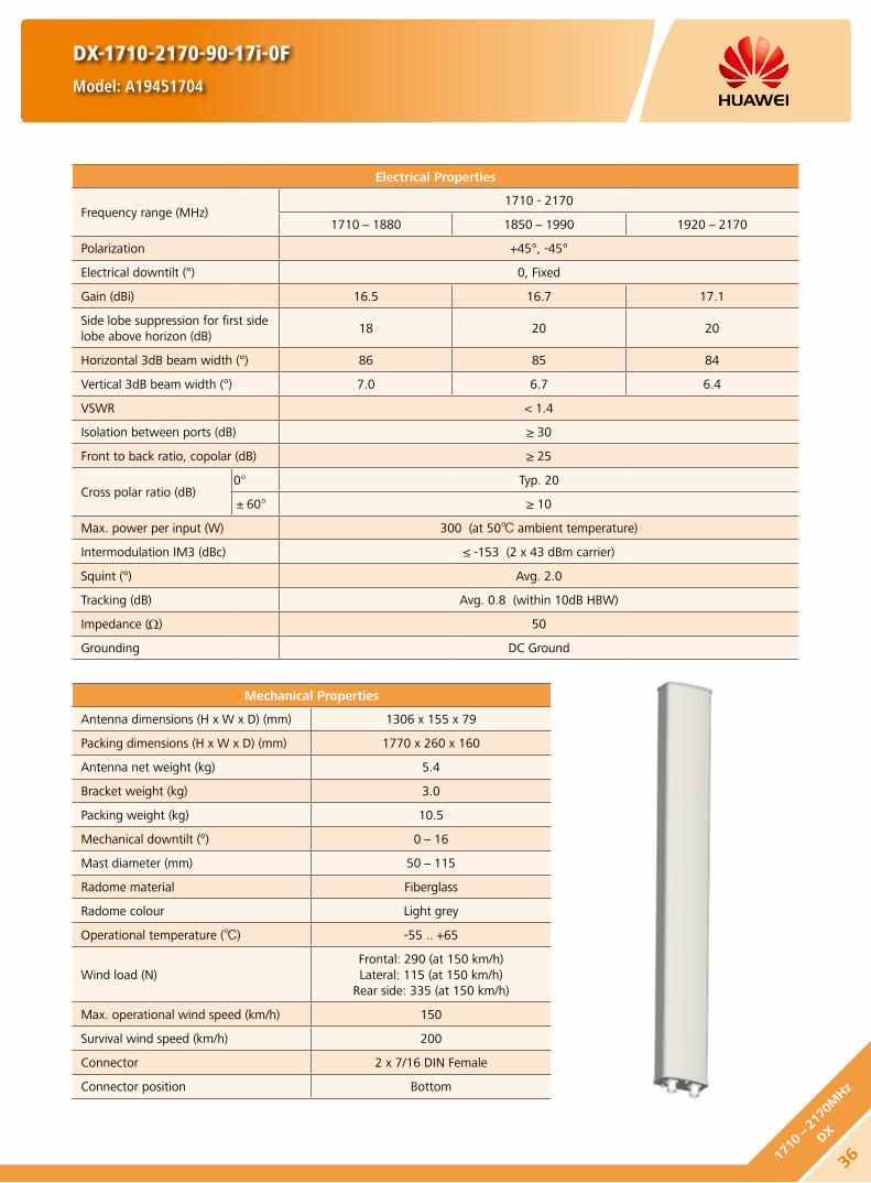
DX-1710-2170-90-17i-0F
Model: A19451704
Electrical Properties
Frequency range (MHz)1710 - 2170
1710-1880 1850-1990 1920-2170
Polarization +45°, -45°
Electrical downtilt (°) 0, Fixed
Gain (dBi) 16.5 16.7 17.1
Side lobe suppression for first side lobe above horizon (dB)
18 20 20
Horizontal 3dB beam width (°) 86 85 84
Vertical 3dB beam width (°) 7.0 6.7 6.4
VSWR < 1.4
Isolation between ports (dB) ≥ 30
Front to back ratio, copolar (dB) ≥ 25
Cross polar ratio (dB)0° Typ. 20
±60° ≥ 10
Max. power per input (W) 300 (at 50 ambient temperature)
Intermodulation IM3 (dBc) ≤ -153 (2 x 43 dBm carrier)
Squint (°) Avg. 2.0
Tracking (dB) Avg. 0.8 (within 10dB HBW)
Impedance (Ω) 50
Grounding DC Ground
Mechanical Properties
Antenna dimensions (H x W x D) (mm) 1306 x 155 x 79
Packing dimensions (H x W x D) (mm) 1770 x 260 x 160
Antenna net weight (kg) 5.4
Bracket weight (kg) 3.0
Packing weight (kg) 10.5
Mechanical downtilt (°) 0-16
Mast diameter (mm) 50-115
Radome material Fiberglass
Radome colour Light grey
Operational temperature () -55 .. +65
Wind load (N)Frontal: 290 (at 150 km/h)Lateral: 115 (at 150 km/h)
Rear side: 335 (at 150 km/h)
Max. operational wind speed (km/h) 150
Survival wind speed (km/h) 200
Connector 2 x 7/16 DIN Female
Connector position Bottom
361710-
2170
MHz
DX

DX-1710-2170-90-17i-0F
Model: A19451704
Unit: mm
1710-2170X
+45°
7/16 (F) 7/16 (F)
-45°
80
1710-2170 MHz
HINT
Extraordinary operating conditions, such as heavy icing or storm wind, may result in the breakage of an antenna. These facts must be considered during the site planning process.
The installation team must be properly qualified and also be familiar with the relevant national safety regulations.
Any previous catalogue issues become invalid.
Issue: 2012-06-01
HUAWEI TECHNOLOGIES CO., LTD.
Huawei Industrial BaseBantian Longgang
Shenzhen 518129, P.R. ChinaTel: +86-755-28780808
Email: [email protected]
www.huawei.com
Copyright © Huawei Technologies Co., Ltd. 2012. All rights reserved.
THIS DOCUMENT IS FOR INFORMATION PURPOSE ONLY, AND DOSE NOT CONSTITUTE ANY KIND OF WARRANTIES.
37
1710-2170M
Hz
DX

DX-1710-2170-90-17i-3F
Model: A19451705
Electrical Properties
Frequency range (MHz)1710 - 2170
1710-1880 1850-1990 1920-2170
Polarization +45°, -45°
Electrical downtilt (°) 3, Fixed
Gain (dBi) 16.5 16.7 17.0
Side lobe suppression for first side lobe above horizon (dB)
18 20 20
Horizontal 3dB beam width (°) 86 85 84
Vertical 3dB beam width (°) 7.0 6.7 6.4
VSWR < 1.4
Isolation between ports (dB) ≥ 30
Front to back ratio, copolar (dB) ≥ 25
Cross polar ratio (dB)0° Typ. 20
±60° ≥ 10
Max. power per input (W) 300 (at 50 ambient temperature)
Intermodulation IM3 (dBc) ≤ -153 (2 x 43 dBm carrier)
Squint (°) Avg. 2
Tracking (dB) Avg. 0.8 (within 10dB HBW)
Impedance (Ω) 50
Grounding DC Ground
Mechanical Properties
Antenna dimensions (H x W x D) (mm) 1306 x 155 x 79
Packing dimensions (H x W x D) (mm) 1770 x 260 x 160
Antenna net weight (kg) 5.4
Bracket weight (kg) 3.0
Packing weight (kg) 10.5
Mechanical downtilt (°) 0-16
Mast diameter (mm) 50-115
Radome material Fiberglass
Radome colour Light grey
Operational temperature () -55 .. +65
Wind load (N)Frontal: 290 (at 150 km/h)Lateral: 115 (at 150 km/h)
Rear side: 335 (at 150 km/h)
Max. operational wind speed (km/h) 150
Survival wind speed (km/h) 200
Connector 2 x 7/16 DIN Female
Connector position Bottom
381710-
2170
MHz
DX
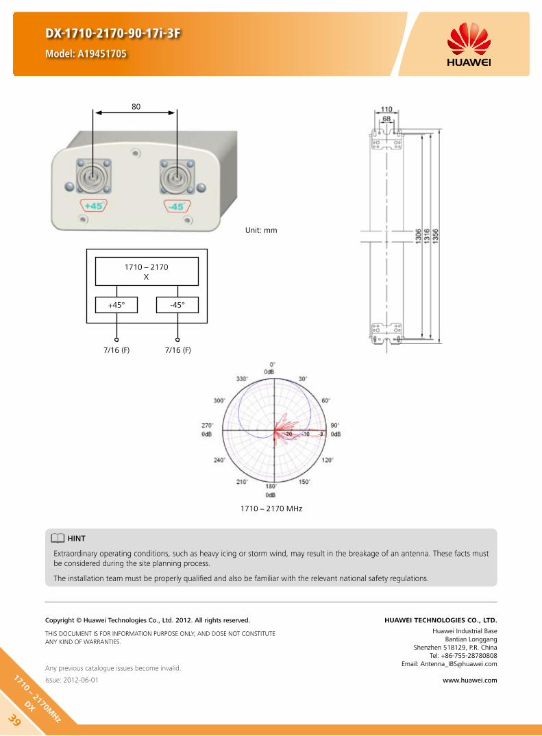
DX-1710-2170-90-17i-3F
Model: A19451705
Unit: mm
1710-2170X
+45°
7/16 (F) 7/16 (F)
-45°
80
1710-2170 MHz
HINT
Extraordinary operating conditions, such as heavy icing or storm wind, may result in the breakage of an antenna. These facts must be considered during the site planning process.
The installation team must be properly qualified and also be familiar with the relevant national safety regulations.
Any previous catalogue issues become invalid.
Issue: 2012-06-01
HUAWEI TECHNOLOGIES CO., LTD.
Huawei Industrial BaseBantian Longgang
Shenzhen 518129, P.R. ChinaTel: +86-755-28780808
Email: [email protected]
www.huawei.com
Copyright © Huawei Technologies Co., Ltd. 2012. All rights reserved.
THIS DOCUMENT IS FOR INFORMATION PURPOSE ONLY, AND DOSE NOT CONSTITUTE ANY KIND OF WARRANTIES.
39
1710-2170M
Hz
DX

1710-1880 MHz 1850-1990 MHz 1920-2170 MHz
DX-1710-2170-65-18i-2F
Model: A19451801
Any previous catalogue issues become invalid.
Issue: 2012-06-01
HUAWEI TECHNOLOGIES CO., LTD.
Huawei Industrial BaseBantian Longgang
Shenzhen 518129, P.R. ChinaTel: +86-755-28780808
Email: [email protected]
www.huawei.com
Copyright © Huawei Technologies Co., Ltd. 2012. All rights reserved.
THIS DOCUMENT IS FOR INFORMATION PURPOSE ONLY, AND DOSE NOT CONSTITUTE ANY KIND OF WARRANTIES.
Electrical Properties
Frequency range (MHz) 1710-1880 1850-1990 1920-2170Polarization +45° , -45°
VSWR ≤ 1.4
Gain (dBi) 17.6 17.8 18.0Side lobe suppression for first side lobe above horizon (dB)
Typ. 20 Typ. 20 Typ. 20
Horizontal 3dB beam width (°) 68 65 62
Vertical 3dB beam width (°) 7.3 6.8 6.2Isolation between ports (dB) ≥ 30Front to back ratio, copolar (dB) Typ. 30
Cross polar ratio (dB)0° Typ. 21±60° Typ. 10
Electrical downtilt (°) 2Intermodulation IM3 (dBc) ≤-150 (2 x 43 dBm carrier)Max. CW input power (W) 200Impedance (Ω) 50Grounding DC Ground
Mechanical Properties
Dimensions (H x W x D) (mm) 1306 x 155 x 79Packing dimensions (H x W x D) (mm) 1770 x 260 x 160Net weight (kg) 5.5Bracket weight (kg) 3.0Packing weight (kg) 11.3
Mechanical downtilt (°) 0-16
Mast diameter (mm) 50-115Radomematerial FiberglassOperating temperature () -55 .. +65
Wind load (N)Frontal: 150 (v=150 km/h)Lateral: 110 (v=150 km/h)
Rear side: 225 (v=150 km/h)Max. wind velocity (km/h) 200Connector 2 x 7/16 DIN Female
1710-2170X
+45°
7/16 (F) 7/16 (F)
-45°
401710-
2170
MHz
DX

DX-1710-2170-33-21i-M
Model: A19452101
Any previous catalogue issues become invalid.
Issue: 2012-06-01
HUAWEI TECHNOLOGIES CO., LTD.
Huawei Industrial BaseBantian Longgang
Shenzhen 518129, P.R. ChinaTel: +86-755-28780808
Email: [email protected]
www.huawei.com
Copyright © Huawei Technologies Co., Ltd. 2012. All rights reserved.
THIS DOCUMENT IS FOR INFORMATION PURPOSE ONLY, AND DOSE NOT CONSTITUTE ANY KIND OF WARRANTIES.
Mechanical Properties
Dimensions (H x W x D) (mm) 1318 x 289 x 85Packing dimensions (H x W x D) (mm) 1662 x 405 x 175Net weight (kg) 11.4Bracket weight (kg) 4.6Packing weight (kg) 18.4
Mechanical downtilt (°) 0-8
Mast diameter (mm) 50-115Radomematerial FiberglassOperating temperature () -55 .. +65
Wind load (N)Frontal: 285 (v=150 km/h)Lateral: 120 (v=150 km/h)
Rear side: 425 (v=150 km/h)Max. wind velocity (km/h) 200Connector 2 x 7/16 DIN Female
Electrical Properties
Frequency range (MHz) 1710-1880 1850-1990 1920-2170Polarization +45° , -45°
VSWR ≤ 1.45
Gain (°) 2 6 10 2 6 10 2 6 10(dBi) 20.0 20.1 20.1 20.3 20.5 20.1 20.7 20.5 19.8
Side lobe suppression for first side lobe above horizon
(°) 2 6 10 2 6 10 2 6 10(dBi) 18 17 16 18 17 16 18 17 16
Horizontal 3dB beam width (°) 35 33 31
Vertical 3dB beam width (°) 7.2 6.6 6.2Isolation between ports (dB) ≥30Front to back ratio, copolar (dB) Typ. 28Cross polar ratio (dB) Typ. 20Electrical downtilt (°) 0-10Intermodulation IM3 (dBc) ≤-150 (2 x 43 dBm carrier)Max. CW input power (W) 300Impedance (Ω) 50Grounding DC Ground
1710-2170X
+45°
7/16 (F) 7/16 (F)
-45°
1710-1880 MHz 1850-1990 MHz 1920-2170 MHz
41
1710-2170M
Hz
DX

1710-1880 MHz 1850-1990 MHz 1920-2170 MHz
DX-1710-2170-33-21i-0F
Model: A19452102
Electrical Properties
Frequency range (MHz) 1710-1880 1850-1990 1920-2170Polarization +45° , -45°
VSWR ≤1.45
Gain (dBi) 20.3 20.7 20.9Side lobe suppression for first side lobe above horizon (dB)
18 18 18
Horizontal 3dB beam width (°) 35 33 31
Vertical 3dB beam width (°) 7.2 6.6 6.2Isolation between ports (dB) ≥30Front to back ratio, copolar (dB) Typ. 28Cross polar ratio (dB) Typ. 20Electrical downtilt (°) 0Intermodulation IM3 (dBc) ≤-150 (2 x 43 dBm carrier)Max. CW input power (W) 300Impedance (Ω) 50Grounding DC Ground
1710-2170X
+45°
7/16 (F) 7/16 (F)
-45°
Any previous catalogue issues become invalid.
Issue: 2012-06-01
HUAWEI TECHNOLOGIES CO., LTD.
Huawei Industrial BaseBantian Longgang
Shenzhen 518129, P.R. ChinaTel: +86-755-28780808
Email: [email protected]
www.huawei.com
Copyright © Huawei Technologies Co., Ltd. 2012. All rights reserved.
THIS DOCUMENT IS FOR INFORMATION PURPOSE ONLY, AND DOSE NOT CONSTITUTE ANY KIND OF WARRANTIES.
Mechanical Properties
Dimensions (H x W x D) (mm) 1318 x 289 x 85Packing dimensions (H x W x D) (mm) 1662 x 405 x 175Net weight (kg) 10.4Bracket weight (kg) 4.6Packing weight (kg) 18
Mechanical downtilt (°) 0-8
Mast diameter (mm) 50-115Radomematerial FiberglassOperating temperature () -55 .. +65
Wind load (N)Frontal: 285 (v=150 km/h)Lateral: 120 (v=150 km/h)
Rear side: 425 (v=150 km/h)Max. wind velocity (km/h) 200Connector 2 x 7/16 DIN Female
421710-
2170
MHz
DX

DX-1710-2170-65-21i-0F
Model: A19452100
Any previous catalogue issues become invalid.
Issue: 2012-06-01
HUAWEI TECHNOLOGIES CO., LTD.
Huawei Industrial BaseBantian Longgang
Shenzhen 518129, P.R. ChinaTel: +86-755-28780808
Email: [email protected]
www.huawei.com
Copyright © Huawei Technologies Co., Ltd. 2012. All rights reserved.
THIS DOCUMENT IS FOR INFORMATION PURPOSE ONLY, AND DOSE NOT CONSTITUTE ANY KIND OF WARRANTIES.
1710-2170X
+45°
7/16 (F) 7/16 (F)
-45°
1710-1880 MHz 1850-1990 MHz 1920-2170 MHz
Electrical Properties
Frequency range (MHz) 1710-1880 1850-1990 1920-2170Polarization +45° , -45°
VSWR ≤ 1.45
Gain (dBi) 20.0 20.5 20.8Side lobe suppression for first side lobe above horizon (dB)
18 18 18
Horizontal 3dB beam width (°) 66 63 60
Vertical 3dB beam width (°) 4.2 3.7 3.3First null_fill below main beam (dB) 20Isolation between ports (dB) ≥ 30Front to back ratio, copolar (dB) ≥ 30
Cross polar ratio (dB)0° ≥ 17±60° ≥ 10
Electrical downtilt (°) 0Intermodulation IM3 (dBc) ≤-150 (2 x 43 dBm carrier)Max. CW input power (W) 300Impedance (Ω) 50Grounding DC Ground
Mechanical Properties
Dimensions (H x W x D) (mm) 2170 x 155 x 79Packing dimensions (H x W x D) (mm) 2580 x 250 x 145Net weight (kg) 9.1Bracket weight (kg) 3Packing weight (kg) 14.5
Mechanical downtilt (°) 0-8
Mast diameter (mm) 50-115Radomematerial FiberglassOperating temperature () -55 .. +65
Wind load (N)Frontal:250 (v=150 km/h)Lateral: 185 (v=150 km/h)
Rear side: 375 (v=150 km/h)Max. wind velocity (km/h) 200Connector 2 x 7/16 DIN Female
43
1710-2170M
Hz
DX

DX-1710-2170-65-21i-2F
Model: A19452103
Any previous catalogue issues become invalid.
Issue: 2012-06-01
HUAWEI TECHNOLOGIES CO., LTD.
Huawei Industrial BaseBantian Longgang
Shenzhen 518129, P.R. ChinaTel: +86-755-28780808
Email: [email protected]
www.huawei.com
Copyright © Huawei Technologies Co., Ltd. 2012. All rights reserved.
THIS DOCUMENT IS FOR INFORMATION PURPOSE ONLY, AND DOSE NOT CONSTITUTE ANY KIND OF WARRANTIES.
1710-2170X
+45°
7/16 (F) 7/16 (F)
-45°
1710-1880 MHz 1850-1990 MHz 1920-2170 MHz
Electrical Properties
Frequency range (MHz) 1710-1880 1850-1990 1920-2170Polarization +45° , -45°
VSWR ≤1.45
Gain (dBi) 20.0 20.5 20.8Side lobe suppression for first side lobe above horizon (dB)
16 16 16
Horizontal 3dB beam width (°) 66 63 60
Vertical 3dB beam width (°) 4.5 4.0 3.6First null_fill below main beam (dB) 20Isolation between ports (dB) ≥ 30Front to back ratio, copolar (dB) ≥ 30
Cross polar ratio (dB)0° ≥ 17±60° ≥ 10
Electrical downtilt (°) 0Intermodulation IM3 (dBc) ≤-150 (2 x 43 dBm carrier)Max. CW input power (W) 300Impedance (Ω) 50Grounding DC Ground
Mechanical Properties
Dimensions (H x W x D) (mm) 2170 x 155 x 79Packing dimensions (H x W x D) (mm) 2580 x 250 x 145Net weight (kg) 9.1Bracket weight (kg) 3Packing weight (kg) 15
Mechanical downtilt (°) 0-8
Mast diameter (mm) 50-115Radomematerial FiberglassOperating temperature () -55 .. +65
Wind load (N)Frontal:250 (v=150 km/h)Lateral: 185 (v=150 km/h)
Rear side: 375 (v=150 km/h)Max. wind velocity (km/h) 200Connector 2 x 7/16 DIN Female
441710-
2170
MHz
DX

DX-1710-2200-65-15.5i-M
Model: A19451505
Electrical Properties
Frequency range (MHz)1710-2200
1710-1880 1850-1990 1920-2170 2170-2200
Polarization +45° , -45°
Electrical downtilt (°) 0-12 , continuously adjustable
Gain (dBi)0° 6° 12° 0° 6° 12° 0° 6° 12° 0° 6° 12°
14.9 15.0 14.6 15.3 15.4 14.8 15.4 15.6 15.0 15.4 15.5 15.0
Side lobe suppression for first side lobe above horizon (Typ.) (dB)
0° 6° 12° 0° 6° 12° 0° 6° 12° 0° 6° 12°
17 16 15 17 16 15 17 16 15 17 16 15
Horizontal 3dB beam width (°) 67 64 61 60
Vertical 3dB beam width (°) 14 13 12.6 11.5
VSWR < 1.5
Isolation between ports (dB) ≥ 30
Front to back ratio, copolar (dB) Typ. 28
Cross polar ratio (dB)0° Typ. 20
±60° Typ. 10
Max. power per input (W) 300 (at 50 ambient temperature)
Intermodulation IM3 (dBc) ≤ -153 (2 x 43 dBm carrier)
Squint (°) Typ. 3
Tracking (dB) Avg. 2 (within 10dB HBW)
Impedance (Ω) 50
Grounding DC Ground
Mechanical Properties
Antenna dimensions (H x W x D) (mm) 730 x 155 x 89
Packing dimensions (H x W x D) (mm) 1227 x 253 x 200
Antenna net weight (kg) 5.3
Bracket weight (kg) 2.6
Packing weight (kg) 9.5
Mechanical downtilt (°) 0-16
Mast diameter (mm) 50-115
Radome material Fiberglass
Radome colour Light grey
Operational temperature () -55 .. +65
Wind load (N)Frontal: 160 (at 150 km/h) Lateral: 80 (at 150 km/h)
Rear side: 185 (at 150 km/h)
Max. operational wind speed (km/h) 150
Survival wind speed (km/h) 200
Connector 2 x 7/16 DIN Female
Connector position Bottom
Any previous catalogue issues become invalid.
Issue: 2012-06-01
HUAWEI TECHNOLOGIES CO., LTD.
Huawei Industrial BaseBantian Longgang
Shenzhen 518129, P.R. ChinaTel: +86-755-28780808
Email: [email protected]
www.huawei.com
Copyright © Huawei Technologies Co., Ltd. 2012. All rights reserved.
THIS DOCUMENT IS FOR INFORMATION PURPOSE ONLY, AND DOSE NOT CONSTITUTE ANY KIND OF WARRANTIES.
Preliminary Issue
45
1710-2200M
Hz
DX
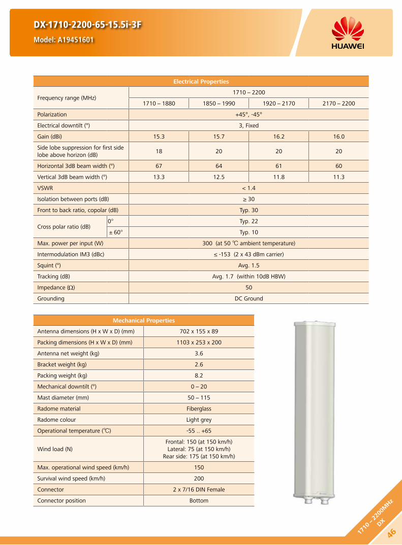
DX-1710-2200-65-15.5i-3F
Model: A19451601
Electrical Properties
Frequency range (MHz)1710-2200
1710-1880 1850-1990 1920-2170 2170-2200
Polarization +45°, -45°
Electrical downtilt (°) 3, Fixed
Gain (dBi) 15.3 15.7 16.2 16.0
Side lobe suppression for first side lobe above horizon (dB)
18 20 20 20
Horizontal 3dB beam width (°) 67 64 61 60
Vertical 3dB beam width (°) 13.3 12.5 11.8 11.3
VSWR < 1.4
Isolation between ports (dB) ≥ 30
Front to back ratio, copolar (dB) Typ. 30
Cross polar ratio (dB)0° Typ. 22
±60° Typ. 10
Max. power per input (W) 300 (at 50 ambient temperature)
Intermodulation IM3 (dBc) ≤ -153 (2 x 43 dBm carrier)
Squint (°) Avg. 1.5
Tracking (dB) Avg. 1.7 (within 10dB HBW)
Impedance (Ω) 50
Grounding DC Ground
Mechanical Properties
Antenna dimensions (H x W x D) (mm) 702 x 155 x 89
Packing dimensions (H x W x D) (mm) 1103 x 253 x 200
Antenna net weight (kg) 3.6
Bracket weight (kg) 2.6
Packing weight (kg) 8.2
Mechanical downtilt (°) 0-20
Mast diameter (mm) 50-115
Radome material Fiberglass
Radome colour Light grey
Operational temperature () -55 .. +65
Wind load (N)Frontal: 150 (at 150 km/h)Lateral: 75 (at 150 km/h)
Rear side: 175 (at 150 km/h)
Max. operational wind speed (km/h) 150
Survival wind speed (km/h) 200
Connector 2 x 7/16 DIN Female
Connector position Bottom
461710-
2200
MHz
DX

1710-2200 MHz
DX-1710-2200-65-15.5i-3F
Model: A19451601
Unit: mm
1710-2200X
+45°
7/16 (F) 7/16 (F)
-45°
91
HINT
Extraordinary operating conditions, such as heavy icing or storm wind, may result in the breakage of an antenna. These facts must be considered during the site planning process.
The installation team must be properly qualified and also be familiar with the relevant national safety regulations.
Any previous catalogue issues become invalid.
Issue: 2012-06-01
HUAWEI TECHNOLOGIES CO., LTD.
Huawei Industrial BaseBantian Longgang
Shenzhen 518129, P.R. ChinaTel: +86-755-28780808
Email: [email protected]
www.huawei.com
Copyright © Huawei Technologies Co., Ltd. 2012. All rights reserved.
THIS DOCUMENT IS FOR INFORMATION PURPOSE ONLY, AND DOSE NOT CONSTITUTE ANY KIND OF WARRANTIES.
47
1710-2200M
Hz
DX

DX-1710-2200-65-15.5i-6F
Model: A19451602
Electrical Properties
Frequency range (MHz)1710-2200
1710-1880 1850-1990 1920-2170 2170-2200
Polarization +45°, -45°
Electrical downtilt (°) 6, Fixed
Gain (dBi) 15.2 15.6 16.1 16.0
Side lobe suppression for first side lobe above horizon (dB)
18 20 20 20
Horizontal 3dB beam width (°) 67 64 61 60
Vertical 3dB beam width (°) 13.3 12.5 11.8 11.3
VSWR < 1.4
Isolation between ports (dB) ≥ 30
Front to back ratio, copolar (dB) Typ. 30
Cross polar ratio (dB)0° Typ. 22
±60° Typ. 10
Max. power per input (W) 300 (at 50 ambient temperature)
Intermodulation IM3 (dBc) ≤ -153 (2 x 43 dBm carrier)
Squint (°) Avg. 1.8
Tracking (dB) Avg. 2.0 (within 10dB HBW)
Impedance (Ω) 50
Grounding DC Ground
Mechanical Properties
Antenna dimensions (H x W x D) (mm) 702 x 155 x 89
Packing dimensions (H x W x D) (mm) 1103 x 253 x 200
Antenna net weight (kg) 3.6
Bracket weight (kg) 2.6
Packing weight (kg) 8.2
Mechanical downtilt (°) 0-20
Mast diameter (mm) 50-115
Radome material Fiberglass
Radome colour Light grey
Operational temperature () -55 .. +65
Wind load (N)Frontal: 150 (at 150 km/h)Lateral: 75 (at 150 km/h)
Rear side: 175 (at 150 km/h)
Max. operational wind speed (km/h) 150
Survival wind speed (km/h) 200
Connector 2 x 7/16 DIN Female
Connector position Bottom
481710-
2200
MHz
DX

DX-1710-2200-65-15.5i-6F
Model: A19451602
1710-2200 MHz
Unit: mm
1710-2200X
+45°
7/16 (F) 7/16 (F)
-45°
91
HINT
Extraordinary operating conditions, such as heavy icing or storm wind, may result in the breakage of an antenna. These facts must be considered during the site planning process.
The installation team must be properly qualified and also be familiar with the relevant national safety regulations.
Any previous catalogue issues become invalid.
Issue: 2012-06-01
HUAWEI TECHNOLOGIES CO., LTD.
Huawei Industrial BaseBantian Longgang
Shenzhen 518129, P.R. ChinaTel: +86-755-28780808
Email: [email protected]
www.huawei.com
Copyright © Huawei Technologies Co., Ltd. 2012. All rights reserved.
THIS DOCUMENT IS FOR INFORMATION PURPOSE ONLY, AND DOSE NOT CONSTITUTE ANY KIND OF WARRANTIES.
49
1710-2200M
Hz
DX

Electrical Properties
Frequency range (MHz)1710-2200
1710-1880 1850-1990 1920-2170 2170-2200
Polarization +45°, -45°
Electrical downtilt (°) 0-10, continuously adjustable
Gain (dBi)0° 5° 10° 0° 5° 10° 0° 5° 10° 0° 5° 10°
17.2 17.6 17.4 17.7 18.0 17.7 18.0 18.1 17.9 18.0 18.2 17.9
Side lobe suppression for first side lobe above horizon (Typ.) (dB)
0° 5° 10° 0° 5° 10° 0° 5° 10° 0° 5° 10°
20 16 18 20 20 18 18 17 16 18 18 16
Horizontal 3dB beam width (°) 67 64 61 60
Vertical 3dB beam width (°) 7.5 7.0 6.7 6.2
VSWR < 1.5
Isolation between ports (dB) ≥ 30
Front to back ratio, copolar (dB) Typ. 30
Cross polar ratio (dB)0° Typ. 22
±60° ≥ 10
Max. power per input (W) 500 (at 50 ambient temperature)
Intermodulation IM3 (dBc) ≤ -153 (2 x 43 dBm carrier)
Squint (°) Avg. 1.2
Tracking (dB) Avg. 1.2 (within 10dB HBW)
Impedance (Ω) 50
Grounding DC Ground
Mechanical Properties
Antenna dimensions (H x W x D) (mm) 1311 x 155 x 89
Packing dimensions (H x W x D) (mm) 1697 x 252 x 200
Antenna net weight (kg) 6.2
Bracket weight (kg) 2.6
Packing weight (kg) 11.5
Mechanical downtilt (°) 0-12
Mast diameter (mm) 50-115
Radome material Fiberglass
Radome colour Light grey
Operational temperature () -55 .. +65
Wind load (N)Frontal: 315 (at 150 km/h)Lateral: 155 (at 150 km/h)
Rear side: 360 (at 150 km/h)
Max. operational wind speed (km/h) 150
Survival wind speed (km/h) 200
Connector 2 x 7/16 DIN Female
Connector position Bottom
DX-1710-2200-65-18i-M
Model: A19451811
501710-
2200
MHz
DX

1710-2200 MHz
1710-2200X
+45°
7/16 (F) 7/16 (F)
-45°
DX-1710-2200-65-18i-M
Model: A19451811
Unit: mm3446
34
HINT
Extraordinary operating conditions, such as heavy icing or storm wind, may result in the breakage of an antenna. These facts must be considered during the site planning process.
The installation team must be properly qualified and also be familiar with the relevant national safety regulations.
Any previous catalogue issues become invalid.
Issue: 2012-06-01
HUAWEI TECHNOLOGIES CO., LTD.
Huawei Industrial BaseBantian Longgang
Shenzhen 518129, P.R. ChinaTel: +86-755-28780808
Email: [email protected]
www.huawei.com
Copyright © Huawei Technologies Co., Ltd. 2012. All rights reserved.
THIS DOCUMENT IS FOR INFORMATION PURPOSE ONLY, AND DOSE NOT CONSTITUTE ANY KIND OF WARRANTIES.
51
1710-2200M
Hz
DX

Electrical Properties
Frequency range (MHz)1710-2690
1710-1990 1920-2200 2200-2490 2490-2690
Polarization +45°, -45°
Electrical downtilt (°) 0-12, continuously adjustable
Gain (dBi)0° 6° 12° 0° 6° 12° 0° 6° 12° 0° 6° 12°
17.3 17.4 17.2 17.6 17.8 17.5 17.7 18.0 17.5 17.8 18.0 17.3
Side lobe suppression for first side lobe above horizon (Typ.) (dB)
0° 6° 12° 0° 6° 12° 0° 6° 12° 0° 6° 12°
18 17 16 18 17 16 18 17 16 17 17 16
Horizontal 3dB beam width (°) 66 63 60 60
Vertical 3dB beam width (°) 6.5 6.2 5.5 4.7
VSWR < 1.5
Isolation between ports (dB) ≥ 30
Front to back ratio, copolar (dB) Typ. 30
Cross polar ratio (dB)0° Typ. 20
±60° Typ. 10
Max. power per input (W) 250 (at 50 ambient temperature)
Intermodulation IM3 (dBc) ≤ -153 (2 x 43 dBm carrier)
Squint (°) Typ. 3
Tracking (dB) Avg. 2 (within 10dB HBW)
Impedance (Ω) 50
Grounding DC Ground
Mechanical Properties
Antenna dimensions (H x W x D) (mm) 1425 x 155 x 89
Packing dimensions (H x W x D) (mm) 1730 x 252 x 200
Antenna net weight (kg) 7.6
Bracket weight (kg) 2.6
Packing weight (kg) 13.5
Mechanical downtilt (°) 0-12
Mast diameter (mm) 50-115
Radome material Fiberglass
Radome colour Light grey
Operational temperature () -55 .. +65
Wind load (N)Frontal: 320 (at 150 km/h)Lateral: 170 (at 150 km/h)
Rear side: 395 (at 150 km/h)
Max. operational wind speed (km/h) 150
Survival wind speed (km/h) 200
Connector 2 x 7/16 DIN Female
Connector position Bottom
RET Type Internal motor
RET Protocols AISG 1.1 / AISG 2.0
RET Connector2 x 8 pin connector according to IEC 60130-9Daisy chain in: Male / Daisy chain out: Female
DX-1710-2690-65-18i-M-R
Model: A264518R0
Preliminary Issue
521710-
2690
MHz
DX

RET Properties
RET Type Internal motor
RET Protocols AISG 1.1 / AISG 2.0
Input voltage range (V) DC 10-30
Power consumption (W) < 10 (motor activated)
< 0.5 (stand by)
Adjustment time (full range) (min) < 1.5 (typically, depending on antenna type)
Calibration time (min) < 3 (typically, depending on antenna type)
RET Connector2 x 8 pin connector according to IEC 60130-9Daisy chain in: Male / Daisy chain out: Female
Pin assignment according AISG 1 2 3 4 5 6 7 8
DC n/c RS-485B n/c RS-485A DC in/out DC return n/c
Lightning protection (kA)AISG interface (each pin)
3 (10/350 μs)10 (8/20 μs)
HINT
Before the installation, check whether the antenna and base station support the same AISG protocol. If not, contact the technical support personnel of Huawei.
Standards:
EN 60950-1 (Safety) y
EN 55022 (Emission) y
EN 55024 (Immunity) y
ETSI EN300386 (1.4.1) y
FCC part15 y
Certification:
CE, FCC, RoHS, WEEE
Any previous catalogue issues become invalid.
Issue: 2012-06-01
HUAWEI TECHNOLOGIES CO., LTD.
Huawei Industrial BaseBantian Longgang
Shenzhen 518129, P.R. ChinaTel: +86-755-28780808
Email: [email protected]
www.huawei.com
Copyright © Huawei Technologies Co., Ltd. 2012. All rights reserved.
THIS DOCUMENT IS FOR INFORMATION PURPOSE ONLY, AND DOSE NOT CONSTITUTE ANY KIND OF WARRANTIES.
DX-1710-2690-65-18i-M-R
Model: A264518R0
Preliminary Issue
53
1710-2690M
Hz
DX

DX-1710-2200-65-18i-0F
Model: A19451800v01
Electrical Properties
Frequency range (MHz)1710-2200
1710-1880 1850-1990 1920-2170 2170-2200
Polarization +45°, -45°
Electrical downtilt (°) 0, Fixed
Gain (dBi) 17.6 18.0 18.3 18.3
Side lobe suppression for first side lobe above horizon (dB)
18 19 19 19
Horizontal 3dB beam width (°) 67 64 62 60
Vertical 3dB beam width (°) 7.0 6.7 6.4 6.0
VSWR < 1.4
Isolation between ports (dB) ≥ 30
Front to back ratio, copolar (dB) Typ. 30
Cross polar ratio (dB)0° Typ. 22
±60° Typ. 10
Max. power per input (W) 300 (at 50 ambient temperature)
Intermodulation IM3 (dBc) ≤ -153 (2 x 43 dBm carrier)
Max. power per input (W) Avg. 1.2
Intermodulation IM3 (dBc) Avg. 1.2 (within 10dB HBW)
Impedance (Ω) 50
Grounding DC Ground
Mechanical Properties
Antenna dimensions (H x W x D) (mm) 1311 x 155 x 89
Packing dimensions (H x W x D) (mm) 1697 x 252 x 200
Antenna net weight (kg) 5.5
Bracket weight (kg) 2.6
Packing weight (kg) 11.7
Mechanical downtilt (°) 0-12
Mast diameter (mm) 50-115
Radome material Fiberglass
Radome colour Light grey
Operational temperature () -55 .. +65
Wind load (N)Frontal: 315 (at 150 km/h)Lateral: 155 (at 150 km/h)
Rear side: 360 (at 150 km/h)
Max. operational wind speed (km/h) 150
Survival wind speed (km/h) 200
Connector 2 x 7/16 DIN Female
Connector position Bottom
541710-
2200
MHz
DX

DX-1710-2200-65-18i-0F
Model: A19451800v01
Unit: mm
1710-2200X
+45°
7/16 (F) 7/16 (F)
-45°
91
1710-2200 MHz
HINT
Extraordinary operating conditions, such as heavy icing or storm wind, may result in the breakage of an antenna. These facts must be considered during the site planning process.
The installation team must be properly qualified and also be familiar with the relevant national safety regulations.
Any previous catalogue issues become invalid.
Issue: 2012-06-01
HUAWEI TECHNOLOGIES CO., LTD.
Huawei Industrial BaseBantian Longgang
Shenzhen 518129, P.R. ChinaTel: +86-755-28780808
Email: [email protected]
www.huawei.com
Copyright © Huawei Technologies Co., Ltd. 2012. All rights reserved.
THIS DOCUMENT IS FOR INFORMATION PURPOSE ONLY, AND DOSE NOT CONSTITUTE ANY KIND OF WARRANTIES.
55
1710-2200M
Hz
DX

DX-1710-2200-65-18i-3F
Model: A19451810v01
Electrical Properties
Frequency range (MHz)1710-2200
1710-1880 1850-1990 1920-2170 2170-2200
Polarization +45°, -45°
Electrical downtilt (°) 3, Fixed
Gain (dBi) 17.7 18.1 18.4 18.2
Side lobe suppression for first side lobe above horizon (dB)
19 19 19 19
Horizontal 3dB beam width (°) 67 64 62 60
Vertical 3dB beam width (°) 7.0 6.7 6.4 6.0
VSWR < 1.4
Isolation between ports (dB) ≥ 30
Front to back ratio, copolar (dB) Typ. 30
Cross polar ratio (dB)0° Typ. 22
±60° Typ. 10
Max. power per input (W) 300 (at 50 ambient temperature)
Intermodulation IM3 (dBc) ≤ -153 (2 x 43 dBm carrier)
Max. power per input (W) Avg. 1.2
Intermodulation IM3 (dBc) Avg. 1.5 (within 10dB HBW)
Impedance (Ω) 50
Grounding DC Ground
Mechanical Properties
Antenna dimensions (H x W x D) (mm) 1311 x 155 x 89
Packing dimensions (H x W x D) (mm) 1697 x 252 x 200
Antenna net weight (kg) 5.5
Bracket weight (kg) 2.6
Packing weight (kg) 11.7
Mechanical downtilt (°) 0-12
Mast diameter (mm) 50-115
Radome material Fiberglass
Radome colour Light grey
Operational temperature () -55 .. +65
Wind load (N)Frontal: 315 (at 150 km/h)Lateral: 155 (at 150 km/h)
Rear side: 360 (at 150 km/h)
Max. operational wind speed (km/h) 150
Survival wind speed (km/h) 200
Connector 2 x 7/16 DIN Female
Connector position Bottom
561710-
2200
MHz
DX

DX-1710-2200-65-18i-3F
Model: A19451810v01
Unit: mm
1710-2200X
+45°
7/16 (F) 7/16 (F)
-45°
91
1710-2200 MHz
HINT
Extraordinary operating conditions, such as heavy icing or storm wind, may result in the breakage of an antenna. These facts must be considered during the site planning process.
The installation team must be properly qualified and also be familiar with the relevant national safety regulations.
Any previous catalogue issues become invalid.
Issue: 2012-06-01
HUAWEI TECHNOLOGIES CO., LTD.
Huawei Industrial BaseBantian Longgang
Shenzhen 518129, P.R. ChinaTel: +86-755-28780808
Email: [email protected]
www.huawei.com
Copyright © Huawei Technologies Co., Ltd. 2012. All rights reserved.
THIS DOCUMENT IS FOR INFORMATION PURPOSE ONLY, AND DOSE NOT CONSTITUTE ANY KIND OF WARRANTIES.
57
1710-2200M
Hz
DX

DX-1710-2200-65-18i-6F
Model: A19451802v01
Electrical Properties
Frequency range (MHz)1710-2200
1710-1880 1850-1990 1920-2170 2170-2200
Polarization +45°, -45°
Electrical downtilt (°) 6, Fixed
Gain (dBi) 17.7 18.1 18.4 18.2
Side lobe suppression for first side lobe above horizon (dB)
18 20 20 20
Horizontal 3dB beam width (°) 67 64 62 60
Vertical 3dB beam width (°) 7.0 6.7 6.4 6.0
VSWR < 1.4
Isolation between ports (dB) ≥ 30
Front to back ratio, copolar (dB) Typ. 30
Cross polar ratio (dB)0° Typ. 22
±60° Typ. 10
Max. power per input (W) 300 (at 50 ambient temperature)
Intermodulation IM3 (dBc) ≤ -153 (2 x 43 dBm carrier)
Max. power per input (W) Avg. 1.5
Intermodulation IM3 (dBc) Avg. 2.0 (within 10dB HBW)
Impedance (Ω) 50
Grounding DC Ground
Mechanical Properties
Antenna dimensions (H x W x D) (mm) 1311 x 155 x 89
Packing dimensions (H x W x D) (mm) 1697 x 252 x 200
Antenna net weight (kg) 5.5
Bracket weight (kg) 2.6
Packing weight (kg) 11.7
Mechanical downtilt (°) 0-12
Mast diameter (mm) 50-115
Radome material Fiberglass
Radome colour Light grey
Operational temperature () -55 .. +65
Wind load (N)Frontal: 315 (at 150 km/h)Lateral: 155 (at 150 km/h)
Rear side: 360 (at 150 km/h)
Max. operational wind speed (km/h) 150
Survival wind speed (km/h) 200
Connector 2 x 7/16 DIN Female
Connector position Bottom
581710-
2200
MHz
DX

DX-1710-2200-65-18i-6F
Model: A19451802v01
Unit: mm
1710-2200X
+45°
7/16 (F) 7/16 (F)
-45°
91
1710-2200 MHz
HINT
Extraordinary operating conditions, such as heavy icing or storm wind, may result in the breakage of an antenna. These facts must be considered during the site planning process.
The installation team must be properly qualified and also be familiar with the relevant national safety regulations.
Any previous catalogue issues become invalid.
Issue: 2012-06-01
HUAWEI TECHNOLOGIES CO., LTD.
Huawei Industrial BaseBantian Longgang
Shenzhen 518129, P.R. ChinaTel: +86-755-28780808
Email: [email protected]
www.huawei.com
Copyright © Huawei Technologies Co., Ltd. 2012. All rights reserved.
THIS DOCUMENT IS FOR INFORMATION PURPOSE ONLY, AND DOSE NOT CONSTITUTE ANY KIND OF WARRANTIES.
59
1710-2200M
Hz
DX

DX-1710-2200-65-19.5i-M
Model: A19451902
Electrical Properties
Frequency range (MHz)1710-2200
1710-1880 1850-1990 1920-2170 2170-2200
Polarization +45°, -45°
Electrical downtilt (°) 0-6, continuously adjustable
Gain (dBi)0° 3° 6° 0° 3° 6° 0° 3° 6° 0° 3° 6°
18.6 18.7 18.5 19.0 19.1 18.9 19.2 19.4 19.1 19.4 19.5 18.8
Side lobe suppression for first side lobe above horizon (Typ.) (dB)
0° 3° 6° 0° 3° 6° 0° 3° 6° 0° 3° 6°
20 17 16 20 17 16 20 18 17 20 18 17
Horizontal 3dB beam width (°) 67 64 62 60
Vertical 3dB beam width (°) 5.0 4.7 4.5 4.1
VSWR < 1.5
Isolation between ports (dB) ≥ 30
Front to back ratio, copolar (dB) Typ. 32
Cross polar ratio (dB)0° Typ. 25
±60° Typ. 10
Max. power per input (W) 300 (at 50 ambient temperature)
Intermodulation IM3 (dBc) ≤ -153 (2 x 43 dBm carrier)
Squint (°) Avg. 1.5
Tracking (dB) Avg. 1.0 (within 10dB HBW)
Impedance (Ω) 50
Grounding DC Ground
Mechanical Properties
Antenna dimensions (H x W x D) (mm) 1954 x 155 x 89
Packing dimensions (H x W x D) (mm) 2357 x 253 x 200
Antenna net weight (kg) 8.4
Bracket weight (kg) 2.6
Packing weight (kg) 14.3
Mechanical downtilt (°) 0-8
Mast diameter (mm) 50-115
Radome material Fiberglass
Radome colour Light grey
Operational temperature () -55 .. +65
Wind load (N)Frontal: 505 (at 150 km/h)Lateral: 250 (at 150 km/h)
Rear side: 575 (at 150 km/h)
Max. operational wind speed (km/h) 150
Survival wind speed (km/h) 200
Connector 2 x 7/16 DIN Female
Connector position Bottom
601710-
2200
MHz
DX

DX-1710-2200-65-19.5i-M
Model: A19451902
Unit: mm
1710-2200X
+45°
7/16 (F) 7/16 (F)
-45°
3446
34
1710-2200 MHz
HINT
Extraordinary operating conditions, such as heavy icing or storm wind, may result in the breakage of an antenna. These facts must be considered during the site planning process.
The installation team must be properly qualified and also be familiar with the relevant national safety regulations.
Any previous catalogue issues become invalid.
Issue: 2012-06-01
HUAWEI TECHNOLOGIES CO., LTD.
Huawei Industrial BaseBantian Longgang
Shenzhen 518129, P.R. ChinaTel: +86-755-28780808
Email: [email protected]
www.huawei.com
Copyright © Huawei Technologies Co., Ltd. 2012. All rights reserved.
THIS DOCUMENT IS FOR INFORMATION PURPOSE ONLY, AND DOSE NOT CONSTITUTE ANY KIND OF WARRANTIES.
61
1710-2200M
Hz
DX

Electrical Properties
Frequency range (MHz)1710-2690
1710-1990 1920-2200 2200-2490 2490-2690
Polarization +45°, -45°
Electrical downtilt (°) 0-10, continuously adjustable
Gain (dBi)0° 5° 10° 0° 5° 10° 0° 5° 10° 0° 5° 10°
17.0 17.1 16.9 17.4 17.6 17.3 17.9 18.1 17.7 18.0 18.1 17.5
Side lobe suppression for first side lobe above horizon (Typ.) (dB)
0° 5° 10° 0° 5° 10° 0° 5° 10° 0° 5° 10°
18 17 16 18 17 16 18 17 16 18 17 16
Horizontal 3dB beam width (°) 69 65 62 60
Vertical 3dB beam width (°) 6.6 6.0 5.4 4.9
VSWR < 1.5
Isolation between ports (dB) ≥ 30
Front to back ratio, copolar (dB) Typ. 27
Cross polar ratio (dB)0° Typ. 20
±60° Typ. 10
Max. power per input (W) 250 (at 50 ambient temperature)
Intermodulation IM3 (dBc) ≤ -153 (2 x 43 dBm carrier)
Squint (°) Avg. 3
Tracking (dB) Typ. 2 (within 10dB HBW)
Impedance (Ω) 50
Grounding DC Ground
Mechanical Properties
Antenna dimensions (H x W x D) (mm) 1410 x 155 x 89
Packing dimensions (H x W x D) (mm) 2027 x 259 x 185
Antenna net weight (kg) 7.3
Bracket weight (kg) 2.6
Packing weight (kg) 13.0
Mechanical downtilt (°) 0-12
Mast diameter (mm) 50-115
Radome material Fiberglass
Radome colour Light grey
Operational temperature () -55 .. +65
Wind load (N)Frontal: 340 (at 150 km/h)Lateral: 170 (at 150 km/h)
Rear side: 390 (at 150 km/h)
Max. operational wind speed (km/h) 150
Survival wind speed (km/h) 200
Connector 2 x 7/16 DIN Female (Long neck)
Connector position Bottom
DX-1710-2690-65-18i-M
Model: A26451800
621710-
2690
MHz
DX

Unit: mm
1710-2200 MHz 2200-2690 MHz
DX-1710-2690-65-18i-M
Model: A26451800
HINT
Extraordinary operating conditions, such as heavy icing or storm wind, may result in the breakage of an antenna. These facts must be considered during the site planning process.
The installation team must be properly qualified and also be familiar with the relevant national safety regulations.
Any previous catalogue issues become invalid.
Issue: 2012-06-01
HUAWEI TECHNOLOGIES CO., LTD.
Huawei Industrial BaseBantian Longgang
Shenzhen 518129, P.R. ChinaTel: +86-755-28780808
Email: [email protected]
www.huawei.com
Copyright © Huawei Technologies Co., Ltd. 2012. All rights reserved.
THIS DOCUMENT IS FOR INFORMATION PURPOSE ONLY, AND DOSE NOT CONSTITUTE ANY KIND OF WARRANTIES.
1710-2690X
+45°
7/16 (F) 7/16 (F)
-45°
5454
63
1710-2690M
Hz
DX
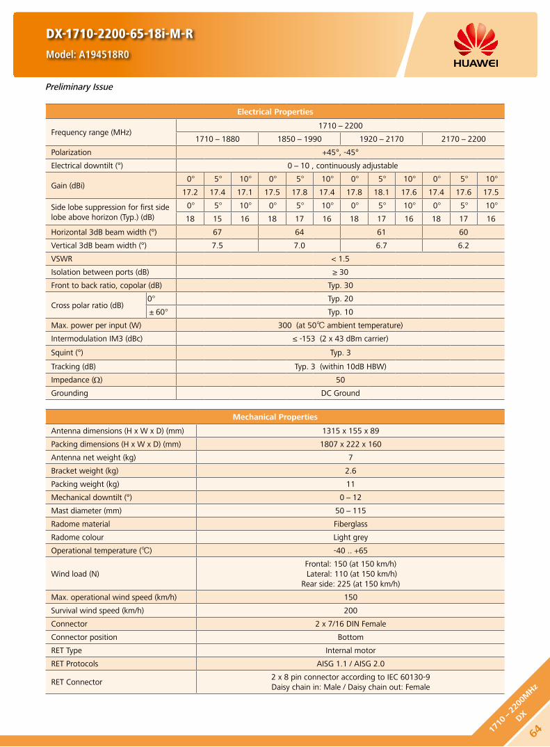
Electrical Properties
Frequency range (MHz)1710-2200
1710-1880 1850-1990 1920-2170 2170-2200
Polarization +45°, -45°
Electrical downtilt (°) 0-10 , continuously adjustable
Gain (dBi)0° 5° 10° 0° 5° 10° 0° 5° 10° 0° 5° 10°
17.2 17.4 17.1 17.5 17.8 17.4 17.8 18.1 17.6 17.4 17.6 17.5
Side lobe suppression for first side lobe above horizon (Typ.) (dB)
0° 5° 10° 0° 5° 10° 0° 5° 10° 0° 5° 10°
18 15 16 18 17 16 18 17 16 18 17 16
Horizontal 3dB beam width (°) 67 64 61 60
Vertical 3dB beam width (°) 7.5 7.0 6.7 6.2
VSWR < 1.5
Isolation between ports (dB) ≥ 30
Front to back ratio, copolar (dB) Typ. 30
Cross polar ratio (dB)0° Typ. 20
±60° Typ. 10
Max. power per input (W) 300 (at 50 ambient temperature)
Intermodulation IM3 (dBc) ≤ -153 (2 x 43 dBm carrier)
Squint (°) Typ. 3
Tracking (dB) Typ. 3 (within 10dB HBW)
Impedance (Ω) 50
Grounding DC Ground
Mechanical Properties
Antenna dimensions (H x W x D) (mm) 1315 x 155 x 89
Packing dimensions (H x W x D) (mm) 1807 x 222 x 160
Antenna net weight (kg) 7
Bracket weight (kg) 2.6
Packing weight (kg) 11
Mechanical downtilt (°) 0-12
Mast diameter (mm) 50-115
Radome material Fiberglass
Radome colour Light grey
Operational temperature () -40 .. +65
Wind load (N)Frontal: 150 (at 150 km/h) Lateral: 110 (at 150 km/h)
Rear side: 225 (at 150 km/h)
Max. operational wind speed (km/h) 150
Survival wind speed (km/h) 200
Connector 2 x 7/16 DIN Female
Connector position Bottom
RET Type Internal motor
RET Protocols AISG 1.1 / AISG 2.0
RET Connector2 x 8 pin connector according to IEC 60130-9Daisy chain in: Male / Daisy chain out: Female
DX-1710-2200-65-18i-M-R
Model: A194518R0
Preliminary Issue
641710-
2200
MHz
DX

RET Properties
RET Type Internal motor
RET Protocols AISG 1.1 / AISG 2.0
Input voltage range (V) DC 10-30
Power consumption (W) < 10 (motor activated)
< 0.5 (stand by)
Adjustment time (full range) (min) < 1.5 (typically, depending on antenna type)
Calibration time (min) < 3 (typically, depending on antenna type)
RET Connector2 x 8 pin connector according to IEC 60130-9Daisy chain in: Male / Daisy chain out: Female
Pin assignment according AISG 1 2 3 4 5 6 7 8
DC n/c RS-485B n/c RS-485A DC in/out DC return n/c
Lightning protection (kA)AISG interface (each pin)
3 (10/350 μs)10 (8/20 μs)
DX-1710-2200-65-18i-M-R
Model: A194518R0
HINT
Before the installation, check whether the antenna and base station support the same AISG protocol. If not, contact the technical support personnel of Huawei.
Standards:
EN 60950-1 (Safety) y
EN 55022 (Emission) y
EN 55024 (Immunity) y
ETSI EN300386 (1.4.1) y
FCC part15 y
Certification:
CE, FCC, RoHS, WEEE
Any previous catalogue issues become invalid.
Issue: 2012-06-01
HUAWEI TECHNOLOGIES CO., LTD.
Huawei Industrial BaseBantian Longgang
Shenzhen 518129, P.R. ChinaTel: +86-755-28780808
Email: [email protected]
www.huawei.com
Copyright © Huawei Technologies Co., Ltd. 2012. All rights reserved.
THIS DOCUMENT IS FOR INFORMATION PURPOSE ONLY, AND DOSE NOT CONSTITUTE ANY KIND OF WARRANTIES.
Preliminary Issue
65
1710-2200M
Hz
DX

Electrical Properties
Frequency range (MHz)1710-2690
1710-1990 1920-2200 2200-2490 2490-2690
Polarization +45°, -45°
Electrical downtilt (°) 0-6, continuously adjustable
Gain (dBi)0° 3° 6° 0° 3° 6° 0° 3° 6° 0° 3° 6°
18.0 18.2 18.1 18.3 18.6 18.5 18.7 19.1 19.0 19.0 19.4 19.1
Side lobe suppression for first side lobe above horizon (Typ.) (dB)
0° 3° 6° 0° 3° 6° 0° 3° 6° 0° 3° 6°
18 18 15 19 18 16 18 18 18 17 17 16
Horizontal 3dB beam width (°) 69 65 62 60
Vertical 3dB beam width (°) 4.9 4.5 4.1 3.7
VSWR < 1.5
Isolation between ports (dB) ≥ 30
Front to back ratio, copolar (dB) Typ. 27
Cross polar ratio (dB)0° Typ. 20
±60° Typ. 10
Max. power per input (W) 250 (at 50 ambient temperature)
Intermodulation IM3 (dBc) ≤ -153 (2 x 43 dBm carrier)
Squint (°) Typ. 4
Tracking (dB) Avg. 2 (within 10dB HBW)
Impedance (Ω) 50
Grounding DC Ground
Mechanical Properties
Antenna dimensions (H x W x D) (mm) 1932 x 155 x 89
Packing dimensions (H x W x D) (mm) 2417 x 292 x 195
Antenna net weight (kg) 9.0
Bracket weight (kg) 2.6
Packing weight (kg) 15.8
Mechanical downtilt (°) 0-8
Mast diameter (mm) 50-115
Radome material Fiberglass
Radome colour Light grey
Operational temperature () -55 .. +65
Wind load (N)Frontal: 490 (at 150 km/h)Lateral: 240 (at 150 km/h)
Rear side: 560 (at 150 km/h)
Max. operational wind speed (km/h) 150
Survival wind speed (km/h) 200
Connector 2 x 7/16 DIN Female (Long neck)
Connector position Bottom
DX-1710-2690-65-19.5i-M
Model: A26451900
661710-
2690
MHz
DX

Unit: mm
1710-2690X
+45°
7/16 (F) 7/16 (F)
-45°
5454
1710-2200 MHz 2200-2690 MHz
DX-1710-2690-65-19.5i-M
Model: A26451900
HINT
Extraordinary operating conditions, such as heavy icing or storm wind, may result in the breakage of an antenna. These facts must be considered during the site planning process.
The installation team must be properly qualified and also be familiar with the relevant national safety regulations.
Any previous catalogue issues become invalid.
Issue: 2012-06-01
HUAWEI TECHNOLOGIES CO., LTD.
Huawei Industrial BaseBantian Longgang
Shenzhen 518129, P.R. ChinaTel: +86-755-28780808
Email: [email protected]
www.huawei.com
Copyright © Huawei Technologies Co., Ltd. 2012. All rights reserved.
THIS DOCUMENT IS FOR INFORMATION PURPOSE ONLY, AND DOSE NOT CONSTITUTE ANY KIND OF WARRANTIES.
67
1710-2690M
Hz
DX

DXX-790-862/880-960-65/65-16i/16.5i-M/M-R
Model: ADU4516R0
Electrical Properties
790-862 880-960
Polarization +45°, -45°
Electrical downtilt (°) 0-12 , continuously adjustable
Gain (dBi)0° 6° 12° 0° 6° 12°
15.6 15.8 15.4 16.1 16.3 15.9
Side lobe suppression for first side lobe above horizon (Typ.) (dB)
0° 6° 12° 0° 6° 12°
17 16 16 17 16 15
Horizontal 3dB beam width (°) 67 63
Vertical 3dB beam width (°) 10.8 9.4
VSWR < 1.5
Isolation between ports (dB) ≥ 30
Front to back ratio, copolar (dB) Typ. 28 Typ. 30
Cross polar ratio (dB)0° Typ. 20
±60° ≥ 10
Max. power per input (W) 400 (at 50 ambient temperature)
Intermodulation IM3 (dBc) ≤ -153 (2 x 43 dBm carrier)
Impedance (Ω) 50
Grounding DC Ground
Mechanical Properties
Antenna dimensions (H x W x D) (mm) 1990 x 259 x 135
Packing dimensions (H x W x D) (mm) 2282 x 398 x 240
Antenna net weight (kg) 24
Bracket weight (kg) 4.6
Packing weight (kg) 32.6
Mechanical downtilt (°) 0-12
Mast diameter (mm) 50-115
Radome material Fiberglass
Radome colour Light grey
Operational temperature () -40 .. +65
Wind load (N)Frontal: 685 (at 150 km/h) Lateral: 355 (at 150 km/h)
Rear side: 910 (at 150 km/h)
Max. operational wind speed (km/h) 150
Survival wind speed (km/h) 200
Connector 4 x 7/16 DIN Female
Connector position Bottom
RET Type Internal motor
RET Protocols AISG 1.1 / AISG 2.0
RET Connector2 x 8 pin connector according to IEC 60130-9Daisy chain in: Male / Daisy chain out: Female
Preliminary Issue
68790-
862/
880-
960M
Hz
DXX

RET Properties
RET Type Internal motor
RET Protocols AISG 1.1 / AISG 2.0
Input voltage range (V) DC 10-30
Power consumption (W) < 10 (motor activated)
< 0.5 (stand by)
Adjustment time (full range) (min) < 1.5 (typically, depending on antenna type)
Calibration time (min) < 3 (typically, depending on antenna type)
RET Connector2 x 8 pin connector according to IEC 60130-9Daisy chain in: Male / Daisy chain out: Female
Pin assignment according AISG 1 2 3 4 5 6 7 8
DC n/c RS-485B n/c RS-485A DC in/out DC return n/c
Lightning protection (kA)AISG interface (each pin)
3 (10/350 μs)10 (8/20 μs)
DXX-790-862/880-960-65/65-16i/16.5i-M/M-R
Model: ADU4516R0
HINT
Before the installation, check whether the antenna and base station support the same AISG protocol. If not, contact the technical support personnel of Huawei.
Standards:
EN 60950-1 (Safety) y
EN 55022 (Emission) y
EN 55024 (Immunity) y
ETSI EN300386 (1.4.1) y
FCC part15 y
Certification:
CE, FCC, RoHS, WEEE
Any previous catalogue issues become invalid.
Issue: 2012-06-01
HUAWEI TECHNOLOGIES CO., LTD.
Huawei Industrial BaseBantian Longgang
Shenzhen 518129, P.R. ChinaTel: +86-755-28780808
Email: [email protected]
www.huawei.com
Copyright © Huawei Technologies Co., Ltd. 2012. All rights reserved.
THIS DOCUMENT IS FOR INFORMATION PURPOSE ONLY, AND DOSE NOT CONSTITUTE ANY KIND OF WARRANTIES.
Preliminary Issue
69
790-862/880-
960MHz
DXX

DXX-790-862/880-960-65/65-17i/17.5i-M/M-R
Model: ADU4517R0
Electrical Properties
790-862 880-960
Polarization +45°, -45°
Electrical downtilt (°) 0-10 , continuously adjustable
Gain (dBi)0° 5° 10° 0° 5° 10°
16.5 16.7 16.4 17.1 17.3 17.0
Side lobe suppression for first side lobe above horizon (Typ.) (dB)
0° 5° 10° 0° 5° 10°
17 16 15 17 16 15
Horizontal 3dB beam width (°) 67 63
Vertical 3dB beam width (°) 8.3 7.2
VSWR < 1.5
Isolation between ports (dB) ≥ 30
Front to back ratio, copolar (dB) Typ. 30
Cross polar ratio (dB)0° Typ. 20
±60° ≥ 10
Max. power per input (W) 400 (at 50 ambient temperature)
Intermodulation IM3 (dBc) ≤ -153 (2 x 43 dBm carrier)
Impedance (Ω) 50
Grounding DC Ground
Mechanical Properties
Antenna dimensions (H x W x D) (mm) 2565 x 259 x 135
Packing dimensions (H x W x D) (mm) 2867 x 397 x 220
Antenna net weight (kg) 27
Bracket weight (kg) 5.6
Packing weight (kg) 38
Mechanical downtilt (°) 0-8
Mast diameter (mm) 50-115
Radome material Fiberglass
Radome colour Light grey
Operational temperature () -40 .. +65
Wind load (N)Frontal: 920 (at 150 km/h) Lateral: 475 (at 150 km/h)
Rear side: 1220 (at 150 km/h)
Max. operational wind speed (km/h) 150
Survival wind speed (km/h) 200
Connector 4 x 7/16 DIN Female
Connector position Bottom
RET Type Internal motor
RET Protocols AISG 1.1 / AISG 2.0
RET Connector2 x 8 pin connector according to IEC 60130-9Daisy chain in: Male / Daisy chain out: Female
Preliminary Issue
70790-
862/
880-
960M
Hz
DXX

RET Properties
RET Type Internal motor
RET Protocols AISG 1.1 / AISG 2.0
Input voltage range (V) DC 10-30
Power consumption (W) < 10 (motor activated)
< 0.5 (stand by)
Adjustment time (full range) (min) < 1.5 (typically, depending on antenna type)
Calibration time (min) < 3 (typically, depending on antenna type)
RET Connector2 x 8 pin connector according to IEC 60130-9Daisy chain in: Male / Daisy chain out: Female
Pin assignment according AISG 1 2 3 4 5 6 7 8
DC n/c RS-485B n/c RS-485A DC in/out DC return n/c
Lightning protection (kA)AISG interface (each pin)
3 (10/350 μs)10 (8/20 μs)
DXX-790-862/880-960-65/65-17i/17.5i-M/M-R
Model: ADU4517R0
HINT
Before the installation, check whether the antenna and base station support the same AISG protocol. If not, contact the technical support personnel of Huawei.
Standards:
EN 60950-1 (Safety) y
EN 55022 (Emission) y
EN 55024 (Immunity) y
ETSI EN300386 (1.4.1) y
FCC part15 y
Certification:
CE, FCC, RoHS, WEEE
Any previous catalogue issues become invalid.
Issue: 2012-06-01
HUAWEI TECHNOLOGIES CO., LTD.
Huawei Industrial BaseBantian Longgang
Shenzhen 518129, P.R. ChinaTel: +86-755-28780808
Email: [email protected]
www.huawei.com
Copyright © Huawei Technologies Co., Ltd. 2012. All rights reserved.
THIS DOCUMENT IS FOR INFORMATION PURPOSE ONLY, AND DOSE NOT CONSTITUTE ANY KIND OF WARRANTIES.
Preliminary Issue
71
790-862/880-
960MHz
DXX

DXX-790-960/1710-2180-65/65-14i/17i-M/M
Model: ADU451503
Electrical Properties
Frequency range (MHz)790-960 1710-2180
790-862 824-894 880-960 1710-1880 1850-1990 1920-2180
Polarization +45°, -45°
Electrical downtilt (°) 0-14, continuously adjustable 0-10, continuously adjustable
Gain (dBi)0° 7° 14° 0° 7° 14° 0° 7° 14° 0° 5° 10° 0° 5° 10° 0° 5° 10°
14.4 14.3 14.0 14.5 14.5 14.1 14.5 14.5 14.1 16.4 16.5 16.3 17.0 17.0 16.2 17.2 17.3 16.4
Side lobe suppression for first side lobe above horizon (Typ.) (dB)
0° 7° 14° 0° 7° 14° 0° 7° 14° 0° 5° 10° 0° 5° 10° 0° 5° 10°
18 18 17 18 18 17 17 15 15 19 17 17 19 16 17 19 16 17
Horizontal 3dB beam width (°) 69 66 64 65 63 60
Vertical 3dB beam width (°) 15.7 15.0 14.0 7.5 7.1 6.6
VSWR < 1.5
Isolation between ports (dB)Intra-system: ≥ 30
Inter-system (790 - 960 / 1710 - 2180 MHz): ≥ 40
Front to back ratio, copolar (dB) Typ. 28 Typ. 28
Cross polar ratio (dB)0° Typ. 25 Typ. 20
±60° Typ. 10 Typ. 10
Max. power per input (W) 500 (at 50 ambient temperature) 300 (at 50 ambient temperature)
Intermodulation IM3 (dBc) ≤ -153 (2 x 43 dBm carrier)
Squint (°) Avg. 2.0
Tracking (dB) Avg. 2.0 (within 10dB HBW)
Impedance (Ω) 50
Grounding DC Ground
Mechanical Properties
Antenna dimensions (H x W x D) (mm) 1360 x 259 x 135
Packing dimensions (H x W x D) (mm) 1784 x 392 x 230
Antenna net weight (kg) 13.7
Bracket weight (kg) 4.6
Packing weight (kg) 22.2
Mechanical downtilt (°) 0-16
Mast diameter (mm) 50-115
Radome material Fiberglass
Radome colour Light grey
Operational temperature () -55 .. +65
Wind load (N)Frontal: 440 (at 150 km/h)Lateral: 230 (at 150 km/h)
Rear side: 585 (at 150 km/h)
Max. operational wind speed (km/h) 150
Survival wind speed (km/h) 200
Connector 4 x 7/16 DIN Female
Connector position Bottom
72790-
960/
1710-
2180
MHz
DXX

790-960 MHz 1710-2180 MHz
790-960X
1710-2180X
+45° +45°
7/16 (F) 7/16 (F)7/16 (F) 7/16 (F)
-45° -45°
Unit: mm7055
56
HINT
Extraordinary operating conditions, such as heavy icing or storm wind, may result in the breakage of an antenna. These facts must be considered during the site planning process.
The installation team must be properly qualified and also be familiar with the relevant national safety regulations.
Any previous catalogue issues become invalid.
Issue: 2012-06-01
HUAWEI TECHNOLOGIES CO., LTD.
Huawei Industrial BaseBantian Longgang
Shenzhen 518129, P.R. ChinaTel: +86-755-28780808
Email: [email protected]
www.huawei.com
Copyright © Huawei Technologies Co., Ltd. 2012. All rights reserved.
THIS DOCUMENT IS FOR INFORMATION PURPOSE ONLY, AND DOSE NOT CONSTITUTE ANY KIND OF WARRANTIES.
DXX-790-960/1710-2180-65/65-14i/17i-M/M
Model: ADU451503
73
790-960/1710-
2180MHz
DXX

DXX-790-960/1710-2180-65/65-16i/18.5i-M/M
Model: ADU451602v01
Electrical Properties
Frequency range (MHz)790-960 1710-2180
790-862 824-894 880-960 1710-1880 1850-1990 1920-2180
Polarization +45°, -45°
Electrical downtilt (°) 0-12, continuously adjustable 0-8, continuously adjustable
Gain (dBi)0° 6° 12° 0° 6° 12° 0° 6° 12° 0° 4° 8° 0° 4° 8° 0° 4° 8°
15.7 15.7 15.3 16.0 16.0 15.5 16.2 16.0 15.6 18.0 18.5 18.3 18.2 18.7 18.3 18.3 18.7 18.3
Side lobe suppression for first side lobe above horizon (Typ.) (dB)
0° 6° 12° 0° 6° 12° 0° 6° 12° 0° 5° 10° 0° 5° 10° 0° 5° 10°
20 17 15 20 18 15 17 18 15 20 18 18 18 17 15 18 15 15
Horizontal 3dB beam width (°) 69 66 64 65 63 60
Vertical 3dB beam width (°) 10.6 10.2 9.5 5.2 5.0 4.7
VSWR < 1.5
Isolation between ports (dB)Intra-system: ≥ 30
Inter-system (790 - 960 / 1710 - 2180 MHz): ≥ 40
Front to back ratio, copolar (dB) Typ. 28 Typ. 30
Cross polar ratio (dB)0° Typ. 25 Typ. 20
±60° Typ. 10 Typ. 10
Max. power per input (W) 500 (at 50 ambient temperature) 300 (at 50 ambient temperature)
Intermodulation IM3 (dBc) ≤ -153 (2 x 43 dBm carrier)
Squint (°) Avg. 2.5
Tracking (dB) Avg. 2.0 (within 10dB HBW)
Impedance (Ω) 50
Grounding DC Ground
Mechanical Properties
Antenna dimensions (H x W x D) (mm) 1936 x 259 x 135
Packing dimensions (H x W x D) (mm) 2357 x 392 x 230
Antenna net weight (kg) 17.3
Bracket weight (kg) 4.6
Packing weight (kg) 27.3
Mechanical downtilt (°) 0-12
Mast diameter (mm) 50-115
Radome material Fiberglass
Radome colour Light grey
Operational temperature () -55 .. +65
Wind load (N)Frontal: 665 (at 150 km/h)Lateral: 345 (at 150 km/h)
Rear side: 880 (at 150 km/h)
Max. operational wind speed (km/h) 150
Survival wind speed (km/h) 200
Connector 4 x 7/16 DIN Female
Connector position Bottom
74790-
960/
1710-
2180
MHz
DXX

790-960 MHz 1710-2180 MHz
790-960X
1710-2180X
+45° +45°
7/16 (F) 7/16 (F)7/16 (F) 7/16 (F)
-45° -45°
Unit: mm7055
56
HINT
Extraordinary operating conditions, such as heavy icing or storm wind, may result in the breakage of an antenna. These facts must be considered during the site planning process.
The installation team must be properly qualified and also be familiar with the relevant national safety regulations.
Any previous catalogue issues become invalid.
Issue: 2012-06-01
HUAWEI TECHNOLOGIES CO., LTD.
Huawei Industrial BaseBantian Longgang
Shenzhen 518129, P.R. ChinaTel: +86-755-28780808
Email: [email protected]
www.huawei.com
Copyright © Huawei Technologies Co., Ltd. 2012. All rights reserved.
THIS DOCUMENT IS FOR INFORMATION PURPOSE ONLY, AND DOSE NOT CONSTITUTE ANY KIND OF WARRANTIES.
DXX-790-960/1710-2180-65/65-16i/18.5i-M/M
Model: ADU451602v01
75
790-960/1710-
2180MHz
DXX

Mechanical Properties
Antenna dimensions (H x W x D) (mm) 1940 x 259 x 135
Packing dimensions (H x W x D) (mm) 2372 x 395 x 228
Antenna net weight (kg) 18
Bracket weight (kg) 4.6
Packing weight (kg) 30
Mechanical downtilt (°) 0-12
Mast diameter (mm) 50-115
Radome material Fiberglass
Radome colour Light grey
Operational temperature () -40 .. +65
Wind load (N)Frontal: 670 (at 150 km/h) Lateral: 345 (at 150 km/h)
Rear side: 885 (at 150 km/h)
Max. operational wind speed (km/h) 150
Survival wind speed (km/h) 200
Connector 4 x 7/16 DIN Female
Connector position Bottom
RET Type Internal motor
RET Protocols AISG 1.1 / AISG 2.0
RET Connector2 x 8 pin connector according to IEC 60130-9Daisy chain in: Male / Daisy chain out: Female
DXX-790-960/1710-2180-65/65-16i/18.5i-M/M-R
Model: ADU4518R3
Electrical Properties
Frequency range (MHz)790-960 1710-2180
790-862 824-894 880-960 1710-1880 1850-1990 1920-2180
Polarization +45°, -45°
Electrical downtilt (°) 0-12 , continuously adjustable 0-8 , continuously adjustable
Gain (dBi)0° 6° 12° 0° 6° 12° 0° 6° 12° 0° 4° 8° 0° 4° 8° 0° 4° 8°
15.2 15.4 15.1 15.4 15.6 15.2 15.8 16.0 15.6 17.7 17.9 17.5 18.0 18.1 17.9 18.1 18.3 17.9
Side lobe suppression for first side lobe above horizon (Typ.) (dB)
0° 6° 12° 0° 6° 12° 0° 6° 12° 0° 4° 8° 0° 4° 8° 0° 4° 8°
17 16 16 17 16 16 17 16 16 17 16 15 17 16 15 17 16 15
Horizontal 3dB beam width (°) 69 66 65 65 63 60
Vertical 3dB beam width (°) 11.3 10.7 10 5.2 4.9 4.6
VSWR < 1.5
Isolation between ports (dB)Intra-system: ≥ 30
Inter-system (790-960 / 1710-2180 MHz): ≥ 40
Front to back ratio, copolar (dB) Typ. 27 Typ. 28
Cross polar ratio (dB)0° Typ. 20 Typ. 20
±60° Typ. 10 Typ. 10
Max. power per input (W) 500 (at 50 ambient temperature) 300 (at 50 ambient temperature)
Intermodulation IM3 (dBc) ≤ -153 (2 x 43 dBm carrier)
Impedance (Ω) 50
Grounding DC Ground
Preliminary Issue
76790-
960/
1710-
2180
MHz
DXX

RET Properties
RET Type Internal motor
RET Protocols AISG 1.1 / AISG 2.0
Input voltage range (V) DC 10-30
Power consumption (W) < 10 (motor activated)
< 0.5 (stand by)
Adjustment time (full range) (min) < 1.5 (typically, depending on antenna type)
Calibration time (min) < 3 (typically, depending on antenna type)
RET Connector2 x 8 pin connector according to IEC 60130-9Daisy chain in: Male / Daisy chain out: Female
Pin assignment according AISG 1 2 3 4 5 6 7 8
DC n/c RS-485B n/c RS-485A DC in/out DC return n/c
Lightning protection (kA)AISG interface (each pin)
3 (10/350 μs)10 (8/20 μs)
DXX-790-960/1710-2180-65/65-16i/18.5i-M/M-R
Model: ADU4518R3
HINT
Before the installation, check whether the antenna and base station support the same AISG protocol. If not, contact the technical support personnel of Huawei.
Standards:
EN 60950-1 (Safety) y
EN 55022 (Emission) y
EN 55024 (Immunity) y
ETSI EN300386 (1.4.1) y
FCC part15 y
Certification:
CE, FCC, RoHS, WEEE
Any previous catalogue issues become invalid.
Issue: 2012-06-01
HUAWEI TECHNOLOGIES CO., LTD.
Huawei Industrial BaseBantian Longgang
Shenzhen 518129, P.R. ChinaTel: +86-755-28780808
Email: [email protected]
www.huawei.com
Copyright © Huawei Technologies Co., Ltd. 2012. All rights reserved.
THIS DOCUMENT IS FOR INFORMATION PURPOSE ONLY, AND DOSE NOT CONSTITUTE ANY KIND OF WARRANTIES.
Preliminary Issue
77
790-960/1710-
2180MHz
DXX

Electrical Properties
Frequency range (MHz)790-960 1710-2180
790-862 824-894 880-960 1710-1880 1850-1990 1920-2180
Polarization +45°, -45°
Electrical downtilt (°) 0-10, continuously adjustable 0-8, continuously adjustable
Gain (dBi)0° 5° 10° 0° 5° 10° 0° 5° 10° 0° 4° 8° 0° 4° 8° 0° 4° 8°
16.6 16.7 16.5 16.9 17.0 16.8 17.0 17.2 16.9 18.1 18.4 18.0 18.3 18.6 18.2 18.3 18.6 18.0
Side lobe suppression for first side lobe above horizon (Typ.) (dB)
0° 5° 10° 0° 5° 10° 0° 5° 10° 0° 4° 8° 0° 4° 8° 0° 4° 8°
19 19 18 19 19 18 19 18 17 18 16 18 20 16 18 20 16 18
Horizontal 3dB beam width (°) 69 66 65 64 62 60
Vertical 3dB beam width (°) 8.4 8 7.5 5.2 4.9 4.6
VSWR < 1.5
Isolation between ports (dB)Intra-system: ≥ 30Intra-system: ≥ 40
Front to back ratio, copolar (dB) Typ. 28 Typ. 29
Cross polar ratio (dB)0° Typ. 30 Typ. 20
±60° Typ. 10 Typ. 10
Max. power per input (W) 500 (at 50 ambient temperature) 300 (at 50 ambient temperature)
Intermodulation IM3 (dBc) ≤ -153 (2 x 43 dBm carrier)
Squint (°) Avg. 2.5
Tracking (dB) Avg. 1 (within 10dB HBW)
Impedance (Ω) 50
Grounding DC Ground
Mechanical Properties
Antenna dimensions (H x W x D) (mm) 2535 x 259 x 135
Packing dimensions (H x W x D) (mm) 2952 x 392 x 230
Antenna net weight (kg) 21
Bracket weight (kg) 5.6
Packing weight (kg) 32.5
Mechanical downtilt (°) 0-8
Mast diameter (mm) 50-115
Radome material Fiberglass
Radome colour Light grey
Operational temperature () -55 .. +65
Wind load (N)Frontal: 910 (at 150 km/h)Lateral: 470 (at 150 km/h)
Rear side: 1200 (at 150 km/h)
Max. operational wind speed (km/h) 150
Survival wind speed (km/h) 200
Connector 4 x 7/16 DIN Female
Connector position Bottom
DXX-790-960/1710-2180-65/65-17i/18.5i-M/M
Model: ADU451807v01
78790-
960/
1710-
2180
MHz
DXX
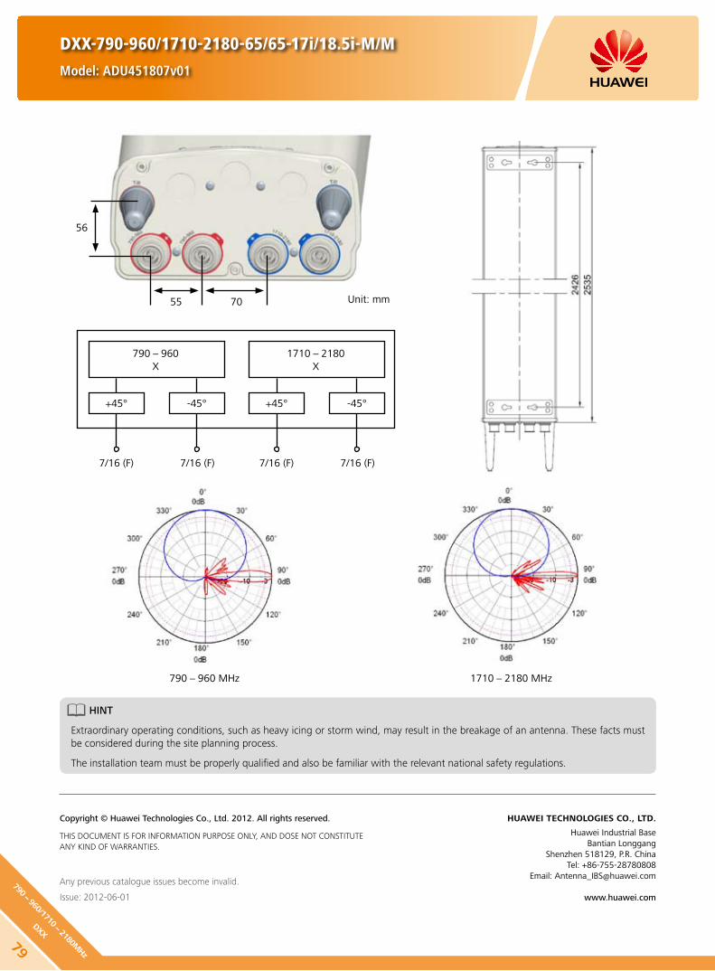
790-960 MHz 1710-2180 MHz
790-960X
1710-2180X
+45° +45°
7/16 (F) 7/16 (F)7/16 (F) 7/16 (F)
-45° -45°
DXX-790-960/1710-2180-65/65-17i/18.5i-M/M
Model: ADU451807v01
Unit: mm7055
56
HINT
Extraordinary operating conditions, such as heavy icing or storm wind, may result in the breakage of an antenna. These facts must be considered during the site planning process.
The installation team must be properly qualified and also be familiar with the relevant national safety regulations.
Any previous catalogue issues become invalid.
Issue: 2012-06-01
HUAWEI TECHNOLOGIES CO., LTD.
Huawei Industrial BaseBantian Longgang
Shenzhen 518129, P.R. ChinaTel: +86-755-28780808
Email: [email protected]
www.huawei.com
Copyright © Huawei Technologies Co., Ltd. 2012. All rights reserved.
THIS DOCUMENT IS FOR INFORMATION PURPOSE ONLY, AND DOSE NOT CONSTITUTE ANY KIND OF WARRANTIES.
79
790-960/1710-
2180MHz
DXX

Mechanical Properties
Antenna dimensions (H x W x D) (mm) 2535 x 259 x 135
Packing dimensions (H x W x D) (mm) 3042 x 400 x 228
Weight (kg) Antenna: 19.0
Bracket: 5.6 Packing: 36.2
Mechanical downtilt (°) 0-8
Mast diameter (mm) 50-115
Radome material Fiberglass
Radome colour Light grey
Operational temperature () -40 .. +65
Wind load (N)Frontal: 910 (at 150 km/h) Lateral: 470 (at 150 km/h)
Rear side: 1200 (at 150 km/h)
Wind speed (km/h)Max. operational: 150 Survival: 200
Connector 4 x 7/16 DIN Female
Connector position Bottom
RET Type Internal motor
RET Protocols AISG 1.1 / AISG 2.0
RET Connector2 x 8 pin connector according to IEC 60130-9Daisy chain in: Male / Daisy chain out: Female
DXX-790-960/1710-2180-65/65-17i/18.5i-M/M-R
Model: ADU4518R0
Electrical Properties
Frequency range (MHz)790-960 1710-2180
790-862 824-894 880-960 1710-1880 1850-1990 1920-2180
Polarization +45°, -45°
Electrical downtilt (°) 0-10 , continuously adjustable 0-8 , continuously adjustable
Gain (dBi)0° 5° 10° 0° 5° 10° 0° 5° 10° 0° 4° 8° 0° 4° 8° 0° 4° 8°
16.4 16.6 16.3 16.7 16.9 16.5 16.9 17 16.7 17.7 17.9 17.5 18 18.1 17.9 18.1 18.3 17.9
Side lobe suppression for first side lobe above horizon (Typ.) (dB)
0° 5° 10° 0° 5° 10° 0° 5° 10° 0° 4° 8° 0° 4° 8° 0° 4° 8°
17 16 16 17 16 16 17 16 16 17 16 15 17 16 15 17 16 15
Horizontal 3dB beam width (°) 69 66 65 65 63 60
Vertical 3dB beam width (°) 8.3 7.8 7.2 5.2 4.9 4.6
VSWR < 1.5
Isolation between ports (dB)Intra-system: ≥ 30Inter-system: ≥ 40
Front to back ratio, copolar (dB) Typ. 27 Typ. 28
Cross polar ratio (dB)0° Typ. 20 Typ. 20
±60° Typ. 10 Typ. 10
Max. power per input (W) 500 (at 50 ambient temperature) 300 (at 50 ambient temperature)
Intermodulation IM3 (dBc) ≤ -153 (2 x 43 dBm carrier)
Impedance (Ω) 50
Grounding DC Ground
Preliminary Issue
80790-
960/
1710-
2180
MHz
DXX

RET Properties
RET Type Internal motor
RET Protocols AISG 1.1 / AISG 2.0
Input voltage range (V) DC 10-30
Power consumption (W) < 10 (motor activated)
< 0.5 (stand by)
Adjustment time (full range) (min) < 1.5 (typically, depending on antenna type)
Calibration time (min) < 3 (typically, depending on antenna type)
RET Connector2 x 8 pin connector according to IEC 60130-9Daisy chain in: Male / Daisy chain out: Female
Pin assignment according AISG 1 2 3 4 5 6 7 8
DC n/c RS-485B n/c RS-485A DC in/out DC return n/c
Lightning protection (kA)AISG interface (each pin)
3 (10/350 μs)10 (8/20 μs)
DXX-790-960/1710-2180-65/65-17i/18.5i-M/M-R
Model: ADU4518R0
HINT
Before the installation, check whether the antenna and base station support the same AISG protocol. If not, contact the technical support personnel of Huawei.
Standards:
EN 60950-1 (Safety) y
EN 55022 (Emission) y
EN 55024 (Immunity) y
ETSI EN300386 (1.4.1) y
FCC part15 y
Certification:
CE, FCC, RoHS, WEEE
Any previous catalogue issues become invalid.
Issue: 2012-06-01
HUAWEI TECHNOLOGIES CO., LTD.
Huawei Industrial BaseBantian Longgang
Shenzhen 518129, P.R. ChinaTel: +86-755-28780808
Email: [email protected]
www.huawei.com
Copyright © Huawei Technologies Co., Ltd. 2012. All rights reserved.
THIS DOCUMENT IS FOR INFORMATION PURPOSE ONLY, AND DOSE NOT CONSTITUTE ANY KIND OF WARRANTIES.
Preliminary Issue
81
790-960/1710-
2180MHz
DXX

Mechanical Properties
Antenna dimensions (H x W x D) (mm) 2535 x 259 x 135
Packing dimensions (H x W x D) (mm) 2952 x 392 x 230
Antenna net weight (kg) 21
Bracket weight (kg) 5.6
Packing weight (kg) 32.5
Mechanical downtilt (°) 0-8
Mast diameter (mm) 50-115
Radome material Fiberglass
Radome colour Light grey
Operational temperature () -55 .. +65
Wind load (N)Frontal: 910 (at 150 km/h)Lateral: 470 (at 150 km/h)
Rear side: 1200 (at 150 km/h)
Max. operational wind speed (km/h) 150
Survival wind speed (km/h) 200
Connector 2 x 7/16 DIN Female
Connector position Bottom
DXX-790-960/1710-2180-65/65-17i/18i-M/M-C
Model: ADU4518C0
Any previous catalogue issues become invalid.
Issue: 2012-06-01
HUAWEI TECHNOLOGIES CO., LTD.
Huawei Industrial BaseBantian Longgang
Shenzhen 518129, P.R. ChinaTel: +86-755-28780808
Email: [email protected]
www.huawei.com
Copyright © Huawei Technologies Co., Ltd. 2012. All rights reserved.
THIS DOCUMENT IS FOR INFORMATION PURPOSE ONLY, AND DOSE NOT CONSTITUTE ANY KIND OF WARRANTIES.
Electrical Properties
Frequency range (MHz)790-960 1710-2180
790-862 824-894 880-960 1710-1880 1850-1990 1920-2180
Polarization +45°, -45°
Electrical downtilt (°) 0-10, continuously adjustable 0-8, continuously adjustable
Gain (dBi)0° 5° 10° 0° 5° 10° 0° 5° 10° 0° 4° 8° 0° 4° 8° 0° 4° 8°
16.6 16.7 16.5 16.9 17.0 16.8 17.0 17.2 16.9 18.0 18.3 17.9 18.2 18.5 18.1 18.2 18.5 17.9
Side lobe suppression for first side lobe above horizon (Typ.) (dB)
0° 5° 10° 0° 5° 10° 0° 5° 10° 0° 4° 8° 0° 4° 8° 0° 4° 8°
19 19 18 19 19 18 19 18 17 18 16 18 20 16 18 20 16 18
Horizontal 3dB beam width (°) 69 66 65 64 62 60
Vertical 3dB beam width (°) 8.4 8 7.5 5.2 4.9 4.6
VSWR < 1.5
Isolation between ports (dB) Intra-system: ≥ 30
Front to back ratio, copolar (dB) Typ. 28 Typ. 29
Cross polar ratio (dB)0° Typ. 30 Typ. 20
±60° Typ. 10 Typ. 10
Max. power per input (W) 250 (at 50 ambient temperature) 200 (at 50 ambient temperature)
Total power per combined input (W) 450 (at 50 ambient temperature)
Intermodulation IM3 (dBc) ≤ -153 (2 x 43 dBm carrier)
Squint (°) Avg. 2.5
Tracking (dB) Avg. 1.0 (within 10dB HBW)
Impedance (Ω) 50
Grounding DC Ground
Preliminary Issue
82790-
960/
1710-
2180
MHz
DXX

Electrical Properties
Frequency range (MHz)790-960 1710-2690
790-862 824-894 880-960 1710-1990 1990-2200 2490-2690
Polarization +45°, -45°
Electrical downtilt (°) 0-10, continuously adjustable 0-8, continuously adjustable
Gain (dBi)0° 5° 10° 0° 5° 10° 0° 5° 10° 0° 4° 8° 0° 4° 8° 0° 4° 8°
15.4 15.6 15.3 15.6 15.8 15.4 16.0 16.1 15.8 17.9 17.7 17.3 18.3 18.1 17.5 18.5 18.3 17.8
Side lobe suppression for first side lobe above horizon (Typ.) (dB)
0° 5° 10° 0° 5° 10° 0° 5° 10° 0° 4° 8° 0° 4° 8° 0° 4° 8°
17 16 16 17 16 16 17 16 16 17 17 16 17 17 16 17 17 16
Horizontal 3dB beam width (°) 69 66 64 64 62 60
Vertical 3dB beam width (°) 10.3 9.9 9.2 4.3 4.1 3.5
VSWR < 1.5
Isolation between ports (dB)Intra-system: ≥ 28Inter-system: ≥ 40
Front to back ratio, copolar (dB) Typ. 28 Typ. 28
Cross polar ratio (dB)0° Typ. 20 Typ. 20
±60° Typ. 10 Typ. 10
Max. power per input (W) 500 (at 50 ambient temperature) 250 (at 50 ambient temperature)
Intermodulation IM3 (dBc) ≤ -153 (2 x 43 dBm carrier)
Impedance (Ω) 50
Grounding DC Ground
Mechanical Properties
Antenna dimensions (H x W x D) (mm) 1995 x 298 x 148
Packing dimensions (H x W x D) (mm) 2350 x 410 x 250
Antenna net weight (kg) 23
Bracket weight (kg) 4.6
Packing weight (kg) 34
Mechanical downtilt (°) 0-12
Mast diameter (mm) 50-115
Radome material Fiberglass
Radome colour Light grey
Operational temperature () -55 .. +65
Wind load (N)Frontal: 540 (at 150 km/h)Lateral: 245 (at 150 km/h)
Rear side: 860 (at 150 km/h)
Max. operational wind speed (km/h) 150
Survival wind speed (km/h) 200
Connector 4 x 7/16 DIN Female
Connector position Bottom
DXX-790-960/1710-2690-65/65-16i/18.5i-M/M
Model: ADU451604
Any previous catalogue issues become invalid.
Issue: 2012-06-01
HUAWEI TECHNOLOGIES CO., LTD.
Huawei Industrial BaseBantian Longgang
Shenzhen 518129, P.R. ChinaTel: +86-755-28780808
Email: [email protected]
www.huawei.com
Copyright © Huawei Technologies Co., Ltd. 2012. All rights reserved.
THIS DOCUMENT IS FOR INFORMATION PURPOSE ONLY, AND DOSE NOT CONSTITUTE ANY KIND OF WARRANTIES.
Preliminary Issue
83
790-960/1710-
2690MHz
DXX

Electrical Properties
Frequency range (MHz)790-960 1710-2690
790-862 824-894 880-960 1710-1990 1990-2200 2490-2690
Polarization +45°, -45°
Electrical downtilt (°) 0-10, continuously adjustable 0-8, continuously adjustable
Gain (dBi)0° 5° 10° 0° 5° 10° 0° 5° 10° 0° 4° 8° 0° 4° 8° 0° 4° 8°
16.4 16.6 16.3 16.6 16.8 16.4 17.0 17.1 16.8 17.9 17.7 17.3 18.3 18.1 17.5 18.5 18.3 17.8
Side lobe suppression for first side lobe above horizon (Typ.) (dB)
0° 5° 10° 0° 5° 10° 0° 5° 10° 0° 4° 8° 0° 4° 8° 0° 4° 8°
17 16 16 17 16 16 17 16 16 17 17 16 17 17 16 17 17 16
Horizontal 3dB beam width (°) 69 66 64 64 62 60
Vertical 3dB beam width (°) 7.9 7.6 7.1 4.3 4.1 3.5
VSWR < 1.5
Isolation between ports (dB)Intra-system: ≥ 28Inter-system: ≥ 40
Front to back ratio, copolar (dB) Typ. 28 Typ. 28
Cross polar ratio (dB)0° Typ. 20 Typ. 20
±60° Typ. 10 Typ. 10
Max. power per input (W) 500 (at 50 ambient temperature) 250 (at 50 ambient temperature)
Intermodulation IM3 (dBc) ≤ -153 (2 x 43 dBm carrier)
Impedance (Ω) 50
Grounding DC Ground
Mechanical Properties
Antenna dimensions (H x W x D) (mm) 2598 x 298 x 148
Packing dimensions (H x W x D) (mm) 2950 x 410 x 250
Antenna net weight (kg) 27
Bracket weight (kg) 5.6
Packing weight (kg) 38
Mechanical downtilt (°) 0-8
Mast diameter (mm) 50-115
Radome material Fiberglass
Radome colour Light grey
Operational temperature () -55 .. +65
Wind load (N)Frontal: 735 (at 150 km/h)Lateral: 335 (at 150 km/h)
Rear side: 1160 (at 150 km/h)
Max. operational wind speed (km/h) 150
Survival wind speed (km/h) 200
Connector 4 x 7/16 DIN Female
Connector position Bottom
DXX-790-960/1710-2690-65/65-17i/18.5i-M/M
Model: ADU451712
Any previous catalogue issues become invalid.
Issue: 2012-06-01
HUAWEI TECHNOLOGIES CO., LTD.
Huawei Industrial BaseBantian Longgang
Shenzhen 518129, P.R. ChinaTel: +86-755-28780808
Email: [email protected]
www.huawei.com
Copyright © Huawei Technologies Co., Ltd. 2012. All rights reserved.
THIS DOCUMENT IS FOR INFORMATION PURPOSE ONLY, AND DOSE NOT CONSTITUTE ANY KIND OF WARRANTIES.
Preliminary Issue
84790-
960/
1710-
2690
MHz
DXX
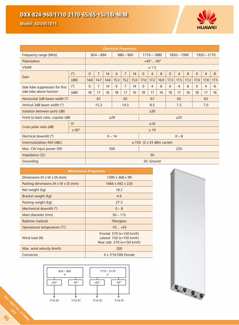
Mechanical Properties
Dimensions (H x W x D) (mm) 1390 x 368 x 99
Packing dimensions (H x W x D) (mm) 1666 x 492 x 220
Net weight (kg) 18.2
Bracket weight (kg) 4.6
Packing weight (kg) 27.5
Mechanical downtilt (°) 0-8
Mast diameter (mm) 50-115
Radome material Fiberglass
Operational temperature () -55 .. +65
Wind load (N)Frontal: 570 (v=150 km/h)Lateral: 150 (v=150 km/h)
Rear side: 570 (v=150 km/h)
Max. wind velocity (km/h) 200
Connector 4 x 7/16 DIN Female
DXX-824-960/1710-2170-65/65-15i/18i-M/M
Model: ADU451815
Electrical Properties
Frequency range (MHz) 824-894 880-960 1710-1880 1850-1990 1920-2170
Polarization +45° , -45°
VSWR ≤ 1.5
Gain (°) 0 7 14 0 7 14 0 4 8 0 4 8 0 4 8
(dBi) 14.8 14.7 14.6 15.3 15.2 15.0 17.0 17.2 16.9 17.3 17.5 17.2 17.6 17.8 17.5
Side lobe suppression for first side lobe above horizon
(°) 0 7 14 0 7 14 0 4 8 0 4 8 0 4 8
(dBi) 18 17 16 18 17 16 18 17 16 18 17 16 18 17 16
Horizontal 3dB beam width (°) 67 65 67 65 63
Vertical 3dB beam width (°) 15.3 14.5 8.5 7.5 7.0
Isolation between ports (dB) ≥30
Front to back ratio, copolar (dB) ≥28 ≥25
Cross polar ratio (dB)0° ≥18
±60° ≥ 10
Electrical downtilt (°) 0-14 0-8
Intermodulation IM3 (dBc) ≤-150 (2 x 43 dBm carrier)
Max. CW input power (W) 500 250
Impedance (Ω) 50
Grounding DC Ground
824-960X
+45°
7/16 (F) 7/16 (F)7/16 (F) 7/16 (F)
-45°
1710-2170X
+45° -45°
85
824-960/1710-
2170MHz
DXX

DXX-824-960/1710-2170-65/65-15i/18i-M/M
Model: ADU451815
Any previous catalogue issues become invalid.
Issue: 2012-06-01
HUAWEI TECHNOLOGIES CO., LTD.
Huawei Industrial BaseBantian Longgang
Shenzhen 518129, P.R. ChinaTel: +86-755-28780808
Email: [email protected]
www.huawei.com
Copyright © Huawei Technologies Co., Ltd. 2012. All rights reserved.
THIS DOCUMENT IS FOR INFORMATION PURPOSE ONLY, AND DOSE NOT CONSTITUTE ANY KIND OF WARRANTIES.
824-870 MHz
1710-1880 MHz
870-916 MHz
1850-1990 MHz
910-960 MHz
1920-2170 MHz
86824-
960/
1710-
2170
MHz
DXX

Mechanical Properties
Dimensions (H x W x D) (mm) 1390 x 368 x 99
Packing dimensions (H x W x D) (mm) 1666 x 492 x 220
Net weight (kg) 18.2
Bracket weight (kg) 4.6
Packing weight (kg) 27.5
Mechanical downtilt (°) 0-8
Mast diameter (mm) 50-115
Radome material Fiberglass
Operational temperature () -55 .. +65
Wind load (N)Frontal: 570 (v=150 km/h)Lateral: 150 (v=150 km/h)
Rear side: 570 (v=150 km/h)
Max. wind velocity (km/h) 200
Connector 2 x 7/16 DIN Female
DXX-824-960/1710-2170-65/65-15i/17.5i-M/M-C
Model: ADU451707
Electrical Properties
Frequency range (MHz) 824-894 880-960 1710-1880 1850-1990 1920-2170
Polarization +45° , -45°
VSWR ≤ 1.5
Gain (°) 0 7 14 0 7 14 0 4 8 0 4 8 0 4 8
(dBi) 14.7 14.6 14.5 15.2 15.1 15.0 16.8 17.0 16.7 17.1 17.3 17.0 17.3 17.5 17.2
Side lobe suppression for first side lobe above horizon
(°) 0 7 14 0 7 14 0 4 8 0 4 8 0 4 8
(dBi) 18 17 16 18 17 16 18 17 16 18 17 16 18 17 16
Horizontal 3dB beam width (°) 67 65 67 65 63
Vertical 3dB beam width (°) 15.3 14.5 8.5 7.5 7.0
Isolation between ports (dB) ≥30
Front to back ratio, copolar (dB) ≥28 ≥25
Cross polar ratio (dB)0° ≥18
±60° ≥ 10
Electrical downtilt (°) 0-14 0-8
Intermodulation IM3 (dBc) ≤-150 (2 x 43 dBm carrier)
Max. CW input power (W) 300 200
Max. power per combined input (W) 500
Impedance (Ω) 50
Grounding DC Ground
824-960X
1710-2170X
+45° +45°
7/16 (F)7/16 (F)
-45° -45°
CC
87
824-960/1710-
2170MHz
DXX

DXX-824-960/1710-2170-65/65-15i/17.5i-M/M-C
Model: ADU451707
Any previous catalogue issues become invalid.
Issue: 2012-06-01
HUAWEI TECHNOLOGIES CO., LTD.
Huawei Industrial BaseBantian Longgang
Shenzhen 518129, P.R. ChinaTel: +86-755-28780808
Email: [email protected]
www.huawei.com
Copyright © Huawei Technologies Co., Ltd. 2012. All rights reserved.
THIS DOCUMENT IS FOR INFORMATION PURPOSE ONLY, AND DOSE NOT CONSTITUTE ANY KIND OF WARRANTIES.
824-870 MHz
1710-1880 MHz
870-916 MHz
1850-1990 MHz
910-960 MHz
1920-2170 MHz
88824-
960/
1710-
2170
MHz
DXX

Mechanical Properties
Dimensions (H x W x D) (mm) 1925 x 368 x 99
Packing dimensions (H x W x D) (mm) 2232 x 492 x 220
Net weight (kg) 22.5
Bracket weight (kg) 7.8
Packing weight (kg) 36.5
Mechanical downtilt (°) 0-8
Mast diameter (mm) 50-115
Radome material Fiberglass
Operational temperature () -55 .. +65
Wind load (N)Frontal: 790 (v=150 km/h)Lateral: 205 (v=150 km/h)
Rear side: 790 (v=150 km/h)
Max. wind velocity (km/h) 200
Connector 2 x 7/16 DIN Female
DXX-824-960/1710-2170-65/65-16i/17.5i-M/M-C
Model: ADU451811
Electrical Properties
Frequency range (MHz) 824-894 880-960 1710-1880 1850-1990 1920-2170
Polarization +45° , -45°
VSWR ≤ 1.5
Gain (°) 0 4 8 0 4 8 0 4 8 0 4 8 0 4 8
(dBi) 15.7 15.8 15.6 15.9 16.1 15.8 16.8 17.0 16.7 17.1 17.3 17.0 17.3 17.5 17.2
Side lobe suppression for first side lobe above horizon
(°) 0 4 8 0 4 8 0 4 8 0 4 8 0 4 8
(dBi) 18 17 16 18 17 16 18 17 16 18 17 16 18 17 16
Horizontal 3dB beam width (°) 67 65 67 65 63
Vertical 3dB beam width (°) 11.5 10.5 8.5 7.5 7.0
Isolation between ports (dB) ≥30
Front to back ratio, copolar (dB) ≥28 ≥25
Cross polar ratio (dB)0° ≥18
±60° ≥ 10
Electrical downtilt (°) 0-8
Intermodulation IM3 (dBc) ≤-150 (2 x 43 dBm carrier)
Max. CW input power (W) 300 200
Max. power per combined input (W) 500
Impedance (Ω) 50
Grounding DC Ground
824-960X
1710-2170X
+45° +45°
7/16 (F)7/16 (F)
-45° -45°
CC
89
824-960/1710-
2170MHz
DXX

DXX-824-960/1710-2170-65/65-16i/17.5i-M/M-C
Model: ADU451811
Any previous catalogue issues become invalid.
Issue: 2012-06-01
HUAWEI TECHNOLOGIES CO., LTD.
Huawei Industrial BaseBantian Longgang
Shenzhen 518129, P.R. ChinaTel: +86-755-28780808
Email: [email protected]
www.huawei.com
Copyright © Huawei Technologies Co., Ltd. 2012. All rights reserved.
THIS DOCUMENT IS FOR INFORMATION PURPOSE ONLY, AND DOSE NOT CONSTITUTE ANY KIND OF WARRANTIES.
824-870 MHz
1710-1880 MHz
870-916 MHz
1850-1990 MHz
910-960 MHz
1920-2170 MHz
90824-
960/
1710-
2170
MHz
DXX

Mechanical Properties
Dimensions (H x W x D) (mm) 1925 x 368 x 99
Packing dimensions (H x W x D) (mm) 2232 x 492 x 220
Net weight (kg) 22.5
Bracket weight (kg) 7.8
Packing weight (kg) 36.5
Mechanical downtilt (°) 0-8
Mast diameter (mm) 50-115
Radome material Fiberglass
Operational temperature () -55 .. +65
Wind load (N)Frontal: 790 (v=150 km/h)Lateral: 205 (v=150 km/h)
Rear side: 790 (v=150 km/h)
Max. wind velocity (km/h) 200
Connector 2 x 7/16 DIN Female
DXX-824-960/1710-2170-65/65-16i/18i-M/M
Model: ADU451806
Electrical Properties
Frequency range (MHz) 824-894 880-960 1710-1880 1850-1990 1920-2170
Polarization +45° , -45°
VSWR ≤ 1.5
Gain (°) 0 4 8 0 4 8 0 4 8 0 4 8 0 4 8
(dBi) 15.8 16.0 15.7 16.0 16.2 15.9 17.0 17.2 16.9 17.3 17.5 17.2 17.6 17.8 17.5
Side lobe suppression for first side lobe above horizon
(°) 0 4 8 0 4 8 0 4 8 0 4 8 0 4 8
(dBi) 18 17 16 18 17 16 18 17 16 18 17 16 18 17 16
Horizontal 3dB beam width (°) 67 65 67 65 63
Vertical 3dB beam width (°) 11.5 10.5 8.5 7.5 7.0
Isolation between ports (dB) ≥30
Front to back ratio, copolar (dB) ≥28 ≥25
Cross polar ratio (dB)0° ≥18
±60° ≥ 10
Electrical downtilt (°) 0-8
Intermodulation IM3 (dBc) ≤-150 (2 x 43 dBm carrier)
Max. CW input power (W) 500 250
Impedance (Ω) 50
Grounding DC Ground
824-960X
+45°
7/16 (F) 7/16 (F)7/16 (F) 7/16 (F)
-45°
1710-2170X
+45° -45°
91
824-960/1710-
2170MHz
DXX

DXX-824-960/1710-2170-65/65-16i/18i-M/M
Model: ADU451806
Any previous catalogue issues become invalid.
Issue: 2012-06-01
HUAWEI TECHNOLOGIES CO., LTD.
Huawei Industrial BaseBantian Longgang
Shenzhen 518129, P.R. ChinaTel: +86-755-28780808
Email: [email protected]
www.huawei.com
Copyright © Huawei Technologies Co., Ltd. 2012. All rights reserved.
THIS DOCUMENT IS FOR INFORMATION PURPOSE ONLY, AND DOSE NOT CONSTITUTE ANY KIND OF WARRANTIES.
824-870 MHz
1710-1880 MHz
870-916 MHz
1850-1990 MHz
910-960 MHz
1920-2170 MHz
92824-
960/
1710-
2170
MHz
DXX

Mechanical Properties
Dimensions (H x W x D) (mm) 2449 x 368 x 99
Packing dimensions (H x W x D) (mm) 2756 x 492 x 220
Net weight (kg) 26.7
Bracket weight (kg) 7.8
Packing weight (kg) 40.2
Mechanical downtilt (°) 0-15
Mast diameter (mm) 50-115
Radome material Fiberglass
Operational temperature () -55 .. +65
Wind load (N)Frontal: 1000 (v=150 km/h)Lateral: 260 (v=150 km/h)
Rear side: 1000 (v=150 km/h)
Max. wind velocity (km/h) 200
Connector 2 x 7/16 DIN Female
DXX-824-960/1710-2170-65/65-17i/17.5i-M/M-C
Model: ADU451700
Electrical Properties
Frequency range (MHz) 824-894 880-960 1710-1880 1850-1990 1920-2170
Polarization +45° , -45°
VSWR ≤ 1.5
Gain (°) 0 4 8 0 4 8 0 4 8 0 4 8 0 4 8
(dBi) 16.7 16.8 16.5 17.1 17.2 16.9 16.7 16.9 16.6 17.0 17.2 16.9 17.3 17.5 17.2
Side lobe suppression for first side lobe above horizon
(°) 0 4 8 0 4 8 0 4 8 0 4 8 0 4 8
(dBi) 18 17 16 18 17 16 18 17 16 18 17 16 18 17 16
Horizontal 3dB beam width (°) 67 65 67 65 63
Vertical 3dB beam width (°) 8.3 7.2 8.0 7.5 7.0
Isolation between ports (dB) ≥30
Front to back ratio, copolar (dB) ≥28 ≥25
Cross polar ratio (dB)0° ≥18
±60° ≥ 10
Electrical downtilt (°) 0-8
Intermodulation IM3 (dBc) ≤-150 (2 x 43 dBm carrier)
Max. CW input power (W) 300 200
Max. power per combined input (W) 500
Impedance (Ω) 50
Grounding DC Ground
824-960X
1710-2170X
+45° +45°
7/16 (F)7/16 (F)
-45° -45°
CC
93
824-960/1710-
2170MHz
DXX
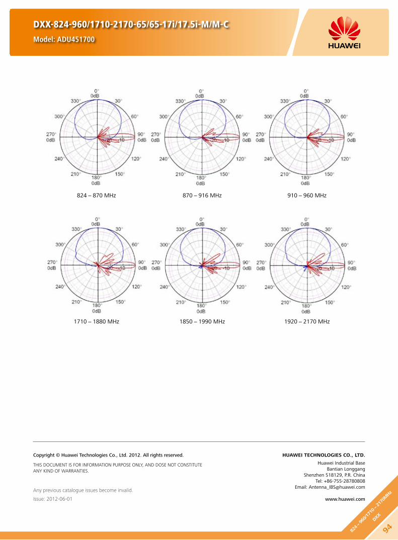
DXX-824-960/1710-2170-65/65-17i/17.5i-M/M-C
Model: ADU451700
Any previous catalogue issues become invalid.
Issue: 2012-06-01
HUAWEI TECHNOLOGIES CO., LTD.
Huawei Industrial BaseBantian Longgang
Shenzhen 518129, P.R. ChinaTel: +86-755-28780808
Email: [email protected]
www.huawei.com
Copyright © Huawei Technologies Co., Ltd. 2012. All rights reserved.
THIS DOCUMENT IS FOR INFORMATION PURPOSE ONLY, AND DOSE NOT CONSTITUTE ANY KIND OF WARRANTIES.
824-870 MHz
1710-1880 MHz
870-916 MHz
1850-1990 MHz
910-960 MHz
1920-2170 MHz
94824-
960/
1710-
2170
MHz
DXX

Mechanical Properties
Dimensions (H x W x D) (mm) 2449 x 368 x 99
Packing dimensions (H x W x D) (mm) 2756 x 492 x 220
Net weight (kg) 30
Bracket weight (kg) 7.8
Packing weight (kg) 41.9
Mechanical downtilt (°) 0-15
Mast diameter (mm) 50-115
Radome material Fiberglass
Operational temperature () -55 .. +65
Wind load (N)Frontal: 1000 (v=150 km/h)Lateral: 260 (v=150 km/h)
Rear side: 1000 (v=150 km/h)
Max. wind velocity (km/h) 200
Connector 4 x 7/16 DIN Female
DXX-824-960/1710-2170-65/65-17.5i/18i-M/M
Model: ADU451801
Electrical Properties
Frequency range (MHz) 824-894 880-960 1710-1880 1850-1990 1920-2170
Polarization +45° , -45°
VSWR ≤ 1.5
Gain (dBi) 17.0 17.5 17.0 17.5 18.0
Side lobe suppression for first side lobe above horizon (dB)
Typ. 18 Typ. 18 Typ. 18 Typ. 18 Typ. 18
Horizontal 3dB beam width (°) 65 63 67 65 63
Vertical 3dB beam width (°) 8.5 7.5 8.2 7.5 7.0
Isolation between ports (dB) ≥30
Front to back ratio, copolar (dB) ≥27 ≥25
Cross polar ratio (dB)0° Typ. 20
±60° ≥ 10
Electrical downtilt (°) 0-10 0-8
Intermodulation IM3 (dBc) ≤-150 (2 x 43 dBm carrier)
Max. CW input power (W) 500 250
Impedance (Ω) 50
Grounding DC Ground
824-960X
+45°
7/16 (F) 7/16 (F)7/16 (F) 7/16 (F)
-45°
1710-2170X
+45° -45°
95
824-960/1710-
2170MHz
DXX

DXX-824-960/1710-2170-65/65-17.5i/18i-M/M
Model: ADU451801
Any previous catalogue issues become invalid.
Issue: 2012-06-01
HUAWEI TECHNOLOGIES CO., LTD.
Huawei Industrial BaseBantian Longgang
Shenzhen 518129, P.R. ChinaTel: +86-755-28780808
Email: [email protected]
www.huawei.com
Copyright © Huawei Technologies Co., Ltd. 2012. All rights reserved.
THIS DOCUMENT IS FOR INFORMATION PURPOSE ONLY, AND DOSE NOT CONSTITUTE ANY KIND OF WARRANTIES.
824-870 MHz
1710-1880 MHz
870-916 MHz
1850-1990 MHz
910-960 MHz
1920-2170 MHz
96824-
960/
1710-
2170
MHz
DXX

Electrical Properties
Frequency range (MHz)2 x (1710-2200)
1710-1880 1850-1990 1920-2170 2170-2200
Polarization +45°, -45°
Electrical downtilt (°) 0-10, continuously adjustable
Gain (dBi)0° 5° 10° 0° 5° 10° 0° 5° 10° 0° 5° 10°
17.0 17.4 17.1 17.3 17.7 17.4 17.6 18.0 17.4 17.5 18.0 17.4
Side lobe suppression for first side lobe above horizon (Typ.) (dB)
0° 5° 10° 0° 5° 10° 0° 5° 10° 0° 5° 10°
18 17 17 19 18 18 19 18 17 19 18 17
Horizontal 3dB beam width (°) 67 64 61 60
Vertical 3dB beam width (°) 7.5 7.0 6.6 6.2
VSWR < 1.5
Isolation between ports (dB) ≥ 30
Front to back ratio, copolar (dB) Typ. 28
Cross polar ratio (dB)0° Typ. 22
±60° Typ. 10
Max. power per input (W) 300 (at 50 ambient temperature)
Intermodulation IM3 (dBc) ≤ -153 (2 x 43 dBm carrier)
Squint (°) Avg. 2
Tracking (dB) Avg. 1.5 (within 10dB HBW)
Impedance (Ω) 50
Grounding DC Ground
Mechanical Properties
Antenna dimensions (H x W x D) (mm) 1311 x 323 x 89
Packing dimensions (H x W x D) (mm) 1737 x 422 x 200
Antenna net weight (kg) 12.8
Bracket weight (kg) 4.6
Packing weight (kg) 21.5
Mechanical downtilt (°) 0-16
Mast diameter (mm) 50-115
Radome material Fiberglass
Radome colour Light grey
Operational temperature () -55 .. +65
Wind load (N)Frontal: 565 (at 150 km/h)Lateral: 105 (at 150 km/h)
Rear side: 640 (at 150 km/h)
Max. operational wind speed (km/h) 150
Survival wind speed (km/h) 200
Connector 4 x 7/16 DIN Female
Connector position Bottom
DXX-1710-2200/1710-2200-65/65-18i/18i-M/M
Model: ADU451819
97
1710-2200/1710-
2200MHz
DXX

1710-2200 MHz
1710-2200X
1710-2200X
+45° +45°
7/16 (F) 7/16 (F)7/16 (F) 7/16 (F)
-45° -45°
DXX-1710-2200/1710-2200-65/65-18i/18i-M/M
Model: ADU451819
Unit: mmL - Left Column R - Right Column
593643
31
HINT
Extraordinary operating conditions, such as heavy icing or storm wind, may result in the breakage of an antenna. These facts must be considered during the site planning process.
The installation team must be properly qualified and also be familiar with the relevant national safety regulations.
Any previous catalogue issues become invalid.
Issue: 2012-06-01
HUAWEI TECHNOLOGIES CO., LTD.
Huawei Industrial BaseBantian Longgang
Shenzhen 518129, P.R. ChinaTel: +86-755-28780808
Email: [email protected]
www.huawei.com
Copyright © Huawei Technologies Co., Ltd. 2012. All rights reserved.
THIS DOCUMENT IS FOR INFORMATION PURPOSE ONLY, AND DOSE NOT CONSTITUTE ANY KIND OF WARRANTIES.
981710-
2200
/171
0-22
00M
Hz
DXX

DXX-1710-2200/1710-2200-65/65-18i/18i-M/M-R
Model: ADU4518R1
Electrical Properties
Frequency range (MHz)2 x (1710-2200)
1710-1880 1850-1990 1920-2170 2170-2200
Polarization +45°, -45°
Electrical downtilt (°) 0-10 , continuously adjustable
Gain (dBi)0° 5° 10° 0° 5° 10° 0° 5° 10° 0° 5° 10°
17.5 17.4 17.0 17.6 17.5 17.2 18.0 17.9 17.4 18.0 17.9 17.2
Side lobe suppression for first side lobe above horizon (Typ.) (dB)
0° 5° 10° 0° 5° 10° 0° 5° 10° 0° 5° 10°
17 16 16 17 16 15 17 16 15 17 16 15
Horizontal 3dB beam width (°) 68 65 61 60
Vertical 3dB beam width (°) 7.5 7.0 6.5 6.2
VSWR < 1.5
Isolation between ports (dB) ≥ 30
Front to back ratio, copolar (dB) Typ. 28
Cross polar ratio (dB)0° Typ. 18
±60° Typ. 10
Max. power per input (W) 300 (at 50 ambient temperature)
Intermodulation IM3 (dBc) ≤ -153 (2 x 43 dBm carrier)
Squint (°) Typ. 5
Tracking (dB) Typ. 3 (within 10dB HBW)
Impedance (Ω) 50
Grounding DC Ground
Mechanical Properties
Antenna dimensions (H x W x D) (mm) 1315 x 323 x 89
Packing dimensions (H x W x D) (mm) 1807 x 442 x 182
Antenna net weight (kg) 14
Bracket weight (kg) 4.6
Packing weight (kg) 20.8
Mechanical downtilt (°) 0-16
Mast diameter (mm) 50-115
Radome material Fiberglass
Radome colour Light grey
Operational temperature () -40 .. +65
Wind load (N)Frontal: 470 (at 150 km/h) Lateral: 120 (at 150 km/h)
Rear side: 470 (at 150 km/h)
Max. operational wind speed (km/h) 150
Survival wind speed (km/h) 200
Connector 4 x 7/16 DIN Female
Connector position Bottom
RET Type Internal motor
RET Protocols AISG 1.1 / AISG 2.0
RET Connector2 x 8 pin connector according to IEC 60130-9Daisy chain in: Male / Daisy chain out: Female
Preliminary Issue
99
1710-2200/1710-
2200MHz
DXX

RET Properties
RET Type Internal motor
RET Protocols AISG 1.1 / AISG 2.0
Input voltage range (V) DC 10-30
Power consumption (W) < 10 (motor activated)
< 0.5 (stand by)
Adjustment time (full range) (min) < 1.5 (typically, depending on antenna type)
Calibration time (min) < 3 (typically, depending on antenna type)
RET Connector2 x 8 pin connector according to IEC 60130-9Daisy chain in: Male / Daisy chain out: Female
Pin assignment according AISG 1 2 3 4 5 6 7 8
DC n/c RS-485B n/c RS-485A DC in/out DC return n/c
Lightning protection (kA)AISG interface (each pin)
3 (10/350 μs)10 (8/20 μs)
DXX-1710-2200/1710-2200-65/65-18i/18i-M/M-R
Model: ADU4518R1
HINT
Before the installation, check whether the antenna and base station support the same AISG protocol. If not, contact the technical support personnel of Huawei.
Standards:
EN 60950-1 (Safety) y
EN 55022 (Emission) y
EN 55024 (Immunity) y
ETSI EN300386 (1.4.1) y
FCC part15 y
Certification:
CE, FCC, RoHS, WEEE
Any previous catalogue issues become invalid.
Issue: 2012-06-01
HUAWEI TECHNOLOGIES CO., LTD.
Huawei Industrial BaseBantian Longgang
Shenzhen 518129, P.R. ChinaTel: +86-755-28780808
Email: [email protected]
www.huawei.com
Copyright © Huawei Technologies Co., Ltd. 2012. All rights reserved.
THIS DOCUMENT IS FOR INFORMATION PURPOSE ONLY, AND DOSE NOT CONSTITUTE ANY KIND OF WARRANTIES.
Preliminary Issue
100
1710-
2200
/171
0-22
00M
Hz
DXX

DXX-1710-2200/1710-2200-65/65-19.5i/19.5i-M/M
Model: ADU451902
Electrical Properties
Frequency range (MHz)2 x (1710-2200)
1710-1880 1850-1990 1920-2170 2170-2200
Polarization +45°, -45°
Electrical downtilt (°) 0-6, continuously adjustable
Gain (dBi)0° 3° 6° 0° 3° 6° 0° 3° 6° 0° 3° 6°
18.5 18.7 18.6 18.9 19.1 18.8 19.1 19.4 18.9 19.1 19.3 18.8
Side lobe suppression for first side lobe above horizon (Typ.) (dB)
0° 3° 6° 0° 3° 6° 0° 3° 6° 0° 3° 6°
20 17 16 20 17 17 20 18 17 20 18 17
Horizontal 3dB beam width (°) 67 65 62 60
Vertical 3dB beam width (°) 5.0 4.7 4.5 4.1
VSWR < 1.5
Isolation between ports (dB) ≥ 30
Front to back ratio, copolar (dB) Typ. 28
Cross polar ratio (dB)0° Typ. 25
±60° Typ. 10
Max. power per input (W) 300 (at 50 ambient temperature)
Intermodulation IM3 (dBc) ≤ -153 (2 x 43 dBm carrier)
Impedance (Ω) 50
Grounding DC Ground
Mechanical Properties
Antenna dimensions (H x W x D) (mm) 1954 x 323 x 89
Packing dimensions (H x W x D) (mm) 2365 x 417 x 200
Antenna net weight (kg) 17.3
Bracket weight (kg) 4.6
Packing weight (kg) 26.3
Mechanical downtilt (°) 0-12
Mast diameter (mm) 50-115
Radome material Fiberglass
Radome colour Light grey
Operational temperature () -55 .. +65
Wind load (N)Frontal: 890 (at 150 km/h)Lateral: 170 (at 150 km/h)
Rear side: 1000 (at 150 km/h)
Max. operational wind speed (km/h) 150
Survival wind speed (km/h) 200
Connector 4 x 7/16 DIN Female
Connector position Bottom
101
1710-2200/1710-
2200MHz
DXX

DXX-1710-2200/1710-2200-65/65-19.5i/19.5i-M/M
Model: ADU451902
1710-2200 MHz
1710-2200X
1710-2200X
+45° +45°
7/16 (F) 7/16 (F)7/16 (F) 7/16 (F)
-45° -45°
Unit: mmL - Left Column R - Right Column
593643
31
HINT
Extraordinary operating conditions, such as heavy icing or storm wind, may result in the breakage of an antenna. These facts must be considered during the site planning process.
The installation team must be properly qualified and also be familiar with the relevant national safety regulations.
Any previous catalogue issues become invalid.
Issue: 2012-06-01
HUAWEI TECHNOLOGIES CO., LTD.
Huawei Industrial BaseBantian Longgang
Shenzhen 518129, P.R. ChinaTel: +86-755-28780808
Email: [email protected]
www.huawei.com
Copyright © Huawei Technologies Co., Ltd. 2012. All rights reserved.
THIS DOCUMENT IS FOR INFORMATION PURPOSE ONLY, AND DOSE NOT CONSTITUTE ANY KIND OF WARRANTIES.
102
1710-
2200
/171
0-22
00M
Hz
DXX

Electrical Properties
Frequency range (MHz)2 x (1710-2690)
1710-1990 1920-2200 2200-2490 2490-2690
Polarization +45°, -45°
Electrical downtilt (°) 0-10, continuously adjustable
Gain (dBi)0° 5° 10° 0° 5° 10° 0° 5° 10° 0° 5° 10°
17.3 17.4 17.2 17.6 17.8 17.5 17.8 18.0 17.6 17.8 18.0 17.3
Side lobe suppression for first side lobe above horizon (Typ.) (dB)
0° 5° 10° 0° 5° 10° 0° 5° 10° 0° 5° 10°
18 17 16 18 17 16 18 17 16 18 17 16
Horizontal 3dB beam width (°) 69 65 65 62
Vertical 3dB beam width (°) 6.5 6.0 5.2 4.8
VSWR < 1.5
Isolation between ports (dB) ≥ 30
Front to back ratio, copolar (dB) Typ. 27
Cross polar ratio (dB)0° Typ. 20
±60° Typ. 10
Max. power per input (W) 300 (at 50 ambient temperature)
Intermodulation IM3 (dBc) ≤ -153 (2 x 43 dBm carrier)
Squint (°) Typ. 5
Tracking (dB) Typ. 3 (within 10dB HBW)
Impedance (Ω) 50
Grounding DC Ground
Mechanical Properties
Antenna dimensions (H x W x D) (mm) 1410 x 299 x 89
Packing dimensions (H x W x D) (mm) 1855 x 435 x 190
Antenna net weight (kg) 14
Bracket weight (kg) 4.6
Packing weight (kg) 23
Mechanical downtilt (°) 0-16
Mast diameter (mm) 50-115
Radome material Fiberglass
Radome colour Light grey
Operational temperature () -55 .. +65
Wind load (N)Frontal: 530 (at 150 km/h)Lateral: 105 (at 150 km/h)
Rear side: 620 (at 150 km/h)
Max. operational wind speed (km/h) 150
Survival wind speed (km/h) 200
Connector 4 x 7/16 DIN Female (Long neck)
Connector position Bottom
DXX-1710-2690/1710-2690-65/65-18i/18i-M/M
Model: ADU451816
103
1710-2690/1710-
2690MHz
DXX

1710-2200 MHz 2200-2690 MHz
5456 43
Unit: mmL - Left Column R - Right Column
DXX-1710-2690/1710-2690-65/65-18i/18i-M/M
Model: ADU451816
HINT
Extraordinary operating conditions, such as heavy icing or storm wind, may result in the breakage of an antenna. These facts must be considered during the site planning process.
The installation team must be properly qualified and also be familiar with the relevant national safety regulations.
Any previous catalogue issues become invalid.
Issue: 2012-06-01
HUAWEI TECHNOLOGIES CO., LTD.
Huawei Industrial BaseBantian Longgang
Shenzhen 518129, P.R. ChinaTel: +86-755-28780808
Email: [email protected]
www.huawei.com
Copyright © Huawei Technologies Co., Ltd. 2012. All rights reserved.
THIS DOCUMENT IS FOR INFORMATION PURPOSE ONLY, AND DOSE NOT CONSTITUTE ANY KIND OF WARRANTIES.
1710-2690X
1710-2690X
+45°+45°
7/16 (F) 7/16 (F)7/16 (F) 7/16 (F)
-45°-45°
104
1710-
2690
/171
0-26
90M
Hz
DXX

DXX-1710-2690/1710-2690-65/65-18i/18i-M/M-R
Model: ADU4518R6
Electrical Properties
Frequency range (MHz)2 x (1710-2690)
1710-1990 1920-2200 2200-2490 2490-2690
Polarization +45°, -45°
Electrical downtilt (°) 0-12 , continuously adjustable
Gain (dBi)0° 6° 12° 0° 6° 12° 0° 6° 12° 0° 6° 12°
17.3 17.4 17.2 17.6 17.8 17.5 17.7 18.0 17.5 17.8 18.0 17.3
Side lobe suppression for first side lobe above horizon (Typ.) (dB)
0° 6° 12° 0° 6° 12° 0° 6° 12° 0° 6° 12°
18 17 16 18 17 16 18 17 16 17 17 16
Horizontal 3dB beam width (°) 66 63 60 60
Vertical 3dB beam width (°) 6.5 6.2 5.2 4.7
VSWR < 1.5
Isolation between ports (dB) ≥ 30
Front to back ratio, copolar (dB) Typ. 28
Cross polar ratio (dB)0° Typ. 20
±60° Typ. 10
Max. power per input (W) 250 (at 50 ambient temperature)
Intermodulation IM3 (dBc) ≤ -153 (2 x 43 dBm carrier)
Impedance (Ω) 50
Grounding DC Ground
Mechanical Properties
Antenna dimensions (H x W x D) (mm) 1425 x 323 x 89
Packing dimensions (H x W x D) (mm) 1770 x 422 x 200
Antenna net weight (kg) 15.6
Bracket weight (kg) 4.6
Packing weight (kg) 24.5
Mechanical downtilt (°) 0-16
Mast diameter (mm) 50-115
Radome material Fiberglass
Radome colour Light grey
Operational temperature () -40 .. +65
Wind load (N)Frontal: 615 (at 150 km/h) Lateral: 115 (at 150 km/h)
Rear side: 695 (at 150 km/h)
Max. operational wind speed (km/h) 150
Survival wind speed (km/h) 200
Connector 4 x 7/16 DIN Female
Connector position Bottom
RET Type Internal motor
RET Protocols AISG 1.1 / AISG 2.0
RET Connector2 x 8 pin connector according to IEC 60130-9Daisy chain in: Male / Daisy chain out: Female
Preliminary Issue
105
1710-2690/1710-
2690MHz
DXX

RET Properties
RET Type Internal motor
RET Protocols AISG 1.1 / AISG 2.0
Input voltage range (V) DC 10-30
Power consumption (W) < 10 (motor activated)
< 0.5 (stand by)
Adjustment time (full range) (min) < 1.5 (typically, depending on antenna type)
Calibration time (min) < 3 (typically, depending on antenna type)
RET Connector2 x 8 pin connector according to IEC 60130-9Daisy chain in: Male / Daisy chain out: Female
Pin assignment according AISG 1 2 3 4 5 6 7 8
DC n/c RS-485B n/c RS-485A DC in/out DC return n/c
Lightning protection (kA)AISG interface (each pin)
3 (10/350 μs)10 (8/20 μs)
DXX-1710-2690/1710-2690-65/65-18i/18i-M/M-R
Model: ADU4518R6
HINT
Before the installation, check whether the antenna and base station support the same AISG protocol. If not, contact the technical support personnel of Huawei.
Standards:
EN 60950-1 (Safety) y
EN 55022 (Emission) y
EN 55024 (Immunity) y
ETSI EN300386 (1.4.1) y
FCC part15 y
Certification:
CE, FCC, RoHS, WEEE
Any previous catalogue issues become invalid.
Issue: 2012-06-01
HUAWEI TECHNOLOGIES CO., LTD.
Huawei Industrial BaseBantian Longgang
Shenzhen 518129, P.R. ChinaTel: +86-755-28780808
Email: [email protected]
www.huawei.com
Copyright © Huawei Technologies Co., Ltd. 2012. All rights reserved.
THIS DOCUMENT IS FOR INFORMATION PURPOSE ONLY, AND DOSE NOT CONSTITUTE ANY KIND OF WARRANTIES.
Preliminary Issue
106
1710-
2690
/171
0-26
90M
Hz
DXX

Electrical Properties
Frequency range (MHz)2 x (1710-2690)
1710-1990 1920-2200 2200-2490 2490-2690
Polarization +45°, -45°
Electrical downtilt (°) 0-6, continuously adjustable
Gain (dBi)0° 3° 6° 0° 3° 6° 0° 3° 6° 0° 3° 6°
18.1 18.3 18.2 18.4 18.6 18.5 18.9 19.2 19.1 19.2 19.4 17.3
Side lobe suppression for first side lobe above horizon (Typ.) (dB)
0° 3° 6° 0° 3° 6° 0° 3° 6° 0° 3° 6°
20 20 16 20 20 17 18 18 18 17 17 18
Horizontal 3dB beam width (°) 69 67 65 60
Vertical 3dB beam width (°) 4.9 4.5 4.1 3.7
VSWR < 1.5
Isolation between ports (dB) ≥ 30
Front to back ratio, copolar (dB) Typ. 27
Cross polar ratio (dB)0° Typ. 20
±60° Typ. 10
Max. power per input (W) 250 (at 50 ambient temperature)
Intermodulation IM3 (dBc) ≤ -153 (2 x 43 dBm carrier)
Impedance (Ω) 50
Grounding DC Ground
Mechanical Properties
Antenna dimensions (H x W x D) (mm) 1930 x 299 x 89
Packing dimensions (H x W x D) (mm) 2390 x 440 x 190
Antenna net weight (kg) 17.5
Bracket weight (kg) 4.6
Packing weight (kg) 28.3
Mechanical downtilt (°) 0-12
Mast diameter (mm) 50-115
Radome material Fiberglass
Radome colour Light grey
Operational temperature () -55 .. +65
Wind load (N)Frontal: 765 (at 150 km/h)Lateral: 150 (at 150 km/h)
Rear side: 890 (at 150 km/h)
Max. operational wind speed (km/h) 150
Survival wind speed (km/h) 200
Connector 4 x 7/16 DIN Female (Long neck)
Connector position Bottom
DXX-1710-2690/1710-2690-65/65-19.5i/19.5i-M/M
Model: ADU451901
107
1710-2690/1710-
2690MHz
DXX

1710-2200 MHz 2200-2690 MHz
DXX-1710-2690/1710-2690-65/65-19.5i/19.5i-M/M
Model: ADU451901
HINT
Extraordinary operating conditions, such as heavy icing or storm wind, may result in the breakage of an antenna. These facts must be considered during the site planning process.
The installation team must be properly qualified and also be familiar with the relevant national safety regulations.
Any previous catalogue issues become invalid.
Issue: 2012-06-01
HUAWEI TECHNOLOGIES CO., LTD.
Huawei Industrial BaseBantian Longgang
Shenzhen 518129, P.R. ChinaTel: +86-755-28780808
Email: [email protected]
www.huawei.com
Copyright © Huawei Technologies Co., Ltd. 2012. All rights reserved.
THIS DOCUMENT IS FOR INFORMATION PURPOSE ONLY, AND DOSE NOT CONSTITUTE ANY KIND OF WARRANTIES.
1710-2690X
1710-2690X
+45°+45°
7/16 (F) 7/16 (F)7/16 (F) 7/16 (F)
-45°-45°
5456 43
Unit: mmL - Left Column R - Right Column
108
1710-
2690
/171
0-26
90M
Hz
DXX

Electrical Properties
Frequency range (MHz) 790-862 880-9601710-2690
1710-1990 1920-2170 2490-2690
Polarization +45°, -45°
Electrical downtilt (°) 0-10, continuously adjustable 0-8, continuously adjustable
Gain (dBi)0° 5° 10° 0° 5° 10° 0° 4° 8° 0° 4° 8° 0° 4° 8°
15.1 15.3 15.0 15.6 15.7 15.4 17.9 17.7 17.3 18.3 18.1 17.5 18.5 18.3 17.8
Side lobe suppression for first side lobe above horizon (Typ.) (dB)
0° 5° 10° 0° 5° 10° 0° 5° 10° 0° 4° 8° 0° 4° 8°
17 16 16 17 16 16 17 17 16 17 17 16 17 17 16
Horizontal 3dB beam width (°) 68 64 64 62 60
Vertical 3dB beam width (°) 10.2 9.7 5.2 4.8 4.0
VSWR < 1.5
Isolation between ports (dB)Intra-system: ≥ 28Inter-system: ≥ 30
Front to back ratio, copolar (dB) Typ. 28 Typ. 28
Cross polar ratio (dB)0° Typ. 18 Typ. 17
±60° Typ. 10 Typ. 10
Max. power per input (W) 400 (at 50 ambient temperature) 250 (at 50 ambient temperature)
Intermodulation IM3 (dBc) ≤ -153 (2 x 43 dBm carrier)
Impedance (Ω) 50
Grounding DC Ground
Mechanical Properties
Antenna dimensions (H x W x D) (mm) 2065 x 298 x 148
Packing dimensions (H x W x D) (mm) 2350 x 450 x 248
Antenna net weight (kg) 32
Bracket weight (kg) 4.6
Packing weight (kg) 42
Mechanical downtilt (°) 0-8
Mast diameter (mm) 50-115
Radome material Fiberglass
Radome colour Light grey
Operational temperature () -40 .. +65
Wind load (N)Frontal: 565 (at 150 km/h)Lateral: 255 (at 150 km/h)
Rear side: 890 (at 150 km/h)
Max. operational wind speed (km/h) 150
Survival wind speed (km/h) 200
Connector 6 x 7/16 DIN Female
Connector position Bottom
RET Type Internal motor
RET Protocols AISG 1.1 / AISG 2.0
RET Connector2 x 8 pin connector according to IEC 60130-9Daisy chain in: Male / Daisy chain out: Female
DXXX-790-862/880-960/1710-2690-65/65/65-15.5i/16i/18.5i-M/M/M-R
Model: ATR4518R2
Preliminary Issue
109
790-862/880-
960/
1710-2690M
Hz
DXXX

RET Properties
RET Type Internal motor
RET Protocols AISG 1.1 / AISG 2.0
Input voltage range (V) DC 10-30
Power consumption (W) < 10 (motor activated)
< 0.5 (stand by)
Adjustment time (full range) (min) < 1.5 (typically, depending on antenna type)
Calibration time (min) < 3 (typically, depending on antenna type)
RET Connector2 x 8 pin connector according to IEC 60130-9Daisy chain in: Male / Daisy chain out: Female
Pin assignment according AISG 1 2 3 4 5 6 7 8
DC n/c RS-485B n/c RS-485A DC in/out DC return n/c
Lightning protection (kA)AISG interface (each pin)
3 (10/350 μs)10 (8/20 μs)
DXXX-790-862/880-960/1710-2690-65/65/65-15.5i/16i/18.5i-M/M/M-R
Model: ATR4518R2
HINT
Before the installation, check whether the antenna and base station support the same AISG protocol. If not, contact the technical support personnel of Huawei.
Standards:
EN 60950-1 (Safety) y
EN 55022 (Emission) y
EN 55024 (Immunity) y
ETSI EN300386 (1.4.1) y
FCC part15 y
Certification:
CE, FCC, RoHS, WEEE
Any previous catalogue issues become invalid.
Issue: 2012-06-01
HUAWEI TECHNOLOGIES CO., LTD.
Huawei Industrial BaseBantian Longgang
Shenzhen 518129, P.R. ChinaTel: +86-755-28780808
Email: [email protected]
www.huawei.com
Copyright © Huawei Technologies Co., Ltd. 2012. All rights reserved.
THIS DOCUMENT IS FOR INFORMATION PURPOSE ONLY, AND DOSE NOT CONSTITUTE ANY KIND OF WARRANTIES.
Preliminary Issue
11079
0-86
2/88
0-96
0/
1710-
2690
MHz
DXXX

DXXX-790-960/1710-2180/1710-2180-65/65/65-14i/14i/14i-M/M/M
Model: ATR451500
Electrical Properties
Frequency range (MHz)790-960 2 x (1710-2180)
790-862 824-894 880-960 1710-1880 1850-1990 1920-2180
Polarization +45°, -45°
Electrical downtilt (°) 0-14, continuously adjustable 0-14, continuously adjustable
Gain (dBi)
0° 7° 14° 0° 7° 14° 0° 7° 14° 0° 7° 14° 0° 7° 14° 0° 7° 14°
14.7 14.8 14.5 15.0 14.8 14.7 15.0 14.8 14.6
Bottom 14.6 14.5 14.3 15.0 14.9 14.5 15.3 15.2 14.7
Top 14.5 14.5 14.0 14.9 14.7 14.1 15.1 15.0 14.3
Side lobe suppression for first side lobe above horizon (Typ.) (dB)
0° 7° 14° 0° 7° 14° 0° 7° 14° 0° 7° 14° 0° 7° 14° 0° 7° 14°
18 17 15 19 18 16 19 18 15 17 17 15 18 18 15 17 17 15
Horizontal 3dB beam width (°) 69 68 67 63 61 60
Vertical 3dB beam width (°) 15.5 14.8 13.8 13.6 12.8 12.1
VSWR < 1.5
Isolation between ports (dB)Intra-system: ≥ 30
Inter-system (790 - 960 / 1710 - 2180 MHz): ≥ 40Inter-system (1710 - 2180 / 1710 - 2180 MHz): ≥ 30
Front to back ratio, copolar (dB) Typ. 28 Typ. 28
Cross polar ratio (dB)0° Typ. 26 Typ. 20
±60° Typ. 10 Typ. 10
Max. power per input (W) 500 (at 50 ambient temperature) 300 (at 50 ambient temperature)
Intermodulation IM3 (dBc) ≤ -153 (2 x 43 dBm carrier)
Squint (°) Avg. 2.5
Tracking (dB) Avg. 2.5 (within 10dB HBW)
Impedance (Ω) 50
Grounding DC Ground
Mechanical Properties
Antenna dimensions (H x W x D) (mm) 1454 x 259 x 135
Packing dimensions (H x W x D) (mm) 1872 x 392 x 230
Antenna net weight (kg) 15.1
Bracket weight (kg) 4.6
Packing weight (kg) 24.5
Mechanical downtilt (°) 0-16
Mast diameter (mm) 50-115
Radome material Fiberglass
Radome colour Light grey
Operational temperature () -55 .. +65
Wind load (N)Frontal: 480 (at 150 km/h)Lateral: 250 (at 150 km/h)
Rear side: 635 (at 150 km/h)
Max. operational wind speed (km/h) 150
Survival wind speed (km/h) 200
Connector 6 x 7/16 DIN Female
Connector position Bottom
111
790-960/1710-
2180/
1710-2180M
Hz
DXXX

DXXX-790-960/1710-2180/1710-2180-65/65/65-14i/14i/14i-M/M/M
Model: ATR451500
790-960 MHz 1710-2180 MHz(Bottom)
1710-2180 MHz(Top)
790-960X
+45°
7/16 (F) 7/16 (F) 7/16 (F)7/16 (F) 7/16 (F) 7/16 (F)
-45°
1710-2180TopX
+45° -45°
1710-2180Bottom
X
+45° -45°
55
17
56
70
61 44
Unit: mmT - Top Column B - Bottom Column
HINT
Extraordinary operating conditions, such as heavy icing or storm wind, may result in the breakage of an antenna. These facts must be considered during the site planning process.
The installation team must be properly qualified and also be familiar with the relevant national safety regulations.
Any previous catalogue issues become invalid.
Issue: 2012-06-01
HUAWEI TECHNOLOGIES CO., LTD.
Huawei Industrial BaseBantian Longgang
Shenzhen 518129, P.R. ChinaTel: +86-755-28780808
Email: [email protected]
www.huawei.com
Copyright © Huawei Technologies Co., Ltd. 2012. All rights reserved.
THIS DOCUMENT IS FOR INFORMATION PURPOSE ONLY, AND DOSE NOT CONSTITUTE ANY KIND OF WARRANTIES.
11279
0-96
0/17
10-
2180
/
1710-
2180
MHz
DXXX

DXXX-790-960/1710-2180/1710-2180-65/65/65-16i/16i/16i-M/M/M
Model: ATR451602v01
Electrical Properties
Frequency range (MHz)790-960 2 x (1710-2180)
790-862 824-894 880-960 1710-1880 1850-1990 1920-2180
Polarization +45°, -45°
Electrical downtilt (°) 0-12, continuously adjustable 0-12, continuously adjustable
Gain (dBi)
0° 6° 12° 0° 6° 12° 0° 6° 12° 0° 6° 12° 0° 6° 12° 0° 6° 12°
16.2 16.0 15.5 16.3 16.3 15.6 16.5 16.2 15.6
Bottom 15.9 16.0 15.6 16.2 16.4 15.8 16.3 16.5 16.0
Top 16.0 16.2 15.6 16.3 16.4 15.7 16.3 16.5 15.7
Side lobe suppression for first side lobe above horizon (Typ.) (dB)
0° 6° 12° 0° 6° 12° 0° 6° 12° 0° 6° 12° 0° 6° 12° 0° 6° 12°
18 17 15 19 18 16 19 18 15 17 17 15 18 18 15 17 17 15
Horizontal 3dB beam width (°) 69 66 65 64 62 60
Vertical 3dB beam width (°) 10.7 10.1 9.4Bottom: 9.6
Top: 8.5Bottom: 8.9
Top: 8.0Bottom: 8.3
Top: 7.5
VSWR < 1.5
Isolation between ports (dB)Intra-system: ≥ 30
Inter-system (790 - 960 / 1710 - 2180 MHz): ≥ 40Inter-system (1710 - 2180 / 1710 - 2180 MHz): ≥ 35
Front to back ratio, copolar (dB) Typ. 28 Typ. 29
Cross polar ratio (dB)0° Typ. 26 Typ. 20
±60° Typ. 10 Typ. 10
Max. power per input (W) 500 (at 50 ambient temperature) 300 (at 50 ambient temperature)
Intermodulation IM3 (dBc) ≤ -153 (2 x 43 dBm carrier)
Squint (°) Avg. 2.5
Tracking (dB) Avg. 2.5 (within 10dB HBW)
Impedance (Ω) 50
Grounding DC Ground
Mechanical Properties
Antenna dimensions (H x W x D) (mm) 2098 x 259 x 135
Packing dimensions (H x W x D) (mm) 2514 x 392 x 230
Antenna net weight (kg) 19.4
Bracket weight (kg) 4.6
Packing weight (kg) 29.7
Mechanical downtilt (°) 0-12
Mast diameter (mm) 50-115
Radome material Fiberglass
Radome colour Light grey
Operational temperature () -55 .. +65
Wind load (N)Frontal: 730 (at 150 km/h)Lateral: 380 (at 150 km/h)
Rear side: 965 (at 150 km/h)
Max. operational wind speed (km/h) 150
Survival wind speed (km/h) 200
Connector 6 x 7/16 DIN Female
Connector position Bottom
113
790-960/1710-
2180/
1710-2180M
Hz
DXXX

DXXX-790-960/1710-2180/1710-2180-65/65/65-16i/16i/16i-M/M/M
Model: ATR451602v01
790-960 MHz 1710-2180 MHz(Bottom)
1710-2180 MHz(Top)
790-960X
+45°
7/16 (F) 7/16 (F) 7/16 (F)7/16 (F) 7/16 (F) 7/16 (F)
-45°
1710-2180TopX
+45° -45°
1710-2180Bottom
X
+45° -45°
55
17
56
70
61 44
Unit: mmT - Top Column B - Bottom Column
HINT
Extraordinary operating conditions, such as heavy icing or storm wind, may result in the breakage of an antenna. These facts must be considered during the site planning process.
The installation team must be properly qualified and also be familiar with the relevant national safety regulations.
Any previous catalogue issues become invalid.
Issue: 2012-06-01
HUAWEI TECHNOLOGIES CO., LTD.
Huawei Industrial BaseBantian Longgang
Shenzhen 518129, P.R. ChinaTel: +86-755-28780808
Email: [email protected]
www.huawei.com
Copyright © Huawei Technologies Co., Ltd. 2012. All rights reserved.
THIS DOCUMENT IS FOR INFORMATION PURPOSE ONLY, AND DOSE NOT CONSTITUTE ANY KIND OF WARRANTIES.
11479
0-96
0/17
10-
2180
/
1710-
2180
MHz
DXXX

Electrical Properties
Frequency range (MHz)790-960 2 x (1710-2180)
790-862 824-894 880-960 1710-1880 1850-1990 1920-2180
Polarization +45° , -45°
Electrical downtilt (°) 0-12 , continuously adjustable 0-12 , continuously adjustable
Gain (dBi)
0° 6° 12° 0° 6° 12° 0° 6° 12° 0° 6° 12° 0° 6° 12° 0° 6° 12°
15.2 15.4 15.1 15.4 15.6 15.2 15.8 16.0 15.6
Bottom 15.6 15.6 15.2 15.9 16.0 15.4 16.1 16.1 15.6
Top 15.5 15.5 15.1 15.9 16.0 15.1 16.0 16.0 15.4
Side lobe suppression for first side lobe above horizon (Typ.) (dB)
0° 6° 12° 0° 6° 12° 0° 6° 12° 0° 6° 12° 0° 6° 12° 0° 6° 12°
17 16 16 17 16 16 17 16 16 17 16 15 17 16 15 17 16 15
Horizontal 3dB beam width (°) 69 66 65 66 63 60
Vertical 3dB beam width (°) 11.3 10.7 10Bottom: 9.5
Top: 8.6Bottom: 9.0
Top: 8.0Bottom: 8.5
Top: 7.5
VSWR < 1.5
Isolation between ports (dB)Intra-system: ≥ 30Inter-system: ≥ 40
Front to back ratio, copolar (dB) Typ. 27 Typ. 27
Cross polar ratio (dB)0° Typ. 20 Typ. 20
±60° Typ. 10 Typ. 10
Max. power per input (W) 500 (at 50 ambient temperature) 300 (at 50 ambient temperature)
Intermodulation IM3 (dBc) ≤ -153 (2 x 43 dBm carrier)
Impedance (Ω) 50
Grounding DC Ground
Mechanical Properties
Antenna dimensions (H x W x D) (mm) 2100 x 259 x 135
Packing dimensions (H x W x D) (mm) 2520 x 312 x 195
Antenna net weight (kg) 24
Bracket weight (kg) 4.6
Packing weight (kg) 36
Mechanical downtilt (°) 0-12
Mast diameter (mm) 50-115
Radome material Fiberglass
Radome colour Light grey
Operational temperature () -40 .. +65
Wind load (N)Frontal: 730 (at 150 km/h) Lateral: 380 (at 150 km/h)
Rear side: 970 (at 150 km/h)
Max. operational wind speed (km/h) 150
Survival wind speed (km/h) 200
Connector 6 x 7/16 DIN Female
Connector position Bottom
RET Type Internal motor
RET Protocols AISG 1.1 / AISG 2.0
RET Connector2 x 8 pin connector according to IEC 60130-9Daisy chain in: Male / Daisy chain out: Female
DXXX-790-960/1710-2180/1710-2180-65/65/65-16i/16i/16i-M/M/M-R
Model: ATR4516R0
Preliminary Issue
115
790-960/1710-
2180/
1710-2180M
Hz
DXXX

RET Properties
RET Type Internal motor
RET Protocols AISG 1.1 / AISG 2.0
Input voltage range (V) DC 10-30
Power consumption (W) < 10 (motor activated)
< 0.5 (stand by)
Adjustment time (full range) (min) < 1.5 (typically, depending on antenna type)
Calibration time (min) < 3 (typically, depending on antenna type)
RET Connector2 x 8 pin connector according to IEC 60130-9Daisy chain in: Male / Daisy chain out: Female
Pin assignment according AISG 1 2 3 4 5 6 7 8
DC n/c RS-485B n/c RS-485A DC in/out DC return n/c
Lightning protection (kA)AISG interface (each pin)
3 (10/350 μs)10 (8/20 μs)
HINT
Before the installation, check whether the antenna and base station support the same AISG protocol. If not, contact the technical support personnel of Huawei.
Standards:
EN 60950-1 (Safety) y
EN 55022 (Emission) y
EN 55024 (Immunity) y
ETSI EN300386 (1.4.1) y
FCC part15 y
Certification:
CE, FCC, RoHS, WEEE
DXXX-790-960/1710-2180/1710-2180-65/65/65-16i/16i/16i-M/M/M-R
Model: ATR4516R0
Any previous catalogue issues become invalid.
Issue: 2012-06-01
HUAWEI TECHNOLOGIES CO., LTD.
Huawei Industrial BaseBantian Longgang
Shenzhen 518129, P.R. ChinaTel: +86-755-28780808
Email: [email protected]
www.huawei.com
Copyright © Huawei Technologies Co., Ltd. 2012. All rights reserved.
THIS DOCUMENT IS FOR INFORMATION PURPOSE ONLY, AND DOSE NOT CONSTITUTE ANY KIND OF WARRANTIES.
Preliminary Issue
11679
0-96
0/17
10-
2180
/
1710-
2180
MHz
DXXX

Electrical Properties
Frequency range (MHz)790-960 2 x (1710-2180)
790-862 824-894 880-960 1710-1880 1850-1990 1920-2180
Polarization +45°, -45°
Electrical downtilt (°) 0-10, continuously adjustable 0-10, continuously adjustable
Gain (dBi)
0° 5° 10° 0° 5° 10° 0° 5° 10° 0° 5° 10° 0° 5° 10° 0° 5° 10°
16.7 16.8 16.6 16.9 17.1 16.7 17.1 17.3 17.0
Bottom 17.0 17.1 16.6 17.6 17.6 16.8 17.4 17.6 17.0
Top 16.8 17.1 16.7 17.1 17.3 16.8 16.9 17.3 16.9
Side lobe suppression for first side lobe above horizon (Typ.) (dB)
0° 5° 10° 0° 5° 10° 0° 5° 10° 0° 5° 10° 0° 5° 10° 0° 5° 10°
19 16 19 19 17 19 19 17 18 15 20 20 15 15 16 18 17 15
Horizontal 3dB beam width (°) 69 66 65 63 62 60
Vertical 3dB beam width (°) 8.4 8 7.5Bottom: 7.5
Top: 7.0Bottom: 7.0
Top: 6.5Bottom: 6.6
Top: 6.1
VSWR < 1.5
Isolation between ports (dB)Intra-system: ≥ 30
Inter-system (790-960 / 1710-2180 MHz): ≥ 40Inter-system (1710-2180 / 1710-2180 MHz): ≥ 40
Front to back ratio, copolar (dB) Typ. 28 Typ. 29
Cross polar ratio (dB)0° Typ. 28 Typ. 20
±60° Typ. 10 Typ. 10
Max. power per input (W) 500 (at 50 ambient temperature) 300 (at 50 ambient temperature)
Intermodulation IM3 (dBc) ≤ -153 (2 x 43 dBm carrier)
Squint (°) Avg. 2.5
Tracking (dB) Avg. 1 (within 10dB HBW)
Impedance (Ω) 50
Grounding DC Ground
Mechanical Properties
Antenna dimensions (H x W x D) (mm) 2680 x 259 x 135
Packing dimensions (H x W x D) (mm) 3107 x 392 x 230
Antenna net weight (kg) 23
Bracket weight (kg) 5.6
Packing weight (kg) 35
Mechanical downtilt (°) 0-8
Mast diameter (mm) 50-115
Radome material Fiberglass
Radome colour Light grey
Operational temperature () -55 .. +65
Wind load (N)Frontal: 970 (at 150 km/h)Lateral: 500 (at 150 km/h)
Rear side: 1285 (at 150 km/h)
Max. operational wind speed (km/h) 150
Survival wind speed (km/h) 200
Connector 6 x 7/16 DIN Female
Connector position Bottom
DXXX-790-960/1710-2180/1710-2180-65/65/65-17i/17i/17i-M/M/M
Model: ATR451704v01
117
790-960/1710-
2180/
1710-2180M
Hz
DXXX

DXXX-790-960/1710-2180/1710-2180-65/65/65-17i/17i/17i-M/M/M
Model: ATR451704v01
790-960 MHz 1710-2180 MHz(Bottom)
1710-2180 MHz(Top)
790-960X
+45°
7/16 (F) 7/16 (F) 7/16 (F)7/16 (F) 7/16 (F) 7/16 (F)
-45°
1710-2180TopX
+45° -45°
1710-2180Bottom
X
+45° -45°
55
17
56
70
61 44
Unit: mm
T - Top Column B - Bottom Column
HINT
Extraordinary operating conditions, such as heavy icing or storm wind, may result in the breakage of an antenna. These facts must be considered during the site planning process.
The installation team must be properly qualified and also be familiar with the relevant national safety regulations.
Any previous catalogue issues become invalid.
Issue: 2012-06-01
HUAWEI TECHNOLOGIES CO., LTD.
Huawei Industrial BaseBantian Longgang
Shenzhen 518129, P.R. ChinaTel: +86-755-28780808
Email: [email protected]
www.huawei.com
Copyright © Huawei Technologies Co., Ltd. 2012. All rights reserved.
THIS DOCUMENT IS FOR INFORMATION PURPOSE ONLY, AND DOSE NOT CONSTITUTE ANY KIND OF WARRANTIES.
11879
0-96
0/17
10-
2180
/
1710-
2180
MHz
DXXX

Electrical Properties
Frequency range (MHz)790-960 2 x (1710-2180)
790-862 824-894 880-960 1710-1880 1850-1990 1920-2180
Polarization +45°, -45°
Electrical downtilt (°) 0-10, continuously adjustable 0-10, continuously adjustable
Gain (dBi)
0° 5° 10° 0° 5° 10° 0° 5° 10° 0° 5° 10° 0° 5° 10° 0° 5° 10°
16.4 16.6 16.3 16.7 16.9 16.5 16.9 17.0 16.7
Bottom 16.5 16.7 16.1 16.8 16.9 16.3 17.1 17.2 16.6
Top 16.4 16.5 16.0 16.7 16.7 16.0 16.8 17.0 16.2
Side lobe suppression for first side lobe above horizon (Typ.) (dB)
0° 5° 10° 0° 5° 10° 0° 5° 10° 0° 5° 10° 0° 5° 10° 0° 5° 10°
17 16 16 17 16 16 17 16 16 17 16 15 17 16 15 17 16 15
Horizontal 3dB beam width (°) 69 66 65 66 63 60
Vertical 3dB beam width (°) 8.3 7.8 7.2Bottom: 7.4
Top: 6.9Bottom: 7.1
Top: 6.6Bottom: 6.7
Top: 6.1
VSWR < 1.5
Isolation between ports (dB)Intra-system: ≥ 30Inter-system: ≥ 40
Front to back ratio, copolar (dB) Typ. 27 Typ. 27
Cross polar ratio (dB)0° Typ. 20 Typ. 20
±60° Typ. 10 Typ. 10
Max. power per input (W) 500 (at 50 ambient temperature) 300 (at 50 ambient temperature)
Intermodulation IM3 (dBc) ≤ -153 (2 x 43 dBm carrier)
Impedance (Ω) 50
Grounding DC Ground
Mechanical Properties
Antenna dimensions (H x W x D) (mm) 2685 x 259 x 135
Packing dimensions (H x W x D) (mm) 3312 x 312 x 195
Weight (kg) Antenna: 30.5
Bracket: 5.6 Packing: 43.2
Mechanical downtilt (°) 0-8
Mast diameter (mm) 50-115
Radome material Fiberglass
Radome colour Light grey
Operational temperature () -40 .. +65
Wind load (N)Frontal: 970 (at 150 km/h) Lateral: 500 (at 150 km/h)
Rear side: 1285 (at 150 km/h)
Wind speed (km/h)Max. operational: 150 Survival: 200
Connector 6 x 7/16 DIN Female
Connector position Bottom
RET Type Internal motor
RET Protocols AISG 1.1 / AISG 2.0
RET Connector2 x 8 pin connector according to IEC 60130-9Daisy chain in: Male / Daisy chain out: Female
DXXX-790-960/1710-2180/1710-2180-65/65/65-17i/17i/17i-M/M/M-R
Model: ATR4517R0
Preliminary Issue
119
790-960/1710-
2180/
1710-2180M
Hz
DXXX

DXXX-790-960/1710-2180/1710-2180-65/65/65-17i/17i/17i-M/M/M-R
Model: ATR4517R0
RET Properties
RET Type Internal motor
RET Protocols AISG 1.1 / AISG 2.0
Input voltage range (V) DC 10-30
Power consumption (W) < 10 (motor activated)
< 0.5 (stand by)
Adjustment time (full range) (min) < 1.5 (typically, depending on antenna type)
Calibration time (min) < 3 (typically, depending on antenna type)
RET Connector2 x 8 pin connector according to IEC 60130-9Daisy chain in: Male / Daisy chain out: Female
Pin assignment according AISG 1 2 3 4 5 6 7 8
DC n/c RS-485B n/c RS-485A DC in/out DC return n/c
Lightning protection (kA)AISG interface (each pin)
3 (10/350 μs)10 (8/20 μs)
HINT
Before the installation, check whether the antenna and base station support the same AISG protocol. If not, contact the technical support personnel of Huawei.
Standards:
EN 60950-1 (Safety) y
EN 55022 (Emission) y
EN 55024 (Immunity) y
ETSI EN300386 (1.4.1) y
FCC part15 y
Certification:
CE, FCC, RoHS, WEEE
Any previous catalogue issues become invalid.
Issue: 2012-06-01
HUAWEI TECHNOLOGIES CO., LTD.
Huawei Industrial BaseBantian Longgang
Shenzhen 518129, P.R. ChinaTel: +86-755-28780808
Email: [email protected]
www.huawei.com
Copyright © Huawei Technologies Co., Ltd. 2012. All rights reserved.
THIS DOCUMENT IS FOR INFORMATION PURPOSE ONLY, AND DOSE NOT CONSTITUTE ANY KIND OF WARRANTIES.
Preliminary Issue
12079
0-96
0/17
10-
2180
/
1710-
2180
MHz
DXXX

Electrical Properties
Frequency range (MHz)790-960 2 x (1710-2690)
790-862 824-894 880-960 1710-1990 1920-2170 2490-2690
Polarization +45°, -45°
Electrical downtilt (°) 0-10, continuously adjustable 0-8, continuously adjustable
Gain (dBi)0° 5° 10° 0° 5° 10° 0° 5° 10° 0° 4° 8° 0° 4° 8° 0° 4° 8°
15.4 15.6 15.3 15.6 15.8 15.4 16.0 16.1 15.8 18.3 18.3 17.8 18.3 18.5 18.0 18.2 18.3 18.0
Side lobe suppression for first side lobe above horizon (Typ.) (dB)
0° 5° 10° 0° 5° 10° 0° 5° 10° 0° 4° 8° 0° 4° 8° 0° 4° 8°
17 16 16 17 16 16 17 16 16 17 17 16 17 17 16 16 16 15
Horizontal 3dB beam width (°) 66 64 62 66 63 60
Vertical 3dB beam width (°) 10.3 9.9 9.2 5.2 4.8 4.0
VSWR < 1.5
Isolation between ports (dB)Intra-system: ≥ 28Inter-system: ≥ 30
Front to back ratio, copolar (dB) Typ. 28 Typ. 28
Cross polar ratio (dB)0° Typ. 18 Typ. 17
±60° Typ. 10 Typ. 10
Max. power per input (W) 500 (at 50 ambient temperature) 250 (at 50 ambient temperature)
Intermodulation IM3 (dBc) ≤ -153 (2 x 43 dBm carrier)
Impedance (Ω) 50
Grounding DC Ground
Mechanical Properties
Antenna dimensions (H x W x D) (mm) 1950 x 349 x 148
Packing dimensions (H x W x D) (mm) 2390 x 499 x 248
Antenna net weight (kg) 29
Bracket weight (kg) 4.6
Packing weight (kg) 40
Mechanical downtilt (°) 0-12
Mast diameter (mm) 50-115
Radome material Fiberglass
Radome colour Light grey
Operational temperature () -40 .. +65
Wind load (N)Frontal: 840 (at 150 km/h) Lateral: 310 (at 150 km/h)
Rear side: 1075 (at 150 km/h)
Max. operational wind speed (km/h) 150
Survival wind speed (km/h) 200
Connector 6 x 7/16 DIN Female
Connector position Bottom
RET Type Internal motor
RET Protocols AISG 1.1 / AISG 2.0
RET Connector2 x 8 pin connector according to IEC 60130-9Daisy chain in: Male / Daisy chain out: Female
DXXX-790-960/1710-2690/1710-2690-65/65/65-16i/18.5i/18.5i-M/M/M-R
Model: ATR4518R4
Preliminary Issue
121
790-960/1710-
2690/
1710-2690M
Hz
DXXX

DXXX-790-960/1710-2690/1710-2690-65/65/65-16i/18.5i/18.5i-M/M/M-R
Model: ATR4518R4
RET Properties
RET Type Internal motor
RET Protocols AISG 1.1 / AISG 2.0
Input voltage range (V) DC 10-30
Power consumption (W) < 10 (motor activated)
< 0.5 (stand by)
Adjustment time (full range) (min) < 1.5 (typically, depending on antenna type)
Calibration time (min) < 3 (typically, depending on antenna type)
RET Connector2 x 8 pin connector according to IEC 60130-9Daisy chain in: Male / Daisy chain out: Female
Pin assignment according AISG 1 2 3 4 5 6 7 8
DC n/c RS-485B n/c RS-485A DC in/out DC return n/c
Lightning protection (kA)AISG interface (each pin)
3 (10/350 μs)10 (8/20 μs)
HINT
Before the installation, check whether the antenna and base station support the same AISG protocol. If not, contact the technical support personnel of Huawei.
Standards:
EN 60950-1 (Safety) y
EN 55022 (Emission) y
EN 55024 (Immunity) y
ETSI EN300386 (1.4.1) y
FCC part15 y
Certification:
CE, FCC, RoHS, WEEE
Any previous catalogue issues become invalid.
Issue: 2012-06-01
HUAWEI TECHNOLOGIES CO., LTD.
Huawei Industrial BaseBantian Longgang
Shenzhen 518129, P.R. ChinaTel: +86-755-28780808
Email: [email protected]
www.huawei.com
Copyright © Huawei Technologies Co., Ltd. 2012. All rights reserved.
THIS DOCUMENT IS FOR INFORMATION PURPOSE ONLY, AND DOSE NOT CONSTITUTE ANY KIND OF WARRANTIES.
Preliminary Issue
12279
0-96
0/17
10-
2690
/
1710-
2690
MHz
DXXX

Mechanical Properties
Dimensions (H x W x D) (mm) 1925 x 368 x 99
Packing dimensions (H x W x D) (mm) 2232 x 492 x 220
Net weight (kg) 24.7
Bracket weight (kg) 7.7
Packing weight (kg) 38.1
Mechanical downtilt (°) 0-8
Mast diameter (mm) 50-115
Radome material Fiberglass
Operational temperature () -55 .. +65
Wind load (N)Frontal: 790 (v=150 km/h)Lateral: 205 (v=150 km/h)
Rear side: 790 (v=150 km/h)
Max. wind velocity (km/h) 200
Connector 6 x 7/16 DIN Female
DXXX-824-960/1710-2170/1710-2170-65/65/65-16.5i/16.5i/16i-M/M/M
Model: ATR451601
Electrical Properties
Frequency range (MHz) 824-894 880-960 1710-1880 1850-1990 1920-2170
Polarization +45° , -45°
VSWR ≤ 1.5
Gain
(°) 0 4 8 0 4 8 0 4 8 0 4 8 0 4 8
824-960 (dBi) 16.0 16.2 15.9 16.3 16.5 16.2
1710-2170 Bottom (dBi) 15.8 16.0 15.7 16.1 16.2 15.9 16.3 16.5 16.2
1710-2170 Top (dBi) 15.3 15.5 15.2 15.6 15.7 15.4 15.8 16.0 15.7
Side lobe suppression for first side lobe above horizon
(°) 0 4 8 0 4 8 0 4 8 0 4 8 0 4 8
(dBi) 18 17 16 18 17 16 18 17 16 18 17 16 18 17 16
Horizontal 3dB beam width (°) 67 65 67 65 63
Vertical 3dB beam width (°) 11.5 10.8 10.7 9.9 9.2
Isolation between ports (dB) ≥ 30
Front to back ratio, copolar (dB) ≥ 28 ≥ 25
Cross polar ratio (dB)0° Typ. 20
±60° ≥ 10
Electrical downtilt (°) 0-8
Intermodulation IM3 (dBc) ≤-150 (2 x 43 dBm carrier)
Max. CW input power (W) 500 250
Impedance (Ω) 50
Grounding DC Ground
824-960X
1710-2170X
+45°
7/16 (F) 7/16 (F) 7/16 (F)7/16 (F) 7/16 (F) 7/16 (F)
+45°-45°
1710-2170X
+45° -45° -45°
123
824-960/1710-
2170/
1710-2170M
Hz
DXXX

DXXX-824-960/1710-2170/1710-2170-65/65/65-16.5i/16.5i/16i-M/M/M
Model: ATR451601
Any previous catalogue issues become invalid.
Issue: 2012-06-01
HUAWEI TECHNOLOGIES CO., LTD.
Huawei Industrial BaseBantian Longgang
Shenzhen 518129, P.R. ChinaTel: +86-755-28780808
Email: [email protected]
www.huawei.com
Copyright © Huawei Technologies Co., Ltd. 2012. All rights reserved.
THIS DOCUMENT IS FOR INFORMATION PURPOSE ONLY, AND DOSE NOT CONSTITUTE ANY KIND OF WARRANTIES.
824-870 MHz
1710-1880 MHz
1710-1880 MHz
870-916 MHz
1850-1990 MHz
1850-1990 MHz
910-960 MHz
1920-2170 MHz
1920-2170 MHz
12482
4-96
0/17
10-
2170
/
1710-
2170
MHz
DXXX
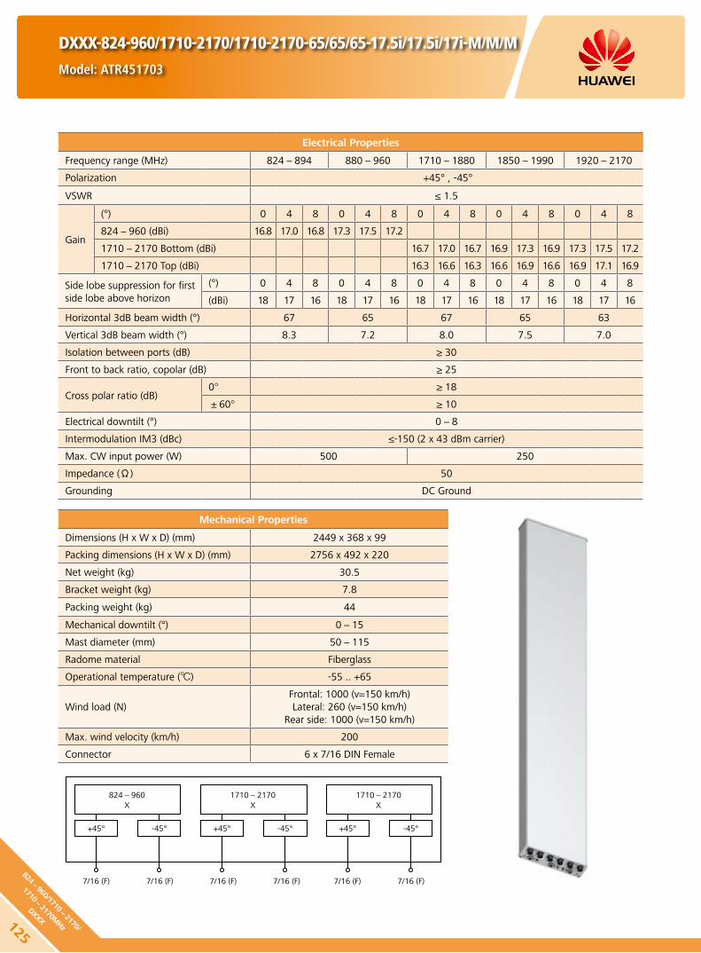
Mechanical Properties
Dimensions (H x W x D) (mm) 2449 x 368 x 99
Packing dimensions (H x W x D) (mm) 2756 x 492 x 220
Net weight (kg) 30.5
Bracket weight (kg) 7.8
Packing weight (kg) 44
Mechanical downtilt (°) 0-15
Mast diameter (mm) 50-115
Radome material Fiberglass
Operational temperature () -55 .. +65
Wind load (N)Frontal: 1000 (v=150 km/h)Lateral: 260 (v=150 km/h)
Rear side: 1000 (v=150 km/h)
Max. wind velocity (km/h) 200
Connector 6 x 7/16 DIN Female
DXXX-824-960/1710-2170/1710-2170-65/65/65-17.5i/17.5i/17i-M/M/M
Model: ATR451703
Electrical Properties
Frequency range (MHz) 824-894 880-960 1710-1880 1850-1990 1920-2170
Polarization +45° , -45°
VSWR ≤ 1.5
Gain
(°) 0 4 8 0 4 8 0 4 8 0 4 8 0 4 8
824-960 (dBi) 16.8 17.0 16.8 17.3 17.5 17.2
1710-2170 Bottom (dBi) 16.7 17.0 16.7 16.9 17.3 16.9 17.3 17.5 17.2
1710-2170 Top (dBi) 16.3 16.6 16.3 16.6 16.9 16.6 16.9 17.1 16.9
Side lobe suppression for first side lobe above horizon
(°) 0 4 8 0 4 8 0 4 8 0 4 8 0 4 8
(dBi) 18 17 16 18 17 16 18 17 16 18 17 16 18 17 16
Horizontal 3dB beam width (°) 67 65 67 65 63
Vertical 3dB beam width (°) 8.3 7.2 8.0 7.5 7.0
Isolation between ports (dB) ≥ 30
Front to back ratio, copolar (dB) ≥ 25
Cross polar ratio (dB)0° ≥ 18
±60° ≥ 10
Electrical downtilt (°) 0-8
Intermodulation IM3 (dBc) ≤-150 (2 x 43 dBm carrier)
Max. CW input power (W) 500 250
Impedance (Ω) 50
Grounding DC Ground
824-960X
1710-2170X
+45°
7/16 (F) 7/16 (F) 7/16 (F)7/16 (F) 7/16 (F) 7/16 (F)
+45°-45°
1710-2170X
+45° -45° -45°
125
824-960/1710-
2170/
1710-2170M
Hz
DXXX

DXXX-824-960/1710-2170/1710-2170-65/65/65-17.5i/17.5i/17i-M/M/M
Model: ATR451703
Any previous catalogue issues become invalid.
Issue: 2012-06-01
HUAWEI TECHNOLOGIES CO., LTD.
Huawei Industrial BaseBantian Longgang
Shenzhen 518129, P.R. ChinaTel: +86-755-28780808
Email: [email protected]
www.huawei.com
Copyright © Huawei Technologies Co., Ltd. 2012. All rights reserved.
THIS DOCUMENT IS FOR INFORMATION PURPOSE ONLY, AND DOSE NOT CONSTITUTE ANY KIND OF WARRANTIES.
824-870 MHz
1710-1880 MHz
1710-1880 MHz
870-916 MHz
1850-1990 MHz
1850-1990 MHz
910-960 MHz
1920-2170 MHz
1920-2170 MHz
12682
4-96
0/17
10-
2170
/
1710-
2170
MHz
DXXX
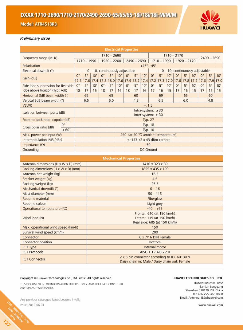
Electrical Properties
Frequency range (MHz)1710-2690 1710-2170
2490-26901710-1990 1920-2200 2490-2690 1710-1990 1920-2170
Polarization +45°, -45°Electrical downtilt (°) 0-10, continuously adjustable 0-10, continuously adjustable
Gain (dBi)0° 5° 10° 0° 5° 10° 0° 5° 10° 0° 5° 10° 0° 5° 10° 0° 5° 10°
17.5 17.6 17.4 17.8 18.0 17.6 17.9 18.2 17.4 17.2 17.3 17.0 17.6 17.8 17.2 17.6 17.9 17.0
Side lobe suppression for first side lobe above horizon (Typ.) (dB)
0° 5° 10° 0° 5° 10° 0° 5° 10° 0° 5° 10° 0° 5° 10° 0° 5° 10°18 17 16 18 17 16 18 17 16 17 16 15 17 16 15 17 16 15
Horizontal 3dB beam width (°) 69 65 60 69 65 60Vertical 3dB beam width (°) 6.5 6.0 4.8 6.5 6.0 4.8VSWR < 1.5
Isolation between ports (dB)Intra-system: ≥ 30Inter-system: ≥ 30
Front to back ratio, copolar (dB) Typ. 27
Cross polar ratio (dB)0° Typ. 18±60° Typ. 10
Max. power per input (W) 250 (at 50 ambient temperature)Intermodulation IM3 (dBc) ≤ -153 (2 x 43 dBm carrier)Impedance (Ω) 50Grounding DC Ground
Mechanical Properties
Antenna dimensions (H x W x D) (mm) 1410 x 323 x 89Packing dimensions (H x W x D) (mm) 1855 x 435 x 190Antenna net weight (kg) 16.5Bracket weight (kg) 4.6Packing weight (kg) 25.5Mechanical downtilt (°) 0-16Mast diameter (mm) 50-115Radome material Fiberglass Radome colour Light greyOperational temperature () -40 .. +65
Wind load (N)Frontal: 610 (at 150 km/h)Lateral: 115 (at 150 km/h)
Rear side: 685 (at 150 km/h)Max. operational wind speed (km/h) 150Survival wind speed (km/h) 200Connector 6 x 7/16 DIN FemaleConnector position BottomRET Type Internal motorRET Protocols AISG 1.1 / AISG 2.0
RET Connector2 x 8 pin connector according to IEC 60130-9Daisy chain in: Male / Daisy chain out: Female
DXXX-1710-2690/1710-2170/2490-2690-65/65/65-18i/18i/18i-M/M/M
Model: ATR4518R3
Any previous catalogue issues become invalid.
Issue: 2012-06-01
HUAWEI TECHNOLOGIES CO., LTD.
Huawei Industrial BaseBantian Longgang
Shenzhen 518129, P.R. ChinaTel: +86-755-28780808
Email: [email protected]
www.huawei.com
Copyright © Huawei Technologies Co., Ltd. 2012. All rights reserved.
THIS DOCUMENT IS FOR INFORMATION PURPOSE ONLY, AND DOSE NOT CONSTITUTE ANY KIND OF WARRANTIES.
Preliminary Issue
127
1710-2690/1710-
2170/
2490-2690M
Hz
DXXX

DXXX-1710-2690/1710-2170/2490-2690-65/65/65-18i/18i/18i-M/M/M
Model: ATR4518R3
RET Properties
RET Type Internal motor
RET Protocols AISG 1.1 / AISG 2.0
Input voltage range (V) DC 10-30
Power consumption (W) < 10 (motor activated)
< 0.5 (stand by)
Adjustment time (full range) (min) < 1.5 (typically, depending on antenna type)
Calibration time (min) < 3 (typically, depending on antenna type)
RET Connector2 x 8 pin connector according to IEC 60130-9Daisy chain in: Male / Daisy chain out: Female
Pin assignment according AISG 1 2 3 4 5 6 7 8
DC n/c RS-485B n/c RS-485A DC in/out DC return n/c
Lightning protection (kA)AISG interface (each pin)
3 (10/350 μs)10 (8/20 μs)
HINT
Before the installation, check whether the antenna and base station support the same AISG protocol. If not, contact the technical support personnel of Huawei.
Standards:
EN 60950-1 (Safety) y
EN 55022 (Emission) y
EN 55024 (Immunity) y
ETSI EN300386 (1.4.1) y
FCC part15 y
Certification:
CE, FCC, RoHS, WEEE
Any previous catalogue issues become invalid.
Issue: 2012-06-01
HUAWEI TECHNOLOGIES CO., LTD.
Huawei Industrial BaseBantian Longgang
Shenzhen 518129, P.R. ChinaTel: +86-755-28780808
Email: [email protected]
www.huawei.com
Copyright © Huawei Technologies Co., Ltd. 2012. All rights reserved.
THIS DOCUMENT IS FOR INFORMATION PURPOSE ONLY, AND DOSE NOT CONSTITUTE ANY KIND OF WARRANTIES.
Preliminary Issue
12817
10-
2690
/171
0-21
70/
2490-
2690
MHz
DXXX

Electrical Properties
Frequency range (MHz)790-960 1710-2690 1710-2170
2490-2690790-894 880-960 1710-1990 1920-2170 2490-2690 1710-1990 1920-2170
Polarization +45°, -45°
Electrical downtilt (°)0-10, continuously
adjustable0-8, continuously adjustable
Gain (dBi)0° 5° 10° 0° 5° 10° 0° 4° 8° 0° 4° 8° 0° 4° 8° 0° 4° 8° 0° 4° 8° 0° 4° 8°
17.5 17.6 17.4 17.5 17.6 17.4 17.5 17.6 17.4 17.8 18.0 17.6 17.9 18.2 17.4 17.2 17.3 17.0 17.6 17.8 17.2 17.6 17.9 17.0
Side lobe suppression for first side lobe above horizon (Typ.) (dB)
0° 5° 10° 0° 5° 10° 0° 4° 8° 0° 4° 8° 0° 4° 8° 0° 4° 8° 0° 4° 8° 0° 4° 8°
17 16 16 17 16 16 17 17 16 17 17 16 16 16 15 17 16 16 17 16 16 16 16 15
Horizontal 3dB beam width (°) 65 63 66 63 60 66 63 60
Vertical 3dB beam width (°) 10.2 9.6 5.2 4.8 4 5.2 4.8 4
VSWR < 1.5
Isolation between ports (dB)Intra-system: ≥ 28Inter-system: ≥ 30
Front to back ratio, copolar (dB) Typ. 28 Typ. 28
Cross polar ratio (dB)0° Typ. 18 Typ. 17
±60° Typ. 10 Typ. 10
Max. power per input (W)500 (at 50 ambient
temperature)250 (at 50 ambient temperature)
Intermodulation IM3 (dBc) ≤ -153 (2 x 43 dBm carrier)
Impedance (Ω) 50
Grounding DC Ground
Mechanical Properties
Antenna dimensions (H x W x D) (mm) 1990 x 349 x 148
Packing dimensions (H x W x D) (mm) 2390 x 499 x 248
Antenna net weight (kg) 34
Bracket weight (kg) 4.6
Packing weight (kg) 49
Mechanical downtilt (°) 0-12
Mast diameter (mm) 50-115
Radome material Fiberglass
Radome colour Light grey
Operational temperature () -40 .. +65
Wind load (N)Frontal: 860 (at 150 km/h)Lateral: 315 (at 150 km/h)
Rear side: 1100 (at 150 km/h)
Max. operational wind speed (km/h) 150
Survival wind speed (km/h) 200
Connector 8 x 7/16 DIN Female
Connector position Bottom
RET Type Internal motor
RET Protocols AISG 1.1 / AISG 2.0
RET Connector2 x 8 pin connector according to IEC 60130-9 Daisy chain in: Male / Daisy chain out: Female
DXXXX-790-960/1710-2690/1710-2170/2490-2690-65/65/65/
65-16i/18.5i/18i/18i-M/M/M/M-R Model: AQU4518R0
Preliminary Issue
129
790-960/1710-
2690/
1710-2170/2490-
2690MHz
DXXXX

RET Properties
RET Type Internal motor
RET Protocols AISG 1.1 / AISG 2.0
Input voltage range (V) DC 10-30
Power consumption (W) < 10 (motor activated)
< 0.5 (stand by)
Adjustment time (full range) (min) < 1.5 (typically, depending on antenna type)
Calibration time (min) < 3 (typically, depending on antenna type)
RET Connector2 x 8 pin connector according to IEC 60130-9Daisy chain in: Male / Daisy chain out: Female
Pin assignment according AISG 1 2 3 4 5 6 7 8
DC n/c RS-485B n/c RS-485A DC in/out DC return n/c
Lightning protection (kA)AISG interface (each pin)
3 (10/350 μs)10 (8/20 μs)
HINT
Before the installation, check whether the antenna and base station support the same AISG protocol. If not, contact the technical support personnel of Huawei.
Standards:
EN 60950-1 (Safety) y
EN 55022 (Emission) y
EN 55024 (Immunity) y
ETSI EN300386 (1.4.1) y
FCC part15 y
Certification:
CE, FCC, RoHS, WEEE
Any previous catalogue issues become invalid.
Issue: 2012-06-01
HUAWEI TECHNOLOGIES CO., LTD.
Huawei Industrial BaseBantian Longgang
Shenzhen 518129, P.R. ChinaTel: +86-755-28780808
Email: [email protected]
www.huawei.com
Copyright © Huawei Technologies Co., Ltd. 2012. All rights reserved.
THIS DOCUMENT IS FOR INFORMATION PURPOSE ONLY, AND DOSE NOT CONSTITUTE ANY KIND OF WARRANTIES.
DXXXX-790-960/1710-2690/1710-2170/2490-2690-65/65/65/
65-16i/18.5i/18i/18i-M/M/M/M-R Model: AQU4518R0
Preliminary Issue
13079
0-96
0/17
10-
2690
/
1710-
2170
/249
0-26
90M
Hz
DXXXX

2300-2500 MHz 2500-2700 MHz
DX-2300-2700-60-18i-M
Model: A25451804
Any previous catalogue issues become invalid.
Issue: 2012-06-01
HUAWEI TECHNOLOGIES CO., LTD.
Huawei Industrial BaseBantian Longgang
Shenzhen 518129, P.R. ChinaTel: +86-755-28780808
Email: [email protected]
www.huawei.com
Copyright © Huawei Technologies Co., Ltd. 2012. All rights reserved.
THIS DOCUMENT IS FOR INFORMATION PURPOSE ONLY, AND DOSE NOT CONSTITUTE ANY KIND OF WARRANTIES.
Mechanical Properties
Dimensions (H x W x D) (mm) 1060 x 155 x 79Packing dimensions (H x W x D) (mm) 1550 x 260 x 160Net weight (kg) 6Bracket weight (kg) 2.7Packing weight (kg) 10.6
Mechanical downtilt (°) 0-16
Mast diameter (mm) 50-115Radomematerial FiberglassOperating temperature () -55 .. +65
Wind load (N)Frontal: 120 (v=150 km/h)Lateral: 90 (v=150 km/h)
Rear side: 180 (v=150 km/h)Max. wind velocity (km/h) 200Connector 2 x N-50KF
Electrical Properties
Frequency range (MHz) 2300-2500 2500-2700Polarization +45° , -45°
VSWR ≤1.45
Gain (°) 2 6 10 2 6 10(dBi) 17.0 17.3 17.0 17.3 17.6 17.1
Side lobe suppression for first side lobe above horizon
(°) 2 6 10 2 6 10(dB)Typ. 18 17 16 18 17 16
Horizontal 3dB beam width (°) 64 60
Vertical 3dB beam width (°) 7.0 6.5Isolation between ports (dB) ≥30Front to back ratio, copolar (dB) Typ. 30Cross polar ratio (dB) 15Electrical downtilt (°) 2-10Max. CW input power (W) 250Impedance (Ω) 50Grounding DC Ground
2300-2700X
+45°
N-50KF N-50KF
-45°
131
2300-2700M
Hz
DX

2300-2500 MHz 2500-2700 MHz
DXX-2300-2700/2300-2700-65/65-18i/18i-M
Model: A25451803
Any previous catalogue issues become invalid.
Issue: 2012-06-01
HUAWEI TECHNOLOGIES CO., LTD.
Huawei Industrial BaseBantian Longgang
Shenzhen 518129, P.R. ChinaTel: +86-755-28780808
Email: [email protected]
www.huawei.com
Copyright © Huawei Technologies Co., Ltd. 2012. All rights reserved.
THIS DOCUMENT IS FOR INFORMATION PURPOSE ONLY, AND DOSE NOT CONSTITUTE ANY KIND OF WARRANTIES.
Mechanical Properties
Dimensions (H x W x D) (mm) 1060 x 289 x 85Packing dimensions (H x W x D) (mm) 1400 x 405 x 175Net weight (kg) 11Bracket weight (kg) 4.5Packing weight (kg) 18.3
Mechanical downtilt (°) 0-16
Mast diameter (mm) 50-115Radomematerial FiberglassOperating temperature () -55 .. +65
Wind load (N)Frontal: 230 (v=150 km/h)Lateral: 100 (v=150 km/h)
Rear side: 340 (v=150 km/h)Max. wind velocity (km/h) 200Connector 4 x N-50KF
Electrical Properties
Frequency range (MHz) 2300-2500 2500-2700Polarization +45° , -45°
VSWR ≤1.45
Gain (°) 2 6 10 2 6 10(dBi) 17.0 17.3 17.0 17.3 17.6 17.1
Side lobe suppression for first side lobe above horizon
(°) 2 6 10 2 6 10(dB)Typ. 18 17 16 18 17 16
Horizontal 3dB beam width (°) 65 65
Vertical 3dB beam width (°) 7.0 6.5Isolation between ports (dB) ≥30Front to back ratio, copolar (dB) Typ. 28Cross polar ratio (dB) 15Electrical downtilt (°) 2-10Max. CW input power (W) 250Impedance (Ω) 50Grounding DC Ground
2300-2700X
+45°
N-50KF N-50KF
-45°
2300-2700X
+45°
N-50KF N-50KF
-45°
132
2300-
2700
/230
0-27
00M
Hz
DXX

Electrical Properties
Frequency range (MHz)1710-2690
1710-1990 1920-2200 2200-2490 2490-2690
Polarization +45° , -45°
Electrical downtilt (°) 0-10 , continuously adjustable
Gain (dBi)0° 5° 10° 0° 5° 10° 0° 5° 10° 0° 5° 10°
17.4 17.3 17.2 17.8 17.6 17.5 18.0 17.8 17.6 18.0 17.8 17.3
Side lobe suppression for first side lobe above horizon (Typ.) (dB)
0° 5° 10° 0° 5° 10° 0° 5° 10° 0° 5° 10°
18 17 16 18 17 16 18 17 16 18 17 16
Horizontal 3dB beam width (°) 66 64 62 59
Vertical 3dB beam width (°) 5.8 5.2 4.6 4.2
VSWR < 1.5
Isolation between ports (dB) ≥ 30
Front to back ratio, copolar (dB) Typ. 28
Cross polar ratio (dB)0° Typ. 18
±60° Typ. 10
Max. power per input (W) 250 (at 50 ambient temperature)
Intermodulation IM3 (dBc) ≤ -153 (2 x 43 dBm carrier)
Impedance (Ω) 50
Grounding DC Ground
Mechanical Properties
Antenna dimensions (H x W x D) (mm) 1425 x Φ 236
Packing dimensions (H x W x D) (mm) 2490 x 400 x 400
Antenna net weight (kg) 26.3
Packing weight (kg) 32.8
Radome material Fiberglass
Radome colour Light grey
Operational temperature () -55 .. +65
Wind load (N) 245 (at 150 km/h)
Max. operational wind speed (km/h) 150
Survival wind speed (km/h) 200
Connector 6 x 7/16 DIN Female (Long neck)
Connector position Bottom
CX-1710-2690-65-18i-M
Model: A264518S0
Any previous catalogue issues become invalid.
Issue: 2012-06-01
HUAWEI TECHNOLOGIES CO., LTD.
Huawei Industrial BaseBantian Longgang
Shenzhen 518129, P.R. ChinaTel: +86-755-28780808
Email: [email protected]
www.huawei.com
Copyright © Huawei Technologies Co., Ltd. 2012. All rights reserved.
THIS DOCUMENT IS FOR INFORMATION PURPOSE ONLY, AND DOSE NOT CONSTITUTE ANY KIND OF WARRANTIES.
Preliminary Issue
133
1710-2690M
Hz
DX

Antenna Line ProductsB

The dual tower mounted amplifier (DTMA) is a low-noise amplifier installed near the antenna. It helps to improve the
signal-to-noise ratio and enhance the receiving sensibility of the BTS. It enhances the uplink coverage and improves uplink
and downlink imbalance of the BTS. It effectively reduces the transmitting power of cellphones, improves voice and data
communication quality.
Product Description
High linearity and low noise performance. y
Balanced LNA design and power failure bypass for high reliability. y
Light weight and compact design. y
Variable gain: 8 - 16 dB, default gain: 12 dB. y
Wall mounting and mast mounting. y
Built-in lightning protection up to 10 kA. y
Support AISG 1.1 and AISG 2.0 protocol. y
Features
Appearance and Block Diagram
DTMA08-008 Model: ATA801100 (AISG 1.1)
DTMA08-009 Model: ATA802000 (AISG 2.0)
135
DTMA

136
DTMA
DTMA08-008 Model: ATA801100 (AISG 1.1)
DTMA08-009 Model: ATA802000 (AISG 2.0)
Tx Specifications
Frequency range (MHz) 791-821
Bandwidth (MHz) 30
Insertion loss* (dB) Avg. < 0.4
Return loss (dB) ≥ 18
Input power (W) < 160 (+52 dBm) CW
< 2000 (+63 dBm) peak
Intermodulation products in Rx band (dBm) ≤ -117 (2 TX carriers at +43 dBm)
Rx Specifications
Frequency range (MHz) 832-862
Bandwidth (MHz) 30
Return loss(dB) ≥ 18 (DC ON) ≥ 13 (DC OFF)
Insertion loss in by-pass mode (dB) ≤ 3 (DC OFF)
Gain (dB) 8-16 (0.5 dB Step, Default gain: 12 dB)
Noise figure** (dB) Avg. < 1.4 (12 dB Gain, +22 ... +28 )
Output 1dB compression (dBm) ≥ 8 (12 dB Gain)
OIP3 (dBm) ≥ 20 (12 dB Gain)
Electrical properties
CWA Mode AISG Mode
DC supply voltage (V) 8.5-15 9-30
Operating current per TMA (mA) (without RET)
40-110 40-370
Alarm management (mA) 150-280 AISG
Power consumption (W) < 3.5
Environmental Specification
Operating temperature range () -40 ... +65
IP rating IP67
MTBF (hours) > 1,000,000
EMC ETS 300 342-3
Lightning protection (kA) 10 (8/20 us)
Mechanical Specification
DTMA dimensions (W x H x D) (mm) 190 x 240 x 120 (without connectors, without brackets)
Packing dimensions (W x H x D) (mm) 365 x 515 x 215
DTMA weight (kg) ≤ 6.1 (with brackets)
Packing weight (kg) ≤ 7.4
DTMA Volume (L) Approx. 5.5
AISG connector8-pin female, IEC 60130-9 (pin1 & pin6: 8.5V-30V DC, pin3: RS485B, pin5:
RS485A, pin7: DC return, other pins: not connected)
MountingWall mounting: with 4 screws (max. 8 mm diameter)
Mast mounting
Mast diameter (mm) Default: 30-125 // Optional: 40-140
Connector 4 x 7/16 DIN Female (Long neck)

DTMA08-008 Model: ATA801100 (AISG 1.1)
DTMA08-009 Model: ATA802000 (AISG 2.0)
Unit: mm
Any previous catalogue issues become invalid.
Issue: 2012-06-01
HUAWEI TECHNOLOGIES CO., LTD.
Huawei Industrial BaseBantian Longgang
Shenzhen 518129, P.R. ChinaTel: +86-755-28780808
Email: [email protected]
www.huawei.com
Copyright © Huawei Technologies Co., Ltd. 2012. All rights reserved.
THIS DOCUMENT IS FOR INFORMATION PURPOSE ONLY, AND DOSE NOT CONSTITUTE ANY KIND OF WARRANTIES.
HINT
Extraordinary operating conditions, such as heavy icing or storm wind, may result in the breakage of a DTMA. These facts must be considered during the site planning process. The installation team must be properly qualified and also be familiar with the relevant national safety regulations.
137
DTMA

The dual tower mounted amplifier (DTMA) is a low-noise amplifier installed near the antenna. It helps to improve the
signal-to-noise ratio and enhance the receiving sensibility of the BTS. It enhances the uplink coverage and improves uplink
and downlink imbalance of the BTS. It effectively reduces the transmitting power of cellphones, improves voice and data
communication quality.
DTMA09-014 Model: ATA901102 (AISG 1.1)
DTMA09-015 Model: ATA902002 (AISG 2.0)
Product Description
High linearity and low noise performance. y
Balanced LNA design and power failure bypass for high reliability. y
Light weight and compact design. y
Variable gain: 8 - 16 dB, default gain: 12 dB. y
Wall mounting and mast mounting. y
Built-in lightning protection up to 10 kA. y
Support AISG 1.1 and AISG 2.0 protocol. y
Features
Appearance and Block Diagram
138
DTMA

DTMA09-014 Model: ATA901102 (AISG 1.1)
DTMA09-015 Model: ATA902002 (AISG 2.0)
Tx Specifications
Frequency range (MHz) 925-950
Bandwidth (MHz) 25
Insertion loss* (dB) Avg. < 0.4
Return loss (dB) ≥ 18
Input power (W) < 160 (+52 dBm) CW
< 2000 (+63 dBm) peak
Intermodulation products in Rx band (dBm) ≤ -117 (2 TX carriers at +43 dBm)
Rx Specifications
Frequency range (MHz) 880-905
Bandwidth (MHz) 25
Return loss(dB) ≥ 18 (DC ON)≥ 13 (DC OFF)
Insertion loss in by-pass mode (dB) ≤ 3.0 (DC OFF)
Gain (dB) 8-16 (0.5 dB Step, Default gain: 12 dB)
Noise figure** (dB) Avg. < 1.4 (12 dB Gain, +22 ... +28 )
Output 1dB compression (dBm) ≥ 8 (12 dB Gain)
OIP3 (dBm) ≥ 20 (12 dB Gain)
Electrical properties
CWA Mode AISG Mode
DC supply voltage (V) 8.5-15 9-30
Operating current per TMA (mA) (without RET)
40-110 40-370
Alarm management (mA) 150-280 AISG
Power consumption (W) < 3.5
Environmental Specification
Operating temperature range () -40 … +65
IP rating IP67
MTBF (hours) > 1,000,000
EMC ETS 300 342-3
Lightning protection (kA) 10 (8/20 us)
Mechanical Specification
DTMA dimensions (W x H x D) (mm) 198 x 308 x 70.5 (without connectors, without brackets)
Packing dimensions (W x H x D) (mm) 315 x 515 x 190
DTMA weight (kg) ≤ 5.5 (with brackets)
Packing weight (kg) ≤ 6.6
DTMA Volume (L) Approx. 4.3
AISG connector8-pin female, IEC 60130-9 (pin1 & pin6: 8.5V-30V DC, pin3: RS485B, pin5:
RS485A, pin7: DC return, other pins: not connected)
MountingWall mounting: with 4 screws (max. 8 mm diameter)
Mast mounting
Mast diameter (mm) Default: 30-125 // Optional: 40-140
Connector 4 x 7/16 DIN Female (Long neck)
139
DTMA

DTMA09-014 Model: ATA901102 (AISG 1.1)
DTMA09-015 Model: ATA902002 (AISG 2.0)
Any previous catalogue issues become invalid.
Issue: 2012-06-01
HUAWEI TECHNOLOGIES CO., LTD.
Huawei Industrial BaseBantian Longgang
Shenzhen 518129, P.R. ChinaTel: +86-755-28780808
Email: [email protected]
www.huawei.com
Copyright © Huawei Technologies Co., Ltd. 2012. All rights reserved.
THIS DOCUMENT IS FOR INFORMATION PURPOSE ONLY, AND DOSE NOT CONSTITUTE ANY KIND OF WARRANTIES.
Unit: mm
HINT
Extraordinary operating conditions, such as heavy icing or storm wind, may result in the breakage of a DTMA. These facts must be considered during the site planning process. The installation team must be properly qualified and also be familiar with the relevant national safety regulations.
140
DTMA

The dual tower mounted amplifier (DTMA) is a low-noise amplifier installed near the antenna. It helps to improve the
signal-to-noise ratio and enhance the receiving sensibility of the BTS system. It enhances the uplink coverage and improves
uplink and downlink imbalance of the base station. It effectively reduces the transmitting power of cellphones, improves
voice and data communication quality.
DTMA09-010 Model: ATA901101 (AISG 1.1)
DTMA09-011 Model: ATA902001 (AISG 2.0)
Product Description
High linearity and low noise performance. y
Balanced LNA design and power failure bypass for high reliability. y
Light weight and compact design. y
Variable gain: 8 - 16 dB, default gain: 12 dB. y
Wall mounting and mast mounting. y
Built-in lightning protection up to 10 kA. y
Support AISG 1.1 and AISG 2.0 protocol. y
Features
Appearance and Block Diagram
141
DTMA

DTMA09-010 Model: ATA901101 (AISG 1.1)
DTMA09-011 Model: ATA902001 (AISG 2.0)
Tx Specifications
Frequency range (MHz) 925-960
Bandwidth (MHz) 35
Insertion loss* (dB) Avg. < 0.4
Return loss (dB) ≥ 18
Input power (W) < 160 (+52 dBm) CW
< 2000 (+63 dBm) peak
Intermodulation products in Rx band (dBm) ≤ -117 (2 TX carriers at +43 dBm)
Rx Specifications
Frequency range (MHz) 880-915
Bandwidth (MHz) 35
Return loss(dB) ≥ 18 (DC ON)≥ 13 (DC OFF)
Insertion loss in by-pass mode (dB) ≤ 3.0 (DC OFF)
Gain (dB) 8-16 (0.5 dB Step, Default gain: 12 dB)
Noise figure** (dB) Avg. < 1.4 (12 dB Gain, +22 ... +28 )
Output 1dB compression (dBm) ≥ 8 (12 dB Gain)
OIP3 (dBm) ≥ 20 (12 dB Gain)
Electrical properties
CWA Mode AISG Mode
DC supply voltage (V) 8.5-15 9-30
Operating current per TMA (mA) (without RET)
40-110 40-370
Alarm management (mA) 150-280 AISG
Power consumption (W) < 3.5
Environmental Specification
Operating temperature range () -40 ... +65
IP rating IP67
MTBF (hours) > 1,000,000
EMC ETS 300 342-3
Lightning protection (kA) 10 (8/20 us)
Mechanical Specification
DTMA dimensions (W x H x D) (mm) 248 x 324 x 75.5 (without connectors, without brackets)
Packing dimensions (W x H x D) (mm) 365 x 515 x 215
DTMA weight (kg) ≤ 6.5 (with brackets)
Packing weight (kg) ≤ 7.7
DTMA Volume (L) Approx. 6.1
AISG connector8-pin female, IEC 60130-9 (pin1 & pin6: 8.5V-30V DC, pin3: RS485B, pin5:
RS485A, pin7: DC return, other pins: not connected)
MountingWall mounting: with 4 screws (max. 8 mm diameter)
Mast mounting
Mast diameter (mm) Default: 30-125 // Optional: 40-140
Connector 4 x 7/16 DIN Female (Long neck)
142
DTMA

DTMA09-010 Model: ATA901101 (AISG 1.1)
DTMA09-011 Model: ATA902001 (AISG 2.0)
Any previous catalogue issues become invalid.
Issue: 2012-06-01
HUAWEI TECHNOLOGIES CO., LTD.
Huawei Industrial BaseBantian Longgang
Shenzhen 518129, P.R. ChinaTel: +86-755-28780808
Email: [email protected]
www.huawei.com
Copyright © Huawei Technologies Co., Ltd. 2012. All rights reserved.
THIS DOCUMENT IS FOR INFORMATION PURPOSE ONLY, AND DOSE NOT CONSTITUTE ANY KIND OF WARRANTIES.
Unit: mm
HINT
Extraordinary operating conditions, such as heavy icing or storm wind, may result in the breakage of a DTMA. These facts must be considered during the site planning process. The installation team must be properly qualified and also be familiar with the relevant national safety regulations.
143
DTMA

The dual tower mounted amplifier (DTMA) is a low-noise amplifier installed near the antenna. It helps to improve the
signal-to-noise ratio and enhance the receiving sensibility of the BTS system. It enhances the uplink coverage and improves
uplink and downlink imbalance of the base station. It effectively reduces the transmitting power of cellphones, improves
voice and data communication quality.
DTMA09-016 Model: ATA901103 (AISG 1.1)
DTMA09-017 Model: ATA902003 (AISG 2.0)
Product Description
High linearity and low noise performance. y
Balanced LNA design and power failure bypass for high reliability. y
Light weight and compact design. y
Variable gain: 8 - 16 dB, default gain: 12 dB. y
Wall mounting and mast mounting. y
Built-in lightning protection up to 10 kA. y
Support AISG 1.1 and AISG 2.0 protocol. y
Features
Appearance and Block Diagram
144
DTMA

DTMA09-016 Model: ATA901103 (AISG 1.1)
DTMA09-017 Model: ATA902003 (AISG 2.0)
Tx Specifications
Frequency range (MHz) 935-960
Bandwidth (MHz) 25
Insertion loss* (dB) Avg. < 0.4
Return loss (dB) ≥ 18
Input power (W) < 160 (+52 dBm) CW
< 2000 (+63 dBm) peak
Intermodulation products in Rx band (dBm) ≤ -117 (2 TX carriers at +43 dBm)
Rx Specifications
Frequency range (MHz) 890-915
Bandwidth (MHz) 25
Return loss(dB) ≥ 18 (DC ON)≥ 13 (DC OFF)
Insertion loss in by-pass mode (dB) ≤ 3.0 (DC OFF)
Gain (dB) 8-16 (0.5 dB Step, Default gain: 12 dB)
Noise figure** (dB) Avg. < 1.4 (12 dB Gain, +22 ... +28 )
Output 1dB compression (dBm) ≥ 8 (12 dB Gain)
OIP3 (dBm) ≥ 20 (12 dB Gain)
Electrical properties
CWA Mode AISG Mode
DC supply voltage (V) 8.5-15 9-30
Operating current per TMA (mA) (without RET)
40-110 40-370
Alarm management (mA) 150-280 AISG
Power consumption (W) < 3.5
Environmental Specification
Operating temperature range () -40 … +65
IP rating IP67
MTBF (hours) > 1,000,000
EMC ETS 300 342-3
Lightning protection (kA) 10 (8/20 us)
Mechanical Specification
DTMA dimensions (W x H x D) (mm) 198 x 308 x 70.5 (without connectors, without brackets)
Packing dimensions (W x H x D) (mm) 315 x 515 x 190
DTMA weight (kg) ≤ 5.5 (with brackets)
Packing weight (kg) ≤ 6.6
DTMA Volume (L) Approx. 4.3
AISG connector8-pin female, IEC 60130-9 (pin1 & pin6: 8.5V-30V DC, pin3: RS485B, pin5:
RS485A, pin7: DC return, other pins: not connected)
MountingWall mounting: with 4 screws (max. 8 mm diameter)
Mast mounting
Mast diameter (mm) Default: 30-125 // Optional: 40-140
Connector 4 x 7/16 DIN Female (Long neck)
145
DTMA

DTMA09-016 Model: ATA901103 (AISG 1.1)
DTMA09-017 Model: ATA902003 (AISG 2.0)
Any previous catalogue issues become invalid.
Issue: 2012-06-01
HUAWEI TECHNOLOGIES CO., LTD.
Huawei Industrial BaseBantian Longgang
Shenzhen 518129, P.R. ChinaTel: +86-755-28780808
Email: [email protected]
www.huawei.com
Copyright © Huawei Technologies Co., Ltd. 2012. All rights reserved.
THIS DOCUMENT IS FOR INFORMATION PURPOSE ONLY, AND DOSE NOT CONSTITUTE ANY KIND OF WARRANTIES.
Unit: mm
HINT
Extraordinary operating conditions, such as heavy icing or storm wind, may result in the breakage of a DTMA. These facts must be considered during the site planning process. The installation team must be properly qualified and also be familiar with the relevant national safety regulations.
146
DTMA

The dual tower mounted amplifier (DTMA) is a low-noise amplifier installed near the antenna. It helps to improve the
signal-to-noise ratio and enhance the receiving sensibility of the BTS system. It enhances the uplink coverage and improves
uplink and downlink imbalance of the base station. It effectively reduces the transmitting power of cellphones, improves
voice and data communication quality.
DTMA18-022 Model: ATA181101 (AISG 1.1)
DTMA18-023 Model: ATA182001 (AISG 2.0)
Product Description
High linearity and low noise performance. y
Power failure bypass for high reliability. y
Light weight and compact design. y
Wall mounting and mast mounting. y
Built-in lightning protection up to 10 kA. y
Support AISG 1.1 and AISG 2.0 protocol. y
Features
Appearance and Block Diagram
147
DTMA

DTMA18-022 Model: ATA181101 (AISG 1.1)
DTMA18-023 Model: ATA182001 (AISG 2.0)
Tx Specifications
Frequency range (MHz) 1805-1880
Bandwidth (MHz) 75
Insertion loss* (dB) Avg. < 0.4
Return loss (dB) ≥ 18
Input power (W) < 160 (+52 dBm) CW
< 2000 (+63 dBm) peak
Intermodulation products in Rx band (dBm) ≤ -117 (2 TX carriers at +43 dBm)
Rx Specifications
Frequency range (MHz) 1710-1785
Bandwidth (MHz) 75
Return loss(dB) ≥ 18 (DC ON)≥ 13 (DC OFF)
Insertion loss in by-pass mode (dB) ≤ 3.0 (DC OFF)
Gain (dB) 12
Noise figure** (dB) Avg. < 1.4 (+22 ... +28 )
Output 1dB compression (dBm) ≥ 12
OIP3 (dBm) ≥ 24
Electrical properties
CWA Mode AISG Mode
DC supply voltage (V) 8.5-15 9-30
Operating current per TMA (mA) (without RET)
40-120 40-370
Alarm management (mA) 150-280 AISG
Power consumption (W) < 3.5
Environmental Specification
Operating temperature range () -40 ... +65
IP rating IP67
MTBF (hours) > 1,000,000
EMC ETS 300 342-3
Lightning protection (kA) 10 (8/20 us)
Mechanical Specification
DTMA dimensions (W x H x D) (mm) 160 x 220 x 100 (without connectors, without brackets)
Packing dimensions (W x H x D) (mm) 315 x 465 x 225
DTMA weight (kg) ≤ 5.1 (with brackets)
Packing weight (kg) ≤ 6.2
DTMA Volume (L) Approx. 3.5
AISG connector8-pin female, IEC 60130-9 (pin1 & pin6: 8.5V-30V DC, pin3: RS485B, pin5:
RS485A, pin7: DC return, other pins: not connected)
MountingWall mounting: with 4 screws (max. 8 mm diameter)
Mast mounting
Mast diameter (mm) Default: 30-125 // Optional: 40-140
Connector 4 x 7/16 DIN Female (Long neck)
148
DTMA
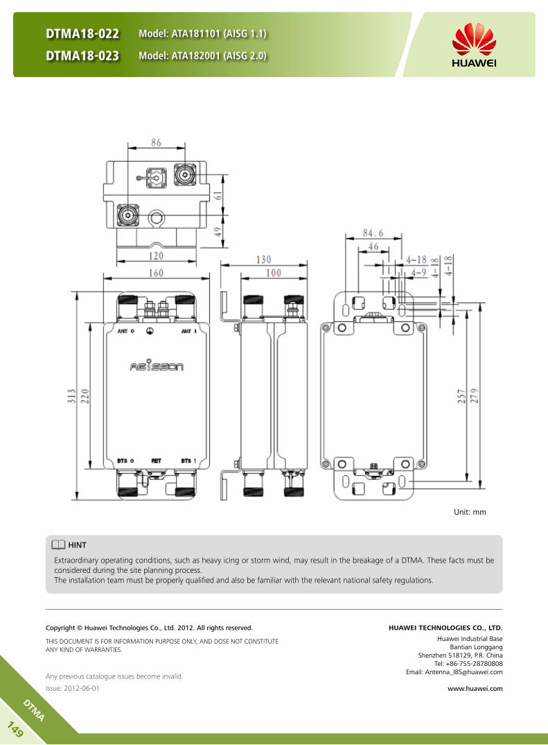
DTMA18-022 Model: ATA181101 (AISG 1.1)
DTMA18-023 Model: ATA182001 (AISG 2.0)
Any previous catalogue issues become invalid.
Issue: 2012-06-01
HUAWEI TECHNOLOGIES CO., LTD.
Huawei Industrial BaseBantian Longgang
Shenzhen 518129, P.R. ChinaTel: +86-755-28780808
Email: [email protected]
www.huawei.com
Copyright © Huawei Technologies Co., Ltd. 2012. All rights reserved.
THIS DOCUMENT IS FOR INFORMATION PURPOSE ONLY, AND DOSE NOT CONSTITUTE ANY KIND OF WARRANTIES.
Unit: mm
HINT
Extraordinary operating conditions, such as heavy icing or storm wind, may result in the breakage of a DTMA. These facts must be considered during the site planning process. The installation team must be properly qualified and also be familiar with the relevant national safety regulations.
149
DTMA

The dual tower mounted amplifier (DTMA) is a low-noise amplifier installed near the antenna. It helps to improve the
signal-to-noise ratio and enhance the receiving sensibility of the BTS system. It enhances the uplink coverage and improves
uplink and downlink imbalance of the base station. It effectively reduces the transmitting power of cellphones, improves
voice and data communication quality.
DTMA21-006 Model: ATA211101 (AISG 1.1)
DTMA21-007 Model: ATA212001 (AISG 2.0
Product Description
High linearity and low noise performance. y
Power failure bypass for high reliability. y
Light weight and compact design. y
Wall mounting and mast mounting. y
Built-in lightning protection up to 10 kA. y
Support AISG 1.1 and AISG 2.0 protocol. y
Features
Appearance and Block Diagram
150
DTMA

DTMA21-006 Model: ATA211101 (AISG 1.1)
DTMA21-007 Model: ATA212001 (AISG 2.0
Tx Specifications
Frequency range (MHz) 2110-2170
Bandwidth (MHz) 60
Insertion loss* (dB) Avg. < 0.25
Return loss (dB) ≥ 18
Input power (W) < 160 (+52 dBm) CW
< 2000 (+63 dBm) peak
Intermodulation products in Rx band (dBm) ≤ -122 (2 TX carriers at +43 dBm)
Rx Specifications
Frequency range (MHz) 1920 - 1980
Bandwidth (MHz) 60
Return loss(dB) ≥ 18 (DC ON)≥ 15 (DC OFF)
Insertion loss in by-pass mode (dB) ≤ 3.0 (DC OFF)
Gain (dB) 12 ±1
Noise figure** (dB) Avg. < 1.2 (+22 ... +28 )
Output 1dB compression (dBm) ≥ 12
OIP3 (dBm) ≥ 24
Electrical properties
CWA Mode AISG Mode
DC supply voltage (V) 8.5-15 9-30
Operating current per TMA (mA) (without RET)
40-120 40-370
Alarm management (mA) 150-280 AISG
Power consumption (W) < 3.5
Environmental Specification
Operating temperature range () -40 … +65
IP rating IP67
MTBF (hours) > 1,000,000
EMC ETS 300 342-3
Lightning protection (kA) 10 (8/20 us)
Mechanical Specification
DTMA dimensions (W x H x D) (mm) 160 x 205 x 54.5 (without connectors, without brackets)
Packing dimensions (W x H x D) (mm) 265 x 395 x 195
DTMA weight (kg) ≤ 3.3 (with brackets)
Packing weight (kg) ≤ 4.0
DTMA Volume (L) Approx. 1.8
AISG connector8-pin female, IEC 60130-9 (pin1 & pin6: 8.5V-30V DC, pin3: RS485B, pin5:
RS485A, pin7: DC return, other pins: not connected)
MountingWall mounting: with 4 screws (max. 8 mm diameter)
Mast mounting
Mast diameter (mm) Default: 30-125 // Optional: 40-140
Connector 4 x 7/16 DIN Female (Long neck)
151
DTMA

DTMA21-006 Model: ATA211101 (AISG 1.1)
DTMA21-007 Model: ATA212001 (AISG 2.0
Any previous catalogue issues become invalid.
Issue: 2012-06-01
HUAWEI TECHNOLOGIES CO., LTD.
Huawei Industrial BaseBantian Longgang
Shenzhen 518129, P.R. ChinaTel: +86-755-28780808
Email: [email protected]
www.huawei.com
Copyright © Huawei Technologies Co., Ltd. 2012. All rights reserved.
THIS DOCUMENT IS FOR INFORMATION PURPOSE ONLY, AND DOSE NOT CONSTITUTE ANY KIND OF WARRANTIES.
Unit: mm
HINT
Extraordinary operating conditions, such as heavy icing or storm wind, may result in the breakage of a DTMA. These facts must be considered during the site planning process. The installation team must be properly qualified and also be familiar with the relevant national safety regulations.
152
DTMA

The dual tower mounted amplifier (DTMA) is a low-noise amplifier installed near the antenna. It helps to improve the
signal-to-noise ratio and enhance the receiving sensibility of the BTS system. It enhances the uplink coverage and improves
uplink and downlink imbalance of the base station. It effectively reduces the transmitting power of cellphones, improves
voice and data communication quality.
DTMA26-012 Model: ATA261100 (AISG 1.1)
DTMA26-013 Model: ATA262000 (AISG 2.0)
Product Description
High linearity and low noise performance. y
Power failure bypass for high reliability. y
Light weight and compact design. y
Wall mounting and mast mounting. y
Built-in lightning protection up to 10 kA. y
Support AISG 1.1 and AISG 2.0 protocol. y
Features
Appearance and Block Diagram
153
DTMA

DTMA26-012 Model: ATA261100 (AISG 1.1)
DTMA26-013 Model: ATA262000 (AISG 2.0)
Tx Specifications
Frequency range (MHz) 2620-2690
Bandwidth (MHz) 70
Insertion loss* (dB) Avg. < 0.4
Return loss (dB) ≥ 18
Input power (W) < 160 (+52 dBm) CW
< 2000 (+63 dBm) peak
Intermodulation products in Rx band (dBm) ≤ -117 (2 TX carriers at +43 dBm)
Rx Specifications
Frequency range (MHz) 2500-2570
Bandwidth (MHz) 70
Return loss(dB) ≥ 18 (DC ON)≥ 13 (DC OFF)
Insertion loss in by-pass mode (dB) ≤ 3.0 (DC OFF)
Gain (dB) 12 ±1
Noise figure** (dB) Avg. < 1.3 (+22 ... +28 )
Output 1dB compression (dBm) ≥ 12
OIP3 (dBm) ≥ 24
Electrical properties
CWA Mode AISG Mode
DC supply voltage (V) 8.5-15 9-30
Operating current per TMA (mA) (without RET)
40-120 40-370
Alarm management (mA) 150-280 AISG
Power consumption (W) < 3.5
Environmental Specification
Operating temperature range () -40 ... +65
IP rating IP67
MTBF (hours) > 1,000,000
EMC ETS 300 342-3
Lightning protection (kA) 10 (8/20 us)
Mechanical Specification
DTMA dimensions (W x H x D) (mm) 160 x 210 x 54.5 (without connectors, without brackets)
Packing dimensions (W x H x D) (mm) 265 x 395 x 195
DTMA weight (kg) ≤ 3.1 (with brackets)
Packing weight (kg) ≤ 4.0
DTMA Volume (L) Approx. 1.8
AISG connector8-pin female, IEC 60130-9 (pin1 & pin6: 8.5V-30V DC, pin3: RS485B, pin5:
RS485A, pin7: DC return, other pins: not connected)
MountingWall mounting: with 4 screws (max. 8 mm diameter)
Mast mounting
Mast diameter (mm) Default: 30-125 // Optional: 40-140
Connector 4 x 7/16 DIN Female (Long neck)
154
DTMA

DTMA26-012 Model: ATA261100 (AISG 1.1)
DTMA26-013 Model: ATA262000 (AISG 2.0)
Any previous catalogue issues become invalid.
Issue: 2012-06-01
HUAWEI TECHNOLOGIES CO., LTD.
Huawei Industrial BaseBantian Longgang
Shenzhen 518129, P.R. ChinaTel: +86-755-28780808
Email: [email protected]
www.huawei.com
Copyright © Huawei Technologies Co., Ltd. 2012. All rights reserved.
THIS DOCUMENT IS FOR INFORMATION PURPOSE ONLY, AND DOSE NOT CONSTITUTE ANY KIND OF WARRANTIES.
Unit: mm
HINT
Extraordinary operating conditions, such as heavy icing or storm wind, may result in the breakage of a DTMA. These facts must be considered during the site planning process. The installation team must be properly qualified and also be familiar with the relevant national safety regulations.
155
DTMA
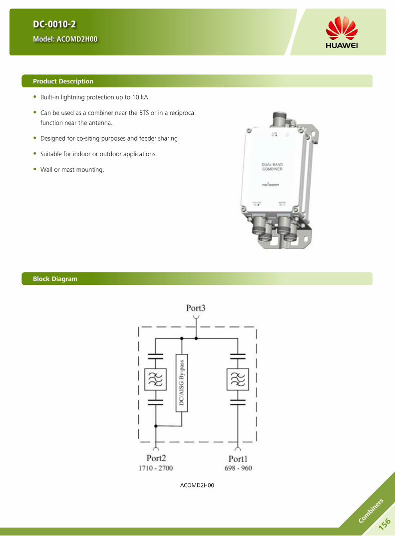
DC-0010-2
Model: ACOMD2H00
Product Description
Built-in lightning protection up to 10 kA. y
Can be used as a combiner near the BTS or in a reciprocal y
function near the antenna.
Designed for co-siting purposes and feeder sharing y
Suitable for indoor or outdoor applications. y
Wall or mast mounting. y
Block Diagram
ACOMD2H00
156Co
mbi
ners

Electrical Properties
Model ACOMD2H00
Pass band (MHz) Band 1 698-960
Band 2 1710-2700
Insertion loss* (dB) Port 1 ←→ Port 3 Typ. < 0.2 (698 MHz-960 MHz)
Port 2 ←→ Port 3 Typ. < 0.25 (1710 MHz-2700 MHz)
DC/AISG transparency Port 1 ←→ Port 3 Stop
Port 2 ←→ Port 3 By-pass (max. 2500 mA)
Isolation (dB) > 40
VSWR < 1.28
Input power (W) Port 1, Port 2 < 300
Intermodulation products (dBm) < -117 (3rd order; with 2 x 43 dBm)
Environmental Specification
Operating temperature () -40 … +65
Application scene Indoor // Outdoor
IP rating IP67
Lightning protection (kA) 10 (8/20 us)
Mechanical Specification
Combiner dimensions (W x H x D) (mm)Double Unit: 130 x 190 x 105
(without connectors, without mounting brackets)
Packing dimensions (W x H x D) (mm) 265 x 415 x 245
Combiner weight (kg) Double Unit: ≤ 4.3
Packing weight (kg) ≤ 5.4
Mounting Wall mounting // Mast mounting
Mast diameter (mm) Default: 40-135
Connector 7/16 DIN Female (Long neck)
DC-0010-2
Model: ACOMD2H00
157
Combiners

158Co
mbi
ners
DC-0010-2
Model: ACOMD2H00
HINT
Extraordinary operating conditions, such as heavy icing or storm wind, may result in the breakage of a combiner. These facts must be considered during the site planning process. The installation team must be properly qualified and also be familiar with the relevant national safety regulations.
Unit: mm
Any previous catalogue issues become invalid.
Issue: 2012-06-01
HUAWEI TECHNOLOGIES CO., LTD.
Huawei Industrial BaseBantian Longgang
Shenzhen 518129, P.R. ChinaTel: +86-755-28780808
Email: [email protected]
www.huawei.com
Copyright © Huawei Technologies Co., Ltd. 2012. All rights reserved.
THIS DOCUMENT IS FOR INFORMATION PURPOSE ONLY, AND DOSE NOT CONSTITUTE ANY KIND OF WARRANTIES.
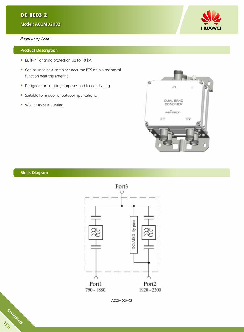
DC-0003-2
Model: ACOMD2H02
Product Description
Built-in lightning protection up to 10 kA. y
Can be used as a combiner near the BTS or in a reciprocal y
function near the antenna.
Designed for co-siting purposes and feeder sharing y
Suitable for indoor or outdoor applications. y
Wall or mast mounting. y
Block Diagram
ACOMD2H02
159
Combiners
Preliminary Issue

Electrical Properties
Model ACOMD2H02
Pass band (MHz) Band 1 790-1880
Band 2 1920-2200
Insertion loss* (dB) Port 1 ←→ Port 3
Typ. < 0.15 (790 MHz-960 MHz)
Typ. < 0.25 (1710 MHz-1880 MHz)
Port 2 ←→ Port 3 Typ. < 0.25 (1920 MHz-2200 MHz)
DC/AISG transparency Port 1 ←→ Port 3 Stop
Port 2 ←→ Port 3 By-pass (max. 2500 mA)
Isolation (dB) > 45
VSWR < 1.28
Input power (W) Port 1, Port 2 < 300
Intermodulation products (dBm) < -110 (3rd order; with 2 x 43 dBm)
Environmental Specification
Operating temperature () -40 … +65
Application scene Indoor // Outdoor
IP rating IP67
Lightning protection (kA) 10 (8/20 us)
Mechanical Specification
Connector 7/16 DIN Female (long neck)
Mounting Wall mounting // Mast mounting
Weight (kg) Double Unit: ≤ 6
Mast diameter (mm) 40-135
Dimensions (W x H x D) (mm) Double Unit: 190 x 154 x 105
(without connectors, without mounting brackets)
DC-0003-2
Model: ACOMD2H02
160Co
mbi
ners
Preliminary Issue
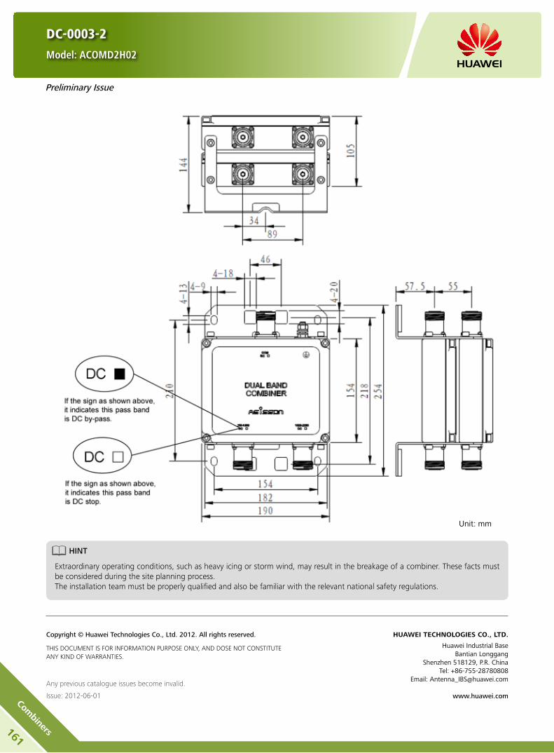
DC-0003-2
Model: ACOMD2H02
Unit: mm
HINT
Extraordinary operating conditions, such as heavy icing or storm wind, may result in the breakage of a combiner. These facts must be considered during the site planning process. The installation team must be properly qualified and also be familiar with the relevant national safety regulations.
Any previous catalogue issues become invalid.
Issue: 2012-06-01
HUAWEI TECHNOLOGIES CO., LTD.
Huawei Industrial BaseBantian Longgang
Shenzhen 518129, P.R. ChinaTel: +86-755-28780808
Email: [email protected]
www.huawei.com
Copyright © Huawei Technologies Co., Ltd. 2012. All rights reserved.
THIS DOCUMENT IS FOR INFORMATION PURPOSE ONLY, AND DOSE NOT CONSTITUTE ANY KIND OF WARRANTIES.
161
Combiners
Preliminary Issue

DC-0013-2
Model: ACOMD2H04
Product Description
Built-in lightning protection up to 10 kA. y
Can be used as a combiner near the BTS or in a reciprocal y
function near the antenna.
Designed for co-siting purposes and feeder sharing y
Suitable for indoor or outdoor applications. y
Wall or mast mounting. y
Block Diagram
ACOMD2H04
162Co
mbi
ners

Electrical Properties
Model ACOMD2H04
Pass band (MHz) Band 1 790-862
Band 2 880-960
Insertion loss* (dB) Port 1 ←→ Port 3 Typ. < 0.3 (790 MHz-862 MHz)
Port 2 ←→ Port 3 Typ. < 0.25 (880 MHz-960 MHz)
DC/AISG transparency Port 1 ←→ Port 3 Stop
Port 2 ←→ Port 3 By-pass (max. 2500 mA)
Isolation (dB) > 50
VSWR < 1.28
Input power (W) Port 1, Port 2 < 200
Intermodulation products (dBm) < -117 (3rd order; with 2 x 43 dBm)
Environmental Specification
Operating temperature () -40 … +65
Application scene Indoor // outdoor
IP rating IP67
Lightning protection (kA) 10 (8/20 us)
Mechanical Specification
Combiner dimensions (W x H x D) (mm)Double Unit: 180 x 210 x 107
(without connectors, without mounting brackets)
Packing dimensions (W x H x D) (mm) 260 x 365 x 210
Combiner weight (kg) Double Unit: ≤ 6.8
Packing weight (kg) ≤ 7.8
Mounting Wall mounting // Mast mounting
Mast diameter (mm) Default: 40-135
Connector 7/16 DIN Female (Long neck)
DC-0013-2
Model: ACOMD2H04
163
Combiners

DC-0013-2
Model: ACOMD2H04
HINT
Extraordinary operating conditions, such as heavy icing or storm wind, may result in the breakage of a combiner. These facts must be considered during the site planning process. The installation team must be properly qualified and also be familiar with the relevant national safety regulations.
Unit: mm
Any previous catalogue issues become invalid.
Issue: 2012-06-01
HUAWEI TECHNOLOGIES CO., LTD.
Huawei Industrial BaseBantian Longgang
Shenzhen 518129, P.R. ChinaTel: +86-755-28780808
Email: [email protected]
www.huawei.com
Copyright © Huawei Technologies Co., Ltd. 2012. All rights reserved.
THIS DOCUMENT IS FOR INFORMATION PURPOSE ONLY, AND DOSE NOT CONSTITUTE ANY KIND OF WARRANTIES.
164Co
mbi
ners

DC-0012-2 Model: ACOMD2H05
DC-0021-2 Model: ACOMD2H07
Product Description
Built-in lightning protection up to 10 kA. y
Can be used as a combiner near the BTS or in a reciprocal y
function near the antenna.
Designed for co-siting purposes and feeder sharing y
Suitable for indoor or outdoor applications. y
Wall or mast mounting. y
Block Diagram
ACOMD2H05 ACOMD2H07
165
Combiners

Electrical Properties
Model ACOMD2H05 ACOMD2H07
Pass band (MHz) Band 1 1710-1880
Band 2 1920-2200
Insertion loss* (dB) Port 1 ←→ Port 3 Typ. < 0.25 (1710 MHz-1880 MHz)
Port 2 ←→ Port 3 Typ. < 0.25 (1920 MHz-2200 MHz)
DC/AISG transparency Port 1 ←→ Port 3 Stop By-pass (max. 2500 mA)
Port 2 ←→ Port 3 By-pass (max. 2500 mA) By-pass (max. 2500 mA)
Isolation (dB) > 45
VSWR < 1.28
Input power (W) Port 1, Port 2 < 300
Intermodulation products (dBm) < -117 (3rd order; with 2 x 43 dBm)
Environmental Specification
Operating temperature () -40 … +65
Application scene Indoor // Outdoor
IP rating IP67
Lightning protection (kA) 10 (8/20 us)
Mechanical Specification
Combiner dimensions (W x H x D) (mm)Double Unit: 160 x 154 x 103
(without connectors, without mounting brackets)
Packing dimensions (W x H x D) (mm) 365 x 260 x 210
Combiner weight (kg) Double Unit: ≤ 4.8
Packing weight (kg) ≤ 5.7
Mounting Wall mounting // Mast mounting
Mast diameter (mm) Default: 40-135
Connector 7/16 DIN Female (Long neck)
DC-0012-2 Model: ACOMD2H05
DC-0021-2 Model: ACOMD2H07
166Co
mbi
ners
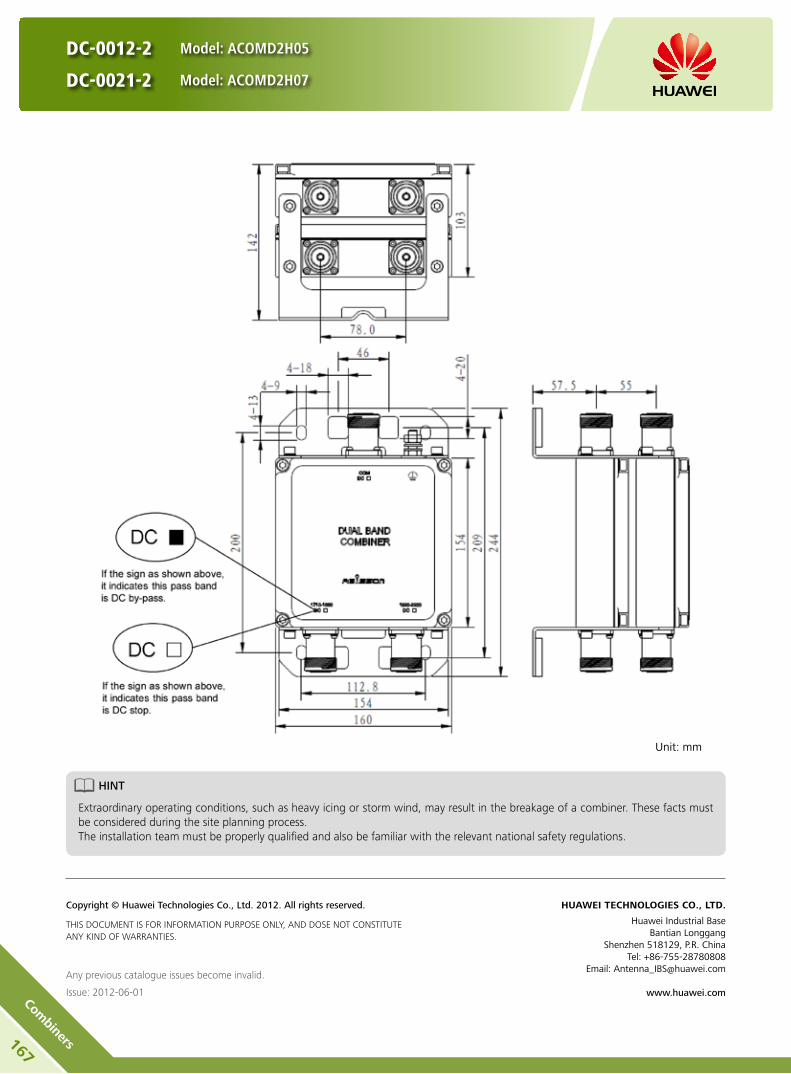
DC-0012-2 Model: ACOMD2H05
DC-0021-2 Model: ACOMD2H07
Unit: mm
HINT
Extraordinary operating conditions, such as heavy icing or storm wind, may result in the breakage of a combiner. These facts must be considered during the site planning process. The installation team must be properly qualified and also be familiar with the relevant national safety regulations.
Any previous catalogue issues become invalid.
Issue: 2012-06-01
HUAWEI TECHNOLOGIES CO., LTD.
Huawei Industrial BaseBantian Longgang
Shenzhen 518129, P.R. ChinaTel: +86-755-28780808
Email: [email protected]
www.huawei.com
Copyright © Huawei Technologies Co., Ltd. 2012. All rights reserved.
THIS DOCUMENT IS FOR INFORMATION PURPOSE ONLY, AND DOSE NOT CONSTITUTE ANY KIND OF WARRANTIES.
167
Combiners

DC-0026-2 Model: ACOMD2H06
DC-0022-2 Model: ACOMD2H08
Product Description
Built-in lightning protection up to 10 kA. y
Can be used as a combiner near the BTS or in a reciprocal y
function near the antenna.
Designed for co-siting purposes and feeder sharing y
Suitable for indoor or outdoor applications. y
Wall or mast mounting. y
Block Diagram
ACOMD2H06 ACOMD2H08
168Co
mbi
ners

DC-0026-2 Model: ACOMD2H06
DC-0022-2 Model: ACOMD2H08
Electrical Properties
Model ACOMD2H06 ACOMD2H08
Pass band (MHz) Band 1 1710-1880
Band 2 1920-2200
Insertion loss* (dB) Port 1 ←→ Port 3 Typ. < 0.25 (1710 MHz-1880 MHz)
Port 2 ←→ Port 3 Typ. < 0.25 (1920 MHz-2200 MHz)
DC/AISG transparency Port 1 ←→ Port 3 Stop By-pass (max. 2500 mA)
Port 2 ←→ Port 3 By-pass (max. 2500 mA) By-pass (max. 2500 mA)
Isolation (dB) > 45
VSWR < 1.28
Input power (W) Port 1, Port 2 < 300
Intermodulation products (dBm) < -110 (3rd order; with 2 x 43 dBm)
Environmental Specification
Operating temperature () -40 … +65
Application scene Indoor // Outdoor
IP rating IP67
Lightning protection (kA) 10 (8/20 us)
Mechanical Specification
Combiner dimensions (W x H x D) (mm)Double Unit: 160 x 154 x 103
(without connectors, without mounting brackets)
Packing dimensions (W x H x D) (mm) 365 x 260 x 210
Combiner weight (kg) Double Unit: ≤ 4.8
Packing weight (kg) ≤ 5.7
Mounting Wall mounting // Mast mounting
Mast diameter (mm) Default: 40-135
Connector 7/16 DIN Female (Long neck)
169
Combiners
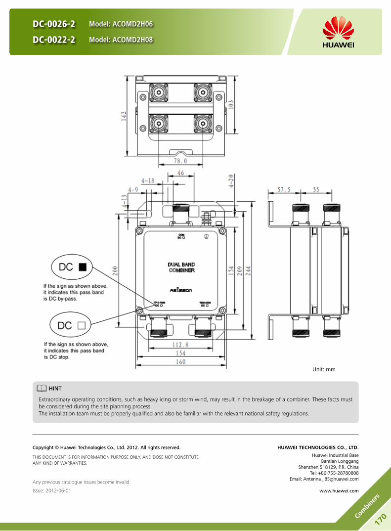
DC-0026-2 Model: ACOMD2H06
DC-0022-2 Model: ACOMD2H08
HINT
Extraordinary operating conditions, such as heavy icing or storm wind, may result in the breakage of a combiner. These facts must be considered during the site planning process. The installation team must be properly qualified and also be familiar with the relevant national safety regulations.
Unit: mm
Any previous catalogue issues become invalid.
Issue: 2012-06-01
HUAWEI TECHNOLOGIES CO., LTD.
Huawei Industrial BaseBantian Longgang
Shenzhen 518129, P.R. ChinaTel: +86-755-28780808
Email: [email protected]
www.huawei.com
Copyright © Huawei Technologies Co., Ltd. 2012. All rights reserved.
THIS DOCUMENT IS FOR INFORMATION PURPOSE ONLY, AND DOSE NOT CONSTITUTE ANY KIND OF WARRANTIES.
170Co
mbi
ners

Product Description
Built-in lightning protection up to 10 kA. y
Can be used as a combiner near the BTS or in a reciprocal y
function near the antenna.
Designed for co-siting purposes and feeder sharing y
Suitable for indoor or outdoor applications. y
Wall or mast mounting. y
Block Diagram
ACOMD2H09
DC-0023-2
Model: ACOMD2H09
171
Combiners

DC-0023-2
Model: ACOMD2H09
Electrical Properties
Model ACOMD2H09
Pass band (MHz) Band 1 790-862
Band 2 880-960
Insertion loss* (dB) Port 1 ←→ Port 3 Typ. < 0.3 (790 MHz-862 MHz)
Port 2 ←→ Port 3 Typ. < 0.25 (880 MHz-960 MHz)
DC/AISG transparency Port 1 ←→ Port 3 Stop
Port 2 ←→ Port 3 By-pass (max. 2500 mA)
Isolation (dB) > 50
VSWR < 1.28
Input power (W) Port 1, Port 2 < 200
Intermodulation products (dBm) < -110 (3rd order; with 2 x 43 dBm)
Environmental Specification
Operating temperature () -40 … +65
Application scene Indoor // Outdoor
IP rating IP67
Lightning protection (kA) 10 (8/20 us)
Mechanical Specification
Combiner dimensions (W x H x D) (mm)Double Unit: 180 x 210 x 107
(without connectors, without mounting brackets)
Packing dimensions (W x H x D) (mm) 260 x 365 x 210
Combiner weight (kg) Double Unit: ≤ 6.8
Packing weight (kg) ≤ 7.8
Mounting Wall mounting // Mast mounting
Mast diameter (mm) Default: 40-135
Connector 7/16 DIN Female (Long neck)
172Co
mbi
ners

DC-0023-2
Model: ACOMD2H09
Unit: mm
HINT
Extraordinary operating conditions, such as heavy icing or storm wind, may result in the breakage of a combiner. These facts must be considered during the site planning process. The installation team must be properly qualified and also be familiar with the relevant national safety regulations.
Any previous catalogue issues become invalid.
Issue: 2012-06-01
HUAWEI TECHNOLOGIES CO., LTD.
Huawei Industrial BaseBantian Longgang
Shenzhen 518129, P.R. ChinaTel: +86-755-28780808
Email: [email protected]
www.huawei.com
Copyright © Huawei Technologies Co., Ltd. 2012. All rights reserved.
THIS DOCUMENT IS FOR INFORMATION PURPOSE ONLY, AND DOSE NOT CONSTITUTE ANY KIND OF WARRANTIES.
173
Combiners

DC-0017-2
Model: ACOMD2H10
Product Description
Built-in lightning protection up to 10 kA. y
Can be used as a combiner near the BTS or in a reciprocal y
function near the antenna.
Designed for co-siting purposes and feeder sharing y
Suitable for indoor or outdoor applications. y
Wall or mast mounting. y
Block Diagram
ACOMD2H10
174Co
mbi
ners

DC-0017-2
Model: ACOMD2H10
Electrical Properties
Model ACOMD2H10
Pass band (MHz) Band 1 698-960
Band 2 1710-2200
Insertion loss* (dB) Port 1 ←→ Port 3 Typ. < 0.15 (698 MHz-960 MHz)
Port 2 ←→ Port 3 Typ. < 0.15 (1710 MHz-2200 MHz)
DC/AISG transparency Port 1 ←→ Port 3 Stop
Port 2 ←→ Port 3 By-pass (max. 2500 mA)
Isolation (dB) > 40
VSWR < 1.28
Input power (W) Port 1, Port 2 < 300
Intermodulation products (dBm) < -117 (3rd order; with 2 x 43 dBm)
Environmental Specification
Operating temperature () -40 … +65
Application scene Indoor // Outdoor
IP rating IP67
Lightning protection (kA) 10 (8/20 us)
Mechanical Specification
Combiner dimensions (W x H x D) (mm)Double Unit: 130 x 190 x 105
(without connectors, without mounting brackets)
Packing dimensions (W x H x D) (mm) 265 x 415 x 245
Combiner weight (kg) Double Unit: ≤ 4.3
Packing weight (kg) ≤ 5.4
Mounting Wall mounting // Mast mounting
Mast diameter (mm) Default: 40-135
Connector 7/16 DIN Female (Long neck)
175
Combiners

DC-0017-2
Model: ACOMD2H10
HINT
Extraordinary operating conditions, such as heavy icing or storm wind, may result in the breakage of a combiner. These facts must be considered during the site planning process. The installation team must be properly qualified and also be familiar with the relevant national safety regulations.
Unit: mm
Any previous catalogue issues become invalid.
Issue: 2012-06-01
HUAWEI TECHNOLOGIES CO., LTD.
Huawei Industrial BaseBantian Longgang
Shenzhen 518129, P.R. ChinaTel: +86-755-28780808
Email: [email protected]
www.huawei.com
Copyright © Huawei Technologies Co., Ltd. 2012. All rights reserved.
THIS DOCUMENT IS FOR INFORMATION PURPOSE ONLY, AND DOSE NOT CONSTITUTE ANY KIND OF WARRANTIES.
176Co
mbi
ners

Product Description
Built-in lightning protection up to 10 kA. y
Can be used as a combiner near the BTS or in a reciprocal y
function near the antenna.
Designed for co-siting purposes and feeder sharing y
Suitable for indoor or outdoor applications. y
Wall or mast mounting. y
Block Diagram
ACOMD2H11
DC-0019-2
Model: ACOMD2H11
177
Combiners

Electrical Properties
Model ACOMD2H11
Pass band (MHz) Band 1 698-960
Band 2 1710-2200
Insertion loss* (dB) Port 1 ←→ Port 3 Typ. < 0.15 (698 MHz-960 MHz)
Port 2 ←→ Port 3 Typ. < 0.15 (1710 MHz-2200 MHz)
DC/AISG transparency Port 1 ←→ Port 3 Stop
Port 2 ←→ Port 3 By-pass (max. 2500 mA)
Isolation (dB) > 40
VSWR < 1.28
Input power (W) Port 1, Port 2 < 300
Intermodulation products (dBm) < -110 (3rd order; with 2 x 43 dBm)
Environmental Specification
Operating temperature () -40 … +65
Application scene Indoor // Outdoor
IP rating IP67
Lightning protection (kA) 10 (8/20 us)
Mechanical Specification
Combiner dimensions (W x H x D) (mm)Double Unit: 130 x 190 x 105
(without connectors, without mounting brackets)
Packing dimensions (W x H x D) (mm) 265 x 415 x 245
Combiner weight (kg) Double Unit: ≤ 4.3
Packing weight (kg) ≤ 5.4
Mounting Wall mounting // Mast mounting
Mast diameter (mm) Default: 40-135
Connector 7/16 DIN Female (Long neck)
DC-0019-2
Model: ACOMD2H11
178Co
mbi
ners

DC-0019-2
Model: ACOMD2H11
Unit: mm
HINT
Extraordinary operating conditions, such as heavy icing or storm wind, may result in the breakage of a combiner. These facts must be considered during the site planning process. The installation team must be properly qualified and also be familiar with the relevant national safety regulations.
Any previous catalogue issues become invalid.
Issue: 2012-06-01
HUAWEI TECHNOLOGIES CO., LTD.
Huawei Industrial BaseBantian Longgang
Shenzhen 518129, P.R. ChinaTel: +86-755-28780808
Email: [email protected]
www.huawei.com
Copyright © Huawei Technologies Co., Ltd. 2012. All rights reserved.
THIS DOCUMENT IS FOR INFORMATION PURPOSE ONLY, AND DOSE NOT CONSTITUTE ANY KIND OF WARRANTIES.
179
Combiners

DC-0018-2
Model: ACOMD2H12
Product Description
Built-in lightning protection up to 10 kA. y
Can be used as a combiner near the BTS or in a reciprocal y
function near the antenna.
Designed for co-siting purposes and feeder sharing y
Suitable for indoor or outdoor applications. y
Wall or mast mounting. y
Block Diagram
ACOMD2H12
180Co
mbi
ners
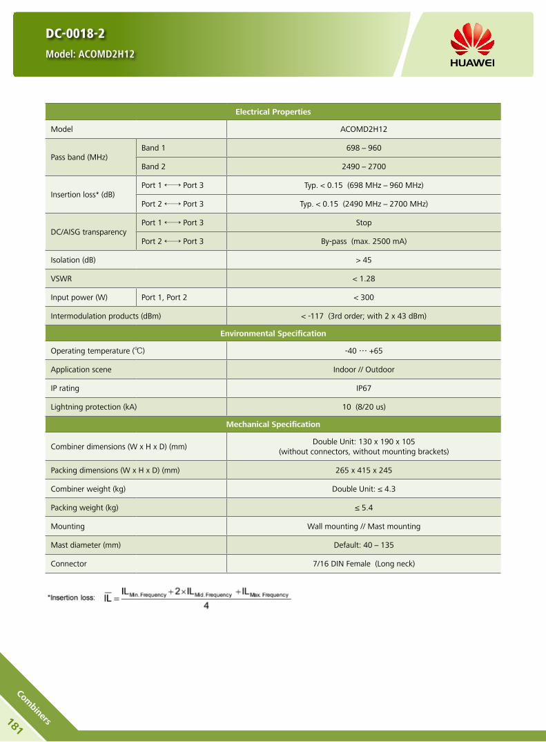
DC-0018-2
Model: ACOMD2H12
Electrical Properties
Model ACOMD2H12
Pass band (MHz) Band 1 698-960
Band 2 2490-2700
Insertion loss* (dB) Port 1 ←→ Port 3 Typ. < 0.15 (698 MHz-960 MHz)
Port 2 ←→ Port 3 Typ. < 0.15 (2490 MHz-2700 MHz)
DC/AISG transparency Port 1 ←→ Port 3 Stop
Port 2 ←→ Port 3 By-pass (max. 2500 mA)
Isolation (dB) > 45
VSWR < 1.28
Input power (W) Port 1, Port 2 < 300
Intermodulation products (dBm) < -117 (3rd order; with 2 x 43 dBm)
Environmental Specification
Operating temperature () -40 … +65
Application scene Indoor // Outdoor
IP rating IP67
Lightning protection (kA) 10 (8/20 us)
Mechanical Specification
Combiner dimensions (W x H x D) (mm)Double Unit: 130 x 190 x 105
(without connectors, without mounting brackets)
Packing dimensions (W x H x D) (mm) 265 x 415 x 245
Combiner weight (kg) Double Unit: ≤ 4.3
Packing weight (kg) ≤ 5.4
Mounting Wall mounting // Mast mounting
Mast diameter (mm) Default: 40-135
Connector 7/16 DIN Female (Long neck)
181
Combiners

DC-0018-2
Model: ACOMD2H12
HINT
Extraordinary operating conditions, such as heavy icing or storm wind, may result in the breakage of a combiner. These facts must be considered during the site planning process. The installation team must be properly qualified and also be familiar with the relevant national safety regulations.
Unit: mm
Any previous catalogue issues become invalid.
Issue: 2012-06-01
HUAWEI TECHNOLOGIES CO., LTD.
Huawei Industrial BaseBantian Longgang
Shenzhen 518129, P.R. ChinaTel: +86-755-28780808
Email: [email protected]
www.huawei.com
Copyright © Huawei Technologies Co., Ltd. 2012. All rights reserved.
THIS DOCUMENT IS FOR INFORMATION PURPOSE ONLY, AND DOSE NOT CONSTITUTE ANY KIND OF WARRANTIES.
182Co
mbi
ners

Product Description
Built-in lightning protection up to 10 kA. y
Can be used as a combiner near the BTS or in a reciprocal y
function near the antenna.
Designed for co-siting purposes and feeder sharing y
Suitable for indoor or outdoor applications. y
Wall or mast mounting. y
Block Diagram
ACOMD2H13
DC-0020-2
Model: ACOMD2H13
183
Combiners

Electrical Properties
Model ACOMD2H12
Pass band (MHz) Band 1 698-960
Band 2 2490-2700
Insertion loss* (dB) Port 1 ←→ Port 3 Typ. < 0.15 (698 MHz-960 MHz)
Port 2 ←→ Port 3 Typ. < 0.15 (2490 MHz-2700 MHz)
DC/AISG transparency Port 1 ←→ Port 3 Stop
Port 2 ←→ Port 3 By-pass (max. 2500 mA)
Isolation (dB) > 45
VSWR < 1.28
Input power (W) Port 1, Port 2 < 300
Intermodulation products (dBm) < -110 (3rd order; with 2 x 43 dBm)
Environmental Specification
Operating temperature () -40 … +65
Application scene Indoor // Outdoor
IP rating IP67
Lightning protection (kA) 10 (8/20 us)
Mechanical Specification
Combiner dimensions (W x H x D) (mm)Double Unit: 130 x 190 x 105
(without connectors, without mounting brackets)
Packing dimensions (W x H x D) (mm) 265 x 415 x 245
Combiner weight (kg) Double Unit: ≤ 4.3
Packing weight (kg) ≤ 5.4
Mounting Wall mounting // Mast mounting
Mast diameter (mm) Default: 40-135
Connector 7/16 DIN Female (Long neck)
DC-0020-2
Model: ACOMD2H13
184Co
mbi
ners

DC-0020-2
Model: ACOMD2H13
Unit: mm
HINT
Extraordinary operating conditions, such as heavy icing or storm wind, may result in the breakage of a combiner. These facts must be considered during the site planning process. The installation team must be properly qualified and also be familiar with the relevant national safety regulations.
Any previous catalogue issues become invalid.
Issue: 2012-06-01
HUAWEI TECHNOLOGIES CO., LTD.
Huawei Industrial BaseBantian Longgang
Shenzhen 518129, P.R. ChinaTel: +86-755-28780808
Email: [email protected]
www.huawei.com
Copyright © Huawei Technologies Co., Ltd. 2012. All rights reserved.
THIS DOCUMENT IS FOR INFORMATION PURPOSE ONLY, AND DOSE NOT CONSTITUTE ANY KIND OF WARRANTIES.
185
Combiners

DC-0006-2
Model: ACOMD2L03
Product Description
Built-in lightning protection up to 10 kA. y
Can be used as a combiner near the BTS or in a reciprocal y
function near the antenna.
Designed for co-siting purposes and feeder sharing y
Suitable for indoor or outdoor applications. y
Wall or mast mounting. y
Block Diagram
ACOMD2L03
186Co
mbi
ners

DC-0006-2
Model: ACOMD2L03
Electrical Properties
Model ACOMD2L03
Pass band (MHz) Band 1 1710-2200
Band 2 2490-2700
Insertion loss* (dB) Port 1 ←→ Port 3 Typ. < 0.15 (1710 MHz-2200 MHz)
Port 2 ←→ Port 3 Typ. < 0.15 (2490 MHz-2700 MHz)
DC/AISG transparency Port 1 ←→ Port 3 By-pass (max. 2500 mA)
Port 2 ←→ Port 3 Stop
Isolation (dB) > 45
VSWR < 1.28
Input power (W) Port 1, Port 2 < 300
Intermodulation products (dBm) < -117 (3rd order; with 2 x 43 dBm)
Environmental Specification
Operating temperature () -40 … +65
Application scene Indoor // Outdoor
IP rating IP67
Lightning protection (kA) 10 (8/20 us)
Mechanical Specification
Combiner dimensions (W x H x D) (mm)Double Unit: 126 x 102 x 103
(without connectors, without mounting brackets)
Packing dimensions (W x H x D) (mm) 365 x 260 x 210
Combiner weight (kg) Double Unit: ≤ 3.2
Packing weight (kg) ≤ 4.2
Mounting Wall mounting // Mast mounting
Mast diameter (mm) Default: 40-135
Connector 7/16 DIN Female (Long neck)
187
Combiners

DC-0006-2
Model: ACOMD2L03
HINT
Extraordinary operating conditions, such as heavy icing or storm wind, may result in the breakage of a combiner. These facts must be considered during the site planning process. The installation team must be properly qualified and also be familiar with the relevant national safety regulations.
Unit: mm
Any previous catalogue issues become invalid.
Issue: 2012-06-01
HUAWEI TECHNOLOGIES CO., LTD.
Huawei Industrial BaseBantian Longgang
Shenzhen 518129, P.R. ChinaTel: +86-755-28780808
Email: [email protected]
www.huawei.com
Copyright © Huawei Technologies Co., Ltd. 2012. All rights reserved.
THIS DOCUMENT IS FOR INFORMATION PURPOSE ONLY, AND DOSE NOT CONSTITUTE ANY KIND OF WARRANTIES.
188Co
mbi
ners

Product Description
Built-in lightning protection up to 10 kA. y
Can be used as a combiner near the BTS or in a reciprocal y
function near the antenna.
Designed for co-siting purposes and feeder sharing y
Suitable for indoor or outdoor applications. y
Wall or mast mounting. y
Block Diagram
ACOMD2L04
DC-0024-2
Model: ACOMD2L04
189
Combiners
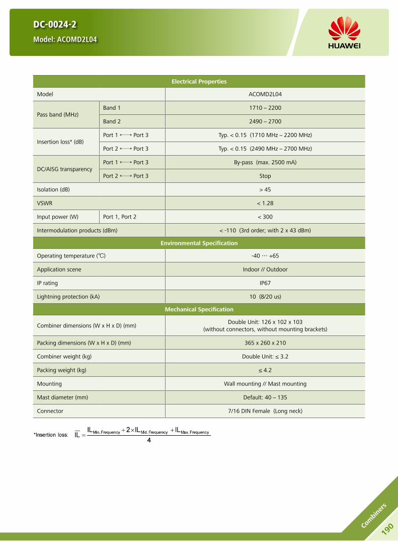
Electrical Properties
Model ACOMD2L04
Pass band (MHz) Band 1 1710-2200
Band 2 2490-2700
Insertion loss* (dB) Port 1 ←→ Port 3 Typ. < 0.15 (1710 MHz-2200 MHz)
Port 2 ←→ Port 3 Typ. < 0.15 (2490 MHz-2700 MHz)
DC/AISG transparency Port 1 ←→ Port 3 By-pass (max. 2500 mA)
Port 2 ←→ Port 3 Stop
Isolation (dB) > 45
VSWR < 1.28
Input power (W) Port 1, Port 2 < 300
Intermodulation products (dBm) < -110 (3rd order; with 2 x 43 dBm)
Environmental Specification
Operating temperature () -40 … +65
Application scene Indoor // Outdoor
IP rating IP67
Lightning protection (kA) 10 (8/20 us)
Mechanical Specification
Combiner dimensions (W x H x D) (mm)Double Unit: 126 x 102 x 103
(without connectors, without mounting brackets)
Packing dimensions (W x H x D) (mm) 365 x 260 x 210
Combiner weight (kg) Double Unit: ≤ 3.2
Packing weight (kg) ≤ 4.2
Mounting Wall mounting // Mast mounting
Mast diameter (mm) Default: 40-135
Connector 7/16 DIN Female (Long neck)
DC-0024-2
Model: ACOMD2L04
190Co
mbi
ners

DC-0024-2
Model: ACOMD2L04
Unit: mm
HINT
Extraordinary operating conditions, such as heavy icing or storm wind, may result in the breakage of a combiner. These facts must be considered during the site planning process. The installation team must be properly qualified and also be familiar with the relevant national safety regulations.
Any previous catalogue issues become invalid.
Issue: 2012-06-01
HUAWEI TECHNOLOGIES CO., LTD.
Huawei Industrial BaseBantian Longgang
Shenzhen 518129, P.R. ChinaTel: +86-755-28780808
Email: [email protected]
www.huawei.com
Copyright © Huawei Technologies Co., Ltd. 2012. All rights reserved.
THIS DOCUMENT IS FOR INFORMATION PURPOSE ONLY, AND DOSE NOT CONSTITUTE ANY KIND OF WARRANTIES.
191
Combiners
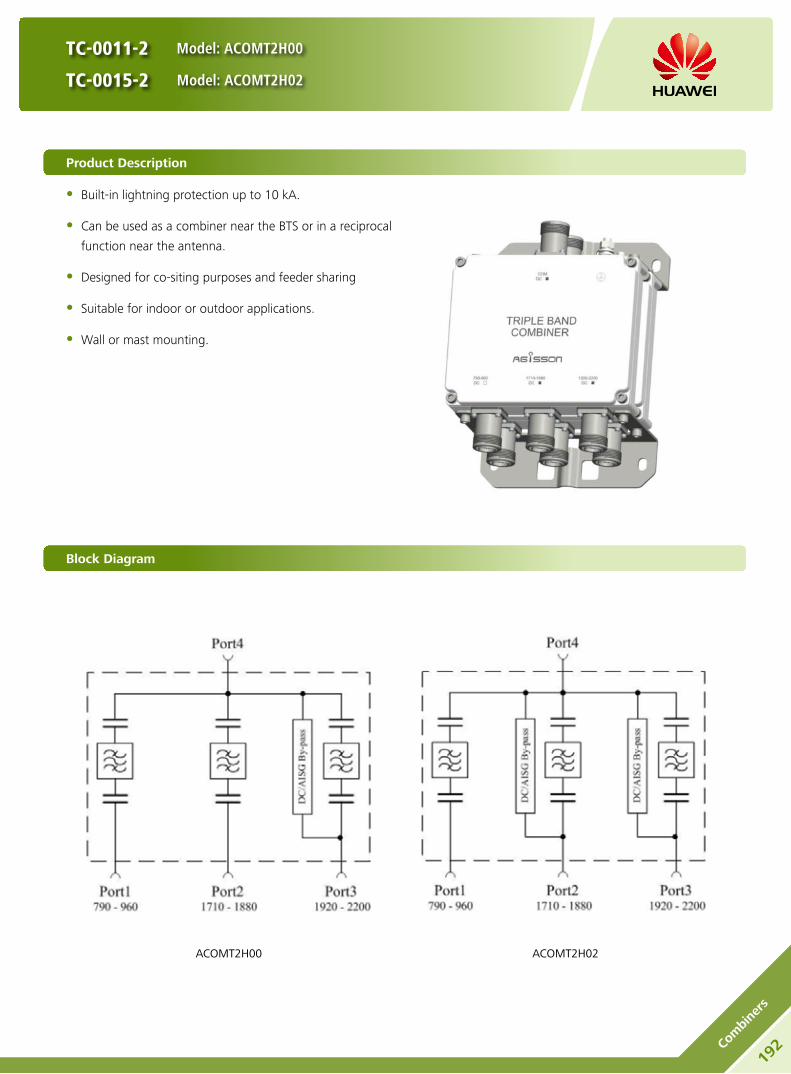
Product Description
Built-in lightning protection up to 10 kA. y
Can be used as a combiner near the BTS or in a reciprocal y
function near the antenna.
Designed for co-siting purposes and feeder sharing y
Suitable for indoor or outdoor applications. y
Wall or mast mounting. y
Block Diagram
ACOMT2H00 ACOMT2H02
TC-0011-2 Model: ACOMT2H00
TC-0015-2 Model: ACOMT2H02
192Co
mbi
ners

TC-0011-2 Model: ACOMT2H00
TC-0015-2 Model: ACOMT2H02
Electrical Properties
Model ACOMT2H00 ACOMT2H02
Pass band (MHz)
Band 1 790-960
Band 2 1710-1880
Band 3 1920-2200
Insertion loss* (dB)
Port 1 ←→ Port 4 Typ. < 0.15 (790 MHz-960 MHz)
Port 2 ←→ Port 4 Typ. < 0.25 (1710 MHz-1880 MHz)
Port 3 ←→ Port 4 Typ. < 0.25 (1920 MHz-2200 MHz)
DC/AISG transparency
Port 1 ←→ Port 4 Stop Stop
Port 2 ←→ Port 4 Stop By-pass (max. 2500 mA)
Port 3 ←→ Port 4 By-pass (max. 2500 mA) By-pass (max. 2500 mA)
Isolation (dB) > 45
VSWR < 1.28
Input power (W) Port 1, Port 2, Port3 < 300
Intermodulation products (dBm) < -117 (3rd order; with 2 x 43 dBm)
Environmental Specification
Operating temperature () -40 … +65
Application scene Indoor // Outdoor
IP rating IP67
Lightning protection (kA) 10 (8/20 us)
Mechanical Specification
Combiner dimensions (W x H x D) (mm)Double Unit: 190 x 154 x 105
(without connectors, without mounting brackets)
Packing dimensions (W x H x D) (mm) 365 x 260 x 210
Combiner weight (kg) Double Unit: ≤ 6.3
Packing weight (kg) ≤ 7.3
Mounting Wall mounting // Mast mounting
Mast diameter (mm) Default: 40-135
Connector 7/16 DIN Female (Long neck)
193
Combiners

TC-0011-2 Model: ACOMT2H00
TC-0015-2 Model: ACOMT2H02
HINT
Extraordinary operating conditions, such as heavy icing or storm wind, may result in the breakage of a combiner. These facts must be considered during the site planning process. The installation team must be properly qualified and also be familiar with the relevant national safety regulations.
Unit: mm
Any previous catalogue issues become invalid.
Issue: 2012-06-01
HUAWEI TECHNOLOGIES CO., LTD.
Huawei Industrial BaseBantian Longgang
Shenzhen 518129, P.R. ChinaTel: +86-755-28780808
Email: [email protected]
www.huawei.com
Copyright © Huawei Technologies Co., Ltd. 2012. All rights reserved.
THIS DOCUMENT IS FOR INFORMATION PURPOSE ONLY, AND DOSE NOT CONSTITUTE ANY KIND OF WARRANTIES.
194Co
mbi
ners

TC-0025-2 Model: ACOMT2H01
TC-0016-2 Model: ACOMT2H03
Product Description
Built-in lightning protection up to 10 kA. y
Can be used as a combiner near the BTS or in a reciprocal y
function near the antenna.
Designed for co-siting purposes and feeder sharing y
Suitable for indoor or outdoor applications. y
Wall or mast mounting. y
Block Diagram
ACOMT2H01 ACOMT2H03
195
Combiners
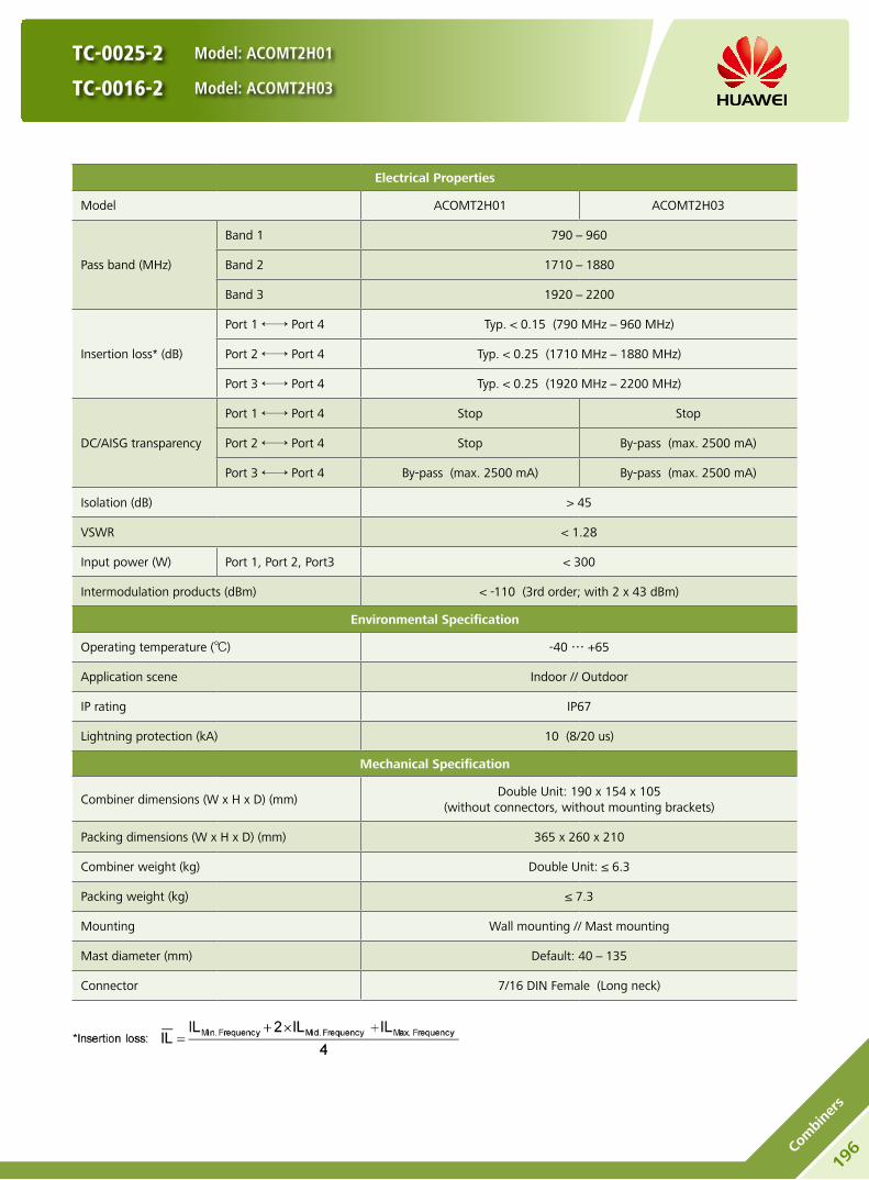
TC-0025-2 Model: ACOMT2H01
TC-0016-2 Model: ACOMT2H03
Electrical Properties
Model ACOMT2H01 ACOMT2H03
Pass band (MHz)
Band 1 790-960
Band 2 1710-1880
Band 3 1920-2200
Insertion loss* (dB)
Port 1 ←→ Port 4 Typ. < 0.15 (790 MHz-960 MHz)
Port 2 ←→ Port 4 Typ. < 0.25 (1710 MHz-1880 MHz)
Port 3 ←→ Port 4 Typ. < 0.25 (1920 MHz-2200 MHz)
DC/AISG transparency
Port 1 ←→ Port 4 Stop Stop
Port 2 ←→ Port 4 Stop By-pass (max. 2500 mA)
Port 3 ←→ Port 4 By-pass (max. 2500 mA) By-pass (max. 2500 mA)
Isolation (dB) > 45
VSWR < 1.28
Input power (W) Port 1, Port 2, Port3 < 300
Intermodulation products (dBm) < -110 (3rd order; with 2 x 43 dBm)
Environmental Specification
Operating temperature () -40 … +65
Application scene Indoor // Outdoor
IP rating IP67
Lightning protection (kA) 10 (8/20 us)
Mechanical Specification
Combiner dimensions (W x H x D) (mm)Double Unit: 190 x 154 x 105
(without connectors, without mounting brackets)
Packing dimensions (W x H x D) (mm) 365 x 260 x 210
Combiner weight (kg) Double Unit: ≤ 6.3
Packing weight (kg) ≤ 7.3
Mounting Wall mounting // Mast mounting
Mast diameter (mm) Default: 40-135
Connector 7/16 DIN Female (Long neck)
196Co
mbi
ners

TC-0025-2 Model: ACOMT2H01
TC-0016-2 Model: ACOMT2H03
Unit: mm
HINT
Extraordinary operating conditions, such as heavy icing or storm wind, may result in the breakage of a combiner. These facts must be considered during the site planning process. The installation team must be properly qualified and also be familiar with the relevant national safety regulations.
Any previous catalogue issues become invalid.
Issue: 2012-06-01
HUAWEI TECHNOLOGIES CO., LTD.
Huawei Industrial BaseBantian Longgang
Shenzhen 518129, P.R. ChinaTel: +86-755-28780808
Email: [email protected]
www.huawei.com
Copyright © Huawei Technologies Co., Ltd. 2012. All rights reserved.
THIS DOCUMENT IS FOR INFORMATION PURPOSE ONLY, AND DOSE NOT CONSTITUTE ANY KIND OF WARRANTIES.
197
Combiners

Product Description
Built-in lightning protection up to 10 kA. y
Can be used as a combiner near the BTS or in a reciprocal y
function near the antenna.
Designed for co-siting purposes and feeder sharing y
Suitable for indoor or outdoor applications. y
Wall or mast mounting. y
Block Diagram
ACOMT2M00
TC-0009-2
Model: ACOMT2M00
198Co
mbi
ners
Preliminary Issue

TC-0009-2
Model: ACOMT2M00
Electrical Properties
Model ACOMT2M00
Pass band (MHz)
Band 1 790-1880
Band 2 1920-2200
Band 3 2490-2700
Insertion loss* (dB)
Port 1 ←→ Port 4 Typ. < 0.15 (790 MHz-960 MHz)
Typ. < 0.25 (1710 MHz-1880 MHz)
Port 2 ←→ Port 4 Typ. < 0.25 (1920 MHz-2200 MHz)
Port 3 ←→ Port 4 Typ. < 0.2 (2490 MHz-2700 MHz)
DC/AISG transparency
Port 1 ←→ Port 4 Stop
Port 2 ←→ Port 4 By-pass (max. 2500 mA)
Port 3 ←→ Port 4 Stop
Isolation (dB) > 45
VSWR < 1.28
Input power (W) Port 1, Port 2, Port3 < 300
Intermodulation products (dBm) < -110 (3rd order; with 2 x 43 dBm)
Environmental Specification
Operating temperature () -40 … +65
Application scene Indoor // Outdoor
IP rating IP67
Lightning protection (kA) 10 (8/20 us)
Mechanical Specification
Connector 7/16 DIN Female (long neck)
Mounting Wall mounting // Mast mounting
Weight (kg) Double Unit: ≤ 7
Mast diameter (mm) 40-135
Dimensions (W x H x D) (mm) Double Unit: 215 x 200 x 105
(without connectors, without mounting brackets)
199
Combiners
Preliminary Issue

TC-0009-2
Model: ACOMT2M00
HINT
Extraordinary operating conditions, such as heavy icing or storm wind, may result in the breakage of a combiner. These facts must be considered during the site planning process. The installation team must be properly qualified and also be familiar with the relevant national safety regulations.
Unit: mm
Any previous catalogue issues become invalid.
Issue: 2012-06-01
HUAWEI TECHNOLOGIES CO., LTD.
Huawei Industrial BaseBantian Longgang
Shenzhen 518129, P.R. ChinaTel: +86-755-28780808
Email: [email protected]
www.huawei.com
Copyright © Huawei Technologies Co., Ltd. 2012. All rights reserved.
THIS DOCUMENT IS FOR INFORMATION PURPOSE ONLY, AND DOSE NOT CONSTITUTE ANY KIND OF WARRANTIES.
200Co
mbi
ners
Preliminary Issue

QC-0007-2
Model: ACOMQ2M00
Product Description
Built-in lightning protection up to 10 kA. y
Can be used as a combiner near the BTS or in a reciprocal y
function near the antenna.
Designed for co-siting purposes and feeder sharing y
Suitable for indoor or outdoor applications. y
Wall or mast mounting. y
Block Diagram
ACOMQ2M00
201
Combiners
Preliminary Issue

QC-0007-2
Model: ACOMQ2M00
Electrical Properties
Model ACOMQ2M00
Pass band (MHz)
Band 1 790-960
Band 2 1710-1880
Band 3 1920-2200
Band 4 2490-2700
Insertion loss* (dB)
Port 1 ←→ Port 5 Typ. < 0.15 (790 MHz-960 MHz)
Port 2 ←→ Port 5 Typ. < 0.25 (1710 MHz-1880 MHz)
Port 3 ←→ Port 5 Typ. < 0.25 (1920 MHz-2200 MHz)
Port 4 ←→ Port 5 Typ. < 0.2 (2490 MHz-2700 MHz)
DC/AISG transparency
Port 1 ←→ Port 5 Stop
Port 2 ←→ Port 5 Stop
Port 3 ←→ Port 5 By- pass (max. 2500 mA)
Port 4 ←→ Port 5 stop
Isolation (dB) > 45
VSWR < 1.28
Input power (W) Port 1, Port 2 Port 3, Port 4
< 300
Intermodulation products (dBm) < -110 (3rd order; with 2 x 43 dBm)
Environmental Specification
Operating temperature () -40 … +65
Application scene Indoor // Outdoor
IP rating IP67
Lightning protection (kA) 10 (8/20 us)
Mechanical Specification
Connector 7/16 DIN Female (long neck)
Mounting Wall mounting // Mast mounting
Weight (kg) Double Unit: ≤ 7.5
Mast diameter (mm) 40-135
Dimensions (W x H x D) (mm) Double Unit: 215 x 200 x 105
(without connectors, without mounting brackets)
202Co
mbi
ners
Preliminary Issue

QC-0007-2
Model: ACOMQ2M00
Unit: mm
HINT
Extraordinary operating conditions, such as heavy icing or storm wind, may result in the breakage of a combiner. These facts must be considered during the site planning process. The installation team must be properly qualified and also be familiar with the relevant national safety regulations.
Any previous catalogue issues become invalid.
Issue: 2012-06-01
HUAWEI TECHNOLOGIES CO., LTD.
Huawei Industrial BaseBantian Longgang
Shenzhen 518129, P.R. ChinaTel: +86-755-28780808
Email: [email protected]
www.huawei.com
Copyright © Huawei Technologies Co., Ltd. 2012. All rights reserved.
THIS DOCUMENT IS FOR INFORMATION PURPOSE ONLY, AND DOSE NOT CONSTITUTE ANY KIND OF WARRANTIES.
203
Combiners
Preliminary Issue

Accessories for RET SystemsC

Antenna ModelRCU
AISG 1.1 AISG 2.0
A90451701
ARCU01104 ARCU02001
A90451704
A19452101
A19451703
A25451803
A25451804
ADU451801 ARCU01101
ARCU02000
ADU451700ARCU01102
ARCU01103
ADU451806 ARCU01100
ADU451811 ARCU01103
ADU451815 ARCU01100
ADU451707 ARCU01103
ATR451703 ARCU01102
ATR451601 ARCU01100
A26451800
ARCU01109 ARCU02004
A26451900
ADU451816
ADU451901
A79451500v01
A79451600v01
A79451700v01
A19451505
A19451811
A19451902
A194518R0
ADU451819
ADU451902
ADU4518R1
ADU451503
ADU451602v01
ADU451807v01
Antenna ModelRCU
AISG 1.1 AISG 2.0
ADU4518R3
ARCU01109 ARCU02004
ADU4518R0
ADU4518C0
ATR451500
ATR451602v01
ATR451704v01
ATR4516R0
ATR4517R0
A264518S0
A90451702v01
A90451705v01
A90451709
A90451802v01
A90451805v01
A90451706
A19451601
A19451602
A19451800v01
A19451810v01
A19451802v01
A19451704
A19451705
A264518R0
ADU451604
ADU451712
ADU4516R0
ADU4517R0
ADU4518R6
ATR4518R2
ATR4518R4
ATR4518R3
AQU4518R0
Antenna and RCU configuration list
205
RCU

206
RCU
RCU Model: ARCU01100 (AISG 1.1) ARCU01101(AISG 1.1) ARCU01102 (AISG 1.1) ARCU01103 (AISG 1.1) ARCU02000 (AISG 2.0)
RCU (Remote Control Unit) drives the phase shifter in antenna through mechanical interface to change the electrical
downtilt. RCU is suitable for daisy chain solution.
HINT: Before the installation, check whether the RCU and base station support the same AISG protocol. If not, contact
the technical support personnel of Huawei.
Appearance Bottom view of RCU Male Female
Daisy chain in: Male
Daisy chain out: Female
Input voltage range (V) DC 10-30
Current (mA) < 600 (motor activated)
< 50 (stand by)
Adjustment time (full range) (min) < 2
Calibration time (min) < 4
Connectors 2 x 8 pin connector according to IEC 60130-9 Daisy chain in: Male / Daisy chain out: Female
Pin assignment according AISG 1 2 3 4 5 6 7 8
DC n/c RS-485B n/c RS-485A DC in/out DC return n/c
Housing material Profile: Aluminium coated / Cover: Aluminium coated
Color Grey
Weight (g) 650
Operating temperature range () -40 … +65
Protection class IP24
Dimensions (L x W x H) (mm) 205 x 65.5 x 56
Packing size (L x W x H) (mm) 268 x 105 x 95
Drainage Hole
Any previous catalogue issues become invalid.
Issue: 2012-06-01
HUAWEI TECHNOLOGIES CO., LTD.
Huawei Industrial BaseBantian Longgang
Shenzhen 518129, P.R. ChinaTel: +86-755-28780808
Email: [email protected]
www.huawei.com
Copyright © Huawei Technologies Co., Ltd. 2012. All rights reserved.
THIS DOCUMENT IS FOR INFORMATION PURPOSE ONLY, AND DOSE NOT CONSTITUTE ANY KIND OF WARRANTIES.

RCU Model: ARCU01104 (AISG 1.1) ARCU02001 (AISG 2.0)
RCU (Remote Control Unit) drives the phase shifter in antenna through mechanical interface to change the electrical
downtilt. RCU is suitable for daisy chain solution.
HINT: Before the installation, check whether the RCU and base station support the same AISG protocol. If not, contact
the technical support personnel of Huawei.
Appearance Bottom view of RCU Male Female
Daisy chain in: Male
Daisy chain out: Female
Input voltage range (V) DC 10-30
Current (mA) < 600 (motor activated)
< 50 (stand by)
Adjustment time (full range) (min) < 2
Calibration time (min) < 4
Connectors 2 x 8 pin connector according to IEC 60130-9 Daisy chain in: Male // Daisy chain out: Female
Pin assignment according AISG 1 2 3 4 5 6 7 8
DC n/c RS-485B n/c RS-485A DC in/out DC return n/c
Housing material Profile: Aluminium coated / Cover: Aluminium coated
Color Grey
Weight (g) 600
Operating temperature range () -40 … +65
Protection class IP24
Dimensions (L x W x H) (mm) 200 x 56 x 47
Packing size (L x W x H) (mm) 268 x 105 x 95
Drainage Hole
Drainage Hole
Any previous catalogue issues become invalid.
Issue: 2012-06-01
HUAWEI TECHNOLOGIES CO., LTD.
Huawei Industrial BaseBantian Longgang
Shenzhen 518129, P.R. ChinaTel: +86-755-28780808
Email: [email protected]
www.huawei.com
Copyright © Huawei Technologies Co., Ltd. 2012. All rights reserved.
THIS DOCUMENT IS FOR INFORMATION PURPOSE ONLY, AND DOSE NOT CONSTITUTE ANY KIND OF WARRANTIES.
207
RCU

RCU (Remote Control Unit) drives the phase shifter in antenna through mechanical interface to change the electrical
downtilt. RCU is suitable for daisy chain solution.
Standards: EN 60950-1 (Safety)
EN 55022 (Emission)
EN 55024 (Immunity)
ETSI EN300386 (1.4.1)
FCC part15
Certification: CE、FCC、RoHS、WEEE
Input voltage range (V) DC 10-30
Current (mA) < 10 (motor activated)
< 0.5 (stand by)
Adjustment time (full range) (min) < 1.5 (typically, depending on antenna type)
Calibration time (min) < 3 (typically, depending on antenna type)
Connectors 2 x 8 pin connector according to IEC 60130-9 Daisy chain in: Male / Daisy chain out: Female
Pin assignment according AISG 1 2 3 4 5 6 7 8
DC n/c RS-485B n/c RS-485A DC in/out DC return n/c
Housing material Profile: Aluminium coated / Cover: Aluminium coated
Color RAL 7035
Weight (g) 600
Operating temperature range () -40 … +65
Protection class IP24
Lightning protection (kA) AISG interface (each pin)
3 (10/350 μs) 10 (8/20 μs)
Dimensions (L x W x H) (mm) 180 x 65 x 54
Packing size (L x W x H) (mm) 268 x 105 x 95
Appearance Bottom view of RCU Male Female
Daisy chain in: Male
Daisy chain out: Female
RCU Model: ARCU01109 (AISG 1.1) ARCU02004 (AISG 2.0)
HINT: Before the installation, check whether the RCU
and base station support the same AISG protocol. If not,
contact the technical support personnel of Huawei.
Drainage Hole
Any previous catalogue issues become invalid.
Issue: 2012-06-01
HUAWEI TECHNOLOGIES CO., LTD.
Huawei Industrial BaseBantian Longgang
Shenzhen 518129, P.R. ChinaTel: +86-755-28780808
Email: [email protected]
www.huawei.com
Copyright © Huawei Technologies Co., Ltd. 2012. All rights reserved.
THIS DOCUMENT IS FOR INFORMATION PURPOSE ONLY, AND DOSE NOT CONSTITUTE ANY KIND OF WARRANTIES.
208
RCU

BT = Bias Tee
BTS = Base Transceiver Station
OOK = On Off Keying
BT-690-2700-001
Model: ABT000001
Features
Used to feed DC voltage and OOK control signals into the feeder cable. y
Low passive intermodulation products, low insertion loss and high power capacity. y
Ultra wide band design for various communication system. y
Small volume, light weight. y
Support AISG 1.1 and AISG 2.0 protocol. y
Block Diagram
RF Block
DC Block
Port 2 (ANT)
DC/OOK
Port 1 (BTS)
209
BT

BT-690-2700-001
Model: ABT000001
Electrical Properties
Frequency range (MHz) 690-2700
Insertion loss (dB) Port 1 ←→ Port 2 ≤ 0.1 (690-960 MHz / 1710-2690 MHz)
≤ 0.15 (960-1710 MHz)
Isolation for DC signal (dB)Port 1 ←→ Port 2
≥ 70Port 1 ←→ Port DC/OOK
VSWR Port 1 and Port 2≤ 1.15 (690-960 MHz / 1710-2690 MHz)
≤ 1.2 (960-1710 MHz)
Input power (W) Port 1 and Port 2 Avg. ≥ 500 (690 - 960 MHz)
Avg. ≥ 250 (1710 - 2690 MHz)
Input current (mA) Port DC/OOK ←→ Port 2 ≤ 2300
DC voltage reduction (V) Port DC/OOK ←→ Port 2 ≤ 1 (when the current is 2300 mA)
DC supply voltage (V) 0 … +30
RF Impedance (Ω) 50
Intermodulation products (dBc) < -160 (2 x 43 dBm carrier)
Environmental Specification
Operating temperature () -40 … +70
Application scene Indoor or outdoor
IP rating IP66
Lightning protection (kA) 3 (10/350 us)
Mechanical Specification
BT Dimensions (W x H x D) (mm) 48.5 x 151 x 45 (with connectors)
Packing dimensions (W x H x D) (mm) 78 x 185 x 58
BT net Weight (kg) < 0.56
Packing weight (kg) < 0.60
Connectors
Port 1 (BTS) 7/16 DIN Male
Port 2 (Antenna) 7/16 DIN Female
Port DC/OOK SMA Female
210
BT

Unit: mm
BT-690-2700-001
Model: ABT000001
Any previous catalogue issues become invalid.
Issue: 2012-06-01
HUAWEI TECHNOLOGIES CO., LTD.
Huawei Industrial BaseBantian Longgang
Shenzhen 518129, P.R. ChinaTel: +86-755-28780808
Email: [email protected]
www.huawei.com
Copyright © Huawei Technologies Co., Ltd. 2012. All rights reserved.
THIS DOCUMENT IS FOR INFORMATION PURPOSE ONLY, AND DOSE NOT CONSTITUTE ANY KIND OF WARRANTIES.
211
BT

SBT = Smart Bias Tee
RCU = Remote Control Unit for remote electrical
control of antenna tilt
BTS = Base Transceiver Station
AISG= Antenna Interface Standards Group
Features
Block Diagram
SBT-690-2700-001 Model: ASBT00001
SBT-690-2700-002 Model: ASBT00002
212
SBT
ASBT00001 ASBT00002
Convert signals between OOK and RS485. y
Low passive intermodulation products, low y
insertion loss and high power capacity.
Ultra wide band design for various y
communication system.
Small volume, light weight. y
Support AISG 1.1 and AISG 2.0 protocol. y

Model ASBT00001 ASBT00002
Port 1 (Connector type) Antenna (7-16 DIN Male) BTS (7-16 DIN Male)
Port 2 (Connector type) Feeder (7-16 DIN Female) Feeder (7-16 DIN Female)
Port AISG AISG (8-pin Connecter Female) AISG (8-pin Connecter Male)
SBT-690-2700-001 Model: ASBT00001
SBT-690-2700-002 Model: ASBT00002
213
SBT
Electrical Properties
Frequency range (MHz) 690-2700
Insertion loss (dB) Port 1 ←→ Port 2 ≤ 0.1 (690-960 MHz / 1710-2690 MHz)
≤ 0.15 (960-1710 MHz)
Isolation for DC signal (dB)Port 1 ←→ Port 2
≥ 70Port 1 ←→ Port AISG
VSWR Port 1 and Port 2≤ 1.15 (690-960 MHz / 1710-2690 MHz)
≤ 1.2 (960-1710 MHz)
Input power (W)Port 1 and Port 2Port AISG
Avg. ≥ 500 (690-960 MHz) / Avg. ≥ 250 (1710-2690 MHz)< 2.5 A (+8 … +30 V DC)
DC supply voltage (V) +8 … +30
RF impedance (Ω) 50
Intermodulation products (dBc) < -160 (3rd order, 2 x 43 dBm)
Power consumption (W) Typ. 0.6
Modem carrier frequency (MHz) 2.176
Environmental Specification
Operating temperature () -40 … +70
Application scene Indoor or outdoor
IP rating IP67
Lightning protection (kA) 3 (10/350 us)
Mechanical Specification
BT Dimensions (W x H x D) (mm) 75 x 160 x 45 (with connectors)
Packing dimensions (W x H x D) (mm) 78 x 185 x 58
SBT net Weight (kg) < 0.75
Packing weight (kg) < 0.80

SBT-690-2700-001 Model: ASBT00001
SBT-690-2700-002 Model: ASBT00002
ASBT00001
ASBT00002
Unit: mm
HINT
Extraordinary operating conditions, such as heavy icing or storm wind, may result in the breakage of a SBT. These facts must be considered during the site planning process.
The installation team must be properly qualified and also be familiar with the relevant national safety regulations.
Any previous catalogue issues become invalid.
Issue: 2012-06-01
HUAWEI TECHNOLOGIES CO., LTD.
Huawei Industrial BaseBantian Longgang
Shenzhen 518129, P.R. ChinaTel: +86-755-28780808
Email: [email protected]
www.huawei.com
Copyright © Huawei Technologies Co., Ltd. 2012. All rights reserved.
THIS DOCUMENT IS FOR INFORMATION PURPOSE ONLY, AND DOSE NOT CONSTITUTE ANY KIND OF WARRANTIES.
214
SBT
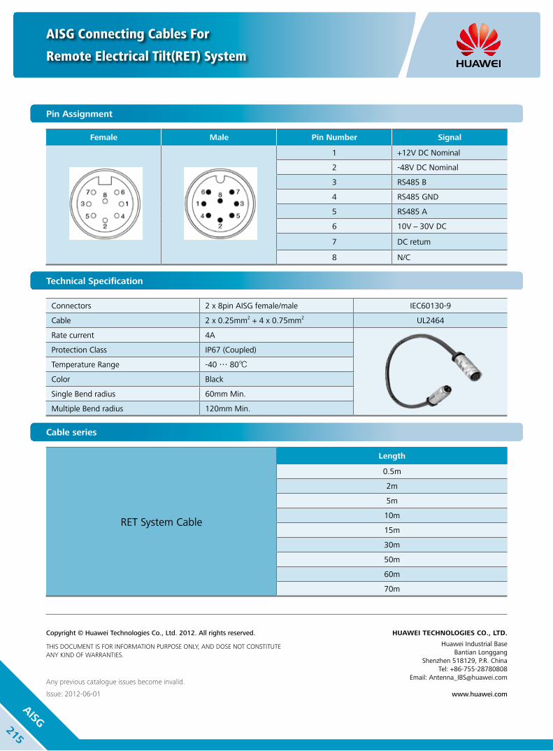
AISG Connecting Cables For
Remote Electrical Tilt(RET) System
Any previous catalogue issues become invalid.
Issue: 2012-06-01
HUAWEI TECHNOLOGIES CO., LTD.
Huawei Industrial BaseBantian Longgang
Shenzhen 518129, P.R. ChinaTel: +86-755-28780808
Email: [email protected]
www.huawei.com
Copyright © Huawei Technologies Co., Ltd. 2012. All rights reserved.
THIS DOCUMENT IS FOR INFORMATION PURPOSE ONLY, AND DOSE NOT CONSTITUTE ANY KIND OF WARRANTIES.
215
AISG
Cable series
RET System Cable
Length
0.5m
2m
5m
10m
15m
30m
50m
60m
70m
Pin Assignment
Female Male Pin Number Signal
1 +12V DC Nominal
2 -48V DC Nominal
3 RS485 B
4 RS485 GND
5 RS485 A
6 10V-30V DC
7 DC retum
8 N/C
IEC60130-9
Technical Specification
Connectors 2 x 8pin AISG female/male IEC60130-9
Cable 2 x 0.25mm2 + 4 x 0.75mm2 UL2464
Rate current 4A
Protection Class IP67 (Coupled)
Temperature Range -40 … 80
Color Black
Single Bend radius 60mm Min.
Multiple Bend radius 120mm Min.

AISG Connecting Cables For
RRU AISG Output
Any previous catalogue issues become invalid.
Issue: 2012-06-01
HUAWEI TECHNOLOGIES CO., LTD.
Huawei Industrial BaseBantian Longgang
Shenzhen 518129, P.R. ChinaTel: +86-755-28780808
Email: [email protected]
www.huawei.com
Copyright © Huawei Technologies Co., Ltd. 2012. All rights reserved.
THIS DOCUMENT IS FOR INFORMATION PURPOSE ONLY, AND DOSE NOT CONSTITUTE ANY KIND OF WARRANTIES.
216
AISG
Pin Assignment
Cable series
RRU AISG Cable
Length
3m
5m
Female Pin Number Signal
1 +12V DC Nominal
2 -48V DC Nominal
3 RS485 B
4 RS485 GND
5 RS485 A
6 10V-30V DC
7 DC retum
8 N/C
Male Pin Number Signal
1 +12V DC Nominal
2 N/C
3 RS485 B
4 RS485 GND
5 RS485 A
6 +12V DC Nominal
7 RS 485 GND
8 N/C
9 RS 485 GND
Technical Specification
IEC60130-9 Connector 1 8pin AISG Male IEC60130-9
Connector 2 9pin D9 Male
Cable 4Pair x 24AWG
Rate current 4A
Protection Class IP67 (Coupled)
Temperature Range -40 … 80
Color Black
Single Bend radius 60mm Min.
Multiple Bend radius 120mm Min.

Mounting InstructionsD

Antenna (C1) Installation Guide
Part Number: 31043744 Issue: 01
HINT
1. Only qualified personnel are allowed to install the antenna. 2. Appearance of the actual antenna may differ from the pictures.
Installation Tools Bracket Subassembly
13 mm combination wrench (2 PCS)
Inclinometer (1 PCS)M8
(2 PCS) (1 PCS) (1 PCS)
1 Assemble the bracket
2 Install the bracket
1 2
218In
stallatio
n
Guide

4 Install the antenna
2
1
Ensure the bracket is fully
collapsed at 0°.
3 Manually adjust the electrical downtilt angle
After adjustment
Ruler
Before adjustment
Adjust angle
The RCU is optional. For
details about how to install
the RCU, see the relevant
RCU Installation Guide.
Antenna (C1) Installation Guide
Part Number: 31043744 Issue: 01
5 Adjust the mechanical downtilt angle
Scale of bracket
Precise measurement
Method 1
Method 2
Finally, tighten all the nuts.
Recommended torque:
M8 = 18 NmBefore adjustment, adjust the inclinometer
to the desired downtilt angle.
After adjustment, locate the bead in the
inclinometer in the middle.
Any previous catalogue issues become invalid.
Issue: 2012-06-01
HUAWEI TECHNOLOGIES CO., LTD.
Huawei Industrial BaseBantian Longgang
Shenzhen 518129, P.R. ChinaTel: +86-755-28780808
Email: [email protected]
www.huawei.com
Copyright © Huawei Technologies Co., Ltd. 2012. All rights reserved.
THIS DOCUMENT IS FOR INFORMATION PURPOSE ONLY, AND DOSE NOT CONSTITUTE ANY KIND OF WARRANTIES.
219
Installation
Guide

Antenna (D1) Installation Guide
Part Number: 31043740 Issue: 02
1 Assemble the bracket
HINT
1. Only qualified personnel are allowed to install the antenna. 2. Appearance of the actual antenna may differ from the pictures.
Installation Tools Bracket Subassembly
13 mm combination wrench (2 PCS)
Inclinometer
(1 PCS)M10
(4 PCS)(2 PCS)(1 PCS)16 mm combination wrench
(2 PCS)
2 Install the bracket
220In
stallatio
n
Guide
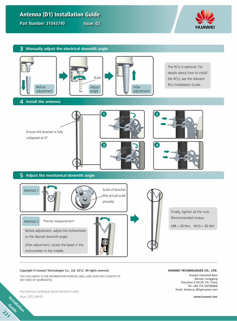
Antenna (D1) Installation Guide
Part Number: 31043740 Issue: 02
3 Manually adjust the electrical downtilt angle
After adjustment
Ruler
Before adjustment
Adjust angle
The RCU is optional. For
details about how to install
the RCU, see the relevant
RCU Installation Guide.
5 Adjust the mechanical downtilt angle
Scale of bracket
(the actual scale
prevails)
Precise measurement
Method 1
Method 2
Finally, tighten all the nuts.
Recommended torque:
M8 = 20 Nm, M10 = 30 NmBefore adjustment, adjust the inclinometer
to the desired downtilt angle.
After adjustment, locate the bead in the
inclinometer in the middle.
4 Install the antenna
2
4
1
3
Ensure the bracket is fully
collapsed at 0°.
Any previous catalogue issues become invalid.
Issue: 2012-06-01
HUAWEI TECHNOLOGIES CO., LTD.
Huawei Industrial BaseBantian Longgang
Shenzhen 518129, P.R. ChinaTel: +86-755-28780808
Email: [email protected]
www.huawei.com
Copyright © Huawei Technologies Co., Ltd. 2012. All rights reserved.
THIS DOCUMENT IS FOR INFORMATION PURPOSE ONLY, AND DOSE NOT CONSTITUTE ANY KIND OF WARRANTIES.
221
Installation
Guide

1
DTMA (A) Installation Guide
Issue: 01
HINT
Only qualified personnel are allowed to install the Dual Tower Mounted Amplifier (DTMA). DTMA and BTS support the same 1. frequency band.
DTMAs are installed in the similar manner, this document uses a DTMA2600 (Model: ATA261100) as an example. Actual 2. products may differ from the pictures, the actual ones prevail.
Connecting the AISG Cable
Connect the AISG cable to the DTMA
2
Tighten the AISG cable by hand, secure the AISG cable.
CAUTION
Remove the AISG protective lid of DTMA only when you want to connect a DTMA to an RCU. When connecting an RCU to a DTMA, align the concave of the DTMA female connector with the convex of the AISG male connector correctly. For details, see step 1.
Installation Tools
Flat-head screwdriver
150 mm x 6 mm (5.91 in. x 0.24 in.)
300 mm x 36 mm(12 in. x 1.4 in.)
Φ 10
Claw hammer
Adjustable wrench Hammer drill Insulation tape Waterproof tape
1 2 3 4
Connecting the RF Jumper
Connect the jumper to the DTMA
Waterproof and Sealed for Connectors
Re. Torque: 25 Nm - 30 Nm(220 lbf.in.- 264 lbf.in.)
Wrap tape method :one layer Insulation tape + three layer waterproof tapes + three layer Insulation tapes
Cable ties
Connect the ANT port on the DTMA to the antenna and
other ports to the BTS.
ANT 0 ANT 1
Tighten the RF jumper
222In
stallatio
n
Guide

Connecting the Ground Cable
Installing the DTMA
Method 1: Pole-Mounting the DTMA
1
1
2
2
3
3
Twist off a nut, a spring washer and a flat washer
Screw Shell Steel strip
Hoop iron
Bracket
Pole mount hole
Hoop iron trail into mast mount hole and partially tighten the hoop iron.
Connect the ground cable to the DTMA
Tighten the hoop iron
Connect the other connector of the ground cable to ground.
CAUTION
Pole-Mounting the DTMA: first connect RF jumpers, the AISG cable and the ground cable, then install the DTMA on a pole.
a
HINT
To partially tighten the hoop iron: press the screw 1. tail into the shell and route the steel strip through the shell. Then press the steel strip towards the pole and strain the steep strip till the steel strip is firmly attached to the pole, as shown in step 1.
To release the hoop iron: press the screw tail into the 2. shell, press the steel strip towards the pole, and push the steel strip outwards till the steel strip is released from the shell.
Position to install hoop irons
DTMA (A) Installation Guide
Issue: 01
223
Installation
Guide

1
3
a b
5
2
4
6
Wall
CAUTION
Wall-Mounting the DTMA: first install the DTMA on the wall, then connect RF jumpers, the AISG cable and the ground cable.
Method 2: Wall-Mounting the DTMAb
Any previous catalogue issues become invalid.
Issue: 2012-06-01
HUAWEI TECHNOLOGIES CO., LTD.
Huawei Industrial BaseBantian Longgang
Shenzhen 518129, P.R. ChinaTel: +86-755-28780808
Email: [email protected]
www.huawei.com
Copyright © Huawei Technologies Co., Ltd. 2012. All rights reserved.
THIS DOCUMENT IS FOR INFORMATION PURPOSE ONLY, AND DOSE NOT CONSTITUTE ANY KIND OF WARRANTIES.
Orientation Drill holes
Install a M8 expansion bolt
Install four M8 expansion bolts
1
3
2
4
Install the DTMA
Twist off nut, spring washer, flat washer
52 mm - 60 mm (2.05 in. - 2.36 in.)
DTMA (A) Installation Guide
Issue: 01
224In
stallatio
n
Guide

150 mm x 6 mm (5.91 in. x 0.24 in.)
300 mm x 36 mm(12 in. x 1.4 in.)
Combiner (A) Installation Guide
Issue: 01
HINT
Only qualified personnel is allowed to install the Combiner. Combiner and BTS support the same frequency band. 1.
This document uses a TC-0011-2 (Model: ACOMT2H00) as an example. Actual products may differ from the pictures, the 2. actual ones prevail.
HINT
If use the combiner near the antenna, connect the COM port of the Combiner to the Main feeder and other ports to the antenna.1.
If use the combiner near the BTS, connect the COM port of the Combiner to the Main feeder and other ports to the BTS.2.
Installation Tools
Connecting the RF Jumper
Flat-head screwdriver
Φ 10
Claw hammer
Adjustable wrench Hammer drill Insulation tape Waterproof tape
1
43
2
Connect the jumper to the Combiner
Waterproof and Sealed for
Connectors
Wrap tape method :one layer Insulation tape + three layer waterproof tapes + three layer Insulation tapes Cable ties
Use cable ties fix upside and downside of tape
Re. Torque:25 Nm - 30 Nm(220 lbf.in.- 264 lbf.in.)
Tighten the RF jumper
225
Installation
Guide

Combiner (A) Installation Guide
Issue: 01
Connecting the Ground Cable
Method 1: Pole-Mounting the Combiner
1 2 3
Screw Shell Steel strip
Hoop iron
Bracket
Pole mount hole
Hoop iron trail into mast mount hole and partially tighten the hoop iron
Tighten the hoop iron
Installing the DTMA
CAUTION
Pole-Mounting the Combiner : first connect the RF jumper and the ground cable, then install the Combiner on a pole.
a
HINT
To partially tighten the hoop iron: press the screw tail into the shell and route the 1. steel strip through the shell. Then press the steel strip towards the pole and strain the steep strip till the steel strip is firmly attached to the pole, as shown in step 1.
To release the hoop iron: press the screw tail into the shell, press the steel strip 2. towards the pole, and push the steel strip outwards till the steel strip is released from the shell.
Position to install the hoop iron
CAUTION
Wall-Mounting the Combiner: first install the Combiner on the wall, then connect RF jumpers and the ground cable.
1 2 3
Twist off the first nut, spring washer, the first flat washer
Connecting the ground cable Connect the other connector of the ground cable to ground.
226In
stallatio
n
Guide

1
3
a b
5
2
4
6
Wall
Method 2: Wall-Mounting the Combinerb
Any previous catalogue issues become invalid.
Issue: 2012-06-01
HUAWEI TECHNOLOGIES CO., LTD.
Huawei Industrial BaseBantian Longgang
Shenzhen 518129, P.R. ChinaTel: +86-755-28780808
Email: [email protected]
www.huawei.com
Copyright © Huawei Technologies Co., Ltd. 2012. All rights reserved.
THIS DOCUMENT IS FOR INFORMATION PURPOSE ONLY, AND DOSE NOT CONSTITUTE ANY KIND OF WARRANTIES.
Orientation Drill holes
Install a M8 expansion bolt
Install four M8 expansion bolts
1
3
2
4
Install the Combiner
Twist off nut, spring washer, flat washer
52 mm - 60 mm (2.05 in. - 2.36 in.)
Combiner (A) Installation Guide
Issue: 01
227
Installation
Guide

RCU (A) Installation Guide
Part Number: 31043715 Issue: 05
HINT
Only qualified personnel is allowed to install the Remote Control Unit (RCU).1.
The serial No. attached to the RCU is the same with the serial No. in the packaging bag of installation guide. To avoid serial 2. No. confusion, do not separate the RCU from the installation guide.
Install RCU hardware under tower. After the installation is complete, you need to configure the RCU onsite. For details about 3. how to configure the RCU, see the RET Antenna Configuration Guide.
This document uses installing the RCU on a dual-band antenna (Model: ADU451801) as an example. Actual products may 4. differ from the pictures, the actual ones prevail.
HINT
Take the serial No. label out, stick the label to the recording form attached in this document, then write down the information.1.
Cut the recording form off and provide it to the network management personnel. 2.
Installation Tools RCU Description
Length x Max mouth width: 300 x 36 mm (12 x 1.4 in.)
Adjustable wrench
Packaging bag
Example
Serial No. label
Appearance
Serial No.Male
Female
Bottom
Drainage hole
Top
Sticking the Serial No.
Taking out the Serial No. Labela Sticking the Serial No. Labelb
Site Name: ABCD
Sector No.: 01
Site No.: 01
Port No.: 1710-2170
228In
stallatio
n
Guide

RCU (A) Installation Guide
Part Number: 31043715 Issue: 05
HINT
Connect the female connector of Antenna Interface Standards Group (AISG) cable to the male connector of the RCU without 1. removing the protective lid from the female connector of the RCU, see step 1.
Connect the other connector of the AISG cable to the SBT or TMA, etc.2.
1
Connecting the AISG Cable
AISG cable female
Protective lid
2
Tighten the AISG cable
1
3
Installing the RCU
2
4 5
CAUTION
Rotate the adjustment screw before 1. installing the RCU. Ensure that the adjustment screw rotates smoothly before installing the RCU. For details, see step 1.
When inserting the RCU into the 2. antenna, ensure that two ports match each other. For details, see step 3. Twist off protective cover
Particular tighten the RCU Tighten the RCU
Re. Torque: 10 - 10.5 Nm(89 - 93 lbf.in.)
229
Installation
Guide

HINT
In the non-daisy chain scenario, an RCU connects with one AISG cable.1.
In the daisy chain scenario, connect each RCU to an AISG cable, then connect the female connector of the upper-level RCU to 2. the male connector of the lower-level RCU with an AISG cable. Do not remove the protective lid from the female connector of the lowest-level RCU.
For particular installation, please contact Huawei Technologies Co., Ltd. www.huawei.com
RCU (A) Installation Guide
Part Number: 31043715 Issue: 05
Non-Daisy Chain Scenarioa Daisy Chain Scenariob
Appendix: Recording form
Any previous catalogue issues become invalid.
Issue: 2012-06-01
HUAWEI TECHNOLOGIES CO., LTD.
Huawei Industrial BaseBantian Longgang
Shenzhen 518129, P.R. ChinaTel: +86-755-28780808
Email: [email protected]
www.huawei.com
Copyright © Huawei Technologies Co., Ltd. 2012. All rights reserved.
THIS DOCUMENT IS FOR INFORMATION PURPOSE ONLY, AND DOSE NOT CONSTITUTE ANY KIND OF WARRANTIES.
HINT
Write down the information, then cut the 1. recording form off and provide it to the network management personnel. This table is used to identify the information when you configure the RCU.
Port No. identifies the antenna port in 2. the frequency band where the RCU port is located.
Site Name:
Sector No.:
Site No.:
Port No.:
Stick Serial No.
230In
stallatio
n
Guide
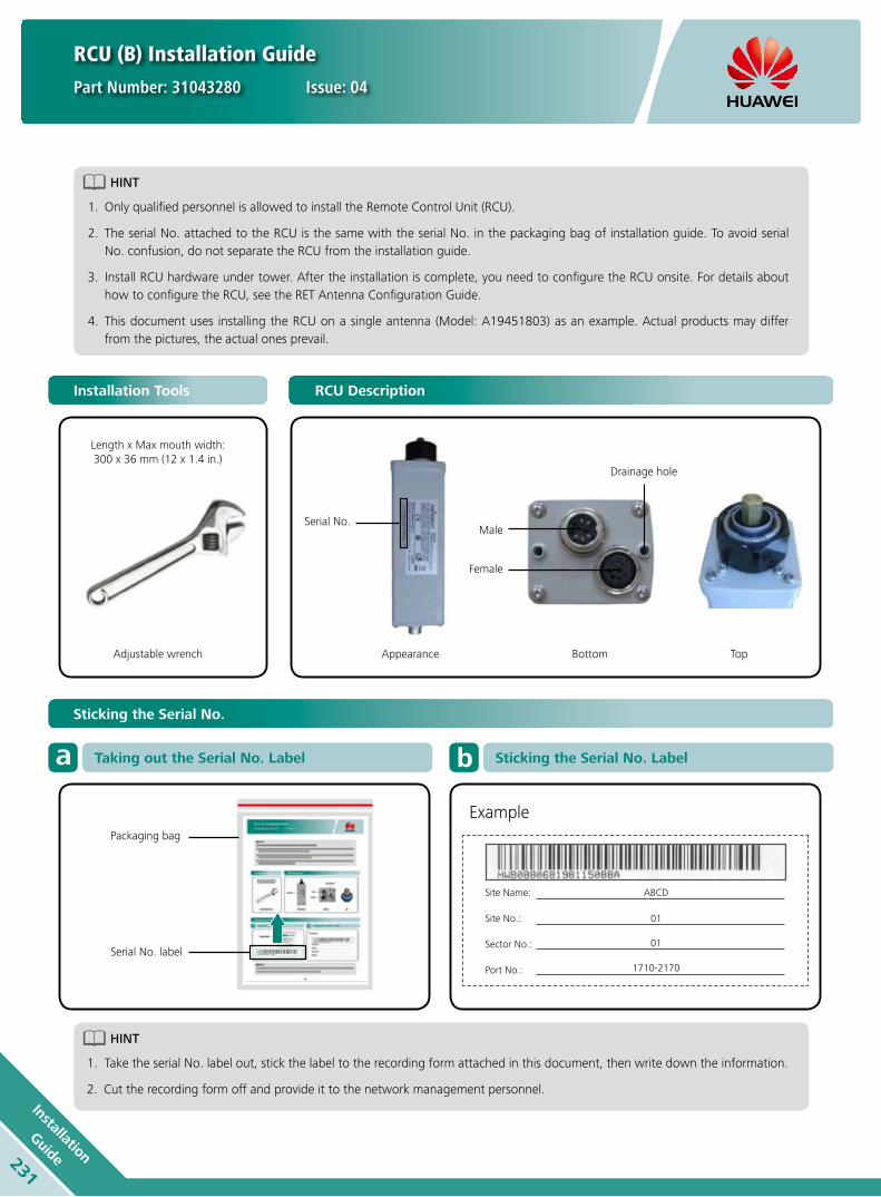
HINT
Only qualified personnel is allowed to install the Remote Control Unit (RCU).1.
The serial No. attached to the RCU is the same with the serial No. in the packaging bag of installation guide. To avoid serial 2. No. confusion, do not separate the RCU from the installation guide.
Install RCU hardware under tower. After the installation is complete, you need to configure the RCU onsite. For details about 3. how to configure the RCU, see the RET Antenna Configuration Guide.
This document uses installing the RCU on a single antenna (Model: A19451803) as an example. Actual products may differ 4. from the pictures, the actual ones prevail.
HINT
Take the serial No. label out, stick the label to the recording form attached in this document, then write down the information.1.
Cut the recording form off and provide it to the network management personnel. 2.
Installation Tools RCU Description
Length x Max mouth width: 300 x 36 mm (12 x 1.4 in.)
Adjustable wrench
Packaging bag
Example
Serial No. label
Appearance
Serial No.Male
Female
Bottom
Drainage hole
Top
Sticking the Serial No.
Taking out the Serial No. Labela Sticking the Serial No. Labelb
RCU (B) Installation Guide
Part Number: 31043280 Issue: 04
Site Name: ABCD
Sector No.: 01
Site No.: 01
Port No.: 1710-2170
231
Installation
Guide

HINT
Connect the female connector 1. of Antenna Interface Standards Group (AISG) cable to the male connector of the RCU without removing the protective lid from the female connector of the RCU, see step 1.
Connect the other connector of 2. the AISG cable to SBT or TMA, etc.
1
Connecting the AISG Cable
AISG cable female
Protective lid
2
Tighten the AISG cable
1
4
6
Installing the RCU
2
5
3
7 8
CAUTION
The protective cover rotates smoothly 1. before the RCU can be installed. For details, see step 4.
When inserting the RCU into the 2. antenna, ensure that the orientation scoop of the RCU is securely locked into the orientation scoop of the antenna. For details, see step 6.
Turn 180°
Twist off protective cover
Install protective coverTwist off protective cover
Particular tighten the
RCU Tighten the RCU
Re. Torque: 10 - 10.5 Nm(89 - 93 lbf.in.)
RCU (B) Installation Guide
Part Number: 31043280 Issue: 04
232In
stallatio
n
Guide

RCU (B) Installation Guide
Part Number: 31043280 Issue: 04
HINT
In the non-daisy chain scenario, an RCU connects with one AISG cable.1.
In the daisy chain scenario, connect each RCU to an AISG cable, then connect the female connector of the upper-level RCU to 2. the male connector of the lower-level RCU with an AISG cable. Do not remove the protective lid from the female connector of the lowest-level RCU.
Non-Daisy Chain Scenarioa Daisy Chain Scenariob
Appendix: Recording form
Any previous catalogue issues become invalid.
Issue: 2012-06-01
HUAWEI TECHNOLOGIES CO., LTD.
Huawei Industrial BaseBantian Longgang
Shenzhen 518129, P.R. ChinaTel: +86-755-28780808
Email: [email protected]
www.huawei.com
Copyright © Huawei Technologies Co., Ltd. 2012. All rights reserved.
THIS DOCUMENT IS FOR INFORMATION PURPOSE ONLY, AND DOSE NOT CONSTITUTE ANY KIND OF WARRANTIES.
HINT
Write down the information, then cut the 1. recording form off and provide it to the network management personnel. This table is used to identify the information when you configure the RCU.
Port No. identifies the antenna port in 2. the frequency band where the RCU port is located.
Site Name:
Sector No.:
Site No.:
Port No.:
Stick Serial No.
For particular installation, please contact Huawei Technologies Co., Ltd. www.huawei.com
233
Installation
Guide

RCU (C) Installation Guide
Part Number: 31043741 Issue: 02
HINT
Only qualified personnel is allowed to install the Remote Control Unit (RCU).1.
The serial No. attached to the RCU is the same with the serial No. in the packaging bag of installation guide. To avoid serial 2. No. confusion, do not separate the RCU from the installation guide.
Install RCU hardware under tower. After the installation is complete, you need to configure the RCU onsite. For details about 3. how to configure the RCU, see the RET Antenna Configuration Guide.
This document uses installing the RCU on a tri-band antenna (Model: ATR451704) as an example. Actual products may differ 4. from the pictures, the actual ones prevail.
HINT
Take the serial No. label out of packaging bag, stick the label to the recording form attached in this document, then write 1. down the information.Cut the recording form off and provide it to the network management personnel. 2.
Installation Tools RCU Description
Length x Max mouth width: 300 x 36 mm (12 x 1.4 in.)
Adjustable wrench
Packaging bag
Example
Serial No. label
Appearance
Serial No.
Drainage hole
Bottom
FemaleMale
Top
Sticking the Serial No.
Taking out the Serial No. Labela Sticking the Serial No. Labelb
Site Name: ABCD
Sector No.: 01
Site No.: 01
Port No.: 1710-2170
234In
stallatio
n
Guide

RCU (C) Installation Guide
Part Number: 31043741 Issue: 02
HINT
Connect the female connector 1. of Antenna Interface Standards Group (AISG) cable to the male connector of the RCU without removing the protective lid from the female connector of the RCU. For details, see step 1.
Connect the other connector of 2. the AISG cable to SBT or TMA, etc.
1
1
4
2
5
3
6
Connecting the AISG Cable
AISG cable female
Protective lid
2
Tighten the AISG cable
Installing the RCU
CAUTION
The protective cover 1. rotates smoothly before the RCU can be installed. For details, see step 4.
When inserting the RCU 2. into the antenna, ensure that the orientation scoop of the RCU is securely locked into the orientation scoop of the antenna. For details, see step 6.
Twist off protective cover Adjustment spindle
Re. Torque:15 - 18 Nm(132 - 159 lbf.in.)
Particular tighten the RCU Tighten the RCU
235
Installation
Guide

HINT
In the non-daisy chain scenario, an RCU connects with one AISG cable.1.
In the daisy chain scenario, connect each RCU to an AISG cable, then connect the female connector of the upper-level RCU to 2. the male connector of the lower-level RCU with an AISG cable. Do not remove the protective lid from the female connector of the lowest-level RCU.
When installing three RCUs on a tri-band antenna (Model: ATR451704), install them in different directions. To be specific, the 3. side with the nameplate of the RCU on the left faces towards the left, the side with the nameplate of the RCU in the middle faces upwards, and the side with the nameplate of the RCU on the right faces towards the right. See the following figures. For details about installation directions of RCUs on other antennas, see the RET Antenna FAQs.
RCU (C) Installation Guide
Part Number: 31043741 Issue: 02
Non-Daisy Chain Scenarioa Daisy Chain Scenariob
Appendix: Recording form
Any previous catalogue issues become invalid.
Issue: 2012-06-01
HUAWEI TECHNOLOGIES CO., LTD.
Huawei Industrial BaseBantian Longgang
Shenzhen 518129, P.R. ChinaTel: +86-755-28780808
Email: [email protected]
www.huawei.com
Copyright © Huawei Technologies Co., Ltd. 2012. All rights reserved.
THIS DOCUMENT IS FOR INFORMATION PURPOSE ONLY, AND DOSE NOT CONSTITUTE ANY KIND OF WARRANTIES.
HINT
Write down the information, then cut the 1. recording form off and provide it to the network management personnel. This table is used to identify the information when you configure the RCU.
Port No. identifies the antenna port in 2. the frequency band where the RCU port is located
Site Name:
Sector No.:
Site No.:
Port No.:
Stick Serial No.
For particular installation, please contact Huawei Technologies Co., Ltd. www.huawei.com
236In
stallatio
n
Guide

HINT
Only qualified personnel is allowed to install the OOK Bias Tee (BT).1.
If the BT is installed indoors, no tapes are required to wrap and seal the connector.2.
This document uses a BT (Model: ABT000001) as an example. Actual products may differ from the pictures, the actual ones 3. prevail.
BT (A) Installation Guide
Issue: 01
Installation Tools OOK Bias Tee Description
Female
Adjustable wrench
8 mm combination wrench
Insulation tape
Waterproof tape
Cable ties
Length x Max mouth width:300 x 36 mm (12 x 1.4 in.)
DC Connector Male
1
Installing the BT
2 3
Tighten the jumper
Re. Torque: 25 - 30 Nm (220 - 264lbf.in.)
Wrap tape method :one layer Insulation tape + three layer waterproof tapes + three
layer Insulation tapesConnect the jumper to
female of BT
237
Installation
Guide

Any previous catalogue issues become invalid.
Issue: 2012-06-01
HUAWEI TECHNOLOGIES CO., LTD.
Huawei Industrial BaseBantian Longgang
Shenzhen 518129, P.R. ChinaTel: +86-755-28780808
Email: [email protected]
www.huawei.com
Copyright © Huawei Technologies Co., Ltd. 2012. All rights reserved.
THIS DOCUMENT IS FOR INFORMATION PURPOSE ONLY, AND DOSE NOT CONSTITUTE ANY KIND OF WARRANTIES.
Installing the BT
4 5 6
Tighten the BTWrap tape method :
one layer Insulation tape + three layer waterproof tapes + three layer Insulation tapes
Connect the male of BT to DDPU
7 8 9
Tighten the DC Power Cable
Torque range:0.8 - 1.1 Nm (7 - 9 lbf.in.)
Torque range:15 - 18 Nm
(132 - 159 lbf.in.)
Wrap tape method :one layer Insulation tape + three
layer waterproof tapes + three layer Insulation tapes
Connect the DC Power Cable to BT
10
Use cable ties to fix both ends of the tape
Cable ties
Cable ties
BT (A) Installation Guide
Issue: 01
238In
stallatio
n
Guide

HINT
Only qualified personnel is allowed to install the Smart Bias Tee (SBT).1.
This document uses a SBT (Model: ASBT00001) as an example. Actual products may differ from the pictures, the actual ones 2. prevail.
SBT (A) Installation Guide
Issue: 01
Installation Tools SBT Description
Adjustable wrench Insulation tape Male
Female AISG Female
Cable ties Waterproof tape
Length x Max mouth width:300 x 36 mm (12 x 1.4 in.)
1
Installing the SBT
2 3
Particular tighten the SBT
Tighten the SBT
Torque range:15 - 18 Nm
Connect Male of SBT to antenna, ensure
that two ports match each other.
239
Installation
Guide

Any previous catalogue issues become invalid.
Issue: 2012-06-01
HUAWEI TECHNOLOGIES CO., LTD.
Huawei Industrial BaseBantian Longgang
Shenzhen 518129, P.R. ChinaTel: +86-755-28780808
Email: [email protected]
www.huawei.com
Copyright © Huawei Technologies Co., Ltd. 2012. All rights reserved.
THIS DOCUMENT IS FOR INFORMATION PURPOSE ONLY, AND DOSE NOT CONSTITUTE ANY KIND OF WARRANTIES.
Installing the BT
4 5 6
7 8 9
SBT (A) Installation Guide
Issue: 01
HINT
Remove the AISG protective lid 1. of SBT only when you want to connect the SBT to the RCU.
Connect the male connector 2. of AISG cable to the female connector of the SBT, ensure that connectors are securely locked, see step 1. Tighten the AISG cable by hand, ensure the AISG cable connector is not loose, see step 2
1
Connecting the AISG Cable
2
Tighten the AISG cable by handEnsure that two ports
match each other
Wrap tapes method :one layer Insulation tape + three layer
waterproof tapes + three layer Insulation
tapes
Tighten the jumper
Wrap tapes method :one layer Insulation tape + three layer
waterproof tapes + three layer Insulation tapes
Re. Torque: 25 - 30 Nm
(220 - 264 lbf.in.)
Use cable ties to fix both ends of the tape
Cable ties
Cable ties
Particular tighten the jumper
Connect the jumper to Female of SBT
240In
stallatio
n
Guide

HINT
Only qualified personnel is allowed to install the Smart Bias Tee (SBT).1.
If the SBT is installed indoors, no tapes are required to wrap and seal the connector.2.
This document uses a SBT (Model: ASBT00002) as an example. Actual products may differ from the pictures, the actual ones 3. prevail.
SBT (B) Installation Guide
Issue: 01
Installation Tools SBT Description
Adjustable wrench Insulation tape
AISG Male
Male
Female
Cable ties Waterproof tape
Length x Max mouth width:300 x 36 mm (12 x 1.4 in.)
1
Installing the SBT
2 3
Particular tighten the SBT Tighten the SBT
Torque range:15 - 18 Nm
Connect Male of SBT to RRU, ensure that two ports match each other.
241
Installation
Guide

Any previous catalogue issues become invalid.
Issue: 2012-06-01
HUAWEI TECHNOLOGIES CO., LTD.
Huawei Industrial BaseBantian Longgang
Shenzhen 518129, P.R. ChinaTel: +86-755-28780808
Email: [email protected]
www.huawei.com
Copyright © Huawei Technologies Co., Ltd. 2012. All rights reserved.
THIS DOCUMENT IS FOR INFORMATION PURPOSE ONLY, AND DOSE NOT CONSTITUTE ANY KIND OF WARRANTIES.
Installing the BT
4 5 6
7 8 9
SBT (B) Installation Guide
Issue: 01
HINT
Remove the AISG protective lid 1. of SBT only when you want to connect the SBT to the CCU.
Align the concave of the AISG 2. cable female connector with the convex of the SBT male connector correctly, see step 1. Tighten the AISG cable by hand, ensure the AISG cable connector is not loose, see step 2.
1
Connecting the AISG Cable
2
Tighten the AISG cable by handConnect the female connector of AISG cable to
the male connector of SBT
Tighten the jumper
Wrap tapes method :one layer Insulation tape + three layer
waterproof tapes + three layer Insulation tapes
Re. Torque: 25 - 30 Nm
(220 - 264 lbf.in.)
Use cable ties to fix both ends of the tape
Cable ties
Cable ties
Particular tighten the jumperConnect the jumper to
Female of SBT
Wrap tapes method :one layer Insulation tape + three layer
waterproof tapes + three layer Insulation
tapes
242In
stallatio
n
Guide

Copyright © Huawei Technologies Co., Ltd. 2012. All rights reserved.
No part of this document may be reproduced or transmitted in any form or by any means without prior written consent of Huawei Technologies Co., Ltd.
Trademark Notice
, HUAWEI, and are trademarks or registered trademarks of Huawei Technologies Co., Ltd.
Other trademarks, product, service and company names mentioned are the property of their respective owners.
HUAWEI TECHNOLOGIES CO., LTD.
Huawei Industrial Base
Bantian Longgang
Shenzhen 518129, P.R. China
Tel: +86-755-28780808
Email: [email protected]
Version No.: M3-022337-20120601-C-1.0
www.huawei.com
General Disclaimer
THE INFORMATION IN THIS DOCUMENT MAY CONTAIN PREDICTIVE STATEMENTS
INCLUDING, WITHOUT LIMITATION, STATEMENTS REGARDING THE FUTURE FINANCIAL
AND OPERATING RESULTS, FUTURE PRODUCT PORTFOLIO, NEW TECHNOLOGY, ETC.
THERE ARE A NUMBER OF FACTORS THAT COULD CAUSE ACTUAL RESULTS AND
DEVELOPMENTS TO DIFFER MATERIALLY FROM THOSE EXPRESSED OR IMPLIED IN THE
PREDICTIVE STATEMENTS. THEREFORE, SUCH INFORMATION IS PROVIDED FOR REFERENCE
PURPOSE ONLY AND CONSTITUTES NEITHER AN OFFER NOR AN ACCEPTANCE. HUAWEI
MAY CHANGE THE INFORMATION AT ANY TIME WITHOUT NOTICE.
Current Supply Route
Future Supply Route
Hungary
5 supply centers
2Hubs, 81 service branches
Holland Hub
Brazil
Mexico
Dubai Hub
China
IndiaWestAfrica