hss shielding for-hospitals2013
TRANSCRIPT
RADIATION SHIELDING FOR CLINICS AND SMALL HOSPITALS
WITH A WHIS-RAD 2013
Gerald P. Hanson Philip E.S. Palmer
Electronic publishing rights granted to
Rotary District 6440 and the Pan American Health Organization Copyright © 2013, Gerald P. Hanson and Philip E.S. Palmer.
District 6440
2
Table of Contents Preface 3 Introduction 4 Workload and workload distribution in a small hospital or clinic 4 The WHIS-RAD X-ray room 6 Dose limits, dose constraints, and the weekly shielding design goals (P) used in calculations 6 Shielding calculation example for a new small X-ray facility not attached to an existing hospital or structure as shown in Figure 2. 9 Results and analysis of the shielding calculations 11 Shielding calculation details (as shown in Tables number 3-17) 13 Extension of these results to a facility using computed radiography 13 Tables 3-17 14-28 Rotary and PAHO are jointly publishing on the Internet this Manual on “Radiation Shielding for Clinics and Small Hospitals with a WHIS-RAD”. The Manual is authored by Drs. Gerald Hanson and Philip E.S. Palmer who are internationally recognized for their work with PAHO and WHO (World Health Organization) in radiation safety and radiology. They have given pre-publication rights to Rotary District 6440 and PAHO to assure immediate availability of the information
3 Preface It was planned during preparation of the manual “Diagnostic Imaging in Clinics and Small Hospitals” (June 2011) to include detailed calculations on radiation shielding for a WHIS-RAD as an annex. However, the length of the radiation shielding calculations was such that it was decided that the manual would serve its purpose much better without any annexes. So this second manual, “Radiation Shielding for Clinics or Small Hospitals with a WHIS-RAD”, details the calculations used to determine the radiation shielding required for the minimum size room (16 square meters) that is acceptable for a WHIS-RAD X-ray unit. Adjoining spaces as well as various situations involving the staff, patients and the storage of X-ray sensitive materials (film and loaded cassettes/ digital receptors) are included. To determine the required shielding (Table 2), the calculations are based on the X-ray examinations of 3,000 patients per year as is common in small hospitals (WL=1), and also for many times that workload. Table 2, with its wide range of situations, is also a useful reference for comparing shielding requirements for similar installations. In an X-ray room of 16 square meters, and at any clinically feasible workload; the shielding provided in the WHIS-RAD cassette-holder and the X-ray room walls (if made of common building materials equal in shielding to about 4 centimeters of concrete) is sufficient. Extra shielding is needed for loaded cassettes/receptors that are stored in the operator’s console area. This can be a storage bin with sufficient lead-equivalent shielding (locally made) together with strict rules limiting the number of loaded cassettes that are kept in the operator’s console area. Although the calculations were made for the minimum size room acceptable for a WHIS-RAD (16 square meters), a larger room has advantages for access and patient-positioning. For example, a room of 24 square meters would decrease the radiation exposure in its vicinity by about 50% due to the increased distances from the X-ray unit to protected areas. The increased cost of a larger room, based on the use of common building materials, would be less than the costly provision of unnecessary-additional lead shielding in the walls. The information will be useful for health authorities, health care and non-profit donor organizations when resources are limited. Funds not spent on unnecessary radiation shielding can be better used for equipment and staffing. The detailed calculations will help government agencies responsible for radiation protection. Staff who are fully capable of making the shielding calculations may not have experience with the radiation protection incorporated in the WHIS-RAD. Other agencies may not have qualified staff and may recommend unnecessary shielding, such as an X-ray room of 25 square meters and 2 millimeters of lead shielding in all the walls. Although this text provides a clear and authoritative guide to radiation shielding for the installation of a WHIS-RAD, the authors emphasize that the local-responsible authorities are charged with protecting health and they must make the final determination. The authors, 28 November 2011
4 Introduction Radiation safety is as important for small clinics and small hospitals as it is for large hospitals and always depends on conscientious work habits, protective measures, and adequate radiation shielding. Because of the high workload in large and busy hospitals, it is often necessary to add a dense material such as leaded sheeting to the walls, depending on room size and the type and layout of the equipment. However, where only a few X-ray examinations are made each day, as is usual in small clinics and small hospitals, common building materials such as adobe, brick, or concrete will provide more that adequate shielding provided that the walls are of sufficient thickness: this again depends on room size and the type of equipment. This manual provides radiation shielding calculations for the small clinic and small hospital. The US National Council on Radiation Protection and Measurements (NCRP) Report Number 147 (NCRP 2004) has been used as a radiation shielding reference. A design loading of 3,000 examinations per year (60 per week), which is typical of small departments, has been used. The X-ray equipment installed meets the specifications of the WHIS-RAD (World Health Organization Imaging System for Radiography). The types of examinations are: chest, extremities, abdomen, spinal column, and the skull. The original design of the WHIS-RAD (known then as the WHO-Basic Radiological System), specified only four distinct X-ray generating potentials: 55, 70, 90, and 120 kV. These four kV settings are currently recommended if a “two component” system (kV and mAs) is installed and are the minimum acceptable. Some manufacturers, as allowed in the updated WHIS-RAD specifications, provide as many as six kV settings, which is the maximum acceptable. Thus, for a WHIS-RAD, there can be the following kV settings: if four kV settings are provided: 55, 70, 90, 120 kV; if five kV settings are provided: 52-55, 70, 80, 90, 120 kV; if six kV settings are provided: 45, 52-55, 70, 80, 90, 120 kV. The X-ray beam may be used in the horizontal position, the vertical position, or at an angle. The X-ray tube and the image receptor are linked by a modified “C-arm”, which is supported on a vertical tube stand. All examinations use a fixed source-image distance (SID) of 140 centimeters (Figure 1). Workload and workload distribution in a small clinic or small hospital The workload in a large hospital’s radiographic room may be 500 to 600 milliampere-minutes per week. In a small hospital the workload may be one-tenth of that.
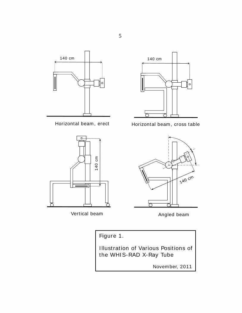
140 cm
Horizontal beam, erect
140 cm
Horizontal beam, cross table
Vertical beam
140
cm
Angled beam
Figure 1.
Illustration of Various Positions of the WHIS-RAD X-Ray Tube
November, 2011
5
6
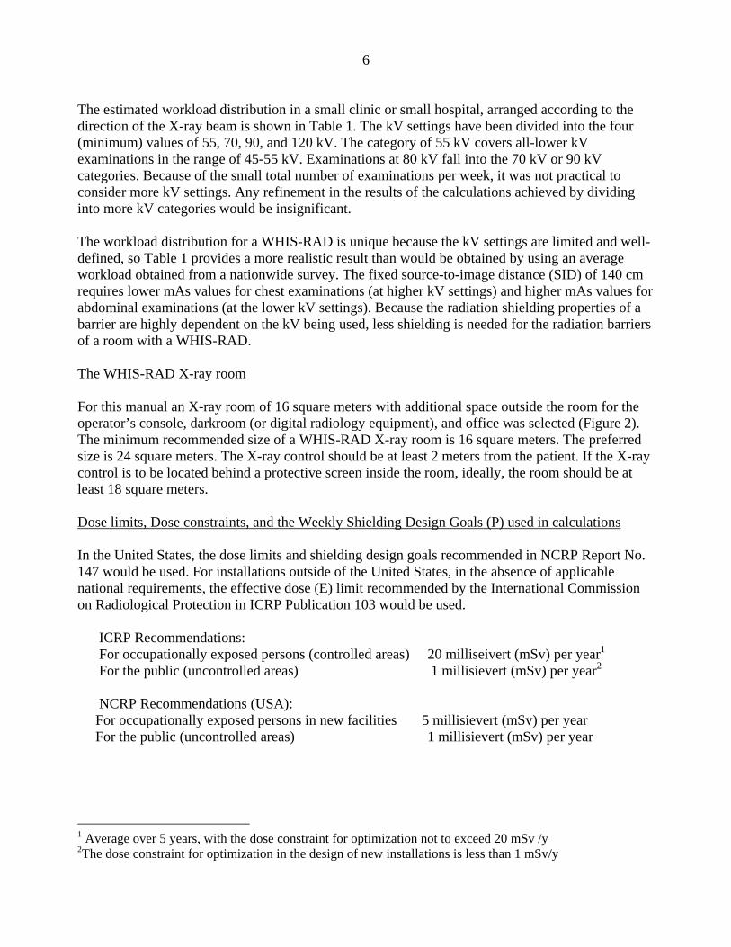
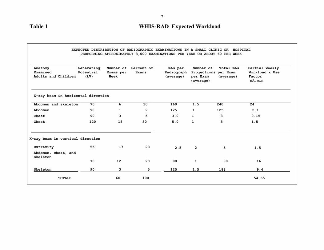
The estimated workload distribution in a small clinic or small hospital, arranged according to the direction of the X-ray beam is shown in Table 1. The kV settings have been divided into the four (minimum) values of 55, 70, 90, and 120 kV. The category of 55 kV covers all-lower kV examinations in the range of 45-55 kV. Examinations at 80 kV fall into the 70 kV or 90 kV categories. Because of the small total number of examinations per week, it was not practical to consider more kV settings. Any refinement in the results of the calculations achieved by dividing into more kV categories would be insignificant. The workload distribution for a WHIS-RAD is unique because the kV settings are limited and well-defined, so Table 1 provides a more realistic result than would be obtained by using an average workload obtained from a nationwide survey. The fixed source-to-image distance (SID) of 140 cm requires lower mAs values for chest examinations (at higher kV settings) and higher mAs values for abdominal examinations (at the lower kV settings). Because the radiation shielding properties of a barrier are highly dependent on the kV being used, less shielding is needed for the radiation barriers of a room with a WHIS-RAD. The WHIS-RAD X-ray room For this manual an X-ray room of 16 square meters with additional space outside the room for the operator’s console, darkroom (or digital radiology equipment), and office was selected (Figure 2). The minimum recommended size of a WHIS-RAD X-ray room is 16 square meters. The preferred size is 24 square meters. The X-ray control should be at least 2 meters from the patient. If the X-ray control is to be located behind a protective screen inside the room, ideally, the room should be at least 18 square meters. Dose limits, Dose constraints, and the Weekly Shielding Design Goals (P) used in calculations In the United States, the dose limits and shielding design goals recommended in NCRP Report No. 147 would be used. For installations outside of the United States, in the absence of applicable national requirements, the effective dose (E) limit recommended by the International Commission on Radiological Protection in ICRP Publication 103 would be used. ICRP Recommendations: For occupationally exposed persons (controlled areas) 20 milliseivert (mSv) per year1 For the public (uncontrolled areas) 1 millisievert (mSv) per year2 NCRP Recommendations (USA): For occupationally exposed persons in new facilities 5 millisievert (mSv) per year For the public (uncontrolled areas) 1 millisievert (mSv) per year
1 Average over 5 years, with the dose constraint for optimization not to exceed 20 mSv /y 2The dose constraint for optimization in the design of new installations is less than 1 mSv/y
7
Table 1 WHIS-RAD Expected Workload
EXPECTED DISTRIBUTION OF RADIOGRAPHIC EXAMINATIONS IN A SMALL CLINIC OR HOSPITAL
PERFORMING APPROXIMATELY 3,000 EXAMINATIONS PER YEAR OR ABOUT 60 PER WEEK
Anatomy Generating Number of Percent of
Examined Potential Exams per Exams
Adults and Children (kV) Week
mAs per Number of Total mAs Partial weekly
Radiograph Projections per Exam Workload x Use
(average) per Exam (average) Factor
(average) mA.min
X-ray beam in horizontal direction
Abdomen and skeleton 70 6 10 160 1.5 240 24
Abdomen 90 1 2 125 1 125 2.1
Chest 90 3 5 3.0 1 3 0.15
Chest 120 18 30 5.0 1 5 1.5
_____________________________________________________________
X-ray beam in vertical direction
Extremity 55 17 28 2.5 2 5 1.5
Abdomen, chest, and
skeleton
70 12 20 80 1 80 16
Skeleton____________
90 3 5
125 1.5 188 9.4____________
TOTALS
60 100 54.65
8
Alternate Location for Dry Bench
VIEWING OFFICE
OPERATOR’SCONSOLE
WALL 12.0 1.5
2.6
2.0
4.6
WALL
2
WALL
4
WALL 3
*
* Numbers refer to items listed in accompanying Shielding Calculation Resume; Table 2.
Scale 1:50 METERS0 1 2 3 4 5
2
3 4
5A
5B
8
6
7
9
SINKPROCESSING
DRY BENCH
LOADED
CASSETTES
1.4
1
Figure 2.
Example of a Small (16 square meters) X-ray Examination Room with a WHIS-RAD
November, 2011
2.25 2.2 3.5
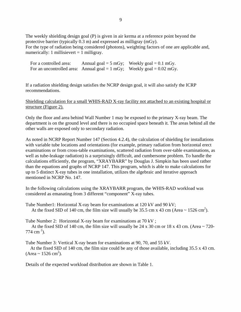
9 The weekly shielding design goal (P) is given in air kerma at a reference point beyond the protective barrier (typically 0.3 m) and expressed as milligray (mGy). For the type of radiation being considered (photons), weighting factors of one are applicable and, numerically: 1 millisievert = 1 milligray. For a controlled area: Annual goal = 5 mGy; Weekly goal = 0.1 mGy. For an uncontrolled area: Annual goal = 1 mGy; Weekly goal = 0.02 mGy. If a radiation shielding design satisfies the NCRP design goal, it will also satisfy the ICRP recommendations. Shielding calculation for a small WHIS-RAD X-ray facility not attached to an existing hospital or structure (Figure 2). Only the floor and area behind Wall Number 1 may be exposed to the primary X-ray beam. The department is on the ground level and there is no occupied space beneath it. The areas behind all the other walls are exposed only to secondary radiation. As noted in NCRP Report Number 147 (Section 4.2.4), the calculation of shielding for installations with variable tube locations and orientations (for example, primary radiation from horizontal erect examinations or from cross-table examinations, scattered radiation from over-table examinations, as well as tube-leakage radiation) is a surprisingly difficult, and cumbersome problem. To handle the calculations efficiently, the program, “XRAYBARR” by Douglas J. Simpkin has been used rather than the equations and graphs of NCRP 147. This program, which is able to make calculations for up to 5 distinct X-ray tubes in one installation, utilizes the algebraic and iterative approach mentioned in NCRP No. 147. In the following calculations using the XRAYBARR program, the WHIS-RAD workload was considered as emanating from 3 different “component” X-ray tubes. Tube Number1: Horizontal X-ray beam for examinations at 120 kV and 90 kV; At the fixed SID of 140 cm, the film size will usually be 35.5 cm x 43 cm (Area ~ 1526 cm2). Tube Number 2: Horizontal X-ray beam for examinations at 70 kV ; At the fixed SID of 140 cm, the film size will usually be 24 x 30 cm or 18 x 43 cm. (Area ~ 720-774 cm 2). Tube Number 3: Vertical X-ray beam for examinations at 90, 70, and 55 kV. At the fixed SID of 140 cm, the film size could be any of those available, including 35.5 x 43 cm. (Area ~ 1526 cm2). Details of the expected workload distribution are shown in Table 1.
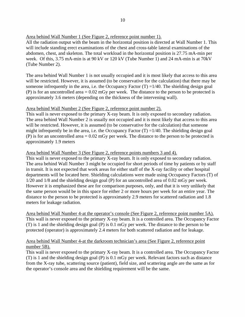
10 Area behind Wall Number 1 (See Figure 2, reference point number 1). All the radiation output with the beam in the horizontal position is directed at Wall Number 1. This will include standing erect examinations of the chest and cross-table lateral examinations of the abdomen, chest, and skeleton. The total workload in the horizontal position is 27.75 mA-min per week. Of this, 3.75 mA-min is at 90 kV or 120 kV (Tube Number 1) and 24 mA-min is at 70kV (Tube Number 2). The area behind Wall Number 1 is not usually occupied and it is most likely that access to this area will be restricted. However, it is assumed (to be conservative for the calculation) that there may be someone infrequently in the area, i.e. the Occupancy Factor (T) =1/40. The shielding design goal (P) is for an uncontrolled area = 0.02 mGy per week. The distance to the person to be protected is approximately 3.6 meters (depending on the thickness of the intervening wall). Area behind Wall Number 2 (See Figure 2, reference point number 2). This wall is never exposed to the primary X-ray beam. It is only exposed to secondary radiation. The area behind Wall Number 2 is usually not occupied and it is most likely that access to this area will be restricted. However, it is assumed (to be conservative for the calculation) that someone might infrequently be in the area, i.e. the Occupancy Factor (T) =1/40. The shielding design goal (P) is for an uncontrolled area = 0.02 mGy per week. The distance to the person to be protected is approximately 1.9 meters Area behind Wall Number 3 (See Figure 2, reference points numbers 3 and 4). This wall is never exposed to the primary X-ray beam. It is only exposed to secondary radiation. The area behind Wall Number 3 might be occupied for short periods of time by patients or by staff in transit. It is not expected that work areas for either staff of the X-ray facility or other hospital departments will be located here. Shielding calculations were made using Occupancy Factors (T) of 1/20 and 1/8 and the shielding design goal (P) for an uncontrolled area of 0.02 mGy per week. However it is emphasized these are for comparison purposes, only, and that it is very unlikely that the same person would be in this space for either 2 or more hours per week for an entire year. The distance to the person to be protected is approximately 2.9 meters for scattered radiation and 1.8 meters for leakage radiation. Area behind Wall Number 4-at the operator’s console (See Figure 2, reference point number 5A). This wall is never exposed to the primary X-ray beam. It is a controlled area. The Occupancy Factor (T) is 1 and the shielding design goal (P) is 0.1 mGy per week. The distance to the person to be protected (operator) is approximately 2.4 meters for both scattered radiation and for leakage. Area behind Wall Number 4-at the darkroom technician’s area (See Figure 2, reference point number 5B). This wall is never exposed to the primary X-ray beam. It is a controlled area. The Occupancy Factor (T) is 1 and the shielding design goal (P) is 0.1 mGy per week. Relevant factors such as distance from the X-ray tube, scattering source (patient), field size, and scattering angle are the same as for the operator’s console area and the shielding requirement will be the same.
11
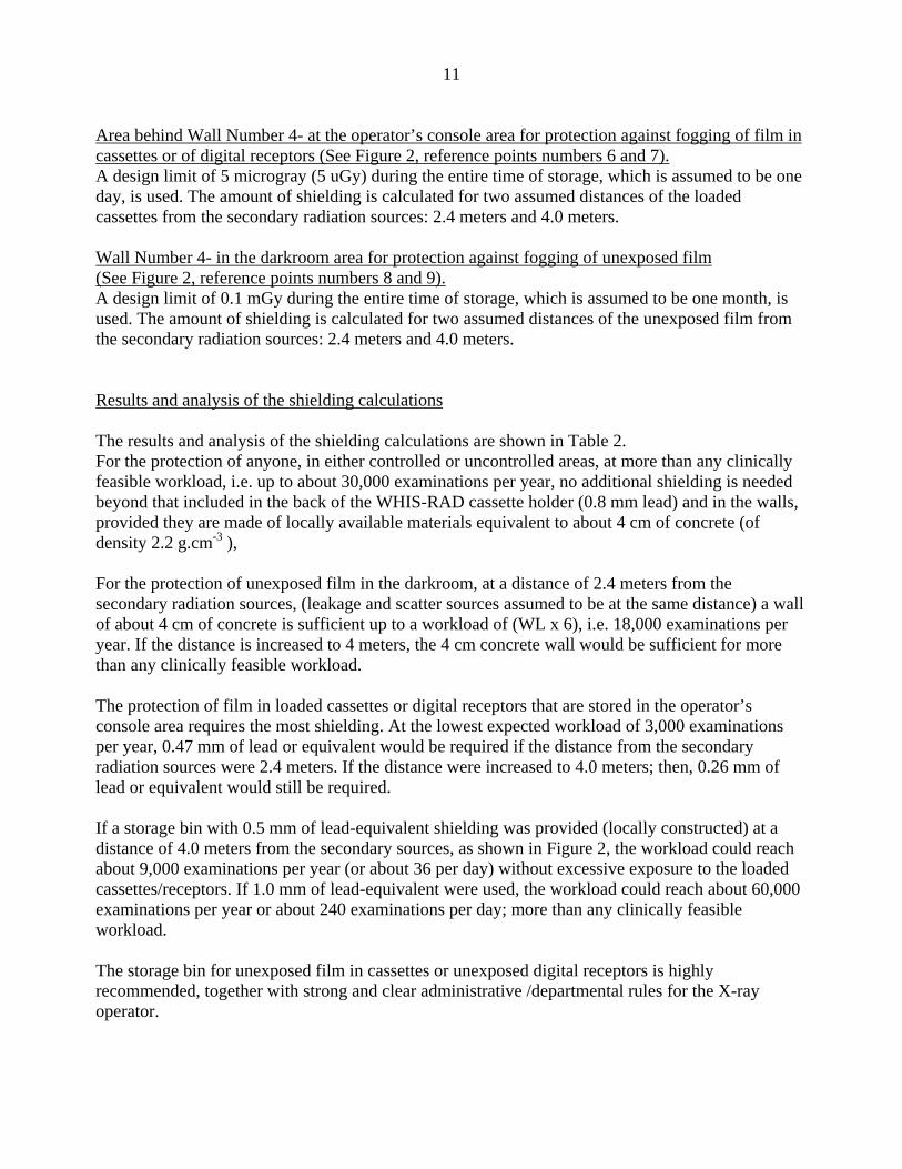
Area behind Wall Number 4- at the operator’s console area for protection against fogging of film in cassettes or of digital receptors (See Figure 2, reference points numbers 6 and 7). A design limit of 5 microgray (5 uGy) during the entire time of storage, which is assumed to be one day, is used. The amount of shielding is calculated for two assumed distances of the loaded cassettes from the secondary radiation sources: 2.4 meters and 4.0 meters. Wall Number 4- in the darkroom area for protection against fogging of unexposed film (See Figure 2, reference points numbers 8 and 9). A design limit of 0.1 mGy during the entire time of storage, which is assumed to be one month, is used. The amount of shielding is calculated for two assumed distances of the unexposed film from the secondary radiation sources: 2.4 meters and 4.0 meters. Results and analysis of the shielding calculations The results and analysis of the shielding calculations are shown in Table 2. For the protection of anyone, in either controlled or uncontrolled areas, at more than any clinically feasible workload, i.e. up to about 30,000 examinations per year, no additional shielding is needed beyond that included in the back of the WHIS-RAD cassette holder (0.8 mm lead) and in the walls, provided they are made of locally available materials equivalent to about 4 cm of concrete (of density 2.2 g.cm-3 ), For the protection of unexposed film in the darkroom, at a distance of 2.4 meters from the secondary radiation sources, (leakage and scatter sources assumed to be at the same distance) a wall of about 4 cm of concrete is sufficient up to a workload of (WL x 6), i.e. 18,000 examinations per year. If the distance is increased to 4 meters, the 4 cm concrete wall would be sufficient for more than any clinically feasible workload. The protection of film in loaded cassettes or digital receptors that are stored in the operator’s console area requires the most shielding. At the lowest expected workload of 3,000 examinations per year, 0.47 mm of lead or equivalent would be required if the distance from the secondary radiation sources were 2.4 meters. If the distance were increased to 4.0 meters; then, 0.26 mm of lead or equivalent would still be required. If a storage bin with 0.5 mm of lead-equivalent shielding was provided (locally constructed) at a distance of 4.0 meters from the secondary sources, as shown in Figure 2, the workload could reach about 9,000 examinations per year (or about 36 per day) without excessive exposure to the loaded cassettes/receptors. If 1.0 mm of lead-equivalent were used, the workload could reach about 60,000 examinations per year or about 240 examinations per day; more than any clinically feasible workload. The storage bin for unexposed film in cassettes or unexposed digital receptors is highly recommended, together with strong and clear administrative /departmental rules for the X-ray operator.
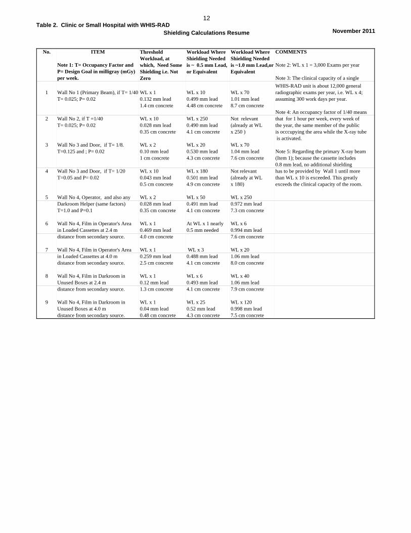
Table 2. Clinic or Small Hospital with WHIS-RAD 12
Shielding Calculations Resume November 2011
No. ITEM COMMENTS
Note 1: T= Occupancy Factor and Note 2: WL x 1 = 3,000 Exams per yearP= Design Goal in milligray (mGy) per week. Note 3: The clinical capacity of a single
WHIS-RAD unit is about 12,000 general1 Wall No 1 (Primary Beam), if T= 1/40 WL x 1 WL x 10 WL x 70 radiographic exams per year, i.e. WL x 4;
T= 0.025; P= 0.02 0.132 mm lead 0.499 mm lead 1.01 mm lead assuming 300 work days per year.1.4 cm concrete 4.48 cm concrete 8.7 cm concrete
Note 4: An occupancy factor of 1/40 means2 Wall No 2, if T =1/40 WL x 10 WL x 250 Not relevant that for 1 hour per week, every week of
T= 0.025; P= 0.02 0.028 mm lead 0.490 mm lead (already at WL the year, the same member of the public 0.35 cm concrete 4.1 cm concrete x 250 ) is occcupying the area while the X-ray tube
is activated.3 Wall No 3 and Door, if T= 1/8. WL x 2 WL x 20 WL x 70
T=0.125 and ; P= 0.02 0.10 mm lead 0.530 mm lead 1.04 mm lead Note 5: Regarding the primary X-ray beam1 cm concrete 4.3 cm concrete 7.6 cm concrete (Item 1); because the cassette includes
0.8 mm lead, no additional shielding 4 Wall No 3 and Door, if T= 1/20 WL x 10 WL x 180 Not relevant has to be provided by Wall 1 until more
T=0.05 and P= 0.02 0.043 mm lead 0.501 mm lead (already at WL than WL x 10 is exceeded. This greatly 0.5 cm concrete 4.9 cm concrete x 180) exceeds the clinical capacity of the room.
5 Wall No 4, Operator, and also any WL x 2 WL x 50 WL x 250Darkroom Helper (same factors) 0.028 mm lead 0.491 mm lead 0.972 mm leadT=1.0 and P=0.1 0.35 cm concrete 4.1 cm concrete 7.3 cm concrete
6 Wall No 4, Film in Operator's Area WL x 1 At WL x 1 nearly WL x 6in Loaded Cassettes at 2.4 m 0.469 mm lead 0.5 mm needed 0.994 mm leaddistance from secondary source. 4.0 cm concrete 7.6 cm concrete
7 Wall No 4, Film in Operator's Area WL x 1 WL x 3 WL x 20in Loaded Cassettes at 4.0 m 0.259 mm lead 0.488 mm lead 1.06 mm leaddistance from secondary source. 2.5 cm concrete 4.1 cm concrete 8.0 cm concrete
8 Wall No 4, Film in Darkroom in WL x 1 WL x 6 WL x 40Unused Boxes at 2.4 m 0.12 mm lead 0.493 mm lead 1.06 mm leaddistance from secondary source. 1.3 cm concrete 4.1 cm concrete 7.9 cm concrete
9 Wall No 4, Film in Darkroom in WL x 1 WL x 25 WL x 120Unused Boxes at 4.0 m 0.04 mm lead 0.52 mm lead 0.998 mm leaddistance from secondary source. 0.48 cm concrete 4.3 cm concrete 7.5 cm concrete
Threshold Workload, at which, Need Some Shielding i.e. Not Zero
Workload Where Shielding Needed is ~ 0.5 mm Lead, or Equivalent
Workload Where Shielding Needed is ~1.0 mm Lead,or Equivalent
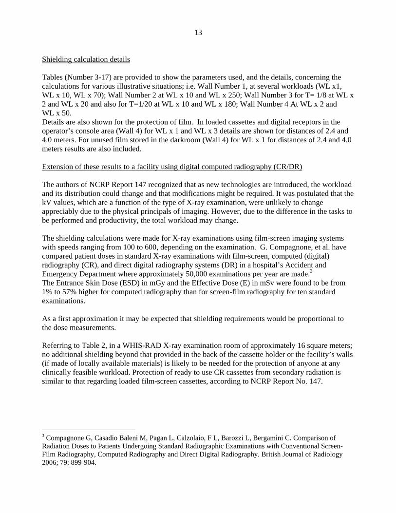
13 Shielding calculation details Tables (Number 3-17) are provided to show the parameters used, and the details, concerning the calculations for various illustrative situations; i.e. Wall Number 1, at several workloads (WL x1, WL x 10, WL x 70); Wall Number 2 at WL x 10 and WL x 250; Wall Number 3 for T= 1/8 at WL x 2 and WL x 20 and also for T=1/20 at WL x 10 and WL x 180; Wall Number 4 At WL x 2 and WL x 50. Details are also shown for the protection of film. In loaded cassettes and digital receptors in the operator’s console area (Wall 4) for WL x 1 and WL x 3 details are shown for distances of 2.4 and 4.0 meters. For unused film stored in the darkroom (Wall 4) for WL x 1 for distances of 2.4 and 4.0 meters results are also included. Extension of these results to a facility using digital computed radiography (CR/DR) The authors of NCRP Report 147 recognized that as new technologies are introduced, the workload and its distribution could change and that modifications might be required. It was postulated that the kV values, which are a function of the type of X-ray examination, were unlikely to change appreciably due to the physical principals of imaging. However, due to the difference in the tasks to be performed and productivity, the total workload may change. The shielding calculations were made for X-ray examinations using film-screen imaging systems with speeds ranging from 100 to 600, depending on the examination. G. Compagnone, et al. have compared patient doses in standard X-ray examinations with film-screen, computed (digital) radiography (CR), and direct digital radiography systems (DR) in a hospital’s Accident and Emergency Department where approximately 50,000 examinations per year are made.3 The Entrance Skin Dose (ESD) in mGy and the Effective Dose (E) in mSv were found to be from 1% to 57% higher for computed radiography than for screen-film radiography for ten standard examinations. As a first approximation it may be expected that shielding requirements would be proportional to the dose measurements. Referring to Table 2, in a WHIS-RAD X-ray examination room of approximately 16 square meters; no additional shielding beyond that provided in the back of the cassette holder or the facility’s walls (if made of locally available materials) is likely to be needed for the protection of anyone at any clinically feasible workload. Protection of ready to use CR cassettes from secondary radiation is similar to that regarding loaded film-screen cassettes, according to NCRP Report No. 147.
3 Compagnone G, Casadio Baleni M, Pagan L, Calzolaio, F L, Barozzi L, Bergamini C. Comparison of Radiation Doses to Patients Undergoing Standard Radiographic Examinations with Conventional Screen- Film Radiography, Computed Radiography and Direct Digital Radiography. British Journal of Radiology 2006; 79: 899-904.
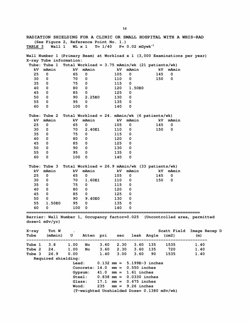
14 RADIATION SHIELDING FOR A CLINIC OR SMALL HOSPITAL WITH A WHIS-RAD (See Figure 2, Reference Point No. 1.) TABLE 3 Wall 1 WL x 1 T= 1/40 P= 0.02 mGywk-1 Wall Number 1 (Primary Beam) at Workload x 1 (3,000 Examinations per year) X-ray Tube information: Tube: Tube 1 Total Workload = 3.75 mAmin/wk (21 patients/wk) kV mAmin kV mAmin kV mAmin kV mAmin 25 0 65 0 105 0 145 0 30 0 70 0 110 0 150 0 35 0 75 0 115 0 40 0 80 0 120 1.50E0 45 0 85 0 125 0 50 0 90 2.25E0 130 0 55 0 95 0 135 0 60 0 100 0 140 0 Tube: Tube 2 Total Workload = 24. mAmin/wk (6 patients/wk) kV mAmin kV mAmin kV mAmin kV mAmin 25 0 65 0 105 0 145 0 30 0 70 2.40E1 110 0 150 0 35 0 75 0 115 0 40 0 80 0 120 0 45 0 85 0 125 0 50 0 90 0 130 0 55 0 95 0 135 0 60 0 100 0 140 0 Tube: Tube 3 Total Workload = 26.9 mAmin/wk (33 patients/wk) kV mAmin kV mAmin kV mAmin kV mAmin 25 0 65 0 105 0 145 0 30 0 70 1.60E1 110 0 150 0 35 0 75 0 115 0 40 0 80 0 120 0 45 0 85 0 125 0 50 0 90 9.40E0 130 0 55 1.50E0 95 0 135 0 60 0 100 0 140 0 ======================================================================= Barrier: Wall Number 1, Occupancy factor=0.025 (Uncontrolled area, permitted dose=1 mSv/yr) X-ray Tot W . Scatt Field Image Recep D Tube (mAmin) U Atten pri sec leak Angle (cm2) (m) -------------------------------------------------------------------------- Tube 1 3.8 1.00 No 3.60 2.30 3.60 135 1535 1.40 Tube 2 24. 1.00 No 3.60 2.30 3.60 135 720 1.40 Tube 3 26.9 0.00 1.40 3.00 3.60 90 1535 1.40 Required shielding: Lead: 0.132 mm = 5.199E-3 inches Concrete: 14.0 mm = 0.550 inches Gypsum: 41.0 mm = 1.61 inches Steel: 0.838 mm = 0.0330 inches Glass: 17.1 mm = 0.675 inches Wood: 235 mm = 9.26 inches (T-weighted Unshielded Dose= 0.1380 mSv/wk)
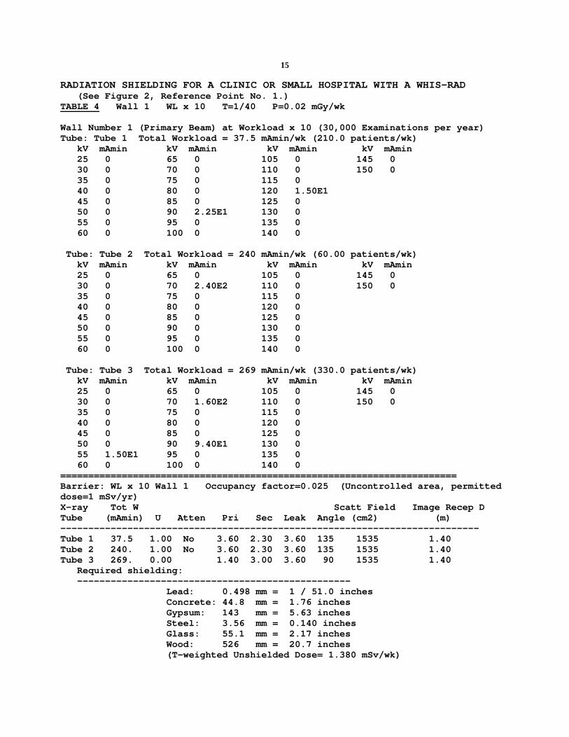
15 RADIATION SHIELDING FOR A CLINIC OR SMALL HOSPITAL WITH A WHIS-RAD (See Figure 2, Reference Point No. 1.) TABLE 4 Wall 1 WL x 10 T=1/40 P=0.02 mGy/wk Wall Number 1 (Primary Beam) at Workload x 10 (30,000 Examinations per year) Tube: Tube 1 Total Workload = 37.5 mAmin/wk (210.0 patients/wk) kV mAmin kV mAmin kV mAmin kV mAmin 25 0 65 0 105 0 145 0 30 0 70 0 110 0 150 0 35 0 75 0 115 0 40 0 80 0 120 1.50E1 45 0 85 0 125 0 50 0 90 2.25E1 130 0 55 0 95 0 135 0 60 0 100 0 140 0 Tube: Tube 2 Total Workload = 240 mAmin/wk (60.00 patients/wk) kV mAmin kV mAmin kV mAmin kV mAmin 25 0 65 0 105 0 145 0 30 0 70 2.40E2 110 0 150 0 35 0 75 0 115 0 40 0 80 0 120 0 45 0 85 0 125 0 50 0 90 0 130 0 55 0 95 0 135 0 60 0 100 0 140 0 Tube: Tube 3 Total Workload = 269 mAmin/wk (330.0 patients/wk) kV mAmin kV mAmin kV mAmin kV mAmin 25 0 65 0 105 0 145 0 30 0 70 1.60E2 110 0 150 0 35 0 75 0 115 0 40 0 80 0 120 0 45 0 85 0 125 0 50 0 90 9.40E1 130 0 55 1.50E1 95 0 135 0 60 0 100 0 140 0 ======================================================================= Barrier: WL x 10 Wall 1 Occupancy factor=0.025 (Uncontrolled area, permitted dose=1 mSv/yr) X-ray Tot W Scatt Field Image Recep D Tube (mAmin) U Atten Pri Sec Leak Angle (cm2) (m) --------------------------------------------------------------------------- Tube 1 37.5 1.00 No 3.60 2.30 3.60 135 1535 1.40 Tube 2 240. 1.00 No 3.60 2.30 3.60 135 1535 1.40 Tube 3 269. 0.00 1.40 3.00 3.60 90 1535 1.40 Required shielding: ------------------------------------------------- Lead: 0.498 mm = 1 / 51.0 inches Concrete: 44.8 mm = 1.76 inches Gypsum: 143 mm = 5.63 inches Steel: 3.56 mm = 0.140 inches Glass: 55.1 mm = 2.17 inches Wood: 526 mm = 20.7 inches (T-weighted Unshielded Dose= 1.380 mSv/wk)
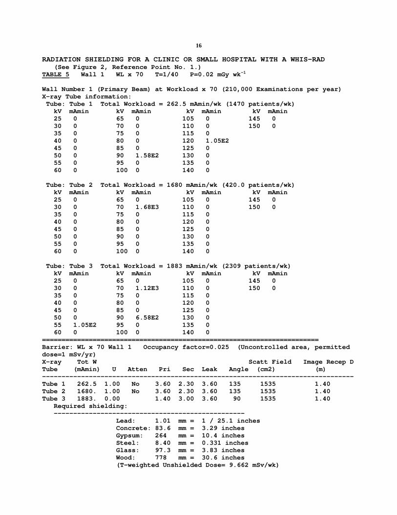
16 RADIATION SHIELDING FOR A CLINIC OR SMALL HOSPITAL WITH A WHIS-RAD (See Figure 2, Reference Point No. 1.) TABLE 5 Wall 1 WL x 70 T=1/40 P=0.02 mGy wk-1 Wall Number 1 (Primary Beam) at Workload x 70 (210,000 Examinations per year) X-ray Tube information: Tube: Tube 1 Total Workload = 262.5 mAmin/wk (1470 patients/wk) kV mAmin kV mAmin kV mAmin kV mAmin 25 0 65 0 105 0 145 0 30 0 70 0 110 0 150 0 35 0 75 0 115 0 40 0 80 0 120 1.05E2 45 0 85 0 125 0 50 0 90 1.58E2 130 0 55 0 95 0 135 0 60 0 100 0 140 0 Tube: Tube 2 Total Workload = 1680 mAmin/wk (420.0 patients/wk) kV mAmin kV mAmin kV mAmin kV mAmin 25 0 65 0 105 0 145 0 30 0 70 1.68E3 110 0 150 0 35 0 75 0 115 0 40 0 80 0 120 0 45 0 85 0 125 0 50 0 90 0 130 0 55 0 95 0 135 0 60 0 100 0 140 0 Tube: Tube 3 Total Workload = 1883 mAmin/wk (2309 patients/wk) kV mAmin kV mAmin kV mAmin kV mAmin 25 0 65 0 105 0 145 0 30 0 70 1.12E3 110 0 150 0 35 0 75 0 115 0 40 0 80 0 120 0 45 0 85 0 125 0 50 0 90 6.58E2 130 0 55 1.05E2 95 0 135 0 60 0 100 0 140 0 ======================================================================= Barrier: WL x 70 Wall 1 Occupancy factor=0.025 (Uncontrolled area, permitted dose=1 mSv/yr) X-ray Tot W Scatt Field Image Recep D Tube (mAmin) U Atten Pri Sec Leak Angle (cm2) (m) -------------------------------------------------------------------------------- Tube 1 262.5 1.00 No 3.60 2.30 3.60 135 1535 1.40 Tube 2 1680. 1.00 No 3.60 2.30 3.60 135 1535 1.40 Tube 3 1883. 0.00 1.40 3.00 3.60 90 1535 1.40 Required shielding: ------------------------------------------------- Lead: 1.01 mm = 1 / 25.1 inches Concrete: 83.6 mm = 3.29 inches Gypsum: 264 mm = 10.4 inches Steel: 8.40 mm = 0.331 inches Glass: 97.3 mm = 3.83 inches Wood: 778 mm = 30.6 inches (T-weighted Unshielded Dose= 9.662 mSv/wk)
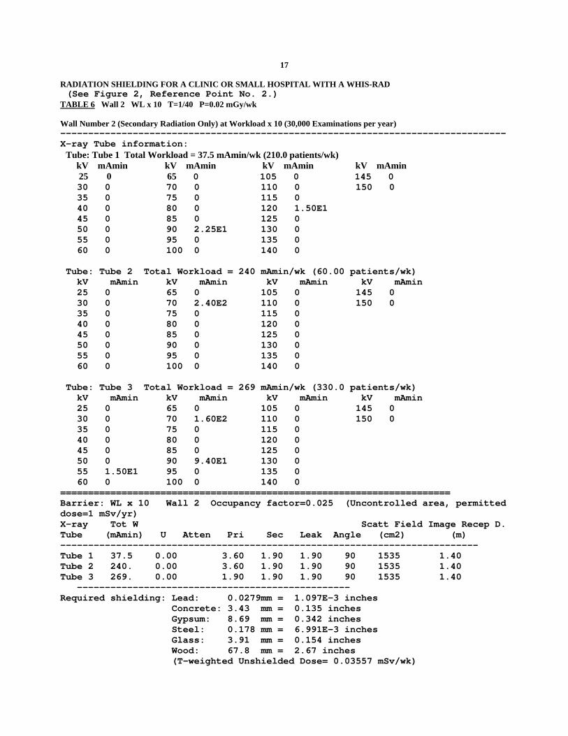
17 RADIATION SHIELDING FOR A CLINIC OR SMALL HOSPITAL WITH A WHIS-RAD (See Figure 2, Reference Point No. 2.) TABLE 6 Wall 2 WL x 10 T=1/40 P=0.02 mGy/wk Wall Number 2 (Secondary Radiation Only) at Workload x 10 (30,000 Examinations per year) -------------------------------------------------------------------------------- X-ray Tube information: Tube: Tube 1 Total Workload = 37.5 mAmin/wk (210.0 patients/wk) kV mAmin kV mAmin kV mAmin kV mAmin 25 0 65 0 105 0 145 0 30 0 70 0 110 0 150 0 35 0 75 0 115 0 40 0 80 0 120 1.50E1 45 0 85 0 125 0 50 0 90 2.25E1 130 0 55 0 95 0 135 0 60 0 100 0 140 0 Tube: Tube 2 Total Workload = 240 mAmin/wk (60.00 patients/wk) kV mAmin kV mAmin kV mAmin kV mAmin 25 0 65 0 105 0 145 0 30 0 70 2.40E2 110 0 150 0 35 0 75 0 115 0 40 0 80 0 120 0 45 0 85 0 125 0 50 0 90 0 130 0 55 0 95 0 135 0 60 0 100 0 140 0 Tube: Tube 3 Total Workload = 269 mAmin/wk (330.0 patients/wk) kV mAmin kV mAmin kV mAmin kV mAmin 25 0 65 0 105 0 145 0 30 0 70 1.60E2 110 0 150 0 35 0 75 0 115 0 40 0 80 0 120 0 45 0 85 0 125 0 50 0 90 9.40E1 130 0 55 1.50E1 95 0 135 0 60 0 100 0 140 0 ====================================================================== Barrier: WL x 10 Wall 2 Occupancy factor=0.025 (Uncontrolled area, permitted dose=1 mSv/yr) X-ray Tot W Scatt Field Image Recep D. Tube (mAmin) U Atten Pri Sec Leak Angle (cm2) (m) --------------------------------------------------------------------------- Tube 1 37.5 0.00 3.60 1.90 1.90 90 1535 1.40 Tube 2 240. 0.00 3.60 1.90 1.90 90 1535 1.40 Tube 3 269. 0.00 1.90 1.90 1.90 90 1535 1.40 ------------------------------------------------- Required shielding: Lead: 0.0279mm = 1.097E-3 inches Concrete: 3.43 mm = 0.135 inches Gypsum: 8.69 mm = 0.342 inches Steel: 0.178 mm = 6.991E-3 inches Glass: 3.91 mm = 0.154 inches Wood: 67.8 mm = 2.67 inches (T-weighted Unshielded Dose= 0.03557 mSv/wk)

18 RADIATION SHIELDING FOR A CLINIC OR SMALL HOSPITAL WITH A WHIS-RAD (See Figure 2, Reference Point No. 2.) TABLE 7 Wall 2 WL x 250 T=1/40 P=0.02 mGy/wk Wall Number 2 (Secondary Radiation Only) at Workload x 250 (750,000 Examinations per year) X-ray Tube information: Tube: Tube 1 Total Workload = 937.5 mAmin/wk (5250 patients/wk) kV mAmin kV mAmin kV mAmin kV mAmin 25 0 65 0 105 0 145 0 30 0 70 0 110 0 150 0 35 0 75 0 115 0 40 0 80 0 120 3.75E2 45 0 85 0 125 0 50 0 90 5.63E2 130 0 55 0 95 0 135 0 60 0 100 0 140 0 Tube: Tube 2 Total Workload = 6000 mAmin/wk (1500 patients/wk) kV mAmin kV mAmin kV mAmin kV mAmin 25 0 65 0 105 0 145 0 30 0 70 6.00E3 110 0 150 0 35 0 75 0 115 0 40 0 80 0 120 0 45 0 85 0 125 0 50 0 90 0 130 0 55 0 95 0 135 0 60 0 100 0 140 0 Tube: Tube 3 Total Workload = 6725 mAmin/wk (8250 patients/wk) kV mAmin kV mAmin kV mAmin kV mAmin 25 0 65 0 105 0 145 0 30 0 70 4.00E3 110 0 150 0 35 0 75 0 115 0 40 0 80 0 120 0 45 0 85 0 125 0 50 0 90 2.35E3 130 0 55 3.75E2 95 0 135 0 60 0 100 0 140 0 ======================================================================= Barrier: WL x 250 Occupancy factor=0.025 (Uncontrolled area, permitted dose=1 mSv/yr) X-ray Tot W Scatt Field Image Recep D Tube (mAmin) U Pri Sec Leak Angle (cm2) (m) -------------------------------------------------------------------------------- Tube 1 937.5 0.00 3.60 1.90 1.90 90 1535 1.40 Tube 2 6000. 0.00 3.60 1.90 1.90 90 1535 1.40 Tube 3 6725. 0.00 1.90 1.90 1.90 90 1535 1.40 Required shielding: ------------------------------------------------- Lead: 0.490 mm = 1 / 51.8 inches Concrete: 41.1 mm = 1.62 inches Gypsum: 129 mm = 5.08 inches Steel: 3.55 mm = 0.140 inches Glass: 49.5 mm = 1.95 inches Wood: 470 mm = 18.5 inches (T-weighted Unshielded Dose= 0.8893 mSv/wk)
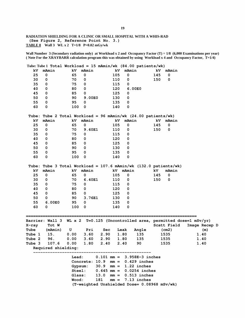
19 RADIATION SHIELDING FOR A CLINIC OR SMALL HOSPITAL WITH A WHIS-RAD (See Figure 2, Reference Point No. 3.) TABLE 8 Wall 3 WL x 2 T=1/8 P=0.02 mGy/wk Wall Number 3 (Secondary radiation only) at Workload x 2 and Occupancy Factor (T) = 1/8 (6,000 Examinations per year) ( Note For the XRAYBARR calculation program this was obtained by using Workload x 4 and Occupancy Factor, T=1/4) Tube: Tube 1 Total Workload = 15 mAmin/wk (84.00 patients/wk) kV mAmin kV mAmin kV mAmin kV mAmin 25 0 65 0 105 0 145 0 30 0 70 0 110 0 150 0 35 0 75 0 115 0 40 0 80 0 120 6.00E0 45 0 85 0 125 0 50 0 90 9.00E0 130 0 55 0 95 0 135 0 60 0 100 0 140 0 Tube: Tube 2 Total Workload = 96 mAmin/wk (24.00 patients/wk) kV mAmin kV mAmin kV mAmin kV mAmin 25 0 65 0 105 0 145 0 30 0 70 9.60E1 110 0 150 0 35 0 75 0 115 0 40 0 80 0 120 0 45 0 85 0 125 0 50 0 90 0 130 0 55 0 95 0 135 0 60 0 100 0 140 0 Tube: Tube 3 Total Workload = 107.6 mAmin/wk (132.0 patients/wk) kV mAmin kV mAmin kV mAmin kV mAmin 25 0 65 0 105 0 145 0 30 0 70 6.40E1 110 0 150 0 35 0 75 0 115 0 40 0 80 0 120 0 45 0 85 0 125 0 50 0 90 3.76E1 130 0 55 6.00E0 95 0 135 0 60 0 100 0 140 0 ======================================================================= Barrier: Wall 3 WL x 2 T=0.125 (Uncontrolled area, permitted dose=1 mSv/yr) X-ray Tot W Scatt Field Image Recep D Tube (mAmin) U Pri Sec Leak Angle (cm2) (m) Tube 1 15. 0.00 3.60 2.90 1.80 135 1535 1.40 Tube 2 96. 0.00 3.60 2.90 1.80 135 1535 1.40 Tube 3 107.6 0.00 1.80 2.40 2.40 90 1535 1.40 Required shielding: ------------------------------------------------- Lead: 0.101 mm = 3.958E-3 inches Concrete: 10.9 mm = 0.429 inches Gypsum: 30.9 mm = 1.22 inches Steel: 0.645 mm = 0.0254 inches Glass: 13.0 mm = 0.513 inches Wood: 181 mm = 7.13 inches (T-weighted Unshielded Dose= 0.08968 mSv/wk)
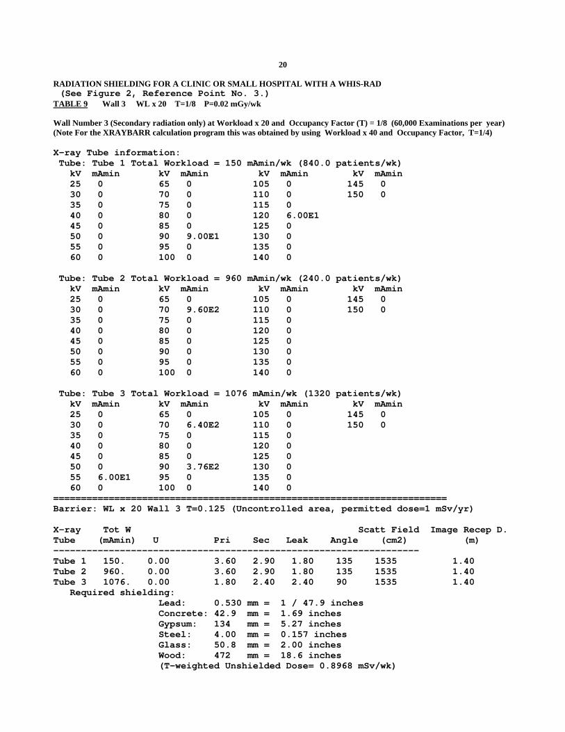
20 RADIATION SHIELDING FOR A CLINIC OR SMALL HOSPITAL WITH A WHIS-RAD (See Figure 2, Reference Point No. 3.) TABLE 9 Wall 3 WL x 20 T=1/8 P=0.02 mGy/wk Wall Number 3 (Secondary radiation only) at Workload x 20 and Occupancy Factor (T) = 1/8 (60,000 Examinations per year) (Note For the XRAYBARR calculation program this was obtained by using Workload x 40 and Occupancy Factor, T=1/4) X-ray Tube information: Tube: Tube 1 Total Workload = 150 mAmin/wk (840.0 patients/wk) kV mAmin kV mAmin kV mAmin kV mAmin 25 0 65 0 105 0 145 0 30 0 70 0 110 0 150 0 35 0 75 0 115 0 40 0 80 0 120 6.00E1 45 0 85 0 125 0 50 0 90 9.00E1 130 0 55 0 95 0 135 0 60 0 100 0 140 0 Tube: Tube 2 Total Workload = 960 mAmin/wk (240.0 patients/wk) kV mAmin kV mAmin kV mAmin kV mAmin 25 0 65 0 105 0 145 0 30 0 70 9.60E2 110 0 150 0 35 0 75 0 115 0 40 0 80 0 120 0 45 0 85 0 125 0 50 0 90 0 130 0 55 0 95 0 135 0 60 0 100 0 140 0 Tube: Tube 3 Total Workload = 1076 mAmin/wk (1320 patients/wk) kV mAmin kV mAmin kV mAmin kV mAmin 25 0 65 0 105 0 145 0 30 0 70 6.40E2 110 0 150 0 35 0 75 0 115 0 40 0 80 0 120 0 45 0 85 0 125 0 50 0 90 3.76E2 130 0 55 6.00E1 95 0 135 0 60 0 100 0 140 0 ======================================================================= Barrier: WL x 20 Wall 3 T=0.125 (Uncontrolled area, permitted dose=1 mSv/yr) X-ray Tot W Scatt Field Image Recep D. Tube (mAmin) U Pri Sec Leak Angle (cm2) (m) ------------------------------------------------------------------ Tube 1 150. 0.00 3.60 2.90 1.80 135 1535 1.40 Tube 2 960. 0.00 3.60 2.90 1.80 135 1535 1.40 Tube 3 1076. 0.00 1.80 2.40 2.40 90 1535 1.40 Required shielding: Lead: 0.530 mm = 1 / 47.9 inches Concrete: 42.9 mm = 1.69 inches Gypsum: 134 mm = 5.27 inches Steel: 4.00 mm = 0.157 inches Glass: 50.8 mm = 2.00 inches Wood: 472 mm = 18.6 inches (T-weighted Unshielded Dose= 0.8968 mSv/wk)
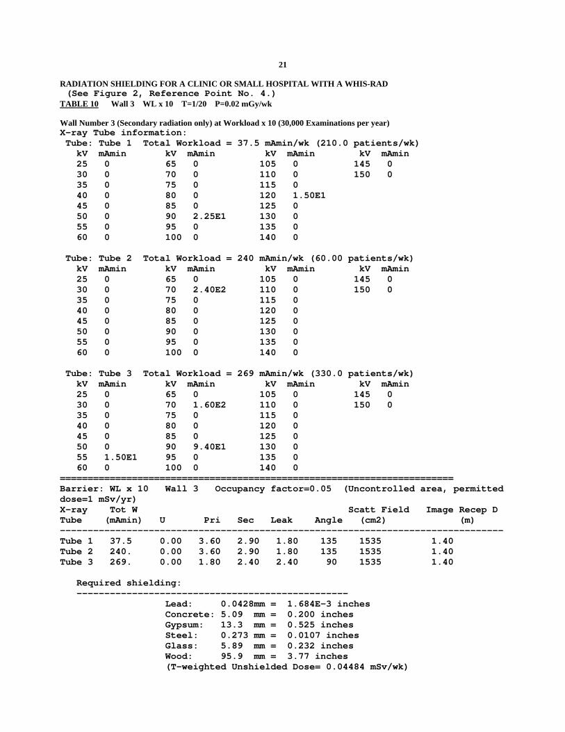
21 RADIATION SHIELDING FOR A CLINIC OR SMALL HOSPITAL WITH A WHIS-RAD (See Figure 2, Reference Point No. 4.) TABLE 10 Wall 3 WL x 10 T=1/20 P=0.02 mGy/wk Wall Number 3 (Secondary radiation only) at Workload x 10 (30,000 Examinations per year) X-ray Tube information: Tube: Tube 1 Total Workload = 37.5 mAmin/wk (210.0 patients/wk) kV mAmin kV mAmin kV mAmin kV mAmin 25 0 65 0 105 0 145 0 30 0 70 0 110 0 150 0 35 0 75 0 115 0 40 0 80 0 120 1.50E1 45 0 85 0 125 0 50 0 90 2.25E1 130 0 55 0 95 0 135 0 60 0 100 0 140 0 Tube: Tube 2 Total Workload = 240 mAmin/wk (60.00 patients/wk) kV mAmin kV mAmin kV mAmin kV mAmin 25 0 65 0 105 0 145 0 30 0 70 2.40E2 110 0 150 0 35 0 75 0 115 0 40 0 80 0 120 0 45 0 85 0 125 0 50 0 90 0 130 0 55 0 95 0 135 0 60 0 100 0 140 0 Tube: Tube 3 Total Workload = 269 mAmin/wk (330.0 patients/wk) kV mAmin kV mAmin kV mAmin kV mAmin 25 0 65 0 105 0 145 0 30 0 70 1.60E2 110 0 150 0 35 0 75 0 115 0 40 0 80 0 120 0 45 0 85 0 125 0 50 0 90 9.40E1 130 0 55 1.50E1 95 0 135 0 60 0 100 0 140 0 ======================================================================= Barrier: WL x 10 Wall 3 Occupancy factor=0.05 (Uncontrolled area, permitted dose=1 mSv/yr) X-ray Tot W Scatt Field Image Recep D Tube (mAmin) U Pri Sec Leak Angle (cm2) (m) -------------------------------------------------------------------------------- Tube 1 37.5 0.00 3.60 2.90 1.80 135 1535 1.40 Tube 2 240. 0.00 3.60 2.90 1.80 135 1535 1.40 Tube 3 269. 0.00 1.80 2.40 2.40 90 1535 1.40 Required shielding: ------------------------------------------------- Lead: 0.0428mm = 1.684E-3 inches Concrete: 5.09 mm = 0.200 inches Gypsum: 13.3 mm = 0.525 inches Steel: 0.273 mm = 0.0107 inches Glass: 5.89 mm = 0.232 inches Wood: 95.9 mm = 3.77 inches (T-weighted Unshielded Dose= 0.04484 mSv/wk)

22 RADIATION SHIELDING FOR A CLINIC OR SMALL HOSPITAL WITH A WHIS-RAD (See Figure 2, Reference Point No. 4.) TABLE 11 Wall 3 WL x 180 T=1/20 P=0.02 mGy/wk Wall Number 3 (Secondary radiation only) at Workload x 180 (540,000 Examinations per year X-ray Tube information: Tube: Tube 1 Total Workload = 675 mAmin/wk (3780 patients/wk) kV mAmin kV mAmin kV mAmin kV mAmin 25 0 65 0 105 0 145 0 30 0 70 0 110 0 150 0 35 0 75 0 115 0 40 0 80 0 120 2.70E2 45 0 85 0 125 0 50 0 90 4.05E2 130 0 55 0 95 0 135 0 60 0 100 0 140 0 Tube: Tube 2 Total Workload = 4320 mAmin/wk (1080 patients/wk) kV mAmin kV mAmin kV mAmin kV mAmin 25 0 65 0 105 0 145 0 30 0 70 4.32E3 110 0 150 0 35 0 75 0 115 0 40 0 80 0 120 0 45 0 85 0 125 0 50 0 90 0 130 0 55 0 95 0 135 0 60 0 100 0 140 0 Tube: Tube 3 Total Workload = 4842 mAmin/wk (5940 patients/wk) kV mAmin kV mAmin kV mAmin kV mAmin 25 0 65 0 105 0 145 0 30 0 70 2.88E3 110 0 150 0 35 0 75 0 115 0 40 0 80 0 120 0 45 0 85 0 125 0 50 0 90 1.69E3 130 0 55 2.70E2 95 0 135 0 60 0 100 0 140 0 ======================================================================= Barrier: WL x 180 Wall 3 Occupancy factor=0.05 (Uncontrolled area, permitted dose=1 mSv/yr) X-ray Tot W Scatt Field Image Recep D Tube (mAmin) U Pri Sec Leak Angle (cm2) (m) -------------------------------------------------------------------------------- Tube 1 675. 0.00 3.60 2.90 1.80 135 1535 1.40 Tube 2 4320. 0.00 3.60 2.90 1.80 135 1535 1.40 Tube 3 4842. 0.00 1.80 2.40 2.40 90 1535 1.40 Required shielding: Lead: 0.501 mm = 1 / 50.7 inches Concrete: 41.0 mm = 1.61 inches Gypsum: 128 mm = 5.04 inches Steel: 3.74 mm = 0.147 inches Glass: 48.7 mm = 1.92 inches Wood: 458 mm = 18.0 inches (T-weighted Unshielded Dose= 0.8071 mSv/wk)
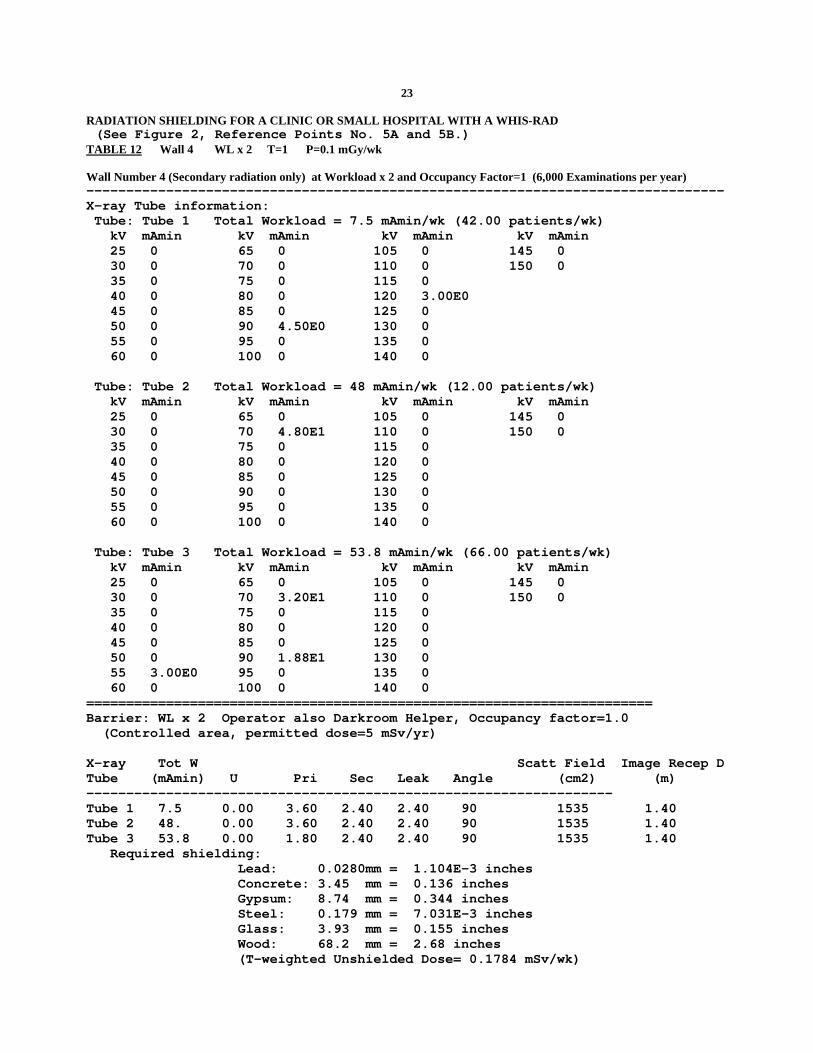
23 RADIATION SHIELDING FOR A CLINIC OR SMALL HOSPITAL WITH A WHIS-RAD (See Figure 2, Reference Points No. 5A and 5B.) TABLE 12 Wall 4 WL x 2 T=1 P=0.1 mGy/wk Wall Number 4 (Secondary radiation only) at Workload x 2 and Occupancy Factor=1 (6,000 Examinations per year) -------------------------------------------------------------------------------- X-ray Tube information: Tube: Tube 1 Total Workload = 7.5 mAmin/wk (42.00 patients/wk) kV mAmin kV mAmin kV mAmin kV mAmin 25 0 65 0 105 0 145 0 30 0 70 0 110 0 150 0 35 0 75 0 115 0 40 0 80 0 120 3.00E0 45 0 85 0 125 0 50 0 90 4.50E0 130 0 55 0 95 0 135 0 60 0 100 0 140 0 Tube: Tube 2 Total Workload = 48 mAmin/wk (12.00 patients/wk) kV mAmin kV mAmin kV mAmin kV mAmin 25 0 65 0 105 0 145 0 30 0 70 4.80E1 110 0 150 0 35 0 75 0 115 0 40 0 80 0 120 0 45 0 85 0 125 0 50 0 90 0 130 0 55 0 95 0 135 0 60 0 100 0 140 0 Tube: Tube 3 Total Workload = 53.8 mAmin/wk (66.00 patients/wk) kV mAmin kV mAmin kV mAmin kV mAmin 25 0 65 0 105 0 145 0 30 0 70 3.20E1 110 0 150 0 35 0 75 0 115 0 40 0 80 0 120 0 45 0 85 0 125 0 50 0 90 1.88E1 130 0 55 3.00E0 95 0 135 0 60 0 100 0 140 0 ======================================================================= Barrier: WL x 2 Operator also Darkroom Helper, Occupancy factor=1.0 (Controlled area, permitted dose=5 mSv/yr) X-ray Tot W Scatt Field Image Recep D Tube (mAmin) U Pri Sec Leak Angle (cm2) (m) ------------------------------------------------------------------ Tube 1 7.5 0.00 3.60 2.40 2.40 90 1535 1.40 Tube 2 48. 0.00 3.60 2.40 2.40 90 1535 1.40 Tube 3 53.8 0.00 1.80 2.40 2.40 90 1535 1.40 Required shielding: Lead: 0.0280mm = 1.104E-3 inches Concrete: 3.45 mm = 0.136 inches Gypsum: 8.74 mm = 0.344 inches Steel: 0.179 mm = 7.031E-3 inches Glass: 3.93 mm = 0.155 inches Wood: 68.2 mm = 2.68 inches (T-weighted Unshielded Dose= 0.1784 mSv/wk)
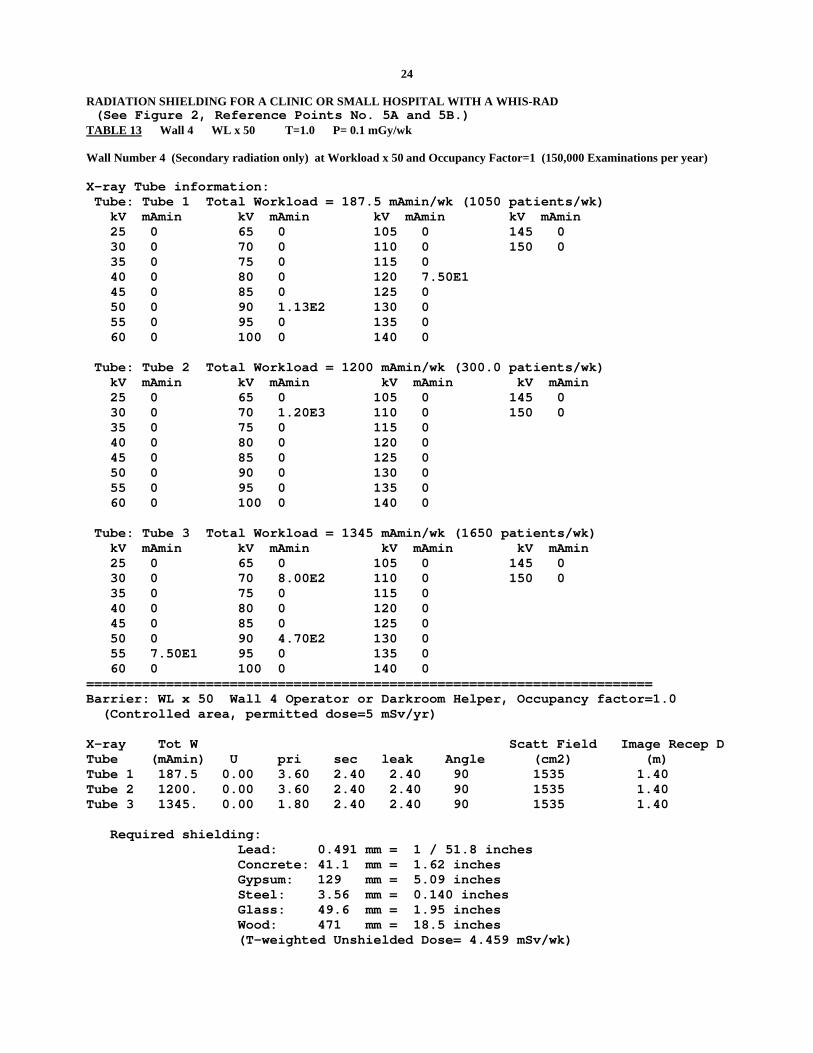
24 RADIATION SHIELDING FOR A CLINIC OR SMALL HOSPITAL WITH A WHIS-RAD (See Figure 2, Reference Points No. 5A and 5B.) TABLE 13 Wall 4 WL x 50 T=1.0 P= 0.1 mGy/wk Wall Number 4 (Secondary radiation only) at Workload x 50 and Occupancy Factor=1 (150,000 Examinations per year) X-ray Tube information: Tube: Tube 1 Total Workload = 187.5 mAmin/wk (1050 patients/wk) kV mAmin kV mAmin kV mAmin kV mAmin 25 0 65 0 105 0 145 0 30 0 70 0 110 0 150 0 35 0 75 0 115 0 40 0 80 0 120 7.50E1 45 0 85 0 125 0 50 0 90 1.13E2 130 0 55 0 95 0 135 0 60 0 100 0 140 0 Tube: Tube 2 Total Workload = 1200 mAmin/wk (300.0 patients/wk) kV mAmin kV mAmin kV mAmin kV mAmin 25 0 65 0 105 0 145 0 30 0 70 1.20E3 110 0 150 0 35 0 75 0 115 0 40 0 80 0 120 0 45 0 85 0 125 0 50 0 90 0 130 0 55 0 95 0 135 0 60 0 100 0 140 0 Tube: Tube 3 Total Workload = 1345 mAmin/wk (1650 patients/wk) kV mAmin kV mAmin kV mAmin kV mAmin 25 0 65 0 105 0 145 0 30 0 70 8.00E2 110 0 150 0 35 0 75 0 115 0 40 0 80 0 120 0 45 0 85 0 125 0 50 0 90 4.70E2 130 0 55 7.50E1 95 0 135 0 60 0 100 0 140 0 ======================================================================= Barrier: WL x 50 Wall 4 Operator or Darkroom Helper, Occupancy factor=1.0 (Controlled area, permitted dose=5 mSv/yr) X-ray Tot W Scatt Field Image Recep D Tube (mAmin) U pri sec leak Angle (cm2) (m) Tube 1 187.5 0.00 3.60 2.40 2.40 90 1535 1.40 Tube 2 1200. 0.00 3.60 2.40 2.40 90 1535 1.40 Tube 3 1345. 0.00 1.80 2.40 2.40 90 1535 1.40 Required shielding: Lead: 0.491 mm = 1 / 51.8 inches Concrete: 41.1 mm = 1.62 inches Gypsum: 129 mm = 5.09 inches Steel: 3.56 mm = 0.140 inches Glass: 49.6 mm = 1.95 inches Wood: 471 mm = 18.5 inches (T-weighted Unshielded Dose= 4.459 mSv/wk)
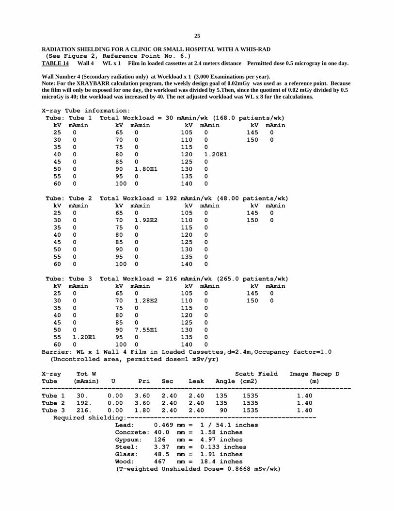
25 RADIATION SHIELDING FOR A CLINIC OR SMALL HOSPITAL WITH A WHIS-RAD (See Figure 2, Reference Point No. 6.) TABLE 14 Wall 4 WL x 1 Film in loaded cassettes at 2.4 meters distance Permitted dose 0.5 microgray in one day. Wall Number 4 (Secondary radiation only) at Workload x 1 (3,000 Examinations per year). Note: For the XRAYBARR calculation program, the weekly design goal of 0.02mGy was used as a reference point. Because the film will only be exposed for one day, the workload was divided by 5.Then, since the quotient of 0.02 mGy divided by 0.5 microGy is 40; the workload was increased by 40. The net adjusted workload was WL x 8 for the calculations. X-ray Tube information: Tube: Tube 1 Total Workload = 30 mAmin/wk (168.0 patients/wk) kV mAmin kV mAmin kV mAmin kV mAmin 25 0 65 0 105 0 145 0 30 0 70 0 110 0 150 0 35 0 75 0 115 0 40 0 80 0 120 1.20E1 45 0 85 0 125 0 50 0 90 1.80E1 130 0 55 0 95 0 135 0 60 0 100 0 140 0 Tube: Tube 2 Total Workload = 192 mAmin/wk (48.00 patients/wk) kV mAmin kV mAmin kV mAmin kV mAmin 25 0 65 0 105 0 145 0 30 0 70 1.92E2 110 0 150 0 35 0 75 0 115 0 40 0 80 0 120 0 45 0 85 0 125 0 50 0 90 0 130 0 55 0 95 0 135 0 60 0 100 0 140 0 Tube: Tube 3 Total Workload = 216 mAmin/wk (265.0 patients/wk) kV mAmin kV mAmin kV mAmin kV mAmin 25 0 65 0 105 0 145 0 30 0 70 1.28E2 110 0 150 0 35 0 75 0 115 0 40 0 80 0 120 0 45 0 85 0 125 0 50 0 90 7.55E1 130 0 55 1.20E1 95 0 135 0 60 0 100 0 140 0 Barrier: WL x 1 Wall 4 Film in Loaded Cassettes,d=2.4m,Occupancy factor=1.0 (Uncontrolled area, permitted dose=1 mSv/yr) X-ray Tot W Scatt Field Image Recep D Tube (mAmin) U Pri Sec Leak Angle (cm2) (m) -------------------------------------------------------------------------------- Tube 1 30. 0.00 3.60 2.40 2.40 135 1535 1.40 Tube 2 192. 0.00 3.60 2.40 2.40 135 1535 1.40 Tube 3 216. 0.00 1.80 2.40 2.40 90 1535 1.40 Required shielding:------------------------------------------------- Lead: 0.469 mm = 1 / 54.1 inches Concrete: 40.0 mm = 1.58 inches Gypsum: 126 mm = 4.97 inches Steel: 3.37 mm = 0.133 inches Glass: 48.5 mm = 1.91 inches Wood: 467 mm = 18.4 inches (T-weighted Unshielded Dose= 0.8668 mSv/wk)
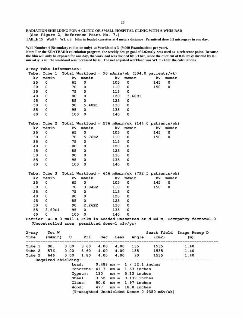
26 RADIATION SHIELDING FOR A CLINIC OR SMALL HOSPITAL CLINIC WITH A WHIS-RAD (See Figure 2, Reference Point No. 7.) TABLE 15 Wall 4 WL x 3 Film in loaded cassettes at 4 meters distance Permitted dose 0.5 microgray in one day. Wall Number 4 (Secondary radiation only) at Workload x 3 (9,000 Examinations per year). Note: For the XRAYBARR calculation program, the weekly design goal of 0.02mGy was used as a reference point. Because the film will only be exposed for one day, the workload was divided by 5.Then, since the quotient of 0.02 mGy divided by 0.5 microGy is 40; the workload was increased by 40. The net adjusted workload was WL x 24 for the calculations. X-ray Tube information: Tube: Tube 1 Total Workload = 90 mAmin/wk (504.0 patients/wk) kV mAmin kV mAmin kV mAmin kV mAmin 25 0 65 0 105 0 145 0 30 0 70 0 110 0 150 0 35 0 75 0 115 0 40 0 80 0 120 3.60E1 45 0 85 0 125 0 50 0 90 5.40E1 130 0 55 0 95 0 135 0 60 0 100 0 140 0 Tube: Tube 2 Total Workload = 576 mAmin/wk (144.0 patients/wk) kV mAmin kV mAmin kV mAmin kV mAmin 25 0 65 0 105 0 145 0 30 0 70 5.76E2 110 0 150 0 35 0 75 0 115 0 40 0 80 0 120 0 45 0 85 0 125 0 50 0 90 0 130 0 55 0 95 0 135 0 60 0 100 0 140 0 Tube: Tube 3 Total Workload = 646 mAmin/wk (792.5 patients/wk) kV mAmin kV mAmin kV mAmin kV mAmin 25 0 65 0 105 0 145 0 30 0 70 3.84E2 110 0 150 0 35 0 75 0 115 0 40 0 80 0 120 0 45 0 85 0 125 0 50 0 90 2.26E2 130 0 55 3.60E1 95 0 135 0 60 0 100 0 140 0 Barrier: WL x 3 Wall 4 Film in Loaded Cassettes at d =4 m, Occupancy factor=1.0 (Uncontrolled area, permitted dose=1 mSv/yr) X-ray Tot W Scatt Field Image Recep D Tube (mAmin) U Pri Sec Leak Angle (cm2) (m) -------------------------------------------------------------------------------- Tube 1 90. 0.00 3.60 4.00 4.00 135 1535 1.40 Tube 2 576. 0.00 3.60 4.00 4.00 135 1535 1.40 Tube 2 646. 0.00 1.80 4.00 4.00 90 1535 1.40 Required shielding:------------------------------------------------------ Lead: 0.488 mm = 1 / 52.1 inches Concrete: 41.3 mm = 1.63 inches Gypsum: 130 mm = 5.13 inches Steel: 3.52 mm = 0.139 inches Glass: 50.0 mm = 1.97 inches Wood: 477 mm = 18.8 inches (T-weighted Unshielded Dose= 0.9350 mSv/wk)

27 RADIATION SHIELDING FOR A CLINIC OR SMALL HOSPITAL WITH A WHIS-RAD (See Figure 2, reference point 8) TABLE 16 Wall 4 WL x 1 Unexposed film stored at 2.4m distance. Permitted dose: 0.1 milligray during one month. Wall number 4 (Secondary radiation only) at workload x 1 (3,000 Examinations per year) Note: For the XRAYBARR calculation program, the weekly design goal of 0.02 mGy was used as a reference point. Because the film will be exposed for one month, the weekly allowable dose will be one-fourth of the design goal of 0.1 mGy=0.025 mGy. Therefore use a multiplication factor of 0.02/0.025 times the workload=1.25 x WL. X-ray Tube information: Tube: Tube 1 Total Workload = 4.69 mAmin/wk (26.26 patients/wk) kV mAmin kV mAmin kV mAmin kV mAmin 25 0 65 0 105 0 145 0 30 0 70 0 110 0 150 0 35 0 75 0 115 0 40 0 80 0 120 1.88E0 45 0 85 0 125 0 50 0 90 2.81E0 130 0 55 0 95 0 135 0 60 0 100 0 140 0 Tube: Tube 2 Total Workload = 30 mAmin/wk (7.50 patients/wk) kV mAmin kV mAmin kV mAmin kV mAmin 25 0 65 0 105 0 145 0 30 0 70 3.00E1 110 0 150 0 35 0 75 0 115 0 40 0 80 0 120 0 45 0 85 0 125 0 50 0 90 0 130 0 55 0 95 0 135 0 60 0 100 0 140 0 Tube: Tube 3 Total Workload = 33.6 mAmin/wk (41.22 patients/wk) kV mAmin kV mAmin kV mAmin kV mAmin 25 0 65 0 105 0 145 0 30 0 70 2.00E1 110 0 150 0 35 0 75 0 115 0 40 0 80 0 120 0 45 0 85 0 125 0 50 0 90 1.17E1 130 0 55 1.87E0 95 0 135 0 60 0 100 0 140 0 ======================================================================= Barrier: WL x 1.25 Wall 4 Unused Film in Boxes at 2.4m Occupancy factor=1.0 (Uncontrolled area, permitted dose=1 mSv/yr) X-ray Tot W Scatt field Image Recp D Tube (mAmin) U pri sec leak Angle (cm2) (m) ------------------------------------------------------------------ Tube 1 4.7 0.00 3.60 2.40 2.40 90 1535 1.40 Tube 2 30. 0.00 3.60 2.40 2.40 90 1535 1.40 Tube 3 33.6 0.00 1.80 2.40 2.40 90 1535 1.40 Required shielding: ------------------------------------------------- Lead: 0.120 mm = 4.733E-3 inches Concrete: 12.8 mm = 0.503 inches Gypsum: 36.9 mm = 1.45 inches Steel: 0.772 mm = 0.0304 inches Glass: 15.4 mm = 0.608 inches (T-weighted Unshielded Dose= 0.1114 mSv/wk)
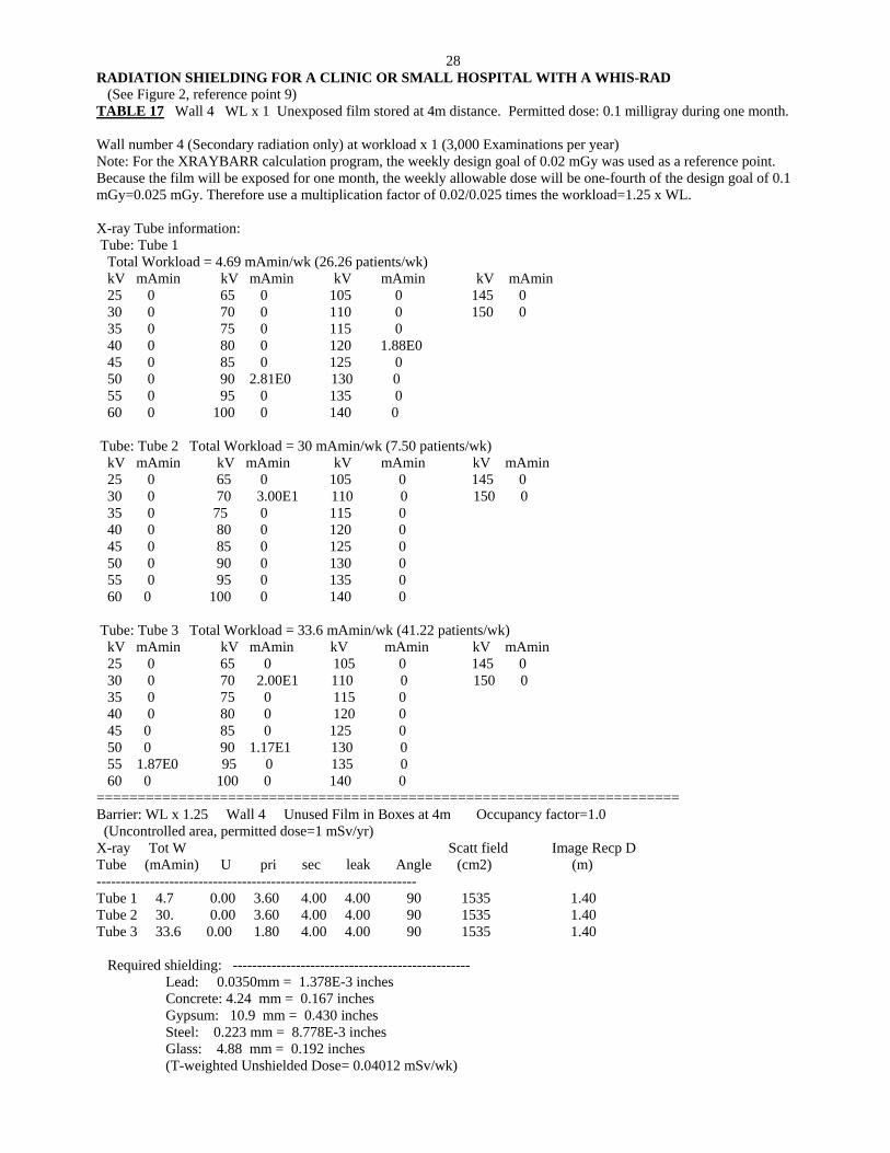
28 RADIATION SHIELDING FOR A CLINIC OR SMALL HOSPITAL WITH A WHIS-RAD (See Figure 2, reference point 9) TABLE 17 Wall 4 WL x 1 Unexposed film stored at 4m distance. Permitted dose: 0.1 milligray during one month. Wall number 4 (Secondary radiation only) at workload x 1 (3,000 Examinations per year) Note: For the XRAYBARR calculation program, the weekly design goal of 0.02 mGy was used as a reference point. Because the film will be exposed for one month, the weekly allowable dose will be one-fourth of the design goal of 0.1 mGy=0.025 mGy. Therefore use a multiplication factor of 0.02/0.025 times the workload=1.25 x WL. X-ray Tube information: Tube: Tube 1 Total Workload = 4.69 mAmin/wk (26.26 patients/wk) kV mAmin kV mAmin kV mAmin kV mAmin 25 0 65 0 105 0 145 0 30 0 70 0 110 0 150 0 35 0 75 0 115 0 40 0 80 0 120 1.88E0 45 0 85 0 125 0 50 0 90 2.81E0 130 0 55 0 95 0 135 0 60 0 100 0 140 0 Tube: Tube 2 Total Workload = 30 mAmin/wk (7.50 patients/wk) kV mAmin kV mAmin kV mAmin kV mAmin 25 0 65 0 105 0 145 0 30 0 70 3.00E1 110 0 150 0 35 0 75 0 115 0 40 0 80 0 120 0 45 0 85 0 125 0 50 0 90 0 130 0 55 0 95 0 135 0 60 0 100 0 140 0 Tube: Tube 3 Total Workload = 33.6 mAmin/wk (41.22 patients/wk) kV mAmin kV mAmin kV mAmin kV mAmin 25 0 65 0 105 0 145 0 30 0 70 2.00E1 110 0 150 0 35 0 75 0 115 0 40 0 80 0 120 0 45 0 85 0 125 0 50 0 90 1.17E1 130 0 55 1.87E0 95 0 135 0 60 0 100 0 140 0 ======================================================================= Barrier: WL x 1.25 Wall 4 Unused Film in Boxes at 4m Occupancy factor=1.0 (Uncontrolled area, permitted dose=1 mSv/yr) X-ray Tot W Scatt field Image Recp D Tube (mAmin) U pri sec leak Angle (cm2) (m) ------------------------------------------------------------------ Tube 1 4.7 0.00 3.60 4.00 4.00 90 1535 1.40 Tube 2 30. 0.00 3.60 4.00 4.00 90 1535 1.40 Tube 3 33.6 0.00 1.80 4.00 4.00 90 1535 1.40 Required shielding: ------------------------------------------------- Lead: 0.0350mm = 1.378E-3 inches Concrete: 4.24 mm = 0.167 inches Gypsum: 10.9 mm = 0.430 inches Steel: 0.223 mm = 8.778E-3 inches Glass: 4.88 mm = 0.192 inches (T-weighted Unshielded Dose= 0.04012 mSv/wk)