hpe reference configuration for docker containers-as-a ... · hpe reference configuration for...
TRANSCRIPT

HPE Reference Configuration for Docker Containers-as-a-Service (CaaS) on HPE Synergy Composable Infrastructure
Reference Architecture
Reference Architecture
Contents Executive Summary ............................................................................................................................................................................................................................................................................................................................... 4 Solution overview ..................................................................................................................................................................................................................................................................................................................................... 4
New in this release ........................................................................................................................................................................................................................................................................................................................... 4 Solution configuration ................................................................................................................................................................................................................................................................................................................... 5 High availability ................................................................................................................................................................................................................................................................................................................................... 7 Sizing considerations ..................................................................................................................................................................................................................................................................................................................... 8 Disaster Recovery ......................................................................................................................................................................................................................................................................................................................... 11 Security ................................................................................................................................................................................................................................................................................................................................................... 11
Solution components ........................................................................................................................................................................................................................................................................................................................ 11 Hardware ............................................................................................................................................................................................................................................................................................................................................... 11 Software ................................................................................................................................................................................................................................................................................................................................................. 12 Application software ................................................................................................................................................................................................................................................................................................................... 13
Preparing the environment ......................................................................................................................................................................................................................................................................................................... 14 Overview of the playbooks .......................................................................................................................................................................................................................................................................................................... 14
Core components .......................................................................................................................................................................................................................................................................................................................... 14 Optional components ................................................................................................................................................................................................................................................................................................................ 14 Backup and restore playbooks .......................................................................................................................................................................................................................................................................................... 14 Convenience playbooks ........................................................................................................................................................................................................................................................................................................... 15 Convenience scripts .................................................................................................................................................................................................................................................................................................................... 15
Deploying the core components ............................................................................................................................................................................................................................................................................................ 15 Post deployment .................................................................................................................................................................................................................................................................................................................................. 15 Kubernetes Persistent Storage configuration ............................................................................................................................................................................................................................................................ 15 Deploying Windows workers ..................................................................................................................................................................................................................................................................................................... 16
Windows operating system and Docker EE .......................................................................................................................................................................................................................................................... 16 Deploying bare metal workers ................................................................................................................................................................................................................................................................................................. 16
Playbooks and configuration .............................................................................................................................................................................................................................................................................................. 16 RHEL golden images ................................................................................................................................................................................................................................................................................................................. 17 Windows golden Images ......................................................................................................................................................................................................................................................................................................... 17 OS Deployment Plans and other Image Streamer artifacts .................................................................................................................................................................................................................... 17
Deploying Sysdig monitoring .................................................................................................................................................................................................................................................................................................... 18 Playbooks for installing Sysdig on RHEL ................................................................................................................................................................................................................................................................ 18
Deploying Splunk monitoring ................................................................................................................................................................................................................................................................................................... 19 Splunk configuration................................................................................................................................................................................................................................................................................................................... 20
Deploying Prometheus and Grafana on Kubernetes .......................................................................................................................................................................................................................................... 20 Playbooks for installing Prometheus and Grafana on Kubernetes .................................................................................................................................................................................................. 20
Deploying Prometheus and Grafana on Docker swarm ................................................................................................................................................................................................................................... 21 Backup and restore ............................................................................................................................................................................................................................................................................................................................ 22
Reference Architecture
Backup and restore UCP and DTR ................................................................................................................................................................................................................................................................................ 23 Backup and restore Docker persistent volumes ............................................................................................................................................................................................................................................... 24 Integrate UCP and DTR backup with HPE RMC and HPE StoreOnce ......................................................................................................................................................................................... 26
Solution life cycle management .............................................................................................................................................................................................................................................................................................. 26 HPE Synergy ...................................................................................................................................................................................................................................................................................................................................... 27 vSphere Docker Volume Service Plug-in ................................................................................................................................................................................................................................................................. 27 Red Hat Enterprise Linux Operating System ...................................................................................................................................................................................................................................................... 27 Docker EE Environment .......................................................................................................................................................................................................................................................................................................... 27 Monitoring Tools ............................................................................................................................................................................................................................................................................................................................ 28
Summary ...................................................................................................................................................................................................................................................................................................................................................... 28 Appendix A: Software Licenses ............................................................................................................................................................................................................................................................................................... 29 Resources and additional links ................................................................................................................................................................................................................................................................................................ 30

Reference Architecture Page 4
Executive Summary HPE Reference Configuration for Docker Containers-as-a-Service (CaaS) on HPE Synergy Composable Infrastructure is a complete solution from Hewlett Packard Enterprise that includes all the hardware, software, professional services, and support you need to deploy a Containers-as-a-Service platform, allowing you to get up and running quickly and efficiently. The solution takes the HPE Synergy infrastructure and combines it with Docker’s enterprise-grade container platform, popular open source tools, along with deployment and advisory services from HPE Pointnext.
HPE Enterprise Containers-as-a-Service with Docker Enterprise Edition (EE) is ideal for customers migrating legacy applications to containers, transitioning to a container DevOps development model or needing a hybrid environment to support container and non-containerized applications on a common VM platform. This Reference Configuration provides a solution for IT operations, addressing the need for a production-ready environment that is easy to deploy and manage.
This release supports Kubernetes 1.11 via Docker EE version 2.1, which is the only platform that manages and secures applications on Kubernetes in multi-Linux, multi-OS and multi-cloud customer environments. This document describes the best practices for deploying and operating HPE Enterprise Containers-as-a-Service with Docker Enterprise Edition (EE). It shows how to automate the provisioning of the environment, using a set of Ansible playbooks. It also outlines a set of manual steps to harden, secure and audit the overall status of the system.
Target Audience: This document is primarily aimed at technical individuals working in the operations side of the software pipeline, such as infrastructure architects, system administrators and infrastructure engineers, but anybody with an interest in automating the provisioning of virtual servers and containers may find this document useful.
Assumptions: The present document assumes a minimum understanding in concepts such as virtualization and containerization and also some knowledge around Linux®, Microsoft Windows® and VMware® technologies.
Solution overview The HPE Reference Configuration for Docker Containers-as-a-Service on HPE Synergy Composable Infrastructure consists of a set of Ansible playbooks that run on top of a VMware virtualization platform on HPE Synergy and HPE 3PAR storage hardware. The solution allows you to configure a flexible OS environment (with both RHEL and Windows workers) providing built-in high availability (HA), container monitoring and security, and backup and restore functionality. This solution assumes that you have already set up your HPE Synergy hardware, that you have installed your VMware virtualization platform and have configured HPE 3PAR for storage.
Figure 1. Solution overview
Figure 1 provides an overview of the steps used to deploy the solution. Deploying your hardware and HPE Synergy is specific to your environment and is not covered here. This document, together with the corresponding deployment guide, shows you how to:
• Prepare the VM templates
• Create the Ansible host
• Configure the Ansible parameters
• Run the Ansible playbooks
Once you are up and running, you should regularly back up the system using the scripts provided as part of this solution.
New in this release The solution provides support for Kubernetes 1.11 via Docker EE version 2.1. New features in this release include:
• Bare metal deployment for Linux and Windows.
Reference Architecture Page 5
Features taken from the most recent release of HPE Express Containers on HPE SimpliVity include:
• Prometheus/Grafana on Kubernetes: The playbooks now set up a full monitoring stack for the deployed Kubernetes infrastructure using Prometheus Operator. They install kube-state-metrics and node-exporter components, as well as supporting Kubelet and Apiserver metrics. Sample dashboards for Grafana are installed to help you monitor your Kubernetes infrastructure.
• Docker UCP metrics for Kubernetes: A separate, stand-alone Prometheus/Grafana deployment is provided to support visualization of UCP metrics.
• Sysdig for Kubernetes: The Sysdig deployment has been updated to use Kubernetes 1.11 RBAC and config maps for sensitive data.
• NFS provisioner for Kubernetes: The NFS provisioner has been updated to use Kubernetes 1.11 RBAC.
• WordPress and MySQL using NFS provisioner: Playbooks are provided to validate the NFS provisioner, featuring a WordPress and MySQL deployment with persistent storage.
• kubectl: A convenience playbook is provided to download and install kubectl.
• Client bundle: A convenience playbook is available to download and configure the client bundle from UCP.
• Helm charts: Playbooks for downloading, installing and configuring Helm are provided, together with sample charts for validation purposes.
For more details on what is new in this release, see the release notes at https://hewlettpackard.github.io/Docker-Synergy/rel-notes/new-features-syn.html.
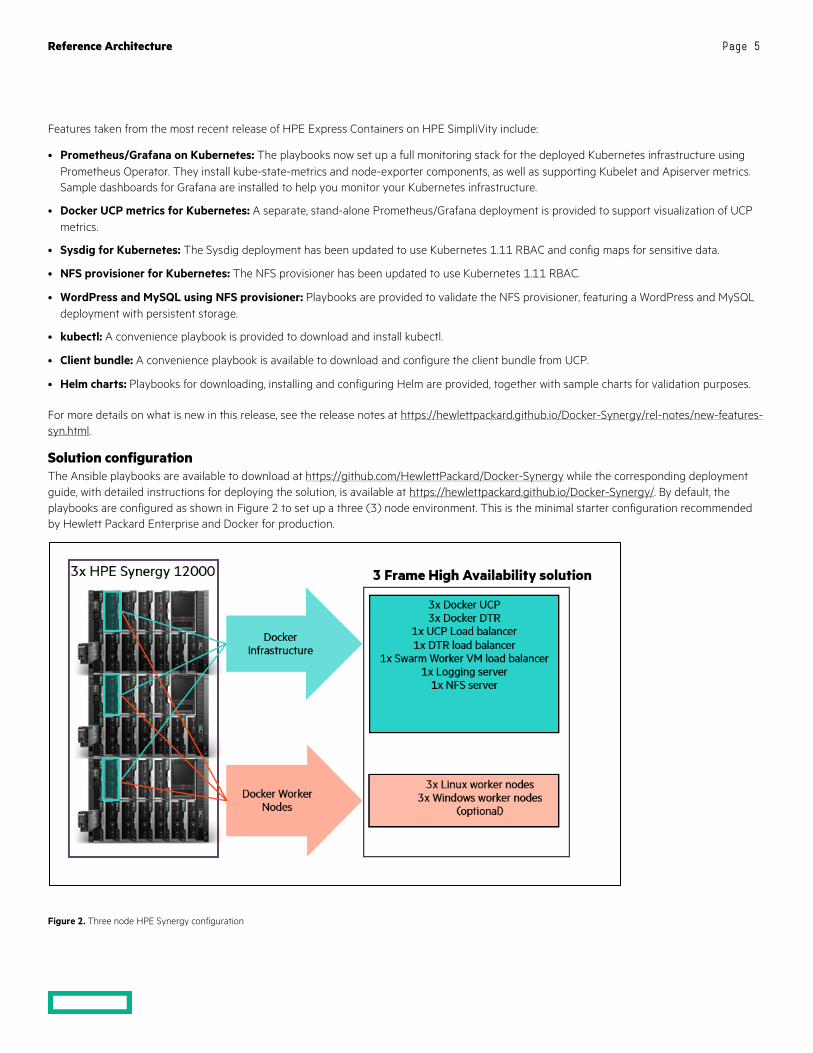
Solution configuration The Ansible playbooks are available to download at https://github.com/HewlettPackard/Docker-Synergy while the corresponding deployment guide, with detailed instructions for deploying the solution, is available at https://hewlettpackard.github.io/Docker-Synergy/. By default, the playbooks are configured as shown in Figure 2 to set up a three (3) node environment. This is the minimal starter configuration recommended by Hewlett Packard Enterprise and Docker for production.
Figure 2. Three node HPE Synergy configuration

Reference Architecture Page 6
The playbooks can also be used for larger container environments, for example, with a three (3) frame, six (6) node HPE Synergy system, as shown in Figure 3 with two (2) nodes in each frame.
Figure 3. Six node HPE Synergy configuration
Linux-only VM configuration • Three Docker Universal Control Plane (UCP) VM nodes for HA and cluster management
• Three Docker Trusted Registry (DTR) VM nodes for HA of the container registry
The Docker UCP and DTR nodes are spread across 3 physical nodes, with one on each physical node. An odd number of manager nodes is recommended to avoid split-brain issues. It is possible to restrict the deployment to 1 UCP and 1 DTR, or to expand to more than 3, but the recommended minimum for an enterprise production deployment is 3 UCPs and 3 DTRs.
• Three Docker Linux worker VM nodes for container workloads - Kubernetes or Docker swarm or a mix
The Docker worker nodes are co-located with the UCP and DTR nodes in a 3 physical node deployment. Where more than 3 physical nodes are available, the worker nodes will typically be separated onto the extra nodes. It is possible to specify that more than one worker node is deployed per physical node but this decision will depend on the requirements of your applications.
• One Docker UCP load balancer VM to ensure access to UCP in the event of a node failure
• One Docker DTR load balancer VM to ensure access to DTR in the event of a node failure
By default, two load balancers are deployed to increase availability of UCP and DTR and these are placed on separate physical nodes. Load balancing for applications running on worker nodes can be achieved by using the playbooks to deploy additional load balancers, or by manually configuring the existing two to support your applications in addition to supporting UCP and DTR.
• One Logging server VM for central logging
• One NFS server VM for storage of Docker DTR images
Reference Architecture Page 7
With the addition of the NFS and logging VMs, a total of 13 VMs are created for the default Linux-only deployment. In addition to these VMs, the playbooks also set up the Docker persistent storage plug-in from VMware. The vSphere® Docker volume plug-in facilitates the storage of data in a shared datastore that can be accessed from any machine in the cluster.
Hybrid VM configuration (Windows and Linux) The hybrid deployment will typically add three (3) Windows worker nodes to the above configuration, co-located with the Linux workers.
• Three Docker swarm Windows worker VM nodes for container workloads (optional)
Bare metal (BM) configuration (Windows and Linux) This solution leverages HPE Synergy OneView 4.10 and HPE Image Streamer 4.10 to provision bare metal servers with an operating system so they can be added to a Docker/Kubernetes cluster as worker nodes. The bare metal worker nodes can be used in conjunction with VM worker nodes or on their own with a virtualized control plane.
Note Some of the application software supported by this configuration does not currently run on Windows, for example, the Sysdig Software Agent (see the section Monitoring with Sysdig).
High availability Uptime is paramount for businesses implementing Docker containers in business critical environments. The HPE Enterprise Containers as a Service with Docker EE solution offers various levels of high availability (HA) to support continuous availability. The Docker EE system components run on multiple manager nodes in the cluster. The management plane continues to operate even in the event of a manager node failure. High availability of the applications is the responsibility of the developers. Depending on the orchestrator of choice, developers can use objects like services in Docker swarm or deployments and replica sets if they are using Kubernetes. The Ansible playbooks can be modified to fit your environment and your high availability (HA) needs.
Load Balancers This solution also deploys load balancers in the system to help with container traffic management. There are two load balancer VMs – the UCP load balancer and DTR load balancer. The playbooks can be configured to deploy one or more worker load balancers depending on the requirements of your applications.
Reference Architecture Page 8
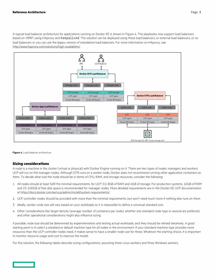
A typical load balancer architecture for applications running on Docker EE is shown in Figure 4. The playbooks now support load balancers based on VRRP, using HAproxy and keepalived. The solution can be deployed using these load balancers, or external load balancers, or no load balancers or you can use the legacy version of standalone load balancers. For more information on HAproxy, see http://www.haproxy.com/solutions/high-availability/.
Figure 4. Load balancer architecture
Sizing considerations A node is a machine in the cluster (virtual or physical) with Docker Engine running on it. There are two types of nodes: managers and workers. UCP will run on the manager nodes. Although DTR runs on a worker node, Docker does not recommend running other application containers on them. To decide what size the node should be in terms of CPU, RAM, and storage resources, consider the following:
All nodes should at least fulfil the minimal requirements, for UCP 3.0, 8GB of RAM and 6GB of storage. For production systems, 16GB of RAM and 25-100GB of free disk space is recommended for manager nodes. More detailed requirements are in the Docker EE UCP documentation at https://docs.docker.com/ee/ucp/admin/install/system-requirements/.
UCP controller nodes should be provided with more than the minimal requirements, but won’t need much more if nothing else runs on them.
Ideally, worker node size will vary based on your workloads so it is impossible to define a universal standard size.
Other considerations like target density (average number of containers per node), whether one standard node type or several are preferred, and other operational considerations might also influence sizing.
If possible, node size should be determined by experimentation and testing actual workloads; and they should be refined iteratively. A good starting point is to select a standard or default machine type for all nodes in the environment. If your standard machine type provides more resources than the UCP controller nodes need, it makes sense to have a smaller node size for these. Whatever the starting choice, it is important to monitor resource usage and cost to improve the model.
For this solution, the following tables describe sizing configurations, assuming three Linux workers and three Windows workers.
Reference Architecture Page 9
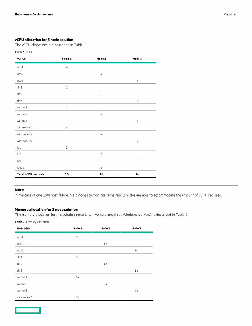
vCPU allocation for 3 node solution The vCPU allocations are described in Table 1.
Table 1. vCPU
vCPUs Node 1 Node 2 Node 3
ucp1 4
ucp2 4
ucp3 4
dtr1 2
dtr2 2
dtr3 2
worker1 4
worker2 4
worker3 4
win-worker1 4
win-worker2 4
win-worker3 4
lb1 2
lb2 2
nfs 2
logger 2
Total vCPU per node 16 18 16
Note In the case of one ESXi host failure in a 3 node solution, the remaining 2 nodes are able to accommodate the amount of vCPU required.
Memory allocation for 3 node solution The memory allocation for this solution three Linux workers and three Windows workers), is described in Table 2.
Table 2. Memory allocation
RAM (GB) Node 1 Node 2 Node 3
ucp1 16
ucp2 16
ucp3 16
dtr1 16
dtr2 16
dtr3 16
worker1 64
worker2 64
worker3 64
win-worker1 64
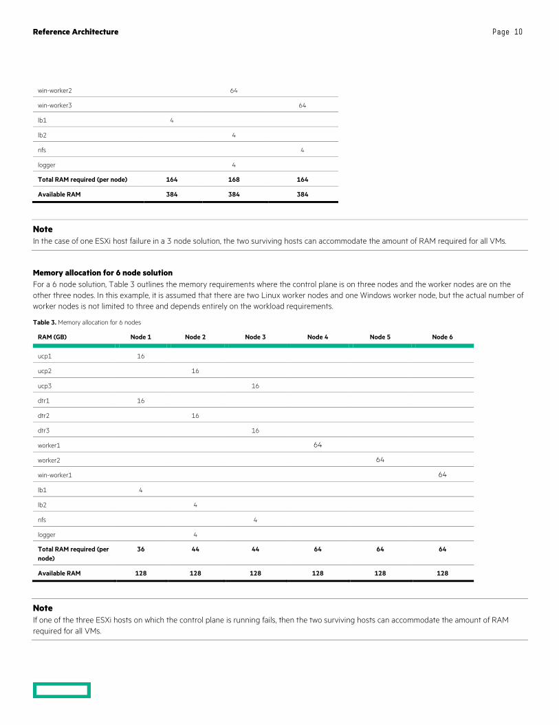
Reference Architecture Page 10
win-worker2 64
win-worker3 64
lb1 4
lb2 4
nfs 4
logger 4
Total RAM required (per node) 164 168 164
Available RAM 384 384 384
Note In the case of one ESXi host failure in a 3 node solution, the two surviving hosts can accommodate the amount of RAM required for all VMs.
Memory allocation for 6 node solution For a 6 node solution, Table 3 outlines the memory requirements where the control plane is on three nodes and the worker nodes are on the other three nodes. In this example, it is assumed that there are two Linux worker nodes and one Windows worker node, but the actual number of worker nodes is not limited to three and depends entirely on the workload requirements.
Table 3. Memory allocation for 6 nodes
RAM (GB) Node 1 Node 2 Node 3 Node 4 Node 5 Node 6
ucp1 16
ucp2 16
ucp3 16
dtr1 16
dtr2 16
dtr3 16
worker1 64
worker2 64
win-worker1 64
lb1 4
lb2 4
nfs 4
logger 4
Total RAM required (per node)
36 44 44 64 64 64
Available RAM 128 128 128 128 128 128
Note If one of the three ESXi hosts on which the control plane is running fails, then the two surviving hosts can accommodate the amount of RAM required for all VMs.
Reference Architecture Page 11
Disaster Recovery Recovery Time Objective (RTO) refers to the time that it takes to recover your data and applications while Recovery Point Objective (RPO) refers to the point in time you can recover to, in the event of a disaster. In essence, RPO tells you how often you will need to make new backups.
In order to protect your installation from disasters, you need to take regular backups and transfer the backups to a safe location. This solution provides a range of convenience scripts and Ansible playbooks to help automate the backup of UCP, DTR, your swarm and your Docker volumes. See the section Backup and restore for best practices, procedures and utilities for implementing disaster recovery.
Security The Docker Reference Architecture for Securing Docker EE and Security Best Practices is available at https://success.docker.com/article/Docker_Reference_Architecture-_Securing_Docker_EE_and_Security_Best_Practices
In addition to having all logs centralized in a single place and the image scanning feature enabled for the DTR nodes, there are other guidelines that should be followed in order to keep your Docker environment as secure as possible. The HPE Reference Configuration paper for securing Docker on HPE Hardware places a special emphasis on securing Docker in DevOps environments and covers best practices in terms of Docker security. The document can be found at http://h20195.www2.hpe.com/V2/GetDocument.aspx?docname=a00020437enw.
In addition, the Sysdig product also provides a strong level of container security and monitoring (see the section Deploying Sysdig monitoring).
Solution components This section describes the various components that were utilized in this Reference Configuration.
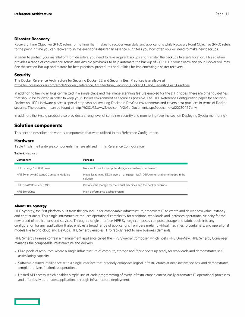
Hardware Table 4 lists the hardware components that are utilized in this Reference Configuration.
Table 4. Hardware
Component Purpose
HPE Synergy 12000 Frame Rack enclosure for compute, storage, and network hardware
HPE Synergy 480 Gen10 Compute Modules Hosts for running ESXi servers that support UCP, DTR, worker and other nodes in the solution
HPE 3PAR StoreServ 8200 Provides the storage for the virtual machines and the Docker backups
HPE StoreOnce High performance backup system
About HPE Synergy HPE Synergy, the first platform built from the ground up for composable infrastructure, empowers IT to create and deliver new value instantly and continuously. This single infrastructure reduces operational complexity for traditional workloads and increases operational velocity for the new breed of applications and services. Through a single interface, HPE Synergy composes compute, storage and fabric pools into any configuration for any application. It also enables a broad range of applications from bare metal to virtual machines to containers, and operational models like hybrid cloud and DevOps. HPE Synergy enables IT to rapidly react to new business demands.
HPE Synergy Frames contain a management appliance called the HPE Synergy Composer, which hosts HPE OneView. HPE Synergy Composer manages the composable infrastructure and delivers:
• Fluid pools of resources, where a single infrastructure of compute, storage and fabric boots up ready for workloads and demonstrates self-assimilating capacity.
• Software-defined intelligence, with a single interface that precisely composes logical infrastructures at near-instant speeds; and demonstrates template-driven, frictionless operations.
• Unified API access, which enables simple line-of-code programming of every infrastructure element; easily automates IT operational processes; and effortlessly automates applications through infrastructure deployment.
Reference Architecture Page 12
Server requirements The minimum platform requirement for this configuration, shown in Figure 2, is a three (3) node HPE Synergy 480 Gen10 deployment. There is a single ESXi cluster with both the control plane and the Docker workers spread out on all three (3) nodes. A single node in each Synergy frame has the following suggested requirements:
• 384 GB DDR4-2133 RAM
• 2 Intel® Xeon® CPU Gold 6130 2.10GHz x 16 core
The solution has also been tested on six node HPE Synergy environment, with two nodes in each frame. In this setup, there is a single ESXi cluster with the control plane on three (3) nodes while the extra three (3) nodes are dedicated exclusively to Docker worker nodes. The six node deployment is depicted graphically in Figure 3 with the following suggested requirements for each node:
• 128 GB DDR4-2133 RAM
• 2 Intel® Xeon® CPU Gold 6130 2.10GHz x 16 core
Storage requirements An HPE 3PAR array is required for the ESXi datastore. This solution makes use of an HPE 3PAR StoreServ 8200 populated with:
• 8 x 480GB SSD for the vSphere cluster datastore
• 8 x 1.8TB HDD for the backup datastore
You should create a large virtual volume on the HPE 3PAR StoreServ to host the virtual machines and another large virtual volume for Docker backups. Create datastores on your vSphere cluster using these virtual volumes. If desired, you can create separate HPE 3PAR StoreServ virtual volumes and attach them to all vSphere cluster hosts for backing up Docker persistent volumes. It is recommended that you configure the volumes that are used for virtual machine deployments on the SSDs. Storage for backups can be configured on the HDDs.
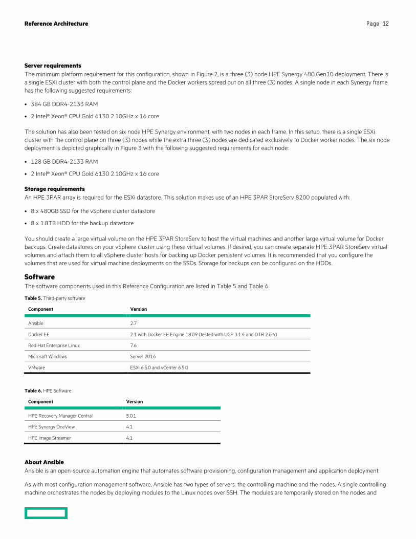
Software The software components used in this Reference Configuration are listed in Table 5 and Table 6.
Table 5. Third-party software
Component Version
Ansible 2.7
Docker EE 2.1 with Docker EE Engine 18.09 (tested with UCP 3.1.4 and DTR 2.6.4)
Red Hat Enterprise Linux 7.6
Microsoft Windows Server 2016
VMware ESXi 6.5.0 and vCenter 6.5.0
Table 6. HPE Software
Component Version
HPE Recovery Manager Central 5.0.1
HPE Synergy OneView 4.1
HPE Image Streamer 4.1
About Ansible Ansible is an open-source automation engine that automates software provisioning, configuration management and application deployment.
As with most configuration management software, Ansible has two types of servers: the controlling machine and the nodes. A single controlling machine orchestrates the nodes by deploying modules to the Linux nodes over SSH. The modules are temporarily stored on the nodes and

Reference Architecture Page 13
communicate with the controlling machine through a JSON protocol over the standard output. When Ansible is not managing nodes, it does not consume resources because no daemons or programs are executing for Ansible in the background. Ansible uses one or more inventory files to manage the configuration of the multiple nodes in the system.
When deploying Windows nodes in a hybrid deployment, the Ansible playbooks make use of the Python pywinrm module which carries out actions via the Windows remote manager.
More information about Ansible can be found at http://docs.ansible.com.
About Docker Enterprise Edition Docker Enterprise Edition (EE) is the leading enterprise-ready container platform for IT that manages and secures diverse applications across disparate infrastructure, both on-premises and in the cloud. Docker EE provides integrated container management and security from development to production. Enterprise-ready capabilities like multi-architecture orchestration and secure software supply chain give IT teams the ability to manage and secure containers without breaking the developer experience.
Docker EE provides:
• Integrated management of all application resources from a single web admin UI.
• Frictionless deployment of applications and Compose files to production in a few clicks.
• Multi-tenant system with granular role-based access control (RBAC) and LDAP/AD integration.
• Self-healing application deployment with the ability to apply rolling application updates.
• End-to-end security model with secrets management, image signing and image security scanning.
More information about Docker Enterprise Edition can be found at https://www.docker.com/enterprise-edition.
Application software A number of different logging and monitoring solutions are supported by this solution:
• Splunk
• Sysdig
• Prometheus and Grafana
The application software components used in this Reference Configuration are listed in Table 7.
Table 7. Application software
Component Version
Splunk 7.1.2
Sysdig latest
Prometheus V2.3.2
Grafana 5.2.3
Monitoring with Splunk and Sysdig The solution can be configured to use either Splunk or Sysdig or to enable both simultaneously. While there is some overlap in the functionality provided by these tools, they are ultimately complimentary in what they offer. Splunk aggregates logging and tracing for a wide variety of sources and provides a clean, high-level dashboard for all your enterprise systems. Sysdig, on the other hand, has been engineered from the ground up to focus on containerized environments and includes both monitoring and security features, with built-in understanding of the different workloads running on your cloud.
More information on configuring Splunk and running the relevant playbooks can be found in the section Deploying Splunk.
For more information on configuring Sysdig and running the relevant playbooks, see the section Deploying Sysdig monitoring.
Reference Architecture Page 14
Monitoring with Prometheus and Grafana The solution can be configured to enable the use of Prometheus and Grafana for monitoring. In this setup, there is no need for native installs and all the required monitoring software runs in containers, deployed as either services or stacks. The solution supports two separate monitoring stacks, with one running on Kubernetes and the other using Docker swarm.
For more information on running Prometheus and Grafana on Kubernetes, see section Deploying Prometheus and Grafana on Kubernetes.
For more information on running Prometheus and Grafana on Docker swarm, see section Deploying Prometheus and Grafana on Docker swarm.
Preparing the environment The following high level steps are required to prepare the environment that was outlined in the architecture section:
• Verify prerequisites including networking, DNS, NTP, RHEL and Docker licensing
• Enable vSphere High Availability (HA)
• Install vSphere Docker Volume Service driver on all ESXi hosts
• Create the Ansible node
• Create the Red Hat Linux Template and configure the yum repositories
• Create the Windows Template (optional)
• Finalize the template
Detailed information on preparing the environment and configuring the solution components is available in the corresponding deployment guide.
Overview of the playbooks The Ansible playbooks are available to download at https://github.com/HewlettPackard/Docker-Synergy. Once you have cloned the repository, change directory to /root/Docker-Synergy.
Core components The playbooks to deploy the core components include:
• Provisioning RHEL VMs
• Provisioning load balancers for UCP and DTR
• Installing Docker UCP and DTR on RHEL VMs
• Deploying RHEL workers
Optional components Playbooks for deploying optional components include:
• Adding Windows workers.
• Deploying bare metal workers on Linux and Windows
• Installing Splunk monitoring
• Installing Prometheus and Grafana on Kubernetes
• Installing Prometheus and Grafana on Docker swarm
Backup and restore playbooks Best practices and procedures are described in the section Backup and restore. Playbooks are provided to:
• Backup the swarm data, UCP, DTR metadata and DTR images
• Restore DTR images, DTR metadata and UCP

Reference Architecture Page 15
Convenience playbooks A number of convenience playbooks are provided to:
• Download and install kubectl on the Ansible controller.
• Install and configure the UCP bundle on the Ansible controller.
• Download and install Helm on the Ansible controller.
• Power off and delete all VMs in your inventory.
• Distribute public keys between all nodes, to allow each node to password-less log in to every other node.
Convenience scripts A number of convenience scripts are provided to:
• Take a backup of the swarm, UCP, DTR metadata and the DTR images in one go.
• Restore DTR metadata and DTR images.
• Scale the worker nodes.
Deploying the core components Once you have prepared the environment and configured the solution components, the system is ready to be deployed. The playbook site.yml is the day 0 playbook used to deploy the solution. It is simply a wrapper around a number of required and optional playbooks that allow you to configure the deployment to your needs. The playbooks should run for approximately 35-40 minutes for the default deployment with three (3) UCP, three (3) DTR and three (3) Linux VM worker nodes (depending on your server specifications and the size of your environment).
Post deployment The playbooks in site.yml are intended to be used to deploy a new environment so you should only use them for Day 0 deployment purposes. The Ansible log is stored in the folder /root/Docker-Synergy. If the deployment fails, you may find useful hints in this log.
The deployment guide describes a number of post-deployment tasks performed using additional playbooks:
• Installing kubectl.
• Installing the client bundle.
• Installing Helm and sample charts.
• Validation using the Kubernetes guestbook example with Redis.
• Capturing UCP cluster metrics in Prometheus.
Kubernetes Persistent Storage configuration The solution leverages the Kubernetes NFS Client Provisioner, https://github.com/kubernetes-incubator/external-storage/tree/master/nfs-client to dynamically provision Kubernetes persistent volumes (PVs). This supports two NFS back ends.
An NFS VM deployed as part of the solution for non-production use.
A Virtual File Server on HPE 3PAR with the File persona software suite license (preferred). For more information about the HPE 3PAR File persona software suite, see the HPE 3PAR Software Products at https://h20195.www2.hpe.com/v2/gethtml.aspx?docname=c04199812.
A sample playbook is provided to show how to use the NFS provisioner for persistent storage for a WordPress and MySQL deployment.
Reference Architecture Page 16
Deploying Windows workers The site.yml playbook will automatically deploy any Windows workers declared in the inventory. The playbooks should run for approximately 70-80 minutes with 3 Windows workers added to the default deployment (depending on your server specifications and the size of your environment). The increase in running time is primarily due to the need to update Windows after creating the VMs. The following tasks are documented in the deployment guide:
• Creating Windows template.
• Configuring Windows variables
• Running the playbooks to deploy Windows workers.
Windows operating system and Docker EE Docker Enterprise Edition for Windows Server (Docker EE) enables native Docker containers on Windows Server. This solution has been tested with Windows worker nodes running Windows Server 2016 and with Docker EE 18.09. More recent versions of Windows Server may work but have not been tested.
Note This solution recommends that you only run Windows Server 2016 on your Windows worker nodes and that you install any required updates to Windows nodes in a timely manner.
For information on how to update Docker EE on Windows Server 2016, see the Docker documentation Update Docker EE.
Deploying bare metal workers This solution leverages HPE Synergy OneView 4.10 and HPE Image Streamer 4.10 to provision bare metal servers with an operating system so they can be added to a Docker/Kubernetes cluster as worker nodes. Before you can provision servers using the playbooks, you need to create one or more Image Streamer Operating System Deployment Plans (OSDP) and one or more OneView Server Profile Templates (SPT).
HPE OneView Server Profile Templates are used to create the OneView Server Profiles (SP) that are applied to the Synergy compute modules, also known as bare metal servers. Each bare metal server listed in the Ansible inventory maps to exactly one OneView Server Profile Template. Depending on the environment, you may need to create one or more SPTs depending on the type of servers available in your Synergy environment. In the simplest case, where all servers are of the same Server Hardware Type and there is a single enclosure group, a single SPT can be used. If, on the other hand, the pool of compute modules consists of different server types (for example Gen9 and Gen10 compute modules), then a separate SPT must be created for each Server Hardware Type. When creating the SPT, an OSDP is specified. In most cases, the same OSDP can be used for all compute modules running the same operating system. If you want to deploy both Windows and Linux worker nodes in the same cluster, you need to create a minimum of two (2) SPTs and two (2) OSDPs. One SPT will specify an OSDP that deploys Linux, while a separate SPT will specify a different OSDP that deploys Windows.
Image Streamer Operating System Deployment Plans leverage Operating System Build Plans (OSBP), each of which contains one or more Plan Scripts that are used to configure the deployed Operating System. Each Plan Script may expose one or more OS custom attributes. Custom attributes are parameters that can either be hard-coded to specific values or exposed to the deployment plan and configured by the SPT using the deployment plan. Custom attributes can hold various data types such as IP addresses, host names, product keys etc. The OSDP also specifies a golden image, which will be used when deploying the OS on the server.
For more information, see the HPE OneView 4.1 User Guide for HPE Synergy available at https://support.hpe.com/hpsc/doc/public/display?docId=a00048164en_us and the HPE Synergy Image Streamer 4.1 User Guide at https://support.hpe.com/hpsc/doc/public/display?docId=emr_na-a00039930en_us&docLocale=en_US
Playbooks and configuration When it comes to the provisioning of bare-metal servers, the Ansible playbooks create Server Profiles (SP) based on specified Server Profile Templates (SPT) and assign the server profiles to physical compute modules in the Synergy enclosures. The provisioning of the operating system is done when the server profile is applied using the Image Streamer OSDP specified in the SPT. Once the servers are provisioned, they are powered on by the playbooks.

Reference Architecture Page 17
The playbook responsible for the provisioning of the bare metal servers support the configuration of redundant connections for both network and storage and the selection of compute modules in the enclosure.
Common variables for all Windows nodes (VM and bare metal) are specified in the file group_vars/windows_box.yml. Windows VM-specific variables are in group_vars/vm_wrk_win.yml while Windows bare metal variables are in group_vars/bm_wrk_win.yml.
RHEL golden images Preparing a RHEL golden image involves the following tasks:
• OS installation and configuration with HPE Synergy Image Streamer.
• Downloading the artifacts for HPE Synergy Image Streamer.
• Adding the artifact bundles to HPE Image Streamer.
• Preparing the compute module for the installation of the Operating System.
• Creating a Server Profile.
• Installing and customizing the Operating System.
Windows golden Images Preparing a Windows golden image involves:
• Preparing Image Streamer with Windows Artifact Bundle.
• Creating Windows golden image.
• Capturing the golden image
For more details on creating and capturing golden images, as well as specifying OSDP custom attributes and configuring Windows proxies, see the accompanying deployment guide for this Reference Configuration.
OS Deployment Plans and other Image Streamer artifacts The solution delivers two artifact bundles, one for Windows Server 2016 systems and one for Red Hat Linux version 7 systems. Each artifact bundle contains one Deployment Plan, one OS Build Plan and all dependent Plan Scripts.
The artifact bundles are included in the Docker-Synergy repository:
# cd ~/Docker-Synergy # ls ./files/ImageStreamer HPE_RHEL7_2019_02_25.zip HPE_WIN2016_2019-03-15.zip
In the Image Streamer UI, upload the two files and extract artifacts from the bundles. After the extraction completes, you should find two new Deployment Plans in your Image Streamer appliance named:
• HPE_RHEL7_2019_02_25 which is the Red Hat Enterprise Linux version 7 OS Deployment Plan
• HPE_WIN2016_2019-03-15 which is the Microsoft Windows Server 2016 OS Deployment Plan
The deployment plans are shipped without a golden image. Golden images for each OS must be created as described in the Deployment Guide and then you update the Deployment Plans, to use the corresponding golden images.
Reference Architecture Page 18
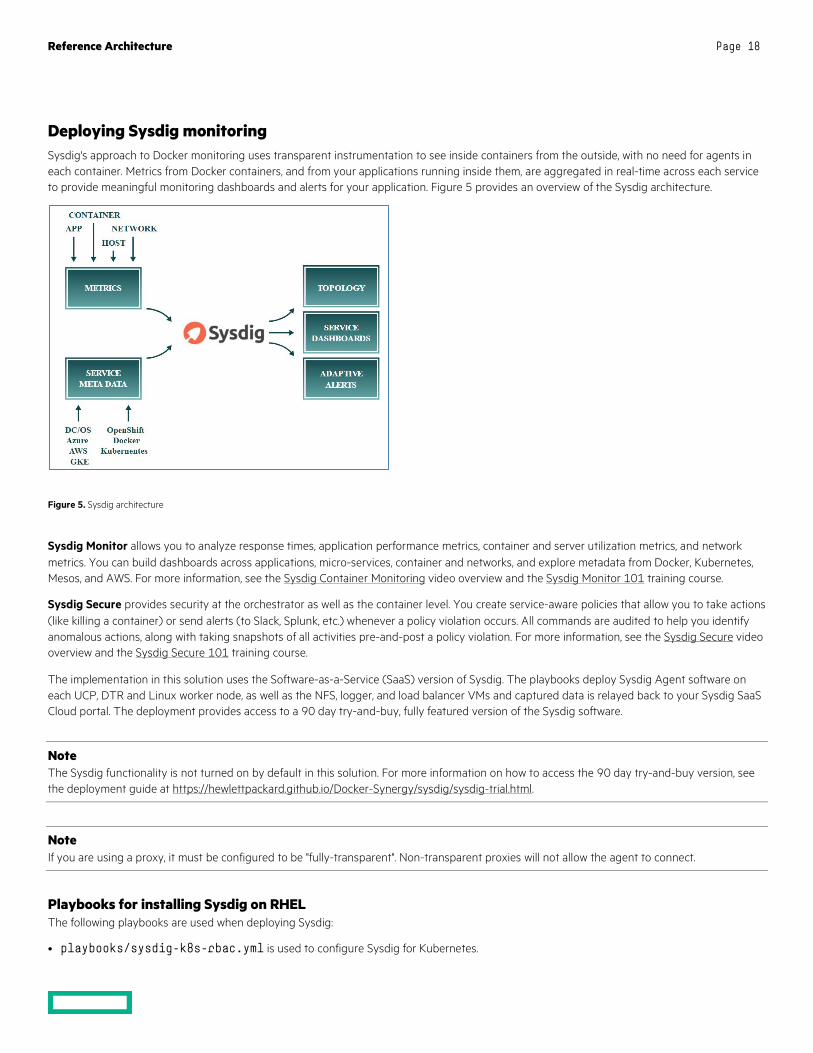
Deploying Sysdig monitoring Sysdig's approach to Docker monitoring uses transparent instrumentation to see inside containers from the outside, with no need for agents in each container. Metrics from Docker containers, and from your applications running inside them, are aggregated in real-time across each service to provide meaningful monitoring dashboards and alerts for your application. Figure 5 provides an overview of the Sysdig architecture.
Figure 5. Sysdig architecture
Sysdig Monitor allows you to analyze response times, application performance metrics, container and server utilization metrics, and network metrics. You can build dashboards across applications, micro-services, container and networks, and explore metadata from Docker, Kubernetes, Mesos, and AWS. For more information, see the Sysdig Container Monitoring video overview and the Sysdig Monitor 101 training course.
Sysdig Secure provides security at the orchestrator as well as the container level. You create service-aware policies that allow you to take actions (like killing a container) or send alerts (to Slack, Splunk, etc.) whenever a policy violation occurs. All commands are audited to help you identify anomalous actions, along with taking snapshots of all activities pre-and-post a policy violation. For more information, see the Sysdig Secure video overview and the Sysdig Secure 101 training course.
The implementation in this solution uses the Software-as-a-Service (SaaS) version of Sysdig. The playbooks deploy Sysdig Agent software on each UCP, DTR and Linux worker node, as well as the NFS, logger, and load balancer VMs and captured data is relayed back to your Sysdig SaaS Cloud portal. The deployment provides access to a 90 day try-and-buy, fully featured version of the Sysdig software.
Note The Sysdig functionality is not turned on by default in this solution. For more information on how to access the 90 day try-and-buy version, see the deployment guide at https://hewlettpackard.github.io/Docker-Synergy/sysdig/sysdig-trial.html.
Note If you are using a proxy, it must be configured to be "fully-transparent". Non-transparent proxies will not allow the agent to connect.
Playbooks for installing Sysdig on RHEL The following playbooks are used when deploying Sysdig:
• playbooks/sysdig-k8s-rbac.yml is used to configure Sysdig for Kubernetes.
Reference Architecture Page 19
• playbooks/install_sysdig.yml is used to configure Sysdig for Docker swarm.
Using the Sysdig Software as a solution (SaaS) website https://app.sysdigcloud.com, you are able to view, analyze and inspect various different dashboards.
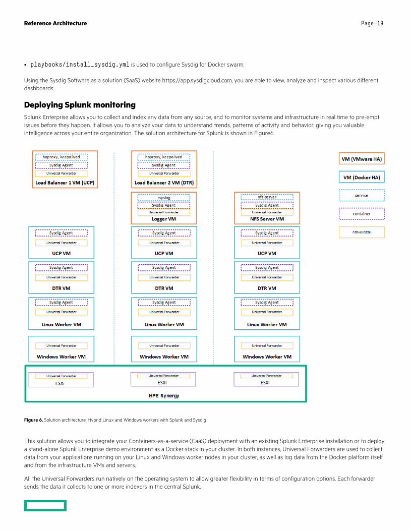
Deploying Splunk monitoring Splunk Enterprise allows you to collect and index any data from any source, and to monitor systems and infrastructure in real time to pre-empt issues before they happen. It allows you to analyze your data to understand trends, patterns of activity and behavior, giving you valuable intelligence across your entire organization. The solution architecture for Splunk is shown in Figure6.
Figure 6. Solution architecture: Hybrid Linux and Windows workers with Splunk and Sysdig
This solution allows you to integrate your Containers-as-a-service (CaaS) deployment with an existing Splunk Enterprise installation or to deploy a stand-alone Splunk Enterprise demo environment as a Docker stack in your cluster. In both instances, Universal Forwarders are used to collect data from your applications running on your Linux and Windows worker nodes in your cluster, as well as log data from the Docker platform itself and from the infrastructure VMs and servers.
All the Universal Forwarders run natively on the operating system to allow greater flexibility in terms of configuration options. Each forwarder sends the data it collects to one or more indexers in the central Splunk.
Reference Architecture Page 20
Splunk configuration This solution supports two types of Splunk deployments. Firstly, there is a built-in deployment useful for demos and for getting up to speed with Splunk. The demo instance comes with two pre-configures apps: the Docker App to view the Docker overview and the k8s App for the Kubernetes overview.
Alternatively, the solution can be configured to interact with a stand-alone, production Splunk deployment that you set up independently. In this case, you must explicitly configure the universal forwarders with external "forward servers" (Splunk indexers), whereas this happens automatically with the built-in option.
Deploying Prometheus and Grafana on Kubernetes Monitoring a Kubernetes cluster with Prometheus is a natural choice as Kubernetes components themselves are instrumented with Prometheus metrics, therefore those components simply have to be discovered by Prometheus and most of the cluster is monitored.
The solution uses the Prometheus Operator to deploy Prometheus and Grafana. The playbooks install kube-state-metrics and node-exporter components, as well as supporting kubelet and apiserver metrics. Sample dashboards for Grafana are installed to help you monitor your Kubernetes infrastructure.
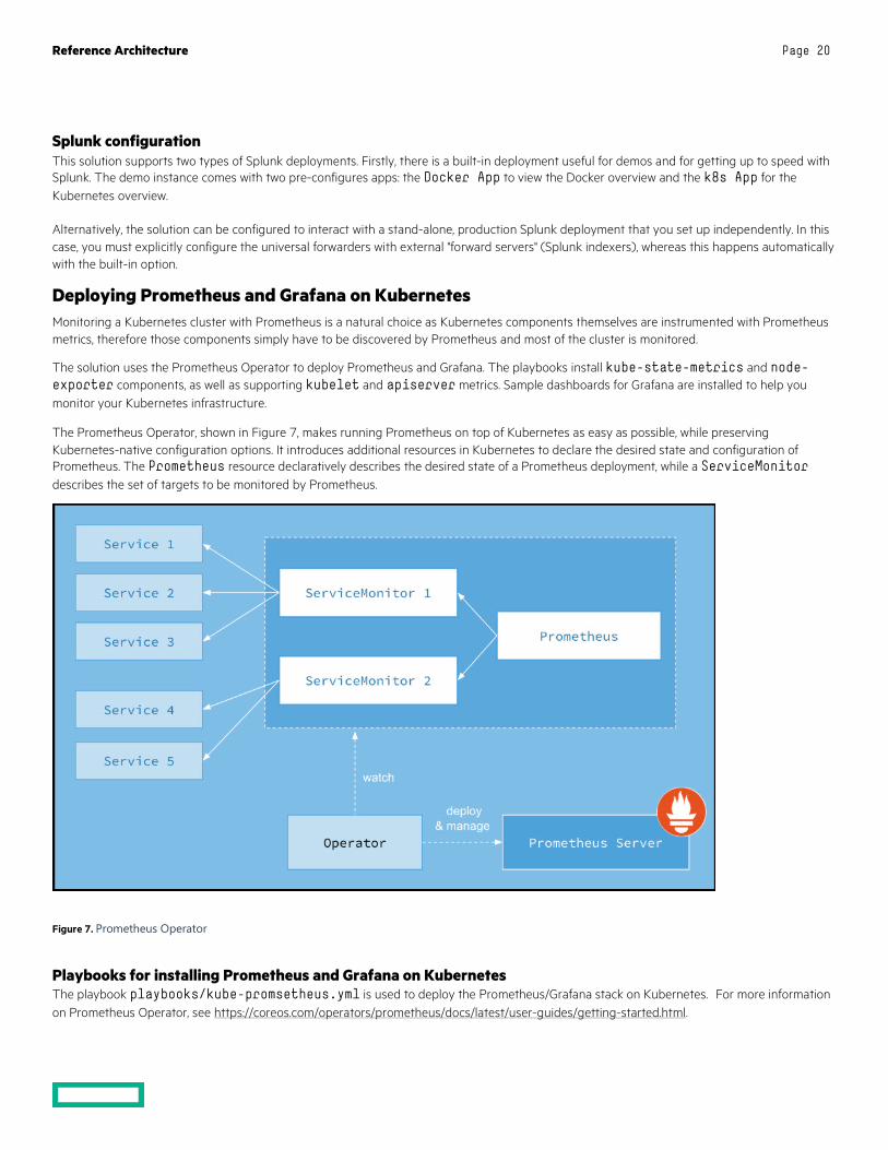
The Prometheus Operator, shown in Figure 7, makes running Prometheus on top of Kubernetes as easy as possible, while preserving Kubernetes-native configuration options. It introduces additional resources in Kubernetes to declare the desired state and configuration of Prometheus. The Prometheus resource declaratively describes the desired state of a Prometheus deployment, while a ServiceMonitor describes the set of targets to be monitored by Prometheus.
Figure 7. Prometheus Operator
Playbooks for installing Prometheus and Grafana on Kubernetes The playbook playbooks/kube-promsetheus.yml is used to deploy the Prometheus/Grafana stack on Kubernetes. For more information on Prometheus Operator, see https://coreos.com/operators/prometheus/docs/latest/user-guides/getting-started.html.
Reference Architecture Page 21
kube state metrics kube-state-metrics is a simple service that listens to the Kubernetes API server and generates metrics about the state of the objects. It is not focused on the health of the individual Kubernetes components, but rather on the health of the various objects inside, such as deployments, nodes and pods. For more information on kube-state-metrics, see https://github.com/kubernetes/kube-state-metrics.
Node exporter The node-exporter provides an overview of cluster node resources including CPU, memory and disk utilization and more. For more information on node-exporter, see https://github.com/prometheus/node_exporter.
Monitors While all the other Kubernetes components run on top of Kubernetes itself, kubelet and apiserver do not, and so they just need service monitors to access these metrics.
cAdvisor Support for cAdvisor is built-in to Kubernetes, so cAdvisor metrics will automatically be available within Prometheus, without any other configuration required.
Note Because Docker EE provides a hosted version of Kubernetes, it is not possible to access metrics for kube-scheduler and kube-controller-manager.
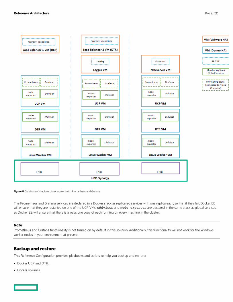
Deploying Prometheus and Grafana on Docker swarm The solution can be configured to enable the use of Prometheus and Grafana for monitoring on Docker swarm. In this setup, there is no need for native installs and all the required monitoring software runs in containers, deployed as either services or stacks. The load among the three hosts will be shared as per Figure 8.
Reference Architecture Page 22
Figure 8. Solution architecture: Linux workers with Prometheus and Grafana
The Prometheus and Grafana services are declared in a Docker stack as replicated services with one replica each, so that if they fail, Docker EE will ensure that they are restarted on one of the UCP VMs. cAdvisor and node-exporter are declared in the same stack as global services, so Docker EE will ensure that there is always one copy of each running on every machine in the cluster.
Note Prometheus and Grafana functionality is not turned on by default in this solution. Additionally, this functionality will not work for the Windows worker nodes in your environment at present.
Backup and restore This Reference Configuration provides playbooks and scripts to help you backup and restore:
• Docker UCP and DTR.
• Docker volumes.
Reference Architecture Page 23
Backup and restore UCP and DTR The playbooks provided in this solution implement the backup and restore procedures as they are described in the Docker documentation at https://docs.docker.com/enterprise/backup/. The solution follows the recommendations in the Docker best practices document at https://success.docker.com/article/backup-restore-best-practices.
Note It is important that you make copies of the backed up data and that you store the copies in a separate physical location. You must also recognize that the backed up data contains sensitive information such as private keys and so it is important to restrict access to the generated files. However, the playbooks do not backup the sensitive information in your group_vars/all/vault file, so you should make sure to keep track of the credentials for the UCP Administrator.
Warning The restore procedures do not restore swarm data. You should follow infrastructure-as-code (IaC) guidelines and maintain your service, stack and network definitions using source code or configuration management tools. You must also ensure that you safely manage the credentials of your administration accounts, as existing UCP Client bundles will not work when you restore UCP on a new swarm.
Backup UCP and DTR The playbooks support backing up the swarm, UCP, DTR metadata and DTR images. All the data that is backed up is streamed over an SSH connection to the backup server. Currently, the playbooks only support the use of the Ansible box as the backup server.
Backing up the swarm When you backup the swarm, your services and stack definitions are backed up together with the network definitions. However, Docker volumes or their contents will not be backed up. (If Docker volumes are defined in stacks, they will be re-created when you restore the stacks, but their content will be lost).
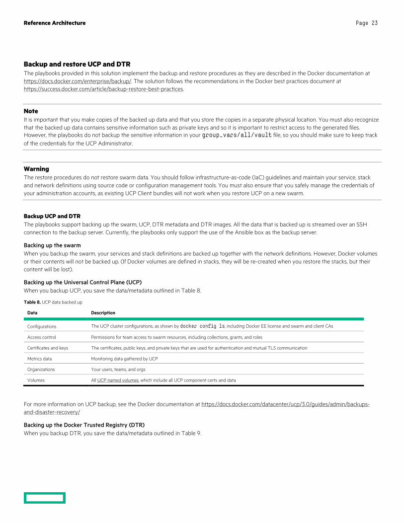
Backing up the Universal Control Plane (UCP) When you backup UCP, you save the data/metadata outlined in Table 8.
Table 8. UCP data backed up
Data Description
Configurations The UCP cluster configurations, as shown by docker config ls, including Docker EE license and swarm and client CAs
Access control Permissions for team access to swarm resources, including collections, grants, and roles
Certificates and keys The certificates, public keys, and private keys that are used for authentication and mutual TLS communication
Metrics data Monitoring data gathered by UCP
Organizations Your users, teams, and orgs
Volumes All UCP named volumes, which include all UCP component certs and data
For more information on UCP backup, see the Docker documentation at https://docs.docker.com/datacenter/ucp/3.0/guides/admin/backups-and-disaster-recovery/
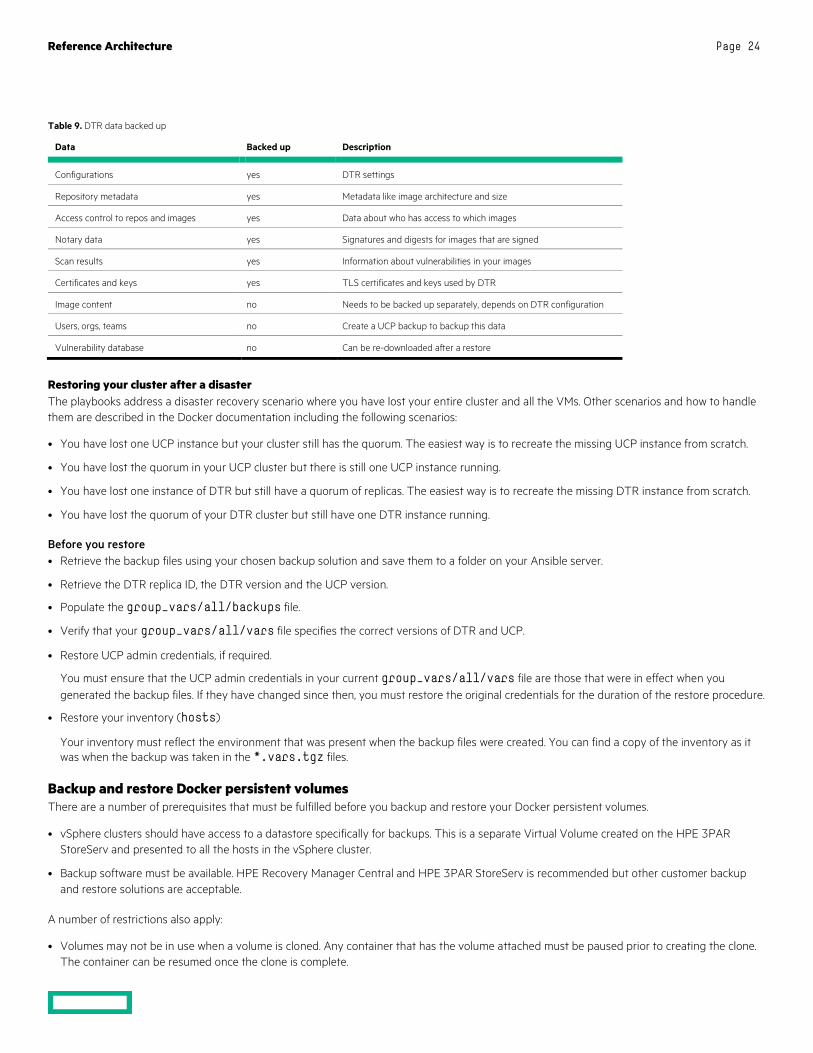
Backing up the Docker Trusted Registry (DTR) When you backup DTR, you save the data/metadata outlined in Table 9.
Reference Architecture Page 24
Table 9. DTR data backed up
Data Backed up Description
Configurations yes DTR settings
Repository metadata yes Metadata like image architecture and size
Access control to repos and images yes Data about who has access to which images
Notary data yes Signatures and digests for images that are signed
Scan results yes Information about vulnerabilities in your images
Certificates and keys yes TLS certificates and keys used by DTR
Image content no Needs to be backed up separately, depends on DTR configuration
Users, orgs, teams no Create a UCP backup to backup this data
Vulnerability database no Can be re-downloaded after a restore
Restoring your cluster after a disaster The playbooks address a disaster recovery scenario where you have lost your entire cluster and all the VMs. Other scenarios and how to handle them are described in the Docker documentation including the following scenarios:
• You have lost one UCP instance but your cluster still has the quorum. The easiest way is to recreate the missing UCP instance from scratch.
• You have lost the quorum in your UCP cluster but there is still one UCP instance running.
• You have lost one instance of DTR but still have a quorum of replicas. The easiest way is to recreate the missing DTR instance from scratch.
• You have lost the quorum of your DTR cluster but still have one DTR instance running.
Before you restore • Retrieve the backup files using your chosen backup solution and save them to a folder on your Ansible server.
• Retrieve the DTR replica ID, the DTR version and the UCP version.
• Populate the group_vars/all/backups file.
• Verify that your group_vars/all/vars file specifies the correct versions of DTR and UCP.
• Restore UCP admin credentials, if required.
You must ensure that the UCP admin credentials in your current group_vars/all/vars file are those that were in effect when you generated the backup files. If they have changed since then, you must restore the original credentials for the duration of the restore procedure.
• Restore your inventory (hosts)
Your inventory must reflect the environment that was present when the backup files were created. You can find a copy of the inventory as it was when the backup was taken in the *.vars.tgz files.
Backup and restore Docker persistent volumes There are a number of prerequisites that must be fulfilled before you backup and restore your Docker persistent volumes.
• vSphere clusters should have access to a datastore specifically for backups. This is a separate Virtual Volume created on the HPE 3PAR StoreServ and presented to all the hosts in the vSphere cluster.
• Backup software must be available. HPE Recovery Manager Central and HPE 3PAR StoreServ is recommended but other customer backup and restore solutions are acceptable.
A number of restrictions also apply:
• Volumes may not be in use when a volume is cloned. Any container that has the volume attached must be paused prior to creating the clone. The container can be resumed once the clone is complete.
Reference Architecture Page 25
• When Docker volumes need to be restored from backup, the backup datastore needs to be detached from all vSphere cluster servers prior to restoration.
Detailed instructions for the persistent storage backup solution are available in the accompanying Deployment Guide.
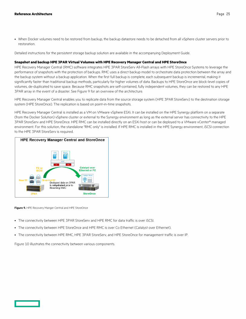
Snapshot and backup HPE 3PAR Virtual Volumes with HPE Recovery Manager Central and HPE StoreOnce HPE Recovery Manager Central (RMC) software integrates HPE 3PAR StoreServ All-Flash arrays with HPE StoreOnce Systems to leverage the performance of snapshots with the protection of backups. RMC uses a direct backup model to orchestrate data protection between the array and the backup system without a backup application. When the first full backup is complete, each subsequent backup is incremental, making it significantly faster than traditional backup methods, particularly for higher volumes of data. Backups to HPE StoreOnce are block-level copies of volumes, de-duplicated to save space. Because RMC snapshots are self-contained, fully independent volumes, they can be restored to any HPE 3PAR array in the event of a disaster. See Figure 9 for an overview of the architecture.
HPE Recovery Manager Central enables you to replicate data from the source storage system (HPE 3PAR StoreServ) to the destination storage system (HPE StoreOnce). The replication is based on point-in-time snapshots.
HPE Recovery Manager Central is installed as a VM on VMware vSphere ESXi. It can be installed on the HPE Synergy platform on a separate (from the Docker Solution) vSphere cluster or external to the Synergy environment as long as the external server has connectivity to the HPE 3PAR StoreServ and HPE StoreOnce. HPE RMC can be installed directly on an ESXi host or can be deployed to a VMware vCenter® managed environment. For this solution, the standalone "RMC only" is installed. If HPE RMC is installed in the HPE Synergy environment, iSCSI connection to the HPE 3PAR StoreServ is required.
Figure 9. HPE Recovery Manger Central and HPE StoreOnce
• The connectivity between HPE 3PAR StoreServ and HPE RMC for data traffic is over iSCSI.
• The connectivity between HPE StoreOnce and HPE RMC is over Co Ethernet (Catalyst over Ethernet).
• The connectivity between HPE RMC, HPE 3PAR StoreServ, and HPE StoreOnce for management traffic is over IP.
Figure 10 illustrates the connectivity between various components.

Reference Architecture Page 26
Figure 10. Connectivity
Refer to HPE RMC User guide for detailed instructions on setup and configuration of HPE RMC and HPE StoreOnce. When RMC is installed, it can be configured with the Backup Appliance Persona. The Backup Persona allows the RMC to manage snapshots and Express Protect Backups. During installation, RMC configuration should specify Data Protection of RMC Core. The initial configuration of backups can be set up using the Protection Wizard as detailed in the Deployment Guide.
RMC leverages HPE 3PAR StoreServ SnapDiff technology to create an application-consistent snapshot. Only changed blocks are sent to the HPE StoreOnce system, which minimizes network traffic and saves disk space on the backup system.
Restoring the volume If a Docker persistent storage volume needs to be restored from backup, the HPE 3PAR volume can be restored either from a snapshot saved on the HPE 3PAR or from a backup on HPE StoreOnce. Detailed instructions are available in the Deployment Guide.
Once the HPE 3PAR virtual volume is restored, the volume must be reattached to the vSphere cluster from RMC. After the volume is reattached, the datastore must be mounted. Applications can then access the restored Docker volume.
Integrate UCP and DTR backup with HPE RMC and HPE StoreOnce You can take advantage of HPE Recovery Manager Central and HPE StoreOnce to provide scheduled snapshots and backup protection for the data generated by the backup procedure for Docker UCP and DTR.
The virtual volume used to host the DockerBackups datastore can be scheduled for snapshot and backup protection with HPE Recovery Manager Central and HPE StoreOnce. Data backed up to HPE StoreOnce can be restored to the HPE 3PAR StoreServ and attached to the Ansible host for recovery.
Solution life cycle management Life cycle management with respect to this solution refers to the maintenance and management of software and hardware of various components that make up the solution stack. Life cycle management is required to keep the solution up-to-date and ensure that the latest versions of the software are running to provide optimal performance, security and to fix any existing defects within the product.
In this section, we will cover life cycle management of the different components that are used in this solution. The life cycle of the following stacks need to be maintained and managed:
• Monitoring Tools (Splunk or Prometheus and Grafana)
• Docker Enterprise Edition Environment
• Virtual Machine Operating Systems
• vSphere Docker Volume service plug-in
• HPE Synergy environment
The general practice and recommendation is to follow a bottom-up approach for updating all components of the environment and making sure the dependencies are met. In this solution, you would start with HPE Synergy and end with the monitoring environment. If all components are not
Reference Architecture Page 27
being updated at the same time, the same approach can be followed – updating only the components that require updates while adhering to the interdependencies of each component that is being updated.
HPE Synergy HPE Synergy Composer powered by HPE OneView provides fast, reliable, and simplified firmware and driver management across many HPE Synergy components. HPE OneView manages firmware to reduce manual interactions and errors, in addition to minimizing downtime. Firmware updates of management appliances and shared infrastructure are non-disruptive to the production workload.
More information is available in the Best Practices for HPE Synergy Firmware and Driver Updates guide at https://support.hpe.com/hpsc/doc/public/display?docId=c05212310.
vSphere Docker Volume Service Plug-in vSphere Docker Volume service plug-in is part of an open source project by VMware that enables running stateful containers by providing persistent Docker volumes leveraging existing storage technology from VMware. There are two parts to the plug-in, namely, client software and server software (see Table 10). Every version of the plug-in that is released includes both pieces of software and it is imperative that the version number installed on the client side and server side are the same.
When updating the Docker Volume service plug-in, ensure the ESXi version you are running is supported and that the client software is compatible with the operating system.
Table 10. vSphere Docker volume service components
Order Component Dependency (compatibility) Download/Documentation
1. Server Software 1. VMware ESXi
2. Docker EE vSphere Docker Volume Service on GitHub
2. Client Software 1. VM Operating System
2. Docker EE
Red Hat Enterprise Linux Operating System This solution is built using Red Hat Enterprise Linux (see Table 11) as the base operating system. When upgrading the operating system on the VMs, first verify that the OS version is compatible with Docker EE by looking at the Docker OS compatibility matrix.
Table 11. Operating System
Order Component Dependency (compatibility) Download/Documentation
1. Red Hat Enterprise Linux 1. Docker EE
2. vDVS client software plugin RHEL
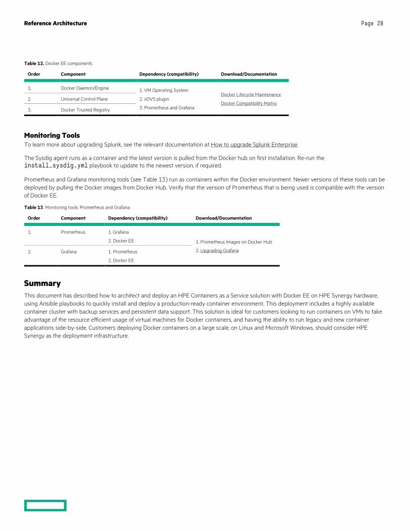
Docker EE Environment Each release of Docker Enterprise Edition contains three (3) technology components – UCP, DTR and the Docker Daemon or Engine. It is imperative that the components belonging to the same version are deployed or upgraded together – see Table 12.
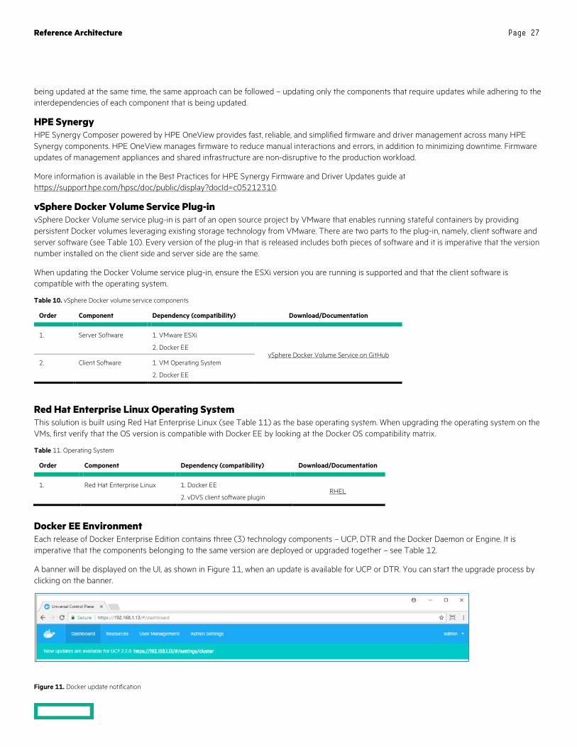
A banner will be displayed on the UI, as shown in Figure 11, when an update is available for UCP or DTR. You can start the upgrade process by clicking on the banner.
Figure 11. Docker update notification
Reference Architecture Page 28
Table 12. Docker EE components
Order Component Dependency (compatibility) Download/Documentation
1. Docker Daemon/Engine 1. VM Operating System
2. vDVS plugin
3. Prometheus and Grafana
Docker Lifecycle Maintenance
Docker Compatibility Matrix 2. Universal Control Plane
3. Docker Trusted Registry
Monitoring Tools To learn more about upgrading Splunk, see the relevant documentation at How to upgrade Splunk Enterprise.
The Sysdig agent runs as a container and the latest version is pulled from the Docker hub on first installation. Re-run the install_sysdig.yml playbook to update to the newest version, if required.
Prometheus and Grafana monitoring tools (see Table 13) run as containers within the Docker environment. Newer versions of these tools can be deployed by pulling the Docker images from Docker Hub. Verify that the version of Prometheus that is being used is compatible with the version of Docker EE.
Table 13. Monitoring tools: Prometheus and Grafana
Order Component Dependency (compatibility) Download/Documentation
1. Prometheus 1. Grafana
2. Docker EE 1. Prometheus Images on Docker Hub
2. Upgrading Grafana 2. Grafana 1. Prometheus
2. Docker EE
Summary This document has described how to architect and deploy an HPE Containers as a Service solution with Docker EE on HPE Synergy hardware, using Ansible playbooks to quickly install and deploy a production-ready container environment. This deployment includes a highly available container cluster with backup services and persistent data support. This solution is ideal for customers looking to run containers on VMs to take advantage of the resource efficient usage of virtual machines for Docker containers, and having the ability to run legacy and new container applications side-by-side. Customers deploying Docker containers on a large scale, on Linux and Microsoft Windows, should consider HPE Synergy as the deployment infrastructure.
Reference Architecture Page 29
Appendix A: Software Licenses Licenses are required for the following software components:
• VMware (version 6.5)
• Red Hat Linux (version 7)
• Microsoft Windows Server 2016
• Docker EE version 2.1
• Splunk (optional software)
• Sysdig (optional software)
Reference Architecture
Sign up for updates
© Copyright 2018-19 Hewlett Packard Enterprise Development LP. The information contained herein is subject to change without notice. The only warranties for Hewlett Packard Enterprise products and services are set forth in the express warranty statements accompanying such products and services. Nothing herein should be construed as constituting an additional warranty. Hewlett Packard Enterprise shall not be liable for technical or editorial errors or omissions contained herein.
Microsoft, Windows, and Windows Server are registered trademarks or trademarks of Microsoft Corporation in the United States and/or other countries. Linux is the registered trademark of Linus Torvalds in the U.S. and other countries. VMware and vSphere are registered trademarks of VMware, Inc. in the United States and/or other jurisdictions. Red Hat and Red Hat Enterprise Linux are registered trademarks of Red Hat, Inc. in the United States and other countries.
a00047301enw, July 2019, Rev 3
Resources and additional links HPE Reference Architectures, hpe.com/info/ra
HPE Synergy, hpe.com/synergy
HPE Servers, hpe.com/servers
HPE Storage, hpe.com/storage
HPE Networking, hpe.com/networking
HPE Technology Consulting Services, hpe.com/us/en/services/consulting.html
Docker Reference Architectures, https://success.docker.com/architectures
Splunk Validated Architectures, https://www.splunk.com/pdfs/white-papers/splunk-validated-architectures.pdf
Sysdig Resources, https://sysdig.com/resources/
Deployment guide, https://hewlettpackard.github.io/Docker-Synergy/
Ansible playbooks, https://github.com/HewlettPackard/Docker-Synergy
To help us improve our documents, please provide feedback at hpe.com/contact/feedback.